JP2019166323A - Rotational tissue cutting control device - Google Patents
Rotational tissue cutting control device Download PDFInfo
- Publication number
- JP2019166323A JP2019166323A JP2019053199A JP2019053199A JP2019166323A JP 2019166323 A JP2019166323 A JP 2019166323A JP 2019053199 A JP2019053199 A JP 2019053199A JP 2019053199 A JP2019053199 A JP 2019053199A JP 2019166323 A JP2019166323 A JP 2019166323A
- Authority
- JP
- Japan
- Prior art keywords
- radial actuator
- drive shaft
- bevel gear
- cutting
- actuator
- Prior art date
- Legal status (The legal status is an assumption and is not a legal conclusion. Google has not performed a legal analysis and makes no representation as to the accuracy of the status listed.)
- Granted
Links
Images


Classifications
-
- A—HUMAN NECESSITIES
- A61—MEDICAL OR VETERINARY SCIENCE; HYGIENE
- A61B—DIAGNOSIS; SURGERY; IDENTIFICATION
- A61B17/00—Surgical instruments, devices or methods
- A61B17/32—Surgical cutting instruments
- A61B17/3201—Scissors
-
- A—HUMAN NECESSITIES
- A61—MEDICAL OR VETERINARY SCIENCE; HYGIENE
- A61B—DIAGNOSIS; SURGERY; IDENTIFICATION
- A61B17/00—Surgical instruments, devices or methods
- A61B17/32—Surgical cutting instruments
- A61B17/3205—Excision instruments
- A61B17/32053—Punch like cutting instruments, e.g. using a cylindrical or oval knife
-
- A—HUMAN NECESSITIES
- A61—MEDICAL OR VETERINARY SCIENCE; HYGIENE
- A61B—DIAGNOSIS; SURGERY; IDENTIFICATION
- A61B17/00—Surgical instruments, devices or methods
- A61B17/32—Surgical cutting instruments
- A61B17/320016—Endoscopic cutting instruments, e.g. arthroscopes, resectoscopes
- A61B17/32002—Endoscopic cutting instruments, e.g. arthroscopes, resectoscopes with continuously rotating, oscillating or reciprocating cutting instruments
-
- A—HUMAN NECESSITIES
- A61—MEDICAL OR VETERINARY SCIENCE; HYGIENE
- A61B—DIAGNOSIS; SURGERY; IDENTIFICATION
- A61B17/00—Surgical instruments, devices or methods
- A61B17/32—Surgical cutting instruments
- A61B17/3205—Excision instruments
- A61B17/3207—Atherectomy devices working by cutting or abrading; Similar devices specially adapted for non-vascular obstructions
- A61B17/320758—Atherectomy devices working by cutting or abrading; Similar devices specially adapted for non-vascular obstructions with a rotating cutting instrument, e.g. motor driven
-
- A—HUMAN NECESSITIES
- A61—MEDICAL OR VETERINARY SCIENCE; HYGIENE
- A61B—DIAGNOSIS; SURGERY; IDENTIFICATION
- A61B17/00—Surgical instruments, devices or methods
- A61B17/32—Surgical cutting instruments
- A61B17/3209—Incision instruments
-
- A—HUMAN NECESSITIES
- A61—MEDICAL OR VETERINARY SCIENCE; HYGIENE
- A61B—DIAGNOSIS; SURGERY; IDENTIFICATION
- A61B17/00—Surgical instruments, devices or methods
- A61B2017/00367—Details of actuation of instruments, e.g. relations between pushing buttons, or the like, and activation of the tool, working tip, or the like
Landscapes
- Health & Medical Sciences (AREA)
- Surgery (AREA)
- Life Sciences & Earth Sciences (AREA)
- Medical Informatics (AREA)
- Animal Behavior & Ethology (AREA)
- Engineering & Computer Science (AREA)
- Biomedical Technology (AREA)
- Heart & Thoracic Surgery (AREA)
- Veterinary Medicine (AREA)
- Molecular Biology (AREA)
- Nuclear Medicine, Radiotherapy & Molecular Imaging (AREA)
- General Health & Medical Sciences (AREA)
- Public Health (AREA)
- Orthopedic Medicine & Surgery (AREA)
- Vascular Medicine (AREA)
- Pathology (AREA)
- Surgical Instruments (AREA)
Abstract
【課題】新規な回転式組織切断制御装置を提供する。【解決手段】開示された実施形態は、組織壁内に開口部を切断するための装置を制御するための装置及びシステムを含む。例示的な実施形態では、逆回転可能な切断装置を制御するための装置は、第1の駆動シャフトに係合するように構成された第1のラジアルアクチュエータを含む。第2のラジアルアクチュエータは、第2の駆動シャフトに係合するように構成され、第2の駆動シャフトは、第1の駆動シャフトと同軸状に配設されている。ハウジングは、第1のラジアルアクチュエータ及び第2のラジアルアクチュエータを支持し、第1の駆動シャフト及び第2の駆動シャフトが内部を通って延在することを可能にし、第1の駆動シャフト及び第2の駆動シャフトは、第1のラジアルアクチュエータ及び第2のラジアルアクチュエータのうちの少なくとも一方の回転に応じて相対的に逆回転可能である。【選択図】図1A novel rotary tissue cutting control device is provided. The disclosed embodiments include devices and systems for controlling a device for cutting an opening in a tissue wall. In an exemplary embodiment, an apparatus for controlling a reversible cutting device includes a first radial actuator configured to engage a first drive shaft. The second radial actuator is configured to engage a second drive shaft, the second drive shaft being disposed coaxially with the first drive shaft. The housing supports a first radial actuator and a second radial actuator, allows the first drive shaft and the second drive shaft to extend therethrough, and includes a first drive shaft and a second drive shaft. Is relatively rotatable in response to rotation of at least one of the first radial actuator and the second radial actuator. [Selection diagram] Fig. 1
Description
[関連出願の相互参照]
本出願は、その内容全体が参照により本明細書に援用される、本明細書と共に出願され、代理人整理番号ORA0106US1が付された同時係属出願「回転式組織切断装置」に関連する。
[Cross-reference of related applications]
This application is related to the co-pending application “Rotary Tissue Cutting Device” filed with this specification and assigned the agent docket number ORA0106US1, the entire contents of which are hereby incorporated by reference.
本開示は、組織壁内に開口部を切断するための装置、システム、及び方法に関する。 The present disclosure relates to devices, systems, and methods for cutting an opening in a tissue wall.
このセクションにおける記述は、単に、本開示に関する背景情報を提供し、先行技術を構成しない場合もある。 The statements in this section merely provide background information related to the present disclosure and may not constitute prior art.
侵襲的手術を伴わずに患者の体内の組織にアクセスする能力により、疼痛の低減、回復時間の短縮、及び合併症のリスクの低減を伴う、常に向上するタイプの分析、診断、及び治療が可能になる。2つの例として、内視鏡撮像及びカテーテル法(catherization)処置は、侵襲的手術をしないで多数の内部損傷の評価及び処置を可能にした。 The ability to access the patient's internal tissue without invasive surgery allows for an ever-increasing type of analysis, diagnosis, and treatment with reduced pain, faster recovery time, and reduced risk of complications become. As two examples, endoscopic imaging and catheterization procedures have allowed the assessment and treatment of numerous internal lesions without invasive surgery.
場合によっては、患者の体内の組織を遠隔で切断するために、細いプローブ状の装置を挿入することが望ましいことがある。例えば、胆管が閉塞されたときに患者に緩和を提供するために、胃腸管の中にプローブを挿入して開口部を切断し、胆嚢が十二指腸内に胆汁を放出することを可能にして、胆嚢の痛みのある膨潤を緩和することが望ましいであろう。しかしながら、プローブを挿入して所望の位置に到達させることは可能であり得るが、小さな切断を遠隔で行うことは非常に困難であることが判明するであろう。組織は非常に柔軟で、切断を行う際に組織の後ろに押し付ける構造が存在しないと、打ち抜く又は突き刺すことができない場合がある。 In some cases, it may be desirable to insert a thin probe-like device to remotely cut tissue within a patient. For example, to provide relief to the patient when the bile duct is obstructed, insert a probe into the gastrointestinal tract and cut the opening, allowing the gallbladder to release bile into the duodenum, It would be desirable to relieve the painful swelling of the skin. However, while it may be possible to insert the probe to reach the desired location, it will prove very difficult to make small cuts remotely. The tissue is very flexible and may not be punched or pierced if there is no structure to press behind the tissue when making a cut.
開示された実施形態は、組織壁内に開口部を切断するための装置、システム、及び方法を含む。 The disclosed embodiments include devices, systems, and methods for cutting an opening in a tissue wall.
例示的な実施形態では、装置は、遠位端に少なくとも1つの第1の切断面を支持する第1の円筒状体を有する内側切断部材を含む。第1の切断面は、第1の円筒状体の軸に対して第1の回転方向に面し、第1の円筒状体の外周に第1の切断縁部を有する。装置はまた、第1の円筒状体の周りに同心円状に配設され、遠位端で少なくとも1つの第2の切断面を支持する第2の円筒状体を有する外側切断部材も含む。第2の切断面は、軸に対して第2の回転方向に面し、第2の円筒状体の内周に第2の切断縁部を有する。組織は、組織に対する装置の遠位端の適用及び内側切断部材及び外側切断部材を逆回転させることに応じて、内側切断部材の第1の切断縁部と外側切断部材の第2の切断縁部との間で回転可能に切断可能である。 In an exemplary embodiment, the apparatus includes an inner cutting member having a first cylindrical body that supports at least one first cutting surface at the distal end. The first cut surface faces in the first rotation direction with respect to the axis of the first cylindrical body, and has a first cutting edge on the outer periphery of the first cylindrical body. The apparatus also includes an outer cutting member having a second cylindrical body disposed concentrically around the first cylindrical body and supporting at least one second cutting surface at the distal end. The second cut surface faces the second rotation direction with respect to the axis and has a second cut edge on the inner periphery of the second cylindrical body. The tissue is responsive to application of the distal end of the device to the tissue and reverse rotation of the inner and outer cutting members, the first cutting edge of the inner cutting member and the second cutting edge of the outer cutting member. And can be cut in a rotatable manner.
別の例示的な実施形態では、装置は、装置の遠位端に2つ以上の第1の切断面を支持する第1の円筒状体を有する内側切断部材を含む。第1の切断面は、第1の円筒状体の軸に対して第1の回転方向に面する。第1の切断面は、第1の円筒状体の外周に第1の切断縁部を含み、内側切断部材の軸に対して傾斜している。第1の切断面はまた、遠位端を越えて外側に延在し、組織を穿孔するように構成されたアンカー先端部を含む。装置はまた、第1の円筒状体の周囲に同心円状に配設され、装置の遠位端に少なくとも1つの第2の切断面を支持する第2の円筒状体を有する外側切断部材も含む。第2の切断面は、軸に対して第2の回転方向に面し、第2の円筒状体の内周に第2の切断縁部を有する。組織は、アンカー先端部によって穿孔可能であり、組織に対する装置の遠位端の適用及び内側切断部材及び外側切断部材を逆回転させることに応じて、内側切断部材の第1の切断縁部と外側切断部材の第2の切断縁部との間で回転可能に切断可能である。 In another exemplary embodiment, the device includes an inner cutting member having a first cylindrical body that supports two or more first cutting surfaces at a distal end of the device. The first cut surface faces the first rotational direction with respect to the axis of the first cylindrical body. The first cutting surface includes a first cutting edge on the outer periphery of the first cylindrical body, and is inclined with respect to the axis of the inner cutting member. The first cutting surface also includes an anchor tip that extends outward beyond the distal end and is configured to pierce tissue. The apparatus also includes an outer cutting member having a second cylindrical body disposed concentrically around the first cylindrical body and supporting at least one second cutting surface at the distal end of the apparatus. . The second cut surface faces the second rotation direction with respect to the axis and has a second cut edge on the inner periphery of the second cylindrical body. The tissue can be pierced by the anchor tip and the first cutting edge and outer side of the inner cutting member in response to application of the distal end of the device to the tissue and reverse rotation of the inner and outer cutting members. It can cut | disconnect so that rotation between the 2nd cutting edges of a cutting member is possible.
更なる例示的な実施形態では、方法は、内側切断部材と、同心の外側切断部材とを有する円筒形切断装置を組織に対して延伸させることを含む。内側切断部材及び同心の外側切断部材は、組織を、内側切断部材及び同心の外側切断部材の軸に直交して半径方向に切断するように構成された対向する切断面を有する。内側切断部材が移動されて、内側切断部材の遠位端のアンカー先端部に組織を穿刺させる。内側切断部材及び同心の外側切断部材が、互いに対して回転されて、組織を半径方向に切断する。 In a further exemplary embodiment, the method includes extending a cylindrical cutting device having an inner cutting member and a concentric outer cutting member to tissue. The inner cutting member and the concentric outer cutting member have opposing cutting surfaces that are configured to cut the tissue radially perpendicular to the axis of the inner cutting member and the concentric outer cutting member. The inner cutting member is moved to puncture tissue at the anchor tip at the distal end of the inner cutting member. The inner cutting member and the concentric outer cutting member are rotated relative to one another to cut tissue radially.
別の例示的な実施形態では、逆回転可能な切断装置を制御するための装置は、第1の駆動シャフトに係合するように構成された第1のラジアルアクチュエータを含む。第2のラジアルアクチュエータは、第2の駆動シャフトに係合するように構成され、第2の駆動シャフトは、第1の駆動シャフトと同軸状に配設されている。ハウジングは、第1のラジアルアクチュエータ及び第2のラジアルアクチュエータを支持し、第1の駆動シャフト及び第2の駆動シャフトが内部を通って延在することを可能にし、第1の駆動シャフト及び第2の駆動シャフトは、第1のラジアルアクチュエータ及び第2のラジアルアクチュエータのうちの少なくとも一方の回転に応じて、相対的に逆回転可能である。 In another exemplary embodiment, an apparatus for controlling a counter-rotatable cutting device includes a first radial actuator configured to engage a first drive shaft. The second radial actuator is configured to engage with the second drive shaft, and the second drive shaft is disposed coaxially with the first drive shaft. The housing supports the first radial actuator and the second radial actuator, allows the first drive shaft and the second drive shaft to extend through the interior, the first drive shaft and the second drive shaft. The drive shaft can relatively rotate in reverse in accordance with the rotation of at least one of the first radial actuator and the second radial actuator.
更なる例示的な実施形態では、逆回転可能な切断装置を制御するための装置は、第1の駆動シャフトに係合するように構成された第1のラジアルアクチュエータを含む。第2のラジアルアクチュエータは、第2の駆動シャフトに係合するように構成され、第2の駆動シャフトは、第1の駆動シャフトと同軸状に配設されている。逆回転機構は、第1のラジアルアクチュエータ及び第2のラジアルアクチュエータを機械的に連結し、逆回転機構は、第1のラジアルアクチュエータが第1の方向に回転されるときに、第2のラジアルアクチュエータを第2の方向に回転させるように構成されている。ハウジングは、第1のラジアルアクチュエータ及び第2のラジアルアクチュエータを支持し、第1の駆動シャフト及び第2の駆動シャフトが内部を通って延在することを可能にする。回転制御装置は、第1のラジアルアクチュエータに機械的に連結されて第1のラジアルアクチュエータの回転を可能にし、第1の駆動シャフト及び第2の駆動シャフトは、第1の回転制御装置の回転に応じて同時に逆回転可能である。 In a further exemplary embodiment, an apparatus for controlling a counter-rotatable cutting device includes a first radial actuator configured to engage a first drive shaft. The second radial actuator is configured to engage with the second drive shaft, and the second drive shaft is disposed coaxially with the first drive shaft. The reverse rotation mechanism mechanically couples the first radial actuator and the second radial actuator, and the reverse rotation mechanism is configured such that the second radial actuator is rotated when the first radial actuator is rotated in the first direction. Is configured to rotate in the second direction. The housing supports the first radial actuator and the second radial actuator and allows the first drive shaft and the second drive shaft to extend therethrough. The rotation control device is mechanically coupled to the first radial actuator to enable rotation of the first radial actuator, and the first drive shaft and the second drive shaft are used to rotate the first rotation control device. Correspondingly, reverse rotation is possible simultaneously.
更に別の例示的な実施形態では、組織壁内に開口部を切断するためのシステムは、第1の駆動シャフトと、第1の駆動シャフトの周りに同軸状に配設され、第1の駆動シャフトとは独立して回転するように構成された第2の駆動シャフトと、第1の駆動シャフト及び第2の駆動シャフトを収容するシースと、を含む、駆動シャフトアセンブリを含む。第1のラジアルアクチュエータは、第1の駆動シャフトに係合するように構成されている。第2のラジアルアクチュエータは、第2の駆動シャフトに係合するように構成されている。ハウジングは、第1のラジアルアクチュエータ及び第2のラジアルアクチュエータを支持し、第1の駆動シャフト及び第2の駆動シャフトを収容するシースが、内部を通って延在することを可能にする。回転制御装置は、第1のラジアルアクチュエータに機械的に連結されており、第2のラジアルアクチュエータに対する、第1のラジアルアクチュエータの回転を可能にする。切断装置は、カッターの遠位端で少なくとも1つの第1の切断面を支持する第1の円筒状体を有する内側切断部材を含み、第1の駆動シャフトに機械的に連結されており、ここで、第1の切断面は、第1の円筒状体の軸に対して第1の回転方向に面し、第1の円筒状体の外周に第1の切断縁部を有する。第2の円筒状体を有する外側切断部材は、第1の円筒状体の周りに同心円状に配設され、第2の駆動シャフトに機械的に連結されており、外側切断部材は、装置の遠位端で少なくとも1つの第2の切断面を支持し、第2の切断面は、軸に対して第2の回転方向に面し、第2の円筒状体の内周に第2の切断縁部を有する。組織は、装置の遠位端の適用及び回転制御装置の回転に応じて、内側切断部材の第1の切断縁部と外側切断部材の第2の切断縁部との間で回転可能に切断可能である。 In yet another exemplary embodiment, a system for cutting an opening in a tissue wall is disposed coaxially around a first drive shaft and the first drive shaft, the first drive A drive shaft assembly includes a second drive shaft configured to rotate independently of the shaft, and a sheath that houses the first drive shaft and the second drive shaft. The first radial actuator is configured to engage the first drive shaft. The second radial actuator is configured to engage the second drive shaft. The housing supports the first radial actuator and the second radial actuator and allows a sheath containing the first drive shaft and the second drive shaft to extend therethrough. The rotation control device is mechanically coupled to the first radial actuator and allows the rotation of the first radial actuator relative to the second radial actuator. The cutting device includes an inner cutting member having a first cylindrical body that supports at least one first cutting surface at a distal end of the cutter, and is mechanically coupled to a first drive shaft, Thus, the first cut surface faces in the first rotation direction with respect to the axis of the first cylindrical body, and has a first cutting edge on the outer periphery of the first cylindrical body. An outer cutting member having a second cylindrical body is disposed concentrically around the first cylindrical body and is mechanically coupled to the second drive shaft, the outer cutting member being Supporting at least one second cutting surface at the distal end, the second cutting surface facing in a second rotational direction relative to the axis, and a second cutting on the inner periphery of the second cylindrical body Has an edge. Tissue can be cut rotatably between the first cutting edge of the inner cutting member and the second cutting edge of the outer cutting member in response to application of the distal end of the device and rotation of the rotation control device. It is.
更なる特徴、利点、及び適用分野は、本明細書に提供される説明から明らかになるであろう。説明及び具体的な例は、単に例示目的のために意図され、本開示の範囲を限定することは意図されないことを理解されたい。 Further features, advantages, and areas of application will become apparent from the description provided herein. It should be understood that the description and specific examples are intended for purposes of illustration only and are not intended to limit the scope of the present disclosure.
本明細書に説明される図面は、単に例示目的のためであり、決して本開示の範囲を制限することは意図されない。図面における構成要素は、必ずしも一定の縮尺ではなく、開示された実施形態の原理を例示することに重点を置かれる。 The drawings described herein are for illustrative purposes only and are not intended to limit the scope of the present disclosure in any way. The components in the drawings are not necessarily to scale, emphasis instead being placed upon illustrating the principles of the disclosed embodiments.
以下の説明は、本質的に単に例示的なものであり、本開示、適用、又は使用を限定することは意図されない。3桁の参照番号のうちの最初の桁及び4桁の参照番号のうちの最初の2桁は、そのエレメントが最初に現れる1桁の図番号のうちの最初の桁及び図番号のうちの最初の2桁にそれぞれ対応することに留意されるだろう。 The following description is merely exemplary in nature and is not intended to limit the present disclosure, application, or use. The first digit of the three-digit reference number and the first two digits of the four-digit reference number are the first digit of the one-digit figure number in which the element first appears and the first of the figure numbers. It will be noted that each corresponds to two digits.
以下の説明は、組織を切断するための装置、システム、及び方法の様々な実施形態を単なる実例として説明するもので、限定するものではない。以下に詳細に記載されるように、逆回転可能な回転要素を有する切断装置は、組織まで延伸され、互いに対して回転されて組織を穿孔及び切断する。 The following description illustrates, by way of example, and not limitation, various embodiments of devices, systems, and methods for cutting tissue. As described in detail below, a cutting device having a counter-rotatable rotating element is stretched to tissue and rotated relative to each other to pierce and cut tissue.
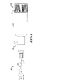
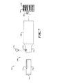
図1を参照すると、患者の解剖学的領域(図1には図示せず)において組織壁に開口部を切断するための例示的なシステム100が提供される。様々な実施形態において、システム100は一般に、切断装置111と、切断装置111を制御するための制御装置150と、切断装置111を制御装置150に連結する駆動シャフトアセンブリ140と、を含む。以下で詳細に説明されるように、切断装置111は、図2、図3A〜図3C、図4A〜図4C、図5A〜図5C、及び図6を参照して以下で更に説明されるように、軸101の周りに方向103又は105に回転するように構成された切断部材を有する、逆回転可能な切断装置である。駆動シャフトアセンブリ140は、第1の駆動シャフトと、いくつかの実施形態において第1の駆動シャフトの周りに同軸状に配設された中空シャフトを含む第2の駆動シャフトと、を含む。第1の駆動シャフト及び第2の駆動シャフトは、切断装置111の部材に連結可能であり、図11を参照して以下で更に説明されるように、シース内に収容される。いくつかの実施形態では、第1の駆動シャフト及び第2の駆動シャフトは、可撓性の逆回転可能なケーブルを含む。制御装置150は、図7、図8、及び/又は図9を参照してそれぞれ以下で更に説明される、位置調節装置170及び少なくとも1つの回転把持部180を支持するハウジング160を含む。
Referring to FIG. 1, an
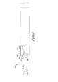
図2を参照すると、切断装置111は、内側切断部材211と、外側切断部材251と、を含む、2つの逆回転可能な部材を含む。図3A〜図3C及び図5A〜図5Cを参照して以下に更に説明されるように、内側切断部材211は、切断装置211における遠位端290で、組織を穿孔及び/又は固定し、次いで、内側切断部材211上の内側切断面241と、外側切断部材251上の外側切断面271と、を含む、対向する切断面の間の切断領域292に組織を引き込むように構成されている。したがって、内側切断部材211及び外側切断部材251の逆回転が組織を切断し、組織内に開口部を形成する。
Referring to FIG. 2, the
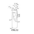
図3A〜図3Cを参照すると、内側切断部材211は、図11を参照して以下に更に記載される駆動シャフトアセンブリ140(図1、図3A〜図3Cには図示せず)に係合する近位端349を有する本体315を含む。内側切断部材211は、遠位端290に向かって長手方向に延在し、軸101の周りで半径方向に方向103に湾曲する1つ以上のアンカー先端部321を含む。アンカー先端部321は、1つ以上の内側切断面241の前方に、遠位端290に向かって延在するように角度付けられている。アンカー先端部321は、内側切断部材211の遠位端290に提示された組織壁(図3A〜図3Cには図示せず)を穿孔するように構成された穿孔端部323を有する。いくつかの実施形態では、図2、図3A〜図3C、及び図6に示されるように、アンカー先端321は、螺旋形状を描く。いくつかの他の実施形態では、アンカー先端部321はまた、遠位端290から離れる方向に面する平坦な固定表面325を含み得る。
3A-3C, the
内側切断部材211はまた、1つ以上の内側切断面241を含む。内側切断面241は、前方切断縁部343から後方切断縁部345まで傾斜している。いくつかの実施形態では、内側切断面241の前方切断縁部343は、内側切断部材の外縁部にあり、そこで、前方切断縁部は、以下で更に記載されるように、外側切断部材251の外側切断面271の前縁部に係合する。いくつかの実施形態では、1つ以上の内側切断面241は、軸101に対して鋭角で傾斜している。1つ以上の内側切断面241は、切断領域292(図2)において、内側切断部材の1つ以上の内側切断面241、及び外側切断部材251の1つ以上の内側切断面271が、1つのはさみの対向する刃のように、遠位端290に面する鋭角で合わさって、組織の切断を容易にするようにそのように角度付けられている。内側切断部材211の内側切断面241は、内側切断面241と外側切断面271との間にはさみの形状を形成するのに役立つように放物線状に形成され、下端347で終了している。
The
引き続き図3A〜図3Cを参照すると、アンカー先端部321を組織壁に対して提示し、内側切断部材211を軸101の周りに方向103に回転させることにより、アンカー先端部321の穿孔端部323を組織に穿孔させる。次いで、軸101の周りで方向103に回転し続けることにより、平坦な固定表面325に、組織壁を遠位端290から離して切断領域292内に引き入れさせることができる。切断領域において、内側切断面241は、前述のように、また図6を参照して以下で更に説明されるように、外側切断面271(図2)に向かって組織を切断する。
With continued reference to FIGS. 3A-3C, the
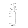
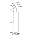
図4A〜図4Cを参照すると、外側切断部材251は、図11を参照して以下に更に説明される駆動シャフトアセンブリ140(図1、図4A〜図4Cには図示せず)に係合する近位端499を有する本体455を含む。外側切断部材251は、先端部461を含み、これは、いくつかの実施形態では、遠位端290に向かって長手軸方向に延在する尖った端部463含む。いくつかの実施形態では、先端部461は、遠位端290おいて尖った端部463から離れて角度付けられており、図6を参照して更に説明されるように、組織壁内への貫通を容易にする。外側切断部材251はまた、1つ以上の外側切断面271を含む。外側切断面271は、前方切断縁部473から後方切断縁部475まで傾斜している。いくつかの実施形態では、外側切断面271の前方切断縁部473は、外側切断部材251の内縁部にあり、そこで、図6を参照して以下に更に説明されるように、内側切断部材221の内側切断面241の前縁部343に係合する。
4A-4C, the
いくつかの実施形態では、外側切断部材251の外側切断面271は、略U字形であり、下端477で終了する。図4A〜図4Cに示されるように、いくつかの実施形態では、外側切断面271は、軸101と実質的に平行である。外側切断部材251を内側切断部材(図2及び図3A〜図3C)と共に組織壁に対して提示し、外側切断部材251を、内側切断部材211に対して、軸101の周りに第2の方向105に逆回転させることにより、図6を参照して以下に更に説明されるように、外側切断部材251の外側切断面271と内側切断部材211の内側切断面241との間で組織を切断するであろう。
In some embodiments, the
いくつかの実施形態では、図3A〜図3C及び図4A〜図4Cに示されるように、内側切断面241は軸101に対して鋭角に角度付けられており、外側切断面271は、軸101と実質的に平行であり、鋭角で交差する対向する切断面を提供して、組織の切断を容易にする。しかしながら、内側切断部材211の内側切断面241を軸101と実質的に平行に配置し、外側切断面271を軸101に対して鋭角に角度付けて、切断面241と271との間に鋭角の切削角を形成することによって、対向する切断面の間に同じ鋭角の切削角が形成され得ることが理解されるであろう。更に、いくつかの他の実施形態では、内側切断部材211の内側切断面214及び外側切断部材251の外側切断面271の両方を、軸101から(反対方向に)角度付けて、対向する切断面241と271との間に鋭角の切削角を形成することができる。また、図3A〜図3C及び図4A〜図4Cを参照して前述したように、内側切断部材221の内側切断面241の前縁部343は、内側切断部材221の外表面にあり、外側切断部材251の外側切断面471の前縁部473は、外側切断部材251の内表面にあるので、前縁部343及び473が、はさみの刃の前縁部のように合わさって、それらの間での組織の切断を容易にするであろう。
In some embodiments, as shown in FIGS. 3A-3C and 4A-4C, the
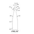
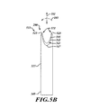
図5A〜図5Cを参照すると、いくつかの他の実施形態では、内側切断部材511は、図10を参照して以下に更に説明される駆動シャフトアセンブリ140(図1、図3A〜図3Cには図示せず)に係合する近位端549を有する本体515を含む。図2及び図3A〜図3Cに示されるような、内側切断部材211の角度付けられたアンカー先端部321の代わりに、内側切断部材511は、いずれかの端部に一対の穿孔端部523を有する凹状アンカー先端部521を含む。穿孔端部523は、内側切断部材511の遠位端290に提示される組織壁(図5A〜図5Cには図示せず)を穿孔するように構成されている。したがって、アンカー先端部521は、外側切断部材251が内側切断部材511に対して逆回転される際に、組織を保持するであろう。内側切断部材511及び外側切断部材(図示せず)は、その後、相対的に逆回転されて、内側切断面の間の組織を切断することができる。いくつかの実施形態では、前縁部543、後縁部545、及び下端547で終了する略放物線状の形状を含む内側切断面541は、図2及び図3A〜3Cに示されるような、内側切断部材211の対応する前縁部343、後縁部345、及び下端347で終了する略放物線状の形状のものと同様である。しかしながら、図4A〜4Cを参照して前述したように、内側切断面541を、外側切断面271の角度付けに対応するように、軸101に対して異なって角度付けて、内側切断面541と外側切断面271との間にはさみ型の形状を形成してもよいことに留意すべきである。
Referring to FIGS. 5A-5C, in some other embodiments, the
様々な実施形態では、図6を参照すると、内側切断部材211及び外側切断部材251を含む切断装置111は、組織を穿孔し、切断するように位置決め及び操作される。切断装置111は、破線で表される組織壁601に位置付けられる。内側切断部材211及び外側切断部材251は、相対的に逆回転されて、内側切断部材211は、軸101の周りに第1の方向103に相対的に逆回転し、外側切断部材251は、軸101の周りに第2の方向105に相対的に逆回転する。内側切断部材321が第1の方向103に回転により、アンカー先端部321の穿孔端部323が組織壁601を穿孔することになる。内側切断部材211を更に相対的に逆回転させることにより、切断装置111の遠位端290から離れる方に面する平坦な固定表面325が、組織壁601の組織を、切断領域292の中に向く方向607に引き込むことになる。
In various embodiments, referring to FIG. 6, a
切断装置111の切断部材211及び251が互いに対して移動する際、組織壁601は、内側切断部材211の内側切断面241と外側切断部材251の外側切断面271との間に引き込まれる。内側切断部材211及び外側切断部材251が軸101の周りで相対的に逆回転する際、内側切断面241及び外側切断面271は、切断装置111の辺縁の周りの組織601を切断して、組織壁601の中に開口部を形成する。
As the cutting
内側切断部材が、図5A〜図5Cに示されたような内側切断部材511等の切断装置111を含むいくつかの他の実施形態では、内側切断部材511のアンカー先端部521は、内側切断部材211のアンカー先端部221(図2、図3A〜図3C、及び図6)と同様に、切断面の間の切断領域内に組織を引き込むように構成されないことがある。しかしながら、切断装置111によって、切断装置111の遠位端290に向かって組織壁601に対して加えられる圧力により、切断装置111が組織壁601の中に穿刺し、切断装置111が組織壁の中に移動して、内側切断部材511の内側切断面541と外側切断部材251の外側切断面271との間の切断領域292の中に組織を取り込むことになる場合がある。
In some other embodiments, where the inner cutting member includes a
図7を参照すると、様々な実施形態において、制御装置150は、切断装置111(図7には図示せず)を位置決めし、相対的に逆回転させるために使用され得る構成要素を含む。位置調節装置170は、駆動シャフトアセンブリ140(図7には図示せず)のシースに固定可能に接合されたスリーブ772を含み、駆動シャフトアセンブリは、切断装置111が配置される方向に面している、スリーブ772の第1の端部779から延在している。スリーブ772は、制御装置150のハウジング160の第1の端部774に摺動可能に受容可能である。スリーブ772は、シースロッキングポート778を通じてハウジング160内に受容されるシースロック776を受容する係合溝777を含む。
Referring to FIG. 7, in various embodiments, the
図7に示すように、いくつかの実施形態では、シースロック776は、スリーブ772内の係合溝777に機械的かつ選択的に係合する、刻み付きロックスクリュの形態である。シースロック776を回転させて、係合溝777からシースロック776を緩めて、スリーブ772、ひいては駆動シャフトアセンブリ140の移動を可能にし得る。スリーブ772は、スリーブ772をハウジング160に対して摺動させることによって操作される。次いで、一旦切断装置111が所望の位置に位置付けられると、シースロック776を回転させて、シースロック776をスリーブ772内の係合溝777に係合させて駆動シャフトアセンブリ140を係止し、こうして切断装置111(同様に図7には図示せず)を所望の位置で駆動シャフトアセンブリ140に連結させることができる。例えば、スリーブ772を定位置に係止するためのレバー又はラッチを含む、他の形態の位置調節装置170が使用され得ることを理解されたい。また、他の形態の位置調節装置170が、気管支鏡又は、ハウジングを移動させると駆動シャフトアセンブリ140が移動するように、切断装置111を導くために使用される他のデバイスの、ハウジングに固定可能に連結され得ることも理解されたい。本開示の実施形態は、位置調節装置170のいかなる特定の形態の使用にも限定されない。
As shown in FIG. 7, in some embodiments, the
更に図7を参照すると、いくつかの実施形態では、回転グリップ180は、刻み付きグリップ等のユーザグリップ781と、図8を参照して以下に説明されるような、回転機構に係合するために使用されるインターフェース782と、を含み得る。
Still referring to FIG. 7, in some embodiments, the
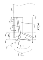
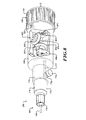
図8を参照すると、いくつかの実施形態では、制御装置150は、逆回転機構802を含む。逆回転機構802は、切断装置111の内側切断部材211(いずれも図8には図示せず)に連結され得る、駆動シャフトアセンブリ140の第1の駆動シャフト(いずれも図8には図示せず)と係合するように構成された第1のラジアルアクチュエータ812を含む。逆回転機構802は、切断装置111の外側切断部材251に連結され得る、駆動シャフトアセンブリ140の第2の駆動シャフト(図8には図示せず)と係合するように構成された第2のラジアルアクチュエータ852を含む。駆動シャフトアセンブリ140の構成は、図11を参照して以下で更に説明される。
Referring to FIG. 8, in some embodiments, the
駆動シャフトアセンブリ140の駆動シャフトを逆回転させるために、第1のラジアルアクチュエータ812及び第2のラジアルアクチュエータ852は、機械的に連結されて、一方又は他方が回転されると、ラジアルアクチュエータ812及び852を反対方向に回転させる。図8に示された逆回転機構802では、第1のラジアルアクチュエータ812は、ハウジング160の第1の端部801に面する第1のベベルギア814を含み、第2のラジアルアクチュエータ852は、ハウジング160の第1の端部801から離れる方に面する第2のベベルギア854を含む。差動ベベルギア894を含むトランスファーギア892が、第1のベベルギア814及び第2のベベルギア854の各々に機械的に連結されている。第1のベベルギア814の回転が、第2のベベルギア854に反対の回転を引き起こす差動ベベルギア894に回転を付与する。逆回転機構802はまた、差動アクチュエータ812及び854と、並びにトランスファーギア892と、を支持するためのシャーシ896を含み得る。図8に示されるように、第1の差動アクチュエータ812は、回転グリップ180が一の方向に回転されると、第1の差動アクチュエータ812が同じ方向に回転し、第2の差動アクチュエータ852が反対方向に回転するように、回転グリップ180上のインターフェース782を受容する。結果として、駆動シャフトアセンブリ140の駆動シャフトは、相対的に逆回転し、切断装置111の切断部材211及び251を逆回転させる。
To reverse the drive shaft of
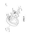
図9を参照すると、駆動シャフトアセンブリ140の駆動シャフト、及び切断装置111(いずれも図9には図示せず)の逆回転を容易にする逆回転機構902の別の実施形態は、図8の逆回転機構802で使用されるようなベベルギアの代わりに、スパーギアを使用する。逆回転機構902は、第1のラジアルアクチュエータ812(図9には図示せず)に連結されたベースギア914を含み、図8を参照して説明されるように第1のラジアルアクチュエータ812が回転されると、ベースギア914に回転を付与する。ベースギア914は、軸101の周りに回転するように構成された内向きスパーギアである。ベースギア914は、アクスル992に係合する。アクスル992は、外向きスパーギアを含み得る第1のトランスファーギア915を含む。ベースギア914は、第1のトランスファーギア915に係合して、例えば図9に示されるような方向103に、ベースギア914の回転と同様に、第1のトランスファーギア915に回転を付与する。第1のラジアルアクチュエータ812、ベースギア914、又はアクスル992が、第1の駆動シャフト又は第2の駆動シャフト(図9には図示せず)のうちの1つに連結されて、第1の駆動シャフトに回転を付与し得る。
Referring to FIG. 9, another embodiment of a
アクスル992はまた、同様に外向きスパーギアを含み得る、第2のトランスファーギア919まで延在する、第1のシャフト907を含み得る。第1のシャフト907は、図9に示される他の要素と共に、クレードル(図9には図示せず)内に回転可能に装着され得る。第1のアクスル907及び第2のトランスファーギア919の両方は、第1のトランスファーギア915と同様に回転する。第2のトランスファーギア919は、同様にクレードル(図9には図示せず)内に回転可能に装着され得る逆回転ギア954に係合している。逆回転ギア954と第2のトランスファーギア919との係合により、逆回転ギア954が、アクスル992の第2のトランスファーギア919と反対に回転される。したがって、例えば、ベースギア914が方向103に回転される場合、逆回転ギア954は、方向105に回転するであろう。逆回転ギア954は、第2のシャフト957に連結され得、この第2のシャフトは、第2の駆動シャフト(第1の駆動シャフトが第1のラジアルアクチュエータ812又はベースギア914に連結されている場合)又は第1の駆動シャフト(第2の駆動シャフトが第1のラジアルアクチュエータ812又はベースギア914に連結されている場合)に連結され得る。いずれの場合にも、第1のラジアルアクチュエータ812及びベースギア914の第1の方向の回転が、逆回転ギア954の反対方向の回転をもたらし、切断装置の切断部材(図9には図示せず)に逆回転を付与する。
The
逆回転機構902は、逆回転ギア954と異なる角速度でベースギア914が回転することを可能にするギア差動装置を含み得ることも理解されたい。例えば、ベースギア914の半径及びそこから延在するスパーの数に対する、第1のトランスファーギア915の半径及びそこから延在するスパーの数が、ベースギア914に対するアクスル992の回転速度を変化させる。代替的に又は追加的に、逆回転ギア954の半径及びそこから延在するスパーの数に対する、第2のトランスファーギア919の半径及びそこから延在するスパーの数が、第2のトランスファーギア919に対する逆回転ギア954の逆回転速度を変化させる。結果として、駆動シャフト(図9には図示せず)が、異なる速度で逆回転して、切断装置の切断部材(図9には図示せず)を異なる速度で逆回転させ得る。また、図9は、スパー及び関連するスパーギアの相互係合を強調するために、スパーギアの円周の周りに部分的に延在するスパーだけを示しているが、スパーは、スパーギアの全円周に延在し得ることを理解されたい。
It should also be appreciated that the
図10を参照すると、いくつかの他の実施形態では、制御機構950は、ハウジング160と、図7及び図8に示される制御装置のような位置調節装置170と、を含む。しかしながら、制御装置150とは異なり、制御装置1050は、2つの回転グリップ1082及び1084を含む。回転グリップの各々は、駆動シャフトアセンブリ140の駆動シャフトに別個に連結され得、切断装置111(図10には図示せず)の関連付けられた切断部材211及び251の個別の回転をもたらす。回転グリップ1082及び1084の各々は、例えば、第1の回転グリップ1082を第1の方向1083に回転させ、第2の回転グリップ1084を第2の方向1085に回転させることによって、別個に回転され得、駆動シャフトアセンブリ140の駆動シャフト、及び切断装置111の関連付けられた切断部材211及び251の個別の回転、又は切断装置111の関連付けられた切断部材211及び251の同時逆回転、を選択的に可能にする。
Referring to FIG. 10, in some other embodiments, the control mechanism 950 includes a
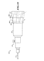
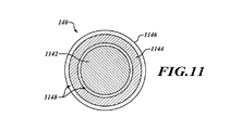
図11を参照すると、様々な実施形態において、駆動シャフトアセンブリ140は、切断装置111の内側切断部材211(図10には図示せず)に連結可能な第1の駆動シャフト1142を含む。駆動シャフトアセンブリ140はまた、切断装置111の外側切断部材251に連結可能な第2の駆動シャフト1144を含む。第1の駆動シャフト1142は、中実又は中空であり得るのに対して、第2の駆動シャフト1144は、第1の駆動シャフト1142の周りに同軸状に配設された中空部材である。第1の駆動シャフト1142及び第2の駆動シャフト1144は、スリーブ772(図7及び図8)に固定可能に連結され得るシース1146内に配設され、駆動シャフトアセンブリ140の延伸及び後退を可能にする。第1の駆動シャフト1142は、第1の駆動シャフト1142の回転を妨げないように、間隙1148によって第2の駆動シャフト1144から分離され得る。同様に、第2の駆動シャフト1144は、シース1146によって第2の駆動シャフト1144の回転を妨げないように、間隙1148によってシース1146から分離され得る。
Referring to FIG. 11, in various embodiments, the
図12を参照すると、組織を切断する例示的な方法1200が提供されている。この方法1200は、ブロック1205で開始する。ブロック1210において、内側切断部材と、同心の外側切断部材と、を有する、円筒形の切断装置が、組織に対して延伸される。内側切断部材及び同心の外側切断部材は、組織を、内側切断部材及び同心の外側切断部材の軸に直交して半径方向に切断するように構成された、対向する切断面を有する。切断部材の構成及びその位置決めは、図2、図3A〜図3C、図4A〜図4C、図5A〜図5C、及び図6を参照して前述されている。
With reference to FIG. 12, an
ブロック1220において、内側切断部材が移動されて、図3A〜図3C、図5A〜図5C及び図6を参照して前述したように、内側切断部材の遠位端のアンカー先端部に組織を穿刺させる。ブロック1230において、内側切断部材及び同心の外側切断部材が、図6を参照して先に詳述したように、互いに対して相対的に回転されて、組織を半径方向に切断する。この方法1200は、ブロック1235で終了する。
At
組織内に孔を切断するために使用されるものとして本明細書に記載された切断装置及び制御装置、並びにシステム及び方法の本明細書は、身体の異なる部分の組織を切断するために使用され得、及び、内視鏡、気管支鏡、腹腔鏡、又は他の装置によって案内され得ることが理解されるであろう。 The cutting device and control device described herein as used to cut a hole in tissue, and the specification of the system and method are used to cut tissue in different parts of the body. It will be appreciated that and can be guided by an endoscope, bronchoscope, laparoscope, or other device.
上に示した発明を実施するための形態は、本質的に単に例示的なものであり、請求項に係る主題の主旨及び/又は趣旨から逸脱しない変形が、請求項の範囲内にあることが意図されることも理解されよう。かかる変形は、請求項に係る主題の趣旨及び範囲から逸脱するものとしてみなされない。 The forms for carrying out the invention described above are merely exemplary in nature and modifications that do not depart from the spirit and / or spirit of the claimed subject matter are within the scope of the claims. It will also be understood that it is intended. Such variations are not to be regarded as a departure from the spirit and scope of the claimed subject matter.
100 システム
101 軸
103 第1の方向
105 第2の方向
111 切断装置
140 駆動シャフトアセンブリ
150 制御装置
160 ハウジング
170 位置調節装置
180 回転把持部
211 切断部材
214 内側切断面
221 アンカー先端部
241 内側切断面
251 外側切断部材
271 外側切断面
290 遠位端
292 切断領域
315 本体
321 アンカー先端部
323 穿孔端部
325 固定表面
343 前方切断縁部
345 後方切断縁部
347 下端
349 近位端
455 本体
461 先端部
463 端部
471 外側切断面
473 前方切断縁部
475 後方切断縁部
477 下端
499 近位端
511 内側切断部材
515 本体
521 凹状アンカー先端部
523 穿孔端部
541 内側切断面
543 前縁部
545 後縁部
547 下端
549 近位端
601 組織
607 方向
772 スリーブ
774 第1の端部
776 シースロック
777 係合溝
778 シースロッキングポート
779 第1の端部
781 ユーザグリップ
782 インターフェース
801 第1の端部
802 逆回転機構
812 第1の差動アクチュエータ
814 第1のベベルギア
852 第2の差動アクチュエータ
854 第2のベベルギア
892 トランスファーギア
894 差動ベベルギア
896 シャーシ
902 逆回転機構
907 第1のシャフト
914 ベースギア
915 第1のトランスファーギア
919 第2のトランスファーギア
950 制御機構
954 逆回転ギア
957 第2のシャフト
992 アクスル
1050 制御装置
1082 第1の回転グリップ
1083 第1の方向
1084 第2の回転グリップ
1085 第2の方向
1142 第1の駆動シャフト
1144 第2の駆動シャフト
1146 シース
1148 間隙
DESCRIPTION OF SYMBOLS 100 System 101 Axis 103 1st direction 105 2nd direction 111 Cutting device 140 Drive shaft assembly 150 Control device 160 Housing 170 Position adjustment device 180 Rotation grip part 211 Cutting member 214 Inner cutting surface 221 Anchor tip 241 Inner cutting surface 251 Outer cutting member 271 Outer cutting surface 290 Distal end 292 Cutting region 315 Body 321 Anchor tip 323 Drilling end 325 Fixed surface 343 Front cutting edge 345 Back cutting edge 347 Lower end 349 Proximal end 455 Main body 461 Tip 463 End 471 Outer cutting surface 473 Front cutting edge 475 Rear cutting edge 477 Lower end 499 Proximal end 511 Inner cutting member 515 Main body 521 Concave anchor tip 523 Perforated end 541 Inner cutting surface 543 Front edge 545 Rear edge 547 Lower end 549 Proximal end 601 Tissue 607 direction 772 Sleeve 774 First end 776 Sheath lock 777 Engaging groove 778 Sheath locking port 779 First end 781 User grip 782 Interface 801 First end 802 Reverse rotation mechanism 812 First differential actuator 814 First bevel gear 852 Second differential actuator 854 Second bevel gear 892 Transfer gear 894 Differential bevel gear 896 Chassis 902 Reverse rotation mechanism 907 First shaft 914 Base gear 915 First transfer Gear 919 Second transfer gear 950 Control mechanism 954 Reverse rotation gear 957 Second shaft 992 Axle 1050 Control device 1082 First rotation grip 1083 First direction 1 84 second rotation grip 1085 second direction 1142 first drive shaft 1144 second drive shaft 1146 Sheath 1148 gap
Claims (20)
第1の駆動シャフトに係合するように構成された第1のラジアルアクチュエータと、
第2の駆動シャフトに係合するように構成された第2のラジアルアクチュエータであって、前記第2の駆動シャフトが、前記第1の駆動シャフトと同軸状に配設されている、第2のラジアルアクチュエータと、
前記第1のラジアルアクチュエータ及び前記第2のラジアルアクチュエータを支持し、前記第1の駆動シャフト及び前記第2の駆動シャフトが内部を通って延在することを可能にするハウジングであって、前記第1の駆動シャフト及び前記第2の駆動シャフトが、前記第1のラジアルアクチュエータ及び前記第2のラジアルアクチュエータのうちの少なくとも一方の回転に応じて相対的に逆回転可能である、ハウジングと、を備える、装置。 A device for controlling a reverse-rotating cutting device,
A first radial actuator configured to engage a first drive shaft;
A second radial actuator configured to engage a second drive shaft, wherein the second drive shaft is disposed coaxially with the first drive shaft; A radial actuator,
A housing that supports the first radial actuator and the second radial actuator and that allows the first drive shaft and the second drive shaft to extend through an interior thereof; And a housing in which the first drive shaft and the second drive shaft are relatively reversely rotatable in response to rotation of at least one of the first radial actuator and the second radial actuator. ,apparatus.
前記第1のラジアルアクチュエータに連結された第1のベベルギアであって、前記第1のベベルギアの第1の斜面が、前記第2のラジアルアクチュエータに面している、第1のベベルギアと、
前記第2のラジアルアクチュエータに連結された第2のベベルギアであって、前記第2のベベルギアの第2の斜面が、前記第1のラジアルアクチュエータに面している、第2のベベルギアと、
前記第1のベベルギアの前記第1の斜面及び前記第2のベベルギアの前記第2の斜面に係合するように構成された差動ベベルギアと、を備える、請求項3に記載の装置。 The reverse rotation mechanism is
A first bevel gear coupled to the first radial actuator, wherein a first slope of the first bevel gear faces the second radial actuator;
A second bevel gear coupled to the second radial actuator, wherein a second bevel gear of the second bevel gear faces the first radial actuator;
4. The apparatus of claim 3, comprising: a differential bevel gear configured to engage the first slope of the first bevel gear and the second slope of the second bevel gear.
第1の駆動シャフトに係合するように構成された第1のラジアルアクチュエータと、
第2の駆動シャフトに係合するように構成された第2のラジアルアクチュエータであって、前記第2の駆動シャフトが、前記第1の駆動シャフトと同軸状に配設されている、第2のラジアルアクチュエータと、
前記第1のラジアルアクチュエータ及び前記第2のラジアルアクチュエータを機械的に連結する逆回転機構であって、前記第1のラジアルアクチュエータが第1の方向に回転されるときに、前記第2のラジアルアクチュエータを第2の方向に回転させるように構成されている、逆回転機構と、
前記第1のラジアルアクチュエータ及び前記第2のラジアルアクチュエータを支持し、前記第1の駆動シャフト及び前記第2の駆動シャフトが内部を通って延在することを可能にする、ハウジングと、
前記第1のラジアルアクチュエータ及び前記第2のラジアルアクチュエータを支持し、前記第1の駆動シャフト及び前記第2の駆動シャフトを収容するシースが内部を通って延在することを可能にするように構成されている、ハウジングと、
前記第1のラジアルアクチュエータに機械的に連結されて、前記第1のラジアルアクチュエータの回転を可能にする回転制御装置であって、前記第1の駆動シャフト及び前記第2の駆動シャフトが、前記第1の回転制御装置の回転に応じて同時に逆回転可能である、回転制御装置と、を備える、装置。 A device for controlling a reverse-rotating cutting device,
A first radial actuator configured to engage a first drive shaft;
A second radial actuator configured to engage a second drive shaft, wherein the second drive shaft is disposed coaxially with the first drive shaft; A radial actuator,
A reverse rotation mechanism that mechanically connects the first radial actuator and the second radial actuator, wherein the second radial actuator is rotated when the first radial actuator is rotated in a first direction. A reverse rotation mechanism configured to rotate in a second direction;
A housing that supports the first radial actuator and the second radial actuator and that allows the first drive shaft and the second drive shaft to extend therethrough;
A sheath supporting the first radial actuator and the second radial actuator and configured to allow a sheath containing the first drive shaft and the second drive shaft to extend therethrough. A housing,
A rotation control device that is mechanically coupled to the first radial actuator to enable rotation of the first radial actuator, wherein the first drive shaft and the second drive shaft are the first and second drive shafts. A rotation control device capable of simultaneously rotating in reverse according to the rotation of one rotation control device.
前記第1のラジアルアクチュエータに連結された第1のベベルギアであって、前記第1のベベルギアの第1の斜面が、前記第2のラジアルアクチュエータに面している、第1のベベルギアと、
前記第2のラジアルアクチュエータに連結された第2のベベルギアであって、前記第2のベベルギアの第2の斜面が、前記第1のラジアルアクチュエータに面している、第2のベベルギアと、
前記第1のベベルギアの前記第1の斜面及び前記第2のベベルギアの前記第2の斜面に係合するように構成された差動ベベルギアであって、前記第1のベベルギア及び前記第2のベベルギアが、前記回転制御装置の回転に応じて相対的に逆回転可能である、差動ベベルギアと、を含む、請求項11に記載の装置。 The reverse rotation mechanism is
A first bevel gear coupled to the first radial actuator, wherein a first slope of the first bevel gear faces the second radial actuator;
A second bevel gear coupled to the second radial actuator, wherein a second bevel gear of the second bevel gear faces the first radial actuator;
A differential bevel gear configured to engage with the first slope of the first bevel gear and the second slope of the second bevel gear, the first bevel gear and the second bevel gear. And a differential bevel gear that is relatively reverse rotatable in response to rotation of the rotation control device.
駆動シャフトアセンブリであって、
第1の駆動シャフトと、
前記第1の駆動シャフトの周りに同軸状に配設され、前記第1の駆動シャフトとは独立して回転するように構成された第2の駆動シャフトと、
前記第1の駆動シャフト及び前記第2の駆動シャフトを収容するシースと、を含む、駆動シャフトアセンブリと、
前記第1の駆動シャフトに係合するように構成された第1のラジアルアクチュエータと、
前記第2の駆動シャフトに係合するように構成された第2のラジアルアクチュエータと、
前記第1のラジアルアクチュエータ及び前記第2のラジアルアクチュエータを支持し、前記第1の駆動シャフト及び前記第2の駆動シャフトを収容する前記シースが内部を通って延在することを可能にする、ハウジングと、
前記第1のラジアルアクチュエータに機械的に連結されて、前記第2のラジアルアクチュエータに対する、前記第1のラジアルアクチュエータの回転を可能にする、回転制御装置と、
切断装置であって、
カッターの遠位端において少なくとも1つの第1の切断面を支持し、前記第1の駆動シャフトに機械的に連結された第1の円筒状体を有する内側切断部材であって、前記第1の切断面が、前記第1の円筒状体の軸に対して第1の回転方向に面し、前記第1の円筒状体の外周に第1の切断縁部を有する、内側切断部材と、
前記第1の円筒状体の周りに同心円状に配設され、前記第2の駆動シャフトに機械的に連結された第2の円筒状体を有する外側切断部材であって、前記外側切断部材が、前記装置の前記遠位端において少なくとも1つの第2の切断面を支持し、前記第2の切断面が、前記軸に対して第2の回転方向に面し、前記第2の円筒状体の内周に第2の切断縁部を有し、前記装置の前記遠位端の適用及び前記回転制御装置の回転に応じて、組織が、前記内側切断部材の前記第1の切断縁部と前記外側切断部材の前記第2の切断縁部との間で回転可能に切断可能である、外側切断部材と、を含む、切断装置と、を備える、システム。 A system for cutting tissue,
A drive shaft assembly comprising:
A first drive shaft;
A second drive shaft disposed coaxially around the first drive shaft and configured to rotate independently of the first drive shaft;
A drive shaft assembly comprising: a sheath that houses the first drive shaft and the second drive shaft;
A first radial actuator configured to engage the first drive shaft;
A second radial actuator configured to engage the second drive shaft;
A housing that supports the first radial actuator and the second radial actuator and that allows the sheath containing the first drive shaft and the second drive shaft to extend therethrough. When,
A rotation control device mechanically coupled to the first radial actuator to allow rotation of the first radial actuator relative to the second radial actuator;
A cutting device,
An inner cutting member having a first cylindrical body that supports at least one first cutting surface at a distal end of a cutter and is mechanically coupled to the first drive shaft, An inner cutting member having a cutting surface facing in a first rotational direction with respect to the axis of the first cylindrical body and having a first cutting edge on an outer periphery of the first cylindrical body;
An outer cutting member having a second cylindrical body disposed concentrically around the first cylindrical body and mechanically coupled to the second drive shaft, wherein the outer cutting member is , Supporting at least one second cutting surface at the distal end of the device, the second cutting surface facing in a second rotational direction relative to the axis, and the second cylindrical body A second cutting edge on the inner circumference of the inner cutting member, and in response to application of the distal end of the device and rotation of the rotation control device, tissue is connected to the first cutting edge of the inner cutting member. A cutting device comprising: an outer cutting member that is rotatably cutable with the second cutting edge of the outer cutting member.
前記第1のラジアルアクチュエータに連結された第1のベベルギアであって、前記第1のベベルギアの第1の斜面が、前記第2のラジアルアクチュエータに面している、第1のベベルギアと、
前記第2のラジアルアクチュエータに連結された第2のベベルギアであって、前記第2のベベルギアの第2の斜面が、前記第1のラジアルアクチュエータに面している、第2のベベルギアと、
前記第1のベベルギアの前記第1の斜面及び前記第2のベベルギアの前記第2の斜面に係合するように構成された差動ベベルギアと、を備える、請求項17に記載のシステム。 The reverse rotation mechanism is
A first bevel gear coupled to the first radial actuator, wherein a first slope of the first bevel gear faces the second radial actuator;
A second bevel gear coupled to the second radial actuator, wherein a second bevel gear of the second bevel gear faces the first radial actuator;
18. The system of claim 17, comprising: a differential bevel gear configured to engage the first slope of the first bevel gear and the second slope of the second bevel gear.
Applications Claiming Priority (2)
| Application Number | Priority Date | Filing Date | Title |
|---|---|---|---|
| US15/933,363 US10779850B2 (en) | 2018-03-22 | 2018-03-22 | Rotational tissue cutting control device |
| US15/933,363 | 2018-03-22 |
Publications (2)
| Publication Number | Publication Date |
|---|---|
| JP2019166323A true JP2019166323A (en) | 2019-10-03 |
| JP7361480B2 JP7361480B2 (en) | 2023-10-16 |
Family
ID=66381261
Family Applications (1)
| Application Number | Title | Priority Date | Filing Date |
|---|---|---|---|
| JP2019053199A Active JP7361480B2 (en) | 2018-03-22 | 2019-03-20 | Rotary tissue cutting control device |
Country Status (5)
| Country | Link |
|---|---|
| US (1) | US10779850B2 (en) |
| JP (1) | JP7361480B2 (en) |
| CN (1) | CN110292417B (en) |
| DE (1) | DE102019105534A1 (en) |
| GB (1) | GB2573868B (en) |
Families Citing this family (3)
| Publication number | Priority date | Publication date | Assignee | Title |
|---|---|---|---|---|
| US10687844B2 (en) * | 2018-11-14 | 2020-06-23 | Pavel Menn | Catheter atherector |
| US20210298725A1 (en) * | 2020-03-31 | 2021-09-30 | Gyrus Acmi, Inc. D/B/A Olympus Surgical Technologies America | Rotatable tissue sampling device |
| CN116407182A (en) * | 2021-12-31 | 2023-07-11 | 杭州德诺电生理医疗科技有限公司 | Thread cutting device |
Citations (5)
| Publication number | Priority date | Publication date | Assignee | Title |
|---|---|---|---|---|
| US5618293A (en) * | 1995-06-06 | 1997-04-08 | Smith & Nephews Dyonics, Inc. | Surgical instrument |
| US20100204722A1 (en) * | 2007-05-18 | 2010-08-12 | Gilsdorf John B | Apparatus for cutting out and removing tissue cylinders from a tissue, and use thereof |
| JP2012520726A (en) * | 2009-03-16 | 2012-09-10 | シー・アール・バード・インコーポレーテッド | Biological tissue examination apparatus having rotational cutting |
| JP2016168103A (en) * | 2015-03-11 | 2016-09-23 | テルモ株式会社 | Foreign object removing device |
| JP2019069141A (en) * | 2017-10-09 | 2019-05-09 | ジャイラス・エーシーエムアイ・インコーポレーテッド | Tissue resection device |
Family Cites Families (7)
| Publication number | Priority date | Publication date | Assignee | Title |
|---|---|---|---|---|
| US5324300A (en) * | 1991-10-25 | 1994-06-28 | Elias Elias G | Device for the controlled excision of tissue from a living body |
| US8465491B2 (en) * | 2006-06-01 | 2013-06-18 | Osteo Innovations Llc | Bone drill |
| DE102007023207A1 (en) * | 2007-05-18 | 2008-11-20 | Wisap Gesellschaft für wissenschaftlichen Apparatebau mbH | Device for cutting and removing tissue cylinder from tissue, comprises cutting elements arranged in one another and rotated relative to each other, which surround distal end |
| DE102008036420A1 (en) * | 2008-08-05 | 2010-02-11 | Wisap Gesellschaft für wissenschaftlichen Apparatebau mbH | Tissue cylinders cutting and removing apparatus for e.g. laparascopic for treatment of myomas of patient, has drive accommodated by housing, where drive is brought in mutual engagement with driving device by coupling device |
| ES2633808T3 (en) * | 2009-04-07 | 2017-09-25 | Doheny Eye Institute | Disposable manual facomorcelation device |
| DE102011100278A1 (en) * | 2011-04-28 | 2012-10-31 | C. & E. Fein Gmbh | Drilling machine, in particular hand-held drilling machine |
| CN204121083U (en) * | 2014-09-28 | 2015-01-28 | 丁轶人 | Peritoneoscope special-purpose taking spleen device |
-
2018
- 2018-03-22 US US15/933,363 patent/US10779850B2/en active Active
-
2019
- 2019-03-05 DE DE102019105534.2A patent/DE102019105534A1/en active Pending
- 2019-03-20 JP JP2019053199A patent/JP7361480B2/en active Active
- 2019-03-21 GB GB1903860.3A patent/GB2573868B/en active Active
- 2019-03-21 CN CN201910218359.9A patent/CN110292417B/en active Active
Patent Citations (5)
| Publication number | Priority date | Publication date | Assignee | Title |
|---|---|---|---|---|
| US5618293A (en) * | 1995-06-06 | 1997-04-08 | Smith & Nephews Dyonics, Inc. | Surgical instrument |
| US20100204722A1 (en) * | 2007-05-18 | 2010-08-12 | Gilsdorf John B | Apparatus for cutting out and removing tissue cylinders from a tissue, and use thereof |
| JP2012520726A (en) * | 2009-03-16 | 2012-09-10 | シー・アール・バード・インコーポレーテッド | Biological tissue examination apparatus having rotational cutting |
| JP2016168103A (en) * | 2015-03-11 | 2016-09-23 | テルモ株式会社 | Foreign object removing device |
| JP2019069141A (en) * | 2017-10-09 | 2019-05-09 | ジャイラス・エーシーエムアイ・インコーポレーテッド | Tissue resection device |
Also Published As
| Publication number | Publication date |
|---|---|
| US20190290313A1 (en) | 2019-09-26 |
| DE102019105534A1 (en) | 2019-09-26 |
| GB2573868A (en) | 2019-11-20 |
| JP7361480B2 (en) | 2023-10-16 |
| GB2573868B (en) | 2022-04-20 |
| GB201903860D0 (en) | 2019-05-08 |
| CN110292417A (en) | 2019-10-01 |
| US10779850B2 (en) | 2020-09-22 |
| CN110292417B (en) | 2024-12-27 |
Similar Documents
| Publication | Publication Date | Title |
|---|---|---|
| JP7684365B2 (en) | Rotary tissue cutting device | |
| US11559327B2 (en) | Optical obturator | |
| US5984939A (en) | Multifunctional grasping instrument with cutting member and operating channel for use in endoscopic and non-endoscopic procedures | |
| US9943377B2 (en) | Methods, systems, and devices for causing end effector motion with a robotic surgical system | |
| EP3981350B1 (en) | Robotic surgical system and methods for articulation calibration | |
| US20080228104A1 (en) | Energy Assisted Medical Devices, Systems and Methods | |
| JP7361480B2 (en) | Rotary tissue cutting control device | |
| US5472451A (en) | Endoscopic surgical instrument with acute angle orientation | |
| DE112018003623T5 (en) | DEVICE FOR SUPPORTING THE POSITIONING AND ANCHORING OF AN ENDOSCOPE IN GASTROINTESTINAL INTERVENTIONS | |
| JP4542362B2 (en) | Endoscopic treatment system | |
| JP5710079B1 (en) | Endoscopic surgical instrument | |
| CN205006941U (en) | Surgical instruments of adjustable turn of multistage | |
| CN111166402A (en) | An endoscope breast augmentation retractor | |
| JP2020146470A (en) | Minimally-invasive surgery equipment | |
| CN224180013U (en) | Rotary module visual guide of (c) | |
| US20220378458A1 (en) | Tissue resecting instrument | |
| JP2013179998A (en) | Lowest invasion surgical operation system | |
| JPH0310731Y2 (en) | ||
| KR20240078759A (en) | Tubular retractor |
Legal Events
| Date | Code | Title | Description |
|---|---|---|---|
| A521 | Request for written amendment filed |
Free format text: JAPANESE INTERMEDIATE CODE: A523 Effective date: 20190801 |
|
| A711 | Notification of change in applicant |
Free format text: JAPANESE INTERMEDIATE CODE: A712 Effective date: 20201005 |
|
| A621 | Written request for application examination |
Free format text: JAPANESE INTERMEDIATE CODE: A621 Effective date: 20220322 |
|
| A977 | Report on retrieval |
Free format text: JAPANESE INTERMEDIATE CODE: A971007 Effective date: 20230222 |
|
| A131 | Notification of reasons for refusal |
Free format text: JAPANESE INTERMEDIATE CODE: A131 Effective date: 20230306 |
|
| A521 | Request for written amendment filed |
Free format text: JAPANESE INTERMEDIATE CODE: A523 Effective date: 20230531 |
|
| TRDD | Decision of grant or rejection written | ||
| A01 | Written decision to grant a patent or to grant a registration (utility model) |
Free format text: JAPANESE INTERMEDIATE CODE: A01 Effective date: 20230904 |
|
| A61 | First payment of annual fees (during grant procedure) |
Free format text: JAPANESE INTERMEDIATE CODE: A61 Effective date: 20231003 |
|
| R150 | Certificate of patent or registration of utility model |
Ref document number: 7361480 Country of ref document: JP Free format text: JAPANESE INTERMEDIATE CODE: R150 |
|
| S111 | Request for change of ownership or part of ownership |
Free format text: JAPANESE INTERMEDIATE CODE: R313113 |
|
| R350 | Written notification of registration of transfer |
Free format text: JAPANESE INTERMEDIATE CODE: R350 |