JP2019166316A - Catheter assemblies with offset device for tissue sampling, systems, and methods for sampling targeted region of tissue - Google Patents
Catheter assemblies with offset device for tissue sampling, systems, and methods for sampling targeted region of tissue Download PDFInfo
- Publication number
- JP2019166316A JP2019166316A JP2019043727A JP2019043727A JP2019166316A JP 2019166316 A JP2019166316 A JP 2019166316A JP 2019043727 A JP2019043727 A JP 2019043727A JP 2019043727 A JP2019043727 A JP 2019043727A JP 2019166316 A JP2019166316 A JP 2019166316A
- Authority
- JP
- Japan
- Prior art keywords
- catheter
- needle
- stylet
- tissue
- lumen
- Prior art date
- Legal status (The legal status is an assumption and is not a legal conclusion. Google has not performed a legal analysis and makes no representation as to the accuracy of the status listed.)
- Granted
Links
Images

Classifications
-
- A—HUMAN NECESSITIES
- A61—MEDICAL OR VETERINARY SCIENCE; HYGIENE
- A61B—DIAGNOSIS; SURGERY; IDENTIFICATION
- A61B10/00—Instruments for taking body samples for diagnostic purposes; Other methods or instruments for diagnosis, e.g. for vaccination diagnosis, sex determination or ovulation-period determination; Throat striking implements
- A61B10/02—Instruments for taking cell samples or for biopsy
- A61B10/0233—Pointed or sharp biopsy instruments
-
- A—HUMAN NECESSITIES
- A61—MEDICAL OR VETERINARY SCIENCE; HYGIENE
- A61B—DIAGNOSIS; SURGERY; IDENTIFICATION
- A61B10/00—Instruments for taking body samples for diagnostic purposes; Other methods or instruments for diagnosis, e.g. for vaccination diagnosis, sex determination or ovulation-period determination; Throat striking implements
- A61B10/02—Instruments for taking cell samples or for biopsy
- A61B10/04—Endoscopic instruments, e.g. catheter-type instruments
-
- A—HUMAN NECESSITIES
- A61—MEDICAL OR VETERINARY SCIENCE; HYGIENE
- A61B—DIAGNOSIS; SURGERY; IDENTIFICATION
- A61B10/00—Instruments for taking body samples for diagnostic purposes; Other methods or instruments for diagnosis, e.g. for vaccination diagnosis, sex determination or ovulation-period determination; Throat striking implements
- A61B10/02—Instruments for taking cell samples or for biopsy
- A61B10/0233—Pointed or sharp biopsy instruments
- A61B10/0283—Pointed or sharp biopsy instruments with vacuum aspiration, e.g. caused by retractable plunger or by connected syringe
-
- A—HUMAN NECESSITIES
- A61—MEDICAL OR VETERINARY SCIENCE; HYGIENE
- A61B—DIAGNOSIS; SURGERY; IDENTIFICATION
- A61B17/00—Surgical instruments, devices or methods
- A61B17/34—Trocars; Puncturing needles
- A61B17/3417—Details of tips or shafts, e.g. grooves, expandable, bendable; Multiple coaxial sliding cannulas, e.g. for dilating
- A61B17/3421—Cannulas
- A61B17/3431—Cannulas being collapsible, e.g. made of thin flexible material
-
- A—HUMAN NECESSITIES
- A61—MEDICAL OR VETERINARY SCIENCE; HYGIENE
- A61B—DIAGNOSIS; SURGERY; IDENTIFICATION
- A61B10/00—Instruments for taking body samples for diagnostic purposes; Other methods or instruments for diagnosis, e.g. for vaccination diagnosis, sex determination or ovulation-period determination; Throat striking implements
- A61B10/02—Instruments for taking cell samples or for biopsy
- A61B10/04—Endoscopic instruments, e.g. catheter-type instruments
- A61B2010/045—Needles
Landscapes
- Health & Medical Sciences (AREA)
- Life Sciences & Earth Sciences (AREA)
- Surgery (AREA)
- Heart & Thoracic Surgery (AREA)
- Pathology (AREA)
- Engineering & Computer Science (AREA)
- Biomedical Technology (AREA)
- Medical Informatics (AREA)
- Molecular Biology (AREA)
- Animal Behavior & Ethology (AREA)
- General Health & Medical Sciences (AREA)
- Public Health (AREA)
- Veterinary Medicine (AREA)
- Nuclear Medicine, Radiotherapy & Molecular Imaging (AREA)
- Radiology & Medical Imaging (AREA)
- Media Introduction/Drainage Providing Device (AREA)
Abstract
【課題】体腔の中に同心円状にまたは偏心して位置する組織の標的領域を採取するためのカテーテルアセンブリ、システム、及び組織の標的領域を採取するための方法を提供する。【解決手段】開示される実施形態は、組織の標的領域を採取するためのカテーテルアセンブリ、システム、及び組織の標的領域を採取するための方法を含む。例示的で非限定的な実施形態では、カテーテルアセンブリは、内部に管腔が画定されているカテーテルであって、カテーテルの壁は、カテーテルの遠位端でカテーテルに開口部を画定している、カテーテルと、管腔内に配置可能であり、カテーテルの遠位端の開口部から管腔の軸線から分岐する角度で延ばすことが可能である、湾曲可撓性針と、を備える。【選択図】図1BA catheter assembly, system, and method for harvesting a target area of tissue located concentrically or eccentrically within a body cavity are provided. The disclosed embodiments include a catheter assembly for collecting a target area of tissue, a system, and a method for collecting a target area of tissue. In an exemplary, non-limiting embodiment, the catheter assembly is a catheter having a lumen defined therein, wherein the catheter wall defines an opening in the catheter at the distal end of the catheter. A catheter and a curved flexible needle that can be positioned within the lumen and extend from an opening at the distal end of the catheter at an angle diverging from the axis of the lumen. [Selection diagram] FIG. 1B
Description
開示される実施形態は、組織採取のためのカテーテルに関する。 The disclosed embodiments relate to a catheter for tissue harvesting.
(優先権の主張)
本出願は、2018年3月14日に出願された「CATHETER ASSEMBLY WITH OFFSET DEVICE FOR TISSUE SAMPLING」と題された米国特許出願第15/920,966号の一部継続出願であり、その内容をここに援用する。
このセクションにおける記述は、単に、本開示に関する背景情報を提供し、先行技術を構成しない場合もある。
(Claiming priority)
This application is a continuation-in-part of US patent application Ser. No. 15 / 920,966, entitled “CATHETHER ASSEMBLY WITH OFFSET DEVICE FOR TISSUE SAMPLING” filed on March 14, 2018, the contents of which are hereby incorporated by reference herein. Incorporated into.
The statements in this section merely provide background information related to the present disclosure and may not constitute prior art.
病変は、典型的には、カテーテル内に画定される管腔に配置される針によって採取される。針が採取される組織の領域に到達すると、針はカテーテルの管腔の遠位端から延ばされる。従来のカテーテルにおいて、針は、カテーテルの管腔の遠位端から軸線方向に延びている。 The lesion is typically harvested by a needle placed in a lumen defined within the catheter. When the needle reaches the area of tissue to be harvested, the needle is extended from the distal end of the catheter lumen. In conventional catheters, the needle extends axially from the distal end of the catheter lumen.
従来のカテーテル及び針による組織領域採取では、採取される組織がカテーテルの遠位端の真っ直ぐ前方に位置する場合には、困難が存在しない。 With conventional catheter and needle tissue region collection, there is no difficulty when the tissue to be collected is located directly in front of the distal end of the catheter.
しかし、カテーテルの管腔の遠位端から直線的に針を延ばす様式では、偏心的な(eccentric)組織領域、つまり、カテーテルの遠位端の真っ直ぐ前方に位置しないか、又は、カテーテルが配置されている体腔(気道など)の外に位置する組織領域の採取が困難な場合がある。このような場合、ユーザは偏心組織領域を採取するために従来のカテーテル及び針を角度付けしようと試みる場合がある。しかしながら、そのような角度付けを正確かつ制御可能に達成するための既知の道具は存在しない。よって、所望の角度付けを達成することは困難である場合がある。その結果、採取時に複数回の試み(各々について、体腔壁の貫通が伴う場合もある)が行われる場合もある。複数の試みは、処置のための時間量を増加させ、不正確で制御できない採取は意図された標的からの低い収率をもたらし得る。また、これらの余分な又は不正確な採取の試みにより、血管を針で突き刺す可能性を増大させることもあり得る。 However, in the manner in which the needle is extended linearly from the distal end of the catheter lumen, the eccentric tissue region, i.e., is not located directly in front of the distal end of the catheter, or the catheter is placed. It may be difficult to collect a tissue region located outside a body cavity (such as an airway). In such cases, the user may attempt to angle a conventional catheter and needle to collect an eccentric tissue region. However, there are no known tools for achieving such angling accurately and controllably. Thus, it may be difficult to achieve the desired angling. As a result, multiple attempts may be made during collection (each of which may involve penetration of the body cavity wall). Multiple attempts increase the amount of time for treatment, and inaccurate and uncontrollable collection can result in low yields from the intended target. These extra or inaccurate collection attempts can also increase the likelihood of piercing a blood vessel with a needle.
開示される実施形態は、組織の標的領域を採取するためのカテーテルアセンブリ、システム、及び組織の標的領域を採取するための方法を含む。組織の標的領域は、体腔の中に同心円状に位置してもよく、偏心して位置してもよい(すなわち、体腔に隣接していてもよい)ことが理解されるであろう。 The disclosed embodiments include a catheter assembly, system, and method for harvesting a target region of tissue for harvesting a target region of tissue. It will be appreciated that the target region of tissue may be located concentrically within the body cavity or may be eccentric (ie, adjacent to the body cavity).
例示的な非限定的な実施形態では、カテーテルアセンブリは、内部に管腔が画定されているカテーテルであって、カテーテルの壁は、カテーテルの遠位端でカテーテルに開口部を画定している、カテーテルと、管腔内に配置可能な(disposable)可撓性の針と、カテーテルの遠位端の開口部から管腔の軸線から分岐する(diverge)角度で延びるように、針を付勢するように構成されたオフセット機構と、を含む。 In an exemplary non-limiting embodiment, the catheter assembly is a catheter having a lumen defined therein, and the catheter wall defines an opening in the catheter at the distal end of the catheter. Bias the needle to extend at an angle that diverges from the lumen axis from the opening at the distal end of the catheter, a flexible needle disposable within the lumen And an offset mechanism configured as described above.
別の例示的な非限定的実施形態では、組織の標的領域を採取するためのシステムは、ハンドルアセンブリと、ハンドルアセンブリに動作可能に結合されたカテーテルアセンブリであって、採取される組織の標的領域に向けて体腔内に挿入可能に構成されている、カテーテルアセンブリと、を備え、ここで、カテーテルアセンブリは、内部に管腔が画定されているカテーテルであって、カテーテルの壁は、カテーテルの遠位端でカテーテルに開口部を画定している、カテーテルと、管腔内に配置可能な可撓性の針と、カテーテルの遠位端の開口部から管腔の軸線から分岐する角度で延びるように、針を付勢するように構成されたオフセット機構と、を含む。 In another exemplary non-limiting embodiment, a system for harvesting a target region of tissue is a handle assembly and a catheter assembly operably coupled to the handle assembly, the target region of tissue being harvested A catheter assembly configured to be insertable into a body cavity toward the catheter, wherein the catheter assembly is a catheter having a lumen defined therein, the wall of the catheter being the distal of the catheter The catheter defines an opening in the catheter at the distal end, a flexible needle positionable within the lumen, and extends at an angle bifurcated from the lumen axis from the distal end opening of the catheter. And an offset mechanism configured to bias the needle.
別の例示的な非限定的実施形態では、組織の標的領域を採取する方法は、採取される組織の標的領域に向けてカテーテルを体腔内に挿入することと、カテーテルの軸線から分岐する角度で、カテーテルの遠位端から、採取される組織の標的領域に向けて、可撓性針を延ばすことと、針を組織に突き刺すことと、組織を採取することと、を含む。 In another exemplary non-limiting embodiment, a method of harvesting a target region of tissue includes inserting a catheter into a body cavity toward the target region of tissue to be harvested and an angle that branches from the axis of the catheter. Extending a flexible needle from the distal end of the catheter toward a target region of the tissue to be harvested, piercing the needle into the tissue, and harvesting the tissue.
別の例示的で非限定的な実施形態では、カテーテルアセンブリは、内部に管腔が画定されているカテーテルであって、カテーテルの壁は、カテーテルの遠位端でカテーテルに開口部を画定している、カテーテルと、管腔内に配置可能であり、カテーテルの遠位端の開口部から管腔の軸線から分岐する角度で延ばすことが可能である、湾曲可撓性針と、を備える。 In another exemplary non-limiting embodiment, the catheter assembly is a catheter having a lumen defined therein, the catheter wall defining an opening in the catheter at the distal end of the catheter. A catheter, and a curved flexible needle that is positionable within the lumen and that can extend from an opening at the distal end of the catheter at an angle that diverges from the lumen axis.
別の例示的で非限定的な実施形態では、組織の標的領域を採取するためのシステムは、ハンドルアセンブリと、ハンドルアセンブリに動作可能に結合されたカテーテルアセンブリであって、採取される組織の標的領域に向けて体腔内に挿入可能に構成されている、カテーテルアセンブリと、を備え、ここで、カテーテルアセンブリは、内部に管腔が画定されているカテーテルであって、カテーテルの壁は、カテーテルの遠位端でカテーテルに開口部を画定している、カテーテルと、管腔内に配置可能であり、カテーテルの遠位端の開口部から管腔の軸線から分岐する角度で延ばすことが可能である、湾曲可撓性針と、を備える。 In another exemplary, non-limiting embodiment, a system for harvesting a target region of tissue includes a handle assembly and a catheter assembly operably coupled to the handle assembly, the tissue target being harvested A catheter assembly configured to be insertable into a body cavity toward a region, wherein the catheter assembly is a catheter having a lumen defined therein, and the wall of the catheter is The catheter defines an opening in the catheter at the distal end and can be placed in the lumen and can extend from the opening at the distal end of the catheter at an angle that diverges from the lumen axis A curved flexible needle.
別の例示的な非限定的実施形態では、組織の標的領域を採取する方法は、採取される組織の標的領域に向けてカテーテルを体腔内に挿入することと、カテーテルの軸線から分岐する角度で、カテーテルの遠位端から、採取される組織の標的領域に向けて、湾曲可撓性針を延ばすことと、針を組織に突き刺すことと、組織を採取することと、を含む。 In another exemplary non-limiting embodiment, a method of harvesting a target region of tissue includes inserting a catheter into a body cavity toward the target region of tissue to be harvested and an angle that branches from the axis of the catheter. Extending the curved flexible needle from the distal end of the catheter toward the target region of the tissue to be harvested, piercing the needle into the tissue, and harvesting the tissue.
更なる特徴、利点、及び適用分野は、本明細書に提供される説明から明らかになるであろう。説明及び具体的な例は、単に例示目的のために意図され、本開示の範囲を限定する意図はないことを理解されたい。 Further features, advantages, and areas of application will become apparent from the description provided herein. It should be understood that the description and specific examples are intended for purposes of illustration only and are not intended to limit the scope of the present disclosure.
本明細書に説明される図面は、単に例示目的のためであり、決して本開示の範囲を制限することは意図されない。図面における構成要素は、必ずしも一定の縮尺ではなく、開示された実施形態の原理を例示することに重点を置かれる。 The drawings described herein are for illustrative purposes only and are not intended to limit the scope of the present disclosure in any way. The components in the drawings are not necessarily to scale, emphasis instead being placed upon illustrating the principles of the disclosed embodiments.
以下の説明は、本質的に単に例示的なものであり、本開示、適用、又は使用を限定することは意図されない。 The following description is merely exemplary in nature and is not intended to limit the present disclosure, application, or use.
組織の標的領域を採取するためのカテーテルアセンブリ、システム、及び組織の標的領域を採取するための方法の様々な実施形態を添付の図面を参照して説明する。本明細書に提示される説明に使用される用語は、限定又は制限するために理解されることを意図しない。むしろ、用語は、アセンブリ、システム、方法及び関連する構成要素の実施形態の詳細な説明と共に単に使用されている。更に、実施形態はいくつかの新規な特徴を含んでもよく、そのうち、単独で望ましい属性を付与するもの、又は本明細書に記載の開示された実施形態を実施するのに不可欠であると考えられるものはない。例えば、「肺」、「気道」、「結節」などの用語と共に、本明細書に記載の実施形態の使用について、本明細書で言及される場合があるが、これらの用語は広義であり、説明した実施形態は、限定されず使用されてもよく、特に示されていない限り、人間及び動物に存在する他の血管、経路、内腔、体腔、組織、及び気管へのアクセスに使用することができる。例えば、胃腸系(すなわち腸)におけるような内腔には、本明細書に記載の実施形態を用いてアクセスすることができる。 Various embodiments of a catheter assembly, system for harvesting a target region of tissue, and a method for harvesting a target region of tissue will be described with reference to the accompanying drawings. The terminology used in the description presented herein is not intended to be understood as limiting or limiting. Rather, the terminology is merely used in conjunction with the detailed description of the embodiments of the assembly, system, method and related components. Further, the embodiments may include several novel features, of which, by themselves, impart desirable attributes or are considered essential to implement the disclosed embodiments described herein. There is nothing. For example, reference may be made herein to the use of the embodiments described herein along with terms such as “lung”, “airway”, “nodule”, etc., but these terms are broad, The described embodiments may be used without limitation, and unless otherwise indicated, are used for access to other blood vessels, pathways, lumens, body cavities, tissues, and trachea present in humans and animals. Can do. For example, lumens such as in the gastrointestinal system (ie, the intestine) can be accessed using the embodiments described herein.
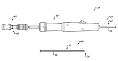
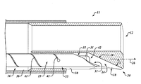
概観として並びに図形1A及び図1Bを参照すると、カテーテルアセンブリ10の例示的で非限定的な実施形態が示される。本明細書で議論されることになるように、カテーテルアセンブリ10の実施形態、並びに本明細書に記載の他の実施形態は、関心のある偏心組織領域(例えば、肺小結節、リンパ節)及び関心のある同心組織領域の位置を特定し、ナビゲートし、そして生検する(すなわち採取する)ための既存のシステム及び方法と共に使用され得る。いくつかの開示された実施形態は、偏心組織領域の採取を可能とし得ることが理解されるであろう。すなわち、開示されるこのような実施形態によれば、カテーテルの遠位端の真っ直ぐ前方に位置していない領域、又はカテーテルアセンブリ10が配置されている体腔(気道など)の外側に位置する領域にある組織の採取が可能となり得る。したがって、開示される実施形態は、ユーザによる、偏心組織領域を採取するためのカテーテル及び針の角度付けが容易になり、これにより、従来のカテーテルよりも容易に所望の角度付けが達成しやすくなるような道具(つまり、カテーテルアセンブリ及びシステム)及び方法を提供することができる。結果として、そのような開示された実施形態は、ユーザが採取を複数回試みる(各々について、体腔壁の貫通が伴う場合がある)可能性を減らすのを助け、それによって針が血管を突き刺す確率を減らすのを助ける。また、いくつかの開示される実施形態は、同心組織領域の採取を可能とし得ることが理解されるであろう。開示される様々な実施形態に関する詳細は、非限定的な例として、以下に記載されるであろう。
As an overview and with reference to FIG. 1A and FIG. 1B, an exemplary, non-limiting embodiment of the
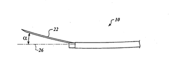
図1A及び図1Bを更に参照すると、カテーテル10の例示的で非限定的な実施形態では、カテーテルアセンブリ12は内部において管腔14を画定する。カテーテル12の壁16は、カテーテル12の遠位端20において、開口部18を画定する。可撓性針22は、管腔14内に配置可能である。オフセット機構24は、カテーテル12の遠位端20にある開口部18から、管腔14の軸線26から分岐する角度で延びるように、針22を付勢するように構成されている。
With further reference to FIGS. 1A and 1B, in an exemplary, non-limiting embodiment of the
オフセット機構24は、様々な様式で具現化されてもよいことが理解されるであろう。いくつかの実施形態において、オフセット機構24は、カテーテル12の遠位端20においてカテーテル12内に画定されたランプ28を含んでもよい。いくつかの他の実施形態では、オフセット機構24は、針22内に同軸的に配置された、形状設定(shape-set)された、湾曲スタイレット30を含んでもよい。いくつかの他の実施形態では、オフセット機構24は、ランプ28及びスタイレット30を含んでもよい。これらの実施形態のそれぞれは、下記に議論される。
It will be appreciated that the offset
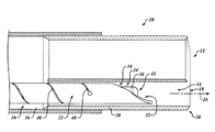
上述したように、また、追加的に図2Aを参照すると、いくつかの実施形態において、オフセット機構24は、カテーテル12の遠位端20においてカテーテル12内に画定されたランプ28を含んでもよい。このような実施形態では、湾曲スタイレット30(図1B)は、針22内に配置されず、又はスタイレット30がカテーテル12の遠位端20を超えて延びないように針22の遠位端から十分に後退させられることが理解されるであろう。しかし、いくつかの実施形態では、所望により、針22を硬化させる(stiffen)ために、針22の中に直線スタイレットが配置されてもよい。その結果、軸線26からの針22のオフセットは、ランプ28によってのみ付与される。そのような実施形態において達成可能なオフセット角度の範囲(後述する)のために、そのような実施形態は、組織の同心領域を採取する用途にも、組織の偏心領域を採取する用途にも好適となり得る。
As described above and with additional reference to FIG. 2A, in some embodiments, the offset
このような実施形態では、ランプ28は、管腔14の軸線26から分岐する(divergent with)傾斜面を有する。このような実施形態においては、また、更に図3Aを参照すると、ランプ28は、管腔14の軸線26からのオフセット角αを約5度〜約25度の範囲内で画定する。いくつかの実施形態では、オフセット角αは、約10度であってもよい。いくつかの実施形態では、オフセット角αは、約20度〜約25度の範囲内であってもよい。いくつかのこのような実施形態では、オフセット角αは、約20度であってもよい。角度αの数値に関わらず、針22がカテーテル12の遠位端20に向かって延びるとき、針22はカテーテル12の遠位端20にあるランプ28(すなわち傾斜面)に到達し、開口部18に向かって付勢される。針22は、ほぼオフセット角αで開口部18から出る(そして、延び続ける)。いくつかの実施形態では、ランプ28は、ポリカーボネートなどの任意の好適な硬質プラスチックからなっていてもよい。
In such an embodiment, the
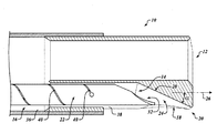
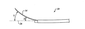
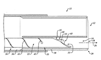
上述されてもいるように、また、追加的に図2Bを参照すると、いくつかの実施形態では、オフセット機構24は、針22内に同軸的に配置された、形状設定された湾曲スタイレット30を含んでもよい。このような実施形態において、ランプ28(図1B及び図2A)は、カテーテル12の遠位端20に配置されていないことが理解されるであろう。その結果、軸線26からの針22のオフセットは、スタイレット30の湾曲によってのみ付与される。スタイレット30に設定される湾曲量に応じて、そのような実施形態は、組織の同心領域を採取する用途にも、組織の偏心領域を採取する用途にも好適となり得る。
As also described above, and additionally referring to FIG. 2B, in some embodiments, the offset
このような実施形態では、形状設定された湾曲スタイレット30は、カテーテル12の遠位端20における開口部18から、針22内にて(針22と共に)延ばされるように構成されている。このような実施形態においては、また、更に図3Bを参照すると、スタイレット30は、管腔14の軸線26から分岐する角度βで、カテーテル12の遠位端20における開口部18から(針22内に同軸的に配置された状態で)延びるように構成されている。
In such an embodiment, the shaped
様々な実施形態において、この形状設定された湾曲スタイレット30は可撓性針22に挿入される。スタイレット30により、針22は、スタイレット30の湾曲に追従させられる。針22、及び針22の中に同軸的に配置されたスタイレット30の複合ユニット(本明細書において、針/スタイレットアセンブリ34と称される)がカテーテル12内に収容される場合、針/スタイレットアセンブリ34は直線状であり、これにより、針/スタイレットアセンブリ34はカテーテル12を通って移動することが可能となる。針/スタイレットアセンブリ34がカテーテル12の遠位端20における開口部18を通って延ばされると、スタイレット30及び結果として、針/スタイレットアセンブリ34は、再度湾曲することができる。
In various embodiments, this shaped
スタイレット30の湾曲量は、スタイレットがカテーテル12の遠位端20を越えて延びる長さに応じることが理解されるであろう。そのため、針/スタイレットアセンブリ34が開口部18を通って延ばされると、スタイレット30、及び、その結果、針/スタイレットアセンブリ34が湾曲し、これにより針22は、体腔から軸ずれした状態となる。スタイレット30の湾曲は、変化する傾きを有しているため、スタイレット30は、スタイレット30がカテーテル12の遠位端20を越えて遠くへ延びるほど、より湾曲させられ得る。よって、針/スタイレットアセンブリ34の湾曲量は、部分的には、針22の先端32からの、スタイレット30の先端42の後退量に依存すること理解されるであろう。先端32からの、先端42の後退が小さいほど、軸線26からのオフセット角度が大きくなる。逆に、先端32からの、先端42の後退が大きいほど、軸線26からのオフセット角度が小さくなる。(スタイレット30がカテーテルの遠位端20を越えて著しく延び得ないように)先端32からの先端42の後退量が十分であると、結果として著しいオフセット角度が生じない。
It will be appreciated that the amount of curvature of the
スタイレット30に十分な湾曲量が設定されると、その湾曲により、針22は気道のような体腔から軸ずれさせられ、針22が気道壁などの体腔壁に突き刺さることが可能となり、これにより、針22により、偏心的に位置する標的を採取することができる。しかし、湾曲により、針22を体腔から軸ずれさせる一方で、針22を体腔内に保ち、これにより、針22によって同心的に位置する標的を採取することができるように、スタイレット30に適切な湾曲量を設定してもよいことが理解されるであろう。
When a sufficient amount of curvature is set in the
図3Bに示されるように、角度βは、針/スタイレットアセンブリ34が開口部18から延びる初期角度であることが理解されるであろう。図3Bに示すように、スタイレット30の湾曲は変化する傾きを有しているため、スタイレット30が開口部18から遠くに延びるにつれて、針/スタイレットアセンブリ34が軸線26から分岐する角度が大きくなり得る。例えば、また、図2Bに示されるように、針/スタイレットアセンブリ34の遠位端は、角度χで軸線26から分岐する。この角度χは、開口部18に近接して達成される角度βより大きいことが理解されるであろう。
It will be appreciated that the angle β is the initial angle at which the needle /
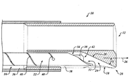
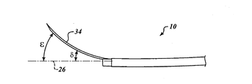
上述されてもいるように、また、図1Bに示されるように、いくつかの実施形態では、オフセット機構24は、ランプ28及び(針22内に同軸的に配置された)スタイレット30を含んでもよい。このような実施形態では、針/スタイレットアセンブリ34がカテーテル12の遠位端20に向かって延びると、針22は、カテーテル12の遠位端20にあるランプ28(すなわち傾斜面)に到達し、針/スタイレットアセンブリ34は、開口部18に向かって付勢される。
As also described above, and as shown in FIG. 1B, in some embodiments, the offset
更に図3Cを参照すると、針/スタイレットアセンブリ34は、開口部18をオフセット角度δで出ている。開口部18を通って出る前に、針/スタイレットアセンブリ34は角度αでランプ28に沿って付勢されており、そして、スタイレット30により、針/スタイレットアセンブリ34は、軸線26から角度βだけ追加的に分岐させられていることから、角度δは、角度βよりも大きいことが理解されるであろう。図3Cに示し、図3Bを参照して上述したように、針/スタイレットアセンブリ34が開口部18から遠くに延びるにつれて、針/スタイレットアセンブリ34が軸線26から分岐する角度が大きくなり得る。例えば、また、図3Cに示されるように、針/スタイレットアセンブリ34の遠位端は、角度εで軸線26から分岐する。この角度εは、スタイレット30の湾曲のために、開口部18に近接して達成される角度δより大きいことが理解されるであろう。
Still referring to FIG. 3C, the needle /
このような実施形態では、針/スタイレットアセンブリ34が開口部18を出ると、ランプ28は針/スタイレットアセンブリ34を開口部18に向けて配向させるのを助けることができることが理解されるであろう。この配向の補助は、様々な実施形態において、スタイレット30が円形であり、特定の方向で管腔14へ進入することに制限されないことから、生じている。例えば、スタイレット30は、(開口部18に対して)上、下、左、右のいずれか1つの配向で、針22内に同軸的にフィットすることができる。スタイレット30の湾曲(すなわち、配向)が誤った方向を向いている場合(例えば、ランプ28が上の場合に下を向くなど)、ランプ28は、スタイレット30の湾曲がランプ28と配向を合わせ、ランプ28の角度αに偏りを加えるように、スタイレット30を正しい向きに向け直すように強制する。スタイレット30の湾曲部がランプ28を通過すると、スタイレット30は強制的にランプ28の方向に湾曲する。このため、このような実施形態では、湾曲スタイレット30は常にランプ28の角度を増加する。
It will be appreciated that in such an embodiment, when the needle /
湾曲スタイレット30はカテーテル12の形状に適合し(conform)、スタイレット30は管腔14内に配置されていることが理解されるであろう。以上のように、湾曲スタイレット30、結果として、針/スタイレットアセンブリ34は、針/スタイレットアセンブリ34が開口部18を通って延ばされた後に湾曲する。結果として、及び以下で更に論じられるように、湾曲スタイレット30は、管腔14から引き抜かれ、それによって針22の栓を抜き、そして針22を介して組織が採取されることを可能にするように構成される。
It will be appreciated that the
様々な実施形態において、例示的なシステム50(図1A)は、組織の標的領域を採取するために提供される。限定するわけではないが、組織は、気道のような体腔に隣接して位置する病変を含んでもよく、体腔内(つまり、同心組織)又は体腔外(つまり、偏心組織)のいずれかに位置してもよいことが理解されるであろう。このような実施形態において、システム50は、ハンドルアセンブリ60(図1A)を含む。カテーテルアセンブリ10は、ハンドルアセンブリ60に動作可能に結合され、カテーテルアセンブリ10は、採取される組織の標的領域に向けて体腔内に挿入可能に構成されている。上述したように、カテーテルアセンブリ10は、カテーテル12を含む。上述されてもいるように、カテーテル12は内部に管腔14を画定し、カテーテル12の壁16はカテーテル12の遠位端20において開口部18を画定する。可撓性針22は、管腔14の中に配置可能であり、オフセット機構24は、カテーテル12の遠位端20の開口部18から、管腔14の軸線26から分岐する角度で延びるように、可撓性針22を付勢するように構成されている。
In various embodiments, an exemplary system 50 (FIG. 1A) is provided for harvesting a target area of tissue. The tissue may include, but is not limited to, a lesion located adjacent to a body cavity, such as an airway, and is located either in the body cavity (ie, concentric tissue) or extracorporeal (ie, eccentric tissue). It will be understood that it may be. In such an embodiment, the
また、上で論じたように、いくつかの実施形態において、オフセット機構24は、カテーテル12の遠位端20においてカテーテル12内に画定されたランプ28を含んでもよい。いくつかの他の実施形態では、オフセット機構24は、針22内に同軸的に配置された、湾曲スタイレット30を含んでもよい。いくつかの他の実施形態では、オフセット機構24は、ランプ28及び湾曲スタイレット30を含んでもよい。これらの全ての実施形態の詳細は、上で検討されており、開示された主題の理解のために繰り返される必要はない。
Also, as discussed above, in some embodiments, the offset
様々な実施形態において、ハンドルアセンブリ60は、複数の機能を行う。例えば、いくつかの実施形態では、ユーザは、ハンドルアセンブリ60を使用してカテーテル12にトルクを与えて開口部18を、結果として、針22を、偏心して位置する組織に向けて回転させることができる。また、いくつかの実施形態では、スタイレット30は、ハンドルアセンブリ60の近位端68に配置されたルアコネクタ66を通じてカテーテルアセンブリ10から取り除かれてもよい。更に、いくつかの実施形態では、注射器(syringe)のような真空装置(図示せず)が、スタイレット30が管腔から引き抜かれた状態で、ハンドルアセンブリ60のルアコネクタ66を介して、針22に動作可能に結合されてもよい。
In various embodiments, the
システム50の様々な実施形態は、次のように動作する。特定の用途に適した内視鏡(図示せず)気管支鏡(図示せず)は、目標位置までの体腔の中で駆動される。標的は、撮像システム(超音波プローブ、光学チャネル、蛍光透視法、光干渉断層法、X線コンピュータ断層撮影支援可視化、及び磁気共鳴画像法など)によって可視化される。カテーテルアセンブリ10は、内視鏡(又は気管支鏡)に装着され、ハンドルアセンブリ60を使用してカテーテル12にトルクを与えて開口部18と標的とを位置合わせする。
Various embodiments of the
オフセット機構がランプ28のみを含む実施形態において、針22は、開口部18を通って、カテーテル12の遠位端20を越えて、標的組織に向けて延ばされる。いくつかの場合において、針22は体腔の壁に突き刺さってもよい。針22は標的組織に突き刺さる。所望により、針22は組織内で繰り返し前後に移動することにより組織をかき混ぜ(agitate)てもよい。標的に針22がある状態で、ハンドルアセンブリ60のルアコネクタ66を介して、注射器のような真空装置(図示せず)が、針22に動作可能に結合される。直線スタイレットが針22内に配置された実施形態では、直線スタイレットは、真空装置がルアコネクタ66を介して針22に動作可能に結合される前に、ルアコネクタ66を通じて取り外される。真空装置は、真空引きすることにより、針22を介して組織を採取する。
In embodiments where the offset mechanism includes only the
オフセット機構24が湾曲スタイレット30のみを含む実施形態、及び、オフセット機構がランプ28及び湾曲スタイレット30を含む実施形態では、針/スタイレットアセンブリ34は、開口部18を通り、カテーテル12の遠位端20を越え、標的に向かって延ばされる。いくつかの場合において、針/スタイレットアセンブリ34は、体腔の壁に突き刺さってもよい。針/スタイレットアセンブリ34は、標的に突き刺さる。所望により、針/スタイレットアセンブリ34は組織内で繰り返し前後に移動することにより組織をかき混ぜてもよい。スタイレット30は、ハンドルアセンブリ60のルアコネクタ66を通じて管腔14から取り外され、組織は針22を組織内にて定位置に保持する。スタイレット30が管腔14から取り外された状態で、注射器のような真空装置(図示せず)が、ハンドルアセンブリ60のルアコネクタ66を介して針22に動作可能に結合される。真空装置は、真空引きすることにより、針22を介して組織を採取する。
In embodiments in which the offset
以下は、実装(implementation)を表す一連のフロー図である。理解を容易にするために、フロー図は、最初のフロー図が例示的な実装を介して実装を提示し、その後、続くフロー図は、最初のフロー図の代替の実装、及び/又は拡張を、1つ以上の以前に提示されたフロー図に基づく、サブ構成操作又は追加の構成操作として提示するように編成されている。当業者は、本明細書で利用される提示様式(すなわち、例示的な実装を提示するフロー図の提示で始まり、その後、後続のフロー図において、追加及び/又は更なる詳細を提供すること)により、様々なプロセス実装の迅速かつ容易な理解が、概ね可能となっていることを理解するであろう。 The following is a series of flow diagrams representing implementation. For ease of understanding, the flow diagram presents an implementation through an exemplary implementation, where the first flow diagram then presents alternative implementations and / or extensions of the first flow diagram. Organized to present as a sub-configuration operation or an additional configuration operation based on one or more previously presented flow diagrams. Those skilled in the art will be familiar with the presentation style utilized herein (ie, starting with the presentation of a flow diagram presenting an exemplary implementation and then providing additional and / or further details in subsequent flow diagrams). It will be appreciated that a quick and easy understanding of various process implementations is generally possible.
図4Aを参照すると、組織の標的領域を採取する例示的な方法100が提供されている。限定するわけではないが、方法100の実施形態は、カテーテルアセンブリ10及びシステム50の様々な実施形態を使用するのに好適となり得ることが理解されるであろう。標的領域は、方法100が開始する前に位置決めされていることも理解されるであろう。
With reference to FIG. 4A, an exemplary method 100 for harvesting a target region of tissue is provided. It will be appreciated that, without limitation, embodiments of method 100 may be suitable for use with various embodiments of
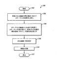
方法100は、ブロック102で開始する。ブロック104では、カテーテルは採取される組織の標的領域に向けて体腔内に挿入される。ブロック106では、カテーテルの軸線から分岐する角度で、カテーテルの遠位端から、採取される組織の標的領域に向けて、可撓性針が延ばされる。ブロック108において、針を組織に突き刺す。ブロック110では、組織が採取される。方法100は、ブロック112で停止する。
The method 100 begins at
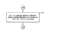
図4Bを参照すると、また、いくつかの実施形態では、ブロック104において、採取される組織の標的領域に向けて、カテーテルが体腔内に挿入された後であって、ブロック106において、採取される組織の標的領域に向けて、カテーテルの軸線から分岐する角度で、カテーテルの遠位端から、可撓性針が延ばされる前に、ブロック114において、カテーテルの遠位端に画定された開口部が、採取される組織の標的領域に向けて配向されるように、カテーテルにトルクが与えられてもよい。
Referring also to FIG. 4B, and in some embodiments, at
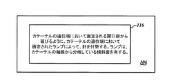
図4Cを参照すると、また、いくつかの実施形態では、ブロック106において、採取される組織の標的領域に向けて、カテーテルの軸線から分岐する角度で、カテーテルの遠位端から、可撓性針を延ばすことは、ブロック116において、カテーテルの遠位端において画定される開口部から延びるように、カテーテルの遠位端において画定されたランプによって、針を付勢することを含んでいてもよく、ここで、ランプは、カテーテルの軸線から分岐している傾斜面を有する。
Referring also to FIG. 4C, and in some embodiments, at
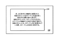
図4Dを参照すると、また、いくつかの実施形態では、ブロック106において、採取される組織の標的領域に向けて、カテーテルの軸線から分岐する角度で、カテーテルの遠位端から、可撓性針を延ばすことは、ブロック118において、針、及び針内に同軸的に配置された湾曲スタイレットをカテーテルの遠位端に画定される開口部から延ばすことを含んでいてもよく、ここで、湾曲スタイレットは、カテーテルから出ると、カテーテルの軸線から分岐する角度で曲がり、湾曲スタイレットは、カテーテル内に配置されている間、カテーテルの形状に適合する。
Referring also to FIG. 4D, and in some embodiments, at
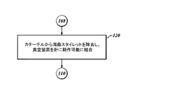
図4Eを参照すると、また、いくつかの実施形態では、ブロック108において針を組織に突き刺した後であって、ブロック110において組織を採取する前に、ブロック120において、湾曲スタイレットは、カテーテルから除去され、真空装置が針に動作可能に結合される。
Referring also to FIG. 4E, and in some embodiments, the curved stylet is removed from the catheter at
図4Fを参照すると、また、いくつかの実施形態では、ブロック106において、採取される組織の標的領域に向けて、カテーテルの軸線から分岐する角度で、カテーテルの遠位端から、可撓性針を延ばすことは、ブロック122において、カテーテルの遠位端において画定される開口部から延びるように、カテーテルの遠位端において画定されたランプによって、針、及び針内に同軸的に配置された湾曲スタイレットを付勢することであって、ランプは、カテーテルの軸線から分岐している傾斜面を有する、ことと、ブロック124において、針、及び針内に同軸的に配置された湾曲スタイレットをカテーテルの遠位端に画定される開口部から延ばすことであって、湾曲スタイレットは、カテーテルから出ると、カテーテルの軸線から分岐する角度で曲がり、湾曲スタイレットは、カテーテル内に配置されている間、カテーテルの形状に適合する、ことと、を含んでもよい。
Referring also to FIG. 4F, and in some embodiments, at
他の例示的な非限定的実施形態では、異なる形態の湾曲可撓性針が所望の採取位置で組織を採取するために使用されてもよい。前述のように、カテーテル器具(又はそれを使用するシステム又は方法)は、可撓性針を通して湾曲スタイレットを延ばすことにより、針を管腔の軸線から分岐させるように、カテーテルの遠位端のランプ及び/又は湾曲スタイレットを使用して所望の採取位置に方向付けることができる可撓性針を含んでもよい。対照的に、別の例示的実施形態では、カテーテル器具(又はそれを採用するシステム又は方法)は、所望の採取位置に方向付けられ得る、概ね直線状の本体部及び湾曲した端部を含み得る、湾曲可撓性針を含んでもよい。カテーテルに対する湾曲可撓性針のオフセットは、カテーテルの遠位端にあるランプ及び/又は直線スタイレットを使用して制御されてもよい。直線スタイレットを湾曲可撓性針を通して延ばすことにより、湾曲可撓性針をその湾曲した構成から偏向させる(deflect)ことができ、これにより、湾曲可撓性針を偏向させてその湾曲を直線状にするか又は減少させる。したがって、湾曲可撓性針が延ばされているか、又は湾曲可撓性針が管腔の遠位端を越えて延ばされた後に(カテーテル内のランプによって偏向されているか、カテーテルから真っ直ぐに延ばされているかに関わらず)、湾曲可撓性針の湾曲の程度は、湾曲可撓性針を通して直線スタイレットを選択的に延ばすことによって変化させ得る。 In other exemplary non-limiting embodiments, different forms of curved flexible needles may be used to harvest tissue at a desired harvest location. As previously described, the catheter device (or system or method using it) can be used to extend the curved stylet through a flexible needle so that the needle branches off of the lumen axis. A flexible needle may be included that can be directed to a desired collection position using a ramp and / or curved stylet. In contrast, in another exemplary embodiment, a catheter device (or system or method employing it) can include a generally straight body and a curved end that can be directed to a desired collection location. A curved flexible needle may be included. The offset of the curved flexible needle relative to the catheter may be controlled using a ramp and / or a linear stylet at the distal end of the catheter. By extending the straight stylet through the curved flexible needle, the curved flexible needle can be deflected from its curved configuration, thereby deflecting the curved flexible needle and straightening the curve. Or reduce. Thus, the curved flexible needle is extended, or after the curved flexible needle is extended beyond the distal end of the lumen (either deflected by a ramp in the catheter or straight from the catheter Whether or not it is extended) the degree of curvature of the curved flexible needle can be varied by selectively extending a straight stylet through the curved flexible needle.
器具及びシステムの実施形態は、前述の器具及びシステムと多数の共通要素を共有する。以下の説明では、これまでの説明で説明した図面を参照して使用した参照番号と同じものを使用する。異なる構成要素を記述するために、異なる参照番号が使用される。 Instrument and system embodiments share a number of common elements with the aforementioned instruments and systems. In the following description, the same reference numerals are used as those used with reference to the drawings described above. Different reference numbers are used to describe different components.
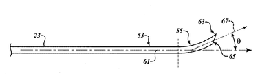
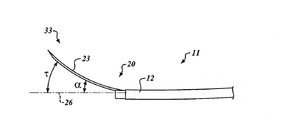
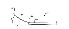
図5を参照すると、湾曲可撓性針23の例示的な、非限定的実施形態は、本体軸線61に沿って延びる概ね直線状の本体部53、及び針23の遠位端63において開口部65を含む湾曲した端部55を含む。湾曲可撓性針23が管腔12内に延びるとき、本体軸線61は、管腔14の軸線26に沿っている。目標軸線67は、開口部65から延びる。目標軸線67は、採取される組織の標的領域に向けて延びてもよい(図示せず)。目標軸線67の本体軸線61からの分岐は、管腔14の軸線26からの、湾曲可撓性針23の分岐を表す。後述するように、目標軸線67の姿勢(attitude)は、開口部65を、採取される組織の標的領域に方向付けるように調整され得る。湾曲部55が初期の変形していない構成にあるとき、目標軸線67は、本体軸線61及び管腔14の軸線26から角度θで分岐する。湾曲可撓性針23は、更に後述するように、カテーテル12の管腔14内に配置されている間、カテーテルの形状に適合するように構成されている。
Referring to FIG. 5, an exemplary, non-limiting embodiment of the curved
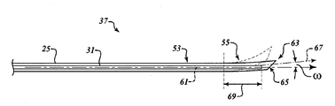
図6Aを参照すると、針/スタイレットアセンブリ35の例示的な非限定的実施形態は、針23及びスタイレット31を含む。針23は、湾曲可撓性針である。針23は形状設定され、湾曲した針である。例示的な、非限定的実施形態では、針23は、本体軸線61に沿って延びる、概ね直線状の本体部53を含む。針23はまた、針23の遠位端63に開口部65を含む湾曲した端部55を含む。図1A、図2A、図3A、及び図3Bを参照して前述した針/スタイレットアセンブリ34の実施形態と同様に、スタイレット31は、針23の近位端(図示せず)で受け入れられ、針23を通って針23の遠位端における先端63に向けて同軸的に延び得る。湾曲可撓性針23は、更に後述するように、カテーテルの管腔内に配置されている間、カテーテルの形状に適合するように構成されている。
With reference to FIG. 6A, an exemplary, non-limiting embodiment of a needle /
スタイレット31が端部55内に延びていない場合、端部55はデフォルトの湾曲形状となる。端部55は、針23の先端63に形成された開口部65で終端している。目標軸線67は、開口部65から延びる。目標軸線67は、採取される組織の標的領域に向けて延びてもよい(図示せず)。後述するように、目標軸線67の姿勢は、開口部65を、採取される組織の標的領域に方向付けるように調整され得る。湾曲部55が初期の変形していない構成にあるとき、目標軸線67は、本体軸線61及び管腔14の軸線26から角度θで分岐する。
When the
図6Bを参照すると、スタイレット31を針23の端部55に延ばすと、結果として針23の端部55には、目標軸線67に対して横方向の力が作用する。この力は、図1B、図2A及び図2Bを参照して説明したように、曲がったスタイレット30と針22の両方がカテーテル12の端部を越えて延びているときに、曲がったスタイレット30によって、針22に対して、外向きに加えられる力に類似している。スタイレット31は、端部55へと距離69だけ延ばされ、これにより、端部55は、目標軸線67に対して横方向の力を受ける。この力は、端部55の部分に作用し、本体軸線61に向かって偏向するように、端部55を付勢する。換言すれば、スタイレット31を端部55に延ばすと端部55が真っ直ぐになり、端部がその自然な湾曲構成から変形する。その結果、目標軸線67端部55が延びる角度は、角度θから角度ωまで減少する。スタイレット31を遠位端63に向かって端部55内に更に延ばすことによって距離69を増加させることは、端部55を更に真っ直ぐにし、目標軸線67が本体軸線61から偏向する角度を減少させ、それにより管腔14の軸線26からの、湾曲可撓性針23の全体的な分岐を減少させることを理解されたい。逆に、スタイレット31を端部55から部分的又は完全に引き抜くことによって距離69を減少させることは、端部55が元の形状をとることを可能にし、目標軸線67が本体軸線61から偏向する角度を大きくし、それにより管腔14の軸線61からの、湾曲可撓性針23の全体的な分岐を大きくする。
Referring to FIG. 6B, when the
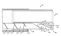
図7、図8A、及び図8Bを参照すると、カテーテルアセンブリ11の例示的で非限定的な実施形態では、カテーテル12は内部に管腔14を画定する。カテーテル12の壁16は、カテーテル12の遠位端20において、開口部18を画定する。可撓性針23は、管腔14内に配置可能である。
With reference to FIGS. 7, 8A, and 8B, in an exemplary, non-limiting embodiment of the
図7を参照すると、オフセット機構24は、カテーテル12の遠位端20の開口部18から、管腔14の軸線26から分岐する角度αで延びるように、針23を付勢するように構成されている。オフセット機構24は、様々な様式で具現化されてもよいことが理解されるであろう。図7の実施形態のようないくつかの実施形態において、オフセット機構24は、カテーテル12の遠位端20においてカテーテル12内に画定されたランプ28を含んでもよい。図8Aの実施形態のようないくつかの他の実施形態では、ランプ28に加えて、オフセット機構24は、針23内に同軸的に配置された直線スタイレット31を含んでもよい。図8Bの実施形態のようないくつかの他の実施形態では、オフセット機構24は、直線スタイレット31のみを含んでもよい。これらの実施形態のそれぞれは、下記に議論される。
Referring to FIG. 7, the offset
上述したように、また、追加的に図7を参照すると、いくつかの実施形態において、オフセット機構24は、カテーテル12の遠位端20においてカテーテル12内に画定されたランプ28を含んでもよい。湾曲可撓性針23は、内部に挿入されるとカテーテル12に適合するように構成されている。針23がカテーテル12の遠位端20を越えて延びているとき、管腔14の軸線26からの針23のオフセットは、ランプ28及び針23の端部55の湾曲によって付与される。そのような実施形態において達成可能なオフセット角度の範囲(後述する)のために、そのような実施形態は、組織の同心領域を採取する用途にも、組織の偏心領域を採取する用途にも好適となり得る。
As described above and with additional reference to FIG. 7, in some embodiments, the offset
図7及び図8Aの実施形態のような、このような実施形態では、ランプ28は、管腔14の軸線26から分岐する傾斜面を有する。いくつかの実施形態では、ランプ28は、管腔14の軸線26からのオフセットを約5度〜約25度の範囲内の角度αで画定する。いくつかの実施形態では、オフセット角αは、約10度であってもよい。いくつかの実施形態では、オフセット角αは、約20度〜約25度の範囲内であってもよい。いくつかのこのような実施形態では、オフセット角αは、約20度であってもよい。角度αの数値に関わらず、針23がカテーテル12の遠位端20に向かって延びるとき、針23はカテーテル12の遠位端20にあるランプ28(すなわち傾斜面)に到達し、開口部18に向かって付勢される。針23は、ほぼオフセット角αで開口部18から出る(そして、延び続ける)。いくつかの実施形態では、ランプ28は、ポリカーボネートなどの任意の好適な硬質プラスチックからなっていてもよい。
In such an embodiment, such as the embodiment of FIGS. 7 and 8A, the
上述されてもいるように、また、追加的に図8Aを参照すると、いくつかの実施形態では、オフセット機構24は、図6A及び図6Bの参照と共に説明されるように、針23内に同軸的に配置された直線スタイレット31を含んでもよい。針23の先端33がカテーテル12の遠位端20を越えて延びると、スタイレット31を選択的に延ばすことにより、針23の先端33の更なるオフセットを制限し得る。スタイレット31が針23の端部55を通って、針23の先端33まで、又は針23の先端33を通って完全に延ばされると、スタイレット31は針23の端部55を真っ直ぐにする。その結果、図9Bを参照して更に説明されるように、針の先端33のオフセットは、ランプ28によって付与されるものに限定される。しかし、図9Aを参照して更に説明されるように、針23の先端33がカテーテル12の遠位端20を越えて延び、スタイレット31が針23の端部55から部分的に又は完全に後退されると、端部55は、その湾曲した形状設定構成に戻って先端33に追加のオフセットを付与し得る。
As also described above and with additional reference to FIG. 8A, in some embodiments, the offset
カテーテルアセンブリ11の例示的で非限定的な実施形態である図8Bを参照すると、オフセット機構24は、カテーテルの遠位端20においてランプを含まない。したがって、針23の先端33は、カテーテル12の遠位端20から真っ直ぐ外に延びる。この構成において、針23の先端33への唯一のオフセットは、針23の端部55の湾曲した形状設定構成から生じるものであり、スタイレット31を針23の端部55へ選択的に延ばすことによって付与される制御を受ける。針23の端部55に設定される湾曲量に応じて、そのような実施形態は、組織の同心領域を採取する用途にも、組織の偏心領域を採取する用途にも好適となり得る。
Referring to FIG. 8B, which is an exemplary, non-limiting embodiment of the
様々な実施形態において、この形状設定され、湾曲した針23はカテーテル12に挿入される。カテーテル12による閉じ込めにより、管腔軸線26と整列するように、針23の端部55を拘束する。スタイレット31の挿入により、針23の端部55に更なる力を加えると、針23の端部55は、湾曲した形状設定構成に戻ることを妨げられ得、それにより、カテーテル12を通して針23の端部55を延ばしやすくし得る。
In various embodiments, this shaped and
上述したように、針23の先端33がカテーテル12から延ばされると、針23の先端33の湾曲又はオフセットの量は、オフセット機構24が、ランプ28、及び/又は、針23の端部55の湾曲を制御するための、スタイレット31が針23の端部55内に延びる距離69(図6B)を含んでいるかどうかにより、もたらされる。
As described above, when the
図9Aを参照すると、湾曲可撓性針23の遠位端33のオフセットは、図7及び図8Aのようなカテーテルアセンブリ11に示されるように、湾曲可撓性針23の湾曲を限定する直線スタイレット31なしで、ランプ28によって付与されたオフセットを用いて示されている。湾曲可撓性針23は、カテーテル12の遠位端20を越えて延ばされている。湾曲可撓性針23の先端33は、シース12の遠位端20から角度τでオフセットされる。湾曲可撓性針23は、カテーテル12の遠位端20から出るときに、ランプ28によって角度αだけオフセットされる。また、湾曲可撓性針23がカテーテル12の遠位端20から出ると、湾曲可撓性針23は、湾曲した形状に戻り、追加的なオフセット(図5を参照すると、最大で角度θとなり得る)を付与してτの総オフセット角に達することができる。
Referring to FIG. 9A, the offset of the
図9Bを参照すると、総オフセット角は、直線スタイレット31を針/スタイレットアセンブリ35の端部まで延ばすことによって角度αまで低減される。湾曲可撓性針23内に直線スタイレット31を挿入すると、湾曲可撓性針23は、直線スタイレット31に適合させられ、湾曲可撓性針23の湾曲によって引き起こされる更なるオフセットが取り除かれるか、又は低減させられる。その結果、オフセット角は、湾曲可撓性針23がカテーテル12から出るときに、ランプ28によって付与される角度αまで減少する。
With reference to FIG. 9B, the total offset angle is reduced to an angle α by extending the
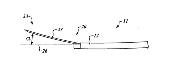
図9Cを参照すると、図8Bに示すような、カテーテル12内にランプ28がないカテーテルアセンブリ11の一実施形態における湾曲可撓性針23のオフセット角が示されている。ランプ28によってオフセットが付与されないとき、湾曲可撓性針23の遠位端33のオフセット角は、図6A及び図6Bを参照して説明したように直線スタイレット31の使用によって制限され得る、湾曲可撓性針23の湾曲から生じたものである。湾曲可撓性針23の湾曲は、湾曲可撓性針23からスタイレット31を部分的又は全体的に引き抜くことによって増大させることができ、又は湾曲可撓性針23の湾曲は、シース12の遠位端を越えて湾曲可撓性針23の部分内に直線スタイレット31を少なくとも部分的に延ばすことによって減少させることができる。例えば、湾曲可撓性針23は、管腔軸線26に対してオフセット角μで示されている。
Referring to FIG. 9C, the offset angle of the curved
様々な実施形態において、カテーテル12はシース36及びシースライナー38を含む。非限定的な例として挙げると、シース36は、編まれて(braided)いてもよく、熱可塑性エラストマーなどの任意の好適な医療用ポリマー材料からなっていてもよい。シース36に対して編まれた材料を使用すれば、カテーテル12にトルクを与えて開口部18を回転させ、これにより、湾曲可撓性針23を標的組織へと回転させ得るように、十分な剛性を提供できることが理解されるであろう。更に非限定的な例を挙げると、シースライナー38は、ポリテトラフルオロエチレン(PTFE)などの任意の好適な材料からなってもよい。
In various embodiments, the
様々な実施形態において、湾曲可撓性針23は、部分的には、湾曲可撓性針23に所望の可撓性及び組織に突き刺さるのに十分な柱強度(column strength)を提供することができる任意の好適な材料からなってもよい。湾曲可撓性針23が変形していない構成にあるとき、湾曲可撓性針23は、湾曲可撓性針23の端部55に所望の形状及び湾曲特性を与える、形状記憶合金(「SMA」)などの任意の好適な材料からなってもよい。非限定的な例として挙げると、様々な実施形態において、湾曲可撓性針23は、ニチノールなどのSMAからなってもよい。
In various embodiments, the curved
湾曲可撓性針23が金属又は金属合金からなるような実施形態では、図1Bに示されるように、レーザ切断などによって、湾曲可撓性針23に画定された切り込み40を介して可撓性が湾曲可撓性針23に付与される。また、非限定的な例として、湾曲可撓性針23は、皮下チューブ(「ハイポチューブ(hypotube)」)からなっていてもよい。いくつかのそのような実施形態では、湾曲可撓性針23は、具体的な用途のサイズ及び可撓性の制約に応じて、24ゲージのハイポチューブなどであってもよい。そのような実施形態では、ハイポチューブは、少なくとも近位部分に沿って比較的滑らかになるように好適に構成され、これにより、例えば、限定的ではなく、カテーテル12の管腔14などの装置内に導入されたときに、ハイポチューブが、管腔14に沿って比較的自由にスライド、回転、又は他の様式で移動することができるようになる。限定的でない単なる例としては、湾曲可撓性針23が上述のように切り込み40を有するように寸法決めされ構成されているとき、様々な実施形態において、湾曲可撓性針23は、短い空間で約45度程度曲がることが可能となり得ることが理解されるであろう。
In embodiments where the curved
このように、直線スタイレット31は、任意の好適な材料からなってもよい。非限定的な例として挙げると、いくつかの実施形態では、スタイレット31は、PEEK、ウルテム(登録商標)などのようなプラスチックからなってもよい。更なる非限定的な例としては、いくつかの実施形態では、スタイレット31は、米国鉄鋼協会(「AISI」)タイプ304ステンレス鋼のようなステンレス鋼、ニチノール、コバルトクロムなどの金属又は金属合金からなってもよい。
Thus, the
様々な実施形態では、スタイレット31は、スタイレットが針23内に同軸的に配置されているときに、スタイレット31が湾曲可撓性針23を塞ぐように寸法決めされ、それによって湾曲可撓性針23が所望の関心領域に位置する前における、湾曲可撓性針23による採取の防止を容易にする。
In various embodiments, the
様々な実施形態において、例示的なシステム50(図1A)は、組織の標的領域を採取するために提供される。限定するわけではないが、組織は、気道のような体腔に隣接して位置する病変を含んでもよく、体腔内(つまり、同心組織)又は体腔外(つまり、偏心組織)のいずれかに位置してもよいことが理解されるであろう。このような実施形態において、システム50は、ハンドルアセンブリ60(図1A)を含む。このシステムは、図1Aに示すような、カテーテルアセンブリ10の代わりに、カテーテルアセンブリ11を備えてもよい。カテーテルアセンブリ11は、ハンドルアセンブリ60に動作可能に結合され、カテーテルアセンブリ11は、採取される組織の標的領域に向けて体腔内に挿入可能に構成されている。上述したように、カテーテルアセンブリ11は、カテーテル12を含む。上述されてもいるように、カテーテル12は内部に管腔14を画定し、カテーテル12の壁16はカテーテル12の遠位端20において開口部18を画定する。湾曲可撓性針23は、管腔14の中に配置可能であり、オフセット機構24は、カテーテル12の遠位端20の開口部18から、管腔14の軸線26から分岐する角度で延びるように、湾曲可撓性針23を付勢するように構成されている。
In various embodiments, an exemplary system 50 (FIG. 1A) is provided for harvesting a target area of tissue. The tissue may include, but is not limited to, a lesion located adjacent to a body cavity, such as an airway, and is located either in the body cavity (ie, concentric tissue) or extracorporeal (ie, eccentric tissue). It will be understood that it may be. In such an embodiment, the
また、上で論じたように、いくつかの実施形態において、オフセット機構24は、カテーテル12の遠位端20においてカテーテル12内に画定されたランプ28を含んでもよい。いくつかの他の実施形態では、オフセット機構24は、上述したように、針の端部55の湾曲を制御するために、針23内に同軸的に配置された直線スタイレット31を有する湾曲可撓性針23を含んでもよい。いくつかの他の実施形態では、オフセット機構24は、ランプ28と、湾曲可撓性針23と共に作動する直線スタイレット31とを含んでもよい。これらの全ての実施形態の詳細は、上で検討されており、開示された主題の理解のために繰り返される必要はない。
Also, as discussed above, in some embodiments, the offset
様々な実施形態において、ハンドルアセンブリ60は、複数の機能を行う。例えば、いくつかの実施形態では、ユーザは、ハンドルアセンブリ60を使用してカテーテル12にトルクを与えて開口部18を、結果として、湾曲可撓性針23を、同心的又は偏心的に位置する組織に向けて回転させることができる。また、いくつかの実施形態では、スタイレット31は、ハンドルアセンブリ60の近位端68に配置されたルアコネクタ66を通じてカテーテルアセンブリ11から取り除かれてもよい。更に、いくつかの実施形態では、注射器のような真空装置(図示せず)が、スタイレット31が管腔から引き抜かれた状態で、ハンドルアセンブリ60のルアコネクタ66を介して、湾曲可撓性針23に動作可能に結合されてもよい。
In various embodiments, the
システム50の様々な実施形態は、次のように動作する。特定の用途に適した内視鏡(図示せず)気管支鏡(図示せず)は、目標位置までの体腔の中で駆動される。標的は、撮像システム(超音波プローブ、光学チャネル、蛍光透視法、光干渉断層法、X線コンピュータ断層撮影支援可視化、及び磁気共鳴画像法など)によって可視化される。カテーテルアセンブリ11は、内視鏡(又は気管支鏡)に装着され、ハンドルアセンブリ60を使用してカテーテル12にトルクを与えて開口部18と標的とを位置合わせする。
Various embodiments of the
オフセット機構24がランプ28のみを含む実施形態において、湾曲可撓性針23は、開口部18を通って、カテーテル12の遠位端20を越えて、標的組織に向けて延ばされる。いくつかの場合において、湾曲可撓性針23は体腔の壁に突き刺さってもよい。湾曲可撓性針23は標的組織に突き刺さる。標的に湾曲可撓性針23がある状態で、注射器のような真空装置(図示せず)が、ハンドルアセンブリ60のルアコネクタ66を介して湾曲可撓性針23に動作可能に結合される。直線スタイレット31が針23内に配置された実施形態では、直線スタイレット31は、真空装置がルアコネクタ66を介して湾曲可撓性針23に動作可能に結合される前に、ルアコネクタ66を通じて取り外される。所望により、湾曲可撓性針23は組織内で繰り返し前後に移動することにより組織をかき混ぜてもよい。真空装置は、真空引きすることにより、湾曲可撓性針23を介して組織を採取する。
In embodiments where the offset
オフセット機構24が湾曲可撓性針23及び直線スタイレット31のみを含む実施形態、及び、オフセット機構がランプ28及び湾曲可撓性針23及び直線スタイレット31を含む実施形態では、針/スタイレットアセンブリ35は、開口部18を通り、カテーテル12の遠位端20を越え、標的に向かって延ばされる。いくつかの場合において、針/スタイレットアセンブリ35は、体腔の壁に突き刺さってもよい。針/スタイレットアセンブリ35は、標的に突き刺さる。スタイレット31は、ハンドルアセンブリ60のルアコネクタ66を通じて管腔14から取り外され、組織は湾曲可撓性針23を組織内にて定位置に保持する。スタイレット31が管腔14から取り外された状態で、注射器のような真空装置(図示せず)が、ハンドルアセンブリ60のルアコネクタ66を介して湾曲可撓性針23に動作可能に結合される。所望により、針/スタイレットアセンブリ35は組織内で繰り返し前後に移動することにより組織をかき混ぜてもよい。真空装置は、真空引きすることにより、湾曲可撓性針23を介して組織を採取する。
In embodiments where the offset
以下は、実装を表す一連のフロー図である。理解を容易にするために、フロー図は、最初のフロー図が例示的な実装を介して実装を提示し、その後、続くフロー図は、最初のフロー図の代替の実装、及び/又は拡張を、1つ以上の以前に提示されたフロー図に基づく、サブ構成操作又は追加の構成操作として提示するように編成されている。当業者は、本明細書で利用される提示様式(すなわち、例示的な実装を提示するフロー図の提示で始まり、その後、後続のフロー図において、追加及び/又は更なる詳細を提供すること)により、様々なプロセス実装の迅速かつ容易な理解が、概ね可能となっていることを理解するであろう。 The following is a series of flow diagrams representing the implementation. For ease of understanding, the flow diagram presents an implementation through an exemplary implementation, where the first flow diagram then presents alternative implementations and / or extensions of the first flow diagram. Organized to present as a sub-configuration operation or an additional configuration operation based on one or more previously presented flow diagrams. Those skilled in the art will be familiar with the presentation style utilized herein (ie, starting with the presentation of a flow diagram presenting an exemplary implementation and then providing additional and / or further details in subsequent flow diagrams). It will be appreciated that a quick and easy understanding of various process implementations is generally possible.
図10Aを参照すると、組織の標的領域を採取する例示的な方法1000が提供されている。限定するわけではないが、方法1000の実施形態は、カテーテルアセンブリ11及びシステム50の様々な実施形態を使用するのに好適となり得ることが理解されるであろう。標的領域は、方法1000が開始する前に位置決めされていることも理解されるであろう。
Referring to FIG. 10A, an exemplary method 1000 for obtaining a target region of tissue is provided. It will be appreciated that, without limitation, embodiments of method 1000 may be suitable for use with various embodiments of
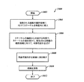
方法1000は、ブロック1002で開始する。ブロック1004では、カテーテルは採取される組織の標的領域に向けて体腔内に挿入される。ブロック1006では、カテーテルの軸線から分岐する角度で、カテーテルの遠位端から、採取される組織の標的領域に向けて、湾曲可撓性針が延ばされる。ブロック1008において、湾曲可撓性針で組織を突き刺す。ブロック1010では、組織が採取される。方法1000は、ブロック1012で停止する。
Method 1000 begins at
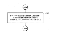
図10Bを参照すると、また、いくつかの実施形態では、ブロック1004において、採取される組織の標的領域に向けて、カテーテルが体腔内に挿入された後であって、ブロック1006において、採取される組織の標的領域に向けて、カテーテルの軸線から分岐する角度で、カテーテルの遠位端から、湾曲可撓性針が延ばされる前に、ブロック1014において、カテーテルの遠位端に画定された開口部が、採取される組織の標的領域に向けて配向されるように、カテーテルにトルクが与えられてもよい。
Referring also to FIG. 10B, and in some embodiments, at
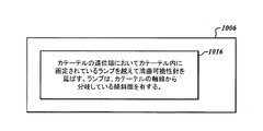
図10Cを参照すると、また、いくつかの実施形態では、ブロック1006において、採取される組織の標的領域に向けて、カテーテルの軸線から分岐する角度で、カテーテルの遠位端から、湾曲可撓性針を延ばすことは、ブロック1016において、カテーテルの遠位端においてカテーテル内に画定されているランプを越えて湾曲可撓性針を延ばすことであって、ランプは、カテーテルの軸線から分岐している傾斜面を有する、ことを含んでいてもよい。
Referring also to FIG. 10C, and in some embodiments, at
図10Dを参照すると、ブロック1014に対して代替的又は追加的に、また、いくつかの実施形態では、ブロック1006において、採取される組織の標的領域に向けて、カテーテルの軸線から分岐する角度で、カテーテルの遠位端から、湾曲可撓性針を延ばすことは、ブロック1018において、湾曲可撓性針内に同軸的に配置可能な直線スタイレットを移動させ、湾曲可撓性針を直線スタイレットの形状に適合させることを含んでもよい。
Referring to FIG. 10D, alternatively or in addition to
肺及び肺結節に使用されるものとして本明細書に記載される生検システム、器具、及び方法の本説明は限定的なものではなく、これらの実施形態は、胃、内視鏡、又は他の好適な箇所を含む患者の他の箇所における、関心領域の生検、ナビゲート及び位置特定に使用されてもよいことが理解されるであろう。同様に、気管支鏡は必要ではなく、様々な内視鏡又は腹腔鏡カニューレを含むがこれらに限定されない、本明細書に記載の実施形態を収容することができる他の好適な装置も使用されてよい。 This description of the biopsy systems, instruments, and methods described herein as used for the lungs and lung nodules is not limiting and these embodiments may be used for stomach, endoscope, or others. It will be appreciated that it may be used for biopsy, navigation and localization of the region of interest in other parts of the patient, including any other suitable part. Similarly, a bronchoscope is not necessary, and other suitable devices that can accommodate the embodiments described herein, including but not limited to various endoscopes or laparoscopic cannulas are also used. Good.
上記の詳細な説明は本質的に単なる例示であり、請求項の主題の要旨及び/又は趣旨から逸脱しない変更は、特許請求の範囲内にあることが意図されていることも理解されるであろう。かかる変更は、請求項にかかる主題の趣旨及び範囲から逸脱するものとしてみなされない。 It is also to be understood that the above detailed description is merely exemplary in nature and that changes that do not depart from the spirit and / or spirit of the claimed subject matter are intended to be within the scope of the claims. Let's go. Such changes are not to be regarded as a departure from the spirit and scope of the claimed subject matter.
10 カテーテル
12 カテーテル
14 管腔
18 開口部
20 遠位端
22 可撓性針
23 湾曲可撓性針
24 オフセット機構
26 軸線
28 ランプ
30 スタイレット
31 直線スタイレット
36 シース
50 システム
53 本体部
55 端部
55 湾曲部
60 ハンドルアセンブリ
61 軸線
65 開口部
66 ルアコネクタ
67 目標軸線
10
Claims (20)
管腔内に配置可能であり、前記カテーテルの前記遠位端の前記開口部から前記管腔の軸線から分岐する角度で延ばすことが可能である、湾曲可撓性針と、を備える、カテーテルアセンブリ。 A catheter having a lumen defined therein, the catheter wall defining an opening in the catheter at a distal end of the catheter; and
A curved flexible needle that is positionable within a lumen and that can extend from the opening at the distal end of the catheter at an angle that diverges from an axis of the lumen. .
前記カテーテルの前記遠位端において前記カテーテル内に画定されているランプであって、前記ランプは、前記管腔の前記軸線から分岐している傾斜面を有する、ランプと、
前記湾曲可撓性針内に同軸的に配置可能な直線スタイレットであって、前記直線スタイレットは、前記湾曲可撓性針を通って延びて、前記湾曲可撓性針を前記直線スタイレットの形状に適合させるように構成されている、直線スタイレットと、を含む、請求項1に記載のカテーテルアセンブリ。 The offset mechanism is
A ramp defined within the catheter at the distal end of the catheter, the ramp having an inclined surface diverging from the axis of the lumen;
A linear stylet that can be coaxially disposed within the curved flexible needle, wherein the linear stylet extends through the curved flexible needle, and the curved flexible needle is connected to the linear stylet. The catheter assembly of claim 1, comprising: a linear stylet configured to conform to the shape of the catheter.
ハンドルアセンブリと、
前記ハンドルアセンブリに動作可能に結合されたカテーテルアセンブリであって、前記カテーテルアセンブリは、採取される組織の標的領域に向けて体腔内に挿入可能に構成されている、カテーテルアセンブリと、を備え、前記カテーテルアセンブリは、
内部に管腔が画定されているカテーテルであって、前記カテーテルの壁は、前記カテーテルの遠位端で前記カテーテルに開口部を画定している、カテーテルと、
管腔内に配置可能であり、前記カテーテルの前記遠位端の前記開口部から前記管腔の軸線から分岐する角度で延ばすことが可能である、湾曲可撓性針と、を備える、システム。 A system for harvesting a target area of tissue, the system comprising:
A handle assembly;
A catheter assembly operably coupled to the handle assembly, the catheter assembly configured to be insertable into a body cavity toward a target region of tissue to be harvested; The catheter assembly
A catheter having a lumen defined therein, the catheter wall defining an opening in the catheter at a distal end of the catheter; and
A curved flexible needle that is positionable within a lumen and that can extend from the opening at the distal end of the catheter at an angle bifurcating from an axis of the lumen.
前記カテーテルの前記遠位端において前記カテーテル内に画定されているランプであって、前記ランプは、前記管腔の前記軸線から分岐している傾斜面を有する、ランプと、
前記針内に同軸的に配置可能な直線スタイレットであって、前記直線スタイレットは、前記湾曲可撓性針を通って延びて、前記湾曲可撓性針を前記直線スタイレットの形状に適合させるように構成されている、直線スタイレットと、を含む、請求項12に記載のシステム。 The offset mechanism is
A ramp defined within the catheter at the distal end of the catheter, the ramp having an inclined surface diverging from the axis of the lumen;
A linear stylet that can be coaxially disposed within the needle, the linear stylet extending through the curved flexible needle to conform the curved flexible needle to the shape of the linear stylet The system of claim 12, comprising: a linear stylet configured to cause
前記スタイレットを前記管腔から引き抜いた状態で、前記ハンドルアセンブリを介して前記針に動作可能に結合可能な真空装置を更に含む、請求項15に記載のシステム。 The stylet is further configured to be withdrawn from the lumen by the handle assembly, the system comprising:
16. The system of claim 15, further comprising a vacuum device operably coupleable to the needle via the handle assembly with the stylet withdrawn from the lumen.
採取される組織の標的領域に向けてカテーテルを体腔内に挿入することと、
前記カテーテルの軸線から分岐する角度で、前記カテーテルの遠位端から、採取される組織の前記標的領域に向けて、湾曲可撓性針を延ばすことと、
前記針を前記組織に突き刺すことと、
前記組織を採取することと、を含む、方法。 A method of collecting a target region of tissue, the method comprising:
Inserting the catheter into the body cavity toward the target area of the tissue to be harvested;
Extending a curved flexible needle from the distal end of the catheter toward the target region of tissue to be harvested at an angle bifurcated from the axis of the catheter;
Piercing the tissue with the needle;
Harvesting the tissue.
前記湾曲可撓性針内に同軸的に配置可能な直線スタイレットを移動させ、前記湾曲可撓性針を前記直線スタイレットの形状に適合させることと、
の少なくとも一方によって前記湾曲可撓性針が前記カテーテルの前記軸線から分岐する角度を制御することを更に含む、請求項18に記載の方法。 Extending the curved flexible needle beyond a ramp defined within the catheter at the distal end of the catheter, the ramp having an inclined surface diverging from the axis of the catheter. Having
Moving a linear stylet coaxially displaceable within the curved flexible needle to conform the curved flexible needle to the shape of the linear stylet;
19. The method of claim 18, further comprising controlling the angle at which the curved flexible needle diverges from the axis of the catheter.
Applications Claiming Priority (4)
| Application Number | Priority Date | Filing Date | Title |
|---|---|---|---|
| US15/920,966 US20190282218A1 (en) | 2018-03-14 | 2018-03-14 | Catheter Assembly With Offset Device For Tissue Sampling |
| US15/920,966 | 2018-03-14 | ||
| US15/933,372 | 2018-03-22 | ||
| US15/933,372 US10912542B2 (en) | 2018-03-14 | 2018-03-22 | Catheter assembly with offset device for tissue sampling |
Publications (2)
| Publication Number | Publication Date |
|---|---|
| JP2019166316A true JP2019166316A (en) | 2019-10-03 |
| JP7338994B2 JP7338994B2 (en) | 2023-09-05 |
Family
ID=66380446
Family Applications (1)
| Application Number | Title | Priority Date | Filing Date |
|---|---|---|---|
| JP2019043727A Active JP7338994B2 (en) | 2018-03-14 | 2019-03-11 | CATHETER ASSEMBLY WITH TISSUE COLLECTION OFFSET DEVICE, SYSTEM, AND METHOD FOR COLLECTING A TARGET REGION OF TISSUE |
Country Status (5)
| Country | Link |
|---|---|
| US (1) | US10912542B2 (en) |
| JP (1) | JP7338994B2 (en) |
| CN (2) | CN118614966A (en) |
| DE (1) | DE102019105316A1 (en) |
| GB (1) | GB2572861B (en) |
Families Citing this family (1)
| Publication number | Priority date | Publication date | Assignee | Title |
|---|---|---|---|---|
| WO2020237420A1 (en) | 2019-05-24 | 2020-12-03 | Becton, Dickinson And Company | Needle-tract assistant including components and methods thereof |
Citations (4)
| Publication number | Priority date | Publication date | Assignee | Title |
|---|---|---|---|---|
| JP2013516292A (en) * | 2010-01-07 | 2013-05-13 | リリーバント メドシステムズ、インコーポレイテッド | System and method for guiding an instrument through bone |
| JP2013176559A (en) * | 2012-02-28 | 2013-09-09 | Spiration Inc | Lung biopsy needle |
| US20160000415A1 (en) * | 2013-03-04 | 2016-01-07 | Rambam Health Corporation | Multiple-tissue fna sampling |
| JP2017515620A (en) * | 2014-04-02 | 2017-06-15 | ザ ボード オブ トラスティーズ オブ ザ リーランド スタンフォード ジュニア ユニバーシティーThe Board Of Trustees Of The Leland Stanford Jr.University | Biopsy device, system and method of use thereof |
Family Cites Families (17)
| Publication number | Priority date | Publication date | Assignee | Title |
|---|---|---|---|---|
| US6283951B1 (en) * | 1996-10-11 | 2001-09-04 | Transvascular, Inc. | Systems and methods for delivering drugs to selected locations within the body |
| US6203524B1 (en) * | 1997-02-10 | 2001-03-20 | Emx, Inc. | Surgical and pharmaceutical site access guide and methods |
| JP4125814B2 (en) * | 1998-03-04 | 2008-07-30 | Hoya株式会社 | Ultrasound endoscope |
| WO2002055130A2 (en) * | 2000-12-11 | 2002-07-18 | Pharmaspec Corporation | Transluminal drug delivery catheter |
| US8613744B2 (en) * | 2002-09-30 | 2013-12-24 | Relievant Medsystems, Inc. | Systems and methods for navigating an instrument through bone |
| US20050159676A1 (en) * | 2003-08-13 | 2005-07-21 | Taylor James D. | Targeted biopsy delivery system |
| US8088072B2 (en) * | 2007-10-12 | 2012-01-03 | Gynesonics, Inc. | Methods and systems for controlled deployment of needles in tissue |
| US9782565B2 (en) * | 2008-10-01 | 2017-10-10 | Covidien Lp | Endoscopic ultrasound-guided biliary access system |
| WO2011062736A1 (en) * | 2009-11-17 | 2011-05-26 | Cook Incorporated | Deflectable biopsy device |
| US20120053485A1 (en) * | 2010-09-01 | 2012-03-01 | Salient Surgical Technologies, Inc. | Catheter Having Needle And Expandable Support Member And Methods Of Use |
| US20140180164A1 (en) * | 2012-12-21 | 2014-06-26 | Cook Medical Technologies Llc | Targetable biopsy needle set and method of using same |
| US10433821B2 (en) * | 2013-01-08 | 2019-10-08 | Sanovas Intellectual Property, Llc | Precision directed medical instruments |
| WO2014112518A1 (en) * | 2013-01-21 | 2014-07-24 | 富士フイルム株式会社 | Tissue sampling device |
| US20180116645A1 (en) * | 2015-04-28 | 2018-05-03 | Michael NOSLER | Stylet and Needle Combinations Used to Collect Tissue Samples During Endoscopic Procedures |
| US10524864B2 (en) * | 2015-08-17 | 2020-01-07 | Albert J. Sinusas | Real-time molecular imaging and minimally-invasive detection in interventional cardiology |
| US10327791B2 (en) * | 2015-10-07 | 2019-06-25 | Medtronic Vascular, Inc. | Occlusion bypassing apparatus with a re-entry needle and a distal stabilization balloon |
| US10835327B2 (en) * | 2017-09-05 | 2020-11-17 | Acclarent, Inc. | Sensor guided instrument with penetrating feature |
-
2018
- 2018-03-22 US US15/933,372 patent/US10912542B2/en active Active
-
2019
- 2019-03-03 DE DE102019105316.1A patent/DE102019105316A1/en active Pending
- 2019-03-11 CN CN202410868915.8A patent/CN118614966A/en active Pending
- 2019-03-11 CN CN201910181797.2A patent/CN110269646B/en active Active
- 2019-03-11 JP JP2019043727A patent/JP7338994B2/en active Active
- 2019-03-13 GB GB1903410.7A patent/GB2572861B/en active Active
Patent Citations (4)
| Publication number | Priority date | Publication date | Assignee | Title |
|---|---|---|---|---|
| JP2013516292A (en) * | 2010-01-07 | 2013-05-13 | リリーバント メドシステムズ、インコーポレイテッド | System and method for guiding an instrument through bone |
| JP2013176559A (en) * | 2012-02-28 | 2013-09-09 | Spiration Inc | Lung biopsy needle |
| US20160000415A1 (en) * | 2013-03-04 | 2016-01-07 | Rambam Health Corporation | Multiple-tissue fna sampling |
| JP2017515620A (en) * | 2014-04-02 | 2017-06-15 | ザ ボード オブ トラスティーズ オブ ザ リーランド スタンフォード ジュニア ユニバーシティーThe Board Of Trustees Of The Leland Stanford Jr.University | Biopsy device, system and method of use thereof |
Also Published As
| Publication number | Publication date |
|---|---|
| CN110269646A (en) | 2019-09-24 |
| US20190282217A1 (en) | 2019-09-19 |
| GB2572861B (en) | 2022-09-21 |
| GB201903410D0 (en) | 2019-04-24 |
| DE102019105316A1 (en) | 2019-09-19 |
| US10912542B2 (en) | 2021-02-09 |
| CN110269646B (en) | 2024-07-16 |
| CN118614966A (en) | 2024-09-10 |
| JP7338994B2 (en) | 2023-09-05 |
| GB2572861A (en) | 2019-10-16 |
Similar Documents
| Publication | Publication Date | Title |
|---|---|---|
| CN110602994B (en) | Super-elastic medical instrument | |
| JP4874259B2 (en) | Steerable device for accessing the target site | |
| US7918819B2 (en) | Variable curve catheter | |
| US10143448B2 (en) | Medical device comprising a curved needle | |
| JP2024014942A (en) | Catheter assembly with offset device for tissue sampling | |
| US20220054763A1 (en) | Variable pitch flexible needle | |
| JP2012513286A (en) | Ultrasound visualization endoscope access device | |
| US20220347394A1 (en) | Sheaths for needle delivery | |
| US11950805B2 (en) | Sharp turning steerable needle | |
| JP7338994B2 (en) | CATHETER ASSEMBLY WITH TISSUE COLLECTION OFFSET DEVICE, SYSTEM, AND METHOD FOR COLLECTING A TARGET REGION OF TISSUE | |
| CN209450624U (en) | Localised puncture external member with push rod | |
| US20190328371A1 (en) | Ramped biopsy needle device |
Legal Events
| Date | Code | Title | Description |
|---|---|---|---|
| A711 | Notification of change in applicant |
Free format text: JAPANESE INTERMEDIATE CODE: A712 Effective date: 20201005 |
|
| A621 | Written request for application examination |
Free format text: JAPANESE INTERMEDIATE CODE: A621 Effective date: 20220311 |
|
| A977 | Report on retrieval |
Free format text: JAPANESE INTERMEDIATE CODE: A971007 Effective date: 20221214 |
|
| A131 | Notification of reasons for refusal |
Free format text: JAPANESE INTERMEDIATE CODE: A131 Effective date: 20221219 |
|
| A521 | Request for written amendment filed |
Free format text: JAPANESE INTERMEDIATE CODE: A523 Effective date: 20230307 |
|
| A131 | Notification of reasons for refusal |
Free format text: JAPANESE INTERMEDIATE CODE: A131 Effective date: 20230417 |
|
| A521 | Request for written amendment filed |
Free format text: JAPANESE INTERMEDIATE CODE: A523 Effective date: 20230718 |
|
| TRDD | Decision of grant or rejection written | ||
| A01 | Written decision to grant a patent or to grant a registration (utility model) |
Free format text: JAPANESE INTERMEDIATE CODE: A01 Effective date: 20230731 |
|
| A61 | First payment of annual fees (during grant procedure) |
Free format text: JAPANESE INTERMEDIATE CODE: A61 Effective date: 20230824 |
|
| R150 | Certificate of patent or registration of utility model |
Ref document number: 7338994 Country of ref document: JP Free format text: JAPANESE INTERMEDIATE CODE: R150 |