JP2019162012A - Power conditioner and power system - Google Patents
Power conditioner and power system Download PDFInfo
- Publication number
- JP2019162012A JP2019162012A JP2018122351A JP2018122351A JP2019162012A JP 2019162012 A JP2019162012 A JP 2019162012A JP 2018122351 A JP2018122351 A JP 2018122351A JP 2018122351 A JP2018122351 A JP 2018122351A JP 2019162012 A JP2019162012 A JP 2019162012A
- Authority
- JP
- Japan
- Prior art keywords
- wiring
- converter
- side wiring
- inverter
- power conditioner
- Prior art date
- Legal status (The legal status is an assumption and is not a legal conclusion. Google has not performed a legal analysis and makes no representation as to the accuracy of the status listed.)
- Granted
Links
Images


Classifications
-
- Y—GENERAL TAGGING OF NEW TECHNOLOGICAL DEVELOPMENTS; GENERAL TAGGING OF CROSS-SECTIONAL TECHNOLOGIES SPANNING OVER SEVERAL SECTIONS OF THE IPC; TECHNICAL SUBJECTS COVERED BY FORMER USPC CROSS-REFERENCE ART COLLECTIONS [XRACs] AND DIGESTS
- Y02—TECHNOLOGIES OR APPLICATIONS FOR MITIGATION OR ADAPTATION AGAINST CLIMATE CHANGE
- Y02E—REDUCTION OF GREENHOUSE GAS [GHG] EMISSIONS, RELATED TO ENERGY GENERATION, TRANSMISSION OR DISTRIBUTION
- Y02E10/00—Energy generation through renewable energy sources
- Y02E10/50—Photovoltaic [PV] energy
- Y02E10/56—Power conversion systems, e.g. maximum power point trackers
Landscapes
- Dc-Dc Converters (AREA)
- Inverter Devices (AREA)
Abstract
Description
本発明は、パワーコンディショナー及び電力システムに関する。 The present invention relates to a power conditioner and a power system.
太陽電池により得られた直流(DC)電力の電圧をDC/DCコンバータによって昇圧し、直流電力を交流(AC)電力に変換してから電力系統に出力するパワーコンディショナーが知られている(例えば、特許文献1参照)。太陽電池アレイにより得られた電力を交流に変換して交流負荷(電気製品)及び/又は電力系統に供給できると共に、余剰電力を蓄電池に充電できるハイブリッド型のパワーコンディショナー(例えば、特許文献2参照)が実用化されている。 There is known a power conditioner that boosts a voltage of a direct current (DC) power obtained by a solar cell by a DC / DC converter, converts the direct current power to an alternating current (AC) power, and then outputs it to an electric power system (for example, Patent Document 1). A hybrid type power conditioner that can convert electric power obtained by the solar cell array into alternating current and supply it to an alternating current load (electric product) and / or an electric power system, and can charge surplus power to a storage battery (see, for example, Patent Document 2) Has been put to practical use.
図9は、従来のパワーコンディショナー101の構成図である。パワーコンディショナー101に蓄電池ユニット102及び電力系統103が接続されている。パワーコンディショナー101は、蓄電池ユニット102から出力される直流電力の電圧を昇圧するDC/DCコンバータ111と、DC/DCコンバータ111から入力された直流電力を交流電力に変換して電力系統103に出力するDC/ACインバータ112とを備える。また、DC/DCコンバータ111は、DC/ACインバータ112から出力される直流電力の電圧を降圧する。パワーコンディショナー101は、平滑コンデンサ113と、ヒューズ114、115とを備える。平滑コンデンサ113は、DC/DCコンバータ111とDC/ACインバータ112との間に配置されている。平滑コンデンサ113の一端が、DC/DCコンバータ111とDC/ACインバータ112とを接続するプラス側配線116に接続されている。平滑コンデンサ113の他端が、DC/DCコンバータ111とDC/ACインバータ112とを接続するマイナス側配線117に接続されている。プラス側配線116にヒューズ114、115が設けられている。ヒューズ114、115は、プラス側配線116に定格以上の電流が流れると溶断し、プラス側配線116を遮断する。
FIG. 9 is a configuration diagram of a
DC/DCコンバータ111は、リアクトル(チョークコイル)121と、スイッチング素子122、123と、平滑コンデンサ124とを備える。スイッチング素子122、123の誤動作や故障により、プラス側配線116に定格以上の短絡電流が流れた場合、ヒューズ114が溶断することで、プラス側配線116が遮断される。また、DC/ACインバータ112が備えるスイッチング素子の誤動作や故障により、プラス側配線116に定格以上の短絡電流が流れた場合、ヒューズ115が溶断することで、プラス側配線116が遮断される。このように、プラス側配線116が遮断されることにより、パワーコンディショナー101から蓄電池ユニット102への異常電流の流れ込みが抑制され、蓄電池ユニット102の故障が回避される。また、蓄電池ユニット102からパワーコンディショナー101への異常電流の流れ込みが抑制され、パワーコンディショナー101の故障が回避される。図6に示すように、DC/DCコンバータ111側にヒューズ114が配置され、DC/ACインバータ112側にヒューズ115が配置されている。そのため、パワーコンディショナー101の部品点数が多くなり、パワーコンディショナー10
1の大型化、高コスト化という問題がある。このような状況に鑑み、本発明は、パワーコンディショナーの部品点数を削減し、パワーコンディショナーの小型化、低コスト化を図ることを目的とする。
The DC /
There is a problem of increase in size and cost. In view of such a situation, an object of the present invention is to reduce the number of parts of a power conditioner and to reduce the size and cost of the power conditioner.
本発明では、上記課題を解決するために、以下の手段を採用した。すなわち、本発明の第一側面は、電源装置に接続されたDC/DCコンバータと、前記DC/DCコンバータに接続されたインバータとを備えるパワーコンディショナーであって、前記DC/DCコンバータと前記インバータとを接続するプラス側配線と、前記DC/DCコンバータと前記インバータとを接続するマイナス側配線と、一端が前記プラス側配線に接続され、他端が前記マイナス側配線に接続されたコンデンサと、前記マイナス側配線に設けられたヒューズと、を備え、前記DC/DCコンバータは、少なくとも一つのスイッチング素子を有し、前記コンデンサの前記他端が、前記ヒューズよりも前記DC/DCコンバータ側における前記マイナス側配線に設けられた第1接続点に接続されており、前記スイッチング素子が、前記ヒューズよりも前記インバータ側における前記マイナス側配線に設けられた第2接続点に接続されている、パワーコンディショナーである。 The present invention employs the following means in order to solve the above-described problems. That is, the first aspect of the present invention is a power conditioner comprising a DC / DC converter connected to a power supply device and an inverter connected to the DC / DC converter, wherein the DC / DC converter and the inverter A negative side wiring for connecting the DC / DC converter and the inverter, a capacitor having one end connected to the positive side wiring and the other end connected to the negative side wiring, A fuse provided on the minus side wiring, wherein the DC / DC converter has at least one switching element, and the other end of the capacitor is located closer to the DC / DC converter than the fuse. Connected to a first connection point provided on the side wiring, and the switching element It is connected to a second connection point provided on the minus side wiring in the inverter side of the fuse, a power conditioner.
パワーコンディショナーによれば、DC/DCコンバータ内又はインバータ内で短絡が発生した場合、短絡電流が第1接続点と第2接続点との間におけるマイナス側配線を流れる。第1接続点と第2接続点との間におけるマイナス側配線に定格以上の短絡電流が流れた場合、第1接続点と第2接続点との間におけるマイナス側配線に設けられたヒューズが溶断することで、マイナス側配線が遮断される。これにより、パワーコンディショナーから電源装置への異常電流の流れ込みが抑制され、電源装置の故障を回避することができる。また、電源装置からパワーコンディショナーへの異常電流の流れ込みが抑制され、パワーコンディショナーの故障を回避することができる。パワーコンディショナーによれば、DC/DCコンバータ内の短絡の発生及びインバータ内の短絡の発生のいずれの場合にも、ヒューズが溶断することで、マイナス側配線が遮断される。したがって、パワーコンディショナーの部品点数を削減し、パワーコンディショナーの小型化、低コスト化を図ることができる。 According to the power conditioner, when a short circuit occurs in the DC / DC converter or in the inverter, a short circuit current flows through the negative wiring between the first connection point and the second connection point. When a short-circuit current exceeding the rating flows in the negative side wiring between the first connection point and the second connection point, the fuse provided in the negative side wiring between the first connection point and the second connection point is blown. By doing so, the minus side wiring is cut off. Thereby, the flow of abnormal current from the power conditioner to the power supply device is suppressed, and a failure of the power supply device can be avoided. Further, the flow of abnormal current from the power supply device to the power conditioner is suppressed, and the failure of the power conditioner can be avoided. According to the power conditioner, in both cases of occurrence of a short circuit in the DC / DC converter and occurrence of a short circuit in the inverter, the fuse is blown so that the negative side wiring is cut off. Therefore, the number of parts of the power conditioner can be reduced, and the size and cost of the power conditioner can be reduced.
パワーコンディショナーにおいて、チョッパ装置が備える第2のDC/DCコンバータに接続されたプラス側接続配線が、前記プラス側配線に接続されており、前記第2のDC/DCコンバータに接続されたマイナス側接続配線が、前記ヒューズよりも前記インバータ側における前記マイナス側配線、又は、前記スイッチング素子を前記第2接続点に接続する接続配線に接続されている。 In the power conditioner, a plus side connection wiring connected to the second DC / DC converter included in the chopper device is connected to the plus side wiring, and a minus side connection connected to the second DC / DC converter. The wiring is connected to the negative wiring on the inverter side of the fuse, or to the connection wiring that connects the switching element to the second connection point.
パワーコンディショナーによれば、第2のDC/DCコンバータ内で短絡が発生した場合、短絡電流が第1接続点と第2接続点との間におけるマイナス側配線を流れる。パワーコンディショナーによれば、DC/DCコンバータ内の短絡の発生、インバータ内の短絡の発生及び第2のDC/DCコンバータ内の短絡の発生のいずれの場合にも、ヒューズが溶断することで、マイナス側配線が遮断される。したがって、パワーコンディショナーの部品点数を削減し、パワーコンディショナーの小型化、低コスト化を図ることができる。 According to the power conditioner, when a short circuit occurs in the second DC / DC converter, a short circuit current flows through the negative wiring between the first connection point and the second connection point. According to the power conditioner, the fuse is blown in both cases of a short circuit in the DC / DC converter, a short circuit in the inverter, and a short circuit in the second DC / DC converter. Side wiring is interrupted. Therefore, the number of parts of the power conditioner can be reduced, and the size and cost of the power conditioner can be reduced.
パワーコンディショナーにおいて、前記DC/DCコンバータは、双方向DC/DCコンバータであり、前記電源装置は、蓄電池ユニットである。パワーコンディショナーによれば、双方向DC/DCコンバータ内で短絡が発生した場合、マイナス側配線が遮断され、パワーコンディショナーから蓄電池ユニットへの異常電流の流れ込みが抑制され、蓄電池ユニットの故障を回避することができる。また、蓄電池ユニットからパワーコンディショナーへの異常電流の流れ込みが抑制され、パワーコンディショナーの故障を回避することができる。 In the power conditioner, the DC / DC converter is a bidirectional DC / DC converter, and the power supply device is a storage battery unit. According to the power conditioner, when a short circuit occurs in the bidirectional DC / DC converter, the minus side wiring is cut off, the flow of abnormal current from the power conditioner to the storage battery unit is suppressed, and the failure of the storage battery unit is avoided. Can do. Further, the flow of abnormal current from the storage battery unit to the power conditioner is suppressed, and a failure of the power conditioner can be avoided.
パワーコンディショナーは、一端が前記ヒューズよりも前記DC/DCコンバータ側における前記マイナス側配線に接続され、他端が前記ヒューズよりも前記インバータ側における前記マイナス側配線に接続された第2コンデンサを備える。パワーコンディショナーによれば、直流電力の高周波成分が第2コンデンサによって除去されるため、パワーコンディショナーにおけるノイズが低減する。 The power conditioner includes a second capacitor having one end connected to the minus-side wiring on the DC / DC converter side with respect to the fuse and the other end connected to the minus-side wiring on the inverter side with respect to the fuse. According to the power conditioner, since the high frequency component of the DC power is removed by the second capacitor, noise in the power conditioner is reduced.
パワーコンディショナーは、基板と、前記基板の第1面に形成された第1配線と、前記基板の前記第1面の反対側の第2面に形成された第2配線と、を備え、前記第1配線の少なくとも一部及び前記第2配線の少なくとも一部が、前記第1面の法線方向から見て重なり合っており、前記第1面の法線方向から見て重なり合った前記第1配線及び前記第2配線を流れる電流の方向が互いに逆方向であり、前記第1配線は、前記マイナス側配線の第1部分を含み、前記第2配線は、前記マイナス側配線の前記第1部分と異なる第2部分を含み、又は、前記第2配線は、前記スイッチング素子を前記第2接続点に接続する接続配線及び前記第2部分を含み、或いは、前記第2配線は、前記接続配線を含む。パワーコンディショナーによれば、第1配線の少なくとも一部の周りに発生する電界と第2配線の少なくとも一部の周りに発生する電界とが打ち消し合い、第1配線の少なくとも一部の周りに発生する磁界と第2配線の少なくとも一部の周りに発生する磁界とが打ち消し合う。これにより、基板の第1面の法線方向から見て重なり合った第1配線及び第2配線の寄生インダクタンスが低減するため、パワーコンディショナーにおけるノイズが低減する。 The power conditioner includes a substrate, a first wiring formed on the first surface of the substrate, and a second wiring formed on the second surface opposite to the first surface of the substrate, At least a part of one wiring and at least a part of the second wiring are overlapped when viewed from the normal direction of the first surface, and the first wirings overlapped when viewed from the normal direction of the first surface; The directions of the currents flowing through the second wiring are opposite to each other, the first wiring includes a first part of the negative side wiring, and the second wiring is different from the first part of the negative side wiring. The second wiring includes the second wiring, or the second wiring includes a connection wiring that connects the switching element to the second connection point and the second portion. Alternatively, the second wiring includes the connection wiring. According to the power conditioner, the electric field generated around at least a part of the first wiring and the electric field generated around at least a part of the second wiring cancel each other, and are generated around at least a part of the first wiring. The magnetic field and the magnetic field generated around at least a part of the second wiring cancel each other. As a result, the parasitic inductance of the first wiring and the second wiring overlapped when viewed from the normal direction of the first surface of the substrate is reduced, so that noise in the power conditioner is reduced.
本発明の第二側面は、パワーコンディショナーとチョッパ装置とを備える電力システムであって、前記パワーコンディショナーは、電源装置に接続され、少なくとも一つのスイッチング素子を有する第1のDC/DCコンバータと、前記第1のDC/DCコンバータに接続されたインバータと、前記第1のDC/DCコンバータと前記インバータとを接続するプラス側配線と、前記第1のDC/DCコンバータと前記インバータとを接続するマイナス側配線と、一端が前記プラス側配線に接続され、他端が前記マイナス側配線に接続されたコンデンサと、前記マイナス側配線に設けられたヒューズと、前記スイッチング素子を前記マイナス側配線に接続する接続配線と、を有し、前記チョッパ装置は、発電装置に接続された第2のDC/DCコンバータと、前記第2のDC/DCコンバータに接続されたプラス側接続配線と、前記第2のDC/DCコンバータに接続されたマイナス側接続配線と、を有し、前記コンデンサの前記他端が、前記ヒューズよりも前記第1のDC/DCコンバータ側における前記マイナス側配線に設けられた第1接続点に接続されており、前記スイッチング素子が、前記ヒューズよりも前記インバータ側における前記マイナス側配線に設けられた第2接続点に接続されており、前記プラス側接続配線が、前記プラス側配線に接続されており、前記マイナス側接続配線が、前記ヒューズよりも前記インバータ側における前記マイナス側配線、又は、前記接続配線に接続されている、電力システムである。 A second aspect of the present invention is a power system comprising a power conditioner and a chopper device, wherein the power conditioner is connected to a power supply device and has a first DC / DC converter having at least one switching element, An inverter connected to the first DC / DC converter, a positive-side wiring connecting the first DC / DC converter and the inverter, and a minus connecting the first DC / DC converter and the inverter Side wiring, one end connected to the plus side wiring, the other end connected to the minus side wiring, a fuse provided in the minus side wiring, and the switching element connected to the minus side wiring And the chopper device has a second DC / DC connected to the power generation device. An inverter, a positive connection wiring connected to the second DC / DC converter, and a negative connection wiring connected to the second DC / DC converter, and the other end of the capacitor is The switching element is connected to a first connection point provided on the negative side wiring on the first DC / DC converter side than the fuse, and the switching element is connected to the negative side wiring on the inverter side than the fuse. Is connected to the second connection point, and the positive connection wiring is connected to the positive wiring, and the negative connection wiring is connected to the negative wiring on the inverter side of the fuse. Or a power system connected to the connection wiring.
電力システムによれば、第1のDC/DCコンバータ内の短絡の発生、インバータ内の短絡の発生及び第2のDC/DCコンバータ内の短絡の発生のいずれの場合にも、ヒューズが溶断することで、マイナス側配線が遮断される。したがって、パワーコンディショナーの部品点数を削減し、パワーコンディショナーの小型化、低コスト化を図ることができる。また、チョッパ装置の部品点数を削減することにより、電力システムの部品点数を削減することができる。これにより、電力システムの小型化、低コスト化を図ることができる。 According to the power system, the fuse is blown in any case of occurrence of a short circuit in the first DC / DC converter, occurrence of a short circuit in the inverter, and occurrence of a short circuit in the second DC / DC converter. Thus, the minus side wiring is cut off. Therefore, the number of parts of the power conditioner can be reduced, and the size and cost of the power conditioner can be reduced. Further, the number of parts of the power system can be reduced by reducing the number of parts of the chopper device. Thereby, size reduction and cost reduction of an electric power system can be achieved.
本発明によれば、パワーコンディショナーの部品点数を削減し、パワーコンディショナーの小型化、低コスト化を図ることができる。 According to the present invention, the number of parts of the power conditioner can be reduced, and the size and cost of the power conditioner can be reduced.
以下、実施形態について図を参照しながら説明する。以下に示す実施形態は、本願の一態様であり、本願の技術的範囲を限定するものではない。 Hereinafter, embodiments will be described with reference to the drawings. The embodiment described below is one aspect of the present application and does not limit the technical scope of the present application.
<適用例>
まず、本発明が適用される場面の一例について説明する。図1は、実施形態に係るパワーコンディショナー1の一例を示す図である。パワーコンディショナー1は、電源装置2に接続されたDC/DCコンバータ11と、DC/DCコンバータ11に接続されたDC/ACインバータ12とを備える。パワーコンディショナー1は、蓄電パワーコンディショナー、太陽光発電用パワーコンディショナー、他の発電用パワーコンディショナー等である。DC/DCコンバータ11は、電源装置2から出力される直流電力の電圧を昇圧し、DC/ACインバータ12から出力される直流電力の電圧を降圧する。DC/ACインバータ12は、DC/DCコンバータ11から入力された直流電力を交流電力に変換して電力系統3に出力し、電力系統3から出力される交流電力を直流電力に変換してDC/DCコンバータ11に出力する。
<Application example>
First, an example of a scene to which the present invention is applied will be described. FIG. 1 is a diagram illustrating an example of a
パワーコンディショナー1は、第1プラス側配線(第1電源配線)21、第1マイナス側配線(第1グランド配線)22、第2プラス側配線(第2電源配線)23、第2マイナス側配線(第2グランド配線)24を備える。第1マイナス側配線22は、マイナス側配線22A、マイナス側配線22B、マイナス側配線22Cを有する。第1プラス側配線21及び第1マイナス側配線22は、DC/DCコンバータ11とDC/ACインバータ12とを接続する。第2プラス側配線23及び第2マイナス側配線24は、電源装置2とDC/DCコンバータ11とを接続する。パワーコンディショナー1は、平滑コンデンサ13、ヒューズ14を備える。ヒューズ14が、第1マイナス側配線22に設けられている。平滑コンデンサ13の一端(プラス側端子)が、第1プラス側配線21に接続され、平滑コンデンサ13の他端(マイナス側端子)が、第1マイナス側配線22に接続されている。ヒューズ14は、第1マイナス側配線22に定格以上の電流が流れると溶断し、第1マイナス側配線22を遮断する。
The
DC/DCコンバータ11は、リアクトル31、スイッチング素子32、33、平滑コンデンサ34を備える。スイッチング素子32、33は、トランジスタやMOSFET等の半導体素子である。平滑コンデンサ13の他端が、第1マイナス側配線22に設けられた接続点25に接続されている。接続点25は、マイナス側配線22Aとマイナス側配線22Bとの境界に設けられている。接続点25は、ヒューズ14よりもDC/DCコンバータ11側における第1マイナス側配線22に設けられている。すなわち、接続点25は、ヒューズ14からDC/DCコンバータ11側に向かって延伸している第1マイナス側配線22に設けられている。スイッチング素子33が、接続配線27を介して、第1マイナス側配線22に設けられた接続点26に接続されている。接続点26は、マイナス側配
線22Bとマイナス側配線22Cとの境界に設けられている。接続点26は、ヒューズ14よりもDC/ACインバータ12側における第1マイナス側配線22に設けられている。すなわち、接続点26は、ヒューズ14からDC/ACインバータ12側に向かって延伸している第1マイナス側配線22に設けられている。したがって、ヒューズ14が、接続点25と接続点26との間に配置されている。このように、第1マイナス側配線22において、DC/DCコンバータ11側からDC/ACインバータ12側に向かって接続点25、接続点26の順に配置されている。DC/ACインバータ12は、スイッチング素子41、42、43、44、リアクトル45、46を備える。
The DC /
例えば、スイッチング素子32、33の誤動作や故障により、スイッチング素子32、33が常時ONとなる場合、DC/DCコンバータ11内で短絡が発生する。平滑コンデンサ13の一端が、第1プラス側配線21に接続され、平滑コンデンサ13の他端が、接続点25に接続されているため、DC/DCコンバータ11内で発生した短絡電流が、接続配線27、マイナス側配線22Bを流れる。また、例えば、スイッチング素子41、42の誤動作や故障により、スイッチング素子41、42が常時ONとなる場合、DC/ACインバータ12内で短絡が発生する。平滑コンデンサ13の一端が、第1プラス側配線21に接続され、平滑コンデンサ13の他端が、接続点25に接続されているため、DC/ACインバータ12内で発生した短絡電流が、マイナス側配線22C、マイナス側配線22Bを流れる。マイナス側配線22Bに定格以上の短絡電流が流れた場合、ヒューズ14が溶断することで、第1マイナス側配線22が遮断される。これにより、パワーコンディショナー1から電源装置2への異常電流の流れ込みが抑制され、電源装置2の故障を回避することができる。また、電源装置2からパワーコンディショナー1への異常電流の流れ込みが抑制され、パワーコンディショナー1の故障を回避することができる。DC/DCコンバータ11内の短絡の発生及びDC/ACインバータ12内の短絡の発生のいずれの場合にも、ヒューズ14が溶断することで、第1マイナス側配線22が遮断される。したがって、実施形態によれば、パワーコンディショナー1の部品点数を削減し、パワーコンディショナー1の小型化、低コスト化を図ることができる。
For example, when the switching
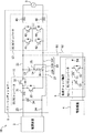
図1及び図2を参照して、実施形態に係るパワーコンディショナー1及び電力システム10を説明する。図1は、実施形態に係るパワーコンディショナー1の一例を示す図である。図2は、実施形態に係る電力システム10の一例を示す図である。電力システム10は、パワーコンディショナー1、電源装置2、電源装置4、直流チョッパ装置5を備える。直流チョッパ装置5は、チョッパ装置の一例である。パワーコンディショナー1は、DC/DCコンバータ11及びDC/ACインバータ12を備える。DC/DCコンバータ11は、第1のDC/DCコンバータの一例である。図1及び図2の例では、DC/DCコンバータ11は、双方向DC/DCコンバータである。図1及び図2の例に限らず、DC/DCコンバータ11は、昇圧コンバータであってもよい。DC/DCコンバータ11が昇圧コンバータである場合、DC/DCコンバータ11には、スイッチング素子32に代えてダイオードが用いられる。
With reference to FIG.1 and FIG.2, the
電源装置2及び電源装置4は、充放電可能な二次電池を有する蓄電池ユニットであってもよいし、発電可能な装置(発電装置)であってもよい。電源装置2は、第1の電源装置の一例である。電源装置4は、第2の電源装置の一例である。充放電可能な二次電池として、例えば、リチウムイオン電池やその他各種の二次電池を適用可能である。発電装置は、太陽電池(PV)ユニット、燃料電池(FC)ユニット及び風力発電ユニット等が例示される。直流チョッパ装置5は、電源装置4から出力される直流電力の電圧を昇圧するDC/DCコンバータ50を備える。DC/DCコンバータ50は、第2のDC/DCコンバータの一例である。DC/DCコンバータ50は、リアクトル51、スイッチング素子52、平滑コンデンサ53、ダイオード54を有する。DC/DCコンバータ50は、双方向DC/DCコンバータであってもよい。この場合、DC/DCコンバータ50は、電
源装置4から出力される直流電力の電圧を昇圧すると共に、パワーコンディショナー1から出力される直流電力の電圧を降圧する。DC/DCコンバータ50が双方向DC/DCコンバータである場合、DC/DCコンバータ50には、ダイオード54に代えてスイッチング素子が用いられる。直流チョッパ装置5は、第3プラス側配線61及び第3マイナス側配線62を備える。第3プラス側配線61及び第3マイナス側配線62を介して、直流チョッパ装置5がパワーコンディショナー1に接続されている。直流チョッパ装置5は、パワーコンディショナー1に着脱可能である。パワーコンディショナー1に直流チョッパ装置5を取り付けていない場合であっても、パワーコンディショナー1は単独で動作可能である。図2の例では、直流チョッパ装置5の個数は1つであるが、図2の例に限定されない。直流チョッパ装置5は複数であってもよく、直流チョッパ装置5の個数は増減可能である。
The
図2の例では、第3プラス側配線61が第1プラス側配線21に接続され、第3マイナス側配線62がマイナス側配線22Cに接続されている。図2の例に限らず、第3プラス側配線61が第1プラス側配線21に接続され、第3マイナス側配線62が接続配線27に接続されてもよい。また、第3プラス側配線61が第1プラス側配線21に接続され、第3マイナス側配線62がヒューズ14と接続点26との間におけるマイナス側配線22Bに接続されてもよい。スイッチング素子52の一端がダイオード54に接続され、ダイオード54の一端が第3プラス側配線61に接続されている。また、スイッチング素子52の他端が第3マイナス側配線62に接続されている。
In the example of FIG. 2, the third
図3及び図4を参照して、DC/DCコンバータ11内の短絡の発生、DC/ACインバータ12内の短絡の発生、DC/DCコンバータ50内の短絡の発生について説明する。図3及び図4は、パワーコンディショナー1の拡大図である。図3の矢印A1は、スイッチング素子32、33の誤動作や故障により、スイッチング素子32、33が常時ONとなった場合の短絡電流の流れを示している。スイッチング素子32、33の誤動作や故障により、スイッチング素子32、33が常時ONとなった場合、DC/DCコンバータ11内で短絡が発生する。図3に示すように、平滑コンデンサ13の一端が、第1プラス側配線21に接続され、平滑コンデンサ13の他端が、接続点25に接続されているため、DC/DCコンバータ11内で発生した短絡電流が、接続配線27、マイナス側配線22Bを流れる。ヒューズ14が、接続点25と接続点26との間におけるマイナス側配線22Bに設けられている。そのため、マイナス側配線22Bに定格以上の短絡電流が流れた場合、ヒューズ14が溶断することで、第1マイナス側配線22が遮断される。DC/DCコンバータ11内で短絡が発生した場合、第1マイナス側配線22が遮断されることにより、パワーコンディショナー1から電源装置2への異常電流の流れ込みが抑制され、電源装置2の故障を回避することができる。同様に、電源装置2からパワーコンディショナー1への異常電流の流れ込みが抑制され、パワーコンディショナー1の故障を回避することができる。
The occurrence of a short circuit in the DC /
図3の矢印A2は、スイッチング素子41、42の誤動作や故障により、スイッチング素子41、42が常時ONとなった場合の短絡電流の流れを示している。スイッチング素子41、42の誤動作や故障により、スイッチング素子41、42が常時ONとなった場合、DC/ACインバータ12内で短絡が発生する。図3に示すように、平滑コンデンサ13の一端が、第1プラス側配線21に接続され、平滑コンデンサ13の他端が、接続点25に接続されているため、DC/ACインバータ12内で発生した短絡電流が、マイナス側配線22C、マイナス側配線22Bを流れる。ヒューズ14が、接続点25と接続点26との間におけるマイナス側配線22Bに設けられている。そのため、マイナス側配線22Bに定格以上の短絡電流が流れた場合、ヒューズ14が溶断することで、第1マイナス側配線22が遮断される。DC/ACインバータ12内で短絡が発生した場合、第1マイナス側配線22が遮断されることにより、パワーコンディショナー1から電源装置2へ
の異常電流の流れ込みが抑制され、電源装置2の故障を回避することができる。同様に、電源装置2からパワーコンディショナー1への異常電流の流れ込みが抑制され、パワーコンディショナー1の故障を回避することができる。
An arrow A2 in FIG. 3 indicates a flow of a short-circuit current when the switching
図4の矢印A3は、ダイオード54が故障後のスイッチング素子52の誤動作や故障により、スイッチング素子52が常時ONとなった場合の短絡電流の流れを示している。スイッチング素子52の誤動作や故障により、スイッチング素子52が常時ONとなった場合、DC/DCコンバータ50内で短絡が発生する。なお、図4の例では、ダイオード54が故障した場合の例を示している。また、第3プラス側配線61及び第3マイナス側配線62が短絡することにより、短絡電流が図4の矢印A3のように流れる場合もある。図4に示すように、平滑コンデンサ13の一端が、第1プラス側配線21に接続され、平滑コンデンサ13の他端が、接続点25に接続されているため、DC/DCコンバータ50内で発生した短絡電流が、マイナス側配線22C、マイナス側配線22Bを流れる。ヒューズ14が、接続点25と接続点26との間におけるマイナス側配線22Bに設けられている。そのため、マイナス側配線22Bに定格以上の短絡電流が流れた場合、ヒューズ14が溶断することで、第1マイナス側配線22が遮断される。DC/DCコンバータ50内で短絡が発生した場合、第1マイナス側配線22が遮断されることにより、パワーコンディショナー1から電源装置2への異常電流の流れ込みが抑制され、電源装置2の故障を回避することができる。同様に、電源装置2からパワーコンディショナー1への異常電流の流れ込みが抑制され、パワーコンディショナー1の故障を回避することができる。
An arrow A3 in FIG. 4 indicates the flow of a short-circuit current when the switching
DC/DCコンバータ11内の短絡の発生、DC/ACインバータ12内の短絡の発生及びDC/DCコンバータ50内の短絡の発生のいずれの場合にも、ヒューズ14が溶断することで、第1マイナス側配線22が遮断される。したがって、実施形態によれば、パワーコンディショナー1の部品点数を削減し、パワーコンディショナー1の小型化、低コスト化を図ることができる。また、実施形態によれば、直流チョッパ装置5の部品点数を削減することにより、電力システム10の部品点数を削減することができる。これにより、電力システム10の小型化、低コスト化を図ることができる。
In any case of occurrence of a short circuit in the DC /
ここで、パワーコンディショナー1のDC/DCコンバータ11と電源装置2との対応関係について説明する。電源装置2が蓄電池ユニットである場合、DC/DCコンバータ11として双方向DC/DCコンバータが用いられる。電源装置2が発電装置である場合、DC/DCコンバータ11として昇圧コンバータ又は双方向DC/DCコンバータが用いられる。また、直流チョッパ装置5のDC/DCコンバータ50と電源装置4との対応関係について説明する。電源装置4が蓄電池ユニットである場合、DC/DCコンバータ50として双方向コンバータが用いられる。電源装置4が発電装置である場合、DC/DCコンバータ50として昇圧コンバータ又は双方向DC/DCコンバータが用いられる。
Here, the correspondence relationship between the DC /
図5は、実施形態に係る電力システム10のブロック図である。図5に示すように、パワーコンディショナー1に対して複数の直流チョッパ装置5を接続することが可能である。各直流チョッパ装置5が、第1プラス側配線21及びマイナス側配線22Cに接続されている。複数の直流チョッパ装置5の少なくとも一つが、第1プラス側配線21及び接続配線27に接続されてもよい。複数の直流チョッパ装置5の少なくとも一つが、第1プラス側配線21に接続されると共に、ヒューズ14と接続点26との間のマイナス側配線22Bに接続されてもよい。
FIG. 5 is a block diagram of the
上記のように、パワーコンディショナー1において、ヒューズ14が、接続点25と接続点26との間に配置されている。また、図6に示すように、パワーコンディショナー1では、矢印B1の配線経路が長くなっている。そのため、寄生インダクタンス及びヒューズ14のインダクタンスが増加することで、パワーコンディショナー1におけるノイズが
悪化する。なお、スイッチング素子32がOFFであり、スイッチング素子33がONである場合、図6の矢印B1の経路に沿って電流が流れる。
As described above, in the
以下では、パワーコンディショナー1におけるノイズを低減するための実施形態の構成について説明する。図7は、パワーコンディショナー1の拡大図である。図7に示すように、マイナス側配線22Aと接続配線27との間にノイズ除去用のコンデンサ71が配置されている。コンデンサ71は、直流電力の高周波成分を除去する。コンデンサ71は、基板に導体パターンで形成されてもよい。コンデンサ71の一端が、ヒューズ14よりもDC/DCコンバータ11側における第1マイナス側配線22に接続され、コンデンサ71の他端が、接続配線27を介して、ヒューズ14よりもDC/ACインバータ12側における第1マイナス側配線22に接続されている。マイナス側配線22Aと接続配線27との間にコンデンサ71が配置されているため、直流電力の高周波成分は、図7の矢印B2の経路における配線を通るが、図7の矢印B1の経路における配線を通らない。コンデンサ71によって直流電力の高周波成分が除去されることで、パワーコンディショナー1におけるノイズが低減する。
Below, the structure of embodiment for reducing the noise in the
図8は、パワーコンディショナー1が備える基板80の断面図である。パワーコンディショナー1は、基板80、第1配線81及び第2配線82を備える。図8に示すように、基板80の第1面(表面)83に第1配線81が形成され、基板80の第2面(裏面)84に第2配線82が形成されている。図8に示すように、第1配線81及び第2配線82が、基板80の第1面83の法線方向(又は第2面84の法線方向)から見て重なり合ってもよい。基板80の第2面84は、基板80の第1面83の反対面である。例えば、基板80に対して導体パターンにより第1配線81及び第2配線82を形成してもよい。図8の例に限らず、基板80の第1面83に第2配線82を形成し、基板80の第2面84に第1配線81を形成してもよい。また、第1配線81の一部及び第2配線82の一部が、基板80の第1面83の法線方向(又は第2面84の法線方向)から見て重なり合ってもよい。この場合、基板80の第1面83の法線方向(又は第2面84の法線方向)で重なり合った第1配線81及び第2配線82を流れる電流の方向が互いに逆方向である。図8の例では、第1配線81を流れる電流の方向(矢印C1の方向)と第2配線82を流れる電流の方向(矢印C2の方向)とが互いに逆方向である。したがって、第1配線81の周りに発生する電界と第2配線82の周りに発生する電界とが打ち消し合い、第1配線81の周りに発生する磁界と第2配線82の周りに発生する磁界とが打ち消し合う。これにより、基板80の第1面83の法線方向(又は第2面84の法線方向)から見て重なり合った第1配線81及び第2配線82の寄生インダクタンスが低減する。この結果、図7の矢印B2の経路における配線の寄生インダクタンスが低減し、パワーコンディショナー1におけるノイズが低減する。
FIG. 8 is a cross-sectional view of the
例えば、第1配線81は、図7の矢印B1の経路における接続点25から接続点28までの配線を含み、第2配線82は、図7の矢印B1の経路における接続点26から接続点25までの配線を含んでもよい。接続点28は、接続点25よりもDC/DCコンバータ11側における第1マイナス側配線22に設けられている。コンデンサ71の一端が、接続点28に接続されている。例えば、第1配線81は、図7の矢印B1の経路におけるヒューズ14から接続点28までの配線を含み、第2配線82は、図7の矢印B1の経路における接続点26からヒューズ14までの配線を含んでもよい。このように、第1配線81は、第1マイナス側配線22の第1部分を含み、第2配線82は、第1マイナス側配線22の第2部分を含んでもよい。第1マイナス側配線22の第2部分は、第1マイナス側配線22の第1部分と異なる。
For example, the
例えば、第1配線81は、図7の矢印B1の経路に接続点25から接続点28までの配線を含み、第2配線82は、図7の矢印B1の経路におけるスイッチング素子33から接
続点25までの配線を含んでもよい。例えば、第1配線81は、図7の矢印B1の経路にヒューズ14から接続点28までの配線を含み、第2配線82は、図7の矢印B1の経路におけるスイッチング素子33からヒューズ14までの配線を含んでもよい。このように、第1配線81は、第1マイナス側配線22の第1部分を含み、第2配線82は、接続配線27及び第1マイナス側配線22の第2部分を含んでもよい。
For example, the
例えば、第1配線81は、図7の矢印B1の経路に接続点26から接続点28までの配線を含み、第2配線82は、図7の矢印B1の経路におけるスイッチング素子33から接続点26までの配線を含んでもよい。このように、第1配線81は、第1マイナス側配線22の第1部分を含み、第2配線82は、接続配線27を含んでもよい。
For example, the
第1配線81の配線長が第2配線82の配線長よりも短くてもよい。例えば、図7の矢印B1の経路において、接続点25から接続点28までの配線の配線長が、スイッチング素子33から接続点25までの配線の配線長よりも短くてもよい。また、第1配線81の配線長と第2配線82の配線長とが同一であってもよい。例えば、図7の矢印B1の経路において、接続点25から接続点28までの配線の配線長と、スイッチング素子33から接続点25までの配線の配線長とが同一であってもよい。
The wiring length of the
<付記>
[1]電源装置(2)に接続されたDC/DCコンバータ(11)と、前記DC/DCコンバータ(11)に接続されたインバータ(12)とを備えるパワーコンディショナー(1)であって、
前記DC/DCコンバータ(11)と前記インバータ(12)とを接続するプラス側配線(21)と、
前記DC/DCコンバータ(11)と前記インバータ(12)とを接続するマイナス側配線(22)と、
一端が前記プラス側配線(21)に接続され、他端が前記マイナス側配線(22)に接続されたコンデンサ(13)と、
前記マイナス側配線(22)に設けられたヒューズ(14)と、
を備え、
前記DC/DCコンバータ(11)は、少なくとも一つのスイッチング素子(33)を有し、
前記コンデンサ(13)の前記他端が、前記ヒューズ(14)よりも前記DC/DCコンバータ(11)側における前記マイナス側配線(22)に設けられた第1接続点(25)に接続されており、
前記スイッチング素子(33)が、前記ヒューズ(14)よりも前記インバータ(12)側における前記マイナス側配線(22)に設けられた第2接続点(26)に接続されている、
ことを特徴とするパワーコンディショナー(1)。
<Appendix>
[1] A power conditioner (1) comprising a DC / DC converter (11) connected to a power supply device (2) and an inverter (12) connected to the DC / DC converter (11),
A plus-side wiring (21) connecting the DC / DC converter (11) and the inverter (12);
A negative-side wiring (22) connecting the DC / DC converter (11) and the inverter (12);
A capacitor (13) having one end connected to the plus side wiring (21) and the other end connected to the minus side wiring (22);
A fuse (14) provided in the negative side wiring (22);
With
The DC / DC converter (11) has at least one switching element (33),
The other end of the capacitor (13) is connected to a first connection point (25) provided on the minus side wiring (22) on the DC / DC converter (11) side than the fuse (14). And
The switching element (33) is connected to a second connection point (26) provided on the minus side wiring (22) on the inverter (12) side than the fuse (14).
Power conditioner (1) characterized by this.
[2]パワーコンディショナー(1)とチョッパ装置(5)とを備える電力システム(10)であって、
前記パワーコンディショナー(1)は、
第1の電源装置(2)に接続され、少なくとも一つのスイッチング素子を有する第1のDC/DCコンバータ(11)と、
前記第1のDC/DCコンバータ(11)に接続されたインバータ(12)と、
前記第1のDC/DCコンバータ(11)と前記インバータ(12)とを接続するプラス側配線(21)と、
前記第1のDC/DCコンバータ(11)と前記インバータ(12)とを接続するマイナス側配線(22)と、
一端が前記プラス側配線(21)に接続され、他端が前記マイナス側配線(22)に接続されたコンデンサ(13)と、
前記マイナス側配線(22)に設けられたヒューズ(14)と、
前記スイッチング素子(33)を前記マイナス側配線(22)に接続する接続配線(27)と、
を有し、
前記チョッパ装置(5)は、
第2の電源装置(4)に接続された第2のDC/DCコンバータと、
前記第2のDC/DCコンバータに接続されたプラス側接続配線(61)と、
前記第2のDC/DCコンバータに接続されたマイナス側接続配線(62)と、
を有し、
前記コンデンサ(13)の前記他端が、前記ヒューズ(14)よりも前記第1のDC/DCコンバータ(11)側における前記マイナス側配線(22)に設けられた第1接続点(25)に接続されており、
前記スイッチング素子(33)が、前記ヒューズ(14)よりも前記インバータ(12)側における前記マイナス側配線(22)に設けられた第2接続点(26)に接続されており、
前記プラス側接続配線(61)が、前記プラス側配線(21)に接続されており、
前記マイナス側接続配線(62)が、前記ヒューズ(14)よりも前記インバータ(12)側における前記マイナス側配線(22)、又は、前記接続配線(27)に接続されている、
ことを特徴とする電力システム(10)。
[2] A power system (10) comprising a power conditioner (1) and a chopper device (5),
The power conditioner (1)
A first DC / DC converter (11) connected to the first power supply (2) and having at least one switching element;
An inverter (12) connected to the first DC / DC converter (11);
A plus-side wiring (21) connecting the first DC / DC converter (11) and the inverter (12);
A negative-side wiring (22) connecting the first DC / DC converter (11) and the inverter (12);
A capacitor (13) having one end connected to the plus side wiring (21) and the other end connected to the minus side wiring (22);
A fuse (14) provided in the negative side wiring (22);
A connection wiring (27) for connecting the switching element (33) to the negative wiring (22);
Have
The chopper device (5)
A second DC / DC converter connected to the second power supply (4);
A positive connection wiring (61) connected to the second DC / DC converter;
A negative connection wiring (62) connected to the second DC / DC converter;
Have
The other end of the capacitor (13) is connected to a first connection point (25) provided on the minus side wiring (22) on the first DC / DC converter (11) side than the fuse (14). Connected,
The switching element (33) is connected to a second connection point (26) provided on the minus side wiring (22) on the inverter (12) side of the fuse (14),
The plus side connection wiring (61) is connected to the plus side wiring (21),
The minus side connection wiring (62) is connected to the minus side wiring (22) or the connection wiring (27) closer to the inverter (12) than the fuse (14).
A power system (10) characterized by that.
1 パワーコンディショナー
2 電源装置
3 電力系統
4 電源装置
5 直流チョッパ装置
10 電力システム
11 DC/DCコンバータ
12 DC/ACコンバータ
13 平滑コンデンサ
14 ヒューズ
21 第1プラス側配線
22 第1マイナス側配線
31 リアクトル
32、33 スイッチング素子
DESCRIPTION OF
Claims (6)
前記DC/DCコンバータと前記インバータとを接続するプラス側配線と、
前記DC/DCコンバータと前記インバータとを接続するマイナス側配線と、
一端が前記プラス側配線に接続され、他端が前記マイナス側配線に接続されたコンデンサと、
前記マイナス側配線に設けられたヒューズと、
を備え、
前記DC/DCコンバータは、少なくとも一つのスイッチング素子を有し、
前記コンデンサの前記他端が、前記ヒューズよりも前記DC/DCコンバータ側における前記マイナス側配線に設けられた第1接続点に接続されており、
前記スイッチング素子が、前記ヒューズよりも前記インバータ側における前記マイナス側配線に設けられた第2接続点に接続されている、
ことを特徴とするパワーコンディショナー。 A power conditioner comprising a DC / DC converter connected to a power supply device and an inverter connected to the DC / DC converter,
A plus-side wiring connecting the DC / DC converter and the inverter;
A negative side wiring connecting the DC / DC converter and the inverter;
A capacitor having one end connected to the plus side wiring and the other end connected to the minus side wiring;
A fuse provided in the negative side wiring;
With
The DC / DC converter has at least one switching element,
The other end of the capacitor is connected to a first connection point provided on the negative wiring on the DC / DC converter side than the fuse,
The switching element is connected to a second connection point provided on the minus side wiring on the inverter side of the fuse;
Power conditioner characterized by that.
前記第2のDC/DCコンバータに接続されたマイナス側接続配線が、前記ヒューズよりも前記インバータ側における前記マイナス側配線、又は、前記スイッチング素子を前記第2接続点に接続する接続配線に接続されている、
ことを特徴とする請求項1に記載のパワーコンディショナー。 The plus side connection wiring connected to the second DC / DC converter included in the chopper device is connected to the plus side wiring,
The negative connection wiring connected to the second DC / DC converter is connected to the negative wiring on the inverter side of the fuse or the connection wiring connecting the switching element to the second connection point. ing,
The power conditioner according to claim 1.
前記電源装置は、蓄電池ユニットである、
ことを特徴とする請求項1又は2に記載のパワーコンディショナー。 The DC / DC converter is a bidirectional DC / DC converter,
The power supply device is a storage battery unit.
The power conditioner according to claim 1 or 2.
ことを特徴とする請求項1から3の何れか一項に記載のパワーコンディショナー。 A second capacitor having one end connected to the minus side wiring on the DC / DC converter side of the fuse and the other end connected to the minus side wiring on the inverter side of the fuse;
The power conditioner as described in any one of Claim 1 to 3 characterized by the above-mentioned.
前記基板の第1面に形成された第1配線と、
前記基板の前記第1面の反対側の第2面に形成された第2配線と、
を備え、
前記第1配線の少なくとも一部及び前記第2配線の少なくとも一部が、前記第1面の法線方向から見て重なり合っており、
前記第1面の法線方向から見て重なり合った前記第1配線及び前記第2配線を流れる電流の方向が互いに逆方向であり、
前記第1配線は、前記マイナス側配線の第1部分を含み、
前記第2配線は、前記マイナス側配線の前記第1部分と異なる第2部分を含み、又は、前記第2配線は、前記スイッチング素子を前記第2接続点に接続する接続配線及び前記第2部分を含み、或いは、前記第2配線は、前記接続配線を含む、
ことを特徴とする請求項1から4の何れか一項に記載のパワーコンディショナー。 A substrate,
A first wiring formed on the first surface of the substrate;
A second wiring formed on the second surface opposite to the first surface of the substrate;
With
At least a part of the first wiring and at least a part of the second wiring overlap each other when viewed from the normal direction of the first surface;
Directions of currents flowing through the first wiring and the second wiring overlapped when viewed from the normal direction of the first surface are opposite to each other;
The first wiring includes a first portion of the negative wiring,
The second wiring includes a second part different from the first part of the minus-side wiring, or the second wiring includes a connection wiring that connects the switching element to the second connection point and the second part. Alternatively, the second wiring includes the connection wiring.
The power conditioner according to any one of claims 1 to 4, wherein the power conditioner is provided.
前記パワーコンディショナーは、
第1の電源装置に接続され、少なくとも一つのスイッチング素子を有する第1のDC/
DCコンバータと、
前記第1のDC/DCコンバータに接続されたインバータと、
前記第1のDC/DCコンバータと前記インバータとを接続するプラス側配線と、
前記第1のDC/DCコンバータと前記インバータとを接続するマイナス側配線と、
一端が前記プラス側配線に接続され、他端が前記マイナス側配線に接続されたコンデンサと、
前記マイナス側配線に設けられたヒューズと、
前記スイッチング素子を前記マイナス側配線に接続する接続配線と、
を有し、
前記チョッパ装置は、
第2の電源装置に接続された第2のDC/DCコンバータと、
前記第2のDC/DCコンバータに接続されたプラス側接続配線と、
前記第2のDC/DCコンバータに接続されたマイナス側接続配線と、
を有し、
前記コンデンサの前記他端が、前記ヒューズよりも前記第1のDC/DCコンバータ側における前記マイナス側配線に設けられた第1接続点に接続されており、
前記スイッチング素子が、前記ヒューズよりも前記インバータ側における前記マイナス側配線に設けられた第2接続点に接続されており、
前記プラス側接続配線が、前記プラス側配線に接続されており、
前記マイナス側接続配線が、前記ヒューズよりも前記インバータ側における前記マイナス側配線、又は、前記接続配線に接続されている、
ことを特徴とする電力システム。 A power system comprising a power conditioner and a chopper device,
The power conditioner is
A first DC / DC connected to the first power supply and having at least one switching element
A DC converter;
An inverter connected to the first DC / DC converter;
A positive-side wiring connecting the first DC / DC converter and the inverter;
A minus side wiring connecting the first DC / DC converter and the inverter;
A capacitor having one end connected to the plus side wiring and the other end connected to the minus side wiring;
A fuse provided in the negative side wiring;
A connection wiring for connecting the switching element to the negative wiring;
Have
The chopper device is
A second DC / DC converter connected to the second power supply;
A positive connection wiring connected to the second DC / DC converter;
A minus side connection wiring connected to the second DC / DC converter;
Have
The other end of the capacitor is connected to a first connection point provided on the negative wiring on the first DC / DC converter side than the fuse,
The switching element is connected to a second connection point provided on the minus side wiring on the inverter side of the fuse;
The positive connection wiring is connected to the positive wiring;
The negative side connection wiring is connected to the negative side wiring on the inverter side of the fuse, or to the connection wiring,
A power system characterized by that.
Priority Applications (2)
| Application Number | Priority Date | Filing Date | Title |
|---|---|---|---|
| US16/219,915 US10381834B1 (en) | 2018-03-08 | 2018-12-13 | Power conditioner and power system |
| TW107145553A TW201939860A (en) | 2018-03-08 | 2018-12-18 | Power conditioner and power system |
Applications Claiming Priority (2)
| Application Number | Priority Date | Filing Date | Title |
|---|---|---|---|
| JP2018042236 | 2018-03-08 | ||
| JP2018042236 | 2018-03-08 |
Publications (2)
| Publication Number | Publication Date |
|---|---|
| JP2019162012A true JP2019162012A (en) | 2019-09-19 |
| JP7073942B2 JP7073942B2 (en) | 2022-05-24 |
Family
ID=67992770
Family Applications (1)
| Application Number | Title | Priority Date | Filing Date |
|---|---|---|---|
| JP2018122351A Active JP7073942B2 (en) | 2018-03-08 | 2018-06-27 | Power conditioner and power system |
Country Status (2)
| Country | Link |
|---|---|
| JP (1) | JP7073942B2 (en) |
| TW (1) | TW201939860A (en) |
Citations (5)
| Publication number | Priority date | Publication date | Assignee | Title |
|---|---|---|---|---|
| JPS507033A (en) * | 1973-05-23 | 1975-01-24 | ||
| JP2005159106A (en) * | 2003-11-27 | 2005-06-16 | Shizuki Electric Co Inc | Connection structure of laminated capacitor |
| JP2014220918A (en) * | 2013-05-08 | 2014-11-20 | 株式会社デンソー | Electronic control device |
| JP2017093212A (en) * | 2015-11-13 | 2017-05-25 | オムロン株式会社 | Power conversion apparatus |
| JP2017103949A (en) * | 2015-12-03 | 2017-06-08 | トヨタ自動車株式会社 | Power supply system |
-
2018
- 2018-06-27 JP JP2018122351A patent/JP7073942B2/en active Active
- 2018-12-18 TW TW107145553A patent/TW201939860A/en unknown
Patent Citations (5)
| Publication number | Priority date | Publication date | Assignee | Title |
|---|---|---|---|---|
| JPS507033A (en) * | 1973-05-23 | 1975-01-24 | ||
| JP2005159106A (en) * | 2003-11-27 | 2005-06-16 | Shizuki Electric Co Inc | Connection structure of laminated capacitor |
| JP2014220918A (en) * | 2013-05-08 | 2014-11-20 | 株式会社デンソー | Electronic control device |
| JP2017093212A (en) * | 2015-11-13 | 2017-05-25 | オムロン株式会社 | Power conversion apparatus |
| JP2017103949A (en) * | 2015-12-03 | 2017-06-08 | トヨタ自動車株式会社 | Power supply system |
Also Published As
| Publication number | Publication date |
|---|---|
| TW201939860A (en) | 2019-10-01 |
| JP7073942B2 (en) | 2022-05-24 |
Similar Documents
| Publication | Publication Date | Title |
|---|---|---|
| JP4322250B2 (en) | Transformer-less grid-connected power conversion circuit | |
| Aleenejad et al. | A fault-tolerant strategy based on fundamental phase-shift compensation for three-phase multilevel converters with quasi-Z-source networks with discontinuous input current | |
| JP5860720B2 (en) | Power converter, DC substation, DC power transmission system, and method for controlling power converter | |
| US10214108B2 (en) | DC voltage source including electrochemical cells having an adaptive voltage level | |
| JP5520722B2 (en) | Grid-connected inverter system | |
| US20160001674A1 (en) | Apparatus for providing an electric voltage with a serial stack converter and a drive arrangement | |
| JP2017135889A (en) | Power conversion device, and power conversion system | |
| CN105659488A (en) | Charging circuit for an energy storage device and method for charging an energy storage device | |
| JP2009273355A (en) | Apparatus for transmitting electric power | |
| EP4346047A1 (en) | Power conversion apparatus and energy storage system | |
| JP2017022872A (en) | Power supply system | |
| JP5513791B2 (en) | Power conversion device for solar cell and solar power generation system including the same | |
| JP6953634B2 (en) | Vehicle charger with DC / DC converter | |
| JP7073942B2 (en) | Power conditioner and power system | |
| US10381834B1 (en) | Power conditioner and power system | |
| JP2010022104A (en) | Power converter for fuel cell | |
| JP4351008B2 (en) | Uninterruptible power system | |
| Tironi et al. | DC networks including multi-port DC/DC converters: Fault analysis | |
| JP2008252987A (en) | Power supply system | |
| JP6444204B2 (en) | Power converter | |
| JP6407775B2 (en) | Power storage device | |
| JP7293459B2 (en) | power converter | |
| JP2019050652A (en) | Power conversion device | |
| JP7072989B2 (en) | Power storage system | |
| US20230099142A1 (en) | Power supply system |
Legal Events
| Date | Code | Title | Description |
|---|---|---|---|
| A621 | Written request for application examination |
Free format text: JAPANESE INTERMEDIATE CODE: A621 Effective date: 20210301 |
|
| A977 | Report on retrieval |
Free format text: JAPANESE INTERMEDIATE CODE: A971007 Effective date: 20220118 |
|
| A131 | Notification of reasons for refusal |
Free format text: JAPANESE INTERMEDIATE CODE: A131 Effective date: 20220125 |
|
| A521 | Request for written amendment filed |
Free format text: JAPANESE INTERMEDIATE CODE: A523 Effective date: 20220328 |
|
| TRDD | Decision of grant or rejection written | ||
| A01 | Written decision to grant a patent or to grant a registration (utility model) |
Free format text: JAPANESE INTERMEDIATE CODE: A01 Effective date: 20220412 |
|
| A61 | First payment of annual fees (during grant procedure) |
Free format text: JAPANESE INTERMEDIATE CODE: A61 Effective date: 20220425 |
|
| R150 | Certificate of patent or registration of utility model |
Ref document number: 7073942 Country of ref document: JP Free format text: JAPANESE INTERMEDIATE CODE: R150 |