JP2019160102A - Information display device and program - Google Patents
Information display device and program Download PDFInfo
- Publication number
- JP2019160102A JP2019160102A JP2018048720A JP2018048720A JP2019160102A JP 2019160102 A JP2019160102 A JP 2019160102A JP 2018048720 A JP2018048720 A JP 2018048720A JP 2018048720 A JP2018048720 A JP 2018048720A JP 2019160102 A JP2019160102 A JP 2019160102A
- Authority
- JP
- Japan
- Prior art keywords
- image
- displayed
- information processing
- processing apparatus
- user
- Prior art date
- Legal status (The legal status is an assumption and is not a legal conclusion. Google has not performed a legal analysis and makes no representation as to the accuracy of the status listed.)
- Pending
Links
Images


Classifications
-
- G—PHYSICS
- G06—COMPUTING; CALCULATING OR COUNTING
- G06F—ELECTRIC DIGITAL DATA PROCESSING
- G06F3/00—Input arrangements for transferring data to be processed into a form capable of being handled by the computer; Output arrangements for transferring data from processing unit to output unit, e.g. interface arrangements
- G06F3/12—Digital output to print unit, e.g. line printer, chain printer
- G06F3/1201—Dedicated interfaces to print systems
- G06F3/1223—Dedicated interfaces to print systems specifically adapted to use a particular technique
- G06F3/1237—Print job management
- G06F3/1253—Configuration of print job parameters, e.g. using UI at the client
- G06F3/1256—User feedback, e.g. print preview, test print, proofing, pre-flight checks
-
- H—ELECTRICITY
- H04—ELECTRIC COMMUNICATION TECHNIQUE
- H04N—PICTORIAL COMMUNICATION, e.g. TELEVISION
- H04N1/00—Scanning, transmission or reproduction of documents or the like, e.g. facsimile transmission; Details thereof
- H04N1/0035—User-machine interface; Control console
- H04N1/00405—Output means
- H04N1/00408—Display of information to the user, e.g. menus
- H04N1/00411—Display of information to the user, e.g. menus the display also being used for user input, e.g. touch screen
-
- G—PHYSICS
- G06—COMPUTING; CALCULATING OR COUNTING
- G06F—ELECTRIC DIGITAL DATA PROCESSING
- G06F3/00—Input arrangements for transferring data to be processed into a form capable of being handled by the computer; Output arrangements for transferring data from processing unit to output unit, e.g. interface arrangements
- G06F3/01—Input arrangements or combined input and output arrangements for interaction between user and computer
- G06F3/048—Interaction techniques based on graphical user interfaces [GUI]
- G06F3/0481—Interaction techniques based on graphical user interfaces [GUI] based on specific properties of the displayed interaction object or a metaphor-based environment, e.g. interaction with desktop elements like windows or icons, or assisted by a cursor's changing behaviour or appearance
- G06F3/04817—Interaction techniques based on graphical user interfaces [GUI] based on specific properties of the displayed interaction object or a metaphor-based environment, e.g. interaction with desktop elements like windows or icons, or assisted by a cursor's changing behaviour or appearance using icons
-
- G—PHYSICS
- G06—COMPUTING; CALCULATING OR COUNTING
- G06F—ELECTRIC DIGITAL DATA PROCESSING
- G06F3/00—Input arrangements for transferring data to be processed into a form capable of being handled by the computer; Output arrangements for transferring data from processing unit to output unit, e.g. interface arrangements
- G06F3/01—Input arrangements or combined input and output arrangements for interaction between user and computer
- G06F3/048—Interaction techniques based on graphical user interfaces [GUI]
- G06F3/0481—Interaction techniques based on graphical user interfaces [GUI] based on specific properties of the displayed interaction object or a metaphor-based environment, e.g. interaction with desktop elements like windows or icons, or assisted by a cursor's changing behaviour or appearance
- G06F3/0482—Interaction with lists of selectable items, e.g. menus
-
- G—PHYSICS
- G06—COMPUTING; CALCULATING OR COUNTING
- G06F—ELECTRIC DIGITAL DATA PROCESSING
- G06F3/00—Input arrangements for transferring data to be processed into a form capable of being handled by the computer; Output arrangements for transferring data from processing unit to output unit, e.g. interface arrangements
- G06F3/01—Input arrangements or combined input and output arrangements for interaction between user and computer
- G06F3/048—Interaction techniques based on graphical user interfaces [GUI]
- G06F3/0484—Interaction techniques based on graphical user interfaces [GUI] for the control of specific functions or operations, e.g. selecting or manipulating an object, an image or a displayed text element, setting a parameter value or selecting a range
- G06F3/04842—Selection of displayed objects or displayed text elements
-
- G—PHYSICS
- G06—COMPUTING; CALCULATING OR COUNTING
- G06F—ELECTRIC DIGITAL DATA PROCESSING
- G06F3/00—Input arrangements for transferring data to be processed into a form capable of being handled by the computer; Output arrangements for transferring data from processing unit to output unit, e.g. interface arrangements
- G06F3/01—Input arrangements or combined input and output arrangements for interaction between user and computer
- G06F3/048—Interaction techniques based on graphical user interfaces [GUI]
- G06F3/0484—Interaction techniques based on graphical user interfaces [GUI] for the control of specific functions or operations, e.g. selecting or manipulating an object, an image or a displayed text element, setting a parameter value or selecting a range
- G06F3/04845—Interaction techniques based on graphical user interfaces [GUI] for the control of specific functions or operations, e.g. selecting or manipulating an object, an image or a displayed text element, setting a parameter value or selecting a range for image manipulation, e.g. dragging, rotation, expansion or change of colour
-
- G—PHYSICS
- G06—COMPUTING; CALCULATING OR COUNTING
- G06F—ELECTRIC DIGITAL DATA PROCESSING
- G06F3/00—Input arrangements for transferring data to be processed into a form capable of being handled by the computer; Output arrangements for transferring data from processing unit to output unit, e.g. interface arrangements
- G06F3/01—Input arrangements or combined input and output arrangements for interaction between user and computer
- G06F3/048—Interaction techniques based on graphical user interfaces [GUI]
- G06F3/0484—Interaction techniques based on graphical user interfaces [GUI] for the control of specific functions or operations, e.g. selecting or manipulating an object, an image or a displayed text element, setting a parameter value or selecting a range
- G06F3/04847—Interaction techniques to control parameter settings, e.g. interaction with sliders or dials
-
- G—PHYSICS
- G06—COMPUTING; CALCULATING OR COUNTING
- G06F—ELECTRIC DIGITAL DATA PROCESSING
- G06F3/00—Input arrangements for transferring data to be processed into a form capable of being handled by the computer; Output arrangements for transferring data from processing unit to output unit, e.g. interface arrangements
- G06F3/01—Input arrangements or combined input and output arrangements for interaction between user and computer
- G06F3/048—Interaction techniques based on graphical user interfaces [GUI]
- G06F3/0487—Interaction techniques based on graphical user interfaces [GUI] using specific features provided by the input device, e.g. functions controlled by the rotation of a mouse with dual sensing arrangements, or of the nature of the input device, e.g. tap gestures based on pressure sensed by a digitiser
- G06F3/0488—Interaction techniques based on graphical user interfaces [GUI] using specific features provided by the input device, e.g. functions controlled by the rotation of a mouse with dual sensing arrangements, or of the nature of the input device, e.g. tap gestures based on pressure sensed by a digitiser using a touch-screen or digitiser, e.g. input of commands through traced gestures
-
- G—PHYSICS
- G06—COMPUTING; CALCULATING OR COUNTING
- G06F—ELECTRIC DIGITAL DATA PROCESSING
- G06F3/00—Input arrangements for transferring data to be processed into a form capable of being handled by the computer; Output arrangements for transferring data from processing unit to output unit, e.g. interface arrangements
- G06F3/12—Digital output to print unit, e.g. line printer, chain printer
- G06F3/1201—Dedicated interfaces to print systems
- G06F3/1202—Dedicated interfaces to print systems specifically adapted to achieve a particular effect
- G06F3/1203—Improving or facilitating administration, e.g. print management
- G06F3/1208—Improving or facilitating administration, e.g. print management resulting in improved quality of the output result, e.g. print layout, colours, workflows, print preview
-
- G—PHYSICS
- G06—COMPUTING; CALCULATING OR COUNTING
- G06F—ELECTRIC DIGITAL DATA PROCESSING
- G06F3/00—Input arrangements for transferring data to be processed into a form capable of being handled by the computer; Output arrangements for transferring data from processing unit to output unit, e.g. interface arrangements
- G06F3/12—Digital output to print unit, e.g. line printer, chain printer
- G06F3/1201—Dedicated interfaces to print systems
- G06F3/1223—Dedicated interfaces to print systems specifically adapted to use a particular technique
- G06F3/1237—Print job management
- G06F3/1268—Job submission, e.g. submitting print job order or request not the print data itself
-
- G—PHYSICS
- G06—COMPUTING; CALCULATING OR COUNTING
- G06F—ELECTRIC DIGITAL DATA PROCESSING
- G06F3/00—Input arrangements for transferring data to be processed into a form capable of being handled by the computer; Output arrangements for transferring data from processing unit to output unit, e.g. interface arrangements
- G06F3/12—Digital output to print unit, e.g. line printer, chain printer
- G06F3/1201—Dedicated interfaces to print systems
- G06F3/1278—Dedicated interfaces to print systems specifically adapted to adopt a particular infrastructure
- G06F3/1285—Remote printer device, e.g. being remote from client or server
Abstract
Description
本発明は、情報表示装置及びプログラムに関する。 The present invention relates to an information display device and a program.
タッチ操作が可能な第1のディスプレイと、第2のディスプレイを含む電子機器に、起動アイコンを前記第1のディスプレイに表示するステップと、起動アイコンに対するタッチ操作の種類を識別するステップと、識別したタッチ操作の種類に応じて起動アイコンを関連付けたアプリケーション画像を第1のディスプレイおよび第2のディスプレイまたはいずれか一方のディスプレイに表示するステップとを有する処理を実行させるためのコンピュータ・プログラムが知られている(特許文献1)。 A step of displaying a start icon on the first display on an electronic device including a first display capable of touch operation and a second display; a step of identifying a type of touch operation on the start icon; A computer program for executing a process including a step of displaying an application image associated with a start icon in accordance with the type of touch operation on a first display and / or a second display is known. (Patent Document 1).
撮像画像と、撮像画像を取得した撮像装置の特徴を表す情報とを取得する画像取得手段と、画像取得手段により取得された撮像画像を縮小したサムネイル画像を表示し、情報に基づいて、撮像装置の特徴に応じた画像または文字をサムネイル画像と共に表示する表示手段とを備える画像表示装置も知られている(特許文献2)。 An image acquisition unit that acquires a captured image and information representing the characteristics of the imaging device that acquired the captured image, a thumbnail image obtained by reducing the captured image acquired by the image acquisition unit, and displays the captured image based on the information There is also known an image display device including display means for displaying an image or a character according to the feature of the image together with a thumbnail image (Patent Document 2).
本発明は、コンテンツの出力指示を容易に行うことができるユーザーインターフェースを提供する。 The present invention provides a user interface capable of easily instructing output of content.
前記課題を解決するために、請求項1に記載の情報処理装置は、
出力可能なコンテンツそれぞれに紐付いている画像に対して利用者の操作指示を受け付けた場合、出力指示を進める画像を表示させる表示制御手段を有する、
ことを特徴とする。
In order to solve the above problem, an information processing apparatus according to claim 1,
When a user's operation instruction is received for an image associated with each content that can be output, the display control unit displays an image that advances the output instruction.
It is characterized by that.
請求項2記載の発明は、請求項1に記載の情報処理装置において、
前記出力指示を進める画像は、前記コンテンツの表示領域に近い予め定められた位置に表示する、
ことを特徴とする。
The invention according to claim 2 is the information processing apparatus according to claim 1,
The image that advances the output instruction is displayed at a predetermined position close to the display area of the content.
It is characterized by that.
請求項3記載の発明は、請求項1に記載の情報処理装置において、
前記出力指示を進める画像は、他のオブジェクト画像と重ならない表示領域に表示する、
ことを特徴とする。
The invention according to claim 3 is the information processing apparatus according to claim 1,
The image that advances the output instruction is displayed in a display area that does not overlap other object images.
It is characterized by that.
請求項4記載の発明は、請求項1に記載の情報処理装置において、
前記出力指示を進める画像は、前記コンテンツに重ねて表示する、
ことを特徴とする。
The invention according to claim 4 is the information processing apparatus according to claim 1,
The image that advances the output instruction is displayed over the content.
It is characterized by that.
請求項5記載の発明は、請求項1に記載の情報処理装置において、
前記出力指示を進める画像は、利用者による操作指示を受け付けると表示態様が変化する、
ことを特徴とする。
The invention according to claim 5 is the information processing apparatus according to claim 1,
The image that advances the output instruction changes its display mode upon receiving an operation instruction from the user.
It is characterized by that.
請求項6記載の発明は、請求項1に記載の情報処理装置において、
前記出力指示を進める画像を操作する度に出力対象の指定の有無が切り替わる、
ことを特徴とする。
The invention according to claim 6 is the information processing apparatus according to claim 1,
Each time the image that advances the output instruction is operated, the presence or absence of designation of the output object is switched,
It is characterized by that.
請求項7記載の発明は、請求項5に記載の情報処理装置において、
表示態様が変化した前記出力指示を進める画像の表示領域に近い予め定められた領域に対する利用者による操作指示を受け付けると、前記出力指示を進める画像が利用者による操作指示を受け付けない状態に変化する、
ことを特徴とする。
The invention according to claim 7 is the information processing apparatus according to claim 5,
When an operation instruction by the user for a predetermined area close to the display area of the image that advances the output instruction whose display mode has changed is accepted, the image that advances the output instruction changes to a state in which the operation instruction by the user is not accepted. ,
It is characterized by that.
請求項8記載の発明は、請求項5に記載の情報処理装置において、
前記コンテンツ及び前記出力指示を進める画像が表示されていない表示領域に対する利用者による操作指示を受け付けると、前記出力指示を進める画像が利用者による操作指示を受け付けない状態に変化する、
ことを特徴とする。
The invention according to claim 8 is the information processing apparatus according to claim 5,
When an operation instruction by a user is received for a display area in which the image that advances the content and the output instruction is not displayed, the image that advances the output instruction changes to a state that does not accept the operation instruction by the user.
It is characterized by that.
請求項9記載の発明は、請求項5に記載の情報処理装置において、
利用者による操作指示を受け付けると、前記出力指示を進める画像が利用者による操作指示を受け付けない状態に変化する操作受け付け画像を表示する、
ことを特徴とする。
The invention according to claim 9 is the information processing apparatus according to claim 5,
When an operation instruction by the user is received, an operation acceptance image is displayed in which the image that advances the output instruction changes to a state that does not accept the operation instruction by the user.
It is characterized by that.
請求項10記載の発明は、請求項5に記載の情報処理装置において、
前記出力指示を進める画像に対する利用者による操作指示を受け付けると、前記出力指示を進める画像の表示領域に近い予め定められた位置にコード画像と出力サイズ画像を表示する、
ことを特徴とする。
The invention according to
When receiving an operation instruction by a user for the image for which the output instruction is advanced, a code image and an output size image are displayed at a predetermined position close to a display area of the image for which the output instruction is advanced,
It is characterized by that.
請求項11記載の発明は、請求項10に記載の情報処理装置において、
前記コード画像と前記出力サイズ画像は、最後に利用者による操作指示を受け付けた前記出力指示を進める画像の表示領域に近い予め定められた位置に表示する、
ことを特徴とする。
The invention according to
The code image and the output size image are displayed at a predetermined position close to a display area of an image that advances the output instruction that has received an operation instruction from the user at the end,
It is characterized by that.
請求項12記載の発明は、請求項10に記載の情報処理装置において、
前記コード画像と出力サイズ画像は、利用者による操作指示を受け付けた複数の前記出力指示を進める画像のうち中央に位置する前記出力指示を進める画像の表示領域に近い予め定められた位置に表示する、
ことを特徴とする。
The invention according to
The code image and the output size image are displayed at a predetermined position close to a display area of the image that advances the output instruction located in the center among the plurality of images that advance the output instruction that has received an operation instruction from the user. ,
It is characterized by that.
請求項13記載の発明は、請求項10に記載の情報処理装置において、
前記コード画像と出力サイズ画像は、利用者による操作指示を受け付けた複数の前記出力指示を進める画像のうち中央に位置する前記出力指示を進める画像の表示領域に近い予め定められた位置に表示可能領域の範囲内で大きく表示する、
ことを特徴とする。
The invention according to
The code image and the output size image can be displayed at a predetermined position close to a display area of the image that advances the output instruction located in the center among the plurality of images that advance the output instruction that has received an operation instruction from the user. Display larger within the area,
It is characterized by that.
請求項14記載の発明は、請求項10に記載の情報処理装置において、
前記出力サイズ画像は、利用者による操作指示を受け付けた複数の前記出力指示を進める画像の表示領域に近い予め定められた位置に前記出力指示を進める画像と対にして表示する、
ことを特徴とする。
The invention according to
The output size image is displayed in a pair with an image for which the output instruction is advanced at a predetermined position close to a display area of an image for which the output instruction is advanced in response to an operation instruction by a user.
It is characterized by that.
請求項15記載の発明は、請求項10に記載の情報処理装置において、
前記出力サイズ画像は、複数の候補の出力サイズごとに表示する、
ことを特徴とする。
The invention according to
The output size image is displayed for each of a plurality of candidate output sizes.
It is characterized by that.
請求項16記載の発明は、請求項10に記載の情報処理装置において、
前記出力サイズ画像が長押しされて利用者による操作指示を受け付けると、前記出力サイズ画像に置き換えて複数の候補の出力サイズ画像を表示する、
ことを特徴とする。
The invention according to
When the output size image is pressed for a long time and an operation instruction from the user is received, the output size image is replaced with the output size image and a plurality of candidate output size images are displayed.
It is characterized by that.
請求項17記載の発明は、請求項10に記載の情報処理装置において、
前記コード画像に対する利用者による操作指示を受け付けると、取得した前記コンテンツにアクセスするためのアクセス情報に紐付くコード化されたコードパターンを表示する、
ことを特徴とする。
The invention according to
When an operation instruction by the user for the code image is received, a coded code pattern associated with access information for accessing the acquired content is displayed.
It is characterized by that.
請求項18記載の発明は、請求項17に記載の情報処理装置において、
前記コードパターンは、前記情報処理装置の表示面の最前面に表示される、
ことを特徴とする。
The invention according to
The code pattern is displayed on the forefront of the display surface of the information processing apparatus.
It is characterized by that.
請求項19記載の発明は、請求項17又は18に記載の情報処理装置において、
前記コードパターンが外部機器により読み取られたことが検知された場合、前記コードパターンの表示を利用者による操作指示を受け付けない状態に変化させる、
ことを特徴とする。
The invention according to
When it is detected that the code pattern is read by an external device, the display of the code pattern is changed to a state in which an operation instruction by a user is not accepted.
It is characterized by that.
請求項20記載の発明は、請求項17又は18に記載の情報処理装置において、
前記コードパターンが表示されて予め定められた時間が経過した場合、前記コードパターンの表示を利用者による操作指示を受け付けない状態に変化させる、
ことを特徴とする。
The invention according to
When a predetermined time has elapsed since the code pattern was displayed, the display of the code pattern is changed to a state in which an operation instruction by a user is not accepted.
It is characterized by that.
請求項21記載の発明は、請求項17又は18に記載の情報処理装置において、
前記コードパターンの表示領域内に、受け付けた利用者による操作指示に応じて前記コードパターンの表示を利用者による操作指示を受け付けない状態に変化する操作受け付け画像を表示する、
ことを特徴とする。
The invention according to
In the display area of the code pattern, an operation reception image that changes the display of the code pattern to a state that does not accept the operation instruction by the user according to the received operation instruction by the user is displayed.
It is characterized by that.
請求項22記載の発明は、請求項17又は18に記載の情報処理装置において、
前記情報処理装置の表示面において前記コードパターンが表示されていない表示領域の予め定められた位置に、受け付けた利用者による操作指示に応じて前記コードパターンの表示を利用者による操作指示を受け付けない状態に変化させる操作受け付け画像を表示する、
ことを特徴とする。
The invention according to
The display of the code pattern is not accepted in response to the received operation instruction from the user at a predetermined position in the display area where the code pattern is not displayed on the display surface of the information processing apparatus. Display the operation acceptance image to change to the state,
It is characterized by that.
請求項23記載の発明は、請求項17又は18に記載の情報処理装置において、
前記出力サイズ画像に対する利用者による操作指示を受け付けると、前記コンテンツを出力するためのプレビュー画像が表示されたプレビュー画面を表示する、
ことを特徴とする。
The invention according to
When an operation instruction by the user for the output size image is received, a preview screen on which a preview image for outputting the content is displayed is displayed.
It is characterized by that.
請求項24記載の発明は、請求項23に記載の情報処理装置において、
前記プレビュー画像に対する利用者による操作指示に応じて、前記プレビュー画像を拡大又は縮小表示する、
ことを特徴とする。
The invention according to
In response to an operation instruction by the user for the preview image, the preview image is enlarged or reduced and displayed.
It is characterized by that.
請求項25記載の発明は、請求項23に記載の情報処理装置において、
前記情報処理装置の回転に応じて、前記プレビュー画像を回転表示する、
ことを特徴とする。
The invention according to
The preview image is rotated and displayed according to the rotation of the information processing apparatus.
It is characterized by that.
請求項26記載の発明は、請求項23に記載の情報処理装置において、
前記プレビュー画面が表示されて予め定められた時間が経過した場合、前記プレビュー画面を非表示にする、
ことを特徴とする。
The invention according to
When the preview screen is displayed and a predetermined time has elapsed, the preview screen is hidden.
It is characterized by that.
請求項27記載の発明は、請求項23に記載の情報処理装置において、
前記プレビュー画面の表示領域内に、受け付けた利用者による操作指示に応じて前記プレビュー画面を非表示にする操作受け付け画像を表示する、
ことを特徴とする。
The invention according to claim 27 is the information processing apparatus according to
In the display area of the preview screen, an operation acceptance image for hiding the preview screen is displayed in response to an operation instruction by the accepted user.
It is characterized by that.
請求項28記載の発明は、請求項23に記載の情報処理装置において、
前記情報処理装置の表示面において前記プレビュー画面が表示されていない表示領域の予め定められた位置に、受け付けた利用者による操作指示に応じて前記プレビュー画面を非表示にする操作受け付け画像を表示する、
ことを特徴とする。
The invention according to claim 28 is the information processing apparatus according to
An operation acceptance image for hiding the preview screen is displayed at a predetermined position in a display area where the preview screen is not displayed on the display surface of the information processing apparatus in response to an operation instruction by the accepted user. ,
It is characterized by that.
請求項29記載の発明は、請求項23に記載の情報処理装置において、
前記プレビュー画面は、表示中のプレビュー画像を他の前記コンテンツに切り換えるための操作受け付け画像を更に表示し、前記操作受け付け画像に対する利用者による操作指示を受け付けると、他の前記コンテンツのプレビュー画像を表示する、
ことを特徴とする。
The invention according to claim 29 is the information processing apparatus according to
The preview screen further displays an operation acceptance image for switching the currently displayed preview image to the other content, and when an operation instruction by the user for the operation acceptance image is accepted, the preview image of the other content is displayed. To
It is characterized by that.
請求項30記載の発明は、請求項23に記載の情報処理装置において、
前記プレビュー画面は、表示中のプレビュー画像に対する利用者の操作指示を受け付けて他の前記コンテンツのプレビュー画像を表示する、
ことを特徴とする。
The invention according to
The preview screen receives a user operation instruction for the currently displayed preview image and displays a preview image of the other content.
It is characterized by that.
請求項31記載の発明は、請求項23に記載の情報処理装置において、
前記プレビュー画面は、表示中の設定を確定して操作を進める操作受け付け画像を更に備え、前記操作受け付け画像に対する利用者による操作指示を受け付けると、前記コンテンツの出力設定パラメータを設定するための出力設定画面を表示する、
ことを特徴とする。
The invention according to claim 31 is the information processing apparatus according to
The preview screen further includes an operation acceptance image for confirming the setting being displayed and proceeding with the operation, and upon receiving an operation instruction from the user for the operation acceptance image, an output setting for setting an output setting parameter for the content Display the screen,
It is characterized by that.
請求項32記載の発明は、請求項23に記載の情報処理装置において、
前記プレビュー画面は、表示中の設定を確定して操作を進める操作受け付け画像を更に表示し、前記操作受け付け画像に対する利用者による操作指示を受け付けると、印刷ジョブを前記情報処理装置と接続された印刷装置に送信する、
ことを特徴とする。
The invention according to claim 32 is the information processing apparatus according to
The preview screen further displays an operation acceptance image for confirming the setting being displayed and advancing the operation. When an operation instruction by the user for the operation acceptance image is accepted, a print job is connected to the information processing apparatus. Send to device,
It is characterized by that.
請求項33記載の発明は、請求項23に記載の情報処理装置において、
前記プレビュー画面は、表示中の設定を確定して操作を進める操作受け付け画像を更に表示し、前記操作受け付け画像に対する利用者による操作指示を受け付けると、利用者による操作指示で選択可能な出力サイズの一覧を表示し、前記出力サイズのひとつが選択された場合、印刷ジョブを前記情報処理装置と接続された印刷装置に送信する、
ことを特徴とする。
The invention according to claim 33 is the information processing apparatus according to
The preview screen further displays an operation acceptance image for confirming the displayed setting and advancing the operation. When an operation instruction by the user for the operation acceptance image is received, an output size that can be selected by the operation instruction by the user is displayed. When a list is displayed and one of the output sizes is selected, a print job is transmitted to a printing apparatus connected to the information processing apparatus.
It is characterized by that.
前記課題を解決するために、請求34に記載のプログラムは、
コンピュータを、
出力可能なコンテンツそれぞれに紐付いている画像に対して利用者の操作指示を受け付けた場合、出力指示を進める画像を表示させる表示制御手段、
として機能させることを特徴とする。
In order to solve the above problem, a program according to claim 34 is provided.
Computer
Display control means for displaying an image that advances an output instruction when a user's operation instruction is received for an image associated with each outputable content;
It is made to function as.
請求項1、34に記載の発明によれば、コンテンツの出力指示を容易に行うことができるユーザーインターフェースを提供することができる。 According to the first and thirty-fourth aspects of the present invention, it is possible to provide a user interface that can easily instruct content output.
請求項2に記載の発明によれば、コンテンツと出力指示を進める画像を関連付けて表示することができる。 According to the second aspect of the present invention, it is possible to display the content and the image for which the output instruction is advanced in association with each other.
請求項3に記載の発明によれば、情報処理装置の表示面に出力指示を進める画像を表示することができる。 According to the third aspect of the present invention, it is possible to display an image that advances an output instruction on the display surface of the information processing apparatus.
請求項4に記載の発明によれば、コンテンツと出力指示を進める画像を関連付けて表示することができる。 According to the fourth aspect of the present invention, it is possible to display the content and the image for which the output instruction is advanced in association with each other.
請求項5に記載の発明によれば、最小限の操作ステップでコンテンツの出力指示を行うことができる。 According to the fifth aspect of the present invention, it is possible to issue a content output instruction with a minimum of operation steps.
請求項6、7、8に記載の発明によれば、最小限の操作ステップで直前の操作をキャンセルすることができる。 According to the sixth, seventh, and eighth aspects of the invention, the immediately preceding operation can be canceled with the minimum number of operation steps.
請求項9に記載の発明によれば、直前の操作のキャンセル方法を明確に表示することができる。 According to the ninth aspect of the present invention, it is possible to clearly display the method of canceling the immediately preceding operation.
請求項10に記載の発明によれば、コンテンツの取得及び出力のための次の操作ステップを表示することができる。
According to the invention described in
請求項11、12に記載の発明によれば、コンテンツと関連付けてコンテンツの取得及び出力のための次の操作ステップを表示することができる。
According to the invention described in
請求項13に記載の発明によれば、コンテンツと関連付けてコンテンツの取得及び出力のための次の操作ステップを利用者にわかりやすく表示することができる。 According to the thirteenth aspect, it is possible to display the next operation step for acquiring and outputting the content in association with the content in an easy-to-understand manner for the user.
請求項14、15に記載の発明によれば、コンテンツの出力のための次の操作ステップを利用者にわかりやすく表示することができる。
According to the invention described in
請求項16に記載の発明によれば、コンテンツの出力のための出力サイズの候補を表示することができる。 According to the sixteenth aspect, output size candidates for content output can be displayed.
請求項17に記載の発明によれば、指定したコンテンツに容易にアクセスすることができる。
According to the invention described in
請求項18に記載の発明によれば、利用者がコード画像を容易に認識することができる。 According to the eighteenth aspect, the user can easily recognize the code image.
請求項19、20、21、22に記載の発明によれば、コード画像を読み取り不可にすることができる。
According to the invention described in
請求項23に記載の発明によれば、最小限の操作ステップでコンテンツの印刷のためのプレビュー画面を表示することができる。 According to the twenty-third aspect of the present invention, a preview screen for printing content can be displayed with a minimum of operation steps.
請求項24、25に記載の発明によれば、プレビュー画像の表示態様を変更することができる。
According to the invention described in
請求項26、27、28に記載の発明によれば、プレビュー画面を非表示にすることができる。
According to invention of
請求項29、30に記載の発明によれば、最小限の操作ステップで他のコンテンツのプレビュー画像を表示することができる。
According to the invention described in
請求項31に記載の発明によれば、最小限の操作ステップで出力設定パラメータを設定する出力設定画面を表示することができる。 According to the invention described in claim 31, it is possible to display an output setting screen for setting output setting parameters with a minimum number of operation steps.
請求項32、33に記載の発明によれば、最小限の操作ステップでコンテンツの出力を行うことができる。 According to the invention described in claims 32 and 33, it is possible to output the content with the minimum operation steps.
次に図面を参照しながら、以下に実施形態及び具体例を挙げ、本発明を更に詳細に説明するが、本発明はこれらの実施形態及び具体例に限定されるものではない。
また、以下の図面を使用した説明において、図面は模式的なものであり、各寸法の比率等は現実のものとは異なることに留意すべきであり、理解の容易のために説明に必要な部材以外の図示は適宜省略されている。
Next, the present invention will be described in more detail with reference to the drawings with reference to embodiments and specific examples. However, the present invention is not limited to these embodiments and specific examples.
Also, in the description using the following drawings, it should be noted that the drawings are schematic and the ratio of each dimension and the like are different from the actual ones, and are necessary for the description for easy understanding. Illustrations other than the members are omitted as appropriate.
(1)情報処理システムの全体構成
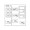
図1は本実施形態に係る情報処理システムの一例を示すブロック図、図2は本実施形態に係る情報処理装置の外観図、図3は本実施形態に係る情報処理装置の機能ブロック図、図4は本実施形態に係る画像形成装置の機能ブロック図である。
画像形成システムは、情報処理装置の一例としての端末装置10と、印刷装置の一例としての画像形成装置20と、サーバ30と、を含む。端末装置10、画像形成装置20及びサーバ30は、ネットワークNWを介して互いに接続されている。図1に示す例では、2つの端末装置10が情報処理システムに含まれているが、1つ以上の端末装置10が情報処理システムに含まれていればよい。また、複数のサーバ30及び複数の画像形成装置20が、情報処理システムに含まれていてもよい。
(1) Overall Configuration of Information Processing System FIG. 1 is a block diagram showing an example of an information processing system according to this embodiment, FIG. 2 is an external view of an information processing apparatus according to this embodiment, and FIG. 3 is according to this embodiment. FIG. 4 is a functional block diagram of the image forming apparatus according to the present embodiment.
The image forming system includes a
端末装置10は、スマートフォン、タブレット端末、ノートPC、またはデスクトップPC等の装置であり、文字や画像などの各種情報が表示される表示面を有するユーザーインターフェース部(UI部)として機能する。
本実施形態の端末装置10は、図2に示すように、平板状の筐体11を有し、筐体11の一方の面(図2において上面)に表示部としての表示パネル12と、入力部としてのタッチパネル13とが一体となった表示入力部15を備えている。筐体11内には表示デバイスとその制御に必要な電子回路基板等が収容されている。
The
As illustrated in FIG. 2, the
図2では、平面視で略矩形の平板型の端末装置10を例示するが、筐体11の外形形状や表示面の画面形状や画面サイズについては特に制限はなく、様々な形状、サイズに設計可能である。例えば、表示面の画面サイズとしてA4サイズ(297mm×210mm)程度の表示領域を有する構成とすることができる。
In FIG. 2, the flat
端末装置10は、図3に示すように、表示部を構成する表示パネル12と、表示パネル12の表示面上に配置されたタッチパネル13と、タッチパネル13から得られるタッチ信号を検出するタッチ信号検出部14と、制御手段として機能するCPU(中央演算処理装置)と、揮発性記憶手段としてのRAMと、不揮発性記憶手段としてのROMと、通信部16と、不揮発性の記憶手段としての記録部17と、表示パネル12の表示内容の更新制御等を行う表示制御部18と、装置内の各部に電力を供給する電源部19と、を備える。
As illustrated in FIG. 3, the
タッチパネル13は、表示パネル12に対する人の手、指、ペンその他の様々な物体の接触を検知する接触検知手段として機能する。タッチパネル13は、表示パネル12の表示面上に表示される文字や画像等の情報を視認可能に載置され、利用者の指やペンなどによって操作される複数の座標を検出しタッチ信号を生成する。
The
タッチ信号検出部14は、タッチパネル13から信号を読み出し、タッチパネル13のタッチ位置(接触点)を示す信号として出力する。タッチパネル13を利用者の指やペンによって操作すると、操作に起因して発生する検出信号が得られ、この信号がCPUに送られ、CPUは受信した検出信号を基に表示パネル12上の操作位置を検出し、接触点の動きや接触領域などを解析して操作動作を解釈する。
The touch
CPU、ROMや記録部17が記憶する制御プログラムや制御データにしたがって動作し、端末装置10の各部を統括して制御する。また、CPUは、タッチパネル13からの検出信号を解析してユーザーの操作動作を解釈する解析処理手段として機能し、ユーザーインターフェースを実現する。
また、表示制御を実行して、表示パネル12上に各種のアイコンや、スクロールバーなどのソフトウェアキー画像を表示させたり、画像表示や文字入力等を行うためのウィンドウを表示させたりすることができる。
The CPU, the ROM, and the
In addition, display control can be executed to display various icons and software key images such as a scroll bar on the
また、CPUは、操作検出制御を実行して、タッチパネル13を通じて、アイコンに対する操作や、ウィンドウの入力欄に対する文字列の入力を受け付けたり、あるいは、スクロールバーを通じた表示画像のスクロール要求を受け付ける。
更にCPUは、操作検出制御の実行により、タッチパネル13に対する操作動作を解釈し、入力操作に応じた入力処理や、各モード切替処理、ソフトウェアキーの表示制御処理などを行う。
In addition, the CPU executes operation detection control and accepts an operation on an icon and an input of a character string in an input field of a window through the
Further, the CPU interprets an operation operation on the
通信部16は、端末装置10に連結される外部機器(本実施形態においては、画像形成装置20やサーバ30)とのインターフェースであり、他の外部機器に通信等又はネットワークにより直接的又は間接的に接続するためのものである。
通信部16を介して外部機器から取得した画像データ(コンテンツ)や各種データは、記録部17に保存することができる。また、タッチパネル13を通じて入力された情報なども記録部17に記録することができる。記録部17に格納されたデータは、表示パネル12に表示させることができる他、通信部16を介して外部に取り出すこともできる。
The
Image data (contents) and various data acquired from an external device via the
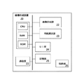
図4には、画像形成装置20の機能構成を示している。
通信部21は通信インターフェースであり、他の装置にデータを送信する機能、及び、他の装置からデータを受信する機能を備えている。通信部21は、無線通信機能を備えた通信インターフェースであってもよいし、有線通信機能を備えた通信インターフェースであってもよい。
FIG. 4 shows a functional configuration of the
The
画像形成部22は画像形成に関する機能を実行する。具体的には、画像形成部22は、スキャン機能、プリント機能、コピー機能及びファクシミリ機能の中の少なくとも1つの機能を実行する。プリント機能が実行されることにより、画像が用紙等の記録媒体上に印刷される。
The
用紙搬送部23は、それぞれサイズが異なる用紙を収容する複数の用紙トレイを備え、各用紙トレイから、選択された用紙を画像形成部22に供給する。
UI部24は、液晶表示パネル、各種操作ボタン、タッチパネル等を組み合わせて構成され、画像形成装置20の使用者は、UI部24を介して各種の設定や指示の入力を行う。また、液晶表示パネルを介して画像形成装置20の使用者へ各種情報を表示する。
The
The
記憶部25はHDD(Hard Disk Drive)やフラッシュメモリ等から成る不揮発性の書き換え可能な記憶装置であり、例えば、画像形成の命令を示す情報(例えばジョブ情報等)、プリントの対象となる画像データ、スキャン機能を実行することにより生成されたスキャンデータ、他の機器のアドレスを示す機器アドレス情報、サーバ30のアドレスを示すサーバアドレス情報、各種の制御データ、各種のプログラム、等が記憶される。CPUは、記憶部25のプログラム記憶領域に記憶されている各種プログラムを実行する。
The
サーバ30は、端末装置10が処理する画像等の共有ファイル及びアプリケーションプログラムを格納する。端末装置10は、サーバ30が格納する共有ファイルを通信部16を介して記録部17にダウンロードし、またはブラウジング可能な状態にする。
The
(2)ユーザーインターフェース
図5は情報処理装置としての端末装置10のユーザーインターフェースを実現する処理の流れを示すフローチャートである。以下、サーバ30の共有ファイルに格納されている出力可能なコンテンツそれぞれに紐付いている画像に対して、利用者の操作指示を受け付けて端末装置10において行われるユーザーインターフェースとしての表示制御について説明する。
(2) User Interface FIG. 5 is a flowchart showing a flow of processing for realizing the user interface of the
端末装置10は、まず、サーバ30の共有ファイルからダウンロードされ、記録部17に記録された画像ファイル(コンテンツ)に紐付いている画像としてのサムネイルSNと、出力指示を進める画像の一例としてのプリンタアイコンPICを表示パネル12上に表示する(S101)。
First, the
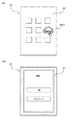
図6(a)は電源入力後に端末装置10に表示される画面の一例を示す図、(b)は端末装置10に表示されるブラウザのログインページを示す図、図7は端末装置10に表示されるアプリケーション選択画面を示す図、図8は端末装置10に表示されたサムネイルとプリンタアイコンを示す図である。
端末装置10は、ウェブブラウザアイコンBIC1(図6(a)参照)のタッチによりブラウザが起動し、所定のURLがブラウザに入力されることでブラウザはサーバ30にアクセスする。サーバ30は、ログインページを端末装置10側のブラウザに送信し(図6(b)参照)、利用者によるIDとパスワード入力を受け付けると、サーバ30が認証し図7に示す複数のアプリケーション(図例では4つ)アイコンを表示するアプリケーション選択画面に遷移する。
6A is a diagram illustrating an example of a screen displayed on the
The
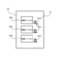
そして、図8に示すように、プログラムは、1つ以上の画像ファイルをサムネイルSN1、2、3として整列して表示し、表示された各画像ファイル(本実施例においては、画像ファイル1、2、3)の近傍にプリンタアイコンPIC1を配置して表示する。これにより、コンテンツとプリンタアイコンを関連付けて表示することができる。 Then, as shown in FIG. 8, the program displays one or more image files arranged as thumbnails SN1, 2, and 3, and displays each displayed image file (in this embodiment, image files 1, 2). 3), the printer icon PIC1 is arranged and displayed in the vicinity. As a result, the content and the printer icon can be displayed in association with each other.
図9は変形例1において端末装置10に表示されたサムネイルとプリンタアイコンを示す図である。
プログラムは、1つ以上の画像ファイルをサムネイルSNとして整列して表示し、プリンタアイコンPIC1は表示面の他のオブジェクト画像と重ならない表示領域に表示する。これにより、端末装置10の表示面にプリンタアイコンPIC1を表示することができる。
FIG. 9 is a diagram showing thumbnails and printer icons displayed on the
The program displays one or more image files aligned as thumbnails SN, and the printer icon PIC1 is displayed in a display area that does not overlap other object images on the display surface. Thus, the printer icon PIC1 can be displayed on the display surface of the
図10は変形例2において端末装置10に表示されたサムネイルとプリンタアイコンを示す図である。
プログラムは、1つ以上の画像ファイルをサムネイルSNとして整列して表示し、プリンタアイコンPIC1は、サムネイルSNに重ねて表示する。これにより、コンテンツとプリンタアイコンをより明確に関連付けて表示することができる。
FIG. 10 is a diagram showing thumbnails and printer icons displayed on the
The program arranges and displays one or more image files as thumbnails SN, and the printer icon PIC1 is displayed so as to overlap the thumbnails SN. As a result, the content and the printer icon can be displayed more clearly associated with each other.
図11は端末装置10に表示されたサムネイルとアクティブ状態となったプリンタアイコンを示す図である。
プログラムは、利用者によるプリンタアイコンPIC1のタッチ1回を検知し(S102)、図11に示すように、プリンタアイコンPIC1をアクティブ状態を示すプリンタアイコンPIC2に切り替える。
尚、プログラムは、複数のプリンタアイコンPIC1に対する利用者によるタッチ操作を検知すると、タッチ検知されたプリンタアイコンPIC1をアクティブ状態を示すプリンタアイコンPIC2に切り替える。
FIG. 11 is a diagram showing thumbnails displayed on the
The program detects one touch of the printer icon PIC1 by the user (S102), and switches the printer icon PIC1 to the printer icon PIC2 indicating the active state as shown in FIG.
When the program detects a touch operation by the user on the plurality of printer icons PIC1, the program switches the touch-detected printer icon PIC1 to a printer icon PIC2 indicating an active state.
図12は端末装置10に表示されたサムネイルとタッチ操作により非アクティブ状態となったプリンタアイコンを示す図である。
プログラムは、図12に示すように、一旦表示態様が変化してアクティブ状態になったプリンタアイコンPIC2に対する利用者によるタッチ操作を検知すると、プリンタアイコンPIC2を利用者によるタッチ操作を受け付けない非アクティブ状態のプリンタアイコンPIC3に遷移させる。
そして、再度、非アクティブ状態に遷移したプリンタアイコンPIC3のタッチ操作を検知した場合には、図11に示すように、プリンタアイコンPIC3をアクティブ状態を示すプリンタアイコンPIC2に切り替える。これにより、最小限の操作ステップで直前の操作をキャンセルすることができる。
FIG. 12 is a diagram showing thumbnails displayed on the
As shown in FIG. 12, when the program detects a touch operation by the user with respect to the printer icon PIC <b> 2 that has been changed to an active state once, the printer icon PIC <b> 2 is not accepted by the user. To the printer icon PIC3.
If a touch operation on the printer icon PIC3 that has transitioned to the inactive state is detected again, the printer icon PIC3 is switched to the printer icon PIC2 indicating the active state, as shown in FIG. As a result, the previous operation can be canceled with a minimum number of operation steps.
図13は変形例3において端末装置10に表示されたサムネイルとプリンタアイコンの近傍のタッチ操作により非アクティブ状態となったプリンタアイコンを示す図である。
変形例3として、プログラムは、図13に示すように、一旦アクティブ状態になったプリンタアイコンPIC2の表示領域に近い予め定められた領域に対する利用者によるタッチ操作を検知すると、プリンタアイコンPIC2を利用者によるタッチ操作を受け付けない非アクティブ状態のプリンタアイコンPIC3に遷移させる。
FIG. 13 is a diagram illustrating a printer icon that is deactivated by a touch operation in the vicinity of the thumbnail and the printer icon displayed on the
As a third modification, as shown in FIG. 13, when the program detects a touch operation by a user on a predetermined area close to the display area of the printer icon PIC2 once activated, the program displays the printer icon PIC2 as a user. The transition is made to the inactive printer icon PIC3 that does not accept the touch operation.
図14は変形例4において端末装置10に表示されたサムネイルと表示面の空き領域のタッチ操作により非アクティブ状態となったプリンタアイコンを示す図である。
同様に、プログラムは、変形例4として、サムネイルSN及びプリンタアイコンPICが表示されていない表示面に対する利用者によるタッチ操作を検知すると、プリンタアイコンPIC2を利用者によるタッチ操作を受け付けない非アクティブ状態のプリンタアイコンPIC3に遷移させる。これにより、最小限の操作ステップで直前の操作をキャンセルすることができる。
FIG. 14 is a diagram illustrating a printer icon that has been deactivated by a touch operation on a thumbnail displayed on the
Similarly, as a fourth modification, when the program detects a touch operation by the user on the display surface on which the thumbnail SN and the printer icon PIC are not displayed, the program is in an inactive state in which the touch operation by the user is not accepted. Transition to the printer icon PIC3. As a result, the previous operation can be canceled with a minimum number of operation steps.
図15は変形例5において端末装置10に表示されたサムネイルと表示面の空き領域のタッチ操作により表示されるキャンセルボタンを示す図である。
プログラムは、変形例5として、サムネイルSN及びプリンタアイコンPICが表示されていない表示面に対する利用者によるタッチ操作を検知すると、プリンタアイコンPIC2を利用者によるタッチ操作を受け付けない非アクティブ状態のプリンタアイコンPIC3に遷移させる操作受け付け画像としてのキャンセルボタンCIC1を表示させる。これにより、直前の操作のキャンセル方法を明確に表示することができる。
FIG. 15 is a diagram illustrating a cancel button displayed by a touch operation on thumbnails displayed on the
As a fifth modification, when the program detects a touch operation by the user on the display surface on which the thumbnail SN and the printer icon PIC are not displayed, the program accepts the printer icon PIC2 in an inactive printer icon PIC3. A cancel button CIC1 is displayed as an operation acceptance image to be shifted to. Thereby, the cancellation method of the last operation can be displayed clearly.
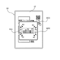
図16は端末装置10に表示されたサムネイルとプリンタアイコンとコード画像と紙サイズアイコンを示す図である。
プログラムは、プリンタアイコンPIC1をアクティブ状態を示すアイコンPIC2に切り替えると、図16に示すようにコード画像の一例としてのQRコード(登録商標)アイコンQIC1と出力サイズ画像の一例としての紙サイズアイコンSIC1をアクティブなプリンタアイコンPIC2の近傍に表示させる(S103)。これにより、コンテンツの取得及び出力のための次の操作ステップを表示することができる。
尚、コード画像としては、二次元コードとしてのQRコード(登録商標)に限られず、他の二次元コードやバーコードのような一次元コードであってもよく、更には三次元コードであってもよい。
FIG. 16 is a diagram showing thumbnails, printer icons, code images, and paper size icons displayed on the
When the program switches the printer icon PIC1 to the icon PIC2 indicating the active state, as shown in FIG. 16, a QR code (registered trademark) icon QIC1 as an example of a code image and a paper size icon SIC1 as an example of an output size image are displayed. It is displayed in the vicinity of the active printer icon PIC2 (S103). Thereby, the next operation step for acquiring and outputting the content can be displayed.
The code image is not limited to a QR code (registered trademark) as a two-dimensional code, and may be a one-dimensional code such as another two-dimensional code or a barcode, and further a three-dimensional code. Also good.
図17は変形例6において端末装置10に表示されたサムネイルとプリンタアイコンとコード画像と紙サイズアイコンを示す図、図18は変形例7において端末装置10に他の表示態様で表示されたサムネイルとプリンタアイコンとコード画像と紙サイズアイコンを示す図である。
プログラムは、変形例6として、プリンタアイコンPIC1をアクティブ状態を示すプリンタアイコンPIC2に切り替えると、図17に示すように、QRコード(登録商標)アイコンQIC1と紙サイズアイコンSIC1を利用者によるタッチ操作を検知した複数のプリンタアイコンPIC2のうち中央に位置するプリンタアイコンPIC2の表示領域に近い予め定められた位置に表示する。
また、図18に示すように、QRコード(登録商標)アイコンQIC1と紙サイズアイコンSIC1を表示面の表示領域の範囲内で大きく表示する。これにより、コンテンツと関連付けてコンテンツの取得及び出力のための次の操作ステップを利用者にわかりやすく表示することができる。
FIG. 17 is a diagram showing thumbnails, printer icons, code images, and paper size icons displayed on the
As a sixth modified example, when the printer icon PIC1 is switched to the printer icon PIC2 indicating the active state, the program performs a touch operation by the user with the QR code (registered trademark) icon QIC1 and the paper size icon SIC1 as illustrated in FIG. Of the detected plurality of printer icons PIC2, the image is displayed at a predetermined position close to the display area of the printer icon PIC2 located at the center.
Further, as shown in FIG. 18, the QR code (registered trademark) icon QIC1 and the paper size icon SIC1 are displayed in a large size within the display area of the display surface. Accordingly, the next operation step for acquiring and outputting the content in association with the content can be displayed in an easy-to-understand manner for the user.
図19は端末装置10に表示するプリンタアイコンと紙サイズアイコンの表示態様を示す図である。
プログラムは、図19に示すように、紙サイズアイコンSIC1は、利用者によるタッチ操作を検知した複数のプリンタアイコンPIC2の表示領域に近い予め定められた位置にプリンタアイコンPIC2と対にして表示する。これにより、コンテンツの出力のための次の操作ステップを利用者にわかりやすく表示することができる。
FIG. 19 is a diagram illustrating a display mode of a printer icon and a paper size icon displayed on the
As shown in FIG. 19, the program displays the paper size icon SIC1 in a pair with the printer icon PIC2 at a predetermined position close to the display area of the plurality of printer icons PIC2 in which the touch operation by the user is detected. As a result, the next operation step for content output can be displayed to the user in an easily understandable manner.
図20は変形例8において端末装置10に表示するプリンタアイコンと紙サイズアイコンの表示態様を示す図である。
プログラムは、図20に示すように、紙サイズアイコンSIC1は、利用者によるタッチ操作を検知した複数のプリンタアイコンPIC2の表示領域に近い予め定められた位置に複数の用紙サイズ候補ごとにプリンタアイコンPIC2と対にして表示する。これにより、コンテンツの出力のための次の操作ステップを利用者にわかりやすく表示することができる。
FIG. 20 is a diagram illustrating a display mode of a printer icon and a paper size icon displayed on the
In the program, as shown in FIG. 20, the paper size icon SIC1 is displayed for each of a plurality of paper size candidates at a predetermined position close to the display area of the plurality of printer icons PIC2 detected by the user's touch operation. And display in pairs. As a result, the next operation step for content output can be displayed to the user in an easily understandable manner.
図21は変形例9において端末装置10に表示するプリンタアイコンと紙サイズアイコンの表示態様を示す図である。
プログラムは、図21に示すように、紙サイズアイコンSIC1は、紙サイズアイコンSIC1が長押しされて利用者によるタッチ操作を検知すると、これまでの紙サイズアイコンSIC1に置き換えて複数の用紙サイズ候補の紙サイズアイコンSIC2、3、4、5を表示する。これにより、コンテンツの出力のための出力サイズの候補を表示することができる。
FIG. 21 is a diagram illustrating a display mode of a printer icon and a paper size icon displayed on the
As shown in FIG. 21, the program replaces the paper size icon SIC1 with a plurality of paper size candidates by replacing the paper size icon SIC1 so far when the paper size icon SIC1 is pressed and detected by the user. Paper size icons SIC2, 3, 4, 5 are displayed. As a result, output size candidates for content output can be displayed.
図22は端末装置10に表示されたコードパターンの表示態様を示す図である。
プログラムは、図22に示すように、QRコード(登録商標)アイコンQIC1のタッチ1回を検知し(S105)、端末装置10の表示面の最前面に別ウィンドウWD1で画像ファイルが格納されたサーバ30にアクセスできるURLに紐付くコード化されたコードパターンの一例としてのQRコード(登録商標)で表示する(S106)。これにより、利用者が二次元コードパターンを容易に認識し、指定したコンテンツに容易にアクセスすることができる。
FIG. 22 is a diagram illustrating a display mode of the code pattern displayed on the
As shown in FIG. 22, the program detects one touch of the QR code (registered trademark) icon QIC1 (S105), and the server stores the image file in the separate window WD1 on the forefront of the display surface of the
図23は端末装置10に表示された非アクティブ化されたコードパターンの表示態様を示す図である。
プログラムは、図23に示すように、QRコード(登録商標)が外部機器により読み取られたことが検知された場合、QRコード(登録商標)の表示を利用者による読み取り操作を受け付けない状態のQRコード(登録商標)QIC2に変化させる。
また、QRコード(登録商標)が表示されて予め定められた時間が経過した場合、QRコード(登録商標)の表示を利用者による読み取り操作を受け付けない状態に変化させる。尚、図23に示すように、QRコード(登録商標)の表示を利用者による読み取り操作を受け付けない状態に変化させることなく、QRコード(登録商標)を表示するウィンドウWD1を非表示にしてもよい。
これにより、二次元コードパターンを読み取り不可状態にすることができる。
FIG. 23 is a diagram illustrating a display mode of the deactivated code pattern displayed on the
As shown in FIG. 23, when it is detected that the QR code (registered trademark) has been read by an external device, the program displays the QR code (registered trademark) in a state where the user does not accept a reading operation. Code (registered trademark) QIC2 is changed.
When a predetermined time has elapsed since the QR code (registered trademark) is displayed, the display of the QR code (registered trademark) is changed to a state in which a reading operation by the user is not accepted. As shown in FIG. 23, the QR code (registered trademark) display window WD1 is not displayed without changing the QR code (registered trademark) display to a state in which the user does not accept the reading operation. Good.
As a result, the two-dimensional code pattern can be made unreadable.
図24は端末装置10に表示された停止ボタンの表示態様を示す図である。
プログラムは、図24に示すように、QRコード(登録商標)の表示領域内に、検知した利用者によるタッチ操作に応じてQRコード(登録商標)の表示を利用者による読み取り操作を受け付けない状態のQRコード(登録商標)QIC2に変化させる操作受け付け画像としての停止ボタンPB1を表示する(S106)。
プログラムは、停止ボタンPB1のタッチ操作を検知した場合(S107)、QRコード(登録商標)の表示を利用者による読み取り操作を受け付けない状態に変化させるか、またはQRコード(登録商標)を表示するウィンドウWD1を非表示にする。これにより、コード画像を読み取り不可状態にすることができる。
FIG. 24 is a diagram illustrating a display mode of the stop button displayed on the
As shown in FIG. 24, the program does not accept a QR code (registered trademark) display operation in the QR code (registered trademark) display area in response to a detected user touch operation. The stop button PB1 as an operation acceptance image to be changed to the QR code (registered trademark) QIC2 is displayed (S106).
When detecting the touch operation of the stop button PB1 (S107), the program changes the display of the QR code (registered trademark) to a state in which the reading operation by the user is not accepted, or displays the QR code (registered trademark). The window WD1 is hidden. As a result, the code image can be made unreadable.
図25は変形例10において端末装置10に表示する停止ボタンの表示態様を示す図である。
プログラムは、図25に示すように、端末装置10の表示面においてQRコード(登録商標)を表示するウィンドウが表示されていない表示領域の予め定められた位置に、検知した利用者によるタッチ操作に応じてQRコード(登録商標)の表示を利用者による操作指示を受け付けない状態に変化させる操作受け付け画像としての停止ボタンPB1を表示する(S106)。
プログラムは、停止ボタンPB1のタッチ操作を検知した場合(S107)、QRコード(登録商標)の表示を利用者による読み取り操作を受け付けない状態のQRコード(登録商標)QIC2に変化させるか、またはQRコード(登録商標)を表示するウィンドウWD1を非表示にする。これにより、コード画像を読み取り不可状態にすることができる。
FIG. 25 is a diagram illustrating a display mode of a stop button displayed on the
As shown in FIG. 25, the program is a touch operation by a detected user at a predetermined position in a display area where a window for displaying a QR code (registered trademark) is not displayed on the display surface of the
When the program detects the touch operation of the stop button PB1 (S107), the program changes the display of the QR code (registered trademark) to the QR code (registered trademark) QIC2 in a state in which the reading operation by the user is not accepted, or QR The window WD1 that displays the code (registered trademark) is hidden. As a result, the code image can be made unreadable.
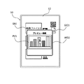
図26は端末装置10に表示されたコンテンツのプレビュー画像の表示態様を示す図である。
プログラムは、図26に示すように、紙サイズアイコンSIC1のタッチ1回を検知し(S108)、端末装置10の表示面の最前面に別ウィンドウで、コンテンツを出力するためのプレビュー画像PV1が表示されたプレビュー画面WD2を表示する(S109)。これにより、最小限の操作ステップでコンテンツの印刷のためのプレビュー画面WD2を表示することができる。
FIG. 26 is a diagram illustrating a display mode of a preview image of content displayed on the
As shown in FIG. 26, the program detects one touch of the paper size icon SIC1 (S108), and a preview image PV1 for outputting contents is displayed in a separate window on the foreground of the display surface of the
図27は端末装置10に表示されたコンテンツのプレビュー画像の表示態様の一例を示す図、図28は端末装置10に表示されたコンテンツのプレビュー画像の表示態様の他の一例を示す図である。
プログラムは、図27に示すように、利用者のピンチイン操作(図中 矢印R1参照)、ピンチアウト(図中 矢印R2参照)操作に応じて、表示されたコンテンツのプレビュー画像PV1を拡大表示、または、縮小表示する。また、図28に示すように、端末装置10の回転に応じて、表示されたコンテンツのプレビュー画像PV1を回転表示する。これにより、プレビュー画像PV1の表示態様を変更することができる。
FIG. 27 is a diagram illustrating an example of a display mode of a content preview image displayed on the
As shown in FIG. 27, the program enlarges and displays a preview image PV1 of the displayed content in accordance with the user's pinch-in operation (see arrow R1 in the figure) and pinch-out (see arrow R2 in the figure), or Zoom out. Further, as shown in FIG. 28, the preview image PV1 of the displayed content is rotated and displayed in accordance with the rotation of the
図29は端末装置10に表示された停止ボタンの表示態様を示す図である。
プログラムは、図29に示すように、プレビュー画像PV1の表示領域内に、検知した利用者によるタッチ操作に応じてプレビュー画像PV1を非表示にする操作受け付け画像としての停止ボタンPB2を表示する(S109)。プログラムは、停止ボタンPB2のタッチ操作を検知した場合(S107)、コンテンツのサムネイル画像表示に遷移する。これにより、一旦表示したプレビュー画面WD2を非表示にすることができる。
FIG. 29 is a diagram illustrating a display mode of the stop button displayed on the
As shown in FIG. 29, the program displays a stop button PB2 as an operation acceptance image for hiding the preview image PV1 in response to the detected touch operation by the user in the display area of the preview image PV1 (S109). ). When detecting a touch operation of the stop button PB2 (S107), the program shifts to a thumbnail image display of content. Thereby, the preview screen WD2 once displayed can be hidden.
図30は変形例11において端末装置10に表示する停止ボタンの表示態様を示す図である。
プログラムは、図30に示すように、端末装置10の表示面においてプレビュー画像PV1を表示するウィンドウWD2が表示されていない表示領域の予め定められた位置に、検知した利用者によるタッチ操作に応じてプレビュー画像PV1を非表示にする操作受け付け画像としての停止ボタンPB2を表示する(S109)。プログラムは、停止ボタンPB2のタッチ操作を検知した場合(S107)、コンテンツのサムネイル画像表示に遷移する。これにより、最小限の操作ステップで一旦表示したプレビュー画面WD2を非表示にすることができる。
FIG. 30 is a diagram illustrating a display mode of a stop button displayed on the
As shown in FIG. 30, the program responds to a detected touch operation by a user at a predetermined position in a display area where the window WD <b> 2 for displaying the preview image PV <b> 1 is not displayed on the display surface of the
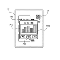
図31は端末装置10に表示する送るボタンの表示態様を示す図である。
プログラムは、図31に示すように、表示中のプレビュー画像PV1を他のコンテンツに切り換えるための操作受け付け画像としての送るボタンPB3を表示し、送るボタンPB3に対する利用者によるタッチ操作を検知すると、現在表示しているコンテンツとは異なる他のコンテンツのプレビュー画像PV2を表示する。これにより、最小限の操作ステップで他のコンテンツのプレビュー画像を表示することができる。
FIG. 31 is a diagram illustrating a display mode of a send button displayed on the
As shown in FIG. 31, the program displays a send button PB3 as an operation acceptance image for switching the preview image PV1 being displayed to another content, and when a touch operation by the user on the send button PB3 is detected, A preview image PV2 of another content different from the displayed content is displayed. As a result, preview images of other contents can be displayed with minimum operation steps.
図32は変形例12において端末装置10に表示するプレビュー画像の表示態様を示す図である。
プログラムは、図32に示すように、表示中のプレビュー画像PV1に対する利用者のタッチ操作を検知すると、現在表示しているコンテンツとは異なる他のコンテンツのプレビュー画像PV2(図31 参照)を表示する。これにより、最小限の操作ステップで他のコンテンツのプレビュー画像を表示することができる。
FIG. 32 is a diagram illustrating a display mode of a preview image displayed on the
As shown in FIG. 32, when detecting the user's touch operation on the currently displayed preview image PV1, the program displays a preview image PV2 (see FIG. 31) of other content different from the currently displayed content. . As a result, preview images of other contents can be displayed with minimum operation steps.
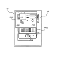
図33は端末装置10に表示する出力設定画面の表示態様を示す図である。
プログラムは、図33に示すように、表示中の設定を確定して操作を進める操作受け付け画像としてのOKボタンPB4を表示して、OKボタンPB4に対する利用者によるタッチ操作を検知すると、プレビュー中のコンテンツの出力(印刷)設定パラメータを設定するための出力(印刷)設定画面PD1を表示する。これにより、最小限の操作ステップで出力(印刷)設定パラメータを設定する出力(印刷)設定画面を表示することができる。
FIG. 33 is a diagram illustrating a display mode of an output setting screen displayed on the
As shown in FIG. 33, the program displays an OK button PB4 as an operation acceptance image for confirming the setting being displayed and advancing the operation, and when a touch operation by the user on the OK button PB4 is detected, An output (print) setting screen PD1 for setting content output (print) setting parameters is displayed. This makes it possible to display an output (print) setting screen for setting output (print) setting parameters with a minimum number of operation steps.
図34は端末装置10に表示する操作を進めるOKボタンの表示態様を示す図である。
プログラムは、図34に示すように、表示中の設定を確定して操作を進める操作受け付け画像としてのOKボタンPB4を表示して、OKボタンPB4に対する利用者によるタッチ操作を検知する(S110)と、プレビュー中のコンテンツの印刷ジョブを端末装置10と接続された画像形成装置20に送信し(S111)、端末装置10の表示面に「プリントしました」を表示する(S112)。これにより、最小限の操作ステップでコンテンツの出力(印刷)を行うことができる。
FIG. 34 is a diagram illustrating a display mode of an OK button that advances an operation to be displayed on the
As shown in FIG. 34, the program displays an OK button PB4 as an operation acceptance image that confirms the setting being displayed and advances the operation, and detects a touch operation by the user on the OK button PB4 (S110). Then, the print job of the content being previewed is transmitted to the
図35は端末装置10に表示する用紙サイズアイコンの表示態様を示す図である。
プログラムは、図35に示すように、表示中の設定を確定して操作を進める操作受け付け画像としてのOKボタンPB4を表示して、OKボタンPB4に対する利用者によるタッチ操作を検知する(S110)と、利用者によるタッチ操作で選択可能な紙サイズアイコンSIC1、2、3、4、5を一覧表示する。
その後、用紙サイズアイコンに対する利用者によるタッチ操作を検知すると、プレビュー中のコンテンツの印刷ジョブを端末装置10と接続された画像形成装置20に送信し(S111)、端末装置10の表示面には「プリントしました」を表示する(S112)。プレビュー中のコンテンツの印刷ジョブを端末装置10と接続された画像形成装置20に送信する。これにより、最小限の操作ステップでコンテンツの出力(印刷)を行うことができる。
FIG. 35 is a diagram illustrating a display mode of a paper size icon displayed on the
As shown in FIG. 35, the program displays an OK button PB4 as an operation acceptance image that confirms the setting being displayed and advances the operation, and detects a touch operation by the user on the OK button PB4 (S110). The paper size icons SIC1, 2, 3, 4, 5 that can be selected by a touch operation by the user are displayed in a list.
Thereafter, when a touch operation by the user on the paper size icon is detected, a print job of the content being previewed is transmitted to the
その後、端末装置10の表示面のいずれかに対する利用者によるタッチ操作を検知する(S113)と、コンテンツのプレビュー画像PV1を表示するプレビュー画面WD2を非表示にして、コンテンツのサムネイルとプリンタアイコンを表示パネル12上に表示する。
Thereafter, when a user's touch operation on one of the display surfaces of the
以上のユーザーインターフェースによってコンテンツの出力指示を容易に行うことができる。
これまで本発明については、図面に示した特定の実施形態に従って説明してきたが、本発明は図面に示した実施形態に限定されるものではなく、本発明の効果を奏する限り、これまで知られた構成及び態様であっても採用することができる。例えば、端末装置10についてはタッチパネル13を備えて利用者のタッチ操作を検知する態様について説明したが、端末装置10はマウス等による選択操作を受け付けて処理を進めてもよい。
With the above user interface, it is possible to easily instruct content output.
Although the present invention has been described according to the specific embodiments shown in the drawings, the present invention is not limited to the embodiments shown in the drawings and is known so far as long as the effects of the present invention are exhibited. Even if it is the structure and aspect which were different, it is employable. For example, although the
10・・・端末装置
12・・・表示パネル
13・・・タッチパネル
14・・・タッチ信号検出部
16・・・通信部
17・・・記録部
18・・・表示制御部
20・・・画像形成装置
30・・・サーバ
PIC・・・プリンタアイコン
SIC・・・紙サイズアイコン
QIC・・・QRコード(登録商標)アイコン
SN・・・サムネイル
PV・・・プレビュー画像
DESCRIPTION OF
Claims (34)
ことを特徴とする情報処理装置。 When a user's operation instruction is received for an image associated with each content that can be output, the display control unit displays an image that advances the output instruction.
An information processing apparatus characterized by that.
ことを特徴とする請求項1に記載の情報処理装置。 The image that advances the output instruction is displayed at a predetermined position close to the display area of the content.
The information processing apparatus according to claim 1.
ことを特徴とする請求項1に記載の情報処理装置。 The image that advances the output instruction is displayed in a display area that does not overlap other object images.
The information processing apparatus according to claim 1.
ことを特徴とする請求項1に記載の情報処理装置。 The image that advances the output instruction is displayed over the content.
The information processing apparatus according to claim 1.
ことを特徴とする請求項1に記載の情報処理装置。 The image that advances the output instruction changes its display mode upon receiving an operation instruction from the user.
The information processing apparatus according to claim 1.
ことを特徴とする請求項5に記載の情報処理装置。 Each time the image that advances the output instruction is operated, the presence or absence of designation of the output object is switched,
The information processing apparatus according to claim 5.
ことを特徴とする請求項5に記載の情報処理装置。 When an operation instruction by the user for a predetermined area close to the display area of the image that advances the output instruction whose display mode has changed is accepted, the image that advances the output instruction changes to a state in which the operation instruction by the user is not accepted. ,
The information processing apparatus according to claim 5.
ことを特徴とする請求項5に記載の情報処理装置。 When an operation instruction by a user is received for a display area in which the image that advances the content and the output instruction is not displayed, the image that advances the output instruction changes to a state that does not accept the operation instruction by the user.
The information processing apparatus according to claim 5.
ことを特徴とする請求項5に記載の情報処理装置。 When an operation instruction by the user is received, an operation acceptance image is displayed in which the image that advances the output instruction changes to a state that does not accept the operation instruction by the user.
The information processing apparatus according to claim 5.
ことを特徴とする請求項5に記載の情報処理装置。 When receiving an operation instruction by a user for the image for which the output instruction is advanced, a code image and an output size image are displayed at a predetermined position close to a display area of the image for which the output instruction is advanced,
The information processing apparatus according to claim 5.
ことを特徴とする請求項10に記載の情報処理装置。 The code image and the output size image are displayed at a predetermined position close to a display area of an image that advances the output instruction that has received an operation instruction from the user at the end,
The information processing apparatus according to claim 10.
ことを特徴とする請求項10に記載の情報処理装置。 The code image and the output size image are displayed at a predetermined position close to a display area of the image that advances the output instruction located in the center among the plurality of images that advance the output instruction that has received an operation instruction from the user. ,
The information processing apparatus according to claim 10.
ことを特徴とする請求項10に記載の情報処理装置。 The code image and the output size image can be displayed at a predetermined position close to a display area of the image that advances the output instruction located in the center among the plurality of images that advance the output instruction that has received an operation instruction from the user. Display larger within the area,
The information processing apparatus according to claim 10.
ことを特徴とする請求項10に記載の情報処理装置。 The output size image is displayed in a pair with an image for which the output instruction is advanced at a predetermined position close to a display area of an image for which the output instruction is advanced in response to an operation instruction by a user.
The information processing apparatus according to claim 10.
ことを特徴とする請求項10に記載の情報処理装置。 The output size image is displayed for each of a plurality of candidate output sizes.
The information processing apparatus according to claim 10.
ことを特徴とする請求項10に記載の情報処理装置。 When the output size image is pressed for a long time and an operation instruction from the user is received, the output size image is replaced with the output size image and a plurality of candidate output size images are displayed.
The information processing apparatus according to claim 10.
ことを特徴とする請求項10に記載の情報処理装置。 When an operation instruction by the user for the code image is received, a coded code pattern associated with access information for accessing the acquired content is displayed.
The information processing apparatus according to claim 10.
ことを特徴とする請求項17に記載の情報処理装置。 The code pattern is displayed on the forefront of the display surface of the information processing apparatus.
The information processing apparatus according to claim 17.
ことを特徴とする請求項17又は18に記載の情報処理装置。 When it is detected that the code pattern is read by an external device, the display of the code pattern is changed to a state in which an operation instruction by a user is not accepted.
The information processing apparatus according to claim 17 or 18, characterized in that:
ことを特徴とする請求項17又は18に記載の情報処理装置。 When a predetermined time has elapsed since the code pattern was displayed, the display of the code pattern is changed to a state in which an operation instruction by a user is not accepted.
The information processing apparatus according to claim 17 or 18, characterized in that:
ことを特徴とする請求項17又は18に記載の情報処理装置。 In the display area of the code pattern, an operation reception image that changes the display of the code pattern to a state that does not accept the operation instruction by the user according to the received operation instruction by the user is displayed.
The information processing apparatus according to claim 17 or 18, characterized in that:
ことを特徴とする請求項17又は18に記載の情報処理装置。 The display of the code pattern is not accepted in response to the received operation instruction from the user at a predetermined position in the display area where the code pattern is not displayed on the display surface of the information processing apparatus. Display the operation acceptance image to change to the state,
The information processing apparatus according to claim 17 or 18, characterized in that:
ことを特徴とする請求項10に記載の情報処理装置。 When an operation instruction by the user for the output size image is received, a preview screen on which a preview image for outputting the content is displayed is displayed.
The information processing apparatus according to claim 10.
ことを特徴とする請求項23に記載の情報処理装置。 In response to an operation instruction by the user for the preview image, the preview image is enlarged or reduced and displayed.
The information processing apparatus according to claim 23.
ことを特徴とする請求項23に記載の情報処理装置。 The preview image is rotated and displayed according to the rotation of the information processing apparatus.
The information processing apparatus according to claim 23.
ことを特徴とする請求項23に記載の情報処理装置。 When the preview screen is displayed and a predetermined time has elapsed, the preview screen is hidden.
The information processing apparatus according to claim 23.
ことを特徴とする請求項23に記載の情報処理装置。 In the display area of the preview screen, an operation acceptance image for hiding the preview screen is displayed in response to an operation instruction by the accepted user.
The information processing apparatus according to claim 23.
ことを特徴とする請求項23に記載の情報処理装置。 An operation acceptance image for hiding the preview screen is displayed at a predetermined position in a display area where the preview screen is not displayed on the display surface of the information processing apparatus in response to an operation instruction by the accepted user. ,
The information processing apparatus according to claim 23.
ことを特徴とする請求項23に記載の情報処理装置。 The preview screen further displays an operation acceptance image for switching the currently displayed preview image to the other content, and when an operation instruction by the user for the operation acceptance image is accepted, the preview image of the other content is displayed. To
The information processing apparatus according to claim 23.
ことを特徴とする請求項23に記載の情報処理装置。 The preview screen receives a user operation instruction for the currently displayed preview image and displays a preview image of the other content.
The information processing apparatus according to claim 23.
ことを特徴とする請求項23に記載の情報処理装置。 The preview screen further includes an operation acceptance image for confirming the setting being displayed and proceeding with the operation, and upon receiving an operation instruction from the user for the operation acceptance image, an output setting for setting an output setting parameter for the content Display the screen,
The information processing apparatus according to claim 23.
ことを特徴とする請求項23に記載の情報処理装置。 The preview screen further displays an operation acceptance image for confirming the setting being displayed and advancing the operation. When an operation instruction by the user for the operation acceptance image is accepted, a print job is connected to the information processing apparatus. Send to device,
The information processing apparatus according to claim 23.
ことを特徴とする請求項23に記載の情報処理装置。 The preview screen further displays an operation acceptance image for confirming the displayed setting and advancing the operation. When an operation instruction by the user for the operation acceptance image is received, an output size that can be selected by the operation instruction by the user is displayed. When a list is displayed and one of the output sizes is selected, a print job is transmitted to a printing apparatus connected to the information processing apparatus.
The information processing apparatus according to claim 23.
出力可能なコンテンツそれぞれに紐付いている画像に対して利用者の操作指示を受け付けた場合、出力指示を進める画像を表示させる表示制御手段、
として機能させることを特徴とするプログラム。 Computer
Display control means for displaying an image that advances an output instruction when a user's operation instruction is received for an image associated with each outputable content;
A program characterized by functioning as
Priority Applications (2)
| Application Number | Priority Date | Filing Date | Title |
|---|---|---|---|
| JP2018048720A JP2019160102A (en) | 2018-03-16 | 2018-03-16 | Information display device and program |
| US16/120,769 US10572201B2 (en) | 2018-03-16 | 2018-09-04 | Information processing apparatus and non-transitory computer readable medium for streamlined display of image to be output and image linked with content |
Applications Claiming Priority (1)
| Application Number | Priority Date | Filing Date | Title |
|---|---|---|---|
| JP2018048720A JP2019160102A (en) | 2018-03-16 | 2018-03-16 | Information display device and program |
Publications (1)
| Publication Number | Publication Date |
|---|---|
| JP2019160102A true JP2019160102A (en) | 2019-09-19 |
Family
ID=67904030
Family Applications (1)
| Application Number | Title | Priority Date | Filing Date |
|---|---|---|---|
| JP2018048720A Pending JP2019160102A (en) | 2018-03-16 | 2018-03-16 | Information display device and program |
Country Status (2)
| Country | Link |
|---|---|
| US (1) | US10572201B2 (en) |
| JP (1) | JP2019160102A (en) |
Families Citing this family (3)
| Publication number | Priority date | Publication date | Assignee | Title |
|---|---|---|---|---|
| JP6834728B2 (en) * | 2017-04-11 | 2021-02-24 | 富士ゼロックス株式会社 | Controls and programs |
| JP7187286B2 (en) * | 2018-11-29 | 2022-12-12 | キヤノン株式会社 | Image processing device, image processing method and program |
| JP7326935B2 (en) * | 2019-07-04 | 2023-08-16 | セイコーエプソン株式会社 | TERMINAL DEVICE, TERMINAL DEVICE CONTROL METHOD, AND PROGRAM |
Citations (18)
| Publication number | Priority date | Publication date | Assignee | Title |
|---|---|---|---|---|
| JP2006244418A (en) * | 2005-03-07 | 2006-09-14 | Nippon Telegr & Teleph Corp <Ntt> | Service providing system and service providing device |
| JP2007223122A (en) * | 2006-02-22 | 2007-09-06 | Seiko Epson Corp | Image forming device and printer with the same |
| JP2008191929A (en) * | 2007-02-05 | 2008-08-21 | Mitsubishi Electric Corp | Content use system, content display device, terminal equipment and use waiting status display method, and program |
| US20090015874A1 (en) * | 2007-07-13 | 2009-01-15 | Sriram Kulumani | Method and system of vending a physical copy of a digital image |
| JP2009048471A (en) * | 2007-08-21 | 2009-03-05 | Kyocera Mita Corp | Condition setting program and image forming device |
| JP2009070207A (en) * | 2007-09-14 | 2009-04-02 | Konica Minolta Business Technologies Inc | Data processor, data output method, and data output program |
| US20090193364A1 (en) * | 2008-01-29 | 2009-07-30 | Microsoft Corporation | Displaying thumbnail copies of running items |
| JP2010536195A (en) * | 2007-07-27 | 2010-11-25 | ラガヴーリン リミテッド | Portable transmitter apparatus, method, system, and user interface |
| JP2012088981A (en) * | 2010-10-21 | 2012-05-10 | Canon Inc | Electronic document management system |
| JP2012123596A (en) * | 2010-12-08 | 2012-06-28 | Toshiba Tec Corp | Electronic menu device and display method therefor |
| JP2013186824A (en) * | 2012-03-09 | 2013-09-19 | Canon Inc | Printing system and method therefor |
| JP2014026588A (en) * | 2012-07-30 | 2014-02-06 | Fujitsu Ltd | Information processing device, method, and program |
| JP2014068152A (en) * | 2012-09-25 | 2014-04-17 | Canon Inc | Image processing apparatus, image processing method, and program |
| JP2014078097A (en) * | 2012-10-10 | 2014-05-01 | Konica Minolta Inc | Image processing apparatus, program, and operation event determination method |
| US20150012381A1 (en) * | 2013-03-07 | 2015-01-08 | Sergio Lazaro | Systems, methods and computer readable media for online shopping |
| US20150143299A1 (en) * | 2013-11-19 | 2015-05-21 | Lg Electronics Inc. | Mobile terminal and controlling method thereof |
| JP2015141454A (en) * | 2014-01-27 | 2015-08-03 | ブラザー工業株式会社 | Image information processing program, image information processing method and image information processing device |
| JP2015166150A (en) * | 2014-03-04 | 2015-09-24 | キヤノン株式会社 | Print setting and print image displaying method |
Family Cites Families (2)
| Publication number | Priority date | Publication date | Assignee | Title |
|---|---|---|---|---|
| JP2009260599A (en) | 2008-04-16 | 2009-11-05 | Nikon Corp | Image display apparatus and electronic camera |
| JP6054892B2 (en) | 2014-01-14 | 2016-12-27 | レノボ・シンガポール・プライベート・リミテッド | Application image display method, electronic apparatus, and computer program for multiple displays |
-
2018
- 2018-03-16 JP JP2018048720A patent/JP2019160102A/en active Pending
- 2018-09-04 US US16/120,769 patent/US10572201B2/en active Active
Patent Citations (18)
| Publication number | Priority date | Publication date | Assignee | Title |
|---|---|---|---|---|
| JP2006244418A (en) * | 2005-03-07 | 2006-09-14 | Nippon Telegr & Teleph Corp <Ntt> | Service providing system and service providing device |
| JP2007223122A (en) * | 2006-02-22 | 2007-09-06 | Seiko Epson Corp | Image forming device and printer with the same |
| JP2008191929A (en) * | 2007-02-05 | 2008-08-21 | Mitsubishi Electric Corp | Content use system, content display device, terminal equipment and use waiting status display method, and program |
| US20090015874A1 (en) * | 2007-07-13 | 2009-01-15 | Sriram Kulumani | Method and system of vending a physical copy of a digital image |
| JP2010536195A (en) * | 2007-07-27 | 2010-11-25 | ラガヴーリン リミテッド | Portable transmitter apparatus, method, system, and user interface |
| JP2009048471A (en) * | 2007-08-21 | 2009-03-05 | Kyocera Mita Corp | Condition setting program and image forming device |
| JP2009070207A (en) * | 2007-09-14 | 2009-04-02 | Konica Minolta Business Technologies Inc | Data processor, data output method, and data output program |
| US20090193364A1 (en) * | 2008-01-29 | 2009-07-30 | Microsoft Corporation | Displaying thumbnail copies of running items |
| JP2012088981A (en) * | 2010-10-21 | 2012-05-10 | Canon Inc | Electronic document management system |
| JP2012123596A (en) * | 2010-12-08 | 2012-06-28 | Toshiba Tec Corp | Electronic menu device and display method therefor |
| JP2013186824A (en) * | 2012-03-09 | 2013-09-19 | Canon Inc | Printing system and method therefor |
| JP2014026588A (en) * | 2012-07-30 | 2014-02-06 | Fujitsu Ltd | Information processing device, method, and program |
| JP2014068152A (en) * | 2012-09-25 | 2014-04-17 | Canon Inc | Image processing apparatus, image processing method, and program |
| JP2014078097A (en) * | 2012-10-10 | 2014-05-01 | Konica Minolta Inc | Image processing apparatus, program, and operation event determination method |
| US20150012381A1 (en) * | 2013-03-07 | 2015-01-08 | Sergio Lazaro | Systems, methods and computer readable media for online shopping |
| US20150143299A1 (en) * | 2013-11-19 | 2015-05-21 | Lg Electronics Inc. | Mobile terminal and controlling method thereof |
| JP2015141454A (en) * | 2014-01-27 | 2015-08-03 | ブラザー工業株式会社 | Image information processing program, image information processing method and image information processing device |
| JP2015166150A (en) * | 2014-03-04 | 2015-09-24 | キヤノン株式会社 | Print setting and print image displaying method |
Non-Patent Citations (1)
| Title |
|---|
| "「マウス操作の基本」", [ONLINE], JPN6022005138, 24 May 2007 (2007-05-24), ISSN: 0004700711 * |
Also Published As
| Publication number | Publication date |
|---|---|
| US10572201B2 (en) | 2020-02-25 |
| US20190286396A1 (en) | 2019-09-19 |
Similar Documents
| Publication | Publication Date | Title |
|---|---|---|
| JP4835118B2 (en) | Operation information recording method for image forming apparatus and image forming apparatus | |
| US9001368B2 (en) | Image processing apparatus, operation standardization method, and non-transitory computer-readable recording medium encoded with operation standardization program with an application program that supports both a touch panel capable of detecting only one position and a touch panel capable of detecting a plurality of positions simultaneously | |
| CN102710879A (en) | Image forming apparatus and image forming processing setting method | |
| JP7062388B2 (en) | A device for setting a file name, etc. on a scanned image, its control method, and a program. | |
| JP2019217687A (en) | Image processing apparatus and control method therefor, and program | |
| JP2019160102A (en) | Information display device and program | |
| JP5920581B2 (en) | Print server printing system | |
| JP2017204190A (en) | Electronic device and image forming apparatus | |
| JP2011070472A (en) | Method, system and program for supporting development of application | |
| US9049323B2 (en) | Data processing apparatus, content displaying method, and non-transitory computer-readable recording medium encoded with content displaying program | |
| JP6840571B2 (en) | Image processing device, control method of image processing device, and program | |
| KR20180006225A (en) | Printing data processing method and apparatus in mobile device | |
| JP2018064221A (en) | Processing unit, program, proxy processing setting method | |
| JP2007166016A (en) | Copying machine, copying machine system, and computer program | |
| US9100519B2 (en) | Data processing apparatus, content displaying method, and non-transitory computer-readable recording medium encoded with browsing program | |
| JP2019120997A (en) | Information processing apparatus, image forming apparatus, and program | |
| US9069464B2 (en) | Data processing apparatus, operation accepting method, and non-transitory computer-readable recording medium encoded with browsing program | |
| US20150009534A1 (en) | Operation apparatus, image forming apparatus, method for controlling operation apparatus, and storage medium | |
| US20180084122A1 (en) | Processing device, image forming apparatus, and non-transitory computer readable medium | |
| KR20140016822A (en) | Information terminal having touch screens, control method therefor, and storage medium | |
| US10574841B2 (en) | Information processing apparatus, control method, and storage medium | |
| JP6539328B2 (en) | Image forming apparatus and program | |
| JP2014106807A (en) | Data processing apparatus, operation reception method, and browsing program | |
| US20230141058A1 (en) | Display apparatus and method for controlling display apparatus | |
| JP2017212499A (en) | Information processor, information processing method, information processing program, image processing apparatus, and image processing system |
Legal Events
| Date | Code | Title | Description |
|---|---|---|---|
| A621 | Written request for application examination |
Free format text: JAPANESE INTERMEDIATE CODE: A621 Effective date: 20210226 |
|
| A977 | Report on retrieval |
Free format text: JAPANESE INTERMEDIATE CODE: A971007 Effective date: 20220112 |
|
| A131 | Notification of reasons for refusal |
Free format text: JAPANESE INTERMEDIATE CODE: A131 Effective date: 20220208 |
|
| A521 | Request for written amendment filed |
Free format text: JAPANESE INTERMEDIATE CODE: A523 Effective date: 20220406 |
|
| A521 | Request for written amendment filed |
Free format text: JAPANESE INTERMEDIATE CODE: A821 Effective date: 20220407 |
|
| A02 | Decision of refusal |
Free format text: JAPANESE INTERMEDIATE CODE: A02 Effective date: 20220823 |