JP2019158181A - Display device - Google Patents
Display device Download PDFInfo
- Publication number
- JP2019158181A JP2019158181A JP2018042146A JP2018042146A JP2019158181A JP 2019158181 A JP2019158181 A JP 2019158181A JP 2018042146 A JP2018042146 A JP 2018042146A JP 2018042146 A JP2018042146 A JP 2018042146A JP 2019158181 A JP2019158181 A JP 2019158181A
- Authority
- JP
- Japan
- Prior art keywords
- display
- temperature
- refrigerant
- indoor unit
- temperature sensor
- Prior art date
- Legal status (The legal status is an assumption and is not a legal conclusion. Google has not performed a legal analysis and makes no representation as to the accuracy of the status listed.)
- Granted
Links
Images
Landscapes
- Air Conditioning Control Device (AREA)
Abstract
【課題】ディスプレイの大きさに関わらず、空気調和機の動作状態の直感的に把握可能な温度表示装置を提供する。【解決手段】ディスプレイ17と、空気調和機2の室内機5内の複数箇所に分散して配置され、各々が温度を検出する複数の温度センサと、複数の温度センサの検出温度の各々を、ディスプレイ17の表示面に予め定められた所定方向に沿って、温度の検出時に室内機5の冷媒が流れる向きの最上流に位置している温度センサの検出温度から順番に並ぶようにディスプレイ17に表示する表示制御部19とを備えるようにした。【選択図】図1PROBLEM TO BE SOLVED: To provide a temperature display device capable of intuitively grasping the operating state of an air conditioner regardless of the size of the display. SOLUTION: A display 17 and a plurality of temperature sensors, which are distributed and arranged at a plurality of locations in an indoor unit 5 of an air conditioner 2 and each detect a temperature, and a detected temperature of each of the plurality of temperature sensors, Along the predetermined direction on the display surface of the display 17, the display 17 is arranged so as to be arranged in order from the temperature detected by the temperature sensor located at the uppermost stream in the direction in which the refrigerant of the indoor unit 5 flows when the temperature is detected. The display control unit 19 for displaying is provided. [Selection diagram] Figure 1
Description
本発明は、表示装置に関する。 The present invention relates to a display device.
従来、空気調和機の動作状態を直感的に把握可能とする技術としては、例えば、室内機が検知した温度をグラフで表示する表示装置がある(例えば特許文献1参照)。こういった技術を基にして、例えば室内機内に配置された温度センサの配置図と温度センサが検出した温度とをグラフィカルに表示する表示装置が考えられる。
こうすることで例えば管理者やサービスマンはグラフィカルな表示から直感的に機器の状態を把握することができる。
しかしながら、上記の表示装置は、温度のグラフや温度センサの配置図等をグラフィカルに表示するため、大型のディスプレイが必要になりコスト高になるという問題があった。
Conventionally, as a technique that makes it possible to intuitively grasp the operating state of an air conditioner, for example, there is a display device that displays a temperature detected by an indoor unit in a graph (see, for example, Patent Document 1). Based on such a technique, for example, a display device that graphically displays an arrangement diagram of temperature sensors arranged in an indoor unit and a temperature detected by the temperature sensor can be considered.
By doing so, for example, an administrator or a service person can intuitively grasp the state of the device from a graphical display.
However, since the display device graphically displays a temperature graph, a temperature sensor layout, and the like, there is a problem that a large display is required and the cost is increased.
本発明は、上記のような課題に着目したもので、小型のディスプレイであっても、空気調和機の状態を直感的に把握できる表示装置を提供することを目的とする。 The present invention focuses on the above-described problems, and an object of the present invention is to provide a display device that can intuitively grasp the state of an air conditioner even with a small display.
上記課題を解決するために、本発明の一態様は、(a)ディスプレイと、(b)室内機内の冷媒が流れる流路に沿って配置された複数のセンサからの検出値を受け付ける受付部と、(c)検出値を、室内機の冷房運転または暖房運転によって定められる冷媒が流れる向きにおいて上流側に位置しているセンサから下流側に位置しているセンサの順に、ディスプレイ上に予め定められた所定の方向に沿って、ディスプレイに表示させる表示制御部とを備える表示装置であることを要旨とする。 In order to solve the above problems, one embodiment of the present invention includes (a) a display, and (b) a reception unit that receives detection values from a plurality of sensors arranged along a flow path through which a refrigerant in the indoor unit flows. (C) The detection value is predetermined on the display in the order of the sensor located on the upstream side and the sensor located on the downstream side in the direction in which the refrigerant determined by the cooling operation or heating operation of the indoor unit flows. The gist of the invention is that the display device includes a display control unit that is displayed on a display along a predetermined direction.
本発明によれば、例えばセンサを温度センサとした場合、冷房運転時には、表示面の所定方向に沿って、温度センサの検出温度の数値が温度の低い順に並ぶことになるため、冷媒が室内機内を流れ、冷媒が徐々に暖まる様子を直感的に把握できる。また、暖房運転時には、表示面の所定方向に沿って、温度センサの検出温度の数値が温度の高い順に並ぶため、冷媒が室内機内を流れ、冷媒が徐々に冷える様子を直感的に把握できる。それゆえ、本発明は、ディスプレイの大きさに関わらず、空気調和機の動作状態の直感的に把握可能な温度表示装置を提供できる。 According to the present invention, for example, when the sensor is a temperature sensor, the values detected by the temperature sensor are arranged in order of increasing temperature along the predetermined direction of the display surface during the cooling operation. It is possible to intuitively understand how the refrigerant gradually warms up. Further, during the heating operation, the numerical values of the temperature detected by the temperature sensor are arranged in descending order along the predetermined direction of the display surface, so that it is possible to intuitively understand how the refrigerant flows through the indoor unit and gradually cools down. Therefore, the present invention can provide a temperature display device that can intuitively grasp the operating state of the air conditioner regardless of the size of the display.
以下、本発明の実施形態に係る温度表示装置について、図面を参照しつつ説明する。
本実施形態では、本発明に係る温度表示装置を、空気調和機のコントローラで実現する。本実施形態では、このようなコントローラを有する空調制御システムを構成した場合を例として説明する。
なお、以下に示す実施形態は、本発明に係る温度表示装置の技術的思想を具体化するための方法や装置を例示するものである。本発明の技術的思想は、構成部品の形状、構造、配置等を下記のものに特定されるものでない。本発明の技術的思想は、請求の範囲に記載された請求項が規定する技術的範囲内において、種々の変更を加えることができる。
Hereinafter, a temperature display device according to an embodiment of the present invention will be described with reference to the drawings.
In this embodiment, the temperature display device according to the present invention is realized by a controller of an air conditioner. This embodiment demonstrates as an example the case where the air-conditioning control system which has such a controller is comprised.
In addition, embodiment shown below illustrates the method and apparatus for materializing the technical idea of the temperature display apparatus which concerns on this invention. The technical idea of the present invention does not specify the shape, structure, arrangement, etc. of the component parts as follows. The technical idea of the present invention can be variously modified within the technical scope defined by the claims described in the claims.
(実施形態)
(構成)
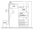
図1に示すように、空調制御システム1は、空気調和機2と、コントローラ3とを備えている。空気調和機2の室内機5及びコントローラ3は、同一の室内に設置されている。
(空気調和機)
空気調和機2は、室外機4と、室内機5とを備えている。室外機4と室内機5は、冷媒配管6で接続されている。また、室内機5は、信号線7を介してコントローラ3と接続されている。そして、空気調和機2は、信号線7を介してコントローラ3から信号を取得し、取得した信号に従い室温が設定温度に維持されるように冷暖房の運転を行う。
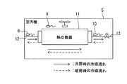
また図2に示すように、室内機5内には、各々が温度を検出値として検出する複数の温度センサ8、9、10を備えている。複数の温度センサ8、9、10は、室内機5内の複数箇所に分散して配置されている。具体的には、各温度センサ8、9、10は、室内機5内を流れる冷媒の流路に沿うように、冷媒の流路の複数箇所に分散して配置されている。
(Embodiment)
(Constitution)
As shown in FIG. 1, the air conditioning control system 1 includes an
(Air conditioner)
The
As shown in FIG. 2, the
温度センサ8(以下「第1温度センサ8」とも呼ぶ)は、液管6aが熱交換器11に接続される接続部12に配置されている。第1温度センサ8は、接続部12内を流れる冷媒の温度を検出値として検出する。
温度センサ9(以下「第2温度センサ9」とも呼ぶ)は、熱交換器11に配置されている。第2温度センサ9は、熱交換器11内を流れる冷媒の温度を検出値として検出する。
温度センサ10(以下「第3温度センサ10」とも呼ぶ)は、ガス管6bが熱交換器11に接続される接続部13に配置されている。第1温度センサ8は接続部13内を流れる冷媒の温度を検出値として検出する。
第1温度センサ8、第2温度センサ9及び第3温度センサ10は、信号線7を介して検出温度(つまり、室内機5内の各部における冷媒の温度)をコントローラ3に出力する。
The temperature sensor 8 (hereinafter also referred to as “
The temperature sensor 9 (hereinafter also referred to as “
The temperature sensor 10 (hereinafter also referred to as “
The
(コントローラ)
コントローラ3は、受付部14と、タッチパネル15と、制御部16とを備えている。
受付部14は、室内機5内に配置された第1温度センサ8と、第2温度センサ9と、第3温度センサ10の検出値を信号線7を介して受け付ける。
タッチパネル15は、ディスプレイ17と、タッチセンサ18とを有している。
制御部16は、表示制御部19を含むハードウェア資源を論理的に備えている。制御部16としては、例えば、マイコンを採用できる。図1では、表示制御部19は、機能に着目したハードウェアとして表現している。即ち、図1の表現は、必ずしも物理的な構造として存在する機能ブロックを意味するものではなく、ソフトウェアで実現されるものであってもよい。
(controller)
The
The accepting
The
The
表示制御部19は、運転モードや設定温度の入力をユーザーに要求する設定画面をディスプレイ17に表示させる。表示制御部19は、タッチセンサ18への入力状態を基に、運転モードや設定温度を指示する信号を、信号線7を介して空気調和機2に出力する。
また、表示制御部19は、温度表示処理を実行する。温度表示処理では、表示制御部19が、受付部14を介して、複数の温度センサ8、9、10が出力した検出温度T1、T2、T3を取得する。そして、表示制御部19は、取得した検出温度T1、T2及T3を、ディスプレイ17に表示させる。温度表示処理の詳細については、後述する。
The
Moreover, the
(温度表示処理)
次に、表示制御部19が実行する温度表示処理について説明する。
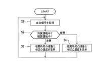
温度表示処理では、図3に示すように、ステップS1で、表示制御部19が、受付部14を介して、複数の温度センサ8、9及び10が出力する温度を取得してステップS2に移行する。
ステップS2では空気調和機2が冷房運転中であるか、暖房運転中であるかを表示制御部19が判定する。これにより、図2に示すように、室内機5内における、温度検出時の冷媒が流れる向きを決定する。そして、表示制御部19が、冷房運転中であると決定した場合(冷房)には、図2に実線で示すように、温度検出時の冷媒が流れる向きが接続部12→熱交換器11→接続部13であると表示制御部19が決定し、ステップS3に移行する。一方、表示制御部19が、暖房運転中であると判定した場合(暖房)には、図2に破線で示すように、温度検出時の冷媒が流れる向きが接続部13→熱交換器11→接続部12であると表示制御部19が決定し、ステップS4に移行する。
(Temperature display processing)
Next, the temperature display process executed by the
In the temperature display process, as shown in FIG. 3, in step S1, the
In step S2, the
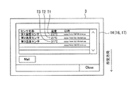
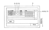
ステップS3では、表示制御部19が、ステップS1で取得した温度を基に、図4に示すように、第1温度センサ8の検出温度T1、第2温度センサ9の検出温度T2及び第3温度センサ10の検出温度T3をセンサの名称と共にディスプレイ17に表示させる。検出温度T1、T2及びT3を表示した後、ステップS1に戻る。具体的には、表示制御部19が、ディスプレイ17の表示面に予め定められた所定方向に沿って、検出温度T1、T2及びT3がT1→T2→T3の順番に並ぶようにテキスト形式でディスプレイ17に表示させる。これにより、検出温度T1、T2及びT3の各々が、室内機5内の冷媒が流れる方向の最上流に位置している温度センサ8の検出温度T1から順番に並ぶようにディスプレイ17に表示される。図4では、所定方向としては、ディスプレイ17の表示面に正対した場合に、図4に矢印で示すように、表示面の上方から下方に向かう方向を用いている。
In step S3, based on the temperature acquired in step S1, the
一方、ステップS4では、表示制御部19が、ステップS1で取得した温度を基に、図5に示すように、第1温度センサ8の検出温度T1、第2温度センサ9の検出温度T2及び第3温度センサ10の検出温度T3をディスプレイ17に表示させる。検出温度T1、T2及びT3を表示した後、ステップS1に戻る。具体的には、表示制御部19が、ディスプレイ17の表示面に予め定められた所定方向に、検出温度T1、T2及びT3がT3→T2→T1の順番に並ぶようにテキスト形式でディスプレイ17に表示させる。これにより、検出温度T1、T2及びT3の各々が、室内機5内の冷媒が流れる向きの最上流に位置している温度センサ8の検出温度T1から順番に並ぶようにディスプレイ17に表示される。図5では、所定方向としては、ディスプレイ17の表示面に正対した場合に、図5に矢印で示すように表示面の上方から下方に向かう方向を用いている。
なお、本実施形態では、所定方向として、ディスプレイ17の表示面の上方から下方に向かう方向を用いたが、他の方向を用いることもできる。例えば、ディスプレイ17の表示面に正対した場合に、表示面の左方から右方に向かう方向を用いていてもよい。
On the other hand, in step S4, based on the temperature acquired in step S1, the
In the present embodiment, the direction from the upper side to the lower side of the display surface of the
以上説明したように、本発明の実施形態に係るコントローラ3(温度表示装置)が、検出温度T1、T2、T3の各々を、テキスト形式で表示するようにした。また、ディスプレイ17の表示面に予め定められた所定方向に、テキスト形式の検出温度T1、T2、T3が並ぶようにした。さらに、温度検出時に室内機5内の冷媒が流れる向きの最上流に位置している温度センサ8又は10の検出温度T1から順番に、数値が並ぶようにした。ここで、空気調和機2が正常に動作している場合、冷房運転時には、冷却された冷媒が、接続部12→熱交換器11→接続部13と順番に流れる。それゆえ、検出温度T1、T2、T3の大小関係が、冷媒が室内機5内を流れ、冷媒が徐々に暖まることで、T1<T2<T3となる。そのため、最上流に位置している温度センサ8の検出温度T1又はT3から順番に、検出温度T1、T2、T3が並べられることにより、温度の低い順に検出温度T1、T2、T3が並ぶことになる。したがって、空気調和機2の点検時等に、空気調和機2の冷媒回路において、冷媒が室内機5内を流れ、冷媒が徐々に暖まる様子を、サービスマンが冷媒回路をイメージしながら確認することで直感的かつ確実に数値を把握できる。
As described above, the controller 3 (temperature display device) according to the embodiment of the present invention displays each of the detected temperatures T1, T2, and T3 in a text format. The detected temperatures T1, T2, and T3 in the text format are arranged in a predetermined direction on the display surface of the
同様に、空気調和機2が正常に動作している場合、暖房運転時には、暖められた冷媒が、接続部13→熱交換器11→接続部12と順番に流れる。それゆえ、複数の温度センサ8、9、10の検出温度T3、T2、T1が、冷媒が室内機5内を流れ、冷媒が徐々に冷えることで、T1<T2<T3となる。そのため、最上流に位置している温度センサ8、9、10の検出温度から順番に、検出温度T1、T2、T3が並べられることにより、温度の高い順に検出温度T3、T2、T1が並ぶことになる。したがって、空気調和機2の冷媒回路において、冷媒が室内機5内を流れ、冷媒が徐々に冷える様子を、サービスマンが、直感的に把握しやすい。また、例えば、空気調和機2に異常が発生し、T1<T2<T3の大小関係が崩れた場合に、サービスマンが、この大小関係が崩れたことを簡単に把握できる。その結果、サービスマンが、空気調和機2の異常を直感的に把握しやすくなり、修理やメンテナンスを適切に行うことができる。
それゆえ、本発明の実施形態は、ディスプレイ17の大きさに関わらず、空気調和機2の動作状態の直感的に把握可能なコントローラ3(温度表示装置)を提供できる。
Similarly, when the
Therefore, the embodiment of the present invention can provide the controller 3 (temperature display device) that can intuitively grasp the operation state of the
また、本発明の実施形態に係るコントローラ3(温度表示装置)では、複数の温度センサ8、9、10の検出温度を並べる所定方向は、ディスプレイ17の表示面に正対した場合に、表示面の上側から下側に向かう方向とした。それゆえ、例えば、横書きのテキスト形式で各温度センサ8、9、10の検出温度が表される場合に、ディスプレイ17が、横書きで表された各温度センサ8、9、10の検出温度を一画面内により多く表示できる。
尚、本実施例ではセンサとして温度センサを用いた場合を説明したが、これに限るものではなく、例えば冷媒の圧力を検出する圧力センサ等を用いてもよい。
Further, in the controller 3 (temperature display device) according to the embodiment of the present invention, the predetermined direction in which the detected temperatures of the plurality of
In this embodiment, the temperature sensor is used as the sensor. However, the present invention is not limited to this. For example, a pressure sensor that detects the pressure of the refrigerant may be used.
1…空調制御システム、2…空気調和機、3…コントローラ、4…室外機、5…室内機、6…冷媒配管、6a…液管、6b…ガス管、7…信号線、8、9、10…温度センサ(第1温度センサ、第2温度センサ、第3温度センサ)、11…熱交換器、12、13…接続部、14…受付部、15…タッチパネル、16…制御部、17…ディスプレイ、18…タッチセンサ、19…表示制御部
DESCRIPTION OF SYMBOLS 1 ... Air-conditioning control system, 2 ... Air conditioner, 3 ... Controller, 4 ... Outdoor unit, 5 ... Indoor unit, 6 ... Refrigerant piping, 6a ... Liquid pipe, 6b ... Gas pipe, 7 ... Signal line, 8, 9, DESCRIPTION OF
Claims (2)
室内機内の冷媒が流れる流路に沿って配置された複数のセンサからの検出値を受け付ける受付部と、
前記検出値を、前記室内機の冷房運転または暖房運転によって定められる冷媒が流れる向きにおいて上流側に位置しているセンサから下流側に位置しているセンサの順に、前記ディスプレイ上に予め定められた所定の方向に沿って、前記ディスプレイに表示させる表示制御部とを備えることを特徴とする表示装置。 Display,
A reception unit that receives detection values from a plurality of sensors arranged along a flow path through which the refrigerant in the indoor unit flows;
The detection value is predetermined on the display in the order of the sensor located on the upstream side and the sensor located on the downstream side in the direction in which the refrigerant determined by the cooling operation or the heating operation of the indoor unit flows. A display device comprising: a display control unit configured to display on the display along a predetermined direction.
The display device according to claim 1, wherein the predetermined direction is a direction from an upper side to a lower side of a display surface of the display.
Priority Applications (1)
| Application Number | Priority Date | Filing Date | Title |
|---|---|---|---|
| JP2018042146A JP7159572B2 (en) | 2018-03-08 | 2018-03-08 | Display device |
Applications Claiming Priority (1)
| Application Number | Priority Date | Filing Date | Title |
|---|---|---|---|
| JP2018042146A JP7159572B2 (en) | 2018-03-08 | 2018-03-08 | Display device |
Publications (2)
| Publication Number | Publication Date |
|---|---|
| JP2019158181A true JP2019158181A (en) | 2019-09-19 |
| JP7159572B2 JP7159572B2 (en) | 2022-10-25 |
Family
ID=67995056
Family Applications (1)
| Application Number | Title | Priority Date | Filing Date |
|---|---|---|---|
| JP2018042146A Active JP7159572B2 (en) | 2018-03-08 | 2018-03-08 | Display device |
Country Status (1)
| Country | Link |
|---|---|
| JP (1) | JP7159572B2 (en) |
Citations (5)
| Publication number | Priority date | Publication date | Assignee | Title |
|---|---|---|---|---|
| JPH1139028A (en) * | 1997-07-15 | 1999-02-12 | Tlv Co Ltd | Equipment diagnostic order decision device, computer-readable recording medium recording equipment diagnostic order decision program, and equipment diagnostic device |
| JPH1183138A (en) * | 1997-09-17 | 1999-03-26 | Yamatake Honeywell Co Ltd | Air conditioning piping pressure monitoring device |
| JP2001133020A (en) * | 1999-10-29 | 2001-05-18 | Sanyo Electric Co Ltd | Automatic address setting system for air conditioners |
| JP2010107189A (en) * | 2008-09-30 | 2010-05-13 | Daikin Ind Ltd | Method and device for diagnosing refrigerating device, and refrigerating device |
| US20160025369A1 (en) * | 2014-07-25 | 2016-01-28 | Lg Electronics Inc. | Air conditioning system |
-
2018
- 2018-03-08 JP JP2018042146A patent/JP7159572B2/en active Active
Patent Citations (5)
| Publication number | Priority date | Publication date | Assignee | Title |
|---|---|---|---|---|
| JPH1139028A (en) * | 1997-07-15 | 1999-02-12 | Tlv Co Ltd | Equipment diagnostic order decision device, computer-readable recording medium recording equipment diagnostic order decision program, and equipment diagnostic device |
| JPH1183138A (en) * | 1997-09-17 | 1999-03-26 | Yamatake Honeywell Co Ltd | Air conditioning piping pressure monitoring device |
| JP2001133020A (en) * | 1999-10-29 | 2001-05-18 | Sanyo Electric Co Ltd | Automatic address setting system for air conditioners |
| JP2010107189A (en) * | 2008-09-30 | 2010-05-13 | Daikin Ind Ltd | Method and device for diagnosing refrigerating device, and refrigerating device |
| US20160025369A1 (en) * | 2014-07-25 | 2016-01-28 | Lg Electronics Inc. | Air conditioning system |
Also Published As
| Publication number | Publication date |
|---|---|
| JP7159572B2 (en) | 2022-10-25 |
Similar Documents
| Publication | Publication Date | Title |
|---|---|---|
| JP6625239B2 (en) | Air conditioner and air conditioning system | |
| US11131474B2 (en) | Thermostat with user interface features | |
| JP6253675B2 (en) | Air conditioner trial run application and air conditioner trial run system | |
| US20140059466A1 (en) | Mobile device with graphical user interface for monitoring a building automation system | |
| JP5627504B2 (en) | Air conditioning equipment maintenance system and data analysis device | |
| JP2012225590A (en) | Local air conditioning system and control device for the same | |
| KR20060103466A (en) | Service and diagnostic tools for HPAC systems | |
| JP5287653B2 (en) | Air conditioner | |
| KR20160099682A (en) | Process system managmenet system, server device, management program, and management method | |
| JPWO2015193976A1 (en) | Air conditioning system | |
| CN107278091A (en) | Servicing unit and householder method | |
| CN104279695B (en) | heat display device and method | |
| JP2017015339A (en) | Control device for heat source unit for air handling unit | |
| JP2019158181A (en) | Display device | |
| US20200224901A1 (en) | Configurable display for sensor device | |
| JP2018147255A (en) | Abnormality judgment system | |
| JP5313715B2 (en) | Building management system | |
| CN107407492A (en) | Construction Inspection System | |
| JP6158063B2 (en) | Centralized control system | |
| JP6435352B2 (en) | Air conditioning management device and display control method thereof | |
| JPWO2017010273A1 (en) | Sensor connection structure | |
| US20140059467A1 (en) | Mobile device with graphical user interface for monitoring a building automation system | |
| JP2012127603A (en) | Air conditioning system | |
| KR20090033682A (en) | Air conditioner and its operation method | |
| JP3456457B2 (en) | Operation control system for multi-type air conditioner |
Legal Events
| Date | Code | Title | Description |
|---|---|---|---|
| RD04 | Notification of resignation of power of attorney |
Free format text: JAPANESE INTERMEDIATE CODE: A7424 Effective date: 20190411 |
|
| A621 | Written request for application examination |
Free format text: JAPANESE INTERMEDIATE CODE: A621 Effective date: 20201225 |
|
| A977 | Report on retrieval |
Free format text: JAPANESE INTERMEDIATE CODE: A971007 Effective date: 20211109 |
|
| A131 | Notification of reasons for refusal |
Free format text: JAPANESE INTERMEDIATE CODE: A131 Effective date: 20211116 |
|
| A521 | Request for written amendment filed |
Free format text: JAPANESE INTERMEDIATE CODE: A523 Effective date: 20211224 |
|
| A131 | Notification of reasons for refusal |
Free format text: JAPANESE INTERMEDIATE CODE: A131 Effective date: 20220308 |
|
| A521 | Request for written amendment filed |
Free format text: JAPANESE INTERMEDIATE CODE: A523 Effective date: 20220425 |
|
| TRDD | Decision of grant or rejection written | ||
| A01 | Written decision to grant a patent or to grant a registration (utility model) |
Free format text: JAPANESE INTERMEDIATE CODE: A01 Effective date: 20220913 |
|
| A61 | First payment of annual fees (during grant procedure) |
Free format text: JAPANESE INTERMEDIATE CODE: A61 Effective date: 20220926 |
|
| R151 | Written notification of patent or utility model registration |
Ref document number: 7159572 Country of ref document: JP Free format text: JAPANESE INTERMEDIATE CODE: R151 |
|
| S533 | Written request for registration of change of name |
Free format text: JAPANESE INTERMEDIATE CODE: R313533 |