JP2019155946A - Electromagnetic wave use system - Google Patents
Electromagnetic wave use system Download PDFInfo
- Publication number
- JP2019155946A JP2019155946A JP2018040704A JP2018040704A JP2019155946A JP 2019155946 A JP2019155946 A JP 2019155946A JP 2018040704 A JP2018040704 A JP 2018040704A JP 2018040704 A JP2018040704 A JP 2018040704A JP 2019155946 A JP2019155946 A JP 2019155946A
- Authority
- JP
- Japan
- Prior art keywords
- electromagnetic wave
- heater
- vehicle
- windshield
- heat insulation
- Prior art date
- Legal status (The legal status is an assumption and is not a legal conclusion. Google has not performed a legal analysis and makes no representation as to the accuracy of the status listed.)
- Pending
Links
- 238000009413 insulation Methods 0.000 claims abstract description 31
- 230000005540 biological transmission Effects 0.000 claims abstract description 3
- 238000010438 heat treatment Methods 0.000 claims description 10
- 239000000126 substance Substances 0.000 claims description 2
- 239000011521 glass Substances 0.000 abstract description 25
- 230000001747 exhibiting effect Effects 0.000 abstract 1
- OKTJSMMVPCPJKN-UHFFFAOYSA-N Carbon Chemical compound [C] OKTJSMMVPCPJKN-UHFFFAOYSA-N 0.000 description 23
- 239000002041 carbon nanotube Substances 0.000 description 22
- 229910021393 carbon nanotube Inorganic materials 0.000 description 22
- 238000003384 imaging method Methods 0.000 description 7
- 239000011230 binding agent Substances 0.000 description 6
- 239000007788 liquid Substances 0.000 description 6
- 238000001514 detection method Methods 0.000 description 5
- 239000000463 material Substances 0.000 description 3
- 238000005259 measurement Methods 0.000 description 3
- 238000000034 method Methods 0.000 description 3
- 239000005662 Paraffin oil Substances 0.000 description 2
- 206010037660 Pyrexia Diseases 0.000 description 2
- VYPSYNLAJGMNEJ-UHFFFAOYSA-N Silicium dioxide Chemical compound O=[Si]=O VYPSYNLAJGMNEJ-UHFFFAOYSA-N 0.000 description 2
- 239000011347 resin Substances 0.000 description 2
- 229920005989 resin Polymers 0.000 description 2
- 239000010409 thin film Substances 0.000 description 2
- 235000015112 vegetable and seed oil Nutrition 0.000 description 2
- 239000008158 vegetable oil Substances 0.000 description 2
- BQCADISMDOOEFD-UHFFFAOYSA-N Silver Chemical compound [Ag] BQCADISMDOOEFD-UHFFFAOYSA-N 0.000 description 1
- 238000000149 argon plasma sintering Methods 0.000 description 1
- 229910052799 carbon Inorganic materials 0.000 description 1
- 239000013078 crystal Substances 0.000 description 1
- 230000020169 heat generation Effects 0.000 description 1
- AMGQUBHHOARCQH-UHFFFAOYSA-N indium;oxotin Chemical compound [In].[Sn]=O AMGQUBHHOARCQH-UHFFFAOYSA-N 0.000 description 1
- 230000002093 peripheral effect Effects 0.000 description 1
- 230000002265 prevention Effects 0.000 description 1
- 230000005855 radiation Effects 0.000 description 1
- 239000000377 silicon dioxide Substances 0.000 description 1
- 229910052709 silver Inorganic materials 0.000 description 1
- 239000004332 silver Substances 0.000 description 1
- 230000000007 visual effect Effects 0.000 description 1
Images


Classifications
-
- G—PHYSICS
- G01—MEASURING; TESTING
- G01S—RADIO DIRECTION-FINDING; RADIO NAVIGATION; DETERMINING DISTANCE OR VELOCITY BY USE OF RADIO WAVES; LOCATING OR PRESENCE-DETECTING BY USE OF THE REFLECTION OR RERADIATION OF RADIO WAVES; ANALOGOUS ARRANGEMENTS USING OTHER WAVES
- G01S17/00—Systems using the reflection or reradiation of electromagnetic waves other than radio waves, e.g. lidar systems
- G01S17/88—Lidar systems specially adapted for specific applications
- G01S17/93—Lidar systems specially adapted for specific applications for anti-collision purposes
- G01S17/931—Lidar systems specially adapted for specific applications for anti-collision purposes of land vehicles
-
- B—PERFORMING OPERATIONS; TRANSPORTING
- B60—VEHICLES IN GENERAL
- B60S—SERVICING, CLEANING, REPAIRING, SUPPORTING, LIFTING, OR MANOEUVRING OF VEHICLES, NOT OTHERWISE PROVIDED FOR
- B60S1/00—Cleaning of vehicles
- B60S1/02—Cleaning windscreens, windows or optical devices
-
- B—PERFORMING OPERATIONS; TRANSPORTING
- B60—VEHICLES IN GENERAL
- B60J—WINDOWS, WINDSCREENS, NON-FIXED ROOFS, DOORS, OR SIMILAR DEVICES FOR VEHICLES; REMOVABLE EXTERNAL PROTECTIVE COVERINGS SPECIALLY ADAPTED FOR VEHICLES
- B60J1/00—Windows; Windscreens; Accessories therefor
- B60J1/02—Windows; Windscreens; Accessories therefor arranged at the vehicle front, e.g. structure of the glazing, mounting of the glazing
-
- B—PERFORMING OPERATIONS; TRANSPORTING
- B60—VEHICLES IN GENERAL
- B60R—VEHICLES, VEHICLE FITTINGS, OR VEHICLE PARTS, NOT OTHERWISE PROVIDED FOR
- B60R11/00—Arrangements for holding or mounting articles, not otherwise provided for
- B60R11/04—Mounting of cameras operative during drive; Arrangement of controls thereof relative to the vehicle
-
- B—PERFORMING OPERATIONS; TRANSPORTING
- B60—VEHICLES IN GENERAL
- B60S—SERVICING, CLEANING, REPAIRING, SUPPORTING, LIFTING, OR MANOEUVRING OF VEHICLES, NOT OTHERWISE PROVIDED FOR
- B60S1/00—Cleaning of vehicles
- B60S1/02—Cleaning windscreens, windows or optical devices
- B60S1/04—Wipers or the like, e.g. scrapers
- B60S1/06—Wipers or the like, e.g. scrapers characterised by the drive
- B60S1/08—Wipers or the like, e.g. scrapers characterised by the drive electrically driven
- B60S1/0818—Wipers or the like, e.g. scrapers characterised by the drive electrically driven including control systems responsive to external conditions, e.g. by detection of moisture, dirt or the like
- B60S1/0822—Wipers or the like, e.g. scrapers characterised by the drive electrically driven including control systems responsive to external conditions, e.g. by detection of moisture, dirt or the like characterized by the arrangement or type of detection means
- B60S1/0833—Optical rain sensor
- B60S1/0844—Optical rain sensor including a camera
- B60S1/0848—Cleaning devices for cameras on vehicle
-
- G—PHYSICS
- G01—MEASURING; TESTING
- G01S—RADIO DIRECTION-FINDING; RADIO NAVIGATION; DETERMINING DISTANCE OR VELOCITY BY USE OF RADIO WAVES; LOCATING OR PRESENCE-DETECTING BY USE OF THE REFLECTION OR RERADIATION OF RADIO WAVES; ANALOGOUS ARRANGEMENTS USING OTHER WAVES
- G01S13/00—Systems using the reflection or reradiation of radio waves, e.g. radar systems; Analogous systems using reflection or reradiation of waves whose nature or wavelength is irrelevant or unspecified
- G01S13/88—Radar or analogous systems specially adapted for specific applications
- G01S13/93—Radar or analogous systems specially adapted for specific applications for anti-collision purposes
-
- G—PHYSICS
- G01—MEASURING; TESTING
- G01S—RADIO DIRECTION-FINDING; RADIO NAVIGATION; DETERMINING DISTANCE OR VELOCITY BY USE OF RADIO WAVES; LOCATING OR PRESENCE-DETECTING BY USE OF THE REFLECTION OR RERADIATION OF RADIO WAVES; ANALOGOUS ARRANGEMENTS USING OTHER WAVES
- G01S17/00—Systems using the reflection or reradiation of electromagnetic waves other than radio waves, e.g. lidar systems
- G01S17/02—Systems using the reflection of electromagnetic waves other than radio waves
- G01S17/06—Systems determining position data of a target
- G01S17/08—Systems determining position data of a target for measuring distance only
- G01S17/10—Systems determining position data of a target for measuring distance only using transmission of interrupted, pulse-modulated waves
-
- G—PHYSICS
- G01—MEASURING; TESTING
- G01S—RADIO DIRECTION-FINDING; RADIO NAVIGATION; DETERMINING DISTANCE OR VELOCITY BY USE OF RADIO WAVES; LOCATING OR PRESENCE-DETECTING BY USE OF THE REFLECTION OR RERADIATION OF RADIO WAVES; ANALOGOUS ARRANGEMENTS USING OTHER WAVES
- G01S17/00—Systems using the reflection or reradiation of electromagnetic waves other than radio waves, e.g. lidar systems
- G01S17/02—Systems using the reflection of electromagnetic waves other than radio waves
- G01S17/06—Systems determining position data of a target
- G01S17/42—Simultaneous measurement of distance and other co-ordinates
-
- G—PHYSICS
- G01—MEASURING; TESTING
- G01S—RADIO DIRECTION-FINDING; RADIO NAVIGATION; DETERMINING DISTANCE OR VELOCITY BY USE OF RADIO WAVES; LOCATING OR PRESENCE-DETECTING BY USE OF THE REFLECTION OR RERADIATION OF RADIO WAVES; ANALOGOUS ARRANGEMENTS USING OTHER WAVES
- G01S17/00—Systems using the reflection or reradiation of electromagnetic waves other than radio waves, e.g. lidar systems
- G01S17/88—Lidar systems specially adapted for specific applications
- G01S17/93—Lidar systems specially adapted for specific applications for anti-collision purposes
-
- G—PHYSICS
- G01—MEASURING; TESTING
- G01S—RADIO DIRECTION-FINDING; RADIO NAVIGATION; DETERMINING DISTANCE OR VELOCITY BY USE OF RADIO WAVES; LOCATING OR PRESENCE-DETECTING BY USE OF THE REFLECTION OR RERADIATION OF RADIO WAVES; ANALOGOUS ARRANGEMENTS USING OTHER WAVES
- G01S7/00—Details of systems according to groups G01S13/00, G01S15/00, G01S17/00
- G01S7/02—Details of systems according to groups G01S13/00, G01S15/00, G01S17/00 of systems according to group G01S13/00
- G01S7/03—Details of HF subsystems specially adapted therefor, e.g. common to transmitter and receiver
-
- G—PHYSICS
- G01—MEASURING; TESTING
- G01S—RADIO DIRECTION-FINDING; RADIO NAVIGATION; DETERMINING DISTANCE OR VELOCITY BY USE OF RADIO WAVES; LOCATING OR PRESENCE-DETECTING BY USE OF THE REFLECTION OR RERADIATION OF RADIO WAVES; ANALOGOUS ARRANGEMENTS USING OTHER WAVES
- G01S7/00—Details of systems according to groups G01S13/00, G01S15/00, G01S17/00
- G01S7/48—Details of systems according to groups G01S13/00, G01S15/00, G01S17/00 of systems according to group G01S17/00
- G01S7/481—Constructional features, e.g. arrangements of optical elements
- G01S7/4811—Constructional features, e.g. arrangements of optical elements common to transmitter and receiver
- G01S7/4813—Housing arrangements
-
- G—PHYSICS
- G01—MEASURING; TESTING
- G01S—RADIO DIRECTION-FINDING; RADIO NAVIGATION; DETERMINING DISTANCE OR VELOCITY BY USE OF RADIO WAVES; LOCATING OR PRESENCE-DETECTING BY USE OF THE REFLECTION OR RERADIATION OF RADIO WAVES; ANALOGOUS ARRANGEMENTS USING OTHER WAVES
- G01S7/00—Details of systems according to groups G01S13/00, G01S15/00, G01S17/00
- G01S7/48—Details of systems according to groups G01S13/00, G01S15/00, G01S17/00 of systems according to group G01S17/00
- G01S7/497—Means for monitoring or calibrating
-
- G—PHYSICS
- G02—OPTICS
- G02B—OPTICAL ELEMENTS, SYSTEMS OR APPARATUS
- G02B27/00—Optical systems or apparatus not provided for by any of the groups G02B1/00 - G02B26/00, G02B30/00
- G02B27/0006—Optical systems or apparatus not provided for by any of the groups G02B1/00 - G02B26/00, G02B30/00 with means to keep optical surfaces clean, e.g. by preventing or removing dirt, stains, contamination, condensation
-
- H—ELECTRICITY
- H05—ELECTRIC TECHNIQUES NOT OTHERWISE PROVIDED FOR
- H05B—ELECTRIC HEATING; ELECTRIC LIGHT SOURCES NOT OTHERWISE PROVIDED FOR; CIRCUIT ARRANGEMENTS FOR ELECTRIC LIGHT SOURCES, IN GENERAL
- H05B3/00—Ohmic-resistance heating
- H05B3/0033—Heating devices using lamps
- H05B3/0038—Heating devices using lamps for industrial applications
- H05B3/0042—Heating devices using lamps for industrial applications used in motor vehicles
-
- H—ELECTRICITY
- H05—ELECTRIC TECHNIQUES NOT OTHERWISE PROVIDED FOR
- H05B—ELECTRIC HEATING; ELECTRIC LIGHT SOURCES NOT OTHERWISE PROVIDED FOR; CIRCUIT ARRANGEMENTS FOR ELECTRIC LIGHT SOURCES, IN GENERAL
- H05B3/00—Ohmic-resistance heating
- H05B3/84—Heating arrangements specially adapted for transparent or reflecting areas, e.g. for demisting or de-icing windows, mirrors or vehicle windshields
-
- G—PHYSICS
- G01—MEASURING; TESTING
- G01S—RADIO DIRECTION-FINDING; RADIO NAVIGATION; DETERMINING DISTANCE OR VELOCITY BY USE OF RADIO WAVES; LOCATING OR PRESENCE-DETECTING BY USE OF THE REFLECTION OR RERADIATION OF RADIO WAVES; ANALOGOUS ARRANGEMENTS USING OTHER WAVES
- G01S7/00—Details of systems according to groups G01S13/00, G01S15/00, G01S17/00
- G01S7/48—Details of systems according to groups G01S13/00, G01S15/00, G01S17/00 of systems according to group G01S17/00
- G01S7/497—Means for monitoring or calibrating
- G01S2007/4975—Means for monitoring or calibrating of sensor obstruction by, e.g. dirt- or ice-coating, e.g. by reflection measurement on front-screen
- G01S2007/4977—Means for monitoring or calibrating of sensor obstruction by, e.g. dirt- or ice-coating, e.g. by reflection measurement on front-screen including means to prevent or remove the obstruction
Abstract
Description
本発明は、電磁波を利用する電磁波利用システムに関する。 The present invention relates to an electromagnetic wave utilization system that utilizes electromagnetic waves.
従来、特許文献1には、車両の後方視界を撮像する車載カメラが記載されている。この従来技術では、車載カメラは、リアウインドウに近接して車室内の天井に設置され、リアウインドウを介して外部を撮像する。 Conventionally, Patent Document 1 describes an in-vehicle camera that captures a rear view of a vehicle. In this prior art, the vehicle-mounted camera is installed on the ceiling in the vehicle compartment in the vicinity of the rear window, and images the outside through the rear window.
この従来技術では、車載カメラは、リアウィンドウのデフォッガーのヒーター線が撮像範囲内に入らないように設置されている。デフォッガーは、ヒータ線がリアウィンドウを加熱することによってリアウインドウの曇りを晴らす装置である。 In this prior art, the in-vehicle camera is installed so that the heater wire of the rear window defogger does not enter the imaging range. The defogger is a device that clears the fog of the rear window by heating the rear window with a heater wire.
この従来技術によると、車載カメラは、リアウィンドウのデフォッガーのヒーター線が撮像範囲内に入らないように設置されているので、車載カメラの視界がデフォッガーのヒーター線によって妨げられることはない。 According to this prior art, since the in-vehicle camera is installed so that the heater wire of the rear window defogger does not enter the imaging range, the field of view of the in-vehicle camera is not hindered by the heater wire of the defogger.
しかしながら、この従来技術では、撮像範囲内にデフォッガーのヒーター線がないので、撮像範囲内の曇りをうまく晴らすことができない。したがって、リアウィンドウが曇る条件下では車載カメラの視界の視認性を良好に確保できない、という問題がある。 However, in this prior art, since there is no defogger heater wire in the imaging range, the fogging in the imaging range cannot be cleared well. Therefore, there is a problem that the visibility of the field of view of the in-vehicle camera cannot be secured satisfactorily under the condition that the rear window is cloudy.
この問題は、可視光を撮影する車載カメラのみならず、レーザー光を送受する車両用レーザー装置等、電磁波を利用する種々の電磁波利用システムにおいても同様に発生する。 This problem occurs not only in an in-vehicle camera that captures visible light but also in various electromagnetic wave utilization systems that utilize electromagnetic waves, such as a vehicle laser device that transmits and receives laser light.
本発明は上記点に鑑みて、電磁波が通過する通過部の加熱を、電磁波の通過を妨げることなく行うことのできる電磁波利用システムを提供することを目的とする。 In view of the above points, an object of the present invention is to provide an electromagnetic wave utilization system capable of heating a passage portion through which an electromagnetic wave passes without disturbing the passage of the electromagnetic wave.
上記目的を達成するため、請求項1に記載の電磁波利用システムでは、
電磁波の送受のうち少なくとも一方を行う電磁波装置(100、201)と、
電磁波装置(100、201)が利用する電磁波が通過する通過部(1、2、203)とを備え、
通過部(1、2、203)は、電磁波装置(100、201)側に設けられた内側部材(2、203b)と、電磁波装置(100、201)と反対側に設けられた外側部材(1、203a)と、内側部材(2、203b)のうち電磁波が通過する部位の曇りを抑制するように内側部材(2、203b)と外側部材(1、203a)との間で断熱機能を発揮する断熱部(3、203c)とを有している。
In order to achieve the above object, in the electromagnetic wave utilization system according to claim 1,
An electromagnetic wave device (100, 201) that performs at least one of electromagnetic wave transmission and reception;
Including a passing portion (1, 2, 203) through which electromagnetic waves used by the electromagnetic wave device (100, 201) pass,
The passage portions (1, 2 and 203) include an inner member (2, 203b) provided on the electromagnetic wave device (100, 201) side and an outer member (1) provided on the opposite side of the electromagnetic wave device (100, 201). , 203a) and the inner member (2, 203b) exhibit a heat insulating function between the inner member (2, 203b) and the outer member (1, 203a) so as to suppress fogging of a portion through which electromagnetic waves pass. And a heat insulating part (3, 203c).
これによると、簡素な構成で、電力等の動力を消費することなく防曇できる。 According to this, anti-fogging can be achieved with a simple configuration without consuming power such as electric power.
なお、この欄および特許請求の範囲で記載した各手段の括弧内の符号は、後述する実施形態に記載の具体的手段との対応関係を示すものである。 In addition, the code | symbol in the bracket | parenthesis of each means described in this column and the claim shows the correspondence with the specific means as described in embodiment mentioned later.
以下、実施形態について図に基づいて説明する。以下の各実施形態相互において、互いに同一もしくは均等である部分には、図中、同一符号を付してある。 Hereinafter, embodiments will be described with reference to the drawings. In the following embodiments, the same or equivalent parts are denoted by the same reference numerals in the drawings.
(第1実施形態)
以下、本実施形態の車両用撮影装置について図に基づいて説明する。図中、上下前後の矢印は、車両の上下前後方向を示している。車両用撮影装置は、電磁波の一種である可視光を利用する電磁波利用システムである。
(First embodiment)
Hereinafter, the vehicle photographing device of the present embodiment will be described with reference to the drawings. In the figure, the up and down arrows indicate the up and down and front and rear directions of the vehicle. The vehicle photographing device is an electromagnetic wave utilization system that utilizes visible light, which is a type of electromagnetic wave.
図1に示すように、カメラユニット10は、車両のフロントガラス1のうち車室内側の面に取り付けられている。カメラユニット10は、車両のフロントガラス1の上部かつ左右方向の略中央部に取り付けられている。カメラユニット10は、図示しないバックミラーの近傍に位置している。
As shown in FIG. 1, the
図2に示すように、カメラユニット10は、カメラ100および筐体101を有している。カメラ100は、車両の窓(本例ではフロントガラス1)を介して車両の前方の外部を撮影する。カメラ100は、電磁波の一種である可視光を撮影する電磁波装置である。フロントガラス1は、カメラ100が撮影する可視光が通過する通過部である。
As shown in FIG. 2, the
筐体101内において、フロントガラス1とカメラ100との間には、内側ガラス2が配置されている。内側ガラス2は、フロントガラス1とともに二重構造を構成している。すなわち、フロントガラス1および内側ガラス2は二重窓を構成している。
Inside the
内側ガラス2は、二重窓のうち車室内側に設けられた内側部材である。フロントガラス1は、二重窓のうち車室外側に設けられた外側部材である。 The inner glass 2 is an inner member provided on the vehicle interior side of the double window. The windshield 1 is an outer member provided outside the passenger compartment in the double window.
内側ガラス2とフロントガラス1との間には断熱部3が形成されている。断熱部3は、内側ガラス2のうちカメラ100が撮影する可視光が通過する部位の曇りを抑制するように断熱機能を発揮する。断熱部3は、真空になっていることによって断熱機能を発揮する。
A heat insulating portion 3 is formed between the inner glass 2 and the windshield 1. The heat insulating portion 3 exhibits a heat insulating function so as to suppress fogging of a portion of the inner glass 2 through which visible light captured by the
カメラ100が撮影した画像データは画像処理装置20に入力される。画像処理装置20は、カメラ100の画像データを処理して、車両前方の物体を検知する。画像処理装置20の検知結果は、衝突安全制御装置21に出力される。衝突安全制御装置21は、画像処理装置20の検知結果に基づいて車両のブレーキ等を制御して、車両の衝突を防止する。
Image data captured by the
カメラ100は、筐体101に収容されている。筐体101は、カメラユニット10の外殻を構成する部材である。筐体101は、フロントガラス1に対して密着していてもよいし、フロントガラス1との間に所定の隙間が設けられていてもよい。
The
内側ガラス2にはヒータ11が設けられている。ヒータ11は、発熱することによって内側ガラス2を加熱し、内側ガラス2の車室内側の面の曇りを晴らす役割を果たす。
The inner glass 2 is provided with a
ヒータ11は、透明薄膜状の部材である。ヒータ11は、フロントガラス1のうち車室内側の面に貼り付けられている。ヒータ11は、フロントガラス1の内部に埋め込まれていてもよい。
The
図3に示すように、ヒータ11は、カーボンナノチューブ111とバインダ112とを有している。カーボンナノチューブ111は、電流が流れると発熱する発熱体である。図3では、図示の都合上、カーボンナノチューブ111を破線の直線で示している。
As shown in FIG. 3, the
カーボンナノチューブ111(CNTとも呼ばれる)は、中空円筒の構造をした炭素の結晶である。カーボンナノチューブ111の直径は、0.7〜70nmと髪の毛の約数万分の一である。カーボンナノチューブ111は、長さが数十μm以下のチューブ形状の物質である。
The carbon nanotube 111 (also referred to as CNT) is a carbon crystal having a hollow cylindrical structure. The diameter of the
バインダ112は、カーボンナノチューブ111を保持する保持部である。バインダ112の材質は、透明な樹脂である。
The
例えば、ヒータ11は、バインダ112内にカーボンナノチューブ111を分散させた薄膜である。ヒータ11は、カーボンナノチューブ111を用いて形成したワイヤを用いた複数の線分状の発熱線を有していてもよい。カーボンナノチューブ111を用いて形成したワイヤの線径は数μm程度である。
For example, the
カーボンナノチューブ111は、肉眼では識別できないほど細い部材である。カーボンナノチューブ111を用いて形成したワイヤも、肉眼では識別できないほど細い部材である。そのため、ヒータ11は、肉眼では透明に見える。カーボンナノチューブ111は、光りを吸収し、光の散乱を防止できる。
The
ヒータ11は、一対の電極113a、113bを有している。電極113a、113bはカーボンナノチューブ111に接続されている。
The
電極113a、113bに車両のバッテリ12から直流電圧が印加されることによって、カーボンナノチューブ111に電流が流れてカーボンナノチューブ111が発熱する。電極113a、113bは、ヒータ11の縁部に沿って細長い形状に形成されている。
When a DC voltage is applied to the
通電部13は、バッテリ12から電極113a、113bへの直流電圧の印加と遮断を切り替える。通電部13は、リレーまたはスイッチを有している。通電部13の作動は、ヒータ制御装置14によって制御される。
The
ヒータ11は、カメラ100の視界v1の全範囲と重なるように配置されている。図3では、理解を容易にするために、カメラ100の視界v1を二点鎖線で示している。ヒータ11は、カメラ100の視界v1よりも一回り広い範囲まで配置されている。
The
ヒータ11の電極113a、113bは、カメラ100の視界v1の外に配置されている。これにより、カメラ100の視界v1がヒータ11によって妨げられることを回避している。
The
ヒータ制御装置14は、CPU、ROMおよびRAM等を含む周知のマイクロコンピュータとその周辺回路から構成され、そのROM内に記憶された制御プログラムに基づいて各種演算、処理を行い、出力側に接続された各種機器の作動を制御する。
The
ヒータ制御装置14の入力側には、窓表面湿度センサ15が接続されている。窓表面湿度センサ15は、窓近傍湿度センサ、窓近傍空気温度センサおよび窓表面温度センサで構成されている。
A window
窓近傍湿度センサは、車室内のフロントガラス1近傍の車室内空気の相対湿度(以下、窓近傍相対湿度と言う。)を検出する。窓近傍空気温度センサは、フロントガラス1近傍の車室内空気の温度を検出する。窓表面温度センサは、フロントガラス1の表面温度を検出する。 The near window humidity sensor detects the relative humidity of the vehicle interior air in the vicinity of the windshield 1 in the vehicle interior (hereinafter referred to as the near window humidity). The near window air temperature sensor detects the temperature of the air in the passenger compartment near the windshield 1. The window surface temperature sensor detects the surface temperature of the windshield 1.
通電部13、ヒータ制御装置14および窓表面湿度センサ15は、ヒータ11の作動を制御するヒータ制御部である。
The
ヒータ制御装置14は、図4のフローチャートに示す制御処理を実行する。図4のフローチャートは、ヒータ制御装置14が実行する制御プログラムのサブルーチンを示している。
The
まず、ステップS100では、窓表面湿度センサ15の検出値に基づいて、フロントガラス1の車室内側表面の相対湿度RHW(以下、窓表面相対湿度と言う。)を算出する。
First, in step S100, the relative humidity RHW (hereinafter referred to as the window surface relative humidity) of the vehicle interior side surface of the windshield 1 is calculated based on the detection value of the window
窓表面相対湿度RHWは、フロントガラス1が曇る可能性を表す指標である。具体的には、窓表面相対湿度RHWの値が大きいほど、フロントガラス1が曇る可能性が高いことを意味する。 The window surface relative humidity RHW is an index representing the possibility that the windshield 1 is clouded. Specifically, the larger the value of the window surface relative humidity RHW, the higher the possibility that the windshield 1 will be fogged.
ステップS110では、窓表面相対湿度RHWが閾値α以上であるか否かを判定する。ステップS110にて窓表面相対湿度RHWが閾値α以上であると判定した場合、ステップS120へ進み、ヒータ11を発熱させる。具体的には、ヒータ制御装置14は、車両のバッテリ12からヒータ11の電極113a、113bに直流電圧を印加する。
In step S110, it is determined whether or not the window surface relative humidity RHW is greater than or equal to a threshold value α. When it is determined in step S110 that the window surface relative humidity RHW is equal to or higher than the threshold value α, the process proceeds to step S120, and the
これにより、フロントガラス1が曇る可能性が高い場合、ヒータ11によってフロントガラス1を加熱してフロントガラス1の曇りを防止したり、フロントガラス1が曇った場合、ヒータ11によってフロントガラス1を加熱してフロントガラス1の曇りを晴らしたりすることができる。
Thereby, when the possibility that the windshield 1 is fogged is high, the windshield 1 is heated by the
一方、ステップS110にて窓表面相対湿度RHWが閾値α以上でないと判定した場合、ステップS130へ進み、ヒータ11の発熱を停止させる。具体的には、ヒータ制御装置14は、ヒータ11の電極113a、113bへの直流電圧の印加を遮断する。
On the other hand, when it determines with window surface relative humidity RHW not being more than threshold value (alpha) in step S110, it progresses to step S130 and heat_generation | fever of the
本実施形態では、断熱部3は、内側ガラス2のうち電磁波が通過する部位の曇りを抑制するように内側ガラス2とフロントガラス1との間で断熱機能を発揮する。これによると、簡素な構成で、電力等の動力を消費することなく防曇できる。 In the present embodiment, the heat insulating portion 3 exhibits a heat insulating function between the inner glass 2 and the windshield 1 so as to suppress fogging of a portion of the inner glass 2 through which electromagnetic waves pass. According to this, anti-fogging can be achieved with a simple configuration without consuming power such as electric power.
本実施形態では、断熱部3は、真空になっていることによって断熱機能を発揮する。これにより、高い断熱性を発揮できる。 In this embodiment, the heat insulation part 3 exhibits a heat insulation function by being in a vacuum. Thereby, high heat insulation can be exhibited.
本実施形態では、内側ガラス2を加熱するヒータ11を備える。これにより、ヒータ11の熱が外気に放熱されることを抑制して、ヒータ11による防曇の効率を高めることができる。
In the present embodiment, a
(第2実施形態)
上記実施形態では、ヒータ11を備える車両用撮影装置について説明したが、本実施形態では、ヒータ21を備える車両用レーザー装置20について図5および図6に基づいて説明する。
(Second Embodiment)
In the above embodiment, the vehicular photographing apparatus including the
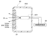
車両用レーザー装置20は、電磁波の一種であるレーザー光をパルス状に照射し、物体に反射されて帰ってくるまでの時間から対象物の距離や方向、属性などを測定する装置であり、例えば車両の自動運転用センサーとして用いられる。
The
車両用レーザー装置20は、レーザー送受器201、筐体202およびカバー203とを有している。レーザー送受器201は、レーザー光を照射するとともに、物体に反射されて帰ってきたレーザー光を受けることによって物体の検知や物体までの距離の測定を行う機器である。
The
例えば、車両用レーザー装置20は、車両の図示しないバンパーに取り付けられていて、車両の前方に向けてレーザー光を照射するとともに、車両の前方から帰ってきたレーザー光を受ける。車両用レーザー装置20が照射するレーザー光は、例えば近赤外線の波長を持つレーザー光である。
For example, the
レーザー送受器201の作動は、自動運転制御装置22によって制御される。レーザー送受器201による検知結果および測定結果は、自動運転制御装置22に入力される。自動運転制御装置22は、レーザー送受器201による検知結果および測定結果に基づいて、車両の自動運転を行う。
The operation of the
レーザー送受器201は、筐体202およびカバー203によって密閉された空間に収容されている。筐体202およびカバー203は、レーザー送受器201を収容するとともにレーザー送受器201を保護する部材である。筐体202は、レーザー送受器201が送受するレーザー光が通過しない領域に配置されている。カバー203は、レーザー送受器201が送受するレーザー光が通過する領域に配置されている。カバー203は、樹脂によって形成されている。
The laser transmitter /
カバー203は二重構造になっている。具体的には、カバー203は外側カバー203aと内側カバー203bと断熱部203cを有している。外側カバー203aは、二重構造のカバー203のうち外側に設けられた外側部材である。内側カバー203bは、二重構造のカバー203のうち内側に設けられた内側部材である。
The
断熱部203cは、外側カバー203aと内側カバー203bとの間に形成されている。断熱部203cは、内側カバー203bのうちレーザー送受器201が利用するレーザー光が通過する部位の曇りを抑制するように断熱機能を発揮する。断熱部203cは、真空になっていることによって断熱機能を発揮する。
The
本実施例ではカバー203の全体が二重構造になっているが、カバー203のうちレーザー送受器201が利用するレーザー光が通過する部位が二重構造になっていればよい。
In the present embodiment, the
ヒータ21は、上記第1実施形態のヒータ11と同様の透明薄膜状の部材であり、カーボンナノチューブとバインダとを有している。ヒータ21のカーボンナノチューブおよびバインダは、レーザー送受器201が送受するレーザー光に対して透明である。
The
レーザー送受器201が送受するレーザー光に対するヒータ21の透明度は80%以上である。したがって、カバー203におけるレーザー光の通過をヒータ21が妨げることを回避できる。レーザー送受器201が送受するレーザー光に対するヒータ21の透明度は95%程度であるのが好ましい。
The transparency of the
ヒータ21は、内側カバー203bの内側の面に接着により貼り付けられている。ヒータ21は、内側カバー203bの外側の面に貼り付けられていてもよい。ヒータ21は、内側カバー203bにインサート成形されていてもよい。
The
ヒータ21は、内側カバー203bの湾曲形状に追従する柔軟性を有している。ヒータ21は、内側カバー203bのうちレーザー送受器201が送受するレーザー光が通過する領域の一部または全部に設けられている。
The
カバー203およびヒータ21は、レーザー送受器201が送受するレーザー光に対して透明である。換言すれば、カバー203およびヒータ21は、レーザー送受器201が送受するレーザー光を透過する。
The
ヒータ21の図示しない電極に車両の図示しないバッテリから直流電圧が印加されることによって、ヒータ21の図示しないカーボンナノチューブに電流が流れてカーボンナノチューブが発熱する。ヒータ21の電極は、ヒータ21の縁部に沿って細長い形状に形成されている。
When a DC voltage is applied to an electrode (not shown) of the
筐体202およびカバー203は密閉空間を形成しているので、密閉空間内外の温度差によってカバー203の内側に曇りが生じることがある。
Since the
本実施形態では、断熱部203cは、内側カバー203bのうち電磁波が通過する部位の曇りを抑制するように内側カバー203bと外側カバー203aとの間で断熱機能を発揮する。これによると、簡素な構成で、電力等の動力を消費することなく防曇できる。
In the present embodiment, the
本実施形態では、断熱部203cは、真空になっていることによって断熱機能を発揮する。これにより、高い断熱性を発揮できる。
In this embodiment, the
本実施形態では、内側カバー203bを加熱するヒータ21を備える。これにより、外気放熱を抑制して、ヒータ21による防曇の効率を高めることができる。
In the present embodiment, the
(他の実施形態)
上記実施形態を適宜組み合わせ可能である。上記実施形態を例えば以下のように種々変形可能である。
(Other embodiments)
The above embodiments can be combined as appropriate. The above embodiment can be variously modified as follows, for example.
(1)上記実施形態では、断熱部3、203cは、真空になっていることによって断熱機能を発揮するが、断熱部3、203cは、空気で満たされていることによって断熱機能を発揮するようになっていてもよい。
(1) In the said embodiment, although the
(2)上記第1実施形態では、断熱部3は、真空になっていることによって断熱機能を発揮するが、断熱部3は、断熱性が高く且つ内側ガラス2またはフロントガラス1と同じ屈折率を有する液体であってもよい。この液体は、例えば植物油やパラフィン油のような有機系の液体である。 (2) In the said 1st Embodiment, although the heat insulation part 3 exhibits a heat insulation function by being in vacuum, the heat insulation part 3 has high heat insulation, and the same refractive index as the inner side glass 2 or the windshield 1 It may be a liquid having This liquid is an organic liquid such as vegetable oil or paraffin oil.
断熱部3が、内側ガラス2またはフロントガラス1と同じ屈折率の物質で満たされていれば、内側ガラス2とフロントガラス1との屈折率の違いによる影響を緩和できる。 If the heat insulating portion 3 is filled with a material having the same refractive index as that of the inner glass 2 or the front glass 1, the influence due to the difference in refractive index between the inner glass 2 and the front glass 1 can be reduced.
(3)上記第2実施形態では、断熱部203cは、真空になっていることによって断熱機能を発揮するが、断熱部3は、断熱性が高く且つ外側カバー203aまたは内側カバー203bと同じ屈折率を有する液体であってもよい。この液体は、例えば植物油やパラフィン油のような有機系の液体である。
(3) In the said 2nd Embodiment, although the
断熱部203cが、内側カバー203bまたは外側カバー203aと同じ屈折率の物質で満たされていれば、内側カバー203bと外側カバー203aとの屈折率の違いによる影響を緩和できる。
If the
(4)断熱部3、203cは透明なエアロゲルで満たされていてもよい。エアロゲルは、例えばシリカエアロゲルである。
(4) The
断熱部3、203cがエアロゲルで満たされていれば、透明度および断熱性を極力低下させずに断熱部3、203cの強度を高めることができる。
If the
(5)上記第1実施形態では、フロントガラス1および内側ガラス2が二重窓を構成しているが、フロントガラス1と内側ガラス2との間に1枚以上のガラスを挟んで三重以上の窓を構成していてもよい。 (5) In the first embodiment, the windshield 1 and the inner glass 2 constitute a double window. However, one or more glasses are sandwiched between the windshield 1 and the inner glass 2 and more than triple. You may comprise the window.
同様に、上記第2実施形態では、外側カバー203aおよび内側カバー203bが二重構造を構成しているが、外側カバー203aと内側カバー203bとの間に1枚以上のカバーを挟んで三重以上の構造を構成していてもよい。
Similarly, in the second embodiment, the
(6)上記第1実施形態では、ヒータ11は、フロントガラス1のうちカメラ100の視界v1よりも一回り広い範囲まで配置されているが、ヒータ11は、フロントガラス1の全体に配置されていてもよい。これにより、フロントガラス1が曇ることを良好に防止できる。ヒータ11は透明であるので、ヒータ11が乗員の視界を妨げることを抑制できる。
(6) In the first embodiment, the
(7)上記第1実施形態では、カメラユニット10およびヒータ11は、フロントガラス1に配置されているが、カメラユニット10およびヒータ11は、例えばリヤガラス等、フロントガラス1以外の窓に配置されていてもよい。
(7) In the first embodiment, the
(8)上記第1実施形態では、ヒータ11の発熱体としてカーボンナノチューブ111が用いられているが、ヒータ11の発熱体として金属粒子、カーボン粒子、金属酸化物粒子等の肉眼では識別できない部材が用いられていてもよい。すなわち、カメラ100が撮影する光に対して透明な種々の部材が用いられていればよい。
(8) In the first embodiment, the
(9)上記第1実施形態では、車両の衝突を防止するためにカメラ100の画像データを利用するが、これに限定されるものではなく、車線逸脱防止や車間距離測定等、種々の用途にカメラ100の画像データを利用してもよい。
(9) In the first embodiment, the image data of the
(10)上記第1実施形態のカメラ100は、可視光を撮影するカメラであるが、赤外光や紫外光を撮影するカメラであってもよい。
(10) The
(11)上記第2実施形態の車両用レーザー装置20は、車両の前方に向けてレーザー光を送受するが、車両の前方以外の方向に向けてレーザー光を送受するようになっていてもよい。
(11) The
例えば、レーザー送受器201を水平面内で回転させながらレーザー光を送受するようになっていてもよい。その場合、ヒータ21をレーザー送受器201とともに回転させるか、レーザー送受器201を360度囲むようにヒーター21を設ければよい。
For example, the laser beam may be transmitted and received while rotating the laser transmitter /
(12)上記第2実施形態ではヒータ21が車両用レーザー装置20に用いられているが、ヒータ21が車両用電波装置に用いられていてもよい。車両用電波装置は、電波を照射し、物体に反射されて帰ってくるまでの時間から対象物の距離や方向、属性などを測定する装置であり、例えば車両の自動運転用センサーとして用いられる。
(12) Although the
この場合、ヒータ21が車両用電波装置のカバーの曇りを除去することによって、曇りによる水分が電波に影響することを防止できる。
In this case, the
(13)上記第2実施形態では、ヒーター21の発熱体はカーボンナノチューブであるが、ヒーター21の発熱体は酸化インジウム錫や銀メッシュ等であってもよい。すなわち、レーザー送受器20が利用するレーザー光に対して透明な種々の部材が用いられていればよい。
(13) In the second embodiment, the heating element of the
(14)上記実施形態では、電磁波利用システムの具体例として、車両用撮影装置および車両用レーザー装置を示したが、電磁波利用システムは、据置型の撮影装置や据置き型のレーザー装置等であってもよい。 (14) In the above embodiment, as a specific example of the electromagnetic wave utilization system, a vehicle photographing apparatus and a vehicle laser apparatus are shown. However, the electromagnetic wave utilization system is a stationary photographing apparatus, a stationary laser apparatus, or the like. May be.
1 フロントガラス(通過部、外側部材)
2 内側ガラス(通過部、内側部材)
3 断熱部
11 ヒータ
100 カメラ(電磁波装置)
1 Windshield (passing part, outer member)
2 Inner glass (passage part, inner member)
3
Claims (5)
前記電磁波装置が利用する前記電磁波が通過する通過部(1、2、203)とを備え、
前記通過部は、前記電磁波装置側に設けられた内側部材(2、203b)と、前記電磁波装置と反対側に設けられた外側部材(1、203a)と、前記内側部材のうち前記電磁波が通過する部位の曇りを抑制するように前記内側部材と前記外側部材との間で断熱機能を発揮する断熱部(3、203c)とを有している電磁波利用システム。 An electromagnetic wave device (100, 201) that performs at least one of electromagnetic wave transmission and reception;
A passage portion (1, 2, 203) through which the electromagnetic wave used by the electromagnetic wave device passes,
The passage part includes an inner member (2, 203b) provided on the electromagnetic wave device side, an outer member (1, 203a) provided on the opposite side of the electromagnetic wave device, and the electromagnetic wave among the inner members. The electromagnetic wave utilization system which has the heat insulation part (3, 203c) which exhibits a heat insulation function between the said inner side member and the said outer side member so that the clouding of the site | part which carries out may be suppressed.
Priority Applications (6)
| Application Number | Priority Date | Filing Date | Title |
|---|---|---|---|
| JP2018040704A JP2019155946A (en) | 2018-03-07 | 2018-03-07 | Electromagnetic wave use system |
| DE112019001176.6T DE112019001176T5 (en) | 2018-03-07 | 2019-01-08 | System for using electromagnetic waves |
| PCT/JP2019/000178 WO2019171745A1 (en) | 2018-03-07 | 2019-01-08 | Electromagnetic wave utilization system |
| CN201980017192.8A CN111819118A (en) | 2018-03-07 | 2019-01-08 | Electromagnetic wave utilization system |
| FI20205862A FI20205862A1 (en) | 2018-03-07 | 2019-01-08 | Electromagnetic wave utilization system |
| US17/004,927 US20200391698A1 (en) | 2018-03-07 | 2020-08-27 | Electromagnetic wave utilization system |
Applications Claiming Priority (1)
| Application Number | Priority Date | Filing Date | Title |
|---|---|---|---|
| JP2018040704A JP2019155946A (en) | 2018-03-07 | 2018-03-07 | Electromagnetic wave use system |
Publications (2)
| Publication Number | Publication Date |
|---|---|
| JP2019155946A true JP2019155946A (en) | 2019-09-19 |
| JP2019155946A5 JP2019155946A5 (en) | 2020-04-09 |
Family
ID=67845958
Family Applications (1)
| Application Number | Title | Priority Date | Filing Date |
|---|---|---|---|
| JP2018040704A Pending JP2019155946A (en) | 2018-03-07 | 2018-03-07 | Electromagnetic wave use system |
Country Status (6)
| Country | Link |
|---|---|
| US (1) | US20200391698A1 (en) |
| JP (1) | JP2019155946A (en) |
| CN (1) | CN111819118A (en) |
| DE (1) | DE112019001176T5 (en) |
| FI (1) | FI20205862A1 (en) |
| WO (1) | WO2019171745A1 (en) |
Cited By (5)
| Publication number | Priority date | Publication date | Assignee | Title |
|---|---|---|---|---|
| CN111068519A (en) * | 2019-12-17 | 2020-04-28 | 深圳大学 | Forward osmosis membrane and preparation method thereof |
| JP2021054009A (en) * | 2019-10-01 | 2021-04-08 | 豊田合成株式会社 | Manufacturing method for near-infrared sensor cover |
| JP2021131931A (en) * | 2020-02-18 | 2021-09-09 | 日立造船株式会社 | Carbon nanotube heater and method for manufacturing carbon nanotube heater |
| JP7046144B1 (en) | 2020-11-05 | 2022-04-01 | 日本信号株式会社 | Optical equipment |
| JP7449177B2 (en) | 2020-06-12 | 2024-03-13 | 株式会社Subaru | In-vehicle camera device |
Families Citing this family (11)
| Publication number | Priority date | Publication date | Assignee | Title |
|---|---|---|---|---|
| US11724669B2 (en) | 2019-12-16 | 2023-08-15 | Plusai, Inc. | System and method for a sensor protection system |
| US11650415B2 (en) | 2019-12-16 | 2023-05-16 | Plusai, Inc. | System and method for a sensor protection mechanism |
| US11754689B2 (en) | 2019-12-16 | 2023-09-12 | Plusai, Inc. | System and method for detecting sensor adjustment need |
| US11077825B2 (en) | 2019-12-16 | 2021-08-03 | Plusai Limited | System and method for anti-tampering mechanism |
| US11470265B2 (en) | 2019-12-16 | 2022-10-11 | Plusai, Inc. | System and method for sensor system against glare and control thereof |
| US11313704B2 (en) * | 2019-12-16 | 2022-04-26 | Plusai, Inc. | System and method for a sensor protection assembly |
| US11738694B2 (en) | 2019-12-16 | 2023-08-29 | Plusai, Inc. | System and method for anti-tampering sensor assembly |
| DE102020113199A1 (en) * | 2020-05-15 | 2021-11-18 | K. L. Kaschier- Und Laminier Gmbh | Image acquisition arrangement of a motor vehicle |
| FR3124122A1 (en) * | 2021-06-20 | 2022-12-23 | Valeo Systèmes D’Essuyage | Vehicle glazing |
| JP2023031168A (en) * | 2021-08-24 | 2023-03-08 | 豊田合成株式会社 | Electromagnetic wave transmission cover |
| US11772667B1 (en) | 2022-06-08 | 2023-10-03 | Plusai, Inc. | Operating a vehicle in response to detecting a faulty sensor using calibration parameters of the sensor |
Citations (6)
| Publication number | Priority date | Publication date | Assignee | Title |
|---|---|---|---|---|
| CN102789115A (en) * | 2012-08-23 | 2012-11-21 | 浙江宇视科技有限公司 | Defogging system of camera |
| JP2016141378A (en) * | 2015-02-05 | 2016-08-08 | 株式会社デンソー | Defogging and deicing device for vehicle |
| WO2017086395A1 (en) * | 2015-11-20 | 2017-05-26 | リンテック株式会社 | Sheet, heating element, and heating device |
| JP2017122022A (en) * | 2016-01-06 | 2017-07-13 | 旭硝子株式会社 | Laminated glass |
| WO2017151348A1 (en) * | 2016-02-29 | 2017-09-08 | Illinois Tool Works, Inc. | Hybrid heater for vehicle sensor system |
| JP2018030459A (en) * | 2016-08-24 | 2018-03-01 | 日本板硝子株式会社 | Side glass |
Family Cites Families (5)
| Publication number | Priority date | Publication date | Assignee | Title |
|---|---|---|---|---|
| JPH02300715A (en) * | 1989-05-16 | 1990-12-12 | Toshiba Corp | Vehicle mounted monitoring camera |
| US7965336B2 (en) * | 2002-11-14 | 2011-06-21 | Donnelly Corporation | Imaging system for vehicle |
| KR20100091181A (en) * | 2007-11-16 | 2010-08-18 | 파나소닉 주식회사 | Heating-element unit, and heating device |
| EP3425999A1 (en) * | 2012-03-05 | 2019-01-09 | Saint-Gobain Glass France | Disc assembly with electrically heated light scattering aperture |
| US10981520B1 (en) * | 2019-11-14 | 2021-04-20 | Zf Friedrichshafen Ag | Driver assist system for a vehicle |
-
2018
- 2018-03-07 JP JP2018040704A patent/JP2019155946A/en active Pending
-
2019
- 2019-01-08 DE DE112019001176.6T patent/DE112019001176T5/en active Pending
- 2019-01-08 CN CN201980017192.8A patent/CN111819118A/en not_active Withdrawn
- 2019-01-08 WO PCT/JP2019/000178 patent/WO2019171745A1/en active Application Filing
- 2019-01-08 FI FI20205862A patent/FI20205862A1/en unknown
-
2020
- 2020-08-27 US US17/004,927 patent/US20200391698A1/en not_active Abandoned
Patent Citations (6)
| Publication number | Priority date | Publication date | Assignee | Title |
|---|---|---|---|---|
| CN102789115A (en) * | 2012-08-23 | 2012-11-21 | 浙江宇视科技有限公司 | Defogging system of camera |
| JP2016141378A (en) * | 2015-02-05 | 2016-08-08 | 株式会社デンソー | Defogging and deicing device for vehicle |
| WO2017086395A1 (en) * | 2015-11-20 | 2017-05-26 | リンテック株式会社 | Sheet, heating element, and heating device |
| JP2017122022A (en) * | 2016-01-06 | 2017-07-13 | 旭硝子株式会社 | Laminated glass |
| WO2017151348A1 (en) * | 2016-02-29 | 2017-09-08 | Illinois Tool Works, Inc. | Hybrid heater for vehicle sensor system |
| JP2018030459A (en) * | 2016-08-24 | 2018-03-01 | 日本板硝子株式会社 | Side glass |
Cited By (6)
| Publication number | Priority date | Publication date | Assignee | Title |
|---|---|---|---|---|
| JP2021054009A (en) * | 2019-10-01 | 2021-04-08 | 豊田合成株式会社 | Manufacturing method for near-infrared sensor cover |
| CN111068519A (en) * | 2019-12-17 | 2020-04-28 | 深圳大学 | Forward osmosis membrane and preparation method thereof |
| JP2021131931A (en) * | 2020-02-18 | 2021-09-09 | 日立造船株式会社 | Carbon nanotube heater and method for manufacturing carbon nanotube heater |
| JP7449177B2 (en) | 2020-06-12 | 2024-03-13 | 株式会社Subaru | In-vehicle camera device |
| JP7046144B1 (en) | 2020-11-05 | 2022-04-01 | 日本信号株式会社 | Optical equipment |
| JP2022074953A (en) * | 2020-11-05 | 2022-05-18 | 日本信号株式会社 | Optical device |
Also Published As
| Publication number | Publication date |
|---|---|
| US20200391698A1 (en) | 2020-12-17 |
| CN111819118A (en) | 2020-10-23 |
| WO2019171745A1 (en) | 2019-09-12 |
| FI20205862A1 (en) | 2020-09-04 |
| DE112019001176T5 (en) | 2020-12-10 |
Similar Documents
| Publication | Publication Date | Title |
|---|---|---|
| WO2019171745A1 (en) | Electromagnetic wave utilization system | |
| JP2019137380A (en) | Electromagnetic wave utilization system | |
| WO2018230358A1 (en) | Electromagnetic wave utilization system | |
| JP6377115B2 (en) | Wind glass device provided with baffle plate capable of being electrically heated, method for manufacturing and using the wind glass device | |
| CN107076852B (en) | Transmissive front heater for vehicle sensor system | |
| JP2012530646A (en) | Window glass with heatable light transmission sensor array | |
| EA021787B1 (en) | Panel having optically transparent sensor field | |
| JP2010534588A (en) | Viewing window for optical sensor system and / or identification system in vehicle | |
| WO2012096306A1 (en) | Automobile window glass | |
| KR101816572B1 (en) | Camera apparatus for vehicle and vehicle | |
| JP2019519412A (en) | Vehicle visor and system therefor, vehicle, and blocking and display method | |
| JP2010032906A (en) | Video display device | |
| JP6897351B2 (en) | Anti-fog device for vehicles | |
| US10870399B2 (en) | Sensor arrangement for a motor vehicle, motor vehicle and method for operating a sensor device | |
| KR101316371B1 (en) | Out side mirror in vehicle | |
| US11034300B2 (en) | Door mirror | |
| EP3460567A1 (en) | Nanostructure-based optical limiters for facilitating aperture protection | |
| JP2009248665A (en) | Road surface freeze warning device | |
| JP2019155947A (en) | Vehicular electromagnetic wave use system | |
| JP2019004254A (en) | Vehicle photographing device | |
| US20210360749A1 (en) | Image acquisition arrangement of a motor vehicle | |
| JP2020147050A (en) | Anti-fogging device for vehicle | |
| CN220701013U (en) | Rearview mirror and vehicle | |
| CN115474431A (en) | Sheet assembly with heatable sensor window |
Legal Events
| Date | Code | Title | Description |
|---|---|---|---|
| A521 | Request for written amendment filed |
Free format text: JAPANESE INTERMEDIATE CODE: A523 Effective date: 20200226 |
|
| A621 | Written request for application examination |
Free format text: JAPANESE INTERMEDIATE CODE: A621 Effective date: 20200306 |
|
| A131 | Notification of reasons for refusal |
Free format text: JAPANESE INTERMEDIATE CODE: A131 Effective date: 20210202 |
|
| A521 | Request for written amendment filed |
Free format text: JAPANESE INTERMEDIATE CODE: A523 Effective date: 20210318 |
|
| A02 | Decision of refusal |
Free format text: JAPANESE INTERMEDIATE CODE: A02 Effective date: 20210706 |