JP2019155486A - Electric tool - Google Patents
Electric tool Download PDFInfo
- Publication number
- JP2019155486A JP2019155486A JP2018041178A JP2018041178A JP2019155486A JP 2019155486 A JP2019155486 A JP 2019155486A JP 2018041178 A JP2018041178 A JP 2018041178A JP 2018041178 A JP2018041178 A JP 2018041178A JP 2019155486 A JP2019155486 A JP 2019155486A
- Authority
- JP
- Japan
- Prior art keywords
- cover
- housing
- attached
- tip tool
- tool holding
- Prior art date
- Legal status (The legal status is an assumption and is not a legal conclusion. Google has not performed a legal analysis and makes no representation as to the accuracy of the status listed.)
- Pending
Links
Images


Classifications
-
- B—PERFORMING OPERATIONS; TRANSPORTING
- B24—GRINDING; POLISHING
- B24B—MACHINES, DEVICES, OR PROCESSES FOR GRINDING OR POLISHING; DRESSING OR CONDITIONING OF ABRADING SURFACES; FEEDING OF GRINDING, POLISHING, OR LAPPING AGENTS
- B24B47/00—Drives or gearings; Equipment therefor
- B24B47/10—Drives or gearings; Equipment therefor for rotating or reciprocating working-spindles carrying grinding wheels or workpieces
- B24B47/12—Drives or gearings; Equipment therefor for rotating or reciprocating working-spindles carrying grinding wheels or workpieces by mechanical gearing or electric power
-
- B—PERFORMING OPERATIONS; TRANSPORTING
- B24—GRINDING; POLISHING
- B24B—MACHINES, DEVICES, OR PROCESSES FOR GRINDING OR POLISHING; DRESSING OR CONDITIONING OF ABRADING SURFACES; FEEDING OF GRINDING, POLISHING, OR LAPPING AGENTS
- B24B55/00—Safety devices for grinding or polishing machines; Accessories fitted to grinding or polishing machines for keeping tools or parts of the machine in good working condition
- B24B55/04—Protective covers for the grinding wheel
- B24B55/05—Protective covers for the grinding wheel specially designed for portable grinding machines
-
- B—PERFORMING OPERATIONS; TRANSPORTING
- B25—HAND TOOLS; PORTABLE POWER-DRIVEN TOOLS; MANIPULATORS
- B25F—COMBINATION OR MULTI-PURPOSE TOOLS NOT OTHERWISE PROVIDED FOR; DETAILS OR COMPONENTS OF PORTABLE POWER-DRIVEN TOOLS NOT PARTICULARLY RELATED TO THE OPERATIONS PERFORMED AND NOT OTHERWISE PROVIDED FOR
- B25F5/00—Details or components of portable power-driven tools not particularly related to the operations performed and not otherwise provided for
- B25F5/02—Construction of casings, bodies or handles
Abstract
Description
本明細書で開示する技術は、電動工具に関する。 The technology disclosed in this specification relates to a power tool.
特許文献1には、モータと、前記モータに接続された動力伝達機構と、前記モータおよび前記動力伝達機構を収容するハウジングと、前記動力伝達機構に接続された先端工具保持部と、前記先端工具保持部の少なくとも一部を覆うカバーと、を備える電動工具が開示されている。 Patent Document 1 discloses a motor, a power transmission mechanism connected to the motor, a housing that houses the motor and the power transmission mechanism, a tip tool holding portion connected to the power transmission mechanism, and the tip tool. A power tool is disclosed that includes a cover that covers at least a portion of the holding portion.
ユーザの安全のために、カバーが取り外された状態では、電動工具を使用できないようにすることが望ましい。本明細書では、カバーが取り外された状態では、電動工具を使用できないようにすることが可能な技術を提供する。 For the safety of the user, it is desirable to prevent the power tool from being used when the cover is removed. The present specification provides a technique capable of preventing an electric tool from being used when the cover is removed.
本明細書は、電動工具を開示する。その電動工具は、モータと、前記モータに接続された動力伝達機構と、前記モータおよび前記動力伝達機構を収容するハウジングと、前記動力伝達機構に接続された先端工具保持部と、前記先端工具保持部の少なくとも一部を覆うカバーを備えていてもよい。前記カバーが前記ハウジングに取り付けられていない状態では、前記先端工具保持部はロックされていてもよい。前記カバーが前記ハウジングに取り付けられた状態では、前記先端工具保持部のロックは解除されていてもよい。 The present specification discloses a power tool. The electric tool includes a motor, a power transmission mechanism connected to the motor, a housing that houses the motor and the power transmission mechanism, a tip tool holding portion connected to the power transmission mechanism, and the tip tool holding You may provide the cover which covers at least one part of a part. In a state where the cover is not attached to the housing, the tip tool holding portion may be locked. In a state where the cover is attached to the housing, the tip tool holding portion may be unlocked.
上記の構成によれば、カバーがハウジングから取り外された状態では、先端工具保持部がロックされるので、電動工具を使用することができない。カバーが取り外された状態では、電動工具を使用できないようにすることができる。 According to the above configuration, the power tool cannot be used because the tip tool holding portion is locked in a state where the cover is removed from the housing. When the cover is removed, the power tool can be disabled.
1つまたはそれ以上の実施形態において、電動工具は、モータと、前記モータに接続された動力伝達機構と、前記モータおよび前記動力伝達機構を収容するハウジングと、前記動力伝達機構に接続された先端工具保持部と、前記先端工具保持部の少なくとも一部を覆うカバーを備えていてもよい。前記カバーが前記ハウジングに取り付けられていない状態では、前記先端工具保持部はロックされていてもよい。前記カバーが前記ハウジングに取り付けられた状態では、前記先端工具保持部のロックは解除されていてもよい。 In one or more embodiments, the power tool includes a motor, a power transmission mechanism connected to the motor, a housing that houses the motor and the power transmission mechanism, and a tip connected to the power transmission mechanism. You may provide the cover which covers at least one part of a tool holding part and the said front-end tool holding part. In a state where the cover is not attached to the housing, the tip tool holding portion may be locked. In a state where the cover is attached to the housing, the tip tool holding portion may be unlocked.
上記の構成によれば、カバーがハウジングから取り外された状態では、先端工具保持部がロックされるので、電動工具を使用することができない。カバーが取り外された状態では、電動工具を使用できないようにすることができる。 According to the above configuration, the power tool cannot be used because the tip tool holding portion is locked in a state where the cover is removed from the housing. When the cover is removed, the power tool can be disabled.
1つまたはそれ以上の実施形態において、前記電動工具は、前記ハウジングに取り付けられており、前記先端工具保持部に係合する係合位置と、前記先端工具保持部と係合しない非係合位置の間で移動可能なロック部材と、前記ロック部材を前記非係合位置から前記係合位置に向けて付勢する弾性部材をさらに備えていてもよい。前記電動工具では、前記カバーを前記ハウジングに取り付ける際に、前記ロック部材が、前記カバーによって押圧されることで前記弾性部材の付勢力に抗して前記係合位置から前記非係合位置に向けて移動してもよい。 In one or more embodiments, the power tool is attached to the housing and is engaged with the tip tool holding portion and is not engaged with the tip tool holding portion. And a resilient member that urges the locking member from the disengaged position toward the engaged position. In the electric power tool, when the cover is attached to the housing, the lock member is pressed by the cover to resist the biasing force of the elastic member from the engagement position toward the non-engagement position. You may move.
上記の構成では、カバーをハウジングから取り外すと、ロック部材が弾性部材によって付勢されて係合位置に移動して先端工具保持部をロックする。また、上記の構成では、カバーをハウジングに取り付けると、ロック部材がカバーによって押圧されて非係合位置に移動して先端工具保持部のロックを解除する。上記の構成によれば、簡素な構成によって、カバーをハウジングから取り外した時に先端工具保持部をロックし、カバーをハウジングに取り付けた時に先端工具保持部のロックを解除することができる。 In the above configuration, when the cover is removed from the housing, the lock member is urged by the elastic member and moves to the engagement position to lock the tip tool holding portion. In the above configuration, when the cover is attached to the housing, the lock member is pressed by the cover and moved to the non-engagement position to unlock the tip tool holding portion. According to the above configuration, the tip tool holding portion can be locked when the cover is removed from the housing, and the tip tool holding portion can be unlocked when the cover is attached to the housing.
1つまたはそれ以上の実施形態において、前記先端工具保持部は、前記ハウジングに対して回転軸周りに回転可能であってもよい。前記カバーは、前記ハウジングに対して前記回転軸に沿ってスライドさせることで着脱可能であってもよい。前記ロック部材は、前記ハウジングに対して前記回転軸に沿って移動可能であってもよい。 In one or more embodiments, the tip tool holder may be rotatable about a rotation axis relative to the housing. The cover may be detachable by sliding along the rotation axis with respect to the housing. The lock member may be movable along the rotation axis with respect to the housing.
上記の構成によれば、非常に簡素な構成によって、カバーをハウジングから取り外した時に先端工具保持部をロックし、カバーをハウジングに取り付けた時に先端工具保持部のロックを解除することができる。 According to the above configuration, the tip tool holding portion can be locked when the cover is removed from the housing, and the tip tool holding portion can be unlocked when the cover is attached to the housing with a very simple configuration.
1つまたはそれ以上の実施形態において、前記先端工具保持部は、フランジ部を備えていてもよい。前記ロック部材は、前記係合位置で前記フランジ部に当接してもよい。 In one or more embodiments, the tip tool holding portion may include a flange portion. The lock member may contact the flange portion at the engagement position.
上記の構成によれば、弾性部材によって非係合位置から係合位置に向けて付勢されているロック部材が、係合位置を超えて移動してしまうことを防止することができる。ロック部材がハウジングから脱落してしまうことを防止することができる。 According to said structure, it can prevent that the lock member currently urged | biased from the non-engagement position toward the engagement position by the elastic member moving beyond an engagement position. It is possible to prevent the lock member from falling off the housing.
1つまたはそれ以上の実施形態において、前記先端工具保持部は、突起部を備えていてもよい。前記ロック部材は、前記突起部が嵌合する嵌合孔を備えていてもよい。前記電動工具では、前記ロック部材が前記係合位置にある場合に、前記突起部が前記嵌合孔に入り込むことで、前記先端工具保持部の前記回転軸周りの回転が禁止されてもよい。前記電動工具では、前記ロック部材が前記非係合位置にある場合に、前記突起部が前記嵌合孔から抜け出すことで、前記先端工具保持部の前記回転軸周りの回転が許容されてもよい。 In one or more embodiments, the tip tool holder may include a protrusion. The lock member may include a fitting hole into which the protrusion is fitted. In the electric power tool, when the lock member is in the engagement position, rotation of the tip tool holding portion around the rotation axis may be prohibited by the projection portion entering the fitting hole. In the electric power tool, when the lock member is in the non-engagement position, the protrusion of the protrusion may come out of the fitting hole to allow the tip tool holding portion to rotate around the rotation axis. .
上記の構成によれば、簡素な構成によって、先端工具保持部の回転がロックされた状態と、先端工具保持部の回転のロックが解除された状態を切り換えることができる。 According to said structure, it can switch by the simple structure the state in which rotation of the tip tool holding part was locked, and the state in which rotation lock of the tip tool holding part was cancelled | released.
1つまたはそれ以上の実施形態において、前記ハウジングは、略円筒形状のカバー取り付け部を備えていてもよい。前記カバーは、前記カバー取り付け部の外側に取り付けられる略円筒形状のバンド部を備えていてもよい。前記ロック部材は、前記カバー取り付け部の外側に配置された当接片を備えていてもよい。前記電動工具では、前記カバーを前記ハウジングに取り付ける際に、前記当接片が前記バンド部の端面に当接することで、前記ロック部材が前記カバーによって押圧されてもよい。 In one or more embodiments, the housing may include a substantially cylindrical cover attachment. The cover may include a substantially cylindrical band portion attached to the outside of the cover attaching portion. The lock member may include a contact piece disposed outside the cover attachment portion. In the electric tool, when the cover is attached to the housing, the abutting piece abuts against an end surface of the band portion, so that the lock member may be pressed by the cover.
上記の構成によれば、簡素な構成によって、ユーザがカバーをハウジングに取り付ける動作に連動して、ロック部材を係合位置から非係合位置に移動させることができる。 According to the above configuration, the lock member can be moved from the engagement position to the non-engagement position in conjunction with the operation of the user attaching the cover to the housing with a simple configuration.
1つまたはそれ以上の実施形態において、前記先端工具保持部は、スピンドルであってもよい。 In one or more embodiments, the tip tool holder may be a spindle.
上記の構成によれば、スピンドルを備える電動工具において、スピンドルの少なくとも一部を覆うカバーの着脱に連動して、スピンドルの回転をロックした状態と、スピンドルの回転のロックを解除した状態を切り換えることができる。 According to the above configuration, in a power tool including a spindle, the spindle rotation is switched to the spindle rotation unlocked state in conjunction with the attachment / detachment of the cover that covers at least a part of the spindle. Can do.
(実施例)
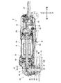
図1に示すように、本実施例のグラインダ2は、モータハウジング4と、リヤハウジング6と、ギヤハウジング8と、ベアリングボックス10と、ホイールカバー12を備えている。
(Example)
As shown in FIG. 1, the
モータハウジング4の内部には、モータ14が収容されている。モータ14は、前後方向に伸びる出力軸16を有している。出力軸16は、ベアリング18,20を介して、モータハウジング4に回転可能に支持されている。
A
リヤハウジング6は、モータハウジング4の後方に取り付けられている。リヤハウジング6の内部には、電源回路22が収容されている。電源回路22には、外部の電源から電源コード24を介して電力が供給される。モータハウジング4の下面にはスイッチレバー26が設けられている。ユーザがスイッチレバー26を上方に押し込むと、リンク28が駆動スイッチ30に当接して、モータ14に電力が供給される。モータ14は、電源回路22から供給される電力によって、出力軸16を回転させる。ユーザがスイッチレバー26から手を離すと、リンク28が駆動スイッチ30から離反して、モータ14への電力の供給が停止される。スイッチレバー26には、スイッチレバー26の押し込み操作を許可する状態と禁止する状態の間で切り換わるロックオフレバー32が設けられている。図1に示す状態では、ユーザによるスイッチレバー26の押し込み操作が禁止されている。この状態から、ロックオフレバー32の下端が後方へ向かう方向(図1では反時計回りの方向)へロックオフレバー32を回動させると、ユーザによるスイッチレバー26の押し込み操作が許容される。
The
ギヤハウジング8は、モータハウジング4の前方に取り付けられている。ギヤハウジング8の内部には、互いに噛み合うように配置された第1ベベルギヤ34と第2ベベルギヤ36が収容されている。第1ベベルギヤ34は、出力軸16の前方端部に固定されている。第2ベベルギヤ36は、上下方向に伸びるスピンドル38の上方端部に固定されている。以下では、第1ベベルギヤ34と第2ベベルギヤ36を総称して、単にベベルギヤ40ともいう。ベベルギヤ40は、モータ14の回転を減速してスピンドル38に伝達する動力伝達機構である。ギヤハウジング8は、ベアリング42を介して、スピンドル38の上方端部を保持している。図2に示すように、ギヤハウジング8の上面には、シャフトロック44が設けられている。ユーザがシャフトロック44を下方に押し込むと、第2ベベルギヤ36の回転が禁止されて、スピンドル38の回転が禁止される。
The
図1に示すように、ベアリングボックス10は、ギヤハウジング8の下方に取り付けられている。ベアリングボックス10は、上下方向に伸びるねじ46a、46b、46c、46d(図2、図5等参照)によって、ギヤハウジング8に固定されている。ベアリングボックス10は、ベアリング48を介して、スピンドル38を保持している。スピンドル38はベアリングボックス10に対して、上下方向に沿った回転軸周りに回転可能である。スピンドル38の下方端部には、インナフランジIFとアウタフランジOFを介して、研削ホイールGWを取り付け可能である。グラインダ2において、モータ14が回転すると、スピンドル38とともに研削ホイールGWが回転軸周りに回転することで、ワークの研削を行うことができる。スピンドル38は、先端工具である研削ホイールGWを保持する先端工具保持部ということもできる。なお、以下の説明では、モータハウジング4、リヤハウジング6、ギヤハウジング8およびベアリングボックス10を総称して、単にハウジング50ともいう。
As shown in FIG. 1, the
ベアリングボックス10には、ホイールカバー12が取り付けられている。ホイールカバー12は、研削ホイールGWの少なくとも一部を覆う形状に形成されている。本実施例では、ホイールカバー12は、研削ホイールGWの略半周にわたる部分を覆う形状に形成されている。図1に示す状態では、ホイールカバー12は、研削ホイールGWの後方の部分を覆う位置に配置されている。ホイールカバー12によって、グラインダ2の使用時に、研削ホイールGWからユーザに向けて研削粉が飛ぶことを防止することができる。なお、ホイールカバー12は、スピンドル38の少なくとも一部を覆っているということもできる。
A
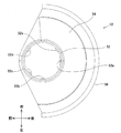
図3に示すように、ホイールカバー12は、バンド部52と、上面部54と、側面部56を備えている。バンド部52は、上下方向に伸びる略円筒形状を有している。図4に示すように、バンド部52の内周面には、内側に向けて突出しており、周方向に長手方向を有する係合リブ52a、52b、52c、52d、52eが形成されている。また、図3に示すように、バンド部52には、所定の角度範囲内に、複数の貫通孔52fが形成されている。係合リブ52a、52b、52c、52d、52eは、上下方向の位置が互いに一致している。複数の貫通孔52fは、上下方向の位置が互いに一致している。上面部54は、バンド部52の下側端部から広がっており、一部が切り欠かれた円錐台形状を有している。側面部56は、上面部54の外側端部から下方に伸びる略半円筒形状の半円筒部56aと、半円筒部56aの下端から内側に屈曲した絞り部56bを備えている。
As shown in FIG. 3, the
図5に示すように、ベアリングボックス10には、スピンドル38の回転軸方向(すなわち上下方向)に沿って下方に突出する略円筒形状のカバー取り付け部58が形成されている。カバー取り付け部58には、圧縮ばね60と、ロックプレート62と、Oリング64が取り付けられている。
As shown in FIG. 5, the
図6に示すように、ベアリングボックス10のカバー取り付け部58の外周面には、円環状の円周方向ガイド溝66が形成されており、円周方向ガイド溝66よりも下端側には外側に突出するフランジ68が形成されている。フランジ68には、ホイールカバー12の係合リブ52a、52b、52c、52d、52eに対応して、切り欠き68a、68b、68c、68d、68eが形成されている。カバー取り付け部58の外周面にはさらに、切り欠き68a、68b、68c、68d、68eに対応して、上下方向に直線状に伸びる上下方向ガイド溝70a、70b、70c、70d、70eが形成されている。上下方向ガイド溝70a、70b、70c、70d、70eは、円周方向ガイド溝66よりも深く形成されている。また、カバー取り付け部58のフランジ68よりも内周側の部分には、圧縮ばね60を受け入れるためのばね受け部72が形成されている。
As shown in FIG. 6, an annular
図7に示すように、ロックプレート62は、皿型の形状を有する基部62aと、基部62aの中央に形成された嵌合孔62bと、カバー取り付け部58の上下方向ガイド溝70a、70b、70c、70d、70eに対応して基部62aの外側端部から屈曲して上方向に伸びる当接片62c、62d、62e、62f、62gを備えている。それぞれの当接片62c、62d、62e、62f、62gは、上方端部で外側に屈曲している。図6に示すように、ロックプレート62は、圧縮ばね60をカバー取り付け部58のばね受け部72に取り付けた状態で、当接片62c、62d、62e、62f、62gがカバー取り付け部58の上下方向ガイド溝70a、70b、70c、70d、70eに入り込むように、カバー取り付け部58に取り付けられている。ロックプレート62がカバー取り付け部58に取り付けられた状態では、ロックプレート62はカバー取り付け部58に対して上下方向に摺動可能であり、カバー取り付け部58に対して回転不能である。また、ロックプレート62の基部62aは圧縮ばね60からの付勢力を受けており、ロックプレート62はカバー取り付け部58に対して下方向に付勢されている。ロックプレート62の当接片62c、62d、62e、62f、62gの上方端部以外の部分は、ロックプレート62がカバー取り付け部58に取り付けられた状態において、カバー取り付け部58の円周方向ガイド溝66の表面と段差がない形状となるように形成されている。
As shown in FIG. 7, the
スピンドル38は、圧縮ばね60とロックプレート62が取り付けられたベアリングボックス10に対して、下方向から差し込むことで、ベアリングボックス10に取り付けられている。図8に示すように、スピンドル38には、下側端部の外周面に形成されており、アウタフランジOF(図1参照)が螺着するねじ部38aと、ねじ部38aよりも上方に形成されており、インナフランジIF(図1参照)が嵌合する下側突起部38bと、下側突起部38bよりも上方に形成されており、円盤状に突出するフランジ部38cと、フランジ部38cよりも上方に形成されており、ロックプレート62の嵌合孔62bに嵌合する上側突起部38dを備えている。
The
図9に示すように、ベアリングボックス10に、圧縮ばね60と、ロックプレート62と、スピンドル38が取り付けられており、ホイールカバー12が取り付けられていない状態では、ロックプレート62が圧縮ばね60によって下方向に付勢されている。このため、スピンドル38の上側突起部38dがロックプレート62の嵌合孔62bに入り込み、ロックプレート62の基部62aの下面がスピンドル38のフランジ部38cの上面に当接する。この状態では、スピンドル38の上側突起部38dがロックプレート62の嵌合孔62bに嵌合しており、かつロックプレート62はカバー取り付け部58に対して回転不能であるため、スピンドル38のベアリングボックス10に対する回転が禁止されている。
As shown in FIG. 9, when the
Oリング64は、圧縮ばね60とロックプレート62が取り付けられたカバー取り付け部58の外側に取り付けられている。Oリング64は、ホイールカバー12がカバー取り付け部58に取り付けられた時に、ホイールカバー12がカバー取り付け部58に対してガタつくことを防止する。
The O-
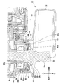
図5に示すように、ベアリングボックス10には、ホイールカバー12の回転角度を固定するためのカバーロック機構74が取り付けられている。カバーロック機構74は、スライドプレート76と、圧縮ばね78を備えている。
As shown in FIG. 5, a
図10に示すように、スライドプレート76は、ギヤハウジング8およびベアリングボックス10と干渉しない形状で左右方向に伸びる平板状の基部76aと、基部76aの左側端部から上方に伸びる操作部76bと、基部76aに形成されており、左右方向に長手方向を有する長孔76c、76dと、基部76aの右側端部の近傍において左側に向けて突出する係止部76eと、基部76aの長孔76cと長孔76dの間で上方に向けて突出する第1柱部76fおよび第2柱部76gと、第1柱部76fから右方向に向けて(第2柱部76gに向けて)伸びる第1凸部76hと、第2柱部76gから左方向に向けて(第1柱部76fに向けて)伸びる第2凸部76iを備えている。
As shown in FIG. 10, the
図5に示すように、スライドプレート76は、ベアリングボックス10をギヤハウジング8に固定しているねじ46a、46b、46c、46dのうち、後方左方に配置されたねじ46cと、後方右方に配置されたねじ46dに取り付けられている。ねじ46cは、スライドプレート76の長孔76cを貫通して、ベアリングボックス10と、ギヤハウジング8を締結している。ねじ46dは、スライドプレート76の長孔76dを貫通して、ベアリングボックス10と、ギヤハウジング8を締結している。スライドプレート76は、左右方向にスライド可能に、ねじ46c、46dに保持されている。
As shown in FIG. 5, the
本実施例のグラインダ2では、ベアリングボックス10に、ばね受け部10aが形成されている。圧縮ばね78は、一端に第1凸部76hが挿入され、他端に第2凸部76iが挿入された状態で、スライドプレート76に取り付けられている。スライドプレート76は、圧縮ばね78の第2凸部76i側の端部が、ばね受け部10aに当接するように、ベアリングボックス10に取り付けられている。このため、圧縮ばね78は、ベアリングボックス10に対してスライドプレート76を左方向、すなわち係止部76eをカバー取り付け部58に近づける方向に付勢している。
In the
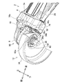
図11に示すように、ホイールカバー12をカバー取り付け部58に取り付ける際には、ホイールカバー12の係合リブ52a、52b、52c、52d、52eをカバー取り付け部58の切り欠き68a、68b、68c、68d、68eに位置合わせする。その状態で、カバーロック機構74の操作部76bを押し込んで、係止部76eをカバー取り付け部58から離反させつつ、カバー取り付け部58がバンド部52の内側に入り込むように、ホイールカバー12をベアリングボックス10に対して上方向にスライドさせる。これによって、図12に示すように、ホイールカバー12が、カバー取り付け部58に取り付けられる。係合リブ52a、52b、52c、52d、52eが切り欠き58a、58b、58c、58d、58eに位置合わせされた状態における、ベアリングボックス10に取り付けられた後のホイールカバー12の位置を、以下では着脱位置ともいう。図13に示すように、ホイールカバー12をカバー取り付け部58に取り付ける際には、ホイールカバー12のバンド部52の上端面が、ロックプレート62の当接片62c、62d、62e、62f、62gの上端部分と当接する。このため、ロックプレート62は、ホイールカバー12をカバー取り付け部58に取り付ける際に、ホイールカバー12から押圧されて圧縮ばね60の付勢力に抗して上方に向けて押し上げられる。
As shown in FIG. 11, when the
ベアリングボックス10に取り付けられたホイールカバー12は、カバー取り付け部58の周りに回転可能である。言い換えると、ホイールカバー12は、ベアリングボックス10に対して、スピンドル38の回転軸方向(すなわち上下方向)周りに回転可能である。ホイールカバー12をベアリングボックス10に対して着脱位置から回転させると、係合リブ52a、52b、52c、52d、52eが円周方向ガイド溝66内で摺動し、フランジ68と係合リブ52a、52b、52c、52d、52eが係合することで、ホイールカバー12のベアリングボックス10に対する下方向へのスライドが禁止される。この場合、ホイールカバー12はベアリングボックス10から取り外すことができない。また、ロックプレート62は、ホイールカバー12によって上方に押し上げられた状態で維持される。
The wheel cover 12 attached to the
ホイールカバー12をベアリングボックス10に対して回転させて、カバーロック機構74の係止部76eをバンド部52の複数の貫通孔52fのうちの一つに位置合わせして、カバーロック機構74の操作部76bから手を離すと、圧縮ばね78の付勢力によって係止部76eが貫通孔52fに入り込む。この状態では、ホイールカバー12がスライドプレート76と係合しているので、ホイールカバー12のベアリングボックス10に対する回転が禁止されて、ホイールカバー12がベアリングボックス10に対して固定される。ホイールカバー12のベアリングボックス10に対する回転角度を変更する場合には、ユーザは、カバーロック機構74の操作部76bを押し込んで、係止部76eを貫通孔52fから抜け出した状態とすることで、ホイールカバー12をベアリングボックス10に対して回転させることができる。係止部76eが入り込む貫通孔52fを適宜選択することで、ホイールカバー12をベアリングボックス10に対して固定する回転角度を選択することができる。
The
図14に示すように、ホイールカバー12をベアリングボックス10に取り付けた状態では、ロックプレート62は、ホイールカバー12によって上方に押し上げられた状態で維持されている。この状態では、スピンドル38の上側突起部38dはロックプレート62の嵌合孔62bから抜け出しているため、スピンドル38のベアリングボックス10に対する回転が許容されている。
As shown in FIG. 14, in a state where the
図15に示すように、本実施例のグラインダ2は、圧縮ばね60とロックプレート62を取り付けない構成とすることもできる。この場合、ホイールカバー12をカバー取り付け部58に取り付けているか否かに関わらず、スピンドル38のベアリングボックス10に対する回転が許容されている。
As shown in FIG. 15, the
一実施形態に係るグラインダ2では、ホイールカバー12の代わりに、図16に示すようなホイールカバー80を使用してもよい。ホイールカバー80は、バンド部82と、カバー部84と、調整ボルト86を備えている。バンド部82は、帯状の平板を円筒形状に湾曲させた湾曲部82aと、湾曲部82aの両端から外側に屈曲して互いに略平行に伸びており、それぞれが中央に貫通孔を有する一対の平板部82b、82cと、平板部82cの外面に溶接されたナット82dを備えている。調整ボルト86は、一対の平板部82b、82cを貫通して、ナット82dに螺着されている。カバー部84は、内側円筒部84aと、円錐台部84bと、外側円筒部84cと、絞り部84dを備えている。内側円筒部84aと外側円筒部84cは、断面が略半円である半円筒形状に形成されている。円錐台部84bは、内側円筒部84aの下端と、外側円筒部84cの上端を接続する円錐台形状に形成されている。絞り部84dは、外側円筒部84cの下端から内側に屈曲している。バンド部82とカバー部84は、内側円筒部84aの外面と湾曲部82aの内面を溶接することによって、互いに固定されている。ホイールカバー80では、湾曲部82aの内周面と、内側円筒部84aの内周面に、内側に向けて突出しており、周方向に長手方向を有する係合リブ88a、88b、88c、88d、88eが形成されている。ホイールカバー80では、調整ボルト86が締められると、湾曲部82aおよび内側円筒部84aがカバー取り付け部58に押圧されて、ホイールカバー80のベアリングボックス10に対する回転が禁止される。調整ボルト86が緩められると、湾曲部82aおよび内側円筒部84aがカバー取り付け部58に押圧されなくなり、ホイールカバー80のベアリングボックス10に対する回転が許容される。なお、図16に示すホイールカバー80を使用する場合には、ベアリングボックス10にばね受け部10aは形成せず、ベアリングボックス10にカバーロック機構74は取り付けない。
In the
図16に示すホイールカバー80をグラインダ2に取り付ける場合も、ホイールカバー12を取り付ける場合と同様に、ホイールカバー80の湾曲部82aや内側円筒部84aの上端面が、ロックプレート62の当接片62c、62d、62e、62f、62gの上端部分と当接して、ロックプレート62は、圧縮ばね60の付勢力に抗して上方に向けて押し上げられる。このため、ホイールカバー80を取り付けた状態では、スピンドル38の上側突起部38dはロックプレート62の嵌合孔62bから抜け出しているため、スピンドル38のベアリングボックス10に対する回転が許容される。
When the
以上のように、1つまたはそれ以上の実施形態において、グラインダ2(電動工具の例)は、モータ14と、モータ14に接続されたベベルギヤ40(動力伝達機構の例)と、モータ14およびベベルギヤ40を収容するハウジング50と、ベベルギヤ40に接続されたスピンドル38(先端工具保持部の例)と、スピンドル38の少なくとも一部を覆うホイールカバー12,80(カバーの例)を備えている。ホイールカバー12,80がハウジング50に取り付けられていない状態では、スピンドル38はロックされている。ホイールカバー12,80がハウジング50に取り付けられた状態では、スピンドル38のロックは解除されている。
As described above, in one or more embodiments, the grinder 2 (an example of an electric tool) includes the
上記の構成によれば、ホイールカバー12,80がハウジング50から取り外された状態では、スピンドル38がロックされるので、グラインダ2を使用することができない。ホイールカバー12,80が取り外された状態では、グラインダ2を使用できないようにすることができる。
According to the above configuration, the
1つまたはそれ以上の実施形態において、グラインダ2は、ハウジング50に取り付けられており、スピンドル38に係合する係合位置と、スピンドル38と係合しない非係合位置の間で移動可能なロックプレート62(ロック部材の例)と、ロックプレート62を非係合位置から係合位置に向けて付勢する圧縮ばね60(弾性部材の例)をさらに備えている。グラインダ2では、ホイールカバー12,80をハウジング50に取り付ける際に、ロックプレート62が、ホイールカバー12,80によって押圧されることで圧縮ばね60の付勢力に抗して係合位置から非係合位置に向けて移動する。
In one or more embodiments, the
上記の構成では、ホイールカバー12,80をハウジング50から取り外すと、ロックプレート62が圧縮ばね60によって付勢されて係合位置に移動してスピンドル38をロックする。また、上記の構成では、ホイールカバー12,80をハウジング50に取り付けると、ロックプレート62がホイールカバー12,80によって押圧されて非係合位置に移動してスピンドル38のロックを解除する。上記の構成によれば、簡素な構成によって、ホイールカバー12,80をハウジング50から取り外した時にスピンドル38をロックし、ホイールカバー12,80をハウジング50に取り付けた時にスピンドル38のロックを解除することができる。
In the above configuration, when the wheel covers 12, 80 are removed from the
1つまたはそれ以上の実施形態において、スピンドル38は、ハウジング50に対して回転軸周りに回転可能である。ホイールカバー12,80は、ハウジング50に対してスピンドル38の回転軸に沿ってスライドさせることで着脱可能である。ロックプレート62は、ハウジング50に対してスピンドル38の回転軸に沿って移動可能である。
In one or more embodiments, the
上記の構成によれば、非常に簡素な構成によって、ホイールカバー12,80をハウジング50から取り外した時にスピンドル38をロックし、ホイールカバー12,80をハウジング50に取り付けた時にスピンドル38のロックを解除することができる。
According to the above configuration, the
1つまたはそれ以上の実施形態において、スピンドル38は、フランジ部38cを備えている。ロックプレート62は、係合位置でフランジ部38cに当接する。
In one or more embodiments, the
上記の構成によれば、圧縮ばね60によって非係合位置から係合位置に向けて付勢されているロックプレート62が、係合位置を超えて移動してしまうことを防止することができる。ロックプレート62がハウジング50から脱落してしまうことを防止することができる。
According to said structure, it can prevent that the
1つまたはそれ以上の実施形態において、スピンドル38は、上側突起部38d(突起部の例)を備えている。ロックプレート62は、上側突起部38dが嵌合する嵌合孔62bを備えている。グラインダ2では、ロックプレート62が係合位置にある場合に、上側突起部38dが嵌合孔62bに入り込むことで、スピンドル38の回転軸周りの回転が禁止される。グラインダ2では、ロックプレート62が非係合位置にある場合に、上側突起部38dが嵌合孔62bから抜け出すことで、スピンドル38の回転軸周りの回転が許容される。
In one or more embodiments, the
上記の構成によれば、簡素な構成によって、スピンドル38の回転がロックされた状態と、スピンドル38の回転のロックが解除された状態を切り換えることができる。
According to the above configuration, it is possible to switch between a state in which the rotation of the
1つまたはそれ以上の実施形態において、ハウジング50は、略円筒形状のカバー取り付け部58を備えている。ホイールカバー12,80は、カバー取り付け部58の外側に取り付けられる略円筒形状のバンド部52,82を備えている。ロックプレート62は、カバー取り付け部58の外側に配置された当接片62c、62d、62e、62f、62gを備えている。グラインダ2では、ホイールカバー12,80をハウジング50に取り付ける際に、当接片62c、62d、62e、62f、62gがバンド部52,82の端面に当接することで、ロックプレート62がホイールカバー12,80によって押圧される。
In one or more embodiments, the
上記の構成によれば、簡素な構成によって、ユーザがホイールカバー12,80をハウジング50に取り付ける動作に連動して、ロックプレート62を係合位置から非係合位置に移動させることができる。
According to the above configuration, the
1つまたはそれ以上の実施形態において、グラインダ2の先端工具保持部は、スピンドル38である。
In one or more embodiments, the tip tool holder of the
上記の構成によれば、スピンドル38を備えるグラインダ2において、スピンドル38の少なくとも一部を覆うホイールカバー12,80の着脱に連動して、スピンドル38の回転をロックした状態と、スピンドル38の回転のロックを解除した状態を切り換えることができる。
According to the above configuration, in the
上記の各実施例では、電動工具がグラインダ2であり、動力伝達機構がベベルギヤ40であり、先端工具保持部がスピンドル38であり、先端工具が研削ホイールGWであり、カバーがホイールカバー12、80である場合を例として説明したが、電動工具は他の種類の電動工具であってもよいし、動力伝達機構は他の種類の減速機構であってもよいし、先端工具保持部は他の種類の先端工具保持部であってもよいし、先端工具は他の種類の先端工具であってもよいし、カバーは他の種類のカバーであってもよい。
In each of the above embodiments, the electric tool is the
以上、本発明の具体例を詳細に説明したが、これらは例示に過ぎず、特許請求の範囲を限定するものではない。特許請求の範囲に記載の技術には、以上に例示した具体例を様々に変形、変更したものが含まれる。本明細書または図面に説明した技術要素は、単独であるいは各種の組合せによって技術的有用性を発揮するものであり、出願時請求項記載の組合せに限定されるものではない。また、本明細書または図面に例示した技術は複数目的を同時に達成し得るものであり、そのうちの一つの目的を達成すること自体で技術的有用性を持つものである。 Specific examples of the present invention have been described in detail above, but these are merely examples and do not limit the scope of the claims. The technology described in the claims includes various modifications and changes of the specific examples illustrated above. The technical elements described in this specification or the drawings exhibit technical usefulness alone or in various combinations, and are not limited to the combinations described in the claims at the time of filing. In addition, the technology exemplified in this specification or the drawings can achieve a plurality of objects at the same time, and has technical usefulness by achieving one of the objects.
2 :グラインダ
4 :モータハウジング
6 :リヤハウジング
8 :ギヤハウジング
10 :ベアリングボックス
10a :ばね受け部
12 :ホイールカバー
14 :モータ
16 :出力軸
18 :ベアリング
20 :ベアリング
22 :電源回路
24 :電源コード
26 :スイッチレバー
28 :リンク
30 :駆動スイッチ
32 :ロックオフレバー
34 :第1ベベルギヤ
36 :第2ベベルギヤ
38 :スピンドル
38a :ねじ部
38b :下側突起部
38c :フランジ部
38d :上側突起部
40 :ベベルギヤ
42 :ベアリング
44 :シャフトロック
46a :ねじ
46b :ねじ
46c :ねじ
46d :ねじ
48 :ベアリング
50 :ハウジング
52 :バンド部
52a :係合リブ
52b :係合リブ
52c :係合リブ
52d :係合リブ
52e :係合リブ
52f :貫通孔
54 :上面部
56 :側面部
56a :半円筒部
56b :絞り部
58 :カバー取り付け部
58a :切り欠き
58b :切り欠き
58c :切り欠き
58d :切り欠き
58e :切り欠き
60 :圧縮ばね
62 :ロックプレート
62a :基部
62b :嵌合孔
62c :当接片
62d :当接片
62e :当接片
62f :当接片
62g :当接片
64 :Oリング
66 :円周方向ガイド溝
68 :フランジ
68a :切り欠き
68b :切り欠き
68c :切り欠き
68d :切り欠き
68e :切り欠き
70a :上下方向ガイド溝
70b :上下方向ガイド溝
70c :上下方向ガイド溝
70d :上下方向ガイド溝
70e :上下方向ガイド溝
72 :ばね受け部
74 :カバーロック機構
76 :スライドプレート
76a :基部
76b :操作部
76c :長孔
76d :長孔
76e :係止部
76f :第1柱部
76g :第2柱部
76h :第1凸部
76i :第2凸部
78 :圧縮ばね
80 :ホイールカバー
82 :バンド部
82a :湾曲部
82b :平板部
82c :平板部
82d :ナット
84 :カバー部
84a :内側円筒部
84b :円錐台部
84c :外側円筒部
84d :絞り部
86 :調整ボルト
88a :係合リブ
88b :係合リブ
88c :係合リブ
88d :係合リブ
88e :係合リブ
2: Grinder 4: Motor housing 6: Rear housing 8: Gear housing 10: Bearing box 10a: Spring receiving portion 12: Wheel cover 14: Motor 16: Output shaft 18: Bearing 20: Bearing 22: Power supply circuit 24: Power supply cord 26 : Switch lever 28: link 30: drive switch 32: lock-off lever 34: first bevel gear 36: second bevel gear 38: spindle 38a: screw portion 38b: lower projection 38c: flange 38d: upper projection 40: bevel gear 42: bearing 44: shaft lock 46a: screw 46b: screw 46c: screw 46d: screw 48: bearing 50: housing 52: band 52a: engagement rib 52b: engagement rib 52c: engagement rib 52d: engagement rib 52e : Engagement rib 2f: Through hole 54: Upper surface portion 56: Side surface portion 56a: Semi-cylindrical portion 56b: Restriction portion 58: Cover attaching portion 58a: Notch 58b: Notch 58c: Notch 58d: Notch 58e: Notch 60: Compression spring 62: lock plate 62a: base 62b: fitting hole 62c: contact piece 62d: contact piece 62e: contact piece 62f: contact piece 62g: contact piece 64: O-ring 66: circumferential guide groove 68: Flange 68a: Notch 68b: Notch 68c: Notch 68d: Notch 68e: Notch 70a: Vertical guide groove 70b: Vertical guide groove 70c: Vertical guide groove 70d: Vertical guide groove 70e: Vertical guide Groove 72: Spring receiving portion 74: Cover lock mechanism 76: Slide plate 76a: Base portion 76b: Operation portion 76c : Long hole 76d: Long hole 76e: Locking part 76f: First pillar part 76g: Second pillar part 76h: First convex part 76i: Second convex part 78: Compression spring 80: Wheel cover 82: Band part 82a: Curved portion 82b: flat plate portion 82c: flat plate portion 82d: nut 84: cover portion 84a: inner cylindrical portion 84b: truncated cone portion 84c: outer cylindrical portion 84d: throttle portion 86: adjusting bolt 88a: engaging rib 88b: engaging rib 88c: engagement rib 88d: engagement rib 88e: engagement rib
Claims (7)
前記モータに接続された動力伝達機構と、
前記モータおよび前記動力伝達機構を収容するハウジングと、
前記動力伝達機構に接続された先端工具保持部と、
前記先端工具保持部の少なくとも一部を覆うカバーを備えており、
前記カバーが前記ハウジングに取り付けられていない状態では、前記先端工具保持部がロックされており、
前記カバーが前記ハウジングに取り付けられた状態では、前記先端工具保持部のロックが解除されている、電動工具。 A motor,
A power transmission mechanism connected to the motor;
A housing for housing the motor and the power transmission mechanism;
A tip tool holding portion connected to the power transmission mechanism;
A cover covering at least a part of the tip tool holding portion;
In a state where the cover is not attached to the housing, the tip tool holding portion is locked,
The electric tool, wherein the tip tool holding portion is unlocked in a state where the cover is attached to the housing.
前記ロック部材を前記非係合位置から前記係合位置に向けて付勢する弾性部材をさらに備えており、
前記カバーを前記ハウジングに取り付ける際に、前記ロック部材が、前記カバーによって押圧されることで前記弾性部材の付勢力に抗して前記係合位置から前記非係合位置に向けて移動する、請求項1の電動工具。 A locking member attached to the housing and movable between an engaging position engaging with the tip tool holding portion and a non-engaging position not engaging with the tip tool holding portion;
An elastic member for urging the lock member from the disengaged position toward the engaged position;
When the cover is attached to the housing, the lock member moves from the engagement position toward the non-engagement position against the urging force of the elastic member by being pressed by the cover. Item 1. The electric tool according to Item 1.
前記カバーが、前記ハウジングに対して前記回転軸に沿ってスライドさせることで着脱可能であり、
前記ロック部材が、前記ハウジングに対して前記回転軸に沿って移動可能である、請求項2の電動工具。 The tip tool holding portion is rotatable about a rotation axis with respect to the housing;
The cover is detachable by sliding along the rotation axis with respect to the housing,
The power tool according to claim 2, wherein the lock member is movable along the rotation axis with respect to the housing.
前記ロック部材が、前記係合位置で前記フランジ部に当接する、請求項3の電動工具。 The tip tool holding portion includes a flange portion;
The electric tool according to claim 3, wherein the lock member abuts on the flange portion at the engagement position.
前記ロック部材が、前記突起部が嵌合する嵌合孔を備えており、
前記ロック部材が前記係合位置にある場合に、前記突起部が前記嵌合孔に入り込むことで、前記先端工具保持部の前記回転軸周りの回転が禁止され、
前記ロック部材が前記非係合位置にある場合に、前記突起部が前記嵌合孔から抜け出すことで、前記先端工具保持部の前記回転軸周りの回転が許容される、請求項3または4の電動工具。 The tip tool holding portion includes a protrusion,
The locking member includes a fitting hole into which the protrusion is fitted;
When the lock member is in the engagement position, the protrusion enters the fitting hole, and rotation of the tip tool holding portion around the rotation axis is prohibited.
5. The rotation according to claim 3, wherein when the lock member is in the non-engagement position, the protrusion is allowed to come out of the fitting hole, whereby rotation of the tip tool holding portion around the rotation axis is allowed. Electric tool.
前記カバーが、前記カバー取り付け部の外側に取り付けられる略円筒形状のバンド部を備えており、
前記ロック部材が、前記カバー取り付け部の外側に配置された当接片を備えており、
前記カバーを前記ハウジングに取り付ける際に、前記当接片が前記バンド部の端面に当接することで、前記ロック部材が前記カバーによって押圧される、請求項3から5の何れか一項の電動工具。 The housing includes a substantially cylindrical cover attaching portion;
The cover includes a substantially cylindrical band portion attached to the outside of the cover attaching portion;
The lock member includes a contact piece disposed outside the cover attaching portion;
The electric tool according to any one of claims 3 to 5, wherein when the cover is attached to the housing, the abutting piece abuts against an end surface of the band portion, whereby the lock member is pressed by the cover. .
Priority Applications (2)
| Application Number | Priority Date | Filing Date | Title |
|---|---|---|---|
| JP2018041178A JP2019155486A (en) | 2018-03-07 | 2018-03-07 | Electric tool |
| PCT/JP2018/047913 WO2019171721A1 (en) | 2018-03-07 | 2018-12-26 | Electrically powered tool |
Applications Claiming Priority (1)
| Application Number | Priority Date | Filing Date | Title |
|---|---|---|---|
| JP2018041178A JP2019155486A (en) | 2018-03-07 | 2018-03-07 | Electric tool |
Publications (1)
| Publication Number | Publication Date |
|---|---|
| JP2019155486A true JP2019155486A (en) | 2019-09-19 |
Family
ID=67847060
Family Applications (1)
| Application Number | Title | Priority Date | Filing Date |
|---|---|---|---|
| JP2018041178A Pending JP2019155486A (en) | 2018-03-07 | 2018-03-07 | Electric tool |
Country Status (2)
| Country | Link |
|---|---|
| JP (1) | JP2019155486A (en) |
| WO (1) | WO2019171721A1 (en) |
Families Citing this family (1)
| Publication number | Priority date | Publication date | Assignee | Title |
|---|---|---|---|---|
| GB2598736A (en) * | 2020-09-09 | 2022-03-16 | Black & Decker Inc | Side handle presence and gripping detection in a power tool |
Family Cites Families (6)
| Publication number | Priority date | Publication date | Assignee | Title |
|---|---|---|---|---|
| JPH0111411Y2 (en) * | 1981-02-27 | 1989-04-03 | ||
| US4467896A (en) * | 1983-06-17 | 1984-08-28 | Black & Decker Inc. | Locking mechanism for a rotary power machine |
| JP3751616B2 (en) * | 2003-07-04 | 2006-03-01 | 不二空機株式会社 | Grinder |
| DE102010044613A1 (en) * | 2010-09-01 | 2012-03-01 | C. & E. Fein Gmbh | sharpener |
| EP3040159A4 (en) * | 2013-08-27 | 2017-07-19 | Hitachi Koki Co., Ltd. | Grinder |
| DE102015224006A1 (en) * | 2015-12-02 | 2017-06-08 | Robert Bosch Gmbh | Hand tool with at least one machine-side contact element |
-
2018
- 2018-03-07 JP JP2018041178A patent/JP2019155486A/en active Pending
- 2018-12-26 WO PCT/JP2018/047913 patent/WO2019171721A1/en active Application Filing
Also Published As
| Publication number | Publication date |
|---|---|
| WO2019171721A1 (en) | 2019-09-12 |
Similar Documents
| Publication | Publication Date | Title |
|---|---|---|
| US8827004B2 (en) | Power tool having off-lock member | |
| CN106475974B (en) | Hand-held tool and clamping device thereof | |
| US20160297052A1 (en) | Guard Assembly for a Power Tool | |
| US11865668B2 (en) | Rotating tool | |
| WO2010134392A1 (en) | Powered tool | |
| JP7001491B2 (en) | Electric tool | |
| WO2019171721A1 (en) | Electrically powered tool | |
| JP2011111822A (en) | Protection device of locking device for vehicle | |
| JP2019141961A (en) | Electric tool | |
| CN113165138B (en) | Working machine | |
| JP7110025B2 (en) | Electric tool | |
| CN209868498U (en) | Power tool and locking mechanism | |
| CN115922641A (en) | Side handle for power tool and power tool | |
| JP6348824B2 (en) | Cylinder lock protection device | |
| US20230158630A1 (en) | Tool | |
| WO2020012746A1 (en) | Electrically powered tool | |
| JP2020182982A (en) | Power tool | |
| JP2019010720A (en) | Electric power tool | |
| WO2024024685A1 (en) | Work machine | |
| WO2024024250A1 (en) | Work machine | |
| US20220324074A1 (en) | Power tool | |
| JP2024018364A (en) | work equipment | |
| JP2024018365A (en) | Handle and work equipment | |
| JP2024018362A (en) | work equipment | |
| JP2020142356A (en) | Working tool |