JP2019155477A - Method for manufacturing circular material - Google Patents
Method for manufacturing circular material Download PDFInfo
- Publication number
- JP2019155477A JP2019155477A JP2019041077A JP2019041077A JP2019155477A JP 2019155477 A JP2019155477 A JP 2019155477A JP 2019041077 A JP2019041077 A JP 2019041077A JP 2019041077 A JP2019041077 A JP 2019041077A JP 2019155477 A JP2019155477 A JP 2019155477A
- Authority
- JP
- Japan
- Prior art keywords
- upper mold
- edge
- columnar
- cylindrical
- mold
- Prior art date
- Legal status (The legal status is an assumption and is not a legal conclusion. Google has not performed a legal analysis and makes no representation as to the accuracy of the status listed.)
- Granted
Links
Images


Abstract
Description
本発明は、円形材の製造方法に関する。 The present invention relates to a method for manufacturing a circular material.
鉄道用車輪、ギア及びリングに代表される円形材は例えば、次のとおり製造される。 For example, circular materials represented by railway wheels, gears and rings are manufactured as follows.
初めに、円柱素材(ビレット)を加熱する。加熱された円柱素材に対して荒地成形加工を実施して、中間品(鍛造荒地)を製造する。荒地成形加工では、1回又は複数回の鍛造を実施する。鍛造荒地に対して、仕上圧延及び仕上鍛造等を実施して、円形材を製造する。仕上鍛造後の円形材に対して、必要に応じて、熱処理及び機械加工を実施する。 First, a cylindrical material (billet) is heated. An intermediate product (forged wasteland) is manufactured by performing wasteland forming processing on the heated cylindrical material. In the rough ground forming process, forging is performed once or a plurality of times. A circular material is manufactured by performing finish rolling, finish forging, and the like on the forged wasteland. If necessary, heat treatment and machining are performed on the circular material after finish forging.
このような円形材では、円形材の中心軸に沿った断面形状がH形状であることが多い。H形状の断面を有する円形材を据込鍛造する場合、円柱素材を大きく変形させる必要があるため、材料が金型の隅々まで流動せず、鍛造荒地に欠肉が生じることがある。鍛造荒地の欠肉を抑制するため、円柱素材の体積を増加させれば、荒地成形加工後に大量のバリが生じ、歩留りが低下する。 In such a circular material, the cross-sectional shape along the central axis of the circular material is often H-shaped. In the case of upsetting forging a circular material having an H-shaped cross section, it is necessary to greatly deform the cylindrical material, so that the material does not flow to every corner of the mold, and the forging waste may be thin. If the volume of the columnar material is increased in order to suppress the forging wasteland thinning, a large amount of burrs are generated after the wasteland forming process, and the yield decreases.
鍛造品の欠肉を抑制する方法は例えば、実開昭50−117137号公報(特許文献1)に開示されている。鍛造品の歩留り低下を抑制する方法は例えば、実公平7−44350号公報(特許文献2)に開示されている。 For example, Japanese Utility Model Laid-Open No. 50-117137 (Patent Document 1) discloses a method for suppressing the lack of a forged product. A method for suppressing the yield reduction of a forged product is disclosed in, for example, Japanese Utility Model Publication No. 7-44350 (Patent Document 2).
特許文献1では、上型、下型、ガイドリングを含む金型によって据込鍛造を実施する。ガイドリングは円柱素材を取り囲み、下型にコイルばねを介して取り付けられる。上型が円柱素材を圧下すると円柱素材がその半径方向に変形する。半径方向に変形した円柱素材がガイドリングに当たる。その後、ガイドリングは上型と一体となって下死点に達する。このとき、円柱素材はガイドリングに接触しているため、ガイドリングが下降すると摩擦により円柱素材のガイドリングに接触している領域も下降する。これにより、下型とガイドリングとで形成される隅領域の欠肉が抑制される、と特許文献1には記載されている。
In
特許文献2では、インナーパンチ及びアウターパンチを含む上型と、下型とによって据込鍛造を実施する。アウターパンチは円形素材を取り囲み、インナーパンチに皿ばねを介して取り付けられる。鍛造を開始すると、まずアウターパンチが下型に当たり、円柱素材が上型及び下型で形成される密閉空間に閉じ込められる。この状態でインナーパンチが円柱素材を圧下する。円柱素材が変形すると密閉空間の内圧が上昇し、内圧が所定値を超えると圧力によりアウターパンチが上昇し、円柱素材の密閉状態が解除される。そのため、円柱素材がバリを成形しながら鍛造される。これにより、成形初期にはバリを成形しないため不必要なバリが抑制され歩留りが向上し、成形末期にはバリを成形するため欠肉も抑制できる、と特許文献2には記載されている。
In
しかしながら、特許文献1の方法では、H形状の断面を有する鍛造品の一方の隅領域(下型とガイドリングにより形成される隅領域)の欠肉は抑制できても、他方の隅領域(上型とガイドリングにより形成される隅領域)の欠肉の抑制は難しい。特許文献2の方法でも同様に、インナーパンチとアウターパンチとにより形成される隅領域、すなわち金型上方の隅領域の欠肉の抑制は難しい。
However, in the method of
本発明の目的は、欠肉を抑制し、かつ、歩留りの低下を抑制できる円形材の製造方法を提供することである。 The objective of this invention is providing the manufacturing method of the circular material which can suppress a thinning and can suppress the fall of a yield.
本実施形態の円形材の製造方法は、中央部と、外周面を有する縁部とを含む円柱素材から円形材を製造する方法である。円形材の製造方法は、円柱素材の中央部を圧下し、円柱素材を半径方向に変形させる工程と、半径方向に変形している円柱素材の半径方向の変形を拘束する工程と、円柱素材の半径方向の変形を拘束する工程後、円柱素材の中央部を圧下し、かつ、中央部の圧下速度よりも遅い圧下速度で円柱素材の縁部を圧下する工程と、縁部を圧下する工程後、円柱素材の中央部及び縁部を同じ圧下速度で圧下する工程と、を備える。 The manufacturing method of the circular material of this embodiment is a method of manufacturing a circular material from the cylindrical raw material containing a center part and the edge which has an outer peripheral surface. The method of manufacturing a circular material includes a step of rolling down a central portion of a cylindrical material and deforming the cylindrical material in a radial direction, a step of restraining radial deformation of the cylindrical material that is deformed in the radial direction, After the step of constraining the deformation in the radial direction, after the step of rolling down the edge of the columnar material with a reduction speed lower than the reduction speed of the center, and the step of rolling down the edge And a step of rolling down the central portion and the edge portion of the cylindrical material at the same rolling speed.
本実施形態の円形材の製造方法によれば、欠肉を抑制し、かつ、歩留りの低下を抑制できる。 According to the manufacturing method of the circular material of this embodiment, a lack of thickness can be suppressed and a decrease in yield can be suppressed.
(1)本実施形態の円形材の製造方法は、中央部と、外周面を有する縁部とを含む円柱素材から円形材を製造する方法である。円形材の製造方法は、円柱素材の中央部を圧下し、円柱素材を半径方向に変形させる工程と、半径方向に変形している円柱素材の半径方向の変形を拘束する工程と、円柱素材の半径方向の変形を拘束する工程後、円柱素材の中央部をさらに圧下し、かつ、中央部の圧下速度よりも遅い圧下速度で円柱素材の縁部を圧下する工程と、縁部を圧下する工程後、円柱素材の中央部及び縁部を同じ圧下速度で圧下する工程と、を備える。 (1) The manufacturing method of the circular material of this embodiment is a method of manufacturing a circular material from the cylindrical raw material containing a center part and the edge part which has an outer peripheral surface. The method of manufacturing a circular material includes a step of rolling down a central portion of a cylindrical material and deforming the cylindrical material in a radial direction, a step of restraining radial deformation of the cylindrical material that is deformed in the radial direction, After the step of constraining the deformation in the radial direction, the step of further reducing the center part of the cylindrical material, and the step of reducing the edge of the cylindrical material at a reduction speed lower than the reduction speed of the central part, and the step of reducing the edge part And a step of rolling down the central portion and the edge portion of the cylindrical material at the same rolling speed.
H形状の断面を有する円形材の据込鍛造では、材料を金型内に充満させることが困難であることが多い。特に、H形状断面の半径方向の端部(縁部)の上方の領域の成形は、上型の圧下方向に逆らって材料を流動させる必要があるため難易度が高い。この点、本実施形態の製造方法では、円柱素材の据込鍛造(荒地成形加工)において、円柱素材の縁部の圧下速度は中央部の圧下速度よりも遅い。そのため、縁部は中央部に対し相対的に上方に押し上げられる。これにより、縁部の上方の領域の欠肉が抑制された鍛造荒地が得られるため、後の仕上圧延等が施された円形材の欠肉も抑制される。また、縁部上方の欠肉を抑制するため、一般的な据込鍛造では通常、円柱素材の体積を大きくする必要がある。しかしながら、本実施形態の製造方法によれば、縁部の上方の領域の欠肉が抑制されるため、円柱素材の体積を大きくしなくてもよい。すなわち、歩留りの低下が抑制される。 In upsetting forging of a circular material having an H-shaped cross section, it is often difficult to fill the mold with the material. In particular, the molding of the region above the end (edge) in the radial direction of the H-shaped cross section is difficult because it is necessary to cause the material to flow against the rolling direction of the upper mold. In this regard, in the manufacturing method of the present embodiment, in the upsetting forging (raw ground forming process) of the cylindrical material, the rolling speed of the edge of the cylindrical material is slower than the rolling speed of the central portion. Therefore, the edge is pushed upward relative to the center. As a result, a forged rough ground in which the lack of the region above the edge is suppressed is obtained, and hence the lack of the circular material subjected to the subsequent finish rolling or the like is also suppressed. Moreover, in order to suppress the lack of thickness above the edge, in general upset forging, it is usually necessary to increase the volume of the columnar material. However, according to the manufacturing method of the present embodiment, the lack of thickness in the region above the edge is suppressed, so the volume of the columnar material does not need to be increased. That is, a decrease in yield is suppressed.
(2)上記(1)の製造方法はさらに、第1上型と、円柱素材の外周面と対向する側壁部を含み、第1上型よりも円柱素材の半径方向の外側に配置され、第1上型に対して圧下方向にスライド可能な第2上型と、第1上型及び第2上型と対向する下型と、を含む鍛造装置に円柱素材を配置する工程、を備えるのが好ましい。この場合、円柱素材を半径方向に変形させる工程では、第1上型が円柱素材の中央部を圧下する。円柱素材の半径方向の変形を拘束する工程では、第2上型の側壁部が円柱素材の外周面と接触し、円柱素材の半径方向の変形を拘束する。円柱素材の中央部を圧下し、かつ、中央部の圧下速度よりも遅い圧下速度で円柱素材の縁部を圧下する工程では、第1上型の下降速度よりも遅い下降速度で第2上型が円柱素材の縁部を圧下する。 (2) The manufacturing method of the above (1) further includes a first upper mold and a side wall portion facing the outer peripheral surface of the cylindrical material, and is disposed on the outer side in the radial direction of the cylindrical material than the first upper mold, A step of disposing a columnar material in a forging device including a second upper die that is slidable in the down direction relative to the upper die, and a lower die that opposes the first upper die and the second upper die. preferable. In this case, in the step of deforming the cylindrical material in the radial direction, the first upper mold presses down the central portion of the cylindrical material. In the step of restraining the radial deformation of the columnar material, the side wall portion of the second upper mold is in contact with the outer peripheral surface of the columnar material, and the radial deformation of the columnar material is constrained. In the step of rolling down the center portion of the cylindrical material and rolling down the edge of the cylindrical material at a rolling speed slower than the rolling speed of the central portion, the second upper mold has a lowering speed slower than the lowering speed of the first upper mold. Squeezes the edge of the cylinder material.
本実施形態の製造方法は、分割された上型を用いる。これにより、縁部の圧下速度を中央部の圧下速度よりも遅くすることが可能となる。 The manufacturing method of this embodiment uses a divided upper mold. Thereby, it becomes possible to make the rolling-down speed of an edge part slower than the rolling-down speed of a center part.
(3)上記(2)の製造方法において、円柱素材の中央部及び縁部を同じ圧下速度で圧下する工程では、第1上型は第2上型と同時に下死点に到達するのが好ましい。 (3) In the manufacturing method of the above (2), in the step of reducing the central portion and the edge portion of the cylindrical material at the same reduction speed, it is preferable that the first upper die reaches the bottom dead center at the same time as the second upper die. .
第1上型が先に下死点に到達すれば、第1上型の下死点到達時に第2上型と下型との間に隙間ができる。そのため、第2上型と下型との間の隙間から材料が流出し、過剰なバリが生じ、歩留りが低下する可能性がある。第2上型が先に下死点に到達すれば、第2上型が下死点に到達した後は、円柱素材の縁部は圧下されない。そのため、円柱素材の縁部において材料を流動させにくく、縁部に欠肉が生じる可能性がある。一方、第1上型が第2上型と同時に下死点に到達すれば、円柱素材の縁部への材料の充満及び歩留りの低下の抑制の双方のバランスを保ちやすい。 If the first upper mold first reaches the bottom dead center, a gap is created between the second upper mold and the lower mold when the first upper mold reaches the bottom dead center. Therefore, the material flows out from the gap between the second upper mold and the lower mold, and excessive burrs are generated, which may reduce the yield. If the second upper mold first reaches the bottom dead center, after the second upper mold reaches the bottom dead center, the edge of the columnar material is not rolled down. Therefore, it is difficult for the material to flow at the edge of the columnar material, and a lack of thickness may occur at the edge. On the other hand, if the first upper mold reaches the bottom dead center at the same time as the second upper mold, it is easy to maintain a balance between the filling of the material into the edge of the cylindrical material and the suppression of the yield reduction.
(4)上記(1)〜(3)の製造方法においてさらに、円柱素材を半径方向に変形させる工程後、円柱素材の縁部を圧下方向と反対方向に加圧する工程を備えるのが好ましい。 (4) It is preferable that the manufacturing method of (1) to (3) further includes a step of pressing the edge of the columnar material in the direction opposite to the reduction direction after the step of deforming the columnar material in the radial direction.
このような製造方法によれば、円柱素材を半径方向に変形させた後、円柱素材の縁部の材料の下方への流動が制限される。これにより、下方へ流動しようとしていた円柱素材の材料が上方へ流動しやすくなり、縁部の上方の領域の欠肉がさらに抑制される。 According to such a manufacturing method, after the cylindrical material is deformed in the radial direction, the downward flow of the material at the edge of the cylindrical material is limited. Thereby, the material of the columnar material which was going to flow downward becomes easy to flow upward, and the lack of the region above the edge is further suppressed.
(5)上記(2)又は(3)の製造方法においてさらに、円柱素材を半径方向に変形させる工程後、円柱素材の縁部を圧下方向と反対方向に加圧する工程を備え、鍛造装置の下型は、第1下型と、第1下型よりも円柱素材の半径方向の外側に配置され、第1下型に弾性部材を介して取り付けられた第2下型と、を含み、円柱素材の縁部を圧下方向と反対方向に加圧する工程では、第2下型が円柱素材の縁部を加圧するのが好ましい。 (5) In the manufacturing method of (2) or (3), further comprising a step of pressing the edge of the columnar material in a direction opposite to the reduction direction after the step of deforming the columnar material in the radial direction, The mold includes a first lower mold and a second lower mold that is disposed on the outer side in the radial direction of the cylindrical material than the first lower mold and is attached to the first lower mold via an elastic member, In the step of pressurizing the edge portion in the direction opposite to the rolling-down direction, it is preferable that the second lower mold pressurizes the edge portion of the cylindrical material.
このような製造方法によれば、下型が分割されており、円柱素材の縁部と接する第2下型によって縁部の材料が下方へ流動するのを抑制でき、縁部の上方の領域の欠肉が抑制される。 According to such a manufacturing method, the lower mold is divided, and it is possible to prevent the material of the edge from flowing downward by the second lower mold that is in contact with the edge of the cylindrical material, and in the region above the edge. The lack of meat is suppressed.
以下、図面を参照して本発明の実施の形態を詳しく説明する。図中同一又は相当部分には同一符号を付してその説明は繰り返さない。まず、第1実施形態の円形材の製造方法に用いられる鍛造装置について説明する。なお、第1実施形態の鍛造装置は、鍛造荒地を製造する荒地成形加工において用いられる。 Hereinafter, embodiments of the present invention will be described in detail with reference to the drawings. In the drawings, the same or corresponding parts are denoted by the same reference numerals and description thereof will not be repeated. First, the forging apparatus used for the manufacturing method of the circular material of 1st Embodiment is demonstrated. In addition, the forging apparatus of 1st Embodiment is used in the wasteland forming process which manufactures a forge wasteland.
[第1実施形態]
[鍛造装置1]
図1は、第1実施形態の鍛造装置1の断面図である。鍛造装置は軸対称形状であるため、図1では円柱素材5の中心軸に沿った片側断面を示す。図1を参照して、鍛造装置1は、第1上型2と、第2上型3と、下型4とを含む。鍛造装置1は、円柱素材に据込鍛造を施す。
[First Embodiment]
[Forging device 1]
FIG. 1 is a cross-sectional view of a forging
第1上型2は、円柱素材5の中央部6と対向する。円柱素材5の中央部とは、円柱素材5の中心軸から所定の半径の領域を意味し、円柱素材5の縁部7及び外周面9は含まない。第1上型2は成形後の鍛造荒地の中央部に対応する形状を有する。第1上型2は、図示しない、ボルスタプレートに取り付けられる。
The first
第2上型3は、第1上型2よりも円柱素材5の半径方向の外側に配置される。第2上型3は、成形後の鍛造荒地の縁部に対応する形状を有する。鍛造荒地の縁部とは、鍛造荒地の中央部よりも半径方向の外側の領域を意味し、外周面を含む。また、鍛造荒地の縁部は、円柱素材5の縁部7及び外周面9に相当する領域である。
The second
第2上型3は、第1上型2に吊り下げられている。すなわち、第2上型3は、バネ等の弾性部材を介して第1上型2に取り付けられておらず、第2上型3には自重のみがかかっている。第2上型3は第1上型2に対して圧下方向に所定の距離だけ自由にスライド可能である。例えば、第1上型2及び第2上型3にキー溝を設けることで第2上型3をスライドさせることができる。鍛造装置1には第2上型3のスライドを制限する図示しないストッパが設けられる。また、第2上型3は円柱素材5の外周面9と対向する側壁部8を含む。なお、側壁部8が外周面9と対向するとは、据込鍛造中に側壁部8が外周面9と対向するという意味である。
The second
鍛造装置1は、図示しないラムを含む。ラムはボルスタプレートを圧下方向に移動させることができる。すなわち、ラムは第1上型2及び第2上型3を上昇又は下降させることができる。このような構成とすることで、後述するように、円柱素材5が第2上型3の側壁部8に接触した後、第1上型2が下降すると第2上型3は第1上型2に対して相対的に上昇する。
The forging
下型4は、第1上型2及び第2上型3と対向する。下型4は、成形後の鍛造荒地の中央部及び縁部に対応する形状を有する。
The
[製造方法]
続いて、第1実施形態の円形材の製造方法について説明する。第1実施形態の円形材の製造方法は、中央部圧下工程と、拘束工程と、異速度圧下工程と、同速度圧下工程と、を含む。第1実施形態の円形材の製造方法では、上述した第1実施形態の鍛造装置1を用いる。
[Production method]
Then, the manufacturing method of the circular material of 1st Embodiment is demonstrated. The manufacturing method of the circular material of a 1st embodiment includes a central part reduction process, a restraint process, a different speed reduction process, and a same speed reduction process. In the manufacturing method of the circular material of 1st Embodiment, the forging
図1を参照して、初めに、円柱素材5を準備する。円柱素材5の材質は例えば、鋼である。円柱素材5のサイズは特に限定されない。製造する鍛造荒地(又は円形材)のサイズに合わせて円柱素材5のサイズは適宜設定される。
With reference to FIG. 1, first, a
次に、円柱素材5を加熱炉で加熱する。加熱炉は例えば、ガス雰囲気加熱炉、インダクションヒータである。円柱素材5の加熱温度は特に限定されない。加熱温度は、円柱素材5の材質、加工量等によって適宜設定される。
Next, the
続いて、加熱された円柱素材5を図1に示すように、鍛造装置1の下型4に配置する。そして、中央部圧下工程が実施される。中央部圧下工程が実施される前に、円柱素材5を予成形してもよい(1回目の荒地成形加工)。これにより、円柱素材5の体積が適切に配分され、歩留りの低下が抑制される。
Subsequently, the heated
[中央部圧下工程]
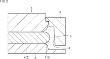
図2は、第1実施形態の中央部圧下工程を示す断面図である。図2を参照して、中央部圧下工程では、ラムがボルスタプレートを下降させる。これにより、第1上型2及び第1上型2に吊り下げられている第2上型3が下降する。中央部圧下工程では、第1上型2が円柱素材5の中央部6を圧下し、第2上型3は円柱素材5を圧下しない。円柱素材5の中央部6を圧下すると、円柱素材5は半径方向の外側に向かって変形する。
[Center part reduction process]
FIG. 2 is a cross-sectional view showing the central part reduction process of the first embodiment. Referring to FIG. 2, the ram lowers the bolster plate in the central reduction step. As a result, the first
[拘束工程]
図3は、第1実施形態の拘束工程を示す断面図である。図3を参照して、拘束工程においても、第1上型2による円柱素材の中央部6の圧下は継続されている。中央部6の圧下により変形している円柱素材5の半径方向の外側には、第1上型2とともに下降した第2上型3の側壁部8が存在する。そのため、第1上型2による中央部6の圧下が進むと、変形している円柱素材5の外周面9が第2上型3の側壁部8に当たる。これにより、円柱素材5の半径方向の変形が拘束される。
[Restriction process]
FIG. 3 is a cross-sectional view showing the restraining process of the first embodiment. Referring to FIG. 3, even in the restraining step, the reduction of the
図4は、一般的な製造方法による鍛造を示す断面図である。図4を参照して、一般的な鍛造では上型100は1つである。この場合、円柱素材5が半径方向の外側に変形し、縁部7が上型100の側壁部102に当たると、縁部7は側壁部102によって下方(下型101側)に引きずられる。したがって、縁部7の上方(上型100側)の隅領域A1に材料が充満しにくく、製造された円形材に欠肉が生じやすい。
FIG. 4 is a cross-sectional view showing forging by a general manufacturing method. Referring to FIG. 4, there is one
これに対し、第1実施形態の製造方法では、以下に説明するように異速度圧下工程において、円柱素材5の縁部7が下方に引きずられることを抑制する。以下、この点について詳述する。
On the other hand, in the manufacturing method of the first embodiment, the
[異速度圧下工程]
図5は、第1実施形態の異速度圧下工程の初期を示す断面図である。図5を参照して、拘束工程で円柱素材5の半径方向の変形を拘束した後、第1上型2はさらに円柱素材5の中央部6を圧下する。これにより、円柱素材5は半径方向に変形しようとするが、円柱素材5の半径方向の変形は側壁部8により拘束されている。上述したように第2上型3は第1上型2に吊り下げられている。さらに、第2上型3の側壁部8は、抜き勾配を有するため、僅かに傾斜している。そのため、半径方向に変形する円柱素材5が側壁部8に与える力によって、第2上型3は第1上型2に対して相対的に上昇する。したがって、第2上型3の下降速度は、第1上型2の下降速度よりも遅い。言い換えると、円柱素材の縁部7の圧下速度は、中央部6の圧下速度よりも遅い。なお、本明細書において「圧下」とは、金型により円柱素材の形状が変化することを意味する。したがって、第2上型3の第1上型2に対する上昇(スライド)により円柱素材5の縁部7の形状は変化するため、この形状の変化も圧下に含まれる。
[Different speed reduction process]
FIG. 5 is a cross-sectional view showing the initial stage of the different speed reduction process of the first embodiment. Referring to FIG. 5, after restraining the radial deformation of the
第2上型3の第1上型2に対する上昇により、縁部7に流れ着いた材料も第1上型2に対して相対的に上昇する。これにより、第1上型2及び第2上型3によって形成される隅領域A1に材料が充満しやすくなり、製品である円形材の縁部上方の領域(第1上型2及び第2上型3により形成される隅領域A1に相当する領域)の欠肉が抑制される。このような第1実施形態の製造方法は、H形状の断面を有する円形材の縁部上方の領域の体積が、縁部下方の領域の体積よりも大きい場合に特に有効である。
Due to the rise of the second
図6は、第1実施形態の異速度圧下工程の末期を示す断面図である。図6を参照して、上述したように、第2上型3の第1上型2に対する上昇は、所定の距離で終了する。所定の距離は、製造する円形材の形状によって適宜設定される。第2上型3の第1上型2に対する上昇が終了すると異速度圧下工程は終了する。
FIG. 6 is a cross-sectional view showing the final stage of the different speed reduction process of the first embodiment. With reference to FIG. 6, as described above, the rise of the second
[同速度圧下工程]
図7は、第1実施形態の同速度圧下工程を示す断面図である。図7を参照して、同速度圧下工程は異速度圧下工程の後に実施される。第2上型3の第1上型2に対する上昇が終了した後、ボルスタプレートはさらに下降する。この場合、第2上型3は第1上型2に対してスライドしないため、第2上型3は第1上型2と一体となって下降する。すなわち、同速度圧下工程では、第1上型2による円柱素材5に対するの圧下速度は第2上型3の圧下速度と同じである。すなわち、円柱素材5の中央部6が第1上型2によって圧下され、円柱素材5の縁部7が第2上型3によって中央部6と同じ圧下速度で圧下される。その後、第1上型2及び第2上型3は下死点に到達する。第1上型2及び第2上型3が下死点に到達すると、鍛造荒地が得られる。
[Same speed reduction process]
FIG. 7 is a cross-sectional view showing the same speed reduction process of the first embodiment. Referring to FIG. 7, the same speed reduction process is performed after the different speed reduction process. After the rise of the second
同速度圧下工程では、第1上型2の圧下によって押し出され、縁部7に流れ着いた材料は、第2上型3によって、縁部7の下方に向けて圧下される。これにより、H形状の断面を有する鍛造荒地の縁部下方の領域A2にも材料が充満しやすくなる。
In the same speed reduction process, the material pushed out by the reduction of the first
製造された鍛造荒地には周知の仕上加工が施され、円形材(製品)とされる。例えば、圧延機を用いて鍛造荒地に対して仕上圧延を実施する。仕上圧延後、仕上鍛造を実施して、円形材を製造する。 The manufactured forged waste land is subjected to a well-known finishing process to obtain a circular material (product). For example, finish rolling is performed on the forged rough ground using a rolling mill. After finish rolling, finish forging is performed to produce a circular material.
ここで、同速度圧下工程では、第1上型2は第2上型3と同時に下死点に到達するのが好ましい。第1上型2が先に下死点に到達すれば、第1上型2の下死点到達時に第2上型3と下型4との間に隙間ができる。第1上型2が下死点に到達した後、円柱素材5の中央部6は圧下されない。したがって、第1上型2によって材料が縁部7に向けて押し出されない。そのため、縁部に欠肉が生じる可能性がある。また、円柱素材5のサイズが十分に大きい場合、第2上型3と下型4との間の隙間から材料が流出し、過剰なバリが生じる可能性がある。そのため、歩留りが低下する可能性がある。他方、第2上型3が先に下死点に到達すれば、第2上型3が下死点に到達した後、円柱素材5の縁部7は圧下されない。そのため、縁部7に材料を充満させにくく、欠肉が生じる可能性がある。第1上型2が第2上型3と同時に下死点に到達すれば、円柱素材の縁部への材料の充満及び歩留りの低下の抑制の双方のバランスを保ちやすい。
Here, in the same speed reduction process, it is preferable that the first
図8は、第1実施形態の鍛造装置における第1上型と第2上型との境界を示す断面図である。図8を参照して、第1上型2と第2上型3との境界、すなわち、上型の分割位置は、円柱素材5の中央部6と縁部7との境界と一致する位置であるのが好ましい。第1上型2と第2上型3とで形成される隅領域の半径方向外側の隅10は材料の流動方向の延長線上に存在する。しかしながら、半径方向内側の隅11は材料の流動方向には存在せず、負角となる位置に存在する。
FIG. 8 is a cross-sectional view showing the boundary between the first upper die and the second upper die in the forging device of the first embodiment. Referring to FIG. 8, the boundary between the first
第1上型2と第2上型3との境界位置が円柱素材5の中央部6と縁部7との境界と一致する場合、円柱素材5の縁部7は、中央部6が圧下されてからある程度の時間が経過するまで第1上型2及び第2上型3と接触しない。したがって、縁部7が早期に金型と接触することがないため、材料の流動性が高いまま圧下が進行し、半径方向内側の隅11に材料が充満しやすい。
When the boundary position between the first
ただし、本実施形態の製造方法は、第1上型2と第2上型3との境界位置を円柱素材の中央部6と縁部7との境界と一致する場合に限定するものではない。加熱温度、材料の組成等により流動性は変化するため、第1上型2と第2上型3との境界が円柱素材の中央部6と縁部7との境界と一致しない場合でも半径方向内側の隅11に材料を充満させることができる場合もあるからである。例えば、図9に示すように、第1上型2と第2上型3との境界は、円柱素材5(鍛造荒地)の外周面9に一致する位置であってもよい。
However, the manufacturing method of this embodiment is not limited to the case where the boundary position between the first
[第2実施形態]
続いて、第2実施形態の円形材の製造方法について説明する。以下では、第1実施形態と異なる点のみ説明し、第1実施形態と同じ点は説明を省略する。まず、第2実施形態の鍛造装置について説明する。
[Second Embodiment]
Then, the manufacturing method of the circular material of 2nd Embodiment is demonstrated. Below, only a different point from 1st Embodiment is demonstrated and description is abbreviate | omitted about the same point as 1st Embodiment. First, a forging device according to the second embodiment will be described.
[鍛造装置]
図10は、第2実施形態の鍛造装置1の断面図である。図10を参照して、鍛造装置1の下型4は、第1下型4Aと、第2下型4Bとを含む。
[Forging equipment]
FIG. 10 is a cross-sectional view of the forging
第1下型4Aは、成形後の鍛造荒地の中央部に対応する形状を有する。
The first
第2下型4Bは、円柱素材5の半径方向において第1下型4Aよりも外側に配置される。第2下型4Bは、成形後の鍛造荒地の縁部に対応する形状を有する。第2下型4Bは、弾性部材12を介して第1下型4Aに接続される。弾性部材12は、第2下型4Bを上下方向に移動可能に支持する。弾性部材12はたとえば、ばね、油圧装置等である。円柱素材5を圧下する前において、第2下型4Bの上面は、第1下型4Aの上面よりも下方に位置する。
The second
[製造方法]
続いて、第2実施形態の円形材の製造方法について説明する。第2実施形態の円形材の製造方法は、上述した第2実施形態の鍛造装置1を用いる。第2実施形態の円形材の製造方法は、第1実施形態の製造方法に加えて、加圧工程を含む。以下、図11〜図13を参照して、第2実施形態の円形材の製造方法について説明する。
[Production method]
Then, the manufacturing method of the circular material of 2nd Embodiment is demonstrated. The manufacturing method of the circular material of 2nd Embodiment uses the forging
[加圧工程]
図11を参照して、第2実施形態の製造方法においても第1実施形態と同様に、まず円柱素材5の中央部6を圧下する中央部圧下工程、円柱素材5の縁部7の外周面9の半径方向への変形を拘束する拘束工程が実施される。
[Pressure process]
Referring to FIG. 11, also in the manufacturing method of the second embodiment, as in the first embodiment, first, a central portion reduction step of reducing the
拘束工程後、第2上型3の側壁部8が、円柱素材5の半径方向の外側への変形を拘束しているため、第1上型2で円柱素材5の中央部6をさらに圧下すると、縁部7において材料が上下方向に流動する。材料が上下方向に流動すると、縁部7の下方には第2下型4Bが配置されているため、縁部7の下面が第2下型4Bと接触するようになる。
After the restraining step, since the
図12を参照して、縁部7の下面が第2下型4Bと接触した後、さらに第1上型2が円柱素材5の中央部6を圧下すると、縁部7において材料が上下方向に流動しようとするが、下方への材料の流動は第2下型4Bによって抑制される。そのため、下方に移動しようとしていた円柱素材5の縁部7の材料が、上方に流動するようになる。縁部7において材料が上方に流動することで、第2上型3も第1上型2に対して相対的にスライドする。この状態からさらに第1上型2を下降させると、第2上型3の上方へのスライドが終了し(異速度圧下工程が終了し)、第1上型2及び第2上型3が同じ下降速度で円柱素材5を圧下する(同速度圧下工程が実施される)。
Referring to FIG. 12, after the lower surface of the
第1上型2及び第2上型3が同じ下降速度で円柱素材5を圧下すると、円柱素材5の縁部7において材料が下方へ流動し、それに押されて第2下型4Bは下方へ移動する。この際、第2下型4Bは弾性部材12で支持されているため、第2下型4Bは円柱素材5の縁部7に対し上方に向かって力を加える。この状態で、第1上型2及び第2上型3は、図13に示すように下死点に到達する。
When the first
このように第2実施形態の円形材の製造方法によれば、円柱素材5の縁部7において材料が下方に流動することを第2下型4Bが抑制する。また、第2上型3のスライドが終了した後も、収縮する弾性部材12に支持された第2下型4Bの加圧作用によって円柱素材5の縁部7に、上方に向かう力を付与し続ける。そのため、円柱素材5の縁部7の材料が上方に流動しやすくなり、製品である円形材の縁部上方の領域の欠肉がさらに抑制される。
Thus, according to the manufacturing method of the circular material of 2nd Embodiment, the 2nd lower mold |
また、第2下型4Bが円柱素材5の縁部7に対し上方に向かって加圧することにより、第1下型4A、第2下型4B及び第2上型3で形成される隅領域の成形を早期に行うことができるため、製品である円形材の縁部下方の領域の欠肉も抑制される。
Further, when the second
なお、上述した第2実施形態では、円柱素材5の縁部7の下面が第2下型4Bと接触した後、第2上型3の上方へのスライドが終了する場合について説明した。しかしながら、円柱素材5の縁部7の下面は、第2上型3の上方へのスライドが終了した後に第2下型4Bと接触してもよい。要するに、加圧工程は、中央部圧下工程後に実施されればよく、そのタイミングは適宜設定すればよい。
In addition, in 2nd Embodiment mentioned above, after the lower surface of the
以上、本実施形態の円形材の製造方法について説明した。その他、本発明は上記の実施形態に限定されず、本発明の趣旨を逸脱しない範囲で、種々の変更が可能であることは言うまでもない。 In the above, the manufacturing method of the circular material of this embodiment was demonstrated. In addition, it goes without saying that the present invention is not limited to the above-described embodiment, and various modifications can be made without departing from the spirit of the present invention.
例えば、上述の各実施形態では、熱間鍛造によって円形材を製造する場合について説明したが、本発明の円形材の製造方法はこれに限定されず、冷間鍛造によって円形材を製造する場合にも適用できる。この場合、上述の各実施形態における加熱工程は省略される。 For example, in each of the above-described embodiments, the case where a circular material is manufactured by hot forging has been described. However, the method for manufacturing a circular material according to the present invention is not limited to this, and when a circular material is manufactured by cold forging. Is also applicable. In this case, the heating process in each embodiment described above is omitted.
1:鍛造装置
2:第1上型
3:第2上型
4:下型
5:円柱素材
6:中央部
7:縁部
8:側壁部
9:外周面
1: Forging device 2: First upper die 3: Second upper die 4: Lower die 5: Column material 6: Center portion 7: Edge portion 8: Side wall portion 9: Outer peripheral surface
Claims (5)
前記円柱素材の中央部を圧下し、前記円柱素材を半径方向に変形させる工程と、
前記半径方向に変形している円柱素材の前記半径方向の変形を拘束する工程と、
前記円柱素材の前記半径方向の変形を拘束する工程後、前記円柱素材の中央部をさらに圧下し、かつ、前記中央部の圧下速度よりも遅い圧下速度で前記円柱素材の縁部を圧下する工程と、
前記縁部を圧下する工程後、前記円柱素材の中央部及び縁部を同じ圧下速度で圧下する工程と、を備える、円形材の製造方法。 A method of manufacturing a circular material from a cylindrical material including a central portion and an edge portion having an outer peripheral surface,
A step of rolling down the central portion of the cylindrical material, and deforming the cylindrical material in a radial direction;
Constraining the radial deformation of the cylindrical material deforming in the radial direction;
After the step of constraining the radial deformation of the columnar material, the step of further reducing the center portion of the columnar material and rolling down the edge of the columnar material at a reduction speed lower than the reduction rate of the center portion When,
And a step of rolling down the central portion and the edge portion of the cylindrical material at the same rolling speed after the step of rolling down the edge portion.
第1上型と、
前記円柱素材の外周面と対向する側壁部を含み、前記第1上型よりも前記円柱素材の半径方向の外側に配置され、前記第1上型に対して圧下方向にスライド可能な第2上型と、
前記第1上型及び前記第2上型と対向する下型と、を含む鍛造装置に前記円柱素材を配置する工程、を備え、
前記円柱素材を半径方向に変形させる工程では、前記第1上型が前記円柱素材の中央部を圧下し、
前記円柱素材の半径方向の変形を拘束する工程では、前記第2上型の側壁部が前記円柱素材の外周面と接触し、前記円柱素材の半径方向の変形を拘束し、
前記円柱素材の中央部を圧下し、かつ、中央部の圧下速度よりも遅い圧下速度で円柱素材の縁部を圧下する工程では、前記第1上型の下降速度よりも遅い下降速度で前記第2上型が前記円柱素材の縁部を圧下する、円形材の製造方法。 The method for producing a circular material according to claim 1, further comprising:
A first upper mold;
A second upper portion that includes a side wall portion that opposes the outer peripheral surface of the columnar material, is disposed on a radially outer side of the columnar material with respect to the first upper die, and is slidable in a downward direction with respect to the first upper die; Type,
Arranging the columnar material in a forging device including a lower die facing the first upper die and the second upper die,
In the step of deforming the cylindrical material in the radial direction, the first upper mold squeezes the central portion of the cylindrical material,
In the step of constraining the radial deformation of the columnar material, the side wall portion of the second upper mold is in contact with the outer peripheral surface of the columnar material, constraining the radial deformation of the columnar material,
In the step of rolling down the central portion of the cylindrical material and rolling down the edge of the cylindrical material at a rolling speed slower than the rolling speed of the central portion, the first lower mold has a lowering speed than the lowering speed of the first upper mold. (2) A method for producing a circular material, wherein the upper mold reduces the edge of the cylindrical material.
前記円柱素材の中央部及び縁部を同じ圧下速度で圧下する工程では、前記第1上型は前記第2上型と同時に下死点に到達する、円形材の製造方法。 It is a manufacturing method of the circular material according to claim 2,
In the step of rolling down the central part and the edge of the cylindrical material at the same rolling speed, the first upper mold reaches the bottom dead center at the same time as the second upper mold.
前記円柱素材を半径方向に変形させる工程後、前記円柱素材の縁部を圧下方向と反対方向に加圧する工程を備える、円形材の製造方法。 The method for producing a circular material according to any one of claims 1 to 3, further comprising:
A method for producing a circular material, comprising a step of pressing an edge of the columnar material in a direction opposite to the reduction direction after the step of deforming the columnar material in a radial direction.
前記円柱素材を半径方向に変形させる工程後、前記円柱素材の縁部を圧下方向と反対方向に加圧する工程を備え、
前記鍛造装置の前記下型は、第1下型と、前記第1下型よりも前記円柱素材の半径方向の外側に配置され、前記第1下型に弾性部材を介して取り付けられた第2下型と、を含み、
前記円柱素材の縁部を圧下方向と反対方向に加圧する工程では、前記第2下型が前記円柱素材の縁部を加圧する、円形材の製造方法。 The method for producing a circular material according to claim 2 or 3, further comprising:
After the step of deforming the columnar material in the radial direction, the step of pressurizing the edge of the columnar material in the direction opposite to the reduction direction,
The lower mold of the forging device is a first lower mold and a second lower mold that is disposed on the outer side in the radial direction of the cylindrical material than the first lower mold and is attached to the first lower mold via an elastic member. Including a lower mold,
In the step of pressing the edge of the columnar material in the direction opposite to the reduction direction, the second lower mold pressurizes the edge of the columnar material.
Applications Claiming Priority (2)
| Application Number | Priority Date | Filing Date | Title |
|---|---|---|---|
| JP2018043729 | 2018-03-12 | ||
| JP2018043729 | 2018-03-12 |
Publications (2)
| Publication Number | Publication Date |
|---|---|
| JP2019155477A true JP2019155477A (en) | 2019-09-19 |
| JP7156099B2 JP7156099B2 (en) | 2022-10-19 |
Family
ID=67992895
Family Applications (1)
| Application Number | Title | Priority Date | Filing Date |
|---|---|---|---|
| JP2019041077A Active JP7156099B2 (en) | 2018-03-12 | 2019-03-07 | Manufacturing method of circular material |
Country Status (1)
| Country | Link |
|---|---|
| JP (1) | JP7156099B2 (en) |
Citations (6)
| Publication number | Priority date | Publication date | Assignee | Title |
|---|---|---|---|---|
| JPS50117137U (en) * | 1974-03-13 | 1975-09-25 | ||
| JPS62192224A (en) * | 1986-02-18 | 1987-08-22 | Mazda Motor Corp | Forging method |
| JPH05138284A (en) * | 1991-11-19 | 1993-06-01 | Aida Eng Ltd | Plasticification working method of gear or similar member |
| JPH0744350Y2 (en) * | 1987-05-25 | 1995-10-11 | 日産自動車株式会社 | Forging die |
| JP2013237056A (en) * | 2012-05-11 | 2013-11-28 | Toyota Jidosha Hokkaido Kk | Gear forming method |
| JP2015009256A (en) * | 2013-06-28 | 2015-01-19 | 新日鐵住金株式会社 | Manufacturing method of circular member and forging device used therefor |
-
2019
- 2019-03-07 JP JP2019041077A patent/JP7156099B2/en active Active
Patent Citations (6)
| Publication number | Priority date | Publication date | Assignee | Title |
|---|---|---|---|---|
| JPS50117137U (en) * | 1974-03-13 | 1975-09-25 | ||
| JPS62192224A (en) * | 1986-02-18 | 1987-08-22 | Mazda Motor Corp | Forging method |
| JPH0744350Y2 (en) * | 1987-05-25 | 1995-10-11 | 日産自動車株式会社 | Forging die |
| JPH05138284A (en) * | 1991-11-19 | 1993-06-01 | Aida Eng Ltd | Plasticification working method of gear or similar member |
| JP2013237056A (en) * | 2012-05-11 | 2013-11-28 | Toyota Jidosha Hokkaido Kk | Gear forming method |
| JP2015009256A (en) * | 2013-06-28 | 2015-01-19 | 新日鐵住金株式会社 | Manufacturing method of circular member and forging device used therefor |
Also Published As
| Publication number | Publication date |
|---|---|
| JP7156099B2 (en) | 2022-10-19 |
Similar Documents
| Publication | Publication Date | Title |
|---|---|---|
| Jin et al. | A single-step hot stamping-forging process for aluminum alloy shell parts with nonuniform thickness | |
| Yoon et al. | Process design of cold forging with thick plate for seat recliner parts | |
| JP5632671B2 (en) | Forging die equipment | |
| CN107186160A (en) | The quiet step forming process of disk two of new-energy automotive air-conditioning compressor | |
| JP2019155477A (en) | Method for manufacturing circular material | |
| CN105880346A (en) | Double-acting extrusion molding control method for copper cone part | |
| RU2572687C1 (en) | Method of production of steel forgings of ball valve half-casings | |
| JP5807293B2 (en) | Method for forming undercut portion and method for producing molded product having undercut portion | |
| RU2584195C1 (en) | Method of making cylindrical components with conical part | |
| JP7167819B2 (en) | Manufacturing method of circular material | |
| CN104550585A (en) | Rolling forming method of structural steel thick-wall ring forging | |
| CN104550622A (en) | Method for rolling and forming beta-phase titanium alloy thick-wall ring forging | |
| CN106734806A (en) | The enclosed hole-punching method of 1Cr12Ni2WMoVNb steel cylinder ring high | |
| JP6605006B2 (en) | Forging method | |
| EP2807651A1 (en) | A method for the manufacture of a vessel bottom with a flange | |
| JP7167820B2 (en) | Manufacturing method of circular material | |
| Sun et al. | Numerical investigation on tooth filling of clutch drum forming processes | |
| JP6136645B2 (en) | Manufacturing method of circular material | |
| JP5608537B2 (en) | Manufacturing method of pipe with flange | |
| JP6605059B2 (en) | Forging method | |
| CN105382155A (en) | Roll forming method for alpha-beta two-phase titanium alloy thick-wall ring forged piece | |
| JP6319418B2 (en) | Forging equipment used for manufacturing circular materials | |
| RU2443497C2 (en) | Method of producing axially symmetric cup parts | |
| KR101544785B1 (en) | method for manufacturing a piston of under drive break | |
| CN114260402B (en) | Design method and forging method of large-diameter thin-wall spherical shell type integral die forging |
Legal Events
| Date | Code | Title | Description |
|---|---|---|---|
| A621 | Written request for application examination |
Free format text: JAPANESE INTERMEDIATE CODE: A621 Effective date: 20211104 |
|
| TRDD | Decision of grant or rejection written | ||
| A977 | Report on retrieval |
Free format text: JAPANESE INTERMEDIATE CODE: A971007 Effective date: 20220831 |
|
| A01 | Written decision to grant a patent or to grant a registration (utility model) |
Free format text: JAPANESE INTERMEDIATE CODE: A01 Effective date: 20220906 |
|
| A61 | First payment of annual fees (during grant procedure) |
Free format text: JAPANESE INTERMEDIATE CODE: A61 Effective date: 20220919 |
|
| R151 | Written notification of patent or utility model registration |
Ref document number: 7156099 Country of ref document: JP Free format text: JAPANESE INTERMEDIATE CODE: R151 |