JP2019149202A - Extramissive spatial imaging digital eyeglass apparatus for virtual or augmediated vision - Google Patents
Extramissive spatial imaging digital eyeglass apparatus for virtual or augmediated vision Download PDFInfo
- Publication number
- JP2019149202A JP2019149202A JP2019091204A JP2019091204A JP2019149202A JP 2019149202 A JP2019149202 A JP 2019149202A JP 2019091204 A JP2019091204 A JP 2019091204A JP 2019091204 A JP2019091204 A JP 2019091204A JP 2019149202 A JP2019149202 A JP 2019149202A
- Authority
- JP
- Japan
- Prior art keywords
- implementation
- space
- user
- light
- sensor
- Prior art date
- Legal status (The legal status is an assumption and is not a legal conclusion. Google has not performed a legal analysis and makes no representation as to the accuracy of the status listed.)
- Pending
Links
- 238000003384 imaging method Methods 0.000 title abstract description 78
- 239000012636 effector Substances 0.000 abstract description 199
- 230000003190 augmentative effect Effects 0.000 description 298
- 239000011521 glass Substances 0.000 description 253
- 230000001953 sensory effect Effects 0.000 description 230
- 238000001514 detection method Methods 0.000 description 226
- 238000000034 method Methods 0.000 description 179
- 210000003811 finger Anatomy 0.000 description 131
- 238000012545 processing Methods 0.000 description 129
- 210000001508 eye Anatomy 0.000 description 95
- 230000007613 environmental effect Effects 0.000 description 90
- 230000009471 action Effects 0.000 description 68
- 230000033001 locomotion Effects 0.000 description 67
- 230000003993 interaction Effects 0.000 description 60
- 210000003813 thumb Anatomy 0.000 description 43
- 230000000007 visual effect Effects 0.000 description 41
- 230000002441 reversible effect Effects 0.000 description 37
- 230000035807 sensation Effects 0.000 description 37
- 230000009466 transformation Effects 0.000 description 36
- 230000006870 function Effects 0.000 description 34
- 230000000694 effects Effects 0.000 description 33
- 238000005286 illumination Methods 0.000 description 33
- 239000013589 supplement Substances 0.000 description 33
- 238000010586 diagram Methods 0.000 description 29
- 210000003128 head Anatomy 0.000 description 29
- 230000003287 optical effect Effects 0.000 description 29
- 238000005259 measurement Methods 0.000 description 25
- 230000008569 process Effects 0.000 description 24
- 238000013461 design Methods 0.000 description 23
- 239000000123 paper Substances 0.000 description 23
- 238000012549 training Methods 0.000 description 22
- 230000004044 response Effects 0.000 description 21
- 238000006073 displacement reaction Methods 0.000 description 20
- 241000282414 Homo sapiens Species 0.000 description 19
- 210000004247 hand Anatomy 0.000 description 19
- 239000011324 bead Substances 0.000 description 18
- 238000004458 analytical method Methods 0.000 description 16
- 230000008859 change Effects 0.000 description 16
- 238000012544 monitoring process Methods 0.000 description 16
- 238000013507 mapping Methods 0.000 description 15
- 235000003166 Opuntia robusta Nutrition 0.000 description 14
- 244000218514 Opuntia robusta Species 0.000 description 14
- 238000004891 communication Methods 0.000 description 14
- 230000006854 communication Effects 0.000 description 14
- 210000004027 cell Anatomy 0.000 description 13
- 238000013528 artificial neural network Methods 0.000 description 12
- 238000001125 extrusion Methods 0.000 description 12
- 238000013519 translation Methods 0.000 description 12
- 210000003414 extremity Anatomy 0.000 description 11
- 239000012530 fluid Substances 0.000 description 11
- 230000001404 mediated effect Effects 0.000 description 11
- 210000002683 foot Anatomy 0.000 description 10
- 230000000670 limiting effect Effects 0.000 description 10
- 230000000712 assembly Effects 0.000 description 9
- 238000000429 assembly Methods 0.000 description 9
- 230000006399 behavior Effects 0.000 description 9
- 230000005540 biological transmission Effects 0.000 description 9
- 230000015572 biosynthetic process Effects 0.000 description 9
- 230000002452 interceptive effect Effects 0.000 description 9
- 238000003825 pressing Methods 0.000 description 9
- 238000003786 synthesis reaction Methods 0.000 description 9
- 239000002131 composite material Substances 0.000 description 8
- 230000010354 integration Effects 0.000 description 8
- 239000011159 matrix material Substances 0.000 description 8
- 238000010422 painting Methods 0.000 description 8
- 230000035945 sensitivity Effects 0.000 description 8
- 239000007787 solid Substances 0.000 description 8
- 230000006641 stabilisation Effects 0.000 description 8
- 230000003068 static effect Effects 0.000 description 8
- 101100274557 Heterodera glycines CLE1 gene Proteins 0.000 description 7
- 239000004927 clay Substances 0.000 description 7
- 238000001228 spectrum Methods 0.000 description 7
- 238000012360 testing method Methods 0.000 description 7
- 238000000844 transformation Methods 0.000 description 7
- 230000001133 acceleration Effects 0.000 description 6
- 238000006243 chemical reaction Methods 0.000 description 6
- 230000000875 corresponding effect Effects 0.000 description 6
- 238000010891 electric arc Methods 0.000 description 6
- 238000007689 inspection Methods 0.000 description 6
- 239000000463 material Substances 0.000 description 6
- 239000000203 mixture Substances 0.000 description 6
- 238000013439 planning Methods 0.000 description 6
- 238000005096 rolling process Methods 0.000 description 6
- 238000012546 transfer Methods 0.000 description 6
- XLYOFNOQVPJJNP-UHFFFAOYSA-N water Substances O XLYOFNOQVPJJNP-UHFFFAOYSA-N 0.000 description 6
- 238000013459 approach Methods 0.000 description 5
- 230000000295 complement effect Effects 0.000 description 5
- 239000000428 dust Substances 0.000 description 5
- 238000011156 evaluation Methods 0.000 description 5
- 239000004744 fabric Substances 0.000 description 5
- 210000005224 forefinger Anatomy 0.000 description 5
- 239000003550 marker Substances 0.000 description 5
- 238000012986 modification Methods 0.000 description 5
- 230000004048 modification Effects 0.000 description 5
- 210000000869 occipital lobe Anatomy 0.000 description 5
- 230000002829 reductive effect Effects 0.000 description 5
- 238000011105 stabilization Methods 0.000 description 5
- KRQUFUKTQHISJB-YYADALCUSA-N 2-[(E)-N-[2-(4-chlorophenoxy)propoxy]-C-propylcarbonimidoyl]-3-hydroxy-5-(thian-3-yl)cyclohex-2-en-1-one Chemical compound CCC\C(=N/OCC(C)OC1=CC=C(Cl)C=C1)C1=C(O)CC(CC1=O)C1CCCSC1 KRQUFUKTQHISJB-YYADALCUSA-N 0.000 description 4
- 230000003044 adaptive effect Effects 0.000 description 4
- 238000004364 calculation method Methods 0.000 description 4
- 230000001413 cellular effect Effects 0.000 description 4
- 239000003086 colorant Substances 0.000 description 4
- 230000036461 convulsion Effects 0.000 description 4
- 229920001971 elastomer Polymers 0.000 description 4
- 238000005516 engineering process Methods 0.000 description 4
- 230000004424 eye movement Effects 0.000 description 4
- 230000014509 gene expression Effects 0.000 description 4
- 230000001965 increasing effect Effects 0.000 description 4
- 230000035515 penetration Effects 0.000 description 4
- 230000002093 peripheral effect Effects 0.000 description 4
- 230000002085 persistent effect Effects 0.000 description 4
- 239000000047 product Substances 0.000 description 4
- 239000005060 rubber Substances 0.000 description 4
- 238000012163 sequencing technique Methods 0.000 description 4
- 238000004088 simulation Methods 0.000 description 4
- 230000000638 stimulation Effects 0.000 description 4
- 230000000153 supplemental effect Effects 0.000 description 4
- 230000001960 triggered effect Effects 0.000 description 4
- 238000003466 welding Methods 0.000 description 4
- 238000002679 ablation Methods 0.000 description 3
- 238000005452 bending Methods 0.000 description 3
- 230000009172 bursting Effects 0.000 description 3
- 208000018747 cerebellar ataxia with neuropathy and bilateral vestibular areflexia syndrome Diseases 0.000 description 3
- 229940112822 chewing gum Drugs 0.000 description 3
- 235000015218 chewing gum Nutrition 0.000 description 3
- 230000001186 cumulative effect Effects 0.000 description 3
- 238000013480 data collection Methods 0.000 description 3
- 238000010410 dusting Methods 0.000 description 3
- 210000005069 ears Anatomy 0.000 description 3
- 210000000887 face Anatomy 0.000 description 3
- 238000007667 floating Methods 0.000 description 3
- 235000013305 food Nutrition 0.000 description 3
- 230000004927 fusion Effects 0.000 description 3
- 239000000976 ink Substances 0.000 description 3
- 238000007726 management method Methods 0.000 description 3
- 238000004519 manufacturing process Methods 0.000 description 3
- 230000002503 metabolic effect Effects 0.000 description 3
- 238000010606 normalization Methods 0.000 description 3
- 239000003973 paint Substances 0.000 description 3
- 230000036961 partial effect Effects 0.000 description 3
- 239000000843 powder Substances 0.000 description 3
- 238000003892 spreading Methods 0.000 description 3
- 230000007480 spreading Effects 0.000 description 3
- 238000000551 statistical hypothesis test Methods 0.000 description 3
- 238000003860 storage Methods 0.000 description 3
- OKTJSMMVPCPJKN-UHFFFAOYSA-N Carbon Chemical compound [C] OKTJSMMVPCPJKN-UHFFFAOYSA-N 0.000 description 2
- 241000270722 Crocodylidae Species 0.000 description 2
- 101150027068 DEGS1 gene Proteins 0.000 description 2
- XEEYBQQBJWHFJM-UHFFFAOYSA-N Iron Chemical compound [Fe] XEEYBQQBJWHFJM-UHFFFAOYSA-N 0.000 description 2
- 241001481166 Nautilus Species 0.000 description 2
- 241000475481 Nebula Species 0.000 description 2
- 206010000269 abscess Diseases 0.000 description 2
- 238000009825 accumulation Methods 0.000 description 2
- 230000003213 activating effect Effects 0.000 description 2
- 229910052782 aluminium Inorganic materials 0.000 description 2
- XAGFODPZIPBFFR-UHFFFAOYSA-N aluminium Chemical compound [Al] XAGFODPZIPBFFR-UHFFFAOYSA-N 0.000 description 2
- 210000000617 arm Anatomy 0.000 description 2
- 230000008901 benefit Effects 0.000 description 2
- 238000004040 coloring Methods 0.000 description 2
- 150000001875 compounds Chemical class 0.000 description 2
- 239000004567 concrete Substances 0.000 description 2
- 230000008602 contraction Effects 0.000 description 2
- 230000001351 cycling effect Effects 0.000 description 2
- LNNWVNGFPYWNQE-GMIGKAJZSA-N desomorphine Chemical compound C1C2=CC=C(O)C3=C2[C@]24CCN(C)[C@H]1[C@@H]2CCC[C@@H]4O3 LNNWVNGFPYWNQE-GMIGKAJZSA-N 0.000 description 2
- 230000005670 electromagnetic radiation Effects 0.000 description 2
- 230000002708 enhancing effect Effects 0.000 description 2
- 239000012634 fragment Substances 0.000 description 2
- 239000003292 glue Substances 0.000 description 2
- 239000010439 graphite Substances 0.000 description 2
- 229910002804 graphite Inorganic materials 0.000 description 2
- 230000005484 gravity Effects 0.000 description 2
- 230000003760 hair shine Effects 0.000 description 2
- 239000011121 hardwood Substances 0.000 description 2
- 230000036541 health Effects 0.000 description 2
- 238000001093 holography Methods 0.000 description 2
- 230000001788 irregular Effects 0.000 description 2
- 210000002414 leg Anatomy 0.000 description 2
- 238000007477 logistic regression Methods 0.000 description 2
- 239000004579 marble Substances 0.000 description 2
- 230000007246 mechanism Effects 0.000 description 2
- 238000002156 mixing Methods 0.000 description 2
- 238000010295 mobile communication Methods 0.000 description 2
- 210000003205 muscle Anatomy 0.000 description 2
- 230000006855 networking Effects 0.000 description 2
- 230000001537 neural effect Effects 0.000 description 2
- 238000012015 optical character recognition Methods 0.000 description 2
- 210000000056 organ Anatomy 0.000 description 2
- 230000000737 periodic effect Effects 0.000 description 2
- 230000037081 physical activity Effects 0.000 description 2
- 238000002360 preparation method Methods 0.000 description 2
- 238000007639 printing Methods 0.000 description 2
- 230000001737 promoting effect Effects 0.000 description 2
- 210000001747 pupil Anatomy 0.000 description 2
- 230000009467 reduction Effects 0.000 description 2
- 238000009877 rendering Methods 0.000 description 2
- 230000008439 repair process Effects 0.000 description 2
- 238000005316 response function Methods 0.000 description 2
- 238000012552 review Methods 0.000 description 2
- 238000010187 selection method Methods 0.000 description 2
- 230000020341 sensory perception of pain Effects 0.000 description 2
- 238000007493 shaping process Methods 0.000 description 2
- 125000006850 spacer group Chemical group 0.000 description 2
- 230000003595 spectral effect Effects 0.000 description 2
- 239000004575 stone Substances 0.000 description 2
- 239000000126 substance Substances 0.000 description 2
- 230000009182 swimming Effects 0.000 description 2
- 238000012800 visualization Methods 0.000 description 2
- 210000000707 wrist Anatomy 0.000 description 2
- 241000372033 Andromeda Species 0.000 description 1
- 206010003805 Autism Diseases 0.000 description 1
- 208000020706 Autistic disease Diseases 0.000 description 1
- NBGBEUITCPENLJ-UHFFFAOYSA-N Bunazosin hydrochloride Chemical compound Cl.C1CN(C(=O)CCC)CCCN1C1=NC(N)=C(C=C(OC)C(OC)=C2)C2=N1 NBGBEUITCPENLJ-UHFFFAOYSA-N 0.000 description 1
- 208000033748 Device issues Diseases 0.000 description 1
- 241000282816 Giraffa camelopardalis Species 0.000 description 1
- PEDCQBHIVMGVHV-UHFFFAOYSA-N Glycerine Chemical compound OCC(O)CO PEDCQBHIVMGVHV-UHFFFAOYSA-N 0.000 description 1
- GVGLGOZIDCSQPN-PVHGPHFFSA-N Heroin Chemical compound O([C@H]1[C@H](C=C[C@H]23)OC(C)=O)C4=C5[C@@]12CCN(C)[C@@H]3CC5=CC=C4OC(C)=O GVGLGOZIDCSQPN-PVHGPHFFSA-N 0.000 description 1
- 235000015842 Hesperis Nutrition 0.000 description 1
- 241000282412 Homo Species 0.000 description 1
- 235000012633 Iberis amara Nutrition 0.000 description 1
- 125000002066 L-histidyl group Chemical group [H]N1C([H])=NC(C([H])([H])[C@](C(=O)[*])([H])N([H])[H])=C1[H] 0.000 description 1
- 208000000114 Pain Threshold Diseases 0.000 description 1
- 241001233278 Scalopus aquaticus Species 0.000 description 1
- 241000593989 Scardinius erythrophthalmus Species 0.000 description 1
- 241000555745 Sciuridae Species 0.000 description 1
- BQCADISMDOOEFD-UHFFFAOYSA-N Silver Chemical compound [Ag] BQCADISMDOOEFD-UHFFFAOYSA-N 0.000 description 1
- 229910000831 Steel Inorganic materials 0.000 description 1
- 206010047571 Visual impairment Diseases 0.000 description 1
- 239000008186 active pharmaceutical agent Substances 0.000 description 1
- 238000004873 anchoring Methods 0.000 description 1
- 238000003491 array Methods 0.000 description 1
- 230000003416 augmentation Effects 0.000 description 1
- 230000002457 bidirectional effect Effects 0.000 description 1
- 230000000903 blocking effect Effects 0.000 description 1
- 230000037237 body shape Effects 0.000 description 1
- 210000005252 bulbus oculi Anatomy 0.000 description 1
- 230000000981 bystander Effects 0.000 description 1
- 239000000919 ceramic Substances 0.000 description 1
- 239000003795 chemical substances by application Substances 0.000 description 1
- 238000004140 cleaning Methods 0.000 description 1
- 230000006835 compression Effects 0.000 description 1
- 238000007906 compression Methods 0.000 description 1
- 238000004590 computer program Methods 0.000 description 1
- 238000005094 computer simulation Methods 0.000 description 1
- 238000012790 confirmation Methods 0.000 description 1
- 235000014510 cooky Nutrition 0.000 description 1
- 238000012937 correction Methods 0.000 description 1
- 230000002596 correlated effect Effects 0.000 description 1
- 238000002790 cross-validation Methods 0.000 description 1
- 108010038204 cytoplasmic linker protein 190 Proteins 0.000 description 1
- 230000006378 damage Effects 0.000 description 1
- 238000005034 decoration Methods 0.000 description 1
- 230000007423 decrease Effects 0.000 description 1
- 230000003247 decreasing effect Effects 0.000 description 1
- 238000000280 densification Methods 0.000 description 1
- 230000001419 dependent effect Effects 0.000 description 1
- 230000004069 differentiation Effects 0.000 description 1
- 230000003467 diminishing effect Effects 0.000 description 1
- 230000026058 directional locomotion Effects 0.000 description 1
- 230000009977 dual effect Effects 0.000 description 1
- 230000008846 dynamic interplay Effects 0.000 description 1
- 210000002310 elbow joint Anatomy 0.000 description 1
- 230000005611 electricity Effects 0.000 description 1
- 230000001747 exhibiting effect Effects 0.000 description 1
- 230000008921 facial expression Effects 0.000 description 1
- 210000003746 feather Anatomy 0.000 description 1
- 230000005057 finger movement Effects 0.000 description 1
- 238000010304 firing Methods 0.000 description 1
- 210000000245 forearm Anatomy 0.000 description 1
- 238000005194 fractionation Methods 0.000 description 1
- 238000009432 framing Methods 0.000 description 1
- 239000007789 gas Substances 0.000 description 1
- 238000003702 image correction Methods 0.000 description 1
- 230000001976 improved effect Effects 0.000 description 1
- 230000000977 initiatory effect Effects 0.000 description 1
- 238000009434 installation Methods 0.000 description 1
- 229910052742 iron Inorganic materials 0.000 description 1
- 230000009191 jumping Effects 0.000 description 1
- 210000004936 left thumb Anatomy 0.000 description 1
- 235000013490 limbo Nutrition 0.000 description 1
- 239000007788 liquid Substances 0.000 description 1
- 230000004807 localization Effects 0.000 description 1
- 230000014759 maintenance of location Effects 0.000 description 1
- 230000013011 mating Effects 0.000 description 1
- 229910052751 metal Inorganic materials 0.000 description 1
- 239000002184 metal Substances 0.000 description 1
- 238000000465 moulding Methods 0.000 description 1
- 239000010813 municipal solid waste Substances 0.000 description 1
- 238000003058 natural language processing Methods 0.000 description 1
- 210000002569 neuron Anatomy 0.000 description 1
- 230000003040 nociceptive effect Effects 0.000 description 1
- 201000005111 ocular hyperemia Diseases 0.000 description 1
- 230000037040 pain threshold Effects 0.000 description 1
- 238000003909 pattern recognition Methods 0.000 description 1
- 230000000149 penetrating effect Effects 0.000 description 1
- 230000000704 physical effect Effects 0.000 description 1
- 239000004033 plastic Substances 0.000 description 1
- 238000009428 plumbing Methods 0.000 description 1
- 238000005381 potential energy Methods 0.000 description 1
- 230000005855 radiation Effects 0.000 description 1
- 238000010223 real-time analysis Methods 0.000 description 1
- 230000002207 retinal effect Effects 0.000 description 1
- 210000004935 right thumb Anatomy 0.000 description 1
- 230000000630 rising effect Effects 0.000 description 1
- 238000010079 rubber tapping Methods 0.000 description 1
- 239000005336 safety glass Substances 0.000 description 1
- 238000007665 sagging Methods 0.000 description 1
- 229920006395 saturated elastomer Polymers 0.000 description 1
- 238000006748 scratching Methods 0.000 description 1
- 230000002393 scratching effect Effects 0.000 description 1
- 230000011218 segmentation Effects 0.000 description 1
- 230000008786 sensory perception of smell Effects 0.000 description 1
- 238000004904 shortening Methods 0.000 description 1
- 229910052709 silver Inorganic materials 0.000 description 1
- 239000004332 silver Substances 0.000 description 1
- 210000003625 skull Anatomy 0.000 description 1
- 230000003997 social interaction Effects 0.000 description 1
- 229910001220 stainless steel Inorganic materials 0.000 description 1
- 239000010935 stainless steel Substances 0.000 description 1
- 239000010959 steel Substances 0.000 description 1
- 230000004936 stimulating effect Effects 0.000 description 1
- 230000009469 supplementation Effects 0.000 description 1
- 230000008093 supporting effect Effects 0.000 description 1
- 238000010408 sweeping Methods 0.000 description 1
- 208000024891 symptom Diseases 0.000 description 1
- 230000002194 synthesizing effect Effects 0.000 description 1
- 238000003325 tomography Methods 0.000 description 1
- 230000007704 transition Effects 0.000 description 1
- 230000017105 transposition Effects 0.000 description 1
- 238000010200 validation analysis Methods 0.000 description 1
- 238000001429 visible spectrum Methods 0.000 description 1
- 238000007794 visualization technique Methods 0.000 description 1
- 230000004584 weight gain Effects 0.000 description 1
- 235000019786 weight gain Nutrition 0.000 description 1
- 239000002023 wood Substances 0.000 description 1
Images


Classifications
-
- G—PHYSICS
- G06—COMPUTING; CALCULATING OR COUNTING
- G06F—ELECTRIC DIGITAL DATA PROCESSING
- G06F3/00—Input arrangements for transferring data to be processed into a form capable of being handled by the computer; Output arrangements for transferring data from processing unit to output unit, e.g. interface arrangements
- G06F3/01—Input arrangements or combined input and output arrangements for interaction between user and computer
- G06F3/017—Gesture based interaction, e.g. based on a set of recognized hand gestures
-
- G—PHYSICS
- G02—OPTICS
- G02B—OPTICAL ELEMENTS, SYSTEMS OR APPARATUS
- G02B27/00—Optical systems or apparatus not provided for by any of the groups G02B1/00 - G02B26/00, G02B30/00
- G02B27/01—Head-up displays
- G02B27/017—Head mounted
-
- G—PHYSICS
- G06—COMPUTING; CALCULATING OR COUNTING
- G06F—ELECTRIC DIGITAL DATA PROCESSING
- G06F3/00—Input arrangements for transferring data to be processed into a form capable of being handled by the computer; Output arrangements for transferring data from processing unit to output unit, e.g. interface arrangements
- G06F3/01—Input arrangements or combined input and output arrangements for interaction between user and computer
- G06F3/011—Arrangements for interaction with the human body, e.g. for user immersion in virtual reality
- G06F3/013—Eye tracking input arrangements
-
- G—PHYSICS
- G06—COMPUTING; CALCULATING OR COUNTING
- G06F—ELECTRIC DIGITAL DATA PROCESSING
- G06F3/00—Input arrangements for transferring data to be processed into a form capable of being handled by the computer; Output arrangements for transferring data from processing unit to output unit, e.g. interface arrangements
- G06F3/01—Input arrangements or combined input and output arrangements for interaction between user and computer
- G06F3/048—Interaction techniques based on graphical user interfaces [GUI]
- G06F3/0481—Interaction techniques based on graphical user interfaces [GUI] based on specific properties of the displayed interaction object or a metaphor-based environment, e.g. interaction with desktop elements like windows or icons, or assisted by a cursor's changing behaviour or appearance
- G06F3/04815—Interaction with a metaphor-based environment or interaction object displayed as three-dimensional, e.g. changing the user viewpoint with respect to the environment or object
-
- G—PHYSICS
- G06—COMPUTING; CALCULATING OR COUNTING
- G06F—ELECTRIC DIGITAL DATA PROCESSING
- G06F3/00—Input arrangements for transferring data to be processed into a form capable of being handled by the computer; Output arrangements for transferring data from processing unit to output unit, e.g. interface arrangements
- G06F3/01—Input arrangements or combined input and output arrangements for interaction between user and computer
- G06F3/048—Interaction techniques based on graphical user interfaces [GUI]
- G06F3/0481—Interaction techniques based on graphical user interfaces [GUI] based on specific properties of the displayed interaction object or a metaphor-based environment, e.g. interaction with desktop elements like windows or icons, or assisted by a cursor's changing behaviour or appearance
- G06F3/0482—Interaction with lists of selectable items, e.g. menus
-
- G—PHYSICS
- G06—COMPUTING; CALCULATING OR COUNTING
- G06F—ELECTRIC DIGITAL DATA PROCESSING
- G06F3/00—Input arrangements for transferring data to be processed into a form capable of being handled by the computer; Output arrangements for transferring data from processing unit to output unit, e.g. interface arrangements
- G06F3/01—Input arrangements or combined input and output arrangements for interaction between user and computer
- G06F3/048—Interaction techniques based on graphical user interfaces [GUI]
- G06F3/0484—Interaction techniques based on graphical user interfaces [GUI] for the control of specific functions or operations, e.g. selecting or manipulating an object, an image or a displayed text element, setting a parameter value or selecting a range
- G06F3/04842—Selection of displayed objects or displayed text elements
-
- G—PHYSICS
- G02—OPTICS
- G02B—OPTICAL ELEMENTS, SYSTEMS OR APPARATUS
- G02B27/00—Optical systems or apparatus not provided for by any of the groups G02B1/00 - G02B26/00, G02B30/00
- G02B27/01—Head-up displays
- G02B27/0101—Head-up displays characterised by optical features
- G02B2027/014—Head-up displays characterised by optical features comprising information/image processing systems
-
- G—PHYSICS
- G02—OPTICS
- G02B—OPTICAL ELEMENTS, SYSTEMS OR APPARATUS
- G02B27/00—Optical systems or apparatus not provided for by any of the groups G02B1/00 - G02B26/00, G02B30/00
- G02B27/01—Head-up displays
- G02B27/017—Head mounted
- G02B2027/0178—Eyeglass type
-
- G—PHYSICS
- G02—OPTICS
- G02B—OPTICAL ELEMENTS, SYSTEMS OR APPARATUS
- G02B27/00—Optical systems or apparatus not provided for by any of the groups G02B1/00 - G02B26/00, G02B30/00
- G02B27/01—Head-up displays
- G02B27/0179—Display position adjusting means not related to the information to be displayed
- G02B2027/0187—Display position adjusting means not related to the information to be displayed slaved to motion of at least a part of the body of the user, e.g. head, eye
Landscapes
- Engineering & Computer Science (AREA)
- General Engineering & Computer Science (AREA)
- Theoretical Computer Science (AREA)
- Physics & Mathematics (AREA)
- General Physics & Mathematics (AREA)
- Human Computer Interaction (AREA)
- Optics & Photonics (AREA)
- User Interface Of Digital Computer (AREA)
- Eye Examination Apparatus (AREA)
Abstract
Description
関連出願の相互参照
本願は、2013年1月3日出願の米国仮特許出願整理番号第61/748,468号および2013年12月16日出願の米国仮特許出願整理番号第61/916,773号に関連し、米国特許法第119条e項に基づきこれらの特許出願の国内優先権の利益を主張する。なお、これらの特許出願の全内容は本願に参照することにより、本願に明確に援用される。
This application is related to US Provisional Patent Application Serial No. 61 / 748,468, filed January 3, 2013, and US Provisional Patent Application Serial Number 61 / 916,773, filed December 16, 2013. And claims the benefit of national priority of these patent applications under Section 119e of the US Patent Act. The entire contents of these patent applications are hereby expressly incorporated herein by reference.
工業プロセスにおける温度センサの使用などのセンサ技術は、環境に関する情報を監視および/または計測する状況下で用いられる。モバイル装置では、様々な用途(例えば電話通信およびモバイル通信など)を支援するために用いられる処理能力がますます増大化しつつある。 Sensor technology, such as the use of temperature sensors in industrial processes, is used in situations where environmental information is monitored and / or measured. In mobile devices, the processing power used to support various applications (eg, telephony and mobile communications) is increasingly increasing.
一態様によれば、第1のコンピュータ介在空間(例えば、シーン、対象物、その他)にインターフェース接続するよう構成された第1のインターフェース・モジュールであって、センサ信号およびエフェクタ信号を第1の空間と交換するよう構成された第1のインターフェース・モジュールと、第2のコンピュータ介在空間(例えばデジタル眼鏡スペース内におけるユーザ自身の個人的視野空間)にインターフェース接続するよう構成された第2のインターフェース・モジュールであって、エフェクタ信号を、およびいくつかの実施形態ではセンサ信号(例えば視標追跡器など)を、第2の空間に提供または第2の空間と交換するよう構成され、エフェクタ信号は少なくとも部分的に第1の空間および第2の空間のいずれか一方においてユーザ提示可能である、第2のインターフェース・モジュールと、を含む、インターフェース・アセンブリを含む検出および表示装置が提供される。 According to one aspect, a first interface module configured to interface with a first computer intervening space (eg, scene, object, etc.), wherein the sensor signal and the effector signal are in the first space. A first interface module configured to exchange with and a second interface module configured to interface to a second computer intervening space (eg, the user's own personal viewing space within the digital eyeglass space) An effector signal, and in some embodiments a sensor signal (e.g., a target tracker) is configured to provide or exchange with the second space, the effector signal being at least partly Thus, in either one of the first space and the second space Is presentable includes a second interface module, a detection and display device including an interface assembly is provided.
一態様によれば、感覚現象を表現するセンサ信号にインターフェース接続するよう構成された第1のインターフェース・モジュールであって、受け取った信号および/または現象は、一実装では、第1の現実空間(例えば視覚的現実空間など)から取得されたものであり、一実装では、第2の視覚的現実空間から受け取った感覚現象を表す、第1のインターフェース・モジュールと、第1の視覚的現実空間および/または第2の視覚的現実空間に対して感覚現象を表現、表示、提示、提供、および/またはその他を行うエフェクタ信号にインターフェース接続するよう構成された第2のインターフェース・モジュールと、を含むインターフェース・アセンブリを含む検出および表示装置が提供される。 According to one aspect, a first interface module configured to interface to sensor signals representing sensory phenomena, wherein the received signals and / or phenomena are, in one implementation, a first real space ( For example, a visual reality space), and in one implementation, a first interface module representing a sensory phenomenon received from a second visual reality space, a first visual reality space, and And / or a second interface module configured to interface to effector signals for representing, displaying, presenting, providing, and / or the like to sensory phenomena with respect to the second visual reality space. A detection and display device including the assembly is provided.
一態様によれば、第1の空間および第2の空間から受け取った感覚現象を表現するセンサ信号を受け取ることを含む動作を含む、方法が提供される。 According to one aspect, a method is provided that includes an operation that includes receiving sensor signals representing sensory phenomena received from a first space and a second space.
一態様によれば、第1の空間および第2の空間にインターフェース接続するよう構成されたインターフェース・アセンブリであって、第1の空間および第2の空間に関連付けられたセンサ信号およびエフェクタ信号を伝達するよう構成されたインターフェース・アセンブリと、インターフェース・アセンブリに動作可能に連結された処理装置であって、インターフェース・アセンブリにより伝達されたセンサ信号およびエフェクタ信号を処理するよう構成された処理装置と、センサ信号およびエフェクタ信号に対して操作を実行することを処理装置に命じるよう構成されたプログラム命令のシーケンスを含む処理用プログラムを有形的に具体化するよう構成されたメモリ・アセンブリと、を含む、検出および表示装置が提供される。 According to one aspect, an interface assembly configured to interface to a first space and a second space, wherein the sensor assembly and the effector signal associated with the first space and the second space are transmitted. An interface assembly configured to, a processing device operably coupled to the interface assembly, the processing device configured to process sensor signals and effector signals transmitted by the interface assembly, and a sensor A memory assembly configured to tangibly embody a processing program including a sequence of program instructions configured to instruct a processing device to perform an operation on the signal and the effector signal. And a display device are provided.
一態様によれば、第1の空間から導出された現象を表示するよう構成された第インターフェース・セクションと、第2の空間から導出された現象を表示するよう構成された第2のインターフェース・セクションと、を含む、ユーザ・インターフェースが提供される。 According to one aspect, a second interface section configured to display a phenomenon derived from the first space, and a second interface section configured to display a phenomenon derived from the second space. A user interface is provided.
一態様によれば、第1の空間内の現象と動作可能にインターフェース接続するよう構成された第1の現象インターフェースと、第2の空間内の現象と動作可能にインターフェース接続するよう構成された第2の現象インターフェースと、を含む、検出および表示装置が提供される。 According to one aspect, a first phenomenon interface configured to operably interface with a phenomenon in the first space, and a first structure configured to operatively interface with a phenomenon in the second space. A detection and display device is provided that includes two phenomenon interfaces.
一態様によれば、請求項において指定される他の態様も提供される。 According to one aspect, other aspects are also provided as specified in the claims.
非限定的な実施形態(例、選択肢、その他)の他の態様および特徴は、ここで、添付の図面と併せて以下の非限定的な実施形態に関する詳細な説明を検討することにより明らかとなることであろう。 Other aspects and features of the non-limiting embodiments (eg, options, etc.) will now become apparent upon review of the following detailed description of the non-limiting embodiments in conjunction with the accompanying drawings. That would be true.
非限定的な実施形態は、以下の添付の図面と併せて以下の非限定的な実施形態に関する説明を参照することにより、より詳細に理解されるであろう。 Non-limiting embodiments will be understood in more detail by reference to the following description of the non-limiting embodiments in conjunction with the accompanying drawings.
これらの図面は必ずしも縮尺どおりであるとは限らず、仮想線、図式的描写、および部分図により示され得る。特定の場合には、実施形態の理解には不必要な詳細(および/または他の詳細に関する認識を困難にさせる詳細)は省略される場合がある。 These drawings are not necessarily to scale, and may be illustrated by phantom lines, schematic depictions, and partial views. In certain cases, details that are not necessary for understanding the embodiments (and / or details that make it difficult to recognize other details) may be omitted.
対応する参照符号は、これらの図面のいくつかの図を通じて、対応する構成要素を示す。いくつかの図面における構成要素は簡略化のために示されたものであり、必ずしも縮尺が一定であるとは限らない。例えば、これらの図面の構成要素のうちのいくつかの寸法は、本明細書で開示する実施形態の理解を支援するために、他の構成要素に対して誇張される場合がある。 Corresponding reference characters indicate corresponding components throughout the several views of these drawings. The components in some of the drawings are shown for simplicity and are not necessarily to scale. For example, the dimensions of some of the components in these drawings may be exaggerated relative to other components to aid in understanding the embodiments disclosed herein.
以下の詳細な説明は性質上、単に例示を目的とするものであり、説明する実施形態(例、選択肢、その他)または用途を、および説明する実施形態の使用を、限定することを意図するものではない。本明細書で用いられる用語「代表的」または「例示的」は例、事例、または例示を意味する。本明細書において「代表的」または「例示的」として説明されるあらゆる実装は、他の実装に対して必ずしも好適または有利であると解釈されるとは限らない。以下で説明する実装のすべては、本開示の実施形態の作成および使用を可能にするために提供された代表的な実装であり、本開示の範囲を限定することを意図するものではない。本明細書における説明のために、「上方」、「下方」、「左」、「後方」、「右」、「前方」、「垂直」、「水平」、およびこれらの派生語は、図面において指向された例に関するものである。さらに、前述の技術分野、背景技術、発明の概要、または以下の発明を実施するための形態において提示される明示または暗示されるいかなる理論にも拘束されることは意図しない。添付の図面において図示され以下の明細書で説明される特定的な装置および処理が代表的な実施形態(例)、態様、および/または概念であることも理解されるべきである。したがって本明細書で開示される実施形態に関する特定的な寸法および他の物理的特性は、任意の請求項の文脈における場合を除き、限定として考えられるべきではなく、請求項の記載に関しては明示的に限定として考えられるべきである。「少なくとも1つ」は「1つ」に等価であると理解される。態様(例、改変例、変更例、選択肢、変化例、実施形態、およびこれらのあらゆる均等物)は図面を参照して説明され、本明細書における説明が、請求される発明が実施され得る様々な実施形態を例示により示すものであり、網羅的または排他的ではないと理解すべきである。これらの態様は、理解を支援し、請求される原理を教示するためにのみ、提示されたものである。これらの態様は必ずしも請求される発明のすべてを代表するものではないことも理解すべきである。そのため本開示の特定的な態様については本明細書では討論されていない。代替的な実施形態が本発明の特定的な箇所に対して提示され得ないこと、またはさらに未説明の代替的な実施形態が特定箇所に対して利用可能であることは、これらの代替的な実施形態の拒否であると考えるべきではない。これらの未説明の実施形態の多数が本発明の同一の原理を組み込むこと、および他の実施形態が等価であることが理解されるであろう。したがって他の実施形態も利用され得ること、および機能的、論理的、組織的、構造的、および/または位相的変更例が本開示の範囲および/または趣旨から逸脱することなく作られ得ることが理解される。 The following detailed description is merely exemplary in nature and is intended to limit the described embodiments (eg, options, etc.) or applications and the use of the described embodiments. is not. As used herein, the term “representative” or “exemplary” means an example, instance, or illustration. Any implementation described herein as "exemplary" or "exemplary" is not necessarily to be construed as preferred or advantageous over other implementations. All of the implementations described below are exemplary implementations provided to enable the creation and use of embodiments of the present disclosure and are not intended to limit the scope of the present disclosure. For the purposes of this description, “upper”, “lower”, “left”, “backward”, “right”, “front”, “vertical”, “horizontal”, and their derivatives are referred to in the drawings. For directed examples. Furthermore, there is no intention to be bound by any expressed or implied theory presented in the preceding technical field, background, summary of the invention or the following detailed description. It is also to be understood that the specific devices and processes illustrated in the accompanying drawings and described in the following specification are representative embodiments (examples), aspects, and / or concepts. Thus, specific dimensions and other physical characteristics related to the embodiments disclosed herein are not to be considered as limiting except in the context of any claim, and are not expressly stated with respect to the claim description. Should be considered as a limitation. “At least one” is understood to be equivalent to “one”. Aspects (e.g., examples, modifications, changes, options, variations, embodiments, and any equivalents thereof) are described with reference to the drawings, and the descriptions herein are various in which the claimed invention may be implemented. The embodiments are shown by way of illustration and should not be understood as being exhaustive or exclusive. These aspects are presented only to aid understanding and to teach the claimed principles. It should also be understood that these aspects do not necessarily represent all claimed inventions. As such, specific aspects of the present disclosure are not discussed herein. It is to be understood that alternative embodiments may not be presented for a particular part of the present invention, or that further unexplained alternative embodiments are available for a particular part. It should not be considered a rejection of the embodiment. It will be appreciated that many of these unexplained embodiments incorporate the same principles of the invention and that other embodiments are equivalent. Accordingly, other embodiments may be utilized and functional, logical, organizational, structural, and / or topological changes may be made without departing from the scope and / or spirit of the present disclosure. Understood.
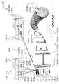
図1Aは一実施形態における検出および表示装置1300の例を概略的に図示する。
FIG. 1A schematically illustrates an example of a detection and
図1Aによれば、検出および表示装置1300はインターフェース・アセンブリ902を含む(がインターフェース・アセンブリ902に限定されない)。一実装では、インターフェース・アセンブリ902は、第1の拡張介在現実空間1000から受け取った感覚現象を、および/または第1の拡張介在現実空間1000内で検出された感覚現象を、表現するセンサ信号904にインターフェース接続するよう構成される。第1の拡張介在現実空間1000は拡張現実空間および/または介在現実空間と呼ばれ得る)。センサ信号904は、一実装では、1以上の追加的な空間(例えば第2の拡張介在現実空間1002など)から受け取った感覚現象も、および/または係る追加的空間内で検出された感覚現象も、表現し得る。一実装では、第1の拡張介在現実空間1000および第2の拡張介在現実空間1002は排他的である(例えば、互いに重なり合うことがない)一方で、他の実装では、第1の拡張介在現実空間1000および第2の拡張介在現実空間1002の全部または一部は、重なり合い、一致し、同一の拡がりを有し、および/またはその他であってよい。いくつかの実装では、第1の拡張介在現実空間1000および第2の拡張介在現実空間1002は、様々な要因(例えばユーザの同一性、装置上で実行される1以上のソフトウェア・アプリケーションの同一性、検出および/または測定された環境要因の特性および/または値(例えば光レベル、時間、GPS、および/または、その他)、および、その他など)に応じて、交互に排他的および/または同一の拡がりを有し得る。インターフェース・アセンブリ902は、一実装では、第1の拡張介在現実空間1000および第2の拡張介在現実空間1002に対して感覚現象の表現、作用、表示、提供、および/またはその他を行うエフェクタ信号906にインターフェース接続するようにも、構成され得る。様々な実装で使用されるインターフェース接続は、交換、伝達、受信、および/またはその他を含み得る。
According to FIG. 1A, detection and
他の例によれば、検出および表示装置1300は、第1のインターフェース・モジュールを含むインターフェース・アセンブリ902を含む(がインターフェース・アセンブリ902に限定されない)。一実装では、第1のインターフェース・モジュールは、第1の拡張介在現実空間1000にインターフェース接続する(または第1の拡張介在現実空間1000に向かって配向されるかまたは第1の拡張介在現実空間1000に対面する)よう構成され得る。他の実装では第1のインターフェース・モジュールは、第1の拡張介在現実空間1000と他の方法で相互作用するよう構成され得る。例えば音響実施形態では、第1のインターフェース・モジュールは1以上のマイクロフォンを含み得る。なおマイクロフォンは、いくつかの実装では、音響源に向かって配向され得る。第1のインターフェース・モジュールは、センサ信号904およびエフェクタ信号906を第1の拡張介在現実空間1000に対して伝達および/または交換するよう構成され得る。インターフェース・アセンブリ902は一実装では、第2のインターフェース・モジュールも含み得る。第2のインターフェース・モジュールは、第2の拡張介在現実空間1002にインターフェース接続する(または第2の拡張介在現実空間1002に向かって配向されるかまたは対向する)よう構成され得る。第2のインターフェース・モジュールは、センサ信号904およびエフェクタ信号906を第2の拡張介在現実空間1002に対して伝達および/または交換するよう構成され得る。一実装では、エフェクタ信号906(および/またはエフェクタ信号906の表現)は、第1の拡張介在現実空間1000および第2の拡張介在現実空間1002のうちの一方または両方において、少なくとも部分的にユーザ提示可能であってよい。
According to another example, detection and
センサ信号904およびエフェクタ信号906は、少なくとも部分的に、例えば第1の拡張介在現実空間1000および第2の拡張介在現実空間1002の一方または両方における視覚的表示、音響的提示、ユーザ操作、および/または任意の他の形態のユーザ消費により、ユーザの感覚的提示および/または消費のために、様々な形態で提示可能である。
The
一選択肢によれば、検出および表示装置1300は、インターフェース・アセンブリ902に動作可能に連結するよう構成された処理装置908も含み得る。一実装では、処理装置908は、インターフェース・アセンブリ902にインターフェース接続および/または別様に関連付けられたセンサ信号904の処理、および/または、インターフェース・アセンブリ902にインターフェース接続および/または別様に関連付けられたエフェクタ信号906の処理、を行うよう構成され得る。処理装置908は、センサ信号904および/またはエフェクタ信号906の処理(例えば、強化、変更、および/またはその他)を含み得る。
According to one option, the detection and
一選択肢によれば、検出および表示装置1300はインターフェース・アセンブリ902を含み得る。一実装では、インターフェース・アセンブリ902は第1のインターフェース・モジュール903を含み得る。なお第1のインターフェース・モジュール903は、(例えば第1の拡張介在現実空間1000から受け取った感覚現象を表現し、および/または第2の拡張介在現実空間1002から受け取った感覚現象も表現する)センサ信号904にインターフェース接続するよう構成される。一実装では、インターフェース・アセンブリ902は、第1の拡張介在現実空間1000および第2の拡張介在現実空間1002に対して感覚現象の表現、表示、提供、投影、および/またはその他を行うエフェクタ信号906にインターフェース接続するよう構成された第2のインターフェース・モジュール905も含み得る。インターフェース・アセンブリ902は本明細書で提供される説明に照らして他の構成も可能である。
According to one option, the detection and
例えば第1の拡張介在現実空間1000は、2人以上のユーザ間で共有される空間(パブリック共有空間)となるよう構成された拡張または介在された現実環境(空間)である。第2の拡張介在現実空間1002は、1人のユーザにより使用される空間(例えばパーソナル空間)となるよう、または有限の人数のユーザにより共有(例えば使用)され得る空間(例えばプライベート空間)となるよう、または第1の拡張介在現実空間1000のユーザ全員により共有され得る空間となるよう、構成された拡張または介在された現実環境(空間)である。
For example, the first augmented intervening
例えば第2の拡張介在現実空間1002は、第1の拡張介在現実空間1000のライブ(間接的または直接的)ビューを(ユーザに)提供するよう構成される。一実装では、第1の拡張介在現実空間1000は、コンピュータ生成された感覚現象(例えば音響要素、ビデオ要素、グラフィック要素、接触性要素、および/またはその他の要素)により拡張、補足、および/または介在(例えば拡張介在)され得る(例えば第1の拡張介在現実空間1000内に含まれる物理的要素上に投影され得る)物理的要素を有する物理的(現実世界)環境を、または変更バージョンがユーザに対して提示される状態で(例えばコンピュータにより)変更された感覚現象(例えば、「散乱物」を除去することによりユーザが世界をより良好に検知および理解することを支援するために減退化された現実。係る減退化された現実も拡張介在現実のさらなる例である)を、含む。したがって装置1300は、いくつかの実装では、出力ディスプレイを介して例えば装置のユーザに対して提示するために、物理的な要素および/もしくは情報、仮想的な要素および/もしくは情報、および/または、環境に対して、または環境から、作用、投影、減法、および/もしくはその他の操作が施される要素、のあらゆる組み合わせを、表示可能な対象物に組み込むことが可能となるよう構成され得る。いくつかの実装ではエフェクタ信号および/または他のコンピュータ生成された感覚現象は、環境内の対象物の照明、強化、および/もしくは分画以外の、および/またはこれらに対して追加的な、多様な用途のいずれ対しても用いられ得る。例えば一実装では、エフェクタ信号および/または他のコンピュータ生成された感覚現象は、一連の低出力フラッシュ発光の後にフラッシュを発光させて瞳孔を収縮させる赤目軽減発光能力を含み得る。別例では、一実装において、エフェクタ信号および/または他のコンピュータ生成された感覚現象は、アラート、警告、目隠し、不能化、混乱化、および/またはその他のためのフラッシュ発光、ストロボ発光、および/またはその他を含み得る。
For example, the second
一実装では、第1の拡張介在現実空間1000は、複数のユーザにより共有される共有空間であってよい。一実装では、第1の拡張介在現実空間1000を共有するユーザは、ローカルエリアネットワーク、Bluetooth(登録商標)ネットワーク、WiFi(登録商標)ネットワーク、および/またはその他など(しかし必ずしもこれらに限定されない)の任意種類のネットワーク接続により互いに対して近位に配置されてもよく、その一方で他の実装ではユーザは、互いに対して遠隔に配置され、広域ネットワーク、セルラ・ネットワーク、TCP/IPネットワーク、およびその他を介して接続されてもよい。第2の拡張介在現実空間1002も共有空間であってよく、他のユーザとの制限された共有のための選択肢を含み得る。第2の拡張介在現実空間1002は、一実装では、ユーザのグループから抜き取られた、事前決定および/または選択されたユーザに属するか、および/または係るユーザに割り当てられ得る。この意味で、第2の拡張介在現実空間1002は事前決定されたユーザのパーソナル空間である。第2の拡張介在現実空間1002のユーザは、第2の拡張介在現実空間1002に対するアクセスを、(例えば第2の拡張介在現実空間1002に割り当てられたユーザの要望または制御にしたがって)第1の拡張介在現実空間1000に関連付けられたユーザの全員に対して拒否、係るユーザのうちの一部に対して許可、または係るユーザの全員に対して許可し得る。様々な実装では、第1の拡張介在現実空間1000と、第2の拡張介在現実空間1002の1以上の具体例と、のうちの一方または両方は、例えばローカルエリアネットワーク、広域ネットワーク、セルラ・ネットワーク、WiFi(登録商標)ネットワーク、Bluetooth(登録商標)ネットワーク、TCP/IP有効化ネットワーク、および/またはその他を含むがこれらに限定されない任意種類のネットワークを介してネットワークアクセス可能であってよい。インターネット・プロトコル・スイートは、インターネットおよび同様のネットワークに対して使用される、ネットワークキング・モデルおよび1セットの通信プロトコルである。インターネット・プロトコルはTCP/IPとしても公知である。この理由は、その最も重要なプロトコルであるトランスミッション・コントロール・プロトコル(TCP)およびインターネット・プロトコル(IP)がこの規格における最初のネットワークキング・プロトコルであったためである。
In one implementation, the first augmented
例えば第1の拡張介在現実空間1000に対して7人のユーザが関連付けられている場合、当該ユーザ・グループに属する各メンバーは、第1の拡張介在現実空間1000に対するアクセスを有し、このように第1の拡張介在現実空間1000は共同空間(例えばパブリック空間)として取り扱われる。第1の拡張介在現実空間1000に関連付けられた現象(感覚現象)は、共同的方法で、感覚および表示装置1300の各ユーザのそれぞれの具体例により第1の拡張介在現実空間1000にアクセスするユーザによって経験または共有され得る。
For example, when seven users are associated with the first
一実装では、各ユーザは、感覚および表示装置1300のそれぞれの具体例を介して、第2の拡張介在現実空間1002のそれぞれの具体例が割り当てられ得る。装置1300は装置1300のユーザが、第1の拡張介在現実空間1000にアクセスすること、および第2の拡張介在現実空間1002のユーザの具体例にアクセスすること、を許可し得る。装置1300は、ユーザが、第2の拡張介在現実空間1002に関する当該ユーザの具体例に対するある程度のアクセス(例えばアクセス拒否、制限アクセス、完全アクセス)を、第1の拡張介在現実空間1000の他のユーザに対して許可することを、許可するよう構成される。一実装では、様々な範囲のアクセス(例えば設定および/または制限された時間および/もしくは場所に対するアクセス、プロファイル、許可、および/もしくは役割に基づくアクセス、タスクおよび/もしくは達成に基づくアクセス、および/またはその他など)が適用および/または実施され得る。係る範囲のアクセスは、一実装では、アクセス・トリガおよび/またはパラメータ値に関連付けられたデータ記録にリンクされたアクセス記録に基づいて実施され得る。共有アクセスの実装では、1人以上の他のユーザの第1の拡張介在現実空間1000に対して共有される第2の拡張介在現実空間1002の第1のユーザの具体例は、注釈、タグ、および/または他のラベルが施され得る。例えば第2の拡張介在現実空間1002の具体例は、第1のユーザが第2の拡張介在現実空間1002と関連付けられたものであることを指定し得る、1以上の特性注釈、ロゴ、透かし、図、画像、写真、名前、ラベル、タグ、色、形状、音響、および/またはその他を含み得る。一実装では、第2の拡張介在現実空間1002の2つ以上の具体例に対するアクセス権を有するユーザは、例えば選択された共有第2の空間のビュー表示を開くこと、閉じること、移動すること、サイズ変更すること、最大化すること、最小化すること、配向すること、握り締めること、伸張すること、スカルプトすること、および/または同様の操作を施すことなどにより、複数の第2の拡張介在現実空間1002のビュー表示選択肢および/または直接ビュー表示を選択し得る。一実装では、少なくとも1つの共有第2の空間に対するアクセス権を有するユーザには、第1の拡張介在現実空間1000と、第2の拡張介在現実空間1002と、いくつかの例では、1以上の追加的な共有第2の空間と、の間で同一のオブジェクトおよび/または物理的空間の矛盾するビュー表示および/または一致しないビュー表示が提示され得る。例えばゲームのシナリオでは、仮想的オブジェクトは数人のユーザに対してはゲーム・パラメータに基づいて表示され、それ以外のユーザに対しては、係る様式では表示されない。したがって2つの共有第2の空間(一方は仮想的オブジェクトを有し、他方は仮想的オブジェクトを有さない)を閲覧するユーザは、同一の物理的空間の異なる閲覧(例えば一方は仮想的オブジェクトを有し、他方は有さない)を感知することとなる。一実装では、第2の拡張介在現実空間1002の閲覧は、互いに対して、および/または第1の拡張介在現実空間1000の閲覧に対して、オーバーレイされ得る。一実装では、オブジェクト、仮想的オブジェクト、および/または他の表示構成要素の一部が、例えば受け入れるユーザの役割、特権、設定、および/またはその他に基づいて、所与の第2の拡張介在現実空間1002の特定の共有閲覧内で提示され得る。
In one implementation, each user may be assigned a respective example of the second
例えば第1のユーザは、感覚および表示装置1300により提供される構成設定により、第1の拡張介在現実空間1000の他のいずれのユーザ(検出および表示装置1300のそれぞれの具体例によりアクセスされる)も第1のユーザの第2の拡張介在現実空間1002に対するアクセスまたは共有アクセスを有さないよう、第2の拡張介在現実空間1002の自分の具体例に対するアクセスを制限することができる。第1のユーザは、(検出および表示装置1300を介する)第2の拡張介在現実空間1002の自分の具体例を、装置1300の自分自身の具体例を有する他のユーザに対してプライベートおよびアクセス不許可にすることを決定した。
For example, the first user can access any other user of the first augmented reality space 1000 (accessed by each specific example of the detection and display device 1300), depending on the sense and configuration settings provided by the
一例では、第1の拡張介在現実空間1000の第2のユーザは、装置1300の自分自身の具体例における構成設定により、第3のユーザおよび第4のユーザが、第2のユーザに対して割り当てられた第2の拡張介在現実空間1002にアクセスすることを許可する。第3のユーザおよび第4のユーザは、第2の拡張介在現実空間1002の自分自身の具体例を第2のユーザと共有するかどうかを決定し得る。
In one example, the second user of first
(第1の拡張介在現実空間1000に関連付けられた)残余のユーザは、(例えば)上記に示したように自分自身の必要性、選択、役割、特権、および/またはその他にしたがって、(検出および表示装置1300の自分自身の具体例を介する)第2の拡張介在現実空間1002の自分自身の具体例のアクセスを設定し得る。 The remaining users (associated with the first augmented reality space 1000) can (detect and detect) according to their own needs, choices, roles, privileges, and / or others as indicated above (for example). Access to the specific example of the second augmented reality space 1002 (via the specific example of the display device 1300) may be set.
例えば一実施形態では、電子ゲーム(例えば拡張介在現実または介在現実ゲームなど)が設定され得る。なお係る電子ゲームでは、2つの対抗するユーザ・チームがチームワークで技能を競い合う。したがって第1の拡張現実空間または第1の拡張介在現実空間1000のユーザ・チームは、当該チームの各メンバーが、第1のチームの各メンバーの第2の拡張介在現実空間1002のそれぞれの具体例に対するアクセスを有するよう、検出および表示装置1300の自分たちの具体例を構成し得る。このようにしてゲームが第1の拡張介在現実空間1000内でプレイされている間、チーム・メンバーは、ゲームをプレイする中で第2のユーザ・チームに対して勝利を勝ち取るために戦略を立てる際にチーム・メンバー間でチャット(ユーザ通信の交換)を行い得る。第1の拡張介在現実空間1000内で、全ユーザは第1の拡張介在現実空間1000に対してアクセスを有し、ゲームのプレイ中、相互作用し得る。電子ゲームは、戦争ゲーム、チェス・ゲーム、およびチーム・プレイヤーが関与する任意種類のゲーム、その他であってよい。チームのサイズは少なくとも1人のユーザであってよい。ユーザは、一例では、物理的には遠隔場所に位置し得る。
For example, in one embodiment, an electronic game (such as an augmented intervening reality or an intervening reality game) may be set. In this electronic game, two opposing user teams compete for skills through teamwork. Therefore, the user team of the first augmented reality space or the first
一選択肢によれば、それぞれが検出および表示装置1300の具体例を装着する複数のユーザは、(例えば第1の拡張介在現実空間1000および/または第2の拡張介在現実空間1002内において)共有されるコンピュータ介在現実を経験し得る。他の選択肢では、検出および表示装置1300を装着しないユーザが、第1の拡張介在現実空間1000内においてコンピュータ介在現実のいくつかの要素を共有し、第1の拡張介在現実空間1000内に参加することさえもあってよい。
According to one option, a plurality of users, each wearing a specific example of the detection and
2人以上のユーザが、同一の対象物を閲覧する間、検出および表示装置1300の自分自身の具体例を装着することもある。装置1300の具体例が複数存在する場合、検出および表示装置1300の各具体例は、一実装では、第1の拡張介在現実空間1000および/または第2の拡張介在現実空間1002内において検出および表示装置1300の1以上の具体例とデータ(例えば現象信号)を共有しつつ、空間撮像機能(動作)を実行するよう構成され得る。
Two or more users may wear their own examples of detection and
検出および表示装置1300は、第1の拡張介在現実空間1000を介して、および/または第2の拡張介在現実空間1002を介して、拡張介在現実環境(例えば各町会剤現実、介在現実経験)を提供するよう構成され得る。なお係る拡張介在現実環境は、自由空間内で、1以上の仮想的オブジェクトと、および/または例えば平坦表面など(例えばテーブル、カウンタ上面、レンジ上面、床、地面、および/またはその他)の有形(物理的)オブジェクトと、相互作用する外肢(手、指、腕、脚、足、その他)をユーザが動かすことにより制御され得る。
The detection and
一実装では、第1の拡張介在現実空間1000および第2の拡張介在現実空間1002は画像(例えば3次元画像など)をユーザに提供するよう構成され得る。第1の拡張介在現実空間1000および第2の拡張介在現実空間1002は、いくつかの実装では、サイボーグ空間および/または介在現実環境と呼ばれ得る。第1の拡張介在現実空間1000および第2の拡張介在現実空間1002は、処理装置908により変更(例えば減退、拡張介在、および/またはその他)され得る現実のアクセス(例えば閲覧)を提供するよう構成され得る。処理装置908は、一実装では、ユーザ(1人および/または複数人)に対する現実の感知を増強するよう構成され得る。一実装では、処理装置908は、第1の拡張介在現実空間1000および第2の拡張介在現実空間1002に、リアルタイムにおよび意味論的なコンテキストで、環境要素(例えば競技中のスポーツイベントのスポーツ・スコアなど)を提供および/または支援するよう構成される。例えばコンピュータ・ビジョン装置および/またはオブジェクト認識装置を追加および/または使用することにより、ユーザ(1人以上)の周囲の現実世界に関する情報は、インタラクティブとなり、検出および表示装置1300の処理装置908によりデジタル的に操作され得る。一実装では、第1の拡張介在現実空間1000および第2の拡張介在現実空間1002に関するメタ(例えば、人工的、仮想的、使い的、拡張介在的、および/またはその他の)情報が、第1の拡張介在現実空間1000に関連付けられた(例えば、第1の拡張介在現実空間1000内に配置された)物理的要素上にオーバーレイされ得る。例えば第1の拡張介在現実空間1000は、ユーザ(例えば2人以上のユーザ)によりアクセス可能となるよう構成され得、第2の拡張介在現実空間1002は1人のみのユーザにより、または第2の拡張介在現実空間1002の具体例のユーザにより所望される任意人数のユーザにより、アクセス可能となるよう構成され得る。第1の拡張介在現実空間1000および第2の拡張介在現実空間1002の追加的な例については、以下で図面と組み合わせて説明する。一選択肢によれば、第1の拡張介在現実空間1000は、第1の拡張介在現実空間1000内に配置された物理的オブジェクト上にグラフィカル情報を表示するよう構成されたデジタル・プロジェクタ(エフェクタ・アセンブリの一例である)を使用することにより現実世界のオブジェクトおよび情景を強化するよう構成された空間拡張介在現実環境を含む。空間拡張介在現実環境は、ユーザ・グループに対するアクセスを提供し得、それにより、空間拡張介在現実環境のユーザ間の、配置された収集(collocated collection)および/または共同作業が可能となり得る。
In one implementation, the first
センサ信号904は、少なくとも部分的に1以上の感覚現象(例えば、視覚現象、聴覚現象、接触現象、および/またはその他の現象)を受け取ることに応答してセンサおよび/またはセンサ・アセンブリにより生成および/または提供される。センサ・アセンブリは、少なくとも部分的に感覚現象(感覚刺激とも呼ばれる)を受け取ることに対して敏感となるよう構成される。センサ・アセンブリは、(例えば1以上の感覚現象に関連付けられた)物理な質および/または量を検出し、物理的な質および/または量をセンサ信号904へと変換および/または顕在化するよう構成される。センサ信号904は電子装置(例えば図1Aの処理装置908など)により読み取り可能となるよう構成される。センサ信号904は例えば、電気信号、光信号、または任意の好適な媒体内で具体化される任意種類の信号であってよい。センサ・アセンブリの例としては温度計または熱電対が挙げられる。別例ではセンサ・アセンブリは接触ベースのセンサを含み得る。センサ・アセンブリの他の例が以下で図1E(および他の図面)と組み合わせて指定される。
The
エフェクタ信号906はエフェクタおよび/またはエフェクタ・アセンブリにより提供(または伝達)される信号である。エフェクタ・アセンブリは、入力(例えば入力信号、感覚現象)を受け取ることに応じてオブジェクト(例えば画像など)において所望の(事前決定された)変化を生成するよう構成される。エフェクタ・アセンブリの一例として光学的投影システムが挙げられる。オブジェクトは、光学的オブジェクト、画像オブジェクト、ビデオ・オブジェクト、および/またはその他のオブジェクトを含み、可視光に基づく画像を含み得る。一実装では、エフェクタ・アセンブリは、作動および/または制御するよう構成されたアクチュエータを含み得る。一実装では、アクチュエータは、制御システムが環境に対して作用する機構である。エフェクタ・アセンブリのさらなる例について、以下で図1E(および他の図面)と組み合わせて指定される。
図1Bを参照すると、一選択肢では、検出および表示装置1300は、第1の感覚現象エフェクタ912および第2の感覚現象エフェクタ914を含むよう構成される。なおこれらの感覚現象エフェクタは、いくつかの例では、空間撮像装置と呼ばれる場合もある。第1の感覚現象エフェクタ912および第2の感覚現象エフェクタ914の例としては、画像カメラもしくはビデオ・カメラおよび/もしくはプロジェクタ、ホログラフィック撮像装置、3次元撮像装置、レーザ撮像装置、LiDAR装置、飛行時間型撮像装置、RaDAR装置、SoNAR装置、深度カメラ、深度センサ、可視光ベースの装置、赤外線ベースの装置、マイクロ波ベースの装置、音響ベースの装置、ホログラフィ装置、立体視装置、(任意の形態の)3次元撮像装置、深度検知装置、視覚ベースの装置、3D特徴抽出装置(shape−from−X device)、および/またはその他の装置が挙げられるが、これらに限定されない。LiDARは光検出と測距(Light Detection And Ranging)を意味する。RaDARは無線探知および測距(Radio Detection And Ranging)を意味する。SoNARは超音波探信(Sound Navigation And Ranging)を意味する。
Referring to FIG. 1B, in one option, the detection and
一実装では、インターフェース・アセンブリ902は、処理装置908(例えばコンピュータなど)と、例えばプリンタまたは人間オペレータ(ユーザ)などの任意の他のエンティティと、の間の相互作用および/または通信の点を提供する。
In one implementation, the
処理装置908は、1以上の入力(例えばデータおよび/または情報)の受容および/または読み出しを行い、受容された確定された入力に基づいて1以上の出力の生成(例えば提供、書き込み)を行うよう構成される。処理装置908は、確定された入力および確定された出力をデータ、事実、情報、および/またはその他として解釈するよう構成される。例えば処理装置908は、データを他のフォーマットに変換するよう構成された変換モジュールと、供給されたデータがクリーンであるかどうか、正確であるかどうか、有用であるかどうかを確認するよう構成された検証モジュールと、項目を何らかの順序に、および/または異なるセットに、配列するよう構成されたソーティング・モジュールと、詳細データをその主要ポイントへと還元するよう構成された要約モジュールと、複数のデータを組み合わせるよう構成された集積モジュールと、データおよび/または情報の収集、組織化、分析、解釈、および提示を行うよう構成された分析モジュールと、および詳細もしくは要約データまたは算出された情報の表示およびリスト化を行うよう構成された報告モジュールと、の組み合わせを含み得る(が、これらに限定されない)。図1Aおよび/または図1Bの処理装置908を実装するにあたり利用され得る処理装置908の・アセンブリおよび/または構成要素は多数存在する。
The
図1Aを参照すると処理装置908は例えば、中央処理装置、処理ユニット、マイクロプロセッサ、マイクロコンピュータ、アレイ・プロセッサ、および/またはベクトル・プロセッサ(およびこれらの任意の等価物)を含み得る。処理装置908は、算術演算、論理演算、および/または入力/出力操作を実行することにより、コンピュータ・プログラムの命令を実行するコンピュータ内のハードウェア回路を含み得る。処理装置908は1つまたは処理ユニットの複数の具体例を含み得る(この場合はマルチプロセシングと呼ばれる)。アレイ・プロセッサおよび/またはベクトル・プロセッサは複数の並行計算要素を含み、そのうちの1つの処理ユニットがセンターと考えられる。分散計算モジュールでは、演算は分散型相互接続プロセッサの集合により実行される。一実装では、処理装置908は処理装置908により動作または実行される任意の命令と置き換わる専用回路の集合を含み得、係る専用回路は、プログラマブル・ロジック・アレイ(PLA:programmable logic array)(および組み合わされた論理回路を実装するよう構成された任意の等価物)を含み得る。PLAは、1セットのプログラム可能なANDゲート面を有し、このANDゲート面は1組のプログラム可能なORゲート面にリンクし、次にこのORゲート面は条件的に補完され、それにより出力が生成される。
Referring to FIG. 1A, the
処理装置908は非一時的機械可読ストレージ媒体909(以後メモリ・アセンブリ909と呼ばれる)を含み得る。メモリ・アセンブリ909はデータおよび実行可能プログラム(プログラム命令)を処理装置908による読み取りが可能となるフォーマットで格納するよう構成される。メモリ・アセンブリ909の例としては、コンピュータ可読および/またはコンピュータ書き込み可能な媒体、磁気ディスク、磁気カード、磁気テープ、および磁気ドラムなどの磁気媒体、パンチ・カードおよび紙テープ、光ディスク、バーコード、磁気インクキャラクタ、および/またはその他が挙げられ得る。機械可読技術の例としては、磁気記録、処理波形、バーコード、および/またはその他が挙げられる。一実装では、光学式文字認識(OCR:optical character recognition)は、処理装置908が情報(例えば人間により読み取り可能な情報など)を読み取ることを可能にするために使用され得る。任意形態のエネルギーにより取得可能な任意の情報は機械可読であってよい。
The
一実装では、処理装置908は、電子ネットワーク接続911にインターフェース接続するよう構成され得る。インターネット接続(またはアクセス)などの電子ネットワーク接続911(またはネットワーク・アクセス)は、処理装置908の具体例(例えばコンピュータ端末、コンピュータ、モバイル装置、セル電話、コンピュータネットワーク、および/またはその他など)を1以上の電子ネットワークに接続し、それによりユーザがネットワーク・サービス(例えば電子メール、ワールド・ワイド・ウェブ、その他)にアクセスすることが可能となるよう、構成され得る。いくつかの実装では処理装置908は、遠隔処理装置または分散型処理装置として実装され得、全体的にまたは部分的に、1以上のワイヤレス通信ネットワークおよび/または有線通信ネットワークを介して装置1300の1以上の具体例に通信可能に連結され得る。
In one implementation, the
いくつかの実装では処理装置908は、ユーザ入力・アセンブリ(例えばマウス装置、キーボード装置、カメラ、タッチ感知性ディスプレイ・スクリーン、マイクロフォン、網膜リーダー、加速度計、環境光センサ、GPS、アンテナ、および/またはその他など)を含むよう構成され得る。処理装置908はさらに、ユーザ出力・アセンブリ(例えばコンピュータ端末、テレビ・スクリーン、もしくは他のビデオ・ディスプレイ・インターフェース、プロジェクタ、タッチ感知性スクリーン、および/またはその他など)を含むよう構成され得る。
In some implementations, the
メモリ・アセンブリ909は有形的に処理用プログラム907(以後、プログラム907と呼ばれる)を具体化するよう構成され得る。プログラム907は、特定の動作(読み取り、書き込み、処理などのタスク)を実施(実行)するよう処理装置908に命じるプログラム命令のシーケンスを含む。処理装置908は例えばプロセッサ・アセンブリを使用することなどによりプログラム907を実行する。プログラム907は、処理装置908がプログラム907により提供されるプログラム命令を実行するために使用し得る実行可能な形態を有する。プログラム907は、人間が詠むことが可能なソースコードの形態で使用され得る。なお係るソースコードから実行可能プログラムが導き出され(例えばコンパイルされ)、それによりプログラム命令はプログラム907内で使用されるかまたは含まれることとなる。プログラム907は、プログラム命令および/または関連データの集合体であり、ソフトウェア(コード)と呼ばれ得る。プログラム907は、例えば画像処理動作(例えばWileyおよびIEEE Press2001を通して、John Wiley and Sonsにより出版されたS.Mannの著作による「Intelligent Image Processing」をタイトルとするウェアラブル・コンピューティング・テキストブックに記載される種類の動作)を実行するよう処理装置908に命じる。
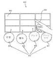
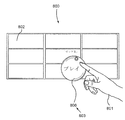
メモリ・アセンブリ909は、有形的にユーザ・インターフェース800を顕在化するよう構成され得る。なおユーザ・インターフェース800の例は図8Aに図示される。ユーザ・インターフェース800は、一実装では、検出および表示装置1300のユーザに(例えば第2の拡張介在現実空間1002を介して)表示または提供され得る。第2の拡張介在現実空間1002のユーザが、第2の拡張介在現実空間1002の具体例(単数および/または複数)を他のユーザと共有するように検出および表示装置1300の構成を設定することを望む場合、検出および表示装置1300の構成は、ユーザがユーザ・インターフェース800に対するアクセスを(例えば他のユーザに対して)許可することを可能にし得る。ユーザ・インターフェース800は、一実装では、図1Aの処理装置908により使用される図1Aのプログラム907がユーザの活動にどのように応答するかの方法と組み合わされた制御要素(例えばグラフィック制御要素および/またはテキスト制御要素)のレイアウトを含む。一実装では、ユーザ・インターフェース800は、検出および表示装置1300のユーザと、検出および表示装置1300自体と、の間の相互作用を支援する構成要素である。ユーザ・インターフェース800は、いくつかの実装では、ユーザの側における処理装置908の効果的な動作および制御のために使用され得、処理装置908からのフィードバックは、動作上の決定(例えばどのように処理装置908を動作するかに関する決定)をなすことにおいて処理装置908のユーザを支援し得る。ユーザ・インターフェース800はハードウェア・コンポーネント(物理的コンポーネント)および/またはソフトウェア・コンポーネント(論理コンポーネントまたは仮想的コンポーネント)を含み得る。ユーザ・インターフェース800は、一実装では、処理装置908の制御または操作をユーザが行うことを可能にするよう構成されたユーザ入力(例えばフィールド)と、ユーザ入力を介して行われたユーザ操作の効果を処理装置908がユーザに対して表示および/または指示することが可能となるよう構成された出力(例えばフィールド)と、を提供するよう構成される。ユーザ・インターフェース800と、いくつかの実装では、グラフィカル・ユーザ・インターフェースおよび/またはヒューマン・マシン・インターフェースとも呼ばれ得る。ユーザ・インターフェース800に対する他の用語は、ヒューマン・コンピュータ・インターフェース(HCI:human−computer interface)およびマン・マシン・インターフェース(MMI:man−machine interface)を含む。ユーザ・インターフェース800は、検出および表示装置1300を介してのユーザによる閲覧のために表示され得る。一実装では、ユーザ・インターフェース800は第2の感覚現象エフェクタ914(例えば図1Bに示すよう)を介してユーザに提示され得る。ユーザ・インターフェース800は1以上のフィールドをユーザに対して提供または表示するよう構成され得る。一実装では、フィールドは、例えばユーザ名などの特定項目の情報に対して割り当てられた空間である。フィールドはフィールドに関連付けられた特定の属性を有するよう構成され得る。例えば数値を示すフィールドもあり、テキストを示すフィールドもある。いくつかの実装では各フィールドは名称(フィールド名と呼ばれる)を有し得る。一実装では、フィールドの集合体はレコードと呼ばれ得る。ユーザは、インターフェース接続された回路または要素を介してユーザ・インターフェース800により提供されるフィールドと相互作用し得る。
一選択肢によれば、検出および表示装置1300は、インターフェース・アセンブリ902、処理装置908、およびメモリ・アセンブリ909の組み合わせを含み得る(が、これに限定されない)。インターフェース・アセンブリ902は、一実装では、第1の拡張介在現実空間1000および第2の拡張介在現実空間1002にインターフェース接続するよう構成され得る。インターフェース・アセンブリ902は、一実装では、第1の拡張介在現実空間1000および第2の拡張介在現実空間1002と関連付けられたセンサ信号904およびエフェクタ信号906を伝達するよう構成され得る。処理装置908が、一実装では、インターフェース・アセンブリ902に動作可能に連結されるよう構成され得る。処理装置908は、インターフェース・アセンブリ902により伝達されるセンサ信号904およびエフェクタ信号906を処理するようさらに構成され得る。 メモリ・アセンブリ909は、一実装では、センサ信号904および/またはエフェクタ信号906に対して操作を実行することを処理装置908に命じるよう構成されたプログラム命令のシーケンスを含む処理用プログラム907を有形的に具体化するよう構成され得る。
According to one option, the detection and
図1AAは、図1Aの検出および表示装置1300に関連付けられた方法1100の一例に関する概略図を示す。
FIG. 1AA shows a schematic diagram for an
方法1100は、図1Aのプログラム907に含まれるプログラム命令として実装され得、方法1100は、プログラム907を介して処理装置908により実行される実行可能動作(プログラム命令)の例を含む。
The
方法1100は動作1102を含む(が、これに限定されない)。なお動作1102は、第1の拡張介在現実空間1000から受け取った感覚現象を表現するセンサ信号904のインターフェース接続された具体例を受け取る(読み取る)こと、および第2の拡張介在現実空間1002から受け取った感覚現象を表現するセンサ信号904のインターフェース接続された具体例を受け取る(読み取る)ことを含む。センサ信号904のインターフェース接続された具体例は、例えばインターフェース・アセンブリ902から処理装置908により受け取られる。動作制御は動作1104に移行される。
方法1100は、動作1104をさらに含む(がこれに限定されない)。なお動作1104は、感覚現象を表現するエフェクタ信号906のインターフェース接続された具体例を第1の拡張介在現実空間1000に提供すること(例えば伝送、書き込み)、およびエフェクタ信号906のインターフェース接続された具体例を第2の拡張介在現実空間1002に提供すること(例えば伝送、書き込み)を含む。エフェクタ信号906のインターフェース接続された具体例は処理装置908によりインターフェース・アセンブリ902に提供される。動作制御は動作1106に移行される。
The
方法1100は動作1106をさらに含む(が、これに限定されない)。なお動作1106は(インターフェース・アセンブリ902から受け取った)センサ信号904を処理することを含み、(インターフェース・アセンブリ902から受け取った)エフェクタ信号906を処理することをさらに含む。ブロックセンサ信号の処理は、センサ信号データの変更、強化、補足、補完、増強、減退化、不明瞭化、遮断、および/またはその他を含み得る(がこれらに限定されない)。動作制御は処理装置908に関連付けられた他の動作に移行される。
The
いくつかの実装では方法1100は、処理装置908により実行される追加的な動作を含み得る。プログラム907に対するプログラム命令は方法1100から導き出される。
In some implementations,
例えば方法1100は動作1108をさらに含む(がこれに限定されない)。なお動作1108は、第1の拡張介在現実空間1000と第2の拡張介在現実空間1002との間でセンサ信号904を転送(例えば、スイッチング、ミキシング、および/またはその他)することを含む。動作制御は動作1110に移行される。例えばスイッチングが、異なる確度および/または精度の2つのセンサの間で、異なる環境に配置されたセンサの間で、異なる時間における所与のセンサの間で(例えばセンサ・レコードに格納された測定値に基づいて)、異なる感覚現象および/または補完的な感覚現象(例えば、色彩および強度、ピッチおよび体積、熱的および可視的、および/またはその他)に感度を有するセンサの間で、異なるユーザにおよび/または装置1300の具体例に関連付けられたセンサの間で、および/またはその他の間で、行われ得る。
For example,
例えば方法1100は動作1110をさらに含む(が、これに限定されない)。なお動作1110は、第1の拡張介在現実空間1000と第2の拡張介在現実空間1002との間でエフェクタ信号を転送(例えば、スイッチング、ミキシング、および/またはその他)することを含む。動作制御は処理装置908の他の動作に移行される。例えばスイッチングが、異なる場所における2つのエフェクタの間で、異なるおよび/または補完的な出力、製品、および/またはその他(例えば可視光対赤外線光、照明対音響)を有する2つのエフェクタの間で、異なるユーザもしくは異なる装置1300の具体例と関連付けられた2つのエフェクタの間で、および/またはその他の2つのエフェクタの間で、行われ得る。
For example,
処理装置908の追加的な動作が、例えば第1の拡張介在現実空間1000に関与するユーザの人数に応じて、および/またはいずれのユーザが、第2の拡張介在現実空間1002の当該ユーザの具体例を、図1Aの第1の拡張介在現実空間1000の選択された他のユーザと共有するかに応じて、および図面と関連して説明された動作に関連して、(プログラム命令の)多数の組み合わせおよび/または順列に対して提供され得ることが理解されるであろう。
The additional operation of the
図1AAに図示される方法1100の動作順序が必ずしも逐次的に実行される必要がなく、方法1100のおよび/または図1Aのプログラム907の、任意の実行順序がプログラムされたコンピュータ命令を介して使用され得ることが理解されるであろう。いくつかの実装では、前述の動作のうちの全部または任意の部分集合、および/またはその他が、所与の実施形態、実装、および/または用途に応じて、並行的に、部分的に逐次的に、連続的に、および/またはこれらの任意の組み合わせで、実行され得る。
The operational sequence of
図1AAは一実施形態におけるデータフローチャートも示し、このデータフローチャートは、センサ信号904を第1の拡張介在現実空間1000と第2の拡張介在現実空間1002との間で転送(例えばスイッチ、ミックス、および/またはその他)するよう構成された処理装置908を示す。処理装置908は、エフェクタ信号を第1の拡張介在現実空間1000と第2の拡張介在現実空間1002との間で経路設計(例えばスイッチ、ミックス、および/またはその他)するよう構成される。加えて処理装置908は、第1の拡張介在現実空間1000から受け取った(例えば図1Bに示す第1の感覚現象センサ910を介して)センサ信号904を、第2の拡張介在現実空間1002に(例えば図1Bに示す第2の感覚現象エフェクタ914を介して)転送するよう構成され得る。一選択肢によれば、処理装置908は、第2の拡張介在現実空間1002から(例えば図1Bに示される第2の感覚現象センサ916を介して)受け取ったセンサ信号904を、第1の拡張介在現実空間1000に(例えば図1Bに示される第1の感覚現象エフェクタ912を介して)転送するよう構成される。センサ信号および/またはエフェクタ信号を転送するための他の選択肢も可能であることが理解されるであろう。
FIG. 1AA also shows a data flow chart in one embodiment, which transfers the
図1AAは、いくつかの実施形態において図面に示される検出および表示装置1300とともに使用される様々なプログラム(例えばプログラム命令)、データ・テーブル、および/または、その他も示す。これらのプログラムは、接触検出器400、射影変換侵入検出器401、合流性センサ402、ビデオ軌道安定化プログラム403、コンパラメトリック合成器404、スーパーポジメトリック合成器405、コンパラメトリック分析プログラム406、スーパーポジメトリック分析器407、スーパーポジメトリック空間撮像プログラム408、コンパラメトリック合成器409、空間撮像マルチプレクサ410、時分割マルチプレクサ411、共同作業的ジェスチャ・ベース・インターフェース412、ジェスチャ追跡検出器413、ニューラル・ネットワーク414、最適オプティマイザ415、傾斜降下器416、正規化器417、オーバーフロー・ペナライザ418、人間ジェスチャ認識プログラム419、バブル・メタファー生成器420、球形体積侵入評価器421、体積侵入検出器422、バブル破裂プログラム423、学習ソフトウェア424、および/またはその他を含むが、これらに限定されない。これらのプログラムは図1Aおよび/または図1Bのメモリ・アセンブリ909内に格納され、図1Aおよび/または図1Bの処理装置908により実行される。これらのプログラムについては以下でより詳細に説明する。
FIG. 1AA also illustrates various programs (eg, program instructions), data tables, and / or others used in some embodiments with the detection and
図1Bは検出および表示装置1300の概略的な例を図示する。
FIG. 1B illustrates a schematic example of a detection and
図1Bに図示される例によれば検出および表示装置1300は、第1の拡張介在現実空間1000から受け取った感覚現象から導き出されたセンサ信号904を伝送するよう構成された感覚現象センサ(910、916)を含む(が、これらに限定されない)。感覚現象センサ(910、916)は、一実装では、第2の拡張介在現実空間1002から受け取った感覚現象から導き出されたセンサ信号904を伝送するようにも構成され得る。
According to the example illustrated in FIG. 1B, the detection and
検出および表示装置1300は、感覚現象に関連付けられたエフェクタ信号906を第1の拡張介在現実空間1000に伝送するよう構成された感覚現象エフェクタ(912、914)をさらに含む。感覚現象エフェクタ(912、914)は、一実装では、感覚現象に関連付けられたエフェクタ信号906を第2の拡張介在現実空間1002に伝送するようにも構成され得る。例えば一実装では、感覚現象エフェクタ(912、914)は、ホログラフィック・ビデオ・ディスプレイ、立体的ビデオ・ディスプレイ、および/またはその他のうちのいずれか1つを表示するよう構成され得る。感覚現象エフェクタ(912、914)は一実装では、構造光または飛行時間型のカメラなどの3次元カメラを含み得る。
Sensing and
一実装では、検出および表示装置1300は、第1の拡張介在現実空間1000から例えば感覚現象センサ(910、916)を介して受け取った感覚現象を表現するセンサ信号904、および第2の拡張介在現実空間1002から受け取った感覚現象を表現するセンサ信号904も、インターフェース接続(例えば伝達、受信)するよう構成されたインターフェース・アセンブリ902も含む。インターフェース・アセンブリ902は、感覚現象を表現するエフェクタ信号906を、感覚現象エフェクタ(912、914)を介して、第1の拡張介在現実空間1000へと、および第2の拡張介在現実空間1002へと、インターフェース接続(例えば伝達、伝送)するようにも構成され得る。
In one implementation, the detection and
一実装では、検出および表示装置1300はインターフェース・アセンブリ902に動作可能に連結された処理装置908も含み得る。一実装では、処理装置908は、インターフェース・アセンブリ902にインターフェース接続された(関連付けられた)センサ信号904と、インターフェース・アセンブリ902にインターフェース接続された(関連付けられた)エフェクタ信号906と、を処理するよう構成される。
In one implementation, the detection and
例えば様々な実装ではセンサ信号904は、音響感覚現象、視覚感覚現象、接触知感覚現象、および/またはその他のうちの1以上から導き出され得る。様々な実装ではエフェクタ信号906は、音響感覚現象、視覚感覚現象、接触知感覚現象、および/またはその他のうちの1以上から導き出され得る。
For example, in various implementations, the
一選択肢によれば、感覚現象センサ(910、916)および感覚現象エフェクタ(912、914)は第1の感覚現象センサ910および第1の感覚現象エフェクタ912をさらに含み得る。第1の感覚現象センサ910は、第1の拡張介在現実空間1000に起因する感覚現象から導き出されたセンサ信号904を伝送するよう構成される。第1の感覚現象エフェクタ912は、感覚現象に関連付けられたエフェクタ信号906を第1の拡張介在現実空間1000に伝送するよう構成される。
According to one option, the sensory phenomenon sensor (910, 916) and sensory phenomenon effector (912, 914) may further include a first
一選択肢によれば、感覚現象センサ(910、916)および感覚現象エフェクタ(912、914)は第2の感覚現象エフェクタ914および第2の感覚現象センサ916を含み得る。第2の感覚現象エフェクタ914は、感覚現象を有するエフェクタ信号906を第2の拡張介在現実空間1002に伝達するよう構成される。第2の感覚現象センサ916は、第2の拡張介在現実空間1002に起因する感覚現象から導き出されたセンサ信号904を伝送するよう構成される。第2の感覚現象センサ916の例としては、ユーザの眼の瞳孔を追跡するよう構成された視標追跡装置が挙げられる。一実装では、視標追跡はユーザの頭部に対して注視点(ユーザが見つめる地点)または眼の運動を測定するプロセスである。視標追跡器は眼の位置および眼の運動を測定するよう構成される。眼の運動は、サーチ・コイルを使用してまたは電気眼球図を使用して眼の位置が抽出されるビデオ画像を使用するなどの様々な方法で測定され得る。
According to one option, sensory phenomenon sensors (910, 916) and sensory phenomenon effectors (912, 914) may include a second
ユーザが検出および表示装置1300を装着する場合に関して、第1の感覚現象センサ910および/または第1の感覚現象エフェクタ912は、一実装では、(例えば第1の拡張介在現実空間1000において)ユーザの視野域の方向に対向し(向けられ)得る。ユーザの視野域は、例えば、眼前方閲覧方向における視野であってよい。例えばユーザの視野域は、ユーザの指がユーザの視野域の外部に配置されていない限り、ユーザが自分の指の位置を閲覧し得る方向を含み得る。ユーザが仮想的キーボード上でタイピングしている場合、ユーザの指は、たとえユーザが他方を見ていたとしても、第1の感覚現象エフェクタ912により追跡され得る。一実装では、第2の感覚現象エフェクタ914および第2の感覚現象センサ916は、ユーザの眼の方向(第2の拡張介在現実空間1002)に対向し(例えば向けられ)得る。いくつかの実装では第1の感覚現象センサ910、第1の感覚現象エフェクタ912、第2の感覚現象センサ916、および/または第2の感覚現象エフェクタ914のうちの1以上はユーザの視野域に対向する以外の方向に向けられ得る。例えば聴覚現象に関係付けられたセンサおよび/もしくはエフェクタ、および/または音響を検知しおよび/もしくは音響を環境および/もしくは装置1300の1人以上のユーザの耳に挿入するためのセンサは、「音響域」の方向(例えば、ユーザの片方または両方の耳に向けられた方向)に向けられ、ユーザの片方または両方の耳から離間する方向に向けられ、全方位的であり、直接音響的および/または水中音響的に装置1300に連結され(例えば頭蓋骨にタッチする、および/またはユーザが水中にいる場合は水に対してインピーダンスが整合する)、および/またはその他であってよい。別例ではセンサおよび/またはエフェクタは、環境の周辺部分、後方部分(例えばユーザの後方)、ブラインド・スポット、および/またはその他に係合するよう構成され得る。
With respect to the case where the user wears the detection and
一例ではインターフェース・アセンブリ902は、(A)第1の感覚現象センサ910にインターフェース接続するよう構成された第1のインターフェース・モジュール903と、(B)第1の感覚現象エフェクタ912にインターフェース接続するよう構成された第2のインターフェース・モジュール905と、(C)第2の感覚現象エフェクタ914にインターフェース接続するよう構成された第3のインターフェース・モジュールと、(D)第2の感覚現象センサ916にインターフェース接続するよう構成された第4のインターフェース・モジュールと、を含む。インターフェース・アセンブリ902用の他のインターフェース・モジュールは、任意個数のセンサおよび/またはエフェクタを収容するにあたっての必要および/または所望に応じて、追加または除去され得る。
In one example, the
図1Cは一実施形態における検出および表示装置1300の概略的な例を示す。
FIG. 1C shows a schematic example of a detection and
図1Cに示すように検出および表示装置1300は、一実施形態では、インターフェース・アセンブリ902および処理装置908の組み合わせを含む。第1の感覚現象センサ910、第1の感覚現象エフェクタ912、第2の感覚現象エフェクタ914、および第2の感覚現象センサ916は、ユーザによりまたは検出および表示装置1300の製造者によりインターフェース・アセンブリ902と一体化される別個の要素として提供される。分散制御の選択肢において、処理装置908は、第1の感覚現象センサ910、第1の感覚現象エフェクタ912、第2の感覚現象エフェクタ914、および第2の感覚現象センサ916の設定および動作を制御するよう構成される。一選択肢において、処理装置908は、第1の感覚現象センサ910、第1の感覚現象エフェクタ912、第2の感覚現象エフェクタ914、および第2の感覚現象センサ916のうちの2つ以上に対して専用の、および/または係る2つ以上間で分散されるプロセッサ・ユニットの具体例を含み得る。一実装では、処理装置908が監督制御器として動作するよう構成され得、その一方で、センサおよびエフェクタのそれぞれに搭載された専用プロセッサが(例えば図1Bに示すように)センサまたはエフェクタの動作を管理するよう構成され得る。
As shown in FIG. 1C, the detection and
図1Dは検出および表示装置1300の概略的な例を図示する。
FIG. 1D illustrates a schematic example of a detection and
図1Dに示すように検出および表示装置1300は、一実施形態では、インターフェース・アセンブリ902、処理装置908、第1の感覚現象センサ910、第1の感覚現象エフェクタ912、第2の感覚現象エフェクタ914、および第2の感覚現象センサ916の組み合わせを含み得る。なおここでは、これらの構成要素の全部が単一ユニットとして、組み合わされおよび/または統合化され、単一ユニットとしてユーザに対して提供される。
As shown in FIG. 1D, the detection and
一実装では、拡張スロットまたは拡張スペース(およびこれらの任意の等価物)が、表示装置1300に対してセンサおよび/またはエフェクタを追加的に設置することが可能となるよう、提供され得る。一実装では、1以上のセンサおよび/またはエフェクタは、表示装置1300に対して外部に配置され得、および/または(例えば1つもしくは複数の有線もしくはワイヤレスの通信ネットワークを介して)表示装置1300にインターフェース接続され得る。
In one implementation, an expansion slot or space (and any equivalent thereof) may be provided to allow additional sensors and / or effectors to be installed relative to the
図1A、図1B、図1C、および図1Dを参照すると、一選択肢では、(図13および図14にも図示される)検出および表示装置1300は、空間対象物および/または3次元的空間対象物をスキャンするよう構成される。好適なセンサ・アセンブリおよび/またはエフェクタ・アセンブリにより、検出および表示装置1300は、図面との関連で指定された対象物の画像を、例えば対象物のコンピュータ生成されたバージョン、コンピュータ増強されたバージョン、コンピュータ介在されたバージョン、および/またはその他(好適なセンサ・アセンブリおよび/またはエフェクタ・アセンブリにより)として、ユーザに提供および/または表示することも行うよう構成され得る。
Referring to FIGS. 1A, 1B, 1C, and 1D, in one option, the detection and display device 1300 (also illustrated in FIGS. 13 and 14) may be a spatial object and / or a three-dimensional spatial object. Configured to scan objects. With a suitable sensor assembly and / or effector assembly, the detection and
一選択肢によれば、検出および表示装置1300は、ユーザが検出および表示装置1300を装着することを支援するよう構成されたユーザ装着可能なインターフェースを含み得る。例えば一実装では、検出および表示装置1300はユーザ装着可能(例えばユーザの頭部に装着される)となるよう構成される。検出および表示装置1300をユーザにインターフェース接続するための他の選択肢が適用され得ることが理解されるであろう。例えばユーザがヘルメット(例えばホッケー、フットボール、および/またはその他の)を装着し、そのヘルメットに検出および表示装置1300が搭載されてもよい。このようにしてスポーツ・チームのメンバーは検出および表示装置1300を、例えばスポーツ競技の準備の際のトレーニング・ツールとして、チームに含まれるべきメンバー候補を評価および選択するために実際のゲーム・プレイに統合化されたパーツとして、および/またはその他の目的に、使用し得る。
According to one option, the detection and
一選択肢によれば、検出および表示装置1300は、ユーザの眼の前方に装着されるよう構成される。検出および表示装置1300は例えば、ユーザの頭部に装着され得る。検出および表示装置1300は、第1の拡張介在現実空間1000および/または第2の拡張介在現実空間1002からユーザの眼に対して利用可能なシーンを記録する(例えばカメラを介して)よう構成され得る。検出および表示装置1300は、ユーザの眼に対して利用可能な本来のシーン上にコンピュータ生成された画像を表示および/またはスーパーインポーズするよう構成され得る。
According to one option, the detection and
一選択肢によれば、検出および表示装置1300は装着者の一方または両方の眼に適用される(例えば両眼が検出および表示装置1300を通して見る)よう構成され得る。一実装では、検出および表示装置1300の別個の具体例がユーザの眼のそれぞれに適用されるよう構成され得る。検出および表示装置1300は、検出および表示装置1300の装着者の一方または両方の目により閲覧されるよう構成され得る。一実装では、検出および表示装置1300は、2眼閲覧(例えば同一または同様のセンサおよび/または異なるおよび/もしくは相補的なセンサを用いて単一の空間を閲覧する2眼からの閲覧、それぞれが異なる空間を閲覧する2眼からの閲覧、および/またはその他)を装置1300内の単眼ディスプレイに提供するよう構成され得る。追加的な閲覧もいくつかの実装において単眼ディスプレイに提供され得る。
According to one option, the detection and
一選択肢では、検出および表示装置1300は、装着者のいずれかの一方または両方の目を通るアクセスを提供するよう構成され得、係るアクセスは見るために使用され得る。一実装では、検出および表示装置1300は、エクストラミッシブ空間撮像デジタル眼鏡、エクストラミッシブ・スペースグラス(登録商標)システム、空間撮像眼鏡、デジタル眼鏡、コンピュータ眼鏡、アイトラップ、コンピュータ・ビジョン・システム、視力補助具、ビジョン補助具、および/またはその他とも呼ばれ得る。いくつかの例では検出および表示装置1300はデジタル眼鏡(DEG:digital eye glass)と呼ばれ得るが、デジタル眼鏡に対するいかなる呼称も例を単にデジタル眼鏡に限定するものではなく、例は検出および表示装置1300に適用されることを理解すべきである。エクストラミッシブ空間撮像デジタル眼鏡は、光(例えば可視光など)を、ユーザまたは第1の拡張介在現実空間1000および第2の拡張介在現実空間1002のユーザから受け取ること、および係るユーザに伝送することを行うよう構成される。
In one option, the detection and
一選択肢によれば、検出および表示装置1300は、(A)ユーザに対して(例えばモニタおよび/またはディスプレイ装置として動作するために)第1の拡張介在現実空間1000および/または第2の拡張介在現実空間1002内に画像を表示することと、(B)(例えばカメラとして動作するために)第1の拡張介在現実空間1000内および/または第2の拡張介在現実空間1002内に環境の画像を取り入れることと、(C)ユーザに対して第1の拡張介在現実空間1000および/または第2の拡張介在現実空間1002内に表示された画像を処理(例えば強化、分析、変更、および/またはその他)することと、を行うよう構成される。画像を強化することは、一実装では、検出および表示装置においてコンピュータ生成された情報(例えばデータおよび/または画像)を通常の世界の画像(例えば図1Bの第1の拡張介在現実空間1000内の現物のシーン)の上にオーバーレイすることを含む。検出および表示装置1300はユーザが第1の拡張介在現実空間1000および/または第2の拡張介在現実空間1002内で感知した現実を強化および介在するよう構成される。
According to one option, the detection and
いくつかの実装では、ユーザ入力は、検出および表示装置1300に対する(例えばユーザによる)自己ジェスチャによる。検出および表示装置1300は、3次元コンピュータ・ビジョン・システムなどのコンピュータ・ビジョン・システムを含み得る。このコンピュータ・ビジョン・システムは、物理的オブジェクト(例えば、デスクトップまたは同様の表面)に関連付けられた接触フィードバックの有無に関わらず作動し得る。一実装では、検出および表示装置1300は、補助センサ(例えば3次元接触性音響ジェスチャまたは振動ジェスチャおよび/または音響多モード・ジェスチャ入力装置など)も含み得る。係る補助センサにおいて表面またはオブジェクトを、ヒットすること、打つこと、擦ること、またはタッチすることは、3次元コンピュータ・ビジョン・システムにより認識される。
In some implementations, the user input is by self-gesture (eg, by the user) to the detection and
一実装では、図1Aのプログラム907は、空間撮像動作を行うよう処理装置908に指示するよう構成され得、および/または検出および表示装置1300は、補助命令により空間撮像動作を実行するよう構成され得る。空間撮像動作は、一実装では、対象物のホログラフィック表示(例えば、対象物(例えば人々)の3次元投影などによるリアルタイム・ビデオまたはリアルタイム・ビデオ・チャットおよび/またはディスカッション)を含み得る。本明細書で使用される「空間撮像」という用語は、様々な実装では、任意の画像スキャン装置(3次元カメラ、3次元センサ、深度カメラ、深度センサ、空間撮像技術を使用するよう構成された任意の装置(ホログラフィック撮像装置、3次元撮像装置、レーザ撮像装置、LiDAR(光検出と測距)装置、飛行時間型撮像装置、RaDAR(無線探知および測距)装置、SoNAR(超音波探信)装置、深度カメラ装置、深度センサ装置、可視光ベースの装置、赤外線ベースの装置、マイクロ波ベースの装置、音響ベースの装置、および/またはその他)を含むが、これらに限定されない)を含み得る。
In one implementation, the
一選択肢によれば、検出および表示装置1300は、小型化が可能となるよう構成されてもよく、既存または新規の眼鏡フレームに一体化されてもよい。
According to one option, the detection and
一選択肢によれば、検出および表示装置1300は、音響センサ(マイクロフォンおよび/またはイヤフォン)などの他のセンサおよび/またはその他のセンサを含み得る。検出および表示装置1300の様々な態様では、マイクロフォンは、音圧、音圧の変化、任意の媒体(固体、液体、または気体)における流れ、もしくは流れにおける変化、および/またはこれらの任意の等価物を検知または判定するよう構成された・アセンブリを含む。
According to one option, the detection and
一実装では、検出および表示装置1300は、パーソナル・コンピュータ(例えばデスクトップコ・ンピュータ、ラップトップ・コンピュータ、セル電話、スマートフォン、カメラ電話、タブレット・コンピュータ、および/またはその他)とともに使用され得、および/または、これらと一体化され得る。
In one implementation, the detection and
図1Eは一実施形態における検出および表示装置1300の概略的な例を示す。
FIG. 1E shows a schematic example of a detection and
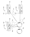
さらに詳細には図1Eは、装着者の一方または両方の眼がそれを通して対象物を見る、検出および表示装置1300の例を図示する。検出および表示装置1300は、図1Aの第1の拡張介在現実空間1000内で他者(例えば他のユーザ)に対して可視および/または不可視であってよいエクストラミッシブ・ビジョンも提供し得る。図1Eの例において示される第1の拡張介在現実空間1000は、チェス・ゲームのプレイにおいて使用される種類の仮想的ゲームボードを含む。図1E、図2A、図3、および図4は、図1Bに関連付けられた感覚現象センサ(910、916)および感覚現象エフェクタ(912、914)の例を図示する。図1E〜図1G、図2A、図3、図4が、検出および表示装置1300上で同一位置を共有し得るエフェクタ・アセンブリおよびセンサ・アセンブリの具体例を図示することと、この構成が例示および簡略化を目的とするものであることと、が理解されるであろう。
More specifically, FIG. 1E illustrates an example of a detection and
検出および表示装置1300が単に表示装置と、またはさらに簡略的に単に装置と、呼ばれ得ることが理解されるであろう。一般に装置1300は、画像を(ユーザ(1人以上)に対して)表示するよう構成され得、ディスプレイ・アセンブリにインターフェース接続するよう構成され得、検知するよう構成され得、および/または検知装置にインターフェース接続するよう構成され得る。
It will be appreciated that the detection and
一選択肢によれば、検出および表示装置1300は、例えば、可視光受信器191および/または可視光送信器192を含む。なお可視光受信器191は第1の感覚現象センサ910(図1B)の、および/または第2の感覚現象センサ916(図1B)の、例であり、可視光送信器192は、第1の感覚現象エフェクタ912(図1B)の、または第2の感覚現象エフェクタ914(図1B)の、例である。
According to one option, the detection and
一選択肢によれば、検出および表示装置1300は、検出および表示装置1300をユーザの頭部に固定的に接続することを支援するよう構成された頭部搭載可能アセンブリ183を含む。一実装では、頭部搭載可能アセンブリ183は、検出および表示装置1300をユーザの頭部に固定するよう構成された、例えばユーザ頭部の後部秒に配置され得る後頭部バンド188を含み得る。一実装では、後頭部バンド188は、ユーザ頭部の後方ゾーンを検知するよう構成されたセンサを含み得る。後頭部バンド188上に配置されたセンサは、例えば、図1Aの第1の拡張介在現実空間1000に関連付けられた他のユーザと共有され得る。
According to one option, the detection and
一実装では、検出および表示装置1300は、配向・慣性測定ユニット184、LiDARユニット187、ビジョン・システム193、光センサ100、ディスプレイ・ユニット181、着脱可能シェード110、および/またはその他などの様々な構成要素を含むデジタル眼鏡180を含む。一実装では、着脱可能シェード110は、2インチ×4.25インチ(約51ミリメートル×108ミリメートル)の標準サイズの溶接シェードであってよい。着脱可能シェードは、ディスプレイ・ユニット181が、明るい太陽光において可視となることを可能にし(例えばANSIシェード番号5〜7を使用して)、または明るいが曇った日に可視となることを可能にし(例えばANSIシェード番号2〜4を使用して)、またはHDR(ハイダイナミックレンジ)撮像を使用して電気アークを見ながら溶接のために検出および表示装置1300を使用することを可能にし(例えばより暗いシェードを使用して)得る。
In one implementation, the detection and
一選択肢によれば、デジタル眼鏡180は単一ガラスを含むよう構成され、溶接作業者用ヘルメットにおける構成と同様にこの単一ガラスを通して両眼が見ることが可能である。1つの変化例によれば、別個の表示または介在ゾーンがそれぞれの眼に対して、1つの眼鏡内で、それぞれの眼に対する別個の眼鏡内で、または1つの眼に対して1つのモノクル眼鏡内で、提供され得る。
According to one option, the
一実装では、デジタル眼鏡180は、視力補助具、ビジョン補助具、および/またはその他として機能するよう構成され得、ハイダイナミックレンジ(HDR)ビジョンを提供するよう構成され得る。なおHDRビジョンでは装着者は例えば、電気アークを眺めつつも完全な暗闇の中で物が見え、暗い小径で明るい自動車ヘッドライトを眺めつつも自動車ナンバープレート上の番号および運転者の顔を鮮明に見ることが可能である。
In one implementation, the
一選択肢では、着脱可能シェード110はエレクトロクロミックであり、光センサ100により、および/またはLiDARユニット187により、および/またはビジョン・システム193により、および/またはこれらの任意の順列および組み合わせにより、制御可能となるよう構成される。この場合、デジタル眼鏡180は、例えば、屋内から屋外への移動、太陽、雲、電気アーク溶接、明るい光、その他などの、起こり得る広範囲のビジョン条件に適応するよう、およびレーザポインタまたは他の光源などからの故意的な投光攻撃からの保護を提供する(係る攻撃に対しては、デジタル眼鏡180が眼の保護をユーザに対して提供し得る)よう、構成される。
In one option, the
一選択肢によれば、光センサ100は、デジタル眼鏡180の着脱可能シェード110の周縁部周りに配置されるか、または着脱可能シェード110に直接的に一体化される。光センサ100は、加えて、着脱可能シェード110の上方にも配置され得る。着脱可能シェード110が取り外されると、この状態はシェード0とみなされ得る(例えば着脱可能シェード110の設定がシェード0となる)。
According to one option, the
一選択肢によれば、センサは着脱可能シェード110の上方に配置される。一選択肢によれば、センサは赤外線送信器186および/または赤外線受信器185を含む。一実装では、赤外線受信器195がデジタル眼鏡190に装備される。赤外線受信器185は、いくつかの実装では、赤外線検出器と呼ばれ得る。赤外線送信器186および赤外線受信器185は、一実装では、赤外線LiDARもしくは他の3次元赤外線カメラ・システム、および/またはその他などの範囲検知用ビジョン・システム(range−sensing vision system)として協働するよう構成され得る。
According to one option, the sensor is located above the
一選択肢によれば、可視光受信器191が提供され、可視光受信器191は、一実装では、(例えばカラーを有する写真画像を提供するための)可視光カメラとして構成され得、一実装では、赤外線送信器186および赤外線受信器185により形成された範囲マップまたは範囲画像と組み合わされ得る。
According to one option, a
一選択肢によれば、可視光送信器192が提供され、可視光送信器192は、デジタル眼鏡180の装着車に可視である対象物(例えば広告、スポンサーのお知らせ、カウンタ、時間/日付表示器、または投影170などの他の指標などの可視的内容を有する表面130(例えばテーブルトップ))を照明するために可視光スペクトルで動作するよう構成される。一実装では、係る投影は、デジタル眼鏡180の具体例を装着しない任意のユーザ(人)の裸眼198に対しても可視であってよい。
According to one option, a visible
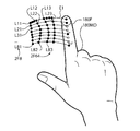
一実装では、検出および表示装置1300において使用されるセンサおよびエフェクタは、ユーザの目の周りに(例えばユーザの頭部上に)配置された周辺フレーム(周辺フレームはフレーム・アセンブリの例である)に固定的に取り付けおよび/または装着され得る。デジタル眼鏡180は、空間画像を(2つの眼に対して)提供する。この空間画像は、いくつかの実装では、水平視差のみの画像および/または立体的画像を有し得る。これは、例えば、ユーザの両眼がそれを通して見る単一眼鏡において、または別個の眼鏡において、2つの別個の具体例またはディスプレイ・ユニット181のステレオの具体例を使用して、なされ得る。1988年の陸軍調査から得られた瞳孔間距離(IPD)値は、男性に対しては64.7ミリメートル(mm)の平均、女性に対しては62.3ミリメートルの平均を示す。これらの2つに対して(例えば男性および女性に対して)平均を計算するならば、64.7+62.3=127.0ミリメートルの合計を2で除算して127/2=63.5ミリメートルの結果が得られ、この値は2.5インチに等しい。したがってディスプレイ・ユニット181の具体例は、例えば、眼点において約2.5インチ離間して配置され得る。いくつかの実装ではディスプレイ・ユニット181の具体例は、所与のユーザのIPDの以前の、並列的な、および/またはリアルタイムの測定値などに基づいて調節可能および/または動的に配置され得る。例えば一実装では、ユーザの顔に向けられたセンサがユーザに対するIPDを検出および/または測定し、それぞれの眼に対するディスプレイ・ユニット181間の距離が、その検出および/または測定に基づいて調節され得る。他の実装では各ディスプレイ・ユニット181のアクティブ表示エリアは、例えば特定的なユーザIPDに基づいて表示エリアの適切な領域に表示内容を提示するために、測定されたユーザIPDに基づいて調節され得る。
In one implementation, the sensors and effectors used in the detection and
一選択肢によれば、検出および表示装置1300は、2眼表示、単眼表示、および/またはその他の表示を提供するよう構成されたデジタル眼鏡180を含み得る。2眼閲覧の場合、右眼アイ・ポイント199Aおよび左眼アイ・ポイント199B(すなわち右アイタップ点および左アイタップ点)が提供される。
According to one option, the detection and
一実装では、真の(または真に近い)3次元画像をキャプチャする能力は、検出および表示装置1300に対して合成効果を作成するよう構成されたライトスペース・コリニアライザを作成するために使用され得る。例えば眼の方向に向けられた光線が撮像システムを通して進路変更され、処理され、本来の光線に対して実質的に同一直線状となるよう再描画され得る。ライトスペース・コリニアライザ(いくつかの実装では、合成コリニアライザと呼ばれる)は、真のまたは真に近い3次元モデルをキャプチャし、あたかもカメラのレンズの中心(絞り、結節点、光学中心、および/またはその他)がユーザの眼球のレンズの中心となる状態で、3次元モデルが実際に装着者の視野内に配置されたものであるかのようにカメラにより生成される画像を計算することと、を行うよう構成される。
In one implementation, the ability to capture a true (or near true) three-dimensional image is used to create a light space collinearizer configured to create a composite effect for the detection and
一実装では、3次元カメラは、空間撮像装置の効果を合成するために使用および/または構成され得、ライトスペース分析眼鏡は装着者の目の上方に配置されたライトスペース分析眼鏡を含み得る。例えば検出および表示装置1300のバイザの全体がライトスペース分析眼鏡として構成され得る。一実装では、3次元カメラは、検出および表示装置1300を通過する光の全光線のライトスペース画像、ライトフィールド画像、複眼画像、ホログラフィック画像、および/またはその他が画像を生成するよう構成され得る。図1Aの処理装置908は(例えば仮想的な)ライトスペース分析眼鏡の出力に応答するよう構成され得、処理装置908は、ライトスペース合成眼鏡に対する光線を計算するよう構成され得る。係る実装では3次元カメラ、プロセッサ、およびディスプレイの組み合わせがライトスペース・コリニアライザを具体化し得る。
In one implementation, the three-dimensional camera may be used and / or configured to synthesize the effects of the spatial imaging device, and the light space analysis glasses may include light space analysis glasses positioned above the wearer's eyes. For example, the entire visor of the detection and
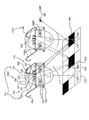
ビジョン・システムの実装における真の3次元の性質により、デジタル眼鏡180およびデジタル眼鏡190のそれぞれは、共有されるゲーム用テーブル(例えば実際の、または想像上の、または仮想的なチェスボード、またはテーブル表面130)などのパブリック対象物140の真の3次元画像をキャプチャし、テーブル130のこの実際のビュー表示またはコンピュータにより変更されたビュー表示、またはこれらの任意の組み合わせを、あたかもその画像がカメラ(ただしカメラ自体、カメラのレンズ、カメラのフィルム、カメラのCCD、および/またはその他が右眼のレンズの正確な中心かまたは略中心に配置されている)によりキャプチャされたものであるかのように描画する他に、他のビュー表示を、あたかもその画像が検出および表示装置1300の装着者の左眼のレンズの正確な中心かまたは略中心に配置されたカメラによりキャプチャされたものであるかのように描画するよう構成され得る。なおCCDは電荷結合素子(charge−coupled device)を意味する。
Due to the true three-dimensional nature of the vision system implementation, each of the
一実装では、デジタル眼鏡180(第1のユーザ用)およびデジタル眼鏡190(第2のユーザ用)のそれぞれは、それぞれビジョン・システムとデジタル眼鏡190から受け取った情報とを併せて使用して、それぞれビジョン・システムのみを使用する場合よりもはるかに詳細な、真の、および/または正確な現実の3次元モデルを構築し得る。この意味において一実装では、数人の異なる参加者は、コンピュータにより介在された現実を共有し得る。このコンピュータにより介在された現実内では、真の(物理的な)世界(第1の拡張介在現実空間1000)は、比較的高い詳細、精度、および/もしくは正確度でキャプチャされ、および/または、追加的および/または相補的な遠近感、方向、ビュー表示、および/またはその他に関連付けられたデータを含む。
In one implementation, each of the digital glasses 180 (for the first user) and the digital glasses 190 (for the second user) each use the vision system and the information received from the
一選択肢によれば、検出および表示装置1300は、多重化方式で動作するよう構成され得、および/または多重化を実行するよう構成され得る。例えばデジタル眼鏡180およびデジタル眼鏡190は、例えば時分割多重化などにより協働し、それにより、第1の拡張介在現実空間1000内に配置された対象を検知および/または理解するために交代的にシーンを照明するよう、構成され得る。多重化は、例えば、符号分割多重化(例えば異なる拡散シーケンス、または拡散スペクトラム、または拡散空間化パターンを使用する)により、および/または共同作業的検知により、実行され得る。協調的検知の場合、デジタル眼鏡180およびデジタル眼鏡190は、一緒に動作してパブリック対象物140および表面130を照明および検知するよう構成される。例えば赤外線送信器186がシーン(第1の拡張介在現実空間1000)を赤外線光で照明する間、赤外線受信器185および赤外線受信器195の両方が、シーン(第1の拡張介在現実空間1000)内の物理的対象から反射された反射赤外線光を検知する。デジタル眼鏡180とデジタル眼鏡190との間の交差検知は、第1の拡張介在現実空間1000においてデジタル眼鏡180とデジタル眼鏡190との間のベースラインがより長いために存在する極端な視差により追加的なシーン情報を提供する。一実装では、図1Aのプログラム907(検出および表示装置1300の具体例において使用される)は、検出および表示装置1300の他の具体例とともに多重化動作を実行するよう構成される。
According to one option, the detection and
結果として、一実装では、合成開口LiDARまたは同等物が、別個の小視差眼鏡間ベースラインおよび大視差眼鏡間ベースラインに数学的に分解され得る解像力を有することとなる。 As a result, in one implementation, the synthetic aperture LiDAR or equivalent will have a resolution that can be mathematically resolved into separate small parallax eyeglass baseline and large parallax eyeglass baseline.
一選択肢によれば、デジタル眼鏡180はコンピュータ160を含み得る(コンピュータ160は図1Aの処理装置908の一例である)。コンピュータ160はデジタル眼鏡180に内蔵(一体化)されてもよく、またはデジタル眼鏡180とは別個であってもよく、および/または、例えば、ユーザのシャツ・ポケットなどの内にフィットするよう構成されてもよい。一選択肢によれば、コンピュータ160は、ネットワーク接続150(例えばワイヤレス接続、WLAN(ワイヤレス・ローカルエリアネットワーク)、WiFi(登録商標)ネットワーク、PSA(パーソナルエリアネットワーク)、Bluetooth(登録商標)ネットワーク、セルラ接続、CDMA(符号分割多元接続)、HSPA(高速パケットアクセス)、HSDPA(高速ダウンリンクパケットアクセス)、GSM(グローバル・システム・フォー・モバイル・コミュニケーションズ)(登録商標)および/または同等物)を含む。デジタル眼鏡180と接続されたコンピュータ160が使用されるいくつかの実装に対して、コンピュータ160はジオフォン182と一体化され得る。
According to one option,
一選択肢によれば、デジタル眼鏡180は内蔵型である。一選択肢によれば、デジタル眼鏡180はコンピュータ160に接続され、デジタル眼鏡180は、例えば収納などのために、装着者のシャツ・ポケット内に配置され得る。デジタル眼鏡180が接続されたいくつかの実装に対して、配線は、通常の眼鏡用安全ストラップの外観を有する布製のパイプ、布製の管、および/または同等物の内部に秘匿され得る。例えば眼鏡用安全ストラップは、眼鏡紐の応力が解放されるようにユーザの衣服の箇所に固定的にクリップ留めされるよう構成されたクリップ189を含み得る。例えばクリップ189は、装着者の衣服を把持しそれにより例えば何らかの形態の応力リリーフを提供するための「ワニ口クリップ」、「ダブルクリップ」、バネクリップ、およびヘッドセット、ペンダント式小形マイクロフォン、ならびに同等物に対して使用される種類のばね仕掛け式クランプであってよい。
According to one option, the
いくつかの状況ではコンピュータ160(コンピュータ160は図1Aの処理装置908の一例である)は、ユーザが着座姿勢にあるとき、オフィスまたは家庭空間の床またはテーブル上に配置され得る。いくつかの係る実装に対してコンピュータ160は、ジオフォン182を含むセンサ・インターフェース・ユニット120(例えばテーブルトップ・ユニット)内に収納され得、このようにしてセンサ・インターフェース・ユニット120は受振能力が有効化される。センサ・インターフェース・ユニット120は、コンピュータ160に提供されるべきセンサ入力をインターフェース接続するよう構成されたセンサ・インターフェース・アセンブリを含む。一実装では、センサ・インターフェース・ユニット120は、例えばチェス駒がテーブルを横切ってスライドされた(またはテーブルにタッチされた)とき、人がテーブルを軽く指で叩いたとき、および/または同様の状況のときなどに、ジオフォンを使用してテーブル表面における音響振動を聴くよう構成される。
In some situations, computer 160 (
ジオフォンという用語は、様々な実装では、任意種類の圧力トランスデューサ、圧力センサ、速度センサ、流量センサ、および/または例えば固形物における圧力、速度、運動、圧縮、粗密化、および/もしくは同等物の変化を電気信号に変換する同等物を指す。ジオフォンは圧力差センサ、テーブルトップなどの固体表面上の絶対圧力センサ、歪みゲージ、収縮センサ、および同等物を含む。したがってジオフォンは、ガラス板もしくはセラミック板、ステンレス鋼、ダイヤフラム、または同等物のそれぞれの側部上に1つずつ、単一の聴音ポートまたは二重ポートを有し得、圧力スイッチなどの圧力における個別の変化のみに応答する圧力センサも含み得、係る圧力センサは、1ビット・ジオフォンとみなされ得る。さらにジオフォンという用語は、圧力または圧力差における変化のみに応答する装置、すなわち静圧の伝達はできない装置、を指すためにも使用され得る。一実装では、ジオフォンという用語は、その周波数範囲が人間に可聴な範囲内であるか、または可聴下周波(一実装では、毎秒0サイクルまでの範囲も含む)であるかどうか、または超音波であるかどうかに関わらず、あらゆる周波数範囲における圧力または圧力変化を検知する圧力センサを説明するために使用される。さらにジオフォンという用語は、いくつかの実装では、例えば固形物内の振動または圧力または圧力変化を検知するよう構成された任意種類の接触型マイクロフォンまたは同様のトランスデューサを説明するために使用され得る。したがってジオフォンという用語は、可聴周波数範囲において動作する接触型マイクロフォン、ならびに可聴周波数ばかりではなく任意の周波数範囲で動作する他の圧力センサを指すために使用され得る。ジオフォンは、例えば、テーブルトップにおける音響振動、ひっかき音、下方に押圧する圧力、テーブル上の重力を(例えばDCすなわち直流オフセットを介して)、および小信号振動を(例えばACすなわち交流信号を介して)、検知するよう構成され得る。いくつかの実装では「ナチュラル・ユーザ・インターフェース」という用語は、現実世界の対象物などの物理的媒体を使用し、メタファーの間接を排除する、この形態の相互作用または他の同様の形態の相互作用を指すために使用され得る。一選択肢によれば、デジタル眼鏡180は、特にセンサ・インターフェース・ユニット120の支援によりナチュラル・ユーザ・インターフェースを具体化する。
The term geophone, in various implementations, is any type of pressure transducer, pressure sensor, velocity sensor, flow sensor, and / or change in pressure, velocity, motion, compression, densification, and / or the like in a solid, for example. Refers to the equivalent of converting to an electrical signal. Geophones include pressure differential sensors, absolute pressure sensors on solid surfaces such as table tops, strain gauges, contraction sensors, and the like. Thus, the geophone can have a single listening port or dual port, one on each side of a glass or ceramic plate, stainless steel, diaphragm, or the like, each at a pressure such as a pressure switch. Pressure sensors that respond only to changes in the pressure may be included, and such pressure sensors may be considered as 1-bit geophones. Furthermore, the term geophone can also be used to refer to a device that responds only to changes in pressure or pressure differential, ie, a device that is not capable of transmitting static pressure. In one implementation, the term geophone is used to determine whether its frequency range is within the range audible to humans, or at audible frequencies (including one up to 0 cycles per second), or ultrasonically. It is used to describe a pressure sensor that detects pressure or pressure changes in any frequency range, whether or not. Furthermore, the term geophone can be used in some implementations to describe any type of contact microphone or similar transducer configured to sense vibration or pressure or pressure changes within a solid object, for example. Thus, the term geophone can be used to refer to contact microphones that operate in the audible frequency range, as well as other pressure sensors that operate in any frequency range, not just the audible frequency range. Geophones, for example, acoustic vibrations at the table top, scratching, downward pressure, gravity on the table (eg via a DC or DC offset), and small signal vibrations (eg via an AC or AC signal) ), May be configured to detect. In some implementations, the term “natural user interface” refers to this form of interaction or other similar form of interaction that uses physical media such as real-world objects and eliminates metaphor indirection. Can be used to refer to action. According to one option, the
加えて、一実装では、LiDARユニット187およびLiDARユニット197は、3次元オブジェクトの位置および同等物を検知するよう構成されたものであり、ジオフォン182および他のセンサにより多モード感覚接触フィードバックを提供するために、コンピュータ160ならびにセンサ・インターフェース・ユニット120にデータを提供する。
In addition, in one implementation,
一選択肢によれば、センサ・インターフェース・ユニット120内のジオフォン182は、伝達および受容を行うよう構成され、ユーザの指によるクリック、タッチ、または接触などの振動接触エネルギーをテーブルトップに伝達し、それをユーザが感じることができるよう、テーブルトップに固定的に取り付けられ得る。代替的に一実装では、力および/または振動接触エネルギーは、例えば劇的な効果のために、半破壊的に使用され得る。
According to one option, the
例えば(図1Eに示すように)「拡張介在チェス」のゲームでは、ジオフォン182は、一方のプレイヤーがゲームに勝ったとき、テーブルを揺さぶってチェス駒を倒し、それにより眼鏡非装着参加者(例えば検出および表示装置1300を使用しないユーザ)の裸眼198に対してさえも可視となる劇的な視覚的効果が生み出されるよう、構成され得る。
For example (as shown in FIG. 1E), in an “extended intervening chess” game, when one player wins the game, the
さらに複数人の参加者が、センサ・インターフェース・ユニット120およびコンピュータ160のそれぞれの具体例を、テーブルトップなどの表面130上に置いた場合、ジオフォン182およびジオフォン194の複数の具体例が、センサ・インターフェース・ユニット120およびコンピュータ160のそれぞれの具体例に存在し、それによりジオフォンのアレイが形成されることとなり得る。センサ・インターフェース・ユニット120および慣性コンピュータ160のそれぞれの具体例内の慣性測定ユニット184、加速度計、および/または同等物、および/または他の追加的なセンサは、一実装では、センサ・インターフェース・ユニット120およびコンピュータ160の相対的位置を計算するために使用され、このようにして、表面130の音響的および/または他の物理的動揺の定位し得るセンサの位相アレイが形成されることとなる。
Further, if multiple participants place their respective examples of
デジタル眼鏡180およびデジタル眼鏡190のそれぞれは、いくつかの実装では、可視光などの光を検知および/または放出するよう構成される。完全双方向の具体例の実装ではデジタル眼鏡180DEGは、両方向において光を検知および放出するよう構成され、それにより、例えば眼自体に対して、前向きエクストラミッシブ・アクティブ・ビジョンおよび内向きエクストラミッシブ・アクティブ・ビジョンが提供される。これは、アイ・トラッキング(例えば検知として)および表示(効果)ならびに図1Aの第1の拡張介在現実空間1000の環境の空間撮像(例えば検知として)および環境に対する投影(例えば効果)を含み得る。この意味においてデジタル眼鏡180は光を眼に送ること、および光を眼から受け取ることを行う他に、デジタル眼鏡180は光を(例えばユーザの目の)視野内の対象物に送ること、および光を係る対象物から受け取ることも行う。
Each of
一選択肢によれば、デジタル眼鏡180は、ユーザの周辺の環境を検知すること、および/またはユーザを検知すること、を行うよう構成される。空間撮像センサ・アセンブリ(例えばLiDARユニット187など)は、一実装では、例えばユーザの腕、手、指、および/または同等物の空間座標、位置、配向、および/または同等物を判定するための深度マップ1308(図13の一例に示す)を提供するよう構成され得る。空間撮像センサ・アセンブリは、例えばユーザが地面を見下ろす場合のために、ユーザの脚、足、および/または同等物の空間座標、位置、配向、および/または同等物を判定するための深度マップを提供することも行うよう構成され得る。一実装では、2種類のスキャン可能な対象物は例えば、自分自身以外の対象物(例えば室内の他の対象物など)と自分自身と、などとして分離され得る。この2つの遭遇したとき係る遭遇は検出および/または追跡され、この状況はいくつかの実装では「物理的接触」または「接触」とも呼ばれ得る。
According to one option, the
一選択肢によれば、図1Aの処理装置908は、一実装では、接触検出器を含み得る。接触検出器は、接触(例えば人体と他のオブジェクトとの間の、2つのオブジェクトの間の、および/または同様の物理的接触)を検出し、それにおうじ手応答するよう構成される。接触検出器は例えば、接触の発生を検出するよう構成されたプログラム命令を含む。一選択肢によれば、接触検出器は、接触音をピックアップまたは別様に検出するよう構成されたジオフォン182を含み、ビジョン・システム(検出および表示装置1300)は、表面(例えばテーブルトップなど)を3次元スキャンし、手、指、および/または同等物が表面にタッチしたときを判定すること、およびこれらが表面に接触したかどうかを判定すること、により、接触の発生を観察するよう構成される。一実装では、このことは点群を介して、例えば群作用(1)により顕在化されるような、手または指の点群が平面の射影変換に侵入するとき、達成され得る。式{1}は、図1Aの処理装置908により、一実装では、図1AAの一例に示すような、接触検出器400により接触の発生を検出するために、使用され得る。

空間内同一の平坦表面の任意の2つの画像は射影変換により関連付けられる(ピンホールカメラのモデルを仮定する)。これは、多数の実際的な応用(例えば2つの画像間での画像修正、画像レジストレーション、カメラ・モーション(回転および平行移動)の計算、および/または同等物など)を可能にする。カメラの回転および平行移動が推定される射影変換行列から抽出されると、この情報は、例えばナビゲーションなどのために、3次元オブジェクトが正しい遠近感で描画され元のシーンの一部であったように見えるよう、3次元オブジェクトを画像またはビデオおよび/または同等物に挿入するために使用され得る。 Any two images of the same flat surface in space are related by projective transformation (assuming a pinhole camera model). This allows for many practical applications such as image correction between two images, image registration, camera motion (rotation and translation) calculations, and / or the like. When extracted from the projective transformation matrix where camera rotation and translation are estimated, this information appears to be part of the original scene where the 3D object was drawn with the correct perspective for navigation, for example. Can be used to insert a three-dimensional object into an image or video and / or the like.
一実装では、[A]は、2×2線形演算子であり、[b]は2×1変換であり、[c]は2×1チャープ(射影)であり、[d]はスカラー定数であり、[x]は2×1空間座標であり、[X]=[x1,x2]Tである(ただしTは転置を示す)。 In one implementation, [A] is a 2 × 2 linear operator, [b] is a 2 × 1 transformation, [c] is a 2 × 1 chirp (projection), and [d] is a scalar constant. Yes, [x] is 2 × 1 spatial coordinates, and [X] = [x1, x2] T (where T indicates transposition).
一実装では、統計的有意性テストが、接触検出器により検出された射影変換的侵入の度合いに対して行われ得る。射影変換的侵入の度合いの測定を行うよう構成された装置は、いくつかの実装では、射影変換侵入評価器または射影変換的侵入評価器と呼ばれ得る。係る評価器に対して閾値が設定され、係る評価器が他の動作に対するトリガ、および/または同等物として使用される一実装では、この装置は、射影変換侵入検出器と呼ばれ得る。一実装では、検出および評価に関する理論(例えばネイマン・ピアソン理論など)が、図1AAの射影変換侵入検出器401に適用され得る。
In one implementation, a statistical significance test may be performed on the degree of projective intrusion detected by the touch detector. An apparatus configured to measure the degree of projective intrusion may be referred to as a projective intrusion evaluator or projective intrusion evaluator in some implementations. In one implementation where a threshold is set for such an evaluator and such evaluator is used as a trigger and / or equivalent for other actions, the apparatus may be referred to as a projective transformation intrusion detector. In one implementation, detection and evaluation theories (eg, Neyman Pearson theory, etc.) may be applied to the projective
視覚入力、聴覚入力(例えばジオフォン182による)、および/または他の感覚入力が用いられる場合において、合流性センサ402(図1AAに図示される)がこれらの2つのモードの検知を融合させるために使用され得る。 In cases where visual input, audio input (eg, via geophone 182), and / or other sensory inputs are used, confluence sensor 402 (illustrated in FIG. 1AA) is used to fuse the detection of these two modes. Can be used.
合流性センサは、一実装では、図1EEの例に示されるように視覚侵害センサおよび/または音響侵害センサの組み合わせから構築され得る。一実装では、係るセンサは、侵害性(侵入性、押出性、またはその両方)、接触、および/または同等物を評価するよう構成されたニューラル・ネットワークを使用し得る。 The confluence sensor may in one implementation be constructed from a combination of visual and / or acoustic infringement sensors as shown in the example of FIG. 1EE. In one implementation, such a sensor may use a neural network configured to evaluate nociceptiveness (intrusion, extrudability, or both), contact, and / or the like.
一実装では、デジタル眼鏡180は、例えば頭部搭載可能アセンブリ183(いくつかの実装ではヘッド・ストラップと呼ばれる)などを用いて、フレームにより(ユーザの)頭部上で支持され得る。一実装では、頭部搭載可能アセンブリ183は、頭部搭載可能アセンブリ183の一部(例えば半分)が後頭葉の下方に、位置合わせ、配置、および/または同様に位置決めされ、残余部分(例えば残余の半分)が後頭葉の上方に、位置合わせ、配置、および/または同様に位置決めされ、それによりデジタル眼鏡180が、体操、ヨーガ、および/または水泳(普通ならば、水流によりデジタル眼鏡180がユーザの顔面から押し流されてしまい得る)などの激しい身体的活動の間にもユーザの頭部に留まるよう、分割され得る。例えば、デジタル眼鏡180のシールされた水密的な具体例の前面平坦表面は、水面上および/または水面下で動作するよう構成され得る。
In one implementation, the
開示される装置、方法、およびシステムの態様は、空間(平面/射影変換、球形オブジェクト、または同等物)に対する侵入を検出し得る視覚的侵入検出器を、より一般的には、侵害評価器を、含み得る。なおこの侵害評価器は、侵害(侵入もしくは押出、または同時にその両方)の度合いを評価することが可能であり、何らかの閾値により、またはその他(例えば、ジェスチャ検知、評価、検出、およびジェスチャ分類)により、実質的に(または直接的に)侵害を検出することが可能である。 Aspects of the disclosed apparatus, methods, and systems provide visual intrusion detectors that can detect intrusions into space (plane / projection transformations, spherical objects, or the like), and more generally, infringement evaluators. Can be included. Note that this breach evaluator can evaluate the degree of breach (intrusion and / or extrusion, or both at the same time), by some threshold or by others (eg gesture detection, evaluation, detection, and gesture classification). It is possible to detect violations substantially (or directly).
いくつかの実装では侵害センサは、合流性(例えば多モード侵害検知の合流性の結果)にも基づき得る。例としては、電磁放射(第1のモード)および音響放射(第2のモード)により検知する侵害センサが挙げられる。 In some implementations, the breach sensor may also be based on merging (eg, merging results of multi-mode breach detection). Examples include infringing sensors that detect by electromagnetic radiation (first mode) and acoustic radiation (second mode).
図1EEは、一実施形態における信号処理システムを図示する。この信号処理システムは、光センサ装置または光センサ・エフェクタ(照明)装置から、ならびに、音響センサ装置または音響センサ・エフェクタ(例えばソナー)装置から、入力を受け取る。 FIG. 1EE illustrates a signal processing system in one embodiment. The signal processing system receives input from an optical sensor device or optical sensor effector (illumination) device, as well as from an acoustic sensor device or acoustic sensor effector (eg, sonar) device.
図1EEは、視覚侵害入力1EE20および音響侵害入力1EE10を含む合流性センサを図示する。一実装では、2種類の侵害が存在し、これらの2種類とは、侵入(例えば、窃盗犯または「侵入者」が構内に入るときに観察される)と、押出(例えばアルミニウムの「I」字形のビームは、アルミニウムを文字「I」の形状に「押出」するときに観察される)と、である。 FIG. 1EE illustrates a confluence sensor that includes a visual infringement input 1EE20 and an acoustic infringement input 1EE10. In one implementation, there are two types of infringement, these two types being intrusion (eg, observed when a thief or “intruder” enters the premises) and extrusion (eg, “I” for aluminum). The shaped beam is observed when aluminum is “extruded” into the shape of the letter “I”).
侵入は、一実装では、1つの物へと、1つの物の上に、または1つの物に抗して「推力」または「押圧」を加えること、または1つの物の近傍に進入することである。進入は、侵入者が構内に進入したとき、2進数のon/offである(例えば「トリガ」する)場合もあり、および/または度合いにより生じる場合もある。例えば、他者の「個人空間」に接近することによって、例えば当該人物にタッチすることさえなく当該人物のパーソナル空間に進入することも、侵入となり得る。 Intrusion is in one implementation by applying “thrust” or “pressing” to one object, on top of one object, or against one object, or by entering the vicinity of one object. is there. The entry may be binary on / off (eg, “trigger”) and / or may occur depending on the degree when the intruder enters the premises. For example, by approaching another person's “personal space”, for example, entering the personal space of the person without even touching the person can be an intrusion.
テーブルの表面に対する侵入は、例えば仮想的オブジェクトをテーブルの表面上に寄せることにより(例えば、テーブルに接近させること、テーブル上でホバリングさせること、テーブルにタッチさせること、および/または同様の動作により)発生させることが可能である。テーブルに対して軽く押圧してもよい。またテーブルに抗してより強く押圧してもよい。このように一実装では、侵入の度合いは、テーブルトップに接近させること、から、テーブルトップに軽くタッチさせることまで、軽く押し当てることまで、押し付けることまで、拳でテーブルを強打することにより特に強く押し付けることまで、および/または同等物まで、変動し得る。このように、このシステムは、侵害および接触(例えばタッチすること、軽く叩くこと、擦ること、打ち付けること、および同様の動作などの接触要素)を検知することができる。 Intrusion to the surface of the table is, for example, by bringing a virtual object onto the surface of the table (eg, by approaching the table, hovering on the table, touching the table, and / or similar actions). Can be generated. You may press lightly with respect to a table. Moreover, you may press more strongly against a table. Thus, in one implementation, the degree of intrusion is particularly strong by banging the table with a fist, from approaching the table top to touching the table top lightly, pressing lightly, pressing. It can vary up to pressing and / or the equivalent. In this way, the system can detect infringement and contact (eg, contact elements such as touching, tapping, rubbing, striking, and similar actions).
また、テーブルから引き抜くことも可能である(押出)。視覚侵害センサ1EE30などの装着可能ビジョン・システムは、テーブルとのタッチ、侵入または押出の度合い、および/または同等物を検知することが可能である。一実装では、タッチ・センサは、複数のモードにより多モード検知を行う(例えば音響侵害センサ1EE25を使用して検知することも行う)よう、構成され得る。 It can also be pulled out of the table (extrusion). A wearable vision system, such as the visual infringement sensor 1EE30, can detect the touch with the table, the degree of intrusion or extrusion, and / or the like. In one implementation, the touch sensor may be configured to provide multi-mode detection with multiple modes (eg, also using the acoustic infringement sensor 1EE25).
本明細書で使用される音響信号は、DC(毎秒0サイクル)までの全ての音響レベルを含み得る。一実装では、音響侵害センサ1EE25は、テーブルの収縮を検知し得るテーブル内またはテーブル上の歪みゲージ、および/またはテーフル内の「湾曲器」もしくは「湾曲センサ」、および/または、テーブル上の重量または力を検知するテーブルの脚に取り付けられたセンサであってよい。 As used herein, an acoustic signal may include all acoustic levels up to DC (0 cycles per second). In one implementation, the acoustic infringement sensor 1EE25 may include a strain gauge or a “bend” or “curvature sensor” in the table and / or a weight on the table that may detect table contraction. Alternatively, it may be a sensor attached to a table leg for detecting force.
一実装では、音響侵害センサ1EE25および視覚侵害センサ1EE30は、侵害測定値を、および/または、「ニューロン」による接続とともに、ノード1EE40、ノード1EE50、ノード1EE70、またはその他のノードにより形成されるニューラル・ネットワークの特徴ベクトル、または重み、または要素とみなされ得る多次元侵害信号1EE35を、供給するよう構成される。接続1EE45および接続1EE60または同等物はノードとともに、侵入、タッチ、および押出を認識するよう訓練されたニューラル・ネットワークを形成する。 In one implementation, the acoustic nociception sensor 1EE25 and the visual nociception sensor 1EE30 may include nociceptive measurements and / or neural connections formed by node 1EE40, node 1EE50, node 1EE70, or other nodes, with connections by “neurons”. A multidimensional infringement signal 1EE35, which may be considered a network feature vector, or weight, or element, is configured to be provided. Connection 1EE45 and Connection 1EE60 or equivalent together with the nodes form a neural network trained to recognize intrusions, touches and pushes.
一実装では、接触信号1EE80は、侵入の度合いを検出および/または提供する。この度合いは、単一の浮動小数点数、侵入の実体を十分にキャプチャする特徴ベクトル、および/または同等物として構成され得る。 In one implementation, the contact signal 1EE80 detects and / or provides a degree of intrusion. This degree may be configured as a single floating point number, a feature vector that fully captures the intrusion entity, and / or the equivalent.
一実装では、接触信号1EE85はタッチの度合いをキャプチャし、タッチに関する情報(例えばタッチの大きさなど)を伝える。一実装では、接触信号1EE85は、実際の物理的オブジェクト(例えばテーブルトップもしくは同等物など)または仮想的オブジェクト(例えば1人以上の人々が一緒に経験することが可能な共有される仮想的オブジェクトなど)に対して何本の指がダッチするか、どの指がタッチするか、および/または同等物に関する情報を伝える。 In one implementation, the contact signal 1EE85 captures the degree of touch and conveys information about the touch (eg, touch magnitude). In one implementation, the touch signal 1EE85 may be an actual physical object (such as a tabletop or equivalent) or a virtual object (such as a shared virtual object that one or more people can experience together). ) Tells the user how many fingers are dutch, which fingers touch, and / or the like.
一構成では、接触信号1EE80、接触信号1EE85、および接触信号1EE90はそれぞれ侵入検出器1EE91、タッチ検出器1EE92、および押出検出器1EE93に渡される。検出された信号(それぞれ信号1EE94、信号1EE95、信号1EE96)はジェスチャ・センサ1EE97に供給され、ジェスチャ・センサ1EE97は、接触および/または侵害が検知される実際のオブジェクトまたは仮想的オブジェクトに関して行われたジェスチャを検知する。 In one configuration, contact signal 1EE80, contact signal 1EE85, and contact signal 1EE90 are passed to intrusion detector 1EE91, touch detector 1EE92, and extrusion detector 1EE93, respectively. The detected signals (signal 1EE94, signal 1EE95, signal 1EE96, respectively) are fed to gesture sensor 1EE97, which was performed on an actual or virtual object where contact and / or infringement is detected. Detect gestures.
ジェスチャ・センサ1EE97は様々な出力信号1EE98(それぞれの出力信号1EE98は特定的なジェスチャを示す)を提供し得る。 Gesture sensor 1EE97 may provide various output signals 1EE98 (each output signal 1EE98 indicates a specific gesture).
侵入検知は様々な(実際のおよび/または仮想的な)オブジェクトに対して行われ得る。例えば侵入は、壁部、テーブル、床、建物外部、および同等物などの平坦および/または略平坦な表面に対して検知され得る。したがってホログラフィ(例えば座標変換の射影群の軌道下での平坦表面上における代数射影幾何)が平面上に画成され、侵入検出がその上で、例えば図2Bの状況において示されるように、実行される。その上での侵入検出は、この平坦表面上で動作巣ルジェスチャに関する情報を提供する。 Intrusion detection can be performed on various (real and / or virtual) objects. For example, intrusions can be detected against flat and / or substantially flat surfaces such as walls, tables, floors, building exteriors, and the like. Thus, holography (eg, algebraic projection geometry on a flat surface under the trajectory of the transformation group of coordinate transformations) is defined on the plane, and intrusion detection is performed thereon, for example as shown in the situation of FIG. 2B. The Intrusion detection thereon provides information about the motion nest gesture on this flat surface.
一実装では、多様体は、ユーザが相互作用することが可能な表面として、ユーザが相互作用することが可能な空間内の「弦」として、および/または同等物として、構成され得る。 In one implementation, the manifold may be configured as a surface with which a user can interact, as a “string” in a space with which the user can interact, and / or as an equivalent.
したがって図1EEの侵害・接触センサは、トポスカルプティング(登録商標)システム(例えばトポロジカル・スカルプティング)による、装着可能な相互作用および相互作用設計のためのマニフォールダイザ・ベースの相互作用器(「相互作用器」)として構成され得る。 Accordingly, the infringement and contact sensor of FIG. 1EE is based on a manifold dither-based interactor ("" for wearable interaction and interaction design with a Topo Sculpting® system (eg, topological sculpting). Can be configured as an "interactor").
相互作用または相互作用設計のための装置、方法、およびシステムは、いくつかの実施形態では、仮想的トポロジカル空間、トポロジカル・スカルプティング、またはトポスカルプティング(登録商標)システムの創造または編集を含む。なおこの仮想トポロジカル空間は、ユークリッド空間に対して局所的に位相同型であるかまたは略位相同型であり、したがって堅固な平面パッチの射影変換を越え、球体、仮想的バブル、多角形、パイプ、湾曲パイプ、光、点、アイコン、文字、不規則形状、湾曲した線ならびに表面、球状小塊、および同等物などの他のオブジェクトとの相互作用も含む。 An apparatus, method, and system for interaction or interaction design, in some embodiments, includes the creation or editing of a virtual topological space, topological sculpting, or topographical system. Note that this virtual topological space is locally or substantially isomorphic with respect to Euclidean space, and thus exceeds the projective transformation of a rigid planar patch, so that a sphere, virtual bubble, polygon, pipe Also includes interaction with other objects such as curved pipes, lights, dots, icons, letters, irregular shapes, curved lines and surfaces, spherical lumps, and the like.
(n次元位相多様体は、n次元ユークリッド空間に対して局所的に位相同型である第2の可算ハウスドルフ空間である。) (An n-dimensional topological manifold is a second countable Hausdorff space that is topologically local to the n-dimensional Euclidean space.)
例えば、3次元(3D)空間内で保持または可視化されるロープ、またはワイヤ、またはケーブルは、1次元ユークリッド空間に対して局所的に位相同型である第2の可算ハウスドルフ空間として表現され得る。(口語的に表現すると、ロープ、またはワイヤ、またはケーブルは「ロープ、またはワイヤ、またはケーブルに画成される曲線に沿った点の小さい近傍では直線のような挙動を示す」)ということになる。一実施形態ではこの点が、AR環境における空間相互作用に対する基礎となる。ARは拡張介在現実を意味する。 For example, a rope, or wire, or cable that is held or visualized in three-dimensional (3D) space can be represented as a second countable Hausdorff space that is locally topographical with respect to the one-dimensional Euclidean space. . (In colloquial terms, a rope, wire, or cable "behaves like a straight line near a small point along the curve defined by the rope, wire, or cable") . In one embodiment, this is the basis for spatial interaction in the AR environment. AR means augmented intervening reality.
本明細書で使用される「多様体」という用語は広く且つ非限定的な意味で使用され、例えば不完全な多様体(例えば、多様体ではないが、「積み重ねられた」多様体の断片部分を交差部分の点(すなわち「非多様体性」の点)を越える箇所に含む「図柄8」の形状)を含み得る。 As used herein, the term “manifold” is used in a broad and non-limiting sense, eg, an incomplete manifold (eg, a non-manifold but a “stacked” fragment portion of a manifold). May be included in a location beyond the intersection point (ie, the “non-manifold” point).
同様に、折り畳まれた地下鉄地図との相互作用は、それが数学的にはあまり良好な挙動を示さない部分(例えば鋭角的な折り目)を含むかどうかに関わらず、開示される装置、方法、およびシステムの範囲に属する。(実際のまたは仮想的な)コンピュータ・スクリーンとの相互作用も、全体的な位相的構造または非位相的構造のいかんに関わらず、いくつかの実装に含まれる。 Similarly, the disclosed apparatus, method, whether interaction with a folded subway map includes portions that do not behave mathematically very well (eg, sharp folds) And belongs to the scope of the system. Interaction with a (real or virtual) computer screen is also included in some implementations, regardless of the overall topological or non-topological structure.
多様体相互作用の第2の例として、自閉症を有する女性アリスが地下鉄駅に入り、地図を取り出す。アリスは、地図上のラインにより混乱されられるが、アリスのスペースグラス(空間撮像眼鏡)が、一実装では、地図を「見」て「理解」し、アリスが地図上を見て回ることを補助することが可能な、スペースグラスの「ホログラフィック・ビジョン」を使用することによりアリスを支援する。スペースグラスは、スペースグラス自体が表面(例えば、2次元ユークリッド空間に局所的に位相同型である第2の可算ハウスドルフ空間。すなわちこの表面は、紙面上の1つの点の小さい近傍では平面のような挙動を示す)を見ていることを認識する。 As a second example of manifold interaction, female Alice with autism enters a subway station and retrieves a map. Alice is confused by lines on the map, but Alice's space glasses (aerial imaging glasses), in one implementation, "see" and "understand" the map and help Alice look around the map Assist Alice by using space glass “holographic vision” that can be done. The space glass is itself a surface (eg, a second countable Hausdorff space that is locally isomorphic to the two-dimensional Euclidean space. That is, the surface is planar in the small neighborhood of a point on the page. Recognize that you are watching).
一実施形態ではスペースグラス(登録商標)システムは、それを取り巻く環境内のオブジェクトに向かって光を放出した後、返された光の他にも環境光または自然光も検知する、エクストラミッシブ空間撮像システムにより、このことを達成し得る。スペースグラス(登録商標)システムは、ロックイン・カメラから放出された光に起因する空間化(spatialization)と、他の箇所から返された光(例えば環境光)と、を(ライトスペースを使用して)区別するロックイン・カメラを含み得る。 In one embodiment, the Space Glass® system emits light toward an object in the environment surrounding it and then detects ambient or natural light in addition to the returned light. This can be achieved by the system. The SpaceGlass® system uses light space (spatialization) due to light emitted from the lock-in camera and light returned from other locations (eg ambient light). A) a distinct lock-in camera.
このようにスペースグラスは、自光源(autolight source)と他光源(allolight source)とを区別するよう構成され得る(なおギリシア語の前置詞“auto”は「自己」を意味し、自光(autolight)とはスペースグラス自体から発せられた光を指し、ギリシア語の前置詞“allo”は自己以外を意味し、すなわち他光(allolight)はスペースグラス以外から発せられた光を指す)。 In this way, the space glass can be configured to distinguish between an auto light source and an all light source (note that the Greek preposition “auto” means “self” and auto light) Is the light emitted from the space glass itself, and the Greek preposition “allo” means other than self, ie, alllight refers to light emitted from other than the space glass).
一実装では、この区別を可能にする装置または機構は「ライトスペーサ」と呼ばれる。ロックイン・カメラはライトスペーサの一実施形態であるが、いくつかの実装では、タイミング回路も含み得る。このタイミング回路はビデオのそれぞれの秒フレーム上で光を短くフラッシュさせ、自発光画像と他発光画像とをライトスペースの理論および実践を使用して別個の光ベルトルおよび/または同等物として比較する。 In one implementation, the device or mechanism that allows this distinction is called a “light spacer”. A lock-in camera is one embodiment of a light spacer, but in some implementations may also include a timing circuit. This timing circuit causes the light to flash briefly on each second frame of the video and compares the self-luminous image with the other light-emitting image as separate optical belts and / or equivalents using light space theory and practice.
アリスのスペースグラスは、自分の地図上に示される地下鉄経路のいくつかを認識し始める。地図が折り畳まれており、見た目には「平坦」な部分も、地図のたるみのために、いくぶん湾曲しているが、アリスのスペースグラスは、局所的な2次元部分空間をその中に含む3次元空間の局所的な2次元部分空間を地図が画成することを検知することが可能である。さらに地下鉄経路自体が多様体、すなわち2次元表面内の1次元多様体であり、地図も、地図を取り巻く3次元空間内の多様体である。 Alice's spaceglass begins to recognize some of the subway routes shown on her map. Although the map is folded and the “flat” part of the appearance is somewhat curved due to the sagging of the map, Alice's space glass contains a local two-dimensional subspace in it. It is possible to detect that the map defines a local two-dimensional subspace of the dimensional space. Furthermore, the subway route itself is a manifold, that is, a one-dimensional manifold in a two-dimensional surface, and a map is also a manifold in a three-dimensional space surrounding the map.
アリスが地図にタッチすると、アリスのスペースグラスは図1EEの接触/侵害センサにしたがってタッチ・ジェスチャを認識する。スペースグラス内のコンタクト・センサもしくはタッチ・センサまたはそのプロセッサは、地図の表面とのタッチおよびコンタクトを検知して接触信号を生成する他にも、地下鉄経路の1次元多様体とのコンタクトを検知して他の接触信号を生成する。接触信号1EE80、接触信号1EE85、および接触信号1EE90は協働する。すなわち、図1EEの接触/侵害センサの2つの具体例が存在し、一方の具体例は地図紙面との接触の検知を担当し、他方は地図紙面上に示された地下鉄経路との接触/侵害の検知を担当する。第1のセンサは紙面の2次元多様体との接触/侵害(「接侵害」)を検知する一方で、第2のセンサは紙面上に描かれた地下鉄地図の1次元多様体との接侵害を検知する。 When Alice touches the map, Alice's space glass recognizes the touch gesture according to the contact / infringement sensor of FIG. 1EE. In addition to detecting contact and contact with the map surface and generating contact signals, the contact sensor or touch sensor in the space glass or its processor detects contact with the one-dimensional manifold of the subway route. To generate another contact signal. Contact signal 1EE80, contact signal 1EE85, and contact signal 1EE90 cooperate. That is, there are two specific examples of the contact / infringement sensor of FIG. 1EE, one specific example is responsible for detecting contact with the map paper, and the other is contact / infringement with the subway route shown on the map paper. In charge of detecting. The first sensor detects contact / infringement with a two-dimensional manifold on paper (“contact infringement”), while the second sensor infringes with a one-dimensional manifold of a subway map drawn on paper. Is detected.
タッチ・センサは、一実装では、タッチ検知の第1のレベル(紙面がタッチされたときのレベル)および第2のレベル(紙面上の経路または曲線または他の多様体がタッチされたとき)の一方または両方を含む。それぞれの場合において、応答は、あたかも紙の表面またはその上の地下鉄経路などの多様体から発せられているかのように描画された拡張介在表示または表示媒体の形態で形成され得る。 Touch sensors, in one implementation, are at the first level of touch detection (the level when the paper is touched) and the second level (when a path or curve or other manifold on the paper is touched). Including one or both. In each case, the response may be formed in the form of an extended intervening display or display medium drawn as if emanating from a manifold such as a paper surface or a subway route thereon.
拡張介在された意味で地図を読むことに加えて、アリスは、新規地下鉄に対する新しい設計も、設計を操作し、停車場があたかもワイヤ上のビーズであるかのように停車場を1次元多様体に沿って移動させることにより、提案することが可能である。アリスが停車場にタッチすると、停車場は、あたかも地図のページ上に存在するかのように描画された、停車場に関する情報で点灯されるよう構成され得る。次に、例えば「ピンチ」ジェスチャ(例えば、アリスの親指および人差し指が地下鉄停車場または他の地図ポイントに逆方向から接近した後、タッチしたときに検知される)などの特定的なジェスチャを用いて、選択されたオブジェクトまたは関心対象点が、仮想空間内でハイライト表示され、地下鉄経路の部分多様体に沿って前後にスライドさせることが可能である。このことは、一実装では、相互作用設計の1つの形態として、リアルタイムで「プラニフォールダイザ(planifoldizer)」、例えば、多様体をリアルタイムで「編集」または「スカルプト」(「トポスカルプト」)することを可能にする多様体計画システム)と呼ばれ得る。 In addition to reading the map in an expanded intervening sense, Alice has also manipulated the design of the new subway design for the new subway, following the stop as if it were a bead on a wire along a one-dimensional manifold. Can be proposed. When Alice touches the stop, the stop may be configured to be lit with information about the stop drawn as if it were on a map page. Then, using specific gestures, such as “pinch” gestures (eg, detected when Alice's thumb and index finger approach the subway stop or other map point from the opposite direction and then touch), The selected object or point of interest is highlighted in the virtual space and can be slid back and forth along the submanifold of the subway route. This means that in one implementation, one form of interaction design is “planifoldizer” in real time, eg, “editing” or “sculpting” (“tosculpting”) a manifold in real time. It can be called a manifold planning system).
一実施形態ではプラニフォールダイザは、1枚の紙などの実際の物理的オブジェクトの接触フィードバックと、編集可能な仮想的多様体と、を組み合わせることができる。 In one embodiment, a planifold dither can combine actual physical object contact feedback, such as a piece of paper, with an editable virtual manifold.
一実装では、プラニフォールダイザは、次元的階層を有するよう構成され得る。親指および人差し指を1枚の紙に沿ってスライドさせることは、ページ外の3D空間内で親指および人差し指をスライドさせることとは異なる方法でポイントを選択するジェスチャとして認識される。このように次元的階層は、2D多様体に制限されたジェスチャと、2D(2次元)多様体上にはない3D(3次元)空間内のジェスチャと、を異なるジェスチャとして認識する。さらに他の種類のジェスチャは、1次元(1D)多様体に制限されたジェスチャ(例えば親指および人差し指を地下鉄経路に沿って、親指が一方の側に位置し人差し指が他方の側に位置する状態で両側から移動させて特定の地下鉄停車場に接近させ、次に親指および人差し指を引き合わせることにより、特定の停車場を選択するジェスチャ)である。このジェスチャは、例えば、経路上移動動作を呼び出す一方で、2D紙平面上で経路外でのそのジェスチャをすることは、経路移動動作(停車場のみを移動させるのではなく、経路全体を移動させる動作)を呼び出す。 In one implementation, the planifold dither may be configured to have a dimensional hierarchy. Sliding the thumb and forefinger along a piece of paper is recognized as a gesture for selecting points in a different way than sliding the thumb and forefinger in 3D space outside the page. In this way, the dimensional hierarchy recognizes gestures restricted to 2D manifolds and gestures in 3D (three-dimensional) space that are not on 2D (two-dimensional) manifolds as different gestures. Yet another type of gesture is a one-dimensional (1D) manifold-restricted gesture (eg, thumb and index finger along the subway path, with the thumb on one side and the index finger on the other side). A gesture that selects a specific stop by moving from both sides to approach a specific subway stop and then pulling the thumb and index finger together. For example, this gesture calls a movement operation on the route, while making a gesture outside the route on the 2D paper plane is a movement operation (an operation that moves the entire route, not just the stop) ).
いくつかの実装ではプラニフォールダイザは、あらゆる地図上での経路計画のために使用することが可能であり、白紙上での経路計画に対してさえ使用可能である。ここで紙は、別様に「エアリー」なユーザ・インターフェースに接触フィードバックのパワーに与えるプラニフォールダイザに対するユーザ・インターフェースとして使用される。係る紙シートは、この状況では、「プラニフォールド」(例えば経路を計画するためのインタラクティブな多様体)と呼ばれ得る。 In some implementations, the planifold dither can be used for route planning on any map, and even for route planning on a blank page. Here, the paper is used as a user interface to a planifold dither that provides the power of contact feedback to an otherwise “Airy” user interface. Such a paper sheet may be referred to in this context as a “planifold” (eg, an interactive manifold for planning a route).
一実施形態ではマニフォールダイザはインタラクティブな入力装置を合成し、係る入力装置においてユーザは仮想空間内に多様体を生成するよう招待される。例としては、ジェスチャにより制御される弦生成器と、ジェスチャにより制御される表面生成器と、が挙げられる。 In one embodiment, the manifold dither synthesizes an interactive input device where the user is invited to create a manifold in the virtual space. Examples include a string generator controlled by a gesture and a surface generator controlled by a gesture.
いくつかの実施形態ではジェスチャを通してユーザは、多様体を画成するために多様体の接線に沿ったユーザのジェスチャの時間積分に略したがう多様体を創造する。例えば仮想的な弦、ロープ、またはワイヤが、マニフォールダイザがその動きの時間積分を合成する間に空間を通して指を動かすことにより、生成される。この結果は、あたかも電球がその中で動かされたかのような長時間露光写真(累積的な光ベルトル)に似ている。この形態のトポスカルプトは、アバコスカルプティング(登録商標)システムと呼ばれる。「アバコスカルプティング」は、ヘブライ語の「abaq」(ダストを意味する)に由来する。なお「abaq」という語幹からは「計算盤」という語も生み出されている。いくつかの意味においてアバコスカルプティングは、計算盤上での計算、すなわち、仮想的なロープ、弦、ワイヤ、または同等物に沿って、あたかも計算盤上のビーズであるかのようにして、関心対象点を動かすこと、に似ている。アバコグラフィ(登録商標)システムは、ダスティング(登録商標)システムとも呼ばれ得る。なお、オブジェクトを「ダスト」することは、そのオブジェクトのアバコグラフを、またはオブジェクトに関する輪転曲線のアバコグラフを、構築するためのガイドとしてそのオブジェクトを使用することを指す。ダストの1つの方法は、空気中に逆反射粉末を蒔くことまたは投げ、周囲に吹き、その間に、共通の光軸を共有するカメラおよびプロジェクタがこのダストを照射することである。長時間露光ビデオの合計を「ダスト」する一実施形態では、「ダスト」は光の縞を描き、係る縞は隠喩的に計算盤上のワイヤとしてみなされ得る。他の実施形態では、粉末の一部がユーザの手の上に堆積され、手のジェスチャがアバコグラフを生成する。他の実施形態では、コンピュータ・ビジョンのみを使用してプロセッサをシミュレーションするにあたってコンピュータ・ビジョン、アルゴリズムが十分に発達しているため、粉末は要求されない。 In some embodiments, through the gesture, the user creates a manifold that follows the time integral of the user's gesture along the manifold's tangent to define the manifold. For example, a virtual string, rope, or wire is generated by moving a finger through space while the manifold dither synthesizes the time integral of its movement. This result resembles a long exposure photograph (cumulative light belt) as if the bulb was moved in it. This form of topo sculpting is called the Abaco Sculpting® system. “Abacoscalpting” is derived from the Hebrew word “abaq” (meaning dust). The word “abaq” has also created the word “calculator”. In some ways, abacus sculpting is a calculation on the calculator, i.e., as if it were a bead on the calculator, along a virtual rope, string, wire, or equivalent. Similar to moving a target point. An abacography® system may also be referred to as a dusting® system. Note that “dusting” an object refers to using the object as a guide for constructing an abakograph of the object or an abakograph of the rolling curve for the object. One way of dusting is to scatter or throw retroreflective powder into the air and blow it around, while the camera and projector sharing a common optical axis illuminate the dust. In one embodiment that “dusts” the total of the long exposure video, the “dust” draws a stripe of light, which can be considered metaphorically as a wire on the calculator. In other embodiments, a portion of the powder is deposited on the user's hand, and the hand gesture generates an abacograph. In other embodiments, powder is not required because computer vision and algorithms are well developed to simulate a processor using only computer vision.
他の例では2次元多様体は、ユーザの手または他の身体部分の接線曲面として、3次元仮想空間内または拡張介在空間内に生成される。 In other examples, the two-dimensional manifold is generated in a three-dimensional virtual space or an extended intervening space as a tangent surface of a user's hand or other body part.
係る装置は「入力マニフォールダイザ」と呼ばれ得る。 Such a device may be referred to as an “input manifold dither”.
一実施形態では、多様体は仮想空間または拡張介在空間内に、または拡張介在器、装置、または同等物により、表示され、ユーザは、事前表示された多様体と相互作用することが可能である。 In one embodiment, the manifold is displayed in a virtual space or expanded interstitial space, or by expanded intervening devices, devices, or the like, and the user can interact with the pre-displayed manifold. .
係る装置は「出力マニフォールダイザ」または「多様体化された表示」とも呼ばれ得る。 Such a device may also be referred to as an “output manifold dither” or “manifolded display”.
一実施形態では入力マニフォールダイザは、出力「マニフォールダイザ」を生成するために使用され得る。 In one embodiment, an input manifold dither may be used to generate an output “manifold dither”.
例は、指を空間中で動かし、それにより「発光ロープ」またはLED(発光ダイオード)の弦の全般的外観を有する物を生じさせ、空間中で指をさらに動かして係る発光ロープをより長く成長させることにより、1次元多様体表示を生成することを含む。結果的に生成される「発光ロープ」上のマニフォールダイザは3次元空間内で合成された1次元多様体であり、係る1次元多様体は、タッチ・ロープであるかのような挙動を示すという意味で、相互作用的である。 An example is to move a finger in space, thereby creating an object with the general appearance of a “light-emitting rope” or LED (light-emitting diode) string, and further moving the finger in space to grow such a light-emitting rope longer Generating a one-dimensional manifold display. The resultant manifold dither on the “light-emitting rope” is a one-dimensional manifold synthesized in a three-dimensional space, and the one-dimensional manifold exhibits a behavior as if it is a touch rope. In this sense, it is interactive.
一実装においてオブジェクトは、あたかも弦に通されたビーズであるかのように、1D多様体に沿って合成され得る。これらのオブジェクトは、例えば、地下鉄経路に沿った地下鉄停車場に対応する。この意味において、これらのオブジェクトは、立体角のイギリスの単位(1スパットは4πステラジアンの立体角に等しい)にしたがって「スパット」と呼ばれる。スパットは、1D多様体の経路に沿って選択、創造、または削除され得る。スパットは、一実装では、望まれるとき、実世界のパノラマに対応する。仮想的弦に沿ってスパットをクリックすると、例えば、特定の地下鉄停車場のパノラマ展望が提示される。開示される装置、方法、およびシステムのサブシステム(相互作用器と呼ばれる)は、ジェスチャを検知し、これらの検知されたジェスチャにしたがって応答を合成する。このサブシステムは、1D多様体に沿ってなされたジェスチャと、ページの表面内でなされているが1D多様体に沿ってなされていないジェスチャと、平面外でなされたジェスチャと、を区別することが可能である。したがってページ内からオブジェクトを把持することと、例えば、ページ外からオブジェクトを把持することと(すなわち、ページとの最初の接触点がスパット自体となるようにページ外からスパットに接近することと、ページ内のスパット以外の箇所にタッチした後にスパットに向かってスライドしていくことと)、は異なる結果をもたらす。 In one implementation, an object can be synthesized along a 1D manifold as if it were a bead threaded. These objects correspond to, for example, subway stops along the subway route. In this sense, these objects are called “spats” according to the British unit of solid angle (one spat is equal to the solid angle of 4π steradians). Spats can be selected, created, or deleted along the path of the 1D manifold. Spat, in one implementation, corresponds to a real-world panorama when desired. Clicking on a spat along a virtual string, for example, presents a panoramic view of a particular subway stop. The subsystems of the disclosed apparatus, method, and system (referred to as interactors) detect gestures and synthesize responses according to these detected gestures. This subsystem can distinguish between gestures made along 1D manifolds, gestures made within the surface of the page but not along 1D manifolds, and gestures made outside the plane. Is possible. Therefore, grasping an object from within the page, for example, grasping an object from outside the page (that is, approaching the spat from outside the page so that the first contact point with the page is the spat itself, (Sliding towards the spat after touching a non-spat part) produces different results.
様々な実施形態では他のジェスチャが使用されてもよく、または明確化されてもよい。例えば一実装では、1D多様体上であるがスパットから離間して箇所においてページにタッチした場合は、多様体を選択し、引き続き多様体に沿って制限された形でのスライドが可能である。それ以外のページの箇所にタッチした場合、多様体自体のスライド、または多様体へのスライドが可能である。これは、第1のジェスチャと別のジェスチャである。 Other gestures may be used or clarified in various embodiments. For example, in one implementation, if the page is touched at a location on a 1D manifold but away from the spat, the manifold can be selected and subsequently slid along the manifold in a restricted manner. When the other page is touched, the manifold itself can slide or slide to the manifold. This is a gesture different from the first gesture.
次の次元において、入力/出力マニフォールダイザは、一実装では、タッチスクリーンであるかのような挙動を示す。したがって、3次元空間において合成された2次元多様体(局所的なユークリッド2次元空間)となる。 In the next dimension, the input / output manifold dither behaves as if it were a touch screen in one implementation. Therefore, it becomes a two-dimensional manifold (local Euclidean two-dimensional space) synthesized in the three-dimensional space.
開示される装置、方法、およびシステムは、より高い次元に対しても構成され得る(例えば、マニフォールダイザ・ベースの相互作用器として合成されたより高い次元の埋込空間における超立体表示)。 The disclosed devices, methods, and systems can also be configured for higher dimensions (eg, hyper-stereoscopic display in higher dimensional embedded spaces synthesized as manifold dither-based interactors).
いくつかの実施形態ではマニフォールダイザは、視覚的相互作用設計(例えば仮想的スクリーン相互作用、またはスカルプティング3次元オブジェクト)に対して構成され得るが、開示される装置、方法、およびシステムは視覚的相互作用設計に限定されない。例えば実施形態は、ハミルトン力学および古典ラグランジアン力学の位相空間と相互作用するために、音響ファイル(例えば1次元マニフォールダイズされた波形)などの他の媒体を、またはシンプレティックな多様体またはメタプレティックな多様体などの他の媒体を、操作するために、構成され得る。例は、オブジェクトまたは媒体の一部が位相空間内で操作されるよう、時間周波数平面のメタプレクトモーフィズム(metaplectomorphism)の操作(例えばチープレットおよびチープレット変換)を含む。 In some embodiments, the manifold dither may be configured for visual interaction design (eg, virtual screen interaction, or sculpting 3D object), although the disclosed apparatus, methods, and systems are visual. It is not limited to dynamic interaction design. For example, embodiments may use other media, such as acoustic files (eg, one-dimensional manifolded waveforms), or symptomatic manifolds or metapletes to interact with Hamiltonian and classical Lagrangian mechanics phase spaces. Other media, such as tick manifolds, can be configured to manipulate. Examples include the manipulation of time-frequency plane metamorphometry (eg, cheaplet and cheaplet transforms) such that a portion of an object or medium is manipulated in phase space.
一実装では、画像はマニフォールダイザにより、例えば4次元位相空間内で編集され得る。 In one implementation, the image can be edited by a manifold dither, eg, in a four-dimensional phase space.
一実施形態における相互作用設計の1つの形態として、マニフォールダイザは、活動を操作すること、活動を取ること、または活動を編集することを行い、それにより、停留作用の原理に限定されることなく、むしろ空間化された拡張介在現実において活動の管理者的操作を与えるために使用され得る。 As one form of interaction design in one embodiment, the manifold dither manipulates the activity, takes the activity, or edits the activity, thereby being limited to the principle of anchoring action Rather, it can be used to provide administrative manipulation of activities in a spatialized augmented reality.
このようにしてロケットなどの装置および同等物は、リアルタイム分析、ラグランジアン(またはハミルトニアン)モデル、および同等物を提供および創造するする仮想的環境内で設計および操作され得る。加えて一実装では、パーツは、パーツが操作される間にリアルタイムCFD(計算流体力学)が実行される相互作用環境内でスカルプトされることが可能である。例えば、単に美観のみに基づいて形状を形成するのではなく、空気流の「推定」される流れを監視し、ナビエ−ストークス方程式に対するリアルタイムの解の効果を見ながら、単にロケット表面を成形することができる。 In this way, devices such as rockets and the like can be designed and operated within a virtual environment that provides and creates real-time analysis, Lagrangian (or Hamiltonian) models, and the like. In addition, in one implementation, a part can be sculpted within an interaction environment where real-time CFD (Computational Fluid Dynamics) is performed while the part is being manipulated. For example, rather than simply shaping the shape based solely on aesthetics, simply shaping the rocket surface while monitoring the “estimated” flow of the air flow and seeing the effect of the real-time solution to the Navier-Stokes equations Can do.
このようにしていくつかの実施形態では、流体流自体が、相互作用の一部を形成し、例えば人が実際の風洞においてパーツを保持し、次にセンサがパーツ上の流体の実際の流れを検知し、実際の流れをシミュレーションに近づけることができる。 Thus, in some embodiments, the fluid flow itself forms part of the interaction, e.g., a person holds the part in an actual wind tunnel, and then the sensor moves the actual flow of fluid on the part. It can detect and bring the actual flow closer to the simulation.
図1Fは、図1Eの感覚および表示装置1300の一実施形態を使用する共有オブジェクトとの相互作用の一例を示す。
FIG. 1F illustrates an example of interaction with a shared object using one embodiment of the sense and
図1Fはマニフォールダイザの一実施形態を図示し、共有されるマニフォールダイズされた相互作用空間および3次元空間に埋め込まれたマニフォールダイズされた表示の他に、他の多様体(デスクトップ、壁または床などの物理的表面であってよい)に埋め込まれた共有されるマニフォールダイズされた相互作用器およびディスプレイを示す。 FIG. 1F illustrates one embodiment of a manifold dither, in addition to a shared manifolded interaction space and a manifolded display embedded in a three-dimensional space, other manifolds (desktops, Fig. 2 shows a shared manifold interactor and display embedded in a physical surface such as a wall or floor).
図1Fは2つの装着可能な眼鏡装置(デジタル眼鏡)眼鏡180DEGおよび眼鏡181DEGとともに実行されるマニフォールダイザの一実施形態を図示する。眼鏡180DEGおよび眼鏡181DEGはエクストラミッシブ・スペースグラス(例えば空間撮像眼鏡)である。眼鏡180DEGおよび眼鏡181DEGとして示されるDEG(digital eye glass:デジタル眼鏡)は様々な実装において様々な要素(配向および慣性センサ180IMU、LiDARユニット180L、ビジョン・システム180V、光センサ、およびディスプレイ・ユニット180Dを含むが、これらに限定されない)を含み得る。LiDARは光検出と測距(Light Detection And Ranging)を意味する。
FIG. 1F illustrates one embodiment of a manifold dither implemented with two wearable spectacle devices (digital spectacles) spectacles 180DEG and spectacles 181DEG. The
図1Fの眼鏡装置すなわちDEGは、視界の改善を支援するための、ビュー表示のコントラストの増大化を支援するための、または装置の秘匿化のための、シェードを含み得る。一実装では、単一のシェードまたは2つの物故のシェード(左右の眼に対して1つずつ)が使用され得る。 The eyeglass device or FIG. 1F of FIG. 1F may include a shade to assist in improving the field of view, to assist in increasing the contrast of the view display, or to conceal the device. In one implementation, a single shade or two shadow shades (one for the left and right eyes) may be used.
図1Fに示すシェードの実装例は2インチ×4.25インチ(約51ミリメートル×108ミリメートル)の標準的サイズの溶接シェードである。これは、ディスプレイ180Dが、明るい陽光の中で可視となる(例えばANSIシェード5〜7を使用して)ことを、明るいが曇った日に可視となる(例えばANSIシェード2〜4を使用して)ことを、またはHDR(ハイダイナミックレンジ)を使用することなどにより、電気アークを見ながらデジタル眼鏡を溶接のために使用する(例えばより暗いシェードを使用して)こと、を可能にする。
The shade implementation shown in FIG. 1F is a standard size weld shade of 2 inches by 4.25 inches (about 51 millimeters by 108 millimeters). This means that the
眼鏡180DEGは、一実装では、(溶接作業者のヘルメットのように)両眼がそれを通して見る単一の眼鏡を含む。一実装では、眼鏡180DEGはさらに、1つの眼鏡内にそれぞれの眼に対する別個のディスプレイまたは介在ゾーンを、それぞれ眼に対する別個の眼鏡を、またはそれぞれの眼に対する単眼眼鏡を、含み得る。 The spectacles 180DEG, in one implementation, includes a single pair of spectacles that both eyes see through (like a welder's helmet). In one implementation, the glasses 180DEG may further include separate displays or intervening zones for each eye, separate glasses for each eye, or monocular glasses for each eye within one eyeglass.
眼鏡180DEGはフレームにより頭部上で支持され得、例えばヘッド・ストラップ180Hおよび/またはマインドストラップ180Mを含み得る。マインドストラップ180Mは、その半分が後頭葉の下方に達し他方が後頭葉の上方に達し、それにより体操、ヨーガ、または普通ならば装着者の顔面からデジタル眼鏡が水流により「流し去」られてしまい得る水泳なとの激しい身体的活動の間でさえも眼鏡が外れることがないよう、分割され得る。眼鏡180DEGの適切にシールされた具体例の前方平坦表面は、水面上または水面下で動作可能である。
The
デジタル眼鏡180DEGは、視力補助具、ビジョン補助具、または同等物を含むがこれらの限定されない様々な使用および/または用途に対して用いられ得、HDRビジョンを可能にし得る。なおこのHDRビジョンビジョンでは、装着者は、電気アークを眺めつつも比較的暗闇の中で(または完ナンバープレート上の番号および運転者の顔が鮮明に見える全な暗闇の中でも、例えばハイダイナミックレンジ・ボロメータを使用して)物が見え、または暗い小径で明るい自動車ヘッドライトを眺めながらも自動車ナンバープレート上の番号および運転者の顔を鮮明に見ることが可能である。 Digital glasses 180DEG may be used for a variety of uses and / or applications including, but not limited to, vision aids, vision aids, or the like, and may enable HDR vision. In this HDR vision vision, the wearer looks at the electric arc in a relatively dark state (or even in a total darkness where the number on the license plate and the driver's face are clearly visible, for example, a high dynamic range. It is possible to see the numbers on the car license plate and the driver's face clearly while looking at the object (using a bolometer) or looking at a light car headlight with a dark small diameter.
一実装では、着脱可能シェード110は、エレクトロクロミックであり、センサもしくはLiDARユニット180Lもしくはビジョン・システム180Vにより、またはこれらの組み合わせにより、制御され得る。このようにして眼鏡180DEGは、屋内から屋外への移動、太陽、曇り、電気アーク溶接、明るい光、その他などの、自然に起こり得る広範囲のビジョン条件に適応することが可能であり、さらには、レーザポインタまたは他の光源からの故意的または悪意的な投光攻撃からの保護さえも提供する(係る投光攻撃に対してはデジタル眼鏡180DEGが保護を提供することが可能である)ことが可能である。
In one implementation, the
一実装では、センサは、眼鏡180DEGの着脱可能シェード110の周縁部周りに配置されてもよく、および/または着脱可能シェード110に直接的に組み込まれてもよい。センサは、また、または追加的に、着脱可能シェード110の存在の如何に関わらず、着脱可能シェード110の上方に配置されてもよい。着脱可能シェード110が取り外されると、この状態はシェード0とみなされる(例えば着脱可能シェード110の設定がシェード0となる)。
In one implementation, the sensor may be placed around the periphery of the
様々な実装では着脱可能シェード110の上方に配置されたセンサは、赤外線送信器180IRTおよび赤外線受信器180IRR(検出器または受信器)の形態を取り得る。一実装では、赤外線送信器180IRTおよび赤外線受信器180IRRは、赤外線LiDARまたは他種類の3D赤外線カメラ・システムなどの測距ビジョン・システムとして協働する。
In various implementations, the sensor disposed above the
一実装では、ビジョン・センサは、可視光受信器180VRとして表記される可視光カメラとして形成され得る。これにより、おそらくはフルカラー画像である写真画像が、赤外線送信器180IRTおよび赤外線受信器180IRRにより形成された距離マップまたは距離画像とともに組み合わされることが可能となる。同様に可視光送信器180VTは、デジタル眼鏡を装着しない他者に対してさえも可視となるよう、対象物上への投影を行うために使用され得る。
In one implementation, the vision sensor may be formed as a visible light camera denoted as visible light receiver 180VR. This allows a photographic image, possibly a full color image, to be combined with a distance map or distance image formed by the
一実装では、ビジョン・送信器が、表面130(例えばテーブルトップ)などの対象物を、広告、スポンサーのお知らせ、カウンタ、時間/日付、および/または投影などの他の指標などの可視的内容で照明するために、可視光スペクトル内で動作し得る。なおこの可視的内容は、DEGの装着者に対しても、DEGを装着しない人の裸眼198に対しても、可視である。
In one implementation, the vision / transmitter displays objects such as surfaces 130 (eg, table tops) with visual content, such as advertisements, sponsor announcements, counters, time / date, and / or other indicators such as projections. It can operate in the visible light spectrum to illuminate. This visible content is visible to both the wearer of the DEG and the
いくつかの実装では眼鏡180DEGは2つの眼に対して空間画像(例えば横視差のみを有する、立体的である、および/または同様の空間画像)を提供する。このことは、一実装では、ディスプレイ180Dの2つの別個の具体例を使用して、またはステレオ・ディスプレイ180D(両方の眼が単一の眼鏡を通して見るステレオ・ディスプレイ180D、または両方の眼が別個の眼鏡を通して得るステレオ・ディスプレイ180D)を使用して、なされ得る。1988年の陸軍調査から得られた瞳孔間距離(IPD)値は、男性に対しては64.7ミリメートルの平均、女性に対しては62.3ミリメートルの平均を示す。
In some implementations, the glasses 180DEG provide a spatial image (eg, having only lateral parallax, stereoscopic and / or similar spatial images) for two eyes. This means that in one implementation, two separate embodiments of
これら2つ(例えば男性および女性)に対する平均を計算すると、64.7+62.3=127.0ミリメートルの合計が得られ、その値を2で除算すると、127/2=63.5ミリメートルの値が得られる。これは63.5/25.4インチ、すなわち2.5インチである。一実装では、ディスプレイ180Dは、大量生産システムでは眼点において約2.5インチ離間し、いくつかの実装では、エンドユーザによるある程度の調節の余地が提供され得る。
Computing the average for these two (eg male and female) gives a total of 64.7 + 62.3 = 127.0 millimeters, and dividing that value by 2 gives a value of 127/2 = 63.5 millimeters. can get. This is 63.5 / 25.4 inches, or 2.5 inches. In one implementation, the
いくつかの実装では、眼鏡180DEGおよび眼鏡181DEGなどの複数のDEG(デジタル眼鏡)が存在し、2眼または単眼の表示能力が提供される。2眼ビュー表示の場合、OD(右眼)アイ・ポイント(point of eye)181POEODおよびOS(左眼)アイ・ポイント181PEOOS(例えば「右アイタップ点」および「左アイタップ点」)が提供される。
In some implementations, there are a plurality of DEG (digital glasses), such as
真の3D画像をキャプチャするこの能力は、一実装では、合成アイタップ効果を生成するライトスペース・コリニアライザを作製するために使用され得る。特に真のアイタップ・システムでは、眼の方向に向けられた光線は撮像システムを通して進路変更され、処理され、本来の光線に対して同一直線状となるよう再描画される。 This ability to capture true 3D images can be used in one implementation to create a light space collinearizer that produces a synthetic eye tap effect. In particular, in a true eye-tap system, rays directed toward the eye are redirected through the imaging system, processed, and redrawn to be collinear with the original rays.
合成コリニアライザ(ライトスペース・コリニアライザ)は、一実装では、真の3Dモデルをキャプチャし、あたかもカメラのレンズの中心(絞り、結節点、光学中心、および/または同等物)が眼球のレンズの中心となる状態で、3Dモデルが実際に装着者の目の内部に置かれたものであるかのようにカメラにより生成される画像を計算することにより、作用する。 A synthetic collinearizer (light space collinearizer), in one implementation, captures a true 3D model, as if the camera lens center (aperture, knot, optical center, and / or equivalent) In the central state, it works by calculating the image generated by the camera as if the 3D model was actually placed inside the wearer's eye.
さらに3Dカメラは、一実装では、装着者の目の上方におかれたライトスペース分析眼鏡を含む空間撮像装置の効果を合成するために使用され得る。例えばスペースグラスのバイザ全体が効果的にライトスペース分析眼鏡となることが可能である。したがってこの3Dカメラは、スペースグラスを通過する光のうちの全光線のライトスペース、ライトフィールド、複眼、および/またはホログラフィックの画像を生成する。したがって1つのプロセッサが、この(仮想的)「ライトスペース分析眼鏡」に対して反応することが可能であり、このプロセッサはさらに、プロセッサの出力に反応する「ライトスペース合成眼鏡」に対する光線を計算することが可能である。 Furthermore, the 3D camera, in one implementation, can be used to synthesize the effects of a spatial imaging device that includes light space analysis glasses placed above the wearer's eyes. For example, the entire visor of the space glass can effectively become the light space analysis glasses. The 3D camera thus produces a light space, light field, compound eye, and / or holographic image of all rays of light passing through the space glass. Thus, one processor can react to this (virtual) “light space analysis glasses”, which further calculates the rays for “light space composite glasses” that react to the output of the processor. It is possible.
一実装では、3Dカメラ、プロセッサ、およびディスプレイの組み合わせがライトスペース・コリニアライザを生み出す。 In one implementation, a combination of a 3D camera, a processor, and a display creates a light space collinearizer.
眼鏡DEG180および眼鏡DEG181のビジョン・システムの実装における真の3Dの性質により、これらの眼鏡のそれぞれの具体例は、共有されるゲーム用テーブル(例えば実際の、または想像上の、または仮想的なチェスボード、またはテーブル表面130自体)などのパブリック対象物140の真の3D画像をキャプチャし、この真のビュー表示、または係る真のビュー表示のコンピュータにより変更されたビュー表示、またはこれらの任意の組み合わせを、あたかも一方のビュー表示が右眼のレンズの中心に、および/または係る中心の実質的な近傍に、配置されたカメラによりキャプチャされたものであるかのように、および他方のビュー表示がDEG(眼鏡)の装着者の左眼のレンズの中心に、および/または係る中心の実質的な近傍に、配置されたカメラによりキャプチャされたものであるかのように、描画するよう、構成される。
Due to the true 3D nature of the
一実装では、眼鏡180DEGおよび眼鏡181DEGのそれぞれは、第5世代メガネ(Generation−5 glass)として機能し得る。さらに眼鏡180DEGは、眼鏡180DEG自体のビジョン・システムと、眼鏡181DEGから受け取った情報とを使用して、眼鏡180DEG単体の場合よりも遥かに詳細な、真の、および正確な現実の3Dモデルを構築し得る。この意味で、数人の異なる参加者はコンピュータにより介在された現実を共有することが可能である。なおこのコンピュータにより介在された現実では、現実世界がより高い詳細度、精度、および確度でキャプチャされたものとなっている。
In one implementation, each of the eyeglasses 180DEG and the eyeglasses 181DEG may function as fifth generation glasses (Generation-5 glass). In addition, the
一実装では、2つのDEGは、例えば時分割多重化(例えば世界を理解するために交代的にシーンを照明する)により、符号分割多重化(例えば異なる拡張シーケンス、拡張スペクトラム、または拡張空間化パターンを使用する)により、共同作業的検知により、および/または同等物により、協働することが可能である。後者の場合、2つ以上のDEGが、パブリック対象物140および表面130を照明および検知するために、協働することが可能である。例えば赤外線送信器180IRTがシーンを照明する間、赤外線受信器180IRRおよび受信器181IRRの両方がシーンを検知する。眼鏡180DEGと眼鏡181DEGとの間の交差検知は、眼鏡180DEGと眼鏡181DEGとの間のベースラインがより長いために存在する極端な視差により、追加的なシーン情報を提供する。
In one implementation, the two DEGs are code-division multiplexed (eg, different extended sequences, extended spectrum, or extended spatialization patterns), eg, by time division multiplexing (eg, illuminating the scene alternately to understand the world). Use), collaborative sensing, and / or the equivalent. In the latter case, two or more DEGs can work together to illuminate and detect
一実装では、結果として、合成開口LiDARまたは同等物が、別個の小視差眼鏡間ベースラインおよび大視差眼鏡間ベースラインに数学的に分解され得る解像力を有することとなる。 In one implementation, the result is a synthetic aperture LiDAR or equivalent having a resolution that can be mathematically resolved into separate small-parallax inter-eyeglass baselines and large-parallax eyeglass baselines.
一実装では、眼鏡180DEGは、装着可能コンピュータを含むかもしくは備え、または装着可能コンピュータであってもよく、または装着可能コンピュータは、シャツ・ポケット内にフィットするなどの別個のユニットであってもよい。眼鏡180DEGのいくつかの秘匿される実施形態では、装置は、完全に内蔵式であってもよく、または眼鏡180DEGの装着者のシャツのポケット内に配置されるために装着可能コンピュータに接続されてもよい。接続式の場合、配線は、布製のパイプ、または布製の管、または同等物の内部などに秘匿され、クロッキーズ(登録商標)眼鏡安全ストラップの外観を有し得る。一実装では、眼鏡安全ストラップは、眼鏡紐の応力が解放されるよう衣服の箇所にクリップ留めされるテザークリップ180Tを有する。テザークリップ180Tは、標準的な「ワニ口クリップ」、「ダブルクリップ」、および/または、ヘッドセット、ペンダント式小形マイクロフォン、および/もしくは同等物に対して使用されるようなばね仕掛け式クランプであってよい。
In one implementation, the eyeglasses 180DEG includes or includes a wearable computer, or may be a wearable computer, or the wearable computer may be a separate unit, such as fitting into a shirt pocket. . In some concealed embodiments of glasses 180DEG, the device may be fully self-contained or connected to a wearable computer for placement in the shirt pocket of the wearer of glasses 180DEG. Also good. When connected, the wiring may be concealed, such as in a cloth pipe, cloth pipe, or the like, and may have the appearance of a Crockeys® eyeglass safety strap. In one implementation, the eyeglass safety strap has a
いくつかの実装では装着可能コンピュータは、眼鏡180DEGが着座姿勢で使用されるためのものである場合、オフィスまたは家庭空間の床またはテーブル上に配置され得る。この場合、装着可能コンピュータは、ジオフォン180Gを含むセンサ・インターフェース・ユニット120(テーブルトップ・ユニットとも呼ばれる)内に収容され得る。(テーブルトップ・ユニットとして実装された)センサ・インターフェース・ユニット120のジオフォン使用可能な具体例は、装着可能コンピュータの感覚入力を検知し係る感覚入力の処理を支援するセンサがセンサ・インターフェース・ユニット120内の存在する状態で、構成され得る。この場合、センサ・インターフェース・ユニット120は、例えばチェス駒がテーブルを横切ってスライドされたとき、またはテーブルにタッチされたとき、または人がテーブルを軽く指で叩いたときなどに、ジオフォンを使用してテーブル表面における「聴く」よう構成される。
In some implementations, the wearable computer may be placed on a floor or table in an office or home space when the glasses 180DEG are for use in a sitting position. In this case, the wearable computer may be housed in a sensor interface unit 120 (also referred to as a table top unit) that includes the geophone 180G. A specific example of the
一実装では、3Dオブジェクトの位置および同等物を検知するLiDARユニット180LおよびLiDARユニット181Lは、ジオフォン180Gおよび他のセンサにより多モード感覚接触フィードバックを提供するために、データを装着可能コンピュータおよびセンサ・インターフェース・ユニット120に提供する。
In one implementation, the
一実装では、センサ・インターフェース・ユニット120内のジオフォン180Gは、テーブルトップにボルト付けされ、それにより大量の振動接触エネルギーをテーブルに伝達し、その振動接触エネルギーがユーザの指により「クリック」、タッチ、または接触として感じられ得る、Clarke Synthesis製のユニットなどの、伝達・受容用ジオフォンであってよい。
In one implementation, the geophone 180G in the
代替的に、この力および/または振動接触エネルギーは、例えば劇的な効果のために、半破壊的に使用され得る。 Alternatively, this force and / or oscillating contact energy can be used semi-destructively, for example for dramatic effects.
例えば「拡張介在チェス」のゲームでは、一方のプレイヤーがゲームに勝ったとき、ジオフォン180Gがテーブルを揺さぶって真のチェス駒を倒し、それにより眼鏡非装着参加者の裸眼198に対してさえも可視となる劇的な視覚的効果が生み出される。
For example, in an “Extended Interstitial Chess” game, when one player wins the game, the geophone 180G shakes the table and defeats the true chess piece, so that even the
さらに複数人の参加者がそれぞれのインターフェース・ユニットをテーブルトップなどの表面130上に置いた場合、ジオフォン180Gおよびジオフォン181Gの複数の具体例がこれらのそれぞれのユニットに存在し、それによりジオフォンのアレイが形成されることとなる。一実装では、これらのユニットのそれぞれにおける追加的なIMU(慣性測定ユニット)および/または他の追加的なセンサは、これらのユニットの相対的位置を計算し、それにより表面130における音響的または他の動揺を定位することが可能なセンサの位相アレイを形成するために使用され得る。
In addition, if multiple participants place their interface units on a
人間の視野ならびにカメラに関して、光線は、反射、屈折、回折、および/または同等物により、その光源(例えば、電球もしくは他の光源、または係る光源から照明された対象物)からその目的地点までたどる。光のこの概念化は光の「イントラミッション理論」と呼ばれ得る。代替的な概念化は、光線が眼から放出される際の光などに関する「エクストラミッション理論」と呼ばれ得る。 With respect to the human field of view and camera, the light ray travels from its light source (eg, a bulb or other light source, or an object illuminated from such a light source) to its destination point by reflection, refraction, diffraction, and / or the like. . This conceptualization of light can be referred to as “intramission theory” of light. An alternative conceptualization can be referred to as “extramission theory”, such as for light as it is emitted from the eye.
一実施形態では「アクティブ・ビジョン」は特別な眼鏡(例えば第5世代デジタル眼鏡)により実装され得る。なお係る第5世代デジタル眼鏡では、眼は、あたかも光の検知および光の放出の両方を行うかのように挙動し得る。 In one embodiment, “active vision” may be implemented by special glasses (eg, 5th generation digital glasses). In the fifth generation digital glasses, the eye can behave as if it both detects light and emits light.
一実施形態では複数のデジタル眼鏡は、例えば1以上のマルチプレクサを使用することにより、空間を共有し得る。係るマルチプレクサの一例としてTDM(時間分割マルチプレクサ)が挙げられ、TDMは、一実施形態では、交替することにより、すなわち一方の人が伝送する一方で他方の人は「静」状態(光はまったく出力されない状態)に留まることにより、形成される。次にこれらの人々は、互いが干渉し合うことがないよう、立場を切り替えて伝送を行う。係る伝送は、一実装では、適応的な方法で適切に見る必要性を満足するためにある程度のエネルギー放出に適応するよう、エネルギー最適化され得る。適応的アクティブ・ビジョンは、エネルギーを節約するために、ならびにビジョン・システムがより良好に検知することおよび/または見ることを行うために、例えば同一の対象物の様々に露光された取得を利用することによるHDR(ハイダイナミックレンジ)などに対して、協働的に実行され得る。 In one embodiment, multiple digital glasses may share space, for example by using one or more multiplexers. An example of such a multiplexer is a TDM (Time Division Multiplexer), which in one embodiment is switched, that is, one person transmits while the other person is in a “static” state (no light output at all). Formed by staying in a state that is not. These people then switch positions and transmit so that they do not interfere with each other. Such transmission may be energy optimized in one implementation to accommodate a certain amount of energy release to meet the need for proper viewing in an adaptive manner. Adaptive active vision uses, for example, various exposed acquisitions of the same object to save energy and to make the vision system better detect and / or view It can be carried out cooperatively for HDR (high dynamic range) or the like.
両方の方向で検知および放出を行う完全双方向DEGの実装は、例えば眼などに対して、前向きエクストラミッシブ・アクティブ・ビジョンおよび内向きエクストラミッシブ・アクティブ・ビジョンを提供し得る。これは、視標追跡(例えば検知として)および表示(効果)、ならびに環境の空間撮像(例えば検知として)および環境に対する投影(例えば効果として)を含む。 An implementation of a fully bidirectional DEG that senses and emits in both directions may provide forward-looking and inward-looking active vision for the eye, for example. This includes optotype tracking (eg as detection) and display (effect), and spatial imaging of the environment (eg as detection) and projection to the environment (eg as effect).
この意味で眼鏡180DEGは、光を眼へと送ること、および光を眼から受け取ること、を行い、光を眼の視野内の対象物へと送ること、および光を係る対象物から受け取ること、も行い得る。
In this sense, the
いくつかの実施形態では、空間撮像眼鏡180DEGおよび空間撮像眼鏡181DEGなどのスペースグラスは、ユーザを取り巻く環境およびユーザ自身の両方を検知する。LiDARユニット180Lなどの空間撮像カメラは、一実装では、ユーザの視覚方向、視野域、および/または同等物に依存し得る、例えばユーザの腕、手、指、脚、足、および/または同等物の空間座標、位置、方向、および同等物を判定するなどのために、深度マップを提供し得る。一実装では、2種類のスキャン可能な対象物、すなわち(A)非自己対象物(例えば室内の他のオブジェクト)および(B)自己、が別個に検出され得る。
In some embodiments, space glasses, such as spatial imaging glasses 180DEG and spatial imaging glasses 181DEG, detect both the environment surrounding the user and the user himself. A spatial imaging camera, such as the
これら2つが遭遇すると、システムはこれを追跡し、この状況は、いくつかの実装では「物理的コンタクト」または「接触」と呼ばれ得る。 When these two are encountered, the system tracks this, and this situation may be called “physical contact” or “contact” in some implementations.
一実装では、コンピュータ160(装着可能コンピュータまたはWearCompユニット)は、接触(例えば人体と他の物との間の物理的コンタクト)を検出し、それにしたがって応答する接触検出器コンポーネントを含み得る。 In one implementation, computer 160 (a wearable computer or WearComp unit) may include a contact detector component that detects contact (eg, physical contact between a human body and another object) and responds accordingly.
接触検出器の一例は、接触音を拾い上げるジオフォン180Gであるが、ビジョン・システムもまた、テーブルトップなどの表面を3Dスキャンし、手または指が表面にタッチしたとき、およびタッチしたかどうかを判定することにより、これを観察することが可能である。一実装では、これは、点群を形成し、式{1}により示される例のように、手または指の点群が、群作用により画成される平面の射影変換に侵入するときを通知することにより、達成され得る。 An example of a touch detector is the geophone 180G that picks up the touch sound, but the vision system also 3D scans a surface such as a table top to determine when and when a hand or finger touches the surface By doing so, it is possible to observe this. In one implementation, this forms a point cloud and informs when a hand or finger point cloud breaks into the projective transformation of the plane defined by the group action, as in the example shown by the expression {1}. Can be achieved.
一実装では、統計的有意性テストが、視覚的接触検出器を形成するために射影変換的侵入の度合いに対して実行され得る。射影変換的侵入の度合いの係る測定を実行する装置、方法、およびシステムは、射影変換侵入評価器または射影変換的侵入評価器と呼ばれ得、係る評価器に閾値が設定されるかまたは係る評価器が他の活動に対するトリガとして使用されるとき、係る装置は射影変換侵入検出器と呼ばれ得る。一実装では、ネイマン・ピアソン理論およびその同等物などの検出および評価の理論が、射影変換侵入検出器の創造に適用され得る。 In one implementation, a statistical significance test may be performed on the degree of projective intrusion to form a visual touch detector. An apparatus, method, and system for performing such a measurement of the degree of projective intrusion may be referred to as a projective intrusion evaluator or a projective intrusion evaluator, where a threshold is set for such an evaluator or such an evaluation. When the instrument is used as a trigger for other activities, such a device can be referred to as a projective transformation intrusion detector. In one implementation, detection and evaluation theories such as Neyman Pearson theory and its equivalents can be applied to the creation of projective transformation intrusion detectors.
いくつかの実施形態は、スタンドアロンでの使用が可能であり、または他のユーザと組み合わせて、共同作業的に使用されることが可能である。全ユーザが必ずしもDEGを装着する必要はない。例えば共有されるコンピュータにより介在された現実が、眼鏡180DEGおよび眼鏡181DEGの装着者の間に存在する。 Some embodiments can be used stand-alone or can be used collaboratively in combination with other users. Not all users need to wear a DEG. For example, the reality mediated by the shared computer exists between the wearers of the glasses 180DEG and the glasses 181DEG.
この共有は、真の多様体または仮想的多様体(例えば実際の表面など)の上で、パブリック対象物140に関して生じることが可能である。パブリック対象物140は、テーブルトップ、黒板、または同等物上の1枚の紙の上に存在してもよく、または多様体として完全に仮想空間内に存在してもよい。
This sharing can occur with respect to the
一実装では、シークレット対象物が、眼鏡180DEGおよび眼鏡181DEGを装着する参加者により共有される仮想世界内に創造され得る。眼鏡180DEGのユーザは、様々な実装では、多様体146をマーキングすることにより、仮想的サイボーグ空間においてのみ表面130を創造、マーキング、注釈付け、変更、および/またはその他を行うことを選択し得る。
In one implementation, a secret object may be created in a virtual world shared by participants wearing glasses 180DEG and glasses 181DEG. The user of glasses 180DEG may choose to create, mark, annotate, modify, and / or otherwise create
一実装では、これは、いくつかの実装では、眼鏡181DEGの他のユーザと共同作業することを含んで、身体部分147を多様体146の軌道に沿って移動させ、多様体146を生成することにより、なされる。第2のユーザの身体部分145も多様体146を編集および画成する。
In one implementation, this includes moving the
図1Fにおいて、多様体は、それ自体が3次元空間内に存在する表面130の2次元具体例内の1次元多様体として示される。一実施形態ではマニフォールダイザは、プロセッサ(眼鏡180DEG内もしくは眼鏡180DEG内に存在するか、またはそれらの間に分散される)と、ビジョン・システム180Vなどのセンサと、およびディスプレイ180Dなどのディスプレイを含む。一実装では、センサおよび/またはプロセッサは、身体部分145などの身体部分の位置を認識し、この身体部分を追跡し、点位置の集合体として統合化された多様体経路を創造し、例えばデータベース内に格納され得、次にこの経路を表示する。したがってユーザは、身体部分145が空間内をまたは空間に沿って移動するのに伴い、連続的および/または周期的に更新される時間的に集積された経路を見ることができる。多様体146は、表面130のような表面に埋め込まれてもよく、または多様体141のように「空間内で浮動」してもよい。多様体が、表面130などの表面上の多様体146のように、埋め込まれている場合、多様体は表面130をタッチすることによりインデックスまたはアドレスが付与され得る。表面コンタクト・センサは、身体部分145が表面130とコンタクトしたかどうかを判定する平坦射影変換検出システムを含み得る。このようにしてプロセッサは、身体部分が多様体146の平面内にあるかどうかを検知することが可能である。いくつかの実装では仮想的オブジェクトが多様体146上に存在し得る。例えばワイヤ上のビーズのように描画されたスライダが出現し、身体部分145が表面130の平面内にあるとき身体部分145を追跡し、身体部分145が表面130の平面内にないとき、「切り離す」ことが可能である。これは、選択的調節、相互作用、または係合を可能にし、これは多次元マニフォールダイゼーション(例えば多次元空間内で上下にスライドすること)と呼ばれ得る。
In FIG. 1F, the manifold is shown as a one-dimensional manifold in a two-dimensional embodiment of the
多様体が表面上にあるとき、他者がデジタル眼鏡(眼鏡またはDEG)を装着していないときでさえも、多様体は他者に対して可視となり得る。 When the manifold is on the surface, the manifold can be visible to others even when the other person is not wearing digital glasses (glasses or DEG).
一実装では、参加者がマーキングをパブリックに設定することを決定したならば、眼鏡を装着しない人でさえもマーキングを見ることが可能である。この場合、パブリックのマーキングは、眼鏡180DEGまたは眼鏡181DEGからのエクストラミッシブ・ビジュアル保護により可視状態に留まり得る。なおここのマーキングは、ビデオ軌道安定化により安定化され得るなどの投影を含む。
In one implementation, if a participant decides to set the marking to public, even a person who does not wear glasses can see the marking. In this case, the public markings may remain visible due to extra visual protection from
一実装では、シークレット対象物340は眼鏡180DEGおよび眼鏡181DEGの共同作業するユーザのデータベース内でのみ可視であってよい。パブリック対象物240は、被参加者に対して(例えばDEG(デジタル眼鏡または眼鏡)に関与しないまたは装着しない人の眼198などに対して)可視である。
In one implementation, the
データのユーザは、多様体146を共有されるシークレットまたはパブリックとして描画するかどうかを決定することが可能である。 The user of the data can decide whether to render manifold 146 as a shared secret or public.
様々な実装では表面130は、デスク、黒板、紙、平坦な、湾曲した2次元多様体、および/または同等物であってよい。代替的に表面130は、表面130がデスクまたはテーブルトップよりもむしろフロアである、スマート・フロアであってよい。一実装では、床部は、疑似ランダム・テクスチャが床部上に存在する状態で構成され得る。なお疑似ランダム・テクスチャは、疑似ランダム・タイルから注意深く作られてもよく、様々なテクスチャ、汚損、擦り傷により、または堅木の床部における木目の自然なテクスチャにより、または石、もしくはコンクリート、もしくは大理石、もしくはゴム、もしくはカーペットの自然なテクスチャにより、自然に発生してもよい。テクスチャはパターンを形成する。そのパターンの射影変換は、代数射影幾何により、赤外線送信器180IRTおよび赤外線受信器180IRRにより形成される3Dカメラ・システムの出力を担当するプロセッサ上で実行されるビデオ軌道手順の下で群作用を形成する。フロア・テクスチャの座標変換のグループは、式{1}に示す例と同様の式により与えられる軌道内に含まれる。
In various implementations, the
フロアが、DEG(デジタル眼鏡または眼鏡)の複数の装着者により閲覧されるこの軌道内に留まる可能性が高いため、フロアは、フロアと同一平面にない他の物質から明確化されることが可能である。 Because the floor is likely to stay in this trajectory viewed by multiple wearers of DEG (digital glasses or glasses), the floor can be clarified from other materials that are not coplanar with the floor It is.
一実装では、真の3D検知の性質が床自体を真の3Dモデルに置くため、この3D平面上の点は、クラスタ化およびセグメント化されることが可能である。 In one implementation, points on this 3D plane can be clustered and segmented because the nature of true 3D detection places the floor itself in a true 3D model.
シークレット対象物340は、例えば、アンダンテフォンの歩行における1人以上の参加者に可視である表面130(床面とも呼ばれる)上に表示された歌詞を含み得る。
The
開示される装置、方法、およびシステムの態様は、仮想的3Dインストラクタによる、またはスペースグラスの複数の装着者による、身体的指導(ヨーガ、ダンス、演劇、武道、ランニング、スポーツ、その他)のために構成され得る。複数のスペースグラスの場合では、身体運動が、他のスペースグラスにより、または環境内に固定されたスペースグラスにより、スキャンされ、インストラクタは、共同作業で支援することが可能である。 Aspects of the disclosed apparatus, method and system are for physical instruction (yoga, dance, drama, martial arts, running, sports, etc.) by a virtual 3D instructor or by multiple wearers of space glasses Can be configured. In the case of multiple space glasses, body movements can be scanned with other space glasses or with space glasses fixed in the environment and the instructor can assist in collaborative work.
代替的に多様体は、多様体146のようにフロア上にあるか、または多様体141のように自由空間内を移動する、縄跳び用ロープまたは真の物理的オブジェクトであってよい。 Alternatively, the manifold may be a jump rope or a true physical object that is on the floor like the manifold 146 or moves in free space like the manifold 141.
代替的に多様体は、現実世界の対応物が存在しないそれ自体の仮想的オブジェクトであってよい。この実施形態では、多様体141は、眼鏡180DEGおよび眼鏡181DEGのユーザに対しては可視であるが裸眼198に対して不可視である画像として、自由空間内で浮動し得る。
Alternatively, the manifold may be its own virtual object with no real world counterpart. In this embodiment, manifold 141 may float in free space as an image that is visible to the user of glasses 180DEG and glasses 181DEG but is invisible to the
一実装では、眼鏡181DEGのユーザは、体肢または身体部分143を使用して、共有される3D空間内で1D多様体をアバコスカルプトし得る。アバコスカルプティングは、いくつかの実施形態では、電球もしくはLEDを、または軌跡144のように長時間露光(「光ベルトルを用いた彩色」)3D写真を描画する他の実際の光源を、用いて実行され得る。他の実施形態では、アバコスカルプティングは、指先を「描画用ツール」として用い、描画された軌跡144が後に残されることにより、実行され得る。眼鏡180DEGの装着者(ユーザ)などの他のユーザは、眼鏡181DEGの装着者(ユーザ)により形成されたアバコグラフに(身体部分142を使用して)「手を伸ばしてタッチ」することが可能である。この場合、アバコグラフは、身体部分142によりタッチされる間、またはそこから選択される間、眼鏡180DEGのユーザに割り当てられた異なる色で光り出し、その結果、眼鏡181DEGのユーザは、自分が他の共同作業者とアバコグラフを共有していることを見ることが可能である。
In one implementation, a user of glasses 181DEG may use a limb or
アバコグラフは、共有される3D空間内で1D多様体として表現され、創作者がこのオブジェクトに対する書き込み許可を与えているならば、いずれの人もアバコグラフを編集することが可能である。 An abacograph is represented as a 1D manifold in a shared 3D space, and any person can edit an abacograph if the author has given write permission for this object.
一実装では、眼鏡181DEGの装着者などのユーザは、読み出し専用許可をアバコグラフに与えることも可能であり、その一方で、アバコグラフに沿ってスライドするスパットに対して書き込み許可を与えることも可能である。このようにしてアバコグラフは、他のユーザに対しては一種の計算盤のように見え、他のユーザは「ビーズ」または他のオブジェクトを単にアバコグラフに沿ってスライドさせることのみが可能であり、アバコグラフを変更することはできない。 In one implementation, a user, such as a wearer of eyeglasses 181DEG, can give read-only permission to the abacograph, while also giving write permission to a spat that slides along the abacograph. . In this way, the Abacograph looks like a sort of calculator to other users, and other users can simply slide “beads” or other objects along the Abacograph, Cannot be changed.
図1Gは、図1Eの感覚および表示装置1300を使用して、一実施形態における、アバコグラフィック軌道に沿って共有オブジェクトと相互作用することの一例を図示する。
FIG. 1G illustrates an example of interacting with a shared object along an abacographic trajectory in one embodiment using the sensation and
図1Gは、一実装におけるアバコグラフィック多様体180AM(以後、多様体180AMと呼ばれる)を図示する。この多様体は実際の多様体または仮想的な多様体であってよい。例えば、アバコグラフィック多様体は、ユーザ180Uの手180MDおよび手180MS内に保持される、実際の渦巻き状もしくは螺旋状または他の湾曲状の一本のワイヤであってもよく、または完全に仮想的な共有されるアバコグラフであってもよい。代替的に、アバコグラフィック多様体は、オウムガイの殻、1枚の紙、地図、または絵画(オウムガイの殻の絵画もしくは写真または平坦な紙もしくは黒板もしくは床上に描かれた螺旋)などの2D多様体または3D多様体であってもよい。アバコグラフィック多様体は、ユーザ180Uの手に保持された1塊の塑像用粘土でさえもあってよい。
FIG. 1G illustrates an abacographic manifold 180AM (hereinafter referred to as manifold 180AM) in one implementation. This manifold may be an actual manifold or a virtual manifold. For example, the abakographic manifold may be a single wire of actual spiral or spiral or other curved shape held in the hand 180MD and hand 180MS of the
ユーザ180Uの右手180MD(「右手」)が多様体180AM(螺旋形状を有し得る)にタッチすると、眼鏡180DEGは、一実装では、アクティブ・ビジョンを通して手180MDに光を送り、戻った光を受け取り、このようにして手180MDが多様体180AMとタッチしたかどうか判定することにより、これを検知する。
When
オブジェクト180O(実際のオブジェクトまたは仮想的オブジェクト)が存在し、オブジェクト180Oにはタッチすることが可能である。ここでオブジェクト180Oはワイヤ上の「ビーズ」として表現され、手がその表面にタッチすると、ビーズは「ハイライト表示」され、すなわちユーザ180Uに対応する異なる色(仮にユーザ180Uに対しては赤、ユーザ181Uに対しては青とする)で描画される。
An object 180O (actual object or virtual object) exists, and the object 180O can be touched. Here the object 180O is represented as a “bead” on the wire, and when the hand touches the surface, the bead is “highlighted”, ie a different color corresponding to the
一実装では、ビーズはスパットである。すなわち、望まれる場合に、および望まれたならば、ビーズは環境マップを表現することが可能である。ここで、ビーズは、オブジェクト180Oにより形成された球体の中心に位置合わせされた投影中心からキャプチャされたパノラマ写真的仮想環境を表現する。ここでオブジェクトは球形状であるが、樹形状、またはピエロの鼻形状、ラブラドル形状、キリン形状、または他の任意の形状であってよい。 In one implementation, the beads are spats. That is, the beads can represent an environmental map when and if desired. Here, the beads represent a panoramic photo-like virtual environment captured from the projection center aligned with the center of the sphere formed by the object 180O. Here, the object has a spherical shape, but may have a tree shape, a clown nose shape, a Labrador shape, a giraffe shape, or any other shape.
いくつかの実施形態ではオブジェクトは現実には実際に球形状であるが、閲覧者に対しては、室内に向かう光線があたえもその中を通ってそこに記録されたかのようなテクスチャ・マップを示す、多角体もしくはゲーム用アイテム、または写真的スパットなどの他の形状として提示される。 In some embodiments, the object is actually spherical in shape, but for the viewer, it shows a texture map as if the rays going into the room were recorded there. , Presented as other shapes such as polygons or gaming items, or photographic spats.
一実装では、オブジェクト180Oなどのオブジェクトに手180MDでタッチし、その一方で同時に他のオブジェクト180Pに手180MSでタッチすることは、2つのオブジェクトを互いに関連付け、それらのオブジェクトの両方と、それらオブジェクト間の経路と、を赤でハイライト表示する。
In one implementation, touching an object such as object 180O with hand 180MD while simultaneously touching another
引き続きユーザ181Uが多様体にタッチすると、オブジェクト180Qの当該ユーザの具体例は、眼鏡181DEGの当該ユーザの具体例および眼鏡180DEGの第1のユーザの具体例の両方において青く光り出し、オブジェクト180Oとオブジェクト180Qとの間の経路もマゼンタ(赤および青の加算混合)で光り出す。
When the
多様体180AMに沿って画成されたこれらの経路は、選択されたオブジェクトが仮想共有空間においてスライドすることができる経路である。 These paths defined along the manifold 180AM are paths through which the selected object can slide in the virtual shared space.
様々な異なる種類のジェスチャが用いられ得る。これらは、多様体180AMにタッチすること、オブジェクト180Oなどのスパットにタッチすること、オブジェクト180Qなどのスパットを、手181MDの親指と人差し指との間で把持すること、および手181MSの人差し指でスパットを叩き、手181MSの指節もスパットに押し当てつつ、タッチすることを含む。
A variety of different types of gestures can be used. These touch the manifold 180AM, touch a spat such as the object 180O, hold the spat such as the
一実装では、マニフォールダイゼーション・ジェスチャ・センサは、多様体に沿ってスライドした後にオブジェクトにタッチするジェスチャと、多様体180AMに沿うことなく3次元空間を通って接近した後にのみオブジェクトにタッチするジェスチャと、の間の差異を認識する。 In one implementation, the manifold gesture sensor is a gesture that touches an object after sliding along the manifold, and a gesture that touches the object only after approaching through a three-dimensional space without being along the manifold 180AM. And recognize the difference between.
一実装では、オブジェクト180Oなどのオブジェクトは、付近にタッチするとハイライト表示することが可能となる「スナップ」特性を有する「ファジー」な雲として表現され得る。これらの雲はオーラのようにスパットを取り巻くように表示され得る。なおこのオーラは、接近の際に漸次的および流動的にハイライト表示され、例えば活動分析(例えば逆変位の時間積分またはプレスメント(presement)。なおプレスメントは時間積分内でのアブスメント(absement)の逆数であり、ここでアブスメントは変位の時間積分である)などを使用して、アナログ選択および選択の度合いが可能となる。 In one implementation, an object, such as object 180O, may be represented as a “fuzzy” cloud with “snap” characteristics that can be highlighted when touched nearby. These clouds can be displayed to surround the spat like an aura. This aura is highlighted progressively and fluidly as it approaches, eg activity analysis (eg reverse displacement time integration or pressing), where pressing is an absolute within time integration. , Where the absment is the time integral of the displacement), etc., allows analog selection and degree of selection.
一実装では、選択は、変位の逆数を積分しそれにより選択オーラの強度を判定する活動集成器(actional integrator)により行われる。 In one implementation, the selection is performed by an action integrator that integrates the reciprocal of the displacement and thereby determines the strength of the selected aura.
加えて露光集成器(exposure integrator)は、いくつかの実装では、例えば選択器を作製するために使用されたハンド・ジェスチャなどの露光または露光器を時間積分するために使用されることができる。 In addition, an exposure integrator can be used in some implementations to time integrate an exposure or exposure tool, such as, for example, a hand gesture used to make a selector.
一実装では、「クラッシュ」ジェスチャは、オブジェクトの破壊(例えばオブジェクト181BBが破裂したバブルのように「死」ぬこと)を示すジェスチャである。 In one implementation, a “crash” gesture is a gesture that indicates the destruction of an object (eg, the object 181BB “dies” like a bursting bubble).
いくつかの実施形態では、開示される装置、方法、およびシステムは、パイ・メニュー、タウ・メニュー、およびスパット・メニューを含む。 In some embodiments, the disclosed devices, methods, and systems include a pie menu, a tau menu, and a spat menu.
一実装では、パイ・メニューは、下方からオブジェクトに接近することにより選択される。この場合、オブジェクトの下半分に選択オーラが与えられる。タウ・メニューは、把持(例えば親指および人差し指)などによる複数方向の接近から選択され得る。スパット・メニューは、逆表面(sousface)へと押しつぶすことにより選択される。逆表面(sousface)は、一実装では、表面の逆である。(フランス語の語源「soffit」に由来する)表面タッチはオブジェクトにタッチすることにより作られるが、しかしオブジェクト内部到達ジェスチャは、タッチとは区別され、一実装では、オブジェクトを貫通してその内部と接続することにより、実現され得る。ここでは、手181MSがオブジェクト内に向かって伸び、その中心を通り越して、オブジェクトの内部に達し、その逆表面にタッチしているため、スパット・メニュー181SMが現れている様子が見られる。 In one implementation, the pie menu is selected by approaching the object from below. In this case, a selection aura is given to the lower half of the object. The tau menu may be selected from multiple directions of approach, such as by gripping (eg, thumb and index finger). The spat menu is selected by crushing to the opposite surface. The reverse surface is the reverse of the surface in one implementation. Surface touches (derived from the French etymology “soffit”) are made by touching an object, but object internal reach gestures are distinct from touch, and in one implementation they penetrate the object and connect to its interior This can be realized. Here, since the hand 181MS extends toward the inside of the object, passes through the center thereof, reaches the inside of the object, and touches the opposite surface, the state where the spat menu 181SM appears can be seen.
逆表面タッチが検出されると(例えば、オブジェクトを貫通して、例えばバブルを「弾け」させ、逆側からその「スベスベ」した断片を把持する)、一実装では、3D時計文字盤メニューが現れる。スパットが装飾を越えて3D選択のためのフレームワークとして使用されるため、これは3Dパイ・メニューを越える。時計の針は、その上の3Dスパットに加えて、別個に操作されることが可能である。次に指は、離脱の様式(例えば方向、速度、加速度、ジャーク(jerk)、ジャウンス(jounce)、および/または同等物、ならびに変位、アブスメント(absement)、アブシティ(absity)、アブセレレーション(abseleration)、および/または同等物)において追跡され、メニューを拡大するためにスパットは拡張される(「引き離される」)。ここで手181MSの人差し指がオブジェクトの中心から引き離され、メニュー選択181Mとして4時の位置が選択されると、これはプロセスの猶予を示す。4時のジェスチャは、閉鎖に値する用途に対する終了ジェスチャとして符号化される。 When a reverse surface touch is detected (eg, penetrating an object, eg, “bounces” a bubble and grips its “smooth” fragment from the opposite side), in one implementation, a 3D clock face menu appears. . This goes beyond the 3D pie menu because spats are used as a framework for 3D selection beyond decoration. The clock hand can be operated separately in addition to the 3D spat on it. The finger then moves away (e.g., direction, velocity, acceleration, jerk, jounce, and / or the equivalent, as well as displacement, abstraction, absity, ablationation). ), And / or the like) and the spat is expanded ("pulled away") to expand the menu. If the index finger of hand 181MS is now pulled away from the center of the object and the 4 o'clock position is selected as menu selection 181M, this indicates a grace period. The 4 o'clock gesture is encoded as an end gesture for an application worthy of closure.
上記は単に1つの具体例として提供されたものであり、範囲の限定を意図するものではまったくないことに注意すべきである。例えば一実装では、共有拡張介在現実環境における1人以上のユーザの1以上の身体部分の進入および/または離脱の3D方向が用いられ得る。様々な実装ではこれらのジェスチャのそれぞれが、メタジェスチャ、自己ジェスチャ、または同等物であってよい。例えばユーザは、バブルを叩くこと、バブルを1本の指でつつくこと、選択・回転ジェスチャとして2本の指で優しくバブルに触れバブルを回転させること、人差し指および親指を同時に締め付ける間に2本の中指でバブルにタッチし、より強くまたはより弱く握り締め、それにより、このジェスチャが行われている間、連続的に変化し動的に進展する連続的なマルチタッチ・自己ジェスチャを確立すること、を行い得る。いくつかの実装では係る動的な「流動ジェスチャ」は連続的な動作することが可能であり、離散的よりもむしろ連続的である「トリガ・ベース」のユーザ・インターフェース・モダリティを生じさせることが可能である。例としてはRWM(リアリティ・ウィンドウ・マネージャ)インターフェースが挙げられ、このRWMでは、すべてのマルチタッチ・メタジェスチャ、マルチタッチ自己ジェスチャ、および同等物により、ウィンドウはタッチすること、擦ること、移動すること、破裂すること、破壊すること、固定すること、修理すること、「洗浄」すること(例えばこする動きにより、テキスト・ウィンドウからテキストを所巨すること)、および同等物が可能である。 It should be noted that the above is provided merely as an example and is not intended to limit the scope in any way. For example, in one implementation, a 3D direction of entry and / or departure of one or more body parts of one or more users in a shared augmented inter reality environment may be used. In various implementations, each of these gestures may be a meta gesture, self-gesture, or the like. For example, the user taps a bubble, taps the bubble with one finger, touches the bubble gently with two fingers as a selection / rotation gesture, rotates the bubble, and tightens the index finger and thumb while simultaneously tightening the index finger and thumb. Touching the bubble with the middle finger and squeezing it stronger or weaker, thereby establishing a continuous multi-touch self-gesture that continuously changes and evolves dynamically during this gesture. Can be done. In some implementations such dynamic “flow gestures” can operate continuously, resulting in a “trigger-based” user interface modality that is continuous rather than discrete. Is possible. An example is the RWM (Reality Window Manager) interface, where all multi-touch meta-gestures, multi-touch self-gestures, and the like allow windows to touch, rub and move. , Bursting, destroying, fixing, repairing, “cleaning” (eg, enlarging text from a text window with a rubbing movement), and the like.
スパット・メニュー181SMは単なる時計文字盤ではなく、3次元である。例えば手が速急にユーザに向かって、またはユーザから離間するよう引かれると、他の動作が取られ得る。 The Spat Menu 181SM is not just a clock face, it is three dimensional. Other actions can be taken, for example, when the hand is pulled toward or away from the user quickly.
開示される装置、方法、およびシステムの実施形態は、任意の次元で動作するよう構成され得る。ここでは、アバコグラフィック多様体180AMを用いる実施形態が示されているが、実施形態は、塑像用粘土などの3Dオブジェクトを、使用、シミュレーション、および/または操作するよう構成されてもよい。手180MDによりスカルプトされる粘土をユーザ180Uが保持し、ユーザは、真の粘土で完璧なスカルプチャを生成するために、オーバーレイによりガイドされる。一実装では、これは、装着可能な3Dホログラフィック・ビジョンを介して実現され得る。ここで粘土自体が、単なる拡張介在されたスカルプティングを越えて、長時間露光スカルプティング効果に対する露光器であってよい。一実装では、ユーザはこれを(仮想的に)3Dプリンタに、プリントするために挿入し得る。
Embodiments of the disclosed apparatus, methods, and systems may be configured to operate in any dimension. Here, an embodiment using an abacographic manifold 180AM is shown, but embodiments may be configured to use, simulate, and / or manipulate 3D objects such as plasticine. The
動作が開放空間内で行われることが可能であるため、粘土は必要ではない。しかし粘土は、トポスカルプティングの経験および確度を改善する有用な接触フィードバックを提供する。 Clay is not necessary because the action can be performed in an open space. However, clay provides useful contact feedback that improves topo sculpting experience and accuracy.
他の実施形態は特別なマーカを有する特別シューズを含む。なおこのシューズにおいては、ユーザ180Uおよびユーザ181Uは、歩行、ダンス、または相互作用などの動作を通してトポスカルプティングを行うことが可能である。ユーザ180Uおよびユーザ181Uは例えば一緒に踊ることにより自分たちの足を用いて、芸術形態として、または身体適性および運動学的データを測定するための実際的な方法として、アバコグラフを生成することが可能である。実施形態は、ダンスシューズ、ヨーガ・ショー、マインドフルネス体操、エアロビック体操、および自転車と動作する構成され得る。ここでは、アバコグラフは、性能を測定すること、および性能測定基準を生成するために使用されることが可能である。
Other embodiments include special shoes with special markers. In this shoe, the
さらに一実装では、複数のユーザ間でのコンパラメトリック相互作用が、アバコグラフを例えば後に生成することが可能であるアバコグラムまたは他のデータ構造を生成するために使用されることが可能である。 Further, in one implementation, parametric interactions between multiple users can be used to generate an abacogram or other data structure, for example, where an abacograph can be generated later.
一実装では、トポスカルプティングは、流体中でも、または流体を用いても、流体を接触媒体として使用して、行われ得る。例えば圧縮流体または加圧流体が、それに対して接触スカルプチャを生成するための流体流場として、使用されることが可能である。 In one implementation, topo sculpting can be performed using a fluid as a contact medium, whether in a fluid or using a fluid. For example, a compressed or pressurized fluid can be used as a fluid flow field for generating a contact sculpture thereto.
図1Hは、図1Eのセンサおよびディスプレイ装置1300を使用して共有オブジェクトと相互作用するための方法の一例を図示する。
FIG. 1H illustrates an example of a method for interacting with a shared object using the sensor and
図1Hは、一実施形態における開示される装置、方法、およびシステムの態様を図示するフローチャートを示す。 FIG. 1H shows a flowchart illustrating aspects of the disclosed apparatus, method and system in one embodiment.
図1Hは、開示される装置、方法、およびシステムのいくつかの態様を図示するフローチャートである。位相センサ1C10は、オブジェクトがユーザ180Uの手180MDの範囲内にあるかどうかを判定する。オブジェクトがユーザ180Uの手180MDの範囲内にない場合、位相センサ1C10は手がオブジェクトの範囲内に入るまで待機する。手が、オブジェクト180Oなどのオブジェクトの「空間」内に十分に「侵入」すると、マニフォールダイゼーション・ディスプレイは、そのような選択されたスパットからのライブ・ビデオなどの状況の記録画像またはライブ画像を再生し始める。
FIG. 1H is a flowchart illustrating some aspects of the disclosed apparatus, method and system. The phase sensor 1C10 determines whether the object is within the range of the hand 180MD of the
このシナリオでは、上方から見下ろすこと(監視、例えば警官が囚人を視察するなど)とも下方から見上げること(例えば市民が警察を写真撮影するなど)とも異なる視察のシステムについて考える。視察とは見る動作である。 In this scenario, consider a system of inspection that differs from looking down from above (eg surveillance, for example, a policeman watching a prisoner) and looking up from below (eg, a citizen taking a picture of the police). An inspection is an operation of viewing.
視察システムは、モノのインターネット(IoT)またはSMARTWORLDフレームワーク内で作動する。例としては、光出力の調節を自動化するために各ライトにカメラを有する街路灯が挙げられる。許可街路を歩行する一般人は、空間を編集すること(だれもが、必要なときに光を要求することができるよう、または変更を示唆することができるよう、書き込み許可を有するものと仮定する)、およびいくらかの量の書き込み許可とある程度まで相互作用することが可能である。 The inspection system operates within the Internet of Things (IoT) or SMARTWORD framework. An example is a street light with a camera in each light to automate the adjustment of light output. The average person walking on the permit street edits the space (assuming everyone has write permission so that they can request the light when necessary or suggest changes) , And some amount of write permissions can be interacted to some extent.
一般人は街の地図と相互作用して、スパットを選択する。一般人の指がスパットにタッチすると、スパットはライブ・ビデオの再生を開始する。これを、マニプレーヤー(登録商標)装置、多様体表示器(再生器)(地球こそがライブ・ビデオを記録した魚眼レンズであるかのようにライブ・ビデオを地球上に再生する)と呼称することとする。他の投影は、例えば、円筒上へのメルカトル投影を含み得る。 The average person interacts with the city map to select a spat. When an ordinary person's finger touches the spat, the spat starts playing the live video. This is called a Maniplayer (registered trademark) device, a manifold indicator (regenerator) (playing live video on the earth as if the earth was a fisheye lens that recorded live video). And Other projections can include, for example, a Mercator projection onto a cylinder.
オブジェクト180Oの球体をマニプレーヤー表面として考える。ここでマニプレー1C20は、カメラが選択されるとただちに街路灯カメラからライブ・ビデオを再生を開始する。ユーザ180Uは自分自身をビデオ上で見ることができ、問題箇所(樹木の枝が風に吹かれ、そのために街路上が無人状態であるときに街路灯がフル輝度で作動しており、大量の電気が浪費されている)を特定することができる。ユーザ180Uは状況のライブ・ビデオをキャプチャし、次回、問題を解決するために市議会会合に参加するときに再生することができるよう、ユーザ180Uはwikiに送付する。ユーザ180Uは、スパット・メニュー181SMを使用して自分の指で視察マスクを描画し、それにより樹木の枝が無視され得るよう樹木の枝を隠す。ユーザ180Uはこの提案マスクをwiki上に書き込む。
The sphere of the object 180O is considered as the surface of the manifold player. Here, as soon as the camera is selected, the manifold 1C20 starts playing the live video from the street light camera. The
視察における係る一般人の関与により、普通ならば監視社会となっていたであろう社会が視察社会となることができる。 Due to the involvement of the general public in the inspection, a society that would normally have been a monitoring society can become an inspection society.
開示される装置、方法、およびシステムのいくつかの実施形態は、実際の多様体または仮想的多様体における、または係る多様体との、手のジェスチャを用いる相互作用設計(例えば、相互作用の方法として、多様体を成形することを含む)を支援し得る。 Some embodiments of the disclosed devices, methods, and systems are designed for interaction design using hand gestures (eg, methods of interaction) in or with actual or virtual manifolds. As well as molding manifolds).
多様体は局所的に平坦である。すなわち、十分に小さい部分を見る限り「世界は(ほぼ)平坦である」。一実装では、1つの点の近傍における位相多様体の挙動を恒等写像(identity)として考察するにあたりリー代数が用いられ得る。したがって位相センサ1C10は、形状(例えば球体)に関わらずオブジェクト180Oの1つの接触点の近傍における局所的な平坦比較(planar comparison)として実装される。 The manifold is locally flat. In other words, the world is (almost) flat as long as you look at a sufficiently small part. In one implementation, Lie algebra can be used to consider the behavior of topological manifolds in the vicinity of a point as an identity. Therefore, the phase sensor 1C10 is implemented as a local planar comparison in the vicinity of one contact point of the object 180O regardless of the shape (for example, a sphere).
一実装では、手180MDの指先などの身体部分がオブジェクト180Oなどのオブジェクトと交差すると、持続検出器1C30は、タッチが偶発的な軽い接触であったのか、または持続的なタッチであったのかどうかを判定する。偶発によるものであるならば、マニプレーはマニプレー終止器1C40により終了させられ得る。一実装では、持続検出は、侵害および/または接触の期間、順序、パターン、度合い、および/または同等物に基づき得る。 In one implementation, when a body part such as a fingertip of hand 180MD intersects an object such as object 180O, persistent detector 1C30 determines whether the touch was an accidental light touch or a persistent touch. Determine. If it is by accident, the manifold can be terminated by a manifold stop 1C40. In one implementation, persistent detection may be based on the duration, order, pattern, degree, and / or equivalent of infringement and / or contact.
それ以外の場合、マニプレーは継続し、ジェスチャ・センサ1C50は、オブジェクト180Oにおける、オブジェクト180Oとの、オブジェクト180O内の、またはオブジェクト180O上での様々な可能なジェスチャから検知する。 Otherwise, the maniplay continues and the gesture sensor 1C50 detects from various possible gestures in the object 180O, with the object 180O, or on the object 180O.
スライド・ジェスチャは、スパットを経路に沿って「スライド」させ、それにより例えば、街路に沿った次の街路灯を選択するか、または街路灯間のカメラ・ビュー表示を補間するための、能力をもたらす。 The slide gesture allows the ability to “slide” the spat along the path, thereby selecting, for example, the next street light along the street or interpolating the camera view display between street lights. Bring.
これによりリアルタイム・インタラクティブ・ストリートビューが提供され、係るストリートビュー内で、ユーザ180Uは自分の通り道に沿ってさらに先にある茂みの後ろに拳銃を持った男が隠れていることを見ることができる。ユーザ180Uは、より良好に見るために、オブジェクト180Oのスパットを通り道に沿ってさらにスライドさせ、次いでスパットを自分の親指と人差し指との間で選択しユーザ180Uの仮想ページの下方右手コーナーにある交番にスパットをドラッグする。ユーザ180Uはそのときまでにすでに、拳銃男を回避するために、代替的な道筋を取り始め、届け出を出すために巡回パトカーに会い、その間に拳銃男は身柄を確保される。次にユーザは、開示される装置、方法、およびシステムの一実施形態の計画機能により、元の道筋よりも長くなることはない道筋をたどって徒歩で帰宅する。係る計画機能がユーザ180Uを効率的に家路に案内する。
This provides a real-time interactive street view within which
次にユーザ180Uは、時計文字盤を4時方向に引き、記録されたビデオを交番にセーブした後、終了ジェスチャを提供することにより、クローズ・ジェスチャを提供する。
Next, the
また他の機会に、ユーザ180Uはワイヤ上でリスが走っているのを見かけ、愛らしい写真をウェブログに送り、街路に沿って「カメラ・ビーズ」を使って様々なジェスチャを行うことができる。一実装では、タッチ・ジェスチャによりスパットがハイライト表示され、タッチ・ジェスチャが終了したとき、ハイライト表示は低照度化される。スクイーズ・ジェスチャはスパットを選択し、それによりスパットは指節で粉砕され、それにより例えば、スパットはより永続的に終了される。これは特に、過度な広告を有し、終了させることが真に望ましいアプリに対して当てはまる。
At other times, the
この場合、スパットはユーザ180Uのリストから削除され、それにより、ユーザ180Uが当該スパットを開くことを望み、カメラのリストに戻さない限り、再び偶発的に当該スパットを開くことはない。このように、好みのカメラまたは最も有用なカメラの「ショートリスト」が一実装において保持され、その一方で、余り有用でないカメラはオブジェクト削除器1C60によりショートリストから取り除かれることができる。
In this case, the spat is deleted from the user's 180U list so that the
一実装では、スパットが、例えば親指と人差し指との間で握り締められたとき、特別メニューが生成され得、当該メニューは、スパット自体がワイヤ上のビーズのように動かされることを可能にするだけではなく、全「ワイヤ」自体の移動も可能にする。例えばユーザは近接する街路まで「車を脇に寄」せて、(次の街路上の新規の1列のカメラを通して見る)ことが可能である。 In one implementation, a special menu may be generated when the spat is squeezed between, for example, the thumb and forefinger, and the menu simply allows the spat itself to be moved like a bead on the wire. It also allows movement of the entire “wire” itself. For example, the user can “close a car” to a nearby street (view through a new row of cameras on the next street).
スパット・メニュー1C70上で「引っ張る」ことは、1つの経路に沿って位置を単に変更するだけではなく、経路変更が要求されことをシステムに対して示し得る。 “Pulling” on the spat menu 1C 70 may indicate to the system that a path change is required, rather than simply changing position along one path.
これは、街路ラインなどの部分多様体を中間にある次の街路へと移動させる(例えばカメラが1台も存在しない裏通りのビュー表示を、裏通りの両側の街路からの補間されたビュー表示を使用して、合成することにより)。 This moves a sub-manifold, such as a street line, to the next street in the middle (for example, using a back-street view display with no cameras, interpolated view display from streets on both sides of the back-street) And by synthesizing).
より強力なジェスチャは「複数プル」ジェスチャである。これは、一実装では、複数のプル・ジェスチャであり、または複数本の指により「ワイヤ」を「引っ張る」ことによりなされる。 A more powerful gesture is the “multiple pull” gesture. This is in one implementation multiple pull gestures or by “pulling” the “wire” with multiple fingers.
一実装では、複数プル・ジェスチャは、次元を1つ上げて2D多様体を取り扱うことを望むことを示す。 In one implementation, a multiple pull gesture indicates that one wants to handle a 2D manifold with one dimension raised.
このように一実施形態においてジェスチャの階層、すなわち(A)0D(0次元)ジェスチャ:「ワイヤ」に沿ってスパットにタッチし、またはスパットを移動させる(例えば、街路に沿って動く)、(B)1D(1次元)ジェスチャ:「ワイヤ」自体を移動させる(例えば、1つの街路から他の街路へと横断する)、(C)2D(2次元)ジェスチャ:多様体の多様体を移動させる(例えば、街のメッシュなど)、および(D)3D(3次元)ジェスチャ:多様体の多様体の多様体を移動させる(例えば埋め込み3D空間自体を移動させる)、が存在する。 Thus, in one embodiment, the hierarchy of gestures, ie, (A) 0D (0 dimensional) gesture: touch the spat along the “wire” or move the spat (eg, move along the street), (B ) 1D (one-dimensional) gesture: moving the “wire” itself (eg, traversing from one street to another), (C) 2D (two-dimensional) gesture: moving a manifold of manifolds ( For example, there are city meshes) and (D) 3D (three-dimensional) gestures: moving manifold manifolds (eg moving the embedded 3D space itself).
部分多様体移動器1C80が、一実装では、街路のレベルにおいて移動させる一方で、多様体移動器1C90は、マップまたはチャートのレベルで移動させる。 Partial manifold mover 1C80, in one implementation, moves at the street level, while manifold mover 1C90 moves at the map or chart level.
チャート・レベルの写像および多様体操作は、いくつかの実装では、プラニフォールド(登録商標)装置と呼ばれ得、この装置は、一実装では、レーダーセットのPPI(平面位置表示器)のように、ユーザが中心に位置し、ユーザが中心に位置する透視画法から街が径方向外向きに示される状態で、表示され得る。 Chart-level mapping and manifold operations may be referred to in some implementations as a Planifold® device, which in one implementation is like a radar set PPI (planar position indicator). In addition, it can be displayed in a state where the user is located at the center and the town is shown radially outward from the perspective image method where the user is located at the center.
プラニフォールドは、他の多様体のように把持および移動が可能である。 Planifolds can be grasped and moved like other manifolds.
プラニフォールドは、任意のテクスチャを有するどのような紙くずの上にも表示が可能であり、折り畳みおよび操作が可能である。 The planifold can be displayed on any piece of paper with an arbitrary texture and can be folded and manipulated.
いくつかの実装では、開示される装置、方法、およびシステムは、仮想空間または拡張介在において例えば粘土もしくは紙くずまたは任意のブリコラージュを使用して、迅速な接触性の試作のために、手を使って3Dでスカルプトして新規部品を作製することと、オブジェクトを生成することと、オブジェクトを変更することと、などを行うよう構成され得る。 In some implementations, the disclosed apparatus, methods, and systems use hands for rapid contact prototyping using, for example, clay or paper scrap or any bricolage in virtual space or extended intervention. Sculpting in 3D to create a new part, creating an object, changing the object, and the like.
他の実施形態では医者が患者を支援するためにトポスカルプティングを使用する。傷を有する患者は、物質のように皮膚(1以上)を印刷する3Dプリンタにより支援されることが可能である。医師は、患者の身体に対する皮膚プリンティングを形成するためにトポスカルプティングを使用する。 In other embodiments, the doctor uses topo sculpting to assist the patient. A patient with a wound can be assisted by a 3D printer that prints the skin (one or more) like a substance. Physicians use topo sculpting to create skin printing for the patient's body.
図2Aは、図1Eの検出および表示装置1300の他の概略的例を図示する。
FIG. 2A illustrates another schematic example of the detection and
さらに詳細には、図2Aは図1Eの検出および表示装置1300を用いていくつかの実施形態において使用される、メタファー・フリー計算およびナチュラル・ユーザ・インターフェースの原理を図示する。デジタル眼鏡180およびデジタル眼鏡190の装着者の間の図1Aの第1の拡張介在現実空間1000などの、共有されるコンピュータにより介在された現実が図示される。表面130は、テーブルトップ上の1枚の紙であり、そこでパブリック対象物140は印刷物を含む。デジタル眼鏡180を装着する参加者(ユーザ)は、一実装では、描画ツール201を用い得る。なおこの描画ツール201はドローツール(登録商標)システムと呼ばれ得る。描画ツール201は慣性測定ユニット204および/または同等物を含み得る。描画ツール201は、仮想装置であるよう構成された、または物理的マーキング・ツール(インキもしくは黒鉛、または他のマーキング物質を有する)を含むよう構成された、ツール・ポイント200を含み得る。ジオフォン・センサ203は、描画ツール201に関連付けられた音響または他の動揺をピックアップするよう構成され、このようにして描画ツール201は、表面130とのコンタクトを検知する描画ツール201内の他のセンサと連係して応答的に相互作用するよう構成される。仮想的対象物202は、シークレット状態(例えば検出および表示装置1300の具体例を使用しない人々には閲覧不能である状態)に保持され得る。仮想的対象物202は、第1の拡張介在現実空間1000内の仮想環境において創造、表示、提示、および/または同様の動作がなされ得、デジタル眼鏡180およびデジタル眼鏡190を装着する参加者により(第1の拡張介在現実空間1000内で)共有される。デジタル眼鏡180のユーザは、第1の拡張介在現実空間1000(例えばサイボーグ空間)内でのみ表面130をマーキングすること、または物理的マーキングで表面130をマーキングすること、を選択し得る。デジタル眼鏡の具体例を装着しない人は、参加者(検出および表示装置1300の具体例を使用するユーザ)が仮想マーキングをパブリックに利用可能にすることを決定した状況に対しては、依然として仮想マーキングを見ることができ得る。この場合、パブリック対象物240などのパブリック・マーキングは、例えばデジタル眼鏡180またはデジタル眼鏡190からのエクストラミッシブ・ビジュアル保護により、可視状態に保持され得る。なおこのマーキングは、図1AAに示すビデオ軌道安定化プログラム403により安定化され得るなどの投影を含む。代替的にマーキングは、黒鉛またはインクなどのマーキング物質により可視状態に保持され得る。
More specifically, FIG. 2A illustrates the principles of metaphor-free computation and natural user interface used in some embodiments using the detection and
図2Bは、一実施形態における、ビデオ軌道安定化およびコンパラメトリック位置合わせ、および/または同等物を図示する。 FIG. 2B illustrates video trajectory stabilization and parametric alignment, and / or the like, in one embodiment.
図2Bは、一実施形態におけるビデオ軌道安定化システムを図示する。ビデオ軌道は、様々な実装において様々な方法(例えばピクセル軌道および/またはボクセル軌道)で作動し得る。一実装では、ピクセル軌道は、1以上の堅固な平面パッチの、および/または係る平面パッチのセグメントの射影変換を用い得る。一実装では、ボクセル軌道は、オブジェクトの3D位置を追跡し、平面を特定し、および/または関連する点群を追跡する。 FIG. 2B illustrates a video trajectory stabilization system in one embodiment. Video trajectories may operate in different ways (eg, pixel trajectories and / or voxel trajectories) in different implementations. In one implementation, the pixel trajectory may use a projective transformation of one or more rigid planar patches and / or segments of such planar patches. In one implementation, a voxel trajectory tracks the 3D position of an object, identifies a plane, and / or tracks related points.
一実装では、ピクセル軌道は2Dカメラを用い、ボクセル軌道は3Dカメラを用い得る。一実装では、ピクセル軌道およびボクセル軌道は、例えば装置1300が1以上の2Dカメラおよび1以上の3Dカメラの両方を含むなどの場合では、組み合わされ得る。例えば装置1300が1台の3Dカメラおよび2台の2Dカメラを含む場合、軌道は、例えば2Dビジョン、立体視、真の3Dビジョン、および/または同等物を使用して追跡されてもよく、および/または、例えば様々な推定値(表面テクスチャがピクセルにどのように顕在化されるか、形状がどのようにボクセルに顕在化されるか)が例えば重み付き合計を通して組み合わされ得る場合、合流性集積器、確信度結合器(certainty combiner)、および/または同等物などを用いて、これらの結果が組み合わされてもよい。一実装では、重みは、例えばコンパラメトリックに(例えばコンパラメトリック方程式(comparametric equation)を介して)、スーパーポジメトリックに(例えばスーパーポジメトリック方程式(superposimetric equation)を介して)、または任意の他の誤差評価により、判定された確実性であってよい。したがって一実装では、アルベド(表面もしくはオブジェクトの明度、色、テクスチャ、その他、または同等物)範囲、および/または同等物は、例えば最適および/または最適化された様式で、組み合わされ得る。アルベドおよび範囲の両方が同一の動きを与える程度まで、合流性結合器(confluence combiner)は、一実装では、推定について使用され得る。ときには表面またはオブジェクトが、3D距離情報がより正確となるような3Dパターンを有さない均一なアルベドとなることもある。夜間の星もしくは空または遠距離のオブジェクトに対する自己運動を追跡するなどのいくつかの実装および/または使用では、距離測定は信頼性がより低く、2Dビデオ軌道が用いられ得る。いくつかの実装では2Dビデオ軌道および3Dビデオ軌道を組み合わせると、堅固な平面パッチなどのオブジェクトを追跡するために、アルベドおよび距離情報の両方が良好に利用され得る。
In one implementation, the pixel trajectory may use a 2D camera and the voxel trajectory may use a 3D camera. In one implementation, pixel trajectories and voxel trajectories may be combined, such as in the case where
2D(ピクセル)軌道の実装では、軌道は、群作用下で生じ得る1セットの変換であると考えられ得る。 In a 2D (pixel) trajectory implementation, the trajectory can be considered as a set of transformations that can occur under group action.
以下の式により定められる、g(q)=f(kq)により与えられるコンパラメトリック・群作用を考える。 Consider the parametric group action given by g (q) = f (kq), defined by the following equation:
g(f(q(x))=f(kq((Ax+b)/(cx+d))), g (f (q (x)) = f (kq ((Ax + b) / (cx + d))),
式中fは変換領域であり、gは変換範囲である。特に、fおよびgは両方とも、光クオンティグラフィック応答関数の領域であり、光クオンティグラフィック応答関数の領域は、受光量q(計量単位(quantimetric unit))である。 In the formula, f is a conversion region, and g is a conversion range. In particular, both f and g are regions of the optical quantitative response function, and the region of the optical quantitative response function is the amount of received light q (quantitative unit).
さらにqはxからの写像の範囲である。なおxは、空間画像座標の2×1列ベクトルである。例えばx=[x1;x2]、その転置であり、および/または太文字のxを使用して、x=[x1;x2]である。 Furthermore, q is the range of mapping from x. Note that x is a 2 × 1 column vector of spatial image coordinates. For example, x = [x1; x2], its transpose, and / or using the bold x, x = [x1; x2].
行列Aはx1およびx2におけるスケール(scale)ならびにx1およびx2における剪断(shear)をキャプチャする。これらはともにxにおける回転も定義する。これらは、2×2行列Aが回転行列であるとき、キャプチャされる。 Matrix A captures the scale at x1 and x2 and the shear at x1 and x2. Both of these also define a rotation in x. These are captured when the 2 × 2 matrix A is a rotation matrix.
行ベクトルcは1×2次元であり、一実装では、x1およびx2におけるチャープまたはチャープレートを表す(これは2つの自由度を有し、チャーピネス(chirpiness)およびチャープの方向として交代的に考えられ得る)。 The row vector c is 1 × 2 dimensional, and in one implementation represents a chirp or chirp at x1 and x2 (which has two degrees of freedom and can be thought of alternately as chirpness and chirp direction obtain).
上記の式において定数dはスカラー定数である。 In the above formula, the constant d is a scalar constant.
写像gは群を形成し、群は5つの実際のパラメータ、すなわちA、b、c、d、およびkを有する。なおこれらは、一実装では、行列[A,b,0;c,d,0;00k]に配置され得る。 The map g forms a group, which has five actual parameters: A, b, c, d, and k. Note that these may be arranged in a matrix [A, b, 0; c, d, 0; 00k] in one implementation.
一実装では、4つのみの自由度(9つのスカラー自由度)が存在する。この理由は、dがゼロでない(またはdがゼロに近くない)ならば、この行列の各要素をdにより除算することが可能であるためである。 In one implementation, there are only 4 degrees of freedom (9 scalar degrees of freedom). This is because if d is not zero (or d is not close to zero), each element of this matrix can be divided by d.
空間撮像眼鏡(スペースグラス(登録商標)装置としても公知)のビュー表示内の対象物、例えば検出および表示装置のビュー表示内の対象物は、しばしば、平坦なもしくはいくぶん平坦な、または平面状のもしくはいくぶん平面状の、表面またはエンティティ上に落ちる。 Objects in the view display of spatial imaging glasses (also known as Space Glass® devices), for example objects in the view display of detection and display devices, are often flat or somewhat flat or planar Or it falls on a surface or entity that is somewhat planar.
対象物が、特に都会的または屋内の環境において、検知されると、いくぶん平坦である多数の表面が多くの場合存在する。ビルディングおよび家具などの多数のオブジェクトは、いくぶん平坦表面からなり、これらの平坦表面はスペースグラス装置により自動的にセグメント化され得る。例えば窓を見る場合、平坦表面上に内容物が見え、窓の後方および/または前方にも内容物が存在し得る。例えば、別個の層からなる窓、または代替的に、フェンス、格子、スクリーン、刑務所の扉、グリル、および/または同等物について考察する。これらはいくぶん平面状の内容物を有し得るが、その前方および/または後方にもオブジェクトを有し得る。 When objects are detected, especially in urban or indoor environments, there are often numerous surfaces that are somewhat flat. Many objects, such as buildings and furniture, consist of somewhat flat surfaces that can be automatically segmented by a space glass device. For example, when looking at a window, the contents can be seen on a flat surface and the contents can also be present behind and / or in front of the window. For example, consider windows of separate layers, or alternatively fences, lattices, screens, prison doors, grills, and / or the like. They can have a somewhat planar content, but can also have objects in front and / or behind them.
対象物2B10などの対象物は、対象物2B20および対象物2B30として、異なる観点から閲覧され得る。対象物2B10、対象物2B20、および対象物2B30のうちのいくつかは、それぞれ、対象物2B16(例えば平面など)により画成される平面上、対象物2B26(例えば平面など)により画成される平面上、および対象物2B36(例えば平面など)により画成される平面内に存在するが、他の対象物、それぞれ対象物2B15、対象物2B25、および対象物2B35は、それぞれ対象物2B16により、対象物2B26により、および対象物2B36により画成された平面にはない。 Objects such as the object 2B10 can be viewed from different viewpoints as the object 2B20 and the object 2B30. Some of the object 2B10, the object 2B20, and the object 2B30 are each defined by the object 2B26 (for example, a plane) on a plane defined by the object 2B16 (for example, a plane). Other objects, the object 2B15, the object 2B25, and the object 2B35, respectively, exist on the plane and in the plane defined by the object 2B36 (for example, a plane), respectively, by the object 2B16, It is not in the plane defined by the object 2B26 and by the object 2B36.
同一対象物のこれら3つの取得のそれぞれは、取得2B1、取得2B2、および取得2B3として表される。いくつかの実装では取得は、絵、アクティブ・ビジョン・システムからの測定値(例えば応答に対する測定値など)の1セット、および/または同等物であってよい。この意味で、取得は、コンパラメトリック測定値、絵、ビデオ、クオンティグラフ、または同等物であってもよく、または取得は、スーパーポジメトリック測定値、またはスーパーポジメトリックの収集(例えば、電磁放射に対する1以上の露光などの刺激または刺激の収集に応答して作られた)であってもよい。 Each of these three acquisitions of the same object is represented as acquisition 2B1, acquisition 2B2, and acquisition 2B3. In some implementations, the acquisition may be a picture, a set of measurements from an active vision system (eg, measurements for response, etc.), and / or the like. In this sense, the acquisition may be a comparametric measurement, a picture, a video, a quantitative graph, or the like, or the acquisition may be a super positive metric measurement, or a collection of super positive metrics (eg, electromagnetic radiation In response to a stimulus or collection of stimuli, such as one or more exposures to
例えばテーブルトップを、電子フラッシュ源をテーブルに向かって発光させ、その間に応答を測定(例えばキャプチャ、写真撮影、および/または同等物を行うこと)することにより、(例えばアバコグラフィックに)「ダスト」することができる。 For example, “dust” (eg, abacographically) by illuminating the table top with an electronic flash source toward the table and measuring the response during that time (eg, capturing, taking pictures, and / or performing the equivalent) can do.
一実装では、フラッシュは、構造化された照明源などのアレマック(aremac)として構成される。 In one implementation, the flash is configured as an aremac, such as a structured illumination source.
アレマック(aremac)(語源的には「カメラ」を逆方向に綴ったもの)は照明源として作用し得、カメラおよびアレマック(「アレマックカメラ」または短縮化して「メカカ」)は協働的に、一実装では、スーパーポジメトリック測定・応答(刺激・検知)システムを形成する。 Aremac (pronounced spelling “camera” in the opposite direction) can act as an illumination source, and the camera and alemac (“Aremac camera” or “Mekka” for short) work together In one implementation, form a super positive metric measurement and response (stimulus and detection) system.
アレマックは、変動する露光に対して変動する量およびパターンの照明を提供し得る。 Allemac may provide varying amounts and patterns of illumination for varying exposures.
カメラなどのセンサは、変動するゲインを、例えばもし存在する場合、照明源などの刺激源として、用いて構成され得る。したかってカメラまたはメカカは同一の対象物の、様々に露光された、例えば取得2B1、取得2B2、および取得2B3などの、取得を提供し得る。 A sensor, such as a camera, may be configured using a varying gain, for example as a stimulus source, such as an illumination source, if present. Thus, the camera or mechaca may provide acquisition of the same object, for example, acquisition 2B1, acquisition 2B2, and acquisition 2B3, which are variously exposed.
取得2B1、取得2B2、および取得2B3は、真の対象物2B上における異なる変換を表現する。取得2B1は、対象物がセンサの視野域の左側に向かった状態で、低レベルの露光または照明で「取得」(例えば受容)された。取得2B2は、対象物が視野域の略中心にあり、しかしわずかに上方を向いた状態で、適度(中間的)なゲイン量または感度または露光または照明で「取得」された。取得2B3は、対象物が視野域の右側に向かう状態で、高い光量(換言すると「露出過度」)で「取得」された。
Acquisition 2B1, acquisition 2B2, and acquisition 2B3 represent different transformations on the
これら3つの取得は、対象物2Bにおける現実の3つの異なる解釈を表現する。
These three acquisitions represent three different real interpretations of the
これら3つの取得は、一実装では、形式g(f(q(x))=f(kq((Ax+b)/(cx+d)))による変換により例えばコンパとメトリックに、投影的に、スーパーポジメトリックに(例えばそれぞれに対して異なる照明が使用された場合)、および/またはその他同様に、互いに関連し得る。 These three acquisitions are, in one implementation, converted to super positive metrics, for example, to compar and metric by conversion in the form g (f (q (x)) = f (kq ((Ax + b) / (cx + d))). (E.g., when different lighting is used for each) and / or the like as well.
この場合、1つの取得、例えば中央の取得2B2、を取り上げ、他の取得を取得2B2に関して表現することとする。A12、b12、c12、d12、およびk12により与えられる1つの変換が存在し、この変換は、取得2B1を取得2B2に関連付け、A23、b23、c23、d23、k23により与えられる他の変換が存在し、この変換は、取得2B2を取得2B3に関連付けるであろう。 In this case, one acquisition, eg, the central acquisition 2B2, is taken and the other acquisition is expressed in terms of acquisition 2B2. There is one transformation given by A12, b12, c12, d12, and k12, this transformation associates acquisition 2B1 with acquisition 2B2, and there is another transformation given by A23, b23, c23, d23, k23. This transformation will associate acquisition 2B2 with acquisition 2B3.
シーン内で生じていることに関する「実際」は、一実装では、推定される合成取得2B0を、取得2B1、取得2B2、および取得2B3から構築することにより再構築され得る。取得2B0は、スペースグラスが対象物2Bに関して「認識」する全部を表現する。
The “actual” of what is happening in the scene may be reconstructed in one implementation by constructing the estimated composite acquisition 2B0 from acquisition 2B1, acquisition 2B2, and acquisition 2B3. The acquisition 2B0 expresses everything that the space glass “recognizes” regarding the
この意味で、平面内の点が均一に離間するよう平面内に落ちる対象物2B06のデチャープされた表現が提供され得る。 In this sense, a dechirped representation of the object 2B06 falling in the plane so that the points in the plane are evenly spaced can be provided.
一実装では、チャープは、鳥のさえずりのようなもの(例えば周波数が増加または減少する音色またはトーンまたは周期波形)である。ビジョンの場合、チャープは、われわれが横断するのに伴い、周波数が上下する。取得2B1の対象物は、例えば、対象物2B16(平面状の内容物)が、最初は低い空間周波数を有し(例えば窓の桟または格子)、われわれが左から右に動く(例えばxに沿って寸法を増加させる)のに伴い空間周波数が増大するという意味において「アップチャープ」される。 In one implementation, the chirp is like a bird singing (eg, a timbre or tone or periodic waveform that increases or decreases in frequency). In the case of vision, chirp goes up and down as we cross. The object of acquisition 2B1, for example, object 2B16 (planar contents) initially has a low spatial frequency (eg window bars or grids) and we move from left to right (eg along x) "Up-chirp" in the sense that the spatial frequency increases with increasing dimensions).
一実装では、取得2B3の対象物2B36は「ダウンチャープ」される。例えば対象物2B36は、最初は高ピッチであるが、われわれがxを増加させる際に左から右に動くのに伴いより低いピッチへと落ちていく。 In one implementation, object 2B36 of acquisition 2B3 is “down-chirped”. For example, object 2B36 is initially high pitch, but falls to a lower pitch as we move from left to right as x increases.
一実装では、取得2B0(合成取得)の対象物2B06は、平面のユニットがスペースグラス・システムの内部に格納されたアレイにおいて均等に離間するよう、デチャープされる。 In one implementation, acquisition 2B0 (composite acquisition) object 2B06 is dechirped so that planar units are evenly spaced in an array stored inside a space glass system.
一実装では、現実からのそれぞれ平面は、例えば現実からの平面をセグメント化し、最初に取得の内の1つ(例えば取得2B2)に写像するよりもむしろ、コーナー2B11、コーナー2B12、コーナー2B13、およびコーナー2B14により示される変換であって、取得2B1から取得2B0へと直接的に写像する変換を提供することなどにより、スペースグラス内のデチャープされたクオンティグラフq(x,y)に格納され得る。 In one implementation, each plane from reality is, for example, segmented from the plane from reality and first mapped to one of the acquisitions (eg, acquisition 2B2), rather than corner 2B11, corner 2B12, corner 2B13, and The transformation indicated by corner 2B14, which can be stored in the dechirped quantigraph q (x, y) in the space glass, such as by providing a transformation that maps directly from acquisition 2B1 to acquisition 2B0 .
これは、一実装では、形式A1、b1、c2、d1、k1を取得2B1に適用して取得2B0を生成することと、形式A2、b2、c2、d2、k2を取得2B2に適用して取得2B0を生成することと、形式A3、b3、c3、d3、k3を取得2B3に適用して取得2B0を生成することと、により達成され得る。なおこれら3つの変換のそれぞれが取得2B0の推定値を提供する。次にこれら3つの推定値は、コンパラメトリック画像合成の確信度規則(certainty rule)にしたがって、組み合わされた取得2B0として一緒に組み合わされる。 This is because in one implementation, the forms A1, b1, c2, d1, k1 are applied to the acquisition 2B1 to generate an acquisition 2B0, and the forms A2, b2, c2, d2, k2 are applied to the acquisition 2B2 Generating 2B0 and applying the forms A3, b3, c3, d3, k3 to the acquisition 2B3 to generate the acquisition 2B0. Note that each of these three transformations provides an estimate of acquisition 2B0. These three estimates are then combined together as a combined acquisition 2B0 according to the confidence rule of the comparametric image composition.
対象物2B16、対象物2B26、および対象物2B36は、対象物2B06によく合流して位置合わせ良好となり、その一方で対象物2B15、対象物2B25、および対象物2B35は、この対象物は平面からずれているため、対象物2B05にあまり合流せず位置合わせ不良となるであろう。 The target object 2B16, the target object 2B26, and the target object 2B36 merge well with the target object 2B06 to achieve good alignment, while the target object 2B15, the target object 2B25, and the target object 2B35 Since it has shifted | deviated, it will not merge so much with the target object 2B05, and will become a misalignment.
同様に、窓を透過して見られる背景の雲も位置合わせ不良となるであろう。 Similarly, background clouds seen through the window will also be misaligned.
結果は、窓の縦仕切りならびに桟、窓枠、およびガラス(例えばガラス上の埃、平面のテクスチャ、パターン、および/または同等物)の合流性合成である。 The result is a confluent composition of window dividers and bars, window frames, and glass (eg, dust on the glass, planar texture, pattern, and / or the like).
われわれが、窓が視野域内にある状態で対象物を見ると、(例えば黒々とした、シルエットの、および/またはその他同様の)前景の対象物が見える。われわれが一方の側を見るのに伴い窓がわれわれの視野の一方の側に行くと(例えば床を見下ろすと)、いくつかのカメラのAGC(自動ゲイン制御)は「ゲインアップ」して、窓の前方に立つ人の顔面における詳細を、ある程度ではあるがあまり詳細にではなく、例えば対象物2B25として描写する。さらに一方の側へとある程度見下ろして、カメラの中心が室内の暗い物(例えば黒い布、または屋内がまったく照明されていない状態で押し入れ(そこには何枚かの黒い衣服が掛けられている)へとつながる玄関の暗い開口部)に向けられた状態となったとき、AGCは「ゲインアップ」して、対象物2B35の顔面を非常に鮮明に描画するが、屋外の雲および空は白く「色あせる」(例えば露出過度となる)であろう。縦仕切りおよび桟でさえもある程度まで「ホワイトアウト」するであろう。 When we look at an object with the window in the field of view, we see an object in the foreground (eg, black, silhouette and / or similar). As we look at one side, when the window goes to one side of our field of view (eg looking down on the floor), the AGC (automatic gain control) of some cameras “gain up” and the window The details of the face of the person standing in front of are not so detailed to some extent, but are depicted as, for example, the object 2B25. Look down to one side to a certain extent, and the center of the camera is dark inside the room (for example, a black cloth, or pushed in without the interior being illuminated at all (a few black clothes are hung there) The AGC “gains up” and draws the face of the object 2B35 very clearly, but the outdoor clouds and sky are white. It will fade (for example, it will be overexposed). Even vertical dividers and bars will “white out” to some extent.
このような寄与が取得2B0にもたらされ、それにより、空および太陽などの対象物の明るいエリアの大部分は取得2B1に由来し、対象物2B35のほぼシルエット化された顔面などのより暗いエリアの大部分は取得2B3に由来する。取得2B2が、中間トーンの多くを提供するであろう。 Such a contribution is made to acquisition 2B0 so that most of the bright areas of the object such as the sky and the sun are derived from acquisition 2B1 and darker areas such as the generally silhouetted face of object 2B35. Most of is derived from acquisition 2B3. Acquisition 2B2 will provide many of the intermediate tones.
このことは、一実装では、対象物の3D形状により画成される多様体上でのコンパラメトリック画像合成により、達成され得る。最も簡単な形状は平面であり、これは非常に正確になされることが可能であるが、顔面はより複雑であり、より低い確度の集積である。 This may be achieved in one implementation by comparametric image synthesis on the manifold defined by the 3D shape of the object. The simplest shape is a plane, which can be made very accurately, but the face is more complex and has a lower accuracy of integration.
したがって取得2B0は、対象物2Bの現実の、真の対象物2B(推定値として)と、対象物2B00と、を推定するために使用され得る。
Accordingly, the acquisition 2B0 can be used to estimate the real,
平面は高い確度での「取得」が可能であるため、このことはスペースグラスにおいて射影変換ユーザ・インターフェースとして機能し得る。同様に、球体などの他の幾何学的形状も射影変換ユーザ・インターフェースとして機能し得る。 This can serve as a projective transformation user interface in space glasses, as planes can be “acquired” with high accuracy. Similarly, other geometric shapes such as spheres may function as a projective transformation user interface.
対象物取得は、合流性(例えばコンパラメトリック方程式理論の確信度関数を使用するなど)により、組み合わせられ得る。代替的に合流性結合器が使用されてもよい。 Object acquisition can be combined by confluence (eg, using a confidence function of the comparametric equation theory). Alternatively, confluent couplers may be used.
一実装では、合流性とは、複数のエンティティが一体となる度合い、または同調して一体になる度合いである。同調が存在する場合、例えば2つの取得が信頼度をもって現実上で同調する場合、これらの取得はより大きい確信度をもって組み合わされ得る。このことは、コンパラメトリック画像合成の理論に対する変更を含み得る。 In one implementation, merging is the degree to which multiple entities are united or united together. If tuning is present, these acquisitions can be combined with greater certainty, for example if the two acquisitions are actually tuned with confidence. This may include changes to the theory of comparametric image synthesis.
合流性合成 Confluent synthesis
2つの信号「a」および「b」の融合を望むとする。信号は、確信度、合流性、および/または同等物により、重み付けられ得る。デジタル実装では、合流性は、より強力な同調を重み付けるために、排他的論理和ゲート(例えば(a+b)(a XOR b))により実装が可能である。 Suppose we want to merge two signals “a” and “b”. The signal can be weighted by confidence, confluence, and / or the like. In digital implementations, confluence can be implemented with exclusive OR gates (eg (a + b) (a XOR b)) to weight stronger tunings.
アナログ実装では、積[ab]を考える。[a]および[b]が大きいならば[a]×[b]の積は大きい。これらの一方が負であり他方が正である場合、積は負となる。 For analog implementation, consider the product [ab]. If [a] and [b] are large, the product of [a] × [b] is large. If one of these is negative and the other is positive, the product is negative.
したがって合流性は、一実装では、 So confluence is one implementation,
c=(a+b)abとして表現され得る。 It can be expressed as c = (a + b) ab.
代替的な実装では、合流性は、 In an alternative implementation, confluence is
c=(a+b)exp(ab)を使用し得る。 c = (a + b) exp (ab) may be used.
係る合流性合成は、いくつかの実装では、多モード感覚融合および/または同等物の他の形態に対して音響的侵害検出と視覚的侵害検出とを組み合わせるために、合流性センサ402に対して使用され得る。
Such merging synthesis is in some implementations for merging
一実装では、電力節約のために、スペースグラスからの照明は、例えば様々な対象物に適応的な様式で調節され得る。例えば、(1)最善の露光のため、(2)電力、エネルギー、作用の節約のため、および/またはその他同等の目的のために、近位にある対象はより小さい光で照明され得る一方で、より遠位にある対象はより大きい光で照明され得る。 In one implementation, to save power, the illumination from the space glass can be adjusted in a manner that is adaptive to, for example, various objects. For example, (1) for best exposure, (2) for power, energy, action savings, and / or for other equivalent purposes, proximal objects may be illuminated with less light More distant subjects can be illuminated with greater light.
いくつかの実装では、作用は、ハミルトニアン作用(例えば運動エネルギーT+ポテンシャルエネルギーVの時間積分)、ラグランジアン作用、T−Vの時間積分、および/またはその他同等物を含み得る。 In some implementations, the action may include a Hamiltonian action (eg, kinetic energy T + potential energy V time integral), Lagrangian action, TV time integral, and / or the like.
いくつかの実装では、停留作用の原理が座標変換の射影群の軌道に適用され得る。 In some implementations, the principle of stasis can be applied to the trajectory of the projected group of coordinate transformations.
適応的PEAM(電力・エネルギー作用管理システム)は、一実装では、(A)低感度の受動的取得が行われること、(B)取得の確信度を判定するために、取得の分析がなされる。画像露光である取得に対しては確信度は確信度画像であること、(C)(閾値、標準値、および/または同等物との比較に基づいて)確信度が低いエリアが存在した場合、より高い感度の取得が行われること、および(D)例えば閾値、標準値、および/または同等物との比較に基づいて十分な露光感度が達成されるまで、このプロセスが反復されること、を含み得る。 Adaptive PEAM (Power / Energy Action Management System), in one implementation, (A) Passive acquisition with low sensitivity is performed, (B) Acquisition analysis is performed to determine confidence in acquisition. . For acquisitions that are image exposures, the confidence is a confidence image, (C) if there is a low confidence area (based on comparison with threshold, standard value, and / or equivalent), That a higher sensitivity acquisition is performed, and (D) that this process is repeated until sufficient exposure sensitivity is achieved, for example, based on comparison with thresholds, standard values, and / or equivalents. May be included.
いくつかの状況ではSPEAMS(スーパーポジメトリック電力・エネルギー作用管理システム)が用いられてもよい。SPEAMSシステムは、一実装では、(A)低感度および低出力の能動的取得が行われること、(B)取得の確信度を判定するために取得の分析が行われ、画像露出である取得に対して、確信度は確信度画像であること、(C)確信度が低いエリアが存在した場合、より高い感度の取得が行われること、(D)十分な露光感度が達成されるまで、このプロセスが反復されること、(E)これらの結果がコンパラメトリックに合成されること、(F)結果的に生成された合流性画像が、低出力の取得に光ベルトルとしてログ記録されること、(G)出力が増加され、複数の取得のプロセス(例えば露光)が、中間的出力の放出から結果的に生成される光ベルトルをキャプチャするために反復されること、(H)これらの光ベルトルのそれぞれがスーパーポジメトリック画像空間を顕在化し、それぞれが特定のエネルギー・コストを有する(すなわち、それぞれの光ベルトルに対して、それぞれが特定的な強度の光出力(例えば低出力、中間出力、その他)のバーストを要求する複数の取得が存在する)こと、(I)エネルギー・コスト関数が生成された光バーストのそれぞれに対して計算され、これらのエネルギー・コスト関数が、スーパーポジメトリック・ライトスペースの計算に関連付けられた作用コストとして蓄積されること、および(J)対象物またはシーンが十分な度合いまでライトスペースされる(例えばライトスペース・コスト関数内の誤差項が十分に最小化される)まで、このプロセスが反復されること、を含み得る。 In some situations, SPEAMS (Super Positive Metric Power and Energy Action Management System) may be used. The SPEAMS system, in one implementation, is (A) that low sensitivity and low power active acquisition is performed, (B) acquisition analysis is performed to determine the confidence of the acquisition, and acquisition is image exposure. On the other hand, the certainty factor is a certainty factor image, (C) when there is an area with a low certainty factor, acquisition of a higher sensitivity is performed, and (D) until sufficient exposure sensitivity is achieved. The process is repeated, (E) these results are comparametrically synthesized, (F) the resulting confluent image is logged as an optical belt on low power acquisition, (G) the output is increased, and multiple acquisition processes (eg, exposure) are repeated to capture the optical velles that result from the emission of the intermediate output; (H) these optical velles. Each of A burst of superpositive metric image spaces, each with a specific energy cost (ie, each with a specific intensity of light output (eg, low power, intermediate power, etc.) (I) an energy cost function is calculated for each of the generated optical bursts, and these energy cost functions are used to calculate the superpositive metric light space. Until it is accumulated as an associated action cost, and (J) the object or scene is lightspaced to a sufficient degree (eg, the error term in the lightspace cost function is sufficiently minimized) The process may be repeated.
このようにして作用は十分に保存される。 In this way the action is well preserved.
いくつかの実装では、ライトスペースは、停留作用の原則(ラグランジアン)を使用しても計算され得、またはハミルトニアン作用(総合作用(total action))を保存するためにも計算され得る。 In some implementations, the light space can also be calculated using the principle of retention (Lagrangian), or it can also be calculated to preserve the Hamiltonian effect (total action).
一実装では、PID(比例、積分、微分)制御器と同様に、われわれは、その積分および微分のすべてにおける動きを判定および/または推定し得る。例えばカメラまたは頭部または眼鏡の軌道は、変位において、フィードバックループにおいて、変位の微分および積分、空間を通しての移動、および/または同等物について、推定される。 In one implementation, similar to a PID (proportional, integral, derivative) controller, we can determine and / or estimate the motion in all of its integrals and derivatives. For example, the trajectory of the camera or head or glasses is estimated for displacement, in a feedback loop, for differentiation and integration of displacement, movement through space, and / or the like.
一実装では、このことは、アブセレレーション、アブシティ、アブスメント、変位、速度、加速度、ジャーク、ジャウンス、その他、運動から計算されたシグネチャ、推定される運動、パラメータ、および/または同等物を介して達成され得る。 In one implementation, this may be via ablation, absity, absmentation, displacement, velocity, acceleration, jerk, jounce, etc., signature calculated from motion, estimated motion, parameter, and / or equivalent. Can be achieved.
図2Cは一実施形態におけるアブスメント・ベースの信号プロセッサを図示する。 FIG. 2C illustrates an abscess-based signal processor in one embodiment.
図2Cに図示する実施形態を参照すると、「SP」と表示される設定点が信号2C70として確立される。これは、例えば、身体部分による、または例えば図2Aに図示される描画ツール201などのドローツールによる、アバコグラフィック・ジェスチャ入力であってよい。信号2C70は、代替的に、ユーザにより保持される光源(例えばLED(発光ダイオード)ライト、LEDライトの任意のアレイ、またはライトが内蔵された特別な手袋)により、または空間撮像眼鏡(登録商標)装置が供給されたライト・スティックにより、入力され得る。このようにして設定点は空間内の点であってよい。この設定点は、検知された、観測された、および現実の特定の軌道および特定の運動により、空間を通してドローされるかまたは移動される。
Referring to the embodiment illustrated in FIG. 2C, a set point labeled “SP” is established as signal 2C70. This may be an abacographic gesture input, for example, by a body part or by a draw tool such as, for example, the
一実装では、停留作用の原理が、実際の運動と比較して、観察された運動に関して計算され得、それにより、例えば汎用ジェスチャ検知、アバコグラフィ、アバコグラフィック・ユーザ・インターフェース、トポスカルプティング、および/または同等物のための、軌道および運動を検知および追跡する制御システム、エフェクタ・システム、および/または同等物が顕在化される。 In one implementation, the principle of stasis can be calculated with respect to the observed motion as compared to the actual motion, so that, for example, generic gesture detection, abacography, abacographic user interface, topo sculpting, and Control systems, effector systems, and / or equivalents that sense and track trajectories and movements for / and the like are manifested.
設定値入力手順は、時間変動する波形信号r(t)を生成する。なおこの信号は、音響信号、視覚信号、またはこれらの組み合わせであってよく、嗅覚(化学センサ)および/または同等物などの他の成分も有し得る。 The set value input procedure generates a waveform signal r (t) that varies with time. This signal may be an acoustic signal, a visual signal, or a combination thereof, and may also have other components such as olfaction (chemical sensor) and / or the like.
プロセス2C10は、一実装では、現実に実際に存在するオブジェクトおよびその運動などの、世界の側面をキャプチャし得る。この現実は、例えば、数学的にK_{−m}、…… K_{−3}、K{−2}、K_{−1}、K0、K1、K2、…… K_nとして指示されるプロセッサ2C35の様々な具体例により、モデル化され得る。 Process 2C10 may, in one implementation, capture aspects of the world, such as objects that actually exist and their motion. This reality is, for example, the processor 2C35 indicated mathematically as K _ {− m},... K _ {− 3}, K {−2}, K _ {− 1}, K0, K1, K2,. Can be modeled according to various embodiments.
「プロセス変数」PVが現実からキャプチャ(例えば検知)され得、プロセス変数2C15として顕在化され得る。設定点と、プロセス変数の負の値と、の合成(例えば[SP]‐[PV])が、エラー信号2C25を提供するために、加算器2C20により計算される。 A “process variable” PV can be captured (eg, sensed) from reality and manifested as a process variable 2C15. A combination of the set point and the negative value of the process variable (eg, [SP]-[PV]) is calculated by adder 2C20 to provide error signal 2C25.
エラー信号2C25は、数学的には、e(t)として示される。一実装では、エラーは、プロセス変数および設定点により測定される任意の単位におけるエラーである。例えばこのエラーは、LiDAR(光検出と測距)装置(例えば「深度」(例えばセンサからの距離または変位)の測定を目的とする、キネクト(登録商標)深度センサ、プライムセンス(登録商標)深度センサ、および/またはソフト・キネクト(登録商標)深度センサ)などの変位センサ、位置センサ、距離センサ、または同等物により検知される位置、変位、距離、または同等物におけるエラーであってよい。 The error signal 2C25 is represented mathematically as e (t). In one implementation, the error is an error in arbitrary units measured by process variables and set points. For example, this error may be caused by the measurement of a LiDAR (light detection and ranging) device (eg “depth” (eg distance or displacement from the sensor), Kinect® depth sensor, PrimeSense® depth). It may be an error in the position, displacement, distance, or equivalent detected by a displacement sensor, such as a sensor and / or a Soft Kinect (R) depth sensor), a position sensor, a distance sensor, or the like.
制御システムは、検知された量の他にもその時間微減および時間積分の一方または両方も使用し得る。運動プロセッサ2C30は、信号e(t)の運動を、例えばその速度、加速度、ジャーク、ジャウンス、アブスメント、アブシティ、アブセレレーション、アブサーク、アブサウンス、および/または同等物を、計算する。 In addition to the sensed amount, the control system may use one or both of its time reduction and time integration. The motion processor 2C30 calculates the motion of the signal e (t), for example, its velocity, acceleration, jerk, jounce, absence, absity, ablation, absark, absound, and / or the like.
変位の時間微分は変位の変化率であり、速度と呼ばれる。大きさまたは絶対値において、距離の時間微分は速さである。 The time derivative of displacement is the rate of change of displacement and is called velocity. In magnitude or absolute value, the time derivative of distance is speed.
変位の時間積分すなわち変位−時間グラフでの面積はアブスメントとして知られる。 The time integral of displacement, or area in the displacement-time graph, is known as an absment.
「深度」センサ上のPID制御器は、一実装では、深度(例えば、メートル、センチメートル、および/または同等物の単位)を計算することを、ならびに、それぞれ速度およびアブスメントにおけるその微分(例えば毎秒メートル(m/s))およびその積分(例えばメートル秒(ms))を、含み得る。一実装では、積分および/または微分は深度エラーe(t)に対して計算され得る。 The PID controller on the “depth” sensor, in one implementation, calculates the depth (eg, units of meters, centimeters, and / or equivalents), and its derivative in speed and abstraction (eg, every second) Meter (m / s)) and integrals thereof (eg, meter seconds (ms)). In one implementation, the integral and / or derivative may be calculated for the depth error e (t).
プロセッサK_{−1}は、アブスメント・プロセッサであり、アブスメント信号(e(t)の時間積分)に対して作用する。プロセッサK0はe(t)に対して作用する。プロセッサK1は微分de(t)/dtに対して作用する。 The processor K _ {− 1} is an abscess processor and operates on the absorpt signal (time integration of e (t)). The processor K0 operates on e (t). The processor K1 acts on the derivative de (t) / dt.
一実装では、制御器は、アブシティ(変位の積分の積分、すなわちアブスメントの積分)信号およびアブセレレーション信号、ならびに加速度信号を使用する。いくつかの実装ではより高次の微分および積分(例えばジャーク、ジャウンス、アブサーク、アブサウンス、および/または、同等物)も用いられ得る。 In one implementation, the controller uses absity (integration of displacement integral, ie, integral of displacement) and ablation signals, and an acceleration signal. In some implementations higher order derivatives and integrals (e.g. jerk, jounce, abstract, abstract, and / or equivalent) may also be used.
処理された運動信号2C40が加算器2C45において加算され、この合計がMV(操作された変数)またはSV(スカルプトされた変数)であり、この合計は、数学的には信号u(t)として示され、図2Cでは信号2C50として示される。 The processed motion signal 2C40 is added in an adder 2C45 and this sum is MV (manipulated variable) or SV (sculpted variable), which is mathematically shown as signal u (t). And shown in FIG. 2C as signal 2C50.
運動信号は、基本的変数として範囲または位置を有するものとして示されるが、これは決して限定を意図するものではない。運動信号は代替的に、量2C55(例えば運動量およびその時間微分)として、および/または量2C60(例えば作用およびその時間微分)として、顕在化され得る。 Motion signals are shown as having a range or position as a basic variable, but this is not intended to be limiting in any way. The motion signal can alternatively be manifested as a quantity 2C55 (eg momentum and its time derivative) and / or as a quantity 2C60 (eg action and its time derivative).
したがってスペースグラスにおけるジェスチャ検知・トポスカルプティング・システムは、拡張介在現実の操作またはスカルプティングの状況における物理的モデリングおよび物理的現実の理解の基礎として物理学の原理を使用し得る。 Thus, the gesture detection and topo sculpting system in space glasses may use physics principles as the basis for physical modeling and understanding of physical reality in augmented intervening reality manipulation or sculpting situations.
図2Dは一実施形態におけるトポスカルプト・システムを図示する。 FIG. 2D illustrates a topo sculpt system in one embodiment.
図2Dは、描画ツール201が例えば押出により3次元空間内に2次元多様体を描画するために使用される、実施形態を図示する。描画ツール201は、一実装では、それぞれが個別にアドレス可能な、光源のアレイを含み得る。一実装では、それぞれの光源は、R(赤)、G(緑)、B(青)、およびI(赤外線)の4つのカラー・チャネルに関するPWM(パルス幅変調)を使用して、色に関してアドレス可能である。一実装では、各RGBIソースは、例えばそれぞれのカラー・チャネルに対する8ビットのバッファなどのバッファからPWM入力を受け取り、それにより、例えば、各カラーが、32ビット長であるカラー・ワードにより判定される。これにより、それぞれの光源が表現し得る略4,295,000,000カラー(すなわち4,096メガラー)がもたらされ、そのうちの16メガカラーが可視スペクトル内において一意的である。
FIG. 2D illustrates an embodiment where the
描画ツール201は、様々な実装では、剣もしくはサーベルの形、もしくは仮想バトルなどのゲームをプレイするための仮想ウェポン状のオブジェクトの形を取り得る。代替的に、描画ツール201は、発光ロープのようなフレキシブルなアイテムであってもよく、またはLEDグローブの形を取るなど、装着可能であってもよい。なおLEDグローブは、1以上のエクストラミッシブ空間撮像デジタル眼鏡装置のアクティブ(エクストラミッシブ)ビジョン・システム、および/または同等物に対して受動的に応答する逆反射するビーズを有する手袋である。
In various implementations, the
図2Dの例において図示される描画ツール201は、48個の光源を、その長さに沿って有し、それらの光源のそれぞれは、一例では、4つのチャネルを含み、したがって192個の光源が描画ツール201に存在する。ドローツールが空間を通して(例えば長時間露光写真のように)動かされると、露光2D40が後に残される。なお露光2D40は描画ツール201の左側に示されている。描画ツール201の48個のランプのうちの最高の8個が、露光2D40の左側に拡大された状態で示される。
The
これら8個のランプのこの拡大図が図示され、ランプL1と標識付けられたランプは露光E1を形成し、ランプL2は露光E2を形成する。この理由は、ランプL1およびランプL2の両方がこの時点では点灯しているためである。ランプL3は非点灯である。ランプL5は点灯され、ランプL8も点灯され、ランプL5およびランプL8の両方がそれぞれの、光の痕跡、縞、または塗りつけを、ランプL1からの露光E1およびランプL2からの露光E2のように、残す。 This enlarged view of these eight lamps is shown, the lamp labeled lamp L1 forms exposure E1, and lamp L2 forms exposure E2. This is because both the lamp L1 and the lamp L2 are lit at this time. The lamp L3 is not lit. Lamp L5 is lit, lamp L8 is also lit, and both lamp L5 and lamp L8 have their respective light traces, stripes, or smears, as exposure E1 from lamp L1 and exposure E2 from lamp L2, respectively. leave.
ランプ2D8(ランプ2D9のうち、マップL8を通るランプL1が例である)は、光の縞を露光2D40として残す。この光の縞は、ランプ2D8が制御可能に調節される場合、制御可能およびアドレス可能な2次元多様体の露光を形成する。この露光は例えば、3D視覚化に対して有用な、スペルアウトされた単語、テキスト、グラフィックス、または形状(例えばロケット・エンジンのノーズ・コーン)であってよい。テキストの例では、われわれは長時間露光写真の間、または露光統合化されたビデオ(exposure−integrated video)として(例えば光クオンティグラフィック的に)表示されるビデオにおいて、単語(例えば「HELLO WORLD」)を空間にスペルアウトし得る。 The lamp 2D8 (the lamp L1 passing through the map L8 among the lamps 2D9 is an example) leaves a light stripe as the exposure 2D40. This stripe of light forms a controllable and addressable two-dimensional manifold exposure when the lamp 2D8 is controllably adjusted. This exposure may be, for example, spelled out words, text, graphics, or shapes (eg, rocket engine nose cones) useful for 3D visualization. In the text example, we use words (eg “HELLO WORD”) in long-exposure photographs, or in videos displayed as exposure-integrated video (eg, optically quantitative). ) Can be spelled out into space.
描画ツール201が左から右へとページを横切って動かされるのに伴い描画ツール201は露光2D40を後に残し、描画ツール201がさらにページを横切って動かされると露光2D40はより長くなる。
As the
「HELLO WORLD」メッセージにおけるあるポイントにおいて、第1の文字すなわち活字「H」は、例えば文字露光2d51として、フォント文字生成器セットから空間を通して「ペイント」または「描画」されるであろう。なおこの活字は、所望により3D空間に形成された「ファジー・フォント」(アンチエイリアスされたフォント、またはトゥルー・フォント(登録商標)フォント)またはフルカラー画像も含み得る。 At some point in the “HELLO WORLD” message, the first character or type “H” will be “painted” or “drawn” through space from the font character generator set, for example, as character exposure 2d51. Note that this type may also include “fuzzy fonts” (anti-aliased fonts or true fonts (registered trademark) fonts) or full-color images formed in 3D space as desired.
メッセージまたはアルファベットを綴る文字のセットは文字露光2D60を表現する。文字露光2D60のうち、活字「H」(文字露光2D51)がその一例である。描画は空間を通して継続し、活字間は暗黒(ゼロ露光)となる状態で、またはいくつかの実装ではそれぞれの活字が空間中で巻かれた3Dリボン上に浮かぶように活字間で背景が露光される状態で、文字露光2D55として、最初に「H」、次に「E」と続き、次第に第5の活字「O」へとそれぞれの活字が綴られ、次にスペースが続き、その後、活字「W」、「O」、「R」、「L」、「D」、その他が後続する。いくつかの実装では、描画、テキスト、および/または同等物が、家の周りに、階段を降りて、玄関を出て、街路を通って、および/またはその他同様に、リボンを引き得る。 A set of characters that spell a message or alphabet represents a character exposure 2D60. Of the character exposure 2D60, the type “H” (character exposure 2D51) is an example. Drawing continues throughout the space and the background is exposed between the characters in a dark (zero exposure) space between the characters, or in some implementations, each character floats on a 3D ribbon wrapped in space. In this state, as character exposure 2D55, first, “H”, then “E” are followed, and each letter is spelled to the fifth letter “O”, followed by a space, and then the letter “2”. Followed by “W”, “O”, “R”, “L”, “D”, etc. In some implementations, drawing, text, and / or the like may pull a ribbon around the house, down the stairs, out of the front door, through the streets, and / or the like.
文字は、一実装では、描画ツール201を保持する人が、描画ツール201およびテーブルトップ表面2D70などの表面を見ることができる装置1300などのDEG(デジタル眼鏡)を装着しているために、ビデオ軌道安定化された空間内に描画され得る。
Characters in one implementation are video because the person holding the
描画ツール201は可視光を文字露光2D60に対して放出し、この可視光はDEGによる追跡と干渉しない。一実装では、描画ツール201により放出される可視カラー(RGB)に関わらず、装置1300からの赤外線光の光線2D21が描画ツール201を照明し、次に、光線2D22として戻り、検知される。
The
可視光線2D23も描画ツール201を照明し、光線2D24として反射され、装置1300により記録される。一実装では、装置1300は、装置1300に対する描画ツール201の正確な位置を時間の関数として記録する一方で、空間を通して移動するドローツールのビデオをキャプチャする。装置1300は、装置1300に対するテーブルトップ表面2D70の位置も、時間の関数として記録する。 テーブルトップの位置(または静的なシーン内の任意の他の認識可能なオブジェクト)、ならびに描画ツール201の、装置1300に対するそれぞれの位置を、知ることにより、環境に対するドローツールの相対的位置が判定され得る。
The visible light 2D23 also illuminates the
空間全域にわたりドローツールを使用すると、空間に関する環境マップが、一実装では、構築されるかまたはダウンロード(利用可能であるならば)され、それにより、空間が屋外景色であったとしても、または屋内の内部空間であったとしても、ドローツールを空間内で動かすことができる。屋内の場合、何もない家の内部でドローツールを部屋から部屋へと移動させ、例えば家に家具が入った場合には家がどのような様子に見えるかをユーザが可視化することが可能となるよう、ドローツールを使用して中空に家具を描画することができる。 Using a draw tool across the space, an environment map for the space is built or downloaded (if available) in one implementation, so that the space is an outdoor landscape or indoors You can move the draw tool in the space even if it is the interior space. When indoors, the draw tool can be moved from room to room inside an empty house, and the user can visualize what the house will look like when furniture is entered in the house, for example The furniture can be drawn in the hollow using a draw tool.
後者の例ではユーザ180Uは、サイトペインティング(登録商標)運動(ライトペインティングと「見ることによる彩色」との組み合わせ)を行い、それによりユーザ180U自身の現実をスカルプトおよび創造する。一実装では、エフェクタ信号、投影、および/またはその他の同等物が、閲覧される環境に対して、マーク付け、注釈付け、図示、および/またはその他の同等物を行うために、さらに用いられ得る。エフェクタ信号は、カスタムメードであってもよく、リアルタイムで作られてもよく、描画されてもよく、および/もしくは格納された記録から導出されてもよく、および/またはその他であってもよい。
In the latter example, the
一実装では、第2のユーザ181Uは、ユーザ180Uにより描画されたアバコグラフまたはトポスカルプトを見ることができ、それらのアバコグラフまたはトポスカルプトに対して注釈付けすること、それらに対して追加すること、および/またはその他の操作を行うことができる。
In one implementation, the
このことは、例えば3D可視化、ロケット・エンジンの共同設計、病院内での患者の支援、および/またはその他の同要物などの、様々な形態の協調のために用いられ得る。 This can be used for various forms of coordination, such as, for example, 3D visualization, rocket engine co-design, patient support in a hospital, and / or other similar items.
一実装では、サイトペインティングを用いる他の形態の共同作業は、例えばユニティ3D(登録商標)ゲーミング環境を使用するゲームであってよい。 In one implementation, another form of collaboration using site painting may be a game using, for example, a Unity 3D ™ gaming environment.
例えばユーザ180Uが、例えば空間を通して「HELLOW WORLD」という語を書き、その語に赤色を割り当てる。ユーザ180Uはこのようにして赤として自己指定した。
For example, the
ユーザ180Uが歩き回り、異なる確度から文字露光2D60のアバコグラフを閲覧するのに伴い、HELLOW WORLDという語は3D空間内で浮かぶように見える。
As
ユーザ180Uはこのアバコグラフを見ることもできる。
The
1つのゲーム・シナリオではユーザ180Uは「赤プレイヤー」でありユーザ181Uは「青プレイヤー」である。
In one game scenario, the
赤プレイヤーが「世界を赤く塗」るべく努力し、青プレイヤーは世界を「青」く彩色するべく努力する。赤プレイヤーは「赤ペイント」(赤色アバコグラフ)にタッチし、さらには「赤ペイント」を貫通するように押すことができるが、青プレイヤーが赤いアバコグラフにタッチした場合、青プレイヤーは「死」んでしまい、ゲームに負ける。 The red player strives to “paint the world red” and the blue player tries to color the world “blue”. The red player can touch “red paint” (red abakograph) and then push through the “red paint”, but if the blue player touches the red abakograph, the blue player will be “dead” , Lose the game.
同様に青プレイヤー、すなわちユーザ181Uが露光2D90を形成する。赤プレイヤーは「VOXaber of Death」(登録商標)システム、すなわち48個のLED(発光ダイオード)を有する剣状のオブジェクトを選択し、その一方で青プレイヤーは、LED発光ロープである「Blue Rope of Tyburn」(登録商標)システムを選択する。ユーザ181Uはその発光ロープをループさせてリングまたは「輪」を作り、それにより露光2D90などの「青パイプ」を空間を通して押出す(引く)。
Similarly, the blue player, that is, the
両方のプレイヤーは実際には、フレキシブルな発光ロープを含む同一のドローツールまたは同一種のドローツールを使用する。係る発光ロープは、気泡ゴム製の「剣」(遊んでいる間に子供が怪我しないよう柔らかい)に取り付け可能であり、または取り外して他のフレキシブルな形状を生成することが可能である。他の実装ではプレイヤーは単一のアプリケーションの具体例内で、異なる描画用ツールおよび/または異なる種類の描画用ツールを使用し得る。 Both players actually use the same draw tool or the same type of draw tool with a flexible light-emitting rope. Such a light-emitting rope can be attached to a bubble rubber “sword” (soft so that the child will not be injured while playing) or can be removed to create other flexible shapes. In other implementations, a player may use different drawing tools and / or different types of drawing tools within a single application embodiment.
一実装では、ドローツールは販売促進品として販売されるそれぞれのDEGに含まれ得る。 In one implementation, a draw tool may be included with each DEG sold as a promotional item.
一実装では、装置1300のDEGを装着しない人も、ユーザ180Uがドローツール を前後に振り続けると、「HELL WORLD」などの語を見ることができる。これは、被参加者が、スペースグラスを購入することにより、またはスペースグラスをレンタルすることにより、ゲームにジョインするために観察することを誘うことを支援し得る。例えば傍観者は、プレイヤーが空間を通して光を振る様子を見ると、プレイすることを望むであろう。アバコグラフのうちのいくつかのライブ・ビデオ供給も印刷され、それにより人々がプレイすることに興味を示し、スペースグラスをレンタルしてゲーム二酸化することを望む可能性がより大きくなることであろう。熱心なプレイヤーは、自分専用のスペースグラスを購入し、自分の手元に置いておけるよう描画ツール201のようなXaber(登録商標)システムを手に入れるであろう。したがって図2Dの実施形態は、装置1300のDEGをマーケッティングする方法として使用されることが可能である。
In one implementation, a person who does not wear the DEG of
加えて、赤プレイヤーが玄関を横切って「HELLO」と書くと、青プレイヤーは室内に監禁しれることとなる。青プレイヤーは赤テキスト「HELLO」にタッチすると死ぬが、例えば文字露光2D55の右手側の下方(この位置では文字露光2D55がわずかに地面から持ち上げられている)を匍匐することができる。このようにして、ゲームは健康増進に資する。 In addition, if the red player writes “HELLO” across the entrance, the blue player will be confined in the room. The blue player dies when he touches the red text “HELLO”. However, the player can hesitate, for example, below the right hand side of the character exposure 2D55 (the character exposure 2D55 is slightly lifted from the ground at this position). In this way, the game contributes to health promotion.
匍匐することおよび狭い空間に身体をすり合わせることは、身体の強度および柔軟性の発展の一助となる。リンボー・ダンスのようなゲームを、拡張介在世界で可視である、空間を通して描画されたアバコグラフィック・ラインを用いてプレイすることが可能となる。 Wandering and rubbing the body in a confined space helps to develop the strength and flexibility of the body. Games like Limbo Dance can be played using abakographic lines drawn through space that are visible in the extended intervening world.
他のゲームでは様々なプレイヤーが空間を通してパイプを描画し得る。露光2D90などの青パイプは青プレイヤーに属する。ユーザは、その側部にタッチすることなくパイプの中を通って匍匐するかまたはジャンプすること、および/または引き続きパイプを押し出すこと、を毎回行うよう、チャレンジされる。ゲームは例えば1本の「フープ」またはリングから開始され、その「フープ」またはリングは、それぞれ順々に、1人を除く全プレイヤーが、パイプにより占有される仮想空間において失敗またはタッチするまで、次第により長く「引き出され」る。 In other games, various players can draw pipes through space. Blue pipes such as exposure 2D90 belong to the blue player. The user is challenged each time to hesitate or jump through the pipe and / or subsequently push the pipe without touching its side. The game starts with, for example, a single “hoop” or ring, each of which in turn, until all players except one fail or touch in the virtual space occupied by the pipe. It will be “drawn” longer.
他のゲーム・シナリオでは、プレイヤーが、パイプの側部にタッチしないようパイプの中を通るようにボール投げる。 In other game scenarios, the player throws the ball through the pipe so as not to touch the side of the pipe.
一実装では、サイトペインティング(登録商標)システムは、装置1300が環境内の基準点を検知しその一方で描画ツール201の位置を追跡することを介して達成され得る。ここで描画ツール201から装置1300へのコンパラメトリック座標変換をg_{2,1}とする。装置1300から、テーブルトップ表面2D70などの環境内のなんらかの表面への変換をg_{1,0}とする。するとドローツールから環境への変換はg_{2,0}=g_{2,1}g_{1,0}により求められる。
In one implementation, the site painting system may be achieved through the
さらにドローツールにおけるそれぞれのLED(発光ダイオード)の、または係るLEDのうちの選択された部分集合の位置は、露光の光縞の写真画像またはビデオグラフィック画像(例えば高レゾリューション)とともに、時間の関数として記録される。ユーザ180Uの立ち位置の、特にユーザのそれぞれ目のPOE(アイ・ポイント)の、座標にアバコグラフを描画するために、画像ベースの描画が使用される。
Furthermore, the position of each LED (light emitting diode) or a selected subset of such LEDs in the draw tool, along with a photo image or video graphic image (eg high resolution) of the exposure light stripes, of time Recorded as a function. Image-based drawing is used to draw an abacograph at the coordinates of the standing position of the
一実装では、このことは、ユーザが空間を通して動くのに伴い、リアルタイムで(例えば、継続的に、周期的に、トリガに基づいて、および/またはその他同様に)実行および更新され、このことは、また、ユーザ181Uなどの他の参加者(これらの参加者の装置1300の具体例は、ランプ2D8からの光線2D32および光線2D34ならびに露光2D40のこれらの参加者の具体例を検知する)に対しても、同様に実行および更新される。
In one implementation, this is performed and updated in real time (eg, continuously, periodically, based on triggers, and / or the like) as the user moves through space, Also, for other participants such as
「HELLO WORLD」を書くために使用された描画ツール201は、マーケッティングおよび販売され、本明細書では様々な実装において、ライト・スティック、ボクセル・スティック、ピクセル・スティック、ライト・ソード、VOX STIX(登録商標)システム、PIX STIX(登録商標)システム、LIGHT SABER(登録商標)システム、Pixel Saber(登録商標)システム、Pix Saber(登録商標)システム、PIXaber(登録商標)システム、VOXaber(登録商標)システム、LIGHT SWORD(登録商標)システム、LightBroom(登録商標)システム、および/または同等物と呼ばれ得る。
The
一実施形態ではDEG(デジタル眼鏡)をマーケッティングする方法は、(A)販売のためにDEGを提供すること、(B)描画ツール201の無料具体例を、または描画ツール201のローンを、販売促進条件の一部としてDEGとともに提供すること、(C)そのように提供されたドローツールを使用する競技への参加にカスタマを招待すること、および(D)競技の賞品としてインセンティブを提供し、そのようにして間接的に描画ツール201とともにDEGを販売促進すること、を含み得る。
In one embodiment, a method for marketing DEG (digital glasses) includes: (A) providing a DEG for sale; (B) a free example of the
一実装では、複数の参加者がアバコグラフをトポスカルプトまたは作成している場合、様々な角度からの(例えば装置1300の別個の具体例のそれぞれからの)可視光記録が組み合わされることとなり、より多くの情報がキャプチャされ、より良好なアバコグラフが描画され得る。 In one implementation, if multiple participants are toposculpting or creating an abacograph, visible light records from different angles (eg, from each of the separate embodiments of the device 1300) will be combined, and more Can be captured and a better abacograph can be drawn.
さらに、いくつかの実装では、環境内において1以上の補助的なカメラ、センサ、光源、プロジェクタ、および/または同等物が使用され得る。例えばゲーム空間では、監視カメラがオーバーヘッドから使用され得、個々のプレイヤーは、自分たちが参加している活動に関するそれぞれの監視記録を提供し得る。監視と逆監視との組み合わせが、監視のみまたは逆監視のみの場合と比較して、より高い確度の視察記録を提供する。 Further, in some implementations, one or more auxiliary cameras, sensors, light sources, projectors, and / or the like may be used in the environment. For example, in a game space, surveillance cameras can be used from the overhead, and individual players can provide their own surveillance records regarding the activities they are participating in. The combination of monitoring and reverse monitoring provides a more accurate inspection record as compared to monitoring only or reverse monitoring only.
カメラは、一実装では、異なるモードで動作し得る。例えば監視カメラが高解像度可視光記録を提供する一方で、逆監視カメラは「手の届く範囲」の近距離確度の視覚的位置情報を提供する。 The camera may operate in different modes in one implementation. For example, a surveillance camera provides high resolution visible light recording, while a reverse surveillance camera provides visual location information with near range accuracy of “reachable range”.
周波数分割多重化 Frequency division multiplexing
いくつかの実装では描画ツール201は、装置1300がオブジェクトの位置および/または範囲を検知する「取得」とは異なるスペクトル・バンドで動作することが可能である。
In some implementations, the
例えば一実装では、ドローツールは、あまり大きいエネルギー、パワー、および/または同等物を、オブジェクトの位置を判定するために装置1300により使用されるスペクトルの赤外線部分には含まない可視光を放出することができる。一実装では、装置1300の2人のユーザは、それぞれ他ユーザの検知と干渉しないよう、またはドローツールが赤外線を放出しないかぎりドローツールにより干渉されないよう(例えば装置1300がオブジェクトの位置を特定するために受動的赤外線ビジョンを使用可能となるよう)、周波数分割多重化(例えば2つの異なる周波数帯)を使用し得る。
For example, in one implementation, the draw tool emits visible light that does not include too much energy, power, and / or the like in the infrared portion of the spectrum used by the
ゲーム内の異なるプレイヤーが、例えば、異なるカラーの可視光を使用し得る程度までは、係る異なるカラーは、周波数分割多重化を具体化し得る。係る周波数分割多重化は、様々なプレイヤーの描画用ツールを明確化するために、ゲーム用システムにより用いられ得る。 To the extent that different players in the game can use, for example, different colors of visible light, such different colors can embody frequency division multiplexing. Such frequency division multiplexing may be used by gaming systems to clarify various player drawing tools.
代替的に時分割多重化も使用され得る。例えば1つのドローツールが第1の「取得」を行う間に放出し、他のドローツールが第2の取得を行う間に放出する。なおここでは取得は、装置1300の1以上の具体例からの、インターリーブされた露光であるか、またはインターレースされた露光である。
Alternatively, time division multiplexing can be used. For example, one draw tool emits while performing a first “acquisition” and another draw tool emits while performing a second acquisition. It should be noted that the acquisition here is an interleaved exposure or an interlaced exposure from one or more embodiments of the
さらにライトスペースの原理(例えばスーパーポジメトリック撮像の原理)が、それぞれの光源に起因する、結果的に生成される露光を判定するために適用され得る。 Further, light space principles (eg, super positive metric imaging principles) can be applied to determine the resulting exposure resulting from each light source.
この状況で、光源はライトスペースにおいて明確化され得る。さらに、描画ツール201内のそれぞれの光源は、その光源に起因する光が検知されるよう、別個に調節され、それにより、トポスカルプチャの個々のピース(例えばパイプ・メッシュまたはパイプ・スカルプチャの個々の「スレッド」)を別個に操作することが可能である。
In this situation, the light source can be defined in the light space. In addition, each light source in the
図2Eは、一実施形態におけるトポスカルプティング・システムのさらなる詳細を図示する。 FIG. 2E illustrates further details of the topo sculpting system in one embodiment.
図2Eは、アバコグラフ2E10などのアバコグラフの様々な例を例示する。このアバコグラフ2E10は、スタート時は微弱露光2E11であり、ユーザが光源(または指先)を空間を通して螺旋状に動かすのに伴い、露光2E12に向かって増加し、ついには露光2E13へと達する。なおこの露光2E13では、露光がより強くなっている。様々な実装では、露出の変動は、ユーザによる制御が(例えばドローツール・インターフェースを介して、トリガを介して、仮想的トリガ・ジェスチャを介して、事前設定された露光プロファイルを介して、および/またはその他同様に)可能であってもよく、自動化されてもよく、事前設定されてもよく、環境的にトリガされてもよく、および/またはその他同様であってもよい。 FIG. 2E illustrates various examples of an abacograph, such as an abacograph 2E10. The abakograph 2E10 is weak exposure 2E11 at the start, and increases toward exposure 2E12 and finally reaches exposure 2E13 as the user moves the light source (or fingertip) spirally through the space. In this exposure 2E13, the exposure is stronger. In various implementations, variations in exposure can be controlled by the user (e.g., via a draw tool interface, via a trigger, via a virtual trigger gesture, via a preset exposure profile, and / or (Or the like as well) may be possible, automated, pre-set, environmentally triggered, and / or the like.
一実装では、トリガは、(例えば玩具のレーシングカーからサルベージされた)60オーム可変抵抗器で、強く握り締めるほど車の速度が増すスクイーズ・トリガであってもよい。このようにするとドローツールは、トリガを強く握り締めるほど明るさが増す光源を有する玩具の銃として作られる。光は出力において連続的に調節可能である。したがって「描画銃」としての描画用ツールは、ホルスターから抜くと、3D空間に描画された任意の角度から見ることが可能な美しい光ペインティングに見える形状を空間内に描画するために使用することができる。 In one implementation, the trigger may be a 60 ohm variable resistor (eg salvaged from a toy racing car) and may be a squeeze trigger that increases the speed of the car as you tighten it tightly. In this way, the draw tool is made as a toy gun with a light source that increases in brightness as the trigger is strongly squeezed. The light is continuously adjustable in output. Therefore, the drawing tool as a “drawing gun” should be used to draw in the space a shape that looks like a beautiful light painting that can be seen from any angle drawn in 3D space when pulled out from the holster. Can do.
代替的に指先を認識する実装では、親指が人差し指に向かって動かされるのに伴い効果が合成され(例えば仮想的光源の強度が増す)得る。指180F自体がドローツールとなっており、60オーム可変抵抗器を使用せずとも、親指180TTが当該の指に近づけられる際、仮想的光源の強度に対する調節は、当該の指の先端部と親指の先端部との間で検出される距離、当該の指と親指180TTとの間の角度、および/またはその他同等物と、対応付けられる。
Alternatively, in an implementation that recognizes the fingertip, effects can be combined (eg, the intensity of the virtual light source increases) as the thumb is moved toward the index finger. Even if the
いくつかの実装ではアバコグラフが描画される際、握り締めジェスチャはそのアバコグラフを把持することができる。1つの係る実装では、装置1300は、例えば手と手が握り合う、または指と指が握り合う際の、肌の触れあいコンタクトを検出する。
In some implementations, when the abacograph is drawn, the clenching gesture can grip the abacograph. In one such implementation, the
肌の触れあいコンタクトは、例えば空間内の3D位置により、肌が他の肌に押し付けられるときの肌の変形により、および/またはその他同様に、検知される。それにより圧力の度合いが確認および検知され、係る確認および検知により、連続的に変化するジェスチャが形成される。連続的に変化するジェスチャは、この状況において、光度加減ジェスチャなどのパラメータ化された制御器として有用である。係る制御器において、ランプ出力は、指180Fと親指180TTとの間で形成される角度に比例する。なお係る角度は、指180Fからビジョン・システム180Vを通って親指180TTまでの角度として装置1300により取られる「角度FVT」と呼ばれる。
Skin contact contacts are detected, for example, by a 3D position in space, by deformation of the skin when the skin is pressed against other skin, and / or the like. Thereby, the degree of pressure is confirmed and detected, and a gesture that changes continuously is formed by such confirmation and detection. Continuously changing gestures are useful in this situation as parameterized controllers such as luminous intensity gestures. In such a controller, the lamp output is proportional to the angle formed between the
一実装では、角度FVTのコサインが計算され、PWMドライバのデューティサイクルを光源に対して調節するために使用され得、および/または、仮想的光源のレベルを制御するために別様に使用され得る。 In one implementation, the cosine of the angle FVT can be calculated and used to adjust the duty cycle of the PWM driver relative to the light source and / or otherwise used to control the level of the virtual light source. .
仮想的光源の場合、照明の効果は、光源と、アバコグラフ2E10のその具体例と、によりルーム照明をキャプチャするために、合成(例えば再描画)される。 In the case of a virtual light source, the lighting effects are combined (e.g., redrawn) to capture room lighting with the light source and its specific example of the Abacograph 2E10.
様々な種類のアバコグラフを操作することが可能である。例えば露光2D90のパイプ形状の具体例は、ハンド・ジェスチャを使用して、アバコグラフ2D91へと、広げられるか、曲げられるか、または再スカルプトされる。この多角形押出成形はアバコグラフ2D92へと解くことも可能である。 It is possible to manipulate various types of Abacographs. For example, a pipe-shaped example of exposure 2D90 is spread, bent, or re-sculpted into an abacograph 2D91 using hand gestures. This polygonal extrusion can also be solved into an Abacograph 2D92.
様々な形態のコンピュータ・グラフィックおよび画像ベースの描画は、高い視覚的訴求を有する写真画質に迫るスカルプチャを提供する。係るコンピュータ・グラフィックおよび描画は、都市の配管工事設計などの、ハイドローロフォンに類する仮想的楽器を、CFD(計算流体力学)環境においてトポスカルプトされ得る仮想的パイプを通る仮想的水を使用して仮想的パイプからスカルプトおよび構築するなどの、および/またはその他同様の、芸術的オブジェクトとして、ゲーム用オブジェクトとして、または実際的および/または工業的目的のために、操作することが可能である。 Various forms of computer graphics and image-based drawing provide a sculpture approaching photographic quality with high visual appeal. Such computer graphics and drawings use virtual water, such as urban plumbing design, using virtual water through virtual pipes that can be topo-sculpted in a CFD (Computational Fluid Dynamics) environment. It may be manipulated as an artistic object, as a gaming object, or for practical and / or industrial purposes, such as sculpting and building from a virtual pipe and / or the like.
図2Fは一実施形態におけるハンド・ベースのトポスカルプト・メッシャーを図示する。 FIG. 2F illustrates a hand-based topo-sculpt mesher in one embodiment.
図2Fは、指自体をドローツールとして使用する実施形態を図示する。指には、例示された例では、「グローブ・ライト」玩具那とのLEDグローブが嵌められる。他の実装では、光源を用いて指の上に投影が作られる。係る投影は、指の上に投影された検出可能な構造体を含み、指、装着されたグローブ、および/またはその他同等物に固定された反射器から反射し得る。一実装では、ドローツールは合成により(例えば、指がただ追跡することにより)実現され得る。光が存在する状況を考えてみることにする(素手の場合、手を仮想的光と見なし得る)。 FIG. 2F illustrates an embodiment using the finger itself as a draw tool. The finger is fitted with an LED glove with a “globe light” toy in the illustrated example. In other implementations, a light source is used to create a projection on the finger. Such a projection may include a detectable structure projected onto the finger and reflect from a reflector secured to the finger, a worn glove, and / or the like. In one implementation, the draw tool may be realized by synthesis (eg, by simply tracking a finger). Consider the situation where light is present (if you have bare hands, you can think of your hands as virtual light).
一実装では、8つのLEDからなる線形アレイが存在し(または合成され)、これらのLEDは、例えばランプ2F64内において縦8個と横8個(8×8)のアレイの64ポイントにより画成されるアバコグラフィック・メッシュを描く。一実装では、これらのポイントは、スパットとしてモデル化され、例えば監視カメラと、これらの監視カメラの観点と、を表現する。それにより手180MDのハンド・ジェスチャが一掃すると、監視メッシュ、またはメッシュ都市、または他のメッシュ空間が画定されることが可能となる。 In one implementation, there is a linear array of 8 LEDs (or synthesized), which are defined by 64 points of 8 vertical and 8 horizontal (8 × 8) arrays, for example, in lamp 2F64. Draw an abako graphic mesh. In one implementation, these points are modeled as spats and represent, for example, surveillance cameras and their perspectives. As a result, when the hand gesture of hand 180MD is wiped out, a monitoring mesh, or mesh city, or other mesh space can be defined.
メッシュは、例えばランプL11から発した露光E1などの8つの輝く露光を含み得る。ランプ2F8の3つの具体例は、第1の時間ポイントにおいて、ランプL11、ランプL21、ランプL31、……、およびランプL81を画成する。 The mesh may include eight bright exposures, such as exposure E1 emanating from lamp L11. Three specific examples of lamp 2F8 define lamp L11, lamp L21, lamp L31,..., And lamp L81 at the first time point.
ランプL11が動かされると、露光E1が形成され、ランプL11は点滅するか、または出力が変動し、それによりアバコグラフが形成される。後の何らかの時間ポイントにおいて、ランプL11はランプL12として、次にランプL13として、以下同様に再び現れ、8回現れると、露光E1の8つの異なる部分が作られる。 When the lamp L11 is moved, an exposure E1 is formed and the lamp L11 blinks or the output fluctuates, thereby forming an abacograph. At some later time point, lamp L11 reappears as lamp L12, then lamp L13, and so on, and when it appears eight times, eight different parts of exposure E1 are created.
ランプL21もランプL22として、次にランプL23、および以下同様に再び現れる。それぞれのランプは、ランプL81に至るまで、1つの経路を描く。例えばランプL81は、これらのランプが様々な時間ポイントにおいて考慮されるのに伴い、ランプL82として、次にランプL83として、経路を描く。 Lamp L21 also appears again as lamp L22, then lamp L23, and so on. Each lamp draws one path to the lamp L81. For example, lamp L81 routes as lamp L82 and then as lamp L83 as these lamps are considered at various time points.
例示される実装では、左から右へと横切って時間が存在し、上方から下方へと、空間が存在する。 In the illustrated implementation, there is time across from left to right and there is space from top to bottom.
8つのランプはこのようにして時空連続体を描く。われわれは縦8×8(すなわち64ピクセル)アレイとしてサンプリングすることを選択したが、この時空連続体は、空間においてサンプリング(離散化)されたものでるが、時間において略連続である。空間とマッチするように時間を刻むというこのタスクを実行する手段、装置、デバイス、ソフトウェア、ファームウェア、またはその他同等物は、メッシャー(登録商標)方法またはシステムと呼ばれる。メッシャーは、われわれが3D「ワイヤフレーム」をアバコグラフから生成することを可能にする。教科書の罫線紙のような1列の平行線に適用されると、メッシャーは、グラフ紙のように見えるものを罫線紙から生成する。時空連続体において、メッシャーは、一実施形態では、メッシュの軸が等方性を示すよう、空間増分にマッチする時間増分を決定する。比喩的に言えば、一実施形態では、アバコグラフィは、ビーズない計算盤に類似したオブジェクトを3D空間に生成する。メッシャーは、ビーズ間の間隔がワイヤ間の間隔とマッチするよう、計算盤状の露光のそれぞれの「ワイヤ」(露光縞線)上に、仮想的なビーズを挿入する。次にこれらのビーズは、ワイヤフレーム・メッシュを生成するために、ワイヤに対して垂直な方向に一緒に接続される。 The eight lamps thus draw a space-time continuum. We have chosen to sample as an 8 × 8 (ie, 64 pixel) array, but this space-time continuum is sampled (discretized) in space but is substantially continuous in time. A means, apparatus, device, software, firmware, or other equivalent that performs this task of ticking time to match a space is referred to as a mesher method or system. The mesher allows us to generate a 3D “wireframe” from an abakograph. When applied to a line of parallel lines such as textbook ruled paper, the mesher generates what looks like graph paper from the ruled paper. In the space-time continuum, the mesher, in one embodiment, determines a time increment that matches the spatial increment so that the axis of the mesh is isotropic. Figuratively speaking, in one embodiment, abacography creates an object in 3D space that resembles a beadless computing board. The mesher inserts virtual beads on each “wire” (exposure fringe line) of the calculation board-like exposure so that the distance between the beads matches the distance between the wires. These beads are then connected together in a direction perpendicular to the wire to produce a wireframe mesh.
このようにして、指は実際の光源および/または合成光源を用いて空間内に「フィンガー・ペインティング」を生成することができ、それにより、一実施形態では、ワイヤフレームのモデルまたはメッシュが生成され、次に係るモデルまたはメッシュに、光を用いて、ハンド・ジェスチャを用いて、またはその他同等物を用いて、テクスチャ・マッピングまたは「ペインティング」を施すことができる。 In this way, a finger can generate “finger painting” in space using real and / or synthetic light sources, thereby creating, in one embodiment, a wireframe model or mesh. Then, such a model or mesh can be textured or “painted” using light, using hand gestures, or other equivalents.
したがって一実装では、メッシュは、時間において直接的に画成され、空間において間接的に画成される(例えば一時的に類推される)。 Thus, in one implementation, the mesh is defined directly in time and indirectly (e.g., temporarily analogized) in space.
横切って一掃するビデオがキャプチャされるのに伴い、その内容は、ポストプロダクションにおいて光出力を変動させることにより(例えば合成的に)編集され、それにより任意の所望のパターンが事後に達成され得る。 As the video sweeping across is captured, its content is edited (eg, synthetically) by varying the light output in post-production so that any desired pattern can be achieved after the fact.
一実装では、デジタル眼鏡190のユーザは描画ツール201を使用し得る。それぞれのユーザは描画ツールの具体例を追跡し、したがって2人以上のユーザは、ユーザ相互作用の間および/またはユーザ相互作用が完了した後に、いかなる物理的なマーキングを形成する必要なしに、共有される描画空間をデジタル眼鏡180およびデジタル眼鏡190を介して(例えば図1Aの第1の拡張介在現実空間1000において)経験し得る。共同作業セッションが記録され、それにより、記録が再生され、ユーザは共同作業セッションを後学のために再閲覧することが可能である。
In one implementation, a user of
この形態の計算は、メタファーの必要がないナチュラル・ユーザ・インターフェースを作り出し、したがって一実装では、直接的なユーザ・インターフェース経験を形成する。 This form of computation creates a natural user interface that does not require a metaphor, and thus in one implementation forms a direct user interface experience.
図2Gは、逆表面およびメタテーブルの一実施形態を図示し、この逆表面およびメタテーブルは、いくつかの実装ではMETAtable Sousface(登録商標)システムと呼ばれ得る。 FIG. 2G illustrates one embodiment of a reverse surface and metatable, which may be referred to as a METAtable Sourceface® system in some implementations.
図2Gは、一実施形態における逆表面およびメタテーブルを図示する。一実装では、スマート表面は(例えば所有地、建築物、壁部、天井、板、およびその他の同等物に固定された)監視カメラにより制御され得るが、表面130の逆具体例は、例えばユーザ180Uにより装着され得る装着可能なカメラ・システムにより追跡されるよう、構成および/または最適化され得る。
FIG. 2G illustrates the reverse surface and metatable in one embodiment. In one implementation, the smart surface may be controlled by a surveillance camera (eg, fixed to property, building, wall, ceiling, board, and other equivalents), but a reverse embodiment of
一実装では、ジェスチャ追跡は、逆監視下にあるオブジェクトに対して行われ得る。一実装では、逆監視は、活動の参加者による活動に関する記録、検知、キャプチャ、および/またはその他の同等物である。一実装では、装着可能カメラは、監視カメラではなく、逆監視カメラであり、したがって、例えば人間中心の相互作用設計のために、人間を中心とする座標系を提供し得る。 In one implementation, gesture tracking may be performed on an object that is under reverse monitoring. In one implementation, reverse monitoring is a recording, detection, capture, and / or other equivalent of activity by an activity participant. In one implementation, the wearable camera is a reverse surveillance camera rather than a surveillance camera, and thus may provide a human-centric coordinate system, eg, for human-centric interaction design.
一実装では、オブジェクトに関して、またはオブジェクトに対して行われたジェスチャは、メタ接触性の経験、および/または情報を提供する。例えばここで、メタ情報は、オブジェクトおよび/または関連するオブジェクト上に、固定、マーク付け、表示、指定、関連づけ、提供、および/またはその他同等物が施され得る。一実装では、係る経験および/または情報は、触覚(例えばタッチすること)および/または自己接触(例えば自己にタッチすること、両手が合わさったときを検知すること、および/またはその他の同等物)を提供する。いくつかの実装では、ジェスチャ検知と組み合わされた触覚およびメタ触覚はメタ・触覚と呼ばれ得る。ここでメタ情報は、触覚およびジェスチャ検知の重なりに存在する。いくつかの実装では、自分自身の身体との触覚、例えば両手を合わせること、中指で他の何かにタッチしつつ人差し指と親指とをタッチすること、および/またはその他の同等物は、「自己触覚」と呼ばれ得る。例えば一実装では、自己触覚マルチ・タッチ・ジェスチャは、他の3本指でオブジェクトにタッチしつつ親指と人差し指を押し付けることを含み得る。このジェスチャは、指先ポイントにより三角形を形成し、それにより、一実装では、3D空間において自由度が9となる。一実装では、10番目の自由度が、親指および人差し指を一緒に握り締める強度により定められ得る。一実装では、親指と人差し指とで作られた肌の閉じられたループは、様々な種類の自己ジェスチャに対する入力および/または追加的なパラメータを提供し得る。いくつかの実装では、メタ・触覚に適用可能なオブジェクトは「メタブル」と呼ばれ得、メタ・触覚に適用可能でないオブジェクトは「非メタブル」と呼ばれ得る。一実装では、ユーザのリーチ、タッチ、把持、および/またはその他の同等物を越えるオブジェクトは、非メタブルである。例として、恒星、遠方の惑星、太陽、月、非常に高い天井を有する建物内の天井付近の高い位置にあるオブジェクト2G140、および/またはその他の同等物が挙げられる。一実装では、オブジェクト2G150のようにリーチをわずかに越えるオブジェクトは「半メタブル」と呼ばれ、トポスカルプト用杖2G160などのメタ細法、描画ツール201、および/またはその他の同等物を用いてリーチすることが可能である。
In one implementation, gestures made on or against an object provide meta-contact experience and / or information. For example, here, the meta information may be fixed, marked, displayed, specified, associated, provided, and / or other equivalents on the object and / or related objects. In one implementation, such experience and / or information may be tactile (eg, touching) and / or self-contacting (eg, touching self, detecting when both hands meet, and / or other equivalents). I will provide a. In some implementations, haptic and meta-haptics combined with gesture detection may be referred to as meta-haptics. Here, meta information exists in the overlap of tactile sensation and gesture detection. In some implementations, tactile sensations with one's own body, such as aligning both hands, touching the index finger and thumb while touching something else with the middle finger, and / or other equivalents, are “self It can be called “tactile”. For example, in one implementation, the self-tactile multi-touch gesture may include pressing the thumb and index finger while touching the object with the other three fingers. This gesture forms a triangle with fingertip points, which in one implementation has 9 degrees of freedom in 3D space. In one implementation, the tenth degree of freedom may be defined by the strength with which the thumb and index finger are squeezed together. In one implementation, a closed loop of skin made with the thumb and index finger may provide input and / or additional parameters for various types of self-gestures. In some implementations, objects that are applicable to meta-tactile may be referred to as “metable”, and objects that are not applicable to meta-tactile may be referred to as “non-metable”. In one implementation, objects that exceed user reach, touch, grip, and / or other equivalents are non-metabolizable. Examples include a star, a distant planet, the sun, the moon, an object 2G140 at a high position near the ceiling in a building with a very high ceiling, and / or other equivalents. In one implementation, an object that slightly exceeds the reach, such as object 2G150, is referred to as a “half-metable” and is reached using meta-detail,
一実装では、非メタブルなオブジェクトは、一実装では、メタブルなオブジェクトに対するよりも、相互作用され得る(例えば何らかの触覚的感覚で、レンズを通して、仮想的にタッチされ得る)。トポスカルプト用杖2G160は、一実装では、例えば、「杖」でリーチされた遠方のオブジェクトに仮想的な触覚を伝えるために、ジオフォン、振動器、呼び出し機用モータ、タクタイド(登録商標)システム、および/またはその他の同等物が嵌合され得る。例えば杖をかざしリング2G161の中を通して例えば遠方の星雲を見た場合、アンドロメダ星雲がリング2G161内に位置したなら、杖が振動し得る。このようにリング2G161は、一実装では、触覚ビューファインダとして動作し、ユーザが「星にタッチ」すること、または別様に空、近方のオブジェクト、遠方のオブジェクト、広告板上の画像、広告、文書、もしくはコンピュータ・スクリーン、および/またはその他の同等物に「触れる」ことを可能にする。一実装では、ジオフォンによる身体接触は、ユーザが星を閲覧し、特定の星を、頭部における震動または頭部上の震動として感じることができるよう、装置1300内で実装され得る。他の実装ではトポスカルプト用杖2G160のハンドルおよび/または装置1300は、遠隔または遠方のオブジェクトと関連付けられたときに接触の感覚が生じるよう、直接的および/もしくは間接的な刺激(例えば、緩やかな、疼痛のない電気ショック)および/または他の形態の刺激を生成するよう構成された電極が嵌合されるよう構成され得る。
In one implementation, a non-metabolizable object can be interacted (in one implementation, virtually touched through the lens with some tactile sensation) than to a metable object. The topo sculpting cane 2G160, in one implementation, includes, for example, a geophone, vibrator, caller motor, Tactide® system, to convey a virtual tactile sensation to a distant object that is reached with a “cane”. And / or other equivalents may be fitted. For example, when a wand is held up and a distant nebula is seen through the ring 2G161, if the Andromeda nebula is located in the ring 2G161, the wand may vibrate. Thus, ring 2G161, in one implementation, acts as a tactile viewfinder and allows the user to “touch the star” or otherwise the sky, nearby objects, distant objects, images on billboards, advertisements , "Touch" documents, or computer screens, and / or other equivalents. In one implementation, physical contact with a geophone may be implemented in
一実装では、トポスカルプト用杖2G160はユーザ把持可能な部分を有し、係る部分は、何らかの制御器であってもよく、または係る部分上に何らかの制御器を有してもよい。例えばユーザ把持可能な部分はトリガであり、および/または、トリガを含み得る。なお係るトリガは一実装では、可変抵抗器を含み得る。係るトリガ可変抵抗器(15、25、45、60、および90オームの抵抗値で販売される)は、その機能(例えばライトL1、ライトL2、ライトL3、その他)を制御するために、照明源と直列に接続されてもよく、および/または、装置1300により、および/または、トポスカルプト用杖2G160と関連付けられた1以上のマイクロコントローラにより、検知されてもよい。
In one implementation, the topo sculpting cane 2G160 has a user grippable portion, which may be some controller, or some controller on such portion. For example, the user grippable portion is a trigger and / or may include a trigger. It should be noted that such a trigger may include a variable resistor in one implementation. Such trigger variable resistors (sold at resistance values of 15, 25, 45, 60, and 90 ohms) are used as illumination sources to control their functions (eg, Light L1, Light L2, Light L3, etc.) Connected in series and / or sensed by the
一実装では、トポスカルプト用杖2G160はトポスカルプト用杖である。一実装では、トポスカルプト用杖2G160は「魔法の杖」としてゲームのために使用され得る。一実装では、トポスカルプト用杖2G160はスカルプト用ツールとして、例えば3D空間内の様々なオブジェクトを成形するために使用され得る。一実装では、トポスカルプト用杖2G160は光ベルトリング(例えば光ベルトルを彩色およびスカルプトすること)のために、ビジュアル・アート形態として、オブジェクトを視覚化する方法として、オブジェクトを設計する方法として、3D可視化の方法として、ナビゲーションの方法として、および/またはその他の同様の方法として、使用され得る。 In one implementation, the topo sculpting cane 2G160 is a topo sculpting cane. In one implementation, the topo sculpting wand 2G160 may be used for a game as a “magic wand”. In one implementation, the topo sculpting wand 2G160 may be used as a sculpting tool, for example to shape various objects in 3D space. In one implementation, the topo sculpting wand 2G160 is a visual art form for a light belt ring (eg, coloring and sculpting a light belt), as a way to visualize the object, as a way to design the object, It can be used as a visualization method, as a navigation method, and / or as other similar methods.
一実装では、トポスカルプト用杖2G160は、リング2G161または他の形状および/もしくは配列の、例えばカラー・アドレス可能なLED(発光ダイオード)などの光源である(を含む)。リング2G161はランプL1、ランプL2、ランプL3、その他を含む。 In one implementation, the topo sculpting cane 2G160 is (including) a light source, such as a color addressable LED (light emitting diode), in a ring 2G161 or other shape and / or arrangement. Ring 2G161 includes lamp L1, lamp L2, lamp L3, and others.
一実装では、トポスカルプト用杖2G160はハンドル2G164を有する。なおハンドル2G164は、トポスカルプト用杖2G160のシャフト2G165を回すために使用され得る着脱可能グリップ2G163を含み得る。一実装では、杖を回すこの能力は、アバコグラフ2G168などの球体を長時間露光アバコグラフにおいて生成する。球形状アバコグラフは、3D空間において「把持」され、例えば他のオブジェクトを設計および構築するための「基本要素」として、操作されることができる。 In one implementation, the topo sculpting cane 2G160 has a handle 2G164. The handle 2G164 may include a detachable grip 2G163 that can be used to turn the shaft 2G165 of the topo sculpting cane 2G160. In one implementation, this ability to turn the wand produces a sphere, such as an abacograph 2G168, in a long exposure abacograph. A spherical abakograph can be “gripped” in 3D space and manipulated, for example, as a “basic element” for designing and building other objects.
一実装では、アバコグラフ2G168のような球形状アバコグラフは、例えばディナー・プレート、小皿、ディスク、および/またはその他の同等物などのメタブルな円形オブジェクト2G130を使用しても生成が可能である。ここでは、把持して回すジェスチャは、検出および表示装置1300を通して認識され、点群が判定および押し出され、および/またはその他の同様の動作がなされる。メタブルな円形オブジェクト2G130はメタブル・オブジェクトと呼ばれ得る。一実装では、検出および表示装置は、メタブルな円形オブジェクト2G130から球形状アバコグラフを生成するために、特定的な、特殊化された、および/または専用のエフェクタ信号および/またはセンサ信号を用い得る。
In one implementation, a spherical aberograph such as the abacograph 2G168 can also be generated using a metallizable circular object 2G130 such as, for example, a dinner plate, a pan, a disc, and / or the like. Here, the gripping and turning gesture is recognized through the detection and
オブジェクト2G120のような他のメタブルなオブジェクトが、いくつかの実装では、アバコグラフを生成するために使用され得る。一実装では、例えばオブジェクトが表面130にタッチする場合、オブジェクトが手180MS、手180MD、および/またはその他の同等物にタッチする場合、メタタッチが認識される。一実装では、他方の手にタッチしている一方の手によりオブジェクト2G120がタッチされる場合(例えば両手が互いにタッチし合っている間に両手がオブジェクト2G120にタッチする場合、または他方の手がオブジェクト2G120にタッチすることなく第1の手にタッチする間に第1の手がオブジェクト2G120にタッチする場合、および/またはその他同様の場合)よりもオブジェクト2G120が一方の手によりタッチされる場合に、異なるジェスチャが割り当てられ得る。メタ・触覚のこれらの例は、一意的な効果を有する一意的なジェスチャを形成する。
Other metable objects such as
例えば一方の手180MSにおいてトポスカルプト用杖2G160を保持するユーザがディナー・プレートまたは他のオブジェクトに他方の手180MDでタッチすると、このジェスチャは、一実装では、ユーザがアバコグラフィに信号を送り、このようにしてディナー・プレートがメタ・ブリコラージュのためのアバコグラフィック・オブジェクトとして認識されたことを意味し得る。一実装では、メタ・ブリコラージュは、例えばテーブルに座りながら、作業環境で収集された、歩き回る間に収集された、および/またはその他同様の、実際のオブジェクトから仮想的オブジェクトを制作することである。 For example, if a user holding a topo sculpting cane 2G160 in one hand 180MS touches a dinner plate or other object with the other hand 180MD, this gesture, in one implementation, causes the user to signal an abacography, In this way, it can mean that the dinner plate has been recognized as an abakographic object for meta bricolage. In one implementation, meta bricolage is the creation of a virtual object from a real object, such as sitting at a table, collected in a work environment, collected while walking, and / or the like. .
一実装では、ロケット・エンジン、オートバイ用の排気マニホールド、パイプ・スカルプチャ、および/またはその他の同等物が、ディナー・プレートまたはメタブルな円形オブジェクト2G130を把持して回し、それにより球体を生成すること、空間を通してディナー・プレートを動かしてパイプを生成する(円筒形を押し出す)こと、3D空間においてアバコグラフ2G168(杖により生成されたものであれ、ディナー・プレートにより生成されたものであれ、ハンド・ジェスチャにより生成されたものであれ、および/またはその他同様に生成されたものであれ、またはハンド・ジェスチャを使用して3Dオブジェクトのライブラリから呼び出されたものであれ、例えば球体オブジェクトなど)を把持することにより、設計され得る。 In one implementation, a rocket engine, motorcycle exhaust manifold, pipe sculpture, and / or other equivalent grips and turns the dinner plate or metabolic circular object 2G130, thereby creating a sphere, Moving the dinner plate through the space to create a pipe (pushing out a cylinder), in 3D space an Abacograph 2G168 (whether generated by a cane or dinner plate, by hand gesture) By grasping whether it was generated and / or otherwise generated, or called from a library of 3D objects using hand gestures (eg, spherical objects) Can be designed, .
一実装では、球体および円筒形などのいくつかの形状が、形状のライブラリから呼び出され得る。例えば、右手180MDで描画形状を作りつつ左手180MSでディナー・プレートにタッチすることなどの、ハンド・ジェスチャは、「円形描画」(例えばディナー・プレートのようなものを描画すること)として認識され得る。一実装では、装置1300および/または構成要素は、タッチされたオブジェクトの画像を取得し、形状ライブラリ内の記録と当該画像とを比較し、1以上の最も近いマッチする形状を選択し得る。一実装では、ユーザは、オブジェクト画像と格納された形状記録との比較の結果が閾値以下となるような、タッチされたオブジェクトに関する複数の選択可能な形状を提示され得る。
In one implementation, several shapes, such as spheres and cylinders, can be called from a library of shapes. For example, a hand gesture, such as touching the dinner plate with the left hand 180MS while creating a drawing shape with the right hand 180MD, may be recognized as a “circular drawing” (eg drawing something like a dinner plate). . In one implementation, the
いくつかの実装では、より複雑、より精緻な、および/またはより複雑な形状が、使用および/または創造され得る。例えばユーザ180Uがディナー・プレートをピックアップして空間を通して振ると、例えば多様体2G184が作られる。多様体2G184は湾曲したパイプ状の形状となり得る。係る多様体に対してユーザ180Uがディナー・プレートを円弧状に振ると、例えば、電気的導管用に使用される「スウィープ」パイプ状の緩やかに湾曲した灰色プラスチック製のエルボ継手が生成され得る。
In some implementations, more complex, more sophisticated, and / or more complex shapes may be used and / or created. For example, when the
2G184 多様体2G184は、一実装では、ディナー・プレート、1巻のダクトテープ、フリスビー、および/またはその他同様の円形オブジェクトを空間を通して円弧状に振ることにより生成され得、一実装では、係る多様体はトポスカルプト用杖2G160を用いて創造され得る。 2G184 A manifold 2G184 can be generated in one implementation by swinging a dinner plate, a roll of duct tape, a Frisbee, and / or other similar circular objects in a circular arc through space, and in one implementation such a manifold Can be created using a topo sculpting cane 2G160.
いくつかの実装では多様体は、2D空間および/または3D空間においてそれに向かって手などを伸ばすことにより、把持することにより、強く握ることにより、つつくことにより、および/またはその他同様の動作により、成形および伸張され移動され得る。一実装では、手が、両端を有するパイプ、またはスウィープ、または他の同様のオブジェクトの両端にタッチすると、当該オブジェクトは、異なる色で光るか、点滅するか、明滅するか、および/またはその他同様の反応を示し、それにより例えば当該オブジェクトが選択された(例えば選択されたオブジェクトは多様体2G189である)ことが示される。選択されたオブジェクトが上記の様式でハイライト表示されると、ハンド・ジェスチャは、例えばパイプ端部の所望の曲率を示すための指の曲率を使用して、パイプの湾曲または屈曲に対して、承認され、認識され、および/または関連付けられる。一実装では、手180MSの指が曲げられていることにより、湾曲半径がより小さいことをユーザ180Uが望んでいることが示される。したがって、ユーザの左側(図2Gにおいて閲覧者の右側)のパイプの端部は、「解かれた」ハンド・ジェスチャに応答して「伸張」されているパイプの他方端と比較すると、より大きく湾曲するように描画されている。
In some implementations, the manifold is in 2D and / or 3D space by extending a hand or the like toward it, grasping, grasping strongly, pecking, and / or by other similar actions, Can be molded and stretched and moved. In one implementation, when a hand touches the ends of a pipe or sweep with two ends, or other similar object, the object glows in a different color, flashes, flickers, and / or otherwise This indicates that, for example, the object is selected (for example, the selected object is a manifold 2G189). When the selected object is highlighted in the manner described above, the hand gesture can be used against pipe bending or bending, for example using finger curvature to indicate the desired curvature of the pipe end. Approved, recognized and / or associated. In one implementation, the finger of hand 180MS is bent, indicating that
一実装では、ビデオグラフィック・アバコグラフは、CEMENT(コンピュータ・エンハンスト・マルチプル・エスクポージャ・ニューメリカル・テクニーク)を使用して編集され得る。なおCEMENTは、空間を通して掃過されたオブジェクトのオブジェクト・データをビデオ・データ、画像データ、位置データ、および/またはその他の同様のデータとしてキャプチャすることを含む操作(1)、およびオブジェクト・データをセグメント化してアバコグラフを生成することを含む操作(2)などの操作を含む。一実装では、トポスカルプト用杖2G160を使用する場合、例えばライトL1、ライトL2、ライトL3、その他が、例えばスーパーポジメトリック分析およびライトスペースの原理を使用して、これらのライト以外の全てのライトを無視する能力を有するロックイン・カメラ、ビジョン・システム、および/またはその他の同等物により、調節および/または検知されるならば、セグメント化は自動化される。操作(3)は、特定的なジェスチャ取得の時間的経過に伴って統合化されたオブジェクトの縁部またはリムの押出成形を表示することを含む。一実装では、取得は、ハンド・ジェスチャを用いて開始および停止され、または杖の場合には、取得はトリガ2G162を握り締めることおよび開放することにより、開始および停止され得る。一実装では、例えば、左側で柔らかく開始して右側で急に停止する多様体2G181(なお多様体2G181は右側で多様体2G184に接合する)に示すように、トポスカルプト用杖2G160を移動させる間にトリガの握りを柔和化して開始または停止を「羽毛状化」することにより、取得は軟開始および軟停止を有する。杖を使用しない実装では、非デジタル複数指ジェスチャ(例えば親指と人差し指との間の角度を変動させることにより、アバコグラフの開始または停止を羽毛状化する連続的トリガが作られる)が使用可能である。一実装では、ライトL1、ライトL2、ライトL3、およびその他により形成されたアバコグラフは、点の補間とクロス・メッシングとを行い、それにより連続的に湾曲したパイプまたはその他の同等物のように間隙が塞がれた「ワイヤフレーム」モデルを生成することにより、トポスカルプチャへと統合化される。 In one implementation, the video graphic abacograph may be edited using CEMENT (Computer Enhanced Multiple Exposure Exposure Technical Technique). Note that CEMENT is an operation (1) that includes capturing object data of objects swept through space as video data, image data, position data, and / or other similar data, and object data. This includes operations such as operation (2) including segmenting and generating an abakograph. In one implementation, when using a topo sculpting cane 2G160, for example, light L1, light L2, light L3, etc., all light other than these lights using, for example, super positive metric analysis and light space principles. Segmentation is automated if it is adjusted and / or detected by a lock-in camera, vision system, and / or other equivalent that has the ability to ignore. Operation (3) includes displaying the integrated object edge or rim extrusion over time for a particular gesture acquisition. In one implementation, acquisition can be started and stopped using hand gestures, or in the case of a cane, acquisition can be started and stopped by squeezing and releasing trigger 2G162. In one implementation, for example, as shown in manifold 2G181 that starts softly on the left side and suddenly stops on the right side (note that manifold 2G181 joins manifold 2G184 on the right side) The acquisition has a soft start and a soft stop by softening the grip of the trigger and “feathering” the start or stop. Non-cane implementations can use non-digital multi-finger gestures (eg, changing the angle between the thumb and forefinger creates a continuous trigger that feathers the start or stop of the abacograph) . In one implementation, the abacograph formed by light L1, light L2, light L3, and others performs point interpolation and cross meshing, thereby creating gaps like a continuously curved pipe or other equivalent. Is integrated into a topological sculpture by creating a “wireframe” model with closed.
一実装では、多様体2G182と多様体2G181と多様体2G184との間の接合部は、多様体2G184に「押し込む」ことにより作られる。なおこの「押し込む」ことは、例えば、多様体2G184を通るように「穿孔」された穴が、他のパイプに対するパイプ接続を受け入れるために、多様体2G184に設けられるべきであることを他方の手180MSで拳を握ることにより示しつつ、一方の手180MDで多様体2G181または多様体2G182を多様体2G184に向かって引き寄せることにより、なされる。 In one implementation, the junction between the manifold 2G182, the manifold 2G181, and the manifold 2G184 is created by “pushing” the manifold 2G184. It should be noted that this “pushing” means, for example, that the hole “drilled” through the manifold 2G184 should be provided in the manifold 2G184 to accept pipe connections to other pipes. This is done by pulling the manifold 2G181 or manifold 2G182 toward the manifold 2G184 with one hand 180MD while showing by grasping the fist at 180MS.
一実装では、これらのパイプが接続されると、流体流シミュレーションが、例えば漏れ、接続、およびその他の同等物をチェックするために、ただちに実行され得る。例えばこれらのパイプが接合されると、特定色のテスト流体がパイプ内に描画され、いずれのパイプが配管回路において一緒に接続されているかが示される。 In one implementation, once these pipes are connected, fluid flow simulation can be performed immediately, for example, to check for leaks, connections, and other equivalents. For example, when these pipes are joined, a specific color of test fluid is drawn in the pipes to indicate which pipes are connected together in the piping circuit.
一実装では、流動する緩やかに湾曲するパイプ回路は、ブリコロジック(登録商標)システムを用いて設計、シミュレーション、および/またはテストされ得る、恣意的なスカルプチャとして、実際的な配管として、電気的導管設置として、構築および/または生成され得る。一実装では、ブリコロジックは論理的(計算的)ブリコラージュである。なお係るブリコラージュは、例えば、継ぎ接ぎ作業を、すなわち、日常的家庭用品オブジェクト、工業用オブジェクトおよび/もしくはデザイン用オブジェクト、建築要素、特定的に設計されたオブジェクトおよび/もしくはタグ付けされたオブジェクト、および/またはその他同様のオブジェクトを含む様々なオブジェクトを使用して、メタ・ジェスチャ、メタ・スカルプティング、アバコグラフィ、トポスカルプティング、および/もしくはその他の同等物のために様々な物を(例えばこれらのオブジェクトを使用して)構築することを、含む。 In one implementation, the flowing slowly curved pipe circuit can be designed, simulated, and / or tested using a BricoLogic® system as an arbitrary sculpture, as a practical pipe, as an electrical conduit. As installation, it can be constructed and / or generated. In one implementation, the bricologic is a logical (computational) bricolage. It should be noted that such bricolages are, for example, splicing operations, i.e. daily household goods objects, industrial objects and / or design objects, building elements, specifically designed objects and / or tagged objects, and Using various objects including / and other similar objects, various objects for meta gestures, meta sculpting, abacography, topo sculpting, and / or other equivalents (e.g., these Building (using objects).
操作(4)に対して、以下が当てはまる。すなわち、一実装では、多様体2G189のようなパイプ(湾曲パイプ)が、例えば露光の特定的なセグメント上で、露光の光クオンティグラフィック合計として描画される。係る多様体2G189(例えばパイプなど)は、例えばトポスカルプト用杖2G160を使用して(例えばユーザの左手180MSからユーザの右手180MDに掃過される)、それに応じて動かされるディナー・プレートおよび/またはその他同様のオブジェクトにより、創造され得る。例えば当該多様体を短縮化する(「内向きに強く押す」)ことを望みつつ、ユーザ180Uが手180MSをパイプの中心に向かって動かす実装では、ビデオフレームは、統合化された露光フレームの合計がシーケンスにおけるより後方で開始するよう、記録の開始点から除去される。例えば10秒のビデオ露光から作られたアバコグラフは、600個のフレームを有するであろう(毎秒60フレームに10秒を乗算した)。全露光は、フレーム1〜フレーム600の光クオンティグラフィック合計である。ユーザの左手に対応するパイプの端部におけるパイプの短縮化は、ジェスチャ認識および/または手位置認識を使用して手がパイプに沿って内向きに移動したかどうかを判定する操作(4a)と、空間位置におけるこの変化を時間における変化に変換するための空間・時間補償を計算し(例えば本来の露光における加速度に対して補償するために)、それにより空間位置を時間位置に変換する(例えば左手がパイプに沿って全長の1/3だけ内向きに移動した場合、その移動はビデオ全体のうちの1/4に対応する)ことを含む操作(4b)と、時間位置をビデオにおけるフレーム番号(例えばここでは仮にフレーム番号を150とする)に変換することを含む操作(4c)と、ビデオフレーム151〜ビデオフレーム600の新規光クオンティグラフィック合計を計算し、この合計を、パイプの新規アバコグラフ(フレーム1〜フレーム150の寄与をもはや含まない)として表示または描画することを含む操作(4d)と、を含む。
The following applies to operation (4). That is, in one implementation, a pipe (curved pipe), such as manifold 2G189, is rendered as an optical quantitative graphic of exposure, for example, on a specific segment of exposure. Such a manifold 2G189 (e.g., a pipe, etc.) uses, for example, a topo sculpting cane 2G160 (e.g., swept from the user's left hand 180MS to the user's right hand 180MD) and / or moved in response to the dinner plate and / or Other similar objects can be created. For example, in an implementation where the
同様に、右手180MDは統合化された露光の合計の終了フレームを制御し得る。例えば右手を中心に向かって移動させることは、フレーム150からフレーム600まで行くことに代わって、フレーム150からフレーム400まで行くよう、その合計を変化させ得る。したがって長時間露光写真は、手において開始および終了する軌跡の縞として生成され得、手が動くのに伴い、縞および/または写真は、例えばビデオ・シーケンスにおいて適切なフレームを選択することにより縞および/または写真が手の終点と合致するよう、描画される。一実装では、ビジョン・システムが真の3Dであるため、結果は、ユーザが位置している任意の角度から描画され得る。また、1以上の追加的なカメラが環境内において、空間を通して動かされた杖またはオブジェクトの高解像度露光をキャプチャし、それにより係る露光をフォトリアリスティックに描画するために(例えば係る露光が暗い道路を移動中の自動車ヘッドライトから生成された長時間露光写真のように見えるように)、固定されてもよい。
Similarly, the right hand 180MD may control the total end frame of the integrated exposure. For example, moving the right hand toward the center may change the sum to go from
操作(5)に関して、以下が当てはまる。すなわち一実装では、メタ・空間・時間連続体演算子が、空間と時間との間の関係(例えば空間と、アバコグラフのビデオ記録のフレーム番号との間の関係)を決定する。ビデオ記録は、例えば、表面130(オブジェクトとも呼ばれる)またはトポスカルプト用杖2G160などの押出器オブジェクト上のすべてのポイントのフォトリアリスティックな軌跡および/または真の3D位置をキャプチャし得る。押出器オブジェクトがトポスカルプト用杖2G160である場合、トリガ2G162の位置などの追加的なメタ情報が記録され得る。いくつかの実装では押出器は、印刷された活字、ジェスチャで示された活字、2D画像、アイコン、ノズル、押出ダイ、「クッキー・カッター」、および/またはその他の同等物であってもよい。例えばユーザ180Uが、右手180MDで押出ジェスチャを引きつつ左手180MSで新聞ヘッドライン中の活字「I」を指した場合、活字「I」を押し出すことにより「I」ビームが作られる。同様に、一方の手で活字「L」を指し他方の手でそれを押し出すことにより、仮想的な「アングル鋼」ビームを作製することができる。一実装では、コンピュータ・ビジョンは活字の正確なフォントを使用し得る。それによりユーザは、例えば、ビーム強度、ビーム剛性のコンピュータ・シミュレーションを使用することによりビーム設計およびそのテストを迅速に行うために、新聞印刷フォント、切り抜き、子供の文字ブロック、および/またはその他の同等物のような様々な実際の物理的な「I」形状オブジェクトを使用し得る。
With respect to operation (5), the following applies: That is, in one implementation, the meta-space-time continuum operator determines the relationship between space and time (eg, the relationship between space and the frame number of an Abacograph video record). The video recording may capture, for example, photorealistic trajectories and / or true 3D positions of all points on the pusher object, such as the surface 130 (also referred to as the object) or the topo sculpting wand 2G160. If the pusher object is a topo sculpting cane 2G160, additional meta information such as the position of the trigger 2G162 may be recorded. In some implementations, the extruder may be a printed type, a type indicated by a gesture, a 2D image, an icon, a nozzle, an extrusion die, a “cookie cutter”, and / or other equivalent. For example, when the
一実装では、空間・時間演算子は、例えばビームまたは他の押出に沿った等しい距離がビデオにおいて位置特定されるよう、ビデオのどのフレームがビームに沿ったどの位置に対応するかを決定する。 In one implementation, the space-time operator determines which frame of the video corresponds to which position along the beam, such that an equal distance along the beam or other extrusion is located in the video.
操作(6)に対して以下が当てはまる。すなわち一実装では、例えばクロス・メッシングが空間および/または時間における等しいポイントにおいて適用される。図2Gに示す軌跡は押出経路に沿う。いくつかの実装では、クロス・メッシングは、パイプに沿った円形として(一実装では、パイプを形成するパイプ形状計算盤の「ワイヤ」のそれぞれに沿った「ビーズ」として。なおここでは、特定の時点に対応する1セットのビーズが「ワイヤ」と接合され、それにより円形が形成される)表示され得る。例えば1つの円形は、パイプに沿って距離の単位ごとに、および/または変動し得る離間プロファイルにしたがって離間した状態で、描画される。 The following applies to operation (6). That is, in one implementation, for example, cross meshing is applied at equal points in space and / or time. The trajectory shown in FIG. 2G is along the extrusion path. In some implementations, the cross meshing is as a circle along the pipe (in one implementation, as a “bead” along each of the “wires” of the pipe shape calculator that forms the pipe. A set of beads corresponding to a point in time can be displayed (joined with a “wire”, thereby forming a circle). For example, a circle is drawn along the pipe in units of distance and / or spaced apart according to a varying spacing profile.
このようにして、例えば、ビデオフレームを光クオンティグラフィックに剛健することにより生成された長時間露光「光ベルトル彩色」写真と同様の快適な外観を有するフォトリアリスティックな輝く光として描画され得る交差メッシュが生成される。 In this way, for example, an intersection that can be rendered as a photorealistic glowing light with a comfortable appearance similar to a long-exposure “light belted” photo produced by stiffening a video frame into a light quantitative graphic. A mesh is generated.
一実装では、ディナー・プレート、箱、ハサミで切り抜き可能な厚紙メタブル、および/またはその他の同等物などのオブジェクトは、糊、テープ、ハサミ、および他のオブジェクトを使用して例えばロケット・エンジンを構築するためにユーザ180Uにより使用され得る。一実装では、装置1300のビジョン・システムは、例えば画像比較を介して糊、テープ、ハサミ、および/または他の構成要素を認識し、それにより、ユーザが何かを構築しようとしていることを推測すること、ユーザが教育用のデータおよび/またはアプリケーションを提供しようとしていることを推測すること、ユーザが何を構築しようとしているかを判定すること、および/またはその他同様の活動を行う。
In one implementation, objects such as dinner plates, boxes, scissor-cable cardboard metables, and / or other equivalents use glue, tape, scissors, and other objects to build rocket engines, for example Can be used by
一実装では、メタブルな逆表面は、追加的な装置2G169を有する表面130であってよく、この装置2G169は、例えば表面130かいつタッチされたかを検知し、表面130上でのハンド・ジェスチャを検知することにより、トポスカルプティング・ジェスチャの検知を支援する。
In one implementation, the metallable reverse surface may be a
いくつかの実装では装置2G169はテーブル上でのタッチを検知する。このことは、例えば装置1300が、テーブルから離れているがテーブルに近接する指と、実際にテーブルを押圧している指と、の間の差異の検知に困難を有する場合に当てはまり得る。一実装では、装置2G169は、装置1300の他の具体例であり、例えば他のユーザ181Uにより装着され得る。このようにして「他者の眼を通して見る」能力により、側方視野がもたらされる。一実装では、四方を見渡すテーブル上のカメラが用いられ得る。
In some implementations, the device 2G169 detects a touch on the table. This may be the case, for example, when the
一実装では、表面130はマーキングの格子を表面130上に含み、係るマーキングは人間可読性であり、および/または機械可読性である。それによりこの表面は、例えば、ドットまたは他の形状のアレイを表面上に有し、ユーザが表面上で手を配向することが支援される。一実装では、接触性ドットが用いられ得る。なお、この接触性ドットは、タッチされたとき、指に刺激を提供する(例えば、直接(刺激)および(例えば、位置の特定が困難な穏やかな電気的刺激による)間接的(刺激))。間接的刺激は、例えば、オブジェクトに触れたような感覚を可能にする。この要して一実装では、多様体2G189のような空中の仮想的オブジェクトにタッチしつつ表面130上に左手を置くユーザ180Uは、例えば穏やかな電気ショックなどを介して、係る仮想的オブジェクトにタッチしている間「ヒリヒリする刺激」を感じる。なおこの電気ショックは、痛み閾値を遥かに下回り、および/または位置特定性が低い(例えば電気刺激が発する位置を正確に認識することは不可能)。代替的に、装置1300のヘッドギア内のクリック音および/または振動は、ユーザによるタッチが過誤であることの手掛かりとなり得る。このようにして多様体2G189は、タッチされたとき、「生気」の印象を与えることが可能であり、例えばタッチされたときに位置特定が困難である何かのものが発生するために、実際に世界の中に存在しているかのような印象を与えることが可能である。
In one implementation, the
いくつかの実装では、逆監視により検知されるために表面130を有するテーブル(メタブル・オブジェクト、またはメタブル表面とも呼ばれる)はMETAble Sousface(登録商標)システムと呼ばれ得る。一実装では、例えば自己身体などの形状の表面が、その上部である一方で、逆表面はその内側(例えば身体が分解されて、および/または逆さまにされたならば、見られるであろうもの)であってよい。 In some implementations, a table having a surface 130 (also referred to as a metable object, or metable surface) to be detected by reverse monitoring may be referred to as a METABLE Sousface (R) system. In one implementation, a shaped surface, such as the self body, is on top of it, while the reverse surface is inside it (eg, what would be seen if the body was disassembled and / or turned upside down) ).
一実装では、逆表面は逆監視の対象であり、例えば、監視を行う表面(例えばセンサを有する表面など)であるよりもむしろ監視される対象となる表面である。逆表面は、したがって、いくつかの実装では、あたかも逆表面が逆のセンサを有するかのように、有するものと、および/または作用するものと、言われ得る。 In one implementation, the reverse surface is the subject of reverse monitoring, for example, the surface to be monitored rather than the surface to be monitored (eg, the surface having a sensor). The reverse surface can thus be said to have and / or act as if the reverse surface had the reverse sensor in some implementations.
一実装では、エピトロコイド(エピサイクロイドはエピトロコイドの一例である)は、より大きいディスクの表面上で小さいディスクを転がすことにより、形成され得る。一実装では、ハイポトロコイド(ハイポサイクロイドはハイポトロコイドの一例であるは、より大きいディスクの逆表面上で小さいディスクを転がすことにより形成され得る。 In one implementation, an epitrochoid (an epicycloid is an example of an epitrochoid) can be formed by rolling a small disk over the surface of a larger disk. In one implementation, hypotrochoids (hypocycloids are an example of hypotrochoids, but can be formed by rolling a small disk over the opposite surface of a larger disk.
一実装では、大きい曲率半径の限界を取ることにより、ハイポトロクロイドおよびエピトロクロイドはトロクロイド(サイクロイドはトロクロイドの一例である)になり得る。係る実装では表面および逆表面は同化する。 In one implementation, hypotrocroids and epitrocroids can be trochoroids (cycloids are an example of trocroids) by taking a large radius of curvature limit. In such an implementation, the surface and the reverse surface are assimilated.
上述のディスクの例では、逆表面および/または表面は1次元とみなされ得る。2次元の実装では、ハイパートロクロイドは、例えば円筒、コーン、球体、箱、および/またはその他の同等物を、他の円筒、円錐、球体、箱、トレイ、および/またはその他の同等物上で転がすことにより、構築され得る。これは、いくつかの例では「ハイパールーレット」と呼ばれ得る。一実装では、ハイパーサイクロイドは、表面および/または逆表面(例えば平坦または湾曲した)上で転がるオブジェクトの外側表面に沿った線により引かれるハイパートロクロイドの一例であってよい。例えば、円筒(例えば厚紙製の郵送用チューブ)の外側縁部に沿って長手方向に走る、長時間露光写真の間にテーブルの間にテーブルを横切って転がる、発光ロープまたは逆反射テープまたは着色テープ、または着色ラインは画像、非常に写実的なドキュメント、および/またはその他の同等物が形成され得、これらは、いくつかの例では、トポロイド(登録商標)システムまたはトポイド(登録商標)システムと呼ばれ得る。「トポロイド」は上記のように形成されたアバコグラフ、または係るアバコグラフのメッシュされたバージョン(すなわち、その「ワイヤフレーム」メッシュ)を指す。一実施形態では、メッシュされたバージョンは、アバコグラフ上でメッシャーを実行することにより構築される。この実施形態では、1列の光は、これらの光を接続する線とともに、装置1300により認識され得る。それにより、これらの光が計算盤の「ワイヤ」を描き、テープの細片全体が、特定的な時間ポイントにおけるそれぞれの十字交差線を描画するために使用され、それにより十字交差線は計算盤のワイヤと同一の離間を有することとなる。このことにより、トポスカルプチャがワイヤフレーム・モデルとなり、そのワイヤフレーム・モデルに所望によりテクスチャ・マッピングが施されるよう、金網に似たメッシュが生成される。
In the example disk described above, the reverse surface and / or the surface can be considered one-dimensional. In a two-dimensional implementation, the hypertrocroid is, for example, a cylinder, cone, sphere, box, and / or other equivalent on another cylinder, cone, sphere, box, tray, and / or other equivalent. It can be constructed by rolling. This may be referred to as “hyper roulette” in some examples. In one implementation, a hypercycloid may be an example of a hypertrocroid drawn by a line along the outer surface of an object that rolls on a surface and / or an opposite surface (eg, flat or curved). For example, a light-emitting rope or retroreflective tape or colored tape that runs longitudinally along the outer edge of a cylinder (eg, a cardboard mailing tube) and rolls across the table between tables during long exposure photography Or colored lines may form images, highly realistic documents, and / or other equivalents, which in some examples are referred to as Toporoid® systems or Topoid® systems Can be. “Topoloid” refers to an abacograph formed as described above, or a meshed version of such an abacograph (ie, its “wireframe” mesh). In one embodiment, the meshed version is constructed by running a mesher on the Abacograph. In this embodiment, a row of light can be recognized by the
一実装では、トポロイドは、ハイパールーレットから仮想的オブジェクトを生成すること(例えばこれらの動作を記録するスペースグラスを通して見ている間に物体を他の物体上で転がすこと)を含むブリコラージュ手法において用いられ得る。 In one implementation, toporoids are used in bricolage techniques that involve generating virtual objects from hyper roulette (eg, rolling an object over other objects while looking through a space glass recording these actions) Can be.
一実装では、逆表面は、リップ部および/または縁部(例えば外辺部の周りに配置されたリムなど)を有し得る。係る逆表面は、ブリコロイド(登録商標)システムおよび/またはブリコイド(登録商標)システムを(例えば長時間露光ブリコロジックから)構築するために用いられ得る。 In one implementation, the reverse surface may have a lip and / or an edge (such as a rim disposed around the outer edge). Such an inverted surface can be used to construct a Bricolloid® system and / or a Bricoid® system (eg, from long exposure Bricologic).
様々な実装では、異なるオブジェクトが、例えば逆表面上で転がされる、手、見つけられたオブジェクト、および/またはその他の同等物を用いて、および/または、オブジェクトおよび/または逆表面に1以上の異なる種類の杖を用いて、構築され得る。 In various implementations, different objects may be rolled, for example, on the reverse surface, using hands, found objects, and / or other equivalents, and / or one or more on the object and / or reverse surface Can be constructed using different types of canes.
一実装では、トポスカルプト用杖2G160は、例えば逆表面および/またはその他の同等物に沿ってベアリングを転がすモータによりスピンまたは回転するベアリング上に車輪、ディスク、および/またはその他の同等物を含むリング2G161を含み得る。一実装では、シャフト・エンコーダが長時間露光写真の時空連続体をエンコードするために使用され得る。一実装では、モータ、アクチュエータ、および/またはその他の同等物が、例えば、リング2G161が表面および/または逆表面に沿って転がるときにリング2G161の回転を回転または検知するために、シャフト・エンコーダとして用いられ得る。一実装では、ランプL1、ランプL2、ランプL3、その他のそれぞれは、長時間露光写真において、例えばトポスカルプト用杖2G160を表面および/または逆表面に沿って転がすときに作られるようなサイクロイド形状の輪郭を描く、および/または係るサイクロイド形状を創造し得る。係るサイクロイド形状は、表面130が洗面器形状であるかぎり、表面130は、主な軸(小さい曲率)、副次的な軸(大きい曲率)、および様々な他の曲率および表面における起伏により画成される利用可能な様々な曲率を有し得る。したがって表面130およびトポスカルプト用杖2G160は、様々な実現形態において、例えば装置1300の3Dカメラおよび/または表面130のまわりの補助カメラ、および/またはその他の同等物を使用して、一緒にフィルム撮影、写真撮影、ビデオによるキャプチャが行われたたとき、広範囲の異なる種類のハイポサイクロイドをアバコグラフとして生成するために使用されることができる。
In one implementation, the topo sculpting cane 2G160 includes a ring that includes wheels, disks, and / or other equivalents on a bearing that spins or rotates, for example, by a motor that rolls the bearings along the reverse surface and / or other equivalents. 2G161 may be included. In one implementation, a shaft encoder may be used to encode a space-time continuum of long exposure photographs. In one implementation, a motor, actuator, and / or other equivalent may be used as a shaft encoder, for example, to rotate or sense the rotation of the ring 2G161 as the ring 2G161 rolls along the surface and / or the reverse surface. Can be used. In one implementation, each of the lamp L1, lamp L2, lamp L3, etc. is of a cycloidal shape as produced in a long exposure photograph, for example, when the topo sculpting cane 2G160 is rolled along the surface and / or the reverse surface. It can outline and / or create such a cycloid shape. Such a cycloid shape is defined by the main axis (small curvature), the secondary axis (large curvature), and various other curvatures and undulations on the surface, as long as the
トポスカルプト用杖2G160上の他の光(例えばまさに縁部上に位置するものではなく、さらに内部に位置された)は、一実装では、長時間露光で写真撮影されたときハイポトロコイドを画成する。閃光は、一実装では、破線カーブ(例えばハイポトロコイドの形状に曲げられた点線)のように見えるハイポトロコイドの経路を与える。他の形状が表面130沿って転がすためにトポスカルプト用杖2G160に取り付けられた実装では、他のトポロイド/トプロイドが、さらにハンド・ジェスチャおよび他の形態の相互作用を使用して、創造され、および/または引き続きトポスカルプトされ得、それにより都市のモデル、配管、パイプ・ネットワーク、宇宙ステーション、ロケット・エンジン、およびその他の同等物などのブリコロイドが生成され得る。一実装では、頂端から基部に走る1列の光を有するリング2G161に取り付けられた円錐は、円錐の頂端から表面130に平行な曲線、円錐の基部における光からのハイポイクロイド、およびその間の光からの様々なハイポトロコイドを含む、一連の曲線を3D空間に生成するであろう。
Other light on the topo sculpting cane 2G160 (eg, not just on the edge, but also inside), in one implementation, defines a hypotrochoid when photographed with long exposure. To do. The flash provides, in one implementation, a hypotrochoidal path that looks like a dashed curve (eg, a dotted line bent into a hypotrochoidal shape). In implementations where other shapes are attached to the topo sculpting cane 2G160 for rolling along the
一実装では、トポスカルプト用杖2G160は、異なる速度で、および異なる回転角度で杖の他の部分を回すような遊星歯車および/または他のギアを特徴として備え得る。例えばリング2G161は、一実装では、ハイポトロコイドよりもむしろ螺旋が生成されるよう、リング2G161に対して直角に他のリングを駆動し得る。これらの2つのリングは、一実装では、例えば螺旋とハイポトロコイドとの中間のアバコグラフか生成されるようにそれらの角度を変化させることが可能となるよう、調節可能であってもよい。 In one implementation, the topo sculpting wand 2G160 may feature planetary gears and / or other gears that rotate other parts of the wand at different speeds and at different rotational angles. For example, ring 2G161 may drive other rings at right angles to ring 2G161 so that in one implementation, a helix is generated rather than hypotrochoid. These two rings may be adjustable in one implementation so that their angles can be varied, for example, to generate an intermediate abakograph between the spiral and the hypotrochoid.
一実装では、アバコグラフおよび/または装置により生成された他の形状は、電気信号と解釈され得る。それにより、ユーザは例えば長時間露光写真および/またはビデオグラフ、ハンド・ジェスチャにより信号をスカルプトすること、および/またはその他の同等物を通して、トポスカルプト用杖2G160を使用する任意の信号を創造することが可能となる。 In one implementation, the abacograph and / or other shapes generated by the device can be interpreted as electrical signals. Thereby, the user can create any signal using the topo sculpting cane 2G160, for example through long exposure photography and / or video graph, sculpting the signal with hand gestures, and / or other equivalents Is possible.
したがって、いくつかの実装では装置1300は、例えばトポスカルプティング環境においてハンド・ジェスチャ、オブジェクトに対するハンド・ジェスチャ、オブジェクトを使用するハンド・ジェスチャ、オブジェクトのブリコロジー(登録商標)システム、および/またはその他の同等物を使用するなどして、様々なオブジェクトをスカルプトするために使用され得る。一実装では、テーブル、METAble、および/または他の同様のテーブル、逆表面、および/またはその他の同等物が、これらの操作および/または使用のうちの1以上のために用いられ得る。
Thus, in some implementations, the
一実装では、表面130(表面を担持するテーブル)は、図2Gの例におけるようなメタブルなラベル2G110(例えば「METAble Sousface」など)を用いて一実装では、メタブルなラベル2G110は、例えばテーブルの側部上で、ラベルの上部半分が白色となり、逆反射性物質で、逆反射性活字で底部半分が黒色であり、機械可読性である。メタブルなラベル2G110のようなラベルが、例えば完全な暗闇の中でも3D空間において認識および位置決めが可能となるよう、表面130の縁部まわりに配置され得る。
In one implementation, the surface 130 (the table carrying the surface) is used with a metallizable label 2G110 (eg, “METAtable Sourceface”, etc.) as in the example of FIG. On the side, the top half of the label is white, is a retroreflective material, is a retroreflective type and the bottom half is black, and is machine readable. A label, such as a measurable label 2G110, can be placed around the edge of the
一実装では、完全な暗闇が、トリガ2G162を握り締めることにより、もたらされ得る。例えばトリガを押圧すると自動的にルームライトを消すことができ、それによりトポスカルプティングがより容易となり、より美しくなり、および/または視覚的な訴求力が増すこととなる。 In one implementation, complete darkness may be brought about by squeezing trigger 2G162. For example, pressing the trigger can automatically turn off the room light, which makes topo-sculpting easier, more beautiful and / or more visually appealing.
いくつかの実装では、暗闇においてさえ、表面130は、暗闇で見えるよう構成され得る装置1300により、ユーザ180Uに可視となり得るが、しかし追加的にテーブルが、装置1300のメタブルな円形オブジェクト2G130の具体例を有するよう構成されてもよい。なおこのオブジェクト2G130は、例えば装置1300のブランキング間隔の間に可視光を放出するよう、照明される。メタブルな円形オブジェクト2G130はスマート・ドットと呼ばれ得る。装置1300は、一実装では、例えば120FPS(毎秒フレーム数)のフレームレートで検知し、メタブルな円形オブジェクト2G130は、それにしたがって、装置1300が光に応答しない間、短く(例えば約1マイクロ秒間)光を放出し得る。係る同期により、これらのドットのシステム制御が可能となり、それにより、これらのドットは所望により装置1300に対して不可視または可視となることが可能である。このようにして人間の眼に対する可視性および装置1300に対する可視性は個別に、制御すること、最適化すること、および/またはその他同様の操作を行うこと、が可能となる。いくつかの実装ではメタブルな円形オブジェクト2G130は、例えば、位置特定作業、可視取得における装置1300に対する慎重な露光、および/またはその他同様の作業を支援するために、赤外線光を放出する。一実装では、したがって3つの取得および/または取得の制御、すなわち(1)人間の眼の露光、(2)装置1300の可視光カメラの露光、(3)装置1300の赤外線ビジョン・システム・カメラ、が存在する。一実装では、第4に、装置1300と相互作用するメタブルな円形オブジェクト2G130の逆反射品質が存在し、それにより、円形オブジェクト2G130のテーブルにおける位置特定が可能となる。さらに他の実装では、メタブルな円形オブジェクト2G130のそれぞれは、オブジェクトをテーブル上で位置特定すること、オブジェクトまでの距離を測定すること、手180MSおよび手180MDなどによるタッチを測定すること、および/またはその他同様の動作を行うための近接センサである。他の実装では、テーブルは金属などの、ユーザの手、グローブ、および/またはその他の同等物との接触に対して敏感な物質で作られる。他の実装ではスマート・ドットは、例えば、ユーザが修繕のためにテーブル上にオブジェクトをネジ留めすることが可能となるよう、試作品を作製するために螺刻された穴を含み得る。穴は例えば、真空を生じさせること、または浮動オブジェクトを周囲を摺動させるための、または吸い付けてテーブル上に保持するための、エアホッケー・テーブルのように空気圧を提供することが可能である。一実装ではテーブルは鉄分を含み、光学台またはその他の同等物上で使用されるように磁石の使用が可能である。
In some implementations, even in the dark, the
したがって一実装では、テーブルは、ブリコロジックのために、および/またはコンピュータによるブリコラージュのために、使用され得る。 Thus, in one implementation, the table may be used for bricologic and / or for computerized collage.
ジオフォンは、タッチを検知し、タッチを生じさせ得、例えばテーブルの振動は振動接触触覚を提供する。 A geophone can detect a touch and cause a touch, for example, vibration of a table provides a vibrating touch haptic.
いくつかの実施形態では表面130は、特にメタ・触覚のために設計および/または構成され得る。1つの係る実施形態では、Meta Table(登録商標)システムは、ユーザ180Uにより装着されるビジョン・システムに対して逆反射性であるパターンを当該システム上に有するよう構築され得る。図2Gの1例に図示される、係るビジョン・システムは、2色カメラ、LiDARユニット187などの測距カメラ、様々な他のセンサ、および/またはその他の同等物を含み得る。
In some embodiments, the
様々な他のセンサは、例えば、ジェスチャ・バンド2G190を手180MDの手首上に含み得る。一実装では、ジェスチャ・バンド2G190は、運動、自己皮膚の電気伝導率により、インピーダンス・トモグラフィにより、および/またはその他の同等物により自己ジェスチャを検知する。したがって中指2G199がオブジェクト2G193にタッチすると、そのジェスチャは、手180MDの人差し指および親指がタッチしているかどうかに応じて、異なって解釈され得る。ジェスチャの意味は、一実装では、手180MDの人差し指と親指とがどれほど強く互いを握り締め合うかの関数として、連続的に変化し得る。その測定は、例えば1以上の歪みゲージを介して、EMG(筋肉信号)、振動、電気的にバンド応力(手首の帯により生じる)を測定すること、および/またはその他の同等物を使用して、ジェスチャ・バンド2G190によりなされ得る。一実装では、装置1300内のビジョン・システムは、肌を接するループ形成(looping)、閉止(closure)、または接合(mating)に基づくなどの、高度に表現的なジェスチャが、タッチに対する他の入力変数として、使用され得るよう、このタスクを実行するよう構成され得る。
Various other sensors may include, for example, gesture band 2G190 on the wrist of hand 180MD. In one implementation, gesture band 2G190 detects self-gestures by motion, self-skin electrical conductivity, by impedance tomography, and / or other equivalents. Thus, when middle finger 2G199 touches object 2G193, the gesture can be interpreted differently depending on whether the index finger and thumb of hand 180MD are touching. The meaning of a gesture may change continuously as a function of how strongly the index finger and thumb of hand 180MD hold each other in one implementation. The measurement may be, for example, using one or more strain gauges to measure EMG (muscle signal), vibration, electrically band stress (caused by wrist band), and / or other equivalents. , Can be made by gesture band 2G190. In one implementation, the vision system in the
一実装では、これらなどの入力変数は、ユーザが、今何が起きているか、オブジェクトが想像されること、および/またはオブジェクトが操作されること、および/またはその他の同等物を感じることを可能にする。上記の例で提供されたメタ接触は、メタブルなジェスチャ(すなわちメタブルな対象物に対する)を通して、ならびに多重触覚性のジェスチャ(例えば処理装置908を介して、ユーザにより理解され且つ装置1300により理解される様々な方法で、他の指または親指を一緒に握り締める間に1本の指でタッチすることなど)を通して、有用な接触フィードバックを提供することを支援する。
In one implementation, input variables such as these allow the user to feel what is happening, the object is imagined, and / or the object is manipulated, and / or other equivalents. To. The meta-contact provided in the above example is understood by the user and understood by the
いくつかの実装では、Meta Tableは、触覚およびメタ・触覚を検知および発生させるよう選択および/または最適化された触覚およびメタ・触覚を様々なセンサおよび/またはエフェクタを含み得る。 In some implementations, the Meta Table may include various sensors and / or effectors that are selected and / or optimized to detect and generate haptics and meta-haptics.
いくつかの実装ではブリコロジカル環境は、ただテーブルを使用するのみではなく、任意の場所で創造が可能である。例えばブリコロジーは屋外の地上で実行され得、その場合、逆表面は地面である。地面に、スペースグラスまたはその他の同等物を用いた逆監視を支援するために、例えばジオフォンおよび/または他のセンサが嵌め込まれ得る。この状況では、スマート地面杭が地面に打ち込まれ得る。スペースグラスおよび/または装置1300と使用される、および/またはインターフェース接続する係る杭は、いくつかの実装では、逆監視器杭と呼ばれ得る。なお逆監視器杭は、トップ・ダウン(「監視」)階層よりもむしろボトム・アップ(「逆監視」)を支援する。例えばスペースグラスの任意の装着者は、もはや監視者および他の当局者のみの範囲ではなくなった地所および物理的空間の情報収集により、現実に注釈をつけることに参加することができる。一実装では、逆監視器データは、1人以上のユーザの識別子および/またはプロファイルと関連付けて格納され得るような注釈、距離、角度、高さ、水平位置、目標物、および/またはその他の同等物を含み得る。
In some implementations, the bricolological environment can be created anywhere, not just using tables. For example, bricology can be performed on the ground outdoors, in which case the reverse surface is the ground. For example, a geophone and / or other sensor may be fitted to the ground to assist in reverse monitoring using a space glass or other equivalent. In this situation, a smart ground pile can be driven into the ground. Such piles used with and / or interfaced with space glasses and / or
一実装では、結果的に生成される逆監視により参加型世界が創造される。係る参加型世界では、個人が例えば、建物のスカルプティングか可能である仮想都市、拡張介在都市の修繕、創造、および/またはその他同様の作業を行うことが可能である。一実装では、例えば大型ゴミ容器または歩道の縁石に捨てられた古い厚紙ボックスなどの損傷されたまたは廃棄されたオブジェクトでさえも、装置1300のビュー表示の位置にまで持ち上げ、ハンド・ジェスチャを介してその画像を操作し、形状の複写および堅固な長方形オブジェクトの伸張により、そのようなボックスをビルへと成形させ、係るビルを道路に面した空いた駐車場へと「設置」し、その場所に高層ビルを描くことも可能である。
In one implementation, the resulting reverse monitoring creates a participatory world. In such a participatory world, an individual can perform, for example, a virtual city that can be sculpted in a building, repair, creation, and / or other similar work in an extended intermediary city. In one implementation, even a damaged or discarded object, such as a large trash can or an old cardboard box thrown into a sidewalk curb, is lifted to the view display position of the
したがっていくつかの実装ではブリコロロジーによるトポスカルプティングは、例えば未来都市、宇宙ステーション、水で実行される「パイプドリーム」という楽器、および/またはその他の同等物の設計および操作を、例えば道から拾い上げた廃品材料などのオブジェクトに関するハンド・ジェスチャを介して可能にする。 Thus, in some implementations, topological sculpting by bricolology has picked up the design and operation of, for example, future cities, space stations, instruments called “pipe dreams” performed in water, and / or other equivalents, eg from the road Enable through hand gestures on objects such as junk material.
オブジェクトおよび/またはトポスカルプトされた多様体は借用および共有され得る。したがって一実装では、1人のユーザが、ディナー・プレートを使用してロケット・エンジンを作り、次にそのプレートおよび/またはロケット・エンジンの設計を他のユーザに渡し、そのユーザがそのプレートを使用してパイプオルガン・スカルプチャを作り、そのパイプオルガン・スカルプチャを第1のユーザと共有すること、および/またはその他同様の作業が可能である。 Objects and / or topo-sculpted manifolds can be borrowed and shared. Thus, in one implementation, one user uses a dinner plate to create a rocket engine and then passes the plate and / or rocket engine design to another user who uses the plate. To create a pipe organ sculpture, share the pipe organ sculpture with the first user, and / or other similar tasks.
いくつかの実装では、ブリコロジーは、例えばメタタッチおよびメタ触覚を使用して様々な物を作製するために、押出、スピン、ねじ曲げ、および/または空間を通しての移動を施すことが可能な支柱などのオブジェクトの共有を含み得る。 In some implementations, bricology is an object such as struts that can be extruded, spun, twisted, and / or moved through space to create various objects using, for example, metatouch and metatactile sensations. May include sharing.
図3は一実施形態における図1Eの検出および表示装置1300の1つの概略的な例を示す。
FIG. 3 shows one schematic example of the detection and
図3は、ソフトウェア・アプリケーション(図1Bのプログラム907に含まれるプログラム命令)の一例を例示する。このソフトウェア・アプリケーションは、図1Eの検出および表示装置1300を使用して、例えばユーザの家庭における食品準備に関してユーザに命令するために使用され得る。共有されるコンピュータにより介在された現実(例えば図1Aの第1の拡張介在現実空間1000など)が、表面130としてキッチンのカウンタ上面に図示され、この表面130は流し台341と、コンロ331を有するレンジ上面334と、を有する。シークレット対象物340は、アクセス権、特権、役割、および/またはデータベース内に格納されたその他同様のデータに反映され得るように、デジタル眼鏡180およびデジタル眼鏡190の共同作業ユーザのグループ内でのみ可視である。パブリック対象物240は非参加者(関与しない人、またはデジタル眼鏡180を装着しない人)に可視である。
FIG. 3 illustrates an example of a software application (program instructions included in the
表面130のカウンタ上面の上にある食料品330は、デジタル眼鏡180およびデジタル眼鏡190の3次元カメラ・システムにより検知され得る。データは、デジタル眼鏡180およびデジタル眼鏡190のそれぞれに関連付けられた(図1Aの)処理装置908間で通信され、それぞれの処理装置908は第1の拡張介在現実空間1000における食料品に関するより正確な3次元モデルを計算するよう構成される。
The
図4は、一実施形態における図1Aおよび/または図1Eの検出および表示装置1300の他の概略的な例を図示する。
FIG. 4 illustrates another schematic example of the detection and
図4は、図1Aの第1の拡張介在現実空間1000において支援され得る様々な種類の活動(例えば、図1Aおよび/または図1Eの検出および表示装置1300を使用し得る、健康、ウェルネス、個人的フィットネスもしくはグループ・フィットネス、運動、エンターテインメント、ゲーム、音楽、ダンス活動、および/またはその他の同等物など)に、検出および表示装置1300を提供する例を示す。
FIG. 4 illustrates various types of activities that can be supported in the first
表面130を有する床部および/または提供する床部が図示される。表面130は、デスク、テーブルトップ、および/またはその他の同等物であってよい。テクスチャが床部上に配置される。テクスチャは一実装では、疑似ランダム・パターンを、異なるテクスチャにより自然に発生する疑似ランダム・タイルから慎重に作られたパターンを、汚損を、擦り傷を、硬木の床面の木目の自然なテクスチャを、石、コンクリート、大理石、ゴム、および/またはカーペットの自然なテクスチャを、および/またはその他の同等物を、含む。テクスチャは一実装では、パターン430を形成し得る。パターン430の射影変換は、代数射影幾何により、赤外線送信器186(図1Bの第1の感覚現象エフェクタ912の一例である)により、および赤外線受信器185(図1Bの第1の感覚現象センサ910の一例である)により、提供される3次元カメラ画像の出力に応答して、図1Aの処理装置908により実行される、ビデオ軌道ソフトウェア(例えば図1Aのプログラム907内に含まれる)下の群作用を形成し得る。一実装におけるビデオ軌道安定化の一例は、図2Bを参照して上記で挙げられている。
A floor having a
一実装では、床部テクスチャの座標変換の群は、式{2}により求められる軌道に含まれる。
[A]は2行2列(2×2)線形演算子であり、[b]は2行1列(2×1)変換であり、[c]は2行1列(2×1)チャープ(投影)であり、[d]はスカラ定数であり、[x]は2行1列(2×1)空間座標であり、[x]=[x1,x2]Tである。 [A] is a 2 × 2 (2 × 2) linear operator, [b] is a 2 × 1 (2 × 1) transformation, and [c] is a 2 × 1 (2 × 1) chirp. (Projection), [d] is a scalar constant, [x] is a 2-by-1 (2 × 1) space coordinate, and [x] = [x1, x2] T.
床部が、検出および表示装置1300の複数の装着者(例えばユーザ)から閲覧して、この軌道内に留まるため、対象物は、床部と同一の平面内にはない他の対象物から明確化され得る。一選択肢によれば、3次元検知の性質により、床部自体が3次元モデル内に配置されることとなり、したがってこの3次元平面上に配置されたポイントは、クラスタ化およびセグメント化され得る。シークレット対象物340は、例えば、アンダンテフォンの歩行におけるように、1人以上の参加者に可視である床面の表面130上に表示された歌詞を含み得る。アンダンテフォンはユーザの歩行に応答して演奏される楽器である。
Since the floor is viewed from a plurality of wearers (eg, users) of the detection and
一選択肢によれば、検出および表示装置1300は、図1Aのプログラム907により生成された拡張介在現実(仮想的3次元)インストラクタによる身体的(体育的)インストラクション(例えば、ヨーガ、ダンス、演技、武道、ランニング、スポーツ、その他など)のために使用され得る。一実装では、仮想的インストラクタの画像が、(例えば)図1Bの第1の感覚現象エフェクタ912により図1Aの第1の拡張介在現実空間1000に投影される。1人以上のユーザが、検出および表示装置1300の自分自身の具体例を有する場合、検出および表示装置1300の選択された具体例が、仮想的インストラクタを図1Aの第1の拡張介在現実空間1000に投影し得る。代替的に、仮想的インストラクタは、検出および表示装置1300のいかなる具体例にも関連付けられない処理装置908の具体例により提供され得る。
According to one option, the detection and
検出および表示装置1300の複数の具体例が使用されるいくつかの実装では、ユーザの身体運動は、検出および表示装置1300の他の具体例により、および/または環境(図1Aの第1の拡張介在現実空間1000)内の静止位置に固定された検出および表示装置1300(または図1Bの第1の感覚現象エフェクタ912)の具体例により、スキャンされ得る。いくつかの係る実装では仮想的インストラクタは、ユーザ(1人以上)の動作を支援し得、および/または係る動作と別様に相互作用し得る。
In some implementations in which multiple embodiments of the detection and
一選択肢によれば、検出および表示装置1300は、(図1Aのプログラム907に含まれたプログラム命令と組み合わされた第1の拡張介在現実空間1000内に配置されたエフェクタを介して)仮想的ミラー(例えば全身ミラー、浴室ミラー、および/またはその他の同等物)を提供することと、例えばフィットネス追跡目的(体重増加、身体測定、および/またはその他の同等物)のために、ユーザの身体をスキャンすることと、を行うよう構成される。一選択肢によれば、検出および表示装置1300は、ミラーのような挙動を示すよう構成され得る。なおこのミラーを通して身体スキャンが実行される。いくつかの実装では検出および表示装置1300は、例えば周期的に、連続的に、および/またはトリガに基づいて、ユーザのフィットネス、身体形状、身体パラメータ、および/またはその他の同等物の受動的スキャン、監視、追跡、および/またはその他同様の操作を行うことと、それに基づいて、通知、アラート、推薦、クーポン、および/またはその他の同等物を、例えば測定された身体パラメータと、通知に関連付けられた値と、を相互に関連付けることなどにより、提供することと、を行うよう構成され得る。
According to one option, the detection and
図5は、一実施形態における、図1Eの検出および表示装置1300のタイミング・シーケンシング動作を示す図の一例を示す。
FIG. 5 illustrates an example of a diagram illustrating the timing and sequencing operation of the detection and
図5は、一実施形態における、図1Eの検出および表示装置1300とともに使用されるプログラム907(図1A)により提供される共同作業的空間撮像のタイミング・シーケンシングの一例を示す。検出および表示装置1300のコンパラメトリック処理および/またはスーパーポジメトリック処理のシーケンスが図5に示される。検出および表示装置1300は、一実装では、例えば赤外線光エネルギーなどのエクストラミッシブ伝送(例えば送信および受信)の周期的パルス列を、パルス列信号500として放出するよう構成され得る。(例えば検出および表示装置1300に装備された赤外線エフェクタからの)第1の放出は、(比較的弱い強度を有する)微弱照度信号510を提供し、それに引き続き、(比較的中間的な強度を有する)中間照度信号520を提供し、それに引き続き(比較的強い強度を有する)強力照度信号530を提供する。照度信号は、時間的に離間されており、図1Aの第1の拡張介在現実空間1000内のオブジェクトに向かって次々とセンサから放出される。
FIG. 5 illustrates an example of collaborative spatial imaging timing sequencing provided by the program 907 (FIG. 1A) used with the detection and
図1Aのプログラム907は、一実装では、合成アパーチャ撮像構築器(例えばプログラム命令)を含むよう構成され得る。なお合成アパーチャ撮像構築器は、図1Aの第1の拡張介在現実空間1000を共有する参加者の照明器(例えばエフェクタ)により生成されたライトスペースに応答するよう構成される。プログラム907は、一実装では、コンパラメトリック合成器404(図1AAにおける一例に図示される)および/またはスーパーポジメトリック合成器405(図1AAにおける一例に図示される)を含むよう構成され得る。コンパラメトリック合成器および/またはスーパーポジメトリック合成器の実施形態のさらなる説明については、例えば図2Bを参照しつつ、上記で提供されている。
The
中間照度信号520は、比較的中間の強度を有するものであり、デジタル眼鏡180(または検出および表示装置1300)の3次元カメラ(センサ)への通常露光により生じた通常強度の信号である。微弱照度信号510は、例えばf値が2段分アンダー露光である3次元カメラの露光により生じた微弱な信号(例えば1/4(25%)強度など)である。強力照度信号530は、例えばf値が2段分オーバー露光である3次元カメラの露光により生じた、比較的強い信号(例えば中間照度信号520の強度の4倍の強度)である。第1の感覚現象エフェクタ912(図1B)が、一実装では、初期信号を第1の拡張介在現実空間1000に送り出し(例えば送信または放出)し、図1Bの第1の感覚現象センサ910が図1Bの第1の拡張介在現実空間1000に配置されたオブジェクトから反射を受け取り得る。
The
結果は、3つの露光、すなわち3つの情報の「取得」である。なお微弱照度信号510の第1の取得は、ハイライト部分の詳細(すなわち、普通ならばセンサを飽和させてしまうであろう取得のエリアの詳細)を豊富に含む。取得は、一実装では、反射された照明(図1Aの第1の拡張介在現実空間1000内に配置されたオブジェクトからの反射)を受け取ること、および/または元の照明源の照明を受け取ること、である。強力照度信号530からの反射は、シャドー部分の詳細を、または微弱信号の詳細(例えばより遠方のオブジェクトに対する、または3次元カメラ(例えば図1Bの第1の感覚現象センサ910)に対する微弱なエネルギーのリターンを有する(例えば微弱なエネルギーを反射し返す)オブジェクトに対する)を、豊富に含む。
The result is three exposures, or “acquisition” of three pieces of information. Note that the first acquisition of the
図1Bのプログラム907は、一実装では、いずれか1つの取得が個別的に提供するよりもより多くの情報をシーン(第1の拡張介在現実空間1000)から判定するために、これらの3つの取得(受け取った反射信号)を組み合わせるよう構成され得る。プログラム907は、一実装では、結果を判定するために、受け取った(例えば反射された)データに対してコンパラメトリック分析を行うよう構成され得る。例えば拡張応答3次元カメラが、コンパラメトリック分析プログラム406(図1AAにおける1例に図示され、図2Bに関連して説明された)を使用することによりコンパラメトリック分析を支援するために提供され得る。
The
他の実装では、カメラ(センサおよび/またはエフェクタ)の感度が、例えば微弱、中間、および強力な3次元画像が得られるよう、調節され得る。これらの信号が受け取られると、プログラム907はただちにこれらの信号を組み合わせ、図1Bの第2の感覚現象エフェクタ914のそれぞれの具体例を介して、ユーザ(1人以上)に対して組み合わせ画像を表示する。加えて可視光線画像も取得され得る。
In other implementations, the sensitivity of the camera (sensor and / or effector) can be adjusted to obtain, for example, weak, intermediate, and strong 3D images. As these signals are received, the
図1Bの第1の拡張介在現実空間1000内に複数のユーザが存在するいくつかの実装では、プログラム907はスーパーポジメトリック分析器407(図1AAに図示され、図2Bに関連して説明した)を含むよう構成され得、プログラム907は、例えばスーパーポジメトリック空間撮像プログラム408(図1AAに図示され、図2Bに関連して説明した)を使用するなどして、スーパーポジメトリック空間撮像を決定するよう構成され得る。
In some implementations where there are multiple users in the first augmented intervening
一実装では、検出および表示装置1300の第1の具体例は、パルス列信号500により(および図1Bの第1の感覚現象センサ910、第1の感覚現象エフェクタ912、およびプログラム907を使用して)3次元シーン情報または画像をキャプチャするよう構成される。検出および表示装置1300の第2の具体例は、パルス列信号509を使用して、同一のシーン(図1Bの第1の拡張介在現実空間1000)から3次元情報をキャプチャするよう構成される。検出および表示装置1300の2つの具体例は、一実装では、第1の時間スロット570、第2の時間スロット571、第3の時間スロット572、第4の時間スロット573、第5の時間スロット574、および第6の時間スロット575などの時間スロットを有する時間ラインにしたがうなどして、3次元シーンを空間的に撮像するように協働するよう構成され得る。それぞれの時間スロットは、図1Aの第1の拡張介在現実空間1000の1人以上のユーザに割り当てられ得る。例えば例示された実装では、第1の時間スロット570は第1のユーザに、第2の時間スロット571は第2のユーザに、第3の時間スロット572は第3のユーザに、第4の時間スロット573は第4のユーザに、第5の時間スロット574は第1のユーザに、第6の時間スロット575は第2のユーザに、そして以下同様に、割り当てられ得る。第1の拡張介在現実空間1000内にそれ以上のユーザがいる場合、より多くの時間スロットが、例えばユーザの人数にしたがってシーケンシャル・オーダーで、割り当てられ得る。他のシーケンシャル・オーダーも、いくつかの実装では、使用され得る。
In one implementation, a first example of detection and
第1の時間スロット570に対して、図1Aの第1の拡張介在現実空間1000の第1のユーザに割り当てられた3つの分割された時間セクションが存在する。第1の時間セクションの間、デジタル眼鏡180は、検出および表示装置1300のそれぞれの具体例を使用して他のユーザと共有されるシーン(第1の拡張介在現実空間1000)へとデジタル眼鏡180から伝達された微弱照度信号510に起因する微弱信号の反射(第1の拡張介在現実空間1000内のオブジェクトから反射された)をキャプチャする。第2の時間セクションの間、デジタル眼鏡180は、第1のユーザに関連付けられたデジタル眼鏡180から伝達された中間照度信号520に起因する中間強度信号の反射をキャプチャする。第3の時間セクションの間、デジタル眼鏡180は、(第1のユーザの)デジタル眼鏡180から伝達された後、引き続き図1Bの第1の拡張介在現実空間1000内に配置された物理的オブジェクトから反射された強力照度信号530に起因する比較的強い信号の反射をキャプチャする。
For the
第2の時間スロット571に対して、図1Bの第1の拡張介在現実空間1000の第2のユーザに割り当てられた3つの分割された時間セクションが存在する。第1の時間セクションの間、(第2のユーザの)デジタル眼鏡190は、デジタル眼鏡190上に配置されたセンサ(例えば図1Bの第1の感覚現象エフェクタ912など)から伝達された後に、ユーザ(関与するそれぞれのユーザは検出および表示装置1300のそれぞれの具体例を要する)により共有されるシーン(第1の拡張介在現実空間1000)に伝達される微弱照度信号511に起因する微弱信号の反射をキャプチャする。第2の時間セクションの間、デジタル眼鏡190は、(第2のユーザの)デジタル眼鏡190から伝達された中間照度信号521に起因する中間強度信号の反射をキャプチャする。第3の時間セクションの間、デジタル眼鏡190は、(第2のユーザの)デジタル眼鏡190から伝達された強力照度信号531に起因する強い信号の反射をキャプチャする。
For the
同一のプロセスが、第3の時間スロット572および第4の時間スロット573に対して、それぞれ第3のユーザおよび第4のユーザに対して、反復される。第5の時間スロット574に対して、サイクルは反復されて第1のユーザに戻り、微弱照度信号540、中間照度信号550、強力照度信号560が、(第1の時間スロット570と同様に)生成および使用される。次に反射は、検出および表示装置1300のそれぞれの具体例上に装備されたセンサにより検知され、次いで、検出および表示装置1300の各(それぞれの)具体例に関連付けられたプログラム907のそれぞれの具体例により処理される。
The same process is repeated for the third user and the fourth user for the
第6の時間スロット575に対して、サイクルは反復されて第2のユーザに戻り、微弱照度信号541、中間照度信号551、および強力照度信号561が、(第2の時間スロット571と同様に)生成および使用され、以下同様に反復される。
For the
例えば時間分割多重、周波数領域多重化、および/またはその他の同等物などの任意種類の多重化および/または切り替えが、様々な実施形態および実装で使用され得る。 Any type of multiplexing and / or switching may be used in various embodiments and implementations, such as, for example, time division multiplexing, frequency domain multiplexing, and / or other equivalents.
一実施形態では検出および表示装置1300のそれぞれの具体例は、例えば図1Bのプログラム907に含まれるプログラム命令などにより、3次元HDR(ハイダイナミックレンジ)撮像を実装するよう構成され得る。ここで、プログラム907はコンパラメトリック合成器を含み、コンパラメトリック合成器は、3次元画像、スキャン、および/またはその他の同等物のワイコフ・セット(Wyckoff Set)上で実装され得る。コンパラメトリック合成器は、方法513(図5A参照)を使用して、同一対象物の複数の異なる取得を組み合わせるよう構成される。方法513は、一実装では、図1Bのプログラム907内の実行可能プログラム命令として提供され得る。
In one embodiment, each specific example of detection and
図5Aは、一実施形態における図1Bの検出および表示装置1300において使用される処理装置908(図1B)に指示を与えるよう構成されたプログラム命令として含まれる方法513の一例を図示する。
FIG. 5A illustrates an example of a method 513 included as program instructions configured to provide instructions to the processing device 908 (FIG. 1B) used in the detection and
(コンパラメトリック合成器の)方法513は、一実装では、ワイコフ・セットを取得することを含む操作502を含む。終了後、制御は次に操作504に渡される。
The method 513 (comparmetric synthesizer) includes an
操作504は、操作502において取得されたワイコフ・セットの要素間のコンパラメトリック関係を決定することを含む。終了後、制御は次に操作506に渡される。
操作506は、ワイコフ・セットの各要素の各レベルに対する確信度関数を決定することを含む。終了後、制御は次に操作508に渡される。
操作508は、例えば式{3}を使用して、重み付き合計を構築することを含む。
一実装では、[k]は取得のワイコフ・セットの各取得の全ゲインまたは振幅であり、[ci]は確信度であり、[qi]は光クオンティグラフィック測定配列(例えば3次元取得自体)である。係る合成はコンパラメトリック合成器409(図1AAにおいて図示し、図2Bに関連して説明した)と呼ばれ、図5Aの方法513において実装される。 In one implementation, [k] is the total gain or amplitude of each acquisition of the acquisition's Wyckoff set, [c i ] is the confidence, and [q i ] is an optical quantitative measurement array (eg, a three-dimensional acquisition). Itself). Such synthesis is referred to as a parametric synthesizer 409 (shown in FIG. 1AA and described in connection with FIG. 2B) and implemented in method 513 of FIG. 5A.
したがって検出および表示装置1300の単一の具体例でさえも方法513を使用することから利益を得る。検出および表示装置1300の複数の具体例からのデータ融合(データの集合)は、例えばスーパーポジメトリックに、方法580(図5Aの例を参照)を使用して、進行し得る。方法580は、一実装では、プログラム命令として構成され得、このプログラム命令は、図1Bのプログラム907に含まれ、次に検出および表示装置1300の処理装置908により実行される。
Thus, even a single embodiment of the detection and
操作582は、クオンティグラフのライトスペース・セット(lightspace set)[qi](例えば、それぞれのクオンティグラフが同一の対象物の異なる照明により提供された、異なるクオンティグラフのセット)を取得することを含む。終了後、制御は次に操作584に渡される。 Operation 582 obtains a Quantity graph lightspace set [qi] (eg, a set of different Quantity graphs, each Quantity graph being provided by a different illumination of the same object). Including that. After completion, control is then passed to operation 584.
操作584は、このセットの異なる光ベルトル間のスーパーポジメトリック関係を決定することを含む。終了後、制御は次に操作586に渡される。 Operation 584 includes determining a superpositive metric relationship between the different optical belts of this set. After completion, control is then passed to operation 586.
操作586は、合成のそれぞれのスーパーポジメトリック法に対する確信度関数を決定することを含む。終了後、制御は次に操作588に渡される。 Operation 586 includes determining a confidence function for each superpositometric method of synthesis. After completion, control is then passed to operation 588.
操作588は、例えば式{4}の例にしたがことなどにより、重み付き合計を構築することを含む。
一実装では、[ci]はそれぞれの照明源(すなわち、それぞれの光ベルトル)に起因するHDR(ハイディフィニションリゾリューション)画像合成の全ゲインまたは振幅である。係る合成はスーパーポジメトリック合成器(例えば図5Aの方法513により実装される)と呼ばれる。 In one implementation, [ci] is the total gain or amplitude of the HDR (High Definition Resolution) image composition due to the respective illumination source (ie, each optical belt). Such a synthesis is called a superpositive metric synthesizer (eg, implemented by method 513 of FIG. 5A).
検出および表示装置1300のそれぞれの具体例に関連付けられたプログラム907は、一実装では、それ自体の光源と、図1Bの第1の拡張介在現実空間1000に関与する検出および表示装置1300の他のすべての具体例における光源からの寄与と、に起因するクオンティグラフ情報を生成するよう構成される。
The
プログラム907は、一実装では、これらのライトスペース・クオンティグラフの全部を組み合わせて(検出および表示装置1300のそれぞれの具体例から1つのライトスペース・グラフ)、例えば図1Bの第1の拡張介在現実空間1000における検出および表示装置1300の参加する具体例の全部の間で共有されるように、マスター・ライトスペース・クオンティグラフを形成するよう、構成され得る。
The
一実施形態では図1Bのプログラム907は、図1Eのデジタル眼鏡180からのスキャニングと図1Eのデジタル眼鏡190からのスキャニングとを多重化するよう構成された(例えば図1AAにおける一例に図示すような)空間撮像マルチプレクサ410を含み得る。
In one embodiment,
例えば一実装では、空間撮像マルチプレクサは、(図1AAの一例に図示される)時分割マルチプレクサ411を含み得る。 For example, in one implementation, the spatial imaging multiplexer may include a time division multiplexer 411 (illustrated in the example of FIG. 1AA).
一実装では、(プログラム命令として構成され得る)時分割マルチプレクサは、図1Bの第1の拡張介在現実空間1000に関連付けられた参加者により装着される検出および表示装置1300の具体例との共同作業を支援するよう構成され得る。例えば一実装では、可変振幅マルチプレクサは、(A)第1の拡張介在現実空間1000における他の参加者により装着される検出および表示装置1300の具体例との共同作業と、(B)対象物から反射された異なる度合いの照明に応答して対象物の略同等な取得を提供することと、を行うよう、構成される。
In one implementation, a time division multiplexer (which may be configured as a program instruction) collaborates with a specific example of a detection and
図6は、一実装における図1Eの検出および表示装置1300を使用する複数の参加者間で共有されるリアルタイム拡張介在現実環境の一例を図示する。
FIG. 6 illustrates an example of a real-time augmented inter reality environment shared among multiple participants using the detection and
図6は、図1Eの検出および表示装置1300を使用する複数の参加者間でリアルタイム拡張介在現実インターフェースが共有されることを可能にする、共同作業的空間撮像と、物理的オブジェクトとのジェスチャ・ベースのインターフェース接続と、の一実装を示す。検出および表示装置1300は、一実装では、(図1AAの一例に図示される)共同作業的ジェスチャ・ベース・インターフェース412を含むよう構成され得る。なお共同作業的ジェスチャ・ベース・インターフェース412は、複数のユーザが、(図1Bの第1の拡張介在現実空間1000内に配置された)現実世界の3次元物理的オブジェクト(例えば追跡可能なボックスなど)と、または図1の第1の拡張介在現実空間1000内に配置されたオブジェクト600の他の具体例と、相互作用することを可能にするよう構成される。
FIG. 6 illustrates a collaborative spatial imaging and physical object gesture that allows a real-time augmented reality interface to be shared among multiple participants using the detection and
オブジェクト600の表面は、一実装では、標識、パターン、および/または3次元幾何学的パターンで注釈される場合があり、または自然に発生する頂点、コーナー部、縁部、または表面は、汚損、擦り傷、凹凸、テクスチャ、および/またはその他の同等物により区別可能である場合がある。これらの表面601は、(例えば第1のユーザに関連付けられた)デジタル眼鏡180により、(例えば第2のユーザに関連付けられた)デジタル眼鏡190により、および(例えば第3のユーザに関連付けられた)デジタル眼鏡196により、スキャンされる。このことは、共有される接触性拡張介在現実アプリケーションを(例えばプログラム907に含まれるよう、または検出および表示装置1300に含まれるよう、または検出および表示装置1300に関連付けられないコンピュータに含まれるよう)支援する。
The surface of the
ユーザは、オブジェクト600などの1以上の実際の物理的オブジェクトにタッチしながら相互作用的ジェスチャを使用して、検出および表示装置1300のそれぞれの具体例を通して、図1Bの第1の拡張介在現実空間1000(例えば第1の拡張介在現実空間1000内の任意の仮想的オブジェクトおよび物理的オブジェクト)を経験および/または係る第1の拡張介在現実空間1000と相互作用する。
The user uses interactive gestures while touching one or more actual physical objects, such as
デジタル眼鏡180、デジタル眼鏡190、およびデジタル眼鏡196は、複数のユーザが、検出および表示装置1300を通して、図1Bの第1の拡張介在現実空間1000内の、多面体オブジェクト、平坦表面を有するオブジェクト、認識可能表面テクスチャ602を有するオブジェクト、画像アイコン603、3次元構造体を有する認識可能な特徴物(例えばコーナー部、頂点、縁部)、および/または表面601などの(図1Bの第1の拡張介在現実空間1000内に配置された)オブジェクト600のこれらの3次元物理的具体例と相互作用することを可能にする。図1Bのプログラム907は、一実施形態では、図1Bの第1の拡張介在現実空間1000内で作られた人間ジェスチャの認識を行うよう構成されたプログラム命令を実行するよう構成され得る。
ジェスチャ入力610、ジェスチャ入力611、およびジェスチャ入力612は、例えば3次元検出器および/もしくはセンサ、測距3次元センサ、および/またはその他の同等物によるなどして、デジタル眼鏡180、デジタル眼鏡190、および/またはデジタル眼鏡196の具体例により認識される。ワイヤレス通信モジュール630、ワイヤレス通信モジュール631、およびワイヤレス通信モジュール632は、ジェスチャ入力610、ジェスチャ入力611、およびジェスチャ入力612などの情報の流れの伝送および共有を可能にすることと、検出および表示装置1300のそれぞれの具体例を介するユーザ間(またはオブジェクト間)のユーザ相互作用の提供および/または支援と、を行うよう構成される。ワイヤレス通信モジュール631は、様々な実装では、WiFi、Bluetooth(登録商標)、セルラ、CDMA、HSPA、HSDPA、GSM(登録商標)、および/またはその他同様のプロトコルなどの様々なワイヤレスプロトコルを介して通信を行うよう構成され得る。一実装では、指差しジェスチャは、情報または選択された指標を共有空間上にまたは共有表面上に描画または注釈し、それにより、デジタル眼鏡180、デジタル眼鏡190、およびデジタル眼鏡196の複数の装着者間での相互作用を可能にするために使用される。
ジェスチャ検知は、一実装では、ジェスチャ追跡検出器を使用することにより支援され得る。ジェスチャ追跡検出器413が図1AAにおける一例に図示される。
Gesture detection may be assisted in one implementation by using a gesture tracking detector.
ジェスチャ追跡検出器413は、一実装では、費用関数を実装するよう構成された(図1AAにおける一例に図示された)ニューラル・ネットワーク414と、評価器と、(評価器からの入力に応答する)ジェスチャ追跡検出器と、を含み得る。ニューラル・ネットワークを訓練するために費用関数が最初に定義される。この費用関数は、ロジスティック回帰の対数尤度を表現する。
一選択肢によれば、検出および表示装置1300は図1AAに図示される最適オプティマイザ415を含む。
According to one option, the detection and
最適オプティマイザは、一実装では、パラメータ選択を通して、「最適」に対する関数を最大化するよう構成される。関数の負の最小化は、例えば、傾斜降下器を通して(例えば費用関数をネゲートする)行われ、それにより、(図1AAにおける一例で示された)傾斜降下器416を使用することにより問題を最小化する状況において最適オプティマイザが構築され得る。 The optimal optimizer is configured in one implementation to maximize the function for “optimal” through parameter selection. Negative minimization of the function is performed, for example, through a ramp descent (eg, negating the cost function), thereby minimizing the problem by using a ramp descent 416 (shown in the example in FIG. 1AA). An optimal optimizer can be constructed in a situation where
最適オプティマイザは、例えば、LOG(対数)尤度関数を最大化するよう構成され得る。訓練データに過度に適合することを防ぐために、正規化器417がいくつかの実装において使用され得る。正規化器417は図1AAにおける一例において図示される。
The optimal optimizer can be configured, for example, to maximize a LOG (logarithmic) likelihood function. A
正規化器417は、費用関数の終端において、それぞれのパラメータの2乗を加えることにより、正規化項を実装する。これらの正規化項は、パラメータが大きくなるのに伴い費用関数をパニッシュ(punish)するであろう。オーバーフロー・ペナライザ418が使用され得、オーバーフロー・ペナライザ418は図1AAにおける一例に図示される。
The
オーバーフロー・ペナライザは、一実装では、任意のパラメータの絶対値が増加するのに伴い増加する値を計算するよう構成され得る。オーバーフロー・ペナライザの例は、出力が入力の絶対値の合計となるよう加算器に対する各入力に対してマグニチューダ(magnituder)が存在する、加算器である。しかし絶対値関数が、原点においてその1次導関数に非連続性を有するため、オーバーフロー・ペナライザは、各入力に対する絶対値2乗器を有する加算器である。絶対値2乗器は、それぞれの入力をその複素共役で乗算し(すなわち、[y]=[x]†[x])、それにより、入力の絶対値2乗(magnitude square)を与える。オーバーフロー・ペナライザは、それぞれのパラメータの2乗絶対値の合計を費用関数に加算する。これは、浮動小数点オーバーフローを防止または阻止する(その発生を低減させる)。訓練費用関数J(θ)は、一実装では、式{5}の例により提供される。
項[l(θ)]は、式{6}により提供される、最小化に対するロジスティック回帰である。
一実装では、[s]は訓練ケースの総数を示し、[c]は出力ジェスチャの総数を示す。この関数の目的は、訓練ケースのそれぞれからの費用を加算することである。したがって、[i]は、費用を計算するために使用される現在の訓練ケースを示すために使用される。[hθ(x(i))]は、順方向伝播(forward propagation)から生じる結果を示す。順方向伝播からの推定値を計算した後、ロジスティック関数が、0と1との間の数値を変倍するために使用され得る。 In one implementation, [s] indicates the total number of training cases and [c] indicates the total number of output gestures. The purpose of this function is to add the costs from each of the training cases. Thus, [i] is used to indicate the current training case that is used to calculate the cost. [Hθ (x (i))] indicates the result resulting from forward propagation. After calculating the estimate from forward propagation, a logistic function can be used to scale a number between 0 and 1.
項R(θ,λ)は、式{7}により与えられる正規化項である。
一実装では、[n]は隠れ層内のノードの総数を示し、[p]は入力層内のノードの総数(訓練画像のそれぞれに見出されるピクセルの個数である)を示す。ニューラル・ネットワークを訓練することは、一実装では、例えば深度検知3次元カメラなどの空間撮像センサを使用することなどにより、訓練データを収集することを含む。例えば検出および表示装置1300は、例えば(A)フレーミング・ジェスチャ(例えば両手で、互いに対して対角線上にコーナー部を形成し、ユーザの手の内に、またはユーザの手の向こう側に、シーンまたはオブジェクトをフレーム内に納めること)、(B)指差しジェスチャ、および/またはその他同様のジェスチャ、などの、人間ジェスチャを認識するよう検出および表示装置1300を訓練するよう構成された(プログラム907に含まれるべき)プログラム命令を含み得る。いくつかの実装では、(図1AAの一例に図示される)人間ジェスチャ認識プログラム419、ジェスチャ・ライブラリ、および/またはその他の同等物が使用され得る。
In one implementation, [n] indicates the total number of nodes in the hidden layer and [p] indicates the total number of nodes in the input layer (which is the number of pixels found in each of the training images). Training the neural network includes, in one implementation, collecting training data, such as by using a spatial imaging sensor such as a depth sensing 3D camera. For example, the detection and
プログラム907は、一実装では、データ収集を支援するよう構成され得る。大量の訓練データを収集することは、学習方法(プログラム907内で使用されるプログラム命令)の性能を改善する1つの方法である。(第1の拡張介在現実空間1000内の)設定ではサンプル・データは、例えば検出および表示装置1300を(日常的使用において)継続的に(長時間にわたり)装着することにより、追加的なジェスチャ・サンプルを収集することにより収集され得る。高い確度は、常にユーザ・ジェスチャをストリーミングし、正確な識別標識、数値、指標、タグ、格付け、および/またはその他の同等物で標識付けし続けることにより、達成され得る。これは、一実装では、各ユーザが検出および表示装置1300のそれぞれの具体例を有するユーザのコミュニティを有するソーシャル・ネットワーク・サイト内で実施され得る。係るデータ収集手法を継続的に実施することにより、学習ソフトウェアが継続的に改善されることとなる。(図1AAの一例に図示される)学習ソフトウェア424が使用され得る。
一実装では、訓練データの過剰適合を回避するために、(例えばプログラム命令として構成された)ヒューズ・ソフトウェアが実装され(プログラム907内に含まれ)得る。過剰な電流が使われたときに切れる(電流の伝導を留める)電気回路内の物理的ヒューズと同様に、ヒューズ・ソフトウェアは、トリガされたときに(例えば適合、訓練、データ収集、および/またはその他の同等物に対して過剰な時間が使用されたときに)切れる(動作を停止する)よう構成され得る。一実装では、ヒューズ・ソフトウェアは、動作(A)、動作(B)、および動作(C)を有する方法にしたがって実装され得る。 In one implementation, fuse software (eg, configured as program instructions) may be implemented (included within program 907) to avoid overfitting of training data. Similar to physical fuses in electrical circuits that blow when excessive current is used (to keep current conducting), fuse software can be used when triggered (eg, fit, train, collect data, and / or It may be configured to run out (stop operation) when excessive time is used relative to other equivalents. In one implementation, the fuse software may be implemented according to a method having action (A), action (B), and action (C).
動作(A)はデータを訓練データとテスト・データとに分割することを含む。例えばデータのうちの分離された80%は訓練データとして特定され、残余の20%はテスト・データとして特定される。終了すると、制御は動作(B)に渡される。 Act (A) includes dividing the data into training data and test data. For example, 80% of the data is identified as training data and the remaining 20% is identified as test data. When finished, control is passed to action (B).
動作(B)は、ニューラル・ネット訓練の各反復で、順方向伝播を実行し、それによりジェスチャ予測確度および費用を訓練セットおよびテスト・セットの両方に対して取得することを含む。制御は動作(C)に渡される。 Action (B) includes performing forward propagation at each iteration of neural net training, thereby obtaining gesture prediction accuracy and cost for both the training set and the test set. Control is passed to action (C).
動作(C)は、訓練反復の回数とともに、訓練セットおよびテスト・セットの両方に対する費用を考慮することを含む。 Action (C) involves considering the cost for both the training set and the test set, as well as the number of training iterations.
何らかのポイント(例えばおよそ2000反復)において、訓練データの費用が依然として減少する一方で、テスト・データの費用が増加し始める。これは、およそ2000反復の後、ニューラル・ネットワークは訓練データに対して過剰に訓練された状態となり、すなわちニューラル・ネットワークが永遠に訓練する状態に保たれて、ニューラル・ネットワークは訓練データに含まれる項目のみに適合し、それに該当しない項目の全部を拒否することになり得ることを示唆する。 At some point (eg, approximately 2000 iterations), while the cost of training data is still decreasing, the cost of test data begins to increase. This is, after approximately 2000 iterations, the neural network becomes over-trained with respect to the training data, i.e. the neural network is kept in a state of training forever, and the neural network is included in the training data. It suggests that you can reject all items that fit only and do not apply to the item.
一選択肢によれば、プログラム907は、ニューラル・ネットワークの訓練段階に対して約99.8%の確度を達成するためのプログラム命令を含む。訓練されたニューラル・ネットワークのクロス検証は約96.8%の確度を達成する。例えば、ジェスチャ認識ソフトウェアを含む検出および表示装置1300の性能がおよそ30FPSであるのに対して、ジェスチャ認識ソフトウェアのみの毎秒フレーム(FPS)における性能はおよそ100FPSである。
According to one option, the
図7は、一実施形態における、図1Eの検出および表示装置1300を使用する複数の参加者(ユーザ)間で共有されるリアルタイム拡張介在現実の他の例を図示する。
FIG. 7 illustrates another example of real-time augmented reality shared among multiple participants (users) using the detection and
さらに詳細には図7は、図1Eの検出および表示装置1300を使用することによる、共同作業的空間撮像および仮想的オブジェクトまたは物理的オブジェクトとのジェスチャ・ベースのインターフェース接続の一例を示す。一実装における仮想的バブル・メタファーとともに使用されるデジタル眼鏡180の一例が図示される。なおここでは、仮想的オブジェクトまたは実際のオブジェクト700はバブル・メタファー(バブルのような挙動を示す物)のユーザの手710によりタッチされる。バブルは、示される例では、アイコンのシンボルである。ここで、アイコンはバブルとして表され、(ある程度まで)バブルのような挙動を図8Aのユーザ・インターフェース800を介してユーザに対して示す。プログラム907は、一実装では、(図1AAの一例に図示される)バブル・メタファー生成器420を含むよう構成され得る。ここで、例えば、バブルの画像(例えば3次元)がユーザ・インターフェース800上に(ユーザに対して)現れる。例えば一実装では、手がバブル画像の球体と交差したとき、バブル画像は、(図8Bおよび図8Cの例に示す)バブルが破裂する、動画(例えばビデオ画像)、アニメーション・グラフィック、(例えばユーザの外肢の位置に対して、および/または環境内のオブジェクトの位置に対して敏感であってよいなどの)対話型アニメーション、および/またはその他の同等物に変化し、次に、破裂するバブル720はスクリーン(ユーザ・インターフェース800)から消滅する。いくつかの実装ではバブルはメニュー項目またはメニュー・アイコンの一例である。
More specifically, FIG. 7 illustrates an example of collaborative spatial imaging and gesture-based interface connection with a virtual or physical object by using the detection and
バブル・メタファー生成器420は、一実装では、式{8}を使用することにより、球体と、当該球体の体積の体積含有率を定めるよう構成され得る。
一実装では、[r]は球体(バブル)の半径である。球体の表面が3次元空間においてゼロの設定測定値上に存在するため、その体積はゼロである。 In one implementation, [r] is the radius of the sphere (bubble). Since the surface of the sphere is on a set measurement of zero in 3D space, its volume is zero.
しかし球体の内部に含まれる体積は[4πr3]であり、したがってこの体積は、3次元空間において非ゼロの測定値を有する。同様に、ユーザの手710からのデータの点群が計算され、手710および/またはその点群が当該球体の体積および/または点群に侵入したとき、干渉信号がプログラム907により生成される。
However, the volume contained within the sphere is [4πr3], so this volume has a non-zero measurement in three-dimensional space. Similarly, a point cloud of data from the user's
プログラム907は、一実装では、例えばネイマン・ピアソンの一定誤警報率にしたがうなどにより干渉信号の強度を計算することを含む動作を実行するよう構成されてもよく、侵入が十分となったときにバブルが破裂されるように統計的に閾値が設定されてもよい。一実装では、ユーザの外肢(指、手、脚、足、および/またはその他の部分)が球体(バブル)の体積に入る点群侵入の度合いに関する統計的有意性テストが実行され得る。
The
プログラム907は、一実装では、球体(または他の形状)内への侵入の度合いの係る測定を実行することを含む動作を実行するよう構成され得る。なお当該動作を実行するためのプログラム命令は、(図1AAの一例に図示される)球形体積侵入評価器421と呼ばれ得る。係る評価器が、他の動作のために閾値が設定されるかまたはトリガとして使用される場合、プログラム命令は、(図1AAに図示される)体積侵入検出器422と呼ばれ得る。体積侵入検出器422は、球形状体積(バブル)および/または任意形状の他の体積の侵入を検出するよう構成され得る。
The
バブル・メタファー生成器420は、一実施形態では、プログラム907内に含まれるプログラム命令を含み、一実装では、1以上のバブル、風船、ボール、または他の2次元もしくは3次元の形状および/またはアイコンのビデオ画像、アニメーション・グラフィック、対話型アニメーション、および/またはその他の同等物を創造するよう構成され、ユーザの身体の全部または一部の点群が、2次元形状または3次元形状の内部エリアまたは内部体積と、十分な度合いおよび/または指定された度合いまで交差したとき、これらの形状を消滅(すなわち自己破壊または破裂)させる。
一選択肢によれば、(図1AAの一例に図示され、バブル破裂メタファーと呼ばれ得る)バブル破裂プログラム423は、物理的オブジェクト(例えばボール)の1以上の表現を含み得る。なおこの物理的オブジェクトは使用され得、ユーザにタッチされたとき、バブル(例えば仮想的アイコン)になるように相互作用される。物理的オブジェクト(図1A第1の拡張介在現実空間1000内の実際のオブジェクト)を使用することは、テーブルトップ、床表面、および/またはその他の同等物に対して前述したように、接触の要素をバブル・メタファー生成器に追加し得る。
According to one option, bubble burst program 423 (illustrated in the example of FIG. 1AA and may be referred to as a bubble burst metaphor) may include one or more representations of physical objects (eg, balls). Note that this physical object can be used and interacts to become a bubble (eg, a virtual icon) when touched by the user. Using physical objects (actual objects in the first
検出および表示装置1300の両方の具体例のセンサ(例えば受信器)は、一実装では、検出および表示装置1300の具体例のエフェクタにより照明される画像を受け取り、そのため検出および表示装置1300の2つの具体例の場合、検出および表示装置1300のそれぞれの具体例は、6つの取得(すなわち、検出および表示装置1300の光源からの3つの取得と、シーン(第1の拡張介在現実空間1000)が、検出および表示装置1300の他の具体例に関連付けられたエフェクタにより照明されたように見えるときの3つの取得と)をキャプチャする。異なる露光と異なる照明を有する画像のこれらのセットは、照度差ステレオばかりではなく、一実装では、3次元空間撮像およびセンサ・フュージョンも、追加的な空間情報を提供する。
Both example sensors (eg, receivers) of detection and
図8Aは、一実施形態における、図1Eの検出および表示装置1300と使用されるためのユーザ・インターフェース800の概略的な例を図示する。
FIG. 8A illustrates a schematic example of a
いくつかの実装では、ユーザ・インターフェース800は、第1の拡張介在現実空間1000に対してセンサ信号904およびエフェクタ信号906を伝達するよう構成されたインターフェース・アセンブリ902(図1A)を介して第1の拡張介在現実空間1000から導き出された現象を表示するよう構成された第インターフェース・セクションを含む(が、これに限定されない)。ユーザ・インターフェース800は、第2の拡張介在現実空間1002に関する対面、検出、相互作用、および/またはその他同様の操作を行うよう構成されたインターフェース・アセンブリ902を介して、第2の拡張介在現実空間1002から導き出された現象を表示するよう構成された第2のインターフェース・セクションも含む。第2のインターフェース・モジュール905は、第2の拡張介在現実空間1002に対してセンサ信号904およびエフェクタ信号906を伝達するよう構成される。エフェクタ信号906は、第1の拡張介在現実空間1000および第2の拡張介在現実空間1002のうちのいずれか1つにおいて、少なくとも部分的にユーザ提示可能である。
In some implementations, the
ユーザ・インターフェース800は、一実装では、図1Aのプログラム907により提供される。図8Aは、第1のセットアップ動作に対してバブル(アイコンとして)を使用するユーザ・インターフェース800の概略的な例を図示する。いくつかの実装では美的なミニマリズムおよび物理的安全性を達成するなどのために、指が視野域に入ると、ただちにバブルがユーザ・インターフェース800の視野域802に向かって上ってくる。視野域802は、ユーザ・インターフェース800を検出および表示装置1300のユーザの眼に投影する検出および表示装置1300のエフェクタに関連付けられる。ユーザ・インターフェース800はユーザ801により使用されるためのものである。ユーザ・インターフェース800は検出および表示装置1300を通して閲覧可能である。一実装では、ユーザ・インターフェース800内の視野域802はグリッドを含み得る。なおグリッドは、(例えばスプレッドシートにおけるように)行列として配列され得るような1以上のセルを含む。図8Aの例では、セルは、サイズが同一であり、セルが重なり合わない規則的な長方形グリッド状に配置された、長方形として図示される。しかし他の実装では、グリッドおよび/またはそのセルは、サイズが、形状が、配向が、および/またはその他の要素が異なってもよく、重なり合ってもよく、三角形格子状に、ハニカム配列に、および/または他の規則的パターンもしくは不規則的パターン状に、配列されてもよい。ユーザ・インターフェース800は、1以上のグループまたはセットに配列および/または収集され得るような、1以上のバブルおよび/またはバルブ・セット803(またはセット)を含む。例えば、作業バブル804、媒体バブル805、プレイ・バブル806、ソーシャル・バブル807、および/またはその他同様のバブルを含む、バブル・セット803の4つの具体例が図示される。一実装では、バブル・セット803のそれぞれのバブルは、選択されるとただちに、ユーザは、選択されたバブルに関連付けられた設定、アプリケーション、データの収集、および/またはその他の同等物を閲覧することが可能となる。
The
図8Bは、一実施形態における、図1Eの検出および表示装置1300とともに使用されるためのユーザ・インターフェース800の概略的な例を図示する。図8Bは、第2のセットアップ動作のためにバブル(アイコンとして)を使用するユーザ・インターフェース800の概略的な例を図示する。アプリケーション・フォルダは、一実装では、ジェスチャ認識技術(例えばプログラム907において使用されるプログラム命令)を介して検出されるようにアプリケーション・フォルダに関連付けられたアイコンをポップすることにより、開かれ得る。アプリケーション・フォルダが開かれると、ただちに他のバブルは視野域802から吹き出される。一実装では、アプリケーション・フォルダは、アプリケーションおよび/または選択可能なアイコン、ショートカット、バブル、および/またはアプリケーションに関連付けられたその他の同等物の収集を含む。
FIG. 8B illustrates a schematic example of a
図8Cは、一実施形態における図1Eの検出および表示装置1300とともに使用されるためのユーザ・インターフェースの概略的な例を図示する。図8Cは、第2のセットアップ動作のためにバブル(アイコンとして)を使用するユーザ・インターフェース800の概略的な例を図示する。アプリケーション・フォルダは、一実装では、ジェスチャ認識技術を使用して検出されるようにアプリケーション・フォルダをポップすることにより、開かれる。アプリケーション・フォルダが開かれると、ただちに他のバブルは視野域802から吹き出される。
FIG. 8C illustrates a schematic example of a user interface for use with the detection and
図9Aは一実施形態における、図1Eの検出および表示装置1300とともに使用されるためのユーザ・インターフェース800の概略的な例を図示する。図9Aはユーザ・インターフェース800内のフォルダ選択の概略的な例を図示する。フォルダ・アイコンは、一実装では、視野域802の想像上のx軸のまわりに垂直方向に螺旋状に動き得る。他の形態のアニメーションも、他の実装において用いられ得る。
FIG. 9A illustrates a schematic example of a
図9Bは一実施形態における図1Eの検出および表示装置1300とともに使用されるためのユーザ・インターフェース800の概略的な例を図示する。図9Bはユーザ・インターフェース800内のフォルダ選択の概略的な例を図示する。フォルダは現在、閲覧されており、指による選択に対して準備が整った状態にある。
FIG. 9B illustrates a schematic example of a
図10Aは一実施形態における、図1Eの検出および表示装置1300とともに使用されるためのユーザ・インターフェース800の概略的な例を図示する。図10Aはユーザ・インターフェース800内のアプリケーション選択の概略的な例を図示する。アプリケーションはフォルダと同様に、選択され視野域802内に入れられる。一実装では、(およそ)1:5の比が、ソフトウェア・アプリケーションのアイコンに関して、3次元不透明ロゴ対バブル比に対して、使用され得る。
FIG. 10A illustrates a schematic example of a
図10Bは一実施形態における、図1Eの検出および表示装置1300とともに使用されるためのユーザ・インターフェース800の概略的な例を図示する。図10Bはユーザ・インターフェース800内のアプリケーション選択の概略的な例を図示する。選択されたアプリケーションのロゴは、一実装では、ユーザ・インターフェース800の上部コーナーに素早く、螺旋状の動き、回転、および/またはその他同様の運動を行い得る。一実装では、(およそ)1:10の比がロゴをセル(3×3グリッドのセルの一部であるセル)にサイズ変更するにあたり使用される。
FIG. 10B illustrates a schematic example of a
図11Aは一実施形態における図1Eの検出および表示装置1300とともに使用されるためのユーザ・インターフェース800の概略的な例を図示する。図11Aはユーザ・インターフェース800内で使用される設定選択の概略的な例を図示する。(ユーザ801の)指が視野域802の上部右側セクション上で追跡されると、一実装では、ただちに設定バブル、ボタン、および/またはその他の同等物808が出現する。これは、例えば、アプリケーション内(ローカル設定に対して)、ホームスクリーンから(グローバル設定に対して)、の両方で起こり得る。したがってユーザ・インターフェース800は、一実装では、設定バブル808を含む。
FIG. 11A illustrates a schematic example of a
図11Bは一実施形態における、図1Eの検出および表示装置1300とともに使用されるためのユーザ・インターフェースの概略的な例を図示する。図11Bはユーザ・インターフェース800内のレベル選択の概略的な例を図示する。一実装では、設定が選択されると、ただちにその設定は、グリッドの最右側列のまわりで内向きに螺旋状に動く。設定バブル808は、例えば(輝度を設定するための)設定タイプ810、(音量を設定するための)設定タイプ811、(ネットワーク接続を設定するための)設定タイプ812、(メディテーション・モードを設定するための)設定タイプ813、および/またはその他同様の設定タイプを含み、これらの設定タイプに接続され、および/またはこれらの設定タイプに対してアクセスを提供し得る。
FIG. 11B illustrates a schematic example of a user interface for use with the detection and
図11Cは一実施形態における、図1Eの検出および表示装置1300とともに使用されるためのユーザ・インターフェース800の概略的な例を図示する。図11Cは、ゴム設定のための(ユーザ・インターフェース800における)設定選択の概略的な例を図示する。例えば輝度設定が選択されると、ただちにゴム状ラインが輝度設定アイコンの中心からユーザの指まで伸張される。一実装では、スケールが絶対値を制御する。
FIG. 11C illustrates a schematic example of a
図12は一実施形態における、図1Eの検出および表示装置1300とともに使用されるためのユーザ・インターフェース800の概略的な例を図示する。図12は、ユーザ・インターフェース800に対する視覚的サーチ・メニューのメタビュー(俯瞰図)の概略的な例を図示する。
FIG. 12 illustrates a schematic example of a
図13は一実施形態における、図1Eの検出および表示装置1300(ハードウェア・アレイとも呼ばれる)の概略的な例を図示する。図13は一実装における、検出および表示装置1300において使用されるハードウェアの概略的な例を図示する。検出および表示装置1300、例えば、第1の拡張介在現実空間1000にインターフェース接続するよう構成された第1の現象インターフェース1302と、第2の拡張介在現実空間1002にインターフェース接続するよう構成された第2の現象インターフェース1306と、を含み得る。第1の現象インターフェース1302の1つの例は、図1Aおよび/または図1Bのインターフェース・アセンブリ902を含む。
FIG. 13 illustrates a schematic example of the detection and display device 1300 (also referred to as a hardware array) of FIG. 1E in one embodiment. FIG. 13 illustrates a schematic example of hardware used in the detection and
一選択肢によれば、第1の現象インターフェース1302は、(例えば図1Bの第1の感覚現象エフェクタ912などの)第1の感覚現象エフェクタと、(例えば図1Bの第1の感覚現象センサ910などの)第1の感覚現象センサと、を含む。なお第1の感覚現象エフェクタおよび第1の感覚現象センサのそれぞれは第1の拡張介在現実空間1000と動作可能に相互作用するよう構成される。第2の現象インターフェース1306は、(図1Bの第2の感覚現象エフェクタ914などの)第2の感覚現象エフェクタと、(図1Bの第2の感覚現象センサ916などの)第2の感覚現象センサと、を含む。なお第2の感覚現象エフェクタおよび第2の感覚現象センサのそれぞれは、第2の拡張介在現実空間1002と動作可能に相互作用するよう構成される。第1の感覚現象エフェクタの例としては図1Bの第1の感覚現象エフェクタ912が挙げられ、第1の感覚現象センサの例としては図1Bの第1の感覚現象センサ910が挙げられる。第2の感覚現象エフェクタの例としては図1Bの第2の感覚現象エフェクタ914が挙げられ、第2の感覚現象センサの例としては図1Bの第2の感覚現象センサ916が挙げられる。
According to one option, the
一選択肢によれば、処理アセンブリ1304は第1の現象インターフェース1302および第2の現象インターフェース1306に動作可能に連結するよう構成される。処理アセンブリ1304は、第1の感覚現象エフェクタ、第1の感覚現象センサ、第2の感覚現象エフェクタ、および第2の感覚現象センサと動作可能に相互作用するよう構成される。処理アセンブリ1304の例としては図1Aおよび/または図1Bの処理装置908が挙げられ、処理アセンブリ1304の例は、一実装では、第1の現象インターフェース1302および第2の現象インターフェース1306に動作可能に連結されるよう構成され得る。
According to one option, the
検出および表示装置1300は、(例えば)第1の現象インターフェース1302を含む。第1の現象インターフェース1302は、指追跡器、深度カメラ、および/または、その他の同等物を含むよう構成された空間撮像センサを含むよう構成され得る。第1の現象インターフェース1302は、図1Bの第1の感覚現象センサ910および/または第1の感覚現象エフェクタ912の組み合わせの一例であってよい。第1の現象インターフェース1302は、いくつかの実装では、装着者(例えばユーザ)の外肢(手、指、腕、脚、足、および/またはその他の同等物)の検出、監視、および/または追跡を行うよう構成される。第1の現象インターフェース1302の例としては、カメラ、3次元空間センサ、3次元スキャン装置、3次元検知装置、および/またはその他の同等物が挙げられる。処理装置908は、空間撮像ソフトウェアを実行するよう構成され得る。装置1300は装着可能となるよう構成された第2の現象インターフェース1306をさらに含む。第2の現象インターフェース1306は、頭部搭載ディスプレイ、透明型頭部搭載ディスプレイ、双眼型頭部搭載ディスプレイ、および/またはその他の同等物となるよう構成され得る。
The detection and
装置1300は、一実施形態では、処理アセンブリ1304も含む。処理アセンブリ1304は、一実装では、図1Aの処理装置908の一例および/またはその構成要素であり、中央処理装置、および/またはグラフィック処理装置、および/またはその他の同等物を含み得る。
The
装置1300は、一実施形態では、(例えば双眼型光学透明頭部搭載ディスプレイを形成するために)頭部搭載ディスプレイを含み得る空間撮像ディスプレイ・ユニットなどの第2の現象インターフェース1306も含む。一実装では、第2の現象インターフェース1306は、閲覧者が(例えば同時に)図1Aの第1の拡張介在現実空間1000を閲覧することと、第2の拡張介在現実空間1002を閲覧することと、が可能となるよう構成される。一実装では、深度マップ1308は、第1の現象インターフェース1302により処理アセンブリ1304(および/または図1Aのプログラム907)に提供される。第2の現象インターフェース1306は、図1Bの第2の感覚現象センサ916および/または第2の感覚現象エフェクタ914の組み合わせの一例である。
The
深度マップ1308は、一実装では、第1の現象インターフェース1302によりシーン(例えば図1Aの第1の拡張介在現実空間1000)内で特定された物理的アーチファクトのデジタル・マップである。
The
図14は一実施形態における、図13の装置1300の概略的な例を図示する。装置1300は、拡張介在現実機能を支援するよう構成された構成要素の組み合わせを提供する。装置1300は、(例えば、デスクトップ、ラップトップ、タブレット、もしくはスマートフォン、および/またはその他の同等物などの)パーソナル・コンピュータ内に実装され得る。一実装では、装置1300は、眼鏡としてユーザの頭部に装着され得る装置として実装され得る。一実装では、装置1300は、図8Aのユーザ・インターフェース800を提供するよう構成されたハードウェア・コンポーネントと、1セットのソフトウェア・アプリケーション(例えば図1Aのプログラム907におけるプログラム命令)と、を含む。
FIG. 14 illustrates a schematic example of the
一実装では、装置1300は、第2の現象インターフェース1306上で立体的3次元画像を閲覧することを支援するよう構成される。装置1300は、拡張介在現実環境(例えば図1Aの第1の拡張介在現実空間1000)におけるユーザ・ジェスチャの動きの全部または任意の一部を通して動作すること、および/または係る動きを認識すること、を行うよう構成される。装置1300は、一実装では、例えばエフェクタ装置により投影されるコンピュータ化された投影(例えば仮想的キーボードなど)との相互作用をシミュレーションするためなどに、ユーザの身体および/または外肢(例えば、指、手、腕、脚、足、および/またはその他の同等物)の制御された動き(ジェスチャ)を認識するよう構成される。エフェクタ装置は2次元画像および/または3次元画像を投影し得、係る画像は1以上の座標系内で閲覧され得る。係る座標系は、例えば、第2の現象インターフェース1306または身体に固定されてもよく、または第1の拡張介在現実空間1000内の現実世界オブジェクトに登録されてもよい。
In one implementation, the
加えて、コンピュータ化されたアプリケーション(生産性、ソリューション、ゲーム、媒体、および/またはその他の同等物などのプログラム命令)は、一実装では、第2の現象インターフェース1306の前において、ユーザの指、手、および/または腕の動きを空間内で使用するなどして、装置1300を通して3次元拡張介在現実(例えば第1の拡張介在現実空間1000または第2の拡張介在現実空間1002)内で制御され得、例えば表面、窓台、およびドアフレームなどの物理的構成要素に対して登録され得る。
In addition, computerized applications (program instructions such as productivity, solutions, games, media, and / or other equivalents), in one implementation, in front of the
装置1300は、例えば体操指導(例えばダンス、武道、トラック・ランニング、スポーツ指導、および/またはその他の同等物)などの様々な用途に対して構成され得る。そこでは、拡張介在現実(例えば仮想的3次元)指導者が動きを実際にやってみせる。2人以上のユーザが装置1300を装着している場合、拡張介在現実指導者は装置1300を通して、動きのクロス認証により学生(ユーザ)の動きを矯正するよう構成される。装置1300は、例えばユーザの頭部に対して固定された、または表面に対して固定された、フル立体的3次元映画の閲覧などの様々な用途のために構成され得る。装置1300は、例えば拡張介在現実キーボードなどの様々な用途のために構成され得る。そこでは、以下のソフトウェア・アプリケーションにおいて説明するように、追跡対象の指がキーを通してスワイプし、論理的プログラム命令および/またはその他の同等物を使用して、言葉を構築する。さらなる例は以下のソフトウェア・アプリケーションにおいて説明される。いくつかの実装では装置1300の構成要素は、例えば眼鏡フレームに収まるよう、縮小化、最小化、および/またはその他同様に寸法変更され得る。なお装置1300の構成要素が眼鏡フレームのフレーム内に埋め込まれ得る。装置1300は、ユーザ・インターフェース800(図8A)を制御するよう構成されたハードウェア装置およびソフトウェア(プログラム命令)と、1セットのソフトウェア・アプリケーションと、の共同作業的組み合わせを含む。
The
図13を参照すると、一選択肢によれば、装置1300は、第1の現象インターフェース1302、第2の現象インターフェース1306、および処理アセンブリ1304の組み合わせを含む。
Referring to FIG. 13, according to one option, the
他の選択肢によれば、装置1300は処理アセンブリ1304を含み、この処理アセンブリ1304は、第1の現象インターフェース1302に動作可能に連結するよう構成された第1のインターフェース・モジュール903に動作可能に連結され、また、第2の現象インターフェース1306に動作可能に連結するよう構成された第2のインターフェース・モジュール905にも動作可能に連結される。
According to another option, the
さらに他の選択肢によれば、装置1300はインターフェース・システムを含む。インターフェース・システムは、第1の現象インターフェース1302に動作可能に連結するよう構成された第1のインターフェース・モジュール903と、第2の現象インターフェース1306に動作可能に連結するよう構成された第2のインターフェース・モジュール905と、処理アセンブリ1304に動作可能に連結するよう構成された第3のインターフェースと、を含む。
According to yet another option, the
一実装では、装置1300は、図1Aの第1の拡張介在現実空間1000から受け取った感覚現象(例えば視覚現象、音響現象、接触現象、および/またはその他の現象など)を検出するよう構成された第1の現象インターフェース1302を含む。第1の現象インターフェース1302は、一実装では、図1Aの第1の拡張介在現実空間1000に感覚現象(例えば画像、その他など)を提供および/または伝送するようにも構成され得る。一実装では、第1の現象インターフェース1302は、ユーザの眼から離間し、第1の拡張介在現実空間1000に向かう方向に配向される(向けられる)ようにも構成され得る。
In one implementation, the
一実装では、第1の現象インターフェース1302は第1の現象センサおよび第1の現象エフェクタを含む。第1の現象センサに対する参照は、第1の現象センサの1つ以上(1つ)の具体例を含み得る。第1の現象エフェクタに対する参照が1つ以上(1つ)の具体例の第1の現象エフェクタを含み得ることは理解されるであろう。第1の現象センサは、例えば、空間撮像センサ、深度カメラ、指追跡カメラ(それぞれのソフトウェアを含む)、および/またはその他の同等物を含み得る。深度カメラの例としては、(i)Asus(登録商標)Xtion Pro(登録商標)システム、(ii)Leap−Motion(登録商標)システム、(iii)Creative(登録商標)インタラクティブ・ジェスチャ・カメラ、(iv)、PMD(登録商標)カム・ボード・ナノ、および/またはその他同様のカメラを含む。第1の現象エフェクタは、スピーカ、ランプ、照明装置、ビデオ・プロジェクタもしくはホログラフィック・プロジェクタ、レーザ、および/またはその他の同等物を含み得る。
In one implementation, the
一実装では、第1の現象インターフェース1302は(例えば第1の現象センサにより)深度マップ1308を計算し、生成し、および/または係る深度マップ1308を処理アセンブリ1304に提供するよう、構成される。第1の現象インターフェース1302は、図1Aの第1の拡張介在現実空間1000内に配置された様々な物理的構成要素(例えば表面、窓、玄関など)の座標および空間的配向を提供するよう(返すよう)構成される。深度マップ1308は、例えば登録目的のために物理的構成要素(オブジェクト)の追跡が可能となるよう構成される。第1の現象インターフェース1302は、一実装では、深度マップ1308を提供するよう構成された指追跡深度カメラを含み得る。第1の現象インターフェース1302は、深度マップ1308を、処理アセンブリ1304に連結されたメモリ・アセンブリ909(図1A)に伝達または伝送するよう構成される。メモリ・モジュール内に格納されたソフトウェア(プログラム命令)は、ユーザの外肢(指、手、腕、脚、足)を追跡するなどのために、深度マップ1308を使用するよう構成され、および/または物理的構成要素は第1の拡張介在現実空間1000(例えばドアフレーム、窓、表面、および/またはその他の同等物)内に配置される。深度マップ1308は、装置1300とともに使用される他のソフトウェア・アプリケーション(プログラム命令)によりアクセスおよび/または使用され得る。メモリ・アセンブリ909内に格納されたソフトウェアは、一実装では、カメラにより提供される深度マップ1308に基づいて、追跡対象項目の物理的座標[X,Y,Z]を計算するよう構成される。[X,Y,Z]のマッピング(深度または寸法マッピング)は例えば、ユーザの身体および/または装置1300自体に関連付けられた、または登録された平面に関連付けられた(例えば物理的オブジェクトに関連付けられた)、座標系内で起こり得る。
In one implementation, the
ユーザが装置1300を装着するいくつかの実装に対して、第1の現象インターフェース1302は、ユーザの視野域(図1Aの第1の拡張介在現実空間1000とも呼ばれる)の方向に対向し、および/または別様に方位付けられる。一実装では、ユーザの視野域は眼前方閲覧方向である。例えば一実装では、ユーザの視野域は、ユーザが自分の指の箇所を閲覧し得る方向であってよい。ユーザが仮想的キーボード上でタイピングしている場合、たとえユーザが他方を見ていたとしても、ユーザの指は第1の現象インターフェース1302により追跡され得る。一実装では、第2の現象インターフェース1306はユーザの眼(図1Aの第2の拡張介在現実空間1002)に向かう方向に対向する(例えば当該方向に向けられる)。
For some implementations in which the user wears the
例えば第1の拡張介在現実空間1000は、装置1300の各自の具体例を有する少なくとも2人のユーザが、少なくとも1人以上のユーザに関連付けられた装置1300の少なくとも1つの具体例により提供される(第1の拡張介在現実空間1000内の)感覚現象とのユーザ相互作用により、第1の拡張介在現実空間1000内で相互作用(例えば共同作業、競争、戦闘、および/またはその他の同等物)を行い得る物理的場所を表現し、および/または係る物理的場所に関連付けられ得る。
For example, the first augmented intervening
例えば第1の拡張介在現実空間1000は、少なくとも1人のユーザが、装置1300の具体例を有し、装置1300の第1の現象インターフェース1302により提供される(第1の拡張介在現実空間1000内の)感覚現象とのユーザ相互作用により、第1の拡張介在現実空間1000内で相互作用し得る、物理的場所を表現し、および/または係る物理的場所に関連付けられ得る。
For example, in the first
第2の現象インターフェース1306は、一実装では、ユーザから受け取った感覚現象を検出(例えば眼の動き、顔の表情、および/またはその他の同等物を追跡)するよう構成される。第2の現象インターフェース1306は、図1Aの第2の拡張介在現実空間1002内のユーザに感覚現象(例えば画像、ビデオ、グラフィック、音響、および/またはその他の同等物など)を提供および/または伝送するようにも構成され得る。第2の現象インターフェース1306は、一実装では、ユーザの単眼または両眼に向かい、第1の拡張介在現実空間1000から離間する方向に配向される(例えば、向けられる)ようにも構成され得る。他の実装では、第2の現象インターフェース1306は、ユーザの、上方に、下方に、周囲に、遠隔に、および/またはその他の位置関係あるエリアに向けて配向されるよう構成され得る。
The
一実装では、第2の現象インターフェース1306は第2の現象センサおよび第2の現象エフェクタを含む。第2の現象センサに対する参照は、第2の現象センサの1以上の単一具体例を含み得る。第2の現象エフェクタに対する参照は第2の現象エフェクタの1以上の単一具体例を含み得る。第2の現象センサは、様々な実装では、空間撮像センサ、深度カメラ、指追跡カメラ(それぞれのソフトウェアを含む)、および/またはその他の同等物を含み得る。第2の現象エフェクタは、一実装では、音響出力(例えばイヤピース)、および/またはユーザの眼に対して画像を表示するよう構成されたディスプレイ・ユニットを含み得る。
In one implementation, the
処理アセンブリ1304は、いくつかの例では空間撮像処理アセンブリと呼ばれ得、図1Aの処理装置908の一例である。処理アセンブリの例としては、中央処理装置、グラフィック処理装置、マイクロプロセッサ、特定用途集積回路(ASIC)、および/またはその他の同等物が挙げられる。処理アセンブリ1304は、一実装では、第1の現象インターフェース1302により提供された情報に基づいて、および/または第1の現象インターフェース1302から受け取った情報に基づいて、指の骨格、手、もしくは腕、および/またはユーザの外肢などのオブジェクトの空間位置および配向を計算するよう構成され得る。処理アセンブリ1304はプログラム命令を実行するよう構成され、いくつかの実装では、(ワイヤレスまたは有線の)ネットワーク接続を有するよう、および/または係るネットワーク接続に連結されるよう、構成され得る。一実装では、処理アセンブリ1304は、感覚現象を表現する信号(例えば空間画像)を(図1Aの第2の拡張介在現実空間1002内の)第2の現象インターフェース1306に提供するよう構成され得る。処理アセンブリ1304は、例えば、モバイルフォン、(例えばベルトに取り付けられた、および/または組み込まれた)モバイル・コンピュータ、(例えばデスク上に置かれる)据置型コンピュータ、および/またはその他の同等物を含み得る。
処理アセンブリ1304は、ソフトウェア(プログラム命令)を実行するよう構成され、一実施形態では、深度マップ1308に含まれる情報に基づくなどして、(第1の拡張介在現実空間1000内の(1人以上)ユーザの)指、手、および/または腕の位置の空間座標および配向を計算するよう構成される。
The
装置1300は、一実装では、ユーザにより装着されるよう構成されたユーザ装着可能なフレーム(例えば頭部装着フレーム、眼鏡フレーム、バイザ、マスク、および/またはその他の同等物)を含み、装置1300の構成要素の任意の組み合わせを支持するようにも構成され得る。
The
ソフトウェア・アプリケーション Software application
以下で説明するソフトウェア・アプリケーション(プログラム命令)は、装置1300と共同作業するよう構成され得る。一実装では、ソフトウェア・アプリケーションは、図1Aのメモリ・アセンブリ909内に格納された深度マップ1308(図13)を使用するよう構成される。深度マップ1308は、第1の現象インターフェース1302により(例えば第1の現象インターフェース1302に関連付けられたセンサを介して)例えば処理アセンブリ1304に提供される。様々なソフトウェア・アプリケーションが、深度マップ1308に基づいてグラフィック画像を生成し、そのグラフィック画像を(例えば第2の現象インターフェース1306を介して)ユーザに表示するよう、構成され得る。一実装では、グラフィック画像は、追跡対象の指、手、腕、脚、足、杖、および/もしくは他のユーザの外肢、および/または第1の拡張介在現実空間1000内に配置された物理的構成要素(例えば窓、ドア、表面、および/またはその他の同等物)の対応する動きを図示する。
The software applications (program instructions) described below may be configured to collaborate with
ソフトウェア・アプリケーションの例としては、シューティング・ゲーム用のユーザ・インターフェース800(図8Aに図示される)を管理するよう構成されたユーザ・インターフェース・アプリケーションが挙げられる。ソフトウェア・アプリケーションは、ユーザ相互作用技術と、(ジェスチャの)ユーザ追跡とを支援するよう構成される。例えば一実装では、ユーザの人差し指が銃の銃身として追跡され得、親指端部と掌との距離を(親指を曲げることにより)縮めることは、ユーザが仮想的銃の発砲をトリガすることを望んでいることを示す。ソフトウェア・アプリケーションは、図1Aの第1の拡張介在現実空間1000内に表示される仮想的ターゲットなどの画像を増大するよう構成される。その場合、ターゲットが仮想的銃で射撃されると、画像が第2の現象インターフェース1306を介してユーザに対して表示されることとなる。
An example of a software application is a user interface application configured to manage a user interface 800 (shown in FIG. 8A) for a shooting game. The software application is configured to support user interaction techniques and user tracking (for gestures). For example, in one implementation, the user's index finger may be tracked as a gun barrel, and reducing the distance between the thumb end and palm (by bending the thumb) would allow the user to trigger a virtual gun firing. Indicates that The software application is configured to augment an image, such as a virtual target, displayed in the first augmented
ソフトウェア・アプリケーションの例としては、拡張介在現実シューティング・ゲームが挙げられる。ソフトウェア・アプリケーションは、(例えばシューティング・ゲームにおいて使用されるのと同様の)ユーザ相互作用技術およびユーザ追跡を支援するよう構成される。ソフトウェア・アプリケーションは、実際の物理的世界に対して登録された、および/または係る物理的世界の中のオブジェクトに対して登録された、仮想的ターゲットを表示するよう構成される。仮想的ターゲットは仮想的銃または武器を使用して射撃される。(仮想的ターゲットと物理的オブジェクトとの間の)登録は、例えば深度マップ1308を使用するなどして、物理的構成要素(例えば、ルーム・コンパートメント)を追跡することにより、なされ得る。
An example of a software application is an augmented intervening reality shooting game. The software application is configured to assist with user interaction techniques and user tracking (eg, similar to those used in shooting games). The software application is configured to display virtual targets that have been registered for the actual physical world and / or registered for objects in such physical world. Virtual targets are shot using virtual guns or weapons. Registration (between virtual targets and physical objects) can be done by tracking physical components (eg, room compartments), such as using a
ソフトウェア・アプリケーションの例としては、拡張介在現実キーボードが挙げられ得る。ソフトウェア・アプリケーションは、ユーザにグラフィックを提供および/または表示するよう構成される。なお仮想的キーボードが第2の現象インターフェース1306によりユーザに示される視野域の下方に存在する。「オープンハンド上昇/下降キーボード」ジェスチャなどの相互作用技術(例えばユーザ・ジェスチャの動き)が装置1300のセンサにより検出されると、ソフトウェアはただちに、上昇してユーザの視野域に入ることをキーボードの画像に行わせるよう構成される。一実装では、仮想的キーボードは、第2の現象インターフェース1306の座標系内に、ユーザの身体の座標系内に、登録された物理的構成要素に対して、装置1300の配向に対して、および/またはその他同様に、固定され得る。一実装では、ソフトウェアは以下の様式でユーザと相互作用するよう構成される。オープンハンド上昇/下降キーボード・ジェスチャに対するユーザ・ジェスチャがユーザにより使用される。開いた手(例えば少なくとも閾値本数の指先、例えば2本)が事前決定された時間量(例えば1秒)を越えて可視となると、ソフトウェアはただちに、拡張介在現実キーボードをユーザの視野域に上昇させるよう構成される。ユーザは、ソフトウェアがそれに応答するよう構成された「指スワイプ・入力装置」ジェスチャを開始し得る。ソフトウェアは、オープンハンド・ジェスチャが(例えば手を閉じること、または1本の指のみを追跡することにより)無効化されたジェスチャを検出するよう構成され、それに応答して、ソフトウェアは、拡張介在現実キーボードの画像を下降させ、ユーザの視野域からキーボードを退出させる。拡張介在現実キーボードの画像を下降させることは、(例えばユーザの)手が、事前決定された時間量(例えば1秒)を越えて再び開かれると、達成され得る。
An example of a software application may be an augmented intervening reality keyboard. The software application is configured to provide and / or display graphics to the user. A virtual keyboard is present below the field of view shown to the user by the
一実装では、ソフトウェアは、指スワイプ・入力装置を含む他のユーザ相互作用技術に応答するよう構成され得る。ユーザは拡張介在現実キーボードの所望のキーを通してスワイプし得る。これは、一実装では、追跡対象の指の動きと、キーの静的位置と、の両方を同一のz平面に固定することにより、達成され得る。この例の構成では、[X,Y,Z]座標系は、第2の現象インターフェース1306に、ユーザの身体に、装置1300の配向に、第1の拡張介在現実空間1000内の登録された物理的構成要素(例えばデスク、球体、および/またはその他の同等物)に、固定され得る。指を動かすことにより、入力運動および静的キーボードの両方を同一のオブジェクト(例えば平面、表面)に固定すると、ユーザは、係る座標系内の[X,Y]座標に沿って入力装置をスワイプすることを可能にする。例えば、指の[X,Y]座標は(例えば深度マップ1308を介して)第1の現象インターフェース1302から戻され、スクリーン(第1の拡張介在現実空間1000)において更新される。指の[X,Y]座標が変化するのに伴い、キー(それぞれが、第2の現象インターフェース1306、身体、またはオブジェクトに対するそれぞれの位置に固定されている)が指と交差する。交差されたそれぞれのキーは、そのキーID(識別子)をローカル・プロセスおよびバックエンド・プロセスの一方または両方に伝播するアクション・イベントをトリガする。バックエンド・プロセスとの通信は、例えば、ネットワーク通信を介して行われ得る。一実装では、バックエンド・プロセスは、例えばバターン認識および/または自然言語処理を介するなどにより、何の単語を書くことが意図されているかを判定し、意図される単語を、または単語提案を返す。他の例の構成では[Z]パラメータは固定されず、指自体が空間内でホバリングしながら仮想的キーと相互作用する。さらに他の例の構成では、仮想的キーは、オブジェクトの表面の頂面上の、または第2の現象インターフェース1306もしくはユーザの身体に固定された座標系内でホバリングする、3次元形状(例えば、隆起、球体、立方体、ボタン、ライト、および/またはその他の同等物)として現れ得、指が、これらの隆起を押圧して、タイピングを達成し得る。他の実装では指の以外の外肢、または指に追加して外肢は(例えば手書き入力ペンもしくは杖、腕、手、複数の指、脚、足、および/またはその他の同等物)は、タイピング、および/または仮想的キーボードとの他の相互作用のために用いられ得る。
In one implementation, the software may be configured to respond to other user interaction techniques including finger swipe and input devices. The user can swipe through the desired keys of the augmented reality keyboard. This can be accomplished in one implementation by fixing both the finger movement to be tracked and the static position of the key in the same z-plane. In this example configuration, the [X, Y, Z] coordinate system is registered to the
ソフトウェア・アプリケーションの例としては、ニュース読みアプリケーション(ニュース・カルーセル)が挙げられ得る。一実装では、ソフトウェアは、(A)内部に記事/媒体・タイトル(例えば不透明3次元メッシュ描画された活字)を有する透明形状を含むグラフィック(例えばバブル)を(ユーザに)表示すること、および(B)当該グラフィックを、視覚的に表示された軸および/または不可視の垂直軸まわりに回転させること、を行うよう構成され得る。この実は、第2の現象インターフェース1306に、ユーザの身体に、および/または第1の拡張介在現実空間1000内の追跡対象の部屋内の垂直軸に対して、固定され得る。カルーセルも追跡され得る。後者の場合(垂直軸が追跡対象の環境内にある)の実装ではユーザがカルーセルに背を向けると、テキストを内部に封入する透明形状が消え去り、ユーザが振り向くと、テキストは、ユーザの視野域にあったときにテキストが占めていた最後の場所に、再び出現することとなる。例えば「バンチト・スワイプ」ジェスチャなどの相互作用技術を使用することにより、テキストが左右にスワイプされると、記事は軸を中心にして回転する。ユーザに最も近位に位置する記事(媒体)が、例えば「スクイーズ・トゥ・ムーブ・アンド・ポップ」(Squeeze to Move and Pop)ジェスチャなどの相互作用技術を使用することにより、選択され得る。記事がポップされると、記事の本体が視野域内で大きくなり、記事は単一の透明形状(例えば、バブル)よりも大きくなるか、または記事は透明形状のサイズのままに留まり、ユーザは記事を読み得る。
An example of a software application may be a news reading application (news carousel). In one implementation, the software (A) displays (to the user) a graphic (eg, a bubble) that includes a transparent shape with an article / medium title (eg, a type drawn with an opaque 3D mesh) inside, and ( B) The graphic may be configured to rotate about a visually displayed axis and / or an invisible vertical axis. This fact may be fixed to the
ソフトウェアは、バンチト・スワイプ・ジェスチャなどの認識などのユーザ相互作用技術を支援するよう構成される。何本かの指が一緒に束ねられ、このジェスチャは、例えば人差し指の先端と中指の先端と検出し、次にこれらの先端を一緒に追跡して、深度マップ1308から1セットの[X,Y,Z]座標を返すことによるなどにより、追跡され得る。次に、ユーザが任意の方向にスワイプ・ジェスチャを行うと、一実装では、仮想的カルーセルがそれぞれの回転方向で垂直軸を中心に回転する。 The software is configured to support user interaction techniques such as recognition of bunch, swipe, gesture, etc. Several fingers are bundled together and this gesture detects, for example, the tip of the index finger and the tip of the middle finger, and then tracks these tips together to produce a set of [X, Y , Z] coordinates may be tracked, such as by returning. Next, when the user performs a swipe gesture in any direction, in one implementation, the virtual carousel rotates about the vertical axis in each direction of rotation.
ソフトウェアは、例えばスクイーズ・トゥ・ムーブ・アンド・ポップ・ジェスチャなどのユーザ相互作用技術を支援するよう構成される。透明カプセル化形状(例えば、バブル)内の記事が選択され、握り締めの度合いに基づいて動かされ得る。なおその度合いは、一実装では、以下の例により判定され得る。 The software is configured to support user interaction techniques such as, for example, squeeze to move and pop gestures. Articles in a transparent encapsulated shape (eg, a bubble) can be selected and moved based on the degree of clenching. Note that the degree can be determined by the following example in one implementation.
動作(1)はムービング・スクイーズ・ジェスチャの認識を含む。例えば人差し指と親指との間の追跡対象距離が測定され得る。バブルが特定的な閾値(例えば5センチメートル)を越え、他の閾値(例えば10センチメートル)より小さい場合、形状は、(3次元空間においてマウスをドラッグすることと同様に)手の動きの方向に沿って動かされる。 Action (1) includes recognition of a moving squeeze gesture. For example, the distance to be tracked between the index finger and the thumb can be measured. If the bubble exceeds a certain threshold (eg 5 centimeters) and smaller than another threshold (eg 10 centimeters), the shape is the direction of hand movement (similar to dragging the mouse in 3D space) Moved along.
動作(2)は、ポッピング・スクイーズ・ジェスチャ(popping squeeze gesture)の認識を含む。距離が両方の閾値より低い場合、形状はポップされ、この場合、記事の本体は大きくなり、視野域を満たす。1つの構成例では、ユーザは、バンチト・スワイプ・ジェスチャ(動き)が記事または媒体の項目に適用されたとき、形状の逆飛び出し(すなわち形状が記事または媒体の本体を再びカプセル化する)を見る。 Act (2) includes recognition of a popping squeeze gesture. If the distance is below both thresholds, the shape is popped, in which case the body of the article grows and fills the viewing area. In one example configuration, the user sees a back-out of shape (ie, the shape re-encapsulates the body of the article or media) when a bunch swipe gesture (motion) is applied to the article or media item. .
動作(3)は動きが存在しないことの認識を含む。ソフトウェアは、距離が両方の閾値を越えたかどうか、形状が移動状態にあるかどうか、および形状が静止状態にあるかどうかを検出するよう構成される。形状が元から静止状態にあったとき、形状は静止状態に留まるであろう。 Action (3) includes recognition that there is no movement. The software is configured to detect whether the distance exceeds both thresholds, whether the shape is in a moving state, and whether the shape is in a stationary state. When the shape was originally stationary, the shape will remain stationary.
ソフトウェア・アプリケーションの例としては、表面上における複数の立体的3次元提示が挙げられ得る。一実装では、ソフトウェアは、以下の例(すなわち、基準標識などの表面追跡技術またはハードウェア・システムのネイティブ物理的構成要素深度追跡器を使用することにより、環境内の1以上の表面(例えば壁部)の位置および配向が追跡されること)にしたがってユーザを追跡するよう構成される。一実装では、ソフトウェアは、例えば以下の例(すなわち、立体的または別様に2次元および/または3次元画像(単数または複数。ムービー、インターネット・ウェブページ、仮想的ブックシェルフ、仮想的アート・ギャラリー、および/または他の媒体提示)が閲覧のために1以上の追跡対象の表面に対して固定されること)によるなどして、グラフィック画像をユーザに提示するよう構成され得る。一実装では、同一ムービー・フレームまたは媒体項目の補完的なセグメントが異なる壁部上に表示され、さらなる実装では、それらの累加的効果により、単一のフレームに対して全方向における深度の錯覚が提供される。他の実装では、すべての提示タイプは、追跡対象の手を使用して(例えば、動作の開始、停止、前進、後退、一時停止、スクロール、キーボードの使用、パン、ズーム、回転を行うために)相互作用され得る。 An example of a software application may include multiple stereoscopic 3D presentations on the surface. In one implementation, the software uses one of the following examples (ie, one or more surfaces (eg, walls) in the environment by using a surface tracking technique such as a reference sign or a hardware system's native physical component depth tracker. The position and orientation of the part) are tracked). In one implementation, the software may include, for example, the following example (ie, stereoscopic or otherwise 2D and / or 3D images (singular or multiple. Movies, Internet web pages, virtual bookshelves, virtual art galleries) , And / or other media presentation) may be configured to be presented to the user, such as by being fixed relative to one or more tracked surfaces for viewing. In one implementation, complementary segments of the same movie frame or media item are displayed on different walls, and in a further implementation, their cumulative effect causes an illusion of depth in all directions for a single frame. Provided. In other implementations, all presentation types use the tracked hand (for example, to start, stop, advance, retract, pause, scroll, use the keyboard, pan, zoom, rotate) ) Can be interacted.
ソフトウェア・アプリケーションの例としては、仮想的スカルプティングが挙げられ得る。一実装では、このソフトウェアは、追跡対象の表面および/またはオブジェクト(例えばデスクなどの追跡対象の物理的構成要素と同一平面状にある1つの面を有する)に対して、またはユーザの前方の空間に対して、固定され得る仮想的形状(例えば立方体などの多角体)を提示するよう構成され得る。一実装では、追跡対象の手の骨格は、追跡対象の手と仮想的オブジェクトとの間の相互作用の任意点をスカルプトすることにより(例えば、指との相互作用に応じて多角形が重心に向かって動的に内向きに凹まされる、現実的な粘土スカルプティング・メタファーを使用して)、仮想的オブジェクトをスカルプトし、その構成を変更するために使用され得、一実装では、ユーザの深度追跡される腕の上でホバリングするように見える仮想的メニュー(パレット)を使用して、ユーザは、自分の他方の手を、手の上方でホバリングするパレットに差し込み、他方の手を使って、テクスチャ、カラー、透明度、または不透明度、輝度、および/またはその他などの効果を立方体に適用し得る。他の実装では、オブジェクトは、層状にグループ化され得る複数の他のオブジェクトから合成され得る。係る実装では、選択メニュー項目は、層/オブジェクトの選択を追跡対象の手が示すことを可能にし、次に、スカルプト/テクスチャ・メニュー項目は、選択された項目をスカルプトまたはテクスチャすることを追跡対象の手が示すことを可能にする。 An example of a software application may be virtual sculpting. In one implementation, the software is for a tracked surface and / or object (eg, having one surface that is coplanar with a tracked physical component such as a desk) or in front of the user In contrast, it may be configured to present a virtual shape that can be fixed (eg, a polygon such as a cube). In one implementation, the skeleton of the tracked hand is sculpted at any point of interaction between the tracked hand and the virtual object (e.g., the polygon is centered in response to finger interaction). Can be used to sculpt virtual objects and change their composition (using a realistic clay sculpting metaphor, dynamically indented towards the user), and in one implementation, user depth Using a virtual menu (pallet) that appears to hover over the arm being tracked, the user inserts his other hand into a pallet that hovers over the hand and uses the other hand, Effects such as texture, color, transparency, or opacity, brightness, and / or others may be applied to the cube. In other implementations, objects can be composited from multiple other objects that can be grouped in layers. In such an implementation, the selection menu item allows the tracked hand to indicate the selection of the layer / object, and then the sculpt / texture menu item is tracked to sculpt or texture the selected item. Allows the hand to show.
ソフトウェア・アプリケーションの例としては、室内の、複数の学生(ユーザ)を有する、または係る学生を有さない拡張介在現実インストラクタが挙げられる。一実装では、ソフトウェアは、ユーザの動きを追跡するよう構成され得る。例えばこの場合での追跡対象である物理的構成要素は、部屋(例えば床部などの表面)である。動作モード例では、ソフトウェアは、「モハメッド・アリとのボクシング対決」のゲームを支援し、ユーザの締め付けられた拳が追跡対象となる。他の動作モード例では、ソフトウェアは「グループ・ヨーガ指導」が支援され、第1のユーザの身体が第2のユーザの深度カメラにより追跡される。一実装では、拡張介在現実インストラクタのアニメーションは、同一の位置配向に現れ、両方のユーザの位置、回転、および倍率変更がソーシャル追跡器方法を使用して相互に追跡されるため、ワールド座標内の両方のユーザに倍率変更する。 An example of a software application is an augmented intermediary instructor with or without multiple students (users) in a room. In one implementation, the software may be configured to track user movement. For example, the physical component to be tracked in this case is a room (for example, a surface such as a floor). In an example mode of operation, the software supports a “boxing showdown with Mohammed Ali” game, where the user's clamped fist is tracked. In another example mode of operation, the software supports “group yoga instruction” and the body of the first user is tracked by the depth camera of the second user. In one implementation, the augmented reality reality instructor animation appears in the same position orientation, and both user positions, rotations, and scale changes are tracked together using the social tracker method, so in world coordinates Change the magnification for both users.
一実装では、ソフトウェアは「モハメッド・アリとのボクシング対決」のゲームを支援するよう構成される。そこでは、ソフトウェアは、等身大の3次元(ステレオまたは非ステレオの)拡張介在現実インストラクタ(例えば仮想的なモハメッド・アリ)のグラフィック画像を提示するよう構成される。なお、このインストラクタは、装置1300の第2の現象インターフェース1306を通して見ると、近距離からユーザに対向するように見える。この仮想的姿は物理的構成要素追跡(例えば床部)に接続および/または登録される。ゲームの進行に伴い、仮想的姿がユーザをパンチすると、ユーザはダッキングしてパンチを回避(これによりポイントが加算される)してもよく、またはパンチを受け(これによりポイントが失われる)てもよく、または仮想的姿をパンチし(これによりポイントを受けることができる)てもよい。
In one implementation, the software is configured to support the “Boxing Showdown with Mohammed Ali” game. There, the software is configured to present a graphic image of a life-size three-dimensional (stereo or non-stereo) augmented intervening reality instructor (eg, virtual Mohammed Ali). Note that this instructor appears to face the user from a short distance when viewed through the
一実装では、ソフトウェアは、「ヨーガ指導」のゲームを支援するよう構成される。そこでは、ソフトウェアは、(床部の上で拡張介在現実インストラクタが拡張介在現実環境内でスーパーインポーズされる)個別ヨーガ指導を含む第1のモードで動作するよう構成される。例えばヨーガの場合、拡張介在現実インストラクタはユーザから遠位に配置され、ユーザに対向して正確なヨーガの動きをユーザに示す。ユーザは係るイベントにおいて拡張介在現実インストラクタにより提供される動きを模倣する。 In one implementation, the software is configured to support a “yoga instruction” game. There, the software is configured to operate in a first mode that includes individual yoga instruction (an augmented intervening instructor is superimposed on an augmented intervening reality environment on the floor). For example, in the case of yoga, the augmented intervening reality instructor is placed distal to the user and shows the user accurate yoga movements facing the user. The user mimics the movement provided by the augmented interventional reality instructor at such events.
一実装では、ソフトウェアは、ヨーガ指導および矯正を含む第2のモードでも動作するよう構成される。この相互作用を達成するにあたり、1つの構成例は、特定的な閾値(例えば5メートル)を越える距離で互いに対向し合う2人以上のユーザを含む。第1のユーザのセンサ(例えば深度カメラ)は第2のユーザの骨格を追跡するよう動作し、第2のユーザのセンサは第1のユーザの骨格を追跡するよう動作する。次に拡張介在現実インストラクタがユーザ間にスーパーインポーズされ、骨格追跡に基づいて関連するユーザに振り向き、当該ユーザのフォームを矯正し、様々なヨーガの動きに対して、関連する指導を提供する。他の構成例では、他の別個のセンサ(例えば、深度カメラ)は、第2の現象インターフェース1306(図13に図示される)を装着する単一のユーザに対向し得、拡張介在現実インストラクタは、ユーザの骨格姿勢に基づいて単一ユーザの動きを矯正し得る。 In one implementation, the software is configured to operate in a second mode that includes yoga teaching and correction. In achieving this interaction, one example configuration includes two or more users facing each other at a distance that exceeds a specific threshold (eg, 5 meters). A first user sensor (eg, a depth camera) operates to track the skeleton of the second user, and a second user sensor operates to track the skeleton of the first user. An augmented intervening reality instructor is then superimposed between the users, turning to the relevant user based on skeletal tracking, correcting the user's form, and providing relevant guidance for various yoga movements. In other example configurations, other separate sensors (eg, depth cameras) may face a single user wearing the second phenomenon interface 1306 (shown in FIG. 13), and the augmented intervening reality instructor is The movement of a single user can be corrected based on the skeleton posture of the user.
ソフトウェア・アプリケーションの例としては、マーカ・レス追跡を使用して3次元空間内において見られうるような、物理的表面に追跡される拡張介在現実戦略実際的状況のゲーム、シミュレーション、および/またはその他の同等物が挙げられ得る。一実装では、ソフトウェアは、ユーザ相互作用技術および追跡のためのモードを含むよう構成される。すなわちユーザの手は、仮想世界内のアヴァター/構造体と相互作用(例えばスマック、ハイタッチ、愛撫、および/またはその他の同等行為)し得る。ゲーム/シミュレーションの仮想的サンドバッグが追跡対象の表面または物理的構成要素(例えば)、ベッド、床面、および/または天井)に対して固定され得る。ソフトウェアは、一実装では、ユーザの手との相互作用したときにアヴァターが特定的なアニメーション・シーケンスで応答し得る(例えば「スマック」されるとアヴァターがジャンプする)ようなグラフィック画像を提示するよう、さらに構成され得る。一実装では、登録されたユーザ・ジェスチャは、データベース(例えばリンクされたジェスチャおよび出力テーブルを含む)に格納された記録を介してアニメーション・シーケンスなどの表示される出力と相互に関連付けられる。 Examples of software applications include augmented intervening strategies that are tracked on a physical surface, such as can be seen in 3D space using markerless tracking, real-world games, simulations, and / or other Can be mentioned. In one implementation, the software is configured to include user interaction techniques and modes for tracking. That is, the user's hand may interact (eg, smack, high touch, caress, and / or other equivalent actions) with an avatar / structure in the virtual world. A game / simulation virtual sandbag may be secured to the tracked surface or physical component (eg, bed, floor, and / or ceiling). The software, in one implementation, presents a graphic image that allows the avatar to respond with a specific animation sequence when interacting with the user's hand (eg, the avatar jumps when “smacked”). Can be further configured. In one implementation, registered user gestures are correlated with a displayed output, such as an animation sequence, through records stored in a database (including, for example, linked gestures and output tables).
ソフトウェア・アプリケーションの例としては、ソーシャル追跡器が挙げられ得る。一実装では、ソフトウェアは、ソーシャル相互作用に関連付けられたユーザ・ジェスチャを追跡するよう構成される。ソフトウェアは、マーカ・ベースまたはマーカ・レスの追跡戦略(例えばマーカの実装では、装置1300の一部に取り付けら得るような、暗闇内発光するか、もしくは別様に発光下で可視である基準マーク、または、他の物理的追跡器)を使用して、実装され得る。一実装では、マーカ・ベースの追跡システムは、追跡を改善するよう構成される。加えて、この手法は、それぞれの眼鏡に対して一意的な識別子(ID)を使用し得(例えばこの例では各マーカは一意的なIDであるかおよび/または一意的なIDを有する)、係るIDは一実装では、もし選択および/または所望される場合、ユーザのソーシャル・ネットワークのユーザネームを介してユーザのデータに接続され得る。そのようにソーシャル・ネットワーク情報はこのシステムのユーザ間で交換され得る。追跡器は以前にシステムにより特定されているため、一方のユーザは、自分の頭部(装着眼鏡)を観察することにより他方のユーザの位置および配向を知り得る。このことは、例えば、ユーザに関する情報を有するバブル・グラフィックが飛び出して、第2の現象インターフェース1306のユーザの具体例に固定されることを可能にする。加えてこのID追跡器により、一実装では、眼鏡により顔が隠され、別様に顔認識ソフトウェアでは認識が不可能なユーザの識別が可能となる。
An example of a software application may be a social tracker. In one implementation, the software is configured to track user gestures associated with social interactions. The software uses a marker-based or marker-less tracking strategy (eg, a marker implementation that emits light in the dark or otherwise is visible under light emission, such as may be attached to part of the device 1300) , Or other physical tracker). In one implementation, the marker-based tracking system is configured to improve tracking. In addition, this approach may use a unique identifier (ID) for each eyeglass (eg, in this example each marker is a unique ID and / or has a unique ID), Such an ID, in one implementation, may be connected to the user's data via the user's social network username if selected and / or desired. As such, social network information can be exchanged between users of the system. Since the tracker has been previously identified by the system, one user can know the position and orientation of the other user by observing his head (wearing glasses). This allows, for example, a bubble graphic with information about the user to pop out and be fixed to the user's specific example of the
例えば一実装では、ソフトウェア(ソーシャル追跡器)は、第1のモード(a)および第2のモード(b)で動作するよう構成される。第1のモード(a)では、ソフトウェアは、装置1300の具体例間での接続(例えば双方向接続、および/または多方向接続)を支援するよう構成される。このモードでは、眼鏡がネットワークに接続されているかぎり、ソーシャル・ネットワーク情報がソーシャル・インターフェースを介してユーザ間で交換される。ユーザがソーシャル・ネットワーク上の友だちであるならば、これらのユーザは共通の友だち、写真、その他を装置1300の各自の具体例内のユーザ・インターフェース800上で閲覧し得る。これらのユーザが友だちではない場合、これらのユーザは、プログラム907により実施され得るように以下の例と同様のガイドラインを使用して、互いの友だち関係をリクエストし得る。
For example, in one implementation, the software (social tracker) is configured to operate in a first mode (a) and a second mode (b). In the first mode (a), the software is configured to support connections (eg, bi-directional connections and / or multi-directional connections) between embodiments of the
(ソーシャル追跡器ソフトウェアに対する)第1のガイドラインは、非友だちモードを含む。すなわち一実装では、非友だち(被リクエスト側)に対して行うことが許可されるのは、特別な形態の友だちリクエストを送ることのみである。しかし係るリクエストを送る前に、被リクエスト側に関する情報は、第2の現象インターフェース1306のリクエスト者の具体例に示される。この情報は、被リクエスト側がリクエスト者のカメラにより追跡される間、または追跡された後、リクエスト者の眼鏡に到着し得る。一実装では、この情報は、例えば友だち関係が確立される前に非デジタルによる直接的に向き合う交換の背後で同程度の情報がこのシステム内で交換されるよう、被リクエスト側の名称を含まず、顔のみを含む。加えて顔のみのリクエストは、一実装では、検索、ストーカー行為、インボックス・スパミング、および/またはその他の同等物が将来行われることを防止および/または制限し得る。
The first guideline (for social tracker software) includes non-friend mode. That is, in one implementation, only a special form of friend request can be sent to non-friends (requestees). However, before sending such a request, information about the requested party is shown in the requester's specific example of the
(ソーシャル追跡器ソフトウェアに対する)第2のガイドラインは、友だちモードを含む。すなわち一実装では、友だち間で交換するにあたり所与のソーシャル・ネットワークAPIにより現時点で許可される任意の情報はデジタル・ソーシャル・システムにおいて同様に交換され得る。(ソーシャル追跡器ソフトウェアの)第2のモードは、装置1300のユーザと、装置1300の具体例を有さないかまたは使用しないユーザと、の間の相互作用(1方向接続)を含む。このことは、いくつかの実装では、当事者A(装置1300を有する観察者)が例えば当事者B(装置1300の具体例を装着しない)の顔を観察することからソーシャル・ネットワークを介して情報を受け取る、任意の状況を指し得る。
The second guideline (for social tracker software) includes friend mode. That is, in one implementation, any information currently allowed by a given social network API for exchange between friends may be exchanged in a digital social system as well. The second mode (of social tracker software) involves interaction (one-way connection) between a user of
(ソーシャル追跡器ソフトウェアに関する)プライバシーに関して、ソフトウェアは、一実装では、アクセプト・モードを支援するよう構成される。なおアクセプト・モードでは、装置1300の任意の具体例において、ユーザは、他ユーザを追跡する権利と引き換えに、素面を追跡されるためのユーザ許可(これはトグル、無効化され得る)を与え得る。一実装では、ユーザは、任意の所与の瞬間において1つのみのプライバシー特権(すなわち追跡する権利または追跡される権利)を有することはできず、両方を有し得る。
With respect to privacy (for social tracker software), the software, in one implementation, is configured to support an accept mode. Note that in the accept mode, in any embodiment of the
ソフトウェア・アプリケーションの例としては、レーシング・ゲームまたは宇宙船ゲームが挙げられ得る。一実装では、ソフトウェアは、ユーザ相互作用を支援すること、および(装置1300を介して)グラフィック画像をユーザに提示すること、を行うよう構成され得る。手が追跡対象となり、仮想的車両が装置1300上に表示され、ソフトウェアは、空間内における手の相対的位置に応答する(例えば手間の垂直/水平方向の変位が、累計的に、例えば自動車ハンドル、ジョイスティック、スロットル、ギア・シフト、および/またはその他の同等物として機能する)。一実装例では、これは、係る変位を測定することにより達成され得、係る測定は自動車ハンドルの回転を制御するために使用される。他の実装例では、カメラからの手の距離が、車両の軌道に関する他の側面(例えば航空機の高度またはピッチ)を制御し得る。指(例えば親指)も、追加的命令をゲームのロジックに対して提供するために(例えば直立した親指を拳に向かって押し下げる所作は宇宙船が発射することを命じ得る)、追跡対象となり得る。他の実装では、右親指は加速/ギア・チェンジを制御し、左親指は減速/ギア・チェンジを制御する。
Examples of software applications may include racing games or spacecraft games. In one implementation, the software may be configured to assist user interaction and present a graphical image to the user (via device 1300). The hand is tracked, a virtual vehicle is displayed on the
ソフトウェア・アプリケーションの例としては、点群実装が挙げられ得る。一実装では、ソフトウェアは、図1Aの第1の拡張介在現実空間1000における、物理的構成要素および/または仮想的構成要素を追跡するよう構成され得る。一実装では、構成要素追跡は、(例えば深度センサから)点群を取得することを含む。深度画像(この例では、一致シーン・ポイントのz深度を含む各ピクセルにおける値をピクセルを通る光線から割り当てる画像として説明される)が、一実装では、ピンホールカメラ・モデルを用いて事前較正されたカメラを使用して供給され得る。このモデルは、センサのレンズが、真の値の測定基準(例えばミリメートル)でピクセルをどのように倍率変更するかを定める、焦点距離および主点を供給する。この例における深度画像における各ピクセルは、主点を減算し、焦点距離で除算し、次にそのピクセルにおけるz深度値で倍率変更することにより、3次元ポイントを生成する。これは、無限光線(infinite ray)が撮像センサ平面上の2次元ピクセルで始まり、シーンに投影され、深度画像のそのピクセルにおけるz深度値と一致する距離における何らかの3次元物理的位置と交差すること、を表現する。これにより、2次元深度センサ内の各画像から、フレーム毎の3次元点群が生成される。ユーザが環境周辺で動くのに伴い、いくつかのフレームからの点群の組み合わせがこの例では生成される。それにより、たんいつの画像フレームが収集し得るよりも大きい、登録された3次元シーン点群が生成される。このことは、一実装では、シーン内の同一の物理的ポイントを表現する同様のポイントを異なるフレームから合致させるためのコンピュータ・ビジョン技術を使用して、達成され得る。これらの静的な3次元点場所が、ユーザが環境周辺で移動するのに伴い、2次元画像内または3次元点群内でどのように移動するかを分析することにより、システムは、(3次元回転行列および3次元平行移動ベクトルの形態における)ユーザの動きを、ならびにシーン内の構造を、推定する。この技術は、いくつかの実装では、simultaneous localization and mapping(SLAM)、またはstructure−from−motion(SFM)と呼ばれる。一実装では、ユーザは、これをリアルタイムで行い得る。それにより、ユーザが環境周辺で動くこと、定位置で頭を回転させること、および/またはその他を行うと、ユーザは異なる閲覧からの3次元点群を、一貫した座標系に組み合わせ得る。それにより、より大きい3次元シーンマップが、共通の座標フレーム内で生成される。係る座標フレーム上に共通のグラフィックが配置され、例えばユーザの動きに関わらず、動きのない状態で保持され得る。
An example of a software application may be a point cloud implementation. In one implementation, the software may be configured to track physical and / or virtual components in the first augmented
ユーザ・インターフェース User interface
以下は、一実施形態における図8Aのユーザ・インターフェース800に関する説明を提供する。ユーザ・インターフェース800は、例えばユーザ・ジェスチャ、動き、および/またはその他の同等物を介して、装置1300の使用により制御可能となり得る。一実装では、ユーザ・インターフェース800に対して様々なレベルが存在する。例えば、レベル(1):ホームスクリーン・レベルと、レベル(2):フォルダ・レベルと、レベル(3):アプリケーション・レベルおよびファイル・レベルと、レベル(4):設定レベル、を含む、4つのレベルが存在する。
The following provides a description of the
レベル(1):ホームスクリーン・レベル
アイコンはソフトウェア・アプリケーションおよび/またはデータを表現し得る。一実装では、アイコンは、バブル・アイコンまたは任意形状のアイコンにより表現され得る。一実装では、バブル・アイコンはバブルに類似した半透光性球体である。アイコンはアプリケーション・ロゴを含み得る。例えばバブル・アイコン内に、3次元の不透明またはほとんど不透明なアプリケーション・ロゴが存在し得る。1つの設計例では、ロゴと、包囲する球体と、の比は、およそ1:5であってよい。ともに、バブル・アイコンおよびアプリケーション・ロゴは、例えば(例えば少なくとも部分的に)ユーザの画像を反射すること、太陽光を反射すること、バブル上での空気流をシミュレートし、バブル形状を軽微に変化させること、他の物理的オブジェクトがバブルを押圧することをシミュレートし、その形状を軽微に変化させること、および/またはその他の同等物などの、バブル状の挙動を引き出す、および/または係る挙動に関連付けられた、効果を含み得る。
Level (1): Home screen level Icons may represent software applications and / or data. In one implementation, the icons may be represented by bubble icons or arbitrarily shaped icons. In one implementation, the bubble icon is a semi-transparent sphere similar to a bubble. The icon can include an application logo. For example, there may be a three-dimensional opaque or almost opaque application logo in the bubble icon. In one design example, the ratio of logo to surrounding sphere may be approximately 1: 5. Together, bubble icons and application logos, for example, reflect (eg at least partially) the user's image, reflect sunlight, simulate air flow over the bubble, and minimize the bubble shape. Elicit and / or relate to bubble-like behavior, such as changing, simulating that other physical objects press the bubble, changing its shape slightly, and / or other equivalents May include effects associated with behavior.
以下は、いくつかの実施形態における、装置1300とともに使用可能ないくつかのユーザ相互作用技術に関する説明である。
The following is a description of some user interaction techniques that can be used with the
第1のユーザ相互作用技術は、例えばユーザ・インターフェース800上に表示されたアイコンを動かすこと、および/または係るアイコンを通して動かすこと、などの、平行移動技術および回転技術を含む。
The first user interaction techniques include translation and rotation techniques, such as moving icons displayed on the
平行移動および回転の方法は、一実装では、「相対的手運動マウスオーバー予備選択」モードを含む。このモードは、アイコンに対する手の深度の認識を必要とすることなく、ユーザ・インターフェース800内のアイコン間を迅速にナビゲートすることを可能にする。代わって、追跡対象手の相対的方向運動は、選択されたアイコンの仮想的表示器を移動させる。視覚的フィードバックを提供するために、1つの設計例では、現在マウスオーバーされた(ホーミング・ターゲットされた)バブルは、その近傍のバブルよりもわずかにより不透明となり、その色調は、より飽和し得る。内部照明が、選択可能性の仮想的指示に対する第3の設計例であってよい。マウスオーバーされたアイコンは、多様な選択技術のいずれかを使用して、選択され得る。マウスオーバーされたアイコンは、手が新規アイコンの方向に動いた場合、変化し、次にこの新規アイコンが新しくホーミング・ターゲットされ得る(例えば、視野域内の特定的な横列のアイコンから最も左側のアイコンを選択するためには(図9Aおよび図10A)、ユーザは追跡対象の手を右に動かすとよい)。フォルダが選択された直後に新規横列のアイコンに移動する(例えばフォルダの内容を開く)ためには、次のレベルのアイコンが視野域内に出現するのに伴い、ユーザは自分の手をカメラから離間する方向に動かす。ユーザが係る動作を行うとただちに、次の横列における同一の縦列からのアイコンがハイライト表示される。
The method of translation and rotation includes, in one implementation, a “relative hand movement mouse over preselection” mode. This mode allows for quick navigation between icons in the
平行移動および回転の方法の他の例は、「スクイーズ・トゥ・ムーブ平行移動」(Squeeze to Move Translation)モードを含み得る。2本の指(例えば人差し指および親指)間の追跡対象距離が測定される。この条件および/または測定が、特定的な閾値(例えば、5センチメートル)より大きく、他の閾値(例えば、8センチメートル)より小さい場合、最も近い形状は、追跡対象の手の方向にしたがって、動かされ得る。一実装例では、アイコンの縁部は2本の指の位置に貼り付き、これらの指が広げられると、ただちに、指の動きの間、(アイコンの)物理的に現実的なゆがみが実現され得る。このことは、上方閾値距離が越えられるまで、起こり続け、その後、アイコンはその状態に留まる。別例では、2本の指間の重心が追跡対象となり、これらのアイコンはその経路に沿って動く。 Other examples of translation and rotation methods may include a “Squeeze to Move Translation” mode. The tracking distance between two fingers (eg, index finger and thumb) is measured. If this condition and / or measurement is greater than a certain threshold (eg, 5 centimeters) and less than another threshold (eg, 8 centimeters), the closest shape is determined according to the direction of the hand being tracked, Can be moved. In one implementation, the edge of the icon sticks to the position of two fingers, and as soon as these fingers are spread, a physically realistic distortion (of the icon) is realized during the movement of the finger. obtain. This continues to occur until the upper threshold distance is exceeded, after which the icon remains in that state. In another example, the center of gravity between two fingers becomes a tracking target, and these icons move along the path.
他の選択技術はアイコンが弾けることを含む。アイコンを弾くための方法は、「スクイーズ・トゥ・ポップ選択」(Squeeze to Pop Selection)ジェスチャを含み得る。この選択相互作用技術例では、指の間の距離が下方閾値(例えば、5センチメートル)より小さいと、これは、アイコンが弾け、アイコン内容が開放され、そのロゴがアイコン(例えばバブル)の内側にあるアプリケーションを開くこと、および/または、その他の同等物をトリガする。アイコンを弾くための他の方法は、「選択を弾くための指」ジェスチャを含む。すなわち追跡対象の指先がアイコンと交差することが、アイコンを開くこと/弾くこと、をトリガする。アイコンを弾くための他の方法は、「選択を弾くための把持」ジェスチャを含む。すなわち、例えばアイコンが開かれること/弾けることをトリガするために、例えば少なくとも2本の指(「オープン」)の開始モードから、全部の指が閉じられた、すなわち閉じられた拳、および/またはその他同様(「クローズ」)の終了モードまで、拳を締め付けることが、追跡される。 Other selection techniques include flipping icons. The method for playing the icon may include a “Squeeze to Pop Selection” gesture. In this example selection interaction technique, if the distance between the fingers is less than the lower threshold (eg, 5 centimeters), this means that the icon will bounce, the icon content will be released, and the logo will be inside the icon (eg, bubble) Open an application at and / or trigger other equivalents. Other methods for playing the icon include a “finger to play selection” gesture. That is, the fact that the fingertip to be tracked crosses the icon triggers the opening / flicking of the icon. Other methods for playing the icon include a “gripping to play selection” gesture. That is, for example, from the start mode of at least two fingers ("open") to trigger the icon to be opened / flipped, all fingers are closed, i.e. closed fist, and / or Tightening the fist is tracked until the end mode is otherwise similar ("closed").
一実装では、装置1300のソフトウェアは、アニメーション技術を提供するよう構成される。アニメーション技術の一例として、「サイクル・バブル・アニメーション」技術が挙げられる。装置1300が電源投入されると、いくつかのバブルは、限界サイクルを視野域内に下方右側スクリーンから、例えば円弧状の軌道を介して、中心スクリーンに入力する。バブルがそれを行うと、バブルは3×3グリッド内の視野域の中央横列に沿って、横1列でならび始める。
In one implementation, the software of
アニメーション技術の他の例としては、内向き/ローロデックス・サイクル技術が挙げられる。では、フォルダ・アイコンが選択されると、ただちに、新規レベルのアイコンが現れる。加えて、ホームスクリーン・レベルのアイコン(トップレベル)の場合、例えば、オープニング・アニメーション・シーケンス(例えば、サイクル・バブル・アニメーション)が完了した後、アイコンはしばらくの間、視野域の下方に位置する(図8A)。この初期状態の場合、内向き/ローロデックス・サイクル技術は、アイコンを選択しなくても、事前決定された短い時間的期間(例えば0.5秒)の後、自動的に開始する。一実装例では、フォルダのアイコン(フォルダ・アイコンの1レベル下方)は、3×3グリッドにおける下方の水平ラインを中心に、ラインの背後から、次にラインの上方でユーザに向かって、高速でサイクル(270°)し、視野域の下方の1/3内で停止することにより、視野域に入る。このサイクルは、高頻度複数アイコン選択の速度を改善し、特定的なエンド・アプリケーションへの経路上の筋肉記憶に対するフレームワークを提供する(例えば、エンド・アプリケーションに対する効果的な可用性を支援する)。他の実装例は、次の横列のアイコンが垂直に上昇することを含むが、これに限定されない。 Other examples of animation techniques include inward / rollodex cycle techniques. Now, as soon as a folder icon is selected, a new level icon appears. In addition, in the case of home screen level icons (top level), for example, after the opening animation sequence (eg cycle bubble animation) is completed, the icon is located below the viewing area for a while. (FIG. 8A). In this initial state, the inward / rollodex cycle technique starts automatically after a short predetermined time period (eg, 0.5 seconds) without selecting an icon. In one implementation, the folder icon (one level below the folder icon) is centered around the lower horizontal line in the 3x3 grid, from behind the line, then to the user above the line at high speed. Cycle (270 °) and enter the viewing area by stopping within 1/3 of the lower viewing area. This cycle improves the speed of frequent multi-icon selection and provides a framework for muscle memory on the path to a specific end application (eg, supports effective availability for the end application). Other implementations include, but are not limited to, the next row of icons rising vertically.
以下は、以下に挙げる動作を使用する、一実装における、ホームスクリーン・レベルにおける進行の方法の一例について説明する。 The following describes an example of how to proceed at the home screen level in one implementation, using the actions listed below.
動作(a)は、(バブルのサイクルに対する)グリーティング・アニメーションを提示することを含む。 Action (a) includes presenting a greeting animation (for a bubble cycle).
動作(b)は、相互作用技術を実行することを含む。開いた手がジェスチャ認識カメラにより、少なくとも特定的な閾値(例えば1秒)にわたり検出された場合、4つのバブル・アイコンが下方から現れ、視野域の底部の1/3(3×3グリッドにおける底部の3つの正方形(図8A参照))に入る。
Act (b) includes performing an interaction technique. If an open hand is detected by the gesture recognition camera for at least a certain threshold (
動作(c)は、ホームスクリーン・アイコンが視野域内にあり、例えばフィンガ−・トゥ・ポップ、グラブ・トゥ・ポップ、またはスクイーズ・トゥ・ポップの選択技術のうちの1以上に対して利用可能である場合、を含む(図8C参照)。 Action (c) has a home screen icon in the field of view and is available for one or more of, for example, finger-to-pop, grab-to-pop, or squeeze-to-pop selection techniques. In some cases (see FIG. 8C).
レベル(2):フォルダ・レベル
一実装では、x軸が視野域802の底部(例えばグリッドの下方ライン)に沿って存在する。以下は、フォルダ・レベルにおける進行例である。ここでは、一実装では、以下の動作を有する方法が使用される。
Level (2): Folder Level In one implementation, the x-axis is along the bottom of the field of view 802 (eg, the lower line of the grid). The following is an example of progress at the folder level. Here, in one implementation, a method having the following operations is used.
動作(a)は、相互作用技術を有する相互作用を含む。選択技術が行われる(例えば「プレイ」フォルダが選択される)。 Action (a) includes an interaction having an interaction technique. A selection technique is performed (eg, a “play” folder is selected).
動作(b)は、内向きスパイラルを介して下方視野域に入る4つのフォルダ・アイコンを表示することを含む(図9Aおよび図9B参照)。 Action (b) includes displaying four folder icons that enter the lower field of view via an inward spiral (see FIGS. 9A and 9B).
動作(c)は、異なるアイコンが選択され得るよう、「相対的手運動マウスオーバー・プレ選択モード(Relative Hand Motion Hover−Over Pre−selection mode)」ジェスチャと相互作用することを含む。 Action (c) includes interacting with a “relative hand motion mouse-over pre-selection mode” gesture so that different icons can be selected.
動作(d)は、他のサブフォルダが選択されたかどうかを判定することを含む。検出された場合、動作は動作(a)に戻り、検出されない場合、ゲーム・アイコンが選択されると、動作は(ゲームをプレイするための)レベル3に進行する。 Operation (d) includes determining whether another subfolder has been selected. If detected, the action returns to action (a), otherwise, if a game icon is selected, the action proceeds to level 3 (for playing the game).
レベル(3):アプリケーションおよびファイル・レベル
エンド・アプリケーションは、アイコンのツリーのリーフを提供(表示)するよう構成されたソフトウェア・アプリケーションである。例えば一実装では、アイコンのツリーは、N分木のツリー(例えば各ノードは最多でN個の子を有する)であってよい。他の実装では、ノードは異なる最大個数の子を有してもよく、無制限個数の子を有してもよく、および/またはその他の子を有してもよい。
Level (3): Application and File Level An end application is a software application that is configured to provide (display) a leaf of a tree of icons. For example, in one implementation, the tree of icons may be an N-ary tree (eg, each node has a maximum of N children). In other implementations, a node may have a different maximum number of children, an unlimited number of children, and / or other children.
一実装では、螺旋運動するロゴは、例えば選択技術を介してバブルが弾かれたとき、生じる。1つの設計では、アプリケーションの3次元アイコンは、アイコンが3×3グリッドおよび/または配列の下方左側から上方右側へと上部右側セルに向かって動くのに伴い、ベクトルを中心に非常な高速で下方左側から上方右側に螺旋運動を開始する。移行の間、一実装では、アイコンは、およそ1:10のアイコン対セル比まで漸進的に最小化される(図10B参照)。これは、非侵襲的アプリケーションが、視野域内に項目が存在しない(例えば人が視野内に入ることを待機する)状態でオープン状態に留まることを決定した場合に、または待機モードにおいて、装置1300の状態に関する視覚的フィードバックを提供する。 In one implementation, a spiraling logo is generated, for example, when a bubble is blown through a selection technique. In one design, the application's 3D icon moves down very quickly around the vector as the icon moves from the lower left side of the 3x3 grid and / or array to the upper right cell toward the upper right cell. The spiral movement starts from the left side to the upper right side. During the transition, in one implementation, the icons are progressively minimized to an icon to cell ratio of approximately 1:10 (see FIG. 10B). This may be the case when the non-invasive application decides to remain open with no items in the field of view (eg, waiting for a person to enter the field of view) or in standby mode. Provide visual feedback about the condition.
ソフトウェア・アプリケーションは、一実装では、「ジャンピング・アウト・オブ・バブル(Jumping out of the Bubble)」効果を提供する。アプリケーションに関連付けられた構成要素(ユーザ・インターフェース800上に表示された)が選択された場合、その構成要素は、アイコン内の以前に不可視であった最小化バージョンから拡大しながら視野域に入るように見え得る。 以下は、一実装における以下の動作を有する以下の方法を使用する、アプリケーションおよびファイル・レベルにおける進行の例である。動作(a)は、螺旋運動するロゴと、つい最近弾かれたバブルからアプリケーションが飛び出すことにより、アプリケーションが同時に開かれることと、を含む(例えば、図10Aおよび図10B参照)。動作(b)は、ユーザ・インターフェース800が視野域を占有することを許可する。
The software application, in one implementation, provides a “Jumping out of the Bubble” effect. If a component associated with the application (displayed on the user interface 800) is selected, that component will enter the viewing area, expanding from a previously invisible minimized version in the icon. Can be seen. The following is an example of progress at the application and file level using the following method with the following behavior in one implementation: Action (a) includes the spiraling logo and the application being opened simultaneously by popping the application from the most recently played bubble (see, eg, FIGS. 10A and 10B). Action (b) allows the
レベル(4):設定レベル
「セッティング・セレクション・テクニック(Settings Selection Technique)」ジェスチャは、一実装では、アプリケーション内に文脈上設定が、それらの設定を使用を希望する各アプリケーション内に存在すること、を含む。選択方法および設定アイコンに対する場所の一例は、以下のようである。すなわち、3×3グリッドの最も右側の縦列の上方半分において、事前決定された時間(例えば2秒)にわたり手を視野域に入れることにより、アイコンが選択され得る。次にバブルが上方右側セルに現れるであろう。このバブルは、例えばフィンガー・セレクション(Finger Selection)方法を介して選択され得る(図11A参照)。
Level (4): Setting Level The “Settings Selection Technique” gesture, in one implementation, is that there are contextual settings within an application within each application that wishes to use those settings, including. An example of the location for the selection method and setting icon is as follows. That is, in the upper half of the rightmost column of the 3 × 3 grid, an icon can be selected by placing the hand in the field of view for a predetermined time (eg, 2 seconds). The bubble will then appear in the upper right cell. This bubble can be selected, for example, via the Finger Selection method (see FIG. 11A).
(ユーザ・インターフェース800の)設定スクリーンは、設定アイコンが選択されると、ただちにいくつかの垂直にスタックされたアイコン(例えば、初期的には4つ)が、例えば垂直ローロデックス・サイクリングを介して、視野域の最も右側の縦列に入る、スクリーンである(例えば図11B参照)。これらのアイコンは、一実装では、設定アイコン・カテゴリーを表現し、一実装では、半透明であるシルバー色調で網掛け表示され得る。 The settings screen (in the user interface 800) shows that as soon as a settings icon is selected, several vertically stacked icons (eg, initially four) are displayed, for example via vertical Rolodex cycling. A screen that enters the rightmost column of the field of view (see, eg, FIG. 11B). These icons represent a set icon category in one implementation and may be shaded in a silver color that is translucent in one implementation.
「チューインガム・トグリング・セッティング(Chewing Gum Toggling of Setting)」(例えば図11C参照)は、1つのスペクトルの値に沿って動くこと、および/または連続体内の値および/または度合い(例えば輝度レベル)を選択すること、を含み得る設定選択に対して構成される。一実装では、設定カテゴリーが選択された場合、アイコンが飛び出し、飛び出したアイコンの位置とユーザの指の縁部との間にラインが形成される。1つの特定的な設定では、ラインは曲線状であり、元のアイコン位置から離間する方向に指が動くのに伴い、チューインガムのように、ラインは直線状になり得る。一実装では、ラインがアイコンの静止中心から離間するように伸張されると、絶対値ラインおよび/またはベクトルの中心上の3次元数値は、到達された値および/またはパーセンテージを示す(例えば、ラインが長いほど、数値が大きくなる)。一実装では、離散的、非連続的、非スペクトル的、および/またはその他同様の設定(例えばWi−Fi設定におけるWi−Fiネットワーク選択などの、離散的選択)に対して、視野域の右側縁部を中心とする垂直ローロデックス・サイクリングは、他のジェスチャを介して選択され得る追加的な選択肢を提示するであろう。 “Chewing Gum Toggling of Setting” (see, eg, FIG. 11C) moves along the value of one spectrum and / or values and / or degrees (eg, brightness levels) within the continuum. Is configured for setting selections that may include selecting. In one implementation, when a setting category is selected, the icon pops out and a line is formed between the position of the popped icon and the edge of the user's finger. In one particular setting, the line is curvilinear, and as the finger moves away from the original icon position, the line can be straight, like chewing gum. In one implementation, when the line is stretched away from the stationary center of the icon, the three-dimensional numerical value on the absolute value line and / or vector center indicates the reached value and / or percentage (eg, line The longer the is, the larger the number). In one implementation, the right edge of the viewing area for discrete, non-continuous, non-spectral, and / or other similar settings (eg, discrete selection, such as Wi-Fi network selection in Wi-Fi settings) Vertical centered Rolodex cycling will present additional options that can be selected through other gestures.
一実装では、メディテーション・モードは、非緊急の電話、メッセージ、および/またはアプリケーションの使用が、事前指定された時間にわたり、またはボタンがトグルされるまで、ブロックされるモードである。時間フィードバックを示すユーザ・インターフェース構成要素(例えば砂時計)が、これまでに経過した時間を示すために表示され得る。 In one implementation, the meditation mode is a mode in which use of non-emergency calls, messages, and / or applications is blocked for a pre-specified time or until the button is toggled. User interface components (eg, hourglasses) that show time feedback may be displayed to show the time that has passed so far.
以下は、一実装における設定レベルにおける進行の一例であり、以下の例に類似する動作を有する方法を含む。動作(a)は、各個別的アプリケーションにおいてローカル設定を有することを含み、このローカル設定は、設定選択技術を介してアクセス可能である。動作(b)は、ローカル設定上部右側アイコンが選択されると、たたちに、垂直にスタックされた設定アイコンのローロデックス・サイクルを表示することを含む。係る設定アイコンは、フォルダ・アイコンの垂直方向選択と同様に、最も右側の縦列により形成される軸を中心に、選択時計方向または反時計方向にサイクルすること、および/または3×3グリッドの右側縦列に入ること、を行い得る。動作(c)は、(スペクトル設定が選択され場合)チューインガム・トグリング・セッティングを表示することを含む。離散的設定項目が選択された場合、他セットのアイコンが選択のために視野域内に入る。 The following is an example of progress at a set level in one implementation and includes a method having operations similar to the following example. Action (a) includes having a local setting in each individual application, which is accessible via a setting selection technique. Action (b) includes displaying the Rolodex cycle of vertically stacked settings icons as soon as the local settings top right icon is selected. Such a setting icon is cycled in a selected clockwise or counterclockwise direction around the axis formed by the rightmost column, and / or to the right of the 3 × 3 grid, similar to the vertical selection of folder icons. Entering the column can be done. Action (c) includes displaying the chewing gum toggling setting (if the spectrum setting is selected). When a discrete setting item is selected, another set of icons falls within the field of view for selection.
レベル(5):上方でアーチ状になるユーザ・インターフェース・テーマおよびジェスチャ
レベル5は、様々な実装における、テーマおよびジェスチャのための実装を提供する。例えば、追加的な相互作用技術は、画像またはビデオを射撃することを示すためのシューティング・ゲームで使用されるガン・ハンド・モーション(gun hand motion)を含み得る。他の例は、アイコンの平坦デスクトップの並行的両手上昇および下降(parallel two−handed raising and lowering)を含む。そこでは、アイコンが視野域下方から上向きに入り、再び下降して視野域から取り外される。選択肢は、仮想的ノブを回転させて、連続的な設定(例えば輝度)を変更することを含む。他の選択肢は、ズーム特徴を使用することを含む。ここでは、掌が上向きの平たい手(例えば掌は、カム・トゥ・ズーム運動(Come to Zoom motion)が起動されるまで、事前決定された時間を平たい状態で費やす)の状態から、(「こっちへ来い」の自然のジェスチャと同様の)同時に曲げられた指の状態へと、動くことにより、ズームが行われる。他の実装は、1本指のみを使用する(残余の指(1本または2本以上の)が静止的に曲げられている間に、1本の指が真っ直ぐの状態から曲げられた状態に変化する)。他の実装は、視野域から手を取り除くことによりズーム・レベルを一定に保持するための能力を含む。他の選択肢はズーム・アウト・ジェスチャ(Zoom Out Gesture)を含む。このジェスチャは、このジェスチャが、事前決定された時間(例えば1秒)にわたり全部の指が曲げられた(例えば拳へと握り締めた)状態から開始される点を除き、カム・トゥ・ズーム・ジェスチャ(Come to Zoom gesture)と同等であってよい。ズーム・アウトは、指が伸ばされたとき、行われる。他の選択肢は親指立てジェスチャを含む。親指立てジェスチャは、ソーシャル・ネットワーク上の画像の嗜好(承認を示す)のめたに、またはネイティブ・オペレーティングシステム内での嗜好のために使用され得る。
Level (5): User interface themes and gestures that are arched up Level 5 provides implementations for themes and gestures in various implementations. For example, additional interaction techniques may include gun hand motion used in shooting games to indicate shooting images or videos. Other examples include parallel two-handed raising and lowering of the flat desktop of icons. There, the icon enters upward from below the viewing area, descends again and is removed from the viewing area. Options include rotating a virtual knob to change a continuous setting (eg, brightness). Other options include using zoom features. Here, from the state of a flat hand with the palm pointing up (for example, the palm spends a predetermined amount of time in a flat state until the Come to Zoom motion is activated). Zooming is done by moving to a bent finger state (similar to a natural gesture of “come”). Other implementations use only one finger (one finger is bent from a straight state while the remaining fingers (one or more) are bent statically) Change). Other implementations include the ability to keep the zoom level constant by removing the hand from the field of view. Other options include Zoom Out Gesture. This gesture is a cam-to-zoom gesture, except that this gesture starts from a state where all fingers are bent (eg, clasped into a fist) for a predetermined time (eg, 1 second). It may be equivalent to (Come to Zoom gesture). Zoom out occurs when the finger is extended. Other options include thumb-up gestures. The thumb gesture can be used for preferences (indicating approval) of images on social networks or for preferences within a native operating system.
レベル5に対する他の選択肢は、上昇ジェスチャおよびアイコン・サーチ・モードを含む(例えば図12参照)。例(i)は、上昇ジェスチャすなわち、一実装では、以下で詳述するサーチ・モードに対する支援を含み、バブルを上向きに視野域へと片手または両手で押し上げるジェスチャからなる。この押し上げは、例えば、掌(一方または両方)を開いた状態・上向きの状態でユーザの前腕(一方または両方)を視野域の下方で伸張することにより、行われ得る。ユーザの掌(一方または両方)が視野域へと上向きに動くと、アイコンは、(例えば、下方から上方へと吹き上げられる、自然的に発生したバブルの挙動に似た状態で)上昇する。例(ii)はサーチ・モード、またはアイコン・ツリーの俯瞰図を含む。これは、視覚的サーチを支援する。以下は、一実装における、サーチ進行の一例に関する説明を提供する。動作(a)は、ユーザ・インターフェース・アイコンのセット全体と、それらのサブフォルダ・アイコン(例えば図12参照)と、を上昇ジェスチャを使用して、視野域へと上昇させる能力と、ルート・アイコンからリーフ・アイコンまでの全部のアイコンが視野域内に配置されるようにディスプレイを動的に倍率変更する能力と、を有する視覚的サーチを含む。次にツリーの下方のリーフはこのようにしてアクセスされ得る。動作(b)は、ロゴを通してアイコンがユーザに対向するよう、ツリーを操作することを含む(例えば、ここではツリーは、回転および/または倍率変更が可能となるようフレキシブルである)。 Other options for level 5 include a lift gesture and icon search mode (see, eg, FIG. 12). Example (i) consists of a lift gesture, i.e., a gesture that, in one implementation, includes support for the search mode detailed below and pushes the bubble upwards into the field of view with one or both hands. This push-up can be performed, for example, by extending the user's forearm (one or both) below the field of view with the palm (one or both) open / upward. As the user's palm (one or both) moves upwards into the field of view, the icon rises (eg, similar to the behavior of a naturally occurring bubble blown up from below). Example (ii) includes a search mode or an overhead view of an icon tree. This supports visual search. The following provides a description of an example search progression in one implementation. Action (a) consists of the ability to raise the entire set of user interface icons and their subfolder icons (see, eg, FIG. 12) to the field of view using the lift gesture, and from the root icon And a visual search having the ability to dynamically scale the display so that all icons up to the leaf icon are placed in the field of view. The leaves below the tree can then be accessed in this way. Action (b) includes manipulating the tree so that the icon faces the user through the logo (eg, the tree is flexible so that it can be rotated and / or scaled).
他のレベル5の選択肢は、一実装では、自然な物理的特性をバブルに取得させることを含む。例えば動作(a)において、追跡対象の手がバブルの近位で動くと、バブルが手から離間する方向に高速移動する。しかしバルブが手から遠ざかるのに伴い、バブルが手から離間する動きは、漸進的に低速化される。動作(b)は、バブル・アイコンが選択技術のうちの1つを使用して弾かれるかまたは開かれたとき、明確的に「弾け」音響が発せられることである。動作(c)は、視覚的サーチ・モードにおいて、通常のアイコン・バブルの横列が前述の迅速なジェスチャにより吹き消されると、それらのバブルは即座に且つ物理的に正確に視野域から吹き出され、非自然的な鏡のような様式で、バブルは事前指定された位置において視野域に再び入ることである。通知およびアラートに関しては、様々な技術例が、例えば様々な実装において、例えば以下に挙げるように、通知の場合にユーザの注目を引くために用いられ得る。 Another level 5 option includes, in one implementation, letting the bubble acquire natural physical properties. For example, in operation (a), when the hand to be tracked moves near the bubble, the bubble moves at a high speed in a direction away from the hand. However, as the valve moves away from the hand, the movement of the bubble away from the hand is gradually slowed down. Action (b) is that when the bubble icon is bounced or opened using one of the selection techniques, a clearly “bounce” sound is emitted. Action (c) is that in visual search mode, if a row of normal icon bubbles is blown out by the aforementioned quick gesture, those bubbles are blown out of the field of view immediately and physically accurately, In a non-natural mirror-like fashion, the bubble is to reenter the field of view at a pre-specified position. With regard to notifications and alerts, various technical examples can be used, for example, in various implementations to attract the user's attention in the case of notifications, such as:
動作(a)は、ファイル構造ツリーの1つのリーフに位置するアプリケーションが通知を有する場合、そのアイコンが、現時点で閲覧されるアイコンのツリー(例えば4分木ツリー)のレベルまで伝播し、赤い色調を有する4つのアイコンの中心へと割り込み、伝統的なロゴの上部に、未読メッセージ数を示す数値が同一の縮尺で出現する、ことである。 Action (a) is that if an application located in one leaf of the file structure tree has a notification, the icon propagates to the level of the currently viewed icon tree (eg, a quadtree tree) The number of unread messages appears at the same scale at the top of the traditional logo.
動作(b)は、現時点で視野域内にある親ノードへと上向きに、赤い色調をリーフのアイコンに伝播し、同時に親バブル内のミニチュア赤バブルにリーフのロゴとおよびアラート番号を挿入することを、含む。 Action (b) is to propagate the red tone to the leaf icon upwards to the parent node currently in view, and simultaneously insert the leaf logo and alert number into the miniature red bubble in the parent bubble. Including.
動作(c)は、通知をトリガしたリーフ・アプリケーションへの選択経路を含み、従来の選択経路、またはシュートカット・ジェスチャでインスタンス化されたショートカット選択経路のいずれかであってよい。 Action (c) includes a selection path to the leaf application that triggered the notification, and may be either a conventional selection path or a shortcut selection path instantiated with a shoot cut gesture.
動作(d)は、リーフ・アプリケーション内でトリガされた通知が(現時点で視野域内にある)親バブルから「飛び出し」、それによりリーフに対するショートカットが可能となることを表現するミニチュア・バブルを含む。 Action (d) includes a miniature bubble that expresses that the notification triggered in the leaf application “pops out” from the parent bubble (currently in view), thereby allowing a shortcut to the leaf.
レベル(6):表面上でタイリングするアプリケーション Level (6): Application tiling on the surface
一実装では、仮想的キャンバスは、3次元仮想的グラフィックがその上部に重ね合わされ得る、配向された平坦表面である。キャンバスは、キャンバスが配向される際に第3の次元を追加するよう構成され得、壁部に掛けた絵画が異なる角度または配向からは人間の眼には異なって見えるように、キャンバスは異なる角度から見られ得る。他の実装では3次元グラフィックは、それに対して配置され得る。 In one implementation, the virtual canvas is an oriented flat surface on which a three-dimensional virtual graphic can be superimposed. The canvas can be configured to add a third dimension when the canvas is oriented, so that the canvas looks different to the human eye from different angles or orientations. Can be seen from. In other implementations, a three-dimensional graphic can be placed against it.
1つのシナリオ例では、ユーザが(例えば眼鏡として構成された、検出および表示装置を装着して)室内、例えばリビングルームに歩み入り、ソファーに腰掛ける。ユーザの全面にはコーヒーテーブル、TVスクリーン、および複数の壁部(例えば1つは前方に、1つは側方に)が存在する。一実装では、ソフトウェアは、コンピュータからのグラフィックをその上にオーバーレイするための表面として機能し得るキャンバス候補を検出するよう構成される。この場合例では、キャンバスはコーヒーテーブル、TVスクリーン、および/または、2つの壁部である。これらの表面は、視覚表示を用いて第2の現象インターフェース1306内でユーザに(例えば、これらのキャンバスのサイズおよび配向を示す、半透明の充填された配向された長方形として)表示され得る。1つの実例では、すべての開かれたアプリケーション(サムネイル/バブル・アイコンとして示される)がスクリーンの底部に配置される。例えば、電子メールウィンドウ、Facebookウィンドウ、または、Microsoft Wordドキュメントについて考えることにする。ユーザは、上述した相互作用技術のうちの1以上を使用して(例えば「スクイーズ・トゥ・ムーブ」ジェスチャを使用して平行移動し、次に「スクイーズ・トゥ・ポップ」ジェスチャを行って、開くことおよび配置を行う)、それぞれのアプリケーション・サムネイルを、一つひとつ、キャンバス候補のそれぞれに、ドラッグし得る。
In one example scenario, a user walks into a room, for example a living room (for example, configured as glasses, wearing a detection and display device) and sits on a sofa. There are a coffee table, a TV screen, and a plurality of walls (eg, one on the front and one on the side) on the entire surface of the user. In one implementation, the software is configured to detect canvas candidates that may serve as a surface for overlaying graphics from the computer thereon. In this case, the canvas is a coffee table, a TV screen, and / or two walls. These surfaces may be displayed to the user within the
一実装例では、ソフトウェアは、以下の例と同様の方法に関連付けられたプログラム命令を介して選択されたキャンバスを検出するよう構成される。 In one implementation, the software is configured to detect the selected canvas via program instructions associated with a method similar to the following example.
動作(a)に関して、一実装では、ユーザは、ユーザが表示することを望むアプリケーション・アイコンに対するサムネイルを選択し、適切な所与のキャンバスに向かってサムネイルをドラッグする。一実装では、サムネイルがこの軌道に沿って動かされると、ラインが原点から(例えば、第2の現象インターフェース1306から、またはユーザの肩から、またはユーザの指の基部から)引かれる。この軌道は平面候補のそれぞれと交差し、サムネイルがキャンバスに向かって平行移動する(例えば、アイコンの初期位置からキャンバスまで、事前決定された距離(例えば20センチメートル)を越える平行移動)際に軌道が成功裏に交差されたかどうかに関する決定がなされる。前述のアイコンが十分に近接していると、ソフトウェアは、一実装では、どのアプリケーションがどのキャンバスと調和するかを類推し、そのキャンバス上のグラフィックを正確な配向に更新する。他の実装では、ユーザは、例えば、フリックまたはスローなどのジェスチャを示すことにより、どのキャンバスが特定的なグラフィックを誘導するべきかを誘導し得、それにより選択されたグラフィックおよび/または他の表示要素が、所与のキャンバス、表面、および/またはその他の同等物に誘導される。
With regard to action (a), in one implementation, the user selects a thumbnail for the application icon that the user wishes to display and drags the thumbnail toward the appropriate given canvas. In one implementation, as the thumbnail is moved along this trajectory, a line is drawn from the origin (eg, from the
動作(b)に関しては、一実装では、全部のアプリケーションがキャンバスに割り当てられると、ただちに、ソフトウェアは、図13の深度マップ1308(このシナリオ例では、静的/不変とされる)を使用し、ユーザの頭部が動くのに伴い、3次元空間内でユーザの頭部(例えば回転および平行移動)を追跡することが可能である。深度マップ1308を座標系として使用すると、各キャンバスの状態がどのように保持されたとしても、次にユーザは起立し、環境周辺で物理的に移動し得る。次にユーザがキャンバス間で移動すると、アプリケーションは、本来選択された(割り当てられた)状態に保持され、ユーザの現時点での頭部の配向および位置に基づいて、更新される。この頭部追跡/シーン・マッピングシナリオの実装における他の構成例では、第2の現象インターフェース1306(図13)の座標系は固定され、部屋/物理的構成要素の3次元マップが追跡される。
With regard to behavior (b), in one implementation, once all applications have been assigned to the canvas, the software uses the
動作(b)に関しては、別例ではユーザは複数のアプリケーションを同一キャンバス上に並列に配置し得る。更新のためにこれらの選択されたキャンバスのうちの1つを選択するために、ユーザは、例えば、キャンバスを選択するために5本指ジェスチャを使用し得る。これは、一実装では、ユーザがこの表示および/またはキャンバスの内容の調節を希望することを指定し得、キャンバスは、キャンバスが操作のために選択されたことを、グラフィック的に示し得る(例えばキャンバスが明滅を開始する)。次に、ユーザの両手の間で計算された仮想的ベクトルを使用して、アプリケーション・リアルエステートは、ベクトルの絶対値または角度を使用して、伸張、収縮、または(平面内で)回転され得る。 Regarding the operation (b), in another example, the user may arrange a plurality of applications in parallel on the same canvas. To select one of these selected canvases for update, the user may use a five finger gesture, for example, to select a canvas. This may, in one implementation, specify that the user wishes to adjust this display and / or the contents of the canvas, and the canvas may indicate graphically that the canvas has been selected for manipulation (eg, The canvas begins to flicker). Then, using the virtual vector calculated between the user's hands, the application real estate can be stretched, contracted, or rotated (in a plane) using the absolute value or angle of the vector. .
装置1300の範囲に含まれる装置1300の設計および構造に対する変化または改変が、本明細書での開示に基づいて可能である。係る変化または改変は、装置1300の趣旨に含まれる場合、請求される発明主題の範囲に含まれることを意図する。
Variations or modifications to the design and structure of the
追加的説明
以下の付記は、装置の実施例に関するさらなる説明として提供される。以下の付記のうちの1以上は、以下の付記のうちのいずれかの他の1以上と、および/またはいずれかの他の付記および/もしくは請求項の組み合わせおよび並び替えのサブセクションすなわち一部と、組み合せ可能である。以下の付記のいずれかの1項は、他の付記と、またはいずれかの他の付記のいずれかの部分と、組み合わされなくても、それ自体の真価を有する。
付記(1):センサ信号およびエフェクタ信号を第1の空間と交換するよう構成された第1のインターフェース・モジュールと、エフェクタ信号を第2の空間と交換するよう構成された第2のインターフェース・モジュールと、を含むインターフェース・アセンブリを含み、前記エフェクタ信号は、前記第1の空間および前記第2の空間のうちの少なくとも1つにおいて少なくとも部分的にユーザ提示可能である、検出および表示装置。
付記(2):第1の空間から受け取った感覚現象を表現する少なくとも1つのセンサ信号にインターフェース接続するよう構成された第1のインターフェース・モジュールと、前記第1の空間および前記第2の空間に対して感覚現象を表現する少なくとも1つのエフェクタ信号にインターフェース接続するよう構成された第2のインターフェース・モジュールと、を含むインターフェース・アセンブリを含む、検出および表示装置。
付記(3):前記少なくとも1つのセンサ信号および前記少なくとも1つのエフェクタ信号は、少なくとも部分的に、前記第1の空間および前記第2の空間のうちの少なくとも1つにおけるユーザ感覚消費に対して提示可能である、本段落に記載のいずれかの付記に記載の装置。
付記(4):前記インターフェース・アセンブリに動作可能に連結され、前記インターフェース・アセンブリにインターフェース接続された前記少なくとも1つのセンサ信号と、前記インターフェース・アセンブリにインターフェース接続された前記少なくとも1つのエフェクタ信号と、を処理するよう構成された処理装置をさらに含む、本段落に記載のいずれかの付記に記載の装置。
付記(5):前記第1の空間から受け取った感覚現象から導出された前記少なくとも1つのセンサ信号を伝送するよう構成されると共に、前記第2の空間から受け取った感覚現象から導出された前記少なくとも1つのセンサ信号を伝送するようにも構成された、感覚現象センサをさらに含む、本段落に記載のいずれかの付記に記載の装置。
付記(6):感覚現象に関連付けられた前記少なくとも1つのエフェクタ信号を前記第1の空間に伝送するよう構成されると共に、感覚現象に関連付けられた前記少なくとも1つのエフェクタ信号を前記第2の空間に伝送するようにも構成された、感覚現象エフェクタをさらに含む、本段落に記載のいずれかの付記に記載の装置。
付記(7):前記インターフェース・アセンブリは、前記第1の空間から前記感覚現象センサを介して受け取った感覚現象を表現し、且つ前記第2の空間から受け取った感覚現象も表現する、少なくとも1つのセンサ信号にインターフェース接続するよう構成されると共に、感覚現象を表現する前記少なくとも1つのエフェクタ信号を感覚現象エフェクタを介して前記第1の空間に、および前記第2の空間に、インターフェース接続するようにも構成された、本段落に記載のいずれかの付記に記載の装置。
付記(8):前記第1の空間はユーザによりアクセス可能となるよう構成され、前記第2の空間は単一ユーザによりアクセス可能となるよう構成された、本段落に記載のいずれかの付記に記載の装置。
付記(9):前記少なくとも1つのセンサ信号は、音響感覚現象、視覚感覚現象、および接触知感覚現象のうちのいずれかの1つから導出される、本段落に記載のいずれかの付記に記載の装置。
付記(10):前記少なくとも1つのエフェクタ信号は、音響感覚現象、視覚感覚現象、および接触知感覚現象のうちのいずれかの1つから導出される、本段落に記載のいずれかの付記に記載の装置。
付記(11):前記感覚現象センサおよび前記感覚現象エフェクタは、感覚現象から導出されたセンサ信号を前記第1の空間から伝送するよう構成された第1の感覚現象センサと、感覚現象に関連付けられたエフェクタ信号を前記第1の空間に伝送するよう構成された第1の感覚現象エフェクタと、を含む、本段落に記載のいずれかの付記に記載の装置。
付記(12):前記感覚現象センサおよび前記感覚現象エフェクタは、感覚現象を有するエフェクタ信号を前記第2の空間に伝送するよう構成された第2の感覚現象エフェクタと、感覚現象から導出されたセンサ信号を前記第2の空間から伝送するよう構成された第2の感覚現象センサと、を含む、本段落に記載のいずれかの付記に記載の装置。
付記(13):前記第1の感覚現象センサおよび前記第1の感覚現象エフェクタは、前記第1の空間内の前記ユーザの視野域の方向に対向し、前記第2の感覚現象エフェクタおよび前記第2の感覚現象センサは、前記第2の空間内の前記ユーザの眼に向かう方向に対向する、本段落に記載のいずれかの付記に記載の装置。
付記(14):前記処理装置は前記センサ信号を前記第1の空間と前記第2の空間との間で転送するよう構成された、本段落に記載のいずれかの付記に記載の装置。
付記(15):前記処理装置は前記エフェクタ信号を前記第1の空間と前記第2の空間との間で転送するよう構成された、本段落に記載のいずれかの付記に記載の装置。
付記(16):前記インターフェース・アセンブリは、前記第1の感覚現象センサにより受け取った感覚現象から導出されたセンサ信号を前記第1の空間から伝送するよう構成された第1の感覚現象センサにインターフェース接続するよう構成された第1のインターフェース・モジュールと、感覚現象に関連付けられたエフェクタ信号を前記第1の空間に伝送するよう構成された第1の感覚現象エフェクタにインターフェース接続するよう構成された第2のインターフェース・モジュールと、を含む、本段落に記載のいずれかの付記に記載の装置。
付記(17):前記インターフェース・アセンブリは、感覚現象を有するエフェクタ信号を前記第2の空間に伝送するよう構成された第2の感覚現象エフェクタにインターフェース接続するよう構成された第3のインターフェース・モジュールと、前記第2の感覚現象センサにより受け取った前記感覚現象から導出されたセンサ信号を前記第2の空間から伝送するよう構成された第2の感覚現象センサにインターフェース接続するよう構成された第4のインターフェース・モジュールと、を含む、本段落に記載のいずれかの付記に記載の装置。
付記(18):前記処理装置は、第1の感覚現象センサから受け取ったセンサ信号を第2の感覚現象エフェクタを介して前記第2の空間に転送するよう構成された、本段落に記載のいずれかの付記に記載の装置。
付記(19):前記処理装置は、第2の感覚現象センサから受け取ったセンサ信号を第1の感覚現象エフェクタを介して前記第1の空間に転送するよう構成された、本段落に記載のいずれかの付記に記載の装置。
付記(20):ユーザが装着することを支援するよう構成されたユーザ装着可能なインターフェースをさらに含む、本段落に記載のいずれかの付記に記載の装置。
付記(21):前記第1の空間から受け取った感覚現象から導出された前記少なくとも1つのセンサ信号を伝送するよう構成されると共に、前記第2の空間から受け取った感覚現象から導出された前記少なくとも1つのセンサ信号を伝送するようにも構成された感覚現象センサと、感覚現象に関連付けられた前記少なくとも1つのエフェクタ信号を前記第1の空間に伝送するよう構成されると共に、感覚現象に関連付けられた前記少なくとも1つのエフェクタ信号を前記第2の空間に伝送するようにも構成された感覚現象エフェクタと、のうちのいずれかの1つを固定的に支持するよう構成されたフレーム・アセンブリをさらに含む、本段落に記載のいずれかの付記に記載の装置。
付記(22):頭部搭載可能アセンブリ、デジタル眼鏡、LiDARユニット、ビジョン・システム、光センサ、ディスプレイ・ユニット、着脱可能シェード、赤外線送信器、赤外線受信器、およびジオフォンのうちのいずれかの1つを固定的に支持するよう構成されたフレーム・アセンブリをさらに含む、本段落に記載のいずれかの付記に記載の装置。
付記(23):第1の空間から、および第2の空間から、受け取った少なくとも1つの感覚現象を表現するセンサ信号を受け取ることと、少なくとも1つのエフェクタ現象を表現するエフェクタ信号を前記第1の空間に、および前記第2の空間に、提供することと、を含む方法。
付記(24):前記センサ信号および前記エフェクタ信号を処理すること、をさらに含む、本段落に記載のいずれかの付記に記載の方法。
付記(25):前記センサ信号を前記第1の空間と前記第2の空間との間で転送すること、をさらに含む、本段落に記載のいずれかの付記に記載の方法。
付記(26):前記エフェクタ信号を前記第1の空間と前記第2の空間との間で転送すること、をさらに含む、本段落に記載のいずれかの付記に記載の方法。
付記(27):第1の空間および第2の空間にインターフェース接続するよう構成されたインターフェース・アセンブリであって、前記第1の空間および前記第2の空間に関連付けられたセンサ信号およびエフェクタ信号を伝達するよう構成されたインターフェース・アセンブリと、前記インターフェース・アセンブリに動作可能に連結された処理装置であって、前記インターフェース・アセンブリにより伝達された前記センサ信号および前記エフェクタ信号を処理するよう構成された処理装置と、前記センサ信号および前記エフェクタ信号に対して操作を実行することを前記処理装置に命じるよう構成されたプログラム命令のシーケンスを含む処理用プログラムを有形的に具体化するよう構成されたメモリ・アセンブリと、を含む、表示装置。
付記(28):第1の空間から導出された現象を表示するよう構成された第1のインターフェース・セクションと、第2の空間から導出された現象を表示するよう構成された第2のインターフェース・セクションと、を含むユーザ・インターフェース。
付記(29):第1の空間に動作可能にインターフェース接続するよう構成された第1の現象インターフェースと、第2の空間に動作可能にインターフェース接続するよう構成された第2の現象インターフェースと、を含む装置。
付記(30):前記第1の現象インターフェースは、それぞれが前記第1の空間に動作可能にインターフェース接続するよう構成された、第1の感覚現象エフェクタおよび第1の感覚現象センサを含む、本段落に記載のいずれかの付記に記載の装置。
付記(31):第2の現象インターフェースは、それぞれが前記第2の空間に動作可能にインターフェース接続するよう構成された、第2の感覚現象エフェクタおよび第2の感覚現象センサを含む、本段落に記載のいずれかの付記に記載の装置。
付記(32):前記第1の現象インターフェースおよび前記第2の現象インターフェースに動作可能に連結するよう構成されると共に、前記第1の感覚現象エフェクタ、前記第1の感覚現象センサ、前記第2の感覚現象エフェクタ、および前記第2の感覚現象センサと動作可能に相互作用するようさらに構成された、処理アセンブリをさらに含む、本段落に記載のいずれかの付記に記載の装置。
付記(33):本段落に記載のいずれかの付記に記載の装置のためのマニフォールダイザであって、前記装置の装着者の身体部分のジェスチャを検知するためのジェスチャ・センサと、前記ジェスチャ・センサにより検出された多様体開始ジェスチャに応答する多様体生成器と、前記装着者と多様体とのコンタクトを検出するための多様体コンタクト検出器と、前記多様体コンタクト生成器の出力に応答する多様体表示生成器と、を含む、マニフォールダイザ。
付記(34):本段落に記載のいずれかの付記に記載のマニフォールダイザを含み、実質的に連続的な多様体継続ジェスチャに応答する多様体集成器をさらに含む、トポスカルプタ。
付記(35):本段落に記載のいずれかの付記に記載のマニフォールダイザを含む、仮想的な装置または実際の装置の出力を表示するための、マニフォールダイズされた表示生成器。
付記(36):前記多様体表示生成器は、前記デジタル眼鏡の前記装着者に可視である3次元拡張介在環境に埋め込まれた硬質な平面パッチを含む2次元多様体を表示する、本段落に記載のいずれかの付記に記載のマニフォールダイズされた表示生成器。
付記(37):3次元ビジョン・システム、プロセッサ、およびディスプレイを含み、前記プロセッサは露光集成器を含み、前記露光集成器は前記3次元ビジョン・システムからの入力に応答する、アバコグラフィック・ユーザ・インターフェース。
付記(38):多様体寸法センサと、前記多様体寸法センサの出力に応答するジェスチャ・センサと、を含む、本段落に記載のいずれかの付記に記載のユーザ・インターフェース。
付記(39):現実世界物理的オブジェクトは2次元多様体を含み、前記多様体寸法センサは、ジェスチャが、アバコグラフに沿って、前記多様体内からアバコグラフまで、または前記多様体上にはない3次元空間内からアバコグラフまで、作られたかどうかを判定する、本段落に記載のいずれかの付記に記載のユーザ・インターフェース。
付記(40):空間内に多様体を生成するための3次元スカルプティング・システムであって、3次元ビジョン・システムと、露光を蓄積する露光集成器と、前記露光集成器の出力を表示するためのディスプレイと、を含むシステム。
付記(41):前記露光集成器の露光蓄積を起動するためのジェスチャを検知するためのジェスチャ・センサをさらに含む、本段落に記載のいずれかの付記に記載のシステム。
付記(42)前記ジェスチャ・センサは前記露光集成器の露光蓄積を停止するためのジェスチャを検出する、本段落に記載のいずれかの付記に記載のシステム。
付記(43):前記露光集成器は、3次元空間内で一時的に発光する多様体を生成する、本段落に記載のいずれかの付記に記載のシステム。
付記(44):ユーザの身体部分の、前記一時的に発光する多様体により画成される経路に対する接触を判定するための接触センサをさらに含む、本段落に記載のいずれかの付記に記載のシステム。
付記(45):露光バッファの割り当て、およびクリアを行うことと、露光器の露光強度の度合いを検知することと、露光器の、3次元空間における位置を検知することと、前記露光器の前記位置に関連する前記露光強度に比例する量を前記露光バッファに加えることと、を含む、アバコグラフィック構成のための方法。
付記(46):露光強度の前記度合いはジェスチャ・センサにより決定されるバイナリ量である、本段落に記載のいずれかの付記に記載の方法。
付記(47):前記露光器は光源であり、前記露光強度は前記光源の照明の度合いである、本段落に記載のいずれかの付記に記載の方法。
付記(48):前記露光器は指先であり、前記露光強度は連続的に変動するハンド・ジェスチャにより決定される、本段落に記載のいずれかの付記に記載の方法。
付記(49):人差し指および親指の「銃」ジェスチャを検知するジェスチャ・センサにより、アバコグラフィック構成を起動すること、をさらに含む、本段落に記載のいずれかの付記に記載の方法。
付記(50):前記露光強度は、前記親指と前記人差し指との間の角度により連続的に変動する、本段落に記載のいずれかの付記に記載の方法。
付記(51):トポスカルプティング・バッファの割り当て、およびクリアを行うことと、露光器の露光強度の度合いを検知することと、露光器の、3次元空間における位置を検知することと、前記露光器の前記位置に関連する前記露光強度に比例する量を前記トポスカルプティング・バッファに加えることと、を含む、トポスカルプティングのための方法。
付記(52):前記位置を検知することは、前記方法のユーザの身体部分の平坦部分の、進行中のトポスカルプチャへの接触を、最も近い時点における前記トポスカルプチャとの接点において、検知することを含み、前記露光強度は前記接触を検知することの出力に比例する、本段落に記載のいずれかの付記に記載の方法。
付記(53):スキャン可能な対象物を閲覧するためのスペースグラス装置であって、空間撮像カメラと、前記空間撮像カメラの少なくとも1つの出力に応答するプロセッサと、ホログラフィック・ビデオ・ディスプレイ、立体的ビデオ・ディスプレイ、アレマック(aremac)、立体ディスプレイからなる群より選択される空間撮像ディスプレイと、を含み、前記空間撮像ディスプレイはプロセッサの少なくとも1つの出力に応答し、前記スキャン可能な対象物のうちの少なくともいくつかから導出されたアイ・ポイント画像を提供する、スペースグラス装置。
付記(54):前記空間撮像カメラは3Dカメラを含む、本段落に記載のいずれかの付記に記載の装置。
付記(55):前記プロセッサは接触検出器を含む、本段落に記載のいずれかの付記に記載の装置。
付記(56):前記プロセッサは射影変換侵入検出器を含む、本段落に記載のいずれかの付記に記載の装置。
付記(57):前記プロセッサは球形状体積侵入検出器を含む、本段落に記載のいずれかの付記に記載の装置。
付記(58):前記プロセッサはバブル・メタファー生成器を含む、本段落に記載のいずれかの付記に記載の装置。
付記59:前記プロセッサは、バブル・メニューと、前記装置のユーザの身体の1部分からrより小さい距離に配置された半径rの球体の体積への侵入に応答するバブル・メニュー選択器と、をシミュレートし、前記ユーザの前記身体の前記一部は、前記体積への侵入の度合いにおいて統計的に有意である、本段落に記載のいずれかの付記に記載の装置。
付記60:スペースグラスのための共有拡張介在現実システムであって、前記共有拡張介在現実システムの第1のユーザにより使用されるための第1のスペースグラスであって、第1の空間撮像カメラを含む、第1のスペースグラスと、前記共有拡張介在現実システムの第2のユーザにより使用されるための第2のスペースグラスであって、前記第2のスペースグラスは第2の空間撮像カメラを含み、前記第1の空間撮像カメラおよび前記第2の空間撮像カメラは対象物の空間撮像を行うよう構成された、第2のスペースグラスと、前記第1の空間撮像カメラおよび前記第2の空間撮像カメラからからのスキャニングを多重化するための空間撮像マルチプレクサと、を含む、システム。
付記61:前記空間撮像マルチプレクサは時分割マルチプレクサである、本段落に記載のいずれかの付記に記載の共有拡張介在現実システム。
付記62:前記デジタル眼鏡の装着者の単眼または両眼により閲覧されるためのデジタル眼鏡装置であって、複数の異なる方向から光を検知するための少なくとも1つのセンサと、前記センサからの少なくとも1つの入力に応答するプロセッサと、前記プロセッサの出力に応答するディスプレイと、を含み、前記ディスプレイはアイ・ポイント画像を提供する、デジタル眼鏡装置。
付記63:前記センサは3Dカメラである、本段落に記載のいずれかの付記に記載のデジタル眼鏡装置。
付記64:前記センサは3Dカメラは3DHDRを実施する、本段落に記載のいずれかの付記に記載のデジタル眼鏡装置。
付記65:前記3Dカメラは、共有コンピュータ介在現実環境内の他の参加者により装着される他の3Dカメラと共同作業する時分割マルチプレクサを含む、本段落に記載のいずれかの付記に記載のデジタル眼鏡装置。
付記66:前記3Dカメラは、共有コンピュータ介在現実環境内の他の参加者により装着される他の3Dカメラと共同作業する可変振幅マルチプレクサを含み、前記可変振幅マルチプレクサは、対象物の略同等の取得を、前記対象物の異なる度合いの照明に応答して、提供する、本段落に記載のいずれかの付記に記載のデジタル眼鏡装置。
付記67:前記プロセッサは、コンピュータ介在現実を共有する少なくとも1人の参加者の照明器により生成されるライトスペースに応答する合成アパーチャ撮像構築器を含む、本段落に記載のいずれかの付記に記載のデジタル眼鏡装置。
付記68:1以上のスペースグラスであって、前記スペースグラスのビュー表示内の対象物を空間撮像するための、スペースグラスを含むスペースグラス・システムであって、少なくとも1つの3Dカメラと、前記少なくとも1つの3Dカメラからの少なくとも1つの入力に応答するプロセッサと、前記プロセッサの出力に応答するディスプレイであって、前記対象物内に存在する空間情報に応答してアイタップ視点描画を提供する、ディスプレイと、をさらに含む、スペースグラス・システム。
付記69:前記プロセッサはコンパラメトリック合成器を含む、本段落に記載のいずれかの付記に記載のシステム。
付記70:第1のスペースグラスおよび第2のスペースグラスをさらに含み、前記プロセッサは前記第2のスペースグラスとともに使用される、本段落に記載のいずれかの付記に記載のシステム。
付記71:第1のスペースグラスおよび第2のスペースグラスをさらに含み、前記プロセッサは前記第2のスペースグラスとともに使用され、前記第1のスペースグラスおよび前記第2のスペースグラスは2人の別個のユーザにより装着され、前記プロセッサはスーパーポジメトリック合成器を含む、本段落に記載のいずれかの付記に記載のシステム。
付記72:ライトスペース分析眼鏡と、前記ライトスペース分析眼鏡の出力に応答するプロセッサと、前記プロセッサの出力に応答するライトスペース合成眼鏡と、ライトスペース・コリニアライザと、を含む空間撮像装置。
付記73:環境内の第1の環境オブジェクトを、少なくとも1つのセンサを介して追跡することと、少なくとも1つの環境オブジェクト識別子を前記第1の環境オブジェクトに割り当てることと、前記第1の環境オブジェクトに関連付けられた少なくとも1つの空間座標を特定することと、前記少なくとも1つの空間座標に基づいて、座標系と前記環境オブジェクト識別子とを関連付けることと、を含むジェスチャ認識プロセッサにより実装される方法。
付記74:第2の環境オブジェクトのジェスチャを前記少なくとも1つのセンサを介して前記座標系にマッピングすること、をさらに含む、本段落に記載のいずれかの付記に記載の方法。
付記75:ジェスチャをマッピングすることは、前記第2の環境オブジェクトに関連付けられた点群を生成すること、をさらに含む、本段落に記載のいずれかの付記に記載の方法。
付記76:ジェスチャをマッピングすることは、前記第2の環境オブジェクトの少なくとも1つの第2の環境オブジェクト空間座標を特定することと、前記第2の環境オブジェクト空間座標と、前記第1の環境オブジェクトの前記空間座標と、の間の関係を判定することと、をさらに含む、本段落に記載のいずれかの付記に記載の方法。
付記77:前記関係は相対的変位を含む、本段落に記載のいずれかの付記に記載の方法。
付記78:前記関係は相対的配向を含む、本段落に記載のいずれかの付記に記載の方法。
付記79:前記センサは深度カメラを含む、本段落に記載のいずれかの付記に記載の方法。
付記80:前記少なくとも1つの第2の環境オブジェクト空間座標を特定することは、前記第2の環境オブジェクトに関連する深度マップを生成することを含む、本段落に記載のいずれかの付記に記載の方法。
付記81:前記第2の環境オブジェクトに関連付けられた前記深度マップと、少なくとも1つの補足的な深度マップと、を組み合わせることにより、拡張深度マップを生成すること、をさらに含む、本段落に記載のいずれかの付記に記載の方法。
付記82:第2の環境オブジェクト空間座標と、前記第1の環境オブジェクトの前記空間座標と、の間の関係を判定することは、前記第2の環境オブジェクトに関連付けられた前記深度マップと、第1の環境オブジェクト深度マップと、を比較すること、をさらに含む、本段落に記載のいずれかの付記に記載の方法。
付記83:前記第1の環境オブジェクトはフレームである、本段落に記載のいずれかの付記に記載の方法。
付記84:前記第1の環境オブジェクトは表面である、本段落に記載のいずれかの付記に記載の方法。
付記85:前記表面はテーブル表面である、本段落に記載のいずれかの付記に記載の方法。
付記86:前記表面は壁部である、本段落に記載のいずれかの付記に記載の方法。
付記87:前記表面はディスプレイ・スクリーンである、本段落に記載のいずれかの付記に記載の方法。
付記88:前記第2の環境オブジェクトはユーザ身体部分である、本段落に記載のいずれかの付記に記載の方法。
付記89:前記ユーザ身体部分はユーザの掌および親指であり、少なくとも1つの第2の環境オブジェクト空間座標を特定することは、前記ユーザの掌および親指の少なくとも1つの相対的位置を特定することを含む、本段落に記載のいずれかの付記に記載の方法。
付記90:第1の環境オブジェクトを環境内で追跡することは、前記第1の環境オブジェクトに関連付けられた少なくとも1つの点群を生成すること、をさらに含む、本段落に記載のいずれかの付記に記載の方法。
付記91:前記第1の環境オブジェクトに関連付けられた前記少なくとも1つの点群と、少なくとも1つの補足的な点群と、を組み合わせることにより、拡張点群を生成すること、本段落に記載のいずれかの付記に記載の方法。
付記92:少なくとも1つの入力センサと、少なくとも1つの出力ディスプレイと、前記少なくとも1つの入力センサおよび前記少なくとも1つの出力ディスプレイに通信可能に連結された少なくとも1つの計算デバイスと、を含み、前記少なくとも1つの計算デバイスは、前記少なくとも1つの入力センサを介して、少なくとも1つの外肢の空間的位置を判定することと、前記空間的位置に基づいて少なくとも1つの表示項目を選択することと、前記少なくとも1つの出力ディスプレイを介して前記少なくとも1つの表示項目を提示することと、を含む、プロセッサ可読プログラム命令を発行するよう構成された、装置。
付記93:少なくとも1つの第1の環境オブジェクトおよび第2の環境オブジェクトの相対的空間位置を検出するよう構成された少なくとも1つのセンサと、前記相対的空間位置を認識すること、および少なくとも1つの表示構成要素を構成すること、を行うよう構成されたプログラム命令を発行する少なくとも1つの計算デバイスと、前記少なくとも1つのディスプレイ構成要素を表示するよう構成された少なくとも1つの出力ディスプレイと、を含む、装置。
付記94:前記少なくとも1つのセンサは、深度マップを生成するよう構成された深度カメラを含む、本段落に記載のいずれかの付記に記載の装置。
付記95:前記計算デバイスは前記深度マップに基づいて前記相対的空間位置を認識する、本段落に記載のいずれかの付記に記載の装置。
付記96:前記計算デバイスは、前記第1の環境オブジェクトに関連付けられた第1の点群と、前記第2の環境オブジェクトに関連付けられた第2の点群と、に基づいて前記相対的空間位置を認識する、本段落に記載のいずれかの付記に記載の装置。
付記97:前記計算デバイスは、前記第1の点群と前記第2の点群との交差に基づいて前記相対的空間位置をタッチ・ジェスチャとして認識する、本段落に記載のいずれかの付記に記載の装置。
付記98:前記少なくとも1つの表示構成要素は仮想的キーボードを含み、前記第2の環境オブジェクトはユーザ身体部分を含む、本段落に記載のいずれかの付記に記載の装置。
付記99:前記第1の物理的オブジェクトは表面であり、前記仮想的キーボードは、前記少なくとも1つの出力ディスプレイ内の前記表面に関連付けられた座標系に固定された、本段落に記載のいずれかの付記に記載の装置。
付記100:前記相対的空間位置は相対的空間動作をさらに含む、本段落に記載のいずれかの付記に記載の装置。
付記101:前記相対的空間動作はスワイプを含む、本段落に記載のいずれかの付記に記載の装置。
付記102:前記スワイプはバンチト・スワイプである、本段落に記載のいずれかの付記に記載の装置。
付記103:前記相対的空間動作はムービング・スクイーズおよびポッピング・スクイーズのうちの少なくとも1つを含む、本段落に記載のいずれかの付記に記載の装置。
付記104:前記第1の環境オブジェクトは表面を含み、前記少なくとも1つの計算デバイスは、前記表面を追跡するよう構成され、前記少なくとも1つの出力ディスプレイは、少なくとも1つの媒体提示を前記追跡される表面に固定するよう構成された、本段落に記載のいずれかの付記に記載の装置。
付記105:前記少なくとも1つの媒体提示は立体的提示に固定される、本段落に記載のいずれかの付記に記載の装置。
付記106:前記少なくとも1つの媒体提示はアプリケーション・データを含む、本段落に記載のいずれかの付記に記載の装置。
付記107:前記相対的空間位置は、前記表面と前記少なくとも1つの媒体提示との間の関連を示す、本段落に記載のいずれかの付記に記載の装置。
付記108:前記相対的空間位置は、前記少なくとも1つの媒体提示の前記表面へのドラッグ・アンド・ドロップを含む、本段落に記載のいずれかの付記に記載の装置。
付記109:前記第2の環境オブジェクトはジェスチャを示す手を含み、前記第1の環境オブジェクトは仮想的環境内の仮想的モデルを含み、前記少なくとも1つの計算デバイスは、前記ジェスチャを示す手と前記仮想的モデルとの間のいずれかの接点をスカルプトすることにより前記仮想的モデルを表現する前記少なくとも1つの表示構成要素を構成するためのプログラム命令を発行する、本段落に記載のいずれかの付記に記載の装置。
付記110:前記少なくとも1つの計算デバイスは、少なくとも1つの一意的な識別子を、前記第1の環境オブジェクトおよび前記第2の環境オブジェクトのうちの少なくとも1つに関連付けるためのプログラム命令を発行し、前記一意的な識別子は、ユーザに関連付けられたソーシャル・ネットワーク・データに接続された、本段落に記載のいずれかの付記に記載の装置。
付記111:少なくとも1つの一意的な識別子を関連付けるための前記プログラム命令は、前記少なくとも1つの出力ディスプレイを介して前記第1の環境オブジェクトおよび前記第2の環境オブジェクトのうちの少なくとも1つにマーカを適用するための命令を含む、本段落に記載のいずれかの付記に記載の装置。
付記112:前記計算デバイスは前記一意的な識別子を認識するためのプログラム命令を発行するよう構成され、前記出力ディスプレイは、前記ユーザに関連づけられた前記ソーシャル・ネットワーク・データのうちの少なくともいくつかを表示するよう構成された、本段落に記載のいずれかの付記に記載の装置。
付記113:前記少なくとも1つのセンサは親指立てジェスチャを検出するよう構成され、前記少なくとも1つの計算デバイスは、フィードバックと、前記一意的IDと、を関連付けるためのプログラム命令を発行する、本段落に記載のいずれかの付記に記載の装置。
付記114:眼鏡として構成された、本段落に記載のいずれかの付記に記載の装置。
付記115:ユーザ・インターフェースを管理するプロセッサにより実装される方法であって、少なくとも1つのジェスチャ追跡センサを介して選択されるよう構成された複数のアイコンを、少なくとも1つの頭部搭載型出力ディスプレイを介して表示するために提供することと、前記複数のアイコンのうちから選択されたアイコンを選択することを示すユーザ・ジェスチャ・データを、前記少なくとも1つのジェスチャ追跡センサを介して受け取ることと、前記選択されたアイコンの前記選択に基づいてアイコンの階層にアクセスすることと、前記選択されたアイコンに基づいて、前記少なくとも1つの頭部搭載型出力ディスプレイを介して表示するために前記アイコンの階層の一部を提供することと、を含む方法。
付記116:表示のために前記複数のアイコンを提供することは、前記少なくとも1つのジェスチャ追跡センサがアイコン呼出ジェスチャを検知したときに、さらに行われる、本段落に記載のいずれかの付記に記載の方法。
付記117:前記アイコン呼出ジェスチャは、開いた手を少なくとも閾値の時間的期間にわたり提示することを含む、本段落に記載のいずれかの付記に記載の方法。
付記118:前記複数のアイコンは少なくとも1つのサイクル・バブル・アニメーションを使用して提示される、本段落に記載のいずれかの付記に記載の方法。
付記119:前記アイコンは壁部バブル・アイコンである、本段落に記載のいずれかの付記に記載の方法。
付記120:前記ユーザ・ジェスチャ・データは相対的手運動マウスオーバー予備選択を含む、本段落に記載のいずれかの付記に記載の方法。
付記121:前記ユーザ・ジェスチャ・データはスクイーズ・トゥ・ムーブ平行移動を含む、本段落に記載のいずれかの付記に記載の方法。
付記122:前記ユーザ・ジェスチャ・データはスクイーズ・トゥ・ポップ選択を含む、本段落に記載のいずれかの付記に記載の方法。
付記123:前記複数のアイコンのうちの少なくとも1つはアプリケーション・ロゴを含む、本段落に記載のいずれかの付記に記載の方法。
付記124:前記少なくとも1つの頭部搭載型出力ディスプレイを介して表示するために前記アイコンの階層の一部を提供することは、前記ユーザ・ジェスチャ・データに応答して前記選択されたアイコンの少なくとも1つのアニメーションを表示すること、を含む、本段落に記載のいずれかの付記に記載の方法。
付記125:前記前記少なくとも1つのアニメーションは内向き/ローロデックス・サイクルを含む、本段落に記載のいずれかの付記に記載の方法。
付記126:前記アイコンの階層はフォルダ・レベルおよびアプリケーション/ファイル・レベルを含む、本段落に記載のいずれかの付記に記載の方法。
付記127:前記アイコンの階層は設定レベルを含む、本段落に記載のいずれかの付記に記載の方法。
付記128:前記アイコンの階層は少なくとも1つの表示パラメータに関連付けられた設定サブレベルをさらに含む、本段落に記載のいずれかの付記に記載の方法。
付記129:前記少なくとも1つの表示パラメータは連続的表示パラメータを含み、前記少なくとも1つのジェスチャ追跡センサを介して、前記少なくとも1つの表示パラメータに関連付けられた前記少なくとも1つの設定サブレベル・アイコンの選択を受け取ることと、前記設定サブレベル・アイコンと、少なくとも1つのユーザ身体部分と、の相対的空間位置を判定することと、前記出力ディスプレイを介して、前記設定サブレベル・アイコンから前記ユーザ身体部分まで延びる線を含むインターフェース要素を提供することと、前記相対的空間位置に基づいて前記少なくとも1つの表示パラメータと、前記線の長さと、を調節することと、をさらに含む、本段落に記載のいずれかの付記に記載の方法。
付記130:メモリと、前記メモリに連結され、且つ前記メモリに格納された複数のプログラム命令を発行するよう構成されたプロセッサと、を含み、前記プログラム命令は、環境内における第1の環境オブジェクトを少なくとも1つのセンサを介して追跡することと、少なくとも1つの環境オブジェクト識別子を前記第1の環境オブジェクトに割り当てることと、前記第1の環境オブジェクトに関連付けられた少なくとも1つ空間座標を特定することと、座標系と、前記環境オブジェクト識別子と、を、前記少なくとも1つの空間座標に基づいて関連付けることと、を含む、ジェスチャ認識装置。
付記131:第2の環境オブジェクトのジェスチャを前記少なくとも1つのセンサを介して前記座標系にマッピングすること、をさらに含む、本段落に記載のいずれかの付記に記載の装置。
付記132:ジェスチャをマッピングすることは、前記第2の環境オブジェクトに関連付けられた点群を生成すること、をさらに含む、本段落に記載のいずれかの付記に記載の装置。
付記133:ジェスチャをマッピングすることは、前記第2の環境オブジェクトの少なくとも1つの第2の環境オブジェクト空間座標を特定することと、前記第2の環境オブジェクト空間座標と、前記第1の環境オブジェクトの前記空間座標と、の間の関係を判定することと、をさらに含む、本段落に記載のいずれかの付記に記載の装置。
付記134:前記関係は相対的変位を含む、本段落に記載のいずれかの付記に記載の装置。
付記135:前記関係は相対的配向を含む、本段落に記載のいずれかの付記に記載の装置。
付記136:前記センサは深度カメラを含む、本段落に記載のいずれかの付記に記載の装置。
付記137:前記少なくとも1つの第2の環境オブジェクト空間座標を特定することは、前記第2の環境オブジェクトに関連する深度マップを生成することを含む、本段落に記載のいずれかの付記に記載の装置。
付記138:前記第2の環境オブジェクトに関連付けられた前記深度マップと、少なくとも1つの補足的な深度マップと、を組み合わせることにより、拡張深度マップを生成すること、をさらに含む、本段落に記載のいずれかの付記に記載の装置。
付記139:第2の環境オブジェクト空間座標と、前記第1の環境オブジェクトの前記空間座標と、の間の関係を判定することは、前記第2の環境オブジェクトに関連付けられた前記深度マップと、第1の環境オブジェクト深度マップと、を比較すること、をさらに含む、本段落に記載のいずれかの付記に記載の装置。
付記140:前記第1の環境オブジェクトはフレームである、本段落に記載のいずれかの付記に記載の装置。
付記141:前記第1の環境オブジェクトは表面である、本段落に記載のいずれかの付記に記載の装置。
付記142:前記表面はテーブル表面である、本段落に記載のいずれかの付記に記載の装置。
付記143:前記表面は壁部である、本段落に記載のいずれかの付記に記載の装置。
付記144:前記表面はディスプレイ・スクリーンである、本段落に記載のいずれかの付記に記載の装置。
付記145:前記第2の環境オブジェクトはユーザ身体部分である、本段落に記載のいずれかの付記に記載の装置。
付記146:前記ユーザ身体部分はユーザの掌および親指であり、少なくとも1つの第2の環境オブジェクト空間座標を特定することは、前記ユーザの掌および親指の少なくとも1つの相対的位置を特定することを含む、本段落に記載のいずれかの付記に記載の装置。
付記147:第1の環境オブジェクトを環境内で追跡することは、前記第1の環境オブジェクトに関連付けられた少なくとも1つの点群を生成すること、をさらに含む、本段落に記載のいずれかの付記に記載の装置。
付記148:前記第1の環境オブジェクトに関連付けられた前記少なくとも1つの点群と、少なくとも1つの補足的な点群と、を組み合わせることにより、拡張点群を生成すること、本段落に記載のいずれかの付記に記載の装置。
付記149:メモリと、前記メモリに連結され、且つ前記メモリに格納された複数のプログラム命令を発行するよう構成されたプロセッサと、を含み、前記プログラム命令は、少なくとも1つのジェスチャ追跡センサを介して選択されるよう構成された複数のアイコンを、少なくとも1つの頭部搭載型出力ディスプレイを介して表示するために提供することと、前記複数のアイコンのうちから選択されたアイコンを選択することを示すユーザ・ジェスチャ・データを、前記少なくとも1つのジェスチャ追跡センサを介して受け取ることと、前記選択されたアイコンの前記選択に基づいてアイコンの階層にアクセスすることと、前記選択されたアイコンに基づいて、前記少なくとも1つの頭部搭載型出力ディスプレイを介して表示するために前記アイコンの階層の一部を提供することと、を含む、ユーザ・インターフェース管理装置。
付記150:表示のために前記複数のアイコンを提供することは、前記少なくとも1つのジェスチャ追跡センサがアイコン呼出ジェスチャを検知したときに、さらに行われる、本段落に記載のいずれかの付記に記載の装置。
付記151:前記アイコン呼出ジェスチャは、開いた手を少なくとも閾値の時間的期間にわたり提示することを含む、本段落に記載のいずれかの付記に記載の装置。
付記152:前記複数のアイコンは少なくとも1つのサイクル・バブル・アニメーションを使用して提示される、本段落に記載のいずれかの付記に記載の装置。
付記153:前記アイコンは壁部バブル・アイコンである、本段落に記載のいずれかの付記に記載の装置。
付記154:前記ユーザ・ジェスチャ・データは相対的手運動マウスオーバー予備選択を含む、本段落に記載のいずれかの付記に記載の装置。
付記155:前記ユーザ・ジェスチャ・データはスクイーズ・トゥ・ムーブ平行移動を含む、本段落に記載のいずれかの付記に記載の装置。
付記156:前記ユーザ・ジェスチャ・データはスクイーズ・トゥ・ポップ選択を含む、本段落に記載のいずれかの付記に記載の装置。
付記157:前記複数のアイコンのうちの少なくとも1つはアプリケーション・ロゴを含む、本段落に記載のいずれかの付記に記載の装置。
付記158:前記少なくとも1つの頭部搭載型出力ディスプレイを介して表示するために前記アイコンの階層の一部を提供することは、前記ユーザ・ジェスチャ・データに応答して前記選択されたアイコンの少なくとも1つのアニメーションを表示すること、を含む、本段落に記載のいずれかの付記に記載の装置。
付記159:前記前記少なくとも1つのアニメーションは内向き/ローロデックス・サイクルを含む、本段落に記載のいずれかの付記に記載の装置。
付記160:前記アイコンの階層はフォルダ・レベルおよびアプリケーション/ファイル・レベルを含む、本段落に記載のいずれかの付記に記載の装置。
付記161:前記アイコンの階層は設定レベルを含む、本段落に記載のいずれかの付記に記載の装置。
付記162:前記アイコンの階層は少なくとも1つの表示パラメータに関連付けられた設定サブレベルをさらに含む、本段落に記載のいずれかの付記に記載の装置。
付記163:前記少なくとも1つの表示パラメータは連続的表示パラメータを含み、前記少なくとも1つのジェスチャ追跡センサを介して、前記少なくとも1つの表示パラメータに関連付けられた前記少なくとも1つの設定サブレベル・アイコンの選択を受け取ることと、前記設定サブレベル・アイコンと、少なくとも1つのユーザ身体部分と、の相対的空間位置を判定することと、前記出力ディスプレイを介して、前記設定サブレベル・アイコンから前記ユーザ身体部分まで延びる線を含むインターフェース要素を提供することと、前記相対的空間位置に基づいて前記少なくとも1つの表示パラメータと、前記線の長さと、を調節することと、をさらに含む、本段落に記載のいずれかの付記に記載の装置。
付記164:ジェスチャ認識非一時的媒体であって、前記媒体に連結されたプロセッサにより発行可能であり、且つ、環境内の第1の環境オブジェクトを、少なくとも1つのセンサを介して追跡することと、少なくとも1つの環境オブジェクト識別子を前記第1の環境オブジェクトに割り当てることと、前記第1の環境オブジェクトに関連付けられた少なくとも1つの空間座標を特定することと、前記少なくとも1つの空間座標に基づいて、座標系と前記環境オブジェクト識別子とを関連付けることと、を前記プロセッサに実行させるプログラム命令を含む、媒体。
付記165:第2の環境オブジェクトのジェスチャを前記少なくとも1つのセンサを介して前記座標系にマッピングすること、をさらに含む、本段落に記載のいずれかの付記に記載の媒体。
付記166:ジェスチャをマッピングすることは、前記第2の環境オブジェクトに関連付けられた点群を生成すること、をさらに含む、本段落に記載のいずれかの付記に記載の媒体。
付記167:ジェスチャをマッピングすることは、前記第2の環境オブジェクトの少なくとも1つの第2の環境オブジェクト空間座標を特定することと、前記第2の環境オブジェクト空間座標と、前記第1の環境オブジェクトの前記空間座標と、の間の関係を判定することと、をさらに含む、本段落に記載のいずれかの付記に記載の媒体。
付記168:前記関係は相対的変位を含む、本段落に記載のいずれかの付記に記載の媒体。
付記169:前記関係は相対的配向を含む、本段落に記載のいずれかの付記に記載の媒体。
付記170:前記センサは深度カメラを含む、本段落に記載のいずれかの付記に記載の媒体。
付記171:前記少なくとも1つの第2の環境オブジェクト空間座標を特定することは、前記第2の環境オブジェクトに関連する深度マップを生成することを含む、本段落に記載のいずれかの付記に記載の媒体。
付記172:前記第2の環境オブジェクトに関連付けられた前記深度マップと、少なくとも1つの補足的な深度マップと、を組み合わせることにより、拡張深度マップを生成すること、をさらに含む、本段落に記載のいずれかの付記に記載の媒体。
付記173:第2の環境オブジェクト空間座標と、前記第1の環境オブジェクトの前記空間座標と、の間の関係を判定することは、前記第2の環境オブジェクトに関連付けられた前記深度マップと、第1の環境オブジェクト深度マップと、を比較すること、をさらに含む、本段落に記載のいずれかの付記に記載の媒体。
付記174:前記第1の環境オブジェクトはフレームである、本段落に記載のいずれかの付記に記載の媒体。
付記175:前記第1の環境オブジェクトは表面である、本段落に記載のいずれかの付記に記載の媒体。
付記176:前記表面はテーブル表面である、本段落に記載のいずれかの付記に記載の媒体。
付記177:前記表面は壁部である、本段落に記載のいずれかの付記に記載の媒体。
付記178:前記表面はディスプレイ・スクリーンである、本段落に記載のいずれかの付記に記載の媒体。
付記179:前記第2の環境オブジェクトはユーザ身体部分である、本段落に記載のいずれかの付記に記載の媒体。
付記180:前記ユーザ身体部分はユーザの掌および親指であり、少なくとも1つの第2の環境オブジェクト空間座標を特定することは、前記ユーザの掌および親指の少なくとも1つの相対的位置を特定することを含む、本段落に記載のいずれかの付記に記載の媒体。
付記181:第1の環境オブジェクトを環境内で追跡することは、前記第1の環境オブジェクトに関連付けられた少なくとも1つの点群を生成すること、をさらに含む、本段落に記載のいずれかの付記に記載の媒体。
付記182:前記第1の環境オブジェクトに関連付けられた前記少なくとも1つの点群と、少なくとも1つの補足的な点群と、を組み合わせることにより、拡張点群を生成すること、をさらに含む、本段落に記載のいずれかの付記に記載の媒体。
付記183:ユーザ・インターフェース管理媒体であって、前記媒体に連結されたプロセッサにより発行可能であり、且つ、少なくとも1つのジェスチャ追跡センサを介して選択されるよう構成された複数のアイコンを、少なくとも1つの頭部搭載型出力ディスプレイを介して表示するために提供することと、前記複数のアイコンのうちから選択されたアイコンを選択することを示すユーザ・ジェスチャ・データを、前記少なくとも1つのジェスチャ追跡センサを介して受け取ることと、前記選択されたアイコンの前記選択に基づいてアイコンの階層にアクセスすることと、前記選択されたアイコンに基づいて、前記少なくとも1つの頭部搭載型出力ディスプレイを介して表示するために前記アイコンの階層の一部を提供することと、を前記プロセッサに実行させるためのプログラム命令を含む、媒体。
付記184:表示のために前記複数のアイコンを提供することは、前記少なくとも1つのジェスチャ追跡センサがアイコン呼出ジェスチャを検知したときに、さらに行われる、本段落に記載のいずれかの付記に記載の媒体。
付記185:前記アイコン呼出ジェスチャは、開いた手を少なくとも閾値の時間的期間にわたり提示することを含む、本段落に記載のいずれかの付記に記載の媒体。
付記186:前記複数のアイコンは少なくとも1つのサイクル・バブル・アニメーションを使用して提示される、本段落に記載のいずれかの付記に記載の媒体。
付記187:前記アイコンは壁部バブル・アイコンである、本段落に記載のいずれかの付記に記載の媒体。
付記188:前記ユーザ・ジェスチャ・データは相対的手運動マウスオーバー予備選択を含む、本段落に記載のいずれかの付記に記載の媒体。
付記189:前記ユーザ・ジェスチャ・データはスクイーズ・トゥ・ムーブ平行移動を含む、本段落に記載のいずれかの付記に記載の媒体。
付記190:前記ユーザ・ジェスチャ・データはスクイーズ・トゥ・ポップ選択を含む、本段落に記載のいずれかの付記に記載の媒体。
付記191:前記複数のアイコンのうちの少なくとも1つはアプリケーション・ロゴを含む、本段落に記載のいずれかの付記に記載の媒体。
付記192:前記少なくとも1つの頭部搭載型出力ディスプレイを介して表示するために前記アイコンの階層の一部を提供することは、前記ユーザ・ジェスチャ・データに応答して前記選択されたアイコンの少なくとも1つのアニメーションを表示すること、を含む、本段落に記載のいずれかの付記に記載の媒体。
付記193:前記前記少なくとも1つのアニメーションは内向き/ローロデックス・サイクルを含む、本段落に記載のいずれかの付記に記載の媒体。
付記194:前記アイコンの階層はフォルダ・レベルおよびアプリケーション/ファイル・レベルを含む、本段落に記載のいずれかの付記に記載の媒体。
付記195:前記アイコンの階層は設定レベルを含む、本段落に記載のいずれかの付記に記載の媒体。
付記196:前記アイコンの階層は少なくとも1つの表示パラメータに関連付けられた設定サブレベルをさらに含む、本段落に記載のいずれかの付記に記載の媒体。
付記197:前記少なくとも1つの表示パラメータは連続的表示パラメータを含み、前記少なくとも1つのジェスチャ追跡センサを介して、前記少なくとも1つの表示パラメータに関連付けられた前記少なくとも1つの設定サブレベル・アイコンの選択を受け取ることと、前記設定サブレベル・アイコンと、少なくとも1つのユーザ身体部分と、の相対的空間位置を判定することと、前記出力ディスプレイを介して、前記設定サブレベル・アイコンから前記ユーザ身体部分まで延びる線を含むインターフェース要素を提供することと、前記相対的空間位置に基づいて前記少なくとも1つの表示パラメータと、前記線の長さと、を調節することと、をさらに含む、本段落に記載のいずれかの付記に記載の媒体。
付記(198):前記アイコンはアバコグラフである、請求項115に記載の方法。
付記(199):前記アイコンはアバコグラフから導出される、請求項115に記載の方法。
付記(200):前記アイコンはトポスカルプチャである、請求項115に記載の方法。
付記(201):前記アイコンはそれぞれ、アバコグラフィック露光の1つの軌跡に対応する、請求項115に記載の方法。
付記(202):前記アイコンはそれぞれ、アバコグラフ上のビーズである、請求項115に記載の方法。
付記(203):前記アイコンは、選択されたとき、前記アバコグラフに沿って移動可能として描画される、請求項134に記載の方法。
Additional explanation
The following supplementary notes are provided as a further description of the device embodiments. One or more of the following supplementary notes may be a subsection or portion of any other one or more of the following supplementary notes and / or any other supplementary and / or claim combinations and permutations: And can be combined. Any one of the following supplementary notes has its own value, even if not combined with any other supplementary note or any part of any other supplementary note.
Appendix (1): a first interface module configured to exchange sensor signals and effector signals with a first space, and a second interface module configured to exchange effector signals with a second space A detection and display device wherein the effector signal is at least partially user presentable in at least one of the first space and the second space.
(2): a first interface module configured to interface with at least one sensor signal representing a sensory phenomenon received from a first space; the first space and the second space; And a second interface module configured to interface to at least one effector signal that represents a sensory phenomenon to the detection and display device.
Appendix (3): The at least one sensor signal and the at least one effector signal are presented at least in part to user sensation consumption in at least one of the first space and the second space. An apparatus as described in any of the appendices described in this paragraph, which is possible.
(4) the at least one sensor signal operably coupled to the interface assembly and interfaced to the interface assembly; and the at least one effector signal interfaced to the interface assembly; An apparatus according to any one of the notes set forth in this paragraph, further comprising a processing apparatus configured to process.
(5) The at least one sensor signal derived from the sensory phenomenon received from the first space is configured to transmit the at least one sensor signal derived from the second space and the at least one sensor signal derived from the sensory phenomenon received from the second space. The apparatus according to any one of the preceding paragraphs, further comprising a sensory sensor configured to transmit one sensor signal.
(6): The at least one effector signal associated with the sensory phenomenon is configured to be transmitted to the first space, and the at least one effector signal associated with the sensory phenomenon is transmitted to the second space. A device according to any of the notes of this paragraph, further comprising a sensory effect effector configured to transmit to the device.
(7) The at least one interface assembly expresses a sensory phenomenon received from the first space via the sensory phenomenon sensor and also expresses a sensory phenomenon received from the second space. Configured to interface to a sensor signal and to interface the at least one effector signal representing a sensory phenomenon to the first space and to the second space via a sensory effector A device as described in any of the supplements described in this paragraph, which is also configured.
Supplementary Note (8): Any one of the supplementary notes described in this paragraph, wherein the first space is configured to be accessible by a user and the second space is configured to be accessible by a single user. The device described.
Appendix (9): The at least one sensor signal is derived from any one of an acoustic sensation phenomenon, a visual sensation phenomenon, and a tactile sensation phenomenon, according to any one of the supplementary notes described in this paragraph. Equipment.
Appendix (10): The at least one effector signal described in any one of the appendices described in this paragraph, wherein the at least one effector signal is derived from any one of an acoustic sensation phenomenon, a visual sensation phenomenon, and a tactile sensation phenomenon. Equipment.
(11) The sensory phenomenon sensor and the sensory phenomenon effector are associated with a sensory phenomenon and a first sensory phenomenon sensor configured to transmit a sensor signal derived from the sensory phenomenon from the first space. And a first sensory effector configured to transmit a transmitted effector signal to the first space.
Supplementary Note (12): The sensory phenomenon sensor and the sensory phenomenon effector include a second sensory phenomenon effector configured to transmit an effector signal having a sensory phenomenon to the second space, and a sensor derived from the sensory phenomenon A device according to any one of the preceding claims, comprising: a second sensory sensor configured to transmit a signal from the second space.
Supplementary Note (13): The first sensory phenomenon sensor and the first sensory phenomenon effector are opposed to the direction of the visual field of the user in the first space, and the second sensory phenomenon effector and the first sensory effector. The device according to any one of the supplementary notes according to this paragraph, wherein the second sensory sensor is opposite to a direction toward the user's eyes in the second space.
Supplement (14): The apparatus according to any one of the supplementary notes of this paragraph, wherein the processing device is configured to transfer the sensor signal between the first space and the second space.
Supplement (15): The apparatus according to any one of the supplementary notes of this paragraph, wherein the processing device is configured to transfer the effector signal between the first space and the second space.
(16): The interface assembly interfaces to a first sensory sensor configured to transmit a sensor signal derived from the sensory phenomenon received by the first sensory sensor from the first space. A first interface module configured to connect, and a first interface module configured to interface to a first sensory effector configured to transmit an effector signal associated with the sensory phenomenon to the first space. 2. The device according to any one of the paragraphs of this paragraph, comprising two interface modules.
(17): A third interface module configured to interface the interface assembly to a second sensory effector configured to transmit an effector signal having a sensory phenomenon to the second space. And a fourth sensor configured to interface with a second sensory phenomenon sensor configured to transmit a sensor signal derived from the sensory phenomenon received by the second sensory phenomenon sensor from the second space. And an interface module according to any of the appendices of this paragraph.
(18): The processing device according to any one of the paragraphs, wherein the processing device is configured to transfer a sensor signal received from a first sensory phenomenon sensor to the second space via a second sensory effector. The device described in the appendix.
(19): The processor according to any one of the paragraphs, wherein the processing device is configured to transfer a sensor signal received from a second sensory phenomenon sensor to the first space via a first sensory effector. The device described in the appendix.
Appendix (20): The device according to any one of the preceding paragraphs, further comprising a user wearable interface configured to assist a user to wear.
Appendix (21): configured to transmit the at least one sensor signal derived from the sensory phenomenon received from the first space, and the at least one derived from the sensory phenomenon received from the second space A sensory phenomenon sensor configured to transmit one sensor signal, and configured to transmit the at least one effector signal associated with the sensory phenomenon to the first space and associated with the sensory phenomenon. A sensory effector configured to transmit the at least one effector signal to the second space; and a frame assembly configured to fixedly support any one of the sensory effector. A device as described in any of the appendices described in this paragraph.
Appendix (22): One of the head-mountable assembly, digital glasses, LiDAR unit, vision system, optical sensor, display unit, removable shade, infrared transmitter, infrared receiver, and geophone The apparatus of any one of the preceding paragraphs, further comprising a frame assembly configured to support the fixedly.
(23): receiving a sensor signal expressing at least one sensory phenomenon received from the first space and from the second space, and sending an effector signal expressing at least one effector phenomenon to the first space Providing to a space and to the second space.
Supplement (24): The method of any of the supplements of this paragraph, further comprising processing the sensor signal and the effector signal.
Supplement (25): The method according to any one of the supplements of this paragraph, further comprising: transferring the sensor signal between the first space and the second space.
Supplement (26): The method according to any one of the supplements of this paragraph, further comprising: transferring the effector signal between the first space and the second space.
(27): An interface assembly configured to interface with a first space and a second space, wherein sensor signals and effector signals associated with the first space and the second space are An interface assembly configured to communicate and a processing device operably coupled to the interface assembly configured to process the sensor signal and the effector signal transmitted by the interface assembly A memory configured to tangibly embody a processing program including a processing device and a sequence of program instructions configured to instruct the processing device to perform an operation on the sensor signal and the effector signal An assembly including .
(28) a first interface section configured to display a phenomenon derived from the first space, and a second interface configured to display a phenomenon derived from the second space A user interface including sections.
(29) A first phenomenon interface configured to operably interface to a first space and a second phenomenon interface configured to operably interface to a second space, Including equipment.
Appendix (30): The first phenomenon interface includes a first sensory phenomenon effector and a first sensory phenomenon sensor, each configured to operably interface with the first space. The device according to any one of the supplementary notes described in 1.
Appendix (31): The second phenomenon interface includes a second sensory phenomenon effector and a second sensory phenomenon sensor, each configured to operably interface with the second space. A device as described in any of the supplementary notes.
Supplementary Note (32): It is configured to be operatively coupled to the first phenomenon interface and the second phenomenon interface, and the first sensory phenomenon effector, the first sensory phenomenon sensor, and the second sensor The apparatus according to any one of the preceding paragraphs, further comprising a processing assembly further configured to operably interact with a sensory phenomenon effector and the second sensory phenomenon sensor.
Supplementary Note (33): A manifold dither for the device according to any one of the supplementary notes described in this paragraph, a gesture sensor for detecting a gesture of a body part of a wearer of the device, and the gesture A manifold generator responsive to a manifold initiation gesture detected by the sensor, a manifold contact detector for detecting contact between the wearer and the manifold, and responsive to the output of the manifold contact generator A manifold display generator, comprising: a manifold display generator;
Supplement (34): A topos sculpter that includes a manifold assembly as described in any of the supplements described in this paragraph, and further including a manifold assembly responsive to a substantially continuous manifold continuation gesture.
Appendix (35): A manifolded display generator for displaying the output of a virtual or actual device, including the manifold dither described in any of the appendices described in this paragraph.
(36): In the present paragraph, the manifold display generator displays a two-dimensional manifold including a rigid planar patch embedded in a three-dimensional extended intervening environment visible to the wearer of the digital glasses. A manifolded display generator as described in any of the appended notes.
(37): An abacographic user user including a three-dimensional vision system, a processor, and a display, wherein the processor includes an exposure collector, and the exposure collector is responsive to input from the three-dimensional vision system. interface.
Supplement (38): The user interface according to any one of the supplements of this paragraph, comprising a manifold dimension sensor and a gesture sensor responsive to the output of the manifold dimension sensor.
Supplement (39): The real-world physical object includes a two-dimensional manifold, and the manifold dimension sensor has a three-dimensional gesture that is not along the manifold, from the manifold to the abacograph, or on the manifold. A user interface as described in any of the appendices described in this paragraph that determines whether it was created from space to an Abacograph.
Supplementary Note (40): A three-dimensional sculpting system for generating manifolds in space, displaying a three-dimensional vision system, an exposure collector that accumulates exposure, and the output of the exposure collector And a display for the system.
Supplement (41): The system according to any one of the supplements of this paragraph, further comprising a gesture sensor for detecting a gesture for activating the exposure accumulation of the exposure collector.
(42) The system according to any one of the preceding paragraphs, wherein the gesture sensor detects a gesture for stopping exposure accumulation of the exposure collector.
Supplement (43): The system according to any one of the supplements of this paragraph, wherein the exposure collector generates a manifold that emits light temporarily in a three-dimensional space.
Appendix (44): according to any of the appendices of this paragraph, further comprising a contact sensor for determining contact of a user's body part to a path defined by the temporarily emitting manifold. system.
(45): assigning and clearing the exposure buffer, detecting the degree of exposure intensity of the exposure device, detecting the position of the exposure device in a three-dimensional space, and Adding to the exposure buffer an amount proportional to the exposure intensity associated with a position.
Supplement (46): The method according to any one of the supplements of this paragraph, wherein the degree of exposure intensity is a binary amount determined by a gesture sensor.
Supplementary Note (47): The method according to any one of supplementary notes, wherein the exposure device is a light source, and the exposure intensity is a degree of illumination of the light source.
Supplement (48): The method according to any one of supplementary notes in this paragraph, wherein the exposure device is a fingertip, and the exposure intensity is determined by a hand gesture that varies continuously.
Appendix (49): The method of any of the appendices of this paragraph, further comprising activating an abakographic configuration with a gesture sensor that detects an index finger and thumb "gun" gesture.
Supplement (50): The method according to any one of supplementary notes according to this paragraph, wherein the exposure intensity continuously varies depending on an angle between the thumb and the index finger.
Supplementary Note (51): Assigning and clearing the topographical buffer, detecting the degree of exposure intensity of the exposure tool, detecting the position of the exposure tool in a three-dimensional space, and the exposure Adding to the topo sculpting buffer an amount proportional to the exposure intensity associated with the position of the vessel.
(52): Detecting the position is to detect the contact of the flat part of the user's body part of the method to the ongoing topo sculpture at the point of contact with the topo sculpture at the nearest point in time. And the exposure intensity is proportional to the output of detecting the contact.
(53): A space glass device for browsing a scanable object, a spatial imaging camera, a processor responsive to at least one output of the spatial imaging camera, a holographic video display, a stereoscopic A spatial imaging display selected from the group consisting of a static video display, an aremac, and a stereoscopic display, wherein the spatial imaging display is responsive to at least one output of a processor, and among the scannable objects A space glass device that provides eye point images derived from at least some of the above.
Supplementary Note (54): The apparatus according to any supplementary note of this paragraph, wherein the spatial imaging camera includes a 3D camera.
Supplement (55): The apparatus according to any supplementary note of this paragraph, wherein the processor includes a contact detector.
Appendix (56): The apparatus according to any one of the preceding paragraphs, wherein the processor includes a projective transformation intrusion detector.
Appendix (57): The apparatus according to any one of the preceding paragraphs, wherein the processor comprises a spherical volume intrusion detector.
Supplement (58): The apparatus according to any supplementary note of this paragraph, wherein the processor includes a bubble metaphor generator.
Appendix 59: The processor includes a bubble menu and a bubble menu selector responsive to intrusion into a volume of a sphere of radius r located at a distance less than r from a portion of the user's body of the device. The apparatus according to any one of the preceding paragraphs that simulates and wherein the part of the body of the user is statistically significant in the degree of penetration into the volume.
Appendix 60: A shared augmented reality system for space glasses, a first space glass for use by a first user of the shared augmented reality system, wherein the first spatial imaging camera is A first space glass and a second space glass for use by a second user of the shared augmented reality system, the second space glass including a second spatial imaging camera The first spatial imaging camera and the second spatial imaging camera are configured to perform spatial imaging of an object, a second space glass, the first spatial imaging camera, and the second spatial imaging. A spatial imaging multiplexer for multiplexing scanning from the camera.
(Supplementary note 61) The shared augmented reality system according to any one of supplementary notes in this paragraph, wherein the spatial imaging multiplexer is a time division multiplexer.
(Supplementary note 62) A digital eyeglass device for viewing with a single eye or both eyes of a wearer of the digital eyeglass, wherein the at least one sensor for detecting light from a plurality of different directions and at least one from the sensor A digital eyewear device comprising a processor responsive to one input and a display responsive to the output of the processor, wherein the display provides an eye point image.
(Supplementary note 63) The digital eyeglass device according to any one of supplementary notes according to this paragraph, wherein the sensor is a 3D camera.
(Supplementary note 64) The digital eyeglass device according to any one of supplementary notes according to this paragraph, wherein the sensor performs 3D HDR in the 3D camera.
Appendix 65: The digital of any of the supplements of this paragraph, wherein the 3D camera includes a time division multiplexer that collaborates with other 3D cameras worn by other participants in a shared computer intervening real environment. Glasses device.
Appendix 66: The 3D camera includes a variable amplitude multiplexer that collaborates with other 3D cameras worn by other participants in a shared computer intervening real environment, the variable amplitude multiplexer being a substantially equivalent acquisition of an object. The digital eyeglass device according to any one of the supplementary notes of this paragraph, wherein the device is provided in response to different degrees of illumination of the object.
Appendix 67: The processor of any of the preceding paragraphs, wherein the processor includes a synthetic aperture imaging builder that is responsive to a light space generated by an illuminator of at least one participant sharing computer-mediated reality. Digital eyeglass device.
Appendix 68: One or more space glasses, a space glass system including space glasses for spatial imaging of objects in a view display of the space glasses, wherein the at least one 3D camera and the at least one A processor responsive to at least one input from one 3D camera, and a display responsive to the output of the processor for providing eye-tap viewpoint rendering in response to spatial information present in the object; A space glass system.
APPENDIX 69: The system of any appendix of this paragraph, wherein the processor includes a comparametric synthesizer.
Appendix 70: The system according to any of the appendices of this paragraph, further comprising a first space glass and a second space glass, wherein the processor is used with the second space glass.
Appendix 71: further comprising a first space glass and a second space glass, wherein the processor is used in conjunction with the second space glass, the first space glass and the second space glass being two separate The system according to any one of the preceding paragraphs, wherein the system is mounted by a user and the processor includes a superpositive synthesizer.
(Supplementary note 72) A spatial imaging device including: a light space analysis glasses; a processor that responds to an output of the light space analysis glasses; a light space composite glasses that responds to an output of the processor;
Appendix 73: Tracking a first environmental object in the environment via at least one sensor; assigning at least one environmental object identifier to the first environmental object; and A method implemented by a gesture recognition processor comprising: identifying at least one associated spatial coordinate; and associating a coordinate system and the environmental object identifier based on the at least one spatial coordinate.
Appendix 74: The method of any of the appendices of this paragraph, further comprising mapping a gesture of a second environmental object to the coordinate system via the at least one sensor.
(Supplementary note 75) The method of any supplementary note of this paragraph, wherein mapping a gesture further comprises generating a point cloud associated with the second environmental object.
(Supplementary note 76) Mapping the gesture includes identifying at least one second environmental object space coordinate of the second environmental object, the second environmental object space coordinate, and the first environmental object. The method according to any of the paragraphs of this paragraph, further comprising: determining a relationship between the spatial coordinates.
Appendix 77: The method according to any one of the appendices set forth in this paragraph, wherein the relationship includes relative displacement.
Appendix 78: The method according to any one of the supplements of this paragraph, wherein the relationship includes relative orientation.
(Supplementary note 79) The method according to any supplementary note of this paragraph, wherein the sensor comprises a depth camera.
APPENDIX 80: As in any appendix of this paragraph, identifying the at least one second environmental object space coordinate includes generating a depth map associated with the second environmental object. Method.
Appendix 81: The method of this paragraph, further comprising: generating an extended depth map by combining the depth map associated with the second environmental object and at least one supplemental depth map. The method according to any one of the supplementary notes.
Appendix 82: Determining a relationship between a second environmental object space coordinate and the spatial coordinate of the first environmental object includes: the depth map associated with the second environmental object; The method according to any one of the paragraphs of this paragraph, further comprising comparing to one environmental object depth map.
Supplementary Note 83: The method according to any one of supplementary notes in this paragraph, wherein the first environmental object is a frame.
Supplementary Note 84: The method according to any supplementary note of this paragraph, wherein the first environmental object is a surface.
Appendix 85: The method according to any one of the appendices described in this paragraph, wherein the surface is a table surface.
Supplementary note 86: The method according to any supplementary note of this paragraph, wherein the surface is a wall.
Appendix 87: A method according to any one of the preceding paragraphs, wherein the surface is a display screen.
Supplementary Note 88: The method according to any supplementary note of this paragraph, wherein the second environmental object is a user body part.
Appendix 89: The user body part is a user's palm and thumb, and identifying at least one second environmental object space coordinate identifies at least one relative position of the user's palm and thumb. A method as described in any one of the supplements as described in this paragraph.
(Supplementary note 90) Any one of the supplementary notes of this paragraph, wherein tracking the first environmental object in the environment further comprises generating at least one point cloud associated with the first environmental object. The method described in 1.
(Supplementary Note 91): An extended point cloud is generated by combining the at least one point cloud associated with the first environmental object and at least one supplementary point cloud; The method described in the appendix.
Appendix 92: including at least one input sensor, at least one output display, and at least one computing device communicatively coupled to the at least one input sensor and the at least one output display, wherein the at least one One computing device determines the spatial position of at least one outer limb via the at least one input sensor, selects at least one display item based on the spatial position, and Presenting the at least one display item via an output display, the apparatus configured to issue processor readable program instructions.
Appendix 93: at least one sensor configured to detect a relative spatial position of at least one first environmental object and a second environmental object, recognizing said relative spatial position, and at least one display An apparatus comprising: at least one computing device that issues program instructions configured to perform the component; and at least one output display configured to display the at least one display component. .
(Supplementary note 94) The apparatus according to any supplementary note of this paragraph, wherein the at least one sensor includes a depth camera configured to generate a depth map.
(Supplementary note 95) The apparatus according to any one of supplementary notes, wherein the computing device recognizes the relative spatial position based on the depth map.
(Supplementary note 96) The computing device is configured to determine the relative spatial position based on a first point group associated with the first environmental object and a second point group associated with the second environmental object. A device as described in any of the supplements described in this paragraph.
Appendix 97: The calculation device recognizes the relative spatial position as a touch gesture based on an intersection between the first point group and the second point group. The device described.
APPENDIX 98: The apparatus according to any appendix of this paragraph, wherein the at least one display component includes a virtual keyboard and the second environmental object includes a user body part.
Appendix 99: Any of the preceding paragraphs, wherein the first physical object is a surface and the virtual keyboard is fixed in a coordinate system associated with the surface in the at least one output display. Device as described in the appendix.
APPENDIX 100: The apparatus according to any appendix of this paragraph, wherein the relative spatial position further includes a relative spatial motion.
APPENDIX 101: The apparatus according to any one of the appendices set forth in this paragraph, wherein the relative spatial motion includes a swipe.
APPENDIX 102: The device according to any one of the appendices set forth in this paragraph, wherein the swipe is a bunch swipe.
APPENDIX 103: The apparatus according to any one of the appendices of this paragraph, wherein the relative spatial motion includes at least one of a moving squeeze and a popping squeeze.
APPENDIX 104: The first environmental object includes a surface, the at least one computing device is configured to track the surface, and the at least one output display includes the tracked surface for at least one media presentation. A device according to any one of the notes set forth in this paragraph, which is configured to be secured to
APPENDIX 105: The apparatus according to any appendix of this paragraph, wherein the at least one media presentation is fixed to a stereoscopic presentation.
APPENDIX 106: The apparatus as in any appendix of this paragraph, wherein the at least one media presentation includes application data.
APPENDIX 107: The apparatus according to any appendix of this paragraph, wherein the relative spatial position indicates an association between the surface and the at least one media presentation.
APPENDIX 108: The apparatus of any appendix of this paragraph, wherein the relative spatial position includes a drag and drop of the at least one media presentation onto the surface.
APPENDIX 109: The second environmental object includes a hand indicating a gesture, the first environmental object includes a virtual model in a virtual environment, and the at least one computing device includes a hand indicating the gesture and the hand The supplement of any of the preceding paragraphs, which issues program instructions for configuring the at least one display component that represents the virtual model by sculpting any contact with the virtual model The device described in 1.
Appendix 110: The at least one computing device issues program instructions to associate at least one unique identifier with at least one of the first environmental object and the second environmental object; The device according to any of the appendices described in this paragraph, wherein the unique identifier is connected to social network data associated with the user.
APPENDIX 111: The program instructions for associating at least one unique identifier mark a marker on at least one of the first environmental object and the second environmental object via the at least one output display. An apparatus according to any one of the notes set forth in this paragraph, including instructions for applying.
Appendix 112: The computing device is configured to issue program instructions for recognizing the unique identifier, and the output display includes at least some of the social network data associated with the user. An apparatus as described in any of the supplements set forth in this paragraph, configured to display.
Appendix 113: The paragraph, wherein the at least one sensor is configured to detect a thumb gesture and the at least one computing device issues a program instruction to associate feedback with the unique ID. The device according to any one of the supplementary notes.
APPENDIX 114: A device according to any of the appendices described in this paragraph, configured as eyeglasses.
APPENDIX 115: A method implemented by a processor that manages a user interface, wherein a plurality of icons configured to be selected via at least one gesture tracking sensor, and at least one head mounted output display. Receiving via the at least one gesture tracking sensor, user gesture data indicating to select a selected icon from the plurality of icons; Accessing a hierarchy of icons based on the selection of the selected icon and, based on the selected icon, of the hierarchy of icons for display via the at least one head mounted output display Providing a portion.
Appendix 116: Providing the plurality of icons for display is further performed when the at least one gesture tracking sensor detects an icon call gesture, as described in any of the appendices of this paragraph. Method.
Appendix 117: The method of any of the appendices of this paragraph, wherein the icon call gesture includes presenting an open hand for at least a threshold time period.
Appendix 118: The method according to any one of the preceding paragraphs, wherein the plurality of icons are presented using at least one cycle bubble animation.
Appendix 119: The method according to any one of the appendices set forth in this paragraph, wherein the icon is a wall bubble icon.
APPENDIX 120: The method of any appendix of this paragraph, wherein the user gesture data includes a relative hand movement mouse over preselection.
(Supplementary note 121) The method according to any supplementary note of this paragraph, wherein the user gesture data includes squeeze-to-move translation.
Appendix 122: The method of any of the appendices of this paragraph, wherein the user gesture data includes a squeeze to pop selection.
Appendix 123: The method according to any one of the appendices of this paragraph, wherein at least one of the plurality of icons includes an application logo.
Appendix 124: Providing a portion of the hierarchy of icons for display via the at least one head mounted output display includes at least one of the selected icons in response to the user gesture data. Displaying a single animation, according to any of the supplementary notes of this paragraph.
Appendix 125: The method according to any one of the preceding paragraphs, wherein the at least one animation comprises an inward / rollodex cycle.
Appendix 126: The method of any of the appendices set forth in this paragraph, wherein the icon hierarchy includes a folder level and an application / file level.
Supplementary note 127: The method according to any supplementary note of this paragraph, wherein the hierarchy of icons includes a set level.
APPENDIX 128: The method of any appendix of this paragraph, wherein the hierarchy of icons further includes a setting sub-level associated with at least one display parameter.
Appendix 129: The at least one display parameter includes a continuous display parameter, and the selection of the at least one setting sub-level icon associated with the at least one display parameter via the at least one gesture tracking sensor. Receiving, determining a relative spatial position of the setting sub-level icon and at least one user body part, and via the output display from the setting sub-level icon to the user body part Any of the paragraphs of this paragraph, further comprising providing an interface element that includes an extending line; and adjusting the at least one display parameter and the length of the line based on the relative spatial position. The method described in the appendix.
APPENDIX 130: A memory, and a processor coupled to the memory and configured to issue a plurality of program instructions stored in the memory, wherein the program instructions include a first environmental object in the environment. Tracking via at least one sensor, assigning at least one environmental object identifier to the first environmental object, and identifying at least one spatial coordinate associated with the first environmental object; Associating a coordinate system with the environmental object identifier based on the at least one spatial coordinate.
APPENDIX 131: The apparatus according to any appendix of this paragraph, further comprising mapping a gesture of a second environmental object to the coordinate system via the at least one sensor.
(Supplementary note 132) The apparatus of any supplementary note of this paragraph, wherein mapping a gesture further comprises generating a point cloud associated with the second environmental object.
APPENDIX 133: Mapping the gesture includes identifying at least one second environmental object space coordinate of the second environmental object, the second environmental object space coordinate, and the first environmental object The apparatus according to any one of the preceding paragraphs, further comprising: determining a relationship between the spatial coordinates.
APPENDIX 134: The apparatus according to any appendix of this paragraph, wherein the relationship includes relative displacement.
APPENDIX 135: The apparatus according to any appendix of this paragraph, wherein the relationship includes relative orientation.
APPENDIX 136: The apparatus according to any appendix of this paragraph, wherein the sensor includes a depth camera.
Appendix 137: Determining the at least one second environmental object space coordinate includes generating a depth map associated with the second environmental object, according to any of the additional statements of this paragraph. apparatus.
Appendix 138: The method according to this paragraph, further comprising: generating an extended depth map by combining the depth map associated with the second environmental object and at least one supplemental depth map. The device according to any one of the supplementary notes.
APPENDIX 139: Determining a relationship between a second environmental object space coordinate and the spatial coordinate of the first environmental object includes: the depth map associated with the second environmental object; The apparatus according to any one of the supplementary notes of this paragraph, further comprising: comparing with one environmental object depth map.
APPENDIX 140: The apparatus according to any one of the appendices described in this paragraph, wherein the first environmental object is a frame.
Supplementary Note 141: The apparatus according to any supplementary note in this paragraph, wherein the first environmental object is a surface.
APPENDIX 142: The apparatus according to any one of the appendices described in this paragraph, wherein the surface is a table surface.
Supplementary Note 143: The apparatus according to any supplementary note of this paragraph, wherein the surface is a wall.
APPENDIX 144: The apparatus according to any appendix of this paragraph, wherein the surface is a display screen.
Appendix 145: The apparatus according to any one of the supplementary notes of this paragraph, wherein the second environmental object is a user body part.
Appendix 146: The user body part is a user's palm and thumb, and identifying at least one second environmental object space coordinate identifies a relative position of at least one of the user's palm and thumb. A device as described in any of the appendices described in this paragraph.
Appendix 147: Any one of the supplementary notes of this paragraph, wherein tracking the first environmental object in the environment further comprises generating at least one point cloud associated with the first environmental object. The device described in 1.
APPENDIX 148: Generating an extended point group by combining the at least one point group associated with the first environmental object and at least one supplementary point group, according to any of the paragraphs The device described in the appendix.
APPENDIX 149: A memory and a processor coupled to the memory and configured to issue a plurality of program instructions stored in the memory, the program instructions via at least one gesture tracking sensor Providing a plurality of icons configured to be selected for display via at least one head mounted output display; and selecting a selected icon from among the plurality of icons. Receiving user gesture data via the at least one gesture tracking sensor; accessing a hierarchy of icons based on the selection of the selected icon; and based on the selected icon. Previous to display via the at least one head mounted output display It includes providing a portion of the icon in the hierarchy, the user interface manager.
Appendix 150: Providing the plurality of icons for display is further performed when the at least one gesture tracking sensor detects an icon call gesture, as described in any of the appendices of this paragraph. apparatus.
APPENDIX 151: The apparatus of any appendix of this paragraph, wherein the icon call gesture includes presenting an open hand for at least a threshold time period.
Supplementary Note 152: The apparatus according to any supplementary note of this paragraph, wherein the plurality of icons are presented using at least one cycle bubble animation.
Supplementary Note 153: The apparatus according to any one of the supplementary notes in this paragraph, wherein the icon is a wall bubble icon.
Appendix 154: The apparatus according to any of the additional paragraphs of this paragraph, wherein the user gesture data includes a relative hand movement mouse over preselection.
Appendix 155: The apparatus according to any one of the preceding paragraphs, wherein the user gesture data includes a squeeze-to-move translation.
Appendix 156: The apparatus according to any one of the preceding paragraphs, wherein the user gesture data includes a squeeze-to-pop selection.
Supplementary Note 157: The apparatus according to any supplementary note of this paragraph, wherein at least one of the plurality of icons includes an application logo.
Appendix 158: Providing a part of the hierarchy of the icons for display via the at least one head mounted output display includes at least one of the selected icons in response to the user gesture data. An apparatus as described in any of the appendices described in this paragraph, including displaying an animation.
Appendix 159: The apparatus according to any one of the preceding paragraphs, wherein the at least one animation includes an inward / rollodex cycle.
APPENDIX 160: Apparatus according to any of the appendices set forth in this paragraph, wherein the hierarchy of icons includes a folder level and an application / file level.
Supplementary Note 161: The apparatus according to any supplementary note in this paragraph, wherein the hierarchy of icons includes a set level.
Supplementary note 162: The apparatus according to any supplementary note of this paragraph, wherein the hierarchy of icons further includes a setting sub-level associated with at least one display parameter.
Appendix 163: The at least one display parameter includes a continuous display parameter, and the selection of the at least one setting sublevel icon associated with the at least one display parameter via the at least one gesture tracking sensor. Receiving, determining a relative spatial position of the setting sub-level icon and at least one user body part, and via the output display from the setting sub-level icon to the user body part Any of the paragraphs of this paragraph, further comprising providing an interface element that includes an extending line; and adjusting the at least one display parameter and the length of the line based on the relative spatial position. The device described in the appendix.
Appendix 164: A gesture recognition non-transitory medium that is publishable by a processor coupled to the medium and that tracks a first environmental object in the environment via at least one sensor; Assigning at least one environmental object identifier to the first environmental object; identifying at least one spatial coordinate associated with the first environmental object; and coordinates based on the at least one spatial coordinate A medium comprising program instructions for causing the processor to associate a system with the environmental object identifier.
Appendix 165: A medium according to any one of the preceding paragraphs, further comprising mapping a gesture of a second environmental object to the coordinate system via the at least one sensor.
Appendix 166: The medium of any one of the Appendixes of this paragraph, wherein mapping a gesture further includes generating a point cloud associated with the second environmental object.
Appendix 167: Mapping a gesture includes identifying at least one second environmental object space coordinate of the second environmental object, the second environmental object space coordinate, and the first environmental object The medium according to any one of the preceding paragraphs, further comprising: determining a relationship between the spatial coordinates.
Appendix 168: A medium according to any one of the Appendixes of this paragraph, wherein the relationship includes relative displacement.
Appendix 169: A medium according to any one of the Appendixes of this paragraph, wherein the relationship includes relative orientation.
APPENDIX 170: The medium of any appendix in this paragraph, wherein the sensor includes a depth camera.
Appendix 171: As described in any of the appendices of this paragraph, identifying the at least one second environmental object space coordinate includes generating a depth map associated with the second environmental object. Medium.
Appendix 172: further comprising generating an extended depth map by combining the depth map associated with the second environmental object and at least one supplemental depth map. The medium described in any one of the supplementary notes.
APPENDIX 173: Determining a relationship between a second environmental object space coordinate and the spatial coordinate of the first environmental object includes: the depth map associated with the second environmental object; The medium according to any one of the supplementary notes of this paragraph, further comprising comparing to one environmental object depth map.
Supplementary Note 174: The medium according to any one of supplementary notes according to this paragraph, wherein the first environmental object is a frame.
Supplementary Note 175: The medium according to any one of supplementary notes according to this paragraph, wherein the first environmental object is a surface.
Supplementary Note 176: The medium according to any one of supplementary notes according to this paragraph, wherein the surface is a table surface.
Supplementary Note 177: The medium according to any one of Supplementary Notes according to this paragraph, wherein the surface is a wall portion.
Appendix 178: A medium according to any one of the supplements of this paragraph, wherein the surface is a display screen.
Supplementary Note 179: The medium according to any one of Supplementary Notes in this paragraph, wherein the second environmental object is a user body part.
APPENDIX 180: The user body part is a user's palm and thumb, and specifying at least one second environmental object space coordinate specifies specifying at least one relative position of the user's palm and thumb. A medium as described in any of the appendices described in this paragraph.
Appendix 181: Tracking the first environmental object in the environment further includes generating at least one point cloud associated with the first environmental object. The medium described in 1.
Appendix 182: The paragraph further comprising generating an extended point cloud by combining the at least one point cloud associated with the first environmental object and at least one supplemental point cloud. The medium according to any one of the supplementary notes described in 1.
(Supplementary note 183) A user interface management medium that can be issued by a processor coupled to the medium and that is configured to be selected via at least one gesture tracking sensor. Providing at least one gesture tracking sensor providing user gesture data for display via a head mounted output display and selecting a selected icon from the plurality of icons Via the computer, accessing a hierarchy of icons based on the selection of the selected icon, and displaying via the at least one head mounted output display based on the selected icon Providing a portion of the icon hierarchy to Comprising program instructions to be executed by the processor, the medium.
Appendix 184: Providing the plurality of icons for display is further performed when the at least one gesture tracking sensor detects an icon call gesture, as described in any of the appendices of this paragraph. Medium.
Appendix 185: The medium according to any one of the preceding paragraphs, wherein the icon call gesture includes presenting an open hand for at least a threshold time period.
Appendix 186: A medium as described in any one of the preceding paragraphs, wherein the plurality of icons are presented using at least one cycle bubble animation.
Appendix 187: The medium according to any one of the supplements of this paragraph, wherein the icon is a wall bubble icon.
Appendix 188: A medium as described in any one of the preceding paragraphs, wherein the user gesture data includes a relative hand movement mouse over preselection.
Appendix 189: A medium as described in any one of the preceding paragraphs, wherein the user gesture data includes squeeze-to-move translation.
Appendix 190: A medium according to any one of the additional clauses of this paragraph, wherein the user gesture data includes a squeeze-to-pop selection.
APPENDIX 191: The medium of any appendix in this paragraph, wherein at least one of the plurality of icons includes an application logo.
(Supplementary note 192) Providing a part of the hierarchy of icons for display via the at least one head-mounted output display means that at least one of the selected icons in response to the user gesture data. The medium according to any one of the appendices described in this paragraph, including displaying one animation.
Appendix 193: A medium according to any one of the preceding paragraphs, wherein the at least one animation includes an inward / rollodex cycle.
Appendix 194: A medium according to any one of the appendices described in this paragraph, wherein the hierarchy of icons includes a folder level and an application / file level.
Supplementary Note 195: The medium according to any supplementary note described in this paragraph, wherein the hierarchy of the icons includes a setting level.
Appendix 196: The medium according to any one of the additional clauses of this paragraph, wherein the hierarchy of icons further includes a setting sub-level associated with at least one display parameter.
Appendix 197: The at least one display parameter includes a continuous display parameter, and the selection of the at least one setting sub-level icon associated with the at least one display parameter via the at least one gesture tracking sensor. Receiving, determining a relative spatial position of the setting sub-level icon and at least one user body part, and via the output display from the setting sub-level icon to the user body part Any of the paragraphs of this paragraph, further comprising providing an interface element that includes an extending line; and adjusting the at least one display parameter and the length of the line based on the relative spatial position. The medium described in the appendix.
Item (198): The method of claim 115, wherein the icon is an abakograph.
Appendix (199): The method of claim 115, wherein the icon is derived from an Abacograph.
116. The method of claim 115, wherein the icon is a topo sculpture.
116. The method of claim 115, wherein each of the icons corresponds to a trajectory of abacographic exposure.
Supplement (202): The method of claim 115, wherein each of the icons is a bead on an abacograph.
Appendix (203): The method of claim 134, wherein the icon is rendered movable along the abacograph when selected.
上述の・アセンブリおよびモジュールが、係る組み合わせおよび並び換えを作製するにあたり当業者の技術の範囲内に含まれる所望の機能およびタスクを実行するために必要に応じて互いに接続され得ることは、それらのうちのそれぞれを明確な用語で説明しなくとも、理解され得るであろう。当該技術に利用可能である均等物のうちのいずれかに対して優秀である特定的な・アセンブリまたは構成要素は存在しない。他に対して優秀である上述の発明主題を実施する特定的なモードは、これらの機能が実行され得るかぎり、存在しない。開示された発明主題の重要な態様の全部が本明細書に提供されたものと考えられる。請求される発明主題の範囲が、(i)従属請求項、(ii)非限定的な実施形態の詳細な説明、(iii)発明の概要、(iv)要約、および/または(v)本明細書外で提供される説明(すなわち、出願された、審査された、および/または付与された、本出願の外部)に限定されないことは、理解される。本明細書の目的のために、「含む」という語句が「包含する」という用語に等価であることが理解される。上記では非限定的な実施形態(例)の概略を記載したものであることに留意すべきである。説明は、特定的な非限定的な実施形態(例)に関してなされたものである。非限定的な実施形態は例として単に例示を旨とするものであることが理解される。 It is understood that the assemblies and modules described above can be connected to each other as necessary to perform the desired functions and tasks that are within the skill of the art in making such combinations and permutations. It will be understood that each of these may not be described in clear terms. There are no specific assemblies or components that are superior to any of the equivalents available in the art. There is no specific mode of implementing the above-described inventive subject matter that is superior to others as long as these functions can be performed. All of the important aspects of the disclosed subject matter are considered to be provided herein. The scope of the claimed subject matter is (i) dependent claims, (ii) detailed description of non-limiting embodiments, (iii) summary of the invention, (iv) summary, and / or (v) this specification. It is understood that the description is not limited to what is provided outside the document (ie, filed, examined, and / or granted outside of the present application). For the purposes of this specification, it will be understood that the phrase “comprising” is equivalent to the term “including”. It should be noted that the above outlines a non-limiting embodiment (example). The description is made with reference to specific non-limiting embodiments (examples). It will be understood that the non-limiting embodiments are merely exemplary by way of example.
2B 対象物または実対象物
100 光センサ
110 着脱可能シェード
120 センサ・インターフェース・ユニット
130 表面
140 パブリック対象物
141 多様体
142 身体部分
143 身体部分
144 軌跡
145 身体部分
145 多様体
146 多様体
147 身体部分
150 ネットワーク接続
160 コンピュータ
170 投影
180AM アバコグラフィック多様体、または多様体
180DEG デジタル眼鏡、眼鏡、または空間撮像眼鏡
180D ディスプレイ、ディスプレイ・ユニット、またはステレオ・ディスプレイ
180F 指
180G ジオフォン
180H ヘッド・ストラップ
180IMU 慣性センサ
180IRR 赤外線受信器
180IRT 赤外線送信器
180L LiDARユニット
180MD 手
180MS 手
180M マインドストラップ
180O オブジェクト
180P オブジェクト
180Q オブジェクト
180T テザークリップ
180TT 親指
180U ユーザ
180VR 可視光受信器
180VT 可視光送信器
180V ビジョン・システム
180 デジタル眼鏡
180U ユーザ
181BB オブジェクト
181DEG 眼鏡、デジタル眼鏡、または空間撮像眼鏡
181G ジオフォン
181IRR 受信器
181L LiDARユニット
181MD 手
181MS 手
181M メニュー選択
181SM スパット・メニュー
181U ユーザ
181 ディスプレイ・ユニット
182 ジオフォン
183 頭部搭載可能アセンブリ
184 慣性測定ユニット
185 赤外線受信器
186 赤外線送信器
187 LiDARユニット
188 後頭部バンド
189 クリップ
190 デジタル眼鏡
191 可視光受信器
192 可視光送信器
193 ビジョン・システム
194 ジオフォン
195 赤外線受信器
196 デジタル眼鏡
197 LiDARユニット
198 眼または裸眼
199A 右眼アイ・ポイント
199B 左眼アイ・ポイント
200 ツール・ポイント
201 描画ツール
202 仮想的対象物
203 ジオフォン・センサ
204 慣性測定ユニット
240 パブリック対象物
2D8 ランプ
2F8 ランプ
330 食料品
331 バーナ
334 レンジ上面
340 シークレット対象物
341 流し台
400 接触検出器
401 射影変換侵入検出器
402 合流性センサ
403 ビデオ軌道安定化プログラム
404 コンパラメトリック合成器
405 スーパーポジメトリック合成器
406 コンパラメトリック分析プログラム
407 スーパーポジメトリック分析器
408 スーパーポジメトリック空間撮像プログラム
409 コンパラメトリック合成器
410 空間撮像マルチプレクサ
411 時分割マルチプレクサ
412 共同作業的ジェスチャ・ベース・インターフェース
413 ジェスチャ追跡検出器
414 ニューラル・ネットワーク
415 最適オプティマイザ
416 傾斜降下器
417 正規化器
418 オーバーフロー・ペナライザ
419 人間ジェスチャ認識プログラム
420 バブル・メタファー生成器
421 球形体積侵入評価器
422 体積侵入検出器
423 バブル破裂プログラム
424 学習ソフトウェア
430 パターン
500 パルス列信号
502 動作
504 動作
506 動作
508 動作
509 パルス列信号
510 微弱照度信号
511 微弱照度信号
513 方法
520 中間照度信号
521 中間照度信号
530 強力照度信号
531 強力照度信号
540 微弱照度信号
541 微弱照度信号
550 中間照度信号
551 中間照度信号
560 強力照度信号
561 強力照度信号
570 第1の時間スロット
571 第2の時間スロット
572 第3の時間スロット
573 第4の時間スロット
574 第5の時間スロット
575 第6の時間スロット
580 方法
582 動作
584 動作
586 動作
588 動作
600 オブジェクト
601 表面
602 認識可能表面テクスチャ
603 画像アイコン
610 ジェスチャ入力
611 ジェスチャ入力
612 ジェスチャ入力
630 ワイヤレス通信モジュール
631 ワイヤレス通信モジュール
632 ワイヤレス通信モジュール
700 実際のオブジェクト
710 手
720 破裂するバブル
800 ユーザ・インターフェース
801 ユーザー
802 ビュー表示
803 バルブ・セット
804 作業バブル
805 媒体バブル
806 プレイ・バブル
807 ソーシャル・バブル
808 設定バブル
810 設定タイプ
811 設定タイプ
811 設定タイプ
813 設定タイプ
8×8 8
902 インターフェース・アセンブリ
903 第1のインターフェース・モジュール
904 センサ信号
905 第2のインターフェース・モジュール
906 エフェクタ信号
907 処理用プログラムまたはプログラム
908 処理装置
909 メモリ・アセンブリまたは非一時的機械可読ストレージ媒体
910 第1の感覚現象センサまたは感覚現象センサ
911 電子ネットワーク接続
912 第1の感覚現象エフェクタまたは感覚現象エフェクタ
914 第2の感覚現象エフェクタまたは感覚現象エフェクタ
916 第2の感覚現象センサまたは感覚現象センサ
1000 第1の拡張介在現実空間
1002 第2の拡張介在現実空間
1100 方法
1102 動作
1104 動作
1106 動作
1108 動作
1110 動作
1300 装置または表示装置
1302 第1の現象インターフェース
1304 処理アセンブリ
1306 第2の現象インターフェース
1308 深度マップ
1C10 位相センサ
1C20 マニプレー
1C30 持続検出器
1C40 マニプレー終止器
1C50 ジェスチャ・センサ
1C60 オブジェクト削除器
1C70 スパット・メニュー
1C80 部分多様体移動器
1C90 多様体移動器
2B00 対象物
2B05 対象物
2B06 対象物
2B10 対象物
2B11 コーナー
2B12 コーナー
2B13 コーナー
2B14 コーナー
2B15 対象物
2B16 対象物
2B20 対象物
2B25 対象物
2B26 対象物
2B30 対象物
2B35 対象物
2B36 対象物
2C10 プロセス
2C15 プロセス変数
2C20 加算器
2C25 エラー信号
2C30 運動プロセッサ
2C35 プロセッサ
2C40 処理済み運動信号
2C45 加算器
2C50 信号
2C55 量
2C60 量
2C70 信号
2D21 光線
2D22 光線
2D23 可視光線
2D24 光線
2D32 光線
2D34 光線
2D40 露光
2D51 文字露光
2D55 文字露光
2D60 文字露光
2D70 テーブルトップ表面
2D90 露光
2D91 アバコグラフ
2D92 アバコグラフ
2E10 アバコグラフ
2E11 微弱露光
2E12 露光
2E13 露光
2F64 ランプ
1EE10 音響侵害入力
1EE20 視覚侵害入力
1EE25 音響侵害センサ
1EE30 視覚侵害センサ
1EE35 多次元侵害信号
1EE40 ノード
1EE45 接続
1EE50 ノード
1EE60 接続
1EE70 ノード
1EE80 接触信号
1EE85 接触信号
1EE90 接触信号
1EE91 侵入検出器
1EE92 タッチ検出器
1EE93 押出検出器
1EE94 信号
1EE95 信号
1EE96 信号
1EE97 ジェスチャ・センサ
1EE98 様々な出力信号
2G110 メタブルなラベル
2G120 オブジェクト
2G130 メタブルな円形オブジェクト
2G140 オブジェクト
2G150 オブジェクト
2G160 トポスカルプト用杖
2G161 リング
2G162 トリガ
2G163 着脱可能グリップ
2G164 ハンドル
2G165 シャフト
2G168 アバコグラフ
2G169 追加的装置または装置
2G181 多様体
2G182 多様体
2G184 多様体
2G189 多様体
2G190 ジェスチャ・バンド
2G193 オブジェクト
2G199 中指
2B Object or Real Object 100 Optical Sensor 110 Detachable Shade 120 Sensor Interface Unit 130 Surface 140 Public Object 141 Manifold 142 Body Part 143 Body Part 144 Trajectory 145 Body Part 145 Manifold 146 Manifold 147 Body Part 150 Network connection 160 Computer 170 Projection 180AM Abakographic manifold, or manifold 180DEG Digital glasses, glasses, or spatial imaging glasses 180D Display, display unit, or stereo display 180F Finger 180G Geophone 180H Head strap 180 IMU Inertial sensor 180 IRR Infrared reception 180IRT Infrared transmitter 180L LiDAR unit 180MD Hand 180MS Hand 180M Mind Trap 180O Object 180P Object 180Q Object 180T Tether clip 180TT Thumb 180U User 180VR Visible light receiver 180VT Visible light transmitter 180V Vision system 180 Digital glasses 180U User 181BB Object 181DEG Glasses, digital glasses, or spatial imaging glasses 181G Geophone 181IRR receiver 181L LiDAR unit 181MD Hand 181MS Hand 181M Menu selection 181SM Spat menu 181U User 181 Display unit 182 Geophone 183 Head mountable assembly 184 Inertial measurement unit 185 Infrared receiver 186 Infrared transmitter 187 LiDAR unit 188 Back head band 189 Clip 190 Digital glasses 91 Visible light receiver 192 Visible light transmitter 193 Vision system 194 Geophone 195 Infrared receiver 196 Digital glasses 197 LiDAR unit 198 Eye or naked eye 199A Right eye eye point 199B Left eye eye point 200 Tool point 201 Drawing tool 202 Virtual object 203 Geophone sensor 204 Inertial measurement unit 240 Public object 2D8 Lamp 2F8 Lamp 330 Foodstuff 331 Burner 334 Range top 340 Secret object 341 Sink 400 Contact detector 401 Projection transformation intrusion detector 402 Confluence sensor 403 Video Orbital stabilization program 404 Compametric synthesizer 405 Super positive metric synthesizer 406 Comparametric analysis program 407 Super positometry Analyzer 408 super positive metric spatial imaging program 409 parametric synthesizer 410 spatial imaging multiplexer 411 time division multiplexer 412 collaborative gesture-based interface 413 gesture tracking detector 414 neural network 415 optimal optimizer 416 gradient descent 417 regular 418 Overflow Penalizer 419 Human Gesture Recognition Program 420 Bubble Metaphor Generator 421 Spherical Volume Intrusion Evaluator 422 Volume Intrusion Detector 423 Bubble Burst Program 424 Learning Software 430 Pattern 500 Pulse Train Signal 502 Action 504 Action 506 Action 508 Action 509 Pulse Train Signal 510 weak illumination signal 511 weak illumination signal 513 method 520 intermediate illumination signal 52 Intermediate illumination signal 530 Strong illumination signal 531 Strong illumination signal 540 Weak illumination signal 541 Weak illumination signal 550 Intermediate illumination signal 551 Intermediate illumination signal 560 Strong illumination signal 561 Strong illumination signal 570 First time slot 571 Second time slot 572 Third Time slot 573 fourth time slot 574 fifth time slot 575 sixth time slot 580 method 582 operation 584 operation 586 operation 588 operation 600 object 601 surface 602 recognizable surface texture 603 image icon 610 gesture input 611 gesture input 612 Gesture Input 630 Wireless Communication Module 631 Wireless Communication Module 632 Wireless Communication Module 700 Actual Object 710 Hand 720 Burst Bubble 800 User I Interface 801 User 802 view display 803 valve set 804 Working Bubble 805 medium bubble 806 play bubble 807 social Bubble 808 sets Bubble 810 Configuration Type 811 configuration type 811 set type 813 set type 8 × 8 8
902 interface assembly 903 first interface module 904 sensor signal 905 second interface module 906 effector signal 907 processing program or program 908 processor 909 memory assembly or non-transitory machine readable storage medium 910 first sense Phenomenon sensor or sensory phenomenon sensor 911 Electronic network connection 912 First sensory phenomenon effector or sensory phenomenon effector 914 Second sensory phenomenon effector or sensory phenomenon effector 916 Second sensory phenomenon sensor or sensory phenomenon effector 1000 First augmented reality Space 1002 Second Augmented Real Space 1100 Method 1102 Operation 1104 Operation 1106 Operation 1108 Operation 1110 Operation 1300 Device or display device 130 First Phenomenon Interface 1304 Processing Assembly 1306 Second Phenomenon Interface 1308 Depth Map 1C10 Phase Sensor 1C20 Manifold 1C30 Persistent Detector 1C40 Manifold Terminator 1C50 Gesture Sensor 1C60 Object Deletor 1C70 Spat Menu 1C80 Partial Manifold Mobile 1C90 Various Body mover 2B00 Object 2B05 Object 2B06 Object 2B10 Object 2B11 Corner 2B12 Corner 2B13 Corner 2B14 Corner 2B15 Object 2B16 Object 2B20 Object 2B25 Object 2B26 Object 2B30 Object 2B35 Object 2B10 Object 2B10 Object 2B10 Object 2B10 Process variable 2C20 Adder 2C25 Error signal 2C30 Motion processor 2C35 Processor 2 40 processed motion signal 2C45 adder 2C50 signal 2C55 quantity 2C60 quantity 2C70 signal 2D21 ray 2D22 ray 2D23 visible ray 2D24 ray 2D32 ray 2D34 ray 2D40 exposure 2D51 character exposure 2D55 character exposure 2D60 character exposure 2D70 table top surface 2D90 2E10 Abercograph 2E11 Weak exposure 2E12 Exposure 2E13 Exposure 2F64 Lamp 1EE10 Acoustic infringement input 1EE20 Visual infringement input 1EE25 Acoustic infringement sensor 1EE30 Visual infringement sensor 1EE35 Multidimensional infringement signal 1EE40 Node 1EE45 Connection 1EE50 Node 1EE60 Signal 1E90 Contact 1E80 Contact 1E80 Contact 1E80 Signal 1EE91 Intrusion detector 1EE 2 Touch detector 1EE93 Pushing detector 1EE94 Signal 1EE95 Signal 1EE96 Signal 1EE97 Gesture sensor 1EE98 Various output signals 2G110 Metable label 2G120 Object 2G130 Metable circular object 2G140 Object 2G150 Object 2G160 Toe sculpting cane 2G161 Trigger 2G16 Trigger 2G16 Trigger 2G16 Grip 2G164 Handle 2G165 Shaft 2G168 Abacograph 2G169 Additional device or device 2G181 Manifold 2G182 Manifold 2G184 Manifold 2G189 Manifold 2G190 Gesture band 2G193 Object 2G199 Middle finger
Claims (1)
Invention described in the specification and / or drawings.
Applications Claiming Priority (4)
| Application Number | Priority Date | Filing Date | Title |
|---|---|---|---|
| US201361748468P | 2013-01-03 | 2013-01-03 | |
| US61/748,468 | 2013-01-03 | ||
| US201361916773P | 2013-12-16 | 2013-12-16 | |
| US61/916,773 | 2013-12-16 |
Related Parent Applications (1)
| Application Number | Title | Priority Date | Filing Date |
|---|---|---|---|
| JP2015551242A Division JP2016509292A (en) | 2013-01-03 | 2014-01-03 | Extramissive spatial imaging digital eyeglass device or extended intervening vision |
Publications (2)
| Publication Number | Publication Date |
|---|---|
| JP2019149202A true JP2019149202A (en) | 2019-09-05 |
| JP2019149202A5 JP2019149202A5 (en) | 2020-04-23 |
Family
ID=51016608
Family Applications (2)
| Application Number | Title | Priority Date | Filing Date |
|---|---|---|---|
| JP2015551242A Pending JP2016509292A (en) | 2013-01-03 | 2014-01-03 | Extramissive spatial imaging digital eyeglass device or extended intervening vision |
| JP2019091204A Pending JP2019149202A (en) | 2013-01-03 | 2019-05-14 | Extramissive spatial imaging digital eyeglass apparatus for virtual or augmediated vision |
Family Applications Before (1)
| Application Number | Title | Priority Date | Filing Date |
|---|---|---|---|
| JP2015551242A Pending JP2016509292A (en) | 2013-01-03 | 2014-01-03 | Extramissive spatial imaging digital eyeglass device or extended intervening vision |
Country Status (8)
| Country | Link |
|---|---|
| US (8) | US9720505B2 (en) |
| EP (1) | EP2951811A4 (en) |
| JP (2) | JP2016509292A (en) |
| KR (1) | KR20150103723A (en) |
| CN (1) | CN105027190B (en) |
| AU (1) | AU2014204252B2 (en) |
| CA (1) | CA2896985A1 (en) |
| WO (1) | WO2014106823A2 (en) |
Families Citing this family (509)
| Publication number | Priority date | Publication date | Assignee | Title |
|---|---|---|---|---|
| US8730156B2 (en) * | 2010-03-05 | 2014-05-20 | Sony Computer Entertainment America Llc | Maintaining multiple views on a shared stable virtual space |
| US9733091B2 (en) * | 2007-05-31 | 2017-08-15 | Trx Systems, Inc. | Collaborative creation of indoor maps |
| US9158116B1 (en) | 2014-04-25 | 2015-10-13 | Osterhout Group, Inc. | Temple and ear horn assembly for headworn computer |
| US9352411B2 (en) | 2008-05-28 | 2016-05-31 | Illinois Tool Works Inc. | Welding training system |
| US9280913B2 (en) * | 2009-07-10 | 2016-03-08 | Lincoln Global, Inc. | Systems and methods providing enhanced education and training in a virtual reality environment |
| US9400390B2 (en) | 2014-01-24 | 2016-07-26 | Osterhout Group, Inc. | Peripheral lighting for head worn computing |
| US9715112B2 (en) | 2014-01-21 | 2017-07-25 | Osterhout Group, Inc. | Suppression of stray light in head worn computing |
| US9366867B2 (en) | 2014-07-08 | 2016-06-14 | Osterhout Group, Inc. | Optical systems for see-through displays |
| US11064910B2 (en) | 2010-12-08 | 2021-07-20 | Activbody, Inc. | Physical activity monitoring system |
| US8670023B2 (en) * | 2011-01-17 | 2014-03-11 | Mediatek Inc. | Apparatuses and methods for providing a 3D man-machine interface (MMI) |
| JP5785753B2 (en) * | 2011-03-25 | 2015-09-30 | 京セラ株式会社 | Electronic device, control method, and control program |
| US9597587B2 (en) | 2011-06-08 | 2017-03-21 | Microsoft Technology Licensing, Llc | Locational node device |
| US8869073B2 (en) * | 2011-07-28 | 2014-10-21 | Hewlett-Packard Development Company, L.P. | Hand pose interaction |
| US9101994B2 (en) | 2011-08-10 | 2015-08-11 | Illinois Tool Works Inc. | System and device for welding training |
| US11493998B2 (en) | 2012-01-17 | 2022-11-08 | Ultrahaptics IP Two Limited | Systems and methods for machine control |
| US9573215B2 (en) | 2012-02-10 | 2017-02-21 | Illinois Tool Works Inc. | Sound-based weld travel speed sensing system and method |
| US10133849B2 (en) | 2012-06-19 | 2018-11-20 | Activbody, Inc. | Merchandizing, socializing, and/or gaming via a personal wellness device and/or a personal wellness platform |
| US10102345B2 (en) | 2012-06-19 | 2018-10-16 | Activbody, Inc. | Personal wellness management platform |
| US9230064B2 (en) | 2012-06-19 | 2016-01-05 | EZ as a Drink Productions, Inc. | Personal wellness device |
| JP6360050B2 (en) | 2012-07-13 | 2018-07-18 | ソフトキネティック ソフトウェア | Method and system for simultaneous human-computer gesture-based interaction using unique noteworthy points on the hand |
| US9530232B2 (en) * | 2012-09-04 | 2016-12-27 | Qualcomm Incorporated | Augmented reality surface segmentation |
| US9710069B2 (en) | 2012-10-30 | 2017-07-18 | Apple Inc. | Flexible printed circuit having flex tails upon which keyboard keycaps are coupled |
| US9502193B2 (en) | 2012-10-30 | 2016-11-22 | Apple Inc. | Low-travel key mechanisms using butterfly hinges |
| US9368045B2 (en) | 2012-11-09 | 2016-06-14 | Illinois Tool Works Inc. | System and device for welding training |
| US9583014B2 (en) | 2012-11-09 | 2017-02-28 | Illinois Tool Works Inc. | System and device for welding training |
| EP2951811A4 (en) | 2013-01-03 | 2016-08-17 | Meta Co | Extramissive spatial imaging digital eye glass for virtual or augmediated vision |
| JP6313339B2 (en) * | 2013-02-06 | 2018-04-18 | アップル インコーポレイテッド | Input / output device with dynamically adjustable appearance and function |
| US20140375684A1 (en) * | 2013-02-17 | 2014-12-25 | Cherif Atia Algreatly | Augmented Reality Technology |
| US9734582B2 (en) * | 2013-02-21 | 2017-08-15 | Lg Electronics Inc. | Remote pointing method |
| US9626489B2 (en) | 2013-03-13 | 2017-04-18 | Intertrust Technologies Corporation | Object rendering systems and methods |
| US9666100B2 (en) | 2013-03-15 | 2017-05-30 | Illinois Tool Works Inc. | Calibration devices for a welding training system |
| US9713852B2 (en) | 2013-03-15 | 2017-07-25 | Illinois Tool Works Inc. | Welding training systems and devices |
| US9728103B2 (en) * | 2013-03-15 | 2017-08-08 | Illinois Tool Works Inc. | Data storage and analysis for a welding training system |
| US9583023B2 (en) | 2013-03-15 | 2017-02-28 | Illinois Tool Works Inc. | Welding torch for a welding training system |
| US9672757B2 (en) | 2013-03-15 | 2017-06-06 | Illinois Tool Works Inc. | Multi-mode software and method for a welding training system |
| JP6110704B2 (en) * | 2013-03-29 | 2017-04-05 | 任天堂株式会社 | Program, information processing apparatus, information processing method, and information processing system |
| USD852828S1 (en) * | 2013-04-05 | 2019-07-02 | Thales Avionics, Inc. | Display screen or portion thereof with graphical user interface |
| US9188426B2 (en) * | 2013-04-23 | 2015-11-17 | Bradley Allen Safranski | Non-contact visual measurement device |
| US9229476B2 (en) | 2013-05-08 | 2016-01-05 | EZ as a Drink Productions, Inc. | Personal handheld electronic device with a touchscreen on a peripheral surface |
| JP6103543B2 (en) | 2013-05-27 | 2017-03-29 | アップル インコーポレイテッド | Short stroke switch assembly |
| US9377294B2 (en) * | 2013-06-18 | 2016-06-28 | Xerox Corporation | Handheld cellular apparatus for volume estimation |
| US11090753B2 (en) | 2013-06-21 | 2021-08-17 | Illinois Tool Works Inc. | System and method for determining weld travel speed |
| US9262064B2 (en) * | 2013-07-09 | 2016-02-16 | EZ as a Drink Productions, Inc. | Handheld computing platform with integrated pressure sensor and associated methods of use |
| US9908310B2 (en) | 2013-07-10 | 2018-03-06 | Apple Inc. | Electronic device with a reduced friction surface |
| US9405398B2 (en) * | 2013-09-03 | 2016-08-02 | FTL Labs Corporation | Touch sensitive computing surface for interacting with physical surface devices |
| KR102165818B1 (en) * | 2013-09-10 | 2020-10-14 | 삼성전자주식회사 | Method, apparatus and recovering medium for controlling user interface using a input image |
| US20150072323A1 (en) * | 2013-09-11 | 2015-03-12 | Lincoln Global, Inc. | Learning management system for a real-time simulated virtual reality welding training environment |
| JP2016532232A (en) | 2013-09-30 | 2016-10-13 | アップル インコーポレイテッド | Key cap with reduced thickness |
| WO2015047606A1 (en) | 2013-09-30 | 2015-04-02 | Apple Inc. | Keycaps having reduced thickness |
| US10116914B2 (en) * | 2013-10-31 | 2018-10-30 | 3Di Llc | Stereoscopic display |
| US10652525B2 (en) | 2013-10-31 | 2020-05-12 | 3Di Llc | Quad view display system |
| US9883173B2 (en) * | 2013-12-25 | 2018-01-30 | 3Di Llc | Stereoscopic display |
| US9639773B2 (en) * | 2013-11-26 | 2017-05-02 | Disney Enterprises, Inc. | Predicting a light probe for an outdoor image |
| US10056010B2 (en) | 2013-12-03 | 2018-08-21 | Illinois Tool Works Inc. | Systems and methods for a weld training system |
| US20160320833A1 (en) * | 2013-12-18 | 2016-11-03 | Joseph Schuman | Location-based system for sharing augmented reality content |
| US9304674B1 (en) * | 2013-12-18 | 2016-04-05 | Amazon Technologies, Inc. | Depth-based display navigation |
| US9757819B2 (en) | 2014-01-07 | 2017-09-12 | Illinois Tool Works Inc. | Calibration tool and method for a welding system |
| US9589481B2 (en) | 2014-01-07 | 2017-03-07 | Illinois Tool Works Inc. | Welding software for detection and control of devices and for analysis of data |
| US10170019B2 (en) | 2014-01-07 | 2019-01-01 | Illinois Tool Works Inc. | Feedback from a welding torch of a welding system |
| US10105782B2 (en) | 2014-01-07 | 2018-10-23 | Illinois Tool Works Inc. | Feedback from a welding torch of a welding system |
| US9724788B2 (en) | 2014-01-07 | 2017-08-08 | Illinois Tool Works Inc. | Electrical assemblies for a welding system |
| US9751149B2 (en) | 2014-01-07 | 2017-09-05 | Illinois Tool Works Inc. | Welding stand for a welding system |
| EP2891950B1 (en) * | 2014-01-07 | 2018-08-15 | Sony Depthsensing Solutions | Human-to-computer natural three-dimensional hand gesture based navigation method |
| US9704132B2 (en) * | 2014-01-11 | 2017-07-11 | Federico Fraccaroli | Method, system and apparatus for adapting the functionalities of a connected object associated with a user ID |
| US10649220B2 (en) | 2014-06-09 | 2020-05-12 | Mentor Acquisition One, Llc | Content presentation in head worn computing |
| US9841599B2 (en) | 2014-06-05 | 2017-12-12 | Osterhout Group, Inc. | Optical configurations for head-worn see-through displays |
| US10254856B2 (en) | 2014-01-17 | 2019-04-09 | Osterhout Group, Inc. | External user interface for head worn computing |
| US9594246B2 (en) | 2014-01-21 | 2017-03-14 | Osterhout Group, Inc. | See-through computer display systems |
| KR101550580B1 (en) * | 2014-01-17 | 2015-09-08 | 한국과학기술연구원 | User interface apparatus and control method thereof |
| US20150228119A1 (en) | 2014-02-11 | 2015-08-13 | Osterhout Group, Inc. | Spatial location presentation in head worn computing |
| US10684687B2 (en) | 2014-12-03 | 2020-06-16 | Mentor Acquisition One, Llc | See-through computer display systems |
| US9829707B2 (en) | 2014-08-12 | 2017-11-28 | Osterhout Group, Inc. | Measuring content brightness in head worn computing |
| US11892644B2 (en) | 2014-01-21 | 2024-02-06 | Mentor Acquisition One, Llc | See-through computer display systems |
| US11737666B2 (en) | 2014-01-21 | 2023-08-29 | Mentor Acquisition One, Llc | Eye imaging in head worn computing |
| US9753288B2 (en) | 2014-01-21 | 2017-09-05 | Osterhout Group, Inc. | See-through computer display systems |
| US11487110B2 (en) | 2014-01-21 | 2022-11-01 | Mentor Acquisition One, Llc | Eye imaging in head worn computing |
| US11669163B2 (en) | 2014-01-21 | 2023-06-06 | Mentor Acquisition One, Llc | Eye glint imaging in see-through computer display systems |
| US20160018652A1 (en) | 2014-01-24 | 2016-01-21 | Osterhout Group, Inc. | See-through computer display systems |
| US9846308B2 (en) | 2014-01-24 | 2017-12-19 | Osterhout Group, Inc. | Haptic systems for head-worn computers |
| US9793066B1 (en) | 2014-01-31 | 2017-10-17 | Apple Inc. | Keyboard hinge mechanism |
| KR20150091724A (en) * | 2014-02-03 | 2015-08-12 | 한국전자통신연구원 | Wearable eyeglass device |
| US10627904B2 (en) * | 2014-02-07 | 2020-04-21 | Ultrahaptics IP Two Limited | Systems and methods of determining interaction intent in three-dimensional (3D) sensory space |
| JP6264087B2 (en) * | 2014-02-21 | 2018-01-24 | ソニー株式会社 | Display control device, display device, and display control system |
| WO2015142800A1 (en) * | 2014-03-17 | 2015-09-24 | Intuitive Surgical Operations, Inc. | Surgical system including a non-white light general illuminator |
| US9779889B2 (en) | 2014-03-24 | 2017-10-03 | Apple Inc. | Scissor mechanism features for a keyboard |
| US10675532B2 (en) | 2014-04-21 | 2020-06-09 | Steelseries Aps | Variable actuators of an accessory and methods thereof |
| US10124246B2 (en) | 2014-04-21 | 2018-11-13 | Activbody, Inc. | Pressure sensitive peripheral devices, and associated methods of use |
| US10022622B2 (en) | 2014-04-21 | 2018-07-17 | Steelseries Aps | Programmable actuation inputs of an accessory and methods thereof |
| US10853589B2 (en) | 2014-04-25 | 2020-12-01 | Mentor Acquisition One, Llc | Language translation with head-worn computing |
| US9651787B2 (en) | 2014-04-25 | 2017-05-16 | Osterhout Group, Inc. | Speaker assembly for headworn computer |
| US20160137312A1 (en) | 2014-05-06 | 2016-05-19 | Osterhout Group, Inc. | Unmanned aerial vehicle launch system |
| KR102173110B1 (en) * | 2014-05-07 | 2020-11-02 | 삼성전자주식회사 | Wearable device and controlling method thereof |
| US20150334785A1 (en) * | 2014-05-15 | 2015-11-19 | Cooktek Induction Systems, Llc | Menu-based cooking appliance |
| US9557955B2 (en) * | 2014-05-21 | 2017-01-31 | International Business Machines Corporation | Sharing of target objects |
| US9575560B2 (en) * | 2014-06-03 | 2017-02-21 | Google Inc. | Radar-based gesture-recognition through a wearable device |
| US10663740B2 (en) | 2014-06-09 | 2020-05-26 | Mentor Acquisition One, Llc | Content presentation in head worn computing |
| US10085584B2 (en) * | 2014-06-09 | 2018-10-02 | Whirlpool Corporation | Method of regulating temperature for sous vide cooking and apparatus therefor |
| US10852838B2 (en) * | 2014-06-14 | 2020-12-01 | Magic Leap, Inc. | Methods and systems for creating virtual and augmented reality |
| US10307853B2 (en) | 2014-06-27 | 2019-06-04 | Illinois Tool Works Inc. | System and method for managing welding data |
| US9862049B2 (en) | 2014-06-27 | 2018-01-09 | Illinois Tool Works Inc. | System and method of welding system operator identification |
| US9937578B2 (en) | 2014-06-27 | 2018-04-10 | Illinois Tool Works Inc. | System and method for remote welding training |
| US10665128B2 (en) | 2014-06-27 | 2020-05-26 | Illinois Tool Works Inc. | System and method of monitoring welding information |
| CN104121892B (en) * | 2014-07-09 | 2017-01-25 | 深圳市欢创科技有限公司 | Method, device and system for acquiring light gun shooting target position |
| EP2977789A1 (en) * | 2014-07-25 | 2016-01-27 | Nxp B.V. | Distance measurement |
| US9724787B2 (en) | 2014-08-07 | 2017-08-08 | Illinois Tool Works Inc. | System and method of monitoring a welding environment |
| US9921660B2 (en) | 2014-08-07 | 2018-03-20 | Google Llc | Radar-based gesture recognition |
| US11014183B2 (en) | 2014-08-07 | 2021-05-25 | Illinois Tool Works Inc. | System and method of marking a welding workpiece |
| US9811164B2 (en) | 2014-08-07 | 2017-11-07 | Google Inc. | Radar-based gesture sensing and data transmission |
| US9588625B2 (en) | 2014-08-15 | 2017-03-07 | Google Inc. | Interactive textiles |
| US10268321B2 (en) | 2014-08-15 | 2019-04-23 | Google Llc | Interactive textiles within hard objects |
| US10796863B2 (en) | 2014-08-15 | 2020-10-06 | Apple Inc. | Fabric keyboard |
| US9875665B2 (en) | 2014-08-18 | 2018-01-23 | Illinois Tool Works Inc. | Weld training system and method |
| US11169988B2 (en) | 2014-08-22 | 2021-11-09 | Google Llc | Radar recognition-aided search |
| US9778749B2 (en) | 2014-08-22 | 2017-10-03 | Google Inc. | Occluded gesture recognition |
| CN104190078B (en) * | 2014-08-28 | 2017-05-31 | 深圳市欢创科技有限公司 | A kind of target identification method, the apparatus and system of light gun shooting |
| US10082880B1 (en) | 2014-08-28 | 2018-09-25 | Apple Inc. | System level features of a keyboard |
| US10228766B2 (en) * | 2014-09-12 | 2019-03-12 | Microsoft Technology Licensing, Llc | Enhanced Display Rotation |
| US10201868B2 (en) * | 2014-09-30 | 2019-02-12 | Illinois Tool Works Inc. | Systems and methods for gesture control of a welding system |
| US10192696B2 (en) | 2014-09-30 | 2019-01-29 | Apple Inc. | Light-emitting assembly for keyboard |
| US10987762B2 (en) * | 2014-09-30 | 2021-04-27 | Illinois Tool Works Inc. | Armband based systems and methods for controlling welding equipment using gestures and like motions |
| US9818225B2 (en) * | 2014-09-30 | 2017-11-14 | Sony Interactive Entertainment Inc. | Synchronizing multiple head-mounted displays to a unified space and correlating movement of objects in the unified space |
| US9600080B2 (en) | 2014-10-02 | 2017-03-21 | Google Inc. | Non-line-of-sight radar-based gesture recognition |
| USD780768S1 (en) * | 2014-10-06 | 2017-03-07 | National Comprehensive Cancer Network | Display screen or portion thereof with icon |
| USD770469S1 (en) * | 2014-10-06 | 2016-11-01 | National Comprehensive Cancer Network | Display screen or portion thereof with icon |
| USD772889S1 (en) | 2014-10-06 | 2016-11-29 | National Comprehensive Cancer Network | Display screen or portion thereof with graphical user interface for clinical practice guidelines |
| USD770468S1 (en) | 2014-10-06 | 2016-11-01 | National Comprehensive Cancer Network | Display screen or portion thereof with graphical user interface for clinical practice guidelines |
| US20160103855A1 (en) * | 2014-10-08 | 2016-04-14 | Lenovo (Singapore) Pte, Ltd. | Collaborative item database |
| US11247289B2 (en) * | 2014-10-16 | 2022-02-15 | Illinois Tool Works Inc. | Remote power supply parameter adjustment |
| US10239147B2 (en) | 2014-10-16 | 2019-03-26 | Illinois Tool Works Inc. | Sensor-based power controls for a welding system |
| DE102014115363A1 (en) * | 2014-10-22 | 2016-04-28 | Bitsea Gmbh | Virtual character in real environment |
| US10402959B2 (en) | 2014-11-05 | 2019-09-03 | Illinois Tool Works Inc. | System and method of active torch marker control |
| US10210773B2 (en) | 2014-11-05 | 2019-02-19 | Illinois Tool Works Inc. | System and method for welding torch display |
| US10373304B2 (en) | 2014-11-05 | 2019-08-06 | Illinois Tool Works Inc. | System and method of arranging welding device markers |
| KR101636460B1 (en) * | 2014-11-05 | 2016-07-05 | 삼성전자주식회사 | Electronic device and method for controlling the same |
| US10490098B2 (en) | 2014-11-05 | 2019-11-26 | Illinois Tool Works Inc. | System and method of recording multi-run data |
| US10204406B2 (en) | 2014-11-05 | 2019-02-12 | Illinois Tool Works Inc. | System and method of controlling welding system camera exposure and marker illumination |
| US10417934B2 (en) | 2014-11-05 | 2019-09-17 | Illinois Tool Works Inc. | System and method of reviewing weld data |
| US9413376B2 (en) | 2014-11-11 | 2016-08-09 | Helio Technology Inc. | Angle encoder and a method of measuring an angle using same |
| EP3234685B1 (en) | 2014-12-18 | 2021-02-03 | Facebook Technologies, LLC | System, device and method for providing user interface for a virtual reality environment |
| WO2016099559A1 (en) | 2014-12-19 | 2016-06-23 | Hewlett-Packard Development Company, Lp | 3d navigation mode |
| CN104461009B (en) * | 2014-12-22 | 2018-01-09 | 百度在线网络技术(北京)有限公司 | The measuring method and smart machine of object |
| WO2016105521A1 (en) | 2014-12-23 | 2016-06-30 | Meta Company | Apparatuses, methods and systems coupling visual accommodation and visual convergence to the same plane at any depth of an object of interest |
| EP3243120A4 (en) * | 2015-01-09 | 2018-08-22 | Razer (Asia-Pacific) Pte Ltd. | Gesture recognition devices and gesture recognition methods |
| US10039975B2 (en) | 2015-01-13 | 2018-08-07 | Disney Enterprises, Inc. | Techniques for representing imaginary participants in an immersive play environment |
| US10773329B2 (en) | 2015-01-20 | 2020-09-15 | Illinois Tool Works Inc. | Multiple input welding vision system |
| US9855497B2 (en) | 2015-01-20 | 2018-01-02 | Disney Enterprises, Inc. | Techniques for providing non-verbal speech recognition in an immersive playtime environment |
| US10265621B2 (en) | 2015-01-20 | 2019-04-23 | Disney Enterprises, Inc. | Tracking specific gestures relative to user movement |
| US9858718B2 (en) * | 2015-01-27 | 2018-01-02 | Microsoft Technology Licensing, Llc | Dynamically adaptable virtual lists |
| US20170061700A1 (en) * | 2015-02-13 | 2017-03-02 | Julian Michael Urbach | Intercommunication between a head mounted display and a real world object |
| US10878775B2 (en) | 2015-02-17 | 2020-12-29 | Mentor Acquisition One, Llc | See-through computer display systems |
| US9911232B2 (en) * | 2015-02-27 | 2018-03-06 | Microsoft Technology Licensing, Llc | Molding and anchoring physically constrained virtual environments to real-world environments |
| US10406638B2 (en) * | 2015-02-27 | 2019-09-10 | Illinois Tool Works Inc. | Augmented vision system with active welder guidance |
| CN113192374B (en) | 2015-03-06 | 2023-09-01 | 伊利诺斯工具制品有限公司 | Sensor assisted head mounted display for welding |
| US10194799B2 (en) * | 2015-03-09 | 2019-02-05 | Sanovas Intellectual Property, Llc | Robotic ophthalmology |
| CN107980153B (en) | 2015-03-09 | 2021-10-22 | 伊利诺斯工具制品有限公司 | Method and apparatus for providing visual information associated with a welding operation |
| US10016162B1 (en) | 2015-03-23 | 2018-07-10 | Google Llc | In-ear health monitoring |
| US9977242B2 (en) | 2015-03-26 | 2018-05-22 | Illinois Tool Works Inc. | Control of mediated reality welding system based on lighting conditions |
| US9983747B2 (en) | 2015-03-26 | 2018-05-29 | Google Llc | Two-layer interactive textiles |
| US10116519B2 (en) * | 2015-03-27 | 2018-10-30 | Yodiwo Ab | Programmable distributed management system of interconnected things and applications |
| US10427239B2 (en) | 2015-04-02 | 2019-10-01 | Illinois Tool Works Inc. | Systems and methods for tracking weld training arc parameters |
| US20160299565A1 (en) * | 2015-04-07 | 2016-10-13 | Siemens Aktiengesellschaft | Eye tracking for registration of a haptic device with a holograph |
| US10306217B2 (en) * | 2015-04-17 | 2019-05-28 | Seiko Epson Corporation | Display device, control method for display device, and computer program |
| JP6550885B2 (en) | 2015-04-21 | 2019-07-31 | セイコーエプソン株式会社 | Display device, display device control method, and program |
| KR102327044B1 (en) | 2015-04-30 | 2021-11-15 | 구글 엘엘씨 | Type-agnostic rf signal representations |
| KR102002112B1 (en) | 2015-04-30 | 2019-07-19 | 구글 엘엘씨 | RF-based micro-motion tracking for gesture tracking and recognition |
| CN111880650A (en) | 2015-04-30 | 2020-11-03 | 谷歌有限责任公司 | Gesture recognition based on wide field radar |
| CN205595253U (en) | 2015-05-13 | 2016-09-21 | 苹果公司 | Electron device , Hinge structure and key mechanism |
| EP3295467A1 (en) | 2015-05-13 | 2018-03-21 | Apple Inc. | Keyboard for electronic device |
| EP3295466B1 (en) | 2015-05-13 | 2023-11-29 | Apple Inc. | Keyboard assemblies having reduced thicknesses and method of forming keyboard assemblies |
| CN206134573U (en) | 2015-05-13 | 2017-04-26 | 苹果公司 | Key, be used for key of keyboard and be used for electron device's input structure |
| US9891077B2 (en) | 2015-05-19 | 2018-02-13 | Magic Leap, Inc. | Dual composite light field device |
| US9693592B2 (en) | 2015-05-27 | 2017-07-04 | Google Inc. | Attaching electronic components to interactive textiles |
| US10088908B1 (en) | 2015-05-27 | 2018-10-02 | Google Llc | Gesture detection and interactions |
| US9934915B2 (en) | 2015-06-10 | 2018-04-03 | Apple Inc. | Reduced layer keyboard stack-up |
| US20160371884A1 (en) * | 2015-06-17 | 2016-12-22 | Microsoft Technology Licensing, Llc | Complementary augmented reality |
| US10363632B2 (en) | 2015-06-24 | 2019-07-30 | Illinois Tool Works Inc. | Time of flight camera for welding machine vision |
| JP2017010387A (en) * | 2015-06-24 | 2017-01-12 | キヤノン株式会社 | System, mixed-reality display device, information processing method, and program |
| US10708571B2 (en) | 2015-06-29 | 2020-07-07 | Microsoft Technology Licensing, Llc | Video frame processing |
| US9887537B2 (en) * | 2015-06-30 | 2018-02-06 | Microsoft Technology Licensing, Llc | Analog limit on digitally set pulse widths |
| US10139966B2 (en) | 2015-07-22 | 2018-11-27 | Osterhout Group, Inc. | External user interface for head worn computing |
| US11003246B2 (en) * | 2015-07-22 | 2021-05-11 | Mentor Acquisition One, Llc | External user interface for head worn computing |
| TWI694604B (en) | 2015-07-23 | 2020-05-21 | 光澄科技股份有限公司 | Optical sensor |
| US10861888B2 (en) | 2015-08-04 | 2020-12-08 | Artilux, Inc. | Silicon germanium imager with photodiode in trench |
| US10761599B2 (en) | 2015-08-04 | 2020-09-01 | Artilux, Inc. | Eye gesture tracking |
| EP3332314B1 (en) * | 2015-08-04 | 2024-04-10 | Google LLC | Input via context sensitive collisions of hands with objects in virtual reality |
| WO2017024121A1 (en) | 2015-08-04 | 2017-02-09 | Artilux Corporation | Germanium-silicon light sensing apparatus |
| US10707260B2 (en) | 2015-08-04 | 2020-07-07 | Artilux, Inc. | Circuit for operating a multi-gate VIS/IR photodiode |
| US10657839B2 (en) | 2015-08-12 | 2020-05-19 | Illinois Tool Works Inc. | Stick welding electrode holders with real-time feedback features |
| US10593230B2 (en) | 2015-08-12 | 2020-03-17 | Illinois Tool Works Inc. | Stick welding electrode holder systems and methods |
| US10438505B2 (en) | 2015-08-12 | 2019-10-08 | Illinois Tool Works | Welding training system interface |
| US10373517B2 (en) | 2015-08-12 | 2019-08-06 | Illinois Tool Works Inc. | Simulation stick welding electrode holder systems and methods |
| US9972215B2 (en) * | 2015-08-18 | 2018-05-15 | Lincoln Global, Inc. | Augmented reality interface for weld sequencing |
| NZ752336A (en) * | 2015-08-18 | 2023-06-30 | Magic Leap Inc | Virtual and augmented reality systems and methods |
| EP3783656B1 (en) | 2015-08-27 | 2023-08-23 | Artilux Inc. | Wide spectrum optical sensor |
| CN106484213B (en) * | 2015-08-31 | 2019-11-01 | 深圳富泰宏精密工业有限公司 | Application icon operating system and method |
| CN105159539B (en) * | 2015-09-10 | 2018-06-01 | 京东方科技集团股份有限公司 | Touch-control response method, device and the wearable device of wearable device |
| US10209851B2 (en) * | 2015-09-18 | 2019-02-19 | Google Llc | Management of inactive windows |
| US10282623B1 (en) * | 2015-09-25 | 2019-05-07 | Apple Inc. | Depth perception sensor data processing |
| US9971084B2 (en) | 2015-09-28 | 2018-05-15 | Apple Inc. | Illumination structure for uniform illumination of keys |
| US10025375B2 (en) | 2015-10-01 | 2018-07-17 | Disney Enterprises, Inc. | Augmented reality controls for user interactions with a virtual world |
| US10368059B2 (en) * | 2015-10-02 | 2019-07-30 | Atheer, Inc. | Method and apparatus for individualized three dimensional display calibration |
| US10630965B2 (en) | 2015-10-02 | 2020-04-21 | Microsoft Technology Licensing, Llc | Calibrating a near-eye display |
| US10817065B1 (en) | 2015-10-06 | 2020-10-27 | Google Llc | Gesture recognition using multiple antenna |
| US10891106B2 (en) | 2015-10-13 | 2021-01-12 | Google Llc | Automatic batch voice commands |
| US11425866B2 (en) * | 2015-11-03 | 2022-08-30 | Keith Charles Burden | Automated pruning or harvesting system for complex morphology foliage |
| US9837760B2 (en) | 2015-11-04 | 2017-12-05 | Google Inc. | Connectors for connecting electronics embedded in garments to external devices |
| US10254389B2 (en) | 2015-11-06 | 2019-04-09 | Artilux Corporation | High-speed light sensing apparatus |
| US10739443B2 (en) | 2015-11-06 | 2020-08-11 | Artilux, Inc. | High-speed light sensing apparatus II |
| US10418407B2 (en) | 2015-11-06 | 2019-09-17 | Artilux, Inc. | High-speed light sensing apparatus III |
| US10886309B2 (en) | 2015-11-06 | 2021-01-05 | Artilux, Inc. | High-speed light sensing apparatus II |
| US10741598B2 (en) | 2015-11-06 | 2020-08-11 | Atrilux, Inc. | High-speed light sensing apparatus II |
| DE102015119065A1 (en) * | 2015-11-06 | 2017-05-11 | Spherie Ug | Wingless aircraft |
| US20170131775A1 (en) * | 2015-11-10 | 2017-05-11 | Castar, Inc. | System and method of haptic feedback by referral of sensation |
| CN105653022B (en) * | 2015-11-13 | 2018-09-21 | 苏州市职业大学 | Human-computer interaction projection arrangement and its algorithm based on RFID movement manifold analyses |
| US10043075B2 (en) * | 2015-11-19 | 2018-08-07 | Microsoft Technology Licensing, Llc | Eye feature identification |
| US10768772B2 (en) * | 2015-11-19 | 2020-09-08 | Microsoft Technology Licensing, Llc | Context-aware recommendations of relevant presentation content displayed in mixed environments |
| CN105487660A (en) * | 2015-11-25 | 2016-04-13 | 北京理工大学 | Immersion type stage performance interaction method and system based on virtual reality technology |
| CN105320820A (en) * | 2015-12-02 | 2016-02-10 | 上海航空电器有限公司 | Rapid cockpit design system and method based on immersive virtual reality platform |
| US10289206B2 (en) * | 2015-12-18 | 2019-05-14 | Intel Corporation | Free-form drawing and health applications |
| JP2017111724A (en) * | 2015-12-18 | 2017-06-22 | 株式会社ブリリアントサービス | Head-mounted display for piping |
| CN105652442A (en) * | 2015-12-31 | 2016-06-08 | 北京小鸟看看科技有限公司 | Head-mounted display equipment and interaction method for head-mounted display equipment and intelligent terminal |
| WO2017120552A1 (en) | 2016-01-06 | 2017-07-13 | Meta Company | Apparatuses, methods and systems for pre-warping images for a display system with a distorting optical component |
| US9952429B2 (en) * | 2016-01-07 | 2018-04-24 | International Business Machines Corporation | Plurality of wearable devices sharing partially obstructing view at different angles to overcome visual obstructions |
| JP6845982B2 (en) * | 2016-01-13 | 2021-03-24 | フォーブ インコーポレーテッド | Facial expression recognition system, facial expression recognition method and facial expression recognition program |
| US10438609B2 (en) * | 2016-01-14 | 2019-10-08 | George Brandon Foshee | System and device for audio translation to tactile response |
| US10114465B2 (en) | 2016-01-15 | 2018-10-30 | Google Llc | Virtual reality head-mounted devices having reduced numbers of cameras, and methods of operating the same |
| KR102567431B1 (en) | 2016-01-19 | 2023-08-14 | 매직 립, 인코포레이티드 | Eye image collection, selection, and combination |
| JP6873599B2 (en) * | 2016-01-20 | 2021-05-19 | キヤノン株式会社 | Image display device, image display system and image display method |
| DE102016200956A1 (en) * | 2016-01-25 | 2017-07-27 | Robert Bosch Gmbh | Method and device for visualizing software |
| WO2017142977A1 (en) | 2016-02-15 | 2017-08-24 | Meta Company | Apparatuses, methods and systems for tethering 3-d virtual elements to digital content |
| US10850116B2 (en) | 2016-12-30 | 2020-12-01 | Mentor Acquisition One, Llc | Head-worn therapy device |
| US10591728B2 (en) | 2016-03-02 | 2020-03-17 | Mentor Acquisition One, Llc | Optical systems for head-worn computers |
| WO2017145158A1 (en) | 2016-02-22 | 2017-08-31 | Real View Imaging Ltd. | Zero order blocking and diverging for holographic imaging |
| US10788791B2 (en) | 2016-02-22 | 2020-09-29 | Real View Imaging Ltd. | Method and system for displaying holographic images within a real object |
| WO2017145154A1 (en) | 2016-02-22 | 2017-08-31 | Real View Imaging Ltd. | Wide field of view hybrid holographic display |
| US11663937B2 (en) | 2016-02-22 | 2023-05-30 | Real View Imaging Ltd. | Pupil tracking in an image display system |
| US10667981B2 (en) | 2016-02-29 | 2020-06-02 | Mentor Acquisition One, Llc | Reading assistance system for visually impaired |
| US9880441B1 (en) | 2016-09-08 | 2018-01-30 | Osterhout Group, Inc. | Electrochromic systems for head-worn computer systems |
| US9826299B1 (en) | 2016-08-22 | 2017-11-21 | Osterhout Group, Inc. | Speaker systems for head-worn computer systems |
| US9773324B1 (en) | 2016-03-23 | 2017-09-26 | Disney Enterprises, Inc. | Systems and methods for identifying targets on a display |
| US10665019B2 (en) * | 2016-03-24 | 2020-05-26 | Qualcomm Incorporated | Spatial relationships for integration of visual images of physical environment into virtual reality |
| US10373381B2 (en) * | 2016-03-30 | 2019-08-06 | Microsoft Technology Licensing, Llc | Virtual object manipulation within physical environment |
| JP2017182495A (en) * | 2016-03-30 | 2017-10-05 | ソニー株式会社 | Information processing device, information processing method and program |
| US10118696B1 (en) | 2016-03-31 | 2018-11-06 | Steven M. Hoffberg | Steerable rotating projectile |
| CN105912101B (en) * | 2016-03-31 | 2020-08-25 | 联想(北京)有限公司 | Projection control method and electronic equipment |
| CN105709369A (en) * | 2016-04-06 | 2016-06-29 | 上海捍康健康管理有限公司 | Multifunctional intelligent treadmill |
| US10466491B2 (en) | 2016-06-01 | 2019-11-05 | Mentor Acquisition One, Llc | Modular systems for head-worn computers |
| US10380800B2 (en) * | 2016-04-18 | 2019-08-13 | Disney Enterprises, Inc. | System and method for linking and interacting between augmented reality and virtual reality environments |
| US10210661B2 (en) * | 2016-04-25 | 2019-02-19 | Microsoft Technology Licensing, Llc | Location-based holographic experience |
| CN105929958B (en) * | 2016-04-26 | 2019-03-01 | 华为技术有限公司 | A kind of gesture identification method, device and wear-type visual device |
| CN105955614A (en) * | 2016-04-29 | 2016-09-21 | 四川数字工匠科技有限公司 | Virtual roaming operation system |
| US10492302B2 (en) | 2016-05-03 | 2019-11-26 | Google Llc | Connecting an electronic component to an interactive textile |
| GB2550124B (en) * | 2016-05-06 | 2021-11-17 | Nctech Ltd | Camera |
| US10248201B2 (en) * | 2016-05-06 | 2019-04-02 | The Board Of Trustees Of The Leland Stanford Junior University | Wolverine: a wearable haptic interface for grasping in virtual reality |
| CN107346906B (en) * | 2016-05-06 | 2020-03-13 | 宏碁股份有限公司 | Wireless system, active pen and mode switching method |
| WO2017200949A1 (en) | 2016-05-16 | 2017-11-23 | Google Llc | Interactive fabric |
| WO2017200570A1 (en) | 2016-05-16 | 2017-11-23 | Google Llc | Interactive object with multiple electronics modules |
| WO2017201487A1 (en) * | 2016-05-20 | 2017-11-23 | Magic Leap, Inc. | Method and system for performing convolutional image transformation estimation |
| US9971960B2 (en) * | 2016-05-26 | 2018-05-15 | Xesto Inc. | Method and system for providing gesture recognition services to user applications |
| NZ748891A (en) | 2016-05-28 | 2019-12-20 | Acoustic Knowledge Llc | Digital camera system for acoustic modeling |
| CN106123916B (en) * | 2016-06-13 | 2019-11-15 | 上海临奇智能科技有限公司 | It is a kind of for calibrating the method and apparatus of Inertial Measurement Unit in VR equipment |
| JP6088094B1 (en) * | 2016-06-20 | 2017-03-01 | 株式会社Cygames | System for creating a mixed reality environment |
| CN106095108B (en) * | 2016-06-22 | 2019-02-05 | 华为技术有限公司 | A kind of augmented reality feedback method and equipment |
| KR102529119B1 (en) | 2016-06-27 | 2023-05-04 | 삼성전자주식회사 | Method and device for acquiring depth information of object and recordimg medium thereof |
| WO2018005692A1 (en) | 2016-06-28 | 2018-01-04 | Against Gravity Corp . | Systems and methods for detecting collaborative virtual gestures |
| US10591988B2 (en) * | 2016-06-28 | 2020-03-17 | Hiscene Information Technology Co., Ltd | Method for displaying user interface of head-mounted display device |
| US10096165B2 (en) * | 2016-06-30 | 2018-10-09 | Intel Corporation | Technologies for virtual camera scene generation using physical object sensing |
| US10042604B2 (en) | 2016-07-01 | 2018-08-07 | Metrik LLC | Multi-dimensional reference element for mixed reality environments |
| KR102402368B1 (en) * | 2016-07-13 | 2022-05-25 | 네이키드 랩스 오스트리아 게엠베하 | Smart body analyzer with 3D body scanner and vital parameter sensors |
| US10877210B2 (en) | 2016-07-15 | 2020-12-29 | Light Field Lab, Inc. | Energy propagation and transverse anderson localization with two-dimensional, light field and holographic relays |
| WO2018020568A1 (en) * | 2016-07-26 | 2018-02-01 | 三菱電機株式会社 | Cable movable region display device, cable movable region display method, and cable movable region display program |
| US10353485B1 (en) | 2016-07-27 | 2019-07-16 | Apple Inc. | Multifunction input device with an embedded capacitive sensing layer |
| CN106249894A (en) * | 2016-08-08 | 2016-12-21 | 南方科技大学 | Virtual reality interactive system and method |
| US10115544B2 (en) | 2016-08-08 | 2018-10-30 | Apple Inc. | Singulated keyboard assemblies and methods for assembling a keyboard |
| CN106201222A (en) * | 2016-08-09 | 2016-12-07 | 深圳市金立通信设备有限公司 | The display packing of a kind of virtual reality interface and terminal |
| JP6940223B2 (en) * | 2016-08-18 | 2021-09-22 | ソニーグループ株式会社 | Information processing equipment, information processing system and information processing method |
| CN106205456B (en) * | 2016-08-19 | 2020-03-06 | 惠州Tcl移动通信有限公司 | Driving device and method for reducing left-eye image delay and right-eye image delay in VR display |
| US10755877B1 (en) | 2016-08-29 | 2020-08-25 | Apple Inc. | Keyboard for an electronic device |
| US11500538B2 (en) | 2016-09-13 | 2022-11-15 | Apple Inc. | Keyless keyboard with force sensing and haptic feedback |
| US10325407B2 (en) * | 2016-09-15 | 2019-06-18 | Microsoft Technology Licensing, Llc | Attribute detection tools for mixed reality |
| CN107835288A (en) * | 2016-09-16 | 2018-03-23 | 天津思博科科技发展有限公司 | The interdynamic recreational apparatus realized using intelligent terminal |
| US10430042B2 (en) * | 2016-09-30 | 2019-10-01 | Sony Interactive Entertainment Inc. | Interaction context-based virtual reality |
| US10514769B2 (en) * | 2016-10-16 | 2019-12-24 | Dell Products, L.P. | Volumetric tracking for orthogonal displays in an electronic collaboration setting |
| TWI584156B (en) * | 2016-10-25 | 2017-05-21 | 華碩電腦股份有限公司 | Manipulation system, manipulation method and stylus |
| US20180126268A1 (en) * | 2016-11-09 | 2018-05-10 | Zynga Inc. | Interactions between one or more mobile devices and a vr/ar headset |
| US10775880B2 (en) * | 2016-11-30 | 2020-09-15 | Universal City Studios Llc | Animated character head systems and methods |
| KR102413561B1 (en) | 2016-12-05 | 2022-06-24 | 매직 립, 인코포레이티드 | Virtual user input controls in a mixed reality environment |
| US10579150B2 (en) | 2016-12-05 | 2020-03-03 | Google Llc | Concurrent detection of absolute distance and relative movement for sensing action gestures |
| US10055028B2 (en) * | 2016-12-05 | 2018-08-21 | Google Llc | End of session detection in an augmented and/or virtual reality environment |
| CN106582012B (en) * | 2016-12-07 | 2018-12-11 | 腾讯科技(深圳)有限公司 | Climbing operation processing method and device under a kind of VR scene |
| US10318130B2 (en) * | 2016-12-12 | 2019-06-11 | Google Llc | Controlling window using touch-sensitive edge |
| EP3559785B1 (en) | 2016-12-21 | 2021-02-03 | PCMS Holdings, Inc. | Systems and methods for selecting spheres of relevance for presenting augmented reality information |
| JP6171079B1 (en) | 2016-12-22 | 2017-07-26 | 株式会社Cygames | Inconsistency detection system, mixed reality system, program, and inconsistency detection method |
| US10088911B2 (en) | 2016-12-30 | 2018-10-02 | Manuel Saez | Programmable electronic helmet |
| US20180189014A1 (en) * | 2017-01-05 | 2018-07-05 | Honeywell International Inc. | Adaptive polyhedral display device |
| CN106839995B (en) * | 2017-01-22 | 2019-11-05 | 南京景曜智能科技有限公司 | A kind of article three-dimensional dimension detection device and detection method |
| CN110268448B (en) | 2017-02-20 | 2023-11-24 | 交互数字Vc控股公司 | Dynamically presenting augmented reality information to reduce peak cognitive demands |
| US10627910B2 (en) * | 2017-02-21 | 2020-04-21 | Adobe Inc. | Stroke operation prediction for three-dimensional digital content |
| CN110325944B (en) * | 2017-02-24 | 2023-06-09 | 松下知识产权经营株式会社 | External locking device |
| US10769861B2 (en) * | 2017-03-02 | 2020-09-08 | Axonom Inc. | Dynamic connection routing in virtual product configurations |
| WO2018165038A1 (en) | 2017-03-06 | 2018-09-13 | Miso Robotics, Inc. | Augmented reality-enhanced food preparation system and related methods |
| US11351673B2 (en) | 2017-03-06 | 2022-06-07 | Miso Robotics, Inc. | Robotic sled-enhanced food preparation system and related methods |
| US11252391B2 (en) | 2017-03-06 | 2022-02-15 | Nevermind Capital Llc | Methods and apparatus for packing images into a frame and/or including additional content or graphics |
| US10567733B2 (en) | 2017-03-06 | 2020-02-18 | Nextvr Inc. | Methods and apparatus for communicating and/or using frames including a captured image and/or including additional image content |
| WO2018165223A1 (en) * | 2017-03-06 | 2018-09-13 | Nextvr Inc. | Methods and apparatus for packing images into a frame and/or including additional content or graphics |
| CN106940477A (en) * | 2017-03-14 | 2017-07-11 | 联想(北京)有限公司 | A kind of control method and electronic equipment |
| US10977858B2 (en) | 2017-03-30 | 2021-04-13 | Magic Leap, Inc. | Centralized rendering |
| KR102551780B1 (en) | 2017-03-30 | 2023-07-04 | 매직 립, 인코포레이티드 | Non-blocking dual driver earphones |
| US20180288392A1 (en) * | 2017-04-01 | 2018-10-04 | Intel Corporation | Adjusting display content based on user distance detection |
| US10657682B2 (en) | 2017-04-12 | 2020-05-19 | Adobe Inc. | Drawing curves in space guided by 3-D objects |
| IL269861B2 (en) | 2017-04-14 | 2023-11-01 | Magic Leap Inc | Multimodal eye tracking |
| US10481755B1 (en) * | 2017-04-28 | 2019-11-19 | Meta View, Inc. | Systems and methods to present virtual content in an interactive space |
| KR102555443B1 (en) | 2017-05-01 | 2023-07-12 | 매직 립, 인코포레이티드 | Matching content to a spatial 3d environment |
| US10503247B2 (en) | 2017-05-09 | 2019-12-10 | Microsoft Technology Licensing, Llc | Calibration of stereo cameras and handheld object |
| US11079522B1 (en) | 2017-05-31 | 2021-08-03 | Magic Leap, Inc. | Fiducial design |
| US10542300B2 (en) | 2017-05-31 | 2020-01-21 | Verizon Patent And Licensing Inc. | Methods and systems for customizing virtual reality data |
| US11263779B2 (en) | 2017-06-20 | 2022-03-01 | Hewlett-Packard Development Company, L.P. | Sensors positions determinations |
| CN110799991B (en) * | 2017-06-28 | 2023-09-05 | 奇跃公司 | Method and system for performing simultaneous localization and mapping using convolution image transformations |
| CN107330198B (en) * | 2017-07-03 | 2020-09-08 | 云南交通职业技术学院 | Depth perception test method and system |
| US10578869B2 (en) | 2017-07-24 | 2020-03-03 | Mentor Acquisition One, Llc | See-through computer display systems with adjustable zoom cameras |
| US11409105B2 (en) | 2017-07-24 | 2022-08-09 | Mentor Acquisition One, Llc | See-through computer display systems |
| US10422995B2 (en) | 2017-07-24 | 2019-09-24 | Mentor Acquisition One, Llc | See-through computer display systems with stray light management |
| KR20220030315A (en) | 2017-07-26 | 2022-03-10 | 매직 립, 인코포레이티드 | Training a neural network with representations of user interface devices |
| US10775850B2 (en) | 2017-07-26 | 2020-09-15 | Apple Inc. | Computer with keyboard |
| US10969584B2 (en) | 2017-08-04 | 2021-04-06 | Mentor Acquisition One, Llc | Image expansion optic for head-worn computer |
| US10782793B2 (en) | 2017-08-10 | 2020-09-22 | Google Llc | Context-sensitive hand interaction |
| US10362296B2 (en) * | 2017-08-17 | 2019-07-23 | Microsoft Technology Licensing, Llc | Localized depth map generation |
| US11249714B2 (en) | 2017-09-13 | 2022-02-15 | Magical Technologies, Llc | Systems and methods of shareable virtual objects and virtual objects as message objects to facilitate communications sessions in an augmented reality environment |
| US11861136B1 (en) * | 2017-09-29 | 2024-01-02 | Apple Inc. | Systems, methods, and graphical user interfaces for interacting with virtual reality environments |
| WO2019067642A1 (en) * | 2017-09-29 | 2019-04-04 | Zermatt Technologies Llc | Environment-based application presentation |
| CA3078420A1 (en) | 2017-10-17 | 2019-04-25 | Magic Leap, Inc. | Mixed reality spatial audio |
| WO2019079826A1 (en) | 2017-10-22 | 2019-04-25 | Magical Technologies, Llc | Systems, methods and apparatuses of digital assistants in an augmented reality environment and local determination of virtual object placement and apparatuses of single or multi-directional lens as portals between a physical world and a digital world component of the augmented reality environment |
| CN109725418B (en) * | 2017-10-30 | 2020-10-16 | 华为技术有限公司 | Display device, method and device for adjusting image presentation of display device |
| WO2019093156A1 (en) * | 2017-11-10 | 2019-05-16 | ソニーセミコンダクタソリューションズ株式会社 | Display processing device and display processing method, and program |
| US11346914B2 (en) * | 2017-11-15 | 2022-05-31 | Fortiss, Llc. | RFID antenna array for gaming |
| US10782382B2 (en) * | 2017-11-15 | 2020-09-22 | Fortiss, Llc. | RFID antenna array for gaming |
| US10424086B2 (en) * | 2017-11-16 | 2019-09-24 | Adobe Inc. | Oil painting stroke simulation using neural network |
| CN107967054B (en) * | 2017-11-16 | 2020-11-27 | 中国人民解放军陆军装甲兵学院 | Immersive three-dimensional electronic sand table with virtual reality and augmented reality coupled |
| CN107657841A (en) * | 2017-11-16 | 2018-02-02 | 岭南师范学院 | A kind of CAD instructional devices and system based on line holographic projections |
| US10299682B1 (en) | 2017-11-22 | 2019-05-28 | Hi Llc | Pulsed ultrasound modulated optical tomography with increased optical/ultrasound pulse ratio |
| US10016137B1 (en) | 2017-11-22 | 2018-07-10 | Hi Llc | System and method for simultaneously detecting phase modulated optical signals |
| USD879831S1 (en) * | 2017-11-22 | 2020-03-31 | Lg Electronics Inc. | Display screen with graphical user interface |
| CN108052202B (en) * | 2017-12-11 | 2021-06-11 | 深圳市星野信息技术有限公司 | 3D interaction method and device, computer equipment and storage medium |
| US10477355B1 (en) * | 2017-12-13 | 2019-11-12 | Amazon Technologies, Inc. | System for locating users |
| AU2018388581A1 (en) * | 2017-12-22 | 2020-07-23 | Magic Leap, Inc. | Methods and system for managing and displaying virtual content in a mixed reality system |
| CN108073285B (en) * | 2018-01-02 | 2021-05-18 | 联想(北京)有限公司 | Electronic equipment and control method |
| CN108053444B (en) * | 2018-01-02 | 2021-03-12 | 京东方科技集团股份有限公司 | Pupil positioning method and device, equipment and storage medium |
| US10739861B2 (en) * | 2018-01-10 | 2020-08-11 | Facebook Technologies, Llc | Long distance interaction with artificial reality objects using a near eye display interface |
| US20190212828A1 (en) * | 2018-01-10 | 2019-07-11 | Facebook Technologies, Llc | Object enhancement in artificial reality via a near eye display interface |
| US11398088B2 (en) | 2018-01-30 | 2022-07-26 | Magical Technologies, Llc | Systems, methods and apparatuses to generate a fingerprint of a physical location for placement of virtual objects |
| CN108446585B (en) * | 2018-01-31 | 2020-10-30 | 深圳市阿西莫夫科技有限公司 | Target tracking method and device, computer equipment and storage medium |
| USD889500S1 (en) * | 2018-02-09 | 2020-07-07 | Lg Electronics Inc. | Display screen with graphical user interface |
| USD888752S1 (en) * | 2018-02-09 | 2020-06-30 | Lg Electronics Inc. | Display screen with graphical user interface |
| USD888750S1 (en) * | 2018-02-09 | 2020-06-30 | Lg Electronics Inc. | Display screen with graphical user interface |
| USD888751S1 (en) * | 2018-02-09 | 2020-06-30 | Lg Electronics Inc. | Display screen with graphical user interface |
| JP2021514081A (en) | 2018-02-15 | 2021-06-03 | マジック リープ, インコーポレイテッドMagic Leap,Inc. | Mixed reality virtual echo |
| CN114679677B (en) | 2018-02-15 | 2024-02-20 | 奇跃公司 | Dual listener position for mixed reality |
| IL276511B2 (en) | 2018-02-15 | 2024-01-01 | Magic Leap Inc | Mixed reality musical instrument |
| US10735649B2 (en) | 2018-02-22 | 2020-08-04 | Magic Leap, Inc. | Virtual and augmented reality systems and methods using display system control information embedded in image data |
| EP3756079A4 (en) | 2018-02-22 | 2021-04-28 | Magic Leap, Inc. | Object creation with physical manipulation |
| CA3089646A1 (en) * | 2018-02-22 | 2019-08-20 | Magic Leap, Inc. | Browser for mixed reality systems |
| US11105928B2 (en) | 2018-02-23 | 2021-08-31 | Artilux, Inc. | Light-sensing apparatus and light-sensing method thereof |
| TWI788246B (en) | 2018-02-23 | 2022-12-21 | 美商光程研創股份有限公司 | Photo-detecting apparatus |
| US10368752B1 (en) | 2018-03-08 | 2019-08-06 | Hi Llc | Devices and methods to convert conventional imagers into lock-in cameras |
| US11712637B1 (en) | 2018-03-23 | 2023-08-01 | Steven M. Hoffberg | Steerable disk or ball |
| CN108776606A (en) * | 2018-04-08 | 2018-11-09 | 中兴通讯股份有限公司 | A kind of terminal control method and device and terminal |
| TWI780007B (en) | 2018-04-08 | 2022-10-01 | 美商光程研創股份有限公司 | Photo-detecting apparatus and system thereof |
| US11206985B2 (en) | 2018-04-13 | 2021-12-28 | Hi Llc | Non-invasive optical detection systems and methods in highly scattering medium |
| CN108563359B (en) * | 2018-04-17 | 2021-05-25 | 中芯集成电路(宁波)有限公司 | Phased array touch module and touch equipment |
| WO2019203952A1 (en) * | 2018-04-17 | 2019-10-24 | Pearson Education, Inc. | Systems and methods for applications of augmented reality |
| CN108563334B (en) * | 2018-04-23 | 2021-09-03 | 京东方科技集团股份有限公司 | Virtual reality head-mounted display equipment, system and positioning and attitude determining method thereof |
| TWI795562B (en) | 2018-05-07 | 2023-03-11 | 美商光程研創股份有限公司 | Avalanche photo-transistor |
| US11857316B2 (en) | 2018-05-07 | 2024-01-02 | Hi Llc | Non-invasive optical detection system and method |
| US10969877B2 (en) | 2018-05-08 | 2021-04-06 | Artilux, Inc. | Display apparatus |
| CN108664124B (en) * | 2018-05-08 | 2021-08-24 | 北京奇艺世纪科技有限公司 | Control method and device based on spatial orientation information |
| US10706584B1 (en) * | 2018-05-18 | 2020-07-07 | Facebook Technologies, Llc | Hand tracking using a passive camera system |
| US20190377538A1 (en) | 2018-06-08 | 2019-12-12 | Curious Company, LLC | Information Presentation Through Ambient Sounds |
| US10667072B2 (en) | 2018-06-12 | 2020-05-26 | Magic Leap, Inc. | Efficient rendering of virtual soundfields |
| CN112534498A (en) | 2018-06-14 | 2021-03-19 | 奇跃公司 | Reverberation gain normalization |
| WO2019241760A1 (en) | 2018-06-14 | 2019-12-19 | Magic Leap, Inc. | Methods and systems for audio signal filtering |
| JP2021528001A (en) | 2018-06-18 | 2021-10-14 | マジック リープ, インコーポレイテッドMagic Leap,Inc. | Spatial audio for a two-way audio environment |
| US11854566B2 (en) | 2018-06-21 | 2023-12-26 | Magic Leap, Inc. | Wearable system speech processing |
| US10549186B2 (en) * | 2018-06-26 | 2020-02-04 | Sony Interactive Entertainment Inc. | Multipoint SLAM capture |
| US11087538B2 (en) | 2018-06-26 | 2021-08-10 | Lenovo (Singapore) Pte. Ltd. | Presentation of augmented reality images at display locations that do not obstruct user's view |
| US11077365B2 (en) * | 2018-06-27 | 2021-08-03 | Niantic, Inc. | Low latency datagram-responsive computer network protocol |
| CN110658518B (en) * | 2018-06-29 | 2022-01-21 | 杭州海康威视数字技术股份有限公司 | Target intrusion detection method and device |
| US11201953B2 (en) | 2018-07-24 | 2021-12-14 | Magic Leap, Inc. | Application sharing |
| SG11202100408XA (en) | 2018-07-25 | 2021-02-25 | Light Field Lab Inc | Light field display system based amusement park attraction |
| KR102169024B1 (en) * | 2018-08-01 | 2020-10-22 | 주식회사 포멀웍스 | System and providing method for joint training of command and control using 3D augmented reality |
| CN110827411B (en) * | 2018-08-09 | 2023-07-18 | 北京微播视界科技有限公司 | Method, device, equipment and storage medium for displaying augmented reality model of self-adaptive environment |
| US11167421B2 (en) | 2018-08-10 | 2021-11-09 | Miso Robotics, Inc. | Robotic kitchen assistant including universal utensil gripping assembly |
| US11393170B2 (en) * | 2018-08-21 | 2022-07-19 | Lenovo (Singapore) Pte. Ltd. | Presentation of content based on attention center of user |
| US10818023B2 (en) * | 2018-08-24 | 2020-10-27 | Wisconsin Alumni Research Foundation | Systems, methods, and media for encoding structured light imaging patterns and estimating depths in a scene |
| CN109272563B (en) * | 2018-08-28 | 2022-12-27 | 广州图语信息科技有限公司 | Structured light construction method and device based on deterministic rule and processing terminal |
| US10991139B2 (en) | 2018-08-30 | 2021-04-27 | Lenovo (Singapore) Pte. Ltd. | Presentation of graphical object(s) on display to avoid overlay on another item |
| US10902678B2 (en) | 2018-09-06 | 2021-01-26 | Curious Company, LLC | Display of hidden information |
| KR102155378B1 (en) * | 2018-09-19 | 2020-09-14 | 주식회사 브이터치 | Method, system and non-transitory computer-readable recording medium for supporting object control |
| US11094127B2 (en) | 2018-09-25 | 2021-08-17 | Magic Leap, Inc. | Systems and methods for presenting perspective views of augmented reality virtual object |
| US10970922B2 (en) * | 2018-09-28 | 2021-04-06 | Apple Inc. | Generating a 3D model of a fingertip for visual touch detection |
| US11122383B2 (en) | 2018-10-05 | 2021-09-14 | Magic Leap, Inc. | Near-field audio rendering |
| CN116249053A (en) | 2018-10-05 | 2023-06-09 | 奇跃公司 | Inter-aural time difference crossfaders for binaural audio rendering |
| CN113168526A (en) | 2018-10-09 | 2021-07-23 | 奇跃公司 | System and method for virtual and augmented reality |
| US11487316B2 (en) | 2018-10-24 | 2022-11-01 | Magic Leap, Inc. | Asynchronous ASIC |
| US11577401B2 (en) | 2018-11-07 | 2023-02-14 | Miso Robotics, Inc. | Modular robotic food preparation system and related methods |
| CN109448050B (en) * | 2018-11-21 | 2022-04-29 | 深圳市创梦天地科技有限公司 | Method for determining position of target point and terminal |
| JP7148634B2 (en) * | 2018-12-04 | 2022-10-05 | マクセル株式会社 | head mounted display device |
| US11055913B2 (en) | 2018-12-04 | 2021-07-06 | Curious Company, LLC | Directional instructions in an hybrid reality system |
| KR102051889B1 (en) * | 2018-12-05 | 2019-12-06 | 주식회사 증강지능 | Method and system for implementing 3d augmented reality based on 2d data in smart glass |
| SE1851597A1 (en) * | 2018-12-17 | 2020-06-02 | Tobii Ab | Gaze tracking via tracing of light paths |
| US10877568B2 (en) * | 2018-12-19 | 2020-12-29 | Arizona Board Of Regents On Behalf Of Arizona State University | Three-dimensional in-the-air finger motion based user login framework for gesture interface |
| WO2020128459A1 (en) * | 2018-12-19 | 2020-06-25 | Bae Systems Plc | Method and system for adjusting luminance profiles in head-mounted displays |
| KR102152217B1 (en) * | 2018-12-20 | 2020-09-04 | 서강대학교 산학협력단 | Jig for matching coordinates of VR and AR devices and method for sharing physical space by using the jig |
| US10970935B2 (en) | 2018-12-21 | 2021-04-06 | Curious Company, LLC | Body pose message system |
| JP2022516074A (en) | 2018-12-27 | 2022-02-24 | マジック リープ, インコーポレイテッド | Systems and methods for virtual and augmented reality |
| US11200655B2 (en) | 2019-01-11 | 2021-12-14 | Universal City Studios Llc | Wearable visualization system and method |
| CA3031479A1 (en) * | 2019-01-25 | 2020-07-25 | Jonathan Gagne | Computer animation methods and systems |
| EP3917430B1 (en) * | 2019-01-31 | 2023-07-05 | Brainlab AG | Virtual trajectory planning |
| JP7234264B2 (en) * | 2019-02-06 | 2023-03-07 | マクセル株式会社 | MIXED REALITY DISPLAY DEVICE AND MIXED REALITY DISPLAY METHOD |
| US11707806B2 (en) * | 2019-02-12 | 2023-07-25 | Illinois Tool Works Inc. | Virtual markings in welding systems |
| US11521512B2 (en) | 2019-02-19 | 2022-12-06 | Illinois Tool Works Inc. | Systems for simulating joining operations using mobile devices |
| US11450233B2 (en) | 2019-02-19 | 2022-09-20 | Illinois Tool Works Inc. | Systems for simulating joining operations using mobile devices |
| SE543332C2 (en) * | 2019-02-19 | 2020-12-01 | Tobii Ab | Method, computer program and head mountable arrangement for assisting a subject to acquire spatial information about an environment |
| KR20230132894A (en) | 2019-02-25 | 2023-09-18 | 나이앤틱, 인크. | Augmented Reality Mobile Edge Computing |
| JP2022522748A (en) | 2019-03-01 | 2022-04-20 | マジック リープ, インコーポレイテッド | Input determination for speech processing engine |
| US11467656B2 (en) * | 2019-03-04 | 2022-10-11 | Magical Technologies, Llc | Virtual object control of a physical device and/or physical device control of a virtual object |
| US10872584B2 (en) | 2019-03-14 | 2020-12-22 | Curious Company, LLC | Providing positional information using beacon devices |
| US11126885B2 (en) * | 2019-03-21 | 2021-09-21 | Infineon Technologies Ag | Character recognition in air-writing based on network of radars |
| US11221487B2 (en) | 2019-03-26 | 2022-01-11 | Kevin Chew Figueroa | Method and device of field sequential imaging for large field of view augmented/virtual reality |
| US10939080B2 (en) * | 2019-03-29 | 2021-03-02 | Facebook Technologies, Llc | Trajectory estimation for a MEMS reflector |
| EP3948747A4 (en) | 2019-04-03 | 2022-07-20 | Magic Leap, Inc. | Managing and displaying webpages in a virtual three-dimensional space with a mixed reality system |
| JP7449462B2 (en) * | 2019-04-18 | 2024-03-14 | イヴァノヴァ マードジェヴァ,ユリアナ | Interactive system and usage |
| CN110110647A (en) * | 2019-04-30 | 2019-08-09 | 北京小米移动软件有限公司 | The method, apparatus and storage medium that information is shown are carried out based on AR equipment |
| US10861243B1 (en) * | 2019-05-31 | 2020-12-08 | Apical Limited | Context-sensitive augmented reality |
| WO2020247863A1 (en) | 2019-06-06 | 2020-12-10 | Magic Leap, Inc. | Photoreal character configurations for spatial computing |
| CN110245601B (en) * | 2019-06-11 | 2022-03-01 | Oppo广东移动通信有限公司 | Eyeball tracking method and related product |
| JP7195430B2 (en) * | 2019-06-21 | 2022-12-23 | 株式会社ソニー・インタラクティブエンタテインメント | Captured data generation device, captured data generation method and program |
| US11030459B2 (en) * | 2019-06-27 | 2021-06-08 | Intel Corporation | Methods and apparatus for projecting augmented reality enhancements to real objects in response to user gestures detected in a real environment |
| CN110322552B (en) * | 2019-07-09 | 2023-05-12 | 广州市云家居云科技有限公司 | Software system for immediately generating three-dimensional house shape based on laser ranging |
| US11776423B2 (en) | 2019-07-22 | 2023-10-03 | Illinois Tool Works Inc. | Connection boxes for gas tungsten arc welding training systems |
| US11288978B2 (en) | 2019-07-22 | 2022-03-29 | Illinois Tool Works Inc. | Gas tungsten arc welding training systems |
| CN110427702B (en) * | 2019-08-02 | 2023-04-25 | 深圳市元征科技股份有限公司 | Method, device and equipment for adding annotation information to PCB screen printing layer |
| US11704874B2 (en) | 2019-08-07 | 2023-07-18 | Magic Leap, Inc. | Spatial instructions and guides in mixed reality |
| US11328740B2 (en) | 2019-08-07 | 2022-05-10 | Magic Leap, Inc. | Voice onset detection |
| CA3150016A1 (en) | 2019-08-09 | 2021-02-18 | Light Field Lab, Inc. | Light field display system based digital signage system |
| EP3782833B1 (en) * | 2019-08-21 | 2023-04-19 | Ningbo Geely Automobile Research & Development Co. Ltd. | Controlling an internal light source of a vehicle for darkening of glasses |
| US11132832B2 (en) * | 2019-08-29 | 2021-09-28 | Sony Interactive Entertainment Inc. | Augmented reality (AR) mat with light, touch sensing mat with infrared trackable surface |
| KR20220054619A (en) * | 2019-09-03 | 2022-05-03 | 라이트 필드 랩 인코포레이티드 | Lightfield display for mobile devices |
| US11517196B2 (en) * | 2019-09-12 | 2022-12-06 | Yuan Ze University | Evaluation device for tear secretion |
| EP4046138A4 (en) | 2019-10-18 | 2022-12-07 | Magic Leap, Inc. | Gravity estimation and bundle adjustment for visual-inertial odometry |
| US10997766B1 (en) * | 2019-11-06 | 2021-05-04 | XRSpace CO., LTD. | Avatar motion generating method and head mounted display system |
| WO2021081442A1 (en) | 2019-10-25 | 2021-04-29 | Magic Leap, Inc. | Non-uniform stereo rendering |
| US11304017B2 (en) | 2019-10-25 | 2022-04-12 | Magic Leap, Inc. | Reverberation fingerprint estimation |
| US20210174275A1 (en) * | 2019-11-13 | 2021-06-10 | Erinn Valencich | System and method for the design industry that enables creative teams to design, collaborate and connect with clients and track and manage progress of each client project providing client status to all interested parties |
| US11959997B2 (en) | 2019-11-22 | 2024-04-16 | Magic Leap, Inc. | System and method for tracking a wearable device |
| US11721231B2 (en) | 2019-11-25 | 2023-08-08 | Illinois Tool Works Inc. | Weld training simulations using mobile devices, modular workpieces, and simulated welding equipment |
| US11322037B2 (en) | 2019-11-25 | 2022-05-03 | Illinois Tool Works Inc. | Weld training simulations using mobile devices, modular workpieces, and simulated welding equipment |
| EP4069387A4 (en) | 2019-12-03 | 2023-11-01 | Light Field Lab, Inc. | Light field display system for video games and electronic sports |
| EP4070159A4 (en) | 2019-12-04 | 2023-01-18 | Magic Leap, Inc. | Variable-pitch color emitting display |
| CN115380311A (en) | 2019-12-06 | 2022-11-22 | 奇跃公司 | Ambient acoustic durability |
| US11269181B2 (en) | 2019-12-09 | 2022-03-08 | Magic Leap, Inc. | Systems and methods for operating a head-mounted display system based on user identity |
| US20210192681A1 (en) * | 2019-12-18 | 2021-06-24 | Ati Technologies Ulc | Frame reprojection for virtual reality and augmented reality |
| US11337023B2 (en) | 2019-12-20 | 2022-05-17 | Magic Leap, Inc. | Physics-based audio and haptic synthesis |
| JP2023507770A (en) | 2019-12-20 | 2023-02-27 | ナイアンティック, インコーポレイテッド | Data hierarchy protocol for data transmission routing |
| CN111192363B (en) * | 2019-12-23 | 2023-09-29 | 杭州电力设备制造有限公司 | User power distribution room design generation method based on cloud computing |
| JP2023514572A (en) | 2020-02-14 | 2023-04-06 | マジック リープ, インコーポレイテッド | session manager |
| EP4104456A4 (en) | 2020-02-14 | 2023-07-19 | Magic Leap, Inc. | Multi-application audio rendering |
| EP4104002A4 (en) | 2020-02-14 | 2023-08-09 | Magic Leap, Inc. | 3d object annotation |
| US11778410B2 (en) | 2020-02-14 | 2023-10-03 | Magic Leap, Inc. | Delayed audio following |
| US11494528B2 (en) | 2020-02-14 | 2022-11-08 | Magic Leap, Inc. | Tool bridge |
| JP2023515886A (en) | 2020-03-02 | 2023-04-14 | マジック リープ, インコーポレイテッド | Immersive audio platform |
| CN111580642B (en) * | 2020-03-20 | 2023-06-09 | 深圳市企鹅网络科技有限公司 | Visual sharing interactive teaching method, system, equipment and storage medium |
| US11917384B2 (en) | 2020-03-27 | 2024-02-27 | Magic Leap, Inc. | Method of waking a device using spoken voice commands |
| CN111508008B (en) * | 2020-04-08 | 2023-07-14 | 达闼机器人股份有限公司 | Point cloud registration method, electronic equipment and storage medium |
| CN111523411B (en) * | 2020-04-10 | 2023-02-28 | 陕西师范大学 | Synthetic aperture imaging method based on semantic patching |
| US11431952B2 (en) * | 2020-05-11 | 2022-08-30 | Sony Interactive Entertainment Inc. | User selection of virtual camera location to produce video using synthesized input from multiple cameras |
| US11636843B2 (en) | 2020-05-29 | 2023-04-25 | Magic Leap, Inc. | Surface appropriate collisions |
| WO2021243103A1 (en) | 2020-05-29 | 2021-12-02 | Magic Leap, Inc. | Determining angular acceleration |
| WO2022040237A1 (en) * | 2020-08-17 | 2022-02-24 | LiquidView Corp | Virtual window apparatus and system |
| WO2022055588A1 (en) | 2020-09-08 | 2022-03-17 | Medtronic, Inc. | Imaging discovery utility for augmenting clinical image management |
| CN116670564A (en) * | 2020-09-15 | 2023-08-29 | 苹果公司 | Headset and connector |
| WO2022060555A1 (en) * | 2020-09-16 | 2022-03-24 | Sterling Labs Llc | Merging computer-generated objects based on extremity tracking data |
| WO2022072747A1 (en) * | 2020-09-30 | 2022-04-07 | Magic Leap, Inc. | Dual mode ported speaker |
| DE102020126953B3 (en) * | 2020-10-14 | 2021-12-30 | Bayerische Motoren Werke Aktiengesellschaft | System and method for detecting a spatial orientation of a portable device |
| US11397956B1 (en) | 2020-10-26 | 2022-07-26 | Wells Fargo Bank, N.A. | Two way screen mirroring using a smart table |
| US11572733B1 (en) | 2020-10-26 | 2023-02-07 | Wells Fargo Bank, N.A. | Smart table with built-in lockers |
| US11429957B1 (en) | 2020-10-26 | 2022-08-30 | Wells Fargo Bank, N.A. | Smart table assisted financial health |
| US11740853B1 (en) | 2020-10-26 | 2023-08-29 | Wells Fargo Bank, N.A. | Smart table system utilizing extended reality |
| US11457730B1 (en) | 2020-10-26 | 2022-10-04 | Wells Fargo Bank, N.A. | Tactile input device for a touch screen |
| US11741517B1 (en) | 2020-10-26 | 2023-08-29 | Wells Fargo Bank, N.A. | Smart table system for document management |
| US11727483B1 (en) | 2020-10-26 | 2023-08-15 | Wells Fargo Bank, N.A. | Smart table assisted financial health |
| CN112417398B (en) * | 2020-11-17 | 2021-12-14 | 广州技象科技有限公司 | Internet of things exhibition hall navigation method and device based on user permission |
| CN112527112B (en) * | 2020-12-08 | 2023-05-02 | 中国空气动力研究与发展中心计算空气动力研究所 | Visual man-machine interaction method for multichannel immersion type flow field |
| US11115512B1 (en) * | 2020-12-12 | 2021-09-07 | John G. Posa | Smartphone cases with integrated electronic binoculars |
| CN112686973A (en) * | 2020-12-24 | 2021-04-20 | 京东方科技集团股份有限公司 | Image editing method, control device, storage medium and computer equipment |
| US11402634B2 (en) * | 2020-12-30 | 2022-08-02 | Facebook Technologies, Llc. | Hand-locked rendering of virtual objects in artificial reality |
| US11543931B2 (en) | 2021-01-27 | 2023-01-03 | Ford Global Technologies, Llc | Systems and methods for interacting with a tabletop model using a mobile device |
| DE102021106126A1 (en) * | 2021-03-12 | 2022-09-15 | Helmut Fischer GmbH Institut für Elektronik und Messtechnik | Method and system for tactile measurement, in particular layer thickness measurement |
| WO2022236227A1 (en) | 2021-05-01 | 2022-11-10 | Miso Robotics, Inc. | Automated bin system for accepting food items in robotic kitchen workspace and related methods |
| US11625094B2 (en) * | 2021-05-04 | 2023-04-11 | Google Llc | Eye tracker design for a wearable device |
| CN113395491A (en) * | 2021-06-11 | 2021-09-14 | 上海海事大学 | Remote monitoring and alarming system for marine engine room |
| CN113726471B (en) * | 2021-07-20 | 2024-01-12 | 西安交通大学 | Parameter optimization method of intelligent reflection surface auxiliary MIMO hidden communication system |
| CN113780136B (en) * | 2021-08-31 | 2023-07-14 | 中国科学技术大学先进技术研究院 | VOCs gas leakage detection method, system and equipment based on space-time texture recognition |
| US11740322B2 (en) * | 2021-09-10 | 2023-08-29 | Htc Corporation | Head mounted display device and position device thereof |
| CN114363557B (en) * | 2022-03-04 | 2022-06-24 | 西安电子科技大学 | Semantic fidelity-oriented virtual conference method and three-dimensional virtual conference system |
| CN114676729B (en) * | 2022-03-28 | 2023-02-07 | 清华大学 | Method, device, equipment and storage medium for tapping time division multiplexing signal |
| CN114578313B (en) * | 2022-05-09 | 2022-07-22 | 中国电子科技集团公司信息科学研究院 | Centroid lookup-based grid detection mirror image elimination method and device |
| CN114818519B (en) * | 2022-06-30 | 2022-10-11 | 湖南工商大学 | Method, system and computer readable medium for predicting bubble collapse of a foam material |
| US11877071B1 (en) | 2022-09-22 | 2024-01-16 | Apple Inc. | Flicker and proximity detection in image sensors with embedded low power readout circuitry |
| CN116258811B (en) * | 2023-05-08 | 2023-07-25 | 北京德风新征程科技股份有限公司 | Information transmission method, apparatus, electronic device, and computer-readable medium |
Citations (6)
| Publication number | Priority date | Publication date | Assignee | Title |
|---|---|---|---|---|
| US20050166163A1 (en) * | 2004-01-23 | 2005-07-28 | Chang Nelson L.A. | Systems and methods of interfacing with a machine |
| JP2006209664A (en) * | 2005-01-31 | 2006-08-10 | Canon Inc | System, image processor and image processing method |
| JP2008309631A (en) * | 2007-06-14 | 2008-12-25 | Canon Inc | Information processing method and information processor |
| CN101727182A (en) * | 2010-01-28 | 2010-06-09 | 南京航空航天大学 | Method and system for visualizing real hand of participant in helmet-type virtual reality environment |
| JP2011227644A (en) * | 2010-04-19 | 2011-11-10 | Sony Corp | Image processing device, image processing method and program |
| US20120105473A1 (en) * | 2010-10-27 | 2012-05-03 | Avi Bar-Zeev | Low-latency fusing of virtual and real content |
Family Cites Families (45)
| Publication number | Priority date | Publication date | Assignee | Title |
|---|---|---|---|---|
| US6909443B1 (en) * | 1999-04-06 | 2005-06-21 | Microsoft Corporation | Method and apparatus for providing a three-dimensional task gallery computer interface |
| US7406214B2 (en) * | 1999-05-19 | 2008-07-29 | Digimarc Corporation | Methods and devices employing optical sensors and/or steganography |
| US6753847B2 (en) | 2002-01-25 | 2004-06-22 | Silicon Graphics, Inc. | Three dimensional volumetric display input and output configurations |
| WO2004044664A1 (en) | 2002-11-06 | 2004-05-27 | Julius Lin | Virtual workstation |
| US7308112B2 (en) * | 2004-05-14 | 2007-12-11 | Honda Motor Co., Ltd. | Sign based human-machine interaction |
| US8279168B2 (en) | 2005-12-09 | 2012-10-02 | Edge 3 Technologies Llc | Three-dimensional virtual-touch human-machine interface system and method therefor |
| JP4765818B2 (en) | 2006-08-02 | 2011-09-07 | 住友電装株式会社 | Wire cover |
| US20100066662A1 (en) | 2006-10-02 | 2010-03-18 | Pioneer Corporation | Image display device |
| JP4926799B2 (en) | 2006-10-23 | 2012-05-09 | キヤノン株式会社 | Information processing apparatus and information processing method |
| US9891435B2 (en) * | 2006-11-02 | 2018-02-13 | Sensics, Inc. | Apparatus, systems and methods for providing motion tracking using a personal viewing device |
| US20090040296A1 (en) | 2007-08-06 | 2009-02-12 | Moscato Jonathan D | Head mounted display assembly |
| EP2188737A4 (en) | 2007-09-14 | 2011-05-18 | Intellectual Ventures Holding 67 Llc | Processing of gesture-based user interactions |
| DE112009000099T5 (en) | 2008-01-04 | 2010-11-11 | 3M Innovative Properties Co., St. Paul | Image signatures for use in a motion-based three-dimensional reconstruction |
| US8933876B2 (en) | 2010-12-13 | 2015-01-13 | Apple Inc. | Three dimensional user interface session control |
| CN102016877B (en) * | 2008-02-27 | 2014-12-10 | 索尼计算机娱乐美国有限责任公司 | Methods for capturing depth data of a scene and applying computer actions |
| US9740293B2 (en) | 2009-04-02 | 2017-08-22 | Oblong Industries, Inc. | Operating environment with gestural control and multiple client devices, displays, and users |
| DE102008002692B4 (en) | 2008-06-26 | 2019-02-21 | Seereal Technologies S.A. | Display device for three-dimensional holographic or stereoscopic display of spatial objects and method for determining an apodization function for an apodisation mask |
| KR101576294B1 (en) * | 2008-08-14 | 2015-12-11 | 삼성전자주식회사 | Apparatus and method to perform processing a sound in a virtual reality system |
| US8289288B2 (en) | 2009-01-15 | 2012-10-16 | Microsoft Corporation | Virtual object adjustment via physical object detection |
| WO2011056657A2 (en) * | 2009-10-27 | 2011-05-12 | Harmonix Music Systems, Inc. | Gesture-based user interface |
| JP4900741B2 (en) * | 2010-01-29 | 2012-03-21 | 島根県 | Image recognition apparatus, operation determination method, and program |
| US8730309B2 (en) | 2010-02-23 | 2014-05-20 | Microsoft Corporation | Projectors and depth cameras for deviceless augmented reality and interaction |
| KR101735610B1 (en) * | 2010-05-06 | 2017-05-15 | 엘지전자 주식회사 | Method for operating an apparatus for displaying image |
| US9372701B2 (en) * | 2010-05-12 | 2016-06-21 | Sony Interactive Entertainment America Llc | Management of digital information via a buoyant interface moving in three-dimensional space |
| US9122307B2 (en) * | 2010-09-20 | 2015-09-01 | Kopin Corporation | Advanced remote control of host application using motion and voice commands |
| US20120113223A1 (en) * | 2010-11-05 | 2012-05-10 | Microsoft Corporation | User Interaction in Augmented Reality |
| US9058093B2 (en) * | 2011-02-01 | 2015-06-16 | 9224-5489 Quebec Inc. | Active element |
| JP5785753B2 (en) * | 2011-03-25 | 2015-09-30 | 京セラ株式会社 | Electronic device, control method, and control program |
| EP3654147A1 (en) * | 2011-03-29 | 2020-05-20 | QUALCOMM Incorporated | System for the rendering of shared digital interfaces relative to each user's point of view |
| US8879828B2 (en) | 2011-06-29 | 2014-11-04 | Matterport, Inc. | Capturing and aligning multiple 3-dimensional scenes |
| US10824310B2 (en) | 2012-12-20 | 2020-11-03 | Sri International | Augmented reality virtual personal assistant for external representation |
| US9092600B2 (en) | 2012-11-05 | 2015-07-28 | Microsoft Technology Licensing, Llc | User authentication on augmented reality display device |
| EP2951811A4 (en) | 2013-01-03 | 2016-08-17 | Meta Co | Extramissive spatial imaging digital eye glass for virtual or augmediated vision |
| KR20160005680A (en) | 2013-03-15 | 2016-01-15 | 임미 인크. | Head mounted display with non-pupil forming optical path |
| TW201447375A (en) | 2013-06-13 | 2014-12-16 | Hsiu-Chi Yeh | Head wearable electronic device and method for augmented reality |
| KR102302233B1 (en) * | 2014-05-26 | 2021-09-14 | 삼성전자주식회사 | Method and apparatus for providing user interface |
| US10120413B2 (en) * | 2014-09-11 | 2018-11-06 | Interaxon Inc. | System and method for enhanced training using a virtual reality environment and bio-signal data |
| KR20160053462A (en) * | 2014-11-04 | 2016-05-13 | 삼성전자주식회사 | Terminal apparatus and method for controlling thereof |
| US10567641B1 (en) * | 2015-01-19 | 2020-02-18 | Devon Rueckner | Gaze-directed photography |
| CN105872729A (en) * | 2015-04-21 | 2016-08-17 | 乐视致新电子科技(天津)有限公司 | Method and device for identification of operation event |
| US20170193705A1 (en) * | 2015-12-31 | 2017-07-06 | Daqri, Llc | Path visualization for motion planning |
| US10832051B1 (en) * | 2016-06-13 | 2020-11-10 | Facebook Technologies, Llc | Eye tracking using optical coherence methods |
| EP3494449A4 (en) * | 2016-08-05 | 2020-03-11 | SZ DJI Technology Co., Ltd. | Methods and associated systems for communicating with/controlling moveable devices by gestures |
| US10409363B1 (en) * | 2017-03-07 | 2019-09-10 | vGolf, LLC | Mixed-reality golf tracking and simulation |
| US10325414B2 (en) * | 2017-05-08 | 2019-06-18 | Microsoft Technology Licensing, Llc | Application of edge effects to 3D virtual objects |
-
2014
- 2014-01-03 EP EP14735321.3A patent/EP2951811A4/en not_active Ceased
- 2014-01-03 US US14/147,199 patent/US9720505B2/en active Active
- 2014-01-03 CA CA2896985A patent/CA2896985A1/en not_active Abandoned
- 2014-01-03 CN CN201480012295.2A patent/CN105027190B/en active Active
- 2014-01-03 AU AU2014204252A patent/AU2014204252B2/en not_active Ceased
- 2014-01-03 KR KR1020157021052A patent/KR20150103723A/en not_active Application Discontinuation
- 2014-01-03 JP JP2015551242A patent/JP2016509292A/en active Pending
- 2014-01-03 WO PCT/IB2014/058042 patent/WO2014106823A2/en active Application Filing
-
2017
- 2017-07-19 US US15/653,719 patent/US10168791B2/en active Active
-
2018
- 2018-10-10 US US16/156,798 patent/US10540014B2/en active Active
-
2019
- 2019-05-14 JP JP2019091204A patent/JP2019149202A/en active Pending
-
2020
- 2020-01-17 US US16/746,454 patent/US11073916B2/en active Active
-
2021
- 2021-07-26 US US17/385,571 patent/US11334171B2/en active Active
-
2022
- 2022-05-02 US US17/734,909 patent/US11550401B2/en active Active
-
2023
- 2023-01-09 US US18/151,811 patent/US11762478B2/en active Active
- 2023-08-03 US US18/230,053 patent/US20230376121A1/en active Pending
Patent Citations (6)
| Publication number | Priority date | Publication date | Assignee | Title |
|---|---|---|---|---|
| US20050166163A1 (en) * | 2004-01-23 | 2005-07-28 | Chang Nelson L.A. | Systems and methods of interfacing with a machine |
| JP2006209664A (en) * | 2005-01-31 | 2006-08-10 | Canon Inc | System, image processor and image processing method |
| JP2008309631A (en) * | 2007-06-14 | 2008-12-25 | Canon Inc | Information processing method and information processor |
| CN101727182A (en) * | 2010-01-28 | 2010-06-09 | 南京航空航天大学 | Method and system for visualizing real hand of participant in helmet-type virtual reality environment |
| JP2011227644A (en) * | 2010-04-19 | 2011-11-10 | Sony Corp | Image processing device, image processing method and program |
| US20120105473A1 (en) * | 2010-10-27 | 2012-05-03 | Avi Bar-Zeev | Low-latency fusing of virtual and real content |
Also Published As
| Publication number | Publication date |
|---|---|
| WO2014106823A2 (en) | 2014-07-10 |
| US11334171B2 (en) | 2022-05-17 |
| WO2014106823A3 (en) | 2014-12-11 |
| US20220253150A1 (en) | 2022-08-11 |
| US10540014B2 (en) | 2020-01-21 |
| CN105027190A (en) | 2015-11-04 |
| JP2016509292A (en) | 2016-03-24 |
| AU2014204252B2 (en) | 2017-12-14 |
| CN105027190B (en) | 2019-06-21 |
| CA2896985A1 (en) | 2014-07-10 |
| US10168791B2 (en) | 2019-01-01 |
| US9720505B2 (en) | 2017-08-01 |
| AU2014204252A1 (en) | 2015-08-06 |
| US11762478B2 (en) | 2023-09-19 |
| US11073916B2 (en) | 2021-07-27 |
| US20180095541A1 (en) | 2018-04-05 |
| US20190278379A1 (en) | 2019-09-12 |
| EP2951811A2 (en) | 2015-12-09 |
| EP2951811A4 (en) | 2016-08-17 |
| US11550401B2 (en) | 2023-01-10 |
| US20230161418A1 (en) | 2023-05-25 |
| US20140184496A1 (en) | 2014-07-03 |
| KR20150103723A (en) | 2015-09-11 |
| US20220083144A1 (en) | 2022-03-17 |
| US20230376121A1 (en) | 2023-11-23 |
| US20200393910A1 (en) | 2020-12-17 |
Similar Documents
| Publication | Publication Date | Title |
|---|---|---|
| US11762478B2 (en) | Virtual or augmediated topological sculpting, manipulation, creation, or interaction with devices, objects, materials, or other entities | |
| US20230079929A1 (en) | Methods and systems for creating virtual and augmented reality | |
| US11656677B2 (en) | Planar waveguide apparatus with diffraction element(s) and system employing same | |
| JP7110252B2 (en) | Methods and systems for creating virtual and augmented reality | |
| US10203762B2 (en) | Methods and systems for creating virtual and augmented reality | |
| CN104011788B (en) | For strengthening and the system and method for virtual reality | |
| Berkman | History of virtual reality | |
| Wang | High-Performance Many-Light Rendering | |
| Chiu et al. | Continuous circular scribble arts. | |
| Bonner et al. | Children, guidebooks, SMS and virtual characters | |
| NZ727637B2 (en) | Methods and systems for creating virtual and augmented reality |
Legal Events
| Date | Code | Title | Description |
|---|---|---|---|
| A521 | Request for written amendment filed |
Free format text: JAPANESE INTERMEDIATE CODE: A523 Effective date: 20190613 |
|
| A621 | Written request for application examination |
Free format text: JAPANESE INTERMEDIATE CODE: A621 Effective date: 20190613 |
|
| A711 | Notification of change in applicant |
Free format text: JAPANESE INTERMEDIATE CODE: A711 Effective date: 20190613 |
|
| A521 | Request for written amendment filed |
Free format text: JAPANESE INTERMEDIATE CODE: A523 Effective date: 20200212 |
|
| A977 | Report on retrieval |
Free format text: JAPANESE INTERMEDIATE CODE: A971007 Effective date: 20200630 |
|
| A131 | Notification of reasons for refusal |
Free format text: JAPANESE INTERMEDIATE CODE: A131 Effective date: 20200721 |
|
| A601 | Written request for extension of time |
Free format text: JAPANESE INTERMEDIATE CODE: A601 Effective date: 20201020 |
|
| A02 | Decision of refusal |
Free format text: JAPANESE INTERMEDIATE CODE: A02 Effective date: 20210309 |