JP2019148477A - Angular velocity sensor, inertia measurement device, moving body positioning device, portable type electronic device, electronic device, and moving body - Google Patents

Angular velocity sensor, inertia measurement device, moving body positioning device, portable type electronic device, electronic device, and moving body Download PDF

Info

Publication number
JP2019148477A
JP2019148477A JP2018032897A JP2018032897A JP2019148477A JP 2019148477 A JP2019148477 A JP 2019148477A JP 2018032897 A JP2018032897 A JP 2018032897A JP 2018032897 A JP2018032897 A JP 2018032897A JP 2019148477 A JP2019148477 A JP 2019148477A
Authority
JP
Japan
Prior art keywords
detection
angular velocity
detection electrode
velocity sensor
electrode
Prior art date
Legal status (The legal status is an assumption and is not a legal conclusion. Google has not performed a legal analysis and makes no representation as to the accuracy of the status listed.)
Ceased
Application number
JP2018032897A
Other languages
Japanese (ja)
Other versions
JP2019148477A5 (en
Inventor
永田 和幸
Kazuyuki Nagata
和幸 永田
菊池 尊行
Takayuki Kikuchi
菊池  尊行
Current Assignee (The listed assignees may be inaccurate. Google has not performed a legal analysis and makes no representation or warranty as to the accuracy of the list.)
Seiko Epson Corp
Original Assignee
Seiko Epson Corp
Priority date (The priority date is an assumption and is not a legal conclusion. Google has not performed a legal analysis and makes no representation as to the accuracy of the date listed.)
Filing date
Publication date
Application filed by Seiko Epson Corp filed Critical Seiko Epson Corp
Priority to JP2018032897A priority Critical patent/JP2019148477A/en
Priority to US16/285,793 priority patent/US11378584B2/en
Publication of JP2019148477A publication Critical patent/JP2019148477A/en
Publication of JP2019148477A5 publication Critical patent/JP2019148477A5/ja
Priority to JP2021075753A priority patent/JP6989046B2/en
Priority to JP2021194015A priority patent/JP7036273B2/en
Priority to US17/742,788 priority patent/US11747358B2/en
Priority to US18/171,483 priority patent/US11852652B2/en
Priority to US18/494,870 priority patent/US20240053375A1/en
Ceased legal-status Critical Current

Links

Images

Classifications

    • GPHYSICS
    • G01MEASURING; TESTING
    • G01PMEASURING LINEAR OR ANGULAR SPEED, ACCELERATION, DECELERATION, OR SHOCK; INDICATING PRESENCE, ABSENCE, OR DIRECTION, OF MOVEMENT
    • G01P3/00Measuring linear or angular speed; Measuring differences of linear or angular speeds
    • G01P3/42Devices characterised by the use of electric or magnetic means
    • G01P3/44Devices characterised by the use of electric or magnetic means for measuring angular speed
    • GPHYSICS
    • G01MEASURING; TESTING
    • G01CMEASURING DISTANCES, LEVELS OR BEARINGS; SURVEYING; NAVIGATION; GYROSCOPIC INSTRUMENTS; PHOTOGRAMMETRY OR VIDEOGRAMMETRY
    • G01C19/00Gyroscopes; Turn-sensitive devices using vibrating masses; Turn-sensitive devices without moving masses; Measuring angular rate using gyroscopic effects
    • G01C19/56Turn-sensitive devices using vibrating masses, e.g. vibratory angular rate sensors based on Coriolis forces
    • G01C19/5719Turn-sensitive devices using vibrating masses, e.g. vibratory angular rate sensors based on Coriolis forces using planar vibrating masses driven in a translation vibration along an axis
    • G01C19/5733Structural details or topology
    • GPHYSICS
    • G01MEASURING; TESTING
    • G01CMEASURING DISTANCES, LEVELS OR BEARINGS; SURVEYING; NAVIGATION; GYROSCOPIC INSTRUMENTS; PHOTOGRAMMETRY OR VIDEOGRAMMETRY
    • G01C19/00Gyroscopes; Turn-sensitive devices using vibrating masses; Turn-sensitive devices without moving masses; Measuring angular rate using gyroscopic effects
    • G01C19/56Turn-sensitive devices using vibrating masses, e.g. vibratory angular rate sensors based on Coriolis forces
    • G01C19/5642Turn-sensitive devices using vibrating masses, e.g. vibratory angular rate sensors based on Coriolis forces using vibrating bars or beams
    • G01C19/5649Signal processing

Abstract

To provide an angular velocity sensor, an inertial measurement device, a moving body positioning device, a portable type electronic device, an electronic device and a moving body that are miniaturized and have high detection accuracy.SOLUTION: An angular velocity sensor 1 comprises: a detection spring 46B that is displaceable in a first direction and includes a longitudinal shape extending in a second direction orthogonal to the first direction; a detection unit 44B that has a movable detection electrode 441B displaceable in the first direction; and a stationary detection electrode 443B that faces the movable detection electrode 441B. The detection spring 46B is connected to the movable detection electrode 441B, and a folding part 461 of the detection spring part 46B is provided at a center side further than an end part 54 of the detection unit 44B in the second direction. The detection unit 44B includes, at an end part 54 side of the detection unit 44B: a first surface 445 that faces the detection spring 46B in the first direction; and a second surface 446 that is provided at the center side further than the first surface 445 in the second direction, and is nearer the detection spring 46B than the first surface 445 in the first direction.SELECTED DRAWING: Figure 4

Description

本発明は、角速度センサー、慣性計測装置、移動体測位装置、携帯型電子機器、電子機器、および移動体に関するものである。   The present invention relates to an angular velocity sensor, an inertial measurement device, a mobile body positioning device, a portable electronic device, an electronic device, and a mobile body.

近年、電子デバイスとして、シリコンMEMS(Micro Electro Mechanical System)技術を用いて製造された角速度センサーが開発されている。このような角速度センサーとして、例えば特許文献1には、櫛歯状をなして対向配置されている可動電極および固定電極を備えている素子を有し、これら二つの電極間の静電容量に基づいて角速度を検出する静電容量式の角速度センサーが記載されている。そして、この構成では、検出感度を高めるため多数の可動電極および固定電極が設けられている。   In recent years, an angular velocity sensor manufactured using silicon MEMS (Micro Electro Mechanical System) technology has been developed as an electronic device. As such an angular velocity sensor, for example, Patent Document 1 has an element including a movable electrode and a fixed electrode that are arranged to face each other in a comb shape, and is based on the capacitance between these two electrodes. An electrostatic capacitance type angular velocity sensor that detects angular velocity is described. In this configuration, a large number of movable electrodes and fixed electrodes are provided to increase detection sensitivity.

米国特許出願公開第2014/0272618号明細書US Patent Application Publication No. 2014/0272618

しかしながら、特許文献1に記載されている角速度センサーの構成では、小型化を図ろうとすると可動電極の変位幅を減らす必要があり、検出感度が低下するという問題があった。   However, in the configuration of the angular velocity sensor described in Patent Document 1, it is necessary to reduce the displacement width of the movable electrode in order to reduce the size, and there is a problem that the detection sensitivity is lowered.

本発明は、上述の課題の少なくとも一部を解決するためになされたものであり、以下の形態または適用例として実現することが可能である。   SUMMARY An advantage of some aspects of the invention is to solve at least a part of the problems described above, and the invention can be implemented as the following forms or application examples.

[適用例1]本適用例に係る角速度センサーは、基板と、前記基板に対して第1方向に変位可能に設けられ、折り返し部から前記第1方向に直交する第2方向に延在する長手形状を含むばね部と、前記第2方向に沿って設けられ、前記第1方向に延在する複数の第1電極指を含む前記第1方向に変位可能な第1検出電極と、前記第2方向に沿って設けられ、前記第1電極指の間で前記第1方向に延在する複数の第2電極指を含む第2検出電極と、を有する検出電極と、を備え、前記ばね部は、前記第1検出電極に接続されており、前記ばね部の前記折り返し部は、前記第2方向において前記検出電極の端部よりも中心側に設けられており、前記検出電極は、前記検出電極の端部側で、前記第1方向において前記ばね部と対向している第1面と、前記第2方向において前記第1面よりも中心側に設けられ、前記第1方向において前記第1面より前記ばね部に近い第2面と、を含むことを特徴とする。   [Application Example 1] An angular velocity sensor according to this application example is provided so as to be displaceable in a first direction with respect to a substrate, and a length extending from a folded portion in a second direction orthogonal to the first direction. A spring portion including a shape, a first detection electrode that is provided along the second direction and that includes a plurality of first electrode fingers extending in the first direction, and that is displaceable in the first direction; and the second A second detection electrode including a plurality of second electrode fingers provided along the direction and extending in the first direction between the first electrode fingers, and the spring portion includes: , Connected to the first detection electrode, and the folded portion of the spring portion is provided more centrally than the end of the detection electrode in the second direction, and the detection electrode is the detection electrode A first surface facing the spring portion in the first direction; Provided at the center side of the first surface in said second direction, characterized in that it comprises a and a second surface close to the spring unit than the first surface in the first direction.

本適用例によれば、検出電極とばね部が対向する領域において、検出電極がばね部から離れた第1面とばね部に近い第2面とを備えているので、検出電極に近接してばね部を配置させつつ、ばね部の変位幅の減少を抑制できる。従って、小型化を図っても、検出感度の低下を低減した角速度センサーを得ることができる。   According to this application example, in the region where the detection electrode and the spring portion face each other, the detection electrode includes the first surface away from the spring portion and the second surface close to the spring portion. While arranging the spring part, it is possible to suppress a decrease in the displacement width of the spring part. Therefore, an angular velocity sensor with reduced reduction in detection sensitivity can be obtained even if the size is reduced.

[適用例2]上記適用例に記載の角速度センサーにおいて、前記第1検出電極は、前記第1方向において前記第2検出電極よりも前記ばね部側に設けられ、前記ばね部の前記折り返し部は、前記第1方向からの平面視で、前記第1面と重なっており、前記第2面と重ならないことが好ましい。   Application Example 2 In the angular velocity sensor according to the application example described above, the first detection electrode is provided closer to the spring part than the second detection electrode in the first direction, and the folded part of the spring part is In a plan view from the first direction, it is preferable that the first surface overlaps the second surface and does not overlap the second surface.

本適用例によれば、第1検出電極(可動検出電極)のばね部と対向する第1面が、折り返し部まで含めてばね部から離れて設けられているので、第1検出電極(可動検出電極)をばね部により近接して配置することができる。従って、角速度センサーの小型化を図ることができる。   According to this application example, since the first surface facing the spring portion of the first detection electrode (movable detection electrode) is provided apart from the spring portion including the folded portion, the first detection electrode (movable detection electrode) is provided. Electrode) can be arranged closer to the spring part. Therefore, the angular velocity sensor can be reduced in size.

[適用例3]上記適用例に記載の角速度センサーにおいて、前記第1検出電極は、前記第1検出電極の端部で前記ばね部と接続されており、前記ばね部と前記第1検出電極の前記第1面との間隔が、前記第2方向において前記第1検出電極の端部から離れるほど大きいことが好ましい。   Application Example 3 In the angular velocity sensor according to the application example, the first detection electrode is connected to the spring portion at an end of the first detection electrode, and the spring portion and the first detection electrode are connected to each other. It is preferable that the distance from the first surface increases as the distance from the end of the first detection electrode in the second direction increases.

本適用例によれば、第1検出電極(可動検出電極)のばね部と対向する第1面が、折り返し部側でばね部からより大きく離れて設けられているので、第1検出電極(可動検出電極)が変位した時により接近しやすい折り返し部において、変位幅の減少を抑制することができる。従って、小型化を図っても、検出感度の低下を低減した角速度センサーを得ることができる。   According to this application example, the first surface facing the spring portion of the first detection electrode (movable detection electrode) is provided farther from the spring portion on the folded-back portion side. It is possible to suppress a decrease in the displacement width at the folded portion that is more accessible when the detection electrode is displaced. Therefore, an angular velocity sensor with reduced reduction in detection sensitivity can be obtained even if the size is reduced.

[適用例4]上記適用例に記載の角速度センサーにおいて、前記第2検出電極は、前記第1方向において前記第1検出電極よりも前記ばね部側に設けられ、前記基板と固定する固定部を含み、前記ばね部は、前記第1方向からの平面視で、前記第1面と重なる領域よりも前記第2面と重なる領域の方が小さいことが好ましい。   Application Example 4 In the angular velocity sensor according to the application example described above, the second detection electrode is provided closer to the spring portion than the first detection electrode in the first direction, and a fixing portion that fixes the substrate is provided. In addition, the spring portion preferably has a smaller area overlapping the second surface than an area overlapping the first surface in a plan view from the first direction.

本適用例によれば、第2検出電極(固定検出電極)のばね部から大きく離れている第1面の領域が、ばね部に近い第2面の領域よりも広く設けられているので、ばね部の変位幅の減少を抑制することができる。従って、小型化を図っても、検出感度の低下を低減した角速度センサーを得ることができる。   According to this application example, the region of the first surface that is far away from the spring portion of the second detection electrode (fixed detection electrode) is provided wider than the region of the second surface that is close to the spring portion. A reduction in the displacement width of the portion can be suppressed. Therefore, an angular velocity sensor with reduced reduction in detection sensitivity can be obtained even if the size is reduced.

[適用例5]上記適用例に記載の角速度センサーにおいて、前記ばね部と前記第2検出電極の前記第1面との距離が、前記第2方向において前記第1検出電極の端部に近づくほど大きいことが好ましい。   Application Example 5 In the angular velocity sensor according to the application example described above, as the distance between the spring portion and the first surface of the second detection electrode approaches the end portion of the first detection electrode in the second direction. Larger is preferred.

本適用例によれば、第2検出電極(固定検出電極)のばね部と対向する第1面が、第2検出電極(固定検出電極)の端部側でばね部からより大きく離れて設けられているので、ばね部が変位した時により接近しやすい第2検出電極(固定検出電極)の端部において、変位幅の減少を抑制することができる。従って、小型化を図っても、検出感度の低下を低減した角速度センサーを得ることができる。   According to this application example, the first surface facing the spring portion of the second detection electrode (fixed detection electrode) is provided farther from the spring portion on the end side of the second detection electrode (fixed detection electrode). Therefore, a decrease in the displacement width can be suppressed at the end of the second detection electrode (fixed detection electrode) that is more easily approached when the spring portion is displaced. Therefore, an angular velocity sensor with reduced reduction in detection sensitivity can be obtained even if the size is reduced.

[適用例6]本適用例に係る慣性計測装置は、上記適用例に記載の角速度センサーと、前記角速度センサーの駆動を制御する制御回路と、を備えていることを特徴とする。   Application Example 6 An inertial measurement apparatus according to this application example includes the angular velocity sensor according to the application example described above and a control circuit that controls driving of the angular velocity sensor.

本適用例によれば、上述したような角速度センサーの効果を享受でき、信頼性の高い慣性計測装置を得ることができる。   According to this application example, the effect of the angular velocity sensor as described above can be enjoyed, and a highly reliable inertial measurement device can be obtained.

[適用例7]本適用例に係る移動体測位装置は、上記適用例に記載の慣性計測装置と、測位用衛星から位置情報が重畳された衛星信号を受信する受信部と、受信した前記衛星信号に基づいて、前記受信部の位置情報を取得する取得部と、前記慣性計測装置から出力された慣性データに基づいて、移動体の姿勢を演算する演算部と、算出された前記姿勢に基づいて前記位置情報を補正することにより、前記移動体の位置を算出する算出部と、を備えていることを特徴とする。   Application Example 7 A mobile positioning device according to this application example includes the inertial measurement device according to the application example, a receiving unit that receives a satellite signal on which position information is superimposed from a positioning satellite, and the received satellite Based on the signal, the acquisition unit that acquires the position information of the reception unit, the calculation unit that calculates the posture of the moving body based on the inertial data output from the inertial measurement device, and the calculated posture And calculating a position of the moving body by correcting the position information.

本適用例によれば、上述したような角速度センサーの効果を享受でき、信頼性の高い移動体測位装置を得ることができる。   According to this application example, the effect of the angular velocity sensor as described above can be enjoyed, and a highly reliable mobile body positioning device can be obtained.

[適用例8]本適用例に係る携帯型電子機器は、上記適用例に記載の角速度センサーと、前記角速度センサーが収容されているケースと、前記ケースに収容され、前記角速度センサーからの出力データを処理する処理部と、前記ケースに収容されている表示部と、前記ケースの開口部を塞いでいる透光性カバーと、を備えていることを特徴とする。   Application Example 8 A portable electronic device according to this application example includes the angular velocity sensor according to the application example, a case in which the angular velocity sensor is accommodated, and output data from the angular velocity sensor that is accommodated in the case. And a display unit housed in the case, and a translucent cover that closes the opening of the case.

本適用例によれば、上述したような角速度センサーの効果を享受でき、信頼性の高い携帯型電子機器を得ることができる。   According to this application example, the effect of the angular velocity sensor as described above can be enjoyed, and a highly reliable portable electronic device can be obtained.

[適用例9]本適用例に係る電子機器は、上記適用例に記載の角速度センサーと、前記角速度センサーから出力された検出信号に基づいて制御を行う制御部と、を備えていることを特徴とする。   Application Example 9 An electronic apparatus according to this application example includes the angular velocity sensor according to the application example, and a control unit that performs control based on a detection signal output from the angular velocity sensor. And

本適用例によれば、上述したような角速度センサーの効果を享受でき、信頼性の高い電子機器を得ることができる。   According to this application example, the effect of the angular velocity sensor as described above can be enjoyed, and a highly reliable electronic device can be obtained.

[適用例10]本適用例に係る移動体は、上記適用例に記載の角速度センサーと、前記角速度センサーから出力された検出信号に基づいて姿勢の制御を行う姿勢制御部と、を備えていることを特徴とする。   Application Example 10 A moving body according to this application example includes the angular velocity sensor according to the application example described above and a posture control unit that performs posture control based on a detection signal output from the angular velocity sensor. It is characterized by that.

本適用例によれば、上述したような角速度センサーの効果を享受でき、信頼性の高い移動体を得ることができる。   According to this application example, the effect of the angular velocity sensor as described above can be enjoyed, and a highly reliable moving body can be obtained.

本発明の第1実施形態に係る角速度センサーを示す平面図。The top view which shows the angular velocity sensor which concerns on 1st Embodiment of this invention. 図1中のA−A線断面図。FIG. 2 is a cross-sectional view taken along line AA in FIG. 1. 図1の角速度センサーが有する素子部を示す平面図。The top view which shows the element part which the angular velocity sensor of FIG. 1 has. 図3中のB部拡大平面図。The B section enlarged plan view in FIG. 図3の素子部が有する逆相ばねの拡大平面図。The enlarged plan view of the reverse phase spring which the element part of FIG. 3 has. 図3の素子部が有する逆相ばねの拡大平面図。The enlarged plan view of the reverse phase spring which the element part of FIG. 3 has. 図3に示す素子部の振動モードを説明するための模式図。The schematic diagram for demonstrating the vibration mode of the element part shown in FIG. 本発明の第2実施形態に係る角速度センサーが有する検出部の一部を示す平面図。The top view which shows a part of detection part which the angular velocity sensor which concerns on 2nd Embodiment of this invention has. 本発明の第2実施形態に係る角速度センサーの変形例を示す平面図。The top view which shows the modification of the angular velocity sensor which concerns on 2nd Embodiment of this invention. 本発明の第3実施形態に係る角速度センサーが有する検出部の一部を示す平面図。The top view which shows a part of detection part which the angular velocity sensor which concerns on 3rd Embodiment of this invention has. 本発明の第3実施形態に係る角速度センサーの変形例を示す平面図。The top view which shows the modification of the angular velocity sensor which concerns on 3rd Embodiment of this invention. 本発明の第3実施形態に係る角速度センサーの変形例を示す平面図。The top view which shows the modification of the angular velocity sensor which concerns on 3rd Embodiment of this invention. 本発明の第4実施形態に係る角速度センサーが有する素子部を示す平面図。The top view which shows the element part which the angular velocity sensor which concerns on 4th Embodiment of this invention has. 図10中のC部拡大平面図。The C section enlarged plan view in FIG. 本発明の第4実施形態に係る角速度センサーの変形例を示す平面図。The top view which shows the modification of the angular velocity sensor which concerns on 4th Embodiment of this invention. 本発明の第4実施形態に係る角速度センサーの変形例を示す平面図。The top view which shows the modification of the angular velocity sensor which concerns on 4th Embodiment of this invention. 慣性計測装置の概略構成を示す分解斜視図。The disassembled perspective view which shows schematic structure of an inertial measurement apparatus. 慣性計測装置の慣性センサー素子の配置例を示す斜視図。The perspective view which shows the example of arrangement | positioning of the inertial sensor element of an inertial measurement apparatus. 移動体測位装置の全体システムを示すブロック図。The block diagram which shows the whole system of a mobile body positioning apparatus. 移動体測位装置の作用を模式的に示す図。The figure which shows the effect | action of a mobile body positioning apparatus typically. 携帯型電子機器の構成を模式的に示す平面図。The top view which shows the structure of a portable electronic device typically. 携帯型電子機器の概略構成を示す機能ブロック図。The functional block diagram which shows schematic structure of a portable electronic device. 電子機器の一例であるモバイル型のパーソナルコンピューターの構成を模式的に示す斜視図。The perspective view which shows typically the structure of the mobile personal computer which is an example of an electronic device. 電子機器の一例であるスマートフォン(携帯型電話機)の構成を模式的に示す斜視図。The perspective view which shows typically the structure of the smart phone (portable telephone) which is an example of an electronic device. 電子機器の一例であるディジタルスチールカメラの構成を示す斜視図。The perspective view which shows the structure of the digital still camera which is an example of an electronic device. 移動体の一例である自動車の構成を示す斜視図。The perspective view which shows the structure of the motor vehicle which is an example of a mobile body.

以下、本発明に係る角速度センサー、慣性計測装置、移動体測位装置、携帯型電子機器、電子機器、および移動体を添付図面に示す実施形態に基づいて詳細に説明する。なお、以下で説明する実施形態は、特許請求の範囲に記載された本発明の内容を不当に限定するものではない。また、本実施形態で説明される構成の全てが、本発明の必須構成要件であるとは限らない。   Hereinafter, an angular velocity sensor, an inertial measurement device, a mobile body positioning device, a portable electronic device, an electronic device, and a mobile body according to the present invention will be described in detail based on embodiments shown in the accompanying drawings. The embodiments described below do not unduly limit the contents of the present invention described in the claims. In addition, all the configurations described in the present embodiment are not necessarily essential configuration requirements of the present invention.

<角速度センサー>
[第1実施形態]
先ず、本発明の第1実施形態に係る角速度センサー1について、図1〜図7を参照して説明する。図1は、本発明の第1実施形態に係る角速度センサーを示す平面図である。図2は、図1中のA−A線断面図である。図3は、図1の角速度センサーが有する素子部を示す平面図である。図4は、図3中のB部拡大平面図である。図5および図6は、それぞれ、図3の素子部が有する逆相ばねの拡大平面図である。図7は、図3に示す素子部の振動モードを説明するための模式図である。なお、図1〜図7、および以降で示す図8A〜図11Cには、互いに直交する三つの軸としてX軸、Y軸およびZ軸が図示され、基板2に接合された素子部4の各部位が配置される平面をX軸およびY軸とし、基板2と蓋体3とが接合されている方向をZ軸としている。また、X軸に平行な方向を本実施形態における「第1方向」または「X軸方向」、Y軸に平行な方向を本実施形態における「第2方向」または「Y軸方向」、Z軸に平行な方向を「Z軸方向」とも言う。また、各軸の矢印先端側を「プラス側」とも言い、反対側を「マイナス側」とも言う。また、Z軸方向プラス側を「上または上側」とも言い、Z軸方向マイナス側を「下または下側」とも言う。
<Angular velocity sensor>
[First Embodiment]
First, an angular velocity sensor 1 according to a first embodiment of the present invention will be described with reference to FIGS. FIG. 1 is a plan view showing an angular velocity sensor according to the first embodiment of the present invention. 2 is a cross-sectional view taken along line AA in FIG. FIG. 3 is a plan view showing an element portion of the angular velocity sensor of FIG. FIG. 4 is an enlarged plan view of a portion B in FIG. 5 and 6 are enlarged plan views of the reverse-phase springs included in the element portion of FIG. 3, respectively. FIG. 7 is a schematic diagram for explaining a vibration mode of the element unit shown in FIG. 3. 1 to 7 and FIGS. 8A to 11C shown below, the X axis, the Y axis, and the Z axis are illustrated as three axes orthogonal to each other, and each of the element portions 4 bonded to the substrate 2 is illustrated. The plane in which the part is arranged is the X axis and the Y axis, and the direction in which the substrate 2 and the lid 3 are joined is the Z axis. Also, the direction parallel to the X axis is the “first direction” or “X axis direction” in this embodiment, the direction parallel to the Y axis is the “second direction” or “Y axis direction” in this embodiment, and the Z axis. The direction parallel to is also referred to as “Z-axis direction”. Further, the arrow tip side of each axis is also referred to as “plus side”, and the opposite side is also referred to as “minus side”. Further, the Z axis direction plus side is also referred to as “upper or upper side”, and the Z axis direction minus side is also referred to as “lower or lower side”.

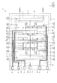
図1に示す角速度センサー1は、Z軸まわりの角速度ωzを検出することのできる角速度センサーである。角速度センサー1は、基板2と、蓋体3と、素子部4と、を有している。   An angular velocity sensor 1 shown in FIG. 1 is an angular velocity sensor that can detect an angular velocity ωz around the Z axis. The angular velocity sensor 1 includes a substrate 2, a lid 3, and an element unit 4.

図1に示すように、基板2は、Z軸方向からの平面視で、矩形の平面視形状を有する板状をなしている。また、基板2は、上側の面である上面に開放する凹部21を有している。凹部21は、素子部4と基板2との接触を防止(抑制)するための逃げ部として機能する。また、基板2は、凹部21の底面から突出する複数のマウント22(221,222,223,224,225)を有している。そして、これらマウント22の上面に素子部4が接合されている。これにより、基板2との接触が防止された状態で、基板2に素子部4を固定することができる。また、基板2は、上面に開放する溝部23,24,25,26,27,28を有している。   As shown in FIG. 1, the board | substrate 2 has comprised the plate shape which has a rectangular planar view shape by planar view from a Z-axis direction. The substrate 2 also has a recess 21 that opens to the upper surface, which is the upper surface. The concave portion 21 functions as a relief portion for preventing (suppressing) the contact between the element portion 4 and the substrate 2. The substrate 2 has a plurality of mounts 22 (221, 222, 223, 224, 225) that protrude from the bottom surface of the recess 21. The element unit 4 is bonded to the upper surface of these mounts 22. Thereby, the element part 4 can be fixed to the board | substrate 2 in the state in which the contact with the board | substrate 2 was prevented. Further, the substrate 2 has groove portions 23, 24, 25, 26, 27, and 28 opened on the upper surface.

基板2としては、例えば、ナトリウムイオン(Na+)、リチウムイオン(Li+)等の可動イオン(アルカリ金属イオン、以下Na+で代表する)を含むガラス材料(例えば、テンパックス(登録商標)ガラス、パイレックス(登録商標)ガラスのような硼珪酸ガラス)で構成されたガラス基板を用いることができる。これにより、例えば、後述するように、基板2と素子部4とを陽極接合することができ、これらを強固に接合することができる。また、光透過性を有する基板2が得られるため、角速度センサー1の外側から、基板2を介して素子部4の状態を視認することができる。ただし、基板2の構成材料としては、特に限定されず、シリコン基板、セラミックス基板等を用いてもよい。   As the substrate 2, for example, a glass material (for example, Tempax (registered trademark) glass, Pyrex (which includes alkali metal ions, hereinafter represented by Na +)) such as sodium ions (Na +) and lithium ions (Li +) is used. (Registered trademark) glass substrate made of borosilicate glass such as glass) can be used. Accordingly, for example, as described later, the substrate 2 and the element portion 4 can be anodically bonded, and these can be firmly bonded. In addition, since the substrate 2 having optical transparency is obtained, the state of the element portion 4 can be visually recognized through the substrate 2 from the outside of the angular velocity sensor 1. However, the constituent material of the substrate 2 is not particularly limited, and a silicon substrate, a ceramic substrate, or the like may be used.

図1に示すように、溝部23,24,25,26,27,28には、それぞれ、配線73,74,75,76,77,78が配置されている。配線73,74,75,76,77,78は、それぞれ、素子部4と電気的に接続されている。また、配線73,74,75,76,77,78の一端部は、それぞれ、蓋体3の外側に露出し、外部装置との電気的な接続を行う電極パッドPとして機能する。   As shown in FIG. 1, wirings 73, 74, 75, 76, 77, and 78 are disposed in the groove portions 23, 24, 25, 26, 27, and 28, respectively. The wirings 73, 74, 75, 76, 77, and 78 are electrically connected to the element unit 4, respectively. Further, one end portions of the wirings 73, 74, 75, 76, 77, and 78 are exposed to the outside of the lid 3 and function as electrode pads P that are electrically connected to an external device.

図1に示すように、蓋体3は、Z軸方向からの平面視で、矩形の平面視形状を有する板状をなしている。また、図2に示すように、蓋体3は、下面に開放する凹部31を有している。蓋体3は、凹部31内に素子部4を収納するようにして、基板2の上面に接合されている。そして、蓋体3および基板2によって、その内側に、素子部4を収納する収納空間Sが形成されている。   As shown in FIG. 1, the lid body 3 has a plate shape having a rectangular plan view shape in plan view from the Z-axis direction. Moreover, as shown in FIG. 2, the cover body 3 has the recessed part 31 opened to the lower surface. The lid 3 is bonded to the upper surface of the substrate 2 so that the element portion 4 is accommodated in the recess 31. A storage space S for storing the element portion 4 is formed inside the cover 3 and the substrate 2.

また、図2に示すように、蓋体3は、収納空間Sの内外を連通する連通孔32を有している。そのため、連通孔32を介して、収納空間Sを所望の雰囲気に置換することができる。また、連通孔32内には封止部材33が配置され、封止部材33によって連通孔32が気密封止されている。なお、収納空間Sは、減圧状態、特に真空状態であることが好ましい。これにより、粘性抵抗が減り、素子部4を効率的に振動させることができる。   Further, as shown in FIG. 2, the lid 3 has a communication hole 32 that communicates the inside and outside of the storage space S. Therefore, the storage space S can be replaced with a desired atmosphere via the communication hole 32. A sealing member 33 is disposed in the communication hole 32, and the communication hole 32 is hermetically sealed by the sealing member 33. The storage space S is preferably in a reduced pressure state, particularly in a vacuum state. Thereby, viscous resistance decreases and the element part 4 can be vibrated efficiently.

このような蓋体3としては、例えば、シリコン基板を用いることができる。ただし、蓋体3としては、特に限定されず、例えば、ガラス基板やセラミックス基板を用いてもよい。また、基板2と蓋体3との接合方法としては、特に限定されず、基板2や蓋体3の材料によって適宜選択すればよいが、例えば、陽極接合、プラズマ照射によって活性化させた接合面同士を接合させる活性化接合、ガラスフリット等の接合材による接合、基板2の上面および蓋体3の下面に成膜した金属膜同士を接合する拡散接合等が挙げられる。本実施形態では、ガラスフリット39(低融点ガラス)を介して基板2と蓋体3とが接合されている。   As such a lid 3, for example, a silicon substrate can be used. However, the lid 3 is not particularly limited, and for example, a glass substrate or a ceramic substrate may be used. Moreover, it does not specifically limit as a joining method of the board | substrate 2 and the cover body 3, What is necessary is just to select suitably according to the material of the board | substrate 2 and the cover body 3, For example, the joining surface activated by anodic bonding and plasma irradiation Examples include activation bonding for bonding together, bonding with a bonding material such as glass frit, diffusion bonding for bonding metal films formed on the upper surface of the substrate 2 and the lower surface of the lid 3, and the like. In the present embodiment, the substrate 2 and the lid 3 are bonded via a glass frit 39 (low melting point glass).

素子部4は、収納空間Sに配置されており、マウント22の上面に接合されている。素子部4は、例えば、リン(P)、ボロン(B)等の不純物がドープされた導電性のシリコン基板をドライエッチング法(シリコンディープエッチング)によってパターニングすることで形成することができる。以下、素子部4について詳細に説明する。なお、以下では、Z軸方向からの平面視で、素子部4の中心Oと交わり、Y軸方向に延びる直線を「仮想直線α」とも言う。   The element unit 4 is disposed in the storage space S and is joined to the upper surface of the mount 22. The element part 4 can be formed, for example, by patterning a conductive silicon substrate doped with impurities such as phosphorus (P) and boron (B) by a dry etching method (silicon deep etching). Hereinafter, the element unit 4 will be described in detail. In the following, a straight line that intersects with the center O of the element unit 4 and extends in the Y-axis direction in plan view from the Z-axis direction is also referred to as a “virtual straight line α”.

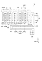
図3に示すように、素子部4の形状は、仮想直線αに対して対称である。また、素子部4は、仮想直線αの両側に配置された駆動部41A,41Bを有している。駆動部41A,41Bは、検出電極としての検出部44A,44Bを駆動可能であり、駆動部41Aは、可動電極部として、櫛歯状の可動駆動電極411Aと、櫛歯状をなし可動駆動電極411Aと空隙を有して互い違いに配置された固定駆動電極412Aと、を有している。同様に、駆動部41Bは、可動電極部として、櫛歯状の可動駆動電極411Bと、櫛歯状をなし可動駆動電極411Bと空隙を有して互い違いに配置された固定駆動電極412Bと、を有している。   As shown in FIG. 3, the shape of the element unit 4 is symmetric with respect to the virtual straight line α. The element unit 4 includes driving units 41A and 41B arranged on both sides of the virtual straight line α. The drive units 41A and 41B can drive the detection units 44A and 44B as detection electrodes. The drive unit 41A has a comb-like movable drive electrode 411A and a comb-like movable drive electrode as the movable electrode unit. 411A and fixed drive electrodes 412A that are alternately arranged with gaps. Similarly, the drive unit 41B includes, as movable electrode units, a comb-like movable drive electrode 411B, and a comb-like movable drive electrode 411B and fixed drive electrodes 412B alternately arranged with gaps. Have.

また、固定駆動電極412Aは、可動駆動電極411Aよりも外側(仮想直線αから遠い側)に位置し、固定駆動電極412Bは、可動駆動電極411Bよりも外側(仮想直線αから遠い側)に位置している。また、固定駆動電極412A,412Bは、それぞれ、マウント221の上面に接合され、基板2に固定されている。また、可動駆動電極411A,411Bは、それぞれ、配線73と電気的に接続されており、固定駆動電極412A,412Bは、それぞれ、配線74と電気的に接続されている。   In addition, the fixed drive electrode 412A is located outside the movable drive electrode 411A (the side far from the virtual straight line α), and the fixed drive electrode 412B is located outside the movable drive electrode 411B (the side far from the virtual straight line α). doing. The fixed drive electrodes 412A and 412B are bonded to the upper surface of the mount 221 and fixed to the substrate 2, respectively. The movable drive electrodes 411A and 411B are electrically connected to the wiring 73, and the fixed drive electrodes 412A and 412B are electrically connected to the wiring 74, respectively.

また、素子部4は、駆動部41Aの周囲に配置された四つの固定部(第1固定部42A、第2固定部421A)と、駆動部41Bの周囲に配置された四つの固定部(第1固定部42B、第2固定部421B)と、を有している。そして、第1固定部42A,42Bおよび第2固定部421A,421Bは、マウント222の上面に接合され、基板2に固定されている。   The element unit 4 includes four fixing portions (first fixing portion 42A and second fixing portion 421A) arranged around the driving portion 41A and four fixing portions (first fixing portions) arranged around the driving portion 41B. 1 fixing part 42B, 2nd fixing part 421B). The first fixing portions 42A and 42B and the second fixing portions 421A and 421B are bonded to the upper surface of the mount 222 and fixed to the substrate 2.

また、素子部4は、第1固定部42Aおよび第2固定部421Aと可動駆動電極411Aとを連結する四つの駆動ばね43Aと、第1固定部42Bおよび第2固定部421Bと可動駆動電極411Bとを連結する四つの駆動ばね43Bと、を有している。各駆動ばね43AがX軸方向に弾性変形することで可動駆動電極411AのX軸方向への変位が許容され、各駆動ばね43BがX軸方向に弾性変形することで可動駆動電極411BのX軸方向への変位が許容される。   The element section 4 includes four drive springs 43A that connect the first fixed section 42A and the second fixed section 421A and the movable drive electrode 411A, the first fixed section 42B, the second fixed section 421B, and the movable drive electrode 411B. And four drive springs 43B for connecting the two. Each drive spring 43A is elastically deformed in the X-axis direction to allow displacement of the movable drive electrode 411A in the X-axis direction, and each drive spring 43B is elastically deformed in the X-axis direction to allow the X-axis of the movable drive electrode 411B. Displacement in the direction is allowed.

配線73,74を介して可動駆動電極411A,411Bと固定駆動電極412A,412Bとの間に駆動電圧を印加すると、可動駆動電極411Aと固定駆動電極412Aとの間および可動駆動電極411Bと固定駆動電極412Bとの間にそれぞれ静電引力が発生する。この静電引力により、可動駆動電極411Aが駆動ばね43AをX軸方向に弾性変形させつつX軸方向に振動すると共に、可動駆動電極411Bが駆動ばね43BをX軸方向に弾性変形させつつX軸方向に振動する。駆動部41A,41Bは、仮想直線αに対して対称的に配置されているため、可動駆動電極411A,411Bは、互いに接近、離間を繰り返すようにX軸方向に逆相で振動する。そのため、可動駆動電極411A,411Bの振動がキャンセルされ、振動漏れを低減することができる。以下では、この振動モードを「駆動振動モード」とも言う。   When a drive voltage is applied between the movable drive electrodes 411A and 411B and the fixed drive electrodes 412A and 412B via the wirings 73 and 74, the movable drive electrode 411A and the fixed drive electrode 412A and the movable drive electrode 411B and the fixed drive are fixed. An electrostatic attractive force is generated between each electrode 412B. Due to this electrostatic attraction, the movable drive electrode 411A vibrates in the X-axis direction while elastically deforming the drive spring 43A in the X-axis direction, and the movable drive electrode 411B causes the drive spring 43B to elastically deform in the X-axis direction and the X-axis. Vibrate in the direction. Since the drive units 41A and 41B are arranged symmetrically with respect to the virtual straight line α, the movable drive electrodes 411A and 411B vibrate in opposite phases in the X-axis direction so as to repeatedly approach and separate from each other. Therefore, the vibrations of the movable drive electrodes 411A and 411B are canceled and vibration leakage can be reduced. Hereinafter, this vibration mode is also referred to as “drive vibration mode”.

なお、本実施形態の角速度センサー1では、静電引力によって駆動振動モードを励振させる静電駆動方式となっているが、駆動振動モードを励振させる方式としては、特に限定されず、例えば、圧電駆動方式、磁場のローレンツ力を利用した電磁駆動方式等を適用することもできる。   The angular velocity sensor 1 according to the present embodiment employs an electrostatic drive method in which the drive vibration mode is excited by electrostatic attraction. However, the method for exciting the drive vibration mode is not particularly limited. A method, an electromagnetic drive method using a Lorentz force of a magnetic field, or the like can also be applied.

また、素子部4は、駆動部41A,41Bの間に配置された検出部44A,44Bを有している。検出部44Aは、第1検出電極としての櫛歯状の可動検出電極441Aと、櫛歯状をなし可動検出電極441Aと空隙を有して互い違いに配置された第2検出電極としての固定検出電極442A,443Aと、を有している。固定検出電極442A,443Aは、Y軸方向に並んで配置され、可動検出電極441Aの中心に対してY軸方向プラス側に固定検出電極442Aが位置し、Y軸方向マイナス側に固定検出電極443Aが位置している。また、固定検出電極442A,443Aは、それぞれ、可動検出電極441AをX軸方向両側から挟み込むようにして一対配置されている。   The element unit 4 includes detection units 44A and 44B disposed between the drive units 41A and 41B. The detection unit 44A includes a comb-like movable detection electrode 441A serving as a first detection electrode, and fixed detection electrodes serving as second detection electrodes arranged in a staggered manner with a comb-like movable detection electrode 441A and a gap. 442A, 443A. The fixed detection electrodes 442A and 443A are arranged side by side in the Y-axis direction, the fixed detection electrode 442A is positioned on the positive side in the Y-axis direction with respect to the center of the movable detection electrode 441A, and the fixed detection electrode 443A is on the negative side in the Y-axis direction. Is located. A pair of fixed detection electrodes 442A and 443A are arranged so as to sandwich the movable detection electrode 441A from both sides in the X-axis direction.

同様に、検出部44Bは、第1検出電極としての櫛歯状の可動検出電極441Bと、櫛歯状をなし可動検出電極441Bと空隙を有して互い違いに配置された第2検出電極としての固定検出電極442B,443Bと、を有している。固定検出電極442B,443Bは、Y軸方向に並んで配置され、可動検出電極441Bの中心に対してY軸方向プラス側に固定検出電極442Bが位置し、Y軸方向マイナス側に固定検出電極443Bが位置している。また、固定検出電極442B,443Bは、それぞれ、可動検出電極441BをX軸方向の両側から挟み込むようにして一対配置されている。   Similarly, the detection unit 44B includes a comb-like movable detection electrode 441B as a first detection electrode, and second detection electrodes arranged in a staggered manner with a comb-like movable detection electrode 441B and a gap. Fixed detection electrodes 442B and 443B. The fixed detection electrodes 442B and 443B are arranged side by side in the Y-axis direction, the fixed detection electrode 442B is located on the positive side in the Y-axis direction with respect to the center of the movable detection electrode 441B, and the fixed detection electrode 443B is on the negative side in the Y-axis direction. Is located. A pair of fixed detection electrodes 442B and 443B are arranged so as to sandwich the movable detection electrode 441B from both sides in the X-axis direction.

可動検出電極441A,441Bは、それぞれ、配線73と電気的に接続され、固定検出電極442A,443Bは、それぞれ、配線75と電気的に接続され、固定検出電極443A,442Bは、それぞれ、配線76と電気的に接続されている。角速度センサー1の駆動時には、可動検出電極441Aと固定検出電極442Aとの間および可動検出電極441Bと固定検出電極443Bとの間に静電容量Caが形成され、可動検出電極441Aと固定検出電極443Aとの間および可動検出電極441Bと固定検出電極442Bとの間に静電容量Cbが形成される。   The movable detection electrodes 441A and 441B are electrically connected to the wiring 73, the fixed detection electrodes 442A and 443B are electrically connected to the wiring 75, and the fixed detection electrodes 443A and 442B are respectively connected to the wiring 76. And are electrically connected. When the angular velocity sensor 1 is driven, a capacitance Ca is formed between the movable detection electrode 441A and the fixed detection electrode 442A and between the movable detection electrode 441B and the fixed detection electrode 443B, and the movable detection electrode 441A and the fixed detection electrode 443A. And a capacitance Cb is formed between the movable detection electrode 441B and the fixed detection electrode 442B.

また、素子部4は、検出部44A,44Bの間に配置された二つの第1固定部451,452を有している。第1固定部451,452は、それぞれ、マウント224の上面に接合され、基板2に固定されている。第1固定部451,452は、Y軸方向に並び、間隔を空けて配置されている。なお、本実施形態では、第1固定部451,452を介して可動駆動電極411A,411Bや可動検出電極441A,441Bが配線73と電気的に接続されている。   The element unit 4 includes two first fixing units 451 and 452 arranged between the detection units 44A and 44B. The first fixing portions 451 and 452 are respectively bonded to the upper surface of the mount 224 and fixed to the substrate 2. The first fixing portions 451 and 452 are arranged in the Y-axis direction and spaced apart. In the present embodiment, the movable drive electrodes 411A and 411B and the movable detection electrodes 441A and 441B are electrically connected to the wiring 73 via the first fixed portions 451 and 452.

また、素子部4は、可動検出電極441Aと第1固定部42A,451,452とを接続する四つのばね部としての検出ばね46Aと、可動検出電極441Bと第1固定部42B,451,452とを接続する四つのばね部としての検出ばね46Bと、を有している。各検出ばね46AがX軸方向に弾性変形することで可動検出電極441AのX軸方向への変位が許容され、Y軸方向に弾性変形することで可動検出電極441AのY軸方向への変位が許容される。同様に、各検出ばね46BがX軸方向に弾性変形することで可動検出電極441BのX軸方向への変位が許容され、Y軸方向に弾性変形することで可動検出電極441BのY軸方向への変位が許容される。   Further, the element section 4 includes a detection spring 46A as four spring sections connecting the movable detection electrode 441A and the first fixed sections 42A, 451, 452, and the movable detection electrode 441B and the first fixed sections 42B, 451, 452. And a detection spring 46B as four spring portions. When each detection spring 46A is elastically deformed in the X-axis direction, displacement of the movable detection electrode 441A in the X-axis direction is allowed, and by elastic deformation in the Y-axis direction, displacement of the movable detection electrode 441A in the Y-axis direction is allowed. Permissible. Similarly, each detection spring 46B is elastically deformed in the X-axis direction to allow displacement of the movable detection electrode 441B in the X-axis direction. By elastic deformation in the Y-axis direction, the movable detection electrode 441B is moved in the Y-axis direction. Displacement of is acceptable.

従って、Z軸まわりの角速度ωzによって、可動検出電極441A,441Bが変位する検出軸方向である第2方向(Y軸方向)へ変位可能となり、Z軸まわりの角速度ωzを検出することができる。   Therefore, the angular velocity ωz around the Z axis can be displaced in the second direction (Y-axis direction), which is the detection axis direction in which the movable detection electrodes 441A and 441B are displaced, and the angular velocity ωz around the Z axis can be detected.

また、図4に示すように、検出部44Bは、櫛歯状に配置された複数の第1電極指としての可動検出電極指51を備えた可動検出電極441Bと、櫛歯状に配置された複数の第2電極指としての固定検出電極指53を備え可動検出電極441Bの可動検出電極指51と空隙を有して互い違いに配置された固定検出電極443Bと、を有している。   Further, as shown in FIG. 4, the detection unit 44B is arranged in a comb-teeth shape with a movable detection electrode 441B having movable detection electrode fingers 51 as a plurality of first electrode fingers arranged in a comb-teeth shape. The movable detection electrode fingers 431B of the movable detection electrode 441B are provided with a plurality of fixed detection electrode fingers 53 as second electrode fingers, and fixed detection electrodes 443B arranged alternately with gaps.

固定検出電極443Bは、第1方向(X軸方向)に沿って延在して設けられている複数の固定検出電極指53を有している。また、可動検出電極441Bは、第2方向(Y軸方向)に沿って延在して設けられている第1幹部50と、第1幹部50からX軸方向に沿って延在して設けられ、固定検出電極指53とY軸方向に間隔を空けて配置される複数の可動検出電極指51と、第1幹部50に連結する第1連結部52と、を有している。   The fixed detection electrode 443B has a plurality of fixed detection electrode fingers 53 provided so as to extend along the first direction (X-axis direction). In addition, the movable detection electrode 441B is provided to extend along the second direction (Y-axis direction) and the first trunk 50, and to extend from the first trunk 50 along the X-axis direction. , A fixed detection electrode finger 53, a plurality of movable detection electrode fingers 51 arranged at intervals in the Y-axis direction, and a first connection portion 52 connected to the first trunk portion 50.

さらに、第1連結部52は、第1幹部50に連結する第1支持部521と、検出ばね46Bに連結する第2支持部522と、を有しており、第1支持部521と固定検出電極443BとのY軸方向の間隔は、第2支持部522と固定検出電極443BとのY軸方向の間隔より小さい。つまり、第1支持部521は、第2支持部522よりも固定検出電極443B側に近接して配置されている。なお、第2支持部522が設けられていることにより、検出ばね46Bを長くすることができ、可動検出電極441Bをより変位し易くすることができる。   Further, the first connecting part 52 has a first support part 521 connected to the first trunk part 50 and a second support part 522 connected to the detection spring 46B, and the first support part 521 and the fixed detection are detected. The distance between the electrode 443B in the Y-axis direction is smaller than the distance between the second support portion 522 and the fixed detection electrode 443B in the Y-axis direction. That is, the first support portion 521 is disposed closer to the fixed detection electrode 443B side than the second support portion 522. By providing the second support portion 522, the detection spring 46B can be lengthened, and the movable detection electrode 441B can be more easily displaced.

また、第1支持部521のX軸方向の長さが、可動検出電極指51のX軸方向の長さと略等しい。そのため、第1支持部521の側面と固定検出電極指53の側面との対向面積が可動検出電極指51の側面と固定検出電極指53の側面との対向面積と等しくすることができる。   The length of the first support portion 521 in the X-axis direction is substantially equal to the length of the movable detection electrode finger 51 in the X-axis direction. Therefore, the facing area between the side surface of the first support portion 521 and the side surface of the fixed detection electrode finger 53 can be made equal to the facing area between the side surface of the movable detection electrode finger 51 and the side surface of the fixed detection electrode finger 53.

第1支持部521と固定検出電極443BとのY軸方向の間隔が、固定検出電極指53と可動検出電極指51とのY軸方向の間隔と略等しい。つまり、対向面積も略等しいため、第1支持部521と固定検出電極443Bと間の静電容量と、固定検出電極指53と可動検出電極指51との間の静電容量と、を等しくすることができる。   The distance in the Y-axis direction between the first support portion 521 and the fixed detection electrode 443B is substantially equal to the distance in the Y-axis direction between the fixed detection electrode finger 53 and the movable detection electrode finger 51. That is, since the opposing areas are substantially equal, the capacitance between the first support portion 521 and the fixed detection electrode 443B and the capacitance between the fixed detection electrode finger 53 and the movable detection electrode finger 51 are made equal. be able to.

従って、第1支持部521と固定検出電極443Bとが一対の固定検出電極指53と可動検出電極指51とに相当するので、第1支持部521を可動検出電極指51と見なすことができ、検出部44BのY軸方向の寸法を変えずに可動検出電極指51を増やすことができる。つまり、可動検出電極441Bと固定検出電極443Bとの間の静電容量を大きくすることができ、検出感度を向上させることができる。また、同等の検出感度を有して小型化を図ることもできる。   Therefore, since the first support portion 521 and the fixed detection electrode 443B correspond to a pair of fixed detection electrode fingers 53 and the movable detection electrode finger 51, the first support portion 521 can be regarded as the movable detection electrode finger 51, The movable detection electrode fingers 51 can be increased without changing the dimension of the detection unit 44B in the Y-axis direction. That is, the capacitance between the movable detection electrode 441B and the fixed detection electrode 443B can be increased, and the detection sensitivity can be improved. In addition, it is possible to reduce the size with the same detection sensitivity.

検出ばね46Bは、第2方向(Y軸方向)に沿って延在する長手形状と、可動検出電極441Bの中心側に折り返し部461とを有し、第1固定部42Bに固定されて第1方向(X軸方向)に弾性変形することができる。また、検出ばね46Bは、第1方向(X軸方向)に沿って延在する長手形状と、可動検出電極441Bの端部側に折り返し部462とを有し、可動検出電極441Bの端部54と接続されて第2方向(Y軸方向)に弾性変形することができる。   The detection spring 46B has a longitudinal shape extending along the second direction (Y-axis direction) and a folded portion 461 on the center side of the movable detection electrode 441B, and is fixed to the first fixing portion 42B and fixed to the first. It can be elastically deformed in the direction (X-axis direction). Further, the detection spring 46B has a longitudinal shape extending along the first direction (X-axis direction) and a folded portion 462 on the end portion side of the movable detection electrode 441B, and the end portion 54 of the movable detection electrode 441B. And can be elastically deformed in the second direction (Y-axis direction).

固定検出電極443Bは、X軸方向において、可動検出電極441Bよりもばね部としての検出ばね46B側に配置され、検出ばね46Bと対向する検出電極としての検出部44B(固定検出電極443B)の第1面445と、Y軸方向において、第1面445より可動検出電極441Bの中心側に設けられた検出部44B(固定検出電極443B)の第2面446と、を有している。検出部44B(固定検出電極443B)の第1面445と検出ばね46BとのX軸方向の間隔G1は、検出部44B(固定検出電極443B)の第2面446と検出ばね46BとのX軸方向の間隔G2より大きい。つまり、X軸方向において、第1面445よりも第2面446が検出ばね46Bに近い。   The fixed detection electrode 443B is arranged on the detection spring 46B side as the spring portion with respect to the movable detection electrode 441B in the X-axis direction, and the detection portion 44B (fixed detection electrode 443B) as the detection electrode facing the detection spring 46B. And a second surface 446 of a detection unit 44B (fixed detection electrode 443B) provided on the center side of the movable detection electrode 441B from the first surface 445 in the Y-axis direction. The distance G1 between the first surface 445 of the detection unit 44B (fixed detection electrode 443B) and the detection spring 46B is the X axis between the second surface 446 of the detection unit 44B (fixed detection electrode 443B) and the detection spring 46B. It is larger than the direction gap G2. That is, the second surface 446 is closer to the detection spring 46B than the first surface 445 in the X-axis direction.

また、検出ばね46Bは、第1方向(X軸方向)の平面視で、第1面445と重なる領域よりも第2面446と重なる領域の方が小さい。さらに、検出ばね46Bの折り返し部461よりも検出ばね46Bの折り返し部461とは反対側の長手形状の端部側で互いの間隔が大きく離れて設けられている。これにより、固定検出電極443Bに対して変位量が小さい検出ばね46Bの折り返し部461に固定検出電極443Bをより近接して配置することができる。そして、固定検出電極443Bに対して変位量が大きい検出ばね46Bの折り返し部461とは反対側の長手形状の端部側から固定検出電極443Bを大きく離すことができ、検出ばね46Bをより変位し易くすることができる。そのため、可動検出電極441Bを大きく変位させることができ、検出感度を向上させることができる。従って、小型化を図っても、検出感度の低下を低減した角速度センサー1を得ることができる。   The detection spring 46B has a smaller area overlapping the second surface 446 than the area overlapping the first surface 445 in plan view in the first direction (X-axis direction). Further, the distance between the detection spring 46B and the end portion of the longitudinal shape opposite to the return portion 461 of the detection spring 46B is larger than the return portion 461 of the detection spring 46B. Accordingly, the fixed detection electrode 443B can be disposed closer to the folded portion 461 of the detection spring 46B having a small displacement with respect to the fixed detection electrode 443B. Then, the fixed detection electrode 443B can be largely separated from the end of the longitudinal shape opposite to the folded portion 461 of the detection spring 46B having a large displacement with respect to the fixed detection electrode 443B, and the detection spring 46B is further displaced. Can be made easier. Therefore, the movable detection electrode 441B can be greatly displaced, and the detection sensitivity can be improved. Therefore, the angular velocity sensor 1 can be obtained in which the decrease in detection sensitivity is reduced even if the size is reduced.

さらに、固定検出電極443Bは、第3固定部447を介して基板2に固定されている。第3固定部447は、Z軸方向からの平面視において、固定検出電極443Bに包含され、固定検出電極443Bの第2面446の一部と対向して設けられている。つまり、第3固定部447は、間隔G2より大きい間隔G1を確保するために面積を小さくした第1面445で形成される領域ではなく、より広い第2面446で形成される領域に設けられている。これにより、第3固定部447の周囲をより太く囲うことができるので、Z軸方向に大きな衝撃を受けた時に、固定検出電極443Bが第3固定部447と接続する境界に応力がかかったとしても、破損されるのを抑制することができる。   Further, the fixed detection electrode 443B is fixed to the substrate 2 via the third fixing portion 447. The third fixing portion 447 is included in the fixed detection electrode 443B in a plan view from the Z-axis direction, and is provided to face a part of the second surface 446 of the fixed detection electrode 443B. That is, the third fixing portion 447 is provided not in a region formed by the first surface 445 having a reduced area in order to ensure a gap G1 larger than the gap G2, but in a region formed by a wider second surface 446. ing. As a result, the periphery of the third fixing portion 447 can be surrounded more thickly, so that stress is applied to the boundary where the fixed detection electrode 443B connects to the third fixing portion 447 when receiving a large impact in the Z-axis direction. Can be prevented from being damaged.

なお、本実施形態では、図3に示すように、検出部44BのY軸方向の両端において、−Y軸方向の端部で、且つ、−X軸方向の端部を一例として挙げ説明したが、検出部44Bの−Y軸方向の端部で、+X軸方向の端部、検出部44Bの+Y軸方向の端部で、X軸方向の両端、および検出部44AのY軸方向の両端で、X軸方向の両端においても同様の構成となっている。   In the present embodiment, as illustrated in FIG. 3, the end portion in the −Y axis direction and the end portion in the −X axis direction are described as an example at both ends in the Y axis direction of the detection unit 44 </ b> B. The end of the detection unit 44B in the −Y-axis direction, the end of the + X-axis direction, the end of the detection unit 44B in the + Y-axis direction, both ends in the X-axis direction, and both ends of the detection unit 44A in the Y-axis direction. The same configuration is provided at both ends in the X-axis direction.

さらに、素子部4は、駆動部41Aと検出部44Aとの間に位置し、可動駆動電極411Aと可動検出電極441Aとを接続する逆相ばね47Aと、駆動部41Bと検出部44Bとの間に位置し、可動駆動電極411Bと可動検出電極441Bとを接続する逆相ばね47Bと、を有している。可動検出電極441Aは、逆相ばね47AがX軸方向に弾性変形することで可動駆動電極411Aに対してX軸方向に変位することができる。同様に、可動検出電極441Bは、逆相ばね47BがX軸方向に弾性変形することで可動駆動電極411Bに対してX軸方向に変位することができる。   Further, the element unit 4 is positioned between the drive unit 41A and the detection unit 44A, and is connected between the reverse-phase spring 47A that connects the movable drive electrode 411A and the movable detection electrode 441A, and between the drive unit 41B and the detection unit 44B. And a reverse-phase spring 47B that connects the movable drive electrode 411B and the movable detection electrode 441B. The movable detection electrode 441A can be displaced in the X-axis direction with respect to the movable drive electrode 411A by the elastic deformation of the anti-phase spring 47A in the X-axis direction. Similarly, the movable detection electrode 441B can be displaced in the X-axis direction with respect to the movable drive electrode 411B by the elastic deformation of the reverse phase spring 47B in the X-axis direction.

図5に示すように、逆相ばね47Aは、ばね本体471Aと、ばね本体471Aと可動駆動電極411Aとを連結する梁477Aと、ばね本体471Aと可動検出電極441Aとを連結する梁478Aと、を有している。また、ばね本体471Aは、Y軸方向に延在する形状をなし、X軸方向に弾性変形可能なアーム472Aと、Y軸方向に延在する形状をなし、X軸方向に弾性変形可能なアーム473Aと、を有している。アーム472A,473Aは、X軸方向に隙間を空けて配置され、アーム472Aの中央部に梁477Aが接続され、アーム473Aの中央部に梁478Aが接続されている。また、ばね本体471Aは、アーム472A,473Aの一端部同士を接続する接続部474Aと、アーム472A,473Aの他端部同士を接続する接続部475Aと、を有している。したがって、ばね本体471Aは、中央部が開口する枠状となっている。   As shown in FIG. 5, the reverse-phase spring 47A includes a spring body 471A, a beam 477A that connects the spring body 471A and the movable drive electrode 411A, a beam 478A that connects the spring body 471A and the movable detection electrode 441A, have. The spring body 471A has a shape extending in the Y-axis direction and elastically deformable in the X-axis direction, and an arm extending in the Y-axis direction and elastically deformable in the X-axis direction. 473A. The arms 472A and 473A are arranged with a gap in the X-axis direction, the beam 477A is connected to the center of the arm 472A, and the beam 478A is connected to the center of the arm 473A. Further, the spring body 471A has a connecting portion 474A that connects one end portions of the arms 472A and 473A and a connecting portion 475A that connects the other end portions of the arms 472A and 473A. Therefore, the spring main body 471A has a frame shape with an open center.

逆相ばね47Bは、逆相ばね47Aと同様の構成であり、図6に示すように、ばね本体471Bと、ばね本体471Bと可動駆動電極411Bとを連結する梁477Bと、ばね本体471Bと可動検出電極441Bとを連結する梁478Bと、を有している。   The reverse-phase spring 47B has the same configuration as the reverse-phase spring 47A. As shown in FIG. 6, the spring body 471B, the beam 477B connecting the spring body 471B and the movable drive electrode 411B, and the spring body 471B are movable. And a beam 478B connecting the detection electrode 441B.

ここで、図7に示すように、駆動振動モードでは、可動駆動電極411Aの振動が逆相ばね47Aを介して可動検出電極441Aに伝わるため、可動検出電極441Aは、可動駆動電極411Aの振動に連動してX軸方向に振動する。同様に、可動駆動電極411Bの振動が逆相ばね47Bを介して可動検出電極441Bに伝わるため、可動検出電極441Bは、可動駆動電極411Bの振動に連動してX軸方向に振動する。また、前述したように、可動駆動電極411A,411BがX軸方向に逆相で振動するため、可動検出電極441A,441Bも、互いに接近、離間を繰り返すようにX軸方向に逆相で振動する。そのため、可動検出電極441A,441Bの振動がキャンセルされ、基板2への振動漏れを低減することができる。   Here, as shown in FIG. 7, in the drive vibration mode, the vibration of the movable drive electrode 411A is transmitted to the movable detection electrode 441A via the reverse-phase spring 47A. Therefore, the movable detection electrode 441A is driven by the vibration of the movable drive electrode 411A. Interlocks and vibrates in the X-axis direction. Similarly, since the vibration of the movable drive electrode 411B is transmitted to the movable detection electrode 441B via the reverse-phase spring 47B, the movable detection electrode 441B vibrates in the X-axis direction in conjunction with the vibration of the movable drive electrode 411B. Further, as described above, since the movable drive electrodes 411A and 411B vibrate in the opposite phase in the X-axis direction, the movable detection electrodes 441A and 441B also vibrate in the opposite phase in the X-axis direction so as to repeatedly approach and separate from each other. . Therefore, the vibration of the movable detection electrodes 441A and 441B is canceled, and vibration leakage to the substrate 2 can be reduced.

さらに、駆動振動モードでは、逆相ばね47Aの弾性変形を利用して、可動検出電極441Aは、可動駆動電極411Aと接近、離間を繰り返すようにX軸方向に逆相で振動する。同様に、逆相ばね47Bの弾性変形を利用して、可動検出電極441Bは、可動駆動電極411Bと接近、離間を繰り返すようにX軸方向に逆相で振動する。これにより、可動検出電極441Aと可動駆動電極411Aの振動の少なくとも一部がキャンセルされると共に、可動検出電極441Bと可動駆動電極411Bの振動の少なくとも一部がキャンセルされる。したがって、可動検出電極441Aと可動駆動電極411Aおよび可動検出電極441Bと可動駆動電極411Bがそれぞれ同相で振動する場合と比較して、基板2への振動漏れをより効果的に低減することができる。なお、駆動振動モードで可動検出電極441Aと可動駆動電極411Aとを逆相で振動させるためには、例えば、これらの間にある逆相ばね47Aのばね定数を調整すればよく、可動検出電極441Bと可動駆動電極411Bとを逆相で振動させるためには、例えば、これらの間にある逆相ばね47Bのばね定数を調整すればよい。   Further, in the drive vibration mode, the movable detection electrode 441A vibrates in the opposite phase in the X-axis direction so as to repeatedly approach and separate from the movable drive electrode 411A using the elastic deformation of the reverse-phase spring 47A. Similarly, using the elastic deformation of the reverse-phase spring 47B, the movable detection electrode 441B vibrates in the reverse phase in the X-axis direction so as to repeatedly approach and separate from the movable drive electrode 411B. Thereby, at least a part of the vibrations of the movable detection electrode 441A and the movable drive electrode 411A is canceled, and at least a part of the vibrations of the movable detection electrode 441B and the movable drive electrode 411B is canceled. Therefore, vibration leakage to the substrate 2 can be more effectively reduced as compared with the case where the movable detection electrode 441A and the movable drive electrode 411A and the movable detection electrode 441B and the movable drive electrode 411B vibrate in the same phase. In order to cause the movable detection electrode 441A and the movable drive electrode 411A to vibrate in reverse phase in the drive vibration mode, for example, the spring constant of the reverse phase spring 47A between them may be adjusted, and the movable detection electrode 441B. In order to vibrate the movable drive electrode 411B in the opposite phase, for example, the spring constant of the opposite phase spring 47B between them may be adjusted.

なお、可動検出電極441Aと可動駆動電極411Aおよび可動検出電極441Bと可動駆動電極411Bがそれぞれ逆相で振動する逆相モードの共振周波数f1と、可動検出電極441Aと可動駆動電極411Aおよび可動検出電極441Bと可動駆動電極411Bがそれぞれ同相で振動する同相モードの共振周波数f2と、の差が大きい程、逆相モードで振動させ易く、また、同相モードが結合し難くなる(すなわち、逆相モードが支配的となる)。具体的は、例えば、逆相モードの共振周波数f1が30kHz程度である場合、同相モードの共振周波数f2は、共振周波数から3kHz以上(すなわち、10%以上)離れていることが好ましい。これにより、同相モードが十分に結合し難くなり、より安定して、逆相モードで駆動させることができる。   It should be noted that the movable detection electrode 441A, the movable drive electrode 411A, the movable detection electrode 441B, and the movable drive electrode 411B each have a negative-phase resonance frequency f1, and the movable detection electrode 441A, the movable drive electrode 411A, and the movable detection electrode. The larger the difference between the resonance frequency f2 of the in-phase mode in which 441B and the movable drive electrode 411B vibrate in the same phase, the easier it is to vibrate in the anti-phase mode, and the in-phase mode becomes difficult to couple (that is, the anti-phase mode is Become dominant). Specifically, for example, when the resonance frequency f1 of the anti-phase mode is about 30 kHz, the resonance frequency f2 of the in-phase mode is preferably separated from the resonance frequency by 3 kHz or more (that is, 10% or more). This makes it difficult for the common-mode mode to be sufficiently coupled, so that it can be driven more stably and in the reverse-phase mode.

なお、「可動検出電極441A(441B)と可動駆動電極411A(411B)とを逆相で振動させる」とは、逆相モード以外の振動が結合していない場合はもちろん、逆相モードが支配的であれば、他の振動モード(例えば、前述した同相モード)が結合していてもよい。また、例えば、可動検出電極441Aと可動駆動電極411Aとの振動に位相差がない場合はもちろん、位相差がある場合も含まれる。位相差がない場合とは、例えば、可動駆動電極411AがX軸方向プラス側に変位し出す時刻と可動検出電極441AがX軸方向マイナス側に変位し出す時刻が一致していることを意味する。また、位相差がある場合とは、例えば、可動駆動電極411AがX軸方向プラス側に変位し出す時刻よりも後から可動検出電極441AがX軸方向マイナス側に変位し出すことを意味する。   Note that “vibrating the movable detection electrode 441A (441B) and the movable drive electrode 411A (411B) in reverse phase” means that the reverse phase mode is dominant as well as the case where vibrations other than the reverse phase mode are not coupled. If so, other vibration modes (for example, the common-mode described above) may be coupled. In addition, for example, the case where there is a phase difference as well as the case where there is no phase difference in vibration between the movable detection electrode 441A and the movable drive electrode 411A are included. The case where there is no phase difference means, for example, that the time when the movable drive electrode 411A starts to be displaced toward the X axis direction plus side coincides with the time when the movable detection electrode 441A begins to be displaced toward the X axis direction minus side. . In addition, the case where there is a phase difference means that, for example, the movable detection electrode 441A starts to be displaced to the X axis direction minus side after the time when the movable drive electrode 411A is displaced to the X axis direction plus side.

このような駆動振動モードで駆動させている最中に角速度センサー1に角速度ωzが加わると、可動検出電極441A,441Bは、コリオリの力によって、図7中の矢印Aに示すように、検出ばね46A,46BをY軸方向に弾性変形させつつY軸方向に逆相で振動する(この振動を「検出振動モード」とも言う)。検出振動モードでは、可動検出電極441A,441BがY軸方向に振動するため、可動検出電極441Aと固定検出電極442A,443Aとのギャップおよび可動検出電極441Bと固定検出電極442B,443Bとのギャップがそれぞれ変化し、それに伴って静電容量Ca,Cbがそれぞれ変化する。そのため、静電容量Ca,Cbの変化に基づいて、角速度ωzを求めることができる。   When the angular velocity ωz is applied to the angular velocity sensor 1 during driving in such a driving vibration mode, the movable detection electrodes 441A and 441B are detected by the Coriolis force as shown by an arrow A in FIG. 46A and 46B are elastically deformed in the Y-axis direction and vibrate in the opposite phase in the Y-axis direction (this vibration is also referred to as “detected vibration mode”). In the detection vibration mode, since the movable detection electrodes 441A and 441B vibrate in the Y-axis direction, there are gaps between the movable detection electrode 441A and the fixed detection electrodes 442A and 443A and gaps between the movable detection electrode 441B and the fixed detection electrodes 442B and 443B. The capacitances Ca and Cb change accordingly. Therefore, the angular velocity ωz can be obtained based on changes in the capacitances Ca and Cb.

検出振動モードでは、静電容量Caが大きくなると静電容量Cbが小さくなり、反対に、静電容量Caが小さくなると静電容量Cbが大きくなる。そのため、配線75に接続されたQVアンプから出力される検出信号(静電容量Caの大きさに応じた信号)と、配線76に接続されたQVアンプから出力される検出信号(静電容量Cbの大きさに応じた信号)とを差動演算(減算処理:Ca−Cb)することで、ノイズをキャンセルすることができ、より精度よく角速度ωzを検出することができる。   In the detection vibration mode, the capacitance Cb decreases as the capacitance Ca increases, and conversely, the capacitance Cb increases as the capacitance Ca decreases. Therefore, the detection signal (signal according to the magnitude of the capacitance Ca) output from the QV amplifier connected to the wiring 75 and the detection signal (capacitance Cb) output from the QV amplifier connected to the wiring 76. Noise) can be canceled and the angular velocity ωz can be detected more accurately.

ここで、駆動振動モードでは、逆相ばね47Aの伸縮によって可動検出電極441Aの振幅が可動駆動電極411Aの振幅よりも大きくなり、逆相ばね47Bの伸縮によって可動検出電極441Bの振幅が可動駆動電極411Bの振幅よりも大きくなる。そのため、駆動振動モードでの可動検出電極441A,441Bの振幅を増大させることができ、その分、より大きいコリオリの力が作用する。したがって、角速度ωzの検出感度が向上する。また、小さい駆動力で可動検出電極441A,441Bを大きく振動させることができるため、消費電力を低減することもできる。   Here, in the drive vibration mode, the amplitude of the movable detection electrode 441A becomes larger than the amplitude of the movable drive electrode 411A due to the expansion and contraction of the reverse phase spring 47A, and the amplitude of the movable detection electrode 441B becomes the movable drive electrode due to the expansion and contraction of the reverse phase spring 47B. It becomes larger than the amplitude of 411B. Therefore, the amplitude of the movable detection electrodes 441A and 441B in the drive vibration mode can be increased, and a larger Coriolis force acts accordingly. Therefore, the detection sensitivity of the angular velocity ωz is improved. Further, since the movable detection electrodes 441A and 441B can be vibrated greatly with a small driving force, power consumption can also be reduced.

また、図3に示すように、素子部4は、その中央部(検出部44Aと検出部44Bとの間)に位置するフレーム48を有している。フレーム48は、アルファベットの「H」の輪郭に沿った形状、所謂H形状をなし、Y軸方向プラス側に位置する欠損部481(凹部)と、Y軸方向マイナス側に位置する欠損部482(凹部)と、を有している。そして、欠損部481の内外に亘って第1固定部451が配置されており、欠損部482の内外に亘って第1固定部452が配置されている。これにより、第1固定部451,452をY軸方向に長く形成することができ、その分、基板2との接合面積が増え、基板2と素子部4との接合強度が増す。   As shown in FIG. 3, the element unit 4 includes a frame 48 that is positioned at the center (between the detection unit 44 </ b> A and the detection unit 44 </ b> B). The frame 48 has a shape along the outline of the alphabet “H”, that is, a so-called H shape, and a missing portion 481 (recessed portion) positioned on the Y axis direction plus side and a missing portion 482 ( A recess). And the 1st fixing | fixed part 451 is arrange | positioned over the inside and outside of the defect | deletion part 481, and the 1st fixing | fixed part 452 is arrange | positioned over the inside and outside of the defect | deletion part 482. FIG. As a result, the first fixing portions 451 and 452 can be formed long in the Y-axis direction, and accordingly, the bonding area with the substrate 2 is increased, and the bonding strength between the substrate 2 and the element portion 4 is increased.

また、素子部4は、第1固定部451とフレーム48との間に位置し、これらを接続するフレームばね488と、第1固定部452とフレーム48との間に位置し、これらを接続するフレームばね489と、を有している。   The element part 4 is located between the first fixing part 451 and the frame 48, is located between the frame spring 488 connecting them, and the first fixing part 452 and the frame 48, and connects them. Frame spring 489.

また、素子部4は、フレーム48と可動検出電極441Aとの間に位置し、これらを接続する接続ばね40Aと、フレーム48と可動検出電極441Bとの間に位置し、これらを接続する接続ばね40Bと、を有している。接続ばね40Aは、検出ばね46Aと共に可動検出電極441Aを支持し、接続ばね40Bは、検出ばね46Bと共に可動検出電極441Bを支持している。そのため、可動検出電極441A,441Bを安定した姿勢で支持することができ、可動検出電極441A,441Bの不要振動(スプリアス)を低減することができる。   The element unit 4 is located between the frame 48 and the movable detection electrode 441A, and is connected between the connection spring 40A that connects them, and between the frame 48 and the movable detection electrode 441B, and a connection spring that connects them. 40B. The connection spring 40A supports the movable detection electrode 441A together with the detection spring 46A, and the connection spring 40B supports the movable detection electrode 441B together with the detection spring 46B. Therefore, the movable detection electrodes 441A and 441B can be supported in a stable posture, and unnecessary vibration (spurious) of the movable detection electrodes 441A and 441B can be reduced.

なお、駆動振動モードでは、接続ばね40A,40Bが弾性変形することで可動検出電極441A,441Bや可動駆動電極411A,411Bなどで構成される可動体4A,4Bの振動が許容され、検出振動モードでは、接続ばね40A,40Bおよびフレームばね488,489が弾性変形すると共に、フレーム48が中心Oまわりに回動することで、可動検出電極441A,441BのY軸方向への振動が許容される。   In the drive vibration mode, the connection springs 40A and 40B are elastically deformed, and the vibrations of the movable bodies 4A and 4B including the movable detection electrodes 441A and 441B and the movable drive electrodes 411A and 411B are allowed. Then, the connection springs 40A and 40B and the frame springs 488 and 489 are elastically deformed, and the frame 48 is rotated around the center O, thereby allowing the movable detection electrodes 441A and 441B to vibrate in the Y-axis direction.

また、素子部4は、駆動振動モードでの可動駆動電極411A,411Bの振動状態を検出するためのモニター部49A,49Bを有している。モニター部49Aは、可動検出電極441Aに配置され、櫛歯状に配置された複数の電極指を備えた可動モニター電極491Aと、櫛歯状に配置された複数の電極指を備え可動モニター電極491Aの電極指と間隙を有して互い違いに配置された固定モニター電極492A,493Aと、を有している。固定モニター電極492Aは、可動モニター電極491Aに対してX軸方向プラス側に位置し、固定モニター電極493Aは、可動モニター電極491Aに対してX軸方向マイナス側に位置している。   The element unit 4 includes monitor units 49A and 49B for detecting the vibration state of the movable drive electrodes 411A and 411B in the drive vibration mode. The monitor unit 49A is disposed on the movable detection electrode 441A, and includes a movable monitor electrode 491A having a plurality of electrode fingers arranged in a comb shape, and a movable monitor electrode 491A having a plurality of electrode fingers arranged in a comb shape. Electrode fingers and fixed monitor electrodes 492A and 493A arranged alternately with a gap. The fixed monitor electrode 492A is located on the plus side in the X axis direction with respect to the movable monitor electrode 491A, and the fixed monitor electrode 493A is located on the minus side in the X axis direction with respect to the movable monitor electrode 491A.

同様に、モニター部49Bは、可動検出電極441Bに配置され、櫛歯状に配置された複数の電極指を備えた可動モニター電極491Bと、櫛歯状に配置された複数の電極指を備え可動モニター電極491Bの電極指と間隙を有して互い違いに配置された固定モニター電極492B,493Bと、を有している。固定モニター電極492Bは、可動モニター電極491Bに対してX軸方向マイナス側に位置し、固定モニター電極493Bは、可動モニター電極491Bに対してX軸方向プラス側に位置している。   Similarly, the monitor unit 49B is disposed on the movable detection electrode 441B, and includes a movable monitor electrode 491B having a plurality of electrode fingers arranged in a comb shape, and a plurality of electrode fingers arranged in a comb shape. The monitor electrodes 491B have fixed monitor electrodes 492B and 493B that are alternately arranged with a gap from the electrode fingers of the monitor electrode 491B. The fixed monitor electrode 492B is located on the minus side in the X axis direction with respect to the movable monitor electrode 491B, and the fixed monitor electrode 493B is located on the plus side in the X axis direction with respect to the movable monitor electrode 491B.

これら固定モニター電極492A,493A,492B,493Bは、それぞれ、マウント225の上面に接合され、基板2に固定されている。また、可動モニター電極491A,491Bは、それぞれ、配線73と電気的に接続され、固定モニター電極492A,492Bは、それそれ、配線77と電気的に接続され、固定モニター電極493A,493Bは、それぞれ、配線78と電気的に接続されている。また、配線77,78は、それぞれ、QVアンプ(電荷電圧変換回路)に接続される。角速度センサー1の駆動時には、可動モニター電極491Aと固定モニター電極492Aとの間および可動モニター電極491Bと固定モニター電極492Bとの間に静電容量Ccが形成され、可動モニター電極491Aと固定モニター電極493Aとの間および可動モニター電極491Bと固定モニター電極493Bとの間に静電容量Cdが形成される。   These fixed monitor electrodes 492A, 493A, 492B, and 493B are bonded to the upper surface of the mount 225 and fixed to the substrate 2, respectively. The movable monitor electrodes 491A and 491B are electrically connected to the wiring 73, the fixed monitor electrodes 492A and 492B are electrically connected to the wiring 77, and the fixed monitor electrodes 493A and 493B are respectively connected to the wiring 73. Are electrically connected to the wiring 78. Further, the wirings 77 and 78 are each connected to a QV amplifier (charge voltage conversion circuit). When the angular velocity sensor 1 is driven, a capacitance Cc is formed between the movable monitor electrode 491A and the fixed monitor electrode 492A and between the movable monitor electrode 491B and the fixed monitor electrode 492B, and the movable monitor electrode 491A and the fixed monitor electrode 493A. And a capacitance Cd is formed between the movable monitor electrode 491B and the fixed monitor electrode 493B.

前述したように、駆動振動モードでは、可動検出電極441A,441BがX軸方向に振動するため、可動モニター電極491Aと固定モニター電極492A,493Aとのギャップおよび可動モニター電極491Bと固定モニター電極492B,493Bとのギャップがそれぞれ変化し、それに伴って静電容量Cc,Cdがそれぞれ変化する。そのため、静電容量Cc,Cdの変化に基づいて、可動体4A,4Bの振動状態(特にX軸方向への振幅)を検出することができる。   As described above, in the drive vibration mode, since the movable detection electrodes 441A and 441B vibrate in the X-axis direction, the gap between the movable monitor electrode 491A and the fixed monitor electrodes 492A and 493A, the movable monitor electrode 491B and the fixed monitor electrode 492B, The gap with 493B changes, and the capacitances Cc and Cd change accordingly. Therefore, based on changes in the capacitances Cc and Cd, the vibration state (especially the amplitude in the X-axis direction) of the movable bodies 4A and 4B can be detected.

駆動振動モードでは、静電容量Ccが大きくなると静電容量Cdが小さくなり、反対に、静電容量Ccが小さくなると静電容量Cdが大きくなる。そのため、配線77に接続されたQVアンプから得られる検出信号(静電容量Ccの大きさに応じた信号)と、配線78に接続されたQVアンプから得られる検出信号(静電容量Cdの大きさに応じた信号)とを差動演算(減算処理:Cc−Cd)することで、ノイズをキャンセルすることができ、より精度よく可動体4A,4Bの振動状態を検出することができる。   In the drive vibration mode, the capacitance Cd decreases as the capacitance Cc increases, and conversely, the capacitance Cd increases as the capacitance Cc decreases. Therefore, a detection signal (a signal corresponding to the magnitude of the capacitance Cc) obtained from the QV amplifier connected to the wiring 77 and a detection signal (a magnitude of the capacitance Cd) obtained from the QV amplifier connected to the wiring 78. By performing a differential operation (subtraction processing: Cc−Cd) with respect to the signal, the noise can be canceled and the vibration state of the movable bodies 4A and 4B can be detected with higher accuracy.

なお、モニター部49A,49Bからの出力によって検出された可動体4A,4Bの振動状態(振幅)は、可動体4A,4Bに電圧V2を印加する駆動回路にフィードバックされる。駆動回路は、可動体4A,4Bの振幅が目標値となるように、電圧V2の周波数やDuty比を変更する。これにより、より確実に、可動体4A,4Bを所定の振幅で振動させることができ、角速度ωzの検出精度が向上する。   The vibration state (amplitude) of the movable bodies 4A and 4B detected by the outputs from the monitor units 49A and 49B is fed back to the drive circuit that applies the voltage V2 to the movable bodies 4A and 4B. The drive circuit changes the frequency of the voltage V2 and the duty ratio so that the amplitudes of the movable bodies 4A and 4B become target values. Thereby, the movable bodies 4A and 4B can be vibrated with a predetermined amplitude more reliably, and the detection accuracy of the angular velocity ωz is improved.

以上で述べたように、第1実施形態に係る角速度センサー1によれば、以下の特徴を有する。
検出部44B(固定検出電極443B)の第1面445と検出ばね46BとのX軸方向の間隔G1は、検出部44B(固定検出電極443B)の第2面446と検出ばね46BとのX軸方向の間隔G2より大きい。つまり、X軸方向において、第1面445よりも第2面446が検出ばね46Bに近い。また、検出ばね46Bの折り返し部461よりも検出ばね46Bの折り返し部461とは反対側の長手形状の端部側で互いの間隔が大きく離れて設けられている。これにより、検出部44B(固定検出電極443B)に対して変位量が小さい検出ばね46Bの折り返し部461に検出部44B(固定検出電極443B)をより近接して近くに配置することができる。そして、検出部44B(固定検出電極443B)に対して変位量が大きい検出ばね46Bの折り返し部461とは反対側の長手形状の端部側から検出部44B(固定検出電極443B)を大きく離すことができ、検出ばね46Bをより変位し易くすることができる。そのため、可動検出電極441Bを大きく変位させることができ、検出感度を向上させることができる。従って、小型化を図っても、検出感度の低下を低減した角速度センサー1を得ることができる。
As described above, the angular velocity sensor 1 according to the first embodiment has the following characteristics.
The distance G1 between the first surface 445 of the detection unit 44B (fixed detection electrode 443B) and the detection spring 46B is the X axis between the second surface 446 of the detection unit 44B (fixed detection electrode 443B) and the detection spring 46B. It is larger than the direction gap G2. That is, the second surface 446 is closer to the detection spring 46B than the first surface 445 in the X-axis direction. Further, the distance between the detection spring 46B and the end portion of the longitudinal shape opposite to the return portion 461 of the detection spring 46B is larger than the return portion 461 of the detection spring 46B. Accordingly, the detection unit 44B (fixed detection electrode 443B) can be disposed closer to and close to the folded portion 461 of the detection spring 46B having a small displacement with respect to the detection unit 44B (fixed detection electrode 443B). Then, the detection unit 44B (fixed detection electrode 443B) is largely separated from the end of the longitudinal shape opposite to the folded portion 461 of the detection spring 46B having a large displacement with respect to the detection unit 44B (fixed detection electrode 443B). And the detection spring 46B can be more easily displaced. Therefore, the movable detection electrode 441B can be greatly displaced, and the detection sensitivity can be improved. Therefore, the angular velocity sensor 1 can be obtained in which the decrease in detection sensitivity is reduced even if the size is reduced.

また、検出ばね46Bは、第1方向(X軸方向)の平面視で、第1面445と重なる領域よりも第2面446と重なる領域の方が小さい。つまり、固定検出電極443Bの検出ばね46Bから大きく離れている第1面445の領域が、検出ばね46Bに近い第2面446の領域よりも広く設けられているので、検出ばね46Bの変位幅の減少を抑制することができる。従って、小型化を図っても、検出感度の低下を低減する角速度センサー1を得ることができる。   The detection spring 46B has a smaller area overlapping the second surface 446 than the area overlapping the first surface 445 in plan view in the first direction (X-axis direction). That is, since the region of the first surface 445 that is far away from the detection spring 46B of the fixed detection electrode 443B is provided wider than the region of the second surface 446 that is close to the detection spring 46B, the displacement width of the detection spring 46B is reduced. Reduction can be suppressed. Therefore, it is possible to obtain the angular velocity sensor 1 that reduces the decrease in detection sensitivity even if the size is reduced.

[第2実施形態]
次に、本発明の第2実施形態に係る角速度センサー1aについて、図8Aを参照して説明する。図8Aは、本発明の第2実施形態に係る角速度センサーが有する検出部の一部を示す平面図である。なお、図8Aは、図3のB部に相当する。
[Second Embodiment]
Next, an angular velocity sensor 1a according to a second embodiment of the present invention will be described with reference to FIG. 8A. FIG. 8A is a plan view showing a part of a detection unit included in the angular velocity sensor according to the second embodiment of the present invention. FIG. 8A corresponds to part B of FIG.

本実施形態に係る角速度センサー1aでは、主に、検出部44A,44Bの固定検出電極443A,443Bの構成が異なっていること以外は、前述した第1実施形態にかかる角速度センサー1と同様である。   The angular velocity sensor 1a according to the present embodiment is the same as the angular velocity sensor 1 according to the first embodiment described above except that the configurations of the fixed detection electrodes 443A and 443B of the detection units 44A and 44B are mainly different. .

なお、以下の説明では、第2実施形態の角速度センサー1aに関し、前述した実施形態との相違点を中心に説明し、同様の事項に関してはその説明を省略する。また、図8Aでは、前述した実施形態と同様の構成について、同一符号を付している。   In the following description, the angular velocity sensor 1a of the second embodiment will be described with a focus on the differences from the above-described embodiment, and description of similar matters will be omitted. Moreover, in FIG. 8A, the same code | symbol is attached | subjected about the structure similar to embodiment mentioned above.

第2実施形態に係る角速度センサー1aの検出部44A,44Bにおいて、検出部44Bを一例として説明する。図8Aに示すように、固定検出電極443Bは、検出ばね46Bに対向し、検出ばね46Bと交差する方向に沿って設けられた検出部44B(固定検出電極443B)の第1面445aと、第1面445aより可動検出電極441Bの中心側に設けられた検出部44B(固定検出電極443B)の第2面446とを有している。検出部44B(固定検出電極443B)の第1面445aと検出ばね46BとのX軸方向の間隔G3は、折り返し部461から離れるほど大きくなる。言い換えれば、第1面445aと検出ばね46BとのX軸方向の間隔G3は、可動検出電極441Bの端部54に近づくほど大きい。よって、検出部44B(固定検出電極443B)の第1面445aと検出ばね46BとのX軸方向の間隔G3は、検出部44B(固定検出電極443B)の第2面446と検出ばね46BとのX軸方向の間隔G4より大きい。つまり、検出ばね46Bの折り返し部461よりも検出ばね46Bの折り返し部461とは反対側の長手形状の端部側で互いの間隔が大きく離れて設けられている。これにより、固定検出電極443Bに対して変位量が小さい検出ばね46Bの折り返し部461に固定検出電極443Bを近くに配置することができる。そして、固定検出電極443Bに対して変位量が大きい検出ばね46Bの折り返し部461とは反対側の長手形状の端部側から固定検出電極443Bを大きく離すことができ、検出ばね46Bをより変位し易くすることができる。そのため、可動検出電極441Bを大きく変位させることができるため、検出感度を向上させることができる。   In the detection units 44A and 44B of the angular velocity sensor 1a according to the second embodiment, the detection unit 44B will be described as an example. As shown in FIG. 8A, the fixed detection electrode 443B is opposed to the detection spring 46B, and the first surface 445a of the detection unit 44B (fixed detection electrode 443B) provided along the direction intersecting the detection spring 46B, It has the 2nd surface 446 of the detection part 44B (fixed detection electrode 443B) provided in the center side of the movable detection electrode 441B from 1 surface 445a. The distance G3 in the X-axis direction between the first surface 445a of the detection unit 44B (fixed detection electrode 443B) and the detection spring 46B increases as the distance from the folded portion 461 increases. In other words, the distance G3 in the X-axis direction between the first surface 445a and the detection spring 46B increases as the distance from the end 54 of the movable detection electrode 441B approaches. Therefore, the gap G3 in the X-axis direction between the first surface 445a of the detection unit 44B (fixed detection electrode 443B) and the detection spring 46B is the distance between the second surface 446 of the detection unit 44B (fixed detection electrode 443B) and the detection spring 46B. It is larger than the gap G4 in the X-axis direction. That is, the distance between the detection spring 46B and the end portion of the longitudinal shape opposite to the return portion 461 of the detection spring 46B is larger than the return portion 461 of the detection spring 46B. Thereby, the fixed detection electrode 443B can be disposed close to the folded portion 461 of the detection spring 46B whose displacement is smaller than the fixed detection electrode 443B. Then, the fixed detection electrode 443B can be largely separated from the end of the longitudinal shape opposite to the folded portion 461 of the detection spring 46B having a large displacement with respect to the fixed detection electrode 443B, and the detection spring 46B is further displaced. Can be made easier. Therefore, the movable detection electrode 441B can be greatly displaced, so that the detection sensitivity can be improved.

また、前述した実施形態では、検出部44B(固定検出電極443B)の第1面445が検出ばね46Bの折り返し部461から端部に向けて検出ばね46Bに対して離れる方向に連続して傾斜しているが、互いに離れていくならば、これに限定されず、例えば、第2実施形態の変形例としての角速度センサー1bは、図8Bに示すように、検出部44B(固定検出電極443B)の第1面445bが複数の面445c,445d,445eで構成され、検出ばね46Bに対して階段状に傾いていてもよい。   In the above-described embodiment, the first surface 445 of the detection unit 44B (fixed detection electrode 443B) is continuously inclined in the direction away from the detection spring 46B from the folded-back portion 461 of the detection spring 46B toward the end. However, as long as they move away from each other, the present invention is not limited to this. For example, an angular velocity sensor 1b as a modification of the second embodiment includes a detection unit 44B (fixed detection electrode 443B) as shown in FIG. 8B. The first surface 445b may be composed of a plurality of surfaces 445c, 445d, and 445e, and may be inclined stepwise with respect to the detection spring 46B.

なお、本実施形態では、第1実施形態と同様に、図3を参照すると、検出部44BのY軸方向の両端において、−Y軸方向の端部で、且つ、−X軸方向の端部を一例として挙げ説明したが、検出部44Bの−Y軸方向の端部で、+X軸方向の端部、検出部44Bの+Y軸方向の端部で、X軸方向の両端、および検出部44AのY軸方向の両端で、X軸方向の両端においても同様の構成となっている。   In the present embodiment, as in the first embodiment, referring to FIG. 3, at both ends in the Y-axis direction of the detection unit 44 </ b> B, an end in the −Y-axis direction and an end in the −X-axis direction As an example, the end of the detection unit 44B in the -Y-axis direction, the end of the + X-axis direction, the end of the detection unit 44B in the + Y-axis direction, both ends in the X-axis direction, and the detection unit 44A The same configuration is adopted at both ends in the Y-axis direction and at both ends in the X-axis direction.

以上、第2実施形態の角速度センサー1a、1bについて説明した。このような第2実施形態によっても、前述した第1実施形態と同様の効果を発揮することができる。   The angular velocity sensors 1a and 1b according to the second embodiment have been described above. Also according to the second embodiment, the same effects as those of the first embodiment described above can be exhibited.

[第3実施形態]
本発明の第3実施形態に係る角速度センサー1cについて、図9Aを参照して説明する。図9Aは、本発明の第3実施形態に係る角速度センサーが有する検出部の一部を示す平面図である。
[Third Embodiment]
An angular velocity sensor 1c according to a third embodiment of the present invention will be described with reference to FIG. 9A. FIG. 9A is a plan view illustrating a part of the detection unit included in the angular velocity sensor according to the third embodiment of the present invention.

本実施形態に係る角速度センサー1cでは、主に、検出部44A,44Bの構成が異なっていること以外は、前述した第1実施形態に係る角速度センサー1と同様である。   The angular velocity sensor 1c according to the present embodiment is the same as the angular velocity sensor 1 according to the first embodiment described above except that the configurations of the detection units 44A and 44B are mainly different.

なお、以下の説明では、第3実施形態の角速度センサー1cに関し、前述した実施形態との相違点を中心に説明し、同様の事項に関してはその説明を省略する。また、図9Aでは、前述した実施形態と同様の構成について、同一符号を付している。   In the following description, the angular velocity sensor 1c according to the third embodiment will be described with a focus on differences from the above-described embodiment, and description of similar matters will be omitted. Moreover, in FIG. 9A, the same code | symbol is attached | subjected about the structure similar to embodiment mentioned above.

前述した実施形態では、検出ばね46Bと可動検出電極441Bとの間に固定検出電極443Bが設けられているが、本実施形態においては、図9Aに示すように、検出ばね46Bと固定検出電極443Bとの間に可動検出電極441Bが設けられている。   In the embodiment described above, the fixed detection electrode 443B is provided between the detection spring 46B and the movable detection electrode 441B. However, in this embodiment, as shown in FIG. 9A, the detection spring 46B and the fixed detection electrode 443B are provided. The movable detection electrode 441B is provided between the two.

可動検出電極441Bは、X軸方向において、固定検出電極443Bよりも検出ばね46B側に配置され、検出ばね46Bと対向する検出部44B(可動検出電極441B)の第1面445と、第1面445より可動検出電極441Bの中心側に設けられた検出部44B(可動検出電極441B)の第2面446と、を有している。検出部44B(可動検出電極441B)の第1面445と検出ばね46BとのX軸方向の間隔G5は、検出部44B(可動検出電極441B)の第2面446と検出ばね46BのY軸方向の延長線とのX軸方向の間隔G6より大きい。また、第1方向(X軸方向)からの平面視で、折り返し部461は、検出部44B(可動検出電極441B)の第1面445と重なっており、第2面446と重なっていない。そのため、検出ばね46Bと可動検出電極441Bとをより近接して配置することができる。よって、検出感度の低下を低減し、小型化の角速度センサー1cを得ることができる。   The movable detection electrode 441B is disposed on the detection spring 46B side of the fixed detection electrode 443B in the X-axis direction, and the first surface 445 of the detection unit 44B (movable detection electrode 441B) facing the detection spring 46B, and the first surface 445, and a second surface 446 of a detection unit 44B (movable detection electrode 441B) provided on the center side of the movable detection electrode 441B. A gap G5 in the X-axis direction between the first surface 445 of the detection unit 44B (movable detection electrode 441B) and the detection spring 46B is the Y-axis direction of the second surface 446 of the detection unit 44B (movable detection electrode 441B) and the detection spring 46B. It is larger than the gap G6 in the X-axis direction with the extended line of. Further, the folded portion 461 overlaps the first surface 445 of the detection unit 44B (movable detection electrode 441B) and does not overlap the second surface 446 in plan view from the first direction (X-axis direction). Therefore, the detection spring 46B and the movable detection electrode 441B can be arranged closer to each other. Therefore, a decrease in detection sensitivity can be reduced, and a miniaturized angular velocity sensor 1c can be obtained.

また、前述した実施形態では、検出部44B(可動検出電極441B)の第1面445が検出ばね46Bの折り返し部461から端部54aまで検出ばね46Bに対して平行に設けられ、X軸方向の間隔G5は常に等しいが、検出ばね46Bの折り返し部461から離れているならば、これに限定されない。   In the above-described embodiment, the first surface 445 of the detection unit 44B (movable detection electrode 441B) is provided in parallel to the detection spring 46B from the folded portion 461 to the end 54a of the detection spring 46B. The interval G5 is always the same, but the distance G5 is not limited to this as long as it is away from the folded portion 461 of the detection spring 46B.

例えば、第3実施形態の変形例としての角速度センサー1dは、図9Bに示すように、検出部44B(可動検出電極441B)の第1面445fと検出ばね46BとのX軸方向の間隔G7は、折り返し部461に近づくほど大きくなる。言い換えれば、第1面445fと検出ばね46BとのX軸方向の間隔G7は、可動検出電極441Bの端部54aから離れるほど大きい。よって、検出部44B(可動検出電極441B)の第1面445fと検出ばね46BとのX軸方向の間隔G7より、検出部44B(可動検出電極441B)の第2面446と検出ばね46BとのX軸方向の間隔G8の方が小さい。従って、第3実施形態と同様に、検出ばね46Bと可動検出電極441Bとをより近接して配置することができる。   For example, as shown in FIG. 9B, the angular velocity sensor 1d as a modified example of the third embodiment has a gap G7 in the X-axis direction between the first surface 445f of the detection unit 44B (movable detection electrode 441B) and the detection spring 46B. The closer to the turn-up portion 461, the larger it becomes. In other words, the distance G7 between the first surface 445f and the detection spring 46B in the X-axis direction increases as the distance from the end 54a of the movable detection electrode 441B increases. Therefore, the distance G7 between the first surface 445f of the detection unit 44B (movable detection electrode 441B) and the detection spring 46B in the X-axis direction causes a difference between the second surface 446 of the detection unit 44B (movable detection electrode 441B) and the detection spring 46B. The gap G8 in the X-axis direction is smaller. Therefore, similarly to the third embodiment, the detection spring 46B and the movable detection electrode 441B can be arranged closer to each other.

また、前述した実施形態では、検出部(検出電極)の第1面445fが検出ばね46Bの端部から折り返し部461に向けて検出ばね46Bに対して離れる方向に連続して傾斜しているが、互いに離れていくならば、これに限定されず、例えば、第3実施形態の変形例としての角速度センサー1eは、図9Cに示すように、検出部44B(可動検出電極441B)の第1面445gが検出ばね46Bに対して階段状に傾いていてもよい。   In the embodiment described above, the first surface 445f of the detection portion (detection electrode) is continuously inclined in the direction away from the detection spring 46B from the end portion of the detection spring 46B toward the folded portion 461. For example, the angular velocity sensor 1e as a modified example of the third embodiment includes a first surface of a detection unit 44B (movable detection electrode 441B) as illustrated in FIG. 9C. 445g may be inclined stepwise with respect to the detection spring 46B.

以上、第3実施形態の角速度センサー1c,1d,1eについて説明した。このような第3実施形態によっても、前述した第1実施形態と同様の効果を発揮することができる。また、検出ばね46Bと検出部44B(可動検出電極441B)とが対向するX軸方向の間隔を、検出ばね46Bの折り返し部461も含めて全て大きく離すことができるので、より確実に可動検出電極441Bを大きく変位させることができる。従って、小型化を図っても、検出感度の低下を低減する角速度センサー1c,1d,1eを得ることができる。   The angular velocity sensors 1c, 1d, and 1e of the third embodiment have been described above. Also according to the third embodiment, the same effects as those of the first embodiment described above can be exhibited. In addition, since the interval in the X-axis direction where the detection spring 46B and the detection portion 44B (movable detection electrode 441B) face each other can be largely separated, including the folded portion 461 of the detection spring 46B, the movable detection electrode can be more reliably provided. 441B can be greatly displaced. Accordingly, it is possible to obtain the angular velocity sensors 1c, 1d, and 1e that reduce the decrease in detection sensitivity even if the size is reduced.

[第4実施形態]
次に、本発明の第4実施形態に係る角速度センサー1fについて、図10および図11Aを参照して説明する。図10は、本発明の第4実施形態に係る角速度センサーが有する素子部を示す平面図である。図11Aは、図10中のC部拡大平面図である。
[Fourth Embodiment]
Next, an angular velocity sensor 1f according to a fourth embodiment of the present invention will be described with reference to FIGS. 10 and 11A. FIG. 10 is a plan view showing an element portion included in the angular velocity sensor according to the fourth embodiment of the present invention. 11A is an enlarged plan view of a portion C in FIG.

本実施形態に係る角速度センサー1fでは、主に、駆動部41A,41Bの構成が異なっていること以外は、前述した第1実施形態にかかる角速度センサー1と同様である。   The angular velocity sensor 1f according to the present embodiment is the same as the angular velocity sensor 1 according to the first embodiment described above except that the configurations of the drive units 41A and 41B are mainly different.

なお、以下の説明では、第4実施形態の角速度センサー1fに関し、前述した実施形態との相違点を中心に説明し、同様の事項に関してはその説明を省略する。また、図10および図11Aでは、前述した実施形態と同様の構成について、同一符号を付している。   In the following description, the angular velocity sensor 1f of the fourth embodiment will be described with a focus on differences from the above-described embodiment, and description of similar matters will be omitted. 10 and 11A, the same reference numerals are given to the same configurations as those in the above-described embodiment.

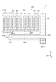
第4実施形態に係る角速度センサー1fの駆動部41A,41Bにおいて、駆動部41Bを一例として説明する。図10および図11Aに示すように、駆動部41Bは、櫛歯状に配置された複数の可動駆動電極指61を備えた可動駆動電極411Bと、櫛歯状に配置された複数の固定駆動電極指63を備え可動駆動電極411Bの可動駆動電極指61と空隙を有して互い違いに配置された固定駆動電極412Bと、を有している。   In the drive units 41A and 41B of the angular velocity sensor 1f according to the fourth embodiment, the drive unit 41B will be described as an example. As shown in FIG. 10 and FIG. 11A, the drive unit 41B includes a movable drive electrode 411B having a plurality of movable drive electrode fingers 61 arranged in a comb shape, and a plurality of fixed drive electrodes arranged in a comb shape. The movable drive electrode fingers 61 of the movable drive electrode 411 </ b> B and the fixed drive electrodes 412 </ b> B arranged alternately with gaps are provided.

固定駆動電極412Bは、第1方向(X軸方向)に沿って延在して設けられている複数の固定駆動電極指63を有している。また、可動駆動電極411Bは、Y軸方向に沿って延在して設けられている第2幹部60と、第2幹部60からX軸方向に沿って延在して設けられ、固定駆動電極指63とY軸方向に間隔を空けて配置される複数の可動駆動電極指61と、第2幹部60に連結する第2連結部62と、を有している。   The fixed drive electrode 412B has a plurality of fixed drive electrode fingers 63 provided so as to extend along the first direction (X-axis direction). The movable drive electrode 411B extends from the second trunk 60 along the X-axis direction and extends from the second trunk 60 along the Y-axis direction. 63 and a plurality of movable drive electrode fingers 61 arranged at intervals in the Y-axis direction, and a second connection portion 62 connected to the second trunk portion 60.

駆動ばね43Bは、第2方向(Y軸方向)に沿って延在する長手形状と、可動駆動電極411Bの中心側に折り返し部431とを有し、第1方向(X軸方向)に弾性変形することができる。また、駆動ばね43Bの折り返し部431とは反対側の長手形状の端部は、第2固定部421Bと可動駆動電極411Bの第2連結部62とにそれぞれ接続されている。   The drive spring 43B has a longitudinal shape extending along the second direction (Y-axis direction) and a folded portion 431 on the center side of the movable drive electrode 411B, and is elastically deformed in the first direction (X-axis direction). can do. Further, the end of the drive spring 43B on the opposite side to the folded portion 431 is connected to the second fixed portion 421B and the second connecting portion 62 of the movable drive electrode 411B.

固定駆動電極412Bは、駆動ばね43Bと対向する駆動部41B(固定駆動電極412B)の第1面415と、第1面415より可動駆動電極411Bの中心側に設けられた駆動部41B(固定駆動電極412B)の第2面416と、を有している。駆動部41B(固定駆動電極412B)の第1面415と駆動ばね43BとのX軸方向の間隔G9は、駆動部41B(固定駆動電極412B)の第2面416と駆動ばね43BとのX軸方向の間隔G10より大きい。つまり、駆動ばね43Bの折り返し部431よりも駆動ばね43Bの折り返し部431とは反対側の長手形状の端部側で互いの間隔が大きく離れて設けられている。これにより、固定駆動電極412Bに対して変位量が小さい駆動ばね43Bの折り返し部431に固定駆動電極412Bをより近接して配置することができる。そして、固定駆動電極412Bに対して変位量が大きい駆動ばね43Bの折り返し部431とは反対側の長手形状の端部側から固定駆動電極412Bを大きく離すことができ、駆動ばね43Bをより変位し易くすることができる。そのため、可動駆動電極411Bを大きく変位させることができるため、可動検出電極441Bが大きく変位し、検出感度をより向上させることができる。従って、小型化を図っても、検出感度の低下を低減した角速度センサー1fを得ることができる。   The fixed drive electrode 412B includes a first surface 415 of the drive unit 41B (fixed drive electrode 412B) facing the drive spring 43B, and a drive unit 41B (fixed drive) provided on the center side of the movable drive electrode 411B from the first surface 415. The second surface 416 of the electrode 412B). The distance G9 between the first surface 415 of the drive unit 41B (fixed drive electrode 412B) and the drive spring 43B in the X-axis direction is the X axis between the second surface 416 of the drive unit 41B (fixed drive electrode 412B) and the drive spring 43B. It is larger than the direction gap G10. That is, the distance between the drive spring 43B and the folded portion 431 of the drive spring 43B is larger than the folded portion 431 of the drive spring 43B on the end side of the longitudinal shape. As a result, the fixed drive electrode 412B can be disposed closer to the folded portion 431 of the drive spring 43B having a small displacement relative to the fixed drive electrode 412B. Then, the fixed drive electrode 412B can be largely separated from the end of the longitudinal shape opposite to the folded portion 431 of the drive spring 43B having a large displacement with respect to the fixed drive electrode 412B, and the drive spring 43B is further displaced. Can be made easier. Therefore, since the movable drive electrode 411B can be displaced greatly, the movable detection electrode 441B can be largely displaced, and the detection sensitivity can be further improved. Therefore, it is possible to obtain an angular velocity sensor 1f in which a decrease in detection sensitivity is reduced even if the size is reduced.

また、前述した実施形態では、駆動部41B(固定駆動電極412B)の第1面415が駆動ばね43Bの折り返し部431から端部まで駆動ばね43Bに対して平行に設けられ、X軸方向の間隔G9は常に等しいが、駆動ばね43Bの折り返し部431から離れているならば、これに限定されない。   In the above-described embodiment, the first surface 415 of the drive portion 41B (fixed drive electrode 412B) is provided in parallel to the drive spring 43B from the folded portion 431 to the end portion of the drive spring 43B, and is spaced in the X-axis direction. G9 is always equal, but is not limited to this as long as it is away from the folded portion 431 of the drive spring 43B.

例えば、第4実施形態の変形例としての角速度センサー1gは、図11Bに示すように、固定駆動電極412Bは、駆動ばね43Bに対向し、駆動ばね43Bと交差する方向に沿って設けられた駆動部41B(固定駆動電極412B)の第1面415aと、第1面415aより可動駆動電極411Bの中心側に設けられた第2面416とを有している。駆動部41B(固定駆動電極412B)の第1面415aと駆動ばね43BとのX軸方向の間隔G11は、折り返し部431から離れるほど大きくなる。駆動部41B(固定駆動電極412B)の第1面415aと駆動ばね43BとのX軸方向の間隔G11は、駆動部41B(固定駆動電極412B)の第2面416と駆動ばね43BとのX軸方向の間隔G12より大きい。つまり、駆動ばね43Bの折り返し部431よりも駆動ばね43Bの折り返し部431とは反対側の長手形状の端部側で互いの間隔が大きく離れて設けられている。これにより、固定駆動電極412Bに対して変位量が小さい駆動ばね43Bの折り返し部431に固定駆動電極412Bを近くに配置することができる。そして、固定駆動電極412Bに対して変位量が大きい駆動ばね43Bの折り返し部431とは反対側の長手形状の端部側から固定駆動電極412Bを大きく離すことができ、駆動ばね43Bをより変位し易くすることができる。そのため、可動駆動電極411Bを大きく変位させることができるため、可動検出電極441Bが大きく変位し、検出感度をより向上させることができる。   For example, in the angular velocity sensor 1g as a modification of the fourth embodiment, as shown in FIG. 11B, the fixed drive electrode 412B faces the drive spring 43B and is provided along the direction intersecting the drive spring 43B. The first surface 415a of the portion 41B (fixed drive electrode 412B) and the second surface 416 provided on the center side of the movable drive electrode 411B from the first surface 415a. The distance G11 in the X-axis direction between the first surface 415a of the drive unit 41B (fixed drive electrode 412B) and the drive spring 43B increases as the distance from the folded portion 431 increases. The distance G11 in the X-axis direction between the first surface 415a of the drive unit 41B (fixed drive electrode 412B) and the drive spring 43B is the X axis between the second surface 416 of the drive unit 41B (fixed drive electrode 412B) and the drive spring 43B. It is larger than the direction gap G12. That is, the distance between the drive spring 43B and the folded portion 431 of the drive spring 43B is larger than the folded portion 431 of the drive spring 43B on the end side of the longitudinal shape. Thereby, the fixed drive electrode 412B can be disposed close to the folded portion 431 of the drive spring 43B having a small displacement with respect to the fixed drive electrode 412B. Then, the fixed drive electrode 412B can be largely separated from the end of the longitudinal shape opposite to the folded portion 431 of the drive spring 43B having a large displacement with respect to the fixed drive electrode 412B, and the drive spring 43B is further displaced. Can be made easier. Therefore, since the movable drive electrode 411B can be displaced greatly, the movable detection electrode 441B can be largely displaced, and the detection sensitivity can be further improved.

また、前述した実施形態では、駆動部41B(固定駆動電極412B)の第1面415が駆動ばね43Bの端部から折り返し部431に向けて駆動ばね43Bに対して離れる方向に連続して傾斜しているが、互いに離れていくならば、これに限定されず、例えば、第4実施形態の変形例としての角速度センサー1hは、図11Cに示すように、駆動部41B(固定駆動電極412B)の第1面415bが駆動ばね43Bに対して階段状に傾いていてもよい。   In the above-described embodiment, the first surface 415 of the drive unit 41B (fixed drive electrode 412B) is continuously inclined in the direction away from the drive spring 43B from the end of the drive spring 43B toward the folded-back portion 431. However, as long as they move away from each other, the present invention is not limited to this. For example, as shown in FIG. 11C, an angular velocity sensor 1h as a modified example of the fourth embodiment includes a drive unit 41B (fixed drive electrode 412B). The first surface 415b may be inclined stepwise with respect to the drive spring 43B.

なお、本実施形態では、図10に示すように、駆動部41BのY軸方向の両端において、−Y軸方向の端部を一例として挙げ、説明したが、駆動部41Bの+Y軸方向の端部や駆動部41AのY軸方向の両端においても同様の構成となっている。   In the present embodiment, as illustrated in FIG. 10, at both ends in the Y-axis direction of the drive unit 41 </ b> B, an end in the −Y-axis direction is given as an example. This is the same configuration at both ends in the Y-axis direction of the drive unit and drive unit 41A.

以上、第4実施形態の角速度センサー1f,1g,1hについて説明した。このような第4実施形態によっても、前述した第1実施形態と同様の効果を発揮することができる。   The angular velocity sensors 1f, 1g, and 1h according to the fourth embodiment have been described above. According to the fourth embodiment, the same effect as that of the first embodiment described above can be exhibited.

<慣性計測装置>
次に、本発明の一実施形態に係る角速度センサー1を適用した慣性計測装置IMU:Inertial Measurement Unit)2000について、図12および図13を参照して説明する。図12は、慣性計測装置の概略構成を示す分解斜視図である。図13は、慣性計測装置の慣性センサー素子の配置例を示す斜視図である。
<Inertial measurement device>
Next, an inertial measurement device IMU (Inertial Measurement Unit) 2000 to which the angular velocity sensor 1 according to an embodiment of the present invention is applied will be described with reference to FIGS. 12 and 13. FIG. 12 is an exploded perspective view showing a schematic configuration of the inertial measurement device. FIG. 13 is a perspective view showing an arrangement example of inertial sensor elements of the inertial measurement device.

図12に示す慣性計測装置2000は、自動車や、ロボットなどの運動体(被装着装置)の姿勢や、挙動(慣性運動量)を検出する装置である。慣性計測装置2000は、3軸の加速度センサーと、3軸の角速度センサーと、を備えた、所謂6軸モーションセンサーとして機能する。   An inertial measurement device 2000 shown in FIG. 12 is a device that detects the posture and behavior (inertia momentum) of a moving body (a wearing device) such as an automobile or a robot. The inertial measurement device 2000 functions as a so-called 6-axis motion sensor including a 3-axis acceleration sensor and a 3-axis angular velocity sensor.

慣性計測装置2000は、平面形状が略正方形の直方体である。また、正方形の対角線方向に位置する2ヶ所の頂点近傍に、固定部としてのネジ穴2110が形成されている。この2ヶ所のネジ穴2110に2本のネジを通して、自動車などの被装着体の被装着面に慣性計測装置2000を固定することができる。なお、部品の選定や設計変更により、例えば、スマートフォンや、デジタルカメラに搭載可能なサイズに小型化することも可能である。   Inertial measuring apparatus 2000 is a rectangular parallelepiped having a substantially square planar shape. Further, screw holes 2110 as fixing portions are formed in the vicinity of two apexes located in the diagonal direction of the square. The inertial measurement device 2000 can be fixed to a mounting surface of a mounting body such as an automobile through two screws through the two screw holes 2110. Note that the size can be reduced to a size that can be mounted on, for example, a smartphone or a digital camera by selecting a part or changing a design.

慣性計測装置2000は、アウターケース2100と、接合部材2200と、センサーモジュール2300と、を有し、アウターケース2100の内部に、接合部材2200を介在させて、センサーモジュール2300を挿入した構成となっている。また、センサーモジュール2300は、インナーケース2310と、基板2320と、を有している。   The inertial measurement device 2000 includes an outer case 2100, a joining member 2200, and a sensor module 2300. The sensor module 2300 is inserted into the outer case 2100 with the joining member 2200 interposed therebetween. Yes. The sensor module 2300 includes an inner case 2310 and a substrate 2320.

アウターケース2100の外形は、慣性計測装置2000の全体形状と同様に、平面形状が略正方形の直方体であり、正方形の対角線方向に位置する2ヶ所の頂点近傍に、それぞれネジ穴2110が形成されている。また、アウターケース2100は、箱状であり、その内部にセンサーモジュール2300が収納されている。   The outer shape of the outer case 2100 is a rectangular parallelepiped having a substantially square shape, similar to the overall shape of the inertial measurement device 2000, and screw holes 2110 are formed in the vicinity of two apexes located in the diagonal direction of the square. Yes. The outer case 2100 is box-shaped, and the sensor module 2300 is accommodated therein.

インナーケース2310は、基板2320を支持する部材であり、アウターケース2100の内部に収まる形状となっている。また、インナーケース2310には、基板2320との接触を防止するための凹部2311や後述するコネクター2330を露出させるための開口2312が形成されている。このようなインナーケース2310は、接合部材2200(例えば、接着剤を含浸させたパッキン)を介してアウターケース2100に接合されている。また、インナーケース2310の下面には、接着剤を介して基板2320が接合されている。   The inner case 2310 is a member that supports the substrate 2320 and has a shape that fits inside the outer case 2100. Further, the inner case 2310 is formed with a recess 2311 for preventing contact with the substrate 2320 and an opening 2312 for exposing a connector 2330 described later. Such an inner case 2310 is joined to the outer case 2100 via a joining member 2200 (for example, a packing impregnated with an adhesive). A substrate 2320 is bonded to the lower surface of the inner case 2310 via an adhesive.

図13に示すように、基板2320の上面には、コネクター2330、Z軸まわりの角速度を検出する角速度センサー2340z、X軸、Y軸およびZ軸の各軸方向の加速度を検出する加速度センサー2350などが実装されている。また、基板2320の側面には、X軸まわりの角速度を検出する角速度センサー2340xおよびY軸まわりの角速度を検出する角速度センサー2340yが実装されている。なお、角速度センサー2340z、2340x、2340yとしては、特に限定されず、例えば前述した角速度センサー1など、コリオリの力を利用した振動ジャイロセンサーを用いることができる。また、加速度センサー2350としては、特に限定されず、例えば、静電容量型の加速度センサーを用いることができる。   As shown in FIG. 13, on the upper surface of the substrate 2320, there are a connector 2330, an angular velocity sensor 2340z that detects an angular velocity around the Z axis, an acceleration sensor 2350 that detects acceleration in each of the X, Y, and Z axes. Has been implemented. On the side surface of the substrate 2320, an angular velocity sensor 2340x that detects an angular velocity around the X axis and an angular velocity sensor 2340y that detects an angular velocity around the Y axis are mounted. The angular velocity sensors 2340z, 2340x, and 2340y are not particularly limited, and for example, a vibration gyro sensor using Coriolis force such as the angular velocity sensor 1 described above can be used. The acceleration sensor 2350 is not particularly limited, and for example, a capacitance type acceleration sensor can be used.

また、基板2320の下面には、制御回路としての制御IC2360が実装されている。制御IC2360は、MCU(Micro Controller Unit)であり、不揮発性メモリーを含む記憶部や、A/Dコンバーターなどを内蔵しており、慣性計測装置2000の各部を制御する。記憶部には、加速度および角速度を検出するための順序と内容を規定したプログラムや、検出データをデジタル化してパケットデータに組込むプログラムおよび付随するデータなどが記憶されている。なお、基板2320には、その他にも複数の電子部品が実装されている。   A control IC 2360 as a control circuit is mounted on the lower surface of the substrate 2320. The control IC 2360 is an MCU (Micro Controller Unit) and includes a storage unit including a nonvolatile memory, an A / D converter, and the like, and controls each unit of the inertial measurement device 2000. The storage unit stores a program that defines the order and contents for detecting acceleration and angular velocity, a program that digitizes detection data and incorporates it into packet data, and accompanying data. Note that a plurality of other electronic components are mounted on the substrate 2320.

以上、慣性計測装置2000について説明した。このような慣性計測装置2000は、角速度センサー1としての角速度センサー2340z、2340x、2340yおよび加速度センサー2350と、これら各センサー2340z、2340x、2340y、2350の駆動を制御する制御IC2360(制御回路)と、を含んでいる。これにより、上述した角速度センサー1の効果を享受でき、信頼性の高い慣性計測装置2000が得られる。   The inertia measuring device 2000 has been described above. The inertial measurement apparatus 2000 includes an angular velocity sensor 2340z, 2340x, 2340y and an acceleration sensor 2350 as the angular velocity sensor 1, a control IC 2360 (control circuit) that controls driving of the sensors 2340z, 2340x, 2340y, and 2350, Is included. Thereby, the effect of the angular velocity sensor 1 mentioned above can be enjoyed, and the highly reliable inertial measurement device 2000 is obtained.

<移動体測位装置>
次に、本発明の一実施形態に係る角速度センサー1を適用した移動体測位装置3000について、図14および図15を参照して説明する。図14は、移動体測位装置の全体システムを示すブロック図である。図15は、移動体測位装置の作用を模式的に示す図である。
<Mobile positioning device>
Next, a mobile body positioning device 3000 to which the angular velocity sensor 1 according to an embodiment of the present invention is applied will be described with reference to FIGS. 14 and 15. FIG. 14 is a block diagram showing an entire system of the mobile body positioning device. FIG. 15 is a diagram schematically illustrating the operation of the mobile body positioning device.

図14に示す移動体測位装置3000は、移動体に装着して用い、当該移動体の測位を行うための装置である。移動体としては、特に限定されず、自転車、自動車(四輪自動車およびバイクを含む)、電車、飛行機、船等のいずれでもよいが、本実施形態では四輪自動車として説明する。移動体測位装置3000は、慣性計測装置3100(IMU)と、演算処理部3200と、GPS受信部3300と、受信アンテナ3400と、位置情報取得部3500と、位置合成部3600と、処理部3700と、通信部3800と、表示部3900と、を有している。なお、慣性計測装置3100としては、例えば、前述した慣性計測装置2000を用いることができる。   A mobile body positioning device 3000 shown in FIG. 14 is a device that is used by being mounted on a mobile body and performs positioning of the mobile body. The moving body is not particularly limited, and may be any of a bicycle, an automobile (including a four-wheel automobile and a motorcycle), a train, an airplane, a ship, and the like, but in the present embodiment, it will be described as a four-wheel automobile. The mobile body positioning device 3000 includes an inertial measurement device 3100 (IMU), an arithmetic processing unit 3200, a GPS receiving unit 3300, a receiving antenna 3400, a position information acquiring unit 3500, a position synthesizing unit 3600, and a processing unit 3700. A communication unit 3800 and a display unit 3900. As the inertial measurement device 3100, for example, the inertial measurement device 2000 described above can be used.

また、慣性計測装置3100は、3軸の加速度センサー3110と、3軸の角速度センサー3120と、を有している。演算部としての演算処理部3200は、加速度センサー3110からの加速度データおよび角速度センサー3120からの角速度データを受け、これらデータに対して慣性航法演算処理を行い、慣性航法測位データ(移動体の加速度および姿勢を含むデータ)を出力する。   The inertial measurement device 3100 includes a triaxial acceleration sensor 3110 and a triaxial angular velocity sensor 3120. The arithmetic processing unit 3200 as the arithmetic unit receives the acceleration data from the acceleration sensor 3110 and the angular velocity data from the angular velocity sensor 3120, performs inertial navigation arithmetic processing on these data, and obtains inertial navigation positioning data (acceleration and acceleration of the moving object). Data including posture).

また、受信部としてのGPS受信部3300は、受信アンテナ3400を介してGPS衛星からの信号(GPS搬送波。位置情報が重畳された衛星信号)を受信する。また、取得部としての位置情報取得部3500は、GPS受信部3300が受信した信号に基づいて、移動体測位装置3000(移動体)の位置(緯度、経度、高度)、速度、方位を表すGPS測位データを出力する。このGPS測位データには、受信状態や受信時刻等を示すステータスデータも含まれている。   A GPS receiving unit 3300 as a receiving unit receives a signal from a GPS satellite (a GPS carrier wave, a satellite signal on which position information is superimposed) via a receiving antenna 3400. The position information acquisition unit 3500 serving as an acquisition unit is a GPS that represents the position (latitude, longitude, altitude), speed, and direction of the mobile body positioning device 3000 (mobile body) based on the signal received by the GPS reception section 3300. Outputs positioning data. This GPS positioning data also includes status data indicating the reception state, reception time, and the like.

算出部としての位置合成部3600は、演算処理部3200から出力された慣性データとしての慣性航法測位データおよび位置情報取得部3500から出力されたGPS測位データに基づいて、移動体の位置、具体的には移動体が地面のどの位置を走行しているかを算出する。例えば、GPS測位データに含まれている移動体の位置が同じであっても、図15に示すように、地面の傾斜等の影響によって移動体の姿勢が異なっていれば、地面の異なる位置を移動体が走行していることになる。そのため、GPS測位データだけでは移動体の正確な位置を算出することができない。そこで、位置合成部3600は、慣性航法測位データ(特に、移動体の姿勢に関するデータ)を用いて、移動体が地面のどの位置を走行しているのかを算出する。なお、当該判定は、三角関数(鉛直方向に対する傾きθ)を用いた演算によって比較的簡単に行うことができる。   The position synthesizing unit 3600 serving as a calculation unit is configured based on the inertial navigation positioning data serving as inertial data output from the arithmetic processing unit 3200 and the GPS positioning data output from the position information acquiring unit 3500. Is used to calculate which position on the ground the moving body is traveling. For example, even if the position of the moving body included in the GPS positioning data is the same, as shown in FIG. 15, if the position of the moving body is different due to the influence of the ground inclination or the like, The moving body is running. Therefore, the exact position of the moving body cannot be calculated only with the GPS positioning data. Therefore, the position synthesis unit 3600 calculates which position on the ground the mobile body is traveling using inertial navigation positioning data (particularly, data related to the posture of the mobile body). This determination can be made relatively easily by calculation using a trigonometric function (inclination θ with respect to the vertical direction).

位置合成部3600から出力された位置データは、処理部3700によって所定の処理が行われ、測位結果として、表示部3900に表示されるようになっている。また、位置データは、通信部3800によって外部装置に送信されるようになっていてもよい。   The position data output from the position synthesizing unit 3600 is subjected to a predetermined process by the processing unit 3700 and is displayed on the display unit 3900 as a positioning result. Further, the position data may be transmitted to the external device by the communication unit 3800.

以上、移動体測位装置3000について説明した。このような移動体測位装置3000は、前述したように、慣性計測装置3100と、測位用衛星から位置情報が重畳された衛星信号を受信するGPS受信部3300(受信部)と、受信した衛星信号に基づいて、GPS受信部3300の位置情報を取得する位置情報取得部3500(取得部)と、慣性計測装置3100から出力された慣性航法測位データ(慣性データ)に基づいて、移動体の姿勢を演算する演算処理部3200(演算部)と、算出された姿勢に基づいて位置情報を補正することにより、移動体の位置を算出する位置合成部3600(算出部)と、を含んでいる。これにより、上述した角速度センサー1(慣性計測装置2000)の効果を享受でき、信頼性の高い移動体測位装置3000が得られる。   The mobile body positioning device 3000 has been described above. As described above, such a mobile body positioning device 3000 includes an inertial measurement device 3100, a GPS receiving unit 3300 (receiving unit) that receives a satellite signal on which position information is superimposed from a positioning satellite, and a received satellite signal. Based on the position information acquisition unit 3500 (acquisition unit) for acquiring the position information of the GPS reception unit 3300 and the inertial navigation positioning data (inertia data) output from the inertial measurement device 3100. A calculation processing unit 3200 (calculation unit) that performs calculation, and a position synthesis unit 3600 (calculation unit) that calculates the position of the moving body by correcting the position information based on the calculated posture are included. Thereby, the effect of the angular velocity sensor 1 (inertial measuring device 2000) mentioned above can be enjoyed, and the highly reliable mobile body positioning device 3000 is obtained.

<携帯型電子機器>
次に、本発明の一実施形態に係る角速度センサー1を適用した携帯型電子機器について、図16および図17を参照して説明する。図16は、携帯型電子機器の構成を模式的に示す平面図である。図17は、携帯型電子機器の概略構成を示す機能ブロック図である。
以下、携帯型電子機器の一例として、腕時計型の活動計(アクティブトラッカー)を示して説明する。
<Portable electronic devices>
Next, a portable electronic device to which the angular velocity sensor 1 according to an embodiment of the present invention is applied will be described with reference to FIGS. FIG. 16 is a plan view schematically showing the configuration of the portable electronic device. FIG. 17 is a functional block diagram illustrating a schematic configuration of the portable electronic device.
Hereinafter, a wristwatch-type activity meter (active tracker) will be described and described as an example of a portable electronic device.

腕時計型の活動計(アクティブトラッカー)であるリスト機器1000は、図16に示すように、バンド1032,1037等によってユーザーの手首等の部位(被検体)に装着され、デジタル表示の表示部150を備えるとともに無線通信が可能である。上述した本発明に係る角速度センサー1は、角速度を計測するセンサーとしてリスト機器1000に組込まれている。   As shown in FIG. 16, wrist device 1000 that is a wristwatch-type activity meter (active tracker) is attached to a part (subject) such as a wrist of a user with bands 1032 and 1037, and a display unit 150 for digital display is provided. And wireless communication is possible. The above-described angular velocity sensor 1 according to the present invention is incorporated in the wrist device 1000 as a sensor for measuring the angular velocity.

リスト機器1000は、少なくとも角速度センサー1が収容されているケース1030と、ケース1030に収容され、角速度センサー1からの出力データを処理する処理部100(図17参照)と、ケース1030に収容されている表示部150と、ケース1030の開口部を塞いでいる透光性カバー1071と、を備えている。ケース1030の透光性カバー1071のケース1030の外側には、ベゼル1078が設けられている。ケース1030の側面には、複数の操作ボタン1080,1081が設けられている。以下、図17も併せて参照しながら、さらに詳細に説明する。   The wrist device 1000 is accommodated in a case 1030 in which at least the angular velocity sensor 1 is accommodated, a processing unit 100 (see FIG. 17) that processes output data from the angular velocity sensor 1 and in the case 1030. The display unit 150 and the translucent cover 1071 that closes the opening of the case 1030 are provided. A bezel 1078 is provided outside the case 1030 of the translucent cover 1071 of the case 1030. A plurality of operation buttons 1080 and 1081 are provided on the side surface of the case 1030. Hereinafter, it will be described in more detail with reference to FIG.

加速度センサー113は、互いに交差する(理想的には直交する)3軸方向の各々の加速度を検出し、検出した3軸加速度の大きさおよび向きに応じた信号(加速度信号)を出力する。また、角速度センサー1としての角速度センサー114は、互いに交差する(理想的には直交する)3軸方向の各々の角速度を検出し、検出した3軸角速度の大きさおよび向きに応じた信号(角速度信号)を出力する。   The acceleration sensor 113 detects accelerations in the three-axis directions that intersect each other (ideally orthogonally), and outputs a signal (acceleration signal) corresponding to the magnitude and direction of the detected three-axis acceleration. The angular velocity sensor 114 as the angular velocity sensor 1 detects angular velocities in three axial directions that intersect (ideally orthogonal) with each other, and a signal (angular velocity) corresponding to the detected magnitude and direction of the three axial angular velocity. Signal).

表示部150を構成する液晶ディスプレイ(LCD)では、種々の検出モードに応じて、例えば、GPSセンサー110や地磁気センサー111を用いた位置情報、移動量や角速度センサー1に含まれる角速度センサー114を用いた運動量などの運動情報、脈拍センサー115などを用いた脈拍数などの生体情報、もしくは現在時刻などの時刻情報などが表示される。なお、温度センサー116を用いた環境温度を表示することもできる。   The liquid crystal display (LCD) constituting the display unit 150 uses, for example, position information using the GPS sensor 110 or the geomagnetic sensor 111, an amount of movement, and an angular velocity sensor 114 included in the angular velocity sensor 1 according to various detection modes. The exercise information such as the amount of exercise, the biological information such as the pulse rate using the pulse sensor 115, or the time information such as the current time is displayed. Note that the environmental temperature using the temperature sensor 116 can also be displayed.

通信部170は、ユーザー端末と図示しない情報端末との間の通信を成立させるための各種制御を行う。通信部170は、例えば、Bluetooth(登録商標)(BTLE:Bluetooth Low Energyを含む)、Wi−Fi(登録商標)(Wireless Fidelity)、Zigbee(登録商標)、NFC(Near field communication)、ANT+(登録商標)等の近距離無線通信規格に対応した送受信機や通信部170はUSB(Universal Serial Bus)等の通信バス規格に対応したコネクターを含んで構成される。   The communication unit 170 performs various controls for establishing communication between the user terminal and an information terminal (not shown). The communication unit 170 includes, for example, Bluetooth (registered trademark) (including BTLE: Bluetooth Low Energy), Wi-Fi (registered trademark) (Wireless Fidelity), Zigbee (registered trademark), NFC (Near field communication), and ANT + (registered). The transceiver and the communication unit 170 corresponding to a short-range wireless communication standard such as a trademark are configured to include a connector corresponding to a communication bus standard such as USB (Universal Serial Bus).

処理部100(プロセッサー)は、例えば、MPU(Micro Processing Unit)、DSP(Digital Signal Processor)、ASIC(Application Specific Integrated Circuit)等により構成される。処理部100は、記憶部140に格納されたプログラムと、操作部120(例えば操作ボタン1080,1081)から入力された信号とに基づき、各種の処理を実行する。処理部100による処理には、GPSセンサー110、地磁気センサー111、圧力センサー112、加速度センサー113、角速度センサー114、脈拍センサー115、温度センサー116、計時部130の各出力信号に対するデータ処理、表示部150に画像を表示させる表示処理、音出力部160に音を出力させる音出力処理、通信部170を介して情報端末と通信を行う通信処理、バッテリー180からの電力を各部へ供給する電力制御処理などが含まれる。   The processing unit 100 (processor) is configured by, for example, an MPU (Micro Processing Unit), a DSP (Digital Signal Processor), an ASIC (Application Specific Integrated Circuit), or the like. The processing unit 100 executes various processes based on a program stored in the storage unit 140 and a signal input from the operation unit 120 (for example, the operation buttons 1080 and 1081). The processing by the processing unit 100 includes data processing for each output signal of the GPS sensor 110, the geomagnetic sensor 111, the pressure sensor 112, the acceleration sensor 113, the angular velocity sensor 114, the pulse sensor 115, the temperature sensor 116, and the time measuring unit 130, and the display unit 150. Display processing for displaying an image on the screen, sound output processing for outputting sound to the sound output unit 160, communication processing for communicating with the information terminal via the communication unit 170, power control processing for supplying power from the battery 180 to each unit, etc. Is included.

このようなリスト機器1000では、少なくとも以下のような機能を有することができる。
1.距離:高精度のGPS機能により計測開始からの合計距離を計測する。
2.ペース:ペース距離計測から、現在の走行ペースを表示する。
3.平均スピード:走行開始から現在までの平均スピードを算出し表示する。
4.標高:GPS機能により、標高を計測し表示する。
5.ストライド:GPS電波が届かないトンネル内などでも歩幅を計測し表示する。
6.ピッチ:1分あたりの歩数を計測し表示する。
7.心拍数:脈拍センサーにより心拍数を計測し表示する。
8.勾配:山間部でのトレーニングやトレイルランにおいて、地面の勾配を計測し表示する。
9.オートラップ:事前に設定した一定距離や一定時間を走った時に、自動でラップ計測を行う。
10.運動消費カロリー:消費カロリーを表示する。
11.歩数:運動開始からの歩数の合計を表示する。
Such a wrist device 1000 can have at least the following functions.
1. Distance: The total distance from the start of measurement is measured by a highly accurate GPS function.
2. Pace: Displays the current running pace from the pace distance measurement.
3. Average speed: Calculate and display the average speed from the start to the present.
4). Elevation: The altitude is measured and displayed by the GPS function.
5. Stride: Steps are measured and displayed even in tunnels where GPS signals do not reach.
6). Pitch: Measures and displays the number of steps per minute.
7). Heart rate: The heart rate is measured and displayed by the pulse sensor.
8). Slope: Measures and displays the slope of the ground during mountain training and trail runs.
9. Auto lap: lap measurement is automatically performed when a predetermined distance or time is set.
10. Exercise calorie consumption: Displays the calorie consumption.
11. Number of steps: Displays the total number of steps from the start of exercise.

なお、リスト機器1000は、ランニングウォッチ、ランナーズウォッチ、デュアスロンやトライアスロン等マルチスポーツ対応のランナーズウォッチ、アウトドアウォッチ、および衛星測位システム、例えばGPSを搭載したGPSウォッチ、等に広く適用できる。   Note that the wrist device 1000 can be widely applied to a running watch, a runner's watch, a multi-sports runner's watch such as a duathlon or a triathlon, an outdoor watch, and a satellite positioning system such as a GPS watch equipped with GPS.

また、上述では、衛星測位システムとしてGPS(Global Positioning System)を用いて説明したが、他の全地球航法衛星システム(GNSS:Global Navigation Satellite System)を利用してもよい。例えば、EGNOS(European Geostationary-Satellite Navigation Overlay Service)、QZSS(Quasi Zenith Satellite System)、GLONASS(GLObal NAvigation Satellite System)、GALILEO、BeiDou(BeiDou Navigation Satellite System)、等の衛星測位システムのうち1又は2以上を利用してもよい。また、衛星測位システムの少なくとも1つにWAAS(Wide Area Augmentation System)、EGNOS(European Geostationary Satellite Navigation Overlay Service)等の静止衛星型衛星航法補強システム(SBAS:Satellite based Augmentation System)を利用してもよい。   In the above description, GPS (Global Positioning System) is used as the satellite positioning system, but other Global Navigation Satellite System (GNSS) may be used. For example, one or more satellite positioning systems such as EGNOS (European Geostationary-Satellite Navigation Overlay Service), QZSS (Quasi Zenith Satellite System), GLONASS (GLObal NAvigation Satellite System), GALILEO, BeiDou (BeiDou Navigation Satellite System) May be used. Further, a satellite based augmentation system (SBAS) such as WAAS (Wide Area Augmentation System) or EGNOS (European Geostationary Satellite Navigation Overlay Service) may be used as at least one of the satellite positioning systems. .

このような携帯型電子機器は、角速度センサー1および処理部100を備えているので、優れた信頼性を有している。   Since such a portable electronic device includes the angular velocity sensor 1 and the processing unit 100, the portable electronic device has excellent reliability.

<電子機器>
次に、本発明の一実施形態に係る角速度センサー1を適用した電子機器について、図18〜図20を参照して説明する。
<Electronic equipment>
Next, an electronic device to which the angular velocity sensor 1 according to an embodiment of the present invention is applied will be described with reference to FIGS.

先ず、図18を参照して、電子機器の一例であるモバイル型のパーソナルコンピューター1100について説明する。図18は、電子機器の一例であるモバイル型のパーソナルコンピューターの構成を模式的に示す斜視図である。   First, a mobile personal computer 1100, which is an example of an electronic device, will be described with reference to FIG. FIG. 18 is a perspective view schematically illustrating a configuration of a mobile personal computer that is an example of an electronic apparatus.

この図において、パーソナルコンピューター1100は、キーボード1102を備えた本体部1104と、表示部1108を備えた表示ユニット1106とにより構成され、表示ユニット1106は、本体部1104に対しヒンジ構造部を介して回動可能に支持されている。このようなパーソナルコンピューター1100には、角速度センサー1が内蔵されており、角速度センサー1の検出データに基づいて制御部1110が、例えば姿勢制御などの制御を行なうことができる。   In this figure, a personal computer 1100 includes a main body portion 1104 provided with a keyboard 1102 and a display unit 1106 provided with a display portion 1108. The display unit 1106 is rotated with respect to the main body portion 1104 via a hinge structure portion. It is supported movably. In such a personal computer 1100, the angular velocity sensor 1 is built in, and the control unit 1110 can perform control such as posture control based on detection data of the angular velocity sensor 1.

図19は、電子機器の一例であるスマートフォン(携帯型電話機)の構成を模式的に示す斜視図である。   FIG. 19 is a perspective view schematically showing a configuration of a smartphone (mobile phone) that is an example of an electronic apparatus.

この図において、スマートフォン1200は、上述した角速度センサー1が組込まれている。角速度センサー1によって検出された検出データ(角速度データ)は、スマートフォン1200の制御部1201に送信される。制御部1201は、CPU(Central Processing Unit)を含んで構成されており、受信した検出データからスマートフォン1200の姿勢や、挙動を認識して、表示部1208に表示されている表示画像を変化させたり、警告音や、効果音を鳴らしたり、振動モーターを駆動して本体を振動させることができる。換言すれば、スマートフォン1200のモーションセンシングを行い、計測された姿勢や、挙動から、表示内容を変えたり、音や、振動などを発生させたりすることができる。特に、ゲームのアプリケーションを実行する場合には、現実に近い臨場感を味わうことができる。   In this figure, the smartphone 1200 incorporates the angular velocity sensor 1 described above. Detection data (angular velocity data) detected by the angular velocity sensor 1 is transmitted to the control unit 1201 of the smartphone 1200. The control unit 1201 includes a CPU (Central Processing Unit), recognizes the attitude and behavior of the smartphone 1200 from the received detection data, and changes the display image displayed on the display unit 1208. It is possible to sound a warning sound or a sound effect, or drive a vibration motor to vibrate the main body. In other words, motion sensing of the smartphone 1200 can be performed, and the display content can be changed or sound or vibration can be generated from the measured posture or behavior. In particular, when a game application is executed, a realistic sensation can be experienced.

図20は、電子機器の一例であるディジタルスチールカメラの構成を示す斜視図である。なお、この図には、外部機器との接続についても簡易的に示されている。   FIG. 20 is a perspective view illustrating a configuration of a digital still camera which is an example of an electronic apparatus. In this figure, connection with an external device is also simply shown.

ディジタルスチールカメラ1300のケース(ボディー)1302の背面には、表示部1310が設けられ、CCDによる撮像信号に基づいて表示を行う構成になっており、表示部1310は、被写体を電子画像として表示するファインダーとしても機能する。また、ケース1302の正面側(図中裏面側)には、光学レンズ(撮像光学系)やCCDなどを含む受光ユニット1304が設けられている。   A display unit 1310 is provided on the back of the case (body) 1302 of the digital still camera 1300, and is configured to display based on an image pickup signal from the CCD. The display unit 1310 displays the subject as an electronic image. Also functions as a viewfinder. A light receiving unit 1304 including an optical lens (imaging optical system), a CCD, and the like is provided on the front side (the back side in the drawing) of the case 1302.

撮影者が表示部1310に表示された被写体像を確認し、シャッターボタン1306を押下すると、その時点におけるCCDの撮像信号が、メモリー1308に転送・格納される。また、このディジタルスチールカメラ1300では、ケース1302の側面に、ビデオ信号出力端子1312と、データ通信用の入出力端子1314とが設けられている。そして、図示されるように、ビデオ信号出力端子1312にはテレビモニター1430が、データ通信用の入出力端子1314にはパーソナルコンピューター1440が、それぞれ必要に応じて接続される。さらに、所定の操作により、メモリー1308に格納された撮像信号が、テレビモニター1430や、パーソナルコンピューター1440に出力される構成になっている。このようなディジタルスチールカメラ1300には、角速度センサー1が内蔵されており、角速度センサー1の検出データに基づいて制御部1316が、例えば手振れ補正などの制御を行なうことができる。   When the photographer confirms the subject image displayed on the display unit 1310 and presses the shutter button 1306, the CCD image pickup signal at that time is transferred and stored in the memory 1308. In this digital still camera 1300, a video signal output terminal 1312 and an input / output terminal 1314 for data communication are provided on the side surface of the case 1302. As shown in the figure, a television monitor 1430 is connected to the video signal output terminal 1312 and a personal computer 1440 is connected to the input / output terminal 1314 for data communication as necessary. Further, the imaging signal stored in the memory 1308 is output to the television monitor 1430 or the personal computer 1440 by a predetermined operation. In such a digital still camera 1300, the angular velocity sensor 1 is built in, and the control unit 1316 can perform control such as camera shake correction based on the detection data of the angular velocity sensor 1.

このような電子機器は、角速度センサー1および制御部1110,1201,1316を備えているので、優れた信頼性を有している。   Since such an electronic device includes the angular velocity sensor 1 and the control units 1110, 1201, and 1316, it has excellent reliability.

なお、角速度センサー1を備える電子機器は、図18のパーソナルコンピューター1100、図19のスマートフォン(携帯型電話機)1200、図20のディジタルスチールカメラ1300の他にも、例えば、タブレット端末、時計、インクジェット式吐出装置(例えばインクジェットプリンター)、ラップトップ型パーソナルコンピューター、テレビ、ビデオカメラ、ビデオテープレコーダー、カーナビゲーション装置、ページャー、電子手帳(通信機能付も含む)、電子辞書、電卓、電子ゲーム機器、ワードプロセッサー、ワークステーション、テレビ電話、防犯用テレビモニター、電子双眼鏡、POS端末、医療機器(例えば電子体温計、血圧計、血糖計、心電図計測装置、超音波診断装置、電子内視鏡)、魚群探知機、各種測定機器、計器類(例えば、車両、航空機、船舶の計器類)、フライトシミュレーター、地震計、歩数計、傾斜計、ハードディスクの振動を計測する振動計、ロボットやドローンなど飛行体の姿勢制御装置、自動車の自動運転用慣性航法に使用される制御機器等に適用することができる。   In addition to the personal computer 1100 shown in FIG. 18, the smartphone (portable phone) 1200 shown in FIG. 19, and the digital still camera 1300 shown in FIG. Discharge device (for example, inkjet printer), laptop personal computer, TV, video camera, video tape recorder, car navigation device, pager, electronic notebook (including communication function), electronic dictionary, calculator, electronic game device, word processor, Workstations, videophones, crime prevention TV monitors, electronic binoculars, POS terminals, medical equipment (for example, electronic thermometers, blood pressure monitors, blood glucose meters, electrocardiogram measuring devices, ultrasonic diagnostic devices, electronic endoscopes), fish detectors, various types Measuring machine , Instruments (eg, vehicle, aircraft, ship instruments), flight simulators, seismometers, pedometers, inclinometers, vibrometers that measure hard disk vibrations, robot and drone attitude control devices, automobile The present invention can be applied to control equipment used for inertial navigation for automatic driving.

<移動体>
次に、本発明の一実施形態に係る角速度センサー1を適用した移動体について、図21を参照して説明する。図21は、移動体の一例である自動車の構成を示す斜視図である。
<Moving object>
Next, a moving body to which the angular velocity sensor 1 according to an embodiment of the present invention is applied will be described with reference to FIG. FIG. 21 is a perspective view illustrating a configuration of an automobile which is an example of a moving body.

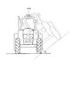
図21に示すように、移動体としての自動車1500には、角速度センサー1が内蔵されており、例えば、角速度センサー1によって車体1501の姿勢を検出することができる。角速度センサー1の検出信号は、車体の姿勢を制御する姿勢制御部としての車体姿勢制御装置1502に供給され、車体姿勢制御装置1502は、その信号に基づいて車体1501の姿勢を検出し、検出結果に応じてサスペンションの硬軟を制御したり、個々の車輪1503のブレーキを制御したりすることができる。また、角速度センサー1は、他にもキーレスエントリー、イモビライザー、カーナビゲーションシステム、カーエアコン、アンチロックブレーキシステム(ABS:Antilock Brake System)、エアバック、タイヤ・プレッシャー・モニタリング・システム(TPMS:Tire Pressure Monitoring System)、エンジンコントロール、ハイブリッド自動車や電気自動車の電池モニター等の電子制御ユニット(ECU:Electronic Control Unit)に広く適用できる。   As shown in FIG. 21, an automobile 1500 as a moving body incorporates an angular velocity sensor 1. For example, the angular velocity sensor 1 can detect the posture of the vehicle body 1501. The detection signal of the angular velocity sensor 1 is supplied to a vehicle body posture control device 1502 as a posture control unit that controls the posture of the vehicle body. The vehicle body posture control device 1502 detects the posture of the vehicle body 1501 based on the signal, and the detection result Accordingly, the suspension hardness can be controlled, and the brakes of the individual wheels 1503 can be controlled. In addition, the angular velocity sensor 1 includes keyless entry, immobilizer, car navigation system, car air conditioner, antilock brake system (ABS), airbag, tire pressure monitoring system (TPMS: Tire Pressure Monitoring). System), engine control, and electronic control units (ECUs) such as battery monitors for hybrid vehicles and electric vehicles.

また、移動体に適用される角速度センサー1は、上記の例示の他にも、例えば、二足歩行ロボットや電車などの姿勢制御、ラジコン飛行機、ラジコンヘリコプター、およびドローンなどの遠隔操縦あるいは自律式の飛行体の姿勢制御、農業機械(農機)、もしくは建設機械(建機)などの姿勢制御、ロケット、人工衛星、船舶、AGV(無人搬送車)、二および足歩行ロボットなどの制御において利用することができる。以上のように、各種移動体の姿勢制御の実現にあたって、角速度センサー1およびそれぞれの制御部(不図示)が組み込まれる。   In addition to the above examples, the angular velocity sensor 1 applied to the moving body is, for example, a posture control such as a bipedal walking robot or a train, a remote control such as a radio control airplane, a radio control helicopter, and a drone or an autonomous type. Used for attitude control of flying objects, attitude control of agricultural machinery (agricultural machinery) or construction machinery (construction machinery), control of rockets, artificial satellites, ships, AGV (automated guided vehicles), biped and legged walking robots, etc. Can do. As described above, the angular velocity sensor 1 and the respective control units (not shown) are incorporated in realizing the posture control of various moving bodies.

このような移動体は、角速度センサー1、および制御部(例えば、姿勢制御部としての車体姿勢制御装置1502)を備えているので、優れた信頼性を有している。   Since such a moving body includes the angular velocity sensor 1 and a control unit (for example, a vehicle body posture control device 1502 as a posture control unit), it has excellent reliability.

以上、角速度センサー1,1a,1b,1c,1d,1e,1f,1g,1h、慣性計測装置2000、移動体測位装置3000、携帯型電子機器(1000)、電子機器(1100,1200,1300)、および移動体(1500)を図示の実施形態に基づいて説明したが、本発明はこれに限定されるものではなく、各部の構成は、同様の機能を有する任意の構成のものに置換することができる。また、本発明に、他の任意の構成物が付加されていてもよい。   As described above, the angular velocity sensors 1, 1a, 1b, 1c, 1d, 1e, 1f, 1g, 1h, the inertial measurement device 2000, the mobile body positioning device 3000, the portable electronic device (1000), and the electronic device (1100, 1200, 1300). The mobile body (1500) has been described based on the illustrated embodiment. However, the present invention is not limited to this, and the configuration of each part may be replaced with any configuration having the same function. Can do. In addition, any other component may be added to the present invention.

また、前述した実施形態では、X軸、Y軸およびZ軸が互いに直交しているが、互いに交差していれば、これに限定されず、例えば、X軸がYZ平面の法線方向に対して若干傾いていてもよいし、Y軸がXZ平面の法線方向に対して若干傾いていてもよいし、Z軸がXY平面の法線方向に対して若干傾いていてもよい。なお、若干とは、角速度センサー1,1a,1b,1c,1d,1e,1f,1g,1hがその効果を発揮することができる範囲を意味し、具体的な傾き角度(数値)は、構成等によって異なる。   In the above-described embodiment, the X axis, the Y axis, and the Z axis are orthogonal to each other. However, the X axis is not limited to this as long as they intersect with each other. The Y axis may be slightly inclined with respect to the normal direction of the XZ plane, or the Z axis may be slightly inclined with respect to the normal direction of the XY plane. Note that “slightly” means a range in which the angular velocity sensors 1, 1a, 1b, 1c, 1d, 1e, 1f, 1g, and 1h can exert their effects, and a specific inclination angle (numerical value) is a configuration. Depends on etc.

1,1a,1b,1c,1d,1e,1f,1g,1h…角速度センサー、2…基板、21…凹部、22,221,222,223,224,225…マウント、23,24,25,26,27,28…溝部、3…蓋体、31…凹部、32…連通孔、33…封止部材、39…ガラスフリット、4…素子部、4A,4B…可動体、41A,41B…駆動部、411A,411B…可動駆動電極、412A,412B…固定駆動電極、42A,42B…第1固定部、421A,421B…第2固定部、43A,43B…駆動ばね、431…折り返し部、44A,44B…検出電極としての検出部、441A,441B…第1検出電極としての可動検出電極、442A,442B,443A,443B…第2検出電極としての固定検出電極、445…第1面、446…第2面、447…第3固定部、451,452…第1固定部、46A,46B…ばね部としての検出ばね、461,462…折り返し部、47A,47B…逆相ばね、471A,471B,…ばね本体、472A,473A…アーム、474A,475A…接続部、477A,477B,478A,478B…梁、48…フレーム、481,482…欠損部、488,489…フレームばね、49A,49B…モニター部、491A,491B…可動モニター電極、492A,492B,493A,493B…固定モニター電極、50…第1幹部、51…第1電極指としての可動検出電極指、52…第1連結部、521…第1支持部、522…第2支持部、53…第2電極指としての固定検出電極指、54…端部、60…第2幹部、61…可動駆動電極指、62…第2連結部、63…固定駆動電極指、73,74,75,76,77,78…配線、1000…携帯型電子機器としてのリスト機器、1100…パーソナルコンピューター、1200…スマートフォン(携帯電話機)、1300…ディジタルスチールカメラ、1500…移動体としての自動車、2000…慣性計測装置、3000…移動体測位装置、G1,G2,G3,G4,G5,G6,G7,G8,G9,G10,G11,G12…間隔。   1, 1a, 1b, 1c, 1d, 1e, 1f, 1g, 1h ... angular velocity sensor, 2 ... substrate, 21 ... recess, 22, 221, 222, 223, 224, 225 ... mount, 23, 24, 25, 26 , 27, 28 ... groove, 3 ... lid, 31 ... recess, 32 ... communication hole, 33 ... sealing member, 39 ... glass frit, 4 ... element part, 4A, 4B ... movable body, 41A, 41B ... drive part 411A, 411B ... movable drive electrode, 412A, 412B ... fixed drive electrode, 42A, 42B ... first fixed portion, 421A, 421B ... second fixed portion, 43A, 43B ... drive spring, 431 ... folded portion, 44A, 44B Detecting unit as detection electrode, 441A, 441B, movable detection electrode as first detection electrode, 442A, 442B, 443A, 443B, fixed detection electrode as second detection electrode, 445 1st surface, 446 ... 2nd surface, 447 ... 3rd fixing | fixed part, 451, 452 ... 1st fixing | fixed part, 46A, 46B ... Detection spring as a spring part, 461, 462 ... Folding part, 47A, 47B ... Reverse phase Spring, 471A, 471B,... Spring body, 472A, 473A ... Arm, 474A, 475A ... Connection, 477A, 477B, 478A, 478B ... Beam, 48 ... Frame, 481, 482 ... Defect, 488, 489 ... Frame spring 49A, 49B ... monitor unit, 491A, 491B ... movable monitor electrode, 492A, 492B, 493A, 493B ... fixed monitor electrode, 50 ... first trunk, 51 ... movable detection electrode finger as first electrode finger, 52 ... first DESCRIPTION OF SYMBOLS 1 Connection part, 521 ... 1st support part, 522 ... 2nd support part, 53 ... Fixed detection electrode finger as 2nd electrode finger, 54 ... End part, 60 ... 2 trunks, 61 ... movable drive electrode fingers, 62 ... second connecting part, 63 ... fixed drive electrode fingers, 73, 74, 75, 76, 77, 78 ... wiring, 1000 ... wrist device as a portable electronic device, 1100 ... Personal computer, 1200 ... Smartphone (mobile phone), 1300 ... Digital still camera, 1500 ... Automobile as mobile body, 2000 ... Inertial measuring device, 3000 ... Moving body positioning device, G1, G2, G3, G4, G5, G6 , G7, G8, G9, G10, G11, G12 ... intervals.

Claims (10)

基板と、
前記基板に対して第1方向に変位可能に設けられ、折り返し部から前記第1方向に直交する第2方向に延在する長手形状を含むばね部と、
前記第2方向に沿って設けられ、前記第1方向に延在する複数の第1電極指を含む前記第1方向に変位可能な第1検出電極と、前記第2方向に沿って設けられ、前記第1電極指の間で前記第1方向に延在する複数の第2電極指を含む第2検出電極と、を有する検出電極と、を備え、
前記ばね部は、前記第1検出電極に接続されており、前記ばね部の前記折り返し部は、前記第2方向において前記検出電極の端部よりも中心側に設けられており、
前記検出電極は、
前記検出電極の端部側で、前記第1方向において前記ばね部と対向している第1面と、
前記第2方向において前記第1面よりも中心側に設けられ、前記第1方向において前記第1面より前記ばね部に近い第2面と、を含むことを特徴とする角速度センサー。
A substrate,
A spring part including a longitudinal shape provided so as to be displaceable in the first direction with respect to the substrate and extending from a folded part in a second direction orthogonal to the first direction;
A first detection electrode that is provided along the second direction and includes a plurality of first electrode fingers extending in the first direction, the first detection electrode being displaceable in the first direction; and provided along the second direction; A detection electrode having a second detection electrode including a plurality of second electrode fingers extending in the first direction between the first electrode fingers,
The spring portion is connected to the first detection electrode, and the folded portion of the spring portion is provided closer to the center than the end portion of the detection electrode in the second direction,
The detection electrode is
A first surface facing the spring portion in the first direction on the end side of the detection electrode;
An angular velocity sensor comprising: a second surface that is provided closer to the center than the first surface in the second direction and is closer to the spring portion than the first surface in the first direction.
前記第1検出電極は、前記第1方向において前記第2検出電極よりも前記ばね部側に設けられ、
前記ばね部の前記折り返し部は、前記第1方向からの平面視で、前記第1面と重なっており、前記第2面と重ならないことを特徴とする請求項1に記載の角速度センサー。
The first detection electrode is provided closer to the spring portion than the second detection electrode in the first direction,
2. The angular velocity sensor according to claim 1, wherein the folded portion of the spring portion overlaps the first surface in a plan view from the first direction and does not overlap the second surface.
前記第1検出電極は、前記第1検出電極の端部で前記ばね部と接続されており、前記ばね部と前記第1検出電極の前記第1面との間隔が、前記第2方向において前記第1検出電極の端部から離れるほど大きいことを特徴とする請求項2に記載の角速度センサー。   The first detection electrode is connected to the spring portion at an end of the first detection electrode, and an interval between the spring portion and the first surface of the first detection electrode is the second direction in the second direction. The angular velocity sensor according to claim 2, wherein the angular velocity sensor increases as the distance from the end of the first detection electrode increases. 前記第2検出電極は、前記第1方向において前記第1検出電極よりも前記ばね部側に設けられ、前記基板と固定する固定部を含み、
前記ばね部は、前記第1方向からの平面視で、前記第1面と重なる領域よりも前記第2面と重なる領域の方が小さいことを特徴とする請求項1に記載の角速度センサー。
The second detection electrode is provided closer to the spring part than the first detection electrode in the first direction, and includes a fixing part that fixes the substrate.
2. The angular velocity sensor according to claim 1, wherein the spring portion has a smaller area overlapping the second surface than an area overlapping the first surface in a plan view from the first direction.
前記ばね部と前記第2検出電極の前記第1面との距離が、前記第2方向において前記第1検出電極の端部に近づくほど大きいことを特徴とする請求項4に記載の角速度センサー。   5. The angular velocity sensor according to claim 4, wherein a distance between the spring portion and the first surface of the second detection electrode is larger as the distance from the end portion of the first detection electrode is closer in the second direction. 請求項1乃至請求項5のいずれか一項に記載の角速度センサーと、
前記角速度センサーの駆動を制御する制御回路と、を備えていることを特徴とする慣性計測装置。
The angular velocity sensor according to any one of claims 1 to 5,
And a control circuit for controlling driving of the angular velocity sensor.
請求項6に記載の慣性計測装置と、
測位用衛星から位置情報が重畳された衛星信号を受信する受信部と、
受信した前記衛星信号に基づいて、前記受信部の位置情報を取得する取得部と、
前記慣性計測装置から出力された慣性データに基づいて、移動体の姿勢を演算する演算部と、
算出された前記姿勢に基づいて前記位置情報を補正することにより、前記移動体の位置を算出する算出部と、を備えていることを特徴とする移動体測位装置。
An inertial measurement device according to claim 6;
A receiving unit for receiving a satellite signal on which position information is superimposed from a positioning satellite;
An acquisition unit that acquires position information of the reception unit based on the received satellite signal;
Based on the inertial data output from the inertial measurement device, a calculation unit that calculates the posture of the moving body;
A moving body positioning apparatus comprising: a calculating unit that calculates the position of the moving body by correcting the position information based on the calculated posture.
請求項1乃至請求項5のいずれか一項に記載の角速度センサーと、
前記角速度センサーが収容されているケースと、
前記ケースに収容され、前記角速度センサーからの出力データを処理する処理部と、
前記ケースに収容されている表示部と、
前記ケースの開口部を塞いでいる透光性カバーと、を備えていることを特徴とする携帯型電子機器。
The angular velocity sensor according to any one of claims 1 to 5,
A case housing the angular velocity sensor;
A processing unit housed in the case and processing output data from the angular velocity sensor;
A display unit housed in the case;
And a translucent cover that closes the opening of the case.
請求項1乃至請求項5のいずれか一項に記載の角速度センサーと、
前記角速度センサーから出力された検出信号に基づいて制御を行う制御部と、を備えていることを特徴とする電子機器。
The angular velocity sensor according to any one of claims 1 to 5,
And a control unit that performs control based on the detection signal output from the angular velocity sensor.
請求項1乃至請求項5のいずれか一項に記載の角速度センサーと、
前記角速度センサーから出力された検出信号に基づいて姿勢の制御を行う姿勢制御部と、を備えていることを特徴とする移動体。
The angular velocity sensor according to any one of claims 1 to 5,
And a posture control unit that performs posture control based on a detection signal output from the angular velocity sensor.
JP2018032897A 2018-02-27 2018-02-27 Angular velocity sensor, inertia measurement device, moving body positioning device, portable type electronic device, electronic device, and moving body Ceased JP2019148477A (en)

Priority Applications (7)

Application Number Priority Date Filing Date Title
JP2018032897A JP2019148477A (en) 2018-02-27 2018-02-27 Angular velocity sensor, inertia measurement device, moving body positioning device, portable type electronic device, electronic device, and moving body
US16/285,793 US11378584B2 (en) 2018-02-27 2019-02-26 Angular velocity sensor, electronic apparatus, and vehicle
JP2021075753A JP6989046B2 (en) 2018-02-27 2021-04-28 Angular velocity sensors, inertial measurement units, mobile positioning devices, portable electronic devices, electronic devices, and mobile objects
JP2021194015A JP7036273B2 (en) 2018-02-27 2021-11-30 Angular velocity sensors, inertial measurement units, mobile positioning devices, portable electronic devices, electronic devices, and mobile objects
US17/742,788 US11747358B2 (en) 2018-02-27 2022-05-12 Angular velocity sensor, electronic apparatus, and vehicle
US18/171,483 US11852652B2 (en) 2018-02-27 2023-02-20 Angular velocity sensor, electronic apparatus, and vehicle
US18/494,870 US20240053375A1 (en) 2018-02-27 2023-10-26 Angular Velocity Sensor, Electronic Apparatus, And Vehicle

Applications Claiming Priority (1)

Application Number Priority Date Filing Date Title
JP2018032897A JP2019148477A (en) 2018-02-27 2018-02-27 Angular velocity sensor, inertia measurement device, moving body positioning device, portable type electronic device, electronic device, and moving body

Related Child Applications (1)

Application Number Title Priority Date Filing Date
JP2021075753A Division JP6989046B2 (en) 2018-02-27 2021-04-28 Angular velocity sensors, inertial measurement units, mobile positioning devices, portable electronic devices, electronic devices, and mobile objects

Publications (2)

Publication Number Publication Date
JP2019148477A true JP2019148477A (en) 2019-09-05
JP2019148477A5 JP2019148477A5 (en) 2021-02-12

Family

ID=67684399

Family Applications (2)

Application Number Title Priority Date Filing Date
JP2018032897A Ceased JP2019148477A (en) 2018-02-27 2018-02-27 Angular velocity sensor, inertia measurement device, moving body positioning device, portable type electronic device, electronic device, and moving body
JP2021075753A Active JP6989046B2 (en) 2018-02-27 2021-04-28 Angular velocity sensors, inertial measurement units, mobile positioning devices, portable electronic devices, electronic devices, and mobile objects

Family Applications After (1)

Application Number Title Priority Date Filing Date
JP2021075753A Active JP6989046B2 (en) 2018-02-27 2021-04-28 Angular velocity sensors, inertial measurement units, mobile positioning devices, portable electronic devices, electronic devices, and mobile objects

Country Status (2)

Country Link
US (4) US11378584B2 (en)
JP (2) JP2019148477A (en)

Families Citing this family (2)

* Cited by examiner, † Cited by third party
Publication number Priority date Publication date Assignee Title
JP2019148477A (en) * 2018-02-27 2019-09-05 セイコーエプソン株式会社 Angular velocity sensor, inertia measurement device, moving body positioning device, portable type electronic device, electronic device, and moving body
US10962424B2 (en) * 2018-09-27 2021-03-30 Taiwan Semiconductor Manufacturing Co., Ltd. Micro-electro-mechanical system (MEMS) thermal sensor

Citations (4)

* Cited by examiner, † Cited by third party
Publication number Priority date Publication date Assignee Title
JP2015004546A (en) * 2013-06-19 2015-01-08 ヤマハ株式会社 Electrostatic capacity variation detecting module and mems sensor
JP2015125124A (en) * 2013-12-27 2015-07-06 株式会社村田製作所 Multiaxial sensor
JP2016099269A (en) * 2014-11-25 2016-05-30 セイコーエプソン株式会社 Gyro sensor, electronic equipment, and mobile body
JP2017067579A (en) * 2015-09-30 2017-04-06 日立オートモティブシステムズ株式会社 Physical quantity sensor

Family Cites Families (10)

* Cited by examiner, † Cited by third party
Publication number Priority date Publication date Assignee Title
JP4555571B2 (en) 2002-01-12 2010-10-06 ローベルト ボツシユ ゲゼルシヤフト ミツト ベシユレンクテル ハフツング Rotational speed sensor
JP4874067B2 (en) * 2006-02-07 2012-02-08 セイコーインスツル株式会社 Angular velocity sensor
JP4968298B2 (en) * 2009-09-04 2012-07-04 株式会社デンソー Vibration type angular velocity sensor
DE102012210144A1 (en) 2012-06-15 2013-12-19 Robert Bosch Gmbh Method for operating and / or measuring a micromechanical device and micromechanical device
JP6322960B2 (en) 2013-02-01 2018-05-16 株式会社リコー Inertial device, method and program
CN108439338B (en) 2013-03-15 2020-01-14 埃克森美孚研究工程公司 Integrated carbon capture and chemical production using fuel cells
JPWO2014203896A1 (en) 2013-06-19 2017-02-23 株式会社村田製作所 MEMS sensor module, vibration drive module, and MEMS sensor
DE102013212112A1 (en) 2013-06-25 2015-01-08 Robert Bosch Gmbh Rotation rate sensor with three sensitive axes and method for producing a rotation rate sensor
JP7167425B2 (en) 2017-10-20 2022-11-09 セイコーエプソン株式会社 Physical quantity sensors, inertial measurement devices, mobile positioning devices, portable electronic devices, electronic devices, and mobile objects
JP2019148477A (en) * 2018-02-27 2019-09-05 セイコーエプソン株式会社 Angular velocity sensor, inertia measurement device, moving body positioning device, portable type electronic device, electronic device, and moving body

Patent Citations (4)

* Cited by examiner, † Cited by third party
Publication number Priority date Publication date Assignee Title
JP2015004546A (en) * 2013-06-19 2015-01-08 ヤマハ株式会社 Electrostatic capacity variation detecting module and mems sensor
JP2015125124A (en) * 2013-12-27 2015-07-06 株式会社村田製作所 Multiaxial sensor
JP2016099269A (en) * 2014-11-25 2016-05-30 セイコーエプソン株式会社 Gyro sensor, electronic equipment, and mobile body
JP2017067579A (en) * 2015-09-30 2017-04-06 日立オートモティブシステムズ株式会社 Physical quantity sensor

Also Published As

Publication number Publication date
US20220268802A1 (en) 2022-08-25
JP6989046B2 (en) 2022-01-05
US11747358B2 (en) 2023-09-05
US20190265266A1 (en) 2019-08-29
JP2021144035A (en) 2021-09-24
US11852652B2 (en) 2023-12-26
US20230204618A1 (en) 2023-06-29
US20240053375A1 (en) 2024-02-15
US11378584B2 (en) 2022-07-05

Similar Documents

Publication Publication Date Title
US11852652B2 (en) Angular velocity sensor, electronic apparatus, and vehicle
JP2019109140A (en) Physical quantity sensor, complex sensor, inertial measurement unit, portable electronic apparatus, electronic apparatus, and moving body
JP2019095277A (en) Physical quantity sensor, method for manufacturing physical quantity sensor, inertia measuring unit, portable electronic apparatus, electronic apparatus, and mobile body
JP7031220B2 (en) Physical quantity sensor, inertial measurement unit, mobile positioning device, portable electronic device, electronic device and mobile body
JP2019132690A (en) Physical quantity sensor, physical quantity sensor device, composite sensor device, inertia measuring device, moving body positioning device, portable electronic apparatus, electronic apparatus, moving body, and method for adjusting output of physical quantity sensor
JP2019078607A (en) Physical quantity sensor, inertia measuring device, moving object positioning device, portable electronic apparatus, electronic apparatus, and moving object
JP2019060737A (en) Physical quantity sensor, inertia measuring device, moving body positioning device, portable electronic apparatus, electronic apparatus, and moving body
US11105631B2 (en) Physical quantity sensor, inertia measurement device, vehicle positioning device, portable electronic apparatus, electronic apparatus, and vehicle
JP7167425B2 (en) Physical quantity sensors, inertial measurement devices, mobile positioning devices, portable electronic devices, electronic devices, and mobile objects
US20190113341A1 (en) Physical Quantity Sensor, Inertial Measurement Device, Vehicle Positioning Device, Portable Electronic Apparatus, Electronic Apparatus, And Vehicle
JP7036273B2 (en) Angular velocity sensors, inertial measurement units, mobile positioning devices, portable electronic devices, electronic devices, and mobile objects
JP7310988B2 (en) Physical quantity sensors, inertial measurement devices, mobile positioning devices, portable electronic devices, electronic devices, and mobile objects
JP7215607B2 (en) Physical quantity sensors, inertial measurement devices, mobile positioning devices, portable electronic devices, electronic devices and mobile objects
JP7013774B2 (en) Physical quantity sensor, inertial measurement unit, mobile positioning device, portable electronic device, electronic device and mobile body
US11561101B2 (en) Physical quantity sensor, inertia measurement device, vehicle positioning device, electronic apparatus, and vehicle
JP2019100727A (en) Physical quantity sensor, physical quantity sensor device, composite sensor device, inertia measuring device, mobile body positioning device, portable electronic apparatus, electronic apparatus, mobile body, and method for manufacturing physical quantity sensor
JP6969696B2 (en) Physical quantity sensors, inertial measurement units, electronics, and mobiles
JP7022364B2 (en) Physical quantity sensors, composite sensors, inertial measurement units, portable electronic devices, electronic devices, and mobiles
JP7135291B2 (en) Physical quantity sensors, inertial measurement devices, mobile positioning devices, electronic devices and mobile objects
JP2019060736A (en) Physical quantity sensor, inertia measuring device, moving body positioning device, portable electronic apparatus, electronic apparatus, and moving body
JP2019132688A (en) Physical quantity sensor, physical quantity sensor device, composite sensor device, inertia measuring device, moving body positioning device, portable electronic apparatus, electronic apparatus, and moving body
JP2019132689A (en) Physical quantity sensor, physical quantity sensor device, composite sensor device, inertia measuring device, moving body positioning device, portable electronic apparatus, electronic apparatus, and moving body
JP2019066277A (en) Physical quantity sensor, inertia measuring device, mobile body positioning device, portable electronic apparatus, electronic apparatus, and mobile body
JP2019074432A (en) Physical quantity sensor, inertial measurement unit, moving body positioning device, electronic apparatus and moving body

Legal Events

Date Code Title Description
RD05 Notification of revocation of power of attorney

Free format text: JAPANESE INTERMEDIATE CODE: A7425

Effective date: 20180910

RD03 Notification of appointment of power of attorney

Free format text: JAPANESE INTERMEDIATE CODE: A7423

Effective date: 20190920

RD07 Notification of extinguishment of power of attorney

Free format text: JAPANESE INTERMEDIATE CODE: A7427

Effective date: 20201021

A521 Request for written amendment filed

Free format text: JAPANESE INTERMEDIATE CODE: A523

Effective date: 20201224

A621 Written request for application examination

Free format text: JAPANESE INTERMEDIATE CODE: A621

Effective date: 20201224

A871 Explanation of circumstances concerning accelerated examination

Free format text: JAPANESE INTERMEDIATE CODE: A871

Effective date: 20201224

A975 Report on accelerated examination

Free format text: JAPANESE INTERMEDIATE CODE: A971005

Effective date: 20210310

A01 Written decision to grant a patent or to grant a registration (utility model)

Free format text: JAPANESE INTERMEDIATE CODE: A01

Effective date: 20210330

A045 Written measure of dismissal of application [lapsed due to lack of payment]

Free format text: JAPANESE INTERMEDIATE CODE: A045

Effective date: 20210831