JP2019148391A - Cooling container - Google Patents

Cooling container Download PDF

Info

Publication number
JP2019148391A
JP2019148391A JP2018034759A JP2018034759A JP2019148391A JP 2019148391 A JP2019148391 A JP 2019148391A JP 2018034759 A JP2018034759 A JP 2018034759A JP 2018034759 A JP2018034759 A JP 2018034759A JP 2019148391 A JP2019148391 A JP 2019148391A
Authority
JP
Japan
Prior art keywords
panel
spacer
container
heat insulating
inner container
Prior art date
Legal status (The legal status is an assumption and is not a legal conclusion. Google has not performed a legal analysis and makes no representation as to the accuracy of the status listed.)
Pending
Application number
JP2018034759A
Other languages
Japanese (ja)
Inventor
能男 成澤
Takao Narisawa
能男 成澤
Current Assignee (The listed assignees may be inaccurate. Google has not performed a legal analysis and makes no representation or warranty as to the accuracy of the list.)
Twinbird Corp
Original Assignee
Twinbird Corp
Priority date (The priority date is an assumption and is not a legal conclusion. Google has not performed a legal analysis and makes no representation as to the accuracy of the date listed.)
Filing date
Publication date
Application filed by Twinbird Corp filed Critical Twinbird Corp
Priority to JP2018034759A priority Critical patent/JP2019148391A/en
Publication of JP2019148391A publication Critical patent/JP2019148391A/en
Pending legal-status Critical Current

Links

Images

Classifications

    • YGENERAL TAGGING OF NEW TECHNOLOGICAL DEVELOPMENTS; GENERAL TAGGING OF CROSS-SECTIONAL TECHNOLOGIES SPANNING OVER SEVERAL SECTIONS OF THE IPC; TECHNICAL SUBJECTS COVERED BY FORMER USPC CROSS-REFERENCE ART COLLECTIONS [XRACs] AND DIGESTS
    • Y02TECHNOLOGIES OR APPLICATIONS FOR MITIGATION OR ADAPTATION AGAINST CLIMATE CHANGE
    • Y02BCLIMATE CHANGE MITIGATION TECHNOLOGIES RELATED TO BUILDINGS, e.g. HOUSING, HOUSE APPLIANCES OR RELATED END-USER APPLICATIONS
    • Y02B40/00Technologies aiming at improving the efficiency of home appliances, e.g. induction cooking or efficient technologies for refrigerators, freezers or dish washers

Landscapes

  • Devices That Are Associated With Refrigeration Equipment (AREA)
  • Refrigerator Housings (AREA)

Abstract

To provide a cooling container capable of enhancing heat insulation performance by reducing a gap between vacuum heat insulation material panels.SOLUTION: A cooling container 1 includes: an inner container 3; an outer container 2 provided so as to surround the outside of the inner container 3; a thermosiphon 12 connected along the inner container 3 in a heat conductive manner; a Stirling refrigeration machine 15 as a cool heat source; and a vacuum heat insulation material panel 19 and a foam material heat insulation part 25 arranged between the inner container 3 and the outer container 2. Outside of the inner container 3, a spacer 16 is provided so as to avoid the thermosiphon 12, and the vacuum heat insulation material panel 19 is provided outside of the inner container 3 in which irregularity is eliminated by the spacer 16. By providing the foam material heat insulation part 25 between the vacuum heat insulation material panel 19 and the outer container 2, the inner container 3 can be covered more by the vacuum heat insulation material panel 19. Thus, heat insulation performance of the cooling container 1 can be improved.SELECTED DRAWING: Figure 3

Description

本発明は、内容器内の熱をサーモサイフォンやヒートパイプを用いて冷熱源に移動させることで、内容器内を冷却する冷却容器に関するものである。   The present invention relates to a cooling container that cools the inside of an inner container by moving heat in the inner container to a cold heat source using a thermosiphon or a heat pipe.

従来、この種の冷却容器としては、内容器と、この内容器を囲むように設けられる外容器と、前記内容器に沿って伝熱的に接続される配管(本願発明のサーモサイフォン又はヒートパイプに相当する)と、スターリング冷凍機(本願発明の冷熱源に相当する)と、前記内容器と外容器との間に配置される真空断熱材(本願発明の真空断熱材パネルに相当する)及び発泡材(本発明の発泡材断熱部に相当する)とを有するものが知られている(例えば、特許文献1参照。)。前記真空断熱材は公知のものであり、基本的に平板状に形成される。   Conventionally, as this type of cooling container, an inner container, an outer container provided so as to surround the inner container, and a pipe thermally connected along the inner container (the thermosiphon or heat pipe of the present invention) A Stirling refrigerator (corresponding to the cold heat source of the present invention), a vacuum heat insulating material (corresponding to the vacuum heat insulating material panel of the present invention) disposed between the inner container and the outer container, and What has a foam material (equivalent to the foam heat insulation part of this invention) is known (for example, refer patent document 1). The said vacuum heat insulating material is a well-known thing, and is fundamentally formed in flat form.

特開2006−90654号公報JP 2006-90654 A

このような冷却容器において、前記サーモサイフォン又はヒートパイプは、前記内容器の外面に沿って伝熱的に接続されるのが一般的である。即ち、前記内容器の外面には、前記サーモサイフォン又はヒートパイプによる凹凸が形成される。このため、複数の前記真空断熱材が前記外容器の内面に沿って位置決めされた状態で、前記内容器と真空断熱材との間に発泡材を充填することで、断熱容器が形成されていた。しかしながら、前記外容器は、その内面に様々な凹凸(例えば、ビス止めのためのボスや補強用のリブ等)が形成される。このため、複数の前記真空断熱材間には、どうしても隙間が形成されてしまう。そして、このように複数の前記真空断熱材間に隙間が形成されることで、断熱性能が低下する虞があった。   In such a cooling container, the thermosiphon or the heat pipe is generally connected in a heat transfer manner along the outer surface of the inner container. That is, irregularities are formed on the outer surface of the inner container by the thermosiphon or heat pipe. For this reason, a heat insulating container was formed by filling a foaming material between the inner container and the vacuum heat insulating material in a state where a plurality of the vacuum heat insulating materials were positioned along the inner surface of the outer container. . However, the outer container has various irregularities (for example, a boss for screwing and a reinforcing rib) on the inner surface thereof. For this reason, a gap is inevitably formed between the plurality of vacuum heat insulating materials. And there existed a possibility that heat insulation performance might fall by forming a crevice between a plurality of said vacuum heat insulating materials in this way.

本発明は以上の問題点を解決し、真空断熱材パネル同士の隙間を少なくして断熱性能を高めることができる冷却容器を提供することを目的とする。   An object of the present invention is to solve the above problems and to provide a cooling container that can improve the heat insulation performance by reducing the gaps between the vacuum heat insulating material panels.

本発明の請求項1に記載の冷却容器は、内容器と、この内容器の外側を囲むように設けられる外容器と、前記内容器に沿って伝熱的に接続されるサーモサイフォン又はヒートパイプと、冷熱源と、前記内容器と外容器との間に配置される真空断熱材パネル及び発泡材断熱部とを有する冷却容器において、前記内容器の外側に、前記サーモサイフォン又はヒートパイプを避けるようにスペーサが設けられ、このスペーサの外側に前記真空断熱材パネルが設けられると共に、この真空断熱材パネルと前記外容器との間に発泡材断熱部が設けられるものである。   The cooling container according to claim 1 of the present invention includes an inner container, an outer container provided so as to surround the outer side of the inner container, and a thermosiphon or heat pipe connected in a heat transfer manner along the inner container. And a cooling heat source, and a vacuum heat insulating panel and a foam heat insulating portion disposed between the inner container and the outer container, and avoiding the thermosiphon or heat pipe outside the inner container A spacer is provided as described above, and the vacuum heat insulating material panel is provided outside the spacer, and a foam heat insulating part is provided between the vacuum heat insulating material panel and the outer container.

また、本発明の請求項2に記載の冷却容器は、請求項1において、前記真空断熱材パネルが前記スペーサの外側に固定されるものである。   The cooling container according to claim 2 of the present invention is the cooling container according to claim 1, wherein the vacuum heat insulating material panel is fixed to the outside of the spacer.

また、本発明の請求項3に記載の冷却容器は、請求項1において、前記スペーサが断熱性を有する材質で構成されるものである。   A cooling container according to claim 3 of the present invention is the cooling container according to claim 1, wherein the spacer is made of a heat insulating material.

また、本発明の請求項4に記載の冷却容器は、請求項2において、前記スペーサが発泡体シートにより構成されるものである。   The cooling container according to claim 4 of the present invention is the cooling container according to claim 2, wherein the spacer is formed of a foam sheet.

更に、本発明の請求項5に記載の冷却容器は、請求項1において、前記真空断熱材パネルが折り曲げ可能に構成されるものである。   Furthermore, the cooling container according to claim 5 of the present invention is configured such that the vacuum heat insulating material panel can be bent.

本発明の請求項1に記載の冷却容器は、以上のように構成することにより、前記スペーサによって凹凸が解消された前記内容器の外側に前記真空断熱材パネルを設けることで、この真空断熱材パネルによって前記内容器をより多く覆うことができるので、前記冷却容器の断熱性能を向上させることができる。   The cooling container according to claim 1 of the present invention is configured as described above, and the vacuum heat insulating material panel is provided on the outer side of the inner container in which the unevenness is eliminated by the spacer. Since the inner container can be covered more by the panel, the heat insulating performance of the cooling container can be improved.

なお、前記真空断熱材パネルが前記スペーサの外側に固定されることで、前記真空断熱材パネルと外容器との間に発泡材を充填して前記発泡材断熱部を容易に形成することができるので、前記冷却容器を容易に製造することができる。   In addition, the said vacuum heat insulating material panel is fixed to the outer side of the said spacer, A foaming material can be filled between the said vacuum heat insulating material panel and an outer container, and the said foam heat insulating part can be formed easily. Therefore, the cooling container can be easily manufactured.

また、前記スペーサが断熱性を有する材質で構成されることで、前記冷却容器の断熱性能をより向上させることができる。   Moreover, the heat insulation performance of the cooling container can be further improved by the spacer being made of a heat insulating material.

また、前記スペーサが発泡体シートにより構成されることで、一定の厚さで前記スペーサを容易に形成することができるので、前記冷却容器を容易に製造することができる。また、前記スペーサ自体の重さを軽くできるので、冷却容器全体を軽量にすることができる。   Moreover, since the said spacer can be easily formed by fixed thickness because the said spacer is comprised with a foam sheet, the said cooling container can be manufactured easily. In addition, since the weight of the spacer itself can be reduced, the entire cooling container can be reduced in weight.

更に、前記真空断熱材パネルが折り曲げ可能に構成されることで、この真空断熱材パネル同士の間隙を少なくすることができるので、前記冷却容器の断熱性能をより高めることができる。   Furthermore, since the said vacuum heat insulating material panel is comprised so that it can be bent, since the clearance gap between these vacuum heat insulating material panels can be decreased, the heat insulation performance of the said cooling container can be improved more.

本発明の第一の実施形態を示す冷却容器の正面図である。It is a front view of the cooling container which shows 1st embodiment of this invention. 同、構造の概略説明図である。It is a schematic explanatory drawing of the structure. 同、A−A断面図である。It is AA sectional drawing. 同、真空断熱材パネル群の斜視図である。It is a perspective view of a vacuum heat insulating material panel group. 同、真空断熱材パネル群の分解斜視図である。It is an exploded perspective view of a vacuum heat insulating material panel group. 同、折り曲げ加工前の真空断熱材パネル単体の斜視図である。It is a perspective view of the vacuum heat insulating material panel single body before a bending process equally. 同、折り曲げ加工後の真空断熱材パネル単体の斜視図である。It is a perspective view of the vacuum heat insulating material panel simple substance after a bending process. 本発明の第二の実施形態を示す冷却容器の正面図である。It is a front view of the cooling container which shows 2nd embodiment of this invention. 同、構造の概略説明図である。It is a schematic explanatory drawing of the structure. 同、B−B断面図である。It is BB sectional drawing. 同、真空断熱材パネル群の斜視図である。It is a perspective view of a vacuum heat insulating material panel group. 同、真空断熱材パネル群の分解斜視図である。It is an exploded perspective view of a vacuum heat insulating material panel group.

以下、本発明の第一の実施形態について、図1乃至図7に基づいて説明する。なお、図1及び図2における左右を、本実施形態における左右と規定する。1は、本発明の冷却容器である。なお、本実施形態では、この冷却容器1は携帯型である。この冷却容器1は、外容器2と、内容器3と、蓋体4と、左ケーシング5と、右ケーシング6とを有する。そして、前記左ケーシング5及び右ケーシング6の上部には、それぞれ左把持部7及び右把持部8が設けられる。   Hereinafter, a first embodiment of the present invention will be described with reference to FIGS. The left and right in FIGS. 1 and 2 are defined as the left and right in the present embodiment. Reference numeral 1 denotes a cooling container according to the present invention. In the present embodiment, the cooling container 1 is a portable type. The cooling container 1 includes an outer container 2, an inner container 3, a lid body 4, a left casing 5, and a right casing 6. A left grip 7 and a right grip 8 are provided on the upper portions of the left casing 5 and the right casing 6, respectively.

前記外容器2は、合成樹脂により、上方が開口した箱状に形成される。同様に、前記内容器3も、上方が開口した箱状に形成される。この内容器3は、金属板を四角筒状に折り曲げて形成された側面部9と、合成樹脂により皿状に形成された底面部10とを有して構成される。そして、前記側面部9の下端部に前記底面部10を結合させることで、前述したように、上方が開口した箱状の前記内容器3が形成される。なお、前記側面部9を構成する金属板は、アルミニウム等の熱良導性金属からなる板であることが望ましい。また、前記外容器2の上端開口部と前記内容器3の上端開口部は、合成樹脂製の枠状の肩部材11によって接続される。   The outer container 2 is formed of a synthetic resin into a box shape having an upper opening. Similarly, the inner container 3 is also formed in a box shape with the top opened. The inner container 3 includes a side surface portion 9 formed by bending a metal plate into a square tube shape, and a bottom surface portion 10 formed in a dish shape from a synthetic resin. And as mentioned above, the box-shaped inner container 3 whose upper side is opened is formed by joining the bottom surface portion 10 to the lower end portion of the side surface portion 9. The metal plate constituting the side surface portion 9 is preferably a plate made of a heat conductive metal such as aluminum. The upper end opening of the outer container 2 and the upper end opening of the inner container 3 are connected by a frame-shaped shoulder member 11 made of synthetic resin.

前記内容器3の側面部9の外面に沿って、サーモサイフォン12の蒸発部13が配設される。前記サーモサイフォン12の蒸発部13は、前記側面部9の外面に伝熱的に接触した状態で固定される。なお、前記蒸発部13は、前記内容器3に対しては、前記側面部9にのみ伝熱的に接し、前記底面部10には接しない。即ち、前記内容器3の側面部9の外面には、前記サーモサイフォン12の蒸発部13による突条が形成される。また、前記サーモサイフォン12の凝縮部14は、冷熱源としてのスターリング冷凍機15に接続される。そして、前記蒸発部13は、前記凝縮部14から離れるに従って低くなるように形成される。   An evaporator 13 of the thermosiphon 12 is disposed along the outer surface of the side surface 9 of the inner container 3. The evaporation part 13 of the thermosiphon 12 is fixed in a state of being in heat transfer contact with the outer surface of the side part 9. The evaporation unit 13 is in thermal contact with the inner container 3 only on the side surface 9 and not on the bottom surface 10. That is, on the outer surface of the side surface portion 9 of the inner container 3, a protrusion is formed by the evaporation portion 13 of the thermosiphon 12. The condenser 14 of the thermosyphon 12 is connected to a Stirling refrigerator 15 as a cold heat source. The evaporating unit 13 is formed to become lower as the distance from the condensing unit 14 increases.

前記側面部9の外面には、前記蒸発部13を避けるように、スペーサ16が設けられる。このスペーサ16は、上スペーサ17と下スペーサ18とを有する。前記上スペーサ17は、前記サーモサイフォン12の蒸発部13よりも上方において、前記内容器3の側面部9の外面に貼り付けられる。一方、前記下スペーサ18は、前記サーモサイフォン12の蒸発部13よりも下方において、前記内容器3の側面部9の外面に貼り付けられる。即ち、前記サーモサイフォン12の蒸発部13は、前記上スペーサ17と下スペーサ18との間に形成された溝状の間隙に配設される。なお、前記上スペーサ17及び下スペーサ18は、何れも断熱性を有する発泡体としての発泡ゴムのシートによって形成される。そして、これら上スペーサ17及び下スペーサ18の厚さは、それぞれ同じであり、且つ一定である。また、これら上スペーサ17及び下スペーサ18の厚さは、前記側面部9からの前記蒸発部13の突出高さよりもやや大きい。なお、前記底面部10の外面には、前記スペーサ16は貼られない。   A spacer 16 is provided on the outer surface of the side surface portion 9 so as to avoid the evaporation portion 13. The spacer 16 has an upper spacer 17 and a lower spacer 18. The upper spacer 17 is attached to the outer surface of the side surface portion 9 of the inner container 3 above the evaporation portion 13 of the thermosiphon 12. On the other hand, the lower spacer 18 is attached to the outer surface of the side surface portion 9 of the inner container 3 below the evaporation portion 13 of the thermosiphon 12. That is, the evaporator 13 of the thermosiphon 12 is disposed in a groove-like gap formed between the upper spacer 17 and the lower spacer 18. The upper spacer 17 and the lower spacer 18 are each formed of a foamed rubber sheet as a foam having heat insulation properties. The thicknesses of the upper spacer 17 and the lower spacer 18 are the same and constant. Further, the thicknesses of the upper spacer 17 and the lower spacer 18 are slightly larger than the protruding height of the evaporation part 13 from the side surface part 9. The spacer 16 is not attached to the outer surface of the bottom surface portion 10.

前記スペーサ16の外面及び前記底面部10の外面は、真空断熱材パネル19により覆われる。この真空断熱材パネル19は、第一パネル20と、第二パネル21と、第三パネル22とからなる。前記第一パネル20は、前面パネル部20Aと、底面パネル部20Bと、これらの間に設けられる折り曲げ部20Cとを有する。前記前面パネル部20Aは、前記内容器3の側面部9の前面側に設けられる。また、前記底面パネル部20Bは、前記底面部10を覆うように設けられる。更に、前記折り曲げ部20Cは、前記前面パネル部20Aの下端縁と前記底面パネル部20Bの前端縁とを繋ぐように設けられる。前記第二パネル21は、右側面パネル部21Aと、背面パネル部21Bと、これらの間に設けられる折り曲げ部21Cとを有する。前記右側面パネル部21Aは、前記内容器3の側面部9の右側面側に設けられる。また、前記背面パネル部21Bは、前記内容器3の側面部9の背面側に設けられる。更に、前記折り曲げ部21Cは、前記右側面パネル部21Aの後端縁と前記背面パネル部21Bの右端縁とを繋ぐように設けられる。前記第三パネル22は、前記内容器3の側面部9の左側面側に設けられる。なお、前記第三パネル22の前側上部には、斜めに切り欠かれた切欠部23が設けられる。この切欠部23は、前記サーモサイフォン12を前記側面部9と真空断熱材パネル19との間に配設するために設けられたものである。また、前記第三パネル22の上端は、前記第一及び第二パネル20,21の上端よりも低く構成される。これは、前記スターリング冷凍機15を制御するための温度センサ(図示せず)を設けるためである。   The outer surface of the spacer 16 and the outer surface of the bottom surface portion 10 are covered with a vacuum heat insulating material panel 19. The vacuum heat insulating material panel 19 includes a first panel 20, a second panel 21, and a third panel 22. The first panel 20 includes a front panel portion 20A, a bottom panel portion 20B, and a bent portion 20C provided therebetween. The front panel portion 20 </ b> A is provided on the front side of the side surface portion 9 of the inner container 3. The bottom panel portion 20B is provided so as to cover the bottom surface portion 10. Further, the bent portion 20C is provided so as to connect the lower end edge of the front panel portion 20A and the front end edge of the bottom panel portion 20B. The second panel 21 includes a right side panel portion 21A, a back panel portion 21B, and a bent portion 21C provided therebetween. The right side panel portion 21 </ b> A is provided on the right side surface side of the side surface portion 9 of the inner container 3. The back panel portion 21 </ b> B is provided on the back side of the side surface portion 9 of the inner container 3. Further, the bent portion 21C is provided so as to connect the rear end edge of the right side panel portion 21A and the right end edge of the rear panel portion 21B. The third panel 22 is provided on the left side of the side part 9 of the inner container 3. A cutout portion 23 that is cut obliquely is provided on the upper front side of the third panel 22. This notch portion 23 is provided for disposing the thermosiphon 12 between the side surface portion 9 and the vacuum heat insulating material panel 19. The upper end of the third panel 22 is configured to be lower than the upper ends of the first and second panels 20 and 21. This is because a temperature sensor (not shown) for controlling the Stirling refrigerator 15 is provided.

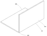
前記第一パネル20について、図6及び図7に基づいて説明する。なお、前記第二パネル21は前記第一パネルと寸法が異なるだけで基本的に同じ構造であるので、説明を省略する。前記第一パネル20の折り曲げ部20Cは、前記第一パネル20の内部に収容される芯材(図示せず)に、直線状の肉薄部を設けることで形成される。即ち、このように肉薄部が形成された芯材を封止袋24に収容し、この封止袋24内を真空とすることで、前記第一パネル20が形成される。そして、前記芯材の肉薄部に当たる部位が前記折り曲げ部20Cとなる。更に、前記第一パネル20を前記折り曲げ部20Cで折り曲げて前記前面パネル部20Aを前記底面パネル部20Bに対し相対的に起こすことで、前記スペーサ16及び底面部10の外側に装着可能な状態となる。なお、前記芯材としては、グラスウール等が用いられる。   The first panel 20 will be described with reference to FIGS. The second panel 21 is basically the same structure except for the size of the first panel, and the description thereof will be omitted. The bent portion 20 </ b> C of the first panel 20 is formed by providing a linear thin portion on a core material (not shown) housed in the first panel 20. That is, the first panel 20 is formed by housing the core material with the thin portion in this manner in the sealing bag 24 and evacuating the sealing bag 24. And the site | part which hits the thin part of the said core material turns into the said bending part 20C. Further, the first panel 20 is bent at the bent portion 20C, and the front panel portion 20A is raised relative to the bottom panel portion 20B so that the first panel 20 can be attached to the outside of the spacer 16 and the bottom portion 10. Become. As the core material, glass wool or the like is used.

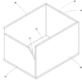
前記真空断熱材パネル19で前記内容器3と前記サーモサイフォン12の蒸発部13と前記スペーサ16とを覆うと、前記第一パネル20と第二パネル21と第三パネル22は、図4に示す位置関係となる。即ち、前記前面パネル部20Aの右端縁部は、前記右側面パネル部21Aの前端縁部と近接(好ましくは当接)する。また、前記前面パネル部20Aの左端縁部は、前記第三パネル22の前端縁部と近接(好ましくは当接)する。また、前記底面パネル部20Bの右端縁部は、前記右側面パネル部21Aの下端縁部と近接(好ましくは当接)する。また、前記底面パネル部20Bの左端縁部は、前記第三パネル22の下端縁部と近接(好ましくは当接)する。また、前記背面パネル部21Bの下端縁部は、前記底面パネル部21Bの後端縁部と近接(好ましくは当接)する。更に、前記背面パネル部21Bの左端縁部は、前記第三パネル22の後端縁部と近接(好ましくは当接)する。そして、前記第一パネル20は、その前面パネル部20Aと底面パネル部20Bが、前記内容器3の前方下部の横縁部にて前記折り曲げ部20Cによって繋がっている。また、前記第二パネル21は、その右側面パネル部21Aと背面パネル部21Bが、前記内容器3の後方右側の縦縁部にて前記折り曲げ部21Cによって繋がっている。このように、前記内容器3の複数の面を一つの前記第一パネル20又は第二パネル21で覆うことにより、前記真空断熱材パネル19間の隙間を減らし、断熱性能を向上させることができる。   When the vacuum insulation panel 19 covers the inner container 3, the evaporator 13 of the thermosiphon 12, and the spacer 16, the first panel 20, the second panel 21, and the third panel 22 are shown in FIG. 4. Positional relationship. That is, the right end edge portion of the front panel portion 20A comes close to (preferably abuts) the front end edge portion of the right side panel portion 21A. Further, the left end edge portion of the front panel portion 20 </ b> A comes close to (preferably abuts) the front end edge portion of the third panel 22. Further, the right end edge portion of the bottom panel portion 20B comes close to (preferably abuts) the lower end edge portion of the right side panel portion 21A. Further, the left end edge portion of the bottom panel portion 20 </ b> B comes close to (preferably abuts) the lower end edge portion of the third panel 22. Moreover, the lower end edge part of the said back panel part 21B adjoins (preferably contact | abuts) the rear-end edge part of the said bottom panel part 21B. Further, the left end edge portion of the back panel portion 21B comes close to (preferably abuts) the rear end edge portion of the third panel 22. The front panel portion 20 </ b> A and the bottom panel portion 20 </ b> B of the first panel 20 are connected by the bent portion 20 </ b> C at the lateral edge portion at the front lower portion of the inner container 3. Further, the right side panel portion 21 </ b> A and the back panel portion 21 </ b> B of the second panel 21 are connected by the bent portion 21 </ b> C at the vertical right edge portion on the rear right side of the inner container 3. Thus, by covering the plurality of surfaces of the inner container 3 with the first panel 20 or the second panel 21, the gap between the vacuum heat insulating material panels 19 can be reduced and the heat insulating performance can be improved. .

更に、前記外容器2と前記真空断熱材パネル19との間には、発泡ウレタンからなる発泡材断熱部25が設けられる。なお、この発泡材断熱部25は、前記真空断熱材パネル19が設けられていない部位においては、前記内容器3と外容器2との間、或いは前記肩部材11と外容器2との間に設けられる。   Further, a foam heat insulating part 25 made of urethane foam is provided between the outer container 2 and the vacuum heat insulating panel 19. The foam heat insulating portion 25 is provided between the inner container 3 and the outer container 2 or between the shoulder member 11 and the outer container 2 in a portion where the vacuum heat insulating material panel 19 is not provided. Provided.

前記蓋体4は、外ケーシング26と内ケーシング27とを有する。なお、前記外ケーシング26の上部内側面は、平坦に形成される。そして、前記外ケーシングの上部内側面には、真空断熱材パネル28が配設される。更に、この真空断熱材パネル28と前記内ケーシング27との間には、発泡材断熱部29が設けられる。なお、前記蓋体4は、前記外容器2に対し、ヒンジ30により開閉可能に枢支される。また、前記蓋体4には、前記肩部材11と蓋体4との隙間を塞ぐパッキン31が設けられる。   The lid 4 has an outer casing 26 and an inner casing 27. The upper inner surface of the outer casing 26 is formed flat. A vacuum heat insulating material panel 28 is disposed on the upper inner surface of the outer casing. Further, a foam heat insulating portion 29 is provided between the vacuum heat insulating material panel 28 and the inner casing 27. The lid 4 is pivotally supported with respect to the outer container 2 by a hinge 30 so as to be opened and closed. The lid 4 is provided with a packing 31 that closes a gap between the shoulder member 11 and the lid 4.

次に、前記冷却容器1の製造工程について説明する。まず、アルミニウム等の金属板を四角筒状に折り曲げて、前記側面部9を形成する。そして、この側面部9の下端部に、前記底面部10を装着して固定する。同様に、前記側面部9の上端部に、前記肩部材11を装着して固定する。更に、前記側面部9の外面に沿って、前記サーモサイフォン12の蒸発部13を配設し、粘着テープ等で固定する。そして、前記側面部9の外面における前記蒸発部13よりも上方に、前記上スペーサ17を貼り付ける。同様に、前記側面部9の外面における前記蒸発部13よりも下方に、前記下スペーサ18を貼り付ける。なお、前述した通り、前記スペーサ16の厚さが、前記側面部9からの前記蒸発部13の突出高さよりもやや大きいので、前記スペーサ16の外面から前記蒸発部13が突出しない。また、前記上スペーサ17及び下スペーサ18の厚さが同じで且つ一定であるので、前記スペーサ16の外面はほぼ平坦となる。更に、前記スペーサ16が柔軟な発泡ゴムからなるので、前記内容器3の側面部9の外面に沿って容易に貼り付けることができる。   Next, the manufacturing process of the cooling container 1 will be described. First, a side plate 9 is formed by bending a metal plate such as aluminum into a square cylinder. Then, the bottom surface portion 10 is attached and fixed to the lower end portion of the side surface portion 9. Similarly, the shoulder member 11 is attached and fixed to the upper end portion of the side surface portion 9. Further, an evaporation portion 13 of the thermosiphon 12 is disposed along the outer surface of the side surface portion 9 and fixed with an adhesive tape or the like. Then, the upper spacer 17 is attached to the outer surface of the side surface portion 9 above the evaporation portion 13. Similarly, the lower spacer 18 is pasted below the evaporation section 13 on the outer surface of the side surface section 9. As described above, since the thickness of the spacer 16 is slightly larger than the protruding height of the evaporation part 13 from the side surface part 9, the evaporation part 13 does not protrude from the outer surface of the spacer 16. Further, since the upper spacer 17 and the lower spacer 18 have the same thickness and are constant, the outer surface of the spacer 16 is substantially flat. Furthermore, since the spacer 16 is made of flexible foam rubber, it can be easily attached along the outer surface of the side surface portion 9 of the inner container 3.

そして、前記スペーサ16の外面及び前記底面部10の外面に、前記真空断熱材パネル19を固定する。なお、この真空断熱材パネル19は、粘着テープ等により固定される。また、前記真空断熱材パネル19のうち、前記第一パネル20の正面パネル部20Aを、正面側の前記スペーサ16及び蒸発部13を覆うように固定し、底面パネル部20Bを、前記底面部10を覆うように固定する。また、前記真空断熱材パネル19のうち、前記第二パネル21の右側面パネル部21Aを、右側面側の前記スペーサ16及び蒸発部13を覆うように固定し、背面パネル部21Bを、背面側の前記スペーサ16及び蒸発部13を覆うように固定する。更に、前記真空断熱材パネル19のうち、前記第三パネル22を、左側面側の前記スペーサ16及び蒸発部13を覆うように固定する。   Then, the vacuum heat insulating material panel 19 is fixed to the outer surface of the spacer 16 and the outer surface of the bottom surface portion 10. The vacuum heat insulating material panel 19 is fixed with an adhesive tape or the like. Further, in the vacuum heat insulating material panel 19, the front panel portion 20A of the first panel 20 is fixed so as to cover the spacer 16 and the evaporation portion 13 on the front side, and the bottom panel portion 20B is fixed to the bottom surface portion 10. Secure the cover. Further, in the vacuum heat insulating material panel 19, the right side panel part 21A of the second panel 21 is fixed so as to cover the spacer 16 and the evaporation part 13 on the right side, and the back panel part 21B is fixed to the back side. It fixes so that the said spacer 16 and the evaporation part 13 may be covered. Further, of the vacuum heat insulating material panel 19, the third panel 22 is fixed so as to cover the spacer 16 and the evaporation part 13 on the left side.

このように、前記サーモサイフォン12、スペーサ16、及び真空断熱材パネル19が固定された前記内容器3を、前記外容器2の内側に組み付けた後、空隙に発泡ウレタンを充填することで、発泡材断熱部25を形成する。そして、前記真空断熱材パネル19を前記スペーサ16の外側に固定することで、前記真空断熱材パネル19と外容器2との間に発泡材を充填して前記発泡材断熱部25を容易に形成することができるので、前記冷却容器1を容易に製造することができる。このようにして、前記冷却容器1の要部が製造される。なお、その他の部位については、製造工程の説明を省略する。   In this manner, after the inner container 3 to which the thermosiphon 12, the spacer 16, and the vacuum heat insulating material panel 19 are fixed is assembled inside the outer container 2, foaming is performed by filling the gap with urethane foam. The material heat insulation part 25 is formed. Then, by fixing the vacuum heat insulating material panel 19 to the outside of the spacer 16, the foam heat insulating material 25 is easily formed by filling a foam material between the vacuum heat insulating material panel 19 and the outer container 2. Therefore, the cooling container 1 can be easily manufactured. Thus, the principal part of the cooling container 1 is manufactured. In addition, about another site | part, description of a manufacturing process is abbreviate | omitted.

このような構成とすることにより、前記冷却容器1の内容器3は、広い範囲が前記真空断熱材パネル19によって覆われることになる。このため、前記冷却容器1の断熱性能を向上させることができる。また、前記真空断熱材パネル19が折り曲げ可能に構成されることで、この真空断熱材パネル19同士の間隙を少なくすることができるので、前記冷却容器1の断熱性能をより高めることができる。   By adopting such a configuration, the inner container 3 of the cooling container 1 is covered with the vacuum heat insulating material panel 19 over a wide range. For this reason, the heat insulation performance of the cooling container 1 can be improved. Moreover, since the said vacuum heat insulating material panel 19 is comprised so that bending is possible, since the clearance gap between these vacuum heat insulating material panels 19 can be decreased, the heat insulation performance of the said cooling vessel 1 can be improved more.

また、前記スペーサ16が断熱性を有する材質で構成されることで、前記冷却容器1の断熱性能をより向上させることができる。また、前記スペーサ16が発泡体としての発泡ゴムからなるシートにより構成されることで、一定の厚さで前記スペーサ16を容易に形成することができるので、前記冷却容器1を容易に製造することができる。また、前記スペーサ16自体の重さを軽くできるので、冷却容器1全体を軽量にすることができる。   Moreover, the heat insulation performance of the said cooling container 1 can be improved more because the said spacer 16 is comprised with the material which has heat insulation. In addition, since the spacer 16 is made of a sheet made of foamed rubber as a foam, the spacer 16 can be easily formed with a constant thickness, and thus the cooling container 1 can be easily manufactured. Can do. Moreover, since the weight of the spacer 16 itself can be reduced, the entire cooling container 1 can be reduced in weight.

次に、本発明の第二の実施形態について、図8乃至図12に基づいて説明する。なお、上述した第一の実施形態と同一部分については、同一の符号を付す。41は、本発明の冷却容器である。なお、本実施形態では、この冷却容器41は携帯型である。この冷却容器41は、外容器2と、内容器3と、蓋体4と、左ケーシング5と、右ケーシング6とを有する。そして、前記左ケーシング5及び右ケーシング6の上部には、それぞれ左把持部7及び右把持部8が設けられる。   Next, a second embodiment of the present invention will be described with reference to FIGS. In addition, the same code | symbol is attached | subjected about the same part as 1st embodiment mentioned above. 41 is a cooling container of the present invention. In the present embodiment, the cooling container 41 is a portable type. The cooling container 41 includes an outer container 2, an inner container 3, a lid body 4, a left casing 5, and a right casing 6. A left grip 7 and a right grip 8 are provided on the upper portions of the left casing 5 and the right casing 6, respectively.

前記外容器2は、合成樹脂により、上方が開口した箱状に形成される。同様に、前記内容器3も、上方が開口した箱状に形成される。この内容器3は、金属板を四角筒状に折り曲げて形成された側面部9と、合成樹脂により皿状に形成された底面部10とを有して構成される。そして、前記側面部9の下端部に前記底面部10を結合させることで、前述したように、上方が開口した箱状の前記内容器3が形成される。なお、前記側面部9を構成する金属板は、アルミニウム等の熱良導性金属からなる板であることが望ましい。また、前記外容器2の上端開口部と前記内容器3の上端開口部は、合成樹脂製の枠状の肩部材11によって接続される。   The outer container 2 is formed of a synthetic resin into a box shape having an upper opening. Similarly, the inner container 3 is also formed in a box shape with the top opened. The inner container 3 includes a side surface portion 9 formed by bending a metal plate into a square tube shape, and a bottom surface portion 10 formed in a dish shape from a synthetic resin. And as mentioned above, the box-shaped inner container 3 whose upper side is opened is formed by joining the bottom surface portion 10 to the lower end portion of the side surface portion 9. The metal plate constituting the side surface portion 9 is preferably a plate made of a heat conductive metal such as aluminum. The upper end opening of the outer container 2 and the upper end opening of the inner container 3 are connected by a frame-shaped shoulder member 11 made of synthetic resin.

前記内容器3の側面部9の外面に沿って、サーモサイフォン12の蒸発部13が配設される。前記サーモサイフォン12の蒸発部13は、前記側面部9の外面に伝熱的に接触した状態で固定される。なお、前記蒸発部13は、前記内容器3に対しては、前記側面部9にのみ伝熱的に接し、前記底面部10には接しない。即ち、前記内容器3の側面部9の外面には、前記サーモサイフォン12の蒸発部13による突条が形成される。また、前記サーモサイフォン12の凝縮部14は、冷熱源としてのスターリング冷凍機15に接続される。そして、前記蒸発部13は、前記凝縮部14から離れるに従って低くなるように形成される。   An evaporator 13 of the thermosiphon 12 is disposed along the outer surface of the side surface 9 of the inner container 3. The evaporation part 13 of the thermosiphon 12 is fixed in a state of being in heat transfer contact with the outer surface of the side part 9. The evaporation unit 13 is in thermal contact with the inner container 3 only on the side surface 9 and not on the bottom surface 10. That is, on the outer surface of the side surface portion 9 of the inner container 3, a protrusion is formed by the evaporation portion 13 of the thermosiphon 12. The condenser 14 of the thermosyphon 12 is connected to a Stirling refrigerator 15 as a cold heat source. The evaporating unit 13 is formed to become lower as the distance from the condensing unit 14 increases.

前記側面部9の外面には、前記蒸発部13を避けるように、スペーサ16が設けられる。このスペーサ16は、上スペーサ17と下スペーサ18とを有する。前記上スペーサ17は、前記サーモサイフォン12の蒸発部13よりも上方において、前記内容器3の側面部9の外面に貼り付けられる。一方、前記下スペーサ18は、前記サーモサイフォン12の蒸発部13よりも下方において、前記内容器3の側面部9の外面に貼り付けられる。即ち、前記サーモサイフォン12の蒸発部13は、前記上スペーサ17と下スペーサ18との間に形成された溝状の間隙に配設される。なお、前記上スペーサ17及び下スペーサ18は、何れも断熱性を有する発泡体としての発泡ゴムのシートによって形成される。そして、これら上スペーサ17及び下スペーサ18の厚さは、それぞれ同じであり、且つ一定である。また、これら上スペーサ17及び下スペーサ18の厚さは、前記側面部9からの前記蒸発部13の突出高さよりもやや大きい。なお、前記底面部10の外面には、前記スペーサ16は貼られない。   A spacer 16 is provided on the outer surface of the side surface portion 9 so as to avoid the evaporation portion 13. The spacer 16 has an upper spacer 17 and a lower spacer 18. The upper spacer 17 is attached to the outer surface of the side surface portion 9 of the inner container 3 above the evaporation portion 13 of the thermosiphon 12. On the other hand, the lower spacer 18 is attached to the outer surface of the side surface portion 9 of the inner container 3 below the evaporation portion 13 of the thermosiphon 12. That is, the evaporator 13 of the thermosiphon 12 is disposed in a groove-like gap formed between the upper spacer 17 and the lower spacer 18. The upper spacer 17 and the lower spacer 18 are each formed of a foamed rubber sheet as a foam having heat insulation properties. The thicknesses of the upper spacer 17 and the lower spacer 18 are the same and constant. Further, the thicknesses of the upper spacer 17 and the lower spacer 18 are slightly larger than the protruding height of the evaporation part 13 from the side surface part 9. The spacer 16 is not attached to the outer surface of the bottom surface portion 10.

前記スペーサ16の外面及び前記底面部10の外面は、真空断熱材パネル42により覆われる。この真空断熱材パネル42は、前面パネル43と、底面パネル44と、背面パネル45と、右側面パネル46と、左側面パネル47とを有する。前記前面パネル43は、前記内容器3の側面部9の前面側に設けられる。また、前記底面パネル44は、前記底面部10を覆うように設けられる。また、前記背面パネル45は、前記内容器3の側面部9の背面側に設けられる。また、前記右側面パネル46は、前記内容器3の側面部9の右側面側に設けられる。更に、前記左側面パネル47は、前記内容器3の側面部9の左側面側に設けられる。なお、前記左側面パネル47の前側上部には、斜めに切り欠かれた切欠部23が設けられる。この切欠部23は、前記サーモサイフォン12を前記側面部9と真空断熱材パネル42との間に配設するために設けられたものである。また、前記左側面パネル47の上端は、前記正面パネル43及び背面パネル45の上端よりも低く構成される。これは、前記スターリング冷凍機15を制御するための温度センサ(図示せず)を設けるためである。   The outer surface of the spacer 16 and the outer surface of the bottom surface portion 10 are covered with a vacuum heat insulating material panel 42. The vacuum heat insulating material panel 42 includes a front panel 43, a bottom panel 44, a back panel 45, a right side panel 46, and a left side panel 47. The front panel 43 is provided on the front side of the side surface portion 9 of the inner container 3. The bottom panel 44 is provided so as to cover the bottom surface portion 10. The back panel 45 is provided on the back side of the side surface portion 9 of the inner container 3. Further, the right side panel 46 is provided on the right side of the side part 9 of the inner container 3. Further, the left side panel 47 is provided on the left side of the side part 9 of the inner container 3. Note that an obliquely cutout portion 23 is provided at the upper front portion of the left side panel 47. The notch 23 is provided to dispose the thermosiphon 12 between the side surface 9 and the vacuum heat insulating material panel 42. Further, the upper end of the left side panel 47 is configured to be lower than the upper ends of the front panel 43 and the back panel 45. This is because a temperature sensor (not shown) for controlling the Stirling refrigerator 15 is provided.

前記真空断熱材パネル42で前記内容器3と前記サーモサイフォン12の蒸発部13と前記スペーサ16とを覆うと、前記各パネル43乃至47は、図11に示す位置関係となる。即ち、前記前面パネル43の右端縁部は、前記右側面パネル46の前端縁部と近接(好ましくは当接)する。また、前記前面パネル43の左端縁部は、前記左側面パネル47の前端縁部と近接(好ましくは当接)する。また、前記前面パネル43の下端縁部は、前記底面パネル44の前端縁部と近接(好ましくは当接)する。また、前記底面パネル44の右端縁部は、前記右側面パネル46の下端縁部と近接(好ましくは当接)する。また、前記底面パネル44の左端縁部は、前記左側面パネル47の下端縁部と近接(好ましくは当接)する。また、前記底面パネル44の後端縁部は、前記背面パネル45の下端縁部と近接(好ましくは当接)する。また、前記背面パネル45の右端縁部は、前記右側面パネル46の後端縁部と近接(好ましくは当接)する。更に、前記背面パネル45の左端縁部は、前記左側面パネル47の後端縁部と近接(好ましくは当接)する。   When the inner container 3, the evaporator 13 of the thermosiphon 12, and the spacer 16 are covered with the vacuum heat insulating material panel 42, the panels 43 to 47 have the positional relationship shown in FIG. 11. That is, the right end edge of the front panel 43 is close to (preferably abuts) the front end edge of the right side panel 46. Further, the left end edge portion of the front panel 43 is close to (preferably abuts) the front end edge portion of the left side panel 47. The lower end edge of the front panel 43 is in close proximity (preferably abutting) with the front end edge of the bottom panel 44. The right edge of the bottom panel 44 is close to (preferably abuts) the lower edge of the right panel 46. Further, the left end edge of the bottom panel 44 is close to (preferably abuts) the lower end edge of the left side panel 47. Further, the rear end edge of the bottom panel 44 is close to (preferably abuts) the lower end edge of the back panel 45. Further, the right end edge portion of the back panel 45 is close to (preferably abuts) the rear end edge portion of the right side panel 46. Further, the left end edge of the back panel 45 is close to (preferably abuts) the rear end edge of the left side panel 47.

更に、前記外容器2と前記真空断熱材パネル42との間には、発泡ウレタンからなる発泡材断熱部25が設けられる。なお、この発泡材断熱部25は、前記真空断熱材パネル42が設けられていない部位においては、前記内容器3と外容器2との間、或いは前記肩部材11と外容器2との間に設けられる。   Further, a foam heat insulating part 25 made of urethane foam is provided between the outer container 2 and the vacuum heat insulating panel 42. The foam heat insulating portion 25 is provided between the inner container 3 and the outer container 2 or between the shoulder member 11 and the outer container 2 in a portion where the vacuum heat insulating material panel 42 is not provided. Provided.

前記蓋体4は、外ケーシング26と内ケーシング27とを有する。なお、前記外ケーシング26の上部内側面は、平坦に形成される。そして、前記外ケーシングの上部内側面には、真空断熱材パネル28が配設される。更に、この真空断熱材パネル28と前記内ケーシング27との間には、発泡材断熱部29が設けられる。なお、前記蓋体4は、前記外容器2に対し、ヒンジ30により開閉可能に枢支される。また、前記蓋体4には、前記肩部材11と蓋体4との隙間を塞ぐパッキン31が設けられる。   The lid 4 has an outer casing 26 and an inner casing 27. The upper inner surface of the outer casing 26 is formed flat. A vacuum heat insulating material panel 28 is disposed on the upper inner surface of the outer casing. Further, a foam heat insulating portion 29 is provided between the vacuum heat insulating material panel 28 and the inner casing 27. The lid 4 is pivotally supported with respect to the outer container 2 by a hinge 30 so as to be opened and closed. The lid 4 is provided with a packing 31 that closes a gap between the shoulder member 11 and the lid 4.

次に、前記冷却容器41の製造工程について説明する。まず、アルミニウム等の金属板を四角筒状に折り曲げて、前記側面部9を形成する。そして、この側面部9の下端部に、前記底面部10を装着して固定する。同様に、前記側面部9の上端部に、前記肩部材11を装着して固定する。更に、前記側面部9の外面に沿って、前記サーモサイフォン12の蒸発部13を配設し、粘着テープ等で固定する。そして、前記側面部9の外面における前記蒸発部13よりも上方に、前記上スペーサ17を貼り付ける。同様に、前記側面部9の外面における前記蒸発部13よりも下方に、前記下スペーサ18を貼り付ける。なお、前述した通り、前記スペーサ16の厚さが、前記側面部9からの前記蒸発部13の突出高さよりもやや大きいので、前記スペーサ16の外面から前記蒸発部13が突出しない。また、前記上スペーサ17及び下スペーサ18の厚さが同じで且つ一定であるので、前記スペーサ16の外面はほぼ平坦となる。更に、前記スペーサ16が柔軟な発泡ゴムからなるので、前記内容器3の側面部9の外面に沿って容易に貼り付けることができる。   Next, the manufacturing process of the cooling container 41 will be described. First, a side plate 9 is formed by bending a metal plate such as aluminum into a square cylinder. Then, the bottom surface portion 10 is attached and fixed to the lower end portion of the side surface portion 9. Similarly, the shoulder member 11 is attached and fixed to the upper end portion of the side surface portion 9. Further, an evaporation portion 13 of the thermosiphon 12 is disposed along the outer surface of the side surface portion 9 and fixed with an adhesive tape or the like. Then, the upper spacer 17 is attached to the outer surface of the side surface portion 9 above the evaporation portion 13. Similarly, the lower spacer 18 is pasted below the evaporation section 13 on the outer surface of the side surface section 9. As described above, since the thickness of the spacer 16 is slightly larger than the protruding height of the evaporation part 13 from the side surface part 9, the evaporation part 13 does not protrude from the outer surface of the spacer 16. Further, since the upper spacer 17 and the lower spacer 18 have the same thickness and are constant, the outer surface of the spacer 16 is substantially flat. Furthermore, since the spacer 16 is made of flexible foam rubber, it can be easily attached along the outer surface of the side surface portion 9 of the inner container 3.

そして、前記スペーサ16の外面及び前記底面部10の外面に、前記真空断熱材パネル42を固定する。なお、この真空断熱材パネル42は、粘着テープ等により固定される。また、前記真空断熱材パネル42のうち、前記正面パネル43を、正面側の前記スペーサ16及び蒸発部13を覆うように固定する。また、前記真空断熱材パネル42のうち、前記底面パネル44を、前記底面部10を覆うように固定する。また、前記真空断熱材パネル42のうち、前記背面パネル45を、背面側の前記スペーサ16及び蒸発部13を覆うように固定する。また、前記真空断熱材パネル42のうち、前記右側面パネル46を、右側面側の前記スペーサ16及び蒸発部13を覆うように固定する。更に、前記真空断熱材パネル42のうち、前記左側面パネル47を、左側面側の前記スペーサ16及び蒸発部13を覆うように固定する。   Then, the vacuum heat insulating material panel 42 is fixed to the outer surface of the spacer 16 and the outer surface of the bottom surface portion 10. The vacuum heat insulating material panel 42 is fixed with an adhesive tape or the like. Moreover, the said front panel 43 among the said vacuum heat insulating material panels 42 is fixed so that the said spacer 16 and the evaporation part 13 of a front side may be covered. Further, the bottom panel 44 of the vacuum heat insulating material panel 42 is fixed so as to cover the bottom surface portion 10. Further, the back panel 45 of the vacuum heat insulating material panel 42 is fixed so as to cover the spacer 16 and the evaporation unit 13 on the back side. Moreover, the right side panel 46 of the vacuum heat insulating material panel 42 is fixed so as to cover the spacer 16 and the evaporation unit 13 on the right side. Furthermore, the left side panel 47 of the vacuum heat insulating material panel 42 is fixed so as to cover the spacer 16 and the evaporation unit 13 on the left side.

このように、前記サーモサイフォン12、スペーサ16、及び真空断熱材パネル42が固定された前記内容器3を、前記外容器2の内側に組み付けた後、空隙に発泡ウレタンを充填することで、発泡材断熱部25を形成する。そして、前記真空断熱材パネル42を前記スペーサ16の外側に固定することで、前記真空断熱材パネル42と外容器2との間に発泡材を充填して前記発泡材断熱部25を容易に形成することができるので、前記冷却容器41を容易に製造することができる。このようにして、前記冷却容器41の要部が製造される。なお、その他の部位については、製造工程の説明を省略する。   In this way, after the inner container 3 to which the thermosiphon 12, the spacer 16, and the vacuum heat insulating material panel 42 are fixed is assembled inside the outer container 2, the foam is filled with urethane foam. The material heat insulation part 25 is formed. And, by fixing the vacuum heat insulating material panel 42 to the outside of the spacer 16, the foam heat insulating material 25 is easily formed by filling a foam material between the vacuum heat insulating material panel 42 and the outer container 2. Therefore, the cooling container 41 can be easily manufactured. In this way, the main part of the cooling container 41 is manufactured. In addition, about another site | part, description of a manufacturing process is abbreviate | omitted.

このような構成とすることにより、前記冷却容器41の内容器3は、広い範囲が前記真空断熱材パネル42によって覆われることになる。このため、前記冷却容器41の断熱性能を向上させることができる。   By adopting such a configuration, the inner container 3 of the cooling container 41 is covered with the vacuum heat insulating material panel 42 over a wide range. For this reason, the heat insulation performance of the cooling container 41 can be improved.

また、前記スペーサ16が断熱性を有する材質で構成されることで、前記冷却容器41の断熱性能をより向上させることができる。また、前記スペーサ16が発泡体としての発泡ゴムからなるシートにより構成されることで、一定の厚さで前記スペーサ16を容易に形成することができるので、前記冷却容器41を容易に製造することができる。また、前記スペーサ16自体の重さを軽くできるので、冷却容器41全体を軽量にすることができる。   Moreover, the heat insulation performance of the cooling container 41 can be further improved by the spacer 16 being made of a heat insulating material. In addition, since the spacer 16 is formed of a sheet made of foamed rubber as a foam, the spacer 16 can be easily formed with a constant thickness, and thus the cooling container 41 can be easily manufactured. Can do. Further, since the weight of the spacer 16 itself can be reduced, the entire cooling container 41 can be reduced in weight.

なお、本発明は以上の実施形態に限定されるものではなく、発明の要旨の範囲内で種々の変形実施が可能である。例えば、上記各実施形態では、内容器の外面にサーモサイフォンを伝熱的に接続したが、内容器の外面にヒートパイプを伝熱的に接続しても良い。また、上記各実施形態では、スペーサを発泡ゴム製のシートにより形成したが、これ以外の断熱部材を用いても良い。また、スペーサは、真空断熱材パネルを配設する際にサーモサイフォン又はヒートパイプが邪魔にならないようにできるものであれば、必ずしも断熱性を有するものでなくても良い。(但し、組立作業性に関与する柔軟性及び冷却容器全体の断熱性に関与する素材自体の断熱性を考慮すれば、発泡ゴム製のシート等の、柔軟で軽量な発泡体が最適である。)更に、上記実施形態では、冷熱源としてスターリング冷凍機を用いたが、これ以外の冷熱源、例えばサーモモジュール等を用いても良い。   In addition, this invention is not limited to the above embodiment, A various deformation | transformation implementation is possible within the range of the summary of invention. For example, in each of the above embodiments, the thermosiphon is connected to the outer surface of the inner container in a heat transfer manner, but a heat pipe may be connected to the outer surface of the inner container in a heat transfer manner. Moreover, in each said embodiment, although the spacer was formed with the sheet | seat made from foamed rubber, you may use heat insulation members other than this. In addition, the spacer does not necessarily have a heat insulating property as long as the thermosiphon or the heat pipe can be kept out of the way when the vacuum heat insulating material panel is disposed. (However, in consideration of the flexibility involved in the assembly workability and the heat insulation of the material itself involved in the heat insulation of the entire cooling container, a flexible and lightweight foam such as a foam rubber sheet is optimal. Furthermore, in the said embodiment, although the Stirling refrigerator was used as a cooling-heat source, you may use other cooling-heat sources, for example, a thermo module.

1,41 冷却容器
2 外容器
3 内容器
9 側面部
10 底面部
12 サーモサイフォン
13 蒸発部
15 スターリング冷凍機(冷熱源)
16 スペーサ
17 上スペーサ
18 下スペーサ
19,42 真空断熱材パネル
20 第一パネル
20A 前面パネル部
20B 底面パネル部
20C 折り曲げ部
21 第二パネル
21A 右側面パネル部
21B 背面パネル部
21C 折り曲げ部
22 第三パネル
25 発泡材断熱部
43 前面パネル
44 底面パネル
45 背面パネル
46 右側面パネル
47 左側面パネル
DESCRIPTION OF SYMBOLS 1,41 Cooling container 2 Outer container 3 Inner container 9 Side surface part 10 Bottom surface part 12 Thermosiphon 13 Evaporating part 15 Stirling refrigerator (cooling heat source)
16 Spacer 17 Upper Spacer 18 Lower Spacer 19, 42 Vacuum Insulation Panel 20 First Panel 20A Front Panel Part 20B Bottom Panel Part 20C Bent Part 21 Second Panel 21A Right Side Panel Part 21B Rear Panel Part 21C Bent Part 22 Third Panel 25 Foam insulation 43 Front panel 44 Bottom panel 45 Rear panel 46 Right side panel 47 Left side panel

Claims (5)

内容器と、この内容器の外側を囲むように設けられる外容器と、前記内容器に沿って伝熱的に接続されるサーモサイフォン又はヒートパイプと、冷熱源と、前記内容器と外容器との間に配置される真空断熱材パネル及び発泡材断熱部とを有する冷却容器において、
前記内容器の外側に、前記サーモサイフォン又はヒートパイプを避けるようにスペーサが設けられ、このスペーサの外側に前記真空断熱材パネルが設けられると共に、この真空断熱材パネルと前記外容器との間に発泡材断熱部が設けられることを特徴とする冷却容器。
An inner container, an outer container provided so as to surround the outer side of the inner container, a thermosiphon or a heat pipe connected in a heat transfer manner along the inner container, a cold source, the inner container and the outer container In a cooling container having a vacuum insulation panel and a foam insulation part disposed between
A spacer is provided outside the inner container so as to avoid the thermosiphon or heat pipe, and the vacuum heat insulating material panel is provided outside the spacer, and between the vacuum heat insulating material panel and the outer container. A cooling container provided with a heat insulating part for foam material.
前記真空断熱材パネルが前記スペーサの外側に固定されることを特徴とする請求項1記載の冷却容器。   The cooling container according to claim 1, wherein the vacuum heat insulating material panel is fixed to the outside of the spacer. 前記スペーサが断熱性を有する材質で構成されることを特徴とする請求項1記載の冷却容器。   The cooling container according to claim 1, wherein the spacer is made of a heat insulating material. 前記スペーサが発泡体シートにより構成されることを特徴とする請求項2記載の冷却容器。   The cooling container according to claim 2, wherein the spacer is made of a foam sheet. 前記真空断熱材パネルが折り曲げ可能に構成されることを特徴とする請求項1記載の冷却容器。   The cooling container according to claim 1, wherein the vacuum heat insulating material panel is configured to be bendable.
JP2018034759A 2018-02-28 2018-02-28 Cooling container Pending JP2019148391A (en)

Priority Applications (1)

Application Number Priority Date Filing Date Title
JP2018034759A JP2019148391A (en) 2018-02-28 2018-02-28 Cooling container

Applications Claiming Priority (1)

Application Number Priority Date Filing Date Title
JP2018034759A JP2019148391A (en) 2018-02-28 2018-02-28 Cooling container

Publications (1)

Publication Number Publication Date
JP2019148391A true JP2019148391A (en) 2019-09-05

Family

ID=67848764

Family Applications (1)

Application Number Title Priority Date Filing Date
JP2018034759A Pending JP2019148391A (en) 2018-02-28 2018-02-28 Cooling container

Country Status (1)

Country Link
JP (1) JP2019148391A (en)

Citations (2)

* Cited by examiner, † Cited by third party
Publication number Priority date Publication date Assignee Title
JPS60155884U (en) * 1984-03-22 1985-10-17 シャープ株式会社 insulation box body
JP2006090654A (en) * 2004-09-24 2006-04-06 Twinbird Corp Cold insulating storage

Patent Citations (2)

* Cited by examiner, † Cited by third party
Publication number Priority date Publication date Assignee Title
JPS60155884U (en) * 1984-03-22 1985-10-17 シャープ株式会社 insulation box body
JP2006090654A (en) * 2004-09-24 2006-04-06 Twinbird Corp Cold insulating storage

Similar Documents

Publication Publication Date Title
JP5500814B2 (en) Insulation structure of vending machine
JP5337681B2 (en) refrigerator
JP5978520B2 (en) Heat insulation box
CN105627657A (en) Refrigerator
JP6091762B2 (en) refrigerator
JP2009024922A (en) Refrigerator
JP6272113B2 (en) refrigerator
JP6550983B2 (en) Reach indoor condensation prevention structure for refrigeration and refrigeration showcase using the same
JP2013242100A (en) Refrigerator heat-insulation box body
JP2019148391A (en) Cooling container
EP2789948A1 (en) Refrigerator
JP2012052674A (en) Water heater
TWI605232B (en) Refrigerator
JP6562682B2 (en) refrigerator
JP5092806B2 (en) vending machine
JPH11142046A (en) Heat insulation wall
KR20150000671U (en) Box-type packaging which can control the internal temperature
JP6901370B2 (en) refrigerator
JP2021169879A (en) refrigerator
WO2019102960A1 (en) Gasket and refrigerator equipped with same
EP4082935A1 (en) Constant temperature container
JP2020128836A (en) Heat insulating door and refrigerator comprising the same
WO2019017138A1 (en) Vacuum heat-insulation case and refrigerator
JP2023146419A (en) Door of refrigerator and refrigerator
JP2019108954A (en) Composite heat insulation panel and heat insulation container

Legal Events

Date Code Title Description
A621 Written request for application examination

Free format text: JAPANESE INTERMEDIATE CODE: A621

Effective date: 20210225

A131 Notification of reasons for refusal

Free format text: JAPANESE INTERMEDIATE CODE: A131

Effective date: 20211206

A521 Request for written amendment filed

Free format text: JAPANESE INTERMEDIATE CODE: A523

Effective date: 20220124

A131 Notification of reasons for refusal

Free format text: JAPANESE INTERMEDIATE CODE: A131

Effective date: 20220609

A521 Request for written amendment filed

Free format text: JAPANESE INTERMEDIATE CODE: A523

Effective date: 20220802

A02 Decision of refusal

Free format text: JAPANESE INTERMEDIATE CODE: A02

Effective date: 20221111