JP2019147331A - Image processing device and image processing method - Google Patents
Image processing device and image processing method Download PDFInfo
- Publication number
- JP2019147331A JP2019147331A JP2018034408A JP2018034408A JP2019147331A JP 2019147331 A JP2019147331 A JP 2019147331A JP 2018034408 A JP2018034408 A JP 2018034408A JP 2018034408 A JP2018034408 A JP 2018034408A JP 2019147331 A JP2019147331 A JP 2019147331A
- Authority
- JP
- Japan
- Prior art keywords
- ink
- image
- sub
- image data
- scanning direction
- Prior art date
- Legal status (The legal status is an assumption and is not a legal conclusion. Google has not performed a legal analysis and makes no representation as to the accuracy of the status listed.)
- Pending
Links
Images


Landscapes
- Ink Jet (AREA)
- Particle Formation And Scattering Control In Inkjet Printers (AREA)
Abstract
Description
本発明は、画像処理装置及び画像処理方法に関する。 The present invention relates to an image processing apparatus and an image processing method.
従来から、紙やフィルムなどの媒体に向かって液滴を噴射することで画像などを印刷するインクジェット方式の印刷装置が知られていた。このような印刷装置では、写真などの画像データを処理して印刷データを生成する画像処理装置を備え、カラーインクで印刷した画像の表面を保護したり、黒濃度を向上させたりするために、カラーインクで形成した画像をクリアインクでオーバーコートするものがある。例えば、特許文献1には、キャリッジを第1方向に移動させて媒体にカラー画像を形成させる第1動作と、キャリッジと媒体とを第2方向に相対移動させる第2動作と、第1動作で形成されたカラー画像の上にクリアインクを吐出させる第3動作とを行う印刷装置が開示されている。
2. Description of the Related Art Conventionally, an ink jet printing apparatus that prints an image or the like by ejecting droplets toward a medium such as paper or film has been known. In such a printing apparatus, an image processing apparatus that processes image data such as a photograph to generate print data is provided. In order to protect the surface of an image printed with color ink or to improve the black density, There are some which overcoat an image formed with color ink with clear ink. For example,
印刷装置には、印刷速度の向上が求められている。そこで、カラーインクを吐出するノズル数をクリアインクを吐出するノズル数よりも多くして、カラー画像の印刷速度を向上させる手法が用いられている。これにより、クリアインクを吐出するノズル数が不足して、全ての画素にクリアインクを吐出することが出来なくなることにより、副走査方向において、周期的なムラ(バンディング)が視認されやすくなり、印刷品質が低下する。そこで、全画素にクリアインクを吐出しないことを前提とした印刷において、バンディングの発生を抑制し印刷品質を向上する画像処理装置が望まれていた。 Printing devices are required to improve printing speed. Therefore, a method is used in which the number of nozzles ejecting color ink is made larger than the number of nozzles ejecting clear ink to improve the printing speed of color images. As a result, the number of nozzles that discharge clear ink is insufficient, and it becomes impossible to discharge clear ink to all pixels, so that periodic unevenness (banding) is easily visible in the sub-scanning direction, and printing is performed. Quality deteriorates. Therefore, an image processing apparatus that suppresses the occurrence of banding and improves print quality in printing based on the premise that clear ink is not discharged to all pixels has been desired.
本願の画像処理装置は、主走査及び副走査を繰り返すことで、媒体に第1インクと前記第1インク上に配置される第2インクとを印刷する印刷装置用の印刷データを、画像データから生成する画像処理装置であって、前記画像データを取得する画像取得部と、前記画像データに基づいて、ハーフトーン処理を行うハーフトーン処理部と、前記ハーフトーン処理された前記画像データに基づいて、前記印刷データを生成する印刷データ生成部と、を備え、前記ハーフトーン処理部は、副走査方向における前記第2インク用のディザマスク格子の長さが、前記副走査方向における前記第1インク用のディザマスク格子の長さよりも長い格子配置で前記ハーフトーン処理を行うことを特徴とする。 The image processing apparatus of the present application repeats main scanning and sub-scanning, and print data for a printing apparatus that prints the first ink and the second ink disposed on the first ink on the medium from the image data. An image processing apparatus for generating an image acquisition unit that acquires the image data, a halftone processing unit that performs halftone processing based on the image data, and the image data that has been subjected to the halftone processing A print data generation unit that generates the print data, wherein the halftone processing unit has a length of the dither mask grid for the second ink in the sub-scanning direction, and the first ink in the sub-scanning direction. The halftone process is performed with a grid arrangement longer than the length of the dither mask grid for use.
本願の画像処理装置は、主走査及び副走査を繰り返すことで、媒体に第1インクと前記第1インク上に配置される第2インクとを印刷する印刷装置用の印刷データを、画像データから生成する画像処理装置であって、前記画像データを取得する画像取得部と、前記画像データに基づいて、ハーフトーン処理を行うハーフトーン処理部と、前記ハーフトーン処理された前記画像データに基づいて、前記印刷データを生成する印刷データ生成部と、を備え、前記ハーフトーン処理部は、前記第1インクに対して、複数のディザマスク格子が副走査方向において互いに連続しない配置であり、前記第2インクに対して、複数のディザマスク格子が主走査方向において互いに連続しない配置でハーフトーン処理を行うことを特徴とする。 The image processing apparatus of the present application repeats main scanning and sub-scanning, and print data for a printing apparatus that prints the first ink and the second ink disposed on the first ink on the medium from the image data. An image processing apparatus for generating an image acquisition unit that acquires the image data, a halftone processing unit that performs halftone processing based on the image data, and the image data that has been subjected to the halftone processing A print data generation unit that generates the print data, wherein the halftone processing unit is arranged so that a plurality of dither mask lattices are not continuous with each other in the sub-scanning direction with respect to the first ink. A halftone process is performed on two inks in an arrangement in which a plurality of dither mask lattices are not continuous with each other in the main scanning direction.
上記の画像処理装置は、前記第2インク用のディザマスク格子を構成する複数のマスク群は、前記第1インク用のディザマスク格子を構成する複数のマスク群を副走査方向に拡張したものであることが好ましい。 In the above image processing apparatus, the plurality of mask groups constituting the dither mask grating for the second ink is an extension of the plurality of mask groups constituting the dither mask grating for the first ink in the sub-scanning direction. Preferably there is.
上記の画像処理装置は、前記第1インクはカラーインクであり、前記第2インクは、クリアインクまたは淡インクであることが好ましい。 In the image processing apparatus, it is preferable that the first ink is a color ink and the second ink is a clear ink or a light ink.
上記の画像処理装置は、前記第2インクとして、クリアインクと淡インクとを併用し、前記ハーフトーン処理部は、前記クリアインクと前記淡インクとで用いるディザマスクを異ならせることが好ましい。 Preferably, the image processing apparatus uses clear ink and light ink in combination as the second ink, and the halftone processing unit uses different dither masks for the clear ink and the light ink.
本願の画像処理方法は、主走査及び副走査を繰り返すことで、媒体に第1インクと前記第1インク上に配置される第2インクとを印刷する印刷装置用の印刷データを、画像データから生成する画像処理方法であって、前記画像データを取得する画像取得工程と、前記画像データに基づいて、ハーフトーン処理を行うハーフトーン処理工程と、前記ハーフトーン処理された前記画像データに基づいて、前記印刷データを生成する印刷データ生成工程と、を備え、前記ハーフトーン処理工程は、副走査方向における前記第2インク用のディザマスク格子の長さが、前記副走査方向における前記第1インク用のディザマスク格子の長さよりも長い格子配置で前記ハーフトーン処理を行うことを特徴とする。 According to the image processing method of the present application, print data for a printing apparatus that prints a first ink and a second ink disposed on the first ink on a medium by repeating main scanning and sub-scanning from image data. An image processing method to generate, an image acquisition step for acquiring the image data, a halftone processing step for performing a halftone process based on the image data, and a method based on the image data subjected to the halftone process A print data generation step for generating the print data, wherein the halftone processing step is such that the length of the dither mask grating for the second ink in the sub-scanning direction is equal to the first ink in the sub-scanning direction. The halftone process is performed with a grid arrangement longer than the length of the dither mask grid for use.
本願の画像処理方法は、主走査及び副走査を繰り返すことで、媒体に第1インクと前記第1インク上に配置される第2インクとを印刷する印刷装置用の印刷データを、画像データから生成する画像処理方法であって、前記画像データを取得する画像取得工程と、前記画像データに基づいて、ハーフトーン処理を行うハーフトーン処理工程と、前記ハーフトーン処理された前記画像データに基づいて、前記印刷データを生成する印刷データ生成工程と、を備え、前記ハーフトーン処理工程は、前記第1インクに対して、複数のディザマスク格子が副走査方向において互いに連続しない配置であり、前記第2インクに対して、複数のディザマスク格子が主走査方向において互いに連続しない配置でハーフトーン処理を行うことを特徴とする。 According to the image processing method of the present application, print data for a printing apparatus that prints a first ink and a second ink disposed on the first ink on a medium by repeating main scanning and sub-scanning from image data. An image processing method to generate, an image acquisition step for acquiring the image data, a halftone processing step for performing a halftone process based on the image data, and a method based on the image data subjected to the halftone process A print data generation step for generating the print data, wherein the halftone processing step is an arrangement in which a plurality of dither mask lattices are not continuous with each other in the sub-scanning direction with respect to the first ink. A halftone process is performed on two inks in an arrangement in which a plurality of dither mask lattices are not continuous with each other in the main scanning direction.
以下、本発明の実施形態について、図面を参照して説明する。なお、図1では、説明の便宜上、互いに直交する三軸として、X軸、Y軸及びZ軸を図示しており、軸方向を図示した矢印の先端側を「+側」、基端側を「−側」としている。X軸に平行な方向を「X軸方向」、Y軸に平行な方向を「Y軸方向」、Z軸に平行な方向を「Z軸方向」という。 Hereinafter, embodiments of the present invention will be described with reference to the drawings. In FIG. 1, for convenience of explanation, the X axis, the Y axis, and the Z axis are illustrated as three axes orthogonal to each other, the tip side of the arrow indicating the axial direction is “+ side”, and the base end side is “− Side”. The direction parallel to the X axis is referred to as “X axis direction”, the direction parallel to the Y axis is referred to as “Y axis direction”, and the direction parallel to the Z axis is referred to as “Z axis direction”.
(実施形態)
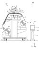
図1は、実施形態に係る印刷装置の概略構成を示す斜視図である。図2は、印刷システムの全体構成を示す断面図である。図3は、印刷システムを制御する電気的構成を模式的に示すブロック図である。まず、本実施形態に係る印刷システム120の概略構成について図1から図3を参照して説明する。なお、本実施形態では、媒体Sに画像などを形成するインクジェット式の印刷装置100と、印刷装置100に印刷を実行させる印刷装置用の印刷データを、画像データから生成する画像処理装置110とを備えた印刷システム120を例に上げて説明する。
(Embodiment)
FIG. 1 is a perspective view illustrating a schematic configuration of a printing apparatus according to an embodiment. FIG. 2 is a cross-sectional view showing the overall configuration of the printing system. FIG. 3 is a block diagram schematically showing an electrical configuration for controlling the printing system. First, a schematic configuration of the
<画像処理装置の概略構成>
まず、画像処理装置110の構成について説明する。
図2および図3に示すように、画像処理装置110は、プリンター制御部111、入力部112、表示部113、記憶部114などを備えている。画像処理装置110としては、パーソナルコンピューター等を使用することができる。画像処理装置110は、印刷装置100と同じ筐体に設けられた構成であってもよい。
<Schematic configuration of image processing apparatus>
First, the configuration of the
As shown in FIGS. 2 and 3, the
プリンター制御部111は、入力部112、表示部113の制御や、印刷装置100に印刷を行わせる印刷ジョブの制御を行うものであり、印刷装置100の制御部1と協調して印刷システム120の全体を制御する。画像処理装置110が動作するソフトウェアには、印刷する画像データを扱う一般的な画像処理アプリケーションソフトウェア(以下アプリケーションと言う)や、印刷装置100に印刷を実行させるための印刷データを生成するプリンタードライバーソフトウェア(以下プリンタードライバーと言う)が含まれる。
The
プリンター制御部111は、CPU(Central Processing Unit)115や、ASIC(Application Specific Integrated Circuit)116、DSP(Digital Signal Processor)117、メモリー118、インターフェイス部(I/F)119などを備え、印刷システム120全体の集中管理を行う。表示部113は、例えば液晶ディスプレイで構成されている。表示部113には、プリンター制御部111の制御の基に、入力部112から入力される情報や、印刷装置100に印刷する画像などが表示される。
The
入力部112は、キーボードや情報入力機器が接続されるポート、表示部113(液晶ディスプレイ)の表面に設けられたタッチパネルなどで構成されている。入力部112は、画像データを取得する画像取得部としても機能する。表示部113は、GUI(Graphical User Interface)ボタン等により、各種コマンドの選択肢を表示すると共に、ユーザーが、入力部112によりコマンドを選択することにより、各種コマンドが入力される。記憶部114は、ハードディスクドライブ(HDD)やメモリーカードなどの書き換え可能な記憶媒体であり、画像処理装置110が動作するソフトウェア(プリンター制御部111で動作するプログラム)や、印刷する画像、印刷ジョブに関係する情報などが記憶される。メモリー118は、CPU115が動作するプログラムを格納する領域や動作する作業領域などを確保する記憶媒体であり、RAM、EEPROMなどの記憶素子によって構成される。
The
<印刷装置の概略構成>
次に、印刷装置100の構成について図1から図3を参照して説明する。本実施形態の印刷装置100は、比較的大型のメディア(媒体)を扱うロール・ツー・ロール方式のラージフォーマットプリンター(LFP)である。
<Schematic configuration of printing device>
Next, the configuration of the
図1から図3に示すように、印刷装置100は、媒体Sを搬送方向に搬送させる搬送部としての搬送ローラー対21、ロール体R1の媒体Sを搬送ローラー対21に供給するための媒体供給部14、搬送される媒体Sに印刷を行う印刷部58、印刷された媒体をロール状に巻き取る媒体巻取部15、を含んで構成されている。印刷部58は、略直方体状の筐体部51内に設けられている。これらの各部は、車輪12が下端に取り付けられた一対の脚部13に支持されている。なお、本実施形態においては、重力方向に沿う上下方向をZ軸とし+Z軸側を「上」とする。Z軸方向と交差する筐体部51の長手方向(左右方向)をX軸とし+X軸側を「左」とする。また、Z軸方向及びX軸方向の双方と交差する方向(前後方向)をY軸とし+Y軸側を「前」とする。また、媒体Sの搬送方向に沿う位置関係を「上流側」「下流側」ともいう。
As shown in FIGS. 1 to 3, the
媒体供給部14は、筐体部51の後側(−Y軸方向)に設けられている。媒体供給部14には、未使用の媒体Sが円筒状に巻き重ねられたロール体R1が保持されている。なお、媒体供給部14には、媒体Sの幅(X軸方向の長さ)や巻き数の異なる複数サイズのロール体R1が交換可能に装填される。また、ロール体R1は何れのサイズであっても、−X軸側の端部に寄せた状態で媒体供給部14に装填される。そして、ロール体R1の装填された媒体供給部14を図2における反時計回り方向に回転させることで、ロール体R1から媒体Sが巻き解かれて印刷部58へ給送される。なお、本実施形態では、媒体Sに印刷される印刷面が外側に巻かれた外巻きのロール体R1を示している。また、本印刷装置100では、媒体Sとして、例えば、64インチ(Inch)程度の幅を有する塩化ビニル系フィルム等が使用される。
The
媒体巻取部15は、筐体部51の前側(+Y軸方向)に設けられている。媒体巻取部15には、印刷部58で印刷された媒体Sが円筒状に巻き取られてロール体R2が形成される。媒体巻取部15は、媒体Sを巻き取ってロール体R2を形成させるための芯材を挟む一対のホルダー17を備えている。一方のホルダー17aには、芯材に回動力を供給する巻取モーター(図示せず)が備えられている。巻取モーターが駆動され芯材が回転することにより、媒体Sが芯材に巻き取られロール体R2を形成する。媒体巻取部15には、自重によって垂れ下がる媒体Sの裏面側を押圧し、媒体巻取部15に巻き取られる媒体Sに張力を付与するテンションローラー16が備えられている。
The
なお、本実施形態の印刷装置100では、媒体Sをロール体R2に巻き取ることなく排出することも可能となっている。例えば、印刷後の媒体Sは、媒体巻取部15に替えて取り付けられる不図示の排出バスケットに収容することもできる。
In the
印刷装置100は、搬送ローラー対21によって搬送される媒体Sを搬送方向に案内する媒体案内部として上流側案内部23、プラテン24および下流側案内部25を備えている。媒体案内部は、媒体Sの搬送経路22において媒体Sを下方(−Z軸側)から支持するものである。上流側案内部23は、筐体部51の後側(−Y軸側)に設けられ、媒体供給部14から供給される媒体Sを搬送ローラー対21に案内する。プラテン24は、印刷部58と対向する位置に設けられ、印刷中の媒体Sを支持する。下流側案内部25は、筐体部51の前側(+Y軸側)に設けられ、印刷された媒体Sをプラテン24から媒体巻取部15へ案内する。上流側案内部23、プラテン24及び下流側案内部25は、媒体Sの搬送経路22を構成している。
The
印刷装置100は、媒体Sを加熱する第1ヒーター(プレヒーター)26と、第2ヒーター(プラテンヒーター)27と、第3ヒーター(アフターヒーター)28とを備えている。第1ヒーター26は、上流側案内部23に支持されている媒体Sを予熱する。第1ヒーター26は、上流側案内部23における媒体Sを支持する面とは反対側の面(−Z軸側の面)側に配置されている。第2ヒーター27は、媒体Sに印刷が行われる領域において媒体Sを加熱する。第2ヒーター27は、プラテン24における媒体Sを支持する面とは反対側の面(−Z軸側の面)側に配置されている。第3ヒーター28は、媒体Sを加熱することによりインクを媒体Sに速やかに乾燥定着させ、滲みやぼやけを防止して、画質を高める構成となっている。第3ヒーター28は、下流側案内部25における媒体Sを支持する面とは反対側の面(−Z軸側の面)側に配置されている。
The
第1、第2及び第3ヒーター26,27,28は、例えば、チューブヒーターであり、アルミテープ等を介して、上流側案内部23、プラテン24及び下流側案内部25のそれぞれの裏面に貼付されている。そして、第1、第2及び第3ヒーター26,27,28を駆動させることにより、熱伝導で上流側案内部23、プラテン24及び下流側案内部25における媒体Sを支持する面が加熱され、媒体Sの裏側(−Z軸側)から媒体Sを加熱することができる。そして、例えば、第1ヒーター26の加熱温度が40℃に設定され、第2ヒーター27の加熱温度が40℃(目標温度)に設定される。また、第3ヒーター28の加熱温度が第1ヒーター26や第2ヒーター27よりも高い50℃に設定される。
The first, second, and
第1ヒーター26は、媒体Sを常温から目標温度(第2ヒーター27における温度)に向けて徐々に昇温させることによって、インクの着弾時からの乾燥を速やかに促す構成となっている。また、第2ヒーター27は、目標温度を維持した状態でインクの着弾を媒体Sに受けさせて、インクの着弾時からの乾燥を速やかに促す構成となっている。そして、第3ヒーター28では、媒体Sを目標温度よりも高い温度まで昇温させ、媒体Sに着弾したインクのうち未だ乾燥していないものを速やかに乾燥させ、少なくとも媒体巻取部15で巻き取る前に、着弾したインクを媒体Sに完全に乾燥定着させる構成となっている。
The
搬送ローラー対21は、媒体Sの搬送方向と交差する方向に延在し、プラテン24と上流側案内部23との間に設けられている。搬送ローラー対21は、搬送経路22の下側に配置されて回転駆動する搬送駆動ローラー21aと、この搬送駆動ローラー21aの上側に配置され、搬送駆動ローラー21aの回転に従動して回転する搬送従動ローラー21bとを備えている。搬送従動ローラー21bは、搬送駆動ローラー21aに対して離間又は圧接するように移動可能に構成されている。搬送駆動ローラー21aと搬送従動ローラー21bとが圧接された状態において、搬送ローラー対21は、媒体Sを挟持(ニップ)しつつ搬送方向(+Y軸方向)の印刷部58に送り出す。筐体部51内には、搬送駆動ローラー21aに回転動力を出力する動力源としての搬送用モーター(図示せず)が設けられている。搬送用モーターが駆動されて搬送駆動ローラー21aが回転駆動することで、搬送従動ローラー21bと搬送駆動ローラー21aとの間に挟持された媒体Sが搬送方向(+Y軸方向)へ搬送される。
The
筐体部51の−X軸方向の上部には、操作パネル62が設けられている。操作パネル62は、印刷条件設定画面等が表示される表示部64と、印刷条件等の入力及び各種指示を与える際に操作される操作部63とを備えている。筐体部51の−X軸方向の下部には、インクを収容可能な図示しないインク収容容器(インクカートリッジ)を装着可能なインク装着部65が設けられている。インク装着部65には、インクの種類や色に対応して、複数のインクカートリッジが装着される。例えば、インクの種類としてシアン(C)、マゼンタ(M)、イエロー(Y)、ブラック(K)のカラーインク、およびカラーインクで印刷した画像の表面を保護したり、黒濃度を向上させたりするためのクリアインク(CL)を有している。さらに、筐体部51内には、印刷装置100の各部に備えられている装置の動作を制御する制御部1が設けられている。
An
筐体部51の内部には、印刷部58が備えられている。筐体部51の背面側(−Y軸側)には、上流側案内部23の上側となる位置に、印刷部58へ媒体Sを供給するための供給口18が形成されている。また、筐体部51の前面側(+Y軸側)には、下流側案内部25の上側となる位置に、印刷部58で印刷された媒体Sを排出するための排出口19が形成されている。
A
印刷部58は、プラテン24の配置位置に対して上方(+Z軸側)に配置され、媒体Sの幅方向に移動可能に設けられている。印刷部58は、媒体供給部14から給送され上流側案内部23及びプラテン24に沿って搬送される媒体Sに対してインクを吐出する吐出ヘッド52、吐出ヘッド52が搭載されるキャリッジ55、キャリッジ55を搬送方向と交差する主走査方向(X軸方向)に移動させるヘッド移動部59などを有している。
The
ヘッド移動部59は、主走査方向にキャリッジ55(吐出ヘッド52)を移動させる。キャリッジ55は、X軸方向に沿って配置されたガイドレール56,57に支持され、ヘッド移動部59によって±X軸方向に往復移動可能に構成されている。ヘッド移動部59の機構としては、例えば、ボールねじとボールナットとを組み合わせた機構や、リニアガイド機構などを採用することができる。さらに、ヘッド移動部59には、キャリッジ55をX軸方向に沿って移動させるための動力源として、モーター(図示せず)が設けられている。制御部1の制御によりモーターが駆動されると、吐出ヘッド52は、キャリッジ55と共にX軸方向に沿って往復移動する。
The
ガイドレール56,57のX軸方向における両端部には、吐出ヘッド52と媒体Sとの離間距離を調整するために吐出ヘッド52の高さ(Z軸方向における位置)を変化させる調整機構53が設けられている。また、キャリッジ55の下部には、吐出ヘッド52よりも搬送方向の下流側(+Y軸側)となる位置に、媒体Sの紙幅(X軸方向の幅)を検知する反射型センサー54が保持されている。
At both ends of the guide rails 56 and 57 in the X-axis direction, there are
反射型センサー54は、図示しない光源部及び受光部を備えた光学式センサーであり、光源部から下方に向けて出射した光の反射光を受光部で受光し、受光部で受けた反射光の強さに応じた検出値(電圧値)を制御部1に出力する。また、キャリッジ55を主走査方向へ移動させながら反射型センサー54で検出を行い、制御部1が検出値に基づいて反射対象の変化する位置、すなわち媒体SのX軸方向における両端部の位置を検知することで、媒体Sの幅(X軸方向における長さ)を算出する。そして、検出された媒体Sの幅に応じて、吐出ヘッド52がインク収容容器から供給されるインクを搬送経路22に沿って搬送される媒体Sに対して噴射することで、印刷が行われる。印刷後の媒体Sは、下流側案内部25に沿って斜め下方に案内され、媒体巻取部15によって巻き取られる。
The
図3に示すように、印刷装置100は、印刷装置100に備えられている各部の制御を行う制御部1を有している。
制御部1は、制御回路4、インターフェイス部(I/F)2、CPU3、メモリー5、などを含んで構成されている。インターフェイス部2は、入力信号や画像を取り扱う画像処理装置110と制御部1との間でデータの送受信を行うためのものであり、画像処理装置110で生成された印刷データなどを受信する。CPU3は、各種の入力信号処理や印刷装置100全体の制御を行うための演算処理装置である。
メモリー5は、CPU3のプログラムを格納する領域や作業領域などを確保するための記憶媒体であり、RAM(Random Access Memory)、EEPROM(Electrically Erasable Programmable Read Only Memory)などの記憶素子を有している。
As illustrated in FIG. 3, the
The
The
制御部1は、制御回路4から出力する制御信号によって搬送駆動ローラー21aに備えられている搬送用モーターの駆動を制御して媒体Sを搬送方向(+Y軸方向)に移動させる。制御部1は、制御回路4から出力する制御信号によってヘッド移動部59に備えられているモーターの駆動を制御して吐出ヘッド52が搭載されているキャリッジ55を媒体Sの幅方向(X軸方向)に移動させる。制御部1は、制御回路4から出力する制御信号によって吐出ヘッド52の駆動を制御して媒体Sに向かってインクを吐出させる。また、制御部1は、図示しない各装置を制御する。
The
制御部1が、ヘッド移動部59及び吐出ヘッド52を制御して、吐出ヘッド52からインクを吐出させながらキャリッジ55(吐出ヘッド52)を移動させる主走査を行うことで、主走査方向にドットの並ぶラスターラインが形成される。そして、この主走査と、制御部1が搬送駆動ローラー21aを制御して媒体Sを搬送方向に搬送させる副走査と、を繰り返すことで搬送方向にラスターラインが並び、媒体Sに画像などが形成される。
The
なお、本実施形態では、長尺の媒体Sをロール・ツー・ロール方式で供給する印刷装置100の構成を示したが、これに限定するものではない。例えば、印刷装置は、予め所定の長さにカットされた単票紙を枚葉式で供給する構成であってもよし、印刷後の媒体Sを媒体巻取部15に替えて取り付けられる不図示の排出バスケットに収容する構成であってもよい。
In the present embodiment, the configuration of the
<画像処理>
図4は、画像を印刷させるための画像処理を説明する図である。次に、印刷データの生成処理について、図4を参照して説明する。媒体Sへの印刷は、画像処理装置110から印刷装置100に印刷データが送信されることにより開始される。印刷データは、プリンタードライバーによって生成される。
<Image processing>
FIG. 4 is a diagram for explaining image processing for printing an image. Next, print data generation processing will be described with reference to FIG. Printing on the medium S is started when print data is transmitted from the
プリンタードライバーは、入力部112で取得した画像データ(例えば、テキストデータやフルカラーのイメージデータなど)をアプリケーションから受け取り、印刷装置100の制御部1が解釈できる形式の印刷データに変換し、印刷データを制御部1に出力する。アプリケーションからの画像データを印刷データに変換する際に、プリンタードライバーは、解像度変換処理・色変換処理(ICCプロファイル生成)・ハーフトーン処理・ラスタライズ処理・コマンド付加処理などを行う。すなわち、プリンタードライバーは、ソフトウェア(あるいはファームウェア)による機能部として、画像データに基づいてハーフトーン処理を行うハーフトーン処理部、ハーフトーン処理された画像データに基づいて印刷データを生成する印刷データ生成部などを備えている(図示省略)。
The printer driver receives image data (for example, text data or full-color image data) acquired by the
ステップS1の解像度変換処理は、アプリケーションから出力された画像データを、媒体Sに印刷する際の解像度(印刷解像度)に変換する処理である。例えば、印刷解像度が720×720dpiに指定されている場合、アプリケーションから受け取ったベクター形式の画像データを720×720dpiの解像度のビットマップ形式の画像データに変換する。解像度変換処理後の画像データの各画素データは、マトリクス状に配置された画素から構成されている。各画素はRGB色空間の例えば256階調の階調値を有している。つまり、解像度変換後の画素データは、対応する画素の階調値を示すものである。
マトリクス状に配置された画素の内の所定の方向に並ぶ1列分の画素に対応する画素データを、ラスタデータという。なお、ラスタデータに対応する画素が並ぶ所定の方向は、画像を印刷するときの吐出ヘッド52の移動方向(主走査方向)と対応している。
The resolution conversion process of step S1 is a process of converting the image data output from the application to a resolution (print resolution) when printing on the medium S. For example, when the print resolution is specified as 720 × 720 dpi, the vector format image data received from the application is converted into bitmap format image data with a resolution of 720 × 720 dpi. Each pixel data of the image data after the resolution conversion process is composed of pixels arranged in a matrix. Each pixel has a gradation value of, for example, 256 gradations in the RGB color space. That is, the pixel data after resolution conversion indicates the gradation value of the corresponding pixel.
Pixel data corresponding to one column of pixels arranged in a predetermined direction among pixels arranged in a matrix is called raster data. The predetermined direction in which the pixels corresponding to the raster data are arranged corresponds to the moving direction (main scanning direction) of the
ステップS2の色変換処理は、RGB色空間からCMYK色空間のデータに変換する処理である。この変換を行うシステムとして、カラーマネージメントシステムが使用される。カラーマネージメントシステムは、それらの色空間の対応関係を記述したプロファイル(例えば、ICC(International Color Consortium)プロファイル)を使用して色空間を変換する。色空間変換は、画像データを取り扱う特定の機器に依存する依存色空間(RGB色空間)から機器に依存しない非依存色空間(例えば、CIELAB色空間)に変換し、その後、出力側の印刷装置100の色空間(CMYK色空間)に変換することにより行われる。
CMYK色とは、シアン(C)、マゼンタ(M)、イエロー(Y)、ブラック(K)であり、CMYK色系空間の画像データは、印刷装置100が有するインクの色に対応したデータである。従って、例えば、印刷装置100がCMYK色系の4種類のインクを使用する場合には、プリンタードライバーは、RGBデータに基づいて、CMYK色系の4次元空間の画像データを生成する。この色変換処理は、RGBデータの階調値とCMYK色系データの階調値とを対応づけたテーブル(色変換ルックアップテーブルLUT)に基づいて行われる。なお、色変換処理後の画素データは、CMYK色系空間により表される例えば256階調のCMYK色系データである。
The color conversion process of step S2 is a process of converting from RGB color space to data in CMYK color space. A color management system is used as a system for performing this conversion. The color management system converts a color space using a profile (for example, an ICC (International Color Consortium) profile) that describes the correspondence between these color spaces. In the color space conversion, a dependent color space (RGB color space) depending on a specific device that handles image data is converted into a device independent color space (for example, CIELAB color space), and then the output side printing apparatus This is performed by converting into 100 color spaces (CMYK color space).
The CMYK colors are cyan (C), magenta (M), yellow (Y), and black (K), and the image data in the CMYK color system space is data corresponding to the ink color that the
ステップS3のハーフトーン処理は、高階調数(256階調)のインク量データを、印刷装置100が形成可能な階調数のデータに変換する処理である。ハーフトーン処理は、ハーフトーン処理部によって行われる。このハーフトーン処理により、256階調を示すインク量データが、2階調(ドット有り、無し)を示す1ビットデータや、4階調(ドット無し、小ドット、中ドット、大ドット)を示す2ビットデータに変換される。具体的には、階調値(0〜255)とドット生成率が対応したドット生成率テーブルから、階調値に対応するドットの生成率(例えば、4階調の場合は、ドット無し、小ドット、中ドット、大ドットのそれぞれの生成率)を求め、得られた生成率において、ディザ法・誤差拡散法などを利用して、ドットが分散して形成されるように画素データが作成される。
つまり、ハーフトーン処理後の画素データは、1ビットまたは2ビットのデータであり、この画素データは各画素でのドットの形成(ドットの有無、ドットの大きさ)を示すデータになる。例えば、2ビット(4階調)の場合、ドット無しに対応するドット階調値[00]、小ドットの形成に対応するドット階調値[01]、中ドットの形成に対応するドット階調値[10]、及び、大ドットの形成に対応するドット階調値[11]のように4段階に変換される。
The halftone process of step S3 is a process of converting the ink amount data having a high gradation number (256 gradations) into data having the gradation number that can be formed by the
That is, pixel data after halftone processing is 1-bit or 2-bit data, and this pixel data is data indicating dot formation (the presence or absence of dots, the size of dots) in each pixel. For example, in the case of 2 bits (4 gradations), a dot gradation value [00] corresponding to no dot, a dot gradation value [01] corresponding to the formation of a small dot, and a dot gradation corresponding to the formation of a medium dot A value [10] and a dot gradation value [11] corresponding to the formation of a large dot are converted into four levels.
ステップS4のラスタライズ処理は、マトリクス状に並ぶ画素データ(例えば、2ビットのデータ)を、印刷時のドット形成順序に従って並べ替える処理である。ラスタライズ処理には、ハーフトーン処理後の画素データによって構成される画像データを、吐出ヘッド52が往復移動しながら液滴を吐出する各主走査に割り付けるパス割り付け処理が含まれる。パス割り付けが完了すると、印刷画像を構成する各ラスターラインを形成する実際のノズルが割り付けられる。
The rasterization process in step S4 is a process of rearranging pixel data arranged in a matrix (for example, 2-bit data) according to the dot formation order at the time of printing. The rasterizing process includes a path allocating process in which image data composed of pixel data after halftone processing is allocated to each main scan that ejects droplets while the
ステップS5のコマンド付加処理は、ラスタライズ処理されたデータに、印刷方式に応じたコマンドデータを付加する処理である。コマンドデータとしては、例えば媒体の搬送仕様(搬送方向への移動量や速度など)に関わる搬送データなどがある。ラスタライズ処理およびコマンド付加処理は、印刷データ生成部で行われ印刷データが生成される。
ステップS6の印刷データ送信処理は、生成された印刷データを、インターフェイス部119を介して印刷装置100に送信する処理である。
プリンタードライバーによるステップS1からステップS6の処理は、CPU115の制御のもとにASIC116及びDSP117によって行われる(図3参照)。
The command addition process in step S5 is a process for adding command data corresponding to the printing method to the rasterized data. The command data includes, for example, transport data related to the transport specifications of the medium (the amount of movement in the transport direction, the speed, etc.). Rasterization processing and command addition processing are performed by the print data generation unit to generate print data.
The print data transmission process in step S6 is a process of transmitting the generated print data to the
The processing from step S1 to step S6 by the printer driver is performed by the
<ヘッドの構成>
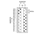
図5は、吐出ヘッドが有するノズルの配列を説明する図である。なお、図5では、説明の便宜上、第1インクとしての複数のカラーインクのうちの1種類であるブラックインク(K)と、第2インクとしてのクリアインク(CL)とのノズル配置を示している。
図5に示すように、吐出ヘッド52には、ブラックインク(K)、クリアインク(CL)のノズル列が含まれている。各ノズル列は、副走査方向に並ぶ複数のノズルを有している。図5では、各ノズル列は、例えば、16個のノズルで構成され、各ノズルには副走査方向における上流側よりノズル番号#1から#16を示している。各ノズルは、奇数のノズル番号のノズルで構成される奇数ノズル列と偶数のノズル番号のノズルで構成される偶数ノズル列とを有している。各ノズルは、副走査方向において300Dpi(dots per inch)のノズルピッチで設けられている。
<Configuration of head>
FIG. 5 is a diagram illustrating the arrangement of nozzles included in the ejection head. For convenience of explanation, FIG. 5 shows a nozzle arrangement of black ink (K), which is one kind of a plurality of color inks as the first ink, and clear ink (CL) as the second ink. Yes.
As shown in FIG. 5, the
印刷装置には、印刷速度の向上が求められており、本実施形態の印刷装置100では、カラーインク(ブラックインク)を吐出するノズル数をクリアインクを吐出するノズル数よりも多くしてカラー画像の印刷速度を向上させている。具体的には、ブラックインクはノズル番号#1から#12のノズルからインクを吐出し、クリアインクはノズル番号#13から#16のノズルからインクを吐出する。図5においては、インクを吐出しないノズルを黒丸で示している。
The printing apparatus is required to improve the printing speed. In the
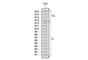
図6は、図5におけるノズル列を簡略化して示す図である。図6に示すように、図5に示したブラックインク(K)のノズル列とクリアインク(CL)のノズル列とは、ブラックインクを吐出するノズル番号#1から#12のノズルと、クリアインク(CL)を吐出するノズル番号#13から#16のノズルとを組み合わせた1列のノズル列を備えた吐出ヘッド52Xと見なすことが出来る。
FIG. 6 is a diagram showing the nozzle rows in FIG. 5 in a simplified manner. As shown in FIG. 6, the nozzle row of black ink (K) and the nozzle row of clear ink (CL) shown in FIG. 5 are the nozzles of
図7は、副走査方向における吐出ヘッドと媒体Sとの相対位置関係を説明する図である。本実施形態の印刷装置100は、吐出ヘッド52Xからインクを吐出しながら主走査方向へ移動させる主走査(以下、パスともいう)、および媒体Sを副走査方向に送る副走査を4回繰り返す。これにより、主走査方向にドットが並ぶラスターラインを形成し、媒体Sにブラックインク(K)とブラックインク(K)上に配置されるクリアインクとを印刷する。クリアインクは、黒濃度を向上させる効果があるので、第2インクにクリアインクを用いることで画像品質を向上することができる。
FIG. 7 is a diagram illustrating the relative positional relationship between the ejection head and the medium S in the sub-scanning direction. The
図7に示すように、制御部1は、最初のパス(パス1)を実行した後、媒体Sを4ノズル分に相当する距離だけ副走査方向に搬送し、次のパス(パス2)を実行する。これをパス4まで繰り返し実行することで、主走査方向にドットが並ぶラスターラインを形成する。なお、図7では、説明の便宜上、媒体Sに対して吐出ヘッド52Xが移動するように図示しているが、実際は吐出ヘッド52Xに対して媒体Sが副走査方向に移動する。
As shown in FIG. 7, after executing the first pass (pass 1), the
<ドット形成可能位置>
図8は、パス毎にインクを吐出可能な画素位置を示す図である。図8の左側には、各パスにおける吐出ヘッド52Xと媒体Sとの相対位置を示し、図8の右側には、各パスにおいて媒体Sにドットを形成可能な画素位置を示している。各パスにおける媒体Sの左側には、主走査方向に並ぶ画素に対応するラスターライン番号(例えば「L16」)を示している。また、媒体Sの上側には、副走査方向に並ぶ画素に対応する水平位置を「1」又は「2」の番号で示している。
<Position where dots can be formed>
FIG. 8 is a diagram illustrating pixel positions where ink can be ejected for each pass. The left side of FIG. 8 shows the relative positions of the
図8に示すように、パス1からパス4の4回のパスによって、ラスターライン番号L13からL16のラスターラインが形成される。本実施形態の印刷装置100は、パス1(奇数回のパス)の主走査においては、奇数のノズル番号のノズルは、水平位置「1」の画素位置にドットを形成可能であり、偶数のノズル番号のノズルは、水平位置「2」の画素位置にドットを形成可能になっている。また、パス2(偶数回のパス)の主走査においては、奇数のノズル番号のノズルは、水平位置「2」の画素位置にドットを形成可能であり、偶数のノズル番号のノズルは、水平位置「1」の画素位置にドットを形成可能になっている。すなわち、各ノズルは、1回のパスにおいて、水平位置「1」又は「2」のいずれか一方の画素位置にインクを吐出可能に構成されている。
As shown in FIG. 8, raster lines with raster line numbers L13 to L16 are formed by four passes from
4回のパスでラスターラインが形成されたラスターライン番号L13からL16に注目する。ラスターライン番号L13からL16は、パス1からパス3において、ノズル番号#1から#12のノズルのうちの少なくとも1つのノズルによって水平位置「1」および「2」の全ての画素にカラーインク(ブラックインク(K))が吐出され、カラーの画像が形成される。そして、ラスターライン番号L13からL16は、パス4において、ノズル番号#13から#16のノズルからクリアインクが吐出され、カラー画像をオーバーコートする。但し、クリアインクを吐出するノズル数は、カラーインクを吐出するノズル数よりも少ないので、各ラスターラインにおいては、水平位置「1」または「2」のいずれか一方の画素位置にしかクリアインクのドットを形成することができない。
Attention is paid to raster line numbers L13 to L16 in which raster lines are formed in four passes. Raster line numbers L13 to L16 indicate that color ink (black) is applied to all pixels at horizontal positions “1” and “2” by at least one of the nozzles of
<ノズル使用率>
図9は、ノズル使用率を説明する図である。あるノズルのノズル使用率が50%であるとは、当該ノズルが吐出可能な画素に対して実際に吐出する画素が50%であることを意味する。図10は、ノズル使用率の違いにより現れる濃淡を説明する図である。図11は、従来技術によるクリアインクの吐出結果を示す図である。なお、図11では、白インクの画像上に吐出させたクリアインクを黒ドットで表している。
<Nozzle usage rate>
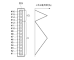
FIG. 9 is a diagram illustrating the nozzle usage rate. The nozzle usage rate of a certain nozzle being 50% means that 50% of pixels are actually ejected with respect to pixels that can be ejected by the nozzle. FIG. 10 is a diagram for explaining the shading that appears due to the difference in nozzle usage rate. FIG. 11 is a diagram illustrating a discharge result of the clear ink according to the conventional technique. In FIG. 11, the clear ink ejected on the white ink image is represented by black dots.
図9の左側には吐出ヘッド52Xを示し、右側には副走査方向に沿って並ぶ複数ノズル(ノズル番号#1〜ノズル番号#16)の各々のノズルのノズル使用率を移動平均化して結んだ形状の一例を示している。これをマスクパターンという。本マスクパターンは、1回のパスによって吐出ヘッド52Xの副走査方向の両端で視認されやすいスジを緩和するために、カラーインクを吐出するノズルおよびクリアインクを吐出するノズルのそれぞれにおいて、両端に位置するノズルから中央に位置するノズルに向かってノズル使用率が直線的に増加する。
The
ノズルから吐出されるインクの吐出量は、ノズル使用率を変えると、1吐出当たりのインク量も変化する。これは、インク使用量の変化によって、インクを吐出するための駆動電圧が変化することで発生し、これを吐出ヘッド52の周波数特性という。ノズル使用率の高いノズルから吐出されるインク量は、ノズル使用率の低いノズルから吐出されるインク量よりも多くなる傾向がある。
図10は、ノズル番号#13から#16のノズルによって吐出されるクリアインクの画素位置を示している。画素31は、ノズル使用率の高いノズル(ノズル番号#14,#15)から吐出可能な画素位置を示している。画素32は、ノズル使用率の低いノズル(ノズル番号#13,#16)から吐出可能な画素位置を示している。例えば、ラスターライン番号L14,L15には、インク量が多いクリアインクによるドットが形成され、ラスターライン番号L16,L17には、インク量が少ないクリアインクによるドットが形成される。このように、印刷速度を優先した印刷は、クリアインクを吐出するパスを少なくすることで実現される。これにより、全ての画素にクリアインクを形成することが出来ない、および1つのラスターラインを異なるノズルで形成することでバンディングを緩和する手法が使用できないことにより、ノズル使用率による濃淡が周期的なムラ(光沢バンディング)として視認されやすくなる。図11に示すように、従来技術による印刷では、毎パス周期や4パス周期で発生する光沢バンディングが視認される。
The amount of ink ejected from the nozzles changes as the nozzle usage rate changes. This occurs when the drive voltage for ejecting ink changes due to a change in the amount of ink used, and this is called the frequency characteristic of the
FIG. 10 shows pixel positions of clear ink ejected by nozzles # 13 to # 16. A
各インクのドットは、ハーフトーン処理で使用するディザマスクに起因して特定の配列で分散されるので、本願発明者らは、光沢バンディングを上述したハーフトーン処理によって改善することを検討した。 Since the dots of each ink are dispersed in a specific arrangement due to the dither mask used in the halftone process, the inventors of the present application have studied to improve the gloss banding by the above-described halftone process.
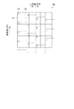
図12は、従来技術によるディザマスクを説明する概念図である。ハーフトーン処理部は、ディザマスク70を使用して、インク量データからドットデータへ変換する。印刷装置100は、媒体Sに画像を1200×1200Dpiの解像度で印刷を行う。図12には、媒体Sに印刷を行う画像に対して1200×1200Dpiの解像度格子71が示されている。また、画像に対して配置されるディザマスク格子72が示されている。
FIG. 12 is a conceptual diagram illustrating a conventional dither mask. The halftone processing unit converts the ink amount data into dot data using the
ディザマスク格子72の大きさは、1024×1024画素である。さらに、ディザマスク格子72は、同類の複数のマスク群73で構成されている。マスク群73の大きさは、任意の画素数に設定可能である。例えば、ディザマスク格子72には、図12における左上から順番に主走査方向および副走査方向にマスク群73が周期的に並べられる。さらに、画像全体は周期的に並ぶディザマスク格子72で覆い尽くされる。ハーフトーン処理部は、画像の画素毎に階調値に応じたドット生成率とディザマスク格子72の各画素に設定されたディザ閾値とを比較してドットを形成するか否かを求める。
The size of the
図12に示すように、ディザマスク70のディザマスク格子72は、主走査方向において互いに連続する配置であり、副走査方向において互いに連続しない配置である。すなわち、副走査方向に向かって配置されるディザマスク格子72は、主走査方向に順次ズレた位置に配置されている。従来技術においては、ハーフトーン処理部は、カラーインクおよびクリアインクともに同じディザマスク70を使用してハーフトーン処理を行っていた。
As shown in FIG. 12, the
図13は、本発明によるディザマスクを説明する概念図である。図14は、本発明によるクリアインクの吐出結果を示す図である。なお、図14では、白インクの画像上に吐出させたクリアインクを黒ドットで表している。
ハーフトーン処理部は、副走査方向におけるクリアインク用のディザマスク格子82の長さが、副走査方向におけるカラーインク用のディザマスク格子72の長さよりも長い格子配置でハーフトーン処理を行う。すなわち、ハーフトーン処理部は、ディザマスク70を用いてカラーインクのハーフトーン処理を行い、ディザマスク80を用いてクリアインクのハーフトーン処理を行う。
FIG. 13 is a conceptual diagram illustrating a dither mask according to the present invention. FIG. 14 is a diagram showing the discharge result of the clear ink according to the present invention. In FIG. 14, the clear ink ejected on the white ink image is represented by black dots.
The halftone processing unit performs halftone processing with a grid arrangement in which the length of the
図13に示すように、クリアインクに使用するディザマスク80のディザマスク格子82を構成する複数のマスク群83は、カラーインクに使用するディザマスク70のディザマスク格子72を構成する複数のマスク群73を副走査方向に2倍に拡張したものである。このマスク群83を用いることにより、副走査方向に2倍に長い2048×1024画素に拡張されたディザマスク格子82を容易に構成することができる。これにより、ディザマスク80は、副走査方向における周期が長くなり、同類のマスク群83も副走査方向に長く分散するので、図14に示すように、光沢バンディングが視認され難くなる。なお、本実施形態では、2倍に拡張されたディザマスク格子82を示したが、2倍以上に拡張されたディザマスク格子であってもよい。
As shown in FIG. 13, a plurality of
<画像処理方法>
次に、画像処理装置における画像処理方法について、図15を参照して説明する。図15は、画像処理方法を説明するフローチャート図である。
<Image processing method>
Next, an image processing method in the image processing apparatus will be described with reference to FIG. FIG. 15 is a flowchart for explaining the image processing method.
ステップS101は、画像データを取得する画像取得工程である。プリンター制御部111は、印刷装置100に印刷させる画像データ(RGB色空間のデータ)を取得し、記憶部114に格納する。
Step S101 is an image acquisition step for acquiring image data. The
ステップS102は、解像度変換・色変換処理工程である。画像データは、解像度変換工程で印刷する際の解像度に変換される。そして、解像度変換処理が完了した画像データに対して色変換処理が行われ、CMYK色空間の画像データを得る。 Step S102 is a resolution conversion / color conversion process. The image data is converted into a resolution for printing in the resolution conversion process. Then, color conversion processing is performed on the image data for which the resolution conversion processing has been completed, and image data in the CMYK color space is obtained.
ステップS103は、画像データに基づいてハーフトーン処理を行うハーフトーン処理工程である。ハーフトーン処理部は、ディザマスクを用いてインク種毎にハーフトーン処理を行う。本実施形態では、カラーインクとクリアインクとで異なるディザマスクを使用する。詳しくは、ハーフトーン処理工程では、副走査方向におけるクリアインク用のディザマスク格子82の長さが副走査方向におけるカラーインク用のディザマスク格子72よりも長い格子配置のディザマスク80でハーフトーン処理が行われる。これにより、クリアインクのドットがカラーインクよりも副走査方向に分散した画素データ(画像データ)が作成される。
Step S103 is a halftone processing step for performing halftone processing based on the image data. The halftone processing unit performs a halftone process for each ink type using a dither mask. In this embodiment, different dither masks are used for color ink and clear ink. Specifically, in the halftone processing step, halftone processing is performed with a
ステップS104は、ハーフトーン処理された画像データに基づいて、印刷データを生成する印刷データ生成工程である。印刷データ生成部は、ハーフトーン処理された画像データに対してラスタライズ処理を行い、最後にコマンド付加処理を行って、印刷データを生成する。 Step S104 is a print data generation process for generating print data based on the halftone-processed image data. The print data generation unit performs rasterization processing on the halftone-processed image data, and finally performs command addition processing to generate print data.
ステップS105は、印刷データ送信工程である。生成された印刷データは、インターフェイス部119を介して印刷装置100に送信される。
Step S105 is a print data transmission step. The generated print data is transmitted to the
なお、本実施形態では、第2インクは、クリアインクであるものとして説明したが、第2インクは、淡インクであってもよい。淡インクとしては、淡ブラック(LK)、極淡ブラック(LLK)などを使用することができる。クリアインクの替わりに淡インクを用いることでも同様の効果が得られる。 In the present embodiment, the second ink has been described as being a clear ink, but the second ink may be a light ink. As the light ink, light black (LK), very light black (LLK), or the like can be used. The same effect can be obtained by using light ink instead of clear ink.
以上述べたように、本実施形態に係る画像処理装置110及び画像処理方法によれば、以下の効果を得ることができる。
画像処理装置110のプリンタードライバーは、ソフトウェア(あるいはファームウェア)による機能部として、画像データに基づいてハーフトーン処理を行うハーフトーン処理部、ハーフトーン処理された画像データに基づいて印刷データを生成する印刷データ生成部などを備えている。ハーフトーン処理部は、副走査方向における第2インクとしてのクリアインク用のディザマスク格子82の長さが、副走査方向における第1インクとしてのカラーインク用のディザマスク格子72の長さよりも長い格子配置でハーフトーン処理を行う。これにより、副走査方向において、周期的に生成されるクリアインクのドットが副走査方向に分散されるので、光沢バンディングが視認され難くなる。したがって、印刷品質を向上させる画像処理装置110を提供することができる。
As described above, according to the
The printer driver of the
ディザマスク格子82を構成する複数のマスク群83は、ディザマスク格子72を構成する複数のマスク群73を副走査方向に拡張したものである。副走査方向に拡張したマスク群83を使用することで、副走査方向に長いディザマスク格子82を容易に構成することができる。
第1インクは、カラーインクであり、第2インクは、クリアインクまたは淡インクである。クリアインクや淡インクは、黒濃度を向上させる効果があるので、クリアインクまたは淡インクをオーバーコートすることで画像品質を向上することができる。
The plurality of
The first ink is a color ink, and the second ink is a clear ink or a light ink. Since clear ink and light ink have the effect of improving black density, image quality can be improved by overcoating clear ink or light ink.
画像処理装置110の画像処理方法は、画像データを取得する画像取得工程と、画像データに基づいてハーフトーン処理を行うハーフトーン処理工程と、ハーフトーン処理された画像データに基づいて、印刷データを生成する印刷データ生成工程とを備えている。ハーフトーン処理工程では、副走査方向における第2インクとしてのクリアインク用のディザマスク格子82の長さが副走査方向における第1インクとしてのカラーインク用のディザマスク格子72の長さよりも長い格子配置のディザマスク80でハーフトーン処理が行われる。これにより、副走査方向において、周期的に発生するクリアインクのドットが副走査方向に分散されるので、光沢バンディングが視認され難くなる。したがって、印刷品質を向上させる画像処理方法を提供することができる。
The image processing method of the
なお、本発明は上述した実施形態に限定されず、上述した実施形態に種々の変更や改良などを加えることが可能である。変形例を以下に述べる。また、実施形態と同一の構成部位については、同一の番号を使用し、重複する説明は省略する。 Note that the present invention is not limited to the above-described embodiment, and various modifications and improvements can be added to the above-described embodiment. A modification will be described below. Moreover, about the same component as embodiment, the same number is used and the overlapping description is abbreviate | omitted.
(変形例1)
図16は、変形例1に係るディザマスクを説明する概念図である。図17は、変形例1によるクリアインクの吐出結果を示す図である。なお、図17では、白インクの画像上に吐出させたクリアインクを黒ドットで表している。
ハーフトーン処理部は、第1インクとしてのカラーインクに対して、複数のディザマスク格子72が副走査方向において互いに連続しない配置であり、第2インクとしてのクリアインクに対して、複数のディザマスク格子72が主走査方向において互いに連続しない配置でハーフトーン処理を行う。詳しくは、ハーフトーン処理部は、ディザマスク70(図12参照)を用いてカラーインクのハーフトーン処理を行い、ディザマスク90を用いてクリアインクのハーフトーン処理を行う。
(Modification 1)
FIG. 16 is a conceptual diagram illustrating a dither mask according to the first modification. FIG. 17 is a diagram illustrating a discharge result of the clear ink according to the first modification. In FIG. 17, the clear ink ejected on the white ink image is represented by black dots.
The halftone processing unit is arranged such that the plurality of
図16に示すように、ディザマスク90のディザマスク格子72は、主走査方向において互いに連続しない配置であり、副走査方向において互いに連続する配置である。すなわち、主走査方向に向かって配置されるディザマスク格子72は、副走査方向に順次ずれた位置に配置されているので、ディザマスク90は、同類のマスク群73が主走査方向に並ばなくなる。これにより、主走査方向におけるクリアインクのドット分散周期が、カラーインクのドット分散周期と異なると共に、副走査方向にずれるので、図17に示すように、光沢バンディングが視認され難くなる。
As shown in FIG. 16, the
次に、変形例1における画像処理方法について、図18を参照して説明する。図18は、画像処理方法を説明するフローチャート図である。なお、本変形例のステップS201,S202,S204およびS205は、実施形態で説明したステップS101,S102,S104およびS105と同じであるので、その説明を省略する。
Next, an image processing method in
ステップS203は、画像データに基づいてハーフトーン処理を行うハーフトーン処理工程である。ハーフトーン処理部は、ディザマスクを用いてインク種毎にハーフトーン処理を行う。本変形例では、カラーインクとクリアインクとで異なるディザマスクを使用する。詳しくは、ハーフトーン処理工程では、カラーインクに対して複数のディザマスク格子72が副走査方向において互いに連続しない配置のディザマスク70でハーフトーン処理を行い、クリアインクに対して複数のディザマスク格子72が主走査方向において互いに連続しない配置のディザマスク90でハーフトーン処理を行う。これにより、主走査方向におけるクリアインクのドットの分散周期が、カラーインクのドット分散周期と異なると共に、副走査方向にずれた画素データ(画像データ)が作成される。
Step S203 is a halftone processing step for performing halftone processing based on the image data. The halftone processing unit performs a halftone process for each ink type using a dither mask. In this modification, different dither masks are used for color ink and clear ink. Specifically, in the halftone processing step, halftone processing is performed with the
なお、本変形例では、ディザマスク90は、従来技術と同じ複数のマスク群73で構成されたディザマスク格子72が配置されているものと説明したが、ディザマスク70と異なるマスク群及びディザマスク格子であってもよい。
In the present modification, the
(変形例2)
図19は、変形例2に係る吐出ヘッドが有するノズルの配列を説明する図である。なお、変形例2では、第2インクとして、クリアインク(CL)と淡インク(LLK)とを併用する。また、図19では、説明の便宜上、第1インクとしての複数のカラーインクのうちの1種類であるブラックインク(K)と、第2インクとしてのクリアインク(CL)と淡インク(LLK)とのノズル配置を示している。
(Modification 2)
FIG. 19 is a diagram illustrating the arrangement of nozzles included in the ejection head according to the second modification. In
図19に示すように、吐出ヘッド252には、ブラックインク(K)、クリアインク(CL)および淡インク(LLK)のノズル列が含まれている。各ノズル列は、副走査方向に並ぶ複数のノズルを有している。図19では、各ノズル列は、例えば、16個のノズルで構成され、ブラックインク(K)およびクリアインク(CL)のノズルには副走査方向における上流側よりノズル番号#1から#16を示し、淡インク(LLK)のノズルには副走査方向における上流側よりノズル番号#1’から#16’を示している。各ノズルは、奇数のノズル番号のノズルで構成される奇数ノズル列と偶数のノズル番号のノズルで構成される偶数ノズル列とを有している。各ノズルは、副走査方向において300Dpi(dots per inch)のノズルピッチで設けられている。
As shown in FIG. 19, the
副走査方向における淡インク(LLK)のノズル列の位置は、クリアインク(CL)のノズル列のノズル位置に対して、ノズルピッチの1/2に相当する距離だけずれた位置に配置されている。すなわち、カラーインク(ブラックインク(K))をオーバーコートするクリアインク(CL)および淡インク(LLK)のノズルは、副走査方向において600Dpiのノズルピッチで設けられている。 The position of the nozzle row of light ink (LLK) in the sub-scanning direction is arranged at a position shifted from the nozzle position of the nozzle row of clear ink (CL) by a distance corresponding to 1/2 of the nozzle pitch. . In other words, the clear ink (CL) and light ink (LLK) nozzles that overcoat the color ink (black ink (K)) are provided at a nozzle pitch of 600 dpi in the sub-scanning direction.
図20は、パス4でインクを吐出可能な画素位置を示す図である。実施形態で説明した図8と同様に、ラスターライン番号L13からL16は、パス1からパス3において、ノズル番号#1から#12のノズルのうちの少なくとも1つのノズルによって水平位置「1」および「2」の全ての画素にカラーインク(ブラックインク(K))が吐出され、カラーの画像が形成される。そして、ラスターライン番号L13からL16は、パス4において、ノズル番号#13から#16のノズルからクリアインクが吐出されカラー画像をオーバーコートする。同時に、ラスターライン番号L13とL14との中間位置、ラスターライン番号L14とL15との中間位置、ラスターライン番号L15とL16との中間位置、およびラスターライン番号L16とL17との中間位置には、ノズル番号#13’から#16’のノズルから淡インクが吐出されカラー画像をオーバーコートする。
FIG. 20 is a diagram illustrating pixel positions where ink can be ejected in
実施形態で説明したドットを形成することができない画素は、その画素面積の1/2を淡インクによって埋められる。例えば、ドットが形成できない、ラスターライン番号L14と水平位置「1」とが交差する位置の画素は、副走査方向における下流側の半分がラスターライン番号L13とL14との中間位置にノズル番号#16’から吐出された淡インクで覆われる。これにより、カラー画像をオーバーコートすることが出来ない面積を縮小することができる。
For pixels that cannot form dots as described in the embodiment, half of the pixel area is filled with light ink. For example, in a pixel at which the raster line number L14 and the horizontal position “1” intersect, in which dots cannot be formed, the downstream half in the sub-scanning direction has a
また、変形例2では、画像処理のハーフトーン処理において、ハーフトーン処理部は、クリアインク(CL)と淡インク(LLK)とで用いるディザマスクを異ならせる。例えば、ハーフトーン処理部は、クリアインク(CL)のハーフトーン処理を実施形態で説明したディザマスク80を用いて行い、淡インク(LLK)のハーフトーン処理を変形例1で説明したディザマスク90を用いて行う。これにより、クリアインク(CL)のドットと淡インク(LLK)のドットとは、異なる周期の配列で分散されるので、光沢バンディングが視認され難くなる。
In the second modification, in the halftone processing of the image processing, the halftone processing unit uses different dither masks for clear ink (CL) and light ink (LLK). For example, the halftone processing unit performs the clear ink (CL) halftone process using the
上記実施形態において、画像処理装置110の機能の少なくとも一部を他の装置が有していても良い。また、画像処理装置110の機能の全てを、印刷装置が有する構成であってもよい。かかる構成においても、上記実施形態と同様の効果を奏することができる。
In the above-described embodiment, another device may have at least a part of the functions of the
以下に、実施形態から導き出される内容を記載する。
本願の画像処理装置は、主走査及び副走査を繰り返すことで、媒体に第1インクと前記第1インク上に配置される第2インクとを印刷する印刷装置用の印刷データを、画像データから生成する画像処理装置であって、前記画像データを取得する画像取得部と、前記画像データに基づいて、ハーフトーン処理を行うハーフトーン処理部と、前記ハーフトーン処理された前記画像データに基づいて、前記印刷データを生成する印刷データ生成部と、を備え、前記ハーフトーン処理部は、副走査方向における前記第2インク用のディザマスク格子の長さが、前記副走査方向における前記第1インク用のディザマスク格子の長さよりも長い格子配置で前記ハーフトーン処理を行うことを特徴とする。
The contents derived from the embodiment will be described below.
The image processing apparatus of the present application repeats main scanning and sub-scanning, and print data for a printing apparatus that prints the first ink and the second ink disposed on the first ink on the medium from the image data. An image processing apparatus for generating an image acquisition unit that acquires the image data, a halftone processing unit that performs halftone processing based on the image data, and the image data that has been subjected to the halftone processing A print data generation unit that generates the print data, wherein the halftone processing unit has a length of the dither mask grid for the second ink in the sub-scanning direction, and the first ink in the sub-scanning direction. The halftone process is performed with a grid arrangement longer than the length of the dither mask grid for use.
この構成によれば、画像処理装置は、画像データに基づいてハーフトーン処理を行うハーフトーン処理部、ハーフトーン処理された画像データに基づいて印刷データを生成する印刷データ生成部などを備えている。ハーフトーン処理部は、副走査方向における第2インク用のディザマスク格子の長さが、副走査方向における第1インク用のディザマスク格子の長さよりも長い格子配置でハーフトーン処理を行う。これにより、副走査方向において、周期的に発生する第2インクのドットが副走査方向に分散されるので、バンディングが視認され難くなる。したがって、印刷品質を向上させる画像処理装置を提供することができる。 According to this configuration, the image processing apparatus includes the halftone processing unit that performs halftone processing based on the image data, the print data generation unit that generates print data based on the image data subjected to the halftone processing, and the like. . The halftone processing unit performs halftone processing with a grid arrangement in which the length of the dither mask grid for the second ink in the sub-scanning direction is longer than the length of the dither mask grid for the first ink in the sub-scanning direction. Accordingly, the dots of the second ink that are periodically generated in the sub-scanning direction are dispersed in the sub-scanning direction, so that banding is difficult to be visually recognized. Therefore, it is possible to provide an image processing apparatus that improves print quality.
本願の画像処理装置は、主走査及び副走査を繰り返すことで、媒体に第1インクと前記第1インク上に配置される第2インクとを印刷する印刷装置用の印刷データを、画像データから生成する画像処理装置であって、前記画像データを取得する画像取得部と、前記画像データに基づいて、ハーフトーン処理を行うハーフトーン処理部と、前記ハーフトーン処理された前記画像データに基づいて、前記印刷データを生成する印刷データ生成部と、を備え、前記ハーフトーン処理部は、前記第1インクに対して、複数のディザマスク格子が副走査方向において互いに連続しない配置であり、前記第2インクに対して、複数のディザマスク格子が主走査方向において互いに連続しない配置でハーフトーン処理を行うことを特徴とする。 The image processing apparatus of the present application repeats main scanning and sub-scanning, and print data for a printing apparatus that prints the first ink and the second ink disposed on the first ink on the medium from the image data. An image processing apparatus for generating an image acquisition unit that acquires the image data, a halftone processing unit that performs halftone processing based on the image data, and the image data that has been subjected to the halftone processing A print data generation unit that generates the print data, wherein the halftone processing unit is arranged so that a plurality of dither mask lattices are not continuous with each other in the sub-scanning direction with respect to the first ink. A halftone process is performed on two inks in an arrangement in which a plurality of dither mask lattices are not continuous with each other in the main scanning direction.
この構成によれば、画像処理装置は、画像データに基づいてハーフトーン処理を行うハーフトーン処理部、ハーフトーン処理された画像データに基づいて印刷データを生成する印刷データ生成部などを備えている。ハーフトーン処理部は、第1インクに対して複数のディザマスク格子が副走査方向において互いに連続しない配置でハーフトーン処理を行い、第2インクに対して複数のディザマスク格子が主走査方向において互いに連続しない配置でハーフトーン処理を行う。これにより、主走査方向における第2インクのドットの分散周期が、第1インクのドット分散周期と異なると共に、副走査方向にずれた画像データが作成されるので、バンディングが視認され難くなる。したがって、印刷品質を向上させる画像処理装置を提供することができる。 According to this configuration, the image processing apparatus includes the halftone processing unit that performs halftone processing based on the image data, the print data generation unit that generates print data based on the image data subjected to the halftone processing, and the like. . The halftone processing unit performs a halftone process on the first ink so that the plurality of dither mask lattices are not continuous with each other in the sub-scanning direction, and the plurality of dither mask lattices with respect to the second ink are mutually connected in the main scanning direction. Halftone processing is performed in a discontinuous arrangement. As a result, the dispersion period of the dots of the second ink in the main scanning direction is different from the dot dispersion period of the first ink, and image data shifted in the sub-scanning direction is created, so that it is difficult to visually recognize the banding. Therefore, it is possible to provide an image processing apparatus that improves print quality.
上記の画像処理装置において、前記第2インク用のディザマスク格子を構成する複数のマスク群は、前記第1インク用のディザマスク格子を構成する複数のマスク群を副走査方向に拡張したものであることが好ましい。 In the image processing apparatus, the plurality of mask groups constituting the dither mask grating for the second ink is an extension of the plurality of mask groups constituting the dither mask grating for the first ink in the sub-scanning direction. Preferably there is.
この構成によれば、第2インクに使用するディザマスク格子を構成する複数のマスク群は、第1インクに使用するディザマスク格子を構成する複数のマスク群を副走査方向に拡張したものである。このマスク群を用いることにより、副走査方向に拡張されたディザマスク格子を容易に構成することができる。これにより、ディザマスク格子の周期は、副走査方向に長くなり、マスク群も副走査方向に長く分散するので、バンディングが視認され難くなる。 According to this configuration, the plurality of mask groups constituting the dither mask grating used for the second ink is an extension of the plurality of mask groups constituting the dither mask grating used for the first ink in the sub-scanning direction. . By using this mask group, a dither mask grating extended in the sub-scanning direction can be easily configured. As a result, the period of the dither mask grating becomes longer in the sub-scanning direction, and the mask group is also dispersed longer in the sub-scanning direction, so that banding is hardly visible.
上記の画像処理装置において、前記第1インクはカラーインクであり、前記第2インクは、クリアインクまたは淡インクであることが好ましい。 In the image processing apparatus, it is preferable that the first ink is a color ink and the second ink is a clear ink or a light ink.
この構成によれば、クリアインクや淡インクは、色濃度を向上させる効果があるので、第1インクとしてカラーインクを用いてカラー画像を形成し、第2インクとしてクリアインまたは淡インクを用いてカラーインクをオーバーコートすることで画像品質を向上させることができる。 According to this configuration, since clear ink and light ink have an effect of improving color density, a color image is formed using color ink as the first ink, and clear-in or light ink is used as the second ink. Image quality can be improved by overcoating with color ink.
上記の画像処理装置は、前記第2インクとして、クリアインクと淡インクとを併用し、前記ハーフトーン処理部は、前記クリアインクと前記淡インクとで用いるディザマスクを異ならせることが好ましい。 Preferably, the image processing apparatus uses clear ink and light ink in combination as the second ink, and the halftone processing unit uses different dither masks for the clear ink and the light ink.
この構成によれば、ハーフトーン処理部は、第2インクとして使用するクリアインクと淡インクとで用いるディザマスクを異ならせる。これにより、クリアインクのドットと淡インクのドットとは、異なる周期の配列で分散されるので、バンディングが視認され難くなる。 According to this configuration, the halftone processing unit uses different dither masks for the clear ink and the light ink used as the second ink. As a result, the clear ink dots and the light ink dots are dispersed in an array with different periods, so that it is difficult to visually recognize the banding.
本願の画像処理方法は、主走査及び副走査を繰り返すことで、媒体に第1インクと前記第1インク上に配置される第2インクとを印刷する印刷装置用の印刷データを、画像データから生成する画像処理方法であって、前記画像データを取得する画像取得工程と、前記画像データに基づいて、ハーフトーン処理を行うハーフトーン処理工程と、前記ハーフトーン処理された前記画像データに基づいて、前記印刷データを生成する印刷データ生成工程と、を備え、前記ハーフトーン処理工程は、副走査方向における前記第2インク用のディザマスク格子の長さが、前記副走査方向における前記第1インク用のディザマスク格子の長さよりも長い格子配置で前記ハーフトーン処理を行うことを特徴とする。 According to the image processing method of the present application, print data for a printing apparatus that prints a first ink and a second ink disposed on the first ink on a medium by repeating main scanning and sub-scanning from image data. An image processing method to generate, an image acquisition step for acquiring the image data, a halftone processing step for performing a halftone process based on the image data, and a method based on the image data subjected to the halftone process A print data generation step for generating the print data, wherein the halftone processing step is such that the length of the dither mask grating for the second ink in the sub-scanning direction is equal to the first ink in the sub-scanning direction. The halftone process is performed with a grid arrangement longer than the length of the dither mask grid for use.
この方法によれば、画像処理方法は、画像データを取得する画像取得工程と、画像データに基づいてハーフトーン処理を行うハーフトーン処理工程と、ハーフトーン処理された画像データに基づいて、印刷データを生成する印刷データ生成工程とを備えている。ハーフトーン処理工程では、副走査方向における第2インク用のディザマスク格子の長さが副走査方向における第1インク用のディザマスク格子の長さよりも長い格子配置でハーフトーン処理が行われる。これにより、副走査方向において、周期的に発生するクリアインクのドットが副走査方向に分散されるので、バンディングが視認され難くなる。したがって、印刷品質を向上させる画像処理方法を提供することができる。 According to this method, the image processing method includes an image acquisition step of acquiring image data, a halftone processing step of performing halftone processing based on the image data, and print data based on the image data subjected to halftone processing. And a print data generation step for generating. In the halftone processing step, halftone processing is performed with a grid arrangement in which the length of the dither mask grid for the second ink in the sub-scanning direction is longer than the length of the dither mask grid for the first ink in the sub-scanning direction. As a result, the dots of clear ink that are periodically generated in the sub-scanning direction are dispersed in the sub-scanning direction, so that banding is difficult to be visually recognized. Therefore, it is possible to provide an image processing method that improves print quality.
本願の画像処理方法は、主走査及び副走査を繰り返すことで、媒体に第1インクと前記第1インク上に配置される第2インクとを印刷する印刷装置用の印刷データを、画像データから生成する画像処理方法であって、前記画像データを取得する画像取得工程と、前記画像データに基づいて、ハーフトーン処理を行うハーフトーン処理工程と、前記ハーフトーン処理された前記画像データに基づいて、前記印刷データを生成する印刷データ生成工程と、を備え、前記ハーフトーン処理工程は、前記第1インクに対して、複数のディザマスク格子が副走査方向において互いに連続しない配置であり、前記第2インクに対して、複数のディザマスク格子が主走査方向において互いに連続しない配置でハーフトーン処理を行うことを特徴とする。 According to the image processing method of the present application, print data for a printing apparatus that prints a first ink and a second ink disposed on the first ink on a medium by repeating main scanning and sub-scanning from image data. An image processing method to generate, an image acquisition step for acquiring the image data, a halftone processing step for performing a halftone process based on the image data, and a method based on the image data subjected to the halftone process A print data generation step for generating the print data, wherein the halftone processing step is an arrangement in which a plurality of dither mask lattices are not continuous with each other in the sub-scanning direction with respect to the first ink. A halftone process is performed on two inks in an arrangement in which a plurality of dither mask lattices are not continuous with each other in the main scanning direction.
この方法によれば、画像処理方法は、画像データを取得する画像取得工程と、画像データに基づいてハーフトーン処理を行うハーフトーン処理工程と、ハーフトーン処理された画像データに基づいて、印刷データを生成する印刷データ生成工程とを備えている。ハーフトーン処理工程では、第1インクに対して複数のディザマスク格子が副走査方向において互いに連続しない配置でハーフトーン処理を行い、第2インクに対して複数のディザマスク格子が主走査方向において互いに連続しない配置でハーフトーン処理を行う。これにより、主走査方向における第2インクのドットの分散周期が、第1インクのドット分散周期と異なると共に、副走査方向にずれた画像データが作成されるので、バンディングが視認され難くなる。したがって、印刷品質を向上させる画像処理方法を提供することができる。 According to this method, the image processing method includes an image acquisition step of acquiring image data, a halftone processing step of performing halftone processing based on the image data, and print data based on the image data subjected to halftone processing. And a print data generation step for generating. In the halftone processing step, halftone processing is performed on the first ink so that the plurality of dither mask lattices are not continuous with each other in the sub-scanning direction, and the plurality of dither mask lattices are mutually connected with respect to the second ink in the main scanning direction. Halftone processing is performed in a discontinuous arrangement. As a result, the dispersion period of the dots of the second ink in the main scanning direction is different from the dot dispersion period of the first ink, and image data shifted in the sub-scanning direction is created, so that it is difficult to visually recognize the banding. Therefore, it is possible to provide an image processing method that improves print quality.
1…制御部、2,119…インターフェイス部、3,115…CPU、4…制御回路、5,118…メモリー、14…媒体供給部、15…媒体巻取部、21…搬送ローラー対、22…搬送経路、31,32…画素、51…筐体部、52,52X,252…吐出ヘッド、55…キャリッジ、58…印刷部、59…ヘッド移動部、62…操作パネル、64,113…表示部、65…インク装着部、70,80,90…ディザマスク、71…解像度格子、72,82…ディザマスク格子、73,83…マスク群、100…印刷装置、110…画像処理装置、111…プリンター制御部、112…入力部、114…記憶部、116…ASIC、117…DSP、120…印刷システム。
DESCRIPTION OF
Claims (7)
前記画像データを取得する画像取得部と、
前記画像データに基づいて、ハーフトーン処理を行うハーフトーン処理部と、
前記ハーフトーン処理された前記画像データに基づいて、前記印刷データを生成する印刷データ生成部と、を備え、
前記ハーフトーン処理部は、副走査方向における前記第2インク用のディザマスク格子の長さが、前記副走査方向における前記第1インク用のディザマスク格子の長さよりも長い格子配置で前記ハーフトーン処理を行うこと、
を特徴とする画像処理装置。 An image processing apparatus that generates print data for a printing apparatus that prints a first ink and a second ink disposed on the first ink on a medium by repeating main scanning and sub-scanning from the image data. And
An image acquisition unit for acquiring the image data;
A halftone processing unit for performing halftone processing based on the image data;
A print data generation unit that generates the print data based on the halftone processed image data,
The halftone processing unit has the lattice arrangement in which the length of the dither mask grating for the second ink in the sub scanning direction is longer than the length of the dither mask grating for the first ink in the sub scanning direction. Processing,
An image processing apparatus.
前記画像データを取得する画像取得部と、
前記画像データに基づいて、ハーフトーン処理を行うハーフトーン処理部と、
前記ハーフトーン処理された前記画像データに基づいて、前記印刷データを生成する印刷データ生成部と、を備え、
前記ハーフトーン処理部は、
前記第1インクに対して、複数のディザマスク格子が副走査方向において互いに連続しない配置であり、
前記第2インクに対して、複数のディザマスク格子が主走査方向において互いに連続しない配置でハーフトーン処理を行うこと、
を特徴とする画像処理装置。 An image processing apparatus that generates print data for a printing apparatus that prints a first ink and a second ink disposed on the first ink on a medium by repeating main scanning and sub-scanning from the image data. And
An image acquisition unit for acquiring the image data;
A halftone processing unit for performing halftone processing based on the image data;
A print data generation unit that generates the print data based on the halftone processed image data,
The halftone processing unit
With respect to the first ink, a plurality of dither mask lattices are arranged not to be continuous with each other in the sub-scanning direction,
Performing a halftone process on the second ink in an arrangement in which a plurality of dither mask lattices are not continuous with each other in the main scanning direction;
An image processing apparatus.
を特徴とする請求項1に記載の画像処理装置。 The plurality of mask groups constituting the dither mask grating for the second ink are obtained by extending the plurality of mask groups constituting the dither mask grating for the first ink in the sub-scanning direction;
The image processing apparatus according to claim 1.
前記第2インクは、クリアインクまたは淡インクであること、
を特徴する請求項1から請求項3のいずれか一項に記載の画像処理装置。 The first ink is a color ink;
The second ink is a clear ink or a light ink;
The image processing apparatus according to any one of claims 1 to 3, wherein
前記ハーフトーン処理部は、前記クリアインクと前記淡インクとで用いるディザマスクを異ならせること、
を特徴する請求項1から請求項3のいずれか一項に記載の画像処理装置。 As the second ink, a clear ink and a light ink are used in combination,
The halftone processing unit is configured to make different dither masks to be used for the clear ink and the light ink;
The image processing apparatus according to any one of claims 1 to 3, wherein
前記画像データを取得する画像取得工程と、
前記画像データに基づいて、ハーフトーン処理を行うハーフトーン処理工程と、
前記ハーフトーン処理された前記画像データに基づいて、前記印刷データを生成する印刷データ生成工程と、を備え、
前記ハーフトーン処理工程は、副走査方向における前記第2インク用のディザマスク格子の長さが、前記副走査方向における前記第1インク用のディザマスク格子の長さよりも長い格子配置で前記ハーフトーン処理を行うこと、
を特徴とする画像処理方法。 An image processing method for generating print data for a printing apparatus for printing a first ink and a second ink disposed on the first ink on a medium by repeating main scanning and sub-scanning from the image data. And
An image acquisition step of acquiring the image data;
A halftone processing step for performing halftone processing based on the image data;
A print data generation step of generating the print data based on the halftone processed image data,
In the halftone processing step, the halftone is arranged in a grid arrangement in which the length of the dither mask grid for the second ink in the sub-scanning direction is longer than the length of the dither mask grid for the first ink in the sub-scanning direction. Processing,
An image processing method characterized by the above.
前記画像データを取得する画像取得工程と、
前記画像データに基づいて、ハーフトーン処理を行うハーフトーン処理工程と、
前記ハーフトーン処理された前記画像データに基づいて、前記印刷データを生成する印刷データ生成工程と、を備え、
前記ハーフトーン処理工程は、
前記第1インクに対して、複数のディザマスク格子が副走査方向において互いに連続しない配置であり、
前記第2インクに対して、複数のディザマスク格子が主走査方向において互いに連続しない配置でハーフトーン処理を行うこと、
を特徴とする画像処理方法。 An image processing method for generating print data for a printing apparatus for printing a first ink and a second ink disposed on the first ink on a medium by repeating main scanning and sub-scanning from the image data. And
An image acquisition step of acquiring the image data;
A halftone processing step for performing halftone processing based on the image data;
A print data generation step of generating the print data based on the halftone processed image data,
The halftone processing step includes
With respect to the first ink, a plurality of dither mask lattices are arranged not to be continuous with each other in the sub-scanning direction,
Performing a halftone process on the second ink in an arrangement in which a plurality of dither mask lattices are not continuous with each other in the main scanning direction;
An image processing method characterized by the above.
Priority Applications (1)
| Application Number | Priority Date | Filing Date | Title |
|---|---|---|---|
| JP2018034408A JP2019147331A (en) | 2018-02-28 | 2018-02-28 | Image processing device and image processing method |
Applications Claiming Priority (1)
| Application Number | Priority Date | Filing Date | Title |
|---|---|---|---|
| JP2018034408A JP2019147331A (en) | 2018-02-28 | 2018-02-28 | Image processing device and image processing method |
Publications (1)
| Publication Number | Publication Date |
|---|---|
| JP2019147331A true JP2019147331A (en) | 2019-09-05 |
Family
ID=67849967
Family Applications (1)
| Application Number | Title | Priority Date | Filing Date |
|---|---|---|---|
| JP2018034408A Pending JP2019147331A (en) | 2018-02-28 | 2018-02-28 | Image processing device and image processing method |
Country Status (1)
| Country | Link |
|---|---|
| JP (1) | JP2019147331A (en) |
-
2018
- 2018-02-28 JP JP2018034408A patent/JP2019147331A/en active Pending
Similar Documents
| Publication | Publication Date | Title |
|---|---|---|
| JP4992788B2 (en) | Correction value calculation method and liquid ejection method | |
| US10708468B2 (en) | Image processing method, image processing device and printing system utilizing different gradation tables in overlapping regions based on attribute and environmental information | |
| JP5211838B2 (en) | Correction value calculation method and liquid ejection method | |
| JP2009190325A (en) | Correction value obtaining method, liquid ejection method, and program | |
| JP7073723B2 (en) | Recording device and recording method | |
| US8976416B2 (en) | Image processing apparatus and method thereof | |
| JP2011255594A (en) | Liquid ejection device and liquid ejection method | |
| JP2020052828A (en) | Information processor, recording system, recording method, and program | |
| JP2004276596A (en) | Recording method and recording device | |
| JP2009190324A (en) | Correction value obtaining method, liquid ejection method, and program | |
| JP2011051111A (en) | Printer | |
| JP2018122557A (en) | Printer and printing method | |
| JP6815511B2 (en) | Image processing equipment and methods, programs and image recording equipment | |
| US8807683B2 (en) | Liquid discharge method for resolving clogged nozzle arrays | |
| JP2019147331A (en) | Image processing device and image processing method | |
| JP2007021811A (en) | Printer, computer program, printing system, and printing method | |
| JP2010064371A (en) | Method of correction and liquid ejection device | |
| JP2009274234A (en) | Method of calculating correction value, and method of ejecting liquid | |
| US9517634B2 (en) | Printing control apparatus and printing control method | |
| JP2009274233A (en) | Liquid ejecting apparatus | |
| JP7207592B2 (en) | Recording device and recording method | |
| US20170266953A1 (en) | Recording apparatus and recording method | |
| JPWO2018235386A1 (en) | Image processing apparatus and method, dither mask set, and image recording apparatus | |
| US12050949B2 (en) | Image forming apparatus, recording amount setting method of image forming apparatus, and recording amount setting program | |
| JP2023019181A (en) | Liquid ejection device and image processing device |
Legal Events
| Date | Code | Title | Description |
|---|---|---|---|
| RD05 | Notification of revocation of power of attorney |
Free format text: JAPANESE INTERMEDIATE CODE: A7425 Effective date: 20180910 |
|
| RD03 | Notification of appointment of power of attorney |
Free format text: JAPANESE INTERMEDIATE CODE: A7423 Effective date: 20190920 |