JP2019140776A - Rotary electric machine control apparatus and rotary electric machine control method - Google Patents
Rotary electric machine control apparatus and rotary electric machine control method Download PDFInfo
- Publication number
- JP2019140776A JP2019140776A JP2018021337A JP2018021337A JP2019140776A JP 2019140776 A JP2019140776 A JP 2019140776A JP 2018021337 A JP2018021337 A JP 2018021337A JP 2018021337 A JP2018021337 A JP 2018021337A JP 2019140776 A JP2019140776 A JP 2019140776A
- Authority
- JP
- Japan
- Prior art keywords
- rotating electrical
- electrical machine
- frequency
- current
- diaphragm
- Prior art date
- Legal status (The legal status is an assumption and is not a legal conclusion. Google has not performed a legal analysis and makes no representation as to the accuracy of the status listed.)
- Granted
Links
Images


Classifications
-
- H—ELECTRICITY
- H02—GENERATION; CONVERSION OR DISTRIBUTION OF ELECTRIC POWER
- H02P—CONTROL OR REGULATION OF ELECTRIC MOTORS, ELECTRIC GENERATORS OR DYNAMO-ELECTRIC CONVERTERS; CONTROLLING TRANSFORMERS, REACTORS OR CHOKE COILS
- H02P6/00—Arrangements for controlling synchronous motors or other dynamo-electric motors using electronic commutation dependent on the rotor position; Electronic commutators therefor
- H02P6/10—Arrangements for controlling torque ripple, e.g. providing reduced torque ripple
-
- G—PHYSICS
- G10—MUSICAL INSTRUMENTS; ACOUSTICS
- G10K—SOUND-PRODUCING DEVICES; METHODS OR DEVICES FOR PROTECTING AGAINST, OR FOR DAMPING, NOISE OR OTHER ACOUSTIC WAVES IN GENERAL; ACOUSTICS NOT OTHERWISE PROVIDED FOR
- G10K9/00—Devices in which sound is produced by vibrating a diaphragm or analogous element, e.g. fog horns, vehicle hooters or buzzers
- G10K9/12—Devices in which sound is produced by vibrating a diaphragm or analogous element, e.g. fog horns, vehicle hooters or buzzers electrically operated
- G10K9/13—Devices in which sound is produced by vibrating a diaphragm or analogous element, e.g. fog horns, vehicle hooters or buzzers electrically operated using electromagnetic driving means
-
- H—ELECTRICITY
- H02—GENERATION; CONVERSION OR DISTRIBUTION OF ELECTRIC POWER
- H02K—DYNAMO-ELECTRIC MACHINES
- H02K21/00—Synchronous motors having permanent magnets; Synchronous generators having permanent magnets
- H02K21/12—Synchronous motors having permanent magnets; Synchronous generators having permanent magnets with stationary armatures and rotating magnets
- H02K21/14—Synchronous motors having permanent magnets; Synchronous generators having permanent magnets with stationary armatures and rotating magnets with magnets rotating within the armatures
-
- H—ELECTRICITY
- H02—GENERATION; CONVERSION OR DISTRIBUTION OF ELECTRIC POWER
- H02P—CONTROL OR REGULATION OF ELECTRIC MOTORS, ELECTRIC GENERATORS OR DYNAMO-ELECTRIC CONVERTERS; CONTROLLING TRANSFORMERS, REACTORS OR CHOKE COILS
- H02P29/00—Arrangements for regulating or controlling electric motors, appropriate for both AC and DC motors
- H02P29/40—Regulating or controlling the amount of current drawn or delivered by the motor for controlling the mechanical load
-
- H—ELECTRICITY
- H02—GENERATION; CONVERSION OR DISTRIBUTION OF ELECTRIC POWER
- H02P—CONTROL OR REGULATION OF ELECTRIC MOTORS, ELECTRIC GENERATORS OR DYNAMO-ELECTRIC CONVERTERS; CONTROLLING TRANSFORMERS, REACTORS OR CHOKE COILS
- H02P29/00—Arrangements for regulating or controlling electric motors, appropriate for both AC and DC motors
- H02P29/50—Reduction of harmonics
-
- H—ELECTRICITY
- H02—GENERATION; CONVERSION OR DISTRIBUTION OF ELECTRIC POWER
- H02P—CONTROL OR REGULATION OF ELECTRIC MOTORS, ELECTRIC GENERATORS OR DYNAMO-ELECTRIC CONVERTERS; CONTROLLING TRANSFORMERS, REACTORS OR CHOKE COILS
- H02P6/00—Arrangements for controlling synchronous motors or other dynamo-electric motors using electronic commutation dependent on the rotor position; Electronic commutators therefor
- H02P6/14—Electronic commutators
- H02P6/16—Circuit arrangements for detecting position
- H02P6/17—Circuit arrangements for detecting position and for generating speed information
Abstract
Description
本発明は、回転電機制御装置、回転電機制御方法に関する。 The present invention relates to a rotating electrical machine control device and a rotating electrical machine control method.
電気自動車(EV(Electric Vehicle))やハイブリッド自動車(HEV(Hybrid Electric Vehicle))では、回転電機(モータ)が使用される。回転電機は、駆動中に発生する音(すなわち、モータ音)として、高次数の単音を発生することが知られている。このようなモータ音は、自動車の乗員に好ましくない感じを与える場合もある。 In an electric vehicle (EV (Electric Vehicle)) and a hybrid vehicle (HEV (Hybrid Electric Vehicle)), a rotating electrical machine (motor) is used. It is known that a rotating electrical machine generates high-order single sounds as sounds generated during driving (that is, motor sounds). Such motor noise may give an unpleasant feeling to the vehicle occupant.
例えば、モータ音を小さく抑える回転電機として、ロータの外周面に凹部が形成されたものが知られている。この回転電機によれば、ロータの外周面に凹部を形成することによりトルク脈動を低減させて、回転電機から発生する音を小さく抑えることが可能とされている(例えば、特許文献1参照)。 For example, as a rotating electrical machine that suppresses motor noise to a low level, one having a recess formed on the outer peripheral surface of a rotor is known. According to this rotating electrical machine, it is possible to reduce the torque pulsation by forming a recess in the outer peripheral surface of the rotor, and to suppress the sound generated from the rotating electrical machine to be small (see, for example, Patent Document 1).
しかしながら、特許文献1に記載の技術では、回転電機のモータ音を聞いた乗員が心地よい感覚を得るころが困難であった。
However, with the technique described in
本発明は、上記の問題点に鑑みてなされたものであって、人にとって心地よい感覚を得ることができる音を発生可能な回転電機制御装置、回転電機制御方法を提供することを目的とする。 The present invention has been made in view of the above problems, and an object of the present invention is to provide a rotating electrical machine control device and a rotating electrical machine control method capable of generating a sound capable of obtaining a comfortable feeling for a person.
(1)上記目的を達成するため、本発明の一態様に係る回転電機制御装置(100)は、回転電機(1)と、前記回転電機の状態を検出するセンサ(センサ101、車速センサ102、アクセルポジションセンサ103、トルクセンサ104)と、前記センサが検出した結果に基づいて、前記回転電機に供給する電流に重畳する電流成分を制御する制御部(110)と、を備える。
(1) In order to achieve the above object, a rotating electrical machine control device (100) according to an aspect of the present invention includes a rotating electrical machine (1) and sensors for detecting the state of the rotating electrical machine (
(2)また、本発明の一態様に係る回転電機制御装置において、前記制御部は、前記センサが検出した結果に含まれるトルクがトルク閾値(閾値X)以上の場合に、前記回転電機に第1周波数未満の電流を重畳するようにしてもよい。 (2) Further, in the rotating electrical machine control device according to one aspect of the present invention, the control unit causes the rotating electrical machine to perform the operation when the torque included in the result detected by the sensor is equal to or greater than a torque threshold (threshold X). A current less than one frequency may be superimposed.
(3)また、本発明の一態様に係る回転電機制御装置において、前記制御部は、前記センサが検出した結果に含まれる加速度が加速度閾値以上の場合に、前記回転電機に第1周波数以上かつ第2周波数以下の電流を重畳するようにしてもよい。 (3) Moreover, in the rotating electrical machine control device according to one aspect of the present invention, the control unit causes the rotating electrical machine to have a first frequency or higher and an acceleration included in a result detected by the sensor that is equal to or higher than an acceleration threshold value. You may make it superimpose the electric current below a 2nd frequency.
(4)また、本発明の一態様に係る回転電機制御装置において、前記制御部は、前記センサが検出した結果に含まれる車両の速度が車速閾値以上の場合に、前記回転電機に第1周波数以上かつ第2周波数以下の電流を重畳するようにしてもよい。 (4) Further, in the rotating electrical machine control device according to one aspect of the present invention, the control unit causes the rotating electrical machine to have a first frequency when a vehicle speed included in a result detected by the sensor is equal to or higher than a vehicle speed threshold. The current having the second frequency or less may be superimposed.
(5)また、本発明の一態様に係る回転電機制御装置において、前記制御部は、前記センサが検出した結果に含まれる車両の速度が車速閾値以上の場合に、前記車両の速度に応じて重畳する電流の振幅を調整するようにしてもよい。 (5) Moreover, in the rotating electrical machine control device according to one aspect of the present invention, the control unit determines whether the speed of the vehicle included in the result detected by the sensor is equal to or higher than a vehicle speed threshold, according to the speed of the vehicle. The amplitude of the superimposed current may be adjusted.
(6)また、本発明の一態様に係る回転電機制御装置において、ステータコア(11)にコイル(13)が装着され、前記コイルに通電することにより磁束を発生するステータと、前記ステータコアに振動板(33〜35)が隣接して設けられ、前記磁束による電磁力で前記振動板が振動することにより所定の音を発生する音発生装置(30)と、を備えるようにしてもよい。 (6) Further, in the rotating electrical machine control device according to one aspect of the present invention, a stator (11) is attached to the stator core (11) and a magnetic flux is generated by energizing the coil, and a diaphragm is provided in the stator core. (33-35) may be provided adjacent to each other, and a sound generator (30) that generates a predetermined sound by vibrating the diaphragm by the electromagnetic force generated by the magnetic flux may be provided.
(7)また、本発明の一態様に係る回転電機制御装置は、ロータコア(21)に磁石(23)が装着されたロータ(20)と、ステータコアにコイルが装着されたステータと、を備え、前記ロータコアの外周面および前記ステータコアの内周面の両方に、周方向の極毎に設定された電磁領域の繰返し形状とは異なる非同一形状部(第1非同一形状部51,52、第2非同一形状部53,54)が設けられているようにしてもよい。
(7) A rotating electrical machine control device according to an aspect of the present invention includes a rotor (20) in which a magnet (23) is mounted on a rotor core (21), and a stator in which a coil is mounted on a stator core, Non-identical shape portions (first
(8)上記目的を達成するため、本発明の一態様に係る回転電機制御方法は、回転電機を有する回転電機制御装置の回転電機制御方法であって、センサが、前記回転電機の状態を検出する手順と、制御部が、前記センサによって検出された結果に基づいて、前記回転電機に供給する電流に重畳する電流成分を制御する手順と、を含む。 (8) In order to achieve the above object, a rotating electrical machine control method according to an aspect of the present invention is a rotating electrical machine control method for a rotating electrical machine control apparatus having a rotating electrical machine, and a sensor detects a state of the rotating electrical machine. And a procedure for the controller to control a current component superimposed on a current supplied to the rotating electrical machine based on a result detected by the sensor.
(1)、(8)の構成によれば、人にとって心地よい感覚を得ることができる音を発生させることができる。
(2)の構成によれば、高トルクの場合に、力強さをイメージする音を出すことができる。
(3)の構成によれば、高いトルクかつ加速時に、大きい音を出すことで、高揚感を演出することができる。
According to the configurations of (1) and (8), it is possible to generate a sound that can provide a comfortable feeling for a person.
According to the configuration of (2), in the case of high torque, it is possible to make a sound that imagines strength.
According to the configuration of (3), it is possible to produce an uplifting feeling by making a loud sound during high torque and acceleration.
(4)の構成によれば、高速移動時に、大きい音を出すことで、高揚感を演出することができる。
(5)の構成によれば、ロードノイズ、風切り音にかき消されない音量を確保ことができる。
(6)、(7)の構成によれば、音を発生させるために電力を消費することなく、回転電機の回転によって、人にとって心地よい感覚を得ることができる音を発生させることができる。
According to the structure of (4), an exhilaration feeling can be produced by making a loud sound during high-speed movement.
According to the structure of (5), the volume which is not drowned out by road noise and a wind noise can be ensured.
According to the configurations of (6) and (7), it is possible to generate a sound that can provide a comfortable sensation for a person by rotating the rotating electrical machine without consuming electric power to generate the sound.
以下、本発明の実施の形態について図面を参照しながら説明する。なお、以下の説明に用いる図面では、各部材を認識可能な大きさとするため、各部材の縮尺を適宜変更している。なお、本実施形態では、回転電機1して、ハイブリッド自動車や電気自動車のような車両用の駆動ユニットに採用するモータについて説明する。ただし、本発明の構成は、車両用の駆動ユニットに採用するモータに限らず、発電用モータやその他の用途のモータ、または車両用以外の回転電機(発電機を含む)にも適用可能である。
Hereinafter, embodiments of the present invention will be described with reference to the drawings. In the drawings used for the following description, the scale of each member is appropriately changed in order to make each member a recognizable size. In the present embodiment, a description will be given of a motor that is used as a rotating
図1は、本実施形態に係る回転電機の断面図である。
回転電機1は、例えばハイブリッド自動車や電気自動車のような車両に搭載される走行用モータである。図1に示すように、回転電機1は、ハウジング2、ステータ10、ロータ20、シャフト4、および音発生装置30を備えている。
FIG. 1 is a cross-sectional view of the rotating electrical machine according to the present embodiment.
The rotating
ハウジング2は、ステータ10およびロータ20を収容するとともに、シャフト4を回転可能に支持している。なお、ステータ10、ロータ20およびシャフト4は、それぞれ軸線Cを共通軸線として配置されている。以下、軸線Cの延びる方向を軸方向と称し、軸線Cに直交する方向を径方向と称し、軸線C回りに周回する方向を周方向と称して説明する。また、各図中において矢印Zは軸方向、矢印Rは径方向、矢印θは周方向をそれぞれ示している。
The
ステータ10は、ステータコア11、およびステータコア11に装着された複数層(例えば、U相、V相、W相)のコイル13、を備える。ステータ10は、コイル13に電流が流れることにより磁界を発生する。
ステータコア11は、軸方向に延在する円筒状に形成されている。ステータコア11は、例えば電磁鋼板を軸方向に複数枚積層することにより形成されている。
The
The
ロータ20は、ステータ10の径方向内側に配置されている。ロータ20は、ロータコア21と、ロータコア21に装着された磁石23と、ロータコア21の軸方向両端面に接して配置された端面板25とを備える。ロータ20は、ステータ10において発生する磁界が磁石23と反発または吸引することにより回転駆動される。
ロータコア21は、軸方向に一様に延在する円筒状に形成され、ステータコア11の内周面11a(図2参照)に対向配置されている。ロータコア21は、例えば電磁鋼板を軸方向に複数枚積層することにより形成されている。ロータコア21の内側には、シャフト4が挿入され、圧入などにより固定されている。これにより、ロータコア21は、シャフト4と一体となって、軸線C回りに回転可能になっている。
The
The
音発生装置30は、取付ボルト37(締結部材)を備えている。なお、音発生装置30の構成については、後述する。
取付ボルト37は、例えば仕切壁27のボス28に締結されている。よって、取付ブラケット31は、仕切壁27のボス28に取付ボルト37で取り付けられる。仕切壁27は、ハウジング2の内部に配置されている。
The
The mounting
次に、回転電機1の構成について、図2、図3を用いて説明する。
図2は、本実施形態に係る回転電機1のステータ10およびロータ20を軸線に対して交差する方向に破断した断面図である。図3は、図2のIII部を拡大した状態を示す断面図である。
Next, the configuration of the rotating
FIG. 2 is a cross-sectional view in which the
図2、図3に示すように、ロータ20は、ロータコア21に複数の磁石23が埋設されている。ここで、ロータ20の構成の理解を容易にするために、複数の磁石23のうち、軸線C方向から見てV字状に配置されている3個の磁石23を、便宜的に、磁石23A,磁石23B,磁石23Cとして説明する。
複数の磁石23のうち、隣接する3個の磁石23A,磁石23B,磁石23Cは、軸線C方向から見てV字状に配置されている。
As shown in FIGS. 2 and 3, the
Of the plurality of
具体的には、磁石23Bは、ロータコア21の外周面21aに対して軸線C側にある程度の間隔をおいて配置されている。磁石23Aは、磁石23Bの一端23Ba側から磁石23Bに対して離れる方向で、かつ、ロータコア21の外周面21aへ向けて傾斜状に配置されている。磁石23Cは、磁石23Bの他端23Bb側から磁石23Bに対して離れる方向で、かつ、ロータコア21の外周面21aに向けて傾斜状に配置されている。
隣接する3個の磁石23A,磁石23B,磁石23Cは、ロータコア21の周方向に交互に異なる磁極となるようにロータコア21内に磁極として埋設されている。
Specifically, the
The three
ロータコア21は、一対の第1非同一形状部51(非同一形状部),第1非同一形状部52(非同一形状部)を有する。一対の第1非同一形状部51,第1非同一形状部52は、ロータコア21の外周面21aのうち、軸線Cに対して対称に形成されている。
以下、一対の第1非同一形状部51,第1非同一形状部52のうち、第1非同一形状部51について詳しく説明して、第1非同一形状部52についての詳しい説明を省略する。
The
Hereinafter, the first
第1非同一形状部51は、ロータコア21の外周面21aのうち、隣接する3個の磁石23A,磁石23B,磁石23Cに対向する部位に形成されている。具体的には、第1非同一形状部51は、磁石23Aと磁石23Cとの間の外周面21aに、ステータコア11の内周面11aに対して反対側へV字状に凹むように凹状に形成されている。
ここで、第1非同一形状部51は、軸線Cから径方向外側に延びる直線C27上に配置されている。直線C27は、軸線Cと、磁極(すなわち、3個の磁石23A,磁石23B,磁石23C)の周方向の中心とを結ぶ直線である。第1非同一形状部51の周方向の中心が軸線C上に配置されている。
The first
Here, the first
また、第1非同一形状部51は、凹状の深さ寸法がJ1に形成されている。第1非同一形状部51の深さ寸法J1は、例えば5mmに設定されている。
一対の第1非同一形状部51,第1非同一形状部52は、周方向の極毎に設定された電磁領域の繰返し形状と異なるように形成されている。一対の第1非同一形状部51,第1非同一形状部52は、ロータコア21の周方向に均等に配置されている。
Further, the first
The pair of first
ステータ10のステータコア11は、内周面11aに沿って複数配列されたティース61と、ティース61間に形成された複数のスロット62とを有する。スロット62は、ステータコア11の内周面11aに沿って周方向に等ピッチで配列されている。スロット62にコイル13が配置されている。
ステータコア11は、一対の第2非同一形状部53(非同一形状部),第2非同一形状部54(非同一形状部)を有する。
The
The
一対の第2非同一形状部53,第2非同一形状部54は、ステータコア11の内周面11aのうち、一対の第1非同一形状部51,第1非同一形状部52に互いに対向する位置に配置されている。
ロータコア21の一対の第1非同一形状部51,第1非同一形状部52と、ステータコア11の一対の第2非同一形状部53,第2非同一形状部54により音発生機構が構成されている。
以下、一対の第2非同一形状部53,第2非同一形状部54のうち、第2非同一形状部53について詳しく説明して、第2非同一形状部54についての詳しい説明を省略する。
The pair of second
The pair of first
Hereinafter, the second
第2非同一形状部53は、ステータコア11の内周面11aのうち、隣接する2個のスロット62,スロット62のスロット開口62aが連通されることにより、ロータコア21の反対側に凹むように凹状に形成されている。
一対の第2非同一形状部53,第2非同一形状部54は、周方向の極毎に設定された電磁領域の繰返し形状と異なるように形成されている。一対の第2非同一形状部53,第2非同一形状部54は、ステータコア11の周方向に均等に配置されている。
The second
The pair of second
つぎに、ロータコア21の第1非同一形状部51,第1非同一形状部52およびステータコア11の第2非同一形状部53,第2非同一形状部54の音発生機構により発生する低次数の音を図2を参照しつつ図4を用いて説明する。図4(a)のグラフは比較例の回転電機が発生する周波数分布を示し、図4(b)のグラフは第1実施形態の回転電機1が発生する周波数分布を示す。比較例は、第1非同一形状部51および第2非同一形状部53が設けられていない回転電機である。第1実施形態は、一対の第1非同一形状部51,第1非同一形状部52および一対の第2非同一形状部53,第2非同一形状部54が設けられた回転電機1である。図4(a)、図4(b)において、縦軸にトルク振幅(Nm)を示し、横軸に周波数(Hz)を示す。
Next, the low-order orders generated by the sound generating mechanisms of the first
図4(a)に示すように、比較例の回転電機が発生するモータ音は、周波数分布が所定の周波数に集中する。すなわち、比較例の回転電機は、モータ音が高次数の単音であり、乗員に対して心地よい音色とはなり難い。 As shown in FIG. 4A, the frequency distribution of the motor sound generated by the rotating electrical machine of the comparative example is concentrated at a predetermined frequency. That is, the rotating electrical machine of the comparative example has a high-order single sound and is unlikely to be a comfortable tone for the occupant.
図4(b)に示すように、本実施形態の回転電機1が発生するモータ音は、周波数f1(Hz)の刻みで(間隔をおいて)広範囲の周波数に分散する。すなわち、周波数f1(Hz)の刻みで広範囲に異なる音が存在する。
回転電機1は、上述したように、ロータコア21の外周面21aに、一対の第1非同一形状部51,第1非同一形状部52が周方向に対して均等の間隔で形成されている。また、ステータコア11の内周面11aに、一対の第2非同一形状部53,第2非同一形状部54が周方向に対して均等の間隔で形成されている。
As shown in FIG. 4B, the motor sound generated by the rotating
As described above, in the rotating
このように、一対の第1非同一形状部51,第1非同一形状部52や、一対の第2非同一形状部53,第2非同一形状部54を周方向に対して均等の間隔で形成した場合、周波数f1(Hz)は、次式(1)の関係が成立する。
In this manner, the pair of first

これにより、本実施形態では、回転電機1のモータ音として、周波数f1(Hz)の刻みで広範囲に異なる音を発生させることができる。
Thereby, in this embodiment, as a motor sound of the rotating
このように、本実施形態の回転電機1によれば、ロータコア21の外周面21aに設けられた一対の第1非同一形状部51,第1非同一形状部52は、周方向の極毎に設定された電磁領域の繰返し形状とは異なるように形成されている。また、本実施形態では、ステータコア11の内周面11aに形成された第2非同一形状部53は、周方向の極毎に設定された電磁領域の繰返し形状とは異なるように形成されている。なお、本実施形態では、図2〜図4に示した構成を、非対象電磁部ともいう。
Thus, according to the rotating
よって、回転電機1は、一対の第1非同一形状部51,第1非同一形状部52および一対の第2非同一形状部53,第2非同一形状部54により低次数の音を発生することができる。さらに、本実施形態では、一対の第1非同一形状部51,第1非同一形状部52および一対の第2非同一形状部53,第2非同一形状部54により発生する低次数の音を、回転電機1の基本次数の音(すなわち、高次数の単音)に追加できる。ここで、回転電機1の基本次数は、次式(2)である。
Therefore, the rotating
このように、本実施形態では、低次数の音を回転電機1の基本次数の音に加えることにより、低次数の音と基本次数の音とを和音を合成して、モータ音の周波数分布を、周波数f1(Hz)の刻みで広範囲に拡散させることができる。
この結果、本実施形態の回転電機1は、運転者にとって高揚感や心地よい感覚を得ることができるモータ音を発生することができる。
As described above, in the present embodiment, the low order sound is added to the basic order sound of the rotating
As a result, the rotating
また、本実施形態の回転電機1によれば、一対の第1非同一形状部51,第1非同一形状部52および一対の第2非同一形状部53,第2非同一形状部54による低次数の音を追加しても、回転電機1の基本次数のトルクリプルを打ち消すことなく、そのまま残すことができる。これにより、本実施形態では、回転電機1の基本性能を低下させることなく、運転者にとって高揚感や心地よい感覚を得ることができる音を発生することができる。
Further, according to the rotating
さらに、本実施形態では、ロータコア21とステータコア11との両方に、一対の第1非同一形状部51,第1非同一形状部52および一対の第2非同一形状部53,第2非同一形状部54が形成されている。よって、本実施形態では、例えば、第1非同一形状部の深さ寸法を変更することにより、様々な次数の振幅(トルク振幅)を発生させることが可能である。加えて、本実施形態では、非対称形状の数を変更することにより、回転電機1が発生する周波数の調整も可能となる。
Furthermore, in this embodiment, a pair of first
ここで、本実施形態では、ロータコア21の一対の第1非同一形状部51,第1非同一形状部52が凹状に形成され、ステータコア11の一対の第2非同一形状部53,第2非同一形状部54が凹状に形成されている。よって、本実施形態では、一対の第1非同一形状部51,第1非同一形状部52および一対の第2非同一形状部53,第2非同一形状部54は、ロータ20を回転する際の邪魔になることはない。
また、本実施形態では、一対の第1非同一形状部51,第1非同一形状部52や一対の第2非同一形状部53,第2非同一形状部54を凹状に形成することにより、ロータコア21およびステータコア11間の間隙を、第1非同一形状部51,第1非同一形状部52や第2非同一形状部53,第2非同一形状部54に対応させて調整する必要がない。
これにより、本実施形態では、回転電機1のコストを抑えた状態で、回転電機1に一対の第1非同一形状部51,第1非同一形状部52および一対の第2非同一形状部53,第2非同一形状部54を形成することができる。
Here, in the present embodiment, the pair of first
In the present embodiment, the pair of first
Thus, in the present embodiment, the pair of first
本実施形態では、図2〜図4を用いて説明した構成によって、車両が走行中の基本となる音(以下、基本音ともいう)を発生させる。
さらに本実施形態では、以下に説明する音発生装置30の構成を用いて、回転電機1に発生するトルクに応じて、基本音に音を追加する。
これにより、本実施形態によれば、回転電機1で発生する基本音に、異なる次数を混ぜることで軽快で心地よい音を発生させることができる。
In the present embodiment, a basic sound while the vehicle is traveling (hereinafter also referred to as a basic sound) is generated by the configuration described with reference to FIGS.
Furthermore, in this embodiment, a sound is added to a basic sound according to the torque which generate | occur | produces in the rotary
Thereby, according to this embodiment, a light and comfortable sound can be generated by mixing different orders into the basic sound generated in the rotating
次に、音発生装置30の構成例を、図5〜図7を参照して説明する。
図5は、図1のII部を拡大した断面図である。図6は、本発実施形態に係る回転電機の音発生装置30を示す断面図である。図7は、本実施形態に係る回転電機1を示す斜視図である。なお、本実施形態では、図5〜図7に示す構成の音発生装置30を、漏れ磁束デバイスともいう。
Next, a configuration example of the
FIG. 5 is an enlarged cross-sectional view of a portion II in FIG. FIG. 6 is a cross-sectional view showing a
図5〜図7に示すように、音発生装置30は、取付ブラケット31、複数の振動板33〜35、および取付ボルト37を備えている。なお、図5〜図7では、複数の振動板33〜35として、例えば第1振動板33、第2振動板34および第3振動板35を例示するが、これに限定しない。また、図4においては、音発生装置30の構成の理解を容易にするために、取付ブラケット31および取付ボルト37を除去した状態で示す。
As shown in FIGS. 5 to 7, the
取付ブラケット31は、樹脂材で成形され、基部41、および取付部42を有する。基部41は、第1支え基部44、第2支え基部45、および第3支え基部46を有する。基部41は、矢視A方向(図6参照)から見た側面視において、第1支え基部44、第2支え基部45、および第3支え基部46が、周方向において反時計回り方向に順に形成されている。
The mounting
第1支え基部44は、軸方向の高さ寸法がH1に形成されている。第2支え基部45は、軸方向の高さ寸法がH2に形成されている。第3支え基部46は、軸方向の高さ寸法がH3に形成されている。第1支え基部44の高さ寸法H1、第2支え基部45の高さ寸法H2、および第3支え基部46の高さ寸法がH3は、H1がH2より短く、H3がH2より長く構成されている。すなわち、第1支え基部44に比べて第2支え基部45がステータコア11の側面である内周面11aに近づくように配置されている。また、第2支え基部45に比べて第3支え基部46がステータコア11の内周面11aに近づくように配置されている。
The
基部41には取付部42が一体に成形されている。具体的には、取付部42は、基部41の径方向内側の面から径方向内側に突出されている。取付部42には取付穴(図示せず)が軸方向に貫通されている。取付穴には、取付ボルト37が貫通される。
A mounting
基部41には例えば第1振動板33、第2振動板34および第3振動板35が取り付けられている。
具体的には、例えば、第1支え基部44に第1振動板33の基端部がインサート成形により一体に取り付けられている。第1振動板33は、第1支え基部44の第1対向面44aからステータコア11の内周面11aに向けて延びるように延在されている。第1振動板33は、例えば一対の平坦面33aで平板状に加工され、平面視において矩形状に形成された電磁鋼板(金属片)である。第1振動板33は、第1対向面44aから先端33bまでの長さ寸法がL1に形成されている。
For example, a
Specifically, for example, the base end portion of the
また、例えば、第2支え基部45に第2振動板34の基端部がインサート成形により一体に取り付けられている。第2振動板34は、第2支え基部45の第2対向面45aからステータコア11の内周面11aに向けて延びるように延在されている。第2振動板34は、例えば一対の平坦面34aで平板状に加工され、平面視において矩形状に形成された電磁鋼板(金属片)である。第2振動板34は、第2対向面45aから先端34bまでの長さ寸法がL2に形成されている。
For example, the base end portion of the
さらに、例えば、第3支え基部46に第3振動板35の基端部がインサート成形により一体に取り付けられている。第3振動板35は、第3支え基部46の第3対向面46aからステータコア11の内周面11aに向けて延びるように延在されている。第3振動板35は、例えば一対の平坦面35aで平板状に加工され、平面視において矩形状に形成された電磁鋼板(金属片)である。第3振動板35は、第3対向面46aから先端35bまでの長さ寸法がL3に形成されている。
Further, for example, the base end portion of the
第1振動板33の先端33b、第2振動板34の先端34b、および第3振動板35の先端35bは、周方向において面一に形成されている。また、第1振動板33の長さ寸法L1、第2振動板34の長さ寸法L2、および第3振動板35の長さ寸法L3は、L1がL2より長く、L3がL2より短くに設定されている。このように、第1振動板33、第2振動板34、および第3振動板35は、長さ寸法L1,L2,L3が相互に異なっている。
The
また、取付ブラケット31が仕切壁27のボス28に取付ボルト37で取り付けられた状態において、第1振動板33、第2振動板34、および第3振動板35は、ステータコア11の内周面11aに隣接して設けられている。
さらに、第1振動板33は、一対の平坦面33aが径方向に対して交差(直交)するように配置されている。さらに、第2振動板34は、一対の平坦面34aが径方向に対して交差(直交)するように配置されている。また、第3振動板35は、一対の平坦面35aが径方向に対して交差(直交)するように配置されている。
Further, in a state where the mounting
Further, the
そして、第1振動板33、第2振動板34、および第3振動板35は、例えば、コイル13のコイルエンド(渡りコイル)13aに沿って配置されている。
また、第1振動板33、第2振動板34、および第3振動板35は、ステータコア11の軸方向に延びて、ステータコア11の周方向に並んで配置されている。
And the
The
そして、第1振動板33が第1支え基部44に支持されている。第2振動板34が第2支え基部45に支持されている。第3振動板35が第3支え基部46に支持されている。
よって、第1振動板33の先端33b、第2振動板34の先端34b、および第3振動板35の先端35bは、ステータコア11の内周面11aに対して同じ距離に配置されている。すなわち、第1振動板33、第2振動板34および第3振動板35は、ステータコア11の内周面11aに対して同一の距離に隣接して配置されている。
The
Therefore, the
回転電機1のコイル13に通電することにより磁束が発生する。発生した磁束は、ステータコア11のステータヨーク12およびロータコア21のロータヨーク22の内部を、図5の矢印Bのように伝達する。ここで、回転電機1のコイル13に高電流を通電した高負荷の状態において、発生した磁束の一部がステータヨーク12およびロータヨーク22の外部(すなわち、ステータコア11の内周面11aの近傍)に、図1、図5の矢印Cのように漏れる。
Magnetic flux is generated by energizing the
ここで、ステータコア11の内周面11aに対して、第1振動板33、第2振動板34、および第3振動板35が同一の距離に隣接して設けられている。
さらに、第1振動板33、第2振動板34および第3振動板35は、外部に漏れた磁束で加振しやすいように、平板状の平坦面33a,34a,35aを磁束に対して交差する方向を向けて配置されている。
よって、外部に漏れた磁束による電磁力により、第1振動板33、第2振動板34、および第3振動板35を、それぞれ加振させて振動させることができる。
Here, the
Further, the
Therefore, the
第1振動板33、第2振動板34、および第3振動板35を振動させることにより、第1振動板33、第2振動板34、および第3振動板35から所定の音(振動音)を発生させることができる。よって、第1振動板33、第2振動板34、および第3振動板35から発生した音をモータ音に重ね合わせたりすることができる。これにより、人間に対して高揚感や心地よい感覚を得ることができる音にモータ音を演出できる。
By vibrating the
ここで、第1振動板33、第2振動板34、および第3振動板35はステータコア11の内周面11aに隣接して設けられている。よって、コイル13に通電することにより発生する磁束のうち、ステータコア11の外部に漏れ出した磁束を利用して第1振動板33、第2振動板34、および第3振動板35を振動させることができる。これにより、回転電機1の性能に影響を与えることなくモータ音を演出できる。
Here, the
また、音発生装置30が、第1振動板33、第2振動板34、および第3振動板35を備えることにより、第1振動板33、第2振動板34、および第3振動板35それぞれの振動で発生する音をそれぞれ変えることができる。これにより、第1振動板33、第2振動板34、および第3振動板35の振動により発生する音で、モータ音の音色を好適に調整することができる。
さらに、第1振動板33、第2振動板34、および第3振動板35の長さ寸法L1,L2,L3を相互に異ならせることにより、例えば第1振動板33、第2振動板34、および第3振動板35それぞれの振動周波数(共振周波数)を変えることができる。これにより、第1振動板33、第2振動板34、および第3振動板35の振動により発生する音で、モータ音の音色を微妙に調整できる。
Further, the
Further, by making the length dimensions L1, L2, L3 of the
次に、回転電機1の回転数と音発生装置30によって発生する音の周波数主成分との関係例を説明する。
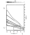
図8は、本実施形態に係る回転電機1の回転数と音発生装置30によって発生する音の周波数主成分との関係例を示す図である。図8において、横軸は重畳する周波数、左の縦軸は回転電機1の回転数である。また、右の縦軸は音圧を表す。
Next, an example of the relationship between the rotational speed of the rotating
FIG. 8 is a diagram illustrating a relationship example between the rotation speed of the rotating
符号g11が示す領域は、音圧が低い領域であり、ノイズがなく人が静寂に感じる領域である。
符号g12が示す領域は、例えば回転数が2000〜6000rpmかつ周波数が150Hz以上の領域であり、人が軽快(スポーティ感)を感じる領域である。
符号g13が示す領域は、例えば回転数が2000〜4000rpmかつ周波数が150Hz以下の領域であり、音の成分によって人が力強さ(迫力感)を感じる領域である。
The region indicated by reference sign g11 is a region where the sound pressure is low, and there is no noise, and the region feels quiet.
The region indicated by reference sign g12 is, for example, a region where the rotational speed is 2000 to 6000 rpm and the frequency is 150 Hz or more, and is a region where a person feels light (sporty feeling).
The region indicated by reference sign g13 is a region where the rotational speed is 2000 to 4000 rpm and the frequency is 150 Hz or less, for example, and is a region in which a person feels strength (powerful feeling) due to sound components.
本実施形態では、前述したように、非対象電磁部によって基本を発生させ、それに加えて、回転電機1の漏れ磁束によって音発生装置30の第1振動板33、第2振動板34、および第3振動板35を振動させることによって、図8に示したような周波数や音圧の音を発生させる。なお、本実施形態では、第1振動板33、第2振動板34、および第3振動板35の長さ寸法L1,L2,L3を調整することで、例えば150Hz以下の重低音を発生させる。
In the present embodiment, as described above, the basic is generated by the non-target electromagnetic unit, and in addition, the
次に、回転電機制御装置100の構成例を説明する。
図9は、本実施形態に係る回転電機制御装置100の構成例を示す図である。図9に示すように、回転電機制御装置100は、センサ101、制御部110、電源121、および回転電機1を備える。センサ101は、車速センサ102、アクセルポジションセンサ103、およびトルクセンサ104を備える。制御部110は、モータ制御部111、および電源制御部112を備える。なお、回転電機制御装置100は、車両に搭載されている。
Next, a configuration example of the rotating electrical
FIG. 9 is a diagram illustrating a configuration example of the rotating electrical
車速センサ102は、例えば加速度センサである。車速センサ102は、車速を検出し、検出した検出結果を制御部110に出力する。
アクセルポジションセンサ103は、アクセル・ペダルの踏み込み量と踏み込み速度を検出し、検出した検出結果を制御部110に出力する。
トルクセンサ104は、回転電機1の発生トルクを検出し、検出した検出結果を制御部110に出力する。
The
The
The
電源121は、電池である。電源121は、電力を電源制御部112に供給する。なお、電源121は、例えばDC/DC変換器(直流−直流変換器)(不図示)を備えていてもよい。
The
制御部110は、回転電機1に供給する電源周波数を変えることで回転電機1の回転数を制御する装置であるインバータを含む。
The
モータ制御部111は、センサ101が出力する検出結果に基づいて、回転電機1に対する指示を電源制御部112に出力する。モータ制御部111は、センサ101が出力する検出結果に基づいて、回転電機1に重畳する電流の振幅、周波数に対する指示を電源制御部112に出力する。モータ制御部111は、電源制御部112を介して電源121の電力が供給される。また、モータ制御部111は、車速と重畳する電流の振幅の関係を予め記憶している。さらに、モータ制御部111は、車速と重畳する電流の周波数の関係を予め記憶している。また、モータ制御部111は、トルクの閾値(トルク閾値)、加速度の閾値(加速度閾値)、および車速の閾値(車速閾値)を予め記憶している。
The
電源制御部112は、モータ制御部111が出力する指示に応じて、回転電機1の回転を制御する。電源制御部112は、モータ制御部111が出力する指示に応じて、回転電機1に重畳する電流の振幅、周波数を制御する。
The
次に、制御部110が行う制御例を説明する。
図10は、本実施形態に係る制御部110が行う制御例を示すフローチャートである。
Next, an example of control performed by the
FIG. 10 is a flowchart illustrating an example of control performed by the
(ステップS1)モータ制御部111は、車両の走行時、センサ101が出力する検出結果に基づいて、回転電機1に対する指示を電源制御部112に出力する。続けて、電源制御部112は、モータ制御部111が出力する指示に応じて、回転電機1の回転を制御する。制御部110は、回転電機1が回転させることで、前述した非対象電磁部によって基本音を発生させる。
(Step S <b> 1) The
(ステップS2)モータ制御部111は、トルクセンサ104が出力する検出結果を取得する。続けて、モータ制御部111は、取得した検出結果に基づいて、発生トルクが閾値X(Nm)以上であるか否かを判別する。モータ制御部111は、発生トルクが閾値X(Nm)以上であると判別した場合(ステップS2;YES)、ステップS3の処理に進める。モータ制御部111は、発生トルクが閾値X(Nm)未満であると判別した場合(ステップS2;NO)、ステップS7の処理に進める。
(Step S <b> 2) The
(ステップS3)モータ制御部111は、例えば150Hz(第1周波数)以下の周波数の電流を重畳することで、力強さをイメージする音を追加する指示を、電源制御部112に出力する。続けて、電源制御部112は、モータ制御部111が出力する指示に応じて、回転電機1に印加する電流に150Hz以下の成分を重畳する。処理後、制御部110は、ステップS4の処理に進める。
(Step S <b> 3) The
(ステップS4)モータ制御部111は、アクセルポジションセンサ103が出力する検出結果を取得する。続けて、モータ制御部111は、取得した検出結果に基づいて、加速度が閾値Y(G)以上であるか否かを判別する。モータ制御部111は、加速度が閾値Y(G)以上であると判別した場合(ステップS4;YES)、ステップS6の処理に進める。モータ制御部111は、加速度が閾値Y(G)未満であると判別した場合(ステップS4;NO)、ステップS5の処理に進める。なお、モータ制御部111は、例えば車速センサ102、トルクセンサ104の検出結果に基づいて、加速度を判別するようにしてもよい。
(Step S4) The
(ステップS5)モータ制御部111は、指示を電源制御部112に出力しない。または、モータ制御部111は、追加音無しの指示を電源制御部112に出力するようにしてもよい。この状態は、トルクが高く、加速度が小さい状態であり、例えば坂道を登っている状態である。処理後、制御部110は、ステップS2の処理に戻す。
(Step S <b> 5) The
(ステップS6)モータ制御部111は、例えば150Hz〜1000Hz(第2周波数)程度の周波数の電流を重畳することで、加速感を表す音を追加する指示を、電源制御部112に出力する。この状態は、トルクが高く、加速度が大きい状態であり、例えば加速している状態である。また、この状態で発生する音は、力強さに加え、高速移動をイメージした音でもある。処理後、制御部110は、ステップS2の処理に戻す。
(Step S <b> 6) The
(ステップS7)モータ制御部111は、車速センサ102が出力する検出結果を取得する。続けて、モータ制御部111は、取得した検出結果に基づいて、車速が閾値Z(km/h)以上であるか否かを判別する。モータ制御部111は、車速が閾値Z(km/h)以上であると判別した場合(ステップS7;YES)、ステップS9の処理に進める。モータ制御部111は、車速が閾値Z(km/h)未満であると判別した場合(ステップS7;NO)、ステップS8の処理に進める。
(Step S <b> 7) The
(ステップS8)モータ制御部111は、指示を電源制御部112に出力しない。または、モータ制御部111は、追加音無しの指示を電源制御部112に出力するようにしてもよい。この状態は、車速が遅い状態であり、例えば低速で走行している状態である。処理後、制御部110は、ステップS2の処理に戻す。
(Step S <b> 8) The
(ステップS9)モータ制御部111は、例えば150Hz〜1000Hz程度の周波数の電流を重畳することで、加速感を表す音を追加する指示を、電源制御部112に出力する。この状態は、車速が速い状態であり、例えば高速で走行している状態である。なお、モータ制御部111は、車速に応じて高調波電流の振幅を調整する。さらに、モータ制御部111は、車速に応じて、高調波電流の周波数を上げていくように制御する。処理後、制御部110は、ステップS2の処理に戻す。
(Step S <b> 9) The
すなわち、本実施形態では、加速度が閾値Y以上のときに、高調波電流を重畳して、加速時に、大きい音を出すことで、高揚感を演出することができる。
さらに、本実施形態では、車速に応じて、高調波電流の振幅を制御部110が調整する。この理由は、ロードノイズ、風切り音にかき消されない音量を確保ためである。
また、本実施形態では、車速に応じて、高調波電流の周波数を制御部110が上げていく。この理由は、車速に連動した音色に調整するためである。
That is, in this embodiment, when the acceleration is equal to or greater than the threshold value Y, the harmonic current is superimposed, and a loud sound can be produced during acceleration to produce an exhilaration feeling.
Further, in the present embodiment, the
Further, in the present embodiment, the
なお、図10に示した処理、重畳する周波数は一例であり、これに限らない。周波数、閾値等は、車両に回転電機1を搭載し、実際に発生する音によって、設計時に周波数等を設定するようにしてもよい。また、漏れ磁束デバイスの複数の振動板33〜35それぞれの寸法L1〜L3も、車両に回転電機1を搭載し、実際に発生する音によって、設計時に設定するようにしてもよい。
In addition, the process shown in FIG. 10 and the frequency to superimpose are examples, and are not restricted to this. The frequency, threshold value, and the like may be set at the time of design by mounting the rotating
なお、図10に示した処理において、トルクの閾値Xは、例えば200(Nm)、加速度の閾値Yは、例えば0.2(G)、車速の閾値Zは、例えば100(km/h)である。なお、各閾値は、これに限らない。 In the process shown in FIG. 10, the torque threshold value X is, for example, 200 (Nm), the acceleration threshold value Y is, for example, 0.2 (G), and the vehicle speed threshold value Z is, for example, 100 (km / h). is there. Each threshold value is not limited to this.
<重畳電流によるリプルへの影響の検討>
次に、回転電機1に電流を重畳した場合のトルクリプルへの影響を検討した結果を説明する。
図11は、回転電機1に電流を重畳した場合のトルクリプルへの影響を検討した結果を説明するための図である。図11において、横軸は時間、縦軸は電流である。
また、時刻0〜t3がロータ20の1回転に相当する。波形g101は、回転電機1の回転時の電流波形である。波形g102は、重畳する電流波形である。
<Examination of influence on ripple due to superimposed current>
Next, the result of examining the influence on the torque ripple when a current is superimposed on the rotating
FIG. 11 is a diagram for explaining the result of studying the influence on torque ripple when a current is superimposed on the rotating
ここで、回転電機1の回転時の電流波形の電流(以下、基本電流ともいう)Iは、次式(3)式のように表される。 Here, the current I of the current waveform during the rotation of the rotating electrical machine 1 (hereinafter also referred to as a basic current) I is expressed by the following equation (3).
式(3)において、I0は、電流の最大値、ωは周波数、θは、ロータ20の角度である。
また、重畳する電流(以下、重畳電流ともいう)I’は、次式(4)式のように表される。
In Expression (3), I 0 is the maximum current value, ω is the frequency, and θ is the angle of the
In addition, a superimposed current (hereinafter also referred to as a superimposed current) I ′ is expressed as the following formula (4).
式(4)において、I’0は、重畳電流の最大値であり、ω’は周波数であり、θ’は、重畳電流の角度(0〜360度)である。
また、磁石の磁束Bは、次式(5)のように表される。
In Equation (4), I ′ 0 is the maximum value of the superimposed current, ω ′ is the frequency, and θ ′ is the angle (0 to 360 degrees) of the superimposed current.
Further, the magnetic flux B of the magnet is expressed as the following equation (5).
式(5)において、B0は、磁束の最大値である。
ロータ20の回転によって発生する発生トルクTは、磁石の磁束Bに比例する。このため、発生トルクTは、次式(6)のように表される。
In equation (5), B 0 is the maximum value of the magnetic flux.
The generated torque T generated by the rotation of the
式(6)において、第1項と第2項{B0I0/2−(B0I0/2)×(cosωt)}は、基本電流に起因する成分である。また、式(6)において、第3項と第4項[(−B0I’0/2)(cos{(ω+ω’)t+θ+θ’})+(B0I’0/2)(cos{(ω−ω’)t+θ−θ’})]は、重畳電流に起因する成分である。すなわち、電流を重畳することによって、トルク成分に、ω+ω’とω−ω’の成分が出現する。 In the formula (6), first and second terms {B 0 I 0 / 2- ( B 0 I 0/2) × (cosωt)} is a component caused by the basic current. Further, in the equation (6), third and fourth term [(-B 0 I '0/ 2) (cos {(ω + ω') t + θ + θ '}) + (B 0 I' 0/2) (cos { (Ω−ω ′) t + θ−θ ′})] is a component caused by the superimposed current. That is, by superimposing the current, the components of ω + ω ′ and ω−ω ′ appear in the torque component.
図12は、基本電流によるトルクリプルの周波数成分例を示す図である。図12において、横軸は周波数、縦軸はトルク振幅である。
符号g111は、36次波による成分を表す。また、符号g112は、72次波による成分を表す。なお、基本電流の周波数は、36次波の1/6の周波数である。
FIG. 12 is a diagram illustrating an example of frequency components of torque ripple caused by the basic current. In FIG. 12, the horizontal axis represents frequency and the vertical axis represents torque amplitude.
A symbol g111 represents a component of a 36th order wave. A symbol g112 represents a component of the 72nd order wave. The frequency of the basic current is 1/6 of the 36th-order wave.
次に、基本電流の周波数の1/2の周波数を重畳した場合のトルクリプルの周波数成分例と、基本電流の周波数の約1/6の周波数を重畳した場合のトルクリプルの周波数成分例を説明する。
図13は、基本電流の周波数の1/2の周波数を重畳した場合のトルクリプルの周波数成分例と、基本電流の周波数の約1/6の周波数を重畳した場合のトルクリプルの周波数成分例を示す図である。図13において、横軸は周波数、縦軸はトルク振幅である。
符号g121は、基本電流の周波数の1/2の周波数を重畳した場合のトルクリプルの周波数成分を表す。また、符号g131は、基本電流の周波数の1/6の周波数を重畳した場合のトルクリプルの周波数成分を表す。
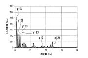
Next, an example of frequency components of torque ripple when a frequency half that of the basic current is superimposed and an example of frequency components of torque ripple when a frequency that is about 1/6 of the frequency of the basic current is superimposed will be described.
FIG. 13 is a diagram illustrating an example of a frequency component of torque ripple when a frequency half of the frequency of the basic current is superimposed and an example of a frequency component of torque ripple when a frequency of about 1/6 of the frequency of the basic current is superimposed. It is. In FIG. 13, the horizontal axis represents frequency and the vertical axis represents torque amplitude.
Symbol g121 represents a frequency component of torque ripple when a half frequency of the basic current is superimposed. Symbol g131 represents a frequency component of torque ripple when a frequency that is 1/6 of the frequency of the basic current is superimposed.
また、図13において、符号g122は、(基本電流の周波数)−(基本電流の周波数の1/2の周波数)であり、すなわち、ω−ω’の成分である。符号g123は、(基本電流の周波数)+(基本電流の周波数の1/2の周波数)であり、すなわち、ω+ω’の成分である。 In FIG. 13, the symbol g <b> 122 is (basic current frequency) − (½ frequency of the basic current frequency), that is, a component of ω−ω ′. The symbol g123 is (the frequency of the basic current) + (a frequency that is ½ of the frequency of the basic current), that is, a component of ω + ω ′.
また、図13において、符号g132は、(基本電流の周波数)−(基本電流の周波数の約1/6の周波数)であり、すなわち、ω−ω’の成分である。符号g133は、(基本電流の周波数)+(基本電流の周波数の約1/6の周波数)であり、すなわち、ω+ω’の成分である。 In FIG. 13, symbol g <b> 132 is (basic current frequency) − (frequency about 1/6 of the fundamental current frequency), that is, a component of ω−ω ′. The symbol g133 is (frequency of the basic current) + (frequency about 1/6 of the frequency of the basic current), that is, a component of ω + ω ′.
次に、基本電流の周波数の1.5倍の周波数を重畳した場合のトルクリプルの周波数成分例と、基本電流の周波数の約1.33倍の周波数を重畳した場合のトルクリプルの周波数成分例を説明する。
図14は、基本電流の周波数の1.5倍の周波数を重畳した場合のトルクリプルの周波数成分例と、基本電流の周波数の約1.33倍の周波数を重畳した場合のトルクリプルの周波数成分例を示す図である。図14において、横軸は周波数、縦軸はトルク振幅である。
符号g141は、基本電流の周波数の1.5倍の周波数を重畳した場合のトルクリプルの周波数成分を表す。また、符号g151は、基本電流の周波数の約1.33倍の周波数を重畳した場合のトルクリプルの周波数成分を表す。
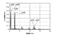
Next, an example of a frequency component of torque ripple when a frequency 1.5 times the frequency of the basic current is superimposed and an example of a frequency component of torque ripple when a frequency approximately 1.33 times the frequency of the basic current is superimposed will be described. To do.
FIG. 14 shows an example of a frequency component of torque ripple when a frequency 1.5 times the frequency of the basic current is superimposed, and an example of a frequency component of torque ripple when a frequency approximately 1.33 times the frequency of the basic current is superimposed. FIG. In FIG. 14, the horizontal axis represents frequency and the vertical axis represents torque amplitude.
Symbol g141 represents a frequency component of torque ripple when a frequency 1.5 times the frequency of the basic current is superimposed. Symbol g151 represents a frequency component of torque ripple when a frequency approximately 1.33 times the frequency of the basic current is superimposed.
また、図14において、符号g142は、(基本電流の周波数)−(基本電流の周波数の1.5倍の周波数)であり、すなわち、ω−ω’の成分である。符号g143は、(基本電流の周波数)+(基本電流の周波数の1.5倍の周波数)であり、すなわち、ω+ω’の成分である。 In FIG. 14, the symbol g <b> 142 is (the frequency of the basic current) − (a frequency that is 1.5 times the frequency of the basic current), that is, a component of ω−ω ′. The symbol g143 is (the frequency of the basic current) + (a frequency that is 1.5 times the frequency of the basic current), that is, a component of ω + ω ′.
また、図14において、符号g152は、(基本電流の周波数)−(基本電流の周波数の約1.33倍の周波数)であり、すなわち、ω−ω’の成分である。符号g153は、(基本電流の周波数)+(基本電流の周波数の約1.33倍の周波数)であり、すなわち、ω+ω’の成分である。 In FIG. 14, the symbol g <b> 152 is (basic current frequency) − (frequency approximately 1.33 times the fundamental current frequency), that is, a component of ω−ω ′. The symbol g153 is (the frequency of the basic current) + (a frequency approximately 1.33 times the frequency of the basic current), that is, a component of ω + ω ′.
次に、加速感を表す音(ジェット機音)の生成例を説明する。
図15は、加速感を表す音の波形例を示す図である。図15において、横軸は電気角であり、縦軸は電流である。
また、波形g161は、基本電流の波形を表す。波形g162は、重畳電流の波形を表す。波形g163は、合成電流の波形を表す。符号g164は、基本電流の1周気分を表す。
Next, an example of generating sound (jet sound) representing an acceleration feeling will be described.
FIG. 15 is a diagram illustrating an example of a sound waveform representing a feeling of acceleration. In FIG. 15, the horizontal axis represents the electrical angle, and the vertical axis represents the current.
A waveform g161 represents the waveform of the basic current. A waveform g162 represents the waveform of the superimposed current. A waveform g163 represents a waveform of the combined current. The symbol g164 represents the one-round air volume of the basic current.
図8、図15に示すように、本実施形態では、加速感を表す音(ジェット機音)の生成する場合、基本電流の周波数より高い周波数の電流を重畳する。
なお、図15において、基本電流の電流値が約I3〜−I3に対して、重畳電流の電流値は、約1/3の約I1〜−I1である。上述したように、重畳電流の振幅は、車速に応じて制御部110が調整する。
As shown in FIGS. 8 and 15, in the present embodiment, when a sound representing an acceleration feeling (jet sound) is generated, a current having a frequency higher than the frequency of the basic current is superimposed.
In FIG. 15, the current value of the basic current is about I3 to -I3, whereas the current value of the superimposed current is about I1 to -I1 which is about 1/3. As described above, the amplitude of the superimposed current is adjusted by the
次に、力強い音の生成例を説明する。
図16は、加速感を表す音の波形例を示す図である。図16において、横軸は電気角であり、縦軸は電流である。
また、波形g171は、基本電流の波形を表す。波形g172は、重畳電流の波形を表す。波形g173は、合成電流の波形を表す。符号g174は、基本電流の1周気分を表す。
Next, an example of generating a powerful sound will be described.
FIG. 16 is a diagram illustrating an example of a sound waveform representing a feeling of acceleration. In FIG. 16, the horizontal axis is the electrical angle, and the vertical axis is the current.
A waveform g171 represents a waveform of the basic current. A waveform g172 represents the waveform of the superimposed current. A waveform g173 represents a waveform of the combined current. The symbol g174 represents the one-round air volume of the basic current.
図8、図16に示すように、本実施形態では、加速感を表す音の生成する場合、基本電流の周波数より低い周波数、振幅の大きな電流を重畳する。
図16において、基本電流の電流値が約I3〜−I3に対して、重畳電流の電流値は、基本電流の電流値と同等の約I3〜−I3がそれ以上である。
As shown in FIGS. 8 and 16, in the present embodiment, when a sound representing an acceleration feeling is generated, a current having a frequency lower than that of the basic current and a large amplitude is superimposed.
In FIG. 16, the current value of the basic current is about I3 to -I3, whereas the current value of the superimposed current is about I3 to -I3, which is equivalent to the current value of the basic current.
なお、図15、図16に示した波形、振幅、周波数は一例であり、これに限られない。回転電機1の大きさや、搭載する車両に応じて、設計時に設定するようにしてもよい。
The waveforms, amplitudes, and frequencies shown in FIGS. 15 and 16 are examples, and the present invention is not limited thereto. You may make it set at the time of design according to the magnitude | size of the rotary
以上のように、本実施形態では、発生トルクが大きい場合に、第1周波数未満の高調波電流を重畳する。これにより、本実施形態によれば、高トルクかつ加速度が大きい場合に、大きい音を出すことで、高揚感を演出することができる。
また、本実施形態では、加速度が閾値Y以上のときに、第1周波数以上かつ第2周波数未満の高調波電流を重畳する。これにより、本実施形態によれば、高いトルクかつ加速時に、大きい音を出すことで、高揚感を演出することができる。
As described above, in the present embodiment, when the generated torque is large, the harmonic current less than the first frequency is superimposed. Thereby, according to this embodiment, when high torque and acceleration are large, an exhilaration feeling can be produced by making a loud sound.
Further, in the present embodiment, when the acceleration is equal to or higher than the threshold value Y, the harmonic current having the first frequency or higher and lower than the second frequency is superimposed. Thereby, according to this embodiment, an exhilaration feeling can be produced by making a loud sound at the time of high torque and acceleration.
また、本実施形態では、車速が閾値Z以上の場合に、第1周波数以上かつ第2周波数未満の高調波電流を重畳する。これにより、本実施形態によれば、高速移動時に、大きい音を出すことで、高揚感を演出することができる。
また、本実施形態では、車速に応じて、高調波電流の振幅を制御部110が調整する。これにより、本実施形態によれば、ロードノイズ、風切り音にかき消されない音量を確保ことができる。
さらに、本実施形態では、車速に応じて、高調波電流の周波数を制御部110が上げていく。これにより、本実施形態によれば、車速に連動した音色に調整することができる。
In the present embodiment, when the vehicle speed is equal to or higher than the threshold value Z, a harmonic current that is equal to or higher than the first frequency and lower than the second frequency is superimposed. Thereby, according to this embodiment, an uplifting feeling can be produced by making a loud sound at the time of high-speed movement.
In the present embodiment, the
Further, in the present embodiment, the
さらに、本実施形態では、非対象電磁部で基本音を発生させるようにした。これにより、本実施形態によれば、余分な電流を流すことなく、さらに、回転電機1の基本性能を低下させることなく、乗員にとって心地よいモータ音を演出することができる。
また、本実施形態では、漏れ磁束デバイスの振動板を漏れ磁束によって振動させることで多様な周波数の音を演出することができる。さらに本実施形態では、回転電機1に、トルク、加速度、速度(車速)に応じて、電流を重畳することで、漏れ磁束デバイスによって発生する音の周波数を制御することができる。これにより、本実施形態によれば、車両の走行状態に応じて、回転電機1の回転を利用して、乗員に心地よい音を発生させることができる。この結果、本実施形態によれば、車両が回転電機1を備える車両であっても、単調なモータ音でなく、エンジンを搭載している車両で乗員が馴染んでいる音を演出することができる。
Furthermore, in this embodiment, the basic sound is generated by the non-target electromagnetic part. As a result, according to the present embodiment, it is possible to produce a motor sound that is comfortable for the occupant without causing an excess current to flow and without lowering the basic performance of the rotating
Moreover, in this embodiment, the sound of various frequencies can be produced by vibrating the diaphragm of the leakage flux device with the leakage flux. Furthermore, in this embodiment, the frequency of the sound generated by the leakage magnetic flux device can be controlled by superimposing current on the rotating
なお、本発明における制御部110の機能の全てまたは一部を実現するためのプログラムをコンピュータ読み取り可能な記録媒体に記録して、この記録媒体に記録されたプログラムをコンピュータシステムに読み込ませ、実行することにより制御部110が行う処理の全てまたは一部を行ってもよい。なお、ここでいう「コンピュータシステム」とは、OSや周辺機器等のハードウェアを含むものとする。また、「コンピュータシステム」は、ホームページ提供環境(あるいは表示環境)を備えたWWWシステムも含むものとする。また、「コンピュータ読み取り可能な記録媒体」とは、フレキシブルディスク、光磁気ディスク、ROM、CD−ROM等の可搬媒体、コンピュータシステムに内蔵されるハードディスク等の記憶装置のことをいう。さらに「コンピュータ読み取り可能な記録媒体」とは、インターネット等のネットワークや電話回線等の通信回線を介してプログラムが送信された場合のサーバやクライアントとなるコンピュータシステム内部の揮発性メモリ(RAM)のように、一定時間プログラムを保持しているものも含むものとする。
Note that a program for realizing all or part of the functions of the
また、上記プログラムは、このプログラムを記憶装置等に格納したコンピュータシステムから、伝送媒体を介して、あるいは、伝送媒体中の伝送波により他のコンピュータシステムに伝送されてもよい。ここで、プログラムを伝送する「伝送媒体」は、インターネット等のネットワーク(通信網)や電話回線等の通信回線(通信線)のように情報を伝送する機能を有する媒体のことをいう。また、上記プログラムは、前述した機能の一部を実現するためのものであってもよい。さらに、前述した機能をコンピュータシステムにすでに記録されているプログラムとの組み合わせで実現できるもの、いわゆる差分ファイル(差分プログラム)であってもよい。 The program may be transmitted from a computer system storing the program in a storage device or the like to another computer system via a transmission medium or by a transmission wave in the transmission medium. Here, the “transmission medium” for transmitting the program refers to a medium having a function of transmitting information, such as a network (communication network) such as the Internet or a communication line (communication line) such as a telephone line. The program may be for realizing a part of the functions described above. Furthermore, what can implement | achieve the function mentioned above in combination with the program already recorded on the computer system, what is called a difference file (difference program) may be sufficient.
以上、本発明を実施するための形態について実施形態を用いて説明したが、本発明はこうした実施形態に何等限定されるものではなく、本発明の要旨を逸脱しない範囲内において種々の変形および置換を加えることができる。 As mentioned above, although the form for implementing this invention was demonstrated using embodiment, this invention is not limited to such embodiment at all, and various deformation | transformation and substitution are within the range which does not deviate from the summary of this invention. Can be added.
1…回転電機、2…ハウジング、4…シャフト、10…ステータ、11…ステータコア、13…コイル、13a…コイルエンド、20…ロータ、21…ロータコア、23…磁石、25…端面板、27…仕切壁、28…ボス、30…音発生装置、31…取付ブラケット、33〜35…第1〜第3の振動板(振動板)、37…取付ボルト、41…基部、42…取付部、51,52…第1非同一形状部、53,54…第2非同一形状部、61…ティース、62…スロット、101…センサ、102…車速センサ、103…アクセルポジションセンサ、104…トルクセンサ、110…制御部、111…モータ制御部、112…電源制御部、121…電源、L1〜L3…振動板の長さ寸法
DESCRIPTION OF
Claims (8)
前記回転電機の状態を検出するセンサと、
前記センサが検出した結果に基づいて、前記回転電機に供給する電流に重畳する電流成分を制御する制御部と、
を備える回転電機制御装置。 Rotating electrical machinery,
A sensor for detecting the state of the rotating electrical machine;
A control unit for controlling a current component superimposed on a current supplied to the rotating electrical machine based on a result detected by the sensor;
A rotating electrical machine control device comprising:
前記ステータコアに振動板が隣接して設けられ、前記磁束による電磁力で前記振動板が振動することにより所定の音を発生する音発生装置と、
を備える、請求項1から請求項5のいずれか1項に記載の回転電機制御装置。 A stator in which a coil is mounted on a stator core, and a magnetic flux is generated by energizing the coil;
A sound generator that is provided adjacent to the stator core, and that generates a predetermined sound when the diaphragm vibrates due to electromagnetic force generated by the magnetic flux;
The rotating electrical machine control device according to claim 1, comprising:
ステータコアにコイルが装着されたステータと、を備え、
前記ロータコアの外周面および前記ステータコアの内周面の両方に、
周方向の極毎に設定された電磁領域の繰返し形状とは異なる非同一形状部が設けられている、請求項1から請求項6のいずれか1項に記載の回転電機制御装置。 A rotor with magnets attached to the rotor core;
A stator with a coil mounted on the stator core,
On both the outer peripheral surface of the rotor core and the inner peripheral surface of the stator core,
The rotating electrical machine control device according to any one of claims 1 to 6, wherein a non-identical shape portion different from a repetitive shape of an electromagnetic region set for each pole in the circumferential direction is provided.
センサが、前記回転電機の状態を検出する手順と、
制御部が、前記センサによって検出された結果に基づいて、前記回転電機に供給する電流に重畳する電流成分を制御する手順と、
を含む回転電機制御方法。 A rotating electrical machine control method of a rotating electrical machine control device having a rotating electrical machine,
A sensor for detecting a state of the rotating electrical machine;
A procedure for controlling a current component to be superimposed on a current supplied to the rotating electrical machine based on a result detected by the sensor;
A rotating electrical machine control method.
Priority Applications (3)
| Application Number | Priority Date | Filing Date | Title |
|---|---|---|---|
| JP2018021337A JP6648172B2 (en) | 2018-02-08 | 2018-02-08 | Rotating electric machine control device and rotating electric machine control method |
| CN201910088674.4A CN110138166B (en) | 2018-02-08 | 2019-01-29 | Rotating electric machine control device and rotating electric machine control method |
| US16/261,612 US10862411B2 (en) | 2018-02-08 | 2019-01-30 | Rotating electrical machine control device and rotating electrical machine control method |
Applications Claiming Priority (1)
| Application Number | Priority Date | Filing Date | Title |
|---|---|---|---|
| JP2018021337A JP6648172B2 (en) | 2018-02-08 | 2018-02-08 | Rotating electric machine control device and rotating electric machine control method |
Publications (2)
| Publication Number | Publication Date |
|---|---|
| JP2019140776A true JP2019140776A (en) | 2019-08-22 |
| JP6648172B2 JP6648172B2 (en) | 2020-02-14 |
Family
ID=67476170
Family Applications (1)
| Application Number | Title | Priority Date | Filing Date |
|---|---|---|---|
| JP2018021337A Active JP6648172B2 (en) | 2018-02-08 | 2018-02-08 | Rotating electric machine control device and rotating electric machine control method |
Country Status (3)
| Country | Link |
|---|---|
| US (1) | US10862411B2 (en) |
| JP (1) | JP6648172B2 (en) |
| CN (1) | CN110138166B (en) |
Cited By (1)
| Publication number | Priority date | Publication date | Assignee | Title |
|---|---|---|---|---|
| JP2022523900A (en) * | 2019-03-18 | 2022-04-27 | ベバスト エスエー | How to generate sound using an electric motor used to drive vehicle roof components |
Citations (7)
| Publication number | Priority date | Publication date | Assignee | Title |
|---|---|---|---|---|
| WO2010023768A1 (en) * | 2008-08-28 | 2010-03-04 | 日産自動車株式会社 | Vehicle operation sound control apparatus and control method |
| JP2011055697A (en) * | 2009-08-03 | 2011-03-17 | Hisashi Takahashi | Motor mechanism controlled to generate sound and electric vehicle |
| JP2012115092A (en) * | 2010-11-26 | 2012-06-14 | Denso Corp | Inverter control apparatus and vehicle |
| JP2012228138A (en) * | 2011-04-22 | 2012-11-15 | Toyota Motor Corp | Vehicle drive device |
| JP2014168998A (en) * | 2013-03-01 | 2014-09-18 | Sumitomo Electric Ind Ltd | Electric power conversion system |
| JP2016063650A (en) * | 2014-09-18 | 2016-04-25 | 株式会社東芝 | Permanent magnet type electrical rotating machine |
| JP2017520444A (en) * | 2014-04-29 | 2017-07-27 | エルエス オートモーティブ コーポレーション | Eco car operating sound generator and control method thereof |
Family Cites Families (4)
| Publication number | Priority date | Publication date | Assignee | Title |
|---|---|---|---|---|
| JP4449035B2 (en) * | 2004-03-10 | 2010-04-14 | 日立オートモティブシステムズ株式会社 | Permanent magnet rotating electric machine for electric vehicles |
| US8212505B2 (en) * | 2008-12-02 | 2012-07-03 | GM Global Technology Operations LLC | Method and system for creating a vibration in an automobile |
| DE102010019502B4 (en) * | 2010-05-06 | 2023-03-23 | Bühler Motor GmbH | Pump with integrated electronically commutated DC motor |
| JP2013162556A (en) * | 2012-02-01 | 2013-08-19 | Suzuki Motor Corp | Electric rotary machine |
-
2018
- 2018-02-08 JP JP2018021337A patent/JP6648172B2/en active Active
-
2019
- 2019-01-29 CN CN201910088674.4A patent/CN110138166B/en active Active
- 2019-01-30 US US16/261,612 patent/US10862411B2/en active Active
Patent Citations (7)
| Publication number | Priority date | Publication date | Assignee | Title |
|---|---|---|---|---|
| WO2010023768A1 (en) * | 2008-08-28 | 2010-03-04 | 日産自動車株式会社 | Vehicle operation sound control apparatus and control method |
| JP2011055697A (en) * | 2009-08-03 | 2011-03-17 | Hisashi Takahashi | Motor mechanism controlled to generate sound and electric vehicle |
| JP2012115092A (en) * | 2010-11-26 | 2012-06-14 | Denso Corp | Inverter control apparatus and vehicle |
| JP2012228138A (en) * | 2011-04-22 | 2012-11-15 | Toyota Motor Corp | Vehicle drive device |
| JP2014168998A (en) * | 2013-03-01 | 2014-09-18 | Sumitomo Electric Ind Ltd | Electric power conversion system |
| JP2017520444A (en) * | 2014-04-29 | 2017-07-27 | エルエス オートモーティブ コーポレーション | Eco car operating sound generator and control method thereof |
| JP2016063650A (en) * | 2014-09-18 | 2016-04-25 | 株式会社東芝 | Permanent magnet type electrical rotating machine |
Cited By (2)
| Publication number | Priority date | Publication date | Assignee | Title |
|---|---|---|---|---|
| JP2022523900A (en) * | 2019-03-18 | 2022-04-27 | ベバスト エスエー | How to generate sound using an electric motor used to drive vehicle roof components |
| JP7241180B2 (en) | 2019-03-18 | 2023-03-16 | ベバスト エスエー | A method of generating sound using an electric motor used to drive a vehicle roof component |
Also Published As
| Publication number | Publication date |
|---|---|
| CN110138166B (en) | 2021-08-06 |
| JP6648172B2 (en) | 2020-02-14 |
| US20190245462A1 (en) | 2019-08-08 |
| US10862411B2 (en) | 2020-12-08 |
| CN110138166A (en) | 2019-08-16 |
Similar Documents
| Publication | Publication Date | Title |
|---|---|---|
| US7170247B2 (en) | Method of control of magnetic sound of alternating current rotating machine | |
| Callegaro et al. | Radial force density analysis of switched reluctance machines: The source of acoustic noise | |
| US8560129B2 (en) | Vibration control device and vehicle | |
| US20050231142A1 (en) | Method of control of magnetic sound of alternating current rotating machine | |
| CN110691717B (en) | Method for operating an electric machine, acoustic control device and motor vehicle | |
| Harries et al. | Noise reduction via harmonic current injection for concentrated-winding permanent magnet synchronous machines | |
| JP4269881B2 (en) | AC rotating electrical equipment | |
| JP6648172B2 (en) | Rotating electric machine control device and rotating electric machine control method | |
| Lu et al. | Comparative study on vibration behaviors of permanent magnet assisted synchronous reluctance machines with different rotor topologies | |
| GB2509132A (en) | Sound generation of an electric motor in an automotive vehicle | |
| US4808863A (en) | Active control system and method for reducing engine noise and vibration | |
| KR102307178B1 (en) | Device and method for controlling impression of riding in a vehicle powered by an electric motor | |
| JP7172239B2 (en) | Vehicle drive system | |
| JP2019054624A (en) | Rotary electric machine | |
| JP5440383B2 (en) | Motor control device | |
| Devillers et al. | Sound quality aspects of electric vehicles | |
| JP6875967B2 (en) | Rotating machine | |
| Elamin | Acoustic noise mitigation of switched reluctance machines through skewing methods | |
| Sun et al. | Vibration control of in-wheel SRM for electric vehicle applications | |
| Chang et al. | Development of the Active Sound Generation Technology using Motor Driven Power Steering System | |
| JP5433338B2 (en) | Vehicle operating sound control device | |
| Sentpali et al. | Using Electric Drives for Active Noise Generation | |
| Liang | Acoustic noise and vibrations in switched reluctance motors: enhanced modeling | |
| JP2019017143A (en) | Electric motor | |
| KR20190056187A (en) | A Fan Able to Make Sounds and Reduce noise |
Legal Events
| Date | Code | Title | Description |
|---|---|---|---|
| A621 | Written request for application examination |
Free format text: JAPANESE INTERMEDIATE CODE: A621 Effective date: 20180927 |
|
| A977 | Report on retrieval |
Free format text: JAPANESE INTERMEDIATE CODE: A971007 Effective date: 20190524 |
|
| A131 | Notification of reasons for refusal |
Free format text: JAPANESE INTERMEDIATE CODE: A131 Effective date: 20190604 |
|
| A521 | Request for written amendment filed |
Free format text: JAPANESE INTERMEDIATE CODE: A523 Effective date: 20190802 |
|
| TRDD | Decision of grant or rejection written | ||
| A01 | Written decision to grant a patent or to grant a registration (utility model) |
Free format text: JAPANESE INTERMEDIATE CODE: A01 Effective date: 20191224 |
|
| A61 | First payment of annual fees (during grant procedure) |
Free format text: JAPANESE INTERMEDIATE CODE: A61 Effective date: 20200115 |
|
| R150 | Certificate of patent or registration of utility model |
Ref document number: 6648172 Country of ref document: JP Free format text: JAPANESE INTERMEDIATE CODE: R150 |