JP2019137521A - Vehicular system - Google Patents
Vehicular system Download PDFInfo
- Publication number
- JP2019137521A JP2019137521A JP2018022655A JP2018022655A JP2019137521A JP 2019137521 A JP2019137521 A JP 2019137521A JP 2018022655 A JP2018022655 A JP 2018022655A JP 2018022655 A JP2018022655 A JP 2018022655A JP 2019137521 A JP2019137521 A JP 2019137521A
- Authority
- JP
- Japan
- Prior art keywords
- vehicle
- magnetic
- tag
- information
- marker
- Prior art date
- Legal status (The legal status is an assumption and is not a legal conclusion. Google has not performed a legal analysis and makes no representation as to the accuracy of the status listed.)
- Pending
Links
- 239000003550 marker Substances 0.000 claims abstract description 128
- 238000001514 detection method Methods 0.000 claims abstract description 47
- 238000004891 communication Methods 0.000 claims abstract description 15
- 238000000034 method Methods 0.000 description 17
- 238000005259 measurement Methods 0.000 description 14
- 238000012545 processing Methods 0.000 description 14
- 230000001133 acceleration Effects 0.000 description 9
- 230000005389 magnetism Effects 0.000 description 8
- 230000004907 flux Effects 0.000 description 6
- 238000005516 engineering process Methods 0.000 description 4
- 238000010586 diagram Methods 0.000 description 3
- 238000006073 displacement reaction Methods 0.000 description 3
- 230000000694 effects Effects 0.000 description 3
- UQSXHKLRYXJYBZ-UHFFFAOYSA-N Iron oxide Chemical compound [Fe]=O UQSXHKLRYXJYBZ-UHFFFAOYSA-N 0.000 description 2
- 230000005540 biological transmission Effects 0.000 description 2
- 238000004364 calculation method Methods 0.000 description 2
- 239000000446 fuel Substances 0.000 description 2
- 229920000139 polyethylene terephthalate Polymers 0.000 description 2
- 239000005020 polyethylene terephthalate Substances 0.000 description 2
- -1 Polyethylene terephthalate Polymers 0.000 description 1
- 238000013459 approach Methods 0.000 description 1
- 238000013473 artificial intelligence Methods 0.000 description 1
- 238000001739 density measurement Methods 0.000 description 1
- 230000005674 electromagnetic induction Effects 0.000 description 1
- 230000006870 function Effects 0.000 description 1
- 230000010354 integration Effects 0.000 description 1
- 239000000696 magnetic material Substances 0.000 description 1
- 239000006247 magnetic powder Substances 0.000 description 1
- 239000000463 material Substances 0.000 description 1
- 239000002184 metal Substances 0.000 description 1
- 229910052751 metal Inorganic materials 0.000 description 1
- 239000004033 plastic Substances 0.000 description 1
- 229920003023 plastic Polymers 0.000 description 1
- 239000002861 polymer material Substances 0.000 description 1
- 230000002123 temporal effect Effects 0.000 description 1
- 238000012546 transfer Methods 0.000 description 1
- 229910000859 α-Fe Inorganic materials 0.000 description 1
Images


Classifications
-
- B—PERFORMING OPERATIONS; TRANSPORTING
- B65—CONVEYING; PACKING; STORING; HANDLING THIN OR FILAMENTARY MATERIAL
- B65G—TRANSPORT OR STORAGE DEVICES, e.g. CONVEYORS FOR LOADING OR TIPPING, SHOP CONVEYOR SYSTEMS OR PNEUMATIC TUBE CONVEYORS
- B65G63/00—Transferring or trans-shipping at storage areas, railway yards or harbours or in opening mining cuts; Marshalling yard installations
-
- G—PHYSICS
- G05—CONTROLLING; REGULATING
- G05D—SYSTEMS FOR CONTROLLING OR REGULATING NON-ELECTRIC VARIABLES
- G05D1/00—Control of position, course or altitude of land, water, air, or space vehicles, e.g. automatic pilot
- G05D1/02—Control of position or course in two dimensions
Abstract
Description
本発明は、空港や港湾などに設定された作業エリア内を移動する作業車両などを対象とする車両用システムに関する。 The present invention relates to a vehicle system intended for a work vehicle that moves within a work area set in an airport, a port, or the like.
従来より、空港や港湾などでは、作業エリア内を自由度高く移動する作業車両が活用されている。例えば空港では、旅客の輸送や荷物の運搬、旅客機への燃料供給などを目的として、GSE(Ground Support Equipment)車両と呼ばれる作業車両が運用されている。また、港湾などのコンテナヤードでは、コンテナを移動するための作業車両が運用されている(例えば特許文献1参照。)。これらの作業車両の運用には多くの人手が必要になるため、作業車両の運用に要するコストを低減するための技術が強く要請されている。 Conventionally, work vehicles that move within a work area with high flexibility have been used in airports and harbors. For example, at an airport, a work vehicle called a GSE (Ground Support Equipment) vehicle is operated for the purpose of transporting passengers, transporting luggage, and supplying fuel to passenger aircraft. Moreover, in a container yard such as a harbor, a work vehicle for moving the container is operated (see, for example, Patent Document 1). Since many operations are required for the operation of these work vehicles, a technology for reducing the cost required for the operation of the work vehicles is strongly demanded.
例えば工場内の床面に敷設された磁気テープを伝って走行する搬送車両であれば、車両位置の特定が比較的容易であり、作業車両の管理や制御などを比較的低コストで実現できる。一方、港湾のコンテナヤードや空港などで運用され、作業エリア内を自由度高く移動する作業車両の場合、車両位置の特定が難しいことに起因し、作業車両の管理や制御に要するコストを低減するための技術の確立が容易でないという問題がある。例えばGPS(Global Positioning System)を利用して車両位置を測位する技術があるが、港湾のコンテナヤードや空港などでの作業車両の運用では、電波を反射する金属製のコンテナの脇の通路や空港施設の屋内の通路など、GPS電波の良好な受信状態を阻害する走行環境が多く存在している。 For example, if it is a conveyance vehicle which travels along the magnetic tape laid on the floor in the factory, the vehicle position can be identified relatively easily, and management and control of the work vehicle can be realized at a relatively low cost. On the other hand, in the case of a work vehicle that is operated in a container yard or airport at a port and moves within the work area with a high degree of freedom, it is difficult to specify the position of the vehicle, thereby reducing the cost required for management and control of the work vehicle. For this reason, there is a problem that it is not easy to establish technology for this purpose. For example, there is a technology that uses GPS (Global Positioning System) to determine the position of a vehicle, but in the operation of a work vehicle in a container yard of a port or an airport, a corridor beside a metal container that reflects radio waves or an airport There are many traveling environments that hinder the good reception of GPS radio waves, such as indoor passages in facilities.
本発明は、前記従来の問題点に鑑みてなされたものであり、空港や港湾の作業エリアなどの走行エリア内を移動する車両の管理や制御等に好適な車両用システムを提供しようとするものである。 The present invention has been made in view of the above-mentioned conventional problems, and intends to provide a vehicle system suitable for management and control of a vehicle moving in a traveling area such as an airport or a port working area. It is.
本発明は、走行エリア内を移動する車両用のシステムであって、
走行エリアに配置された複数の磁気マーカと、
無線通信により固有のタグ情報を外部出力する複数の無線タグと、
前記磁気マーカを検出する検出ユニット、及び前記無線タグが外部出力するタグ情報を取得するタグリーダユニットを備える車両と、
車両が取得したタグ情報を利用して車両が検出した磁気マーカを特定することにより走行エリアにおける車両位置を特定する位置特定部と、を含み、
前記複数の磁気マーカのうちの少なくとも一部の磁気マーカに対して、前記無線タグが一対一に対応するように同じ位置に配置されている車両用システムにある。
The present invention is a system for a vehicle that moves in a traveling area,
A plurality of magnetic markers arranged in the traveling area;
A plurality of wireless tags for outputting unique tag information to the outside by wireless communication;
A vehicle including a detection unit for detecting the magnetic marker, and a tag reader unit for acquiring tag information output from the wireless tag externally;
A position specifying unit that specifies the vehicle position in the travel area by specifying the magnetic marker detected by the vehicle using the tag information acquired by the vehicle,
It exists in the system for vehicles by which the said radio | wireless tag is arrange | positioned at the same position so that it may respond | correspond one to one with respect to the magnetic marker of at least one part of these magnetic markers.
本発明の車両用システムにおいては、無線通信により固有のタグ情報を外部出力する無線タグが、少なくとも一部の磁気マーカと一対一に対応するように同じ位置に設けられている。この磁気マーカシステムでは、タグ情報を利用して車両が検出した磁気マーカを特定することで、走行エリアにおける車両の位置が特定される。 In the vehicle system of the present invention, the wireless tag that outputs the unique tag information to the outside by wireless communication is provided at the same position so as to correspond to at least a part of the magnetic markers. In this magnetic marker system, the position of the vehicle in the travel area is specified by specifying the magnetic marker detected by the vehicle using the tag information.
特に、この車両用システムでは、少なくとも一部の磁気マーカと同じ位置に無線タグが配置されているので、磁気マーカに対する車両の進入方向に関わらず、磁気マーカに到達すると同時に無線タグに到達できる。それ故、車両が磁気マーカを検出する際、その検出時点を基準とする同様のタイミングで無線タグと通信でき、タグ情報を確実性高く取得可能である。 In particular, in this vehicle system, since the wireless tag is disposed at the same position as at least a part of the magnetic marker, the wireless tag can be reached at the same time as reaching the magnetic marker regardless of the approach direction of the vehicle with respect to the magnetic marker. Therefore, when the vehicle detects the magnetic marker, it can communicate with the wireless tag at the same timing with the detection time as a reference, and tag information can be acquired with high reliability.
このように本発明の車両用システムは、走行エリア内の車両の位置を確実性高く特定可能なシステムであり、走行エリア内を移動する車両の管理や制御等に好適である。 As described above, the vehicle system according to the present invention is a system that can specify the position of the vehicle in the traveling area with high reliability, and is suitable for management and control of the vehicle moving in the traveling area.
本発明の実施の形態につき、以下の実施例を用いて具体的に説明する。
(実施例1)
本例は、空港などに設定された作業エリア1Aを移動する作業車両5を管理するための車両用システムである作業車両システム1に関する例である。この内容について、図1〜図9を用いて説明する。
The embodiment of the present invention will be specifically described with reference to the following examples.
Example 1
This example is an example related to the
図1の作業車両システム1は、空港などで飛行機190に関する各種の作業を実施する作業車両5を管理するためのシステムである。作業車両5としては、飛行機190に給油するための作業車両(給油車)や、旅客を搭乗させるための作業車両(タラップ車)や、荷物や飲食物を搬入する作業車両(ベルトローダー、ケータリングカー)や、飛行機を牽引する作業車両(トーイングトラクター)など、各種の作業毎の専用のGSE車両がある。
A
作業車両システム1では、図1のごとく、飛行機190の駐機スペースと、空港ビル100内の作業スペースと、に跨って作業車両5の走行エリアである作業エリア1Aが設定されている。作業エリア1Aでは、縦横2m間隔で格子状に磁気マーカ10が配置されている。作業車両システム1では、例えば空港ビル100内に設置されたサーバ装置18による管理の下、作業車両5が磁気マーカ10を伝うようにして作業エリア1A内を移動して作業を実施する。
In the
作業車両システム1(図1)では、サーバ装置18と作業車両5とが無線通信を介して通信可能に接続されている。サーバ装置18は、各作業車両5の車両位置を管理すると共に、各作業車両5の経路1Rを演算し、その経路1Rに沿って走行できるように作業車両5を遠隔制御する。作業車両5は、磁気マーカ10を検出する毎にRFIDタグ(無線タグ)15から取得したタグ情報をサーバ装置18に送信し、サーバ装置18から受信する制御情報に応じて自動走行する。
In the work vehicle system 1 (FIG. 1), the
以下、作業エリア1Aに敷設される(1)磁気マーカ10を概説した後、(2)サーバ装置18、(3)作業車両5、の構成を説明する。
(1)磁気マーカ
磁気マーカ10(図2)は、直径20mm、高さ28mmの柱状をなし、作業車両5が移動する路面100Sに設けた孔に収容された状態で敷設される態様のものである。磁気マーカ10をなす磁石は、磁性材料である酸化鉄の磁粉を基材である高分子材料中に分散させたフェライトプラスチックマグネットであり、最大エネルギー積(BHmax)=6.4kJ/m3という特性を備えている。この磁気マーカ10は、作業車両5側の検出ユニット2(図5を参照して後述。)の取付け高さとして想定する範囲100〜250mmの上限の250mm高さにおいて、8μT(マイクロテスラ)の磁束密度の磁気を作用する。
Hereinafter, after (1) the
(1) Magnetic marker The magnetic marker 10 (FIG. 2) has a columnar shape with a diameter of 20 mm and a height of 28 mm, and is laid in a state of being accommodated in a hole provided in the
本例の磁気マーカ10では、図2及び図3のごとく、無線によりタグ情報を出力するRFID(Radio Frequency IDentification)タグ15が、路面100S側の表面に積層配置されている。RFIDタグ15は、無線による外部給電により動作し、タグ情報の一例をなすタグIDを外部出力する。
In the
RFIDタグ15は、例えばPET(Polyethylene terephthalate)フィルムから切り出したタグシート150の表面にICチップ157を実装した電子部品である。タグシート150の表面には、ループコイル151及びアンテナ153の印刷パターンが設けられている。ループコイル151は、外部からの電磁誘導によって励磁電流が発生する受電コイルである。アンテナ153は、位置データ等を無線送信するための送信アンテナである。
The
(2)サーバ装置
サーバ装置18は、図4のごとく、CPU(Central Processing Unit)181やROM(Read Only Memory)182やRAM(Random Access Memory)183などの電子部品が実装された電子基板180を中心にして構成されたコンピュータ装置である。電子基板180には、I/O(Input/Output)184を介して、ハードディスクドライブ等の記憶装置185や無線通信ユニット189等が接続されている。サーバ装置18は、記憶装置185から読み出したソフトウェアプログラムをCPU181で処理することで、以下の各部としての機能を実現する。
(2) Server Device As shown in FIG. 4, the
(2.1)位置特定部:作業車両5が位置する車両位置を特定する。車両位置を特定する方法は、作業車両5が磁気マーカ10を検出したときと、磁気マーカ10を検出した後、新たな磁気マーカ10を検出するまでの間と、で相違している。磁気マーカ10の検出時には、位置特定部は、各作業車両5がRFIDタグ15から受信したタグ情報(タグ)を利用して車両位置を特定する。新たな磁気マーカ10を検出するまでの間では、位置特定部は、次に説明する位置推定部が推定する移動先の相対位置を利用して車両位置を特定する。
(2.2)位置推定部:作業車両5が通過した磁気マーカ10の敷設位置を基準として作業車両5の移動先の相対的な位置を推定する。
(2.3)経路演算部:予め設定された作業内容に応じて作業車両5の経路(図1中の符号1R)を演算する。経由地や目的地などを含む作業内容は、例えばキーボードやマウスやディスプレイ等の入力機器を利用して作業オペレータが入力する。
(2.4)遠隔制御部:演算された経路1Rに沿って作業車両5を移動させるように遠隔制御する。制御部の一例をなす遠隔制御部は、各作業車両5の車両位置や加速度の計測値などの各種の車両情報を入力値とした演算処理により、目標操舵角、目標車速等の制御値を算出して制御情報として返信する。なお、目標速度は、速度ゼロ、すなわち停止制御も含む制御値となっている。
(2.1) Position specifying unit: specifies a vehicle position where the
(2.2) Position estimation unit: Estimates the relative position of the movement destination of the
(2.3) Route calculation unit: calculates a route (
(2.4) Remote control unit: Remotely controls the
サーバ装置18では、記憶装置185の記憶領域を利用して、作業エリア1Aに配置された各磁気マーカ10の敷設位置を格納するマーカデータベース(マーカDB)185Mが形成されている。マーカDB185Mに記録された磁気マーカ10の敷設位置には、付設されたRFIDタグ15の識別情報であるタグID(タグ情報)が紐付け(対応付け)られている。
In the
(3)作業車両
作業車両5は、図5及び図6のごとく、作業目的に応じた専用の作業装置(図示略)の他に、磁気マーカ10を検出等する検出ユニット2、RFIDタグ15からタグIDを取得するタグリーダユニット34、及び制御ユニット32、などを共通装備として備えている。さらに、作業車両5は、図示しないステアリング操舵ユニットやエンジンスロットルやブレーキアクチュエータなどを制御する車両ECU(Electronic Control Unit)61を備えている。制御部の一例をなす車両ECU61は、サーバ装置18から取得する制御情報(制御値)に基づいて作業車両5を経路1R(図1参照。)に沿って自動走行させる制御を実行可能である。なお、検出ユニット2及びタグリーダユニット34について、容易な理解のため別体で図示しているが、これらが一体化されたユニットを採用しても良い。
(3) Work vehicle As shown in FIGS. 5 and 6, the
(3.1)検出ユニット
検出ユニット2は、図5及び図6のごとく、磁気検出部であるセンサアレイ21と、IMU(Inertial Measurement Unit)22と、が一体化されたユニットである。この検出ユニット2は、車幅方向に長い棒状のユニットであり、例えば作業車両5のフロントバンパーの内側に路面100Sと対面する状態で取り付けられる。図5の作業車両5の場合、路面100Sを基準とした検出ユニット2の取付け高さが200mmとなっている。
(3.1) Detection Unit As shown in FIGS. 5 and 6, the
検出ユニット2のセンサアレイ21は、車幅方向に沿って一直線上に配列された15個の磁気センサCn(nは1〜15の整数)と、図示しないCPU等を内蔵した検出処理回路212と、を備えている。なお、センサアレイ21では、15個の磁気センサCnが10cmの等間隔で配置されている。
The
磁気センサCnは、アモルファスワイヤなどの感磁体のインピーダンスが外部磁界に応じて敏感に変化するという公知のMI効果(Magnet Impedance Effect)を利用して磁気を検出するセンサである。磁気センサCnでは、アモルファスワイヤなどの図示しない感磁体が直交する2軸方向に沿って配置され、これにより直交する2軸方向に作用する磁気の検出が可能となっている。なお、本例では、進行方向及び車幅方向の磁気成分を検出できるように磁気センサCnがセンサアレイ21に組み込まれている。
The magnetic sensor Cn is a sensor that detects magnetism using a known MI effect (Magnet Impedance Effect) in which the impedance of a magnetic sensitive body such as an amorphous wire changes sensitively according to an external magnetic field. In the magnetic sensor Cn, a magnetic sensitive body (not shown) such as an amorphous wire is disposed along two orthogonal axes so that magnetism acting in the two orthogonal axes can be detected. In this example, the magnetic sensor Cn is incorporated in the
磁気センサCnは、磁束密度の測定レンジが±0.6mTであって、測定レンジ内の磁束分解能が0.02μTという高感度のセンサである。ここで、磁気マーカ10は、上記のように、磁気センサCnの取付け高さとして想定する範囲100〜250mmにおいて8μT以上の磁束密度の磁気を作用できる。磁束密度8μT以上の磁気を作用する磁気マーカ10であれば、磁束分解能が0.02μTの磁気センサCnを用いて確実性高く検出可能である。
The magnetic sensor Cn is a highly sensitive sensor having a magnetic flux density measurement range of ± 0.6 mT and a magnetic flux resolution within the measurement range of 0.02 μT. Here, as described above, the
センサアレイ21の検出処理回路212(図6)は、磁気マーカ10を検出するためのマーカ検出処理などを実行する演算回路である。この検出処理回路212は、各種の演算を実行するCPUのほか、ROMやRAMなどのメモリ素子等を利用して構成されている。
The detection processing circuit 212 (FIG. 6) of the
検出処理回路212は、各磁気センサCnが出力するセンサ信号を3kHz周期で取得してマーカ検出処理を実行する。そして、マーカ検出処理の検出結果を制御ユニット32に入力する。詳しくは後述するが、このマーカ検出処理では、磁気マーカ10の検出に加えて、磁気マーカ10に対する作業車両5の横ずれ量の計測が行われる。
The
検出ユニット2に組み込まれたIMU22は、慣性航法による作業車両5の相対位置の推定に必要な計測値を取得する慣性航法ユニットである。IMU22は、方位を計測する電子コンパスである2軸磁気センサ221と、加速度を計測する2軸加速度センサ222と、角速度を計測する2軸ジャイロセンサ223と、を備えている。
The
(3.2)タグリーダユニット
図6のタグリーダユニット34は、磁気マーカ10(図2)の表面に積層配置されたRFIDタグ15と無線で通信する通信ユニットである。タグリーダユニット34は、RFIDタグ15の動作に必要な電力を無線で送電してRFIDタグ15を動作させ、RFIDタグ15の識別情報であるタグIDを取得する。
(3.2) Tag Reader Unit The
(3.3)制御ユニット
制御ユニット32(図6)は、検出ユニット2やタグリーダユニット34を制御すると共に、サーバ装置18(図1参照。)との間で各種の情報やデータを送受信するユニットである。制御ユニット32は、RFIDタグ15から取得したタグIDやIMU22による計測値等の車両情報をサーバ装置18に送信し、サーバ装置18から自動走行のための制御情報を取得する。制御ユニット32は、取得した制御情報(制御値)を車両ECU61に入力する。
(3.3) Control Unit The control unit 32 (FIG. 6) controls the
サーバ装置18に対して制御ユニット32が送信する車両情報は、走行中に所定時間毎に送信する車両情報と、磁気マーカ10を検出したときに送信する車両情報と、で相違がある。作業車両5が走行中に随時、送信する車両情報には、2軸磁気センサ221が計測した方位、2軸加速度センサ222が計測した加速度、2軸ジャイロセンサ223が計測した角速度等の計測値などが含まれる。作業車両5が磁気マーカ10を検出したときに送信する車両情報には、これらの計測値に加えて、磁気マーカ10を検出した旨、磁気マーカ10に対する横ずれ量、RFIDタグ15から取得したタグID(タグ情報)などが含まれる。
The vehicle information transmitted by the
次に、(1)マーカ検出処理、及び(2)作業車両システム1の全体動作について説明する。
(1)マーカ検出処理
マーカ検出処理は、検出ユニット2のセンサアレイ21が実行する処理である。センサアレイ21は、磁気センサCnを用いて3kHzの周期でマーカ検出処理を実行する。
Next, (1) marker detection processing and (2) overall operation of the
(1) Marker detection process The marker detection process is a process executed by the
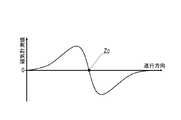
上記のごとく、磁気センサCnは、作業車両5の進行方向及び車幅方向の磁気成分を計測するように構成されている。例えばこの磁気センサCnが、進行方向に移動して磁気マーカ10の真上を通過するとき、進行方向の磁気計測値は、図7のごとく磁気マーカ10の前後で正負が反転すると共に、磁気マーカ10の真上の位置でゼロを交差するように変化する。したがって、作業車両5の走行中では、いずれかの磁気センサCnが検出する進行方向の磁気について、その正負が反転するゼロクロスZcが生じたとき、検出ユニット2が磁気マーカ10の真上に位置すると判断できる。検出処理回路212は、このように検出ユニット2が磁気マーカ10の真上に位置し進行方向の磁気計測値のゼロクロスZcが生じたときに磁気マーカ10を検出したと判断する。
As described above, the magnetic sensor Cn is configured to measure the magnetic components in the traveling direction and the vehicle width direction of the
また、例えば、磁気センサCnと同じ仕様の磁気センサについて、磁気マーカ10の真上を通過する車幅方向の仮想線に沿う移動を想定すると、車幅方向の磁気計測値は、磁気マーカ10を挟んだ両側で正負が反転すると共に、磁気マーカ10の真上の位置でゼロを交差するように変化する。15個の磁気センサCnを車幅方向に配列した検出ユニット2の場合には、磁気マーカ10を介してどちらの側にあるかによって磁気センサCnが検出する車幅方向の磁気の正負が異なってくる(図8)。
Further, for example, assuming that a magnetic sensor having the same specifications as the magnetic sensor Cn is moved along a virtual line in the vehicle width direction that passes directly above the
検出ユニット2の各磁気センサCnの車幅方向の磁気計測値を例示する図8の分布に基づけば、車幅方向の磁気の正負が反転するゼロクロスZcを挟んで隣り合う2つの磁気センサCnの中間の位置、あるいは検出する車幅方向の磁気がゼロであって両外側の磁気センサCnの正負が反転している磁気センサCnの直下の位置が、磁気マーカ10の車幅方向の位置となる。検出処理回路212は、検出ユニット2の中央の位置(磁気センサC8の位置)に対する磁気マーカ10の車幅方向の位置の偏差を上記の横ずれ量として計測する。例えば、図8の場合であれば、ゼロクロスZcの位置がC9とC10との中間辺りのC9.5に相当する位置となっている。上記のように磁気センサC9とC10の間隔は10cmであるから、磁気マーカ10の横ずれ量は、車幅方向において検出ユニット2の中央に位置するC8を基準として(9.5−8)×10cmとなる。
Based on the distribution of FIG. 8 illustrating the magnetic measurement values in the vehicle width direction of the magnetic sensors Cn of the
(2)作業車両システムの全体動作
次に、作業車両システム1の全体動作について図9を参照して説明する。同図のごとく、作業車両システム1の全体動作では、作業車両5を自動走行させるための遠隔制御を含むサーバ装置18側の処理と、上記のマーカ検出処理P1を含む作業車両5側の処理と、が並行して実行される。
(2) Overall Operation of Work Vehicle System Next, the overall operation of the
サーバ装置18は、作業車両5の遠隔制御の実行に当たって、作業車両5に所定の作業内容を設定するための図示しない作業内容入力画面を作業オペレータに提示する。サーバ装置18は、キーボードやマウス等を利用して作業内容入力画面上で作業オペレータが入力した目的地等の作業内容を設定する(S101)。そして、対象の作業車両5の車両位置をスタート地点として、設定された目的地に効率良く到達するための経路を演算する(S102)。
When executing remote control of the
なお、サーバ装置18では、作業エリア1Aに配置された各磁気マーカ10の配列及び敷設位置が管理されている。サーバ装置18は、作業車両5を自動走行させる経路(図1中の経路1R)として、磁気マーカ10を伝う経路を演算により決定し、作業車両5を自動走行させるための遠隔制御を開始する(S103)。
The
一方、作業車両5の制御ユニット32は、サーバ装置18による遠隔制御により自動走行している間、上記のマーカ検出処理P1を検出ユニット2に繰り返し実行させ、磁気マーカ10の検出を試みる。そして、磁気マーカ10が検出された場合には、検出ユニット2が計測した磁気マーカ10に対する上記の横ずれ量を取得する。
On the other hand, the
作業車両5の走行中に磁気マーカ10が検出されたとき(S201:YES)、制御ユニット32は、磁気マーカ10に付設されたRFIDタグ15に給電できるようにタグリーダユニット34を制御する(S202)。これにより、制御ユニット32は、RFIDタグ15を動作させて無線送信されるタグIDを取得し(S203)、マーカ検出処理P1で計測された横ずれ量と共に取得したタグIDをサーバ装置18に向けて送信する(S204)。なお、磁気マーカ10が検出されなかった場合には(S201:NO)、上記のステップS202〜S204が迂回される。さらに、制御ユニット32は、IMU22を制御して加速度や方位や角速度等の計測値を取得し(S205)、これらの計測値をサーバ装置18に向けて送信する(S206)。
When the
一方、サーバ装置18は、作業車両5を遠隔制御している間、作業車両5からタグIDを取得したか否かを随時、判断する(S104)。サーバ装置18は、タグIDを取得すると(S104:YES)、マーカDB185Mを参照してそのタグIDが紐付けられた(磁気マーカ10の)敷設位置を取得し、車両位置を特定する(S105)。具体的には、マーカDB185Mを参照して取得した敷設位置を、タグIDと共に取得した横ずれ量の分だけオフセットさせることで、車両位置を特定する。
On the other hand, the
一方、作業車両5が磁気マーカ10を検出した後、新たな磁気マーカ10を検出までの期間であってタグIDを取得できないときは(S104:NO)、サーバ装置18は、作業車両5から取得する車両情報を利用して相対位置を推定する演算を実行する(S115)。具体的には、サーバ装置18は、作業車両5が備えるIMU22の2軸加速度センサ222の計測値である加速度の二階積分により変位量を演算し、2軸ジャイロセンサ223等により計測された作業車両5の進行方向変化や計測された方位に沿って変位量を積算することで基準位置に対する相対位置を推定する。基準位置としては、作業車両5が検出した直近の磁気マーカ10の敷設位置に基づいて特定された車両位置を適用可能である。さらに、サーバ装置18は、基準位置に対して推定した相対位置を加算することで車両位置を特定する(S105)。
On the other hand, if the tag ID cannot be acquired after the
サーバ装置18は、ステップS105で特定した作業車両5の車両位置や、作業車両5から取得した車両情報(IMU22の計測値など)を入力値とする演算処理により、対象の作業車両5を経路1Rに沿って走行させるための制御値を算出する(S106)。そして、サーバ装置18は、車両情報の送信元の作業車両5に対して、ステップS106で演算した制御値を含む制御情報を送信する。
The
作業車両5の制御ユニット32は、サーバ装置18から制御情報として送信された制御値を車両ECU61に入力し、自動走行制御を実行させる(S207)。この自動走行制御では、サーバ装置18から入力された制御値に基づいて車両ECU61がステアリング制御、スロットル制御などを実行し、作業車両5の自動走行を実現させる。サーバ装置18は、作業車両5が経路1Rの終点である目的地に到達するまで(S107:NO)、ステップS104〜S106の各処理を繰り返し実行し、目的地への到達に応じて作業車両5の遠隔制御を終了する(S107:YES)。
The
以上のような構成の作業車両システム1は、磁気マーカ10と同じ位置に配設されたRFIDタグ15のタグIDを利用して、作業車両5の位置を特定するシステムである。この作業車両システム1では、無線通信によりタグ情報を送信可能である一方、所在位置を車両側で高精度に特定することが困難であるRFIDタグ15と、敷設位置を車両側で精度高く特定可能な磁気マーカ10と、を組み合わせることで高精度な位置特定を実現している。
The
作業車両システム1では、磁気マーカ10に対してRFIDタグ15を付設することで、作業車両5が検出した磁気マーカ10の特定を可能としている。マーカDB185Mには、各磁気マーカ10の敷設位置がタグIDを紐付けた状態で管理されている。作業車両5が磁気マーカ10を検出したとき、同時に受信したタグIDを利用してマーカDB185Mを参照すれば、その磁気マーカ10を特定でき、その敷設位置を取得できる。そして、作業車両5が検出した磁気マーカ10の敷設位置に基づけば、作業車両5の車両位置を高精度に特定できる。
In the
特に、本例の構成では、磁気マーカ10の上面の中央近くにRFIDタグ15が取り付けられている。そのため、磁気マーカ10に対する作業車両5の進入方向によらず、磁気マーカ10を検出するタイミングと、RFIDタグ15と通信可能になるタイミングと、の時間的な相対関係がほぼ一定である。したがって、作業車両5が磁気マーカ10を検出したとき、その磁気マーカ10に付設されたRFIDタグ15と確実性高く通信できる。
In particular, in the configuration of this example, the
また、作業車両システム1の構成を採用した場合、磁気マーカ10が目印となるので、作業車両5側でRFIDタグ15を探索して通信を実行する必要がない。この作業車両システム1では、タグリーダユニット34の電波が届く範囲を狭く設定できるので、隣り合う他の磁気マーカ10に付設されたRFIDタグ15との混信を回避できる。本例の構成では、2m間隔という比較的狭い間隔の格子状で磁気マーカ10が配置されるため、他の磁気マーカ10に付設されたRFIDタグ15との混信を回避できる効果は特に有効である。
Further, when the configuration of the
このように作業車両システム1は、作業エリア1A内の作業車両5の位置を確実性高く特定可能なシステムであり、作業エリア1A内を移動する作業車両5の管理や制御等を確実性高く実行できる。この作業車両システム1は、GPS電波等の受信を前提とせずに作業車両5の車両位置を特定できる。そのため、例えば屋内や飛行機の下などGPS電波が不安定になる場所や、作為的にGPSの精度が抑えられることがある空港などの施設においても、車両位置の特定精度が影響を受けることがない。作業車両システム1が特定する車両位置を利用すれば、作業車両5の所在を精度高く管理でき、確実な遠隔制御を実現できる。
As described above, the
なお、本例では、磁気マーカ10の上面に、シート状のRFIDタグ15を取り付けた構成を例示しているが、磁気マーカ10とRFIDタグ15とが一体をなしている構成は必須ではない。磁気マーカ10とRFIDタグ15とが同じ位置に配置されていれば良く、磁気マーカ10の鉛直方向上方、あるいは下方にRFIDタグ15が配置されていても良い。
In this example, the configuration in which the sheet-
また、本例では、作業車両5の経由地や目的地などを含む作業内容について、例えばキーボードやマウスやディスプレイ等の入力機器を利用して作業オペレータが入力する構成を例示している。飛行機の離発着情報を入力した処理装置が、例えば人工知能的な処理により必要な作業を決定し、その決定内容に応じて各作業車両5の作業内容を決定することも良い。
Further, in this example, the configuration in which the work operator inputs the work content including the waypoint and the destination of the
本例では、全ての磁気マーカ10にRFIDタグ15が付設された構成を例示している。これに代えて、一部の磁気マーカ10にRFIDタグ15を付設することも良い。RFIDタグ15が付設された磁気マーカ10を検出したときには、タグIDを利用してその磁気マーカ10の敷設位置を取得できる。この磁気マーカ10を通過した後は、この磁気マーカ10の敷設位置を基準位置として、IMU22による計測値に基づく相対位置を加算して作業車両5の車両位置を推定的に特定すると良い。RFIDタグ15なしの磁気マーカ10を新たに検出したときには、マーカDB185Mを参照し、推定した車両位置に最も近い敷設位置を探索することで磁気マーカ10を特定すると良い。検出した磁気マーカ10を特定できれば、タグIDを取得できた場合と同様に、磁気マーカ10の敷設位置に基づいて車両位置を高精度に特定できる。
In this example, a configuration in which RFID tags 15 are attached to all the
本例では、サーバ装置18が遠隔制御部(制御部)を有し、複数の作業車両5を遠隔制御する構成を例示している。これに代えて、自動走行により車両を移動させるための制御部を各作業車両5が備えていることも良い。車両側に制御部を設ければ、各作業車両5が車両位置の特定を繰り返しながら自律的に自動走行する構成や、サーバ装置18が特定した車両位置を各作業車両5が取得し、その車両位置に基づいて自律的に自動走行する構成等を採用できる。
In this example, the
他の車両から情報を取得する他車情報取得部として、車々間通信を実行する車々間通信ユニットを各作業車両5に設けることも良い。他の車両の絶対位置あるいは相対位置を表す情報を含む他車両情報を取得できれば、各作業車両5が互いの位置の情報を交換することで、衝突を回避しながら移動できるようになる。また、例えばレーザレーダやミリ波レーダや音波レーダ等の測距センサ等を他車情報取得部として採用しても良い。測距センサ等を利用すれば、他の車両との相対位置を表す情報を他車両情報として取得できる。
さらに、車々間通信を利用すれば、他の車両が移動しようとする経路、他の車両の移動情報である速度や加速度や操舵角などの情報を含む他車両情報を取得できる。これらの他車両情報を取得できれば、進路の譲り合いなどを含めて各作業車両5が一層効率良く移動できるようになる。
As another vehicle information acquisition unit that acquires information from other vehicles, an inter-vehicle communication unit that performs inter-vehicle communication may be provided in each
Furthermore, if the inter-vehicle communication is used, it is possible to acquire other vehicle information including information such as a route on which the other vehicle is moving, and information such as speed, acceleration, and steering angle, which are movement information of the other vehicle. If these other vehicle information can be acquired, each
RFIDタグ15のタグIDを紐付けて磁気マーカ10の敷設位置が管理されるマーカDB185Mをサーバ装置18側に設けた構成を例示したが、各作業車両5がマーカDB185Mを備えている構成であっても良い。各作業車両5がマーカDBを備える構成であれば、サーバ装置18からの情報に依存することなく各作業車両5が車両位置を特定できるようになる。加えて自動走行のための上記の制御部を各作業車両5が備えていれば、サーバ装置18からの制御に依存することなく自動走行できるようになる。このように各作業車両5が自律的な自動走行が可能な構成の場合についても、各作業車両5が車両位置をサーバ装置18に送信するように構成すると良い。この場合には、サーバ装置18側で各作業車両5の車両位置の管理が可能となる。サーバ装置18が各作業車両5の車両位置を管理していれば、例えば、各作業車両5の移動経路の設定などを実行でき、複数の作業車両5全体として作業の効率を向上できる。
The configuration in which the
さらに、本例の作業車両システム1における各作業車両5の車両位置を特定する構成は、作業車両5を遠隔制御あるいは自律制御により自動走行させるシステムばかりでなく、作業者が運転する作業車両5の位置をサーバ装置側で高精度に管理するためのシステムに対しても有用である。
Furthermore, the configuration for specifying the vehicle position of each
本例の作業車両システム1の構成は、港湾のコンテナヤードなどで使用される作業車両など、2次元的なエリア内を自由度高く移動する車両の位置の管理や制御等に有効である。
また、本例では、RFIDタグ15の固有情報であるタグIDをタグ情報として例示しているが、磁気マーカ10の敷設位置を表す情報等をタグ情報に含めることも良い。磁気マーカの格子状配置における敷設番地をタグ情報に含めることも良い。この場合には、作業エリア1Aの形状や、磁気マーカの配置や、施設の位置、駐機場所、などの情報を含むマップ情報を記憶するマップデータベースを車両側に設けると良い。
The configuration of the
Moreover, in this example, tag ID which is the specific information of the
以上、実施例のごとく本発明の具体例を詳細に説明したが、これらの具体例は、特許請求の範囲に包含される技術の一例を開示しているにすぎない。言うまでもなく、具体例の構成や数値等によって、特許請求の範囲が限定的に解釈されるべきではない。特許請求の範囲は、公知技術や当業者の知識等を利用して前記具体例を多様に変形、変更あるいは適宜組み合わせた技術を包含している。 As described above, specific examples of the present invention have been described in detail as in the embodiments. However, these specific examples merely disclose an example of the technology included in the scope of claims. Needless to say, the scope of the claims should not be construed as limited by the configuration, numerical values, or the like of the specific examples. The scope of the claims includes techniques in which the specific examples are variously modified, changed, or appropriately combined using known techniques and knowledge of those skilled in the art.
1 作業車両システム(車両用システム)
1A 作業エリア(走行エリア)
1R 経路
10 磁気マーカ
15 RFIDタグ(無線タグ)
18 サーバ装置(位置特定部、位置推定部、制御部)
185M マーカデータベース(マーカDB)
2 検出ユニット
21 センサアレイ(磁気検出部)
212 検出処理回路
22 IMU
221 2軸磁気センサ(方位特定部)
32 制御ユニット
34 タグリーダユニット
5 作業車両(車両)
61 車両ECU(制御部)
1 Work vehicle system (vehicle system)
1A Work area (travel area)
18 Server device (position specifying part, position estimating part, control part)
185M Marker database (Marker DB)
2
212
221 Two-axis magnetic sensor (azimuth specifying part)
32
61 Vehicle ECU (control unit)
Claims (7)
走行エリアに配置された複数の磁気マーカと、
無線通信により固有のタグ情報を外部出力する複数の無線タグと、
前記磁気マーカを検出する検出ユニット、及び前記無線タグが外部出力するタグ情報を取得するタグリーダユニットを備える車両と、
車両が取得したタグ情報を利用して車両が検出した磁気マーカを特定することにより走行エリアにおける車両位置を特定する位置特定部と、を含み、
前記複数の磁気マーカのうちの少なくとも一部の磁気マーカに対して、前記無線タグが一対一に対応するように同じ位置に配置されている車両用システム。 A system for a vehicle moving in a driving area,
A plurality of magnetic markers arranged in the traveling area;
A plurality of wireless tags for outputting unique tag information to the outside by wireless communication;
A vehicle including a detection unit for detecting the magnetic marker, and a tag reader unit for acquiring tag information output from the wireless tag externally;
A position specifying unit that specifies the vehicle position in the travel area by specifying the magnetic marker detected by the vehicle using the tag information acquired by the vehicle,
A vehicle system in which the wireless tag is disposed at the same position so as to correspond one-to-one with respect to at least some of the plurality of magnetic markers.
前記他車情報取得部は、前記他車両情報を前記制御部に入力する車両用システム。 In claim 5, the vehicle includes the control unit, and further includes an other vehicle information acquisition unit that acquires other vehicle information including information indicating an absolute position or a relative position of the other vehicle,
The other vehicle information acquisition unit is a vehicle system that inputs the other vehicle information to the control unit.
Priority Applications (2)
| Application Number | Priority Date | Filing Date | Title |
|---|---|---|---|
| JP2018022655A JP2019137521A (en) | 2018-02-12 | 2018-02-12 | Vehicular system |
| PCT/JP2019/004522 WO2019156194A1 (en) | 2018-02-12 | 2019-02-07 | Vehicle system |
Applications Claiming Priority (1)
| Application Number | Priority Date | Filing Date | Title |
|---|---|---|---|
| JP2018022655A JP2019137521A (en) | 2018-02-12 | 2018-02-12 | Vehicular system |
Publications (1)
| Publication Number | Publication Date |
|---|---|
| JP2019137521A true JP2019137521A (en) | 2019-08-22 |
Family
ID=67549444
Family Applications (1)
| Application Number | Title | Priority Date | Filing Date |
|---|---|---|---|
| JP2018022655A Pending JP2019137521A (en) | 2018-02-12 | 2018-02-12 | Vehicular system |
Country Status (2)
| Country | Link |
|---|---|
| JP (1) | JP2019137521A (en) |
| WO (1) | WO2019156194A1 (en) |
Cited By (4)
| Publication number | Priority date | Publication date | Assignee | Title |
|---|---|---|---|---|
| JP7076935B1 (en) | 2022-01-18 | 2022-05-30 | トーヨーカネツ株式会社 | Floor equipment for driving unmanned transfer vehicles |
| WO2022210194A1 (en) * | 2021-04-01 | 2022-10-06 | 愛知製鋼株式会社 | System |
| WO2022210203A1 (en) | 2021-04-01 | 2022-10-06 | 愛知製鋼株式会社 | Magnetic marker system, and design method for magnetic marker system |
| JP7453537B2 (en) | 2020-05-12 | 2024-03-21 | シンフォニアテクノロジー株式会社 | Driving route setting system and driving route setting method |
Family Cites Families (6)
| Publication number | Priority date | Publication date | Assignee | Title |
|---|---|---|---|---|
| JP3120724B2 (en) * | 1996-03-13 | 2000-12-25 | トヨタ自動車株式会社 | Automatic traveling equipment for vehicles |
| JP5984986B1 (en) * | 2015-03-12 | 2016-09-06 | 株式会社シンテックホズミ | Transport vehicle system |
| JP2017107456A (en) * | 2015-12-10 | 2017-06-15 | 国立大学法人豊橋技術科学大学 | Autonomous traveling robot system |
| SG11201809407QA (en) * | 2016-04-28 | 2018-11-29 | Aichi Steel Corp | Magnetic marker and driving assistance system |
| WO2017187881A1 (en) * | 2016-04-28 | 2017-11-02 | 愛知製鋼株式会社 | Driving assistance system |
| JP7012421B2 (en) * | 2016-06-17 | 2022-01-28 | 愛知製鋼株式会社 | Magnetic marker and marker system |
-
2018
- 2018-02-12 JP JP2018022655A patent/JP2019137521A/en active Pending
-
2019
- 2019-02-07 WO PCT/JP2019/004522 patent/WO2019156194A1/en active Application Filing
Cited By (6)
| Publication number | Priority date | Publication date | Assignee | Title |
|---|---|---|---|---|
| JP7453537B2 (en) | 2020-05-12 | 2024-03-21 | シンフォニアテクノロジー株式会社 | Driving route setting system and driving route setting method |
| WO2022210194A1 (en) * | 2021-04-01 | 2022-10-06 | 愛知製鋼株式会社 | System |
| WO2022210203A1 (en) | 2021-04-01 | 2022-10-06 | 愛知製鋼株式会社 | Magnetic marker system, and design method for magnetic marker system |
| KR20230164099A (en) | 2021-04-01 | 2023-12-01 | 아이치 세이코우 가부시키가이샤 | Magnetic marker system, and method of designing the magnetic marker system |
| JP7076935B1 (en) | 2022-01-18 | 2022-05-30 | トーヨーカネツ株式会社 | Floor equipment for driving unmanned transfer vehicles |
| JP2023104722A (en) * | 2022-01-18 | 2023-07-28 | トーヨーカネツ株式会社 | Floor device for unmanned transfer vehicle travel |
Also Published As
| Publication number | Publication date |
|---|---|
| WO2019156194A1 (en) | 2019-08-15 |
Similar Documents
| Publication | Publication Date | Title |
|---|---|---|
| US11119499B2 (en) | Marker system | |
| WO2019156194A1 (en) | Vehicle system | |
| JP6946695B2 (en) | Marker system | |
| US11801827B2 (en) | Automatic parking system | |
| US11454516B2 (en) | Gyro sensor calibration method | |
| WO2019142737A1 (en) | Vehicle location management system and vehicle location management method | |
| US11687088B2 (en) | Vehicular system | |
| US11933633B2 (en) | Point cloud data acquiring method and point cloud data acquiring system | |
| US11244129B2 (en) | Vehicular system and tag communication method | |
| JP7047506B2 (en) | Vehicle system and tag communication method | |
| JP7381939B2 (en) | 3D structure estimation method and 3D structure estimation system | |
| US11862014B2 (en) | Magnetic marker system | |
| CN114746720A (en) | Map and map generation method | |
| US20230271630A1 (en) | Operation system and operation system control method | |
| WO2022270365A1 (en) | Vehicular system | |
| WO2022210201A1 (en) | Information acquisition method and vehicular system |