JP2019132302A - Jig and assembling method - Google Patents
Jig and assembling method Download PDFInfo
- Publication number
- JP2019132302A JP2019132302A JP2018012922A JP2018012922A JP2019132302A JP 2019132302 A JP2019132302 A JP 2019132302A JP 2018012922 A JP2018012922 A JP 2018012922A JP 2018012922 A JP2018012922 A JP 2018012922A JP 2019132302 A JP2019132302 A JP 2019132302A
- Authority
- JP
- Japan
- Prior art keywords
- tapered roller
- roller bearing
- shim
- rotating body
- rotation axis
- Prior art date
- Legal status (The legal status is an assumption and is not a legal conclusion. Google has not performed a legal analysis and makes no representation as to the accuracy of the status listed.)
- Granted
Links
Images


Classifications
-
- B—PERFORMING OPERATIONS; TRANSPORTING
- B25—HAND TOOLS; PORTABLE POWER-DRIVEN TOOLS; MANIPULATORS
- B25B—TOOLS OR BENCH DEVICES NOT OTHERWISE PROVIDED FOR, FOR FASTENING, CONNECTING, DISENGAGING OR HOLDING
- B25B27/00—Hand tools, specially adapted for fitting together or separating parts or objects whether or not involving some deformation, not otherwise provided for
- B25B27/02—Hand tools, specially adapted for fitting together or separating parts or objects whether or not involving some deformation, not otherwise provided for for connecting objects by press fit or detaching same
- B25B27/06—Hand tools, specially adapted for fitting together or separating parts or objects whether or not involving some deformation, not otherwise provided for for connecting objects by press fit or detaching same inserting or withdrawing sleeves or bearing races
-
- F—MECHANICAL ENGINEERING; LIGHTING; HEATING; WEAPONS; BLASTING
- F16—ENGINEERING ELEMENTS AND UNITS; GENERAL MEASURES FOR PRODUCING AND MAINTAINING EFFECTIVE FUNCTIONING OF MACHINES OR INSTALLATIONS; THERMAL INSULATION IN GENERAL
- F16C—SHAFTS; FLEXIBLE SHAFTS; ELEMENTS OR CRANKSHAFT MECHANISMS; ROTARY BODIES OTHER THAN GEARING ELEMENTS; BEARINGS
- F16C19/00—Bearings with rolling contact, for exclusively rotary movement
- F16C19/22—Bearings with rolling contact, for exclusively rotary movement with bearing rollers essentially of the same size in one or more circular rows, e.g. needle bearings
- F16C19/34—Bearings with rolling contact, for exclusively rotary movement with bearing rollers essentially of the same size in one or more circular rows, e.g. needle bearings for both radial and axial load
-
- F—MECHANICAL ENGINEERING; LIGHTING; HEATING; WEAPONS; BLASTING
- F16—ENGINEERING ELEMENTS AND UNITS; GENERAL MEASURES FOR PRODUCING AND MAINTAINING EFFECTIVE FUNCTIONING OF MACHINES OR INSTALLATIONS; THERMAL INSULATION IN GENERAL
- F16C—SHAFTS; FLEXIBLE SHAFTS; ELEMENTS OR CRANKSHAFT MECHANISMS; ROTARY BODIES OTHER THAN GEARING ELEMENTS; BEARINGS
- F16C33/00—Parts of bearings; Special methods for making bearings or parts thereof
- F16C33/30—Parts of ball or roller bearings
- F16C33/46—Cages for rollers or needles
-
- F—MECHANICAL ENGINEERING; LIGHTING; HEATING; WEAPONS; BLASTING
- F16—ENGINEERING ELEMENTS AND UNITS; GENERAL MEASURES FOR PRODUCING AND MAINTAINING EFFECTIVE FUNCTIONING OF MACHINES OR INSTALLATIONS; THERMAL INSULATION IN GENERAL
- F16C—SHAFTS; FLEXIBLE SHAFTS; ELEMENTS OR CRANKSHAFT MECHANISMS; ROTARY BODIES OTHER THAN GEARING ELEMENTS; BEARINGS
- F16C35/00—Rigid support of bearing units; Housings, e.g. caps, covers
- F16C35/04—Rigid support of bearing units; Housings, e.g. caps, covers in the case of ball or roller bearings
Landscapes
- Engineering & Computer Science (AREA)
- General Engineering & Computer Science (AREA)
- Mechanical Engineering (AREA)
- Mounting Of Bearings Or Others (AREA)
- Automatic Assembly (AREA)
- General Details Of Gearings (AREA)
- Rolling Contact Bearings (AREA)
- Support Of The Bearing (AREA)
Abstract
Description
本発明は円錐ころ軸受を用いた軸受装置の組み立て技術に関する。 The present invention relates to a technique for assembling a bearing device using a tapered roller bearing.
回転体を円錐ころ軸受で支持する場合、外輪の変位を防止して円滑な回転を維持するため、円錐ころ軸受の外輪とケースとの間にシムを介在させ、外輪に回転軸方向の圧力を付与する構成が知られている。回転体の回転軸を通る平面でケースが分割された構成の場合、一方の分割体に対して、回転体、円錐ころ軸受及びシムの組立体を組み付けた後、他方の分割体を一方の分割体に組み付ける。しかし、シムの厚みは外輪を加圧する目的で設定されているので、回転体、円錐ころ軸受及びシムの組立体は、そのままでは一方の分割体に装着できない。そこで、回転体に装着された円錐ころ軸受の外輪及びシムに治具によって回転軸方向の圧力を予め付与しておき、これを一方の分割体に組み付けることが提案されている(特許文献1〜4)。 When a rotating body is supported by a tapered roller bearing, a shim is interposed between the outer ring of the tapered roller bearing and the case in order to prevent the outer ring from being displaced and maintain a smooth rotation. The structure to give is known. When the case is divided by a plane passing through the rotation axis of the rotating body, after assembling the rotating body, tapered roller bearing and shim assembly to one divided body, the other divided body is divided into one. Assemble to the body. However, since the thickness of the shim is set for the purpose of pressurizing the outer ring, the rotating body, the tapered roller bearing and the shim assembly cannot be mounted on one of the divided bodies as they are. Therefore, it has been proposed that pressure in the direction of the rotation axis is applied in advance to the outer ring and shim of the tapered roller bearing mounted on the rotating body by a jig, and this is assembled to one of the divided bodies (Patent Documents 1 to 3). 4).
特許文献1〜4に開示された方法では、ケースの分割体に、回転体及び円錐ころ軸受の組立体を組み付ける前に、外輪及びシムを治具によって加圧する工程に加えて、分割体に組立体を移載する工程が必要とされる。したがって、工数が増える。また、外輪及びシムを治具によって加圧する工程においては、回転体等を一時的に支持するための台座等も必要となり、組み立て作業空間においてその設置スペースを確保しなければならない点でも不利である。 In the methods disclosed in Patent Documents 1 to 4, before the assembly of the rotating body and the tapered roller bearing is assembled to the divided body of the case, the outer ring and the shim are assembled to the divided body in addition to the step of pressing with a jig. A process of transferring the solid is required. Therefore, man-hours increase. Further, in the process of pressurizing the outer ring and the shim with a jig, a pedestal or the like for temporarily supporting the rotating body is required, which is disadvantageous in that the installation space must be secured in the assembly work space. .
本発明の目的は、円錐ころ軸受を用いた軸受装置の組み立てに関し、工数の削減や組立作業空間の省スペース化を図ることにある。 An object of the present invention relates to the assembly of a bearing device using a tapered roller bearing, and is to reduce man-hours and to save the assembly work space.
本発明によれば、
回転体と、前記回転体を回転軸方向に離間した第一の円錐ころ軸受及び第二の円錐ころ軸受を介して回転自在に支持するケースとを備える軸受装置の組み立てに用いる治具であって、
前記ケースは、前記回転軸方向の第一の端部と第二の端部とを備え、
前記第一の端部には、前記回転体を露出させる第一の開口部と、該第一の開口部の奥側において前記第一の円錐ころ軸受が取り付けられる第一の取付部が形成され、
前記第二の端部には、前記回転体を露出させる第二の開口部と、該第二の開口部の奥側において前記第二の円錐ころ軸受が取り付けられる第二の取付部が形成され、
前記第一の取付部の底部と前記第一の円錐ころ軸受の外輪との間には、環状の第一のシムが設けられ、
前記第二の取付部の底部と前記第二の円錐ころ軸受の外輪との間には、環状の第二のシムが設けられ、
前記ケースは、前記回転体の回転軸心を通る面で分割された第一の分割体及び第二の分割体から構成され、
前記治具は、
前記第一の分割体の前記第一の端部側に配置される本体ユニットと、
前記本体ユニットに支持された引き寄せユニットと、を備え、
前記引き寄せユニットは、
前記第一の円錐ころ軸受及び第二の円錐ころ軸受並びに前記第一のシムと共に前記第一の分割体に組み付けられた前記回転体を、前記回転軸方向で前記第一の端部側に引き寄せるように構成され、
前記本体ユニットは、
前記回転軸方向に前記第一のシムと当接するシム当接部と、
前記回転軸方向に前記第一の分割体の前記第一の端部に当接するケース当接部と、を含む、
ことを特徴とする治具が提供される。
According to the present invention,
A jig used for assembling a bearing device comprising: a rotating body; and a case that rotatably supports the rotating body via a first tapered roller bearing and a second tapered roller bearing spaced apart in the direction of the rotation axis. ,
The case includes a first end and a second end in the rotation axis direction,
The first end portion is formed with a first opening for exposing the rotating body and a first attachment portion to which the first tapered roller bearing is attached on the back side of the first opening. ,
The second end portion is formed with a second opening for exposing the rotating body and a second attachment portion to which the second tapered roller bearing is attached on the back side of the second opening. ,
An annular first shim is provided between the bottom of the first mounting portion and the outer ring of the first tapered roller bearing,
An annular second shim is provided between the bottom of the second mounting portion and the outer ring of the second tapered roller bearing,
The case is composed of a first divided body and a second divided body divided by a plane passing through the rotation axis of the rotating body,
The jig is
A main body unit disposed on the first end side of the first divided body;
A drawing unit supported by the main unit,
The attraction unit is
The first tapered roller bearing, the second tapered roller bearing, and the first shim together with the first divided body draw the rotating body toward the first end in the direction of the rotation axis. Configured as
The main unit is
A shim contact portion that contacts the first shim in the rotational axis direction;
A case abutting portion that abuts on the first end of the first divided body in the rotation axis direction,
The jig characterized by this is provided.
また、本発明によれば、
回転体と、前記回転体を回転軸方向に離間した第一の円錐ころ軸受及び第二の円錐ころ軸受を介して回転自在に支持するケースとを備える軸受装置を組み立てる組立方法であって、
前記ケースは、前記回転軸方向の第一の端部と第二の端部とを備え、
前記第一の端部には、前記回転体を露出させる第一の開口部と、該第一の開口部の奥側において前記第一の円錐ころ軸受が取り付けられる第一の取付部が形成され、
前記第二の端部には、前記回転体を露出させる第二の開口部と、該第二の開口部の奥側において前記第二の円錐ころ軸受が取り付けられる第二の取付部が形成され、
前記第一の取付部の底部と前記第一の円錐ころ軸受の外輪との間には、環状の第一のシムが設けられ、
前記第二の取付部の底部と前記第二の円錐ころ軸受の外輪との間には、環状の第二のシムが設けられ、
前記ケースは、前記回転体の回転軸心を通る面で分割された第一の分割体及び第二の分割体から構成され、
前記組立方法は、
前記第二のシムを前記第一の分割体の前記第二の取付部の底部と前記第二の円錐ころ軸受の外輪との間から外した状態で、前記第一の円錐ころ軸受と前記第二の円錐ころ軸受と前記第一のシムと前記回転体とを前記第一の分割体に組み付ける工程と、
前記回転体を、前記回転軸方向で前記第一の端部側に付勢する工程と、
前記回転体を前記第一の端部側に付勢した状態で、前記第二のシムを前記第一の分割体の前記第二の取付部の底部と前記第二の円錐ころ軸受の外輪との間に配置する工程と、を含む、
ことを特徴とする組立方法が提供される。
Moreover, according to the present invention,
An assembly method for assembling a bearing device including a rotating body and a case that rotatably supports the rotating body via a first tapered roller bearing and a second tapered roller bearing that are spaced apart in the direction of the rotation axis,
The case includes a first end and a second end in the rotation axis direction,
The first end portion is formed with a first opening for exposing the rotating body and a first attachment portion to which the first tapered roller bearing is attached on the back side of the first opening. ,
The second end portion is formed with a second opening for exposing the rotating body and a second attachment portion to which the second tapered roller bearing is attached on the back side of the second opening. ,
An annular first shim is provided between the bottom of the first mounting portion and the outer ring of the first tapered roller bearing,
An annular second shim is provided between the bottom of the second mounting portion and the outer ring of the second tapered roller bearing,
The case is composed of a first divided body and a second divided body divided by a plane passing through the rotation axis of the rotating body,
The assembly method is as follows:
With the second shim removed from between the bottom of the second mounting portion of the first divided body and the outer ring of the second tapered roller bearing, the first tapered roller bearing and the first Assembling two tapered roller bearings, the first shim and the rotating body into the first divided body;
Urging the rotating body toward the first end in the direction of the rotation axis;
In a state where the rotating body is biased toward the first end, the second shim is attached to the bottom of the second mounting portion of the first divided body and the outer ring of the second tapered roller bearing. Placing between
An assembly method is provided.
本発明によれば、円錐ころ軸受を用いた軸受装置の組み立てに関し、工数の削減や組立作業空間の省スペース化を図ることができる。 According to the present invention, it is possible to reduce the number of man-hours and save the assembly work space with respect to the assembly of the bearing device using the tapered roller bearing.
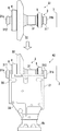
図1は組み立て対象の例である軸受装置1の外観図、図2は図1のI−I線に沿う断面図である。軸受装置1は、四輪駆動自動車等の車両の後輪駆動機構を構成する装置であり、特に、差動装置の一部である回転方向変換機構を構成する装置である。すなわち、車両の前部に配置された駆動ユニット(例えばエンジン、変速機)からプロペラシャフトを介して軸受装置1に駆動力が伝達される。軸受装置1は、プロペラシャフトからの車両前後方向の回転軸回りの駆動力を車幅方向の回転軸回りの駆動力に変換し、左右の後輪に伝達する。以下、軸受装置1の構成を説明する。 FIG. 1 is an external view of a bearing device 1 that is an example of an assembly target, and FIG. 2 is a cross-sectional view taken along the line II of FIG. The bearing device 1 is a device that constitutes a rear wheel drive mechanism of a vehicle such as a four-wheel drive automobile, and in particular, is a device that constitutes a rotation direction conversion mechanism that is a part of a differential device. That is, a driving force is transmitted to the bearing device 1 via a propeller shaft from a driving unit (for example, an engine or a transmission) disposed in the front portion of the vehicle. The bearing device 1 converts the driving force around the rotational axis in the vehicle front-rear direction from the propeller shaft into the driving force around the rotational axis in the vehicle width direction and transmits the driving force to the left and right rear wheels. Hereinafter, the configuration of the bearing device 1 will be described.
軸受装置1は、ピニオン軸8と、回転体3とこれらを回転自在に支持するケース2とを備える。ピニオン軸8の一端には上述したプロペラシャフトと連結される継手8bが固定され、他端にはピニオンギア8aが設けられている。軸受装置1を車両に設置した場合、ピニオン軸8の軸方向は車両前後方向とされる。
The bearing device 1 includes a pinion shaft 8, a
回転体3は、回転軸31と回転軸31に設けられたリングギア32とを備える。リングギア32とピニオンギア8aとはハイポイドギアを構成する。軸受装置1を車両に設置した場合、回転軸31の軸方向は車幅方向とされる。破線Cは回転軸31の回転軸心を示している。
The
回転軸31は軸方向に部分的に径が異なる中空の円筒体であり、軸方向で一方の端部31aと他方の端部31bとを有する。端部31a、端部31bはクラッチ装置9、9にそれぞれ接続される。その接続のため、端部31aの外周面にはスプライン311が形成され、端部31bの外周面にはスプライン312が形成されている。クラッチ装置9、9の一方は左車輪用、他方は右車輪用とされ、回転体3の回転駆動力を左右の車軸に断続する。その断続を制御することで左右輪の差動機能を実現する。
The rotating
回転軸31は軸方向の途中部外周面にはスプライン313が形成されている。リングギア32のボス部内周面には、スプライン313と係合するスプライン320が形成されている。このスプライン係合により、ピニオン軸8から伝達される駆動力がリングギア32を介して回転軸31に伝達される。
The
回転体3は、回転軸31の軸方向に離間した円錐ころ軸受4及び5を介してケース2に回転自在に支持されている。円錐ころ軸受4は端部31a側に位置しており、外輪41、内輪42及び外輪41と内輪42との間の複数のころ43を備える。複数のころ43は保持器で保持されている。円錐ころ軸受5は端部31b側に位置しており、外輪51、内輪52及び外輪51と内輪52との間の複数のころ53を備える。複数のころ53は保持器で保持されている。
The
リングギア32のボス部には、円錐ころ軸受4の内輪42を取り付ける取付部321が形成されている。回転軸31には、円錐ころ軸受5の内輪52を取り付ける取付部314が形成されている。取付部321、取付部314はいずれも内輪42又は52の内周面と端面とが当接するように径を変化させた肩部である。
An
ケース2は、回転軸心Cを通る面で分割された分割体2A及び2Bから構成されており、これらをボルトで締結することで組み立てられる。分割体2Aにはピニオン軸8が回転自在に支持されている。回転体3は分割体2Aと分割体2Bとにより回転自在に支持される。
The case 2 is composed of divided
ケース2には、回転軸31の軸方向で一方の端部20と他方の端部21とを有する。回転軸31の端部31a、31bとの関係で言うと、端部20側に端部31aが位置し、かつ、端部31aはケース2から外側に突出している。また、端部21側に端部31bが位置し、かつ、端部31bはケース2から外側に突出している。
The case 2 has one
以下、ケース2の端部20及び21における構成について説明するが、これらは略半分ずつ、分割体2Aと2Bとで構成されることになる。
Hereinafter, although the structure in the
端部20には、回転体3(特に回転軸31の端部31a付近)を露出させる、回転軸31と同軸で円形の開口部200が形成されている。開口部200の奥側(端部21側)には円錐ころ軸受4を取り付ける取付部201が形成されている。取付部201は底部201aを有し、回転軸31と同軸で円形の穴又は凹部である。取付部201は円錐ころ軸受4の外輪41の外周面と端面とが当接するように径を変化させた肩部であり、外輪41と底部201aとの間には環状のシム6が設けられている。シム6はここでは板状で無端の円環である。開口部200の径と比較すると、シム6の内径は小さく、外径は大きい。
The
端部21には、回転体3(特に回転軸31の端部31b付近)を露出させる、回転軸31と同軸で円形の開口部210が形成されている。開口部210の奥側(端部20側)には円錐ころ軸受5を取り付ける取付部211が形成されている。取付部211は底部211aを有し、回転軸31と同軸で円形の穴又は凹部である。取付部211は円錐ころ軸受5の外輪51の外周面と端面とが当接するように径を変化させた肩部であり、外輪51と底部211aとの間には環状のシム7が設けられている。シム7はここでは板状で無端の円環である。開口部210の径と比較すると、シム7の内径は小さく、外径は大きい。
The
シム6とシム7との厚さにより、円錐ころ軸受4及び5の各外輪41、51には、回転軸31の軸方向中央部に向かう圧力が予め付与される。これにより、円錐ころ軸受4及び5の各外輪41、51と各ころ43、53との隙間調整や、ピニオンギア8aに対するリングギア32の位置調整を行うことができる。
Due to the thickness of the
<軸受装置の組立方法>
軸受装置1の組立方法の例について説明する。軸受装置1は、ケース2が回転軸心Cを通る面で分割された分割体2Aと分割体2Bとで構成されている。上記の通り、シム6とシム7とは円錐ころ軸受4及び5の各外輪41、51に圧力を付与する目的でその厚さが設定されている。このため、例えば、回転体3に円錐ころ軸受4及び5並びにシム6及び7を加圧無しで組み付けた状態では、分割体2A、2Bのいずれにもこの組立体を装着することはできない。なぜならこの組立体におけるシム6の外側端面からシム7の外側端面までの距離は、底部201aから底部211aまでの距離よりも長くなってしまうからである。そこで本実施形態では以下の組み付け手順を採用する。
<Assembly method of bearing device>
An example of a method for assembling the bearing device 1 will be described. The bearing device 1 is configured by a divided
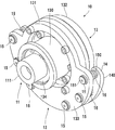
図3を参照して、まず、回転体3に円錐ころ軸受4及び5並びにシム6を組み付けた組立体A1を作成する。シム7は組み付けない。組立体A1を、先に分割体2Aに搭載して組立体A2とする。分割体2Aにはには予めピニオン軸8等が組み付けられており、ピニオン軸8の軸方向を上下方向とし、継手8b側が下向きとされる。これにより、図3に示すように組立体A1を水平姿勢で分割体2Aに載せることができ、作業性を向上できる。図4は組立体A2の平面図である。なお、組立体A1を先に分割体2Bに組み付けることも可能であるが、分割体2Aに組み付ける方が作業性がよい。
Referring to FIG. 3, first, an assembly A <b> 1 in which
この段階でもシム7は組み付けない。シム7を組み付けない結果、その厚さ分だけ余裕ができる。つまり、底部201aから底部211aまでの距離内に、シム6の外側端面から円錐ころ軸受5の外側端面までの距離が収まるので、組立体A1を分割体2Aに組み付けることができる。逆に言うと、この段階ではシム7を組みつけるための隙間が、円錐ころ軸受5の外輪51と、底部211aの間にはない。図7(A)はこの段階における回転軸31の端部31b側を示す斜視図である。シム7は端部31bにかけられるものの、外輪51と、底部211aとの間に差し込むことは困難である。
At this stage, the shim 7 is not assembled. As a result of not installing the shim 7, there is a margin for the thickness. That is, since the distance from the outer end surface of the
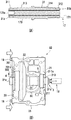
次に、シム7を外輪51と、底部211aとの間に差し込むための隙間を形成する作業を行う。ここでは、図5に示す治具10を用いる。治具10は分割体2Aの端部20側に配置される。図6は治具10の使用状態における断面図を示している。まず、治具10の構成について説明する。
Next, an operation for forming a gap for inserting the shim 7 between the outer ring 51 and the bottom 211a is performed. Here, the
治具10は、本体ユニット12と、本体ユニット12に支持された引き寄せユニット11とを備える。概説すると、引き寄せユニット11により回転体3を分割体2Aの端部20側に引き寄せることで、シム7を外輪51と、底部211aとの間に差し込むための隙間を形成する。
The
引き寄せユニット11は、回転軸31の軸方向に延びる軸部110と、軸部110の一端部に設けられた頭部111とを備える。軸部110の他端部は外周にねじ110aが形成されたねじ軸を構成している。本実施形態の場合、回転軸31の端部31aは外周面にスプライン311が、内周面にねじ310が形成された円筒部を構成しており、ねじ110aは、ねじ310と螺合する。本実施形態では、ねじ310は治具10のために形成されている。
The pulling
本体ユニット11は、分割体2Aの端部20側に配置される。本体ユニット11は、本体部13と、可動部14とを備える。可動部14は本体部13に対して回転軸31の軸方向に変位可能である。
The
本体部13は、内筒部130と、外周部131とを一体的に備える。内筒部130は引き寄せユニット11の軸部110が挿入される筒体である。内筒部130の内周面には、軸部110を回転自在に支持する軸受134が設けられている。内筒部130の内周面には、また、回転軸31のスプライン311と係合するスプライン131が形成されている。これらのスプライン係合により、治具10に対する回転軸31の回り止めを行える。回転軸31のスプライン311はクラッチ9との係合用のスプラインであるが、本実施形態では、治具10に対する回転軸31の回り止めとしても活用している。
The
外周部131は、シム当接部132と支持部133とを備える。シム当接部132は、シム6の外側端面に当接するよう、回転軸31の軸方向で端部31b側へ向かって突出しており、かつ、本実施形態の場合、回転軸心Cの回りに全周に渡って形成されている。したがって、シム当接部132は円筒状の外形を有している。
The outer
支持部133は、可動部14を支持する部分である。本実施形態の場合、可動部14は、板状でC字型を有している。支持部133は可動部14の外形に倣って板状でC字型を有している。支持部133と可動部14とは複数の支持軸15を介して連結されている。支持軸15は軸部150と、軸部150の一方端部に設けられた頭部151とを備える。軸部150の他端部の外周面にはねじが形成されており、可動部14のねじ穴141に螺合して両者が固定される。軸部150は支持部130を貫通しており、かつ、支持部130に対して軸方向にスライド自在とされている。頭部151は軸部150のスライドのストッパとなっており、支持部130の表面に当接する。以上の構成により、可動部14は複数の支持軸15の案内により、支持部133に対して回転軸31の軸方向に変位可能である。
The
可動部14の端面140は、分割体2Aの端部20に当接するケース当接部を構成している。以下、端面140のことをケース当接部140という。
The
本実施形態の場合、支持部133と可動部14との間には弾性部材16が設けられており、弾性部材16は可動部14を支持部133から離間するように付勢している。本実施形態の場合、弾性部材16はコイルばねであり、支持軸15毎に設けられている。軸部150はコイルばねである弾性部材16を挿通しており、弾性部材16の支持部材としても機能している。
In the present embodiment, an
治具10を用いた組立方法について説明する。図6に示すように、治具10は端部20の側に配置され、引き寄せユニット11のねじ110aが回転軸31のねじ310に螺合される。矢印D1で示すように引き寄せユニット11を回転軸心Cの回りで締め付け方向に回転する。回転軸31は、スプライン131、311の係合で回り止めがされているため、ねじ込みが進むと、引き寄せユニット11と回転軸31とが近付く方向に力が働く。この過程で、シム当接部132はシム6の外側端面に当接し、シム6を介して外輪41に矢印D2で示すように圧力がかかる。
An assembly method using the
また、矢印D3で示すようにケース当接部140が分割体2Aの端部20に当接する。このため、引き寄せユニット11を締め付け方向に回転していくと、回転軸31が矢印D3で示すように、分割体2Aに対してその軸方向で端部20側に変位する。この結果、端部21側において、円錐ころ軸受5の外輪51と、底部211aとの間にシム7を差し込む隙間が形成されていく。このため、図7(A)の状態から図7(B)に示すように、シム7を外輪51と、底部211aとの間に配置することができる。
Further, as indicated by an arrow D3, the
ケース当接部140が分割体2Aの端部20に当接している間、弾性部材16の弾性変形によって、ケース当接部140が分割体2Aの端部20に過大な荷重が作用することを防止できる。また、ケース当接部140はC字型で帯状の面であるため、応力が集中することを防止し、分割体2Aの端部20に過大な荷重が作用することを防止することができる。
While the
シム7を外輪51と、底部211aとの間に配置したのち、分割体2Bを分割体2Aに組み付け、両者をボルトで締結する。その後、治具10を取り外して軸受装置1の組立作業が終了する。
After the shim 7 is disposed between the outer ring 51 and the bottom 211a, the divided
以上のように本実施形態では、分割体2A上で組立体2Aの組み付け、シム6を介した外輪41への加圧、シム7の組み付けを行うことができる。外輪への加圧作業を、別の台座等を用いて行う必要がなく、台座等を用いた場合に比べて、工数の削減や組立作業空間の省スペース化を図ることができる。また、組み立て作業の大部分を、分割体2Aの端部20の側から行うことができ、作業者が手作業で組付作業を行う場合に、その作業性を向上することができる。
As described above, in this embodiment, the
<他の実施形態>
上記実施形態では、ケース当接部140を可動部14に形成し、本体部13に対して変位可能な構成としたが、変位不能に固定された構成としてもよい。但し、この場合、上述した弾性部材16の変形による緩衝作用がないため、ケース当接部140と分割体2Aの端部との当接面積がより広くなるようにケース当接部140を形成し、分割体2Aの一部に対して応力が集中することがないようにすることが好ましい。
<Other embodiments>
In the above-described embodiment, the
上記実施形態では、引き寄せユニット11のねじ110aに対する回転軸31の締結部位をねじ310としたが、図8(A)に示すように別の治具17を利用してもよい。治具17は回転軸31の内部を挿通する軸170の一方端部に頭部171が他方端部にねじ穴170aが設けられた構成である。頭部171は回転軸31の端部31bと当接するストッパとなり、ねじ穴170に引き寄せユニット11のねじ110aを螺合する。部品点数が増えるが、回転軸31にねじ310を形成する必要がない。
In the above embodiment, the fastening portion of the
上記実施形態では、引き寄せユニット11と回転軸31との連結及び引き寄せにねじ構造を用いたが、ねじ構造以外であってもよい。引き寄せユニット11と回転軸31との連結は、ねじ以外に径方向にピン等を差し込むような係合構造であってもよい。引き寄せはトグルクランプ等、他の機構やシリンダ等のアクチュエータを用いてもよい。
In the above embodiment, the screw structure is used for the connection and drawing between the pulling
上記実施形態では、回転軸31を分割体2Aの端部20側へ引き寄せる構成としたが、引き寄せに限られず、回転軸31を端部31b側から端部20側へ付勢できればよい。図8(B)はその一例を示す。同図の例では、端部20にストッパ19を配置する一方、回転軸31の端部31bに油圧シリンダ18を配置し、油圧シリンダ18を伸長して回転軸31を分割体2Aに対して端部20側に変位させている。
In the said embodiment, although it was set as the structure which draws the rotating
上記実施形態では、軸受装置1として、差動装置の一部である回転方向変換機構を構成する装置を例示したが、本発明は円錐ころ軸受により回転体をケースに支持する装置に広く適用可能である。 In the above embodiment, the bearing device 1 is exemplified by a device that constitutes a rotation direction conversion mechanism that is a part of the differential device. However, the present invention can be widely applied to devices that support a rotating body on a case with a tapered roller bearing. It is.
<実施形態のまとめ>
1.上記実施形態の治具(例えば10)は、
回転体(例えば3)と、前記回転体を回転軸方向に離間した第一の円錐ころ軸受(例えば4)及び第二の円錐ころ軸受(例えば5)を介して回転自在に支持するケース(例えば2)とを備える軸受装置(例えば1)の組み立てに用いる治具(例えば10)であって、
前記ケースは、前記回転軸方向の第一の端部(例えば20)と第二の端部(例えば21)とを備え、
前記第一の端部には、前記回転体を露出させる第一の開口部(例えば200)と、該第一開口部の奥側において前記第一の円錐ころ軸受が取り付けられる第一の取付部(例えば201)が形成され、
前記第二の端部には、前記回転体を露出させる第二の開口部(例えば210)と、該第二の開口部の奥側において前記第二の円錐ころ軸受が取り付けられる第二の取付部(例えば211)が形成され、
前記第一の取付部の底部(例えば201a)と前記第一の円錐ころ軸受の外輪(例えば41)との間には、環状の第一のシム(例えば6)が設けられ、
前記第二の取付部の底部(例えば211a)と前記第二の円錐ころ軸受の外輪(例えば51)との間には、環状の第二のシム(例えば7)が設けられ、
前記ケースは、前記回転体の回転軸心を通る面で分割された第一の分割体(例えば2A)及び第二の分割体(例えば2B)から構成され、
前記治具は、
前記第一の分割体の前記第一の端部側に配置される本体ユニット(例えば11)と、
前記本体ユニットに支持された引き寄せユニット(例えば12)と、を備え、
前記引き寄せユニットは、
前記第一の円錐ころ軸受及び第二の円錐ころ軸受並びに前記第一のシムと共に前記第一の分割体に組み付けられた前記回転体を、前記回転軸方向で前記第一の端部側に引き寄せるように構成され、
前記本体ユニットは、
前記回転軸方向に前記第一のシムと当接するシム当接部(例えば132)と、
前記回転軸方向に前記第一の分割体の前記第一の端部に当接するケース当接部(例えば140)と、を含む。
<Summary of Embodiment>
1. The jig of the above embodiment (for example, 10) is
A rotating body (e.g. 3) and a case (e.g. a rotatable supporting body via a first tapered roller bearing (e.g. 4) and a second tapered roller bearing (e.g. 5) spaced apart in the direction of the rotational axis (e.g. 2) and a jig (for example, 10) used for assembling a bearing device (for example, 1),
The case includes a first end (for example, 20) and a second end (for example, 21) in the rotation axis direction,
A first opening (for example, 200) that exposes the rotating body, and a first mounting portion to which the first tapered roller bearing is mounted on the back side of the first opening are exposed to the first end. (E.g. 201) is formed,
A second opening (for example, 210) that exposes the rotating body and a second attachment to which the second tapered roller bearing is attached on the back side of the second opening are exposed to the second end. Part (for example 211) is formed,
An annular first shim (for example, 6) is provided between the bottom of the first mounting portion (for example, 201a) and the outer ring (for example, 41) of the first tapered roller bearing,
An annular second shim (for example, 7) is provided between the bottom of the second mounting portion (for example, 211a) and the outer ring (for example, 51) of the second tapered roller bearing,
The case is composed of a first divided body (for example, 2A) and a second divided body (for example, 2B) divided by a plane passing through the rotation axis of the rotating body,
The jig is
A body unit (for example, 11) disposed on the first end side of the first divided body;
A drawing unit (for example, 12) supported by the main unit, and
The attraction unit is
The first tapered roller bearing, the second tapered roller bearing, and the first shim together with the first divided body draw the rotating body toward the first end in the direction of the rotation axis. Configured as
The main unit is
A shim contact portion (for example, 132) that contacts the first shim in the rotational axis direction;
A case contact portion (for example, 140) that contacts the first end portion of the first divided body in the rotation axis direction.
この実施形態によれば、前記第一の分割体で前記第一のシム及び前記第一の円錐ころ軸受けの外輪を加圧しつつ、前記回転体を前記第一の端部側に引き寄せることができる。この結果、前記第二の端部において、前記第二の取付部の底部と前記第二の円錐ころ軸受の外輪との間に、前記第二のシムを挿入する隙間を形成することができる。こうして、前記第一の分割体上で組み立てを行うことができるため、工数の削減や組立作業空間の省スペース化を図ることができる。 According to this embodiment, it is possible to draw the rotating body toward the first end while pressing the outer ring of the first shim and the first tapered roller bearing with the first divided body. . As a result, a gap for inserting the second shim can be formed at the second end portion between the bottom portion of the second mounting portion and the outer ring of the second tapered roller bearing. Thus, since the assembly can be performed on the first divided body, the man-hours can be reduced and the assembly work space can be saved.
2.上記実施形態では、
前記引き寄せユニットは、ねじ(例えば110a,310,170a)の締め付けによって前記回転体を引き寄せる機構である。
2. In the above embodiment,
The pulling unit is a mechanism that pulls the rotating body by tightening screws (for example, 110a, 310, 170a).
この実施形態によれば、比較的簡単な構成で前記回転体の引き寄せ機構を構築することができる。 According to this embodiment, the pulling mechanism of the rotating body can be constructed with a relatively simple configuration.
3.上記実施形態では、
前記引き寄せユニットは、前記回転軸心と同軸回りに回転自在に前記本体ユニットに支持され、かつ、前記回転体の一端部(例えば31a)に形成されたねじ(例えば310)と螺合する。
3. In the above embodiment,
The pulling unit is supported by the body unit so as to be rotatable about the same axis as the rotation axis, and is screwed with a screw (for example, 310) formed at one end (for example, 31a) of the rotating body.
この実施形態によれば、作業者が前記第一の分割体の前記一端部側から組付作業を行い易くすることができる。 According to this embodiment, an operator can easily perform the assembly work from the one end side of the first divided body.
4.上記実施形態では、
前記回転体の前記一端部は、円筒部であり、
前記円筒部の内周面に前記ねじ(例えば310)が形成され、
前記円筒部の外周面にスプライン(例えば311)が形成され、
前記本体ユニットは、前記スプラインと係合するスプライン(例えば131)を有する。
4). In the above embodiment,
The one end of the rotating body is a cylindrical part,
The screw (for example, 310) is formed on the inner peripheral surface of the cylindrical portion,
Splines (for example, 311) are formed on the outer peripheral surface of the cylindrical portion,
The main unit has a spline (eg, 131) that engages with the spline.
この実施形態によれば、前記本体ユニットによって前記回転体の回り止めを行うことができ、作業者は前記引き寄せユニットを回転させるだけで前記回転体を引き寄せることができる。 According to this embodiment, the rotating body can be prevented from being rotated by the main body unit, and an operator can draw the rotating body only by rotating the pulling unit.
5.上記実施形態では、
前記本体ユニットは、
前記シム当接部を有すると共に前記引き寄せユニットを支持する本体部(例えば13)と、
前記ケース当接部を有し、前記本体部に対して前記回転軸方向に変位可能に前記本体部に取り付けられた可動部(例えば14)と、
前記本体部と前記可動部との間に設けられた弾性部材(例えば16)と、を含む。
5). In the above embodiment,
The main unit is
A main body (e.g., 13) having the shim abutting portion and supporting the pulling unit;
A movable portion (e.g., 14) attached to the main body so as to be displaceable in the direction of the rotation axis with respect to the main body, the case contact portion;
And an elastic member (for example, 16) provided between the main body portion and the movable portion.
この実施形態によれば、前記ケース当接部が前記第一の分割体に当接する圧力が過大になることを防止して、前記第一の分割体が損傷することを防止できる。 According to this embodiment, it can prevent that the pressure which the said case contact part contact | abuts to said 1st division body becomes excessive, and can prevent that said 1st division body is damaged.
6.上記実施形態の組立方法は、
回転体(例えば3)と、前記回転体を回転軸方向に離間した第一の円錐ころ軸受(例えば4)及び第二の円錐ころ軸受(例えば5)を介して回転自在に支持するケース(例えば2)とを備える軸受装置(例えば1)を組み立てる組立方法であって、
前記ケースは、前記回転軸方向の第一の端部(例えば20)と第二の端部(例えば21)とを備え、
前記第一の端部には、前記回転体を露出させる第一の開口部(例えば200)と、該第一の開口部の奥側において前記第一の円錐ころ軸受が取り付けられる第一の取付部(例えば201)が形成され、
前記第二の端部には、前記回転体を露出させる第二の開口部(例えば210)と、該第二の開口部の奥側において前記第二の円錐ころ軸受が取り付けられる第二の取付部(例えば211)が形成され、
前記第一の取付部の底部(例えば201a)と前記第一の円錐ころ軸受の外輪(例えば41)との間には、環状の第一のシム(例えば6)が設けられ、
前記第二の取付部の底部(例えば211a)と前記第二の円錐ころ軸受の外輪(例えば51)との間には、環状の第二のシム(例えば7)が設けられ、
前記ケースは、前記回転体の回転軸心を通る面で分割された第一の分割体(例えば2A)及び第二の分割体(例えば2B)から構成され、
前記組立方法は、
前記第二のシムを前記第一の分割体の前記第二の取付部の底部と前記第二の円錐ころ軸受の外輪との間から外した状態で、前記第一の円錐ころ軸受と前記第二の円錐ころ軸受と前記第一のシムと前記回転体とを前記第一の分割体に組み付ける工程(例えば図3,4)と、
前記回転体を、前記回転軸方向で前記第一の端部側に付勢する工程(例えば図6)と、
前記回転体を前記第一の端部側に付勢した状態で、前記第二のシムを前記第一の分割体の前記第二の取付部の底部と前記第二の円錐ころ軸受の外輪との間に配置する工程(例えば図7)と、を含む。
6). The assembly method of the above embodiment is
A rotating body (e.g. 3) and a case (e.g. a rotatable supporting body via a first tapered roller bearing (e.g. 4) and a second tapered roller bearing (e.g. 5) spaced apart in the direction of the rotational axis (e.g. 2) and an assembly method for assembling a bearing device (for example, 1) comprising:
The case includes a first end (for example, 20) and a second end (for example, 21) in the rotation axis direction,
A first opening (e.g., 200) that exposes the rotating body and a first attachment at which the first tapered roller bearing is attached to the back side of the first opening at the first end. Part (e.g. 201) is formed,
A second opening (for example, 210) that exposes the rotating body and a second attachment to which the second tapered roller bearing is attached on the back side of the second opening are exposed to the second end. Part (for example 211) is formed,
An annular first shim (for example, 6) is provided between the bottom of the first mounting portion (for example, 201a) and the outer ring (for example, 41) of the first tapered roller bearing,
An annular second shim (for example, 7) is provided between the bottom of the second mounting portion (for example, 211a) and the outer ring (for example, 51) of the second tapered roller bearing,
The case is composed of a first divided body (for example, 2A) and a second divided body (for example, 2B) divided by a plane passing through the rotation axis of the rotating body,
The assembly method is as follows:
With the second shim removed from between the bottom of the second mounting portion of the first divided body and the outer ring of the second tapered roller bearing, the first tapered roller bearing and the first Assembling two tapered roller bearings, the first shim and the rotating body to the first divided body (for example, FIGS. 3 and 4);
Urging the rotating body toward the first end in the direction of the rotation axis (for example, FIG. 6);
In a state where the rotating body is biased toward the first end, the second shim is attached to the bottom of the second mounting portion of the first divided body and the outer ring of the second tapered roller bearing. (For example, FIG. 7).
この実施形態によれば、前記第一の分割体で前記第一のシム及び前記第一の円錐ころ軸受けの外輪を加圧しつつ、前記回転体を前記第一の端部側に変位させることができる。この結果、前記第二の端部において、前記第二の取付部の底部と前記第二の円錐ころ軸受の外輪との間に、前記第二のシムを挿入する隙間を形成することができる。こうして、前記第一の分割体上で組み立てを行うことができるため、工数の削減や組立作業空間の省スペース化を図ることができる。 According to this embodiment, the rotary member can be displaced toward the first end while pressing the first shim and the outer ring of the first tapered roller bearing with the first divided body. it can. As a result, a gap for inserting the second shim can be formed at the second end portion between the bottom portion of the second mounting portion and the outer ring of the second tapered roller bearing. Thus, since the assembly can be performed on the first divided body, the man-hours can be reduced and the assembly work space can be saved.
1 軸受装置、2 ケース、2A 分割体、2B 分割体、3 回転体、10 治具、132 シム当接部、140 ケース当接部 DESCRIPTION OF SYMBOLS 1 Bearing apparatus, 2 case, 2A division body, 2B division body, 3 rotary body, 10 jig | tool, 132 shim contact part, 140 case contact part
Claims (6)
前記ケースは、前記回転軸方向の第一の端部と第二の端部とを備え、
前記第一の端部には、前記回転体を露出させる第一の開口部と、該第一の開口部の奥側において前記第一の円錐ころ軸受が取り付けられる第一の取付部が形成され、
前記第二の端部には、前記回転体を露出させる第二の開口部と、該第二の開口部の奥側において前記第二の円錐ころ軸受が取り付けられる第二の取付部が形成され、
前記第一の取付部の底部と前記第一の円錐ころ軸受の外輪との間には、環状の第一のシムが設けられ、
前記第二の取付部の底部と前記第二の円錐ころ軸受の外輪との間には、環状の第二のシムが設けられ、
前記ケースは、前記回転体の回転軸心を通る面で分割された第一の分割体及び第二の分割体から構成され、
前記治具は、
前記第一の分割体の前記第一の端部側に配置される本体ユニットと、
前記本体ユニットに支持された引き寄せユニットと、を備え、
前記引き寄せユニットは、
前記第一の円錐ころ軸受及び第二の円錐ころ軸受並びに前記第一のシムと共に前記第一の分割体に組み付けられた前記回転体を、前記回転軸方向で前記第一の端部側に引き寄せるように構成され、
前記本体ユニットは、
前記回転軸方向に前記第一のシムと当接するシム当接部と、
前記回転軸方向に前記第一の分割体の前記第一の端部に当接するケース当接部と、を含む、
ことを特徴とする治具。 A jig used for assembling a bearing device comprising: a rotating body; and a case that rotatably supports the rotating body via a first tapered roller bearing and a second tapered roller bearing spaced apart in the direction of the rotation axis. ,
The case includes a first end and a second end in the rotation axis direction,
The first end portion is formed with a first opening for exposing the rotating body and a first attachment portion to which the first tapered roller bearing is attached on the back side of the first opening. ,
The second end portion is formed with a second opening for exposing the rotating body and a second attachment portion to which the second tapered roller bearing is attached on the back side of the second opening. ,
An annular first shim is provided between the bottom of the first mounting portion and the outer ring of the first tapered roller bearing,
An annular second shim is provided between the bottom of the second mounting portion and the outer ring of the second tapered roller bearing,
The case is composed of a first divided body and a second divided body divided by a plane passing through the rotation axis of the rotating body,
The jig is
A main body unit disposed on the first end side of the first divided body;
A drawing unit supported by the main unit,
The attraction unit is
The first tapered roller bearing, the second tapered roller bearing, and the first shim together with the first divided body draw the rotating body toward the first end in the direction of the rotation axis. Configured as
The main unit is
A shim contact portion that contacts the first shim in the rotational axis direction;
A case abutting portion that abuts on the first end of the first divided body in the rotation axis direction,
A jig characterized by that.
前記引き寄せユニットは、ねじの締め付けによって前記回転体を引き寄せる機構である、
ことを特徴とする治具。 The jig according to claim 1,
The pulling unit is a mechanism that pulls the rotating body by tightening a screw;
A jig characterized by that.
前記引き寄せユニットは、前記回転軸心と同軸回りに回転自在に前記本体ユニットに支持され、かつ、前記回転体の一端部に形成されたねじと螺合する、
ことを特徴とする治具。 The jig according to claim 1,
The pulling unit is supported by the main body unit so as to be rotatable about the same axis as the rotation axis, and is screwed with a screw formed at one end of the rotating body.
A jig characterized by that.
前記回転体の前記一端部は、円筒部であり、
前記円筒部の内周面に前記ねじが形成され、
前記円筒部の外周面にスプラインが形成され、
前記本体ユニットは、前記スプラインと係合するスプラインを有する、
ことを特徴とする治具。 The jig according to claim 3,
The one end of the rotating body is a cylindrical part,
The screw is formed on the inner peripheral surface of the cylindrical portion,
Splines are formed on the outer peripheral surface of the cylindrical portion,
The main unit has a spline that engages with the spline.
A jig characterized by that.
前記本体ユニットは、
前記シム当接部を有すると共に前記引き寄せユニットを支持する本体部と、
前記ケース当接部を有し、前記本体部に対して前記回転軸方向に変位可能に前記本体部に取り付けられた可動部と、
前記本体部と前記可動部との間に設けられた弾性部材と、を含む、
ことを特徴とする治具。 The jig according to any one of claims 1 to 4,
The main unit is
A main body having the shim contact portion and supporting the pulling unit;
A movable part having the case contact part and attached to the main body part so as to be displaceable in the direction of the rotation axis with respect to the main body part;
An elastic member provided between the main body portion and the movable portion,
A jig characterized by that.
前記ケースは、前記回転軸方向の第一の端部と第二の端部とを備え、
前記第一の端部には、前記回転体を露出させる第一の開口部と、該第一の開口部の奥側において前記第一の円錐ころ軸受が取り付けられる第一の取付部が形成され、
前記第二の端部には、前記回転体を露出させる第二の開口部と、該第二の開口部の奥側において前記第二の円錐ころ軸受が取り付けられる第二の取付部が形成され、
前記第一の取付部の底部と前記第一の円錐ころ軸受の外輪との間には、環状の第一のシムが設けられ、
前記第二の取付部の底部と前記第二の円錐ころ軸受の外輪との間には、環状の第二のシムが設けられ、
前記ケースは、前記回転体の回転軸心を通る面で分割された第一の分割体及び第二の分割体から構成され、
前記組立方法は、
前記第二のシムを前記第一の分割体の前記第二の取付部の底部と前記第二の円錐ころ軸受の外輪との間から外した状態で、前記第一の円錐ころ軸受と前記第二の円錐ころ軸受と前記第一のシムと前記回転体とを前記第一の分割体に組み付ける工程と、
前記回転体を、前記回転軸方向で前記第一の端部側に付勢する工程と、
前記回転体を前記第一の端部側に付勢した状態で、前記第二のシムを前記第一の分割体の前記第二の取付部の底部と前記第二の円錐ころ軸受の外輪との間に配置する工程と、を含む、
ことを特徴とする組立方法。 An assembly method for assembling a bearing device including a rotating body and a case that rotatably supports the rotating body via a first tapered roller bearing and a second tapered roller bearing that are spaced apart in the direction of the rotation axis,
The case includes a first end and a second end in the rotation axis direction,
The first end portion is formed with a first opening for exposing the rotating body and a first attachment portion to which the first tapered roller bearing is attached on the back side of the first opening. ,
The second end portion is formed with a second opening for exposing the rotating body and a second attachment portion to which the second tapered roller bearing is attached on the back side of the second opening. ,
An annular first shim is provided between the bottom of the first mounting portion and the outer ring of the first tapered roller bearing,
An annular second shim is provided between the bottom of the second mounting portion and the outer ring of the second tapered roller bearing,
The case is composed of a first divided body and a second divided body divided by a plane passing through the rotation axis of the rotating body,
The assembly method is as follows:
With the second shim removed from between the bottom of the second mounting portion of the first divided body and the outer ring of the second tapered roller bearing, the first tapered roller bearing and the first Assembling two tapered roller bearings, the first shim and the rotating body into the first divided body;
Urging the rotating body toward the first end in the direction of the rotation axis;
In a state where the rotating body is biased toward the first end, the second shim is attached to the bottom of the second mounting portion of the first divided body and the outer ring of the second tapered roller bearing. Placing between
An assembling method characterized by the above.
Priority Applications (2)
| Application Number | Priority Date | Filing Date | Title |
|---|---|---|---|
| JP2018012922A JP6622331B2 (en) | 2018-01-29 | 2018-01-29 | Jig and assembly method |
| CN201811623512.8A CN110094412B (en) | 2018-01-29 | 2018-12-28 | Jig and assembling method |
Applications Claiming Priority (1)
| Application Number | Priority Date | Filing Date | Title |
|---|---|---|---|
| JP2018012922A JP6622331B2 (en) | 2018-01-29 | 2018-01-29 | Jig and assembly method |
Publications (2)
| Publication Number | Publication Date |
|---|---|
| JP2019132302A true JP2019132302A (en) | 2019-08-08 |
| JP6622331B2 JP6622331B2 (en) | 2019-12-18 |
Family
ID=67443717
Family Applications (1)
| Application Number | Title | Priority Date | Filing Date |
|---|---|---|---|
| JP2018012922A Active JP6622331B2 (en) | 2018-01-29 | 2018-01-29 | Jig and assembly method |
Country Status (2)
| Country | Link |
|---|---|
| JP (1) | JP6622331B2 (en) |
| CN (1) | CN110094412B (en) |
Families Citing this family (1)
| Publication number | Priority date | Publication date | Assignee | Title |
|---|---|---|---|---|
| CN113001469B (en) * | 2021-03-15 | 2022-03-22 | 明阳智慧能源集团股份公司 | Assembly method for flexible output gear shaft of wind power yaw speed reducer |
Family Cites Families (6)
| Publication number | Priority date | Publication date | Assignee | Title |
|---|---|---|---|---|
| US5046870A (en) * | 1990-08-02 | 1991-09-10 | General Motors Corporation | End play and preload adjusting assembly for tapered bearings |
| US5269731A (en) * | 1991-10-30 | 1993-12-14 | Dana Corporation | Differential unit having adjustable bearing assemblies |
| US7155827B2 (en) * | 2003-10-30 | 2007-01-02 | Torque-Traction Technologies, Llc. | Method for verifying predetermined bearing preload of differential assembly module |
| JP2011085255A (en) * | 2009-09-18 | 2011-04-28 | Aisin Aw Co Ltd | Drive device |
| JP2013160290A (en) * | 2012-02-03 | 2013-08-19 | Showa Corp | Assembling method and tool of final reduction gear |
| JP6442945B2 (en) * | 2014-09-16 | 2018-12-26 | アイシン精機株式会社 | Valve timing control device |
-
2018
- 2018-01-29 JP JP2018012922A patent/JP6622331B2/en active Active
- 2018-12-28 CN CN201811623512.8A patent/CN110094412B/en active Active
Also Published As
| Publication number | Publication date |
|---|---|
| JP6622331B2 (en) | 2019-12-18 |
| CN110094412A (en) | 2019-08-06 |
| CN110094412B (en) | 2020-10-23 |
Similar Documents
| Publication | Publication Date | Title |
|---|---|---|
| US10118479B2 (en) | In-wheel motor drive device | |
| DE102014111114B4 (en) | Inner shaft support device of a vehicle drive train | |
| DE112013007157T5 (en) | Electric lathe | |
| EP1605178A2 (en) | Flange assembly for supporting a bearing and an end fitting in a driveshaft assembly | |
| US20130017921A1 (en) | Apparatus for supporting a pinion shaft of a differential for a motor vehicle | |
| JP6622331B2 (en) | Jig and assembly method | |
| US9927021B1 (en) | Planet carrier for a planetary gear set | |
| EP3889465B1 (en) | Friction roller-type reduction gear | |
| US10830327B2 (en) | Drive unit pinion and method of installation | |
| JP2009073385A (en) | Supporting structure of propeller shaft | |
| JP5250942B2 (en) | Rolling bearing device for wheels | |
| WO2008027120A1 (en) | Axle and axle components and method of manufacturing | |
| JP2007261379A (en) | Bearing device for wheel | |
| JP4715172B2 (en) | Bearing device assembling apparatus and assembling method thereof | |
| WO2017033571A1 (en) | Power transmission device | |
| US11498362B2 (en) | Tone wheel assembly, an axle assembly made therewith, and a method of manufacturing an axle assembly | |
| US20180320769A1 (en) | Bearing arrangement for a stepped planetary gear, and epicyclic gearing equipped therewith for a motor vehicle drive unit | |
| JP4894652B2 (en) | Manufacturing method of wheel bearing rolling bearing unit | |
| JP4857858B2 (en) | Wheel bearing device | |
| EP4414574A1 (en) | Roller bearing for supporting wheel | |
| JP2018132174A (en) | Differential case assembling body | |
| JP2008045592A (en) | Pinion shaft supporting device and pinion unit bearing | |
| CN109210144A (en) | Pre-load member, preloaded components, double mass flywheel and motor vehicles | |
| JP4798051B2 (en) | Assembly method of rolling bearing device for wheel | |
| JP2005291313A (en) | Wheel driving unit |
Legal Events
| Date | Code | Title | Description |
|---|---|---|---|
| A621 | Written request for application examination |
Free format text: JAPANESE INTERMEDIATE CODE: A621 Effective date: 20180927 |
|
| A131 | Notification of reasons for refusal |
Free format text: JAPANESE INTERMEDIATE CODE: A131 Effective date: 20190618 |
|
| A521 | Written amendment |
Free format text: JAPANESE INTERMEDIATE CODE: A523 Effective date: 20190807 |
|
| TRDD | Decision of grant or rejection written | ||
| A01 | Written decision to grant a patent or to grant a registration (utility model) |
Free format text: JAPANESE INTERMEDIATE CODE: A01 Effective date: 20191101 |
|
| A61 | First payment of annual fees (during grant procedure) |
Free format text: JAPANESE INTERMEDIATE CODE: A61 Effective date: 20191121 |
|
| R150 | Certificate of patent or registration of utility model |
Ref document number: 6622331 Country of ref document: JP Free format text: JAPANESE INTERMEDIATE CODE: R150 |