JP2019128564A - Image heating device and manufacturing method thereof - Google Patents

Image heating device and manufacturing method thereof Download PDF

Info

Publication number
JP2019128564A
JP2019128564A JP2018012095A JP2018012095A JP2019128564A JP 2019128564 A JP2019128564 A JP 2019128564A JP 2018012095 A JP2018012095 A JP 2018012095A JP 2018012095 A JP2018012095 A JP 2018012095A JP 2019128564 A JP2019128564 A JP 2019128564A
Authority
JP
Japan
Prior art keywords
heater
protrusion
flexible member
support member
disposed
Prior art date
Legal status (The legal status is an assumption and is not a legal conclusion. Google has not performed a legal analysis and makes no representation as to the accuracy of the status listed.)
Pending
Application number
JP2018012095A
Other languages
Japanese (ja)
Inventor
鈴木 隆史
Takashi Suzuki
隆史 鈴木
一志 西方
Kazushi Nishikata
一志 西方
福沢 大三
Daizo Fukuzawa
大三 福沢
一郎 金指
Ichiro Kanezashi
一郎 金指
征児 尾畑
Seiji Ohata
征児 尾畑
Current Assignee (The listed assignees may be inaccurate. Google has not performed a legal analysis and makes no representation or warranty as to the accuracy of the list.)
Canon Inc
Original Assignee
Canon Inc
Priority date (The priority date is an assumption and is not a legal conclusion. Google has not performed a legal analysis and makes no representation as to the accuracy of the date listed.)
Filing date
Publication date
Application filed by Canon Inc filed Critical Canon Inc
Priority to JP2018012095A priority Critical patent/JP2019128564A/en
Publication of JP2019128564A publication Critical patent/JP2019128564A/en
Pending legal-status Critical Current

Links

Images

Landscapes

  • Fixing For Electrophotography (AREA)

Abstract

【課題】ヒータを支持する支持部材の突起部からヒータ面までの高さの精度を向上することのできる像加熱装置及びその製造方法を提供する。
【解決手段】支持部材4が、ヒータ3の可撓性部材と接触する面であるヒータ面31と交差する方向において回転体2側に突出した突起部42a、42bを有する像加熱装置107は、支持部材4は、ヒータ面31と交差する方向においてヒータ31に対し回転体2とは反対側にヒータ3と離隔して配置された基礎部43を有し、ヒータ面31と交差する方向におけるヒータ3と基礎部43との間に、支持部材4とは別部材である樹脂部材8が配置されて、ヒータ面31と交差する方向における突起部42a、42bの回転体2側の先端とヒータ面31との間の距離が決められている構成とする。
【選択図】図7
An image heating apparatus capable of improving the accuracy of the height from a protruding portion of a support member supporting a heater to a heater surface and a method for manufacturing the same are provided.
An image heating apparatus (107) has projections (42a, 42b) protruding toward the rotating body 2 in a direction intersecting with a heater surface 31, which is a surface of the heater 3 in contact with a flexible member. The supporting member 4 has a base portion 43 disposed apart from the heater 3 on the side opposite to the rotating body 2 with respect to the heater 31 in the direction intersecting the heater surface 31, and the heater in the direction intersecting the heater surface 31 The resin member 8 which is a separate member from the support member 4 is disposed between the base portion 43 and the base portion 43, and the tips of the protrusions 42a and 42b on the rotary body 2 side in the direction intersecting the heater surface 31 and the heater surface It is assumed that the distance to 31 is determined.
[Selected figure] Figure 7

Description

本発明は、電子写真方式や静電記録方式を用いたプリンタ、複写機、ファクシミリ装置などの画像形成装置にて用いられる像加熱装置、及びその像加熱装置の製造方法に関するものである。   The present invention relates to an image heating apparatus used in an image forming apparatus such as a printer, a copying machine, or a facsimile apparatus using an electrophotographic system or an electrostatic recording system, and a method of manufacturing the image heating apparatus.

従来、電子写真方式などを用いた画像形成装置では、画像を担持した記録材を加熱する像加熱装置として、例えば記録材上の未定着のトナー像を記録材に定着させる定着装置が用いられている。また、この定着装置として、オンデマンド性に優れたフィルム加熱方式の定着装置がある。   2. Description of the Related Art Conventionally, in an image forming apparatus using an electrophotographic method or the like, for example, a fixing device that fixes an unfixed toner image on a recording material to a recording material is used as an image heating device that heats a recording material carrying an image. There is. Further, as this fixing device, there is a film heating type fixing device excellent in on-demand property.

フィルム加熱方式の定着装置は、加熱源としてのヒータと、ヒータを支持する支持部材と、耐熱性の加熱フィルムと、加圧ローラと、を有する。支持部材に支持されたヒータと加圧ローラとで加熱フィルムが挟まれることで、加圧ローラと加熱フィルムとが接触するニップ部が形成される。そして、フィルム加熱方式の定着装置は、このニップ部で記録材を挟持して搬送することで、記録材上の未定着のトナー像を加熱及び加圧して記録材に定着させる。   The film heating type fixing device has a heater as a heating source, a supporting member for supporting the heater, a heat resistant heating film, and a pressure roller. The heating film is sandwiched between the heater supported by the support member and the pressure roller, whereby a nip portion where the pressure roller and the heating film are in contact with each other is formed. Then, the fixing device of the film heating system holds the recording material at the nip portion and conveys it, thereby heating and pressing the unfixed toner image on the recording material to fix it on the recording material.

特許文献1には、フィルム加熱方式の定着装置において、ニップ部における記録材搬送方向の下流側に突起部を設けることが開示されている。この突起部は、回転する加熱フィルムの内面がヒータのエッジとの接触で摩耗することを防止する役割を持っている。具体的には、加熱フィルムの内面がヒータのエッジに接触する前に突起部で加熱フィルムの内面をガイドしている。   Patent Document 1 discloses that, in a fixing device of a film heating system, a projection is provided on the downstream side of the nip portion in the recording material conveyance direction. The protrusions serve to prevent the inner surface of the rotating heating film from being worn by contact with the edge of the heater. Specifically, the projection guides the inner surface of the heating film before the inner surface of the heating film contacts the edge of the heater.

特開2007−33552号公報Japanese Patent Application Publication No. 2007-33552

しかしながら、上述のように支持部材に突起部を設ける場合、支持部材の突起部から、ヒータの加熱フィルムと接触する面であるヒータ面までの高さに、ばらつきが生じることがある。図15は、定着装置の一例におけるニップ部の近傍の記録材搬送方向の断面図である。突起部からヒータ面までの高さのばらつきは、突起部から、支持部材のヒータを支持する面であるヒータ支持面までの高さの公差と、ヒータの厚みの公差と、を足し合わせたものである。   However, when the protrusions are provided on the support member as described above, the height from the protrusions of the support member to the heater surface which is the surface in contact with the heating film of the heater may vary. FIG. 15 is a cross-sectional view in the recording material conveyance direction near the nip portion in an example of the fixing device. The variation in height from the protrusion to the heater surface is the sum of the height tolerance from the protrusion to the heater support surface that supports the heater of the support member, and the heater thickness tolerance. It is.

上述のような突起部からヒータ面までの高さのばらつきが大きいと、特に、定着装置の高寿命化の観点から問題となることがある。具体的には、定着装置の高寿命化を実現する場合には、加熱フィルムの表面が記録材との摩擦力により徐々に摩耗することを抑える必要があるため、突起部による記録材に与える圧力のピークを低くすることが求められる。一方で、圧力のピークを低くするために突起部の高さを低くし過ぎると、加熱フィルムの内面がヒータのエッジと接触して摩耗してしまう。   If the variation in height from the projection to the heater surface as described above is large, this may cause a problem, particularly from the viewpoint of increasing the life of the fixing device. Specifically, in order to achieve a long life of the fixing device, it is necessary to suppress the surface of the heating film from being gradually worn away by the frictional force with the recording material. It is required to lower the peak of On the other hand, if the height of the protrusions is too low in order to lower the pressure peak, the inner surface of the heating film contacts the edge of the heater and wears.

このように、例えば、定着装置の高寿命化を実現するために、突起部からヒータ面までの高さの精度を向上することが求められる。しかし、突起部からヒータ支持面までの高さの精度とヒータの厚みの精度とを厳しく管理して、突起部からヒータ面までの高さの精度を向上することには限界がある。   Thus, for example, in order to realize a long life of the fixing device, it is required to improve the accuracy of the height from the projection to the heater surface. However, there is a limit in improving the accuracy of the height from the projection to the heater surface by strictly controlling the accuracy of the height from the projection to the heater support surface and the accuracy of the thickness of the heater.

したがって、本発明の目的は、ヒータを支持する支持部材の突起部からヒータ面までの高さの精度を向上することのできる像加熱装置及びその製造方法を提供することである。   SUMMARY OF THE INVENTION Therefore, an object of the present invention is to provide an image heating apparatus capable of improving the accuracy of the height from the projection of the support member supporting the heater to the heater surface, and a method of manufacturing the same.

上記目的は本発明に係る像加熱装置及びその製造方法にて達成される。要約すれば、本発明は、無端状の可撓性部材と、前記可撓性部材の内周面側に配置され前記可撓性部材を加熱するヒータと、前記可撓性部材の内周面側に配置され前記ヒータを支持する支持部材と、前記可撓性部材を介して前記支持部材及び前記ヒータに押圧されてニップ部を形成する回転体と、を有し、前記支持部材は、前記ヒータの前記可撓性部材と接触する面であるヒータ面と交差する方向において前記回転体側に突出した突起部を有する像加熱装置において、前記支持部材は、前記ヒータ面と交差する方向において前記ヒータに対し前記回転体とは反対側に前記ヒータと離隔して配置された基礎部を有し、前記ヒータ面と交差する方向における前記ヒータと前記基礎部との間に、前記支持部材とは別部材である樹脂部材が配置されて、前記ヒータ面と交差する方向における前記突起部の前記回転体側の先端と前記ヒータ面との間の距離が決められていることを特徴とする像加熱装置である。   The above object is achieved by the image heating apparatus and the method for manufacturing the same according to the present invention. In summary, the present invention provides an endless flexible member, a heater disposed on the inner circumferential surface side of the flexible member for heating the flexible member, and an inner circumferential surface of the flexible member A support member disposed on the side and supporting the heater, and a rotating body pressed by the support member and the heater via the flexible member to form a nip, the support member being In the image heating apparatus having a protrusion that protrudes toward the rotating body in a direction intersecting a heater surface that is a surface in contact with the flexible member of the heater, the support member is formed in the direction intersecting the heater surface. On the opposite side to the rotating body, the base has a base portion spaced apart from the heater, and is separate from the support member between the heater and the base portion in a direction intersecting the heater surface. The resin member which is a member is arranged It is an image heating apparatus according to claim in which the distance between the tip and the heater surface of the rotor side of the protrusion in the direction intersecting the heater surface are determined.

本発明の他の態様によると、無端状の可撓性部材と、前記可撓性部材の内周面側に配置され前記可撓性部材を加熱するヒータと、前記可撓性部材の内周面側に配置され前記ヒータを支持する支持部材と、前記可撓性部材を介して前記支持部材及び前記ヒータに押圧されてニップ部を形成する回転体と、を有し、前記支持部材は、前記ヒータの前記可撓性部材と接触する面であるヒータ面と交差する方向において前記回転体側に突出した突起部を有する像加熱装置の製造方法において、前記ヒータが配置される第1配置部と、前記突起部が配置される第2配置部と、を有する位置決め台の前記第1配置部に前記ヒータ面を接触させるようにして前記ヒータを前記位置決め台に配置する工程と、前記第2配置部に前記突起部を接触させると共に、前記ヒータを覆うようにして前記支持部材を前記位置決め台に配置する工程と、前記ヒータと前記支持部材との間に樹脂材料を充填する工程と、を有することを特徴とする像加熱装置の製造方法が提供される。   According to another aspect of the present invention, there is provided an endless flexible member, a heater disposed on the inner peripheral surface side of the flexible member for heating the flexible member, and an inner periphery of the flexible member. A support member that is disposed on the surface side and supports the heater; and a rotating body that is pressed by the support member and the heater via the flexible member to form a nip portion. In the method of manufacturing an image heating apparatus having a protrusion that protrudes toward the rotating body in a direction intersecting a heater surface that is a surface in contact with the flexible member of the heater, a first arrangement portion in which the heater is arranged; A step of disposing the heater on the positioning table such that the heater surface is brought into contact with the first disposing portion of the positioning table having a second disposing portion on which the protrusion is disposed; and the second disposition And contact the projection with the An image heating apparatus comprising: a step of disposing the support member on the positioning table so as to cover the heater; and a step of filling a resin material between the heater and the support member. A method is provided.

本発明の他の態様によると、無端状の可撓性部材と、前記可撓性部材の内周面側に配置され前記可撓性部材を加熱するヒータと、前記可撓性部材の内周面側に配置され前記ヒータを支持する支持部材と、前記可撓性部材を介して前記支持部材及び前記ヒータに押圧されてニップ部を形成する回転体と、を有し、前記支持部材は、前記ヒータの前記可撓性部材と接触する面であるヒータ面と交差する方向において前記回転体側に突出した突起部を有する像加熱装置の製造方法において、前記ヒータが配置される第1配置部と、前記突起部が配置される第2配置部と、を有する位置決め台の前記第1配置部に前記ヒータ面を接触させるようにして前記ヒータを前記位置決め台に配置する工程と、前記ヒータの前記ヒータ面とは反対側の側面であるヒータ上面に樹脂材料を塗布する工程と、前記第2配置部に前記突起部を接触させると共に、前記ヒータを覆うようにして前記支持部材を前記位置決め台に配置し、前記支持部材と前記ヒータとの間で前記樹脂材料を挟み込む工程と、を有することを特徴とする像加熱装置の製造方法が提供される。   According to another aspect of the present invention, there is provided an endless flexible member, a heater disposed on the inner peripheral surface side of the flexible member for heating the flexible member, and an inner periphery of the flexible member. A support member disposed on the surface side and supporting the heater; and a rotating body pressed by the support member and the heater via the flexible member to form a nip portion, the support member comprising: In a method of manufacturing an image heating apparatus having a protrusion that protrudes to the rotating body side in a direction intersecting the heater surface which is a surface in contact with the flexible member of the heater, a first arrangement portion in which the heater is arranged A step of disposing the heater on the positioning table such that the heater surface is brought into contact with the first disposing portion of the positioning table having a second disposing portion on which the protrusion is disposed; and It is the side opposite to the heater surface A step of applying a resin material to the upper surface of the rotor, contacting the protrusion with the second placement portion, and placing the support member on the positioning table so as to cover the heater, the support member and the heater And sandwiching the resin material therebetween. A method of manufacturing an image heating apparatus is provided.

本発明の他の態様によると、無端状の可撓性部材と、前記可撓性部材の内周面側に配置され前記可撓性部材を加熱するヒータと、前記可撓性部材の内周面側に配置され前記ヒータを支持する支持部材と、前記可撓性部材を介して前記支持部材及び前記ヒータに押圧されてニップ部を形成する回転体と、を有し、前記支持部材は、前記ヒータの前記可撓性部材と接触する面であるヒータ面と交差する方向において前記回転体側に突出した突起部を有する像加熱装置の製造方法において、前記ヒータが配置される第1配置部と、前記突起部が配置される第2配置部と、を有する位置決め台の前記第1配置部に前記ヒータ面を接触させるようにして前記ヒータを前記位置決め台に配置する工程と、前記ヒータの前記ヒータ面とは反対側の面であるヒータ上面にスペーサ部材を配置する工程と、前記第2配置部に前記突起部を接触させると共に、前記ヒータ及び前記スペーサ部材を覆うようにして前記支持部材を前記位置決め台に配置する工程と、前記ヒータと前記スペーサ部材との間に樹脂材料を充填する工程と、を有することを特徴とする像加熱装置の製造方法が提供される。   According to another aspect of the present invention, there is provided an endless flexible member, a heater disposed on the inner peripheral surface side of the flexible member for heating the flexible member, and an inner periphery of the flexible member. A support member disposed on the surface side and supporting the heater; and a rotating body pressed by the support member and the heater via the flexible member to form a nip portion, the support member comprising: In the method of manufacturing an image heating apparatus having a protrusion that protrudes toward the rotating body in a direction intersecting a heater surface that is a surface in contact with the flexible member of the heater, a first arrangement portion in which the heater is arranged; And disposing the heater on the positioning table such that the heater surface is in contact with the first arrangement portion of the positioning table having a second arrangement portion in which the projection is arranged; The face opposite to the heater face A step of arranging a spacer member on the upper surface, a step of bringing the protrusion into contact with the second arrangement portion, and a step of arranging the support member on the positioning table so as to cover the heater and the spacer member, And a step of filling a resin material between the heater and the spacer member.

以上説明したように、本発明によれば、ヒータを支持する支持部材の突起部からヒータ面までの高さの精度を向上することができる。   As described above, according to the present invention, it is possible to improve the accuracy of the height from the projection of the support member supporting the heater to the heater surface.

本発明を適用可能な画像形成装置の一例の概略断面図である。1 is a schematic cross-sectional view of an example of an image forming apparatus to which the present invention can be applied. 実施例1の定着装置及びそのニップ部近傍の記録材搬送方向の断面図である。FIG. 2 is a cross-sectional view of the fixing device of Example 1 and the vicinity of the nip portion in the recording material conveyance direction. 実施例1の定着装置の長手方向の断面図である。FIG. 3 is a longitudinal sectional view of the fixing device according to the first exemplary embodiment. 実施例1のヒータホルダの外観斜視図である。1 is an external perspective view of a heater holder according to Embodiment 1. FIG. 実施例1のヒータとヒータホルダとの位置決め方法の手順を示す断面図である。FIG. 7 is a cross-sectional view showing the procedure of the method for positioning the heater and the heater holder of the first embodiment. 実施例1のヒータとヒータホルダとが位置決めされた状態の外観斜視図である。It is an external appearance perspective view in the state where the heater of Example 1, and a heater holder were positioned. 実施例1のヒータとヒータホルダとが位置決めされた状態の断面図である。FIG. 5 is a cross-sectional view of the state where the heater and the heater holder of Embodiment 1 are positioned. 実施例1の変形例のヒータとヒータホルダとが位置決めされた状態の外観斜視図及び断面図である。It is an external appearance perspective view and a sectional view of a state where a heater and a heater holder of a modification of Example 1 were positioned. 実施例2のヒータホルダの外観斜視図である。It is an external appearance perspective view of the heater holder of Example 2. FIG. 実施例2のヒータとヒータホルダとの位置決め方法の手順を示す断面図である。FIG. 14 is a cross-sectional view showing the procedure of the method for positioning the heater and the heater holder in Example 2; 実施例3のヒータとヒータホルダとが位置決めされた状態の外観斜視図及び断面図である。It is an external appearance perspective view and sectional drawing of the state in which the heater of Example 3 and the heater holder were positioned. 実施例3のヒータホルダの外観斜視図である。6 is an external perspective view of a heater holder according to Embodiment 3. FIG. 実施例4の定着装置のニップ部近傍の記録材搬送方向の断面図である。FIG. 14 is a cross-sectional view in the recording material conveyance direction near the nip portion of the fixing device of Example 4; 実施例4のヒータとヒータホルダとの位置決め方法の手順を示す断面図である。FIG. 18 is a cross-sectional view showing the procedure of the method for positioning the heater and the heater holder according to the fourth embodiment. 課題を説明するための定着装置の一例のニップ近傍の断面図である。FIG. 2 is a cross-sectional view of the vicinity of a nip of an example of a fixing device for describing a problem.

以下、本発明に係る像加熱装置及びその製造方法を図面に則して更に詳しく説明する。   Hereinafter, the image heating apparatus and the method of manufacturing the same according to the present invention will be described in more detail with reference to the drawings.

[実施例1]
1.画像形成装置の全体的な構成及び動作
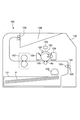
図1は、本実施例の像加熱装置としての定着装置107を備えた画像形成装置100の概略断面図である。本実施例では、画像形成装置100は、電子写真方式を用いたレーザビームプリンタである。
Example 1
1. FIG. 1 is a schematic cross-sectional view of an image forming apparatus 100 including a fixing device 107 as an image heating apparatus according to the present exemplary embodiment. In this embodiment, the image forming apparatus 100 is a laser beam printer using an electrophotographic method.

画像形成装置100は、トナー像を担持する像担持体としての、回転可能なドラム型(円筒形)の感光体(電子写真感光体)である感光ドラム101を有する。感光ドラム101は、図中矢印R1方向(時計回り)に回転駆動される。回転する感光ドラム101の表面は、帯電手段としてのローラ型の帯電部材(接触帯電部材)である帯電ローラ102によって、所定の極性(本実施例では負極性)の所定の電位に帯電処理される。帯電処理された感光ドラム101の表面は、露光手段としての露光装置(レーザスキャナ)103によって、画像情報に基づいてレーザービームが照射されて走査露光され、感光ドラム101上に静電像(静電潜像)が形成される。感光ドラム101上に形成された静電像は、現像手段としての現像装置104によって現像剤としてのトナーが供給されて現像(可視化)され、感光ドラム101上にトナー像が形成される。   The image forming apparatus 100 has a photosensitive drum 101 which is a rotatable drum-shaped (cylindrical) photosensitive member (electrophotographic photosensitive member) as an image bearing member carrying a toner image. The photosensitive drum 101 is rotationally driven in the direction of arrow R1 (clockwise) in the drawing. The surface of the rotating photosensitive drum 101 is charged to a predetermined potential of a predetermined polarity (negative in this embodiment) by the charging roller 102 which is a roller type charging member (contact charging member) as charging means. . The surface of the photosensitive drum 101 subjected to the charging process is irradiated with a laser beam based on image information and scanned and exposed by an exposure device (laser scanner) 103 as an exposure unit, and an electrostatic image (electrostatic Latent image) is formed. The electrostatic image formed on the photosensitive drum 101 is supplied with toner as a developer and developed (visualized) by a developing device 104 as developing means, and a toner image is formed on the photosensitive drum 101.

感光ドラム101に対向して、転写手段としてのローラ型の転写部材である転写ローラ105が配置されている。転写ローラ105は、感光ドラム101に向けて押圧され、感光ドラム101と転写ローラ105とが接触する転写部(転写ニップ部)Ntを形成する。感光ドラム101上に形成されたトナー像は、転写部Ntにおいて、感光ドラム101と転写ローラ105とに挟持されて搬送される紙などの記録材P上に転写される。記録材Pは、カセット121内に積載されており、給送ローラ122によって最上位の記録材Pから1枚ずつピックアップされ、レジストローラ123とレジストコロ124とで形成されるレジスト部125へと送られる。記録材Pは、レジスト部125で搬送方向を揃えられた後、感光ドラム101上のトナー像とタイミングが合わされて転写部Ntへと搬送される。転写工程において記録材Pに転写されずに感光ドラム101上に残留したトナー(転写残トナー)は、クリーニング手段としてのクリーニング装置106によって感光ドラム101上から除去されて回収される。   A transfer roller 105, which is a roller type transfer member as a transfer unit, is disposed to face the photosensitive drum 101. The transfer roller 105 is pressed toward the photosensitive drum 101, and forms a transfer portion (transfer nip portion) Nt in which the photosensitive drum 101 and the transfer roller 105 are in contact with each other. The toner image formed on the photosensitive drum 101 is transferred onto a recording material P such as paper which is nipped and conveyed by the photosensitive drum 101 and the transfer roller 105 at the transfer portion Nt. The recording material P is loaded in the cassette 121, picked up one by one from the uppermost recording material P by the feeding roller 122, and sent to the registration unit 125 formed by the registration roller 123 and the registration roller 124. Be After the recording material P is aligned in the conveyance direction by the registration unit 125, the recording material P is conveyed to the transfer unit Nt at the same timing as the toner image on the photosensitive drum 101. The toner (transfer residual toner) remaining on the photosensitive drum 101 without being transferred to the recording material P in the transfer step is removed from the photosensitive drum 101 and collected by the cleaning device 106 as a cleaning unit.

トナー像が転写された記録材Pは、像加熱装置としての定着装置107へと搬送される。定着装置107は、未定着のトナー像を担持した記録材Pを加熱及び加圧することで、トナー像を記録材Pに定着(溶融、固着)させる。定着装置107については、後述して更に詳しく説明する。定着装置107を通過してトナー像が定着された記録材Pは、排出ローラ対108によって、画像形成装置100の装置本体110の上部に設けられた記録材積載部109上に排出(出力)される。   The recording material P on which the toner image is transferred is conveyed to a fixing device 107 as an image heating device. The fixing device 107 fixes (melts and fixes) the toner image on the recording material P by heating and pressing the recording material P carrying the unfixed toner image. The fixing device 107 will be described in more detail later. The recording material P on which the toner image is fixed after passing through the fixing device 107 is discharged (output) onto the recording material stacking portion 109 provided on the upper portion of the apparatus main body 110 of the image forming apparatus 100 by the discharge roller pair 108. Ru.

2.定着装置の概略構成
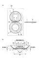
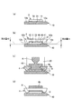
次に、本実施例の定着装置107について説明する。なお、以下の説明において、定着装置107及び定着装置107を構成する部材に関して、「長手方向」とは、記録材Pの搬送方向(「記録材搬送方向」)と略直交する方向である。図2(a)は、定着装置107の記録材搬送方向の断面図であり、図2(b)は、定着装置107のニップ部の近傍の記録材搬送方向の拡大断面図である。また、図3は、定着装置107の長手方向の断面図である。
2. Next, the fixing device 107 of this embodiment will be described. In the following description, regarding the fixing device 107 and the members constituting the fixing device 107, the “longitudinal direction” is a direction substantially perpendicular to the recording material P conveyance direction (“recording material conveyance direction”). FIG. 2A is a cross-sectional view of the fixing device 107 in the recording material conveyance direction, and FIG. 2B is an enlarged cross-sectional view of the fixing device 107 near the nip portion in the recording material conveyance direction. FIG. 3 is a longitudinal sectional view of the fixing device 107.

本実施例の定着装置107は、加熱回転体としての無端状(筒状)の可撓性部材で構成された加熱フィルム1と、加圧回転体としての加圧ローラ2と、加熱体としてのヒータ3と、支持部材としてのヒータホルダ4と、を有する。加圧ローラ2は、軸部(心金)2aの外周に耐熱性弾性体層2bが形成されて構成されている。本実施例の定着装置107は、加圧ローラ2を回転駆動して加熱フィルム1を加圧ローラ2の搬送力により回転させる、加圧ローラ駆動方式・フィルム加熱方式の像加熱装置である。   The fixing device 107 according to the present embodiment includes a heating film 1 formed of an endless (cylindrical) flexible member as a heating rotating body, a pressure roller 2 as a pressure rotating body, and a heating body. It has a heater 3 and a heater holder 4 as a support member. The pressure roller 2 is configured by forming a heat resistant elastic layer 2 b on the outer periphery of a shaft (core) 2 a. The fixing device 107 of the present embodiment is an image heating device of a pressure roller drive system and a film heating system in which the pressure roller 2 is rotationally driven to rotate the heating film 1 by the conveying force of the pressure roller 2.

ヒータ3は、ヒータホルダ4によって支持されている。ヒータホルダ4は、その長手方向の両端部が、装置フレーム(図示せず)に保持されている。また、ヒータホルダ4の加圧ローラ2側とは反対側の側面に当接するように、加圧ローラ2に対して加圧力を伝達する加圧ステー5が配置されている。加熱フィルム1は、ヒータホルダ4、ヒータ3、及び加圧ステー5の外側に外嵌されている。加熱フィルム1の長手方向の両端部には、加熱フィルム1の長手方向への移動を規制する規制部材としての定着フランジ6が配置されている。加圧ステー5は、その長手方向の両端部が、加圧手段としての加圧バネ7により、定着フランジ6を介して、加圧ローラ2の回転軸線に向けて付勢されている。これによって、ヒータ3と加熱フィルム1との間に、記録材搬送方向の幅が所定幅の内面ニップ部N2が形成される。また、これによって、加熱フィルム1と加圧ローラ2との間に、記録材搬送方向における幅が所定幅の定着ニップ部N1が形成される。トナー像Tの定着に必要な熱は、内面ニップ部N2でヒータ3から加熱フィルム1に伝えられ、定着ニップ部N1で加熱フィルム1から記録材Pに伝えられる。   The heater 3 is supported by a heater holder 4. Both ends in the longitudinal direction of the heater holder 4 are held by a device frame (not shown). In addition, a pressure stay 5 that transmits a pressing force to the pressure roller 2 is disposed so as to contact the side surface of the heater holder 4 opposite to the pressure roller 2 side. The heating film 1 is externally fitted to the heater holder 4, the heater 3, and the pressure stay 5. Fixing flanges 6 as restricting members for restricting movement of the heating film 1 in the longitudinal direction are arranged at both ends in the longitudinal direction of the heating film 1. Both ends of the pressure stay 5 in the longitudinal direction are urged toward the rotation axis of the pressure roller 2 via a fixing flange 6 by pressure springs 7 as pressure means. As a result, an inner nip portion N2 having a predetermined width in the recording material conveyance direction is formed between the heater 3 and the heating film 1. As a result, a fixing nip portion N1 having a predetermined width in the recording material conveyance direction is formed between the heating film 1 and the pressure roller 2. Heat necessary for fixing the toner image T is transmitted from the heater 3 to the heating film 1 at the inner surface nip portion N2, and is transmitted from the heating film 1 to the recording material P at the fixing nip portion N1.

加圧ローラ2は、駆動源(図示せず)から駆動ギアGを介して駆動力が伝達されることで回転駆動され、加熱フィルム1は加圧ローラ2の回転に伴って従動回転する。定着ニップ部N1に導入されるトナー像Tを担持した記録材Pは、加熱フィルム1と加圧ローラ2とに挟持されて搬送される。その搬送過程において、記録材Pには、ヒータ3により加熱されている加熱フィルム1の熱と、定着ニップ部N1の圧力と、が加えられる。これにより、トナー像Tが記録材P上に定着される。   The pressure roller 2 is rotationally driven by the drive power being transmitted from a drive source (not shown) through the drive gear G, and the heating film 1 is driven to rotate as the pressure roller 2 rotates. The recording material P carrying the toner image T introduced to the fixing nip portion N1 is nipped by the heating film 1 and the pressure roller 2 and conveyed. In the conveyance process, the heat of the heating film 1 heated by the heater 3 and the pressure of the fixing nip portion N1 are applied to the recording material P. As a result, the toner image T is fixed on the recording material P.

ヒータホルダ4は、加圧ローラ2側の側面に、ヒータホルダ4の長手方向に沿って、凹形状の溝41を有する。そして、詳しくは後述するように、この溝41に対応する位置にヒータ3が配置される。また、ヒータホルダ4は、記録材搬送方向においてヒータ3の上流側に、ヒータホルダ4の長手方向に沿って、上流突起部42aを有する。上流突起部42aは、ヒータ3の加熱フィルム1と接触(摺擦)する面であるヒータ面(摺動面)31と略直交する方向においてヒータ面31よりも加圧ローラ2側に突出しており、加熱フィルム1の内周面と接触する。また、ヒータホルダ4は、記録材搬送方向においてヒータ3の下流側に、ヒータホルダ4の長手方向に沿って、下流突起部42bを有する。下流突起部42bは、ヒータ面31と略直交する方向においてヒータ面31よりも加圧ローラ2側に突出しており、加熱フィルム1の内周面と接触する。加熱フィルム1は、ヒータ3並びにヒータホルダ4の上流突起部42a及び下流突起部42bと、加圧ローラ2と、の間に挟持されて、定着ニップ部N1を形成する。   The heater holder 4 has a recessed groove 41 along the longitudinal direction of the heater holder 4 on the side surface on the pressure roller 2 side. Then, the heater 3 is disposed at a position corresponding to the groove 41 as described later in detail. Further, the heater holder 4 has an upstream projection 42 a along the longitudinal direction of the heater holder 4 on the upstream side of the heater 3 in the recording material conveyance direction. The upstream protruding portion 42 a protrudes further toward the pressure roller 2 than the heater surface 31 in a direction substantially orthogonal to the heater surface (sliding surface) 31 that is a surface that contacts (slids) the heating film 1 of the heater 3. , And the inner peripheral surface of the heating film 1. Further, the heater holder 4 has a downstream projection 42 b along the longitudinal direction of the heater holder 4 on the downstream side of the heater 3 in the recording material conveyance direction. The downstream protrusion 42 b protrudes toward the pressure roller 2 more than the heater surface 31 in the direction substantially orthogonal to the heater surface 31, and contacts the inner circumferential surface of the heating film 1. The heating film 1 is sandwiched between the pressure roller 2 and the upstream projections 42a and downstream projections 42b of the heater 3 and the heater holder 4 to form a fixing nip N1.

また、本実施例では、ヒータホルダ4は、ヒータ面31と略直交する方向においてヒータ3に対し加圧ローラ2とは反対側にヒータ3と離隔して配置された、ヒータ3の位置を決める基礎となる基礎部としての支持面43を有する。本実施例では、この支持面43は、ヒータホルダ4の溝41の底部(あるいは天井)で構成される。そして、ヒータ面31と略直交する方向におけるヒータ3と支持面43との間に、ヒータホルダ4とは別部材である樹脂部材8が配置されている。これにより、ヒータ面31と略直交する方向における、上流突起部42a、下流突起部42bのそれぞれの加圧ローラ2側の先端とヒータ面31との間の距離が決められている。本実施例では、樹脂部材8は、ヒータ3とヒータホルダ4との間に、これら両方と接触するように充填されて配置されている。   Further, in the present embodiment, the heater holder 4 is a base that determines the position of the heater 3 that is disposed away from the heater 3 on the side opposite to the pressure roller 2 with respect to the heater 3 in a direction substantially orthogonal to the heater surface 31. And a support surface 43 as a base portion. In the present embodiment, the support surface 43 is formed by the bottom (or ceiling) of the groove 41 of the heater holder 4. A resin member 8 which is a separate member from the heater holder 4 is disposed between the heater 3 and the support surface 43 in a direction substantially orthogonal to the heater surface 31. Thereby, the distance between the tip of the upstream protrusion 42 a and the downstream protrusion 42 b on the pressure roller 2 side and the heater surface 31 in the direction substantially orthogonal to the heater surface 31 is determined. In the present embodiment, the resin member 8 is filled between the heater 3 and the heater holder 4 so as to be in contact with both of them.

なお、本実施例では、ヒータホルダ4は、耐熱性樹脂である液晶ポリマー(LCP)で形成されている。また、本実施例では、ヒータ面31と略直交する方向に沿ってヒータ3と加圧ローラ2とが加熱フィルム1を介して互いに加圧されるが、ヒータ面31に対して角度を有してヒータ3と加圧ローラ2とが加熱フィルム1を介して互いに加圧されてもよい。そして、例えば、そのようにヒータ面31に対して角度を有してヒータ3と加圧ローラ2とが互いに加圧される場合などには、本実施例においてヒータ面31と略直交する方向として説明する方向は、該角度を有してヒータ面31と交差する方向であってよい。   In the present embodiment, the heater holder 4 is formed of a liquid crystal polymer (LCP) which is a heat resistant resin. Moreover, in the present embodiment, the heater 3 and the pressure roller 2 are mutually pressed via the heating film 1 along the direction substantially orthogonal to the heater surface 31, but have an angle with respect to the heater surface 31. The heater 3 and the pressure roller 2 may be mutually pressed via the heating film 1. Then, for example, when the heater 3 and the pressure roller 2 are mutually pressed at an angle with respect to the heater surface 31 as such, the direction substantially orthogonal to the heater surface 31 in the present embodiment is taken. The described direction may be a direction intersecting the heater surface 31 with the angle.

ここでは、ヒータ面31と略直交する方向における上流突起部42a、下流突起部42bのそれぞれの先端とヒータ面31との間の距離を、「突起部からヒータ面までの高さ」、あるいは「突出量」ともいう。この上流突起部42a、下流突起部42bからヒータ面31までの高さ、及び定着装置107の製造方法(特に、ヒータ3とヒータホルダ4との位置決め方法)については、以下で更に詳しく説明する。   Here, the distance between each tip of the upstream protrusion 42a and the downstream protrusion 42b and the heater surface 31 in the direction substantially orthogonal to the heater surface 31 is defined as “the height from the protrusion to the heater surface” or “ It is also called "protrusion amount". The upstream projection 42a, the height from the downstream projection 42b to the heater surface 31, and the method for manufacturing the fixing device 107 (particularly, the positioning method between the heater 3 and the heater holder 4) will be described in more detail below.

3.突起部からヒータ面までの高さ
次に、本実施例におけるヒータホルダ4の上流突起部42a、下流突起部42bからヒータ面31までの高さ(突出量)について詳細に説明する。図2(b)に示すように、上流突起部42a、下流突起部42bは、ヒータ面31と略直交する方向においてヒータ面31よりも加圧ローラ2側にそれぞれ突出量h1、h2だけ突出している。なお、これに限定されるものではないが、突出量h1、h2は、例えば0.1mm〜3mm程度とされる。上流突起部42a、下流突起部42bがそれぞれヒータ面31よりも突出していることで、加熱フィルム1の内面がヒータ3のエッジとの接触で摩耗することを抑制することができる。しかし、上流突起部42a、下流突起部42bによる記録材Pに与える圧力のピークが高いほど、加熱フィルム1の表面と記録材Pとの摩擦力が大きくなるため、加熱フィルム1の表面の摩耗が進行しやすくなる。したがって、上流突起部42a、下流突起部42bによる記録材Pに与える圧力のピークを低くすることが求められるが、上流突起部42a、下流突起部42bの高さを低くし過ぎると、加熱フィルム1の内面がヒータ3のエッジと接触して摩耗してしまう。
3. Height from Projection to Heater Surface Next, the height (projection amount) from the upstream projection 42a and the downstream projection 42b to the heater surface 31 of the heater holder 4 in this embodiment will be described in detail. As shown in FIG. 2B, the upstream projection 42a and the downstream projection 42b respectively project by the amount of projection h1 and h2 closer to the pressure roller 2 than the heater surface 31 in the direction substantially orthogonal to the heater surface 31. Yes. In addition, although not limited to this, protrusion amount h1, h2 shall be about 0.1 mm-3 mm, for example. The upstream projection 42 a and the downstream projection 42 b respectively project from the heater surface 31, so that the inner surface of the heating film 1 can be prevented from being worn by contact with the edge of the heater 3. However, as the peak of the pressure applied to the recording material P by the upstream protrusions 42a and the downstream protrusions 42b is higher, the frictional force between the surface of the heating film 1 and the recording material P is larger. Easy to progress. Therefore, it is required to lower the peak of the pressure applied to the recording material P by the upstream projection 42a and the downstream projection 42b. However, if the heights of the upstream projection 42a and the downstream projection 42b are too low, the heating film 1 is required. The inner surface of the contact with the edge of the heater 3 wears.

そのため、定着装置107の高寿命化を実現するためには、突起部42a、42bからヒータ面31までの高さを所望の高さとする精度を向上することが求められる。しかし、前述のように、突起部42a、42bからヒータホルダ4のヒータ支持面までの高さの精度とヒータ3の厚みの精度とを厳しく管理して、突起部42a、42bからヒータ面31までの高さの精度を向上することには限界がある。   Therefore, in order to realize an increase in the service life of the fixing device 107, it is required to improve the accuracy of setting the height from the protrusions 42a and 42b to the heater surface 31 to a desired height. However, as described above, the height accuracy from the projections 42a and 42b to the heater support surface of the heater holder 4 and the thickness accuracy of the heater 3 are strictly managed, and the projections 42a and 42b to the heater surface 31 are strictly controlled. There is a limit to improving the accuracy of the height.

そこで、本実施例では、ヒータ3と、ヒータホルダ4の支持面43との間に、ヒータホルダ4とは別部材である樹脂部材8が配置されて、高精度に所望の突出量h1、h2を得ることが可能な構成とされている。   Therefore, in this embodiment, the resin member 8, which is a separate member from the heater holder 4, is disposed between the heater 3 and the support surface 43 of the heater holder 4 to obtain the desired protrusion amounts h1 and h2 with high accuracy. It is made possible.

4.ヒータとヒータホルダとの位置決め方法
次に、本実施例における定着装置107の製造方法(特に、ヒータ3とヒータホルダ4との位置決め方法)について説明する。
4. Method of Positioning Heater and Heater Holder Next, a method of manufacturing the fixing device 107 in the present embodiment (in particular, a method of positioning the heater 3 and the heater holder 4) will be described.

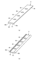
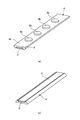
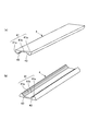
図4(a)、(b)は、本実施例におけるヒータホルダ4の外観斜視図であり、図4(a)は加圧ローラ2側に配置される側とは反対側から見た様子、図4(b)は加圧ローラ2側に配置される側から見た様子を示す。本実施例では、ヒータホルダ4には、溝41からヒータホルダ4の加圧ローラ2側とは反対側の側面である上面44を貫通する貫通穴45が設けられている。本実施例では、貫通穴45は、ヒータホルダ4の長手方向に沿って複数(本実施例では4個)設けられている。ただし、貫通穴45は1つでもよい。また、本実施例では、貫通穴45は、平面視略円形とされている。ただし、貫通穴45の形状は平面視略円形に限定されるものではなく、例えば、平面視略矩形などの他の任意の形状であってよい。また、本実施例では、溝41の底部に相当する支持面43は、ヒータ3(より詳細には、ヒータ3のヒータ面31とは反対側の側面であるヒータ上面32)との間に隙間を有するように意図的にヒータホルダ4の上面44側にオフセットされている。なお、ヒータ面31と略直交する方向におけるこの隙間の幅は、これに限定されるものではないが、0.5mm〜3mm程度であれば十分であることが多い。   4 (a) and 4 (b) are external perspective views of the heater holder 4 in this embodiment, and FIG. 4 (a) is a view from the side opposite to the side disposed on the pressure roller 2 side, 4 (b) shows a view from the side disposed on the pressure roller 2 side. In the present embodiment, the heater holder 4 is provided with a through hole 45 penetrating the upper surface 44 which is the side surface of the heater holder 4 opposite to the pressure roller 2 side from the groove 41. In the present embodiment, a plurality of through holes 45 (four in the present embodiment) are provided along the longitudinal direction of the heater holder 4. However, the number of through holes 45 may be one. Further, in the present embodiment, the through hole 45 is substantially circular in plan view. However, the shape of the through hole 45 is not limited to a substantially circular shape in plan view, and may be, for example, any other shape such as a substantially rectangular shape in plan view. Further, in the present embodiment, the support surface 43 corresponding to the bottom of the groove 41 is a gap between the heater 3 (more specifically, the heater upper surface 32 that is the side surface opposite to the heater surface 31 of the heater 3). Are intentionally offset on the upper surface 44 side of the heater holder 4. The width of the gap in the direction substantially orthogonal to the heater surface 31 is not limited to this, but it is often sufficient if it is about 0.5 mm to 3 mm.

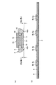
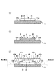
図5は、本実施例におけるヒータ3とヒータホルダ4との位置決め方法の手順を示す。以下、図5(a)〜(d)に示す各工程について順次説明する。   FIG. 5 shows the procedure of the method of positioning the heater 3 and the heater holder 4 in the present embodiment. Hereinafter, each process shown to Fig.5 (a)-(d) is demonstrated sequentially.

(a)ヒータ配置工程
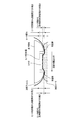
図5(a)に示すように、ヒータ3とヒータホルダ4との位置決めには、位置決め台10を使用する。本実施例では、位置決め台10は、金属で形成されている。位置決め台10は、ヒータホルダ4の長手方向の長さと同等の長手方向の長さを有する。そして、位置決め台10は、長手方向と略直交する短手方向の中央部に、ヒータホルダ4の長手方向に沿って、第1配置部として、凸部であるヒータ配置部11を有する。典型的には、位置決め台10は、略水平な設置面上に設置される。このように位置決め台10が略水平に設置された状態で、ヒータ配置部11は略水平な平面とされている。ヒータ3とヒータホルダ4との位置決めを行う際には、ヒータ配置部11にヒータ面31を接触させるようにして、ヒータ3を位置決め台10に配置する。このとき、本実施例では、ヒータ3をヒータ配置部11に接触させ、ヒータ3を位置決め台10上の所定位置に保持するように位置決め台10に固定する。
(A) Heater Arrangement Step As shown in FIG. 5A, a positioning table 10 is used for positioning the heater 3 and the heater holder 4. In this embodiment, the positioning table 10 is made of metal. The positioning table 10 has a length in the longitudinal direction equivalent to the length in the longitudinal direction of the heater holder 4. And the positioning stand 10 has the heater arrangement | positioning part 11 which is a convex part as a 1st arrangement | positioning part along the longitudinal direction of the heater holder 4 in the center part of the transversal direction substantially orthogonal to a longitudinal direction. Typically, the positioning table 10 is installed on a substantially horizontal installation surface. In this manner, the heater placement portion 11 is a substantially horizontal plane in a state where the positioning table 10 is installed substantially horizontally. When positioning the heater 3 and the heater holder 4, the heater 3 is arranged on the positioning table 10 so that the heater surface 31 is brought into contact with the heater arrangement portion 11. At this time, in this embodiment, the heater 3 is brought into contact with the heater placement portion 11 and fixed to the positioning table 10 so as to hold the heater 3 at a predetermined position on the positioning table 10.

(b)ヒータホルダ配置工程
図5(b)に示すように、位置決め台10は、短手方向におけるヒータ配置部11の両側に、第2配置部として、ヒータ配置部11とは高さが異なる上流突起配置部12a、下流突起配置部12bを有する。本実施例では、位置決め台10が略水平に設置された場合に、重力方向における上流突起配置部12a及び下流突起配置部12bの高さは、ヒータ配置部11の高さよりも低い。上述のように位置決め台10が略水平に設置された状態で、上流突起配置部12a、下流突起配置部12bは、それぞれ略水平な平面とされている。ヒータ3を位置決め台10に配置した後、上流突起配置部12a、下流突起配置部12bにそれぞれ上流突起部42a、下流突起部42bを接触させると共に、ヒータ3を覆うようにして、ヒータホルダ4を位置決め台10に配置する。このとき、本実施例では、上流突起部42a、下流突起部42bをそれぞれ上流突起配置部12a、下流突起配置部12bに接触させ、ヒータホルダ4を位置決め台10上の所定位置に保持するように位置決め台10に固定する。ここで、上流突起配置部12aからヒータ配置部11までの高さ(段差)、下流突起配置部12bからヒータ配置部11までの高さ(段差)は、それぞれ設計上必要な突出量h1、h2と同じ高さになっている。そして、ヒータホルダ4は、前述のように位置決め台10に配置された状態で、ヒータ3と、ヒータホルダ4の溝41の底部に相当する支持面43と、が接触せず、これらの間に空間(隙間)46ができるように構成されている。なお、本実施例では、位置決め台10の形状は長手方向の全域で略同一であり、ヒータ3及びヒータホルダ4はそれぞれ長手方向の全域で均一に位置決め台10に接触し、固定される。
(B) Heater Holder Arrangement Step As shown in FIG. 5 (b), the positioning table 10 is located upstream of the heater arrangement portion 11 as a second arrangement portion on both sides of the heater arrangement portion 11 in the short direction. It has the protrusion arrangement | positioning part 12a and the downstream protrusion arrangement | positioning part 12b. In the present embodiment, when the positioning table 10 is installed substantially horizontally, the heights of the upstream protrusion arrangement portion 12 a and the downstream protrusion arrangement portion 12 b in the gravity direction are smaller than the height of the heater arrangement portion 11. As described above, in the state in which the positioning table 10 is installed substantially horizontally, the upstream projection arrangement portion 12a and the downstream projection arrangement portion 12b are each formed into a substantially horizontal plane. After placing the heater 3 on the positioning table 10, the upstream protrusion 42a and the downstream protrusion 42b are brought into contact with the upstream protrusion 12a and the downstream protrusion 12b, respectively, and the heater holder 4 is positioned so as to cover the heater 3. Arranged on the base 10. At this time, in this embodiment, the upstream protrusion 42a and the downstream protrusion 42b are brought into contact with the upstream protrusion 12a and the downstream protrusion 12b, respectively, and the heater holder 4 is positioned so as to be held at a predetermined position on the positioning table 10. Secure to the base 10. Here, the height (step difference) from the upstream protrusion arrangement portion 12a to the heater arrangement portion 11 and the height (step difference) from the downstream protrusion arrangement portion 12b to the heater arrangement portion 11 are respectively the protrusion amounts h1 and h2 necessary for design. Is the same height. And, in the state where the heater holder 4 is disposed on the positioning table 10 as described above, the heater 3 and the support surface 43 corresponding to the bottom of the groove 41 of the heater holder 4 do not come in contact with each other. (Gap) 46 is formed. In the present embodiment, the shape of the positioning table 10 is substantially the same over the entire area in the longitudinal direction, and the heater 3 and the heater holder 4 contact the positioning table 10 uniformly throughout the entire area in the longitudinal direction and are fixed.

(c)樹脂充填工程
図5(c)に示すように、ヒータホルダ4を位置決め台10に配置した後、ヒータホルダ4の貫通穴45に対応して樹脂注入部材20をヒータホルダ4の上面44に固定する。本実施例では、ヒータホルダ4に設けられた4個の貫通穴45のそれぞれに対して樹脂注入部材20を固定する。樹脂注入部材20は、溶融した耐熱性樹脂Aを送り出す装置(図示せず)と繋がっている。そして、樹脂部材8を構成する樹脂材料としての溶融した耐熱性樹脂Aを、樹脂注入部材20から射出し、貫通穴45を通して空間46に注入して、その耐熱性樹脂Aで空間46を埋めるように、その耐熱性樹脂Aを空間46に充填する。なお、本実施例では耐熱性樹脂Aは熱硬化型であるが、光硬化型や湿度硬化型等、樹脂を硬化させられれば良い。
(C) Resin Filling Step As shown in FIG. 5C, after the heater holder 4 is arranged on the positioning table 10, the resin injection member 20 is fixed to the upper surface 44 of the heater holder 4 corresponding to the through hole 45 of the heater holder 4. . In this embodiment, the resin injection member 20 is fixed to each of the four through holes 45 provided in the heater holder 4. The resin injection member 20 is connected to a device (not shown) that sends out the molten heat-resistant resin A. The molten heat-resistant resin A as the resin material constituting the resin member 8 is injected from the resin injection member 20 and injected into the space 46 through the through hole 45 so that the space 46 is filled with the heat-resistant resin A. In addition, the space 46 is filled with the heat resistant resin A. In this embodiment, the heat-resistant resin A is a thermosetting type, but it is sufficient that the resin is cured, such as a photo-curing type or a humidity-curing type.

(d)保持工程
図5(d)に示すように、耐熱性樹脂Aが冷却した後に、樹脂注入部材20をヒータホルダ4から移動させる。空間46に充填された耐熱性樹脂Aは、樹脂部材8としてヒータ3とヒータホルダ4との間に介在する。したがって、上述の突出量h1、h2を維持してヒータ3とヒータホルダ4とが位置決めされる。また、樹脂部材8は、ヒータホルダ4に対してアンカーのような形状をしており、組立中にヒータホルダ4から脱落しないようになっている。つまり、本実施例では、樹脂注入部材20は、図5(c)に示すように、空間46を埋める樹脂部材8、貫通穴45を埋める連結部8a、及びヒータホルダ4の上面44上に配置される平面視略円形の係止部8bを形成するように構成されている。この係止部8bの直径は、貫通穴45の直径よりも大きい。これら樹脂部材8、連結部8a及び係止部8bは、樹脂注入部材20から射出された耐熱性樹脂Aで一体的に成形されることになる。このような樹脂部材8の樹脂注入部材20側の端部、つまり本実施例ではアンカー状の係止部8bには、樹脂注入部材20からの射出跡が残っている。
(D) Holding Step As shown in FIG. 5D, after the heat-resistant resin A is cooled, the resin injection member 20 is moved from the heater holder 4. The heat resistant resin A filled in the space 46 is interposed between the heater 3 and the heater holder 4 as the resin member 8. Therefore, the heater 3 and the heater holder 4 are positioned while maintaining the above-described protrusion amounts h1 and h2. In addition, the resin member 8 is shaped like an anchor with respect to the heater holder 4 so as not to drop out of the heater holder 4 during assembly. That is, in the present embodiment, as shown in FIG. 5C, the resin injection member 20 is disposed on the resin member 8 filling the space 46, the connecting portion 8a filling the through hole 45, and the upper surface 44 of the heater holder 4. The latching portion 8b having a substantially circular shape in plan view is formed. The diameter of the locking portion 8 b is larger than the diameter of the through hole 45. The resin member 8, the connecting portion 8 a and the locking portion 8 b are integrally formed of the heat resistant resin A injected from the resin injection member 20. The injection mark from the resin injection member 20 remains at the end of the resin member 8 on the resin injection member 20 side, that is, the anchor-shaped locking portion 8b in this embodiment.

5.本実施例の効果
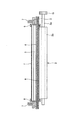
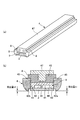
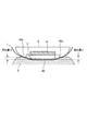
図6(a)、(b)は、本実施例におけるヒータ3が取り付けられたヒータホルダ4の外観斜視図であり、図6(a)は加圧ローラ2側に配置される側とは反対側から見た様子、図6(b)は加圧ローラ2側に配置される側から見た様子を示す。また、図7(a)は、本実施例におけるヒータ3が取り付けられたヒータホルダ4の記録材搬送方向の断面図であり、図7(b)は、その長手方向の断面図である。
5. 6 (a) and 6 (b) are external perspective views of the heater holder 4 to which the heater 3 in the present embodiment is attached, and FIG. 6 (a) is disposed on the pressure roller 2 side. FIG. 6B shows a state seen from the side opposite to the side, and FIG. 6B shows a state seen from the side disposed on the pressure roller 2 side. 7A is a cross-sectional view in the recording material conveyance direction of the heater holder 4 to which the heater 3 is attached in the present embodiment, and FIG. 7B is a cross-sectional view in the longitudinal direction thereof.

上述のように、本実施例の定着装置107は、無端状の可撓性部材1と、可撓性部材1の内周面側に配置され可撓性部材を加熱するヒータ3と、を有する。また、この定着装置107は、可撓性部材1の内周面側に配置されヒータ3を支持する支持部材4と、可撓性部材1を介して支持部材4及びヒータ3に押圧されてニップ部N1を形成する回転体2と、を有する。また、支持部材4は、ヒータ3の可撓性部材1と接触する面であるヒータ面31と交差する方向において回転体側に突出した突起部42a、42bを有する。特に、本実施例では、突起部42a、42bの先端は、ヒータ面31と交差する方向においてヒータ面31に対し回転体2側に位置する。つまり、本実施例では、加圧ローラ2に対してヒータ面31よりも上流突起部42a、下流突起部42bの方が高い。また、支持部材4は、ヒータ面31と交差する方向においてヒータ3に対し回転体2とは反対側にヒータ3と離隔して配置された基礎部(支持面)43を有する。そして、ヒータ面31と交差する方向におけるヒータ3と基礎部43との間に、支持部材4とは別部材である樹脂部材8が配置されて、ヒータ面31と交差する方向における突起部42a、42bの回転体2側の先端とヒータ面31との間の距離が決められている。また、本実施例では、樹脂部材8は、ヒータ3と支持部材4との間の空間46を埋めるように充填されている。また、本実施例では、支持部材4は、樹脂部材8によって埋められた、樹脂部材8を構成する樹脂材料を注入するための貫通孔45を有する。   As described above, the fixing device 107 of the present embodiment includes the endless flexible member 1 and the heater 3 disposed on the inner peripheral surface side of the flexible member 1 and heating the flexible member. . The fixing device 107 is disposed on the inner peripheral surface side of the flexible member 1 and supports the heater 3. The fixing device 107 is pressed by the support member 4 and the heater 3 via the flexible member 1 to nip the nip. And a rotating body 2 forming the portion N1. In addition, the support member 4 has protrusions 42 a and 42 b that protrude toward the rotating body in a direction intersecting the heater surface 31 which is a surface of the heater 3 in contact with the flexible member 1. In particular, in the present embodiment, the tips of the protrusions 42 a and 42 b are located on the rotating body 2 side with respect to the heater surface 31 in the direction intersecting the heater surface 31. That is, in the present embodiment, the upstream projection 42 a and the downstream projection 42 b are higher than the heater surface 31 with respect to the pressure roller 2. In addition, the support member 4 has a base portion (support surface) 43 disposed apart from the heater 3 on the opposite side of the heater 3 with respect to the heater 3 in the direction intersecting the heater surface 31. A resin member 8, which is a separate member from the support member 4, is disposed between the heater 3 and the base portion 43 in the direction intersecting the heater surface 31, and the protrusion 42 a in the direction intersecting the heater surface 31. The distance between the tip of the rotating body 2 side of 42 b and the heater surface 31 is determined. Further, in the present embodiment, the resin member 8 is filled so as to fill the space 46 between the heater 3 and the support member 4. In the present embodiment, the support member 4 has a through hole 45 filled with the resin member 8 for injecting a resin material constituting the resin member 8.

本実施例では、ヒータ面31と略直交する方向において、ヒータ3とヒータホルダ4の支持面43とは接触していない。そして、本実施例では、このヒータ3と支持面43との間に樹脂部材8が介在し、ヒータホルダ4からの加圧力は樹脂部材8を介してヒータ3に加えられる。   In the present embodiment, the heater 3 and the support surface 43 of the heater holder 4 are not in contact with each other in the direction substantially orthogonal to the heater surface 31. In the present embodiment, the resin member 8 is interposed between the heater 3 and the support surface 43, and the pressure from the heater holder 4 is applied to the heater 3 via the resin member 8.

これは、ヒータ3とヒータホルダ4との位置決めが、図5(b)に示す手順において、ヒータ面31と、上流突起部42a、下流突起部42bと、を基準にして行われるためである。したがって、突出量h1、h2は、実質的に位置決め台10の段差のみで管理することができ、ヒータ3とヒータホルダ4とを従来よりも高精度に位置決めすることが可能となる。これにより、加熱フィルム1の表面の摩耗速度の抑制を高水準で達成することができる。   This is because the positioning of the heater 3 and the heater holder 4 is performed with reference to the heater surface 31, the upstream protrusion 42a, and the downstream protrusion 42b in the procedure shown in FIG. Therefore, the protrusion amounts h1 and h2 can be managed substantially only by the steps of the positioning table 10, and the heater 3 and the heater holder 4 can be positioned with higher accuracy than in the prior art. Thereby, suppression of the wear rate of the surface of the heating film 1 can be achieved at a high level.

なお、本実施例では、樹脂部材8の材料として耐熱性樹脂を用いているが、樹脂部材8の材料として熱硬化型、光硬化型、湿度硬化型等の耐熱性接着材を用いてもよく、貫通穴45を通して空間46を埋めることが可能な材料であればよい。   In the present embodiment, a heat-resistant resin is used as the material of the resin member 8, but a heat-resistant adhesive such as a thermosetting resin, a photo-curable resin, or a humidity-curable resin may be used as the material of the resin member 8. Any material that can fill the space 46 through the through hole 45 may be used.

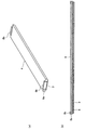
また、本実施例では、貫通穴45から樹脂材料を注入することで樹脂部材8を形成したが、これに限定されるものではない。図8(a)は、本実施例の変形例におけるヒータ3が取り付けられたヒータホルダ4の外観斜視図であり、図8(b)はその長手方向の断面図である。この変形例では、ヒータホルダ4の長手方向の端部から樹脂材料を注入することで樹脂部材8を形成する。このような構成によっても、本実施例と同様の効果を得ることができる。なお、この変形例では、樹脂部材8の長手方向の端部(連結部8a、係止部8b)をヒータホルダ4の上面44にアンカーとして引っかけることで、ヒータホルダ4から樹脂部材8が脱落しないようにすることができる。   Moreover, although the resin member 8 was formed by inject | pouring a resin material from the through-hole 45 in a present Example, it is not limited to this. FIG. 8A is an external perspective view of the heater holder 4 to which the heater 3 according to the modification of the present embodiment is attached, and FIG. 8B is a cross-sectional view in the longitudinal direction thereof. In this modification, the resin member 8 is formed by injecting a resin material from the end of the heater holder 4 in the longitudinal direction. Even with such a configuration, the same effect as in the present embodiment can be obtained. In this modification, the resin member 8 is prevented from dropping from the heater holder 4 by hooking the longitudinal ends (the connecting portion 8a and the locking portion 8b) of the resin member 8 as anchors on the upper surface 44 of the heater holder 4. can do.

[実施例2]
次に、本発明の他の実施例について説明する。本実施例の画像形成装置、定着装置の基本的な構成及び動作は、実施例1のものと同じである。したがって、本実施例の画像形成装置、定着装置において、実施例1の画像形成装置、定着装置のものと同一又は対応する機能あるいは構成を有する要素については、実施例1と同一符号を付して、詳しい説明は省略する。
Example 2
Next, another embodiment of the present invention will be described. The basic configuration and operation of the image forming apparatus and the fixing device of the present embodiment are the same as those of the first embodiment. Therefore, in the image forming apparatus and the fixing device of the present embodiment, elements having the same or corresponding functions or configurations as those of the image forming apparatus and the fixing device of the first embodiment are given the same reference numerals as in the first embodiment. Detailed explanation is omitted.

1.ヒータとヒータホルダとの位置決め方法
本実施例における定着装置107の製造方法(特に、ヒータ3とヒータホルダ4との位置決め方法)について説明する。
1. Method of Positioning Heater and Heater Holder A method of manufacturing the fixing device 107 in the present embodiment (in particular, a method of positioning the heater 3 and the heater holder 4) will be described.

図9(a)、(b)は、本実施例におけるヒータホルダ4の外観斜視図であり、図9(a)は加圧ローラ2側に配置される側とは反対側から見た様子、図9(b)は加圧ローラ2側に配置される側から見た様子を示す。本実施例では、ヒータホルダ4は、実施例1と同様に、加圧ローラ2側の側面に、ヒータホルダ4の長手方向に沿って、凹形状の溝41を有する。ただし、本実施例では、この溝41は2段階の深さを有し、記録材搬送方向の両端部に配置されたより浅い第1の溝部41a、41aと、記録材搬送方向の中央部に配置されたより深い第2の溝部41bと、を有する。そして、詳しくは後述するように、この溝41に対応する位置にヒータ3が配置される。また、本実施例では、ヒータ3の位置を決める基礎となる基礎部としての支持面43を構成する第1の溝部41a、41aは、実施例1と同様に、ヒータ3との間に隙間を有するように意図的にヒータホルダ4の上面44側にオフセットされている。   9 (a) and 9 (b) are external perspective views of the heater holder 4 in the present embodiment, and FIG. 9 (a) is a view from the side opposite to the side disposed on the pressure roller 2 side, 9 (b) shows a state viewed from the side disposed on the pressure roller 2 side. In the present embodiment, as in the first embodiment, the heater holder 4 has a concave groove 41 along the longitudinal direction of the heater holder 4 on the side surface on the pressure roller 2 side. However, in this embodiment, the groove 41 has two levels of depth, and is disposed at the shallower first groove portions 41a and 41a disposed at both ends in the recording material conveyance direction and in the central portion in the recording material conveyance direction. A deeper second groove 41b. Then, the heater 3 is disposed at a position corresponding to the groove 41 as described later in detail. In the present embodiment, the first groove portions 41a and 41a constituting the support surface 43 serving as a base portion that determines the position of the heater 3 have a gap between the heater 3 and the first embodiment. It is intentionally offset to the upper surface 44 side of the heater holder 4 so as to have.

図10は、本実施例におけるヒータ3とヒータホルダ4との位置決め方法の手順を示す。以下、図10(a)〜(c)に示す各工程について順次説明する。   FIG. 10 shows the procedure of the method of positioning the heater 3 and the heater holder 4 in the present embodiment. Hereinafter, each process shown to FIG.10 (a)-(c) is demonstrated one by one.

(a)ヒータ配置工程
図10(a)に示すように、ヒータ3とヒータホルダ4との位置決めには、位置決め台10を使用する。位置決め台10は、実施例1で説明したものと実質的に同じである。ヒータ3とヒータホルダ4との位置決めを行う際には、ヒータ配置部11にヒータ面31を接触させるようにして、ヒータ3を位置決め台10に配置する。このとき、本実施例では、ヒータ3をヒータ配置部11に接触させ、ヒータ3を位置決め台10上の所定位置に保持するように位置決め台10に固定する。
(A) Heater Arrangement Step As shown in FIG. 10A, a positioning table 10 is used for positioning the heater 3 and the heater holder 4. The positioning table 10 is substantially the same as that described in the first embodiment. When positioning the heater 3 and the heater holder 4, the heater 3 is disposed on the positioning table 10 such that the heater placement portion 11 is in contact with the heater surface 31. At this time, in the present embodiment, the heater 3 is brought into contact with the heater arrangement portion 11, and the heater 3 is fixed to the positioning table 10 so as to be held at a predetermined position on the positioning table 10.

(b)樹脂塗布工程
図10(b)に示すように、ヒータ3を位置決め台10に配置した後、ヒータ3のヒータ面31とは反対側の面であるヒータ上面32に、樹脂部材8を構成する樹脂材料としての未硬化状態の耐熱性接着部材Bを塗布する。この耐熱性接着部材Bを塗布する個所は、ヒータホルダ4の支持面43を構成する第1の溝部41a、41aに対応する箇所である。つまり、ヒータ上面32の記録材搬送方向の両端部に、ヒータ上面32の長手方向に沿って、ヒータ3の略全長に渡り耐熱性接着部材Bを塗布する。
(B) Resin Application Step As shown in FIG. 10 (b), after the heater 3 is placed on the positioning table 10, the resin member 8 is placed on the heater upper surface 32 that is the surface opposite to the heater surface 31 of the heater 3. An uncured heat-resistant adhesive member B as a resin material to be formed is applied. The portion to which the heat-resistant adhesive member B is applied is a portion corresponding to the first groove portions 41 a and 41 a constituting the support surface 43 of the heater holder 4. That is, the heat resistant adhesive member B is applied to both end portions of the heater upper surface 32 in the recording material conveyance direction along the longitudinal direction of the heater upper surface 32 over substantially the entire length of the heater 3.

(c)ヒータホルダ配置工程
図10(c)に示すように、耐熱性接着部材Bが未硬化状態の間に、上流突起配置部12a、下流突起配置部12bにそれぞれ上流突起部42a、下流突起部42bを接触させると共に、ヒータ3を覆うようにして、ヒータホルダ4を位置決め台10に配置する。このとき、本実施例では、上流突起部42a、下流突起部42bをそれぞれ上流突起配置部12a、下流突起配置部12bに接触させ、ヒータホルダ4を位置決め台10上の所定位置に保持するように位置決め台10に固定する。これによって、ヒータホルダ4の第1の溝部41a、41aとヒータ上面32との間で耐熱性接着材Bが押しつぶされる。ここで、本実施例では、実施例1と同様に、上流突起配置部12aからヒータ配置部11までの高さ(段差)、下流突起配置部12bからヒータ配置部11までの高さ(段差)は、それぞれ設計上必要な突出量h1、h2と同じ高さになっている。したがって、耐熱性接着部材Bが硬化することで、耐熱性接着剤Bが樹脂部材8としてヒータ3とヒータホルダ4との間に介在し、上述の突出量h1、h2を維持してヒータ3とヒータホルダ4とが位置決めされ、かつ、固定される。
(C) Heater holder placement step As shown in FIG. 10C, while the heat-resistant adhesive member B is in the uncured state, the upstream protrusion placement portion 12a and the downstream protrusion placement portion 12b have an upstream protrusion 42a and a downstream protrusion, respectively. The heater holder 4 is arranged on the positioning table 10 so as to contact the heater 42 b and cover the heater 3. At this time, in this embodiment, the upstream protrusion 42a and the downstream protrusion 42b are brought into contact with the upstream protrusion 12a and the downstream protrusion 12b, respectively, and the heater holder 4 is positioned so as to be held at a predetermined position on the positioning table 10. Secure to the base 10. As a result, the heat resistant adhesive B is crushed between the first grooves 41 a and 41 a of the heater holder 4 and the heater upper surface 32. Here, in the present embodiment, as in the first embodiment, the height (step difference) from the upstream protrusion arrangement portion 12a to the heater arrangement portion 11, and the height (step difference) from the downstream protrusion arrangement portion 12b to the heater arrangement portion 11 Are the same height as the projections h1 and h2 required for the design. Therefore, when the heat-resistant adhesive member B is cured, the heat-resistant adhesive B is interposed between the heater 3 and the heater holder 4 as the resin member 8, and the above-described protrusion amounts h1 and h2 are maintained to maintain the heater 3 and the heater holder. 4 is positioned and fixed.

2.本実施例の効果
本実施例では、ヒータ面31と略直交する方向において、ヒータ3とヒータホルダ4の支持面43とは接触していない。そして、本実施例では、このヒータ3と支持面43との間に樹脂部材8が介在し、ヒータホルダ4からの加圧力は樹脂部材8を介してヒータ3に加えられる。
2. Effects of the Present Embodiment In the present embodiment, the heater 3 and the support surface 43 of the heater holder 4 are not in contact with each other in the direction substantially orthogonal to the heater surface 31. In this embodiment, the resin member 8 is interposed between the heater 3 and the support surface 43, and the applied pressure from the heater holder 4 is applied to the heater 3 through the resin member 8.

また、本実施例では、ヒータ3とヒータホルダ4の第2の溝部41bとの間に空間48を形成することができる。つまり、本実施例では、樹脂部材8は、ヒータ3と支持部材4との間の一部に配置されており、ヒータ3と支持部材4との間に空間48が形成されている。そのため、本実施例では、このヒータ3とヒータホルダ4との間に形成される空間48によって断熱効果を生み出し、熱エネルギーをより効率的に記録材Pに与えることが可能となる。   Further, in the present embodiment, the space 48 can be formed between the heater 3 and the second groove 41 b of the heater holder 4. That is, in the present embodiment, the resin member 8 is disposed in a part between the heater 3 and the support member 4, and a space 48 is formed between the heater 3 and the support member 4. Therefore, in the present embodiment, the space 48 formed between the heater 3 and the heater holder 4 produces a heat insulating effect, and thermal energy can be applied to the recording material P more efficiently.

また、本実施例では、耐熱性接着部材Bを用いることで、ヒータ3とヒータホルダ4とが固定されるため、組立性が向上する。   Further, in the present embodiment, by using the heat-resistant adhesive member B, the heater 3 and the heater holder 4 are fixed, so that the assemblability is improved.

なお、本実施例では、樹脂部材8の材料として耐熱性接着部材Bを用いているが、これに限定されるものではない。この材料は、該材料がヒータ3に配置された後にヒータホルダ4が位置決め台10に配置された状態で変形し、その後硬化するものであればよい。例えば、耐熱性接着部材Bの代わりに、熱硬化型樹脂をヒータ3に配置し、ヒータホルダ4を位置決め台10に配置した後に該熱硬化型樹脂を加熱して硬化させても、本実施例と同様の効果が得られる。   In the present embodiment, although the heat-resistant adhesive member B is used as the material of the resin member 8, the present invention is not limited to this. This material may be any material that deforms in a state where the heater holder 4 is disposed on the positioning table 10 after the material is disposed on the heater 3 and then hardens. For example, instead of the heat-resistant adhesive member B, a thermosetting resin may be disposed in the heater 3, and the heater holder 4 may be disposed on the positioning table 10 and then the thermosetting resin may be heated and cured. The same effect is obtained.

[実施例3]
次に、本発明の他の実施例について説明する。本実施例の画像形成装置、定着装置の基本的な構成及び動作は、実施例1のものと同じである。したがって、本実施例の画像形成装置、定着装置において、実施例1の画像形成装置、定着装置のものと同一又は対応する機能あるいは構成を有する要素については、実施例1と同一符号を付して、詳しい説明は省略する。
[Example 3]
Next, another embodiment of the present invention will be described. The basic configuration and operation of the image forming apparatus and the fixing device of the present embodiment are the same as those of the first embodiment. Therefore, in the image forming apparatus and the fixing device of the present embodiment, elements having the same or corresponding functions or configurations as those of the image forming apparatus and the fixing device of the first embodiment are given the same reference numerals as in the first embodiment. Detailed explanation is omitted.

図11(a)は、本実施例におけるヒータ3が取り付けられたヒータホルダ4の外観斜視図であり、図11(b)は、その記録材搬送方向の断面図である。本実施例では、ヒータ面31と略直交する方向におけるヒータ3とヒータホルダ4の支持面43との間に、ヒータホルダ4とは別部材であるスペーサ部材9が配置されている。そして、本実施例では、樹脂部材8は、ヒータ面31と略直交する方向におけるスペーサ部材9とヒータホルダ4の支持面43との間に配置される。これにより、ヒータ面31と略直交する方向における、上流突起部42a、下流突起部42bのそれぞれの加圧ローラ2側の先端とヒータ面31との間の距離が決められている。   FIG. 11A is an external perspective view of the heater holder 4 to which the heater 3 in the present embodiment is attached, and FIG. 11B is a cross-sectional view in the recording material conveyance direction. In the present embodiment, a spacer member 9, which is a separate member from the heater holder 4, is disposed between the heater 3 and the support surface 43 of the heater holder 4 in a direction substantially orthogonal to the heater surface 31. Further, in the present embodiment, the resin member 8 is disposed between the spacer member 9 and the support surface 43 of the heater holder 4 in the direction substantially orthogonal to the heater surface 31. Thereby, the distance between the tip of the upstream protrusion 42 a and the downstream protrusion 42 b on the pressure roller 2 side and the heater surface 31 in the direction substantially orthogonal to the heater surface 31 is determined.

図12(a)は、本実施例におけるヒータホルダ4及びスペーサ部材9の外観斜視図であり、図12(b)は、その記録材搬送方向の断面図である。本実施例では、ヒータホルダ4には、上面44を貫通する貫通穴45が設けられている。本実施例では、貫通穴45は、ヒータホルダ4の長手方向に沿って、記録材搬送方向において2個設けられている。また、本実施例では、ヒータホルダ4には、ヒータ面31と略直交する方向において上面44から加圧ローラ2側とは反対側に突出して補強部47が設けられている。補強部47は、図12(b)に示すように断面略T字形状を有し、記録材搬送方向に伸びる部分が貫通穴45と対向する。本実施例では、この補強部47の貫通穴45と対向する面が、ヒータ3の位置を決める基礎となる基礎部としての支持面43を構成する。また、本実施例では、スペーサ部材9は、ヒータ3側の側面に、長手方向に沿って、凹形状のスペーサ溝91を有する。そして、スペーサ部材9は、このスペーサ溝91の記録材搬送方向の両側の、長手方向に沿って伸びる当接部(座面)92、92でヒータ上面32に当接する。スペーサ部材9は、ヒータ3とヒータホルダ4の支持面43との間に配置されるように、ヒータホルダ4の凹形状の溝41内に篏合されて配置される。そして、このスペーサ部材9とヒータホルダ4の支持面43との間に樹脂部材8が配置される。   FIG. 12A is an external perspective view of the heater holder 4 and the spacer member 9 in the present embodiment, and FIG. 12B is a cross-sectional view in the recording material conveyance direction. In the present embodiment, the heater holder 4 is provided with a through hole 45 penetrating the upper surface 44. In the present embodiment, two through holes 45 are provided in the recording material conveyance direction along the longitudinal direction of the heater holder 4. Further, in the present embodiment, the reinforcing portion 47 is provided on the heater holder 4 so as to protrude from the upper surface 44 to the opposite side to the pressure roller 2 side in the direction substantially orthogonal to the heater surface 31. The reinforcing portion 47 has a substantially T-shaped cross section as shown in FIG. 12B, and a portion extending in the recording material conveyance direction faces the through hole 45. In the present embodiment, the surface of the reinforcing portion 47 opposed to the through hole 45 constitutes a support surface 43 as a base serving as a basis for determining the position of the heater 3. Further, in the present embodiment, the spacer member 9 has a spacer groove 91 having a concave shape along the longitudinal direction on the side surface on the heater 3 side. The spacer member 9 abuts on the heater upper surface 32 at abutment portions (seating surfaces) 92 and 92 extending along the longitudinal direction on both sides of the spacer groove 91 in the recording material conveyance direction. The spacer member 9 is fitted and disposed in the concave groove 41 of the heater holder 4 so as to be disposed between the heater 3 and the support surface 43 of the heater holder 4. The resin member 8 is disposed between the spacer member 9 and the support surface 43 of the heater holder 4.

このように、本実施例では、ヒータ面31と交差する方向におけるヒータ3と基礎部(支持面)43との間に、支持部材4とは別部材であるスペーサ部材9が配置されている。そして、樹脂部材8が、ヒータ面31と交差する方向におけるスペーサ部材9と基礎部43との間に配置されて、ヒータ面31と交差する方向における突起部42a、42bの回転体2側の先端とヒータ面31との間の距離が決められている。また、本実施例では、樹脂部材8は、スペーサ部材9と支持部材4との間の空間を埋めるように充填されている。また、本実施例では、ヒータ3はスペーサ部材9の一部と接触し、ヒータ3とスペーサ部材9との間に空間48が形成されている。   Thus, in the present embodiment, the spacer member 9, which is a separate member from the support member 4, is disposed between the heater 3 and the base portion (support surface) 43 in the direction intersecting the heater surface 31. And the resin member 8 is arrange | positioned between the spacer member 9 and the base part 43 in the direction which cross | intersects the heater surface 31, and the front-end | tip at the side of the rotary body 2 of the protrusion parts 42a and 42b in the direction which cross | intersects the heater surface 31 The distance between the heater surface 31 and the heater surface 31 is determined. Further, in this embodiment, the resin member 8 is filled so as to fill the space between the spacer member 9 and the support member 4. Further, in the present embodiment, the heater 3 is in contact with a part of the spacer member 9, and a space 48 is formed between the heater 3 and the spacer member 9.

本実施例における定着装置107の製造方法(特に、ヒータ3とヒータホルダ4との位置決め方法)は、図5を参照して説明した実施例1における方法と概略同様である。ただし、本実施例では、図5(a)に示すヒータ配置工程において、ヒータ3を位置決め台10上に配置すると共に、スペーサ部材9をヒータ3上に配置する。また、本実施例では、図5(b)に示すヒータホルダ配置工程において、突起配置部12a、12bに突起部42a、42bを接触させると共に、ヒータ3及びスペーサ部材9を覆うようにして、ヒータホルダ4を位置決め台10に配置する。また、本実施例では、図5(c)に示す樹脂充填工程において、貫通穴45から樹脂部材8を構成する樹脂材料としての耐熱性樹脂Aを注入して、スペーサ部材9とヒータホルダ4の補強部47の支持面43との間に樹脂部材8を介在させる。   The method of manufacturing the fixing device 107 (in particular, the method of positioning the heater 3 and the heater holder 4) in the present embodiment is substantially the same as the method in the first embodiment described with reference to FIG. However, in the present embodiment, the heater 3 is disposed on the positioning table 10 and the spacer member 9 is disposed on the heater 3 in the heater disposing step shown in FIG. 5A. Further, in this embodiment, in the heater holder arranging step shown in FIG. 5B, the protrusions 42a and 42b are brought into contact with the protrusion arranging parts 12a and 12b and the heater 3 and the spacer member 9 are covered so as to cover the heater holder 4. Are placed on the positioning table 10. Further, in this embodiment, in the resin filling step shown in FIG. 5C, the heat resistant resin A as the resin material constituting the resin member 8 is injected from the through hole 45 to reinforce the spacer member 9 and the heater holder 4. The resin member 8 is interposed between the support surface 43 of the portion 47.

上述のようにしてスペーサ部材9とヒータホルダ4の支持面43との間に樹脂部材8を介在させることで、ヒータ3とヒータホルダ4とを位置決めすることができる。図11(b)に示すように、本実施例では、ヒータ面31と略直交する方向において、スペーサ部材9とヒータホルダ4の補強部47の支持面43とは接触していない。そして、本実施例では、このスペーサ部材9と支持面43との間に樹脂部材8が介在し、ヒータ3からの加圧力の反力を最終的に補強部47の支持面43で受けるようにしている。これによって、貫通穴45上の加圧方向の強度を高めることが可能となり、加圧時の位置精度の信頼性が向上する。   By interposing the resin member 8 between the spacer member 9 and the support surface 43 of the heater holder 4 as described above, the heater 3 and the heater holder 4 can be positioned. As shown in FIG. 11B, in the present embodiment, the spacer member 9 and the support surface 43 of the reinforcing portion 47 of the heater holder 4 are not in contact with each other in the direction substantially orthogonal to the heater surface 31. In the present embodiment, the resin member 8 is interposed between the spacer member 9 and the support surface 43 so that the reaction force of the pressure from the heater 3 is finally received by the support surface 43 of the reinforcing portion 47. ing. By this, it is possible to increase the strength in the pressing direction on the through hole 45, and the reliability of positional accuracy at the time of pressing is improved.

また、本実施例では、スペーサ部材9にスペーサ溝91が設けられており、ヒータ3との間に空間48が形成される。ここで、実施例2では、ヒータ3とヒータホルダ4との間の空間48の体積は、耐熱性接着部材Bの形状によって決まる。そして、実施例2では、位置決め台10上で所定の突出量h1、h2を得る際に耐熱性接着部材Bの厚さが変化して、上記空間48の体積も変化する。そのため、実施例2では、空間48による断熱効果にばらつきが生じる可能性がある。これに対し、本実施例では、スペーサ溝91の形状を予め設定すれば、ヒータ3とスペーサ部材9との間の空間48が実施例2のように製造過程で変化することはない。これによって、断熱効果のばらつきを抑え、記録材Pに熱を与える効率性の信頼性を向上させることができる。   Further, in the present embodiment, the spacer groove 91 is provided in the spacer member 9, and a space 48 is formed between the spacer member 9 and the heater 3. Here, in the second embodiment, the volume of the space 48 between the heater 3 and the heater holder 4 is determined by the shape of the heat-resistant adhesive member B. Then, in the second embodiment, when obtaining the predetermined protrusion amounts h1 and h2 on the positioning table 10, the thickness of the heat-resistant adhesive member B changes, and the volume of the space 48 also changes. Therefore, in the second embodiment, the heat insulating effect of the space 48 may vary. On the other hand, in the present embodiment, if the shape of the spacer groove 91 is set in advance, the space 48 between the heater 3 and the spacer member 9 does not change in the manufacturing process as in the second embodiment. By this, it is possible to suppress the variation of the heat insulation effect and to improve the reliability of the efficiency of applying heat to the recording material P.

なお、本実施例では、貫通穴45を用いて樹脂部材8の材料を充填しているが、実施例1にて説明したのと同様に、ヒータホルダ4の長手方向の端部から樹脂部材8の材料を充填しても同様の効果が得られる。また、樹脂部材8の材料は、耐熱性樹脂であっても、耐熱性接着材であってもよい。   In the present embodiment, although the material of the resin member 8 is filled using the through holes 45, the end portion of the heater holder 4 in the longitudinal direction is similar to that described in the first embodiment. The same effect can be obtained by filling the material. The material of the resin member 8 may be a heat resistant resin or a heat resistant adhesive.

[実施例4]
次に、本発明の他の実施例について説明する。本実施例の画像形成装置、定着装置の基本的な構成及び動作は、実施例1のものと同じである。したがって、本実施例の画像形成装置、定着装置において、実施例1の画像形成装置、定着装置のものと同一又は対応する機能あるいは構成を有する要素については、実施例1と同一符号を付して、詳しい説明は省略する。
Example 4
Next, another embodiment of the present invention will be described. The basic configuration and operation of the image forming apparatus and the fixing device of the present embodiment are the same as those of the first embodiment. Therefore, in the image forming apparatus and the fixing apparatus of the present embodiment, elements having the same or corresponding functions or configurations as those of the image forming apparatus and the fixing apparatus of the first embodiment are denoted by the same reference numerals as those of the first embodiment. Detailed explanation is omitted.

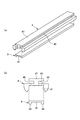
図13は、本実施例の定着装置107のニップ部の近傍の記録材搬送方向の断面図である。本実施例では、実施例1と同様、支持部材4は、ヒータ3の可撓性部材1と接触する面であるヒータ面31と交差する方向において回転体2側に突出した突起部42a、42bを有する。ただし、本実施例では、突起部42a、42bの先端は、ヒータ面31と交差する方向においてヒータ面31に対し回転体2とは反対側に位置する。つまり、本実施例では、加圧ローラ2に対してヒータ面31よりも上流突起部42a、下流突起部42bの方が低い。   FIG. 13 is a cross-sectional view in the recording material conveyance direction in the vicinity of the nip portion of the fixing device 107 of this embodiment. In the present embodiment, as in the first embodiment, the support member 4 has protrusions 42 a and 42 b that protrude toward the rotating body 2 in the direction intersecting the heater surface 31 that is a surface that contacts the flexible member 1 of the heater 3. Have However, in the present embodiment, the tips of the protrusions 42 a and 42 b are located on the opposite side of the rotor 2 with respect to the heater surface 31 in the direction intersecting the heater surface 31. That is, in this embodiment, the upstream protrusion 42 a and the downstream protrusion 42 b are lower than the heater surface 31 with respect to the pressure roller 2.

具体的には、本実施例では、ヒータ3の表面にはガラスの摺動層49が設けられており、この摺動層49の加圧ローラ2側の面がヒータ面31を構成している。摺動層49には、ヒータ3の加熱フィルム1との摺動性を上げる効果があるため、加熱フィルム1の内面の摩耗をさらに抑えることができる。さらに、摺動層49の厚みによってヒータ3のエッジと加熱フィルム1との距離が離れるため、ヒータ3のエッジと加熱フィルム1とが接触しない程度まで上流突起部42a、下流突起部42bの高さを低くすることができる。これにより、本実施例では、加圧ローラ2に対してヒータ面31よりも上流突起部42a、下流突起部42bの方が低いニップ構成を実現している。本実施例では、加圧ローラ2に対してヒータ面31よりも上流突起部42a、下流突起部42bの方が低いため、上流突起部42a、下流突起部42bによる圧力のピークを下げることができる。したがって、加熱フィルム1と記録材Pとの摩擦力による加熱フィルム1の表層の摩耗をさらに抑えることができる。   Specifically, in the present embodiment, a sliding layer 49 of glass is provided on the surface of the heater 3, and the surface of the sliding layer 49 on the pressure roller 2 side constitutes the heater surface 31. . The sliding layer 49 has the effect of improving the sliding property of the heater 3 with the heating film 1, so that the wear of the inner surface of the heating film 1 can be further suppressed. Further, since the distance between the edge of the heater 3 and the heating film 1 is increased depending on the thickness of the sliding layer 49, the height of the upstream protrusion 42 a and the downstream protrusion 42 b to the extent that the edge of the heater 3 and the heating film 1 do not contact each other. Can be lowered. Thus, in this embodiment, a nip configuration is realized in which the upstream protrusion 42 a and the downstream protrusion 42 b are lower than the heater surface 31 with respect to the pressure roller 2. In the present embodiment, the upstream protrusion 42a and the downstream protrusion 42b are lower than the heater surface 31 with respect to the pressure roller 2, so that the pressure peaks due to the upstream protrusion 42a and the downstream protrusion 42b can be lowered. . Therefore, the abrasion of the surface layer of the heating film 1 due to the frictional force between the heating film 1 and the recording material P can be further suppressed.

図14は、本実施例におけるヒータ3とヒータホルダ4との位置決め方法の手順を示す。図14(a)〜(d)に示す各工程は、それぞれ実施例1における図5(a)〜(d)に示す各工程と同様である。ただし、本実施例では、位置決め台10の形状が実施例1とは異なる。具体的には、本実施例では、位置決め台10が略水平に設置された場合に、重力方向における上流突起配置部12a及び下流突起配置部12bの高さは、ヒータ配置部11の高さよりも高い。これにより、図14(b)に示すヒータホルダ配置工程では、ヒータホルダ4を位置決め台10に固定することで、加圧ローラ2に対してヒータ面31よりも上流突起部42a、下流突起部42bを高精度に低く位置決めすることが可能となる。   FIG. 14 shows the procedure of the method of positioning the heater 3 and the heater holder 4 in the present embodiment. Each process shown in FIGS. 14A to 14D is the same as each process shown in FIGS. 5A to 5D in the first embodiment. However, in the present embodiment, the shape of the positioning table 10 is different from that of the first embodiment. Specifically, in the present embodiment, when the positioning table 10 is installed substantially horizontally, the height of the upstream protrusion arrangement portion 12a and the downstream protrusion arrangement portion 12b in the direction of gravity is higher than the height of the heater arrangement portion 11. high. Accordingly, in the heater holder arranging step shown in FIG. 14B, the upstream protrusion 42 a and the downstream protrusion 42 b are made higher than the heater surface 31 with respect to the pressure roller 2 by fixing the heater holder 4 to the positioning table 10. It is possible to position with low accuracy.

なお、本実施例では、実施例1と同様の構成の定着装置107において、上流突起部42a、下流突起部42bをヒータ面31よりも加圧ローラ2とは反対側に退避させたニップ構成とした場合について説明した。実施例2、実施例3と同様の構成の定着装置107においても、本実施例と同様に上流突起部42a、下流突起部42bをヒータ面31よりも加圧ローラ2とは反対側に退避させたニップ構成とすることができる。この場合も、ヒータ3とヒータホルダ4との位置決め方法においては、位置決め台10のヒータ配置部11と上流突起配置部12a、下流突起配置部12bとの高さ関係を、実施例2、3における関係から本実施例と同様の関係に変更すればよい。   In the present exemplary embodiment, the fixing device 107 having the same configuration as that of the first exemplary embodiment has a nip configuration in which the upstream protruding portion 42a and the downstream protruding portion 42b are retracted to the opposite side of the pressure roller 2 from the heater surface 31. I explained the case. Also in the fixing device 107 having the same configuration as in the second and third embodiments, the upstream protrusion 42a and the downstream protrusion 42b are retracted to the opposite side of the pressure roller 2 from the heater surface 31 as in the present embodiment. It is possible to have a different nip configuration. Also in this case, in the positioning method of the heater 3 and the heater holder 4, the height relationship between the heater placement portion 11 of the positioning base 10, the upstream projection placement portion 12a, and the downstream projection placement portion 12b is the relationship in the second and third embodiments. The relationship may be changed to the same relationship as this embodiment.

[その他]
以上、本発明を具体的な実施例に即して説明したが、本発明は上述の実施例に限定されるものではない。
[Others]
As mentioned above, although this invention was described based on the specific Example, this invention is not limited to the above-mentioned Example.

例えば、画像を担持した記録材を加熱する像加熱装置は、典型的には未定着のトナー像を記録材に定着させる定着装置であるが、例えばトナー像が定着された記録材を再加熱して光沢を制御する装置などであってもよい。   For example, an image heating apparatus for heating a recording material carrying an image is typically a fixing apparatus for fixing an unfixed toner image to the recording material, but for example, the recording material on which the toner image is fixed is reheated It may be a device that controls gloss.

また、上述の実施例ではモノクロ画像形成装置を例として説明したが、本発明はこれに限定されるものではない。本発明は、例えばイエロー、マゼンダ、シアン、ブラックの4色などの複数色のトナー像を重ねて印字するカラー画像形成装置にて用いられる像加熱装置に関しても適用することも可能であり、上述の実施例と同様の作用効果を得ることができる。   In the above-described embodiments, the monochrome image forming apparatus has been described as an example. However, the present invention is not limited to this. The present invention can also be applied to an image heating apparatus used in a color image forming apparatus for printing a plurality of color toner images such as yellow, magenta, cyan, and black, for example. The same effect as that of the embodiment can be obtained.

1 加熱フィルム
2 加圧ローラ
3 ヒータ
4 支持部材
8 樹脂部材
9 スペーサ部材
10 位置決め台
20 樹脂注入部材
31 ヒータ面
43 支持面(基礎部)
45 貫通穴
A 耐熱性樹脂
B 耐熱性接着部材
DESCRIPTION OF SYMBOLS 1 Heating film 2 Pressure roller 3 Heater 4 Support member 8 Resin member 9 Spacer member 10 Positioning stand 20 Resin injection member 31 Heater surface 43 Support surface (base part)
45 Through hole A Heat resistant resin B Heat resistant adhesive member

Claims (12)

無端状の可撓性部材と、
前記可撓性部材の内周面側に配置され前記可撓性部材を加熱するヒータと、
前記可撓性部材の内周面側に配置され前記ヒータを支持する支持部材と、
前記可撓性部材を介して前記支持部材及び前記ヒータに押圧されてニップ部を形成する回転体と、
を有し、
前記支持部材は、前記ヒータの前記可撓性部材と接触する面であるヒータ面と交差する方向において前記回転体側に突出した突起部を有する像加熱装置において、
前記支持部材は、前記ヒータ面と交差する方向において前記ヒータに対し前記回転体とは反対側に前記ヒータと離隔して配置された基礎部を有し、
前記ヒータ面と交差する方向における前記ヒータと前記基礎部との間に、前記支持部材とは別部材である樹脂部材が配置されて、前記ヒータ面と交差する方向における前記突起部の前記回転体側の先端と前記ヒータ面との間の距離が決められていることを特徴とする像加熱装置。
Endless flexible member,
A heater that is disposed on the inner peripheral surface side of the flexible member and heats the flexible member;
A support member disposed on the inner peripheral surface side of the flexible member and supporting the heater;
A rotating body that is pressed by the support member and the heater through the flexible member to form a nip portion;
Have
In the image heating apparatus, the support member includes a protrusion that protrudes toward the rotating body in a direction intersecting a heater surface that is a surface that contacts the flexible member of the heater.
The support member has a base portion that is disposed apart from the heater on the side opposite to the rotating body with respect to the heater in a direction intersecting the heater surface.
A resin member, which is a member different from the support member, is disposed between the heater and the base in a direction intersecting the heater surface, and the protrusion side in the direction intersecting the heater surface is on the rotating body side. An image heating apparatus characterized in that a distance between a tip of the heater and the heater surface is determined.
前記樹脂部材は、前記ヒータと前記支持部材との間の空間を埋めるように充填されていることを特徴とする請求項1に記載の像加熱装置。   The image heating apparatus according to claim 1, wherein the resin member is filled so as to fill a space between the heater and the support member. 前記樹脂部材は、前記ヒータと前記支持部材との間の一部に配置されており、前記ヒータと前記支持部材との間に空間が形成されていることを特徴とする請求項1に記載の像加熱装置。   The said resin member is arrange | positioned in part between the said heater and the said supporting member, Space is formed between the said heater and the said supporting member, It is characterized by the above-mentioned. Image heating device. 前記ヒータ面と交差する方向における前記ヒータと前記基礎部との間に、前記支持部材とは別部材であるスペーサ部材が配置されており、前記樹脂部材が、前記ヒータ面と交差する方向における前記スペーサ部材と前記基礎部との間に配置されて、前記ヒータ面と交差する方向における前記突起部の前記回転体側の先端と前記ヒータ面との間の距離が決められていることを特徴とする請求項1に記載の像加熱装置。   A spacer member, which is a separate member from the support member, is disposed between the heater and the base in the direction intersecting the heater surface, and the resin member is in the direction intersecting the heater surface. It is disposed between a spacer member and the base portion, and the distance between the tip of the protrusion on the rotating body side and the heater surface in a direction intersecting the heater surface is determined. An image heating apparatus according to claim 1. 前記樹脂部材は、前記スペーサ部材と前記支持部材との間の空間を埋めるように充填されていることを特徴とする請求項4に記載の像加熱装置。   The image heating apparatus according to claim 4, wherein the resin member is filled so as to fill a space between the spacer member and the support member. 前記ヒータは前記スペーサ部材の一部と接触し、前記ヒータと前記スペーサ部材との間に空間が形成されていることを特徴とする請求項4又は5に記載の像加熱装置。   The image heating apparatus according to claim 4, wherein the heater is in contact with a part of the spacer member, and a space is formed between the heater and the spacer member. 前記支持部材は、前記樹脂部材によって埋められた、前記樹脂部材を構成する樹脂材料を注入するための貫通孔を有することを特徴とする請求項1乃至6のいずれか1項に記載の像加熱装置。   The image heating device according to any one of claims 1 to 6, wherein the supporting member has a through hole filled with the resin member and for injecting a resin material constituting the resin member. apparatus. 前記ヒータ面と交差する方向において、前記突起部の前記回転体側の先端は、前記ヒータ面に対し前記回転体側、又は前記回転体とは反対側に位置することを特徴とする請求項1乃至7のいずれか1項に記載の像加熱装置。   The tip end of the protrusion on the rotating body side is located on the rotating body side or the opposite side of the rotating body with respect to the heater surface in a direction intersecting with the heater surface. The image heating apparatus according to any one of the above. 無端状の可撓性部材と、前記可撓性部材の内周面側に配置され前記可撓性部材を加熱するヒータと、前記可撓性部材の内周面側に配置され前記ヒータを支持する支持部材と、前記可撓性部材を介して前記支持部材及び前記ヒータに押圧されてニップ部を形成する回転体と、を有し、前記支持部材は、前記ヒータの前記可撓性部材と接触する面であるヒータ面と交差する方向において前記回転体側に突出した突起部を有する像加熱装置の製造方法において、
前記ヒータが配置される第1配置部と、前記突起部が配置される第2配置部と、を有する位置決め台の前記第1配置部に前記ヒータ面を接触させるようにして前記ヒータを前記位置決め台に配置する工程と、
前記第2配置部に前記突起部を接触させると共に、前記ヒータを覆うようにして前記支持部材を前記位置決め台に配置する工程と、
前記ヒータと前記支持部材との間に樹脂材料を充填する工程と、
を有することを特徴とする像加熱装置の製造方法。
An endless flexible member, a heater that is disposed on the inner peripheral surface side of the flexible member and that heats the flexible member, and is disposed on the inner peripheral surface side of the flexible member and supports the heater And a rotating body that is pressed by the support member and the heater via the flexible member to form a nip portion, and the support member includes the flexible member of the heater. In the method of manufacturing an image heating apparatus having a protrusion protruding toward the rotating body in a direction intersecting a heater surface that is a contact surface
The heater is positioned by bringing the heater surface into contact with the first arrangement portion of a positioning table having a first arrangement portion where the heater is arranged and a second arrangement portion where the protrusion is arranged. Placing on the table,
Placing the support member on the positioning table so as to cover the heater while bringing the protrusion into contact with the second placement portion;
Filling a resin material between the heater and the support member;
A method for manufacturing an image heating apparatus, comprising:
無端状の可撓性部材と、前記可撓性部材の内周面側に配置され前記可撓性部材を加熱するヒータと、前記可撓性部材の内周面側に配置され前記ヒータを支持する支持部材と、前記可撓性部材を介して前記支持部材及び前記ヒータに押圧されてニップ部を形成する回転体と、を有し、前記支持部材は、前記ヒータの前記可撓性部材と接触する面であるヒータ面と交差する方向において前記回転体側に突出した突起部を有する像加熱装置の製造方法において、
前記ヒータが配置される第1配置部と、前記突起部が配置される第2配置部と、を有する位置決め台の前記第1配置部に前記ヒータ面を接触させるようにして前記ヒータを前記位置決め台に配置する工程と、
前記ヒータの前記ヒータ面とは反対側の側面であるヒータ上面に樹脂材料を塗布する工程と、
前記第2配置部に前記突起部を接触させると共に、前記ヒータを覆うようにして前記支持部材を前記位置決め台に配置し、前記支持部材と前記ヒータとの間で前記樹脂材料を挟み込む工程と、
を有することを特徴とする像加熱装置の製造方法。
An endless flexible member, a heater that is disposed on the inner peripheral surface side of the flexible member and that heats the flexible member, and is disposed on the inner peripheral surface side of the flexible member and supports the heater And a rotating body that is pressed by the support member and the heater via the flexible member to form a nip portion, and the support member includes the flexible member of the heater. In the method of manufacturing an image heating apparatus having a protrusion protruding toward the rotating body in a direction intersecting a heater surface that is a contact surface,
The heater is positioned by bringing the heater surface into contact with the first arrangement portion of a positioning table having a first arrangement portion where the heater is arranged and a second arrangement portion where the protrusion is arranged. Placing on the table,
Applying a resin material on the heater upper surface which is the side surface of the heater opposite to the heater surface;
Placing the support member on the positioning table to bring the protrusion into contact with the second placement portion and covering the heater, and sandwiching the resin material between the support member and the heater;
A method for manufacturing an image heating apparatus, comprising:
無端状の可撓性部材と、前記可撓性部材の内周面側に配置され前記可撓性部材を加熱するヒータと、前記可撓性部材の内周面側に配置され前記ヒータを支持する支持部材と、前記可撓性部材を介して前記支持部材及び前記ヒータに押圧されてニップ部を形成する回転体と、を有し、前記支持部材は、前記ヒータの前記可撓性部材と接触する面であるヒータ面と交差する方向において前記回転体側に突出した突起部を有する像加熱装置の製造方法において、
前記ヒータが配置される第1配置部と、前記突起部が配置される第2配置部と、を有する位置決め台の前記第1配置部に前記ヒータ面を接触させるようにして前記ヒータを前記位置決め台に配置する工程と、
前記ヒータの前記ヒータ面とは反対側の面であるヒータ上面にスペーサ部材を配置する工程と、
前記第2配置部に前記突起部を接触させると共に、前記ヒータ及び前記スペーサ部材を覆うようにして前記支持部材を前記位置決め台に配置する工程と、
前記ヒータと前記スペーサ部材との間に樹脂材料を充填する工程と、
を有することを特徴とする像加熱装置の製造方法。
An endless flexible member, a heater that is disposed on the inner peripheral surface side of the flexible member and that heats the flexible member, and is disposed on the inner peripheral surface side of the flexible member and supports the heater And a rotating body that is pressed by the support member and the heater via the flexible member to form a nip portion, and the support member includes the flexible member of the heater. In the method of manufacturing an image heating apparatus having a protrusion protruding toward the rotating body in a direction intersecting a heater surface that is a contact surface,
The heater is positioned by bringing the heater surface into contact with the first arrangement portion of a positioning table having a first arrangement portion where the heater is arranged and a second arrangement portion where the protrusion is arranged. Placing on the table,
A step of disposing a spacer member on the upper surface of the heater which is a surface opposite to the heater surface of the heater;
Placing the support member on the positioning table so as to contact the protrusion with the second placement portion and to cover the heater and the spacer member;
Filling a resin material between the heater and the spacer member;
A method for manufacturing an image heating apparatus, comprising:
前記第2配置部の高さは、前記第1配置部の高さよりも低い又は高いことを特徴とする請求項9乃至11のいずれか1項に記載の像加熱装置の製造方法。   The method for manufacturing an image heating apparatus according to any one of claims 9 to 11, wherein the height of the second arrangement portion is lower or higher than the height of the first arrangement portion.
JP2018012095A 2018-01-26 2018-01-26 Image heating device and manufacturing method thereof Pending JP2019128564A (en)

Priority Applications (1)

Application Number Priority Date Filing Date Title
JP2018012095A JP2019128564A (en) 2018-01-26 2018-01-26 Image heating device and manufacturing method thereof

Applications Claiming Priority (1)

Application Number Priority Date Filing Date Title
JP2018012095A JP2019128564A (en) 2018-01-26 2018-01-26 Image heating device and manufacturing method thereof

Publications (1)

Publication Number Publication Date
JP2019128564A true JP2019128564A (en) 2019-08-01

Family

ID=67472309

Family Applications (1)

Application Number Title Priority Date Filing Date
JP2018012095A Pending JP2019128564A (en) 2018-01-26 2018-01-26 Image heating device and manufacturing method thereof

Country Status (1)

Country Link
JP (1) JP2019128564A (en)

Cited By (1)

* Cited by examiner, † Cited by third party
Publication number Priority date Publication date Assignee Title
US12061429B2 (en) 2021-10-11 2024-08-13 Canon Kabushiki Kaisha Heater, heating device, and image forming apparatus

Cited By (1)

* Cited by examiner, † Cited by third party
Publication number Priority date Publication date Assignee Title
US12061429B2 (en) 2021-10-11 2024-08-13 Canon Kabushiki Kaisha Heater, heating device, and image forming apparatus

Similar Documents

Publication Publication Date Title
US10663894B2 (en) Fixing device and image forming apparatus
JP6347163B2 (en) Fixing apparatus and image forming apparatus
US10928767B2 (en) Heating device with a guide having convex and recess portions and a connector with a conduction terminal
JP6365039B2 (en) Fixing apparatus and image forming apparatus
US9791813B2 (en) Fixing device and image forming apparatus
US11994815B2 (en) Heating apparatus and image forming apparatus
JP2013221975A (en) Developing unit, process cartridge, and electrophotographic image forming apparatus
JP6376841B2 (en) Cartridge and image forming apparatus
JP2015084082A (en) Fixing apparatus and image forming apparatus
JP6884540B2 (en) Fixing device
US10353327B2 (en) Fixing device for fixing an image on a recording material and having a nip plate with a projection that projects towards a roller
US9195182B2 (en) Image heating apparatus, lubricant application system, lubricant application method, and lubricant container-applicator
JP2019128564A (en) Image heating device and manufacturing method thereof
JP6190761B2 (en) Image forming apparatus
KR100708161B1 (en) Variable tension belt fixing device of image forming apparatus and driving method thereof
JP2015079082A (en) Fixing device and image forming apparatus
JP2005158639A (en) Heating apparatus and image forming apparatus
JP2010247435A (en) Light source unit, light source device, optical scanning device, and image forming apparatus
JP2019204067A (en) Image heating device and method for forming the same
JP6129383B2 (en) Developing unit, process cartridge, and electrophotographic image forming apparatus
JP7127496B2 (en) Fixing device and image forming device
US20250355389A1 (en) Fixing device and image forming apparatus incorporating same
KR102022326B1 (en) Fixing device and image forming apparatus using the same
JP2011112673A (en) Image forming method and image forming device using the same
JP6289111B2 (en) Fixing device