JP2019124904A - Image formation device - Google Patents

Image formation device Download PDF

Info

Publication number
JP2019124904A
JP2019124904A JP2018084172A JP2018084172A JP2019124904A JP 2019124904 A JP2019124904 A JP 2019124904A JP 2018084172 A JP2018084172 A JP 2018084172A JP 2018084172 A JP2018084172 A JP 2018084172A JP 2019124904 A JP2019124904 A JP 2019124904A
Authority
JP
Japan
Prior art keywords
image forming
forming apparatus
handle
unit
fixing unit
Prior art date
Legal status (The legal status is an assumption and is not a legal conclusion. Google has not performed a legal analysis and makes no representation as to the accuracy of the status listed.)
Pending
Application number
JP2018084172A
Other languages
Japanese (ja)
Other versions
JP2019124904A5 (en
Inventor
小林 高志
Takashi Kobayashi
高志 小林
雄太 小林
Yuta Kobayashi
雄太 小林
Current Assignee (The listed assignees may be inaccurate. Google has not performed a legal analysis and makes no representation or warranty as to the accuracy of the list.)
Oki Electric Industry Co Ltd
Original Assignee
Oki Data Corp
Priority date (The priority date is an assumption and is not a legal conclusion. Google has not performed a legal analysis and makes no representation as to the accuracy of the date listed.)
Filing date
Publication date
Application filed by Oki Data Corp filed Critical Oki Data Corp
Priority to US16/249,507 priority Critical patent/US10545452B2/en
Publication of JP2019124904A publication Critical patent/JP2019124904A/en
Publication of JP2019124904A5 publication Critical patent/JP2019124904A5/ja
Pending legal-status Critical Current

Links

Images

Abstract

To solve the problem in which, in an image formation device such as an electrophotographic printer and the like, some of a fixation unit fixing a toner image of a recording medium include a handle part and are configured to be detachably attachable for replacement or maintenance purposes, but a temperature of the fixation unit rises, and the handle part gets hot, and at a time of the replacement, special attention is required.SOLUTION: An image formation device comprises: a fixation unit 70 that includes a developing unit 51 forming a toner image, and a handle 75 with a grip part 75a, and fixes a toner image transferred to a recording sheet to the recording sheet; and a heat insulation duct 15 that lies between the developing unit 51 and the fixation unit 70, and suppresses heat of the fixation unit 70 from being delivered to the developing unit 51. The handle 75 is provided displaceably between an operation position for an operator to grab and an action position abutting with the heat insulation duct 15.SELECTED DRAWING: Figure 4

Description

本発明は、プリンタ、複写機等の画像形成装置に関し、特に着脱自在な定着装置を備えた画像形成装置に関する。   The present invention relates to an image forming apparatus such as a printer and a copier, and more particularly to an image forming apparatus provided with a detachable fixing device.

電子写真プリンタを代表とする画像形成装置において、記録媒体に画像を形成する方法は、感光体ドラムと転写ベルトで記録媒体にトナー像を転写した後、加熱部材を備えた定着ローラや加圧ローラ等で構成される定着ユニットで、記録媒体のトナー像を定着させている。この定着ユニットには、交換やメンテナンスのため、ハンドル部を備えて着脱可能に構成されたものがある(例えば、特許文献1参照)。   In an image forming apparatus represented by an electrophotographic printer, a method of forming an image on a recording medium includes transferring a toner image to the recording medium by a photosensitive drum and a transfer belt, and then fixing roller or pressure roller provided with a heating member And the like, and fixes the toner image of the recording medium. There is a fixing unit which is detachably configured with a handle portion for replacement and maintenance (see, for example, Patent Document 1).

特開2008−89809号公報(第4〜5頁、図3)JP, 2008-89809, A (page 4-5, FIG. 3)

しかしながら、大量印刷した後は、定着ユニットが高温になりハンドル部が熱くなっている場合があるため、既存機では定着ユニットを着脱する際には、ユーザへの注意喚起として高温注意ラベル等で注意を促している。また、製品安全規格である「IEC62368‐1」では、ユーザが10秒以上1分未満接触するプラスチックの部分は60℃以下にしなければならないという決まりがある。もし定着ユニットのハンドル部がこの条件に該当する場合は、何かしらの冷やす対策が必要であった。   However, after printing in a large amount, the fixing unit may become hot and the handle section may become hot. Therefore, when attaching and detaching the fixing unit in existing machines, pay attention to the high temperature caution label etc. as a user's attention. Prompting. Further, according to the product safety standard “IEC 62368-1”, there is a rule that the portion of plastic which the user contacts for 10 seconds or more and less than 1 minute must be 60 ° C. or less. If the handle of the fixing unit falls under this condition, some cooling measures are required.

本発明は、現像剤像を形成する現像ユニットと、把持部を有するハンドルを備え、記録媒体に転写した前記現像剤像を前記記録媒体に定着する定着ユニットと、前記現像ユニットと前記定着ユニットとの間に介在し、前記定着ユニットの熱が前記現像ユニットに伝わるのを抑制する断熱ダクトとを備え、
前記ハンドルが、操作者が把持するための第1のポジションと、前記断熱ダクトに当接する第2のポジションとの間で変位可能に備えられたことを特徴とする。
The present invention is provided with a developing unit for forming a developer image, and a handle having a gripping portion, for fixing the developer image transferred onto a recording medium to the recording medium, the developing unit, and the fixing unit And an insulation duct for suppressing heat transfer from the fixing unit to the developing unit.
The handle is provided so as to be displaceable between a first position for gripping by an operator and a second position abutting on the heat insulation duct.

また別の発明は、画像形成装置本体内部を開閉するアッパーカバーを備えた画像形成装置において、
把持部を有するハンドルを備え、画像形成装置本体に対して着脱自在に備えられた定着ユニットを有し、
前記アッパーカバーは、開口部を有し、
前記アッパーカバーが前記画像形成装置本体内部を閉じる位置にあるとき、前記ハンドルの一部が前記開口部から外部に露出するように構成されたことを特徴とする。
Another aspect of the invention is an image forming apparatus including an upper cover for opening and closing the inside of the image forming apparatus main body,
And a fixing unit provided detachably with respect to the image forming apparatus main body.
The upper cover has an opening,
When the upper cover is in a position for closing the inside of the image forming apparatus main body, a part of the handle is configured to be exposed to the outside from the opening.

本発明によれば、印刷動作中に、定着ユニットのハンドルの熱を、効率よく逃がすことが可能となるため、ハンドルの把持部の温度が高くなるのを抑制することが可能となる。   According to the present invention, since heat of the handle of the fixing unit can be efficiently dissipated during the printing operation, it is possible to suppress an increase in temperature of the grip portion of the handle.

本発明に基づく実施の形態1の画像形成装置の要部構成を示す要部構成図である。FIG. 1 is a main part configuration diagram showing a main part configuration of an image forming apparatus of a first embodiment based on the present invention. 画像形成装置本体に対して、現像ユニットや定着ユニットを外した状態を示す外観斜視図であり、(a)は、現像ユニットを外した状態を示し、(b)は、更に定着ユニットを外した状態を示す。FIG. 7 is an external perspective view showing the image forming apparatus main body with the developing unit and the fixing unit removed. FIG. 7A shows the developing unit removed and FIG. 7B further shows the fixing unit removed. Indicates the status. 定着ユニットの外観斜視図であり、(a)は、ハンドルが、定着ユニットの上部から上方に突き出た操作位置にある状態を示し、(b)は、ハンドルが、定着ユニットの上部から手前に屈曲した動作位置にある状態を示す。FIG. 6A is an external perspective view of the fixing unit, in which (a) shows a state in which the handle is in an operation position projecting upward from the upper part of the fixing unit, and in (b) is a handle bent toward the front from the upper part of the fixing unit. Indicates the state of being in the operating position. 実施の形態1において、画像形成装置内の所定位置に装着された定着ユニット及びその周辺を部分拡大した部分拡大図であり、(a)は、アッパーカバーが開位置にあって、定着ユニットのハンドルが操作位置にある状態を示し、(b)は、定着ユニットのハンドルが動作位置にあって、アッパーカバーが閉位置にある状態を示す。FIG. 7 is a partially enlarged view of the fixing unit mounted at a predetermined position in the image forming apparatus and the periphery thereof in Embodiment 1, and (a) is a handle of the fixing unit with the upper cover in the open position. Shows the state in the operating position, and (b) shows the state in which the handle of the fixing unit is in the operating position and the upper cover is in the closed position. 変形例1において、定着ユニット及びその周辺を部分拡大した部分拡大図であり、(a)は、アッパーカバーが開位置にあって、定着ユニットのハンドルが操作位置にある状態を示し、(b)は、定着ユニットのハンドルが動作位置にあって、アッパーカバーが閉位置にある状態を示す。FIG. 17A is a partially enlarged view of the fixing unit and the periphery thereof in modification 1; FIG. 19A shows a state in which the upper cover is in the open position and the handle of the fixing unit is in the operating position; Shows the state in which the handle of the fixing unit is in the operating position and the upper cover is in the closed position. 本発明に基づく実施の形態2の画像形成装置の定着ユニット及びその周辺部の構成を示す部分拡大図である。FIG. 8 is a partially enlarged view showing the configuration of a fixing unit and its peripheral portion of an image forming apparatus of Embodiment 2 based on the present invention. 本発明に基づく実施の形態3の画像形成装置の要部構成を示す要部構成図である。FIG. 10 is a main part configuration diagram showing a main part configuration of an image forming apparatus of a third embodiment based on the present invention. 実施の形態3の定着ユニットの外観斜視図である。FIG. 18 is an external perspective view of a fixing unit of a third embodiment. 実施の形態3において、定着ユニットと定着ユニットに係合する冷却ユニットとを示す外観斜視図である。FIG. 17 is an external perspective view showing a fixing unit and a cooling unit engaged with the fixing unit in the third embodiment. 実施の形態3において、冷却ユニットを斜め下方からみた外観斜視図である。但し、開口部に取り付けられるファンモータは省かれている。In Embodiment 3, it is an external appearance perspective view which saw the cooling unit from diagonally downward. However, the fan motor attached to the opening is omitted. 図9に示すように通風ダクトを形成する定着ユニット及び冷却ユニットの右側面図である。FIG. 10 is a right side view of a fixing unit and a cooling unit which form a ventilation duct as shown in FIG. 9; 図11に示すA−A断面図である。但し、冷却ユニットとハンドルが存在する領域のみを示す。It is AA sectional drawing shown in FIG. However, only the area where the cooling unit and the handle are present is shown. 通風カバーとハンドルの外側表面とによって通風ダクトが形成されている状態で、冷却ユニットのファンモータによって通風ダクトに送り込まれる冷却風の流路を概略的に示す概略説明図である。FIG. 10 is a schematic explanatory view schematically showing the flow path of the cooling air fed into the ventilation duct by the fan motor of the cooling unit in a state where the ventilation duct is formed by the ventilation cover and the outer surface of the handle. 実施の形態3において、アッパーカバーに配設された冷却ユニットと、画像形成装置内に配置された定着ユニットとの係合関係を概略的に示す動作説明図である。FIG. 16 is an operation explanatory view schematically showing an engagement relationship between a cooling unit disposed in the upper cover and a fixing unit disposed in the image forming apparatus in the third embodiment. 実施の形態3において、アッパーカバーに配設された冷却ユニットと、画像形成装置内に配置された定着ユニットとの係合関係を概略的に示す動作説明図である。FIG. 16 is an operation explanatory view schematically showing an engagement relationship between a cooling unit disposed in the upper cover and a fixing unit disposed in the image forming apparatus in the third embodiment. 本発明に基づく実施の形態4の画像形成装置に採用される定着ユニットと冷却ユニットとを示す外観斜視図である。FIG. 14 is an external perspective view showing a fixing unit and a cooling unit employed in the image forming apparatus of Embodiment 4 based on the present invention. 定着ユニット及び冷却ユニットを、図16に対して異なる角度から見た外観斜視図である。FIG. 17 is an external perspective view of the fixing unit and the cooling unit as viewed from different angles with respect to FIG. 16. 図16における一点鎖線で囲まれた部分の部分拡大図であり、シャッター部材が矢印C方向に移動したときの状態を示す。It is the elements on larger scale of the part enclosed with the dashed-dotted line in FIG. 16, and shows the state when a shutter member moves to the arrow C direction. 図16における一点鎖線で囲まれた部分の部分拡大図であり、シャッター部材が矢印D方向に移動したときの状態を示す。It is the elements on larger scale of the part enclosed with the dashed-dotted line in FIG. 16, and shows the state when a shutter member moves to the arrow D direction.

実施の形態1.
図1は、本発明に基づく実施の形態1の画像形成装置の要部構成を示す要部構成図である。
Embodiment 1
FIG. 1 is a main configuration diagram showing a main configuration of an image forming apparatus according to a first embodiment of the present invention.

同図に示すように、画像形成装置100は、例えばタンデム型カラー電子写真式プリンタとしての構成を備え、給紙カセット10は、内部に記録媒体としての記録用紙が積層され、画像形成装置100に着脱自在に装着される。ピックアップローラ21は、接触した状態で対に配設された給紙ローラ22及び分離ローラ23と共に給紙部20を構成している。ピックアップローラ21及び給紙ローラ22は、図示しない回転駆動手段によって回転駆動され、分離ローラ23は、図示しないトルク発生手段によって、反回転方向にトルクを発生している。   As shown in the figure, the image forming apparatus 100 has, for example, a configuration as a tandem-type color electrophotographic printer, and in the sheet feeding cassette 10, recording sheets as recording media are stacked inside, and the image forming apparatus 100 is It is detachably attached. The pickup roller 21 constitutes a sheet feeding unit 20 together with the sheet feeding roller 22 and the separating roller 23 disposed in a pair in a state of being in contact with each other. The pickup roller 21 and the sheet feeding roller 22 are rotationally driven by a rotation driving unit (not shown), and the separation roller 23 generates a torque in the opposite rotation direction by a torque generating unit (not shown).

従って、ピックアップローラ21は、給紙カセット10内から当接した最上部の記録用紙を引き出し、給紙ローラ22及び分離ローラ23は、例えば、記録用紙が複数同時に引き出されたような場合にも、一枚ずつこの記録用紙を順次搬送経路に繰出す。   Therefore, the pickup roller 21 pulls out the uppermost recording sheet in contact with the inside of the sheet feeding cassette 10, and the sheet feeding roller 22 and the separation roller 23 take, for example, the case where a plurality of recording sheets are drawn simultaneously. The recording sheets are sequentially fed to the conveyance path one by one.

記録用紙の搬送方向における、給紙部20の下流側の搬送路には、順に、レジストローラ31、搬送ローラ32が配置されている。レジストローラ31は、このレジストローラ31を加圧して搬送力を生み出す連れ回りのプレッシャローラ33と対をなし、搬送ローラ32は、この搬送ローラ32を加圧して搬送力を生み出す連れ回りのプレッシャローラ34と対をなしている。レジストローラ31のローラ対は記録用紙の斜行を強制し、搬送ローラ32のローラ対は画像形成部に記録用紙を送り込む。   In the conveyance path on the downstream side of the sheet feeding unit 20 in the conveyance direction of the recording sheet, a registration roller 31 and a conveyance roller 32 are disposed in order. The resist roller 31 forms a pair with the pressure roller 33 which rotates the pressure of the resist roller 31 to generate a conveying force, and the conveying roller 32 presses the conveyance roller 32 to generate a conveying force. It is paired with 34. The pair of registration rollers 31 force skewing of the recording sheet, and the pair of conveying rollers 32 feeds the recording sheet to the image forming unit.

画像形成部は、着脱自在に直列に並べられた4つの現像ユニット51K,51Y,51M,51C(特に区別する必要がない場合には51と付す)と、現像ユニット51により形成されたトナー現像を、記録用紙の上面にクーロン力により転写する転写部60からなる。直列に並べられた4つの現像ユニット51は、構成的には全て同じであり、使用されるトナーの色、即ちブラック(K)、イエロー(Y)、マゼンタ(M)、シアン(C)と、その動作タイミングのみが異なる。ここでは用紙搬送方向の上流側から順に、ブラック(K)用の現像ユニット51K、イエロー(Y)用の現像ユニット51Y、マゼンタ(M)用の現像ユニット51M、及びシアン(C)用の現像ユニット51Cが配列されている。   The image forming unit includes four developing units 51K, 51Y, 51M, and 51C (denoted as 51 in the case where there is no need to distinguish them in particular) detachably arranged in series, and the toner development formed by the developing unit 51. And a transfer unit 60 for transferring on the upper surface of the recording sheet by coulomb force. The four developing units 51 arranged in series are all structurally the same, and the colors of toners used, that is, black (K), yellow (Y), magenta (M), cyan (C), Only the operation timing is different. Here, the developing unit 51K for black (K), the developing unit 51Y for yellow (Y), the developing unit 51M for magenta (M), and the developing unit for cyan (C) in this order from the upstream side of the sheet conveyance direction. 51C is arranged.

従って、ここでは代表してブラック(K)の現像ユニット51Kの内部構成について以下に説明する。   Therefore, the internal configuration of the black (K) developing unit 51K will be described below as a representative example.

現像ユニット51Kは、トナー現像を担持する感光体ドラム52K、感光体ドラム52Kの表面を帯電させる帯電ローラ53、LEDヘッド57Kによる露光によって感光体ドラム52Kの帯電した表面に形成された静電潜像に、摩擦帯電によりトナー現像を形成する現像ローラ54、現像ローラ54にトナーを供給するトナー供給ローラ55、転写後に感光体ドラム52の表面に残る残トナーを掻き落とすクリーニングブレード56などを備える。尚、各現像ユニット51に用いられているドラムやローラは、図示しない駆動モータからギアなどを経由して動力が伝達される。   The developing unit 51K includes a photosensitive drum 52K for carrying toner development, a charging roller 53 for charging the surface of the photosensitive drum 52K, and an electrostatic latent image formed on the charged surface of the photosensitive drum 52K by exposure by the LED head 57K. The developing roller 54 forms toner development by frictional charging, a toner supply roller 55 for supplying the toner to the developing roller 54, and a cleaning blade 56 for scraping off residual toner remaining on the surface of the photosensitive drum 52 after transfer. Incidentally, power is transmitted to the drums and rollers used in each developing unit 51 from a drive motor (not shown) via gears and the like.

転写部60は、記録用紙を静電吸着して搬送する転写ベルト61、転写ベルト61を駆動するドライブローラ62、ドライブローラ62と対を成して転写ベルト61を張架するテンションローラ63、現像ユニット51の各感光体ドラム52K,52Y,52M,52C(特に区別する必要がない場合には52と付す)にそれぞれが対向して圧接するよう配置され、トナー現像を記録用紙に転写するよう電圧を印加する転写ローラ67K,67Y,67M,67C(特に区別する必要がない場合には67と付す)等を備える。   The transfer unit 60 includes a transfer belt 61 for electrostatically attracting and conveying the recording sheet, a drive roller 62 for driving the transfer belt 61, a tension roller 63 for stretching the transfer belt 61 in pair with the drive roller 62, and development The photosensitive drums 52K, 52Y, 52M, and 52C of the unit 51 are disposed so as to be in pressure contact with each other (referred to as 52 when it is not necessary to distinguish them in particular), and a voltage is applied to transfer toner development onto recording paper. The transfer rollers 67 K, 67 Y, 67 M, 67 C (in the case where there is no need to make a distinction between them) are attached.

現像ユニット51と転写ベルト61は同期して駆動され、転写ベルト61に静電吸着された記録用紙に各色のトナー現像を順次重ね合わせて転写する。このようにして画像形成部でトナー現像を転写された記録用紙は、トナー現像を熱と圧力で記録用紙に融着させる定着ユニット70へ送り出される。   The developing unit 51 and the transfer belt 61 are driven in synchronization, and sequentially superimpose and transfer toner development of each color on the recording sheet electrostatically attracted to the transfer belt 61. The recording sheet on which the toner development has been transferred in the image forming section in this manner is sent out to the fixing unit 70 which fuses the toner development to the recording sheet by heat and pressure.

着脱自在に配置された定着ユニット70は、ヒータ等の熱源71aを備えて記録用紙に上方から接する定着ベルト71bと、従動して回転するバックアップローラ72を備え、加熱した定着ベルト71bとバックアップローラ72の間を記録用紙が搬送されることで定着ベルト71bの熱で記録用紙に付着したトナーを融着し、記録用紙にトナー画像を定着させる。   The fixing unit 70 disposed detachably includes a fixing belt 71b provided with a heat source 71a such as a heater and in contact with the recording sheet from above, and a backup roller 72 that rotates following the heating sheet. The heated fixing belt 71b and the backup roller 72 By the recording sheet being conveyed between the above, the toner attached to the recording sheet is fused by the heat of the fixing belt 71b, and the toner image is fixed on the recording sheet.

記録用紙の搬送方向における、定着ユニット70の下流側の搬送路には、順に、排出ローラ対81,82が配置され、定着ユニット70から排出される定着済みの記録用紙を経路に沿って搬送し、排出トレイ90へと排出する。   In the conveyance path on the downstream side of the fixing unit 70 in the conveyance direction of the recording sheet, discharge roller pairs 81 and 82 are arranged in order, and the fixed recording sheet discharged from the fixing unit 70 is conveyed along the path. , Discharge to the discharge tray 90.

4つの現像ユニット51の用紙搬送方向の最下流に配置されたシアン(C)用の現像ユニット51Cと定着ユニット70の間には断熱ダクト15が配置されている。断熱ダクト15は、後述するように、現像ユニット51Cと定着ユニット70の間にあって、現像ユニット51の感光体ドラム52の回転軸方向に延在し、その内部には、図示しない空冷ファンによって装置外部の外気が流れている。   A heat insulating duct 15 is disposed between the fixing unit 70 and the developing unit 51 C for cyan (C) disposed at the most downstream of the four developing units 51 in the sheet conveyance direction. As described later, the heat insulation duct 15 is located between the developing unit 51C and the fixing unit 70 and extends in the rotational axis direction of the photosensitive drum 52 of the developing unit 51. The outside air is flowing.

これにより、定着ユニット70の熱が、断熱ダクト15の内部を流通する外気に伝わって順次外部に排出されて現像ユニット51まで伝わりにくくなり、熱によって現像ユニット51で発生するトナーの固着などの問題を抑制できる。   As a result, the heat of the fixing unit 70 is transmitted to the outside air flowing through the inside of the heat insulation duct 15 and is sequentially discharged to the outside and hardly transmitted to the developing unit 51. Problems such as toner sticking in the developing unit 51 due to heat Can be suppressed.

定着ユニット70は、後述するように、定着ユニット70を、着脱したり、搬送したりする際の持ち手となるハンドル75を備え、所定の回動範囲で回動自在に保持されたハンドル75は、図1に示すように、定着ユニット70が所定の位置に装着された状態で、その把持部75aが、断熱ダクト15の表面に当接した状態となるように構成されている。これらの構成については、後で詳細に説明する。   As described later, the fixing unit 70 includes a handle 75 serving as a handle when attaching or detaching or transporting the fixing unit 70, and the handle 75 rotatably held in a predetermined rotation range is As shown in FIG. 1, in the state where the fixing unit 70 is mounted at a predetermined position, the holding portion 75a is in contact with the surface of the heat insulation duct 15. These configurations will be described in detail later.

尚、図1中のX、Y、Zの各軸は、各感光体ドラム52の回転軸方向にY軸をとり、鉛直方向にZ軸をとり、これら両軸と直交する方向にX軸をとっている。また、後述する他の図においてX、Y、Zの各軸が示される場合、これらの軸方向は、共通する方向を示すものとする。即ち、各図のX、Y、Z軸は、各図の描写部分が、図1に示す画像形成装置100を構成する際の配置方向を示している。またここでは、画像形成装置100の底面に垂直に交わる方向が、略Z軸の方向となるように配置されるものとする。   The X, Y, and Z axes in FIG. 1 have the Y axis in the rotational axis direction of each photosensitive drum 52, the Z axis in the vertical direction, and the X axis in the direction orthogonal to these two axes. It is taking. Moreover, when each axis | shaft of X, Y, Z is shown in the other figure mentioned later, these axial directions shall show a common direction. That is, the X, Y, and Z axes in each of the drawings indicate the arrangement direction when the depicted portion in each of the drawings constitutes the image forming apparatus 100 shown in FIG. Here, it is assumed that the direction perpendicular to the bottom surface of the image forming apparatus 100 is disposed substantially in the Z-axis direction.

図2は、画像形成装置100本体に対して、現像ユニット51や定着ユニット70を外した状態を示す外観斜視図であり、同図(a)は、現像ユニット51を外した状態を示し、同図(b)は、更に定着ユニット70を外した状態を示す。   FIG. 2 is an external perspective view of the image forming apparatus 100 with the developing unit 51 and the fixing unit 70 removed. FIG. 2A shows the image forming apparatus 100 with the developing unit 51 removed. FIG. 6B shows the state in which the fixing unit 70 is further removed.

同図(a)に示すように、アッパーカバー4は、画像形成装置100本体に対して、排出ローラ対82(図1)の近傍に設けられてY軸方向に延在する図示しない回動軸回りに回動可能とされ、同図に示す略垂直状態となる開位置まで回動し、この開位置に留まることができるように構成されている。尚、同図に示すように、各LEDヘッド57は、このアッパーカバー4に取り付けられ、アッパーカバー4の回動に応じて、図1に示す所定の動作位置と、図2に示す退避位置との間を変位するように構成されている。また、前記した排出トレイ90もアッパーカバー4の一部を構成するものである。   As shown in FIG. 6A, the upper cover 4 is provided in the vicinity of the discharge roller pair 82 (FIG. 1) with respect to the main body of the image forming apparatus 100 and extends in the Y axis direction. It is configured to be able to turn around to an open position that is substantially vertical as shown in the figure, and to stay in this open position. As shown in the figure, each LED head 57 is attached to the upper cover 4 and, according to the rotation of the upper cover 4, the predetermined operating position shown in FIG. 1 and the retracted position shown in FIG. It is configured to displace between. Further, the discharge tray 90 also constitutes a part of the upper cover 4.

また、フロントカバー5は、画像形成装置100本体に対して、給紙部20(図1)の近傍に設けられてY軸方向に延在する図示しない回動軸回りに回動可能とされ、同図に示す傾斜した開位置まで回動し、この開位置に留まることができるように構成されている。尚、このフロントカバー5には、操作パネル5a等が配設されている。   Further, the front cover 5 is rotatable relative to the main body of the image forming apparatus 100 about a pivot shaft (not shown) provided in the vicinity of the sheet feeding unit 20 (FIG. 1) and extending in the Y axis direction. It is configured to rotate to the inclined open position shown in the figure and to stay in this open position. The front cover 5 is provided with an operation panel 5a and the like.

アッパーカバー4及びフロントカバー5を共に開位置まで開いた状態で、操作者は、同図(a)に示すように各現像ユニット51を装着位置から外し、矢印方向に引き出すことができる。この時各現像ユニット51は、それぞれに対応して画像形成装置100本体に形成されたガイド溝6に沿って引き出される。逆の装着時にも、各現像ユニット51は、それぞれ対応するガイド溝6によって装着位置に導かれる。   With both the upper cover 4 and the front cover 5 open to the open position, the operator can remove each developing unit 51 from the mounting position as shown in FIG. At this time, each developing unit 51 is pulled out along the guide groove 6 formed in the main body of the image forming apparatus 100 correspondingly. Also at the time of reverse mounting, each developing unit 51 is guided to the mounting position by the corresponding guide groove 6.

図2(b)は、画像形成装置100本体から4つの現像ユニット51を取り出した後、更に定着ユニット70を装着位置から外し、矢印方向に引き出した状態を示す。この時操作者は、定着ユニット70のハンドル75の把持部75aに手をかけ、定着ユニット70を引き出すことになる。   FIG. 2B shows a state in which the fixing unit 70 is removed from the mounting position and taken out in the arrow direction after the four developing units 51 are taken out of the main body of the image forming apparatus 100. At this time, the operator puts his hand on the grip portion 75 a of the handle 75 of the fixing unit 70 and pulls out the fixing unit 70.

尚、画像形成装置100の現像ユニット51のように、着脱可能な或いは可動な構成要素の個々に対して、その構成要素を除いた部分を画像形成装置100本体と称す場合がある。また、操作パネル5aの側(矢印A方向)からみて、画像形成装置100の左右、上下、前後を特定する場合がある。   Note that, as in the case of the developing unit 51 of the image forming apparatus 100, a part of the removable or movable components excluding the components may be referred to as the image forming apparatus 100 main body. Further, when viewed from the side of the operation panel 5a (the direction of the arrow A), the right, left, top, and front and back of the image forming apparatus 100 may be specified.

断熱ダクト15は、図2に示すように、画像形成装置100の左側部100aと右側部100bとの間に延在し、左側部100aに接する左端部において、左側部100aに配設された図示しないファンによって装置外の空気が断熱ダクト15内に送り込まれ、送り込まれた外気はダクト内を通って右端部に至り、右端部に接して右側部100b及び画像形成装置100本体の外筐3に形成された通気孔7を介して装置外に排出されるように構成されている。   The heat insulation duct 15 extends between the left side portion 100a and the right side portion 100b of the image forming apparatus 100 and is disposed on the left side portion 100a at the left end portion contacting the left side portion 100a as shown in FIG. The air outside the apparatus is fed into the heat insulation duct 15 by the fan which does not pass, and the sent outside air passes through the inside of the duct to reach the right end and contacts the right end to the right part 100b and the outer casing 3 of the image forming apparatus 100 main body. It is configured to be discharged out of the device through the formed vent holes 7.

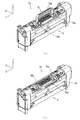
図3は、定着ユニット70の外観斜視図であり、同図(a)は、ハンドル75が、定着ユニット70の上部から上方に突き出た第1のポジションとしての操作位置にある状態を示し、同図(b)は、ハンドル75が、定着ユニット70の上部から手前に屈曲した第2のポジションとしての動作位置にある状態を示す。   FIG. 3 is an external perspective view of the fixing unit 70, and FIG. 3A shows a state where the handle 75 is in the operating position as a first position projecting upward from the top of the fixing unit 70. FIG. 6B shows the state where the handle 75 is in the operating position as the second position bent from the top of the fixing unit 70 to the front.

同図に示すように、定着ユニット70は、操作者が、ハンドル75の把持部75aに手をかけて持ち運びできるように構成されている。ハンドル75は、把持部75aとその両端部から略直角に互いに対向するように連設された一対の取り付け部が略コ字状に形成されて、その両端部が、定着ユニット70の上部に配設された保持部70a,70bによって回動自在に保持され、同図(a)に示す操作位置から同図(b)に示す動作位置まで略90度にわたって回動自在に構成されている。   As shown in the figure, the fixing unit 70 is configured such that the operator can carry the holding portion 75 a of the handle 75 with his / her hand. The handle 75 includes a grip 75a and a pair of attachment portions arranged in a row so as to face each other at substantially right angles from both ends thereof formed in a substantially U shape, and the both ends are disposed at the upper portion of the fixing unit 70. The holding portions 70a and 70b are rotatably held by the provided holding portions 70a and 70b, and are configured to be rotatable about 90 degrees from the operation position shown in FIG. 6A to the operation position shown in FIG.

ハンドル75が、同図(a)に示す操作位置にあるとき、その把持部75aが定着ユニット70本体の上部から上方に突き出た位置となり、図2(b)で説明したように、操作者は、この把持部75aに手をかけて、画像形成装置100内から引き出したり、装置外から装置内の所定の位置に装着したりすることが可能となる。   When the handle 75 is in the operation position shown in FIG. 2A, the gripping portion 75a protrudes upward from the upper portion of the fixing unit 70, as described with reference to FIG. It is possible to put a hand on the grip portion 75a and pull it out of the inside of the image forming apparatus 100 or attach it from the outside of the apparatus to a predetermined position in the apparatus.

一方、定着ユニット70が、図1に示す画像形成装置100内の所定の位置にあって、アッパーカバー4が閉じた閉位置にあるとき、定着ユニット70のハンドル75は、図3(b)に示す動作位置にあって、後述するように、少なくともその把持部75aが、断熱ダクト15の一部、例えばその上表面部に接するように構成されている。   On the other hand, when the fixing unit 70 is at a predetermined position in the image forming apparatus 100 shown in FIG. 1 and the upper cover 4 is in the closed position, the handle 75 of the fixing unit 70 is as shown in FIG. In the operation position shown, as will be described later, at least the holding portion 75a is configured to be in contact with a part of the heat insulation duct 15, for example, the upper surface thereof.

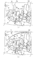
図4は、画像形成装置100内の所定位置に装着された定着ユニット70及びその周辺を部分拡大した部分拡大図であり、同図(a)は、アッパーカバー4が開位置にあって、定着ユニット70のハンドル75が操作位置にある状態を示し、同図(b)は、定着ユニット70のハンドル75が動作位置にあって、アッパーカバー4が閉位置にある状態を示す。   FIG. 4 is a partially enlarged view of the fixing unit 70 mounted at a predetermined position in the image forming apparatus 100 and the periphery thereof. FIG. 4A shows the fixing when the upper cover 4 is in the open position. The handle 75 of the unit 70 is in the operating position, and FIG. 7B shows the handle 75 of the fixing unit 70 in the operating position and the upper cover 4 in the closed position.

同図(a)は、画像形成装置100のアッパーカバー4が開位置(図2参照)にあって、操作者が、画像形成装置100本体から定着ユニット70を装着位置から外して装置外に引き出す時、或は装置外から定着ユニット70を装着位置に装着した時、等に相当し、ハンドル75が操作位置にあって、その把持部75aが定着ユニット70の上部から上方に突き出た状態を示している。   In FIG. 6A, the upper cover 4 of the image forming apparatus 100 is in the open position (see FIG. 2), and the operator removes the fixing unit 70 from the mounting position of the image forming apparatus 100 and pulls it out of the apparatus. When the fixing unit 70 is attached to the mounting position from the outside of the apparatus or the like, the handle 75 is at the operating position, and the gripping portion 75a protrudes upward from the upper portion of the fixing unit 70. ing.

同図(b)は、定着ユニット70が、画像形成装置100本体の装着位置に装着され、定着ユニット70のハンドル75が動作位置にあって、例えば画像形成装置100が印刷動作を実行している状態を示している。このとき、アッパーカバー4は閉位置にあり、ハンドル75の、少なくとも把持部75aを含む一部が、断熱ダクト15の上表面15aに当接し、ハンドル75の熱が、断熱ダクト15を介してダクト内を流通する外気に移ることができるように構成されている。   In FIG. 7B, the fixing unit 70 is mounted at the mounting position of the main body of the image forming apparatus 100, the handle 75 of the fixing unit 70 is in the operating position, and the image forming apparatus 100 is executing printing operation. It shows the state. At this time, the upper cover 4 is in the closed position, and at least a portion of the handle 75 including the grip portion 75a abuts on the upper surface 15a of the heat insulation duct 15, and the heat of the handle 75 is ducted through the heat insulation duct 15. It is configured to be able to transfer the outside air circulating inside.

以上のように、本実施の形態の画像形成装置100によれば、少なくとも画像形成装置100の印刷動作中、定着ユニット70のハンドル75が断熱ダクト15の表面に接しているので、定着ユニット70の熱源71aからハンドル75に伝わる熱を、内部に冷却用の外気が流通する断熱ダクト15へと逃がすことができるため、ハンドル75の把持部75aの温度上昇を抑制することができる。   As described above, according to the image forming apparatus 100 of the present embodiment, the handle 75 of the fixing unit 70 is in contact with the surface of the heat insulating duct 15 at least during the printing operation of the image forming apparatus 100. The heat transmitted from the heat source 71a to the handle 75 can be dissipated to the heat insulation duct 15 in which the outside air for cooling circulates, so that the temperature rise of the grip portion 75a of the handle 75 can be suppressed.

(変形例1)
図5は、実施の形態1の画像形成装置の変形例の要部構成を示す部分拡大図である。この変形例1の画像形成装置が前記した図1に示す画像形成装置100に対して異なる点は、断熱ダクト115(図1の画像形成装置100では断熱ダクト15)の構成である。
(Modification 1)
FIG. 5 is a partially enlarged view showing the main configuration of a modification of the image forming apparatus of the first embodiment. The image forming apparatus of the first modification differs from the image forming apparatus 100 shown in FIG. 1 described above in the configuration of the heat insulating duct 115 (the heat insulating duct 15 in the image forming apparatus 100 of FIG. 1).

図5は、変形例1において、画像形成装置の所定位置に装着された定着ユニット70及びその周辺を部分拡大した部分拡大図であり、同図(a)は、アッパーカバー4が開位置にあって、定着ユニット70のハンドル75が操作位置にある状態を示し、同図(b)は、定着ユニット70のハンドル75が動作位置にあって、アッパーカバー4が閉位置にある状態を示す。   FIG. 5 is a partially enlarged view of fixing unit 70 mounted at a predetermined position of the image forming apparatus and the periphery thereof in the first modification, and FIG. 5A shows that upper cover 4 is in the open position. 5B shows the state where the handle 75 of the fixing unit 70 is in the operating position, and FIG. 5B shows the state where the handle 75 of the fixing unit 70 is in the operating position and the upper cover 4 is in the closed position.

同図に示すように、ここでの断熱ダクト115は、その上面に開口115aが形成されている。この開口115aは、同図(b)に示すように、定着ユニット70のハンドル75が動作位置にあるとき、少なくともその把持部75aによって塞がれる形状を有するもので、このため、開口115aの周辺においても、ハンドル75が動作位置に収まるように形成されている。   As shown to the same figure, the opening 115a is formed in the upper surface of the heat insulation duct 115 here. The opening 115a has a shape that is closed by at least the gripping portion 75a when the handle 75 of the fixing unit 70 is in the operating position, as shown in FIG. Also in the case, the handle 75 is formed to fit in the operating position.

以上の構成により、ハンドル75の把持部75aは、直接、断熱ダクト115内を流通する外気に触れることになる。   According to the above configuration, the grip portion 75 a of the handle 75 is in direct contact with the outside air flowing in the heat insulation duct 115.

従って、変形例の画像形成装置によれば、少なくとも画像形成装置100の印刷動作中、定着ユニット70のハンドル75が断熱ダクト115の内部を流通する空気に直接触れて熱を逃がすことができるため、ハンドル75の把持部75aの温度上昇をより効率的に抑制することができる。   Therefore, according to the image forming apparatus of the modification, since the handle 75 of the fixing unit 70 can directly touch the air flowing through the inside of the heat insulating duct 115 at least during the printing operation of the image forming apparatus 100, the heat can be dissipated. The temperature rise of the grip portion 75a of the handle 75 can be suppressed more efficiently.

実施の形態2.
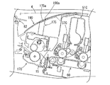
図6は、本発明に基づく実施の形態2の画像形成装置の定着ユニット170及びその周辺部の構成を示す部分拡大図である。
Second Embodiment
FIG. 6 is a partially enlarged view showing the configuration of the fixing unit 170 and its peripheral portion of the image forming apparatus of Embodiment 2 based on the present invention.

この画像形成装置の構成が、前記した図1に示す実施の形態1の画像形成装置100の構成と主に異なる点は、定着ユニット170(実施の形態1では定着ユニット70)のハンドル175(実施の形態1ではハンドル75)の構成と、排出トレイ190(実施の形態1では排出トレイ90)の一部形状である。   The configuration of this image forming apparatus is mainly different from the configuration of the image forming apparatus 100 of the first embodiment shown in FIG. 1 described above in that the handle 175 (embodiment of the fixing unit 70 in the first embodiment) is implemented. In the first embodiment, the configuration of the handle 75) and the partial shape of the discharge tray 190 (in the first embodiment, the discharge tray 90).

従って、この定着ユニット170を有する画像形成装置が、前記した実施の形態1の画像形成装置100と共通する部分には同符号を付して、或いは図面を省いて説明を省略し、異なる点を重点的に説明する。尚、本実施の形態の画像形成装置の構成は、定着ユニット170の構成、及び排出トレイ190の一部形状を除いて、図1に示す実施の形態1の画像形成装置100の要部構成と共通するため、必要に応じて図1を参照する。   Therefore, in the image forming apparatus having the fixing unit 170, the same parts as those of the image forming apparatus 100 of the first embodiment described above are denoted by the same reference numerals, or the drawings are omitted to omit the description. Emphasize. The configuration of the image forming apparatus of the present embodiment is the main configuration of the image forming apparatus 100 of the first embodiment shown in FIG. 1 except for the configuration of the fixing unit 170 and the partial shape of the discharge tray 190. As it is common, refer to FIG. 1 as needed.

図6は、本実施の形態における画像形成装置内の所定位置に装着された定着ユニット170及びその周辺を部分拡大した部分拡大図である。   FIG. 6 is a partially enlarged view of the fixing unit 170 mounted at a predetermined position in the image forming apparatus according to the present embodiment and the periphery thereof.

同図に示すように、ここでの定着ユニット170は、その上部に、一体的に固定配置されたハンドル175を備える。このハンドル175は、図3に示す実施の形態1のハンドル75と同様に略コ字状に形成され、定着ユニット170の上部から植立するように固定配置され、その把持部175aの上表面が、植立方向に対して傾斜した傾斜面となっている。   As shown in the figure, the fixing unit 170 here is provided with a handle 175 integrally fixedly disposed on the top thereof. The handle 175 is formed substantially in a U-shape similar to the handle 75 of the first embodiment shown in FIG. 3 and fixedly arranged to be erected from the upper portion of the fixing unit 170, and the upper surface of the grip portion 175a is , It is an inclined surface inclined to the planting direction.

一方、排出トレイ190には、図6に示すように開口部としての開口190aが形成され、アッパーカバー4が閉じた状態の閉位置にあるとき、その開口190aにハンドル175の把持部175aが嵌入し、且つ排出トレイ190の載置面と把持部175aの傾斜面とが面一となるように、開口190aの位置、形状、及び把持部175aの傾斜面が形成されている。   On the other hand, the discharge tray 190 is formed with an opening 190a as an opening as shown in FIG. 6, and the grip portion 175a of the handle 175 is fitted into the opening 190a when the upper cover 4 is in the closed position. The position, the shape, and the inclined surface of the gripping portion 175a are formed such that the placement surface of the discharge tray 190 and the inclined surface of the gripping portion 175a are flush with each other.

従って、定着ユニット170のハンドル175は、把持部175aの上表面が、画像形成装置の外部に直接晒されるため、ハンドル175の熱が、把持部175aの上表面を介して装置外に移ることができるように構成されている。   Therefore, since the upper surface of the grip portion 175a is directly exposed to the outside of the image forming apparatus, the heat of the handle 175 can be transferred out of the apparatus through the upper surface of the grip portion 175a. It is configured to be able to.

尚、本実施の形態では、排出トレイ190の載置面と把持部175aの傾斜面とが面一となるように形成したが、これに限定されるものではなく、例えば、把持部175aの上表面が、開口190aに嵌入するまでもなく、開口190aを介して外部に露出するように構成しても良いなど種々の態様を取り得るものである。   In the present embodiment, the placement surface of the discharge tray 190 and the inclined surface of the gripping portion 175a are formed to be flush with each other. However, the present invention is not limited to this. Various aspects can be taken such that the surface may be configured to be exposed to the outside through the opening 190a without being inserted into the opening 190a.

以上のように、本実施の形態の画像形成装置によれば、少なくとも画像形成装置100の印刷動作中、定着ユニット170のハンドル175の把持部175aの上表面が、装置外に晒されるため、定着ユニット170の熱源71aからハンドル175に伝わる熱を、装置外へと放出することができるため、ハンドル175の把持部175aの温度上昇を抑制することができる。   As described above, according to the image forming apparatus of the present embodiment, since the upper surface of the grip portion 175a of the handle 175 of the fixing unit 170 is exposed to the outside of the apparatus, at least during the printing operation of the image forming apparatus 100. The heat transmitted from the heat source 71 a of the unit 170 to the handle 175 can be released to the outside of the device, so that the temperature rise of the grip portion 175 a of the handle 175 can be suppressed.

実施の形態3.
図7は、本発明に基づく実施の形態3の画像形成装置200の要部構成を示す要部構成図である。
Third Embodiment
FIG. 7 is a main configuration diagram showing the main configuration of an image forming apparatus 200 according to a third embodiment of the present invention.

この画像形成装置200の構成が、前記した図1に示す実施の形態1の画像形成装置100の構成と主に異なる点は、定着ユニット270(実施の形態1では定着ユニット70)のハンドル275(実施の形態1ではハンドル75)の構成と、冷却ユニット250が追加された点である。従って、この画像形成装置200が、前記した実施の形態1の画像形成装置100と共通する部分には同符号を付して、或いは図面を省いて説明を省略し、異なる点を重点的に説明する。   The main difference between the configuration of the image forming apparatus 200 and the configuration of the image forming apparatus 100 according to the first embodiment shown in FIG. 1 is the handle 275 (fusing unit 70 in the first embodiment). In the first embodiment, the configuration of the handle 75) and the point that the cooling unit 250 is added. Therefore, parts in common with image forming apparatus 100 in the first embodiment described above are denoted by the same reference numerals, or the drawings are omitted and the description is omitted, and different points are mainly described. Do.

図7に示すように、本実施の形態の画像形成装置200においては、定着ユニット270のハンドル275が、定着ユニット本体に固定的に配設され、冷却ユニット250が、保持部材201によってアッパーカバー4に固定的に配設され、アッパーカバー4が閉じた閉位置にあるとき、後述するように、冷却ユニット250の通風カバー250b(図9参照)が定着ユニット270のハンドル275の所定部を覆うように構成されている。また、画像形成装置200は、装置全体を駆動制御する駆動制御部95を備え、定着ユニット270の所定部、ここでは定着ベルト71bの左右の非通紙部76,77(図13参照)の温度を検出し、温度情報を駆動制御部95に送信する温度検知部としての温度検知器271を備える。   As shown in FIG. 7, in the image forming apparatus 200 of the present embodiment, the handle 275 of the fixing unit 270 is fixedly disposed on the fixing unit main body, and the cooling unit 250 is the upper cover 4 by the holding member 201. When the upper cover 4 is in the closed position, the ventilation cover 250b (see FIG. 9) of the cooling unit 250 covers a predetermined portion of the handle 275 of the fixing unit 270 when the upper cover 4 is in the closed position. Is configured. The image forming apparatus 200 further includes a drive control unit 95 that drives and controls the entire apparatus, and the temperature of a predetermined portion of the fixing unit 270, here, the temperature of the non-sheet-passing portions 76 and 77 (see FIG. 13) of the fixing belt 71b. And a temperature detector 271 as a temperature detection unit that transmits temperature information to the drive control unit 95.

図8は、実施の形態3の定着ユニット270の外観斜視図である。   FIG. 8 is an external perspective view of the fixing unit 270 of the third embodiment.

同図に示すように、定着ユニット270は、操作者が、ハンドル275の把持部275aに手をかけて持ち運びできるように構成されている。ハンドル275は、略コ字状に形成されて、その両端部が、定着ユニット270本体の上部に固定され、定着ユニット270本体と一体的に形成されている。   As shown in the figure, the fixing unit 270 is configured to be carried by the operator with his hand on the grip portion 275 a of the handle 275. The handle 275 is formed substantially in a U-shape, and both ends thereof are fixed to the upper portion of the fixing unit 270 main body, and are integrally formed with the fixing unit 270 main body.

固定されたハンドル275の両端部の左右近傍には、左右一対の通風孔210,211が形成されている。左通風孔210及び右通風孔211は、後で詳しく説明するが、それぞれが定着ユニット270内部の所定位置まで延在する冷却ダクトに繋がっている。   A pair of left and right ventilation holes 210 and 211 are formed in the vicinity of the left and right of both ends of the fixed handle 275. The left vent hole 210 and the right vent hole 211 are respectively connected to cooling ducts extending to a predetermined position inside the fixing unit 270, which will be described in detail later.

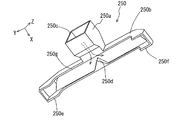
図9は、定着ユニット270と定着ユニット270に係合する冷却ユニット250とを示す外観斜視図である。この状態は、図7に示すように画像形成装置200のアッパーカバー4が閉じた閉位置にあるときの定着ユニット270と冷却ユニット250との位置関係に相当し、それぞれが単体で示されている。   FIG. 9 is an external perspective view showing the fixing unit 270 and the cooling unit 250 engaged with the fixing unit 270. As shown in FIG. This state corresponds to the positional relationship between the fixing unit 270 and the cooling unit 250 when the upper cover 4 of the image forming apparatus 200 is in the closed position, as shown in FIG. .

同図に示すように、冷却ユニット250は、定着ユニット270の長手方向(Y軸方向)に延在するハンドル275の所定部を覆う通風カバー部としての通風カバー250bと、冷却ユニット250の中央部に位置し、開口部250cに、通風カバー250b内部に冷却風を送り込むファンモータ251が固定された送風カバー部250aを備えている。尚、送風カバー部250a、開口部250c、及びファンモータ251が送風部に相当する。   As shown in the figure, the cooling unit 250 includes a ventilation cover 250 b as a ventilation cover that covers a predetermined portion of the handle 275 extending in the longitudinal direction (Y-axis direction) of the fixing unit 270, and a central portion of the cooling unit 250. In the opening 250c, there is provided a blower cover portion 250a to which a fan motor 251 for feeding cooling air into the ventilation cover 250b is fixed. The blower cover 250a, the opening 250c, and the fan motor 251 correspond to the blower.

図10は、冷却ユニット250を斜め下方からみた外観斜視図である。但し、図10において、開口部250cに取り付けられるファンモータ251は省かれている。   FIG. 10 is an external perspective view of the cooling unit 250 as viewed obliquely from below. However, in FIG. 10, the fan motor 251 attached to the opening 250c is omitted.

同図に示すように、開口部250cは、通風カバー250bの内部に通じており、通風カバー250bの内部の、開口部250cに対向する内部壁には、楔状の分離突起250dが形成されている。通風カバー250bの底面は、略コ字状に形成されたハンドル275(図8参照)の外側表面275bの幅方向(略X軸方向)における両端部と当接するように形成されたハンドル当接部250gと、定着ユニット270の左通風孔210を覆うようにその周辺部と当接するように形成された左側当接部250eと、定着ユニット270の右通風孔211を覆うようにその周辺部と当接するように形成された右側当接部250fとからなり、これらが連続する曲面となっている。   As shown in the figure, the opening 250c communicates with the inside of the ventilation cover 250b, and the inside wall of the ventilation cover 250b is formed with a hook-like separation projection 250d on the inner wall facing the opening 250c. . The bottom surface of the ventilation cover 250b is a handle abutment portion formed to abut on both ends in the width direction (substantially X axis direction) of the outer surface 275b of the substantially U-shaped handle 275 (see FIG. 8) 250 g, a left contact portion 250 e formed to abut the peripheral portion of the fixing unit 270 so as to cover the left vent hole 210, and a peripheral portion of the fixing portion 270 so as to cover the right vent hole 211. It consists of the right side contact part 250f formed so that it may touch, and these become a continuous curved surface.

従って、通風カバー250bは、画像形成装置200のアッパーカバー4が閉じた閉位置にあるとき、図9に示すように、ハンドル275の外側表面275b(図8参照)とによって、開口部250cが、定着ユニット270の左右の通風孔210,211に通じる通風ダクト230(図12参照)を形成する。   Therefore, when the upper cover 4 of the image forming apparatus 200 is in the closed position, the ventilating cover 250b has an opening 250c formed by the outer surface 275b (see FIG. 8) of the handle 275, as shown in FIG. Ventilation ducts 230 (see FIG. 12) communicating with the left and right ventilation holes 210 and 211 of the fixing unit 270 are formed.

従って、ファンモータ251によって開口部250cから送り込まれる冷却風は、通風ダクト230内において、図10に示すように分離突起250dによって左右に振り分けられ、ハンドル275の外側表面275bに接しながら左右の通風孔210,211(図8参照)に流れ込む。   Therefore, the cooling air sent from the opening 250c by the fan motor 251 is distributed to the left and right by the separation protrusion 250d in the ventilation duct 230 as shown in FIG. 10, and the left and right ventilation holes are in contact with the outer surface 275b of the handle 275. Flows into 210 and 211 (see FIG. 8).

図11は、図9に示すように通風ダクト230(図12参照)を形成する定着ユニット270及び冷却ユニット250の右側面図であり、図12は、図11に示すA−A断面図である。但し、冷却ユニット250とハンドル275が存在する領域のみを示す。   FIG. 11 is a right side view of the fixing unit 270 and the cooling unit 250 forming the ventilation duct 230 (see FIG. 12) as shown in FIG. 9, and FIG. 12 is a sectional view taken on line A-A shown in FIG. . However, only the area where the cooling unit 250 and the handle 275 exist is shown.

図12に示すように、ハンドル275の外側表面275bと冷却ユニット250の通風カバー250bとによって通風ダクト230が形成され、この通風ダクト230が左右の通風孔210,211まで延在している。   As shown in FIG. 12, a ventilation duct 230 is formed by the outer surface 275b of the handle 275 and the ventilation cover 250b of the cooling unit 250, and the ventilation duct 230 extends to the left and right ventilation holes 210 and 211.

図13は、通風カバー250bとハンドル275の外側表面275b(図8参照)とによって通風ダクト230が形成されている状態で、冷却ユニット250のファンモータ251によって通風ダクト230に送り込まれる冷却風の流路を概略的に示す概略説明図である。   FIG. 13 shows the flow of the cooling air fed to the ventilation duct 230 by the fan motor 251 of the cooling unit 250 in a state where the ventilation duct 230 is formed by the ventilation cover 250 b and the outer surface 275 b of the handle 275 (see FIG. 8). It is a schematic explanatory drawing which shows a path roughly.

同図に示すように、定着ユニット270内において、左通風孔210から、定着ベルト71bの左端部であって記録用紙の通過領域外に相当する左非通紙部76の近傍に位置する左排出部212まで、左ダクト220が形成され、同様に、右通風孔211から、定着ベルト71bの右端部であって記録用紙の通過領域外に相当する右非通紙部77の近傍に位置する右排出部213まで、右ダクト221が形成されている。   As shown in the figure, in the fixing unit 270, the left discharge located at the left end portion of the fixing belt 71b from the left ventilation hole 210 and in the vicinity of the left non-sheet passing portion 76 corresponding to the outside of the recording sheet passing area. The left duct 220 is formed up to the portion 212. Similarly, the right duct located at the right end portion of the fixing belt 71b from the right ventilation hole 211 and in the vicinity of the right non-sheet passing portion 77 corresponding to the outside of the recording sheet passing area The right duct 221 is formed up to the discharge portion 213.

以上の構成において、ファンモータ251によって通風ダクト230内に送り込まれた冷却風は、分離突起250d(図12)によって左右に振り分けられハンドル275の外側表面275bに接しながら通風ダクト230内を進み、やがて左右の通風孔210,211を介して左右のダクト220,221に流入する。   In the above configuration, the cooling air sent into the ventilation duct 230 by the fan motor 251 is distributed to the left and right by the separation projection 250 d (FIG. 12) and travels in the ventilation duct 230 while in contact with the outer surface 275 b of the handle 275. The air flows into the left and right ducts 220 and 221 through the left and right ventilation holes 210 and 211.

左ダクト220に入った冷却風は、同ダクト内を進んで左排出部212に至り、左排出部212から定着ベルト71bの左非通紙部76に向けて排出される。同様に、右ダクト221に入った冷却風は、同ダクト内を進んで右排出部213に至り、右排出部213から定着ベルト71bの右非通紙部77に向けて排出される。   The cooling air that has entered the left duct 220 travels in the duct and reaches the left discharge portion 212, and is discharged from the left discharge portion 212 toward the left non-sheet-passing portion 76 of the fixing belt 71b. Similarly, the cooling air that has entered the right duct 221 travels in the duct and reaches the right discharge portion 213, and is discharged from the right discharge portion 213 toward the right non-sheet passing portion 77 of the fixing belt 71b.

図14、図15は、画像形成装置200のアッパーカバー4に配設された冷却ユニット250と、図7に示すように画像形成装置200内に配置された定着ユニット270との係合関係を概略的に示す動作説明図であり、図14は、アッパーカバー4が閉じた閉位置にある状態に対応し、図15は、アッパーカバー4が、定着ユニット270と冷却ユニット250とが離間する位置まで、開位置(図2参照)に向かって開いた状態に対応している。尚、図14、図15は、図7とは反対側から見た図となっている。   14 and 15 schematically show the engagement relationship between the cooling unit 250 disposed on the upper cover 4 of the image forming apparatus 200 and the fixing unit 270 disposed in the image forming apparatus 200 as shown in FIG. 7. FIG. 14 corresponds to a state where the upper cover 4 is in the closed position, and FIG. 15 shows the upper cover 4 up to the position where the fixing unit 270 and the cooling unit 250 are separated. , Corresponding to the open state towards the open position (see FIG. 2). 14 and 15 are views as viewed from the opposite side to FIG.

図14に示すように、アッパーカバー4は、排出ローラ対82(図7)の近傍に設けられてY軸方向に延在する回動軸25回りに回動自在に保持されており、このアッパーカバー4には、冷却ユニット250が備えられている。アッパーカバー4が同図に示すように閉じた閉位置にあるとき、冷却ユニット250と定着ユニット270のハンドル275が係合関係となる。ここでの係合関係とは、前記した図9から図13で説明したように、冷却ユニット250の通風カバー250b(図9参照)とハンドル275の外側表面275b(図8参照)とによって通風ダクト230〈図12参照〉が形成されている状態をいう。   As shown in FIG. 14, the upper cover 4 is rotatably held around a pivot shaft 25 provided in the vicinity of the discharge roller pair 82 (FIG. 7) and extending in the Y-axis direction. The cover 4 is provided with a cooling unit 250. When the upper cover 4 is in the closed closed position as shown in the figure, the cooling unit 250 and the handle 275 of the fixing unit 270 are in an engaged relationship. The engagement relationship here is the ventilation duct by the ventilation cover 250b (refer to FIG. 9) of the cooling unit 250 and the outer surface 275b (refer to FIG. 8) of the handle 275 as described with reference to FIGS. The state 230 (see FIG. 12) is formed.

一方、アッパーカバー4が、図2に示す開位置まで開く間に、図15に示すように冷却ユニット250と定着ユニット270とが離間し、更に図2に示す開位置に至った段階で定着ユニット270のハンドル275が完全に露出し、冷却ユニット250が、定着ユニット270の着脱操作を妨げない位置まで退避するように構成されている。   On the other hand, while the upper cover 4 is opened to the open position shown in FIG. 2, the cooling unit 250 and the fixing unit 270 are separated as shown in FIG. 15, and the fixing unit is reached at the stage shown in FIG. The handle 275 of 270 is completely exposed, and the cooling unit 250 is configured to be retracted to a position that does not interfere with the attaching and detaching operation of the fixing unit 270.

以上の構成において、駆動制御部95(図7)は、印刷動作中に、温度検知器271が検出する定着ベルト71bの左右の非通紙部76,77の温度を監視し、所定値以上の温度になるとファンモータ251を作動させて冷却風を通風ダクト230内に送り込む。ファンモータ251によって通風ダクト230内に送り込まれた冷却風は、図13を参照して説明したように、ハンドル275の外側表面275bに接してこれを冷却しながら定着ユニット270内の左右のダクト220,221(図13)に流入し、左排出部212から定着ベルト71bの左非通紙部76に向け、また右排出部213から定着ベルト71bの右非通紙部77に向けて、それぞれ排出され、左右の非通紙部76,77を冷却する。   In the above configuration, the drive control unit 95 (FIG. 7) monitors the temperatures of the left and right non-sheet-passing portions 76 and 77 of the fixing belt 71b detected by the temperature detector 271 during printing operation. When the temperature is reached, the fan motor 251 is operated to feed the cooling air into the ventilation duct 230. The cooling air fed into the ventilation duct 230 by the fan motor 251 contacts the outer surface 275 b of the handle 275 to cool the left and right ducts 220 in the fixing unit 270 as described with reference to FIG. 13. , 221 (FIG. 13) from the left discharge portion 212 to the left non-sheet-passing portion 76 of the fixing belt 71b, and from the right discharge portion 213 to the right non-sheet-passing portion 77 of the fixing belt 71b. And cool the left and right non-sheet-passing portions 76, 77.

その後、駆動制御部95(図7)は、左右の非通紙部76,77(図13)の温度が所定値以下の温度まで低下したのを検知するとファンモータ251の作動を停止する。印刷中、以上の駆動制御が継続されることにより、ファンモータ251は、動作・停止を繰り返す。   Thereafter, the drive control unit 95 (FIG. 7) stops the operation of the fan motor 251 when detecting that the temperature of the left and right non-sheet-passing portions 76 and 77 (FIG. 13) has dropped to a predetermined temperature or less. By continuing the above-described drive control during printing, the fan motor 251 repeats operation and stop.

尚、本実施の形態では、冷却ユニット250のハンドル当接部250g(図10)が、定着ユニット270のハンドル275〈図8〉の外側表面275bの両側端部と当接することで通風ダクト230(図12)を形成するように説明したが、これに限定されるものではなく、定着ユニット270の通風カバー250bがハンドル275を覆うように形成しても良いなど、種々の態様を取り得るものである。   In the present embodiment, the handle contact portion 250g (FIG. 10) of the cooling unit 250 abuts on both end portions of the outer surface 275b of the handle 275 of the fixing unit 270 (FIG. 8). Although FIG. 12 is described to form, the invention is not limited to this, and various aspects may be taken such that the ventilation cover 250b of the fixing unit 270 may be formed to cover the handle 275. is there.

以上のように、本実施の形態の画像形成装置200によれば、ファンモータ251が作動するたびに、通風ダクト230を流れる冷却風によって定着ユニット270のハンドル275が冷却されるため、ハンドル275の把持部275aの温度上昇を抑制することができる。   As described above, according to the image forming apparatus 200 of the present embodiment, the handle 275 of the fixing unit 270 is cooled by the cooling air flowing through the ventilation duct 230 each time the fan motor 251 operates. The temperature rise of the grip portion 275a can be suppressed.

また、定着ユニット270本体に固定したハンドル275の外側表面275bを、通風ダクト230の一壁面として利用する構成のため、ハンドル形状が特定されることなく剛性の高い構造とすることができる。更に、冷却ユニット250がアッパーカバー4に取り付けられ、アッパーカバー4の回動に伴って一体的に変位するため、余計な操作をすることなく定着ユニット270の着脱作業を実行することが可能となる。   In addition, since the outer surface 275 b of the handle 275 fixed to the fixing unit 270 main body is used as one wall surface of the ventilation duct 230, the handle can have a highly rigid structure without being identified. Furthermore, since the cooling unit 250 is attached to the upper cover 4 and is integrally displaced with the rotation of the upper cover 4, the fixing unit 270 can be attached and detached without unnecessary operations. .

実施の形態4.
図16は、本発明に基づく実施の形態4の画像形成装置に採用される定着ユニット270と冷却ユニット350とを示す外観斜視図であり、図17は、定着ユニット270及び冷却ユニット350を、図16に対して異なる角度から見た外観斜視図である。
Fourth Embodiment
FIG. 16 is an external perspective view showing a fixing unit 270 and a cooling unit 350 employed in the image forming apparatus according to the fourth embodiment of the present invention, and FIG. 17 shows the fixing unit 270 and the cooling unit 350. It is the external appearance perspective view seen from a different angle with respect to 16.

この冷却ユニット350を採用する画像形成装置の構成が、前記した図7に示す実施の形態3の画像形成装置200の構成と主に異なる点は、冷却ユニット350(実施の形態3では冷却ユニット250)の構成において、シャッター部材302とこれを駆動するソレノイド301が追加され、これに伴って、通風カバー350bの形状が、実施の形態3の通風カバー250bに対して一部変更された点である。従って、この画像形成装置が、前記した実施の形態3の画像形成装置200と共通する部分には同符号を付して、或いは図面を省いて説明を省略し、異なる点を重点的に説明する。   The configuration of the image forming apparatus employing cooling unit 350 is mainly different from the configuration of image forming apparatus 200 of the third embodiment shown in FIG. 7 described above in the cooling unit 350 (cooling unit 250 in the third embodiment). In the configuration of the third embodiment, the shutter member 302 and the solenoid 301 for driving the shutter member 302 are added, and the shape of the ventilation cover 350b is partially changed with respect to the ventilation cover 250b of the third embodiment. . Therefore, in this image forming apparatus, parts common to those of the image forming apparatus 200 of the third embodiment described above are given the same reference numerals, or the drawings are omitted and the description is omitted, and different points are mainly described. .

本実施の形態における冷却ユニット350は、その送風カバー部350aの下部に固定配備された動力部としてのソレノイド301と、ソレノイド301によってスライド駆動されるシャッター部材302とを備える。シャッター部材302は、左シャッター部302a、右シャッター部302b、及びこれらの間に介在してこれらと一体に形成された支持部とを有する。   Cooling unit 350 in the present embodiment is provided with a solenoid 301 as a power unit fixedly disposed at the lower part of air blowing cover portion 350a, and a shutter member 302 slide-driven by solenoid 301. The shutter member 302 has a left shutter portion 302a, a right shutter portion 302b, and a support portion interposed therebetween and integrally formed therewith.

シャッター部材302は、少なくとも、画像形成装置のアッパーカバー4が閉じて、図16に示すように、通風ダクト230(図12参照)を形成する段階で、左シャッター部302aが、定着ユニット270の左通風孔210(図8)と通風カバー350bの左側当接部(図10の250eに相当)との間に介在し、右シャッター部302bが、定着ユニット270の右通風孔211(図8)と通風カバー350bの右側当接部(図10の250fに相当)との間に介在し、更に図16に示す矢印C,D方向(略X軸方向)にスライド可能に保持されている。   In the shutter member 302, at least the upper cover 4 of the image forming apparatus is closed to form the ventilation duct 230 (see FIG. 12) as shown in FIG. The right shutter portion 302b is interposed between the ventilation hole 210 (FIG. 8) and the left contact portion (corresponding to 250e in FIG. 10) of the ventilation cover 350b, and the right ventilation hole 211 (FIG. 8) of the fixing unit 270. It is interposed between the ventilation cover 350b and the right contact portion (corresponding to 250f in FIG. 10), and is further slidably held in the directions of arrows C and D shown in FIG. 16 (substantially in the X-axis direction).

ソレノイド301は、そのシャフト301aが、シャッター部材302の支持部の中央と連結し、駆動制御部95(図7)によってオン・オフ駆動制御される。シャッター部材302は、ソレノイド301のオン動作によって矢印D方向に引き寄せられ、ソレノイド301のオフ時には図示しない付勢部材によって矢印C方向に移動される。   The shaft 301a of the solenoid 301 is connected to the center of the support of the shutter member 302, and the drive control unit 95 (FIG. 7) performs on / off drive control. The shutter member 302 is drawn in the direction of arrow D when the solenoid 301 is turned on, and is moved in the direction of arrow C by a biasing member (not shown) when the solenoid 301 is off.

図18、図19は、図16における一点鎖線400で囲まれた部分の部分拡大図であり、図18は、シャッター部材302が矢印C方向に移動したときの状態を示し、図19は、シャッター部材302が矢印D方向に移動したときの状態を示す。尚、図18、図19において通風カバー350bは、その内部を示すために手前側半部を除いた状態で描かれている。   18 and 19 are partial enlarged views of a portion surrounded by an alternate long and short dash line 400 in FIG. 16, and FIG. 18 shows a state when the shutter member 302 moves in the arrow C direction. The state when the member 302 moves in the direction of the arrow D is shown. In FIG. 18 and FIG. 19, the ventilation cover 350 b is drawn with the front half removed to show the inside.

図18に示すように、左シャッター部302aは、平板状に形成され、その一部には開口303が形成され、矢印C方向端部には壁面304が配設されている。一方、図19に示すように、通風カバー350bの、壁面304と対向する壁部には、排出口350hが形成されている。   As shown in FIG. 18, the left shutter portion 302a is formed in a flat plate shape, an opening 303 is formed in a part of the left shutter portion 302a, and a wall surface 304 is disposed at an end in the arrow C direction. On the other hand, as shown in FIG. 19, a discharge port 350h is formed in a wall portion of the ventilation cover 350b facing the wall surface 304.

図18に示すように、ソレノイド301がオフになってシャッター部材302が矢印C方向に移動するときには、その壁面304が、通風カバー350bの排出口350hが形成された壁面に圧接し、排出口350hを塞ぐと同時に同方向への移動が規制され、この段階で、開口303が定着ユニット270の左通風孔210(図8)と重なる位置となる。   As shown in FIG. 18, when the solenoid 301 is turned off and the shutter member 302 moves in the direction of arrow C, the wall surface 304 is in pressure contact with the wall surface on which the outlet 350h of the ventilation cover 350b is formed. At the same time, movement in the same direction is restricted, and at this stage, the opening 303 is positioned so as to overlap the left vent hole 210 (FIG. 8) of the fixing unit 270.

従って、ファンモータ251によって通風ダクト230(図12参照)内に送り込まれた冷却風は、同図に矢印で示すように開口303及び左通風孔210(図8)を介して、定着ユニット270内の左ダクト220(図13)に送り込まれる。尚、左シャッター部302aと右シャッター部302bとは左右対称に構成されているため、右側においても、冷却風が同様にして定着ユニット270内の右ダクト221(図13)に送り込まれる。   Accordingly, the cooling air sent into the air flow duct 230 (see FIG. 12) by the fan motor 251 passes through the opening 303 and the left air vent 210 (FIG. 8) inside the fixing unit 270 as shown by the arrows in FIG. Is fed into the left duct 220 (FIG. 13). Since the left shutter portion 302a and the right shutter portion 302b are configured to be symmetrical in the left-right direction, the cooling air is also sent to the right duct 221 (FIG. 13) in the fixing unit 270 on the right side as well.

一方、図19に示すように、ソレノイド301がオンになってシャッター部材302が矢印D方向に移動するときには、その壁面304が、通風カバー350bの排出口350hから離間し、開口303が定着ユニット270の左通風孔210(図8)とずれた位置に移動して停止する。   On the other hand, as shown in FIG. 19, when the solenoid 301 is turned on and the shutter member 302 moves in the direction of arrow D, the wall surface 304 is separated from the outlet 350h of the ventilation cover 350b, and the opening 303 is the fixing unit 270. It moves to the position shifted from the left vent hole 210 (FIG. 8) and stops.

従って、ファンモータ251によって通風ダクト230(図12参照)内に送り込まれた冷却風は、定着ユニット270内には入り込まず、同図に矢印で示すように通風カバー350bの排出口350hから装置後方へ抜けていく。尚、通風カバー350bの、右側の右シャッター部302bの壁面(図示せず)に対向する位置にも排出口(図示せず)が形成されているため、右側においても、冷却風が同様にして通風カバー350bの排出口から装置後方へ抜けていく。   Accordingly, the cooling air sent into the ventilation duct 230 (see FIG. 12) by the fan motor 251 does not enter into the fixing unit 270, and as shown by the arrow in the figure, from the outlet 350h of the ventilation cover 350b Go through. In addition, since the discharge port (not shown) is also formed at a position facing the wall surface (not shown) of the right shutter portion 302b on the right side of the ventilation cover 350b, the cooling air is also the same on the right side. The air passes from the outlet of the ventilation cover 350b to the rear of the device.

以上の構成において、駆動制御部95(図7)は、印刷開始と同時にファンモータ251を作動させ、温度検知部としての温度検知器271が検出する定着ベルト11の左右の非通紙部76,77(図13)の温度を監視し、所定値以上の温度になるとソレノイド301をオフにして冷却風を定着ユニット270内に送り込む。定着ユニット270内に送り込まれた冷却風は、図18に示すように、定着ユニット270内の左右のダクト220,221(図13)に流入し、左排出部212から定着ベルト71bの左非通紙部76に向け、また右排出部213から定着ベルト71bの右非通紙部77に向けて、それぞれ排出され、左右の非通紙部76,77を冷却する。   In the above configuration, the drive control unit 95 (FIG. 7) operates the fan motor 251 simultaneously with the start of printing, and the left and right non-sheet-passing portions 76 of the fixing belt 11 detected by the temperature detector 271 as a temperature detection unit The temperature of 77 (FIG. 13) is monitored, and when the temperature exceeds a predetermined value, the solenoid 301 is turned off and cooling air is sent into the fixing unit 270. The cooling air sent into the fixing unit 270 flows into the left and right ducts 220 and 221 (FIG. 13) in the fixing unit 270 as shown in FIG. The sheet is discharged toward the paper portion 76 and from the right discharge portion 213 to the right non-sheet-passing portion 77 of the fixing belt 71b, thereby cooling the left and right non-sheet-passing portions 76, 77.

その後、駆動制御部95(図7)は、左右の非通紙部76,77(図13)の温度が所定値以下の温度まで低下したのを検知するとソレノイド301をオンにし、図19に示すように、冷却風を定着ユニット270内に送り込むことなく、通風カバー350bの排出口350hから外部に排出する。   Thereafter, the drive control unit 95 (FIG. 7) turns on the solenoid 301 when it detects that the temperature of the left and right non-sheet-passing portions 76 and 77 (FIG. 13) has fallen to a predetermined temperature or less. Thus, the cooling air is discharged to the outside from the discharge port 350 h of the ventilation cover 350 b without feeding the cooling air into the fixing unit 270.

印刷中、以上の駆動制御が継続されることにより、ファンモータ251は動作したまま、ソレノイド301が、オン・オフを繰り返して定着ユニット270内の温度を調節する。   During printing, the above drive control is continued, so that the solenoid 301 repeatedly turns on and off to adjust the temperature in the fixing unit 270 while the fan motor 251 is operating.

以上のように、本実施の形態の画像形成装置によれば、定着ユニット270の温度にかかわらず、印刷動作中、常時通風ダクト230を流れる冷却風によって定着ユニット270のハンドル275が冷却されるため、安定してハンドル275の把持部275aの温度上昇を抑制することができる。   As described above, according to the image forming apparatus of the present embodiment, the handle 275 of the fixing unit 270 is cooled by the cooling air constantly flowing through the ventilation duct 230 during the printing operation regardless of the temperature of the fixing unit 270. Thus, the temperature rise of the grip portion 275a of the handle 275 can be stably suppressed.

また、実施の形態の説明において、「上」、「下」、「左」、「右」、「前」、「後」といった言葉を使用したが、これらは便宜上であって、画像形成装置を配置する状態における絶対的な位置関係を限定するものではない。   Further, in the description of the embodiment, words such as “upper”, “lower”, “left”, “right”, “front”, and “rear” are used, but these are for convenience and the image forming apparatus It does not limit the absolute positional relationship in the state of arrangement.

本実施の形態では、画像形成装置としてプリンタを例に説明したが、カラープリンタの他、複写機、FAX、或いはこれらの装置の機能を複合させたMFP(Multi Function Peripheral)等の画像形成装置についても有用である。また、画像形成装置として複数の現像ユニットを備えたタンデム型カラープリンタを例に説明したが、1つの現像ユニットによるモノクロの画像形成装置についても有用である。   In the present embodiment, a printer has been described as an example of an image forming apparatus, but in addition to a color printer, an image forming apparatus such as a copier, a fax machine or an MFP (Multi Function Peripheral) combining functions of these apparatuses Is also useful. Further, although a tandem type color printer having a plurality of developing units has been described as an example of the image forming apparatus, a monochrome image forming apparatus using one developing unit is also useful.

3 外筐、 4 アッパーカバー、 5 フロントカバー、 5a 操作パネル、 6 ガイド溝、 7 通気孔、 10 給紙カセット、 15 断熱ダクト、 15a 上表面、 20 給紙部、 21 ピックアップローラ、 22 給紙ローラ、 23 分離ローラ、 25 回動軸、 31 レジストローラ、 32 搬送ローラ、 33 プレッシャローラ、 34 プレッシャローラ、 51 現像ユニット、 52 感光体ドラム、 53 帯電ローラ、 54 現像ローラ、 55 トナー供給ローラ、 56 クリーニングブレード、 57 LEDヘッド、 60 転写部、 61 転写ベルト、 62 ドライブローラ、 63 テンションローラ、 67 転写ローラ、 70 定着ユニット、 70a 保持部、 70b 保持部、 71a 熱源、 71b 定着ベルト、 72 バックアップローラ、 75 ハンドル、 75a 把持部、 76 左非通紙部、 77 右非通紙部、 81 排出ローラ対、 82 排出ローラ対、 90 排出トレイ、 95 駆動制御部、 100 画像形成装置、 100a 左側部、 100b 右側部、 115 断熱ダクト、 115a 開口、 170 定着ユニット、 175 ハンドル、 175a 把持部、 190 排出トレイ、 190a 開口、 200 画像形成装置、 201 保持部材、 210 左通風孔 211 右通風孔、 212 右排出部、 213 左排出部、 220 左ダクト、 221 左ダクト、 230 通風ダクト、 250 冷却ユニット、 250a 送風カバー部、 250b 通風カバー、 250c 開口部、 250d 分離突起、 250e 左側当接部、 250f 右側当接部、 250g ハンドル当接部、 251 ファンモータ、 270 定着ユニット、 271 温度検知器、 275 ハンドル、 275a 把持部、 275b 外側表面、 301 ソレノイド、 301a シャフト、 302 シャッター部材、 302a 左シャッター部、 302b 右シャッター部、 303 開口、 304 壁面、 350 冷却ユニット、 350a 送風カバー部、 350b 通風カバー、 350h 排出口。

Reference Signs List 3 outer case, 4 upper cover, 5 front cover, 5a operation panel, 6 guide groove, 7 air vent, 10 sheet cassette, 15 heat insulation duct, 15a upper surface, 20 sheet feeding section, 21 pickup roller, 22 sheet feeding roller Reference numeral 23 separation roller 25 rotation shaft 31 registration roller 32 conveyance roller 33 pressure roller 34 pressure roller 51 development unit 52 photosensitive drum 53 charge roller 54 development roller 55 toner supply roller 56 cleaning Blade, 57 LED head, 60 transfer unit, 61 transfer belt, 62 drive roller, 63 tension roller, 67 transfer roller, 70 fixing unit, 70a holding unit, 70a holding unit, 70b holding unit, 71a heat source, 71b fixing belt, 72 backup roller, 75 Han Dollar, 75a gripping unit, 76 left non-sheet passing unit, 77 right non-sheet passing unit, 81 discharge roller pair, 82 discharge roller pair, 90 discharge tray, 95 drive control unit, 100 image forming apparatus, 100a left side, 100b right side Reference numeral 115 heat insulation duct 115a opening 170 fixing unit 175 handle 175a holding portion 190 discharge tray 190a opening 190a image forming apparatus 201 holding member 210 left vent hole 211 right vent hole 212 right outlet portion 213 left exhaust part, 220 left duct, 221 left duct, 230 ventilating duct, 250 cooling unit, 250a ventilating cover part, 250b ventilating cover, 250c opening part, 250d separating projection, 250e left abutment part, 250f right abutment part, 250g handle abutment, 251 fan motor, 2 DESCRIPTION OF SYMBOLS 0 Fixing unit, 271 temperature detector, 275 handle, 275a grip portion, 275b outer surface, 301 solenoid, 301a shaft, 302 shutter member, 302a left shutter portion, 302b right shutter portion, 303 opening, 304 wall surface, 350 cooling unit, 350a vent cover, 350b vent cover, 350h outlet.

Claims (17)

現像剤像を形成する現像ユニットと、
把持部を有するハンドルを備え、記録媒体に転写した前記現像剤像を前記記録媒体に定着する定着ユニットと、
前記現像ユニットと前記定着ユニットとの間に介在し、前記定着ユニットの熱が前記現像ユニットに伝わるのを抑制する断熱ダクトと
を備え、
前記ハンドルが、操作者が把持するための第1のポジションと、前記断熱ダクトに当接する第2のポジションとの間で変位可能に備えられたことを特徴とする画像形成装置。
A developing unit for forming a developer image;
A fixing unit provided with a handle having a holding unit and fixing the developer image transferred onto a recording medium onto the recording medium;
A heat insulation duct interposed between the developing unit and the fixing unit to suppress transfer of heat of the fixing unit to the developing unit;
The image forming apparatus according to claim 1, wherein the handle is provided displaceably between a first position for gripping by an operator and a second position abutting on the heat insulation duct.
前記ハンドルは、前記第1のポジションと前記第2のポジションとの間で回動自在に備えられたことを特徴とする請求項1記載の画像形成装置。   The image forming apparatus according to claim 1, wherein the handle is rotatably provided between the first position and the second position. 前記ハンドルは、前記第2のポジションにあるとき、少なくとも前記把持部が前記断熱ダクトの表面に接することを特徴とする請求項1又は2に記載の画像形成装置。   The image forming apparatus according to claim 1, wherein when the handle is in the second position, at least the grip portion contacts the surface of the heat insulation duct. 前記断熱ダクトは、内部空間に通じる開口を有し、前記ハンドルが前記第2のポジションにあるとき、前記ハンドルの一部によって前記開口が塞がれることを特徴とする請求項1又は2に記載の画像形成装置。   The said heat insulation duct has an opening which leads to interior space, When said handle is in said 2nd position, said opening is blocked by a part of said handle. Image forming device. 前記ハンドルの一部は、前記把持部であることを特徴とする請求項4記載の画像形成装置。   The image forming apparatus according to claim 4, wherein a part of the handle is the grip unit. 前記ハンドルは、コ字状に形成されて、両端部が、前記定着ユニット本体によって、回動自在に保持されたことを特徴とする請求項1から5までの何れかに記載の画像形成装置。   The image forming apparatus according to any one of claims 1 to 5, wherein the handle is formed in a U-shape, and both end portions are rotatably held by the fixing unit main body. 画像形成装置本体内部を開閉するアッパーカバーを備えた画像形成装置において、
把持部を有するハンドルを備え、画像形成装置本体に対して着脱自在に備えられた定着ユニットを有し、
前記アッパーカバーは、開口部を有し、
前記アッパーカバーが前記画像形成装置本体内部を閉じる位置にあるとき、前記ハンドルの一部が前記開口部から外部に露出するように構成されたことを特徴とする画像形成装置。
In the image forming apparatus provided with an upper cover for opening and closing the inside of the image forming apparatus main body,
And a fixing unit provided detachably with respect to the image forming apparatus main body.
The upper cover has an opening,
An image forming apparatus characterized in that when the upper cover is at a position closing the inside of the image forming apparatus main body, a part of the handle is exposed to the outside from the opening.
前記アッパーカバーが前記画像形成装置本体内部を閉じる位置にあるとき、前記ハンドルの一部が前記開口部に嵌入し、前記画像形成装置の外部に臨むように構成されたことを特徴とする請求項7記載の画像形成装置。   When the upper cover is in a position for closing the inside of the image forming apparatus main body, a part of the handle is fitted in the opening to face the outside of the image forming apparatus. The image forming apparatus according to 7. 前記アッパーカバーは、前記開口部が形成されて記録媒体が載置される排出トレイを有し、
前記ハンドルの一部が前記把持部であり、
前記アッパーカバーが前記画像形成装置本体内部を閉じる位置にあるとき、前記排出トレイの記録媒体載置面と前記把持部の前記外部に臨む面とが面一となるように形成されたことを特徴とする請求項8記載の画像形成装置。
The upper cover has a discharge tray on which the opening is formed and a recording medium is placed.
A part of the handle is the grip;
When the upper cover is at a position closing the inside of the image forming apparatus main body, the recording medium placement surface of the discharge tray is formed flush with the surface facing the outside of the grip portion. The image forming apparatus according to claim 8, wherein
本体内部に着脱自在に備えられる定着ユニットと、冷却ユニットを備えて前記本体内部を開閉するアッパーカバーとを備えた画像形成装置において、
前記定着ユニットは、把持部を有するハンドルと、
前記ハンドルの近傍に配設されて内部に通じる通風孔と、
前記内部にあって、前記通風孔と発熱部の近傍との間に配備されたダクトと
を有し、
前記冷却ユニットは、
送風部と、
通風カバー部と
を有し、
前記通風カバー部と前記ハンドルとは、前記アッパーカバーが前記本体内部を閉じる位置にあるとき、前記送風部と前記通風孔とをつなぐ通風ダクトを形成することを特徴とする画像形成装置。
An image forming apparatus comprising: a fixing unit detachably provided inside the main body; and an upper cover provided with a cooling unit for opening and closing the inside of the main body,
The fixing unit includes a handle having a grip portion;
An air vent disposed in the vicinity of the handle and leading to the inside;
A duct disposed inside the ventilating hole and in the vicinity of the heat generating portion;
The cooling unit is
With the blower section,
Has a ventilation cover and
The image forming apparatus, wherein the ventilating cover portion and the handle form a ventilating duct that connects the air blowing portion and the ventilating hole when the upper cover is in a position to close the inside of the main body.
前記送風部は、ファンモータと、前記ファンモータを保持して該ファンモータから送られる風を前記通風ダクトに送り込む送風カバー部とを有することを特徴とする請求項10記載の画像形成装置。   11. The image forming apparatus according to claim 10, wherein the blower unit includes a fan motor and a blower cover unit that holds the fan motor and sends the wind sent from the fan motor to the ventilation duct. 前記ハンドルの外側表面が前記通風ダクトの内部壁面となることを特徴とする請求項10又は11に記載の画像形成装置。   The image forming apparatus according to claim 10, wherein an outer surface of the handle is an inner wall surface of the ventilation duct. 前記ハンドルは、コ字状に形成されて両端部が前記定着ユニット本体に固定され、前記両端部近傍にそれぞれ前記通風孔が形成されていることを特徴とする請求項10から12までの何れかに記載の画像形成装置。   The handle according to any one of claims 10 to 12, wherein the handle is formed in a U-shape, both ends thereof are fixed to the fixing unit main body, and the ventilating holes are formed in the vicinity of the both ends. The image forming apparatus according to claim 1. 前記ダクトの前記発熱部側の開口部は、前記発熱部の一部の近傍に設けられたことを特徴とする請求項10から13までの何れかに記載の画像形成装置。   The image forming apparatus according to any one of claims 10 to 13, wherein the heat generating portion side opening of the duct is provided in the vicinity of a part of the heat generating portion. 装置全体の制御と駆動とを行う駆動制御部と、前記発熱部の温度を検出して温度情報を前記駆動制御部に送信する温度検知部とを備え、
前記駆動制御部は、前記発熱部の温度に応じて前記ファンモータをオン・オフ制御することを特徴とする請求項11に記載の画像形成装置。
A drive control unit that controls and drives the entire apparatus; and a temperature detection unit that detects the temperature of the heat generation unit and transmits temperature information to the drive control unit.
The image forming apparatus according to claim 11, wherein the drive control unit performs on / off control of the fan motor according to a temperature of the heat generating unit.
前記通風カバー部に形成された排出口と、
前記通風ダクトと前記通風孔との間に設けられたシャッター部材と、
前記シャッター部材を第1の位置と第2の位置との間で変位させる動力部と
を備え、
前記シャッター部材は、前記第1の位置にあるときに、前記通風孔を開けると共に前記排出口を閉じて前記送風部から送られる風を前記ダクトに導き、前記第2の位置にあるときに、前記通風孔を閉じると共に前記排出口を開いて前記送風部から送られる風を通風ダクト外に排出することを特徴とする請求項10から14までの何れかに記載の画像形成装置。
An outlet formed in the ventilation cover portion;
A shutter member provided between the ventilation duct and the ventilation hole;
A power unit for displacing the shutter member between a first position and a second position;
The shutter member opens the vent and closes the outlet when the shutter member is in the first position, guides the wind sent from the blower to the duct, and is in the second position. The image forming apparatus according to any one of claims 10 to 14, wherein the air vents are closed and the discharge port is opened to discharge the air sent from the air blower out of the air air duct.
装置全体の制御と駆動とを行う駆動制御部と、前記発熱部の温度を検出して温度情報を前記駆動制御部に送信する温度検知部とを備え、
前記駆動制御部は、前記発熱部の温度に応じて、前記シャッター部材を第1の位置と第2の位置との間で変位することを特徴とする請求項16に記載の画像形成装置。

A drive control unit that controls and drives the entire apparatus; and a temperature detection unit that detects the temperature of the heat generation unit and transmits temperature information to the drive control unit.
The image forming apparatus according to claim 16, wherein the drive control unit displaces the shutter member between a first position and a second position in accordance with a temperature of the heat generating portion.

JP2018084172A 2018-01-16 2018-04-25 Image formation device Pending JP2019124904A (en)

Priority Applications (1)

Application Number Priority Date Filing Date Title
US16/249,507 US10545452B2 (en) 2018-01-16 2019-01-16 Image forming device including handle with shiftable operational positions

Applications Claiming Priority (2)

Application Number Priority Date Filing Date Title
JP2018004723 2018-01-16

Publications (2)

Publication Number Publication Date
JP2019124904A true JP2019124904A (en) 2019-07-25
JP2019124904A5 JP2019124904A5 (en) 2020-09-24

Family

ID=67398580

Family Applications (1)

Application Number Title Priority Date Filing Date
JP2018084172A Pending JP2019124904A (en) 2018-01-16 2018-04-25 Image formation device

Country Status (1)

Country Link
JP (1) JP2019124904A (en)

Cited By (2)

* Cited by examiner, † Cited by third party
Publication number Priority date Publication date Assignee Title
JP2021041598A (en) * 2019-09-10 2021-03-18 キヤノン株式会社 Recording device
JP7413792B2 (en) 2020-01-23 2024-01-16 沖電気工業株式会社 Image forming unit and image forming device

Cited By (3)

* Cited by examiner, † Cited by third party
Publication number Priority date Publication date Assignee Title
JP2021041598A (en) * 2019-09-10 2021-03-18 キヤノン株式会社 Recording device
JP7393163B2 (en) 2019-09-10 2023-12-06 キヤノン株式会社 Recording device and control method
JP7413792B2 (en) 2020-01-23 2024-01-16 沖電気工業株式会社 Image forming unit and image forming device

Similar Documents

Publication Publication Date Title
US11835876B2 (en) Image forming apparatus having removable duct and filter
JP2012058287A (en) Image forming apparatus
JP4025663B2 (en) Image carrier attaching / detaching mechanism and color image forming apparatus having the same
JP2019124904A (en) Image formation device
US9223242B2 (en) Image forming apparatus
US8886078B2 (en) Image forming apparatus
JP2011158510A (en) Image forming apparatus
JP6319650B2 (en) Exhaust flow path unit and image forming apparatus
JP6107449B2 (en) Image forming apparatus
JP6156721B2 (en) Image forming apparatus
JP4694740B2 (en) Development device
JP6693143B2 (en) Image forming device
JP4546763B2 (en) Image forming apparatus
US10545452B2 (en) Image forming device including handle with shiftable operational positions
JP5104087B2 (en) Image forming apparatus and imaging unit
JP4136436B2 (en) Image forming apparatus
JP2007219430A (en) Fixing device and image forming apparatus
JP2019124778A (en) Fixing device and image formation apparatus
JP2019120713A (en) Image formation device
US11221586B2 (en) Image forming apparatus
JP2007323005A (en) Image forming apparatus
JP4709030B2 (en) Image forming apparatus
JP5755077B2 (en) Image forming apparatus
JP2015075541A (en) Image forming apparatus
JP5895436B2 (en) Image forming apparatus

Legal Events

Date Code Title Description
A521 Written amendment

Free format text: JAPANESE INTERMEDIATE CODE: A523

Effective date: 20200812

A621 Written request for application examination

Free format text: JAPANESE INTERMEDIATE CODE: A621

Effective date: 20200812

A711 Notification of change in applicant

Free format text: JAPANESE INTERMEDIATE CODE: A712

Effective date: 20210615

A977 Report on retrieval

Free format text: JAPANESE INTERMEDIATE CODE: A971007

Effective date: 20210721

A131 Notification of reasons for refusal

Free format text: JAPANESE INTERMEDIATE CODE: A131

Effective date: 20210810

A521 Written amendment

Free format text: JAPANESE INTERMEDIATE CODE: A523

Effective date: 20211006

A02 Decision of refusal

Free format text: JAPANESE INTERMEDIATE CODE: A02

Effective date: 20211019