JP2019122865A - Endoscope light source device, endoscope system, and method of operating endoscope light source device - Google Patents
Endoscope light source device, endoscope system, and method of operating endoscope light source device Download PDFInfo
- Publication number
- JP2019122865A JP2019122865A JP2019089498A JP2019089498A JP2019122865A JP 2019122865 A JP2019122865 A JP 2019122865A JP 2019089498 A JP2019089498 A JP 2019089498A JP 2019089498 A JP2019089498 A JP 2019089498A JP 2019122865 A JP2019122865 A JP 2019122865A
- Authority
- JP
- Japan
- Prior art keywords
- light
- light source
- amount ratio
- contrast
- blood vessel
- Prior art date
- Legal status (The legal status is an assumption and is not a legal conclusion. Google has not performed a legal analysis and makes no representation as to the accuracy of the status listed.)
- Pending
Links
Images


Abstract
Description
本発明は、観察対象に照射する照明光を複数の光源を用いて形成する内視鏡光源装置、内視鏡システム、及び内視鏡光源装置の作動方法に関する。 The present invention relates to an endoscope light source device, an endoscope system, and an operating method of the endoscope light source device, in which illumination light to be irradiated to an observation object is formed using a plurality of light sources.
医療分野においては、内視鏡光源装置、内視鏡、及びプロセッサ装置を備える内視鏡システムを用いた診断が広く行われている。内視鏡光源装置は、体腔の粘膜等の観察対象に照射する光(以下、照明光という)を発生する装置である。内視鏡光源装置には、従来、キセノンランプが用いられてきたが、近年では、キセノンランプの代わりに、LED(Light Emitting Diode)やレーザーダイオード(以下、LD(Laser Diode)という)等の半導体光源が用いられつつある。 In the medical field, diagnosis using an endoscope system including an endoscope light source device, an endoscope, and a processor device is widely performed. The endoscope light source device is a device that generates light (hereinafter referred to as illumination light) to be irradiated to an observation target such as a mucous membrane of a body cavity. Conventionally, xenon lamps have been used as endoscope light source devices, but in recent years semiconductors such as light emitting diodes (LEDs) and laser diodes (hereinafter referred to as LDs (laser diodes)) have been used instead of xenon lamps. Light sources are being used.
例えば、特許文献1及び特許文献2の内視鏡システムは、内視鏡光源装置にLD1とLD2の2個のLDを搭載し、これらのLDが発するレーザー光を蛍光体(波長変換部材)に通すことで、蛍光体を透過するレーザー光と蛍光体が発する蛍光とで形成される白色光を観察対象に照射する。特に、特許文献1では、LD1とLD2の光量比を調節することによって白色光の成分を変えることによって、診断に適したコントラストの画像を得られるようにしている。また、特許文献2の内視鏡システムでは、LD1とLD2の光量比を調節することで血管と粘膜のコントラスト(輝度比)が変化することが記載されており、血管と粘膜のコントラストが1.6以上になるようにLD1とLD2の光量比を設定することで、粘膜下の比較的浅い位置にある血管(以下、表層血管という)の抽出能力が得られるようにしている。
For example, in the endoscope systems of
特許文献3の内視鏡システムは、紫色光を発するLEDと、青色光を発するLEDと蛍光体を組み合わせて白色光を発する白色光源を利用している。そして、これらの光路中に配置されるダイクロイックミラーを挿抜する等して、白色光を用いて観察する観察モードと、紫色光と白色光の一部成分の光とを用いて観察をする観察モードを切り替えている。 The endoscope system of Patent Document 3 utilizes an LED emitting purple light and a white light source emitting white light by combining an LED emitting blue light and a phosphor. Then, an observation mode in which observation is performed using white light by, for example, inserting and removing dichroic mirrors disposed in these optical paths, and an observation mode in which observation is performed using light of purple light and a part of white light Switching.
また、近年では、白色光を照射する場合よりも血管の有無や走行パターンを観察しやすくする、いわゆる狭帯域光観察が可能な内視鏡システムも普及している。狭帯域光観察は、例えば、広帯域光の波長帯域を制限する広帯域光用帯域制限フィルタを用いてキセノンランプの白色光から青色波長帯域の狭帯域光(以下、青色狭帯域光という)と、緑色波長帯域の狭帯域光(以下、緑色狭帯域光という)を生成する。そして、青色狭帯域光で観察対象を撮影して得る信号と、緑色狭帯域光で観察対象を撮影して得る信号とを組み合わせて用いることで、血管を観察しやすくした画像を提供する。 Further, in recent years, an endoscope system capable of so-called narrow-band light observation has also become widespread, which makes it easier to observe the presence or absence of a blood vessel and a traveling pattern than when white light is irradiated. In narrow band light observation, for example, a narrow band light (hereinafter referred to as a blue narrow band light) of a blue wavelength band from white light of a xenon lamp using a band limit filter for wide band light which limits the wavelength band of wide band light The narrow band light of the wavelength band (hereinafter referred to as green narrow band light) is generated. And the image which made it easy to observe a blood vessel is provided by using combining the signal obtained by imaging an observation object with blue narrow band light, and the signal obtained by imaging an observation object with green narrow band light.
内視鏡システムで用いる光源は、キセノンランプから半導体光源に置き換わりつつあるが、キセノンランプ等が発する白色光と、半導体光源によって発生させる白色光とでは、白色光とは言っても各々の分光スペクトルは異なっている。このため、キセノンランプ等による従来の白色光を観察対象に照射する場合と、半導体光源による白色光を観察対象に照射する場合とでは、粘膜下の深さや太さに応じて、血管の観察しやすさに違いが生じる。 The light source used in the endoscope system is being replaced with a semiconductor light source from a xenon lamp, but the white light emitted by a xenon lamp etc. and the white light generated by a semiconductor light source are each spectral spectrum Are different. For this reason, according to the depth and the thickness of the submucosa, blood vessels are observed in the case where the observation target is irradiated with the conventional white light by a xenon lamp etc. and in the case where the observation target is irradiated with white light by the semiconductor light source. There is a difference in ease.
例えば、粘膜下のある特定の深さ及び太さの血管に着目すると、キセノンランプを用いるよりも半導体光源を用いる方が、粘膜に対するコントラストが高く、観察しやすくなっているが、別の深さ及び太さの血管に着目すると、キセノンランプを用いるよりも半導体光源を用いる方が、粘膜に対するコントラストが低く、観察し難くなっているといったことが起こる場合がある。このようなキセノンランプと半導体光源の分光スペクトルの違いによって生じる血管の見え方の違いは、血管を強調する狭帯域光観察をする場合には特に顕著になる。したがって、キセノンランプを用いる内視鏡システムを利用していた医師が、半導体光源を用いる内視鏡システムを利用すると、上記のような血管の見え方の違いによって困惑してしまうことがあるので、半導体光源を用いる内視鏡システムでもキセノンランプを用いる場合と同様の血管の見え方を再現したい、特にキセノンランプの白色光から青色狭帯域光及び緑色狭帯域光を生成する狭帯域光観察の血管の見え方を再現したいという要望がある。 For example, focusing on blood vessels of a certain depth and thickness below the mucous membrane, using a semiconductor light source is higher in contrast to the mucous membrane and easier to observe than using a xenon lamp. Focusing on blood vessels of large size and thickness, using a semiconductor light source rather than using a xenon lamp may result in low contrast to the mucous membrane, making it difficult to observe. The difference in the appearance of the blood vessel caused by the difference in the spectrum of the xenon lamp and the semiconductor light source is particularly noticeable when narrow-band light observation is performed to emphasize the blood vessel. Therefore, if a doctor who used an endoscope system that uses a xenon lamp uses the endoscope system that uses a semiconductor light source, he may be confused because of the difference in how blood vessels look like the above. In an endoscope system using a semiconductor light source, it is desired to reproduce the same view of blood vessels as in the case of using a xenon lamp, in particular, a blood vessel of narrow band observation for generating blue narrow band light and green narrow band light from white light of the xenon lamp There is a demand to reproduce the appearance of
一方で、さらに正確かつ詳細な診断をするために、キセノンランプでは観察し難かった深さ及び太さの血管をより良く観察したいという要望もある。半導体光源を用いると、キセノンランプとの分光スペクトルの違いによって、キセノンランプでは観察し難かった血管がよく観察できるようになる場合がある。これは狭帯域光観察をする場合も同様である。すなわち、半導体光源を用いる場合の利点を活かすことが望まれている。 On the other hand, there is also a demand for better observation of blood vessels of depth and thickness, which were difficult to observe with a xenon lamp, in order to make a more accurate and detailed diagnosis. When a semiconductor light source is used, due to the difference in spectrum from the xenon lamp, blood vessels that were difficult to observe with the xenon lamp may be able to be observed well. The same applies to narrowband light observation. That is, it is desirable to take advantage of the advantages of using a semiconductor light source.
したがって、上記2つの要望に応えるためには、半導体光源を用いる内視鏡システムでは、粘膜下の血管の深さ及び太さに応じて血管のコントラストを自在に調節して観察できるようにしておくことが望ましい。本発明は、粘膜下の深さ及び太さに応じて血管のコントラストを自在に調節することができる内視鏡光源装置、内視鏡システム、及び内視鏡光源装置の作動方法を提供することを目的とする。 Therefore, in order to meet the above two demands, in the endoscope system using a semiconductor light source, the contrast of the blood vessel can be freely adjusted and observed according to the depth and thickness of the blood vessel under the mucous membrane. Is desirable. The present invention provides an endoscope light source device, an endoscope system, and an operating method of the endoscope light source device capable of freely adjusting the contrast of a blood vessel in accordance with the submucosal depth and thickness. With the goal.
本発明の内視鏡光源装置は、観察対象の粘膜下にある血管に対して、深さ分解能を有する紫色光であるV光を発する第1光源と、青色光であるB光、及び、励起光としてのB光を蛍光体に照射して得られる蛍光を発する第2光源と、第2光源から発せられる光のうち、青色狭帯域光であるBs光と、血管に対して太さ分解能を有する緑色狭帯域光であるGn光とを少なくとも透過させるBs光及びGn光生成用帯域制限フィルタと、V光とBs光の光量比を設定し、粘膜に対する血管のコントラストを、血管の深さ及び太さに応じた目標コントラストにする光量比設定部と、光量比設定部が設定する光量比を用いて第1光源及び第2光源を制御する光源制御部と、を備える。 In the endoscope light source device of the present invention, a first light source for emitting V light which is violet light having depth resolution, B light which is blue light, and excitation for a blood vessel under the mucous membrane to be observed The second light source that emits fluorescence obtained by irradiating the phosphor with B light as light and Bs light, which is blue narrow band light among the light emitted from the second light source, and thickness resolution for blood vessels The band limiting filter for generating Bs light and Gn light that transmits at least Gn light, which is green narrow band light, the light amount ratio of V light to Bs light is set, the blood vessel contrast to the mucous membrane, the blood vessel depth and And a light source control unit configured to control the first light source and the second light source using the light amount ratio set by the light amount ratio setting unit.
V光のピーク波長は、ヘモグロビンの吸光スペクトルのピークよりも短波長側にあり、かつ、Bs光のピーク波長はヘモグロビンの吸光スペクトルのピークよりも長波長側にあることが好ましい。光量比設定部は、Bs光を観察対象に照射する場合の血管のコントラストを目標コントラストにして、光量比を設定することが好ましい。光量比設定部は、粘膜下の深さが等しく、かつ、太さが異なる複数の血管のコントラストのバランスを、Bs光を観察対象に照射する場合のバランスと等しくする光量比を設定することが好ましい。光量比設定部は、粘膜下の深さが異なり、かつ、太さが等しい複数の血管のコントラストのバランスを、Bs光を観察対象に照射する場合のバランスと等しくする光量比を設定することが好ましい。光量比設定部は、血管のコントラストの大きさを、Bs光を観察対象に照射する場合の血管のコントラストの大きさと等しくする光量比を設定することが好ましい。 Preferably, the peak wavelength of V light is shorter than the peak of the absorption spectrum of hemoglobin, and the peak wavelength of Bs light is longer than the peak of the absorption spectrum of hemoglobin. It is preferable that the light amount ratio setting unit sets the light amount ratio by setting the contrast of the blood vessel when irradiating the Bs light to the observation target as the target contrast. The light amount ratio setting unit may set the light amount ratio to equalize the balance of contrast of a plurality of blood vessels having the same depth in the submucosa and different in thickness with the balance when irradiating the Bs light to the observation target preferable. The light amount ratio setting unit may set the light amount ratio to equalize the balance of contrast of a plurality of blood vessels having different depths under the mucous membrane and equal in thickness to the balance in the case of irradiating the Bs light to the observation target. preferable. It is preferable that the light amount ratio setting unit sets the light amount ratio that makes the size of the blood vessel contrast equal to the size of the blood vessel contrast when irradiating the Bs light to the observation target.
Bs光を観察対象に照射する場合の血管のコントラストを基準とし、光量比設定部は、粘膜下の深さが等しく、かつ、太さが異なる複数の血管のコントラストの比または差を、Bs光を照射する場合のコントラストの比または差よりも大きくする光量比を設定することが好ましい。Bs光を観察対象に照射する場合の血管のコントラストを基準とし、光量比設定部は、粘膜下の深さが異なり、かつ、太さが等しい複数の血管のコントラストの比または差を、Bs光を照射する場合のコントラストの比または差よりも大きくする光量比を設定することが好ましい。 Based on the contrast of the blood vessel when the Bs light is irradiated to the observation target, the light quantity ratio setting unit sets the ratio or difference of the contrast of a plurality of blood vessels having the same depth in the submucosa and different in thickness to the Bs light It is preferable to set the light amount ratio to be larger than the contrast ratio or the difference in the case of irradiating. Based on the contrast of the blood vessel when the Bs light is irradiated to the observation target, the light quantity ratio setting unit sets the ratio or difference of the contrast of a plurality of blood vessels having different depths under the mucous membrane and having the same thickness to the Bs light It is preferable to set the light amount ratio to be larger than the contrast ratio or the difference in the case of irradiating.
光源制御部は、光量比設定部が設定する光量比を用いて、第1光源及び第2光源の発光量を制御することが好ましい。光量比設定部は、光量比設定部が設定する光量比を用いて、第1光源及び第2光源の発光時間を制御することが好ましい。光源制御部は、光量比設定部が設定する光量比を用いて、第1光源及び第2光源の発光量及び発光時間の両方を制御することが好ましい。 The light source control unit preferably controls the light emission amounts of the first light source and the second light source using the light amount ratio set by the light amount ratio setting unit. Preferably, the light amount ratio setting unit controls the light emission time of the first light source and the second light source using the light amount ratio set by the light amount ratio setting unit. The light source control unit preferably controls both the light emission amount and the light emission time of the first light source and the second light source using the light amount ratio set by the light amount ratio setting unit.
第1光源は、V光を発するV−LEDであり、第2光源は、B光を発するB−LED、及び蛍光体を含むことが好ましい。蛍光には、緑色光であるG光と、赤色光であるR光とを含むことが好ましい。 Preferably, the first light source is a V-LED that emits V light, and the second light source includes a B-LED that emits B light, and a phosphor. The fluorescence preferably includes green light G light and red light R light.
本発明の内視鏡システムは、観察対象の粘膜下にある血管に対して、深さ分解能を有する紫色光であるV光を発する第1光源と、青色光であるB光、及び、励起光としてのB光を蛍光体に照射して得られる蛍光を発する第2光源と、第2光源から発せられる光のうち、青色狭帯域光であるBs光と、血管に対して太さ分解能を有する緑色狭帯域光であるGn光とを少なくとも透過させるBs光及びGn光生成用帯域制限フィルタと、V光とBs光の光量比を設定し、粘膜に対する血管のコントラストを、血管の深さ及び太さに応じた目標コントラストにする光量比設定部と、光量比設定部が設定する光量比を用いて第1光源及び第2光源を制御する光源制御部と、観察対象を撮像する撮像センサと、を備える。 In the endoscope system of the present invention, a first light source that emits V light, which is violet light having depth resolution, and B light, which is blue light, and excitation light for blood vessels under the mucous membrane to be observed And Bs light, which is a blue narrow band light of the light emitted from the second light source, and has a thickness resolution with respect to blood vessels. Set the band limiting filter for Bs light and Gn light generation that transmits at least Gn light that is green narrow band light, and set the light amount ratio of V light and Bs light, and contrast the blood vessels to the mucous membranes A light amount ratio setting unit for setting a target contrast according to the length, a light source control unit for controlling the first light source and the second light source using the light amount ratio set by the light amount ratio setting unit, an imaging sensor for imaging an observation target; Equipped with
本発明は、観察対象の粘膜下にある血管に対して、深さ分解能を有する紫色光であるV光を発する第1光源と、青色光であるB光、及び、励起光としてのB光を蛍光体に照射して得られる蛍光を発する第2光源と、第2光源から発せられる光のうち、青色狭帯域光であるBs光と、血管に対して太さ分解能を有する緑色狭帯域光であるGn光とを少なくとも透過させるBs光及びGn光生成用帯域制限フィルタと、を備える内視鏡光源装置の作動方法において、光量比設定部が、V光とBs光の光量比を設定するステップと、光源制御部が、光量比設定部が設定する光量比を用いて第1光源及び第2光源を制御するステップと、を備える。 The present invention provides a first light source for emitting V light which is violet light having depth resolution, B light which is blue light, and B light as excitation light for blood vessels under the mucous membrane to be observed Among the light emitted from the second light source, the second light source emitting fluorescence obtained by irradiating the phosphor, Bs light which is blue narrow band light, and the green narrow band light having thickness resolution with respect to the blood vessel In the operating method of an endoscope light source apparatus including a Bs light and a Gn light generation band-limiting filter that transmits at least a Gn light, the light amount ratio setting unit sets a light amount ratio of V light to Bs light And the light source control unit controls the first light source and the second light source using the light amount ratio set by the light amount ratio setting unit.
本発明によれば、粘膜下の深さ及び太さに応じて血管のコントラストを自在に調節することができる。 According to the present invention, the contrast of blood vessels can be freely adjusted according to the submucosal depth and thickness.
[第1実施形態]
図1に示すように、内視鏡システム10は、内視鏡12と、内視鏡光源装置14と、プロセッサ装置16と、モニタ18と、コンソール19とを有する。内視鏡12は内視鏡光源装置14と光学的に接続されるとともに、プロセッサ装置16と電気的に接続される。内視鏡12は、被検体内に挿入される挿入部12aと、挿入部12aの基端部分に設けられた操作部12bと、挿入部12aの先端側に設けられた湾曲部12c及び先端部12dを有している。操作部12bのアングルノブ12eを操作することにより、湾曲部12cは湾曲動作する。この湾曲動作によって、先端部12dが所望の方向に向けられる。また、操作部12bには、アングルノブ12eの他、ズーム操作部13等が設けられている。
First Embodiment
As shown in FIG. 1, the
プロセッサ装置16は、モニタ18及びコンソール19と電気的に接続される。モニタ18は、各観察モードの画像や画像に付帯する画像情報等を出力表示する。コンソール19は、機能設定等の入力操作を受け付けるユーザインタフェースとして機能する。なお、プロセッサ装置16には、画像や画像情報等を記録する外付けの記録部(図示省略)を接続してもよい。
The
図2に示すように、内視鏡光源装置14は、観察対象に照射する照明光を発生する装置であり、複数の光源を有する光源部20と、光源部20の各光源を制御する光源制御部22と、複数の光源の光量比を設定する光量比設定部23と、光源部20が発する光の光路を結合する光路結合部24とを備えている。
As shown in FIG. 2, the endoscope
光源部20は、第1波長帯域の光を発する第1光源20aと、第1波長帯域よりも広帯域で連続的な分光スペクトルを有する第2波長帯域の光を発する第2光源20bの2種類の光源を備える。第1光源20aは、紫色LED(以下、V−LED(Violet Light Emitting Diode)という)である。第2光源20bは、青色LED(以下、B−LED(Blue Light Emitting Diode)という)と、B−LEDが発する青色光(以下、B光という)によって緑色波長帯域から赤色波長帯域の蛍光を発生する蛍光体とを含み、蛍光体を透過するB光と、蛍光体が発する蛍光とによって白色光を発生する。
The
図3に示すように、第1光源20aを構成するV−LEDは、中心波長415nm、波長帯域が約400〜430nmの紫色光(以下、V光という)を発光する紫色光源である。本実施形態では、V−LEDの中心波長は415nmであるが、中心波長が約400〜430nmにあるV−LEDを用いることができる。第2光源20bを構成するB−LEDは、中心波長450nm、波長帯域430〜470nmの青色光(以下、B光という)を発する青色光源であり、第2光源20bを構成する蛍光体は、B光の照射により、波長帯域が480〜650nmに及ぶ蛍光を発する。このため、蛍光体が発する蛍光には、波長帯域が約480〜600nmの緑色光(以下、G光という)と、波長帯域が約600nm〜680nmの赤色光(以下、R光という)が含まれる。したがって、第2光源20bが発する光は、蛍光体を透過するB光と、励起光としてB光を照射する場合に蛍光体が発生する蛍光が含むG光及びR光とからなる白色光を発する。詳細は後述するが、第1光源20aが発する第1波長帯域の光とはV光であり、第1波長帯域はV光に対応する紫色波長帯域である。そして、第2光源20bが発する第2波長帯域の光とは白色光であり、第2波長帯域とはB光からR光の波長帯域である。 As shown in FIG. 3, the V-LED constituting the first light source 20 a is a violet light source that emits violet light (hereinafter referred to as V light) having a center wavelength of 415 nm and a wavelength band of about 400 to 430 nm. In the present embodiment, the central wavelength of the V-LED is 415 nm, but a V-LED having a central wavelength of about 400 to 430 nm can be used. The B-LED constituting the second light source 20b is a blue light source that emits blue light (hereinafter referred to as B light) having a central wavelength of 450 nm and a wavelength band of 430 to 470 nm, and the phosphor constituting the second light source 20b is B The irradiation of light emits fluorescence having a wavelength band ranging from 480 to 650 nm. Therefore, the fluorescence emitted by the phosphor includes green light having a wavelength band of about 480 to 600 nm (hereinafter referred to as G light) and red light having a wavelength band of about 600 nm to 680 nm (hereinafter referred to as R light). . Therefore, the light emitted from the second light source 20b emits white light composed of B light passing through the phosphor and G light and R light including fluorescence generated by the phosphor when the B light is irradiated as excitation light. . Although the details will be described later, the light of the first wavelength band emitted by the first light source 20a is V light, and the first wavelength band is a violet wavelength band corresponding to V light. The light of the second wavelength band emitted by the second light source 20b is white light, and the second wavelength band is the wavelength band of B light to R light.
なお、V−LED及びB−LEDの中心波長は±5nmから±10nm程度の幅を有する。中心波長とは波長帯域のほぼ中心の波長であり、分光スペクトルの形状によっては、分光スペクトルのピークに対応する波長(以下、ピーク波長という)と中心波長とが一致するとは限らない。内視鏡システム10で用いるV光は、中心波長とピーク波長が異なっていてもよく、中心波長とピーク波長がほぼ一致していてもよい。本実施形態のV光の中心波長とピーク波長はほぼ一致している。同様に、内視鏡システム10で用いるB光は、中心波長とピーク波長が異なっていてもよく、中心波長とピーク波長がほぼ一致していてもよい。本実施形態のB光の中心波長とピーク波長はほぼ一致している。
The center wavelength of the V-LED and the B-LED has a width of about ± 5 nm to about ± 10 nm. The center wavelength is a wavelength substantially at the center of the wavelength band, and depending on the shape of the spectrum, the wavelength corresponding to the peak of the spectrum (hereinafter, referred to as peak wavelength) may not coincide with the center wavelength. The V light used in the
第2光源20bを構成するB−LEDが発光するB光及びG光のうち、約450nmから約500nmの波長の光は表層血管やピットパターン等の微細な構造のコントラストを低下させてしまうので、第2光源20bの光路中には、この約450nmから約500nmの波長帯域の光を低減するための帯域制限フィルタ(第1の帯域制限フィルタ。以下、Bs光生成用帯域制限フィルタという)25が配置されている。このため、Bs光生成用帯域制限フィルタ25は、主に第2光源20bが発する白色光から約450nmから約500nmの波長帯域の成分を低減した青色光(以下、Bs光という)及び緑色光(以下、Gs光という)を生成する。Bs光のピーク波長は約440nm〜450nmであり、Bs光は第2波長帯域の光(白色光)から生成される第3波長帯域の光である。Bs光と、V光、Gs光、及びR光は、光路結合部24によって混合され、図4に示す照明光26になる。
Of the B light and G light emitted by the B-LED constituting the second light source 20b, light with a wavelength of about 450 nm to about 500 nm lowers the contrast of fine structures such as surface blood vessels and pit patterns. In the optical path of the second light source 20b, a band limiting filter (first band limiting filter, hereinafter referred to as a band limiting filter for Bs light generation) 25 for reducing light in the wavelength band of about 450 nm to about 500 nm. It is arranged. For this reason, the
すなわち、光源部20は、これらの互いに異なる色の光を独立して発光する複数の光源によって、V光、Bs光、Gs光、及びR光を重ね合わせたスペクトルを有する照明光26を発する。第1光源20a及び第2光源20bの発光量(以下、単に光量という)や発光時間の長さ等はそれぞれ独立に制御可能であるため、照明光の分光スペクトルは、第1光源20a及び第2光源20bの光量や発光時間の長さ等を変えることによって変化させることができる。
That is, the
光源制御部22は、光量比設定部23が設定する光量比を用いて、第1光源20aを構成するV−LED及び第2光源20bを構成するB−LEDの駆動電流や駆動電圧、駆動電流または駆動電圧を制御する。具体的には、各LEDに入力する制御パルスのパルス幅やパルス長等を個別に制御することにより、第1光源20aが発するV光、及び第2光源20bが発する白色光の発光タイミングや光量、発光時間の長さ等を制御する。これにより、光源制御部22は、照明光の実質的な分光スペクトルを変化させる。本実施形態では、光源制御部22は、第1光源20aを構成するV−LED及び第2光源20bを構成するB−LEDの光量を制御する。
The light
光量比設定部23は、光源制御部22に対してV光とBs光の光量比を設定する。具体的には、光量比設定部23は、第1光源20aのV−LEDが発するV光の光量と、第2光源20bのB−LEDが発光するB光の光量を設定することで、照明光26に含むV光とBs光の光量を設定する。すなわち、光量比設定部23が設定する光量比は、第1光源20aを構成するV−LED及び第2光源20bを構成するB−LEDの制御パラメータであり、これらの発光時間の長さを考慮した実質的な光量比(広義の光量比)である。本実施形態では、光源制御部22は、第1光源20a及び第2光源20bの発光時間の長さを同じにし、単位時間あたりの発光量の比(狭義の光量比)を制御する。このため、光量比設定部23は、光源制御部22の制御方法に合わせて、第1光源20aを構成するV−LED及び第2光源20bを構成するB−LEDの単位時間あたりの発光量の比を光量比として設定する。
The light amount
光量比設定部23は、少なくとも、観察対象の粘膜下にある血管に対して深さ分解能を有する第1波長帯域の光と、粘膜下の同じ深さにある血管に対して太さ分解能を有する第3波長帯域の光の光量比を光源制御部22に対して設定する。すなわち、光量比設定部23は、V光とBs光の光量比を設定する。これにより、光量比設定部23は、粘膜に対する血管のコントラストを、血管の深さ及び太さに応じた目標コントラストにする。
The light quantity
目標コントラストとは、深さ及び太さが異なる複数の血管の粘膜に対するコントラストのバランスの目標であり、光量比設定部23が設定する光量比と一対一に対応する。複数の光量比及び目標コントラストが、光量比設定部23にプリセットされているが、操作部12bやコンソール19等の入力デバイスを用いて設定を任意に選択または変更することができる。
The target contrast is a target of balance of contrast to the mucous membranes of a plurality of blood vessels having different depths and thicknesses, and corresponds one-to-one with the light amount ratio set by the light amount
深さ分解能とは、粘膜表面からの血管の深さによって粘膜に対するコントラストが変化し、粘膜に対するコントラストの変化によって深さを識別できることを言う。太さ分解能とは、血管の太さによって粘膜に対するコントラストが変化し、粘膜に対するコントラストの変化によって血管の太さを識別できることを言う。 Depth resolution refers to the fact that the contrast to the mucous membrane changes with the depth of the blood vessel from the mucosal surface, and the depth can be identified by the change in the contrast to the mucous membrane. The thickness resolution means that the contrast with respect to the mucous membrane is changed by the thickness of the blood vessel, and the thickness of the blood vessel can be identified by the change in the contrast with respect to the mucous membrane.
図5に示すように、観察対象の粘膜から血管の上端(最も粘膜に近い箇所)までの距離を血管の深さ「d」μm、血管の直径を血管の太さ「φ」μmとする場合に、粘膜と、深さ及び太さが異なる複数の血管の反射率をシミュレーションによって算出したグラフが図6である。図6及び以下では、粘膜表面からの深さを「d」と数値、血管の太さを「φ」と数値によって表す。例えば、深さ5μmかつ直径20μmの血管は「d5φ20」で表す。他の深さ及び太さの血管についても同様であり、図6では、d5φ20の血管の他、d5φ40(深さ5μm直径40μm)の血管、d15φ20(深さ15μm直径20μm)の血管、d50φ10(深さ50μm直径10μm)の血管、d50φ20(深さ50μm直径20μm)の血管の各反射率のグラフを示している。
As shown in FIG. 5, when the distance from the observation target mucous membrane to the upper end of the blood vessel (the point closest to the mucous membrane) is the blood vessel depth "d" μm and the blood vessel diameter is the blood vessel thickness "φ" μm The graph which calculated the reflectance of the mucous membrane and the several blood vessel from which depth and thickness differ by simulation is FIG. In FIG. 6 and the following, the depth from the mucosal surface is represented by “d” as a numerical value, and the thickness of the blood vessel is represented as “φ” as a numerical value. For example, a blood vessel having a depth of 5 μm and a diameter of 20 μm is represented by “d5φ20”. The same is true for blood vessels of other depths and thicknesses, and in FIG. 6, blood vessels of d5.phi. 40 (
図6から分かる通り、深さ及び太さが異なる複数の血管の反射率のグラフは、概ね450nm以下の波長帯域では、太さ「φ」が異なっていても、深さ「d」が同じ場合には概ね同じの反射率に収束し、かつ、深さ「d」の違いによって収束する反射率の値が異なる。そして、粘膜下の浅い位置にある血管ほど反射率は低く、粘膜下の深い位置にある血管ほど反射率が高くなって、粘膜の反射率に近づく。血管のコントラストは、例えば粘膜の反射率と血管の反射率の比(または差)であり、粘膜に対する明るさの違いが大きいほど視認性が高い。このため、概ね450nm以下の光を照射して観察対象を撮像する場合、図6に反射率のグラフを示す血管の中では、深さ5μm(d5)の血管が最も反射率が低く、暗い血管なので、粘膜に対するコントラストが高く、視認性が良い。逆に、深さ50μm(d50)の血管は最も反射率が粘膜に近く、明るい血管なので、粘膜に対するコントラストは低く、視認性は最も悪い。したがって、概ね450nm以下の波長帯域の光を照射して観察対象を撮像すると、血管の太さによらず、血管の深さによってコントラストがつく。そして、深さの違う血管を比較した場合、血管の深さによって、血管のコントラストに違いがでる。したがって、概ね450nm以下の波長帯域の光は、深さ及び太さが異なる複数の血管に対して、深さ分解能を有する。 As can be seen from FIG. 6, in the graph of the reflectance of a plurality of blood vessels having different depths and thicknesses, in the wavelength band of about 450 nm or less, even if the thicknesses “φ” are different, the depth “d” is the same. The values of the reflectance converge to approximately the same reflectance and differ depending on the difference in depth "d". And, the lower the submucosal blood vessels, the lower the reflectance, and the lower the submucosal blood vessels, the higher the reflectance and the closer to the mucosal reflectance. The contrast of the blood vessel is, for example, the ratio (or difference) between the reflectance of the mucous membrane and the reflectance of the blood vessel, and the larger the difference in brightness to the mucous membrane, the higher the visibility. Therefore, when imaging the observation target by irradiating light of about 450 nm or less, the blood vessel with a depth of 5 μm (d5) has the lowest reflectance among the blood vessels whose reflectance is shown in FIG. Therefore, the contrast to the mucous membrane is high and the visibility is good. Conversely, a blood vessel having a depth of 50 μm (d50) is most reflective near the mucous membrane and is a bright blood vessel, so the contrast to the mucous membrane is low and the visibility is the worst. Therefore, when light of a wavelength band of about 450 nm or less is irradiated to image an observation target, contrast is obtained depending on the depth of the blood vessel, regardless of the thickness of the blood vessel. And when blood vessels of different depths are compared, the blood vessel contrast differs depending on the blood vessel depth. Therefore, light in a wavelength band of about 450 nm or less has depth resolution for a plurality of blood vessels having different depths and thicknesses.
一方、概ね450nm以上600nm以下の波長帯域では、深さ「d」が異なっていても、太さ「φ」が同じ場合には概ね同じ反射率に収束し、かつ、太さ「φ」の違いによって収束する反射率の値が異なる。そして、太い血管ほど反射率が低く、細い血管ほど反射率が高くなって、粘膜の反射率に近づく。このため、概ね450nm以下の光を照射して観察対象を撮像する場合、図6に反射率のグラフを示す血管の中では、太さ40μm(φ40)の血管が最も反射率が低く、暗い血管なので、粘膜に対するコントラストが高く、視認性が良い。逆に、太さ10μm(φ10)の血管は最も反射率が粘膜に近く、明るい血管可なので、粘膜に対するコントラストは低く、視認性は最も悪い。したがって、概ね450nm以上600nm以下の波長帯域の光を照射して観察対象を撮像すると、血管の深さによらず、血管の太さによってコントラストがつく。そして、太さの違う血管を比較した場合、血管の太さによって血管のコントラストに違いがでる。したがって、概ね450nm以上600nm以下の波長帯域の光は、深さ及び太さが異なる血管に対して太さ分解能を有する。 On the other hand, in the wavelength band of about 450 nm to 600 nm, even if the depth "d" is different, when the thickness "φ" is the same, it converges to substantially the same reflectance, and the difference in the thickness "φ" The value of the reflectance which converges by differs. The thicker the blood vessel, the lower the reflectance, and the thinner the blood vessel, the higher the reflectance and the closer to the reflectance of the mucous membrane. Therefore, when imaging the observation target by irradiating light of about 450 nm or less, the blood vessel with a thickness of 40 μm (φ 40) has the lowest reflectance among the blood vessels whose reflectance is shown in FIG. Therefore, the contrast to the mucous membrane is high and the visibility is good. On the other hand, blood vessels with a thickness of 10 μm (φ 10) are the most reflective to the mucous membrane, and are bright, and therefore the contrast to the mucous membrane is low and the visibility is the worst. Therefore, when light of a wavelength band of approximately 450 nm or more and 600 nm or less is irradiated to image an observation target, contrast is obtained depending on the thickness of the blood vessel, regardless of the depth of the blood vessel. And when blood vessels of different thicknesses are compared, the contrast of the blood vessels is different depending on the thickness of the blood vessels. Therefore, light in a wavelength band of approximately 450 nm to 600 nm has a resolution of thickness for blood vessels having different depths and thicknesses.
なお、図6によれば、概ね600nm以上の波長帯域の光は、血管の深さ及び太さによらず、全ての血管の反射率は粘膜の反射率に近くなるので、600nm以上の波長帯域の光を照射して観察対象を撮像しても、血管は観察し難いことが分かる。 According to FIG. 6, the light in the wavelength band of approximately 600 nm or more has a reflectance of all the blood vessels close to the reflectance of the mucous membrane regardless of the depth and thickness of the blood vessel, so the wavelength band of 600 nm or more It is understood that blood vessels are difficult to observe even if the observation target is imaged by irradiating the light of.
図7に示すように、波長415nmの光を照射する場合のd5φ20の血管の粘膜に対する明るさは、図6のグラフを用いて、「d5φ20の血管の反射率R1/粘膜の反射率R0」(または、d5φ20の血管の反射率R1−粘膜の反射率R0)で求められ、波長450nmを照射する場合のd5φ20の血管の粘膜に対する明るさは「d5φ20の血管の反射率R3/粘膜の反射率R2」(または、d5φ20の血管の反射率R3−粘膜の反射率R2)で求められる。したがって、粘膜の反射率を照射する光の波長帯域で積分した値に対する血管の反射率を照射する光の波長帯域で積分した値の比(または差)が、粘膜に対する血管の明るさである。そして、粘膜に対する血管の明るさの逆数は、血管のコントラストを表す。
As shown in FIG. 7, when the light of
V光を照射する場合、深さ及び太さが異なる複数の血管の粘膜に対する明るさは、図8に示すとおりである。また、V光を照射する場合、深さ及び太さが異なる複数の血管のコントラストは、図9に示すとおりである。図9の棒グラフによれば、V光照射時の深さ及び太さが異なる血管のコントラストは、深さが等しければコントラストがほぼ等しい値になる。また、図9の棒グラフをφ20のグループとφ40のグループでそれぞれ深さ順に並べ直した図10からも分かるように、同じ太さの血管を比較すれば、粘膜下の浅い位置にあるほどコントラストが高なっており、深い位置にあるほど粘膜に対するコントラストが小さくなっている。したがって、V光は、深さ分解能を有する。本実施形態では、深さ分解能を有する第1波長帯域とはV光に対応する紫色波長帯域である。 When V light is irradiated, the brightness with respect to the mucous membrane of a plurality of blood vessels different in depth and thickness is as shown in FIG. Further, in the case of irradiating V light, the contrasts of a plurality of blood vessels having different depths and thicknesses are as shown in FIG. According to the bar graph of FIG. 9, the contrasts of blood vessels having different depths and thicknesses at the time of V light irradiation have nearly equal values if the depths are equal. Further, as can be seen from FIG. 10 in which the bar graphs of FIG. 9 are rearranged in order of depth in the φ20 group and the φ40 group, when blood vessels of the same thickness are compared, the shallower the submucosa is The higher the position, the lower the contrast to the mucous membrane. Thus, V-light has depth resolution. In the present embodiment, the first wavelength band having depth resolution is a violet wavelength band corresponding to V light.
Bs光は、波長450nm近傍の波長帯域を有する光であり、深さ分解能を有する短波長側の波長帯域と、太さ分解能を有する長波長側の波長帯域との境界にあるので、これらの間の過渡的な性質を有することが予測される(図6参照)。Bs光の特性を調べるために、V光と同様にして、深さ及び太さの異なる複数の血管の粘膜に対する明るさを算出し、棒グラフで表したものが図11のグラフである。そして、深さ及び太さの異なる複数の血管の粘膜に対するコントラストを、血管の深さ毎にグループにして太さ順に棒グラフで表したグラフが図12であり、血管の太さ毎にグループにして深さ順に棒グラフで表したグラフが図13である。 Bs light is light having a wavelength band near 450 nm, and is located at the boundary between the wavelength band on the short wavelength side having depth resolution and the wavelength band on the long wavelength side having thickness resolution. Is expected to have the transient nature of (see FIG. 6). In order to investigate the characteristics of the Bs light, the brightness of the mucous membranes of a plurality of blood vessels having different depths and thicknesses is calculated in the same manner as the V light, and a bar graph is shown in FIG. And the graph which represented the contrast to the mucous membrane of a plurality of blood vessels which differ in depth and thickness in a group by every blood vessel depth and was represented by a bar graph in thickness order is FIG. The graph represented by the bar graph in order of depth is FIG.
図12からわかるように、粘膜下の同じ深さにあって、太さが異なる血管の粘膜に対するコントラストを比較すると、Bs光を照射する場合、血管が太い方が、粘膜に対するコントラストが高くなる。すなわち、Bs光は、粘膜下の同じ深さにある血管に対して太さ分解能を有する。したがって、本実施形態では、粘膜下の同じ深さにある血管に対して太さ分解能を有する第3波長帯域の光とはBs光であり、第3波長帯域とはBs光に対応する青色波長帯域である。 As can be seen from FIG. 12, when contrast is compared with the mucous membranes of blood vessels which are at the same depth under the mucous membrane, when the Bs light is irradiated, the thicker the blood vessel, the higher the contrast to the mucous membrane. That is, Bs light has thickness resolution for blood vessels at the same depth below the mucous membrane. Therefore, in the present embodiment, the light of the third wavelength band having thickness resolution for blood vessels at the same depth under the mucous membrane is Bs light, and the third wavelength band is the blue wavelength corresponding to the Bs light It is a band.
なお、図13から分かるように、Bs光を照射する場合、同じ太さで、深さが異なる血管の粘膜に対するコントラストを比較すると、粘膜下の浅い位置にある血管ほどコントラストが高く、深い位置にある血管ほど粘膜に対するコントラストが低くなる。したがって、Bs光は、同じ太さの血管に対して深さ分解能を有する。 As can be seen from FIG. 13, when the Bs light is irradiated, the contrast with the mucous membranes of the same thickness but different depths is compared. The more blood vessels there are, the lower the contrast to the mucosa. Thus, Bs light has depth resolution for blood vessels of the same thickness.
また、図14に示すように、ヘモグロビンの吸光スペクトルのピークは、約420nmから約430nmにある。そして、V光(第1波長帯域の光)のピーク波長は、ヘモグロビンの吸光スペクトルのピークよりも短波長側にあり、かつ、Bs光(第3波長帯域の光)のピーク波長は、ヘモグロビンの吸光スペクトルのピークよりも長波長側にある。そして、V光及びBs光の各ピーク波長における光量が等しければ、ヘモグロビンの吸光強度は同じ程度になる。このため、V光の深さ分解能、及びBs光の同じ深さにある血管に対する太さ分解能は、ヘモグロビンの吸光強度の違いによるものではなく、それぞれV光とBs光の性質である。 Also, as shown in FIG. 14, the peak of the absorption spectrum of hemoglobin is at about 420 nm to about 430 nm. The peak wavelength of V light (light in the first wavelength band) is on the short wavelength side of the peak of the absorption spectrum of hemoglobin, and the peak wavelength of Bs light (light in the third wavelength band) is hemoglobin It is on the longer wavelength side than the peak of the absorption spectrum. And if the light quantity in each peak wavelength of V light and Bs light is equal, the absorption intensity of hemoglobin will become the same grade. For this reason, the depth resolution of V light and the thickness resolution for blood vessels at the same depth of Bs light are not due to the difference in the absorption intensity of hemoglobin but are properties of V light and Bs light, respectively.
光源部20及びBs光生成用帯域制限フィルタ25によって発生した照明光は、光路結合部24を介して挿入部12a内に相通されたライトガイド41に入射する(図2参照)。ライトガイド41は、内視鏡12及びユニバーサルコード(内視鏡12と内視鏡光源装置14及びプロセッサ装置16とを接続するコード)内に内蔵されており、光路結合部24から導光される照明光を内視鏡12の先端部12dまで伝搬する。なお、ライトガイド41としては、マルチモードファイバを使用することができる。一例として、コア径105μm、クラッド径125μm、外皮となる保護層を含めた経がφ0.3〜0.5mmの細径なファイバケーブルを使用することができる。
The illumination light generated by the
内視鏡12の先端部12dには、照明光学系30aと撮像光学系30bが設けられている。照明光学系30aは照明レンズ45を有しており、この照明レンズ45を介して、ライトガイド41によって伝搬された照明光は観察対象に照射される。撮像光学系30bは、対物レンズ46、ズームレンズ47、撮像センサ48を有している。観察対象からの戻り光(反射光の他、観察対象等から発生する蛍光を含む光)は、対物レンズ46及びズームレンズ47を介して撮像センサ48に入射する。これにより、撮像センサ48に観察対象が結像される。なお、ズームレンズ47は、ズーム操作部13を操作することで、テレ端とワイド端の間で自在に移動され、撮像センサ48に結像する観察対象を拡大または縮小する。
An illumination optical system 30 a and an imaging
撮像センサ48はカラー撮像センサであり、観察対象からの戻り光を撮像して画像信号を出力する。撮像センサ48としては、CCD(Charge Coupled Device)撮像センサやCMOS(Complementary Metal-Oxide Semiconductor)撮像センサを利用可能である。また、図15に示すように、撮像センサ48は、R(赤色)カラーフィルタ,G(緑色)カラーフィルタ,及びB(青色)カラーフィルタの3色のカラーフィルタが画素毎に設けられており、観察対象からの戻り光を撮像して色毎の画像信号を出力する。すなわち、撮像センサ48は、Rカラーフィルタが設けられたR画素(赤色画素)と、Gカラーフィルタが設けられたG画素(緑色画素)と、Bカラーフィルタが設けられたB画素(青色画素)とを有し、各画素からそれぞれ画像信号を出力することにより、RGB画像信号を出力する。具体的には、撮像センサ48は、照明光のうちV光とBs光の各戻り光をB画素で受光し、青色画像信号(以下、B画像信号という)を出力する。同様に、照明光のうちG光の戻り光をG画素で受光し、緑色画像信号(以下、G画像信号という)を出力し、R光の戻り光をR画素で受光し、赤色画像信号(以下、R画像信号という)を出力する。 The imaging sensor 48 is a color imaging sensor, which images return light from the observation target and outputs an image signal. As the imaging sensor 48, a CCD (Charge Coupled Device) imaging sensor or a CMOS (Complementary Metal-Oxide Semiconductor) imaging sensor can be used. Further, as shown in FIG. 15, the imaging sensor 48 is provided with color filters of three colors of R (red) color filter, G (green) color filter, and B (blue) color filter for each pixel. The return light from the observation target is imaged to output an image signal for each color. That is, the imaging sensor 48 includes an R pixel (red pixel) provided with an R color filter, a G pixel (green pixel) provided with a G color filter, and a B pixel (blue pixel) provided with a B color filter. And outputs an image signal from each pixel to output an RGB image signal. Specifically, the imaging sensor 48 receives each return light of V light and Bs light in the illumination light by the B pixel, and outputs a blue image signal (hereinafter referred to as a B image signal). Similarly, among the illumination light, return light of G light is received by G pixel, a green image signal (hereinafter referred to as G image signal) is output, return light of R light is received by R pixel, red image signal ( Hereinafter, the R image signal is output.
光量比設定部23によって、観察対象の粘膜下にある血管に対して深さ分解能を有するV光と、粘膜下の同じ深さにある血管に対して太さ分解能を有するBs光の光量比が設定されているので、上記各色の画像信号のうち、B画像信号では、粘膜に対する血管のコントラストが、血管の深さ及び太さに応じた目標コントラストになっている。
The light amount
なお、原色のカラー撮像センサである撮像センサ48の代わりに、C(シアン)、M(マゼンタ)、Y(イエロー)及びG(緑)の補色フィルタを備えた補色撮像センサを用いても良い。補色撮像センサを用いる場合には、CMYGの4色の画像信号が出力されるので、補色−原色色変換によって、CMYGの4色の画像信号をRGBの3色の画像信号に変換することにより、撮像センサ48と同様のRGB画像信号を得ることができる。また、撮像センサ48の代わりに、カラーフィルタを設けていないモノクロセンサを用いても良い。この場合、光源部20に、例えば回転式の帯域制限フィルタ(カラーフィルタ)を設けることによって、光源制御部22は、必要に応じて、V光、B光、G光、R光を時分割で点灯させる。但し、V光とB光はどちらもB画素で受光されるので、V光とB光は同時に点灯させても良い。
A complementary color imaging sensor provided with complementary color filters of C (cyan), M (magenta), Y (yellow) and G (green) may be used instead of the imaging sensor 48 which is a color imaging sensor of primary colors. When a complementary color imaging sensor is used, four color CMYG image signals are output. Therefore, the four color CMYG image signals are converted to three color RGB image signals by complementary color-primary color conversion. An RGB image signal similar to that of the imaging sensor 48 can be obtained. Also, instead of the imaging sensor 48, a monochrome sensor provided with no color filter may be used. In this case, by providing, for example, a rotary band limiting filter (color filter) in the
撮像センサ48から出力される画像信号は、CDS/AGC回路50に送信される。CDS/AGC回路50は、アナログ信号である画像信号に相関二重サンプリング(CDS;Correlated Double Sampling)や自動利得制御(AGC;Automatic Gain Control)を行う。CDS/AGC回路50を経た画像信号は、A/Dコンバータ51により、デジタル画像信号に変換される。A/D変換後のデジタル画像信号がプロセッサ装置16に入力される。
The image signal output from the imaging sensor 48 is transmitted to the CDS /
プロセッサ装置16は、受信部53と、DSP(Digital Signal Processor)56と、ノイズ除去部58と、画像生成部62と、映像信号生成部66とを備えている。
The
受信部53は、内視鏡12からデジタルのRGB画像信号を受信する。DSP56は、受信した画像信号に対して、欠陥補正処理、オフセット処理、ゲイン補正処理、リニアマトリクス処理、ガンマ変換処理、及びデモザイク処理等の各種信号処理を施す。欠陥補正処理では、撮像センサ48の欠陥画素の信号が補正される。オフセット処理では、欠陥補正処理が施されたRGB画像信号から暗電流成分が除かれ、正確な零レベルが設定される。ゲイン補正処理では、オフセット処理後のRGB画像信号に特定のゲインを乗じることにより信号レベルが整えられる。ゲイン補正処理後のRGB画像信号には、色再現性を高めるためのリニアマトリクス処理が施される。その後、ガンマ変換処理によって明るさや彩度が整えられる。リニアマトリクス処理後のRGB画像信号には、デモザイク処理(等方化処理、同時化処理とも言う)が施され、各画素で不足した色の信号が補間によって生成される。このデモザイク処理によって、全画素がRGB各色の信号を有するようになる。
The receiving unit 53 receives digital RGB image signals from the
ノイズ除去部58は、DSP56でデモザイク処理等が施されたRGB画像信号に対してノイズ除去処理(例えば移動平均法やメディアンフィルタ法等による)を施すことによって、RGB画像信号からノイズを除去する。ノイズが除去されたRGB画像信号は、画像生成部62に送信される。
The
画像生成部62は、RGB画像信号に対して、色変換処理、色彩強調処理、及び構造強調処理を行い、画像(以下、内視鏡画像という)を生成する。色変換処理では、RGB画像信号に対して3×3のマトリックス処理、階調変換処理、及び3次元LUT(ルックアップテーブル)処理などにより色変換処理を行う。色彩強調処理は、色変換処理済みのRGB画像信号に対して行われる。構造強調処理は、例えば表層血管やピットパターン等の観察対象の構造を強調する処理であり、色彩強調処理後のRGB画像信号に対して行われる。上記のように、構造強調処理まで各種画像処理等を施したRGB画像信号を用いたカラー画像が内視鏡画像である。映像信号生成部66は、画像生成部62が生成した内視鏡画像をモニタ18で表示可能な映像信号に変換する。この映像信号を用いて、モニタ18は内視鏡画像を表示する。
The image generation unit 62 performs color conversion processing, color enhancement processing, and structure enhancement processing on the RGB image signal to generate an image (hereinafter referred to as an endoscopic image). In color conversion processing, color conversion processing is performed on an RGB image signal by 3 × 3 matrix processing, tone conversion processing, three-dimensional LUT (look-up table) processing, or the like. The color emphasizing process is performed on the color-converted RGB image signal. The structure emphasizing process is, for example, a process of emphasizing the structure of an observation target such as a superficial blood vessel or a pit pattern, and is performed on the RGB image signal after the color emphasizing process. As described above, a color image using an RGB image signal subjected to various image processing and the like up to the structure enhancement processing is an endoscope image. The video signal generation unit 66 converts the endoscopic image generated by the image generation unit 62 into a video signal that can be displayed on the
次に、内視鏡システム10の作用を説明する。内視鏡システム10は、光量比設定部23によって、粘膜に対する血管のコントラストが、血管の深さ及び太さに応じた目標コントラストになるように、V光とBs光の光量比を設定する。例えば、表1に示すように、光量比設定部23にはV光とBs光の光量比A0〜A10がプリセットされており、医師は、これらから、B画像信号において、深さ及び太さの異なる血管間のコントラストのバランスが、目標とするコントラストのバランスになる光量比を選択して設定する。表1の光量比A1〜A9の値は、V光のピーク波長の光量/Bs光のピーク波長の光量である。光量比A0は、第1光源20aのV−LEDを消灯し、第2光源20bのB−LEDを点灯させることにより、B画素で受光する波長帯域の成分をBs光のみにする設定であり、光量比A10は、第1光源20aのV−LEDを点灯し、第2光源20bのB−LEDを消灯することにより、B画素で受光する波長帯域の成分をV光のみにする設定である。
Next, the operation of the

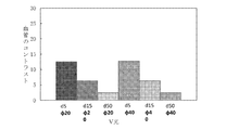
図16には、V光とBs光の光量比をA0〜A10の各光量比にした場合の粘膜に対する血管のコントラストを示す。図16では、各光量比の設定で得られる深さ及び太さが異なる血管のコントラストを表す棒グラフを、左から順にd5φ20、d5φ40、d15φ20、d15φ40、d50φ20、及びd50φ40の順に並べている。図16から分かるように、V光の成分が多いほど、太さが異なる血管間のコントラストの差が小さくなり、粘膜下の深さに応じて粘膜に対する血管のコントラストがつくようになる。逆に、Bs光の成分が多いほど、粘膜下の深さだけでなく、血管の太さに応じてコントラストに差がつくようになる。 FIG. 16 shows the contrast of the blood vessel with respect to the mucous membrane when the light amount ratio of V light to Bs light is set to each light amount ratio of A0 to A10. In FIG. 16, bar graphs representing contrasts of blood vessels having different depths and thicknesses obtained by setting the light amount ratio are arranged in order of d5φ20, d5φ40, d15φ20, d15φ40, d50φ20, and d50φ40 from the left. As can be seen from FIG. 16, as the component of V light increases, the difference in contrast between blood vessels having different thicknesses decreases, and the blood vessel contrast with respect to the mucous membrane is enhanced according to the submucosal depth. On the contrary, as the component of Bs light increases, the contrast becomes different according to the thickness of the blood vessel as well as the depth of the submucosa.
医師は、鑑別したい病変の特性に応じて、あるいは従来の内視鏡システムとの使用感の違いをなくす等の目的に応じて目標コントラストを定め、定めた目標コントラストが得られる光量比A0〜A10から所望の光量比を選択する。光源制御部22は、V光とBs光の光量比が、光量比設定部23が設定した光量比になるように、第1光源20aと第2光源20bとを制御する。このため、V光及びBs光の戻り光を受光するB画素で得られるB画像信号では、深さ及び太さが異なる複数の血管のコントラストのバランスが、設定された光量比に対応するバランスになる。画像生成部62では、このB画像信号を用いて内視鏡画像を生成するので、内視鏡システム10で生成及び表示する内視鏡画像は、粘膜に対する血管のコントラストが、血管の深さ及び太さに応じた目標コントラストになる。
The doctor determines the target contrast according to the characteristics of the lesion to be differentiated or according to the purpose such as eliminating the difference in the feeling of use from the conventional endoscope system, and the light quantity ratio A0 to A10 at which the defined target contrast is obtained. And select the desired light intensity ratio. The light
なお、上記第1実施形態では、11種類の光量比A0〜A10を例示しているが、内視鏡システム10では、V光とBs光の光量比を任意に設定可能なので、内視鏡システム10は、粘膜下の深さ及び太さに応じて血管のコントラストを自在に調節することができる。
In the first embodiment, although 11 types of light amount ratios A0 to A10 are illustrated, in the
[第2実施形態]
図17に示す第2実施形態の内視鏡システム200は、従来の内視鏡システムで行われるいわゆる狭帯域光観察を行うことができるようにした内視鏡システムである。内視鏡システム200には、第2光源20bの光路中に、第2光源20bが発する白色光から、約450nm以下の青色波長帯域を有する青色狭帯域光(第1実施形態のBs光と同じなので、以下、Bs光という)と、Bs光の波長帯域(第3波長帯域)とは異なり、かつ、血管に対して太さ分解能を有する約530nmから550nmの緑色波長帯域(第4波長帯域)を有する緑色狭帯域光(以下、Gn光)を生成するBs光及びGn光生成用帯域制限フィルタ225が挿抜自在に設けられている。Gn光の緑色波長帯域が第4波長帯域であり、Bs光の波長帯域(第3波長帯域)とは異なり、かつ、血管に対して太さ分解能を有する(図6参照)。Bs光及びGn光生成用帯域制限フィルタ225は、第1の帯域制限フィルタであり、かつ、第2の帯域制限フィルタである。
Second Embodiment
An
Bs光及びGn光生成用帯域制限フィルタ225の挿抜は、モード切り替え部230によって制御される。観察モード切り替え部230は、操作部12bにある図示しない観察モード切り替えボタンや、図示しないフットスイッチ等の操作によって動作し、Bs光及びGn光生成用帯域制限フィルタ225を挿抜することによって、白色光を用いて観察をする第1観察モードと、V光、Bs光、及びGn光を用いて観察をする第2観察モードと、を切り替える。第1観察モードはいわゆる通常観察モードであり、第2観察モードはいわゆる狭帯域観察モードである。したがって、観察モード切り替え部230は、狭帯域光観察をする第2観察モードが選択された場合には、観察モード切り替え部230はBs光及びGn光生成用帯域制限フィルタ225を第2光源20bの光路中に挿入し、白色光を照射して通常の観察をする第1観察モードが選択された場合には第2光源20bの光路中からBs光及びGn光生成用帯域制限フィルタ225を退避させる。
The
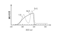
図18に示すように、内視鏡システム200で狭帯域光観察をする場合の照明光226は、V光、Bs光、及びGn光によって構成される。そして、内視鏡システム200の画像生成部62では、B画素でV光とBs光の戻り光を撮像して得たB画像信号を、Bチャンネル(生成する内視鏡画像のB画素)とGチャンネル(生成する内視鏡画像のG画素)に割り当て、G画素でGn光の戻り光を撮像して得たG画像信号を、Rチャンネル(生成する内視鏡のR画素)に割り当てた内視鏡画像(以下、狭帯域光観察画像という)を生成する。これ以外は、第1実施形態の内視鏡システム10と同様である。
As shown in FIG. 18, the
図19に示すように、従来の内視鏡システムでは、V光またはBs光よりも波長帯域が広い広帯域光から、広帯域光の波長帯域を制限する帯域制限フィルタ(以下、広帯域光用帯域制限フィルタという)によって生成される狭帯域光を用いて狭帯域光観察をする。例えば、光源としてキセノンランプを用いる場合、広帯域光はキセノンランプが発光する白色光227であり、この白色光227から、広帯域光用帯域制限フィルタを用いて、約350nmから450nmの波長帯域を有する青色狭帯域光(以下、Bn光という)と、Gn光を生成し、これらを照明光として用いて観察対象を撮像する。狭帯域光観察をする場合、内視鏡システム200のGn光は、従来の内視鏡システムのGn光はほぼ同じ分光スペクトルにすることができるので、G画像信号における深さ及び太さが異なる複数の血管のコントラストのバランスは、従来の内視鏡システムとほぼ等しい。一方、図20に示すように、従来の内視鏡システムで用いるBn光と、内視鏡システム200で用いるV光及びBs光の分光スペクトルは一致しない。このため、従来の内視鏡システムで狭帯域光観察をする場合に得られるB画像信号と、内視鏡システム200で狭帯域光観察をする場合に得られるB画像信号とでは、深さ及び太さが異なる複数の血管の粘膜に対するコントラストのバランスも同じにはならない。
As shown in FIG. 19, in a conventional endoscope system, a band limiting filter (hereinafter referred to as a band limiting filter for wide band light) limits the wavelength band of wide band light from wide band light having a wider wavelength band than V light or Bs light. Narrow band light observation using narrow band light generated by For example, when a xenon lamp is used as a light source, the broadband light is
しかし、内視鏡システム200は、光量比設定部23によってV光とBs光の光量比を設定することにより、B画像信号における深さ及び太さが異なる複数の血管間のコントラストのバランスを自在に調節することができる。すなわち、内視鏡システム200は、広帯域光から広帯域光用帯域制限フィルタを用いて生成されるBn光を観察対象に照射する場合の血管のコントラストを目標コントラストにして、V光とBs光の光量比を設定することで、B画像信号における深さ及び太さが異なる複数の血管のコントラストのバランスを、従来の狭帯域光観察をする内視鏡システムのB画像信号におけるコントラストのバランスに一致させることができる。この結果、内視鏡システム200で生成及び表示する狭帯域光観察画像の血管の見え方を、従来の狭帯域光観察画像の血管の見え方にほぼ一致させることができる。
However, in the
まず、図21に示すように、広帯域光から生成される従来のBn光を照射する場合に得られるB画像信号の血管のコントラストのバランスは、内視鏡システム200でBs光のみ(光量比A0)を照射した場合や、V光のみ(光量比A10)を照射した場合のB画像信号のコントラストのバランスとは一致しない。 First, as shown in FIG. 21, the balance of the blood vessel contrast of the B image signal obtained when the conventional Bn light generated from the wide band light is irradiated is Bs light only (the light amount ratio A0 in the endoscope system 200). And the balance of the contrast of the B image signal in the case where only V light (light amount ratio A10) is irradiated.
一方、図22には、光量比設定部23がV光とBs光の光量比を第1実施形態の光量比A0〜A10(表1参照)に設定する場合の粘膜に対する血管のコントラストを、従来のBn光を照射する場合の粘膜に対する血管のコントラストで規格化して得られるコントラスト比を示す。また、図22には、深さ及び太さが異なる複数の血管のコントラスト比を示す。このため、図22のグラフは、値が100%に近いほど、粘膜に対する血管のコントラストが、従来のBn光を照射する場合に近いことを表す。
On the other hand, in FIG. 22, the contrast of the blood vessel with respect to the mucous membrane when the light amount
図22から分かるように、光量比A0〜A6に設定すると、血管の深さ及び深さに応じたばらつきが大きくなるが、多くの血管が、従来のBn光を照射する場合のコントラスト(100%のライン)を超え、従来よりも視認性が向上する。一方、光量比A7〜A10に設定すると、従来のBn光を照射する場合のコントラストを若干下回るが、血管の深さ及び太さによるコントラストのばらつきは小さくなり、従来のBn光を照射する場合に近いコントラストのバランスが得られる。 As can be seen from FIG. 22, when the light amount ratio A0 to A6 is set, the variation depending on the depth and depth of the blood vessels becomes large, but the contrast (100%) when many blood vessels are irradiated with the conventional Bn light Line), and the visibility improves more than before. On the other hand, when the light amount ratio A7 to A10 is set, the contrast in the case of irradiating the conventional Bn light is slightly lower, but the variation in contrast due to the depth and thickness of the blood vessel becomes smaller, and the case of irradiating the conventional Bn light A close contrast balance is obtained.
また、図23には、光量比設定部23がV光とBs光の光量比A0〜A10(表1参照)に設定する場合について、粘膜下の深さが等しく、かつ、太さが異なる血管間のコントラスト比のグラフを示す。具体的には、図23では、φ20の血管に対するφ40の血管のコントラスト比(φ40/φ20)を、深さd5、d15、d50の3種類の深さについて示している。また、図23のグラフは、従来のBn光を照射する場合のコントラスト比で規格化しているので、値が100%に近いほど、粘膜下の深さが等しく、かつ、太さが異なる血管間のコントラスト比が、従来のBn光を照射する場合に近いことを表す。
In addition, in FIG. 23, when the light quantity
図23から分かるように、光量比A0〜A6に設定すると、粘膜下の深さが等しく、かつ、太さが異なる血管間のコントラスト比は、深さの違いによるばらつきが大きくなるが、値が100%を超え、従来のBn光を照射する場合よりも概ね大きくなる。このため、光量比A0〜A6に設定すると、粘膜下の深さが等しく、かつ、太さが異なる血管を、従来のBn光を照射する場合よりもはっきり特別して観察できるようになる。一方、光量比A7〜A10に設定すると、粘膜下の深さが等しく、かつ、太さが異なる血管間のコントラスト比は、従来のBn光を照射する場合を若干下回る場合もあるが、深さの違いによるばらつきも小さく、従来のBn光を照射する場合のコントラスト比にほぼ近い値を維持することができる。特に、光量比をA7からA9に設定すると、粘膜下の深さが等しく、かつ、太さが異なる血管間のコントラスト比は、深さの違いによるばらつきが殆どなく、かつ、従来のBn光を照射する場合のコントラスト比にほぼ一致する。 As can be seen from FIG. 23, when the light amount ratio A0 to A6 is set, the contrast ratio between blood vessels having the same depth and different thickness under the mucous membrane has a large variation due to the difference in depth, but the value is It exceeds 100% and is generally larger than the case of irradiating conventional Bn light. For this reason, when the light amount ratio A0 to A6 is set, blood vessels having the same depth and different thickness can be observed more clearly and specifically than in the case where conventional Bn light is irradiated. On the other hand, when the light amount ratio is set to A7 to A10, the contrast ratio between blood vessels having the same depth in the submucosa and different in thickness may be slightly lower than in the case where conventional Bn light is irradiated. The variation due to the difference in B.sub.2 is small, and a value close to the contrast ratio in the case of conventional Bn light irradiation can be maintained. In particular, when the light amount ratio is set to A7 to A9, the contrast ratio between blood vessels having the same depth and different thickness under the mucous membrane has almost no variation due to the difference in depth, and the conventional Bn light It almost matches the contrast ratio in the case of irradiation.
図24には、光量比設定部23がV光とBs光の光量比A0〜A10(表1参照)に設定する場合について、太さが等しく、かつ、粘膜下の深さが異なる血管間のコントラスト比のグラフを示す。具体的には、図24では、φ20及びφ40の2種類の太さの血管について、深さd15の血管に対する深さd5の血管のコントラスト比(d5/d15)と、深さd50の血管に対する深さd15の血管のコントラスト比(d15/d50)とを示している。また、図24のグラフは、従来のBn光を照射する場合のコントラスト比で規格化しているので、値が100%に近いほど、太さが等しく、かつ、粘膜下の深さが異なる血管間のコントラスト比が、従来のBn光を照射する場合に近いことを表す。
In FIG. 24, when the light amount
図24から分かるように、太さが等しく、かつ、粘膜下の深さが異なる血管間のコントラスト比は、光量比の設定によらず、従来のBn光を照射する場合に概ね近い値が得られる。但し、光量比A7の条件を境界に、Bs光の成分が多い光量比A0〜A6を比較的細い血管(φ20)のコントラスト比が低下しやすく、血管の太さの違いによるばらつきが大きくなる。また、光量比A7の条件を境界に、V光の成分が多い光量比A8〜A10に設定すると、概ね全ての太さの血管の深さの違いによるコントラスト比は、太さの違いによるばらつきが小さいまま、従来のBn光を照射する場合のコントラスト比を上回る。したがって、光量比をA8〜A10に設定すると、従来のBn光を照射する場合よりも、太さが等しく、かつ、粘膜下の深さが異なる血管を識別しやすくなる。 As can be seen from FIG. 24, the contrast ratio between blood vessels of equal thickness and different submucosal depths does not depend on the setting of the light quantity ratio, and a value close to that obtained when irradiating conventional Bn light is obtained. Be However, the contrast ratio of a relatively thin blood vessel (φ 20) tends to decrease with the light amount ratio A0 to A6 having many components of Bs light at the boundary of the light amount ratio A7, and the variation due to the difference in blood vessel diameter increases. Also, if the light amount ratio A8 to A10 with many V light components is set at the boundary of the light amount ratio A7, the contrast ratio due to the difference in the blood vessel depth of almost all the thickness will vary due to the difference in the thickness While being small, it exceeds the contrast ratio in the case of irradiating conventional Bn light. Therefore, when the light amount ratio is set to A8 to A10, it becomes easier to identify blood vessels having the same thickness and different submucosal depths than in the case of irradiating conventional Bn light.
また、表2には、(1)深さ及び太さが異なる血管間のコントラストのバランス、(2)粘膜下の深さが等しく、かつ、太さが異なる血管間のコントラスト比、(3)太さが等しく、かつ、粘膜下の深さが異なる血管間のコントラスト比、の3個の観点で、内視鏡システム200で光量比をA0〜A10に設定した場合に得られたB画像信号と、従来のBn光を照射して得たB画像信号とで官能的に1〜5の5段階評価した結果を示す。評価は、従来のBn光を照射した場合と最もかけ離れているという評価が「1」、従来のBn光を照射した場合に最も近いという評価を「5」である。評価結果は、複数人が評価した結果の平均値である。
Table 2 also shows (1) contrast balance between blood vessels of different depths and thicknesses, (2) contrast ratio between blood vessels of equal submucosal depth and different thickness, (3) B image signal obtained when the light amount ratio is set to A0 to A10 in the
以上のことから、内視鏡システム200で使用する青色狭帯域光はV光とBs光で形成され、従来の広帯域光から形成されるBn光とは異なっており、分光スペクトルは一致しないが、光量比設定部23が、V光とBs光の光量比を「A7」の値(V光のピーク波長の光量/Bs光のピーク波長の光量=5.0)に設定すれば、血管のコントラストの大きさを、Bn光を前記観察対象に照射する場合の血管のコントラストの大きさとほぼ等しくし、
深さ及び太さが異なる複数の血管の粘膜に対するコントラストのバランスが従来のBn光を照射する場合とほぼ一致するするB画像信号を得ることができる。このため、内視鏡システム200は、従来の狭帯域光観察画像と血管の見え方がほぼ等しい狭帯域光観察画像を生成及び表示することができる。
From the above, the blue narrow band light used in the
It is possible to obtain a B image signal in which the balance of contrast with respect to the mucous membranes of a plurality of blood vessels different in depth and thickness is substantially the same as in the case where conventional Bn light is irradiated. Therefore, the
上記の通り、従来の狭帯域光観察画像と血管の見え方がほぼ等しい狭帯域光観察画像を得るためには、光量比設定部23がV光とBs光の光量比を「A7」の値に設定することが最も好ましいが、「V光のピーク波長の光量/Bs光のピーク波長の光量」の値が2.0(光量比A6)以上8.0(光量比A8)以下であれば、従来の狭帯域光観察画像と血管の見え方が概ね等しい狭帯域光観察画像を得ることができる。また、「V光のピーク波長の光量/Bs光のピーク波長の光量」の値が約1.0(光量比A4)以上であれば、従来の狭帯域光観察画像を違和感なく模した狭帯域光観察画像を生成及び表示することができる。
As described above, the light amount
この他、内視鏡システム200では、光量比設定部23によってV光とBs光の光量比を「A0」〜「A6」に設定することで、粘膜下の深さが等しく、かつ、太さが異なる複数の血管のコントラストの比または差を、V光またはBs光よりも波長帯域が広い広帯域光から広帯域光用帯域制限フィルタを用いて生成されるBn光を観察対象に照射する場合の血管のコントラストの比または差を基準として、これよりも大きくすることができる。すなわち、光量比を「A0」〜「A6」に設定することで、粘膜下の深さが等しく、かつ、太さが異なる複数の血管のコントラストの比または差を、従来のBn光を用いる場合よりも強調した新たな狭帯域光観察画像を提供することができる。
Besides, in the
また、内視鏡システム200では、光量比設定部23によってV光とBs光の光量比を「A8」〜「A10」に設定することで、粘膜下の深さが異なり、かつ、太さが等しい複数の血管間のコントラストの比または差を、Bn光を観察対象に照射する場合の血管のコントラストの比または差を基準として、これよりも大きくすることができる。すなわち、光量比を「A8」〜「A10」に設定することで、粘膜下の深さが異なり、かつ、太さが等しい複数の血管のコントラストの比または差を、従来のBn光を用いる場合よりも強調した新たな狭帯域光観察画像を提供することができる。
Further, in the
なお、上記第2実施形態では、内視鏡システム200と、狭帯域光観察をする従来の内視鏡システムとして、キセノンランプが発する白色光227から、Bn光及びGn光を生成して利用する内視鏡システムと、を比較しているが、キセノンランプ以外の広帯域光を発する光源(例えば白色LED等)を利用して狭帯域光観察をする内視鏡システムもある。内視鏡システム200は、上記第2実施形態と同様にして、光量比設定部23によって適切な光量比を設定すれば、こうした従来の内視鏡システムで得る狭帯域光観察画像と血管の見え方がほぼ等しい狭帯域光観察画像を得ることができる。
In the second embodiment, Bn light and Gn light are generated and used from
上記第2実施形態では、Bs光及びGn光生成用帯域制限フィルタ225を用いて、第2光源20bが発する白色光からBs光とGn光を同時に生成するが、この代わりに、例えば、図25に示す回転式の帯域制限フィルタ(以下、回転フィルタという)235を用いて、光源制御部22は、Bs光とGn光を順次生成して、Bs光とGn光を観察対象に時分割照射しても良い。回転フィルタ235は、第2光源20bが発する白色光からBs光を生成するBs光生成用帯域制限フィルタ235a(第1の帯域制限フィルタ。第1実施形態のBs光生成用帯域制限フィルタ25に対応する。)と、Gn光を生成するGn光生成用帯域制限フィルタ235b(第2の帯域制限フィルタ)とを外周部に有し、内周には、第2光源20bが発する白色光を透過する素抜け部235cを有する。狭帯域光観察をする第2観察モードが選択された場合、観察モード切り替え部230は、Bs光生成用帯域制限フィルタ235aとGn光生成用帯域制限フィルタ235bとが交互に、第2光源20bの光路中を横切るように回転フィルタ235を配置し、回転させる。一方、通常観察をする第1観察モードが選択された場合、観察モード切り替え部230は、素抜け部235cを、第2光源20bの光路中に配置する。撮像センサ48にモノクロセンサを用いる場合は、回転フィルタ235等を用いて、上記のようにBs光とGn光を順次生成して時分割照射すると良い。
In the second embodiment, Bs light and Gn light are simultaneously generated from white light emitted by the second light source 20b using the
なお、上記第1実施形態及び第2実施形態で用いるV−LEDやB−LEDの代わりに、中心波長やピーク波長等がこれらと異なる他の半導体光源を用いることもできる。例えば、上記第1実施形態及び第2実施形態では、中心波長415nmのV光を発するV−LEDを用いているが、この代わりに、例えば中心波長405nmのV光を発するLEDを用いることもできる。中心波長405nmのLEDを用いる場合でも、光量比設定部23が設定する光量比は上記第1実施形態及び第2実施形態と光量比とほぼ同じである。また、LEDの代わりに、レーザーダイオード等の他の半導体光源を用いても良い。
Note that, instead of the V-LEDs and B-LEDs used in the first embodiment and the second embodiment, other semiconductor light sources having different center wavelengths, peak wavelengths, etc., can also be used. For example, in the first and second embodiments, a V-LED emitting V light with a central wavelength of 415 nm is used, but instead, an LED emitting V light with a central wavelength of 405 nm may be used instead, for example. . Even when an LED with a central wavelength of 405 nm is used, the light amount ratio set by the light amount
上記第1実施形態及び第2実施形態では、光源制御部22は、光量比設定部23が設定する光量比を用いて、第1光源20aのV−LEDと第2光源20bのB−LEDの光量(発光量)を制御するが、光量を制御する代わりに、V−LEDとB−LEDの発光時間を制御して、V光とBs光の光量比を光量比設定部23が設定した光量比にしても良い。また、光量と発光時間の両方を制御して、V光とBs光の光量比を光量比設定部23が設定した光量比にしても良い。V−LEDやB−LEDの光量には、限度があるが、発光時間を制御すれば、あるいは光量と発光時間の両方を制御すれば、光量の制御だけでは実現できない光量比でV光及びBs光を含む照明光を発生させることができる。
In the first embodiment and the second embodiment, the light
上記第1実施形態及び第2実施形態では、B光からBs光を生成して照明光に利用しているが、B光をそのまま照明光に利用してもよい。但し、前述のとおり、Bs光を利用したほうが、粘膜に対する血管のコントラストが得られやすい。 In the first and second embodiments, Bs light is generated from B light and used as illumination light, but B light may be used as it is as illumination light. However, as described above, it is easier to obtain the blood vessel contrast to the mucous membrane when Bs light is used.
上記第1実施形態及び第2実施形態では、撮像センサ48が設けられた内視鏡12を被検体内に挿入して観察を行う内視鏡システムによって本発明を実施しているが、カプセル内視鏡システムでも本発明は好適である。例えば、図26に示すように、カプセル内視鏡システムでは、カプセル内視鏡400と、プロセッサ装置(図示しない)とを少なくとも有する。
In the first and second embodiments described above, the present invention is implemented by the endoscope system that inserts the
カプセル内視鏡400は、光源402と制御部403と、撮像センサ404と、画像生成部406と、送受信アンテナ408と、を備えている。光源402は、V光を発するV−LEDと、B光を発するB−LEDと、B光の照射によって蛍光を発する蛍光体と、Bs光生成用帯域制限フィルタと、を有しており、上記第1実施形態及び第2実施形態の光源部20に対応する。
The
制御部403は、上記第1実施形態及び第2実施形態の光源制御部22及び光量比設定部23と同様に機能し、V光とBs光の光量比を設定して光源402を発光制御する。また、制御部403は、送受信アンテナ408によって、カプセル内視鏡システムのプロセッサ装置と無線で通信可能である。カプセル内視鏡システムのプロセッサ装置は、上記各実施形態及び変形例のプロセッサ装置16とほぼ同様であるが、画像生成部406はカプセル内視鏡400に設けられ、生成された内視鏡画像は、送受信アンテナ408を介してプロセッサ装置に送信される。撮像センサ404は上記第1実施形態及び第2実施形態の撮像センサ48と同様に構成される。
The
10,200 内視鏡システム
12 内視鏡
14 内視鏡光源装置
16 プロセッサ装置
20a 第1光源
20b 第2光源
22 光源制御部
23 光量比設定部
25,235a Bs光生成用帯域制限フィルタ
225 Bs光及びGn光生成用帯域制限フィルタ
230 観察モード切り替え部
235b Gn光生成用帯域制限フィルタ
10, 200
Claims (15)
青色光であるB光、及び、励起光としての前記B光を蛍光体に照射して得られる蛍光を発する第2光源と、
前記第2光源から発せられる光のうち、青色狭帯域光であるBs光と、血管に対して太さ分解能を有する緑色狭帯域光であるGn光とを少なくとも透過させるBs光及びGn光生成用帯域制限フィルタと、
前記V光と前記Bs光の光量比を設定し、粘膜に対する血管のコントラストを、血管の深さ及び太さに応じた目標コントラストにする光量比設定部と、
前記光量比設定部が設定する前記光量比を用いて前記第1光源及び前記第2光源を制御する光源制御部と、
を備える内視鏡光源装置。 A first light source that emits V light, which is violet light having depth resolution, for a blood vessel under the mucosa to be observed;
A second light source that emits fluorescence obtained by irradiating the phosphor with blue light B light and the B light as excitation light;
Of the light emitted from the second light source, Bs light and Gn light for transmitting at least Bs light, which is blue narrow band light, and Gn light, which is green narrow band light having thickness resolution for blood vessels A band limiting filter,
A light amount ratio setting unit for setting a light amount ratio of the V light and the Bs light and setting a contrast of a blood vessel to a mucous membrane to a target contrast according to a depth and a thickness of the blood vessel;
A light source control unit configured to control the first light source and the second light source using the light amount ratio set by the light amount ratio setting unit;
Endoscope light source device provided with.
前記光量比設定部は、粘膜下の深さが等しく、かつ、太さが異なる複数の血管のコントラストの比または差を、前記Bs光を照射する場合の前記コントラストの比または差よりも大きくする前記光量比を設定する請求項1または2に記載の内視鏡光源装置。 Based on the contrast of the blood vessel when the Bs light is irradiated to the observation target,
The light amount ratio setting unit makes the ratio or the difference of the contrast of a plurality of blood vessels having the same depth in the submucosa and the different thickness larger than the ratio or the difference of the contrast in the case of irradiating the Bs light. The endoscope light source device according to claim 1, wherein the light amount ratio is set.
前記光量比設定部は、粘膜下の深さが異なり、かつ、太さが等しい複数の血管のコントラストの比または差を、前記Bs光を照射する場合の前記コントラストの比または差よりも大きくする前記光量比を設定する請求項1または2に記載の内視鏡光源装置。 Based on the contrast of the blood vessel when the Bs light is irradiated to the observation target,
The light amount ratio setting unit makes the ratio or difference of contrast of a plurality of blood vessels having different submucosal depths and equal thicknesses larger than the ratio or difference of the contrast when the Bs light is irradiated. The endoscope light source device according to claim 1, wherein the light amount ratio is set.
青色光であるB光、及び、励起光としての前記B光を蛍光体に照射して得られる蛍光を発する第2光源と、
前記第2光源から発せられる光のうち、青色狭帯域光であるBs光と、血管に対して太さ分解能を有する緑色狭帯域光であるGn光とを少なくとも透過させるBs光及びGn光生成用帯域制限フィルタと、
前記V光と前記Bs光の光量比を設定し、粘膜に対する血管のコントラストを、血管の深さ及び太さに応じた目標コントラストにする光量比設定部と、
前記光量比設定部が設定する前記光量比を用いて前記第1光源及び前記第2光源を制御する光源制御部と、
前記観察対象を撮像する撮像センサと、
を備える内視鏡システム。 A first light source that emits V light, which is violet light having depth resolution, for a blood vessel under the mucosa to be observed;
A second light source that emits fluorescence obtained by irradiating the phosphor with blue light B light and the B light as excitation light;
Of the light emitted from the second light source, Bs light and Gn light for transmitting at least Bs light, which is blue narrow band light, and Gn light, which is green narrow band light having thickness resolution for blood vessels A band limiting filter,
A light amount ratio setting unit for setting a light amount ratio of the V light and the Bs light and setting a contrast of a blood vessel to a mucous membrane to a target contrast according to a depth and a thickness of the blood vessel;
A light source control unit configured to control the first light source and the second light source using the light amount ratio set by the light amount ratio setting unit;
An imaging sensor for imaging the observation target;
An endoscope system comprising:
であるB光、及び、励起光としての前記B光を蛍光体に照射して得られる蛍光を発する第2光源と、前記第2光源から発せられる光のうち、青色狭帯域光であるBs光と、血管に対して太さ分解能を有する緑色狭帯域光であるGn光とを少なくとも透過させるBs光及びGn光生成用帯域制限フィルタと、を備える内視鏡光源装置の作動方法において、
光量比設定部が、前記V光と前記Bs光の光量比を設定するステップと、
光源制御部が、前記光量比設定部が設定する前記光量比を用いて前記第1光源及び前記第2光源を制御するステップと、
を備える内視鏡光源装置の作動方法。 A first light source for emitting V light, which is purple light having depth resolution, and B light, which is blue light, and B light which is excitation light, for a blood vessel under a mucous membrane to be observed Among the light emitted from the second light source, the second light source emitting fluorescence obtained by the irradiation, Bs light which is blue narrow band light, and Gn which is green narrow band light having thickness resolution with respect to the blood vessel In a method of operating an endoscope light source apparatus, the method comprises: a band limiting filter for generating Bs light and Gn light that transmits at least light.
A light amount ratio setting unit sets a light amount ratio of the V light and the Bs light;
Controlling the first light source and the second light source using the light amount ratio set by the light amount ratio setting unit;
Method of operating an endoscopic light source device comprising:
Priority Applications (1)
| Application Number | Priority Date | Filing Date | Title |
|---|---|---|---|
| JP2019089498A JP2019122865A (en) | 2019-05-10 | 2019-05-10 | Endoscope light source device, endoscope system, and method of operating endoscope light source device |
Applications Claiming Priority (1)
| Application Number | Priority Date | Filing Date | Title |
|---|---|---|---|
| JP2019089498A JP2019122865A (en) | 2019-05-10 | 2019-05-10 | Endoscope light source device, endoscope system, and method of operating endoscope light source device |
Related Parent Applications (1)
| Application Number | Title | Priority Date | Filing Date |
|---|---|---|---|
| JP2015039625A Division JP2016158837A (en) | 2015-02-27 | 2015-02-27 | Endoscope light source device, endoscope system, and operation method of endoscope light source device |
Publications (1)
| Publication Number | Publication Date |
|---|---|
| JP2019122865A true JP2019122865A (en) | 2019-07-25 |
Family
ID=67397251
Family Applications (1)
| Application Number | Title | Priority Date | Filing Date |
|---|---|---|---|
| JP2019089498A Pending JP2019122865A (en) | 2019-05-10 | 2019-05-10 | Endoscope light source device, endoscope system, and method of operating endoscope light source device |
Country Status (1)
| Country | Link |
|---|---|
| JP (1) | JP2019122865A (en) |
Citations (6)
| Publication number | Priority date | Publication date | Assignee | Title |
|---|---|---|---|---|
| JP2011010998A (en) * | 2009-07-06 | 2011-01-20 | Fujifilm Corp | Lighting device for endoscope and endoscope apparatus |
| WO2011010534A1 (en) * | 2009-07-23 | 2011-01-27 | オリンパスメディカルシステムズ株式会社 | Transmissivity-adjusting device, observation device and observation system |
| WO2012101904A1 (en) * | 2011-01-28 | 2012-08-02 | オリンパスメディカルシステムズ株式会社 | Illumination device and observation system |
| JP2012152413A (en) * | 2011-01-27 | 2012-08-16 | Fujifilm Corp | Electronic endoscope system |
| JP2013150713A (en) * | 2012-01-25 | 2013-08-08 | Fujifilm Corp | Endoscope system, processor device for endoscope system, and image processing method |
| JP2013248319A (en) * | 2012-06-04 | 2013-12-12 | Olympus Corp | Fluorescent endoscope apparatus |
-
2019
- 2019-05-10 JP JP2019089498A patent/JP2019122865A/en active Pending
Patent Citations (6)
| Publication number | Priority date | Publication date | Assignee | Title |
|---|---|---|---|---|
| JP2011010998A (en) * | 2009-07-06 | 2011-01-20 | Fujifilm Corp | Lighting device for endoscope and endoscope apparatus |
| WO2011010534A1 (en) * | 2009-07-23 | 2011-01-27 | オリンパスメディカルシステムズ株式会社 | Transmissivity-adjusting device, observation device and observation system |
| JP2012152413A (en) * | 2011-01-27 | 2012-08-16 | Fujifilm Corp | Electronic endoscope system |
| WO2012101904A1 (en) * | 2011-01-28 | 2012-08-02 | オリンパスメディカルシステムズ株式会社 | Illumination device and observation system |
| JP2013150713A (en) * | 2012-01-25 | 2013-08-08 | Fujifilm Corp | Endoscope system, processor device for endoscope system, and image processing method |
| JP2013248319A (en) * | 2012-06-04 | 2013-12-12 | Olympus Corp | Fluorescent endoscope apparatus |
Similar Documents
| Publication | Publication Date | Title |
|---|---|---|
| JP6461739B2 (en) | Image processing apparatus, endoscope system, and method of operating image processing apparatus | |
| JP5767775B2 (en) | Endoscope device | |
| US10335014B2 (en) | Endoscope system, processor device, and method for operating endoscope system | |
| WO2017170233A1 (en) | Image processing device, operation method for image processing device, and image processing program | |
| JP6389140B2 (en) | Endoscope system, processor device, and operation method of endoscope system | |
| US9962070B2 (en) | Endoscope system, processor device, and method for operating endoscope system | |
| JP6533180B2 (en) | Endoscope system, processor device, and operation method of endoscope system | |
| US11044416B2 (en) | Endoscope system, processor device, and endoscope system operation method | |
| JP6690003B2 (en) | Endoscope system and operating method thereof | |
| US20190208986A1 (en) | Endoscopic system, processor device, and method of operating endoscopic system | |
| US20150080653A1 (en) | Endoscope system, processor device, and method for operating endoscope system | |
| JP6247610B2 (en) | Endoscope system, operation method of endoscope system, light source device, and operation method of light source device | |
| JP6408400B2 (en) | Endoscope system, endoscope processor device, and operation method of endoscope system | |
| JP2017185258A (en) | Endoscope apparatus | |
| CN109381154B (en) | Endoscope system | |
| JP2017184861A (en) | Image processing device and operation method of the same, and processor device for endoscope and operation method of the same | |
| JP2016007355A (en) | Light source device, endoscope system, operation method of light source device, and operation method of endoscope system | |
| JP6155367B2 (en) | Endoscope device | |
| JP2016158837A (en) | Endoscope light source device, endoscope system, and operation method of endoscope light source device | |
| JP2019136555A (en) | Endoscope light source device, endoscope system, and method of operating endoscope light source device | |
| JP6905038B2 (en) | Light source device and endoscopic system | |
| JP2016059401A (en) | Light source device for endoscope and endoscope system | |
| JP2019122865A (en) | Endoscope light source device, endoscope system, and method of operating endoscope light source device | |
| JP6386939B2 (en) | Endoscope light source device, endoscope system, and operation method of endoscope light source device | |
| JP6379260B2 (en) | Endoscope device |
Legal Events
| Date | Code | Title | Description |
|---|---|---|---|
| A621 | Written request for application examination |
Free format text: JAPANESE INTERMEDIATE CODE: A621 Effective date: 20190510 |
|
| A977 | Report on retrieval |
Free format text: JAPANESE INTERMEDIATE CODE: A971007 Effective date: 20200318 |
|
| A131 | Notification of reasons for refusal |
Free format text: JAPANESE INTERMEDIATE CODE: A131 Effective date: 20200407 |
|
| A521 | Request for written amendment filed |
Free format text: JAPANESE INTERMEDIATE CODE: A523 Effective date: 20200515 |
|
| A02 | Decision of refusal |
Free format text: JAPANESE INTERMEDIATE CODE: A02 Effective date: 20200811 |