JP2019122402A - Non-combustion flavor inhaler and aerosol delivery method - Google Patents
Non-combustion flavor inhaler and aerosol delivery method Download PDFInfo
- Publication number
- JP2019122402A JP2019122402A JP2019064175A JP2019064175A JP2019122402A JP 2019122402 A JP2019122402 A JP 2019122402A JP 2019064175 A JP2019064175 A JP 2019064175A JP 2019064175 A JP2019064175 A JP 2019064175A JP 2019122402 A JP2019122402 A JP 2019122402A
- Authority
- JP
- Japan
- Prior art keywords
- aerosol
- unit
- supply
- control unit
- atomization
- Prior art date
- Legal status (The legal status is an assumption and is not a legal conclusion. Google has not performed a legal analysis and makes no representation as to the accuracy of the status listed.)
- Granted
Links
Images


Abstract
Description
本発明は、燃焼を伴わずにエアロゾル源を霧化する霧化部を有する非燃焼型香味吸引器
及びエアロゾル送達方法に関する。
The present invention relates to a non-combustion flavor aspirator having an atomization unit that atomizes an aerosol source without combustion and an aerosol delivery method.
従来、燃焼を伴わずに香味を吸引するための非燃焼型香味吸引器が知られている。非燃
焼型香味吸引器は、燃焼を伴わずに燃焼を伴わずにエアロゾル源を霧化する霧化部と、ユ
ーザのパフ動作を検知するセンサとを有する。非燃焼型香味吸引器は、パフ動作の検知に
応じて、霧化部に対する電源出力の供給を開始する(例えば、特許文献1)。
DESCRIPTION OF RELATED ART Conventionally, the non-combustion type flavor suction device for attracting | sucking a flavor without combustion is known. The non-combustion type flavor suction device has an atomization unit that atomizes an aerosol source without combustion and without combustion, and a sensor that detects a puff operation of the user. The non-combustion type flavor suction device starts supply of power output to the atomization unit in response to the detection of the puff operation (e.g., Patent Document 1).
第1の特徴は、非燃焼型香味吸引器であって、燃焼を伴わずにエアロゾル源を霧化する
霧化部と、前記霧化部に対する電源出力を制御する制御部とを備え、前記制御部は、ユー
ザのパフ動作の開始前に前記霧化部に対する電源出力の供給を開始するとともに、ユーザ
のパフ動作中に前記霧化部に対する電源出力の供給を停止することを要旨とする。
The first feature is a non-combustion type flavor suction device, comprising: an atomization unit that atomizes an aerosol source without combustion; and a control unit that controls power output to the atomization unit, the control The gist of the present invention is to start the supply of the power output to the atomizing unit before the start of the puff operation by the user, and to stop the supply of the power output to the atomizing unit during the puff operation of the user.
第2の特徴は、第1の特徴において、前記非燃焼型香味吸引器は、ユーザのパフ動作が
行われるときに、前記霧化部に対する電源出力の供給を停止する状態に切り替わる霧化ス
イッチを備えることを要旨とする。
The second feature is that, in the first feature, the non-combustion type flavor suction device is switched to a state in which supply of power output to the atomization unit is stopped when a puff operation of a user is performed. Make it a gist.
第3の特徴は、第2の特徴において、前記霧化スイッチは、ユーザのパフ動作が行われ
なくなるときに、前記霧化部に対する電源出力の供給を開始する状態に切り替わることを
要旨とする。
According to a third feature, in the second feature, the atomization switch switches to a state of starting supply of power output to the atomization unit when the user does not perform puff operation.
第4の特徴は、第2の特徴又は第3の特徴において、前記霧化スイッチは、パフ動作を
検知する吸引センサと連動しており、前記制御部は、前記吸引センサによってパフ動作が
検知されたときに、前記霧化部に対する電源出力の供給を停止することを要旨とする。
A fourth feature is that in the second feature or the third feature, the atomization switch is interlocked with a suction sensor that detects a puff operation, and the control unit detects the puff operation by the suction sensor The gist of the present invention is to stop the supply of the power supply output to the atomizing unit.
第5の特徴は、第2の特徴乃至第4の特徴のいずれかにおいて、前記霧化スイッチは、
パフ動作を検知する吸引センサと連動しており、前記制御部は、前記吸引センサによって
パフ動作が検知されなくなったときに、前記霧化部に対する電源出力の供給を開始するこ
とを要旨とする。
According to a fifth feature, in any one of the second feature to the fourth feature, the atomization switch is
The control unit is interlocked with a suction sensor that detects a puff operation, and the control unit is configured to start supply of power output to the atomizing unit when the puff operation is not detected by the suction sensor.
第6の特徴は、第2の特徴又は第3の特徴において、前記霧化スイッチは、操作インタ
フェースに対するユーザ操作と連動しており、前記制御部は、前記操作インタフェースに
対するユーザ操作が行われなくなったときに、前記霧化部に対する電源出力の供給を停止
することを要旨とする。
A sixth feature is that, in the second feature or the third feature, the atomization switch is interlocked with a user operation on the operation interface, and the control unit stops the user operation on the operation interface The gist of the present invention is to stop the supply of the power output to the atomizing unit.
第7の特徴は、第2の特徴、第3の特徴及び第6の特徴のいずれかにおいて、前記霧化
スイッチは、操作インタフェースに対するユーザ操作と連動しており、前記制御部は、前
記操作インタフェースに対するユーザ操作が行われたときに、前記霧化部に対する電源出
力の供給を開始することを要旨とする。
A seventh feature is that in any one of the second feature, the third feature and the sixth feature, the atomization switch is interlocked with a user operation on an operation interface, and the control unit is the operation interface The present invention is summarized as starting supply of power output to the atomizing unit when a user's operation is performed.
第8の特徴は、第1の特徴において、前記非燃焼型香味吸引器は、操作インタフェース
に対するユーザ操作が行われているときにオン状態に切り替わり、前記操作インタフェー
スに対するユーザ操作が行われていないときにオフ状態に切り替わる第1スイッチと、ユ
ーザのパフ動作の開始によってオン状態に切り替わり、ユーザのパフ動作の終了によって
オフ状態に切り替わる第2スイッチとを備え、前記制御部は、前記第1スイッチがオン状
態に切り替わったときに、前記霧化部に対する電源出力の供給を開始するとともに、前記
第2スイッチがオン状態に切り替わったときに、前記霧化部に対する電源出力の供給を停
止することを要旨とする。
According to an eighth feature, in the first feature, the non-burning type flavor suction device is switched to the on state when a user operation on the operation interface is performed, and the user operation on the operation interface is not performed And a second switch that is switched to the on state by the start of the puff operation of the user, and is switched to the off state by the end of the puff operation of the user, the control unit including the first switch The power supply output to the atomization unit is started when switched to the ON state, and the supply of the power output to the atomization unit is stopped when the second switch is switched to the ON state. I assume.
第9の特徴は、第1の特徴乃至第8の特徴のいずれかにおいて、前記制御部は、前記霧
化部に対する電源出力の供給を開始してから第1時間が経過した場合に、前記霧化部に対
する電源出力の供給を停止することを要旨とする。
A ninth aspect is according to any one of the first aspect to the eighth aspect, wherein the control unit is configured to control the fog when a first time period has elapsed since the supply of power supply output to the atomization unit is started. The gist of the present invention is to stop the supply of power output to the conversion unit.
第10の特徴は、第9の特徴において、前記制御部は、前記第1時間の経過によって前
記霧化部に対する電源出力の供給を停止してから第2時間が経過した場合に、前記霧化部
に対する電源出力の供給を再開することを要旨とする。
A tenth feature is the ninth feature, wherein the control unit performs the atomization when a second time has elapsed since the supply of the power output to the atomization unit is stopped due to the elapse of the first time. The gist is to resume the supply of power output to the unit.
第11の特徴は、第1の特徴乃至第10の特徴のいずれかにおいて、前記非燃焼型香味
吸引器は、所望量のエアロゾルを供給可能な期間において、所望量のエアロゾルを供給可
能な旨を報知する報知部を備えることを要旨とする。
According to an eleventh feature, in any one of the first feature to the tenth feature, the non-burning type flavor aspirator can supply a desired amount of aerosol in a period in which a desired amount of aerosol can be supplied. The gist of the present invention is to provide a notification unit for giving a notification.
第12の特徴は、第1の特徴乃至第11の特徴のいずれかにおいて、所望量のエアロゾ
ルを供給することができない期間において、所望量のエアロゾルを供給可能でない旨を報
知する報知部を備えることを要旨とする。
A twelfth feature is that any one of the first feature to the eleventh feature is provided with a notification unit that notifies that a desired amount of aerosol can not be supplied in a period when the desired amount of aerosol can not be supplied. As the abstract.
第13の特徴は、第1の特徴乃至第12の特徴において、前記霧化部によって発生する
エアロゾルの流路に露出する壁面には、凝縮したエアロゾルを吸収する吸収部材が設けら
れることを要旨とする。
A thirteenth feature of the present invention is that, in the first feature to the twelfth feature, an absorption member that absorbs condensed aerosol is provided on a wall surface exposed to a flow path of the aerosol generated by the atomizing unit. Do.
第14の特徴は、第1の特徴乃至第13の特徴のいずれかにおいて、前記非燃焼型香味
吸引器は、パフ動作を検知する吸引センサを備え、前記制御部は、前記吸引センサによっ
てパフ動作が検知されていない非吸引状態から前記吸引センサによってパフ動作が検知さ
れている吸引状態への切替え及び前記吸引状態から前記非吸引状態への切替えが行われた
ときに、前記霧化部に対する通電処理をトリガーすることを要旨とする。
A fourteenth feature is that, in any one of the first to thirteenth features, the non-burning type flavor suction device includes a suction sensor that detects a puff operation, and the control unit performs the puff operation by the suction sensor. Is switched from the non-sucking state in which the air pressure is not detected to the sucking state in which the puffing operation is detected by the suction sensor and the switching from the suction state to the non-sucking state is performed. The point is to trigger processing.
第15の特徴は、エアロゾル送達方法であって、インレットからアウトレットまで連続
する吸引経路内で流体流れが発生していない状態で、前記吸引経路内でエアロゾルを発生
させるステップAと、前記ステップAの後に前記エアロゾルの発生を停止した状態で、前
記エアロゾルを前記吸引経路内の流体流れによってユーザーの口腔内に移動させるステッ
プBとを含むことを要旨とする。
A fifteenth feature relates to an aerosol delivery method comprising: step A of generating an aerosol in the suction path, with no fluid flow occurring in a continuous suction path from the inlet to the outlet; And moving the aerosol into the user's oral cavity by fluid flow in the suction path, with the generation of the aerosol being stopped later.
第16の特徴は、第13の特徴において、前記ステップAは、操作インタフェースに対
するユーザ操作が行われたときに、霧化部に対する電源出力の供給を開始するステップで
あり、前記ステップBは、前記操作インタフェースに対するユーザ操作が行われなくなっ
たときに、前記霧化部に対する電源出力の供給を停止するステップであることを要旨とす
る。
A sixteenth feature is the thirteenth feature, wherein the step A is a step of starting supply of a power output to the atomizing unit when a user operation on the operation interface is performed, and the step B is the step The gist of the present invention is the step of stopping the supply of the power supply output to the atomizing unit when the user operation on the operation interface is not performed.
上述した特徴において、操作インタフェースに対するユーザ操作は、ユーザのパフ動作
を含まないことに留意すべきである。操作インタフェースは、特に限定されるものではな
いが、ユーザの手などによって直接的に操作されるインタフェースであり、操作インタフ
ェースに対するユーザ操作は、例えば、ボタン操作、レバー操作、スイッチ操作などであ
る。
In the features described above, it should be noted that the user operation on the operation interface does not include the puff operation of the user. The operation interface is not particularly limited, but is an interface directly operated by the user's hand or the like, and the user operation on the operation interface is, for example, button operation, lever operation, switch operation or the like.
以下において、実施形態について説明する。なお、以下の図面の記載において、同一又
は類似の部分には、同一又は類似の符号を付している。但し、図面は模式的なものであり
、各寸法の比率などは現実のものとは異なる場合があることに留意すべきである。
Embodiments will be described below. In the following description of the drawings, the same or similar parts are denoted by the same or similar reference numerals. However, it should be noted that the drawings are schematic, and ratios of dimensions may be different from actual ones.
従って、具体的な寸法などは以下の説明を参酌して判断すべきものである。また、図面
相互間においても互いの寸法の関係や比率が異なる部分が含まれていることは勿論である
。
Therefore, specific dimensions and the like should be determined in consideration of the following description. Moreover, it is a matter of course that portions having different dimensional relationships and ratios among the drawings are included.
[実施形態の概要]
上述した背景技術で記載した非燃焼型香味吸引器は、パフ動作の検知に応じて、霧化部
に対する電源出力の供給を開始する。しかしながら、霧化部によってエアロゾルを発生し
ている途中において霧化部の温度が変化するため、エアロゾルを構成する粒子の粒径分布
が広がってしまう。言い換えると、1回のパフ動作内又は複数のパフ動作間において、エ
アロゾルを構成する粒子の粒径がばらついてしまう。
[Overview of the embodiment]
The non-burning type flavor suction device described in the background art described above starts supply of power output to the atomization unit in response to detection of the puff operation. However, since the temperature of the atomization unit changes in the middle of generating the aerosol by the atomization unit, the particle size distribution of the particles constituting the aerosol spreads. In other words, the particle sizes of the particles constituting the aerosol vary in one puff operation or between a plurality of puff operations.
実施形態に係る非燃焼型香味吸引器は、燃焼を伴わずにエアロゾル源を霧化する霧化部
と、前記霧化部に対する電源出力を制御する制御部とを備え、前記制御部は、ユーザのパ
フ動作の開始前に前記霧化部に対する電源出力の供給を開始するとともに、ユーザのパフ
動作中に前記霧化部に対する電源出力の供給を停止する。
The non-combustion type flavor suction device according to the embodiment includes an atomization unit that atomizes an aerosol source without combustion, and a control unit that controls power output to the atomization unit, and the control unit is a user Before the start of the puff operation, the supply of the power output to the atomizing unit is started, and the supply of the power output to the atomizing unit is stopped during the puff operation of the user.
実施形態では、制御部は、ユーザのパフ動作中に霧化部に対する電源出力の供給を停止
する。霧化部によってエアロゾルを発生している途中において、ユーザのパフ動作によっ
て霧化部の温度が変化することがない。従って、1回のパフ動作内又は複数のパフ動作間
において、エアロゾルを構成する粒子の粒径がばらつく事態が抑制される。
In an embodiment, the control unit stops the supply of the power output to the atomization unit during the puff operation of the user. While the aerosol is generated by the atomizing unit, the temperature of the atomizing unit does not change due to the puff operation of the user. Therefore, it is possible to suppress the dispersion of the particle sizes of the particles constituting the aerosol in one puff operation or between a plurality of puff operations.
[実施形態]
(非燃焼型香味吸引器)
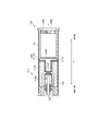
以下において、実施形態に係る非燃焼型香味吸引器について説明する。図1は、実施形
態に係る非燃焼型香味吸引器100を示す図である。非燃焼型香味吸引器100は、燃焼
を伴わずに香喫味成分を吸引するための器具であり、非吸口端から吸口端に向かう方向で
ある所定方向Aに沿って延びる形状を有する。図2は、実施形態に係る霧化ユニット11
1を示す図である。なお、以下においては、非燃焼型香味吸引器100を単に香味吸引器
100と称することに留意すべきである。
[Embodiment]
(Non-combustion type flavor suction device)
Below, the non-combustion type flavor suction device which concerns on embodiment is demonstrated. FIG. 1 is a view showing a non-burning type
FIG. It should be noted that, in the following, the non-burning type
図1に示すように、香味吸引器100は、吸引器本体110と、カートリッジ130と
を有する。
As shown in FIG. 1, the
吸引器本体110は、香味吸引器100の本体を構成しており、カートリッジ130を
接続可能な形状を有する。具体的には、吸引器本体110は、吸引器ハウジング110X
を有しており、カートリッジ130は、吸引器ハウジング110Xの吸口端に接続される
。吸引器本体110は、燃焼を伴わずにエアロゾル源を霧化するように構成された霧化ユ
ニット111と、電装ユニット112とを有する。
The aspirator
The
実施形態では、霧化ユニット111は、吸引器ハウジング110Xの一部を構成する第
1筒体111Xを有する。霧化ユニット111は、図2に示すように、リザーバ111P
と、ウィック111Qと、霧化部111Rとを有する。リザーバ111P、ウィック11
1Q及び霧化部111Rは、第1筒体111Xに収容される。第1筒体111Xは、所定
方向Aに沿って延びる筒状形状(例えば、円筒形状)を有する。リザーバ111Pは、エ
アロゾル源を保持する。例えば、リザーバ111Pは、樹脂ウェブ等の材料によって構成
される孔質体である。ウィック111Qは、リザーバ111Pから供給されるエアロゾル
源を保持する液保持部材の一例である。例えば、ウィック111Qは、ガラス繊維によっ
て構成される。霧化部111Rは、ウィック111Qによって保持されるエアロゾル源を
霧化する。霧化部111Rは、例えば、ウィック111Qに所定ピッチで巻き回される発
熱抵抗体(例えば、電熱線)によって構成される。
In the embodiment, the
, The
1Q and the
エアロゾル源は、グリセリン又はプロピレングリコールなどの液体である。エアロゾル
源は、例えば、上述したように、樹脂ウェブ等の材料によって構成される孔質体によって
保持される。孔質体は、非たばこ材料によって構成されていてもよく、たばこ材料によっ
て構成されていてもよい。なお、エアロゾル源は、香喫味成分(例えば、ニコチン成分等
)を含んでいてもよい。或いは、エアロゾル源は、香喫味成分を含まなくてもよい。
The aerosol source is a liquid such as glycerin or propylene glycol. The aerosol source is, for example, held by a porous body constituted by a material such as a resin web as described above. The porous body may be made of non-tobacco material and may be made of tobacco material. The aerosol source may contain a flavor and taste component (for example, a nicotine component and the like). Alternatively, the aerosol source may be free of flavor and aroma components.
実施形態において、霧化部111Rによって発生するエアロゾルの流路に露出する壁面
には、凝縮したエアロゾルを吸収する吸収部材111Sが設けられる。エアロゾルの流路
に露出する壁面は、例えば、エアロゾルの流路に露出する第1筒体111Xの内面、エア
ロゾルの流路に露出するリザーバ111Pの外面などである。ここで、吸収部材111S
がリザーバ111Pと接触していない場合には、吸収部材111Sによって吸収されたエ
アロゾル(凝縮したエアロゾル)は、毛細管現象を利用して吸収部材111Sから霧化部
111Rに導かれることが好ましい。一方で、吸収部材111Sがリザーバ111Pと接
触している場合には、吸収部材111Sによって吸収されたエアロゾル(凝縮したエアロ
ゾル)は、吸収部材111Sからリザーバ111Pに導かれることが好ましい。吸収部材
111Sは、凝縮したエアロゾルを吸収する機能を有する部材であればよく、例えば、リ
ザーバ111Pと同様の材料(樹脂ウェブ)によって構成されていてもよく、ウィック1
11Qと同様の材料(ガラス繊維)によって構成されてもよい。
In the embodiment, an absorbing
When it is not in contact with the
You may be comprised by the material (glass fiber) similar to 11Q.
電装ユニット112は、吸引器ハウジング110Xの一部を構成する第2筒体112X
を有する。実施形態において、電装ユニット112は、インレット112Aを有する。イ
ンレット112Aから流入する空気は、図2に示すように、霧化ユニット111(霧化部
111R)に導かれる。詳細には、電装ユニット112は、電源10と、吸引センサ20
と、押しボタン30と、発光素子40と、制御回路50とを有する。電源10、吸引セン
サ20、押しボタン30及び制御回路50は、第2筒体112Xに収容される。第2筒体
112Xは、所定方向Aに沿って延びる筒状形状(例えば、円筒形状)を有する。
The
Have. In the embodiment, the
, A
電源10は、例えば、リチウムイオン電池である。電源10は、香味吸引器100の動
作に必要な電力を蓄積する。例えば、電源10は、吸引センサ20及び制御回路50に供
給する電力を蓄積する。また、電源10は、霧化ユニット111(霧化部111R)に供
給する電力を蓄積する。
The
吸引センサ20は、インレット112Aからアウトレット130Aまで連続する吸引経
路内の流体流れを検知する。吸引センサ20は、インレット112Aからアウトレット1
30A側への流体流れが所定閾値以上である場合に、吸引(吸引状態)を検知する。吸引
センサ20は、インレット112Aからアウトレット130A側への流体流れが所定閾値
未満である場合に、非吸引(非吸引状態)を検知する。
The
When the fluid flow to the 30A side is equal to or higher than a predetermined threshold, suction (suction state) is detected. The
押しボタン30は、香味吸引器100の外側から内側に向けて押し込むように構成され
る。実施形態では、押しボタン30は、香味吸引器100の非吸口端に設けられており、
非吸口端から吸口端に向かう方向(すなわち、所定方向A)に押し込むように構成される
。例えば、香味吸引器100の電源が投入されていない状態において、押しボタン30が
所定回数に亘って連続的に押し込まれた場合に、香味吸引器100の電源が投入されても
よい。一方で、香味吸引器100の電源が投入された状態において、押しボタン30が所
定回数に亘って連続的に押し込まれた場合に、香味吸引器100の電源が切断されてもよ
い。或いは、パフ動作が行われてからパフ動作が行われないまま所定時間が経過した場合
に、香味吸引器100の電源が切断されてもよい。
The
It is configured to be pushed in the direction from the non-sucking end toward the sucking end (that is, the predetermined direction A). For example, in a state where the power of the
発光素子40は、例えば、LEDや電灯などの光源である。発光素子40は、所定方向
に沿って延びる側壁に設けられる。発光素子40は、非吸口端の近傍の側壁に設けられる
ことが好ましい。これによって、所定方向Aの軸線上において非吸口端の端面のみに発光
素子が設けられるケースと比べて、ユーザは、パフ動作中において発光素子40の発光パ
ターンを容易に視認することができる。発光素子40の発光パターンは、香味吸引器10
0の状態をユーザに通知するパターンである。
The
This is a pattern for notifying the user of the state of 0.
実施形態において、発光素子40は、所望量のエアロゾルを供給可能な旨を報知する報
知部を構成してもよい。ここで、発光素子40は、所望量のエアロゾルを供給可能な期間
の開始から終了までの間に亘って、所望量のエアロゾルを供給可能な旨を継続的に報知し
てもよい。或いは、発光素子40は、所望量のエアロゾルを供給可能でない旨を報知する
報知部を構成してもよい。ここで、発光素子40は、所望量のエアロゾルを供給可能でな
い期間の開始から終了までの間に亘って、所望量のエアロゾルを供給可能でない旨を継続
的に報知してもよい。
In the embodiment, the
制御回路50は、香味吸引器100の動作を制御する。具体的には、制御回路50は、
霧化ユニット111(霧化部111R)に対する電源出力を制御する。また、制御回路5
0は、発光素子40を制御する。
The
The power supply output to the atomization unit 111 (
0 controls the
カートリッジ130は、香味吸引器100を構成する吸引器本体110に接続可能に構
成される。カートリッジ130は、吸口から吸い込まれる気体(以下、空気)の流路上に
おいて霧化ユニット111よりも下流に設けられる。言い換えると、カートリッジ130
は、必ずしも物理空間的に霧化ユニット111よりも吸口側に設けられている必要はなく
、霧化ユニット111から発生するエアロゾルを吸口側に導くエアロゾル流路上において
霧化ユニット111よりも下流に設けられていればよい。
The
Is not necessarily provided on the inlet side of the
具体的には、カートリッジ130は、カートリッジハウジング131と、香味源132
と、網目133Aと、フィルタ133Bとを有する。また、カートリッジ130は、吸口
に設けられるアウトレット130Aを有する。
Specifically, the
, A
カートリッジハウジング131は、所定方向Aに沿って延びる筒状形状(例えば、円筒
形状)を有する。カートリッジハウジング131は、香味源132を収容する。ここでは
、カートリッジハウジング131は、吸引器ハウジング110Xに所定方向Aに沿って挿
入されるように構成される。
The
香味源132は、インレット112Aからアウトレット130Aまで連続する吸引経路
上において霧化ユニット111よりもアウトレット130A(吸口)側に設けられる。香
味源132は、エアロゾル源から発生するエアロゾルに香喫味成分を付与する。言い換え
ると、香味源132によってエアロゾルに付与される香喫味成分は、アウトレット130
A(吸口)に運ばれる。
The
It is carried to A (intake).
実施形態において、香味源132は、霧化ユニット111から発生するエアロゾルに香
喫味成分を付与する原料片によって構成される。原料片のサイズは、0.2mm以上1.
2mm以下であることが好ましい。さらには、原料片のサイズは、0.2mm以上0.7
mm以下であることが好ましい。香味源132を構成する原料片のサイズが小さいほど、
比表面積が増大するため、香味源132を構成する原料片から香喫味成分がリリースされ
やすい。従って、所望量の香喫味成分をエアロゾルに付与するにあたって、原料片の量を
抑制できる。香味源132を構成する原料片としては、刻みたばこ、たばこ原料を粒状に
成形した成形体を用いることができる。但し、香味源132は、たばこ原料をシート状に
成形した成形体であってもよい。また、香味源132を構成する原料片は、たばこ以外の
植物(例えば、ミント、ハーブ等)によって構成されてもよい。香味源132には、メン
トールなどの香料が付与されていてもよい。
In the embodiment, the
It is preferable that it is 2 mm or less. Furthermore, the size of the raw material piece is 0.2 mm or more 0.7
It is preferable that it is mm or less. As the size of the raw material pieces constituting the
Since the specific surface area is increased, the flavor and taste components are easily released from the raw material pieces constituting the
ここで、香味源132を構成する原料片は、例えば、JIS Z 8801に準拠した
ステンレス篩を用いて、JIS Z 8815に準拠する篩分けによって得られる。例え
ば、0.71mmの目開きを有するステンレス篩を用いて、乾燥式かつ機械式振とう法に
よって20分間に亘って原料片を篩分けによって、0.71mmの目開きを有するステン
レス篩を通過する原料片を得る。続いて、0.212mmの目開きを有するステンレス篩
を用いて、乾燥式かつ機械式振とう法によって20分間に亘って原料片を篩分けによって
、0.212mmの目開きを有するステンレス篩を通過する原料片を取り除く。すなわち
、香味源132を構成する原料片は、上限を規定するステンレス篩(目開き=0.71m
m)を通過し、下限を規定するステンレス篩(目開き=0.212mm)を通過しない原
料片である。従って、実施形態では、香味源132を構成する原料片のサイズの下限は、
下限を規定するステンレス篩の目開きによって定義される。なお、香味源132を構成す
る原料片のサイズの上限は、上限を規定するステンレス篩の目開きによって定義される。
Here, the raw material piece which comprises the
It is a raw material piece which passes m) and does not pass a stainless steel sieve (opening = 0.212 mm) which defines the lower limit. Therefore, in the embodiment, the lower limit of the size of the raw material pieces constituting the
It is defined by the mesh size of the stainless steel sieve which defines the lower limit. In addition, the upper limit of the size of the raw material piece which comprises the
実施形態において、香味源132は、アルカリ性のpHを有するたばこ源である。たば
こ源のpHは、7よりも大きいことが好ましく、8以上であることがより好ましい。pH
を7よりも大きくすることによって、たばこ源から発生する香喫味成分をエアロゾルによ
って効率的に取り出すことができる。これにより、所望量の香喫味成分をエアロゾルに付
与するにあたって、たばこ源の量を抑制できる。一方、たばこ源のpHは、12以下であ
ることが好ましく、10以下であることがより好ましい。pHを12以下とすることによ
って、香味吸引器100(例えば、カートリッジ130又は吸引器本体110)に対する
ダメージ(腐食等)をより効果的に抑制することができる。
In embodiments,
By making the value of 7 or more, the flavor and taste components generated from the tobacco source can be efficiently removed by the aerosol. Thereby, when providing a desired amount of flavor and taste components to an aerosol, the quantity of a tobacco source can be suppressed. On the other hand, the pH of the tobacco source is preferably 12 or less, more preferably 10 or less. By setting the pH to 12 or less, damage (such as corrosion) to the flavor suction device 100 (for example, the
なお、香味源132から発生する香喫味成分はエアロゾルによって搬送されており、香
味源132自体を加熱する必要はないことに留意すべきである。
It should be noted that the flavor and taste components generated from the
網目133Aは、香味源132の上流においてカートリッジハウジング131の開口を
塞ぐように設けられており、フィルタ133Bは、香味源132の下流においてカートリ
ッジハウジング131の開口を塞ぐように設けられている。網目133Aは、香味源13
2を構成する原料片が通過しない程度の粗さを有する。網目133Aの粗さは、例えば、
0.077mm以上0.198mm以下の目開きを有する。フィルタ133Bは、通気性
を有する物質によって構成される。フィルタ133Bは、例えば、アセテートフィルタで
あることが好ましい。フィルタ133Bは、香味源132を構成する原料片が通過しない
程度の粗さを有する。
The
It has the roughness of the extent which the raw material piece which comprises 2 does not pass. The roughness of the
It has an opening of 0.077 mm or more and 0.198 mm or less. The
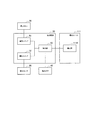
(ブロック構成)
以下において、実施形態に係る非燃焼型香味吸引器のブロック構成について説明する。
図3は、実施形態に係る香味吸引器100のブロック構成を示す図である。
(Block configuration)
Hereinafter, the block configuration of the non-burning type flavor suction device according to the embodiment will be described.
FIG. 3 is a diagram showing a block configuration of the
図3に示すように、制御回路50は、電源スイッチ51と、霧化スイッチ52と、制御
部53とを有する。
As shown in FIG. 3, the
電源スイッチ51は、香味吸引器100の電源が投入される場合にオン状態に切り替わ
り、香味吸引器100の電源が切断される場合にオフ状態に切り替わる。例えば、電源ス
イッチ51は、押しボタン30に接続されており、香味吸引器100の電源が投入されて
いない状態において、押しボタン30が所定回数に亘って連続的に押し込まれた場合にオ
ン状態に切り替わってもよい。一方で、電源スイッチ51は、香味吸引器100の電源が
投入された状態において、押しボタン30が所定回数に亘って連続的に押し込まれた場合
にオフ状態に切り替わってもよい。或いは、電源スイッチ51は、パフ動作の終了に応じ
て起動するタイマを有しており、タイマの満了(所定時間の経過)に応じてオフ状態に切
り替わってもよい。
The
霧化スイッチ52は、ユーザのパフ動作が行われるときに、霧化部111Rに対する電
源出力の供給を停止する状態(オフ状態)に切り替わり、ユーザのパフ動作が行われなく
なるときに、霧化部111Rに対する電源出力の供給を開始する状態(オン状態)に切り
替わる。実施形態では、霧化スイッチ52は、パフ動作を検知する吸引センサと連動して
いる。霧化スイッチ52は、吸引センサ20によってパフ動作が検知されたときに、オフ
状態に切り替わる。一方で、霧化スイッチ52は、吸引センサ20によってパフ動作が検
知されなくなったときに、オン状態に切り替わる。
When the puff operation of the user is performed, the
ここで、吸引センサ20によってパフ動作が検知されていない状態を非吸引状態と称し
、吸引センサ20によってパフ動作が検知されている状態を吸引状態と称することもある
。従って、霧化スイッチ52は、非吸引状態から吸引状態への切り替えによってオフ状態
に切り替わり、吸引状態から非吸引状態への切り替えによってオン状態に切り替わる。
Here, a state in which the puff operation is not detected by the
制御部53は、香味吸引器100の電源が投入された状態において、香味吸引器100
を制御する。
The
Control.
第1に、制御部53は、霧化部111Rに対する電源出力を制御する。実施形態におい
て、制御部53は、ユーザのパフ動作の開始前に霧化部111Rに対する電源出力の供給
を開始するとともに、ユーザのパフ動作中に霧化部111Rに対する電源出力の供給を停
止する。実施形態では、制御部53は、霧化スイッチ52がオフ状態になった場合に、霧
化部111Rに対する電源出力の供給を停止する。一方で、制御部53は、霧化スイッチ
52がオン状態になったときに、霧化部111Rに対する電源出力の供給を開始する。言
い換えると、制御部53は、吸引センサ20によってパフ動作が検知されたときに、霧化
部111Rに対する電源出力の供給を停止する。一方で、制御部53は、吸引センサ20
によってパフ動作が検知されなくなったときに、霧化部111Rに対する電源出力の供給
を開始する。
First, the
When the puff operation is not detected due to, the supply of power output to the
ここで、電源出力の大きさは、霧化部111Rに対して連続的に電圧が印加されるケー
スにおいては、霧化部111Rに対して印加される電圧の値で定義される。一方で、電源
出力の大きさは、霧化部111Rに対して断続的に電圧が印加されるケース(パルス制御
)においては、霧化部111Rに対して印加される電圧の値、パルス幅及びパルス間隔の
少なくともいずれか1つのパラメータによって定義される。
Here, the magnitude of the power supply output is defined by the value of the voltage applied to the
実施形態において、制御部53は、霧化部111Rに対する電源出力の供給を開始して
から第1時間が経過した場合に、霧化部111Rに対する電源出力の供給を停止してもよ
い。ここで、第1時間は、非吸引状態の時間長に依存せずにエアロゾルの供給量を所望量
に収めるための時間である。言い換えると、第1時間は、エアロゾルの供給量が所望量の
範囲の上限を超えないようにするために定められた時間である。
In the embodiment, the
例えば、第1時間の上限は5秒であることが好ましい。より好ましくは、第1時間の上
限は4秒であり、さらにより好ましくは、第1時間の上限は3秒である。例えば、第1時
間の下限は0.5秒であることが好ましい。より好ましくは、第1時間の下限は1秒であ
り、さらにより好ましくは、第1時間の下限は1.5秒である。例えば、第1時間は0.
5秒以上5秒以下であることが好ましい。より好ましくは、第1時間は1秒以上4秒以下
であることが好ましい。さらにより好ましくは、第1時間は1.5秒以上3秒以下である
ことが好ましい。
For example, the upper limit of the first time is preferably 5 seconds. More preferably, the upper limit of the first time is 4 seconds, and still more preferably, the upper limit of the first time is 3 seconds. For example, the lower limit of the first time is preferably 0.5 seconds. More preferably, the lower limit of the first time is 1 second, and even more preferably, the lower limit of the first time is 1.5 seconds. For example, the first time is 0.
The time is preferably 5 seconds or more and 5 seconds or less. More preferably, it is preferable that the first time is 1 second or more and 4 seconds or less. Still more preferably, the first time is 1.5 seconds or more and 3 seconds or less.
実施形態では、制御部53は、第1時間の経過によって霧化部111Rに対する電源出
力の供給を停止してから第2時間が経過した場合に、霧化部111Rに対する電源出力の
供給を再開してもよい。ここで、第2時間は、エアロゾルの流路に露出する壁面にエアロ
ゾルが凝縮することによって、エアロゾルの供給量が所望量の範囲の下限を下回らないよ
うにするために定められた時間である。なお、吸収部材111Sによって吸収された凝縮
後のエアロゾルが電源出力の供給再開によって再霧化されてもよい。
In the embodiment, the
上述したように、吸収部材111Sがリザーバ111Pと接触していない場合には、吸
収部材111Sによって吸収されたエアロゾル(凝縮したエアロゾル)は、毛細管現象を
利用して吸収部材111Sから霧化部111Rに導かれることが好ましい。一方で、吸収
部材111Sがリザーバ111Pと接触している場合には、吸収部材111Sによって吸
収されたエアロゾル(凝縮したエアロゾル)は、吸収部材111Sからリザーバ111P
に導かれることが好ましい。
As described above, when the absorbing
It is preferable to be led to
第2に、制御部53は、発光素子40を制御する。実施形態において、制御部53は、
所望量のエアロゾルを供給可能な旨を報知するように発光素子40を制御してもよい。制
御部53は、所望量のエアロゾルを供給可能な期間の開始から終了までの間に亘って、所
望量のエアロゾルを供給可能な旨を継続的に報知するように発光素子40を制御してもよ
い。例えば、所望量のエアロゾルを供給可能な期間の開始タイミングは、霧化部111R
に対する電源出力の供給を開始してから第1時間よりも短い一定時間が経過するタイミン
グである。一定時間は、例えば、霧化部111Rに対する電源出力の供給を開始してから
エアロゾルの供給量が所望量の範囲の下限に達するまでの時間である。
Second, the
The
Is a timing at which a certain time shorter than the first time elapses after the supply of the power supply output to the circuit starts. The fixed time is, for example, a time from when the supply of the power supply output to the
また、制御部53は、所望量のエアロゾルを供給可能でない旨を報知するように発光素
子40を制御してもよい。制御部53は、所望量のエアロゾルを供給可能でない期間の開
始から終了までの間に亘って、所望量のエアロゾルを供給可能でない旨を継続的に報知す
るように発光素子40を制御してもよい。所望量のエアロゾルを供給可能でない期間の開
始タイミングは、例えば、霧化部111Rに対する電源出力の供給を開始したタイミング
である。なお、所望量のエアロゾルを供給可能でない期間の終了タイミングは、所望量の
エアロゾルを供給可能な期間の開始タイミングと同様である。
In addition, the
第3に、制御部53は、非吸引状態から吸引状態への切替え及び吸引状態から非吸引状
態への切替えが行われたときに、霧化部111Rに対する通電処理をトリガーしてもよい
。言い換えると、初回のパフ動作は、エアロゾルの発生を伴わず、霧化部111Rに対す
る通電処理をトリガーするために行われる。霧化部111Rに対する通電処理とは、霧化
部111Rに対する電源出力の供給によってエアロゾルを発生させる処理である。
Thirdly, the
例えば、初回のパフ動作は、ユーザが正規のユーザであるか否かを認証するために用い
られてもよい。例えば、初回のパフ動作に伴う吸引センサ20の応答値が所定条件(例え
ば、流速の傾きが所定値以上である条件)を満たす場合に、ユーザが正規のユーザである
と認証される。初回のパフ動作とは、香味吸引器100の電源が導入された後の初回のパ
フ動作であってもよく、パフ動作が行われないまま所定時間が経過した後の初回のパフ動
作であってもよい。ここで、制御部53は、初回のパフ動作について、非吸引状態から吸
引状態への切替え及び吸引状態から非吸引状態への切替えがトリガー時間内に行われなけ
れば、霧化部111Rに対する通電処理をトリガーしなくてもよい。このような認証動作
については、国際出願番号PCT/JP2015/63036(2015年4月30日出
願)の全内容が参照により組み込まれる。
For example, an initial puff operation may be used to authenticate whether the user is a legitimate user. For example, when the response value of the
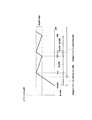
(制御例)
以下において、実施形態に係る霧化部111Rに対する電源出力の制御例について説明
する。図4は、実施形態に係る霧化部111Rに対する電源出力の制御例を説明するため
の図である。
(Example of control)
Below, the example of control of the power supply output to atomization
上述したように、制御部53は、霧化スイッチ52がオン状態(すなわち、非吸引状態
)になったときに、霧化部111Rに対する電源出力の供給を開始する。制御部53は、
霧化スイッチ52がオフ状態(すなわち、吸引状態)になったときに、霧化部111Rに
対する電源出力の供給を停止する。
As described above, when the
When the
このようなケースにおいて、制御部53は、図4に示すように、霧化部111Rに対す
る電源出力の供給を開始してから、霧化スイッチ52がオン状態(すなわち、非吸引状態
)のまま第1時間が経過した場合に、霧化部111Rに対する電源出力の供給を停止する
。第1時間は、エアロゾルの供給量が所望量の範囲の上限を超えないようにするために定
められた時間である。なお、第1時間は、エアロゾル流路に滞留するエアロゾルの量によ
って可変である。
In such a case, as shown in FIG. 4, the
また、制御部53は、第1時間の経過によって霧化部111Rに対する電源出力の供給
を停止してから、霧化スイッチ52がオン状態(すなわち、非吸引状態)のまま第2時間
が経過した場合に、霧化部111Rに対する電源出力の供給を再開する。第2時間は、エ
アロゾルの供給量が所望量の範囲の下限を下回らないようにするために定められた時間で
ある。実施形態に係る制御例では、霧化部111Rに対する電源出力の供給の停止及び再
開を繰り返すことによって、エアロゾルの供給量が所望量の範囲内で増減する。ここで、
所望量の範囲は、上限と下限とによって定めてもよく、下限は0.1mg以上であること
が好ましく、1.0mg以上であることがさらに好ましい。一方で、所望量の上限は、1
0.0mg以下であることが好ましく、5.0mg以下であることがさらに好ましい。0
.1mg以上10.0mg以下としてもよく、1.0mg以上5.0mg以下としてもよ
い。また、所望量の範囲は、所望量の目標値を基準として定めてもよく、例えば、所望量
の目標値を基準として±50%以下の範囲(例えば、所望量の目標値を2.0mgとした
場合には、所望量の範囲は1.0mg以上3.0mg以下)であることが好ましく、±2
5%以下の範囲(例えば、所望量の目標値を2.0mgとした場合には、所望量の範囲は
1.5mg以上2.5mg以下)であることがさらに好ましい。
In addition, the
The range of the desired amount may be determined by the upper limit and the lower limit, and the lower limit is preferably 0.1 mg or more, and more preferably 1.0 mg or more. On the other hand, the upper limit of the desired amount is 1
It is preferably 0.0 mg or less, and more preferably 5.0 mg or less. 0
. It may be 1 mg or more and 10.0 mg or less, or may be 1.0 mg or more and 5.0 mg or less. In addition, the range of the desired amount may be determined based on the target value of the desired amount, for example, a range of ± 50% or less based on the target value of the desired amount (for example, If desired, the range of the desired amount is preferably 1.0 mg or more and 3.0 mg or less),
It is more preferable that the range of 5% or less (for example, when the target value of the desired amount is 2.0 mg, the range of the desired amount is 1.5 mg or more and 2.5 mg or less).
ここで、制御部53は、所望量のエアロゾルを供給可能な旨を報知するように発光素子
40を制御する。また、制御部53は、所望量のエアロゾルを供給可能でない旨を報知す
るように発光素子40を制御する。実施形態に係る制御例では、霧化部111Rに対する
電源出力の供給を開始してからエアロゾルの供給量が所望量の範囲の下限に達するまで、
所望量のエアロゾルを供給可能でない旨が報知される。霧化部111Rに対する電源出力
の供給を開始してからエアロゾルの供給量が所望量の範囲の下限を上回った場合に、所望
量のエアロゾルを供給可能な旨が報知される。所望量のエアロゾルを供給可能な期間の開
始タイミングは、霧化部111Rに対する電源出力の供給を開始してから第1時間よりも
短い一定時間が経過するタイミングである。一定時間は、例えば、霧化部111Rに対す
る電源出力の供給を開始してからエアロゾルの供給量が所望量の範囲の下限に達するまで
の時間である。
Here, the
It is informed that the desired amount of aerosol can not be supplied. If the supply amount of the aerosol exceeds the lower limit of the desired amount range after the supply of the power supply output to the
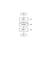
(エアロゾル送達方法)
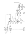
以下において、実施形態に係るエアロゾル送達方法について説明する。図5〜図7は、
実施形態に係るエアロゾル送達方法を示すフロー図である。図5〜図7では、香味吸引器
100(制御部53)の動作について主として説明する。
(Aerosol delivery method)
Below, the aerosol delivery method which concerns on embodiment is demonstrated. 5 to 7 are
It is a flow figure showing an aerosol delivery method concerning an embodiment. 5-7, the operation | movement of the flavor suction device 100 (control part 53) is mainly demonstrated.
図5に示すように、ステップS10において、香味吸引器100の電源が投入される。
例えば、押しボタン30が所定回数に亘って連続的に押し込まれた場合に、香味吸引器1
00の電源が投入される。
As shown in FIG. 5, in step S10, the power of the
For example, when the
The power of 00 is turned on.
ステップS20において、制御部53は、パフ動作に伴う電源出力の制御を行う。なお
、ステップS20の詳細については後述する(図6及び図7を参照)。
In step S20, the
ステップS30において、香味吸引器100の電源が切断される。例えば、押しボタン
30が所定回数に亘って連続的に押し込まれた場合に、香味吸引器100の電源が切断さ
れる。或いは、パフ動作が行われてからパフ動作が行われないまま所定時間が経過した場
合に、香味吸引器100の電源が切断されてもよい。
In step S30, the power supply of the
続いて、上述したステップS20の詳細について説明する。図6は、初回のパフ動作に
おけるエアロゾル送達方法を示すフロー図である。図6に示すように、ステップS201
において、香味吸引器100は、吸引センサ20によってパフ動作が検知されていない非
吸引状態である。
Subsequently, details of step S20 described above will be described. FIG. 6 is a flow diagram illustrating an aerosol delivery method in a first puff operation. As shown in FIG. 6, step S201.
The
ステップS202において、制御部53は、非吸引状態から吸引状態への切り替えが行
われたかを判定する。言い換えると、制御部53は、霧化スイッチ52がオン状態からオ
フ状態に切り替わったかを判定する。制御部53は、判定結果がYESである場合には、
ステップS203の処理に移る。制御部53は、判定結果がNOである場合には、ステッ
プS201の処理に戻る。
In step S202, the
The process proceeds to step S203.
ステップS203において、制御部53は、吸引状態から非吸引状態への切り替えが行
われたかを判定する。言い換えると、制御部53は、霧化スイッチ52がオフ状態からオ
ン状態に切り替わったかを判定する。制御部53は、判定結果がYESである場合には、
ステップS204の処理に移る。制御部53は、判定結果がNOである場合には、そのま
ま待機する。
In step S203, the
It moves to a process of step S204. When the determination result is NO, the
ステップS204において、制御部53は、非吸引状態から吸引状態への切り替え及び
吸引状態から非吸引状態への切り替えがトリガー時間内に行われたかを判定する。すなわ
ち、制御部53は、吸引状態への切り替えが行われたタイミングから非吸引状態への切り
替えが行われたタイミングまでの時間がトリガー時間内であるかを判定する。制御部53
は、判定結果がYESである場合には、ステップS205の処理に移る。制御部53は、
判定結果がNOである場合には、ステップS201の処理に戻る。但し、ステップS20
4の処理は省略されてもよい。
In step S204, the
When the determination result is YES, the processing of step S 205 is performed. The
If the determination result is NO, the process returns to the process of step S201. However, step S20
The process of 4 may be omitted.
ステップS205において、制御部53は、霧化部111Rに対する通電処理をトリガ
ーする。すなわち、制御部53は、ステップS202及びステップS203で検知された
初回のパフ動作が行われた後に、霧化部111Rに対する電源出力の供給を開始する。ま
た、初回のパフ動作は、ユーザが正規のユーザであるか否かを認証するために用いられて
もよい。初回のパフ動作とは、香味吸引器100の電源が投入された後の初回のパフ動作
であってもよく、パフ動作が行われないまま所定時間が経過した後の初回のパフ動作であ
ってもよい。所定時間は、少なくとも第1時間及び第2時間よりも長い。
In step S205, the
ここで、制御部53は、霧化部111Rに対する電源出力の供給を開始してからエアロ
ゾルの供給量が所望量の範囲の下限に達するまで、所望量のエアロゾルを供給可能でない
旨を報知するように、発光素子40を制御してもよい。一方で、制御部53は、霧化部1
11Rで生成されたエアロゾルの供給量が所望量の範囲の下限を上回ったときに、所望量
のエアロゾルを供給可能な旨を報知するように発光素子40を制御してもよい。発光素子
40は、所望量のエアロゾルを供給可能な期間の開始から終了までの間に亘って、所望量
のエアロゾルを供給可能な旨を継続的に報知してもよい。
Here, the
When the supply amount of the aerosol generated in 11R exceeds the lower limit of the desired amount range, the
なお、制御部53は、ステップS205の処理の後に、図7に示すステップS211の
処理に移る。図7は、認証後のパフ動作(例えば、2回目以降のパフ動作)におけるエア
ロゾル送達方法を示すフロー図である。
In addition, the
図7に示すように、ステップS211において、制御部53は、非吸引状態から吸引状
態への切り替えが行われたかを判定する。言い換えると、制御部53は、霧化スイッチ5
2がオン状態からオフ状態に切り替わったかを判定する。制御部53は、判定結果がYE
Sである場合には、ステップS212の処理に移る。制御部53は、判定結果がNOであ
る場合には、ステップS216の処理に移る。
As shown in FIG. 7, in step S211, the
It is determined whether 2 has switched from the on state to the off state.
If it is S, the process proceeds to step S212. If the determination result is NO, the
ステップS212において、香味吸引器100は、吸引センサ20によってパフ動作が
検知されている吸引状態である。
In step S212, the
ステップS213において、制御部53は、霧化部111Rに対する電源出力の供給を
停止する。
In step S213, the
ステップS214において、吸引状態から非吸引状態への切り替えが行われたかを判定
する。言い換えると、制御部53は、霧化スイッチ52がオフ状態からオン状態に切り替
わったかを判定する。制御部53は、判定結果がYESである場合には、ステップS21
5の処理に移る。制御部53は、判定結果がNOである場合には、吸引状態が終了するま
で待機する。
In step S214, it is determined whether switching from the suction state to the non-suction state has been performed. In other words, the
Move to processing of 5. When the determination result is NO, the
ステップS215において、制御部53は、霧化部111Rに対する電源出力の供給を
再開する。ここで、制御部53は、霧化部111Rで生成されたエアロゾルの供給量が所
望量の範囲の下限を上回るまでは、所望量のエアロゾルを供給可能でない旨を報知するよ
うに発光素子40を制御してもよい。制御部53は、霧化部111Rで生成されたエアロ
ゾルの供給量が所望量の範囲の下限を上回ったときに、所望量のエアロゾルを供給可能な
旨を報知するように発光素子40を制御してもよい。なお、制御部53は、ステップS2
15の後にステップS211の処理に戻る。
In step S215, the
After step 15, the process returns to the process of step S211.
ステップS216において、制御部53は、霧化部111Rに対する電源出力の供給を
開始してから第1時間が経過したかを判定する。なお、第1時間は、上述したように、エ
アロゾルの供給量が所望量の範囲の上限を超えないようにするために定められた時間であ
る。制御部53は、判定結果がYESである場合には、ステップS217の処理に移る。
制御部53は、判定結果がNOである場合には、ステップS211の処理に戻る。
In step S216, the
ステップS217において、制御部53は、霧化部111Rに対する電源出力の供給を
停止する。ここで、制御部53は、霧化部111Rで生成されたエアロゾルの供給量が所
望量の範囲の下限を下回ったときに、所望量のエアロゾルを供給可能でない旨を報知する
ように発光素子40を制御してもよい。発光素子40は、所望量のエアロゾルを供給可能
でない期間の開始から終了までの間に亘って、所望量のエアロゾルを供給可能でない旨を
継続的に報知してもよい。
In step S217, the
但し、図4に示す制御例のように、エアロゾルの供給量が所望量の範囲の下限を上回っ
た後においてエアロゾルの供給量が所望範囲内で増減する場合には、エアロゾルの供給量
が所望量の範囲の下限を上回った状態が維持されることに留意すべきである。従って、ス
テップS217で所望量のエアロゾルを供給可能でない旨を報知する必要はない。
However, as in the control example shown in FIG. 4, when the supply amount of the aerosol increases or decreases within the desired range after the supply amount of the aerosol exceeds the lower limit of the desired amount range, the supply amount of the aerosol is the desired amount It should be noted that the lower limit of the range is maintained. Therefore, in step S217, it is not necessary to notify that the desired amount of aerosol can not be supplied.
ステップS218において、制御部53は、第1時間の経過によって霧化部111Rに
対する電源出力の供給を停止してから第2時間が経過したかを判定する。なお、第2時間
は、上述したように、エアロゾルの供給量が所望量の範囲の下限を下回らないようにする
ために定められた時間である。制御部53は、判定結果がYESである場合には、ステッ
プS219の処理に移る。制御部53は、判定結果がNOである場合には、ステップS2
20の処理に移る。
In step S218, the
Move to processing of 20.
ステップS219において、制御部53は、終了条件が満たされているかを判定する。
制御部53は、判定結果がYESである場合には、一連の処理を終了する。制御部53は
、判定結果がNOである場合には、ステップS221の処理に戻る。終了条件は、パフ動
作が行われないまま所定時間が経過することであってもよく、所定回数のパフ動作が行わ
れたことであってもよい。
In step S219, the
ステップS220において、制御部53は、非吸引状態から吸引状態への切り替えが行
われたかを判定する。言い換えると、制御部53は、霧化スイッチ52がオン状態からオ
フ状態に切り替わったかを判定する。制御部53は、判定結果がYESである場合には、
ステップS212の処理に移る。制御部53は、判定結果がNOである場合には、ステッ
プS218の処理に戻る。
In step S220, the
It moves to a process of step S212. If the determination result is NO, the
ステップS221において、制御部53は、霧化部111Rに対する電源出力の供給を
再開する。ここで、制御部53は、ステップS205と同様に、霧化部111Rで生成さ
れたエアロゾルの供給量が所望量の範囲の下限を上回ったときに、所望量のエアロゾルを
供給可能な旨を報知するように発光素子40を制御してもよい。発光素子40は、所望量
のエアロゾルを供給可能な期間の開始から終了までの間に亘って、所望量のエアロゾルを
供給可能な旨を継続的に報知してもよい。
In step S221, the
但し、図4に示す制御例のように、エアロゾルの供給量が所望量の範囲の下限を上回っ
た後においてエアロゾルの供給量が所望範囲内で増減する場合には、エアロゾルの供給量
が所望量の範囲の下限を上回った状態が維持されることに留意すべきである。従って、霧
化部111Rで生成されたエアロゾルの供給量が所望量の範囲の下限を上回ったタイミン
グで所望量のエアロゾルを供給可能な旨が1回だけ報知される場合には、ステップS21
5で所望量のエアロゾルを供給可能な旨を報知する必要はない。なお、制御部53は、ス
テップS221の後にステップS211の処理に戻る。
However, as in the control example shown in FIG. 4, when the supply amount of the aerosol increases or decreases within the desired range after the supply amount of the aerosol exceeds the lower limit of the desired amount range, the supply amount of the aerosol is the desired amount It should be noted that the lower limit of the range is maintained. Therefore, when notification that the desired amount of aerosol can be supplied is notified only once at the timing when the supply amount of the aerosol generated by the
In 5, it is not necessary to notify that the desired amount of aerosol can be supplied. The
上述したように、エアロゾル送達方法は様々な工程を含むが、実施形態はこれに限定さ
れるものではない。エアロゾル送達方法は、吸引経路内でエアロゾルを発生させるステッ
プA(すなわち、ステップS205、ステップS215、ステップS221)と、ステッ
プAの後にエアロゾルの発生を停止した状態で、エアロゾルを吸引経路内の流体流れによ
ってユーザーの口腔内に移動させるステップB(すなわち、ステップS213)とを少な
くとも含めばよい。
As mentioned above, the aerosol delivery method includes various steps, but the embodiment is not limited thereto. The aerosol delivery method includes the step A of generating an aerosol in the suction path (ie, step S205, step S215, step S221), and the flow of aerosol in the suction path with the generation of the aerosol stopped after step A. Step B (i.e., step S213) of moving it into the oral cavity of the user.
(作用及び効果)
実施形態では、制御部53は、ユーザのパフ動作中に霧化部111Rに対する電源出力
の供給を停止する。霧化部111Rによってエアロゾルを発生している途中において、ユ
ーザのパフ動作によって霧化部111Rの温度が変化することがない。従って、1回のパ
フ動作内又は複数のパフ動作間において、エアロゾルを構成する粒子の粒径がばらつく事
態が抑制される。
(Action and effect)
In the embodiment, the
実施形態では、制御部53は、霧化部111Rに対する電源出力の供給を開始してから
第1時間が経過した場合に、霧化部111Rに対する電源出力の供給を停止する。従って
、パフ動作の間隔に依存せずにエアロゾルの供給量を所望量に収めることができる。
In the embodiment, the
実施形態では、制御部53は、第1時間の経過によって霧化部111Rに対する電源出
力の供給を停止してから第2時間が経過した場合に、霧化部111Rに対する電源出力の
供給を再開する。これによって、エアロゾルの流路に露出する壁面にエアロゾルが凝縮す
ることによって、エアロゾルの供給量が所望量の範囲の下限を下回ることを抑制すること
ができる。
In the embodiment, the
実施形態では、発光素子40は、所望量のエアロゾルを供給可能な期間において、所望
量のエアロゾルを供給可能な旨を報知する。これによって、ユーザは、適切なタイミング
におけるパフ動作の開始を促進することができる。
In the embodiment, the
実施形態では、発光素子40は、所望量のエアロゾルを供給することができない期間に
おいて、所望量のエアロゾルを供給可能でない旨を報知する。これによって、不適切なタ
イミングにおけるパフ動作の開始を抑制することができる。
In the embodiment, the
実施形態では、霧化部111Rによって発生するエアロゾルの流路に露出する壁面には
、凝縮したエアロゾルを吸収する吸収部材111Sが設けられる。これによって、吸収部
材111Sによって吸収されるエアロゾルの再霧化によって、エアロゾル源の無駄を抑制
することができる。
In the embodiment, on the wall surface exposed to the flow path of the aerosol generated by the
実施形態では、制御部53は、非吸引状態から吸引状態への切替え及び吸引状態から非
吸引状態への切替えが行われたときに、霧化部111Rに対する通電処理をトリガーする
。これによって、霧化部111Rに対する通電処理を適切にトリガーすることができる。
さらに、初回のパフ動作をユーザ認証に流用することもできる。
In the embodiment, when the switching from the non-sucking state to the sucking state and the switching from the suction state to the non-sucking state are performed, the
Furthermore, the first puff operation can be diverted to user authentication.
[変更例1]
以下において、実施形態の変更例1について説明する。以下においては、実施形態に対
する相違点について主として説明する。
[Modification 1]
Below, the
具体的には、実施形態では、霧化スイッチ52は、吸引センサ20に連動している。こ
れに対して、変更例1では、霧化スイッチ52は、図8に示すように、操作インタフェー
ス80に接続されており、操作インタフェース80に対するユーザ操作と連動している。
操作インタフェース80は、上述した押しボタン30であってもよく、上述した押しボタ
ン30とは別に設けられたインタフェースであってもよい。
Specifically, in the embodiment, the
The
操作インタフェース80は、パフ動作の開始前に操作されるように構成されたインタフ
ェースである。すなわち、ユーザは、パフ動作を行わない期間において操作インタフェー
ス80を操作し、パフ動作を行う期間において操作インタフェース80を操作しない。従
って、霧化スイッチ52は、操作インタフェース80に対するユーザ操作が行われなくな
ったときにオフ状態に切り替わる。一方で、霧化スイッチ52は、操作インタフェース8
0に対するユーザ操作が行われたときにオン状態に切り替わる。すなわち、操作インタフ
ェース80に対するユーザ操作が行われている状態は非吸引状態であり、操作インタフェ
ース80に対するユーザ操作が行われていない状態は吸引状態である。
The
It switches to the on state when a user operation for 0 is performed. That is, the state in which the user operation on the
変更例1において、制御部53は、操作インタフェース80に対するユーザ操作が行わ
れたときに霧化部111Rに対する電源出力の供給を開始するとともに、操作インタフェ
ース80に対するユーザ操作が行われなくなったときに霧化部111Rに対する電源出力
の供給を停止する。
In the first modification,
ここで、実施形態の制御を変更例1に適用するケースにおいては、「吸引センサ20に
よってパフ動作が検知されたとき」を「操作インタフェース80に対するユーザ操作が行
われなくなったとき」と読み替えるとともに、「吸引センサ20によってパフ動作が検知
されなくなったとき」を「操作インタフェース80に対するユーザ操作が行われたとき」
と読み替えればよい。
Here, in the case where the control of the embodiment is applied to the first modification, “when the puff operation is detected by the
It should be read as.
このような読み替えを前提とした場合に、変更例1において、吸引経路内でエアロゾル
を発生させるステップA(上述したステップS205、ステップ213、ステップ219
)は、操作インタフェース80に対するユーザ操作が行われたときに霧化部111Rに対
する電源出力の供給を開始するステップであり、ステップAの後にエアロゾルの発生を停
止した状態で、エアロゾルを吸引経路内の流体流れによってユーザーの口腔内に移動させ
るステップBは、操作インタフェース80に対するユーザ操作が行われなくなったときに
霧化部111Rに対する電源出力の供給を停止するステップである。
Step A of generating an aerosol in the aspiration path in the first modification example on the premise of such rereading (Step S205, Step 213, Step 219 described above
Is a step of starting supply of power output to the
(制御例)
以下において、変更例1に係る霧化部111Rに対する電源出力の制御例について説明
する。図9は、変更例1に係る霧化部111Rに対する電源出力の制御例を説明するため
の図である。
(Example of control)
Below, the example of control of the power supply output to atomization
上述したように、制御部53は、操作インタフェース80に対するユーザ操作が行われ
たときに、霧化部111Rに対する電源出力の供給を開始する。制御部53は、操作イン
タフェース80に対するユーザ操作が行われていないときに、霧化部111Rに対する電
源出力の供給を停止する。
As described above, when the user operation on the
このようなケースにおいて、制御部53は、図9に示すように、霧化部111Rに対す
る電源出力の供給を開始してから、霧化スイッチ52がオン状態(すなわち、非吸引状態
)のまま第1時間が経過した場合に、霧化部111Rに対する電源出力の供給を停止する
。すなわち、操作インタフェース80に対するユーザ操作が行われている状態が継続して
いても、霧化部111Rに対する電源出力の供給が停止する。第1時間は、エアロゾルの
供給量が所望量の範囲の上限を超えないようにするために定められた時間である。但し、
変更例1に係る制御例では、上述した第2時間を用いて所望量の範囲の下限を上回るよう
にエアロゾルの供給量を維持する制御が行われない。
In such a case, as shown in FIG. 9, the
In the control example according to the first modification, control for maintaining the supply amount of the aerosol to exceed the lower limit of the desired amount range using the second time described above is not performed.
ここで、制御部53は、所望量のエアロゾルを供給可能な旨を報知するように発光素子
40を制御する。また、制御部53は、所望量のエアロゾルを供給可能でない旨を報知す
るように発光素子40を制御する。変更例1に係る制御例では、エアロゾルの供給量が所
望量の範囲の下限を下回っているときに、所望量のエアロゾルを供給可能でない旨が報知
される。エアロゾルの供給量が所望量の範囲の下限を上回っているときに、所望量のエア
ロゾルを供給可能な旨が報知される。
Here, the
(作用及び効果)
変更例1においては、吸引センサ20に代えて操作インタフェース80を用いても、実
施形態と同様の効果を得ることができる。また、上述した第2時間を用いて所望量の範囲
の下限を上回るようにエアロゾルの供給量を維持する制御が省略されるため、実施形態と
比べて、電力消費量や処理負荷が軽減される。
(Action and effect)
In the first modification, even if the
[変更例2]
以下において、実施形態の変更例2について説明する。以下においては、実施形態に対
する相違点について主として説明する。
[Modification 2]
Below, the
実施形態では、吸引センサ20に連動している霧化スイッチ52が設けられる。これに
対して、変更例2では、図10に示すように、操作インタフェース80に連動している第
1スイッチ57及び吸引センサ20に連動している第2スイッチ58が設けられる。操作
インタフェース80は、上述した押しボタン30であってもよく、上述した押しボタン3
0とは別に設けられたインタフェースであってもよい。
In the embodiment, an
It may be an interface provided separately from 0.
変更例2において、第1スイッチ57は、操作インタフェース80に対するユーザ操作
が行われたときにオン状態に切り替わり、操作インタフェース80に対するユーザ操作が
行われなくなったときにオフ状態に切り替わる。一方で、第2スイッチ58は、吸引セン
サ20によってパフ動作が検知されたときにオン状態に切り替わり、吸引センサ20によ
ってパフ動作が検知されなくなったときにオフ状態に切り替わる。すなわち、第2スイッ
チ58は、ユーザのパフ動作の開始によってオン状態に切り替わり、ユーザのパフ動作の
終了によってオフ状態に切り替わる。
In the second modification, the
変更例2において、制御部53は、第1スイッチ57がオン状態に切り替わったときに
、霧化部111Rに対する電源出力の供給を開始するとともに、第2スイッチ58がオン
状態に切り替わった場合に、霧化部111Rに対する電源出力の供給を停止する。言い換
えると、制御部53は、操作インタフェース80に対するユーザ操作が行われたときに霧
化部111Rに対する電源出力の供給を開始するとともに、操作インタフェース80に対
するユーザ操作が行われている状態であっても、吸引センサ20によってパフ動作が検知
されたときに霧化部111Rに対する電源出力の供給を停止する。
In the second modification, when the
このように、変更例2において、霧化部111Rに対する電源出力の供給を開始する契
機は、操作インタフェース80に対するユーザ操作が行われること(第1スイッチ57が
オン状態に切り替わること)であり、吸引センサ20によってパフ動作が検知されなくな
ること(第2スイッチ58がオフ状態に切り替わること)ではないことに留意すべきであ
る。
As described above, in the second modification, the trigger to start the supply of the power output to the
なお、変更例2において、操作インタフェース80は、霧化部111Rに対する電源出
力の供給を開始するためのインタフェースとして用いられている。従って、制御部53は
、操作インタフェース80に対するユーザ操作が行われなくなったときに、霧化部111
Rに対する電源出力の供給を停止しなくてもよい。但し、変更例2はこれに限定されるも
のではない。具体的には、制御部53は、操作インタフェース80に対するユーザ操作が
行われなくなったときに、霧化部111Rに対する電源出力の供給を停止してもよい。具
体的には、操作インタフェース80に対するユーザ操作が行われている(すなわち、第1
スイッチ57がオン状態である)という前提下において、霧化部111Rに対する電源出
力の供給が許容されると考えてもよい。
In the second modification, the
It is not necessary to stop the supply of the power supply output to R. However, the second modification is not limited to this. Specifically, when the user operation on the
It may be considered that the supply of the power output to the
なお、変更例2においては、変更例1と同様に、霧化部111Rに対する電源出力の制
御として図9に示す制御が行われることに留意すべきである。すなわち、上述した第2時
間を用いて所望量の範囲の下限を上回るようにエアロゾルの供給量を維持する制御が行わ
れない。
In the second modification, it is to be noted that the control shown in FIG. 9 is performed as the control of the power supply output to the
変更例2において、霧化部111Rに対する電源出力の供給を停止する観点では、吸引
センサ20に連動している第2スイッチ58が霧化スイッチであると考えてもよい。霧化
部111Rに対する電源出力の供給を開始する観点では、操作インタフェース80に連動
している第1スイッチ57が霧化スイッチであると考えてもよい。
In the second modification, the
(エアロゾル送達方法)
以下において、変更例2に係るエアロゾル送達方法について説明する。図11は、変更
例2に係るエアロゾル送達方法を示すフロー図である。図11では、香味吸引器100(
制御部53)の動作について主として説明する。図11では、図5に示すステップS20
の詳細について説明する。
(Aerosol delivery method)
Below, the aerosol delivery method which concerns on the example 2 of a change is demonstrated. FIG. 11 is a flow chart showing an aerosol delivery method according to the second modification. In FIG. 11, the flavor suction device 100 (
The operation of the control unit 53) will be mainly described. In FIG. 11, step S20 shown in FIG.
Explain the details of.
図11に示すように、ステップS311において、第1スイッチ57がオフ状態である
。すなわち、操作インタフェース80に対するユーザ操作が行われていない。
As shown in FIG. 11, in step S311, the
ステップS312において、制御部53は、終了条件が満たされているかを判定する。
制御部53は、判定結果がYESである場合には、一連の処理を終了する。制御部53は
、判定結果がNOである場合には、ステップS313の処理に戻る。終了条件は、パフ動
作が行われないまま所定時間が経過することであってもよく、所定回数のパフ動作が行わ
れたことであってもよい。
In step S312, the
ステップS313において、制御部53は、第1スイッチ57がオフ状態からオン状態
に切り替わったかを判定する。言い換えると、制御部53は、操作インタフェース80に
対するユーザ操作が行われたかを判定する。制御部53は、判定結果がYESである場合
には、ステップS314の処理に移る。制御部53は、判定結果がNOである場合には、
ステップS311の処理に戻る。
In step S313, the
It returns to the process of step S311.
ステップS314において、制御部53は、霧化部111Rに対する電源出力の供給を
開始する。ここで、制御部53は、霧化部111Rで生成されたエアロゾルの供給量が所
望量の範囲の下限を上回ったときに、所望量のエアロゾルを供給可能な旨を報知するよう
に発光素子40を制御してもよい。
In step S314, the
ステップS315において、制御部53は、第2スイッチ58がオフ状態からオン状態
に切り替わったかを判定する。言い換えると、制御部53は、吸引センサ20によってパ
フ動作が検知されたかを検知する。制御部53は、判定結果がYESである場合には、ス
テップS316の処理に移る。制御部53は、判定結果がNOである場合には、ステップ
S318の処理に戻る。
In step S315, the
ステップS316において、制御部53は、霧化部111Rに対する電源出力の供給を
停止する。
In step S316, the
ステップS317において、制御部53は、第2スイッチ58がオン状態からオフ状態
に切り替わったかを判定する。言い換えると、制御部53は、吸引センサ20によってパ
フ動作が検知されなくなったかを検知する。制御部53は、判定結果がYESである場合
には、ステップS311の処理に戻る。図11に示すフローでは、ステップS311の処
理に戻る際に、操作インタフェース80に対するユーザ操作が継続していても、第1スイ
ッチ57がオン状態からオフ状態に切り替わる。一方で、制御部53は、判定結果がNO
である場合には、そのまま待機する。言い換えると、ユーザのパフ動作の検知によって第
2スイッチ58がオン状態である場合には、次のステップが処理されないため、操作イン
タフェース80に対するユーザ操作によって第1スイッチ57がオン状態になっても、霧
化部111Rに対する電源出力が開始しないことに留意すべきである。
At step S317,
If it is, it waits as it is. In other words, when the
ステップS318において、第1スイッチ57がオン状態からオフ状態に切り替わった
かを判定する。言い換えると、制御部53は、操作インタフェース80に対するユーザ操
作が行われなくなったかを判定する。制御部53は、判定結果がYESである場合には、
ステップS319の処理に移る。制御部53は、判定結果がNOである場合には、ステッ
プS320の処理に戻る。
In step S318, it is determined whether the
The process proceeds to step S319.
ステップS319において、制御部53は、霧化部111Rに対する電源出力の供給を
停止する。ここで、制御部53は、霧化部111Rで生成されたエアロゾルの供給量が所
望量の範囲の下限を下回ったときに、所望量のエアロゾルを供給可能でない旨を報知する
ように発光素子40を制御してもよい。なお、制御部53は、ステップS319の後にス
テップS311の処理に戻る。
In step S319, the
ステップS320において、制御部53は、霧化部111Rに対する電源出力の供給を
開始してから第1時間が経過したかを判定する。なお、第1時間は、上述したように、エ
アロゾルの供給量が所望量の範囲の上限を超えないようにするために定められた時間であ
る。制御部53は、判定結果がYESである場合には、ステップS321の処理に移る。
制御部53は、判定結果がNOである場合には、ステップS315の処理に戻る。
In step S320, the
If the determination result is NO, the
ステップS321において、制御部53は、霧化部111Rに対する電源出力の供給を
停止する。ここで、制御部53は、霧化部111Rで生成されたエアロゾルの供給量が所
望量の範囲の下限を下回ったときに、所望量のエアロゾルを供給可能でない旨を報知する
ように発光素子40を制御してもよい。なお、制御部53は、ステップS321の後にス
テップS311の処理に戻る。図11に示すフローでは、ステップS311の処理に戻る
際に、操作インタフェース80に対するユーザ操作が継続していても、第1スイッチ57
がオン状態からオフ状態に切り替わる。
In step S321, the
Switches from the on state to the off state.
(作用及び効果)
変更例2においては、霧化スイッチ52に代えて第1スイッチ57及び第2スイッチ5
8を用いても、実施形態と同様の効果を得ることができる。また、上述した第2時間を用
いて所望量の範囲の下限を上回るようにエアロゾルの供給量を維持する制御が省略される
ため、実施形態と比べて、電力消費量や処理負荷が軽減される。
(Action and effect)
In the second modification, the
Even if 8 is used, the same effect as that of the embodiment can be obtained. Further, since the control for maintaining the supply amount of the aerosol to exceed the lower limit of the desired amount range using the second time described above is omitted, the power consumption and the processing load are reduced as compared with the embodiment. .
[その他の実施形態]
本発明は上述した実施形態によって説明したが、この開示の一部をなす論述及び図面は
、この発明を限定するものであると理解すべきではない。この開示から当業者には様々な
代替実施形態、実施例及び運用技術が明らかとなろう。
Other Embodiments
Although the present invention has been described by the embodiments described above, it should not be understood that the descriptions and the drawings that form a part of this disclosure limit the present invention. Various alternative embodiments, examples and operation techniques will be apparent to those skilled in the art from this disclosure.
実施形態では、カートリッジ130は霧化ユニット111を含まないが、実施形態はこ
れに限定されるものではない。例えば、カートリッジ130は、霧化ユニット111とと
もに1つのユニットを構成してもよい。
In the embodiment, the
実施形態では、香味吸引器100はカートリッジ130を有しているが、実施形態はこ
れに限定されるものではない。香味吸引器100はカートリッジ130を有していていな
くてもよい。このようなケースにおいて、エアロゾル源は、香味成分を含むことが好まし
い。
In the embodiment, the
実施形態では、香味吸引器100は電源スイッチ51を有しているが、実施形態はこれ
に限定されるものではない。言い換えると、吸引センサ20に対する通電が常に行われて
いてもよい。
In the embodiment, the
押しボタン30は、香味吸引器100の非吸口端に設けられるが、実施形態はこれに限
定されるものではない。例えば、押しボタン30は、吸引器ハウジング110Xの外周に
設けられてもよい。
The
変更例1及び変更例2では、図9に示すように、第2時間を用いる制御、すなわち、所
望量の範囲の下限を上回るようにエアロゾルの供給量を維持する制御が行われないが、実
施形態はこれに限定されるものではない。変更例1及び変更例2においても、図4に示す
ように、第2時間を用いる制御が行われてもよい。詳細には、変更例1に係る制御部53
は、第1時間の経過によって霧化部111Rに対する電源出力の供給を停止してから、霧
化スイッチ52がオン状態のまま(すなわち、操作インタフェース80に対するユーザ操
作が行われたまま)、第2時間が経過した場合に、霧化部111Rに対する電源出力の供
給を再開してもよい。変更例2に係る制御部53は、第1時間の経過によって霧化部11
1Rに対する電源出力の供給を停止してから、第1スイッチ57がオン状態であり、かつ
、第2スイッチ58がオフ状態のまま(すなわち、操作インタフェース80に対するユー
ザ操作が継続しており、かつ、吸引センサ20によってパフ動作が検知されないまま)、
第2時間が経過した場合に、霧化部111Rに対する電源出力の供給を再開してもよい。
In the first modification and the second modification, as shown in FIG. 9, control using the second time, that is, control for maintaining the supply amount of the aerosol to exceed the lower limit of the desired amount range is not performed. The form is not limited to this. Also in the modified example 1 and the modified example 2, as shown in FIG. 4, control using the second time may be performed. Specifically, the
After stopping the supply of the power supply output to the
After stopping the supply of the power supply output to 1R, the
The supply of power output to the
実施形態では特に触れていないが、霧化ユニット111は、電装ユニット112とは別
体として設けられており、電装ユニット112に対して接続可能に構成されていてもよい
。
Although not particularly mentioned in the embodiment, the
実施形態によれば、エアロゾルを構成する粒子の粒径のばらつきを抑制することを可能
とする非燃焼型香味吸引器及びエアロゾル送達方法を提供することができる。
According to the embodiment, it is possible to provide a non-combustion flavor aspirator and an aerosol delivery method capable of suppressing variation in the particle size of particles constituting the aerosol.
本発明の第1の側面は、非燃焼型香味吸引器に係り、前記非燃焼型香味吸引器は、燃焼を伴わずにエアロゾル源を霧化する、発熱抵抗体を含む霧化部と、前記霧化部を所定期間にわたって制御する制御部とを備え、前記所定期間は、前記発熱抵抗体の温度を連続的に上昇させる動作を行う第1期間、前記第1期間の後、前記動作を行わない第2期間、前記第2期間の後、前記動作を行う第3期間、前記第3期間の後、前記動作を行わない第4期間を含む。
以下において、上記発明とは別に本明細書に記載された発明のいくつかの特徴を説明するが、それらの特徴は、本願の親出願の特許請求の範囲に記載された発明に関連するものであり、本願の特許請求の範囲に記載された発明ではない。
第1の特徴は、非燃焼型香味吸引器であって、燃焼を伴わずにエアロゾル源を霧化する霧化部と、前記霧化部に対する電源出力を制御する制御部とを備え、前記制御部は、ユーザのパフ動作の開始前に前記霧化部に対する電源出力の供給を開始するとともに、ユーザのパフ動作中に前記霧化部に対する電源出力の供給を停止することを要旨とする。
A first aspect of the present invention relates to a non-combustible flavor aspirator, wherein the non-combustible flavor aspirator comprises an atomization portion including a heating resistor, which atomizes an aerosol source without combustion. And a control unit for controlling the atomizing unit for a predetermined period, the first period performing the operation of continuously raising the temperature of the heating resistor, and performing the operation after the first period. The second period includes the third period in which the operation is performed after the second period, and the fourth period in which the operation is not performed after the third period.
In the following, some of the features of the invention described herein are described separately from the above invention, which features relate to the invention described in the claims of the parent application of the present application. It is not the invention described in the claims of the present application.
The first feature is a non-combustion type flavor suction device, comprising: an atomization unit that atomizes an aerosol source without combustion; and a control unit that controls power output to the atomization unit, the control The gist of the present invention is to start the supply of the power output to the atomizing unit before the start of the puff operation by the user, and to stop the supply of the power output to the atomizing unit during the puff operation of the user.
Claims (6)
え、
前記制御部は、
エアロゾルの供給量が所望量の範囲に収まるように、前記霧化部に対する電源出力の
停止と再開を繰り返し、
ユーザのパフ動作中に前記霧化部に対する電源出力の供給を停止することを特徴とす
る、非燃焼型香味吸引器の制御回路。 It has a control unit that controls the power output to the atomization unit that atomizes the aerosol source without combustion.
The control unit
Repeatedly stop and restart the power supply output to the atomization unit so that the supply amount of aerosol falls within the desired amount range,
A control circuit of a non-burning type flavor suction device characterized by stopping supply of power output to the atomizing unit during puff operation of a user.
することを特徴とする請求項1に記載の非燃焼型香味吸引器の制御回路。 The control circuit of the non-burning type flavor suction device according to claim 1, wherein the control unit starts supply of power output to the atomization unit before start of puff operation of a user.
記所望量の範囲に収まったことを契機として、報知部に報知を行わせることを特徴とする
請求項1又は請求項2に記載の非燃焼型香味吸引器の制御回路。 The control unit causes the notification unit to notify when the supply amount of the aerosol falls within the range of the desired amount after the start of the supply of the power supply output to the atomization unit. The control circuit of the non-burning type flavor suction device of Claim 1 or Claim 2.
味吸引器。 A non-combustion flavor aspirator comprising the control circuit according to any one of claims 1 to 3.
の供給量が所望量の範囲に収まるように前記霧化部に対する電源出力の停止と再開を繰り
返し、ユーザのパフ動作中に前記霧化部に対する電源出力の供給を停止する制御部を備え
た非燃焼型香味吸引器に用いられるカートリッジであって、
香味源を収容することを特徴とするカートリッジ。 Control the power supply output to the atomization unit that atomizes the aerosol source without burning, and repeatedly stop and restart the power supply output to the atomization unit so that the supply amount of aerosol falls within the desired amount range. A cartridge used for a non-burning type flavor suction device comprising a control unit for stopping supply of power output to the atomizing unit during puff operation,
A cartridge characterized by containing a flavor source.
の供給量が所望量の範囲に収まるように前記霧化部に対する電源出力の停止と再開を繰り
返し、ユーザのパフ動作中に前記霧化部に対する電源出力の供給を停止する制御部を備え
た非燃焼型香味吸引器に用いられる霧化ユニットであって、
前記エアロゾル源を保持するリザーバ及び前記霧化部を有することを特徴とする霧化ユ
ニット。 Control the power supply output to the atomization unit that atomizes the aerosol source without burning, and repeatedly stop and restart the power supply output to the atomization unit so that the supply amount of aerosol falls within the desired amount range. An atomizing unit for use in a non-burning type flavor suction device comprising a control unit for stopping supply of power output to the atomizing unit during puff operation,
An atomization unit comprising a reservoir for holding the aerosol source and the atomization unit.
Priority Applications (1)
| Application Number | Priority Date | Filing Date | Title |
|---|---|---|---|
| JP2019064175A JP6621557B2 (en) | 2019-03-28 | 2019-03-28 | Non-burning flavor inhaler |
Applications Claiming Priority (1)
| Application Number | Priority Date | Filing Date | Title |
|---|---|---|---|
| JP2019064175A JP6621557B2 (en) | 2019-03-28 | 2019-03-28 | Non-burning flavor inhaler |
Related Parent Applications (1)
| Application Number | Title | Priority Date | Filing Date |
|---|---|---|---|
| JP2018159536A Division JP6587327B2 (en) | 2018-08-28 | 2018-08-28 | Non-combustion flavor inhaler control circuit and atomization unit |
Publications (2)
| Publication Number | Publication Date |
|---|---|
| JP2019122402A true JP2019122402A (en) | 2019-07-25 |
| JP6621557B2 JP6621557B2 (en) | 2019-12-18 |
Family
ID=67397133
Family Applications (1)
| Application Number | Title | Priority Date | Filing Date |
|---|---|---|---|
| JP2019064175A Active JP6621557B2 (en) | 2019-03-28 | 2019-03-28 | Non-burning flavor inhaler |
Country Status (1)
| Country | Link |
|---|---|
| JP (1) | JP6621557B2 (en) |
Citations (9)
| Publication number | Priority date | Publication date | Assignee | Title |
|---|---|---|---|---|
| JP2000041654A (en) * | 1998-08-04 | 2000-02-15 | Japan Tobacco Inc | Electric heating control system for flavor-productive article |
| JP2002527153A (en) * | 1998-10-14 | 2002-08-27 | クリサリス テクノロジーズ インコーポレイテッド | Aerosol generator, method of manufacturing aerosol generator and method of using aerosol generator |
| JP3325028B2 (en) * | 1996-06-17 | 2002-09-17 | 日本たばこ産業株式会社 | Flavor producing products |
| JP2011087569A (en) * | 2009-05-15 | 2011-05-06 | Jbs:Kk | Electronic cigarette and charging unit |
| US20130033304A1 (en) * | 2011-08-03 | 2013-02-07 | Mi Yan | Two-stage pulse signal controller |
| JP2014501107A (en) * | 2010-12-24 | 2014-01-20 | フィリップ・モーリス・プロダクツ・ソシエテ・アノニム | Aerosol generation system with means to handle consumption of liquid temperament |
| JP2014530632A (en) * | 2011-10-27 | 2014-11-20 | フィリップ・モーリス・プロダクツ・ソシエテ・アノニム | Aerosol generation system with improved aerosol generation |
| JP2014534814A (en) * | 2011-10-27 | 2014-12-25 | フィリップ・モーリス・プロダクツ・ソシエテ・アノニム | Electro-actuated aerosol generation system with aerosol generation control |
| WO2015046387A1 (en) * | 2013-09-30 | 2015-04-02 | 日本たばこ産業株式会社 | Non-combusting flavor inhaler |
-
2019
- 2019-03-28 JP JP2019064175A patent/JP6621557B2/en active Active
Patent Citations (9)
| Publication number | Priority date | Publication date | Assignee | Title |
|---|---|---|---|---|
| JP3325028B2 (en) * | 1996-06-17 | 2002-09-17 | 日本たばこ産業株式会社 | Flavor producing products |
| JP2000041654A (en) * | 1998-08-04 | 2000-02-15 | Japan Tobacco Inc | Electric heating control system for flavor-productive article |
| JP2002527153A (en) * | 1998-10-14 | 2002-08-27 | クリサリス テクノロジーズ インコーポレイテッド | Aerosol generator, method of manufacturing aerosol generator and method of using aerosol generator |
| JP2011087569A (en) * | 2009-05-15 | 2011-05-06 | Jbs:Kk | Electronic cigarette and charging unit |
| JP2014501107A (en) * | 2010-12-24 | 2014-01-20 | フィリップ・モーリス・プロダクツ・ソシエテ・アノニム | Aerosol generation system with means to handle consumption of liquid temperament |
| US20130033304A1 (en) * | 2011-08-03 | 2013-02-07 | Mi Yan | Two-stage pulse signal controller |
| JP2014530632A (en) * | 2011-10-27 | 2014-11-20 | フィリップ・モーリス・プロダクツ・ソシエテ・アノニム | Aerosol generation system with improved aerosol generation |
| JP2014534814A (en) * | 2011-10-27 | 2014-12-25 | フィリップ・モーリス・プロダクツ・ソシエテ・アノニム | Electro-actuated aerosol generation system with aerosol generation control |
| WO2015046387A1 (en) * | 2013-09-30 | 2015-04-02 | 日本たばこ産業株式会社 | Non-combusting flavor inhaler |
Also Published As
| Publication number | Publication date |
|---|---|
| JP6621557B2 (en) | 2019-12-18 |
Similar Documents
| Publication | Publication Date | Title |
|---|---|---|
| US11633557B2 (en) | Non-combustion type flavor inhaler and aerosol delivery method | |
| JP6928194B1 (en) | Non-combustion type flavor aspirator | |
| JP6735943B2 (en) | Non-burning type flavor suction device | |
| JP6621554B2 (en) | Non-burning flavor inhaler | |
| JP6621556B2 (en) | Non-burning flavor inhaler | |
| JP2019122402A (en) | Non-combustion flavor inhaler and aerosol delivery method | |
| JP6621555B2 (en) | Non-burning flavor inhaler | |
| JP6735946B2 (en) | Non-burning type flavor suction device | |
| JP6744515B2 (en) | Non-burning type flavor suction device | |
| JP6737971B2 (en) | Non-combustion flavor inhaler | |
| JP6466618B2 (en) | Non-burning flavor inhaler and aerosol delivery method | |
| JP6737972B2 (en) | Non-combustion flavor inhaler | |
| JP6587327B2 (en) | Non-combustion flavor inhaler control circuit and atomization unit | |
| JP6678807B2 (en) | Non-burning type flavor inhaler and aerosol delivery method | |
| JP2022125132A (en) | Non-combustion flavor inhaler and aerosol delivery method | |
| JP2023101724A (en) | Non-combustion flavor inhaler and aerosol delivery method |
Legal Events
| Date | Code | Title | Description |
|---|---|---|---|
| A521 | Request for written amendment filed |
Free format text: JAPANESE INTERMEDIATE CODE: A523 Effective date: 20190328 |
|
| A621 | Written request for application examination |
Free format text: JAPANESE INTERMEDIATE CODE: A621 Effective date: 20190328 |
|
| A871 | Explanation of circumstances concerning accelerated examination |
Free format text: JAPANESE INTERMEDIATE CODE: A871 Effective date: 20190328 |
|
| A521 | Request for written amendment filed |
Free format text: JAPANESE INTERMEDIATE CODE: A523 Effective date: 20190408 |
|
| A975 | Report on accelerated examination |
Free format text: JAPANESE INTERMEDIATE CODE: A971005 Effective date: 20190606 |
|
| A131 | Notification of reasons for refusal |
Free format text: JAPANESE INTERMEDIATE CODE: A131 Effective date: 20190716 |
|
| A521 | Request for written amendment filed |
Free format text: JAPANESE INTERMEDIATE CODE: A523 Effective date: 20190807 |
|
| TRDD | Decision of grant or rejection written | ||
| A01 | Written decision to grant a patent or to grant a registration (utility model) |
Free format text: JAPANESE INTERMEDIATE CODE: A01 Effective date: 20191101 |
|
| A61 | First payment of annual fees (during grant procedure) |
Free format text: JAPANESE INTERMEDIATE CODE: A61 Effective date: 20191119 |
|
| R150 | Certificate of patent or registration of utility model |
Ref document number: 6621557 Country of ref document: JP Free format text: JAPANESE INTERMEDIATE CODE: R150 |
|
| R250 | Receipt of annual fees |
Free format text: JAPANESE INTERMEDIATE CODE: R250 |
|
| R250 | Receipt of annual fees |
Free format text: JAPANESE INTERMEDIATE CODE: R250 |