JP2019120894A - Optical fiber, coated optical fiber, and optical transmission system - Google Patents
Optical fiber, coated optical fiber, and optical transmission system Download PDFInfo
- Publication number
- JP2019120894A JP2019120894A JP2018002523A JP2018002523A JP2019120894A JP 2019120894 A JP2019120894 A JP 2019120894A JP 2018002523 A JP2018002523 A JP 2018002523A JP 2018002523 A JP2018002523 A JP 2018002523A JP 2019120894 A JP2019120894 A JP 2019120894A
- Authority
- JP
- Japan
- Prior art keywords
- optical fiber
- refractive index
- core
- outer diameter
- less
- Prior art date
- Legal status (The legal status is an assumption and is not a legal conclusion. Google has not performed a legal analysis and makes no representation as to the accuracy of the status listed.)
- Pending
Links
- 239000013307 optical fiber Substances 0.000 title claims abstract description 74
- 230000005540 biological transmission Effects 0.000 title claims abstract description 30
- 230000003287 optical effect Effects 0.000 title claims abstract description 26
- 239000011521 glass Substances 0.000 claims abstract description 26
- 238000005253 cladding Methods 0.000 claims description 25
- 239000010410 layer Substances 0.000 claims description 14
- 239000011248 coating agent Substances 0.000 claims description 4
- 238000000576 coating method Methods 0.000 claims description 4
- 239000011253 protective coating Substances 0.000 claims description 4
- 238000009826 distribution Methods 0.000 abstract description 19
- 238000005452 bending Methods 0.000 abstract description 10
- 238000010586 diagram Methods 0.000 description 4
- 239000003365 glass fiber Substances 0.000 description 4
- 230000001902 propagating effect Effects 0.000 description 4
- 230000007423 decrease Effects 0.000 description 3
- 239000011347 resin Substances 0.000 description 3
- 229920005989 resin Polymers 0.000 description 3
- VYPSYNLAJGMNEJ-UHFFFAOYSA-N Silicium dioxide Chemical compound O=[Si]=O VYPSYNLAJGMNEJ-UHFFFAOYSA-N 0.000 description 2
- 230000015556 catabolic process Effects 0.000 description 2
- 238000006731 degradation reaction Methods 0.000 description 2
- 230000001681 protective effect Effects 0.000 description 2
- 229910005793 GeO 2 Inorganic materials 0.000 description 1
- 238000004040 coloring Methods 0.000 description 1
- 230000008878 coupling Effects 0.000 description 1
- 238000010168 coupling process Methods 0.000 description 1
- 238000005859 coupling reaction Methods 0.000 description 1
- 230000006866 deterioration Effects 0.000 description 1
- 238000004519 manufacturing process Methods 0.000 description 1
- 238000000034 method Methods 0.000 description 1
- 238000012986 modification Methods 0.000 description 1
- 230000004048 modification Effects 0.000 description 1
Images


Classifications
-
- G—PHYSICS
- G02—OPTICS
- G02B—OPTICAL ELEMENTS, SYSTEMS OR APPARATUS
- G02B6/00—Light guides; Structural details of arrangements comprising light guides and other optical elements, e.g. couplings
- G02B6/02—Optical fibres with cladding with or without a coating
- G02B6/02395—Glass optical fibre with a protective coating, e.g. two layer polymer coating deposited directly on a silica cladding surface during fibre manufacture
-
- G—PHYSICS
- G02—OPTICS
- G02B—OPTICAL ELEMENTS, SYSTEMS OR APPARATUS
- G02B6/00—Light guides; Structural details of arrangements comprising light guides and other optical elements, e.g. couplings
- G02B6/02—Optical fibres with cladding with or without a coating
- G02B6/02004—Optical fibres with cladding with or without a coating characterised by the core effective area or mode field radius
- G02B6/02009—Large effective area or mode field radius, e.g. to reduce nonlinear effects in single mode fibres
- G02B6/02014—Effective area greater than 60 square microns in the C band, i.e. 1530-1565 nm
- G02B6/02019—Effective area greater than 90 square microns in the C band, i.e. 1530-1565 nm
-
- G—PHYSICS
- G02—OPTICS
- G02B—OPTICAL ELEMENTS, SYSTEMS OR APPARATUS
- G02B6/00—Light guides; Structural details of arrangements comprising light guides and other optical elements, e.g. couplings
- G02B6/02—Optical fibres with cladding with or without a coating
- G02B6/036—Optical fibres with cladding with or without a coating core or cladding comprising multiple layers
- G02B6/03605—Highest refractive index not on central axis
- G02B6/03611—Highest index adjacent to central axis region, e.g. annular core, coaxial ring, centreline depression affecting waveguiding
-
- C—CHEMISTRY; METALLURGY
- C03—GLASS; MINERAL OR SLAG WOOL
- C03B—MANUFACTURE, SHAPING, OR SUPPLEMENTARY PROCESSES
- C03B2203/00—Fibre product details, e.g. structure, shape
- C03B2203/10—Internal structure or shape details
- C03B2203/22—Radial profile of refractive index, composition or softening point
- C03B2203/23—Double or multiple optical cladding profiles
-
- C—CHEMISTRY; METALLURGY
- C03—GLASS; MINERAL OR SLAG WOOL
- C03B—MANUFACTURE, SHAPING, OR SUPPLEMENTARY PROCESSES
- C03B37/00—Manufacture or treatment of flakes, fibres, or filaments from softened glass, minerals, or slags
- C03B37/01—Manufacture of glass fibres or filaments
- C03B37/02—Manufacture of glass fibres or filaments by drawing or extruding, e.g. direct drawing of molten glass from nozzles; Cooling fins therefor
- C03B37/025—Manufacture of glass fibres or filaments by drawing or extruding, e.g. direct drawing of molten glass from nozzles; Cooling fins therefor from reheated softened tubes, rods, fibres or filaments, e.g. drawing fibres from preforms
- C03B37/0253—Controlling or regulating
-
- G—PHYSICS
- G02—OPTICS
- G02B—OPTICAL ELEMENTS, SYSTEMS OR APPARATUS
- G02B6/00—Light guides; Structural details of arrangements comprising light guides and other optical elements, e.g. couplings
- G02B6/02—Optical fibres with cladding with or without a coating
- G02B6/036—Optical fibres with cladding with or without a coating core or cladding comprising multiple layers
- G02B6/03616—Optical fibres characterised both by the number of different refractive index layers around the central core segment, i.e. around the innermost high index core layer, and their relative refractive index difference
- G02B6/03622—Optical fibres characterised both by the number of different refractive index layers around the central core segment, i.e. around the innermost high index core layer, and their relative refractive index difference having 2 layers only
- G02B6/03627—Optical fibres characterised both by the number of different refractive index layers around the central core segment, i.e. around the innermost high index core layer, and their relative refractive index difference having 2 layers only arranged - +
Landscapes
- Physics & Mathematics (AREA)
- General Physics & Mathematics (AREA)
- Optics & Photonics (AREA)
- Optical Fibers, Optical Fiber Cores, And Optical Fiber Bundles (AREA)
- Manufacture, Treatment Of Glass Fibers (AREA)
- Glass Compositions (AREA)
Abstract
Description
本発明は、光ファイバ、光ファイバ心線および光伝送システムに関するものである。 The present invention relates to an optical fiber, an optical fiber core wire and an optical transmission system.
信号光を伝送する光伝送路として光ファイバを用いる光伝送システムにおいて、信号対雑音比(SN比)を改善するため、光ファイバは低損失かつ低非線形性であることが要求される。光ファイバの非線形性を低減するためには、光ファイバの実効断面積を大きくすることが有効である。また、光ファイバの実効断面積を大きくするためには、光ファイバのコア径を大きくすることが有効である。しかし、光ファイバのコア径を大きくすると、基底モード光だけでなく高次モード光も伝搬してしまい、基底モード光と高次モード光との間のモード間干渉が生じて、信号劣化が生じる。そこで、モード間干渉による信号劣化を防ぐため、ITU-T G.650.1に記載されるケーブルカットオフ波長は信号光波長以下であることが要求される。例えばCバンド(1530〜1565nm)で信号光を伝搬させる場合にはケーブルカットオフ波長は1530nm以下であることが要求される。 In an optical transmission system using an optical fiber as an optical transmission path for transmitting signal light, the optical fiber is required to have low loss and low nonlinearity in order to improve the signal-to-noise ratio (SN ratio). In order to reduce the nonlinearity of the optical fiber, it is effective to increase the effective area of the optical fiber. In order to increase the effective cross-sectional area of the optical fiber, it is effective to increase the core diameter of the optical fiber. However, if the core diameter of the optical fiber is increased, not only the fundamental mode light but also the higher mode light propagates, and intermode interference between the fundamental mode light and the higher mode light occurs, resulting in signal degradation. . Therefore, in order to prevent signal degradation due to inter-mode interference, the cable cutoff wavelength described in ITU-T G. 650.1 is required to be equal to or less than the signal light wavelength. For example, in the case of propagating signal light in the C band (1530-1565 nm), the cable cutoff wavelength is required to be 1530 nm or less.
1530nm以上の波長において実効的にシングルモードにするとともに実効断面積を拡大することができる光ファイバの径方向の屈折率分布として、W型やトレンチ型屈折率分布が知られている。これらの屈折率分布では、単純なステップ型屈折率分布に対して、高次モードの曲げ損失のみを大きくすることができるので、所望のカットオフ波長を維持しつつ実効断面積を拡大することができる。また、従来では、光ファイバの曲げ損失特性の改善も、光ファイバの屈折率分布の設計・調整によりなされていた。 A W-type or trench-type refractive index distribution is known as a refractive index distribution in the radial direction of an optical fiber capable of effectively making a single mode and expanding an effective cross-sectional area at a wavelength of 1530 nm or more. With these refractive index distributions, it is possible to increase only the bending loss of the high-order mode with respect to a simple step type refractive index distribution, so that the effective cross-sectional area can be expanded while maintaining the desired cutoff wavelength. it can. Also, conventionally, the improvement of the bending loss characteristic of the optical fiber is also made by the design and adjustment of the refractive index distribution of the optical fiber.
従来では、光ファイバの実効断面積の拡大および曲げ損失特性の改善は、光ファイバの屈折率分布設計の検討によるものであった。しかし、この場合、特性の向上を追求すると、構造の複雑化および量産性(製造トレランス)の悪化が懸念される。 Heretofore, the expansion of the effective cross-sectional area of the optical fiber and the improvement of the bending loss characteristic have been based on the study of the refractive index distribution design of the optical fiber. However, in this case, if the improvement of the characteristics is pursued, there is a concern that the structure is complicated and the mass productivity (manufacturing tolerance) is deteriorated.
本発明は、上記問題点を解消する為になされたものであり、屈折率分布の設計への依存を低減して実効断面積の拡大および曲げ損失特性の改善が可能な光ファイバを提供することを目的とする。また、本発明は、このような光ファイバを備える光ファイバ心線、および、このような光ファイバを光伝送路として備える光伝送システムを、提供することを目的とする。 The present invention has been made to solve the above-mentioned problems, and provides an optical fiber capable of reducing the dependence of refractive index distribution on the design and expanding the effective area and improving the bending loss characteristic. With the goal. Another object of the present invention is to provide an optical fiber core wire including such an optical fiber, and an optical transmission system including such an optical fiber as an optical transmission path.
本発明の光ファイバは、波長1550nmにおける実効断面積が110μm2以上180μm2以下であり、ケーブルカットオフ波長が1530nm以下であり、ガラス外径の長手方向の平均値が125±0.5μmであり、ガラス外径の長手方向の標準偏差をσとしたとき3σが0.1μm以上0.5μm以下である。 Optical fiber of the present invention, the effective area at the wavelength of 1550nm is at 110 [mu] m 2 or more 180 [mu] m 2 or less, the cable cutoff wavelength is less than or equal 1530 nm, the average value of the longitudinal direction of the glass outer diameter be 125 ± 0.5 [mu] m When the standard deviation of the glass outer diameter in the longitudinal direction is σ, 3σ is 0.1 μm or more and 0.5 μm or less.
本発明によれば、屈折率分布の設計への依存を低減して実効断面積の拡大および曲げ損失特性の改善が可能な光ファイバを提供することができる。 According to the present invention, it is possible to provide an optical fiber capable of reducing the dependence of refractive index distribution on design and expanding the effective area and improving the bending loss characteristics.
本発明の光ファイバは、波長1550nmにおける実効断面積が110μm2以上180μm2以下であり、ケーブルカットオフ波長が1530nm以下であり、ガラス外径の長手方向の平均値が125±0.5μmであり、ガラス外径の長手方向の標準偏差をσとしたとき3σが0.1μm以上0.5μm以下である。 Optical fiber of the present invention, the effective area at the wavelength of 1550nm is at 110 [mu] m 2 or more 180 [mu] m 2 or less, the cable cutoff wavelength is less than or equal 1530 nm, the average value of the longitudinal direction of the glass outer diameter be 125 ± 0.5 [mu] m When the standard deviation of the glass outer diameter in the longitudinal direction is σ, 3σ is 0.1 μm or more and 0.5 μm or less.
本発明の光ファイバは、波長1550nmにおける伝送損失が0.174dB/km以下であるのが好適である。 The optical fiber of the present invention preferably has a transmission loss of 0.174 dB / km or less at a wavelength of 1550 nm.
本発明の光ファイバは、コアと、前記コアを取り囲み前記コアの屈折率より小さい屈折率を有する内クラッドと、前記内クラッドを取り囲み前記コアの屈折率より小さく前記内クラッドの屈折率より大きい屈折率を有する外クラッドと、を含むのが好適である。また、前記コアが、中心コアと、前記中心コアを取り囲み前記中心コアの屈折率より大きい屈折率を有するリングコアと、を含むのが好適である。 The optical fiber according to the present invention comprises a core, an inner cladding surrounding the core and having a refractive index smaller than the refractive index of the core, and a refractive index smaller than the refractive index of the core surrounding the inner cladding and larger than the refractive index of the inner cladding. And an outer cladding having a ratio. Preferably, the core includes a central core and a ring core surrounding the central core and having a refractive index greater than that of the central core.
本発明の光ファイバ心線は、上記の本発明の光ファイバと、前記光ファイバを取り囲み2層の保護被覆層を含む被覆部と、前記被覆部を取り囲み外径が180μm以上210μm以下である着色層と、を備える。 The optical fiber according to the present invention comprises the optical fiber according to the present invention described above, a covering part surrounding the optical fiber and including two protective covering layers, and a coloring part surrounding the covering part and having an outer diameter of 180 μm to 210 μm. And a layer.
本発明の光伝送システムは、信号光を伝送する光伝送路として上記の本発明の光ファイバを備える。 The optical transmission system of the present invention includes the above-described optical fiber of the present invention as an optical transmission path for transmitting signal light.
以下、添付図面を参照して、本発明を実施するための形態を詳細に説明する。なお、図面の説明において同一の要素には同一の符号を付し、重複する説明を省略する。本発明は、これらの例示に限定されるものではなく、特許請求の範囲によって示され、特許請求の範囲と均等の意味および範囲内でのすべての変更が含まれることが意図される。 Hereinafter, with reference to the accompanying drawings, modes for carrying out the present invention will be described in detail. In the description of the drawings, the same elements will be denoted by the same reference symbols, without redundant description. The present invention is not limited to these exemplifications, is shown by the claims, and is intended to include all modifications within the scope and meaning equivalent to the claims.
光ファイバの長手方向のガラス外径の変動は、例えば、光ファイバ母材の線引工程における線引速度などの条件によって容易に調整することができる。この外径変動量に比例してコア径が変動する。コア径の変動が大きくなると、コアを伝搬する光波はクラッドモードへ結合しやすくなり、漏洩損失が大きくなる。 The fluctuation of the glass outer diameter in the longitudinal direction of the optical fiber can be easily adjusted, for example, by the conditions such as the drawing speed in the drawing process of the optical fiber preform. The core diameter fluctuates in proportion to the outer diameter fluctuation amount. As the variation in core diameter becomes large, the lightwave propagating in the core tends to be coupled to the cladding mode, resulting in a large leakage loss.
伝搬光とクラッドモードとの間の実効屈折率差が小さいほど、クラッドモードへの結合が生じやすくなる。伝搬光のなかでも高次モードは、基底モードと比較して実効断面積が大きい。そのため、屈折率の低いクラッドの影響で実効屈折率は低くなり、クラッドモードとの実効屈折率差は小さくなる。このことから、高次モードはガラス径変動による漏洩損失が生じやすいと言える。それ故、光ファイバの長手方向のガラス外径変動幅を適切に制御することによって、基底モードの散乱損失を低く保ちつつ、高次モードの散乱損失のみを大きくすることができる。これにより、カットオフ波長を所望の範囲に維持しつつ、実効断面積を拡大することができる。 The smaller the effective refractive index difference between the propagating light and the cladding mode, the easier it is for coupling to the cladding mode to occur. Among the propagating light, higher order modes have a larger effective cross-section than the fundamental modes. Therefore, the effective refractive index decreases due to the influence of the cladding having a low refractive index, and the effective refractive index difference with the cladding mode decreases. From this, it can be said that higher order modes are prone to leakage loss due to glass diameter variation. Therefore, by appropriately controlling the glass outer diameter fluctuation width in the longitudinal direction of the optical fiber, it is possible to increase only the scattering loss of the higher mode while keeping the scattering loss of the fundamental mode low. Thereby, the effective cross-sectional area can be expanded while maintaining the cutoff wavelength in a desired range.
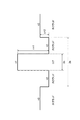
図1に示される径方向の屈折率分布を有する光ファイバ母材を線引して光ファイバを製造した。線引工程において、レーザ外径測定器を用いてガラス外径をモニタし、条件を調整することで、光ファイバの長手方向のガラス外径変動幅を様々な値とした。ガラス外径変動幅の各値に対して、ケーブルカットオフ波長および伝送損失を測定した。なお、ガラス外径の長手方向のばらつき(標準偏差)をσとしたとき、ガラス外径変動幅を3σで規定した。 An optical fiber was manufactured by drawing an optical fiber preform having the radial refractive index distribution shown in FIG. In the drawing step, the glass outer diameter is monitored using a laser outer diameter measuring device, and the conditions are adjusted, whereby the glass outer diameter fluctuation range in the longitudinal direction of the optical fiber is set to various values. The cable cutoff wavelength and the transmission loss were measured for each value of the glass outer diameter fluctuation range. When the variation (standard deviation) in the longitudinal direction of the glass outer diameter is σ, the glass outer diameter fluctuation range is defined as 3σ.
製造した光ファイバは、屈折率n1を有するコアと、このコアを取り囲み屈折率n2を有する内クラッドと、この内クラッドを取り囲み屈折率n3を有する外クラッドと、を含むものであった。コアはGeO2を含まないシリカガラスであり、内クラッドおよび外クラッドはFを含むシリカガラスであった。各領域の屈折率の大小関係は、n1>n3>n2 であった。内クラッドに対するコアの比屈折率差Δn1は0.32%であり、内クラッドに対する外クラッドの比屈折率差Δn3は0.06%であった。光ファイバの長手方向のコア径2aの平均値は12μmであった。光ファイバの長手方向の内クラッドの外径の平均値は36μmであった。光ファイバの長手方向の外クラッドの外径(ガラス径)の平均値は125±0.5μmであった。
The manufactured optical fiber included a core having a refractive index n1, an inner cladding surrounding the core and having a refractive index n2, and an outer cladding surrounding the inner cladding and having a refractive index n3. The core was silica glass not containing GeO 2 , and the inner cladding and the outer cladding were silica glass containing F. The magnitude relationship of the refractive index of each region was n1>n3> n2. The relative refractive index difference Δn1 of the core to the inner cladding was 0.32%, and the relative refractive index difference Δn3 of the outer cladding to the inner cladding was 0.06%. The average value of the
図2は、光ファイバの長手方向のガラス外径変動幅とケーブルカットオフ波長との関係を示すグラフである。この図2に示されるとおり、ガラス外径変動が大きくなると、ケーブルカットオフ波長は短くなる。図3は、光ファイバの長手方向のガラス外径変動幅と波長1550nmにおける伝送損失との関係を示すグラフである。この図3に示されるとおり、ガラス外径変動が凡そ0.5μmより大きくなると、波長1550nmにおける伝送損失は大きくなる。 FIG. 2 is a graph showing the relationship between the glass outer diameter fluctuation width in the longitudinal direction of the optical fiber and the cable cutoff wavelength. As shown in FIG. 2, the cable cutoff wavelength decreases as the glass outer diameter fluctuation increases. FIG. 3 is a graph showing the relationship between the glass outer diameter fluctuation width in the longitudinal direction of the optical fiber and the transmission loss at a wavelength of 1550 nm. As shown in FIG. 3, when the glass outer diameter fluctuation is larger than about 0.5 μm, the transmission loss at the wavelength of 1550 nm becomes large.
図2および図3から、光ファイバの長手方向のガラス外径変動幅を0.1μm以上0.5μm以下とすることにより、伝送損失の増加を抑制しつつ実効断面積の拡大が可能であることが分かる。また、光ファイバのケーブルカットオフ波長は1530nm以下である。光ファイバの波長1550nmにおける伝送損失は0.174dB/km以下である。光ファイバの波長1550nmにおける実効断面積は110μm2以上180μm2以下である。 From FIG. 2 and FIG. 3, by setting the glass outer diameter fluctuation width in the longitudinal direction of the optical fiber to 0.1 μm or more and 0.5 μm or less, it is possible to expand the effective cross section while suppressing the increase of the transmission loss. I understand. Also, the cable cutoff wavelength of the optical fiber is 1530 nm or less. The transmission loss of the optical fiber at a wavelength of 1550 nm is 0.174 dB / km or less. Effective area at the wavelength 1550nm optical fiber is 110 [mu] m 2 or more 180 [mu] m 2 or less.
本実施形態の光ファイバの径方向の屈折率分布は、図1に示されたものに限られるものではなく、他の屈折率分布であってもよい。例えば、単純なステップ型、トレンチ型、空孔付与型などの屈折率分布であってもよい。また、図4に示されるような屈折率分布であってもよい。図4に示される屈折率分布は、図1に示された屈折率分布において、コアが、中心コアと、この中心コアを取り囲むリングコアと、を含むものである。中心コアの屈折率n0は、リングコアの屈折率n1より小さい。これらの何れの屈折率分布であっても、光ファイバの長手方向のガラス外径変動幅を0.1μm以上0.5μm以下とすることにより、伝送損失の増加を抑制しつつ実効断面積の拡大が可能である。 The refractive index distribution in the radial direction of the optical fiber of the present embodiment is not limited to that shown in FIG. 1, and may be another refractive index distribution. For example, it may be a refractive index distribution such as a simple step type, a trench type, or a vacancy type. Also, it may be a refractive index distribution as shown in FIG. The refractive index profile shown in FIG. 4 is such that in the refractive index profile shown in FIG. 1, the core includes a central core and a ring core surrounding the central core. The refractive index n0 of the central core is smaller than the refractive index n1 of the ring core. In any of these refractive index distributions, by setting the fluctuation width of the glass outer diameter in the longitudinal direction of the optical fiber to 0.1 μm or more and 0.5 μm or less, the increase of the effective loss is suppressed while suppressing the increase of the transmission loss. Is possible.
特に、図4に示される屈折率分布を有する光ファイバは、モードフィールド径を維持しつつ実効断面積を拡大することができる。つまり、汎用シングルモード光ファイバと接続した際のモードフィールド径の不整合による接続損失の増加を抑制しつつ非線形性を低くすることが可能となる。 In particular, the optical fiber having the refractive index profile shown in FIG. 4 can expand the effective cross section while maintaining the mode field diameter. That is, it is possible to reduce non-linearity while suppressing an increase in connection loss due to a mismatch in mode field diameter when connected to a general-purpose single mode optical fiber.
本実施形態の光ファイバは、屈折率分布の設計への依存を低減して実効断面積の拡大および曲げ損失特性の改善が可能である。ガラス外径変動は線引時の条件調整で容易にコントロールすることができるので、複雑な屈折率分布の設計が不要であり、量産性の向上が期待される。 The optical fiber of this embodiment can reduce the dependence of the refractive index distribution on the design, and can enlarge the effective area and improve the bending loss characteristics. Since the glass outer diameter fluctuation can be easily controlled by adjusting the conditions at the time of drawing, it is not necessary to design a complicated refractive index distribution, and improvement of mass productivity is expected.
図5に示されるように、一般に、光ファイバ心線1は、ガラスファイバ10と、このガラスファイバ10を取り囲み2層の保護被覆層21,22を含む被覆部20と、この被覆部20を取り囲む着色層30と、を備える。被覆部20のうち内側の保護被覆層21は低ヤング率の樹脂からなり、外側の保護被覆層22は高ヤング率の樹脂からなる。着色層30は識別の為に設けられる樹脂層であり、通常は、その外径は凡そ250μmである。近年では、光ファイバ心線の外径(着色層の外径)を200μm程度まで細くすることで、光ケーブルの高密度化が検討されている。このように細径化した光ファイバ心線は、曲げ損失特性の向上が要求される。
As shown in FIG. 5, generally, the
本実施形態の光ファイバ心線1では、ガラスファイバ10は、コア11、内クラッド12および外クラッド13を含む前述したとおりの光ファイバである。着色層30の外径は180μm以上210μm以下である。本実施形態の光ファイバ心線1は、このように細径化しても、曲げ損失特性の向上が可能である。
In the optical
図6は、光伝送システム100の構成を示す図である。この光伝送システム100では、光送信器110と光受信器120との間に光伝送路130が敷設されている。光伝送システム100は、光送信器110から光受信器120へ信号光を伝送する光伝送路130として本実施形態の光ファイバを備える。光伝送路130は、実効断面積の拡大および曲げ損失特性の改善が可能である本実施形態の光ファイバを備えるので、信号劣化を抑制して長距離の信号光伝送が可能である。
FIG. 6 is a diagram showing the configuration of the
1…光ファイバ心線、10…ガラスファイバ(光ファイバ)、20…被覆部、21,22…保護被覆層、30…着色層、100…光伝送システム、110…光送信器、120…光受信器、130…光伝送路。
DESCRIPTION OF
Claims (6)
ケーブルカットオフ波長が1530nm以下であり、
ガラス外径の長手方向の平均値が125±0.5μmであり、
ガラス外径の長手方向の標準偏差をσとしたとき3σが0.1μm以上0.5μm以下である、
光ファイバ。 Effective area at the wavelength of 1550nm is at 110 [mu] m 2 or more 180 [mu] m 2 or less,
Cable cutoff wavelength is 1530 nm or less,
The average value of the glass outer diameter in the longitudinal direction is 125 ± 0.5 μm,
3σ is 0.1 μm or more and 0.5 μm or less, where σ is the standard deviation in the longitudinal direction of the glass outer diameter,
Optical fiber.
請求項1に記載の光ファイバ。 Transmission loss at a wavelength of 1550 nm is 0.174 dB / km or less
The optical fiber according to claim 1.
請求項1または2に記載の光ファイバ。 A core, an inner cladding surrounding the core and having a refractive index smaller than the refractive index of the core, and an outer cladding surrounding the inner cladding and having a refractive index smaller than the refractive index of the core and larger than the refractive index of the inner cladding; including,
The optical fiber according to claim 1 or 2.
請求項3に記載の光ファイバ。 The core includes a central core and a ring core surrounding the central core and having a refractive index greater than the refractive index of the central core;
The optical fiber according to claim 3.
Priority Applications (5)
| Application Number | Priority Date | Filing Date | Title |
|---|---|---|---|
| JP2018002523A JP2019120894A (en) | 2018-01-11 | 2018-01-11 | Optical fiber, coated optical fiber, and optical transmission system |
| CN201880086209.0A CN111656234B (en) | 2018-01-11 | 2018-12-21 | Optical fiber, coated optical fiber and optical transmission system |
| EP18900276.9A EP3737979A4 (en) | 2018-01-11 | 2018-12-21 | Optical fiber, coated optical fiber, and optical transmission system |
| PCT/JP2018/047271 WO2019138848A1 (en) | 2018-01-11 | 2018-12-21 | Optical fiber, coated optical fiber, and optical transmission system |
| US16/919,262 US10989864B2 (en) | 2018-01-11 | 2020-07-02 | Optical fiber, coated optical fiber, and optical transmission system |
Applications Claiming Priority (1)
| Application Number | Priority Date | Filing Date | Title |
|---|---|---|---|
| JP2018002523A JP2019120894A (en) | 2018-01-11 | 2018-01-11 | Optical fiber, coated optical fiber, and optical transmission system |
Publications (1)
| Publication Number | Publication Date |
|---|---|
| JP2019120894A true JP2019120894A (en) | 2019-07-22 |
Family
ID=67218267
Family Applications (1)
| Application Number | Title | Priority Date | Filing Date |
|---|---|---|---|
| JP2018002523A Pending JP2019120894A (en) | 2018-01-11 | 2018-01-11 | Optical fiber, coated optical fiber, and optical transmission system |
Country Status (5)
| Country | Link |
|---|---|
| US (1) | US10989864B2 (en) |
| EP (1) | EP3737979A4 (en) |
| JP (1) | JP2019120894A (en) |
| CN (1) | CN111656234B (en) |
| WO (1) | WO2019138848A1 (en) |
Cited By (3)
| Publication number | Priority date | Publication date | Assignee | Title |
|---|---|---|---|---|
| WO2020162406A1 (en) * | 2019-02-05 | 2020-08-13 | 古河電気工業株式会社 | Optical fiber |
| WO2021079788A1 (en) * | 2019-10-24 | 2021-04-29 | 住友電気工業株式会社 | Optical fiber and optical cable |
| WO2024150692A1 (en) * | 2023-01-11 | 2024-07-18 | 住友電気工業株式会社 | Optical fiber |
Citations (20)
| Publication number | Priority date | Publication date | Assignee | Title |
|---|---|---|---|---|
| US20010017967A1 (en) * | 1999-04-13 | 2001-08-30 | Masaaki Hirano | Optical fiber and optical communication system including the same |
| US20020178762A1 (en) * | 2001-06-01 | 2002-12-05 | Foster John D. | Methods and apparatus for forming and controlling the diameter of drawn optical glass fiber |
| US20110091178A1 (en) * | 2009-10-15 | 2011-04-21 | Ipg Photonics Corporation | Double clad optical fiber having ring core surrounding core for high power operation |
| US20110211788A1 (en) * | 2010-02-26 | 2011-09-01 | Sumitomo Electric Industries, Ltd. | Optical fiber and optical communication system including same |
| CN103257393A (en) * | 2012-10-30 | 2013-08-21 | 长飞光纤光缆有限公司 | Optical fiber large in effective area |
| CN103619767A (en) * | 2011-11-21 | 2014-03-05 | 住友电气工业株式会社 | Optical fiber preform, method for producing optical fiber, and optical fiber |
| US20140226948A1 (en) * | 2012-01-10 | 2014-08-14 | Sumitomo Electric Industries, Ltd. | Optical fiber producing method and apparatus and optical fiber |
| JP2015000839A (en) * | 2013-06-18 | 2015-01-05 | 住友電気工業株式会社 | Optical fiber manufacturing method and device |
| JP2015093815A (en) * | 2013-11-13 | 2015-05-18 | 住友電気工業株式会社 | Optical fiber manufacturing method and optical fiber drawing furnace |
| CN104834054A (en) * | 2014-02-12 | 2015-08-12 | 住友电气工业株式会社 | Optical fiber |
| US20150251945A1 (en) * | 2012-09-24 | 2015-09-10 | Sumitomo Electric Industries, Ltd. | Optical fiber fabrication method |
| CN104981440A (en) * | 2013-02-04 | 2015-10-14 | 住友电气工业株式会社 | Optical-fiber preform and method for manufacturing optical-fiber preform |
| WO2016074602A1 (en) * | 2014-11-12 | 2016-05-19 | 长飞光纤光缆股份有限公司 | Single-mode fiber with ultra-low attenuation and large effective area |
| US20170017032A1 (en) * | 2015-05-29 | 2017-01-19 | Corning Incorporated | Optical fiber with macrobend loss mitigating layer |
| US9551828B2 (en) * | 2014-11-13 | 2017-01-24 | Sumitomo Electric Industries, Ltd. | Optical fiber |
| CN106415344A (en) * | 2014-06-05 | 2017-02-15 | 住友电气工业株式会社 | Optical fiber |
| CN106662704A (en) * | 2014-08-28 | 2017-05-10 | 住友电气工业株式会社 | Optical fiber and optical fiber transmission path |
| JP2017088463A (en) * | 2015-11-16 | 2017-05-25 | 住友電気工業株式会社 | Method of manufacturing optical fiber |
| WO2017217559A1 (en) * | 2016-06-13 | 2017-12-21 | 住友電気工業株式会社 | Optical fiber cable |
| JP2018045028A (en) * | 2016-09-13 | 2018-03-22 | 住友電気工業株式会社 | Optical fiber and coated optical fiber |
Family Cites Families (6)
| Publication number | Priority date | Publication date | Assignee | Title |
|---|---|---|---|---|
| CA2229280A1 (en) * | 1997-02-12 | 1998-08-12 | Sumitomo Electric Industries, Ltd. | Dispersion-shifted fiber |
| CN1289422C (en) * | 2001-11-20 | 2006-12-13 | 王胜国 | Optic fibre of controlling robust diameter in drawing optic fibre |
| FR2941540B1 (en) * | 2009-01-27 | 2011-05-06 | Draka Comteq France | MONOMODE OPTICAL FIBER HAVING ENHANCED EFFECTIVE SURFACE |
| US8670643B2 (en) * | 2011-05-18 | 2014-03-11 | Corning Incorporated | Large effective area optical fibers |
| JP6551137B2 (en) * | 2015-10-15 | 2019-07-31 | 住友電気工業株式会社 | Optical fiber |
| JP2019152811A (en) * | 2018-03-06 | 2019-09-12 | 住友電気工業株式会社 | Optical fiber, coated optical fiber, and optical transmission system |
-
2018
- 2018-01-11 JP JP2018002523A patent/JP2019120894A/en active Pending
- 2018-12-21 WO PCT/JP2018/047271 patent/WO2019138848A1/en unknown
- 2018-12-21 CN CN201880086209.0A patent/CN111656234B/en active Active
- 2018-12-21 EP EP18900276.9A patent/EP3737979A4/en not_active Ceased
-
2020
- 2020-07-02 US US16/919,262 patent/US10989864B2/en active Active
Patent Citations (20)
| Publication number | Priority date | Publication date | Assignee | Title |
|---|---|---|---|---|
| US20010017967A1 (en) * | 1999-04-13 | 2001-08-30 | Masaaki Hirano | Optical fiber and optical communication system including the same |
| US20020178762A1 (en) * | 2001-06-01 | 2002-12-05 | Foster John D. | Methods and apparatus for forming and controlling the diameter of drawn optical glass fiber |
| US20110091178A1 (en) * | 2009-10-15 | 2011-04-21 | Ipg Photonics Corporation | Double clad optical fiber having ring core surrounding core for high power operation |
| US20110211788A1 (en) * | 2010-02-26 | 2011-09-01 | Sumitomo Electric Industries, Ltd. | Optical fiber and optical communication system including same |
| CN103619767A (en) * | 2011-11-21 | 2014-03-05 | 住友电气工业株式会社 | Optical fiber preform, method for producing optical fiber, and optical fiber |
| US20140226948A1 (en) * | 2012-01-10 | 2014-08-14 | Sumitomo Electric Industries, Ltd. | Optical fiber producing method and apparatus and optical fiber |
| US20150251945A1 (en) * | 2012-09-24 | 2015-09-10 | Sumitomo Electric Industries, Ltd. | Optical fiber fabrication method |
| CN103257393A (en) * | 2012-10-30 | 2013-08-21 | 长飞光纤光缆有限公司 | Optical fiber large in effective area |
| CN104981440A (en) * | 2013-02-04 | 2015-10-14 | 住友电气工业株式会社 | Optical-fiber preform and method for manufacturing optical-fiber preform |
| JP2015000839A (en) * | 2013-06-18 | 2015-01-05 | 住友電気工業株式会社 | Optical fiber manufacturing method and device |
| JP2015093815A (en) * | 2013-11-13 | 2015-05-18 | 住友電気工業株式会社 | Optical fiber manufacturing method and optical fiber drawing furnace |
| CN104834054A (en) * | 2014-02-12 | 2015-08-12 | 住友电气工业株式会社 | Optical fiber |
| CN106415344A (en) * | 2014-06-05 | 2017-02-15 | 住友电气工业株式会社 | Optical fiber |
| CN106662704A (en) * | 2014-08-28 | 2017-05-10 | 住友电气工业株式会社 | Optical fiber and optical fiber transmission path |
| WO2016074602A1 (en) * | 2014-11-12 | 2016-05-19 | 长飞光纤光缆股份有限公司 | Single-mode fiber with ultra-low attenuation and large effective area |
| US9551828B2 (en) * | 2014-11-13 | 2017-01-24 | Sumitomo Electric Industries, Ltd. | Optical fiber |
| US20170017032A1 (en) * | 2015-05-29 | 2017-01-19 | Corning Incorporated | Optical fiber with macrobend loss mitigating layer |
| JP2017088463A (en) * | 2015-11-16 | 2017-05-25 | 住友電気工業株式会社 | Method of manufacturing optical fiber |
| WO2017217559A1 (en) * | 2016-06-13 | 2017-12-21 | 住友電気工業株式会社 | Optical fiber cable |
| JP2018045028A (en) * | 2016-09-13 | 2018-03-22 | 住友電気工業株式会社 | Optical fiber and coated optical fiber |
Non-Patent Citations (2)
| Title |
|---|
| OLSHANSKY, R. AND NOLAN, D. A.: "Mode-dependent attenuation of optical fibers: excess loss", APPLIED OPTICS, vol. 15, no. 4, JPN6021052603, April 1976 (1976-04-01), pages 1045 - 1047, XP002261005, ISSN: 0004678915, DOI: 10.1364/AO.15.001045 * |
| SUZUKI,M. ET AL: "Low-loss Splice of Large Effective Area Fiber Using Fluorine-doped Cladding Standard Effective Area", OPTICAL FIBER COMMUNICATIONS CONFERENCE AND EXHIBITION (OFC), JPN6021052604, 2017, pages 1 - 3, XP033100813, ISSN: 0004844776, DOI: 10.1364/OFC.2017.M2F.4 * |
Cited By (6)
| Publication number | Priority date | Publication date | Assignee | Title |
|---|---|---|---|---|
| WO2020162406A1 (en) * | 2019-02-05 | 2020-08-13 | 古河電気工業株式会社 | Optical fiber |
| JPWO2020162406A1 (en) * | 2019-02-05 | 2021-12-16 | 古河電気工業株式会社 | Optical fiber |
| US11719879B2 (en) | 2019-02-05 | 2023-08-08 | Furukawa Electric Co., Ltd. | Optical fiber |
| WO2021079788A1 (en) * | 2019-10-24 | 2021-04-29 | 住友電気工業株式会社 | Optical fiber and optical cable |
| US11841529B2 (en) | 2019-10-24 | 2023-12-12 | Sumitomo Electric Industries, Ltd. | Optical fiber and optical cable |
| WO2024150692A1 (en) * | 2023-01-11 | 2024-07-18 | 住友電気工業株式会社 | Optical fiber |
Also Published As
| Publication number | Publication date |
|---|---|
| US20200333528A1 (en) | 2020-10-22 |
| WO2019138848A1 (en) | 2019-07-18 |
| EP3737979A1 (en) | 2020-11-18 |
| EP3737979A4 (en) | 2021-03-03 |
| CN111656234B (en) | 2022-05-17 |
| CN111656234A (en) | 2020-09-11 |
| US10989864B2 (en) | 2021-04-27 |
Similar Documents
| Publication | Publication Date | Title |
|---|---|---|
| US9678270B2 (en) | Multimode optical fiber with high bandwidth over an extended wavelength range, and corresponding multimode optical system | |
| JP5379396B2 (en) | Transmission optical fiber with large effective area | |
| JP4065716B2 (en) | Positive dispersion optical fiber with wide effective area | |
| JP4999063B2 (en) | Optical fiber | |
| US7773845B2 (en) | Optical fiber and optical-fiber transmission line | |
| JP2006227173A (en) | Multimode dispersion compensating fiber, mode dispersion compensating method, optical waveguide, optical transmission line, and optical communication system | |
| EP3537192B1 (en) | Optical fiber, colored optical fiber, and optical transmission system | |
| JP2009122277A (en) | Optical fiber and optical transmission system | |
| US10989864B2 (en) | Optical fiber, coated optical fiber, and optical transmission system | |
| US7231121B2 (en) | Optical fiber having reduced residual stress discontinuity | |
| KR20040014669A (en) | Dispersion and slope compensating optical fiber and transmission link including same | |
| KR100342711B1 (en) | Dispersion shifted fiber with triple clad | |
| JP2003172844A (en) | Optical fiber having negative dispersion and negative dispersion slope | |
| US7437045B2 (en) | Dispersion optimized optical fiber for wideband optical transmission | |
| JP3725523B2 (en) | Optical fiber and optical transmission system | |
| KR100749295B1 (en) | Dispersion-compensating optical fiber with W-shaped index profile | |
| US6442320B1 (en) | Limited mode dispersion compensating optical fiber | |
| EP3754394B1 (en) | Optical fiber | |
| US9835796B2 (en) | Multimode optical fiber with high bandwidth over an extended wavelength range, and corresponding multimode optical system | |
| JP4568485B2 (en) | Single mode optical fiber and optical communication system | |
| US11137540B2 (en) | Non-zero dispersion shifted fiber with low cut off wavelength and large effective area | |
| US20050058418A1 (en) | Dispersion optimized fiber having higher spot area | |
| JP2002182056A (en) | Dispersion compensating optical fiber, optical transmission line including it and dispersion compensating module | |
| JP5184011B2 (en) | Optical fiber and optical fiber transmission line | |
| AU8460098A (en) | Dispersion-flattened optical fiber |
Legal Events
| Date | Code | Title | Description |
|---|---|---|---|
| A621 | Written request for application examination |
Free format text: JAPANESE INTERMEDIATE CODE: A621 Effective date: 20201221 |
|
| A131 | Notification of reasons for refusal |
Free format text: JAPANESE INTERMEDIATE CODE: A131 Effective date: 20220111 |
|
| A601 | Written request for extension of time |
Free format text: JAPANESE INTERMEDIATE CODE: A601 Effective date: 20220310 |
|
| A521 | Request for written amendment filed |
Free format text: JAPANESE INTERMEDIATE CODE: A523 Effective date: 20220421 |
|
| A02 | Decision of refusal |
Free format text: JAPANESE INTERMEDIATE CODE: A02 Effective date: 20220809 |