JP2019120599A - Temperature measuring device, specimen retainer for heat cycle test, and heat cycle test device - Google Patents

Temperature measuring device, specimen retainer for heat cycle test, and heat cycle test device Download PDF

Info

Publication number
JP2019120599A
JP2019120599A JP2018001031A JP2018001031A JP2019120599A JP 2019120599 A JP2019120599 A JP 2019120599A JP 2018001031 A JP2018001031 A JP 2018001031A JP 2018001031 A JP2018001031 A JP 2018001031A JP 2019120599 A JP2019120599 A JP 2019120599A
Authority
JP
Japan
Prior art keywords
specimen
pipe
thermocouple
opening
temperature measuring
Prior art date
Legal status (The legal status is an assumption and is not a legal conclusion. Google has not performed a legal analysis and makes no representation as to the accuracy of the status listed.)
Granted
Application number
JP2018001031A
Other languages
Japanese (ja)
Other versions
JP7067063B2 (en
Inventor
加藤 明
Akira Kato
加藤  明
Current Assignee (The listed assignees may be inaccurate. Google has not performed a legal analysis and makes no representation or warranty as to the accuracy of the list.)
IHI Corp
Original Assignee
IHI Corp
Priority date (The priority date is an assumption and is not a legal conclusion. Google has not performed a legal analysis and makes no representation as to the accuracy of the date listed.)
Filing date
Publication date
Application filed by IHI Corp filed Critical IHI Corp
Priority to JP2018001031A priority Critical patent/JP7067063B2/en
Publication of JP2019120599A publication Critical patent/JP2019120599A/en
Application granted granted Critical
Publication of JP7067063B2 publication Critical patent/JP7067063B2/en
Active legal-status Critical Current
Anticipated expiration legal-status Critical

Links

Images

Abstract

To provide a temperature measuring device or the like capable of measuring the temperature of a measured temperature surface with better measurement accuracy and responsiveness.SOLUTION: A temperature measuring device 10 includes a pair of thermocouple wires 16 and a flat thermocouple 14 over the temperature measuring contact 14c which is their junction, and an insulating tube 12 which is supported via an elastic member 20. The thermocouple 14 is disposed in an exposed state and so that the temperature measuring contact 14c is along the tip surface 12d of the insulating tube 12 . Further, the thermocouple 14 is sandwiched between the tip surface 12d and a measured temperature surface 100a with the application of the restoring force of the elastic member 20 from the tip surface 12d.SELECTED DRAWING: Figure 3

Description

本開示は、測温装置、熱サイクル試験用の供試体保持具、及び、熱サイクル試験装置に関する。   The present disclosure relates to a temperature measuring device, a specimen holder for thermal cycle test, and a thermal cycle test device.

ジェットエンジン等の燃費改善のため、高圧タービンなどホットセクション部品の軽量化と耐熱性向上が望まれている。近年、それらを達成するための材料として、SiC繊維強化SiCマトリックス複合材料(CMC:Ceramic Matrix Composites)等が期待されている。また、高温燃焼ガス環境下におけるCMC材の性能向上のため、各種コーティングも注目されている。例えば、耐環境性コーティング(EBC:Environmental Barrier Coating)や遮熱コーティング(TBC:Thermal Barrier Coating)などである。   In order to improve fuel consumption such as jet engines, weight reduction and heat resistance improvement of hot section parts such as high pressure turbines are desired. In recent years, SiC fiber reinforced SiC matrix composites (CMC: Ceramic Matrix Composites) etc. are expected as materials for achieving them. In addition, various coatings are also attracting attention in order to improve the performance of CMC materials in a high temperature combustion gas environment. For example, environmental barrier coating (EBC) or thermal barrier coating (TBC).

熱サイクル試験は、ホットセクション部品の各種材料及びコーティングの繰り返し熱負荷(熱サイクル)に対する耐久性を評価するための試験である。典型的な熱サイクル試験では、供試体の表面をバーナで加熱しつつ裏面に冷却空気を吹き付けて冷却することで、供試体に厚さ方向の温度勾配を付与する工程を、所定回数、所定の頻度で繰り返す。供試体の裏面の温度は、熱電対を用いた測温装置で測定される。この測温装置には、高い測定精度及び応答性が要求される。   A thermal cycle test is a test for evaluating the durability of various materials and coatings of hot section parts against repeated thermal load (thermal cycle). In a typical thermal cycle test, a predetermined number of steps of applying a temperature gradient in the thickness direction to the sample by blowing cooling air to the back side while cooling the surface of the sample with a burner are performed a predetermined number of times. Repeat with frequency. The temperature on the back of the specimen is measured by a temperature measuring device using a thermocouple. This temperature measuring device is required to have high measurement accuracy and responsiveness.

特許文献1は、熱電対を用いた測温装置を開示している。この測温装置では、熱電対先端の測温接点が露出したままの状態で被測定物の測温箇所に接触し、且つ機械的に着脱可能に押し付けられて被測定物に保持されている。   Patent Document 1 discloses a temperature measuring device using a thermocouple. In this temperature measuring device, the temperature measuring point of the thermocouple tip is in contact with the temperature measuring point of the object under measurement with the temperature measuring contact exposed, and is mechanically held detachably by the object under measurement.

特開2004−132702号公報JP 2004-132702

しかしながら、上記の測温装置では、測温接点の周囲に隙間が形成されるため、熱サイクル試験に要求される測定精度及び応答性を得ることが難しい。   However, in the above-described temperature measuring device, since a gap is formed around the temperature measuring contact, it is difficult to obtain the measurement accuracy and responsiveness required for the thermal cycle test.

そこで、本開示は、より優れた測定精度及び応答性で被測温面の温度を測定することが可能な測温装置、熱サイクル試験用の供試体保持具、及び、熱サイクル試験装置を提供することを目的とする。   Therefore, the present disclosure provides a temperature measuring device capable of measuring the temperature of a temperature measuring surface with better measurement accuracy and responsiveness, a specimen holder for a thermal cycle test, and a thermal cycle test device. The purpose is to

本開示の一態様である測温装置は、一対の熱電対素線とそれらの接合部である測温接点とに亘って平板状の熱電対と、弾性部材を介して支持される絶縁管と、を備え、熱電対は、露出した状態で、且つ、測温接点が絶縁管の先端面に沿うように配置されており、熱電対は、先端面から弾性部材の復元力を受けて先端面と被測温面との間に挟持される。   A temperature measuring apparatus according to an aspect of the present disclosure includes a flat thermocouple and an insulating pipe supported via an elastic member across a pair of thermocouple wires and a temperature measuring junction which is a junction thereof. The thermocouple is disposed in an exposed state and the temperature measuring contact is disposed along the tip surface of the insulating tube, and the thermocouple receives the restoring force of the elastic member from the tip surface and the tip surface is It is sandwiched between the and the temperature measurement surface.

上記の測温装置において、熱電対は、先端面上に弾性を有する断熱シートを介して積層されていてもよい。   In the above-mentioned temperature measuring device, the thermocouple may be laminated via a heat insulating sheet having elasticity on the tip surface.

また、本開示の一態様である熱サイクル試験用の供試体保持具は、バーナ側の側面に板状の供試体を嵌め込むための開口が形成された枠部材と、開口に嵌め込まれた供試体のバーナ側と反対側の面に冷却空気を吹き付けるための吹き出し口を備えた空気供給管と、上記の測温装置であって、絶縁管が、枠部材に弾性部材を介して支持され、且つ、吹き出し口から先端を突出させた状態で空気供給管に挿通されている測温装置と、を備え、供試体が開口に嵌め込まれた状態において、熱電対が、先端面と供試体との間に挟持されるとともに、供試体が、開口の内周縁部と測温装置とによって保持される。   Further, the specimen holder for the thermal cycle test which is one aspect of the present disclosure has a frame member in which an opening for inserting a plate-like specimen is formed on a side surface on the burner side, and An air supply pipe provided with a blowout port for blowing cooling air on the surface of the sample opposite to the burner side, and the above temperature measuring device, wherein the insulating pipe is supported by the frame member via an elastic member, The temperature measuring device is inserted into the air supply pipe in a state in which the tip is protruded from the blowout port, and in a state in which the sample is fitted into the opening, the thermocouple measures the tip surface and the sample While being held between, the sample is held by the inner peripheral edge of the opening and the temperature measuring device.

上記の供試体保持具は、開口の内周縁部と、開口に嵌め込まれた供試体の外周縁部との間に介在し、内周縁部と外周縁部とを互いに離間した状態に保持する複数の球体を備えていてもよい。また、上記の供試体保持具において、開口は、水平方向に向いた円形状の開口であり、複数の球体のうち少なくとも開口の中心より上方に位置する球体は、開口の径方向外側へ移動可能に内周縁部に保持されていてもよい。また、空気供給配管は、内管と外管とからなる二重管構造を有しており、吹き出し口は、内管の先端部と外管の先端部との間に画成されており、絶縁管は、内管に挿通されていてもよい。   The above-mentioned specimen holder is interposed between the inner peripheral edge of the opening and the outer peripheral edge of the test piece fitted into the opening, and a plurality of the inner peripheral edge and the outer peripheral edge are held apart from each other It may have a sphere of Further, in the above-described specimen holder, the opening is a horizontally-oriented circular opening, and at least one of the plurality of spheres located above the center of the opening is movable radially outward of the opening. May be held at the inner peripheral edge. Also, the air supply piping has a double pipe structure consisting of an inner pipe and an outer pipe, and the outlet is defined between the tip of the inner pipe and the tip of the outer pipe, The insulating pipe may be inserted into the inner pipe.

また、本開示の一態様である熱サイクル試験装置は、供試体を保持する上記の供試体保持具と、供試体を加熱するバーナと、バーナ又は供試体保持具に供試体への熱負荷を繰り返させているときの供試体の温度データを熱電対から取得する制御部と、を備える。   Moreover, the thermal cycle test apparatus which is one aspect of the present disclosure includes the above-mentioned specimen holder for holding the specimen, the burner for heating the specimen, and the burner or the specimen holder for the heat load on the specimen. And a controller configured to acquire temperature data of the specimen during repetition from the thermocouple.

本開示によれば、より優れた測定精度及び応答性で被測温面の温度を測定することが可能な測温装置、熱サイクル試験用の供試体保持具、及び、熱サイクル試験装置を提供することができる。   According to the present disclosure, a temperature measuring device capable of measuring the temperature of a temperature measuring surface with better measurement accuracy and responsiveness, a specimen holder for a thermal cycle test, and a thermal cycle test device are provided. can do.

一実施形態に係る測温装置の構成を示す図である。It is a figure showing composition of a temperature measuring device concerning one embodiment. 一実施形態に係る測温装置の構成を示す図である。It is a figure showing composition of a temperature measuring device concerning one embodiment. 一実施形態に係る測温装置の測定状態を示す図である。It is a figure which shows the measurement state of the temperature measuring device which concerns on one Embodiment. 一実施形態に適用可能な供試体の形状を示す図である。It is a figure which shows the shape of the specimen applicable to one Embodiment. 一実施形態に係る供試体保持具の前面側を示す図である。It is a figure which shows the front side of the specimen holder which concerns on one Embodiment. 一実施形態に係る供試体保持具の後面側を示す図である。It is a figure which shows the rear surface side of the specimen holder which concerns on one Embodiment. 一実施形態に係る供試体保持具の構成を示す断面図である。It is a sectional view showing the composition of the specimen holder concerning one embodiment. 供試体保持具における供試体の保持部分の構成及び形状を示す図である。It is a figure which shows the structure and shape of the holding part of the test object in a test object holder. 供試体保持具における供試体の保持部分の細部の構成を示す図である。It is a figure which shows the structure of the detail of the holding part of the test object in a test object holder. 供試体保持具に含まれる熱電対固定ユニットの構成を示す図である。It is a figure which shows the structure of the thermocouple fixing unit contained in a specimen holder. 一実施形態に係る熱サイクル試験装置の構成を示す図である。It is a figure showing composition of a thermal cycle testing device concerning one embodiment.

以下、本開示の実施形態について図面を参照して詳細に説明する。ここで、実施形態に示す寸法、材料、その他、具体的な数値等は例示にすぎず、特に断る場合を除き、本開示を限定するものではない。また、実質的に同一の機能及び構成を有する要素については、同一の符号を付することにより重複説明を省略し、本開示に直接関係のない要素については、図示を省略する。   Hereinafter, embodiments of the present disclosure will be described in detail with reference to the drawings. Here, dimensions, materials, other specific numerical values, and the like shown in the embodiments are merely examples, and the present disclosure is not limited unless otherwise specified. In addition, with regard to elements having substantially the same function and configuration, redundant description is omitted by giving the same reference numerals, and illustration of elements that are not directly related to the present disclosure is omitted.

また、以下の各図では、測温装置の延伸方向に沿う方向をZ方向と規定する。Z方向に垂直な平面内に、互いに垂直となるX方向及びY方向を規定する。特に、鉛直方向上方に向かう方向がX方向である。また、測温装置が測温対象とする供試体上の被測温面は、XY平面内にある。   Moreover, in each of the following drawings, the direction along the extending direction of the temperature measuring device is defined as the Z direction. An X direction and a Y direction perpendicular to each other are defined in a plane perpendicular to the Z direction. In particular, the direction toward the upper side in the vertical direction is the X direction. Moreover, the temperature-measurement surface on the sample which a temperature-measurement apparatus makes temperature measurement object exists in XY plane.

(測温装置)
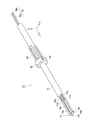
まず、本実施形態に係る測温装置について説明する。図1は、測温装置10全体の構成を示す斜視図である。図2は、測温装置10の測温接点14c近傍の構成を示す分解斜視図である。測温装置10は、絶縁管12と、熱電対14と、熱電対素線16と、断熱シート18とを備える。
(Temperature measuring device)
First, the temperature measuring device according to the present embodiment will be described. FIG. 1 is a perspective view showing the entire configuration of the temperature measuring device 10. As shown in FIG. FIG. 2 is an exploded perspective view showing the configuration in the vicinity of the temperature measurement contact 14 c of the temperature measuring device 10. The temperature measuring device 10 includes an insulating tube 12, a thermocouple 14, a thermocouple wire 16, and a heat insulating sheet 18.

絶縁管12は、セラミックス等の絶縁性の材料から構成される管状部材である。絶縁管12は、延伸方向に並列する2つの管路12a,12bを有する。また、絶縁管12は、熱電対14を設置する側の先端部に、切り欠き部12cを有する。切り欠き部12cは、2つの管路12a,12bのそれぞれの一部を絶縁管12の延伸方向に沿って露出させる形状を有する。また、熱電対14を設置する側の絶縁管12の先端面12dは、絶縁管12の延伸方向に対しておおよそ垂直な平面である。   The insulating tube 12 is a tubular member made of an insulating material such as ceramics. The insulating pipe 12 has two pipelines 12a and 12b arranged in parallel in the extending direction. Further, the insulating tube 12 has a notch 12 c at the end on which the thermocouple 14 is to be installed. The notch 12 c has a shape that exposes a part of each of the two pipelines 12 a and 12 b along the extension direction of the insulating pipe 12. Further, the tip end surface 12 d of the insulating pipe 12 on the side where the thermocouple 14 is installed is a flat surface substantially perpendicular to the extending direction of the insulating pipe 12.

また、絶縁管12は、弾性部材20を介して支持される。弾性部材20は、絶縁管12に対して、絶縁管12の延伸方向に沿って、且つ、熱電対14が設置されていない側から熱電対14が設置されている側に向かう方向に、力を与える。弾性部材20は、例えば、軸方向に沿って内側に絶縁管12を通すコイルばねである。   The insulating tube 12 is also supported via the elastic member 20. The elastic member 20 applies a force to the insulating pipe 12 in a direction along the extension direction of the insulating pipe 12 and in a direction from the side where the thermocouple 14 is not installed to the side where the thermocouple 14 is installed. give. The elastic member 20 is, for example, a coil spring which passes the insulating pipe 12 inside along the axial direction.

また、絶縁管12には、弾性部材20の熱電対14側の端部に接触する固定部材22が設置されていてもよい。固定部材22は、例えば、内壁側に絶縁管12を貫通させる環状部材である。固定部材22は、外壁側から内壁側に貫通する不図示のねじ穴を有する。このねじ穴に外壁側から止めねじ24を通し、止めねじ24の先端部を絶縁管12に接触させた状態で締結させることで、固定部材22が絶縁管12の外周の一部に固定される。   In addition, a fixing member 22 that contacts the end of the elastic member 20 on the thermocouple 14 side may be installed in the insulating tube 12. The fixing member 22 is, for example, an annular member which causes the insulating pipe 12 to penetrate the inner wall side. The fixing member 22 has a screw hole (not shown) penetrating from the outer wall side to the inner wall side. The fixing member 22 is fixed to a part of the outer periphery of the insulating pipe 12 by inserting the set screw 24 from the outer wall side into the screw hole and fastening the tip end of the set screw 24 in contact with the insulating pipe 12. .

熱電対14は、それぞれ異なる金属材からなる2つの金属板同士を接合させた、シート状の熱電対である。熱電対14の種類としては、例えば、JIS規格に準拠し、一方の金属材がクロメルであり、他方の金属材がアルメルであるK型とし得る。熱電対14は、例えば、一方の金属板で構成される第1板部14aと、他方の金属板で構成される第2板部14bと、一方の金属板と他方の金属板との接合部としての測温接点14cを有する先端板部14dとを含む。   The thermocouple 14 is a sheet-like thermocouple in which two metal plates made of different metal materials are joined to each other. The type of the thermocouple 14 may be, for example, a K-type in which one metal material is chromel and the other metal material is alumel according to the JIS standard. The thermocouple 14 is, for example, a joint portion between a first plate portion 14a formed of one metal plate, a second plate portion 14b formed of the other metal plate, and one metal plate and the other metal plate. And a tip plate portion 14d having a temperature measurement contact 14c.

第1板部14aは、絶縁管12の切り欠き部12cにおいて露出している一方の管路12aに沿って配置される平板部である。第2板部14bは、切り欠き部12cにおいて露出している他方の管路12bに沿って配置される平板部である。第1板部14aと第2板部14bとは、同一平面内で、且つ、非接触で、並列している。また、第1板部14a又は第2板部14bの延伸方向の長さL2は、それぞれ、切り欠き部12cの延伸方向の長さL1よりも短い。ただし、必ずしも第1板部14aの延伸方向の長さと第2板部14bの延伸方向の長さとを一致させる必要はない。   The first plate portion 14 a is a flat plate portion disposed along one of the conduits 12 a exposed in the cutout portion 12 c of the insulating pipe 12. The second plate portion 14b is a flat plate portion disposed along the other conduit 12b exposed in the cutout portion 12c. The first plate portion 14a and the second plate portion 14b are juxtaposed in the same plane and in a non-contact manner. Further, the length L2 in the extending direction of the first plate portion 14a or the second plate portion 14b is shorter than the length L1 in the extending direction of the notch 12c. However, the length in the extending direction of the first plate portion 14a and the length in the extending direction of the second plate portion 14b do not necessarily have to match.

先端板部14dは、絶縁管12の先端面12dに対しておおよそ平行となる平板部である。先端板部14dは、第1板部14aに連続する一方の金属板と、第2板部14bに連続する他方の金属板とが接合された平板部である。ここで、先端板部14dに含まれる一方の金属板と他方の金属板とは、第1板部14a又は第2板部14bに連続する部分から絶縁管12の先端面12dに沿うようにおおよそ90°折れ曲がっている。また、先端板部14dに含まれる一方の金属板と他方の金属板とは、第1板部14aと第2板部14bとが対向するY方向とは平面内で垂直となるX方向に沿った1辺で接合される。この1辺が、熱電対14における測温接点14cである。すなわち、熱電対14は、露出した状態で、且つ、測温接点14cが絶縁管12の先端面12dに沿うように配置されている。   The end plate portion 14 d is a flat plate portion which is approximately parallel to the end surface 12 d of the insulating tube 12. The front end plate portion 14d is a flat plate portion in which one metal plate continuous with the first plate portion 14a and the other metal plate continuous with the second plate portion 14b are joined. Here, one metal plate and the other metal plate included in the tip end plate portion 14d are approximately along the tip end surface 12d of the insulating pipe 12 from the portion continuing to the first plate portion 14a or the second plate portion 14b. It is bent 90 degrees. Further, one metal plate and the other metal plate included in the tip end plate portion 14d are along the X direction in which the Y direction in which the first plate portion 14a and the second plate portion 14b face each other is perpendicular in a plane. It joins at one side. This one side is a temperature measurement contact 14 c in the thermocouple 14. That is, the thermocouple 14 is disposed in the exposed state and with the temperature measurement contact 14 c along the tip surface 12 d of the insulating tube 12.

先端板部14dにおいて、測温接点14cの位置に相当する一方の金属板と他方の金属板とは、互いの端面同士で接合される。したがって、先端板部14dの厚さは、全体として略一定である。すなわち、第1板部14a、第2板部14b及び先端板部14dを含む熱電対14全体としても、各部の厚さは略一定である。   In the front end plate portion 14d, one metal plate corresponding to the position of the temperature measurement contact 14c and the other metal plate are joined to each other at their end faces. Therefore, the thickness of the end plate portion 14d is substantially constant as a whole. That is, even in the entire thermocouple 14 including the first plate portion 14a, the second plate portion 14b, and the distal end plate portion 14d, the thickness of each portion is substantially constant.

一対の熱電対素線16は、絶縁管12の一方の管路12aに配設され、絶縁管12の外部に導かれる第1素線16aと、絶縁管12の他方の管路12bに配設され、絶縁管12の外部に導かれる第2素線16bとを含む。第1素線16aは、熱電対14の第1板部14aと同一の金属材からなる。第2素線16bは、熱電対14の第2板部14bと同一の金属材からなる。第1素線16aは、絶縁管12の切り欠き部12cにおいて露出している一方の管路12a上の接合点17aで、第1板部14aと接合される。第2素線16bは、切り欠き部12cにおいて露出している他方の管路12b上の接合点17bで、第2板部14bと接合される。   The pair of thermocouple wires 16 are disposed in one of the conduits 12 a of the insulating tube 12 and disposed in the first wire 16 a led to the outside of the insulating tube 12 and the other conduit 12 b of the insulating tube 12. And a second strand 16 b led to the outside of the insulating pipe 12. The first wire 16 a is made of the same metal material as the first plate portion 14 a of the thermocouple 14. The second wire 16 b is made of the same metal material as the second plate portion 14 b of the thermocouple 14. The first strands 16a are joined to the first plate portion 14a at junctions 17a on one of the conduits 12a exposed at the notch 12c of the insulating tube 12. The second strand 16b is joined to the second plate portion 14b at a junction point 17b on the other conduit 12b exposed in the notch 12c.

断熱シート18は、絶縁管12の先端面12dと熱電対14の先端板部14dとの間に設置されるシート状の部材である。断熱シート18を構成する材料は、断熱性を有する。また、断熱シート18を構成する材料は、弾性を有することが望ましい。断熱シート18を構成する材料としては、例えばガラスウールが採用され得る。断熱シート18の平面形状は、先端板部14dの平面形状におおよそ合う。   The heat insulating sheet 18 is a sheet-like member disposed between the front end surface 12 d of the insulating tube 12 and the front end plate portion 14 d of the thermocouple 14. The material which comprises the heat insulation sheet 18 has heat insulation. Moreover, as for the material which comprises the heat insulation sheet 18, it is desirable to have elasticity. As a material which comprises the heat insulation sheet 18, glass wool can be employ | adopted, for example. The planar shape of the heat insulating sheet 18 roughly matches the planar shape of the tip plate portion 14 d.

次に、測温装置10の作用について説明する。   Next, the operation of the temperature measuring device 10 will be described.

図3は、測温時の状態を示す測温装置10の側面図である。ここでは、測温装置10が供試体100の被測温面100aの温度を測定する場合を例示する。供試体100は、鉛直方向に沿って立設する板状の部材である。被測温面100aは、鉛直方向に沿ったXY平面である。   FIG. 3 is a side view of the temperature measuring device 10 showing a state at the time of temperature measurement. Here, the case where the temperature measuring apparatus 10 measures the temperature of the temperature-measurement surface 100a of the sample 100 is illustrated. The specimen 100 is a plate-like member which is provided vertically along the vertical direction. The temperature-measured surface 100a is an XY plane along the vertical direction.

測温装置10は、熱電対14の測温接点14cを含む先端板部14dの表面全体が被測温面100aに対して面接触するように配置される。つまり、測温時の測温装置10は、絶縁管12の延伸方向が被測温面100aに対しておおよそ垂直となる姿勢となる。   The temperature measuring device 10 is disposed such that the entire surface of the tip plate portion 14d including the temperature measurement contact 14c of the thermocouple 14 is in surface contact with the temperature measurement surface 100a. That is, the temperature measuring device 10 at the time of temperature measurement has a posture in which the extension direction of the insulating tube 12 is approximately perpendicular to the temperature measurement surface 100 a.

測温装置10全体、具体的には絶縁管12は、例えば2つの支持部材を用いて支持される。第1支持部材110は、絶縁管12を延伸方向に摺動可能とし、固定部材22から熱電対14設置側にある絶縁管12の外周領域の一部を支持する。第2支持部材112は、固定部材22に接する側とは反対側の弾性部材20の端部に接しつつ、絶縁管12を延伸方向に摺動可能として、絶縁管12の外周領域の一部を支持する。   The entire temperature measuring device 10, specifically the insulating tube 12, is supported using, for example, two support members. The first support member 110 enables the insulating pipe 12 to slide in the extending direction, and supports a part of the outer peripheral region of the insulating pipe 12 on the installation side of the thermocouple 14 from the fixing member 22. The second support member 112 is capable of sliding the insulating pipe 12 in the extending direction while contacting the end of the elastic member 20 opposite to the side in contact with the fixing member 22 so that a part of the outer peripheral region of the insulating pipe 12 is To support.

例えば、第1支持部材110は、不図示の支持機構を介して試験台に固定されている。一方、第2支持部材112は、絶縁管12の延伸方向に沿って移動可能である。ここで、熱電対14の先端板部14dの表面が被測温面100aに接触している状態で、図3において白抜きの矢印で示すように、第2支持部材112が第1支持部材110側に移動したとする。このとき、第2支持部材112に接触している弾性部材20は、絶縁管12に固定されている固定部材22を被測温面100a側に押圧する。これにより、熱電対14の先端板部14dは、図3において黒塗りの矢印で示すように、絶縁管12の先端面12dから弾性部材20の復元力を受けて、先端面12dと被測温面100aとの間に挟持される。また、断熱シート18は、絶縁管12の先端面12dと熱電対14の先端板部14dとの間に挟持される。すなわち、熱電対14の特に先端板部14dは、被測温面100aに対する熱電対14の接触方向に、先端面12d上に断熱シート18を介して積層されている。   For example, the first support member 110 is fixed to the test stand via a support mechanism (not shown). On the other hand, the second support member 112 is movable along the extension direction of the insulating pipe 12. Here, in a state where the surface of the tip end plate portion 14d of the thermocouple 14 is in contact with the temperature measurement surface 100a, as shown by the white arrow in FIG. Suppose you move to the side. At this time, the elastic member 20 in contact with the second support member 112 presses the fixing member 22 fixed to the insulating tube 12 toward the temperature measuring surface 100 a. As a result, as shown by the black arrows in FIG. 3, the tip plate portion 14d of the thermocouple 14 receives the restoring force of the elastic member 20 from the tip surface 12d of the insulating tube 12, and the tip surface 12d and the temperature measurement target It is held between the surface 100a. Further, the heat insulating sheet 18 is sandwiched between the tip end surface 12 d of the insulating tube 12 and the tip end plate portion 14 d of the thermocouple 14. That is, in particular, the front end plate portion 14d of the thermocouple 14 is stacked on the front end surface 12d via the heat insulating sheet 18 in the contact direction of the thermocouple 14 with the temperature measurement surface 100a.

なお、熱電対素線16は、外部に設置されている不図示の計測器等に接続されている。また、測定値の導出方法は、熱電対を用いた一般的な導出方法を採用し得る。   The thermocouple wire 16 is connected to a measuring instrument (not shown) installed outside. Moreover, the derivation | leading-out method of a measured value can employ | adopt the general derivation | leading-out method which used the thermocouple.

次に、測温装置10による効果について説明する。   Next, the effect of the temperature measuring device 10 will be described.

まず、本実施形態に係る測温装置10は、一対の熱電対素線16とそれらの接合部である測温接点14cとに亘って平板状の熱電対14と、弾性部材20を介して支持される絶縁管12とを備える。熱電対14は、露出した状態で、且つ、測温接点14cが絶縁管12の先端面12dに沿うように配置されている。また、熱電対14は、先端面12dから弾性部材20の復元力を受けて先端面12dと被測温面100aとの間に挟持される。   First, the temperature measuring device 10 according to the present embodiment is supported by the flat thermocouple 14 and the elastic member 20 across the pair of thermocouple wires 16 and the temperature measurement contact 14 c which is a junction thereof. And an insulating pipe 12. The thermocouple 14 is disposed in the exposed state and with the temperature measurement contact 14 c along the tip surface 12 d of the insulating tube 12. Further, the thermocouple 14 receives the restoring force of the elastic member 20 from the distal end surface 12 d and is sandwiched between the distal end surface 12 d and the temperature measuring surface 100 a.

本実施形態に係る測温装置10によれば、熱電対14の測温接点14が絶縁管12の先端面12dに沿って露出した状態で配置されている。そのため、先端面12dと被測温面100aとの間に熱電対14が挟持されたときの測温接点14cと被測温面100aとの接触面積がより大きくなる。これにより、より優れた測定精度及び応答性で、被測温面100aの温度を測定することができる。   According to the temperature measuring device 10 according to the present embodiment, the temperature measurement contact 14 of the thermocouple 14 is disposed in a state of being exposed along the tip surface 12 d of the insulating tube 12. Therefore, the contact area between the temperature measurement contact 14c and the temperature measurement surface 100a when the thermocouple 14 is held between the tip surface 12d and the temperature measurement surface 100a is further increased. Thereby, the temperature of the temperature measurement surface 100a can be measured with more excellent measurement accuracy and responsiveness.

また、熱電対14が一対の熱電対素線16と測温接点14cとに亘って平板状であるので、測温接点14cの周囲に隙間が形成されづらく、密着性が向上する。これにより、周囲の空気による影響を受けにくく、より高精度で応答性のよい測温が可能になる。   Further, since the thermocouple 14 is flat over the pair of thermocouple wires 16 and the temperature measurement contact 14c, a gap is not easily formed around the temperature measurement contact 14c, and the adhesion is improved. This makes it possible to perform temperature measurement with high accuracy and responsiveness, which is less susceptible to ambient air.

また、本実施形態に係る測温装置10では、熱電対14は、先端面上に弾性を有する断熱シート18を介して積層されている。   Further, in the temperature measuring device 10 according to the present embodiment, the thermocouple 14 is stacked on the tip end surface via the heat insulating sheet 18 having elasticity.

本実施形態に係る測温装置10によれば、熱電対14が断熱シート18を介して積層されるので、被測温面100a側から絶縁管12側への熱伝達が抑えられる。これにより、測定値が絶縁管12側の温度の影響を受けることが抑えられるので、測定誤差を小さくすることができる。また、断熱シート18は、例えば、空冷時に測温接点14c近傍が冷却されるような場合でも、その影響を抑え、測定誤差を小さくすることができる。   According to the temperature measuring device 10 according to the present embodiment, since the thermocouples 14 are stacked via the heat insulating sheet 18, heat transfer from the temperature measuring surface 100a side to the insulating tube 12 side can be suppressed. As a result, the measurement value can be suppressed from being influenced by the temperature on the insulating pipe 12 side, so that the measurement error can be reduced. In addition, even when the heat insulating sheet 18 is cooled near the temperature measurement contact 14c, for example, during air cooling, the influence thereof can be suppressed, and the measurement error can be reduced.

また、断熱シート18が弾性を有するので、弾性部材20の復元力がより均等に分散して熱電対14の先端板部14dに伝達される。これにより、先端面12dと被測温面100aとの偏当たりが抑制され、測温接点14cと被測温面100aとの接触面積がさらに大きくなる。   Further, since the heat insulating sheet 18 has elasticity, the restoring force of the elastic member 20 is dispersed more evenly and transmitted to the tip plate portion 14 d of the thermocouple 14. Thereby, the deviation of the tip surface 12d and the temperature measurement surface 100a is suppressed, and the contact area between the temperature measurement contact 14c and the temperature measurement surface 100a is further increased.

(熱サイクル試験用の供試体保持具)
次に、一実施形態に係る熱サイクル試験用の供試体保持具について説明する。熱サイクル試験とは、供試体の材料及びコーティングの繰り返し熱負荷、いわゆる熱サイクルに対する耐久性を評価する試験をいう。本実施形態では、供試体の一部をバーナで加熱しつつ他の部分に冷却空気を吹き付けて冷却することで、供試体に厚さ方向の温度勾配を付与する工程を、所定回数、所定の頻度で繰り返す熱サイクル試験を想定する。
(Specimen holder for thermal cycle test)
Next, a specimen holder for a thermal cycle test according to an embodiment will be described. The thermal cycle test refers to a test that evaluates the repeated heat load of the material of the specimen and the coating, that is, the durability against so-called thermal cycle. In the present embodiment, a step of applying a temperature gradient in the thickness direction to the sample by cooling it by blowing cooling air to the other part while heating a part of the sample with a burner is performed a predetermined number of times. Assume a thermal cycle test that repeats at frequency.

図4は、本実施形態に係る供試体保持具の保持対象である供試体120の形状を示す図である。図4(a)は、供試体120の表面120a側を見た正面図である。図4(b)は、供試体120の側面図である。   FIG. 4 is a view showing the shape of the test object 120 which is the holding object of the test object holder according to the present embodiment. FIG. 4A is a front view looking at the surface 120 a side of the specimen 120. FIG. 4 (b) is a side view of the specimen 120.

供試体120の形状は、表面120aと、表面120aに対しておおよそ平行な裏面120bとを有する円板状である。本実施形態では、供試体120の表面120aが被加熱面となる。また、供試体120は、互いに径の異なる2つの外周縁部、すなわち、第1外周縁部120cと、第2外周縁部120dとを有する。第1外周縁部120cは、表面120a側の外周縁部である。以下、第1外周縁部120cの径をD1とする。第2外周縁部120dは、裏面120b側の外周縁部である。以下、第2外周縁部120dの径をD2とする。第2外周縁部120dの径D2は、第1外周縁部120cの径D1よりも大きい。また、供試体120の厚さをT0、第1外周縁部120cの厚さをT1、及び、第2外周縁部120dの厚さをT2とそれぞれ規定する。なお、供試体120の厚さT0は、第1外周縁部120cの厚さT1と第2外周縁部120dの厚さT2とを加えたものである。以下、径がD2の部分を、フランジ部120eという。   The shape of the specimen 120 is a disk shape having a surface 120 a and a back surface 120 b approximately parallel to the surface 120 a. In the present embodiment, the surface 120 a of the specimen 120 is the surface to be heated. Further, the specimen 120 has two outer peripheral edge portions having different diameters, that is, a first outer peripheral edge portion 120c and a second outer peripheral edge portion 120d. The first outer peripheral edge portion 120c is an outer peripheral edge portion on the surface 120a side. Hereinafter, the diameter of the first outer peripheral edge portion 120c is D1. The second outer peripheral edge portion 120d is an outer peripheral edge portion on the back surface 120b side. Hereinafter, the diameter of the second outer peripheral edge portion 120d is D2. The diameter D2 of the second outer peripheral edge 120d is larger than the diameter D1 of the first outer peripheral edge 120c. Further, the thickness of the specimen 120 is defined as T0, the thickness of the first outer peripheral portion 120c as T1, and the thickness of the second outer peripheral portion 120d as T2. The thickness T0 of the specimen 120 is the sum of the thickness T1 of the first outer peripheral edge 120c and the thickness T2 of the second outer peripheral edge 120d. Hereinafter, a portion having a diameter D2 is referred to as a flange portion 120e.

供試体120を構成する材料としては、種々のものが適用可能である。一例として、供試体120を、ジェットエンジン等の高圧タービンを構成するホットセクション部品としてもよい。この場合、供試体120として適用される材料は、CMC材であってもよい。また、供試体120としてCMC材を採用する場合には、供試体120の表面120aにEBCやTBC等のコーティングが施されていてもよい。   As a material which comprises the specimen 120, various things are applicable. As an example, the specimen 120 may be a hot section component that constitutes a high pressure turbine such as a jet engine. In this case, the material to be applied as the specimen 120 may be a CMC material. When a CMC material is used as the specimen 120, the surface 120a of the specimen 120 may be coated with EBC, TBC, or the like.

図5は、本実施形態に係る供試体保持具30の前面側を示す斜視図である。図6は、供試体保持具30の後面側を示す斜視図である。図7は、供試体保持具30の構成を示す断面図である。本実施形態では、供試体120が、表面120a及び裏面120bがおおよそ水平方向を向くように供試体保持具30に保持される。以下、供試体保持具30において、供試体120を保持しているときに供試体120の表面120aが露出する側を「前面側」と規定する。ここで、表面120aは、例えばバーナで加熱される被加熱面であるので、前面側を「バーナ側」と表現することもできる。一方、供試体120を保持しているときに供試体120の裏面120bが露出する側を「後面側」と規定する。つまり、各図中、Z方向プラス側から見た方が、供試体保持具30の前面側である。一方、Z方向マイナス側から見た方が、供試体保持具30の後面側である。   FIG. 5 is a perspective view showing the front side of the specimen holder 30 according to the present embodiment. FIG. 6 is a perspective view showing the rear side of the specimen holder 30. As shown in FIG. FIG. 7 is a cross-sectional view showing the configuration of the specimen holder 30. As shown in FIG. In the present embodiment, the specimen 120 is held by the specimen holder 30 such that the front surface 120 a and the back surface 120 b face substantially in the horizontal direction. Hereinafter, in the specimen holder 30, the side on which the surface 120a of the specimen 120 is exposed when holding the specimen 120 is defined as the “front side”. Here, since the surface 120a is, for example, a heated surface heated by a burner, the front side can also be expressed as a "burner side". On the other hand, the side on which the back surface 120 b of the specimen 120 is exposed when holding the specimen 120 is defined as “rear surface side”. That is, in each figure, the direction seen from the Z direction plus side is the front side of the specimen holder 30. On the other hand, the rear side of the specimen holder 30 is the one viewed from the negative side in the Z direction.

供試体保持具30は、枠部材32と、熱電対固定ユニット34と、シールド36とを備える。   The specimen holder 30 includes a frame member 32, a thermocouple fixing unit 34, and a shield 36.

枠部材32は、供試体120を保持する部材である。枠部材32は、前面側に位置する第1壁部40と、第1壁部40に連続する側壁部46とを含む。枠部材32を構成する材料としては、例えば、熱伝導性に優れる銅や真鍮などを採用することが望ましい。   The frame member 32 is a member for holding the specimen 120. The frame member 32 includes a first wall 40 located on the front side and a side wall 46 connected to the first wall 40. As a material which comprises the frame member 32, it is desirable to employ | adopt copper which is excellent in heat conductivity, a brass, etc., for example.

第1壁部40は、平面形状が一例として正方形の構造体である。第1壁部40は、前面側の側面42に、供試体120を嵌め込むための開口44(図8(b)参照)を有する。   The first wall portion 40 is a square structure as an example having a planar shape. The first wall portion 40 has an opening 44 (see FIG. 8B) for inserting the test object 120 in the side surface 42 on the front side.

図8は、開口44の内周縁部44aの形状及び構成を示す図である。図8(a)は、開口44に供試体120が嵌め込まれている状態で、鉛直方向に、且つ、供試体120の円盤形状の軸方向に切断した斜視断面図である。図8(b)は、開口44に供試体120が嵌め込まれていない状態で、開口44近傍の後面側を見た平面図である。   FIG. 8 is a view showing the shape and configuration of the inner peripheral edge portion 44 a of the opening 44. FIG. 8A is a perspective sectional view of the test body 120 cut in the vertical direction and in the axial direction of the disk shape of the test body 120 in a state in which the test body 120 is fitted in the opening 44. FIG. 8B is a plan view looking at the rear surface side in the vicinity of the opening 44 in a state in which the specimen 120 is not fitted into the opening 44.

開口44は、水平方向に向いた円形状を有し、前面側と後面側との間で貫通する。開口44の内周縁部44aの径D3は、供試体120の第1外周縁部120cの径D1よりも大きく、第2外周縁部120dの径D2よりも小さい。また、開口44の内周縁部44aの厚さT3は、供試体120の第1外周縁部120cの厚さT1よりも小さい。そして、供試体120は、複数の球体38を介して、開口44の内周縁部44aに保持される。   The opening 44 has a horizontally oriented circular shape and penetrates between the front side and the rear side. The diameter D3 of the inner peripheral edge 44a of the opening 44 is larger than the diameter D1 of the first outer peripheral edge 120c of the sample 120, and smaller than the diameter D2 of the second outer peripheral edge 120d. Further, the thickness T3 of the inner peripheral edge portion 44a of the opening 44 is smaller than the thickness T1 of the first outer peripheral edge portion 120c of the specimen 120. Then, the test object 120 is held by the inner peripheral edge 44 a of the opening 44 via the plurality of spheres 38.

供試体保持具30は、開口44の内周縁部44aと、開口44に嵌め込まれた供試体120の第1外周縁部120cとの間に介在し、内周縁部44aと第1外周縁部120cとを互いに離間した状態に保持する複数の球体38を有する。球体38は、例えば、耐熱ジルコニア製のセラミックボールである。以下、本実施形態では、4つの球体38a〜38dを用いる場合を例示する。   The specimen holder 30 is interposed between the inner peripheral edge 44 a of the opening 44 and the first outer peripheral edge 120 c of the sample 120 fitted in the opening 44, and the inner peripheral edge 44 a and the first outer peripheral edge 120 c And a plurality of spheres 38 which keep the two separated from each other. The spheres 38 are, for example, ceramic balls made of heat-resistant zirconia. Hereinafter, in the present embodiment, the case of using four spheres 38a to 38d will be illustrated.

複数の球体38のうち、少なくとも開口44の中心より上方に位置する球体38は、開口44の径方向外側へ移動可能に、内周縁部44aに保持されている。本実施形態では、内周縁部44aにおいて最上部に設置されている第1球体38aが、これに相当する。   Among the plurality of spheres 38, the spheres 38 located above at least the center of the opening 44 are held by the inner peripheral edge 44a so as to be movable radially outward of the opening 44. In the present embodiment, the first spherical body 38a disposed at the top in the inner peripheral edge portion 44a corresponds to this.

図9は、開口44の内周縁部44aの各位置における球体38の保持部の形状を示す斜視図である。図9(a)は、図8(b)に示すXAの部分拡大図に相当し、第1球体38aを保持する第1球体保持部44bの形状を示す図である。第1球体保持部44bは、開口44の径方向内側と、開口44の開口方向後面側との2つの側を開放とする溝である。第1球体保持部44bの周方向の幅W1は、第1球体38aが開口44の周方向へ若干のズレを許容可能とする程度に、球体38の径D5よりも大きい。また、第1球体保持部44bの径方向の幅W2は、第1球体38aが開口44の径方向外側へ移動可能となるように、後述する第2球体保持部44c等における径方向の幅W3に比べて長い。   FIG. 9 is a perspective view showing the shape of the holding portion of the spherical body 38 at each position of the inner peripheral edge 44 a of the opening 44. FIG. 9 (a) corresponds to a partial enlarged view of XA shown in FIG. 8 (b), and shows the shape of the first ball holding portion 44b holding the first ball 38a. The first spherical body holding portion 44 b is a groove in which two sides, that is, the inner side in the radial direction of the opening 44 and the rear side in the opening direction of the opening 44 are open. The circumferential width W1 of the first spherical body holding portion 44b is larger than the diameter D5 of the spherical body 38 such that the first spherical body 38a can allow a slight displacement in the circumferential direction of the opening 44. The radial width W2 of the first spherical body holding portion 44b is the radial width W3 of the second spherical body holding portion 44c or the like described later so that the first spherical body 38a can move outward in the radial direction of the opening 44. Longer than.

一方、複数の球体38のうち、開口44の径方向外側へ移動可能に保持されている球体38以外で、且つ、開口44の中心より下方に位置する球体38は、開口44の径方向外側へ移動が不能となるように、内周縁部44aに保持されている。本実施形態では、内周縁部44aにおいて最下部に設置されている第2球体38b、並びに、それぞれ第2球体38bから周方向に一定距離離間している第3球体38c及び第4球体38dが、これらに相当する。   On the other hand, among the plurality of spheres 38, the spheres 38 other than the sphere 38 held movably radially outward of the opening 44 and located below the center of the opening 44 are radially outward of the opening 44 It is held by the inner peripheral edge portion 44a so as not to move. In the present embodiment, the second spherical body 38b disposed at the lowermost portion in the inner peripheral edge portion 44a, and the third spherical body 38c and the fourth spherical body 38d spaced apart from the second spherical body 38b by a constant distance in the circumferential direction, It corresponds to these.

図9(b)は、図8(b)に示すXBの部分拡大図に相当し、一例として、第2球体38bを保持する第2球体保持部44cと、第3球体38cを保持する第3球体保持部44dとの形状を示す図である。なお、第4球体38dを保持する第4球体保持部44eの形状も第2球体保持部44c等の形状と同様であるので、以下、併せて説明する。第2球体保持部44c〜第4球体保持部44eが、それぞれ、開口44の径方向内側と、開口44の開口方向後面側との2つの側を開放とする溝である点は、第1球体保持部44bと同様である。また、第2球体保持部44c〜第4球体保持部44eの周方向の幅W1も、第1球体保持部44bにおける幅W1と同様である。しかし、第2球体38bは、内周縁部44aにおいて最下部に設置されているので、第1球体38aとは異なり、供試体120の自重を受ける。また、第3球体38c又は第4球体38dは、供試体120を保持する状態によっては、供試体120側から何らかの力を受ける可能性がある。したがって、第2球体保持部44c〜第4球体保持部44eの径方向の幅W3は、供試体120側から自重等を受けても、供試体120の第1外周縁部120cと開口44の内周縁部44aとが接触しないように、球体38の径D5よりも小さい。   FIG. 9 (b) corresponds to a partial enlarged view of XB shown in FIG. 8 (b), and as an example, a second sphere holding part 44c holding the second sphere 38b and a third holding the third sphere 38c. It is a figure which shows the shape of the spherical body holding | maintenance part 44d. The shape of the fourth spherical body holding portion 44e for holding the fourth spherical body 38d is the same as the shape of the second spherical body holding portion 44c and the like, and therefore, will be described together. The second spherical body holding portion 44c to the fourth spherical body holding portion 44e are grooves which respectively open on the two sides of the opening 44 in the radial direction and the rear side of the opening 44 in the opening direction. The same as the holding unit 44 b. The circumferential width W1 of the second ball holding portion 44c to the fourth ball holding portion 44e is also the same as the width W1 of the first ball holding portion 44b. However, since the second spherical body 38b is disposed at the lowermost portion in the inner peripheral edge portion 44a, the second spherical body 38b receives the weight of the specimen 120 unlike the first spherical body 38a. Further, depending on the state in which the third spherical body 38 c or the fourth spherical body 38 d holds the test object 120, there is a possibility that some force may be received from the test object 120 side. Therefore, the radial width W3 of the second spherical body holding portion 44c to the fourth spherical body holding portion 44e is within the first outer peripheral edge portion 120c of the specimen 120 and the opening 44 even when receiving its own weight from the specimen 120 side. The diameter D5 of the sphere 38 is smaller than the diameter D5 of the sphere 38 so as not to contact the peripheral edge 44a.

さらに、第1球体保持部44b〜第4球体保持部44eの溝の深さH1、供試体120の第1外周縁部120cの厚さT1、及び、供試体120の第2外周縁部120dの径D2の具体的な大きさは、以下の条件を満足するように決定されることが望ましい。   Furthermore, the depth H1 of the groove of the first spherical body holding portion 44b to the fourth spherical body holding portion 44e, the thickness T1 of the first outer peripheral edge portion 120c of the test object 120, and the second outer peripheral edge portion 120d of the test object 120 It is desirable that the specific size of the diameter D2 be determined so as to satisfy the following conditions.

第1に、開口44の径方向に関して、第2球体38b〜第4球体38dの少なくともいずれか1つが供試体120の第1外周縁部120cに接触している状態では、第1外周縁部120cは、開口44の内周縁部44aに接触しない。   First, in a state where at least one of the second spherical body 38b to the fourth spherical body 38d is in contact with the first outer peripheral edge portion 120c of the specimen 120 in the radial direction of the opening 44, the first outer peripheral edge portion 120c Does not contact the inner peripheral edge 44 a of the opening 44.

第2に、開口44の開口方向に関して、すべての球体38は、それぞれの第1球体保持部44b〜第4球体保持部44eに保持されている状態では、供試体120のフランジ部120eの表面120a側の面120fに接触する。ただし、この状態では、フランジ部120eは、開口44が形成されている第1壁部40に接触しない。   Second, with respect to the opening direction of the opening 44, in a state in which all the spheres 38 are held by the first to fourth ball holding portions 44b to 44e, the surface 120a of the flange portion 120e of the specimen 120 Contact the side surface 120f. However, in this state, the flange portion 120 e does not contact the first wall portion 40 in which the opening 44 is formed.

第3に、供試体120が開口44に嵌め込まれている状態では、第1壁部40の前面側の側面42に対する供試体120の表面120aの高さは、側面42と同等、又は、側面42よりも若干突出する高さとなる。ここで、若干突出する高さとは、例えば、供試体120の表面120aにコーティングが施されている場合には、そのコーティングの厚さ程度の高さをいう。   Thirdly, in a state in which the specimen 120 is fitted into the opening 44, the height of the surface 120a of the specimen 120 with respect to the side surface 42 on the front side of the first wall 40 is equal to that of the side surface 42 or The height is slightly more prominent than that. Here, the slightly protruding height refers to, for example, when the surface 120 a of the specimen 120 is coated, the height about the thickness of the coating.

また、第1壁部40の前面側では、図5に示すように、開口44が形成されている前面側の側面42を、平面形状が正方形の外周領域の側面42aよりも開口方向に突出するものとしてもよい。この場合、側面42の平面形状は、開口44と同一中心とする円形状としてもよい。また、側面42と、外周領域の側面42aとの境界は、側面42から外周領域の側面42aに向けて徐々に低くなる傾斜面42bとすることが望ましい。熱サイクル試験時には、供試体120の表面120aのおおよそ中心位置がバーナで加熱される。そこで、第1壁部40は、このような傾斜面42bを有するものとすれば、バーナの炎による熱の流れを均一化させて、加熱領域の偏りを抑えることができる。   Further, on the front surface side of the first wall portion 40, as shown in FIG. 5, the side surface 42 on the front surface side where the opening 44 is formed protrudes in the opening direction more than the side surface 42a of the outer peripheral region having a square planar shape. It is good also as things. In this case, the planar shape of the side surface 42 may be a circle having the same center as the opening 44. Further, it is desirable that the boundary between the side surface 42 and the side surface 42 a of the outer peripheral region be an inclined surface 42 b which becomes gradually lower from the side surface 42 toward the side surface 42 a of the outer peripheral region. At the time of the thermal cycle test, the approximate center position of the surface 120 a of the specimen 120 is heated by the burner. Therefore, if the first wall portion 40 has such an inclined surface 42b, the heat flow due to the flame of the burner can be made uniform, and the deviation of the heating area can be suppressed.

また、第1壁部40の後面側では、図8(b)に示すように、第1壁部40の厚みが、開口44が形成されている中心部よりも、さらに外側の部分の方が厚くなるようにしてもよい。この場合、開口44が形成されている中心部の平面44fの平面形状は、開口44と同一中心とする円形状としてもよい。また、平面44fと、外側領域の平面44gとの境界は、平面44fから外側領域の平面44gに向けて徐々に高くなる傾斜面44hとすることが望ましい。熱サイクル試験時には、供試体120の裏面120bのおおよそ中心位置に冷却空気が吹き付けられる。そこで、第1壁部40は、このような傾斜面44hを有するものとすれば、冷却空気の流れを均一化させて、冷却領域の偏りを抑えることができる。   Further, on the rear surface side of the first wall portion 40, as shown in FIG. 8B, the thickness of the first wall portion 40 is closer to the outer side than the central portion where the opening 44 is formed. You may make it thick. In this case, the planar shape of the flat surface 44 f of the central portion in which the opening 44 is formed may be a circle having the same center as the opening 44. The boundary between the flat surface 44f and the flat surface 44g in the outer region is preferably an inclined surface 44h that gradually increases from the flat surface 44f toward the flat surface 44g in the outer region. During the thermal cycle test, cooling air is blown to approximately the center position of the back surface 120 b of the specimen 120. Therefore, if the first wall portion 40 has such an inclined surface 44h, the flow of the cooling air can be made uniform, and the deviation of the cooling region can be suppressed.

一方、枠部材32の側壁部46は、第1壁部40に連接する筒状の壁部である。本実施形態では、側壁部46の形状は、平面形状が正方形である第1壁部40の各端辺に合わせて、開口方向の断面がおおよそ正方形の環状となる。側壁部46は、第2壁部46a、第3壁部46b、第4壁部46c及び第5壁部46dを含む。第2壁部46a〜第5壁部46dの各壁部は、それぞれ、隣り合う壁部と垂直に連接する。また、第2壁部46a〜第5壁部46dの前面側の各端辺は、それぞれ、第1壁部40に連接する。一方、第2壁部46a〜第5壁部46dの後面側の各端辺は、露出された状態となる。これにより、枠部材32は、後面側に、開口48を有する形状となる。開口48は、前面側にある開口44に連通する。すなわち、枠部材32の内部には、開口44と開口48との間に内部空間S1が形成される。   On the other hand, the side wall 46 of the frame member 32 is a cylindrical wall connected to the first wall 40. In the present embodiment, the shape of the side wall portion 46 is an annular shape in which the cross section in the opening direction is approximately square according to each end of the first wall portion 40 having a square planar shape. The side wall 46 includes a second wall 46 a, a third wall 46 b, a fourth wall 46 c, and a fifth wall 46 d. The respective wall portions of the second wall portion 46 a to the fifth wall portion 46 d are vertically connected to the adjacent wall portions. In addition, respective end sides on the front surface side of the second wall 46 a to the fifth wall 46 d are respectively connected to the first wall 40. On the other hand, each end of the second wall 46 a to the fifth wall 46 d on the rear surface side is exposed. Thereby, the frame member 32 has a shape having the opening 48 on the rear surface side. The opening 48 communicates with the opening 44 located on the front side. That is, an internal space S <b> 1 is formed between the opening 44 and the opening 48 inside the frame member 32.

ここで、枠部材32は、例えば、後述するような冷却流路の設置や、シールド36の支持を容易とするために、複数の構造体を組み合わせることで構成されることが望ましい。一例として、本実施形態では、枠部材32は、前面側にある第1構造体32aと、後面側にある第2構造体32bと、第1構造体32aと第2構造体32bとの間に設置される第3構造体32cとを組み合わせることで構成される。この場合、第1構造体32a、第2構造体32b及び第3構造体32cは、図6又は図7に示すように、第2壁部46a〜第5壁部46dの各壁部における後面側の端43bから前面側に向けて挿入される4つのボルト50を用いた締結により互いに固定される。第1構造体32aは、第1壁部40と、第1壁部40に連接する側壁部46の一部とを含む。第2構造体32b及び第3構造体32cは、それぞれ、開口方向の断面がおおよそ正方形の環状となる形状を有する。   Here, it is desirable that the frame member 32 be configured by combining a plurality of structures in order to facilitate, for example, the installation of a cooling flow path as described later and the support of the shield 36. As an example, in the present embodiment, the frame member 32 is disposed between the first structure 32a on the front side, the second structure 32b on the rear side, and the first structure 32a and the second structure 32b. It is comprised by combining with the 3rd structure 32c installed. In this case, the first structural body 32a, the second structural body 32b, and the third structural body 32c are, as shown in FIG. 6 or 7, the rear surface side of each of the second to fourth wall portions 46a to 46d. Are fixed to each other by fastening using four bolts 50 inserted from the end 43 b of the The first structure 32 a includes a first wall 40 and a part of the side wall 46 connected to the first wall 40. Each of the second structure 32 b and the third structure 32 c has a shape in which the cross section in the opening direction is an approximately square ring shape.

また、枠部材32は、供試体120の主に加熱時の耐久性を向上させるために、第1壁部40又は側壁部46に、冷却水を還流させる冷却流路を有する。本実施形態では、第1壁部40は、供試体120を保持する開口44を含むので、供試体120の加熱時には、高温になりやすい。そこで、第1構造体32aは、第1壁部40の外周領域に沿って冷却水を環流させる水冷流路45を有する。水冷流路45は、第1構造体32aにおける第3構造体32cと接する端面に形成される溝部である。第1構造体32aと第3構造体32cとの組み合わせ時には、水冷流路45と第3構造体32cとの間に溝蓋52を介すことにより、冷却水の漏れが抑止される。一方、第2構造体32b及び第3構造体32cは、それぞれの内部を貫通するとともに、一端が水冷流路45の一部に連通する貫通流路47を有する。貫通流路47は、水冷流路45に冷却水を導入する導入用流路と、水冷流路45を環流した冷却水を回収する回収用流路とを含む。なお、図7では、貫通流路47のうち、導入用流路47aを例示している。   In addition, the frame member 32 has a cooling flow path for returning the cooling water to the first wall portion 40 or the side wall portion 46 in order to improve the durability mainly at the time of heating of the specimen 120. In the present embodiment, since the first wall portion 40 includes the opening 44 for holding the test object 120, the first wall portion 40 tends to have a high temperature when the test object 120 is heated. Therefore, the first structure 32 a has a water cooling channel 45 for circulating the cooling water along the outer peripheral region of the first wall 40. The water cooling channel 45 is a groove formed on the end face of the first structure 32 a in contact with the third structure 32 c. When the first structural body 32a and the third structural body 32c are combined, leakage of the cooling water is suppressed by interposing the groove lid 52 between the water cooling channel 45 and the third structural body 32c. On the other hand, the second structural body 32 b and the third structural body 32 c have a through flow passage 47 which penetrates the inside of each of the second structure 32 b and the third structure 32 c and has one end communicating with a part of the water cooling flow passage 45. The through flow path 47 includes an introduction flow path for introducing the cooling water into the water cooling flow path 45 and a recovery flow path for collecting the cooling water circulated around the water cooling flow path 45. Note that FIG. 7 illustrates the introduction channel 47 a of the through channels 47.

また、枠部材32の後面側の端43bには、図6に示すように、一端が貫通流路47の導入用流路47aに連接する導入用の水冷配管54aと、一端が貫通流路47の回収用流路に連接する回収用の水冷配管54bとが、溶接等により接続されている。なお、水冷配管54a及び水冷配管54bの他端は、外部に設置されている冷却水循環装置に接続されている。なお、図7では、導入用流路47aに連接する導入用の水冷配管54aを例示している。   Further, as shown in FIG. 6, the end 43 b on the rear surface side of the frame member 32 has a water-cooled pipe 54 a for introduction whose one end is connected to the introduction passage 47 a of the through passage 47 and one end is the through passage 47. A water-cooled pipe 54b for recovery connected to the recovery flow path is connected by welding or the like. The other ends of the water cooling pipe 54 a and the water cooling pipe 54 b are connected to a cooling water circulation device installed outside. Note that FIG. 7 exemplifies a water cooling pipe 54a for introduction that is connected to the introduction flow path 47a.

なお、上記説明では、枠部材32の開口方向の平面形状を正方形としたが、円形であってもよい。この場合、第1壁部40の平面形状が円形となるとともに、側壁部46の形状は、第1壁部40の平面形状に合わせた円筒形となる。   In the above description, the planar shape of the frame member 32 in the opening direction is square, but may be circular. In this case, the planar shape of the first wall portion 40 is circular, and the shape of the side wall portion 46 is cylindrical with the planar shape of the first wall portion 40.

熱電対固定ユニット34は、上記実施形態に係る測温装置10を用いて、枠部材32の開口44に保持されている供試体120の裏面120bの測温を行う。熱電対固定ユニット34は、測温装置10と、空気供給管60と、管保持部62と、空冷配管64と、ユニット取付部材66と、調整ねじ68と、調整ねじ支持部材70とを備える。以下、上記説明した測温装置10の各構成要素と同一のものには同一の符号を付し、説明を省略する。   The thermocouple fixing unit 34 measures the temperature of the back surface 120 b of the specimen 120 held in the opening 44 of the frame member 32 using the temperature measuring device 10 according to the above embodiment. The thermocouple fixing unit 34 includes a temperature measuring device 10, an air supply pipe 60, a pipe holding portion 62, an air cooling pipe 64, a unit mounting member 66, an adjusting screw 68, and an adjusting screw support member 70. Hereinafter, the same code | symbol is attached | subjected to the same thing as each component of the temperature measuring device 10 demonstrated above, and description is abbreviate | omitted.

熱電対固定ユニット34は、熱電対14の測温接点14cを含む先端板部14dの表面全体が供試体120の被測温面である裏面120bに対して面接触するように、測温装置10を固定する。つまり、測温時の測温装置10は、絶縁管12の延伸方向が裏面120bに対しておおよそ垂直となる姿勢となる。   The thermocouple fixing unit 34 has the temperature measuring device 10 such that the entire surface of the tip plate portion 14 d including the temperature measurement contact 14 c of the thermocouple 14 is in surface contact with the back surface 120 b which is the temperature measurement surface of the specimen 120. Fix the That is, the temperature measuring device 10 at the time of temperature measurement has a posture in which the extension direction of the insulating tube 12 is approximately perpendicular to the back surface 120 b.

空気供給管60は、測温装置10を保持するとともに、供試体120の裏面120bに冷却空気を吹き付ける。空気供給管60は、第1管部72を内管とし、第2管部74を外管とする二重管構造を有する。第1管部72は、測温装置10に含まれる絶縁管12の一部を挿通して、測温装置10を保持する。第2管部74は、第1管部72の外径よりも大きい内径を有する。管保持部62は、第1管部72の外壁面72aと第2管部74の内壁面74aとが非接触で、且つ、第1管部72と第2管部74とがおおよそ同軸となるように、第1管部72と第2管部74との後面側の各端部を密に保持する。一方、第1管部72と第2管部74との前面側の各端部は、それぞれ、他の部材と連通することなく、供試体120の裏面120bに対向する。したがって、第1管部72と第2管部74との間に形成されている空間は、供試体120の裏面120bに近接して対向する位置で開放されている。空冷配管64は、一方の端部が第1管部72と第2管部74との間に形成されている空間に連通し、他方の端部が外部に設置されている空気供給装置に接続されている。   The air supply pipe 60 holds the temperature measuring device 10 and blows cooling air on the back surface 120 b of the sample 120. The air supply pipe 60 has a double pipe structure in which the first pipe portion 72 is an inner pipe and the second pipe portion 74 is an outer pipe. The first pipe portion 72 inserts a part of the insulating pipe 12 included in the temperature measuring device 10 and holds the temperature measuring device 10. The second pipe portion 74 has an inner diameter larger than the outer diameter of the first pipe portion 72. In the pipe holding portion 62, the outer wall surface 72a of the first pipe portion 72 and the inner wall surface 74a of the second pipe portion 74 do not contact, and the first pipe portion 72 and the second pipe portion 74 are approximately coaxial. Thus, the respective rear end portions of the first pipe portion 72 and the second pipe portion 74 are closely held. On the other hand, the end portions on the front surface side of the first pipe portion 72 and the second pipe portion 74 respectively face the back surface 120 b of the sample 120 without communicating with other members. Therefore, the space formed between the first pipe portion 72 and the second pipe portion 74 is open at a position facing and facing the back surface 120 b of the sample 120. The air-cooling pipe 64 communicates with the space formed at one end thereof between the first pipe portion 72 and the second pipe portion 74, and the other end is connected to an air supply device installed outside. It is done.

上記の構成により、空気供給管60では、第1管部72と第2管部74との間に形成されている空間が、空冷配管64から導入された冷却空気が流通する空冷流路76となる。そして、第1管部72の先端部と第2管部74の先端部との間に画成された前面側の開口が、空冷流路76を流通してきた冷却空気を供試体120の裏面120bに吹き付ける吹き出し口78となる。なお、図7では、冷却空気の流れを矢印で示している。   With the above configuration, in the air supply pipe 60, the space formed between the first pipe portion 72 and the second pipe portion 74 is the air-cooling flow path 76 through which the cooling air introduced from the air-cooling pipe 64 flows. Become. The opening on the front side defined between the tip of the first pipe portion 72 and the tip of the second pipe portion 74 is the cooling air flowing through the air-cooling flow path 76 as the back surface 120 b of the sample 120 It becomes the outlet 78 which blows on. In FIG. 7, the flow of cooling air is indicated by arrows.

また、空気供給管60の第1管部72が絶縁管12の一部を挿通し、測温装置10を保持するとき、測温装置10の先端、すなわち、熱電対14の先端板部14dを含む部分が吹き出し口78から突出させた状態とする。   Further, when the first pipe portion 72 of the air supply pipe 60 inserts a part of the insulating pipe 12 and holds the temperature measuring device 10, the tip of the temperature measuring device 10, that is, the tip plate portion 14 d of the thermocouple 14 It is assumed that the part including the part protrudes from the outlet 78.

図10は、熱電対固定ユニット34を後面側から見た斜視図である。ユニット取付部材66は、熱電対固定ユニット34を枠部材32に固定するための部材である。例えば、ユニット取付部材66は、水平方向で、且つ、空気供給管60の延伸方向とは垂直となる方向に伸びる長板状の金属部材である。この場合、ユニット取付部材66は、長手方向の中央部分に、絶縁管12を貫通させる孔66aを含み、管保持部62を複数のボルト80を用いて固定するフランジ面66bを有する。また、ユニット取付部材66は、長手方向の両端部に、それぞれ、ユニット取付部材66を枠部材32の後面側の端43bに固定するための貫通孔66cを有する。図6に示すように、貫通孔66cにボルト82を通過させてユニット取付部材66を端43bに締結させることで、熱電対固定ユニット34を枠部材32に固定させることができる。   FIG. 10 is a perspective view of the thermocouple fixing unit 34 as viewed from the rear side. The unit attachment member 66 is a member for fixing the thermocouple fixing unit 34 to the frame member 32. For example, the unit attachment member 66 is a long plate-like metal member extending in the horizontal direction and in the direction perpendicular to the extending direction of the air supply pipe 60. In this case, the unit attachment member 66 includes a hole 66a at the central portion in the longitudinal direction, through which the insulating tube 12 passes, and has a flange surface 66b for fixing the tube holding portion 62 using a plurality of bolts 80. The unit attachment member 66 also has through holes 66c at the both longitudinal end portions for fixing the unit attachment member 66 to the rear end 43b of the frame member 32, respectively. As shown in FIG. 6, the thermocouple fixing unit 34 can be fixed to the frame member 32 by passing the bolt 82 through the through hole 66c and fastening the unit mounting member 66 to the end 43b.

調整ねじ68は、測温装置10に含まれる弾性部材20に加える力を調整可能とする。調整ねじ68は、軸方向に絶縁管12を摺動可能に貫通させる孔68aと、弾性部材20と接触する雄ねじ部68bと、雄ねじ部68bに連接して雄ねじ部68bを軸周りに回転可能とするハンドル部68cとを有する。   The adjusting screw 68 can adjust the force applied to the elastic member 20 included in the temperature measuring device 10. The adjusting screw 68 has a hole 68a through which the insulating tube 12 can slide in the axial direction, a male screw 68b in contact with the elastic member 20, and a male screw 68b connected to the male screw 68b so that the male screw 68b can be rotated about its axis And a handle portion 68c.

調整ねじ支持部材70は、調整ねじ68を支持する部材である。例えば、調整ねじ支持部材70は、ユニット取付部材66に対して平行となる長板状の金属部材である。この場合、調整ねじ支持部材70は、長手方向の中央部分に、調整ねじ68の雄ねじ部68bに係合する雌ねじ部70aを含むフランジ面70bを有する。また、調整ねじ支持部材70の長手方向の両端部は、それぞれ、支柱84及びボルト86を介してユニット取付部材66に対して固定されている。つまり、ユニット取付部材66と調整ねじ支持部材70との間の距離は、不変である。   The adjusting screw support member 70 is a member that supports the adjusting screw 68. For example, the adjustment screw support member 70 is a long plate-like metal member parallel to the unit attachment member 66. In this case, the adjusting screw support member 70 has a flange surface 70 b at the central portion in the longitudinal direction, which includes an internal thread 70 a engaged with the external thread 68 b of the adjusting screw 68. Further, both ends in the longitudinal direction of the adjusting screw support member 70 are fixed to the unit mounting member 66 via the columns 84 and the bolts 86, respectively. That is, the distance between the unit attachment member 66 and the adjustment screw support member 70 remains unchanged.

調整ねじ68及び調整ねじ支持部材70の構成によれば、絶縁管12は、枠部材32に対して、第1管部72を介してだけでなく、弾性部材20を介して支持されている。ここで、図3を用いて説明した測温装置10では、絶縁管12を支持する部材として、第1支持部材110及び第2支持部材112を例示した。この例示に対して熱電対固定ユニット34の構成を当てはめると、ユニット取付部材66が第1支持部材110に相当する。一方、調整ねじ68が第2支持部材112に相当する。   According to the configuration of the adjusting screw 68 and the adjusting screw support member 70, the insulating pipe 12 is supported by the frame member 32 not only through the first pipe portion 72 but also through the elastic member 20. Here, in the temperature measuring device 10 described with reference to FIG. 3, the first support member 110 and the second support member 112 are illustrated as members for supporting the insulating tube 12. When the configuration of the thermocouple fixing unit 34 is applied to this example, the unit mounting member 66 corresponds to the first support member 110. On the other hand, the adjustment screw 68 corresponds to the second support member 112.

ここで、枠部材32の内部に形成されている内部空間S1は、熱電対固定ユニット34の一部、例えば空気供給管60の部分を内包するに十分な広さが確保されていることが望ましい。特に空気供給管60には、図7に示すように、空冷配管64が接続されている。そこで、内部空間S1に連なる開口48は、熱電対固定ユニット34を枠部材32に取り付けたときに空冷配管64が枠部材32に干渉しない程度に大きく開放されていることが望ましい。   Here, it is desirable that the internal space S1 formed in the inside of the frame member 32 has a sufficient area for including a portion of the thermocouple fixing unit 34, for example, a portion of the air supply pipe 60. . In particular, as shown in FIG. 7, an air-cooling pipe 64 is connected to the air supply pipe 60. Therefore, it is desirable that the opening 48 connected to the internal space S1 be largely open to the extent that the air cooling pipe 64 does not interfere with the frame member 32 when the thermocouple fixing unit 34 is attached to the frame member 32.

また、内部空間S1では、空気供給管60の吹き出し口78から供試体120の裏面120bに冷却空気が吹き付けられるので、吹き付けられた後の冷却空気は、内部空間S1内に分散する。そこで、内部空間S1の広さ、又は、開口48の大きさは、吹き付けられた後の冷却空気が開口48から効率よく外部に排出されるように決定されることが望ましい。また、熱電対固定ユニット34は、吹き出し口78から供試体120の裏面120bの中央部に冷却空気が吹き付けるので、供試体120を中心部から放射状に均一に冷却することができる。そこで、内部空間S1の形状は、熱電対固定ユニット34の周囲から均一に開口48側に向かうような、熱電対固定ユニット34を基準とした対称形とすることが望ましい。ここで、熱電対固定ユニット34を枠部材32に固定するユニット取付部材66は、その形状が長板状であるので、開口48からの冷却空気の排出を妨げることが抑えられている。   Further, in the internal space S1, the cooling air is sprayed from the outlet 78 of the air supply pipe 60 to the back surface 120b of the sample 120, so the sprayed cooling air is dispersed in the internal space S1. Therefore, it is desirable that the size of the internal space S1 or the size of the opening 48 be determined so that the sprayed cooling air is efficiently discharged from the opening 48 to the outside. Further, since the cooling air is blown from the blowout port 78 to the central portion of the back surface 120 b of the test object 120 from the blowout port 78, the thermocouple fixing unit 34 can uniformly cool the test object 120 radially from the central portion. Therefore, it is desirable that the shape of the internal space S1 be symmetrical on the basis of the thermocouple fixing unit 34 so as to uniformly go from the periphery of the thermocouple fixing unit 34 to the opening 48 side. Here, since the unit mounting member 66 for fixing the thermocouple fixing unit 34 to the frame member 32 is in the shape of a long plate, the discharge of the cooling air from the opening 48 is suppressed.

シールド36は、供試体120の表面120aを、バーナ等を用いて加熱する際に、後方にある各部材に熱が到達することを回避するための保護部材である。シールド36は、金属製の複数の板体を溶接等により組み合わせて製作されてもよいし、金属製の1枚の板体を折り曲げ加工することで製作されてもよい。本実施形態では、シールド36の水平方向に向かう平面形状は、第1壁部40の平面形状に合わせて正方形である。シールド36は、枠部材32の側壁部46の周囲を取り囲むように、側壁部46に支持される。   The shield 36 is a protective member for preventing heat from reaching each member at the back when heating the surface 120 a of the specimen 120 using a burner or the like. The shield 36 may be manufactured by combining a plurality of metal plates by welding or the like, or may be manufactured by bending a metal plate. In the present embodiment, the planar shape of the shield 36 in the horizontal direction is a square in accordance with the planar shape of the first wall 40. The shield 36 is supported by the side wall 46 so as to surround the side wall 46 of the frame member 32.

ここで、枠部材32は、上記のとおり、第1構造体32a〜第3構造体32cの3つの構造体で構成される。そこで、図7に示すように、例えば、第3構造体32cは、第2構造体32bと接続される側の端面43cの周端部に、シールド36を取り付けるための溝部49を有してもよい。この場合、シールド36は、水平方向に向かう平面上の中央領域に、溝部49に係合可能な大きさの貫通孔36aを有する。このような構成によれば、シールド36の貫通孔36aの端部が、溝部49と第2構造体32bの端面43dとの間に挟まれるので、例えば、シールド36取り付け用のボルト等を用いることなく、シールド36を簡易的に枠部材32に支持させることができる。   Here, as described above, the frame member 32 is configured by three structural bodies of the first structural body 32a to the third structural body 32c. Therefore, as shown in FIG. 7, for example, even if the third structural body 32c has a groove 49 for attaching the shield 36 at the peripheral end of the end face 43c on the side connected to the second structural body 32b. Good. In this case, the shield 36 has a through hole 36 a of a size that can be engaged with the groove 49 in a central region on a plane directed in the horizontal direction. According to such a configuration, the end of the through hole 36a of the shield 36 is sandwiched between the groove 49 and the end face 43d of the second structure 32b. Therefore, for example, a bolt for attaching the shield 36 may be used. Instead, the shield 36 can be simply supported by the frame member 32.

なお、後方にある各部材への熱の到達をより抑えるために、シールド36は、その外周部に、バーナからの熱をより効率よく枠部材32の外周側へ分散させる、前面側から後面側へ傾斜した傾斜面36bを有してもよい。   In addition, in order to further reduce the arrival of heat to the respective members in the rear, the shield 36 distributes the heat from the burner to the outer peripheral side of the frame member 32 more efficiently on the outer peripheral portion thereof. It may have an inclined surface 36b inclined to the bottom.

また、供試体保持具30は、試験位置に供試体保持具30を固定するための取付アーム88を有してもよい。取付アーム88は、例えば、第1アーム部88a、第2アーム部88b及び第3アーム部88cを含む。第1アーム部88a及び第3アーム部88cは、それぞれ鉛直方向に沿って延伸する板体である。一方、第2アーム部88bは、水平方向に沿って延伸する板体である。第1アーム部88aの一端は、枠部材32の端面43dに対してボルト90を用いて固定される。第1アーム部88aの他端は、第2アーム部88bの一端に連接される。第2アーム部88bの他端は、第3アーム部88cの一端に連接される。なお、第3アーム部88cの他端は、試験位置にある不図示の固定部材に固定される。   The specimen holder 30 may also have a mounting arm 88 for fixing the specimen holder 30 at the test position. The mounting arm 88 includes, for example, a first arm 88a, a second arm 88b, and a third arm 88c. The first arm portion 88a and the third arm portion 88c are plates extending in the vertical direction. On the other hand, the second arm portion 88b is a plate extending in the horizontal direction. One end of the first arm 88 a is fixed to the end face 43 d of the frame member 32 using a bolt 90. The other end of the first arm 88a is connected to one end of a second arm 88b. The other end of the second arm 88b is connected to one end of the third arm 88c. The other end of the third arm 88 c is fixed to a fixing member (not shown) at the test position.

ここで、第1アーム部88aは、枠部材32に固定されている状態で、前面側から供試体保持具30を見てシールド36に隠れる大きさであることが望ましい。この場合、前面側から供試体保持具30を見てシールド36から露出する部分に相当する第3アーム部88cが、第2アーム部88bの長さ分、枠部材32から水平方向に離れることになる。したがって、取付アーム88がバーナからの熱で温められる影響を抑えることができる。   Here, it is desirable that the first arm portion 88a has a size such that it can be hidden by the shield 36 when seen from the front side with the specimen holder 30 fixed to the frame member 32. In this case, the third arm 88c corresponding to the portion exposed from the shield 36 looking at the specimen holder 30 from the front side is horizontally separated from the frame member 32 by the length of the second arm 88b. Become. Therefore, the influence of the mounting arm 88 being heated by the heat from the burner can be suppressed.

次に、枠部材32に形成されている開口44への供試体120の取り付け方について説明する。まず、作業者は、枠部材32に熱電対固定ユニット34を取り付けていない状態で、開口44の後面側が鉛直方向上側に若干向くように傾ける。次に、作業者は、第2球体保持部44c〜第4球体保持部44eの3つの球体保持部に、それぞれ、第2球体38b〜第4球体38dを設置する。次に、作業者は、供試体120の第1外周縁部120cに第2球体38b〜第4球体38dが接するように、供試体120を開口44に嵌め込む。次に、作業者は、第1球体保持部44bに、第1球体38aを挿入する。次に、作業者は、供試体120の姿勢を維持しながら、枠部材32に熱電対固定ユニット34を取り付ける。このとき、作業者は、熱電対固定ユニット34の先端から突出する熱電対14の先端板部14dを、供試体120の裏面120bに面接触させる。次に、作業者は、熱電対固定ユニット34を枠部材32に取り付けた後、適宜、ハンドル部68cを回すことで、測温装置10に対して軸方向に加える力を調整し、熱電対14の先端板部14dを供試体120の裏面120bに押し付ける。最後に、作業者は、供試体保持具30を試験に適した姿勢に戻す。したがって、供試体保持具30では、供試体120は、開口44の内周縁部44aによって前面側及び外周側が支持され、測温装置10によって後面側が支持されることで、開口44に保持されることになる。   Next, how to attach the specimen 120 to the opening 44 formed in the frame member 32 will be described. First, in a state in which the thermocouple fixing unit 34 is not attached to the frame member 32, the worker tilts so that the rear surface side of the opening 44 is slightly upward in the vertical direction. Next, the worker places the second spheres 38b to the fourth spheres 38d in the three sphere holding portions of the second sphere holding portion 44c to the fourth sphere holding portion 44e, respectively. Next, the worker inserts the test object 120 into the opening 44 such that the second spherical body 38 b to the fourth spherical body 38 d are in contact with the first outer peripheral edge portion 120 c of the test object 120. Next, the worker inserts the first spherical body 38a into the first spherical body holding portion 44b. Next, the worker mounts the thermocouple fixing unit 34 on the frame member 32 while maintaining the posture of the specimen 120. At this time, the operator brings the end plate portion 14 d of the thermocouple 14 protruding from the end of the thermocouple fixing unit 34 into surface contact with the back surface 120 b of the specimen 120. Next, after attaching the thermocouple fixing unit 34 to the frame member 32, the operator appropriately adjusts the force applied to the temperature measuring device 10 by turning the handle portion 68c, and the thermocouple 14 is adjusted. The front end plate portion 14d of the test piece 120 is pressed against the back surface 120b of the specimen 120. Finally, the operator returns the specimen holder 30 to a posture suitable for the test. Therefore, in the specimen holder 30, the specimen 120 is supported by the inner peripheral edge 44a of the opening 44 on the front side and the outer periphery, and supported by the temperature measuring device 10 on the rear side to be held by the opening 44. become.

次に、供試体保持具30による効果について説明する。   Next, the effect of the specimen holder 30 will be described.

まず、本実施形態に係る熱サイクル試験用の供試体保持具30は、バーナ側の側面に板状の供試体120を嵌め込むための開口44が形成された枠部材32を備える。供試体保持具30は、開口44に嵌め込まれた供試体120のバーナ側と反対側の面に冷却空気を吹き付けるための吹き出し口78を備えた空気供給管60を備える。また、供試体保持具30は、絶縁管12が、枠部材32に弾性部材20を介して支持され、且つ、吹き出し口78から先端を突出させた状態で空気供給管60に挿通されている、上記の実施形態に係る測温装置10を備える。ここで、供試体120が開口44に嵌め込まれた状態において、熱電対14が、先端面12dと供試体120との間に挟持される。また、供試体120が、開口44の内周縁部44aと測温装置10とによって保持される。   First, the specimen holder 30 for a thermal cycle test according to the present embodiment includes the frame member 32 in which an opening 44 for inserting the plate-like specimen 120 is formed on the side surface on the burner side. The specimen holder 30 includes an air supply pipe 60 provided with an outlet 78 for blowing cooling air on the surface of the specimen 120 fitted in the opening 44 on the opposite side to the burner side. In the specimen holder 30, the insulating tube 12 is supported by the frame member 32 via the elastic member 20, and is inserted through the air supply tube 60 in a state in which the tip is protruded from the blowout port 78. A temperature measuring device 10 according to the above embodiment is provided. Here, in a state in which the specimen 120 is fitted into the opening 44, the thermocouple 14 is sandwiched between the tip surface 12 d and the specimen 120. Further, the specimen 120 is held by the inner peripheral edge 44 a of the opening 44 and the temperature measuring device 10.

本実施形態に係る供試体保持具30によれば、開口44の内周縁部44aと測温装置10とで供試体120を開口44に嵌め込まれた状態に保持するため、供試体120の外周側面に固定ピン挿入穴等を形成する必要がない。これにより、供試体120の厚さが十分でないために、その外周側面に穴加工を施すことができない場合であっても、供試体120を枠部材32に安定して保持しつつその温度を測定することができる。また、供試体120を支持するための支持部材を供試体120に接合して形成する必要もないため、供試体120が、例えばCMC材のように支持部材を直接接合できない材料からなる場合であっても、これを安定して保持しつつその温度を測定することができる。   According to the specimen holder 30 according to the present embodiment, the outer peripheral side surface of the specimen 120 is held in order to hold the specimen 120 fitted in the opening 44 by the inner peripheral edge portion 44 a of the opening 44 and the temperature measuring device 10. It is not necessary to form a fixing pin insertion hole etc. in. As a result, since the thickness of the sample 120 is not sufficient, even if it is impossible to make a hole on the outer peripheral side, the temperature is measured while stably holding the sample 120 on the frame member 32. can do. Moreover, since it is not necessary to bond and form the support member for supporting the test body 120 to the test body 120, it is a case where the test body 120 consists of a material which can not directly bond a support member like CMC material, for example. Even if this is kept stable, its temperature can be measured.

また、絶縁管12は、その先端面12dが吹き出し口78から突出した状態で空気供給管60に挿通されているので、供試体120のバーナ側と反対側の被測温面のうち熱電対14が接触している部分の周囲近傍を効率的に冷却することができる。なお、供試体120の被測温面とは、例えば裏面120bである。   Further, since the insulating pipe 12 is inserted into the air supply pipe 60 in a state where the tip end surface 12 d protrudes from the blowout port 78, the thermocouple 14 of the temperature measurement surface on the opposite side to the burner side of the specimen 120 It is possible to efficiently cool the vicinity of the periphery of the portion in contact. In addition, the to-be-measured surface of the test object 120 is the back surface 120b, for example.

さらに、絶縁管12は、その先端面12dが吹き出し口78から突出した状態で空気供給管60に挿通されている。そのため、熱電対14が供試体120に押し付けられた状態において、空気供給管60の吹き出し口78の先端縁と供試体120の被測温面との間には、周方向に連続する隙間Gが形成される。従って、吹き出し口78から被測温面に吹き付けられた冷却空気は、この隙間Gから、熱電対14を中心として放射状に広がるようにして流れる。これにより、被測温面を効率よく冷却することができる。   Furthermore, the insulating pipe 12 is inserted into the air supply pipe 60 in a state in which the tip end surface 12 d protrudes from the blowout port 78. Therefore, in the state where the thermocouple 14 is pressed against the specimen 120, a gap G which is continuous in the circumferential direction is formed between the tip edge of the outlet 78 of the air supply pipe 60 and the temperature measurement surface of the specimen 120. It is formed. Accordingly, the cooling air blown to the temperature measurement surface from the blowout port 78 flows radially from the gap G centering around the thermocouple 14. Thereby, the surface to be measured can be cooled efficiently.

また、本実施形態に係る供試体保持具30は、開口44の内周縁部44aと、開口44に嵌め込まれた供試体120の外周縁部であるとの間に介在し、内周縁部44aと外周縁部とを互いに離間した状態に保持する複数の球体38を備える。なお、供試体120の外周縁部とは、例えば第1外周縁部120cである。   In addition, the specimen holder 30 according to the present embodiment is interposed between the inner peripheral edge 44 a of the opening 44 and the outer peripheral edge of the sample 120 fitted in the opening 44, and the inner peripheral edge 44 a A plurality of spheres 38 are provided to hold the outer circumferential edge apart from each other. The outer peripheral edge portion of the specimen 120 is, for example, the first outer peripheral edge portion 120c.

本実施形態に係る供試体保持具30によれば、供試体120と枠部材32との間の直接の接触を防止し、且つ、供試体120との接触面積を減少させて、供試体120からの熱の逃げを抑制することができる。   According to the specimen holder 30 according to the present embodiment, direct contact between the specimen 120 and the frame member 32 is prevented, and the contact area with the specimen 120 is reduced. You can control the escape of heat.

また、本実施形態に係る供試体保持具30は、開口44は、水平方向に向いた円形状の開口である。また、複数の球体38のうち少なくとも開口44の中心より上方に位置する球体は、開口44の径方向外側へ移動可能に内周縁部に保持されている。なお、開口44の中心より上方に位置する球体とは、例えば第1球体38aである。   Further, in the specimen holder 30 according to the present embodiment, the opening 44 is a circular opening that is directed in the horizontal direction. Further, among the plurality of spheres 38, the spheres located above at least the center of the opening 44 are held at the inner peripheral edge so as to be movable radially outward of the opening 44. The sphere located above the center of the opening 44 is, for example, the first sphere 38a.

本実施形態に係る供試体保持具30によれば、供試体120が熱膨張した場合でも、開口44の中心より上方に位置する球体38が径方向外側に移動して、供試体120の熱膨張を吸収することができる。したがって、過度な熱応力が供試体120に負荷されることを抑止することができる。   According to the specimen holder 30 according to the present embodiment, even when the specimen 120 is thermally expanded, the spheres 38 located above the center of the opening 44 move radially outward, and the thermal expansion of the specimen 120 occurs. Can be absorbed. Therefore, excessive thermal stress can be suppressed from being applied to the specimen 120.

また、本実施形態に係る供試体保持具30では、空気供給管60は、内管と外管とからなる二重管構造を有する。吹き出し口78は、内管の先端部と外管の先端部との間に画成されている。また、絶縁管12は、内管に挿通されている。なお、空気供給管60の内管とは、例えば第1管部72である。一方、空気供給管60の外管とは、例えば第2管部74である。   Moreover, in the specimen holder 30 according to the present embodiment, the air supply pipe 60 has a double pipe structure including an inner pipe and an outer pipe. The outlet 78 is defined between the tip of the inner pipe and the tip of the outer pipe. The insulating pipe 12 is inserted into the inner pipe. The inner pipe of the air supply pipe 60 is, for example, the first pipe portion 72. On the other hand, the outer pipe of the air supply pipe 60 is, for example, the second pipe portion 74.

本実施形態に係る供試体保持具30によれば、供試体120の被測温面を、熱電対14が接触している部分を中心として周方向に均一に冷却することができる。また、絶縁管12の軸方向の移動を内管でガイドすることができるため、内管がない場合と比較して、供試体120の被測温面上における熱電対14の位置を安定させることができる。すなわち、温度の計測位置の再現性が向上する。   According to the specimen holder 30 according to the present embodiment, the temperature measurement surface of the specimen 120 can be uniformly cooled in the circumferential direction centering on the portion in contact with the thermocouple 14. In addition, since the axial movement of the insulating pipe 12 can be guided by the inner pipe, the position of the thermocouple 14 on the temperature measurement surface of the specimen 120 can be stabilized as compared with the case where the inner pipe is not provided. Can. That is, the reproducibility of the temperature measurement position is improved.

(熱サイクル試験装置)
次に、一実施形態に係る熱サイクル試験装置について説明する。本実施形態に係る熱サイクル試験装置は、上記実施形態に係る熱サイクル試験用の供試体保持具30を用いて、所望の供試体に対して熱サイクル試験を行う装置の一例である。
(Thermal cycle test equipment)
Next, a thermal cycle test apparatus according to an embodiment will be described. The thermal cycle test apparatus according to the present embodiment is an example of an apparatus that performs a thermal cycle test on a desired sample using the sample holder 30 for a thermal cycle test according to the above embodiment.

図11は、本実施形態に係る熱サイクル試験装置200の構成を示す図である。なお、上記各実施形態において説明した各構成要素と同一のものには同一の符号を付し、説明を省略する。熱サイクル試験装置200は、試験ユニット202と、制御ユニット204とを含む。   FIG. 11 is a view showing the configuration of a thermal cycle test apparatus 200 according to the present embodiment. In addition, the same code | symbol is attached | subjected to the same thing as each component demonstrated in said each embodiment, and description is abbreviate | omitted. The thermal cycle test apparatus 200 includes a test unit 202 and a control unit 204.

試験ユニット202は、供試体120の熱サイクル試験を行うユニットである。試験ユニット202は、試験実施部206と、制御機器収納部208とを備える。試験実施部206及び制御機器収納部208は、架台210に設置される。熱サイクル試験中の状況確認や、供試体120の取り付け又は取り外しなどの作業を容易とするために、試験実施部206は、架台210の上部に設置されることが望ましい。この場合、制御機器収納部208は、架台210の下部に設置される。   The test unit 202 is a unit that performs a thermal cycle test of the specimen 120. The test unit 202 includes a test implementation unit 206 and a control device storage unit 208. The test implementation unit 206 and the control device storage unit 208 are installed on the gantry 210. It is desirable that the test implementation unit 206 be installed on the top of the gantry 210 in order to facilitate operations such as confirmation of the condition during the thermal cycle test and attachment or removal of the specimen 120. In this case, the control device storage unit 208 is installed below the gantry 210.

試験実施部206は、熱サイクル試験が実施される領域である。試験実施部206は、供試体保持具30と、バーナ214と、放射温度計216とを備える。供試体保持具30は、上記実施形態において例示した供試体保持具である。供試体保持具30は、固定バイス218を介して、架台210に連結されている試験台212に設置される。バーナ214は、供試体120を加熱する加熱装置である。バーナ214は、供試体保持具30に保持されている供試体120の表面120aに向けて炎を吹き出す。そのため、バーナ214は、炎の吹き出し面が供試体120の表面120aに対向する位置に、支持脚220を介して試験台212に設置される。放射温度計216は、例えば、架台210の上部に設置され、供試体120の表面120aの温度を非接触で測定する。   The test implementation unit 206 is an area where a thermal cycle test is performed. The test implementation unit 206 includes a specimen holder 30, a burner 214, and a radiation thermometer 216. The specimen holder 30 is the specimen holder exemplified in the above embodiment. The specimen holder 30 is installed on the test stand 212 connected to the gantry 210 via the fixed vise 218. The burner 214 is a heating device for heating the specimen 120. The burner 214 blows a flame toward the surface 120 a of the specimen 120 held by the specimen holder 30. Therefore, the burner 214 is installed on the test stand 212 via the support leg 220 at a position where the flame blowing surface faces the surface 120 a of the specimen 120. The radiation thermometer 216 is installed, for example, on the top of the gantry 210, and measures the temperature of the surface 120a of the specimen 120 without contact.

また、バーナ214は、供試体保持具30に保持されている供試体120の表面120aに向けて冷却空気を吹き付ける冷却機構を有してもよい。この場合、空冷機構は、供試体保持具30側からの空冷機構と、バーナ214側からの空冷機構との2系統となる。これにより、降温時の冷却速度を調整しやすくなる。また、このように2系統の空冷機構を設けることにより、高速冷却が可能となる。   In addition, the burner 214 may have a cooling mechanism for blowing cooling air toward the surface 120 a of the specimen 120 held by the specimen holder 30. In this case, the air cooling mechanism has two systems of an air cooling mechanism from the side of the specimen holder 30 and an air cooling mechanism from the side of the burner 214. This makes it easy to adjust the cooling rate at the time of temperature decrease. In addition, by providing two air cooling mechanisms in this manner, high-speed cooling can be achieved.

なお、固定バイス218や支持脚220は、試験台212上で移動可能としてもよい。これにより、供試体120、供試体保持具30若しくはバーナ214の大きさや種類、又は、その他の試験条件により、適宜、供試体保持具30又はバーナ214の位置を変更することができる。また、試験実施部206の側面の少なくとも一部は、供試体120の取り付け又は取り外しや、試験実施部206内に設置されている供試体保持具30等の各種ユニットの位置の調整などを行うために、開閉可能である。   The fixed vice 218 and the support leg 220 may be movable on the test stand 212. Thereby, the position of the specimen holder 30 or the burner 214 can be appropriately changed according to the size and type of the specimen 120, the specimen holder 30 or the burner 214, or other test conditions. In addition, at least a part of the side surface of the test execution unit 206 performs attachment or removal of the test object 120, and adjustment of positions of various units such as the specimen holder 30 installed in the test execution unit 206. It can be opened and closed.

制御機器収納部208は、各種制御機器や配管系を収納する領域である。制御機器収納部208は、燃焼ガス系統に含まれるマスフローコントローラ222と、冷却水及び冷却空気系統に含まれるバルブユニット224と、データ記憶装置226とを備える。   The control device storage unit 208 is an area for storing various control devices and a piping system. The control device storage unit 208 includes a mass flow controller 222 included in the combustion gas system, a valve unit 224 included in the cooling water and the cooling air system, and a data storage device 226.

マスフローコントローラ222は、バーナ214に供給する燃焼ガスの流量等を調整する。マスフローコントローラ222の導入側は、外部に設置されている燃焼ガス供給部300に、第1燃焼ガス配管230を介して接続されている。マスフローコントローラ222の排出側は、バーナ214に、第2燃焼ガス配管232を介して接続されている。   The mass flow controller 222 adjusts the flow rate and the like of the combustion gas supplied to the burner 214. The introduction side of the mass flow controller 222 is connected to a combustion gas supply unit 300 installed outside via a first combustion gas pipe 230. The discharge side of the mass flow controller 222 is connected to the burner 214 via a second combustion gas pipe 232.

バルブユニット224は、調整バルブや電磁弁を含み、供試体保持具30に供給する冷却水若しくは冷却空気、又は、バーナ214に供給する冷却水の流量を調整したり、流れのON/OFF切り替えたりする。バルブユニット224の導入側は、外部に設置されている冷却水/冷却空気供給部302に、第1冷却水配管234及び第1冷却空気配管236を介して接続されている。バルブユニット224の一方の排出側は、供試体保持具30に、水冷配管54及び空冷配管64を介して接続されている。バルブユニット224の他方の排出側は、バーナ214に、水冷配管242を介して接続されている。ただし、第1冷却水配管234、水冷配管54及び水冷配管242は、図11中ではそれぞれ1つの管で表示されているが、実際には冷却水の供給と回収とを繰り返す循環系である。   The valve unit 224 includes a control valve and a solenoid valve, and adjusts the flow rate of cooling water or cooling air supplied to the specimen holder 30, or cooling water supplied to the burner 214, or switches the flow ON / OFF Do. The inlet side of the valve unit 224 is connected to a cooling water / cooling air supply unit 302 installed outside via a first cooling water pipe 234 and a first cooling air pipe 236. One discharge side of the valve unit 224 is connected to the specimen holder 30 via a water cooling pipe 54 and an air cooling pipe 64. The other discharge side of the valve unit 224 is connected to the burner 214 via a water cooling pipe 242. However, although the 1st cooling water piping 234, the water cooling piping 54, and the water cooling piping 242 are each displayed by one pipe in FIG. 11, it is a circulation system which repeats supply and collection | recovery of a cooling water in fact.

データ記憶装置226は、熱サイクル試験中に測定された供試体120の温度データを取得し、記憶する。データ記憶装置226は、第1に、放射温度計216に電気的に接続され、供試体120の表面120aの温度データを取得し、記憶する。また、データ記憶装置226は、第2に、供試体保持具30内に設置されている測温装置10に含まれる熱電対素線16に電気的に接続され、供試体120の裏面120bの温度データを取得し、記憶する。   Data storage device 226 acquires and stores temperature data of specimen 120 measured during the thermal cycling test. The data storage device 226 is first electrically connected to the radiation thermometer 216 to obtain and store temperature data of the surface 120 a of the specimen 120. Second, the data storage device 226 is electrically connected to the thermocouple wire 16 included in the temperature measuring device 10 installed in the specimen holder 30, and the temperature of the back surface 120b of the specimen 120 is measured. Acquire and store data.

制御ユニット204は、試験ユニット202に含まれる各種構成要素の動作等を制御するユニットである。制御ユニット204は、制御部252と、シーケンサ254と、操作パネル256とを含む。制御部252、シーケンサ254及び操作パネル256は、制御架台250に設置される。   The control unit 204 is a unit that controls the operation and the like of various components included in the test unit 202. The control unit 204 includes a control unit 252, a sequencer 254, and an operation panel 256. The control unit 252, the sequencer 254 and the operation panel 256 are installed on the control rack 250.

制御部252は、データ記憶装置226から温度データを取得し、データ処理や外部への出力等を実行する。シーケンサ254は、予め操作パネル256から入力された試験条件等に基づいて、マスフローコントローラ222やバルブユニット224を作動させる。特に、シーケンサ254によれば、例えば、点火・失火・冷却の1サイクルの試験パターンや、繰り返しサイクル数を一括制御することができるため、再現性のある連続運転が可能となる。操作パネル256は、オペレータが試験条件等を入力する、例えば液晶式のタッチパネルである。   The control unit 252 acquires temperature data from the data storage device 226, and executes data processing, output to the outside, and the like. The sequencer 254 operates the mass flow controller 222 and the valve unit 224 based on test conditions and the like input from the operation panel 256 in advance. In particular, according to the sequencer 254, for example, a test pattern of one cycle of ignition / misfire / cooling and the number of repetitive cycles can be collectively controlled, so that continuous operation with repeatability is possible. The operation panel 256 is, for example, a liquid crystal touch panel on which an operator inputs test conditions and the like.

このように、本実施形態に係る熱サイクル試験装置200は、供試体120を保持する供試体保持具30と、供試体120を加熱するバーナ214とを備える。また、熱サイクル試験装置200は、供試体120の温度データを熱電対14から取得する制御部252を備える。   As described above, the thermal cycle test apparatus 200 according to the present embodiment includes the specimen holder 30 for holding the specimen 120 and the burner 214 for heating the specimen 120. The thermal cycle test apparatus 200 also includes a control unit 252 that acquires temperature data of the test object 120 from the thermocouple 14.

本実施形態によれば、上記説明した測温装置10又は供試体保持具30を備えるので、それらによる効果を奏する熱サイクル試験装置200を提供することができる。   According to the present embodiment, since the above-described temperature measuring device 10 or the specimen holder 30 is provided, it is possible to provide the thermal cycle test apparatus 200 that exhibits the effects of these.

以上、本開示の好ましい実施形態について説明したが、本開示は、これらの実施形態に限定されず、その要旨の範囲内で種々の変形及び変更が可能である。   Although the preferred embodiments of the present disclosure have been described above, the present disclosure is not limited to these embodiments, and various modifications and changes are possible within the scope of the present invention.

10 測温装置
12 絶縁管
12d 先端面
14 熱電対
14c 測温接点
16 熱電対素線
18 断熱シート
20 弾性部材
30 供試体保持具
32 枠部材
38 球体
44 開口
44a 内周縁部
60 空気供給管
72 第1管部
74 第2管部
78 吹き出し口
120 供試体
120c 第1外周縁部
DESCRIPTION OF SYMBOLS 10 Temperature measuring device 12 Insulating tube 12d Tip surface 14 Thermocouple 14c Temperature measuring contact 16 Thermocouple wire 18 Thermal insulation sheet 20 Elastic member 30 Specimen holder 32 Frame member 38 Sphere 44 Opening 44a Inner peripheral part 60 Air supply tube 72 1 pipe part 74 second pipe part 78 air outlet 120 specimen 120 c first outer peripheral edge

Claims (7)

一対の熱電対素線とそれらの接合部である測温接点とに亘って平板状の熱電対と、
弾性部材を介して支持される絶縁管と、
を備え、
前記熱電対は、露出した状態で、且つ、前記測温接点が前記絶縁管の先端面に沿うように配置されており、
前記熱電対は、前記先端面から前記弾性部材の復元力を受けて前記先端面と被測温面との間に挟持される、測温装置。
A flat thermocouple which extends across a pair of thermocouple wires and a temperature measurement junction which is a junction thereof;
An insulating pipe supported via an elastic member;
Equipped with
The thermocouple is disposed in an exposed state, and the temperature measurement contact is disposed along a tip surface of the insulating tube.
The temperature measurement device, wherein the thermocouple receives the restoring force of the elastic member from the tip end surface and is sandwiched between the tip end surface and the temperature measurement surface.
前記熱電対は、前記先端面上に弾性を有する断熱シートを介して積層されている、請求項1に記載の測温装置。   The temperature measuring device according to claim 1, wherein the thermocouple is stacked on the tip surface via an elastic heat insulating sheet. バーナ側の側面に板状の供試体を嵌め込むための開口が形成された枠部材と、
前記開口に嵌め込まれた前記供試体の前記バーナ側と反対側の面に冷却空気を吹き付けるための吹き出し口を備えた空気供給管と、
請求項1又は2に記載の測温装置であって、前記絶縁管が、前記枠部材に前記弾性部材を介して支持され、且つ、前記吹き出し口から先端を突出させた状態で前記空気供給管に挿通されている測温装置と、
を備え、
前記供試体が前記開口に嵌め込まれた状態において、前記熱電対が、前記先端面と前記供試体との間に挟持されるとともに、前記供試体が、前記開口の内周縁部と前記測温装置とによって保持される、熱サイクル試験用の供試体保持具。
A frame member formed with an opening for inserting a plate-like specimen on the side surface on the burner side;
An air supply pipe provided with an outlet for blowing cooling air to the surface of the sample inserted into the opening opposite to the burner side;
The temperature measuring apparatus according to claim 1 or 2, wherein the insulating pipe is supported by the frame member via the elastic member, and the air supply pipe in a state in which a tip is protruded from the blowout port. A temperature measuring device inserted in the
Equipped with
In a state in which the sample is fitted into the opening, the thermocouple is sandwiched between the tip surface and the sample, and the sample includes the inner peripheral edge of the opening and the temperature measuring device. Specimen holder for thermal cycling test, held by and.
前記開口の内周縁部と、前記開口に嵌め込まれた前記供試体の外周縁部との間に介在し、前記内周縁部と前記外周縁部とを互いに離間した状態に保持する複数の球体を備えた、請求項3に記載の供試体保持具。   A plurality of spheres are interposed between the inner peripheral edge of the opening and the outer peripheral edge of the sample fitted into the opening, and which keep the inner peripheral edge and the outer peripheral edge spaced apart from each other. The specimen holder according to claim 3 provided. 前記開口は、水平方向に向いた円形状の開口であり、
前記複数の球体のうち少なくとも前記開口の中心より上方に位置する球体は、前記開口の径方向外側へ移動可能に前記内周縁部に保持されている、請求項4に記載の供試体保持具。
The opening is a circular opening facing horizontally,
The specimen holder according to claim 4, wherein among the plurality of spheres, at least the sphere located above the center of the opening is held by the inner peripheral portion so as to be movable radially outward of the opening.
前記空気供給管は、内管と外管とからなる二重管構造を有しており、
前記吹き出し口は、前記内管の先端部と前記外管の先端部との間に画成されており、
前記絶縁管は、前記内管に挿通されている、請求項3乃至5のいずれか一項に記載の供試体保持具。
The air supply pipe has a double pipe structure consisting of an inner pipe and an outer pipe,
The outlet is defined between the tip of the inner pipe and the tip of the outer pipe,
The specimen holder according to any one of claims 3 to 5, wherein the insulating pipe is inserted into the inner pipe.
供試体を保持する請求項3乃至6のいずれか一項に記載の供試体保持具と、
前記供試体を加熱するバーナと、
前記供試体の温度データを前記熱電対から取得する制御部と、
を備える熱サイクル試験装置。
The specimen holder according to any one of claims 3 to 6, which holds a specimen.
A burner for heating the specimen;
A control unit that acquires temperature data of the specimen from the thermocouple;
Thermal cycle test equipment comprising:
JP2018001031A 2018-01-09 2018-01-09 Temperature measuring device, specimen holder for heat cycle test, and heat cycle test device Active JP7067063B2 (en)

Priority Applications (1)

Application Number Priority Date Filing Date Title
JP2018001031A JP7067063B2 (en) 2018-01-09 2018-01-09 Temperature measuring device, specimen holder for heat cycle test, and heat cycle test device

Applications Claiming Priority (1)

Application Number Priority Date Filing Date Title
JP2018001031A JP7067063B2 (en) 2018-01-09 2018-01-09 Temperature measuring device, specimen holder for heat cycle test, and heat cycle test device

Publications (2)

Publication Number Publication Date
JP2019120599A true JP2019120599A (en) 2019-07-22
JP7067063B2 JP7067063B2 (en) 2022-05-16

Family

ID=67307266

Family Applications (1)

Application Number Title Priority Date Filing Date
JP2018001031A Active JP7067063B2 (en) 2018-01-09 2018-01-09 Temperature measuring device, specimen holder for heat cycle test, and heat cycle test device

Country Status (1)

Country Link
JP (1) JP7067063B2 (en)

Citations (6)

* Cited by examiner, † Cited by third party
Publication number Priority date Publication date Assignee Title
JPS54166889U (en) * 1978-05-16 1979-11-24
US4438290A (en) * 1981-06-15 1984-03-20 Thermo Electric Co., Inc. Fast response thermocouple surface probe
JPS5990835U (en) * 1982-12-13 1984-06-20 株式会社チノ− surface thermometer
JPH05312655A (en) * 1992-05-07 1993-11-22 Hitachi Cable Ltd Contact-type temperature detector
JPH0680141U (en) * 1993-04-20 1994-11-08 株式会社ブリヂストン Temperature sensor
US20100246632A1 (en) * 2009-03-24 2010-09-30 Kabushiki Kaisha Toyota Chuo Kenkyusho Thermal fatigue testing device and recording medium recorded with a program

Patent Citations (7)

* Cited by examiner, † Cited by third party
Publication number Priority date Publication date Assignee Title
JPS54166889U (en) * 1978-05-16 1979-11-24
US4438290A (en) * 1981-06-15 1984-03-20 Thermo Electric Co., Inc. Fast response thermocouple surface probe
JPS5990835U (en) * 1982-12-13 1984-06-20 株式会社チノ− surface thermometer
JPH05312655A (en) * 1992-05-07 1993-11-22 Hitachi Cable Ltd Contact-type temperature detector
JPH0680141U (en) * 1993-04-20 1994-11-08 株式会社ブリヂストン Temperature sensor
US20100246632A1 (en) * 2009-03-24 2010-09-30 Kabushiki Kaisha Toyota Chuo Kenkyusho Thermal fatigue testing device and recording medium recorded with a program
JP2010249803A (en) * 2009-03-24 2010-11-04 Toyota Central R&D Labs Inc Thermal fatigue testing device and program

Also Published As

Publication number Publication date
JP7067063B2 (en) 2022-05-16

Similar Documents

Publication Publication Date Title
Van Maaren et al. Measurement of flame temperature and adiabatic burning velocity of methane/air mixtures
JP5212407B2 (en) Thermal fatigue test equipment
KR101199253B1 (en) Thermal gradient fatigue test apparatus for multi-specimen
Hu et al. Limiting oxygen concentration for extinction of upward spreading flames over inclined thin polyethylene-insulated NiCr electrical wires with opposed-flow under normal-and micro-gravity
Li et al. Thermocouple correction method evaluation for measuring steady high-temperature gas
JP2008180376A (en) Testing machine, and piping for thermostat
JP6650887B2 (en) Air flow diverter for reduced sample temperature gradient
JP7067063B2 (en) Temperature measuring device, specimen holder for heat cycle test, and heat cycle test device
RU2284514C1 (en) Method and device for determining heat-protecting properties of high-temperature coating of blanks
KR20190053386A (en) Insulation Socket for Heat Loss Prevention of Aerodynamic Heating Evaluation Device
Lebel et al. An experimental apparatus and procedure for the simulation of thermal stresses in gas turbine combustion chamber panels made of ceramic matrix composites
CN112378776A (en) Thermal-force-oxygen-laser multi-field coupling ground test system for thermal protection material
CN106124559A (en) ORC is at 500~1500 DEG C of interval antioxygenic property test devices
CN115728344A (en) Test piece and test device for checking heat insulation performance of low-thermal conductivity material
KR102040928B1 (en) Torch Testing Apparatus for Ideal Surface Heating and Method for Assembling the Same
Esposito et al. A mixed radiative-convective technique for the calibration of heat flux sensors in hypersonic flow
CN113484020B (en) Thermal power coupling test device for simulating high-temperature service environment of aircraft engine
KR101175630B1 (en) Cooling unit for thermal gradient fatigue tester using electric furnace
TR201821017A2 (en) A measuring setup.
RU205572U1 (en) A device for measuring heat flux to the surface of a material heated in a high-enthalpy gas jet to high temperatures
Jones et al. Assessment of infrared thermography for cyclic high-temperature measurement and control
CN108344656A (en) Space Quick Extended batch test specimen thermal shock experiment device
NL2029045B1 (en) Heating assembly for a chromatography system
US11156504B2 (en) Reference temperature block
Tzeng An investigation of microcombustion thermal phenomena

Legal Events

Date Code Title Description
A621 Written request for application examination

Free format text: JAPANESE INTERMEDIATE CODE: A621

Effective date: 20201203

A977 Report on retrieval

Free format text: JAPANESE INTERMEDIATE CODE: A971007

Effective date: 20211006

A131 Notification of reasons for refusal

Free format text: JAPANESE INTERMEDIATE CODE: A131

Effective date: 20211012

A521 Request for written amendment filed

Free format text: JAPANESE INTERMEDIATE CODE: A523

Effective date: 20211122

TRDD Decision of grant or rejection written
A01 Written decision to grant a patent or to grant a registration (utility model)

Free format text: JAPANESE INTERMEDIATE CODE: A01

Effective date: 20220329

A61 First payment of annual fees (during grant procedure)

Free format text: JAPANESE INTERMEDIATE CODE: A61

Effective date: 20220411

R151 Written notification of patent or utility model registration

Ref document number: 7067063

Country of ref document: JP

Free format text: JAPANESE INTERMEDIATE CODE: R151