JP2019120146A - Electric motor assembly, pump device, and method for identifying abnormal vibration of electric motor assembly - Google Patents

Electric motor assembly, pump device, and method for identifying abnormal vibration of electric motor assembly Download PDF

Info

Publication number
JP2019120146A
JP2019120146A JP2017253423A JP2017253423A JP2019120146A JP 2019120146 A JP2019120146 A JP 2019120146A JP 2017253423 A JP2017253423 A JP 2017253423A JP 2017253423 A JP2017253423 A JP 2017253423A JP 2019120146 A JP2019120146 A JP 2019120146A
Authority
JP
Japan
Prior art keywords
vibration
motor
value
vibration sensor
inverter
Prior art date
Legal status (The legal status is an assumption and is not a legal conclusion. Google has not performed a legal analysis and makes no representation as to the accuracy of the status listed.)
Pending
Application number
JP2017253423A
Other languages
Japanese (ja)
Inventor
和馬 西村
Kazuma Nishimura
和馬 西村
Current Assignee (The listed assignees may be inaccurate. Google has not performed a legal analysis and makes no representation or warranty as to the accuracy of the list.)
Ebara Corp
Original Assignee
Ebara Corp
Priority date (The priority date is an assumption and is not a legal conclusion. Google has not performed a legal analysis and makes no representation as to the accuracy of the date listed.)
Filing date
Publication date
Application filed by Ebara Corp filed Critical Ebara Corp
Priority to JP2017253423A priority Critical patent/JP2019120146A/en
Priority to DK18215617.4T priority patent/DK3514389T3/en
Priority to EP20188820.3A priority patent/EP3748162A1/en
Priority to US16/229,778 priority patent/US11209008B2/en
Priority to ES18215617T priority patent/ES2820227T3/en
Priority to EP18215617.4A priority patent/EP3514389B1/en
Priority to TW107146704A priority patent/TWI809023B/en
Priority to CN201811608474.9A priority patent/CN110017290B/en
Priority to CN202111548805.6A priority patent/CN114198320A/en
Publication of JP2019120146A publication Critical patent/JP2019120146A/en
Priority to US17/464,908 priority patent/US20210396238A1/en
Pending legal-status Critical Current

Links

Images

Abstract

To provide an electric motor assembly that can identify abnormal vibration of a component.SOLUTION: An electric motor assembly 100 comprises a motor 3, an inverter 22 that is variable speed means for the motor 3, and a control device 23 for controlling the motor 3. The electric motor assembly 100 comprises a first bearing 21 arranged on an anti-load side of the motor 3 and rotatably supporting a driving shaft 2 for the motor 3, and a second bearing 25 arranged on a load side of the motor 3 and rotatably supporting the driving shaft 2, and comprises a first motor side vibration sensor 31 for detecting vibration of the first bearing 21, a second motor side vibration sensor 35 for detecting vibration of the second bearing 25, and an inverter side vibration sensor 36 for detecting vibration of the inverter 22. The control device 23 detects abnormal vibration on the basis of respective values detected by the first motor side vibration sensor 31, the second motor side vibration sensor 35, and the inverter side vibration sensor 36.SELECTED DRAWING: Figure 1

Description

本発明は、電動機組立体、ポンプ装置、および、電動機組立体の異常振動を特定する方法に関するものである。   The present invention relates to a motor assembly, a pump device, and a method of identifying abnormal vibration of the motor assembly.

ポンプ等の回転機械の駆動機である電動機と電動機の可変速手段であるインバータとを一体的に備えた電動機組立体が知られている。このような電動機組立体における電動機の駆動軸は高速で回転する回転体であり、駆動軸を介して回転機械の振動がインバータを含む電動機組立体の各構成要素に伝達されるおそれがある。   There is known an electric motor assembly integrally including an electric motor which is a driving machine of a rotary machine such as a pump and an inverter which is variable speed means of the electric motor. The drive shaft of the motor in such a motor assembly is a rotating body rotating at high speed, and there is a possibility that the vibration of the rotary machine is transmitted to each component of the motor assembly including the inverter via the drive shaft.

電動機組立体は、ライフラインを支える装置(例えば、給水ポンプ)に適用可能な装置である。電動機組立体とポンプとを組み合わせたポンプ装置に異常振動が発生すると、最悪の場合は、ポンプが運転できずに、例えば、水道水の断水や排水が溢れる等の生活環境に重大な影響を受けるおそれがある。したがって、このようなポンプ装置の振動対策は重要な要素である。   The motor assembly is a device applicable to a device for supporting the lifeline (for example, a water supply pump). In the worst case, if abnormal vibration occurs in the pump device combining the motor assembly and the pump, the pump can not be operated in the worst case, and it is seriously affected by the living environment such as tap water overflow or drainage overflow. There is a fear. Therefore, vibration control of such a pump device is an important factor.

特開2008−131713号公報JP, 2008-131713, A 特開2015−231295号公報JP, 2015-231295, A 特開2001−330510号公報JP 2001-305510 A 特開昭55−101705号公報Japanese Patent Application Laid-Open No. 55-101705

インバータは様々な電子部品を備えている。例えば、インバータは、電解コンデンサなど、重心位置が高く、振動の影響を受けやすい部品を備えている。したがって、インバータが異常振動の影響を受けると、破損し回転機械の運転に支障がでるおそれがある。   The inverter comprises various electronic components. For example, the inverter is provided with a component such as an electrolytic capacitor, which has a high center of gravity and is susceptible to vibration. Therefore, if the inverter is affected by the abnormal vibration, it may be broken and the operation of the rotary machine may be hindered.

また、電動機組立体に発生する振動は、電動機組立体の設置環境や使用状況によって左右される要素である。特に、ポンプ装置では、ポンプの口径や出力などの機械的電気的な要素、揚程、流量、および、搬送液の種類等の使用環境によっても発生する振動は異なる。また、異常振動で回転機械を停止するか否かは、電動機組立体の装置構成や使用環境によって異なり、軽微な振動でも停止させることもあれば、振動があっても可能な限りは運転を継続したいこともある。   In addition, the vibration generated in the motor assembly is a factor that is dependent on the installation environment and usage of the motor assembly. In particular, in the pump device, the generated vibrations also differ depending on mechanical and electrical elements such as the bore diameter and output of the pump, the head and flow rate, and the use environment such as the type of carrier liquid. Whether or not to stop the rotating machine due to abnormal vibration depends on the configuration of the motor assembly and the operating environment, and even if it is a slight vibration, it may be stopped, and operation will be continued as much as possible even in the presence of vibration. I also want to do something.

異常振動で回転機械を停止するか否かを判断するためには、異常が発生している電動機組立体の構成要素を特定する必要がある。また、異常振動の原因によって電動機組立体を停止させる場合、異常が発生している電動機組立体の構成要素を特定して、部品交換など、異常振動を解消するための対応を迅速に行うことが求められる。   In order to determine whether to stop the rotating machine due to abnormal vibration, it is necessary to identify the component of the motor assembly in which the abnormality has occurred. In addition, when stopping the motor assembly due to the cause of the abnormal vibration, it is possible to identify the components of the motor assembly in which the abnormality has occurred and promptly take measures to eliminate the abnormal vibration, such as component replacement. Desired.

そこで、本発明は、構成要素の異常振動を特定することができる電動機組立体、該電動機を備えたポンプ装置、および、電動機組立体の構成要素の異常振動を特定する方法を提供することを目的とする。   Therefore, the present invention aims to provide a motor assembly capable of identifying abnormal vibration of a component, a pump device provided with the motor, and a method of identifying abnormal vibration of a component of the motor assembly. I assume.

一態様は、モータと、前記モータの可変速手段であるインバータと、前記モータを制御する制御装置と、を、備えた電動機組立体であって、前記電動機組立体は、前記モータの反負荷側に配置され、前記モータの駆動軸を回転自在に支持する第1軸受と、前記モータの負荷側に配置され、前記駆動軸を回転自在に支持する第2軸受と、を、有し、前記第1軸受の振動を検出する第1モータ側振動センサと、前記第2軸受の振動を検出する第2モータ側振動センサと、前記インバータの振動を検出するインバータ側振動センサと、を、備えており、前記制御装置は、前記第1モータ側振動センサ、前記第2モータ側振動センサ、および、前記インバータ側振動センサにて検出した各値に基づいて異常振動を検出する、ことを特徴とする。
上記態様によれば、制御装置は、電動機組立体の構成要素の異常振動を特定することができる。
One aspect is a motor assembly comprising a motor, an inverter that is variable speed means of the motor, and a control device that controls the motor, wherein the motor assembly is a non-load side of the motor And a second bearing disposed on the load side of the motor and rotatably supporting the drive shaft. A first motor-side vibration sensor for detecting the vibration of one bearing, a second motor-side vibration sensor for detecting the vibration of the second bearing, and an inverter-side vibration sensor for detecting the vibration of the inverter The control device detects abnormal vibration on the basis of values detected by the first motor-side vibration sensor, the second motor-side vibration sensor, and the inverter-side vibration sensor.
According to the above aspect, the control device can identify abnormal vibration of components of the motor assembly.

好ましい態様は、前記制御装置は、前記第1モータ側振動センサ、前記第2モータ側振動センサ、および、前記インバータ側振動センサにて検出した各値の周波数帯域ごとの振動レベルを算出して計測振動値として記憶部に記憶し、前記振動レベルのうちの少なくともひとつと比較する少なくともひとつの所定のしきい値を有し、前記計測振動値の振動レベルが前記しきい値以下の状態を第1状態、前記計測振動値の振動レベルが前記しきい値より大きい状態を第2状態、とし、前記制御装置は、少なくともひとつの前記振動レベルが前記第2状態であるときに異常振動を検出するとともに、前記計測振動値に基づいて異常振動の原因を特定することを特徴とする。
上記態様によれば、制御装置は、電動機組立体の構成要素の異常振動の原因を特定することができるため、作業者は、部品交換など、異常振動を解消するための対応を迅速に行うことができる。
In a preferable aspect, the control device calculates and measures the vibration level for each frequency band of each value detected by the first motor side vibration sensor, the second motor side vibration sensor, and the inverter side vibration sensor. It has at least one predetermined threshold value stored in the storage unit as a vibration value and compared with at least one of the vibration levels, and the vibration level of the measured vibration value is less than or equal to the first threshold value State, wherein the vibration level of the measured vibration value is greater than the threshold value is the second state, and the control device detects abnormal vibration when at least one of the vibration levels is the second state And identifying the cause of the abnormal vibration based on the measured vibration value.
According to the above aspect, the control device can identify the cause of the abnormal vibration of the component of the motor assembly, so that the operator can promptly take measures to eliminate the abnormal vibration, such as component replacement. Can.

好ましい態様は、前記インバータ側振動センサが前記第1状態、前記第1モータ側振動センサが前記第2状態、および、前記第2モータ側振動センサが前記第2状態であり、更に、前記第1モータ側振動センサおよび前記第2モータ側振動センサによって検出された異常振動における前記周波数帯域が同じである場合、前記駆動軸に異常が発生していると判断することを特徴とする。
上記態様によれば、制御装置は、駆動軸に異常が発生していると判断することができるため、作業者は、駆動軸の交換を迅速に行うことができる。
In a preferred aspect, the inverter-side vibration sensor is in the first state, the first motor-side vibration sensor is in the second state, and the second motor-side vibration sensor is in the second state. When the frequency band in the abnormal vibration detected by the motor-side vibration sensor and the second motor-side vibration sensor is the same, it is determined that an abnormality occurs in the drive shaft.
According to the above aspect, since the control device can determine that an abnormality occurs in the drive shaft, the operator can quickly replace the drive shaft.

好ましい態様は、前記制御装置は、前記インバータ側振動センサが前記第1状態、前記第1モータ側振動センサが前記第2状態、および、前記第2モータ側振動センサが前記第1状態である場合には、前記第1軸受に異常が発生していると判断し、前記インバータ側振動センサが前記第1状態、前記第1モータ側振動センサが前記第1状態、および、前記第2モータ側振動センサが前記第2状態である場合には、前記第2軸受に異常が発生していると判断することを特徴とする。
上記態様によれば、制御装置は、第1軸受に発生している異常および第2軸受に発生している異常を特定することができるため、作業者は、異常が発生している軸受の交換を迅速に行うことができる。
In a preferred aspect, in the control device, the inverter-side vibration sensor is in the first state, the first motor-side vibration sensor is in the second state, and the second motor-side vibration sensor is in the first state. It is determined that an abnormality has occurred in the first bearing, the inverter-side vibration sensor is in the first state, the first motor-side vibration sensor is in the first state, and the second motor-side vibration When the sensor is in the second state, it is determined that an abnormality has occurred in the second bearing.
According to the above aspect, since the control device can identify the abnormality occurring in the first bearing and the abnormality occurring in the second bearing, the operator can replace the bearing in which the abnormality has occurred. Can be done quickly.

好ましい態様は、前記制御装置は、前記インバータ側振動センサが前記第2状態、前記第1モータ側振動センサが前記第1状態、前記第2モータ側振動センサが前記第1状態である場合には、前記インバータを備えるインバータ部に異常が発生していると判断することを特徴とする。
上記態様によれば、制御装置は、インバータ部に異常が発生していると判断することができる。
In a preferable aspect, in the control device, the inverter-side vibration sensor is in the second state, the first motor-side vibration sensor is in the first state, and the second motor-side vibration sensor is in the first state. And determining that an abnormality has occurred in an inverter unit including the inverter.
According to the above aspect, the control device can determine that an abnormality has occurred in the inverter unit.

好ましい態様は、前記制御装置は、前記インバータ側振動センサが前記第2状態であり、前記第1モータ側振動センサが前記第2状態であり、および、前記第2モータ側振動センサが前記第2状態である場合には、前記電動機組立体の筐体に異常が発生していると判断することを特徴とする。
上記態様によれば、制御装置は、電動機組立体の筐体、すなわち、モータケーシングおよびインバータハウジングの全体に異常が発生していると判断することができる。
In a preferable aspect, in the control device, the inverter-side vibration sensor is in the second state, the first motor-side vibration sensor is in the second state, and the second motor-side vibration sensor is in the second state. In the case of the state, it is determined that an abnormality has occurred in the housing of the motor assembly.
According to the above aspect, the control device can determine that an abnormality has occurred in the entire housing of the motor assembly, that is, the motor casing and the inverter housing.

好ましい態様は、前記制御装置は、前記インバータ側振動センサが前記第2状態であり、前記第1モータ側振動センサが前記第1状態であり、および、前記第2モータ側振動センサが前記第1状態である場合、警報を発報しつつ、前記モータの運転を継続することを特徴とする。
上記態様によれば、制御装置はモータの運転を継続することができ、作業者はインバータ部の異常を迅速に発見することができる。
In a preferable aspect, in the control device, the inverter-side vibration sensor is in the second state, the first motor-side vibration sensor is in the first state, and the second motor-side vibration sensor is in the first state. In the case of the state, the operation of the motor is continued while issuing an alarm.
According to the above aspect, the control device can continue the operation of the motor, and the operator can quickly detect an abnormality in the inverter unit.

好ましい態様は、前記記憶部は、前記モータの回転速度を所定の回転速度まで段階的に上昇させた各段階における前記計測振動値を記憶する記憶テーブルを有し、前記制御装置は、試験運転にて前記モータの回転速度を所定の回転速度まで段階的に上昇した各段階における前記計測振動値を試験計測振動値として記憶テーブルに記憶し、前記試験計測振動値に所定の割合を示す数値を加算または乗算して前記しきい値を決定し、または、前記試験計測振動値の平均値、最大値、または最小値の何れかを代表値として算出し、該代表値に所定の値を加算または乗算して前記しきい値を決定し、または、前記試験計測振動値と所定の基準振動値との差分である補正量を算出し、算出された補正量に基づいて前記しきい値を決定することを特徴とする。
上記態様によれば、電動機組立体の個体差等にあったしきい値を決定できる。また、決定したしきい値は比較的、幅を持って決定されるため、制御装置は、電動機組立体の構成要素の異常振動の原因をより確実に特定することができる。
In a preferred aspect, the storage unit includes a storage table for storing the measured vibration value at each stage in which the rotational speed of the motor is increased stepwise to a predetermined rotational speed, and the control device performs test operation. The measured vibration value at each stage where the rotational speed of the motor is increased stepwise to a predetermined rotational speed is stored as a test measured vibration value in a storage table, and a numerical value indicating a predetermined ratio is added to the test measured vibration value. Alternatively, the threshold value is determined by multiplication or any one of the average value, the maximum value or the minimum value of the test measurement vibration values is calculated as a representative value, and the representative value is added or multiplied by a predetermined value. To determine the threshold value, or to calculate a correction amount which is a difference between the test measurement vibration value and a predetermined reference vibration value, and to determine the threshold value based on the calculated correction amount. Is characterized by .
According to the above aspect, it is possible to determine the threshold value that matches the individual differences of the motor assembly and the like. In addition, since the determined threshold value is determined with a width relatively, the controller can more reliably identify the cause of the abnormal vibration of the component of the motor assembly.

好ましい態様は、前記しきい値は、第1しきい値と、該第1しきい値よりも大きな第2しきい値とを含んでおり、前記制御装置は、前記第1モータ側振動センサ、前記第2モータ側振動センサ、および、前記インバータ側振動センサの計測振動値のうちの少なくともひとつが前記第2しきい値以上の場合、前記モータの運転を停止することを特徴とする。
上記態様によれば、制御装置は過剰な振動でモータの運転を停止することができる。その一方で、第2しきい値以下であれば、振動異常を検出しながら運転を継続するため、作業者は電動機組立体の構成要素の異常振動を迅速に発見することができる。
In a preferred aspect, the threshold value includes a first threshold value and a second threshold value larger than the first threshold value, and the control device includes the first motor-side vibration sensor. The operation of the motor may be stopped if at least one of the measured vibration values of the second motor-side vibration sensor and the inverter-side vibration sensor is equal to or greater than the second threshold.
According to the above aspect, the control device can stop the operation of the motor with excessive vibration. On the other hand, if it is less than the second threshold, the operation can be continued while detecting the vibration abnormality, so that the operator can quickly find the abnormal vibration of the component of the motor assembly.

好ましい態様は、前記電動機組立体は、前記モータを収容し、前記第1軸受を支持する第1軸受支持部および前記第2軸受を支持する第2軸受支持部を有するモータケーシングと、前記インバータを収容するインバータハウジングと、を備えており、前記第1モータ側振動センサは、前記第1軸受支持部に取り付けられており、前記第2モータ側振動センサは、前記第2軸受支持部に取り付けられており、前記インバータ側振動センサは、前記インバータまたは前記インバータハウジングの内面に取り付けられていることを特徴とする。
上記態様によれば、第1モータ側振動センサは第1軸受の異常振動をより確実に検出することができ、第2モータ側振動センサは第2軸受の異常振動をより確実に検出することができ、インバータ側振動センサはインバータ部の異常振動をより確実に検出することができる。
In a preferred aspect, the motor assembly includes a motor casing having a first bearing support that houses the motor and supports the first bearing and a second bearing support that supports the second bearing; and the inverter And an inverter housing for containing the first motor side vibration sensor, the first motor side vibration sensor being attached to the first bearing support portion, and the second motor side vibration sensor being attached to the second bearing support portion The inverter-side vibration sensor is mounted on an inner surface of the inverter or the inverter housing.
According to the above aspect, the first motor-side vibration sensor can more reliably detect the abnormal vibration of the first bearing, and the second motor-side vibration sensor can more reliably detect the abnormal vibration of the second bearing Thus, the inverter-side vibration sensor can more reliably detect abnormal vibration of the inverter unit.

好ましい態様は、前記駆動軸は、前記インバータの貫通孔を貫通していることを特徴とする。
上記態様によれば、インバータ部における駆動軸の振動の影響を軽減できるので、制御装置は、インバータ部の異常振動の原因を特定することができる。
好ましい態様は、前記制御装置は、前記異常振動の検出によって前記モータの回転速度を変更する振動抑制運動を実行することを特徴とする。
上記態様によれば、制御装置は、ポンプの異常振動の原因を特定することができる。
A preferred embodiment is characterized in that the drive shaft passes through a through hole of the inverter.
According to the above aspect, since the influence of the vibration of the drive shaft in the inverter unit can be reduced, the control device can identify the cause of the abnormal vibration of the inverter unit.
A preferred embodiment is characterized in that the control device executes a vibration suppressing motion that changes the rotational speed of the motor by detecting the abnormal vibration.
According to the above aspect, the control device can identify the cause of the abnormal vibration of the pump.

他の態様は、上記電動機組立体によって駆動されるポンプを備えたことを特徴とするポンプ装置である。   Another aspect is a pump device comprising a pump driven by the motor assembly.

さらに他の態様は、モータと、該モータの可変速手段であるインバータとを備える電動機組立体の異常振動を特定する方法であって、前記モータの駆動軸を回転自在に支持する第1軸受の振動を検出する第1モータ側振動センサ、該第1軸受と対象位置に設けられ、該駆動軸を回転自在に支持する第2軸受の振動を検出する第2モータ側振動センサ、および、前記インバータの振動を検出するインバータ側振動センサにて検出した各値に基づいて異常振動を特定することを特徴とする。
上記態様によれば、作業者は、電動機組立体の構成要素の異常振動の原因を特定することができるため、作業者は、部品交換など、異常振動を解消するための対応を迅速に行うことができる。
Yet another aspect is a method of identifying abnormal vibration of a motor assembly comprising a motor and an inverter which is variable speed means of the motor, wherein the first bearing rotatably supports a drive shaft of the motor A first motor-side vibration sensor for detecting vibration, a second motor-side vibration sensor for detecting a vibration of a second bearing provided at the first bearing and the target position and rotatably supporting the drive shaft, and the inverter The abnormal vibration is specified based on each value detected by the inverter-side vibration sensor that detects the vibration of.
According to the above aspect, since the operator can identify the cause of the abnormal vibration of the component of the motor assembly, the worker can quickly take measures to eliminate the abnormal vibration, such as component replacement. Can.

好ましい態様は、前記第1モータ側振動センサ、前記第2モータ側振動センサ、および、前記インバータ側振動センサにて検出した各値の周波数帯域ごとの振動レベルを算出して計測振動値とし、前記計測振動値の振動レベルが該振動レベルのうちの少なくともひとつと比較する少なくともひとつの所定のしきい値以下の状態を第1状態、前記計測振動値の振動レベルが前記しきい値より大きい状態を第2状態、とし、少なくともひとつの前記振動レベルが前記第2状態であるときに異常振動を特定するとともに、前記計測振動値に基づいて異常振動の原因を特定することを特徴とする。
上記態様によれば、作業者は、電動機組立体の構成要素の異常振動の原因を特定することができるため、作業者は、部品交換など、異常振動を解消するための対応を迅速に行うことができる。
In a preferable aspect, a vibration level for each frequency band of each value detected by the first motor-side vibration sensor, the second motor-side vibration sensor, and the inverter-side vibration sensor is calculated to be a measured vibration value. The first state where the vibration level of the measured vibration value is at least one predetermined threshold value to be compared with at least one of the vibration levels is a first state, and the state where the vibration level of the measured vibration value is greater than the threshold value In the second state, when at least one of the vibration levels is the second state, the abnormal vibration is specified, and the cause of the abnormal vibration is specified based on the measured vibration value.
According to the above aspect, since the operator can identify the cause of the abnormal vibration of the component of the motor assembly, the worker can quickly take measures to eliminate the abnormal vibration, such as component replacement. Can.

電動機組立体は、第1モータ側振動センサと、第2モータ側振動センサと、インバータ側振動センサとを備えている。したがって、制御装置は、電動機組立体の構成要素の異常振動の原因を特定することができる。結果として、作業者は、部品交換など、異常振動を解消するための対応を迅速に行うことができる。   The motor assembly includes a first motor-side vibration sensor, a second motor-side vibration sensor, and an inverter-side vibration sensor. Thus, the controller can identify the cause of the abnormal vibration of the components of the motor assembly. As a result, the operator can promptly take measures to eliminate abnormal vibration, such as component replacement.

電動機組立体の一実施形態を示す図である。FIG. 5 illustrates one embodiment of a motor assembly. 電動機組立体およびポンプ等を備えるポンプ装置を模式的に示す断面図である。It is a sectional view showing typically a pump device provided with a motor assembly, a pump, etc. 制御装置の構成を示す模式図である。It is a schematic diagram which shows the structure of a control apparatus. ポンプ装置が備えられたポンプ設備の模式図である。It is a schematic diagram of the pump installation provided with the pump apparatus. 試験運転モードにおける動作フローチャートを示す図である。It is a figure which shows the operation | movement flowchart in test driving | running mode. 記憶部における計測振動値を記憶する記憶テーブルの一例を示す図である。It is a figure which shows an example of the memory | storage table which memorize | stores the measurement vibration value in a memory | storage part. 駆動軸に異常が発生している場合における計測振動値を示す図である。It is a figure which shows the measurement vibration value in, when abnormality generate | occur | produces in a drive shaft. 制御装置による電動機組立体の構成要素の異常振動の原因を特定するフローチャートを示す図である。It is a figure which shows the flowchart which identifies the cause of the abnormal vibration of the component of the motor assembly by a control apparatus. 図7における第1モータ側振動センサ、第2モータ側振動センサ、およびインバータ側振動センサの異常振動の検出の有無を示す図である。It is a figure which shows the presence or absence of detection of abnormal vibration of the 1st motor side vibration sensor in FIG. 7, a 2nd motor side vibration sensor, and an inverter side vibration sensor. 軸受に異常が発生している場合における計測振動値を示す図である。It is a figure which shows the measurement vibration value in, when abnormality generate | occur | produces in a bearing. 制御装置による電動機組立体の構成要素の異常振動の原因を特定するフローチャートを示す図である。It is a figure which shows the flowchart which identifies the cause of the abnormal vibration of the component of the motor assembly by a control apparatus. 図10における第1モータ側振動センサ、第2モータ側振動センサ、およびインバータ側振動センサの異常振動の検出の有無を示す図である。It is a figure which shows the presence or absence of detection of abnormal vibration of the 1st motor side vibration sensor in FIG. 10, a 2nd motor side vibration sensor, and an inverter side vibration sensor. インバータ部の異常が原因の異常振動が発生している場合における計測振動値を示す図である。It is a figure which shows the measurement vibration value in, when the abnormal vibration resulting from the abnormality of an inverter part has generate | occur | produced. 制御装置による電動機組立体の構成要素の異常振動の原因を特定するフローチャートを示す図である。It is a figure which shows the flowchart which identifies the cause of the abnormal vibration of the component of the motor assembly by a control apparatus. 図13における第1モータ側振動センサ、第2モータ側振動センサ、およびインバータ側振動センサの異常振動の検出の有無を示す図である。It is a figure which shows the presence or absence of detection of abnormal vibration of the 1st motor side vibration sensor in FIG. 13, the 2nd motor side vibration sensor, and the inverter side vibration sensor. 電動機組立体の筐体に異常が発生している場合における計測振動値を示す図である。It is a figure which shows the measurement vibration value in, when abnormality generate | occur | produces in the housing | casing of a motor assembly. 制御装置による電動機組立体の構成要素の異常振動の原因を特定するフローチャートを示す図である。It is a figure which shows the flowchart which identifies the cause of the abnormal vibration of the component of the motor assembly by a control apparatus. 図16における第1モータ側振動センサ、第2モータ側振動センサ、およびインバータ側振動センサの異常振動の検出の有無を示す図である。It is a figure which shows the presence or absence of detection of abnormal vibration of the 1st motor side vibration sensor in FIG. 16, the 2nd motor side vibration sensor, and the inverter side vibration sensor. 電動機組立体の運転状態の変化を示す状態還移図である。FIG. 7 is a state transition diagram showing changes in the operating state of the motor assembly. 制御装置による電動機組立体の異常振動の検出フローチャートを示す図である。It is a figure which shows the detection flowchart of the abnormal vibration of the motor assembly by a control apparatus. 通常運転のフローチャートを示す図である。It is a figure which shows the flowchart of normal driving | operation. 第1振動抑制運転のフローチャートを示す図である。It is a figure which shows the flowchart of a 1st vibration suppression driving | operation. 第2振動抑制運転のフローチャートを示す図である。It is a figure which shows the flowchart of 2nd vibration suppression driving | operation. 本変形例のポンプ装置の運転パネルの一例を示す図である。It is a figure which shows an example of the operation panel of the pump apparatus of this modification.

以下、本発明の実施形態について図面を参照して説明する。なお、以下で説明する図面において、同一又は相当する構成要素には、同一の符号を付して重複した説明を省略する。   Hereinafter, embodiments of the present invention will be described with reference to the drawings. In the drawings to be described below, the same or corresponding components are denoted by the same reference numerals and redundant description will be omitted.

(実施例1)
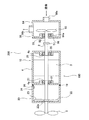
図1は、電動機組立体100の一実施形態を示す図である。図1に示すように、電動機組立体100は、モータ部(電動機部)10と、モータ部10に隣接して配置されたインバータ部20とを備えている。モータ部10は、駆動軸2と、駆動軸2を回転させるモータ(電動機)3と、モータ3を収容するモータケーシング4と、を備える。インバータ部20は、モータ3に可変周波数の交流電力を供給する可変速手段であるインバータ22と、インバータ22の動作を制御する制御装置23と、インバータ22を収容するインバータハウジング24とを備えている。制御装置23は、インバータ22を介してモータ3やモータ3が駆動する回転機器の回転速度を制御する。インバータ22は、基板と、該基板の上に実装されたスイッチング素子やコンデンサなどの各要素を備えており、インバータ22の基板は環状形状を有している。駆動軸2は、インバータ22の中央に形成された貫通孔22aを貫通しており、インバータ22は駆動軸2と同心状に配置されている。
Example 1
FIG. 1 is a diagram illustrating one embodiment of a motor assembly 100. As shown in FIG. 1, the motor assembly 100 includes a motor unit (motor unit) 10 and an inverter unit 20 disposed adjacent to the motor unit 10. The motor unit 10 includes a drive shaft 2, a motor (electric motor) 3 that rotates the drive shaft 2, and a motor casing 4 that houses the motor 3. The inverter unit 20 includes an inverter 22 which is variable speed means for supplying AC power of variable frequency to the motor 3, a control device 23 for controlling the operation of the inverter 22, and an inverter housing 24 for housing the inverter 22. . The control device 23 controls the rotational speed of the rotating device driven by the motor 3 and the motor 3 via the inverter 22. The inverter 22 includes a substrate and elements such as a switching element and a capacitor mounted on the substrate, and the substrate of the inverter 22 has an annular shape. The drive shaft 2 passes through a through hole 22 a formed at the center of the inverter 22, and the inverter 22 is disposed concentrically with the drive shaft 2.

モータケーシング4およびインバータハウジング24は封水部19を介して互いに接続されている。封水部19は、例えば、環状形状を有する弾性シール部材であり、モータケーシング4とインバータハウジング24との間からの液体の浸入を防止する。   The motor casing 4 and the inverter housing 24 are connected to each other via a water sealing portion 19. The sealing portion 19 is, for example, an elastic sealing member having an annular shape, and prevents the infiltration of liquid from between the motor casing 4 and the inverter housing 24.

モータケーシング4およびインバータハウジング24は駆動軸2と同心状に配置されており、駆動軸2はモータケーシング4の中央部分およびインバータハウジング24の中央部分を貫通している。駆動軸2は軸受21、軸受25によって回転自在に支持されている。本実施形態では、インバータハウジング24は駆動軸2の軸方向に配置されるため、電動機組立体100はコンパクトな構造を有することができる。以下、本明細書において、モータケーシング4およびインバータハウジング24を総称して電動機組立体100の筐体と呼ぶことがある。なお、インバータ22と同様に、駆動軸2は、インバータハウジング24の中央部分に形成された貫通孔(不図示)を貫通してもよい。駆動軸2がインバータハウジング24の貫通孔(不図示)と貫通孔22aを貫通することで、駆動軸2とインバータハウジング24が接しないので、駆動軸2の振動がインバータ22に直接伝わるのを防ぐことができる。   The motor casing 4 and the inverter housing 24 are arranged concentrically with the drive shaft 2, and the drive shaft 2 passes through the central portion of the motor casing 4 and the central portion of the inverter housing 24. The drive shaft 2 is rotatably supported by bearings 21 and 25. In this embodiment, since the inverter housing 24 is disposed in the axial direction of the drive shaft 2, the motor assembly 100 can have a compact structure. Hereinafter, in the present specification, the motor casing 4 and the inverter housing 24 may be collectively referred to as a housing of the motor assembly 100. As in the case of the inverter 22, the drive shaft 2 may penetrate a through hole (not shown) formed in the central portion of the inverter housing 24. The drive shaft 2 penetrates the through hole (not shown) of the inverter housing 24 and the through hole 22a, so that the drive shaft 2 and the inverter housing 24 are not in contact with each other. be able to.

図1において、モータ3は模式的に描かれている。モータ3は、例えば、ロータに永久磁石を用いた永久磁石型モータである。しかしながら、モータ3は、永久磁石型モータに限定されず、誘導モータやSRモータなど、様々な種類のモータであってもよい。   In FIG. 1, the motor 3 is schematically depicted. The motor 3 is, for example, a permanent magnet type motor using a permanent magnet as a rotor. However, the motor 3 is not limited to a permanent magnet type motor, and may be various types of motors such as an induction motor and an SR motor.

電動機組立体100は、駆動軸2に固定された冷却ファン8をさらに備えている。冷却ファン8は、駆動軸2と同心状に配置されており、インバータハウジング24の外部に位置している。モータ3が駆動すると、その駆動力は駆動軸2に伝えられ、駆動軸2に固定された冷却ファン8は駆動軸2とともに回転する。結果として、冷却ファン8は周囲の空気を吸い込み、吸い込まれた空気はインバータハウジング24およびモータケーシング4の外面上を流れ、インバータ部20およびモータ部10を冷却する。インバータ部20は冷却ファン8とモータ部10との間に配置されており、冷却ファン8、インバータ部20、およびモータ部10はこの順に直列に配置されている。   The motor assembly 100 further includes a cooling fan 8 fixed to the drive shaft 2. The cooling fan 8 is disposed concentrically with the drive shaft 2 and is located outside the inverter housing 24. When the motor 3 is driven, the driving force is transmitted to the drive shaft 2, and the cooling fan 8 fixed to the drive shaft 2 rotates with the drive shaft 2. As a result, the cooling fan 8 sucks ambient air, and the sucked air flows on the outer surfaces of the inverter housing 24 and the motor casing 4 to cool the inverter unit 20 and the motor unit 10. The inverter unit 20 is disposed between the cooling fan 8 and the motor unit 10, and the cooling fan 8, the inverter unit 20, and the motor unit 10 are disposed in series in this order.

本実施形態では、インバータハウジング24の周壁部はモータケーシング4の外形形状に合わせて円筒形状を有している。一実施形態では、モータケーシング4がフィンや端子箱などの部材によって特殊な外形形状を有している場合、インバータハウジング24は、このモータケーシング4の形状に合わせた構造を有してもよい。   In the present embodiment, the peripheral wall portion of the inverter housing 24 has a cylindrical shape in accordance with the outer shape of the motor casing 4. In one embodiment, when the motor casing 4 has a special external shape by a member such as a fin or a terminal box, the inverter housing 24 may have a structure adapted to the shape of the motor casing 4.

電動機組立体100の主たる振動源としては駆動軸2が考えられる。例えば、モータ3の運転中に、軸受21、軸受25の摩耗が進行し異常が発生すると駆動軸2の振動に変化が現れる場合が多い。また、駆動軸2が接続される回転機器の振動は駆動軸2を伝わる。したがって、制御装置23は、この駆動軸2を支持している軸受21、軸受25の振動を測定することが望ましい。そこで、電動機組立体100は、インバータ22側の軸受21に隣接して配置された第1モータ側振動センサ31と、不図示の負荷側の軸受25に隣接して配置された第2モータ側振動センサ35とを備えている。第1モータ側振動センサ31、第2モータ側振動センサ35のそれぞれは、信号線を介して制御装置23に電気的に接続されており、駆動軸2やモータ部10の振動を検出する。   As a main vibration source of the motor assembly 100, the drive shaft 2 can be considered. For example, when the wear of the bearings 21 and 25 progresses and the abnormality occurs while the motor 3 is in operation, the vibration of the drive shaft 2 often changes. Further, the vibration of the rotating device to which the drive shaft 2 is connected is transmitted through the drive shaft 2. Therefore, it is desirable that the control device 23 measure the vibrations of the bearings 21 and 25 supporting the drive shaft 2. Therefore, the motor assembly 100 includes a first motor-side vibration sensor 31 disposed adjacent to the bearing 21 on the inverter 22 side and a second motor-side vibration disposed adjacent to the load-side bearing 25 (not shown). And a sensor 35. Each of the first motor-side vibration sensor 31 and the second motor-side vibration sensor 35 is electrically connected to the control device 23 through a signal line, and detects the vibration of the drive shaft 2 and the motor unit 10.

軸受21はインバータ部20に隣接してモータ3の反負荷側に配置されており、軸受25はモータ3を挟んで軸受21の反対側(モータ3の負荷側)に配置されている。軸受21はモータケーシング4の軸受支持部4aに支持されており、軸受25はモータケーシング4の軸受支持部4bに支持されている。第1モータ側振動センサ31は軸受支持部4aに取り付けられており、第2モータ側振動センサ35は軸受支持部4bに取り付けられている。   The bearing 21 is disposed adjacent to the inverter unit 20 and on the opposite load side of the motor 3, and the bearing 25 is disposed on the opposite side of the bearing 21 (on the load side of the motor 3) across the motor 3. The bearing 21 is supported by the bearing support 4 a of the motor casing 4, and the bearing 25 is supported by the bearing support 4 b of the motor casing 4. The first motor side vibration sensor 31 is attached to the bearing support 4a, and the second motor side vibration sensor 35 is attached to the bearing support 4b.

軸受21、軸受25は定期的に交換される消耗部品であり、交換可能な構造を有しているため、第1モータ側振動センサ31、第2モータ側振動センサ35は、軸受21、軸受25の交換が妨げられない箇所に配置されるとよい。一実施形態では、軸受支持部4aの内面(すなわち、軸受21に接触する面)に溝(図示しない)を形成し、この溝に軸受21を配置してもよい。同様に、軸受支持部4bの内面(すなわち、軸受25に接触する面)に溝(図示しない)を形成し、この溝に軸受25を配置してもよい。   The bearings 21 and 25 are consumable parts that are periodically replaced and have a replaceable structure. Therefore, the first motor-side vibration sensor 31 and the second motor-side vibration sensor 35 include bearings 21 and bearings 25. It is good to be arranged in the place where exchange of is not prevented. In one embodiment, a groove (not shown) may be formed on the inner surface (that is, the surface in contact with the bearing 21) of the bearing support 4a, and the bearing 21 may be disposed in this groove. Similarly, a groove (not shown) may be formed on the inner surface (that is, the surface in contact with the bearing 25) of the bearing support 4b, and the bearing 25 may be disposed in this groove.

更には、軸受21、軸受25を着脱することなく、第1モータ側振動センサ31、第2モータ側振動センサ35のそれぞれを交換可能とするために、第1モータ側振動センサ31、第2モータ側振動センサ35のそれぞれは、交換可能な構造を有しているとよい。一実施形態では、第1モータ側振動センサ31、第2モータ側振動センサ35のそれぞれは着脱可能に信号線に接続されているとよい。   Furthermore, in order to make each of the first motor side vibration sensor 31 and the second motor side vibration sensor 35 replaceable without attaching and detaching the bearing 21 and the bearing 25, the first motor side vibration sensor 31, the second motor Each of the side vibration sensors 35 may have a replaceable structure. In one embodiment, each of the first motor side vibration sensor 31 and the second motor side vibration sensor 35 may be detachably connected to the signal line.

第1モータ側振動センサ31、第2モータ側振動センサ35によって検出された振動値は、制御装置23に入力される。第1モータ側振動センサ31、第2モータ側振動センサ35の信号線は、モータ3の動作および/または電動機組立体100の設置(縦置きまたは横置き)の妨げにならないように、例えば、電動機組立体100の筐体に沿って配線され、制御装置23に接続されるとよい。モータ3とインバータ22とを接続する動力線を含む接続線は、この接続線が電動機組立体100の外部に露出しないようにモータケーシング4およびインバータハウジング24の内部を延びているとよい。   The vibration values detected by the first motor side vibration sensor 31 and the second motor side vibration sensor 35 are input to the control device 23. The signal lines of the first motor-side vibration sensor 31 and the second motor-side vibration sensor 35 do not disturb the operation of the motor 3 and / or the installation (longitudinal installation or horizontal installation) of the motor assembly 100, for example, motor It may be wired along the housing of the assembly 100 and connected to the controller 23. A connection line including a power line connecting the motor 3 and the inverter 22 may extend inside the motor casing 4 and the inverter housing 24 so that the connection line is not exposed to the outside of the motor assembly 100.

インバータ部20の振動、より具体的には、インバータ22およびインバータハウジング24の何れかにおける振動を検出するために、電動機組立体100は、インバータ部20に配置されたインバータ側振動センサ36を備えている。本実施形態では、インバータ側振動センサ36は、インバータハウジング24の内部の気密性(および水密性)を保つために、インバータハウジング24の内面に取り付けられている。また、振動源である駆動軸2から離間した位置に配置されているため、インバータ22に起因する振動(例えば、インバータ22の不図示の電解コンデンサなどの重心位置が高い部品が共振する等)を測定することができる。一実施形態では、インバータ側振動センサ36は、インバータ22に取り付けられてもよい。この場合、インバータ側振動センサ36は、インバータ22の駆動軸2から離間した位置、すなわち、インバータ22の外周部分に取り付けられてもよい。また、封水部19に、ゴム等の弾性体から構成された防振パッドを用いることで、インバータハウジング24は、駆動軸2の振動の影響をより抑えることができる。インバータ側振動センサ36は、信号線を介して制御装置23に電気的に接続されており、インバータ22の振動を検出する。   In order to detect the vibration of the inverter unit 20, more specifically, the vibration in any of the inverter 22 and the inverter housing 24, the motor assembly 100 includes an inverter-side vibration sensor 36 disposed in the inverter unit 20. There is. In the present embodiment, the inverter-side vibration sensor 36 is attached to the inner surface of the inverter housing 24 in order to maintain the air tightness (and water tightness) of the inside of the inverter housing 24. In addition, since it is disposed at a position separated from the drive shaft 2 which is a vibration source, vibration caused by the inverter 22 (for example, a component having a high gravity position such as an electrolytic capacitor (not shown) of the inverter 22 resonates) It can be measured. In one embodiment, the inverter-side vibration sensor 36 may be attached to the inverter 22. In this case, the inverter-side vibration sensor 36 may be attached to a position separated from the drive shaft 2 of the inverter 22, that is, the outer peripheral portion of the inverter 22. Moreover, the inverter housing 24 can suppress the influence of the vibration of the drive shaft 2 more by using the anti-vibration pad comprised from elastic bodies, such as rubber | gum, for the sealing water part 19. FIG. The inverter-side vibration sensor 36 is electrically connected to the control device 23 via a signal line, and detects the vibration of the inverter 22.

本実施形態では、電動機組立体100は、第1モータ側振動センサ31、第2モータ側振動センサ35、およびインバータ側振動センサ36を備えているが、これら振動センサとしては、例えば、加速度、速度、変位等を検出する各種センサのうち、ひとつまたは複数種類のセンサが組合せで用いられてもよい。また、振動センサの個数や配置箇所は本実施形態には限定されない。駆動軸2やインバータ22の他に振動源となる部材が存在し、この部材の振動を特に検出する必要がある場合、この部材の振動を検出するセンサをさらに配置してもよい。   In the present embodiment, the motor assembly 100 includes the first motor-side vibration sensor 31, the second motor-side vibration sensor 35, and the inverter-side vibration sensor 36. Examples of these vibration sensors include acceleration and speed. Among various sensors for detecting displacement, etc., one or more kinds of sensors may be used in combination. Further, the number of vibration sensors and the arrangement location thereof are not limited to this embodiment. In addition to the drive shaft 2 and the inverter 22, a member serving as a vibration source is present, and when it is necessary to particularly detect the vibration of this member, a sensor for detecting the vibration of this member may be further disposed.

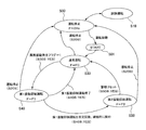
図2は、電動機組立体100および電動機組立体100の負荷側にポンプ50等の回転機器を備えるポンプ装置200を模式的に示す断面図である。図2に示すように、ポンプ50は例えば遠心ポンプであって、回転軸52に固定された羽根車53と、羽根車53を収容するポンプケーシング54とを備え、吸込口50aから流入した搬送流体を加圧して吐出し口50bへ吐出する。そして、ポンプ装置200は、カップリング51を介して駆動軸2に連結された回転軸52と、回転軸52をポンプケーシング54から回転自在に支持する軸受55とを備えている。軸受55はポンプケーシング54の軸受支持部54aに支持されている。   FIG. 2 is a cross-sectional view schematically showing a motor assembly 100 and a pump device 200 provided with a rotating device such as a pump 50 on the load side of the motor assembly 100. As shown in FIG. As shown in FIG. 2, the pump 50 is, for example, a centrifugal pump, and includes an impeller 53 fixed to the rotating shaft 52 and a pump casing 54 for housing the impeller 53, and the transport fluid flowing in from the suction port 50a. Is pressurized and discharged to the discharge port 50b. The pump device 200 includes a rotary shaft 52 connected to the drive shaft 2 via a coupling 51, and a bearing 55 rotatably supporting the rotary shaft 52 from the pump casing 54. The bearing 55 is supported by a bearing support 54 a of the pump casing 54.

本実施形態では、回転軸52も振動源となる。ポンプ50の搬送流体の脈動が回転軸52に伝わる。また、例えば、搬送流体に異物が混在していると、異物が羽根車53に当たりその振動が回転軸52にも伝わる。更には、軸受55の摩耗が進行しても回転軸52の振動が変化する。したがって、この軸受55を支持する軸受支持部54aにはポンプ側振動センサ56が取り付けられている。ポンプ側振動センサ56は、制御装置23に電気的に接続されており、軸受支持部54aの内面(すなわち、軸受55に接触する面)に形成された溝に配置されている。ポンプ側振動センサ56は、信号線を介して制御装置23に電気的に接続されており、ポンプ50の振動を検出する。   In the present embodiment, the rotation shaft 52 also serves as a vibration source. The pulsation of the transport fluid of the pump 50 is transmitted to the rotating shaft 52. Further, for example, when foreign matter is mixed in the transport fluid, the foreign matter strikes the impeller 53 and its vibration is also transmitted to the rotation shaft 52. Furthermore, even if the wear of the bearing 55 progresses, the vibration of the rotating shaft 52 changes. Therefore, the pump-side vibration sensor 56 is attached to the bearing support 54 a that supports the bearing 55. The pump-side vibration sensor 56 is electrically connected to the control device 23, and is disposed in a groove formed in the inner surface of the bearing support 54a (that is, the surface in contact with the bearing 55). The pump-side vibration sensor 56 is electrically connected to the control device 23 via a signal line, and detects the vibration of the pump 50.

本実施形態に係る電動機組立体100は、寸法互換性がある限り、様々なポンプに適用可能である。本実施形態に係る電動機組立体100とポンプ50の駆動軸である回転軸52との接続は、カップリングの有無および/または設置状況(例えば、縦置きまたは横置き)に左右されない。例えば、電動機組立体100とポンプ50は直動式として、駆動軸2をポンプケーシング54の内部まで延伸して羽根車53を固定してもよい。また、ポンプ50は立軸形ポンプでも横軸形ポンプでもよいし、羽根車53は単段でも多段でもよい。なお、本実施形態では、図2に示すポンプ装置200は、陸上に設置される給水用ポンプ装置であるとして説明するが、ポンプ装置200の用途は本実施形態には限定されない。例えば、ポンプ装置200は、水中に設置される水中ポンプ装置であってもよく、または、真空を形成する真空ポンプ装置であってもよい。ポンプ装置200の用途は使用環境等に応じて変更されてもよい。   The motor assembly 100 according to the present embodiment is applicable to various pumps as long as dimensional compatibility is provided. The connection between the motor assembly 100 according to the present embodiment and the rotary shaft 52, which is the drive shaft of the pump 50, is not influenced by the presence or absence of the coupling and / or the installation situation (for example, vertical or horizontal). For example, the motor assembly 100 and the pump 50 may be direct acting, and the drive shaft 2 may be extended to the inside of the pump casing 54 to fix the impeller 53. Further, the pump 50 may be a vertical shaft pump or a horizontal shaft pump, and the impeller 53 may be a single stage or multiple stages. In the present embodiment, although the pump device 200 shown in FIG. 2 is described as a water supply pump device installed on land, the application of the pump device 200 is not limited to this embodiment. For example, the pump device 200 may be a submersible pump device installed in water, or may be a vacuum pump device that forms a vacuum. The application of the pump device 200 may be changed according to the use environment and the like.

図3は、制御装置23の構成を示す模式図である。図3に示すように、制御装置23は、制御プログラムや各種データなどが格納(記憶)される記憶部60と、記憶部60に格納されている各種制御プログラムに従って演算を行う演算部61と、演算部61に接続されたタイマー62と、外部端末63と通信可能な外部通信部64と、各種信号を入出力する入出力部65と、を備えている。また、制御装置23には、ポンプ装置200の状態表示や各種操作を行うことができる運転パネル66を備えてもよい。   FIG. 3 is a schematic view showing the configuration of the control device 23. As shown in FIG. As shown in FIG. 3, the control device 23 includes a storage unit 60 in which control programs and various data are stored (stored), and an operation unit 61 that performs operations in accordance with various control programs stored in the storage unit 60. A timer 62 connected to the arithmetic unit 61, an external communication unit 64 capable of communicating with the external terminal 63, and an input / output unit 65 for inputting / outputting various signals are provided. In addition, the control device 23 may be provided with an operation panel 66 capable of performing state display of the pump device 200 and various operations.

記憶部60は、ROM、HDD、EEPROM、FeRAM、及び、フラッシュメモリ等の不揮発性メモリ、RAM等の揮発性メモリが用いられ、ポンプ50の自動運転、手動運転、および後述する試験運転等のポンプ装置200を制御するための制御プログラムと、装置情報、設定値情報、メンテナンス情報、履歴情報、異常情報、運転情報等のポンプ装置200に関する各種データを記憶する。また、記憶部60は、詳細を後述する第1モータ側振動センサ31、第2モータ側振動センサ35、インバータ側振動センサ36、ポンプ側振動センサ56による計測振動値と、所定の基準振動値と、ポンプ装置200の異常振動の基準となるしきい値と、を記憶する。   The storage unit 60 uses ROM, HDD, EEPROM, FeRAM, nonvolatile memory such as flash memory, volatile memory such as RAM, and pumps such as automatic operation of the pump 50, manual operation, and test operation described later A control program for controlling the device 200 and various data related to the pump device 200 such as device information, set value information, maintenance information, history information, abnormality information, operation information and the like are stored. In addition, the storage unit 60 measures the vibration value measured by the first motor side vibration sensor 31, the second motor side vibration sensor 35, the inverter side vibration sensor 36, and the pump side vibration sensor 56, which will be described in detail later. , And a threshold value which is a reference of abnormal vibration of the pump device 200.

演算部61は、例えば、CPU(中央処理装置)などが用いられ、記憶部60に記憶された制御プログラムや各種情報に基づいてポンプ装置200を制御するための演算を行う。演算部61は、第1モータ側振動センサ31、第2モータ側振動センサ35、インバータ側振動センサ36、ポンプ側振動センサ56から入出力部65へ入力される振動(振動データまたは振動情報)に対してフーリエ変換を実行して、周波数帯域ごとの振動レベルを算出し「計測振動値」として記憶部60に記憶する。さらに、演算部61は、該計測振動値と所定のしきい値とを比較して計測振動値がしきい値よりも大きい場合、ポンプ装置200の異常振動と判断する。また、記憶部60の各種制御プログラムや各種データに基づいてモータ3の回転速度を算出し、入出力部65を介してインバータ22へ出力する。   The calculation unit 61 uses, for example, a CPU (central processing unit) or the like, and performs calculations for controlling the pump device 200 based on the control program and various information stored in the storage unit 60. The calculation unit 61 is for the vibration (vibration data or vibration information) input from the first motor-side vibration sensor 31, the second motor-side vibration sensor 35, the inverter-side vibration sensor 36, and the pump-side vibration sensor 56 to the input / output unit 65. On the other hand, Fourier transform is performed to calculate the vibration level for each frequency band and store it in the storage unit 60 as a “measured vibration value”. Furthermore, the calculation unit 61 compares the measured vibration value with a predetermined threshold value, and determines that the vibration of the pump device 200 is abnormal if the measured vibration value is larger than the threshold value. Further, the rotational speed of the motor 3 is calculated based on various control programs of the storage unit 60 and various data, and is output to the inverter 22 through the input / output unit 65.

タイマー62は、計時部であって、例えば、セラミック発振子、水晶振動子及び発振器等が用いられる。また、タイマー62に代えて演算部61のCPUのクロックを用いてもよい。   The timer 62 is a timekeeping unit, and for example, a ceramic oscillator, a quartz oscillator, an oscillator or the like is used. Also, instead of the timer 62, the clock of the CPU of the calculation unit 61 may be used.

外部通信部64は外部端末63と通信可能である。外部端末63は、専用のコントローラ、PC(パーソナルコンピュータ)、またはスマートフォンなどのPDA(Personal Digital Assistant)であって、制御情報を任意に表示変更することができる端末であれば、特に限定されない。制御装置23は、有線通信または無線通信によって外部端末63に接続されている。なお、運転パネル66と外部端末63は、同一の機能を有するGUI(Graphical User Interface)であるとよい。   The external communication unit 64 can communicate with the external terminal 63. The external terminal 63 is not particularly limited as long as it is a dedicated controller, a PC (personal computer), or a PDA (Personal Digital Assistant) such as a smart phone and can arbitrarily change display of control information. The control device 23 is connected to the external terminal 63 by wired communication or wireless communication. The operation panel 66 and the external terminal 63 preferably have a GUI (Graphical User Interface) having the same function.

入出力部65は、例えば、ポートや通信等が使用され、各種信号の入出力を行う。入力信号の例としては、第1モータ側振動センサ31、第2モータ側振動センサ35、インバータ側振動センサ36、および、ポンプ側振動センサ56の検出値、インバータ22の状態(電圧、電流、異常、周波数の現在値等)等である。また、出力信号の例としては、演算部にて算出したモータ3の運転信号、停止信号、回転速度等をインバータ22や不図示の外部出力端子へ出力する。また、入出力部65は、後述する圧力センサ73、圧力センサ74、および、流量センサ72による検出信号を入力できるとよい。入出力部65は、後述する試験運転モードへの切り替え並びに試験運転を実行するための外部入力端子(不図示)を備えてもよい。   The input / output unit 65 uses, for example, a port or communication, and inputs and outputs various signals. As an example of the input signal, detection values of the first motor side vibration sensor 31, the second motor side vibration sensor 35, the inverter side vibration sensor 36, and the pump side vibration sensor 56, the state of the inverter 22 (voltage, current, abnormality , Current value of frequency, etc.). Further, as an example of the output signal, the operation signal, stop signal, rotational speed, etc. of the motor 3 calculated by the calculation unit are output to the inverter 22 or an external output terminal (not shown). Further, it is preferable that the input / output unit 65 can input detection signals from a pressure sensor 73, a pressure sensor 74, and a flow sensor 72 described later. The input / output unit 65 may include an external input terminal (not shown) for switching to a test operation mode to be described later and performing the test operation.

以下、本明細書中において、第1モータ側振動センサ31、第2モータ側振動センサ35、インバータ側振動センサ36、ポンプ側振動センサ56を特に区別する必要がない場合、単に「振動センサ」と呼ぶことがある。これら振動センサとしては、例えば、加速度、速度、および、変位を検出するセンサであり、これらセンサのうちひとつまたは複数種類を組合せて用いられてもよい。   Hereinafter, in the present specification, when it is not necessary to distinguish the first motor side vibration sensor 31, the second motor side vibration sensor 35, the inverter side vibration sensor 36, and the pump side vibration sensor 56, simply “vibration sensor” I sometimes call. These vibration sensors are, for example, sensors that detect acceleration, velocity, and displacement, and one or more of these sensors may be used in combination.

図4は、ポンプ装置200が備えられたポンプ設備210の模式図である。図4に示すように、ポンプ設備210は、ポンプ50の流入口50aに接続された流入管70と、ポンプ50の吐出し口50bに接続された吐出し管71と、ポンプ50を流れる流体の流量を検出する流量センサ(流量検出器)72と、ポンプ50の流入圧力を検出する圧力センサ(圧力検出器)73と、ポンプ50の吐出し圧力を検出する圧力センサ(圧力検出器)74が設けられている。また、吐出し管71における圧力センサ(圧力検出器)74の下流側には、ポンプ50の吐出し側の流路を止水するバルブ75が設けられている。   FIG. 4 is a schematic view of a pump installation 210 provided with the pump device 200. As shown in FIG. As shown in FIG. 4, the pump equipment 210 includes an inflow pipe 70 connected to the inflow port 50 a of the pump 50, a discharge pipe 71 connected to the discharge port 50 b of the pump 50, and the fluid flowing through the pump 50. A flow sensor (flow detector) 72 for detecting the flow rate, a pressure sensor (pressure detector) 73 for detecting the inflow pressure of the pump 50, and a pressure sensor (pressure detector) 74 for detecting the discharge pressure of the pump 50 It is provided. Further, on the downstream side of the pressure sensor (pressure detector) 74 in the discharge pipe 71, a valve 75 for stopping the flow passage on the discharge side of the pump 50 is provided.

流入管70には、ポンプ50の内部を流れる流体の流量を検出する流量センサ(流量検出器)72と、ポンプ50の流入圧力を検出する圧力センサ(圧力検出器)73とが取り付けられているとよい。吐出管71には、ポンプ50の吐出側の圧力を検出する圧力センサ(圧力検出器)74が取り付けられている。流量センサ72、および圧力センサ73,74は制御装置23の入出力部65に電気的に接続されており、流量センサ72によって検出された流量信号、圧力センサ73,74によって検出された圧力信号は制御装置23の入出力部65に出力される。制御装置23は、流量センサ72によって検出された流量に基づいて流量値を取得し、圧力センサ73,74によって検出された圧力に基づいて圧力値を取得する。なお、流入管70に設けられた流量センサ72はポンプ50の吐出し流量を計測する。また、流入管70に設けられた流量センサ72に代えて、もしくは加えて吐出管71に流量センサ72を備えてもよい。   A flow rate sensor (flow rate detector) 72 for detecting the flow rate of the fluid flowing inside the pump 50 and a pressure sensor (pressure detector) 73 for detecting the inflow pressure of the pump 50 are attached to the inflow pipe 70 It is good. A pressure sensor (pressure detector) 74 for detecting the pressure on the discharge side of the pump 50 is attached to the discharge pipe 71. The flow rate sensor 72 and the pressure sensors 73 and 74 are electrically connected to the input / output unit 65 of the controller 23. The flow rate signal detected by the flow rate sensor 72 and the pressure signal detected by the pressure sensors 73 and 74 are The data is output to the input / output unit 65 of the control device 23. The control device 23 acquires a flow rate value based on the flow rate detected by the flow rate sensor 72, and acquires a pressure value based on the pressure detected by the pressure sensors 73 and 74. The flow rate sensor 72 provided in the inflow pipe 70 measures the discharge flow rate of the pump 50. Further, instead of or in addition to the flow rate sensor 72 provided in the inflow pipe 70, the flow rate sensor 72 may be provided in the discharge pipe 71.

ポンプ装置200の設置環境およびポンプ装置200の寸法誤差、ポンプ50の出力や羽根車53の外径、揚程や流量、発停頻度等の使用環境を含む各要素によって、ポンプ装置200に発生する振動の大きさには、ばらつきが存在する。そこで、後述する試験運転を行ってポンプ装置200の計測振動値を記憶部60に記憶し、該計測振動値によってポンプ50の揚水運転中の異常振動を検出するとよい。例えば、ポンプ装置200の異常振動を決定するための基準となるしきい値を計測振動値により補正することで、制御装置23は、ポンプ装置200の異常振動の発生をより正確に決定することができる。以下、ポンプ装置200の試験運転方法について説明する。   Vibration generated in the pump device 200 by various factors including installation environment of the pump device 200 and dimensional error of the pump device 200, output of the pump 50, outer diameter of the impeller 53, lift and flow rate, start / stop frequency, etc. There is a variation in the size of. Therefore, it is preferable to perform a test operation to be described later, store the measured vibration value of the pump device 200 in the storage unit 60, and detect the abnormal vibration during the pumping operation of the pump 50 by the measured vibration value. For example, the control device 23 can more accurately determine the occurrence of the abnormal vibration of the pump device 200 by correcting the threshold value which is a reference for determining the abnormal vibration of the pump device 200 using the measured vibration value. it can. Hereinafter, a test operation method of the pump device 200 will be described.

試験運転は、試験運転モードにて実行され、ポンプ装置200の工場出荷時、ポンプ装置200の初期設置後またはポンプ装置200のメンテナンス(例えば、軸受などの部品の交換)が終了した後等で、ポンプ装置200に何れの故障も発生しておらず正常な揚水運転ができるタイミングに行われるとよい。より具体的には、給水装置200は、外部端末63や運転パネル66に不図示の試験運転ボタンを設け、モータ3の初起動時(電源投入時)または再起動時(電源再投入時)等に、ユーザーによる試験運転ボタンの操作によって、試験運転モードへの切り替え並びに試験運転が実行されるとよい。また、試験運転モードは、ユーザーの操作等による任意のタイミングで中断できるとよい。   The test operation is performed in the test operation mode, and when the pump device 200 is shipped from the factory, after initial installation of the pump device 200 or after maintenance of the pump device 200 (for example, replacement of parts such as bearings) It is preferable that the pump device 200 be performed at a timing at which any failure does not occur and a normal pumping operation can be performed. More specifically, in the water supply apparatus 200, the external terminal 63 and the operation panel 66 are provided with a test operation button (not shown), and the motor 3 is initially activated (power on) or restarted (power on) Furthermore, switching to the test operation mode and the test operation may be performed by the user operating the test operation button. In addition, it is preferable that the test operation mode can be interrupted at an arbitrary timing by a user operation or the like.

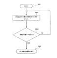
図5は、試験運転モードにおける動作フローチャートを示す図である。まず、ユーザーは、試験運転を開始する準備を行う。本実施例では、配管設備に対する影響を考慮して、バルブ75を全閉にして、ポンプ50の締切運転にて試験運転を行う。そのため、まず、ステップS101では、ユーザーは、ポンプ50の吐出し側の流路を一旦開放した後にバルブ75を全閉にする。また、ユーザーは、ポンプ装置200の電源投入し、試験運転モードに切り替える等の準備を行う(図5のステップS101参照)。次に、ユーザーによる操作等をトリガとして、ポンプ装置200の試験運転を開始する(図5のステップS102参照)。   FIG. 5 is a diagram showing an operation flowchart in the test operation mode. First, the user prepares to start the test operation. In the present embodiment, in consideration of the influence on the piping system, the valve 75 is fully closed, and the test operation is performed by the shutoff operation of the pump 50. Therefore, first, in step S101, the user once opens the flow path on the discharge side of the pump 50 and then fully closes the valve 75. Further, the user turns on the power of the pump device 200 and prepares to switch to the test operation mode (see step S101 in FIG. 5). Next, a test operation of the pump device 200 is started with an operation or the like by the user as a trigger (see step S102 in FIG. 5).

制御装置23は、モータ3の回転速度を所定の回転速度(例えば、定格回転速度)まで段階的に上昇させ、各段階における回転速度に対応する振動値(計測振動値)を取得する(図5のステップS103参照)。一実施形態では、制御装置23は、インバータ22の周波数を0Hzから最大周波数(例えば、50Hz)まで5Hzの間隔で段階的(0Hz,5Hz,10Hz,・・・・・45Hz,50Hz)に上昇させる。また、目標圧力を段階的に上昇させ、ポンプ50の吐出し圧力が該目標圧力となるようにモータ3の回転速度を制御することで、モータ3の回転速度を段階的に上昇させてもよい。各段階における周波数では、周波数や吐出し圧力が安定するまで所定時間(例えば10秒間程度)待機させた後の計測振動値を記憶部60に記憶する。なお、制御装置23もしくは外部端末に不図示の「記憶ボタン」を設ける等して、ユーザーによるボタン操作にて、各段階における計測振動値を記憶部60に記憶してもよい。   The control device 23 raises the rotational speed of the motor 3 stepwise to a predetermined rotational speed (for example, rated rotational speed), and acquires a vibration value (measurement vibration value) corresponding to the rotational speed in each step (FIG. 5) Step S103)). In one embodiment, the controller 23 raises the frequency of the inverter 22 stepwise (0 Hz, 5 Hz, 10 Hz,... 45 Hz, 50 Hz) at intervals of 5 Hz from 0 Hz to the maximum frequency (for example, 50 Hz). . Alternatively, the rotational speed of the motor 3 may be increased stepwise by controlling the rotational speed of the motor 3 such that the target pressure is increased stepwise and the discharge pressure of the pump 50 becomes the target pressure. . In the frequency in each step, the measured vibration value after waiting for a predetermined time (for example, about 10 seconds) until the frequency and the discharge pressure are stabilized is stored in the storage unit 60. The measured vibration value at each stage may be stored in the storage unit 60 by a button operation of the user by providing a “memory button” (not shown) on the control device 23 or an external terminal.

図6は、記憶部60における計測振動値を記憶する記憶テーブルの一例を示す図である。本実施形態では、記憶テーブルTbl1とTbl2、Tbl3、Tbl4は同じ配列構造をもつ記憶テーブルであり振動センサ毎の計測振動値を試験計測振動値として記憶する。つまり、第1モータ側振動センサ31の計測振動値は記憶テーブルTbl1、第2モータ側振動センサ35の計測振動値は記憶テーブルTbl2、インバータ側振動センサ36の計測振動値は記憶テーブルTbl3、ポンプ側振動センサ56の計測振動値は記憶テーブルTbl4に記憶する。記憶テーブルTbl1に示すように、記憶部60には、回転速度に対応する振動の周波数帯域(例えば、f1、f2、f3・・・)ごとの振動レベルを記憶するとよい。具体的には、制御装置23は、各回転速度にて振動センサから送られた振動に対してフーリエ変換を実行して、複数の周波数帯域(例えば、f1、f2、f3・・・FN)ごとの振動レベルを計測振動値として、該当する周波数毎に記憶するとよい。   FIG. 6 is a diagram showing an example of a storage table for storing the measured vibration value in the storage unit 60. As shown in FIG. In the present embodiment, the storage tables Tbl1 and Tbl2, Tbl3 and Tbl4 are storage tables having the same array structure, and the measured vibration value for each vibration sensor is stored as a test measured vibration value. That is, the measured vibration value of the first motor side vibration sensor 31 is the memory table Tbl1, the measured vibration value of the second motor side vibration sensor 35 is the memory table Tbl2, and the measured vibration value of the inverter side vibration sensor 36 is the memory table Tbl3, the pump side The measured vibration value of the vibration sensor 56 is stored in the storage table Tbl4. As shown in the storage table Tb11, the storage unit 60 may store the vibration level for each frequency band (for example, f1, f2, f3...) Of the vibration corresponding to the rotational speed. Specifically, the control device 23 performs Fourier transform on the vibration sent from the vibration sensor at each rotational speed, and for each of a plurality of frequency bands (for example, f1, f2, f3... FN) The vibration level of V may be stored as a measured vibration value for each corresponding frequency.

ここで、ポンプ50の試験運転中に特定の回転速度において過剰な振動が発生した場合には、制御装置23は、該回転速度時のポンプ装置200の状態を記憶するとよい。具体的には、記憶部60は、過剰な振動が発生した回転速度時のポンプ装置200の状態を記憶する「振動異常領域」を有し、振動異常領域には、例えば、該回転速度、該回転速度時の吐出し圧力、該回転速度時の吐出し流量等のポンプ装置200の状態のうち少なくともひとつを記憶するとよい。そして、制御装置23は、ポンプ装置200の自動運転における揚水運転時において、この過剰な振動が発生した「振動異常領域」の状態を回避するようにポンプ50を制御してもよい。具体的には、制御装置23は、振動異常領域に記憶された回転速度や吐出し流量を回避するようにモータ3の回転速度を制御したり、目標圧力が振動異常領域に記憶された吐出し圧力と同じとなるのを回避するようにポンプ50を制御するとよい。そうすることで、特定の回転数または吐出し圧力における振動を抑制することができる。なお、制御装置23は、所定のしきい値より大きな振動が発生した場合や、他の回転速度の振動値との差分が所定のしきい値より大きい場合に、特定の回転速度において過剰な振動が発生したと判断し、ポンプ装置200の状態を振動異常領域に記憶するとよい。また、ポンプ50の試験運転中に「振動異常領域」を記憶するのに加えて、または、代えて、ユーザーが「振動異常領域」を運転パネル66や外部端末63にて変更可能としてもよい。記憶部60は、ひとつまたは複数の「振動異常領域」を有するとよい。   Here, when excessive vibration occurs at a specific rotational speed during the test operation of the pump 50, the control device 23 may store the state of the pump device 200 at the rotational speed. Specifically, the storage unit 60 has a “vibration abnormal area” for storing the state of the pump apparatus 200 at the rotational speed at which excessive vibration occurs, and the rotational speed, for example, in the vibration abnormal area. It is preferable to store at least one of the pump pressure at the rotational speed and the discharge flow rate at the rotational speed. Then, the control device 23 may control the pump 50 so as to avoid the state of the “vibration abnormal region” in which the excessive vibration occurs during the pumping operation in the automatic operation of the pump device 200. Specifically, the control device 23 controls the rotational speed of the motor 3 so as to avoid the rotational speed and the discharge flow rate stored in the vibration abnormal area, or the discharge in which the target pressure is stored in the vibration abnormal area. The pump 50 may be controlled to avoid becoming equal to the pressure. By doing so, it is possible to suppress the vibration at a specific rotational speed or discharge pressure. In addition, when a vibration larger than a predetermined threshold occurs, or when the difference between the vibration value of other rotational speeds is larger than the predetermined threshold, the control device 23 excessive vibration at a specific rotational speed. It is preferable to store the state of the pump device 200 in the vibration abnormal area, judging that In addition to or instead of storing the “vibration abnormal area” during the test operation of the pump 50, the user may change the “vibration abnormal area” by the operation panel 66 or the external terminal 63. The storage unit 60 may have one or more “vibration abnormal area”.

制御装置23は、更に、試験運転の各段階における回転速度に対応する吐出し圧力を取得し、記憶テーブルTbl1、Tbl2、Tbl3、Tbl4に記憶するとよい。そうすれば、制御装置23は、吐出し圧力と振動値とを関連付けることができ、ポンプ50に作用する流体の圧力に起因する振動を特定することができる。ポンプ装置200が、例えば直結給水装置用のブースタポンプ等であって、吸込圧力が変動する場合は、記憶テーブルTbl1、Tbl2、Tbl3、Tbl4には、更に各段階における回転速度に対応する吸込圧力を記憶してもよい。この場合、吐出し圧力から吸込圧力を差し引いた圧力値を記憶してもよい。   The control device 23 may further acquire the discharge pressure corresponding to the rotational speed at each stage of the test operation, and store the discharge pressure in the storage tables Tbl1, Tbl2, Tbl3, and Tbl4. Then, the control device 23 can associate the discharge pressure with the vibration value, and can identify the vibration caused by the pressure of the fluid acting on the pump 50. When the pump device 200 is, for example, a booster pump for a direct connection water supply device and the suction pressure fluctuates, the storage tables Tbl1, Tbl2, Tbl3 and Tbl4 further have suction pressures corresponding to rotational speeds in respective stages. You may memorize. In this case, a pressure value obtained by subtracting the suction pressure from the discharge pressure may be stored.

次に、図5のステップS103にて所定の回転速度まで計測振動値の測定が終了したら、ユーザーによる操作等をトリガとしてポンプ装置200の試験運転モードを終了し、ポンプ装置200の試験運転を終了する(図5のステップS104参照)。ステップS103にて記憶された記憶テーブルTbl1〜Tbl4の計測振動値は、正常時におけるポンプ装置200の振動値であるので、制御装置23は、記憶テーブルTbl1〜Tbl4の計測振動値に基づいてポンプ装置200の異常振動を検出することができる。   Next, when the measurement of the measured vibration value is finished up to a predetermined rotational speed in step S103 of FIG. 5, the test operation mode of the pump device 200 is ended using the operation by the user as a trigger, and the test operation of the pump device 200 is ended. (See step S104 in FIG. 5). Since the measured vibration values of the storage tables Tbl1 to Tbl4 stored in step S103 are vibration values of the pump device 200 at the normal time, the control device 23 is a pump device based on the measured vibration values of the storage tables Tbl1 to Tbl4. 200 abnormal vibrations can be detected.

このように、制御装置23は、計測振動値を記憶部60の記憶テーブルTbl1〜Tbl4に記憶することで、ポンプ装置200毎の個体差や設置環境等に応じて異常振動を検出することができる。   As described above, the control device 23 can detect abnormal vibration in accordance with individual differences among the pump devices 200, the installation environment, and the like by storing the measured vibration values in the storage tables Tbl1 to Tbl4 of the storage unit 60. .

次に、ポンプ装置200の運転中における異常振動の検出について説明する。異常振動は、例えば、ポンプ50が自動運転にて揚水しているとき、すなわちモータ3が運転中に検出されるとよい。ここで、ポンプ装置200の電動機組立体100は、軸受21、軸受25に隣接して配置された第1モータ側振動センサ31と、第2モータ側振動センサ35と、インバータ部20に配置されたインバータ側振動センサ36とを備えており、各振動センサの異常振動の組み合わせにて電動機組立体100の構成要素の異常振動の原因を特定することができる。以下の実施形態では、電動機組立体100の異常を決定し、異常振動の原因を特定する方法について説明する。   Next, detection of abnormal vibration during operation of the pump device 200 will be described. The abnormal vibration may be detected, for example, when the pump 50 is pumping in automatic operation, that is, while the motor 3 is operating. Here, the motor assembly 100 of the pump device 200 is disposed in the bearing 21 and the first motor-side vibration sensor 31 disposed adjacent to the bearing 25, the second motor-side vibration sensor 35, and the inverter unit 20. An inverter-side vibration sensor 36 is provided, and the cause of the abnormal vibration of the component of the motor assembly 100 can be identified by the combination of the abnormal vibration of each vibration sensor. In the following embodiment, a method of determining abnormality of the motor assembly 100 and identifying the cause of the abnormal vibration will be described.

制御装置23は、自動運転もしくは手動運転でモータ3が運転中に、第1モータ側振動センサ31、第2モータ側振動センサ35、インバータ側振動センサ36によって検出された振動を分析(フーリエ変換の実行)し、複数の周波数帯域(f1,f2,f3・・・)に対応する振動レベルを計測振動値の現在値として記憶部60に記憶する。そして、第1モータ側振動センサ31、第2モータ側振動センサ35およびインバータ側振動センサ36の計測振動値の現在値の振動レベルのうち、少なくとも1つが所定のしきい値を超えた状態で所定の時間継続したときに振動異常として、制御装置23は、電動機組立体100に何らかの異常が発生していると判断する。   The control device 23 analyzes the vibration detected by the first motor side vibration sensor 31, the second motor side vibration sensor 35, and the inverter side vibration sensor 36 while the motor 3 is operating in automatic operation or manual operation (the Fourier transform And store the vibration level corresponding to the plurality of frequency bands (f1, f2, f3...) In the storage unit 60 as the current value of the measured vibration value. Then, at least one of the vibration levels of the current values of the measured vibration values of the first motor-side vibration sensor 31, the second motor-side vibration sensor 35, and the inverter-side vibration sensor 36 exceeds a predetermined threshold. The controller 23 determines that some abnormality has occurred in the motor assembly 100 as a vibration abnormality when the time period i continues.

ここで、振動異常を検出するしきい値は基本的に振動レベルの値である。しきい値は、予め制御装置23の記憶部60に、ひとつまたは複数個記憶されてもよいし、制御装置23は、外部通信部64を介して外部端末63のメモリ(図示しない)に格納されている初期値として読み込んでもよい。しきい値は、固定値でもよいし、ユーザーにより設定変更できる設定値でもよい。また、しきい値は試験運転時に記憶テーブルTbl1〜Tbl4に記憶された計測振動値により算出されたり、補正されてもよい。   Here, the threshold value for detecting the vibration abnormality is basically the value of the vibration level. One or more threshold values may be stored in advance in the storage unit 60 of the control device 23. The control device 23 is stored in a memory (not shown) of the external terminal 63 via the external communication unit 64. It may be read as an initial value. The threshold may be a fixed value or a set value that can be changed by the user. The threshold value may be calculated or corrected based on the measured vibration value stored in the storage tables Tbl1 to Tbl4 during the test operation.

ここで、以下の説明にて使用する所定のしきい値について説明する。しきい値は、2段階のしきい値、すなわち、しきい値A1,A2,A3(第1しきい値)と、しきい値A1,A2,A3よりも大きなしきい値B1,B2,B3(第2しきい値)とを含んでいる。しきい値A1,B1は、インバータ側振動センサ36の計測振動値の現在値との比較対象となる。しきい値A2,B2は、第1モータ側振動センサ31の計測振動値の現在値との比較対象となる。しきい値A3,B3は、第2モータ側振動センサ35の計測振動値の現在値との比較対象となる。   Here, the predetermined threshold used in the following description will be described. The threshold value is a two-stage threshold value, that is, threshold values A1, A2 and A3 (first threshold value), and threshold values B1, B2 and B3 larger than threshold values A1, A2 and A3. And (second threshold). The threshold values A1 and B1 are to be compared with the current value of the measured vibration value of the inverter-side vibration sensor 36. The threshold values A2 and B2 are to be compared with the current value of the measured vibration value of the first motor-side vibration sensor 31. The threshold values A3 and B3 are to be compared with the current value of the measured vibration value of the second motor-side vibration sensor 35.

一実施形態では、しきい値A1〜A3のそれぞれは同じ値であってもよく、他の実施形態では、しきい値A1〜A3のそれぞれは異なる値であってもよい。同様に、しきい値B1〜B3のそれぞれは同じ値であってもよく、他の実施形態では、しきい値B1〜B3のそれぞれは異なる値であってもよい。しきい値は、ポンプ装置200の運転や外部に及ぼす影響に基づいて決定されてもよい。例えば、軸受21、軸受25、軸受55の少なくとも1つが破損しているときに発生する振動、騒音が発生してしまう振動、またはポンプ装置の構成部品の欠落および/またはねじのゆるみ等の機械的な要素によって発生してしまう振動等によりしきい値の値が異なってもよい。以下、しきい値A1〜A3を総称してしきい値A(第1しきい値)と呼ぶことがあり、しきい値B1〜B3を総称してしきい値B(第2しきい値)と呼ぶことがある。   In one embodiment, each of the thresholds A1 to A3 may be the same value, and in another embodiment, each of the thresholds A1 to A3 may be different values. Similarly, each of the thresholds B1 to B3 may be the same value, and in another embodiment, each of the thresholds B1 to B3 may be different values. The threshold may be determined based on the operation of the pump device 200 and the influence on the outside. For example, vibration generated when at least one of the bearing 21, the bearing 25, and the bearing 55 is broken, vibration causing noise, or mechanical components such as missing components of the pump apparatus and / or loose screws. The threshold value may be different due to vibration or the like generated by the Hereinafter, threshold values A1 to A3 may be collectively referred to as threshold value A (first threshold value), and threshold values B1 to B3 are collectively referred to as threshold value B (second threshold value). Sometimes called.

制御装置23は、振動センサの計測振動値の現在値のうちの少なくとも1つがしきい値B以上の場合(第3状態)、警報を発報してモータ3の運転を停止する。振動センサの計測振動値の現在値のうちの少なくとも1つがしきい値Aよりも大きい(第2状態)場合、制御装置23は、異常振動を検出するとともに、計測振動値に基づいて異常振動の原因を特定する。そして、運転パネル66や外部端末63に警報を発報してモータ3の運転を継続する。また、振動センサの計測振動値の現在値の全てがしきい値A以下(第1状態)の場合は、振動は正常な範囲内である。   The control device 23 issues an alarm and stops the operation of the motor 3 when at least one of the present values of the measured vibration value of the vibration sensor is equal to or more than the threshold value B (third state). When at least one of the current measured vibration values of the vibration sensor is larger than the threshold value A (second state), the control device 23 detects the abnormal vibration and, based on the measured vibration value, the abnormal vibration specify a reason. Then, an alarm is issued to the operation panel 66 and the external terminal 63 to continue the operation of the motor 3. In addition, when all of the present values of the measured vibration values of the vibration sensor are equal to or less than the threshold A (first state), the vibration is within the normal range.

ここで、制御装置23は、図5にて説明した試験運転によって得られた記憶テーブルTbl1〜Tbl3の各計測振動値によって、ポンプ50の回転速度もしくは吐出し圧力と、各振動センサに対応したしきい値A,Bを算出する例を説明する。   Here, the control device 23 corresponds to the rotational speed or discharge pressure of the pump 50 and each vibration sensor according to each measured vibration value of the storage tables Tbl1 to Tbl3 obtained by the test operation described in FIG. An example of calculating the threshold values A and B will be described.

例えば、制御装置23は、記憶テーブルTbl1からTbl3の各計測振動値に所定の割合を示す数値(例えば、数パーセント)を加算または乗算してしきい値A,Bを決定してもよい。また、ポンプ装置200が推定末端圧力制御を行う場合には、流量(ポンプ50の回転速度)が増加するほど目標圧力も高くなるため、ポンプ装置には振動が発生しやすくなる。したがって、ポンプ50の回転速度が高くなるほど、記憶テーブルTbl1からTbl3の計測振動値に加算または乗算される上記数値を大きくしてもよい。もしくは、記憶テーブルTbl1〜Tbl4の各計測振動値の平均値、最大値、又は、最小値等の何れかを代表値として算出し、該代表値に所定の値を加算もしくは乗算等することで、しきい値A,Bを算出するとよい。   For example, control device 23 may determine threshold values A and B by adding or multiplying a numerical value (for example, several percent) indicating a predetermined ratio to each measured vibration value of storage tables Tbl1 to Tbl3. In addition, when the pump device 200 performs estimated end pressure control, the target pressure also increases as the flow rate (rotational speed of the pump 50) increases, so that the pump device is likely to generate vibrations. Therefore, the higher the rotational speed of the pump 50 is, the larger the numerical value to be added to or multiplied by the measured vibration value of the storage tables Tbl1 to Tbl3 may be. Alternatively, any one of an average value, a maximum value, and a minimum value of each measured vibration value of the storage tables Tbl1 to Tbl4 may be calculated as a representative value, and a predetermined value may be added to or multiplied by the representative value. It is preferable to calculate threshold values A and B.

また、記憶テーブルTbl1〜Tbl3よりしきい値A,Bを決定する方法の他の例として、記憶テーブルTbl1からTbl3の計測振動値と所定の基準振動値との差分である補正量(補正値)を算出し、算出された補正量に基づいて予め記憶部60に記憶されている所定のしきい値A,Bの初期値を補正してもよい。ここで、上述した基準振動値は、同一設計および同一機種の多数のポンプ装置を運転したときの代表性能値に相当し、記憶テーブルTbl1からTbl3と同じ配列を有する記憶テーブル(不図示)に計測振動値が記憶されているとよい。例えば、制御装置23は、補正量を所定のしきい値A,Bの初期値に加算または減算してしきい値を算出する。制御装置23は、初期値から補正されたしきい値(補正しきい値)をしきい値A,Bとして記憶部60に格納する。   Further, as another example of the method of determining the threshold values A and B from the storage tables Tbl1 to Tbl3, a correction amount (correction value) which is a difference between measured vibration values of the storage tables Tbl1 to Tbl3 and a predetermined reference vibration value. The initial values of the predetermined threshold values A and B stored in advance in the storage unit 60 may be corrected based on the calculated correction amount. Here, the reference vibration value described above corresponds to a representative performance value when a large number of pump devices of the same design and the same model are operated, and is measured in a memory table (not shown) having the same arrangement as memory tables Tbl1 to Tbl3. The vibration value may be stored. For example, the control device 23 calculates the threshold value by adding or subtracting the correction amount to the initial values of the predetermined threshold values A and B. Control device 23 stores threshold values (corrected threshold values) corrected from the initial value in storage unit 60 as threshold values A and B.

なお、しきい値A,Bを算出するタイミングは、図5のステップS103が終了したタイミングでもよいし、ポンプ50の運転開始でもよい。また、基準振動値やしきい値A,Bの初期値が変更された際にもしきい値A,Bは算出されるとよい。また、「振動異常領域」における記憶テーブルTbl1〜Tbl4の計測振動値に代えて所定の初期値を用いるなどして、「振動異常領域」の計測振動値は除外されるしきい値A,Bを算出してもよい。このように、記憶テーブルTbl1からTbl3の計測振動値を用いてしきい値A,Bを決定することで、試験運転にて記憶した計測振動値に基づいてポンプ装置200の異常振動を検出することができるので、ポンプ装置200の設置環境や用途に応じた異常振動を検出することができる。   The timing at which the threshold values A and B are calculated may be the timing at which step S103 in FIG. 5 ends, or the operation start of the pump 50 may be started. The threshold values A and B may be calculated also when the reference vibration value and the initial values of the threshold values A and B are changed. In addition, the measurement vibration values of the “vibration abnormal area” are excluded from the threshold values A and B by using predetermined initial values instead of the measured vibration values of the storage tables Tbl1 to Tbl4 in the “vibration abnormal area”. It may be calculated. Thus, by determining the threshold values A and B using the measured vibration values of the memory tables Tbl1 to Tbl3, the abnormal vibration of the pump device 200 is detected based on the measured vibration values stored in the test operation. Therefore, abnormal vibration can be detected according to the installation environment and application of the pump device 200.

以下、異常振動を検出し、更に、電動機組立体100の構成要素の異常振動の原因を特定する方法について説明する。   Hereinafter, a method of detecting the abnormal vibration and further identifying the cause of the abnormal vibration of the components of the motor assembly 100 will be described.

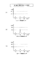
図7、図10、図13、および、図16は、何らかの原因により異常振動が発生している場合における計測振動値を示す図である。図9、図12、図15、および、図18は、第1モータ側振動センサ31、第2モータ側振動センサ35、インバータ側振動センサ36の異常振動の検出の有無を示す図である。図7において、横軸は振動の周波数帯域[Hz]を示しており、縦軸は振動レベル[dB]を示している。なお、後述する図10、図13、および図16においても、同様に、横軸は振動の周波数帯域[Hz]を示しており、縦軸は振動レベル[dB]を示している。図7、図10、図13、および図16のそれぞれの(1)は、インバータ側振動センサ36にて検出した計測振動値を示す図であり、図7、図10、図13、および図16のそれぞれの(2)は、第1モータ側振動センサ31にて検出した計測振動値を示す図であり、図7、図10、図13、および図16のそれぞれの(3)は、第2モータ側振動センサ35にて検出した計測振動値を示す図である。図8、図11、図14、および、図17は、制御装置23による電動機組立体100の構成要素の異常振動の原因を特定するフローチャートを示し、電動機組立体100の運転中に任意のタイミングにて繰り返し実行される。また、制御装置23は、図8、図11、図14、および、図17のフローチャートを、並列に処理するように実行し、同時に複数の異常振動の原因を検出できるとよい。   FIGS. 7, 10, 13 and 16 are diagrams showing measured vibration values when abnormal vibration is generated due to any cause. FIGS. 9, 12, 15 and 18 are diagrams showing the presence or absence of detection of abnormal vibration of the first motor side vibration sensor 31, the second motor side vibration sensor 35, and the inverter side vibration sensor 36. FIG. In FIG. 7, the horizontal axis indicates the frequency band [Hz] of vibration, and the vertical axis indicates the vibration level [dB]. Also in FIG. 10, FIG. 13 and FIG. 16 described later, the horizontal axis indicates the frequency band [Hz] of vibration and the vertical axis indicates the vibration level [dB]. Each of FIGS. 7, 10, 13 and 16 shows the measured vibration value detected by the inverter-side vibration sensor 36, which is shown in FIGS. 7, 10, 13 and 16. Each (2) of is a figure which shows the measurement vibration value detected with the 1st motor side vibration sensor 31, and (3) of each of FIG.7, FIG.10, FIG.13 and FIG. It is a figure which shows the measurement vibration value detected by the motor side vibration sensor 35. FIG. FIGS. 8, 11, 14 and 17 show a flow chart for identifying the cause of abnormal vibration of the components of the motor assembly 100 by the controller 23, and at any timing during operation of the motor assembly 100. It is repeatedly executed. Further, it is preferable that the control device 23 execute the flowcharts of FIG. 8, FIG. 11, FIG. 14 and FIG. 17 in parallel so as to be able to simultaneously detect the causes of a plurality of abnormal vibrations.

電動機組立体100の構成要素の異常振動の第1原因の例として、駆動軸2に異常が発生している場合について図7、図8、および、図9を参照しつつ説明する。図7は、駆動軸2に異常が発生している場合における計測振動値を示す図である。回転する駆動軸2が曲がっていたり歪んだりした場合、駆動軸2を支持する軸受21と軸受25に概ね同じ周波数帯域で異常振動が発生していることが考えられる。したがって、この場合、第1モータ側振動センサ31、第2モータ側振動センサ35は異常振動を同時に検出するが、駆動軸2と直接接していないインバータ側振動センサ36は異常振動を検出しない(図9参照)。   As an example of the 1st cause of the abnormal vibration of the component of the motor assembly 100, the case where abnormality has generate | occur | produced in the drive shaft 2 is demonstrated, referring FIG. 7, FIG. 8 and FIG. FIG. 7 is a diagram showing measured vibration values when an abnormality occurs in the drive shaft 2. When the rotating drive shaft 2 is bent or distorted, it is conceivable that abnormal vibration is generated in the substantially same frequency band in the bearing 21 and the bearing 25 that support the drive shaft 2. Therefore, in this case, although the first motor side vibration sensor 31 and the second motor side vibration sensor 35 simultaneously detect abnormal vibration, the inverter side vibration sensor 36 not in direct contact with the drive shaft 2 does not detect abnormal vibration (see FIG. 9).

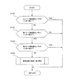
具体的には、図8に示すように、制御装置23は、インバータ側振動センサ36の計測振動値の現在値の振動レベルとしきい値A1とを比較し(図8のステップS150参照)、インバータ側振動センサ36の計測振動値の現在値の振動レベルがしきい値A1以下の場合(ステップS150:NO)、第1モータ側振動センサ31の計測振動値の現在値の振動レベルとしきい値A2とを比較する(図8のステップS152参照)。第1モータ側振動センサ31の計測振動値の現在値の振動レベルがしきい値A2よりも大きい場合(ステップS152:YES)、制御装置23は、第2モータ側振動センサ35の計測振動値の現在値の振動レベルとしきい値A3とを比較する(図8のステップS154参照)。第2モータ側振動センサ35の計測振動値の現在値の振動レベルがしきい値A3よりも大きい場合(ステップS154:YES)、制御装置23は、第1モータ側振動センサ31、および第2モータ側振動センサ35によってしきい値Aより大きな振動が検出された周波数帯域が同じか否かを判断し(図8のステップS156参照)、当該周波数帯域が同じであると判断した場合(ステップS156:YES)、駆動軸2の異常が異常振動の原因であると判断(ステップS158)し、図8のフローチャートを終了する。また、ステップS156にて、しきい値Aより大きな振動が発生した周波数帯域が異なる場合(ステップS156:NO)は、制御装置23は異常振動の原因を特定することなく、図17のフローチャートを終了する。   Specifically, as shown in FIG. 8, the control device 23 compares the vibration level of the current value of the measured vibration value of the inverter-side vibration sensor 36 with the threshold value A1 (see step S150 in FIG. 8). When the vibration level of the current value of the measured vibration value of the side vibration sensor 36 is less than or equal to the threshold value A1 (step S150: NO), the vibration level of the current value of the measured vibration value of the first motor side vibration sensor 31 and the threshold value A2 And (see step S152 in FIG. 8). If the vibration level of the current value of the measured vibration value of the first motor-side vibration sensor 31 is larger than the threshold value A2 (step S152: YES), the control device 23 controls the measurement vibration value of the second motor-side vibration sensor 35. The vibration level of the current value is compared with the threshold value A3 (see step S154 in FIG. 8). When the vibration level of the current value of the measured vibration value of the second motor-side vibration sensor 35 is larger than the threshold value A3 (step S154: YES), the control device 23 controls the first motor-side vibration sensor 31 and the second motor It is judged whether the frequency band in which the vibration larger than the threshold A is detected by the side vibration sensor 35 is the same (see step S156 in FIG. 8) and the frequency band is the same (step S156: YES), it is determined that the abnormality of the drive shaft 2 is the cause of the abnormal vibration (step S158), and the flowchart of FIG. 8 is ended. If the frequency band in which the vibration larger than the threshold value A is different in step S156 (step S156: NO), the control device 23 ends the flowchart of FIG. 17 without specifying the cause of the abnormal vibration. Do.

インバータ側振動センサ36の計測振動値の現在値の振動レベルがしきい値A1よりも大きい(ステップS150:YES)、第1モータ側振動センサ31の計測振動値の現在値の振動レベルがしきい値A2以下(ステップS152:NO)、または、第2モータ側振動センサ35の計測振動値の現在値の振動レベルがしきい値A3以下(ステップS154:NO)、の何れかの場合では、制御装置23は異常振動の原因を特定することなく、図8のフローチャートを終了する。   The vibration level of the current value of the measured vibration value of the inverter-side vibration sensor 36 is larger than the threshold value A1 (step S150: YES), the vibration level of the current value of the measured vibration value of the first motor-side vibration sensor 31 is the threshold In the case where the vibration level of the current value of the measured vibration value of the second motor-side vibration sensor 35 is less than or equal to the threshold value A3 (step S154: NO), the control is performed. The apparatus 23 ends the flowchart of FIG. 8 without identifying the cause of the abnormal vibration.

図7に示すように、制御装置23は、第1モータ側振動センサ31の計測振動値の現在値と第2モータ側振動センサ35の計測振動値の現在値との振動レベルが概ね同じ周波数帯域(ここでは、f3)においてしきい値A以上であり、なお且つ、インバータ側振動センサ36の計測振動値の当該周波数帯域(ここでは、f3)において振動レベルがしきい値A以下の場合は、制御装置23は、駆動軸2に異常が発生していると判断する。   As shown in FIG. 7, the control device 23 determines that the vibration levels of the current value of the measured vibration value of the first motor side vibration sensor 31 and the current value of the measured vibration value of the second motor side vibration sensor 35 are substantially the same. (Here, f3) is equal to or higher than the threshold A, and in the case where the vibration level is equal to or lower than the threshold A in the relevant frequency band (here, f3) of the measured vibration value of the inverter-side vibration sensor 36, The controller 23 determines that an abnormality has occurred in the drive shaft 2.

電動機組立体100の構成要素の異常振動の第2原因の例として、軸受21、軸受25のうちのいずれかに異常が発生している場合について図10、図11、および、図12を参照しつつ説明する。図10は、軸受21に異常が発生している場合における計測振動値を示す図である。図11は、制御装置23による電動機組立体100の構成要素の異常振動の原因を特定するフローチャートである。図12は、図10における第1モータ側振動センサ31、第2モータ側振動センサ35、インバータ側振動センサ36の異常振動の検出の有無を示す図である。   As an example of the second cause of the abnormal vibration of the component of the motor assembly 100, referring to FIGS. 10, 11, and 12 for the case where an abnormality occurs in any of the bearing 21 and the bearing 25. While explaining. FIG. 10 is a diagram showing measured vibration values when an abnormality occurs in the bearing 21. As shown in FIG. FIG. 11 is a flowchart for identifying the cause of abnormal vibration of the components of the motor assembly 100 by the control device 23. FIG. 12 is a diagram showing the presence or absence of detection of abnormal vibration of the first motor side vibration sensor 31, the second motor side vibration sensor 35, and the inverter side vibration sensor 36 in FIG.

軸受21、軸受25のいずれかに異常(例えば、損傷)が発生している場合、異常が発生している軸受が特に大きく振動するため、該軸受のみの異常振動(特定の振動)が発生する。したがって、この場合、異常が発生している軸受に対応する振動センサのみが他の振動センサよりも先にしきい値Aを超える振動を検出する(図12)。   When an abnormality (for example, damage) occurs in any of the bearing 21 and the bearing 25, the abnormal vibration (specific vibration) occurs only in the bearing because the bearing in which the abnormality occurs has a particularly large vibration. . Therefore, in this case, only the vibration sensor corresponding to the bearing in which the abnormality has occurred detects the vibration exceeding the threshold A earlier than the other vibration sensors (FIG. 12).

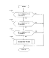
具体的には、図11に示すように、制御装置23は、インバータ側振動センサ36の計測振動値の現在値の振動レベルとしきい値A1とを比較し(図11のステップS160参照)、インバータ側振動センサ36の計測振動値の現在値の振動レベルがしきい値A1以下の場合(ステップS160:NO)、第1モータ側振動センサ31の計測振動値の現在値の振動レベルとしきい値A2とを比較する(図11のステップS162参照)。第1モータ側振動センサ31の計測振動値の現在値の振動レベルがしきい値A2よりも大きい場合(ステップS162:YES)、制御装置23は、第2モータ側振動センサ35の計測振動値の現在値の振動レベルとしきい値A3とを比較する(図11のステップS164参照)。第2モータ側振動センサ35の計測振動値の現在値の振動レベルがしきい値A3以下の場合(ステップS164:NO)、制御装置23は、異常振動の原因が軸受21であると判断(図11のステップS168参照)して、図11のフローチャートを終了する。   Specifically, as shown in FIG. 11, the control device 23 compares the vibration level of the current value of the measured vibration value of the inverter-side vibration sensor 36 with the threshold value A1 (see step S160 in FIG. 11). When the vibration level of the current value of the measured vibration value of the side vibration sensor 36 is less than or equal to the threshold value A1 (step S160: NO), the vibration level of the current value of the measured vibration value of the first motor side vibration sensor 31 and the threshold value A2 And (refer to step S162 in FIG. 11). When the vibration level of the current value of the measured vibration value of the first motor side vibration sensor 31 is larger than the threshold value A2 (step S162: YES), the control device 23 controls the measurement vibration value of the second motor side vibration sensor 35. The vibration level of the current value is compared with the threshold value A3 (see step S164 in FIG. 11). If the vibration level of the current value of the measured vibration value of the second motor-side vibration sensor 35 is less than or equal to the threshold value A3 (step S164: NO), the controller 23 determines that the cause of the abnormal vibration is the bearing 21 (see FIG. Then, the flow chart of FIG. 11 is ended.

インバータ側振動センサ36の計測振動値の現在値の振動レベルがしきい値A1よりも大きい(ステップS160:YES)、第1モータ側振動センサ31の計測振動値の現在値の振動レベルがしきい値A2以下(ステップS162:NO)、または、第2モータ側振動センサ35の計測振動値の現在値の振動レベルがしきい値A3よりも大きい(ステップS164:YES)、の、何れかの場合は、制御装置23は、異常振動の原因を特定せずに、フローチャートを終了する。   The vibration level of the current value of the measured vibration value of the inverter-side vibration sensor 36 is larger than the threshold value A1 (step S160: YES), the vibration level of the current value of the measured vibration value of the first motor-side vibration sensor 31 is the threshold In the case of either value A2 or less (step S162: NO) or the vibration level of the current value of the measured vibration value of the second motor side vibration sensor 35 is larger than the threshold A3 (step S164: YES) The controller 23 ends the flowchart without specifying the cause of the abnormal vibration.

例えば、軸受21が損傷し駆動軸2が軸受支持部4aに接触すると、まずは、第1モータ側振動センサ31は、一定の周波数帯域(ここではf2)で、他の振動センサに比べて大きな振動レベルを検出する。そのため、第1モータ側振動センサ31の計測振動値の振動レベルの何れかが一定の周波数帯域(ここではf2)において特定のしきい値A2を超え、なお且つ、第2モータ側振動センサ35の計測振動値の振動レベルは何れの周波数帯域でもしきい値A3を超えておらず、更に、インバータ側振動センサ36の計測振動値の振動レベルが何れの周波数帯域でもしきい値A1を超えていない場合は、制御装置23は、軸受21に異常が発生したと判断することができる。   For example, when the bearing 21 is damaged and the drive shaft 2 comes into contact with the bearing support 4a, the first motor-side vibration sensor 31 first vibrates in a fixed frequency band (here, f2) as compared to other vibration sensors. Detect the level. Therefore, any of the vibration levels of the measured vibration value of the first motor-side vibration sensor 31 exceeds the specific threshold A2 in a constant frequency band (here, f2), and the second motor-side vibration sensor 35 The vibration level of the measured vibration value does not exceed the threshold A3 in any frequency band, and furthermore, the vibration level of the measured vibration value of the inverter-side vibration sensor 36 does not exceed the threshold A1 in any frequency band In this case, the control device 23 can determine that an abnormality has occurred in the bearing 21.

同様に、制御装置23は、第2モータ側振動センサ35の計測振動値の振動レベルの何れかがしきい値A3を超え、なお且つ、第1モータ側振動センサ31の計測振動値の振動レベルの何れもしきい値A2を超えておらず、更に、インバータ側振動センサ36の計測振動値の振動レベルの何れもしきい値A1を超えていない場合は、制御装置23は、軸受25に異常が発生していると判断できる。   Similarly, in the control device 23, any vibration level of the measured vibration value of the second motor-side vibration sensor 35 exceeds the threshold value A3, and the vibration level of the measured vibration value of the first motor-side vibration sensor 31. If neither of the above exceeds the threshold value A2, and furthermore, none of the vibration levels of the measured vibration value of the inverter-side vibration sensor 36 exceeds the threshold value A1, the controller 23 causes an abnormality in the bearing 25. It can be determined that

電動機組立体100の構成要素の異常振動の第3原因の例として、インバータ部20に異常が発生している場合について図13、図14、および、図15を参照しつつ説明する。図13は、インバータ部20の異常が原因の異常振動が発生している場合における計測振動値を示す図である。図15は、図13における第1モータ側振動センサ31、第2モータ側振動センサ35、インバータ側振動センサ36の異常振動の検出の有無を示す図である。   As an example of the 3rd cause of the abnormal vibration of the component of the motor assembly 100, the case where abnormality generate | occur | produces in the inverter part 20 is demonstrated, referring FIG. 13, FIG. 14, and FIG. FIG. 13 is a diagram showing measured vibration values in the case where abnormal vibration caused by abnormality of the inverter unit 20 is generated. FIG. 15 is a diagram showing the presence or absence of detection of abnormal vibration of the first motor side vibration sensor 31, the second motor side vibration sensor 35, and the inverter side vibration sensor 36 in FIG.

インバータ22のインバータハウジング24への固定の不安定および/またはインバータ22を構成する素子の共振などの原因によりインバータ部20に異常振動が発生していることが考えられる。この場合、まずは、インバータ側振動センサ36の計測振動値は異常振動を検出し、第1モータ側振動センサ31、第2モータ側振動センサ35の計測振動値のいずれも異常振動を検出しない(図15参照)。   It is conceivable that abnormal vibration is generated in the inverter unit 20 due to instability of fixing of the inverter 22 to the inverter housing 24 and / or resonance of elements constituting the inverter 22 or the like. In this case, first, the measured vibration value of the inverter-side vibration sensor 36 detects abnormal vibration, and none of the measured vibration values of the first motor-side vibration sensor 31 and the second motor-side vibration sensor 35 detects abnormal vibration (see FIG. 15).

具体的には、図14に示すように、制御装置23は、インバータ側振動センサ36の計測振動値の現在値の振動レベルとしきい値A1とを比較し(図14のステップS170参照)、インバータ側振動センサ36の計測振動値の現在値の振動レベルがしきい値A1よりも大きい場合(ステップS170:YES)、第1モータ側振動センサ31の計測振動値の現在値の振動レベルとしきい値A2とを比較する(図14のステップS172参照)。第1モータ側振動センサ31の計測振動値の現在値の振動レベルがしきい値A2以下の場合(ステップS172:NO)、制御装置23は、第2モータ側振動センサ35の計測振動値の現在値の振動レベルとしきい値A3とを比較する(図14のステップS174参照)。第2モータ側振動センサ35の計測振動値の現在値の振動レベルがしきい値A3以下の場合(ステップS174:NO)、制御装置23は、異常振動の原因がインバータ部20であると判断(ステップS178)し、図14のフローチャートを終了する。   Specifically, as shown in FIG. 14, the control device 23 compares the vibration level of the current value of the measured vibration value of the inverter-side vibration sensor 36 with the threshold value A1 (see step S170 in FIG. 14). When the vibration level of the current value of the measured vibration value of the side vibration sensor 36 is larger than the threshold value A1 (step S170: YES), the vibration level and the threshold value of the current value of the measured vibration value of the first motor side vibration sensor 31 It compares with A2 (refer step S172 of FIG. 14). If the vibration level of the current value of the measured vibration value of the first motor side vibration sensor 31 is less than or equal to the threshold value A2 (step S172: NO), the control device 23 determines the current measured vibration value of the second motor side vibration sensor 35. The vibration level of the value is compared with the threshold value A3 (see step S174 in FIG. 14). If the vibration level of the current value of the measured vibration value of the second motor-side vibration sensor 35 is less than or equal to the threshold A3 (step S174: NO), the control device 23 determines that the cause of the abnormal vibration is the inverter unit 20 ( Step S178) is performed, and the flow chart of FIG. 14 is ended.

インバータ側振動センサ36の計測振動値の現在値の振動レベルがしきい値A1以下(ステップS170:NO)、第1モータ側振動センサ31の計測振動値の現在値の振動レベルがしきい値A2よりも大きく(ステップS172:YES)、または、第2モータ側振動センサ35の計測振動値の現在値の振動レベルがしきい値A3よりも大きい(ステップS174:YES)、の何れかの場合には、制御装置23は、異常振動の原因を特定せずに、図14のフローチャートを終了する。   The vibration level of the current value of the measured vibration value of the inverter-side vibration sensor 36 is less than or equal to the threshold A1 (step S170: NO), and the vibration level of the current value of the measured vibration value of the first motor-side vibration sensor 31 is the threshold A2 If the vibration level of the current value of the measured vibration value of the second motor side vibration sensor 35 is larger than the threshold value A3 (step S174: YES). The controller 23 ends the flowchart of FIG. 14 without identifying the cause of the abnormal vibration.

制御装置23は、インバータ側振動センサ36の計測振動値の振動レベルの何れかが一定の周波数帯域(ここではf1)において特定のしきい値A1を超え、第1モータ側振動センサ31の計測振動値の振動レベルが何れの周波数帯域でもしきい値A2を超えておらず、第2モータ側振動センサ35の計測振動値の振動レベルが何れの周波数帯域でもしきい値A3を超えていない場合、インバータ部20が振動異常の原因であると判断する。   The control device 23 measures the measured vibration of the first motor-side vibration sensor 31 by exceeding any one of the threshold values A1 in a fixed frequency band (here, f1) with any of the vibration levels of the measured vibration value of the inverter-side vibration sensor 36. If the vibration level of the value does not exceed the threshold A2 in any frequency band and the vibration level of the measured vibration value of the second motor-side vibration sensor 35 does not exceed the threshold A3 in any frequency band, It is determined that the inverter unit 20 is the cause of the vibration abnormality.

ここで、図13に示すように、インバータ側振動センサ36が異常振動を検出し、その他の第1モータ側振動センサ31、第2モータ側振動センサ35が異常振動を検出しない場合、制御装置23は、しきい値A1〜A3のみに基づいて、インバータ部20の異常の発生を決定するとよい。この場合、制御装置23がインバータ部20の異常の発生を決定した後に、警報を発報しつつ、電動機組立体100の運転を継続するとよい。ポンプ装置200が給水や排水用のポンプ装置等のライフラインとして用いられる場合もあり、過大な振動によってインバータ部20の素子が脱落するなどのモータ3へ電力が供給できない異常が発生するまではポンプ50の運転を継続することが好ましい。   Here, as shown in FIG. 13, when the inverter-side vibration sensor 36 detects abnormal vibration and the other first motor-side vibration sensor 31 and second motor-side vibration sensor 35 do not detect abnormal vibration, the control device 23. It is preferable to determine the occurrence of abnormality of the inverter unit 20 based on only the threshold values A1 to A3. In this case, after the control device 23 determines the occurrence of the abnormality of the inverter unit 20, it is preferable to continue the operation of the motor assembly 100 while issuing an alarm. The pump device 200 may be used as a lifeline of a pump device for water supply or drainage, etc., and a pump can not supply power to the motor 3 such as dropping of an element of the inverter unit 20 due to excessive vibration. It is preferable to continue the operation of 50.

電動機組立体100の構成要素の異常振動の第4原因の例として、モータケーシング4およびインバータハウジング24(電動機組立体100の筐体)に異常が発生している場合について図16、図17、および、図18を参照しつつ説明する。図16は、電動機組立体100の筐体に異常が発生している場合における計測振動値を示す図である。図18は、図16における第1モータ側振動センサ31、第2モータ側振動センサ35、インバータ側振動センサ36の異常振動の検出の有無を示す図である。   As an example of the fourth cause of the abnormal vibration of the component of the motor assembly 100, the case where abnormality occurs in the motor casing 4 and the inverter housing 24 (the housing of the motor assembly 100) is shown in FIGS. This will be described with reference to FIG. FIG. 16 is a diagram showing measured vibration values when an abnormality occurs in the housing of the motor assembly 100. As shown in FIG. FIG. 18 is a diagram showing the presence or absence of detection of abnormal vibration of the first motor side vibration sensor 31, the second motor side vibration sensor 35, and the inverter side vibration sensor 36 in FIG.

例えば、電動機組立体100の据え付けの不安定などの原因により、電動機組立体100の筐体に異常(例えば、騒音)が発生する場合、モータケーシング4およびインバータハウジング24に異常振動が発生していることが考えられる。したがって、この場合、第1モータ側振動センサ31、第2モータ側振動センサ35、インバータ側振動センサ36のいずれもが同時に異常振動を検出する(図18参照)。   For example, when an abnormality (for example, noise) is generated in the housing of the motor assembly 100 due to an unstable installation of the motor assembly 100 or the like, an abnormal vibration is generated in the motor casing 4 and the inverter housing 24 It is conceivable. Therefore, in this case, all of the first motor side vibration sensor 31, the second motor side vibration sensor 35, and the inverter side vibration sensor 36 simultaneously detect abnormal vibration (see FIG. 18).

具体的には、図17に示すように、制御装置23は、インバータ側振動センサ36の計測振動値の現在値の振動レベルとしきい値A1とを比較し(図17のステップS180参照)、インバータ側振動センサ36の計測振動値の現在値の振動レベルがしきい値A1よりも大きい場合(ステップS180:YES)、第1モータ側振動センサ31の計測振動値の現在値の振動レベルとしきい値A2とを比較する(図17のステップS182参照)。第1モータ側振動センサ31の計測振動値の現在値の振動レベルがしきい値A2よりも大きい場合(ステップS182:YES)、制御装置23は、第2モータ側振動センサ35の計測振動値の現在値の振動レベルとしきい値A3とを比較する(図17のステップS184参照)。第2モータ側振動センサ35の計測振動値の現在値の振動レベルがしきい値A3よりも大きい場合(ステップS184:YES)、制御装置23は、これらインバータ側振動センサ36、第1モータ側振動センサ31、および第2モータ側振動センサ35によってしきい値Aより大きな振動が検出された周波数帯域が同じか否かを判断し(図17のステップS186参照)、これら振動が発生した周波数帯域が同じであると判断した場合(ステップS186:YES)、電動機組立体100の筐体に異常が発生していると判断(ステップS188)し、図17のフローチャートを終了する。また、ステップS186にて、しきい値Aより大きな振動が発生した周波数帯域のうち、少なくともひとつが異なる場合(ステップS186:NO)は、制御装置23は異常振動の原因を特定することなく、図17のフローチャートを終了する。   Specifically, as shown in FIG. 17, the control device 23 compares the vibration level of the current value of the measured vibration value of the inverter-side vibration sensor 36 with the threshold value A1 (see step S180 in FIG. 17). When the vibration level of the current value of the measured vibration value of the side vibration sensor 36 is larger than the threshold value A1 (step S180: YES), the vibration level and the threshold value of the current value of the measured vibration value of the first motor side vibration sensor 31 It compares with A2 (refer step S182 of FIG. 17). When the vibration level of the current value of the measured vibration value of the first motor side vibration sensor 31 is larger than the threshold value A2 (step S182: YES), the control device 23 controls the measurement vibration value of the second motor side vibration sensor 35. The vibration level of the current value is compared with the threshold value A3 (see step S184 in FIG. 17). When the vibration level of the current value of the measured vibration value of the second motor-side vibration sensor 35 is larger than the threshold value A3 (step S184: YES), the control device 23 controls the inverter-side vibration sensor 36 and the first motor-side vibration. It is determined whether the frequency band in which the vibration larger than the threshold A is detected by the sensor 31 and the second motor-side vibration sensor 35 is the same (see step S186 in FIG. 17), and the frequency band in which these vibrations are generated is If it is determined that they are the same (step S186: YES), it is determined that an abnormality has occurred in the housing of the motor assembly 100 (step S188), and the flowchart of FIG. 17 is ended. If at least one of the frequency bands in which the vibration larger than the threshold value A is different in step S186 (step S186: NO), the control device 23 does not specify the cause of the abnormal vibration, as shown in FIG. End the flowchart of 17.

インバータ側振動センサ36の計測振動値の現在値の振動レベルがしきい値A1以下(ステップS180:NO)、第1モータ側振動センサ31の計測振動値の現在値の振動レベルがしきい値A2以下(ステップS182:NO)、または、第2モータ側振動センサ35の計測振動値の現在値の振動レベルがしきい値A3以下(ステップS184:NO)、の何れかの場合では、制御装置23は異常振動の原因を特定することなく、図17のフローチャートを終了する。   The vibration level of the current value of the measured vibration value of the inverter-side vibration sensor 36 is less than or equal to the threshold A1 (step S180: NO), and the vibration level of the current value of the measured vibration value of the first motor-side vibration sensor 31 is the threshold A2 In the case where either of the following (step S182: NO) or the vibration level of the current value of the measured vibration value of the second motor side vibration sensor 35 is the threshold A3 or less (step S184: NO), the control device 23 Ends the flowchart of FIG. 17 without identifying the cause of the abnormal vibration.

制御装置23は、第1モータ側振動センサ31の計測振動値、第2モータ側振動センサ35の計測振動値、およびインバータ側振動センサ36の計測振動値のいずれの振動レベルがしきい値A1〜A3を超えた場合、モータケーシング4およびインバータハウジング24の全体、すなわち、電動機組立体100の筐体に異常が発生していると判断する。電動機組立体100の筐体に異常が発生する場合には、第1モータ側振動センサ31、第2モータ側振動センサ35、インバータ側振動センサ36は、同じ周期(この例では、f1、f2、f3)である一定の振れ幅以上の異常振動を検出する。   The control device 23 determines that any vibration level of the measurement vibration value of the first motor side vibration sensor 31, the measurement vibration value of the second motor side vibration sensor 35, and the measurement vibration value of the inverter side vibration sensor 36 has threshold values A1 to A1. If A3 is exceeded, it is determined that an abnormality has occurred in the whole of the motor casing 4 and the inverter housing 24, that is, the housing of the motor assembly 100. When an abnormality occurs in the housing of the motor assembly 100, the first motor-side vibration sensor 31, the second motor-side vibration sensor 35, and the inverter-side vibration sensor 36 have the same cycle (in this example, f1, f2,. f3) detecting an abnormal vibration equal to or more than a predetermined swing width.

図16に示すように、第1モータ側振動センサ31、第2モータ側振動センサ35、インバータ側振動センサ36のいずれもが異常振動を検出する場合、制御装置23は、しきい値A1〜A3のみに基づいて、電動機組立体100の筐体の異常の発生を決定するとよい。制御装置23は、電動機組立体100の筐体の異常が発生した場合、警報を発報しつつ、電動機組立体100の運転を継続する。これは、電動機組立体100の筐体に異常が発生している場合には、電動機組立体100自体が重大な影響を受ける可能性は低いので、運転を継続することが好ましい。   As shown in FIG. 16, when all of the first motor side vibration sensor 31, the second motor side vibration sensor 35, and the inverter side vibration sensor 36 detect abnormal vibration, the control device 23 sets threshold values A1 to A3. The occurrence of an abnormality in the housing of the motor assembly 100 may be determined based solely on the When an abnormality occurs in the housing of the motor assembly 100, the control device 23 continues the operation of the motor assembly 100 while issuing an alarm. This is preferable to continue the operation, since the motor assembly 100 itself is unlikely to be seriously affected if the housing of the motor assembly 100 is abnormal.

なお、ポンプ50と電動機組立体100の構成および/または設置環境等により、発生する異常とそれに対応する特定の計測振動値は異なる。したがって、それらに対応できるよう、単体あるいは複数の振動センサによる異常振動の検出の組み合わせは変更してもよい。また、上述した異常振動の第1原因から第4原因にて、しきい値A,Bは同じ記号を用いて説明したが、第1原因から第4原因にて、それぞれ異なるしきい値を用いてもよい。   The generated abnormality and the corresponding specific measurement vibration value differ depending on the configuration of the pump 50 and the motor assembly 100 and / or the installation environment. Therefore, the combination of detection of abnormal vibration by a single or a plurality of vibration sensors may be changed to cope with them. Also, although the threshold values A and B have been described using the same symbols as the first cause to the fourth cause of the abnormal vibration described above, different threshold values are used for the first cause to the fourth cause, respectively. May be

本実施形態によれば、複数の振動センサの異常振動を検出することで、制御装置23は、異常振動の原因を特定することができる。したがって、作業者は、部品交換など、異常振動を解消するための対応を迅速に行うことができる。   According to the present embodiment, the control device 23 can identify the cause of the abnormal vibration by detecting the abnormal vibration of the plurality of vibration sensors. Therefore, the worker can promptly take measures to eliminate abnormal vibration, such as component replacement.

なお、上述した方法にて一旦特定した異常振動の原因は、制御装置23にて原因が除去されたと確認できるまで保持されてもよい。具体的には、第1モータ側振動センサ31、第2モータ側振動センサ35、インバータ側振動センサ36の全てにおいて、運転中の計測振動値の現在値がしきい値A以下となるまで、および/または、操作者によりリセット操作されるまで継続してもよい。また、これに限らず、異常振動の原因を特定する条件の全てを満たしている間のみ継続してもよい。なお、異常振動の原因を特定した際に、制御装置23は、運転パネル66、外部端末63、および/または、入出力部65にて報知してもよい。また、特定した振動の原因を記憶部60に履歴として記憶してもよい。   The cause of the abnormal vibration once specified by the above-described method may be held until it can be confirmed by the control device 23 that the cause has been removed. Specifically, in all of the first motor side vibration sensor 31, the second motor side vibration sensor 35, and the inverter side vibration sensor 36, until the present value of the measured vibration value during operation becomes equal to or less than the threshold value A, Or, it may be continued until the reset operation is performed by the operator. Further, the present invention is not limited to this, and may continue only while all the conditions for identifying the cause of the abnormal vibration are satisfied. When the cause of the abnormal vibration is specified, the control device 23 may notify by the operation panel 66, the external terminal 63, and / or the input / output unit 65. Further, the cause of the identified vibration may be stored in the storage unit 60 as a history.

上述した実施形態では、電動機組立体100の異常振動の原因を特定する方法について説明したが、異常振動を判断する方法は、ポンプ側振動センサ56が設けられたポンプ装置200(図2参照)にも適用することができる。   In the embodiment described above, the method of identifying the cause of the abnormal vibration of the motor assembly 100 has been described, but the method of determining the abnormal vibration is the pump device 200 (see FIG. 2) provided with the pump-side vibration sensor 56. Can also be applied.

上述した実施形態では、制御装置23が電動機組立体100の異常振動を判断する方法について説明したが、給水や排水設備用のようなライフラインとしてポンプ装置200が用いられる場合は、ポンプ50の運転を可能な限り継続することが好ましい。そこで、制御装置23は、異常振動の検出によってモータ3の回転速度を変更する振動抑制運転(第1振動抑制運転、第2振動抑制運転)を実行する。以下の実施形態では、可能な限り、運転を継続することができる振動抑制運転を実行する方法について、図面を参照しつつ説明する。   In the embodiment described above, the method for the controller 23 to determine abnormal vibration of the motor assembly 100 has been described, but when the pump device 200 is used as a lifeline such as for water supply or drainage, the operation of the pump 50 It is preferable to continue as much as possible. Therefore, the control device 23 executes a vibration suppression operation (a first vibration suppression operation, a second vibration suppression operation) in which the rotational speed of the motor 3 is changed by detecting the abnormal vibration. In the following embodiments, a method for performing a vibration suppression operation that can continue the operation as much as possible will be described with reference to the drawings.

図19は、電動機組立体100の運転状態の変化を示す状態還移図である。図19の状態還移図は、制御装置23の電源起動後に任意(例えば、数msec〜数100msec)のタイミングにて、繰り返し実行されるとよい。また、図19の状態還移図は、図8、図11、図14、および、図17のフローチャートと並列に処理するように実行されるとよい。なお、図19において、後述する図20〜図23と同じ処理については、同じ符号を付与し一部説明を省略する。   FIG. 19 is a state transition diagram showing changes in the operating state of the motor assembly 100. As shown in FIG. The state transition diagram of FIG. 19 may be repeatedly executed at an arbitrary timing (for example, several msec to several hundreds msec) after power-on of the control device 23. Also, the state transition diagram of FIG. 19 may be implemented to be processed in parallel with the flowcharts of FIGS. 8, 11, 14 and 17. In addition, in FIG. 19, about the process same as FIGS. 20-23 mentioned later, the same code | symbol is provided and partial description is abbreviate | omitted.

まず、図19に示す電動機組立体100の運転状態の変化について説明する。ポンプ装置200が設置された後もしくはメンテナンス終了時の最初の電源起動時には、電動機組立体100の運転状態は、S00の運転停止状態である。ここで、ユーザーの操作により必要に応じて試験運転モードS10(図5参照)にて試験運転を行う場合は、図5のフローチャートを実行し、試験運転モードのS10の終了(図5のステップS104参照)にて運転停止状態S00にもどる。運転停止状態S00から、ユーザーの手動操作等により、制御装置23の初期化等の処理を行うSTART状態S01になり、続いて、吐出し圧力が低下する等の自動操作もしくは手動操作等によって、電動機組立体100の運転状態は、通常運転状態S30へ移行する。ここで、START状態S01は省略してもよい。   First, changes in the operating state of the motor assembly 100 shown in FIG. 19 will be described. After the pump device 200 is installed or at the time of first power-on at the end of maintenance, the operating state of the motor assembly 100 is the operation stop state of S00. Here, when the test operation is performed in the test operation mode S10 (see FIG. 5) as needed by the operation of the user, the flowchart of FIG. 5 is executed, and the test operation mode S10 ends (step S104 in FIG. 5). Return to the operation stop state S00 at reference). From the operation stop state S00, the state becomes the START state S01 in which processing such as initialization of the control device 23 is performed by the user's manual operation or the like, and subsequently, the motor is operated by the automatic operation or the manual operation or the like The operating state of the assembly 100 shifts to the normal operating state S30. Here, the START state S01 may be omitted.

通常運転状態S30中は、制御装置23はモータ3の回転速度Fを後述する通常回転速度F0に設定する。そして、第1振動抑制運転状態S40中に並行して実行中の図20のフローチャートにて計測振動値がしきい値B以上(ステップS208:YES)となり運転停止(ステップS209)となると、電動機組立体100の運転状態は、運転停止状態S00にもどる。通常運転状態S30中に、電動機組立体100の計測振動値がしきい値Aよりも大きく、且つ、しきい値B未満となり異常発生フラグ=1(ステップS206)となる異常振動が発生した場合(ステップS302:YES)、電動機組立体100の運転状態は、第1振動抑制運転状態S40に移行する。   During the normal operation state S30, the control device 23 sets the rotational speed F of the motor 3 to a normal rotational speed F0 described later. Then, when the measured vibration value becomes equal to or greater than the threshold B (step S208: YES) in the flowchart of FIG. 20 being executed in parallel during the first vibration suppression operation state S40, the motor assembly is stopped (step S209). The operation state of the solid 100 returns to the operation stop state S00. When abnormal vibration occurs in which the measured vibration value of the motor assembly 100 is larger than the threshold A and smaller than the threshold B and becomes abnormal occurrence flag = 1 (step S206) during the normal operation state S30 (the step S206) Step S302: YES) The operating state of the motor assembly 100 shifts to the first vibration suppression operating state S40.

第1振動抑制運転状態S40中は、制御装置23はモータ3の回転速度Fを後述する第1回転速度F1に設定する。そして、第1振動抑制運転状態S40中に並行して実行中の図20のフローチャートにて計測振動値がしきい値B以上(ステップS208:YES)となり運転停止(ステップS209)となると、電動機組立体100の運転状態は、運転停止状態S00にもどる。第1振動抑制運転状態S40中に、第1振動抑制運転状態S40が終了(ステップS406:YES)すると、電動機組立体100の運転状態は、通常運転S30にもどる。さらには、図22のステップS408にて第1振動抑制運転状態S40が所定回数連続的に実行された(ステップS408:YES)ら、電動機組立体100の運転状態は、第1振動抑制運転状態S40から第2振動抑制運転状態S50に移行する。   During the first vibration suppression operation state S40, the control device 23 sets the rotational speed F of the motor 3 to a first rotational speed F1 described later. Then, when the measured vibration value becomes equal to or greater than the threshold B (step S208: YES) in the flowchart of FIG. 20 being executed in parallel during the first vibration suppression operation state S40, the motor assembly is stopped (step S209). The operation state of the solid 100 returns to the operation stop state S00. When the first vibration suppression operation state S40 ends (step S406: YES) during the first vibration suppression operation state S40, the operation state of the motor assembly 100 returns to the normal operation S30. Furthermore, since the first vibration suppression operation state S40 is continuously executed a predetermined number of times in step S408 of FIG. 22 (step S408: YES), the operation state of the motor assembly 100 is the first vibration suppression operation state S40. To the second vibration suppression operation state S50.

第2振動抑制運転状態S50中は、制御装置23はモータ3の回転速度Fを後述する第2回転速度F2に設定する。そして、第2振動抑制運転状態S50中に並行して実行中の図20のフローチャートにて、計測振動値がしきい値B以上(ステップS208:YES)となり運転停止(ステップS209)となると、電動機組立体100の運転状態は、運転停止状態S00にもどる。また、第2振動抑制運転状態S50中は、ユーザーによる警報リセット(S508:YES)をトリガとして、電動機組立体100の運転状態を通常運転S30に戻すことができる。   During the second vibration suppression operation state S50, the control device 23 sets the rotational speed F of the motor 3 to a second rotational speed F2 described later. Then, in the flowchart of FIG. 20 being executed in parallel during the second vibration suppression operation state S50, when the measured vibration value becomes equal to or higher than the threshold B (step S208: YES) and the operation stops (step S209), the motor The operation state of the assembly 100 returns to the operation stop state S00. Further, during the second vibration suppression operation state S50, the operation state of the motor assembly 100 can be returned to the normal operation S30 by using the alarm reset by the user (S508: YES) as a trigger.

このように、制御装置23は、第1振動抑制運転状態S40と第2振動抑制運転状態S50の2段階において振動を抑制する運転を実行することができるため、可能な限り、電動機組立体100の運転を継続することができる。   As described above, since the control device 23 can execute the operation of suppressing the vibration in the two steps of the first vibration suppression operating state S40 and the second vibration suppression operating state S50, the control device 23 can Driving can be continued.

ここで、通常運転状態S30、第1振動抑制運転状態S40並びに第2振動抑制運転状態S50について、図20、図21、図22、図23のフローチャートを用いて詳細に説明する。図20は、制御装置23による電動機組立体の異常振動の検出フローチャートを示す。図21は、制御装置23による通常運転のフローチャートを示す。図22は、制御装置23による第1振動抑制運転のフローチャートを示す。図23は、制御装置23による第2振動抑制運転のフローチャートを示す。また、図19の状態還移図における通常運転状態S30では、図20と図21のフローチャートが並行して実行され、第1振動抑制運転状態S40では、図20と図22のフローチャートが並行して実行され、第2振動抑制運転状態S50では、図20と図23のフローチャートが並行して実行される。   Here, the normal driving state S30, the first vibration suppression driving state S40, and the second vibration suppression driving state S50 will be described in detail with reference to the flowcharts of FIGS. 20, 21, 22 and 23. FIG. 20 shows a flowchart for detecting abnormal vibration of the motor assembly by the controller 23. FIG. 21 shows a flowchart of the normal operation by the control device 23. FIG. 22 shows a flowchart of the first vibration suppressing operation by the control device 23. FIG. 23 shows a flowchart of the second vibration suppressing operation by the control device 23. In the normal operation state S30 in the state transition diagram of FIG. 19, the flowcharts of FIG. 20 and FIG. 21 are executed in parallel, and in the first vibration suppression operation state S40, the flowcharts of FIG. In the second vibration suppression operation state S50, the flowcharts of FIG. 20 and FIG. 23 are executed in parallel.

電動機組立体100の運転時における制御装置23の動作について、図20を参照して説明する。電動機組立体100が自動運転中に、制御装置23は、図20のフローチャートを任意の周期(タイミング)で繰り返し実行する。   The operation of the control device 23 at the time of operation of the motor assembly 100 will be described with reference to FIG. While the motor assembly 100 is in automatic operation, the control device 23 repeatedly executes the flowchart of FIG. 20 at an arbitrary cycle (timing).

まず、制御装置23は、電動機組立体100が停止中である場合(ステップS201:NO)は、詳細を後述する異常振動発生フラグ=0(ステップS210)として、一旦、図20のフローチャートを抜ける。制御装置23は、電動機組立体100が運転中である場合(ステップS201)、任意の周期(タイミング)で振動センサから送られる振動を取得する(ステップS202)。その後、制御装置23は、振動センサから送られた振動を分析(フーリエ変換の実行)して複数の振動の周波数帯域(f1,f2,f3・・・fn)に対応する振動値(V1,V2,V3・・・Vn)を計測振動値として取得する(ステップS203)。   First, when the motor assembly 100 is stopped (step S201: NO), the control device 23 temporarily exits the flowchart of FIG. 20 as an abnormal vibration occurrence flag = 0 (step S210) which will be described in detail later. When the motor assembly 100 is in operation (step S201), the control device 23 acquires the vibration sent from the vibration sensor at an arbitrary cycle (timing) (step S202). Thereafter, the control device 23 analyzes the vibration sent from the vibration sensor (performs Fourier transform), and outputs vibration values (V1, V2) corresponding to the plurality of frequency bands (f1, f2, f3 ... fn). , V3... Vn) are obtained as measured vibration values (step S203).

制御装置23は、振動の周波数帯域ごとの計測振動値と、しきい値Aおよびしきい値Bとを比較(ステップS204)し、比較した計測振動値のうち、少なくともひとつがしきい値Aよりも大きく、かつしきい値Bよりも小さい場合(ステップS205:YES)、電動機組立体100(モータ部10およびインバータ部20の少なくとも1つ)に異常振動が発生しているとして、異常振動発生フラグを値1にセットする(ステップS206)。このとき、制御装置23は、上述した図8、図11、図14、および、図17のフローチャートを実行し、電動機組立体100の構成要素の異常振動の原因を特定してもよい。異常振動発生フラグは、しきい値A<計測振動値<しきい値Bにて値1にセットされるフラグであり、制御装置23の電源起動時、モータ3停止時、および、しきい値A≧計測振動値等のタイミングにて値0に初期化される。   The control device 23 compares the measured vibration value for each frequency band of vibration with the threshold A and the threshold B (step S204), and at least one of the compared measured vibration values is greater than the threshold A Is also larger than the threshold value B (step S205: YES), it is determined that abnormal vibration is occurring in the motor assembly 100 (at least one of the motor unit 10 and the inverter unit 20), and an abnormal vibration occurrence flag Is set to the value 1 (step S206). At this time, the control device 23 may execute the flowcharts of FIG. 8, FIG. 11, FIG. 14 and FIG. 17 described above to identify the cause of the abnormal vibration of the components of the motor assembly 100. The abnormal vibration occurrence flag is a flag which is set to a value 1 at threshold A <measured vibration value <threshold B, and when power of control device 23 is turned on, when motor 3 is stopped, and threshold A It is initialized to the value 0 at the timing of ≧ measurement vibration value etc.

図20のステップS205が「NO」の場合、制御装置23は、振動の周波数帯域ごとの計測振動値と、しきい値Bとを比較する(ステップS207)。制御装置23は、比較した計測振動値のうちの少なくともひとつがしきい値B以上の場合(ステップS208:YES)、電動機組立体100の運転を停止する(ステップS209)。この場合、制御装置23は、モータ3の停止と同時にエラー情報を外部に出力、すなわち、運転パネル66および外部端末63にて警報を発報するとよい。その後、制御装置23は、異常振動発生フラグをクリアする(ステップS210)。   When step S205 of FIG. 20 is "NO", the control device 23 compares the measured vibration value for each frequency band of vibration with the threshold value B (step S207). The control device 23 stops the operation of the motor assembly 100 when at least one of the compared measured vibration values is equal to or greater than the threshold B (step S208: YES) (step S209). In this case, the control device 23 may output error information to the outside simultaneously with the stop of the motor 3, that is, an alarm may be issued on the operation panel 66 and the external terminal 63. Thereafter, the control device 23 clears the abnormal vibration occurrence flag (step S210).

比較した計測振動値の全てがしきい値B未満の場合(ステップS208:NO)、制御装置23は、全ての計測振動値が正常値内(計測振動値≦しきい値A)であると判断して、異常振動発生フラグを値0に初期化する(ステップS210)。   If all the measured vibration values compared are less than the threshold B (step S208: NO), the control device 23 determines that all measured vibration values are within the normal value (measured vibration value ≦ threshold A). Then, the abnormal vibration occurrence flag is initialized to the value 0 (step S210).

次に、図21にて通常運転状態S30について説明する。図19の状態還移図のSTART状態S01から通常運転状態S30へ移行したタイミングにて、制御装置23は、図21のフローチャートを開始する。ここで、ポンプ装置200における通常運転時とは、規定点でポンプ50が揚水運転を行っている状態をいう。通常運転状態S30では、図21のステップS301に示すように、制御装置23は、モータ3の回転速度Fを任意の回転速度である通常回転速度F0に決定し、モータ3を通常回転速度F0で駆動する。この通常回転速度F0は、電動機組立体100の通常運転時におけるモータ3の回転速度(通常回転速度)である。一実施形態では、通常回転速度F0はポンプ50の性能曲線図に示された規定揚程と規定吐出し量との交点である規定点における回転速度である。   Next, the normal operation state S30 will be described with reference to FIG. The control device 23 starts the flowchart of FIG. 21 at the timing when the transition from the START state S01 of FIG. 19 to the normal operation state S30 is made. Here, the normal operation time of the pump device 200 refers to a state in which the pump 50 performs a pumping operation at a specified point. In the normal operation state S30, as shown in step S301 of FIG. 21, the control device 23 determines the rotational speed F of the motor 3 to be the normal rotational speed F0 which is an arbitrary rotational speed, and sets the motor 3 at the normal rotational speed F0. To drive. The normal rotation speed F0 is the rotation speed (normal rotation speed) of the motor 3 during the normal operation of the motor assembly 100. In one embodiment, the normal rotational speed F0 is the rotational speed at a specified point which is the intersection of the specified head and the specified discharge shown in the performance curve of the pump 50.

なお、通常運転状態S30にて、制御装置23によるポンプ50の通常回転速度F0の制御方法の例としては、ポンプ50の吐出し圧力の目標圧力を所定の設定圧力とするようにポンプ50の回転速度を制御する吐出し圧力一定制御、給水先の末端の圧力が所定の設定圧力となるようにポンプ50の回転速度を制御する推定末端圧力一定制御、不図示の電流センサの値が所定の値となるようにポンプ50の回転速度を制御する電流一定制御、流量センサ72の流量が所定の値となるようにポンプ50の回転速度を制御する流量一定制御、電動機3の回転速度が所定の値となるようにポンプ50の回転速度を制御する回転数一定制御等が挙げられる。   In the normal operation state S30, as an example of the control method of the normal rotational speed F0 of the pump 50 by the control device 23, the rotation of the pump 50 is made to set the target pressure of the discharge pressure of the pump 50 to a predetermined set pressure. Constant discharge pressure control to control the speed, estimated constant end pressure control to control the rotational speed of the pump 50 so that the pressure at the end of the water supply destination becomes a predetermined set pressure, the value of the current sensor (not shown) has a predetermined value Constant current control for controlling the rotational speed of the pump 50 to achieve the above, constant flow control for controlling the rotational speed of the pump 50 such that the flow rate of the flow rate sensor 72 becomes a predetermined value, The rotation speed constant control which controls the rotation speed of the pump 50 so that it becomes is mentioned.

次に、ステップS302にて異常振動発生フラグが値1か否かを判断する。異常振動発生フラグが図20のステップS206にて値1にセットされていたら(ステップS302:YES)、図22の第1振動抑制運転に移行(ステップS40)し、異常振動発生フラグが値0(ステップS302:NO)であれば、ステップS301に戻り通常運転状態ステップS30を継続する。   Next, in step S302, it is determined whether the abnormal vibration occurrence flag has a value of one. If the abnormal vibration occurrence flag is set to the value 1 in step S206 of FIG. 20 (step S302: YES), the process proceeds to the first vibration suppression operation of FIG. 22 (step S40) and the abnormal vibration occurrence flag has the value 0 (zero) If it is step S302: NO), it will return to step S301 and will continue normal driving | running state step S30.

図22にて第1振動抑制運転状態S40について説明する。図22の第1振動抑制運転では、モータ3の回転速度Fを通常回転速度F0とは異なる第1回転速度F1にて運転する。第1回転速度F1の値は任意の値であってもよい。一実施形態では、第1回転速度F1の値は、通常回転速度F0の値に任意の値を加算、減算、または乗算した値であってもよい。他の実施形態では、第1回転速度F1の値は、第1回転速度F1でのモータ3の駆動回数を示す第1駆動回数CN1に応じて変化してもよい。また、ポンプ50の試験運転S10で「振動異常領域」を記憶していれば、この「振動異常領域」を回避するように目標圧力や第1回転速度F1を設定してもよいし、回転速度ごとの基準振動値が記憶部60に記憶されていれば基準振動値の大きい回転速度を回避するように第1回転速度F1を設定してもよい。   The first vibration suppression operation state S40 will be described with reference to FIG. In the first vibration suppression operation of FIG. 22, the rotation speed F of the motor 3 is operated at a first rotation speed F1 different from the normal rotation speed F0. The value of the first rotation speed F1 may be any value. In one embodiment, the value of the first rotation speed F1 may be a value obtained by adding, subtracting, or multiplying an arbitrary value to the value of the normal rotation speed F0. In another embodiment, the value of the first rotational speed F1 may be changed according to the first drive number CN1 indicating the number of times the motor 3 is driven at the first rotational speed F1. In addition, if the “vibration abnormal area” is stored in the test operation S10 of the pump 50, the target pressure or the first rotational speed F1 may be set so as to avoid the “vibration abnormal area”, or the rotational speed If the reference vibration value for each cycle is stored in the storage unit 60, the first rotation speed F1 may be set so as to avoid a large rotation speed of the reference vibration value.

まず、通常運転状態S30から第1振動抑制運転状態S40に移行したら、図22のステップS401に示すように、制御装置23は、第1駆動回数CN1のカウント数を確認し、このカウント数が存在する場合、駆動回数CN1のカウント数をクリアする。次に、制御装置23は、モータ3の回転速度Fを第1回転速度F1に決定し(図22のステップS402参照)、モータ3を第1回転速度F1で所定の時間T10(ステップS403:NO)の間運転した後(ステップS403:YES)に、モータ3の回転速度Fを再び通常回転速度F0に変更する(ステップS404参照)。   First, when the normal operation state S30 is shifted to the first vibration suppression operation state S40, as shown in step S401 of FIG. 22, the control device 23 confirms the count number of the first drive number CN1, and this count number exists. If it does, the count number of the drive number CN1 is cleared. Next, the control device 23 determines the rotational speed F of the motor 3 as the first rotational speed F1 (see step S402 in FIG. 22), and the motor 3 at the first rotational speed F1 for a predetermined time T10 (step S403: NO). After the operation during step b) (step S403: YES), the rotational speed F of the motor 3 is changed again to the normal rotational speed F0 (see step S404).

その後、制御装置23は、モータ3を通常回転速度F0で所定の時間T11(ステップS405:NO)の間運転した後(図22のステップS405:YES)、異常振動発生フラグが値1か否かを判断(ステップS406)する。ここで、時間T10,T11は同じであってもよく、異なっていてもよい。   Thereafter, the controller 23 operates the motor 3 at the normal rotation speed F0 for a predetermined time T11 (step S405: NO) (step S405 in FIG. 22: YES), and then the abnormal vibration occurrence flag has a value of 1 or not (Step S406). Here, the times T10 and T11 may be the same or different.

異常振動発生フラグが図20のステップS206にて値1にセットされていたら(ステップS406:YES参照)、制御装置23は、第1駆動回数CN1に1を加算する(ステップS407)。第1駆動回数CN1のカウント数は制御装置23の記憶部60に格納される。制御装置23は、第1駆動回数CN1が所定の回数よりも大きい場合(図22のステップS408の「YES」参照)、すなわち、第1振動抑制運転が連続的に所定回数、実行された場合、制御装置23は、図23の第2振動抑制運転状態S50へと移行(図22のステップS50参照)する。   If the abnormal vibration occurrence flag is set to the value 1 at step S206 in FIG. 20 (see step S406: YES), the control device 23 adds 1 to the first drive number CN1 (step S407). The count number of the first drive number CN1 is stored in the storage unit 60 of the control device 23. If the first drive number CN1 is larger than the predetermined number (see “YES” in step S408 in FIG. 22), that is, if the first vibration suppression operation is continuously performed a predetermined number of times, the control device 23 The control device 23 shifts to the second vibration suppression operation state S50 of FIG. 23 (see step S50 of FIG. 22).

ここで、図22のステップS406にて、異常振動発生フラグが値0の場合(図20のステップS206にて値1にセットされていない場合)ステップS406はNOとなり、図21の通常運転状態S30へ移行(ステップS30)する。   Here, if the abnormal vibration occurrence flag is the value 0 at step S406 in FIG. 22 (if it is not set to the value 1 at step S206 in FIG. 20) step S406 is NO, and the normal operation state S30 in FIG. It transfers to (step S30).

図23にて第2振動抑制運転状態S50について説明する。図23の第2振動抑制運転状態S50では、モータ3の回転速度Fを通常回転速度F0、第1回転速度F1とは異なる第2回転速度F2に変更して運転する。第2回転速度F2の値は任意の値であってもよい。一実施形態では、第2回転速度F2の値は、通常回転速度F0の値または第1回転速度F1の値に任意の値を加算、減算、または乗算した値であってもよい。他の実施形態では、第2回転速度F2の値は、第2回転速度F2でのモータ3の駆動回数を示す第2駆動回数CN2に応じて変化してもよい。また、第1回転速度F1と同様にポンプ50の試験運転S10中の振動や基準振動値に基づいて第2回転速度F2を設定してもよい。   The second vibration suppression operation state S50 will be described with reference to FIG. In the second vibration suppression operation state S50 of FIG. 23, the rotational speed F of the motor 3 is changed to the normal rotational speed F0 and the second rotational speed F2 different from the first rotational speed F1 for operation. The value of the second rotational speed F2 may be any value. In one embodiment, the value of the second rotational speed F2 may be the value of the normal rotational speed F0 or the value of the first rotational speed F1 plus, minus, or multiplied by an arbitrary value. In another embodiment, the value of the second rotational speed F2 may change in accordance with the second drive number CN2 indicating the number of times the motor 3 is driven at the second rotational speed F2. Further, the second rotation speed F2 may be set based on the vibration during the test operation S10 of the pump 50 or the reference vibration value as in the first rotation speed F1.

図23のステップS501に示すように、制御装置23は、モータ3の回転速度Fを任意の第2回転速度F2に決定し、モータ3を第2回転速度F2で所定の時間T20(ステップS502:NO)の間、運転した後(ステップS502:YES)、異常振動発生フラグの値が1か否かを判断する。   As shown in step S501 in FIG. 23, the control device 23 determines the rotational speed F of the motor 3 to an arbitrary second rotational speed F2, and the motor 3 at the second rotational speed F2 for a predetermined time T20 (step S502: After the operation (step S502: YES), it is determined whether the value of the abnormal vibration occurrence flag is 1 or not.

制御装置23は、異常振動発生フラグの値が1(図20のステップS206にて値1にセット)の場合(ステップS503:YES)、第2駆動回数CN2に1を加算する(ステップS504)。第2駆動回数CN2のカウント数は制御装置23の記憶部60に格納される。   When the value of the abnormal vibration occurrence flag is 1 (set to the value 1 at step S206 in FIG. 20) (step S503: YES), the control device 23 adds 1 to the second drive frequency CN2 (step S504). The count number of the second drive number CN2 is stored in the storage unit 60 of the control device 23.

制御装置23は、第2駆動回数CN2が所定の回数よりも大きい場合(ステップS506:YES)、すなわち、第2振動抑制運転が連続的に所定回数、実行された場合、エラー情報を外部に出力、すなわち、警報を発報する(ステップS507)。その後、制御装置23は、警報がリセットされるまでの間(ステップS508:NO)、モータ3の回転速度Fを第2回転速度F2に決定した状態で電動機組立体100を運転する(ステップS508)。警報がリセットされた場合(ステップS508:YES)、制御装置23は、電動機組立体100の運転を図21の通常運転状態S30に戻す。   The control device 23 outputs the error information to the outside when the second drive number CN2 is larger than the predetermined number (step S506: YES), that is, when the second vibration suppression operation is continuously performed a predetermined number of times. That is, an alarm is issued (step S507). Thereafter, the controller 23 operates the motor assembly 100 in a state in which the rotational speed F of the motor 3 is determined to the second rotational speed F2 until the alarm is reset (step S508: NO) (step S508). . When the alarm is reset (step S508: YES), the control device 23 returns the operation of the motor assembly 100 to the normal operation state S30 of FIG.

ここで、ステップS503に説明を戻す。ステップS503にて異常振動発生フラグの値が0の場合(図23のステップS503の「NO」参照)は、第2駆動回数CN2のカウント数をクリア(ステップS505)し、再び図23のステップS501を実行する。ステップS503がNOとなった要因は、モータ3の回転速度Fを第2回転速度F2に変更したことで異常振動が抑えられた、と考えることができる。よって、ステップS503でNOとなっても、モータ3の回転速度Fを第2回転速度F2のままポンプ50の運転を継続することで、モータ3の回転速度Fを通常回転速度F0や第1回転速度F1に戻すよりも確実に給水を継続できる。また、制御装置23は、第2駆動回数CN2が所定の回数以下の場合(ステップS506:NO)は、再び図23のステップS501を実行し、警報の発報を回避する。   Here, the description returns to step S503. If the value of the abnormal vibration occurrence flag is 0 in step S503 (see "NO" in step S503 in FIG. 23), the count number of the second drive frequency CN2 is cleared (step S505), and step S501 in FIG. Run. It can be considered that the abnormal vibration is suppressed by changing the rotational speed F of the motor 3 to the second rotational speed F2 when the step S503 is NO. Therefore, even if NO in step S503, the rotational speed F of the motor 3 is maintained at the normal rotational speed F0 or the first rotational speed by continuing the operation of the pump 50 with the rotational speed F of the motor 3 remaining at the second rotational speed F2. Water supply can be continued more reliably than returning to speed F1. Further, when the second drive number CN2 is equal to or less than the predetermined number (step S506: NO), the control device 23 executes step S501 of FIG. 23 again to avoid the alert notification.

このように、第1振動抑制運転、第2振動抑制運転を実行することで、計測振動値がしきい値B以上となりポンプ50が振動異常で停止することを回避することができる。   As described above, by performing the first vibration suppression operation and the second vibration suppression operation, it is possible to prevent the measured vibration value from being greater than or equal to the threshold value B and causing the pump 50 to stop due to vibration abnormality.

以上、上述した実施形態では、電動機組立体100に異常振動が発生した場合における振動抑制運転について説明したが、制御装置23は、ポンプ50に異常振動が発生した場合であっても、振動抑制運転を実行することができる。   As described above, in the embodiment described above, the vibration restraining operation in the case where abnormal vibration occurs in the motor assembly 100 has been described, but the control device 23 performs the vibration restraining operation even when abnormal vibration occurs in the pump 50. Can be performed.

(実施例2)
上述した実施例1では、ポンプ50の吐出し側のバルブ75を全閉した状態での試験運転について説明したが、以下の実施形態では、バルブ75を開いた状態でのポンプ50の運転時における試験運転について説明する。なお、以下の実施形態において、上述した実施形態と同様の方法並びに構成については、その説明を省略することがある。
(Example 2)
In the first embodiment described above, the test operation in a state where the valve 75 on the discharge side of the pump 50 is fully closed has been described, but in the following embodiment, the operation of the pump 50 in the state where the valve 75 is open The test operation will be described. In the following embodiments, descriptions of the same methods and configurations as the above-described embodiments may be omitted.

本実施形態では、制御装置23は、ポンプ50が最高効率点もしくは規定点で運転されるように、バルブ75が開かれた状態でモータ3の回転速度を段階的に上昇させる。このとき、流量センサ72によって検出された流量に基づいて、各段階における回転速度に対応する流量値(計測流量値)を取得してもよい。   In the present embodiment, the controller 23 gradually increases the rotational speed of the motor 3 with the valve 75 open so that the pump 50 is operated at the highest efficiency point or at a specified point. At this time, based on the flow rate detected by the flow rate sensor 72, a flow rate value (measured flow rate value) corresponding to the rotational speed in each stage may be acquired.

図5にて、本実施形態の試験運転モードにおける動作フローチャートを説明する。まず、ユーザーは、試験運転を開始する準備を行う。本実施例では、まず、ステップS101では、ユーザーは、ポンプ50が最高効率点もしくは規定点で運転されるようにバルブ75の開度を調整する。また、ユーザーは、ポンプ装置200の電源投入し、試験運転モードに切り替える等の準備を行う(図5のステップS101参照)。次に、ユーザーによる操作等をトリガとして、ポンプ装置200の試験運転を開始する(図5のステップS102参照)。   An operation flowchart in the test operation mode of the present embodiment will be described with reference to FIG. First, the user prepares to start the test operation. In the present embodiment, first, in step S101, the user adjusts the opening degree of the valve 75 so that the pump 50 is operated at the highest efficiency point or the specified point. Further, the user turns on the power of the pump device 200 and prepares to switch to the test operation mode (see step S101 in FIG. 5). Next, a test operation of the pump device 200 is started with an operation or the like by the user as a trigger (see step S102 in FIG. 5).

制御装置23は、モータ3の回転速度を所定の回転速度(例えば、定格回転速度)まで段階的に上昇させ、各段階における回転速度に対応する振動値(計測振動値)を取得する(図5のステップS103参照)。一実施形態では、制御装置23は、インバータ22の周波数を0Hzから最大周波数(例えば、50Hz)まで5Hzの間隔で段階的(0Hz,5Hz,10Hz,・・・・・45Hz,50Hz)に上昇させる。また、目標圧力を段階的に上昇させ、ポンプ50の吐出し圧力が該目標圧力となるようにモータ3の回転速度を制御することで、モータ3の回転速度を段階的に上昇させてもよい。各段階における周波数では、周波数や吐出し圧力が安定するまで所定時間(例えば10秒間程度)待機させた後の計測振動値を記憶部60に記憶する。   The control device 23 raises the rotational speed of the motor 3 stepwise to a predetermined rotational speed (for example, rated rotational speed), and acquires a vibration value (measurement vibration value) corresponding to the rotational speed in each step (FIG. 5) Step S103)). In one embodiment, the controller 23 raises the frequency of the inverter 22 stepwise (0 Hz, 5 Hz, 10 Hz,... 45 Hz, 50 Hz) at intervals of 5 Hz from 0 Hz to the maximum frequency (for example, 50 Hz). . Alternatively, the rotational speed of the motor 3 may be increased stepwise by controlling the rotational speed of the motor 3 such that the target pressure is increased stepwise and the discharge pressure of the pump 50 becomes the target pressure. . In the frequency in each step, the measured vibration value after waiting for a predetermined time (for example, about 10 seconds) until the frequency and the discharge pressure are stabilized is stored in the storage unit 60.

本実施形態でも図6に示す記憶テーブルTbl1、Tbl2、Tbl3、および、Tbl4に振動センサ毎の計測振動値を記憶するとよい。   Also in this embodiment, it is preferable to store the measured vibration value for each vibration sensor in the storage tables Tbl1, Tbl2, Tbl3 and Tbl4 shown in FIG.

また、ポンプ50の試験運転中に特定の回転速度において過剰な振動が発生した場合には、制御装置23は、実施形態1と同様に該回転速度、該回転速度時の吐出し流量、および、該回転速度時の吐出し圧力の少なくともひとつを「振動異常領域」として記憶部60にて記憶するとよい。   Further, when excessive vibration occurs at a specific rotational speed during the test operation of the pump 50, the control device 23 controls the rotational speed, the discharge flow rate at the rotational speed, and the like in the first embodiment. At least one of the discharge pressure at the time of the rotational speed may be stored in the storage unit 60 as a “vibration abnormal area”.

制御装置23は、更に、各段階における回転速度に対応する吐出し圧力、吐出し流量を取得し記憶するとよい。そうすれば、制御装置23は、吐出し圧力および吐出し流量と振動値とを関連付けることができ、ポンプ50に作用する流量に起因する振動を特定することができる。ポンプ装置200が、例えば直結給水装置用のブースタポンプ等であって、吸込圧力が変動する場合は、記憶テーブルTbl1、Tbl2、Tbl3、Tbl4には、更に各段階における回転速度に対応する吸込圧力を記憶してもよい。この場合、吐出し圧力から吸込圧力を差し引いた圧力値を記憶してもよい。   The control device 23 may further acquire and store the discharge pressure and the discharge flow rate corresponding to the rotational speed at each stage. Then, the control device 23 can associate the discharge pressure and the discharge flow rate with the vibration value, and can specify the vibration caused by the flow rate acting on the pump 50. When the pump device 200 is, for example, a booster pump for a direct connection water supply device and the suction pressure fluctuates, the storage tables Tbl1, Tbl2, Tbl3 and Tbl4 further have suction pressures corresponding to rotational speeds in respective stages. You may memorize. In this case, a pressure value obtained by subtracting the suction pressure from the discharge pressure may be stored.

次に、図5のステップS103にて所定の回転速度まで計測振動値の測定が終了したら、ユーザーによる操作等をトリガとしてポンプ装置200の試験運転モードを終了し、ポンプ装置200の試験運転を終了する(図5のステップS104参照)。ステップS103にて記憶された記憶テーブルTbl1〜Tbl4の計測振動値は、正常時におけるポンプ装置の振動値であるので、制御装置23は、記憶テーブルTbl1〜Tbl4の計測振動値に基づいてポンプ装置200の異常振動を検出することができる。   Next, when the measurement of the measured vibration value is finished up to a predetermined rotational speed in step S103 of FIG. 5, the test operation mode of the pump device 200 is ended using the operation by the user as a trigger, and the test operation of the pump device 200 is ended. (See step S104 in FIG. 5). Since the measured vibration values of the storage tables Tbl1 to Tbl4 stored in step S103 are vibration values of the pump device at the normal time, the control device 23 selects the pump device 200 based on the measured vibration values of the storage tables Tbl1 to Tbl4. Abnormal vibration can be detected.

ポンプ50の吐出し流量は回転速度に比例するため、制御装置23は、ポンプ50の吐出し流量と振動値とを関連付けることができ、結果として、ポンプ装置200によって移送される流体の流量に起因する計測振動値を得ることができる。   Since the discharge flow rate of the pump 50 is proportional to the rotational speed, the controller 23 can associate the discharge flow rate of the pump 50 with the vibration value, and as a result, the flow rate of the fluid transported by the pump device 200 results. Measurement vibration value can be obtained.

制御装置23は実施例1と同様に計測振動値に基づいて振動異常を検出するとよい。また、ポンプ装置200によって移送される流体の流量が増加するほど、ポンプ装置200に発生する振動が大きくなる可能性があるため、流体の流量が高くなるほど、記憶テーブルTb11からTb13の計測振動値に加算または乗算される数値(記憶テーブルTbl1からTbl3の各計測振動値に所定の割合を示す数値)を大きくしてもよい。   As in the first embodiment, the control device 23 may detect a vibration abnormality based on the measured vibration value. Further, as the flow rate of the fluid transferred by the pump device 200 increases, the vibration generated in the pump device 200 may increase. Therefore, as the flow rate of the fluid increases, the measured vibration values of the storage tables Tb11 to Tb13 are obtained. A numerical value to be added or multiplied (a numerical value indicating a predetermined ratio to each measured vibration value of the storage tables Tbl1 to Tbl3) may be increased.

本実施形態によれば、制御装置23は、第1モータ側振動センサ31、第2モータ側振動センサ35、インバータ側振動センサ36、ポンプ側振動センサ56の少なくとも1つの計測振動値と、上述した手段と同様の手段によって得られたしきい値とを比較して、ポンプ装置200の構成要素の異常振動の発生をより正確に決定することができる。   According to the present embodiment, at least one measured vibration value of the first motor-side vibration sensor 31, the second motor-side vibration sensor 35, the inverter-side vibration sensor 36, and the pump-side vibration sensor 56, and the control device 23 By comparing the means with a threshold value obtained by the same means, the occurrence of abnormal vibration of the components of the pump device 200 can be determined more accurately.

上述した実施形態では、ポンプ装置200の異常振動の基準となるしきい値を補正する方法について説明したが、しきい値の補正方法は、電動機組立体100(図1参照)に対しても適用することができる。   In the embodiment described above, the method of correcting the threshold value that is the reference of abnormal vibration of the pump device 200 has been described, but the method of correcting the threshold value is also applied to the motor assembly 100 (see FIG. 1) can do.

(変形例)
また、上述した実施例1、実施例2では、計測振動値の記憶テーブルTb11〜Tbl4への記憶は、制御装置23の試験運転モードにて実行したが、これに代えて、ポンプ50の手動運転にて計測振動値を記憶してもよい。本変形例のポンプ装置200の運転パネル66の一例を図24に示す。運転パネル66は、記憶部60の各種情報を表示する複数桁の(ここでは4桁)7セグメントLED660、7セグメントLED660の表示内容を切り替える表示切替ボタン661、ユーザーの設定変更を確定する設定ボタン662、7セグメントLED660の値や表示項目を加算するアップボタン663、7セグメントLED660の値や表示項目を減算するダウンボタン664、ポンプ50の手動運転を選択する手動運転ボタン665、ポンプ50の自動運転を選択する自動運転ボタン666、および、ポンプ50の運転可不可を選択する運転選択スイッチ667を有する。なお、運転パネル66は、後述する各機能が満たされれば、タッチパネル式の液晶表示等にて構成されてもよい。
(Modification)
In the above-described first and second embodiments, storage of the measured vibration values in the storage tables Tb11 to Tbl4 is performed in the test operation mode of the control device 23. Instead of this, the manual operation of the pump 50 is performed. The measured vibration value may be stored in An example of the operation panel 66 of the pump device 200 of this modification is shown in FIG. The operation panel 66 displays a variety of information in the storage unit 60. A display switching button 661 for switching the display contents of the 7-segment LED 660 and 7-segment LED 660 of multiple digits (here, 4 digits), and a setting button 662 for determining a user's setting change , Add up 7 Segment LED 660 value and display item Up button 663, Down subtraction button 7 64 7 Segment LED 660 value and display item, Manual operation button 665 to select the manual operation of the pump 50, Automatic operation of the pump 50 It has an automatic operation button 666 to select and an operation selection switch 667 to select whether the pump 50 can be operated. The operation panel 66 may be configured by a touch panel liquid crystal display or the like as long as each function described later is satisfied.

運転パネル66は、ユーザーの手動運転によるポンプ50の回転速度を入力可能な手段を有し、手動運転によってインバータ22の周波数を0Hzから最大周波数(例えば、50Hz)までの間で任意に設定することができる。具体的には、手動運転ボタン665、を押下して手動運転を選択し、運転選択スイッチ667を運転可にした状態で、アップボタン663またはダウンボタン664にて7セグメントLED660に表示されたポンプ50の回転速度を加算または減算することで、ユーザーはポンプ50の回転速度を任意に設定することができる。   The operation panel 66 has means capable of inputting the rotational speed of the pump 50 by the manual operation of the user, and the frequency of the inverter 22 is arbitrarily set from 0 Hz to the maximum frequency (for example, 50 Hz) by the manual operation. Can. Specifically, with the manual operation button 665 pressed, manual operation is selected, and the operation selection switch 667 is operable, the pump 50 displayed on the 7-segment LED 660 with the up button 663 or the down button 664 The user can arbitrarily set the rotational speed of the pump 50 by adding or subtracting the rotational speeds of

また、運転パネル66や外部端末63は、ポンプ50の回転速度と計測振動値の現在値を表示するとよい。具体的には、ユーザーが表示切替ボタン661を押下することで7セグメントLED660にポンプ50の回転速度と計測振動値の現在値を表示する。さらには、運転パネル66は、計測振動値を入力し、入力された計測振動値を記憶テーブルTbl1〜Tbl4に設定する設定手段を有する。具体的には、表示切替ボタン661にて入力する計測振動値を選択し7セグメントLED660に表示し、アップボタン663またはダウンボタン664にて設定する計測振動値の値を入力し、設定ボタンを押下することで、ユーザーは、入力した計測振動値の値を記憶テーブルTbl1〜Tbl4に設定することができるとよい。   In addition, the operation panel 66 and the external terminal 63 may display the rotational speed of the pump 50 and the current value of the measured vibration value. Specifically, when the user presses the display switching button 661, the 7-segment LED 660 displays the rotational speed of the pump 50 and the current value of the measured vibration value. Further, the operation panel 66 has setting means for inputting the measured vibration value and setting the input measured vibration value in the storage tables Tbl1 to Tbl4. Specifically, the measurement vibration value to be input is selected by the display switching button 661 and displayed on the 7-segment LED 660, the value of the measurement vibration value to be set is input by the up button 663 or the down button 664, and the setting button is pressed. By doing this, it is preferable that the user can set the values of the input measured vibration values in the storage tables Tbl1 to Tbl4.

本変形例では、図5のステップS101の準備の後に、ユーザーは、ステップS102でポンプ装置200の手動運転を開始し、ステップS103でモータ3の回転速度を所定の回転速度(例えば、定格回転速度)まで段階的に上昇させ、且つ、ユーザーは各段階における回転速度に対応する振動値(計測振動値)を取得する。   In the present modification, after preparation of step S101 in FIG. 5, the user starts manual operation of the pump device 200 in step S102, and the rotational speed of the motor 3 is set to a predetermined rotational speed (for example, rated rotational speed) in step S103. And the user acquires a vibration value (measured vibration value) corresponding to the rotational speed in each step.

一実施形態では、ユーザーは、手動運転によってインバータ22の周波数を0Hzから最大周波数(例えば、50Hz)まで5Hzの間隔で段階的(0Hz,5Hz,10Hz,・・・・・45Hz,50Hz)に上昇させる。そして、ユーザーは、各段階における周波数の計測振動値を運転パネル66や外部端末63より視認し、該計測振動値を図6に示す記憶テーブルTbl1〜Tbl4に記憶する。具体的には、制御装置23もしくは外部端末63に不図示の「記憶ボタン」を設け、ユーザーが該「記憶ボタン」を操作すると計測振動値が記憶テーブルTbl1〜Tbl4に記憶されてもよいし、ユーザーは、7セグメントLED660に段階毎の計測振動値を表示し、表示された計測振動値を紙媒体や記憶メディア等に記録し、記録した計測振動値を運転パネル66や外部端末から入力して記憶テーブルTbl1〜Tbl4に設定してもよい。また、外部端末63の記憶部(不図示)に各段階における計測振動値を記憶し、外部端末63に記憶した計測振動値を制御装置23に通信等にて書き込みしてもよい。   In one embodiment, the user manually raises the frequency of the inverter 22 from 0 Hz to the maximum frequency (eg, 50 Hz) stepwise (0 Hz, 5 Hz, 10 Hz,... 45 Hz, 50 Hz) from 0 Hz to the maximum frequency Let Then, the user visually recognizes the measured vibration value of the frequency in each step from the operation panel 66 and the external terminal 63, and stores the measured vibration value in the storage tables Tbl1 to Tbl4 shown in FIG. Specifically, the control device 23 or the external terminal 63 may be provided with a "memory button" (not shown), and when the user operates the "memory button", the measured vibration values may be stored in the memory tables Tbl1 to Tbl4. The user displays the measured vibration value for each step on the 7-segment LED 660, records the displayed measured vibration value on a paper medium, a storage medium, etc., and inputs the recorded measured vibration value from the operation panel 66 or an external terminal. It may be set in the storage tables Tbl1 to Tbl4. Alternatively, the measured vibration value at each step may be stored in a storage unit (not shown) of the external terminal 63, and the measured vibration value stored in the external terminal 63 may be written to the control device 23 by communication or the like.

次に、図5のステップS103にて所定の回転速度まで計測振動値の測定が終了したら、ユーザーは、ポンプを停止して、手動運転によるポンプ装置200の試験運転を終了する(図5のステップS104参照)。なお、ポンプ装置200の試験運転を終了した後に、ユーザーは、S103にて取得した記憶テーブルTbl1〜Tbl4の計測振動値を記憶してもよい。   Next, when the measurement of the measured vibration value is completed up to a predetermined rotation speed in step S103 of FIG. 5, the user stops the pump and ends the test operation of the pump device 200 by the manual operation (step of FIG. 5) See S104). Note that after the test operation of the pump device 200 is ended, the user may store the measured vibration values of the storage tables Tbl1 to Tbl4 acquired at S103.

本変形例によっても、制御装置23は、第1モータ側振動センサ31、第2モータ側振動センサ35、インバータ側振動センサ36、ポンプ側振動センサ56の少なくとも1つの計測振動値と、記憶テーブルTbl1〜Tbl4より得られたしきい値と、を上述した実施例と同様の手段によって比較して、ポンプ装置200の構成要素の異常振動の発生をより正確に決定することができる。   Also in this modification, the control device 23 measures at least one measured vibration value of the first motor-side vibration sensor 31, the second motor-side vibration sensor 35, the inverter-side vibration sensor 36, and the pump-side vibration sensor 56, and the storage table Tbl1. The occurrence of abnormal vibration of the components of the pump device 200 can be determined more accurately by comparing the threshold value obtained from Tbl4 by means similar to the above-described embodiment.

これまで本発明の実施形態について説明したが、本発明は上述の実施形態に限定されず、その技術思想の範囲内において、種々の異なる形態で実施されてよいことは勿論である。   Although the embodiments of the present invention have been described above, the present invention is not limited to the above-described embodiments, and, of course, may be implemented in various different forms within the scope of the technical idea thereof.

2 駆動軸
3 モータ(電動機)
4 モータケーシング
4a 軸受支持部
4b 軸受支持部
8 冷却ファン
10 モータ部
19 封水部
20 インバータ部
21,25 軸受
22 インバータ
22a 貫通孔
23 制御装置
24 インバータハウジング
31 第1モータ側振動センサ
35 第2モータ側振動センサ
36 インバータ側振動センサ
50 ポンプ
51 カップリング
52 回転軸
53 羽根車
54 ポンプケーシング
54a 軸受支持部
55 軸受
56 ポンプ側振動センサ
60 記憶部
61 演算部
62 タイマー
63 外部端末
64 外部通信部
65 入出力部
66 運転パネル
70 流入管
71 吐出管
72 流量センサ(流量検出器)
73,74 圧力センサ(圧力検出器)
75 バルブ
100 電動機組立体
200 ポンプ装置
210 ポンプ設備
2 drive shaft 3 motor (motor)
DESCRIPTION OF SYMBOLS 4 motor casing 4a bearing support part 4b bearing support part 8 cooling fan 10 motor part 19 sealing part 20 inverter part 21 and 25 bearing 22 inverter 22a through hole 23 control apparatus 24 inverter housing 31 1st motor side vibration sensor 35 2nd motor Side vibration sensor 36 inverter side vibration sensor 50 pump 51 coupling 52 rotating shaft 53 impeller 54 pump casing 54a bearing support portion 55 bearing 56 pump side vibration sensor 60 storage portion 61 operation portion 62 timer 63 external terminal 64 external communication portion 65 Output part 66 Operation panel 70 Inflow pipe 71 Discharge pipe 72 Flow sensor (flow detector)
73, 74 Pressure sensor (pressure detector)
75 valve 100 motor assembly 200 pump device 210 pump equipment

Claims (15)

モータと、
前記モータの可変速手段であるインバータと、
前記モータを制御する制御装置と、
を、備えた電動機組立体であって、
前記電動機組立体は、
前記モータの反負荷側に配置され、前記モータの駆動軸を回転自在に支持する第1軸受と、
前記モータの負荷側に配置され、前記駆動軸を回転自在に支持する第2軸受と、
を、有し、
前記第1軸受の振動を検出する第1モータ側振動センサと、
前記第2軸受の振動を検出する第2モータ側振動センサと、
前記インバータの振動を検出するインバータ側振動センサと、
を、備えており、
前記制御装置は、
前記第1モータ側振動センサ、前記第2モータ側振動センサ、および、前記インバータ側振動センサにて検出した各値に基づいて異常振動を検出する、ことを特徴とする電動機組立体。
Motor,
An inverter which is variable speed means of the motor;
A controller for controlling the motor;
A motor assembly comprising:
The motor assembly is
A first bearing, disposed on the opposite load side of the motor, for rotatably supporting the drive shaft of the motor;
A second bearing disposed on the load side of the motor and rotatably supporting the drive shaft;
Have,
A first motor-side vibration sensor that detects vibration of the first bearing;
A second motor-side vibration sensor that detects vibration of the second bearing;
An inverter-side vibration sensor that detects the vibration of the inverter;
And have
The controller is
A motor assembly characterized in that abnormal vibration is detected based on respective values detected by the first motor side vibration sensor, the second motor side vibration sensor, and the inverter side vibration sensor.
前記制御装置は、
前記第1モータ側振動センサ、前記第2モータ側振動センサ、および、前記インバータ側振動センサにて検出した各値の周波数帯域ごとの振動レベルを算出して計測振動値として記憶部に記憶し、
前記振動レベルのうちの少なくともひとつと比較する少なくともひとつの所定のしきい値を有し、
前記計測振動値の振動レベルが前記しきい値以下の状態を第1状態、前記計測振動値の振動レベルが前記しきい値より大きい状態を第2状態、とし、
前記制御装置は、
少なくともひとつの前記振動レベルが前記第2状態であるときに異常振動を検出するとともに、前記計測振動値に基づいて異常振動の原因を特定することを特徴とする請求項1に記載の電動機組立体。
The controller is
The vibration level for each frequency band of each value detected by the first motor side vibration sensor, the second motor side vibration sensor, and the inverter side vibration sensor is calculated and stored as a measured vibration value in the storage unit,
Having at least one predetermined threshold value to be compared to at least one of the vibration levels;
A state in which the vibration level of the measured vibration value is less than or equal to the threshold is referred to as a first state, and a state in which the vibration level of the measured vibration value is greater than the threshold is referred to as a second state.
The controller is
The motor assembly according to claim 1, wherein when the at least one vibration level is the second state, the abnormal vibration is detected, and the cause of the abnormal vibration is specified based on the measured vibration value. .
前記インバータ側振動センサが前記第1状態、前記第1モータ側振動センサが前記第2状態、および、前記第2モータ側振動センサが前記第2状態であり、更に、前記第1モータ側振動センサおよび前記第2モータ側振動センサによって検出された異常振動における前記周波数帯域が同じである場合、前記駆動軸に異常が発生していると判断することを特徴とする請求項2に記載の電動機組立体。   The inverter-side vibration sensor is in the first state, the first motor-side vibration sensor is in the second state, and the second motor-side vibration sensor is in the second state, and further, the first motor-side vibration sensor The motor set according to claim 2, wherein when the frequency band in the abnormal vibration detected by the second motor-side vibration sensor is the same, it is determined that the drive shaft is abnormal. Three-dimensional. 前記制御装置は、
前記インバータ側振動センサが前記第1状態、前記第1モータ側振動センサが前記第2状態、および、前記第2モータ側振動センサが前記第1状態である場合には、前記第1軸受に異常が発生していると判断し、
前記インバータ側振動センサが前記第1状態、前記第1モータ側振動センサが前記第1状態、および、前記第2モータ側振動センサが前記第2状態である場合には、前記第2軸受に異常が発生していると判断することを特徴とする請求項2または3に記載の電動機組立体。
The controller is
When the inverter-side vibration sensor is in the first state, the first motor-side vibration sensor is in the second state, and the second motor-side vibration sensor is in the first state, the first bearing has an abnormality Judging that is occurring,
When the inverter-side vibration sensor is in the first state, the first motor-side vibration sensor is in the first state, and the second motor-side vibration sensor is in the second state, the second bearing has an abnormality The motor assembly according to claim 2 or 3, wherein it is determined that the following occurs.
前記制御装置は、前記インバータ側振動センサが前記第2状態、前記第1モータ側振動センサが前記第1状態、前記第2モータ側振動センサが前記第1状態である場合には、前記インバータを備えるインバータ部に異常が発生していると判断することを特徴とする請求項2から4の何れか1項に記載の電動機組立体。   When the inverter-side vibration sensor is in the second state, the first motor-side vibration sensor is in the first state, and the second motor-side vibration sensor is in the first state, the control device operates the inverter. The motor assembly according to any one of claims 2 to 4, wherein it is determined that an abnormality has occurred in the inverter unit provided. 前記制御装置は、前記インバータ側振動センサが前記第2状態であり、前記第1モータ側振動センサが前記第2状態であり、および、前記第2モータ側振動センサが前記第2状態である場合には、前記電動機組立体の筐体に異常が発生していると判断することを特徴とする請求項2から5の何れか1項に記載の電動機組立体。   When the control device is such that the inverter-side vibration sensor is in the second state, the first motor-side vibration sensor is in the second state, and the second motor-side vibration sensor is in the second state The motor assembly according to any one of claims 2 to 5, wherein it is determined that an abnormality has occurred in a housing of the motor assembly. 前記制御装置は、
前記インバータ側振動センサが前記第2状態であり、前記第1モータ側振動センサが前記第1状態であり、および、前記第2モータ側振動センサが前記第1状態である場合、警報を発報しつつ、前記モータの運転を継続することを特徴とする請求項2から6の何れか1項に記載の電動機組立体。
The controller is
When the inverter-side vibration sensor is in the second state, the first motor-side vibration sensor is in the first state, and the second motor-side vibration sensor is in the first state, an alarm is issued. The motor assembly according to any one of claims 2 to 6, wherein the operation of the motor is continued.
前記記憶部は、前記モータの回転速度を所定の回転速度まで段階的に上昇させた各段階における前記計測振動値を記憶する記憶テーブルを有し、
前記制御装置は、
試験運転にて前記モータの回転速度を所定の回転速度まで段階的に上昇した各段階における前記計測振動値を試験計測振動値として記憶テーブルに記憶し、
前記試験計測振動値に所定の割合を示す数値を加算または乗算して前記しきい値を決定し、または、
前記試験計測振動値の平均値、最大値、または最小値の何れかを代表値として算出し、該代表値に所定の値を加算または乗算して前記しきい値を決定し、または、
前記試験計測振動値と所定の基準振動値との差分である補正量を算出し、算出された補正量に基づいて前記しきい値を決定することを特徴とする請求項2から7の何れか1項に記載の電動機組立体。
The storage unit includes a storage table for storing the measured vibration value at each stage in which the rotational speed of the motor is increased stepwise to a predetermined rotational speed,
The controller is
Storing the measured vibration value at each stage where the rotational speed of the motor is stepwise increased to a predetermined rotational speed in the test operation as a test measured vibration value in the storage table;
The threshold value is determined by adding or multiplying a numerical value indicating a predetermined ratio to the test measurement vibration value, or
The average value, the maximum value, or the minimum value of the test measurement vibration values is calculated as a representative value, and the representative value is added or multiplied by a predetermined value to determine the threshold value, or
The correction value which is the difference between the test measurement vibration value and a predetermined reference vibration value is calculated, and the threshold value is determined based on the calculated correction amount. A motor assembly according to item 1.
前記しきい値は、第1しきい値と、該第1しきい値よりも大きな第2しきい値とを含んでおり、
前記制御装置は、
前記第1モータ側振動センサ、前記第2モータ側振動センサ、および、前記インバータ側振動センサの計測振動値のうちの少なくともひとつが前記第2しきい値以上の場合、前記モータの運転を停止することを特徴とする請求項2から8の何れか1項に記載の電動機組立体。
The threshold includes a first threshold and a second threshold greater than the first threshold,
The controller is
When at least one of the measured vibration values of the first motor-side vibration sensor, the second motor-side vibration sensor, and the inverter-side vibration sensor is greater than or equal to the second threshold value, the operation of the motor is stopped. A motor assembly according to any one of claims 2 to 8, characterized in that.
前記電動機組立体は、
前記モータを収容し、前記第1軸受を支持する第1軸受支持部および前記第2軸受を支持する第2軸受支持部を有するモータケーシングと、
前記インバータを収容するインバータハウジングと、を備えており、
前記第1モータ側振動センサは、前記第1軸受支持部に取り付けられており、
前記第2モータ側振動センサは、前記第2軸受支持部に取り付けられており、
前記インバータ側振動センサは、前記インバータまたは前記インバータハウジングの内面に取り付けられていることを特徴とする請求項1から9の何れか1項に記載の電動機組立体。
The motor assembly is
A motor casing having a first bearing support that houses the motor and supports the first bearing and a second bearing support that supports the second bearing;
And an inverter housing for housing the inverter.
The first motor side vibration sensor is attached to the first bearing support portion,
The second motor side vibration sensor is attached to the second bearing support portion,
The motor assembly according to any one of claims 1 to 9, wherein the inverter-side vibration sensor is attached to the inner surface of the inverter or the inverter housing.
前記駆動軸は、前記インバータの貫通孔を貫通していることを特徴とする請求項10に記載の電動機組立体。   11. The motor assembly according to claim 10, wherein the drive shaft passes through a through hole of the inverter. 前記制御装置は、前記異常振動の検出によって前記モータの回転速度を変更する振動抑制運転を実行することを特徴とする請求項1から11の何れか1項に記載の電動機組立体。   The motor assembly according to any one of claims 1 to 11, wherein the control device executes a vibration suppression operation to change a rotational speed of the motor based on the detection of the abnormal vibration. 請求項1から12の何れか1項に記載の前記電動機組立体によって駆動されるポンプを備えたことを特徴とするポンプ装置。   A pump apparatus comprising a pump driven by the motor assembly according to any one of claims 1 to 12. モータと、該モータの可変速手段であるインバータとを備える電動機組立体の異常振動を特定する方法であって、
前記モータの駆動軸を回転自在に支持する第1軸受の振動を検出する第1モータ側振動センサ、該第1軸受と対象位置に設けられ、該駆動軸を回転自在に支持する第2軸受の振動を検出する第2モータ側振動センサ、および、前記インバータの振動を検出するインバータ側振動センサにて検出した各値に基づいて異常振動を特定することを特徴とする異常振動の特定方法。
A method of identifying abnormal vibration of a motor assembly comprising a motor and an inverter which is variable speed means of the motor, comprising:
A first motor-side vibration sensor for detecting a vibration of a first bearing rotatably supporting a drive shaft of the motor, a second bearing provided at the target position with the first bearing and rotatably supporting the drive shaft A method of identifying an abnormal vibration, comprising: identifying a second vibration based on respective values detected by a second motor-side vibration sensor for detecting a vibration and an inverter-side vibration sensor for detecting a vibration of the inverter.
前記第1モータ側振動センサ、前記第2モータ側振動センサ、および、前記インバータ側振動センサにて検出した各値の周波数帯域ごとの振動レベルを算出して計測振動値とし、
前記計測振動値の振動レベルが該振動レベルのうちの少なくともひとつと比較する少なくともひとつの所定のしきい値以下の状態を第1状態、前記計測振動値の振動レベルが前記しきい値より大きい状態を第2状態、とし、
少なくともひとつの前記振動レベルが前記第2状態であるときに異常振動を特定するとともに、前記計測振動値に基づいて異常振動の原因を特定することを特徴とする請求項14に記載の方法。
The vibration level for each frequency band of each value detected by the first motor-side vibration sensor, the second motor-side vibration sensor, and the inverter-side vibration sensor is calculated to be a measured vibration value.
The first state where the vibration level of the measured vibration value is at least one predetermined threshold value to be compared with at least one of the vibration levels is a first state, and the vibration level of the measured vibration value is greater than the threshold value The second state,
The method according to claim 14, wherein when the at least one vibration level is the second state, an abnormal vibration is specified, and a cause of the abnormal vibration is specified based on the measured vibration value.
JP2017253423A 2017-12-28 2017-12-28 Electric motor assembly, pump device, and method for identifying abnormal vibration of electric motor assembly Pending JP2019120146A (en)

Priority Applications (10)

Application Number Priority Date Filing Date Title
JP2017253423A JP2019120146A (en) 2017-12-28 2017-12-28 Electric motor assembly, pump device, and method for identifying abnormal vibration of electric motor assembly
EP18215617.4A EP3514389B1 (en) 2017-12-28 2018-12-21 Pump apparatus, test operation method of pump apparatus, motor assembly and method for identifying abnormal vibration of motor assembly
EP20188820.3A EP3748162A1 (en) 2017-12-28 2018-12-21 Pump apparatus, test operation method of pump apparatus, motor assembly and method for identifying abnormal vibration of motor assembly
US16/229,778 US11209008B2 (en) 2017-12-28 2018-12-21 Pump apparatus, test operation method of pump apparatus, motor assembly and method for identifying abnormal vibration of motor assembly
ES18215617T ES2820227T3 (en) 2017-12-28 2018-12-21 Pump apparatus, test operation procedure of pump apparatus, motor assembly, and procedure to identify abnormal vibration of motor assembly
DK18215617.4T DK3514389T3 (en) 2017-12-28 2018-12-21 PUMP DEVICE, TEST OPERATING METHOD OF PUMP DEVICE, ENGINE DEVICE AND METHOD TO IDENTIFY ANNORAL VIBRATION OF ENGINE DEVICE
TW107146704A TWI809023B (en) 2017-12-28 2018-12-24 Pump apparatus, test operation method of pump apparatus, motor assembly and method for identifying abnormal vibration of motor assembly
CN201811608474.9A CN110017290B (en) 2017-12-28 2018-12-26 Pump device, test operation method for pump device, motor assembly, and method for determining abnormal vibration of motor assembly
CN202111548805.6A CN114198320A (en) 2017-12-28 2018-12-26 Pump device, motor assembly, and method for determining abnormal vibration of motor assembly
US17/464,908 US20210396238A1 (en) 2017-12-28 2021-09-02 Pump apparatus, test operation method of pump apparatus, motor assembly and method for identifying abnormal vibration of motor assembly

Applications Claiming Priority (1)

Application Number Priority Date Filing Date Title
JP2017253423A JP2019120146A (en) 2017-12-28 2017-12-28 Electric motor assembly, pump device, and method for identifying abnormal vibration of electric motor assembly

Publications (1)

Publication Number Publication Date
JP2019120146A true JP2019120146A (en) 2019-07-22

Family

ID=67306956

Family Applications (1)

Application Number Title Priority Date Filing Date
JP2017253423A Pending JP2019120146A (en) 2017-12-28 2017-12-28 Electric motor assembly, pump device, and method for identifying abnormal vibration of electric motor assembly

Country Status (1)

Country Link
JP (1) JP2019120146A (en)

Cited By (2)

* Cited by examiner, † Cited by third party
Publication number Priority date Publication date Assignee Title
CN113551930A (en) * 2021-09-03 2021-10-26 贵州黔新哲米科技有限公司 Electromechanical device fault detector
JP2021179192A (en) * 2020-05-13 2021-11-18 株式会社荏原製作所 Pump device and electric motor

Citations (8)

* Cited by examiner, † Cited by third party
Publication number Priority date Publication date Assignee Title
JPH029969A (en) * 1988-06-28 1990-01-12 Nkk Corp Deterioration diagnosis for lng pump
JPH07218333A (en) * 1994-01-28 1995-08-18 Nippon Steel Corp Method for diagnosing rotary equipment
JPH07324974A (en) * 1994-06-02 1995-12-12 Mitsubishi Electric Corp Apparatus for diagnosing vibration of rotary machine
JP2008298527A (en) * 2007-05-30 2008-12-11 Toshiba Corp Vibration diagnostic method on rotating machine and its vibration diagnostic device
JP2012034427A (en) * 2010-07-28 2012-02-16 Toshiba Schneider Inverter Corp Inverter device
JP2013029484A (en) * 2011-07-29 2013-02-07 Toshiba Corp Rotary machine state monitor, rotary machine state monitoring method and rotary machine state monitoring program
JP2015502513A (en) * 2011-10-21 2015-01-22 プライム デイタム、インコーポレーテッド Direct drive fan system with variable processing control
US20150361991A1 (en) * 2014-06-17 2015-12-17 Hayward Industries, Inc. Water-Cooled Electronic Inverter

Patent Citations (8)

* Cited by examiner, † Cited by third party
Publication number Priority date Publication date Assignee Title
JPH029969A (en) * 1988-06-28 1990-01-12 Nkk Corp Deterioration diagnosis for lng pump
JPH07218333A (en) * 1994-01-28 1995-08-18 Nippon Steel Corp Method for diagnosing rotary equipment
JPH07324974A (en) * 1994-06-02 1995-12-12 Mitsubishi Electric Corp Apparatus for diagnosing vibration of rotary machine
JP2008298527A (en) * 2007-05-30 2008-12-11 Toshiba Corp Vibration diagnostic method on rotating machine and its vibration diagnostic device
JP2012034427A (en) * 2010-07-28 2012-02-16 Toshiba Schneider Inverter Corp Inverter device
JP2013029484A (en) * 2011-07-29 2013-02-07 Toshiba Corp Rotary machine state monitor, rotary machine state monitoring method and rotary machine state monitoring program
JP2015502513A (en) * 2011-10-21 2015-01-22 プライム デイタム、インコーポレーテッド Direct drive fan system with variable processing control
US20150361991A1 (en) * 2014-06-17 2015-12-17 Hayward Industries, Inc. Water-Cooled Electronic Inverter

Cited By (3)

* Cited by examiner, † Cited by third party
Publication number Priority date Publication date Assignee Title
JP2021179192A (en) * 2020-05-13 2021-11-18 株式会社荏原製作所 Pump device and electric motor
CN113551930A (en) * 2021-09-03 2021-10-26 贵州黔新哲米科技有限公司 Electromechanical device fault detector
CN113551930B (en) * 2021-09-03 2022-08-02 贵州黔新哲米科技有限公司 Electromechanical device fault detector

Similar Documents

Publication Publication Date Title
CN110017290B (en) Pump device, test operation method for pump device, motor assembly, and method for determining abnormal vibration of motor assembly
JP2019120145A (en) Pump device and pump device test run method
JP7025205B2 (en) Motor assembly
JP5017665B2 (en) Pump control system
JP2019120146A (en) Electric motor assembly, pump device, and method for identifying abnormal vibration of electric motor assembly
CN111386398B (en) Pump and method for controlling a pump
JP2011017346A (en) Pump device
JP5222203B2 (en) Pump device
JP7055737B2 (en) Drive unit with multiple motor assemblies
TW202242259A (en) Control of liquid ring pump
JP6591391B2 (en) Well pump equipment
JP2018035705A (en) Well pump unit
JP6571811B2 (en) Self-priming pump operating device, liquid supply device, and self-priming pump operating method
JP6374998B2 (en) Self-priming pump operating device, liquid supply device, and self-priming pump operating method
JP7475655B2 (en) Water supply equipment
JP2022117271A (en) Water feeder and method for detecting malfunction in water feeder
JP6805299B1 (en) Water supply device and control method of water supply device
JP2020099166A (en) Drive device having plurality of electric motor assemblies
JP2019152178A (en) Water supply device and control method for water supply device
JP6828072B2 (en) Water supply device
JP2022047274A (en) Water leak detection device and water supply device
JP2005291180A (en) Pump device
JP2021008855A (en) Pump device, control method of pump device and pump system
CN116221141A (en) Method for setting motor speed control in fluid system

Legal Events

Date Code Title Description
A621 Written request for application examination

Free format text: JAPANESE INTERMEDIATE CODE: A621

Effective date: 20201202

A977 Report on retrieval

Free format text: JAPANESE INTERMEDIATE CODE: A971007

Effective date: 20211018

A131 Notification of reasons for refusal

Free format text: JAPANESE INTERMEDIATE CODE: A131

Effective date: 20211026

A521 Request for written amendment filed

Free format text: JAPANESE INTERMEDIATE CODE: A523

Effective date: 20211210

A131 Notification of reasons for refusal

Free format text: JAPANESE INTERMEDIATE CODE: A131

Effective date: 20220111

A02 Decision of refusal

Free format text: JAPANESE INTERMEDIATE CODE: A02

Effective date: 20220705