JP2019120065A - Bathroom unit - Google Patents

Bathroom unit Download PDF

Info

Publication number
JP2019120065A
JP2019120065A JP2018001269A JP2018001269A JP2019120065A JP 2019120065 A JP2019120065 A JP 2019120065A JP 2018001269 A JP2018001269 A JP 2018001269A JP 2018001269 A JP2018001269 A JP 2018001269A JP 2019120065 A JP2019120065 A JP 2019120065A
Authority
JP
Japan
Prior art keywords
counter
unit
light
water
light emitting
Prior art date
Legal status (The legal status is an assumption and is not a legal conclusion. Google has not performed a legal analysis and makes no representation as to the accuracy of the status listed.)
Granted
Application number
JP2018001269A
Other languages
Japanese (ja)
Other versions
JP7043025B2 (en
Inventor
阿部 智之
Tomoyuki Abe
智之 阿部
康弘 古澤
Yasuhiro Furusawa
康弘 古澤
Current Assignee (The listed assignees may be inaccurate. Google has not performed a legal analysis and makes no representation or warranty as to the accuracy of the list.)
Toto Ltd
Original Assignee
Toto Ltd
Priority date (The priority date is an assumption and is not a legal conclusion. Google has not performed a legal analysis and makes no representation as to the accuracy of the date listed.)
Filing date
Publication date
Application filed by Toto Ltd filed Critical Toto Ltd
Priority to JP2018001269A priority Critical patent/JP7043025B2/en
Publication of JP2019120065A publication Critical patent/JP2019120065A/en
Application granted granted Critical
Publication of JP7043025B2 publication Critical patent/JP7043025B2/en
Active legal-status Critical Current
Anticipated expiration legal-status Critical

Links

Images

Abstract

To provide a bathroom unit capable of acquiring favorable usability, even when a faucet counter and a sink counter are provided.SOLUTION: A bathroom unit includes: a faucet counter including a counter body in which a top surface is formed into a shelf shape so that articles can be placed on an upper part, and a water discharge part provided at a lower part of the counter body and having a water discharge port for discharging hot water/water; a sink counter which is arranged below the faucet counter, and capable of placing a wash bowl on a top surface; a first illumination part for radiating light toward the upper surface of the sink counter; and a second illumination part for radiating light toward a floor surface below the sink counter.SELECTED DRAWING: Figure 1

Description

本発明の態様は、一般的に、浴室ユニットに関する。   Aspects of the present invention generally relate to bathroom units.

上部に物品を載置できるように上面が棚形状に形成された水栓カウンターが知られている(例えば、特許文献1参照)。このように上面が棚形状に形成された水栓カウンターは、上面にシャンプーなどの物品を載置できるため使い勝手が良いものであるが、棚下となる水栓カウンターの直下の空間が暗くなってしまう可能性があった。   DESCRIPTION OF RELATED ART The faucet counter in which the upper surface was formed in the shelf shape so that articles | goods can be mounted in upper part is known (for example, refer patent document 1). The faucet counter whose upper surface is shaped like a shelf in this way is convenient because articles such as shampoo can be placed on the upper surface, but the space immediately below the faucet counter below the shelf becomes dark There was a possibility.

例えば、水栓カウンターの直下の空間が暗くなり、吐水口を有する吐水部から吐水された湯水が視認し辛くなってしまう可能性ある。   For example, the space immediately below the water faucet counter may become dark, and hot and cold water discharged from a water discharge portion having a water discharge port may become visible and difficult.

そこで、水栓カウンターの下部に照明を設置し、水栓カウンターの直下の空間を照らすことで、水栓カウンターの直下の空間が暗くなってしまうことを解決することが考えられている。   Therefore, it has been considered to solve the problem that the space immediately below the faucet counter becomes dark by installing lighting under the faucet counter and illuminating the space immediately below the faucet counter.

一方で、水栓カウンターの下方に、洗面器などを載置するための洗面カウンターを配置することも提案されている。この場合、水栓カウンターの下部に配置された照明の光が、洗面カウンターの上面に当たって反射し、使用者に眩しさを感じさせてしまう可能性がある。   On the other hand, it is also proposed to arrange a wash-basin counter for placing a wash-basin etc under the faucet counter. In this case, the light of the illumination arranged at the lower part of the water faucet counter may be reflected on the upper surface of the washroom counter to cause the user to feel glare.

このように、反射光が使用者の目に入ると、使用者の目の瞳孔が収縮し、視神経が感じる光量を制限してしまうことで、光を感じ難くなってしまう場合がある。そして、これにより、光があまり照らされていない洗面カウンターの下方周辺など、使用者の足元周辺が見辛くなり、足元の椅子などの器具に脚をぶつけてしまったり、器具を踏みつけてしまうなど、使用者に煩わしさを感じさせてしまう可能性ある。   As described above, when the reflected light enters the user's eyes, the pupil of the user's eyes contracts and the amount of light felt by the optic nerve may be limited to make it difficult to feel the light. And this makes it difficult to see around the user's feet, such as around the lower part of the wash-basin where the light is not illuminated a lot, and hitting legs with equipment such as a foot chair or stepping on the equipment, etc. This may cause the user to feel bothersome.

特開2017−23557号公報Unexamined-Japanese-Patent No. 2017-23557

本発明は、かかる課題の認識に基づいてなされたものであり、水栓カウンターと洗面カウンターとを設けた場合にも、良好な使い勝手を得ることができる浴室ユニットを提供することを目的とする。   This invention is made based on recognition of this subject, and also when a faucet counter and a washing counter are provided, it aims at providing the bathroom unit which can acquire favorable usability.

第1の発明は、上部に物品を載置できるように上面が棚形状に形成されたカウンター本体と、前記カウンター本体の下部に設けられ、湯水を吐水する吐水口を有する吐水部と、を有する水栓カウンターと、前記水栓カウンターの下方に配置され、上面に洗面器を載置可能とする洗面カウンターと、前記洗面カウンターの前記上面に向かって光を照射する第1照明部と、前記洗面カウンターの下方の床面に向かって光を照射する第2照明部と、を備えたことを特徴とする浴室ユニット。   The first invention has a counter main body whose upper surface is formed in a shelf shape so that articles can be placed on the upper part, and a water discharger provided at the lower part of the counter main body and having a water outlet for discharging water and water. A faucet counter, a washout counter disposed below the faucet counter and capable of mounting a wash basin on the upper surface, a first lighting unit for emitting light toward the upper surface of the wash counter, and the wash wash And a second lighting unit that emits light toward the floor surface below the counter.

この浴室ユニットによれば、第1照明部の光によって吐水部周辺の視認性を確保しつつも、第1照明部の光によって使用者の目の瞳孔が収縮した状態であっても、第2照明部の光によって洗面カウンターの下方周辺など使用者の足元周辺の視認性を確保することができる。従って、使用者が器具に脚をぶつけたり、器具を踏みつけてしまったりすることを抑制でき、浴室ユニットの使い勝手を向上させることができる。   According to this bathroom unit, while securing the visibility around the water discharger by the light of the first illumination unit, the second pupil of the user's eyes is contracted by the light of the first illumination unit, the second The light of the lighting unit can ensure visibility of the area around the user's feet such as the area around the lower part of the washroom counter. Therefore, the user can be prevented from hitting the apparatus with the legs or stepping on the apparatus, and the usability of the bathroom unit can be improved.

第2の発明は、第1の発明において、前記第1照明部は、前記水栓カウンターの下部に設けられ、光を照射する第1発光部を有し、前記第2照明部は、前記洗面カウンターの下部に設けられ、光を照射する第2発光部を有し、前記第2発光部から前記床面までの距離は、前記第1発光部から前記洗面カウンターの前記上面までの距離よりも短いことを特徴とする請求項1記載の浴室ユニット。   According to a second aspect of the present invention, in the first aspect, the first lighting unit includes a first light emitting unit provided below the faucet counter and emitting light, and the second lighting unit includes the toilet A second light emitting unit is provided below the counter and emits light, and the distance from the second light emitting unit to the floor surface is greater than the distance from the first light emitting unit to the upper surface of the wash counter. The bathroom unit according to claim 1, characterized in that it is short.

この浴室ユニットによれば、第2発光部から床面までの距離を、第1発光部から洗面カウンターの上面までの距離よりも短くすることにより、第1照明部よりも使用者の顔から遠い位置にある第2照明部から照射され、床面で反射して使用者に視認される光の強度を、第1照明部から照射され、洗面カウンターの上面で反射して使用者に視認される光の強度に近付けることができる。従って、使用者に視認されるそれぞれの光の強度差が小さくなり、第2照明部の光によって洗面カウンターの下方周辺など使用者の足元周辺の視認性を、より確実に確保することができる。   According to this bathroom unit, the distance from the second light emitting unit to the floor surface is shorter than the distance from the first light emitting unit to the upper surface of the wash counter, whereby the user's face is farther than the first lighting unit. The intensity of light emitted from the second illumination unit in the position and reflected by the floor surface and viewed by the user is emitted from the first illumination unit and reflected by the upper surface of the wash counter and viewed by the user It can approach the light intensity. Therefore, the difference in intensity between the lights visually recognized by the user is reduced, and the visibility of the area around the feet of the user, such as the lower area of the washroom counter, can be ensured more reliably by the light of the second illumination unit.

第3の発明は、第1又は第2の発明において、前記第1照明部は、前記水栓カウンターの下部に設けられ、光を照射する第1発光部を有し、前記第2照明部は、前記洗面カウンターの下部に設けられ、光を照射する第2発光部を有し、前記第2発光部は、前記第1発光部よりも前方に配置されていることを特徴とする浴室ユニットである。   In a third invention according to the first or second invention, the first lighting unit is provided under the water faucet counter, and has a first light emitting unit for emitting light, and the second lighting unit is provided. A bathroom unit comprising a second light emitting unit provided below the washout counter and emitting light, wherein the second light emitting unit is disposed in front of the first light emitting unit. is there.

この浴室ユニットによれば、第2発光部を第1発光部よりも前方に配置することにより、第1照明部よりも使用者の顔から遠い位置にある第2照明部から照射され、床面で反射して使用者に視認される光の強度を、第1照明部から照射され、洗面カウンターの上面で反射して使用者に視認される光の強度に近付けることができる。従って、使用者に視認されるそれぞれの光の強度差が小さくなり、第2照明部の光によって洗面カウンターの下方周辺など使用者の足元周辺の視認性を、より確実に確保することができる。   According to this bathroom unit, by arranging the second light emitting unit in front of the first light emitting unit, the second light emitting unit is irradiated from the second lighting unit farther from the user's face than the first lighting unit, and the floor surface The intensity of light reflected by the light and viewed by the user can be closer to the intensity of light emitted from the first illumination unit and reflected by the upper surface of the wash counter and viewed by the user. Therefore, the difference in intensity between the lights visually recognized by the user is reduced, and the visibility of the area around the feet of the user, such as the lower area of the washroom counter, can be ensured more reliably by the light of the second illumination unit.

第4の発明は、第1〜第3のいずれか1つの発明において、前記第1照明部は、前記水栓カウンターの下部に設けられ、光を照射する第1発光部を有し、前記第2照明部は、前記洗面カウンターの下部に設けられ、光を照射する第2発光部を有し、前記第2発光部から照射される光の強度は、前記第1発光部から照射される光の強度よりも強いことを特徴とする浴室ユニットである。   In a fourth invention according to any one of the first to third inventions, the first lighting unit is provided at a lower part of the faucet counter, and has a first light emitting unit for emitting light. The second illumination unit is provided below the wash counter and has a second light emitting unit that emits light, and the intensity of the light emitted from the second light emitting unit is the light emitted from the first light emitting unit. It is a bathroom unit characterized by being stronger than the strength of

この浴室ユニットによれば、第2発光部から照射される光の強度を、第1発光部から照射される光の強度よりも強くすることにより、第1照明部よりも使用者の顔から遠い位置にある第2照明部から照射され、床面で反射して使用者に視認される光の強度を、第1照明部から照射され、洗面カウンターの上面で反射して使用者に視認される光の強度に近付けることができる。従って、使用者に視認されるそれぞれの光の強度差が小さくなり、第2照明部の光によって洗面カウンターの下方周辺など使用者の足元周辺の視認性を、より確実に確保することができる。   According to this bathroom unit, by making the intensity of the light emitted from the second light emitting unit stronger than the intensity of the light emitted from the first light emitting unit, it is farther from the user's face than the first lighting unit The intensity of light emitted from the second illumination unit in the position and reflected by the floor surface and viewed by the user is emitted from the first illumination unit and reflected by the upper surface of the wash counter and viewed by the user It can approach the light intensity. Therefore, the difference in intensity between the lights visually recognized by the user is reduced, and the visibility of the area around the feet of the user, such as the lower area of the washroom counter, can be ensured more reliably by the light of the second illumination unit.

本発明の態様によれば、水栓カウンターと洗面カウンターとを設けた場合にも、良好な使い勝手を得ることができる浴室ユニットが提供される。   ADVANTAGE OF THE INVENTION According to the aspect of this invention, also when the faucet counter and the washroom counter are provided, the bathroom unit which can obtain favorable usability can be provided.

実施形態に係る浴室ユニットを模式的に表す斜視図である。It is a perspective view which represents the bathroom unit which concerns on embodiment typically. 実施形態に係る浴室ユニットを模式的に表す正面図である。It is a front view which represents the bathroom unit which concerns on embodiment typically. 実施形態に係る浴室ユニットの電気的構成を模式的に表すブロック図である。It is a block diagram which represents typically the electric constitution of the bathroom unit which concerns on embodiment. 実施形態に係る水栓カウンターの一部を模式的に表す正面図である。It is a front view which represents typically a part of the faucet counter which concerns on embodiment. 実施形態に係る水栓カウンターの一部を模式的に表す底面図である。It is a bottom view which represents typically a part of the faucet counter which concerns on embodiment. 実施形態に係る水栓カウンターを模式的に表す分解斜視図である。It is a disassembled perspective view which represents the faucet counter which concerns on embodiment typically. 実施形態に係る水栓カウンターの一部を模式的に表す断面図である。It is a sectional view showing a part of a faucet counter concerning an embodiment typically. 実施形態に係る洗面カウンターの一部を模式的に表す断面図である。It is sectional drawing which represents typically a part of the washbasin counter which concerns on embodiment. 実施形態に係る洗面カウンターの一部を模式的に表す断面図である。It is sectional drawing which represents typically a part of the washbasin counter which concerns on embodiment. 実施形態に係る第2照明部を模式的に表す分解斜視図である。It is a disassembled perspective view which represents typically the 2nd illumination part which concerns on embodiment. 実施形態に係る第2照明部の一部を模式的に表す断面図である。It is sectional drawing which represents typically a part of 2nd illumination part which concerns on embodiment. 実施形態に係る水栓カウンター及び洗面カウンターを模式的に表す側面図である。It is a side view which represents the faucet counter and the washout counter which concern on embodiment typically. 実施形態に係る水栓カウンター及び洗面カウンターの変形例を模式的に表す側面図である。It is a side view which represents typically the modification of the faucet counter which concerns on embodiment, and a wash-basin counter. 実施形態に係る水栓カウンターの変形例を模式的に表す断面図である。It is sectional drawing which represents typically the modification of the faucet counter which concerns on embodiment.

以下、本発明の実施の形態について図面を参照しつつ説明する。なお、各図面中、同様の構成要素には同一の符号を付して詳細な説明は適宜省略する。
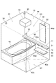
図1は、実施形態に係る浴室ユニットを模式的に表す斜視図である。
図2は、実施形態に係る浴室ユニットを模式的に表す正面図である。
図1及び図2に表したように、浴室ユニット10は、水栓カウンター11と、洗面カウンター12と、第1照明部21(照明部)と、を備える。
Hereinafter, embodiments of the present invention will be described with reference to the drawings. In the drawings, the same components are denoted by the same reference numerals and the detailed description will be appropriately omitted.
FIG. 1 is a perspective view schematically showing a bathroom unit according to the embodiment.
FIG. 2 is a front view schematically showing a bathroom unit according to the embodiment.
As represented to FIG.1 and FIG.2, the bathroom unit 10 is provided with the faucet counter 11, the washroom counter 12, and the 1st illumination part 21 (illumination part).

また、この例において、浴室ユニット10は、例えば、第2照明部22と、照明器具30と、制御部32と、浴槽40と、洗い場床42と、壁パネル44と、天井パネル46と、鏡48と、をさらに備える。   Also, in this example, the bathroom unit 10 includes, for example, the second lighting unit 22, the lighting fixture 30, the control unit 32, the bath 40, the washing floor 42, the wall panel 44, the ceiling panel 46, and the mirror And 48.

洗い場床42は、浴槽40に隣接して設けられる。浴室ユニット10は、例えば、複数の壁パネル44を有する。各壁パネル44は、浴槽40及び洗い場床42を囲むように設けられる。天井パネル46は、各壁パネル44の上に設けられ、各壁パネル44で囲まれた空間の上部を塞ぐ。浴室ユニット10は、複数枚の天井パネル46を有してもよい。浴室ユニット10は、1枚の天井パネル46で各壁パネル44の上部を塞いでもよいし、複数枚の天井パネル46で各壁パネル44の上部を塞いでもよい。   A wash floor 42 is provided adjacent to the bath 40. The bathroom unit 10 has, for example, a plurality of wall panels 44. Each wall panel 44 is provided to surround the bath 40 and the wash floor 42. A ceiling panel 46 is provided on each wall panel 44 and blocks the top of the space surrounded by each wall panel 44. The bathroom unit 10 may have a plurality of ceiling panels 46. The bathroom unit 10 may block the top of each wall panel 44 with one ceiling panel 46, or may block the top of each wall panel 44 with a plurality of ceiling panels 46.

浴室ユニット10は、例えば、浴槽40、洗い場床42、周囲の各壁パネル44、及び天井パネル46などをユニット化した、いわゆるユニットバスやシステムバスなどである。浴室ユニット10は、建築躯体の内部に設置され、建築躯体の内部に浴室BRを形成する。洗い場床42は、浴室BRの床面42aを形成する。各壁パネル44は、浴室BRの浴室壁44aを形成する。   The bathroom unit 10 is, for example, a so-called unit bus, a system bus or the like in which the bathtub 40, the washing floor 42, the surrounding wall panels 44, the ceiling panel 46 and the like are unitized. The bathroom unit 10 is installed inside the building frame and forms the bathroom BR inside the building frame. Washing floor 42 forms floor 42a of bathroom BR. Each wall panel 44 forms a bathroom wall 44a of the bathroom BR.

浴室ユニット10は、例えば、浴室BR内に出入りするためのドア部材などをさらに備えてもよい。また、浴室ユニット10において、浴槽40、洗い場床42、各壁パネル44、天井パネル46、及び鏡48などは、必要に応じて設けられ、省略可能である。浴室ユニット10は、少なくとも水栓カウンター11と洗面カウンター12と第1照明部21とを備えていればよい。すなわち、浴室ユニット10は、浴室BR自体を形成するものに限ることなく、水栓カウンター11、洗面カウンター12、及び第1照明部21などを既設の浴室BR内に取り付けて使用されるものなどでもよい。   Bathroom unit 10 may further include, for example, a door member or the like for entering and exiting bathroom BR. Moreover, in the bathroom unit 10, the bathtub 40, the washing floor 42, each wall panel 44, the ceiling panel 46, the mirror 48, etc. are provided as needed, and can be abbreviate | omitted. The bathroom unit 10 may include at least the faucet counter 11, the washing counter 12, and the first lighting unit 21. That is, the bathroom unit 10 is not limited to the one that forms the bathroom BR itself, but may be one that is used by attaching the faucet counter 11, the washroom counter 12, the first lighting unit 21 and the like in the existing bathroom BR. Good.

洗い場床42は、床面42aに流れた湯水を外部に排出するための排水口部42bを有する。排水口部42bは、例えば、浴槽40と隣接して設けられる。排水口部42bは、例えば、浴室BRの中心付近に設けられる。   The washing floor 42 has a drainage port 42b for discharging the water flowing to the floor surface 42a to the outside. The drain port 42 b is provided, for example, adjacent to the bath 40. The outlet 42 b is provided, for example, near the center of the bathroom BR.

水栓カウンター11及び洗面カウンター12は、壁パネル44の浴室壁44aに取り付けて使用される。水栓カウンター11及び洗面カウンター12は、例えば、洗い場床42の床面42aと連続する浴室壁44aに取り付けられる。   The faucet counter 11 and the washout counter 12 are used by being attached to the bathroom wall 44 a of the wall panel 44. The faucet counter 11 and the washroom counter 12 are attached to, for example, a bathroom wall 44a continuous with the floor surface 42a of the washing floor 42.

この例において、水栓カウンター11及び洗面カウンター12は、浴槽40と洗い場床42とが並ぶ方向に延びる浴室壁44aに取り付けられている。洗面カウンター12は、洗い場床42の上方に位置するように浴室壁44aに取り付けられている。水栓カウンター11は、浴槽40及び洗い場床42の上方に位置にするように浴室壁44aに取り付けられている。換言すれば、水栓カウンター11は、浴槽40及び洗い場床42に跨るように浴室壁44aに取り付けられている。   In this example, the faucet counter 11 and the washroom counter 12 are attached to a bathroom wall 44a extending in the direction in which the bathtub 40 and the wash floor 42 are aligned. The washing counter 12 is attached to the bathroom wall 44 a so as to be located above the washing floor 42. The faucet counter 11 is attached to the bathroom wall 44 a so as to be located above the bath 40 and the wash floor 42. In other words, the faucet counter 11 is attached to the bathroom wall 44 a so as to straddle the bath 40 and the wash floor 42.

水栓カウンター11は、必ずしも浴槽40側まで延びていなくてもよい。水栓カウンター11は、少なくも洗い場床42の上方に配置されていればよい。水栓カウンター11及び洗面カウンター12を取り付ける浴室壁44aは、上記に限ることなく、浴室BRの任意の浴室壁44aでよい。   The faucet counter 11 may not necessarily extend to the bathtub 40 side. The faucet counter 11 should just be arrange | positioned above the wash floor 42 at least. The bathroom wall 44a to which the faucet counter 11 and the washout counter 12 are attached may be any bathroom wall 44a of the bathroom BR without being limited to the above.

水栓カウンター11は、カウンター本体60と、吐水部61と、を有する。カウンター本体60は、シャンプーボトルなどの物品を上部に載置できるように棚形状に形成された上面60aを有する。吐水部61は、カウンター本体60の下部に設けられ、湯水を吐水する吐水口61a(図5参照)を有する。吐水部61は、換言すれば、スパウトである。このように、水栓カウンター11は、湯水を吐出する水栓として機能するとともに、物品を載置可能なカウンターとしても機能する。   The water faucet counter 11 has a counter main body 60 and a water discharger 61. The counter body 60 has an upper surface 60a formed in a shelf shape so that an article such as a shampoo bottle can be placed thereon. The water discharger 61 is provided at the lower part of the counter main body 60, and has a water discharge port 61a (see FIG. 5) that discharges hot and cold water. The water discharger 61 is, in other words, a spout. Thus, the faucet counter 11 functions as a faucet for discharging hot and cold water and also functions as a counter on which articles can be placed.

洗面カウンター12は、水栓カウンター11の下方に配置される。洗面カウンター12は、例えば、水栓カウンター11の下方において、浴槽40と壁パネル44との間に設けられる。洗面カウンター12は、例えば、洗い場床42に置かれた風呂椅子などに腰掛けた状態の使用者に対し、載置した洗面器などが使用し易い高さに設けられる。   The washroom counter 12 is disposed below the water faucet counter 11. The washing counter 12 is provided, for example, between the bath 40 and the wall panel 44 below the water faucet counter 11. The washroom counter 12 is provided, for example, at a height at which the user can easily use a wash basin or the like while sitting on a bath chair or the like placed on the washing floor 42.

洗面カウンター12は、棚部80と、支持部81と、を有する。棚部80は、洗面器などの物品を載置可能な上面80aを有する。支持部81は、棚部80と浴室壁44aとを接続し、棚部80を浴室壁44aに支持する。   The washroom counter 12 has a shelf 80 and a support 81. The shelf 80 has an upper surface 80a on which articles such as a basin can be placed. The support part 81 connects the shelf part 80 and the bathroom wall 44a, and supports the shelf part 80 on the bathroom wall 44a.

このように、洗面カウンター12は、水栓カウンター11の下方に洗面器を載置可能とすることにより、水栓カウンター11から吐水された湯水を洗面器で受けられるようにする。洗面カウンター12の構成は、棚部80及び支持部81を有する構成に限ることなく、少なくとも洗面器を載置可能な任意の構成でよい。   Thus, the wash-basin counter 12 enables the hot water discharged from the water-faucet counter 11 to be received by the wash-basin by enabling the wash-basin to be placed below the water-faucet counter 11. The configuration of the washout counter 12 is not limited to the configuration having the shelf 80 and the support 81, and may be at least any configuration on which the washstand can be placed.

支持部81の左右方向の長さL2は、例えば、棚部80の左右方向の長さL1よりも短い。吐水部61は、例えば、左右方向において支持部81と重なる位置に配置される。   The length L2 in the left-right direction of the support portion 81 is shorter than, for example, the length L1 in the left-right direction of the shelf 80. The water discharger 61 is disposed, for example, at a position overlapping the support 81 in the left-right direction.

鏡48は、例えば、水栓カウンター11よりも上方に設けられ、洗い場床42に置かれた風呂椅子などに腰掛けた状態の使用者が、自身の顔などを確認できるようにする。   The mirror 48 is provided, for example, above the water faucet counter 11 so that a user sitting on a bath chair or the like placed on the wash floor 42 can check his / her face or the like.

第1照明部21は、水栓カウンター11の下方に向かって光を照射する。洗面カウンター12は、水栓カウンター11及び第1照明部21の下方に配置される。第1照明部21は、洗面カウンター12の上面80aに向かって光を照射する。これにより、水栓カウンター11の下方の空間を明るくすることができる。例えば、水栓カウンター11から吐水された吐水流や洗面カウンター12の上面80aなどを明るくすることができる。   The first lighting unit 21 emits light toward the lower side of the water faucet counter 11. The washing counter 12 is disposed below the water faucet counter 11 and the first lighting unit 21. The first lighting unit 21 emits light toward the upper surface 80 a of the wash counter 12. Thereby, the space under the faucet counter 11 can be brightened. For example, the spouted water flow spouted from the faucet counter 11, the upper surface 80a of the washing counter 12, etc. can be made bright.

第2照明部22は、洗面カウンター12の下方に向かって光を照射する。より詳しくは、第2照明部22は、洗面カウンター12の下方の床面42aに向かって光を照射する。これにより、洗面カウンター12の下方の空間及び床面42aなどを明るくすることができる。   The second lighting unit 22 emits light toward the lower side of the washroom counter 12. More specifically, the second lighting unit 22 emits light toward the floor surface 42 a below the wash counter 12. Thereby, the space below the washroom counter 12, the floor surface 42a, etc. can be made bright.

照明器具30は、天井パネル46に設けられている。照明器具30は、天井パネル46から下方に向かって光を照射することにより、浴室BR内を照明する。照明器具30は、いわゆるダウンライトである。浴室ユニット10は、例えば、複数の照明器具30を有する。この例において、浴室ユニット10は、矩形状の天井パネル46の四隅付近に配置された4つの照明器具30を有する。照明器具30の数は、複数に限ることなく、1つでもよい。また、照明器具30は、ダウンライトに限ることなく、例えば、浴室壁44aに取り付けて使用される照明器具などでもよい。照明器具30は、浴室BR内を明るくすることができる任意の照明器具でよい。   The lighting fixture 30 is provided on the ceiling panel 46. The lighting fixture 30 illuminates the inside of the bathroom BR by emitting light downward from the ceiling panel 46. The lighting fixture 30 is a so-called downlight. The bathroom unit 10 has, for example, a plurality of lighting fixtures 30. In this example, the bathroom unit 10 has four lighting fixtures 30 disposed near the four corners of the rectangular ceiling panel 46. The number of lighting devices 30 is not limited to a plurality, and may be one. Moreover, the luminaire 30 is not limited to a downlight, but may be, for example, a luminaire attached to the bathroom wall 44a. The lighting fixture 30 may be any lighting fixture that can brighten the interior of the bathroom BR.

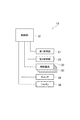
図3は、実施形態に係る浴室ユニットの電気的構成を模式的に表すブロック図である。 図3に表したように、制御部32は、第1照明部21、第2照明部22、及び各照明器具30のそれぞれと電気的に接続されている。制御部32は、第1照明部21、第2照明部22、及び各照明器具30のそれぞれの点灯、及び消灯を制御する。   FIG. 3 is a block diagram schematically showing the electrical configuration of the bathroom unit according to the embodiment. As shown in FIG. 3, the control unit 32 is electrically connected to each of the first lighting unit 21, the second lighting unit 22, and each lighting fixture 30. The control unit 32 controls lighting and extinguishing of the first lighting unit 21, the second lighting unit 22, and each lighting fixture 30.

制御部32は、例えば、天井パネル46の上に設けられる(図1、図2参照)。換言すれば、制御部32は、天井パネルと建築躯体との間の空間に設けられる。制御部32の位置は、上記に限ることなく、各照明の点灯及び消灯を制御可能な任意の位置でよい。   The control unit 32 is provided, for example, on the ceiling panel 46 (see FIGS. 1 and 2). In other words, the control unit 32 is provided in the space between the ceiling panel and the building frame. The position of the control unit 32 is not limited to the above, and may be any position that can control lighting and extinguishing of each light.

図3に表したように、浴室ユニット10は、例えば、スイッチ34と、リモコン36と、をさらに備える。スイッチ34は、制御部32と電気的に接続されている。スイッチ34は、例えば、浴室BRの外側の壁面(例えば脱衣室の壁面)、又は浴室BR内の浴室壁44aに取り付けられる。スイッチ34は、各照明の点灯及び消灯の切り替えを制御部32に指示する。制御部32は、スイッチ34からの点灯の指示応じて第1照明部21、第2照明部22、及び各照明器具30のそれぞれを点灯させ、スイッチ34からの消灯の指示応じて第1照明部21、第2照明部22、及び各照明器具30のそれぞれを消灯させる。   As shown in FIG. 3, the bathroom unit 10 further includes, for example, a switch 34 and a remote control 36. The switch 34 is electrically connected to the control unit 32. The switch 34 is attached to, for example, the outer wall of the bathroom BR (for example, the wall of the dressing room) or the bathroom wall 44a in the bathroom BR. The switch 34 instructs the control unit 32 to switch on and off each light. The control unit 32 lights each of the first lighting unit 21, the second lighting unit 22, and each lighting fixture 30 according to the lighting instruction from the switch 34, and the first lighting unit according to the lighting instruction from the switch 34. Each of the second lighting unit 22 and each lighting fixture 30 is turned off.

このように、第2照明部22は、第1照明部21と連動して点灯・消灯する。この例では、第1照明部21、第2照明部22、及び各照明器具30のそれぞれが、連動して点灯・消灯する。制御部32は、第1照明部21、第2照明部22、及び各照明器具30のそれぞれを連動させて点灯・消灯する。   Thus, the second lighting unit 22 is turned on and off in conjunction with the first lighting unit 21. In this example, each of the first lighting unit 21, the second lighting unit 22, and the lighting fixtures 30 is turned on and off in conjunction with one another. The control unit 32 interlocks each of the first lighting unit 21, the second lighting unit 22, and each lighting fixture 30 to turn on / off.

リモコン36は、制御部32と電気的に接続されている。リモコン36は、例えば、浴室BR内の浴室壁44a又は浴槽40の内壁に取り付けられる。リモコン36は、使用者からの操作指示を受け付けるための操作部を有する。リモコン36は、例えば、複数の操作部を有する。リモコン36は、操作部の操作に応じて、第1照明部21、第2照明部22、及び各照明器具30のそれぞれの個別の点灯及び消灯の切り替えを制御部32に指示する。制御部32は、スイッチ34からの指示に応じて、第1照明部21、第2照明部22、及び各照明器具30のそれぞれを点灯させた後、リモコン36からの指示に応じて、第1照明部21、第2照明部22、及び各照明器具30のそれぞれ点灯及び消灯を個別に切り替える。   The remote control 36 is electrically connected to the control unit 32. The remote control 36 is attached to, for example, the bathroom wall 44 a in the bathroom BR or the inner wall of the bath 40. The remote control 36 has an operation unit for receiving an operation instruction from the user. The remote control 36 has, for example, a plurality of operation units. The remote controller 36 instructs the control unit 32 to switch on and off of the first lighting unit 21, the second lighting unit 22, and each lighting fixture 30 individually according to the operation of the operation unit. The control unit 32 turns on each of the first lighting unit 21, the second lighting unit 22, and each lighting fixture 30 according to the instruction from the switch 34, and then, according to the instruction from the remote control 36, The lighting unit 21, the second lighting unit 22, and the lighting fixtures 30 are individually switched on and off.

これにより、リモコン36の操作部を操作することによって、第1照明部21、第2照明部22、及び各照明器具30のそれぞれ点灯状態を個別に切り替えることができる。例えば、各照明器具30のみを点灯させた状態としたり、反対に、各照明器具30を消灯させ、第1照明部21及び第2照明部22のみを点灯させた状態としたりすることができる。   Thereby, by operating the operation part of the remote control 36, the lighting state of each of the first lighting part 21, the second lighting part 22, and each lighting fixture 30 can be switched individually. For example, only the lighting fixtures 30 can be turned on, or conversely, the lighting fixtures 30 can be turned off and only the first lighting unit 21 and the second lighting unit 22 can be turned on.

また、制御部32は、第1照明部21、第2照明部22、及び各照明器具30から照射される光の照度を変化させる調光機能を有する。リモコン36は、操作部の操作に応じて、照度の切り替えを制御部32に指示する。制御部32は、リモコン36からの指示に応じて、点灯中の第1照明部21、第2照明部22、及び各照明器具30の照度を切り替える。これにより、制御部32は、第1照明部21、第2照明部22、及び各照明器具30の照度を連動させる。   The control unit 32 also has a light control function of changing the illuminance of light emitted from the first lighting unit 21, the second lighting unit 22, and each lighting fixture 30. The remote controller 36 instructs the control unit 32 to switch the illuminance in accordance with the operation of the operation unit. The control unit 32 switches the illuminance of the first lighting unit 21, the second lighting unit 22, and the lighting fixtures 30 that are on, in accordance with an instruction from the remote control 36. Thus, the control unit 32 interlocks the illuminance of the first lighting unit 21, the second lighting unit 22, and the lighting fixtures 30.

なお、「照度を連動させる」とは、第1照明部21、第2照明部22、及び各照明器具30のそれぞれの照度を共に増減させることを意味し、それぞれの照度を同一にするという意味ではない。第1照明部21、第2照明部22、及び各照明器具30のそれぞれの照度は、同じでもよいし、異なってもよい。また、照度の増減の幅も、第1照明部21、第2照明部22、及び各照明器具30のそれぞれで異なってもよい。   Note that "to interlock the illuminance" means to increase or decrease the illuminance of each of the first lighting unit 21, the second lighting unit 22, and each lighting fixture 30, and means that the respective illuminances are made the same. is not. The illuminance of each of the first lighting unit 21, the second lighting unit 22, and each lighting fixture 30 may be the same or different. In addition, the width of increase and decrease of the illuminance may be different for each of the first lighting unit 21, the second lighting unit 22, and each lighting fixture 30.

また、第1照明部21、第2照明部22、及び各照明器具30のそれぞれは、照射する光の色温度(発光色)を変化させる調色機能を有する。制御部32は、リモコン36からの指示に応じて第1照明部21、第2照明部22、及び各照明器具30の照度を切り替える場合に、照度とともに色温度を変化させる。制御部32は、例えば、照度を高くするほど白色光に近づくように色温度を高くし、照度を低くするほど電球色に近づくように色温度を低くする。このように、制御部32は、第1照明部21、第2照明部22、及び各照明器具30の色温度を照度に応じて連動させる。これにより、例えば、照度に応じた適切な空間演出を行うことができ、浴室BRの見栄えをより向上させることができる。   Moreover, each of the 1st illumination part 21, the 2nd illumination part 22, and each lighting fixture 30 has a toning function which changes the color temperature (luminescence color) of the light to irradiate. The control unit 32 changes the color temperature together with the illuminance when switching the illuminance of the first lighting unit 21, the second lighting unit 22, and the lighting fixtures 30 according to the instruction from the remote control 36. For example, the control unit 32 increases the color temperature so as to approach white light as the illuminance increases, and decreases the color temperature so as to approach the bulb color as the illuminance decreases. Thus, the control unit 32 interlocks the color temperatures of the first lighting unit 21, the second lighting unit 22, and the lighting fixtures 30 according to the illuminance. Thereby, for example, it is possible to perform appropriate space rendering according to the illuminance, and it is possible to further improve the appearance of the bathroom BR.

なお、色温度は、例えば、リモコン36の操作により、照度とは無関係に調節できるようにしてもよい。また、第1照明部21、第2照明部22、及び各照明器具30の照度及び色温度は、例えば、リモコン36の操作により、個別に調節できるようにしてもよい。   The color temperature may be adjusted, for example, by operating the remote control 36 independently of the illuminance. Further, the illuminance and the color temperature of the first lighting unit 21, the second lighting unit 22, and the lighting fixtures 30 may be individually adjusted by, for example, the operation of the remote control 36.

「色温度を連動させる」とは、第1照明部21、第2照明部22、及び各照明器具30のそれぞれの光の色温度を共に増減させることを意味し、それぞれの光の色温度を同一にするという意味ではない。第1照明部21、第2照明部22、及び各照明器具30のそれぞれの光の色温度は、同じでもよいし、異なってもよい。また、色温度の増減の幅も、第1照明部21、第2照明部22、及び各照明器具30のそれぞれで異なってもよい。   “To interlock color temperature” means to increase or decrease the color temperature of each of the first lighting unit 21, the second lighting unit 22, and each lighting fixture 30 together, and the color temperature of each light is It does not mean to make them identical. The color temperatures of the lights of the first lighting unit 21, the second lighting unit 22, and the lighting fixtures 30 may be the same or different. Further, the width of increase and decrease of the color temperature may be different in each of the first lighting unit 21, the second lighting unit 22, and each lighting fixture 30.

第1照明部21、第2照明部22、及び各照明器具30の色温度を連動させる場合、制御部32は、例えば、第1照明部21、第2照明部22、及び各照明器具30のそれぞれの色温度のバラツキを±400K以下にする。これにより、第1照明部21、第2照明部22、及び各照明器具30のそれぞれから照射される光の色味を合わせることができ、浴室BRの見栄えをより向上させることができる。このように、第1照明部21、第2照明部22、及び各照明器具30のそれぞれの色温度は、僅かに異なっていてもよい。   In the case where the color temperatures of the first lighting unit 21, the second lighting unit 22, and the lighting fixtures 30 are interlocked, for example, the control unit 32 may control the first lighting unit 21, the second lighting unit 22, and the lighting fixtures 30. Make the variation of each color temperature ± 400 K or less. Thereby, the color of the light irradiated from each of the 1st illumination part 21, the 2nd illumination part 22, and each lighting fixture 30 can be united, and the appearance of bathroom BR can be improved more. Thus, the color temperature of each of the first lighting unit 21, the second lighting unit 22, and each lighting fixture 30 may be slightly different.

スイッチ34と制御部32との間の信号の送受、及びリモコン36と制御部32との間の信号の送受は、例えば、無線を介して行ってもよい。スイッチ34と制御部32及びリモコン36と制御部32は、必ずしも信号線などを介して物理的に接続されていなくてもよい。   Transmission and reception of signals between the switch 34 and the control unit 32, and transmission and reception of signals between the remote control 36 and the control unit 32 may be performed, for example, via radio. The switch 34 and the control unit 32, and the remote control 36 and the control unit 32 may not necessarily be physically connected via a signal line or the like.

図4は、実施形態に係る水栓カウンターの一部を模式的に表す正面図である。
図5は、実施形態に係る水栓カウンターの一部を模式的に表す底面図である。
図4及び図5に表したように、水栓カウンター11のカウンター本体60は、例えば、シャワー接続口62、吐水口操作部63、シャワー操作部64、温度調節部65、流量調節部66、及び止水栓67、68などをさらに有する。
FIG. 4 is a front view schematically showing a part of the water faucet counter according to the embodiment.
FIG. 5 is a bottom view schematically showing a part of the water faucet counter according to the embodiment.
As shown in FIGS. 4 and 5, the counter main body 60 of the faucet counter 11 includes, for example, a shower connection port 62, a spout operation section 63, a shower operation section 64, a temperature control section 65, a flow rate control section 66, and It further has a water stop valve 67, 68 and the like.

シャワー接続口62は、カウンター本体60の下部に設けられている。シャワー接続口62は、可撓性を有するホース70と接続されるとともに、ホース70を介してシャワーヘッド72と接続される。シャワーヘッド72は、より詳しくは、ハンドシャワーである。   The shower connection port 62 is provided at the lower part of the counter main body 60. The shower connection port 62 is connected to the flexible hose 70 and connected to the shower head 72 via the hose 70. The shower head 72 is more specifically a hand shower.

カウンター本体60は、例えば、天井に取り付けて使用されるオーバーヘッドシャワーと接続してもよい。カウンター本体60は、ハンドシャワー及びオーバーヘッドシャワーのいずれか一方のみと接続してもよいし、ハンドシャワー及びオーバーヘッドシャワーの双方と接続してもよい。   The counter main body 60 may be connected to, for example, an overhead shower used by being attached to a ceiling. The counter body 60 may be connected to only one of the hand shower and the overhead shower, or may be connected to both the hand shower and the overhead shower.

カウンター本体60をオーバーヘッドシャワーと接続する場合には、シャワー接続口62を用いてもよいし、別の接続口を介して接続してもよい。カウンター本体60をオーバーヘッドシャワーと接続する場合には、例えば、カウンター本体60の背面側に接続口を設け、壁パネル44と建築躯体との間の空間を利用してカウンター本体60をオーバーヘッドシャワーとを接続することが好ましい。これにより、配管などが浴室BR内に露出することを抑制し、浴室BRの見栄えを向上させることができる。   When connecting the counter main body 60 to the overhead shower, the shower connection port 62 may be used or may be connected via another connection port. When connecting the counter main body 60 to the overhead shower, for example, a connection port is provided on the back side of the counter main body 60, and the counter main body 60 is overhead shower using the space between the wall panel 44 and the building frame. It is preferable to connect. Thereby, it can suppress that piping etc. are exposed in bathroom BR, and the appearance of bathroom BR can be improved.

吐水口操作部63、シャワー操作部64、温度調節部65、及び流量調節部66は、カウンター本体60の前面部に設けられている。但し、吐水口操作部63、シャワー操作部64、温度調節部65、及び流量調節部66の配置は、上記に限ることなく、これらを操作し易いカウンター本体60の任意の位置でよい。   The water discharge port operating unit 63, the shower operating unit 64, the temperature control unit 65, and the flow rate control unit 66 are provided on the front surface of the counter main body 60. However, the arrangement of the water discharge port operation unit 63, the shower operation unit 64, the temperature adjustment unit 65, and the flow rate adjustment unit 66 is not limited to the above, and may be any position of the counter main body 60 which can easily operate them.

吐水口操作部63及びシャワー操作部64は、例えば、押しボタン式の操作部である。吐水部61から湯水が吐水されていない状態で吐水口操作部63を押圧操作することにより、吐水部61の吐水口61aから湯水が吐水される。そして、吐水部61の吐水口61aから湯水が吐水されている状態で吐水口操作部63を押圧操作することにより、吐水部61の吐水口61aからの湯水の吐水が停止される。   The water spout operation unit 63 and the shower operation unit 64 are, for example, push button operation units. By pressing the water discharge port operation part 63 in a state where hot water is not discharged from the water discharge part 61, hot water is discharged from the water discharge port 61a of the water discharge part 61. Then, the hot water discharge from the water discharge port 61 a of the water discharge unit 61 is stopped by pressing the water discharge port operation unit 63 in a state where hot water is discharged from the water discharge opening 61 a of the water discharge unit 61.

同様に、シャワーヘッド72から湯水が吐水されていない状態でシャワー操作部64を押圧操作することにより、シャワーヘッド72から湯水が吐水される。そして、シャワーヘッド72から湯水が吐水されている状態でシャワー操作部64を押圧操作することにより、シャワーヘッド72からの湯水の吐水が停止される。   Similarly, the hot water is discharged from the shower head 72 by pressing the shower operation unit 64 in a state where the hot water is not discharged from the shower head 72. Then, the hot water discharge from the shower head 72 is stopped by pressing the shower operation unit 64 while the hot water is discharged from the shower head 72.

このように、水栓カウンター11では、吐水口操作部63及びシャワー操作部64の操作により、吐水部61及びシャワーヘッド72から選択的に湯水を吐止水することができる。なお、吐水口操作部63及びシャワー操作部64は、押しボタン式の操作部に限ることなく、吐止水の切り替えを制御可能な任意の操作部でよい。吐水口操作部63及びシャワー操作部64は、例えば、回転式のハンドルやレバーなどでもよい。   As described above, in the faucet counter 11, hot water can be selectively discharged from the water discharge unit 61 and the shower head 72 by the operation of the water discharge port operation unit 63 and the shower operation unit 64. In addition, the water spout operation unit 63 and the shower operation unit 64 may be any operation unit capable of controlling the switching of the discharge water without being limited to the push button type operation unit. The spout port operation unit 63 and the shower operation unit 64 may be, for example, a rotary handle or a lever.

温度調節部65及び流量調節部66は、例えば、回転式のハンドルである。温度調節部65は、吐水部61及びシャワーヘッド72から吐水される湯水の温度を調節可能とする。水栓カウンター11は、図示を省略した給水管及び給湯管と接続される。温度調節部65は、給水管から供給される水と給湯管から供給されるお湯との混合比を調節することにより、吐水部61及びシャワーヘッド72から吐水される湯水の温度を調節する。   The temperature control unit 65 and the flow rate control unit 66 are, for example, rotary handles. The temperature control unit 65 can adjust the temperature of the hot and cold water discharged from the water discharger 61 and the shower head 72. The faucet counter 11 is connected to a water supply pipe and a hot water supply pipe which are not shown. The temperature control unit 65 controls the temperature of the hot and cold water discharged from the water discharger 61 and the shower head 72 by adjusting the mixing ratio between the water supplied from the water supply pipe and the hot water supplied from the hot water supply pipe.

流量調節部66は、吐水部61及びシャワーヘッド72から吐水される湯水の流量を調節可能とする。これにより、水栓カウンター11では、温度調節部65及び流量調節部66を操作することで、使用者の所望する温度及び流量の湯水を吐水部61及びシャワーヘッド72から吐水することができる。   The flow rate adjustment unit 66 can adjust the flow rate of hot and cold water discharged from the water discharge unit 61 and the shower head 72. Thereby, in the faucet counter 11, by operating the temperature control unit 65 and the flow rate control unit 66, hot and cold water having a temperature and a flow rate desired by the user can be discharged from the water discharge unit 61 and the shower head 72.

なお、温度調節部65及び流量調節部66は、回転式のハンドルに限ることなく、湯水の温度や流量を調節可能な任意の操作部でよい。また、この例では、温度調節部65と流量調節部66とを設けているが、例えば、吐水される湯水の温度及び流量を1つの操作部で調節できるようにしてもよい。   In addition, the temperature control part 65 and the flow volume adjustment part 66 may be arbitrary operation parts which can adjust the temperature and flow volume of hot and cold water, without restricting to a rotary handle. Moreover, although the temperature control part 65 and the flow volume adjustment part 66 are provided in this example, you may enable it to be able to adjust the temperature and flow volume of the hot and cold water discharged, for example by one operation part.

止水栓67、68は、カウンター本体60の下部に設けられている。止水栓67、68は、吐水部61及びシャワーヘッド72に送水される湯水を遮断する。止水栓67は、例えば、給水管から吐水部61及びシャワーヘッド72へと至る経路上に設けられ、給水管から吐水部61及びシャワーヘッド72への水の供給を遮断する。止水栓68は、例えば、給湯管から吐水部61及びシャワーヘッド72へと至る経路上に設けられ、給湯管から吐水部61及びシャワーヘッド72への湯の供給を遮断する。   The water stop valves 67 and 68 are provided at the lower part of the counter body 60. The water stop valves 67 and 68 shut off the hot and cold water supplied to the water discharger 61 and the shower head 72. The water stop valve 67 is provided, for example, on a path from the water supply pipe to the water discharge unit 61 and the shower head 72, and blocks the supply of water from the water supply pipe to the water discharge unit 61 and the shower head 72. The water stop valve 68 is provided, for example, on a route from the hot water supply pipe to the water discharge part 61 and the shower head 72, and blocks the supply of hot water from the hot water supply pipe to the water discharge part 61 and the shower head 72.

止水栓67、68は、吐水部61及びシャワーヘッド72への送水を可能にする状態と、吐水部61及びシャワーヘッド72への送水を遮断した状態と、を切り替えるための操作部67a、68aを有する。止水栓67、68は、例えば、操作部67a、68aを下方に向けた状態で、カウンター本体60の下部に設けられる。   The water blocking plugs 67 and 68 are operation parts 67a and 68a for switching between a state in which water can be supplied to the water discharger 61 and the shower head 72 and a state in which water supply to the water discharger 61 and the shower head 72 is blocked. Have. The water stop valves 67 and 68 are provided at the lower part of the counter main body 60, for example, with the operation parts 67a and 68a directed downward.

例えば、吐水部61側への吐水とシャワーヘッド72側への吐水とを切り替える切替弁を設けるとともに、切替弁で選択された吐水部61又はシャワーヘッド72からの吐止水、流量の調節、及び温度の調節を1つの操作部で操作できるようにしてもよい。水栓カウンター11及びカウンター本体60の構成は、上記に限ることなく、少なくとも吐水部61からの吐止水を切り替え可能な任意の構成でよい。   For example, a switching valve is provided to switch between water spouting to the water spouting portion 61 and water spouting to the shower head 72 side, and water spouting from the water spouting portion 61 or the shower head 72 selected by the switching valve, adjustment of flow rate, Temperature control may be operated by one operation unit. The configuration of the faucet counter 11 and the counter main body 60 is not limited to the above, and may be any configuration capable of switching at least the water discharge from the water discharger 61.

図6は、実施形態に係る水栓カウンターを模式的に表す分解斜視図である。
図6に表したように、水栓カウンター11のカウンター本体60は、例えば、天板100と、複数の支持体102と、補強板104、106、108と、カバー110と、下側カバー112と、を有する。
FIG. 6 is an exploded perspective view schematically showing the water faucet counter according to the embodiment.
As shown in FIG. 6, the counter main body 60 of the faucet counter 11 includes, for example, the top plate 100, the plurality of supports 102, the reinforcing plates 104, 106, 108, the cover 110, and the lower cover 112. And.

天板100は、左右方向に延びた略矩形の平板状の部材である。天板100は、カウンター本体60の上面60aを形成する。水栓カウンター11は、天板100の上に、シャンプーのボトルなどの物品を載置可能とする。   The top 100 is a substantially rectangular flat member extending in the left-right direction. The top plate 100 forms an upper surface 60 a of the counter main body 60. The faucet counter 11 enables an article such as a bottle of shampoo to be placed on the top 100.

複数の支持体102は、左右方向に並べて壁パネル44の浴室壁44aに取り付けられる。各支持体102は、天板100を支持する。各支持体102は、例えば、天板100を壁パネル44から僅かに離間させた状態で支持する。換言すれば、各支持体102は、カウンター本体60の上面60aの後端を浴室壁44aから離間させる。これにより、使用者に対して水栓カウンター11を浮いているように見せることができ、水栓カウンター11のデザイン性を向上させることができる。従って、浴室BRの見栄えを向上させることができる。なお、図6では、便宜的に、壁パネル44の一部分のみを図示している。   The plurality of supports 102 are attached to the bathroom wall 44 a of the wall panel 44 side by side in the left-right direction. Each support 102 supports the top 100. Each support 102 supports, for example, the top 100 slightly spaced from the wall panel 44. In other words, each support 102 separates the rear end of the upper surface 60a of the counter main body 60 from the bathroom wall 44a. This makes it possible for the user to make the water faucet counter 11 appear to be floating, and the design of the water faucet counter 11 can be improved. Therefore, the appearance of the bathroom BR can be improved. In FIG. 6, for convenience, only a part of the wall panel 44 is shown.

補強板104、106、108は、各支持体102の間に架け渡されるように、各支持体102の上に設けられる。天板100は、補強板104、106、108の上に設けられる。これにより、補強板104、106、108は、天板100の撓みを抑制する。   Reinforcing plates 104, 106, 108 are provided on each support 102 so as to be bridged between the supports 102. The top plate 100 is provided on the reinforcing plates 104, 106, 108. Thereby, the reinforcing plates 104, 106, 108 suppress the deflection of the top plate 100.

吐水口操作部63、シャワー操作部64、温度調節部65、及び流量調節部66などの水栓機能部は、例えば、補強板106に取り付けられ、補強板106を介して各支持体102に支持される。   Water faucet functional units such as the water discharge port operating unit 63, the shower operating unit 64, the temperature control unit 65, and the flow rate control unit 66 are attached to, for example, the reinforcing plate 106 and supported by the respective supports 102 via the reinforcing plate 106. Be done.

カバー110は、各支持体102の上に取り付けられ、天板100と壁パネル44との間の部分の各支持体102の上方を覆うとともに、天板100と壁パネル44との間の部分の各支持体102の側方を覆う。   A cover 110 is mounted on each support 102 and covers the top of each support 102 in the portion between the top 100 and the wall panel 44, and the portion between the top 100 and the wall panel 44. The sides of each support 102 are covered.

下側カバー112は、各支持体102の下方に取り付けられ、天板100の下方を覆う。すなわち、下側カバー112は、各支持体102や水栓機能部などが下方に露出することを抑制する。また、下側カバー112は、開口部112aを有する。開口部112aは、下側カバー112の下端部に設けられ、壁パネル44との間に隙間を形成する。   The lower cover 112 is attached below each support 102 and covers the bottom of the top 100. That is, the lower cover 112 suppresses exposure of the supports 102, the water faucet functional portion, and the like to the lower side. The lower cover 112 also has an opening 112a. The opening 112 a is provided at the lower end of the lower cover 112 and forms a gap with the wall panel 44.

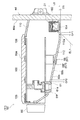
図7は、実施形態に係る水栓カウンターの一部を模式的に表す断面図である。
図7に表したように、第1照明部21は、水栓カウンター11の下部に設けられる。第1照明部21は、例えば、各支持体102にネジ止めされることにより、水栓カウンター11の下部に取り付けられる。第1照明部21は、例えば、カウンター本体60内に設けられる。第1照明部21は、下側カバー112の開口部112aの上方に配置され、開口部112aを介して下方に露出する。これにより、第1照明部21は、カウンター本体60内に設けられた状態において、開口部112aを介して水栓カウンター11の下方に向かって光を照射する。
FIG. 7 is a cross-sectional view schematically showing a part of the water faucet counter according to the embodiment.
As shown in FIG. 7, the first lighting unit 21 is provided below the water faucet counter 11. The first lighting unit 21 is attached to the lower part of the water faucet counter 11 by, for example, being screwed to each support 102. The first lighting unit 21 is provided, for example, in the counter main body 60. The first illumination unit 21 is disposed above the opening 112 a of the lower cover 112 and exposed downward through the opening 112 a. Thereby, in a state where the first lighting unit 21 is provided in the counter main body 60, the first lighting unit 21 emits light toward the lower side of the water faucet counter 11 through the opening 112a.

また、図7に表したように、吐水部61の少なくとも一部は、カウンター本体60の下面60bよりも下方に突出している。第1照明部21は、吐水部61よりも後方かつ下方に位置するように配置されている。すなわち、第1照明部21の前端は、吐水部61の前端よりも後方に位置する。そして、第1照明部21の下端は、吐水部61の下端よりも下方に位置する。   Further, as shown in FIG. 7, at least a part of the water discharger 61 protrudes below the lower surface 60 b of the counter main body 60. The first illumination unit 21 is disposed to be located rearward and below the water discharger 61. That is, the front end of the first lighting unit 21 is located rearward of the front end of the water discharger 61. The lower end of the first lighting unit 21 is located below the lower end of the water discharger 61.

カウンター本体60の下面60bは、吐水部61と第1照明部21との間において、後方に向かうに従って下降傾斜する傾斜部60cを有する。カウンター本体60は、吐水部61の少なくとも一部を、傾斜部60cによってカウンター本体60の下面60bよりも下方に突出させる。   The lower surface 60 b of the counter main body 60 has an inclined portion 60 c which is inclined downward toward the rear between the water discharge portion 61 and the first lighting portion 21. The counter main body 60 causes at least a part of the water discharger 61 to protrude below the lower surface 60 b of the counter main body 60 by the inclined portion 60 c.

傾斜部60cは、例えば、吐水部61よりも前方まで延びている。吐水部61の下端の後端は、傾斜部60cとほぼ同じ高さの位置にある。ここで、「ほぼ同じ高さ」とは、例えば、吐水部61の下端の後端と傾斜部60cとの間の上下方向の位置の差が、5mm以下の状態である。吐水部61の下端の前端61fは、傾斜部60cよりも低い位置にある。カウンター本体60は、下面60bと第1照明部21の前端との間に空隙GP1を有する。また、この例において、カウンター本体60は、吐水部61の後端と、吐水部61よりも後方の下面60bと、の間に、空隙GP2を有する。   The inclined portion 60 c extends, for example, to the front of the water discharger 61. The rear end of the lower end of the water discharger 61 is at the same height as the inclined portion 60c. Here, “almost the same height” means, for example, a state in which the difference in vertical position between the rear end of the lower end of the water discharger 61 and the inclined portion 60c is 5 mm or less. The front end 61f of the lower end of the water discharger 61 is at a lower position than the inclined portion 60c. The counter body 60 has an air gap GP1 between the lower surface 60b and the front end of the first lighting unit 21. Further, in this example, the counter main body 60 has a gap GP2 between the rear end of the water discharger 61 and the lower surface 60b behind the water discharger 61.

止水栓67、68の少なくとも一部は、カウンター本体60の下面60bよりも下方に突出するように配置されている。第1照明部21は、止水栓67、68よりも後方かつ下方に位置するように配置されている。   At least a portion of the water stop valve 67, 68 is arranged to project downward below the lower surface 60 b of the counter body 60. The first lighting unit 21 is disposed rearward and downward of the water shutoff plugs 67 and 68.

傾斜部60cは、止水栓67、68と第1照明部21との間においても、後方に向かうに従って下降傾斜している。カウンター本体60は、止水栓67、68の少なくとも一部を、傾斜部60cによってカウンター本体60の下面60bよりも下方に突出させる。傾斜部60cは、止水栓67、68よりも前方まで延びている。止水栓67、68の下端の後端は、傾斜部60cとほぼ同じ高さの位置にある。ここで、「ほぼ同じ高さ」とは、例えば、止水栓67、68の下端の後端と傾斜部60cとの間の上下方向の位置の差が、5mm以下の状態である。止水栓67、68の下端の前端67f、68fは、傾斜部60cよりも低い位置にある。   The inclined portion 60 c is inclined downward toward the rear as well between the water stop valves 67 and 68 and the first lighting unit 21. The counter body 60 causes at least a portion of the water stop valves 67 and 68 to protrude below the lower surface 60 b of the counter body 60 by the inclined portion 60 c. The inclined portion 60 c extends forward of the water stop valves 67 and 68. The rear ends of the lower ends of the water stop plugs 67, 68 are at approximately the same height as the inclined portion 60c. Here, “almost the same height” means, for example, a state in which the difference in vertical position between the rear end of the lower ends of the water blocking plugs 67 and 68 and the inclined portion 60 c is 5 mm or less. The front end 67f, 68f of the lower end of the water stop valve 67, 68 is at a lower position than the inclined portion 60c.

カウンター本体60の傾斜部60cの部分には、吐水部61や止水栓67、68の他に、例えば、シャワー接続口62などが、さらに設けられる。傾斜部60cの部分には、例えば、カウンター本体60の内部から水を抜くための水抜栓(図示は省略)などを、さらに設けてもよい。   In addition to the water discharger 61 and the water blocking plugs 67 and 68, for example, a shower connection port 62 or the like is further provided at a portion of the inclined portion 60c of the counter main body 60. For example, a drain plug (not shown) for draining water from the inside of the counter main body 60 may be further provided at the inclined portion 60c.

図8は、実施形態に係る洗面カウンターの一部を模式的に表す断面図である。
図8に表したように、洗面カウンター12は、例えば、天板130と、支持体132と、補強板134と、カバー136と、を有する。
FIG. 8 is a cross-sectional view schematically showing a part of the washing counter according to the embodiment.
As shown in FIG. 8, the washing counter 12 includes, for example, a top plate 130, a support 132, a reinforcing plate 134, and a cover 136.

天板130は、横方向に延びた略矩形の平板状の部材である。天板130は、洗面カウンター12の上面80aを形成する。洗面カウンター12は、天板130の上に、洗面器やシャンプーのボトルなどの物品を載置可能とする。   The top plate 130 is a substantially rectangular flat member extending in the lateral direction. The top plate 130 forms the upper surface 80 a of the washroom counter 12. The washing counter 12 can place an article such as a wash basin or a bottle of shampoo on the top plate 130.

支持体132は、壁パネル44の浴室壁44aに取り付けられ、天板130を支持する。支持体132は、例えば、天板130を壁パネル44から僅かに離間させた状態で支持する。換言すれば、支持体132は、棚部80の上面80aの後端を浴室壁44aから離間させる。これにより、使用者に対して洗面カウンター12を浮いているように見せることができ、洗面カウンター12のデザイン性を向上させることができる。従って、浴室BRの見栄えを、より向上させることができる。なお、図8では、便宜的に、壁パネル44の一部分のみを図示している。   The support 132 is attached to the bathroom wall 44 a of the wall panel 44 and supports the top plate 130. The support 132 supports, for example, the top 130 in a state of being slightly separated from the wall panel 44. In other words, the support 132 separates the rear end of the top surface 80a of the shelf 80 from the bathroom wall 44a. This makes it possible for the user to appear as if the washroom counter 12 is floating, and the design of the washroom counter 12 can be improved. Therefore, the appearance of the bathroom BR can be further improved. In FIG. 8, only a part of the wall panel 44 is shown for convenience.

補強板134は、天板130と支持体132との間に設けられる。天板130は、補強板134の上に設けられる。これにより、補強板134は、天板130の撓みを抑制する。   The reinforcing plate 134 is provided between the top plate 130 and the support 132. The top plate 130 is provided on the reinforcing plate 134. Thus, the reinforcing plate 134 suppresses the deflection of the top plate 130.

カバー136は、支持体132の下方に取り付けられ、支持体132及び補強板134の前方及び下方を覆う。これにより、カバー136は、支持体132及び補強板134が外部に露出することを抑制する。また、カバー136は、下方に開口する開口部136aを有する。   The cover 136 is attached below the support 132 and covers the front and the bottom of the support 132 and the reinforcing plate 134. Thereby, the cover 136 suppresses the support 132 and the reinforcing plate 134 from being exposed to the outside. Also, the cover 136 has an opening 136a that opens downward.

洗面カウンター12の棚部80は、例えば、天板130及び補強板134などによって形成される。洗面カウンター12の支持部81は、例えば、支持体132及びカバー136などによって形成される。   The shelf 80 of the washing counter 12 is formed of, for example, the top plate 130 and the reinforcing plate 134. The support portion 81 of the washing counter 12 is formed of, for example, a support 132 and a cover 136.

図9は、実施形態に係る洗面カウンターの一部を模式的に表す断面図である。
図9に表したように、第2照明部22は、洗面カウンター12の下部に設けられる。第2照明部22は、例えば、支持体132にネジ止めされることにより、洗面カウンター12の下部に取り付けられる。第2照明部22は、例えば、支持部81内に設けられる。換言すれば、第2照明部22は、カバー136内に設けられる。第2照明部22は、カバー136の開口部136aの上方に配置され、開口部136aを介して下方に露出する。これにより、第2照明部22は、支持部81内に設けられた状態において、開口部136aを介して洗面カウンター12の下方に向かって光を照射する。
FIG. 9 is a cross-sectional view schematically showing a part of the washing counter according to the embodiment.
As shown in FIG. 9, the second lighting unit 22 is provided at the lower part of the washroom counter 12. The second lighting unit 22 is attached to the lower part of the washing counter 12 by, for example, being screwed to the support 132. The second illumination unit 22 is provided, for example, in the support unit 81. In other words, the second illumination unit 22 is provided in the cover 136. The second illumination unit 22 is disposed above the opening 136 a of the cover 136 and exposed downward through the opening 136 a. Thereby, in a state where the second lighting unit 22 is provided in the support unit 81, the second lighting unit 22 emits light toward the lower side of the counter 12 via the opening 136a.

また、図9に表したように、支持部81は、例えば、棚部80の後端80bを浴室壁44aから離間させた状態で、棚部80を浴室壁44aに支持する。棚部80の後端80bと浴室壁44aとの間に設けられる支持部81の上面81aは、例えば、浴室壁44aに向かって下方に傾斜する。上面81aの傾斜は、直線状でもよいし、曲面状に湾曲してもよい。   In addition, as illustrated in FIG. 9, for example, the support portion 81 supports the shelf 80 on the bathroom wall 44 a in a state in which the rear end 80 b of the shelf 80 is separated from the bathroom wall 44 a. The upper surface 81a of the support 81 provided between the rear end 80b of the shelf 80 and the bathroom wall 44a inclines downward, for example, toward the bathroom wall 44a. The inclination of the upper surface 81a may be linear or curved.

図10は、実施形態に係る第2照明部を模式的に表す分解斜視図である。
図11は、実施形態に係る第2照明部の一部を模式的に表す断面図である。
図10及び図11に表したように、第2照明部22は、照明部材150と、取付部材152と、を有する。
FIG. 10 is an exploded perspective view schematically showing a second illumination unit according to the embodiment.
FIG. 11 is a cross-sectional view schematically showing a part of the second illumination unit according to the embodiment.
As illustrated in FIGS. 10 and 11, the second lighting unit 22 includes a lighting member 150 and a mounting member 152.

照明部材150は、光(可視光)を照射する。取付部材152は、水栓カウンター11や洗面カウンター12などへの照明部材150の取り付けに用いられる。照明部材150及び取付部材152は、例えば、左右方向に延びた長尺状である。第2照明部22は、例えば、左右方向に延びた横長状の光を照射する、いわゆるライン照明である。   The illumination member 150 emits light (visible light). The attachment member 152 is used to attach the illumination member 150 to the faucet counter 11 or the washroom counter 12 or the like. The illumination member 150 and the attachment member 152 are, for example, elongated in the left-right direction. The second illumination unit 22 is, for example, so-called line illumination that emits horizontally elongated light extending in the left-right direction.

照明部材150は、発光部160と、収納ケース162と、一対のキャップ164、166と、放熱板168と、を有する。発光部160は、左右方向に延びた横長状である。発光部160は、例えば、基板170と、基板170の表面に並べて設けられた複数の光源172と、を有する。基板170は、例えば、横長な平板状である。各光源172は、少なくとも左右方向に並べて配置される。これにより、基板170及び各光源172は、左右方向に直線状に延びた幅広な光を照射する。   The illumination member 150 includes a light emitting unit 160, a storage case 162, a pair of caps 164 and 166, and a heat sink 168. The light emitting unit 160 is horizontally elongated extending in the left-right direction. The light emitting unit 160 includes, for example, a substrate 170 and a plurality of light sources 172 provided side by side on the surface of the substrate 170. The substrate 170 is, for example, a horizontally long flat plate. The light sources 172 are arranged side by side at least in the left-right direction. Thus, the substrate 170 and the light sources 172 emit wide light linearly extending in the left-right direction.

各光源172には、例えば、LED(Light Emitting Diode)、LD(Laser Diode)、又はOLED(Organic Light Emitting Diode)などの発光素子が用いられる。例えば、有機EL(Electro-Luminescence)素子などの面発光型の発光素子を光源172として用いる場合には、光源172は、1つでもよい。光源172は、上記に限ることなく、光を照射する任意の素子でよい。   For each light source 172, for example, a light emitting element such as a light emitting diode (LED), a laser diode (LD), or an organic light emitting diode (OLED) is used. For example, in the case of using a surface-emitting light emitting element such as an organic EL (Electro-Luminescence) element as the light source 172, the light source 172 may be one. The light source 172 is not limited to the above, and may be any element that emits light.

発光部160では、各光源172に供給する電圧又は電流の大きさを変化させることにより、各光源172から照射される光の明るさを変化させることができる。すなわち、第1照明部21及び第2照明部22に調光機能を持たせることができる。   In the light emitting unit 160, the brightness of the light emitted from each light source 172 can be changed by changing the magnitude of the voltage or current supplied to each light source 172. That is, the first illumination unit 21 and the second illumination unit 22 can have a light control function.

また、この例において、発光部160は、前後方向に並ぶ2種類の光源172を有する。発光部160は、光源172aと、光源172bと、を有する。光源172aの発光色は、光源172bの発光色と異なる。光源172aは、例えば、白色光を照射する。光源172bは、例えば、黄色光を照射する。これにより、光源172aから照射される光の明るさと、光源172bから照射される光の明るさと、を調節することにより、発光部160から照射される光の色を変化させることができる。すなわち、第1照明部21及び第2照明部22に調光機能を持たせることができる。なお、異なる色の光を照射可能な素子を光源172に用いた場合には、発光部160に含まれる光源172は、1種類でよい。   Further, in this example, the light emitting unit 160 has two types of light sources 172 aligned in the front-rear direction. The light emitting unit 160 has a light source 172a and a light source 172b. The emission color of the light source 172a is different from the emission color of the light source 172b. The light source 172a emits, for example, white light. The light source 172 b emits yellow light, for example. Thus, the color of the light emitted from the light emitting unit 160 can be changed by adjusting the brightness of the light emitted from the light source 172a and the brightness of the light emitted from the light source 172b. That is, the first illumination unit 21 and the second illumination unit 22 can have a light control function. In addition, when the element which can irradiate the light of a different color is used for the light source 172, the light source 172 contained in the light emission part 160 may be one type.

収納ケース162は、左右方向に連続した筒状である。収納ケース162は、例えば、発光部160の左右方向の両端間に亘って連続した筒状である。収納ケース162は、例えば、断面略矩形の筒状である。収納ケース162は、内部に発光部160を収納する。収納ケース162は、透光性を有する。発光部160から照射された光は、収納ケース162を透過して外部に出射される。   The storage case 162 has a cylindrical shape that is continuous in the left-right direction. The storage case 162 has, for example, a cylindrical shape which is continuous across both ends of the light emitting unit 160 in the left-right direction. The storage case 162 is, for example, a tubular shape having a substantially rectangular cross section. The storage case 162 houses the light emitting unit 160 inside. The storage case 162 has translucency. The light emitted from the light emitting unit 160 is transmitted through the storage case 162 and emitted to the outside.

収納ケース162には、例えば、ポリカーボネイト樹脂、ポリプロピレン樹脂、ABS(Acrylonitrile‐Butadiene‐Styrene)樹脂、アクリル樹脂などの透光性を有する樹脂材料が用いられる。これにより、例えば、押出成形などによって収納ケース162を容易に成形することができる。   For the storage case 162, for example, a translucent resin material such as polycarbonate resin, polypropylene resin, ABS (Acrylonitrile-Butadiene-Styrene) resin, or acrylic resin is used. Thereby, for example, the storage case 162 can be easily formed by extrusion molding or the like.

キャップ164は、収納ケース162の左右方向の一端に取り付けられ、収納ケース162の左右方向の一方の開口162aを塞ぐ。キャップ166は、収納ケース162の左右方向の他端に取り付けられ、収納ケース162の左右方向の他方の開口162bを塞ぐ。   The cap 164 is attached to one end in the left-right direction of the storage case 162 and closes one opening 162 a in the left-right direction of the storage case 162. The cap 166 is attached to the other end of the storage case 162 in the left-right direction, and closes the other opening 162 b in the left-right direction of the storage case 162.

これにより、収納ケース162及び各キャップ164、166は、シール性を有する空間を形成する。収納ケース162及び各キャップ164、166は、この空間内に発光部160を収納する。これにより、発光部160の被水が抑制される。   Thus, the storage case 162 and the caps 164 and 166 form a space having a sealing property. The storage case 162 and the caps 164 and 166 store the light emitting unit 160 in this space. Thereby, the water coverage of the light emitting unit 160 is suppressed.

放熱板168は、基板170(発光部160)を支持する。放熱板168は、例えば、基板170の各光源172が設けられた表面と反対側の面に接触することにより、基板170と熱的に結合する。これにより、放熱板168は、各光源172の点灯にともなって発生する熱を放熱する。放熱板168には、例えば、アルミニウムや銅などの熱伝導率の高い金属材料などが用いられる。基板170は、放熱板168に支持された状態で、収納ケース162内に収納される。放熱板168は、例えば、収納ケース162内の所定の位置に発光部160を支持する支持体としても機能する。例えば、光源172に有機EL素子などの発熱量の少なくい素子を用いる場合などには、必ずしも放熱板168を設けなくてもよい。   The heat sink 168 supports the substrate 170 (the light emitting unit 160). The heat dissipation plate 168 is thermally coupled to the substrate 170, for example, by contacting the surface of the substrate 170 opposite to the surface on which the light sources 172 are provided. Thus, the heat dissipation plate 168 dissipates heat generated as the light sources 172 are turned on. For the heat dissipation plate 168, for example, a metal material having high thermal conductivity such as aluminum or copper is used. The substrate 170 is housed in the housing case 162 while being supported by the heat sink 168. The heat dissipation plate 168 also functions as a support that supports the light emitting unit 160 at a predetermined position in the storage case 162, for example. For example, in the case where an element with a small amount of heat generation such as an organic EL element is used as the light source 172, the heat sink 168 may not necessarily be provided.

取付部材152は、例えば、収納ケース162を係合によって支持する。取付部材152は、例えば、第1部分152aと、第2部分152bと、第3部分152cと、を有する。第1部分152aは、収納ケース162の前面を覆う。第2部分152bは、収納ケース162の後面を覆う。第3部分152cは、収納ケース162の上面を覆う。取付部材152は、換言すれば、下方に開口した断面略U字状の部材である。取付部材152は、第1部分152a及び第2部分152bを収納ケース162に係合させることにより、収納ケース162を支持する。換言すれば、取付部材152は、第1部分152a及び第2部分152bで収納ケース162を前後に挟むことにより、収納ケース162を支持する。   The mounting member 152 supports, for example, the storage case 162 by engagement. The attachment member 152 has, for example, a first portion 152a, a second portion 152b, and a third portion 152c. The first portion 152 a covers the front of the storage case 162. The second portion 152 b covers the rear surface of the storage case 162. The third portion 152 c covers the top surface of the storage case 162. The mounting member 152 is, in other words, a member having a substantially U-shaped cross section opened downward. The mounting member 152 supports the storage case 162 by engaging the first portion 152 a and the second portion 152 b with the storage case 162. In other words, the mounting member 152 supports the storage case 162 by sandwiching the storage case 162 back and forth with the first portion 152a and the second portion 152b.

取付部材152には、例えば、鉄、ステンレス、又はアルミニウムなどの金属材料が用いられる。取付部材152は、遮光性を有する。取付部材152は、照明部材150から照射された光に対して光反射性を有する。これにより、取付部材152は、照明部材150から照射された光を下方のみに向けて出射させる。従って、この例では、収納ケース162の下端部分が、発光部160から照射された光を透過させる発光窓154として機能する。この例では、収納ケース162の一部が、取付部材152の下端よりも下方に突出している。このため、発光窓154は、換言すれば、収納ケース162のうちの取付部材152の下端よりも下方に突出した部分である。   For the mounting member 152, for example, a metal material such as iron, stainless steel, or aluminum is used. The mounting member 152 has a light shielding property. The attachment member 152 is light reflective to the light emitted from the illumination member 150. Thereby, the attachment member 152 emits the light emitted from the illumination member 150 only downward. Therefore, in this example, the lower end portion of the storage case 162 functions as a light emitting window 154 for transmitting the light emitted from the light emitting unit 160. In this example, a part of the storage case 162 protrudes below the lower end of the mounting member 152. For this reason, the light emission window 154 is, in other words, a portion of the storage case 162 that protrudes below the lower end of the attachment member 152.

また、前述のように、収納ケース162には、樹脂材料が用いられる。従って、取付部材152の剛性は、収納ケース162の剛性よりも高い。これにより、収納ケース162を取付部材152に支持させることで、樹脂材料からなる収納ケース162を長尺状にした場合などにも、収納ケース162の撓みを抑制することができる。例えば、収納ケース162内に収納された発光部160が、収納ケース162の撓みによって破損してしまうことなどを抑制することができる。   Further, as described above, a resin material is used for the storage case 162. Therefore, the rigidity of the mounting member 152 is higher than the rigidity of the storage case 162. Thus, by causing the storage case 162 to be supported by the mounting member 152, it is possible to suppress the deflection of the storage case 162 even when the storage case 162 made of a resin material is elongated. For example, the light emitting unit 160 stored in the storage case 162 can be prevented from being damaged by the bending of the storage case 162.

第2照明部22は、例えば、連通配管174と、接続部材176と、ホースバンド178、180と、配線部材182と、をさらに備える。   The second lighting unit 22 further includes, for example, a communication pipe 174, a connection member 176, hose bands 178 and 180, and a wiring member 182.

連通配管174の一端は、照明部材150に接続される。連通配管174の他端は、壁パネル44に接続される。これにより、連通配管174は、照明部材150の内部の空間と、壁パネル44の裏側の空間と、を連通させる。   One end of the communication pipe 174 is connected to the illumination member 150. The other end of the communication pipe 174 is connected to the wall panel 44. Thus, the communication pipe 174 causes the space inside the illumination member 150 to communicate with the space on the back side of the wall panel 44.

キャップ164は、連通配管174を接続するための接続口164aと、収納ケース162を接続するための接続口164bと、接続口164aと接続口164bとを接続する管路と、を有する。キャップ164は、例えば、略L字状に屈曲した配管状である。キャップ164は、接続口164bを収納ケース162の一方の開口162aに挿し込むことにより、収納ケース162の一方の開口162aを塞ぐとともに、内部の管路を筒状の収納ケース162の内部の空間と連通させる。   The cap 164 has a connection port 164a for connecting the communication pipe 174, a connection port 164b for connecting the storage case 162, and a pipeline for connecting the connection port 164a and the connection port 164b. The cap 164 is, for example, a pipe shape bent in a substantially L shape. The cap 164 closes the one opening 162a of the storage case 162 by inserting the connection port 164b into the one opening 162a of the storage case 162, and the internal pipeline is formed with the internal space of the cylindrical storage case 162. Make it communicate.

連通配管174の一端は、接続口164aに接続される。これにより、連通配管174の内部の空間が、照明部材150の内部の空間と連通する。照明部材150と連通配管174との接続は、キャップ164の接続口164aに限定されるものではない。例えば、収納ケース162に接続口を設け、収納ケース162に連通配管174の一端を接続することにより、連通配管174の内部の空間と照明部材150の内部の空間とを連通させてもよい。   One end of the communication pipe 174 is connected to the connection port 164a. Thus, the space inside the communication pipe 174 communicates with the space inside the illumination member 150. The connection between the illumination member 150 and the communication pipe 174 is not limited to the connection port 164 a of the cap 164. For example, by providing a connection port in the storage case 162 and connecting one end of the communication pipe 174 to the storage case 162, the space in the communication pipe 174 may be communicated with the space in the illumination member 150.

接続部材176は、連通配管174と壁パネル44との接続に用いられる。接続部材176は、筒状の本体部176aと、本体部176aの外周面から径を大きくするように外側に突出したフランジ部176bと、を有する。   The connection member 176 is used to connect the communication pipe 174 and the wall panel 44. The connection member 176 has a cylindrical main body portion 176a, and a flange portion 176b which protrudes outward so as to increase the diameter from the outer peripheral surface of the main body portion 176a.

壁パネル44には、接続部材176の本体部176aの形状に対応した開口が設けられる。接続部材176は、浴室BRの室内側から本体部176aの後端部分を壁パネル44の開口に挿通する。そして、接続部材176は、フランジ部176bで開口を塞ぎ、フランジ部176bの部分で壁パネル44にネジ止めされることなどにより、壁パネル44に取り付けられる。   The wall panel 44 is provided with an opening corresponding to the shape of the main body portion 176 a of the connection member 176. The connection member 176 inserts the rear end portion of the main body portion 176 a into the opening of the wall panel 44 from the indoor side of the bathroom BR. The connecting member 176 is attached to the wall panel 44 by closing the opening with the flange portion 176 b and screwing to the wall panel 44 at the flange portion 176 b.

連通配管174の他端は、接続部材176の本体部176aに接続される。これにより、収納ケース162の内部の空間から、キャップ164の管路、連通配管174、及び接続部材176の本体部176aを介して壁パネル44の裏側の空間へと至る経路が形成され、連通配管174によって、照明部材150内の空間と壁パネル44の裏側の空間とが連通する。   The other end of the communication pipe 174 is connected to the main body portion 176 a of the connection member 176. Thus, a path is formed from the space inside the storage case 162 to the space on the back side of the wall panel 44 through the pipe line of the cap 164, the communication pipe 174, and the main portion 176a of the connection member 176. The space 174 in the lighting member 150 and the space on the back side of the wall panel 44 communicate with each other.

連通配管174は、可撓性を有する。連通配管174には、例えば、ゴムチューブや金属製のフレキシブルホースなどが用いられる。但し、連通配管174は、必ずしも可撓性を有していなくてもよい。連通配管174は、金属や樹脂などを用いたリジッドな配管などでもよい。   The communication pipe 174 has flexibility. For the communication pipe 174, for example, a rubber tube or a flexible hose made of metal is used. However, the communication pipe 174 may not necessarily have flexibility. The communication pipe 174 may be a rigid pipe using metal, resin or the like.

ホースバンド178は、連通配管174とキャップ164の接続口164aとの接続部に取り付けられ、連通配管174の上から連通配管174及び接続口164aを締め付けることにより、連通配管174の抜けを抑制する。ホースバンド180は、連通配管174と接続部材176の本体部176aとの接続部に取り付けられ、連通配管174の上から連通配管174及び本体部176aを締め付けることにより、連通配管174の抜けを抑制する。   The hose band 178 is attached to the connection between the communication pipe 174 and the connection port 164 a of the cap 164, and suppresses the disconnection of the communication pipe 174 by tightening the communication pipe 174 and the connection port 164 a from above the communication pipe 174. The hose band 180 is attached to a connecting portion between the communication pipe 174 and the main body portion 176a of the connection member 176, and suppresses the disconnection of the communication pipe 174 by tightening the communication pipe 174 and the main body portion 176a from above the communication pipe 174. .

配線部材182は、収納ケース162内で基板170と接続され、基板170に電力を供給するための配線である。配線部材182は、連通配管174内に挿通され、壁パネル44の裏側の空間に入り込む。より詳しくは、配線部材182は、収納ケース162、キャップ164、連通配管174、及び接続部材176を介して、壁パネル44の裏側の空間に入り込む。   The wiring member 182 is connected to the substrate 170 in the storage case 162 and is a wiring for supplying power to the substrate 170. The wiring member 182 is inserted into the communication pipe 174 and enters the space on the back side of the wall panel 44. More specifically, the wiring member 182 enters the space on the back side of the wall panel 44 via the storage case 162, the cap 164, the communication pipe 174, and the connection member 176.

配線部材182の一端は、収納ケース162内において基板170に接続される。配線部材182の他端は、壁パネル44の裏側の空間内に位置する。配線部材182の他端は、例えば、壁パネル44の裏側の空間内において、制御部32に接続される。制御部32は、配線部材182を介して基板170に電力を供給する。各光源172は、例えば、制御部32からの電力の供給に応じて点灯し、制御部32からの電力の供給の停止に応じて消灯する。   One end of the wiring member 182 is connected to the substrate 170 in the storage case 162. The other end of the wiring member 182 is located in the space on the back side of the wall panel 44. The other end of the wiring member 182 is connected to the control unit 32 in the space on the back side of the wall panel 44, for example. The control unit 32 supplies power to the substrate 170 via the wiring member 182. Each light source 172 is turned on, for example, in response to the supply of power from the control unit 32, and is turned off in response to the stop of the supply of power from the control unit 32.

第1照明部21の構成は、左右方向の長さが異なる程度で、第2照明部22の構成と実質的に同じである。従って、第1照明部21についての詳細な説明は省略する。第1照明部21は、第2照明部22と同様に、照明部材150と、取付部材152と、を有する。照明部材150は、発光部160と、収納ケース162と、一対のキャップ164、166と、放熱板168と、を有し、収納ケース162の下端部分が、発光部160から照射された光を透過させる発光窓154として機能する。   The configuration of the first lighting unit 21 is substantially the same as the configuration of the second lighting unit 22 to the extent that the lengths in the left-right direction are different. Therefore, the detailed description of the first lighting unit 21 is omitted. Similar to the second illumination unit 22, the first illumination unit 21 includes an illumination member 150 and an attachment member 152. The illumination member 150 includes a light emitting unit 160, a storage case 162, a pair of caps 164 and 166, and a heat sink 168, and the lower end portion of the storage case 162 transmits the light emitted from the light emitting unit 160. Function as a light emission window 154.

第1照明部21の発光部160は、複数の光源172を有する。第1照明部21の発光部160は、例えば、複数の光源172aと、複数の光源172bと、を有する。各光源172aは、左右方向に並ぶ。各光源172bは、左右方向に並ぶ(図5参照)。換言すれば、各光源172a及び各光源172bは、洗面カウンター12の棚部80の後端80bと略平行な方向に並べて設けられている。   The light emitting unit 160 of the first lighting unit 21 has a plurality of light sources 172. The light emitting unit 160 of the first lighting unit 21 includes, for example, a plurality of light sources 172 a and a plurality of light sources 172 b. The light sources 172a are arranged in the left-right direction. The light sources 172b are arranged in the left-right direction (see FIG. 5). In other words, the light sources 172 a and the light sources 172 b are arranged in a direction substantially parallel to the rear end 80 b of the shelf 80 of the washroom counter 12.

前述のように、第1照明部21は、水栓カウンター11の下部に設けられる。この際、発光窓154とカウンター本体60の下面60bとの間の上下方向の距離DSは、第1照明部21の上下方向の長さLSよりも短い(図7参照)。すなわち、発光窓154の下端は、カウンター本体60の下面60bと略同一の高さにある。発光窓154は、例えば、カウンター本体60の下面60bよりも上方に位置している。発光窓154の下端は、例えば、カウンター本体60の下面60bよりも僅かに上方に位置する。   As described above, the first lighting unit 21 is provided below the water faucet counter 11. At this time, a distance DS in the vertical direction between the light emitting window 154 and the lower surface 60b of the counter main body 60 is shorter than a length LS in the vertical direction of the first lighting unit 21 (see FIG. 7). That is, the lower end of the light emitting window 154 is at substantially the same height as the lower surface 60 b of the counter main body 60. The light emitting window 154 is located, for example, above the lower surface 60 b of the counter main body 60. The lower end of the light emitting window 154 is located, for example, slightly above the lower surface 60 b of the counter body 60.

図12は、実施形態に係る水栓カウンター及び洗面カウンターを模式的に表す側面図である。
図12に表したように、第1照明部21は、洗面カウンター12の前端12fよりも前方には直接光を照射せず、洗面カウンター12の前端12fよりも後方のみに直接光を照射する。洗面カウンター12の前端12fは、例えば、棚部80の前端である。
FIG. 12 is a side view schematically showing the water faucet counter and the wash counter according to the embodiment.
As illustrated in FIG. 12, the first lighting unit 21 does not directly emit light forward of the front end 12 f of the wash counter 12, but directly emits light only rearward of the front end 12 f of the wash counter 12. The front end 12 f of the washing counter 12 is, for example, the front end of the shelf 80.

第1照明部21の発光部160から照射された光の一部は、取付部材152の第1部分152aによって遮られる(図7参照)。すなわち、この例では、第1照明部21に設けられた取付部材152の第1部分152aが、発光部160から照射された光の前方への広がりを抑制する第1遮光部として機能する。なお、以下では、便宜的に、第1照明部21の発光部160を第1発光部160aと称し、第2照明部22の発光部160を第2発光部160bと称すこととする。   A portion of the light emitted from the light emitting unit 160 of the first lighting unit 21 is blocked by the first portion 152 a of the mounting member 152 (see FIG. 7). That is, in this example, the first portion 152 a of the attachment member 152 provided in the first lighting unit 21 functions as a first light shielding unit that suppresses the forward spread of the light emitted from the light emitting unit 160. Hereinafter, for convenience, the light emitting unit 160 of the first lighting unit 21 is referred to as a first light emitting unit 160 a, and the light emitting unit 160 of the second lighting unit 22 is referred to as a second light emitting unit 160 b.

第1発光部160aと第1部分152aの下端とを結ぶ仮想直線の延長線EL1は、洗面カウンター12の前端12fよりも後方において洗面カウンター12と交差する。これにより、上記のように、第1照明部21が、洗面カウンター12の前端12fよりも後方のみに直接光を照射することができる。   An extension line EL1 of a virtual straight line connecting the first light emitting unit 160a and the lower end of the first portion 152a intersects the washout counter 12 behind the front end 12f of the washout counter 12. Thus, as described above, the first lighting unit 21 can directly emit light only to the rear of the front end 12 f of the washing counter 12.

仮想直線は、より詳しくは、第1発光部160aの発光面の前後方向の中央と、第1遮光部の下端とを結ぶ直線である。さらに詳しくは、仮想直線は、第1発光部160aの各光源172の発光面の前後方向の中央と、第1遮光部の下端とを結ぶ直線である。第1発光部160aが、前後方向に並ぶ複数の光源172を有する場合、仮想直線は、例えば、最も後方に位置する光源172(光源172b)の発光面の前後方向の中央と、第1遮光部の下端とを結ぶ直線である。   More specifically, the virtual straight line is a straight line connecting the center of the light emitting surface of the first light emitting unit 160a in the front-rear direction and the lower end of the first light shielding unit. More specifically, the virtual straight line is a straight line connecting the center in the front-rear direction of the light emitting surface of each light source 172 of the first light emitting unit 160a and the lower end of the first light shielding unit. When the first light emitting unit 160a includes a plurality of light sources 172 aligned in the front-rear direction, the virtual straight line may be, for example, the center in the front-rear direction of the light emitting surface of the light source 172 (light source 172b) located at the rearmost position; Is a straight line connecting the lower end of the

第1遮光部は、取付部材152の第1部分152aに限ることなく、第1発光部160aよりも前方に位置し、第1発光部160aから照射された光の前方への広がりを抑制する任意の部材でよい。例えば、下側カバー112の開口部112aの部分を第1遮光部としてもよい。このように、第1遮光部は、水栓カウンター11に設けてもよい。   The first light shielding portion is not limited to the first portion 152a of the attachment member 152, and is located in front of the first light emitting portion 160a and is optional to suppress the forward spread of the light emitted from the first light emitting portion 160a. It may be a member of For example, the portion of the opening 112a of the lower cover 112 may be used as the first light shield. Thus, the first light shield may be provided on the faucet counter 11.

また、第1遮光部は、必ずしも設けられていなくてもよい。例えば、各光源172の配光角(光の広がる角度)が定義されている場合、各光源172の配光角に沿って延びる仮想直線が、洗面カウンター12の前端12fよりも後方において洗面カウンター12と交差するようにしてもよい。この場合にも、上記と同様に、第1照明部21が、洗面カウンター12の前端12fよりも後方のみに直接光を照射することができる。   Moreover, the first light shielding portion may not necessarily be provided. For example, when the light distribution angle (angle of light spread) of each light source 172 is defined, the virtual straight line extending along the light distribution angle of each light source 172 is the wash counter 12 behind the front end 12 f of the wash counter 12. You may cross it. In this case as well, the first lighting unit 21 can directly emit light only to the rear of the front end 12 f of the washing counter 12 as described above.

第1照明部21は、洗面カウンター12の前端12fよりも後方のみに直接光を照射し、棚部80の上面80aに光を照射するとともに、棚部80の後端80bにも光を照射する。より詳しくは、第1照明部21は、棚部80の後端80bに直接光を照射する。換言すれば、第1照明部21の直接光の照射範囲は、洗面カウンター12の前端12f(棚部80の前端)に重ならず、棚部80の後端80bに重なる。   The first lighting unit 21 emits light directly only to the rear of the front end 12 f of the washroom counter 12 and applies light to the upper surface 80 a of the shelf 80 and also applies light to the rear end 80 b of the shelf 80 . More specifically, the first lighting unit 21 directly irradiates the rear end 80 b of the shelf 80 with light. In other words, the irradiation range of the direct light of the first lighting unit 21 does not overlap the front end 12 f (the front end of the shelf 80) of the washing counter 12 and overlaps the rear end 80 b of the shelf 80.

図1及び図2などに表したように、水栓カウンター11の左右方向の長さ(横幅)は、洗面カウンター12の左右方向の長さよりも長い。第1照明部21の左右方向の長さは、洗面カウンター12の左右方向の長さよりも長い。これにより、第1照明部21は、棚部80の後端80bの左右方向の全体に光を照射する。第1照明部21は、棚部80の後端80bの左右方向の全体に直接光を照射する。   As represented to FIG.1 and FIG.2 etc., the length (horizontal width) of the left-right direction of the faucet counter 11 is longer than the length of the washout counter 12 in the left-right direction. The length of the first lighting unit 21 in the left-right direction is longer than the length of the wash counter 12 in the left-right direction. Thereby, the first lighting unit 21 emits light to the entire left and right direction of the rear end 80 b of the shelf 80. The first lighting unit 21 applies light directly to the entire left and right direction of the rear end 80 b of the shelf 80.

なお、水栓カウンター11の左右方向の長さは、洗面カウンター12の左右方向の長さよりも短くてもよい。第1照明部21の左右方向の長さは、洗面カウンター12の左右方向の長さよりも短くてもよい。第1照明部21は、洗面カウンター12の上面80aの少なくとも一部に光を照射可能に構成されていればよい。第1照明部21は、少なくとも洗面カウンター12の上面80aの中央部に光を照射することが好ましい。   The length in the left-right direction of the faucet counter 11 may be shorter than the length in the left-right direction of the wash counter 12. The length of the first lighting unit 21 in the left-right direction may be shorter than the length of the wash counter 12 in the left-right direction. The first lighting unit 21 may be configured to be capable of emitting light to at least a part of the upper surface 80 a of the washing counter 12. Preferably, the first lighting unit 21 emits light at least to the central portion of the upper surface 80 a of the wash counter 12.

第1照明部21は、棚部80の後端80bに光を照射するとともに、矢線A11で表したように、支持部81の上面81aにも光を照射する。第1照明部21は、支持部81の上面81aにも直接光を照射する。   The first illumination unit 21 irradiates light to the rear end 80b of the shelf 80, and also irradiates light to the upper surface 81a of the support unit 81 as represented by arrow A11. The first illumination unit 21 also directly irradiates the upper surface 81 a of the support unit 81 with light.

この例において、第1照明部21は、前後方向において、支持部81の上面81aと重なる位置に配置され、直下に向かって光を照射する。これにより、支持部81の上面81aに対して適切に直接光を照射することができる。   In this example, the first illumination unit 21 is disposed at a position overlapping the upper surface 81 a of the support unit 81 in the front-rear direction, and emits light toward the lower side. Thereby, the light can be irradiated directly to the upper surface 81 a of the support portion 81 appropriately.

第1照明部21から照射され、支持部81の上面81aで反射した光は、矢線A12で表したように、上面81aの傾斜に従って浴室壁44a側に向かう。そして、浴室壁44aに当たった光は、浴室壁44aでさらに反射し、矢線A13で表したように、吐水部61側に向かう。これにより、第1照明部21から照射された光によって、洗面カウンター12の上面80aのみならず、吐水部61の周辺も明るくすることができる。   The light emitted from the first illumination unit 21 and reflected by the upper surface 81a of the support unit 81 travels toward the bathroom wall 44a in accordance with the inclination of the upper surface 81a, as indicated by the arrow A12. And the light which hit the bathroom wall 44a is further reflected by the bathroom wall 44a, and as indicated by arrow A13, it goes to the water discharge part 61 side. Thus, not only the top surface 80 a of the wash counter 12 but also the periphery of the water discharger 61 can be brightened by the light emitted from the first lighting unit 21.

また、前述のように、第1照明部21の左右方向の長さは、洗面カウンター12の左右方向の長さよりも長い。従って、左右方向において支持部81が設けられていない箇所では、矢線A21で表したように、洗面カウンター12よりも下方にそのまま光が抜けていく。これにより、洗面カウンター12の下方の空間を、より明るくすることができる。   Further, as described above, the length of the first lighting unit 21 in the left-right direction is longer than the length of the wash counter 12 in the left-right direction. Therefore, in a portion where the support portion 81 is not provided in the left-right direction, light is directly emitted below the wash counter 12 as indicated by an arrow A21. Thereby, the space under the washroom counter 12 can be made brighter.

第2照明部22は、例えば、洗面カウンター12の前端12fよりも前方には直接光を照射せず、洗面カウンター12の前端12fよりも後方のみに直接光を照射する。但し、第2照明部22は、洗面カウンター12の前端12fよりも前方まで直接光を照射してもよい。   For example, the second illumination unit 22 does not irradiate light directly in front of the front end 12 f of the wash counter 12, but directly irradiates light only in back of the front end 12 f of the wash counter 12. However, the second lighting unit 22 may emit light directly to the front of the front end 12 f of the washing counter 12.

第2照明部22の第2発光部160bから照射された光の一部は、カバー136の開口部136aの部分によって遮られる(図9参照)。すなわち、この例では、洗面カウンター12に設けられたカバー136の開口部136aの部分が、第2発光部160bから照射された光の前方への広がりを抑制する第2遮光部として機能する。   A part of the light emitted from the second light emitting unit 160 b of the second lighting unit 22 is blocked by the portion of the opening 136 a of the cover 136 (see FIG. 9). That is, in this example, the portion of the opening 136a of the cover 136 provided on the wash-basin counter 12 functions as a second light shield that suppresses the forward spread of the light emitted from the second light emitter 160b.

第2発光部160bと開口部136aの下端とを結ぶ仮想直線の延長線EL2は、洗面カウンター12の前端12fよりも後方において浴室BRの床面42aと交差する。これにより、上記のように、第2照明部22が、洗面カウンター12の前端12fよりも後方のみに直接光を照射することができる。   An extension line EL2 of a virtual straight line connecting the second light emitting unit 160b and the lower end of the opening 136a intersects the floor surface 42a of the bathroom BR at the rear of the front end 12f of the washout counter 12. Thus, as described above, the second lighting unit 22 can directly emit light only to the rear of the front end 12 f of the washroom counter 12.

なお、延長線EL2の定義の仕方は、延長線EL1の定義の仕方と同様とすることができる。従って、延長線EL2についての詳細な説明は省略する。また、第2遮光部は、第1遮光部と同様に、第2発光部160bから照射された光の前方への広がりを抑制する任意の部材でよい。第2遮光部は、必ずしも設けられていなくてもよい。   Note that the method of defining the extension line EL2 can be the same as the method of defining the extension line EL1. Therefore, the detailed description of the extension line EL2 is omitted. Further, the second light blocking portion may be any member that suppresses the forward spread of the light emitted from the second light emitting portion 160b, similarly to the first light blocking portion. The second light shield may not necessarily be provided.

第2発光部160bから床面42aまでの距離D2は、例えば、第1発光部160aから洗面カウンター12の棚部80の上面80aまでの距離D1よりも短い。より詳しくは、第2発光部160bの各光源172(第2光源)から床面42aまでの距離は、第1発光部160aの各光源172(第1光源)から洗面カウンター12の棚部80の上面80aまでの距離よりも短い。第1光源は、換言すれば、第1発光素子であり、第2光源は、換言すれば、第2発光素子である。但し、距離D2は、距離D1と同じでもよいし、距離D1よりも長くてもよい。   The distance D2 from the second light emitting unit 160b to the floor surface 42a is shorter than, for example, the distance D1 from the first light emitting unit 160a to the upper surface 80a of the shelf 80 of the washroom counter 12. More specifically, the distance from each light source 172 (second light source) of the second light emitting unit 160 b to the floor surface 42 a is the distance from each light source 172 (first light source) of the first light emitting unit 160 a to the shelf 80 of the wash counter 12. It is shorter than the distance to the upper surface 80a. The first light source is, in other words, the first light emitting element, and the second light source is, in other words, the second light emitting element. However, the distance D2 may be the same as the distance D1 or may be longer than the distance D1.

第2発光部160bは、例えば、第1発光部160aよりも前方に配置される。より詳しくは、第2発光部160bの各光源172(第2光源)は、第1発光部160aの各光源172(第1光源)よりも前方に配置される。但し、第2発光部160bの前後方向の位置は、第1発光部160aの前後方向の位置と同じでもよいし、第1発光部160aよりも後方に配置してもよい。   The second light emitting unit 160 b is disposed, for example, in front of the first light emitting unit 160 a. More specifically, each light source 172 (second light source) of the second light emitting unit 160 b is disposed in front of each light source 172 (first light source) of the first light emitting unit 160 a. However, the position in the front-rear direction of the second light emitting unit 160b may be the same as the position in the front-rear direction of the first light emitting unit 160a, or may be disposed behind the first light emitting unit 160a.

第2発光部160bから照射される光の強度は、例えば、第1発光部160aから照射される光の強度よりも強い。換言すれば、第2発光部160bから照射される光は、第1発光部160aから照射される光よりも明るい。これにより、例えば、第1発光部160aから照射された光が、洗面カウンター12の上面80aで反射し、使用者の目に入射することにより、使用者に眩しさを与えてしまうことを抑制しつつ、第2発光部160bから照射された光によって洗面カウンター12の下方の空間を適切に明るくし、使用者の足元などが暗くなってしまうことを抑制することができる。   The intensity of the light emitted from the second light emitting unit 160 b is, for example, stronger than the intensity of the light emitted from the first light emitting unit 160 a. In other words, the light emitted from the second light emitting unit 160b is brighter than the light emitted from the first light emitting unit 160a. Thereby, for example, the light emitted from the first light emitting unit 160a is reflected by the upper surface 80a of the washing counter 12, and is suppressed from giving glare to the user by entering the eyes of the user. At the same time, the space under the washroom counter 12 can be appropriately brightened by the light emitted from the second light emitting unit 160b, and the user's feet and the like can be prevented from becoming dark.

例えば、制御部32は、第2発光部160bに対して第1発光部160aよりも高い電圧又は高い電流の電力を供給する。これにより、第2発光部160bから照射される光の強度を、第1発光部160aから照射される光の強度よりも強くすることができる。但し、第2発光部160bから照射される光の強度は、第1発光部160aから照射される光の強度と同じでもよいし、弱くてもよい。   For example, the control unit 32 supplies power of a voltage or current higher than that of the first light emitting unit 160 a to the second light emitting unit 160 b. Thereby, the intensity of the light emitted from the second light emitting unit 160b can be made stronger than the intensity of the light emitted from the first light emitting unit 160a. However, the intensity of the light emitted from the second light emitting unit 160b may be the same as the intensity of the light emitted from the first light emitting unit 160a, or may be weak.

浴室BRの床面42aは、浴室壁44aから前方に向かうに従って下降傾斜する。床面42aは、水栓カウンター11及び洗面カウンター12が取り付けられた浴室壁44aよりも前方に設けられた排水口部42bに向かって下降傾斜する。すなわち、床面42aは、排水勾配を有する。このように、床面42aを傾斜させることにより、例えば、第2発光部160bから照射され、床面42aで反射した光が、前方に向かいやすくなり、使用者の足元などが暗くなってしまうことを、より確実に抑制することができる。   The floor surface 42a of the bathroom BR slopes downward as it goes forward from the bathroom wall 44a. The floor surface 42a is inclined downward toward the drainage port 42b provided forward of the bathroom wall 44a to which the faucet counter 11 and the washroom counter 12 are attached. That is, the floor surface 42a has a drainage gradient. In this manner, by tilting the floor surface 42a, for example, the light emitted from the second light emitting unit 160b and reflected by the floor surface 42a becomes easy to go forward, and the feet of the user become dark. Can be suppressed more reliably.

洗面カウンター12の上面80aは、浴室壁44aから前方に向かうに従って下降傾斜する。これにより、洗面カウンター12の上面80aに滴下した湯水が、上面80aの上に留まってしまうことを抑制することができる。洗面カウンター12の上面80aの傾斜角度θ1は、例えば、床面42aの傾斜角度θ2よりも大きい。これにより、例えば、第1発光部160aから照射され、上面80aで反射する光の反射角(広がり角)を大きくすることができる。上面80aで反射した光の広がる角度を大きくすることにより、強度の高い光が使用者の目に入射してしまうことを抑制し、使用者に眩しさを与えてしまうことをより抑制することができる。   The upper surface 80a of the washout counter 12 slopes downward as it goes forward from the bathroom wall 44a. Thereby, the hot and cold water dropped onto the upper surface 80a of the washing counter 12 can be prevented from staying on the upper surface 80a. The inclination angle θ1 of the upper surface 80a of the washing counter 12 is, for example, larger than the inclination angle θ2 of the floor surface 42a. Thereby, for example, it is possible to increase the reflection angle (spreading angle) of the light emitted from the first light emitting unit 160a and reflected by the upper surface 80a. By increasing the spread angle of the light reflected by the upper surface 80a, it is suppressed that the light with high intensity enters the eyes of the user, and it is further suppressed that the user is given glare. it can.

洗面カウンター12の上面80aの反射率は、床面42aの反射率よりも高い。また、洗面カウンター12の上面80aの表面粗さは、床面42aの表面粗さよりも小さい。換言すれば、上面80aでの光の散乱は、床面42aでの光の散乱と比べて小さい。従って、例えば、上記のように洗面カウンター12の上面80aの傾斜角度θ1を、床面42aの傾斜角度θ2よりも大きくすることにより、使用者に眩しさを与えてしまうことを抑制することが好ましい。反射率の違いは、材質の違いによるものでもよいし、表面粗さの違いによるものでもよい。   The reflectance of the top surface 80a of the washroom counter 12 is higher than the reflectance of the floor surface 42a. Moreover, the surface roughness of the upper surface 80a of the washing counter 12 is smaller than the surface roughness of the floor surface 42a. In other words, the scattering of light on the top surface 80a is smaller than the scattering of light on the floor surface 42a. Therefore, for example, it is preferable to suppress giving glare to the user by making the inclination angle θ1 of the upper surface 80a of the washing counter 12 larger than the inclination angle θ2 of the floor surface 42a as described above . The difference in reflectance may be due to the difference in material, or may be due to the difference in surface roughness.

また、上記とは反対に、洗面カウンター12の上面80aの反射率が、床面42aの反射率よりも低くなるようにしてもよい。洗面カウンター12の上面80aの表面粗さが、床面42aの表面粗さよりも高くなるようにしてもよい。これにより、例えば、使用者に眩しさを与えてしまうことを、より抑制することができる。   Also, contrary to the above, the reflectance of the upper surface 80a of the washroom counter 12 may be lower than the reflectance of the floor surface 42a. The surface roughness of the upper surface 80a of the washing counter 12 may be higher than the surface roughness of the floor surface 42a. Thereby, for example, it is possible to further suppress giving glare to the user.

以上、説明したように、本実施形態に係る浴室ユニット10では、第1照明部21から照射された光の直接光が、洗面カウンター12の前端12fよりも前方には照射されず、洗面カウンター12の前端12fよりも後方にのみ照射される。このため、棚形状に形成された水栓カウンター11の下方に洗面カウンター12が配置されている場合でも、第1照明部21からの光が、洗面カウンター12及び洗面カウンター12よりも前方の床面42aに当たることで、浴室BRの床面42aにくっきりとした影ができてしまうことを抑制することができる。従って、第1照明部21から照射された光によって水栓カウンター11の下方の空間を照らすことにより、吐水部61から吐水された湯水の視認性を確保し、使い勝手を向上させつつも、影によって浴室BRの見栄えが低下してしまうことを抑制することができる。   As described above, in the bathroom unit 10 according to the present embodiment, the direct light of the light emitted from the first lighting unit 21 is not irradiated further forward than the front end 12 f of the washroom counter 12. It is irradiated only behind the front end 12f of the. For this reason, even when the washroom counter 12 is disposed below the faucet counter 11 formed into a shelf shape, the light from the first lighting unit 21 is a floor surface forward of the washroom counter 12 and the washroom counter 12 By hitting 42a, it can be suppressed that a clear shadow is produced on the floor surface 42a of the bathroom BR. Therefore, by illuminating the space under the faucet counter 11 with the light emitted from the first illumination unit 21, the visibility of the hot and cold water discharged from the water discharger 61 is ensured, and the usability is improved, but the shadow is It can suppress that the appearance of bathroom BR falls.

浴室ユニット10では、第1発光部160aと第1遮光部の下端とを結ぶ仮想直線の延長線EL1が、洗面カウンター12の前端12fよりも後方において洗面カウンター12と交差する。これにより、棚形状に形成された水栓カウンター11の下方に洗面カウンター12が配置されている場合でも、第1照明部21からの光が、洗面カウンター12及び洗面カウンター12よりも前方の床面42aに当たることで、浴室BRの床面42aにくっきりとした影ができてしまうことを、より適切に抑制することができる。吐水部61から吐水された湯水の視認性を確保し、使い勝手を向上させつつも、影によって浴室BRの見栄えが低下してしまうことを、より適切に抑制することができる。   In the bathroom unit 10, an extension line EL1 of a virtual straight line connecting the first light emitting unit 160a and the lower end of the first light shielding unit intersects the washroom counter 12 behind the front end 12f of the washroom counter 12. Thereby, even when the washroom counter 12 is disposed below the faucet counter 11 formed in a shelf shape, the light from the first lighting unit 21 is a floor surface ahead of the washroom counter 12 and the washroom counter 12 By hitting 42a, it can be more appropriately suppressed that a clear shadow is formed on the floor surface 42a of the bathroom BR. While ensuring the visibility of the hot and cold water spouted from the water spouting portion 61 and improving the usability, it is possible to more appropriately suppress the appearance of the bathroom BR from being degraded by the shadow.

浴室ユニット10では、第2照明部22をさらに備えているため、洗面カウンター12の下方の空間を明るくし、より見栄えを向上させることができる。例えば、洗面カウンター12の前端12fよりも前方には直接光を照射せず、洗面カウンター12の前端12fよりも後方のみに直接光を照射するように第1照明部21を構成したとしても、第1照明部21から照射された直接光が回折や反射などした間接光が、洗面カウンター12の前端12fよりも前方に照射されてしまい、浴室BRの床面42aに薄い影ができてしまう可能性がある。そこで、洗面カウンター12の下方に向かって光を照射する第2照明部22をさらに設けることにより、床面42aに影ができてしまうことを、より適切に抑制することができる。間接光の影響で発生する薄い影の暗さを、より低減させることができる。   The bathroom unit 10 further includes the second lighting unit 22. Therefore, the space below the washroom counter 12 can be brightened and the appearance can be further improved. For example, even if the first illumination unit 21 is configured to direct light only to the rear of the front end 12f of the washout counter 12 without irradiating the light directly to the front than the front end 12f of the washout counter 12, 1) Indirect light, such as direct light emitted from the lighting unit 21 that has been diffracted or reflected, may be emitted forward of the front end 12f of the washroom counter 12 and a thin shadow may be formed on the floor surface 42a of the bathroom BR There is. Therefore, by further providing the second illumination unit 22 that emits light toward the lower side of the washroom counter 12, it is possible to more appropriately suppress the occurrence of shadows on the floor surface 42a. It is possible to further reduce the lightness of the light shadow that occurs due to the influence of indirect light.

浴室ユニット10では、第2照明部22が、洗面カウンター12の前端12fよりも後方のみに直接光を照射する。これにより、第1照明部21から照射された光の間接光によってできる浴室BRの床面42aの薄い影を、第2照明部22から照射された光の間接光によって適切に抑制することができる。第2照明部22から照射された光の直接光により、浴室BRの床面42aの洗面カウンター12の前端12fよりも前方の部分が明るくなり過ぎてしまうことを抑制することができる。さらには、第2照明部22から照射された光の直接光が、浴室BRの使用者などに視認され易くなってしまうことを抑制することができる。   In the bathroom unit 10, the second lighting unit 22 directly emits light only to the rear of the front end 12f of the washing counter 12. Thereby, the thin shadow of the floor surface 42a of the bathroom BR formed by the indirect light of the light emitted from the first lighting unit 21 can be appropriately suppressed by the indirect light of the light emitted from the second lighting unit 22. . The direct light of the light emitted from the second illumination unit 22 can prevent the portion in front of the front end 12 f of the washroom counter 12 on the floor surface 42 a of the bathroom BR from being too bright. Furthermore, it can suppress that direct light of the light irradiated from the 2nd illumination part 22 becomes easy to be visually recognized by the user etc. of bathroom BR.

浴室ユニット10では、第2発光部160bと第2遮光部の下端とを結ぶ仮想直線の延長線EL2が、洗面カウンター12の前端12fよりも後方において床面42aと交差する。これにより、第1照明部21から照射された光の間接光によってできる浴室BRの床面42aの薄い影を、第2照明部22から照射された光の間接光によって、より適切に抑制することができる。   In the bathroom unit 10, an extension line EL2 of a virtual straight line connecting the second light emitting unit 160b and the lower end of the second light blocking unit intersects the floor surface 42a behind the front end 12f of the washroom counter 12. Thereby, the thin shadow of the floor surface 42a of the bathroom BR, which is produced by the indirect light of the light emitted from the first lighting unit 21, is more appropriately suppressed by the indirect light of the light emitted from the second lighting unit 22. Can.

浴室ユニット10では、第2照明部22が、第1照明部21と連動して点灯・消灯する。これにより、第1照明部21のみが点灯して浴室BRの床面42aに影ができてしまうことを抑制することができる。従って、吐水部61から吐水された湯水の視認性を確保し、使い勝手を向上させつつも、影によって浴室BRの見栄えが低下してしまうことを、より確実に抑制することができる。   In the bathroom unit 10, the second lighting unit 22 is turned on / off in conjunction with the first lighting unit 21. Thereby, it can suppress that only the 1st illumination part 21 lights up and a shadow is made on the floor surface 42a of the bathroom BR. Therefore, the visibility of the hot and cold water spouted from the water spouting portion 61 can be ensured, and the appearance of the bathroom BR can be more reliably suppressed from being degraded by the shadow while improving the usability.

浴室ユニット10では、第2照明部22を設けることにより、第1照明部21の光によって吐水部61の周辺の視認性を確保しつつも、第1照明部21の光によって使用者の目の瞳孔が収縮した状態であっても、第2照明部22の光によって洗面カウンター21の下方周辺など使用者の足元周辺の視認性を確保することができる。従って、使用者が器具に脚をぶつけたり、器具を踏みつけてしまったりすることを抑制でき、浴室ユニット10の使い勝手を向上させることができる。   In the bathroom unit 10, by providing the second lighting unit 22, the light from the first lighting unit 21 ensures visibility around the water discharger 61, while the light from the first lighting unit 21 causes the eyes of the user Even when the pupil is in a contracted state, the light of the second illumination unit 22 can ensure visibility of the user's foot periphery such as the lower periphery of the washroom counter 21. Therefore, it is possible to prevent the user from hitting the leg with the appliance or stepping on the appliance, and the usability of the bathroom unit 10 can be improved.

浴室ユニット10では、第2発光部160bから床面42aまでの距離D2を、第1発光部160aから洗面カウンター12の上面80aまでの距離D1よりも短くすることにより、第1照明部21よりも使用者の顔から遠い位置にある第2照明部22から照射され、床面42aで反射して使用者に視認される光の強度を、第1照明部21から照射され、洗面カウンター12の上面80aで反射して使用者に視認される光の強度に近付けることができる。従って、使用者に視認されるそれぞれの光の強度差が小さくなり、第2照明部22の光によって洗面カウンター12の下方周辺など使用者の足元周辺の視認性を、より確実に確保することができる。   In the bathroom unit 10, the distance D2 from the second light emitting unit 160b to the floor surface 42a is shorter than the distance D1 from the first light emitting unit 160a to the upper surface 80a of the wash counter 12 so that the first lighting unit 21 is The intensity of light emitted from the second illumination unit 22 at a position far from the user's face, reflected by the floor surface 42 a and visually recognized by the user is emitted from the first illumination unit 21, and the upper surface of the wash counter 12 The light intensity reflected by 80 a can be made closer to the intensity of light visible to the user. Therefore, the difference in intensity between the lights visually recognized by the user is reduced, and the visibility of the area around the feet of the user such as the lower area of the washroom counter 12 by the light of the second lighting unit 22 is more reliably ensured. it can.

浴室ユニット10では、第2発光部160bを第1発光部160aよりも前方に配置することにより、第1照明部21よりも使用者の顔から遠い位置にある第2照明部22から照射され、床面42aで反射して使用者に視認される光の強度を、第1照明部21から照射され、洗面カウンター12の上面80aで反射して使用者に視認される光の強度に近付けることができる。従って、使用者に視認されるそれぞれの光の強度差が小さくなり、第2照明部22の光によって洗面カウンター12の下方周辺など使用者の足元周辺の視認性を、より確実に確保することができる。   In the bathroom unit 10, by arranging the second light emitting unit 160b in front of the first light emitting unit 160a, the light is emitted from the second lighting unit 22 which is farther from the user's face than the first lighting unit 21. The intensity of light reflected by the floor surface 42 a and viewed by the user may be irradiated from the first illumination unit 21 and may be reflected by the upper surface 80 a of the washing counter 12 so as to approach the intensity of light viewed by the user it can. Therefore, the difference in intensity between the lights visually recognized by the user is reduced, and the visibility of the area around the feet of the user such as the lower area of the washroom counter 12 by the light of the second lighting unit 22 is more reliably ensured. it can.

浴室ユニット10では、第2発光部160bから照射される光の強度を、第1発光部160aから照射される光の強度よりも強くすることにより、第1照明部21よりも使用者の顔から遠い位置にある第2照明部22から照射され、床面42aで反射して使用者に視認される光の強度を、第1照明部21から照射され、洗面カウンター12の上面80aで反射して使用者に視認される光の強度に近付けることができる。従って、使用者に視認されるそれぞれの光の強度差が小さくなり、第2照明部22の光によって洗面カウンター12の下方周辺など使用者の足元周辺の視認性を、より確実に確保することができる。   In the bathroom unit 10, the intensity of the light emitted from the second light emitting unit 160b is made stronger than the intensity of the light emitted from the first light emitting unit 160a, so that the user's face can be seen more than the first lighting unit 21. The intensity of light emitted from the second illumination unit 22 located far away and reflected by the floor surface 42a and viewed by the user is emitted from the first illumination unit 21 and reflected by the upper surface 80a of the wash counter 12 It can be close to the intensity of the light seen by the user. Therefore, the difference in intensity between the lights visually recognized by the user is reduced, and the visibility of the area around the feet of the user such as the lower area of the washroom counter 12 by the light of the second lighting unit 22 is more reliably ensured. it can.

浴室ユニット10では、第1照明部21が、浴室壁44aから離間している棚部80の後端80bに光を照射するため、棚形状に形成された水栓カウンター11の下方に洗面カウンター12が配置されている場合でも、浴室壁44aから離間している棚部80の後端80bを使用者に明瞭に視認させることができ、使用者に洗面カウンター12の浮遊感をしっかりと感じさせることができる。従って、水栓カウンター11と洗面カウンター12とを設けた場合にも、高いデザイン性を得ることができる。   In the bathroom unit 10, the first lighting unit 21 irradiates light to the rear end 80b of the shelf 80 separated from the bathroom wall 44a, so the washout counter 12 is formed below the faucet counter 11 formed in the shelf shape. Even when the rear wall 80a is disposed, the rear end 80b of the shelf 80 separated from the bathroom wall 44a can be clearly seen by the user, and the user can feel the floating counter of the washroom 12 firmly. Can. Therefore, high design can be obtained even when the faucet counter 11 and the washroom counter 12 are provided.

浴室ユニット10では、第1照明部21が、棚部80の後端80bだけでなく、浴室壁44aに向かって下方に傾斜した支持部81の上面81aにも光を照射する。これにより、図12において矢線A11〜A13で表したように、傾斜した支持部81の上面81aに当たった光が、浴室壁44aを介して反射し、左右方向において支持部81と重なる位置に配置された吐水部61の周辺を照らすことができる。従って、棚部80の後端80bを照らして洗面カウンター12の浮遊感を出すだけでなく、吐水部61の周辺をより明るくし、吐水部61から吐水される湯水をより見え易くし、浴室ユニット10の使い勝手をより向上させることができる。   In the bathroom unit 10, the first lighting unit 21 emits light not only to the rear end 80b of the shelf 80 but also to the upper surface 81a of the support 81 which is inclined downward toward the bathroom wall 44a. Thus, as shown by arrow lines A11 to A13 in FIG. 12, the light striking the upper surface 81a of the inclined support 81 is reflected through the bathroom wall 44a, and is overlapped with the support 81 in the left-right direction. The area around the disposed water discharger 61 can be illuminated. Therefore, the rear end 80b of the shelf 80 is illuminated to provide a floating feeling of the washroom counter 12 and also brightens the periphery of the water discharger 61 to make the hot water discharged from the water discharger 61 more visible. The usability of 10 can be further improved.

一方で、図12において矢線A21で表したように、左右方向において支持部81が設けられていない箇所では、洗面カウンター12よりも下方にそのまま光が抜けていくため、洗面カウンター12の下方の空間を、より明るくすることができる。洗面カウンター12の直下の空間が暗くなることを抑制し、見栄えの向上と使い勝手の向上とを図ることができる。   On the other hand, as shown by arrow A21 in FIG. 12, the light does not pass down to the counter 12 at the locations where the support portion 81 is not provided in the left-right direction. You can make the space brighter. Darkening of the space immediately below the washroom counter 12 can be suppressed, and an improvement in appearance and an improvement in usability can be achieved.

浴室ユニット10では、第1照明部21が、前後方向において、支持部81の上面81aと重なる位置に配置され、直下に向かって光を照射する。これにより、支持部81の上面81aに対して近い位置から光を照射することで、支持部81の上面81a及び浴室壁44aを介して吐水部61側に向かう光を増加させ、吐水部61の周辺をより明るくすることができる。吐水部61から吐水される湯水をさらに見え易くし、浴室ユニット10の使い勝手をさらに向上させることができる。   In the bathroom unit 10, the first lighting unit 21 is disposed at a position overlapping with the upper surface 81a of the support unit 81 in the front-rear direction, and emits light toward immediately below. Thus, by irradiating light from a position close to the upper surface 81a of the support 81, the light directed to the water discharger 61 side via the upper surface 81a of the support 81 and the bathroom wall 44a is increased. You can make the surroundings brighter. The hot water discharged from the water discharger 61 can be made more visible, and the usability of the bathroom unit 10 can be further improved.

また、本実施形態に係る水栓カウンター11では、吐水部61の少なくとも一部が、カウンター本体60の下面60bよりも下方に突出しているため、吐水部61を容易に視認することができつつも、この吐水部61より後方かつ下方に位置するように第1照明部21を配置したことで、第1照明部21の光によって吐水部61が直接照らされ難くなり、吐水部61によって前方に影ができたり、吐水部61が暗く視認されてしまったりすることを抑制することができる。従って、良好な使い勝手と見栄えとを得ることができる水栓カウンター11を提供することができる。   Further, in the faucet counter 11 according to the present embodiment, at least a part of the water discharger 61 protrudes downward below the lower surface 60b of the counter main body 60, so the water discharger 61 can be easily viewed. By arranging the first lighting unit 21 so as to be positioned rearward and below the water discharging unit 61, it becomes difficult for the water discharging unit 61 to be directly illuminated by the light of the first lighting unit 21, and the water discharging unit 61 shadows forward. It can be suppressed that the water discharge part 61 is viewed dark. Therefore, the faucet counter 11 which can obtain good usability and appearance can be provided.

水栓カウンター11では、カウンター本体60が、吐水部61の少なくとも一部を、傾斜部60cによってカウンター本体60の下面60bよりも下方に突出させるため、吐水部61と第1照明部21との間に不要な段差を設ける必要がなく、第1照明部21を点灯させた際にこの段差部分の入隅に影ができてしまうことを抑制でき、より見栄えを向上させることができる。   In the faucet counter 11, the counter main body 60 causes at least a part of the water discharger 61 to project downward by the inclined portion 60 c below the lower surface 60 b of the counter main 60, so that between the water discharger 61 and the first lighting unit 21. It is not necessary to provide an unnecessary level difference, and it is possible to suppress that a shadow is formed at the inside corner of the level difference portion when the first lighting unit 21 is turned on, and the appearance can be further improved.

水栓カウンター11では、傾斜部60cは、吐水部61よりも前方まで延び、吐水部61の下端の後端は、傾斜部60cとほぼ同じ高さの位置にあり、吐水部61の下端の前端61fは、傾斜部60cよりも低い位置にある。これにより、吐水部61の下端の後端は、傾斜部60cとほぼ同じ高さの位置にあるため、吐水部61をカウンター本体60の下面60bよりも下方に突出させるために、吐水部61の下端の後端と傾斜部60cとの間に不要な段差を設けることなく、水栓カウンター11の前方にいる使用者に吐水部61を視認させ易くしつつ、水栓カウンター11の見栄えをより向上させることができる。   In the faucet counter 11, the sloped portion 60c extends to the front of the water discharger 61, and the rear end of the lower end of the water discharger 61 is at approximately the same height as the sloped portion 60c. 61 f is at a lower position than the inclined portion 60 c. As a result, the rear end of the lower end of the water discharger 61 is located at substantially the same height as the inclined portion 60c, so that the water discharger 61 protrudes downward below the lower surface 60b of the counter main body 60. The appearance of the faucet counter 11 is further improved while making it easier for the user located in front of the faucet counter 11 to visually recognize the water discharger 61 without providing an unnecessary step between the rear end of the lower end and the inclined portion 60c. It can be done.

水栓カウンター11では、カウンター本体60が、下面60bと第1照明部21の前端との間に空隙GP1を有する。これにより、カウンター本体60の下面60bが吐水部61と第1照明部21との間において後方に向かうに従って下降傾斜する傾斜部60cを有していても、吐水部61の吐水口61aから流れた水が、傾斜部60cを伝って第1照明部21に接触し、第1照明部21からの発光に影響が出てしまうことを抑制することができる。また、この例において、カウンター本体60は、吐水部61の後端と、吐水部61よりも後方の下面60bと、の間に、空隙GP2を有する。これにより、吐水部61の吐水口61aから流れた水が、傾斜部60cを伝って第1照明部21に接触し、第1照明部21からの発光に影響が出てしまうことを、より確実に抑制することができる。   In the faucet counter 11, the counter body 60 has a gap GP <b> 1 between the lower surface 60 b and the front end of the first lighting unit 21. Accordingly, even if the lower surface 60b of the counter main body 60 has the inclined portion 60c which is inclined downward as it goes backward between the water discharge portion 61 and the first lighting portion 21, it flows from the water discharge port 61a of the water discharge portion 61 Water can be prevented from affecting the light emission from the first illumination unit 21 by contacting the first illumination unit 21 along the inclined portion 60c. Further, in this example, the counter main body 60 has a gap GP2 between the rear end of the water discharger 61 and the lower surface 60b behind the water discharger 61. Thus, it is more reliable that the water flowing from the water discharge port 61a of the water discharger 61 travels along the inclined portion 60c to contact the first lighting unit 21 and the light emission from the first lighting unit 21 is affected. Can be suppressed.

水栓カウンター11では、止水栓67、68の少なくとも一部が、カウンター本体60の下面60bよりも下方に突出しているため、止水栓67、68を容易に視認することができつつも、この止水栓67、68より後方かつ下方に位置するように第1照明部21を配置したことで、第1照明部21の光によって止水栓67、68が直接照らされ難くなり、止水栓67、68によって前方に影ができたり、止水栓67、68が暗く視認されてしまったりすることを抑制することができる。従って、使い勝手と見栄えとをより向上させることができる。   In the faucet counter 11, at least a part of the water stop valves 67, 68 protrudes below the lower surface 60b of the counter main body 60, so the water stop valves 67, 68 can be easily viewed. By arranging the first lighting unit 21 so as to be positioned behind and below the water blocking plugs 67 and 68, it is difficult for the water blocking plugs 67 and 68 to be directly illuminated by the light of the first lighting unit 21 With the plugs 67 and 68, it is possible to suppress shadowing in the front and prevent the water stop plugs 67 and 68 from being viewed dark. Therefore, usability and appearance can be further improved.

水栓カウンター11では、傾斜部60cが、止水栓67、68よりも前方まで延び、止水栓67、68の下端の後端は、傾斜部60cとほぼ同じ高さの位置にあり、止水栓67、68の下端の前端67f、68fが、傾斜部60cよりも低い位置にある。これにより、止水栓67、68をカウンター本体60の下面60bよりも下方に突出させるために、止水栓67、68の下端の後端と傾斜部60cとの間に不要な段差を設けることなく、水栓カウンター11の前方にいる使用者に止水栓67、68を視認させ易くしつつ、水栓カウンター11の見栄えをより向上させることができる。   In the faucet counter 11, the inclined portion 60c extends forward of the water stop valves 67 and 68, and the rear ends of the lower ends of the water stop valves 67 and 68 are at approximately the same height as the inclined portion 60c. The front end 67f, 68f of the lower end of the faucet 67, 68 is at a lower position than the inclined portion 60c. Thus, an unnecessary step is provided between the rear end of the lower ends of the water blocking plugs 67 and 68 and the inclined portion 60 c in order to cause the water blocking plugs 67 and 68 to protrude below the lower surface 60 b of the counter main body 60. Instead, the appearance of the faucet counter 11 can be further improved while making it easier for the user in front of the faucet counter 11 to visually recognize the water stopcocks 67 and 68.

水栓カウンター11では、カウンター本体60が、止水栓67、68の少なくとも一部を、傾斜部60cによってカウンター本体60の下面60bよりも下方に突出させるため、止水栓67、68と第1照明部21との間に不要な段差を設ける必要がなく、第1照明部21を点灯させた際にこの段差部分の入隅に影ができてしまうことを抑制でき、より見栄えを向上させることができる。   In the faucet counter 11, since the counter main body 60 causes at least a part of the water stopcocks 67 and 68 to protrude below the lower surface 60b of the counter main body 60 by the inclined portion 60c, the water stopcocks 67 and 68 and the first There is no need to provide an unnecessary step with the lighting unit 21, and it is possible to suppress the appearance of a shadow at the inside corner of the step portion when the first lighting unit 21 is turned on, thereby further improving the appearance. Can.

水栓カウンター11では、第1照明部21の発光窓154とカウンター本体60の下面60bとの間の上下方向の距離DSが、第1照明部21の上下方向の長さLSよりも短い。これにより、前方から見た時に、第1照明部21の発光窓154が、カウンター本体60によって隠蔽され易くなる。例えば、発光窓154の高さをカウンター本体60の下面60bの高さと略同一にすることにより、前方から見た時に、第1照明部21の発光窓154を、より確実にカウンター本体60によって隠蔽することができる。このため、止水栓67、68の作業時に、止水栓67、68を作業し易くするために第1照明部21を点灯させた時にも、第1照明部21からの直接光が、作業者の目に届き難くなり、回折などによる間接光が作業者の目に届くため、止水栓67、68を視認し易くし、かつ眩しくない状態で作業させることができる。   In the faucet counter 11, the vertical distance DS between the light emitting window 154 of the first lighting unit 21 and the lower surface 60 b of the counter main body 60 is shorter than the vertical length LS of the first lighting unit 21. As a result, when viewed from the front, the light emitting window 154 of the first lighting unit 21 is easily concealed by the counter body 60. For example, by making the height of the light emission window 154 substantially the same as the height of the lower surface 60 b of the counter main body 60, the light emission window 154 of the first lighting unit 21 is more reliably concealed by the counter main body 60 when viewed from the front. can do. Therefore, even when the first lighting unit 21 is turned on in order to make the water blocking valves 67 and 68 easy to work when the water blocking valves 67 and 68 are working, the direct light from the first lighting unit 21 does not work Since it becomes difficult for the eyes of the person to reach and indirect light due to diffraction or the like reaches the eyes of the worker, the water blocking plugs 67 and 68 can be easily viewed and can be worked in a non-glare state.

水栓カウンター11では、発光窓154が、カウンター本体60の下面60bよりも上方に位置している。これにより、前方から見た時に、第1照明部21の発光窓154が、より確実にカウンター本体60によって隠蔽される。従って、第1照明部21を点灯させて止水栓67、68を作業する際に、止水栓67、68をより視認し易くすることができるとともに、直接光が作業者の目に届いて眩しさを感じさせてしまうことを、より確実に抑制することができる。   In the faucet counter 11, the light emitting window 154 is located above the lower surface 60 b of the counter main body 60. Thereby, when it sees from the front, the light emission window 154 of the 1st illumination part 21 is concealed by the counter main body 60 more reliably. Therefore, when working the water blocking plugs 67 and 68 by lighting the first lighting unit 21, the water blocking plugs 67 and 68 can be more easily visually recognized, and direct light reaches the eyes of the worker It is possible to more reliably suppress the feeling of glare.

図13は、実施形態に係る水栓カウンター及び洗面カウンターの変形例を模式的に表す側面図である。
なお、以下の変形例において、上記実施形態と機能・構成上実質的に同じものについては、同符号を付し、詳細な説明を省略する。
図13に表したように、洗面カウンター12の上面80aは、後方に向かうに従って下降傾斜してもよい。この場合には、例えば、第1発光部160aから照射され、洗面カウンター12の上面80aで反射した光が、前方側に向かうことを抑制することできる。従って、洗面カウンター12の上面80aで反射した光が、使用者の目に入射し、使用者に眩しさを感じさせてしまうことを、より抑制することができる。
FIG. 13 is a side view schematically showing a modification of the water faucet counter and the washout counter according to the embodiment.
In the following modifications, the same reference numerals are given to those substantially the same in function and configuration as the above embodiment, and the detailed description will be omitted.
As shown in FIG. 13, the upper surface 80 a of the washing counter 12 may be inclined downward toward the rear. In this case, for example, the light emitted from the first light emitting unit 160a and reflected by the upper surface 80a of the washing counter 12 can be suppressed from traveling forward. Therefore, it is possible to further suppress the light reflected by the upper surface 80a of the washroom counter 12 from entering the eyes of the user and causing the user to feel glare.

図14は、実施形態に係る水栓カウンターの変形例を模式的に表す断面図である。
図14に表したように、この例の水栓カウンター11aでは、カウンター本体60の下面60bが、水平部60dを、さらに有する。水平部60dは、傾斜部60cの後端から後方に向かって略水平に延びる。水平部60dは、換言すれば、水平方向に対する傾斜が、傾斜部60cよりも小さい部分である。
FIG. 14 is a cross-sectional view schematically showing a modification of the water faucet counter according to the embodiment.
As shown in FIG. 14, in the faucet counter 11a of this example, the lower surface 60b of the counter main body 60 further includes a horizontal portion 60d. The horizontal portion 60 d extends substantially horizontally rearward from the rear end of the inclined portion 60 c. In other words, the horizontal portion 60d is a portion whose inclination with respect to the horizontal direction is smaller than that of the inclined portion 60c.

そして、水栓カウンター11aでは、水平部60dの上部に止水栓67、68が設けられている。すなわち、水栓カウンター11aでは、カウンター本体60の内部に、止水栓67、68が設けられている。この例において、止水栓67、68の下端は、カウンター本体60の下面60bよりも上方に位置している。   And in the faucet counter 11a, the water stop valves 67 and 68 are provided in the upper part of the horizontal part 60d. That is, in the faucet counter 11 a, the water stop valves 67 and 68 are provided inside the counter main body 60. In this example, the lower ends of the water stop valves 67 and 68 are located above the lower surface 60 b of the counter main body 60.

一方、吐水部61の下端は、上記実施形態と同様に、カウンター本体60の下面60bよりも下方に突出している。   On the other hand, the lower end of the water discharger 61 protrudes below the lower surface 60b of the counter main body 60 as in the above embodiment.

このように、止水栓67、68は、必ずしもカウンター本体60の下面60bよりも下方に突出していなくてもよい。   Thus, the water stop valves 67 and 68 do not necessarily have to protrude below the lower surface 60 b of the counter main body 60.

図14に表したように、止水栓67、68が、カウンター本体60の下面60bよりも下方に突出していない状態において、第1照明部21を止水栓67、68よりも後方に配置してもよい。これにより、止水栓67、68を操作する際に、第1照明部21を点灯させることで、止水栓67、68の周囲を明るくし、止水栓67、68を操作し易くすることができる。また、この場合、第1照明部21の発光窓154は、図14に表したように、カウンター本体60の下面60bよりも上方に位置することが好ましい。これにより、止水栓67、68を操作する際に、第1照明部21の直接光が作業者の目に入射し、眩しさを与えてしまうことを抑制することができる。   As shown in FIG. 14, in a state in which the water stop valve 67, 68 does not protrude downward beyond the lower surface 60 b of the counter main body 60, the first lighting unit 21 is disposed rearward of the water stop valve 67, 68. May be Thereby, when operating the water stop valves 67 and 68, the first lighting unit 21 is turned on to brighten the surroundings of the water stop valves 67 and 68, thereby making it easy to operate the water stop valves 67 and 68. Can. Further, in this case, it is preferable that the light emission window 154 of the first illumination unit 21 be located above the lower surface 60 b of the counter main body 60 as shown in FIG. 14. Thereby, when operating the water blocking plugs 67 and 68, it can suppress that the direct light of the 1st illumination part 21 injects into a worker's eyes, and gives glare.

以上、本発明の実施の形態について説明した。しかし、本発明はこれらの記述に限定されるものではない。前述の実施の形態に関して、当業者が適宜設計変更を加えたものも、本発明の特徴を備えている限り、本発明の範囲に包含される。例えば、浴室ユニット10や水栓カウンター11、11aなどが備える各要素の形状、寸法、材質、配置などは、例示したものに限定されるわけではなく適宜変更することができる。
また、前述した各実施の形態が備える各要素は、技術的に可能な限りにおいて組み合わせることができ、これらを組み合わせたものも本発明の特徴を含む限り本発明の範囲に包含される。
The embodiments of the present invention have been described above. However, the present invention is not limited to these descriptions. Those skilled in the art can appropriately modify the above-described embodiment as long as they have the features of the present invention and fall within the scope of the present invention. For example, the shapes, dimensions, materials, arrangements, and the like of the elements provided in the bathroom unit 10 and the faucet counters 11 and 11a are not limited to those illustrated, and can be appropriately changed.
Moreover, each element with which each embodiment mentioned above is equipped can be combined as much as technically possible, and what combined these is also included in the scope of the present invention as long as the feature of the present invention is included.

10 浴室ユニット、 11、11a 水栓カウンター、 12 洗面カウンター、 21 第1照明部(照明部)、 22 第2照明部、 30 照明器具、 32 制御部、 34 スイッチ、 36 リモコン、 40 浴槽、 42 洗い場床、 44 壁パネル、 46 天井パネル、 48 鏡、 60 カウンター本体、 61 吐水部、 62 シャワー接続口、 63 吐水口操作部、 64 シャワー操作部、 65 温度調節部、 66 流量調節部、 67、68 止水栓、 70 ホース、 72 シャワーヘッド、 80 棚部、 81 支持部、 100 天板、 102 支持体、 104、106、108 補強板、 110 カバー、 112 下側カバー、 130 天板、 132 支持体、 134 補強板、 136 カバー、 150 照明部材、 152 取付部材、 154 発光窓、 160 発光部、 160a 第1発光部、 160b 第2発光部、 162 収納ケース、 164、166 キャップ、 168 放熱板、 170 基板、 172 光源、 174 連通配管、 176 接続部材、 178、180 ホースバンド、 182 配線部材   DESCRIPTION OF SYMBOLS 10 bathroom unit, 11, 11a faucet counter, 12 washroom counter, 21 1st illumination part (illumination part) 22, 22 2nd illumination part, 30 illumination fixtures, 32 control parts, 34 switches, 36 remote controls, 40 bathtubs, 42 washrooms Floor, 44 wall panels, 46 ceiling panels, 48 mirrors, 60 counters, 61 spouts, 62 shower ports, 63 spout controls, 64 shower controls, 65 temperature control sections, 66 flow control sections, 67, 68 Water stop valve, 70 hose, 72 shower head, 80 shelf, 81 support, 100 top plate, 102 support, 104, 106, 108 reinforcement plate, 110 cover, 112 lower cover, 130 top plate, 132 support , 134 reinforcement plate, 136 cover, 150 illumination members, 152 mounting members, 54 light emitting window 160 light emitting unit 160 a first light emitting unit 160 b second light emitting unit 162 storage case 164, 166 cap 168 heat dissipation plate 170 substrate 172 light source 174 communicating pipe 176 connecting member 178 180 Hose band, 182 wiring member

Claims (4)

上部に物品を載置できるように上面が棚形状に形成されたカウンター本体と、前記カウンター本体の下部に設けられ、湯水を吐水する吐水口を有する吐水部と、を有する水栓カウンターと、
前記水栓カウンターの下方に配置され、上面に洗面器を載置可能とする洗面カウンターと、
前記洗面カウンターの前記上面に向かって光を照射する第1照明部と、
前記洗面カウンターの下方の床面に向かって光を照射する第2照明部と、
を備えたことを特徴とする浴室ユニット。
A faucet counter having a counter main body whose upper surface is formed in a shelf shape so that articles can be placed on the upper part, and a water discharger provided at a lower part of the counter main body and having a water outlet for discharging hot water and water;
A wash-basin counter disposed below the water faucet counter and capable of mounting a wash basin on the top surface;
A first lighting unit that emits light toward the upper surface of the washroom counter;
A second lighting unit that emits light toward the floor below the washroom counter;
The bathroom unit characterized by having.
前記第1照明部は、前記水栓カウンターの下部に設けられ、光を照射する第1発光部を有し、
前記第2照明部は、前記洗面カウンターの下部に設けられ、光を照射する第2発光部を有し、
前記第2発光部から前記床面までの距離は、前記第1発光部から前記洗面カウンターの前記上面までの距離よりも短いことを特徴とする請求項1記載の浴室ユニット。
The first lighting unit is provided below the water faucet counter, and includes a first light emitting unit that emits light.
The second lighting unit is provided at a lower part of the washroom counter and includes a second light emitting unit that emits light.
The bathroom unit according to claim 1, wherein a distance from the second light emitting unit to the floor surface is shorter than a distance from the first light emitting unit to the upper surface of the wash counter.
前記第1照明部は、前記水栓カウンターの下部に設けられ、光を照射する第1発光部を有し、
前記第2照明部は、前記洗面カウンターの下部に設けられ、光を照射する第2発光部を有し、
前記第2発光部は、前記第1発光部よりも前方に配置されていることを特徴とする請求項1又は2に記載の浴室ユニット。
The first lighting unit is provided below the water faucet counter, and includes a first light emitting unit that emits light.
The second lighting unit is provided at a lower part of the washroom counter and includes a second light emitting unit that emits light.
The bathroom unit according to claim 1, wherein the second light emitting unit is disposed in front of the first light emitting unit.
前記第1照明部は、前記水栓カウンターの下部に設けられ、光を照射する第1発光部を有し、
前記第2照明部は、前記洗面カウンターの下部に設けられ、光を照射する第2発光部を有し、
前記第2発光部から照射される光の強度は、前記第1発光部から照射される光の強度よりも強いことを特徴とする請求項1〜3のいずれか1つに記載の浴室ユニット。
The first lighting unit is provided below the water faucet counter, and includes a first light emitting unit that emits light.
The second lighting unit is provided at a lower part of the washroom counter and includes a second light emitting unit that emits light.
The bathroom unit according to any one of claims 1 to 3, wherein the intensity of the light emitted from the second light emitting unit is higher than the intensity of the light emitted from the first light emitting unit.
JP2018001269A 2018-01-09 2018-01-09 Bathroom unit Active JP7043025B2 (en)

Priority Applications (1)

Application Number Priority Date Filing Date Title
JP2018001269A JP7043025B2 (en) 2018-01-09 2018-01-09 Bathroom unit

Applications Claiming Priority (1)

Application Number Priority Date Filing Date Title
JP2018001269A JP7043025B2 (en) 2018-01-09 2018-01-09 Bathroom unit

Publications (2)

Publication Number Publication Date
JP2019120065A true JP2019120065A (en) 2019-07-22
JP7043025B2 JP7043025B2 (en) 2022-03-29

Family

ID=67306943

Family Applications (1)

Application Number Title Priority Date Filing Date
JP2018001269A Active JP7043025B2 (en) 2018-01-09 2018-01-09 Bathroom unit

Country Status (1)

Country Link
JP (1) JP7043025B2 (en)

Cited By (3)

* Cited by examiner, † Cited by third party
Publication number Priority date Publication date Assignee Title
JP7169562B1 (en) 2021-08-31 2022-11-11 Toto株式会社 bathroom unit
JP2023035791A (en) * 2021-08-31 2023-03-13 Toto株式会社 bathroom unit
JP7417869B2 (en) 2021-09-28 2024-01-19 Toto株式会社 lighting equipment

Citations (6)

* Cited by examiner, † Cited by third party
Publication number Priority date Publication date Assignee Title
JPS5698094U (en) * 1979-12-27 1981-08-03
US5065462A (en) * 1990-11-02 1991-11-19 Raymond Romano Handicap-accessible restroom
JPH10255526A (en) * 1997-03-06 1998-09-25 Toto Ltd Unit room lighting system
JP2000348502A (en) * 1999-06-01 2000-12-15 Toto Ltd Bathroom decorative lighting system
JP2004100427A (en) * 2002-07-18 2004-04-02 Yamaha Livingtec Corp Faucet for bathroom
JP2017023557A (en) * 2015-07-24 2017-02-02 Toto株式会社 Bathroom and bathroom counter

Patent Citations (6)

* Cited by examiner, † Cited by third party
Publication number Priority date Publication date Assignee Title
JPS5698094U (en) * 1979-12-27 1981-08-03
US5065462A (en) * 1990-11-02 1991-11-19 Raymond Romano Handicap-accessible restroom
JPH10255526A (en) * 1997-03-06 1998-09-25 Toto Ltd Unit room lighting system
JP2000348502A (en) * 1999-06-01 2000-12-15 Toto Ltd Bathroom decorative lighting system
JP2004100427A (en) * 2002-07-18 2004-04-02 Yamaha Livingtec Corp Faucet for bathroom
JP2017023557A (en) * 2015-07-24 2017-02-02 Toto株式会社 Bathroom and bathroom counter

Cited By (5)

* Cited by examiner, † Cited by third party
Publication number Priority date Publication date Assignee Title
JP7169562B1 (en) 2021-08-31 2022-11-11 Toto株式会社 bathroom unit
JP2023035791A (en) * 2021-08-31 2023-03-13 Toto株式会社 bathroom unit
JP2023035790A (en) * 2021-08-31 2023-03-13 Toto株式会社 bathroom unit
JP7253156B2 (en) 2021-08-31 2023-04-06 Toto株式会社 bathroom unit
JP7417869B2 (en) 2021-09-28 2024-01-19 Toto株式会社 lighting equipment

Also Published As

Publication number Publication date
JP7043025B2 (en) 2022-03-29

Similar Documents

Publication Publication Date Title
JP7043026B2 (en) Bathroom unit
JP7043025B2 (en) Bathroom unit
WO2009142153A1 (en) Washing counter
JP6849875B2 (en) Bathroom unit
JP7085110B2 (en) Bathroom vanity
JP7022375B2 (en) Faucet counter
JP7043024B2 (en) Bathroom unit
JP6843372B2 (en) Bathroom unit
JP7022376B2 (en) Faucet counter
JP6372791B1 (en) Bathroom unit
JP2016185221A (en) Mirror cabinet and washstand
JP2002242246A (en) Illuminated faucet device
JP7411393B2 (en) Bathroom vanity
JP7383930B2 (en) Wall-mounted lighting devices for bathrooms and bathrooms
JP7114902B2 (en) Plumbing equipment
JP2004100427A (en) Faucet for bathroom
JP2022101111A (en) Faucet unit and wash cabinet provided with the same
JP7186002B2 (en) Cabinet and bathroom vanity using it
JP7186001B2 (en) Cabinet and bathroom vanity using it
JP7133144B2 (en) bowl unit
JP6724460B2 (en) Bathroom vanity
JP2019122469A (en) Wet area equipment
JP6922317B2 (en) Lighting equipment, water supply members, and bathroom units
JP7381302B2 (en) Bathroom vanity
JP7391624B2 (en) Faucet device

Legal Events

Date Code Title Description
A621 Written request for application examination

Free format text: JAPANESE INTERMEDIATE CODE: A621

Effective date: 20201102

A977 Report on retrieval

Free format text: JAPANESE INTERMEDIATE CODE: A971007

Effective date: 20210902

A131 Notification of reasons for refusal

Free format text: JAPANESE INTERMEDIATE CODE: A131

Effective date: 20211005

A521 Request for written amendment filed

Free format text: JAPANESE INTERMEDIATE CODE: A523

Effective date: 20211203

TRDD Decision of grant or rejection written
A01 Written decision to grant a patent or to grant a registration (utility model)

Free format text: JAPANESE INTERMEDIATE CODE: A01

Effective date: 20220214

A61 First payment of annual fees (during grant procedure)

Free format text: JAPANESE INTERMEDIATE CODE: A61

Effective date: 20220227

R150 Certificate of patent or registration of utility model

Ref document number: 7043025

Country of ref document: JP

Free format text: JAPANESE INTERMEDIATE CODE: R150