JP2019102403A - Slave circuit, power supply device for illumination and illumination control system - Google Patents
Slave circuit, power supply device for illumination and illumination control system Download PDFInfo
- Publication number
- JP2019102403A JP2019102403A JP2017235873A JP2017235873A JP2019102403A JP 2019102403 A JP2019102403 A JP 2019102403A JP 2017235873 A JP2017235873 A JP 2017235873A JP 2017235873 A JP2017235873 A JP 2017235873A JP 2019102403 A JP2019102403 A JP 2019102403A
- Authority
- JP
- Japan
- Prior art keywords
- switch
- signal
- priority mode
- unit
- setting value
- Prior art date
- Legal status (The legal status is an assumption and is not a legal conclusion. Google has not performed a legal analysis and makes no representation as to the accuracy of the status listed.)
- Granted
Links
Images

Landscapes
- Circuit Arrangement For Electric Light Sources In General (AREA)
Abstract
【課題】照明制御専用のコントローラ又は照明制御及び設定処理可能なコントローラのどちらに接続される場合でも照明制御に関する各種設定を行うことができるスレーブ回路を提供する。【解決手段】スレーブ回路6は、スイッチ優先モード又は遠隔優先モードの手動選択及び照明制御システム1に関する設定値の手動指定が可能なスイッチ部60と、コントローラ3からの照明制御信号又は設定処理信号を設定値に基づいて受信可能な通信部61と、照明制御信号に基づいて照明用電源回路7に照明制御を実行させる照明制御部63と、設定処理信号が新たな設定値を含む場合において、スイッチ優先モードが選択されている場合には新たな設定値を処理せず、遠隔優先モードが選択されている場合には現在の設定値を新たな設定値に変更する設定処理部65とを備える。【選択図】 図1PROBLEM TO BE SOLVED: To provide a slave circuit capable of making various settings related to lighting control regardless of whether it is connected to a controller dedicated to lighting control or a controller capable of lighting control and setting processing. SOLUTION: A slave circuit 6 has a switch unit 60 capable of manually selecting a switch priority mode or a remote priority mode and manually specifying a set value related to a lighting control system 1, and a lighting control signal or a setting processing signal from a controller 3. A communication unit 61 that can receive based on the set value, a lighting control unit 63 that causes the lighting power supply circuit 7 to execute lighting control based on the lighting control signal, and a switch when the setting processing signal includes a new setting value. When the priority mode is selected, the new setting value is not processed, and when the remote priority mode is selected, the setting processing unit 65 for changing the current setting value to the new setting value is provided. [Selection diagram] Fig. 1
Description
本発明は、スレーブ回路、照明用電源装置及び照明制御システムに関する。 The present invention relates to a slave circuit, a lighting power supply device, and a lighting control system.
特許文献1の照明制御システムは、DMX信号を用いて照明装置を制御する照明制御装置と、照明制御装置に接続された複数の照明装置とを有する。照明制御装置はDMX512規格に準拠したDMX信号を複数の照明装置に対して出力し、各照明装置は照明制御装置から受信したDMX信号に従って照明制御を実行する。また、DMX信号の拡張として、RDM規格に準拠した双方向性のRDM信号が使用され得ることが開示される。一般に、RDM信号を用いれば、照明装置のアドレス設定などの各種設定及びその応答処理を遠隔から行うことができるが、RDM信号を用いるには送信側の照明制御装置(コントローラ)及び受信側の照明装置の双方がRDM規格に対応している必要がある。 The lighting control system of patent document 1 has a lighting control device which controls a lighting device using a DMX signal, and a plurality of lighting devices connected to the lighting control device. The lighting control device outputs a DMX signal conforming to the DMX 512 standard to a plurality of lighting devices, and each lighting device performs lighting control in accordance with the DMX signal received from the lighting control device. It is also disclosed that bi-directional RDM signals compliant with the RDM standard may be used as an extension of DMX signals. Generally, if RDM signals are used, various settings such as address settings of lighting devices and their response processing can be performed remotely, but using RDM signals, the lighting control device (controller) on the transmission side and the lighting on the reception side Both devices need to be compatible with the RDM standard.
上記のように、照明制御システムにおける通信には、DMX信号のような照明制御を専用とした信号規格と、RDM信号のような照明制御及び設定処理を可能とする信号規格とが存在する。前者の規格の下では、照明装置のアドレスなどの各種設定の手動設定を可能とするために、照明装置の電源回路装置内にスイッチなどを設ける必要がある。そして、照明装置を設置した後に設定の変更が必要となった場合には、その電源回路装置の筐体の蓋を開けてスイッチの切換を行う必要がある。照明装置の電源回路装置は、通常は高所に設置されることが多く、設定変更の度に電源回路装置のスイッチを操作するには労力を要することが多い。これに対して、RDM規格などの下では、設定変更の遠隔処理が可能となるので、上記のようなスイッチなどは不要といえる。 As described above, in the communication in the lighting control system, a signal standard dedicated to lighting control such as DMX signal and a signal standard capable of lighting control and setting processing such as RDM signal exist. Under the former standard, in order to enable manual setting of various settings such as the address of the lighting device, it is necessary to provide a switch or the like in the power supply circuit device of the lighting device. When it is necessary to change the setting after installing the lighting device, it is necessary to open the cover of the case of the power supply circuit device and switch the switch. The power supply circuit of the lighting device is usually installed at a high place, and it is often laborious to operate the switch of the power supply circuit every time the setting is changed. On the other hand, under the RDM standard or the like, since remote processing of setting change becomes possible, it can be said that the above switch is unnecessary.
ところで、照明制御システムを構築する際に、RDM規格に対応した照明装置とRDM規格に対応したコントローラとが同時に導入されるとは限らない。言い換えると、照明装置側がRDM規格に対応していてもコントローラがRDM規格に対応していない(すなわち、DMX512にしか対応していない)場合もある。このような場合、照明装置側の各種設定は、やはり照明装置の電源回路装置内に設けられるスイッチなどによって手動設定される必要があり、照明装置側に手動設定用の構成を残しておくことが望ましい。しかし、照明装置側がRDM規格に対応しつつもスイッチなどの手動設定用の構成を有する場合、RDM信号による遠隔設定とスイッチなどによる手動設定とが正しく調整されないと、ユーザにおいて設定上の混乱がもたらされる可能性がある。 By the way, when constructing a lighting control system, a lighting device compatible with the RDM standard and a controller compatible with the RDM standard are not necessarily introduced at the same time. In other words, there are cases where the controller does not support the RDM standard (that is, it supports only the DMX 512) even though the lighting apparatus side supports the RDM standard. In such a case, various settings on the lighting device side need to be manually set by a switch or the like also provided in the power supply circuit device of the lighting device, and the configuration for manual setting may be left on the lighting device side. desirable. However, when the lighting device side has a configuration for manual setting such as a switch while complying with the RDM standard, if the remote setting by the RDM signal and the manual setting by the switch etc. are not properly adjusted, confusion in the setting will occur for the user. There is a possibility that
そこで、本発明は、照明制御専用のコントローラ又は照明制御及び設定処理可能なコントローラのどちらに接続される場合でも、照明制御に関する各種設定を好適に行うことができるスレーブ回路を提供することを課題とする。また、本発明は、そのようなスレーブ回路を用いた照明用電源装置及び照明制御システムを提供することを課題とする。 Therefore, it is an object of the present invention to provide a slave circuit capable of suitably performing various settings relating to illumination control, even when connected to either a controller dedicated to illumination control or a controller capable of performing illumination control and setting processing. Do. Another object of the present invention is to provide a lighting power supply device and a lighting control system using such a slave circuit.
本発明の、照明制御システムにおけるコントローラに対するスレーブ回路は、スイッチ優先モード又は遠隔優先モードの手動選択及び照明制御システムに関する設定値の手動指定が可能なスイッチ部と、コントローラからの照明制御信号又は設定処理信号を設定値に基づいて受信可能な通信部と、照明制御信号に基づいて照明用電源回路に照明制御を実行させる照明制御部と、設定処理信号が新たな設定値を含む場合において、スイッチ優先モードが選択されている場合には新たな設定値を処理せず、遠隔優先モードが選択されている場合には現在の設定値を新たな設定値に変更する設定処理部とを備える。 The slave circuit to the controller in the lighting control system according to the present invention includes a switch unit capable of manually selecting a switch priority mode or a remote priority mode and manually specifying setting values for the lighting control system, and a lighting control signal from the controller or setting processing In the case where the communication section capable of receiving the signal based on the setting value, the illumination control section that causes the illumination power circuit to execute the illumination control based on the illumination control signal, and the setting processing signal includes a new setting value, the switch priority A setting processing unit is provided that does not process a new set value when the mode is selected, and changes the current set value to a new set value when the remote priority mode is selected.
上記構成のスレーブ回路によると、スイッチ部によってスイッチ優先モード又は遠隔優先モードの手動選択及び設定値の手動指定が可能であり、設定処理信号が新たな設定値を含む場合において、設定処理部は、スイッチ優先モードが選択されている場合には新たな設定値を処理せず、遠隔優先モードが選択されている場合には現在の設定値を新たな設定値に変更する。これにより、照明制御専用のコントローラ又は照明制御及び設定処理可能なコントローラのどちらに接続される場合でも、照明制御に関する各種設定を好適に行うことができるスレーブ回路が実現される。 According to the slave circuit having the above configuration, the switch processing unit enables manual selection of the switch priority mode or the remote priority mode and manual specification of the set value, and the setting processing unit is configured to include the new set value. When the switch priority mode is selected, the new set value is not processed, and when the remote priority mode is selected, the current set value is changed to the new set value. As a result, a slave circuit capable of suitably performing various settings relating to lighting control is realized even when connected to either a controller dedicated to lighting control or a controller capable of lighting control and setting processing.
さらに、スレーブ回路は、スイッチ部による選択及び指定の内容を記憶するメモリと、設定処理信号がスイッチ有効化コマンドを含む場合でかつスイッチ部によってスイッチ優先モードが選択されている場合にはスイッチ優先モードを維持してメモリに記憶し、設定処理信号がスイッチ有効化コマンドを含む場合でかつスイッチ部によって遠隔優先モードが選択されている場合には遠隔優先モードを維持してメモリに記憶し、設定処理信号がスイッチ無効化コマンドを含む場合にはスイッチ部による選択にかかわらず遠隔優先モードを決定してメモリに記憶するスイッチ有効/無効化部とを備え、設定処理信号が新たな設定値を含む場合において、設定処理部は、スイッチ優先モードが記憶されている場合には新たな設定値を処理せず、遠隔優先モードが記憶されている場合には現在の設定値を新たな設定値に変更するように構成される。このように、コントローラからの設定処理信号によってスイッチ優先モード又は遠隔優先モードを切り替えることができ、遠隔設定処理と手動設定処理の選択が、簡便かつ適切な態様で実行可能となる。 Furthermore, the slave circuit stores the contents of selection and designation by the switch unit, and the switch priority mode when the setting processing signal includes the switch enable command and the switch priority mode is selected by the switch unit. Is stored in the memory, and when the setting processing signal includes the switch activation command and the remote priority mode is selected by the switch unit, the remote priority mode is maintained and stored in the memory, setting processing When the signal includes the switch invalidation command, the remote enable / disable unit determines the remote priority mode and stores it in the memory regardless of the selection by the switch unit, and the setting processing signal includes a new setting value In the case where the switch priority mode is stored, the setting processing unit does not process the new setting value and If the previous mode is stored is configured to change the current settings to the new settings. Thus, the switch priority mode or the remote priority mode can be switched by the setting processing signal from the controller, and the selection of the remote setting processing and the manual setting processing can be performed in a simple and appropriate manner.
特に、照明制御信号がDMX512規格に準拠した信号であり、設定処理信号がRDM規格に準拠した信号である場合に、本発明は好適に適用可能である。 In particular, the present invention is suitably applicable when the illumination control signal is a signal conforming to the DMX 512 standard and the setting processing signal is a signal conforming to the RDM standard.
設定値は、照明制御信号及び設定処理信号を受信するためのアドレスを示すものであってもよい。これにより、コントローラに対する複数のスレーブ回路の接続構成の変更に伴うアドレス変更への対応が容易化される。 The setting value may indicate an illumination control signal and an address for receiving the setting processing signal. This facilitates handling of the address change accompanying the change of the connection configuration of the plurality of slave circuits to the controller.
また、設定値は、照明制御信号の受信が停止した場合に実行される照明制御の指定を示すものであってもよい。これにより、コントローラの停電時などにおける照明制御信号不受信時の照明制御の指定をスレーブ回路の設置前及び設置後に柔軟に行うことが可能となる。 Further, the setting value may indicate designation of illumination control performed when reception of the illumination control signal is stopped. This makes it possible to flexibly specify the illumination control when the illumination control signal is not received at the time of a power failure of the controller or the like before or after the installation of the slave circuit.
また、照明用電源回路が接続される複数の出力チャネルが設けられ、設定値は、複数の出力チャネルのうちの使用される出力チャネルの指定を示すものであってもよい。これにより、スレーブ回路に対する照明用電源回路の接続構成の変更への対応が容易化される。 Further, a plurality of output channels to which the lighting power supply circuit is connected may be provided, and the setting value may indicate designation of the output channel to be used among the plurality of output channels. Thus, the response to the change in the connection configuration of the lighting power supply circuit with respect to the slave circuit is facilitated.
また、設定処理部は、設定処理信号に含まれる所定のコマンドに応じて現設定値の一部又は全部をスイッチ部によって指定される設定値にリセットするように構成されてもよい。これにより、スレーブ回路の使用終了時などに、スイッチ部が示す設定値に実際の設定値を一致させ、スレーブ回路の再使用時のスムーズな取扱いが可能となる。 Further, the setting processing unit may be configured to reset a part or all of the current setting values to the setting value designated by the switch unit in response to a predetermined command included in the setting processing signal. As a result, when the use of the slave circuit is finished, the actual set value is made to coincide with the set value indicated by the switch section, and smooth handling at the time of reuse of the slave circuit becomes possible.
さらに、設定処理信号に対する応答信号を通信部からコントローラに送信させる応答生成部がさらに設けられ、設定処理信号が所定のコマンドを含む場合に、応答生成部が、現在の自機アドレスと、スイッチ部によって指定される設定値の一部又は全部とを対応付けた応答信号を生成するように構成されてもよい。これにより、スレーブ回路の設定変更後又はコントローラに対する複数のスレーブ回路の接続構成の変更後も、コントローラ側から各設定値を確認することができる。特に、設定値がアドレスの場合には、各スレーブ回路の接続位置などを追跡することができ、その管理性が向上する。 Furthermore, a response generation unit for transmitting a response signal to the setting processing signal from the communication unit to the controller is further provided, and when the setting processing signal includes a predetermined command, the response generation unit includes the current own machine address and the switch unit. May be configured to generate a response signal associated with a part or all of the setting values designated by. Thus, each setting value can be confirmed from the controller side even after changing the setting of the slave circuit or after changing the connection configuration of the plurality of slave circuits with respect to the controller. In particular, when the set value is an address, the connection position of each slave circuit can be traced, and the manageability is improved.
また、本発明の照明用電源装置は、上記いずれかのスレーブ回路と、上記照明用電源回路とを備える。さらに、本発明の照明制御システムは、その照明用電源装置と、照明制御信号及び設定処理信号を出力可能なコントローラとを備える。これにより、上記の各効果を奏する照明用電源装置及び照明制御システムが実現される。 Further, a lighting power supply device according to the present invention includes any one of the slave circuits described above and the lighting power supply circuit. Furthermore, the lighting control system of the present invention includes the lighting power supply device and a controller capable of outputting a lighting control signal and a setting processing signal. As a result, a lighting power supply device and a lighting control system that achieve the above respective effects are realized.
<実施形態>
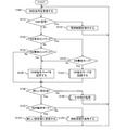
図1に、本発明の実施形態による照明制御システム1のブロック図を示す。照明制御システム1は、制御装置2、コントローラ3及び照明装置4−1〜4−nを備える。照明装置4−1〜4−nを総称して又はいずれか1つを代表して照明装置4という。各照明装置4は、LED電源装置5及び照明器具8を含み、ブロック図上は同一の構成を有するものとする。各LED電源装置5は、スレーブ回路6(スレーブ基板)及びLED電源回路7を、例えば1つの筐体内に含む。制御装置2とコントローラ3とはLAN通信線で接続され、コントローラ3と各照明装置4とは適宜の通信線で接続され、照明装置4−1〜4−nはデイジーチェーン接続される。あるいは、コントローラ3と各照明器具4とは無線接続されてもよい。照明器具8は、本実施形態では、LEDアレイを有するLED照明器具である。
Embodiment
FIG. 1 shows a block diagram of a lighting control system 1 according to an embodiment of the present invention. The lighting control system 1 includes a control device 2, a
制御装置2は、例えば、岩崎電気株式会社製のITACSなどであり、処理部21、記憶部22、ユーザI/F23及び入出力部24を備える。処理部21は、制御装置2の全体を統括制御するプロセッサなどで構成され、記憶部22はプログラム及びデータを記憶する。ユーザI/F23は、例えばタッチパネル上のグラフィカルユーザインターフェース(GUI)などである。入出力部24はLANポートなどであり、LANケーブルを介してコントローラ3(入出力部31)に接続される。制御装置2は、記憶部22に記憶された情報又はユーザI/F23から入力された情報に基づいて制御指令をコントローラ3に出力する。
The control device 2 is, for example, an ITACS manufactured by Iwasaki Electric Co., Ltd., and includes a
コントローラ3は、DMX512規格に対応した照明コントローラ(以下、「DMXコントローラ」という)又はRDM(Remote Device Management)規格に対応した照明コントローラ(以下、「RDMコントローラ」という)である。コントローラ3は、入出力部31、CPU32、メモリ35及び通信部36を備える。コントローラ3は、各照明装置4に対するマスタ装置として機能し、制御装置2から入力される制御指令に基づいて制御信号を各照明装置4に送信する。
The
コントローラ3がDMXコントローラの場合にはCPU32は信号生成部33を含み、コントローラ3がRDMコントローラの場合にはCPU32は信号生成部33及び応答処理部34を含む。これらの各部は、バスを介して相互に信号及びデータのやり取りが可能な態様で接続される。CPU32及びメモリ35は、1つのマイクロコンピュータに含まれ得る。CPU32は、そこに含まれる各部の機能とともに、通信部36の通信制御、信号生成部33及び応答処理部34の統括制御など、特に明記しない一般的なCPUとしての機能も実行可能であるものとする。メモリ35は、プログラム、ファイル及びデータを記憶するRAM、ROMなどの記憶部である。通信部36は、各照明装置4のスレーブ回路6(通信部61)に対するマスタ通信部として機能する。以下、特に断りがない限り、コントローラ3はRDMコントローラであるものとして各部の構成を説明する。
When the
信号生成部33は、制御装置2からの制御指令に基づいて制御信号を生成し、この制御信号を通信部36から照明装置4に送信する。この制御信号は、照明制御用のDMX512規格に準拠した信号(以下、「DMX信号」という)又は設定処理用のRDM規格に準拠した信号(以下、「RDM信号」又は「コマンド」という)である。すなわち、信号生成部33は、各照明装置4の点灯、消灯、調光などの照明制御を行う場合にはDMX信号を生成し、各照明装置4の設定処理を行う場合にはRDM信号を生成する。
The signal generation unit 33 generates a control signal based on the control command from the control device 2, and transmits the control signal from the
なお、DMX信号は一方向信号であるのに対し、RDM信号は双方向信号である。したがって、RDM信号の通信においては、コマンドがコントローラ3から照明装置4に送信され、このコマンドに対するレスポンスが照明装置4からコントローラ3に返信される(照明装置4からコントローラ3に自発的にレスポンスの信号を送信することはできない)。設定処理には、処理対象の照明装置4の設定値の設定又は変更(SET)、処理対象の照明装置4の設定値の取得(GET)、又は照明装置4−1〜4−n全体における検索(DISCOVERY)が含まれる。設定値については後述する。DMX信号を構成するDMXフレーム及びRDM信号を構成するRDMフレームは、所定フィールドの値の相違によって識別される。具体的には、両フレームに共通のASC(Alternative Start Code)フィールドのスタートコードの値がDMXフレームとRDMフレームとで異なり、これがスレーブ回路6において適宜識別される。
The DMX signal is a one-way signal, whereas the RDM signal is a two-way signal. Therefore, in the communication of the RDM signal, a command is transmitted from the
応答処理部34は、各照明装置4から通信部36を介して受信されたレスポンスを処理する。応答処理部34は、信号生成部33が生成したコマンドに対するレスポンスを、必要に応じて形式変換又は解析して制御装置2に出力する。これにより、制御装置2は、このレスポンスに基づいて、照明装置4の設定に関する情報をユーザI/F23に出力することができる。
The
スレーブ回路6は、スイッチ部60、通信部61、CPU62及び出力チャネル68を備える回路基板(スレーブ基板)である。CPU62は、照明制御部63、スイッチ有効/無効化部64、設定処理部65、応答生成部66及びメモリ67を含む。これらの各部は、バスを介して相互に信号及びデータのやり取りが可能な態様で接続される。CPU62は、1つのマイクロコンピュータとなり得る。CPU62は、そこに含まれる各部の機能とともに、通信部61の通信制御、照明制御部63、スイッチ有効/無効化部64、設定処理部65、応答生成部66及びメモリ67の統括制御など、特に明記しない一般的なCPUとしての機能も実行可能であるものとする。メモリ67は、プログラム、ファイル及びデータを記憶するRAM、ROMなどの記憶部であり、不揮発性メモリを含む。なお、メモリ67はCPU62の外部にあってもよく、この場合、CPU62及びメモリ67は1つのマイクロコンピュータに含まれ得る。
The slave circuit 6 is a circuit board (slave board) including the
通信部61は、マスタ通信部としての通信部36に対するスレーブ通信部として機能する。照明装置4−1〜4−(n−1)の通信部61はデイジーチェーン接続され、DMX信号又はRDM信号を受信すると、自機のスタートアドレスに対応するDATAフィールドを取り込むとともに、受信したDMX信号又はRDM信号を後続の照明装置4に送信する。
The
出力チャネル68は複数のチャネル(例えば、4チャネル)を含み、各チャネルに1台のLED電源回路7が接続されてもよいし、複数チャネルに1台のLED電源回路7が接続されてもよい。例えば、4チャネルに対応して、赤色(R)、緑色(G)、青色(B)及び白色(W)の4色のLEDが点灯制御されるようにしてもよい。本実施形態では、1チャネルのみが使用される例(すなわち、1台のスレーブ回路6に1台のLED電源回路7が接続される例)を示すが、使用されるチャネル数はこれに限定されない。また、1台のスレーブ回路6に設けられるチャネル数は、特に限定されない。出力チャネル68の各チャネルにはアドレスが設定される。すなわち、例えば、ある照明装置4で4個の出力チャネル68が使用され得る場合、その照明装置4は、そのスタートアドレス以降の4個のアドレスを使用することになる。
The
スイッチ部60は、ディップスイッチ、ロータリースイッチなどで構成される。例えば、ディップスイッチによって、所定の設定値の各々について1ビット(2値)〜3ビット(8値)程度の設定値を効率的に設定することができる。また、複数のロータリースイッチによって、より大きな数値を効率的に設定することができる。スイッチ部60によって選択又は指定される各値は、メモリ67に記憶される。以下に、種々の設定値について説明する。
The
(1)スイッチ優先モード/遠隔優先モードの選択
ディップスイッチによって、スイッチ優先モード又は遠隔優先モードが選択される。スイッチ優先モードは、ディップスイッチによって指定される設定値をRDM信号によって指定される設定値に優先するモードである(以下、「SW優先モード」ともいう)。遠隔優先モードは、RDM信号によって指定される設定値をディップスイッチによって指定される設定値に優先するモードである(以下、「RDM優先モード」ともいう)。例えば、1ビットのディップスイッチによって、「0」がRDM優先モード、「1」がSW優先モードに割り当てられる。なお、SW優先モード又はRDM優先モードのいずれが選択されている場合であっても、DMX信号の受信時の処理は同じである。
(1) Selection of switch priority mode / remote priority mode The dip switch selects the switch priority mode or the remote priority mode. The switch priority mode is a mode in which the setting value designated by the dip switch is prioritized over the setting value designated by the RDM signal (hereinafter also referred to as “SW priority mode”). The remote priority mode is a mode in which the setting value designated by the RDM signal is prioritized over the setting value designated by the dip switch (hereinafter also referred to as “RDM priority mode”). For example, "0" is assigned to the RDM priority mode and "1" is assigned to the SW priority mode by the 1-bit dip switch. The process at the time of receiving the DMX signal is the same regardless of whether the SW priority mode or the RDM priority mode is selected.
(2)スタートアドレスの指定
ロータリースイッチによって、スレーブ回路6のスタートアドレスが設定される。例えば、3個のロータリースイッチを、それぞれ百の位、十の位及び一の位の数値設定用に設けることによって、1ユニバース(512個のアドレス)に対応する数値をそれぞれ指定することができる。
(2) Designation of Start Address The start address of the slave circuit 6 is set by the rotary switch. For example, by providing three rotary switches for setting numerical values in the hundreds, tens and ones places, respectively, it is possible to respectively specify numerical values corresponding to one universe (512 addresses).
(3)DMX信号不受信時の照明制御の指定
照明装置4が給電される一方で、コントローラ3(及び制御装置2)が停電した場合又は通信障害が発生した場合など、照明装置4が照明制御可能な状態であるにもかかわらずDMX信号が受信されない状況が生じ得る。このようにDMX信号が中断又は停止して状態(途絶えた状態)に照明装置4が実行すべき照明制御を事前に決定しておくことが必要である。このようなDMX信号不受信時の照明制御として、例えば、2ビットのディップスイッチ(すなわち4値)によって、全光点灯、消灯、最終状態の維持(照明制御信号が途絶える直前の状態の再現)又はその他の制御(条件付きの制御、所定調光率での点灯など)が指定され得る。
(3) Specification of lighting control when DMX signal is not received While
(4)出力チャネル68の指定
ディップスイッチによって、出力チャネル68のいずれが使用されるのかが指定される。例えば、出力チャネル68としてチャネルCH1〜CH4が設けられている場合、2ビットのディップスイッチ(すなわち4値)によって、CH1の使用、CH1及びCH2の使用、CH1〜CH3の使用又は全CH1〜CH4の使用が指定され得る。
(4) Designation of
照明制御部63は、DMX信号が受信される場合に、DMX信号で指定される照明制御を出力チャネル68に接続されるLED電源回路7に実行させる。LED電源回路7は、この照明制御に従って照明器具8の点灯状態を制御する。例えば、照明制御においては、DMX信号のDATAフィールドの8ビットデータによって、256階調の調光が表現され得る。
When the DMX signal is received, the
スイッチ有効/無効化部64は、RDM信号にスイッチ有効化コマンド又はスイッチ無効化コマンドが含まれる場合に、スイッチ部60によるモード選択との関係で、SW優先モード又はRDM優先モードを決定し、決定されたモードをメモリ67に記憶する。
When the RDM signal includes a switch enable command or a switch disable command, switch enable / disable
具体的には、スイッチ有効/無効化部64は、
・RDM信号に「スイッチ有効化コマンド」が含まれ、かつスイッチ部60によって「SW優先モード「1」」が選択されている場合には、「SW優先モード」を決定及び記憶する(すなわち、スイッチ部60による選択を維持する)
・RDM信号に「スイッチ有効化コマンド」が含まれ、かつスイッチ部60によって「RDM優先モード「0」」が選択されている場合には、「RDM優先モード」を決定及び記憶する(すなわち、スイッチ部60による選択を維持する)
・RDM信号に「スイッチ無効化コマンド」が含まれ、かつスイッチ部60によって「SW優先モード「1」」が選択されている場合には、「RDM優先モード」を決定及び記憶する(すなわち、スイッチ部60による選択から変更する)
・RDM信号に「スイッチ無効化コマンド」が含まれ、かつスイッチ部60によって「RDM優先モード「0」」が選択されている場合には、「RDM優先モード」を決定及び記憶する(すなわち、スイッチ部60による選択を維持する)。
言い換えると、RDM信号に「スイッチ無効化コマンド」が含まれる場合には、スイッチ部60の選択にかかわらず(すなわち、「1」及び「0」の場合のいずれも)、「RDM優先モード」が決定及び記憶される。
Specifically, the switch enable / disable
· When the RDM signal includes a "switch activation command" and "SW priority mode" 1 "is selected by
· If the RDM signal includes a "switch activation command" and "RDM priority mode" 0 "is selected by
· When the RDM signal includes the "switch invalidation command" and the "SW priority mode" 1 "is selected by the
When the RDM signal includes the “switch invalidation command” and the “RDM priority mode“ 0 ”” is selected by the
In other words, when the RDM signal includes the “switch invalidation command”, the “RDM priority mode” is “regardless of the selection of the switch unit 60 (that is, both“ 1 ”and“ 0 ”). Determined and stored.
設定処理部65は、RDM信号(コマンド)が新たな設定値を含む場合で、かつRDM優先モードが記憶されている場合には、現設定値を新たな設定値に変更する。一方、設定処理部65は、RDM信号が新たな設定値を含む場合であっても、SW優先モードが記憶されている場合には、RDM信号に含まれる新たな設定値を無視し、現設定値を維持する。新たな設定値には、上述した(2)スタートアドレスの設定、(3)DMX信号不受信時の照明制御の指定、(4)使用する出力チャネルの指定を示す値が含まれ得る。
If the RDM signal (command) includes a new setting value, and the RDM priority mode is stored, the setting
また、RDM信号が、各設定値をスイッチ部60によって指定される設定値に戻すためのリセット用コマンドを含むようにしてもよい。具体的には、リセット用コマンドが受信されると、設定処理部65は、スイッチ部60によって指定される設定値(以下、「手動設定値」という)を読み出し、現設定値をこの手動設定値に変更する。このリセット用コマンドは、全ての手動設定値に関するものであってもよいし、一部の手動設定値に関するものであってもよい。
Further, the RDM signal may include a reset command for returning each setting value to the setting value designated by the
応答生成部66は、受信されたコマンドに対するレスポンスを生成し、通信部61からコントローラ3に送信する。レスポンスには、コマンドに対するアクノリッジメント、現設定値などが含まれ得る。上述したように、コントローラ3の応答処理部34が、このレスポンスを処理する。また、手動設定値の一部又は全部の取得を要求するためのスイッチ確認用コマンドが設けられてもよく、この場合には要求された手動設定値がレスポンスに含まれる。
The
LED電源回路7は、入力電源(不図示)から供給された電圧を照明器具8の点灯に適した電流(電流波形、電流値などが制御された電流)に変換し、その電流を照明器具8に供給する。入力電源が交流電源であり、照明器具8がLED照明器具である場合には、LED電源回路7は、交流電源を全波整流する整流回路、及び整流回路の出力電圧から直流定電流を生成してそれを照明器具8に出力するDC/DCコンバータを備える。これにより、LED電源回路7は、スレーブ回路6(出力チャネル68)から入力された信号に応じて照明器具8に電力を供給し、照明器具8を点灯制御する。
The LED power supply circuit 7 converts the voltage supplied from the input power supply (not shown) into a current suitable for lighting the lighting device 8 (a current waveform, a current whose current value is controlled, etc.), and the
図2に、スレーブ回路6における照明制御及び設定処理の処理に関するフローチャートを示す。フローチャートの開始以前に、スイッチ部60による各手動設定値がメモリ67に記憶されているものとする。そして、ステップS100において、通信部61が、コントローラ3からの制御信号を受信する。
FIG. 2 shows a flowchart regarding processing of illumination control and setting processing in the slave circuit 6. It is assumed that each manual setting value by the
ステップS110において、照明制御部63が、制御信号がDMX信号か否かを判定する。制御信号がDMX信号の場合(ステップS110、Yes)、ステップS112において、照明制御部63は、DMX信号で指定される照明制御をLED電源回路7に実行させる。その後、処理はステップS100に戻る。一方、制御信号がDMX信号でない場合、すなわち、制御信号がRDM信号の場合(ステップS110、No)、処理はステップS120に進む。
In step S110, the
ステップS120において、スイッチ有効/無効化部64が、RDM信号がスイッチ有効化コマンドを含むか否かを判定する。RDM信号がスイッチ有効化コマンドを含む場合(ステップS120、Yes)、処理はステップS124に進む。
ステップS124において、スイッチ有効/無効化部64は、スイッチ部60によってSW優先モードが選択されているか否かを判定する。SW優先モードが選択されている場合(ステップS124、Yes)、ステップS126において、スイッチ有効/無効化部64はSW優先モードを維持する。一方、SW優先モードが選択されていない場合、すなわち、RDM優先モードが選択されている場合(ステップS124、No)、ステップS128において、スイッチ有効/無効化部64はRDM優先モードを維持する。
In step S120, the switch enabling / disabling
In step S124, switch validation /
一方、ステップS120において、RDM信号がスイッチ有効化コマンドを含まない場合(ステップS120、No)、処理はステップS122に進む。
ステップS122において、スイッチ有効/無効化部64は、RDM信号がスイッチ無効化コマンドを含むか否かを判定する。RDM信号がスイッチ無効化コマンドを含む場合(ステップS120、Yes)、処理はステップS128に進む。一方、RDM信号がスイッチ無効化コマンドを含まない場合(ステップS120、No)、処理はステップS130に進む。
ステップS128において、スイッチ有効/無効化部64は、スイッチ部60によってSW優先モードが選択されているか、RDM優先モードが選択されているかにかかわらず、RDM優先モードを決定し、それをメモリ67に記憶する。ステップS126又はS128の後、処理はステップS130に進む。
On the other hand, when the RDM signal does not include the switch activation command in step S120 (step S120, No), the process proceeds to step S122.
In step S122, the switch enable / disable
In step S128, the switch enabling / disabling
ステップS130において、設定処理部65は、RDM信号が、新たな設定値を含むか否かを判定する。RDM信号が新たな設定値を含む場合(ステップS130、Yes)、処理はステップS132に進む。一方、RDM信号が新たな設定値を含まない場合(ステップS130、No)、ステップS140において、設定処理部65(及び応答生成部66)は、その他の処理、すなわち、設定値取得若しくは各種検索又はリセットなどの適宜の処理を実行する。その後、処理はステップS100に戻る。
In step S130, the setting
ステップS132において、設定処理部65は、RDM優先モードが記憶されているか否かを判定する。RDM優先モードが記憶されている場合(ステップS132、Yes)、ステップS134において、設定処理部65は、現設定値を新たな設定値に更新する。RDM優先モードが記憶されていない場合、すなわち、SW優先モードが記憶されている場合(ステップS132、No)、ステップS136において、設定処理部65は、現設定値を維持する。ステップS134又はS136の後、処理はステップS100に戻る。
In step S132, the setting
以上のように、本実施形態によるスレーブ回路6は、SW優先モード又はRDM優先モードの手動選択及び照明制御システム1に関する設定値の手動指定が可能なスイッチ部60と、コントローラ3からのDMX信号又はRDM信号を設定値に基づいて受信可能な通信部61と、DMX信号に基づいてLED電源回路7に照明制御を実行させる照明制御部63と、RDM信号が新たな設定値を含む場合において、SW優先モードが選択されている場合には新たな設定値を処理せず、RDM優先モードが選択されている場合には現在の設定値を新たな設定値に変更する設定処理部65とを備える。
As described above, in the slave circuit 6 according to the present embodiment, the
このように、スイッチ部60によってSW優先モード又はRDM優先モードの手動選択及び設定値の手動指定が可能であり、RDM信号が新たな設定値を含む場合において、設定処理部65は、SW優先モードが選択されている場合には新たな設定値を処理せず、RDM優先モードが選択されている場合には現在の設定値を新たな設定値に変更する。したがって、照明制御専用のDMXコントローラ又は照明制御及び設定処理可能なRDMコントローラのどちらに接続される場合でも、照明制御に関する各種設定を好適に行うことができるスレーブ回路6が実現される。
As described above, when the
さらに、スレーブ回路6は、スイッチ部60による選択及び指定の内容を記憶するメモリ67と、RDM信号がスイッチ有効化コマンドを含む場合でかつスイッチ部60によってSW優先モードが選択されている場合にはSW優先モードを維持してメモリ67に記憶し、RDM信号がスイッチ有効化コマンドを含む場合でかつスイッチ部60によってRDM優先モードが選択されている場合にはRDM優先モードを維持してメモリ67に記憶し、RDM信号がスイッチ無効化コマンドを含む場合にはスイッチ部60による選択にかかわらずRDM優先モードを決定してメモリ67に記憶するスイッチ有効/無効化部64とを備え、RDM信号が新たな設定値を含む場合において、設定処理部65は、SW優先モードが記憶されている場合には新たな設定値を処理せず、RDM優先モードが記憶されている場合には現在の設定値を新たな設定値に変更するように構成される。
Furthermore, the slave circuit 6 stores the contents of selection and designation by the
このように、このように、コントローラ3からの設定処理信号によってSW優先モード又はRDM優先モードを切り替えることができ、遠隔設定処理と手動設定処理の選択が、簡便かつ適切な態様で実行可能となる。
Thus, in this manner, the SW priority mode or the RDM priority mode can be switched by the setting processing signal from the
上記構成は、例えば次のような場合に、特に有用となる。例えば、スイッチ部60によってSW優先モードが選択された状態でLED電源装置5(又は照明装置4)が出荷又は設置された場合を想定する。仮にスイッチ無効化が行われないとすると、SW優先モードの適用が維持されてしまい、RDM信号による設定値の変更を行うことができない(上述したような、高所でLED電源装置5の筐体の蓋を開けてスイッチ部60を操作する作業が必要となる)。しかし、上記のようにスイッチ無効化コマンドを用いることによってRDM優先モードの適用が可能となり、RDM信号による設定値の変更が可能となる。
The above configuration is particularly useful, for example, in the following cases. For example, it is assumed that the LED power supply device 5 (or the lighting device 4) is shipped or installed in a state where the SW priority mode is selected by the
また、例えば、コントローラ3が当初はDMXコントローラで構成され(すなわち、SW優先モードの下でスイッチ部60による手動設定が行われ)、その後にDMXコントローラがRDMコントローラに置き換えられる場合を想定する。この場合、置き換え後にコントローラ3(RDMコントローラ)からスイッチ無効化コマンドを各スレーブ回路6に送信することによって、その後のRDM信号を用いた設定変更が可能となり、問題なくRDM信号の機能が使用可能となる。
Also, for example, it is assumed that the
また逆に、コントローラ3をRDMコントローラからDMXコントローラに置き換える場合を想定する。この場合、上記のようにスイッチ有効化コマンドが処理されることによってSW優先モードの適用が可能となり、スイッチ部60を用いた設定値の手動設定が再度可能となる。
Conversely, it is assumed that the
ここで、上記設定値は、DMX信号及びRDM信号を受信するためのアドレスを示すものであってもよい。これにより、コントローラ3に対する複数のスレーブ回路6の接続構成の変更に伴うアドレス変更への対応が容易化される。
Here, the setting value may indicate an address for receiving the DMX signal and the RDM signal. Thereby, the response to the address change accompanying the change of the connection configuration of the plurality of slave circuits 6 to the
また、設定値は、DMX信号の受信が停止した場合に実行される照明制御の指定を示すものであってもよい。これにより、コントローラ3の停電時などにおける照明制御信号不受信時の照明制御の指定をスレーブ回路6の設置前及び設置後に柔軟に行うことが可能となる。
Further, the setting value may indicate designation of illumination control to be performed when reception of the DMX signal is stopped. As a result, it becomes possible to flexibly specify the illumination control when the illumination control signal is not received at the time of a power failure or the like of the
また、LED電源回路7が接続される複数の出力チャネル68が設けられ、設定値は、複数の出力チャネル68のうちの使用される出力チャネル68の指定を示すものであってもよい。これにより、スレーブ回路6に対するLED電源回路7の接続構成の変更への対応が容易化される。
Further, a plurality of
また、設定処理部65は、RDM信号に含まれるリセット用コマンドに応じて現設定値の一部又は全部を手動設定値にリセットするように構成されてもよい。これにより、スレーブ回路6の使用終了時に、スイッチ部60が示す設定値に実際の設定値を一致させ、スレーブ回路6の再使用時のスムーズな取扱いが可能となる。例えば、その後のDMXコントローラとの使用、又はLED電源装置5を回収してからのスタンドアロンでの使用へのスムーズな移行が可能となる。
In addition, the setting
さらに、RDM信号(コマンド)に対する応答信号(レスポンス)を通信部61からコントローラ3に送信させる応答生成部66がさらに設けられ、RDM信号がスイッチ確認用コマンドを含む場合に、応答生成部66が、現在の自機アドレスと、手動設定値の一部又は全部とを対応付けた応答信号を生成するように構成されてもよい。これにより、スレーブ回路6の設定変更後又はコントローラ3に対する複数のスレーブ回路6の接続構成の変更後も、コントローラ3側から各設定値を確認することができる。特に、設定値がアドレスの場合には、各スレーブ回路6の接続位置などを追跡することができ、その管理性が向上する。
Furthermore, a
<変形例>
以上に本発明の好適な実施形態を示したが、本発明は、例えば以下に示すように種々の態様に変形可能である。
<Modification>
Although the preferred embodiments of the present invention have been described above, the present invention can be modified in various aspects, for example, as described below.
(1)信号規格に関する変形
上記実施形態では、DMX512規格及びRDM規格に準拠した通信による照明制御及び設定処理を説明した。一方、現存する又は将来開発され得る他の通信規格が用いられる場合においても、照明制御専用の規格と照明制御及び設定処理可能な規格とが併存し得る状況下で、本発明のスレーブ回路6、LED電源装置5又は照明制御システム1が適用可能となる。
(1) Modification Regarding Signal Standard In the above embodiment, the lighting control and setting process by communication conforming to the DMX 512 standard and the RDM standard has been described. On the other hand, even when other communication standards that are existing or may be developed in the future, the slave circuit 6 of the present invention may be used under the situation where the standard dedicated to lighting control and the standard capable of lighting control and setting processing can coexist. The
(2)スイッチ部60に関する変形
上記実施形態では、スイッチ部60としてディップスイッチ及びロータリースイッチの組合せを例示したが、スイッチ部60は、ディップスイッチのみ又はロータリースイッチのみであってもよい。また、スイッチ部60として、トグルスイッチ、スライドスイッチなどの他の形態のスイッチ、又は上述したスイッチの組合せが適宜採用され得る。
(2) Modification Regarding
(3)照明器具8の光源に関する変形
上記実施形態では、LEDを光源とする照明器具8を説明したが、照明器具8の光源は、放電灯、ハロゲンランプなど、他の種類の光源であってもよい。この場合、LED電源回路7及びLED電源装置5の代わりに、その光源に適合した照明用電源回路及び照明用電源装置が適宜採用される。
(3) Modification Regarding Light Source of
1 照明制御システム
2 制御装置
3 コントローラ
4、4−1〜4−n 照明装置
5 LED電源装置(照明用電源装置)
6 スレーブ回路
7 LED電源回路(照明用電源回路)
8 照明器具
60 スイッチ部
61 通信部
62 CPU
63 照明制御部
64 スイッチ有効/無効化部
65 設定処理部
66 応答生成部
67 メモリ
68 出力チャネル
DESCRIPTION OF SYMBOLS 1 Lighting control system 2
6 slave circuit 7 LED power circuit (lighting power circuit)
8
63
Claims (10)
スイッチ優先モード又は遠隔優先モードの手動選択及び前記照明制御システムに関する前記設定値の手動指定が可能なスイッチ部と、
前記コントローラからの照明制御信号又は設定処理信号を前記設定値に基づいて受信可能な通信部と、
前記照明制御信号に基づいて前記照明用電源回路に照明制御を実行させる照明制御部と、
前記設定処理信号が新たな設定値を含む場合において、前記スイッチ優先モードが選択されている場合には前記新たな設定値を処理せず、前記遠隔優先モードが選択されている場合には現在の前記設定値を前記新たな設定値に変更する設定処理部と
を備えたスレーブ回路。 A slave circuit for the controller in the lighting control system,
A switch unit capable of manually selecting a switch priority mode or a remote priority mode and manually specifying the setting value of the lighting control system;
A communication unit capable of receiving an illumination control signal or setting processing signal from the controller based on the setting value;
An illumination control unit that causes the illumination power circuit to execute illumination control based on the illumination control signal;
When the setting processing signal includes a new setting value, the new setting value is not processed when the switch priority mode is selected, and the current setting when the remote priority mode is selected. And a setting processing unit configured to change the setting value to the new setting value.
前記設定処理信号がスイッチ有効化コマンドを含む場合でかつ前記スイッチ部によってスイッチ優先モードが選択されている場合には前記スイッチ優先モードを維持して前記メモリに記憶し、前記設定処理信号が前記スイッチ有効化コマンドを含む場合でかつ前記スイッチ部によって遠隔優先モードが選択されている場合には前記遠隔優先モードを維持して前記メモリに記憶し、前記設定処理信号がスイッチ無効化コマンドを含む場合には前記スイッチ部による選択にかかわらず前記遠隔優先モードを決定して前記メモリに記憶するスイッチ有効/無効化部と
をさらに備え、
前記設定処理信号が新たな設定値を含む場合において、前記設定処理部が、前記スイッチ優先モードが記憶されている場合には前記新たな設定値を処理せず、前記遠隔優先モードが記憶されている場合には現在の前記設定値を前記新たな設定値に変更するように構成された、請求項1に記載のスレーブ回路。 A memory for storing contents of selection and designation by the switch unit;
When the setting processing signal includes a switch activation command and the switch priority mode is selected by the switch unit, the switch priority mode is maintained and stored in the memory, and the setting processing signal is the switch. When the remote priority mode is selected by the switch unit when the activation command is included, the remote priority mode is maintained and stored in the memory, and the setting processing signal includes the switch invalidation command. And the switch enable / disable unit which determines the remote priority mode and stores it in the memory regardless of the selection made by the switch unit.
When the setting processing signal includes a new setting value, the setting processing unit does not process the new setting value when the switch priority mode is stored, and the remote priority mode is stored. The slave circuit according to claim 1, configured to change the current setting value to the new setting value, if any.
前記設定処理信号が所定のコマンドを含む場合に、前記応答生成部が、現在の自機アドレスと前記スイッチ部によって指定される設定値の一部又は全部とを対応付けた応答信号を生成するように構成された、請求項1から7のいずれか一項に記載のスレーブ回路。 It further comprises a response generation unit that causes the communication unit to transmit a response signal to the setting processing signal to the controller,
When the setting processing signal includes a predetermined command, the response generation unit generates a response signal in which the current own machine address is associated with a part or all of the setting value designated by the switch unit. The slave circuit according to any one of claims 1 to 7, configured in
A lighting control system comprising: the lighting power supply device according to claim 9; and the controller capable of outputting the lighting control signal and the setting processing signal.
Priority Applications (1)
| Application Number | Priority Date | Filing Date | Title |
|---|---|---|---|
| JP2017235873A JP6977523B2 (en) | 2017-12-08 | 2017-12-08 | Slave circuit, power supply for lighting and lighting control system |
Applications Claiming Priority (1)
| Application Number | Priority Date | Filing Date | Title |
|---|---|---|---|
| JP2017235873A JP6977523B2 (en) | 2017-12-08 | 2017-12-08 | Slave circuit, power supply for lighting and lighting control system |
Publications (2)
| Publication Number | Publication Date |
|---|---|
| JP2019102403A true JP2019102403A (en) | 2019-06-24 |
| JP6977523B2 JP6977523B2 (en) | 2021-12-08 |
Family
ID=66974033
Family Applications (1)
| Application Number | Title | Priority Date | Filing Date |
|---|---|---|---|
| JP2017235873A Active JP6977523B2 (en) | 2017-12-08 | 2017-12-08 | Slave circuit, power supply for lighting and lighting control system |
Country Status (1)
| Country | Link |
|---|---|
| JP (1) | JP6977523B2 (en) |
Cited By (2)
| Publication number | Priority date | Publication date | Assignee | Title |
|---|---|---|---|---|
| JP2022116516A (en) * | 2021-01-29 | 2022-08-10 | 岩崎電気株式会社 | Communication control system and lighting control system |
| JP2022140199A (en) * | 2021-03-12 | 2022-09-26 | 株式会社遠藤照明 | Lighting apparatus |
Citations (3)
| Publication number | Priority date | Publication date | Assignee | Title |
|---|---|---|---|---|
| JP2000286076A (en) * | 1999-03-31 | 2000-10-13 | Toshiba Lighting & Technology Corp | Lighting control system |
| US20140184097A1 (en) * | 2012-12-28 | 2014-07-03 | John F. Luk | Economical power and data track lighting system |
| JP2017527073A (en) * | 2014-07-28 | 2017-09-14 | フィリップス ライティング ホールディング ビー ヴィ | Lighting control and status inquiry |
-
2017
- 2017-12-08 JP JP2017235873A patent/JP6977523B2/en active Active
Patent Citations (3)
| Publication number | Priority date | Publication date | Assignee | Title |
|---|---|---|---|---|
| JP2000286076A (en) * | 1999-03-31 | 2000-10-13 | Toshiba Lighting & Technology Corp | Lighting control system |
| US20140184097A1 (en) * | 2012-12-28 | 2014-07-03 | John F. Luk | Economical power and data track lighting system |
| JP2017527073A (en) * | 2014-07-28 | 2017-09-14 | フィリップス ライティング ホールディング ビー ヴィ | Lighting control and status inquiry |
Cited By (4)
| Publication number | Priority date | Publication date | Assignee | Title |
|---|---|---|---|---|
| JP2022116516A (en) * | 2021-01-29 | 2022-08-10 | 岩崎電気株式会社 | Communication control system and lighting control system |
| JP7552387B2 (en) | 2021-01-29 | 2024-09-18 | 岩崎電気株式会社 | Communication control system and lighting control system |
| JP2022140199A (en) * | 2021-03-12 | 2022-09-26 | 株式会社遠藤照明 | Lighting apparatus |
| JP7472077B2 (en) | 2021-03-12 | 2024-04-22 | 株式会社遠藤照明 | lighting equipment |
Also Published As
| Publication number | Publication date |
|---|---|
| JP6977523B2 (en) | 2021-12-08 |
Similar Documents
| Publication | Publication Date | Title |
|---|---|---|
| EP2490509A2 (en) | Apparatus and method for controlling lighting based on DALI communication | |
| US9072134B2 (en) | Configurable lighting devices under broadcast control | |
| US10129945B2 (en) | Modular light control system | |
| US20070018783A1 (en) | Digital addressable lighting interface translation method | |
| CN104110620A (en) | Lighting device, lighting system and control method | |
| US20110280251A1 (en) | Apparatus having a fixture with an integrated gateway and methods thereof | |
| JP2019102403A (en) | Slave circuit, power supply device for illumination and illumination control system | |
| JP2017224406A (en) | Lighting control device and lighting control system | |
| JP6787218B2 (en) | Lighting controller and lighting system | |
| JP6901289B2 (en) | Lighting control device and lighting system | |
| KR20120095154A (en) | Light control device and method | |
| JP6691755B2 (en) | Communication system, communication method, lighting control system, lighting control method, and program | |
| JP6058551B2 (en) | Address initialization of lighting device unit | |
| JP6536995B2 (en) | Lighting control system, lighting control method, and lighting control device | |
| JP6467705B2 (en) | Address determining method, lighting control system, control device, and operation device | |
| JP7349663B2 (en) | Communication systems and communication system controllers | |
| JP2019216046A (en) | Illumination system | |
| WO2016043150A1 (en) | Lighting control system, communication system, lighting control method, communication method, and program | |
| JP5505017B2 (en) | Lighting control system | |
| JP7762869B2 (en) | Lighting control system, dimmer panel, lighting control method, and program | |
| JP7491167B2 (en) | Controls and lighting systems | |
| JP6751896B2 (en) | Device control method | |
| JP2021158055A (en) | Lighting control system, lighting control method, and program | |
| JP2019212558A (en) | Load control system | |
| JP6555047B2 (en) | lighting equipment |
Legal Events
| Date | Code | Title | Description |
|---|---|---|---|
| A621 | Written request for application examination |
Free format text: JAPANESE INTERMEDIATE CODE: A621 Effective date: 20201112 |
|
| A977 | Report on retrieval |
Free format text: JAPANESE INTERMEDIATE CODE: A971007 Effective date: 20210818 |
|
| A131 | Notification of reasons for refusal |
Free format text: JAPANESE INTERMEDIATE CODE: A131 Effective date: 20210824 |
|
| A521 | Request for written amendment filed |
Free format text: JAPANESE INTERMEDIATE CODE: A523 Effective date: 20210907 |
|
| TRDD | Decision of grant or rejection written | ||
| A01 | Written decision to grant a patent or to grant a registration (utility model) |
Free format text: JAPANESE INTERMEDIATE CODE: A01 Effective date: 20211012 |
|
| A61 | First payment of annual fees (during grant procedure) |
Free format text: JAPANESE INTERMEDIATE CODE: A61 Effective date: 20211025 |
|
| R150 | Certificate of patent or registration of utility model |
Ref document number: 6977523 Country of ref document: JP Free format text: JAPANESE INTERMEDIATE CODE: R150 |
|
| S111 | Request for change of ownership or part of ownership |
Free format text: JAPANESE INTERMEDIATE CODE: R313111 |
|
| R350 | Written notification of registration of transfer |
Free format text: JAPANESE INTERMEDIATE CODE: R350 |