JP2019101192A - Image display device - Google Patents
Image display device Download PDFInfo
- Publication number
- JP2019101192A JP2019101192A JP2017231011A JP2017231011A JP2019101192A JP 2019101192 A JP2019101192 A JP 2019101192A JP 2017231011 A JP2017231011 A JP 2017231011A JP 2017231011 A JP2017231011 A JP 2017231011A JP 2019101192 A JP2019101192 A JP 2019101192A
- Authority
- JP
- Japan
- Prior art keywords
- image
- unit
- memory
- frame
- frequency
- Prior art date
- Legal status (The legal status is an assumption and is not a legal conclusion. Google has not performed a legal analysis and makes no representation as to the accuracy of the status listed.)
- Pending
Links
- 230000015654 memory Effects 0.000 claims abstract description 266
- 238000012545 processing Methods 0.000 claims abstract description 74
- 239000000872 buffer Substances 0.000 claims description 29
- 238000005520 cutting process Methods 0.000 claims description 22
- 230000008859 change Effects 0.000 claims description 10
- 238000012937 correction Methods 0.000 claims description 2
- 238000012986 modification Methods 0.000 description 63
- 230000004048 modification Effects 0.000 description 63
- 238000010586 diagram Methods 0.000 description 32
- 238000000034 method Methods 0.000 description 19
- 230000006870 function Effects 0.000 description 18
- 230000000694 effects Effects 0.000 description 9
- 230000003111 delayed effect Effects 0.000 description 7
- 230000001133 acceleration Effects 0.000 description 6
- 238000005516 engineering process Methods 0.000 description 6
- 238000012549 training Methods 0.000 description 6
- 230000015572 biosynthetic process Effects 0.000 description 4
- 230000008569 process Effects 0.000 description 4
- 238000003786 synthesis reaction Methods 0.000 description 4
- 230000007704 transition Effects 0.000 description 3
- 238000002834 transmittance Methods 0.000 description 3
- 238000007792 addition Methods 0.000 description 2
- 238000013459 approach Methods 0.000 description 2
- 238000006243 chemical reaction Methods 0.000 description 2
- 238000004891 communication Methods 0.000 description 2
- 238000000605 extraction Methods 0.000 description 2
- 230000004044 response Effects 0.000 description 2
- 230000002411 adverse Effects 0.000 description 1
- 230000008901 benefit Effects 0.000 description 1
- 239000002131 composite material Substances 0.000 description 1
- 239000000470 constituent Substances 0.000 description 1
- 238000013461 design Methods 0.000 description 1
- 230000005057 finger movement Effects 0.000 description 1
- 230000007246 mechanism Effects 0.000 description 1
- 238000011160 research Methods 0.000 description 1
- 238000012546 transfer Methods 0.000 description 1
Images


Classifications
-
- G—PHYSICS
- G06—COMPUTING; CALCULATING OR COUNTING
- G06T—IMAGE DATA PROCESSING OR GENERATION, IN GENERAL
- G06T1/00—General purpose image data processing
- G06T1/60—Memory management
-
- G06T5/80—
-
- G—PHYSICS
- G09—EDUCATION; CRYPTOGRAPHY; DISPLAY; ADVERTISING; SEALS
- G09G—ARRANGEMENTS OR CIRCUITS FOR CONTROL OF INDICATING DEVICES USING STATIC MEANS TO PRESENT VARIABLE INFORMATION
- G09G5/00—Control arrangements or circuits for visual indicators common to cathode-ray tube indicators and other visual indicators
- G09G5/36—Control arrangements or circuits for visual indicators common to cathode-ray tube indicators and other visual indicators characterised by the display of a graphic pattern, e.g. using an all-points-addressable [APA] memory
- G09G5/37—Details of the operation on graphic patterns
-
- G—PHYSICS
- G09—EDUCATION; CRYPTOGRAPHY; DISPLAY; ADVERTISING; SEALS
- G09G—ARRANGEMENTS OR CIRCUITS FOR CONTROL OF INDICATING DEVICES USING STATIC MEANS TO PRESENT VARIABLE INFORMATION
- G09G5/00—Control arrangements or circuits for visual indicators common to cathode-ray tube indicators and other visual indicators
- G09G5/36—Control arrangements or circuits for visual indicators common to cathode-ray tube indicators and other visual indicators characterised by the display of a graphic pattern, e.g. using an all-points-addressable [APA] memory
- G09G5/39—Control of the bit-mapped memory
- G09G5/395—Arrangements specially adapted for transferring the contents of the bit-mapped memory to the screen
- G09G5/397—Arrangements specially adapted for transferring the contents of two or more bit-mapped memories to the screen simultaneously, e.g. for mixing or overlay
-
- G—PHYSICS
- G09—EDUCATION; CRYPTOGRAPHY; DISPLAY; ADVERTISING; SEALS
- G09G—ARRANGEMENTS OR CIRCUITS FOR CONTROL OF INDICATING DEVICES USING STATIC MEANS TO PRESENT VARIABLE INFORMATION
- G09G2310/00—Command of the display device
- G09G2310/04—Partial updating of the display screen
-
- G—PHYSICS
- G09—EDUCATION; CRYPTOGRAPHY; DISPLAY; ADVERTISING; SEALS
- G09G—ARRANGEMENTS OR CIRCUITS FOR CONTROL OF INDICATING DEVICES USING STATIC MEANS TO PRESENT VARIABLE INFORMATION
- G09G2340/00—Aspects of display data processing
- G09G2340/12—Overlay of images, i.e. displayed pixel being the result of switching between the corresponding input pixels
- G09G2340/125—Overlay of images, i.e. displayed pixel being the result of switching between the corresponding input pixels wherein one of the images is motion video
-
- G—PHYSICS
- G09—EDUCATION; CRYPTOGRAPHY; DISPLAY; ADVERTISING; SEALS
- G09G—ARRANGEMENTS OR CIRCUITS FOR CONTROL OF INDICATING DEVICES USING STATIC MEANS TO PRESENT VARIABLE INFORMATION
- G09G2354/00—Aspects of interface with display user
-
- G—PHYSICS
- G09—EDUCATION; CRYPTOGRAPHY; DISPLAY; ADVERTISING; SEALS
- G09G—ARRANGEMENTS OR CIRCUITS FOR CONTROL OF INDICATING DEVICES USING STATIC MEANS TO PRESENT VARIABLE INFORMATION
- G09G2360/00—Aspects of the architecture of display systems
- G09G2360/12—Frame memory handling
- G09G2360/127—Updating a frame memory using a transfer of data from a source area to a destination area
-
- G—PHYSICS
- G09—EDUCATION; CRYPTOGRAPHY; DISPLAY; ADVERTISING; SEALS
- G09G—ARRANGEMENTS OR CIRCUITS FOR CONTROL OF INDICATING DEVICES USING STATIC MEANS TO PRESENT VARIABLE INFORMATION
- G09G2360/00—Aspects of the architecture of display systems
- G09G2360/18—Use of a frame buffer in a display terminal, inclusive of the display panel
-
- G—PHYSICS
- G09—EDUCATION; CRYPTOGRAPHY; DISPLAY; ADVERTISING; SEALS
- G09G—ARRANGEMENTS OR CIRCUITS FOR CONTROL OF INDICATING DEVICES USING STATIC MEANS TO PRESENT VARIABLE INFORMATION
- G09G2380/00—Specific applications
- G09G2380/10—Automotive applications
-
- G—PHYSICS
- G09—EDUCATION; CRYPTOGRAPHY; DISPLAY; ADVERTISING; SEALS
- G09G—ARRANGEMENTS OR CIRCUITS FOR CONTROL OF INDICATING DEVICES USING STATIC MEANS TO PRESENT VARIABLE INFORMATION
- G09G2380/00—Specific applications
- G09G2380/12—Avionics applications
-
- G—PHYSICS
- G09—EDUCATION; CRYPTOGRAPHY; DISPLAY; ADVERTISING; SEALS
- G09G—ARRANGEMENTS OR CIRCUITS FOR CONTROL OF INDICATING DEVICES USING STATIC MEANS TO PRESENT VARIABLE INFORMATION
- G09G5/00—Control arrangements or circuits for visual indicators common to cathode-ray tube indicators and other visual indicators
- G09G5/36—Control arrangements or circuits for visual indicators common to cathode-ray tube indicators and other visual indicators characterised by the display of a graphic pattern, e.g. using an all-points-addressable [APA] memory
- G09G5/39—Control of the bit-mapped memory
- G09G5/399—Control of the bit-mapped memory using two or more bit-mapped memories, the operations of which are switched in time, e.g. ping-pong buffers
Landscapes
- Engineering & Computer Science (AREA)
- Physics & Mathematics (AREA)
- General Physics & Mathematics (AREA)
- Theoretical Computer Science (AREA)
- Computer Hardware Design (AREA)
- Controls And Circuits For Display Device (AREA)
- Geometry (AREA)
- Image Processing (AREA)
- Transforming Electric Information Into Light Information (AREA)
Abstract
Description
本開示は、プロジェクタ等の画像表示装置に関する。 The present disclosure relates to an image display device such as a projector.
パノラマ映像を生成、更新しながら、コントローラの操作に従ってパノラマ映像から一部の領域を切り出し、画像表示装置に表示する手法がある。(例えば、特許文献1参照)。この手法では、シミュレータなどの用途で、自動車のウィンドシールドを通して見える風景、飛行機のコックピットの窓を通してから見える風景などが、パノラマ映像に対する切出画像として切り出される。この手法によれば、コントローラの操作により画像の切出領域が変化し、進行方向が変わったように体感させる。 While generating and updating a panoramic video, there is a method of cutting out a partial area from the panoramic video according to the operation of the controller and displaying it on the image display device. (See, for example, Patent Document 1). In this method, a scene viewed through a windshield of a car, a scene viewed through a window of an airplane cockpit, and the like are cut out as cut-out images for a panoramic image in applications such as a simulator. According to this method, the cutout area of the image is changed by the operation of the controller, and the user feels as if the traveling direction is changed.
本開示は、画像処理を高速化し、画像を滑らかに表示する画像表示装置を提供する。 The present disclosure provides an image display device that accelerates image processing and smoothly displays an image.
本開示の画像表装置は、画像信号源からの画像信号が入力される画像入力部と、メモリと、前記画像入力部に入力された画像信号を前記メモリに第1の周波数で書き込む動作をする書込部と、前記第1の周波数よりも高い第2の周波数で、前記メモリに書き込まれた画像信号を読み出す読出部と、前記読出部で読み出された画像信号を表示部に出力する画像出力部と、表示部に出力する画像を補間する画像補間部と、を備える。 An image display apparatus according to the present disclosure operates to write an image input unit to which an image signal from an image signal source is input, a memory, and an image signal input to the image input unit to the memory at a first frequency. A writing unit, a reading unit that reads the image signal written to the memory at a second frequency higher than the first frequency, and an image that outputs the image signal read by the reading unit to a display unit An output unit and an image interpolation unit that interpolates an image to be output to the display unit.
本開示における画像表示装置によれば、画像処理を高速化し、画像を滑らかに表示する。 According to the image display device in the present disclosure, the image processing can be speeded up and the image can be displayed smoothly.
以下、適宜図面を参照しながら、実施の形態を詳細に説明する。但し、必要以上に詳細な説明は省略する場合がある。例えば、既によく知られた事項の詳細説明や実質的に同一の構成に対する重複説明を省略する場合がある。これは、以下の説明が不必要に冗長になるのを避け、当業者の理解を容易にするためである。
なお、発明者(ら)は、当業者が本開示を十分に理解するために添付図面および以下の説明を提供するのであって、これらによって特許請求の範囲に記載の主題を限定することを意図するものではない。
Hereinafter, embodiments will be described in detail with reference to the drawings as appropriate. However, the detailed description may be omitted if necessary. For example, detailed description of already well-known matters and redundant description of substantially the same configuration may be omitted. This is to avoid unnecessary redundancy in the following description and to facilitate understanding by those skilled in the art.
The inventor (s) provide the accompanying drawings and the following description so that those skilled in the art can fully understand the present disclosure, and intend to limit the subject matter described in the claims by these. It is not something to do.
(実施の形態1)
1.構成
1.1 全体の構成
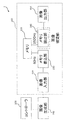
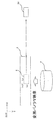
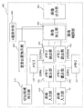
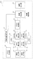
本開示の画像表示装置について図1および図2を用いて説明する。図1は、実施の形態1に係る画像表示システムを示すブロック図である。図2は、実施の形態1に係る画像の書き込み動作と読み取り動作を説明するための図である。
1. Configuration 1.1 Overall Configuration The image display device of the present disclosure will be described using FIGS. 1 and 2. FIG. 1 is a block diagram showing an image display system according to the first embodiment. FIG. 2 is a diagram for explaining an image writing operation and an image reading operation according to the first embodiment.
図1に示すように、本実施の形態における画像表示システム1は、コントローラ100と、画像生成部200と、画像表示装置300とを備える。コントローラ100は、図示を省略するスクリーン等の画像表示部に表示される画像の視点を移動させる等の指示を行うための操作部である。
As shown in FIG. 1, the
画像生成部200は、画像信号源としての一例であり、画像として、所定のフレームレートの動画を生成し、画像信号として出力する機能を有している。本実施の形態では、一例として、画像生成部200は60fpsの動画を生成する。画像生成部200により生成される動画は、撮影動画を編集・加工したものであってもよいし、CG(Computer Graphics)であってもよい。本実施の形態では、一例として、パーソナルコンピュータにより画像生成部200を構成している。画像生成部200は、コントローラ100の操作量に応じて視点を移動させた動画を生成する。
The
画像表示装置300は、画像入力部310、メモリ320、メモリ書込部330、メモリ読出部340、および画像出力部350を備えている。画像表示装置300は、FGPA(Field-Programmable Gate Array)で構成してもよいし、CPUとソフトウェアにより構成してもよい。
The
1.2 画像表示装置の構成
画像入力部310は、画像生成部200によって生成される動画を画像信号として入力する機能を有する。画像生成部200と画像入力部310との接続は、HDMI(登録商標)ケーブルまたはUSBケーブル、あるいはこれらの両方を用いて行われる。
1.2 Configuration of Image Display Device The
メモリ320は、本実施の形態では、フレームバッファが1つだけのシングルバッファで構成される。よって、メモリ320に対するデータの書き込みと同時にメモリ320からのデータの読み出しが可能である。メモリ書込部330は、画像入力部310に入力された動画を、1フレームごとに、第1の周波数である60Hzの周波数でメモリ320に書き込む機能を有する。
In the present embodiment, the
メモリ読出部340は、メモリ書込部330のメモリ320への書込み動作中に、つまり非同期に、メモリ320に書き込まれたフレーム画像を、第1の周波数よりも高い第2の周波数である1920Hzで読み出す機能を有する。
The memory read
画像出力部350は、メモリ読出部340によって読み出されたフレーム画像を出力する機能を有し、画像表示部に画像を出力する。これにより、画像表示部において動画が表示される。
The
2. 動作
通常、画像の読出しは、画像の書き込み動作が完了した後に行う。そのため、入力された動画に対して、出力される動画に1/60秒の遅延が発生する。これに対し、本実施の形態では、メモリ読出部340は、メモリ320への1フレーム画像の書き込みの完了を待たずに、画像の書き込み動作とは非同期に画像を読み出すので、画像入力部310に入力される動画に対して、画像出力部350から出力される動画の遅延はほとんど発生しない。
2. Operation Usually, the image is read out after the image writing operation is completed. Therefore, a delay of 1/60 seconds occurs in the output moving image with respect to the input moving image. On the other hand, in the present embodiment, the
しかしながら、書込み動作中にメモリ320に書き込まれた画像を読み出すと、1つ前のフレームの画像と書込み中のフレームの画像が混在した画像が読み出される。通常、動きのある映像でこのような画像を表示すると、出力される動画上において、異なるフレーム画像間の境界線が視認され、画質に悪影響を及ぼす。
However, when the image written in the
そこで、本実施の形態においては、メモリ読出部340によるメモリ320からの読み
出し周波数を、メモリ書込部330による書き込み周波数に比べて十分に高くすることにより、前記境界線が視認されることを防いでいる。このように、本実施の形態においては、図1に一点鎖線の矩形枠で示すように、メモリ読出部340が、画像表示部に出力する画像を補間する画像補間部として機能している。
Therefore, in the present embodiment, by making the read frequency from
図2に、前記境界線が視認されることを防いでいるメカニズムを示す。図2は、1920Hzで画像出力部350から出力されるフレーム画像Fの移り変わりを示す例である。画像入力部310に入力される動画は、解像度が1920×1080であり、コントローラ100の操作に応じて、四角形の物体Sが右方向に移動する動画である。フレーム画像Fは上から下に、順に書き換えられる。具体的には、フレーム画像の左上の画素座標を原点(0,0)、右方向をX軸、下方向をY軸とし、原点からX軸のプラス方向に1行目の画像情報を書き換え、その後、Y軸のプラス方向に各行の画像情報を順次書き換える。
FIG. 2 shows a mechanism that prevents the border from being visible. FIG. 2 is an example showing transition of the frame image F output from the
画像入力部310に入力される動画の周波数は60Hzであり、メモリ読出部340における画像の読出し周波数は1920Hzなので、メモリ読出部340は、画像入力部310に入力される動画の1フレームに対し、32回読出しを行う。つまり、32回の読出しで画像全体の書き換えが1回完了する。そのため、1回の読出しに対し、平均33.75行(1080/32)ずつ、フレーム画像の書き換えが進行した画像を読み出すことになる。図2の各フレーム画像FにおいてY軸方向に複数配置された横線は、33.75行ごとの位置を示している。
Since the frequency of the moving image input to the
図2における(A)の画像は、一つ前のフレームにおいて四角形Sを含む1フレーム分の画像のメモリ320への書き込みが完了した後に、次のフレームにおいて、四角形Sの直前の行まで、メモリ320への画像の書き込みが完了し、画像出力部350から出力された画像を示している。
The image of (A) in FIG. 2 is the memory up to the line immediately before the square S in the next frame after writing of the image of one frame including the square S to the
その下の図2における(B)の画像は、四角形Sのうち上部の33.75行分が次のフレームの画像に書き換わり、右に移動して画像出力部350から出力された画像を示している。図2の(A)に示す画像から図2の(B)に示す画像までの経過時間は、約0.5ms(1/1920)である。同様に、図2における(C)から(I)に示すように、約0.5ms毎に、四角形Sが33.75行ずつ右に移動した画像が、画像出力部350から順次出力される。ここで、異なるフレーム画像間の境界線の上下の領域に着目すると、本実施の形態においては、左右にズレが生じた状態から0.5ms後には、ズレのない状態の表示になるということである。
The image of (B) in FIG. 2 below that, the upper 33.75 lines of the quadrangle S is replaced with the image of the next frame, moves to the right and shows the image output from the
読み出しの周波数が書き込み周波数よりも十分に高く、このズレが生じた状態からズレのない状態への遷移時間が短いと、異なるフレーム画像間の境界線は視認できなくなる。遷移時間の目安としては、例えば、タブレット等のタッチパネルの指の動きに対する線の描画の遅延が、10msでは視認可能で、1msでは視認できないという報告がされている(https://www.microsoft.com/en-us/research/video/applied-sciences-group-high-performance-touch/)。0.5msはこの1msよりもさらに短い時間である。 When the read frequency is sufficiently higher than the write frequency, and the transition time from the shifted state to the non-shifted state is short, boundaries between different frame images can not be visually recognized. As a measure of the transition time, for example, it has been reported that the delay of drawing a line to the movement of a finger of a touch panel such as a tablet is visible in 10 ms and not visible in 1 ms (https://www.microsoft. com / en-us / research / video / applied-sciences-group-high-performance-touch /). 0.5 ms is a time shorter than 1 ms.
動画の周波数で表すと、指の動きに対して、100Hzの描画だとズレが認知されるが、1000Hzで描画すればズレが認知されないということになる。指の動きと描画の動きを、異なるフレーム画像間の境界線の上の領域と下の領域に置き換えると、100Hzの周波数で画像を読み出す場合には、画像出力部350から出力される画像において遅れて移動するのが視認されるが、1000Hzの周波数で読み出す場合には、画像出力部350から出力される画像において遅れて移動するのが視認されない、ということになる。このことから、遅れが目立ちにくくなる周波数の目安としては、両者の中央付近の500Hz程度と考えられる。
If it is expressed with the frequency of a moving image, with respect to the movement of the finger, the deviation will be recognized if drawn at 100 Hz, but if drawn at 1000 Hz, the deviation will not be recognized. When the finger movement and the drawing movement are replaced with an area above and below the boundary between different frame images, in the case of reading out an image at a frequency of 100 Hz, a delay occurs in the image output from the
ところで、先述の通り、画像入力部310に入力される動画の周波数は60Hzであり、メモリ読出部340における画像の読出し周波数が1920Hzであるので、入力される動画の1フレームに対して、32回、読み出し動作が行われる。この32回のうち、最初の1回は入力された画像のメモリ320への書込み動作の開始と同期してメモリ320から画像を読み出してもよい。この場合、残りの31回は、1フレームの時間を32等分した時間間隔で、メモリ読出部340によりメモリ320から画像を読み出すとよい。
また、本実施の形態のメモリ読出部340における画像の読出し周波数1920Hzは、画像入力部310に入力される動画の周波数60Hzの整数倍であるが、整数倍でなくてもよく、例えば1930Hzや1950Hzでもよい。
By the way, as described above, the frequency of the moving image input to the
In addition, although the image readout frequency 1920 Hz in the
3. 効果等
本開示の画像表示装置300は、画像信号源として画像生成部200からの画像信号が入力される画像入力部310と、メモリ320と、画像入力部310に入力された画像信号をメモリ320に第1の周波数の一例としての60Hzで書き込む動作をするメモリ書込部330と、第1の周波数よりも高い第2の周波数の一例としての1920Hzで、メモリ320に書き込まれた画像信号を読み出すメモリ読出部340と、メモリ読出部340で読み出された画像信号を画像表示部に出力する画像出力部350と、画像表示部に出力する画像を補間する画像補間部としてのメモリ読出部340とを備える。その結果、例えばコントローラ100により、動画の視点位置を変更する操作が行われると、この操作に対応する動画の更新が、画像生成部200で行われ、画像入力部310に入力される。このような場合でも、本実施の形態によれば、コントローラ100の操作から、この操作に対応する動画の表示までの遅延を最小限に抑えることができる。
3. Effects, Etc. The
(実施の形態2)
1.構成
1.1 全体の構成
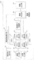
本開示の画像表示装置における実施の形態2について図3および図4を参照しつつ説明する。図3は、実施の形態2に係る画像表示システムを示すブロック図である。図4は、全周パノラマ動画の1フレーム画像に対する切出開始座標および切出領域と、切出領域に対応する切出画像との関係を説明するための図である。
Second Embodiment
1. Configuration 1.1
図2に示すように、本実施の形態における画像表示システム1Aは、一例として、運転技術または操縦技術をトレーニングするためのドライブシミュレータまたはフライトシミュレータに用いられるシステムである。図3に示すように、画像表示システム1Aは、コントローラ100と、画像生成部200と、画像表示装置300Aとを備える。
As shown in FIG. 2, the image display system 1A in the present embodiment is, as an example, a system used in a drive simulator or flight simulator for training driving technology or steering technology. As shown in FIG. 3, the image display system 1A includes a
コントローラ100は、シミュレータにおける運転または操縦等に関する操作部であり、例えば、ドライブシミュレータにおけるステアリングホイール、アクセル、ブレーキ等が該当する。フライトシミュレータにおいては、操縦桿、スロットルレバー、ラダーペダル、スラストリバーサーレバー、トリムレバー、ピッチレバー、スピードブレーキレバー等が該当する。また、コントローラ100は、ジョイスティック、ジョグダイヤル、あるいはジャイロセンサーであってもよい。
The
画像生成部200Aは、所定のフレームレートの動画を生成し、画像信号として出力する機能を有している。本実施の形態においも、画像生成部200は、一例として60fpsの動画を生成する。画像生成部200により生成される動画は、撮影動画を編集・加工したものであってもよいし、CG(Computer Graphics)であってもよい。本実施の形態では、一例として、パーソナルコンピュータにより画像生成部200を構成している。本実施の形態における画像生成部200は、自動車または飛行機等のウィンドシールドを通して視認可能な風景に相当する動画を生成する。この動画は、水平方向360度に亘る全周パノラマ動画である。
The
本実施の形態においては、画像生成部200Aは、後述する切出領域指示部305と接続されている。画像生成部200Aは、切出領域指示部305から出力される、アクセルやブレーキの操作に応じた、加速、減速、停止、あるいは巡航速度等の速度または加速度に関する指示を入力可能に構成されている。画像生成部200Aは、切出領域指示部305から速度または加速度に関する指示を入力した場合には、当該速度または加速度に応じた全周パノラマ動画を生成する。
In the present embodiment, the
1.2 画像表示装置の構成
画像表示装置300Aは、切出領域指示部305、画像入力部310、メモリ320、メモリ書込部330、メモリ読出部340A、および画像出力部350を備えている。画像表示装置300Aのうち、画像入力部310、メモリ320、メモリ書込部330、メモリ読出部340、および画像出力部350については、FGPAで構成してもよいし、CPUとソフトウェアにより構成してもよい。
1.2 Configuration of Image Display Device The
画像入力部310は、画像生成部200Aによって生成される全周パノラマ動画を画像信号として入力する機能を有する。画像生成部200Aと画像入力部310との接続は、HDMIケーブルまたはUSBケーブル、あるいはこれらの両方を用いて行われる。
The
メモリ320は、本実施の形態では、フレームバッファが1つだけのシングルバッファで構成される。但し、メモリ320は、フレームバッファを2つ備えたダブルバッファで構成されていてもよい。メモリ320としてダブルバッファのメモリを用いた例については後述する。
In the present embodiment, the
メモリ書込部330は、画像入力部310に入力された全周パノラマ動画を、1フレームごとに第1の周波数である60Hzの周波数でメモリ320に書き込む機能を有する。
The
メモリ読出部340Aは、メモリ書込部330のメモリ320への書込み動作中に、つまり非同期に、メモリ320に書き込まれたフレーム画像を、第1の周波数よりも高い第2の周波数である1920Hzで読み出す機能を有する。本実施の形態においては、メモリ読出部340Aは、切出領域指示部305と接続されている。メモリ読出部340Aは、切出領域指示部305から出力される切出開始座標に基づき、切出領域に対応するフレーム画像を1920Hzで読み出す。切出開始座標および切出領域についての詳細は後述する。
The
画像出力部350は、メモリ読出部340によって読み出された切出領域に対応するフレーム画像を出力する機能を有し、画像表示部に画像を出力する。これにより、画像表示部において切出領域に対応する動画が表示される。
The
切出領域指示部305は、コントローラ100に接続されており、コントローラ100として、ステアリングホイールやジョイスティック等が用いられている場合には、コントローラ100の操作量および操作角度等を1秒間に1920回のサイクルで検出する。切出領域指示部305は、また、画像生成部200Aに接続されており、検出したコントローラ100の操作量に応じた速度または加速度等に関する情報を画像生成部200Aに出力する。切出領域指示部305は、さらに、メモリ読出部340Aに接続されており、検出したコントローラ100の操作角度等に応じた切出開始座標をメモリ読出し部340Aに出力する。
The cutout area designation unit 305 is connected to the
切出領域指示部305は、コントローラ100として、ジャイロセンサーが用いられている場合には、コントローラ100の回転量および回転方向を1秒間に1920回のサイクルで検出する。切出領域指示部305は、検出したコントローラ100の回転量に応じた速度または加速度等に関する情報を画像生成部200Aに出力する。切出領域指示部305は、検出したコントローラ100の回転方向に応じた切出開始座標をメモリ読出部340Aに出力する。
When a gyro sensor is used as the
2. 動作
図4は、全周パノラマ動画の1フレーム画像に対する切出開始座標および切出領域と、切出領域に対応する切出画像との関係を説明するための図である。図4に示すように、画像入力部310に入力される全周パノラマ動画Pの1フレーム分の画像Fは、メモリ書込部330によってメモリ320に書き込まれる。
2. Operation FIG. 4 is a diagram for explaining the relationship between the clipping start coordinates and clipping area for one frame image of the panoramic panoramic moving image and the clipping image corresponding to the clipping area. As shown in FIG. 4, the
切出領域Rは、切出開始座標(x,y)から、X軸方向に長さLx、Y軸方向に幅Lyの大きさを有している。切出領域Rの大きさは、自動車または飛行機等のウィンドシールドから見える画角に対応している。 The cutout area R has a length Lx in the X-axis direction and a width Ly in the Y-axis direction from the cutout start coordinate (x, y). The size of the cutout area R corresponds to the angle of view viewed from a windshield of a car or a plane.
画像表示システム1Aの起動時等の初期状態においては、切出開始座標(x,y)は所定の座標に設定されている。操作者がコントローラ100を操作すると、その操作角度等が切出領域指示部305により1920Hzの周波数で検出され、その操作角度等に応じた切出開始座標がメモリ読出部340Aに出力される。
In an initial state such as when the image display system 1A is activated, the clipping start coordinate (x, y) is set to a predetermined coordinate. When the operator operates the
メモリ読出部340Aは、切出領域指示部305から出力された切出開始座標を基準として、切出領域Rに対応する画像を1920Hzの周波数で読み出す。メモリ読出部340Aにより読み出された画像は、画像出力部350から出力され、画像表示部に切出画像SGとして表示される。本実施の形態においては、メモリ読出部340Aによるメモリ320からの読み出し周波数を、メモリ書込部330による書き込み周波数に比べて十分に高くすることにより、コントローラ100の操作に対応して遅延なく切出画像SGが表示されるように補間を行っている。このように本実施の形態においては、図3に一点鎖線の矩形枠で示すように、メモリ読出部340が、画像表示部に出力する画像を補間する画像補間部として機能している。
The
3. 効果等
本開示の画像表示装置300Aは、画像信号源として画像生成部200Aからの画像信号が入力される画像入力部310と、メモリ320と、画像入力部310に入力された画像信号をメモリ320に第1の周波数の一例としての60Hzで書き込む動作をするメモリ書込部330と、第1の周波数よりも高い第2の周波数の一例としての1920Hzで、メモリ320に書き込まれた画像信号を読み出すメモリ読出部340Aと、メモリ読出部340Aで読み出された画像信号を画像表示部に出力する画像出力部350と、画像表示部に出力する画像を補間する画像補間部としてのメモリ読出部340Aとを備える。また、画像表示装置300Aは、コントローラ100を備え、メモリ読出部340Aは、コントローラ100の操作に応じた切出領域RSごとに、メモリ320に書き込まれた画像信号を読み出す。その結果、コントローラ100の操作角度等を1920Hzの周波数で検出し、検出した操作角度等に応じた切出開始座標を基準として、フレームレートが60fpsの入力画像のうち、切出領域Rに対応する画像を1920Hzの周波数で読み出して出力する。したがって、コントローラ100の操作により切出開始座標が変更された場合に、コントローラ100の操作に対して遅延を生じさせずに円滑に切出開始座標の異なる動画を表示することができる。
3. Effect etc. The
例えば、コントローラ100が自動車等のステアリングホイールの場合、ステアリングホイールを切った方向に対応して切出開始座標が更新され、ステアリングホイールを切った方向に対応する動画が、ステアリングホイールを切るという操作に対して遅延なく表示される。
For example, when the
また、メモリ読出部340Aによる読み出し周波数が60Hzの場合には、画像表示部に表示される切出領域Rの変化が飛び飛びに感じられる。しかし、本実施の形態のように、メモリ読出部340Aによる読み出し周波数が1920Hzであれば、画像表示部において、切出領域Rが滑らかに変化して見えるという利点もある。以上のように、本実施の形態によれば、コントローラ100の操作から、動画が表示されるまでの遅延を最小限に抑えることができる。なお、コントローラ100の操作に対する切出領域Rの移動という観点から、遅延が目立ちにくくなるメモリ読出部340Aによる読み出し周波数の目安としては、実施の形態1と同じく500Hz程度と考えられる。
In addition, when the reading frequency by the
なお、本実施の形態における画像表示システム1Aをドライブシミュレータに適用した場合には、コントローラ100の操作は水平方向のみなので、切出開始座標はX座標のみでよい。また、パノラマ映像の高さを画像表示部の高さより大きくし、道路の凹凸や傾斜を考慮してY方向の座標も変化させてもよい。
In addition, when the image display system 1A in the present embodiment is applied to a drive simulator, the operation of the
4. 実施の形態2の変形例
4.1 全体の構成
実施の形態2の変形例について図5を用いて説明する。図5は、実施の形態2の変形例に係る画像表示システムを示すブロック図である。本変形例は、フライトシミュレータのような用途で、視点を360度に亘って自在に移動させる場合の構成である。本変形例の画像表示システム1Aにおいては、画像生成部200Aは、半球状または球面状のパノラマ動画を生成する。このようなパノラマ動画の例としては、水平360度、地平線から頭上までの90度の範囲を1枚の画像におさめるドームマスター形式の動画が挙げられる。また、他の例としては、水平360度、足元から頭上までの180度の範囲を1枚の画像におさめるエクイレクタングラー形式などで記録された動画が挙げられる。
4. Modification 4.1 of
コントローラ100の操作による切出開始座標の更新は、X座標とY座標の両方について行われる。また、図5に示すように、画像表示装置300Aは、画像加工部360を備えており、切出領域指示部305Aと画像加工部360とが接続されている。
The update of the extraction start coordinate by the operation of the
図5に示す変形例では、メモリ320に書き込まれる画像は、上述のような半球状または球面状のパノラマ動画のフレーム画像を平面画像に変換した画像となる。したがって、この画像においては、本来、矩形で表示されるべき画像が湾曲しており、歪みが生じている。そこで、図5に示す変形例では、切出開始座標と切出領域Rのサイズとの調整処理を行っている。
In the modification shown in FIG. 5, the image written in the
メモリ書込部330は、画像生成部200Aによって入力された半球状または球面状のパノラマ動画の1フレーム分の画像を平面画像に変換し、60Hzの周波数でメモリ320に書き込む。
The
切出領域指示部305Aは、コントローラ100による操作角度等を検出すると、切出開始座標と切出領域Rのサイズを、前記歪みに対応させて設定し、設定した切出開始座標と切出領域Rのサイズをメモリ読出部340Aに出力する。また、切出領域指示部305Aは、上述のように設定した切出領域Rのサイズを画像加工部360に出力する。切出領域指示部305Aにおいて設定される切出開始座標と切出領域Rのサイズは、ドームマスター形式の動画のフレーム画像またはエクイレクタングラー形式の動画のフレーム画像を平面画像に変換する変換処理の逆変換処理により得られる。
When the cutout
メモリ読出部340Aは、切出領域指示部305から、上述のように設定された切出開始座標と切出領域Rのサイズとを入力すると、当該切出開始座標を基準として、当該サイズに対応する切出領域Rにおける画像の切り出しを行う。
When the
画像加工部360は、切出領域指示部305から、上述のように設定された切出領域Rのサイズを入力すると、メモリ読出部340Aにより切り出された切出領域Rにおける切出画像の歪みを取り除き、切出画像のサイズを、画像表示部において表示されるサイズに加工する。
When the
4.2 動作
画像生成部200Aによって半球状または球面状のパノラマ動画が生成され、画像入力部310に入力されると、入力された半球状または球面状のパノラマ動画の1フレーム分の画像は、メモリ書込部330によって平面画像に変換され、60Hzの周波数でメモリ320に書き込まれる。
4.2 Operation When the hemispherical or spherical panoramic moving image is generated by the
操作者がコントローラ100を操作すると、その操作角度等が切出領域指示部305により1920Hzの周波数で検出され、その操作角度等に応じて切出開始座標と切出領域Rのサイズが、切出領域指示部305により前記歪みに対応させて設定される。設定された切出開始座標と切出領域Rのサイズは、切出領域指示部305により、メモリ読出部340Aに出力される。また、設定された切出領域Rのサイズは、切出領域指示部305により、画像加工部360に出力される。
When the operator operates the
メモリ書込部330によって書き込まれた平面画像のうち、前記設定された切出開始座標を基準とする前記サイズの切出領域Rの画像は、メモリ読出部340Aによって1920Hzの周波数で切り出される。
Of the planar image written by the
切り出された画像は、画像加工部360により、前記歪みが取り除かれ、切出画像のサイズは、画像加工部360により、画像表示部において表示されるサイズに加工される。前記歪みが取り除かれ、サイズが加工された画像は、画像出力部350から出力され、画像表示部に切出画像として表示される。
The
本実施の形態においては、メモリ読出部340Aによるメモリ320からの読み出し周波数を、メモリ書込部330Aによる書き込み周波数に比べて十分に高くすることにより、コントローラ100の操作に対応して遅延なく画像の出力が行われるように補間を行っている。また、本実施の形態においては、画像加工部360により、前記歪みを取り除き、歪みのない画像の出力が行われるように補間を行っている。このように本実施の形態においては、図5に一点鎖線の矩形枠で示すように、メモリ読出部340Aと画像加工部360とが、画像表示部に出力する画像を補間する画像補間部として機能している。
In the present embodiment, the read frequency from the
4.3 効果等
以上のように、本変形例においては、動画が半球状または球面状のパノラマ動画の場合であっても、メモリ書込部330Aによって60Hzの周波数でメモリ320に書き込まれた画像を1920Hzの周波数で読み出して出力する。したがって、動画が半球状または球面状のパノラマ動画の場合であっても、コントローラ100の操作により切出開始座標が変更された場合に、コントローラ100の操作に対して遅延を生じさせずに円滑に切出開始座標の異なる動画を表示することができる。また、半球状または球面状のパノラマ動画のフレーム画像を平面画像に変換してメモリ320に書き込み、上述のように画像加工部360により画像の歪みを取り除くので、半球状または球面状のパノラマ動画に適合した切出画像を表示することができる。
4.3 Effects, Etc. As described above, in the present modification, even if the moving image is a hemispherical or spherical panoramic moving image, the image written to the
5. 実施の形態2の別の変形例
5.1 全体の構成
実施の形態2の別の変形例について図6を用いて説明する。図6は、実施の形態2の別の変形例に係る画像表示システムを示すブロック図である。本変形例の画像表示システム1Bにおいては、画像入力部310により入力する画像として、頭上も含む全天球動画のフレーム画像を用いる。また、画像出力部350により画像を出力する画像表示部については、ドームディスプレイや全周(全天球)ディスプレイを用い、全天球動画の全てを表示する。
5. Another Modification of the Second Embodiment 5.1 Overall Configuration Another modification of the second embodiment will be described with reference to FIG. FIG. 6 is a block diagram showing an image display system according to another modification of the second embodiment. In the image display system 1B of the present modified example, a frame image of an omnidirectional moving image including overhead is used as an image input by the
本変形例においては、図6に示すように、コントローラ100の操作角度等を、方向指示部306により検出する。方向指示部306は、検出したコントローラ100の操作角度等に応じた視点座標を画像生成部200Bに出力する。
In the present modification, as shown in FIG. 6, the operation angle of the
画像生成部200Bは、方向指示部306により出力される視点座標が、画像表示装置において予め定められた表示中心位置となるように、全天球動画を生成し、出力する。
The
メモリ読出し部340Bは、本変形例においては、コントローラ100の操作に対して画像の切り出しは行わず、60Hzでメモリ320に書き込まれたフレーム画像を、メモリ320から1920Hzで読み出す。
In the present modification, the memory reading unit 340B does not cut out the image in response to the operation of the
画像加工部360Aは、方向指示部306により出力される視点座標が変更された場合には、ドームディスプレイや全周(全天球)ディスプレイにおける曲面の投影面において、画像が正しく表示されるように画像の歪みを取り除く補正を行う。また、ドームディスプレイや全周(全天球)ディスプレイが、複数の画像表示装置(プロジェクタ)で構成される場合には、画像加工部360Aは、メモリ320から読み出した画像を分割し、分割画像を各画像表示装置の表示サイズに加工する処理、あるいは、画像を各画像表示装置に割り当てる処理を行う。
In the
本実施の形態においては、メモリ読出部340によるメモリ320からの読み出し周波数を、メモリ書込部330による書き込み周波数に比べて十分に高くすることにより、コントローラ100の操作に対応して遅延なく画像の出力が行われるように補間を行っている。また、本実施の形態においては、画像加工部360により、前記歪みを取り除き、歪みのない画像の出力が行われるように補間を行っている。このように本実施の形態においては、図6に一点鎖線の矩形枠で示すように、メモリ読出部340と画像加工部360Aとが、画像表示部に出力する画像を補間する画像補間部として機能している。
In the present embodiment, by setting the read frequency from
5.2 動作
全天球動画が画像入力部310に入力されると、入力された全天球動画の1フレーム分の画像は、メモリ書込部330によって60Hzの周波数でメモリ320に書き込まれる。
5.2 Operation When the omnidirectional animation is input to the
操作者がコントローラ100を操作すると、その操作角度等が方向指示部306により1920Hzの周波数で検出され、その操作角度等に応じた視点座標が、画像生成部200Bに出力される。また、この視点座標は、方向指示部306により、画像加工部360に出力される。
When the operator operates the
画像生成部200Bは、方向指示部306により出力される視点座標が、画像表示装置において予め定められた表示中心位置となるように、全天球動画を生成し、全天球動画のフレーム画像を画像入力部310に出力する。画像入力部310により入力された全天球動画のフレーム画像は、メモリ書込部330により、60Hzの周波数でメモリ320に書き込まれる。
The
メモリ320に書き込まれた画像は、メモリ読出部340によって1920Hzの周波数で読み出される。
The image written in the
読み出された画像は、画像加工部360Aにより、ドームディスプレイや全周(全天球)ディスプレイにおける曲面の投影面で正しく表示されるように歪みが取り除く補正が行われる。また、ドームディスプレイや全周(全天球)ディスプレイが、複数の画像表示装置(プロジェクタ)で構成される場合には、メモリ320から読み出された画像は、画像加工部360Aにより分割され、分割された画像は、各画像表示装置の表示サイズに加工される。あるいは、分割された画像は、画像加工部360Aにより各画像表示装置に割り当てられる。前記歪みが取り除かれ、サイズが加工された画像は、画像出力部350から出力され、画像表示部において、前記視点座標を表示中心位置とするように表示される。
The read-out image is corrected by the
本実施の形態においては、メモリ読出部340によるメモリ320からの読み出し周波数を、メモリ書込部330による書き込み周波数に比べて十分に高くすることにより、コントローラ100の操作に対応して遅延なく視点位置を移動させた画像の出力が行われるように補間を行っている。また、本実施の形態においては、画像加工部360Aにより、前記歪みを取り除き、歪みのない画像の出力が行われるように補間を行っている。このように本実施の形態においては、図6に一点鎖線の矩形枠で示すように、メモリ読出部340と画像加工部360Aとが、画像表示部に出力する画像を補間する画像補間部として機能している。
In the present embodiment, by setting the read frequency from
5.3 効果等
以上のように、本変形例においては、全天球動画の全てを表示する場合であっても、メモリ書込部330によって60Hzの周波数でメモリ320に書き込まれた画像を1920Hzの周波数で読み出して出力する。したがって、全天球動画の全てを表示する場合であっても、コントローラ100の操作により視点座標が変更された際に、コントローラ100の操作に対して遅延を生じさせずに円滑に表示中心位置の異なる動画を表示することができる。
5.3 Effects, Etc. As described above, in the present modification, even when all omnidirectional animation is displayed, the image written in the
6. 実施の形態2の別の変形例
6.1 全体の構成
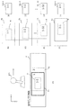
実施の形態2のさらに別の変形例について図7を用いて説明する。図7は、実施の形態2のさらに別の変形例に係る入力画像、画像の切出領域R、及び出力画像の関係を示す図である。本変形例の画像表示システムにおいては、画像入力部310により入力する画像として、全周パノラマ画像の全体ではなく、進行方向を含む一部の領域の画像を用いる。本変形例は、図3に示す実施の形態2の画像表示システム1A、及び図5に示す変形例の画像表示システム1Bに適用可能である。
6. Another Modification of
コントローラ100の操作による1/60秒での進行方向の変化幅には上限がある。そのため、それ以外の領域の画像を含むのは無駄である。そこで、本変形例では、切出領域Rのサイズに、1/60秒間の切出領域Rの移動量の上限より大きいサイズを追加したサイズの画像を入力映像とする。
There is an upper limit to the width of change in the traveling direction in 1/60 seconds due to the operation of the
図7の(A)は、コントローラ100の状態と、入力映像のフレームF1とフレームF2の画像の、全周パノラマ画像Pに対する位置を示している。コントローラ100が右(図7に示すY軸方向)に倒れているので、フレームF2はフレームF1より右側の方向の画像となる。
FIG. 7A shows the state of the
図7の(B)から(E)は、各フレーム画像F1,F2から、1920Hzで切り出す切出画像Rの位置を示す。図7の(F)から(I)は、画像出力部350から出力される出力フレーム画像SG1−1から出力フレーム画像SG2−1までを示す。コントローラ100が右に倒れているので、切出領域Rはフレームが進むに従って右に移動する。出力フレーム画像SG1−1に対応するフレーム画像F1の切出領域Rは、図7の(B)に示すように、フレームF1の中央付近である。しかし、出力フレーム画像SG1−32に対応するフレーム画像F1の切出領域Rは、図7の(D)に示すように、フレームF1の端に近づく。
(B) to (E) in FIG. 7 show the positions of the cut-out image R cut out at 1920 Hz from the frame images F1 and F2. (F) to (I) of FIG. 7 show the output frame image SG1-1 output from the
この切出領域Rの移動速度は、画像表示システムの用途により決まるので、出力フレーム画像SG1−32がフレーム画像F1からはみ出さないよう、フレーム画像F1のサイズは予め決めることができる。そして、フレーム画像F2は、切出領域Rが、図7の(E)に示すようにフレーム画像F2の中央付近となるよう、画像生成部200Aにおいて生成され、供給される。
Since the moving speed of the cutout area R is determined by the application of the image display system, the size of the frame image F1 can be determined in advance so that the output frame image SG1-32 does not protrude from the frame image F1. Then, the frame image F2 is generated and supplied by the
なお、本変形例では画像生成部200Aにおいて生成される画像の例として、全周パノラマ画像を挙げたが、ドームマスター形式やエクイレクタングラー形式などの全周パノラマ画像であってもよい。
In this modification, the panoramic panoramic image is given as an example of the image generated by the
6.2 動作
画像生成部200Aは、全周パノラマ画像Pの全体から、一部の領域の画像であるフレーム画像F1を切り出し、画像表示装置300Aに出力する。画像表示装置300Aの画像入力部310は、フレーム画像F1を入力し、メモリ書込部330は、入力されたフレーム画像F1を60Hzの周波数でメモリ320に書き込む。コントローラ100が操作されると、画像生成部200Aは、コントローラ100の操作に応じてフレーム画像の切り出し位置をシフトする。例えば、図7の(A)に示すように、フレーム画像F1よりも右側(Y軸方向)にシフトしたフレーム画像F2を切り出し、画像表示装置300Aに出力する。メモリ読出部340Aは、メモリ320に書き込まれたフレーム画像F1およびフレーム画像F2から、1920Hzの周波数で、切出領域Rの画像を切り出す。切出領域Rの画像は、画像出力部350から出力され、画像表示部において、出力フレーム画像SG1−1から出力フレーム画像SG2−1のように表示される。なお、本変形例を、図5に示す変形例の画像表示システム1Bに適用する場合には、切出領域Rの画像は、画像加工部360により、画像表示部において表示されるサイズに加工される。また、切出領域Rの画像は、画像加工部360により歪みが取り除かれる。
6.2 Operation The
6.3 効果等
以上のように本変形例によれば、画像表示装置300Aに入力する画像のデータサイズを低減することができ、処理高速化を図ることができる。また、本変形例においても、コントローラ100の操作により切出開始座標が変更された際に、コントローラ100の操作に対して遅延を生じさせずに円滑に切出開始座標の異なる動画を表示することができる。
6.3 Effects Etc. As described above, according to the present modification, the data size of an image input to the
7. メモリの構成
ところで、一般的に、メモリ320への画像の書き込みに対して、メモリ320からの画像の読み出しは高速である。したがって、メモリ320への画像の書き込みが完了した後に、メモリ320からの画像の読み出しを開始する。そして、メモリ320からの画像の読み出しの間、次のフレームの画像のメモリ320への書き込みを行うために、メモリ320においてフレームバッファを2フレーム分準備し、フレーム毎に、画像を書き込むフレームバッファと、画像を読み出すフレームバッファとを切り替えるダブルバッファと呼ばれる手法をとるのが一般的である。ダブルバッファでは、1フレームの期間、書き込みが行われていない方のフレームバッファ上で画像が保持される。
7. Memory Configuration In general, reading of an image from the
一方で、メモリ320において1フレーム分のフレームバッファだけを準備し、同じフレームバッファに対して読み出しと書き込みを同時に行う手法を、シングルバッファと呼ぶ。以上の実施の形態2、および各変形例においては、メモリ制御はシングルバッファの手法を用いても良いし、ダブルバッファの手法を用いても良い。ダブルバッファの手法の場合、メモリ320は2フレーム分の容量を備える。そして、メモリ読出部340Aは、書き込みを行っていないフレームメモリから画像を読み出す。シングルバッファの手法に対し、ダブルバッファの手法では、動画のフレームの更新は遅延が発生するが、コントローラ100の操作に対する遅延は発生しない。
On the other hand, a method of preparing only a frame buffer for one frame in the
(実施の形態3)
1.構成
1.1 全体の構成
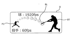
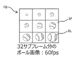
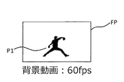
本開示の画像表示装置における実施の形態3について図8から図12を参照しつつ説明する。図8は、実施の形態3における画像表示部に表示される出力画像の一例を示す図である。図9は、実施の形態3に係る画像表示装置を示すブロック図である。図10は、実施の形態3におけるメモリ上のボールのサブフレーム画像の配置を説明するための図である。図11は、実施の形態3におけるメモリ上の背景動画のフレーム画像を説明するための図である。図12は、実施の形態3におけるメモリからの画像の読み出しと画像合成を説明するための図である。
Third Embodiment
1. Configuration 1.1 Overall Configuration Embodiment 3 of the image display device of the present disclosure will be described with reference to FIGS. 8 to 12. FIG. 8 is a diagram showing an example of an output image displayed on the image display unit in the third embodiment. FIG. 9 is a block diagram showing an image display apparatus according to the third embodiment. FIG. 10 is a diagram for explaining the arrangement of subframe images of a ball on a memory according to the third embodiment. FIG. 11 is a diagram for explaining a frame image of a background moving image on the memory in the third embodiment. FIG. 12 is a diagram for explaining reading of an image from a memory and image synthesis in the third embodiment.
実施の形態3は、本開示の画像表示装置を、一例とて、野球のシミュレータに適用したものである。図8に示すように、画像表示部に表示される出力画像Dには、投手P1の動画およびバッターBTの画像を含む背景動画と、ボールBLの動画が含まれる。投手P1の動画は60Hzで表示され、ボールBLの動画は1920Hzで表示される。なお、使用者がバッターとして映像を見る場合は、バッターBTは表示されなくてもよい。 Embodiment 3 applies the image display apparatus of this indication to the simulator of a baseball as an example. As shown in FIG. 8, the output image D displayed on the image display unit includes a background moving image including the moving image of the pitcher P1 and the batter BT image, and the moving image of the ball BL. The moving image of the pitcher P1 is displayed at 60 Hz, and the moving image of the ball BL is displayed at 1920 Hz. In addition, when a user looks at an image as a batter, the batter BT may not be displayed.
図9に示すように、画像表示装置400は、画像入力部410,411、メモリ420,421、メモリ書込部430,431、メモリ読出部440,441、画像加工部460、画像出力部450、切出領域指示部470、重畳位置指示部480、およびα値指示部490を備える。
As shown in FIG. 9, the
画像表示装置400は、全体をFGPAで構成してもよいし、CPUとソフトウェアにより構成してもよい。また、画像表示装置400は、切出領域指示部470、重畳位置指示部480、およびα値指示部490をパソコンで構成し、その他の構成部をFGPA、またはCPUとソフトウェアにより構成してもよい。
The
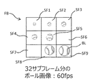
画像入力部410は、図示を省略する画像生成部によって生成され、出力されるボールBLの動画のフレーム画像を入力する。ボールの動画の1フレーム画像は、32サブフレーム分のボールBLの画像からなる。図9はボールの動画のサブフレーム画像SFを示す図である。なお、図9においては、簡略化のために、ボールBLのフレーム画像FBを9枚のサブフレーム画像SFで例示している。図9に示すように、各サブフレーム画像SFは、ボールBLの径、および回転状態が異なる画像となっている。32枚のサブフレーム画像FBでボールBLの動画の1フレーム画像FBを構成することにより、ボールBLが投手P1の手元から離れ、回転しながら徐々にバッターBTに向かって近づいてくる様子を表現することができる。32枚のサブフレーム画像SFからなるボールBLの各フレーム画像FBは、60fpsのフレームレートで画像入力部410に入力される。
The
画像生成部と画像入力部410との接続は、USBケーブルおよびHDMIケーブルを用いて行われる。USBケーブルを介して制御信号が画像生成部から出力され、HDMIケーブルを介して画像データが画像生成部から出力される。
The connection between the image generation unit and the
画像入力部411は、図示を省略する画像生成部によって生成される背景動画のフレーム画像を入力する。図11に示すように、背景動画のフレーム画像FPは、投球動作を行う投手P1の動画のフレーム画像を含む。背景動画の各フレーム画像FPは、60fpsのフレームレートで画像入力部411に入力される。画像生成部と画像入力部411との接続は、USBケーブルおよびHDMIケーブルを用いて行われる。USBケーブルを介して制御信号が画像生成部から出力され、HDMIケーブルを介して画像データが画像生成部から出力される。
The
メモリ420,421は、本実施の形態では、フレームバッファが2つのダブルバッファのメモリである。メモリ420には、ボールBLのフレーム画像が書き込まれる。メモリ421には、投手P1を含む背景動画のフレーム画像FPが書き込まれる。
In the present embodiment, the
メモリ書込部430は、画像入力部410に入力されたボールBLの動画を、32枚のサブフレーム画像SFからなる1フレーム画像FBごとに、第1の周波数である60Hzの周波数でメモリ420に書き込む。メモリ書込部431は、画像入力部411に入力された投手P1を含む背景動画を、1フレーム画像FPごとに60Hzの周波数でメモリ421に書き込む。
The
メモリ読出部440は、メモリ書込部430のメモリ420への書込み動作中に、つまり非同期に、メモリ420に書き込まれたボールのフレーム画像を、第1の周波数よりも高い第2の周波数である1920Hzで読み出す。本実施の形態においては、メモリ読出部440は、切出領域指示部470と接続されている。メモリ読出部440は、切出領域指示部470から出力される切出指示に基づき、1フレームのボールの画像から、サブフレームとして描かれたボールの画像を順次切り出して出力する。
The memory read
メモリ読出部441は、メモリ書込部431のメモリ421への書込み動作中に、つまり非同期に、メモリ421に書き込まれた投手のフレーム画像を、1920Hzで読み出す。投手のフレーム画像については、切り出さないか、もしくは切出領域は変わらないので、実質60Hzの動画となる。
The
画像加工部460は、メモリ読出部441で読み出された投手P1を含む背景画像のフレーム画像FPに、メモリ読出部440で読み出されたボールBLのサブフレーム画像SFを合成し、画像出力部450に出力する。
The
画像出力部450は、投手P1を含む背景画像とボールBLの画像とが合成された画像を、図示を省略する画像表示部に表示する。
The
切出領域指示部470は、ボールBLの1フレーム画像FBのうち、どのサブフレーム画像SFを切り出すかをメモリ読出部440に指示する。
The cutout
重畳位置指示部480は、投手P1を含む背景動画のフレーム画像FP上に、ボールBLのサブフレーム画像SFを重畳する位置を、画像加工部460に指示する。
The superimposing
α値指示部490は、ボールBLのサブフレーム画像SF上のボールBLの領域を、画素情報上の透過率を示すα値で指定する。これにより、サブフレーム画像SFからボールBLの画像だけが切り出され、画像加工部460により背景動画と合成される。例えば、ボールBLの領域は透過率を0%とし、その他の領域の透過率を100%とすれば、ボールBLの画像だけを切り出すことができる。
The α
1.2 メモリからの読み出し周波数の決定基準
スポーツにおいて、ボールなどのオブジェクトは時速100km以上で動く。通常、画像出力部450から出力する動画のフレームレートは、入力する動画のフレームレートと同程度であり、本実施の形態では60fpsとなっている。見掛けのフレームレートを増やすために、高い周波数で動画を表示するケースはあるが、そのケースでは、同じ画像を繰り返し表示するだけで、画像自体は変化しない。そのため、60fpsのフレームレートで動画を表示する場合、時速100kmで進むオブジェクトが1フレーム(1/60秒)で進む距離は463mmとなる。この距離は多くの場合、オブジェクトのサイズより大きい。したがって、動くオブジェクトを目で追っている場合、あるフレームが表示されてから次のフレームが表示されるまでの間、オブジェクトは同じ位置に表示されたままある。したがって、観察者は、画像表示部における画面上のオブジェクトが表示されていない領域において、オブジェクトの動きを予測して視線を遷移させる。つまり、視線の動きに対して、オブジェクトが大きく遅延して表示されている状態となる。
1.2 Criteria for Reading Frequency from Memory In sports, objects such as balls move at speeds of 100 km / hr or more. Usually, the frame rate of the moving image output from the
なお、上記の進む距離は、オブジェクトの進行方向に対してである。オブジェクトが画面に平行に移動する場合の画面上の移動距離であり、画面に垂直な成分がある場合は、画面上の移動距離は463mmより小さい。したがって、本実施の形態では、システムの設計上、画面上の移動距離が最大となる条件を考慮して読み出し周波数を決定している。また、表示装置を2台使用する3D表示の場合は、知覚される空間上の移動は463mmとなるため、本実施の形態では、やはりこの条件を考慮してメモリ420からの読み出し周波数を決定している。
Note that the above travel distance is with respect to the travel direction of the object. The movement distance on the screen when the object moves parallel to the screen, and when there is a component perpendicular to the screen, the movement distance on the screen is less than 463 mm. Therefore, in the present embodiment, the reading frequency is determined in consideration of the condition that the moving distance on the screen is maximum in the design of the system. In addition, in the case of 3D display using two display devices, the movement in space is 463 mm, so in this embodiment, the read frequency from
本実施の形態では、1920Hzでオブジェクトを表示するので、1フレーム(1/1920秒)で進む距離は14mmとなる。この距離は多くの場合、オブジェクトのサイズより小さい。これにより、視線の動きに対して、オブジェクトが遅延して表示されるということはなくなる。 In this embodiment, since the object is displayed at 1920 Hz, the distance to advance in one frame (1/1920 seconds) is 14 mm. This distance is often less than the size of the object. This prevents the object from being displayed delayed with respect to the movement of the line of sight.
また、出力する動画の周波数が60Hzだと、オブジェクトの移動が飛び飛びに感じられる。さらに野球の場合、変化球は1秒間に約60回転するが、60fpsでは回転が表現できない。しかし、本実施の形態のように、オブジェクトの表示周波数を1920Hzとすれば、オブジェクトの移動が滑らかになるだけでなく、32枚のサブフレームで約1回転するので、回転も表現可能となる。 In addition, if the frequency of the moving image to be output is 60 Hz, the movement of the object seems to be skipping. Furthermore, in the case of baseball, the changing ball rotates about 60 per second, but can not express rotation at 60 fps. However, if the display frequency of the object is 1920 Hz as in the present embodiment, not only the movement of the object becomes smooth, but also rotation can be expressed because it rotates about once in 32 subframes.
なお、視線の動きに対するオブジェクトの移動という観点から、遅れが目立ちにくくなる周波数の目安としては、前述の実施の形態と同じく500Hz程度と考えられる。 From the viewpoint of the movement of the object with respect to the movement of the line of sight, as a measure of the frequency at which the delay is less noticeable, it can be considered to be about 500 Hz as in the above embodiment.
1.3 メモリからの画像の読み出しと画像合成の態様
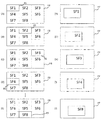
メモリ420からの画像の読み出しと画像合成について、図12により説明する。図12に示す例では分かりやすくするために、ボールBLの1フレーム画像FBを構成するサブフレーム数を8とする。また、8個のサブフレーム数から成るボールBLの1フレーム画像FBの書き込みにおけるフレームレートは60fps、1サブフレーム画像FBの画像の読み出しにおけるフレームレートは480fpsとする。
1.3 Image Reading from Memory and Aspect of Image Synthesis Reading of an image from the
図12の(A)に示すように、メモリ420上にボールBLの動画の1フレーム画像FBに対するサブフレーム画像SF1〜SF8が書き込まれているものとする。サブフレーム画像SF1〜SF8の読み出しは、サブフレーム画像SF1〜SF8のサイズに対応した切出領域RSごとに行われる。本実施の形態では、メモリ読出部440は、切出領域指示部470からの指示を受けて、図12の(A)〜(E)に示すように、サブフレーム画像SF1〜SF8の順に切出領域RSを切り換えて各サブフレーム画像を480fpsのフレームレートで読み出す。
As shown in FIG. 12A, it is assumed that sub-frame images SF1 to SF8 for one frame image FB of the moving image of the ball BL are written on the
そして、画像加工部460は、重畳位置指示部480からの指示を受けて、図12の(F)〜(J)に示すように、背景動画の1フレーム画像FP上に、ボールBLの動画のサブフレーム画像SF1〜SF8を順次重畳する。
Then, the
上記の各サブフレーム画像の各々の切出領域RSは固定されていてもよいが、サブフレーム画像毎に変わっても良い。その場合は、USBなどの通信手段で画像生成部から指示を入力してもよいし、動画のヘッダ情報などに重畳してもよい。 The cutout area RS of each of the above sub-frame images may be fixed or may be changed for each sub-frame image. In that case, the instruction may be input from the image generation unit by a communication unit such as USB, or may be superimposed on header information of a moving image or the like.
また、ボールBLの動画の各サブフレーム画像を重畳する位置は、固定されていてもよいが、サブフレーム画像毎に変わっても良い。その場合も、USBなどの通信手段で画像生成部から指示を入力してもよいし、動画のヘッダ情報などに重畳してもよい。 Further, the position at which each sub-frame image of the moving image of the ball BL is superimposed may be fixed or may be changed for each sub-frame image. Also in this case, an instruction may be input from the image generation unit by a communication unit such as USB, or may be superimposed on header information of a moving image or the like.
ところで、メモリ420へのフレーム画像FBの書き込みが60Hz、メモリ420からのサブフレーム画像SFの読み出しが480Hzの場合、動画の1フレーム画像FBに対して、8回の読み出し動作が行われる。この8回のうち、最初の1回は1フレーム画像FBのメモリ420への書込み動作と同期してメモリ420からサブフレーム画像SFを読み出してもよい。この場合、残りの7回は、1フレーム画像FBの時間を8等分した時間間隔で、メモリ420からサブフレーム画像SFを読み出してもよい。
When the writing of the frame image FB to the
2. 動作
図示を省略する画像生成部は、投手P1の動画を含む背景動画を生成し、背景動画のフレーム画像FPを画像表示装置400に出力する。また、画像生成部は、ボールBLの動画を生成し、32枚で構成される1フレーム画像FBを画像表示装置400に出力する。画像表示装置400の画像入力部410は、ボールBLの32枚で構成される1フレーム画像FBを入力し、メモリ書込部430は、入力された1フレーム画像FBを60Hzの周波数でメモリ420に書き込む。また、画像表示装置400の画像入力部411は、投手P1の動画を含む背景動画の1フレーム画像FPを入力し、メモリ書込部431は、入力された1フレーム画像FPを60Hzの周波数でメモリ421に書き込む。
2. Operation The image generation unit (not shown) generates a background moving image including the moving image of the pitcher P1, and outputs a frame image FP of the background moving image to the
メモリ読出部440は、メモリ420に書き込まれた1フレーム画像FBから、切出領域指示部470により指示された切出領域RSのサブフレーム画像SFを、1920Hzの周波数で切り出す。また、メモリ読出部441は、メモリ421に書き込まれた1フレーム画像FPを、1920Hzの周波数で読み出す。投手のフレーム画像については、切り出さないか、もしくは切出領域は変わらないので、実質60Hzの動画となる。
The
画像加工部460は、背景動画の1フレーム画像FP上において、重畳位置指示部480からの指示を受けた位置にボールBLのサブフレーム画像SFを重畳させ、α値指示部490からの指示を受けてボールBLの画像だけを背景動画の1フレーム画像FPに合成させる。合成された画像は、画像出力部450から出力され、画像表示部において表示される。本実施の形態においては、径および回転角度の異なるボールBLの各サブフレーム画像SFが、メモリ420への書き込み周波数である60Hzよりも高い1920Hzで読み込まれ、それぞれ位置を変えて背景動画と合成される。したがって、ボールBLの画像は、投手P1の手元からバッターBTの位置に至るまで、野球シミュレータを使用するプレーヤーの視線の動きに対して、遅延なく円滑に移動し、かつ、ボールBLの回転が表現されて表示される。このように本実施の形態においては、図9に一点鎖線の枠で示すように、メモリ読出部440および画像加工部460が、画像表示部に出力する画像を補間する画像補間部として機能している。
The
3. 効果等
本開示の画像表示装置400は、画像入力部は、異なる画像信号が入力される第1の画像入力部410および第2の画像入力部411を備え、メモリは、第1のメモリ420および第2のメモリ421を備え、メモリ書込部は、第1の画像入力部410に入力された画像信号を第1のメモリ420に第1の周波数の一例としての60Hzで書き込む動作をする第1のメモリ書込部430と、第2の画像入力部411に入力された画像信号を第2のメモリ421に第1の周波数の一例としての60Hzで書き込む動作をする第2のメモリ書込部431とを備え、メモリ読出部は、第1の周波数よりも高い第2の周波数の一例としての1920Hzで、第1のメモリ420に書き込まれた画像信号を読み出す第1のメモリ読出部440と、第1の周波数の一例としての60Hzで、第2のメモリ421に書き込まれた画像信号を読み出す第2のメモリ読出部441とを備え、画像補間部は、第1の読出部440により読み出された画像信号と、第2の読出部441により読み出された画像信号とを合成する画像加工部460を備える。また、本開示の画像表示装置400は、第1の読出部440と第2の読出部441で読み出された画像信号を画像表示部に出力する画像出力部450を備える。その結果、例えば、野球シミュレータにおいて、ボールBLの画像を、野球シミュレータを使用するプレーヤーの視線の動きに対して、遅延なく円滑に移動させ、かつ、ボールBLの回転を表現しながら表示することができる。
3. Effects, Etc. The
4. 実施の形態3の変形例
4.1 全体の構成
実施の形態3の変形例について、図13を用いて説明する。図13は、本変形例におけるメモリへのボールのフレーム画像の書き込みとメモリからのボールのサブフレーム画像の読み出しとを説明するための図である。本変形例は、実施の形態3とは、メモリ420へのフレーム画像の書き込みに対する、メモリ420からのサブフレーム画像の読み出しのタイミングが異なる。
4. Modification 4.1 of Embodiment 3 Overall Configuration A modification of Embodiment 3 will be described with reference to FIG. FIG. 13 is a diagram for describing writing of a frame image of a ball to a memory and reading of a subframe image of a ball from the memory in the present modification. The present modification is different from the third embodiment in the timing of reading the sub-frame image from the
実施の形態3では、メモリ制御として、ダブルバッファの手法を前提に説明した。即ちメモリ420は、2フレーム分の容量を備えていた。本変形例は、シングルバッファの手法を用いる場合の例である。ダブルバッファの手法の場合、メモリ420へのボールBLのフレーム画像FBの書き込みが完了するまで、サブフレーム画像SFの読み出しを開始しないので、フレーム画像FBの書き込みから表示までに遅延が発生する。そこで、本変形例では、この遅延を最少化するために、必要なフレーム画像FBがメモリ420に書き込まれた時点で、サブフレーム画像SFの読み出しを開始する。
The third embodiment has been described on the premise of the double buffer method as memory control. That is, the
前述の通り、メモリ420のフレーム画像FBの情報は上から下に、順に書き換えられる。図13の(A)は、1枚目のフレーム画像FB1のサブフレーム画像SF1−1〜SF1−8の書き込みが完了した状態を示している。この状態から、図13の(B)および(C)に示すように、1枚目のフレーム画像FB1のうち、サブフレーム画像SF1−1,SF1−2,SF1−3が書き込まれた領域から、2枚目のフレーム画像FB2のサブフレーム画像SF2−1,SF2−2,SF2−3の情報に書き換えられる。図13の(B)〜(H)に点線で示す境界線は、1枚目のフレーム画像FB1におけるサブフレーム画像の情報が既に書き込まれた領域と、2枚目のフレーム画像FB2におけるサブフレーム画像の情報に新たに書き換えられた領域との境界を示している。
As described above, the information of the frame image FB in the
サブフレーム画像SF2−1,SF2−2,SF2−3書き換えが完了すると、続いて、図13の(D)および(E)に示すように、フレーム画像FB1のサブフレームSF1−4,SF1−5,SF1−6の情報から、フレーム画像FB2のサブフレーム画像SF2−4,SF2−5,SF2−6の情報への書き換えが始まる。このとき、既にサブフレーム画像SF2−1の情報は書き換えが完了しているので、図13の(D)に示すように、サブフレーム画像SF2−1の領域を切出領域RSとして読み出しを開始する。その後、図13の(E)および(F)に示すように、サブフレーム画像SF2−2,SF2−3の読み出しを行う。図13の(G),(H)および(I)に示すタイミングでは、フレーム画像FB2のサブフレーム画像SF2−4,SF2−5,SF2−6の情報への書き換えが完了しているので、続いてサブフレーム画像SF2−4,SF2−5,SF2−6の領域を切出領域RSとして、読み出しを開始する。図13の(I)は、フレーム画像FB2の書き込みが完了した状態を示している。 When rewriting of the subframe images SF2-1, SF2-2, SF2-3 is completed, then, as shown in (D) and (E) of FIG. 13, the subframes SF1-4, SF1-5 of the frame image FB1. , SF1-6, the rewriting of the sub-frame images SF2-4, SF2-5, SF2-6 of the frame image FB2 to the information starts. At this time, since rewriting of the information of the sub-frame image SF2-1 has already been completed, as shown in (D) of FIG. 13, the reading of the area of the sub-frame image SF2-1 is started as the cutout area RS. . Thereafter, as shown in (E) and (F) of FIG. 13, the sub-frame images SF2-2 and SF2-3 are read out. At the timings shown in (G), (H) and (I) of FIG. 13, rewriting of the frame image FB2 to the information of the sub-frame images SF2-4, SF2-5, and SF2-6 is completed. Then, the area of the sub-frame images SF2-4, SF2-5, and SF2-6 is set as the cutout area RS, and reading is started. (I) of FIG. 13 shows a state in which the writing of the frame image FB2 is completed.
以上の手順により、メモリ420のフレーム画像の書き換えラインが、読み出し画像と重ならないようにタイミングを制御することができ、全てのフレーム画像の情報への書き換えが完了していなくても、必要なサブフレーム画像の読み出しを行うことができる。より具体的には、サブフレーム画像が3行(×3列)に渡って合成されているので、フレーム画像FB1からフレーム画像FB2への書き換えが始まってから、1フレーム期間(1/60秒)の1/3の期間が経過した後に、サブフレーム画像FB2−1の読み出しを開始すればよい。より一般的には、サブフレーム画像をM行×N列に分割する場合、1フレーム期間の1/Mだけ経過してから読み出しを開始すればよい。
According to the above procedure, the timing can be controlled so that the rewrite line of the frame image of the
4.2 効果等
以上のように本変形例によれば、シングルバッファのメモリを用いることにより、フレーム画像のメモリへの書き込みから、サブフレーム画像の読み取りまでの遅延を最少化することができる。
4.2 Effects, Etc. As described above, according to the present modification, by using a single buffer memory, it is possible to minimize the delay from the writing of a frame image to the memory to the reading of a sub-frame image.
5. 実施の形態3の別の変形例
5.1 全体の構成
実施の形態3の別の変形例について、図14を用いて説明する。図14は、実施の形態3の別の変形例に係る画像表示装置を示すブロック図である。実施の形態3では、切出領域指示部470とα値指示部490とを備え、切出領域として切り出したサブフレーム画像においてα値を指定してボールBLの画像を切り出した。本変形例では、図14に示すように、画像表示装置400Aは、クロマキー色指示部491とクロマキー処理部461とを備え、クロマキー処理を利用してボールBLの画像を切り出す。
5. Another Modification of Third Embodiment 5.1 Overall Configuration Another modification of the third embodiment will be described with reference to FIG. FIG. 14 is a block diagram showing an image display apparatus according to another modification of the third embodiment. In the third embodiment, the clipping
クロマキー色指示部491は、画像入力部410に入力されたボールBLの1フレーム画像FBを構成するサブフレーム画像SFのうち、ボールBLの画像の周囲を、指定した色で一様に塗りつぶすように、画像入力部410に対して指示を行う。その結果、メモリ書込部430によりメモリ420に書き込まれる各サブフレーム画像SFは、ボール画像の周囲が、クロマキー色指示部491により指定された色で一様に塗りつぶされている。なお、クロマキー色は、一般的にはボール画像に使用されていない色を選択する。
The chroma key
クロマキー処理部461は、メモリ読出部440により読み出したサブフレーム画像SFについて、クロマキー色指示部491から指定されたクロマキー色の部分を透過させ、ボールBLの画像を切り出す処理を行う。
The chroma key processing unit 461 transmits the portion of the chroma key color designated by the chroma key
5.2 動作
図示を省略する画像生成部は、投手P1の動画を含む背景動画を生成し、背景動画のフレーム画像FPを画像表示装置400Aに出力する。また、画像生成部は、ボールBLの動画を生成し、32枚で構成される1フレーム画像FBを画像表示装置400Aに出力する。画像表示装置400Aの画像入力部410は、ボールBLの32枚で構成される1フレーム画像FBを入力する。画像入力部410は、また、クロマキー色指示部491からの指示により、ボールBLの1フレーム画像FBを構成するサブフレーム画像SFのうち、ボールBLの画像の周囲を、指定された色で一様に塗りつぶす。
5.2 Operation The image generation unit (not shown) generates a background moving image including the moving image of the pitcher P1 and outputs a frame image FP of the background moving image to the
メモリ書込部430は、ボールBLの画像の周囲が指定された色で一様に塗りつぶされた1フレーム画像FBを60Hzの周波数でメモリ420に書き込む。また、画像表示装置400Aの画像入力部411は、投手P1の動画を含む背景動画の1フレーム画像FPを入力し、メモリ書込部431は、入力された1フレーム画像FPを60Hzの周波数でメモリ421に書き込む。
The
メモリ読出部440は、メモリ420に書き込まれた1フレーム画像FBから、サブフレーム画像SFを、1920Hzの周波数で読み出す。また、メモリ読出部441は、メモリ421に書き込まれた1フレーム画像FPを、1920Hzの周波数で読み出す。投手のフレーム画像については、切り出さないか、もしくは切出領域は変わらないので、実質60Hzの動画となる。
The
クロマキー処理部461は、メモリ読出部440により読み出したサブフレーム画像SFについて、クロマキー色指示部491から指定されたクロマキー色の部分を透過させ、ボールBLの画像を切り出す。
The chroma key processing unit 461 transmits the portion of the chroma key color designated by the chroma key
画像加工部460は、背景動画の1フレーム画像FP上において、重畳位置指示部480からの指示を受けた位置に、クロマキー処理部461により切り出されたボールBLの画像を重畳させ、背景動画の1フレーム画像FPに合成させる。合成された画像は、画像出力部450から出力され、画像表示部において表示される。本実施の形態においては、径および回転角度の異なるボールBLの各サブフレーム画像SFが、メモリ420への書き込み周波数である60Hzよりも高い1920Hzで読み込まれ、それぞれ位置を変えて背景動画と合成される。したがって、ボールBLの画像は、投手P1の手元からバッターBTの位置に至るまで、野球シミュレータを使用するプレーヤーの視線の動きに対して、遅延なく円滑に移動し、かつ、ボールBLの回転が表現されて表示される。このように本実施の形態においては、図14に一点鎖線の枠で示すように、メモリ読出部440、クロマキー処理部461、および画像加工部460が、画像表示部に出力する画像を補間する画像補間部として機能している。
The
5.3 効果等
以上のように本変形例によれば、野球シミュレータにおいて、ボールBLの画像を、野球シミュレータを使用するプレーヤーの視線の動きに対して、遅延なく円滑に移動させ、かつ、ボールBLの回転を表現しながら表示することができる。
As described above, according to the present modification, in the baseball simulator, the image of the ball BL is smoothly moved without delay with respect to the movement of the line of sight of the player using the baseball simulator, and the ball It can be displayed while expressing the rotation of BL.
6. 実施の形態3の別の変形例
6.1 全体の構成
実施の形態3のさらに別の変形例について、図15を用いて説明する。図15は、実施の形態3の別の変形例に係る画像表示装置を示すブロック図である。実施の形態3では、切出領域指示部470とα値指示部490とを備え、切出領域として切り出したサブフレーム画像においてα値を指定してボールBLの画像を切り出した。本変形例では、図15に示すように、画像表示装置400Bは、マスク作成部492とマスク処理部462とを備え、マスク処理を利用してボールBLの画像を切り出す。
6. Another Modification of Embodiment 3 6.1 Overall Configuration Yet another modification of Embodiment 3 will be described with reference to FIG. FIG. 15 is a block diagram showing an image display apparatus according to another modification of the third embodiment. In the third embodiment, the clipping
マスク作成部492は、ボールBLの領域を1、他の領域を0とする2値化画像を作成する。マスク処理部462は、メモリ読出部440により読み出したサブフレーム画像SFの各画素値と、マスク作成部492により作成された2値化画像との画素値の積を演算し、ボールBLの画像を切り出す処理を行う。
The
6.2 動作
図示を省略する画像生成部は、投手P1の動画を含む背景動画を生成し、背景動画のフレーム画像FPを画像表示装置400Bに出力する。また、画像生成部は、ボールBLの動画を生成し、32枚で構成される1フレーム画像FBを画像表示装置400Bに出力する。画像表示装置400Bの画像入力部410は、ボールBLの32枚で構成される1フレーム画像FBを入力する。
6.2 Operation The image generation unit (not shown) generates a background moving image including the moving image of the pitcher P1 and outputs a frame image FP of the background moving image to the
メモリ書込部430は、ボールBLの1フレーム画像FBを60Hzの周波数でメモリ420に書き込む。また、画像表示装置400Bの画像入力部411は、投手P1の動画を含む背景動画の1フレーム画像FPを入力し、メモリ書込部431は、入力された1フレーム画像FPを60Hzの周波数でメモリ421に書き込む。
The
メモリ読出部440は、メモリ420に書き込まれた1フレーム画像FBから、サブフレーム画像SFを、1920Hzの周波数で読み出す。また、メモリ読出部441は、メモリ421に書き込まれた1フレーム画像FPを、1920Hzの周波数で読み出す。投手のフレーム画像については、切り出さないか、もしくは切出領域は変わらないので、実質60Hzの動画となる。
The
マスク作成部492は、ボールBLの領域を1、他の領域を0とする2値化画像を作成する。マスク処理部462は、メモリ読出部440により読み出したサブフレーム画像SFの各画素値と、マスク作成部492により作成された2値化画像との画素値の積を演算し、ボールBLの画像を切り出す処理を行う。
The
画像加工部460は、背景動画の1フレーム画像FP上において、重畳位置指示部480からの指示を受けた位置に、マスク処理部462により切り出されたボールBLの画像を重畳させ、背景動画の1フレーム画像FPに合成させる。合成された画像は、画像出力部450から出力され、画像表示部において表示される。本実施の形態においては、径および回転角度の異なるボールBLの各サブフレーム画像SFが、メモリ420への書き込み周波数である60Hzよりも高い1920Hzで読み込まれ、それぞれ位置を変えて背景動画と合成される。したがって、ボールBLの画像は、投手P1の手元からバッターBTの位置に至るまで、野球シミュレータを使用するプレーヤーの視線の動きに対して、遅延なく円滑に移動し、かつ、ボールBLの回転が表現されて表示される。このように本実施の形態においては、図15に一点鎖線の枠で示すように、メモリ読出部440、マスク処理部462、および画像加工部460が、画像表示部に出力する画像を補間する画像補間部として機能している。
The
6.3 効果等
以上のように本変形例によれば、野球シミュレータにおいて、ボールBLの画像を、野球シミュレータを使用するプレーヤーの視線の動きに対して、遅延なく円滑に移動させ、かつ、ボールBLの回転を表現しながら表示することができる。
6.3 Effects, Etc. As described above, according to this modification, in the baseball simulator, the image of the ball BL is smoothly moved without delay with respect to the movement of the line of sight of the player using the baseball simulator, and the ball It can be displayed while expressing the rotation of BL.
なお、切り出し、クロマキー、マスク処理以外にも、形状の変形やWarp処理など、ボールBLの画像を切り出す加工処理にはさまざまな処理が考えられる。図16は、このような種々の画像加工処理機能を備えた画像表示装置400Cのブロック図である。一般的には、図16に示すように、画像表示装置400Cとして画像加工指示部493と画像加工処理部463とを備えて、切り出し、クロマキー、マスク処理以外の、形状の変形やWarp処理など、ボールBLの画像を切り出す加工処理を行えばよい。この場合には、メモリ読出部440、画像加工処理部463、および画像加工部460が画像補間部として機能する。
In addition to the cutout, chroma key, and mask processing, various types of processing can be considered as processing for cutting out the image of the ball BL, such as shape deformation and Warp processing. FIG. 16 is a block diagram of an
7. 実施の形態3の別の変形例
7.1 全体の構成
実施の形態3のさらに別の変形例について、図17および図18を用いて説明する。図17は、本変形における画像表示装置のブロック図である。図18は、本変形例におけるボールの動画のサブフレーム画像を示す図である。本変形例は、実施の形態3の応用例であり、特定のサブフレームの物体を表示しないことで、予測能力を訓練するシステムに本開示の画像表示装置を適用したものである。
7. Another Modification of the Third Embodiment 7.1 Overall Configuration Still another modification of the third embodiment will be described with reference to FIGS. 17 and 18. FIG. FIG. 17 is a block diagram of an image display device in this modification. FIG. 18 is a diagram showing a sub-frame image of a moving image of a ball in the present modification. The present modification is an application example of the third embodiment, in which the image display device of the present disclosure is applied to a system for training a prediction ability by not displaying an object in a specific subframe.
図17に示すように、本変形例の画像表示装置400Dは、実施の形態3の画像表示装置400と比べると、α値指示部490を備えていない。本変形例では、ボールBLのフレーム画像FBとして、図18に例示されるフレーム画像FBを用いる。
As shown in FIG. 17, the
図18に示す例では、あるフレーム画像FBの9つのサブフレーム画像SFのうち、サブフレーム画像SF6とサブフレーム画像SF7はボールBLが含まれていない。このようなフレーム画像FBを用いることにより、画像表示部に表示される合成画像においては、サブフレーム画像SF6とサブフレーム画像SF7の表示タイミングでボールBLが表示されない。これにより、システムの利用者は一瞬ボールが見えなくなるため、その後の軌跡を予測する必要がある。 In the example shown in FIG. 18, among the nine subframe images SF of a certain frame image FB, the subframe image SF6 and the subframe image SF7 do not include the ball BL. By using such a frame image FB, in the composite image displayed on the image display unit, the ball BL is not displayed at the display timing of the sub-frame image SF6 and the sub-frame image SF7. As a result, since the user of the system can not see the ball for a moment, it is necessary to predict the trajectory thereafter.
7.2 効果等
以上のように本変形例によれば、野球シミュレータにおいて、ボールBLの画像を、野球シミュレータを使用するプレーヤーの視線の動きに対して、遅延なく円滑に移動させ、かつ、ボールBLの回転を表現しながら表示することができる。さらに、ボールBLを一瞬見えなくすることができるため、ボールBLの軌跡を予測するトレーニングに利用することができる。
7.2 Effects, Etc. As described above, according to this modification, in the baseball simulator, the image of the ball BL is smoothly moved without delay with respect to the movement of the line of sight of the player using the baseball simulator, and the ball It can be displayed while expressing the rotation of BL. Further, since the ball BL can be made invisible for a moment, it can be used for training for predicting the trajectory of the ball BL.
以上のように、本開示により、シミュレータなどのシステムにおいて、入力される動画のフレームレートよりも高いフレームレートで表示を行う必要がある場合でも、動画の入力から表示までの遅延を低減し、円滑な表示を行うことができる。また、コントローラの操作から、操作に対応した動画の表示までの遅延を低減することができる。さらに、目の動きに対する物体の表示遅延を低減し、円滑な表示を行うことができる。 As described above, according to the present disclosure, even when it is necessary to perform display at a frame rate higher than the frame rate of the input moving image in a system such as a simulator, the delay from input to display of the moving image can be reduced. Can be displayed. Further, the delay from the operation of the controller to the display of the moving image corresponding to the operation can be reduced. Furthermore, it is possible to reduce the display delay of the object with respect to the movement of the eye and to perform smooth display.
(他の実施の形態)
以上のように、本出願において開示する技術の例示として、実施の形態1から実施の形態3を説明した。しかしながら、本開示における技術は、これに限定されず、適宜、変更、置き換え、付加、省略などを行った実施の形態にも適用可能である。また、上記実施の形態1、実施の形態2、実施の形態3、および各変形例で説明した各構成要素を組み合わせて、新たな実施の形態とすることも可能である。そこで、以下、他の実施の形態を例示する。
(Other embodiments)
As described above,
上述した実施の形態1では、本開示の画像表示装置を1台だけ使用する態様について説明したが、例えば、画像表示装置を2台使用して、3D表示を行う態様であっても本開示の画像表示装置を適用可能である。
Although
上述した実施の形態2では、本開示の画像表示装置をドライブシミュレータまたはフライトシミュレータに適用した態様について説明したが、例えば、画像表示装置を、ヨット、カヌー、ボートまたは船舶のシミュレータ、もしくは、ボブスレー、リュージュ等のシミュレータ等、操縦または操作を伴う移動手段のシミュレータとして広く利用可能である。
上述した実施の形態3では、本開示の画像表示装置を、野球シミュレータに適用した態様について説明したが、例えば、ゴルフ、サッカー、ホッケー等の各種の球技用のトレーニング装置にも適用可能である。また、球技以外にも、射撃等のトレーニング装置にも本開示の画像表示装置は適用可能である。 Embodiment 3 mentioned above demonstrated the aspect which applied the image display apparatus of this indication to the baseball simulator, However, For example, it is applicable also to the training apparatus for various ball games, such as golf, soccer, and hockey. Moreover, the image display apparatus of this indication is applicable also to training apparatuses, such as a shooting other than a ball game.
以上のように、本開示における技術の例示として、実施の形態を説明した。そのために、添付図面および詳細な説明を提供した。したがって、添付図面および詳細な説明に記載された構成要素の中には、課題解決のために必須な構成要素だけでなく、上記技術を例示するために、課題解決のためには必須でない構成要素も含まれ得る。そのため、それらの必須ではない構成要素が添付図面や詳細な説明に記載されていることをもって、直ちに、それらの必須ではない構成要素が必須であるとの認定をするべきではない。 As described above, the embodiment has been described as an example of the technology in the present disclosure. For that purpose, the attached drawings and the detailed description are provided. Therefore, among the components described in the attached drawings and the detailed description, not only components essential for solving the problem but also components not essential for solving the problem in order to exemplify the above-mentioned technology May also be included. Therefore, the fact that those non-essential components are described in the attached drawings and the detailed description should not immediately mean that those non-essential components are essential.
また、上述の実施の形態は、本開示における技術を例示するためのものであるから、特許請求の範囲またはその均等の範囲において種々の変更、置き換え、付加、省略などを行うことができる。 In addition, since the above-described embodiment is for illustrating the technique in the present disclosure, various modifications, replacements, additions, omissions, and the like can be made within the scope of the claims or the equivalents thereof.
本開示は、プロジェクタ等の画像表示装置に適用可能である。具体的には、本開示は、パノラマ画像を表示する装置、ドライブシミュレータまたはフライトシミュレータ、各種スポーツのトレーニング用のシミュレータ等に適用可能である。 The present disclosure is applicable to an image display device such as a projector. Specifically, the present disclosure is applicable to a device that displays a panoramic image, a drive simulator or flight simulator, a simulator for training of various sports, and the like.
1 画像表示システム
100 コントローラ
200 画像生成部
300 画像表示装置
310 画像入力部
320 メモリ
330 メモリ書込部
340 メモリ読出部
350 画像出力部
400 画像表示装置
410 画像入力部
411 画像入力部
420 メモリ
421 メモリ
430 メモリ書込部
431 メモリ書込部
440 メモリ読出部
441 メモリ読出部
450 画像出力部
460 画像加工部
Claims (9)
メモリと、
前記画像入力部に入力された画像信号を前記メモリに第1の周波数で書き込む動作をする書込部と、
前記第1の周波数よりも高い第2の周波数で、前記メモリに書き込まれた画像信号を読み出す読出部と、
前記読出部で読み出された画像信号を表示部に出力する画像出力部と、
表示部に出力する画像を補間する画像補間部と、
を備える画像表示装置。 An image input unit to which an image signal from an image signal source is input;
With memory
A writing unit for writing the image signal input to the image input unit into the memory at a first frequency;
A reading unit that reads an image signal written to the memory at a second frequency higher than the first frequency;
An image output unit that outputs an image signal read by the reading unit to a display unit;
An image interpolation unit that interpolates an image to be output to the display unit;
An image display apparatus comprising:
前記読出部は、前記書込部による書き込み動作と同期して、前記メモリに書き込まれた画像信号を読み出す、
請求項1に記載の画像表示装置。 The memory is a single buffer,
The reading unit reads an image signal written to the memory in synchronization with a writing operation by the writing unit.
The image display device according to claim 1.
前記読出部は、前記書込部による書き込み動作と非同期で、前記メモリに書き込まれた画像信号を読み出す、
請求項1に記載の画像表示装置。 The memory is a double buffer,
The reading unit reads the image signal written in the memory asynchronously with the writing operation by the writing unit.
The image display device according to claim 1.
前記切出領域指示部は、前記切出領域の位置を変更可能である、
請求項1ないし請求項3のいずれか1項に記載の画像表示装置。 The image processing apparatus further includes a cutout area instruction unit that instructs an area to be read out of the image signal written in the memory as a cutout area.
The cutout area designation unit can change the position of the cutout area.
The image display apparatus according to any one of claims 1 to 3.
請求項1ないし請求項4のいずれか1項に記載の画像表示装置。 The image interpolation unit includes an image processing unit that performs image processing including distortion correction of a panoramic image or an omnidirectional image.
The image display apparatus according to any one of claims 1 to 4.
前記読出部は、前記コントローラの操作に応じた領域ごとに、前記メモリに書き込まれた画像信号を読み出す、
請求項1ないし請求項5のいずれか1項に記載の画像表示装置。 Equipped with a controller
The reading unit reads the image signal written in the memory for each area corresponding to the operation of the controller.
The image display apparatus according to any one of claims 1 to 5.
前記メモリは、第1のメモリおよび第2のメモリを備え、
前記書込部は、前記第1の画像入力部に入力された画像信号を前記第1のメモリに第1の周波数で書き込む動作をする第1の書込部と、前記第2の画像入力部に入力された画像信号を前記第2のメモリに第1の周波数で書き込む動作をする第2の書込部とを備え、
前記読出部は、前記第1の周波数よりも高い第2の周波数で、前記第1のメモリに書き込まれた画像信号を読み出す第1の読出部と、前記第1の周波数で、前記第2のメモリに書き込まれた画像信号を読み出す第2の読出部とを備え、
前記画像補間部は、前記第1の読出部により読み出された画像信号と、前記第2の読出部により読み出された画像信号とを合成する画像加工部を備える、
請求項1ないし請求項4のいずれか1項に記載の画像表示装置。 The image input unit includes a first image input unit and a second image input unit to which different image signals are input,
The memory comprises a first memory and a second memory,
The writing unit is a first writing unit that writes an image signal input to the first image input unit into the first memory at a first frequency, and the second image input unit And a second writing unit operable to write the image signal inputted to the second memory at a first frequency,
The reading unit reads the image signal written in the first memory at a second frequency higher than the first frequency, and the second reading unit at the first frequency. And a second reading unit for reading the image signal written in the memory,
The image interpolation unit includes an image processing unit that combines the image signal read by the first reading unit and the image signal read by the second reading unit.
The image display apparatus according to any one of claims 1 to 4.
請求項7に記載の画像表示装置。 The image signal input to the first image input unit comprises a plurality of subframes,
The image display apparatus according to claim 7.
請求項8に記載の画像表示装置。 The image interpolation unit includes an image processing instruction unit and an image processing unit for cutting out a specific image from the sub frame.
The image display apparatus according to claim 8.
Priority Applications (2)
| Application Number | Priority Date | Filing Date | Title |
|---|---|---|---|
| JP2017231011A JP2019101192A (en) | 2017-11-30 | 2017-11-30 | Image display device |
| US16/200,841 US10817975B2 (en) | 2017-11-30 | 2018-11-27 | Image display device including first and second input units, memories, writing units, and reading units, and an interpolation unit that combines image signals read by the reading units from the memory units |
Applications Claiming Priority (1)
| Application Number | Priority Date | Filing Date | Title |
|---|---|---|---|
| JP2017231011A JP2019101192A (en) | 2017-11-30 | 2017-11-30 | Image display device |
Publications (2)
| Publication Number | Publication Date |
|---|---|
| JP2019101192A true JP2019101192A (en) | 2019-06-24 |
| JP2019101192A5 JP2019101192A5 (en) | 2020-12-10 |
Family
ID=66633417
Family Applications (1)
| Application Number | Title | Priority Date | Filing Date |
|---|---|---|---|
| JP2017231011A Pending JP2019101192A (en) | 2017-11-30 | 2017-11-30 | Image display device |
Country Status (2)
| Country | Link |
|---|---|
| US (1) | US10817975B2 (en) |
| JP (1) | JP2019101192A (en) |
Cited By (1)
| Publication number | Priority date | Publication date | Assignee | Title |
|---|---|---|---|---|
| JP2021039146A (en) * | 2019-08-30 | 2021-03-11 | 株式会社音楽館 | Railroad simulator system, display control method, and program |
Families Citing this family (1)
| Publication number | Priority date | Publication date | Assignee | Title |
|---|---|---|---|---|
| CN110830848B (en) * | 2019-11-04 | 2021-12-07 | 上海眼控科技股份有限公司 | Image interpolation method, image interpolation device, computer equipment and storage medium |
Citations (6)
| Publication number | Priority date | Publication date | Assignee | Title |
|---|---|---|---|---|
| JP2002189455A (en) * | 2000-12-20 | 2002-07-05 | Seiko Epson Corp | Circuit and method for driving electro-optical device |
| JP2003122336A (en) * | 2001-10-12 | 2003-04-25 | Nec Viewtechnology Ltd | Image display device and adjusting method for color and gamma value of display image |
| JP2005045513A (en) * | 2003-07-28 | 2005-02-17 | Olympus Corp | Image processor and distortion correction method |
| JP2005124167A (en) * | 2003-09-25 | 2005-05-12 | Canon Inc | Frame rate conversion device, overtaking prediction method used in the same, display control device and video image receiving display device |
| JP2005142680A (en) * | 2003-11-04 | 2005-06-02 | Olympus Corp | Image processing apparatus |
| JP2009009405A (en) * | 2007-06-28 | 2009-01-15 | Toshiba Corp | Cellular phone |
Family Cites Families (5)
| Publication number | Priority date | Publication date | Assignee | Title |
|---|---|---|---|---|
| US6151075A (en) * | 1997-06-11 | 2000-11-21 | Lg Electronics Inc. | Device and method for converting frame rate |
| US6161169A (en) * | 1997-08-22 | 2000-12-12 | Ncr Corporation | Method and apparatus for asynchronously reading and writing data streams into a storage device using shared memory buffers and semaphores to synchronize interprocess communications |
| JP3410703B2 (en) | 2000-01-31 | 2003-05-26 | ディー・リンク株式会社 | Image display method |
| JP2004094523A (en) | 2002-08-30 | 2004-03-25 | Canon Inc | Information processor and information processing method |
| JP2015005936A (en) | 2013-06-24 | 2015-01-08 | 三菱電機株式会社 | Projection type image display device |
-
2017
- 2017-11-30 JP JP2017231011A patent/JP2019101192A/en active Pending
-
2018
- 2018-11-27 US US16/200,841 patent/US10817975B2/en active Active
Patent Citations (6)
| Publication number | Priority date | Publication date | Assignee | Title |
|---|---|---|---|---|
| JP2002189455A (en) * | 2000-12-20 | 2002-07-05 | Seiko Epson Corp | Circuit and method for driving electro-optical device |
| JP2003122336A (en) * | 2001-10-12 | 2003-04-25 | Nec Viewtechnology Ltd | Image display device and adjusting method for color and gamma value of display image |
| JP2005045513A (en) * | 2003-07-28 | 2005-02-17 | Olympus Corp | Image processor and distortion correction method |
| JP2005124167A (en) * | 2003-09-25 | 2005-05-12 | Canon Inc | Frame rate conversion device, overtaking prediction method used in the same, display control device and video image receiving display device |
| JP2005142680A (en) * | 2003-11-04 | 2005-06-02 | Olympus Corp | Image processing apparatus |
| JP2009009405A (en) * | 2007-06-28 | 2009-01-15 | Toshiba Corp | Cellular phone |
Cited By (1)
| Publication number | Priority date | Publication date | Assignee | Title |
|---|---|---|---|---|
| JP2021039146A (en) * | 2019-08-30 | 2021-03-11 | 株式会社音楽館 | Railroad simulator system, display control method, and program |
Also Published As
| Publication number | Publication date |
|---|---|
| US10817975B2 (en) | 2020-10-27 |
| US20190164252A1 (en) | 2019-05-30 |
Similar Documents
| Publication | Publication Date | Title |
|---|---|---|
| KR102564801B1 (en) | Graphics processing systems | |
| JP3877077B2 (en) | Game device and image processing program | |
| JP3786132B2 (en) | Game image processing program and storage medium | |
| JP3056256B2 (en) | Three-dimensional simulator device and image synthesizing method | |
| US9595083B1 (en) | Method and apparatus for image producing with predictions of future positions | |
| US20030054882A1 (en) | Game apparatus, method of reporducing movie images and recording medium recording program thereof | |
| CN109427283B (en) | Image generating method and display device using the same | |
| JPS58121091A (en) | Stereoscopic display system | |
| JP4982862B2 (en) | Program, information storage medium, and image generation system | |
| US10928892B2 (en) | Optical engine time warp for augmented or mixed reality environment | |
| WO2020192493A1 (en) | Display control method, storage medium, display control apparatus, and display apparatus | |
| CN108604438A (en) | Display control method and program for making the computer-implemented display control method | |
| JP4343207B2 (en) | Game device and image processing program | |
| US10817975B2 (en) | Image display device including first and second input units, memories, writing units, and reading units, and an interpolation unit that combines image signals read by the reading units from the memory units | |
| US6842183B2 (en) | Three-dimensional image processing unit and computer readable recording medium storing three-dimensional image processing program | |
| US10540826B2 (en) | Method of playing virtual reality image and program using the same | |
| JPH08182023A (en) | Device converting 2-dimension image into 3-dimension image | |
| US10997884B2 (en) | Reducing video image defects by adjusting frame buffer processes | |
| JP2006061717A (en) | Game image display control program, game device, and storage medium | |
| JP2019101192A5 (en) | ||
| JP7176348B2 (en) | Image output system, method and program | |
| JP5660573B2 (en) | Display control apparatus, display control method, program, and recording medium | |
| JP6442619B2 (en) | Information processing device | |
| JP2000105533A (en) | Three-dimensional simulator device and image compositing method | |
| US11494883B1 (en) | Image correction |
Legal Events
| Date | Code | Title | Description |
|---|---|---|---|
| A521 | Request for written amendment filed |
Free format text: JAPANESE INTERMEDIATE CODE: A523 Effective date: 20201027 |
|
| A621 | Written request for application examination |
Free format text: JAPANESE INTERMEDIATE CODE: A621 Effective date: 20201027 |
|
| A977 | Report on retrieval |
Free format text: JAPANESE INTERMEDIATE CODE: A971007 Effective date: 20210729 |
|
| A131 | Notification of reasons for refusal |
Free format text: JAPANESE INTERMEDIATE CODE: A131 Effective date: 20210824 |
|
| A521 | Request for written amendment filed |
Free format text: JAPANESE INTERMEDIATE CODE: A523 Effective date: 20211021 |
|
| A131 | Notification of reasons for refusal |
Free format text: JAPANESE INTERMEDIATE CODE: A131 Effective date: 20211207 |
|
| A02 | Decision of refusal |
Free format text: JAPANESE INTERMEDIATE CODE: A02 Effective date: 20220531 |