JP2019098853A - Vehicle seat - Google Patents
Vehicle seat Download PDFInfo
- Publication number
- JP2019098853A JP2019098853A JP2017230133A JP2017230133A JP2019098853A JP 2019098853 A JP2019098853 A JP 2019098853A JP 2017230133 A JP2017230133 A JP 2017230133A JP 2017230133 A JP2017230133 A JP 2017230133A JP 2019098853 A JP2019098853 A JP 2019098853A
- Authority
- JP
- Japan
- Prior art keywords
- vehicle seat
- seat
- side frame
- frame
- cushion
- Prior art date
- Legal status (The legal status is an assumption and is not a legal conclusion. Google has not performed a legal analysis and makes no representation as to the accuracy of the status listed.)
- Pending
Links
Images


Abstract
Description
本発明は、乗物用シートに係り、特に、クッションパッドを覆うトリムカバーをシートフレームに掛止めるための掛止め部を有する乗物用シートに関する。 The present invention relates to a vehicle seat, and more particularly to a vehicle seat having a hook portion for hooking a trim cover covering a cushion pad to a seat frame.
一般に、車両用シートは、シートフレームにクッションパッドを載置し、トリムカバーを被覆することにより形成されている。このような車両用シートにおけるトリムカバー端末の係止は、例えば特許文献1に記載されているように、トリムカバーの端末にU字状の樹脂フックを縫着し、該樹脂フックをシートフレームに掛止めすることによって行われている。
Generally, a vehicle seat is formed by mounting a cushion pad on a seat frame and covering a trim cover. As described in, for example,
しかし、上述のような車両用シートにおいては、過大な荷重がシートクッションにかかってトリムカバーが移動した場合や、シートクッションの座面が持ち上がる(チルトアップ)構成である場合には、トリムカバー端末のフックが外れやすいという課題があった。 However, in the vehicle seat as described above, the trim cover terminal when the trim cover is moved due to an excessive load applied to the seat cushion, or when the seat cushion has a raised seat surface (tilt up). There was a problem that the hook was easy to come off.
本発明は、上記の課題に鑑みてなされたものであり、その目的は、過大な荷重がシートクッションにかかってトリムカバーが移動した場合や、チルトアップ可能なシートの場合であっても、掛止め部材のシートフレームに対する位置を規制することで、トリムカバーがシートフレームから外れてしまうことが抑制された車両用シートを提供することにある。 The present invention has been made in view of the above problems, and an object thereof is to apply a load even when the trim cover is moved due to being applied to the seat cushion or when the seat can be tilted up. An object of the present invention is to provide a vehicle seat in which the trim cover is prevented from coming off the seat frame by restricting the position of the retaining member relative to the seat frame.
前記課題は、本発明の乗物用シートによれば、シートクッションを備えた乗物用シートであって、前記シートクッションは、クッションフレームと、前記クッションフレームに載置されたパッド部材と、前記パッド部材を覆うトリムカバーと、を備え、前記トリムカバーには、突出部が設けられた掛止め部材が取り付けられており、前記クッションフレームは、シート前後方向に延出する係合部が設けられたサイドフレームを備え、前記サイドフレームの前記係合部に、前記掛止め部材の前記突出部が挿入されて係合することにより解決される。 According to the vehicle seat of the present invention, the subject is a vehicle seat provided with a seat cushion, the seat cushion comprising a cushion frame, a pad member placed on the cushion frame, and the pad member A trim cover for covering the seat, a hooking member provided with a projecting portion is attached to the trim cover, and the cushion frame has a side provided with an engagement portion extending in the seat longitudinal direction A frame is provided, and the problem is solved by inserting and engaging the protrusion of the hooking member with the engaging portion of the side frame.
上記のように構成された本発明のシートクッションでは、掛止め部材の突出部がクッションフレームのシート前後方向に延出する係合部に挿入されて係合することで、掛止め部材のシート前後方向における位置を規制することが可能となる。したがって、過大な荷重がシートクッションにかかってトリムカバーが移動した場合や、チルトアップ可能なシートの場合に、掛止め部材がクッションフレームから外れる方向に移動したとしても、掛止め部材がクッションフレームから外れてしまうことが抑制される。 In the seat cushion of the present invention configured as described above, the projecting portion of the hooking member is inserted into and engaged with the engaging portion that extends in the seat longitudinal direction of the cushion frame, whereby the seat back and forth of the hooking member is It is possible to regulate the position in the direction. Therefore, when the trim cover moves due to an excessive load being applied to the seat cushion, or in the case of a seat that can be tilted up, even if the retaining member moves in the direction of disengaging from the cushion frame, the retaining member is removed from the cushion frame It is suppressed that it separates.
また、上記の構成において、前記掛止め部材は、前記サイドフレームに係合した状態で前記サイドフレームの前記乗物用シートの幅方向における外側に配置される外側配置部と、前記サイドフレームの前記乗物用シートの幅方向における内側に配置される内側配置部と、を備え、前記突出部は、前記内側配置部から前記乗物用シートの幅方向において外側に突出しているとよい。
上記の構成では、突出部がサイドフレームの内側からシート幅方向において外側に突出して係合部に係合するため、掛止め部材がクッションフレームから外れてしまうことが適切に抑制される。
Further, in the above configuration, the hooking member engages with the side frame, and the outside arrangement portion disposed outside in the width direction of the vehicle seat of the side frame, and the vehicle of the side frame It is preferable that the vehicle seat according to the present invention further comprises: an inner disposition portion disposed inward in a width direction of the seat, wherein the projection protrudes outward in the width direction of the vehicle seat from the inner disposition portion.
In the above-described configuration, the protrusion protrudes outward from the inner side of the side frame in the seat width direction to engage with the engaging portion, so that the retaining member is appropriately prevented from being detached from the cushion frame.
また、上記の構成において、前記サイドフレームには、前記乗物用シートの幅方向において内側に凹んだ凹部が形成されており、前記凹部は、前記係合部が配置された係合面部を備え、前記乗物用シートの前後方向における前記外側配置部の長さは、前記係合面部の長さよりも長く形成されているとよい。
上記の構成では、掛止め部材の外側配置部がサイドフレームに当接し、内側配置部が外側配置部とシート幅方向において離間した位置でサイドフレームの外面部に当接するため、シート幅方向における掛止め部材の位置が規制される。
Further, in the above configuration, the side frame is formed with a recess recessed inward in the width direction of the vehicle seat, and the recess includes an engagement surface portion on which the engagement portion is disposed, The length of the outside arrangement portion in the front-rear direction of the vehicle seat may be longer than the length of the engagement surface portion.
In the above configuration, the outside arrangement portion of the hooking member abuts the side frame, and the inside arrangement portion abuts the outside surface of the outside arrangement portion in the seat width direction and the outside surface of the side frame. The position of the stop member is regulated.
また、上記の構成において、前記係合部が、前記シートクッションの前後方向の中央よりも前方に配置されているとよい。
上記の構成では、掛止め部材の突出部が係合するサイドフレームの係合部がシートクッションの中央よりも前側に配置されることで、乗員(着座者)の乗り降りに伴って掛止め部材がクッションフレームから外れてしまうことが抑制される。
Further, in the above configuration, the engagement portion may be disposed forward of the center in the front-rear direction of the seat cushion.
In the above configuration, the engagement portion of the side frame with which the projection of the engagement member engages is disposed on the front side of the center of the seat cushion, whereby the engagement member is engaged with the occupant (seated person) getting on and off. It is suppressed that it separates from a cushion frame.
また、上記の構成において、前記係合部が、前記乗物用シートの幅方向において前記サイドフレームの外側に配置されているとよい。
上記の構成では、掛止め部材を係合部に掛止める際の作業性が向上する。
Further, in the above configuration, the engagement portion may be disposed outside the side frame in the width direction of the vehicle seat.
In the above configuration, the workability at the time of hooking the hooking member on the engaging portion is improved.
また、上記の構成において、前記係合部が、前記乗物用シートの幅方向における前記サイドフレームの外端面よりも内側に設けられているとよい。
上記の構成では、係合部がサイドフレームの外端面よりも内側に設けられていることで、乗員が乗り降りする動作を行う際に、乗員がサイドフレームの外端面に接触したとしても、掛止め部材がクッションフレームから外れてしまうことが抑制される。
Further, in the above configuration, the engagement portion may be provided inside the outer end surface of the side frame in the width direction of the vehicle seat.
In the above configuration, the engaging portion is provided inside the outer end surface of the side frame, and therefore, even when the occupant comes in contact with the outer end surface of the side frame when performing an operation of getting on and off the passenger, The member is prevented from coming off the cushion frame.
また、上記の構成において、前記サイドフレームは、本体部と、該本体部に取り付けられるブラケット部材とを備え、前記ブラケット部材に前記係合部が形成されているとよい。
上記の構成では、サイドフレームの本体部とは別の部材に係合部を設けているため、設計し易い。
In the above configuration, the side frame may include a main body portion and a bracket member attached to the main body portion, and the engagement portion may be formed on the bracket member.
In the above configuration, since the engaging portion is provided in a member different from the main body portion of the side frame, it is easy to design.
また、上記の構成において、前記ブラケット部材は、基部と、前記基部から曲折して設けられた取付部と、を備え、前記サイドフレームの前記本体部は、前記乗物用シートの幅方向における内側に延出するフランジ部を備え、前記取付部は、前記フランジ部において前記サイドフレームに固定されるとよい。
上記の構成では、係合部が形成されたブラケット部材がサイドフレームの本体部に安定して取り付けられるため、掛止め部材のサイドフレームに対する掛止めが安定する。
Further, in the above configuration, the bracket member includes a base portion and an attachment portion provided bent from the base portion, and the main body portion of the side frame is provided inside in the width direction of the vehicle seat It is good to provide the flange part which extends and the said attachment part is fixed to the said side frame in the said flange part.
In the above configuration, the bracket member having the engaging portion is stably attached to the main body of the side frame, so that the hooking of the hooking member to the side frame is stable.
また、上記の構成において、前記ブラケット部材が、前記サイドフレームの前記本体部に前記乗物用シートの幅方向において固定されているとよい。
上記の構成では、係合部が形成されたブラケット部材がシート幅方向においてサイドフレームの本体部に取り付けられるため、掛止め部材のサイドフレームに対する掛止めが安定する。
Further, in the above configuration, the bracket member may be fixed to the main body of the side frame in the width direction of the vehicle seat.
In the above configuration, since the bracket member in which the engaging portion is formed is attached to the main body of the side frame in the seat width direction, the hooking of the hooking member to the side frame is stabilized.
また、上記の構成において、前記ブラケット部材は、前記シートクッションを傾斜させる傾斜機構の一部であるとよい。
上記の構成では、シートクッションを傾斜(チルトアップ)可能な乗物用シートにおいても、シートクッションの傾斜動作時に掛止め部材がクッションフレームから外れてしまうことが抑制される。
Further, in the above configuration, the bracket member may be part of an inclination mechanism that inclines the seat cushion.
In the above configuration, even in a vehicle seat capable of tilting (tilting up) the seat cushion, detachment of the retaining member from the cushion frame during tilting operation of the seat cushion is suppressed.
本発明の乗物用シートによれば、過大な荷重がシートクッションにかかってトリムカバーが移動した場合や、チルトアップ可能なシートの場合に、掛止め部材がクッションフレームから外れる方向に移動したとしても、掛止め部材がクッションフレームから外れてしまうことが抑制される。
また、本発明の乗物用シートによれば、突出部がサイドフレームの内側からシート幅方向において外側に突出して係合部に係合するため、掛止め部材がクッションフレームから外れてしまうことが適切に抑制される。
また、本発明の乗物用シートによれば、掛止め部材の外側配置部がサイドフレームに当接し、内側配置部が外側配置部とシート幅方向において離間した位置でサイドフレームの係合面部に当接するため、シート幅方向における掛止め部材の位置が規制される。
また、本発明の乗物用シートによれば、掛止め部材の突出部が係合するサイドフレームの係合部がシートクッションの中央よりも前側に配置されることで、乗員(着座者)の乗り降りに伴って掛止め部材がクッションフレームから外れてしまうことが抑制される。
また、本発明の乗物用シートによれば、掛止め部材を係合部に掛止める際の作業性が向上する。
また、本発明の乗物用シートによれば、係合部がサイドフレームの外端面よりも内側に設けられていることで、乗員が乗り降りする動作を行う際に、乗員がサイドフレームの外端面に接触したとしても、掛止め部材がクッションフレームから外れてしまうことが抑制される。
また、本発明の乗物用シートによれば、サイドフレームの本体部とは別の部材に係合部を設けているため、設計し易い。
また、本発明の乗物用シートによれば、係合部が形成されたブラケット部材がサイドフレームの本体部に安定して取り付けられるため、掛止め部材のサイドフレームに対する掛止めが安定する。
また、本発明の乗物用シートによれば、係合部が形成されたブラケット部材がシート幅方向においてサイドフレームの基部に取り付けられるため、掛止め部材のサイドフレームに対する掛止めが安定する。
また、本発明の乗物用シートによれば、シートクッションを傾斜(チルトアップ)可能な乗物用シートにおいても、シートクッションの傾斜動作時に掛止め部材がクッションフレームから外れてしまうことが抑制される。
According to the vehicle seat of the present invention, even when the trim cover moves due to an excessive load being applied to the seat cushion, or in the case of a seat that can be tilted up, the retaining member moves in the direction of disengaging from the cushion frame. The detachment of the hooking member from the cushion frame is suppressed.
Further, according to the vehicle seat of the present invention, since the projection projects outward from the inner side of the side frame in the seat width direction and engages with the engaging part, it is appropriate that the retaining member is detached from the cushion frame Suppressed.
Further, according to the vehicle seat of the present invention, the outside arrangement portion of the retaining member abuts against the side frame, and the inside arrangement portion abuts against the engagement surface of the side frame at a position separated from the outside arrangement portion in the seat width direction. Because of the contact, the position of the latching member in the sheet width direction is regulated.
Further, according to the vehicle seat of the present invention, the engaging portion of the side frame with which the protruding portion of the hooking member engages is disposed forward of the center of the seat cushion, thereby allowing the passenger (seated person) to get on and off. It is suppressed that a latching member detaches from a cushion frame with it.
Further, according to the vehicle seat of the present invention, the workability at the time of hooking the hooking member on the engaging portion is improved.
Further, according to the vehicle seat of the present invention, the engaging portion is provided on the inner side of the outer end surface of the side frame, whereby the passenger can make the outer end surface of the side frame Even if it contacts, it is suppressed that a latching member remove | deviates from a cushion frame.
Further, according to the vehicle seat of the present invention, since the engaging portion is provided in a member different from the main body portion of the side frame, it is easy to design.
Further, according to the vehicle seat of the present invention, the bracket member having the engaging portion is stably attached to the main body of the side frame, so that the hooking of the hooking member to the side frame is stable.
Further, according to the vehicle seat of the present invention, the bracket member having the engaging portion formed thereon is attached to the base of the side frame in the seat width direction, so that the hooking of the hooking member to the side frame is stable.
Further, according to the vehicle seat of the present invention, even in the vehicle seat capable of tilting (tilting up) the seat cushion, the retaining member is prevented from being detached from the cushion frame at the time of the tilting operation of the seat cushion.
以下、図1乃至図8Bを参照しながら、本発明の実施の形態(以下、本実施形態)に係るシートフレームについて説明する。本実施形態に係るシートフレームとして、車両に搭載される車両用シートの骨格をなすシートフレームを例に挙げて説明することとするが車両用シートのシートフレームに限定されるものではない。
なお、以下に説明する実施形態は、本発明の理解を容易にするための一例に過ぎず、本発明を限定するものではない。すなわち、以下に説明する部材の形状、寸法、配置等については、本発明の趣旨を逸脱することなく、変更、改良され得るとともに、本発明にはその等価物が含まれることは勿論である。
A seat frame according to an embodiment of the present invention (hereinafter, the present embodiment) will be described below with reference to FIGS. 1 to 8B. As a seat frame concerning this embodiment, although a seat frame which makes a frame of a vehicle seat carried in vehicles is mentioned as an example and explained, it is not limited to a seat frame of a vehicle seat.
The embodiments described below are merely examples for facilitating the understanding of the present invention, and are not intended to limit the present invention. That is, the shapes, sizes, arrangements, etc. of members described below can be modified or improved without departing from the scope of the present invention, and it is a matter of course that the present invention includes the equivalents thereof.
以下の説明中、「前後方向」とは、車両用シートの着座者から見たときの前後方向を意味し、車両の走行方向と一致する方向である。
「シート幅方向」とは、車両用シートの横幅方向を意味し、車両用シートの着座者から見たときの左右方向と一致する。
また、「上下方向」とは、車両用シートの高さ方向を意味し、車両用シートを正面から見たときの上下方向と一致している。
「シート内側方向」とは、車両用シートの内側方向(車両用シートの中央に向かう方向)を意味し、「シートフレーム内側方向」とは、シートフレームの内側方向(シートフレームの中央に向かう方向)を意味する。
In the following description, the “front-rear direction” means the front-rear direction when viewed from the seated person of the vehicle seat, and is a direction coinciding with the traveling direction of the vehicle.
The “seat width direction” means the width direction of the vehicle seat, which coincides with the left-right direction when viewed from the seated person of the vehicle seat.
Further, "vertical direction" means the height direction of the vehicle seat, which is the same as the vertical direction when the vehicle seat is viewed from the front.
"Seat inward direction" means the inward direction of the vehicle seat (direction toward the center of the vehicle seat), and "inward direction of the seat frame" means the inward direction of the seat frame (direction toward the center of the seat frame) Means).
[1.車両用シートSの構成]
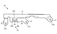
本実施形態に係る車両用シートSは、図1に図示した外観を有している。なお、図1中、車両用シートSの一部(具体的には、シートクッションS1の前端角部)については、説明の都合上、トリムカバー101を外した構成にて図示している。
[1. Configuration of Vehicle Seat S]
The vehicle seat S according to the present embodiment has the appearance illustrated in FIG. In FIG. 1, a part of the vehicle seat S (specifically, a front end corner portion of the seat cushion S1) is illustrated in a configuration in which the
車両用シートSは、着座者の臀部を支える着座部分となるシートクッションS1、着座者の背部を支える背もたれ部分となるシートバックS2、及び、シートバックS2の上部に配置され、着座者の頭部を支えるヘッドレストS3を主な構成要素として有する。シートクッションS1及びシートバックS2の各々は、後述するシートクッションフレーム1及び不図示のシートバックフレームにクッションパッド100を載置し、更にクッションパッド100をトリムカバー101で覆うことで構成されている。なお、シートクッションS1及びシートバックS2は、後述するチルトブラケット20や掛止め部材30を除き、公知の構成を採用している。
The vehicle seat S is disposed on the seat cushion S1 serving as a seating portion supporting the buttocks of the seated person, the seat back S2 serving as a backrest portion supporting the back of the seated person, and the seat back S2 As a main component. Each of the seat cushion S1 and the seat back S2 is configured by placing a
シートクッションS1は、シートクッションフレーム1と、シートクッションフレーム1上に載置されたクッションパッド100と、シートクッションフレーム1及びクッションパッド100を覆うトリムカバー101を含んで構成されている。
クッションパッド100は、ウレタンフォームなどの弾性を有するクッション材からなり、トリムカバー101は、合成皮革や布地などからなり、複数の表皮材が縫製されて形成されている。
The seat cushion S1 includes a
The
[2.シートフレームの概要]
まず、図2を参照しながら、本実施形態に係るシートクッションフレーム1の構成の概要について説明する。シートクッションフレーム1は脚部で支持されており、この脚部には、インナレールが取り付けられ、車体フロアに設置されるアウタレールとの間で、前後方向において位置調整可能なスライド式に組み立てられている。またシートクッションフレーム1の後端部は、不図示のリクライニング機構を介して不図示のシートバックフレームと連結されている。
[2. Outline of seat frame]
First, the outline of the configuration of the
シートクッションフレーム1は、図2に示されるように、上方から見たときに方形枠状の外形形状をなしている。そして、シートクッションフレーム1は、シート幅方向における端部を構成するサイドフレーム1a,1bと、シートクッションフレーム1の前端部を構成するパンフレーム1cと、右のサイドフレーム1aと左のサイドフレーム1bを連結する連結パイプ1dとを主たる構成要素とする。
As shown in FIG. 2, the
2本(一対)のサイドフレーム1a,1bは、シートクッションフレーム1の幅を規定するため、左右方向に離間して配設されており、前後方向に延在するように配設されている。そして、サイドフレーム1a,1bの後方側に連結パイプ1dが取り付けられており、連結パイプ1dによって左右のサイドフレーム1a,1bが後方側で連結される。
In order to define the width of the
また、パンフレーム1cは、一対のサイドフレーム1a,1bの前方側に固着接合されており、パンフレーム1cによって左右のサイドフレーム1a,1bが前方側で連結される。より詳細には、パンフレーム1c左右方向の端部は、それぞれ、溶接などの固定手段によってサイドフレーム1a,1bに設けられたフランジに固定されている。
The pan frame 1c is fixedly joined to the front side of the pair of
パンフレーム1cは、主として着座者(乗員)の大腿部を支持するためのものであり、その上面がほぼ平坦な略矩形形状に形成された金属製の板材から形成されるフレームである。パンフレーム1cは、前方端部が下方に折曲された前方折曲部と、後端部において下方に折曲された後方折曲部を備えている。また、前方折曲部と後方折曲部との間には、上面がほぼ平坦である支持面が備えられている。なお、この支持面の左右方向の端部は、それぞれサイドフレーム1a,1bのフランジに固定されている(図2)。
The pan frame 1c is mainly for supporting the thighs of a seated person (passenger), and is a frame formed of a metal plate material whose upper surface is formed in a substantially flat and substantially rectangular shape. The pan frame 1c includes a front bent portion whose front end is bent downward and a rear bent portion which is bent downward at the rear end. Further, a support surface having a substantially flat upper surface is provided between the front bent portion and the rear bent portion. In addition, the end part of the left-right direction of this support surface is being fixed to the flange of
[3.サイドフレームの構成]
以下、本実施形態に係る車両用シートSのシートクッションフレーム1を構成するサイドフレーム1a,1b及びチルトブラケット20について、図3A乃至4Bを参照しながら説明する。以下、一方のサイドフレーム1bを用いて説明するが、他方のサイドフレーム1aも同様の構成を有している。図3Aは、サイドフレーム1bに取り付けられたチルトブラケット20を示す、シート幅方向の外側から見た斜視図であり、図3Bは、サイドフレーム1bに取り付けられたチルトブラケット20を示す、シート幅方向の内側から見た斜視図である。図4Aは、チルトブラケット20の正面図であり、図4Bは、チルトブラケット20の上面図である。
[3. Configuration of side frame]
Hereinafter, the side frames 1a and 1b and the
図3A及び3Bに示すように、サイドフレーム1bはシート前後方向に延在するサイドフレーム本体10と、サイドフレーム本体10に取り付けられたチルトブラケット20を主構成要素とし、リンク部材12などの傾斜機構(チルトアップ機構)が取り付けられている。
As shown in FIGS. 3A and 3B, the
サイドフレーム本体10は、シートフレーム内側方向に延出するフランジ部10aを備えている。フランジ部10aには、締結部材11a,11bによって、後述するチルトブラケット20の上方取付部28が取り付けられている。
The side frame
また、サイドフレーム本体10には、チルトブラケット20の前方取付部22が締結部材13によって取り付けられ、チルトブラケット20の後方取付部23が締結部材14によって取り付けられている。
Further, the
図3A及び4Aに示すように、チルトブラケット20は、基部21と、基部21の前端部に設けられた前方取付部22と、基部21の後端部に設けられた後方取付部23と、前方取付部22と後方取付部23の間に設けられた延出部24とを備えている。前方取付部22及び後方取付部23には、締結部材を挿通するための取付孔22a及び取付孔23aがそれぞれ設けられている。
As shown in FIGS. 3A and 4A, the
延出部24には、係合凹部25が設けられており、係合凹部25の底部である係合面部25aには基部21の長手方向(シート前後方向)に延出する係合孔26が穿設されている。延出部24の後方側には、不図示のシートベルトバックルを取り付けるためのバックル取付部27が設けられている。バックル取付部27には、締結部材を挿通するためのバックル取付孔27aが設けられている。
An
チルトブラケット20は、基部21から曲折して上方取付部28が形成されており、上方取付部28の前方側には取付孔28aが穿設され、上方取付部28の後方側には取付孔28bが穿設されている(図4B)。
The
図3Bに示すように、シート幅方向において、サイドフレーム本体10とチルトブラケット20の前方取付部22の間には、リンク部材12が締結部材13を介して取り付けられている。本実施形態において、リンク部材12やチルトブラケット20は、シートクッションS1の座面を持ち上げる傾斜機構(チルトアップ機構)の一部である。
As shown in FIG. 3B, the
本実施形態において、チルトブラケット20の係合孔26は、後述する掛止め部材30のフック部33(突出部)が挿入される係合部に相当する。
In the present embodiment, the
[4.トリムカバー及び掛止め部材の構成]
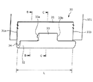
図5A乃至5Cに、本実施形態に係る掛止め部材30を示す。図5Aは、トリムカバー101に縫着された掛止め部材30の斜視図であり、図5Bは、図5AのB−B断面図であり、図5Cは、図5AのC−C断面図である。
[4. Configuration of trim cover and hooking member]
FIGS. 5A to 5C show a hooking
図5Aに示すように、トリムカバー101の端末部には樹脂製の断面J字形状の掛止め部材30が縫着されている。掛止め部材30は、基部31と、該基部31から湾曲して形成された湾曲部32と、湾曲部32から延出するフック部33を備えている。
As shown in FIG. 5A, a
掛止め部材30は、トリムカバー101との縫着部とは反対側の端部にフック部33を有している。また、掛止め部材30のJ字形状の内側には、チルトブラケット20の延出部24を収容するための収容部34が形成されている。
The hooking
図5Aに示すように、フック部33は、湾曲部32の一部から延出するように形成されている。具体的には、基部31の長手方向の第一側端面31aと第二側端面31bとの間の距離L(基部31の長手方向の長さL)は、フック部33の長手方向の第一側端面33aと第二側端面33bとの間の距離(フック部33の長手方向の長さ)よりも長くなるように設定されている。
As shown in FIG. 5A, the
換言すると、フック部33の第一側端面33aは、基部31の第一側端面31aよりも第二側端面31b側にあり、フック部33の第二側端面33bは、基部31の第二側端面31bよりも第一側端面31a側にあるようにフック部33が形成されている。
In other words, the first side end face 33 a of the
図5Cに示すように、フック部33の突出方向は、J字形状の内側に向かう方向(換言すると基部31に向かう方向)となるように形成されている。
As shown to FIG. 5C, the protrusion direction of the
掛止め部材30の収容部34に、チルトブラケット20の延出部24が収容されるとともに、掛止め部材30のフック部33(突出部)が、チルトブラケット20の係合孔26(係合部)と係合することでトリムカバー101がシートクッションフレーム1に取り付けられる。
The
[5.被掛止め部の作用]
図6A,6B及び図7に、チルトブラケット20の係合孔26に対して、トリムカバー101の端部に設けられた掛止め部材30のフック部33を係合させた状態を示す。なお、図6A,6B及び図7では、説明のためにトリムカバー101を省略している。
[5. Action of the hooking portion]
6A, 6B and 7 show a state in which the
シートクッションフレーム1にクッションパッド100を載置した状態で、トリムカバー101がサイドフレーム1bのシート幅方向における外側を覆い、サイドフレーム1a,1bの下端側から掛止め部材30をチルトブラケット20に係合させる。
With the
そして、掛止め部材30の収容部34にチルトブラケット20の延出部24が位置するようにして、掛止め部材30のフック部33をチルトブラケット20の係合孔26に係止する。このようにして、掛止め部材30のサイドフレーム1bに対する取り付けが行われる。
Then, the
図7はフック部33と係合孔26の周囲の断面を示す斜視説明図であって、フック部33が係合孔26と係合した状態を示す説明図である。掛止め部材30が係合孔26と係合した状態においては、シート幅方向の外側から順番に、掛止め部材30のフック部33、チルトブラケット20の延出部24、掛止め部材30の基部31が配置されている。
FIG. 7 is a perspective explanatory view showing a cross section of the
掛止め部材30は、サイドフレーム1bのチルトブラケット20に係合した状態において、基部31(外側配置部)がチルトブラケット20のシート幅方向における外側に配置され、フック部33(内側配置部)がチルトブラケット20のシート幅方向における内側に配置されており、フック部33(突出部)は、シート幅方向において基部31に向かう側(外側)に突出している。
The base member 31 (outer arrangement part) is arranged outside the
したがって、掛止め部材30の基部31(外側配置部)がチルトブラケット20に当接し、フック部33(内側配置部)が基部31(外側配置部)とシート幅方向において離間した位置でチルトブラケット20の外面部に当接するため、シート幅方向における掛止め部材30の位置が規制されることになる。
Therefore, the
また、図8A及び8Bに示すように、掛止め部材30がチルトブラケット20に係合した状態において、フック部33の第一側端面33aのシート前後方向における位置が、係合孔26の第一端部26aによって規制され、フック部33の第二側端面33bのシート前後方向における位置が、係合孔26の第二端部26bによって規制される。
Further, as shown in FIGS. 8A and 8B, in the state where the hooking
つまり、掛止め部材30のフック部33が係合孔26と係合することで、掛止め部材30のシート前後方向における位置が、係合孔26が延出する範囲に規制されるため、過大な荷重がシートクッションにかかってトリムカバーが移動した場合や、チルトアップ可能なシートの場合に、掛止め部材30がシートクッションフレーム1から外れる方向に移動したとしても、掛止め部材がシートクッションフレーム1から外れてしまうことが抑制される。
That is, when the
さらに、シート幅方向において内側に凹んだ係合凹部25の係合面部25aのシート前後方向における長さをlとしたときに(図8A)、シート前後方向における基部31(外側配置部)の長さLは(図8B)、係合面部25aの長さlよりも長くなるように形成されている(L>l)。
Furthermore, when the length of the
したがって、掛止め部材30の基部31(外側配置部)がチルトブラケット20(サイドフレーム)に当接し、フック部33(内側配置部)が基部31とシート幅方向において離間した位置でチルトブラケット20の外面部(延出部24の外面)に当接するため、シート幅方向における掛止め部材30の位置が規制されることになる。
Accordingly, the base 31 (outer arrangement portion) of the
本実施形態の車両用シートSでは、係合孔26(係合部)が、シート幅方向においてサイドフレーム1a,bの外側に配置されているため、掛止め部材30を係合孔26に掛止める際の作業性が向上している。
In the vehicle seat S of the present embodiment, since the engagement hole 26 (engagement portion) is disposed outside the side frames 1a and 1b in the seat width direction, the hooking
本実施形態の車両用シートSでは、係合孔26(係合部)が、シート幅方向におけるサイドフレーム1a,bの外端面よりも内側に設けられているため、乗員が乗り降りする動作を行う際に、乗員がサイドフレーム1a,1bの外端面に接触したとしても、掛止め部材30がシートクッションフレーム1から外れてしまうことが抑制されている。
In the vehicle seat S of the present embodiment, the engagement hole 26 (engagement portion) is provided inside the outer end surface of the side frames 1a and 1b in the seat width direction, so the passenger performs an operation of getting on and off In this case, even if the occupant contacts the outer end face of the side frames 1a and 1b, the retaining
本実施形態の車両用シートSでは、サイドフレーム1a,1bは、サイドフレーム本体10に取り付けられるチルトブラケット20を備えており、チルトブラケット20に係合孔26(係合部)が形成されているため、各部材を設計し易いという効果を奏する。
In the vehicle seat S of the present embodiment, the side frames 1a and 1b include the
本実施形態の車両用シートSでは、チルトブラケット20は、シート幅方向における内側に延出する上方取付部28を備えており、上方取付部28が、サイドフレーム本体10のフランジ部10aにおいて固定されている。したがって、チルトブラケット20がサイドフレーム本体10に安定して取り付けられるため、掛止め部材30のサイドフレーム1a,1bに対する掛止めが安定するという効果を奏する。
In the vehicle seat S of the present embodiment, the
本実施形態の車両用シートSでは、係合孔26(係合部)が形成されたチルトブラケット20が、サイドフレーム1a,1bのサイドフレーム本体10にシート幅方向において固定されているため、掛止め部材30のサイドフレーム1a,1bに対する掛止めが安定するという効果を奏する。
In the vehicle seat S of the present embodiment, the
本実施形態の車両用シートSは、シートクッションS1を傾斜(チルトアップ)可能であり、チルトブラケット20は、シートクッションS1を傾斜させる傾斜機構の一部であるが、掛止め部材30の位置が適切に規制されているため、シートクッションS1の傾斜動作時に掛止め部材30がサイドフレーム1a,1bから外れてしまうことが抑制されている。
The vehicle seat S of the present embodiment can tilt (tilt up) the seat cushion S1, and the
[6.変形例]
本発明は上記の実施形態に限定されるものではない。図4Aにおいて、チルトブラケット20(サイドフレーム)に設けられた係合部の例として、係合孔26の例を示したが、係合部は孔の形態に限定されるものではない。例えば、係合部を、サイドフレームの長手方向(シート前後方向)に掛止め部材30の位置を規制する規制面を備える溝、切欠き、凹部などの形態とすることも可能である。
[6. Modified example]
The present invention is not limited to the above embodiment. Although the example of the engaging
図5Aではフック部33(突出部)が1つ設けられた例を示したが、突出部の数は、これに限定されるものではなく、掛止め部材30を安定して係止できるのであれば、突出部の数を2つ以上とすることも可能である。
Although the example in which one hook part 33 (protrusion part) was provided was shown in FIG. 5A, the number of the projection parts is not limited to this, and the
上述の実施形態において、図3Aに示すように、係合孔26(係合部)がサイドフレーム1a,1bの一部であるチルトブラケット20に設けられた例を示したが、係合部を配置する位置はこれに限定されるものではなく、係合部を、サイドフレーム1a,1bを構成するサイドフレーム本体10などの部材に設けることも可能である。
In the above embodiment, as shown in FIG. 3A, an example is shown in which the engagement hole 26 (engagement portion) is provided on the
以上、本実施形態に係る乗物用シートを車両に搭載される車両用シートを例として説明した。本実施形態に係る乗物用シートは、車両用シートに限定されるものではなく、シートフレーム上に載置したクッションパッドをカバー部材により覆うことで構成されるシート、特に、カバー部材をシートフレームに掛止めする構造を採用したシートのシートフレームであれば、特に用途についての制限はない。例えば、本発明の乗物用シートは、車両以外の乗物内で使用される乗物用シートのシートフレームとしても利用可能である。 In the above, the vehicle seat according to the present embodiment has been described as an example of the vehicle seat mounted on the vehicle. The vehicle seat according to the present embodiment is not limited to a vehicle seat, and a seat configured by covering a cushion pad placed on a seat frame with a cover member, in particular, a cover member as a seat frame If it is a seat frame of the seat which adopted the structure to which it latches, there is no restriction in particular about a use. For example, the vehicle seat of the present invention can also be used as a seat frame of a vehicle seat used in a vehicle other than a vehicle.
S 車両用シート
S1 シートクッション
S2 シートバック
S3 ヘッドレスト
100 クッションパッド(パッド部材)
101 トリムカバー
1 シートクッションフレーム(クッションフレーム)
1a サイドフレーム
1b サイドフレーム
1c パンフレーム
1d 連結パイプ
10 サイドフレーム本体(本体部)
10a フランジ部
11a 締結部材
11b 締結部材
12 リンク部材
13 締結部材
14 締結部材
20 チルトブラケット(ブラケット部材)
21 基部
22 前方取付部
22a 取付孔
23 後方取付部
23a 取付孔
24 延出部
25 係合凹部
25a 係合面部
26 係合孔(係合部)
26a 第一端部
26b 第二端部
27 バックル取付部
27a バックル取付孔
28 上方取付部
28a 取付孔
28b 取付孔
30 掛止め部材
31 基部(外側配置部)
31a 第一側端面
31b 第二側端面
32 湾曲部
33 フック部(突出部、内側配置部)
33a 第一側端面
33b 第二側端面
34 収容部
S Vehicle seat S1 Seat cushion S2 Seat back
101
DESCRIPTION OF
26a
31a first
33a first
Claims (10)
前記シートクッションは、
クッションフレームと、
前記クッションフレームに載置されたパッド部材と、
前記パッド部材を覆うトリムカバーと、を備え、
前記トリムカバーには、突出部が設けられた掛止め部材が取り付けられており、
前記クッションフレームは、シート前後方向に延出する係合部が設けられたサイドフレームを備え、
前記サイドフレームの前記係合部に、前記掛止め部材の前記突出部が挿入されて係合することを特徴とする乗物用シート。 A vehicle seat provided with a seat cushion,
The seat cushion is
Cushion frame,
A pad member placed on the cushion frame;
A trim cover covering the pad member;
A hooking member provided with a projection is attached to the trim cover,
The cushion frame includes a side frame provided with an engaging portion extending in the seat longitudinal direction,
A seat for a vehicle, wherein the projection of the hooking member is inserted into and engaged with the engaging portion of the side frame.
前記サイドフレームの前記乗物用シートの幅方向における内側に配置される内側配置部と、を備え、
前記突出部は、前記内側配置部から前記乗物用シートの幅方向において外側に突出していることを特徴とする請求項1に記載の乗物用シート。 The hooking member is an outer disposition portion disposed outside in the width direction of the vehicle seat of the side frame in a state of being engaged with the side frame;
And an inward placement portion disposed inward in a width direction of the vehicle seat of the side frame;
2. The vehicle seat according to claim 1, wherein the projecting portion protrudes outward in the width direction of the vehicle seat from the inside arrangement portion.
前記凹部は、前記係合部が配置された係合面部を備え、
前記乗物用シートの前後方向における前記外側配置部の長さは、前記係合面部の長さよりも長く形成されていることを特徴とする請求項2に記載の乗物用シート。 The side frame is formed with a recess that is recessed inward in the width direction of the vehicle seat,
The recess includes an engagement surface portion on which the engagement portion is disposed,
The vehicle seat according to claim 2, wherein a length of the outer arrangement portion in the front-rear direction of the vehicle seat is formed longer than a length of the engagement surface portion.
本体部と、該本体部に取り付けられるブラケット部材とを備え、
前記ブラケット部材に前記係合部が形成されていることを特徴とする請求項1乃至6のいずれか一項に記載の乗物用シート。 The side frame is
A main body portion, and a bracket member attached to the main body portion;
The vehicle seat according to any one of claims 1 to 6, wherein the engaging portion is formed on the bracket member.
基部と、
前記基部から曲折して設けられた取付部と、を備え、
前記サイドフレームの前記本体部は、前記乗物用シートの幅方向における内側に延出するフランジ部を備え、
前記取付部は、前記フランジ部において前記サイドフレームに固定されることを特徴とする請求項7に記載の乗物用シート。 The bracket member is
The base,
And an attaching portion provided by bending from the base portion,
The main body portion of the side frame includes a flange portion extending inward in the width direction of the vehicle seat,
The vehicle seat according to claim 7, wherein the attachment portion is fixed to the side frame at the flange portion.
Priority Applications (6)
| Application Number | Priority Date | Filing Date | Title |
|---|---|---|---|
| JP2017230133A JP2019098853A (en) | 2017-11-30 | 2017-11-30 | Vehicle seat |
| CN201880076047.2A CN111386211B (en) | 2017-11-30 | 2018-11-28 | Seat for vehicle |
| BR112020010496-5A BR112020010496B1 (en) | 2017-11-30 | 2018-11-28 | DRIVING SEAT |
| PCT/JP2018/043869 WO2019107451A1 (en) | 2017-11-30 | 2018-11-28 | Vehicle seat |
| US16/767,167 US11059402B2 (en) | 2017-11-30 | 2018-11-28 | Conveyance seat |
| JP2022160368A JP7381957B2 (en) | 2017-11-30 | 2022-10-04 | vehicle seat |
Applications Claiming Priority (1)
| Application Number | Priority Date | Filing Date | Title |
|---|---|---|---|
| JP2017230133A JP2019098853A (en) | 2017-11-30 | 2017-11-30 | Vehicle seat |
Related Child Applications (1)
| Application Number | Title | Priority Date | Filing Date |
|---|---|---|---|
| JP2022160368A Division JP7381957B2 (en) | 2017-11-30 | 2022-10-04 | vehicle seat |
Publications (1)
| Publication Number | Publication Date |
|---|---|
| JP2019098853A true JP2019098853A (en) | 2019-06-24 |
Family
ID=66975563
Family Applications (2)
| Application Number | Title | Priority Date | Filing Date |
|---|---|---|---|
| JP2017230133A Pending JP2019098853A (en) | 2017-11-30 | 2017-11-30 | Vehicle seat |
| JP2022160368A Active JP7381957B2 (en) | 2017-11-30 | 2022-10-04 | vehicle seat |
Family Applications After (1)
| Application Number | Title | Priority Date | Filing Date |
|---|---|---|---|
| JP2022160368A Active JP7381957B2 (en) | 2017-11-30 | 2022-10-04 | vehicle seat |
Country Status (1)
| Country | Link |
|---|---|
| JP (2) | JP2019098853A (en) |
Citations (4)
| Publication number | Priority date | Publication date | Assignee | Title |
|---|---|---|---|---|
| JP2010057855A (en) * | 2008-09-08 | 2010-03-18 | Toyota Boshoku Corp | Skin material draw-in structure for vehicle seat |
| JP2016087197A (en) * | 2014-11-07 | 2016-05-23 | トヨタ紡織株式会社 | Vehicle seat |
| JP2017012227A (en) * | 2015-06-26 | 2017-01-19 | 株式会社タチエス | Trim cover fixture and trim cover, and vehicle seat |
| JP2017124791A (en) * | 2016-01-15 | 2017-07-20 | トヨタ紡織株式会社 | Vehicular seat |
Family Cites Families (1)
| Publication number | Priority date | Publication date | Assignee | Title |
|---|---|---|---|---|
| US3981534A (en) | 1975-06-27 | 1976-09-21 | Universal Oil Products Company | Seat cover fastening system |
-
2017
- 2017-11-30 JP JP2017230133A patent/JP2019098853A/en active Pending
-
2022
- 2022-10-04 JP JP2022160368A patent/JP7381957B2/en active Active
Patent Citations (4)
| Publication number | Priority date | Publication date | Assignee | Title |
|---|---|---|---|---|
| JP2010057855A (en) * | 2008-09-08 | 2010-03-18 | Toyota Boshoku Corp | Skin material draw-in structure for vehicle seat |
| JP2016087197A (en) * | 2014-11-07 | 2016-05-23 | トヨタ紡織株式会社 | Vehicle seat |
| JP2017012227A (en) * | 2015-06-26 | 2017-01-19 | 株式会社タチエス | Trim cover fixture and trim cover, and vehicle seat |
| JP2017124791A (en) * | 2016-01-15 | 2017-07-20 | トヨタ紡織株式会社 | Vehicular seat |
Also Published As
| Publication number | Publication date |
|---|---|
| JP2022173555A (en) | 2022-11-18 |
| JP7381957B2 (en) | 2023-11-16 |
Similar Documents
| Publication | Publication Date | Title |
|---|---|---|
| CN111516568B (en) | Seat for vehicle | |
| CN108372817B (en) | Seat assembly with pillow subassembly | |
| JP2015209079A (en) | Vehicular seat | |
| JP2003191780A (en) | Seat device for automobile | |
| CN111532178B (en) | Vehicle seat | |
| CN111516558A (en) | Vehicle seat | |
| JP2023115320A (en) | vehicle seat | |
| JP2019098853A (en) | Vehicle seat | |
| JP2017205619A (en) | Hanging-in structure of skin material | |
| JP2022147823A (en) | Vehicle seat and manufacturing method of vehicle seat | |
| CN113508055A (en) | Covering for a cushion part of a vehicle seat, cushion part of a vehicle seat and vehicle seat | |
| JP7397301B2 (en) | vehicle seat | |
| JP7328494B2 (en) | vehicle seat | |
| JP7193703B2 (en) | vehicle seat | |
| JP6922096B2 (en) | Seat frame and seat | |
| JP7153618B2 (en) | Rear seat boundary covering structure | |
| JP2020124976A (en) | Vehicular seat | |
| US11849857B2 (en) | Cover material fixing device and conveyance seat | |
| CN113365532B (en) | Vehicle seat | |
| JP2020124974A (en) | Vehicular seat | |
| JP2021079763A (en) | Vehicle seat | |
| JP7128404B2 (en) | vehicle seat | |
| US10710472B2 (en) | Vehicle seat | |
| JP6907919B2 (en) | Vehicle seat | |
| JP2020124978A (en) | Vehicular seat |
Legal Events
| Date | Code | Title | Description |
|---|---|---|---|
| A621 | Written request for application examination |
Free format text: JAPANESE INTERMEDIATE CODE: A621 Effective date: 20201117 |
|
| A131 | Notification of reasons for refusal |
Free format text: JAPANESE INTERMEDIATE CODE: A131 Effective date: 20220118 |
|
| A521 | Request for written amendment filed |
Free format text: JAPANESE INTERMEDIATE CODE: A523 Effective date: 20220309 |
|
| A02 | Decision of refusal |
Free format text: JAPANESE INTERMEDIATE CODE: A02 Effective date: 20220705 |