JP2019098601A - Method for molding tubular hollow body and tubular hollow body - Google Patents
Method for molding tubular hollow body and tubular hollow body Download PDFInfo
- Publication number
- JP2019098601A JP2019098601A JP2017230765A JP2017230765A JP2019098601A JP 2019098601 A JP2019098601 A JP 2019098601A JP 2017230765 A JP2017230765 A JP 2017230765A JP 2017230765 A JP2017230765 A JP 2017230765A JP 2019098601 A JP2019098601 A JP 2019098601A
- Authority
- JP
- Japan
- Prior art keywords
- resin
- hollow body
- tubular hollow
- layer portion
- core
- Prior art date
- Legal status (The legal status is an assumption and is not a legal conclusion. Google has not performed a legal analysis and makes no representation as to the accuracy of the status listed.)
- Pending
Links
Images


Abstract
Description
本発明は、多層構造の管状中空体を成形する管状中空体成形方法及び管状中空体に関する。 The present invention relates to a tubular hollow body forming method and tubular hollow body for forming a tubular hollow body having a multilayer structure.
樹脂製の管状中空体は、ウォーターパイプ、オイルクーリングパイプ、エアダクト等の様々な部品に用いられるとともに、様々な屈曲形状に成形される。このような管状中空体を製造するための一つの方法として、特許文献1,2に記載された流体アシスト成形がある。流体アシスト成形では、一端にフローティングコアが設けられた加圧ポートが形成されるとともに他端に排出部が形成された主キャビティと、主キャビティの排出部に連通された副キャビティと、を備える成形用型を用意する。そして、主キャビティに樹脂を射出した後、加圧ポートから加圧流体を圧入することによりフローティングコアを移動させ、主キャビティ内の樹脂及びフローティングコアを排出部から副キャビティに排出する。これにより、管状中空体の内周面が成形される。その後、主キャビティ及び副キャビティから樹脂の成形品を取り出して、副キャビティに排出された部分を成形品から切断除去することで、管状中空体が得られる。
The tubular hollow body made of resin is used for various parts such as a water pipe, an oil cooling pipe, an air duct and the like, and is formed into various bent shapes. As one method for producing such a tubular hollow body, there is fluid assist molding described in
そして、特許文献1に記載された成形方法では、外層部を成形するための第一樹脂及び内層部を形成するための第二樹脂を主キャビティに射出した後、フローティングコアを移動させることで、二層の管状中空体を成形している。 Then, in the molding method described in Patent Document 1, the first resin for molding the outer layer portion and the second resin for forming the inner layer portion are injected into the main cavity, and then the floating core is moved, A two-layered tubular hollow body is formed.
また、特許文献2に記載された成形方法では、第一成形用型に外層部を成形するための第一樹脂を射出してフローティングコアを移動させることで外層部を成形し、その成形品を第二成形用型に移し替え、第二成形用型に内層部を形成するための第二樹脂を射出してフローティングコアを移動させることで、二層の管状中空体を成形している。
Further, in the molding method described in
しかしながら、特許文献1に記載された成形方法では、外層部を成形するための第一樹脂及び内層部を形成するための第二樹脂の双方を射出する特殊な射出装置が必須となるため、成形コストが高くなるという問題がある。更に、この成形方法では、射出した第一樹脂と第二樹脂とを層状に形成する必要があるため、極めて高度な射出技術が必要になる。しかも、副キャビティに排出された樹脂は第一樹脂と第二樹脂との混合物となるため、これらを分離することが困難であり、排出された樹脂を再利用することができないという問題もある。 However, the molding method described in Patent Document 1 requires a special injection device for injecting both the first resin for molding the outer layer portion and the second resin for forming the inner layer portion. There is a problem that the cost is high. Furthermore, in this molding method, since it is necessary to form the injected first resin and the second resin in layers, a very advanced injection technique is required. In addition, since the resin discharged into the sub cavity is a mixture of the first resin and the second resin, it is difficult to separate them, and there is also a problem that the discharged resin can not be reused.
また、特許文献2に記載された成形方法でも、外層部成形用の成形用型及び内層部成形用の成型用型の2つの成形用型を用意する必要があるとともに、第一樹脂の成型品を第一成形用型から第二成形用型に移し替える工程が必要となるため、成形コストが高くなるという問題がある。
Further, even with the molding method described in
そこで、本発明は、成形コストを抑制することができる管状中空体成形方法及び管状中空体を提供することを課題とする。 Then, this invention makes it a subject to provide the tubular hollow body shaping | molding method and tubular hollow body which can suppress shaping | molding cost.
本発明者は、上記課題について鋭意検討した結果、フローティングコアを溶融させながら移動させて、このフローティングコアの溶融物により内層部を成形することで、成形コストを抑制して多層構造の管状中空体を成形することができるとの知見を得た。 As a result of intensive studies on the above problems, the present inventor moves the floating core while melting it, and the inner layer portion is formed by the molten material of the floating core, thereby suppressing the forming cost and forming a tubular hollow body having a multilayer structure. We have found that it can be molded.
なお、特許文献3及び4には、フローティングコアが溶融しないように、フローティングコア(プロジェクタイル)として、成形用型に射出する樹脂よりも高い融点を有する材料等を用いることが記載されている。しかしながら、特許文献3及び4の方法では、フローティングコアが溶融しないため、当該フローティングコアにより内層部を形成することができない。
本発明の一側面に係る管状中空体成形方法は、外層部と外層部の内層側に積層される内層部とを備える多層構造の管状中空体を成形する管状中空体成形方法であって、管状中空体の外形を成して、第一樹脂が射出される主キャビティと、主キャビティの一端に形成されて、主キャビティに加圧流体が圧入される加圧ポートと、主キャビティの他端に形成されて、主キャビティから第一樹脂を排出する排出部と、を有する成形用型の加圧ポートに、フローティングコアを着脱可能に設けるコア設置工程と、コア設置工程の後、主キャビティに第一樹脂を射出する射出工程と、射出工程の後、加圧ポートから加圧流体を圧入することでフローティングコアを加圧ポートから排出部側に向けて移動させ、排出部から第一樹脂を排出するコア移動工程と、を備え、フローティングコアは、第一樹脂とは種類の異なる第二樹脂により形成されており、射出工程では、主キャビティに射出する第一樹脂の射出温度を、第二樹脂の融点よりも高くし、コア移動工程では、フローティングコアを溶融させながら加圧ポートから排出部側に向けて移動させる。 The method for forming a tubular hollow body according to one aspect of the present invention is a method for forming a tubular hollow body having a multilayer structure comprising an outer layer portion and an inner layer portion laminated on the inner layer side of the outer layer portion. The hollow body has an outer shape, a main cavity into which the first resin is injected, a pressure port formed at one end of the main cavity, into which the pressurized fluid is pressed into the main cavity, and the other end of the main cavity After the core setting step of forming the floating core so as to be able to be detachably attached to the pressure port of the forming die having the discharge portion for discharging the first resin from the main cavity, and the core setting step, (1) After the injection step of injecting the resin and the injection step, the floating core is moved from the pressure port toward the discharge portion by pressing the pressurized fluid from the pressure port, and the first resin is discharged from the discharge portion Core transfer process The floating core is formed of a second resin different in type from the first resin, and in the injection step, the injection temperature of the first resin injected into the main cavity is higher than the melting point of the second resin In the core moving step, the floating core is moved from the pressure port toward the outlet while melting the floating core.
この管状中空体成形方法では、射出工程において、主キャビティに第一樹脂を射出し、その後、コア移動工程において、加圧ポートから加圧流体を圧入して、フローティングコアを加圧ポートから排出部側に向けて移動させ、排出部から第一樹脂を排出する。これにより、主キャビティに射出された第一樹脂は、中空状に形成される。ここで、射出工程において、第二樹脂の融点よりも高い射出温度で第一樹脂を主キャビティに射出する。このため、主キャビティに射出された第一樹脂からの入熱により、更には第一樹脂との間の摩擦熱により、フローティングコアを溶融させることができる。そこで、フローティングコアを溶融させながら加圧ポートから排出部側に向けて移動させることで、第一樹脂を中空状に形成すると同時に、中空状に形成された第一樹脂の内周側に溶融した第二樹脂を付着させることができる。これにより、第一樹脂の外層部と第二樹脂の内層部とが積層された多層構造の管状中空体を得ることができる。なお、管状中空体を3層以上の多層構造とする場合は、例えば、上記の管状中空体成形方法により得た管状中空体に対して、更に、上記の管状中空体成形方法、二色成形、公知の流体アシスト成形等を行うことで、管状中空体の内層側又は/及び外層側に更な層を成形すればよい。このように、主キャビティに樹脂を射出して、フローティングコアを移動させるという簡易な方法で、多層構造の管状中空体を成形することができるため、成形コストを抑制することができる。 In this tubular hollow body forming method, in the injection step, the first resin is injected into the main cavity, and then, in the core moving step, the pressurized fluid is pressed in from the pressure port to discharge the floating core from the pressure port. Move to the side and discharge the first resin from the discharge unit. Thereby, the first resin injected into the main cavity is formed hollow. Here, in the injection step, the first resin is injected into the main cavity at an injection temperature higher than the melting point of the second resin. For this reason, the floating core can be melted by heat input from the first resin injected into the main cavity and further by frictional heat with the first resin. Therefore, the first resin is formed in a hollow shape, and at the same time, the first resin is melted on the inner peripheral side of the first resin formed in a hollow shape by moving the floating core from the pressure port toward the discharge portion while melting the floating core. A second resin can be deposited. Thus, a tubular hollow body having a multilayer structure in which the outer layer portion of the first resin and the inner layer portion of the second resin are laminated can be obtained. When the tubular hollow body has a multilayer structure of three or more layers, for example, the tubular hollow body obtained by the above-mentioned tubular hollow body molding method further includes the above-mentioned tubular hollow body molding method, two-color molding, Further layers may be formed on the inner layer side and / or the outer layer side of the tubular hollow body by performing known fluid assisted molding or the like. As described above, since the tubular hollow body having a multilayer structure can be formed by a simple method of injecting the resin into the main cavity and moving the floating core, the forming cost can be suppressed.
第一樹脂の射出温度は、第二樹脂の融点よりも80〜160℃高くてもよい。この管状中空体成形方法では、第一樹脂の射出温度が第二樹脂の融点よりも80〜160℃高いため、フローティングコアを溶融させやすくしつつ、第一樹脂の射出温度が高くなりすぎるのを抑制することができる。 The injection temperature of the first resin may be 80 to 160 ° C. higher than the melting point of the second resin. In this tubular hollow body molding method, since the injection temperature of the first resin is 80 to 160 ° C. higher than the melting point of the second resin, the injection temperature of the first resin becomes too high while facilitating melting of the floating core. It can be suppressed.
第二樹脂の融点は、第一樹脂の融点よりも低くてもよい。この管状中空体成形方法では、フローティングコアを形成する第二樹脂の融点が主キャビティに射出される第一樹脂の融点よりも低いため、主キャビティに射出された第一樹脂により、フローティングコアを溶融させやすくなる。 The melting point of the second resin may be lower than the melting point of the first resin. In this tubular hollow body molding method, since the melting point of the second resin forming the floating core is lower than the melting point of the first resin injected into the main cavity, the floating core is melted by the first resin injected into the main cavity It becomes easy to do.
第二樹脂の融点は、第一樹脂の融点よりも65〜80℃低くてもよい。この管状中空体成形方法では、第二樹脂の融点が第一樹脂の融点よりも65〜80℃低いため、フローティングコアを溶融させやすくしつつ、第二樹脂の選択の幅を広げることができる。 The melting point of the second resin may be 65 to 80 ° C. lower than the melting point of the first resin. In this tubular hollow body molding method, the melting point of the second resin is 65 to 80 ° C. lower than the melting point of the first resin, so the range of choice of the second resin can be expanded while facilitating melting of the floating core.
射出工程が終了してから4〜6秒後にコア移動工程を行ってもよい。この管状中空体成形方法では、射出工程が終了してから4〜6秒後にコア移動工程を行うことで、主キャビティに射出された第一樹脂からフローティングコアへの入熱量を大きくすることができるため、フローティングコアを溶融させやすくすることができる。
The core moving step may be performed 4 to 6 seconds after the injection step is completed. In this method for forming a tubular hollow body, the heat transfer amount from the first resin injected into the main cavity to the floating core can be increased by performing the
成形用型は、排出部に連通されて排出部から排出された第一樹脂を貯留する副キャビティを更に有し、コア移動工程では、フローティングコアを、副キャビティの手前で停止させてもよい。この管状中空体形成方法では、フローティングコア及びフローティングコアの溶融物は、副キャビティに排出されないため、副キャビティに排出された樹脂を容易に再利用することができる。これにより、成形コストを更に抑制することができる。 The mold may further include a sub cavity in communication with the discharge portion and storing the first resin discharged from the discharge portion, and in the core moving step, the floating core may be stopped before the sub cavity. In this method for forming a tubular hollow body, the floating core and the melt of the floating core are not discharged to the sub cavity, so the resin discharged to the sub cavity can be easily reused. Thereby, the molding cost can be further suppressed.
射出工程では、補強材を含有させた第一樹脂を主キャビティに射出してもよい。この管状中空体成形方法では、補強材を含有させた第一樹脂を主キャビティに射出するため、成形された管状中空体の強度を高めることができる。 In the injection step, the first resin containing the reinforcing material may be injected into the main cavity. In this tubular hollow body molding method, since the first resin containing the reinforcing material is injected into the main cavity, the strength of the molded tubular hollow body can be increased.
本発明の一側面に係る管状中空体は、外層部と外層部の内層側に積層される内層部とを備える多層構造の管状中空体であって、外層部は、第一樹脂により形成されており、内層部は、第一樹脂よりも融点の低い第二樹脂により形成されている。 The tubular hollow body according to one aspect of the present invention is a tubular hollow body having a multilayer structure including an outer layer portion and an inner layer portion laminated on the inner layer side of the outer layer portion, wherein the outer layer portion is formed of a first resin The inner layer portion is formed of a second resin having a melting point lower than that of the first resin.
この管状中空体では、第一樹脂により形成された外層部と、第一樹脂よりも融点の低い第二樹脂により形成された内層部と、が積層されているため、上記の何れかの方法により成形することができる。このため、成形コストを抑制することができる。つまり、この管状中空体は、上記の何れかの方法により成形されたものとすることができる。また、内層部は、外層部の第一樹脂よりも融点の低い第二樹脂により形成されているため、例えば、内層部において低透過性、耐食性、耐薬品性等を高め、外層部において耐熱性を高めることができる。 In this tubular hollow body, the outer layer portion formed of the first resin and the inner layer portion formed of the second resin having a melting point lower than that of the first resin are laminated, and thus any of the methods described above It can be molded. For this reason, molding cost can be suppressed. That is, this tubular hollow body can be formed by any of the methods described above. Further, since the inner layer portion is formed of the second resin having a melting point lower than the first resin of the outer layer portion, for example, low permeability, corrosion resistance, chemical resistance, etc. are enhanced in the inner layer portion, and heat resistance in the outer layer portion Can be enhanced.
外層部と内層部とは、互いに融合されていてもよい。この管状中空体では、外層部と内層部とが互いに融合されているため、外層部と内層部とが剥離するのを抑制することができる。 The outer layer portion and the inner layer portion may be fused with each other. In this tubular hollow body, since the outer layer portion and the inner layer portion are fused to each other, it is possible to suppress peeling of the outer layer portion and the inner layer portion.
一方端における内径は、他方端における内径と異なっていてもよい。この管状中空体では、一方端における内径が他方端における内径と異なるため、管状中空体内を流通する流体の圧力を変えることができる。 The inner diameter at one end may be different from the inner diameter at the other end. In this tubular hollow body, since the inner diameter at one end is different from the inner diameter at the other end, the pressure of fluid flowing in the tubular hollow body can be changed.
一方端から他方端にかけて、内径が徐々に小さくなっていてもよい。この管状中空体では、一方端から他方端にかけて内径が徐々に小さくなっているため、管状中空体内を流通する流体の圧力を変えることができる。 The inner diameter may be gradually reduced from one end to the other end. In this tubular hollow body, since the inner diameter gradually decreases from one end to the other end, the pressure of the fluid flowing in the tubular hollow body can be changed.
外層部には、第一樹脂を補強する補強材が含有されていてもよい。この管状中空体では、外層部に、第一樹脂を補強する補強材が含有されているため、管状中空体の強度を高めることができる。 The outer layer portion may contain a reinforcing material for reinforcing the first resin. In this tubular hollow body, since the outer layer portion contains a reinforcing material for reinforcing the first resin, the strength of the tubular hollow body can be enhanced.
本発明に係る管状中空体成形方法及び管状中空体によれば、成形コストを抑制することができる。 According to the tubular hollow body molding method and the tubular hollow body according to the present invention, the molding cost can be suppressed.
以下、図面を参照して、本発明の実施形態について説明する。本明細書において「〜」を用いて示された数値範囲は、「〜」の前後に記載される数値をそれぞれ最小値及び最大値として含む範囲を示す。なお、各図において同一又は相当する要素については同一の符号を付し、重複する説明を省略する。 Hereinafter, embodiments of the present invention will be described with reference to the drawings. The numerical range shown using "-" in this specification shows the range which includes the numerical value described before and after "-" as minimum value and the maximum value, respectively. The same or corresponding elements in the drawings will be denoted by the same reference symbols, without redundant description.
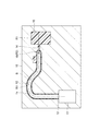
図1に示すように、本実施形態に係る管状中空体1は、一方端1aから他方端1bにかけて細長い管状に形成された樹脂製の中空体である。管状中空体1の管形状は、特に限定されるものではなく、例えば、外周面1c及び内周面1dの断面が円形となる円管状とすることができる。なお、本実施形態では、管状中空体1は円管状であるものとして説明する。
As shown in FIG. 1, the tubular hollow body 1 according to the present embodiment is a hollow resin body that is formed in an elongated tubular shape from one
一方端1aにおける管状中空体1の内径は、他方端1bにおける管状中空体1の内径と異なっている。より具体的には、一方端1aから他方端1bにかけて、管状中空体1の内径が徐々に小さくなっている。なお、管状中空体1における両端のうち、何れが一方端1a又は他方端1bであってもよい。
The inner diameter of the tubular hollow body 1 at one
管状中空体1は、管状中空体1の軸線Aに沿って、1又は2以上の直線部2と、1又は2以上の屈曲部3を備える。なお、直線部2の数、位置、長さ等は特に限定されるものではない。また、屈曲部3の数、位置、長さ、形状(曲率)等は特に限定されるものではない。
The tubular hollow body 1 includes one or more
管状中空体1の外周面1cには、管状中空体1をエンジン等の他部材に固定するための固定板部4が設けられている。固定板部4の数、位置、形状等は特に限定されるものではない。なお、管状中空体1には、必ずしも固定板部4が設けられていなくてもよい。
A fixing
管状中空体1は、複数の樹脂層が積層された多層構造となっている。なお、本実施形態では、管状中空体1は、外層部5と、外層部5の内層側に積層される内層部6と、を備えた二層構造であるものとして説明する。
The tubular hollow body 1 has a multilayer structure in which a plurality of resin layers are stacked. In the present embodiment, the tubular hollow body 1 is described as having a two-layer structure including the
外層部5は、第一樹脂により形成されている。外層部5を形成する第一樹脂としては、例えば、耐熱性、耐衝撃性、耐食性等に優れる性質を有する樹脂を用いることが好ましい。第一樹脂としては、例えば、ポリアミド6(PA6)、ポリアミド66(PA66)等のポリアミド(PA)、芳香族ポリアミド、ポリフェニレンサルファイド(PPS)等が挙げられる。
The
内層部6は、第一樹脂とは種類の異なる第二樹脂により形成されている。第二樹脂の融点は、第一樹脂の融点よりも低い。第二樹脂の融点は、第一樹脂の融点よりも低ければ特に限定されないが、第一樹脂の融点よりも65〜80℃低いことが好ましく、65〜70℃低いことが更に好ましく、65℃低いことが特に好ましい。内層部6を形成する第二樹脂としては、例えば、耐薬品性、耐熱性等に優れる性質を有する樹脂を用いることが好ましい。第二樹脂としては、例えば、ポリアミド6(PA6)、ポリアミド66(PA66)等のポリアミド(PA)、ポリプロピレン(PP)、ポリエチレン(PE)、エチレン−ビニルアルコール共重合体(EVOH)等が挙げられる。
The
外層部5の第一樹脂及び内層部6の第二樹脂には、補強材(不図示)が含有されていてもよい。補強材としては、ガラス繊維、炭素繊維、天然繊維等の繊維状補強材、ガラスビーズ等の粒状補強材などが挙げられる。なお、補強材は、外層部5の第一樹脂及び内層部6の第二樹脂の双方に含有されていてもよいが、製造容易性等の観点から外層部5の第一樹脂にのみ含有されていてもよい。
The first resin of the
外層部5と内層部6とは、互いに融合されている。つまり、外層部5と内層部6との間には、二色成形又は2回の流体アシスト成形により外層部と内層部とを積層した場合に形成される界面が形成されていない。但し、外層部5と内層部6とが互いに融合されていれば、外層部5と内層部6との間に界面が形成されていてもよい。
The
次に、本実施形態に係る管状中空体成形方法について説明する。 Next, the method for forming a tubular hollow body according to the present embodiment will be described.
まず、図4に示すように、成形用型10を用意する。成形用型10は、流体アシスト成形により管状中空体1を成形するための金型である。成形用型10は、主キャビティ11と、加圧ポート12と、インジェクタ13と、排出部14と、副キャビティ15と、フローティングコア16と、を備えている。
First, as shown in FIG. 4, a
主キャビティ11は、管状中空体1の外形(外周面1cの形状)を成して、第一樹脂(加熱溶融した第一樹脂)が射出されるキャビティである。加圧ポート12は、主キャビティ11の一端に形成されて、主キャビティ11に加圧流体が圧入されるポートである。インジェクタ13は、加圧ポート12に連通されて加圧流体を噴射する噴射装置である。排出部14は、主キャビティ11の他端に形成されて、主キャビティ11から第一樹脂を排出する流路である。なお、排出部14は、主キャビティ11と副キャビティ15とを連通する単なる開口であってもよい。副キャビティ15は、排出部14に連通されたキャビティであって、排出部14から排出された第一樹脂を貯留するキャビティである。
The
フローティングコア16は、プロジェクタイルとも呼ばれる。フローティングコア16は、加圧ポート12に着脱可能に設けられる。フローティングコア16は、加圧ポート12から圧入される加圧流体で押圧されるように、加圧ポート12を背にして主キャビティ11内に設けられる。フローティングコア16の最大径は、主キャビティ11の内径よりも小さく、排出部14の内径よりも十分に大きい。このため、加圧ポート12から加圧流体が圧入されると、フローティングコア16は、主キャビティ11を加圧ポート12から排出部14側に向けて移動し、主キャビティ11の排出部14側の壁面に衝突して停止する。フローティングコア16の形状は、特に限定されるものではなく、砲弾形、円錐形、半球形、球形等とすることができる。本実施形態では、フローティングコア16は、砲弾形であるものとして説明する。
The floating
本実施形態に係る管状中空体成形方法では、コア設置工程、射出工程、コア移動工程、取出工程、及び切断工程をこの順で行う。 In the method for forming a tubular hollow body according to the present embodiment, the core setting step, the injection step, the core moving step, the removing step, and the cutting step are performed in this order.
図4に示すように、コア設置工程では、成形用型10の加圧ポート12に、第二樹脂R2で形成されたフローティングコア16を着脱可能に設ける。フローティングコア16を形成する第二樹脂R2は、管状中空体1の内層部6を形成する第二樹脂と同じである。なお、フローティングコア16は、補強材を含有させた第二樹脂R2により形成されていてもよい。この補強材は、上述した管状中空体1の内層部6に含有される補強材と同じである。
As shown in FIG. 4, in the core installation step, the floating
図5に示すように、次の射出工程では、油圧シリンダ等により副キャビティ15を閉じて、主キャビティ11に第一樹脂R1を射出する。主キャビティ11に射出する第一樹脂R1は、上述した管状中空体1の外層部5を形成する第一樹脂と同じである。成形用型10には、主キャビティ11に連通される1又は複数のゲート(不図示)が形成されており、このゲートから主キャビティ11に加熱溶融した第一樹脂R1を射出する。すると、主キャビティ11及び排出部14に第一樹脂R1が充填される。
As shown in FIG. 5, in the next injection process, the
また、射出工程では、第一樹脂R1を加熱溶融することで、主キャビティ11に射出する第一樹脂R1の射出温度を、フローティングコア16を形成する第二樹脂R2の融点よりも高くする。第一樹脂R1の射出温度は、第二樹脂R2の融点よりも高ければ特に限定されないが、第二樹脂R2の融点よりも80〜160℃以上高いことが好ましく、90〜160℃以上高いことが更に好ましく、95〜160℃以上高いことが特に好ましい。例えば、第一樹脂R1の射出温度は、第二樹脂R2の融点よりも95℃高い温度とすることができる。
In the injection step, the first resin R1 is heated and melted to make the injection temperature of the first resin R1 injected into the
また、射出工程では、補強材を含有させた第一樹脂R1を主キャビティ11に射出してもよい。この補強材は、上述した管状中空体1の外層部5に含有される補強材と同じである。
Further, in the injection step, the first resin R1 containing a reinforcing material may be injected into the
次のコア移動工程では、油圧シリンダ等により副キャビティ15を開く。そして、図6及び図7に示すように、加圧ポート12から加圧流体を圧入して、フローティングコア16を加圧ポート12から排出部14側に向けて移動させる。つまり、加圧ポート12から主キャビティ11に加圧流体を圧入すると、加圧ポート12に設けられていたフローティングコア16は、加圧流体に押圧されることで、主キャビティ11の軸線Bに沿って加圧ポート12から排出部14側に向けて移動する。そして、フローティングコア16を、副キャビティ15の手前で停止させる。具体的には、加圧ポート12から排出部14側に向けて移動するフローティングコア16を、主キャビティ11の排出部14側の壁面に衝突させることで、その移動を停止させる。加圧流体としては、第一樹脂R1の射出温度及び圧力下で、第一樹脂R1と反応又は相溶しない気体又は液体を用いることが好ましい。加圧流体としては、例えば、窒素ガス、炭酸ガス、空気、水、グリセリン、流動パラフィン等が挙げられる。そして、フローティングコア16をこのように移動させることで、排出部14から副キャビティ15に第一樹脂R1を排出する。これにより、主キャビティ11に射出された第一樹脂R1は、中空状に形成される。
In the next core moving step, the
ここで、第二樹脂R2の融点が第一樹脂R1よりも低く、また、第二樹脂R2の融点よりも高い射出温度で第一樹脂R1を主キャビティ11に射出しているため、主キャビティ11に射出された第一樹脂R1からの入熱により、更には第一樹脂R1との間の摩擦熱により、フローティングコア16を溶融させることができる。このとき、射出工程が終了した直後にコア移動工程を行ってもよいが、フローティングコア16を溶融させやすくする観点から、射出工程が終了してから4〜6秒後にコア移動工程を行うことが好ましく、射出工程が終了してから5〜6秒後にコア移動工程を行うことが更に好ましく、射出工程が終了してから6秒後にコア移動工程を行うことが特に好ましい。
Here, since the first resin R1 is injected into the
そして、コア移動工程では、フローティングコア16を溶融させながら加圧ポート12から排出部14側に向けて移動させる。これにより、第一樹脂R1が中空状に形成される同時に、第一樹脂R1の内周側に溶融した第二樹脂R2が付着して、第一樹脂R1の内周側に第二樹脂R2が積層された状態となる。ここで、フローティングコア16は、溶融しながら加圧ポート12から排出部14側に向けて移動するため、加圧ポート12から排出部14側に向かうに従い徐々に小さくなっていく。このため、主キャビティ11における加圧ポート12側の先端から排出部14側の先端にかけて、第一樹脂R1と第二樹脂R2との積層物の内径が徐々に小さくなる。つまり、第一樹脂R1と第二樹脂R2との積層物の内径は、主キャビティ11における加圧ポート12側の先端よりも排出部14側の先端の方が小さくなる。
Then, in the core moving step, the floating
そして、フローティングコア16は、主キャビティ11の排出部14側の壁面に衝突して停止するため、フローティングコア16及びフローティングコア16の溶融物は、副キャビティ15に排出されない。たとえ、フローティングコア16の溶融物が副キャビティ15に排出されたとしても、その排出量は極微量である。そして、第一樹脂R1及び第二樹脂R2が冷却硬化するまで待つ。
Then, since the floating
図8に示すように、次の取出工程では、油圧アーム等により成形用型10から第一樹脂R1及び第二樹脂R2の成形品Mを取り出す。そして、成形品Mの両端部を切断除去することで、図1に示す管状中空体1が得られる。 As shown in FIG. 8, in the next take-out step, the molded article M of the first resin R1 and the second resin R2 is taken out of the molding die 10 by a hydraulic arm or the like. Then, by cutting and removing both ends of the molded article M, the tubular hollow body 1 shown in FIG. 1 is obtained.
なお、管状中空体1を3層以上の多層構造とする場合は、例えば、上記の管状中空体成形方法により得た管状中空体1に対して、更に、上記の管状中空体成形方法、二色成形、公知の流体アシスト成形等を行うことで、管状中空体1の内層側又は/及び外層側に更な層を成形すればよい。 When the tubular hollow body 1 has a multilayer structure of three or more layers, for example, the tubular hollow body 1 obtained by the above-mentioned tubular hollow body forming method further includes the above-mentioned tubular hollow body forming method, two colors Further layers may be formed on the inner layer side and / or the outer layer side of the tubular hollow body 1 by performing molding, known fluid assisted molding, or the like.
このように、本実施形態に係る管状中空体成形方法では、射出工程において、主キャビティ11に第一樹脂R1を射出し、その後、コア移動工程において、加圧ポート12から加圧流体を圧入して、フローティングコア16を加圧ポート12から排出部14側に向けて移動させ、排出部14から第一樹脂R1を排出する。これにより、主キャビティ11に射出された第一樹脂R1は、中空状に形成される。ここで、射出工程において、第二樹脂R2の融点よりも高い射出温度で第一樹脂R1を主キャビティ11に射出する。このため、主キャビティ11に射出された第一樹脂R1からの入熱により、更には第一樹脂R1との間の摩擦熱により、フローティングコア16を溶融させることができる。そこで、フローティングコア16を溶融させながら加圧ポート12から排出部14側に向けて移動させることで、第一樹脂R1を中空状に形成すると同時に、第一樹脂R1の内周側に溶融した第二樹脂R2を付着させることができる。これにより、第一樹脂R1の外層部5と第二樹脂R2の内層部6とが積層された多層構造の管状中空体1を得ることができる。このように、主キャビティ11に樹脂を射出して、フローティングコア16を移動させるという簡易な方法で、多層構造の管状中空体1を成形することができるため、成形コストを抑制することができる。
As described above, in the method for forming a tubular hollow body according to the present embodiment, the first resin R1 is injected into the
また、この管状中空体成形方法では、第一樹脂R1の射出温度を第二樹脂R2の融点よりも80〜160℃高くすることで、フローティングコア16を溶融させやすくしつつ、第一樹脂R1の射出温度が高くなりすぎるのを抑制することができる。
Moreover, in this tubular hollow body molding method, the floating
また、この管状中空体成形方法では、フローティングコア16を形成する第二樹脂R2の融点を主キャビティ11に射出される第一樹脂R1の融点よりも低くすることで、主キャビティ11に射出された第一樹脂R1により、フローティングコア16を溶融させやすくなる。
Moreover, in this tubular hollow body molding method, the melting point of the second resin R2 forming the floating
また、この管状中空体成形方法では、第二樹脂R2の融点を第一樹脂R1の融点よりも65〜80℃低くすることで、フローティングコア16を溶融させやすくしつつ、第二樹脂R2の選択の幅を広げることができる。
Moreover, in this tubular hollow body molding method, the floating
また、この管状中空体成形方法では、射出工程が終了してから4〜6秒後にコア移動工程を行うことで、主キャビティ11に射出された第一樹脂R1からフローティングコア16への入熱量を大きくすることができるため、フローティングコア16を溶融させやすくすることができる。
Moreover, in this tubular hollow body molding method, the heat input from the first resin R1 injected into the
また、この管状中空体成形方法では、フローティングコア16を形成する第二樹脂R2が副キャビティ15に排出されないため、副キャビティ15に排出された樹脂を容易に再利用することができる。これにより、成形コストを更に抑制することができる。
Moreover, in this tubular hollow body molding method, the second resin R2 forming the floating
また、この管状中空体成形方法では、補強材を含有させた第一樹脂R1を主キャビティ11に射出することで、成形された管状中空体1の強度を高めることができる。
Moreover, in this tubular hollow body molding method, the strength of the molded tubular hollow body 1 can be enhanced by injecting the first resin R1 containing the reinforcing material into the
本実施形態に係る管状中空体1では、第一樹脂により形成された外層部5と、第一樹脂よりも融点の低い第二樹脂により形成された内層部6と、が積層されているため、上記の方法により成形することができる。このため、成形コストを抑制することができる。また、内層部6は、外層部5の第一樹脂よりも融点の低い第二樹脂により形成されているため、例えば、内層部6において低透過性、耐食性、耐薬品性等を高め、外層部5において耐熱性を高めることができる。
In the tubular hollow body 1 according to the present embodiment, the
また、この管状中空体1では、外層部5と内層部6とが互いに融合されているため、外層部5と内層部6とが剥離するのを抑制することができる。
Further, in the tubular hollow body 1, since the
また、この管状中空体1では、一方端1aにおける内径が他方端1bにおける内径と異なるため、管状中空体1内を流通する流体の圧力を変えることができる。
Further, in the tubular hollow body 1, the inner diameter at one
また、この管状中空体1では、一方端1aから他方端1bにかけて内径が徐々に小さくなっているため、管状中空体1内を流通する流体の圧力を変えることができる。
Further, in the tubular hollow body 1, the inner diameter gradually decreases from the one
また、この管状中空体1では、外層部5に、第一樹脂を補強する補強材が含有されていることで、管状中空体の強度を高めることができる。
Further, in the tubular hollow body 1, the strength of the tubular hollow body can be enhanced by the
以上、本発明の好適な実施形態について説明したが、本発明は上記実施形態に限定されるものではない。 As mentioned above, although the suitable embodiment of the present invention was described, the present invention is not limited to the above-mentioned embodiment.
例えば、上記の管状中空体成形方法では、第二樹脂R2の融点が第一樹脂R1よりも低いものとして説明したが、第二樹脂R2の融点よりも高い射出温度で第一樹脂R1を主キャビティ11に射出すれば、必ずしも第二樹脂R2の融点が第一樹脂R1よりも低くなくてもよい。 For example, in the above-described tubular hollow body molding method, the melting point of the second resin R2 is described as being lower than that of the first resin R1, but the first resin R1 is used as the main cavity at an injection temperature higher than the melting point of the second resin R2. If it injects to 11, the melting point of 2nd resin R2 does not necessarily need to be lower than 1st resin R1.
また、上記実施形態では、管状中空体、主キャビティ、及びフローティングコアの断面形状は、円形であるものとして説明したが、これらの断面形状は、円形に限定されるものではなく、例えば、楕円、多角形等としてもよい。 Also, in the above embodiment, the cross-sectional shapes of the tubular hollow body, the main cavity, and the floating core are described as being circular, but the cross-sectional shapes of these are not limited to circular. It may be a polygon or the like.
また、上記実施形態では、管状中空体の全域において多層構造であるものとして説明したが、多層構造の管状中空体の一部を単層構造としてもよい。 Moreover, although the said embodiment demonstrated as what is a multilayer structure in the whole area of a tubular hollow body, it is good also as a part of tubular hollow body of a multilayer structure into a single layer structure.
次に、本発明の実施例について説明する。但し、本発明は以下の実施例に限定されるものではない。 Next, examples of the present invention will be described. However, the present invention is not limited to the following examples.
(実施例1)
図4に示す成形用型を用いて、実施例1の管状中空体を成形した。コア設置工程では、融点が225℃のポリアミド6(PA6)により形成されたフローティングコアを加圧ポートに設けた。射出工程では、ガラス繊維が含有されたポリフェニレンサルファイド(PPS−GF)を、320℃の射出温度で主キャビティに射出した。その後、そのまま6秒保持した後、コア移動工程を行い、加圧ポートから加圧流体を圧入することでフローティングコアを加圧ポートから排出部側に向けて移動させた。その後、成形用型から成形体を取り出し、管状中空体を得た。
Example 1
The tubular hollow body of Example 1 was molded using the mold shown in FIG. In the core setting step, a floating core formed of polyamide 6 (PA 6) having a melting point of 225 ° C. was provided in the pressure port. In the injection process, polyphenylene sulfide (PPS-GF) containing glass fibers was injected into the main cavity at an injection temperature of 320 ° C. Then, after holding for 6 seconds as it was, the core moving step was performed, and the floating core was moved from the pressure port toward the discharge unit side by pressing the pressurized fluid from the pressure port. Thereafter, the molded body was taken out of the molding die to obtain a tubular hollow body.
(実施例2)
実施例2では、射出温度を330℃とした他は、実施例1と同条件とした。
(Example 2)
In Example 2, the conditions were the same as in Example 1 except that the injection temperature was 330.degree.
(実施例3)
実施例3では、射出工程の後、5秒保持した後にコア移動工程を行った他は、実施例1と同条件とした。
(Example 3)
In Example 3, the same conditions as in Example 1 were followed except that the core moving step was performed after holding for 5 seconds after the injection step.
(実施例4)
実施例4では、射出工程の後、4秒保持した後にコア移動工程を行った他は、実施例1と同条件とした。
(Example 4)
In Example 4, the same conditions as in Example 1 were followed except that the core moving step was performed after holding for 4 seconds after the injection step.
(評価)
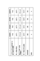
実施例1〜4の管状中空体を切断して、外層部と内層部との積層状態を観察した。その結果を図9に示す。図9では、外層部の内層側に内層部が十分に積層されている場合をA、外層部の内層側に内層部が部分的に積層されている場合をB、外層部の内層側に内層部が積層されていない場合をCとした。
(Evaluation)
The tubular hollow bodies of Examples 1 to 4 were cut, and the laminated state of the outer layer portion and the inner layer portion was observed. The results are shown in FIG. In FIG. 9, the case where the inner layer portion is sufficiently stacked on the inner layer side of the outer layer portion is A, the case where the inner layer portion is partially stacked on the inner layer side of the outer layer portion is B, and the inner layer on the inner layer side of the outer layer portion. The case where the part was not laminated was C.
図9に示すように、全ての実施例において、外層部の内層側に内層部が積層されていることが確認された。特に、射出工程終了後からコア移動工程までの保持時間を5秒以上とした実施例1及び2は、外層部の内層側に内層部が十分に積層されていることが確認された。 As shown in FIG. 9, in all the examples, it was confirmed that the inner layer portion was laminated on the inner layer side of the outer layer portion. In particular, in Examples 1 and 2 in which the holding time from the end of the injection step to the core moving step was 5 seconds or more, it was confirmed that the inner layer portion was sufficiently laminated on the inner layer side of the outer layer portion.
1…管状中空体、1a…一方端、1b…他方端、1c…外周面、1d…内周面、2…直線部、3…屈曲部、4…固定板部、5…外層部、6…内層部、10…成形用型、11…主キャビティ、12…加圧ポート、13…インジェクタ、14…排出部、15…副キャビティ、16…フローティングコア、A…管状中空体の軸線、B…主キャビティの軸線、M…成形品、R1…第一樹脂、R2…第二樹脂。
DESCRIPTION OF SYMBOLS 1 ... Tubular hollow body, 1a ... one end, 1b ... other end, 1c ... outer peripheral surface, 1d ... inner peripheral surface, 2 ... linear part, 3 ... bending part, 4 ... fixed plate part, 5 ... outer layer part, 6 ... Inner layer portion 10: mold for molding 11: main cavity 12: pressure port 13: injector 14: discharge portion 15: sub-cavity 16: floating core A: axial axis of tubular hollow body B: main Axial axis of cavity, M: molded article, R1: first resin, R2: second resin.
Claims (12)
前記管状中空体の外形を成して、第一樹脂が射出される主キャビティと、前記主キャビティの一端に形成されて、前記主キャビティに加圧流体が圧入される加圧ポートと、前記主キャビティの他端に形成されて、前記主キャビティから前記第一樹脂を排出する排出部と、を有する成形用型の前記加圧ポートに、フローティングコアを着脱可能に設けるコア設置工程と、
前記コア設置工程の後、前記主キャビティに第一樹脂を射出する射出工程と、
前記射出工程の後、前記加圧ポートから加圧流体を圧入することで前記フローティングコアを前記加圧ポートから前記排出部側に向けて移動させ、前記排出部から前記第一樹脂を排出するコア移動工程と、を備え、
前記フローティングコアは、前記第一樹脂とは種類の異なる第二樹脂により形成されており、
前記射出工程では、前記主キャビティに射出する前記第一樹脂の射出温度を、前記第二樹脂の融点よりも高くし、
前記コア移動工程では、前記フローティングコアを溶融させながら前記加圧ポートから前記排出部側に向けて移動させる、
管状中空体成形方法。 A tubular hollow body forming method for forming a tubular hollow body having a multilayer structure comprising an outer layer portion and an inner layer portion laminated on the inner layer side of the outer layer portion,
A main cavity into which the first resin is injected, and a pressure port which is formed at one end of the main cavity and into which the pressurized fluid is pressed and which is formed into the outer shape of the tubular hollow body, and the main A core setting step of detachably attaching a floating core to the pressing port of the molding die having a discharge part formed at the other end of the cavity and discharging the first resin from the main cavity;
An injection process of injecting a first resin into the main cavity after the core installation process;
After the injection step, the floating core is moved from the pressure port toward the discharge portion by pressing the pressurized fluid from the pressure port, and the core is discharged from the discharge portion. A transfer process,
The floating core is formed of a second resin different in type from the first resin,
In the injection step, the injection temperature of the first resin injected into the main cavity is made higher than the melting point of the second resin,
In the core moving step, the floating core is moved from the pressure port toward the discharge portion while melting the floating core.
Tubular hollow body molding method.
請求項1に記載の管状中空体成形方法。 The injection temperature of the first resin is 80 to 160 ° C. higher than the melting point of the second resin,
The method for forming a tubular hollow body according to claim 1.
請求項1に記載の管状中空体成形方法。 The melting point of the second resin is lower than the melting point of the first resin,
The method for forming a tubular hollow body according to claim 1.
請求項1に記載の管状中空体成形方法。 The melting point of the second resin is 65 to 80 ° C. lower than the melting point of the first resin,
The method for forming a tubular hollow body according to claim 1.
請求項1〜4の何れか一項に記載の管状中空体成形方法。 The core moving step is performed 4 to 6 seconds after the injection step is completed,
The method for forming a tubular hollow body according to any one of claims 1 to 4.
前記コア移動工程では、前記フローティングコアを、前記副キャビティの手前で停止させる、
請求項1〜5の何れか一項に記載の管状中空体成形方法。 The molding die further includes a sub cavity communicating with the discharge unit and storing the first resin discharged from the discharge unit,
In the core moving step, the floating core is stopped before the sub cavity.
The method for forming a tubular hollow body according to any one of claims 1 to 5.
請求項1〜6の何れか一項に記載の管状中空体成形方法。 In the injection step, the first resin containing a reinforcing material is injected into the main cavity,
The method for forming a tubular hollow body according to any one of claims 1 to 6.
前記外層部は、第一樹脂により形成されており、
前記内層部は、前記第一樹脂よりも融点の低い第二樹脂により形成されている、
管状中空体。 A tubular hollow body having a multilayer structure comprising an outer layer portion and an inner layer portion laminated on the inner layer side of the outer layer portion,
The outer layer portion is formed of a first resin,
The inner layer portion is formed of a second resin having a melting point lower than that of the first resin,
Tubular hollow body.
請求項8に記載の管状中空体。 The outer layer portion and the inner layer portion are fused to each other,
A tubular hollow body according to claim 8.
請求項8又は9に記載の管状中空体。 The inner diameter at one end is different from the inner diameter at the other end,
The tubular hollow body according to claim 8 or 9.
請求項8又は9に記載の管状中空体。 The inner diameter gradually decreases from one end to the other end,
The tubular hollow body according to claim 8 or 9.
請求項8〜11の何れか一項に記載の管状中空体。
The outer layer portion contains a reinforcing material for reinforcing the first resin,
The tubular hollow body according to any one of claims 8 to 11.
Priority Applications (1)
| Application Number | Priority Date | Filing Date | Title |
|---|---|---|---|
| JP2017230765A JP2019098601A (en) | 2017-11-30 | 2017-11-30 | Method for molding tubular hollow body and tubular hollow body |
Applications Claiming Priority (1)
| Application Number | Priority Date | Filing Date | Title |
|---|---|---|---|
| JP2017230765A JP2019098601A (en) | 2017-11-30 | 2017-11-30 | Method for molding tubular hollow body and tubular hollow body |
Publications (1)
| Publication Number | Publication Date |
|---|---|
| JP2019098601A true JP2019098601A (en) | 2019-06-24 |
Family
ID=66975326
Family Applications (1)
| Application Number | Title | Priority Date | Filing Date |
|---|---|---|---|
| JP2017230765A Pending JP2019098601A (en) | 2017-11-30 | 2017-11-30 | Method for molding tubular hollow body and tubular hollow body |
Country Status (1)
| Country | Link |
|---|---|
| JP (1) | JP2019098601A (en) |
Cited By (1)
| Publication number | Priority date | Publication date | Assignee | Title |
|---|---|---|---|---|
| JP2021088089A (en) * | 2019-12-03 | 2021-06-10 | いすゞ自動車株式会社 | Molding device of hollow body |
-
2017
- 2017-11-30 JP JP2017230765A patent/JP2019098601A/en active Pending
Cited By (2)
| Publication number | Priority date | Publication date | Assignee | Title |
|---|---|---|---|---|
| JP2021088089A (en) * | 2019-12-03 | 2021-06-10 | いすゞ自動車株式会社 | Molding device of hollow body |
| JP7251456B2 (en) | 2019-12-03 | 2023-04-04 | いすゞ自動車株式会社 | Hollow body forming device |
Similar Documents
| Publication | Publication Date | Title |
|---|---|---|
| ES2562206T3 (en) | Item manufacturing method | |
| JP4431086B2 (en) | Blow molding mold apparatus, resin hollow body manufacturing method using the blow molding mold apparatus, and resin hollow molded body manufactured by the manufacturing method | |
| JP5416080B2 (en) | Hollow body forming equipment | |
| WO2005118255A1 (en) | Die assembly for blow molding, process for producing hollow molded item of resin with use of the die assembly, and hollow molded item of resin produced by the process | |
| DE102011011838A1 (en) | Extruded, pipe-welded container liner with injection-molded end caps | |
| US10569461B2 (en) | Preform for biaxial stretching blow molding, and container | |
| JP2010076298A (en) | Blow molding apparatus | |
| JP6310385B2 (en) | Hollow body forming equipment | |
| AU2015248156B2 (en) | Molded catheter tip | |
| JP2019098601A (en) | Method for molding tubular hollow body and tubular hollow body | |
| DE102014215556A1 (en) | Pressure vessel and apparatus and method for producing a pressure vessel blank comprising at least one connection element | |
| JP6012062B2 (en) | Container making method from thermoplastic material | |
| JP6989245B2 (en) | Mold for forming a tubular hollow body, a method for forming a tubular hollow body, and a tubular hollow body | |
| JP5658577B2 (en) | Hollow body forming equipment | |
| US9242549B2 (en) | Method of blow molding reservoir, and reservoir made thereby | |
| JP6762833B2 (en) | Manufacturing method of tubular resin molded product | |
| WO2020116083A1 (en) | Method for manufacturing resin pipe | |
| JP2009148970A (en) | Molding process of two-layer hollow molded article | |
| CN107848188A (en) | Liquid blow molding apparatus and liquid blow molding method | |
| CN204869607U (en) | Plastics storage tank by parison blow molding | |
| US11305644B2 (en) | Method for forming a welding spout on a parison during the blowing of a tank | |
| JP6593888B2 (en) | Fuel tank pipe mounting structure | |
| EP2788165B1 (en) | A manufacturing method for bellow pipes | |
| JP7442388B2 (en) | How to manufacture hollow tanks | |
| JP2009148969A (en) | Molding process of two-layer hollow molded article |