JP2019098002A - Absorbent article - Google Patents
Absorbent article Download PDFInfo
- Publication number
- JP2019098002A JP2019098002A JP2017233911A JP2017233911A JP2019098002A JP 2019098002 A JP2019098002 A JP 2019098002A JP 2017233911 A JP2017233911 A JP 2017233911A JP 2017233911 A JP2017233911 A JP 2017233911A JP 2019098002 A JP2019098002 A JP 2019098002A
- Authority
- JP
- Japan
- Prior art keywords
- width direction
- knob
- boundary
- absorbent article
- fastening
- Prior art date
- Legal status (The legal status is an assumption and is not a legal conclusion. Google has not performed a legal analysis and makes no representation as to the accuracy of the status listed.)
- Granted
Links
Images


Abstract
Description
本発明は、使い捨ておむつ等の吸収性物品に関し、特に面ファスナを備えた展開型吸収性物品に関する。 The present invention relates to absorbent articles such as disposable diapers, and more particularly to a deployable absorbent article provided with a hook-and-loop fastener.
吸収性物品としての展開型のおむつの典型的な形態としては、吸収性コアと外装体とを備える吸収性本体と、止着用部材とを具備するものが挙げられる。吸収性本体は、着用者の腹側に配される腹側部及び背側に配される背側部並びにそれらの間に位置する股下部を有する。止着用部材は、吸収性本体の背側部における両側縁部に設けられる。止着用部材は面ファスナを備え、面ファスナを腹側部の外表面に止着しておむつは着用される(例えば特許文献1参照)。
止着用部材の側端部は、面ファスナが設けられていない基材シートのみからなる摘み部となっている。作業者は、着用者におむつを着用させる際、摘み部を指でつまんで止着作業を行う。
As a typical form of a development type diaper as an absorptive article, what has an absorptive main part provided with an absorptive core and an exterior body, and a stop wearing member is mentioned. The absorbent body has a ventral side disposed on the ventral side of the wearer, a dorsal portion disposed on the dorsal side, and a crotch portion located therebetween. Retaining members are provided on the side edges of the dorsal side of the absorbent body. The fastening member is provided with a hook-and-loop fastener, and the diaper is worn by fastening the hook-and-loop fastener to the outer surface of the ventral side (see, for example, Patent Document 1).
The side end of the fastening member is a knob formed only of the base sheet on which the surface fastener is not provided. When making a wearer wear a diaper, a worker squeezes a pinching portion with a finger and performs fastening work.
おむつを着用させる際、着用者が動いたりすることによって、摘み部が折れ込んで摘み部が面ファスナに貼り付いてしてしまうことがある。このような場合、貼り付いた部分を剥がす作業が生じ、止着作業を円滑に行えないことがある。 When putting on a diaper, when a wearer moves, a knob part may be broken and a knob part may stick to a hook-and-loop fastener. In such a case, a work of peeling off the stuck portion may occur, and the fastening work may not be performed smoothly.
本発明の課題は、止着作業に適した止着用部材を備える吸収性物品に関する。 The subject of the present invention relates to an absorbent article provided with a fastening member suitable for fastening work.
本発明の一形態に係る吸収性物品は、本体と、一対の止着用部材とを具備する。
上記本体は、股下部と、上記股下部の前後方向の両側にそれぞれ配される腹側部及び背側部とを有する。
上記一対の止着用部材は、基材と上記基材上に配された止着材を含んで構成され、上記本体の上記背側部の上記前後方向に直交する幅方向両側縁部から延出し、上記両側縁部に固定されて設けられる。
上記止着用部材は、上記背側部と固定される固定端と、上記止着材を挟んで上記固定端と上記幅方向に対向する摘み部と、上記前後方向に延びる上記止着材と上記摘み部との境界にまたがって位置し、上記境界に沿って非連続で配置される複数の圧痕部とを有する。
An absorbent article according to an aspect of the present invention comprises a main body and a pair of fastening members.
The body has a crotch, and ventral and dorsal portions respectively disposed on both sides of the crotch in the front-rear direction.
The pair of fastening members includes a base material and a fastening material disposed on the base material, and extends from both side edges in the width direction orthogonal to the front and rear direction of the back side of the main body. , Fixed to the both side edge portions.
The fastening member includes a fixed end fixed to the back side, a knob facing the fixed end and the width direction with the fastening member interposed therebetween, the fastening member extending in the front-rear direction, and the fastening member. It has a plurality of indentations located across the boundary with the knob and arranged discontinuously along the boundary.
以上のように、本発明によれば、止着用部材の止着作業を円滑に行うことができる。 As described above, according to the present invention, the fastening work of the fastening member can be smoothly performed.
以下、図面を参照しながら、本発明の実施形態を説明する。 Hereinafter, embodiments of the present invention will be described with reference to the drawings.
[使い捨ておむつの全体構成]
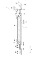
図1は、本発明の一実施形態に係る使い捨ておむつ1の展開状態を示す平面図である。図1に示す使い捨ておむつ1は、吸収性物品本体(本体)としてのおむつ本体10をXY平面に沿って伸展させた状態である。図1では、X軸方向が前後方向、Y軸方向が幅方向に対応する。使い捨ておむつ1は、着用者である乳幼児の排泄物を漏らさずに捕捉するための吸収性物品である。
図2は、図1のII−II線で切断した模式的な断面図である。
[Whole composition of disposable diapers]
FIG. 1: is a top view which shows the unfolded state of the
FIG. 2 is a schematic cross-sectional view taken along the line II-II in FIG.
各図に示すように、使い捨ておむつ(以下、単におむつと称す。)1は、おむつ本体10と、一対の止着用部材としてのファスニングテープ40を備える。おむつ1は、いわゆる展開型のパネルタイプの使い捨ておむつである。
As shown to each figure, the disposable diaper (it is only hereafter called a diaper) 1 is equipped with the diaper
以下、各構成における「内側」とは、おむつ着用時に着用者の肌に向けられる側をいい、「外側」とは、着用者の肌とは反対側に向けられる側をいう。また、「着用時」とは、通常の適正な着用位置、すなわち吸収性物品の正しい着用位置が維持された状態を意味する。 Hereinafter, the "inside" in each structure means the side directed to the wearer's skin when the diaper is worn, and the "outside" means the side directed to the side opposite to the wearer's skin. Moreover, "at the time of wear" means the state in which the normal proper wearing position, ie, the correct wearing position of the absorbent article, was maintained.
おむつ本体10は、股下部10Mと、腹側部10Fと、背側部10Rとを有する。
股下部10Mは、着用時に着用者の股間に配され、腹側部10Fは着用者の腹側に配され、背側部10Rは着用者の背側に配される。腹側部10Fと背側部10Rとは、股下部10Mを介して股下部10Mの前後方向(X軸方向)の両側にそれぞれ配される。ここでは、着用時に着用者の腹側に位置するおむつ本体10の端部側が前側に相当し、着用者の背側に位置するおむつ本体10の端部側が後側に相当する。
腹側部10F、股下部10M及び背側部10Rは、おむつ1を前後方向(X軸方向)に略3等分するように区分したときの各領域に相当する。
The
The
The
おむつ本体10は、吸収性本体20と、サイドパネル30とを有する。
吸収性本体20は、吸収体15と、表面シート16と、裏面シート17と、サイドシート19とを備えている。表面シート16は液透過性シートであり、吸収体15の内側に配置される。裏面シート17は液不透過性或いは撥水性のシートであり、吸収体15の外側に配置される。裏面シート17は、着用時の状態でおむつ1の外装体を構成する。
サイドシート19は、吸収性本体20の表面シート16側における前後方向に沿う左右両側にそれぞれ配置されている。
The
The absorbent
The
吸収体15は、表面シート16と裏面シート17との間に配置され、表面シート16及び裏面シート17により保持される。吸収体15は排泄物を捕捉するとともに、排泄物に含まれる液体を吸収可能に構成されている。吸収体15は、前後方向に長い帯状に形成され、腹側部10Fから股下部10Mを通って背側部10Rにわたる広い範囲に配置されている。
The
吸収体15は、液保持性の吸収性コア151と、吸収性コア151を覆うコアラップシート152とを含んで構成される。吸収性コア151は、前後方向に長い形状を有し、腹側部10Fから股下部10Mを通って背側部10Rまで前後方向のほぼ全域にわたっている。吸収性コア151は、吸収性材料を含むコア形成材料が積繊されてなり、この種の形成材料として通常用いられるものを特に制限なく用いることができる。コアラップシート152は、吸収性コア151全体を被覆する。
The
表面シート16及び裏面シート17は、それぞれ吸収体15よりも大きな寸法を有し、吸収体15の周縁から幅方向の外方に延出し、それらの延出部どうしは、接着剤62により互いに接合されている。接着剤以外に、ヒートシール、超音波シール等の公知の接合手段が用いられてもよい。
The
表面シート16及び裏面シート17としては、それぞれ、この種の吸収性物品に従来用いられている各種のものを特に制限なく用いることができる。例えば、表面シート16としては各種の不織布や開孔フィルム等を用いることができる。裏面シート17としては樹脂フィルムや、樹脂フィルムと不織布等とのラミネート等を用いることができる。裏面シート17には、例えば液不透過性のフィルムシート単独の形態と、該フィルムシートの外側に外装シートを積層配置した形態とがある。外装シートは例えば不織布である。
As the
サイドシート19は、前後方向に沿う内側縁部と、該内側縁部よりも幅方向の外方に位置して前後方向に沿う外側縁部とを有する。サイドシート19の内側縁部は吸収体15と重なり、表面シート16と接着剤61を介して接合される。サイドシート19の外側縁部は、吸収体15の前後方向に沿う側縁から幅方向の外方に延出して、背側部10Rを含むおむつ本体10の幅方向における側縁部18を形成する。吸収体15の幅方向の外方において、サイドシート19及び裏面シート17は、接着剤63を介してサイドパネル30と接合される。
The
図1に示すように、一対のサイドシート19のそれぞれには、糸状の弾性部材12が、股下部10Mを通って前後方向に延びるように伸長状態で配置されている。股下部10Mにおけるサイドシート19は、おむつ1の着用時に着用者の脚周りに配されるいわゆるレッグ部として機能する部位であり、かかる構成により該レッグ部には、おむつ1の着用時において弾性部材12の収縮により一対のレッグギャザーが形成される。
As shown in FIG. 1, in each of the pair of
サイドパネル30は、吸収性本体20の幅方向における両側縁部18から幅方向の外方に延出するように設けられる。サイドパネル30の一端は固定端31として接着剤63を介して吸収性本体20(表面シート16及び裏面シート17)に接合される。
The
サイドパネル30は、吸収性本体20の幅方向に伸縮性を有する弾性シートで構成される。本実施形態においてサイドパネル30は、2枚の平面矩形状のパネル材34と、両パネル材34の間に配された複数の線状の弾性部材35とを含んで構成される。
The
複数の弾性部材35は、サイドパネル30の幅方向の中央部にて前後方向に所定間隔を置いて配置されている。各弾性部材35は、伸長状態で2枚のパネル材34間に接合される。サイドパネル30における弾性部材35の配置部位は、弾性部材35の伸長方向である幅方向に伸縮可能な伸縮部であり、この伸縮部によりサイドパネル30は、幅方向に伸縮性を有している。
The plurality of
サイドパネル30のパネル材34としては、例えば、エアースルー不織布、ヒートロール不織布、スパンレース不織布、スパンボンド不織布、メルト部ローン不織布等の各種製法による不織布、織布、編布、紙、樹脂フィルム等、及びこれら2以上を積層一体化させてなるシート材等を用いることができる。
As the
サイドパネル30と、吸収性本体20と、ファスニングテープ40は、それぞれ別部材で構成される。
The
[ファスニングテープの詳細な構成]
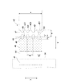
次に、ファスニングテープ40の詳細な構成について、図2及び図3を用いて詳細に説明する。図3は、ファスニングテープ40の拡大平面図である。
[Detailed configuration of fastening tape]
Next, the detailed configuration of the
ファスニングテープ40は、サイドパネル30の先端部32から幅方向の外方に延出するように、サイドパネル30の先端部32に固定されている。ファスニングテープ40は、長手方向が幅方向に沿った略長方形形状を有する。ファスニングテープ40は、固定端41と、自由端42とを有する。ファスニングテープ40の固定端41は、おむつ本体10に固定される。詳細には、固定端41は、おむつ本体10の一部を構成するサイドパネル30の先端部32の外側面に接着剤64によって固定される。接着剤以外の公知の接合手段が用いられてもよい。
The
ファスニングテープ40は、テープ基材44と、止着材である面ファスナ45とを含んで構成されている。更に、ファスニングテープ40は、複数の圧痕部46を有している。テープ基材44は、図3に示すように平面視において幅方向(Y軸方向)に長い略長方形形状を有し、ファスニングテープ40の外形はテープ基材44の外形と一致する。
The
テープ基材44の内側の面には、面ファスナ45が接合されている。面ファスナ45は、平面矩形状を有し、テープ基材44の前後方向に亘って、テープ基材44の幅方向中央部に配置される。つまり、面ファスナ45は、テープ基材44の固定端41及び自由端42それぞれから間隙をおいて配置される。ファスニングテープ40の自由端42には、面ファスナ45は位置しておらず、自由端42は、テープ基材44の一部で構成される。自由端42は、止着作業をする際に作業者によって指でつままれる摘み部47を形成する。摘み部47は、ファスニングテープ40の固定端41と、面ファスナ45を挟んで幅方向に対向する。
A hook and
ファスニングテープ40は、着用時におむつ本体10の腹側部10Fの外側(非肌対向面)に止着可能に構成される。ファスニングテープ40が腹側部10Fの外側に止着されることにより、ウエスト開口部とレッグ開口部を有するパンツ形状のおむつ1が形成される。
The
ファスニングテープ40を構成するテープ基材44としては、例えば、柔軟性を有する不織布や不織布と樹脂フィルムの積層体等を用いることができる。本実施形態では、テープ基材44として柔軟性を有する非伸縮性の不織布を用いた。
As the
面ファスナ45は、機械的面ファスナのオス部材を構成するフック部を有する。一方、腹側部10Fの外側(非肌対向面)には、機械的面ファスナのメス部材を構成する被止着領域11(図1参照)が形成されている。被止着領域11は、ファスニングテープ40の面ファスナ45を着脱自在に止着可能である。
The hook-and-
面ファスナ45は、テープ基材44に接着剤などにより接合される。ファスニングテープ40は、図3に示すように、面ファスナ45と摘み部47との前後方向に延びる境界48に、複数の圧痕部46を有する。圧痕部46は、エンボス凸ロールとフラットロールを用いたエンボス加工等の加圧処理、ヒートシール処理、超音波シール処理等により形成される。処理が施されて形成される圧痕部46は、処理が施されていない領域よりも固く、剛性が高い。
The hook-and-
圧痕部46は、複数、本実施形態では4つ設けられる。複数の圧痕部46のそれぞれは、境界48にまたがって位置する。複数の圧痕部46は、境界48に沿って等間隔で、互いに連続することなく非連続で配置される。本実施形態では、複数の圧痕部46は、互いに合同の楕円形状を有し、各圧痕部46の楕円の短軸が境界48上に位置する。
A plurality of
摘み部47を形成する自由端42の先端は、波型形状を有する。波型形状は、延出方向に向かう凸部421と固定端41に向かう凹部422が交互に配置された形状を有し、凸部421と凹部422の輪郭はそれぞれ曲線状となっている。
The tip of the
圧痕部46は、幅方向(Y軸方向)に沿って凹部422と対向して位置する。隣り合う2つの圧痕部46の間の非圧痕領域49は、幅方向に沿って凸部421と対向して位置する。
The
前後方向(X軸方向)に隣接する凸部421の中心間距離は、境界48上における隣接する圧痕部46間の中心間距離と同じとなるように設定される。楕円状の圧痕部46は、短軸を境に2つに分けられる一方の半楕円部分が面ファスナ45上に位置し、他方の半楕円部分は面ファスナ45が配置されない摘み部47に位置する。
The center-to-center distance of the
図3に示すように、本実施形態において、ファスニングテープ40の前後方向(X軸方向)における長さaは、例えば35mmである。
圧痕部46の前後方向における長さbは、例えば3.5mmである。本実施形態においては、圧痕部46の前後方向における長さは、楕円形状の圧痕部46の短軸の長さに相当する。
As shown in FIG. 3, in the present embodiment, the length a of the
The length b of the
圧痕部46の幅方向における長さcは、例えば7mmである。本実施形態においては、圧痕部46の幅方向における長さは、圧痕部46の長軸の長さに相当する。
境界48上に位置する隣り合う圧痕部46の中心間距離dは、例えば8.75mmである。
The length c in the width direction of the
The center-to-center distance d of the
摘み部47の幅方向における長さeは、好ましくは7mm以上30mm以下であり、本実施形態では10mmである。摘み部47の幅方向における長さは、摘み部47の先端のうち最も外側にある最先端部423と境界48との距離に相当する。
The length e in the width direction of the
摘み部47に位置する圧痕部46の幅方向における長さfは、例えば3.5mmである。本実施形態においては、摘み部47に位置する圧痕部46の幅方向における長さは、摘み部47に位置する圧痕部46の半楕円部分の長軸半径fに相当する。
The length f in the width direction of the
尚、ここで示したファスニングテープ40を構成する各構成の寸法は、単なる一例であり、勿論これらに限られない。例えば、おむつは着用する着用者の年齢等により大きさが変わるため、おむつの大きさによってファスニングテープ40を構成する基材テープ及び面ファスナ45の寸法は適宜設定される。また、これに応じて、圧痕部46の大きさ、数、位置も適宜設定される。
In addition, the dimension of each structure which comprises the
本実施形態においては、圧痕部46は、境界48上における複数の圧痕部46それぞれの前後方向における長さの和が境界48の長さに対して、例えば40%の割合となるように配置される。また、圧痕部46は、摘み部47に位置する圧痕部46の幅方向における長さが、摘み部47の幅方向における長さに対して、例えば35%の割合となるように配置される。
In the present embodiment, the
各圧痕部46の幅方向の側部のうち摘み部47の先端寄りにある側部461をつなげた仮想線50は、境界48よりも摘み部47の先端寄りに位置する。本実施形態では、各圧痕部46の幅方向の側部のうち摘み部47の先端寄りにある側部とは、楕円の長軸と楕円の周縁部とが交差する2点のうち摘み部47の先端寄りにある点に相当する。
An
[本実施形態の作用効果]
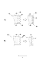
図4は本実施形態におけるファスニングテープ及び参考例としてのファスニングテープそれぞれの折れ位置を説明する図である。
図4(A)は圧痕部46を有する本実施形態におけるファスニングテープ40の要部平面図である。
図4(B)は圧痕部46が設けられていない参考例としてのファスニングテープ140の要部平面図である。
[Operation and effect of this embodiment]
FIG. 4 is a view for explaining bending positions of the fastening tape and the fastening tape as a reference example in the present embodiment.
FIG. 4A is a plan view of an essential part of the
FIG. 4B is a plan view of relevant parts of a
図4(B)に示す圧痕部46が設けられていないファスニングテープ140では、面ファスナ45が設けられる領域と、面ファスナ45が設けられていない摘み部47の領域とでは剛性が異なり、これらの領域の境界48は直線状となっている。
このため、参考例のファスニングテープ140では、摘み部47が面ファスナ45側に折れ込んだ場合、摘み部47は、境界48を起点として折れやすい。
In the
For this reason, in the
これに対し、本実施形態においては、複数の圧痕部46が、面ファスナ45と摘み部47との境界48にまたがって配置される。ファスニングテープ40において、圧痕部46が設けられる領域はそれが設けられていない領域よりも剛性が高くなっている。
On the other hand, in the present embodiment, the plurality of
このように複数の圧痕部46を、境界48をまたいで境界48に沿って設けることにより、摘み部47が面ファスナ45側に折れ込んだ場合、摘み部47は、境界48を起点として折れにくく、代わりに、境界線よりも摘み部47の先端寄りの仮想線50を起点として折れやすくなる。
Thus, by providing the plurality of
摘み部47が仮想線50を起点として折れた場合、境界48を起点として折れた場合よりも、摘み部47の先端は、面ファスナ45から遠いところに位置することとなる。これにより、摘み部47と面ファスナ45とが係合しない、或いは、係合面積を小さくすることができ、摘み部47の面ファスナ45への貼り付きを防止または軽減することができる。これにより、止着作業を円滑に行うことができ、おむつ1の使い勝手が向上する。
When the
更に、本実施形態においては、複数の圧痕部46は、境界48に沿って互いに離間して配置、すなわち非連続で配置されている。
圧痕部46は圧痕処理が施されていない領域(非圧痕領域)よりも固くなるため、複数の圧痕部46を非連続で配置することにより、ファスニングテープ40の境界48部分が硬くなり過ぎず、柔らかな風合いのファスニングテープ40とすることができ、肌触りをより良いものとすることができる。これにより、ファスニングテープ40が着用者の肌に触れても、着用者に違和感を生じさせにくい。
Furthermore, in the present embodiment, the plurality of
Since the
また、圧痕部46が非連続で配置されることにより、連続して配置される場合と比較して、面ファスナ45上で圧痕部46によりフック材が殺される領域が減少するので、所望とする安定した止着機能を確保することができる。
In addition, since the
以上のように、本実施形態では、柔らかさが保持され、かつ、摘み部47の折れによる面ファスナ45への貼り付きが軽減された使い勝手の良いファスニングテープ40を得ることができる。
As described above, in the present embodiment, it is possible to obtain a user-
また、本実施形態では、摘み部47の先端は凸部421と凹部422とを有している。これにより、凹凸部で指がひっかかりやすく、摘み部47を摘まみやすくすることができ、止着作業を円滑に行うことができ、おむつ1の使い勝手が向上する。
Further, in the present embodiment, the tip end of the
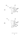
図5は本実施形態におけるファスニングテープ及び参考例としてのファスニングテープそれぞれの摘み部47の状態を説明する図である。
図5(A)は本実施形態におけるファスニングテープ40の要部平面図である。
図5(B)は参考例としてのファスニングテープ40の要部平面図であり、本実施形態におけるファスニングテープと圧痕部46の配置位置が異なっている。
各図において、点線の円で囲んだ領域がより摘まみやすい領域471となり得る領域である。
FIG. 5 is a view for explaining the state of the pinching
FIG. 5A is a plan view of the main part of the
FIG. 5B is a plan view of an essential part of a
In each drawing, a region surrounded by a dotted circle is a region that can be a
本実施形態では、摘み部47の先端が凹凸形状を有しており、この凹凸形状を構成する凹部422は、幅方向に沿って圧痕部46と対向して位置する。
ここで、摘み部47において、圧痕部46を形成するための処理が行われる領域とこの処理が行われていない非圧痕領域49とでは、剛性が異なる。剛性がより低く柔らかい、処理が行われていない領域の方が、作業者にとってより摘まみやすい領域471となりやすい。
In the present embodiment, the tip end of the
Here, in the
従って、図5(A)に示すように、凹部422が幅方向に沿って圧痕部46と対向して位置することにより、隣り合う2つの圧痕部46の間の非圧痕領域49は、幅方向に沿って凸部421と対向して位置することになり、摘み部47において、作業者がより摘まみやすい領域471を広く確保することができる。
Therefore, as shown in FIG. 5A, the
これに対し、図5(B)に示す参考例では、摘み部47の先端の凸部421が、幅方向に沿って圧痕部46と対向して位置する。このような配置パターンでは、点線の円で囲んだ領域が、摘まみやすい領域471となりやすい。図5(A)及び(B)に示すように、凹部422が、幅方向に沿って圧痕部46と対向して位置する方が、摘まみやすい領域471が広くなる。
On the other hand, in the reference example shown in FIG. 5B, the
このように、摘み部47の先端の凹部422が、幅方向に沿って圧痕部46と対向して位置することにより、摘まみやすい領域471を広く確保することができる。
As described above, the recessed
また、本実施形態では、ファスニングテープ40のテープ基材44に、柔軟性のある不織布を用いており、柔らかな手触りのファスニングテープ40とすることができる。これにより、着用者の肌にファスニングテープ40が直接触れても着用者に違和感を生じさせにくい。
Further, in the present embodiment, a flexible non-woven fabric is used as the
更に、本実施形態では、ファスニングテープ40のテープ基材44に非伸縮性の不織布が用いられている。これにより、テープ基材44の伸縮力が面ファスナ45に作用するということが起こらないので、伸縮力が作用して面ファスナ45に皺がよるなどして面ファスナ45のテープ基材44への接着強度が保持できなくなるということがない。従って、面ファスナ45とテープ基材44との接着強度を保持することができ、安定した品質のおむつ1とすることができる。
Furthermore, in the present embodiment, a non-stretchable nonwoven fabric is used as the
また、本実施形態では、圧痕部46は、境界48上における複数の圧痕部46それぞれの前後方向における長さの和が境界48の長さに対して40%の割合となるように配置される。これにより、ファスニングテープ40の柔らかさを保持しつつ、折れ込んだ時の起点が仮想線50上となりやすく、摘み部47の面ファスナ45への貼り付けを軽減することができる。
Further, in the present embodiment, the
圧痕部46は、境界48上における複数の圧痕部46の前後方向における長さの和が境界48の長さに対して15%以上50%以下の割合となるように配置されることが好ましい。
15%以上とすることにより、折れ込んだ時の起点を、境界48ではなく、境界48よりも摘み部47の先端寄りにすることができる。これにより、摘み部47の面ファスナ45への貼り付きを軽減することができる。
50%以下とすることにより、ファスニングテープ40が硬くなりすぎず、柔らかな風合いを保持することができる。
The
By setting it as 15% or more, the starting point at the time of folding can be made closer to the tip of the pinching
By setting the content to 50% or less, the
本実施形態においては、摘み部47に位置する圧痕部46の幅方向における長さが、摘み部47の幅方向における長さに対して35%の割合となるように、圧痕部46が配置される。これにより、作業者による摘み作業がより円滑に行えるように摘み部47における摘まみやすい領域を確保することができる。
In the present embodiment, the
摘み部47に位置する圧痕部46の幅方向における長さは、摘み部47の幅方向における長さに対して40%以下の割合となるように、圧痕部46は配置されることが好ましい。これにより、作業者による摘み作業がより円滑に行えるように摘み部47における摘まみやすい領域を確保することができる。
The
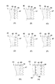
<変形例>
上述の実施形態において、摘み部47の先端は波型形状を有していたが、これに限定されない。例えば、図6(A)に示すように、直線状であってもよい。
<Modification>
In the above-mentioned embodiment, although the tip of
また、上述の実施形態では摘み部47の延出方向に向かう凸部421と固定端に向かう凹部422とが交互に配置され、凹部422と凸部421の輪郭が曲線状となっていた。
Moreover, in the above-mentioned embodiment, the
これに対し、凹部422と凸部421の輪郭が図6(B)に示すように矩形状であってもよい。また、凹部422と凸部421の輪郭が図6(C)に示すように三角形状で、ギザギザ状であってもよい。
また、図6(D)及び(E)のように、凹部422、凸部421の形状が曲線形状、矩形状、または三角形状が組み合わさった形状であってもよい。
このように、摘み部47の先端を凹凸形状とすることにより、指にひっかかりやすく摘み部47とすることができる。
On the other hand, the contours of the
Further, as shown in FIGS. 6D and 6E, the shape of the
Thus, by making the tip of the
また、上述の実施形態において、圧痕部46の形状が楕円であったが、これに限定されない。例えば図7(A)、(B)に示すように矩形であってもよいし、図7(C)に示すように圧痕部46の形状が真円であってもよい。
Moreover, in the above-mentioned embodiment, although the shape of the
また、図7(D)、(E)、(F)に示すように圧痕部467が円弧状であってもよく、向きも限定されない。このように円弧状とすることにより、面ファスナ45において、圧痕部47によって殺されるフック部の領域を狭くすることができ、止着機能を保持することができる。
Further, as shown in FIGS. 7D, 7 E, and 7 F, the indentations 467 may have an arc shape, and the direction is not limited. By making it circular in this way, in the
また、図7(G)に示すように、複数の形状の異なる圧痕部46を配置してもよい。
Further, as shown in FIG. 7G, a plurality of
また、上述の実施形態において、圧痕部46は、摘み部47と面ファスナ45との境界48上にのみ設けられていたが、この構成に加え、図7(H)に示すように、固定端41と面ファスナ45との境界58上に、非連続に複数の圧痕部56を配置してもよい。
Moreover, in the above-mentioned embodiment, although the
いずれにおいても、複数の圧痕部46が、摘み部47と面ファスナ45との境界48をまたいで互いに離間して境界48に沿って配置される。尚、圧痕部46の形状はここに記載されたものに限定されない。
In any case, a plurality of
以上、本発明の一実施形態について説明したが、本発明は上述の実施形態にのみ限定されるものではなく、本発明の要旨を逸脱しない範囲内において種々変更を加え得ることは勿論である。 As mentioned above, although one Embodiment of this invention was described, this invention is not limited only to the above-mentioned embodiment, Of course in the range which does not deviate from the summary of this invention, a various change can be added.
例えば、上述の実施形態では、おむつ本体10をそれぞれ別部材で形成された吸収性本体10とサイドパネル30とにより構成していたが、吸収性本体とサイドパネルが一体化したおむつ本体に、これとは別部材のファスニングテープが固定される形態であってもよい。吸収性本体とサイドパネルが一体化された形態では、例えば、表面シート及び裏面シートが、吸収体を覆うほかサイドパネルの領域まで延在されて構成される。
For example, in the above-mentioned embodiment, although the diaper
本発明に係る吸収性物品は、乳幼児用の使い捨ておむつでなくてもよく、例えば、大人用や子供用の使い捨ておむつであってもよい。更に、本発明に係る吸収性物品は、下半身に着用するタイプの吸収性物品であれば、使い捨ておむつでなくてもよい。このような吸収性物品としては、例えば、展開型のおむつタイプの生理用ナプキンや尿漏れパッドなどが挙げられる。 The absorbent article according to the present invention may not be a disposable diaper for infants, and may be, for example, a disposable diaper for adults or children. Furthermore, the absorbent article according to the present invention may not be a disposable diaper as long as it is an absorbent article of a type worn on the lower body. Examples of such an absorbent article include a spreadable diaper type sanitary napkin and a urine leak pad.
1…おむつ(使い捨ておむつ、吸収性物品)
10…おむつ本体(本体)
10M…股下部
10F…腹側部
10R…背側部
17…裏面シート(外装体)
18…吸収性本体の両側縁部
30…サイドパネル
40…ファスニングテープ(止着用部材)
41…ファスニングテープのおむつ本体に固定される固定端
44…テープ基材(基材)
45…面ファスナ(止着材)
46…圧痕部
47…摘み部
48…境界
151…吸収性コア
421…凸部
422…凹部
1 ... diapers (disposable diapers, absorbent articles)
10 ... diaper body (body)
10M ...
18 ... both side edges of the absorbent
41: Fixed end of fastening tape fixed to diaper body 44: Tape base material (base material)
45-Surface fastener (fastening material)
46 ...
Claims (5)
基材と前記基材上に配された止着材を含んで構成され、前記本体の前記背側部の前記前後方向に直交する幅方向両側縁部から延出し、前記両側縁部に固定されて設けられた一対の止着用部材と
を具備し、
前記一対の止着用部材は、前記背側部と固定される固定端と、前記止着材を挟んで前記固定端と前記幅方向に対向する摘み部と、前記前後方向に延びる前記止着材と前記摘み部との境界にまたがって位置し、前記境界に沿って非連続で配置される複数の圧痕部とを有する
吸収性物品。 A body having a crotch and ventral sides and a dorsal side respectively disposed on both sides in the front-rear direction of the crotch;
A base material and a fastening material disposed on the base material, extending from both side edges in the width direction orthogonal to the front and rear direction of the back side of the main body, and fixed to the both side edges And a pair of stop wearing members provided,
The pair of fastening members includes a fixed end fixed to the back side, a knob facing the fixed end in the width direction with the fixing member interposed therebetween, and the fixing member extending in the front-rear direction An absorbent article comprising: a plurality of indentations positioned across the boundary between the first and second knobs and arranged discontinuously along the boundary.
前記摘み部の先端部は、前記延出方向に向かう凸部と前記固定端に向かう凹部が交互に配置された形状を有し、
前記圧痕部は、前記幅方向に沿って前記凹部と対向して位置する
吸収性物品。 An absorbent article according to claim 1, wherein
The tip end portion of the knob portion has a shape in which a protrusion toward the extension direction and a recess toward the fixed end are alternately arranged.
The said indentation part is located facing the said recessed part along the said width direction. Absorbent article.
前記圧痕部は、円又は円弧形状を有する
吸収性物品。 The absorbent article according to claim 1 or 2, wherein
The indented portion has a circular or arc shape. Absorbent article.
前記圧痕部は、前記境界上における複数の前記圧痕部の前記前後方向における長さの和が前記境界の長さに対して15%以上50%以下の割合となるように配置される
吸収性物品。 The absorbent article according to any one of claims 1 to 3, wherein
The indented portion is arranged such that the sum of lengths of the plurality of indented portions on the boundary in the front-rear direction is 15% to 50% of the length of the boundary. .
前記圧痕部は、前記摘み部に位置する前記圧痕部の前記幅方向における長さは、前記摘み部の前記幅方向における長さに対して40%以下の割合となるように配置される
吸収性物品。 The absorbent article according to any one of claims 1 to 4, wherein
The indented portion is arranged such that the length in the width direction of the indented portion located in the knob portion is 40% or less of the length in the width direction of the knob portion. Goods.
Priority Applications (1)
| Application Number | Priority Date | Filing Date | Title |
|---|---|---|---|
| JP2017233911A JP7057112B2 (en) | 2017-12-06 | 2017-12-06 | Absorbent article |
Applications Claiming Priority (1)
| Application Number | Priority Date | Filing Date | Title |
|---|---|---|---|
| JP2017233911A JP7057112B2 (en) | 2017-12-06 | 2017-12-06 | Absorbent article |
Publications (2)
| Publication Number | Publication Date |
|---|---|
| JP2019098002A true JP2019098002A (en) | 2019-06-24 |
| JP7057112B2 JP7057112B2 (en) | 2022-04-19 |
Family
ID=66974856
Family Applications (1)
| Application Number | Title | Priority Date | Filing Date |
|---|---|---|---|
| JP2017233911A Active JP7057112B2 (en) | 2017-12-06 | 2017-12-06 | Absorbent article |
Country Status (1)
| Country | Link |
|---|---|
| JP (1) | JP7057112B2 (en) |
Citations (7)
| Publication number | Priority date | Publication date | Assignee | Title |
|---|---|---|---|---|
| JP2006510390A (en) * | 2002-05-17 | 2006-03-30 | ザ プロクター アンド ギャンブル カンパニー | Improved diaper closure system |
| JP2008029640A (en) * | 2006-07-28 | 2008-02-14 | Kao Corp | Fastening tape |
| JP2008188349A (en) * | 2007-02-07 | 2008-08-21 | Uni Charm Corp | Disposable diaper with tape fastener |
| JP2010029532A (en) * | 2008-07-30 | 2010-02-12 | Oji Nepia Co Ltd | Fixing tape, method of manufacturing the same, and tape type diaper |
| JP2013027752A (en) * | 2012-11-05 | 2013-02-07 | Oji Nepia Co Ltd | Method of manufacturing fastening tape and tape type disposable diaper |
| JP2015104649A (en) * | 2013-12-03 | 2015-06-08 | 王子ホールディングス株式会社 | Tape type disposable diaper and method for manufacturing fastening tape |
| JP2015524682A (en) * | 2012-06-29 | 2015-08-27 | ザ プロクター アンド ギャンブルカンパニー | Wearable article having an outermost layer that is a multi-component nonwoven fabric that provides improved mechanical properties |
Family Cites Families (1)
| Publication number | Priority date | Publication date | Assignee | Title |
|---|---|---|---|---|
| JP4533182B2 (en) | 2005-02-22 | 2010-09-01 | 株式会社リブドゥコーポレーション | Fastening piece manufacturing method and absorbent article manufacturing method |
-
2017
- 2017-12-06 JP JP2017233911A patent/JP7057112B2/en active Active
Patent Citations (7)
| Publication number | Priority date | Publication date | Assignee | Title |
|---|---|---|---|---|
| JP2006510390A (en) * | 2002-05-17 | 2006-03-30 | ザ プロクター アンド ギャンブル カンパニー | Improved diaper closure system |
| JP2008029640A (en) * | 2006-07-28 | 2008-02-14 | Kao Corp | Fastening tape |
| JP2008188349A (en) * | 2007-02-07 | 2008-08-21 | Uni Charm Corp | Disposable diaper with tape fastener |
| JP2010029532A (en) * | 2008-07-30 | 2010-02-12 | Oji Nepia Co Ltd | Fixing tape, method of manufacturing the same, and tape type diaper |
| JP2015524682A (en) * | 2012-06-29 | 2015-08-27 | ザ プロクター アンド ギャンブルカンパニー | Wearable article having an outermost layer that is a multi-component nonwoven fabric that provides improved mechanical properties |
| JP2013027752A (en) * | 2012-11-05 | 2013-02-07 | Oji Nepia Co Ltd | Method of manufacturing fastening tape and tape type disposable diaper |
| JP2015104649A (en) * | 2013-12-03 | 2015-06-08 | 王子ホールディングス株式会社 | Tape type disposable diaper and method for manufacturing fastening tape |
Also Published As
| Publication number | Publication date |
|---|---|
| JP7057112B2 (en) | 2022-04-19 |
Similar Documents
| Publication | Publication Date | Title |
|---|---|---|
| JP5000551B2 (en) | Absorbent article and absorbent main body holding cover | |
| JP6442224B2 (en) | Pants-type absorbent article | |
| JP5681770B2 (en) | Disposable absorbent article | |
| JP2003038556A (en) | Underpants-shaped disposable wearing article | |
| JP5503863B2 (en) | Disposable absorbent article | |
| JP5999889B2 (en) | Pants-type absorbent article | |
| JP2007097920A (en) | Disposable diaper | |
| JP2009195647A (en) | Absorbent article and absorbent body-keeping cover | |
| JP2019030551A (en) | Underpants type absorbent article | |
| JP3166677U (en) | Absorbent article and absorbent main body holding cover | |
| WO2013015099A1 (en) | Tape-type disposable diaper | |
| JP6661374B2 (en) | Absorbent articles | |
| JP6660961B2 (en) | Worn article | |
| KR102315291B1 (en) | Disposable diaper | |
| JP2015112414A (en) | Underpants-type absorbent article | |
| JP6123860B2 (en) | Belt-type disposable diapers | |
| JP2019098002A (en) | Absorbent article | |
| JP5996256B2 (en) | Disposable diapers | |
| JP3818923B2 (en) | Absorbent articles | |
| JP7075517B1 (en) | Disposable diapers with fastening tape and fastening tape | |
| JP7058307B2 (en) | Disposable diapers | |
| JP3933472B2 (en) | Absorbent articles | |
| JP6913131B2 (en) | Disposable diapers | |
| CN111182873B (en) | Absorption pad | |
| JP7178849B2 (en) | Absorbent article and method of using absorbent article |
Legal Events
| Date | Code | Title | Description |
|---|---|---|---|
| A621 | Written request for application examination |
Free format text: JAPANESE INTERMEDIATE CODE: A621 Effective date: 20200910 |
|
| A131 | Notification of reasons for refusal |
Free format text: JAPANESE INTERMEDIATE CODE: A131 Effective date: 20210810 |
|
| A521 | Request for written amendment filed |
Free format text: JAPANESE INTERMEDIATE CODE: A523 Effective date: 20210927 |
|
| RD02 | Notification of acceptance of power of attorney |
Free format text: JAPANESE INTERMEDIATE CODE: A7422 Effective date: 20210927 |
|
| A131 | Notification of reasons for refusal |
Free format text: JAPANESE INTERMEDIATE CODE: A131 Effective date: 20220208 |
|
| A521 | Request for written amendment filed |
Free format text: JAPANESE INTERMEDIATE CODE: A523 Effective date: 20220214 |
|
| TRDD | Decision of grant or rejection written | ||
| A01 | Written decision to grant a patent or to grant a registration (utility model) |
Free format text: JAPANESE INTERMEDIATE CODE: A01 Effective date: 20220405 |
|
| A61 | First payment of annual fees (during grant procedure) |
Free format text: JAPANESE INTERMEDIATE CODE: A61 Effective date: 20220407 |
|
| R151 | Written notification of patent or utility model registration |
Ref document number: 7057112 Country of ref document: JP Free format text: JAPANESE INTERMEDIATE CODE: R151 |