JP2019093405A - Reinforcing bar bending apparatus - Google Patents
Reinforcing bar bending apparatus Download PDFInfo
- Publication number
- JP2019093405A JP2019093405A JP2017223747A JP2017223747A JP2019093405A JP 2019093405 A JP2019093405 A JP 2019093405A JP 2017223747 A JP2017223747 A JP 2017223747A JP 2017223747 A JP2017223747 A JP 2017223747A JP 2019093405 A JP2019093405 A JP 2019093405A
- Authority
- JP
- Japan
- Prior art keywords
- reinforcing bar
- clamp
- rebar
- operation control
- bending
- Prior art date
- Legal status (The legal status is an assumption and is not a legal conclusion. Google has not performed a legal analysis and makes no representation as to the accuracy of the status listed.)
- Granted
Links
Images


Abstract
Description
本発明は、鉄筋曲げ装置に関する。 The present invention relates to a reinforcing bar bending apparatus.
従来、鉄筋曲げ装置では、3次元構造に曲げ加工するのは困難で、人の手で鉄筋を持ちながら、その鉄筋の軸心回りに回動操作して3次元構造に曲げ操作することが行われている(適当な文献が見当たらない)。 Conventionally, in a reinforcing bar bending apparatus, it is difficult to perform bending processing into a three-dimensional structure, and while holding a reinforcing bar by hand, performing bending operation to a three-dimensional structure by rotating around the axis of the reinforcing bar Yes (no suitable literature is found).
しかし、人手による3次元構造に曲げ加工するには危険が伴うと共に、手間が多くかかるばかりか、加工精度が安定しにくいという問題があった。 However, bending to a three-dimensional structure by hand is not only dangerous but also takes time and effort, and there is a problem that the processing accuracy is difficult to stabilize.
従って、本発明の目的は、上記問題点を解消し、手間が少なく、人を介さなくては作業ができなかった装置でも、無人で鉄筋加工が行え、且つ、安全で高精度に曲げ加工できるようにする鉄筋曲げ装置を提供するところにある。 Therefore, the object of the present invention is to solve the above-mentioned problems, and even with an apparatus which requires little labor and can not work without human intervention, rebar processing can be performed by unmanned operation, and bending processing can be performed safely and with high accuracy. It is in place to provide a rebar bending apparatus.
本発明の第1の特徴構成は、鉄筋を曲げ加工するために、支点部と、その支点部周りに回動して鉄筋を屈曲させる力点部とを設けた鉄筋曲げ機を設け、前記鉄筋曲げ機に対して遠近移動及び上下左右に搖動操作自在なアームと、そのアームの先端側で鉄筋をクランプ操作自在なクランプ部とを設けたロボットアーム装置を一対設け、前記鉄筋曲げ機に対して鉄筋を、前記一対のロボットアーム装置における一方の前記クランプ部と他方の前記クランプ部とによってクランプして供給する鉄筋供給操作制御と、前記鉄筋曲げ機に供給した鉄筋の先端側曲げ予定箇所とは異なる基端側固定個所を、少なくとも一つの前記クランプ部によってクランプしたまま前記鉄筋曲げ機による曲げ作動を行う鉄筋曲げ操作制御と、前記クランプ部によってクランプしている鉄筋を、前記鉄筋曲げ機から取り出す鉄筋取り出し操作制御とを行う第1制御手段を設け、前記鉄筋曲げ操作制御において、鉄筋をその軸心回りに所定角度回動させるのに、一方の前記クランプ部と他方の前記クランプ部で鉄筋をクランプしながら、回動操作時に一方のクランプ部で回動操作すると同時に、他方のクランプ部の挟持圧を一方のクランプ部よりも小にするか、又は、他方のクランプ部を非挟持状態にして鉄筋のその軸心回りの回動を許容するように制御する第1鉄筋回動操作制御を、前記第1制御手段に設けたところにある。 According to a first aspect of the present invention, there is provided a reinforcing bar bending machine having a fulcrum portion and a power point portion which is turned around the fulcrum portion to bend the rebar in order to bend the rebar. A pair of robot arm devices provided with an arm that can be moved in perspective and in the vertical and horizontal directions with respect to the machine and a clamp that can clamp the rebar at the tip end of the arm is provided. Are different from the rebar supply operation control to be supplied by being clamped and supplied by one clamp part and the other clamp part in the pair of robot arm devices, and the tip side bending scheduled part of the rebar supplied to the rebar bending machine Rebar bending operation control in which bending operation is performed by the reinforcing bar bending machine while the proximal fixing position is clamped by the at least one clamp portion; Providing a first control means for taking out the reinforcing bar taking out operation control for taking out the reinforcing bar from the reinforcing bar bending machine, and in the reinforcing bar bending operation control, to rotate the reinforcing bar by a predetermined angle around its axis Whether the clamping pressure of the other clamp part is made smaller than that of one of the clamps at the same time that the rebars are clamped by the clamp part of the other and the clamp part of the other at the same time. Alternatively, the first control means is provided with a first reinforcing bar turning operation control for controlling the turning of the reinforcing bar about its axis with the other clamp portion in the non-sandwich state.
本発明の第1の特徴構成によれば、鉄筋曲げ機に対して、一対のロボットアーム装置によって、鉄筋供給操作制御と鉄筋曲げ操作制御と鉄筋取り出し操作制御とを行う第1制御手段を設けることにより、人手の代わりにロボットアーム装置によって、安全で且つ手間少なく鉄筋を複雑な形状に曲げ加工できる。
その上、前記鉄筋曲げ操作制御において、鉄筋をその軸心回りに所定角度回動させるのに、一方の前記クランプ部と他方の前記クランプ部で鉄筋をクランプしながら、回動操作時に一方のクランプ部で回動操作すると同時に、他方のクランプ部の挟持圧を一方のクランプ部よりも小にするか、又は、他方のクランプ部を非挟持状態にして鉄筋のその軸心回りの回動を許容するように制御する第1鉄筋回動操作制御を、前記第1制御手段に設けたことにより、鉄筋を3次元構造に曲げ加工できる。
つまり、第1鉄筋回動操作制御を設けることで、鉄筋は一対のクランプ部によって鉄筋を安定支持しながら鉄筋をその軸心回りに回動操作を行うことが出来、その鉄筋が軸心回りに回動操作されることで、鉄筋の曲げ加工された部分の先端側の向きが自在に変更されて、3次元形状に曲げ加工できる。
従って、鉄筋曲げ機と一対のロボットアーム装置によって、人手操作で行う曲げ加工に比べて、高精度な製品を安定して提出できる。
According to the first feature configuration of the present invention, the reinforcing bar bending machine is provided with the first control means for performing the reinforcing bar supply operation control, the reinforcing bar bending operation control, and the reinforcing bar extraction operation control by the pair of robot arm devices. By means of the robot arm device, instead of human hands, it is possible to bend reinforcing bars into complex shapes safely and with little effort.
Furthermore, in the reinforcing bar bending operation control, while rotating the reinforcing bar by a predetermined angle around its axis, one clamp at the time of the rotating operation while clamping the reinforcing bar by the one clamp portion and the other clamp portion. Make the clamping pressure of the other clamp part smaller than that of one of the clamps at the same time as turning operation at one part, or make the other clamp part non-sandwich and allow rotation of the rebar around its axis The reinforcing bar can be bent into a three-dimensional structure by providing the first control means with the first control means for controlling the rotation of the reinforcing bar.
That is, by providing the first reinforcing bar rotational operation control, the reinforcing bar can stably rotate the reinforcing bar around its axis while stably supporting the reinforcing bar by the pair of clamp portions, and the reinforcing bar can rotate around the axial center By turning, the direction of the tip side of the bent portion of the reinforcing bar can be freely changed, and bending can be performed into a three-dimensional shape.
Therefore, it is possible to stably deliver a high-precision product by means of a reinforcing bar bending machine and a pair of robot arm devices, as compared to manual bending.
本発明の第2の特徴構成は、前記鉄筋曲げ操作制御において、前記第1鉄筋回動操作制御によって鉄筋を曲げ操作した後に、鉄筋を更にその軸心回りに所定角度回動させるのに、鉄筋の基端側を一方の前記クランプ部でクランプしたまま、他方の前記クランプ部で曲げた先端側を掴みかえて、回動操作時に他方の前記クランプ部で回動操作すると同時に、一方の前記クランプ部の挟持圧を他方の前記クランプ部よりも小にするか、又は、一方の前記クランプ部を非挟持状態にして鉄筋のその軸心回りの回動を許容するように制御する第2鉄筋回動操作制御を第1制御手段に設けたところにある。 According to a second feature of the present invention, in the reinforcing bar bending operation control, the reinforcing bar is further rotated about its axis by a predetermined angle after bending operation of the reinforcing bar by the first reinforcing bar rotational operation control. While clamping the proximal end side of one of the clamps while grasping the bent end of the other clamp, and at the same time rotating the other clamp at the time of rotational operation, the one clamp The second rebar turn to make the clamping pressure of the part smaller than the other clamp part or to make one of the clamp parts unclamped to allow the rebar to rotate around its axis The dynamic operation control is provided to the first control means.
本発明の第2の特徴構成によれば、本発明の第1の特徴構成による上述の作用効果を叶えることができるのに加えて、第2鉄筋回動操作制御によって、前記第1鉄筋回動操作制御で鉄筋を曲げ操作した後に、鉄筋の基端側を一方の前記クランプ部でクランプしたまま、他方の前記クランプ部で曲げた先端側を掴みかえて、鉄筋を更にその軸心回りに所定角度回動させることにより、より複雑な3次元形状に曲げ加工できる。
従って、人手による曲げ加工に比べてより複雑な形状の曲げ加工を、安定して安全に行えるようになる。
According to the second feature configuration of the present invention, in addition to the above-mentioned operation and effect by the first feature configuration of the present invention can be obtained, the first reinforcing rod rotation is controlled by the second reinforcing rod rotation operation control. After bending the rebar by operation control, while holding the proximal end side of the rebar clamped by one of the above clamps, grasp the tip side bent by the other one of the above clamps, and further predetermine the rebar around its axial center By turning it at an angle, it can be bent into a more complicated three-dimensional shape.
Therefore, bending with a more complicated shape can be performed stably and safely as compared to manual bending.
以下に本発明の実施の形態を図面に基づいて説明する。
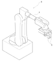
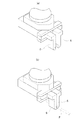
図1〜図2に示すように、鉄筋を曲げ加工するために、上下方向に軸心を沿わせてある支点ローラーから成る支点部1と、その支点部1周りに回動して鉄筋を屈曲させる回動ローラーから成る力点部2とを設けた鉄筋横曲げ用の鉄筋曲げ機3を設け、その鉄筋曲げ機3に対して、遠近移動及び上下左右に搖動操作自在なアーム4と、そのアーム4の先端側で鉄筋をクランプ操作自在なクランプ部5とを設けたロボットアーム装置6を、横方向に一対並べて設け、鉄筋曲げ機3に対して複数本の鉄筋を、個別に順次提供できるように搬送する鉄筋搬送装置7を設けて、鉄筋曲げ装置を構成してある。
尚、鉄筋曲げ操作においては、支点部1と力点部2との間に鉄筋を配置して支点部1周りの力点部2の回動操作で鉄筋を曲げるのであるが、鉄筋曲げ時の反力を受ける反力受部8を鉄筋曲げ機3には設けてある。従って、鉄筋を鉄筋曲げ機3に供給する際には、支点部1と反力受部8との間に鉄筋を供給配置する。
Embodiments of the present invention will be described below based on the drawings.
As shown in FIGS. 1 and 2, in order to bend the rebar, the
In the reinforcing bar bending operation, a reinforcing bar is disposed between the
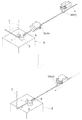
一対のロボットアーム装置6には、図1〜図5に示すように、一対のロボットアーム装置6における一方のクランプ部5R(5)と他方のクランプ部5L(5)とによってクランプして鉄筋搬送装置7から鉄筋Fを取り出して、鉄筋曲げ機3の支点部1と力点部2との間に供給する鉄筋供給操作制御と、鉄筋曲げ機3に供給した鉄筋Fの先端側曲げ予定箇所とは異なる基端側固定個所を、少なくとも一つのクランプ部5によってクランプしたまま鉄筋曲げ機3による曲げ作動を行う鉄筋曲げ操作制御と(図4)、クランプ部5によってクランプしている鉄筋Fを、鉄筋曲げ機3から取り出す鉄筋取り出し操作制御とを行う第1制御手段を設け、鉄筋曲げ操作制御において、鉄筋Fを3次元形状に曲げ加工する場合、鉄筋Fをその軸心回りに所定角度回動させるのに、一方のクランプ部5Rと他方のクランプ部5Lで鉄筋Fをクランプしながら、図5に示すように、回動操作時に一方のクランプ部5Rで回動操作すると同時に、他方のクランプ部5Lの挟持圧を一方のクランプ部5Rよりも小にするか、又は、他方のクランプ部5Lを非挟持状態にして鉄筋Fのその軸心回りの回動を許容するように制御する第1鉄筋回動操作制御を、第1制御手段に設けてある(図5)。
As shown in FIGS. 1 to 5, the pair of
つまり、鉄筋Fの先端側を力点部2の回動操作で曲げ加工する第1曲げ工程の後、鉄筋Fの基端側を、先端側の曲げ加工部分を含む第1仮想面とは異なる第2仮想面上に、曲げ加工して3次元形状に曲げ加工するのに、クランプ部5で挟持して支持している基端側の鉄筋部分を、その軸心回りに回動させ、前述の第1鉄筋回動操作制御を行う。
That is, after the first bending step of bending the distal end side of the reinforcing bar F by the turning operation of the
更に図6〜図8に示すように、前記鉄筋曲げ操作制御において、前記第1鉄筋回動操作制御によって鉄筋Fを曲げ操作した後に、鉄筋Fを更にその軸心回りに所定角度回動させるのに、鉄筋Fの基端側を他方の前記クランプ部5Lでクランプすると共に、一方の前記クランプ部5Rで曲げた先端側を掴みかえて(図6→図7→図8)、回動操作時に一方の前記クランプ部5Rで回動操作すると同時に、他方の前記クランプ部5Lの挟持圧を一方の前記クランプ部5Rよりも小にするか、又は、他方の前記クランプ部5Lを非挟持状態にして鉄筋Fのその軸心回りの回動を許容するように制御する第2鉄筋回動操作制御を前記第1制御手段に設け、結果として、例えば、図9に示すような3次元形状に鉄筋Fを曲げ加工できるように構成してある。
Furthermore, as shown in FIGS. 6-8, in the reinforcing bar bending operation control, after reinforcing bar F is bent by the first reinforcing bar rotational operation control, reinforcing bar F is further rotated about its axis by a predetermined angle. While the base end side of the reinforcing bar F is clamped by the
〔別実施形態〕
以下に他の実施の形態を説明する。
〈1〉 前記一対のロボットアーム装置6の夫々のクランプ部5R、5Lで鉄筋を軸心回りに回動させたり、持ち替えたりする操作制御は、上記の曲げ加工形状の例に限らず、加工予定の3次元形状によって種々様々に変更して実施しても良い。
[Another embodiment]
Other embodiments will be described below.
<1> The operation control of rotating the rebar around the axis by the
1 支点部
2 力点部
3 鉄筋曲げ機
4 アーム
5 クランプ部
6 ロボットアーム装置
1
Claims (2)
前記鉄筋曲げ機に対して遠近移動及び上下左右に搖動操作自在なアームと、そのアームの先端側で鉄筋をクランプ操作自在なクランプ部とを設けたロボットアーム装置を一対設け、
前記鉄筋曲げ機に対して鉄筋を、前記一対のロボットアーム装置における一方の前記クランプ部と他方の前記クランプ部とによってクランプして供給する鉄筋供給操作制御と、
前記鉄筋曲げ機に供給した鉄筋の先端側曲げ予定箇所とは異なる基端側固定個所を、少なくとも一つの前記クランプ部によってクランプしたまま前記鉄筋曲げ機による曲げ作動を行う鉄筋曲げ操作制御と、
前記クランプ部によってクランプしている鉄筋を、前記鉄筋曲げ機から取り出す鉄筋取り出し操作制御とを行う第1制御手段を設け、
前記鉄筋曲げ操作制御において、鉄筋をその軸心回りに所定角度回動させるのに、一方の前記クランプ部と他方の前記クランプ部で鉄筋をクランプしながら、回動操作時に一方のクランプ部で回動操作すると同時に、他方のクランプ部の挟持圧を一方のクランプ部よりも小にするか、又は、他方のクランプ部を非挟持状態にして鉄筋のその軸心回りの回動を許容するように制御する第1鉄筋回動操作制御を、前記第1制御手段に設けてある鉄筋曲げ装置。 To bend the rebar, provide a rebar bending machine with a fulcrum and a point of force that turns around the fulcrum to bend the rebar.
A pair of robot arm devices provided with an arm which can be moved in a perspective movement and swinging vertically and horizontally with respect to the reinforcing bar bending machine and a clamp portion which can clamp the reinforcing bar on the tip end side of the arm are provided.
Rebar supply operation control to be supplied by clamping a reinforcing bar to the reinforcing bar bending machine by the one clamp portion and the other clamp portion in the pair of robot arm devices;
Rebar bending operation control for performing bending operation by the rebar bending machine while clamping a proximal end side fixing point different from a tip end bending expected place of the rebar supplied to the rebar bending machine by at least one clamp unit;
The first control means is provided to perform a reinforcing bar takeout operation control for taking out the reinforcing bar clamped by the clamp unit from the reinforcing bar bending machine,
In the reinforcing bar bending operation control, in order to rotate the reinforcing bar by a predetermined angle around its axis, the reinforcing bar is clamped by one of the clamp portion and the other clamp portion while rotating by one of the clamp portions during the rotating operation. At the same time as the movement operation, make the clamping pressure of the other clamp part smaller than that of one clamp part, or make the other clamp part non-clasping state so as to allow rotation of the rebar around its axis The rebar bending apparatus which is provided with the first control means for controlling a first rebar rotation operation control.
鉄筋の基端側を一方の前記クランプ部でクランプしたまま、他方の前記クランプ部で曲げた先端側を掴みかえて、回動操作時に他方の前記クランプ部で回動操作すると同時に、一方の前記クランプ部の挟持圧を他方の前記クランプ部よりも小にするか、又は、一方の前記クランプ部を非挟持状態にして鉄筋のその軸心回りの回動を許容するように制御する第2鉄筋回動操作制御を前記第1制御手段に設けてある請求項1に記載の鉄筋曲げ装置。 In the reinforcing bar bending operation control, after the reinforcing bar is bent by the first reinforcing bar rotational operation control, the reinforcing bar is further rotated about its axis by a predetermined angle.
While the proximal end side of the reinforcing bar is clamped by one of the clamps, the other clamp side bends the bent distal end, and at the same time the other clamp performs the turning operation at the same time, A second reinforcing bar which controls the clamping pressure of the clamping unit to be smaller than the other clamping unit, or controls one of the clamping units to be unclamping to allow rotation of the reinforcing bar about its axis The reinforcing bar bending apparatus according to claim 1, wherein a rotational operation control is provided to the first control means.
Priority Applications (1)
| Application Number | Priority Date | Filing Date | Title |
|---|---|---|---|
| JP2017223747A JP6984880B2 (en) | 2017-11-21 | 2017-11-21 | Reinforcing bar bending device |
Applications Claiming Priority (1)
| Application Number | Priority Date | Filing Date | Title |
|---|---|---|---|
| JP2017223747A JP6984880B2 (en) | 2017-11-21 | 2017-11-21 | Reinforcing bar bending device |
Publications (2)
| Publication Number | Publication Date |
|---|---|
| JP2019093405A true JP2019093405A (en) | 2019-06-20 |
| JP6984880B2 JP6984880B2 (en) | 2021-12-22 |
Family
ID=66970562
Family Applications (1)
| Application Number | Title | Priority Date | Filing Date |
|---|---|---|---|
| JP2017223747A Active JP6984880B2 (en) | 2017-11-21 | 2017-11-21 | Reinforcing bar bending device |
Country Status (1)
| Country | Link |
|---|---|
| JP (1) | JP6984880B2 (en) |
Cited By (1)
| Publication number | Priority date | Publication date | Assignee | Title |
|---|---|---|---|---|
| CN115030562A (en) * | 2022-06-30 | 2022-09-09 | 中国建筑第五工程局有限公司 | Supporting device for residential composite floor slab |
Citations (6)
| Publication number | Priority date | Publication date | Assignee | Title |
|---|---|---|---|---|
| JPS61172623A (en) * | 1985-01-28 | 1986-08-04 | Usui Internatl Ind Co Ltd | Automatic bending method and apparatus for metal pipe |
| JPH0335820A (en) * | 1989-06-30 | 1991-02-15 | Chuo Electric Mfg Co Ltd | Bending apparatus |
| JP2007508144A (en) * | 2003-08-05 | 2007-04-05 | ローゼンベルガー アーゲー | Bending method for workpiece |
| JP2008036676A (en) * | 2006-08-07 | 2008-02-21 | Opton Co Ltd | Bending apparatus |
| JP2014000646A (en) * | 2012-06-20 | 2014-01-09 | Yaskawa Electric Corp | Robotic system and fitting member manufacturing method |
| JP2016159331A (en) * | 2015-03-02 | 2016-09-05 | 株式会社オプトン | Bending device |
-
2017
- 2017-11-21 JP JP2017223747A patent/JP6984880B2/en active Active
Patent Citations (6)
| Publication number | Priority date | Publication date | Assignee | Title |
|---|---|---|---|---|
| JPS61172623A (en) * | 1985-01-28 | 1986-08-04 | Usui Internatl Ind Co Ltd | Automatic bending method and apparatus for metal pipe |
| JPH0335820A (en) * | 1989-06-30 | 1991-02-15 | Chuo Electric Mfg Co Ltd | Bending apparatus |
| JP2007508144A (en) * | 2003-08-05 | 2007-04-05 | ローゼンベルガー アーゲー | Bending method for workpiece |
| JP2008036676A (en) * | 2006-08-07 | 2008-02-21 | Opton Co Ltd | Bending apparatus |
| JP2014000646A (en) * | 2012-06-20 | 2014-01-09 | Yaskawa Electric Corp | Robotic system and fitting member manufacturing method |
| JP2016159331A (en) * | 2015-03-02 | 2016-09-05 | 株式会社オプトン | Bending device |
Cited By (2)
| Publication number | Priority date | Publication date | Assignee | Title |
|---|---|---|---|---|
| CN115030562A (en) * | 2022-06-30 | 2022-09-09 | 中国建筑第五工程局有限公司 | Supporting device for residential composite floor slab |
| CN115030562B (en) * | 2022-06-30 | 2024-02-06 | 中国建筑第五工程局有限公司 | Support device for house composite floor slab |
Also Published As
| Publication number | Publication date |
|---|---|
| JP6984880B2 (en) | 2021-12-22 |
Similar Documents
| Publication | Publication Date | Title |
|---|---|---|
| TWI317314B (en) | Automatic tool changing method and device for machine tool controlled by numerical controller | |
| JP6654351B2 (en) | Bending equipment | |
| JP6619560B2 (en) | Bending machine | |
| EP2799158B1 (en) | Matrix and countermatrix type bending machine for right-hand and left-hand bending an elongated piece | |
| CN104128832B (en) | Instrument exchange method and toolroom machine | |
| EP2982332A1 (en) | Master-slave system | |
| CN205308219U (en) | Chemical instrumentation shakes even device | |
| JP6568165B2 (en) | Robot system and robot controller | |
| JP2019093405A (en) | Reinforcing bar bending apparatus | |
| CN103659805A (en) | Robot and robot system | |
| TW201505735A (en) | Bending system | |
| JP2010166799A (en) | Method and apparatus for constituting coils | |
| JP5405879B2 (en) | Bending machine | |
| JPS62224428A (en) | Bending device | |
| JP2006326738A (en) | Inverted pendulum type carriage robot | |
| WO2010117038A1 (en) | Bending device | |
| JP5477579B2 (en) | Robot hand | |
| EP2435224A1 (en) | Wood processing apparatus | |
| CN102729131A (en) | Apparatus for grinding a continuously cast workpiece | |
| JPH11179430A (en) | Bend straightening device for long size shaft and its method | |
| JPH0829358B2 (en) | Left and right bending type bender device | |
| JP2018140455A (en) | Robot and robot system | |
| JPH0335820A (en) | Bending apparatus | |
| JP2015179733A (en) | Winding device and winding method | |
| EP3508312A1 (en) | Robot and method for operating same |
Legal Events
| Date | Code | Title | Description |
|---|---|---|---|
| A621 | Written request for application examination |
Free format text: JAPANESE INTERMEDIATE CODE: A621 Effective date: 20201111 |
|
| A977 | Report on retrieval |
Free format text: JAPANESE INTERMEDIATE CODE: A971007 Effective date: 20210825 |
|
| TRDD | Decision of grant or rejection written | ||
| A01 | Written decision to grant a patent or to grant a registration (utility model) |
Free format text: JAPANESE INTERMEDIATE CODE: A01 Effective date: 20211102 |
|
| A61 | First payment of annual fees (during grant procedure) |
Free format text: JAPANESE INTERMEDIATE CODE: A61 Effective date: 20211117 |
|
| R150 | Certificate of patent or registration of utility model |
Ref document number: 6984880 Country of ref document: JP Free format text: JAPANESE INTERMEDIATE CODE: R150 |