JP2019089377A - Battery loading structure of electric vehicle - Google Patents
Battery loading structure of electric vehicle Download PDFInfo
- Publication number
- JP2019089377A JP2019089377A JP2017217931A JP2017217931A JP2019089377A JP 2019089377 A JP2019089377 A JP 2019089377A JP 2017217931 A JP2017217931 A JP 2017217931A JP 2017217931 A JP2017217931 A JP 2017217931A JP 2019089377 A JP2019089377 A JP 2019089377A
- Authority
- JP
- Japan
- Prior art keywords
- pair
- frame
- battery
- closed cross
- flange portion
- Prior art date
- Legal status (The legal status is an assumption and is not a legal conclusion. Google has not performed a legal analysis and makes no representation as to the accuracy of the status listed.)
- Granted
Links
Images


Classifications
-
- Y—GENERAL TAGGING OF NEW TECHNOLOGICAL DEVELOPMENTS; GENERAL TAGGING OF CROSS-SECTIONAL TECHNOLOGIES SPANNING OVER SEVERAL SECTIONS OF THE IPC; TECHNICAL SUBJECTS COVERED BY FORMER USPC CROSS-REFERENCE ART COLLECTIONS [XRACs] AND DIGESTS
- Y02—TECHNOLOGIES OR APPLICATIONS FOR MITIGATION OR ADAPTATION AGAINST CLIMATE CHANGE
- Y02T—CLIMATE CHANGE MITIGATION TECHNOLOGIES RELATED TO TRANSPORTATION
- Y02T10/00—Road transport of goods or passengers
- Y02T10/60—Other road transportation technologies with climate change mitigation effect
- Y02T10/62—Hybrid vehicles
Abstract
Description
本発明は、電気車両のバッテリ搭載構造に関し、特にフロア下方のフロアフレームがバッテリモジュールを支持する支持フレームを上側から保持する電気車両のバッテリ搭載構造に関する。 The present invention relates to a battery mounting structure of an electric vehicle, and more particularly to a battery mounting structure of an electric vehicle in which a floor frame below the floor holds a support frame supporting a battery module from above.
従来より、ハイブリッド車や電気自動車等の電気車両では、車輪を駆動する電気モータの動力源であるバッテリが大型且つ大容量になるため、バッテリセルの集合体からなる複数のバッテリモジュールを車体フロアの下方空間を利用して配置している。
大型のバッテリモジュールをフロアパネル下のフロアフレームに保持された支持フレームによって支持する場合、衝突時の衝撃荷重がバッテリモジュールに直接的に伝達され易いため、衝突時、特に、側突時におけるバッテリモジュールの保護が求められている。
Conventionally, in an electric vehicle such as a hybrid vehicle or an electric vehicle, a battery serving as a power source of an electric motor for driving a wheel is large and has a large capacity. It arranges using lower space.
When a large battery module is supported by the support frame held by the floor frame below the floor panel, the shock load at the time of the collision is easily transmitted directly to the battery module, so the battery module at the time of a collision, especially at the side collision Protection is required.
特許文献1の車体下部構造は、左右1対のサイドシル間に掛け渡されたフロアパネルを上方に膨出形成したバッテリ収容凹部と、枠状の周縁フレームを含みバッテリをバッテリ収容凹部内に配置するバッテリトレイと、バッテリ収容凹部の車幅方向外側壁下部の外縁に沿って前後方向に延びるエクステンションメンバと、フロアパネルの上面と協働して1対のサイドシル間に断面略逆U字状の閉断面を形成するクロスメンバとを備え、周縁フレームがエクステンションメンバの下部に連結され、クロスメンバがエクステンションメンバの車幅方向外側壁とサイドシルの内側壁との間に第1の閉断面構造部を形成している。
The vehicle body lower structure of
特許文献1の車体下部構造は、側突時、サイドシルに入力された衝撃荷重がエクステンションメンバとサイドシルとの間の第1閉断面構造部によって支持され、この第1閉断面構造部を介して非衝突側に拡散されることにより、バッテリの保護効果を高めている。
しかし、特許文献1の車体下部構造では、衝撃荷重に対する反力を高めるため、第1閉断面構造部に加えて、エクステンションメンバとサイドシルとの間を連結するガセット、エクステンションメンバの内側に形成された第2閉断面構造部及びバッテリ収容凹部の上部に形成された第3閉断面構造部等が夫々設けられており、部品点数の増加に伴って車体重量の増加を招く虞がある。
In the vehicle body lower structure of
However, in the vehicle body lower structure of
そこで、部品点数削減による軽量化を目的として、車体骨格部材に高強度鋼等の特殊材料フレームを用いることも考えられる。
しかし、各車体骨格部材を高強度の特殊部材で形成することは、材料コストの観点から非経済的であり、また、衝突時において、衝撃荷重を分散するためのロードパス設定の観点からも非効果的であることから、現実的な対策ではない。
即ち、車体重量を軽減しつつバッテリモジュールの保護を図るためには、更なる改善が必要である。
Therefore, it is also conceivable to use a special material frame such as high strength steel as the body frame member for the purpose of weight reduction by reducing the number of parts.
However, it is uneconomical to form each vehicle body frame member from high strength special members from the viewpoint of material cost, and also from the viewpoint of setting the load path for dispersing the impact load at the time of collision. Because it is effective, it is not a realistic measure.
That is, in order to reduce the weight of the vehicle and protect the battery module, further improvement is required.
本発明の目的は、重量軽減を図りつつバッテリモジュールを保護可能な電気車両のバッテリ搭載構造等を提供することである。 An object of the present invention is to provide a battery mounting structure or the like of an electric vehicle capable of protecting a battery module while reducing weight.
請求項1の電気車両のバッテリ搭載構造は、左右1対のサイドシルの車幅方向内側に配設され且つフロアパネルと協働してフロアパネル下方に前後方向に延びる第1閉断面を形成する左右1対のフロアフレームと、充放電可能なバッテリモジュールを支持すると共に前後方向に延びる左右1対の支持フレームとを備え、前記1対のフロアフレームが前記1対の支持フレームを上側から夫々保持する電気車両のバッテリ搭載構造において、前記サイドシルにサイドシルアウタパネルとサイドシルインナパネルとを協働させて形成した第2閉断面の下端部から下方に延びる下側フランジ部を設け、前記支持フレームに支持フレームロアパネルと支持フレームアッパパネルとを協働させて形成した第3閉断面の車幅方向外側端部から上方に延びる外側フランジ部を設け、前記外側フランジ部が、前記下側フランジ部と側面視にて重なり合うように形成されたことを特徴としている。
The battery mounting structure of the electric vehicle according to
この電気車両のバッテリ搭載構造では、サイドシルにサイドシルアウタパネルとサイドシルインナパネルとを協働させて形成した第2閉断面の下端部から下方に延びる下側フランジ部を設け、前記支持フレームに支持フレームロアパネルと支持フレームアッパパネルとを協働させて形成した第3閉断面の車幅方向外側端部から上方に延びる外側フランジ部を設けたため、サイドシルの下側フランジ部と支持フレームの外側フランジ部を平面視にて隣り合うように配置することができる。
外側フランジ部が、前記下側フランジ部と側面視にて重なり合うように形成されたため、側突時、バッテリモジュールを支持する支持フレームを用いてサイドシルの車幅方向内側への変位をフランジ部同士が当接することにより抑制することができ、バッテリモジュールの保護を図ることができる。
In the battery mounting structure of the electric vehicle, the side sill is provided with a lower flange portion extending downward from the lower end portion of the second closed cross section formed by cooperating the side sill outer panel and the side sill inner panel, and the support frame lower panel And the support frame upper panel cooperate with each other to form an outer flange portion extending upward from the outer end portion in the vehicle width direction of the third closed cross section. They can be arranged to be adjacent to each other visually.
Since the outer flange portion is formed to overlap the lower flange portion in a side view, in the side collision, the flange portion is configured to displace the side sill inward in the vehicle width direction using the support frame for supporting the battery module. It can suppress by contact | abutting and protection of a battery module can be aimed at.
請求項2の発明は、請求項1の発明において、前記外側フランジ部が、前記下側フランジ部と第1閉断面との間に形成されると共に前記第1閉断面と側面視にて重なり合うように形成されたことを特徴としている。
この構成によれば、側突時、フロアフレームを用いて支持フレームの車幅方向内側への変位を抑制することができ、結果的に、サイドシルの車幅方向内側への変位を抑制することができる。
The invention of
According to this configuration, at the time of a side collision, the floor frame can be used to suppress the inward displacement of the support frame in the vehicle width direction, and as a result, to suppress the inward displacement of the side sill in the vehicle width direction. it can.
請求項3の発明は、請求項1又は2の発明において、前記第3閉断面が、上下方向寸法よりも車幅方向寸法が大きい略扁平形状に形成されたことを特徴としている。
この構成によれば、支持フレームをフロアフレームの下方に配置しながら支持フレームの外側フランジ部を平面視にてサイドシルの下側フランジ部とフロアフレームの第1閉断面との間に配設することができる。
The invention of
According to this configuration, the outer flange portion of the support frame is disposed between the lower flange portion of the side sill and the first closed cross section of the floor frame in plan view while the support frame is disposed below the floor frame. Can.
請求項4の発明は、請求項1〜3の何れか1項の発明において、前記1対の支持フレームは、前記1対のフロアフレームに沿うように後側程車幅方向外側に移行するように配設され、前記外側フランジ部に上下方向に延びる複数の成型皺が形成されたことを特徴としている。
この構成によれば、支持フレームの車幅方向に対する曲げ強度を増加することができる。
According to the invention of claim 4, in the invention of any one of
According to this configuration, it is possible to increase the bending strength of the support frame in the vehicle width direction.
請求項5の発明は、請求項1〜4の何れか1項の発明において、前記1対の支持フレームと、前記1対の支持フレームの前端部同士を連結する前端フレームと、前記1対の支持フレームの後端部同士を連結する後端フレームとにより前記バッテリモジュールの周囲に位置する枠状フレームを形成し、前記枠状フレームが、前記バッテリモジュールの上側部分を覆う少なくともアッパカバーと協働してバッテリパックを構成したことを特徴としている。
この構成によれば、バッテリモジュールを保護しつつ側突時の衝撃荷重を非衝突側に効率よく分散することができる。
The invention of
According to this configuration, it is possible to efficiently disperse the impact load at the side collision to the non-collision side while protecting the battery module.
本発明の電気車両のバッテリ搭載構造によれば、部品点数を増加させることなく、重量軽減とバッテリモジュールの保護を両立することができる。 According to the battery mounting structure of the electric vehicle of the present invention, weight reduction and protection of the battery module can be compatible without increasing the number of parts.
以下、本発明の実施形態を図面に基づいて詳細に説明する。
以下の説明は、本発明を電気車両Vのバッテリ搭載構造に適用したものを例示したものであり、本発明、その適用物、或いは、その用途を制限するものではない。
Hereinafter, embodiments of the present invention will be described in detail based on the drawings.
The following description exemplifies what applied this invention to the battery mounting structure of the electric vehicle V, and does not restrict this invention, its application thing, or its use.
以下、本発明の実施例1について図1〜図14に基づいて説明する。
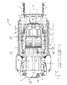
図1,図2に示すように、電気車両Vは、駆動輪を回転駆動する電動モータMと、バッテリパックBと、発電装置Gと、排気装置E等を備えている。
この車両Vは、充電専用エンジン61と駆動専用モータMとを備えており、搭載されたバッテリの保有電力が所定閾値(例えば、SOCが30%)以上においてエンジン61の停止状態を継続し、バッテリの保有電力が所定閾値未満において応急的にエンジン61を始動して充電を行うレンジエクステンダタイプの電気車両である。
Hereinafter, Example 1 of the present invention will be described based on FIGS. 1 to 14.
As shown in FIGS. 1 and 2, the electric vehicle V includes an electric motor M that rotationally drives drive wheels, a battery pack B, a power generation device G, an exhaust device E, and the like.
The vehicle V includes the charge-
まず、車両Vの骨格部材に係る前提構造について説明する。
尚、以下、矢印Fを前方、矢印Lを左方、矢印Uを上方として説明する。
フロアパネル1は、車室の床面を構成し、前席(図示略)が配設される略水平状のフロントフロアパネル1aと、このフロントフロアパネル1aの後端から高さ位置が高くなるように後方上り傾斜状に移行して後席(図示略)が配置されるキックアップ部1bと、このキックアップ部1bから後方に延びるリヤフロアパネル1cとを有している。
リヤフロアパネル1cの後側上部には、リヤフロアパネル1cと協働して左右に延び且つ車室と荷室とを区分するクロスメンバ16が配設されている。
First, the premise structure which concerns on the frame member of the vehicle V is demonstrated.
Hereinafter, the arrow F is described as the front, the arrow L as the left, and the arrow U as the upper.
The
A
図1〜図5に示すように、フロアパネル1(フロントフロアパネル1a)の左右両端には、前後に延びる左右1対のサイドシル2が夫々連結されている。
サイドシル2は、車体側部を構成するサイドフレーム3が連結された断面ハット状のサイドシルアウタパネル2aと、フロアパネル1が連結された断面ハット状のサイドシルインナパネル2bとから構成されている。
アウタパネル2aとインナパネル2bは、上側フランジ同士を接合して上側フランジ部2cを形成すると共に下側フランジ同士を接合して下側フランジ部2dを形成することにより断面略矩形状の閉断面C2(第2閉断面)を構成している。
上側フランジ部2cは閉断面C2の上壁略中央部から上方に延び、下側フランジ部2dは閉断面C2の下壁略中央部から下方に延びている。
As shown in FIGS. 1 to 5, a pair of left and
The
The
The upper flange portion 2c extends upward from a substantially central portion of the upper wall of the closed cross section C2, and the
図4に示すように、1対のサイドシル2の車幅方向内側には、前後に延びる左右1対のフロアフレーム4が設けられている。これら1対のフロアフレーム4は、後側程左右方向の離隔距離が大きくなるように配設されている。
フロアフレーム4は、断面ハット状に形成され、フロアパネル1の下側にフロアパネル1と協働して断面略矩形状の閉断面C1(第1閉断面)を構成している。
フロアフレーム4の下端部は、サイドシル2の下端部(下側フランジ部2dの下端部)よりも高さ位置が低くなるように形成されている。
また、フロアフレーム4の車幅方向外側壁部とサイドシル2の車幅方向内側壁部(インナパネル2b)とは、フロアパネル1と協働して閉断面を形成する複数の補強部材5によって連結されている。これにより、側突時におけるサイドシル2の車幅方向内側への移動を抑制し、衝撃荷重の分散を図っている。
As shown in FIG. 4, on the inner side in the vehicle width direction of the pair of
The floor frame 4 is formed in a hat shape in cross section, and cooperates with the
The lower end portion of the floor frame 4 is formed to be lower in height position than the lower end portion of the side sill 2 (the lower end portion of the
Further, the vehicle width direction outer side wall portion of the floor frame 4 and the vehicle width direction inner side wall portion (
1対のフロアフレーム4の前側延長部分には、フロアパネル1の前端に連なるダッシュパネル6を介して左右1対のフロントサイドフレーム7が前方に延びるように配設されている。これら1対のフロントサイドフレーム7の前端部には、圧縮変形により衝撃吸収可能なクラッシュカンが夫々固定され、これらのクラッシュカンを連結するようにバンパレインフォースメントとバンパフェースが装着されている(何れも図示略)。
1対のフロントサイドフレーム7の間に形成された空間部には、駆動輪である前輪(図示略)を回転駆動する駆動専用モータMが配置されている。
A pair of left and right front side frames 7 is disposed on the front extension portion of the pair of floor frames 4 so as to extend forward via a dash panel 6 connected to the front end of the
In a space formed between the pair of front side frames 7, a drive motor M is disposed which rotationally drives a front wheel (not shown) which is a drive wheel.
1対のフロアフレーム4の後側延長部分には、左右1対のリヤサイドフレーム8が後方に延びるように配設されている。
図6,図13に示すように、1対のリヤサイドフレーム8の後端部には、圧縮変形により衝撃吸収可能なクラッシュカン9が夫々固定され、これらのクラッシュカン9を連結するようにバンパレインフォースメント10とバンパフェース(図示略)が装着されている。
1対のリヤサイドフレーム8の下方には、前後に延びる左右1対の第1リヤサブフレーム11と、これら1対の第1リヤサブフレーム11の下方に配置された左右1対の第2リヤサブフレーム12と、第1,第2リヤサブフレーム11,12の後方に左右に延びる左右1対の第3リヤサブフレーム13が夫々設けられている。
A pair of left and right rear side frames 8 are disposed on the rear extension portions of the pair of floor frames 4 so as to extend rearward.
As shown in FIGS. 6 and 13,
Below the pair of rear side frames 8, a pair of left and right first
第1リヤサブフレーム11は、リヤサイドフレーム8の途中部下部に連結されると共に下方に向かって緩湾曲状に移行し、第2リヤサブフレーム12は、第1リヤサブフレーム11の車幅方向内側において、バッテリパックBの後端部に連結されると共に緩湾曲状に上方に移行するように形成されている。第1,第2リヤサブフレーム11,12の後端側部分がブラケット14を介して排気装置Eの後端部と連結されている。
これにより、後突時、リヤサイドフレーム8及び第1,第2リヤサブフレーム11,12によって複数のロードパスを形成でき、衝撃吸収に必要なクラッシュスペースを短縮することができる。これら1対のリヤサイドフレーム8及び第1,第2リヤサブフレーム11,12の間に形成された空間部には、発電装置Gが配置されている。
図1,図2,図8,図13に示すように、1対の第3リヤサブフレーム13の車幅方向内側部分が排気装置Eの左右両端部に夫々連結され、車幅方向外側部分がリヤサイドフレーム8の途中部下部に夫々連結されている。
The first
As a result, at the time of rear end collision, a plurality of load paths can be formed by the
As shown in FIG. 1, FIG. 2, FIG. 8 and FIG. 13, the vehicle width direction inner portions of the pair of third
次に、バッテリパックBについて説明する。
バッテリパックBは、複数(例えば、16個)のバッテリモジュール20を直列接続した高電圧バッテリを車室外、特に、フロアパネル1の下方空間にレイアウトする必要があるため、耐振性(剛性)及び耐水性(防水性)を確保するように構成されている。
このバッテリパックBは、バッテリモジュール20に発生する熱を熱伝導を利用して直接的に車両外部に放出する自然空冷方式を用いており、冷却水や送風ファンによる冷却風を用いた強制冷却方式は採用していない。
Next, the battery pack B will be described.
The battery pack B is required to lay out a high voltage battery in which a plurality of (for example, 16)
This battery pack B uses a natural air cooling system in which the heat generated in the
ここで、バッテリパックBの説明の前に、バッテリモジュール20について説明する。
図7に示すように、バッテリモジュール20は、規格電圧を有する直方体形状の複数(例えば、12個)のバッテリセル21をセパレータ22を間に介して水平方向に積層状に整列させた直方体形状のバッテリ集合体Aを備えている。
バッテリセル21は、例えば、2次電池の一種であるリチウムイオンバッテリである。
以下、積層方向が前後方向に設定されたバッテリモジュール20の例について説明する。
Here, before describing the battery pack B, the
As shown in FIG. 7, the
The
Hereinafter, an example of the
セパレータ22は、異常なバッテリセル21の熱を他の正常なバッテリセル21に伝播させないように熱遮断性、耐熱性及び熱安定性に優れた合成樹脂材料、例えば、ポリブチレンテレフタレート(PBT)シートにより構成されている。
このバッテリ集合体Aにおいて、全てのバッテリセル21の各々の電極が上方に向うように配列されているため、隣り合う電極を接続するバスバー23(電極接続部)、各ハーネスやケーブルが上面部に配設されている。
The
In this battery assembly A, since each electrode of all the
図7に示すように、バッテリモジュール20は、前後1対のエンドプレート24と、左右1対のアルミ合金製バインドバー25(挟持パネル部材)と、アッパプレート26等を有している。
エンドプレート24の一方がバッテリ集合体Aの前端部全域を覆うように重畳され、エンドプレート24の他方がバッテリ集合体Aの後端部全域を覆うように重畳されている。
プレート状のバインドバー25は、バッテリ集合体Aの両方の側面部全域を覆うように夫々配置され、1対のエンドプレート24を前後方向から挟み込み可能に構成されている。
左側のバインドバー25には、前端部及び後端部から右側直交方向に夫々屈曲した前後1対の取付部25aが設けられ、1対の取付部25aと1対のエンドプレート24とが締結部材を介して夫々締結固定されている。
尚、右側のバインドバー25は、左側のバインドバー25と左右対称の構成である。
As shown in FIG. 7, the
One
The plate-like bind bars 25 are respectively disposed so as to cover the entire area of both side surfaces of the battery assembly A, and are configured to be able to sandwich the pair of
The
The
左右1対のバインドバー25のうち一方、例えば、左側のバインドバー25の左側面部には、ヒータユニット27(シート状ヒータ手段)が装着されている。
ヒータユニット27は、周辺温度を自己判断して放熱量制御を行うシート状の電熱線ヒータ、例えば、バインドバー25に部分的に面接触可能なPTC(Positive Temperature Coefficient)ヒータによって構成されている。
これにより、ヒータユニット27からの熱は、ヒータユニット27の形状に拘らず、バインドバー25を介してバッテリ集合体Aの側面部全域に伝播される。
A heater unit 27 (sheet-like heater means) is attached to one of the pair of left and right bind bars 25, for example, the left side surface of the
The
Thereby, the heat from the
アッパプレート26は、合成樹脂製プレート材で構成され、バスバー23や各ハーネス等を含んでバッテリ集合体Aの上面部全域を覆うように形成されている。
バッテリモジュール20をバッテリパックB内に収容する際、バッテリ集合体Aの下面部の略全域には、熱伝導性に優れたシリコンシート28(熱伝導シート)が貼着されている。尚、積層方向が左右方向に設定されたバッテリモジュール20の場合、前述した積層方向が前後方向に設定されたバッテリモジュール20を鉛直軸回りに90°回転させた構成になっている。
The
When the
また、バッテリパックBの説明に戻る。
バッテリパックBは、発電装置G及び排気装置Eと一体的に組み立てられて組立ユニットを形成している。
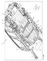
図8〜図11に示すように、バッテリパックBは、略ロ字状の金属製枠状フレーム30と、金属製底板31と、合成樹脂製アッパカバー32とを主要な構成要素としている。
枠状フレーム30と金属製底板31とが、バッテリパックBのロアカバーに相当している。
Also, the description returns to the battery pack B.
The battery pack B is integrally assembled with the power generation device G and the exhaust device E to form an assembly unit.
As shown in FIGS. 8 to 11, the battery pack B mainly includes a substantially
The frame-shaped
枠状フレーム30は、前後に延びる左右1対の支持フレーム33と、これら1対の支持フレーム33の前端部を左右に連結する前端フレーム34と、1対の支持フレーム33の後端部を左右に連結する後端フレーム35とを備えている。
1対の支持フレーム33は、1対のフロアフレーム4の下方において1対のフロアフレーム4に沿って後側程車幅方向外側に移行するように配設されている。
The frame-
The pair of support frames 33 is disposed below the pair of floor frames 4 so as to be shifted outward along the pair of floor frames 4 toward the rear in the vehicle width direction.
図4に示すように、支持フレーム33は、略L字状の支持フレームロアパネル33aと、略W字状の支持フレームアッパパネル33bとを有している。
支持フレームロアパネル33aと支持フレームアッパパネル33bは、左側(車幅方向外側)フランジ同士を接合して外側フランジ部33cを形成すると共に右側フランジ同士を接合して内側フランジ部33dを形成することにより略扁平形状の閉断面C3(第3閉断面)を構成している。鋼板製の支持フレームロアパネル33aと支持フレームアッパパネル33bは、プレス加工によって各々の形状に成形された後、各フランジ同士が溶接接合されているため、外側フランジ部33cには、上下方向に延びた複数のビード状成形皺33e(図2,図8,図10,図11参照)が形成されている。
閉断面C3は、上下寸法よりも左右寸法が大きい略扁平形状に形成され、閉断面C3の上端部とフロアフレーム4の下端部とは所定間隔離隔するように構成されている。
As shown in FIG. 4, the
The support frame
The closed cross section C3 is formed in a substantially flat shape in which the left and right dimensions are larger than the upper and lower dimensions, and the upper end of the closed cross section C3 and the lower end of the floor frame 4 are separated by a predetermined distance.
外側フランジ部33cは、閉断面C3の左端上側頂部から上方に延び、その上端部の高さ位置がサイドシル2の下側フランジ部2dの下端部の高さ位置よりも高くなる、換言すれば、外側フランジ部33cと下側フランジ部2dが、側面視にて重なり合うように形成されている。また、外側フランジ部33cの上端部の高さ位置がフロアフレーム4(閉断面C1)の下端部の高さ位置よりも高くなるように形成されている。
これにより、側突時、サイドシル2の車幅方向内側への移動を外側フランジ部33cによって抑制し、更に衝撃荷重が大きい場合、支持フレーム33の車幅方向内側への移動を閉断面C1によって抑制することができる。
内側フランジ部33dは、閉断面C3の右端下側頂部から右方に延びている。
The
Thereby, at the time of a side collision, the movement of the
The
図8,図10,図11に示すように、支持フレーム33の上壁部には、対向するフロアフレーム4の下端部に支持させるための4本のボルト部33f〜33iが設けられている。
これらのボルト部33f〜33iは、フロアパネル1の上側において前方から後方にかけて順に配設され、車幅方向に延びる閉断面を形成する各々のクロスメンバ(図示略)とフロアフレーム4とが重なり合う部分にナット部材(図示略)を用いて夫々締結固定されている。
As shown in FIGS. 8, 10, and 11, four
These
前端フレーム34は、1対の支持フレーム33の前端部同士を連結する閉断面を形成している。この前端フレーム34の途中部には、左右1対のボルト部34aが形成され、これら1対のボルト部34aが車体前部に対して締結固定されている。
後端フレーム35は、1対の支持フレーム33の後端部同士を連結する閉断面を形成している。この後端フレーム35の途中部には、左右1対のブラケット36が設けられている。これら1対のブラケット36は、後端フレーム35の後壁部に夫々固定され、上方に延びるように夫々形成されている。これらのブラケット36は、クロスメンバ16の下部にナット部材(図示略)を用いて夫々締結固定されている。
後端フレーム35の後壁部の左右端側部分は、1対のリヤサブフレーム12の前端部を当接支持している。これにより、リヤサブフレーム12に入力した衝撃荷重を車室から独立した枠状フレーム30全域に分散させて減衰することができる。
The
The
The left and right end side portions of the rear wall portion of the
図11に示すように、枠状フレーム30には、底板31の上側において底板31と協働して閉断面を形成する補強用メンバ41〜44が設けられている。
各メンバ41〜44のうち横メンバ41〜43は、1対のボルト部33f,33g,33iの間を夫々左右方向に連結し、縦メンバ44は、横メンバ43の左寄り途中部と後端フレーム35の左寄り途中部の間を前後方向に連結するように構成されている。
そして、枠状フレーム30の横メンバ43よりも前側部分は、フロントフロアパネル1aの下方に配置され、枠状フレーム30の横メンバ43よりも後側部分は、キックアップ部1b及びリヤフロアパネル1cの下方に配置されている。
本実施例では、縦メンバ44と左側支持フレーム33との離隔距離と縦メンバ44と右側支持フレーム33との離隔距離の比率は、1:3に設定されている。
As shown in FIG. 11, the frame-shaped
Of the
The front side portion of the frame-shaped
In the present embodiment, the ratio of the separation distance between the
底板31は、熱伝導性に優れた金属、例えば、アルミ合金によって構成されている。
図4,図5に示すように、底板31の左端側部分は、クランク状に形成され、支持フレーム33の上壁部と内側フランジ部33dとに支持されている。底板31の右端側部分も同様である。また、底板31の前端側部分及び後端側部分は、クランク状に形成され、前端フレーム34及び後端フレーム35のフランジ部及び上壁部によって夫々支持されている。
The
As shown in FIGS. 4 and 5, the left end side portion of the
アッパカバー32は、軽量で剛性に優れた合成樹脂材料、例えば、ガラス繊維強化材が含有されたポリプロピレン(PP)によって構成されている。
図8,図9に示すように、アッパカバー32は、前側部分が後側部分よりも大きい左右寸法で且つ小さい上下寸法にされた左右非対称形状である。
アッパカバー32の前側部分上部には、リレー等を含むジャンクションボックスを収容可能な凸部が形成され、後側部分上部には、ECUを含む電池監視ユニットを収容可能な凸部が形成されている。
このアッパカバー32の外周フランジ部は、シール用のガスケット(図示略)を介して枠状フレーム30の上壁部内縁に対して密着状に固定されている。
The
As shown in FIGS. 8 and 9, the
A convex portion capable of housing a junction box including a relay or the like is formed on the front side upper portion of the
The outer peripheral flange portion of the
バッテリパックBの内部には、1層配置で搭載された第1バッテリモジュールと上下2層配置で搭載された第2バッテリモジュールとによって構成された複数のバッテリモジュール20が収容されている。
図9,図10に示すように、横メンバ41,42の間において積層方向が前後になるように配置され且つ左右に整列された4個、横メンバ42,43の間において積層方向が左右になるように配置され且つ前後に整列された3個を左右2列に配列した6個、横メンバ43と後端フレーム35との間において縦メンバの右側に積層方向が前後になるように配置され且つ左右に整列された3個を上下2段に配列した6個の合計16個のバッテリモジュール20が密閉状態で収容されている。
これらのバッテリモジュール20は、複数のバスバー29により電気的に直列接続になるように連結されている。
以下、横メンバ43と後端フレーム35との間、所謂キックアップ部1b及びリヤフロアパネル1cの下方に配置された6個のバッテリモジュール20のうち、特に、下段に配列された3個のバッテリモジュール20をロアバッテリモジュール20a、上段に配列された3個のバッテリモジュール20をアッパバッテリモジュール20bと表し、これらを総称する場合には、バッテリモジュール20と表す。
Inside the battery pack B, a plurality of
As shown in FIGS. 9 and 10, four of the
The
Hereinafter, among the six
図3,図5に示すように、3個のアッパバッテリモジュール20bは、金属製、例えばアルミ合金製支持体50を介してバッテリパックBに夫々支持されている。
図12に示すように、支持体50は、水平方向に延び且つ左右に隣り合う3つの板状載置部51と、これら板状載置部51の左右両端部から下方に延び且つ左右に隣り合う4つの板状脚部52等を備えている。
載置部51は、アッパバッテリモジュール20bの底部(バッテリセル集合体Aの下面部)にシリコンシート28を介して面接触可能に構成されている。
脚部52は、載置部51と一体的に連なるように形成され、隣り合う脚部52の間に載置されたロアバッテリモジュール20aを収容可能に構成されている。
この脚部52は、下端部が底板31に面接触可能に形成され、前端壁及び後端壁の中段部に水平方向に延びる取付部53が夫々設けられている。前端側取付部53は締結部材を介して横メンバ43に締結固定され、後端側取付部53は締結部材を介して後端フレーム35に締結固定される。
As shown in FIGS. 3 and 5, the three
As shown in FIG. 12, the
The
The
The lower end portion of the
脚部52は、上半部に前後方向に直交する面を備えた冷却用上側フィン52aが設けられ、左右両端の脚部52には、下半部に前後方向に直交する面を備えると共に下端部が底板31に面接触する冷却用下側フィン52bが設けられている。
後側の下側フィン52bは、上側フィン52aに連なるように形成されている。
これにより、アッパバッテリモジュール20bの熱をシリコンシート28を介して載置部51に導入し、導入された熱を脚部52の下端部と下側フィン52bの下端部とから外部に放出することができる。
The
The rear
Thereby, the heat of the
次に、モータMについて説明する。
1対のフロントサイドフレーム7の間で且つ前輪のサスペンションクロスメンバ(図示略)の直ぐ前側には、車両Vを駆動するパワーユニット(図示略)が設けられている。
パワーユニットは、例えば、モータM(図1,図2参照)やモータ用インバータであるDC−ACコンバータ(図示略)を含むモータユニットと、このモータユニットの駆動力を前輪へ伝達するための動力伝達機構(減速機構及び差動機構)を含むトランクアクスル(図示略)とが車幅方向に並ぶように一体的に結合されている。
モータMのモータ軸心、トランクアクスルにおけるモータ軸と連結される入力軸の軸心、及びパワーユニットの出力軸(ジョイントシャフト)の軸心は、何れも車幅方向に延びている。
Next, the motor M will be described.
A power unit (not shown) for driving the vehicle V is provided between the pair of front side frames 7 and immediately in front of the suspension cross member (not shown) of the front wheels.
The power unit includes, for example, a motor unit including a motor M (see FIGS. 1 and 2) and a DC-AC converter (not shown) which is an inverter for the motor, and a power transmission for transmitting the driving force of the motor unit to the front wheels. A trunk axle (not shown) including a mechanism (a speed reduction mechanism and a differential mechanism) is integrally coupled to line in the vehicle width direction.
The motor shaft center of the motor M, the shaft center of the input shaft connected to the motor shaft in the trunk axle, and the shaft center of the output shaft (joint shaft) of the power unit all extend in the vehicle width direction.
次に、発電装置Gについて説明する。
図3,図6,図8に示すように、発電装置Gは、エンジン61と、ジェネレータ62と、AC−DCコンバータ63と、アンダカバー69と、燃料タンクT等を備えている。
発電装置Gは、車幅方向中央位置においてバッテリパックBの後端近傍位置に配設されている。この発電装置Gは、一体的にユニット化されており、前端部がブラケット64を介してクロスメンバ16の下部に固定され、左右両側部がブラケット(図示略)を介してリヤサブフレーム11,12に固定されている。そして、発電装置Gの下部は、合成樹脂製のアンダカバー69で覆われている。
Next, the power generation device G will be described.
As shown in FIGS. 3, 6, and 8, the power generation device G includes an
The power generation device G is disposed at a center position in the vehicle width direction near the rear end of the battery pack B. The power generation device G is integrally formed as a unit, the front end portion is fixed to the lower portion of the
エンジン61は、1ロータの小型ロータリエンジンであり、ロータの回転軸が前後に延びるように配設されている。このエンジン61は、側壁に排気ポートが形成されたサイド排気式に構成され、燃料タンクTから供給された燃料を燃焼させて得られたエネルギーでロータの回転軸に連結されたジェネレータ62の回転軸を回転駆動している。
バッテリパックBの保有電力が所定閾値未満に低下したとき、エンジン61が始動され、ジェネレータ62が最大発電効率になるよう予め設定された規定回転数で運転される。
エンジン61の燃焼室には、吸気通路を形成する吸気管(図示略)及び排気通路を形成する排気管65が連通されている。
吸気管は、途中部にエアクリーナが配設され、右側ホイールハウスのインナパネルに設けられた差込口に差込接続されている(何れも図示略)。
排気管65は、その途中部に触媒装置66と、消音装置67とが設けられている。
The
When the stored power of the battery pack B falls below the predetermined threshold, the
An intake pipe (not shown) forming an intake passage and an
An air cleaner is disposed in the middle of the intake pipe, and is connected to an insertion port provided on an inner panel of the right wheel house (not shown).
The
図3,図6,図8に示すように、ジェネレータ62は、バッテリパックBとエンジン61との間に配置されている。これにより、エンジン61を含む前後寸法を短縮化することができると共にジェネレータ62を前方配置することができ、後突時、高電圧部品であるジェネレータ62と排気装置Eとの直接的な干渉を回避している。
コンバータ63は、エンジン61の始動による充電時、ジェネレータ62からの交流電流を直流電流に変換して各バッテリモジュール20に供給している。
As shown in FIGS. 3, 6 and 8, the
The
燃料タンクTは、横メンバ43と後端フレーム35との間において縦メンバ44の左側に底板31に搭載された状態で配置され、横メンバ43と後端フレーム35とに固定された前後1対のブラケット37(図11参照)を介してバッテリパックBに上部開放状態で支持されている。燃料タンクTの内部には、燃料ポンプと、この燃料ポンプへの吸込用ストレーナ等が収容されている(何れも図示略)。
図5,図8〜図10に示すように、燃料タンクTは、エンジン61の小型化に伴って貯留容量が小型化されており、正面視にて略縦長形状に形成されている。具体的には、燃料タンクTの頂部が、第2バッテリモジュールであるアッパバッテリモジュール20bの頂部の高さ位置に略等しくなるように設定されている。
The fuel tank T is disposed on the
As shown in FIGS. 5 and 8 to 10, the storage capacity of the fuel tank T is reduced as the
図5に示すように、燃料タンクTの下半部は、上側程左右寸法(横断面積)が大きくなるように形成されている。これにより、設置面積とタンク容量の確保を両立している。
また、図5,図8,図9に示すように、燃料タンクTの中段部が右方に張り出しているため、アッパカバー32の左側後部に燃料タンクTを避けるように右方に凹入した回避部32aが設けられている。
これにより、燃料タンクTとアッパカバー32の干渉を回避でき、アッパカバー32の損傷防止によりバッテリモジュール20に対するシール性向上を図ることができる。
As shown in FIG. 5, the lower half portion of the fuel tank T is formed such that the left-right dimension (crossing area) increases toward the upper side. Thus, both the installation area and the tank capacity are secured.
Further, as shown in FIGS. 5, 8 and 9, since the middle step portion of the fuel tank T protrudes rightward, the left side of the
Thus, the interference between the fuel tank T and the
次に、排気装置Eについて説明する。
充電時、高回転駆動されたエンジン61の排気ガス温度が高温になるため、排気装置Eは、排気ガスを外部に放出する前段階において、排気ガスとエア(外気)とを予め攪拌し、排気ガス温度を低下させてから外部に放出するように構成されている。
図3,図6,図8,図13,図14に示すように、排気管65と、この排気管65の途中部に設けられた触媒装置66と、この触媒装置66よりも下流側に設けられた消音装置67と、エア混合手段68と、触媒装置66、消音装置67及びエア混合手段68等を所定間隔を空けて囲繞する金属製の排気ボックス70等を備えている。
触媒装置66は、略円柱状に形成され、その軸心がエンジン61のロータ軸心と略同じ高さ位置で且つ左右に延びるように配設されている。
消音装置67は、略楕円柱状に形成されている。この消音装置67は、触媒装置66の下方位置に配置され、その軸心が触媒装置66の軸心と略平行に延び且つ断面形状の長径が前後に延びるように配設されている。
Next, the exhaust system E will be described.
Since the exhaust gas temperature of the
As shown in FIG. 3, FIG. 6, FIG. 8, FIG. 13 and FIG. 14, the
The
The
それ故、排気管65は、エンジン61の排気ポートが形成された後部左方から後側上方に延びた後、右側下方に湾曲しながら触媒装置66の左端部に形成された導入口に接続されている。そして、排気管65は、触媒装置66の右端部に形成された排出口から下方に湾曲して消音装置67の右端前部に形成された導入口に接続され、消音装置67の左端後部に形成された排出口から左方に延びている。
これにより、後突時、触媒装置66は前側下方に移行し、消音装置67は前側下方に移行しつつ側面視にて導入口を中心として時計回りに回動するため、発電装置Gとの干渉を抑制することができる。
Therefore, after the
As a result, at the time of rear end collision, the
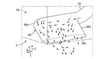
図14に示すように、エア混合手段68は、排気管65の下流端部に設けられ、進行方向誘導部68aと、本体部68bと、扁平開口部68c等を備えている。
進行方向誘導部68aは、消音装置67の排出口から左方に向かって流れる排気ガスの進路を下方を除いて遮断し、排気ガスの進行方向を下方に誘導するように構成されている。
具体的には、排気ガスの進行方向正面に緩湾曲状で且つ下方に延びる壁部を形成している。
As shown in FIG. 14, the air mixing means 68 is provided at the downstream end of the
The traveling
Specifically, a wall portion which is gently curved and extends downward is formed on the front side in the advancing direction of the exhaust gas.
本体部68bは、左右に延びた略扁平状で且つ後方下り傾斜状の容積室を形成している。
進行方向誘導部68aに誘導された排気ガスの進行方向ベクトルは、下向きベクトルと壁部からの反射による右向きベクトルが存在しているため、排気ガスの一部は、他からの力が加わらない限り、下向きベクトルと右向きベクトルの合成ベクトルにより図中矢印で示すような前後方向軸を中心とした反時計回りの旋回流(渦流)を形成する。
それ故、本体部68bは、反時計回りの旋回流を形成するために十分な上下長及び左右長を有している。
The
The traveling direction vector of the exhaust gas guided to the traveling
Therefore, the
扁平開口部68cは、本体部68bの下端に下向き且つ左右に延びると共に周囲のエア(外気)を導入可能に形成されている。
このエア混合手段68は、走行風が存在していない車両停車時、本体部68bから外部に飛び出した旋回外側の流れを排気ボックス70内で且つエア混合手段68周りのエアと一緒に扁平開口部68cから本体部68bの内部に取り込むことにより、排出前に本体部68b内で排気ガス温度を低下させる第1の温度低下機能を有している。
The
The air mixing means 68 is a flat opening together with the air in the
図2、図13に示すように、排気ボックス70は略直方体のボックス形状に形成され、エア混合手段68が左側部分に配設され、エンジン61の始動に同期して作動すると共に排気ボックス70の内部に外気を導入可能な掃気ファン71(エア導入手段)が右側壁部に形成されている。排気ボックス70の左側後方底部には、扁平開口部68cに対向して開口70aが形成されている。
これにより、車両停車時でも、掃気ファン71によって排気ボックス70内に左方に流動する外部エアを導入することができ、第1温度低下機能に加えて、エア混合手段68周りの排気ガス温度を低下させることができるため、本体部68b内で更に排気ガス温度を低下させる第2の温度低下機能を有している。
As shown in FIGS. 2 and 13, the
Thereby, even when the vehicle is stopped, the scavenging fan 71 can introduce the external air flowing leftward into the
また、扁平開口部68cと開口70aが近接配置されているため、車両走行時、前述した第1温度低下機能に加え、排気ボックス70内のエアと混合して温度低下された排気ガスを走行風の負圧による吸出し作用により車外に排出することができる。
以上により、車両Vの走行状態に拘らず、排気装置Eから排出されるガス温度を排気装置E(本体部68b)内部で低下することができ、特に、車両停車時、車両周囲への高温ガスの排出を回避することができ、乗降時、後席乗員の熱い空気流による違和感を解消することができる。
Further, since the
As described above, regardless of the traveling state of the vehicle V, the temperature of the gas discharged from the exhaust device E can be reduced inside the exhaust device E (
次に、上記電気車両のバッテリ搭載構造の作用、効果について説明する。
実施例1に係る電気車両Vのバッテリ搭載構造によれば、サイドシル2にサイドシルアウタパネル2aとサイドシルインナパネル2bとを協働させて形成した閉断面C2の下端部から下方に延びる下側フランジ部2dを設け、支持フレーム33に支持フレームロアパネル33aと支持フレームアッパパネル33bとを協働させて形成した閉断面C3の車幅方向外側端部から上方に延びる外側フランジ部33cを設けたため、サイドシル2の下側フランジ部2dと支持フレーム33の外側フランジ部33cを平面視にて隣り合うように配置することができる。
外側フランジ部33cが、下側フランジ部2dと側面視にて重なり合うように形成されたため、側突時、バッテリモジュール20を支持する支持フレーム33を用いてサイドシル2の車幅方向内側への変位をフランジ部同士が当接することにより抑制することができ、バッテリモジュール20の保護を図ることができる。
Next, the operation and effects of the battery mounting structure of the electric vehicle will be described.
According to the battery mounting structure of the electric vehicle V according to the first embodiment, the
Since the
外側フランジ部33cが、下側フランジ部2dと閉断面C1との間に形成されると共に閉断面C1と側面視にて重なり合うように形成されたため、側突時、フロアフレーム4を用いて支持フレーム33の車幅方向内側への変位を抑制することができ、結果的に、サイドシル2の車幅方向内側への変位を抑制することができる。
Since the
閉断面C3が、上下方向寸法よりも車幅方向寸法が大きい略扁平形状に形成されたため、支持フレーム33をフロアフレーム4の下方に配置しながら支持フレーム33の外側フランジ部33cを平面視にてサイドシル2の下側フランジ部2dとフロアフレーム4の閉断面C1との間に配設することができる。
Since the closed cross section C3 is formed in a substantially flat shape having a vehicle width direction dimension larger than the vertical direction dimension, the
1対の支持フレーム33は、1対のフロアフレーム4に沿うように後側程車幅方向外側に移行するように配設され、外側フランジ部33cに上下方向に延びる複数の成型皺33eが形成されたため、支持フレーム33の車幅方向に対する曲げ強度を増加することができる。
The pair of support frames 33 is disposed to move to the outer side in the vehicle width direction toward the rear side along the pair of floor frames 4, and a plurality of
1対の支持フレーム33と、1対の支持フレーム33の前端部同士を連結する前端フレーム34と、1対の支持フレーム33の後端部同士を連結する後端フレーム35とによりバッテリモジュール20の周囲に位置する枠状フレーム30を形成し、枠状フレーム30が、バッテリモジュール20の上側部分を覆う少なくともアッパカバー32と協働してバッテリパックBを構成したため、バッテリモジュール20を保護しつつ側突時の衝撃荷重を非衝突側に効率よく分散することができる。
The
次に、前記実施形態を部分的に変更した変形例について説明する。
1〕前記実施形態においては、レンジエクステンションタイプのハイブリッド車の例を説明したが、少なくともフロアパネルの下方空間にバッテリモジュールを支持した電気車両であれば良く、スプリットタイプ、シリーズタイプ、パラレルタイプのうち何れのハイブリッド車にも適用することができる。また、電気自動車に適用しても良い。
Next, a modification in which the embodiment is partially changed will be described.
1) In the above embodiment, an example of a range extension type hybrid vehicle has been described, but it is sufficient if it is an electric vehicle supporting a battery module at least in the space below the floor panel, and among split type, series type and parallel type It can be applied to any hybrid vehicle. Also, it may be applied to an electric car.
2〕前記実施形態においては、キックアップ部の前側に1層で搭載された第1バッテリモジュールとキックアップ部の後側に2層で搭載された第2バッテリモジュールとをバッテリパック内に収容した例を説明したが、第1バッテリモジュール或いは第2バッテリモジュールの何れか一方のみを収容したバッテリパックであっても良い。
また、キックアップ部の前後に亙ってバッテリモジュールを1層のみ設けることも可能である。
2) In the above embodiment, the first battery module mounted in a single layer on the front side of the kickup portion and the second battery module mounted in a second layer on the rear side of the kickup portion are accommodated in the battery pack Although the example has been described, it may be a battery pack that accommodates only one of the first battery module and the second battery module.
It is also possible to provide only one layer of battery module across the front and back of the kickup portion.
3〕前記実施形態においては、バッテリモジュールの保有電力が閾値以下に低下したとき、発電するために始動するエンジンの例を説明したが、バッテリモジュールの保有電力が閾値以下ではなくとも、例えば、潤滑油を循環させるために停止期間が所定期間継続したとき、エンジンを始動しても良い。また、モータ以外にエンジンによっても走行可能に構成し、乗員による加速要求が高いとき、エンジン駆動に切り替えてエンジンを始動させても良い。 3) In the above embodiment, an example of the engine started to generate electric power when the owned power of the battery module falls below the threshold has been described, but if the owned power of the battery module is not below the threshold, for example, lubrication The engine may be started when the stop period continues for a predetermined period to circulate the oil. In addition to the motor, it is possible to run by the engine, and when acceleration demand from the passenger is high, it is possible to switch to engine drive and start the engine.
4〕その他、当業者であれば、本発明の趣旨を逸脱することなく、前記実施形態に種々の変更を付加した形態や各実施形態を組み合わせた形態で実施可能であり、本発明はそのような変更形態も包含するものである。 4) In addition, those skilled in the art can carry out the embodiments in which various modifications are added to the embodiments or a combination of the embodiments without departing from the spirit of the present invention, and the present invention can be implemented as such It also includes various modifications.
1 フロアパネル
2 サイドシル
2a サイドシルアウタパネル
2b サイドシルインナパネル
2d 下側フランジ部
4 フロアフレーム
20 バッテリモジュール
30 枠状フレーム
32 アッパカバー
33 支持フレーム
33a 支持フレームロアパネル
33b 支持フレームアッパパネル
33c 外側フランジ部
33e 成形皺
34 前端フレーム
35 後端フレーム
V 車両
B バッテリパック
C1,C2,C3 閉断面
Claims (5)
前記サイドシルにサイドシルアウタパネルとサイドシルインナパネルとを協働させて形成した第2閉断面の下端部から下方に延びる下側フランジ部を設け、
前記支持フレームに支持フレームロアパネルと支持フレームアッパパネルとを協働させて形成した第3閉断面の車幅方向外側端部から上方に延びる外側フランジ部を設け、
前記外側フランジ部が、前記下側フランジ部と側面視にて重なり合うように形成されたことを特徴とする電気車両のバッテリ搭載構造。 A pair of floor frames disposed on the inner side in the vehicle width direction of the pair of left and right side sills and forming a first closed cross section extending in the longitudinal direction below the floor panel in cooperation with the floor panel, and a chargeable / dischargeable battery In a battery mounting structure of an electric vehicle, comprising: a pair of left and right support frames supporting the module and extending in the front and rear direction, wherein the pair of floor frames respectively hold the pair of support frames from above;
The side sill is provided with a lower flange portion extending downward from a lower end portion of a second closed cross section formed by causing the side sill outer panel and the side sill inner panel to cooperate with each other.
The support frame is provided with an outer flange portion extending upward from an outer end in the vehicle width direction of a third closed cross section formed by cooperating the support frame lower panel and the support frame upper panel in cooperation with each other.
The battery mounting structure for an electric vehicle, wherein the outer flange portion is formed to overlap with the lower flange portion in a side view.
前記外側フランジ部に上下方向に延びる複数の成型皺が形成されたことを特徴とする請求項1〜3の何れか1項に記載の電気車両のバッテリ搭載構造。 The pair of support frames are disposed so as to shift to the outside in the vehicle width direction toward the rear side along the pair of floor frames,
The battery mounting structure for an electric vehicle according to any one of claims 1 to 3, wherein the outer flange portion is formed with a plurality of molding ridges extending in the vertical direction.
前記枠状フレームが、前記バッテリモジュールの上側部分を覆う少なくともアッパカバーと協働してバッテリパックを構成したことを特徴とする請求項1〜4の何れか1項に記載の電気車両のバッテリ搭載構造。
Around the battery module by the pair of support frames, the front end frame connecting the front ends of the pair of support frames, and the rear end frame connecting the rear ends of the pair of support frames Form a frame-like frame,
The battery mounting of an electric vehicle according to any one of claims 1 to 4, wherein the frame-like frame constitutes a battery pack in cooperation with at least an upper cover covering an upper portion of the battery module. Construction.
Priority Applications (1)
| Application Number | Priority Date | Filing Date | Title |
|---|---|---|---|
| JP2017217931A JP6555550B2 (en) | 2017-11-13 | 2017-11-13 | Electric vehicle battery mounting structure |
Applications Claiming Priority (1)
| Application Number | Priority Date | Filing Date | Title |
|---|---|---|---|
| JP2017217931A JP6555550B2 (en) | 2017-11-13 | 2017-11-13 | Electric vehicle battery mounting structure |
Publications (2)
| Publication Number | Publication Date |
|---|---|
| JP2019089377A true JP2019089377A (en) | 2019-06-13 |
| JP6555550B2 JP6555550B2 (en) | 2019-08-07 |
Family
ID=66837058
Family Applications (1)
| Application Number | Title | Priority Date | Filing Date |
|---|---|---|---|
| JP2017217931A Active JP6555550B2 (en) | 2017-11-13 | 2017-11-13 | Electric vehicle battery mounting structure |
Country Status (1)
| Country | Link |
|---|---|
| JP (1) | JP6555550B2 (en) |
Cited By (4)
| Publication number | Priority date | Publication date | Assignee | Title |
|---|---|---|---|---|
| CN112519894A (en) * | 2019-09-03 | 2021-03-19 | 铃木株式会社 | Vehicle lower structure |
| JP2021068522A (en) * | 2019-10-18 | 2021-04-30 | 株式会社神戸製鋼所 | Battery accommodating unit |
| CN113525091A (en) * | 2020-04-22 | 2021-10-22 | 现代自动车株式会社 | Load absorbing structure for vehicle |
| JP7474229B2 (en) | 2021-09-29 | 2024-04-24 | 本田技研工業株式会社 | Mobile |
Families Citing this family (1)
| Publication number | Priority date | Publication date | Assignee | Title |
|---|---|---|---|---|
| DE102018132255A1 (en) * | 2018-12-14 | 2020-06-18 | Bayerische Motoren Werke Aktiengesellschaft | Energy storage floor assembly for a car body shell |
Citations (4)
| Publication number | Priority date | Publication date | Assignee | Title |
|---|---|---|---|---|
| JP2014226972A (en) * | 2013-05-20 | 2014-12-08 | 三菱自動車工業株式会社 | Vehicle body structure of automobile |
| JP2015074244A (en) * | 2013-10-04 | 2015-04-20 | トヨタ自動車株式会社 | Car body frame and vehicle underfloor structure |
| US20160257346A1 (en) * | 2015-03-05 | 2016-09-08 | Ford Global Technologies, Llc | Energy absorbing rocker assembly |
| JP2018149836A (en) * | 2017-03-10 | 2018-09-27 | マツダ株式会社 | Lower body structure of vehicle |
-
2017
- 2017-11-13 JP JP2017217931A patent/JP6555550B2/en active Active
Patent Citations (4)
| Publication number | Priority date | Publication date | Assignee | Title |
|---|---|---|---|---|
| JP2014226972A (en) * | 2013-05-20 | 2014-12-08 | 三菱自動車工業株式会社 | Vehicle body structure of automobile |
| JP2015074244A (en) * | 2013-10-04 | 2015-04-20 | トヨタ自動車株式会社 | Car body frame and vehicle underfloor structure |
| US20160257346A1 (en) * | 2015-03-05 | 2016-09-08 | Ford Global Technologies, Llc | Energy absorbing rocker assembly |
| JP2018149836A (en) * | 2017-03-10 | 2018-09-27 | マツダ株式会社 | Lower body structure of vehicle |
Cited By (5)
| Publication number | Priority date | Publication date | Assignee | Title |
|---|---|---|---|---|
| CN112519894A (en) * | 2019-09-03 | 2021-03-19 | 铃木株式会社 | Vehicle lower structure |
| JP2021068522A (en) * | 2019-10-18 | 2021-04-30 | 株式会社神戸製鋼所 | Battery accommodating unit |
| CN113525091A (en) * | 2020-04-22 | 2021-10-22 | 现代自动车株式会社 | Load absorbing structure for vehicle |
| CN113525091B (en) * | 2020-04-22 | 2024-03-15 | 现代自动车株式会社 | Load absorbing structure for vehicle |
| JP7474229B2 (en) | 2021-09-29 | 2024-04-24 | 本田技研工業株式会社 | Mobile |
Also Published As
| Publication number | Publication date |
|---|---|
| JP6555550B2 (en) | 2019-08-07 |
Similar Documents
| Publication | Publication Date | Title |
|---|---|---|
| JP6515980B1 (en) | Battery mounting structure of electric vehicle | |
| US11008041B2 (en) | Fuel cell vehicle | |
| JP6489194B1 (en) | Battery mounting structure of electric vehicle | |
| JP6555550B2 (en) | Electric vehicle battery mounting structure | |
| JP7059737B2 (en) | Battery pack | |
| US11548553B2 (en) | Vehicle underbody structure | |
| JP6840934B2 (en) | Vehicle battery-mounted structure | |
| EP3888963B1 (en) | Vehicle lower structure and method of accommodating battery in a vehicle | |
| JP7322790B2 (en) | vehicle undercarriage | |
| JP7327245B2 (en) | vehicle undercarriage | |
| JP6106577B2 (en) | Vehicle component mounting structure | |
| JP6106576B2 (en) | Vehicle component mounting structure | |
| JP6617933B2 (en) | Electric vehicle exhaust structure | |
| JP6555549B2 (en) | Body structure of electric vehicle | |
| US10988019B2 (en) | Exhaust structure of vehicle | |
| JP6569724B2 (en) | Generator-equipped vehicle | |
| JP7279677B2 (en) | vehicle undercarriage | |
| JP7276227B2 (en) | vehicle undercarriage | |
| JP7322789B2 (en) | vehicle undercarriage | |
| JP6743576B2 (en) | Battery pack structure | |
| JP2013187124A (en) | Power storage device |
Legal Events
| Date | Code | Title | Description |
|---|---|---|---|
| A621 | Written request for application examination |
Free format text: JAPANESE INTERMEDIATE CODE: A621 Effective date: 20180323 |
|
| A131 | Notification of reasons for refusal |
Free format text: JAPANESE INTERMEDIATE CODE: A131 Effective date: 20190129 |
|
| A601 | Written request for extension of time |
Free format text: JAPANESE INTERMEDIATE CODE: A601 Effective date: 20190211 |
|
| A521 | Request for written amendment filed |
Free format text: JAPANESE INTERMEDIATE CODE: A523 Effective date: 20190520 |
|
| TRDD | Decision of grant or rejection written | ||
| A01 | Written decision to grant a patent or to grant a registration (utility model) |
Free format text: JAPANESE INTERMEDIATE CODE: A01 Effective date: 20190613 |
|
| A61 | First payment of annual fees (during grant procedure) |
Free format text: JAPANESE INTERMEDIATE CODE: A61 Effective date: 20190626 |
|
| R150 | Certificate of patent or registration of utility model |
Ref document number: 6555550 Country of ref document: JP Free format text: JAPANESE INTERMEDIATE CODE: R150 |