JP2019088596A - Bathtub - Google Patents
Bathtub Download PDFInfo
- Publication number
- JP2019088596A JP2019088596A JP2017220520A JP2017220520A JP2019088596A JP 2019088596 A JP2019088596 A JP 2019088596A JP 2017220520 A JP2017220520 A JP 2017220520A JP 2017220520 A JP2017220520 A JP 2017220520A JP 2019088596 A JP2019088596 A JP 2019088596A
- Authority
- JP
- Japan
- Prior art keywords
- cover
- bathtub
- top plate
- plate member
- wall
- Prior art date
- Legal status (The legal status is an assumption and is not a legal conclusion. Google has not performed a legal analysis and makes no representation as to the accuracy of the status listed.)
- Granted
Links
Images


Abstract
Description
本発明は、浴槽に関する。 The present invention relates to a bathtub.
浴室に配置される浴槽は、種々の構造を有する者が提案されているが、例えば、特許文献1には、次のような浴槽が開示されている。この浴槽は、底壁部、その周縁から立ち上がる角筒状の側壁部、及びこの側壁部の上端から外側に延びる枠状のフランジ部を有する浴槽本体と、フランジ部の上面に配置される天板部材と、を備えている。そして、天板部材のみを人工大理石などで形成することで、比較的安価に、浴槽の装飾性を向上したり、高級感を奏するようにしている。 Although the person who has a various structure is proposed for the bathtub arrange | positioned at a bathroom, the following bathtubs are disclosed by patent document 1, for example. The bathtub has a bottom wall portion, a rectangular tubular side wall portion rising from the periphery thereof, and a tub body having a frame-like flange portion extending outward from the upper end of the side wall portion, and a top plate disposed on the upper surface of the flange portion And a member. Then, by forming only the top plate member with an artificial marble or the like, the decorativeness of the bath can be improved relatively inexpensively, and a sense of luxury can be exhibited.
しかしながら、上記浴槽では、浴槽本体のフランジ部と天板部材との接続部分にシーリング処理を行う必要があり、見栄えがよくなかった。本発明は、上記問題を解決するためになされたものであり、浴槽本体と天板部材とを組立てる構造を有する浴槽であって、見栄えをよくすることができる、浴槽を提供することを目的する。 However, in the above-mentioned bathtub, it is necessary to seal the connecting portion between the flange portion of the bathtub body and the top plate member, and the appearance is not good. The present invention has been made to solve the above-mentioned problems, and it is an object of the present invention to provide a bathtub having a structure for assembling a bathtub body and a top plate member, which can be improved in appearance. .
本発明は、浴室に配置される浴槽であって、底壁部、及び当該底壁部の周縁から起立する筒状の側壁部と、前記側壁部の上端縁から外方に延びるフランジ部、を有する浴槽本体と、前記フランジ部を覆うように枠状に形成された天板部材と、を備え、前記天板部材は、前記フランジ部の上面を覆い、当該フランジ部を越えて、前記浴槽本体の内側に突出している。 The present invention is a bathtub disposed in a bathroom, comprising: a bottom wall; and a cylindrical side wall rising from the periphery of the bottom wall; and a flange extending outward from an upper end edge of the side wall And a top plate member formed in a frame shape so as to cover the flange portion, the top plate member covering the upper surface of the flange portion, and beyond the flange portion, the bathtub body Protruding inside of
上記浴槽において、前記側壁部とフランジ部との連結部分は、円弧状に形成されており、前記天板部材は、前記連結部分を覆うように形成することができる。 In the bathtub, a connection portion between the side wall portion and the flange portion is formed in an arc shape, and the top plate member can be formed to cover the connection portion.
上記浴槽において、前記天板部材の内壁面は、下方にいくにしたがって外側に延びて、前記側壁部と接する下端面を有するように構成することができる。 In the bathtub, the inner wall surface of the top plate member may be configured to extend outward as it goes downward, and to have a lower end surface in contact with the side wall portion.
上記各浴槽において、前記浴槽本体は平面視矩形状に形成されており、前記側壁部は、対向する一対の第1壁面部、及び前記第1壁面部と直交するように配置されて対向する一対の第2壁面部を備え、前記天板部材は、前記各第1壁面部と対応するように延びる一対の第1カバー部、及び前記各第2壁面部と対応するように延びる一対の第2カバー部を備え、前記天板部材においては、一方の前記第1カバー部が前記浴室の洗場に沿うように配置され、当該一方の第1カバー部は、前記フランジ部から前記洗場側に突出するように形成することができる。 In each of the bathtubs, the bathtub main body is formed in a rectangular shape in a plan view, and the side wall portion is disposed to be orthogonal to the pair of first wall surface portions facing each other and the first wall surface portion, and the pair is facing each other A pair of first cover portions extending to correspond to the first wall portions, and a pair of second cover portions extending to correspond to the second wall portions. A cover portion is provided, and in the top plate member, one of the first cover portions is disposed along the washroom of the bathroom, and the one first cover portion is from the flange portion to the washing side It can be formed to protrude.
上記各浴槽では、前記側壁部において、前記第1壁面部と前記第2壁面部との連結部分には、上下方向に沿って延び、且つ前記浴槽本体の内側に突出する突条部が形成されており、前記天板部材における前記第1カバー部と前記第2カバー部との連結部分には、前記突条部を受入れる切り欠きが形成されているものとすることができる。 In each of the bathtubs, in the side wall portion, a ridge extending in the vertical direction and projecting to the inside of the bathtub main body is formed in the connecting portion between the first wall surface portion and the second wall surface portion. In the connecting portion between the first cover portion and the second cover portion in the top plate member, a notch for receiving the protrusion can be formed.
上記各浴槽において、前記第1カバー部は、上面と、前記上面と接続され、前記浴槽本体の内側を向き略上下方向に延びる内壁面と、前記第内壁面の下端部に接続され、下方にいくにしたがって、前記側壁部の第1壁面部に向って傾斜する下端面と、を備えており、前記第2カバー部は、上面と、前記上面と接続され、前記浴槽本体の内側を向き略上下方向に延びる内壁面と、前記第内壁面の下端部に接続され、下方にいくにしたがって、前記側壁部の第2壁面部に向って傾斜する下端面と、を備えており、前記第1カバー部の下端面と、前記第2カバー部の下端面との接続部分には、前記切り欠きが形成されており、前記切り欠きにおいて、前記第1カバー部の下端面の上端と、前記第2カバー部の下端面の上端とが、一致するように構成することができる。 In each of the bathtubs, the first cover portion is connected to the upper surface and the upper surface, and is connected to the inner wall extending in the substantially vertical direction facing the inner side of the bathtub main body and the lower end of the inner wall; And the second cover portion is connected to the upper surface and the upper surface, and is directed substantially toward the inside of the bathtub body. An inner wall surface extending in the vertical direction, and a lower end surface connected to the lower end portion of the first inner wall surface and inclined toward the second wall portion of the side wall portion as it goes downward, The notch is formed in the connection portion between the lower end surface of the cover portion and the lower end surface of the second cover portion, and in the notch, the upper end of the lower end surface of the first cover portion, and the first (2) The upper end of the lower end face of the cover unit is configured to match Rukoto can.
上記各浴槽において、前記一方の第1カバー部には、前記側壁部において前記洗場を向く面を覆うエプロン部材を取付けることができる。 In each of the bathtubs, an apron member that covers a surface facing the washing in the side wall portion can be attached to the one first cover portion.
上記各浴槽において、前記天板部材は、前記一対の第1カバー部及び前記一対の第2カバー部を組立てることで、枠状に形成され、前記各第1カバー部及び各第2カバー部の少なくとも1つの表面の少なくとも一部には装飾用シートが取付けられているものとすることができる。 In each of the bathtubs, the top plate member is formed in a frame shape by assembling the pair of first cover portions and the pair of second cover portions, and the top plate member is formed of the first cover portions and the second cover portions. A decorative sheet may be attached to at least a portion of the at least one surface.
上記各浴槽において、前記一対の第1カバー部及び前記一対の第2カバー部は、直方体状に形成することができる。 In each bathtub, the pair of first cover portions and the pair of second cover portions can be formed in a rectangular shape.
上記各浴槽において、前記フランジ部の一部の外縁と、前記浴室の壁面との間には隙間が形成されており、前記天板部材は、前記隙間を埋めるように、前記フランジ部から突出させることができる。 In each of the bathtubs, a gap is formed between the outer edge of a part of the flange portion and the wall surface of the bathroom, and the top plate member is protruded from the flange portion so as to fill the gap. be able to.
本発明によれば、浴槽本体と天板部材とを組立てる構造を有する浴槽において、見栄えをよくすることができる。 According to the present invention, it is possible to improve the appearance of a bathtub having a structure in which the bathtub body and the top plate member are assembled.
以下、本発明に係る浴槽の一実施形態について、図面を参照しつつ説明する。 Hereinafter, an embodiment of a bathtub according to the present invention will be described with reference to the drawings.
<1.浴槽の概要>
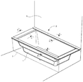
図1は本実施形態に係る浴槽の斜視図である。図1に示すように、本実施形態に係る浴槽は、浴室に配置されるものであり、浴槽本体1と、その上面を覆う枠型の天板部材2と、浴槽本体1の側面を覆うエプロン部材3と、を備えている。これらを構成する材料は特には限定されないが、例えば、浴槽本体1は、例えば、FRPや人工大理石成形品などで形成することができる。一方、天板部材2は、例えば、発泡材などの樹脂材料で形成することができる。また、エプロン部材3は、樹脂材料で形成することができる。但し、図1では、エプロン部材3を取り外した図を示している。以下、これらについて、詳細に説明する。
<1. Summary of bathtub>
FIG. 1 is a perspective view of a bathtub according to the present embodiment. As shown in FIG. 1, the bathtub according to the present embodiment is disposed in a bathroom, and the bathtub body 1, a frame-shaped
<1−1.浴槽本体>
図2は浴槽本体の斜視図、図3は図2のA−A線断面図である。図2に示すように、浴槽本体1は、矩形状の底壁部11と、この底壁部11の周縁から立ち上がる角筒状の側壁部12とを備えており、これらによって湯が貯まる空間部が形成される。より詳細に説明すると、底壁部11は、一対の長辺と、一対の短辺とを有する長方形状に形成されており、このうち、一の長辺と一対の短辺が、概ね浴室の壁面5に沿うように構成され、他の長辺が洗場を向くように構成される。これと対応して、側壁部12は、底壁部11の長辺から立ち上がる一対の長壁部(第1壁面部)121,122及び、短辺から立ち上がる一対の短壁部(第2壁面部)123,124を組み合わせることで構成されている。ここでは、側壁部12の長壁部121,122のうち、洗場を向くものを第1長壁部121と称し、これとは反対側を第2長壁部122と称することとする。したがって、側壁部のうち、両短壁部123,124及び第2長壁部122は、洗場の壁面5と対向するように配置されている。
<1-1. Bathtub body>
FIG. 2 is a perspective view of the bathtub main body, and FIG. 3 is a cross-sectional view taken along the line AA of FIG. As shown in FIG. 2, the bathtub main body 1 includes a rectangular bottom wall 11 and a rectangular
側壁部12において、長壁部121,122と短壁部123,124との連結部分には、上下方向に延び、且つ浴槽本体1の空間部側に突出する突条部18が形成されている。突条部18は、長壁部121,122と短壁部123,124との間で円弧状に突出する滑らかな面を形成している。さらに、側壁部12の上端縁には、外方に向かって水平に延びるフランジ部13が形成され、このフランジ部13の外周縁には、下方に向かって延びるエッジ部14が形成されている。したがって、フランジ部13及びエッジ部14は、側壁部12と対応するように、平面視矩形状の枠状に形成されている。
In the
図2に示すように、フランジ部13と側壁部12との連結部分は、滑らかな円弧状に形成されている。また、フランジ部13には、複数箇所に円形の取付孔15(図10参照)が形成されており、この取付孔15は、後述する天板部材2との固定に用いられる。エッジ部14のうちの3辺は、側壁部12とともに、浴室の壁面5と対向しているが、壁面5との間には隙間が形成されている。この点については後述する。
As shown in FIG. 2, the connecting portion between the
<1−2.天板部材>
次に、天板部材について、図4〜図7を参照しつつ説明する。図4は天板部材の斜視図、図5は図1のB−B線断面図、図6は図1のC−C線断面図、図7は図1のD−D線断面図である。
<1-2. Top plate member>
Next, the top plate member will be described with reference to FIGS. 4 to 7. 4 is a perspective view of the top plate member, FIG. 5 is a cross-sectional view taken along the line B-B in FIG. 1, FIG. 6 is a cross-sectional view taken along the line C-C in FIG. 1, and FIG. 7 is a cross-sectional view taken along the line D-D in FIG. .
図4に示すように、天板部材2は、浴槽本体1のフランジ部13上に配置される部材であり、平面視矩形状の枠状に形成されている。より詳細には、浴槽本体1の長壁部121,122と対応する一対の長辺部(第1カバー部)21,22と、短壁部123,124と対応する一対の短辺部(第2カバー部)23,24と、を組み合わせることで構成されている。そして、長辺部21,22及び短辺部23,24は、それぞれ直方体状に形成され、例えば、押出し成形により形成することができる。また、長辺部21,22の両端部において、互いに対向する内壁面同士を繋ぐように、短辺部23,24が固定されている。なお、以下では、2つの長辺部21,22のうち、洗場に面する長辺部を第1長辺部21、反対側を第2長辺部22と称することとする。
As shown in FIG. 4, the
<1−2−1.長辺部>
次に、第1長辺部21について説明する。図5に示すように、第1長辺部21は、上面211、浴槽の内側を向く内壁面212、浴槽の外側を向く外壁面213、下面214、及び長手方向の両端の一対の側壁面215を有しており、全体として、直方体状に形成されている。
<1-2-1. Long side>
Next, the first
特に、第1長辺部21は、フランジ部13から洗場側へ大きく突出しており、第1長辺部21の下面214には、外側から内側に向かって、水平に延びる突出面2141、フランジ部13と接する接触面2142、及び内壁面212と接続される下端面2143が、この順で形成されている。突出面2141は、フランジ部13から洗場側へ突出する面であり、長手方向に延びる溝216が形成されている。そして、この溝216には、下方へ延びる板状のエプロン部材3が嵌め込まれている。このエプロン部材3により、浴槽本体1の第1長壁部121が洗場側から見えないように覆われる。
In particular, the first
接触面2142は、突出面2141と連続する面であり、外側から内側に向かって、フランジ部13の上面と接する平坦面、及びフランジ部13と第1長壁部121との連結部分と接する曲面が、この順で連続するように形成されている。曲面は、内側にいくにしたがって下方に延びる円弧状に形成されている。また、下端面2143は、接触面2142の曲面と、内壁面212とを連結するように形成され、内側にいくにしたがって上方に延びるような概ね平坦な傾斜面により構成されている。
The
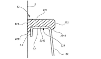
次に、第2長辺部22について説明する。図6に示すように、第2長辺部22は、第1長辺部21と同様に、上面221、浴槽の内側を向く内壁面222、浴槽の外側を向く外壁面223、下面224、及び長手方向の両端の一対の側壁面225を有しており、全体として、直方体状に形成されている。第1長辺部21との違いは次の通りである。
Next, the second
まず、第1長辺部21よりも幅が狭く、外側への突出量が小さい。また、下面224の構成が第1長辺部21と相違している。すなわち、第2長辺部22の下面224には、外側から内側に向かって、突出部2241、フランジ部13と接する接触面2242、及び内壁面222と接続される下端面2243が、この順で形成されている。突出部2241は、外壁面223と連続するように下方に突出しており、この突出部2241は、上述したエッジ部14に係合するようになっている。接触面2242は、外側から内側に向かって、フランジ部13の上面と接する平坦面、及びフランジ部13と第2長壁部122との連結部分と接する曲面が、この順で連続するように形成されている。曲面は、内側にいくにしたがって下方に延びる円弧状に形成されている。また、下端面2243は、接触面2242の曲面と、内壁面222とを連結するように形成され、内側にいくにしたがって上方に延びるような概ね平坦な傾斜面により構成されている。
First, the width is narrower than the first
このように、第2長辺部22は、フランジ部13よりも外側に突出しているが、突出した外壁面223が浴室の壁面5と接触するようになっている。すなわち、上述したとおり、エッジ部14と浴室の壁面5との間には隙間が形成されているが、第2長辺部22により、その隙間が埋められるようになっている。
Thus, although the 2nd
<1−2−2.短辺部>
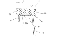
次に、短辺部23,24について、図7を参照しつつ説明する。図7に示すように、2つの短辺部23,24は、同じ構成であるため、一方のみ説明する。すなわち、短辺部23は、上面231、浴槽の内側を向く内壁面232、浴槽の外側を向く外壁面233、下面234、及び長手方向の両端の一対の側壁面を有しており、全体として、直方体状に形成されている。なお、側壁面は、長辺部21,22の内壁面212,222に固定される面である。
<1-2-2. Short side>
Next, the
短辺部23の厚みは、長辺部21,22よりもやや小さく、上面231が長辺部21,22の上面211,221よりもやや下方に配置されている。また、短辺部23の内壁面232は、円弧状に傾斜しており、下方にいくにしたがって内側に延びるように形成されている。短辺部23の下面234は、フランジ部13と接する接触面2342、及び内壁面232と接続される下端面2343が、この順で形成されている。第2長辺部22と異なり、突出部が設けられていないが、その他の具体的な構成は、第2長辺部22とほぼ同じであるため、説明を省略する。
The thickness of the
このように、各短辺部23,24は、フランジ部13よりも外側に突出しているが、突出した外壁面233が浴室の壁面5と接触するようになっている。上述したとおり、エッジ部14と浴室の壁面5との間には隙間が形成されているが、各短辺部23,24により、その隙間が埋められるようになっている。
Thus, although each
<1−2−3.長辺部と短辺部との連結部分の構造>
次に、長辺部21,22と短辺部23,24との連結部分の構成について、図8及び図9を参照しつつ説明する。図8は第2長辺部と短辺部との連結部分の拡大図、図9は図8のE−E線断面図である。上記のように、浴槽本体1の側壁部12には、長壁部121,122と短壁部123,124との連結部分に、上下方向に延びる突条部18が形成されている。そのため、第2長辺部22と短辺部23との連結部分には、この突条部18と干渉しないように、切り欠き部28が形成されている。なお、ここでは、第2長辺部22と一方の短辺部23との連結について説明するが、第1長辺部21と短辺部23,24との連結構造も同じである。
1-2-3. Structure of connecting part of long side and short side>
Next, the structure of the connection part of the
具体的には、図8に示すように、第2長辺部22及び短辺部23の下端面2243,2343の両側部が斜めに切りかかれており、これら傾斜部分228,238の間に形成される凹部(切り欠き部)28に、突条部18が嵌まるようになっている。また、第2長辺部22と短辺部23において、切り欠かれた下端面2243,2343の上端の点X同士が接触するように構成されている。これにより、天板部材2と突条部18との干渉をなくすとともに、第2長辺部22と短辺部23の下端面2243,2343同士が滑らかに繋がっているように見せることができる。
Specifically, as shown in FIG. 8, both side portions of the second
<1−3.浴槽本体と天板部材との連結構造>
次に、浴槽本体1と天板部材2との連結構造について、図10を参照しつつ説明する。図10は、浴槽本体の天板部材の連結構造を示す断面図である。なお、このような連結構造は、浴槽本体1のフランジ部13と天板部材2のいずれの位置に設けられてもよく、個数も特には限定されない。好ましくは、フランジ部13もしくは天板部2のコーナーと20〜50cmおきに設けられる。以下では、一例として、天板部材2の第2長辺部22とフランジ部13との連結構造について説明する。
<1-3. Connection structure between bathtub body and top plate member>
Next, the connection structure between the bathtub body 1 and the
まず、上述したように、浴槽本体1のフランジ部13には、複数箇所に取付孔15が形成されている。これと対応するように、図10に示すように、天板部材2には、複数の固定部4が取付けられている。各固定部4は、取付孔15に嵌まる突出部材41と、この突出部材41を支持する支持部材42と、を備えている。突出部材41は、断面円形状に形成された棒状部411と、この棒状部411の上端部に形成されたヘッド部412とを備えている。棒状部411は、フランジ部13の取付孔15の内径よりも大きい径を有しており、後述するように、取付孔15に圧入される部位である。そして、棒状部411の下端部は半球状に形成されており、取付孔15への位置決めを容易にしている。また、ヘッド部412は、棒状部411よりも幅広で具体的には径の大きい円板状に形成されている。但し、その上面は中央にいくにしたがって厚みが大きくなるような断面円弧状に形成されている。なお、突出部材41は、例えば、弾性変形可能な樹脂材料等で形成することができる。
First, as described above, mounting
一方、支持部材42は、第2長辺部22の下面224に形成された凹部131に固定される板状の基部421と、この基部421に取付けられる保持部422と、を備えている。保持部422は、基部421との間で空間部を形成するようにカップ状に形成されており、底面には保持部422を貫通する挿通孔423が形成されている。そして、この空間部に、突出部材41のヘッド部412が収容されるとともに、挿通孔423に棒状部411が挿通される。空間部の上下方向の高さは、ヘッド部412の厚みとほぼ同じであり、これによって、空間部において、突出部材41が上下動しないように保持される。また、挿通孔423の径は、ヘッド部412よりも小さいが、棒状部411よりは大きくなっている。そのため、突出部材41が挿通孔423から抜け出るのを防止することができるとともに、棒状部411が挿通孔423内で水平方向に移動するようになっている。したがって、突出部材41は、支持部材42によって、上下動はしないが、水平方向には1mm〜1cm程度移動可能に保持されるようになっている。なお、製造精度にもよるが、棒状部411は水平方向のうち、特定方向、具体的には、長辺部21,22や短辺部23,24の長手(延び)方向または幅方向に移動するようになっていてもよい。また、突出部材41のヘッド部412は中央の厚みが大きく、この部分が主として基部421に接している。そのため、突出部材41が支持部材42内で移動する際の摩擦抵抗が低減され、スムーズに移動できるようになっている。
On the other hand, the
<2.浴槽の組立>
まず、浴槽本体1を浴室内に配置する。上記のように、側壁部12の第2長壁部122及び両短壁部123,124が、浴室の壁面5と対向するように配置され、これと対応するエッジ部14と、浴室の壁面5との間には、例えば、図6及び図7に示すように、隙間が形成される。
<2. Assembly of bathtub>
First, the bathtub body 1 is placed in the bathroom. As described above, the second
次に、天板部材2を取付ける。まず、天板部材2を浴槽本体1のフランジ部13上に配置し、突出部材41の先端部が、取付孔15に嵌まるように位置決めする。このとき、突出部材41の先端部は半球状に形成されているため、取付孔15に嵌まりやすい。このとき、例えば、図11に示すように、突出部材41の先端が取付孔15に完全に嵌まらないとしても、突出部材41は水平方向に移動可能に保持されているため、天板部材2を押圧すると、突出部材41は先端部の半球部分が、取付孔15に嵌まるように水平方向に移動する。その上で、さらに天板部材2を下方に向けて押圧すると、図12に示すように、突出部材41が取付孔15に圧入され、天板部材2が浴槽本体1に固定される。
Next, the
このとき、天板部材2の第2長辺部22及び両短辺部23,24は、図6及び図7に示すように、エッジ部14と浴室の壁面5を埋め、第2長辺部22及び両短辺部23,24の外壁面233,243は、浴室の壁面5と接するように配置される。そして、最後に、天板部材2の第1長辺部21の溝216に、エプロン部材3を嵌め込んで、浴槽本体1の第1長壁部121を覆えば、図1に示すように、浴槽の組立が完了する。
At this time, the second
<3.特徴>
以上のように、本実施形態によれば、以下の効果を得ることができる。
(1)浴槽本体1のフランジ部13が、天板部材2に覆われ、特に、天板部材2の内壁面212,222,232,242が浴槽本体1の内側に突出しているため、フランジ部13と天板部材2の接続部分を隠すことができ、見栄えをよくすることができる。また、天板部材2の下端面2143,2243,2343,2443が下方に向かって斜めに傾斜しながら、フランジ部13と側壁部12との連結部分を覆って、側壁部12の内面にまで延びているため、汚れが溜まりにくく、清掃を容易にすることができる。
<3. Feature>
As described above, according to this embodiment, the following effects can be obtained.
(1) The
(2)天板部材2が、浴槽本体1とは別部材で形成され、且つ複数の直方体形状の長辺部21,22及び短辺部23,24を組み合わせることで形成されている。そのため、これら長辺部21,22及び短辺部23,24の表面に、木目などの意匠性の高いシートを貼付けたり、巻き付けたりすることができる。したがって、天板部材2の装飾性を大きく向上することができる。例えば、長辺部21,22及び短辺部23,24は、発泡材などの樹脂材料の押出成形によって形成することができ、これに装飾用のアクリルやABS等のシートを接着剤、熱処理などによって貼付けることができる。
(2) The
(3)天板部材2のみを取り外すことができるため、浴槽のうち、天板部材2のみを交換することができる。したがって、浴槽全体を交換する必要がなく、施工性が高く、また交換に係るコストを低減することができる。例えば、浴槽本体1を取り外すには追い炊きのためなどの配管を取り外す必要があるが、そのような作業が不要であるため、施工性が高い。
(3) Since only the
(4)浴槽本体1のエッジ部14と、浴室の壁面5との間には隙間が形成されているため、この隙間に手を入れながら作業ができる。したがって、施工性を高めることができる。その一方で、天板部材2の第2長辺部22の外壁面223及び短辺部23,24の外壁面233,243は、壁面5に接しており、この間に指を入れることはできない。したがって、例えば、一般利用者が天板部材2を真っ直ぐに引っ張り上げて取り外すことはほぼ不可能である。よって、天板部材2にがたつきが生じるのを防止することができる。
(4) Since a gap is formed between the
(5)天板部材2に設けられた突出部材41が水平方向に移動可能に保持されているため、例えば、図10に示すように、寸法誤差により突出部材41の軸心と、取付孔15の軸心とがずれていたとしても、突出部材41が水平方向に移動することで、両者の軸心が揃うため、突出部材41を取付孔15に対して正確に嵌め込むことができる。したがって、天板部材2と浴槽本体1とを確実に固定することができる。
(5) Since the projecting
(6)突出部材41は圧入により取付孔15に嵌め込まれるため、天板部材2を押し込むだけで、浴槽本体1への固定が可能となる。ボルトなどで固定する作業が不要となり、施工性を高めることができる。
(6) The projecting
<4.変形例>
以上、本発明の一実施形態について説明したが、本発明はこれに限定されるものではなく、その趣旨を逸脱しない限りにおいて種々の変更が可能である。なお、以下の変形例は、適宜組み合わせ可能である。
<4. Modified example>
As mentioned above, although one Embodiment of this invention was described, this invention is not limited to this, A various change is possible unless it deviates from the meaning. The following modifications can be combined as appropriate.
<4−1>
上記実施形態では、天板部材2を矩形の枠状に形成しているが、これに限定されず、平面視円形、楕円形、多角形など種々の形状にすることができる。これに合わせて、浴槽本体1も平面視円形、楕円形、多角形状にすることもできる。また、エッジ部14は必ずしも必要ではない。
<4-1>
In the said embodiment, although the top-
<4−2>
天板部材2は、少なくとも内壁面側が、フランジ部13を越えて内側に突出することで、フランジ部13と天板部材2との接触部分が隠れるように構成されていればよいため、その他の形状は特には限定されない。したがって、例えば、上記実施形態では、天板部材2に下端面2143,2243,2343,2443を形成しているが、このような面がなくてもよい。
<4-2>
The
<4−3>
浴槽本体1のフランジ部13の幅や、天板部材2の長辺部21,22及び短辺部23,24の幅は特には限定されず、例えば、図13(a)に示すように、両者の幅を小さくしたり、図13(b)に示すように、天板部材2の上面を円弧状に形成することもできる。
<4-3>
The width of the
<4−4>
浴槽本体1のエッジ部14を浴室の壁面5と接するようにしてもよい。あるいは、天板部材2と浴室の壁面5との間に隙間を形成することもできる。
<4-4>
The
<4−5>
天板部材2の長辺部21,22と短辺部23,24との連結部分の切り欠き部28の形状は特には限定されず、上記実施形態のような形状以外でもよい。すなわち、浴槽本体1の突条部18と干渉しないような形態であれば、特には限定されない。また、突条部の形状も特には限定されない。あるいは、浴槽本体1に突条部18を形成しなくてもよい。
<4-5>
The shape of the notch 28 of the connection portion between the
<4−6>
上記実施形態では、図10〜図12に示すような連結構造により、浴槽本体1と天板部材2とを連結しているが、これらの連結方法は特には限定されず、ネジ、接着剤など、種々の連結方法を採用することができる。
<4-6>
In the said embodiment, although the bathtub main body 1 and the top-
1 浴槽本体
11 底壁部
12 側壁部
13 フランジ部
2 天板部材
21 第1長辺部(第1カバー部)
22 第2長辺部(第1カバー部)
23 第1短辺部(第2カバー部)
24 第2短辺部(第2カバー部)
28 切り欠き部
3 エプロン部材
DESCRIPTION OF SYMBOLS 1 bathtub main body 11
22 Second long side (first cover)
23 1st short side (2nd cover)
24 second short side (second cover)
28 Notched
Claims (10)
底壁部、及び当該底壁部の周縁から起立する筒状の側壁部と、前記側壁の上端縁から外方に延びるフランジ部、を有する浴槽本体と、
前記フランジ部を覆うように枠状に形成された天板部材と、
を備え、
前記天板部材は、前記フランジ部の上面を覆い、当該フランジ部を越えて、前記浴槽本体の内側に突出している、浴槽。 It is a bathtub placed in the bathroom,
A tub body having a bottom wall portion, a cylindrical side wall portion rising from a peripheral edge of the bottom wall portion, and a flange portion extending outward from an upper end edge of the side wall;
A top plate member formed in a frame shape so as to cover the flange portion;
Equipped with
The top plate member covers an upper surface of the flange portion, and protrudes to the inside of the bathtub body beyond the flange portion.
前記天板部材は、前記連結部分を覆うように形成されている、請求項1に記載の浴槽。 The connecting portion between the side wall portion and the flange portion is formed in an arc shape,
The bathtub according to claim 1, wherein the top plate member is formed to cover the connecting portion.
前記側壁部は、対向する一対の第1壁面部、及び前記第1壁面部と直交するように配置されて対向する一対の第2壁面部を備え、
前記天板部材は、前記各第1壁面部と対応するように延びる一対の第1カバー部、及び前記各第2壁面部と対応するように延びる一対の第2カバー部を備え、
前記天板部材においては、一方の前記第1カバー部が前記浴室の洗場に沿うように配置され、
当該一方の第1カバー部は、前記フランジ部から前記洗場側に突出するように形成されている、請求項1または2に記載の浴槽。 The bathtub body is formed in a rectangular shape in plan view,
The side wall portion includes a pair of first wall surface portions facing each other, and a pair of second wall surface portions disposed to be orthogonal to the first wall surface portion and facing each other,
The top plate member includes a pair of first cover portions extending to correspond to the first wall surface portions, and a pair of second cover portions extending to correspond to the second wall surface portions.
In the top plate member, one of the first cover portions is disposed along a washroom of the bathroom,
The bathtub according to claim 1, wherein the one first cover portion is formed to project from the flange portion to the washing side.
前記天板部材における前記第1カバー部と前記第2カバー部との連結部分には、前記突条部を受入れる切り欠きが形成されている、請求項4に記載の浴槽。 In the side wall portion, a protruding portion extending in the vertical direction and projecting to the inside of the bathtub main body is formed at a connection portion between the first wall surface portion and the second wall surface portion.
The bathtub according to claim 4, wherein a notch for receiving the protrusion portion is formed at a connection portion between the first cover portion and the second cover portion in the top plate member.
前記第2カバー部は、上面と、前記上面と接続され、前記浴槽本体の内側を向き略上下方向に延びる内壁面と、前記第内壁面の下端部に接続され、下方にいくにしたがって、前記側壁部の第2壁面部に向って傾斜する下端面と、を備えており、
前記第1カバー部の下端面と、前記第2カバー部の下端面との接続部分には、前記切り欠きが形成されており、
前記切り欠きにおいて、前記第1カバー部の下端面の上端と、前記第2カバー部の下端面の上端とが、一致するように構成されている、請求項5に記載の浴槽。 The first cover portion is connected to the upper surface and the inner wall surface which is connected to the upper surface and extends in the substantially vertical direction facing the inner side of the bathtub body, and connected to the lower end of the inner wall surface. And a lower end surface inclined toward the first wall surface portion of the side wall portion,
The second cover portion is connected to the upper surface and the inner wall surface which is connected to the upper surface and extends in the substantially vertical direction facing the inner side of the bathtub body, and connected to the lower end of the inner wall surface. And a lower end surface inclined toward the second wall portion of the side wall portion,
The notch is formed in a connection portion between the lower end surface of the first cover portion and the lower end surface of the second cover portion,
The bathtub according to claim 5, wherein in the notch, an upper end of a lower end face of the first cover portion and an upper end of a lower end face of the second cover portion coincide with each other.
前記各第1カバー部及び各第2カバー部の少なくとも1つの表面の少なくとも一部には装飾用シートが取付けられている、請求項4から7のいずれかに記載の浴槽。 The top plate member is formed in a frame shape by assembling the pair of first cover portions and the pair of second cover portions.
The bathtub according to any one of claims 4 to 7, wherein a decorative sheet is attached to at least a part of at least one surface of each of the first cover part and each second cover part.
前記天板部材は、前記隙間を埋めるように、前記フランジ部から突出している、請求項1から9のいずれかに記載の浴槽。 A gap is formed between the outer edge of a part of the flange portion and the wall surface of the bathroom,
The bathtub according to any one of claims 1 to 9, wherein the top plate member protrudes from the flange portion so as to fill the gap.
Priority Applications (1)
| Application Number | Priority Date | Filing Date | Title |
|---|---|---|---|
| JP2017220520A JP7096659B2 (en) | 2017-11-15 | 2017-11-15 | Bathtub |
Applications Claiming Priority (1)
| Application Number | Priority Date | Filing Date | Title |
|---|---|---|---|
| JP2017220520A JP7096659B2 (en) | 2017-11-15 | 2017-11-15 | Bathtub |
Publications (2)
| Publication Number | Publication Date |
|---|---|
| JP2019088596A true JP2019088596A (en) | 2019-06-13 |
| JP7096659B2 JP7096659B2 (en) | 2022-07-06 |
Family
ID=66836925
Family Applications (1)
| Application Number | Title | Priority Date | Filing Date |
|---|---|---|---|
| JP2017220520A Active JP7096659B2 (en) | 2017-11-15 | 2017-11-15 | Bathtub |
Country Status (1)
| Country | Link |
|---|---|
| JP (1) | JP7096659B2 (en) |
Cited By (1)
| Publication number | Priority date | Publication date | Assignee | Title |
|---|---|---|---|---|
| WO2020226083A1 (en) | 2019-05-08 | 2020-11-12 | Canon Kabushiki Kaisha | Information processing apparatus, control method for information processing apparatus, and storage medium |
Citations (15)
| Publication number | Priority date | Publication date | Assignee | Title |
|---|---|---|---|---|
| JPS5358841U (en) * | 1976-10-19 | 1978-05-19 | ||
| JPS5836888U (en) * | 1981-09-04 | 1983-03-10 | ミサワホ−ム株式会社 | molded bathtub |
| JPS5936788U (en) * | 1982-08-31 | 1984-03-08 | サンウエーブ工業株式会社 | Upper edge covering structure of bathtub |
| JPS60142824A (en) * | 1983-12-29 | 1985-07-29 | 大和重工株式会社 | Bath tub equipment and its fabrication |
| JPH0446890U (en) * | 1990-08-27 | 1992-04-21 | ||
| JPH0451288U (en) * | 1990-09-05 | 1992-04-30 | ||
| JPH0593372U (en) * | 1992-05-27 | 1993-12-21 | 松下電工株式会社 | Wooden bathtub |
| JPH063187U (en) * | 1991-01-14 | 1994-01-18 | 田島産業株式会社 | Wooden bathtub |
| JPH09158507A (en) * | 1995-12-13 | 1997-06-17 | Inax Corp | Unit bath with washing place in one united body |
| JP3074751U (en) * | 2000-02-03 | 2001-01-26 | 紹群 楊 | Three-function integrated multi-effect baby bathtub |
| JP2005245648A (en) * | 2004-03-03 | 2005-09-15 | Shinji Yamaguchi | Bathtub |
| KR200417993Y1 (en) * | 2006-03-08 | 2006-06-07 | 주식회사 신성하이테크 | Bathtub for home use |
| KR100699774B1 (en) * | 2006-02-16 | 2007-03-28 | 권길상 | Timber Bathtub |
| JP3142085U (en) * | 2008-03-19 | 2008-06-05 | 利秋 柳沢 | FRP bathtub with wood grain pattern |
| JP2009226154A (en) * | 2008-03-25 | 2009-10-08 | Tono Craft Kk | Method for manufacturing bathtub |
-
2017
- 2017-11-15 JP JP2017220520A patent/JP7096659B2/en active Active
Patent Citations (15)
| Publication number | Priority date | Publication date | Assignee | Title |
|---|---|---|---|---|
| JPS5358841U (en) * | 1976-10-19 | 1978-05-19 | ||
| JPS5836888U (en) * | 1981-09-04 | 1983-03-10 | ミサワホ−ム株式会社 | molded bathtub |
| JPS5936788U (en) * | 1982-08-31 | 1984-03-08 | サンウエーブ工業株式会社 | Upper edge covering structure of bathtub |
| JPS60142824A (en) * | 1983-12-29 | 1985-07-29 | 大和重工株式会社 | Bath tub equipment and its fabrication |
| JPH0446890U (en) * | 1990-08-27 | 1992-04-21 | ||
| JPH0451288U (en) * | 1990-09-05 | 1992-04-30 | ||
| JPH063187U (en) * | 1991-01-14 | 1994-01-18 | 田島産業株式会社 | Wooden bathtub |
| JPH0593372U (en) * | 1992-05-27 | 1993-12-21 | 松下電工株式会社 | Wooden bathtub |
| JPH09158507A (en) * | 1995-12-13 | 1997-06-17 | Inax Corp | Unit bath with washing place in one united body |
| JP3074751U (en) * | 2000-02-03 | 2001-01-26 | 紹群 楊 | Three-function integrated multi-effect baby bathtub |
| JP2005245648A (en) * | 2004-03-03 | 2005-09-15 | Shinji Yamaguchi | Bathtub |
| KR100699774B1 (en) * | 2006-02-16 | 2007-03-28 | 권길상 | Timber Bathtub |
| KR200417993Y1 (en) * | 2006-03-08 | 2006-06-07 | 주식회사 신성하이테크 | Bathtub for home use |
| JP3142085U (en) * | 2008-03-19 | 2008-06-05 | 利秋 柳沢 | FRP bathtub with wood grain pattern |
| JP2009226154A (en) * | 2008-03-25 | 2009-10-08 | Tono Craft Kk | Method for manufacturing bathtub |
Cited By (1)
| Publication number | Priority date | Publication date | Assignee | Title |
|---|---|---|---|---|
| WO2020226083A1 (en) | 2019-05-08 | 2020-11-12 | Canon Kabushiki Kaisha | Information processing apparatus, control method for information processing apparatus, and storage medium |
Also Published As
| Publication number | Publication date |
|---|---|
| JP7096659B2 (en) | 2022-07-06 |
Similar Documents
| Publication | Publication Date | Title |
|---|---|---|
| USD572061S1 (en) | Symmetrical shower caddy with bent wire trays | |
| USD568728S1 (en) | Display hanger | |
| USD512225S1 (en) | Bathing scrubber with bath brush | |
| US20140374552A1 (en) | Combination-Type Suction Cup Base | |
| JP2019088596A (en) | Bathtub | |
| USD651655S1 (en) | Snap in panel assembly for a basket | |
| JP2019088521A (en) | Bathtub | |
| CA2675479C (en) | Tub and shower surround with hidden storage | |
| JP2012100746A (en) | Table leg cover and table equipped with the same | |
| USD494794S1 (en) | Bathroom shower caddy | |
| CN202468662U (en) | Combined type sucker base | |
| KR200417993Y1 (en) | Bathtub for home use | |
| JP5313056B2 (en) | Garbage bag holder | |
| JP7345321B2 (en) | bathroom counter | |
| KR101191311B1 (en) | Prefabricated kitchen shelves | |
| KR200451430Y1 (en) | Bathroom Wall Hangers | |
| KR200146977Y1 (en) | Wall tapestry type shelf for the bathroom | |
| USD1002822S1 (en) | Expanding infant bathtub | |
| KR200201306Y1 (en) | Apron structure of bathtub | |
| KR200210842Y1 (en) | Filling-wall-up type ornamental bath shelf | |
| KR200212933Y1 (en) | Tile plate closing molding for ceiling construction | |
| JP3106156U (en) | Floor type fall prevention vase | |
| JP3056734U (en) | Assembling shelf | |
| KR200373178Y1 (en) | Hook button having support projection needle | |
| JP2009195513A (en) | Bath unit |
Legal Events
| Date | Code | Title | Description |
|---|---|---|---|
| A625 | Written request for application examination (by other person) |
Free format text: JAPANESE INTERMEDIATE CODE: A625 Effective date: 20200820 |
|
| A131 | Notification of reasons for refusal |
Free format text: JAPANESE INTERMEDIATE CODE: A131 Effective date: 20210622 |
|
| A977 | Report on retrieval |
Free format text: JAPANESE INTERMEDIATE CODE: A971007 Effective date: 20210623 |
|
| A521 | Request for written amendment filed |
Free format text: JAPANESE INTERMEDIATE CODE: A523 Effective date: 20210820 |
|
| A131 | Notification of reasons for refusal |
Free format text: JAPANESE INTERMEDIATE CODE: A131 Effective date: 20211214 |
|
| A521 | Request for written amendment filed |
Free format text: JAPANESE INTERMEDIATE CODE: A523 Effective date: 20220214 |
|
| TRDD | Decision of grant or rejection written | ||
| A01 | Written decision to grant a patent or to grant a registration (utility model) |
Free format text: JAPANESE INTERMEDIATE CODE: A01 Effective date: 20220614 |
|
| A61 | First payment of annual fees (during grant procedure) |
Free format text: JAPANESE INTERMEDIATE CODE: A61 Effective date: 20220624 |
|
| R150 | Certificate of patent or registration of utility model |
Ref document number: 7096659 Country of ref document: JP Free format text: JAPANESE INTERMEDIATE CODE: R150 |