JP2019088491A - Game machine - Google Patents
Game machine Download PDFInfo
- Publication number
- JP2019088491A JP2019088491A JP2017219459A JP2017219459A JP2019088491A JP 2019088491 A JP2019088491 A JP 2019088491A JP 2017219459 A JP2017219459 A JP 2017219459A JP 2017219459 A JP2017219459 A JP 2017219459A JP 2019088491 A JP2019088491 A JP 2019088491A
- Authority
- JP
- Japan
- Prior art keywords
- view
- unit
- showed
- mpu
- plate
- Prior art date
- Legal status (The legal status is an assumption and is not a legal conclusion. Google has not performed a legal analysis and makes no representation as to the accuracy of the status listed.)
- Pending
Links
- 230000000694 effects Effects 0.000 claims description 226
- 230000001965 increasing effect Effects 0.000 abstract description 84
- 230000002708 enhancing effect Effects 0.000 abstract description 3
- 238000006073 displacement reaction Methods 0.000 description 974
- 238000001514 detection method Methods 0.000 description 376
- 230000005540 biological transmission Effects 0.000 description 343
- 230000005484 gravity Effects 0.000 description 312
- 238000003780 insertion Methods 0.000 description 272
- 230000037431 insertion Effects 0.000 description 272
- 230000008859 change Effects 0.000 description 229
- 210000000078 claw Anatomy 0.000 description 220
- 238000005096 rolling process Methods 0.000 description 214
- 238000005034 decoration Methods 0.000 description 205
- 239000000758 substrate Substances 0.000 description 205
- 230000036544 posture Effects 0.000 description 196
- 229910052751 metal Inorganic materials 0.000 description 176
- 239000002184 metal Substances 0.000 description 176
- 238000012545 processing Methods 0.000 description 144
- 230000000875 corresponding effect Effects 0.000 description 135
- 238000000034 method Methods 0.000 description 132
- 238000009826 distribution Methods 0.000 description 112
- 230000002829 reductive effect Effects 0.000 description 107
- 238000005452 bending Methods 0.000 description 97
- 239000000463 material Substances 0.000 description 96
- 230000002093 peripheral effect Effects 0.000 description 93
- 230000008569 process Effects 0.000 description 92
- 230000033001 locomotion Effects 0.000 description 86
- 230000008093 supporting effect Effects 0.000 description 84
- 229920005989 resin Polymers 0.000 description 83
- 239000011347 resin Substances 0.000 description 83
- 230000036961 partial effect Effects 0.000 description 79
- 230000001976 improved effect Effects 0.000 description 75
- 101100168642 Arabidopsis thaliana CRN gene Proteins 0.000 description 74
- 101100045632 Arabidopsis thaliana TCX2 gene Proteins 0.000 description 74
- 101150103732 sol2 gene Proteins 0.000 description 74
- 230000033228 biological regulation Effects 0.000 description 70
- 238000010304 firing Methods 0.000 description 64
- 230000001105 regulatory effect Effects 0.000 description 53
- 230000004308 accommodation Effects 0.000 description 52
- 238000010586 diagram Methods 0.000 description 50
- 230000006870 function Effects 0.000 description 49
- 238000004519 manufacturing process Methods 0.000 description 48
- 238000009429 electrical wiring Methods 0.000 description 46
- 238000003825 pressing Methods 0.000 description 39
- 230000009471 action Effects 0.000 description 38
- 238000011144 upstream manufacturing Methods 0.000 description 36
- 230000000630 rising effect Effects 0.000 description 35
- 230000000149 penetrating effect Effects 0.000 description 33
- 230000002441 reversible effect Effects 0.000 description 32
- 238000005192 partition Methods 0.000 description 30
- 101100045633 Arabidopsis thaliana TCX3 gene Proteins 0.000 description 29
- 101150037491 SOL1 gene Proteins 0.000 description 29
- 230000001681 protective effect Effects 0.000 description 29
- 238000009877 rendering Methods 0.000 description 29
- 239000011521 glass Substances 0.000 description 28
- 238000013461 design Methods 0.000 description 27
- 230000015572 biosynthetic process Effects 0.000 description 26
- 238000005520 cutting process Methods 0.000 description 26
- 230000005284 excitation Effects 0.000 description 24
- 238000013459 approach Methods 0.000 description 23
- 230000003028 elevating effect Effects 0.000 description 22
- 239000010409 thin film Substances 0.000 description 21
- 238000012544 monitoring process Methods 0.000 description 20
- 238000006243 chemical reaction Methods 0.000 description 18
- 238000012546 transfer Methods 0.000 description 17
- 230000009467 reduction Effects 0.000 description 13
- 238000000926 separation method Methods 0.000 description 13
- 230000001360 synchronised effect Effects 0.000 description 13
- 238000009434 installation Methods 0.000 description 12
- 238000007789 sealing Methods 0.000 description 12
- 230000001276 controlling effect Effects 0.000 description 11
- 230000006378 damage Effects 0.000 description 11
- 238000011084 recovery Methods 0.000 description 11
- 230000007246 mechanism Effects 0.000 description 10
- 229920003002 synthetic resin Polymers 0.000 description 10
- 239000000057 synthetic resin Substances 0.000 description 10
- 230000000903 blocking effect Effects 0.000 description 9
- 230000035882 stress Effects 0.000 description 9
- 239000000470 constituent Substances 0.000 description 8
- 238000007599 discharging Methods 0.000 description 8
- 230000005611 electricity Effects 0.000 description 8
- 238000005286 illumination Methods 0.000 description 8
- 239000007788 liquid Substances 0.000 description 8
- 239000004973 liquid crystal related substance Substances 0.000 description 8
- 239000000047 product Substances 0.000 description 8
- 238000003860 storage Methods 0.000 description 8
- 230000008901 benefit Effects 0.000 description 7
- 230000008878 coupling Effects 0.000 description 7
- 238000010168 coupling process Methods 0.000 description 7
- 238000005859 coupling reaction Methods 0.000 description 7
- 239000003651 drinking water Substances 0.000 description 7
- 235000020188 drinking water Nutrition 0.000 description 7
- 230000005281 excited state Effects 0.000 description 7
- 210000003128 head Anatomy 0.000 description 7
- 239000000696 magnetic material Substances 0.000 description 7
- 238000012423 maintenance Methods 0.000 description 7
- 230000015654 memory Effects 0.000 description 7
- 230000002265 prevention Effects 0.000 description 7
- 230000004044 response Effects 0.000 description 7
- 238000010079 rubber tapping Methods 0.000 description 7
- 102100030953 Cleavage and polyadenylation specificity factor subunit 4 Human genes 0.000 description 6
- 101000727105 Homo sapiens Cleavage and polyadenylation specificity factor subunit 4 Proteins 0.000 description 6
- 208000027418 Wounds and injury Diseases 0.000 description 6
- 230000001154 acute effect Effects 0.000 description 6
- 239000003086 colorant Substances 0.000 description 6
- 230000006835 compression Effects 0.000 description 6
- 238000007906 compression Methods 0.000 description 6
- 230000008602 contraction Effects 0.000 description 6
- 230000007423 decrease Effects 0.000 description 6
- 230000005489 elastic deformation Effects 0.000 description 6
- 229920001971 elastomer Polymers 0.000 description 6
- 210000000887 face Anatomy 0.000 description 6
- 238000010438 heat treatment Methods 0.000 description 6
- 239000012212 insulator Substances 0.000 description 6
- 230000007257 malfunction Effects 0.000 description 6
- 239000007769 metal material Substances 0.000 description 6
- 239000011120 plywood Substances 0.000 description 6
- 230000007480 spreading Effects 0.000 description 6
- 238000003892 spreading Methods 0.000 description 6
- 230000001960 triggered effect Effects 0.000 description 6
- 229910001369 Brass Inorganic materials 0.000 description 5
- 206010034719 Personality change Diseases 0.000 description 5
- 238000004891 communication Methods 0.000 description 5
- 239000011162 core material Substances 0.000 description 5
- 206010016256 fatigue Diseases 0.000 description 5
- 230000006872 improvement Effects 0.000 description 5
- 230000001788 irregular Effects 0.000 description 5
- 230000003287 optical effect Effects 0.000 description 5
- 230000035515 penetration Effects 0.000 description 5
- 230000010363 phase shift Effects 0.000 description 5
- 230000003014 reinforcing effect Effects 0.000 description 5
- 229920005992 thermoplastic resin Polymers 0.000 description 5
- 230000000007 visual effect Effects 0.000 description 5
- 241000218033 Hibiscus Species 0.000 description 4
- 235000005206 Hibiscus Nutrition 0.000 description 4
- 235000007185 Hibiscus lunariifolius Nutrition 0.000 description 4
- 230000004913 activation Effects 0.000 description 4
- 230000000712 assembly Effects 0.000 description 4
- 238000000429 assembly Methods 0.000 description 4
- 230000006399 behavior Effects 0.000 description 4
- 239000013078 crystal Substances 0.000 description 4
- 230000007547 defect Effects 0.000 description 4
- 238000011049 filling Methods 0.000 description 4
- 238000007667 floating Methods 0.000 description 4
- 230000009187 flying Effects 0.000 description 4
- 230000002452 interceptive effect Effects 0.000 description 4
- 239000004814 polyurethane Substances 0.000 description 4
- 230000011514 reflex Effects 0.000 description 4
- 235000015170 shellfish Nutrition 0.000 description 4
- 238000004904 shortening Methods 0.000 description 4
- 230000000087 stabilizing effect Effects 0.000 description 4
- 239000004925 Acrylic resin Substances 0.000 description 3
- 229920000178 Acrylic resin Polymers 0.000 description 3
- XEEYBQQBJWHFJM-UHFFFAOYSA-N Iron Chemical group [Fe] XEEYBQQBJWHFJM-UHFFFAOYSA-N 0.000 description 3
- 230000004397 blinking Effects 0.000 description 3
- 239000010951 brass Substances 0.000 description 3
- 238000012937 correction Methods 0.000 description 3
- 238000013016 damping Methods 0.000 description 3
- 238000005553 drilling Methods 0.000 description 3
- 239000000428 dust Substances 0.000 description 3
- 210000004932 little finger Anatomy 0.000 description 3
- 230000007774 longterm Effects 0.000 description 3
- 238000002844 melting Methods 0.000 description 3
- 230000008018 melting Effects 0.000 description 3
- NJPPVKZQTLUDBO-UHFFFAOYSA-N novaluron Chemical compound C1=C(Cl)C(OC(F)(F)C(OC(F)(F)F)F)=CC=C1NC(=O)NC(=O)C1=C(F)C=CC=C1F NJPPVKZQTLUDBO-UHFFFAOYSA-N 0.000 description 3
- 239000011049 pearl Substances 0.000 description 3
- 238000007747 plating Methods 0.000 description 3
- 238000002360 preparation method Methods 0.000 description 3
- 230000000717 retained effect Effects 0.000 description 3
- 230000007704 transition Effects 0.000 description 3
- 229910001018 Cast iron Inorganic materials 0.000 description 2
- VYZAMTAEIAYCRO-UHFFFAOYSA-N Chromium Chemical compound [Cr] VYZAMTAEIAYCRO-UHFFFAOYSA-N 0.000 description 2
- RYGMFSIKBFXOCR-UHFFFAOYSA-N Copper Chemical compound [Cu] RYGMFSIKBFXOCR-UHFFFAOYSA-N 0.000 description 2
- 239000004640 Melamine resin Substances 0.000 description 2
- 229920000877 Melamine resin Polymers 0.000 description 2
- 239000004743 Polypropylene Substances 0.000 description 2
- 239000004793 Polystyrene Substances 0.000 description 2
- 229910000831 Steel Inorganic materials 0.000 description 2
- 229920000122 acrylonitrile butadiene styrene Polymers 0.000 description 2
- 239000000853 adhesive Substances 0.000 description 2
- 230000001070 adhesive effect Effects 0.000 description 2
- 239000002390 adhesive tape Substances 0.000 description 2
- 230000001174 ascending effect Effects 0.000 description 2
- 239000012298 atmosphere Substances 0.000 description 2
- 230000002238 attenuated effect Effects 0.000 description 2
- 238000004364 calculation method Methods 0.000 description 2
- 230000015556 catabolic process Effects 0.000 description 2
- 239000000919 ceramic Substances 0.000 description 2
- 229910052804 chromium Inorganic materials 0.000 description 2
- 239000011651 chromium Substances 0.000 description 2
- 238000000748 compression moulding Methods 0.000 description 2
- 239000012141 concentrate Substances 0.000 description 2
- 238000010924 continuous production Methods 0.000 description 2
- 230000002596 correlated effect Effects 0.000 description 2
- 230000003247 decreasing effect Effects 0.000 description 2
- 235000012489 doughnuts Nutrition 0.000 description 2
- 229920006351 engineering plastic Polymers 0.000 description 2
- 239000003822 epoxy resin Substances 0.000 description 2
- 238000005304 joining Methods 0.000 description 2
- 239000011133 lead Substances 0.000 description 2
- 230000001795 light effect Effects 0.000 description 2
- 230000005389 magnetism Effects 0.000 description 2
- 230000014759 maintenance of location Effects 0.000 description 2
- 238000007726 management method Methods 0.000 description 2
- 230000004048 modification Effects 0.000 description 2
- 238000012986 modification Methods 0.000 description 2
- 229920003023 plastic Polymers 0.000 description 2
- 239000004033 plastic Substances 0.000 description 2
- 229920000515 polycarbonate Polymers 0.000 description 2
- 239000004417 polycarbonate Substances 0.000 description 2
- 229920000647 polyepoxide Polymers 0.000 description 2
- -1 polypropylene Polymers 0.000 description 2
- 229920001155 polypropylene Polymers 0.000 description 2
- 229920002223 polystyrene Polymers 0.000 description 2
- 229920005749 polyurethane resin Polymers 0.000 description 2
- 238000004080 punching Methods 0.000 description 2
- 238000009751 slip forming Methods 0.000 description 2
- 238000000638 solvent extraction Methods 0.000 description 2
- 238000001179 sorption measurement Methods 0.000 description 2
- 239000010959 steel Substances 0.000 description 2
- 238000012360 testing method Methods 0.000 description 2
- 229920001187 thermosetting polymer Polymers 0.000 description 2
- 230000017260 vegetative to reproductive phase transition of meristem Effects 0.000 description 2
- 230000005570 vertical transmission Effects 0.000 description 2
- NLHHRLWOUZZQLW-UHFFFAOYSA-N Acrylonitrile Chemical compound C=CC#N NLHHRLWOUZZQLW-UHFFFAOYSA-N 0.000 description 1
- 241000209202 Bromus secalinus Species 0.000 description 1
- 235000003385 Diospyros ebenum Nutrition 0.000 description 1
- 241000792913 Ebenaceae Species 0.000 description 1
- 125000002066 L-histidyl group Chemical group [H]N1C([H])=NC(C([H])([H])[C@](C(=O)[*])([H])N([H])[H])=C1[H] 0.000 description 1
- 241000287127 Passeridae Species 0.000 description 1
- 241000237503 Pectinidae Species 0.000 description 1
- PPBRXRYQALVLMV-UHFFFAOYSA-N Styrene Natural products C=CC1=CC=CC=C1 PPBRXRYQALVLMV-UHFFFAOYSA-N 0.000 description 1
- HCHKCACWOHOZIP-UHFFFAOYSA-N Zinc Chemical compound [Zn] HCHKCACWOHOZIP-UHFFFAOYSA-N 0.000 description 1
- 230000002159 abnormal effect Effects 0.000 description 1
- 230000001133 acceleration Effects 0.000 description 1
- 238000009825 accumulation Methods 0.000 description 1
- 230000002730 additional effect Effects 0.000 description 1
- 230000032683 aging Effects 0.000 description 1
- 229910052782 aluminium Inorganic materials 0.000 description 1
- XAGFODPZIPBFFR-UHFFFAOYSA-N aluminium Chemical compound [Al] XAGFODPZIPBFFR-UHFFFAOYSA-N 0.000 description 1
- 238000000149 argon plasma sintering Methods 0.000 description 1
- 230000004323 axial length Effects 0.000 description 1
- 230000004888 barrier function Effects 0.000 description 1
- 238000007664 blowing Methods 0.000 description 1
- 230000000739 chaotic effect Effects 0.000 description 1
- 150000001875 compounds Chemical class 0.000 description 1
- 239000004020 conductor Substances 0.000 description 1
- 238000012790 confirmation Methods 0.000 description 1
- 230000002844 continuous effect Effects 0.000 description 1
- 230000010485 coping Effects 0.000 description 1
- 229920001577 copolymer Polymers 0.000 description 1
- 238000000354 decomposition reaction Methods 0.000 description 1
- 230000003111 delayed effect Effects 0.000 description 1
- 230000000994 depressogenic effect Effects 0.000 description 1
- 230000006866 deterioration Effects 0.000 description 1
- 238000011161 development Methods 0.000 description 1
- 230000018109 developmental process Effects 0.000 description 1
- 238000009792 diffusion process Methods 0.000 description 1
- 230000003292 diminished effect Effects 0.000 description 1
- 230000008034 disappearance Effects 0.000 description 1
- 230000005672 electromagnetic field Effects 0.000 description 1
- 238000004049 embossing Methods 0.000 description 1
- 230000004438 eyesight Effects 0.000 description 1
- 210000003811 finger Anatomy 0.000 description 1
- 230000009969 flowable effect Effects 0.000 description 1
- 239000003292 glue Substances 0.000 description 1
- 238000009499 grossing Methods 0.000 description 1
- 230000003760 hair shine Effects 0.000 description 1
- 238000007731 hot pressing Methods 0.000 description 1
- 238000002347 injection Methods 0.000 description 1
- 239000007924 injection Substances 0.000 description 1
- 238000001746 injection moulding Methods 0.000 description 1
- 208000014674 injury Diseases 0.000 description 1
- 229910052742 iron Inorganic materials 0.000 description 1
- 230000009191 jumping Effects 0.000 description 1
- 238000011068 loading method Methods 0.000 description 1
- 235000013372 meat Nutrition 0.000 description 1
- 239000000155 melt Substances 0.000 description 1
- 150000002739 metals Chemical class 0.000 description 1
- 125000005395 methacrylic acid group Chemical group 0.000 description 1
- 239000000203 mixture Substances 0.000 description 1
- 239000003973 paint Substances 0.000 description 1
- 239000002245 particle Substances 0.000 description 1
- 229920005668 polycarbonate resin Polymers 0.000 description 1
- 239000004431 polycarbonate resin Substances 0.000 description 1
- 229920001225 polyester resin Polymers 0.000 description 1
- 239000004645 polyester resin Substances 0.000 description 1
- 229920005672 polyolefin resin Polymers 0.000 description 1
- 229920005990 polystyrene resin Polymers 0.000 description 1
- 239000004800 polyvinyl chloride Substances 0.000 description 1
- 229920000915 polyvinyl chloride Polymers 0.000 description 1
- 238000007639 printing Methods 0.000 description 1
- 230000002250 progressing effect Effects 0.000 description 1
- 230000000384 rearing effect Effects 0.000 description 1
- 239000012779 reinforcing material Substances 0.000 description 1
- 230000008439 repair process Effects 0.000 description 1
- 235000020637 scallop Nutrition 0.000 description 1
- 238000007790 scraping Methods 0.000 description 1
- 238000005549 size reduction Methods 0.000 description 1
- 239000007787 solid Substances 0.000 description 1
- 230000001629 suppression Effects 0.000 description 1
- 239000000725 suspension Substances 0.000 description 1
- 230000002459 sustained effect Effects 0.000 description 1
- 239000012209 synthetic fiber Substances 0.000 description 1
- 229920002994 synthetic fiber Polymers 0.000 description 1
- 229920001169 thermoplastic Polymers 0.000 description 1
- 239000004416 thermosoftening plastic Substances 0.000 description 1
- 230000003867 tiredness Effects 0.000 description 1
- 208000016255 tiredness Diseases 0.000 description 1
- 239000002023 wood Substances 0.000 description 1
- 230000037303 wrinkles Effects 0.000 description 1
- 210000000707 wrist Anatomy 0.000 description 1
- 239000011701 zinc Substances 0.000 description 1
- 229910052725 zinc Inorganic materials 0.000 description 1
Images


Abstract
Description
本発明は、パチンコ機などの遊技機に関するものである。 The present invention relates to a gaming machine such as a pachinko machine.
従来より、パチンコ機などの遊技機は、遊技盤面上に設けられた始動口に遊技球が入球すると、遊技の当否が抽選され、その抽選結果が当たりであった場合には、遊技者に有利となる特典遊技が実行されるものがある。 Conventionally, in a gaming machine such as a pachinko machine, when the game ball enters the starting opening provided on the gaming board surface, the success or failure of the game is lottery, and if the lottery result is a hit, the player There are some games for which an advantageous bonus game is performed.
しかしながら、更なる遊技の興趣向上が求められていた。 However, there has been a demand for further improvement in the interest of the game.
本発明は、上記例示した問題点等を解決するためになされたものであり、遊技の興趣を向上できる遊技機を提供することを目的とする。 The present invention has been made to solve the above-described problems and the like, and it is an object of the present invention to provide a gaming machine capable of improving the interest of a game.
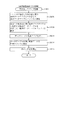
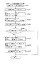
この目的を達成するために請求項1記載の遊技機は、遊技者が操作可能な操作手段と、その操作手段に対して所定の操作が行われたことを判別可能な操作判別手段と、その操作判別手段の判別結果に基づいて所定の操作演出を実行可能な操作演出実行手段と、を有するものであり、前記操作演出実行手段により実行される前記操作演出として、複数の前記操作演出から一の前記操作演出を設定する操作演出設定手段と、前記操作手段の態様を可変可能な態様可変手段と、を有し、前記態様可変手段は、前記操作手段の態様を、前記操作演出設定手段により設定される前記一の操作演出を示唆する態様に可変するものである。
In order to achieve this object, the gaming machine according to
請求項2記載の遊技機は、請求項1記載の遊技機において、前記操作手段における遊技者が視認可能な領域を発光させる発光手段を有し、前記態様可変手段は、前記発光手段の発光態様を可変させるものである。 According to a second aspect of the present invention, there is provided the gaming machine according to the first aspect, further comprising: a light emitting means for emitting light in an area visible to the player in the operation means; To make it variable.
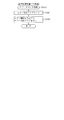
請求項3記載の遊技機は、請求項1または2記載の遊技機において、所定の判別を実行する判別手段と、その判別手段による判別結果を示すための識別情報を表示手段に所定期間動的表示させる動的表示実行手段と、その動的表示実行手段により動的表示された前記識別情報が特定の表示態様で停止表示したことに基づいて特典を付与する特典付与手段と、を有し、前記操作演出設定手段は、前記識別情報が動的表示される期間中に異なる操作演出を設定可能なものである。
The gaming machine according to
請求項1記載の遊技機によれば、遊技者が操作可能な操作手段と、その操作手段に対して所定の操作が行われたことを判別可能な操作判別手段と、その操作判別手段の判別結果に基づいて所定の操作演出を実行可能な操作演出実行手段と、を有するものであり、前記操作演出実行手段により実行される前記操作演出として、複数の前記操作演出から一の前記操作演出を設定する操作演出設定手段と、前記操作手段の態様を可変可能な態様可変手段と、を有し、前記態様可変手段は、前記操作手段の態様を、前記操作演出設定手段により設定される前記一の操作演出を示唆する態様に可変するものである。
According to the gaming machine of
これにより、遊技の興趣を向上することができるという効果がある。 This has the effect of improving the interest of the game.
請求項2記載の遊技機によれば、請求項1記載の遊技機の奏する効果に加え、次の効果を奏する。即ち、前記操作手段における遊技者が視認可能な領域を発光させる発光手段を有し、前記態様可変手段は、前記発光手段の発光態様を可変させるものである。
According to the gaming machine of
これにより、操作手段を操作しようとする遊技者に対して現在の状況を分かり易く報知することができるという効果がある。 As a result, the present situation can be reported to the player who is going to operate the operation means in an easy-to-understand manner.
請求項3記載の遊技機によれば、請求項1または2記載の遊技機の奏する効果に加え、次の効果を奏する。即ち、所定の判別を実行する判別手段と、その判別手段による判別結果を示すための識別情報を表示手段に所定期間動的表示させる動的表示実行手段と、その動的表示実行手段により動的表示された前記識別情報が特定の表示態様で停止表示したことに基づいて特典を付与する特典付与手段と、を有し、前記操作演出設定手段は、前記識別情報が動的表示される期間中に異なる操作演出を設定可能なものである。 According to the gaming machine of the third aspect, in addition to the effects of the gaming machine of the first aspect or the second aspect, the following effect can be obtained. That is, determination means for executing a predetermined determination, dynamic display execution means for causing the display means to dynamically display identification information for indicating the determination result by the determination means, and the dynamic display execution means A privilege giving means for giving a privilege based on the fact that the displayed identification information is stopped and displayed in a specific display mode, and the operation effect setting means performs the period during which the identification information is dynamically displayed It is possible to set different operation effects.
これにより、1回の動的表示期間中に異なる操作演出が設定されるため、遊技者に対して操作手段を操作するタイミングを楽しませることができる。よって、遊技の興趣を向上させることができるという効果がある。 As a result, different operation effects are set during one dynamic display period, so that the player can enjoy the timing of operating the operation means. Therefore, there is an effect that the interest of the game can be improved.
以下、本発明の実施形態について、添付図面を参照して説明する。まず、図1から図4
4を参照し、第1実施形態として、本発明をパチンコ遊技機(以下、単に「パチンコ機」
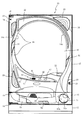
という)10に適用した場合の一実施形態について説明する。図1は、第1実施形態にお
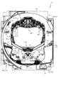
けるパチンコ機10の正面図であり、図2はパチンコ機10の遊技盤13の正面図であり
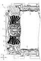
、図3はパチンコ機10の背面図である。
Hereinafter, embodiments of the present invention will be described with reference to the attached drawings. First, Figure 1 to Figure 4
Referring to 4, as a first embodiment, the present invention pachinko machine (hereinafter simply "pachinko machine"
An embodiment in the case of being applied to 10) will be described. FIG. 1 is a front view of the
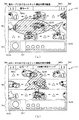
図1に示すように、パチンコ機10は、略矩形状に組み合わせた木枠により外殻が形成
される外枠11と、その外枠11と略同一の外形形状に形成され外枠11に対して開閉可
能に支持された内枠12とを備えている。外枠11には、内枠12を支持するために正面
視(図1参照)左側の上下2カ所に金属製のヒンジ18が取り付けられ、そのヒンジ18
が設けられた側を開閉の軸として内枠12が正面手前側へ開閉可能に支持されている。
As shown in FIG. 1, the
The
内枠12には、多数の釘や入賞口63,64等を有する遊技盤13(図2参照)が裏面
側から着脱可能に装着される。この遊技盤13の正面を球(遊技球)が流下することによ
り弾球遊技が行われる。なお、内枠12には、球を遊技盤13の正面領域に発射する球発
射ユニット112a(図4参照)やその球発射ユニット112aから発射された球を遊技
盤13の正面領域まで誘導する発射レール(図示せず)等が取り付けられている。
In the
内枠12の正面側には、その正面上側を覆う正面枠14と、その下側を覆う下皿ユニッ
ト15とが設けられている。正面枠14及び下皿ユニット15を支持するために正面視(
図1参照)左側の上下2カ所に金属製のヒンジ19が取り付けられ、そのヒンジ19が設
けられた側を開閉の軸として正面枠14及び下皿ユニット15が正面手前側へ開閉可能に
支持されている。なお、内枠12の施錠と正面枠14の施錠とは、シリンダ錠20の鍵穴
21に専用の鍵を差し込んで所定の操作を行うことでそれぞれ解除される。
On the front side of the
1) Metal hinges 19 are attached to the upper and lower two places on the left side, and the
正面枠14は、装飾用の樹脂部品や電気部品等を組み付けたものであり、その略中央部
には略楕円形状に開口形成された窓部14cが設けられている。正面枠14の裏面側には
2枚の板ガラスを有するガラスユニット16が配設され、そのガラスユニット16を介し
て遊技盤13の正面がパチンコ機10の正面側に視認可能となっている。
The
正面枠14には、球を貯留する上皿17が正面側へ張り出して上面を開放した略箱状に
形成されており、この上皿17に賞球や貸出球などが排出される。上皿17の底面は正面
視(図1参照)右側に下降傾斜して形成され、その傾斜により上皿17に投入された球が
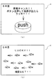
球発射ユニット112a(図4参照)へと案内される。また、上皿17の上面には、枠ボ
タン22が設けられている。この枠ボタン22は、例えば、第3図柄表示装置81(図2
参照)で表示される演出のステージを変更したり、スーパーリーチの演出内容を変更した
りする場合などに、遊技者により操作される。
In the
The game is operated by the player, for example, in the case of changing the stage of the effect displayed in the reference) or changing the content of the effect of the super reach.
正面枠14には、その周囲(例えばコーナー部分)に各種ランプ等の発光手段が設けら
れている。これら発光手段は、大当たり時や所定のリーチ時等における遊技状態の変化に
応じて、点灯又は点滅することにより発光態様が変更制御され、遊技中の演出効果を高め
る役割を果たす。窓部14cの周縁には、LED等の発光手段を内蔵した電飾部29〜3
3が設けられている。パチンコ機10においては、これら電飾部29〜33が大当たりラ
ンプ等の演出ランプとして機能し、大当たり時やリーチ演出時等には内蔵するLEDの点
灯や点滅によって各電飾部29〜33が点灯または点滅して、大当たり中である旨、或い
は大当たり一歩手前のリーチ中である旨が報知される。また、正面枠14の正面視(図1
参照)左上部には、LED等の発光手段が内蔵され賞球の払い出し中とエラー発生時とを
表示可能な表示ランプ34が設けられている。
The
Three are provided. In the
Reference) In the upper left part, a light emitting means such as an LED is incorporated and provided with a
また、右側の電飾部32下側には、正面枠14の裏面側を視認できるように裏面側より
透明樹脂を取り付けて小窓35が形成され、遊技盤13正面の貼着スペースK1(図2参
照)に貼付される証紙等がパチンコ機10の正面から視認可能とされている。また、パチ
ンコ機10においては、より煌びやかさを醸し出すために、電飾部29〜33の周りの領
域にクロムメッキを施したABS樹脂製のメッキ部材36が取り付けられている。
A
窓部14cの下方には、貸球操作部40が配設されている。貸球操作部40には、度数
表示部41と、球貸しボタン42と、返却ボタン43とが設けられている。パチンコ機1
0の側方に配置されるカードユニット(球貸しユニット)(図示せず)に紙幣やカード等
を投入した状態で貸球操作部40が操作されると、その操作に応じて球の貸出が行われる
。具体的には、度数表示部41はカード等の残額情報が表示される領域であり、内蔵され
たLEDが点灯して残額情報として残額が数字で表示される。球貸しボタン42は、カー
ド等(記録媒体)に記録された情報に基づいて貸出球を得るために操作されるものであり
、カード等に残額が存在する限りにおいて貸出球が上皿17に供給される。返却ボタン4
3は、カードユニットに挿入されたカード等の返却を求める際に操作される。なお、カー
ドユニットを介さずに球貸し装置等から上皿17に球が直接貸し出されるパチンコ機、い
わゆる現金機では貸球操作部40が不要となるが、この場合には、貸球操作部40の設置
部分に飾りシール等を付加して部品構成は共通のものとしても良い。カードユニットを用
いたパチンコ機と現金機との共通化を図ることができる。
Under the
When the rental
3 is operated when it is requested to return a card or the like inserted in the card unit. In the case of a pachinko machine in which a ball is lent directly to the
上皿17の下側に位置する下皿ユニット15には、その左側部に上皿17に貯留しきれ
なかった球を貯留するための下皿50が上面を開放した略箱状に形成されている。下皿5
0の右側には、球を遊技盤13の正面へ打ち込むために遊技者によって操作される操作ハ
ンドル51が配設される。
In the
On the right side of 0, an
操作ハンドル51の内部には、球発射ユニット112aの駆動を許可するためのタッチ
センサ51aと、押下操作している期間中には球の発射を停止する発射停止スイッチ51
bと、操作ハンドル51の回動操作量(回動位置)を電気抵抗の変化により検出する可変
抵抗器(図示せず)などが内蔵されている。操作ハンドル51が遊技者によって右回りに
回動操作されると、タッチセンサ51aがオンされると共に可変抵抗器の抵抗値が回動操
作量に対応して変化し、その可変抵抗器の抵抗値に対応した強さ(発射強度)で球が発射
され、これにより遊技者の操作に対応した飛び量で遊技盤13の正面へ球が打ち込まれる
。また、操作ハンドル51が遊技者により操作されていない状態においては、タッチセン
サ51aおよび発射停止スイッチ51bがオフとなっている。
Inside the
b and a variable resistor (not shown) for detecting the amount of rotational operation (rotational position) of the operation handle 51 based on a change in electric resistance. When the operation handle 51 is turned clockwise by the player, the
下皿50の正面下方部には、下皿50に貯留された球を下方へ排出する際に操作するた
めの球抜きレバー52が設けられている。この球抜きレバー52は、常時、右方向に付勢
されており、その付勢に抗して左方向へスライドさせることにより、下皿50の底面に形
成された底面口が開口して、その底面口から球が自然落下して排出される。この球抜きレ
バー52の操作は、通常、下皿50の下方に下皿50から排出された球を受け取る箱(一
般に「千両箱」と称される)を置いた状態で行われる。下皿50の右方には、上述したよ
うに操作ハンドル51が配設され、下皿50の左方には灰皿(図示せず)が取り付けられ
ている。
At the front lower portion of the
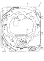
図2に示すように、遊技盤13は、正面視略正方形状に切削加工したベース板60に、
球案内用の多数の釘(図示せず)や風車(図示せず)の他、レール61,62、一般入賞
口63、第1入賞口64、第2入賞口140、可変入賞装置65、スルーゲート67、可
変表示装置ユニット80等を組み付けて構成され、その周縁部が内枠12(図1参照)の
裏面側に取り付けられる。
As shown in FIG. 2, the
Other than a large number of nails (not shown) for guiding a ball and a windmill (not shown), rails 61 and 62, a general winning
ベース板60は、木製の板部材から形成される。一般入賞口63、第1入賞口64、第
2入賞口140、可変表示装置ユニット80は、ルータ加工によってベース板60に形成
された貫通穴に配設され、遊技盤13の正面側からタッピングネジ等により固定されてい
る。なお、ベース板60を光透過性の樹脂材料から構成しても良い。この場合、その正面
側からベース板60の背面側に配設された各種構造体を遊技者に視認させることが可能と
なる。
The
遊技盤13の正面中央部分は、正面枠14の窓部14c(図1参照)を通じて内枠12
の正面側から視認することができる。以下に、主に図2を参照して、遊技盤13の構成に
ついて説明する。
The front center portion of the
Can be viewed from the front side of the Hereinafter, the configuration of the
遊技盤13の正面には、帯状の金属板を略円弧状に屈曲加工して形成した外レール62
が植立され、その外レール62の内側位置には外レール62と同様に帯状の金属板で形成
した円弧状の内レール61が植立される。この内レール61と外レール62とにより遊技
盤13の正面外周が囲まれ、遊技盤13とガラスユニット16(図1参照)とにより前後
が囲まれることにより、遊技盤13の正面には、球の挙動により遊技が行われる遊技領域
が形成される。遊技領域は、遊技盤13の正面であって2本のレール61,62とレール
間を繋ぐ樹脂製の外縁部材73とにより区画して形成される領域(入賞口等が配設され、
発射された球が流下する領域)である。
An
An arc-shaped
The area where the fired ball flows down).
2本のレール61,62は、球発射ユニット112a(図4参照)から発射された球を
遊技盤13上部へ案内するために設けられたものである。内レール61の先端部分(図2
の左上部)には戻り球防止部材68が取り付けられ、一旦、遊技盤13の上部へ案内され
た球が再度球案内通路内に戻ってしまうといった事態が防止される。外レール62の先端
部(図2の右上部)には、球の最大飛翔部分に対応する位置に返しゴム69が取り付けら
れ、所定以上の勢いで発射された球は、返しゴム69に当たって、勢いが減衰されつつ中
央部側へ跳ね返される。
The two
The
遊技領域の正面視左側下部(図2の左側下部)には、発光手段である複数のLED及び
7セグメント表示器を備える第1図柄表示装置37A,37Bが配設されている。第1図
柄表示装置37A,37Bは、主制御装置110(図4参照)で行われる各制御に応じた
表示がなされるものであり、主にパチンコ機10の遊技状態の表示が行われる。本実施形
態では、第1図柄表示装置37A,37Bは、球が、第1入賞口64へ入賞したか、第2
入賞口140へ入賞したかに応じて使い分けられるように構成されている。具体的には、
球が、第1入賞口64へ入賞した場合には、第1図柄表示装置37Aが作動し、一方で、
球が、第2入賞口140へ入賞した場合には、第1図柄表示装置37Bが作動するように
構成されている。
First
It is configured to be used properly depending on whether the winning
When the ball wins the first winning
When the ball wins the second winning
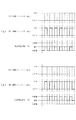
また、第1図柄表示装置37A,37Bは、LEDにより、パチンコ機10が確変中か
時短中か通常中であるかを点灯状態により示したり、変動中であるか否かを点灯状態によ
り示したり、停止図柄が確変大当たりに対応した図柄か普通大当たりに対応した図柄か外
れ図柄であるかを点灯状態により示したり、保留球数を点灯状態により示すと共に、7セ
グメント表示装置により、大当たり中のラウンド数やエラー表示を行う。なお、複数のL
EDは、それぞれのLEDの発光色(例えば、赤、緑、青)が異なるよう構成され、その
発光色の組み合わせにより、少ないLEDでパチンコ機10の各種遊技状態を示唆するこ
とができる。
In addition, the first
The ED is configured such that the emission colors (for example, red, green, and blue) of the respective LEDs are different, and the combination of the emission colors can indicate various gaming states of the
尚、本パチンコ機10では、第1入賞口64及び第2入賞口140へ入賞があったこと
を契機として抽選が行われる。パチンコ機10は、その抽選において、大当たりか否かの
当否判定(大当たり抽選)を行うと共に、大当たりと判定した場合はその大当たり種別の
判定も行う。ここで判定される大当たり種別としては、15R確変大当たり、4R確変大
当たり、15R通常大当たりが用意されている。第1図柄表示装置37A,37Bには、
変動終了後の停止図柄として抽選の結果が大当たりであるか否かが示されるだけでなく、
大当たりである場合はその大当たり種別に応じた図柄が示される。
In the
Not only is it shown whether or not the result of the lottery is a jackpot as a stop symbol after the end of the fluctuation,
If it is a jackpot, a symbol according to the jackpot type is shown.
ここで、「15R確変大当たり」とは、最大ラウンド数が15ラウンドの大当たりの後
に高確率状態へ移行する確変大当たりのことであり、「4R確変大当たり」とは、最大ラ
ウンド数が4ラウンドの大当たりの後に高確率状態へ移行する確変大当たりのことである
。また、「15R通常大当たり」は、最大ラウンド数が15ラウンドの大当たりの後に、
低確率状態へ移行すると共に、所定の変動回数の間(例えば、100変動回数)は時短状
態となる大当たりのことである。
Here, "15R probability variation jackpot" is a probability variation jackpot where the maximum number of rounds shifts to a high probability state after 15 round jackpots, and "4R probability variation jackpot" is a maximum number of round jackpots with 4 rounds It is a probability change jackpot to shift to a high probability state after. In addition, “15R normal jackpot” is the maximum number of rounds after 15 rounds of jackpot,
While transitioning to the low probability state, for a predetermined number of fluctuations (for example, 100 fluctuation numbers) is a jackpot that becomes a short time state.
また、「高確率状態」とは、大当たり終了後に付加価値としてその後の大当たり確率が
アップした状態、いわゆる確率変動中(確変中)の時をいい、換言すれば、特別遊技状態
へ移行し易い遊技の状態のことである。本実施形態における高確率状態(確変中)は、後
述する第2図柄の当たり確率がアップして第2入賞口140へ球が入賞し易い遊技の状態
を含む。「低確率状態」とは、確変中でない時をいい、大当たり確率が通常の状態、即ち
、確変の時より大当たり確率が低い状態をいう。また、「低確率状態」のうちの時短状態
(時短中)とは、大当たり確率が通常の状態であると共に、大当たり確率がそのままで第
2図柄の当たり確率のみがアップして第2入賞口140へ球が入賞し易い遊技の状態のこ
とをいう。一方、パチンコ機10が通常中とは、確変中でも時短中でもない遊技の状態(
大当たり確率も第2図柄の当たり確率もアップしていない状態)である。
Also, "high probability state" refers to a state in which the subsequent jackpot probability is increased as added value after the end of the jackpot, so-called probability fluctuation (during a definite change), in other words, a game that is easy to shift to a special gaming state The state of The high probability state (in a definite change) in the present embodiment includes a game state in which the ball is likely to be won in the second winning
It is a state where neither the jackpot probability nor the hit probability of the second symbol is up).
確変中や時短中は、第2図柄の当たり確率がアップするだけではなく、第2入賞口14
0に付随する羽部材945(電動役物)が開放される時間も変更され、通常中と比して長
い時間が設定される。羽部材945が開放された状態(開放状態)にある場合は、その羽
部材945が閉鎖された状態(閉鎖状態)にある場合と比して、第2入賞口140へ球が
入賞しやすい状態となる。よって、確変中や時短中は、第2入賞口140へ球が入賞し易
い状態となり、大当たり抽選が行われる回数を増やすことができる。
During a definite change or during a time cut, not only is the probability of hitting the second symbol up, but the second winning
The time for which the wing member 945 (motor part) associated with 0 is opened is also changed, and a longer time is set as compared with the normal time. When the
なお、確変中や時短中において、第2入賞口140に付随する羽部材945の開放時間
を変更するのではなく、または、その開放時間を変更することに加えて、1回の当たりで
羽部材945が開放する回数を通常中よりも増やす変更を行うものとしてもよい。また、
確変中や時短中において、第2図柄の当たり確率は変更せず、第2入賞口140に付随す
る羽部材945が開放される時間および1回の当たりで羽部材945が開放する回数の少
なくとも一方を変更するものとしてもよい。また、確変中や時短中において、第2入賞口
140に付随する羽部材945が開放される時間や、1回の当たりで羽部材945を開放
する回数はせず、第2図柄の当たり確率だけを、通常中と比してアップするよう変更する
ものであってもよい。
In addition, in addition to changing the opening time of the
During probability change or time, the probability of hitting the second pattern is not changed, and at least one of the time when the
遊技領域には、球が入賞することにより5個から15個の球が賞球として払い出される
複数の一般入賞口63が配設されている。また、遊技領域の中央部分には、可変表示装置
ユニット80が配設されている。可変表示装置ユニット80には、第1入賞口64及び第
2入賞口140への入賞(始動入賞)をトリガとして、第1図柄表示装置37A,37B
における変動表示と同期させながら、第3図柄の変動表示を行う液晶ディスプレイ(以下
単に「表示装置」と略す)で構成された第3図柄表示装置81と、スルーゲート67の球
の通過をトリガとして第2図柄を変動表示するLEDで構成される第2図柄表示装置(図
示せず)とが設けられている。また、可変表示装置ユニット80には、第3図柄表示装置
81の外周を囲むようにして、センターフレーム86が配設されている。
In the game area, there are provided a plurality of general winning
The third
第3図柄表示装置81は9インチサイズの大型の液晶ディスプレイで構成されるもので
あり、表示制御装置114(図4参照)によって表示内容が制御されることにより、例え
ば上、中及び下の3つの図柄列が表示される。各図柄列は複数の図柄(第3図柄)によっ
て構成され、これらの第3図柄が図柄列毎に横スクロールして第3図柄表示装置81の表
示画面上にて第3図柄が可変表示されるようになっている。本実施形態の第3図柄表示装
置81は、主制御装置110(図4参照)の制御に伴った遊技状態の表示が第1図柄表示
装置37A,37Bで行われるのに対して、その第1図柄表示装置37A,37Bの表示
に応じた装飾的な表示を行うものである。なお、表示装置に代えて、例えばリール等を用
いて第3図柄表示装置81を構成するようにしても良い。
The third
第2図柄表示装置は、球がスルーゲート67を通過する毎に表示図柄(第2図柄(図示
せず))としての「○」の図柄と「×」の図柄とを所定時間交互に点灯させる変動表示を
行うものである。パチンコ機10では、球がスルーゲート67を通過したことが検出され
ると、当たり抽選が行われる。その当たり抽選の結果、当たりであれば、第2図柄表示装
置において、第2図柄の変動表示後に「○」の図柄が停止表示される。また、当たり抽選
の結果、外れであれば、第2図柄表示装置において、第3図柄の変動表示後に「×」の図
柄が停止表示される。
The second symbol display device alternately turns on the symbol “o” and the symbol “x” as display symbols (the second symbol (not shown)) for a predetermined time each time the ball passes through
パチンコ機10は、第2図柄表示装置における変動表示が所定図柄(本実施形態におい
ては「○」の図柄)で停止した場合に、第2入賞口140に付随された羽部材945が所
定時間だけ作動状態となる(開放される)よう構成されている。
In the
第2図柄の変動表示にかかる時間は、遊技状態が通常中の場合よりも、確変中または時
短中の方が短くなるように設定される。これにより、確変中および時短中は、第2図柄の
変動表示が短い時間で行われるので、当たり抽選を通常中よりも多く行うことができる。
よって、当たり抽選において当たりとなる機会が増えるので、第2入賞口140の羽部材
945が開放状態となる機会を遊技者に多く与えることができる。よって、確変中および
時短中は、第2入賞口140へ球が入賞しやすい状態とすることができる。
The time taken for the variable display of the second symbol is set so as to be shorter during the probability change or during the time saving than when the gaming state is normal. As a result, since the variation display of the second symbol is performed in a short time during the definite change and during the short time, it is possible to perform the winning lottery more frequently than in the middle.
Therefore, since the chance of winning in the winning lottery increases, it is possible to give the player many opportunities for the
なお、確変中または時短中において、当たり確率を高める、1回に当たりに対する羽部
材945の開放時間や開放回数を増やすなど、その他の方法によっても、確変中または時
短中に第2入賞口140へ球が入賞しやすい状態としている場合は、第2図柄の変動表示
にかかる時間を遊技状態にかかわらず一定としてもよい。一方、第2図柄の変動表示にか
かる時間を、確変中または時短中において通常中よりも短く設定する場合は、当たり確率
を遊技状態にかかわらず一定にしてもよいし、また、1回の当たりに対する羽部材945
の開放時間や開放回数を遊技状態にかかわらず一定にしてもよい。
In addition, during definite change or time shortening, increase the probability of hitting, increase the opening time and opening frequency of
The opening time and the number of times of opening may be made constant regardless of the gaming state.
スルーゲート67は、可変表示装置ユニット80の左右の領域において遊技盤13に組
み付けられ、遊技盤13に発射された球の一部が通過可能に構成されている。スルーゲー
ト67を球が通過すると、第2図柄の当たり抽選が行われる。当たり抽選の後、第2図柄
表示装置にて変動表示を行い、当たり抽選の結果が当たりであれば、変動表示の停止図柄
として「○」の図柄を表示し、当たり抽選の結果が外れであれば、変動表示の停止図柄と
して「×」の図柄を表示する。
The through
球のスルーゲート67の通過回数は、合計で最大4回まで保留され、その保留球数が上
述した第1図柄表示装置37A,37Bにより表示されると共に第2図柄保留ランプ(図
示せず)においても点灯表示される。第2図柄保留ランプは、最大保留数分の4つ設けら
れ、第3図柄表示装置81の下方に左右対称に配設されている。
The number of times the ball passes through
なお、第2図柄の変動表示は、本実施形態のように、第2図柄表示装置において複数の
ランプの点灯と非点灯を切り換えることにより行うものの他、第1図柄表示装置37A,
37B及び第3図柄表示装置81の一部を使用して行うようにしても良い。同様に、第2
図柄保留ランプの点灯を第3図柄表示装置81の一部で行うようにしても良い。また、ス
ルーゲート67の球の通過に対する最大保留球数は4回に限定されるものでなく、3回以
下、又は、5回以上の回数(例えば、8回)に設定しても良い。また、スルーゲート67
の組み付け数は2つに限定されるものではなく、例えば1つであっても良い。また、スル
ーゲート67の組み付け位置は可変表示装置ユニット80の左右に限定されるものではな
く、例えば、可変表示装置ユニット80の下方でも良い。また、第1図柄表示装置37A
,37Bにより保留球数が示されるので、第2図柄保留ランプにより点灯表示を行わない
ものとしてもよい。
In addition, as in the present embodiment, the second symbol display device performs the variable display of the second symbol by switching on and off the plurality of lamps in the second symbol display device, as well as the first
37B and a part of the third
The lighting of the symbol holding lamp may be performed by part of the third
The number of assembly is not limited to two, and may be one, for example. Further, the mounting position of the through
, 37B indicate the number of holding balls, so the second symbol holding lamp may not perform the lighting display.
可変表示装置ユニット80の下方には、球が入賞し得る第1入賞口64が配設されてい
る。この第1入賞口64へ球が入賞すると遊技盤13の裏面側に設けられる第1入賞口ス
イッチ(図示せず)がオンとなり、その第1入賞口スイッチのオンに起因して主制御装置
110(図4参照)で大当たりの抽選がなされ、その抽選結果に応じた表示が第1図柄表
示装置37Aで示される。
Below the
一方、第1入賞口64の正面視下方には、球が入賞し得る第2入賞口140が配設され
ている。この第2入賞口140へ球が入賞すると遊技盤13の裏面側に設けられる第2入
賞口スイッチ(図示せず)がオンとなり、その第2入賞口スイッチのオンに起因して主制
御装置110(図4参照)で大当たりの抽選がなされ、その抽選結果に応じた表示が第1
図柄表示装置37Bで示される。
On the other hand, below the first winning
It is shown by the
また、第1入賞口64および第2入賞口140は、それぞれ、球が入賞すると5個の球
が賞球として払い出される入賞口の1つにもなっている。なお、本実施形態においては、
第1入賞口64へ球が入賞した場合に払い出される賞球数と第2入賞口140へ球が入賞
した場合に払い出される賞球数とを同じに構成したが、第1入賞口64へ球が入賞した場
合に払い出される賞球数と第2入賞口140へ球が入賞した場合に払い出される賞球数と
を異なる数、例えば、第1入賞口64へ球が入賞した場合に払い出される賞球数を3個と
し、第2入賞口140へ球が入賞した場合に払い出される賞球数を5個として構成しても
よい。
In addition, each of the first winning
Although the number of winning balls to be paid out when the ball has won the first winning
第2入賞口140には羽部材945が付随されている。この羽部材945は開閉可能に
構成されており、通常は羽部材945が閉鎖状態(縮小状態)となって、球が第2入賞口
140へ入賞しにくい状態となっている。一方、スルーゲート67への球の通過を契機と
して行われる第2図柄の変動表示の結果、「○」の図柄が第2図柄表示装置に表示された
場合、羽部材945が開放状態(拡大状態)となり、球が第2入賞口140へ入賞しやす
い状態となる。
A
上述した通り、確変中および時短中は、通常中と比して第2図柄の当たり確率が高く、
また、第2図柄の変動表示にかかる時間も短いので、第2図柄の変動表示において「○」
の図柄が表示され易くなって、羽部材945が開放状態(拡大状態)となる回数が増える
。更に、確変中および時短中は、羽部材945が開放される時間も、通常中より長くなる
。よって、確変中および時短中は、通常時と比して、第2入賞口140へ球が入賞しやす
い状態を作ることができる。
As mentioned above, the probability of hitting the second pattern is higher than that during normal change during and after a certain period of time,
In addition, since the time taken to change the second symbol is also short, in the second symbol's variable display, "○"
The symbol of is easily displayed, and the number of times the
ここで、第1入賞口64に球が入賞した場合と第2入賞口140へ球が入賞した場合と
で、大当たりとなる確率は、低確率状態であっても高確率状態でも同一である。しかしな
がら、大当たりとなった場合に選定される大当たりの種別として15R確変大当たりとな
る確率は、第2入賞口140へ球が入賞した場合のほうが第1入賞口64へ球が入賞した
場合よりも高く設定されている。一方、第1入賞口64は、第2入賞口140にあるよう
な羽部材は有しておらず、球が常時入賞可能な状態となっている。
Here, the probability of being a big hit is the same in either the low probability state or the high probability state in the case where the ball has won in the first winning
よって、通常中においては、第2入賞口140に付随する羽部材が閉鎖状態にある場合
が多く、第2入賞口140に入賞しづらいので、羽部材のない第1入賞口64へ向けて、
可変表示装置ユニット80の左方を球が通過するように球を発射し(所謂「左打ち」)、
第1入賞口64への入賞によって大当たり抽選の機会を多く得て、大当たりとなることを
狙った方が、遊技者にとって有利となる。
Therefore, during normal operation, the wing member attached to the second winning
Fire a ball so that the ball passes to the left of the variable display unit 80 (so-called "left-handed");
It is advantageous for the player to aim at becoming a jackpot by obtaining many opportunities for a jackpot lottery by winning in the first winning
一方、確変中や時短中は、スルーゲート67に球を通過させることで、第2入賞口14
0に付随する羽部材945が開放状態となりやすく、第2入賞口140に入賞しやすい状
態であるので、第2入賞口140へ向けて、可変表示装置80の右方を球が通過するよう
に球を発射し(所謂「右打ち」)、スルーゲート67を通過させて羽部材を開放状態にす
ると共に、第2入賞口140への入賞によって15R確変大当たりとなることを狙った方
が、遊技者にとって有利となる。
On the other hand, by passing the ball to the through
Since the
なお、本実施形態におけるパチンコ機10は、遊技盤13の構成が左右対称とされるた
め、「右打ち」で第1入賞口64を狙うことも、「左打ち」で第2入賞口140を狙うこ
ともできる。そのため、本実施形態のパチンコ機10は、パチンコ機10の遊技状態(確
変中であるか、時短中であるか、通常中であるか)に応じて、遊技者に対し、球の発射の
仕方を「左打ち」と「右打ち」とに変えさせることを不要にできる。よって、球の打ち方
を変化させる煩わしさを解消することができる。
In the
第1入賞口64の下方には可変入賞装置65(図2参照)が配設されており、その略中
央部分に特定入賞口65aが設けられている。パチンコ機10においては、第1入賞口6
4又は第2入賞口140への入賞に起因して行われた大当たり抽選が大当たりとなると、
所定時間(変動時間)が経過した後に、大当たりの停止図柄となるよう第1図柄表示装置
37A又は第1図柄表示装置37Bを点灯させると共に、その大当たりに対応した停止図
柄を第3図柄表示装置81に表示させて、大当たりの発生が示される。その後、球が入賞
し易い特別遊技状態(大当たり)に遊技状態が遷移する。この特別遊技状態として、通常
時には閉鎖されている特定入賞口65aが、所定時間(例えば、30秒経過するまで、或
いは、球が10個入賞するまで)開放される。
A variable winning device 65 (see FIG. 2) is disposed below the first winning
When the jackpot lottery performed due to the winning of the 4 or
After turning on the first
この特定入賞口65aは、所定時間が経過すると閉鎖され、その閉鎖後、再度、その特
定入賞口65aが所定時間開放される。この特定入賞口65aの開閉動作は、最高で例え
ば15回(15ラウンド)繰り返し可能にされている。この開閉動作が行われている状態
が、遊技者にとって有利な特別遊技状態の一形態であり、遊技者には、遊技上の価値(遊
技価値)の付与として通常時より多量の賞球の払い出しが行われる。
The
なお、上記した形態に特別遊技状態は限定されるものではない。特定入賞口65aとは
別に開閉される大開放口を遊技領域に設け、第1図柄表示装置37A,37Bにおいて大
当たりに対応したLEDが点灯した場合に、特定入賞口65aが所定時間開放され、その
特定入賞口65aの開放中に、球が特定入賞口65a内へ入賞することを契機として特定
入賞口65aとは別に設けられた大開放口が所定時間、所定回数開放される遊技状態を特
別遊技状態として形成するようにしても良い。また、特定入賞口65aは1つに限るもの
ではなく、1つ若しくは2以上の複数(例えば3つ)を配置しても良く、また配置位置も
第1入賞口64の下方右側や、第1入賞口64の下方左側に限らず、例えば、可変表示装
置ユニット80の左方でも良い。
In addition, the special gaming state is not limited to the above-mentioned form. A large opening is provided in the game area, which is opened and closed separately from the specific winning
遊技盤13の下側における右隅部には、証紙や識別ラベル等を貼着するための貼着スペ
ースK1が設けられ、貼着スペースK1に貼られた証紙等は、正面枠14の小窓35(図
1参照)を通じて視認することができる。
In the lower right corner of the
遊技盤13には、アウト口71が設けられている。遊技領域を流下する球であって、い
ずれの入賞口63,64,65a,640にも入賞しなかった球は、アウト口71を通っ
て図示しない球排出路へと案内される。アウト口71は、特定入賞口65aの左右に一対
で配設される。
The
遊技盤13には、球の落下方向を適宜分散、調整等するために多数の釘が植設されてい
るとともに、風車等の各種部材(役物)とが配設されている。
A large number of nails are implanted in the
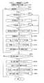
図3に示すように、パチンコ機10の背面側には、制御基板ユニット90,91と、裏
パックユニット94とが主に備えられている。制御基板ユニット90は、主基板(主制御
装置110)と音声ランプ制御基板(音声ランプ制御装置113)と表示制御基板(表示
制御装置114)とが搭載されてユニット化されている。制御基板ユニット91は、払出
制御基板(払出制御装置111)と発射制御基板(発射制御装置112)と電源基板(電
源装置115)とカードユニット接続基板116とが搭載されてユニット化されている。
As shown in FIG. 3,
裏パックユニット94は、保護カバー部を形成する裏パック92と払出ユニット93と
がユニット化されている。また、各制御基板には、各制御を司る1チップマイコンとして
のMPU、各種機器との連絡をとるポート、各種抽選の際に用いられる乱数発生器、時間
計数や同期を図る場合などに使用されるクロックパルス発生回路等が、必要に応じて搭載
されている。
In the
なお、主制御装置110、音声ランプ制御装置113及び表示制御装置114、払出制
御装置111及び発射制御装置112、電源装置115、カードユニット接続基板116
は、それぞれ基板ボックス100〜104に収納されている。基板ボックス100〜10
4は、ボックスベースと該ボックスベースの開口部を覆うボックスカバーとを備えており
、そのボックスベースとボックスカバーとが互いに連結されて、各制御装置や各基板が収
納される。
The
Are housed in the
4 includes a box base and a box cover that covers the opening of the box base, and the box base and the box cover are connected to each other to accommodate the control devices and the substrates.
また、基板ボックス100(主制御装置110)及び基板ボックス102(払出制御装
置111及び発射制御装置112)は、ボックスベースとボックスカバーとを封印ユニッ
ト(図示せず)によって開封不能に連結(かしめ構造による連結)している。また、ボッ
クスベースとボックスカバーとの連結部には、ボックスベースとボックスカバーとに亘っ
て封印シール(図示せず)が貼着されている。この封印シールは、脆性な素材で構成され
ており、基板ボックス100,102を開封するために封印シールを剥がそうとしたり、
基板ボックス100,102を無理に開封しようとすると、ボックスベース側とボックス
カバー側とに切断される。よって、封印ユニット又は封印シールを確認することで、基板
ボックス100,102が開封されたかどうかを知ることができる。
In addition, the substrate box 100 (main controller 110) and the substrate box 102 (dispensing
When the
払出ユニット93は、裏パックユニット94の最上部に位置して上方に開口したタンク
130と、タンク130の下方に連結され下流側に向けて緩やかに傾斜するタンクレール
131と、タンクレール131の下流側に縦向きに連結されるケースレール132と、ケ
ースレール132の最下流部に設けられ、払出モータ216(図4参照)の所定の電気的
構成により球の払出を行う払出装置133とを備えている。タンク130には、遊技ホー
ルの島設備から供給される球が逐次補給され、払出装置133により必要個数の球の払い
出しが適宜行われる。タンクレール131には、当該タンクレール131に振動を付加す
るためのバイブレータ134が取り付けられている。
Dispensing
また、払出制御装置111には状態復帰スイッチ120が設けられ、発射制御装置11
2には可変抵抗器の操作つまみ121が設けられ、電源装置115にはRAM消去スイッ
チ122が設けられている。状態復帰スイッチ120は、例えば、払出モータ216(図
4参照)部の球詰まり等、払出エラーの発生時に球詰まりを解消(正常状態への復帰)す
るために操作される。操作つまみ121は、発射ソレノイドの発射力を調整するために操
作される。RAM消去スイッチ122は、パチンコ機10を初期状態に戻したい場合に電
源投入時に操作される。
In addition, the
2 is provided with a
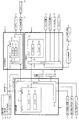
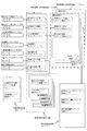
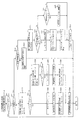
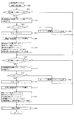
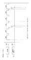
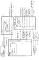
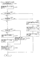
次に、図4を参照して、本パチンコ機10の電気的構成について説明する。図4は、パ
チンコ機10の電気的構成を示すブロック図である。
Next, the electrical configuration of the
主制御装置110には、演算装置である1チップマイコンとしてのMPU201が搭載
されている。MPU201には、該MPU201により実行される各種の制御プログラム
や固定値データを記憶したROM202と、そのROM202内に記憶される制御プログ
ラムの実行に際して各種のデータ等を一時的に記憶するためのメモリであるRAM203
と、そのほか、割込回路やタイマ回路、データ送受信回路などの各種回路が内蔵されてい
る。主制御装置110では、MPU201によって、大当たり抽選や第1図柄表示装置3
7A,37B及び第3図柄表示装置81における表示の設定、第2図柄表示装置における
表示結果の抽選といったパチンコ機10の主要な処理を実行する。
The
Besides, various circuits such as an interrupt circuit, a timer circuit, and a data transmission / reception circuit are incorporated. In the
The main processing of the
なお、払出制御装置111や音声ランプ制御装置113などのサブ制御装置に対して動
作を指示するために、主制御装置110から該サブ制御装置へ各種のコマンドがデータ送
受信回路によって送信されるが、かかるコマンドは、主制御装置110からサブ制御装置
へ一方向にのみ送信される。
Although various commands are transmitted from the
RAM203は、各種エリア、カウンタ、フラグのほか、MPU201の内部レジスタ
の内容やMPU201により実行される制御プログラムの戻り先番地などが記憶されるス
タックエリアと、各種のフラグおよびカウンタ、I/O等の値が記憶される作業エリア(
作業領域)とを有している。なお、RAM203は、パチンコ機10の電源の遮断後にお
いても電源装置115からバックアップ電圧が供給されてデータを保持(バックアップ)
できる構成となっており、RAM203に記憶されるデータは、すべてバックアップされ
る。
The
Work area). Note that the
The configuration is such that all data stored in the
停電などの発生により電源が遮断されると、その電源遮断時(停電発生時を含む。以下
同様)のスタックポインタや、各レジスタの値がRAM203に記憶される。一方、電源
投入時(停電解消による電源投入を含む。以下同様)には、RAM203に記憶される情
報に基づいて、パチンコ機10の状態が電源遮断前の状態に復帰される。RAM203へ
の書き込みはメイン処理(図示せず)によって電源遮断時に実行され、RAM203に書
き込まれた各値の復帰は電源投入時の立ち上げ処理(図示せず)において実行される。な
お、MPU201のNMI端子(ノンマスカブル割込端子)には、停電等の発生による電
源遮断時に、停電監視回路252からの停電信号SG1が入力されるように構成されてお
り、その停電信号SG1がMPU201へ入力されると、停電時処理としてのNMI割込
処理(図示せず)が即座に実行される。
When the power is shut off due to the occurrence of a power failure or the like, the stack pointer at the time of the power shutoff (including the time of the power failure, the same applies hereinafter) and the value of each register are stored in the
主制御装置110のMPU201には、アドレスバス及びデータバスで構成されるバス
ライン204を介して入出力ポート205が接続されている。入出力ポート205には、
払出制御装置111、音声ランプ制御装置113、第1図柄表示装置37A,37B、第
2図柄表示装置、第2図柄保留ランプ、特定入賞口65aの開閉板の下辺を軸として正面
側に開閉駆動するための大開放口ソレノイドや羽部材を駆動するためのソレノイドなどか
らなるソレノイド209が接続され、MPU201は、入出力ポート205を介してこれ
らに対し各種コマンドや制御信号を送信する。
An input /
Drive open / close to the front side centering on the lower side of the opening / closing plate of
また、入出力ポート205には、図示しないスイッチ群およびスライド位置検出センサ
Sや回転位置検出センサRを含むセンサ群などからなる各種スイッチ208、電源装置1
15に設けられた後述のRAM消去スイッチ回路253が接続され、MPU201は各種
スイッチ208から出力される信号や、RAM消去スイッチ回路253より出力されるR
AM消去信号SG2に基づいて各種処理を実行する。
The input /
The
Various processing is executed based on the AM cancellation signal SG2.
払出制御装置111は、払出モータ216を駆動させて賞球や貸出球の払出制御を行う
ものである。演算装置であるMPU211は、そのMPU211により実行される制御プ
ログラムや固定値データ等を記憶したROM212と、ワークメモリ等として使用される
RAM213とを有している。
The
払出制御装置111のRAM213は、主制御装置110のRAM203と同様に、M
PU211の内部レジスタの内容やMPU211により実行される制御プログラムの戻り
先番地などが記憶されるスタックエリアと、各種のフラグおよびカウンタ、I/O等の値
が記憶される作業エリア(作業領域)とを有している。RAM213は、パチンコ機10
の電源の遮断後においても電源装置115からバックアップ電圧が供給されてデータを保
持(バックアップ)できる構成となっており、RAM213に記憶されるデータは、すべ
てバックアップされる。なお、主制御装置110のMPU201と同様、MPU211の
NMI端子にも、停電等の発生による電源遮断時に停電監視回路252から停電信号SG
1が入力されるように構成されており、その停電信号SG1がMPU211へ入力される
と、停電時処理としてのNMI割込処理(図示せず)が即座に実行される。
Similar to the
A stack area in which the contents of the internal registers of the
Even after the power is turned off, the backup voltage is supplied from the
1 is configured to be input, and when the power failure signal SG1 is input to the
払出制御装置111のMPU211には、アドレスバス及びデータバスで構成されるバ
スライン214を介して入出力ポート215が接続されている。入出力ポート215には
、主制御装置110や払出モータ216、発射制御装置112などがそれぞれ接続されて
いる。また、図示はしないが、払出制御装置111には、払い出された賞球を検出するた
めの賞球検出スイッチが接続されている。なお、該賞球検出スイッチは、払出制御装置1
11に接続されるが、主制御装置110には接続されていない。
An input /
11, but not to the
発射制御装置112は、主制御装置110により球の発射の指示がなされた場合に、操
作ハンドル51の回動操作量に応じた球の打ち出し強さとなるよう球発射ユニット112
aを制御するものである。球発射ユニット112aは、図示しない発射ソレノイドおよび
電磁石を備えており、その発射ソレノイドおよび電磁石は、所定条件が整っている場合に
駆動が許可される。具体的には、遊技者が操作ハンドル51に触れていることをタッチセ
ンサ51aにより検出し、球の発射を停止させるための発射停止スイッチ51bがオフ(
操作されていないこと)を条件に、操作ハンドル51の回動操作量(回動位置)に対応し
て発射ソレノイドが励磁され、操作ハンドル51の操作量に応じた強さで球が発射される
。
The
It controls a. The
Under the condition that it is not operated, the firing solenoid is excited corresponding to the amount of rotational operation (rotational position) of the
音声ランプ制御装置113は、音声出力装置(図示しないスピーカなど)226におけ
る音声の出力、ランプ表示装置(電飾部29〜33、表示ランプ34など)227におけ
る点灯および消灯の出力、変動演出(変動表示)や予告演出といった表示制御装置114
で行われる第3図柄表示装置81の表示態様の設定などを制御するものである。演算装置
であるMPU221は、そのMPU221により実行される制御プログラムや固定値デー
タ等を記憶したROM222と、ワークメモリ等として使用されるRAM223とを有し
ている。
The sound
It controls the setting of the display mode of the third
音声ランプ制御装置113のMPU221には、アドレスバス及びデータバスで構成さ
れるバスライン224を介して入出力ポート225が接続されている。入出力ポート22
5には、主制御装置110、表示制御装置114、音声出力装置226、ランプ表示装置
227、その他装置228、枠ボタン22などがそれぞれ接続されている。その他装置2
28には駆動モータMT1や、電磁ソレノイドSOL1,SOL2が含まれる。
An input /
The
28 includes a drive motor MT1 and electromagnetic solenoids SOL1 and SOL2.
音声ランプ制御装置113は、主制御装置110から受信した各種のコマンド(変動パ
ターンコマンド、停止種別コマンド等)に基づいて、第3図柄表示装置81の表示態様を
決定し、決定した表示態様をコマンド(表示用変動パターンコマンド、表示用停止種別コ
マンド等)によって表示制御装置114へ通知する。また、音声ランプ制御装置113は
、枠ボタン22からの入力を監視し、遊技者によって枠ボタン22が操作された場合は、
第3図柄表示装置81で表示されるステージを変更したり、スーパーリーチ時の演出内容
を変更したりするように、表示制御装置114へ指示する。ステージが変更される場合は
、変更後のステージに応じた背面画像を第3図柄表示装置81に表示させるべく、変更後
のステージに関する情報を含めた背面画像変更コマンドを表示制御装置114へ送信する
。ここで、背面画像とは、第3図柄表示装置81に表示させる主要な画像である第3図柄
の背面側に表示される画像のことである。表示制御装置114は、この音声ランプ制御装
置113から送信されるコマンドに従って、第3図柄表示装置81に各種の画像を表示す
る。
The voice
It instructs the
また、音声ランプ制御装置113は、表示制御装置114から第3図柄表示装置81の
表示内容を表すコマンド(表示コマンド)を受信する。音声ランプ制御装置113では、
表示制御装置114から受信した表示コマンドに基づき、第3図柄表示装置81の表示内
容に合わせて、その表示内容に対応する音声を音声出力装置226から出力し、また、そ
の表示内容に対応させてランプ表示装置227の点灯および消灯を制御する。
In addition, the audio
Based on the display command received from the
表示制御装置114は、音声ランプ制御装置113及び第3図柄表示装置81が接続さ
れ、音声ランプ制御装置113より受信したコマンドに基づいて、第3図柄表示装置81
における第3図柄の変動演出などの表示を制御するものである。また、表示制御装置11
4は、第3図柄表示装置81の表示内容を通知する表示コマンドを適宜音声ランプ制御装
置113へ送信する。音声ランプ制御装置113は、この表示コマンドによって示される
表示内容にあわせて音声出力装置226から音声を出力することで、第3図柄表示装置8
1の表示と音声出力装置226からの音声出力とをあわせることができる。
The
It controls the display of the fluctuation effect of the third symbol in. In addition, the
4 appropriately transmits a display command for notifying the display content of the third
1 and the audio output from the
電源装置115は、パチンコ機10の各部に電源を供給するための電源部251と、停
電等による電源遮断を監視する停電監視回路252と、RAM消去スイッチ122(図3
参照)が設けられたRAM消去スイッチ回路253とを有している。電源部251は、図
示しない電源経路を通じて、各制御装置110〜114等に対して各々に必要な動作電圧
を供給する装置である。その概要としては、電源部251は、外部より供給される交流2
4ボルトの電圧を取り込み、各種スイッチ208などの各種スイッチや、ソレノイド20
9などのソレノイド、モータ等を駆動するための12ボルトの電圧、ロジック用の5ボル
トの電圧、RAMバックアップ用のバックアップ電圧などを生成し、これら12ボルトの
電圧、5ボルトの電圧及びバックアップ電圧を各制御装置110〜114等に対して必要
な電圧を供給する。
The
And the RAM erase
Take in a voltage of 4 volts and use various switches such as
Generate a voltage of 12 volts for driving solenoids such as 9 motors, a motor, etc., a voltage of 5 volts for logic, a backup voltage for RAM backup, etc. Necessary voltages are supplied to the
停電監視回路252は、停電等の発生による電源遮断時に、主制御装置110のMPU
201及び払出制御装置111のMPU211の各NMI端子へ停電信号SG1を出力す
るための回路である。停電監視回路252は、電源部251から出力される最大電圧であ
る直流安定24ボルトの電圧を監視し、この電圧が22ボルト未満になった場合に停電(
電源断、電源遮断)の発生と判断して、停電信号SG1を主制御装置110及び払出制御
装置111へ出力する。停電信号SG1の出力によって、主制御装置110及び払出制御
装置111は、停電の発生を認識し、NMI割込処理を実行する。なお、電源部251は
、直流安定24ボルトの電圧が22ボルト未満になった後においても、NMI割込処理の
実行に充分な時間の間、制御系の駆動電圧である5ボルトの電圧の出力を正常値に維持す
るように構成されている。よって、主制御装置110及び払出制御装置111は、NMI
割込処理(図示せず)を正常に実行し完了することができる。
The power
The
The power failure signal SG1 is output to the
The interrupt process (not shown) can be successfully executed and completed.
RAM消去スイッチ回路253は、RAM消去スイッチ122(図3参照)が押下され
た場合に、主制御装置110へ、バックアップデータをクリアさせるためのRAM消去信
号SG2を出力するための回路である。主制御装置110は、パチンコ機10の電源投入
時に、RAM消去信号SG2を入力した場合に、バックアップデータをクリアすると共に
、払出制御装置111においてバックアップデータをクリアさせるための払出初期化コマ
ンドを払出制御装置111に対して送信する。
The RAM erase
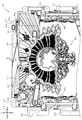
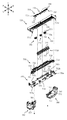
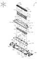
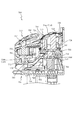
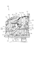
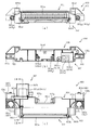
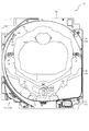
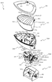
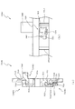
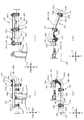
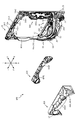
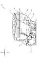
次いで、遊技盤13及び動作ユニット300の構造について説明する。図5は、遊技盤
13及び動作ユニット300の分解正面斜視図であり、図6は、遊技盤13及び動作ユニ
ット300の分解背面斜視図である。なお、図5及び図6の説明においては、図2を適宜
参照する。また、図6では、第3図柄表示装置81の図示が省略されている。
Next, the structures of the
遊技盤13は、上述のように、正面視略正方形状に切削加工したベース板60に、球案
内用の多数の釘(図示せず)や風車(図示せず)の他、レール61,62、一般入賞口6
3、第1入賞口64、第2入賞口140、スルーゲート67、可変入賞装置65、可変表
示装置ユニット80、左右一対の窓部可動ユニット150、遊技領域から排出された球が
流下可能に構成される球流下ユニット290等を組み付けて構成され、その周縁部が内枠
12(図1参照)の裏面側に取り付けられる。
As described above, the
3, the first winning
ベース板60は、上述のように、ベニヤ板を重ね合わせた合板から形成されており、そ
の正面側からベース板60の背面側に配設された各種構造体を遊技者に視認させないよう
にベース板60で遮蔽可能に形成される。
As described above, the
図6に示すように、ベース板60は、略中央位置において可変表示装置ユニット80を
配設可能に穿設される貫通孔の他に、スルーゲート67に接続される電気配線を通すため
に穿設される複数(本実施形態では2個)の小貫通孔60aと、動作ユニット300の前
端部と凹凸嵌合可能に凹設される複数(本実施形態では3個)の嵌合凹部60bと、左右
下部において前後方向に穿設される複数(本実施形態では2個)の光透過孔60cとを備
える。
As shown in FIG. 6,
光透過孔60cは、動作ユニット300側から照射された光が通過可能な位置に形成さ
れており、発光演出の観点から、遊技盤13の演出効果の向上を図っている。このことに
ついて詳しく説明する。
The
光通過孔60cの正面側には、光透過性の樹脂材料から形成される流下面構成部材91
,92が配設されており、その流下面構成部材91,92の外側部94が光通過孔60c
を覆設する態様で、流下面構成部材91,92はベース板60に締結固定される。
On the front side of the
, 92 are disposed, and the
In the aspect which covers, the flow lower surface
左右の流下面構成部材91,92は、右側の流下面構成部材92の正面側に覆設板FB
が配設されることを除き、略左右対称形状で構成されるので、左側の流下面構成部材91
について詳しく説明し、右側の流下面構成部材92の説明は省略する。
The left and right flow lower
Is arranged in a substantially left-right symmetrical shape, except for the provision of
Will be described in detail, and the explanation of the right
図5に示すように、流下面構成部材91は、ベース板60の正面に沿って配設される板
状部が、内レール61と同等の幅の帯状に形成される帯状部93により遊技領域が区画さ
れるように構成されており、帯状部93と、その帯状部93により区画される遊技領域の
外側部分(正面視外側部分)である外側部94と、帯状部93により区画される遊技領域
の内側部分(正面視内側部分)である内側部95とを備える。
As shown in FIG. 5, in the flow lower
外側部94は、上述のように、遊技領域の外側なので、球の流下に影響を与え難い部分
として構成される。従って、外板部94が変位することに伴う球への影響を考慮する必要
が無いので、外側部94の肉厚を薄く設計することができる。
The
また、外側部94を薄く設計した結果、内側部95の肉厚が薄くなったとしても、内側
部95の背面側にはベース板60の肉部が配設されるので、ベース板60の剛性を利用し
て内側部95の前後方向の変位(厚み方向の変形)を抑制することができる。更に、外側
部94及び内側部95の肉厚を薄く設計することにより、遊技領域の前後幅を十分に確保
することができる。
In addition, even if the thickness of the
このように、内側部95に要求される機能を損なわずに、外側部94の肉厚を薄く設計
することができ、その結果として、動作ユニット300側から照射され光透過孔60cを
通る光を、外側部94を介して遊技者に視認させ易くすることができる。
In this manner, the thickness of the
本実施形態では、ベース板60が木製の板部材から形成されるので、背面側から照射さ
れた光をベース板60の肉厚を介して遊技者に視認させることは困難である。一方で、本
実施形態のように光透過孔60c(図6参照)を形成し、その背面側に発光手段を配置す
ることで、ベース板60を木製の板部材で構成しながら、ベース板60を介して視認され
る明るさを容易に変化させることができる。
In the present embodiment, since the
例えば、外側部94と、その他の部分とに正面視で連続的に繋がるように視認される装
飾模様を形成する場合に、外側部94の背面側に配置される電飾基板777に配設される
発光手段778の発光態様を複数種類で変化させ外側部94の明るさを変化させることで
、同じ装飾模様であっても、その見え方を複数種類に変化させることができる。
For example, in the case of forming a decorative pattern visually recognized so as to be continuously connected to the
また、例えば、発光手段778の発光態様により視認可能な模様を変化させる装飾部材
を外側部94に貼り付けるようにしても良い。この場合、発光手段778の発光態様によ
り遊技盤13の見栄え(イメージ)を大きく変化させることができる。
In addition, for example, a decorative member that changes a visible pattern according to the light emission mode of the light emitting means 778 may be attached to the
なお、発光態様により視認可能な模様を変化させる装飾部材の態様は、何ら限定される
ものでは無い。例えば、イルミネーションプレートに代表されるような、光を当てる角度
により異なる模様を視認可能に設計される部材でも良い。また、例えば、複数色で模様が
描かれており、照射される光の色も複数色用意されている前提で、発光色を変えることで
視認される模様を変化させるよう設計される部材でも良い。
In addition, the aspect of the decoration member which changes the pattern which can be visually recognized by the light emission aspect is not limited at all. For example, a member such as an illumination plate, which is designed to be able to visually recognize different patterns depending on the angle of light application may be used. Further, for example, on the premise that a pattern is drawn in a plurality of colors and the color of the light to be irradiated is also prepared in a plurality of colors, a member designed to change the pattern to be recognized by changing the emission color may be used. .
内側部95は、上述のように、遊技領域の内側に配設されている。内側部95が変位(
変形)すると、遊技領域を流下する球に影響を与える虞があるが、本実施形態では、内側
部95の背面側にペース板60の肉部が配置されるように構成されているので(光透過孔
60cが正面視で帯状部93に対して外側部94側に収まるように構成されているので)
、ベース板60の剛性を利用して、内側部95の変位(変形)を防止することができる。
これにより、球の流下を安定させることができる。
The
If there is a possibility that the ball flowing down the game area may be affected if it is modified, in the present embodiment, the light portion of the
The rigidity of the
This makes it possible to stabilize the flow of the ball.
内側部95には一般入賞口63が配設されており、その一般入賞口63はルータ加工に
よってベース板60に形成された貫通穴に配設され、流下面構成部材91が遊技盤13の
正面側からタッピングネジ等により固定されることにより固定されている。
A general winning
遊技盤13の正面中央部分は、正面枠14の窓部14c(図1参照)を通じて内枠12
の正面側から視認することができる。以下に、主に図2を参照して、遊技盤13の構成に
ついて説明する。
The front center portion of the
Can be viewed from the front side of the Hereinafter, the configuration of the
上述のように、可変表示装置ユニット80には、第3図柄表示装置81の外周を囲むよ
うにして、センターフレーム86が配設されており、そのセンターフレーム86の左右上
隅部に窓部可動ユニット150が配設されている。
As described above, the
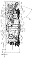
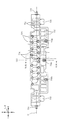
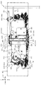
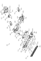
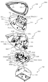
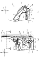
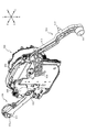
図7は、遊技盤13の分解背面斜視図である。なお、図7では、遊技盤13の下部の図
示が省略され、補助装置160が分解され正面斜視で図示される。
FIG. 7 is an exploded back perspective view of the
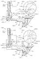
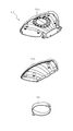
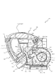
窓部可動ユニット150は、回転変位可能とされ、センターフレーム86の内側の窓部
において遊技者が視認可能に構成される変位部材151と、その変位部材151の背面側
に配設され、変位部材151を駆動させる駆動力を発生させたり、変位部材151へ向け
て光を照射したりする補助装置160とを備える。
The window
変位部材151は、前後方向視二股形状に形成され、折れ曲がり部分付近に構成される
基端部において軸支される二股部152と、その二股部152の両先端部に配設され背面
側が開放される箱状(袋状、コップ状)に形成される先端部153と、二股部152の基
端部から径方向へ張り出す張出部154とを備える。
The
先端部153は、底側を正面側へ向けた箱状(袋状、コップ状)に形成され遊技者が視
認可能に配設される演出部153aと、その演出部153aの開放部側に締結固定される
リング状部であって、演出部153a側に比較して演出部153aの逆側の方がすぼまる
形状とされるリング状部153bとを備える。
The
演出部153aは、内側面に光拡散形状(ギザギザ形状)が形成されており、背面側か
ら開放部の内側に照射される光を拡散させることができるので、実際に照射される光は狭
い範囲に照射されるものであっても、正面側から演出部153aを視認する遊技者に対し
て演出部153aの全体が(淡く)光っているように視認させることができる。
In the
張出部154は、センターフレーム86側から突設される一対の爪部86aにより回転
方向双方向で変位可能範囲を規定されている。即ち、変位部材151は、爪部86aの配
置と、張出部154との関係で規定される角度(360度未満の角度)において回転変位
可能に構成される。
The overhanging
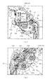
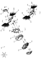
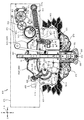
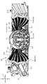
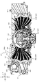
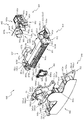
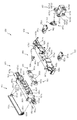
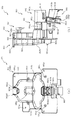
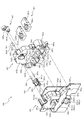
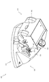
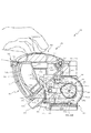
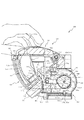
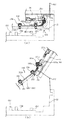
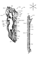
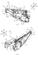
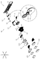
図8は、補助装置160の分解正面斜視図であり、図9は、補助装置160の分解背面
斜視図である。補助装置160は、変位部材151(図7参照)と当接可能な位置に配置
される当接部材161と、その当接部材161に一端(正面側端)が相対回転不能に連結
される金属製(本実施形態では、真鍮製)の伝達軸棒部162と、その伝達軸棒部162
の他端(背面側端)に相対回転不能に連結される被駆動部材163と、伝達軸棒部162
の両端に径方向から嵌め込まれる公知のEリング164と、伝達軸棒部162を軸支可能
に構成され、全体がケース状に構成される支持ケース170と、その支持ケース170の
内部に配設される電飾基板180とを備えている。
8 is an exploded front perspective view of the assisting
Driven
A
伝達軸棒部162は、中腹部の軸方向(前後方向)視の外形が真円形状である円柱状の
部材であって、両側先端において所定の径方向から面状に削られることで、両側先端が断
面略D字形状とされている。この両側端部が、当接部材161の被挿通孔161bや、被
駆動部材163の被挿通孔163bと嵌合することで、当接部材161、伝達軸棒部16
2及び被駆動部材163が相対回転不能(一体的)に連結される。
The transmission
2 and the driven
当接部材161は、樹脂材料から形成されており、伝達軸棒部162が挿通される貫通
孔であって断面D字形状に構成される被挿通孔161bが穿設される基端部161aと、
その基端部161aの外方へ向けて延設され、正面視略コの字状に構成される腕部161
cとを備える。
The
An
and c.
被駆動部材163は、樹脂材料から形成されており、伝達軸棒部162が挿通される貫
通孔であって断面D字形状に構成される被挿通孔163bが穿設される基端部163aと
、その基端部161aの外方へ向けて真っすぐに延設され、略平板状に構成される腕部1
63cとを備える。
The driven
And 63c.
被駆動部材163の上面には、金属製(磁性体)の金属板部材MB1が配設される。本
実施形態では、金属板部材MB1は、弾性爪163dとの係合により被駆動部材163に
固定される。
A metal plate member MB1 made of metal (magnetic material) is disposed on the top surface of the driven
詳述すると、腕部163cの径方向両端部において金属板部材MB1の前後スライドを
案内するレール部が配設されており、このレール部は、金属板部材MB1を正面側からの
み案内できるように形成されている(正面側のみ十分に開放されている)。レール部に沿
って金属板部材MB1をスライドさせる際には弾性爪163dが金属板部材MB1により
押し下げられており、そのまま金属板部材MB1をスライドさせると、レール部の背面側
壁に金属板部材MB1が当たることでスライドが規制され、当該位置においては金属板部
材MB1による弾性爪163dの押し下げは解除されており(金属板部材MB1の側面と
対向する位置まで上昇しており)、弾性爪163dが金属板部材MB1の正面側への退避
を規制するように係合する。
More specifically, rail portions for guiding the back and forth slide of the metal plate member MB1 are disposed at both end portions in the radial direction of the
なお、金属板部材MB1の被駆動部材163への固定方法はこれに限られるものではな
い。例えば、金属板部材MB1を被駆動部材163に締結固定するものでも良いし、結束
バンドでしばりつけても良いし、粘着性のテープ等で貼り付けても良い。
The method of fixing the metal plate member MB1 to the driven
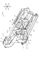
支持ケース170は、後部材170Bと、その後部材170Bの正面側に配設され伝達
軸棒部162が挿通される支持孔174が形成される中部材170Mと、その中部材17
0Mの正面側に配設され正面側に装飾形状(波模様)が形成される前部材170Fとを備
え、これら複数(本実施形態では3個)の板状部材が前後に積層され締結固定されている
。
The
A
電飾基板180は、前部材170Fの形状に合わせて正面視略L字の板形状に形成され
ており、演出を考慮して設計された位置に配設される複数のLED等から構成される発光
手段181と、電気配線が接続される部分として配設されるコネクタ182と、組み付け
用に電飾基板180に穿設される複数の貫通孔183とを備える。
The
発光手段181は、正面視で光透過孔177の内側に配置される強発光手段181aと
、光透過孔177の外側に配置される(前部材170Fの板背面と対向配置される)弱発
光手段181bとを備える。
The light emitting means 181 is a strong
貫通孔183は、傾斜する方向に沿って長い長円形状で形成されている。これにより、
正面視で外形が真円形状で形成される突設円柱部172に対する貫通孔183の組み付け
を容易とすることができる。
The through
The through
即ち、電飾基板180の姿勢が傾斜する一方で(図10参照)、突設円柱部172の突
設方向は傾斜していない(前後方向である)ので、同一方向で組み付ける場合に比較して
組み付け不良(組み付けられなかったり、緩くなったり)が生じ易くなるが、本実施形態
では、貫通孔183が電飾基板180の姿勢が傾斜する方向に沿って長い長円形状で形成
されるので、傾斜する方向に沿う貫通孔183の余裕代を大きめにとることができ、突設
円柱部172に対する貫通孔183の組み付けを容易とすることができる。
That is, while the posture of the
電飾基板180は、前部材170Fと中部材170Mとの間に収容されるが、この際、
電飾基板180は板正面が斜め下方を向く(法線が正面側下方へ傾斜する)姿勢とされる
。このことについて、図10を参照して詳述する。
Although the
The
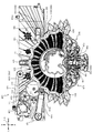
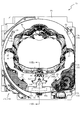
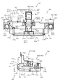
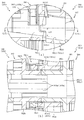
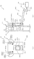
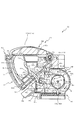
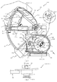
図10は、図2のX−X線における窓部可動ユニット150の断面図である。なお、理
解を容易とするために、後部材170Bの図示が省略され、変位部材151の外形が想像
線で図示される。なお、X−X線は、上側の突設円柱部172の中心を通るよう配置され
る。なお、以下の説明では、図8及び図9を適宜参照する。
FIG. 10 is a cross-sectional view of the window
中部材170Mは、その正面側の壁状部の態様が、上側壁状部170MUと、下側壁状
部170MDとで異なる。即ち、上側壁状部170MUは、非傾斜(法線が水平方向を向
く)の壁状部として構成され、下側壁状部170MDは、傾斜する(法線が正面側下方へ
向く)壁状部として構成される。
The
このように法線の異なる壁状部に対し、電飾基板180は、板背面が下側壁状部170
MDに沿う姿勢(法線が正面側下方へ傾斜する姿勢)となるように支持される。即ち、組
立状態(図2参照)において、電飾基板180の発光手段181から照射される光の光軸
の方向は、正面側下方へ傾斜する。
Thus, with respect to the wall-like portions having different normals, the
It is supported so as to be in a posture along MD (a posture in which the normal inclines downward to the front side). That is, in the assembled state (see FIG. 2), the direction of the optical axis of the light emitted from the light emitting means 181 of the
中部材170Mは、正面側へ向けて枠状に突設される突設枠部171と、その突設枠部
の内側において正面側へ細径円柱状に突設される複数の突設円柱部172と、左右外側(
左側)隅部においてコネクタ182を囲う配置で前後方向に穿設される配線通し孔173
とを備える。
The
Wiring through
And
突設枠部171は、前部材170Fの外枠部と前後で当接することで、電飾基板180
の周囲に亘って封をする。これにより、電飾基板180が、前部材170Fと中部材17
0Mとの間から視認されることを回避することができると共に、同様の位置から光漏れが
生じることを防止することができる。
The projecting
Seal around the perimeter of the Thereby, the
While being able to avoid being visually recognized from between 0M, it can prevent that a light leak arises from the same position.
突設円柱部172は、大径の座部と、その座部から更に突設される小径の挿通部とを備
えており、電飾基板180の貫通孔183に挿通部が入るように組み付けることで電飾基
板180の板背面が座部に支えられ、電飾基板180の配置を安定させることができる。
The projecting
ここで、下側壁状部170MDに配設される突設円柱部172の座部に比べ、上側壁状
部170MUに配設される突設円柱部172の座部が高くなっている。これにより、上述
の傾斜姿勢で組み付けられる電飾基板180を安定して支持することができると共に、上
側壁状部170MUと電飾基板180との間に空隙を確保することができる。
Here, the seat portion of the projecting
突設円柱部172の座部の突設先端は、電飾基板180の姿勢に合わせた傾斜面(下方
へ向かう程に突設長さが短くなるよう構成される傾斜面)として形成されている。これに
より、突設円柱部172に、電飾基板180の配置を安定させる機能のみならず、電飾基
板180の姿勢を安定させる機能を付与することができる。
The projecting end of the seat of the projecting
配線通し孔173は、電飾基板180のコネクタ182に接続される電気配線を通すた
めの貫通孔である。この電気配線を介して電飾基板180にかけられる負荷により電飾基
板180の姿勢維持を図ることができるので、電飾基板180を締結固定することなく、
電飾基板180の姿勢を安定的に支持することができる。
The wiring through
The attitude of the
前部材170Fは、有色(本実施形態では白色)で光透過性の樹脂材料から背側面が下
側壁状部170MDと略平行な面となる形状で形成され、前後方向で円形に穿設される複
数の光透過孔177と、背面側へ向けて細径円柱状に突設される複数の突設円柱部178
と、板背面と外周を形成する枠部との間を連結する左右方向視L字形状のL字形支持部1
79とを備える。
The
And an L-shaped supporting
And 79.
光透過孔177は、発光手段181を構成するいずれかのLEDを正面視で囲むように
形成される。これにより、光透過孔177の背面側に配設される発光手段181と、それ
以外の発光手段181とでは、前部材170Fの正面側から視認される態様が変化する。
即ち、光透過孔177の内側の方が、それ以外の箇所に比較して強発光しているように視
認させることができる。
The light transmission holes 177 are formed to surround any of the LEDs constituting the light emitting means 181 in a front view. Thereby, the aspect visually recognized from the front side of the
That is, the inside of the
突設円柱部178は、複数が略同等の突設長さで形成されている。これにより、前部材
170Fの本体板部と電飾基板180との間隔を電飾基板180の配設範囲全体に亘って
一様としつつ、傾斜姿勢の電飾基板180を複数位置で面支持することができるので、発
光手段181の配置自由度を維持すると共に発光態様のムラを抑えながら、電飾基板18
0の支持の安定感を向上することができる。
A plurality of projecting
The stability of the support of 0 can be improved.
即ち、電飾基板180は板正面が正面側下方へ向く傾斜姿勢とされるので、その姿勢を
維持するためには正面側から下支えすることが好ましいが、一箇所に大面積の支持部を設
けて電飾基板180を支持するようにすると、電飾基板180の正面側に配設する発光手
段181の配置可能領域が制限され易くなる傾向があった。発光手段181の配置可能領
域を優先して支持部の面積を小さくすると、電飾基板180の姿勢が崩れ前部材170F
の本体板部と電飾基板180との間隔が電飾基板180の配設範囲でバラつき易く、発光
態様のムラが生じやすくなる虞があった。
That is, since the
There is a possibility that the distance between the main body plate portion and the
これに対し、本実施形態では、同様の突設高さで細径の突設円柱部178を複数設け、
それらで電飾基板180の板正面を複数点で同時に支持できるように構成していることか
ら、隣接する発光手段181の間に生じる小さな複数の隙間位置に電飾基板180を支持
する突設円柱部178を複数配設することができる。これにより、発光手段181の配置
自由度を維持すると共に発光態様のムラを抑えながら、電飾基板180の支持の安定感を
向上することができる。
On the other hand, in the present embodiment, a plurality of projecting
Since they are configured to simultaneously support the plate front of the
L字形支持部179は、組立状態において、電飾基板180の上面および正面と対向配
置し、電飾基板180の変位を抑制するよう機能する。即ち、電飾基板180が自重で前
倒れするのを、電飾基板180の板正面と対向配置するL字形支持部179の下部が下支
えして防止している。
The L-shaped
また、電飾基板180の板上面と対向配置するL字形支持部179の後部と電飾基板1
80とは、通常では隙間を空けて配置されることで、電飾基板180を緩く支持しながら
、電飾基板180の上下方向の変位を最小限に抑制することができる。
In addition, the rear portion of the L-shaped
In 80, by disposing a gap normally, the vertical displacement of the
なお、L字形支持部179と同形状の支持部が、中部材170Mの下側壁状部170M
Dの正面側にも形成されており(左右2位置に形成されており)、電飾基板180の下面
および背面と対向配置し、電飾基板180の変位を抑制するよう機能する。即ち、本実施
形態では、電飾基板180の上下に配置されるL字形支持部によって、電飾基板180の
前後方向および上下方向への変位を抑制可能に構成している。
In addition, the L-shaped
It is also formed on the front side of D (formed at two positions on the left and right) and disposed to face the lower surface and the back surface of the
このように、本実施形態では、電飾基板180は直接的には締結固定されておらず、前
部材170Fと中部材170Mとに前後から挟まれ支持されることで、安定的に支持され
ている。これは、例えば、中部材170Mと電飾基板180とを締結固定し、単一の剛体
として構成すると、中部材170Mに生じる振動の影響を受けて電飾基板180が振動す
る可能性があるので、それを考慮しての対策である。
As described above, in the present embodiment, the
即ち、本実施形態によれば、電飾基板180が中部材170Mにも前部材170Fにも
締結固定されていないので、中部材170Mや前部材170Fに振動が生じた場合であっ
ても、それと独立して電飾基板180の配置を維持し易くすることができる。
That is, according to the present embodiment, since the
ここで、中部材170Mの振動の原因になり易いのは、中部材170Mの背面側に配設
される電磁ソレノイドSOL1であると考えられるが、本実施形態では、電磁ソレノイド
SOL1は、上側壁状部170MUの正面側に生じる隙間を挟んで電飾基板180の反対
側(背面側)に配設される。
Here, although it is considered that the electromagnetic solenoid SOL1 disposed on the back side of the
この構成により、電磁ソレノイドSOL1の振動は細径の突設円柱部172を介して電
飾基板180に伝達されることになるので、振動ソレノイドSOL1の振動を突設円柱部
172の変形で緩和することができ、電飾基板180に振動が伝達されることを抑制する
ことができる。従って、振動源としての電磁ソレノイドSOL1から電飾基板180へ直
接的に振動が伝達されることを回避することができる。
With this configuration, the vibration of the electromagnetic solenoid SOL1 is transmitted to the
中部材170Mは、伝達軸棒部162の直径よりも若干長い直径で前後方向に穿設され
伝達軸棒部162を回転可能に支持可能に構成される支持孔174と、電磁ソレノイドS
OL1の下方に配設される下側規制部175と、電磁ソレノイドSOL1に対して支持孔
174の反対側に配設される上側規制部176とを備える。
The
A
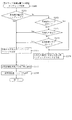
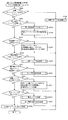
被駆動部材163は通常、自重で傾倒している(図11(a)参照)が、電磁ソレノイ
ドSOL1に電気が供給されることで磁力(電磁力)が発生し、その磁力(電磁力)によ
り金属板部材MB1が吸着され上昇変位する。即ち、本実施形態では、金属板部材MB1
が電磁力で上昇した結果配置される上昇位置と、電磁力が消失し自重で下降した結果配置
される下降位置との間で変位することに伴って当接部材161及び被駆動部材163が回
転変位する。以下、図11及び図12を参照して、その回転変位について説明する。
The driven
The
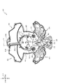
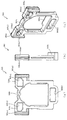
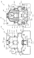
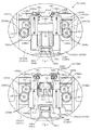
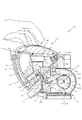
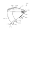
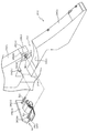
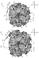
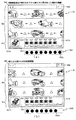
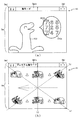
図11(a)は、窓部可動ユニット150の背面図であり、図11(b)は、窓部可動
ユニット150の正面図である。また、図12(a)は、窓部可動ユニット150の背面
図であり、図12(b)は、窓部可動ユニット150の正面図である。
11A is a back view of the window
なお、図11(a)及び図11(b)では、電磁ソレノイドSOL1に電気が供給され
ておらず被駆動部材163が自重で傾倒している状態(下降位置の状態)が図示され、図
12(a)及び図12(b)では、電磁ソレノイドSOL1に電気が供給され発生する電
磁力により金属板部材MB1及び被駆動部材163が上昇している状態(上昇位置の状態
)が図示される。
11 (a) and 11 (b), a state (state in the lowered position) in which the driven
また、図11(a)及び図12(a)では、理解を容易とするために、後部材170B
の図示が省略され、図11(b)及び図12(b)では、変位部材151の外形と背面側
の開放部の形状が想像線で図示される。
Further, in FIGS. 11A and 12A, the
11 (b) and 12 (b), the outline of the
図11(a)及び図12(a)に示すように、被駆動部材163は、下降位置において
は下側規制部175の上面に貼り付けられるクッション部175aに当接し下降変位を規
制され、上昇位置においては上側規制部176の下面に貼り付けられるクッション部17
6aに当接し上昇変位を規制される。
As shown in FIGS. 11 (a) and 12 (a), in the lowered position, the driven
It abuts on 6a and the upward displacement is restricted.
なお、クッション部175a,176aの材質は何ら限定されるものではない。例えば
、ポリプロピレン、ポリスチレン等の汎用プラスチックでも良いし、ポリカーボネート等
のエンジニアリングプラスチックでも良いし、メラミン樹脂、ポリウレタン、エポキシ樹
脂などの熱硬化性樹脂でも良いし、ゴム性材料でも良い。また、クッション部175a,
176aの材質を同じで構成しても良いし、異ならせても良い。
In addition, the material of the
The materials of the
ここで、下側規制部175及び上側規制部176は、伝達軸棒部162を基準とした配
置(伝達軸棒部162からの距離)が異なるように構成されているが、それにより生じる
効果について説明する。
Here, although the lower
まず、下側規制部175に被駆動部材163を介して与えられる負荷は、主に被駆動部
材163の自重により生じる負荷であるので、被駆動部材163の重心を支えることで被
駆動部材163を安定して支持することができる。この理由から、下側規制部175は、
被駆動部材163の重心位置(腕長さの略中央位置)に配設される。
First, since the load applied to the
It is disposed at the center of gravity of the driven member 163 (approximately at the center of the arm length).
これに対し、上側規制部176に被駆動部材163を介して与えられる負荷は、主に電
磁ソレノイドSOL1で生じる磁力(電磁力)による負荷であるので、上規制部材176
の配置を被駆動部材163の重心位置に関連させる利点は少ない。本実施形態では、上規
制部材176を被駆動部材163の回転先端に対向配置させることで、被駆動部材163
を介して上規制部材176へ伝達される負荷を低減している。
On the other hand, the load applied to the
There is little advantage in relating the arrangement of the to the center of gravity of the driven
The load transmitted to the upper regulating
即ち、同じ大きさの力のモーメントが発生している場合、被駆動部材163の回転軸か
ら離れた位置(モーメントに係る腕が長い位置)の方が、被駆動部材163を介して伝達
される負荷が小さくなるので、上規制部材176へ伝達される負荷を低減することができ
る。
That is, when a moment of force having the same magnitude is generated, the position away from the rotation axis of the driven member 163 (the position at which the arm related to the moment is longer) is transmitted via the driven
このように、上規制部材176への負荷伝達は、被駆動部材163の回転先端部におい
て生じることが望ましいので、本実施形態では、クッション部176aの幅寸法(径方向
幅)が短くされる(クッション部175aの幅寸法よりも短くされる)。これにより、被
駆動部材163の中間部で負荷伝達することを回避し、回転先端での負荷伝達を安定的に
生じさせることができる。
As described above, since it is desirable that the load transmission to the upper regulating
また、上昇位置では電磁ソレノイドSOL1による磁力(電磁力)が発生し続けるので
、クッション部176aに衝突した後で被駆動部材163が跳ね返ることは考えにくい。
In addition, since the magnetic force (electromagnetic force) continues to be generated by the electromagnetic solenoid SOL1 at the raised position, it is unlikely that the driven
一方、下側規制部175のクッション部175aの幅寸法(径方向幅)を長く(クッシ
ョン部176aの幅寸法よりも長く)することで、負荷を受ける面の面積を広くすること
ができ、被駆動部材163の自重による負荷によりクッション部175aに生じる圧力(
応力)を低減することができる。これにより、クッション部175aに衝突した後の被駆
動部材163の跳ね返り(バウンド)を抑制することができる。
On the other hand, by increasing the width dimension (radial direction width) of the
Stress) can be reduced. Thus, it is possible to suppress the bounce of the driven
従って、本実施形態によれば、上下両方向の変位時において被駆動部材163を介して
クッション部175a,176aに伝達される負荷を低減しながら、被駆動部材163の
跳ね返りを抑制することができる。
Therefore, according to the present embodiment, it is possible to suppress the rebound of the driven
上側規制部176の下方には、中部材170Mの背面側に湾曲形状で突設される突設部
176bが形成される。突設部176bは、被駆動部材163の回動先端部と対向配置さ
れ、被駆動部材163が正面側に変位した場合に被駆動部材163との接触を小面積で抑
えながら、被駆動部材163の回動を案内する。
Below the
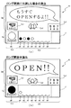
図11(b)及び図12(b)に示すように、正面視で光透過孔177の内側に配置さ
れる強発光手段181aの正面側に変位部材151の先端部153が配置される。そのた
め、強発光手段181aから照射される光は、先端部153を介して遊技者に視認される
。
As shown in FIGS. 11B and 12B, the
上述したように、演出部153aの内部形状によって、正面側から演出部153aを視
認する遊技者に対して演出部153aの全体が(淡く)光っているように視認させること
ができるので、強発光手段181aの実際の配置は変化しない一方で変位部材151が変
位する状況においても、演出部153aの発光態様の変化を抑制することができる。
As described above, the internal shape of the
換言すれば、演出部153aを介して視認される光が、演出部153aの変位と同期し
て変位しているように遊技者に視認させることができるので、あたかも演出部153aの
内側にLED等の発光手段が配設され、演出部153aの変位と同期して変位しているか
のように錯覚させることができる。
In other words, the light visually recognized via the
一方で、弱発光手段181bは固定位置で発光しているように見せることができるので
、配置固定の電飾基板180を採用しながら、その電飾基板180に配設される弱発光手
段181bは固定位置で発光しているように視認させ、同じく電飾基板180に配設され
る強発光手段181aは変位しながら発光しているように視認させることができる。
On the other hand, since the weak light emitting means 181b can appear to emit light at the fixed position, the weak light emitting means 181b disposed on the
これにより、電飾基板を複数採用して、第1の基板は固定配置で、第2の基板は変位可
能に構成することで実現が図られがちな発光演出を、配置固定で単一の電飾基板を利用し
て実現することができる。その結果、同様の演出効果を奏しながら、電飾基板の枚数を減
らすことができる。
As a result, a plurality of electric decoration substrates are adopted, the first substrate is in a fixed arrangement, and the second substrate is displaceable, so that the light emission effect which is likely to be realized is fixed in arrangement and single electric electricity. It can be realized using a decorative substrate. As a result, the number of electric decoration substrates can be reduced while achieving the same effect.
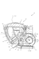
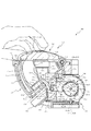
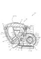
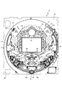
図5に戻って説明する。動作ユニット300は、遊技盤13の背面側に配置され、各種
発光手段や、各種動作ユニットが内部に配設されている。
Referring back to FIG. The
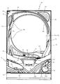
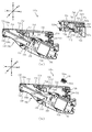
図13は、動作ユニット300の分解正面斜視図である。動作ユニット300は、底壁
部311と、その底壁部311の外縁から立設される外壁部312とから正面側が開放さ
れた箱状に形成される背面ケース310とを備える。
FIG. 13 is an exploded front perspective view of the
背面ケース310は、底壁部311の中央に矩形状の開口311aが開口形成されるこ
とで、正面視矩形の枠状に形成される。開口311aは、第3図柄表示装置81の表示領
域の外形(外縁)に対応した(即ち、第3図柄表示装置81の表示領域を正面視で区切る
ことが可能な)大きさに形成される。
The
動作ユニット300は、背面ケース310の内部空間に、可動装置が開口311aの上
側を含む経路で変位可能に配設される第1動作ユニット400と、開口311aの左右両
側に配設され、発光演出等を行う左右演出ユニット600と、開口311aの下側に配設
される第2動作ユニット700と、がそれぞれ収容され、これを1ユニットとして構成さ
れる。
The
具体的には、第1動作ユニット400は、開口311aの上方位置において、第2動作
ユニット700は、開口311aの下方位置において、それぞれ背面ケース310の底壁
部311に配設される。なお、図5では、第1動作ユニット400及び第2動作ユニット
700が背面ケース310に装着された状態が図示される。
Specifically, the
背面ケース310は、外壁部312の正面側端部に遊技盤13の背面に沿う(例えば、
平行に配置される)平面板として延設され、組立状態(図2参照)において遊技盤13を
面支持する支持板部313を備える。
The
A
支持板部313は、遊技盤13のベース板60に形成される嵌合凹部60bと嵌合可能
な形状で正面側へ向けて突設される位置決め凸部313aと、ベース板60に締結される
締結ネジを挿通可能に穿設される複数の挿通孔313bとを備える。
The
嵌合凹部60b(図6参照)に位置決め凸部313aを嵌合させることによりベース板
60に対して背面ケース310を位置決めし、締結ネジを挿通孔313bに挿通し、ベー
ス板60に螺入することにより、遊技盤13と動作ユニット300とを一体的に固定する
ことができるので、遊技盤13及び動作ユニット300の全体としての剛性の向上を図る
ことができる。
The
なお、位置決め凸部313aの形状は何ら限定されるものではなく、種々の態様が例示
される。例えば、嵌合凹部60bの内形(本実施形態では、円形または長円形)よりも若
干小さな外形の凸部でも良いし、組み付け時の作業性を考慮して、嵌合隙間が大きくなる
ような形状(更に小さな外形)の突部でも良い。また、嵌合凹部60bの内形が矩形状に
形成される場合には、それに対応して位置決め凸部313aの形状も矩形状とされること
は当然想定される。
In addition, the shape of the positioning
図5及び図13に示すように、本実施形態では、背面ケース310の左側および上側に
支持板部313が多く密に配設され、右側および下側では支持板部313の形成が少なく
されるが、これは遊技盤13及び動作ユニット300の全体としての剛性の向上と、スペ
ース効率とのバランスを考慮して設計した結果である。
As shown in FIGS. 5 and 13, in the present embodiment, a large number of
即ち、本実施形態のように遊技盤13のベース板60がベニヤ板を重ね合わせた合板か
ら形成されている場合、遊技盤13の背面側に配設される可動部材はベース板60の肉部
を通しては視認不能となるので、可動部材を視認可能に配設する演出用の領域として遊技
盤13のベース板60に開口形成(側面から凹設形成)できる領域の背面側全体が有効と
なる。
That is, as in the present embodiment, when the
これに対し、支持板部313を形成する箇所においては、支持板部313の正面視にお
ける面積の分だけ背面ケース310の内部空間が内側に侵食されることになるので、その
分、可動部材を配設可能な領域が狭まることになる。そのため、支持板部313を省略し
ても強度的な問題が解消されたまま維持可能であれば、支持板部313を省略することで
可動部材の配設範囲が制限されることを回避できるということである。
On the other hand, at the portion where the
本実施形態において背面ケース310の左側および上側に支持板部313が多く配設さ
れているのは、遊技領域等に発射された球を遊技者が視認可能な領域の範囲と関連がある
。即ち、発射された球が視認される範囲以外の箇所において、支持板部313を形成する
ようにしている。
The large number of
より詳しく説明すると、本実施形態において、球発射ユニット112a(図4)から発
射された球は、内レール61及び外レール62の間を通り、戻り球防止部材68を通過す
るようにして遊技領域に導入され、それ以降は遊技領域を流下するように構成される。弾
球遊技において、もっとも注目が集まると考えられる箇所は球が通る箇所であり、その他
の外方領域(例えば、外レール62や内レール61を挟んで第3図柄表示装置81の反対
側の領域)への注目力は低いことが通常である。
More specifically, in the present embodiment, the ball fired from the
そのため、球が到達し得ない範囲としての、外レール62により形成される左に凸の円
弧を基準とした左下部および左上部と、上に凸の円弧を基準とした左上部および右上部と
への遊技者の注目力は低くなると考えられる。
Therefore, the lower left portion and the upper left portion based on the left convex arc formed by the
加えて、本実施形態では、上述の外縁部材73と、外レール62の左下部および左上部
における外レール62に対する面が外レール62に沿う形状に形成され遊技盤13の正面
側に配設されるブロック状部材74とは、光不透過の樹脂材料から形成されており、遊技
盤13がそもそも光を透過し難いベニヤ板から構成されていることに加え、遊技盤13の
正面側から外縁部材73やブロック状部材74を介して遊技盤13の背面側を視認するこ
とはできないように構成されている。
In addition, in the present embodiment, the
本実施形態では、これらの注目力が低くなる箇所や、視認不能な箇所に、優先的に支持
板部313を配設している。現に、支持板部313が多く形成される左側部および上側部
においても、支持板部313は、外レール62の張出端部としての中央部は避けて、背面
ケース310の隅部付近に形成される。
In the present embodiment, the
換言すれば、支持板部313を形成することによりスペースが侵食される箇所を、そも
そも視認性の低い(演出能力の低い)箇所から選択することにより、動作ユニット300
及び遊技盤13全体の剛性の確保を図るという効果を奏しながら、球に注目する遊技者の
視界に入る領域の設計自由度を高く確保することができる。
In other words, the
And while achieving the effect of securing the rigidity of the
この観点において、球発射ユニット112aにより発射された球を外レール62に沿っ
て転動させ遊技領域に導入するというパチンコ機に共通の構成があることから、球が流下
しない範囲を左下部、左上部および右上部に容易に配設することができる。
From this point of view, there is a common configuration for pachinko machines in which the ball fired by the
右側の外壁部312の略下半部には、背面側へ向けて切り欠かれる(切欠き形成される
)切り欠き部312aを備える。この切り欠き部312aは、正面視で遊技盤13の帯状
部93(図5参照)よりも下方において切り欠かれており、組立状態(図2参照)におい
て、遊技盤13との間に隙間を形成する。
A substantially lower half portion of the right
このように切り欠き部312aが形成されることにより、以下のような効果を奏するこ
とができる。例えば、切り欠き部312aにより形成される隙間を、可変入賞装置65に
連結される電気配線が背面ケース310の外方へ通過する配線通しとして機能させること
ができる。これにより、配線を上下へ引き回す場合に比較して、電気配線が他の構成部分
と干渉する可能性を低くすることができる。
By forming the notched
また、切り欠き部312aにより形成される隙間を、可変入賞装置65に必要となる構
成の配置スペースとして利用することができる。なお、可変入賞装置65に必要となる構
成としては、例えば、駆動力を発生させるソレノイドや、球を流す流路や、発光演出に伴
う基板や、球を検出する検出センサや、その他構造物等が例示される。
Further, the gap formed by the notched
また、切欠き部312aの近傍にLED等の発光手段を配置することで、その発光手段
から照射される光を、輪郭のぼやけた光として遊技者に視認させ易くすることができる。
換言すると、背面ケース310の全周が遊技盤13と連結されている場合(遊技盤13の
背面側から照射される光の境界が背面ケース310の形状に沿って形成される場合)に比
較して、遊技盤13を通して視認される光の境界を曖昧にすることができる。これにより
、遊技盤13を通して視認される光の境界が背面ケース310の形状に依存することを避
けることができ、発光演出の自由度を向上することができる。
Further, by disposing a light emitting means such as an LED in the vicinity of the
In other words, compared to the case where the entire circumference of the
更に、LED等の発光手段に接続される電気配線を、遊技盤13の背面に沿って動作ユ
ニット300の外部へ出すように配設する場合に比較して、切り欠き部312aを通して
電気配線を動作ユニット300の外部へ出す本実施形態のような構成の方が、電気配線が
LEDから発光される光を遮る可能性を低くすることができる。
Furthermore, the electric wiring is operated through the
即ち、電気配線をLEDの正面側にまわすことなく動作ユニット300の外部に出すこ
とができるように構成することで、電気配線がLEDから発光される光を遮る可能性を排
除することができる。従って、LED等の発光手段から発光される光による演出の設計自
由度を向上することができる。
That is, by configuring so that the electrical wiring can be output to the outside of the
なお、切り欠き部312aの形成長さ(上下方向長さ)は何ら限定されるものではない
。例えば、上下の支持板部313の間の全領域(上下幅)に亘って切り欠き部312aが
形成されるようにしても良い。
In addition, the formation length (up-down direction length) of the
上述したように、本実施形態では、背面ケース310の右側部において遊技盤13との
締結固定が省略されるので、遊技盤13の右側部における剛性を考えるにあたり、動作ユ
ニット300の剛性に頼ることはできない。
As described above, in the present embodiment, the fastening / fixing with the
この対策として、本実施形態では、遊技盤13の右端部に対応する位置において外縁部
73に金属製の金属板状部材75が配設される。以下、金属板状部材75について説明す
る。
As a countermeasure, in the present embodiment, a
図14は、遊技盤13、外縁部材73及び金属板状部材75の分解正面斜視図であり、
図15は、遊技盤13、外縁部材73及び金属板状部材75の分解背面斜視図である。な
お、図14及び図15では、理解を容易とするために、遊技盤13が単体で図示され、遊
技盤13に配設される他の部材の図示が省略される。
FIG. 14 is an exploded front perspective view of the
FIG. 15 is an exploded rear perspective view of the
外縁部材73は、樹脂材料から形成され、上側部を構成し内側面が円弧形状とされる円
弧壁部73aと、その円弧壁部73aの下端部から下方へ向けて薄壁状に延設される縦壁
部73bと、その縦壁部73bの下端部から左方へ向けて下降傾斜する上面を有して形成
される傾斜壁部73cと、を備える。このように、外縁部材73を、上下方向のほぼ全域
を覆う単一の部材で構成することで、外縁部材73が上下に分かれる複数の部材から形成
される場合に比較して、外縁部材73の遊技盤13への組み付け工数を少なくすることが
できる。
The
縦壁部73bは、右面部に沿って背面側へ板状に突設される複数の板状突設部73b1
と、右面部の正面側縁部から上下方向視コ字状に折曲形成される複数の折曲部73b2と
、円弧壁部73a及び傾斜壁部73cとの継ぎ目部分において背面側へ円柱状に突設され
る円柱突設部73b3と、その円柱突設部73b3に併設され締結ネジを螺入可能に形成
される締結部73b4と、を備える。
The
And a plurality of bent portions 73b2 formed in a U-shape in the vertical direction from the front side edge portion of the right surface portion and a cylindrical portion toward the back side at the joint portion of the
折曲部73b2は、板状突設部73b1の配設間隔の中間位置に配置される。これによ
り、後述する金属板状部材75との関係において、金属板状部材75に形成される継ぎ目
貫通部75cの形成個数の抑制を図りながら、縦壁部73bに対する金属板状部材75の
保持力を向上させることができる。
The bending part 73b2 is arrange | positioned in the middle position of the arrangement | positioning space | interval of the plate-shaped protrusion part 73b1. Thereby, the holding force of the
換言すれば、3箇所の板状突設部73b1のみで金属板状部材75の湾曲に抵抗する場
合に比較して、板状突設部73b1と、折り曲げ部73b2とで金属板状部材75の湾曲
に対する抵抗力を生じさせることができるので、一箇所に発生する負荷を低減することが
できる。加えて、板状突設部73b1及び折り曲げ部73b2が等間隔で配設されること
で、金属板状部材75の湾曲発生時に生じる負荷を均等に割り当てることができるので、
いずれか一か所に過大な負荷が生じることを防止することができる。
In other words, compared with the case where the bending of the metal plate-
It is possible to prevent an excessive load from occurring in any one place.
金属板状部材75は、短手方向が複数回折り返される一方、長手方向には折り目無く形
成される本体板部75aと、その本体板部75aの背面側縁において左方へ折曲形成され
る折曲部75bと、本体板部75a及び折曲部75bとの継ぎ目部分に前後方向へ貫通形
成される複数の継ぎ目貫通部75cと、折曲部75bの上下端部において前後方向に貫通
形成される貫通孔75dと、その貫通孔75dの形成された板部に併設され正面側へ段付
けされた板部に締結ネジが挿通可能に穿設される挿通孔75eと、を備える。
The
金属板状部材75は、本体板部75aの折り目の付き方に加えて、折曲部75bが上下
方向に亘って形成されることから長尺方向の湾曲に特に強い抵抗を発生させる。そのため
、長尺方向で湾曲し易い縦壁部73bと一体的に配設することで、縦壁部73bを効率的
に補強することができる。
The
継ぎ目貫通部75cは、縦壁部73bの板状突設部73b1を挿通可能な大きさで形成
される。本実施形態では、継ぎ目貫通部75cに板状突設部73b1を挿通させることで
、縦壁部73bと金属板状部材75を一体化することができるように形成される。
The
金属板状部材75を縦壁部73bに一体化するように組み付けると、本体板部75aの
正面側縁は折曲部73b2と縦壁部73bの外側面との間に挟まれ、円柱突設部73b3
が貫通孔75dに挿通される。このように、金属板状部材75と縦壁部73bとは、上下
方向に亘り複数箇所で互いに位置決めされる。この状態で、挿通孔75eに挿通した締結
ネジを締結部73b4に螺入することで、外縁部材73と金属板状部材75とを締結固定
することができる。
When the
Are inserted into the through
上記構成から、金属板状部材75は縦壁部73bの上下に亘って配設されるので、縦壁
部73bの全体を補強することができる。ここで、縦壁部73bの板状突設部73b1及
び円柱突設部73b3は、金属板状部材75を突き抜け、背面側まで延びており、その先
端部は遊技盤13に係合する。以下、金属板状部材75と遊技盤13との係合について説
明する。
From the above configuration, the metal plate-
遊技盤13は、正面の右側縁に板状突設部73b1を受け入れ可能に凹設される複数の
凹設部13eと、その凹設部13eの上側および下側において円柱突設部73b3を受け
入れ可能な窪みとして凹設形成される複数の位置決め孔13fと、を備える。
The
外縁部材73及び金属板状部材75が一体化した状態で遊技盤13に組み付けられると
、板状突設部73b1が凹設部13eに、円状突設部73b3が位置決め孔13fに、そ
れぞれ受け入れられ、位置決めされる。即ち、板状突設部73b1及び円状突設部73b
3は、金属板状部材75との位置決めだけでなく、遊技盤13との位置決めにも兼用され
る。これにより、位置決め個数の低減を図ることができる。
When the
3 is used not only for positioning with the metal plate-
本実施形態では、上述のように、金属板状部材75が縦壁部73bの湾曲を抑制するよ
うに組み付けられるので、縦壁部73bに単体で十分な剛性を付与する必要が無く、縦壁
部73bを、単体では容易に左右方向へ湾曲する程に薄く形成することができる。
In the present embodiment, as described above, the metal plate-
更に、金属板部材75の剛性により遊技盤13の変形を抑制できる(剛性を向上するこ
とができる)ので、遊技盤13と背面ケース310との間に隙間が生じていても、遊技盤
13の形状を維持することができる。
Furthermore, since the deformation of the
図5及び図13に戻って説明する。動作ユニット300の第3図柄表示装置81の上側
には、第1動作ユニット400が配設されている。第1動作ユニット400は、図5及び
図13に示す状態から、第3図柄表示装置81の正面側の位置まで変位可能な発光演出装
置LA1を備えており、第3図柄表示装置81の表示と同期して変位するよう制御したり
、遊技者が操作可能な枠ボタン22の操作と同期して変位するよう制御したりすることで
、遊技者を視覚的に楽しませる装置である。以下において、第1動作ユニット400の詳
細について説明する。
Referring back to FIG. 5 and FIG. A
図16及び図17は、動作ユニット300の部分正面図である。図16では、第1動作
ユニット400の各構成部材が第3図柄表示装置81の上側へ退避する退避状態が図示さ
れ、図17では、第1動作ユニット400の各構成部材が退避状態よりも第3図柄表示装
置81側へ張り出す(下降する)張出状態が図示される。
16 and 17 are partial front views of the
図16及び図17に示すように、背面ケース310の内部形状は左右対称には作られて
いない。特に、上側壁(天井面)については、払出ユニット93のタンク130の形状(
図3参照)との関係により、正面視右側の方が、正面視左側に比較して下がっている。即
ち、タンク130が動作ユニット300の上部右側に配設されるところ、その配設領域を
確保するために、背面ケース310の上側壁が、左側に比較して右側の方が下がった位置
に配設されている(壁模式線ULに沿って配設されている)。
As shown in FIGS. 16 and 17, the inner shape of the
Due to the relationship with FIG. 3, the right side in the front view is lower than the left side in the front view. That is, while the
このように、背面ケース310の内側において、右側に比較して左側の方が大きな領域
を確保し易い(天井高さに余裕がある)ことから、本実施形態では、駆動モータMT1や
、コイルスプリングSP1などの演出の見栄えに直接は影響しない(遊技者に視認させる
ことを目的としない)補助的装置を左側に配設するようにしている。
As described above, in the inside of the
これにより、背面ケース310の上壁の左右非対称形状により生じる窪み(隙間部分)
を有効利用して駆動モータMT1やコイルスプリングSP1を配設でき、第1動作ユニッ
ト400の下縁を左右対称形状としながら最大限上側に寄せることができるので、第3図
柄表示装置81の表示の視認領域の上下寸法を大きく確保し易くすることができる。
Thus, a recess (gap portion) caused by the left-right asymmetry of the upper wall of the
The drive motor MT1 and the coil spring SP1 can be disposed to effectively use the lower end of the
また、本実施形態では、背面ケース310の上壁の左右非対称形状に合わせて、第1動
作ユニット400の羽状部材460(図16参照)の形状のうち、第1動作ユニット40
0の退避状態で背面ケース310の上壁に対向配置する側の形状を設計している。即ち、
左側の羽状部材460を、右側の羽状部材460に比較して背面ケース310の上壁側に
張り出す形状で設計している。
Further, in the present embodiment, the
The shape of the side disposed opposite to the upper wall of the
The
なお、羽状部材460は、第1動作ユニット400の退避状態から張出状態へ状態が変
わることで合体し、一体的に視認されるよう構成され、この状態において左右対称形状と
なるよう設計されるので、左右の羽状部材460が非対称形状で構成されていることを遊
技者に気づかれ難くすることができる。
The wing-
本実施形態では、第1動作ユニット400の退避状態において、羽状部材460の非対
称形状部分(合体する際に当接する上側辺)が遊技盤13に隠されるので(図2参照)、
左右の羽状部材460が非対称形状で構成されていることを遊技者に気づかれ難くするこ
とができる。
In this embodiment, in the retracted state of the
It can be made difficult for the player to notice that the left and right wing-
図18及び図19は、第1動作ユニット400の正面斜視図であり、図20及び図21
は、第1動作ユニット400の背面斜視図である。図18及び図20では、第1動作ユニ
ット400の退避状態が図示され、図19及び図21では、第1動作ユニット400の張
出状態が図示される。
18 and 19 are front perspective views of the
7 is a rear perspective view of the
第1動作ユニット400は、駆動モータMT1が回転駆動されることにより、間に介在
する複数のギアを介してアーム部材414が回転移動し、その回転移動と同期して昇降板
430が昇降する。
In the
昇降板430は、略左右中央位置に配設され、上下に伸縮可能に構成される金属製の金
属レール405と、アーム部材414の左右反対側に配設される補助アーム部材444と
に支持される。
The elevating
昇降板430には、補助アーム部材444の姿勢変化と同期して上下方向に相対変位す
る相対変位部材442が配設されており、この相対変位部材442の変位と同期して、左
右対称に回転変位する複数の羽状部材460が変位する。
The
従って、第1動作ユニット400の構成部材は、駆動モータMT1の駆動に伴い、昇降
と、回転とが組み合わされた変位態様で退避状態と張出状態との間で変位する。これによ
り、単一の駆動モータMT1を利用するだけにも関わらず、複数方向で構成部材を変位さ
せることができるので、演出効果を向上させることができる。
Therefore, with the drive of the drive motor MT1, the constituent members of the
図20に示すように、第1動作ユニット400の退避状態において、補助アーム部材4
44の円弧上ギア部444bの上端位置部が、昇降板430の上縁部よりも上方へ張り出
すように構成される。第1動作ユニット400の退避状態において、昇降板430の上縁
部は遊技盤13のベース板60により遮蔽され(図2参照)、視認され難いことから、昇
降板430の上縁部から円弧状ギア部444bが張り出していることを遊技者に気付かれ
難くすることができる。
As shown in FIG. 20, in the retracted state of the
An upper end position portion of the
一方で、第1動作ユニット400の退避状態から張出状態へ向けて昇降板430を下降
変位させることに連動して補助アーム部材444は回転するので、退避状態において昇降
板430の上縁部よりも上方へ張り出していた円弧状ギア部444bは(図27参照)、
昇降板430の下降変位に伴い下方へ変位し、昇降板430の上縁よりも下方に隠される
(図28参照)。
On the other hand, since the
It is displaced downward with the downward displacement of the
このように、配置上ベース板60に遮蔽される箇所において補助アーム部材444の円
弧状ギア部444bの昇降板430からの張り出し(はみ出し)を許容し、昇降板430
がベース板60に遮蔽されない位置に変位するまでに張り出し分を昇降板430の背面側
に隠すように補助アーム部材444を変位させるように構成することで、常に昇降板43
0の背面側に補助アーム部材444を隠すように構成する場合に比較して補助アーム部材
444及び昇降板430の設計自由度を向上することができる。
As described above, the protrusion (protruding) of the arc-shaped
By displacing the
Compared with the case where the
例えば、昇降板430の上縁部をより下側に配置することができるので、昇降板430
の上縁部と背面ケース310の上部の外壁部312との干渉を避け易くすることができる
(図16参照)。
For example, since the upper edge portion of the
Interference between the upper edge of the lower case and the
また、補助アーム部材444を回転変位する構成とすることで、第3図柄表示装置81
側にラックギア状の部分(直線に沿って形成されるギア歯を有する部分)が張り出したま
ま維持される状況を回避しながら、昇降板430の第3図柄表示装置81側への張り出し
長さを十分に確保することができる。
In addition, the third
The overhanging length of the
即ち、固定のラックギア状の部分を本体板部401の昇降板430側に形成し、回転ギ
ア441と歯合するように構成しても、昇降板430の上下変位に伴い昇降板430に対
して相対変位部材442を上下変位させることはできるが、この場合、固定のラックギア
状の部分を昇降板430が配置される位置に沿って常に配設させておく必要がある。その
ため、本実施形態の昇降板430のように昇降板430の大部分が本体板部401の下縁
から下方に張り出す構成を流用すると、固定のラックギア状の部分を本体板部401の下
縁から第3図柄表示装置81側へ張り出して形成する必要があった。
That is, even if a fixed rack gear-like portion is formed on the raising and lowering
そのため、第3図柄表示装置81が固定のラックギア状の部分に遮蔽されることにより
第3図柄表示装置81の視認性が悪くなる不具合や、第1動作ユニット400の退避状態
において昇降板430でラックギア状の部分を隠す目的から昇降板430の設計自由度が
低くなる不具合等が生じる虞がある。
Therefore, there is a problem that the third
これに対し、本実施形態によれば、固定のラックギア状の部分の代わりに、可変の補助
アーム部材444を採用しているので、昇降板430の変位に合わせて、その背面側に(
隠すように)補助アーム部材444を配置させることができる。従って、第3図柄表示装
置81側にラックギア状の部分が張り出したまま維持される状況を回避しながら、昇降板
430の第3図柄表示装置81側への張り出し長さ(変位量)を十分に確保することがで
きる。
On the other hand, according to the present embodiment, the variable
図22(a)及び図23は、第1動作ユニット400の分解正面斜視図であり、図22
(b)は、羽状部材460と補助部材470の歯合状態を示す羽状部材460及び補助部
材470の正面斜視図であり、図24及び図25は、第1動作ユニット400の分解背面
斜視図である。
22 (a) and 23 are exploded front perspective views of the
(B) is a front perspective view of the wing-
図22(a)、図23、図24及び図25に示すように、第1動作ユニット400は、
樹脂材料から左右に長尺の板状に形成され、背面ケース310(図16参照)の底壁部3
11に締結固定される本体板部401と、その本体板部401に回転可能に軸支される複
数部材から構成される伝達ユニット410と、その伝達ユニット410のアーム部材41
4の先端に連結される連結板部421を含み同一平面上に配置される複数の板状部から構
成される背面配置板420と、その背面配置板420の正面側に配置され、背面配置板4
20が締結固定される昇降板430と、その昇降板430と背面配置板420の収容板部
425との間に支持される同期動作ユニット440とを備える(図23及び図25参照)
。
As shown in FIGS. 22 (a), 23, 24, and 25, the
The
11, a
A
20. The
.
加えて、第1動作ユニット400は、昇降板430に締結固定される板状の支持板部4
50と、その支持板部450に回転可能に支持され、同期動作ユニット440の正面側に
締結固定される固定伝達板490の変位により与えられる負荷で回転変位する左右一組の
羽状部材460と、その羽状部材460と同期回転する補助部材470とを備える(図2
2(a)、図22(b)及び図24参照)。
In addition, the
50, and a pair of left and
2 (a), FIG. 22 (b) and FIG. 24).
本体板部401は、伝達ギア412を軸支する軸支柱部402と、その右下部に配置さ
れ終端ギア413を支持する終端支持部403と、アーム部材414を支持する柱状部で
あるアーム支持部404と、左右中央部に配設され正面側部が上下変位可能となるように
背面側部が固定される金属レール405と、その金属レール405よりも右側において左
右長尺の開口として穿設される長孔部406と、光透過性の樹脂材料から板状に形成され
長孔部406が形成される領域に背面側から蓋をする蓋部407と、状態を検出するため
の検出センサSC1とを備える。
The main
終端支持部403は、軸支柱部402と同形状で形成される軸支柱部403aと、その
軸支柱部403aを中心とする円に沿って突設される円環状突部403bと、その円環状
突部403bと軸支柱部403aとの間の位置において扇状に正面側に突設されるストッ
パ部403cとを備える。ストッパ部403cは、一般的な圧縮成形により構成されるも
のであり、突設部の反対側は凹設部として形成される。
The
蓋部407は、長孔部406が形成される領域を閉塞する。本実施形態では、後述する
ように、本体板部401に貫通形成される配線通し孔401aを本体板部401の正面側
から通り長孔部406の背面側に到達した電気配線DH1が、長孔部406を通して正面
側へ案内される。そのため、蓋部407が無く、背面側が開放された状況では、電気配線
DH1が背面側へ張り出し、組立作業に伴い背面ケース310の底壁部311(図13参
照)と本体板部401との間で挟み込まれる虞がある。これに対し、本実施形態では、電
気配線DH1が配置される領域が蓋部407により仕切られるので、電気配線DH1が底
壁部311と本体板部401との間で挟み込まれることを防止することができる。
The
これにより、電気配線DH1の配置を確認することなく第1動作ユニット400を背面
ケース310に組み付けることができるので、組立作業の効率化を図ることができる。
As a result, the
伝達ユニット410は、駆動モータMT1の回転軸に相対回転不能に連結される駆動ギ
ア411と、その駆動ギア411に歯合され軸支柱部402に回転可能に軸支される伝達
ギア412と、その伝達ギア412に歯合され軸支柱部403aに回転可能に軸支される
終端ギア413と、その終端ギア413の回転に伴い姿勢変化可能にアーム支持部404
に軸支されるアーム部材414とを備える。
The
And an
終端ギア413は、円環状突部403bの外径よりも若干長い内径の円環状に背面側へ
突設される円環状突部413aと、その円環状突部413aの内側面との間に隙間を空け
てストッパ部403cと同様に扇状に突設される被ストッパ部413bと、軸支柱部40
3aから離れた偏心位置で正面側へ円柱状に張り出す円柱張出部413cと、ギア部の正
面側にフランジ状に形成されるフランジ部から外径方向へ扇状に延設される被検出部41
3dとを備える。
The
A cylindrical overhanging
And 3d.
円環状突部413aは、軸側の側面が円環状突部403bと対向するように配設され、
円環状突部403bを被ストッパ部413bとの間に挟む。即ち、円環状突部403bが
、終端ギア413の回転を案内する案内レールとしての役割を果たしている。
The
The
被ストッパ部413bは、一般的な圧縮成形により構成されるものであり、突設部の反
対側は凹設部として形成される。被ストッパ部413bは、その回転方向でストッパ部4
03cと干渉する。即ち、本実施形態では、終端ギア413の回転角度は、ストッパ部4
03c及び被ストッパ部413bの周方向の寸法分だけ制限されることになる。即ち、終
端ギア413は、360度未満の回転角度で回転変位する。
The stoppered
It interferes with 03c. That is, in the present embodiment, the rotation angle of the
It will be limited by the dimension of the circumferential direction of 03c and the to-
なお、ストッパ部403c及び被ストッパ部413bの形状を設計する場合は、終端ギ
ア413に必要な回転角度を算出し、その余りの角度(終端ギア413の回転角度を36
0度から差し引いた角度)を二等分した角度でストッパ部403c及び被ストッパ部41
3bの形状をそれぞれ設計すればいい。これにより、ストッパ部403c及び被ストッパ
部413bのいずれか一方が強度的に弱くなることを避けることができるので、第1動作
ユニット400の耐用年数を延ばすことができる。
When designing the shapes of the
The
Design each 3b shape. As a result, since it is possible to prevent any one of the
円柱張出部413cは、真鍮製の金属棒であり、樹脂製の終端ギア413に嵌合固定さ
れる。張出先端部には、摩擦低減用のリング形状のカラーC1と、公知のEリングE1と
が配置されており、アーム部材414が脱落不能に円柱張出部413cに連結支持される
。
The
被検出部413dは、検出センサSC1の検出隙間を通過可能な厚みで形成されており
、被検出部413dが検出センサSC1に検出されることにより、音声ランプ制御装置1
13のMPU221は第1動作ユニット400が退避状態であると判定することができる
。
The to-
The
アーム部材414は、アーム支持部404に回転可能に軸支される環状部414aと、
その環状部414aの正面側部から径方向へ板状に延設される板状部414bと、その板
状部414bに対して背面側へ平行移動して配置され板状部414bの延設端部と連結さ
れる中間板部414cと、その中間板部414cに長孔形状に穿設される長孔部414d
と、中間板部414cに対して背面側へ平行移動して配置され中間板部414cの延設端
部と連結される先端板部414eと、その先端板部414eの延設先端から正面側へ円柱
状に張り出す円柱張出部414fとを備える。
The
A plate-
And a front
長孔部414dは、終端ギア413の円柱張出部413cが挿通可能な大きさで形成さ
れ、この長孔部414dを介して駆動モータMT1の駆動力が伝達される。
The
円柱張出部414fは、真鍮製の金属棒であり、樹脂製の先端板部414eに嵌合固定
される。円柱張出部414fの張出先端部には、摩擦低減用のリング形状のカラーC1と
、公知のEリングE1とが配置されており、背面配置板420の連結板部421が脱落不
能に円柱張出部414fに連結支持される。
The
図26は、第1動作ユニット400の上面図である。図26では、第1動作ユニット4
00の第2中間位置が図示されており、理解を容易とするために、コイルスプリングSP
1、コイルスプリングSP1が案内される定滑車、駆動モータMT1及びその駆動モータ
MT1が締結固定されるベース板の図示が省略される。
FIG. 26 is a top view of the
The second intermediate position of 00 is illustrated and, for ease of understanding, the coil spring SP
1, illustration of a fixed pulley to which the coil spring SP1 is guided, a drive motor MT1 and a base plate to which the drive motor MT1 is fastened and fixed is omitted.
図26によれば、本実施形態では、アーム部材414の形状を、アーム部材414の正
面側の領域を大きく確保することができるように設計している。即ち、アーム部材414
を前後に屈曲した形状で形成することで、他の部材との干渉を機能的に避けることができ
る。以下、このことについて説明する。
According to FIG. 26, in the present embodiment, the shape of the
By forming in a shape bent back and forth, interference with other members can be functionally avoided. This will be described below.
板状部414bは、検出センサSC1との干渉を避けるために、検出センサSC1より
も正面側に配置される。即ち、板状部414bの前後位置の制限は検出センサSC1との
関係によるものなので、検出センサSC1と関係しない箇所(検出センサSC1を基準と
して回転軸(アーム支持部404)の反対側の箇所)では、前後位置を任意で設計するこ
とができる。
The
本実施形態では、検出センサSC1を基準として回転軸(アーム支持部404)の反対
側の箇所に配設される中間板部414cが、板状部414bに比較して背面側に配置され
る。これにより、終端ギア413の板前面とアーム部材414との前後間隔を狭めること
ができ、円柱張出部413cの根元側でアーム部材414への負荷伝達を生じさせること
ができるので、負荷伝達時に円柱張出部413cが変形することより負荷の伝達効率が低
下することを回避することができる。
In the present embodiment, an
更に、中間板部414cの前後位置の終端ギア413との関係によるものなので、終端
ギア413と関係しない箇所(終端ギア413を基準として回転軸(アーム支持部404
)の反対側の箇所)では、前後位置を任意で設計することができる。
Furthermore, because it is due to the relationship between the
In the place opposite to), front and back positions can be designed arbitrarily.
本実施形態では、終端ギア413を基準として回転軸(アーム支持部404)の反対側
の箇所に配設される先端板部414eが、中間板部414cに比較して背面側に配置され
る。これにより、先端板部414eの正面側のスペースを大きく確保することができるの
で、先端板部414eの正面側であって昇降板430の背面側である位置に配設される背
面配置板420及び同期動作ユニット440等の構成部材の前後寸法を確保し易くするこ
とができる。
In the present embodiment, a tip
このように、本実施形態では、アーム部材414の形状を他の部材との干渉を回避可能
な形状とすることを目的として設定しているが、他にも構造的な効果がある。例えば、ア
ーム部材414を段階的に屈曲形成することで、アーム部材414に生じる負荷が局所的
(一点)に集中することを回避することができ(応力集中を緩和することができ)、アー
ム部材414の耐久性を向上させることができる。
As described above, in the present embodiment, the shape of the
更に、他の部材との干渉を回避するために必要最小限の隙間を構成することで、その隙
間を確保する他の部材に対してアーム部材414の反対側にまとまった隙間を構成するこ
とができるので、その隙間を利用して電気配線(電気配線DH1とは異なる電気配線)を
這わせたり、追加の演出部材(電飾基板等)を配設したりすることができる。
Furthermore, by forming a minimum necessary gap to avoid interference with other members, it is possible to configure a gap collected on the opposite side of the
また、図26によれば、本実施形態では、本体板部401側から発光演出装置LA1ま
で到達するように配設される電気配線DH1が、意図せず羽状部材460に挟み込まれた
り、回転ギア441や相対変位部材442のギア歯部分に噛み込まれたりすることを防止
可能に構成されている。以下、このことについて説明する。なお、この説明において、図
25を適宜参照する。
Further, according to FIG. 26, in the present embodiment, the electric wiring DH1 disposed so as to reach the light emitting effect device LA1 from the main
電気配線DH1は、まず本体板部401側から長孔部406を通り補助アーム部材44
4に案内される。この時、電気配線DH1は、端部側板448の貫通孔448aに挿通さ
れることで延設部444cの内側へ通される。
First, the electric wiring DH1 passes through the
You will be guided to 4 At this time, the electrical wiring DH1 is passed through the through
延設部444cの内側において、電気配線DH1は、抜け止め部444c1に脱落を防
止されつつ基端側部444aまで案内される。その後、電気配線DH1は、基端側部44
4aから収容板部425の背面側へ案内され、収容板部425の背面側へ突設される枠部
と閉塞板428とで仕切られるL字の領域を通り貫通孔427に到達する。
Inside the
It is guided to the back side of the
収容板部425の背面側へ突設される枠部には、挿通孔425aを中心として略半周に
亘って突設が省略される省略部425bを備える。省略部425bにより、電気配線DH
1が閉塞板428の正面側へ案内される角度を180度で設けることができる。これによ
り、補助アーム部材444の回転時に挿通孔425a付近で電気配線DH1が折れ曲がる
可能性を低くすることができる。
The frame portion protruding toward the rear surface side of the
The angle by which 1 is guided to the front side of the
電気配線DH1は、貫通孔427を正面側へ通されることで、その貫通孔427と前後
で重なる位置に形成される筒状部433を通り昇降板430の正面側へ案内され、支持板
部450の締結部451に結束バンド等で仮留めされつつ、発光演出装置LA1の電飾基
板に配設されるコネクタに接続される。
The electric wiring DH1 is guided through the through
このように、電気配線DH1は、その経路の大部分で構成部材(補助アーム部材444
や背面配置板420)の内側に配設されているので、従来のパチンコ機のように電気配線
が経路の大部分で露見される(露出している)場合に比較して、電気配線DH1が他の可
動部材と衝突して負荷を受ける可能性を低くすることができる。
Thus, the electrical wiring DH1 is a component (auxiliary arm member 444) in most of its path.
And the rear wiring plate 420), the electric wiring DH1 is compared with the case where the electric wiring is exposed (exposed) in most of the paths as in the conventional pachinko machine. The possibility of colliding with another movable member to receive a load can be reduced.
また、本実施形態では、電気配線DH1の案内経路と、スライド変位する相対変位部材
442とを分断している。即ち、電気配線DH1に屈曲や湾曲等の変形を生じさせ得るの
は、補助アーム部材444の回転変位(回転軸のスライド変位を伴う回転変位)に限定さ
れる。
Further, in the present embodiment, the guide path of the electric wiring DH1 and the
これにより、昇降板430の上下変位の変位速度と、相対変位部材442の変位速度と
が大きく異なるように構成される場合でも、電気配線DH1の変形と相対変位部材442
の変位速度との関係を断つことにより、電気配線DH1に与えられる負荷が大きくなるこ
とを回避することができる。
Thereby, even when the displacement speed of the vertical displacement of the
By breaking the relationship with the displacement speed of the above, it is possible to prevent the load given to the electrical wiring DH1 from becoming large.
図22(a)、図23、図24及び図25に戻って説明する。背面配置板420は、ア
ーム部材414の円柱張出部414fに連結され昇降板430に締結固定される板状の連
結板部421と、その連結板部421の右側に配設され昇降板430に締結固定されると
共に金属レール405の正面側部材が締結固定される収容板部425と、その収容板部4
25に締結固定され、収容板部425の背面側部を部分的に閉塞するL字板形状の閉塞板
428とを備える。
Referring back to FIG. 22 (a), FIG. 23, FIG. 24, and FIG. The rear
25 and an L-shaped
連結板部421は、本体板部に左右方向に長い長孔形状で穿設され円柱張出部414f
を挿通可能に形成される挿通長孔422と、その挿通長孔422の下方において正面側お
よび上側が開放される箱状に形成される支持箱部423とを備える。
The connecting
And a
支持箱部423が挿通長孔422を基準として下方へ長く形成されていることで、支持
箱部423を用いて収容板部425の剛性を補強することができる。即ち、支持箱部42
3は、支持壁部426と左右に対向配置されており、支持壁部426が左方へ大きく撓み
変形し支持箱部423と当接した場合には、その変形を支持箱部423の剛性で抑制する
ことができる。
The
3 is disposed opposite to the
収容板部425は、本体板部の左縁部に、上下方向に沿う直線状の板状に正面側へ突設
される支持壁部426と、閉塞板428の正面側で穿設される貫通孔427とを備える。
The
本実施形態では、貫通孔427に電気配線DH1が挿入される。即ち、貫通孔427は
、電気配線DH1の端部に配設されるコネクタを挿通可能な内径で形成される。
In the present embodiment, the electrical wiring DH1 is inserted into the through
閉塞板428は、収容板部425の背面側に枠状に突設される枠部に板正面が当接する
ように形成され、収容板部425と閉塞板428との間で領域を仕切るように構成される
。本実施形態では、収容板部425の枠部の内側(閉塞板428の正面側)においてのみ
電気配線DH1が配置されるように構成されている。従って、電気配線DH1が金属レー
ル405側(枠部よりも左側)に進入することを防止することができる。
The
省略部425bよりも貫通孔427側の位置において背面側にコ字状に張り出す部分で
ある仮留部425cが、背面視で視認可能となるように閉塞板428に異形孔428aが
貫通形成される。
A
異形孔428aは、仮留部425cの横幅よりも若干長い左右幅の横長形状部と、結束
バンドを通すことができる領域を確保するために横長形状部と交差して設けられる縦長形
状部とから形成される。
The
仮留部425cは、結束バンドの留め部としての役割を持つ。結束バンドで電気配線D
H1を仮留めすることで、電気配線DH1の配置を安定させることができる。この場合、
結束バンドを締め付けることで、補助アーム部材444から閉塞板428側へ案内される
電気配線DH1の経路を閉塞板428側に寄せることができるので、収容板部425の挿
通孔425aを中心とした半円形状板部のエッジ部分と電気配線DH1との間に隙間を設
けることができる(図25、図26参照)。これにより、電気配線DH1が収容板部42
5のエッジ部分と擦れることを回避することができるので、電気配線DH1の耐用年数を
延ばすことができる。
The
By temporarily fixing H1, the arrangement of the electrical wiring DH1 can be stabilized. in this case,
By tightening the binding band, the path of the electrical wiring DH1 guided from the
Since rubbing with the edge portion of 5 can be avoided, the service life of the electrical wiring DH1 can be extended.
また、本実施形態によれば、省略部425b間に案内される電気配線DH1(図26参
照)を仮留めする結束バンドを閉塞板428の異形孔428aから露出させることができ
るので、結束バンドの交換や組み付けを、閉塞板428を取り外すことなく行うことがで
きる。
Further, according to the present embodiment, since the binding band for temporarily fixing the electric wiring DH1 (see FIG. 26) guided between the omitted
これにより、電気配線DH1の仮留め位置を収容板部425と閉塞板428との間の位
置という、第1動作ユニット400の構成部材に対する電気配線DH1の位置が固定され
る箇所(即ち、電気配線DH1の一端が接続される発光演出装置LA1から電気配線DH
1の経路を伝っていく場合に、昇降板430に対して電気配線DH1を変位させる初めて
の部分である補助アーム部材444の基端側部444aまでの経路と重なる箇所)で電気
配線DH1を仮留めしながら、結束バンドの取り替えは閉塞板428を取り外さずに行う
ことができる。従って、電気配線DH1の耐用年数の向上を図ることができると共に、電
気配線DH1に係る結束バンドのメンテナンス性の向上を図ることができる。
Thus, the temporary fixing position of the electric wiring DH1 is the position between the
When the electric wire DH1 is moved along the path 1), the electric wire DH1 is temporarily placed in a position overlapping the path to the
本実施形態では、電気配線DH1が閉塞板428の正面側を閉塞板428の形状に沿っ
て這わされるところ、閉塞板428が背面視L字形状とされているので、電気配線DH1
は、閉塞板428の正面側で前後方向と直交する第1平面に沿って湾曲する一方で、貫通
孔427付近で左右方向と直交する第2平面(第1平面と直交する平面)に沿って湾曲す
ることになる。これにより、電気配線DH1を閉塞板428及び収容板425に保持する
保持力を向上することができ、電気配線DH1の位置を安定させることができる。
In the present embodiment, the front side of the
Is curved along a first plane orthogonal to the front-rear direction on the front side of the
昇降板430は、背面配置板420の締結固定に係る複数の部分から構成される締結部
431と、同期動作ユニット440の支持に係る複数の部分から構成される支持部432
と、電気配線DH1を挿通可能に形成される筒状部433と、支持板部450の締結固定
に係る複数の部分から構成される締結部434と、部材同士の干渉を避けるために本体板
部に形成される複数の対処部435と、板正面に略左右対称形状の模様が施される装飾部
436とを備える。
The elevating
In order to avoid interference between the members, a
締結部431は、少なくとも、昇降板430の下端部に配置され相対変位部材442(
スライドラック)の上下変位を支持する一対の瓢箪状突部431aを備えている。瓢箪状
突部431aは、相対変位部材442を支持する部分でありながら、その先端部から雌ネ
ジ形状が形成されており、収容板部425を昇降板430に締結固定する締結ネジが螺入
される。即ち、背面配置板420の締結固定に係る部分と、同期動作ユニット440の支
持に係る部分とに兼用されている。
The
The slide rack is provided with a pair of hook-shaped
筒状部433は、同期動作ユニット440の構成部材間の隙間を通して背面側へ延設さ
れ、その背面側端部が収容板部425の板前面に当接し、その当接状態で貫通孔427と
筒状部433の内部とが連続的に繋がる。この連続的に繋がる部分を通して電気配線DH
1が前後に挿通される。
The
1 is inserted back and forth.
対処部435としては、例えば、固定伝達板490と相対変位部材442との連結部分
(本実施形態では、上下に並んで配設される嵩上げ締結部)との干渉を避けるために本体
板部の下縁から上方へ向けて切り欠かれる切り欠き部435aや、補助アーム部材444
の円弧状ギア部444bの軸上方を保護するように壁状に形成される壁部に凹設され円弧
状ギア部444bとの干渉を避けるように形成される凹設部435b等が例示される。
As the coping
Of the arc-shaped
装飾部436は、羽状部材460の背面側に配置され、羽状部材460の変位に伴い羽
状部材460と連携して一連の模様を視認させることができるように構成されるが、詳細
は後述する。
The
同期動作ユニット440は、互いに歯合する一対の回転ギア441と、その回転ギア4
41の一方と歯合し上下方向に変位可能に形成される相対変位部材442と、その相対変
位部材442に長孔状に穿設される一対の長孔443と、回転ギア441の他方と歯合す
る回転ギア歯を有する補助アーム部材444と、補助アーム部材444の回転先端部に背
面側から締結固定される端部側板448とを備える。
The
A
長孔443には、瓢箪状突部431aが挿通される。瓢箪形状の長手方向と、長孔44
3の長尺方向とが略平行に配置されることで、相対変位部材442の姿勢の安定化を図る
ことができる。
The hook-
The disposition of the
加えて、瓢箪状突部431aが長円状に形成される場合に比較して、長孔443と接触
する面積を小さくすることができるので、瓢箪状突設部431aと相対変位部材442と
の間で生じる摩擦抵抗を低減することができる。
In addition, since the area in contact with the
補助アーム部材444は、支持部432の大径突部432aに軸支されるリング状の基
端側部444aと、その基端側部444aのリング形状と同心円状にギア歯が形成される
円弧ギア部444bと、基端側部444aからリング形状の径方向に延設される延設部4
44cと、その延設部444cの延設先端部に配設される略半筒状に形成される部分であ
って筒内側の開放部が延設部444cの開放部と連続的に繋がるよう構成される筒状部材
444dとを備える。
The
44c and a portion formed in a substantially semi-cylindrical shape disposed at the extending distal end portion of the extending
基端側部444aは、大径突部432aに挿通された状態で、その大径突部432aの
先端に形成される雌ネジ部に螺入される締結ネジが挿通される挿通孔425aを有する収
容板部425に背面側への移動を規制される。即ち、基端側部444aは、昇降板430
及び収容板部425に前後から対向する態様で脱落不能に軸支される。
The base
And it is pivotally supported by the
延設部444cは、背面側が開放された箱状に形成されており、背面側部において短手
方向一側から他側へ向けて延設され、他側との間で電気配線DH1の短手方向寸法(幅寸
法)よりも若干長い隙間を有して形成される抜け止め部444c1を備える。この抜け止
め部444c1は、延設部444cの短手方向他側との間に電気配線DH1を通され延設
部444cの内側に配設される電気配線DH1の、その後の脱落を防止する役割を持つ。
The
なお、抜け止め部444c1の態様はこれに限られるものではない。例えば、延設部4
44cと抜け止め部444c1との間の隙間が電気配線DH1の短手方向寸法(幅寸法)
よりも短く構成されても良い。この場合には、延設部444cと抜け止め部444c1と
の間の隙間に電気配線DH1を組み付ける(入れ込む)際に抜け止め部444c1を撓ま
せて隙間を拡げる必要が生じるが、組み付け後の電気配線DH1の脱落防止効果を向上す
ることができる。
The form of the retaining portion 444c1 is not limited to this. For example, the
The gap between the 44c and the retaining portion 444c1 is the widthwise dimension of the electrical wiring DH1.
It may be configured to be shorter than that. In this case, when assembling (inserting) the electric wiring DH1 in the gap between the extending
電気配線DH1が延設部444cの内側に配設される限りにおいて、第1動作ユニット
400の昇降変位における電気配線DH1の伸縮を最低限に抑えることができるが、詳細
については、図27から図30を参照して後述する。
As long as the electric wiring DH1 is disposed inside the extending
筒状部材444dは、その外径が長孔部406の短手方向寸法よりも若干短く設計され
ており、長孔部406に挿通されることで、長孔部406の長手方向(左右方向)に沿っ
た補助アーム部材444のスライド移動と、補助アーム部材444の回転移動とを可能に
する。
The outer diameter of the
端部側板448には、電気配線DH1を挿通可能な貫通孔448aが穿設されており、
貫通孔448aに挿通された電気配線DH1は、長孔部406に挿通されている筒状部4
44dの内側を通り、延設部444cの内側を通り、基端側部444aの背面側に案内さ
れ、閉塞板428と収容板部425との間に入り込む。そして、貫通孔427及び筒状部
433を通り正面側へ案内される。
The
The electric wire DH1 inserted into the through
It passes through the inside of 44 d and the inside of the extending
このように電気配線DH1が通される関係上、貫通孔448aの内形は電気配線DH1
の端部に連結されるコネクタの外形よりも大きく形成される。換言すれば、貫通孔448
aはコネクタを挿通可能な大きさで形成される。
As described above, the inner shape of the through
It is formed larger than the external shape of the connector connected to the end of the. In other words, the through
a is formed in the size which can insert a connector.
貫通孔448aは、端部側板448の中心部のみでは無く、径外部に偏心した領域を含
む異形形状で形成されており、特に、延設部444c側に大きく開口形成されている。従
って、補助アーム部材444の姿勢に関わらず、電気配線DH1を延設部444c側に寄
せることができるので、補助アーム部材444の姿勢変化に伴って電気配線DH1の補助
アーム部材444に対する配置が大きく変わる(暴れる)ことを回避することができる。
The through
加えて、貫通孔448aは、端部側板448の外径側部において延設部444c側を基
準に背面視反時計回りに延長されている。この延長分により、第1動作ユニット400の
退避状態における貫通孔448aの開口範囲を右側に拡大することができるので、電気配
線DH1に要求される左右方向変位幅を抑えることができる。
In addition, the through
この場合、昇降板430が昇降変位する際に端部側板448が左右に変位する本実施形
態の構成であっても、貫通孔448aの向きが変わることで、端部側板448の左右方向
変位を緩和するように機能させることができる。従って、端部側板448の変位幅に比較
して電気配線DH1に要求される変位幅を短くすることができるので、電気配線DH1の
変位を考慮して設定される配線の余分長さを短くすることができると共に、端部側板44
8から電気配線DH1に与えられる負荷を低減することができる。
In this case, even in the configuration of the present embodiment in which the
The load applied to the electrical wiring DH1 can be reduced from the point of FIG.
相対変位部材442の正面側には固定伝達板490が締結固定される。即ち、昇降板4
30と相対変位部材442とが相対変位するのと同様に、昇降板430に締結固定される
支持板部450と相対変位部材442に締結固定される固定伝達板490とは相対変位す
る。
A fixed
Similarly to the relative displacement of the relative displacement member 44 and the relative displacement member 44, the
支持板部450は、円板状に形成され背面側に発光基板が配設される発光演出装置LA
1が正面側に締結固定される板状部材であって、昇降板430に挿通される締結ネジが螺
入される複数の締結部451と、羽状部材460の筒状部461に内嵌され、昇降板43
0に挿通される締結ネジが螺入される左右一対の締結軸支兼用部452と、その締結軸支
兼用部452の下側において左右一対で穿設される貫通孔453と、発光演出装置LA1
の上部突片LA1bを引っ掛けて支持する支持部454とを備える。
The
A plate-
A pair of left and right fastening
And a
発光演出装置LA1は、下部には支持板部450に挿通される締結ネジが螺入される一
対の締結部LA1aを備え、上部には支持部454に差し込み可能に突設される一対の突
片LA1bを備える。このように、発光演出装置LA1の下部は締結固定で支持しつつ、
上部は係合で支持することで、十分な支持強度を確保しながら、電飾基板の上部背面側に
締結ネジの影が生じることを回避することができる。
The light emitting effect device LA1 includes a pair of fastening portions LA1a in the lower portion into which the fastening screws inserted into the
By supporting the upper portion by engagement, it is possible to avoid that the shadow of the fastening screw is generated on the upper back side of the electric decoration substrate while securing sufficient supporting strength.
発光演出装置LA1の正面には、遊技者に視認可能に構成され立体的または平面的な装
飾模様が施される。この装飾模様は、羽状部材460や補助部材470に隠されずに視認
される状況において、羽状部材460や補助部材470と一体的な装飾として視認させる
ことができるように構成される(図34参照)。
A three-dimensional or flat decorative pattern is formed on the front of the light emitting effect device LA1 so as to be visible to the player. This decorative pattern is configured to be visible as a decoration integrated with the
なお、本実施形態では、羽状部材460や補助部材470の形状が貝(例えば、ほたて
貝)を模した形状とされており、その間に配置される発光演出装置LA1の形状は真珠の
ように視認可能な正面視略円形状から形成される。即ち、発光演出部材LA1、羽状部材
460及び補助部材470を一体的に視認させることで、「開いた貝の内側に配置される
真珠」という一連の概念を想起させる外観を構成することができる。
In addition, in this embodiment, the shape of the wing-
羽状部材460は、締結軸支兼用部452に支持される複数の部材から構成され、締結
軸支兼用部452に回転可能に軸支される筒状部461と、その筒状部461を中心とす
る円弧状に形成され互いに歯合される円弧状ギア462と、筒状部461から円弧状ギア
462の反対側へ板状に延設される延設部463と、その延設部463の延設端側に形成
され板正面部に鍍金が塗布されることで光を強度に反射可能に構成される形成部464L
,464Rと、円弧状ギア462よりも小径の円弧に沿って円弧状ギア462よりも正面
側に形成される下流ギア465と、円弧状ギア462の背面側を覆うフランジ状に形成さ
れるフランジ部466と、そのフランジ部466が外形方向へ延設された延設端部から背
面側へ円柱状に張り出す円柱張出部467とを備える。
The
, 464 R, a
円弧状ギア462は、一対の筒状部461の中間位置で歯合する径同一の円弧に形成さ
れるギア歯として形成される。即ち、円弧状ギア462の歯合により回転する複数(左右
)の羽状部材460の回転角度は同一(対称)となる。
The arc-shaped
延設部463は、右側においてのみ凹設形成される凹設部463aを備える。凹設部4
63aは、筒状部433を通り昇降板430の正面側へ案内される電気配線との干渉を避
け易くするための形状部であるが、詳細は後述する。
The extending
The reference numeral 63 a is a shape portion for making it easy to avoid interference with the electrical wiring guided to the front side of the
形成部464L,464Rは、第1動作ユニット400の張出状態において合体し、一
連の略半円形状(略半楕円形状)の装飾体として構成される(図17参照)一方で、第1
動作ユニット400の退避状態においては、左右に分かれて配置され、且つ、その大きさ
は左右非対称とされる(図16参照)。
The forming
In the retracted state of the
詳述すれば、下部側は左右対称に形成される一方、合体時に当接する上部側の形状にお
いて、左側の形成部464Lの方が、右側の形成部464Rに比較して回転方向に張り出
して形成されることで、大きく形成される。換言すれば、第1動作ユニット400の張出
状態において、形成部464L,464Rの当接面S1が右側寄りに配置される(図17
参照)。
Specifically, the lower side is formed symmetrically in the left-right direction, while in the shape of the upper side which abuts at the time of uniting, the
reference).
羽状部材464L,464Rの上端部であって、互いに対向配置される部分の形状は、
筒状部461からの距離で異なる。即ち、筒状部461に近い側(回転軸に近い側、内径
側)は、羽状部材464L,464Rが最接近した場合に正面視で互いに重なることがで
きるよう、羽状部材464L,464Rの回転軸方向に位置ずれして配置される干渉部4
64aを設けた形状とされる。
The shapes of the upper end portions of the
The distance from the
It is set as the shape which provided 64a.
本実施形態では、筒状部461に近い側は、羽状部材464L,464Rが最接近した
場合に一連の模様として視認される装飾模様が形成される部分に相当する。上述の干渉部
464aによって、羽状部材464L,464Rが最接近した場合に羽状部材464L,
464Rの当接面S1に切れ目が生じることの防止を図ることができるので、装飾模様を
遊技者に違和感なく視認させることができる。
In the present embodiment, the side close to the
Since it is possible to prevent the occurrence of a break on the contact surface S1 of the 464R, the decorative pattern can be visually recognized by the player without a sense of discomfort.
一方、筒状部461から遠い側(回転軸から遠い側、外径側)では、羽状部材464L
,464Rの回転を当接により停止させることができるよう、羽状部材464L,464
Rの回転軸方向で合致する位置に当接面が配置される形状とされる。
On the other hand, on the side far from the cylindrical portion 461 (the side far from the rotation shaft, the outer diameter side), the
, 464 R so that the rotation of the 464 R can be stopped by the abutment.
The abutment surface is disposed at a position coincident with the rotational axis direction of R.
羽状部材464L,464Rの停止時の負荷が当接により生じる部分を、力のモーメン
トの計算における腕長さが最長となる最外径部に設けることで、当接により羽状部材46
4L,464Rに生じる負荷を最小限に抑えることができる。
By providing the portion where the load at the time of stopping of the wing-
The load generated on 4L and 464R can be minimized.
このように、羽状部材464L,464Rの形状を筒状部461からの距離で変化させ
ることにより、羽状部材464L,464Rが最接近した際に形成される一連の装飾模様
を遊技者に違和感なく視認させることができると共に、羽状部材464L,464Rの最
接近時に羽状部材464L,464Rに生じ得る負荷を最小限に抑えることができる。
As described above, by changing the shape of the
フランジ部466は、円弧状ギア462の前後方向の位置ずれを抑制することと、円弧
状ギア462と固定伝達板490との間を仕切ることとに兼用される。これにより、円弧
状ギア462の歯合状態の適正化を図ると共に、円弧状ギア462が固定伝達板490に
当接して引っかかり、過大な抵抗が生じることを防止することができる。
The
円柱張出部467は、固定伝達板490の長孔部491に挿通され、張出先端部には摩
擦低減用のリング形状のカラーC1が挿通される。加えて、張出先端部には、雌ネジが形
成され、カラーC1に挿通されると共にカラーC1の内径よりも大きな傘部を有する締結
ネジが螺入される。これにより、固定伝達板490が円柱張出部467に脱落不能に連結
される。
The
補助部材470は、回転可能に支持される左右一対の板状部材から構成され、有底筒状
に形成される被支持部471と、貫通孔453に通され被支持部471に挿通され回転不
能に嵌合される金属製の挿通金属棒472と、その挿通金属棒472の端部に回転不能に
嵌合され挿通金属棒472を中心とする円弧上に形成されるギア歯を有するギア部473
とを備える。
And
挿通金属棒472の正面側部には、径方向に雌ネジが形成されており、被支持部471
の対応する位置には雌ネジに螺入される締結ネジの螺入部を挿通可能な貫通孔が形成され
る。挿通金属棒472を被支持部471に挿通した後で、貫通孔を通して雌ネジに締結ネ
ジを螺入することで、挿通金属棒472が被支持部471から脱落することを防止するこ
とができる。
A female screw is formed in the radial direction on the front side portion of the
A through hole is formed at a corresponding position of the through hole into which the screwing portion of the fastening screw to be screwed into the female screw can be inserted. After the
ギア部473は、挿通金属棒472が貫通孔453に支持されることに伴い、貫通孔4
53を中心に回転可能に軸支される。ギア部473は、下流ギア465と歯合している(
図22(b)参照)ので、羽状部材460の回転角度と同期して回転する。
The
It is rotatably supported around 53. The
As shown in FIG. 22 (b)), it rotates in synchronization with the rotation angle of the wing-
固定伝達板490は、相対変位部材442の正面側に締結固定される板状部と、その板
状部に湾曲する長孔として穿設される長孔部491と、板状部の下端部に回転不能に支持
される金属製の棒状部材であって正面側へ張り出す金属棒492と、その金属棒492の
張出先端部に回転不能に固定される装飾部493とを備える。
The fixed
長孔部491は、上下方向に沿って形成される上下方向部491aと、上下方向部49
1aよりも左右方向に曲げられて形成される湾曲変化部491bとを備える。このように
、長孔部491を区画分けすることで、固定伝達板490の上下方向変位と、それに伴う
羽状部材460の回転変位とを完全同期させるのではなく、同期態様にずれを設けること
ができるが、詳細については後述する。
The
And a
金属棒492と装飾部493との連結固定は、上述の挿通金属棒472と被支持部47
1との連結態様と同様である。これにより、金属棒492が装飾部493から脱落するこ
とを防止することができる。
The connection fixation between the
It is similar to the mode of linkage with 1. Thus, the
次いで、第1動作ユニット400の動作態様について説明する。図27、図28、図2
9及び図30は、第1動作ユニット400の背面図である。図27から図30では、駆動
モータMT1の回転に伴い各構成部材が変位する様子が図示されており、図27では、第
1動作ユニット400の退避状態が、図28では、壁模式線UL(図16参照)の上下ず
れ寸法よりも若干長い距離だけ昇降板430が退避状態から下降した第1動作ユニット4
00の第1中間状態が、図29では、補助アーム部材444の長手方向が左右方向を向く
第1動作ユニット400の第2中間状態が、図30では、第1動作ユニット400の張出
状態が、それぞれ図示される。
Next, an operation aspect of the
9 and 30 are rear views of the
In FIG. 29, the first intermediate state of 00 corresponds to the second intermediate state of the
図27に示すように、第1動作ユニット400の退避状態では、被検出部413dが検
出センサSC1の検出隙間に入り込むことで、終端ギア413の姿勢が判定される。本実
施形態では、検出センサSC1により検出される状態は退避状態のみであり、その他の状
態(第1中間状態、第2中間状態、張出状態)は、退避状態から予め設定された変位量だ
け変位した後の状態であって、検出センサSC1により検出されるものではない。
As shown in FIG. 27, in the retracted state of the
図27に示すように、第1動作ユニット400の退避状態では、終端ギア413の回転
軸と円柱張出部413cとを結ぶ直線と、アーム部材414の長孔部414dの長尺方向
(アーム部材414の回転の径方向)とが直交する。これにより、アーム部材414から
終端ギア413へ与えられる負荷が終端ギア413の回転軸を通る直線方向に沿って生じ
ることになるので、駆動モータMT1の動力を遮断した状態であってもアーム部材414
の姿勢を維持することができる(死点の利用)。
As shown in FIG. 27, in the retracted state of the
Can maintain its attitude (use of dead point).
アーム部材414の先端板部414eは、アーム部材414の回転軸を中心として終端
ギア413の円板部に外接する円弧MXSの外方に配設される。これにより、アーム部材
414の回転変位の最中に、先端板部414eと終端ギア413とが干渉することを避け
ることができる。
The tip
補助アーム部材444は、昇降板430の右側部が下降することを妨げるように機能す
る。補助アーム部材444は長孔部406をスライド移動可能に支持されているものの、
それは無抵抗のものではなく、筒状部444d(図25参照)と長孔部406との間に生
じる接触摩擦により動作抵抗が生じる。即ち、この動作抵抗の作用で、昇降部430の右
側部を補助アーム部材444により支持することができる。
The
It is not a non-resistance one, but the contact friction generated between the
図28に示すように、アーム部材414が回転変位することで昇降板430が下降変位
し、それに伴い変位する補助アーム部材444と歯合する回転ギア441の回転に伴い、
相対変位部材442が昇降板430の変位量を超える変位量で下降変位する。
As shown in FIG. 28, as the
The
複雑な形状をしているものの、補助アーム部材444から相対変位部材442への駆動
力の伝達はギアの歯合によるものなので、相対変位部材442の昇降板430に対する変
位量と、補助アーム部材444の回転角度とは一対一で対応する。
Since the transmission of the driving force from the
図28に示すように、上述のようにアーム部材414、補助アーム部材444、昇降板
430及び相対変位部材442が変位している一方で、羽状部材460は退避状態におけ
る姿勢と同一の姿勢を維持する。
As shown in FIG. 28, while the
即ち、本実施形態によれば、第1動作ユニット400の退避状態から昇降板430が下
降を開始するタイミングと、羽状部材460が回転を開始するタイミングとに時間ずれが
生じる。この時間ずれの発生原因については、後述する。
That is, according to the present embodiment, there is a time lag between the timing at which the
なお、本実施形態では、羽状部材460が回転を開始するまでの間に昇降板430が壁
模式線UL(図16参照)の上下寸法分下降することになるので、羽状部材460が回転
変位する際に背面ケース310の上壁部に衝突する不具合の発生を防止し易くすることが
できる。
In the present embodiment, since the elevating
別の言い方をすれば、壁模式線ULの上下寸法分下降した後で羽状部材460が回転変
位する変位態様は、背面ケース310の上壁部が左右で高さにずれが無いように形成され
る場合に昇降板430の下降と同時に羽状部材460を回転させる変位態様(従来型の変
位態様)と同じ条件である。従って、従来型の変位態様の動作条件(ギア比や、変位量等
のパラメーター)を流用して、本実施形態の第1動作ユニット400の動作を実現するこ
とができる。これにより、設計に要するコストを低減することができる。
In other words, the displacement mode in which the wing-
図27に示すように、退避状態では昇降板430の背面側に隠されていたアーム部材4
14が、図28に示すように、昇降板430が下降することに伴い昇降板430の上側に
張り出すように変位する。
As shown in FIG. 27, the
As shown in FIG. 28, as the
これに対し、本実施形態では、アーム部材414を隠すように羽状部材460が昇降板
430に対して変位可能に構成される(図29参照)。即ち、羽状部材460が、表面側
に形成される装飾模様を遊技者に視認させて遊技を盛り上げる演出を実行する演出手段と
してのみでは無く、駆動伝達のためのアーム部材414を昇降板430と共同で隠す遮蔽
手段としても機能する。
On the other hand, in the present embodiment, the
特に、本実施形態では、駆動力伝達の機能を有するアーム部材414が配設される側の
羽状部材460の形成部464Lの方が、逆側の羽状部材460の形成部464Rに比較
して大きな形状とされるので、アーム部材414を遊技者の視界から隠しやすくすること
ができる。
In particular, in the present embodiment, the forming
なお、これと同様に、形成部464Rが、補助アーム部材444を隠すように構成され
る(図30参照)。本実施形態では、その構成から、第2中間状態においてアーム部材4
14は昇降板430の上側に張り出している一方で、補助アーム部材444は依然として
昇降板430の背面側に隠されている。即ち、アーム部材414が昇降板430の上側に
張り出した後で、補助アーム部材444が昇降板430の上側に張り出すよう構成される
(図30参照)。
Similarly to this, the forming
14 projects to the upper side of the
従って、形成部464Lよりも小さな形状とされる(同時点における昇降板430の上
側への張り出し量が形成部464Lよりも小さい)形成部464Rを利用する場合であっ
ても、問題なく補助アーム部材444を遊技者の視界から隠すことができる。
Therefore, even when the forming
図29に示すように、円柱張出部414fがアーム部材414の回転軸から左方へ最も
離れた状態を若干過ぎた位置で、補助アーム部材444が、長尺方向が左右方向を向く姿
勢となる。円柱張出部414fがアーム部材414の回転軸から左方へ最も離れた状態で
は、アーム部材414から昇降板430へ与えられる右向きの負荷が大きくなり易いが、
これに対向して、同じタイミングで補助アーム部材444が昇降板430へ左向きの負荷
を与える場合、昇降板430の変位抵抗が大きくなってしまう。
As shown in FIG. 29, the
Opposite to this, when the
これに対し、本実施形態では、円柱張出部414fがアーム部材414の回転軸から左
方へ最も離れた状態を若干過ぎた位置で補助アーム部材444の姿勢を倒し、筒状部44
4d(図25参照)を長孔部406の右端に配置することで、補助アーム部材444を介
して昇降板430へ左向きの負荷を与えられるように構成することで、昇降板430の昇
降変位の変位抵抗を抑制しながら、昇降板430に与えられる左右方向の負荷で昇降板4
30が左右方向に変位することを抑制することができる。
On the other hand, in the present embodiment, the posture of the
By disposing 4 d (see FIG. 25) at the right end of the
It can suppress that 30 is displaced in the left-right direction.
なお、図29に示す状態では、終端ギア413の円柱張出部413cが円弧MXSの外
側に配置されているが、先端板部414eが既に円柱張出部413cの下方に行き過ぎて
いることから、先端板部414eと終端ギア413との干渉を避けることができる。
In the state shown in FIG. 29, the cylindrical overhanging
即ち、円弧MXSは、あくまで目安の位置として規定されるものであり、終端ギア41
3とアーム部材414との設計は、実際に終端ギア413及びアーム部材414を連動さ
せた場合に干渉が生じるか否かを動的に検討して行われる。
That is, the arc MXS is defined as the position of the guide to the last, and the
The design of the
図30に示すように、第1動作ユニット400の張出状態では、終端ギア413の被ス
トッパ部413bが本体板部401のストッパ部403cと当接する位置を終点として終
端ギア413が回転する。なお、制御としては、被ストッパ部413bがストッパ部40
3cと当接する位置よりも若干手前の位置で終端ギア413が止まるように駆動モータM
T1を駆動するようにしている。これにより、被ストッパ部413b及びストッパ部40
3cが早期に破損することを回避しながら、終端ギア413が過回転することを構造的に
防止することができる。
As shown in FIG. 30, in the overhanging state of the
Drive motor M so that the
It is made to drive T1. Thereby, the stoppered
It is possible to structurally prevent the
図30に示すように、第1動作ユニット400の張出状態では、終端ギア413の回転
軸と円柱張出部413cとを結ぶ直線と、アーム部材414の長孔部414dの長尺方向
(アーム部材414の回転の径方向)とが直交する。これにより、アーム部材414から
終端ギア413へ与えられる負荷が終端ギア413の回転軸を通る直線方向に沿って生じ
ることになるので、駆動モータMT1の動力を遮断した状態であってもアーム部材414
の姿勢を維持することができる(死点の利用)。
As shown in FIG. 30, in the overhanging state of the
Can maintain its attitude (use of dead point).
なお、姿勢の維持は、アーム部材414の回転方向に沿う両方向に生じる。即ち、重力
方向の変位に限らず、第1動作ユニット400の張出状態から退避状態側へ上昇変位する
ことも防止することができる。
The maintenance of the posture occurs in both directions along the rotation direction of the
これにより、張出状態に到達した後で、アーム部材414に連結される昇降板430が
跳ね返り上昇変位することを防止することができるので、駆動力の伝達経路としての昇降
板430の下流側の部材(同期動作ユニット440、羽状部材460、補助部材470等
)が変位することを防止できる。従って、羽状部材460の当接状態を維持し易くするこ
とができる。
As a result, since it is possible to prevent the
補助アーム部材444は、昇降板430の右側部が上昇することを妨げるように機能す
る。補助アーム部材444は長孔部406をスライド移動可能に支持されているものの、
それは無抵抗のものではなく、筒状部444d(図25参照)と長孔部406との間に生
じる接触摩擦により動作抵抗が生じる。即ち、この動作抵抗の作用で、昇降部430の右
側部を補助アーム部材444により支持することができる。
The
It is not a non-resistance one, but the contact friction generated between the
加えて、補助アーム部材444は、昇降板430を吊り下げ支持している。これにより
、駆動モータMT1による駆動力や、コイルスプリングSP1による付勢力が左右一側(
左側)のみに生じる構成でありながら、金属レール405の左右で昇降板430の姿勢が
不安定になることを避けることができる。
In addition, the
It is possible to prevent the attitude of the
ここで、上述のように、電気配線DH1が延設部444cの内側に配設される限りにお
いて、第1動作ユニット400の昇降板430の昇降変位における電気配線DH1の伸縮
を最低限に抑えることができることについて説明する。
Here, as described above, as long as the electric wiring DH1 is disposed inside the extending
電気配線DH1の経路を発光演出装置LA1側から辿った場合、補助アーム部材444
に到達するまでは昇降板430に固定の経路とされており、補助アーム部材444で初め
て経路が可変となる。一方で、電気配線DH1が内部に配設される延設部444cは、昇
降板430が上下変位する間も形状が固定されるので、電気配線DH1に伸縮変位が生じ
る可能性を低くすることができる。
When the path of the electric wiring DH1 is traced from the light emitting effect device LA1, the
The path is fixed to the
貫通孔448aから背面側に抜け出た位置においては、電気配線DH1に端部側板44
8の左右方向変位に伴う左右方向変位が生じることになる。このように、電気配線DH1
に伸縮が生じる可能性がある変位は端部側板448の変位によるものに限定されるので、
本実施形態では、端部側板448の左右方向変位を測定し、必要分の余分長さを算出し、
その余分長さを電気配線DH1の固定位置から端部側板448までの経路における電気配
線DH1に追加した上で(電気配線DH1が弛んだ状態で)、電気配線DH1を本体板部
401に固定している。
At the position where the electric wire DH1 is pulled out from the through
Lateral displacement occurs with the lateral displacement of 8. Thus, the electrical wiring DH1
Because the displacement that may cause expansion and contraction is limited to the displacement of the
In this embodiment, the lateral displacement of the
After the extra length is added to the electrical wiring DH1 in the path from the fixing position of the electrical wiring DH1 to the end side plate 448 (with the electrical wiring DH1 slackened), the electrical wiring DH1 is fixed to the main
換言すれば、昇降板430の上下変位に伴い電気配線DH1に伸縮が生じる可能性が生
じる箇所を端部側板448付近に限定することができ、加えて、伸縮を生じさせる変位量
を昇降板430の上下変位量の半分以下に抑えることができる。
In other words, it is possible to limit the location where the expansion and contraction of the electric wiring DH1 may occur due to the vertical displacement of the lifting and lowering
更に、上述のように、端部側板448の貫通孔448aの形状により、端部側板448
の変位幅に比較して、電気配線DH1の変位幅を低減することができるので、電気配線D
H1の余分長さを短くすることができる。
Furthermore, as described above, according to the shape of the through
Since the displacement width of the electrical wiring DH1 can be reduced compared to the displacement width of the
The extra length of H1 can be shortened.
図31、図32、図33及び図34は、第1動作ユニット400の正面図である。図3
1から図34では、駆動モータMT1の回転に伴い各構成部材が変位する様子が図示され
ており、図31では、第1動作ユニット400の退避状態が、図32では、第1動作ユニ
ット400の第1中間状態が、図33では、第1動作ユニット400の第2中間状態が、
図34では、第1動作ユニット400の張出状態が、それぞれ図示される。
31, 32, 33 and 34 are front views of the
FIGS. 1 to 34 illustrate how each component is displaced as the drive motor MT1 rotates. In FIG. 31, the retracted state of the
In FIG. 34, the overhanging state of the
図31に示すように、羽状部材460の下縁部は左右対称に形成される。そのため、第
1動作ユニット400の退避状態において、第3図柄表示装置81を視認する視界に入り
込む第1動作ユニット400は、左右対称形状の可動部材として遊技者に視認させること
ができる。
As shown in FIG. 31, the lower edges of the
図32に示すように、昇降板430が若干下降変位する際には、羽状部材460の姿勢
が維持される。そのため、図32に示す状態においてもなお、第3図柄表示装置81を視
認する視界に入り込む第1動作ユニット400を、左右対称形状の可動部材として遊技者
に視認させることができる。
As shown in FIG. 32, when the
図32に示す第1中間状態では、図31に示す退避状態に比較して、羽状部材460の
姿勢は変化しない一方、昇降板430の下降に伴い羽状部材460及び補助部材470が
同じだけ下降変位し、その下降変位量を超える変位量で装飾部493が下降変位する。
In the first intermediate state shown in FIG. 32, compared with the retracted state shown in FIG. 31, the posture of the
従って、第1動作ユニット400を退避状態から第1中間状態へ変化させる場合に、昇
降板430を視認する遊技者に対して、単独の昇降板430が上下変位する様子のみなら
ず、その昇降板430の上下変位量と異なる上下変位量で変位する装飾部493が上下変
位する様子を視認させることができるので、演出効果を向上させることができる。
Therefore, when changing the
図33に示すように、第2中間状態では、第1中間状態に比較して昇降板430の変位
量と装飾部493の変位量との差が増大し、加えて羽状部材460及び補助部材470が
姿勢変化する。
As shown in FIG. 33, in the second intermediate state, the difference between the displacement of the
図34では、羽状部材460が対向位置で当接し合う状態が図示される。羽状部材46
0は、左右一対の部材が合体することであたかも単一の略半円形状(半楕円形状)の装飾
部材であるかのように視認されるところ、その当接面S1は、金属レール405が配設さ
れる左右中央位置から右側へずれた位置に形成されている。
In FIG. 34, a state in which the wing-
A
本実施形態では、予め形成部464Lの上縁側を、形成部464Rの上縁側に比較して
形成部464R側に余分に構成することにより、張出状態における当接面S1が左右中央
からずれるように構成している。
In the present embodiment, the upper edge side of the forming
形成部464L,464Rの上縁部は、第1動作ユニット400の退避状態では、遊技
盤13のベース板60に遮蔽される位置に配設されることから(図2参照)、形成部46
4L,464Rを左右非対称の形状で構成していることを遊技者に気付かれ難くすること
ができる。これにより、形成部464L,464Rの形状が左右非対称であることによる
違和感を遊技者に与えることを避けることができる。
The upper edge portions of the forming
It can be made difficult for the player to notice that the 4L and 464R are configured in a left-right asymmetry shape. As a result, it is possible to avoid giving the player an uncomfortable feeling due to the asymmetric shape of the forming
また、当接面S1が金属レール405と正面視でずれているので、万が一に、羽状部材
460が当接時の衝撃で跳ね返り再び隙間が生じた場合であっても、その隙間からレール
部材405が視認されることを回避することができ、あくまで本体板部401の板正面に
形成される装飾形状が視認されるようにすることができる。
In addition, since the contact surface S1 is offset from the
これにより、無機的な金属レール405(換言すれば、可動役物の変位を実現するため
に必要不可欠な部材であって装飾を目的としていない部材)が、隙間から視認される場合
に比較して、演出効果の低下を抑制することができる。
Thereby, as compared with the case where the inorganic metal rail 405 (in other words, a member which is an essential member for realizing the displacement of the movable part but is not intended for decoration) is visually recognized from the gap It is possible to suppress the reduction of the rendering effect.
また、左右で当接離反する一対の可動部材の切れ目として一般的に遊技者が想定する左
右中央位置からずれた位置に当接面S1が配置されている。即ち、遊技者が、隙間が生じ
るであろうと予想しながら視認する箇所(左右中央位置)には隙間を生じさせず、その箇
所からずれた位置に隙間発生の可能性がある当接面S1を配置することで、隙間が発生し
たとしてもその隙間を目立ち難くすることができる。
In addition, the contact surface S1 is disposed at a position deviated from the center position of the left and right generally assumed by the player as a cut of the pair of movable members which contact and separate from each other. That is, the player does not generate a gap at a position (center position in the left and right) to be visually recognized while expecting a gap to be generated, but a contact surface S1 which may be generated at a position deviated from that position. By arranging, even if a gap is generated, the gap can be made inconspicuous.
図31から図34に示すように、装飾部436の視認性が羽状部材460の配置によっ
て変化する。即ち、第1動作ユニット400の退避状態(図31参照)から第2中間状態
(図33参照)では、装飾部436の外形部が羽状部材460に遮蔽されており、その全
貌を遊技者が把握し難い構成となっている。
As shown in FIGS. 31 to 34, the visibility of the
一方、第1動作ユニット400の張出状態(図34参照)では、羽状部材460の下側
に配置される装飾部436の外形部が視認可能とされ、その外形部は、羽状部材460の
外形と正面視で連なるように形成されている。
On the other hand, in the overhanging state of the first operation unit 400 (see FIG. 34), the outer portion of the
即ち、一対の羽状部材460が第1動作ユニット400の張出状態で視認させる一連の
装飾形状(本実施形態では「貝」の形状)が、下縁部から下方へ更に延長されるように装
飾部436が形成されている。従って、一対の羽状部材460を合体させることで構成さ
れる一連の装飾形状(図38参照)よりも大きな一連の装飾形状を構成することができ、
遊技者に視認させることができる。
That is, a series of decorative shapes (in the present embodiment, the shape of “shellfish”) allowing the pair of wing-
It can be made visible to the player.
このように、本実施形態では、羽状部材460の変位により一連の装飾形状を構成する
までの変位の過程が一通りではない。即ち、第1の変位の過程として、一連の装飾形状の
一構成としての一対の羽状部材460は、互いに近接する態様で変位し合体することで一
連の装飾形状を構成する過程が挙げられる。
Thus, in this embodiment, the process of displacement until it comprises a series of decoration shapes by displacement of the wing-
一方、第2の変位の過程として、一連の装飾形状の一構成としての羽状部材460と装
飾部436とは、第1動作ユニット400の退避状態において正面視で前後に重なってお
り、張出状態へ近づくにつれて、その重なり代が小さくなる方向(羽状部材460が装飾
部436から離れる方向)へ羽状部材460が変位することで一連の装飾形状を構成する
過程が挙げられる。
On the other hand, as a process of the second displacement, the wing-
これらの異なる過程により、羽状部材460の変位自体は近接変位という単純な変位態
様としながら、羽状部材460の変位方向に沿った両端縁部において形状を繋げることが
でき、一連の装飾形状を構成することができる。従って、個別に変位する羽状部材460
の形状を小さく抑制しつつも、その大きさに比較して、第1動作ユニット400の張出状
態において合体して構成される一連の装飾形状を大きく構成することができる。
By these different processes, while the displacement of the wing-
As compared with the size of the shape of the
図35、図36、図37及び図38は、支持板部450、羽状部材460、補助部材4
70及び固定伝達板490の背面図である。図35から図38では、駆動モータMT1の
回転に伴い各構成部材が変位する様子が図示されており、図35では、第1動作ユニット
400の退避状態が、図36では、第1動作ユニット400の第1中間状態が、図37で
は、第1動作ユニット400の第2中間状態が、図38では、第1動作ユニット400の
張出状態が、それぞれ図示される。
35, 36, 37 and 38 show the
70 is a rear view of the fixed
図35に示すように、発光演出装置LA1の背面側には、円弧形状に沿って分散配置さ
れる複数の貫通孔LA1cが形成されており、この貫通孔LA1cを通して、光が背面側
へ漏れ出るように構成している。第1動作ユニット400の張出状態では、貫通孔LA1
cの背面側を覆うように羽状部材460が配置されるので、貫通孔LA1cから漏れ出た
光を羽状部材460の形成部464L,464Rで正面側へ反射させることができる。
As shown in FIG. 35, a plurality of through holes LA1c distributed along an arc shape are formed on the back side of the light emitting effect device LA1, and light leaks to the back side through the through holes LA1c. It is configured as follows. In the overhang state of the
Since the wing-
図35から図38を参照し、羽状部材460の回転変位について説明する。羽状部材4
60の回転変位は、円柱張出部467と固定伝達板490の長孔部491との関係により
生じるので、この部分について特に詳しく説明する。
The rotational displacement of the
The rotational displacement of 60 is caused by the relationship between the cylindrical projecting
図35に図示される退避状態から、図36に図示される第1中間状態までは、円柱張出
部467が挿通される長孔部491の上下方向部491aの開放される方向(上下方向)
と、固定伝達板490の変位方向とが同じであるので、円柱張出部467に与えられる負
荷で羽状部材460が回転変位することを防止することができる。
From the retracted state shown in FIG. 35 to the first intermediate state shown in FIG. 36, the direction (vertical direction) in which the
Since the displacement direction of the fixed
なお、本実施形態では羽状部材460を退避状態側へ付勢する個別の部材を用意してい
るわけでは無いが、形成部464L,464Rの形状から重心が回転軸よりも左右外方に
配置されており、自重により退避状態の姿勢で維持されている。
Although the individual members for urging the wing-
図37に示す第2中間状態では、円柱張出部467が湾曲変化部491bに進入するこ
とで、円柱張出部467へ左右方向の負荷が生じ、羽状部材460が回転変位を開始する
。駆動力の伝達経路の観点から説明すると、駆動モータMT1の駆動力は、固定伝達板4
90から円柱張出部467を介して左側の羽状部材460へ伝達され、次いで右側の羽状
部材460へ伝達される。即ち、右側の羽状部材460に比較して、左側の羽状部材46
0の方が駆動力の伝達経路において上流側である。
In the second intermediate state shown in FIG. 37, the cylindrical overhanging
From 90, it is transmitted to the
Zero is the upstream side in the drive force transmission path.
本実施形態では、駆動力の伝達経路において上流側とされる左側の羽状部材460の形
成部464Lの方が、形成部464Rに比較して若干大きく形成されている(重く形成さ
れている)ことから、駆動力の伝達経路における下流側へ向けて、順次、可動部材が軽く
なるように並べることができる。これにより、駆動力の良好な伝達を図ることができると
共に、各構成部材が終端位置まで変位した後に跳ね返り変位することを抑制することがで
きる。
In the present embodiment, the forming
電気配線DH1の案内経路としての筒状部433を形成部464R側に配置しているこ
との理由の一つも、形成部464L,464Rの重量の違いである。詳述すると、形成部
464L,464R同士は、円弧状ギア462の歯合と、形成部464L,464Rの対
向面の当接とで変位後の位置が決まるところ、円弧状ギア462の噛み合わせの誤差や、
羽状部材460の回転角度を規定する長孔部491の経年的な変形等により、形成部46
4L,464Rの変位後の位置が若干変化することはあり得る。
One of the reasons for arranging the
The formation portion 46 is formed by, for example, aging deformation of the
It is possible that the position after displacement of 4L and 464R changes slightly.
この場合、変位後の位置の変化は、形成部464L,464Rの重量バランスに寄ると
ころが大きい。即ち、形成部464Lが形成部464Rに乗るように、形成部464Lが
押し下げられる可能性が高い。
In this case, the change in position after displacement largely depends on the weight balance of the forming
これを考慮して、本実施形態では、電気配線DH1が通る筒状部433の下側に羽状部
材460の延設部463が配設される。加えて、筒状部433と延設部463との重なり
が少なくなるように凹設部463aが設けられている。これにより、形成部464Lに意
図せず押し下げられる変位が生じた場合であっても、電気配線DH1と形成部464Lと
が干渉する可能性を低くすることができる。
In consideration of this, in the present embodiment, the extending
また、形成部464Lに変位が生じやすい側が想定できているので、背面視で筒状部4
33と凹設部463とが部分的に干渉する位置で設計することができる(図38参照)。
これにより、設計自由度を向上することができる。
In addition, since it is possible to assume the side where displacement is likely to occur in the forming
It can be designed at a position where 33 and the
Thereby, the design freedom can be improved.
本実施形態では、凹設部463aの形成範囲は、筒状部433の下側部を特に開放でき
る範囲に設定される。これにより、筒状部433の内部において自重で垂れ易い電気配線
DH1と延設部463との接触を回避しながら、左右一対の延設部463の形状の違いを
最小限に抑えることができる。
In the present embodiment, the formation range of the recessed
即ち、凹設部463が形成部464側に近づきすぎるのを避けることができ、これによ
り、第1動作ユニット400の退避状態や第1中間状態において、凹設部463aを補助
部材470の背面側に配置することができ、凹設部463aを補助部材470で部分的に
隠すように構成することができる(図31参照)。
That is, it is possible to prevent the recessed
これにより、第1動作ユニット400の退避状態から張出状態までのどの状態において
も、凹設部463aを補助部材470で部分的に隠すように構成することができる。従っ
て、左右一対の羽状部材460の延設部463及び形成部464L,464Rの下縁部を
左右対称に視認させ易くすることができるので、対称に変位する部材が非対称に構成され
ることによる違和感を遊技者に与えることを回避することができる。
Thus, in any state from the retracted state to the extended state of the
固定伝達板490から円柱張出部467への駆動力の伝達は、固定伝達板490が羽状
部材460の筒状部461から下方へ離れるように変位することで生じる。駆動力の伝達
に伴い円柱張出部467が固定伝達板490につられて筒状部461を中心として回転変
位するが、固定伝達板490が等速変位すると仮定した場合に円柱張出部467は等速で
は変位しないよう構成されている(角速度が変化するように構成される)。
The transmission of the driving force from the fixed
詳述すると、円柱張出部467の初期位置が筒状部461の左右付近に設定されている
ので(図35参照)、湾曲変化部491bが水平方向(左右方向)に延びる長孔だと仮定
する場合、円柱張出部467が下方へ変位する程、上下方向の変位幅に対する円柱張出部
467の回転変位の角度が大きくなる。従って、固定伝達板490が等速変位する場合に
は、円柱張出部467の回転変位の速度(角速度)が漸増することになる。
More specifically, since the initial position of the
従って、一対の羽状部材460が変位中に減速するような構成に比較して、高速で変位
し、合体するという迫力のある演出を構成することができる。
Therefore, compared to a configuration in which the pair of wing-
一方で、円柱張出部467の角速度の漸増は、一対の羽状部材460が近接して合体す
る直前における羽状部材460の高速化につながることになるが、高速化が行き過ぎると
、合体の際の衝撃で一対の羽状部材460が大きく跳ね返る可能性があり、一対の羽状部
材460を合体させて一連の装飾模様を視認させるという本実施形態の演出効果が下がる
虞がある。
On the other hand, although the gradual increase of the angular velocity of the
これに対し、本実施形態では、湾曲変化部491bを、水平方向(左右方向)に対して
円柱張出部467を備える羽状部材460(左側の羽状部材460)の回転軸側へ向けて
上昇傾斜する方向に延びる長孔として形成している。これにより、円柱張出部467の回
転変位の速度(角速度)の増加を抑制することができる。
On the other hand, in the present embodiment, the
その抑制の程度は、円柱張出部467が配置される箇所における水平方向(左右方向)
と平行な長孔に対する湾曲変化部491bの上方への変位量(以下、「上方修正量」とも
称する)に対応している。
The degree of suppression is in the horizontal direction (right and left direction) at the location where the
And the amount of upward displacement (hereinafter also referred to as “upward correction amount”) of the
本実施形態のように、湾曲変化部491bを回転軸側へ向けて上昇傾斜する方向に延び
る長孔として構成する場合、円柱張出部467が下方へ変位するほど(一対の羽状部材4
60が合体する状態へ近づくほど)、上記の上方修正量が大きくなる。そのため、円柱張
出部467の回転変位の速度(角速度)の増加を抑制する程度(減少幅)を、円柱張出部
467の配置が下側へ変化するほど漸増させることができる。
As in the present embodiment, in the case where the curved changing
The above-mentioned upward correction amount becomes large, as 60 approaches to the state to which it unites. Therefore, it is possible to gradually increase the degree (decreasing width) of suppressing the increase in the speed (angular velocity) of the rotational displacement of the
従って、同じ摩擦状態を維持するようなブレーキ構造に例示される構成に比較して、程
よく速度増加を抑制することができる。なお、羽状部材460の実際の変位速度について
は後述する。
Therefore, the speed increase can be moderately suppressed as compared with the configuration exemplified in the brake structure that maintains the same friction state. The actual displacement speed of the
図39(a)から図39(c)は、第1動作ユニット400の変位関係を模式的に図示
する模式図である。図39(a)から図39(c)では、終端ギア413の回転角度が横
軸に示され、図39(a)では、昇降板430の下方への変位量が縦軸に、図39(b)
では、補助アーム部材444の回転量(角度変化)が縦軸に、図39(c)では、羽状部
材460の回転量(角度変化)が縦軸に、それぞれ図示される。
39 (a) to 39 (c) are schematic views schematically illustrating the displacement relationship of the
Then, the amount of rotation (angle change) of the
ここで、駆動モータMT1を等速回転させる場合を想定する。この場合、終端ギア41
3が等速回転する一方で、アーム部材414の回転移動は等速回転とはならず、昇降板4
30の昇降変位も等速変位とはならない。
Here, it is assumed that the drive motor MT1 is rotated at a constant speed. In this case, the
While 3 rotates at a constant speed, the rotational movement of the
The vertical displacement of 30 does not result in constant velocity displacement.
即ち、駆動モータMT1の制御態様(例えば、等速回転)と、昇降板430の制御態様
(非等速変位)との間にずれが生じることになり、駆動力の伝達経路における昇降板43
0の下流側の変位態様は、このずれの影響を受ける。従って、駆動モータMT1を等速回
転させたとしても、伝達経路における下流側に配置される構成部材を等速変位させること
が困難であった。
That is, a shift occurs between the control mode (for example, constant speed rotation) of the drive motor MT1 and the control mode (non-constant speed displacement) of the
The displacement mode on the downstream side of 0 is affected by this deviation. Therefore, even if the drive motor MT1 is rotated at a constant speed, it is difficult to displace the components arranged downstream in the transmission path at a constant speed.
例えば、本体板部401に固定のラックギア状の部分を形成し、そのラックギア状の部
分が同期動作ユニット440の回転ギア441と歯合するように構成したとしても、相対
変位部材442の昇降変位は昇降板430の昇降変位態様に依存するので、等速変位とは
ならない。
For example, even if a fixed rack gear shaped portion is formed on the main
これに対し、本実施形態では、相対変位部材442の昇降変位が固定のラックギア状の
部分に規定される構成ではなく、アーム部材414の回動変位が昇降板430の昇降変位
(上下方向変位)に変換されるのと同様に補助アーム部材444の回動変位が相対変位部
材442の昇降変位(上下方向変位)に変換される構成を採用している。
On the other hand, in the present embodiment, the elevation displacement of the
即ち、終端ギア413の回転変位から、アーム部材414の円柱張出部414fの上下
変位に伴う昇降板430の昇降変位に変換するための所定の規則(例えば、図39(a)
の横軸の数値を縦軸の数値に変換する変換式)を、昇降板430の上下変位に伴う補助ア
ーム部材444の筒状部444dの昇降変位から回転ギア441の回転変位に変換するた
めに逆転して適用することで、変位態様のずれを部分的に相殺し、終端ギア413の変位
態様と回転ギア441の変位態様とを近似させることができる。
That is, a predetermined rule for converting the rotational displacement of the
To convert the vertical axis displacement of the
換言すれば、昇降板430の上下方向変位は、終端ギア413の回転角度が90度、1
40度付近から終端ギア413の変位態様とのずれが生じ始める(図39(a)参照)一
方で、補助アーム部材444の回転角度は、終端ギア413の回転角度が30度から17
0度付近に亘り終端ギア413の変位態様とのずれが抑制される(図39(b)参照)。
In other words, the vertical displacement of the
On the other hand, as for the rotation angle of the
Deviation from the displacement mode of the
これにより、例えば、駆動モータMT1及び終端ギア413を等速回転することに伴い
、補助アーム部材444を大部分で等速回転させることができるので(図39(b)参照
)、相対変位部材442を昇降板430に対して略等速で上下変位させることができる。
As a result, for example, the
これにより、駆動モータMT1の速度制御を、相対変位部材442の変位態様と結び付
け易くすることができるので、遊技者に視認させる駆動演出として第1動作ユニット40
0に実行させたい変位態様から逆算的に駆動モータMT1の速度を設定し易くすることが
できる。
As a result, the speed control of the drive motor MT1 can be easily linked to the displacement mode of the
The speed of the drive motor MT1 can be easily set back from the displacement mode desired to be executed at zero.
また、本実施形態の構成によれば、駆動力の伝達経路における駆動装置側でのみ有利な
効果が生じる構成が、伝達経路の先端側に及ぼす影響を低減することができる。ここで、
昇降板430を基準として駆動モータMT1側を伝達経路の駆動装置側とし、その逆側を
伝達経路の先端側として説明する。
Further, according to the configuration of the present embodiment, the configuration that produces an advantageous effect only on the drive device side in the transmission path of the driving force can reduce the influence exerted on the tip side of the transmission path. here,
The drive motor MT1 side is referred to as the drive device side of the transmission path with reference to the
伝達経路の駆動装置側では、第1動作ユニット400の退避状態または張出状態におい
て終端ギア413の回転角度に対するアーム部材414の回動角度が抑えられることは、
アーム部材414の始動や停止を迅速に行うという観点からは好ましいが、伝達経路の先
端側では、退避状態または張出状態に到達する直前におけるアーム部材414の速度が極
端に小さくなることから、変位が緩慢になり易いという点で問題があった。
On the drive side of the transmission path, the rotation angle of the
Although it is preferable from the viewpoint of quickly starting and stopping the
この観点からいうと、伝達経路の先端側の変位態様をアーム部材414の減速の影響を
受けないように構成するためには、駆動モータMT1の動作速度をアーム部材414が変
位終端に到達する前に変化させたり、アーム部材414の減速が生じる前(退避状態また
は張出状態に到達するよりも十分に前)にアーム部材414を停止するように制御したり
することで対処することはできる。
From this point of view, in order to configure the displacement mode on the tip end side of the transmission path not to be affected by the deceleration of the
しかし、前者によれば、複雑な制御を必要とするし、後者によれば、伝達経路の先端側
の変位に用いることができるアーム部材414の回転角度が小さくなり変位態様の幅が狭
まるという問題点があった。
However, according to the former, complicated control is required, and according to the latter, the rotation angle of the
これに対し、本実施形態によれば、伝達経路の先端側の変位態様を駆動モータMT1及
び終端ギア413の変位態様に近似させることができるので、退避状態または張出状態に
到達する直前において同期動作ユニット440の相対変位部材442が減速する程度を小
さくし易くすることができる。従って、アーム部材414の回転角度を最大限に利用しな
がら、伝達経路の先端側に配設される相対変位部材442(及び、その下流側に配設され
る羽状部材460や補助部材470)の変位が緩慢になることを回避することができる。
On the other hand, according to the present embodiment, since the displacement mode on the tip side of the transmission path can be approximated to the displacement mode of the drive motor MT1 and the
遊技者に視認されるのは、羽状部材460及び補助部材470の変位である。図39(
c)に示すように、終端ギア413を等速回転させる場合の羽状部材460及び補助部材
470の回転角速度は、停止直前までは増加傾向(等速以上)とされ、停止直前で、上述
した長孔部491の湾曲変化部491bの形状に対応して減速する。
What is visually recognized by the player is the displacement of the wing-
As shown in c), the rotational angular velocity of the wing-
これにより、昇降板430の変位態様に依存して羽状部材460及び補助部材470の
変位態様が決まる場合に比較して、羽状部材460及び補助部材470の変位の緩急を激
しくすることができるので、迫力のある変位を実現でき、演出効果を向上することができ
る。
Thereby, as compared with the case where the displacement mode of the wing-
一方で、羽状部材460及び補助部材470の回転角速度が増加傾向のまま停止させる
(羽状部材460同士を合体させる)のではなく、直前に減速させる区間を設けることで
、羽状部材460が合体した後に跳ね返り変位することを抑制することができる。
On the other hand, instead of stopping the rotational angular velocity of the wing-shaped
このように、本実施形態によれば、駆動モータMT1の駆動力により連なって変位する
昇降板430の変位態様と、その下流側で変位する同期動作ユニット440の相対変位部
材442、固定伝達板490、羽状部材460及び補助部材470の変位態様とを異なら
せることができる。
As described above, according to the present embodiment, the displacement mode of the
特に、駆動力の伝達経路に沿って下流に向かう間に、一度変化した変位態様を、再び元
に戻る側に変化させることができる。これにより、複数部材が同期して変位する構成にお
いて、独特な変位態様を構成することができる。
In particular, while going downstream along the transmission path of the driving force, it is possible to change the once-changed displacement mode back to the original side. Thereby, a unique displacement aspect can be configured in a configuration in which a plurality of members are displaced synchronously.
駆動モータMT1の制御態様として退避状態から張出状態まで変位する場合について説
明したが、必ずしもこれに限られるものでは無い。例えば、途中位置で反転するように制
御しても良い。即ち、例えば、第1動作ユニット400が退避状態と第1中間状態とで往
復変位(繰り返し往復変位)するように駆動モータMT1の回転方向を反転制御しても良
い。
Although the control mode of the drive motor MT1 has been described as being displaced from the retracted state to the extended state, this is not necessarily the case. For example, control may be performed to reverse at an intermediate position. That is, for example, the rotational direction of the drive motor MT1 may be reversely controlled so that the
この場合、昇降板430が下降を開始してから、羽状部材460及び補助部材470が
回転開始する前に昇降板430を上昇させて退避状態まで復帰させることになるので、遊
技者に視認させる第1動作ユニット400の変位を上下方向変位に限定し、回転変位を排
除することができる。
In this case, since the
なお、第1中間状態までの変位であっても、昇降板430に対して固定伝達板490及
び装飾部493は上下方向に相対変位するので、第1動作ユニット400の見栄えに変化
を生じさせ易くすることができる。
In addition, since the fixed
図40は、動作ユニット300の分解正面斜視図である。図40では、動作ユニット3
00から遊技盤13が取り外され正面側に配置された状態が図示され、動作ユニット30
0及び遊技盤13の上部の図示が省略されている。また、図40では、第3図柄表示装置
81の下縁に沿って配設され、無色の光透過性の樹脂から形成される透明カバー部材79
0の外形が想像線で図示され、その下方の構成が視認可能に図示される。
FIG. 40 is an exploded front perspective view of the
A state where the
Illustration of 0 and the upper part of the
The outline of 0 is illustrated by an imaginary line, and the configuration below it is illustrated so as to be visible.
遊技盤13と動作ユニット300とが締結固定され、遊技に使用される場合には、セン
ターフレーム86(図2参照)に区画される窓部を通して第3図柄表示装置81の表示領
域の下方正面側に導光部材714及び第2動作ユニット700の上面が視認可能に配置さ
れる。また、電飾基板777により正面側へ出射された光は光透過孔60cを通過するの
でベース板60の正面側から視認可能とされる。
When the
図41は、第2動作ユニット700の正面斜視図であり、図42は、第2動作ユニット
700の背面斜視図である。図41及び図42に示すように、第2動作ユニット700は
、複数(本実施形態では8個)が左右方向に並んで配設される導光部材714と、左右に
配設される電飾基板777とを備えている。
FIG. 41 is a front perspective view of the
導光部材714のそれぞれは、下方から照射される照射光を導光可能に構成されており
、その照射光を上端部から透過させる。電飾基板777は、正面側へ光を照射可能に構成
されるLED等の発光手段778を備えている。このように、第2動作ユニット700は
、導光部材714を介して上側へ光を出射し、電飾基板777により正面側へ光を出射す
ることができる。
Each of the
図43及び図44は、第2動作ユニット700の分解正面斜視図であり、図45は、第
2動作ユニット700の分解背面斜視図である。図43では、上から見下げる方向視で図
示され、図44及び図45では、下から見上げる方向視で図示される。また、図45では
、突設押さえ部724が拡大して図示される。
FIGS. 43 and 44 are exploded front perspective views of the
図43、図44及び図45に示すように、第2動作ユニット700は、背面ケース31
0(図40参照)の底壁部311に締結固定される土台部材701と、その土台部材70
1の上方から被せられ土台部材701に締結固定されるカバー部材720と、そのカバー
部材720と土台部材701とに挟まれ回転変位可能(回転角度約6度で回転変位可能)
に軸支される板状変位部材730と、その板状変位部材730の上面に置かれる中空の部
材であって、少なくとも上下変位可能に構成される複数(本実施形態では8個)の中空部
材740と、その中空部材740よりも正面側において板状変位部材730の上面に置か
れ少なくとも上下変位可能に構成される複数(本実施形態では3個)の可変装飾部材75
0と、土台部材701の左右下側に配設されるそれぞれが、上下方向に沿う直線に対して
略線対称な構成を有し板状変位部材730に負荷を付与可能に構成される一対の駆動ユニ
ット760と、透明カバー部材790(図40参照)とを備える。
As shown in FIGS. 43, 44 and 45, the
Plate-
0 and a pair of members disposed on the left and right lower sides of the
透明カバー部材790は、第2動作ユニット700のカバー部材720の上面および正
面を覆う形状の無色透明の樹脂部材であり、カバー部材720に埃や微粒子が到達するの
を未然に防いだり、第1動作ユニット400のいずれかの構成部材が誤動作を生じた場合
であっても第1動作ユニット400とカバー部材720及び導光部材714とが衝突する
ことを防止したりするように作用する。
The
透明カバー790の上面は背面側へ向けて下降傾斜していることから、導光部材714
の上端部から真上に出射された光の一部を背面側へ屈折させることができる。これにより
、第3図柄表示装置81に導光部材714から出射される光が映り込み易くすることがで
きるので、遊技者が第3図柄表示装置81に注目している場合であっても、導光部材71
4の点灯状態の変化(明暗の変化や光の振動、中空部材740の変位に基づくものを含む
)に気づかせ易くすることができる。
Since the upper surface of the
It is possible to refract part of the light emitted upward from the upper end of the light source to the back side. As a result, the light emitted from the
It can be made easy to notice the change of the lighting state of 4 (including the change of light and dark, the vibration of light, and the displacement based on the hollow member 740).
なお、図43、図44及び図45では、透明カバー部材790の図示が省略される。ま
ず、第2動作ユニット700の骨格を形成する土台部材701について、図46を参照し
て説明する。
In FIGS. 43, 44 and 45, the
図46は、土台部材701の分解正面斜視図である。図46に示すように、土台部材7
01は、十分な強度を持つように形成される板状部材702と、その板状部材702の上
面に対向して締結固定される電飾基板705と、その電飾基板705の板上面に対向配置
され板状部材702に締結固定される仕切り部材708と、その仕切り部材708の上に
被される部材であって、樹脂から薄膜状に形成される薄膜カバー部材712と、その薄膜
カバー部材712の上に当接する状態で載置される複数(本実施形態では、8個)の導光
部材714と、その導光部材714の上側から被せられる板状部材であって、導光部材7
14の上昇および水平方向への変位を規制する変位規制部材716とを備える。
FIG. 46 is an exploded front perspective view of the
01 is a
And a
板状部材702は、カバー部材720の鉤状部721cに係合可能に形成される係合部
702aと、板状部材702の左右側部に一対で形成され板状変位部材730の被軸支部
731を軸支可能に凹設形成される受入凹部702bと、前側縁から上方に突設され板状
変位部材730の回転を規制可能に形成される規制突部702cと、締結ネジが螺入可能
に形成される複数の締結部703aと、その締結部703aを超えて上方へ向けて柱状に
突設され突設先端部に締結ネジを螺入可能に形成される複数の柱状突設部703bと、上
下方向に穿設される複数の貫通孔704とを備える。
The plate-
複数の締結部703aは、電飾基板705に挿通される締結ネジが締結固定されるもの
であって、左右中央および左右両端の三か所に形成され、特に左右両端の締結部703a
には、位置決め用の突設ピンが併設される。
The plurality of
There are juxtaposed projecting pins for positioning.
位置決め用の突設ピンに対応して電飾基板705に穿設される貫通孔に突設ピンが挿通
されるように電飾基板705を配置することで、電飾基板705に締結ネジを挿通する用
に穿設される貫通孔と締結部703aとが連続的に繋がるので、そこに締結ネジを通し螺
入することで、電飾基板705を板状部材702に締結固定することができる。
By arranging the
柱状突設部703bは、変位規制部材716、薄膜カバー部材712、仕切り部材70
8の順に挿通される締結ネジが螺入される部分であって、基端側が台状に傾斜形成されて
いる。これにより、電飾基板705を適切な位置に配置し易くすることができる。
The
It is a part into which the fastening screw penetrated in order of 8 is screwed in, Comprising: The base end side is inclinedly formed in base shape. Thus, the
貫通孔704は、電飾基板705の下面に配設されるコネクタ(図示せず)や、そのコ
ネクタに接続される電気配線を通すことができる大きさで穿設されるものである。従って
、本実施形態では、電飾基板705に接続される電気配線は電飾基板705の下面側に配
設されることになり、電飾基板705の上方に張り出してくることは無い。これにより、
電飾基板705の板上面全体をLED等の発光手段706の配設可能領域として活用する
ことができる。
The through
The entire top surface of the
電飾基板705は、LED等から構成される複数の発光手段706と、土台部材701
の組立状態(図43参照)において柱状突設部703bと若干の隙間が空くように開放形
成される開放部707とを備える。
The
In the assembled state of (see FIG. 43), the
発光手段706は、左右方向を向く直線に沿って並べられる複数(本実施形態では、8
個)の個別発光手段706aと、その個別発光手段706aとは異なる位置に配設される
複数の全体発光手段706bとを備える。
A plurality of light emitting means 706 are arranged along a straight line facing in the left and right direction (in the present embodiment, 8
) Individual
開放部707は、柱状突設部703bと対応する位置に形成されており、柱状突設部7
03bの突設終端位置は電飾基板705が組立状態において配置される位置よりも上方と
される。そのため、電飾基板705を組立状態において配置される位置まで下降変位させ
ると、開放部707は柱状突設部703bに沿って進むことになる。
The
The projecting end position of 03 b is above the position where the electric
本実施形態では、柱状突設部703bの基端側部が上方へ向かうほどすぼまる上面視円
形状かつ正面視台形状に形成されているので、柱状突設部703bの基端側部の側面が上
下方向に対して傾斜する。電飾基板705を下降変位させる際に、組立状態において配置
される位置に対して前後方向に大きく位置ずれしている場合には、柱状突設部703bの
基端側部の側面の傾斜に沿って電飾基板705の位置ずれを修正することができるので、
電飾基板705を目的の位置に配置し易くすることができる。
In the present embodiment, since the base end side portion of the
The
仕切り部材708は、光を透過し難い有色(本実施形態では、黒色)の硬質樹脂材料か
ら形成され、個別発光手段706aと対応する位置に穿設される複数の透光孔709と、
柱状突設部703bの先端部を挿通可能な内径で穿設される複数の通し孔710aと、変
位規制部材716に挿通される締結ネジを螺入可能に形成される複数の締結部710bと
、その締結部710bに対して前後方向にずれた位置に変位規制部材716の下面から突
設される突設ピン716bを受け入れ可能に凹設(又は穿設)される複数の受入部710
cとを備える。
The
A plurality of through
and c.
透光孔709は、前後に長尺のクリスタル形状(略楕円形状、略亀甲形状)断面で形成
されており、その長尺方向が左右中央からの位置に対応して異なる方向を向く。即ち、中
央寄りの透光孔709ほど長尺方向と前後方向とのずれが小さくされ(本実施形態では、
一致され)、左右端へ寄るほど、長尺方向が前側へ向けて左右中央寄りに傾斜する方向と
される。
The
The longitudinal direction is set to be inclined toward the center in the left and right direction toward the front side as it approaches the left and right ends.
即ち、透光孔709の長尺方向は、正面側へ向け左右中央寄りに傾斜する方向に設定さ
れており、その傾斜の角度が、左右端寄りになるほど大きくなるように設計される。本実
施形態では、傾斜角度の増分が一定(約5度)となるように構成される。
That is, the longitudinal direction of the
薄膜カバー部材712は、剛性の低い薄膜状の無色透明の樹脂部材であって、中央部が
盛り上がるように形成され、下面側が開放されており、上底部の左右端部において上下に
穿設される一対の大貫通孔712aと、その外貫通孔712aよりも左右方向内側におい
て上下に穿設される複数の中貫通孔712bと、その中貫通孔712bに対して前後方向
に位置ずれして上下に穿設される複数の小貫通孔712cとを備える。
The thin
大貫通孔712aは、変位規制部材716の下面から挿通孔716aの周囲を囲む環状
に突設される突設部716e(図72参照)の直径よりも長い直径で形成されている。変
位規制部材716の下面から突設される突設部716eは、薄膜カバー部材712の厚み
を超える突設長さで突設されるので、大貫通孔712aの縁部分に組み付け時の負荷(締
結負荷)が生じることを回避することができる。
The large through
中貫通孔712bは、正面側中央位置において柱状突設部703bに対応する位置に一
つが配設され、その他が締結部710bに対応する位置に配設される。
One of the middle through
小貫通孔712cは、締結部710bに対応する位置に配設される中貫通孔712bに
対して前後方向に位置ずれして配設されており、変位規制部材716の下面から突設され
仕切り部材708の受入部710cに受け入れられる突設ピン716bを挿通可能な大き
さで形成される。
The small through
従って、仕切り部材708に薄膜カバー部材712を被せ、その上から変位規制部材7
16を乗せた後で各所に締結ネジを螺入することで各部材が締結固定されるところ、仕切
り部材716の下面から突設される突設ピン716bが小貫通孔712c及び受入部71
0cに挿通されるので、締結ネジを螺入する前の状態において仕切り部材708に対する
薄膜カバー部材712及び変位規制部材716の位置合わせを容易に(同時に)行うこと
ができ、その後で締結ネジを螺入する作業の効率を向上させることができる。
Therefore, the thin
After mounting 16, each member is fastened and fixed by screwing in a fastening screw at each place. A projecting pin 716 b projecting from the lower surface of the
Since it is inserted into 0c, the thin
導光部材714は、無色で光透過性の樹脂材料から上部に底を有する有底筒状に形成さ
れ、上面視外形が前後に長尺のクリスタル形状(略楕円形状、略亀甲形状)に形成される
本体部714aと、その下縁から左右および前方に張り出す張出縁部714bと、本体部
714aの上端部において正面側へ向かうほど下方へ下降傾斜する傾斜面部714cとを
備える。
The
本体部714aの上部外面にはシボ加工が形成されているので、単一の個別発光手段7
06aから出射され導光部材714の内部を進行し上端部に到達した光を遊技者に視認さ
せる際に、点発光では無く、面で発光しているように視認させることができる。
Since the upper outer surface of the
When the light emitted from the light source 06 a travels the inside of the
一方、本体部714aには、上部外面以外の部分(中間部等)には、シボ加工は形成さ
れておらず、平滑面が形成される。これにより、導光部材714の内部を進行する途中の
光が本体部714aの内壁面に入射した場合に乱反射が生じることを防止することができ
、光を平滑面で全反射させて本体部714aの上端部へ向かわせ易くすることができるの
で、本体部714aの途中位置における光のエネルギーロスを低減することができる。
On the other hand, in the
各導光部材714の本体部714aの上面視長尺方向は、上述した透光孔709の長尺
方向の設定に倣う。即ち、中央寄りの導光部材714ほど長尺方向と前後方向とのずれが
小さくされ(本実施形態では、一致され)、左右端へ寄るほど、長尺方向が前側へ向けて
左右中央寄りに傾斜する方向とされる。
The upper surface view longitudinal direction of the
即ち、導光部材714の長尺方向は、正面側へ向け左右中央寄りに傾斜する方向に設定
されており、その傾斜の角度が、左右端寄りになるほど大きくなるように設計される。本
実施形態では、傾斜角度の増分が一定(約5度)となるように構成される。
That is, the longitudinal direction of the
このように構成することで、導光部材714の上面視における長尺方向の手前側端部(
光を遊技者側へ照射する部分として遊技者に近い側の部分)が、長尺方向の中央位置に比
較して遊技者側(正面側左右中央)を向くようにすることができる。即ち、導光部材71
4から遊技者側へ照射される光が遊技者へ向けて集まっているように遊技者に感じさせる
ことができる。
With this configuration, the front end portion of the
The portion closer to the player as a portion for emitting light to the player side can be made to face the player side (front side left and right center) as compared with the central position in the longitudinal direction. That is, the
It is possible to make the player feel that the light emitted from 4 to the player side is gathered toward the player.
張出縁部714bは、上下厚み一定で形成され、導光部材714の位置および姿勢を安
定化させるための部分として機能し、傾斜面部714cは、導光部材714の下方から入
射した光を正面側寄りに出射させるように機能するが、詳細は後述する。
The overhanging
変位規制部材716は、光を透過し難い有色(本実施形態では、黒色)の硬質樹脂材料
から形成され、締結ネジを挿通可能に穿設される複数の挿通孔716aと、下面から突設
される複数の突設ピン716bと、導光部材714に対応する位置に上下に貫通する筒状
に形成される複数の受入筒部716cと、その受入筒部716cの下縁部の内形を拡大す
るように段付きで凹設され導光部材714の張出縁部714bを受入可能な形状で構成さ
れる複数の凹設部716dとを備える。
The
受入筒部716cは、内形が上面視で透光孔709の内形と略同等の形状とされており
、内側に導光部材714が挿通される。また、凹設部716dの凹設深さは、導光部材7
14の張出縁部714bの厚み寸法と同等とされていることから、第2動作ユニット70
0の組立状態(図40参照)において、薄膜カバー部材712の上面と変位規制部材71
6の下面(凹設部716dの下面)とで張出縁部714bを挟み込むように安定的に面で
支持することができる。
The inner shape of the receiving
The
In the assembled state of 0 (see FIG. 40), the upper surface of the thin
The overhanging
張出縁部714bは、左右および正面側に張り出し形成され、背面側への形成は省略さ
れる。これに対応して、変位規制部材716の凹設部716dも、左右および正面側に凹
設され、背面側への凹設は省略される。これにより、導光部材714が前後逆向きで組み
付けられることを防止することができる。
The overhanging
即ち、導光部材714を前後逆向きで配置し、変位規制部材716を組み付けようとし
ても、凹設部716dと張出縁部714bの配置がずれているため、凹設部716dに張
出縁部714bを入れ込むことができず、張出縁部714bが変位規制部材716の下面
から張り出すことになる。張出縁部714bの厚み寸法分の隙間が薄膜カバー部材712
と変位規制部材716との間に生じさせ、締結固定することを困難とすることで、組立作
業者(又は組立用の自動機)に導光部材714が前後逆向きであることを気付かせること
ができる。
That is, even if the
Making it difficult for the assembly worker (or an automatic machine for assembly) to notice that the
土台部材701の組立状態(図43参照)では、凹設部716dと薄膜カバー部材71
2との間に張出縁部714bが上下方向で挟まれ、これにより導光部材714の位置およ
び姿勢が安定的に固定される。
In the assembled state of the base member 701 (see FIG. 43), the recessed
The overhanging
土台部材701の組み付け手順について説明する。まず、電飾基板705を柱状突設部
703bに通して締結位置に配置し、板状部材702に締結固定する。次に、電飾基板7
05の上方に、仕切り部材708、薄膜カバー部材712、導光部材714、変位規制部
材716の順に各構成部材を配置する。
The assembly procedure of the
The respective constituent members are arranged in the order of the
その際、仕切り部材708の通し孔710aに柱状突設部703bの先端を通すことで
仕切り部材708が板状部材702に位置決めされ、受入部710c及び小貫通孔712
cに突設ピン716bを通すことで、変位規制部材716及び薄膜カバー部材712が仕
切り部材708に位置決めされる。また、本体部714aを受入筒部716cに通すこと
で、導光部材714が変位規制部材716に位置決めされる。このように、各構成部材同
士は、締結ネジを螺入する前から相対的に位置決めされるので、締結ネジを螺入する作業
の効率化を図ることができる。
At that time, the distal end of the
The
最後に、挿通孔716aに締結ネジを挿通し、締結部710b及び柱状突設部703b
に螺入することで、各構成部材を締結固定することができる。本実施形態によれば、電飾
基板705の上方に配置される各構成部材を適切な位置に置いたあと、複数の締結ネジを
まとめて螺入することができるので、作業工程を単純化することができる。加えて、締結
ネジの螺入工程の自動化(ネジ回し用の自動機の利用)を図ることができる。
Finally, a fastening screw is inserted into the
By screwing in each component, each component can be fastened and fixed. According to the present embodiment, after the constituent members disposed above the
本実施形態では、挿通孔716aに挿通した締結ネジを柱状突設部703bに螺入する
段階で仕切り部材708が抜き取り不能となるが、挿通孔716aに挿通した締結ネジを
締結部710bに螺入することで、仕切り部材708を変位規制部材716側に接近させ
ることができる。
In this embodiment, the
これにより、導光部材714を薄膜カバー部材712に乗せるという構成ながら、実質
的には、仕切り部材708に導光部材714が乗るという構成と同一視でき、仕切り部材
708の剛性で導光部材714を下支えすることで、導光部材714の支持の安定化を図
ることができる。
Thus, while the
加えて、薄膜カバー部材712を挟んで、変位規制部材716と仕切り部材708との
上下離間寸法を低減することができるので、変位規制部材716と仕切り部材708との
間からの光漏れの防止を図ることができる。
In addition, since it is possible to reduce the distance between the
図43、図44及び図45に戻って説明する。カバー部材720は、有色(本実施形態
では、青色)光透過性の樹脂材料から形成され、土台部材701に締結固定される部材で
あって、下面視周縁部に配設され土台部材701との結合に利用される複数の結合部72
1と、土台部材701の導光部材714の位置に対応して導光部材714よりも大きな形
状で穿設される複数の後側貫通孔722と、その後側貫通孔722の正面側において左右
一対で1セットの貫通孔として複数箇所(本実施形態では3箇所)に穿設される複数の前
側貫通孔723と、後側貫通孔722の背面側左右外側部や正面側左右内側部から下方に
突設される複数の突設押さえ部724とを備える。
Referring back to FIGS. 43, 44 and 45, description will be made. The
1 and a plurality of rear side through
結合部721は、上方から締結ネジが挿通可能に穿設される複数の挿通孔721aと、
土台部材701に下方から挿通される締結ネジが螺入される複数の締結部721bと、左
右外方背面部に鉤状に形成され土台部材701に係合される複数の鉤状部721cとを備
える。
The
A plurality of
後側貫通孔722は、中央寄りの4箇所と、左右寄りの4箇所とで、下縁部の上下位置
が異なる。本実施形態では、中央寄りの方が高く形成されている。これは、カバー部材7
20の上面形状の設計に伴うものである。即ち、カバー部材720の上面形状に立体感を
持たせるために中央寄りの部分が盛り上がって見えるように上方へ湾曲形成されているこ
とに伴って、後側貫通孔722の下縁部の上下位置が調整されている。
In the rear through
This is due to the design of the top surface shape of 20. That is, the upper and lower positions of the lower edge portion of the rear through
突設押さえ部724は、後側貫通孔722の下縁部の上下位置の違いを部分的に相殺す
るように突設長さが調整されている。即ち、中央寄りに配設される突設押さえ部724の
方が突設長さを長くすることにより、中空部材740の上下変位幅を左右で同等に調整し
ている。なお、正面側の突設押さえ部724及び背面側の突設押さえ部724は、共に、
中空部材740の突設柱状部743と上下方向視で重なる位置に配設されるので、中空部
材740の姿勢が崩れたとしても、中空部材740の突設柱状部743が板状変位部材7
30の小受け部735から脱落することを防止することができる。
The
The projecting
30 can be prevented from falling off the
本実施形態では、正面側の突設押さえ部724の下端部の上下位置に比較して、背面側
の突設押さえ部724の下端部の上下位置の方が下方に配置される。これにより、中空部
材740が突設押さえ部724に当接した場合であっても、中空部材740の姿勢を後傾
姿勢に寄せることができる。これにより、正面側から見下げる方向視で中空部材740を
見る遊技者に対して、中空部材740の筒状本体部741の正面側の形状や模様を見せ易
くすることができる。
In the present embodiment, the upper and lower positions of the lower end portion of the rear side protruding and holding
板状変位部材730は、無色で光透過性の樹脂材料から形成され、板状部材702の左
右側部に一対で形成される受入凹部702bと、カバー部材720の下面とに回転可能に
軸支持される部材であって、左右両端から同軸上に円形断面で突設される一対の被軸支部
731と、複数箇所において上下方向に穿設される光透過孔732と、被軸支部731よ
りも正面側へ板状に延設され下方からの押し上げ負荷を受ける一対の被負荷部733と、
土台部材701の導光部材714を挿通可能な大きさで上下方向に穿設される複数の導光
挿通孔734と、その導光挿通孔734の対角線上に一対で配設され上面視リング形状に
突設される複数の小受け部735と、上面視でカバー部材720の前側貫通孔723の中
央位置に配置され上面視リング形状に突設される複数の大受け部736とを備える。
The plate-
A plurality of light guide insertion holes 734 drilled in the vertical direction with a size capable of inserting the
図47は、板状変位部材730の上面図である。被負荷部733は、被軸支部731の
中心を通る回転軸よりも正面側に配設されており、左右それぞれに、別々の駆動ユニット
760が対応し、下方から負荷が与えられる。
FIG. 47 is a top view of the plate-
板状変位部材730は、被負荷部733に与えられる負荷の態様の違い(例えば、片側
のみに負荷が与えられているのか、又は両側に負荷が与えられているのかや、短い時間間
隔の負荷が与えられているのか、又は持続的な負荷が与えられているのか等)により、異
なる態様で被軸支部731を中心として回転変位するが、詳細は後述する。
The plate-
図47に示すように、導光挿通孔734の形状は、上述の透光孔709の形状に倣って
形成される。即ち、導光挿通孔734は、前後に長尺のクリスタル形状(略楕円形状、略
亀甲形状)で穿設されており、その長尺方向が左右中央からの位置に対応して異なる方向
を向く。
As shown in FIG. 47, the shape of the light
即ち、中央寄りの導光挿通孔734ほど長尺方向と前後方向とのずれが小さくされ(本
実施形態では、一致され)、左右端へ寄るほど、長尺方向が前側へ向けて左右中央寄りに
傾斜する方向とされる。
That is, the shift between the longitudinal direction and the front-back direction is smaller as the light
即ち、導光挿通孔734の長尺方向は、正面側へ向け左右中央寄りに傾斜する方向に設
定されており、その傾斜の角度が、左右端寄りになるほど大きくなるように設計される。
本実施形態では、傾斜角度の増分が一定(約5度)となるように構成される。
That is, the longitudinal direction of the light
In this embodiment, the increment of the tilt angle is configured to be constant (approximately 5 degrees).
小受け部735は、がたつきを許容して中空部材740を支持する部分であって、板状
変位部材730の左右方向中心位置を通る中心線CL1に対して左右対称に配置され、導
光挿通孔734の長尺方向に対する関係(一対の小受け部735の間隔や、一対の小受け
部735を結ぶ直線と導光挿通孔734の長尺方向とがなす角度)が維持される。
The
これにより、中心線CL1の一側に配置される複数の中空部材740を同一形状としな
がら(他側に配置される中空部材740とは左右対称形状としながら)、第2動作ユニッ
ト700の組立状態(図40参照)における中空部材740の姿勢を異ならせることがで
きる。
Thereby, the assembled state of the
即ち、導光挿通孔734の形状と同様に、中央寄りの中空部材740ほど長尺方向と前
後方向とのずれが小さくされ、左右端へ寄るほど、長尺方向が前側へ向けて左右中央寄り
に傾斜する方向とされる。
That is, similarly to the shape of the light
即ち、中空部材740の長尺方向は、正面側へ向け左右中央寄りに傾斜する方向に設定
されており、その傾斜の角度が、左右端寄りになるほど大きくなるように設計される。本
実施形態では、傾斜角度の増分が一定(約5度)となるように構成される。
That is, the longitudinal direction of the
一対の小受け部735は、基準O1に対して正面側に配置され断面円形状の有底筒状に
形成される前小受け部735aと、基準O1に対して背面側に配置され断面円形状の有底
筒状に形成される後小受け部735bとを備える。
The pair of small receiving
本実施形態では、前小受け部735aの内筒の直径に比較して、後小受け部735bの
内筒の直径の方が長くなるよう設計される。具体的には、中空部材740の突設柱状部7
43の断面の直径が3[mm]で設計され、前小受け部735aの内筒の直径は4.8[
mm]で設計され、後小受け部735bの内筒の直径は5.0[mm]で設計される。
In this embodiment, the diameter of the inner cylinder of the rear small receiving
The diameter of the cross section of 43 is designed to be 3 [mm], and the diameter of the inner cylinder of the front
The diameter of the inner cylinder of the rear small receiving
即ち、小受け部735と突設柱状部743との対向方向で生じる隙間寸法は、前小受け
部735aと突設柱状部743との隙間寸法の方が、後小受け部735bと突設柱状部7
43との隙間寸法に比較して小さくなる。
That is, the gap between the
It becomes smaller than the gap size with 43.
これにより、がたつきを許容して支持される中空部材740の変位態様に秩序を持たせ
ることができる。即ち、本実施形態では、前小受け部735aを軸とした回転変位の方が
、後小受け部735bを軸とした回転変位に比較して生じ易くすることができる。
This allows the displacement aspect of the
換言すれば、前小受け部735a付近においては中空部材740の配置を維持し易い一
方で、後小受け部735b付近においては中空部材740の配置にずれが生じやすいよう
に構成することができるので、後述する板状変位部材730の回転変位に伴う中空部材7
40の変位の方向を、背面側へ向けて左右外側へ広がる方向に整えることができる。
In other words, the arrangement of the
The direction of the displacement of 40 can be adjusted in the direction which spreads to the back left and right and outward.
大受け部736は、がたつきを許容して可変装飾部材750を支持する部分であって、
中心線CL1上に配置される大受け部736に比較して、左右両側に配置される大受け部
736の方が、被軸支部731の中心を通る回転軸からの間隔が長くされ、上下位置も異
なるように形成されるが、詳細は後述する。
The
Compared with the
図43、図44及び図45に戻って説明する。中空部材740は、左側に並べて配設さ
れる4個の同一形状部材と、右側に並べて配設される4個の同一形状部材とが、左右対称
形状で構成されるので、右側に配設される中空部材740について詳細に説明し、左側に
配設される中空部材740については説明を省略する。
Referring back to FIGS. 43, 44 and 45, description will be made. The
図48は、中空部材740の正面斜視図である。図48に示すように中空部材740は
、導光部材714の前後左右を囲むように配設されることで導光部材714の前後左右か
ら漏れ出る光が遊技者に視認されない(難い)よう遮蔽し、光を視認し易い導光部材71
4の上先端部に遊技者の視線を集められるよう構成される部材であって、前後に長尺のク
リスタル形状(略楕円形状、略亀甲形状)で外枠が設計され上下に開放された筒状に形成
される筒状本体部741と、その筒状本体部741の下縁部から前後左右方向に平板状に
延設される平板延設部742と、その平板延設部742の板下面から下方に柱状に突設さ
れる一対の突設柱状部743とを備える。
FIG. 48 is a front perspective view of the
A member configured to gather the line of sight of the player at the upper tip of 4 and having an outer frame designed in a long crystal shape (substantially oval shape, substantially turtle-shaped shape) in the front and back and opened up and down Cylindrical
筒状本体部741の上面視の外形は、カバー部材720の後側貫通孔722の上面視内
形よりも若干小さく形成される一方で、平板延設部742の上面視の外形は、カバー部材
720の後側貫通孔722の上面視内形よりも大きくなるように形成される。即ち、第2
動作ユニット700の組立状態において(図40参照)、中空部材740は、後側貫通孔
722に挿通された状態で、上下変位可能とされつつ、カバー部材720の上方へ引き抜
かれることは規制される。
The outer shape of the cylindrical
In the assembled state of the operation unit 700 (see FIG. 40), the
筒状本体部741の上縁部は、正面側へ向かう程下げられている。これにより、導光部
材714の上端部に到達した光を正面側上方へ集中的に放射することができる。一方で、
背面側上方へ向かう光は、大部分が筒状本体部741に遮られることになる。従って、導
光部材714の上端部に到達した光を遊技者の目に良好に届けることができると共に、導
光部材714の上端部に到達した光が第3図柄表示装置81に多量に移り込んでしまうこ
とで表示の視認性が悪くなることを防止することができる。
The upper edge portion of the cylindrical
Most of the light traveling upward on the rear side is blocked by the cylindrical
平板延設部742は、突設押さえ部724(図45参照)に上昇変位を規制される部分
としても機能する。即ち、突設押さえ部724は、背面側の突設柱状部743と対応する
位置に形成され、中空部材740が上昇変位することを規制する。このように、突設押さ
え部724と突設柱状部743とが対応する位置に形成されることにより、中空部材74
0が姿勢変化する場合であっても、突設柱状部743が板状変位部材730の小受け部7
35から抜け出ることを防止することができるので、中空部材740を安定して支持する
ことができる。
The flat
Even when the posture changes with 0, the protruding
The
突設柱状部743は、突設先端が半球状に形成され、板状変位部材730(図43参照
)の小受け部735の配置間隔に合わせて配設され、第2動作ユニット700の組立状態
において(図40参照)、小受け部735に受け入れられる。
The protruding
一対の突設柱状部743と、筒状本体部741とは、回転対称では無いように構成され
るこれにより、前後逆に組み付けた場合に導光部材714との位置関係を変化させること
ができ、誤取付防止を図ることができる。なお、左右4個ずつ配設される中空部材740
は、左右対称形状から形成されていることから、左右中心位置よりも左側に組み付けられ
る中空部材740が右側に組み付けられることを防止することができる(誤取付防止を図
ることができる)。
The pair of projecting
Since the left and right symmetrical shapes are formed, it is possible to prevent the
ここで、小受け部735は、板状変位部材730の変位態様と同じく左右方向を向く回
転軸中心に回転変位する一方で、突設柱状部743は中空部材740に許容される上下変
位で主に変位することになるところ、突設柱状部743の突設先端が半球状に形成されて
いることから抵抗少なく中空部材740を変位させることができる。ここで、板状変位部
材730の回転変位に伴う中空部材740の変位態様について説明する。
Here, the
図49(a)、図49(b)及び図49(c)は、図47のXLIX−XLIX線にお
ける導光部材714、板状変位部材730及び中空部材740の断面図である。図49(
a)では、板状変位部材730の下終端姿勢(初期姿勢)が図示され、図49(b)では
、板状変位部材730の水平姿勢が図示され、図49(c)では、板状変位部材730の
上終端姿勢が図示される。なお、水平姿勢は、下終端姿勢から板状変位部材730が基準
O1を中心に約2.1度だけ回転(起き上がり変位)した姿勢に対応し、上終端姿勢は、
水平姿勢から板状変位部材730が基準O1を中心に約4度だけ回転(起き上がり変位)
した姿勢に対応する。
49 (a), 49 (b) and 49 (c) are cross-sectional views of the
In a), the lower end attitude (initial attitude) of the plate-
From the horizontal position, the plate-
Correspond to the attitude that
図49(a)に示すように、駆動ユニット760が作動していない場合には、水平姿勢
よりも板状変位部材730が約2.1度だけ前傾した姿勢(下終端姿勢(初期姿勢))で
板状変位部材730は安定的に支持される。本実施形態では、前小受け部735aよりも
後小受け部735bを深底に凹設することで、板状変位部材730の下終端姿勢(初期姿
勢)における前小受け部735aの支持位置(底部)と後小受け部735bの支持位置(
底部)の上下方向のずれを抑えている。
As shown in FIG. 49 (a), when the
Vertical displacement of the bottom part is suppressed.
これにより、下終端姿勢(初期姿勢)の板状変位部材730に支持される中空部材74
0の姿勢が前傾姿勢となることを防止することができる。また、前小受け部735a及び
後小受け部735bの支持位置(底部)の面が板状変位部材730の傾斜と同様に正面側
へ向かう程下降傾斜するよう構成されることで、中空部材740が背面側へ変位した場合
であっても、支持位置(底部)の傾斜を利用して中空部材740を滑らせることで中空部
材740を正面側に戻すことができる。
Thus, the hollow member 74 supported by the plate-
It is possible to prevent the posture of 0 from being inclined forward. In addition, the
従って、例えば、正面枠14を開閉する際に生じる負荷により中空部材740が位置ず
れした場合であっても、駆動ユニット760の作動前から、中空部材740の位置を正面
寄りの位置(初期位置)に安定的に維持することができる。
Therefore, for example, even when the
図49(b)に示すように、板状変位部材730の水平姿勢では、中空部材740の突
設柱状部743は、前後共に、小受け部735との隙間を十分に確保可能とされている。
従って、例えば、水平姿勢付近の姿勢で板状変位部材730が小振動する場合には、突設
柱状部743の小受け部735の内側における振動の態様が、前後の突設柱状部743で
大きな差が無く、中空部材740は前後左右に無秩序に変位し易い。
As shown in FIG. 49 (b), in the horizontal posture of the plate-
Therefore, for example, when the plate-
図49(c)に示すように、板状変位部材730が上終端姿勢まで変位する過程におい
て、中空部材740の前側の突設柱状部743は前小受け部735aと当接し、背面側へ
押進される。
As shown in FIG. 49C, in the process of displacement of the plate-
従って、例えば、上終端姿勢を基準として(上終端姿勢付近で)板状変位部材730が
小振動する場合には、前小受け部735aに支持される突設柱状部743を軸として中空
部材740が回転変位し易い。即ち、小振動の基準となる板状変位部材730の姿勢に対
応して、中空部材740に生じ易い変位態様を変化可能に構成される。
Therefore, for example, in the case where the plate-
中空部材740には、筒状本体部741の内側に導光部材714が挿通され、一対の突
設柱状部743が板状変位部材730の小受け部735に受け入れられることで支持され
る。そのため、中空部材740の変位は小受け部735の変位に対応するので、まず、小
受け部735の変位態様について説明する。
In the
小受け部735は、板状変位部材730の一部なので、板状変位部材730の変位に追
従して変位する。板状変位部材730は、被軸支部731同士を結ぶ直線(左右方向を向
く直線)である基準O1を中心に回転変位するので、小受け部735は、基準O1方向(
左右方向)には変位せず、基準O1と直交する平面上で変位することになる。これに伴い
、導光部材714の左右に配置される一対の小受け部735を結ぶ直線の中心線CL1に
対する傾斜の度合いが変化することになる。そのため、中空部材740についても、中心
線CL1に対する傾斜の度合いの変化が促されることになる。
Since the
It does not displace in the left-right direction, but displaces on a plane orthogonal to the reference O1. Along with this, the degree of inclination of the straight line connecting the pair of small receiving
一対の小受け部735に支持される中空部材740には、上述の傾斜の度合いの変化に
伴い、基準O1に直交する平面上の変位だけでなく、前後左右方向(水平方向)での変位
や姿勢変化が許容される。
With the
板状変位部材730の小受け部735の配置が中心線CL1を基準として左右対称とさ
れることから、上述の傾斜の度合いの変化も中心線CL1に対して左右対称とされるので
、中空部材740の前後左右方向(水平方向)での変位または姿勢変化を左右対称に生じ
させることができる。
Since the arrangement of the small receiving
また、中心線CL1に対する傾斜の度合いの変化は、変化前の状態における一対の小受
け部735の配置に対応するので、中心線CL1に近い側(中央側)の一対の小受け部7
35の傾斜の度合いの変化と、中心線CL1から遠い側(左右外側)の一対の小受け部7
35の傾斜の度合いの変化とは異なる。本実施形態では、中心線CL1に対して平行な方
向の変位が維持されることから、変化前の状態において中心線CL1に対する傾斜角度が
大きい左右外側の一対の小受け部735の傾斜の変化度合いの方が、中央側の一対の小受
け部735の傾斜の変化度合いに比較して大きくなる(図47参照)。これにより、板状
変位部材730が一定の態様で変位する場合の中空部材740の姿勢変化量を、中心線C
L1に近い側か遠い側かで変化させることができる。
Further, since the change in the degree of inclination with respect to the center line CL1 corresponds to the arrangement of the pair of small receiving
35 changes in the degree of inclination, and a pair of
It is different from the change of the degree of inclination of 35. In the present embodiment, since displacement in a direction parallel to the center line CL1 is maintained, the degree of change in inclination of the pair of small receiving
It can be changed on the side near or far from L1.
変位発生時における中空部材740と導光部材714との関係について説明する。中空
部材740の変位時の抵抗を抑制するために、中空部材740の内側面と導光部材714
の外側面との間に隙間が生じる寸法関係で、小受け部735の配置、中空部材740の形
状および導光部材714の形状が設計される。
The relationship between the
The arrangement of the
ここで、設計上の隙間は、上面視における導光部材714の長尺方向と、長尺方向に対
して直交する方向とで異なっている。即ち、長尺方向の隙間の方が、長尺方向に対して直
交する方向の隙間に対して大きい。
Here, the designed gap is different between the longitudinal direction of the
従って、導光部材714の上面視における長尺方向の中心線CL1に対する傾斜角度が
大きくなるほど(左右外側に配設されるものほど)、中空部材740の内側面と導光部材
714の外側面との間の前後方向の隙間が狭まることになる。
Accordingly, the inner side surface of the
そのため、板状変位部材730の回転変位に伴い中空部材740が前後方向に同じだけ
変位するとなると、左右外側に配設される中空部材740が導光部材714に押し付けら
れ、擦れが生じたり、大きな負荷がかかり易くなったりして破損する可能性がある。一方
で、その対策として、予め中空部材740の内側面と導光部材714の外側面との間の前
後方向の隙間を大きめに設定すると、導光部材714と中空部材740とが離れすぎてし
まうので、導光部材714の先端部以外を中空部材740により遮蔽し導光部材714の
先端部に遊技者の視線を集めるという効果が薄れてしまう。
Therefore, when the
これに対し、本実施形態では、左右外側に配設される中空部材740の前後方向の変位
量を、左右中央側に配設される中空部材740の前後方向の変位量に比較して小さくする
ように構成されている。
On the other hand, in the present embodiment, the amount of displacement of the
即ち、本実施形態では、基準O1に対して平行な同一平面上に複数の小受け部735が
配置される構成において、左右外側に配設される小受け部735の方が、左右中央側に配
設される小受け部735に比較して、前側の小受け部735と基準O1との前後方向間隔
が短くなるように配設されている。
That is, in the present embodiment, in the configuration in which the plurality of small receiving
これにより、板状変位部材730の回転変位に伴い前側の小受け部735が後方変位す
ることにより、押進されて後方へ変位する中空部材740の前後変位量が、左右中央側に
配設される部材に比較して、左右外側に配設される部材の方が若干小さくなるように幾何
学的に規定することができる。
Thereby, the front small receiving
板状変位部材730の初期姿勢において、小受け部735と中空部材740の突設柱状
部743との間の隙間は、前後左右で略均等に構成され、且つ、中空部材740が水平方
向に平行移動しても導光部材714と中空部材740との間の隙間を埋めない程度に設け
られている。
In the initial posture of the plate-
従って、板状変位部材730が初期姿勢とされている状態(電磁ソレノイドSOL2の
非励磁状態)において、遊技者がパチンコ機10を叩いたり、揺らそうとしたりして、パ
チンコ機10に外力が加えられた場合に中空部材740が変位したとしても、その変位が
導光部材714と中空部材740との間の隙間寸法未満に抑えられる。従って、導光部材
714と中空部材740との間で伝達される負荷を低減することができる。
Therefore, in a state in which the plate-
板状変位部材730の回転変位に伴い、導光挿通孔734の左右に配置される一対の小
受け部735の間の距離が、上面視で変化することから、小受け部735の中心と中空部
材740の突設柱状部743の中心とが一致したまま中空部材740が前後方向に変位す
る可能性は低い。
Since the distance between the pair of small receiving
少なくとも、小受け部735と突設柱状部743との間の隙間において小受け部735
に対する突設柱状部743の配置が変化するので、この変化に伴い中空部材740の左右
方向への変位や姿勢変化が生じ得る。
At least in the gap between the
Since the arrangement of the projecting
中空部材740を押進する態様について説明する。図49に示すように、板状変位部材
730の回転変位中に、前小受け部735a(前後方向変位が大きい側の小受け部735
)の内側面の正面側部が突設柱状部743の前側面と当接開始し、背面側へ押進される。
An aspect of pushing the
The front side portion of the inner side surface of the) starts to abut on the front side surface of the projecting
この時、上述した寸法関係から、後小受け部735bの内側面前部と突設柱状部743
の前面部との間に隙間が維持される。従って、前小受け部735aに支持される突設柱状
部743を軸とする回転方向のがたつきが許容されることになる。このがたつきを利用し
た変位により、上面視における小受け部735同士の間隔が変化したことに対応すること
ができるよう構成されている。
At this time, from the above-described dimensional relationship, the inner surface front portion of the rear small receiving
A gap is maintained between the front of the Therefore, rattling in the rotational direction about the projecting
このように、小受け部735が中空部材740を背面側へ変位させるよう構成され、且
つ、前側の突設柱状部743を軸とした回転変位が許容されるだけのがたつきを後小受け
部735bと突設柱状部743との間に設けるよう構成されている。従って、電磁ソレノ
イドSOL2を駆動源とした板状変位部材730の回転変位に基づく中空部材740の変
位中に、中空部材740と導光部材714とが衝突した場合でも、中空部材740と導光
部材714との間で生じる負荷を小さく抑えることができるので、中空部材740または
導光部材714が割れたり、欠けたりすることを防止することができる。
In this manner, the
図43、図44及び図45に戻って説明する。可変装飾部材750は、カバー部材72
0と板状変位部材730との間に支持される二股支持部材751と、その二股支持部材7
51に締結固定されカバー部材720の上側に配設される装飾部材756とを備える。
Referring back to FIGS. 43, 44 and 45, description will be made. The variable
And a
And a
二股支持部材751は、左右長尺の板状に形成される板状本体部の中心部下面から下方
へ向けて柱状に突設される柱状突設部752と、板状本体部の左右両端部から上方へ向け
て筒状に突設される一対の筒状突設部753(長さ違い)と、板状本体部の中心部から背
面側へ板状に延設される板状延設部754とを備える。
The
柱状突設部752の突設先端は半球状に形成されており、板状変位部材730の大受け
部736に受け入れられる。二股支持部材751の筒状突設部753は前側貫通孔723
に挿通可能に形成され、前側貫通孔723により二股支持部材751の上下方向変位が許
容される一方、大受け部736は被軸支部731の中心を通る軸を中心に回転変位する。
従って、互いに変位の方向が異なるが、柱状突設部752の突設先端が半球状に形成され
ていることにより、板状変位部材730の変位に伴い抵抗少なく可変装飾部材750を変
位させることができる。
The projecting end of the
While the front through
Therefore, although the directions of displacement are different from each other, the projecting end of the
板状延設部754は、可変装飾部材750の重心位置を柱状突設部752の中心よりも
背面側に配置するよう作用する。即ち、可変装飾部材750が自重で安定する姿勢を、後
傾姿勢とすることができる。これにより、板状変位部材730が初期姿勢とされる場合の
柱状突設部752と板状変位部材730との当接位置を、可変装飾部材750が傾斜せず
に直立する場合に比較して正面側に寄せることができるので、板状変位部材730の姿勢
変化開始時点付近における可変装飾部材750の変位量を大きくすることができる。
The plate-like extending
装飾部材756は、筒状突設部753に対応して下方へ突設される一対の突設脚部75
7を備え、突設脚部757の先端には雌ネジが形成される。突設脚部757は、筒状突設
部753の内側に挿通される。
The
7, and a female screw is formed at the tip of the projecting
二股支持部材751の板状本体部には、筒状突設部753の中心位置に沿って締結ネジ
を挿通可能な挿通孔が形成される。その挿通孔に締結ネジを挿通して、その締結ネジを突
設脚部757の先端の雌ネジに螺入することにより、二股支持部材751と装飾部材75
7とが締結固定される。
In the plate-like main portion of the
7 is fastened and fixed.
第2動作ユニット700の組立工程について説明する。まず、カバー部材720に可変
装飾部材750を組み付ける。即ち、二股支持部材751の筒状突設部753をカバー部
材720の前側貫通孔723に下側から通し、装飾部材756の突設脚部757を筒状突
設部753に挿通し、突設脚部757の先端の雌ネジに締結ネジを螺入する。
The assembly process of the
次に、土台部材701に、板状変位部材730、中空部材740、カバー部材720を
順番に乗せ、土台部材701にカバー部材720を締結固定する。なお、カバー部材72
0を土台部材701に組み付ける際には、鉤状部721cを板状部材702の背面側に形
成される係合部702aに係合した状態で上から挿通孔721aに締結ネジを挿通しカバ
ー部材720と土台部材701とを締結固定した後で、上下を逆さまにして締結部721
bに締結ネジを螺入する。
Next, the plate-
When assembling 0 to the
Screw a fastening screw into b.
これにより、土台部材701とカバー部材720との間に複数の部材を非固定で配置す
る構成であり、且つ、下面から複数箇所に締結ネジを螺入するという構成ながら、組立途
中で各構成部材が土台部材701とカバー部材720との間から脱落することを防止する
ことができる。
Thus, a plurality of members are non-fixedly arranged between the
最後に、駆動ユニット760を土台部材701の下方に配置し、下方から締結ネジを螺
入して締結固定する。第2動作ユニット700の組立状態では(図40参照)、下方から
螺入される締結ネジの進行方向と背面ケース310の外壁部312とが干渉するので、背
面ケース310に第2動作ユニット700を収容した状態で締結ネジを抜き取ることは困
難とされる。従って、動作ユニット300の正面側が不正に開放された場合に、駆動ユニ
ット760を独立して背面ケース310から取り出すことを防止することができる。
Finally, the
また、駆動ユニット760の背面側には、背面ケース310の底壁部311に挿通され
る締結ネジが締結固定される締結部766が形成される。従って、駆動ユニット760が
組み付いていない状態で第2動作ユニット700が背面ケース310に組み付けられた場
合には、底壁部311に締結ネジを挿通して第2動作ユニット700の締結固定を行う段
階で締結ネジを締結できない箇所が生じるので、駆動ユニット760が不足していること
を作業者に気付かせることができる。これにより、駆動ユニット760の組み付け忘れを
抑制することができる。
Further, on the back side of the
図50は、駆動ユニット760の分解正面斜視図である。図50では、正面視右側に配
設される駆動ユニット760が図示される。駆動ユニット760は、若干外観が異なるが
、構成要素は左右対称とされるので、右側の駆動ユニット760について詳細に説明し、
左側の駆動ユニット760の説明を省略する。
FIG. 50 is an exploded front perspective view of
The description of the
駆動ユニット760は、板状変位部材730に負荷を付与可能に構成される負荷部材7
61と、その負荷部材761の基端側を回転可能に支持する金属製(本実施形態では、真
鍮製)の円柱形状に形成される軸棒部762と、その軸棒部762が固定され全体がケー
ス状に構成される支持ケース763と、その支持ケース763の内側に配設される電磁ソ
レノイドSOL2と、支持ケース763の正面側に配設され支持ケース763に締結固定
される前蓋部材770と、その前蓋部材770の正面側に締結固定される電飾基板777
とを備えている。
The
61 and a
And have.
負荷部材761は、樹脂材料から形成されており、軸棒部762が挿通される貫通孔が
形成される基端部761aと、その基端部761aの外方へ向けて延設され、略くの字状
に屈曲形成される棒状延設部761bと、その棒状延設部761bの延設先端から上方へ
向けて正面側へ屈曲する棒状に形成される縦棒状延設部761cと、棒状延設部761b
の延設先端から棒状延設部761bの延設方向に沿って張り出す張出部761dと、その
張出部761dと棒状延設部761bとの境界部において軸棒部762を中心とする円弧
形状に形成され前蓋部材770の湾曲突設部774と対向配置される対向湾曲部761e
とを備える。
The
An overhanging
And
棒状延設部761bの上面には、金属製(磁性体)の金属板部材MB2が配設される。
本実施形態では、金属板部材MB2は、上述の金属板部材MB1と同様に、弾性爪との係
合により棒状延設部761bに固定される。
A metal plate member MB2 made of metal (magnetic material) is disposed on the top surface of the rod-like
In the present embodiment, the metal plate member MB2 is fixed to the rod-like extending
詳述すると、棒状延設部761bの長手方向両側に金属板部材MB2の前後スライドを
案内するレール部が配設されており、このレール部は、金属板部材MB2を背面側からの
み案内できるように形成されている(背面側のみ十分に開放されている)。レール部に沿
って金属板部材MB2をスライドさせる際には弾性爪が金属板部材MB2により押し下げ
られており、そのまま金属板部材MB2をスライドさせると、レール部の正面側壁に金属
板部材MB2が当たることでスライドが規制され、当該位置においては金属板部材MB2
による弾性爪の押し下げは解除されており(金属板部材MB1の側面と対向する位置まで
上昇しており)、弾性爪が金属板部材MB2の背面側への退避を規制するように係合する
。
More specifically, rail portions for guiding the back and forth slide of the metal plate member MB2 are disposed on both sides in the longitudinal direction of the rod-like extending
The depression of the elastic claw due to is released (raised to a position facing the side surface of the metal plate member MB1), and the elastic claw engages so as to restrict the retraction of the metal plate member MB2 to the back side.
なお、金属板部材MB2の棒状延設部761bへの固定方法はこれに限られるものでは
ない。例えば、金属板部材MB2を棒状延設部761bに締結固定するものでも良いし、
結束バンドでしばりつけても良いし、粘着性のテープ等で貼り付けても良い。
Note that the method of fixing the metal plate member MB2 to the rod-like
It may be bound with a binding band, or may be attached with an adhesive tape or the like.
前蓋部材770は、正面側へ向けて枠状に突設される突設枠部771と、その突設枠部
771の内側において正面側へ細径円柱状に突設される複数の突設円柱部772と、下縁
部において電飾基板777に接続される電気配線または電気配線の端部に連結されるコネ
クタを通すことができるように凹設される配線通し凹部773と、板背面から軸棒部76
2を中心とする円弧形状に沿って湾曲板状に突設される湾曲突設部774とを備える。
The
And a curved projecting
突設枠部771は、電飾基板777の周囲と対向配置するように形成されており、電飾
基板777に上下左右方向から負荷が与えられることを防止する部分である。
The projecting
突設円柱部772は、正面視瓢箪状の座部と、その座部から更に突設される小径の挿通
部とを備えており、電飾基板777の貫通孔779に挿通部が入るように組み付けること
で電飾基板777の板背面が座部に支えられ、電飾基板777の配置を安定させることが
できる。座部には、締結ネジを螺入可能な雌ネジ部が挿通部に併設され、この雌ネジ部に
螺入される締結ネジにより電飾基板777が前蓋部材770に締結固定される。
The projecting
電飾基板777は、演出を考慮して設計された位置に配設される複数のLED等から構
成される発光手段778と、組み付け用に電飾基板777に穿設される複数の貫通孔77
9とを備える。
The
And 9.
貫通孔779は、円形の貫通孔が、突設円柱部772の挿通部と雌ネジ部とに対応する
一対が一組として複数箇所(本実施形態では、2箇所)に形成される。
In the through
本実施形態では、電飾基板777が前蓋部材770に直接的に締結固定される。即ち、
電磁ソレノイドSOL2の正面側に近接配置される前蓋部材770と電飾基板777とが
単一の剛体のように構成されている場合に対応する。そのため、電磁ソレノイドSOL2
の励磁により生じる振動により電飾基板777を振動し易くさせることができ、電磁ソレ
ノイドSOL2の励磁により生じる振動により、発光手段778から照射される光の光軸
を振動させるように構成することができる。
In the present embodiment, the
This corresponds to the case where the
The
なお、本実施形態では、電磁ソレノイドSOL2により変位する負荷部材761と、前
蓋部材770の板背面部との間に湾曲突設部774が配設されている。即ち、振動源側と
しての負荷部材761と、前蓋部材770とが少なくとも湾曲突設部774の幅寸法分だ
け離れるので、振動が過度に伝達されることを防止することができる。
In the present embodiment, a curved projecting
なお、湾曲突設部774の幅寸法は任意に設定可能とされる。そのため、発光手段77
8から照射される光の光軸を振動させたいか、振動させずに維持したいかにより湾曲突設
部774の幅寸法の設定を変化させることができる。前者であれば、幅寸法を短くすれば
良いし、後者であれば、幅寸法を長くすれば良い。
The width dimension of the curved projecting
The setting of the width dimension of the curved projecting
支持ケース763は、電磁ソレノイドSOL2の下方に配設される下側規制部764と
、電磁ソレノイドSOL2に対して軸棒部762の反対側に配設される上側規制部765
と、背面ケース310の底壁部311(図6参照)に挿通される締結ネジが螺入される締
結部766(図45参照)とを備える。
The
And a fastening portion 766 (see FIG. 45) into which a fastening screw inserted into the bottom wall portion 311 (see FIG. 6) of the
負荷部材761は通常、自重で傾倒している(図51(a)参照)が、電磁ソレノイド
SOL2に電気が供給されることで磁力(電磁力)が発生し、その磁力(電磁力)により
金属板部材MB2が吸着され上昇変位する。
Normally, the
即ち、本実施形態では、金属板部材MB2が電磁力で上昇した結果配置される上昇位置
と、電磁力が消失し自重で下降した結果配置される下降位置との間で変位することに伴っ
て、負荷部材761からの負荷を受ける板状変位部材730(図43参照)が被軸支部7
31を中心とする回転方向に変位する。以下、図51を参照して、その回転変位について
説明する。
That is, in the present embodiment, the metal plate member MB2 is displaced between the rising position disposed as a result of rising by the electromagnetic force and the falling position disposed as the result of disappearance of the electromagnetic force and falling by its own weight. The plate-like displacement member 730 (see FIG. 43) which receives the load from the
It is displaced in the direction of rotation about 31. Hereinafter, the rotational displacement will be described with reference to FIG.
図51(a)及び図51(b)は、駆動ユニット760の正面図である。なお、図51
(a)及び図51(b)では、湾曲突設部774を除き前蓋部材770及び電飾基板77
7の図示が省略されており、湾曲突設部774は外形が想像線で図示される。
51 (a) and 51 (b) are front views of the
In (a) and FIG. 51 (b), the
7 is omitted, and the curved projecting
また、図51(a)では、電磁ソレノイドSOL2に電流が流されておらず負荷部材7
61が自重で下降位置に配置された状態が図示され、図51(b)では、電磁ソレノイド
SOL2に電流が流され発生する電磁力により金属板部材MB2が吸着され負荷部材76
1が上昇位置に配置された状態が図示される。
Further, in FIG. 51 (a), no current flows in the electromagnetic solenoid SOL2, and the
FIG. 51 (b) shows that the metal plate member MB2 is attracted by the electromagnetic force generated by passing a current through the electromagnetic solenoid SOL2 and the
A state in which 1 is placed at the raised position is illustrated.
図51(a)及び図51(b)に示すように、負荷部材761は、下降位置においては
下側規制部764に当接し下降変位を規制され、上昇位置においては上側規制部765に
当接し上昇変位を規制される。
As shown in FIGS. 51 (a) and 51 (b), the
ここで、下側規制部764及び上側規制部765は、軸棒部762を基準とした配置(
軸棒部762からの距離)が異なるように構成されているが、それにより生じる効果につ
いて説明する。
Here, the
Although the distance from the
まず、下側規制部764に負荷部材761を介して与えられる負荷は、主に負荷部材7
61の自重により生じる負荷であるので、負荷部材761の重心を支えることで負荷部材
761を安定して支持することができる。この理由から、下側規制部764は、負荷部材
761の重心位置に配設される。
First, the load applied to the
Since the load is generated by the weight of the
上述の、窓部可動ユニット150の説明においては、被駆動部材163が真っすぐな棒
状に形成されていることから重心位置が部材の略中央位置となるとしたが、負荷部材76
1は、棒状延設部761bの延設先端側から縦棒状延設部761cと張出部761dとが
二股で延びるので、重心位置は棒状延設部761bの略中央位置よりも延設先端側に配置
されることになる。
In the above description of the window
1, since the vertical
このことを考慮して、本実施形態では、下側規制部764が、負荷部材761の重心位
置と対応する位置として、棒状延設部761bの略中央位置よりも延設先端側に配置され
る。
In consideration of this, in the present embodiment, the
これに対し、上側規制部765に負荷部材761を介して与えられる負荷は、主に電磁
ソレノイドSOL2で生じる磁力(電磁力)による負荷であるので、上側規制部765の
配置を負荷部材761の重心位置に関連させる利点は少ない。本実施形態では、上側規制
部765を負荷部材761の回転先端に対向配置させることで、負荷部材761を介して
上側規制部765へ伝達される負荷を低減している。
On the other hand, the load given to the
即ち、同じ大きさの力のモーメントが発生している場合、負荷部材761の回転軸から
離れた位置(モーメントに係る腕が長い位置)の方が、負荷部材761を介して伝達され
る負荷が小さくなるので、上側規制部765へ伝達される負荷を低減することができる。
That is, when a moment of force having the same magnitude is generated, the load transmitted via the
このように、上規制部材765への負荷伝達は、負荷部材761の回転先端部において
生じることが望ましいので、本実施形態では、棒状延設部761bの延設先端から、張出
部761dが更に軸棒部762を中心とする円の外径側へ張り出し、その張出部761d
が上規制部材765と当接するように構成されている。これにより、負荷部材761の中
間部で負荷伝達することを回避し、回転先端側での負荷伝達を安定的に生じさせることが
できる。
As described above, since it is desirable that the load transmission to the upper regulating
Is configured to abut on the upper regulating
本実施形態では、電磁ソレノイドSOL2は、負荷部材761を押進する構成では無く
、吸着力により引き上げる構成とされる。即ち、電磁ソレノイドSOL2に配設されてい
る鉄心に生じる磁力が金属板部材MB2を引き付けることで負荷部材761を引き上げる
ように構成される。
In the present embodiment, the electromagnetic solenoid SOL2 is not configured to push the
この構成によれば、電磁力で移動する部材で負荷部材761を押進する構成に比較して
、負荷部材761に与えられる負荷により負荷部材761が変位した場合であっても過負
荷(局所的な負荷)が生じにくいので、電磁ソレノイドSOL2の構成が損傷を受けるこ
とを回避し易くすることができる。これにより、本実施形態のように、負荷部材761が
変動する負荷を受けるような構成であっても、電磁ソレノイドSOL2の耐用年数を延ば
すことができる。
According to this configuration, compared to the configuration in which the
図51(b)に示すように、負荷部材761は、電磁ソレノイドSOL2から吸着力を
受ける状態(上昇位置)で金属板部材MB2の上面が面接触(電磁ソレノイドSOL2の
金属ケースの下縁に所定平面上の複数点で接触)する一方で、金属板部材MB2と電磁ソ
レノイドSOL2の本体部(コイルを内蔵している部分)との間には隙間を設けるよう構
成され、上述の面接触する面と平行な面上で上側規制部765と張出部761dとが面で
当接するように構成される。
As shown in FIG. 51 (b), the
これにより、負荷部材761が電磁ソレノイドSOL2の本体に衝突することを回避す
ることで電磁ソレノイドSOL2に過負荷が与えられることを回避しながら、電磁力によ
り生じる負荷を、電磁ソレノイドSOL2の金属ケースの下縁部や上側規制部765の下
面(当接面)で分散させて受け止めることができる。局所的に大きな負荷が生じることを
回避することができる。
This prevents the
なお、負荷部材761の上昇位置において、電磁ソレノイドSOL2の本体部と金属板
部材MB2との間だけでなく、電磁ソレノイドSOL2の金属ケースの下縁部と金属板部
材MB2との間にも隙間を設けるよう構成し、負荷部材761からの負荷を上側規制部7
65のみで受け止めるように構成しても良い。この場合、負荷部材761と電磁ソレノイ
ドSOL2との間の物理的な負荷伝達を遮断することができるので、電磁ソレノイドSO
L2の耐久性を向上することができる。
At the raised position of the
It may be configured to receive only 65. In this case, since the physical load transmission between the
The durability of L2 can be improved.
この場合において、負荷部材761の内、張出部761dに負荷が集中し易いので、張
出部761dが優先的に破損(破断)することになるが、張出部761dが破損(破断)
した場合であっても、金属板部材MB2が電磁ソレノイドSOL2の金属ケースの下縁に
所定平面上の複数点で当接するよう構成されているので、一点に負荷が集中することを回
避することができる。
In this case, since the load tends to concentrate on the overhanging
Even in such a case, the metal plate member MB2 is configured to abut on the lower edge of the metal case of the electromagnetic solenoid SOL2 at a plurality of points on a predetermined plane, thereby avoiding concentration of load at one point. it can.
更に、この場合において、張出部761dが破損(破断)すると、金属板部材MB2が
金属ケースの下縁に複数点で当接するので、この当接を検出可能に検出センサが別途構成
されることにより、張出部761dの破損(破断)を容易に判定することができる。
Furthermore, in this case, when the overhanging
また、上昇位置では電磁ソレノイドSOL2による磁力(電磁力)が発生し続けるので
、上側規制部765に衝突した後で負荷部材761が跳ね返ることは考えにくい。そのた
め、上側規制部765に伝達される負荷を低減させる効率のみを考えて上側規制部765
の配置や姿勢を設計することができる(軸棒部762の中心を通る直線と上側規制部76
5の幅方向に沿う直線との角度を小さく設計することができる)。
Further, since the magnetic force (electromagnetic force) continues to be generated by the electromagnetic solenoid SOL2 at the raised position, it is unlikely that the
Position and posture can be designed (a straight line passing the center of the
The angle with the straight line along the width direction of 5 can be designed small).
一方、下側規制部764は、その幅方向に沿う直線が、下側規制部764を通り且つ軸
棒部762の中心を通る直線rL1に対して傾斜しているので、下側規制部764の幅方
向に沿う直線と直線rL1とが平行または同一直線上である場合に比較して、反発力の生
じる方向を分散させることができる(力の分解)。これにより、下側規制部764に衝突
した後の負荷部材761の跳ね返り(バウンド)を抑制することができる。
On the other hand, since the
且つ、下側規制部764は、幅寸法(径方向に沿う幅)が長めに形成されていることか
ら、負荷を受ける面の面積を広く確保することができ、負荷部材761の自重による負荷
により下側規制部764に生じる圧力(応力)を低減することができる。
In addition, since the
従って、本実施形態によれば、上下両方向の変位時において負荷部材761を介して下
側規制部764及び上側規制部765に伝達される負荷を低減しながら、負荷部材761
の跳ね返り(バウンド)を抑制することができる。
Therefore, according to the present embodiment, the
You can suppress the bounce.
なお、上側規制部765及び下側規制部764の材質は何ら限定されるものではない。
例えば、ポリプロピレン、ポリスチレン等の汎用プラスチックでも良いし、ポリカーボネ
ート等のエンジニアリングプラスチックでも良いし、メラミン樹脂、ポリウレタン、エポ
キシ樹脂などの熱硬化性樹脂でも良いし、ゴム性材料でも良い。また、上側規制部765
及び下側規制部764の材質を同じで構成しても良いし、異ならせても良い。
In addition, the material of the
For example, general-purpose plastics such as polypropylene and polystyrene may be used, engineering plastics such as polycarbonate may be used, thermosetting resins such as melamine resin, polyurethane and epoxy resin may be used, and rubber materials may be used. In addition,
The material of the
例えば、上昇位置において負荷部材761が板状変位部材730から受け得る負荷によ
り、負荷部材761に生じる可能性がある前後方向への位置ずれを抑制する機能を上側規
制部765に付与する場合は、上側規制部765の素材として、減衰性のみではなく、摩
擦抵抗に優れた材料や構造を採用するようにしても良い。
For example, in the case where the upper restricting
この場合、板状変位部材730から負荷部材761に与えられる負荷により負荷部材7
61が前後方向(軸方向)に変位することを、特に張出部761dと上側規制部765と
が当接する状態に限り防止し易くすることができる。
In this case, the
It can be made easy to prevent the displacement of the
負荷部材761が変位する際には、対向湾曲部761eが湾曲突設部774の背面側を
変位する。対向湾曲部761e及び湾曲突設部774は共に軸棒部762を中心とする円
弧形状とされるので、負荷部材761が正面側に位置ずれし対向湾曲部761e及び湾曲
突設部774が当接した状態で負荷部材761が回転変位したとしても、対向湾曲部76
1e及び湾曲突設部774が回転方向に沿って摺動するに留まるので、回転変位の抵抗を
低減することができる。
When the
The resistance of the rotational displacement can be reduced because the 1e and the
また、対向湾曲部761eを負荷部材761の下端部に形成することで、その上方に十
分なスペースを確保することができる。本実施形態では、この確保したスペースに縦棒状
延設部761cが配設されている。
Further, by forming the opposing
縦棒状延設部761cは、対向湾曲部761eの上方に延びているが、湾曲形成される
対向湾曲部761eとは異なり、正面視で真っすぐに延設される。即ち、負荷部材761
が上昇位置に配置された状態で、正面視で上下方向に延びる棒状に形成される。
The vertical rod-like extending
Is formed in a bar-like shape extending in the vertical direction in a front view in a state where it is disposed at the rising position.
これにより、板状変位部材730から受ける負荷により負荷部材761が左右に撓み変
形することを抑制できるので、本実施形態のように、負荷部材761の先端が左右に若干
位置ずれしながら上昇変位する構成であっても、板状変位部材730を安定的に押し上げ
ることができる。なお、板状変位部材730から受ける負荷および支持態様については後
述する。
As a result, since the
なお、縦棒状延設部761cは、正面視では上下方向に真っすぐ延びる棒状に形成され
ているが、側面視では下端部よりも上端部の方が正面側に配置されるように途中位置(軸
棒部762の左方位置)で屈曲(鈍角で屈曲)形成されている。
The vertical
これにより、軸棒部762付近よりも下側において負荷部材761が占める領域を背面
側に寄せることができ、その正面側に配設される部材の配設領域を確保することができる
。即ち、電飾基板777の配設位置を背面側に寄せることができるので、遊技盤13(図
40参照)と電飾基板777との間隔を離すことで、発光手段778から照射され流下面
構成部材91,92越しに視認される光を広がりのある光として視認させ易くすることが
できる。換言すれば、LEDの外形程度の大きさで視認される点発光ではなく、光軸を中
心とした円状に光が到達し面状に光る面発光で視認させ易くすることができる。
Thereby, the area occupied by the
更に、板状変位部材730から受ける負荷により負荷部材761が前後に撓み変形し易
くすることができるので、単一の負荷部材761により板状変位部材730を支持する場
合に局所的に過負荷が生じたとしても、負荷部材761が撓み変形することで負荷を逃が
すことができる。これにより、負荷部材761の耐久性を向上することができる。
Furthermore, since the
従って、本実施形態によれば、負荷部材761の撓み易さを前後左右で異ならせること
で、板状変位部材730の押し上げの安定性と、負荷部材761の耐久性の向上とを図る
ことができるという効果を奏することができる。
Therefore, according to the present embodiment, by making the pliability of the
負荷部材761は、上昇位置に配置された状態において、電磁ソレノイドSOL2によ
り生じる上向きの電磁力と、負荷部材761の左右両端において軸棒部762及び上側規
制部765との間で生じる下向きの負荷とにより安定的に支持される。
When the
そのため、後述するように、負荷部材761に板状変位部材730から負荷が与えられ
る場合においても、基端部761aから張出部761dまでは安定的に支持されることは
変わらないので、負荷により撓みが生じる範囲を縦棒状延設部761cに限定することが
できる。
Therefore, as described later, even when a load is applied to the
これにより、板状変位部材730から与えられる負荷により負荷部材761が全体的に
前後方向に変位し、支持ケース763や前蓋部材770と当接することを回避することが
できる。換言すれば、負荷部材761が他の部材と擦れることで部材に損傷を与えたり、
負荷部材761を駆動させるための駆動力が余分に必要となったりすることを防止するこ
とができる。
Thereby, the
Extra driving force for driving the
<第2動作ユニット700の作用>
第2動作ユニット700の動作態様について説明する。第2動作ユニット700では、
左右に配設される駆動ユニット760の駆動態様に対応して板状変位部材730の変位が
異なるので、それに伴い板状変位部材730の上に支持される中空部材740と可変装飾
部材750の変位も異なるよう構成される。以下では、まず板状変位部材730の変位態
様について説明し、次いで可変装飾部材750及び中空部材740の変位態様について説
明する。
<Operation of
The operation mode of the
Since the displacement of the plate-
図52、図53及び図54は、第2動作ユニット700の正面図である。図52では、
左右の駆動ユニット760の負荷部材761が両方とも下降位置に配置された状態が図示
され、図53では、左側の駆動ユニット760の負荷部材761のみ下降位置に配置され
、右側の駆動ユニット760の負荷部材761は下降位置から上昇位置へ向けて上昇変位
した状態が図示され、図54では、左右の駆動ユニット760の負荷部材761が両方と
も上昇位置に配置された状態が図示される。
52, 53 and 54 are front views of the
It is illustrated that the
図52に示す状態は、左右の駆動ユニット760の電磁ソレノイドSOL2(図50参
照)に電流が流れていない状態(非励磁状態)に対応している。この状態では、板状変位
部材730の被負荷部733と負荷部材761とは接触しておらず、板状変位部材730
の姿勢は土台部材701との当接により維持される下終端姿勢(初期姿勢)とされる。
The state shown in FIG. 52 corresponds to the state (non-excitation state) in which no current flows in the electromagnetic solenoids SOL2 (see FIG. 50) of the left and
The lower end position (initial position) is maintained by contact with the
図53に示す状態は、片側(右側)の駆動ユニット760の電磁ソレノイドSOL2(
図50参照)に電流が流れるよう制御されている状態(片側励磁状態)に対応している。
この状態では、右側の負荷部材761に、板状変位部材730の被負荷部733が押し上
げられることで、板状変位部材730が起き上がり方向に姿勢変化され、途中姿勢となっ
ている。なお、本実施形態では、途中姿勢において、板状変位部材730が水平姿勢から
約1.3度回転変位している。
In the state shown in FIG. 53, the electromagnetic solenoid SOL2 of the
This corresponds to the state (one-side excitation state) in which the current is controlled to flow in FIG.
In this state, when the
図53に示す状態では、板状変位部材730及びその上に乗っている中空部材740や
可変装飾部材750の自重による負荷が右側の負荷部材761に集中する。本実施形態で
は、負荷部材761が細径棒状に形成され、且つ、前後方向に屈曲形成されるており、短
手方向(前後方向)に撓み易く構成され、板状変位部材730及びその上に乗っている中
空部材740や可変装飾部材750の自重によって撓み変形可能な程度の強度(剛性)で
形成される。
In the state shown in FIG. 53, the loads due to the weight of the plate-
本実施形態では、板状変位部材730及びその上に乗っている中空部材740や可変装
飾部材750の自重による負荷が、負荷部材761との当接位置において前後方向成分を
含む方向にかけられることから(図55参照)、負荷部材761が撓み変形し易いように
構成されており、この撓み変形によって負荷を逃がすことができる。即ち、図53に示す
状態は、負荷部材761が撓み変形している状態に対応する。
In this embodiment, the load due to the weight of the plate-
なお、図53に示す状態と、以下で説明する図54に示す状態における板状変位部材7
30の起き上がり方向の姿勢の違いは、負荷部材761の撓みの度合いによるものとして
説明することができる。即ち、負荷部材761の弾性係数を適宜設定することにより、板
状変位部材730の姿勢の違いを設計することができる。なお、負荷部材761の弾性係
数は左右で同等に設計しても良いし、異ならせても良い。
The plate-
The difference in the posture in the rising direction of 30 can be described as depending on the degree of deflection of the
また、本実施形態では、左右の駆動ユニット760の負荷部材761の形状が左右対称
とされるので、図53に示す状態と左右逆の状態として、左側の駆動ユニット760の電
磁ソレノイドSOL2(図50参照)に電流が流され、右側の駆動ユニット760の電磁
ソレノイドSOL2に電流が流されないようにしても、板状変位部材730の姿勢は図5
3に示す姿勢と同等となる。従って、以下においては、図53に示す状態を片側励磁状態
と称し、電磁ソレノイドSOL2の励磁の関係が左右対称となる状態についての説明を省
略する。
Further, in the present embodiment, since the shapes of the
It becomes equivalent to the posture shown in 3. Therefore, in the following, the state shown in FIG. 53 is referred to as the one-side excitation state, and the description of the state in which the relationship of the excitation of the electromagnetic solenoid SOL2 is symmetrical is omitted.
図54に示す状態では、板状変位部材730が左右の駆動ユニット760の両方に支持
される。そのため、板状変位部材730を介して負荷部材761にかけられる自重の負荷
が半分に減ることになるので、負荷部材761の撓み変位を小さくすることができる。
In the state shown in FIG. 54, the plate-
即ち、図54に示す状態では、図53に示す状態に比較して、左側の負荷部材761が
上昇位置に配置されていることに加え、板状変位部材730を介して与えられる負荷によ
る負荷部材761の撓みの程度が約半分であることが異なる。
That is, in the state shown in FIG. 54, compared to the state shown in FIG. 53, in addition to the
図55(a)は、図53のLVa−LVa線における第2動作ユニット700の断面図
であり、図55(b)は、図54のLVb−LVb線における第2動作ユニット700の
断面図である。
55 (a) is a cross-sectional view of the
図55(b)に示すように、左右一対の電磁ソレノイドSOL2が励磁状態とされる場
合は、板状変位部材730を介して負荷部材761にかけられる負荷が二分割されている
ことから、負荷部材761の撓み変形が少ない状態(撓み変形が約半分の状態)で板状変
位部材730を起き上がり変位させることができる。
As shown in FIG. 55 (b), when the pair of left and right electromagnetic solenoids SOL2 are excited, the load applied to the
一方で、図55(a)に示すように、左右一対の電磁ソレノイドSOL2の片側が励磁
状態とされる場合は、板状変位部材730を介して負荷部材761にかけられる負荷が片
側の負荷部材761に集中する。この負荷により負荷部材761に生じる撓み変形が大き
くなるので、負荷部材761の回転角度が同じであっても、撓み変形の分だけ板状変位部
材730の起き上がり変位量が抑えられる。
On the other hand, as shown in FIG. 55A, when one side of the pair of left and right electromagnetic solenoids SOL2 is excited, the load applied to the
本実施形態では、板状変位部材730が基準O1を中心として回転変位するよう構成さ
れている。板状変位部材730が規制突部702cに下支えされる状態(初期姿勢、図5
5(a)に想像線で図示)では、板状変位部材730の被負荷部733の当接面(下面)
から延びる法線が背面方向下側へ延びる状態で駆動ユニット760の負荷部材761に当
接する。
In the present embodiment, the plate-
5 (a) (shown by imaginary lines), the contact surface (lower surface) of the
The normal extending from the lower end abuts on the
即ち、被負荷部733を介して板状変位部材730から負荷部材761へ与えられる負
荷が、縦棒状延設部761cの延びる方向に沿って生じるので、負荷部材761に生じる
撓み変形が小さく抑えられる。そのため、この状態では、負荷部材761を介して伝達さ
れる駆動力が、主に板状変位部材730の起き上がり変位に使用される。
That is, since the load applied from the plate-
一方、途中姿勢では(図55(a)参照)、基準O1よりも正面方向下側において、板
状変位部材730の被負荷部733の当接面(下面)から延びる法線が正面方向下側へ延
びる状態で駆動ユニット760の負荷部材761に当接する。
On the other hand, in the middle posture (see FIG. 55A), the normal line extending from the contact surface (lower surface) of the
即ち、負荷部材761の変位が大きくなることから負荷部材761の撓み変形量が大き
くなり易い途中姿勢(図55(a)参照)付近において、被負荷部733の下面を介して
負荷部材761へ向けて与えられる負荷が、正面方向成分および下方向成分を備える。本
実施形態では、負荷部材761が正面へ向かう程上昇傾斜する方向に延びる棒状に形成さ
れていることから、正面方向成分および下方向成分を備える負荷は、負荷部材761を撓
み変形させる負荷として作用する。そのため、この状態では、負荷部材761を介して伝
達される駆動力が、板状変位部材730の起き上がり変位だけでなく、負荷部材761の
撓み変形に使用される(負荷部材761の撓み変形に使用される割合が徐々に増加する)
。
That is, since the displacement of the
.
このように、本実施形態によれば、板状変位部材730の姿勢変化に伴って、負荷部材
761に与えられる負荷による負荷部材761の撓み変形のし易さが変化する。即ち、負
荷部材761から被負荷部733に負荷が与えられ始める姿勢(下終端姿勢(初期姿勢)
)においては負荷部材761に撓み変形が生じにくい方向の後側負荷が生じ、水平姿勢か
らは、後側負荷の方向よりも負荷部材761に撓み変形が生じ易い方向の負荷(下方への
負荷や、前側への負荷)が生じる。
As described above, according to the present embodiment, with the change in the posture of the plate-
In the direction in which bending deformation is less likely to occur in the
これにより、駆動ユニット760の配置、負荷部材761の変位幅および電磁ソレノイ
ドSOL2の発生力が同じ場合であっても、負荷部材761の形状(特に、縦棒状延設部
761cの形状)や被負荷部733の設計次第で、負荷部材761に撓みが生じ易くなる
タイミング(板状変位部材730の姿勢)や、撓み変形量を調整することができるので、
駆動ユニット760を駆動した場合の第2動作ユニット700の動作態様を異なるように
設計することができる。
Thereby, even if the arrangement of the
The operation mode of the
本実施形態では、縦棒状延設部761cが正面側へ張り出しながら上方へ延設される形
状とされるので、早い段階から縦棒状延設部761cに撓み変形を生じさせることができ
る。即ち、板状変位部材730が水平姿勢とされ鉛直下向きの負荷が負荷部材761に与
えられる場合であっても、その負荷により縦棒状延設部761cを撓み変形(前傾方向へ
の変形)させることができる。換言すれば、板状変位部材730が水平姿勢に到達する前
段階から、板状変位部材730を介して伝達される自重の負荷を、負荷部材761の撓み
変形に使用し始めることができる。
In the present embodiment, since the vertical rod-like
このように、負荷部材761を介して板状変位部材730へ伝達される駆動力の使い道
を、板状変位部材730の変位と、負荷部材761の変形とでバランスさせるよう構成す
ることで、負荷部材761に変位過多や、変位不足が生じたとしても、板状変位部材73
0の姿勢に生じる変動を小さくすることができる。
As described above, the usage of the driving force transmitted to the plate-
It is possible to reduce the variation that occurs in the zero attitude.
例えば、負荷部材761がほとんど撓み変形しない場合には、負荷部材761の変位量
の違いや負荷部材761の上端部の高さの違いは、板状変位部材730の姿勢変化に直接
的に影響するため、負荷部材761の変位量や負荷部材761の上端部の高さにズレが生
じないように精密に設計しないと、板状変位部材730の姿勢変化を安定させることがで
きなかった。この場合、部材の製造段階においても、組立段階においても、高精度が求め
られることになので、製造コストが嵩むことになる。
For example, when the
一方、負荷部材761が撓み変形する場合、負荷部材761の変位量の違いや負荷部材
761の上端部の高さの違いが多少生じたとしても、負荷部材761の撓み変形で相殺す
るように設計しておくことで、板状変位部材730の姿勢変化を安定させることができる
。そのため、板状変位部材730の姿勢変化を安定させるために求められる製造段階、組
立段階の精度を低く抑えることができるので、製造コストを抑えることができる。
On the other hand, when the
これは、負荷部材761単体のみの話では無く、左右の負荷部材761を組み合わせた
変位についても、同様のことがいえる。即ち、本実施形態のように、左右の駆動ユニット
760の負荷部材761が左右対称の形状から構成される場合において、左右の駆動ユニ
ット760で負荷部材761の変位量や負荷部材761の上端部の高さに多少の違いがあ
ったとしても、その違い分を負荷部材761の撓み変形に使用させることができる。
This is not the story of only the
これにより、左右の駆動ユニット760のどちらが駆動されることで生じている片側励
磁状態なのかに関わらず、片側励磁状態における板状変位部材730の姿勢を途中姿勢で
安定させることができる。
Thus, regardless of which of the left and
また、被負荷部733を介して負荷部材761に与えられる負荷により負荷部材761
に生じる撓みの方向を、正面側に限定することができる。この方向は、棒状延設部761
bに対して、縦棒状延設部761cに設定される前後方向の位置ずれの方向と一致する。
これにより、負荷部材761に撓み変形を生じさせる負荷が棒状延設部761bから遠ざ
かる方向を向くように構成できる。
The
It is possible to limit the direction of deflection that occurs to the front side. This direction is the bar-
With respect to b, it coincides with the direction of positional deviation in the front-rear direction set in the vertical
Thus, the load causing the
従って、被負荷部733から負荷部材761へ向けて与えられる負荷の大部分を負荷部
材761の撓み変形で吸収することができ、被負荷部733から与えられる負荷により棒
状延設部761bが受ける影響を小さくすることができる。換言すれば、負荷部材761
に与えられる影響を縦棒状延設部761c付近に抑えることができる。
Therefore, most of the load applied from the
Can be suppressed in the vicinity of the vertical
即ち、負荷部材761の他の当接部(例えば、基端部761aと軸棒部762、金属板
部材MB2と電磁ソレノイドSOL2、湾曲突設部774と対向湾曲部761e等)に生
じる擦れや変形を抑制することができる。これにより、負荷部材761の撓み変形の態様
を予想し易くすることができるので、負荷部材761が撓み変形することを前提とした負
荷部材761の構造および板状変位部材730の変位態様の設計を容易とすることができ
る。
That is, rubbing or deformation that occurs on other contact parts of the load member 761 (for example, the
加えて、負荷部材761に生じる撓みの方向を正面側に限定することができる(同一の
箇所が、状況次第で正面側に撓んだり、背面側に撓んだりすることを回避することができ
る)ので、板状変位部材730の被負荷部733の位置と負荷部材761の撓み量とを一
対一で関係づけることができ、且つ、前後両側に撓み得る場合に比較して負荷部材761
の耐久性を向上することができる。
In addition, the direction of deflection occurring in the
Durability can be improved.
図55(a)及び図55(b)では、縦棒状延設部761cの変形の程度により板状変
位部材730の姿勢が変化しているものであり、負荷部材761は共に上昇位置とされて
いる(図51(b)参照)。
In FIGS. 55 (a) and 55 (b), the posture of the plate-
そのため、上述したように、縦棒状延設部761cの撓み変形の影響で負荷部材761
に与えられる負荷による負荷部材761の前後方向変位を、張出部761dと上側規制部
765との間で生じる摩擦により抑制することができる。
Therefore, as described above, the
It is possible to suppress the longitudinal displacement of the
従って、縦棒状延設部761cの撓みと解除とが繰り返し生じるように制御する場合で
あっても(例えば、一方の電磁ソレノイドSOL2を励磁状態のまま維持し、他方の電磁
ソレノイドSOL2を励磁状態と非励磁状態とで繰り返し切り替える制御態様)、負荷部
材761が全体的に前後方向に変位することを抑制することができる。
Therefore, even in the case where control is performed so that bending and release of the
これは、本実施形態のように、負荷部材761を軸棒部762のみでは無く、軸棒部7
62と上側規制部765とで支持する構成により良好に実現可能となるものである。更に
詳しく言えば、負荷部材761を下降位置と上昇位置との間に配置する状態で板状変位部
材730からの負荷を受ける態様ではなく、負荷部材761を上昇位置に固定した状態で
板状変位部材730からの負荷を受ける態様だからこそ良好に実現可能となるものである
。
This is because the
The structure supported by the
即ち、負荷部材761を軸棒部762のみで支持する場合、板状変位部材730からの
負荷の前後方向成分に対し、基端部761a及び棒状延設部761bという軸棒部762
側の部分を含め抵抗することになるが、板状変位部材730からの負荷により棒状延設部
761bがねじれたり、前後方向に位置ずれしたりすると、金属板部材MB2と電磁ソレ
ノイドSOL2との間に隙間が生じる可能性がある。
That is, when the
However, if the rod-
金属板部材MB2と電磁ソレノイドSOL2との隙間が電磁力を有効に発生させる距離
を超えると、電磁力が急激に弱まり、負荷部材761を上昇位置で維持することが困難と
なる。対策として、棒状延設部761bの剛性を高くしたり、軸棒部762と負荷部材7
61との抵抗を増加させたりすることで対策することもできるが、前者の場合、負荷部材
761が重くなり電磁ソレノイドSOL2の大型化を招き、後者の場合、負荷部材761
を回転させるための駆動力が過大に必要となり電磁ソレノイドSOL2の大型化を招くこ
とになるので、好ましくない。
When the gap between the metal plate member MB2 and the electromagnetic solenoid SOL2 exceeds the distance for effectively generating the electromagnetic force, the electromagnetic force is sharply reduced, which makes it difficult to maintain the
Measures can also be taken by increasing the resistance with 61. However, in the case of the former, the
This is not preferable because the driving force for rotating the motor is required excessively to cause the enlargement of the electromagnetic solenoid SOL2.
これに対し、本実施形態では、縦棒状延設部761cの撓み発生時において、負荷部材
761を軸棒部762のみでは無く、軸棒部762と上側規制部765という左右両端位
置で安定的に支持している。これにより、左右片側で支持する場合に比較して棒状延設部
761bのねじり変形を抑制することができることに加え、上側規制部765との間で生
じる摩擦抵抗により負荷部材761の軸方向変位を抑制することができる。
On the other hand, in the present embodiment, when bending of the vertical rod-like
従って、電磁ソレノイドSOL2の大型化を招くことなく、縦棒状延設部761cの撓
みと解除とが繰り返し生じるように制御する場合に、負荷部材761が全体的に前後方向
に変位することを抑制することができる。
Therefore, when controlling so that the bending and release of the vertical rod-like
なお、本実施形態では、金属板部材MB2の支持態様から、金属板部材MB2が棒状延
設部761bの補強材として機能している(図51参照)。即ち、金属板部材MB2の剛
性により棒状延設部761bのねじり変形を防止することができる。
In addition, in this embodiment, the metal plate member MB2 functions as a reinforcing material of the rod-like
図54に戻って説明する。図54に示す状態は、左右の駆動ユニット760の電磁ソレ
ノイドSOL2(図50参照)に電流が流れている状態(励磁状態)に対応している。こ
の状態では、左右両側の負荷部材761に板状変位部材730の左右両側の被負荷部73
3が押し上げられることで、板状変位部材730が起き上がり方向に姿勢変化され、上終
端姿勢となっている。なお、本実施形態では、上終端姿勢において、板状変位部材730
が途中姿勢から約2.7度(下終端姿勢から約6.1度、水平姿勢から約4度)回転変位
している。
Referring back to FIG. The state shown in FIG. 54 corresponds to a state (excitation state) in which current flows in the electromagnetic solenoids SOL2 (see FIG. 50) of the left and
As 3 is pushed up, the plate-
There is a rotational displacement of about 2.7 degrees from the middle posture (about 6.1 degrees from the lower end posture, about 4 degrees from the horizontal posture).
図54に示す状態では、図53に示す状態に比較して、板状変位部材730及びその上
に乗っている中空部材740や可変装飾部材750の自重による負荷が左右両側の負荷部
材761に分割されることで、負荷部材761に生じる撓みが緩和されている。
In the state shown in FIG. 54, compared to the state shown in FIG. 53, the load due to the weight of the plate-
なお、図54では、便宜的に、左右の負荷部材761の撓みが判別できないほど小さい
ものとして図示される。即ち、図52で図示される負荷部材761の形状と同じ形状で図
示される。
In FIG. 54, for convenience, it is illustrated as being so small that deflection of the left and
図52から図54に示すように、本実施形態では、左右の電磁ソレノイドSOL2(図
50参照)への導通状態を切り替えることにより、板状変位部材730の姿勢を複数通り
(少なくとも、3通り)で切り替えることができる。
As shown in FIG. 52 to FIG. 54, in the present embodiment, the attitude of the plate-
なお、図53から図54に板状変位部材730の姿勢を切り替えるためには、右側の駆
動ユニット760の電磁ソレノイドSOL2(図50参照)の励磁を維持したまま、左側
の駆動ユニット760の電磁ソレノイドSOL2を励磁させれば良いので、容易に、姿勢
の切り替えを滑らかにすることができる。
In order to switch the attitude of the plate-
図56(a)、図56(b)、図57(a)及び図57(b)は、左右の電磁ソレノイ
ドSOL2の導通の計時変化と板状変位部材730の姿勢変化の一例を示した模式図であ
る。図56(a)、図56(b)、図57(a)及び図57(b)では、上段のタイミン
グチャートが左側の電磁ソレノイドSOL2の導通状態を示し、中段のタイミングチャー
トが右側の電磁ソレノイドSOL2の導通状態を示し、下段のタイミングチャートが板状
変位部材730の姿勢を示している。
56 (a), 56 (b), 57 (a) and 57 (b) are schematic diagrams showing an example of the time change of conduction of the left and right electromagnetic solenoids SOL2 and the posture change of the plate-
なお、構成上、電磁ソレノイドSOL2に電気を導通させるタイミングと同時に板状変
位部材730が変位するものではない(若干の時間差が生じる)が、図56及び図57で
は、理解を容易とする目的から便宜的に、電磁ソレノイドSOL2の導通と同時に板状変
位部材730が変位しているように図示する。
Although the plate-
図56(a)に示す電磁ソレノイドSOL2の導通態様は、図52で示す状態と図53
に示す状態とが交互に切り替えられる態様と同じである。図56(b)に示す電磁ソレノ
イドSOL2の導通態様は、図53で示す状態と図54に示す状態とが交互に切り替えら
れる態様と同じである。図57(a)に示す電磁ソレノイドSOL2の導通態様は、図5
2で示す状態と図54に示す状態とが交互に切り替えられる態様と同じである。
The conduction mode of the electromagnetic solenoid SOL2 shown in FIG. 56 (a) is the state shown in FIG. 52 and FIG.
Is the same as the aspect in which the states shown in are alternately switched. The conduction mode of the electromagnetic solenoid SOL2 shown in FIG. 56 (b) is the same as the mode in which the state shown in FIG. 53 and the state shown in FIG. 54 are alternately switched. The conduction mode of the electromagnetic solenoid SOL2 shown in FIG.
This is the same as the aspect in which the state shown by 2 and the state shown in FIG. 54 are alternately switched.
図57(b)に示す電磁ソレノイドSOL2の導通態様は、図52で示す状態と図53
に示す状態とが交互に切り替えられる態様と、図52で示す状態と図54に示す状態とが
交互に切り替えられる態様とが繰り返される態様と同じである。
The conduction mode of the electromagnetic solenoid SOL2 shown in FIG. 57 (b) is the same as the state shown in FIG. 52 and FIG.
It is the same as the aspect in which the aspect shown in Fig. 52 is alternately switched, and the aspect in which the state shown in Fig. 52 and the state shown in Fig. 54 are alternately switched is repeated.
このように、図52から図54で上述した状態の切り替えのパターンは一通りでは無く
、左右の電磁ソレノイドSOL2の導通態様の組み合わせを異ならせることにより、複数
通りで生じる。
As described above, the switching patterns of the states described above with reference to FIGS. 52 to 54 are not unique, and are generated in multiple ways by making the combination of the conduction modes of the left and right electromagnetic solenoids SOL2 different.
従って、板状変位部材730の姿勢の切り替えのパターンが複数通りで生じることにな
るので、板状変位部材730の上に乗る中空部材740や、可変装飾部材750(図43
参照)の変位のパターンを複数通りで構成することができるが、詳細は後述する。
Therefore, since the pattern for switching the attitude of the plate-
The displacement pattern of reference) can be configured in a plurality of ways, and the details will be described later.
なお、図56(a)、図56(b)、図57(a)及び図57(b)では、便宜的に、
電磁ソレノイドSOL2の短時間の導通長さ及び導通間隔を一定で図示したが、これは一
例に過ぎない。例えば、短時間の導通間隔をバラバラに設定しても良いし、徐々に長くな
ったり、徐々に短くなったりするように構成しても良く、任意に設定可能である。
In FIGS. 56 (a), 56 (b), 57 (a) and 57 (b), for convenience,
Although the short conduction length and the conduction interval of the electromagnetic solenoid SOL2 are illustrated as being constant, this is merely an example. For example, the conduction intervals for a short time may be set separately, or may be configured to be gradually longer or gradually shorter, and can be set arbitrarily.
また、電磁ソレノイドSOL2の短時間の導通長さを短くすることで、板状変位部材7
30の姿勢変化を瞬間的(パルス的)に発生させることができる一方で、導通長さを長く
することで、十分な長さで姿勢変化を維持することができる。更に、電磁ソレノイドSO
L2の導通間隔を短くすることで、板状変位部材730が振動しているように板状変位部
材730を姿勢変化させることができる。
In addition, the plate-
While 30 posture changes can be generated instantaneously (pulsewise), the posture change can be maintained with a sufficient length by lengthening the conduction length. Furthermore, the electromagnetic solenoid SO
By shortening the conduction interval of L2, it is possible to change the attitude of the plate-
図58は、第2動作ユニット700の上面図である。図58に示すように、第2動作ユ
ニット700は上面視において略左右対称形状で形成されている。以下においては、対称
軸から右側の部分について詳細に説明し、左側の部分の説明を省略する。
FIG. 58 is a top view of the
図59、図60、図61及び図62は、図58のLIX−LIX線における第2動作ユ
ニット700の部分断面図である。図59、図60、図61及び図62では、第2動作ユ
ニット700の変位が時系列で図示されており、図59では、板状変位部材730が下終
端姿勢(初期姿勢)とされた状態が図示され、図60では、板状変位部材730が水平姿
勢とされた状態が図示され、図61では、板状変位部材730が途中位置とされた状態が
図示され、図62では、板状変位部材730が上終端姿勢とされた状態が図示される。
59, 60, 61 and 62 are partial cross-sectional views of the
図59から図62では、板状変位部材730の回転変位の回転軸として、一対の被軸支
部731(図43参照)の中心を結ぶ直線が基準O1として図示される。基準O1につい
ては、以降の図面について同様の意味で図示される。図59から図62では、左右中央の
可変装飾部材750の左右方向中心における断面が図示される。
59 to 62, a straight line connecting the centers of a pair of axially supported portions 731 (see FIG. 43) is illustrated as a reference O1 as a rotational axis of rotational displacement of the plate-
左右中央の可変装飾部材750は、前側貫通孔723(図43参照)に上下方向の変位
を許容されており、前後左右の変位は前側貫通孔723と筒状突設部753との間の隙間
分が許容され、板状変位部材730の大受け部736に下支えされており、板状変位部材
730の姿勢変化により大受け部736が変位することに伴って変位する。
The left and right center variable
以下において、板状変位部材730の姿勢変化に伴う(左右方向中央の)可変装飾部材
750の変位について説明する。なお、理解を容易にするために、可変装飾部材750の
重力方向の姿勢変化を省略して図示する。
Hereinafter, the displacement of the variable decorative member 750 (at the center in the left-right direction) along with the change in posture of the plate-
図59、図60及び図61の状態変化では、大受け部736の前側面は、可変装飾部材
750の柱状突設部752の側面と当接する位置までは変位していない(後退していない
)。即ち、可変装飾部材750の変位は上下方向の変位に限定されている。
59, 60 and 61, the front side surface of the large receiving
一方、図61と図62との状態変化では、大受け部736の前側面が可変装飾部材75
0の柱状突設部752の前側面と当接する位置まで変位し(後退し)、前後方向の負荷伝
達が生じる。即ち、可変装飾部材750が上下方向だけでなく、前後方向にも変位する。
On the other hand, in the state change shown in FIGS. 61 and 62, the front side surface of the large receiving
It is displaced (retracted) to a position where it abuts on the front side surface of the zero
従って、板状変位部材730の姿勢変化に伴う(左右方向中央の)可変装飾部材750
の変位は、主に上下方向で生じる第1段階(板状変位部材730の初期姿勢からの姿勢変
化が小さい段階、図59、図60、図61参照)と、上下方向と前後方向との組み合わせ
による方向で生じる第2段階(板状変位部材730の初期姿勢からの姿勢変化が大きい段
階、図61、図62参照)とから構成される。これにより、(左右方向中央の)可変装飾
部材750の変位態様のバリエーションを増やすことができる。
Therefore, the variable decorative member 750 (at the center in the left-right direction) along with the posture change of the plate-
The first stage (in which the attitude change from the initial attitude of the plate-
ここで、図61に示す状態が片側励磁状態に対応し、図62に示す状態が励磁状態に対
応するので、電磁ソレノイドSOL2の駆動態様を切り替えることで、(左右方向中央の
)可変装飾部材750の変位態様を複数のバリエーションで切り替えることができる。
Here, since the state shown in FIG. 61 corresponds to the one-side excitation state and the state shown in FIG. 62 corresponds to the excitation state, the variable decorative member 750 (at the center in the left-right direction) can be switched by switching the drive mode of the electromagnetic solenoid SOL2. The displacement mode of can be switched in a plurality of variations.
図62に示すように、二股支持部材751の板状本体部の上面と、前側貫通孔723を
構成する筒状部の下端とには隙間が維持される。従って、カバー部材720と板状変位部
材730とが上下から可変装飾部材750を挟み込む関係になっていないので、負荷の発
生が抑制され、可変装飾部材750の姿勢を不安定な状態で維持することができる。
As shown in FIG. 62, a gap is maintained between the upper surface of the plate-like main portion of the bifurcated
図63、図64、図65及び図66は、図58のLXIII−LXIII線における第
2動作ユニット700の部分断面図である。図63、図64、図65及び図66では、第
2動作ユニット700の変位が時系列で図示されており、図63では、板状変位部材73
0が下終端姿勢(初期姿勢)とされた状態が図示され、図64では、板状変位部材730
が水平姿勢とされた状態が図示され、図65では、板状変位部材730が途中位置とされ
た状態が図示され、図66では、板状変位部材730が上終端姿勢とされた状態が図示さ
れる。図63から図66では、右側の可変装飾部材750の左右方向中心における断面が
図示される。
63, 64, 65 and 66 are partial cross-sectional views of the
A state in which 0 is in the lower end attitude (initial attitude) is shown in FIG.
Shows the state in which the horizontal attitude is taken, in FIG. 65 the state in which the plate-
左右両側の可変装飾部材750は、前側貫通孔723(図43参照)に上下方向の変位
を許容されており、前後左右の変位は前側貫通孔723と筒状突設部753との間の隙間
分が許容され、板状変位部材730の大受け部736に下支えされており、板状変位部材
730の姿勢変化により大受け部736が変位することに伴って変位する。
The left and right variable
左右両側の大受け部736は、左右中央の大受け部736aに比較して、上下方向で基
準O1に近く、前後方向で基準O1から離れた位置に配設されている。
The large receiving
以下において、板状変位部材730の姿勢変化に伴う(左右両側の)可変装飾部材75
0の変位について説明する。なお、理解を容易にするために、可変装飾部材750の重力
方向の姿勢変化が省略して図示される。
In the following, the variable decorative member 75 (both on the left and right) along with the posture change of the plate-
The displacement of 0 will be described. Note that, in order to facilitate understanding, the posture change in the direction of gravity of the variable
図63、図64及び図65の状態変化では、大受け部736の前側面は、可変装飾部材
750の柱状突設部752の側面と当接する位置までは変位していない(後退していない
)。即ち、可変装飾部材750の変位は上下方向の変位に限定されている。
In the state change of FIGS. 63, 64 and 65, the front side surface of the large receiving
一方、図65と図66との状態変化では、大受け部736の前側面が可変装飾部材75
0の柱状突設部752の前側面と当接する程度まで変位しているが(後退しているが)、
それ以上に押進するような関係になく、前後方向の負荷伝達は抑えられている。
On the other hand, in the state change shown in FIGS. 65 and 66, the front side surface of the large receiving
Although it is displaced to such an extent that it abuts on the front side surface of the column-
There is no further pushing relationship, and the load transfer in the front-rear direction is suppressed.
即ち、可変装飾部材750に大受け部736から与えられる負荷は主に上下方向の負荷
だけで構成されており、変位の上下方向成分のみを比較した場合には、左右方向中央の可
変装飾部材750の変位量に比較して、左右方向両側の可変装飾部材750の変位量の方
が大きくなるように構成される。
That is, the load given to the variable
このように、板状変位部材730の姿勢変化に伴う(左右方向中央の)可変装飾部材7
50の変位が段階ごとにその方向が異なるように構成されているのに対して、左右方向両
側の可変装飾部材750の変位は、主に上下方向で生じる。これにより、板状変位部材7
30の姿勢変化の程度によって、左右方向中央の可変装飾部材750と、左右方向両側の
可変装飾部材750の変位態様を異ならせることができる。
Thus, the variable decorative member 7 (at the center in the left-right direction) along with the posture change of the plate-
The displacement of the variable
The displacement mode of the variable
上述したように、左右方向両側の可変装飾部材750の上下方向変位が大きく確保され
るので、図66に示すように、左右方向中央の可変装飾部材750に注目していた時には
生じていた二股支持部材751の板状本体部の上面と前側貫通孔723を構成する筒状部
の下端との隙間が消失し、そのままの前後位置では二股支持部材751の板状本体部が前
側貫通孔723を構成する筒状部に食い込む寸法関係となっている。
As described above, since the vertical displacement of the variable
図66では、二股支持部材751の板状本体部が変形しないという前提で、前側貫通孔
723を構成する筒状部の下端に当接し二股支持部材751が背面側へ平行移動した後の
状態が図示されている。
In FIG. 66, on the premise that the plate-like main portion of the
従って、カバー部材720と板状変位部材730とが上下から可変装飾部材750を挟
み込む関係となるので、可変装飾部材750に対して、カバー部材720及び板状変位部
材730から上下圧縮方向の負荷が与えられる。これにより、可変装飾部材750の姿勢
の保持力が大きくなり、可変装飾部材750の姿勢を安定化させることができる。
Accordingly, since the
従って、左右両側の駆動ユニット760が励磁状態とされ板状変位部材730が上終端
姿勢となった状態において、左右中央の可変装飾部材750は不安定な状態で支持される
(図62参照)一方で、左右両側の可変装飾部材750は安定に支持される。そのため、
板状変位部材730が上終端姿勢とされた後における複数の可変装飾部材750の様子を
異ならせることができる。
Therefore, in the state where the
The appearance of the plurality of variable
即ち、左右中央の可変装飾部材750は、板状変位部材730の姿勢変化の名残として
僅かな変位を許容するように構成される(緩く支持される)一方で、左右両側の可変装飾
部材750は、変位を抑えるように構成される(固く支持される)ことにより、遊技者の
注目力を左右中央の可変装飾部材750に引き付けることができる。
That is, the left and right variable
上述したように、板状変位部材730の姿勢変化に伴う上下方向の変位は、左右中央の
可変装飾部材750に比較して左右両側の可変装飾部材750の方が大きいので、上下方
向の変位としては左右両側の可変装飾部材750に遊技者の注目力が集まり易い一方で、
板状変位部材730を上終端姿勢で維持する場合には、左右中央の可変装飾部材750に
遊技者の注目力を集めやすくすることができる。
As described above, the displacement in the vertical direction accompanying the posture change of the plate-
When the plate-
従って、駆動ユニット760の駆動状態を、板状変位部材730を上終端姿勢に到達さ
せなかったり、上終端姿勢では保持しない(停止しない)ように姿勢変化を繰り返したり
するように設定する場合には左右両側の可変装飾部材750に遊技者の視線を集め易くす
ることができ、板状変位部材730を上終端姿勢で若干保持する態様で設定する場合には
左右中央の可変装飾部材750に遊技者の視線を集め易くすることができる。
Therefore, when the drive state of the
これにより、複数の導光部材714の内、特に遊技者に注目させたい特定の導光部材7
14がある場合に、その導光部材714付近の可変装飾部材750に遊技者の視線を集め
易い態様で駆動ユニット760が駆動するように制御することで(導光部材714の発光
態様と駆動ユニット760の駆動態様とを関連させて制御することで)、遊技者の視線を
特定の導光部材714に集めることができる。
Thereby, among the plurality of
In the case where the
図67は、大受け部736の回転変位を模式的に示す模式図である。図67では、基準
O1の方向視が図示され、板状変位部材730の水平姿勢および上終端姿勢における中央
大受け部736a及び左右外側の左右大受け部736bの配置が図示されている。
FIG. 67 is a schematic view schematically showing rotational displacement of the
中央大受け部736aは、基準O1の正面側上方に配置されているので、板状変位部材
730が回転変位する僅かな角度(約4度)において、上下方向変位に比較して前後方向
変位が大きくなる。
Since the large
左右大受け部736bは、中央大受け部736aに比較して基準O1から離れているの
で、板状変位部材730の回転変位に伴う変位自体は中央大受け部736aよりも大きい
。一方で、左右大受け部736bは、基準O1の真正面に配置されているので(水平ライ
ン上に配置されているので)、板状変位部材730が回転変位する僅かな角度(約4度)
において、前後方向変位に比較して上下方向変位が大きくなる。
Since the large left and right receiving
In the above, the vertical displacement is larger than the longitudinal displacement.
このように、本実施形態によれば、板状変位部材730を基準O1中心に回転変位させ
ることで、中央大受け部736aの変位態様と、左右大受け部736bの変位態様とを異
ならせることができる。そのため、大受け部736に変位可能に支持される可変装飾部材
750の変位態様を、左右中央に配置される部材と左右外側に配置される部材とで異なら
せることができる。
As described above, according to the present embodiment, the displacement of the central
図68、図69、図70及び図71は、図58のLXVIII−LXVIII線におけ
る第2動作ユニット700の部分断面図である。図68、図69、図70及び図71では
、第2動作ユニット700の変位が時系列で図示されており、図68では、板状変位部材
730が下終端姿勢(初期姿勢)とされた状態が図示され、図69では、板状変位部材7
30が水平姿勢とされた状態が図示され、図70では、板状変位部材730が途中位置と
された状態が図示され、図71では、板状変位部材730が上終端姿勢とされた状態が図
示される。
68, 69, 70, and 71 are partial cross-sectional views of the
A state in which 30 is in the horizontal position is illustrated, and in FIG. 70, a state in which the plate-
図68から図71では、導光部材714の左右方向中心における断面が図示される。上
述したように、板状変位部材730の途中姿勢(図70参照)までは前小受け部735a
の内側面前部と突設柱状部743の正面側部との当接が生じず、中空部材740の変位は
主に上下方向変位となる。
68 to 71, a cross section at the center in the left-right direction of the
There is no contact between the front portion of the inner surface and the front side of the projecting
一方で、板状変位部材730の途中姿勢から上終端姿勢までの間に前小受け部735a
の内側面前部と突設柱状部743の正面側部とが当接し、当接後において中空部材740
が板状変位部材730の変位に伴い背面側へ押進される。このように、板状変位部材73
0の変位に伴い押進されることで生じる中空部材740の上下方向変位と、水平方向変位
との開始タイミングに時間差を設けることができる。
On the other hand, the front
And the front side portion of the projecting
Is pushed to the back side as the plate-
A time difference can be provided between the start timing of the vertical displacement of the
図68及び図71に示すように、板状変位部材730の変位に伴い、導光部材714の
上端部を通して屈折する光の幅が変化することによる作用について説明する。
As shown in FIG. 68 and FIG. 71, an operation by changing the width of light refracted through the upper end portion of the
板状変位部材730が下終端姿勢(初期姿勢)とされる場合において導光部材714か
ら遊技者側へ放射される光の幅は幅LH1aであるのに対して、板状変位部材730が上
終端姿勢とされる場合において導光部材714から遊技者側へ放射される光の幅は幅LH
1bに変化する(LH1a>LH1b)。
When the plate-
It changes to 1b (LH1a> LH1b).
一方で、板状変位部材730の変位が生じても、導光部材714から第3図柄表示装置
81側(背面側)へ放射される光の幅は幅LH2で維持される。そのため、板状変位部材
730の姿勢変化に伴い、導光部材714から遊技者側へ放射される光の量と、背面側へ
放射される光の量のバランスを変化させることができる。
On the other hand, even if displacement of the plate-
即ち、駆動ユニット760を駆動させ、板状変位部材730を上終端姿勢へ変化させる
ことで、板状変位部材730が下終端姿勢(初期姿勢)とされる場合に比較して遊技者に
向けられる光が弱くなることから、導光部材714を直視し易く(見やすく)できると共
に、同様の比較で第3図柄表示装置81に向けられる光が強くなることから、導光部材7
14から放射される光が第3図柄表示装置81に移り込み易くすることができる。これに
より、遊技者が第3図柄表示装置81に注目している場合に、その視線を導光部材714
へ引き寄せることができる。
That is, by driving the
The light emitted from 14 can be easily transferred to the third
Can be drawn to
図72は、図58のLXXII−LXXII線における第2動作ユニット700の断面
図である。仕切り部材708と電飾基板705との間には、上述のように隙間が構成され
るが、本実施形態では、図72に示すように、発光手段706から照射された光がこの隙
間を通じて漏れることを抑制するように構成している。
FIG. 72 is a cross-sectional view of the
即ち、本実施形態では、仕切り部材708と電飾基板705との間に若干の隙間があり
、その隙間の寸法が電飾基板705の発光手段706を構成するLEDの出射面(上端面
)の高さ寸法よりも短いので、特に個別発光手段706aから照射された光をほとんど漏
れなく導光部材714側へ向けることができる(図72拡大図参照)。
That is, in the present embodiment, there is a slight gap between the
また、各個別発光手段706aから照射された光は、それぞれ別々の導光部材714に
向けて照射されるが、他の導光部材714(一の個別発光手段706aに着目した場合に
、その真上に配置された導光部材714以外の導光部材714)に向かうことを防止する
ように構成されている。即ち、導光部材714同士は基端側が変位規制部材716により
分断されているため、導光部材714の内部を通り光が他の導光部材714へ向かうこと
を防止することができる(図72拡大図参照)。
Also, the light emitted from each individual
また、薄膜カバー部材712を介して導光部材714同士が間接的に繋がるよう構成さ
れているが、薄膜カバー部材712が個別発光手段706aの光軸方向(上下方向)に沿
って薄肉に構成されているので、個別発光手段706aから照射された光が他の導光部材
714に到達することを防止することができる。
Further, although the
従って、各個別発光手段706aから照射される光の色や強度をそれぞれ異ならせるよ
うな演出を行う場合に、光が他の導光部材714に到達し、他の導光部材714の見え方
に影響を与えることを回避することができる。換言すれば、意図しない導光部材714が
発光したり、別々の個別発光手段706aから照射された光が混ざり合った状態で導光部
材714を介して視認されたりすることを防止することができる。
Therefore, when performing effects such that the color and intensity of the light emitted from each individual light emitting means 706 a are different, the light reaches the other
なお、個別発光手段706aから照射された光が電飾基板705と仕切り部材708と
の隙間から漏れ出した場合には、その光を全体発光手段706bの光と混ざり合わせて遊
技者に視認させることができる。
In the case where the light emitted from the individual
上述したように、第2動作ユニット700は、板状変位部材730の左右下方にそれぞ
れ配設される駆動ユニット760の駆動態様(図56、図57参照)を異ならせることで
、異なる態様で変位する。
As described above, the
例えば、板状変位部材730を繰り返し変位させる場合、第1の変位態様として、一方
の駆動ユニット760を繰り返し作動させることで、板状変位部材730を下終端姿勢と
途中姿勢との間で往復変位させることができる。また、第2の変位態様として、一方の駆
動ユニット760を励磁状態で維持した上で、他方の駆動ユニット760を繰り返し作動
させることで、板状変位部材730を途中姿勢と上終端姿勢との間で往復変位させること
ができる。
For example, when the plate-
また、例えば、板状変位部材730を下終端姿勢(初期姿勢)とは異なる姿勢で停止さ
せる場合、第1の停止態様として、一方の駆動ユニット760を励磁状態で維持すること
で、板状変位部材730を途中姿勢で停止させることができる。また、第2の停止態様と
して、一方の駆動ユニット760を励磁状態で維持した上で、他方の駆動ユニット760
を励磁状態で維持することにより、板状変位部材730を上終端姿勢で停止させることが
できる。
Further, for example, when stopping the plate-
The plate-
特に、本実施形態では、左右の駆動ユニット760に構造的な違いを設けることでは無
く、一方の駆動ユニット760のみが励磁状態とされる場合に負荷部材761に板状変位
部材730から与えられる負荷により負荷部材761に生じる撓みの影響で板状変位部材
730の姿勢を調整している(図55(a)参照)。
In particular, in the present embodiment, the structural difference is not provided between the left and
そのため、上述の第1の変位態様(停止態様)または第2の変位態様(停止態様)にお
ける、一方の駆動ユニット760、他方の駆動ユニット760は、左右いずれかの駆動ユ
ニット760として固定されるものでは無く、状況次第で入れ替えることができる。
Therefore, one
従って、一方の駆動ユニット760、他方の駆動ユニット760を、左右いずれかの駆
動ユニット760として固定する場合と異なり、励磁状態で維持する側の駆動ユニット7
60や、繰り返し作動する側の駆動ユニット760を動作回数に応じて交互に切り替えた
り、期間ごとに切り替えたりすることで、左右一対の駆動ユニット760の構成材料の疲
労の程度を合わせる(調整する)ことができる。これにより、左右の駆動ユニット760
の取り替え時期を合わせることができるので、結果的に第2動作ユニット700の耐用年
数を長く維持することができる。
Therefore, unlike the case where one
60. The degree of fatigue of the constituent materials of the pair of left and
As a result, the service life of the
なお、負荷部材761に生じる撓みの程度は一例に過ぎず、任意に設定できるものであ
り、撓みの大小に寄らず、撓みが生じてさえいればいい。即ち、駆動ユニット760の片
方を駆動制御するか、両方ともを駆動制御するかの違いをわずかでも生じさせることがで
きる構成であれば足りる。
The degree of deflection occurring in the
第2動作ユニット700は、センターフレーム86により区画される窓部を通して、遊
技者目線で第3図柄表示装置81と第1入賞口64との間の位置に視認可能に配置される
(図2参照)。第2動作ユニット700の制御態様は任意に設定されるものであるが、例
えば、第1入賞口64、第2入賞口140及び特定入賞口65aへの遊技球の入球と、駆
動ユニット760の制御態様や電飾基板705の発光手段706の点灯状態の制御態様と
を対応づけるように制御しても良い。
The
例えば、点灯状態の制御態様との対応付けとしては、第1入賞口64に遊技球が複数入
球し、変動を保留している保留個数に合わせて左側に配置される個別発光手段706aを
点灯させるように制御し、第2入賞口140に遊技球が複数入球し、変動を保留している
保留個数に合わせて右側に配置される個別発光手段706aを点灯させるように制御して
も良い。
For example, in association with the control mode of the lighting state, a plurality of gaming balls enter the first winning
この場合、導光部材714の発光態様を確認することで、遊技者が保留球数を把握可能
に構成することができる。その上で、遊技球の入球と駆動ユニット760の制御態様とを
対応づけることにより、遊技者の視線を導光部材第2動作ユニット700に集めることが
できる。
In this case, by confirming the light emission mode of the
例えば、第1入賞口64に遊技球が入球した場合に、上述した第1の変位態様で駆動ユ
ニット760を駆動制御する一方で、第1入賞口64への入球よりも遊技者にとって有利
な場合が多い第2入賞口140に遊技球が入球した場合に、上述した第2の変位態様で駆
動ユニット760を駆動制御することで、第2動作ユニット700の変位態様の違いから
、遊技球が第1入賞口64に入球したか、第2入賞口140に入球したかを遊技者に容易
に把握させることができる。
For example, when the game ball enters the first winning
また、遊技球の入球と駆動ユニット760の制御態様とを対応づける別の例として、保
留球数の上限値との関係で駆動ユニット760を駆動制御しても良い。即ち、例えば、第
1入賞口64の保留球数が上限値の時に第1入賞口64に遊技球が入球した場合、賞球は
得られるが、変動の機会を得られない分、遊技者に不利となるので、第1入賞口64の保
留球数が上限に近い場合には、それを遊技者に報知することが望ましい。
Further, as another example of associating the ball entry of the game ball with the control mode of the
本実施形態の構成によれば、駆動ユニット760を駆動制御することで第2動作ユニッ
ト700の中空部材740や可変装飾部材750を変位させることができ、第2動作ユニ
ット700の見栄えを変化させることができるので、遊技者の注目を集めることができる
。そのため、第1入賞口64の保留球数が上限に近い(または上限値である)場合に駆動
ユニット760を駆動制御することで、遊技者に保留球数が上限に近い(または上限値で
ある)ことを容易に気づかせることができる。
According to the configuration of the present embodiment, the
また、遊技球の入球と駆動ユニット760の制御態様や電飾基板705の発光手段70
6の点灯状態の制御態様とを対応づける別の例として、特定入賞口65aへの遊技球の入
球と対応づけても良い。
In addition, control of the ball entry of the game ball and the
As another example of correlating with the control mode of the lighting state of 6, it may be correlated with the entering of the game ball to the specific winning
この場合において、例えば、特定入賞口65aに遊技球が入球したことに対応づけても
良いし、特定入賞口65aの開放時に入球が期待される個数(大当たりラウンドあたりの
最大カウント数)を超える球数の遊技球が特定入賞口65aに入球した(所謂、オーバー
入賞をした)ことに対応づけても良い。
In this case, for example, it may be associated with the game ball entering the specified winning
これにより、第2動作ユニット700の状態を視認させることで、特定入賞口65aに
遊技球が入球したことや、特定入賞口65aに想定を超えた球数の遊技球が入球したこと
を遊技者に把握させることができる。
Thereby, by visually recognizing the state of the
図73を参照して、第2実施形態について説明する。第1実施形態では、電磁ソレノイ
ドSOL1の吸着力が上下方向に作用する場合について説明したが、第2実施形態の窓部
可動ユニット2150の電磁ソレノイドSOL1は、吸着力が左右方向に作用するよう構
成される。なお、上述した各実施形態と同一の部分には同一の符号を付して、その説明は
省略する。
The second embodiment will be described with reference to FIG. In the first embodiment, the case where the attraction force of the electromagnetic solenoid SOL1 acts in the vertical direction has been described, but the electromagnetic solenoid SOL1 of the window
図73(a)及び図73(b)は、第2実施形態における窓部可動ユニット2150の
背面図である。図73(a)では、電磁ソレノイドSOL1に通電され電磁力が発生した
状態が図示され、図73(b)では、通電が解除され電磁力が消えた状態が図示される。
73 (a) and 73 (b) are rear views of the window
窓部可動ユニット2150は、補助装置160と同軸で支持され被駆動部材163と回
転方向で当接可能に配設される当接部材2190と、その当接部材2190を付勢する付
勢バネSP21とを備える。
The window
被駆動部材163の腕部163cの上端部には、重心位置調整のための錘部W21が形
成されており、電磁ソレノイドSOL1の非励磁状態において、被駆動部材163が自重
で回転変位するよう構成されている(図73(b)参照)。
A weight W21 for adjusting the center of gravity is formed at the upper end of the
当接部材2190は、被駆動部材163と当接可能に配設されるクッション部175a
と、そのクッション部175aを支持する回動部材2191とを備える。
The
And a pivoting
回動部材2191は、付勢バネSP21と対向配置されており、付勢バネSP21の付
勢力が回動部材2191を電磁ソレノイドSOL1側へ押し返す方向に生じている。
The pivoting
被駆動部材163及び回動部材2191の変位態様について説明する。電磁ソレノイド
SOL1の励磁状態では、被駆動部材163は、電磁ソレノイドSOL1に電磁力で引き
付けられた状態で維持される。
The displacement aspect of the driven
一方、電磁ソレノイドSOL1の非励磁状態では、被駆動部材163は自重で回転変位
し、図73(b)に示す状態を経由して、付勢バネSP21の付勢力に対抗して回動部材
2191を回転変位させる。即ち、図73(b)に示す状態までは被駆動部材163が単
体で変位し、図73(b)に示す状態からは被駆動部材163と回動部材2191とが一
体的に変位する。即ち、被駆動部材163の変位速度を、図73(b)の状態を境に変化
させることができる。
On the other hand, in the non-excitation state of the electromagnetic solenoid SOL1, the driven
また、本実施形態では、図73(b)の状態の後は、変動する付勢力により被駆動部材
163を振動変位させることができる。これにより、被駆動部材163の変位のバリエー
ションを増やすことができる。
Further, in the present embodiment, after the state shown in FIG. 73B, the driven
図74から図78を参照して、第3実施形態について説明する。第1実施形態では、ア
ーム部材414の回転変位に連動して昇降板430が上下変位する場合について説明した
が、第3実施形態の第1動作ユニット3400は、昇降板430が等速で上下変位するよ
う駆動力を伝達する伝達手段3410(例えば、不図示のラックアンドピニオンによる伝
達機構)を備えている。なお、上述した各実施形態と同一の部分には同一の符号を付して
、その説明は省略する。
The third embodiment will be described with reference to FIGS. 74 to 78. FIG. In the first embodiment, the case where the elevating
図74から図77は、第3実施形態における第1動作ユニット3400の正面図である
。図74から図77では、昇降板430が下降変位する様子が時系列で図示される。
74 to 77 are front views of the
図78(a)から図78(c)は、第1動作ユニット3400の変位関係を模式的に図
示する模式図である。図78(a)から図78(c)では、終端ギア413の回転角度が
横軸に示され、図78(a)では、昇降板430の下方への変位量が縦軸に、図78(b
)では、補助アーム部材444の回転量(角度変化)が縦軸に、図78(c)では、昇降
板430を基準とした相対変位部材442の変位量が縦軸に、それぞれ図示される。
78 (a) to 78 (c) are schematic views schematically illustrating the displacement relationship of the
In FIG. 78 (c), the amount of displacement of the
第1動作ユニット3400は、本体板部401にL字形状(長辺同士が直交する長方形
を一体化した形状)の長孔部3406が貫通形成される。長孔部3406は、補助アーム
部材444の筒状部444dが上下左右方向に変位可能な大きさで開口形成される。
In the
図74では、筒状部444dが長孔部3406の上下方向に長尺の開口部の上端位置に
配置されており、図75までの変位で、その上下方向に長尺の開口部を下降変位する。即
ち、図74から図75までの変位において、筒状部444dの左右位置は変化していない
ため、補助アーム部材444に回転は生じない。
In FIG. 74, the
一方で、図75から図77では、昇降板430の下降変位に連動して、補助アーム部材
444が回転変位する。即ち、本実施形態によれば、昇降板430の上下方向変位に伴い
補助アーム部材444が回転変位する区間と、昇降板430が上下方向変位しても補助ア
ーム部材444の姿勢が維持される区間とを構成することができる。
On the other hand, in FIGS. 75 to 77, the
昇降板430が上下方向変位しても補助アーム部材444の姿勢が維持される区間を構
成することにより、補助アーム部材444を基準として駆動力伝達の下流側への駆動力の
伝達を遮断することができるが、この役割は、第1実施形態において説明した固定伝達板
490の上下方向部491aと同様である(図35参照)。本実施形態によれば、固定伝
達板490から上下方向部491aを省略することができるので、固定伝達板490の上
下方向寸法を小さくすることができる(固定伝達板490の設計自由度を向上することが
できる)。
By configuring a section in which the posture of the
従って、昇降板430と羽状部材460との動作開始タイミングをずらすことができる
という効果を維持しながら、固定伝達板490の設計自由度を向上することができる。
Therefore, the design freedom of the fixed
本実施形態では、伝達手段3410により、昇降板430を等速直線運動で上下変位さ
せることが容易となっているところ(図78(a)参照)、この場合、第1実施形態で上
述した同期動作ユニット440の構成をそのまま流用すると、補助アーム部材444の回
転変位の速度が変位途中で大きく変化する。
In the present embodiment, it is easy to vertically displace the
詳述すると、第1動作ユニット3400の退避状態付近や張出状態付近での回転変位の
角速度に比較して、第1動作ユニット4300の第2中間状態付近での回転変位の角速度
が低速になる(基端側部444aの変位量に対する角度変化量が小さくなる)。
More specifically, the angular velocity of the rotational displacement in the vicinity of the second intermediate state of the
そのため、相対変位部材442を昇降板430に対して概略等速変位させることができ
なくなる。これに対し、本実施形態では、左下の回転ギア441の代替品として、円弧状
ギア部444dとギア比が等しいギアを備え、右上の回転ギア441と歯合し、相対変位
部材442と連結される延設部を備えるアーム付き回転ギア3441が配設される。これ
により、補助アーム部材444の角速度の変化を部分的に相殺し、昇降板430と相対変
位部材442との変位態様の違いを解消することができる。
Therefore, the
即ち、基端側部444aの上下方向変位量に対する角度変化量に対応(比例)して相対
変位部材442を上下変位させる第1実施形態の構成では無く、基端側部444aの上下
方向変位量に対する角度変化量を、再度、アーム付き回転ギア3441のアーム先端部の
上下変位量に変換し、そのアーム先端部の上下変位量に対応して相対変位部材442を上
下変位させるよう構成することで、昇降板430と相対変位部材442との変位態様の違
いを部分的に解消(相殺)することができる。
That is, the vertical displacement amount of the
従って、昇降板430に対する相対変位部材442の変位態様を、昇降板430の変位
態様に寄せることができる。
Therefore, the displacement mode of the
本実施形態において、電気配線DH1がアーム付き回転ギア3441の回転軸を通り、
相対変位部材442に案内されるよう構成しても良い。即ち、電気配線DH1の経路を、
補助アーム部材444、昇降板430、アーム付き回転ギア3441及び相対変位部材4
42の順で連続的に形成することで、第1動作ユニット3400の変位に伴う電気配線D
H1の経路長が大きく変動することを回避することができる。
In the present embodiment, the electric wire DH1 passes through the rotation shaft of the arm-mounted
It may be configured to be guided by the
The electric wiring D accompanying the displacement of the
It is possible to avoid that the path length of H1 greatly fluctuates.
この場合、電気配線DH1を装飾部493に容易に接続することができるので、装飾部
493に電飾基板を配設して、LED等の発光手段で発光演出を実行することを容易とす
ることができる。
In this case, since the electric wiring DH1 can be easily connected to the
図79を参照して、第4実施形態について説明する。第1実施形態では、第2動作ユニ
ット700の状態を検出するための検出センサが配置されていない場合について説明した
が、第4実施形態の第2動作ユニット4700は、駆動ユニット4760の状態を検出す
るための検出装置4780を備えている。なお、上述した各実施形態と同一の部分には同
一の符号を付して、その説明は省略する。
The fourth embodiment will be described with reference to FIG. Although the first embodiment has described the case where the detection sensor for detecting the state of the
図79(a)及び図79(b)は、第4実施形態における第2動作ユニット4700の
駆動ユニット4760の正面図である。なお、図79(a)及び図79(b)では、湾曲
突設部774を除き前蓋部材770及び電飾基板777の図示が省略されており、湾曲突
設部774は外形が想像線で図示される。
FIGS. 79 (a) and 79 (b) are front views of the
また、図79(a)では、電磁ソレノイドSOL2に電流が流されておらず負荷部材4
761が自重で下降位置に配置された状態が図示され、図79(b)では、電磁ソレノイ
ドSOL2に電流が流され発生する電磁力により金属板部材MB2が吸着され負荷部材4
761が上昇位置に配置された状態が図示される。
Further, in FIG. 79 (a), no current flows through the electromagnetic solenoid SOL2, and the
A state where 761 is placed at the lowered position by its own weight is illustrated, and in FIG. 79 (b), the metal plate member MB2 is attracted by the electromagnetic force generated by passing a current through the electromagnetic solenoid SOL2, and the
A state where the 761 is disposed at the raised position is illustrated.
図79(a)及び図79(b)に示すように、負荷部材4761は、下降位置において
は下側規制部764に当接し下降変位を規制され、上昇位置においては上側規制部765
に当接し上昇変位を規制される。
As shown in FIGS. 79 (a) and 79 (b), the
It is abutted against and the upward displacement is restricted.
負荷部材4761は、第1実施形態で説明した負荷部材761との比較として、張出部
761dが、厚肉張出部4761f及び薄肉張出部4761gに変更されていることを除
いて、その他の構成は同一である。
The
厚肉張出部4761fは、棒状延設部761bの延設先端から棒状延設部761bと同
等の肉厚(前後幅)で棒状延設部761bの延設方向に沿って張り出す部分であり、負荷
部材4761が上昇位置に配置される過程で上側規制部765に当接し、負荷を受ける止
める部分に対応する。
The
薄肉張出部4761gは、厚肉張出部4761fの張り出し先端から厚肉張出部476
1fよりも薄肉(前後幅が短い)の板状で棒状延設部761bの延設方向に沿って張り出
す部分である。薄肉張出部4761gの上下面(張出方向に平行な上下の面)と厚肉張出
部4761fの上下面(張出方向に平行な上下の面)とが面一に形成されている。
The thin-
It is a plate-like portion thinner than 1 f (short in front and rear width), and is a portion that protrudes along the extending direction of the rod-like extending
薄肉張出部4761gは、負荷部材4761が上昇位置に配置される過程で厚肉張出部
4761fと同様に上側規制部765に当接するよう構成されているところ、厚肉張出部
4761fに比較して細いので、電磁ソレノイドSOL2を繰り返し励磁することによる
疲労の蓄積により、厚肉張出部4761fに比較して優先的に破損する。
The
なお、この観点からすれば、薄肉張出部4761gの上下面(張出方向に平行な上下の
面)と厚肉張出部4761fの上下面(張出方向に平行な上下の面)とが面一に形成され
ている必要はなく、少なくとも上面が面一であれば足り、下面の位置については任意に設
定可能である。例えば、薄肉張出部4761gの上下幅を厚肉張出部4761fの上下幅
に比較して短くすることで、薄肉張出部4761gが破損するまでの電磁ソレノイドSO
L2の繰り返し励磁回数を減らすことで薄肉張出部4761gが破損するまでの期間を調
整することができる。
From this point of view, the upper and lower surfaces (upper and lower surfaces parallel to the extension direction) of the
By reducing the number of times of repeated excitation of L2, it is possible to adjust the period until the
駆動ユニット4760は、検出装置4780を備えている。検出装置4780は、支持
ケース763の下部に固定されるプリント基板4781と、そのプリント基板4781に
配設され検出溝に薄肉張出部4761gを抜き差し可能に配設される検出センサ4782
とを備える。
The
And
検出センサ4782は、フォトカプラ方式の検出装置であって、負荷部材4761の下
降位置では薄肉張出部4761gが検出光を遮り(図79(a)参照)、負荷部材476
1の上昇位置では薄肉張出部4761gが検出光を遮らないように上方に配置される(図
79(b)参照)。
The
In the rising position of 1, the thin-
検出センサ4782の機能について説明する。通常、検出センサ4782の検出結果と
、負荷部材4761の位置とが対応するので、検出センサ4782の検出結果により負荷
部材4761が適切に動作しているかの確認をすることができる。この確認をMPU22
1(図4参照)に行わせ、誤動作であると判定した場合に警報を発生させたり、表示装置
にエラー表示をしたりすることで、第2動作ユニット4700の誤動作を遊技者やホール
店員に気付かせ易くすることができる。
The function of the
1 (see FIG. 4), and if it is determined that a malfunction occurs, an alarm is generated or an error is displayed on the display device, whereby the malfunction of the
加えて、薄肉張出部4761gが破損(破断)して落下した場合には、薄肉張出部47
61gと負荷部材4761とが同期動作しなくなるので、負荷部材4761の位置変化と
検出センサ4782の検出結果とが対応しなくなる。負荷部材4761の位置変化と検出
センサ4782の検出結果とが対応しなくなった場合に、MPU221(図4参照)に警
報を発生させたり、表示装置にエラー表示をしたりすることで、薄肉張出部4761gが
破損(破断)したことを遊技者やホール店員に気付かせ易くすることができる。
In addition, when the
Since 61 g and the
このように、本実施形態によれば、検出センサ4782を、負荷部材4761の位置を
検出する位置検出手段と、負荷部材4761の破損(破断)を検出する破損検出手段とで
兼用することができる。
As described above, according to the present embodiment, the
なお、本実施形態によれば、薄肉張出部4761gが破損した場合であっても、厚肉張
出部4761fが上側規制部765と当接することにより負荷部材4761を上昇位置で
停止させることができるので、薄肉張出部4761gが破損する前と同様の対応で負荷部
材4761を変位させることができる。従って、薄肉張出部4761gが破損したとして
も、直ちに遊技を中止させメンテナンス状態とする必要があるものでは無く、暫くは遊技
を継続可能であるので、遊技者に不測の不利益を与えることを回避することができる。
According to the present embodiment, even when the
このように、上側規制部765と当接する部分の内、優先的に破損(破断)する部分を
設け、その破損(破断)を検出センサ4782で検出することにより、厚肉張出部476
1fが破損(破断)するほどに疲労が蓄積する前に負荷部材を取り替えることができる。
As described above, among the portions in contact with the
The load member can be replaced before fatigue builds up to such an extent that 1f breaks.
図80を参照して、第5実施形態について説明する。第1実施形態では、縦棒状延設部
761c自体の剛性との関係で撓み変形する場合について説明したが、第5実施形態の第
2動作ユニット5700は、縦棒状延設部761cに負荷を与え撓み変形を調整する撓み
調整装置5780を備えている。なお、上述した各実施形態と同一の部分には同一の符号
を付して、その説明は省略する。
The fifth embodiment will be described with reference to FIG. In the first embodiment, the bending deformation is described in relation to the rigidity of the vertical
図80(a)及び図80(b)は、図53のLVa−LVa線に対応する線における第
5実施形態の第2動作ユニット5700の断面図である。撓み調整装置5780は、金属
製のコイルが内蔵された箱状の基礎部材5781と、その基礎部材5781に上下方向に
進退可能に支持される鉄棒であって、基礎部材5781の上側に張り出して配置される調
整部材5782とを備える。
FIGS. 80 (a) and 80 (b) are cross-sectional views of the
図80(b)に示すように、左右一対の電磁ソレノイドSOL2が片側励磁状態であっ
ても、撓み調整装置5780が駆動されることで負荷部材761の撓み変形が少ない状態
(撓み変形が約半分の状態)に状態変化する。換言すれば、第1実施形態において左右一
対の電磁ソレノイドSOL2を(双方とも)励磁状態とすることで板状変位部材730を
上終端姿勢に変化させる構成の代わりとして、撓み調整装置5780を採用している。
As shown in FIG. 80 (b), even when the pair of left and right electromagnetic solenoids SOL2 is in one-side excitation state, the bending
即ち、電磁ソレノイドSOL2を片側励磁状態としたままで(図80(a)参照)、撓
み調整装置5780の基礎部材5781に内蔵される金属製のコイル(図示せず)が調整
部材5782の周囲を巻くように配置されている状況で金属製のコイルに通電し電磁石を
構成し、調整部材5782を上側に駆動することで、縦棒状延設部761cの撓みを戻す
(回復させる)方向の負荷を縦棒状延設部761cに付与することができる(図80(b
)参照)。
That is, while the electromagnetic solenoid SOL2 is in the one-side excitation state (see FIG. 80A), a metal coil (not shown) built in the
)reference).
このように、本実施形態によれば、板状変位部材730の左右いずれか片側の電磁ソレ
ノイドSOL2と、その電磁ソレノイドSOL2側に配設される調整装置5780とを協
調駆動させることで、板状変位部材730を下終端姿勢(初期姿勢)、途中姿勢および上
終端姿勢で姿勢維持させることが可能となる。
As described above, according to the present embodiment, the plate-like displacement is generated by cooperatively driving the electromagnetic solenoid SOL2 on one of the left and right sides of the plate-
これにより、電磁ソレノイドSOL2を左右一対で配設する必要がある場合に比較して
、駆動手段の配置を固めることができる。例えば、駆動手段の各装置に接続される電気配
線の配置を固めることができるので、配線を通す経路として必要な領域が各所(例えば、
左右)に分散することを回避することができる。
Thereby, the arrangement of the drive means can be made firm compared to the case where it is necessary to arrange the electromagnetic solenoids SOL2 in pairs. For example, since the arrangement of the electrical wiring connected to each device of the driving means can be solidified, a region required as a path for passing the wiring can be various places (for example,
Distribution to the left and right) can be avoided.
次いで、図81から図121を参照して、第6実施形態における遊技盤13について説
明する。第6実施形態では、第1入賞口64、第2入賞口140及び特定入賞口65aが
1のユニットとして構成される入賞口ユニット930に形成される。上述した各実施形態
と同一の部分には同一の符号を付して、その説明は省略する。
Next, with reference to FIG. 81 to FIG. 121, the
また、以下では、第1実施形態と同様に、図1に示すパチンコ機10の上下方向を重力
方向として、図1に示すパチンコ機1の左右方後方を左右方向として、図1に示すパチン
コ機10の紙面手前側を正面側(又は前方)として、図1に示すパチンコ機10の紙面奥
側を背面側(又は後方)として説明する。
In the following, similarly to the first embodiment, the vertical direction of the
初めに、図81及び図82を参照して、第6実施形態における遊技盤13のベース板に
配設される入賞口ユニット930及び送球ユニット970について説明する。図81は、
第6実施形態における遊技盤13の正面図である。図82は、遊技盤13の分解斜視正面
図である。なお、図82では、ベース板60に配設される入賞口ユニット930及び送球
ユニット970以外のユニット(例えば、センターフレーム86(図81参照)など)の
図示が省略される。
First, with reference to FIG. 81 and FIG. 82, the winning
It is a front view of the
図82に示すように、ベース板60には、センターフレーム86(図81参照)が取り
付けられる中央開口の重力方向下側(図82下側)にベース板60の厚み方向に貫通する
貫通孔60aがルータ加工によって形成される。
As shown in FIG. 82, a through
貫通孔60aは、後述する正面ユニット940の正面視における外形よりも若干小さく
形成され、内側に正面ユニット940に配設される駆動ユニット960及び特定入賞口ユ
ニット950が挿入される。
The through
ベース板60には、遊技領域(正面)側から入賞口ユニット930が配設され、遊技領
域と反対(背面)側から送球ユニット970が配設され、それぞれタッピングネジ等によ
り締結固定される。なお、入賞口ユニット930及び送球ユニット970の詳細な構成に
ついては後述する。
A winning
次いで、図83から図86を参照して入賞口ユニット930の全体構成について説明す
る。図83(a)は、入賞口ユニット930の正面図であり、図83(b)は、入賞口ユ
ニット930の背面図である。図84(a)は、入賞口ユニット930の斜視正面図であ
り、図84(b)は、入賞口ユニット930の斜視背面図である。図85は、入賞口ユニ
ット930の分解斜視正面図であり、図86は、入賞口ユニット930の分解斜視背面図
である。
Next, the overall configuration of the winning
図83から図86に示すように、入賞口ユニット930は、正面ユニット940と、そ
の正面ユニット940の背面(図83(b)紙面手前)側に配設される特定入賞口ユニッ
ト950と、その特定入賞口ユニット950の背面(図83(b)紙面手前))側に配設
される駆動ユニット960と、その駆動ユニット960及び正面ユニット940との間に
配設される変位部材966とを主に備えて形成される。
As shown in FIGS. 83 to 86, the winning
正面ユニット940は、上述したように正面視における外形がベース板60の貫通孔6
0aよりも大きく形成される。従って、ベース板60に入賞口ユニット930(正面ユニ
ット940)を配設することで、貫通孔60aの開口を塞ぐことができる。これにより、
遊技盤13の遊技領域を流下する遊技球が、後述する正面ユニット940に形成される遊
技球の通過経路(第1入賞口64、第2入賞口140及び特定入賞口65a)以外の空間
から貫通孔60aを通過することを抑制できる。
As described above, the
It is formed larger than 0a. Therefore, by arranging the winning opening unit 930 (front unit 940) on the
The game ball flowing down the game area of the
特定入賞口ユニット950は、正面ユニット940に形成される特定入賞口65aの内
側に一部が挿入されており、特定入賞口65aを介して遊技球を特定入賞口ユニット95
0の内側に送球可能とされる。なお、特定入賞口ユニット950についての詳しい説明は
後述する。
A part of the specified winning
It is possible to throw the ball inside 0. A detailed description of the specific winning a
駆動ユニット960は、特定入賞口ユニット950の背面側に配設されると共に、変位
部材966を介してその一部(伝達部材965の挿入部965e)が正面ユニットに配設
される羽部材945に連結される。これにより、駆動ユニット960の伝達部材965を
動作させて羽部材945を回転変位させることができる。なお、羽部材945の動作につ
いての詳しい説明は後述する。
The
次いで、図87から図89を参照して、正面ユニット940の詳細な説明をする。図8
7(a)は、正面ユニット940の正面図であり、図87(b)は、正面ユニット940
の背面図である。図88は、正面ユニット940の分解斜視正面図であり、図89は、正
面ユニット940の分解斜視背面図である。なお、図87(a)及び図87(b)では、
羽部材945の外形が鎖線で図示される。
Next, the
7 (a) is a front view of the
It is a rear view of. FIG. 88 is an exploded perspective front view of
The outline of the
図87から図89に示すように、正面ユニット940は、ベース板60に締結される背
面ベース941と、その背面ベース941に遊技球の直径よりも大きい距離を隔てて配設
される正面ベース943と、背面ベース941及び正面ベース943の対向間に回転可能
な状態で配設される2個(一対)の羽部材945とを主に備えて形成される。
As shown in FIGS. 87 to 89, the
背面ベース941は、正面視における外形が上下反対向きの略T字状に形成されると共
に、所定の板厚を備える板状体から形成される。また、背面ベース941は、無色透明の
樹脂材料から形成されており、入賞口ユニット930(正面ユニット940)がベース板
60に配設された状態において、背面ベース941を介してベース板60の貫通孔60a
の内部を視認できる。
The
You can see inside the
背面ベース941は、遊技球の流下側(重力方向下側(図87(b)下側))に切り欠
き形成される第1アウト口71と、その第1アウト口71の上方(図87(b)上方)に
位置し水平方向に長い矩形状に貫通形成される特定入賞口65aと、その特定入賞口65
aの上方に貫通形成される第2入賞口140と、第1アウト口71と反対側の縁部に切り
欠き形成される第1入賞口64とを主に備える。
The
The second winning
また、背面ベース941は、外縁部に板厚方向に貫通する貫通孔941aを複数個備え
る。貫通孔941aは、正面側(図87(a)紙面手前側)から背面側(図87(b)紙
面手前側)に向かって縮径する第1貫通孔941a1と、背面側から正面側に向かって縮
径する第2貫通孔941a2とから形成される。
Further, the
第1貫通孔941a1は、背面ベース941(入賞口ユニット930)をベース板60
に締結固定するためのタッピングネジを挿通する孔であり、内径がタッピングネジの螺入
部分の外径よりも大きく設定される。また、第1貫通孔941a1は、上述したように、
正面側から背面側に向かって縮径して形成されるので、タッピングネジの頭部を正面側の
拡径部分に収容することができる。従って、タッピングネジの頭部が遊技領域に突出する
ことを抑制できる。さらに、第1貫通孔941a1の近傍には、背面ベース941の背面
から円柱状に突出する位置決め突起942aが形成される。
The first through
The inner diameter is set to be larger than the outer diameter of the threaded portion of the tapping screw. Also, as described above, the first through holes 941a1
Since the diameter is reduced from the front side to the back side, the head of the tapping screw can be accommodated in the enlarged diameter portion on the front side. Therefore, it can suppress that the head of a tapping screw protrudes in a game area. Further, in the vicinity of the first through hole 941a1, a
位置決め突起942aは、ベース板60の貫通孔60aの周囲に形成される位置決め孔
60b(図82参照)に対応する位置に形成されると共に、位置決め孔60bの内径と略
同一の外径に形成される。これにより、背面ベース941(入賞口ユニット930)をベ
ース板60に対して位置決めして配設できる。
The
第2貫通孔941a2は、背面ベース941と正面ベース943とを締結するためのネ
ジを背面ベース941側から挿通する孔であり、内径がネジの螺入部分の外径よりも大き
く設定される。即ち、正面ベース943は、背面ベース941の背面側からネジで締結さ
れる。この場合、正面ベース943の背面ベース941からの取り外しの作業は、入賞口
ユニット930をベース板60から取り外した状態とする必要がある。従って、遊技者が
不正をして遊技盤13の前面側(遊技領域側)から正面ベース943のみを取り外すこと
を抑制できる。
The second through hole 941a2 is a hole through which a screw for fastening the
また、第2貫通孔941a2は、上述したように、背面側から正面側に向かって縮径し
て形成されるので、ネジの頭部を背面側の拡径部分に収容することができる。従って、背
面ベース941の背面側にネジの頭部が突出することを抑制できる。その結果、背面ベー
ス941の背面側に後述する特定入賞口ユニット950を配設する場合に、ネジの頭が特
定入賞口ユニット950に当接することを抑制できる。
Further, as described above, since the second through hole 941a2 is formed so as to reduce in diameter from the back side to the front side, the head of the screw can be accommodated in the enlarged diameter portion on the back side. Therefore, it can suppress that the head of a screw projects to the back side of
背面べース941は、重力方向下側(図87(b)下側)端部の外形が、遊技盤13の
内レール61(図81参照)の内縁に沿って形成される。第1アウト口71は、切欠き底
部の縁部(重力方向上側の縁部)が内レール61の内縁と遊技球の直径以上離間する寸法
に形成される。これにより、遊技盤13(ベース板60)の前面に形成される遊技領域を
流下する遊技球のうち第1入賞口64、第2入賞口140、特定入賞口65a及び一般入
賞口63()のいずれにも流入しなかった遊技球を、第1アウト口71を介して遊技盤1
3の背面側(遊技領域の反対側(図87(b)紙面手前側))に送球できる。
The outer surface of the
The ball can be thrown to the back side of 3 (the opposite side of the game area (the front side of the drawing of FIG. 87 (b)).
第1入賞口64は、第1アウト口71と反対側の重力方向上側(図87(b)上側)の
端部を半円形状に切り欠いて形成される。また、第1入賞口64は、その内縁の寸法が遊
技球の直径よりも大きい寸法に形成される。これにより、後述する第1受部941gの内
部に流入する遊技球を第1入賞口64を介して背面側(遊技領域の反対側(図87(b)
紙面手前側)に送球できる。
The first winning
It is possible to throw the ball to the front side of the paper).
第1入賞口64の縁部には、遊技領域側(図87(a)紙面手前側)に突出すると共に
カップ状に形成される第1受部941gと、遊技領域と反対側(図87(b)紙面手前側
)に断面U字状に突出する第1送球部942gとが形成される。
At the edge of the first winning
第1受部941gは、内側に1球分の遊技球を受け入れ可能な大きさに形成される。こ
れにより、第1受部941g(第1入賞口64)の重力方向上側から遊技領域を流下する
遊技球を第1受部941gの内側に流入させることができる。
The
また、第1受部941gは、底面が背面側(遊技領域の反対側(図87(b)紙面手前
側))に下降傾斜して形成される。これにより、第1受部941gに流入した遊技球を第
1入賞口64を下介して背面側(第1送球部942g側)に送球できる。
In addition, the first receiving
さらに、第1受部941gは、ベース板60の短手方向(図87左右方向)両端の上端
部から、第2入賞口側(重力方向下側(図87(a)下側))に向かってベース板60の
短手方向外側に傾斜して立設される案内部941g1を備える。案内部941g1は、所
定の厚みを備える板状体に形成されると共に、遊技領域と反対側(背面側)の側面が、背
面ベース941の前面側に連結される。これにより、第1受部941gの剛性を高めるこ
とができ、流下領域を流下する遊技球が第1受部941gに衝突して、第1受部941g
が破損することを抑制できる。
Further, the first receiving
Can be suppressed.
また、背面ベース941に第1入賞口64、第2入賞口140及び特定入賞口65を一
体に形成すると、遊技領域を流下する遊技球に変化を与える遊技釘の配置が足りなくなる
ため、遊技球の流下方向を変化させ難くなる。従って、遊技者の興趣が損なわれる恐れが
あるところ、案内部941g1に遊技球を衝突させることで、遊技球の流下方向に変化を
与えることができ、遊技者の興趣が損なわれることを抑制できる。
In addition, when the first winning
さらに、案内部941g1は、第2入賞口140側に向かってベース板60の短手方向
外側(図87(a)左右方向両側)に傾斜して形成されるので、案内部941g1に衝突
した遊技球を背面ベース941の水平方向外側に案内できる。これにより、ベース板60
に配設される遊技釘(図示しない)に再度衝突させることができ、遊技球の流下方向に変
化を与えやすくできる。従って遊技者の興趣が損なわれることを抑制できる。
Further, the guide portion 941g1 is formed to be inclined to the outside of the width direction of the base plate 60 (both sides in FIG. 87 (a) in FIG. 87A) toward the second winning
It can be made to collide again with the game nail (not shown) arrange | positioned at, and it can be easy to give a change to the flow-down direction of a game ball. Therefore, it is possible to suppress the loss of the player's interest.
第1送球部942gは、重力方向上側が開放するU字に形成されており、その内縁の対
向間の距離寸法が遊技球の直径よりも大きく形成される。また、第1送球部942gは、
底面が背面側(遊技領域と反対側(図87(b)紙面手前側))に向かって下降傾斜して
形成されると共に、突出先端側が、後述する送球ユニット970の流入口982dの縁部
に当接される。これにより、第1受部941gの内側から第1入賞口64を介して第1送
球部942gに送球される遊技球を背面側に転動させて、送球ユニット970に送球する
ことができる。
The first
The bottom surface is formed to be inclined downward toward the back side (the side opposite to the game area (the front side in FIG. 87 (b)), and the protruding tip side is at the edge of the
第1送球部942gは、突出先端の上方端部が、側面視矩形状に切り欠かれる第1凹欠
部942g1を備える。第1凹欠部942g1は、後述する送球ユニット970の第2突
起982d1が載置される切欠きであり、第2突起982d1の側面視形状と略同一の大
きさに凹欠される。なお、第1送球部942g及び送球ユニット970の配置についての
詳しい説明は後述する。
The first
第2入賞口140は、正面視において上方が湾曲した略D字状に貫通形成されると共に
、内縁が遊技球の外径よりも大きく形成される。これにより、後述する羽部材945の対
向間に送球される遊技球を第2入賞口140を介して背面側(遊技領域の反対側(図87
(b)紙面手前側))に送球できる。
The second winning
(B) It is possible to throw the ball to the front side of the sheet).
第2入賞口140には、その縁部に、正面側(遊技領域側(図87(a)紙面手前側)
)に突出する正面側壁部941bと、背面側(遊技領域と反対側(図87(b)紙面手前
側))に突出する第2送球部942cとが形成される。
At the edge of the second winning
And a
正面側壁部941bは、ベース板60の短手方向における第2入賞口の両側縁部に沿っ
て形成される。正面側壁部941bは、その突出先端面が後述する正面ベース943の送
球ガイド部943dと当接する大きさに設定される。
The front
第2送球部942cは、第2入賞口140の下側縁部の両端のそれぞれに背面視略L字
に屈曲して形成される。第2送球部942cは、重力方向(図87(b)上下方向)にお
ける寸法が遊技球の半径よりも大きく設定される。これにより、後述する正面ベース94
3の転動部943aを転動する遊技球が転動部943aの上面から落下することを抑制で
きる。
The second
It is possible to suppress the game balls rolling on the
一対の第2送球部942cは、ベース板60の短手方向(図87(b)左右方向)にお
ける対向間の距離寸法が後述する正面ベース943の転動部943aのベース板60の短
手方向(図87(b)左右方向)における長さ寸法と略同一に設定され、内側に転動部9
43aが配設される。また、第2送球部942cは、突出先端部の重力方向他側(重力方
向上側(図87(b)上側))に第2凹欠部942c1が切り欠き形成される。第2凹欠
部942c1は、内側に後述する通路ユニットの突起981b1が載置される部分であり
、その詳しい説明は後述する。
The pair of second
43a is disposed. In the second
背面ベース941は、第2入賞口140の近傍の重力方向他側(第1入賞口64側(図
87(b)上側))に、背面ベース941の遊技領域側から遊技領域と反対側に向かって
円形状に2箇所に凹設される第1軸孔941dと、その第1軸孔941dの軸を中心に湾
曲して背面ベース941に貫通形成される2箇所の第1開口941eと、その2箇所の第
1開口941eの対向方向外側に位置し背面側に突設される第1ガイド壁942bと、第
1入賞口64及び第2入賞口140との間に突設される突出部941cとを備えて形成さ
れる。
The
第1軸孔941dは、後述する羽部材945を軸支する軸部材945aを支持可能とさ
れ、軸部材945aの外径と略同一の内径に形成される。これにより、軸部材945aの
一端を第1軸孔941dに挿入して支持できる。
The
第1開口941eは、第1軸孔941dの中心を軸とする円弧状に開口される。また、
第1開口941eは、羽部材945の突起945bを挿通可能とされ、羽部材945の回
転軸(挿通孔945c)の径方向における突起945bの最大幅寸法よりも大きく設定さ
れる。これにより、羽部材945が回転した際に突起945bが第1開口941eの内面
に当接することを抑制できる。
The
The
突出部941cは、正面視における外形が二等辺の三角形状に形成され、二等辺の連結
部の角部が後述する羽部材945の対向間の中央位置と略同一の平面上に位置される。ま
た、突出部941cの不等辺は、羽部材945の対向方向と平行に延設して形成されてお
り、その長さ寸法が、閉鎖状態における羽部材945の対向間寸法よりも若干大きく設定
される。さらに、突出部941cは、閉鎖状態の羽部材945との最短の離間距離が遊技
球の直径よりも小さくされる位置に形成される。これにより、羽部材945が閉鎖状態と
される場合に、遊技球が第2入賞口140(一対の羽部材945の対向間)に送球される
ことを抑制できる。なお、羽部材945の閉鎖状態についての詳しい説明は後述する。
The projecting
一対の第1ガイド壁942bは、後述する変位部材966が変位される際に、変位部材
966の変位を案内する壁であり、一対の第1ガイド壁942bの対向間における距離寸
法が、変位部材966の短手方向の距離寸法よりも若干大きく設定される。
The pair of
また、一対の第1ガイド壁942bは、背面視略L字に形成され、屈曲部分が互いに近
づく方向に延設される。これにより、変位部材966の突出部966aを第1ガイド壁9
42bの屈曲部分に当接させて、変位部材966の変位距離を規制できる。
Further, the pair of
The displacement distance of the displacing
特定入賞口65aは、一対の羽部材945の対向方向(図87(b)左右方向)に長い
矩形状に開口形成されており、その開口の内側に後述する特定入賞口ユニット950の板
部材951を挿入することができる。これにより、遊技領域を流下する遊技球を特定入賞
口65aを介して特定入賞口ユニット950の内部に送球できる。
The
また、背面ベース941は、特定入賞口65aの周囲を取り囲むと共に背面側(遊技領
域と反対側)に立設される立設部942fと、特定入賞口65aの長手方向両端部に背面
側から凹設される凹部941hとを備える。
Further, the
立設部942fは、その内縁の形状が後述する特定入賞口ユニット950の正面視形状
と略同一に設定される。これにより、立設部942fの内側に特定入賞口ユニット950
を位置決めして配設し易くできる。
The standing
Can be positioned and arranged easily.
凹部941hは、特定入賞口ユニット950が背面ベース941に配設された状態にお
いて、特定入賞口ユニット950の板部材951の回転軸となる棒部材952が挿入され
る壁部953dと対応する位置に形成される。これにより、棒部材952が板部材951
から抜け出る方向に変位した場合に、棒部材952の端面を凹部941hの内縁に当接さ
せて、棒部材952が板部材951から抜け出ることを抑制できる。
The
When the
さらに、正面ベース942は、立設部942fと第2送球部942cとの対向間に膨出
する膨出部942hと、立設部942fの外周面から第1ガイド壁942b側(図87(
b)上側)に突出する第2ガイド壁942dとを備える。
Furthermore, the
b) a
膨出部942hは、背面ベース941の背面側に膨出すると共に、立設部942fと第
2送球部942cとに連結される。これにより、後述する変位部材966(図90参照)
を背面ベース941の背面側(図87(b)紙面手前側)に配設した場合に、変位部材9
66と背面ベース941の背面との間に所定の隙間を形成できる。その結果、変位部材9
66が変位する場合に、変位部材966の摩擦(摺動)抵抗を抑えることができる。
The bulging
Is disposed on the back side of the back surface base 941 (the front side in FIG. 87 (b)), the
A predetermined gap can be formed between the
When 66 is displaced, the friction (sliding) resistance of the
第2ガイド壁942dは、変位部材966の下端部分の変位を案内する壁面であり、一
対の第2ガイド壁942dの対向間の距離寸法が変位部材966の短手方向の距離寸法よ
りも若干大きく設定される。従って、変位部材966を一対の第2ガイド壁942dの対
向間に配設した場合に、変位部材966の下端部分の変位部材966の短手方向への変位
距離を規制できる。
The
背面ベース941は、特定入賞口65aの長手方向(図87(b)左右方向)両端の重
力方向他側(重力方向上側)の縁部に重力方向一側(重力方向下側)に向かって半円状に
切り欠いて形成される第2アウト口941fを備える。第2アウト口941fは、正面ベ
ース943に形成される第3受部944aに流入した遊技球をベース板60の背面側(遊
技領域と反対側)に送球するための切り欠きであり、遊技球の直径よりも大きい形状に形
成される。
The
また、第2アウト口941fの縁部には、背面視略U字状に形成され背面側に突出する
第3送球部942eが形成される。これにより、第2アウト口941fの内側を介して背
面側に送球した遊技球を第3送球部942eの内側に送球できる。
Further, at the edge of the second
第3送球部942eは、背面視U字の湾曲部分(下側部分)が背面側に突出するに従っ
て重力方向下側に傾斜して形成されており、第2アウト口941fから送球された遊技球
を背面側に転動させることができる。なお、第3送球部942eの内面を転動する遊技球
についての詳しい説明は後述する。
The third
正面ベース943は、正面視における外形が背面ベースよりも小さい上下反対の略T字
状に形成される。また、正面ベース943は、無色透明な板状体から形成される。これに
より、正面ベース943と背面ベース941との対向間を流下する遊技球を遊技者に視認
させることができる。
The
正面ベース943は、上述した背面ベース941の第2入賞口140及び第2アウト口
941fのそれぞれに対応する位置に突設される第2受部943c及び第3受部944a
とを主に備えて形成される。
The
And are mainly formed.
第2受部943cは、背面視略U字に形成され、正面視において内側に背面ベース94
1の第2入賞口140が配置される。また、第2受部943cの開放側(U字の開放側)
には、後述する一対の羽部材945が配設される。さらに、第2受部943cの背面ベー
ス941側への突出距離は、遊技球の直径よりも大きく設定される。よって、背面ベース
941及び正面ベース943の対向間に遊技球を送球することができると共に、遊技球が
後述する一対の羽部材945の対向間の外側から第2入賞口140に流入することを抑制
できる。
The
A second winning
A pair of
また、第2受部943cは、その内縁から内側に突設される送球ガイド部943dと、
背面ベース941側(図87(b)紙面手前側)から、円形状に凹設される第1凹部94
3caと、湾曲部分の内側から背面ベース側に突設される転動部943aとを備える。
In addition, the
A first
3ca and a rolling
送球ガイド部943dは、一対の羽部材945の重力方向下側(図87(b)下側)に
一対形成される。また、一対の送球ガイド部943dは、背面ベース941の正面側壁部
941bと対応する位置にそれぞれ形成されており、背面ベース941と正面ベース94
3とが組み合わされると、その端面同士が当接される。これにより、一対の羽部材945
の対向間に流入した遊技球を送球ガイド部943dの対向間に送球できる。
The pair of the throwing
When 3 is combined, the end faces are in contact with each other. Thereby, a pair of
The game ball which has flowed in between the opposing sides of the ball can be thrown between the opposing sides of the throwing
転動部943aは、一対の送球ガイド部943dの対向間の重力方向一側(重力方向下
側)に形成されると共に、重力方向上側の端面943a1が背面ベース941側に向かっ
て下降傾斜して形成される。また、上述したように、転動部943aは、背面ベース94
1と正面ベース943とが締結された(組み合わされた)状態において、凹部941jの
内側に配置されると共に、先端が背面ベース941の背面側(図87(b)紙面手前側)
に突出される。
The rolling
1 and the
It is projected on.
これにより、一対の送球ガイド部943dの対向間に送球された遊技球を転動部の端面
943a1に送球できると共に、その遊技球を端面943a1の上部を転動させて、背面
ベース941の背面側に送球できる。
Thus, the game ball sent between the pair of
また、正面ベース943は、第2受部943cの開口側(重力方向上側)に、背面ベー
ス941の第1軸孔941dと対向する位置に円環状に突設される円環突起943bを備
える。円環突起943bは、その内縁の第2軸孔943b1を備え、その第2軸孔943
b1の内側に後述する羽部材945を軸支する軸部材945aの他端を挿入できる。上述
したように、軸部材945aは、一端が背面ベース941の第1軸孔941dに挿入され
る。よって、背面ベース941と正面ベース943との対向間に軸部材945aを挟持し
て支持できる。
Further, the
The other end of the
第3受部944aは、背面視略U字形成されており、その内側に背面ベース941の第
2アウト口941fが配置される。これにより、遊技盤13の遊技領域を流下する遊技球
を第3受部944aの内側に流入させることができると共に、第3受部944aに流入し
た遊技球を第2アウト口941fを介して背面側(遊技領域と反対側)に送球することが
できる。
The
また、第2受部943c及び第3受部944aには、第1凹部943ca及び第2凹部
944a1が、背面ベース941側(図87(b)紙面手前側)から円形状に凹設される
。第1凹部943ca及び第2凹部944a1は、上述した第2貫通孔941a2に挿入
されたネジが螺合される被締結部であり、背面ベース941の第2貫通孔941a2の軸
と同軸上に形成される。これにより、背面ベース941と正面ベース943とを締結でき
る。
Further, in the
羽部材945は、正面視において、背面ベース941に形成される第2入賞口140を
間に挟んで一対配設される。羽部材945は、有色の半透明材料から形成されており、正
面ベース943を介して遊技者から視認可能とされる。
The
羽部材945は、正面視略三角形状に形成されると共に、背面ベース941と正面ベー
ス943との対向間よりも小さい厚みに形成される。羽部材945は、厚み方向(背面ベ
ース941側から正面ベース943側)に貫通形成される挿通孔945cと、背面ベース
941側の面(背面)から突出する突起945bとを主に備える。
The
挿通孔945cは、背面ベース941と正面ベース943との対向間に支持される軸部
材945aの外径よりも大きい内径に形成される。よって、背面ベース941と正面ベー
ス943とを締結(組立)する際に、挿通孔945cに軸部材945aを挿通させること
で、羽部材945を回転可能な状態で背面ベース941と正面ベース943との対向間に
配設できる。これにより、羽部材945は、対向する側面が重力方向に平行な状態の閉鎖
状態と、その側面の一側を対向方向外側に変位させた開放状態とで変位可能とされる。
The
突起945bは、後述する変位部材966と連結され、駆動ユニット960の駆動を羽
部材945に伝達する伝達部分であり、その先端が背面ベース941の第1開口941e
を介して変位部材966が配設される背面ベース941の背面側(遊技領域と反対側)に
突出する寸法に設定される。なお、突起945bと変位部材966との連結状態について
の詳しい説明は後述する。
The
Of the
次いで、図90を参照して、変位部材966についての詳細な説明をする。図90(a
)は、変位部材966の正面図であり、図90(b)は、変位部材966の側面図であり
、図90(c)は、変位部材966の斜視正面図である。
Next, the
90 is a front view of the
変位部材966は、正面視縦長矩形の板状体から形成されると共に、正面視略中央位置
に第2開口966cが板厚方向(図90(b)左右方向)に貫通形成される。第2開口9
66cは、正面視における内縁の形状が上述した背面ベース941の第2入賞口140の
内縁の形状よりも大きく形成されると共に、内側に第2入賞口140が配置される。これ
により、第2入賞口140を介して遊技領域と反対側に送球される遊技球が変位部材96
6の内縁に衝突することを抑制できる。
The
The shape of the inner edge 66c in the front view is formed larger than the shape of the inner edge of the second winning
The collision with the inner edge of 6 can be suppressed.
変位部材966は、長手方向(図90(a)上下方向)一端側(図90(a)上側)か
ら短手方向(図90(a)左右方向)に突出する突出部966aと、長手方向他端側(図
90(b)下側)から背面側(背面ベース941側(図85参照))に膨出する膨出部9
66bとを備える。
The
And 66b.
突出部966aは、変位部材966の板厚方向に貫通して形成される摺動溝966a2
と、変位部材966の短手方向両外側に位置すると共に長手方向に延設される当接部96
6a1とを備える。
The projecting
And a contact portion 96 located on the both lateral sides of the
And 6a1.
摺動溝966a2は、内側に上述した羽部材945の突起945bが挿入される長孔で
あり、変位部材966の短手方向に長い長穴に形成される。また、摺動溝966a2は、
幅寸法が羽部材945の回転軸(挿通孔945c)の径方向における突起945bの幅寸
法よりも大きく設定される。これにより、羽部材945が回転した際に、突起945bが
摺動溝966a2の幅方向に対向する両内面に当接して、羽部材945の動作が規制され
ることを抑制できる。
The sliding
The width dimension is set larger than the width dimension of the
当接部966a1は、正面側(正面ベース943側(図85参照))と背面側(背面ベ
ース941側)にそれぞれ膨出して形成される。これにより、変位部材966と正面ベー
ス943及び後述する駆動ユニット960とが当接する面積を小さくできる。その結果、
変位部材966が駆動する場合の抵抗を小さくできる。
The contact portion 966a1 is formed to bulge on the front side (the
The resistance when driving the
膨出部966bは、背面側(背面ベース941側)に膨出して形成されると共に、背面
視における内側部分に横長矩形の連結孔966b1が形成される。連結孔966b1は、
後述する駆動ユニット960の伝達部材965の先端(挿入部965e)が挿入される開
口であり、内縁の形状が、伝達部材965の先端の外形よりも大きく設定される。なお、
連結孔966b1と伝達部材965との連結状態の詳しい説明は後述する。
The bulging
The opening (the
A detailed description of the connection between the
連結孔966b1は、変位部材966の短手方向に長い矩形状に形成され、重力方向他
側(重力方向上側(図90(a)上側))の内周面の一側被当接部966b2と、重力方
向一側(重力方向下側(図90(a)下側))の内周面の他側被当接部966b3とを備
える。
The connection hole 966b1 is formed in a rectangular shape long in the width direction of the
一側被当接部966b2は、後述する伝達部材965の挿入部965eの膨出部965
e1が当接する面である。変位部材966は、一側被当接部966b2に、膨出部965
e1が当接されてスライド変位されることで、羽部材945を開放状態(図92参照)に
変位させることができる。
The one
e1 is a contact surface. The displacing
The
他側被当接部966b3は、後述する伝達部材965の挿入部965eの膨出部965
e1と反対側の側面が当接する面である。変位部材966は、他側被当接部966b3に
、膨出部965e1と反対側の側面が当接されてスライド変位されることで、羽部材94
5を閉鎖状態(図91参照)に変位させることができる。
The other side abutted
The side opposite to e1 abuts on the side. The
5 can be displaced to the closed state (see FIG. 91).
次いで、図91及び図92を参照して、変位部材966と羽部材945との連結状態に
ついて詳しく説明する。図91及び図92は、図87(b)の範囲XCIにおける入賞口
ユニット930及び変位部材966の背面図である。なお、図91及び図92では、羽部
材945の外形が鎖線で図示される。また、図91では、羽部材945の閉鎖状態が図示
され、図92では、羽部材945の開放状態が図示される。
Next, referring to FIGS. 91 and 92, the connection between the
図91及び図92に示すように、羽部材945の突起945bは、背面視において略三
角形状に形成されており、閉鎖状態における一対の羽部材945の対向する面と平行に形
成される第1面945b1と、その第1面945b1に連なると共に重力方向一側(特定
入賞口65a側)に位置する第3面945b3と、第1面945b1及び第3面945b
3と連なる第2面945b2とを主に備える。
As shown in FIGS. 91 and 92, the
A third surface 945b2 is mainly provided.
摺動溝966a2は、重力方向一側(連結孔966b1側)に位置し突起945bと当
接して羽部材945を開放状態に変位させる下側内面966a4と、その下側内面966
a4と対向すると共に突起945bと当接して羽部材945を閉鎖状態に変位させる上側
内面966a3と、変位部材966の短手方向(図91左右方向)外側から下側内面96
6a4側に向かって変位部材966の短手方向内側に傾斜する傾斜面966a5とを備え
る。
The sliding groove 966a2 is located on one side in the direction of gravity (the connection hole 966b1 side) and is in contact with the
An upper inner surface 966a3 facing the a4 and abutted against the
And an inclined surface 966a5 which is inclined inward in the lateral direction of the
なお、変位部材966は、後述する伝達部材965により、背面ベース941に対して
長手方向(図91上下方向)に変位可能に配設される。羽部材945は、変位部材966
が特定入賞口65a側(図91下側)に変位されると閉鎖状態とされ、変位部材966が
第2入賞口140側(図91上側)に変位されると開放状態とされる。
The displacing
Is displaced toward the specific winning
次いで、変位部材966の摺動溝966a2と羽部材945の突起945bとの連結に
ついて説明する。上述したように、羽部材945の突起945bは、変位部材の摺動溝9
66a2の内側に配置される。
Next, the connection between the sliding groove 966a2 of the
It is located inside the 66a2.
図91に示すように、羽部材945は、閉鎖状態とされると突起945bが摺動溝96
6a2の傾斜面966a5側(変位部材966の短手方向外側)に配置される。この状態
から、変位部材966が第2入賞口140側(重力方向他側(図91上側))に変位され
ると、変位部材966の下側内面966a4が、突起945bの第3面945b3と当接
して突起945bが変位される。これにより、羽部材945を回転変位させることができ
る。
As shown in FIG. 91, when the
It is disposed on the
ここで、遊技球が入球可能に形成される入球口と、その入球口を挟んだ位置に回転可能
に軸支され入球口を開放または閉鎖する一対の羽部材と、それら一対の羽部材を回転させ
るための駆動力を発生させる駆動手段と、その駆動手段の駆動力を一対の羽部材に伝達す
る伝達機構とを備えた遊技機が知られている。伝達機構は、駆動手段の駆動力により回転
させる回転部材を備え、その回転部材の一端側が、一対の羽部材の背面から突設される突
設部に連結される。詳細には、回転部材の一端側には、上下に所定の間隔を隔てて対向す
る対向部が形成され、その対向部の対向間に羽部材の突設部が挿通される。よって、回転
部材が回転されると、その回転部材の対向部によって羽部材の突設部が押し上げられる又
は押し下げられることで、羽部材が開放または閉鎖される。
Here, a ball entry opening in which the game ball is formed so as to be capable of entering the ball, a pair of wing members rotatably supported rotatably at a position across the ball entry opening and closing the ball entry opening, and the pair There is known a gaming machine provided with driving means for generating a driving force for rotating a wing member and a transmission mechanism for transmitting the driving force of the driving means to a pair of wing members. The transmission mechanism includes a rotating member which is rotated by the driving force of the driving means, and one end side of the rotating member is connected to a projecting portion which is provided so as to protrude from the back surface of the pair of wing members. In detail, on the one end side of the rotation member, an opposing portion is formed which is vertically opposed at predetermined intervals, and a projecting portion of the wing member is inserted between the opposing portions. Therefore, when the rotating member is rotated, the projecting portion of the wing member is pushed up or pushed down by the facing portion of the rotating member, whereby the wing member is opened or closed.
しかしながら、従来の遊技機では、対向部と、突設部との間の隙間を大きく設定する必
要があるため、羽部材の開閉動作が安定しないという問題があった。即ち、羽部材の開閉
動作のために、回転部材が回転される際には、対向部の姿勢が突設部に対して傾斜される
ところ、対向部の対向間隔が突設部の外形と同等であると、対向部の対向間に突設部が干
渉して、回転部材が回転できなくなる。そのため、突設部が干渉しない大きさに対向部の
対向間隔を設定する必要があり、その分、対向部と突設部との間の隙間が大きくなる。そ
の結果、羽部材のがたつきが生じやすいため、羽部材の開閉動作が安定しない。
However, in the conventional game machine, since it is necessary to set a large gap between the facing portion and the projecting portion, there is a problem that the opening and closing operation of the wing member is not stable. That is, when the rotating member is rotated to open and close the wing member, the posture of the facing portion is inclined with respect to the protruding portion, and the facing distance of the facing portion is equal to the outer shape of the protruding portion In such a case, the projecting portion interferes with the facing portion so that the rotating member can not rotate. Therefore, it is necessary to set the facing distance of the facing portions to a size that does not cause the protruding portions to interfere, and the gap between the facing portions and the protruding portions becomes larger accordingly. As a result, the feathering member tends to rattle, so the opening and closing operation of the feathering member is not stable.
これに対し、本実施形態によれば、伝達機構は、駆動手段(駆動ユニット960)の駆
動力により回転される伝達部材965と、その伝達部材965の回転に伴ってスライド変
位される変位部材966とを備え、一対の羽部材945から突起945bが突設されると
共に、その突起945bが摺動可能に挿通される摺動溝966a2が変位部材966に凹
設されるので、摺動溝966a2の溝幅を抑制することができる。即ち、変位部材966
の変位がスライド変位であり、摺動溝966a2の姿勢が突起945bに対して傾斜しな
いので、従来品のように回転する際の突設部との干渉を避ける必要がない。よって、摺動
溝966a2の溝幅を突起945bの大きさに近似させることができ、溝幅を抑制できる
ので、摺動溝966a2と突起945bとの間の隙間を小さくできる。その結果、羽部材
945のがたつきを抑制でき、羽部材945の開閉動作を安定させることができる。 ま
た、変位部材966の変位の方向が、一対の羽部材945の回転軸に略直交する方向であ
るので、変位部材966を羽部材945に対して略平行に配設することができる。その結
果、羽部材945及び変位部材966の配設に必要なスペースを抑制でき、その分、他の
部材を配設するスペースを確保できる。即ち、変位部材966が変位した場合に、変位部
材966が一対の羽部材945の回転軸方向に変位しないので、一対の羽部材945の回
転軸方向における変位部材の配設に必要なスペースを抑制できる。その結果、他の部材を
配設するスペースを確保できる。
On the other hand, according to the present embodiment, the transmission mechanism includes the
Since the displacement of the sliding groove 966a2 is not inclined with respect to the
ここで、一対の羽部材に回転部材が直接連結される従来品に対し、本発明では、羽部材
945と伝達部材965との間に変位部材966が介在されるため、変位部材966を重
力方向上側(重力方向他側)へスライド変位させる方向への動作時には、変位部材966
の重さが加算される分、慣性力が大きくなり、駆動手段(後述するソレノイド610)に
必要な駆動力が嵩む。よって、停止状態にある羽部材945の駆動を開始して、開放状態
または閉鎖状態に変位させる際の初期動作をスムーズに行うことが困難となる。
Here, in the present invention, the
In addition, the inertia force is increased, and the driving force required for the driving means (a
これに対し、本実施形態では、一対の羽部材945が閉鎖状態とされる場合において、
突起945bは、羽部材945の回転軸(挿通孔945c)の重力方向下側(重力方向一
側)に位置される。即ち、変位部材966が重力方向上側(重力方向他側)へ向けてスラ
イド変位を開始する際の突起945bの位置が、羽部材945の回転軸の重力方向に沿っ
た下方に設定される。これにより、摺動溝966a2の内壁押し上げられる突起945b
の変位成分を、水平方向(図91左右方向)に大きくし、重力方向(図91下方向)に小
さくできる。よって、変位部材966の重さが加算させる本発明においても、停止状態(
閉鎖状態)にある羽部材945の駆動を開始して、開放または閉鎖させる際の初期動作を
スムーズに行うことができる。
On the other hand, in the present embodiment, when the pair of
The
This displacement component can be increased in the horizontal direction (left and right direction in FIG. 91) and reduced in the gravity direction (lower direction in FIG. 91). Therefore, also in the present invention in which the weight of the
By driving the
また、羽部材945の重心は、回転軸(挿通孔945c)を挟んで突起945bの反対
側に設定される。これにより、羽部材945が閉鎖状態から開放状態に変位される際には
、羽部材945の自重を利用して羽部材945を開放状態に変位させることができる。即
ち、変位部材966が重力方向上側(重力方向一側)へ向けてスライド変位を開始すると
、羽部材945が開放される方向へ回転されるので、羽部材945をその重さ(自重)に
より回転させることができる。よって、変位部材966の重さが加算される本発明におい
ても、停止状態(閉鎖状態)にある羽部材945の駆動を開始して、開放させる際の初期
動作をスムーズに行うことができる。
Further, the center of gravity of the
さらに、上述した傾斜面966a5は、羽部材945の回転軸(挿通孔945c)の重
力方向一側(重力方向下側(図91下側))に形成される。これにより、突起945bの
位置が、羽部材945の回転軸の重力方向に沿った下方に設定される場合であっても、傾
斜面966a5の傾斜方向に沿って突起945bを案内して、変位部材966の重力方向
他側(重力方向上側)へ向けたスライド変位をスムーズに開始させることができる。
Further, the inclined surface 966a5 described above is formed on one side (lower side in the direction of gravity (lower side in FIG. 91)) of the rotation shaft (
また、摺動溝966a2の内壁に傾斜面966a5が形成されることで、その分、摺動
溝966a2の内壁と突起945bとの間の隙間を小さくできるだけでなく、かかる傾斜
面966a5への突起945bの当接により、突起945bの重力方向への変位に加え、
水平方向への変位も規制することができる。よって、閉鎖状態とされる場合の羽部材94
5のがたつきを抑制しやすくできる。即ち、遊技球の流下に伴う振動の影響を受けた場合
でも、羽部材945を開放姿勢または閉鎖姿勢に維持しやすくできる。
In addition, by forming the inclined surface 966a5 on the inner wall of the sliding groove 966a2, the gap between the inner wall of the sliding groove 966a2 and the
Horizontal displacement can also be regulated. Thus, the
5 can be easily suppressed. That is, even in the case of receiving the influence of the vibration accompanying the flow of the game ball, the
図92に示すように、羽部材945が開放状態から閉鎖状態に変位される場合には、変
位部材966が、第2入賞口140側から特定入賞口65a側(重力方向一側(図92下
側))に変位される。これにより、変位部材966の上側内面966a3が、突起945
bの第1面945b1と当接して突起945bが変位される。これにより、羽部材945
を回転変位させることができる。
As shown in FIG. 92, when the
The
Can be rotationally displaced.
また、変位部材966の第2入賞口140側から特定入賞口65a側の変位方向は、重
力方向(図92下方向)に設定される。これにより、羽部材945を閉鎖する場合に、変
位部材966の自重を利用して羽部材945を変位させることができる。その結果、羽部
材945を開放状態から閉鎖状態に変位させやすくできる。
Further, the displacement direction from the second winning
次いで、図93から図95を参照して、駆動ユニット960について詳細な説明をする
。図93(a)は、駆動ユニット960の側面図であり、図93(b)は、駆動ユニット
960の上面図であり、図93(c)は、駆動ユニット960の斜視正面図である。図9
4は、駆動ユニット960の分解斜視正面図であり、図95は、駆動ユニット960の分
解斜視背面図である。
The
4 is an exploded perspective front view of the
図93から図95に示すように、駆動ユニット960は、箱形状に形成され対向して配
設される第1収容部962及び第2収容部963と、第1収容部962及び第2収容部9
63の間の空間に配設されるソレノイド610と、そのソレノイド610に連結される連
結部材964と、第1収容部962及び第2収容部963に軸支されると共に連結部材9
64に連結される伝達部材965とを主に備えて形成される。
As shown in FIGS. 93 to 95, the
A
And a
第1収容部962は、無色透明の樹脂材料から形成され、ソレノイド610の一側(図
93(a)上側)を覆う覆設部962aと、その覆設部962aから背面ベース941側
(図85参照)に突出するガイド部962bとを備える。
The
覆設部962aは、ソレノイド610側(図93(a)下側)及びガイド部962b側
が開放される略箱形状に形成される。また、覆設部962aは、対向する壁面の一部を切
り欠いて形成される被係合部962cと、対向する壁面の外側に対向する方向に突出する
締結部962dとを備える。
The covering
被係合部962cは、後述する第2収容部963の係合部963cを係合させる切欠き
であり、側面視において係合部963cの外形よりも大きい形状に切り欠き形成される。
これにより、第1収容部962及び第2収容部963を締結する前に、被係合部962c
に係合部963cを係合させることができるので、第1収容部962及び第2収容部96
3との締結の作業性を向上できる。
The engaged
Thus, before the
And the first
The workability of fastening with 3 can be improved.
締結部962dは、駆動ユニット960が組み立てられた状態において、第2収容部9
63の締結孔963b1と対向する位置に形成されており、第2収容部963側(図93
(a)下側)に向かって貫通する貫通孔962daを備える。
The
It is formed at a position facing the 63 fastening holes 963b1, and the second
(A) A through hole 962da penetrating downward is provided.
貫通孔962daは、第2収容部963の締結孔963b1に螺合されるネジ(図示し
ない)を挿通する孔であり、締結孔963b1と同軸上に形成されると共に、締結孔96
3b1よりも大きい内径に形成される。これにより、第1収容部962と第2収容部96
3とを締結固定できる。
The through hole 962da is a hole for inserting a screw (not shown) screwed into the fastening hole 963b1 of the
The inner diameter is larger than 3b1. Thereby, the
3 can be fastened and fixed.
ガイド部962bは、覆設部962aの対向する壁面に連なって側面視略L字状に形成
される一対の腕部962eと、その一対の腕部962eに連結されると共に、正面視門型
に形成される壁部962fと、その壁部962fから覆設部962aと反対側(背面ベー
ス941側(図85参照))に突設される突設部962gとを備えて形成される。
The
腕部962eは、覆設部962aの対向する壁面のそれぞれから背面ベース941側(
図85参照)に突出すると共に突出先端側を重力方向他側(ソレノイド610側と反対側
)に屈曲する側面視略L字に形成される。また、一対の腕部962eは、対向間の寸法が
後述する振分けユニット980の側壁部981b(図109(a)参照)の水平方向両端
部の距離寸法と略同一に設定され、対向間に側壁部981bが挿入される。
The
In addition, it is formed in a substantially L-shape in a side view that protrudes to the other side in the direction of gravity (opposite to the side of the solenoid 610) and protrudes in the direction of gravity. Further, the pair of
壁部962fは、上述した腕部962eの先端側(屈曲側)の側面をそれぞれ連結して
形成され、その正面視における形状が、上述した変位部材966の正面視形状よりも大き
く形成される。また、壁部962fは、対向方向(図93(b)上下方向)における外側
の距離寸法L3(図93(b)参照)が、上述した背面ベース941の一対の第1ガイド
壁942bの対向方向における外側の距離寸法L4(図91参照)と略同一に設定される
(L3=L4)。さらに、壁部962fは、重力方向(図93(a)上下方向)における
距離寸法L5(図93(a)参照)が、背面ベース941の第1ガイド壁942bの上端
面から立設部942fの外面までの距離寸法L6(図91参照)と略同一に設定される(
L5=L6)。これにより、壁部962f及び背面ベース941との対向間に変位部材9
66を配設できると共に、変位部材966を第1ガイド壁942bの対向間に収容できる
。さらに、壁部962fと背面ベース941との対向間に配設される変位部材966の摺
動溝966a2を、その対向間に配置することができる。
The
L5 = L6). Thus, the
While being able to arrange 66, the
突設部962gは、壁部962fの一対の腕部962eの対向方向(図93(b)上下
方向)外側から腕部962eと反対側に突出して形成され、その突出寸法が、背面ベース
941の第1ガイド壁942bの突出寸法と略同一に設定される。また、突設部962g
の対向方向(図93(b)上下方向)における内側寸法L7は、背面ベース941の一対
の第2ガイド壁942dの対向方向における外側寸法L8(図91参照)よりも若干大き
く設定される。さらに、突設部962gは、重力方向の寸法が、第1ガイド壁942b及
び立設部942fの対向間の寸法と略同一に設定さる。
The projecting
The inner dimension L7 in the opposing direction (the vertical direction in FIG. 93 (b)) is set to be slightly larger than the outer dimension L8 (see FIG. 91) in the opposing direction of the pair of
これにより、組み立て状態における駆動ユニット960を背面ベース941(正面ユニ
ット940)に配設する際には、突設部962gの対向間に第2ガイド壁942dを挿入
すると共に、第1ガイド壁942b及び立設部942fの対向間に突設部962gを挿入
することで、駆動ユニット960を背面ベース941に対して位置決めして配設できる。
Thus, when the
第2収容部963は、無色透明の樹脂材料から形成され、ソレノイド610の他側(図
93(a)下側)を覆う箱状体に形成される。第2収容部963は、上面視において後述
するソレノイド610の駆動方向(図93(b)左右方向)に長い矩形状に形成される。
また、第2収容部963は、長手方向に延設される両壁部の複数箇所に凹設される凹設部
963eと、その複数箇所の凹設部963eの間から第1収容部962側に突出する係合
部963cと、長手方向に延設される両壁部から短手方向に突出する突出部963bと、
短手方向に延設される一方側(背面ベース941側(図85参照)の壁部に凹設される軸
受部963dとを備えて形成される。
The
In addition, the
It is formed to include a bearing
突出部963bは、第2収容部963の短手方向外側に半円弧状に突出して形成され、
第1収容部962の貫通孔962daと同軸の締結孔963b1を備える。これにより、
第1収容部962の貫通孔962da側からネジを挿通したネジを締結孔963b1に螺
合して、第1収容部962と第2収容部963とを締結固定できる。
The protruding
A
The
凹設部963eは、第1収容部962と第2収容部963との対向間に形成される空間
に空気を循環させる開口である。凹設部963eを介して空気を循環させることで、第1
収容部962と第2収容部963との対向間に配設されるソレノイド610を冷却できる
。
The recessed
The
係合部963cは、複数個並設される凹設部963eの間から第1収容部962側に突
出され、その先端が第2収容部963の短手方向内側に屈曲する鉤状に形成される。また
、上述したように係合部963cは、第1収容部962の被係合部962cと対応する位
置に形成されており、第1収容部962と第2収容部963とが組み合わされると、係合
部963cが被係合部962cの内側に配設されると共に、係合部963cの屈曲部分が
第1収容部962の一側端面に係合される。
The engaging
また、係合部963cは、凹設部963eの間に形成されるので、係合部963cの基
端から先端までの距離を長くできる。従って、係合部963cを第1収容部962に配設
する場合に、係合部963cを撓ませ易くでき、係合部963cを第1収容部962に係
合させやすくできる。
Further, since the engaging
軸受部963dは、後述する伝達部材965の回転軸965cを収容する凹みであり、
回転軸965cの外形よりも大きい形状に凹設される。また、軸受部963dの第1収容
部962側の端面は、第1収容部962の重力方向一側の側面に覆設されており、第1収
容部962と第2収容部963とが組み合わされた状態では、軸受部963dに収容され
た回転軸965cが軸受部963dの外側に外れることを抑制できる。
The bearing
It is recessed in a shape larger than the outer shape of the
ソレノイド610は、直方体に形成される本体部961aと、その本体部961aの内
側に挿入されると共に本体部961aに対して変位可能な軸部961bと、その軸部96
1bの本体部961aと反対側の端部に配設される円環部961cと、円環部961cと
本体部961aとの間に配設されるコイルばねSP1とを備える。
The
An
本体部961aは、電力が付与(供給)されることで、磁性を発生させるコイル部分で
あり、その磁性により本体部961aに挿入される軸部961bを内側に引き寄せて挿入
できる。
The
軸部961bは、磁性を有する金属材料から形成されると共に、円柱状に形成される。
軸部961bは、軸方向が背面ベース941側に向かう方向に配置されると共に、背面ベ
ース941側の一部が本体部961aから突出した状態で配置される。
The
The
円環部961cは、本体部961aから突出した軸部961bの端部に配置される。円
環部961cには、後述する連結部材964が連結される。これにより、軸部961bが
、本体部961aに対して変位されると、その変位が円環部961cから連結部材964
に伝達され連結部材964を変位させることができる。
The
And the
コイルばねSP1は、螺旋状に複数回巻いたバネ部材である。コイルばねSP1は、軸
部961bの周囲に配設されると共に、円環部961cと本体部961aとの対向間に少
し圧縮された状態で配設される。これにより、円環部961cを本体部961aから離間
する方向に付勢できる。従って、本体部961aに電力が付与(供給)されていない状態
では、円環部961cを本体部961aから離間させた状態に維持できる。また、本体部
961aに電力が付与(供給)された後、電力の付与(供給)が遮断された際には、円環
部961cを本体部961aから素早く離間させることができる。
The coil spring SP1 is a spring member wound a plurality of times in a spiral. The coil spring SP1 is disposed around the
連結部材964は、無色透明の樹脂材料から形成される。連結部材964は、ソレノイ
ド610の円環部961cの軸と直交する平面と平行な板状体に形成されるベース部96
4aと、そのベース部964aの重力方向他側から背面ベース941側(図85参照)側
に屈曲する立設部964bとを備えて形成される。
The connecting
4a and an
ベース部964aは、ソレノイド610の円環部961cと連結される部分であり、重
力方向一側(図93(b)紙面奥側)の端面から円環部961cの直径よりも大きい寸法
で凹設される第1凹設部964cと、その第1凹設部964cのソレノイド610側に位
置し軸部961bの直径よりも大きい寸法で凹設される第2凹設部964dとを備える。
The
第1凹設部964cは、ソレノイド610の円環部961cを挿入する溝であり、断面
視において重力方向一側が開放する略U字状に形成される。また、第1凹設部964cは
、その溝幅が円環部961cの板厚よりも大きく設定れる。これにより、第1凹設部96
4cに円環部961cを挿入できる。
The first recessed
The
第2凹設部964dは、上述したように円環部961cを第1凹設部964cの内側に
配設した場合に、軸部961bとベース部964aとが干渉することを抑制する切欠きで
あり、背面視において下側が開放する略U字状に形成されると共に、第1凹設部964c
側からソレノイド610側に開口して形成される。
The second recessed
It is formed to open to the side of the
立設部964bは、重力方向に貫通する挿通孔964eを備え、その挿通孔964eの
内部に後述する伝達部材965の突出部965dが挿入される。これにより、連結部材9
64がソレノイド610の変位により動作されると、挿通孔964eの内縁に突出部96
5dが当接して伝達部材965が変位される。なお、伝達部材965の変位についての詳
しい説明は後述する。
The
When the 64 is operated by the displacement of the
The
伝達部材965は、側面視において屈曲して形成され、ソレノイド610の軸部961
bの変位方向に延設される先端部965aと、その先端部965aと連なると共に連結部
材964側に延設される回転部965bとから形成される。
The
It is formed of a
回転部965bは、第2収容部963の短手方向(図93(b)上下方向)における幅
寸法が、第2収容部963に一対形成される軸受部963dの対向間の寸法よりも小さく
形成される。また、回転部965bは、964側の端部に第2収容部963の短手方向(
図93(b)上下方向)両側に円柱状に突出する回転軸965cと、その回転軸965c
の径方向であって重力方向一端側に突出する突出部965dとを備える。
The rotating
Fig. 93 (b) the
And a projecting
回転軸965cは、上述したように、軸受部963dの溝幅よりも小さい外径に形成さ
れる。また、一対の回転軸965cは、突出先端同士の離間距離が、第2収容部963に
一対形成される軸受部963dの対向間の距離寸法よりも大きく設定される。これにより
、一対の回転軸965cを軸受部963dの内側に挿入して配設できる。従って、回転軸
965cを軸受部963dに挿入すると共に第2収容部963と第1収容部962とを締
結することで、伝達部材965を回転軸965cを軸に回転可能な状態で支持できる。
As described above, the
突出部965dは、上述したように、連結部材964の挿通孔964eに挿入される突
起であり、上面視においてその外形が挿通孔964eの内縁形状よりも小さく設定される
。また、突出部965dは、ソレノイド610の軸部961bが変位される(本体部96
1aに電力が付与(供給)される)前の状態において、ソレノイド610の軸部961b
の変位方向の幅寸法が、挿通孔964eの幅寸法よりも十分に大きく設定される(本実施
形態では、挿通孔964eの幅寸法が突出部965dの幅寸法の2倍に設定される)。こ
れにより、伝達部材965が、回転軸965cを軸に回転変位された場合に、軸部961
bの変位方向両端面の突出部965dと挿通孔964eとが当接して伝達部材965の回
転が規制されることを抑制できる。
As described above, the
The
The width dimension in the displacement direction is set to be sufficiently larger than the width dimension of the
It can suppress that the
先端部965aは、ソレノイド610から離間するに従って回転軸965cの軸方向に
おける幅寸法が小さく形成される。また、先端部965aは、その先端に上述した変位部
材966の連結孔966b1に挿入される挿入部965eと、回転部965bとの連結側
から重力方向一側に突設される立設部965fとを備えて形成される。
The
挿入部965eは、正面視における外形が変位部材966の連結孔966b1の内縁形
状よりも小さく形成されており、連結孔966b1の内側に挿通して配設される。これに
より、伝達部材965が回転変位されると、挿入部965eと連結孔966b1とが当接
して変位部材966が変位される。なお、伝達部材965と変位部材966との変位につ
いての詳しい説明は後述する。
The external shape in a front view of the
次いで、図96を参照して、駆動ユニット960の変位動作について説明する。図96
(a)及び図96(b)は、図93(b)のXCVI−XCVI線における駆動ユニット
960の断面図である。なお、図96(a)では、ソレノイド610の動作前の状態が図
示され、図96(b)では、ソレノイド610の動作後の状態が図示される。また、図9
6(a)及び図96(b)では、伝達部材965の回転軸965cの外形が鎖線で図示さ
れる。
The displacement operation of
(A) and FIG. 96 (b) is a cross-sectional view of the
In FIG. 6 (a) and FIG. 96 (b), the outline of the
図96(a)に示すように、ソレノイド610の本体部961aに電力が付与(供給)
されていない状態では、本体部961aと円環部961cとの間に配設されるコイルばね
SP1の付勢力により円環部961cが本体部961aから離間する状態とされる。これ
により、円環部961cに連結される連結部材964が本体部961aから離間する方向
(図96(a)左側)に押し出された状態とされる。
As shown in FIG. 96 (a), power is applied (supplied) to the
In a state in which the
連結部材964が本体部961aから離間する方向に押し出されると、伝達部材965
の突出部965dのソレノイド610側(図96(a)右側)の面と、連結部材964の
挿通孔964eのソレノイド610側の内面とが当接した状態とされる。これにより、伝
達部材965の先端部965aが回転軸965cを軸に重力方向一側(図96(a)下側
)に押し下げられた状態とされる。また、伝達部材965の先端部965aの重力方向一
側への変位は、当接部965gが第2収容部963と当接して規制される。
When
The surface on the
図96(b)に示すように、ソレノイド610の本体部961aに電力が付与(供給)
された状態では、本体部961aに発生する磁力により、軸部961bが本体部961a
の内部に引き込まれ円環部961cと本体部961aとが(本体部961aに電力が付与
(供給)されていない状態よりも)近接される。これにより、円環部961cに連結され
る連結部材964が本体部961aに近接する方向(図96(a)右側)に変位された状
態とされる。
As shown in FIG. 96 (b), power is applied (supplied) to the
In the closed state, the
The
連結部材964が本体部961aに近接する方向に変位されると、伝達部材965の突
出部965dのソレノイド610と反対側(図96(b)左側)の面と、連結部材964
の挿通孔964eのソレノイド610側と反対側(図96(b)左側)の内面とが当接し
た状態とされる。これにより、伝達部材965の先端部965aが回転軸965cを軸に
重力方向他側(図96(b)上側)に押し上げられた状態とされる。また、伝達部材96
5の先端部965aの重力方向他側への変位は、伝達部材965の先端部965aと回転
部965bとの連結部分が第1収容部962と当接して規制される。
When the connecting
The inner surface of the
The displacement of the
従って、伝達部材965の先端部965aが重力方向他側または重力方向一側のどちら
か一方に変位されることで、伝達部材965を第1収容部962または第2収容部963
のどちらか一方に当接させることができる。これにより、遊技者の不正行為を抑制するこ
とができる。
Therefore, the
It can be made to abut on either one. Thereby, it is possible to suppress the player's cheating.
例えば、遊技者が、遊技者側(遊技領域側)からソレノイド610に伝達部材965及
び第1収容部962又は第2収容部963の隙間にピアノ線等を挿通した場合に、そのピ
アノ線の太さの分、伝達部材965の変位距離を少なくすることができる。従って、伝達
部材965により変位される羽部材945の変位動作に異常が出るため、店舗の運営者に
その不正を発見させやすくできる。
For example, when the player inserts a piano wire or the like from the player side (the game area side) to the
また、上述したように、伝達部材965は、回転軸965cから延設されると共に変位
部材966に連結される先端部965a及び回転部965bと、回転軸965cから延設
されると共にソレノイド610に連結される突出部965dとを備え、先端部965a及
び回転部965bが、回転軸965cの軸方向視において略くの字状に屈曲して形成され
るので、変位部材966の変位量を確保しつつ、ソレノイド610と変位部材966の間
の距離を抑制できる。
In addition, as described above, the
即ち、先端部965aと回転部965bとを回転軸965cの軸方向視において直線状
に形成し、且つ、先端部965aと回転部965bとの長さ寸法距離を、本実施形態の先
端部965aと回転部965bとを合わせた距離と略同等に設定した場合には、変位部材
966のスライド変位量を本実施形態と同等にできるが、ソレノイド610と変位部材9
66との間の距離が嵩み、全体が大型化する。
That is, the
The distance between 66 and 66 becomes large, and the whole becomes large.
一方、先端部965aと回転部965bとを回転軸965cの軸方向視において直線状
に形成、且つ、先端部965aと回転部965bとの長さ寸法距離を、本実施形態の挿入
部965eから回転軸965cまでの距離寸法と略同一に設定した(先端部965aと回
転部965bとの距離を短くした)場合には、ソレノイド610と変位部材966との間
の距離を本実施形態と同等とできるが、変位部材966の変位量が小さくなる。
On the other hand, the
これに対し、本実施形態によれば、先端部965aと回転部965bとが、回転軸96
5cの軸方向視において略くの字状に屈曲して形成されることで、変位部材966のスラ
イド変位量を確保しつつ、ソレノイド610と変位部材966との間の距離を抑制できる
。 また、突出部965dは、変位部材966と反対側となる先端部965a及び回転部
965bの背面側(図96(a)右側)に形成される。これにより、先端部965a及び
回転部965bを屈曲させることで生じたスペースを有効に活用して、伝達部材965を
小型化できる。即ち、正面ユニット940の転動部943a(後述する送球ユニット97
0)及び特定入賞口ユニット950の通路部材955との間のスペースに伝達部材965
を効率的に配設して、全体としての小型化を図ることができる。
On the other hand, according to the present embodiment, the
By bending in a substantially V shape in the axial direction view of 5 c, the distance between the
0) and the
Can be efficiently disposed to achieve overall downsizing.
次いで、図97及び図98を参照して、駆動ユニット960と変位部材966との連結
について詳しく説明する。図97は、図83のXCVII−XCVII線における入賞口
ユニット930の断面図である。図98(a)及び図98(b)は、図97のXCVII
I−XCVIII線における入賞口ユニット930の断面図である。なお、図98(a)
では、ソレノイド610の動作前の状態が図示され、図98(b)では、ソレノイド61
0の動作後の状態が図示される。
Next, with reference to FIGS. 97 and 98, the connection between the
It is a cross-sectional view of the winning
In FIG. 98 (b), the state before the operation of the
The state after the operation of 0 is illustrated.
図97及び図98に示すように、駆動ユニット960と正面ユニット940とが組み上
げられた状態では、伝達部材965の先端部965aが変位部材966の連結孔966b
1に挿入される。
As shown in FIGS. 97 and 98, in the state where the
It is inserted into 1.
従って、上述したように、駆動ユニット960のソレノイド610が駆動されて、伝達
部材965の先端部965aが重力方向他側(図98(a)上方)に変位されると、図9
8(a)及び図98(b)に示すように、挿入部965eの膨出部965e1と変位部材
966の連結孔966b1の一側被当接部966b2とが当接して変位部材966が重力
方向他側にスライド変位される。
Therefore, as described above, when the
As shown in FIG. 8 (a) and FIG. 98 (b), the bulging portion 965e1 of the
上述したように、変位部材966が重力方向他側(第2入賞口140側)にスライド変
位されると、羽部材945の突起945bが変位されて、羽部材945が開放状態とされ
る。即ち、ソレノイド610の本体部961aに電力を付与することで、羽部材945が
開放状態とされる。
As described above, when the
一方、ソレノイド610の本体部961aへの電力の付与(供給)が遮断されると、上
述したようにソレノイド610に配設したコイルばねSP1の付勢力により伝達部材96
5の先端部965aが重力方向一側(図98(a)下側)に変位される。これにより、図
98(a)に示すように、膨出部965e1の反対面と変位部材966の連結孔966b
1の他側被当接部966b3とが当接して変位部材966が重力方向一側にスライド変位
される。
On the other hand, when the application (supply) of power to the
The
The
上述したように、変位部材966が重力方向一側(特定入賞口65a側)にスライド変
位されると、羽部材945の突起945bが変位されて、羽部材945が閉鎖状態とされ
る。即ち、ソレノイド610の本体部961aへの電力の付与(供給)を遮断することで
、羽部材945が閉鎖状態とされる。
As described above, when the
この場合、本体部961aへの電力の付与(供給)を遮断した状態で、羽部材945を
閉鎖状態とできるので、本体部961aの配線が断線した場合や遊技者の不正行為により
本体部961aの配線が切断された場合に、羽部材945が開放状態となり第2入賞口1
40に遊技球が流入しやすい状態とされることを抑制できる。
In this case, since the
It can be suppressed that the gaming ball is likely to flow into 40.
また、伝達部材965の回転変位は、変位部材966の短手方向略中間位置に形成され
る連結孔966b1により変位部材966に伝達される。これにより、一対の羽部材94
5と伝達部材965との間での変位部材の姿勢変化を許容しやすくできる。よって、伝達
部材の回転に伴い、変位部材966をスムーズにスライド変位させることができる。その
結果、羽部材945を確実に開放または閉鎖させることができる。
Further, the rotational displacement of the
The change in posture of the displacement member between the
即ち、伝達部材965の回転に伴って、変位部材966をスライド変位させ、一対の羽
部材945を開放または閉鎖させる動作中に、一対の羽部材945の内の一方のみに遊技
球からの負荷が作用されると、変位部材966の姿勢が変化されるところ、変位部材96
6が、一対の羽部材945に対して2カ所で連結されると共に、伝達部材965に対して
も2カ所で連結されていると、一対の羽部材945と伝達部材965との間での変位部材
966の姿勢の変化が許容され難く、変位部材966をスライド変位させる(即ち、伝達
部材965を回転させる)際の抵抗が発生して、羽部材の開放または閉鎖が阻害される。
これに対し、本発明によれば、変位部材966が、一対の羽部材945に対して2カ所で
連結されると共に、伝達部材965に対して1カ所で連結されているので、一対の羽部材
945のうちの一方のみに遊技球からの負荷が作用されても、一対の羽部材945と伝達
部材965との間での変位部材966の姿勢変化を許容しやすくできる。
That is, while the
When 6 is connected to the pair of
On the other hand, according to the present invention, the
さらに、挿入部965eの一側被当接部966b2及び他側被当接部966b3との当
接面の幅寸法D1(図98(a)参照)は、突起945bの最大外形寸法D2(図98(
a)参照)の3倍よりも小さく設定される。これにより、一対の羽部材945と伝達部材
965との間での変位部材966の姿勢変化を許容しやすくできる。即ち、挿入部965
eの幅寸法D1が大きく設定されると、一対の羽部材945と伝達部材965との間での
変位部材966の姿勢変化をした場合に、挿入部965eと連結孔966b1との当接し
やすくなり、変位部材966の姿勢変化が規制されるところ、かかる挿入部965eの幅
寸法D1を、突起945bの最大外形寸法D2の3倍よりも小さく設定することで、変位
部材966の姿勢変化が規制されることを抑制できる。その結果、一対の羽部材945と
伝達部材965との間での変位部材966の姿勢変化を許容しやすくできる。
Further, the width dimension D1 (see FIG. 98A) of the contact surface with the one side abutted portion 966b2 and the other side abutted
a) is set smaller than three times the reference). Accordingly, it is possible to easily allow the posture change of the
When the width dimension D1 of e is set large, when the attitude of the
なお、挿入部965eの幅寸法D1は、突起945bの最大外形寸法D2の2倍よりも
小さく設定されることが好ましい。これによれば、変位部材966の姿勢が変化した場合
に、挿入部965eと連結孔966b1とが当接することを抑制しやすくできる。その結
果、一対の羽部材945と伝達部材965との間での変位部材966の姿勢変化を許容し
やすくできる。
The width dimension D1 of the
次いで、図99から図101を参照して特定入賞口ユニット950について説明する。
図99(a)は、特定入賞口ユニット950の正面図であり、図99(b)は、特定入賞
口ユニット950の背面図であり、図99(c)は、特定入賞口ユニット950の上面図
である。図100は、特定入賞口ユニット950の分解斜視正面図であり、図101は、
特定入賞口ユニット950の分解斜視背面図である。
Next, the specified winning
FIG. 99 (a) is a front view of the specified winning
FIG. 33 is an exploded perspective rear view of the specific winning
図99から図101に示すように、特定入賞口ユニット950は、遊技者側(図99紙
面手前側)が開放する箱状体に形成される入球部材953と、その入球部材953の開放
部分を覆う状態に配設される板部材951と、入球部材953を挟んで板部材951の反
対側に配設される通路部材955と、板部材951を動作させる駆動ユニット957とを
備えて形成される。
As shown in FIGS. 99 to 101, the specific winning
板部材951は、有色半透明の樹脂材料から形成され、板部材951を介して入球部材
953側を流下する遊技球を遊技者に視認させることができる。板部材951は、正面視
横長矩形の板状体に形成される本体部951aと、その本体部951aの長手方向両外側
に円筒状に凹設される軸孔951bと、本体部951aの長手方向の一方の端部から入球
部材953側に突出する突起951cと、本体部951aの長手方向の他方の端部から入
球部材953側に突出する係合部951dとを備えて形成される。
The
本体部951aは、正面視において後述する入球部材953の開放側を覆設する大きさ
に形成されると共に、上述した正面ユニット940の特定入賞口65aの内縁形状よりも
若干小さい形状とされる。
The
軸孔951bは、本体部951aの重力方向一側(重力方向下側)に形成されると共に
、長手方向の両端のそれぞれが同軸上に設定される。また、軸孔951bは、後述する棒
部材952の外径よりも若干大きい内径に形成され、内側に棒部材952を挿入可能とさ
れる。よって、棒部材952を軸孔951bに挿入した状態で入球部材953に支持させ
ることで、板部材951を入球部材953に対して軸支できる。
The
突起951cは、本体部951aの長手方向の一方側に突出して形成される。これによ
り、板部材951が後述する駆動ユニット957の駆動により軸孔951bを軸に回転変
位され、板部材951の重力方向他側が遊技領域側に傾斜する状態とされた場合に、本体
部951aに流下した遊技球が本体部951aの長手方向の一方側からから落下すること
を抑制できる。
The
係合部951dは、突出先端に部分的に凹設される凹設部951d1を備える。凹設部
951d1は、その内側に後述する伝達部材958の先端部958cが連結され、駆動ユ
ニット957の動作が伝達される。また、係合部951dは、板部材951が軸孔951
bを軸に回転変位された場合に、その一部が流下領域側に突出することで、本体部951
aに流下した遊技球が本体部951aの長手方向の他方側から落下することを抑制できる
。
The engaging
When it is rotationally displaced about the axis b, a part of the
It can suppress that the game ball which flowed down to a falls from the other side of the longitudinal direction of
入球部材953は、無色透明の樹脂材料から形成される。入球部材953は、正面視横
長矩形の箱形状に形成される本体部953aと、その本体部953aの開放側と反対側の
面に立設される立設壁953bと、本体部953aの開放側と反対側の面に突設される係
合部953fと、本体部953aの開放側と反対側の面に円環形状に突設される円環突起
953cと、本体部953aの開放側の縁部の長手方向両外側から板部材951側に突設
される壁部953dと、本体部953aの長手方向の他方側に通路部材955側から板部
材951側に貫通する挿通孔953eと、本体部953aの長手方向両端側から突設され
る突設部953gと、本体部953aの開放側縁部から板部材951側に突出する突起9
53hと、本体部953aの底面に貫通形成される2箇所の流入口953jとを備えて形
成される。
The
53h, and two
本体部953aは、箱形状の内側部分に遊技球を挿通可能な大きさに形成され、板部材
951側に開口する開口953a1と、その開口953a1から流入される遊技球を転動
させる転動面953a2とを備えて形成される。また、本体部953aの正面視における
外形形状は、上述した正面ユニット940の立設部942fの内縁形状よりも若干小さく
形成される。これにより、本体部953a(入球部材953)を立設部942fの内側に
挿入して正面ユニット940と締結固定できる。なお、本体部953aの内側形状につい
ての詳しい説明は後述する。
The
また、本体部953aの長手方向寸法は、上述した一対の羽部材945の対向方向外側
の離間距離よりも大きく設定される。これにより、遊技領域を流下する遊技球が一対の羽
部材945の外周面に衝突した場合であっても、遊技球を特定入賞口65aを介して本体
部953aに流入させることができる。
The longitudinal dimension of the
開口953a1は、内縁の形状が遊技球の直径よりも大きく形成されており、板部材9
51が開放状態とされる場合に、遊技球を開口953a1を介して本体部953aの内側
に流入させることができる。
The shape of the inner edge of the opening 953a1 is larger than the diameter of the gaming ball, and the
When 51 is in the open state, the gaming ball can be made to flow into the inside of the
転動面953a2は、本体部953aの重力方向下側の内縁であり、上面視において矩
形状に形成される。また、背面側(通路部材955側)から正面側(板部材951側)の
方向(短手方向)における寸法が遊技球の直径よりも大きく形成される。よって、開口9
53a1から本体部953aの内側に送球される遊技球を、転動面953a2で転動させ
ることができる。
The rolling surface 953a2 is an inner edge on the lower side in the direction of gravity of the
A game ball which is thrown from the inner surface 53a1 to the inside of the
立設壁953bは、本体部953aの開放側と反対側に配設される検出装置SE1を保
持する壁であり、背面視略横長矩形に形成される検出装置SE1の3方向の外周面を囲う
大きさに形成される。
The
係合部953fは、立設壁953bにより囲われた3方向以外の検出装置SE1の外周
面に沿って形成される。これにより、検出装置SE1を立設壁953b及び係合部953
fにより囲われた部分の内側に配設できる。また、係合部953fは、基端側から検出装
置SE1の厚み分の距離を隔てた先端部分が立設壁953b側に屈曲される。よって、検
出装置SE1と係合部953fとが係合して、本体部953aに配設した検出装置SE1
が脱落することを抑制できる。
The engaging
It can be disposed inside the part enclosed by f. Further, in the engaging
Can be suppressed from falling out.
なお、検出装置SE1は、遊技球の通過を検知する装置であり、その厚み方向に遊技球
よりも若干大きい内径の検出孔SE1aが貫通形成される。検出孔SE1aは、背面視横
長矩形の状態で配設される検出装置SE1の長手方向のどちらか一方または他方に偏って
形成されており、検出孔SE1aが形成されていない長手方向のどちらか他方または一方
に検出装置SE1を制御する検出基板SE1bが配設される。また、検出孔SE1aは、
後述する流入口953jと対応する位置に配置されており、流入口953jに流入する遊
技球を通過させることができる。
The detection device SE1 is a device that detects the passage of the game ball, and a detection hole SE1a having an inner diameter slightly larger than the game ball is formed in a penetrating manner in the thickness direction. The detection hole SE1a is formed to be biased toward one or the other of the longitudinal direction of the detection device SE1 disposed in a rectangular shape in rear view, and the other in the longitudinal direction in which the detection hole SE1a is not formed. Alternatively, a detection substrate SE1b that controls the detection device SE1 is disposed on one side. Also, the detection hole SE1a is
It is disposed at a position corresponding to an
円環突起953cは、本体部953aの開放側と反対側に円環状に複数箇所から突出し
て形成され、その内縁部分に通路部材955と入球部材953と締結固定するネジが螺合
される。
The
壁部953dは、本体部953aの長手方向両外側に一対形成されており、その対向間
における距離寸法が、板部材951の長手方向寸法よりも短く形成される。これにより、
一対の壁部953dの対向間に板部材951を配設できる。
A pair of
The
また、壁部953dには、本体部953aの長手方向(図99(a)左右方向)に円形
状に貫通する軸孔953d1が形成される。軸孔953d1は、板部材951の軸孔95
1bの内径と略同一の大きさに形成される。よって、一対の壁部953dの対向間に板部
材951を配置した後に、板部材951の長手方向両外側から、棒部材952を軸孔95
3d1及び軸孔951bに挿入することで、板部材951を入球部材953に軸支できる
。
Further, in the
It is formed in substantially the same size as the inner diameter of 1b. Therefore, after arranging the
The
さらに、壁部953dは、上述した正面ユニット940の背面ベース941に形成され
る凹部941hの凹設距離よりも小さい突出寸法に形成される。従って、正面ユニット9
40及び特定入賞口ユニット950を組み合わせた状態とすることで、凹部941hの内
側に壁部953dを収容できる。これにより、軸孔953d1及び軸孔951bに挿入し
た棒部材952が抜け出ることを抑制できる。
Furthermore, the
By combining 40 and the specific winning
挿通孔953eは、後述する通路部材955に配設される伝達部材965の一部を板部
材951側に挿通させる孔であり、通路部材955に配設される伝達部材965と対応す
る位置に形成される。
The
突設部953gは、正面ユニット940の連結突起942jの軸上に突出形成される。
また、正面ユニット940と特定入賞口ユニット950とが組み合わされた状態において
、連結突起942jの内円942j1と突設部953gに貫通形成される挿通孔953g
1とが同軸上に配置されると共に、突設部953gと連結突起942jとが当接される。
これにより、特定入賞口ユニット950側から挿通孔953g1に挿通したねじを、内円
942j1に螺合することで、特定入賞口ユニット950と正面ユニット940とを締結
固定できる。
The protruding
In addition, in a state where
1 is coaxially disposed, and the projecting
Thus, the specific winning
突起953hは、板部材951側に突出して形成される。これにより、後述する駆動ユ
ニット957により板部材951が変位される際に、板部材951と本体部953aの縁
部との間に遊技球が挟まり難くできる。
The
また、突起953hは、板部材951の突起951c及び係合部951dの板部材95
1の長手方向(図99(a)左右方向)において略同一の位置に形成される。これにより
、突起953hの突出側に遊技球を転動し難くできる。その結果、板部材951が変位さ
れる際に、板部材951と突起951cとの間に遊技球が挟まり難くできる。
Further, the
They are formed at substantially the same position in the longitudinal direction 1 (the left-right direction in FIG. 99 (a)). This makes it difficult for the gaming ball to roll on the protruding side of the
流入口953jは、板部材951側から通路部材955側に、遊技球の直径よりも大き
い内縁形状に開口して形成される。流入口953jは、本体部953aの内側に流入した
遊技球を通路部材955に送球する孔であり、本体部953aの長手方向に一対形成され
る。
The
ここで、遊技球が入球可能に形成される入球口とその入球口を開閉する開閉部材と、入
球口に入球された遊技球の通路を形成する通路部材とを備えた遊技機が知られている。入
球口は、複数の遊技球が同時に入球可能な大きさに形成され、入球口に入球された遊技球
は、転動面を転動することで通路部材に集められ、通路部材へ一球ずつ流入される。しか
しながら、上述した従来の遊技機では、入球口を大型化すると、その分入球口の端部から
通路部材までの遊技球の転動距離(転動面の長さ)が長くなる。そのため、通路部材へ到
着するまでに時間を要し、開閉部材により入球口を閉鎖するまでに別の遊技球が入球口か
ら入球されることで、オーバー入賞が生じ易いという問題があった。
Here, a game comprising a ball entry port in which the game ball is formed so as to be capable of entering the ball, an opening / closing member for opening and closing the ball entry port, and a passage member for forming a passage of the game ball entered in the ball entry port. The machine is known. The ball entry opening is formed in a size that allows a plurality of game balls to enter at the same time, and the game balls entered into the ball entry opening are collected in the passage member by rolling the rolling surface, and the passage member It flows in one at a time. However, in the above-described conventional gaming machine, when the ball entrance is enlarged, the rolling distance (the length of the rolling surface) of the game ball from the end of the ball entrance to the passage member becomes long. Therefore, it takes time to arrive at the passage member, and another game ball may enter from the ball entry by the opening / closing member, which tends to cause an over winning. The
これに対して、本実施形態では、流入口953jが、所定の間隔を隔てて一対(2箇所
に)形成されるので、本体部953aの開口953a1を大型化した場合でも、流入口9
53jまでの遊技球の転動距離(転動面の長さ)の長さを短くできる。よって、その分、
流入口953jへ到達するまでの時間を短くして、流入口953jへ短時間で流入させる
ことができる。その結果、板部材951により開口953a1を閉鎖するまでの間に別の
遊技球が入球されることを抑制して、オーバー入賞を抑制できる。
On the other hand, in the present embodiment, since the
The length of the rolling distance (the length of the rolling surface) of the gaming ball up to 53 j can be shortened. Therefore, that amount
The time to reach the
さらに、入球部材953への遊技球の流入を検出する検出装置SE1は、流入口953
jと後述する通路部材955の凹設部955aとの連結部分に配設される。これにより、
本体部953aの開口953a1に入球した遊技球をより短時間で検知できる。よって、
板部材951により開口953a1を閉鎖するまでの間に別の遊技球が入球されることを
抑制でき、オーバー入賞を抑制できる。
Further, the detection device SE1 for detecting the inflow of gaming balls into the
It is arrange | positioned by the connection part of j and the recessed
The gaming ball having entered the opening 953a1 of the
It is possible to suppress another game ball from entering until the closing of the opening 953a1 by the
また、流入口953jは、正面ユニット940及び特定入賞口ユニット950が締結さ
れた状態において、閉鎖状態の一対の羽部材945と重力方向に重ならない位置に形成さ
れる。即ち、一対の流入口953jの間に閉鎖状態の一対の羽部材945が配置される。
Further, the
ここで、上述したように、特定入賞口ユニット950は、第2入賞口140(一対の羽
部材945)の重力方向下側に配設される。また、一対の羽部材945は、遊技領域に配
設されるので、遊技領域を流下する遊技球が一対の羽部材945の重力方向下側に流下し
難い。従って、特定入賞口ユニット950の入球部材953に流入する遊技球の流入位置
に偏りが生じる。本実施形態では、上述したように、流入口953jが閉鎖状態の一対の
羽部材945と重力方向に重ならない位置に形成されるので、入球部材953に流入する
遊技球の流入が多い位置に流入口953jを近づけることができる。これにより、入球部
材953に流入する遊技球を短時間で流入口953jに流入させることができる。その結
果、入球部材953への遊技球のオーバー入賞を抑制できる。
Here, as described above, the specific winning
通路部材955は、無色透明な樹脂材料から形成され、その正面視における外形が、上
述した入球部材953の正面視における外形と略同一の形状に形成される。また、通路部
材955は、各検出装置SE1の検出孔SE1aと対向する位置に凹設される一対の凹設
部955aと、長手方向の他方側に位置し駆動ユニット957側から入球部材953側に
貫通形成される第2開口955bと、長手方向両端に駆動ユニット957側から入球部材
953側に貫通形成される一対の第3開口955cと、その第3開口955cの重力方向
他側に凹設される転動部955dと、一対の凹設部955aの間に位置し駆動ユニット9
57側から凹設される第2凹設部955fとを備えて形成される。
The
And a second recessed
凹設部955aは、検出孔SE1aを挿通する遊技球を案内する通路であり、通路部材
955の長手方向の凹設寸法および駆動ユニット957側の凹設寸法が、遊技球の直径よ
りも大きく設定される。
The recessed
第2開口955bは、後述する駆動ユニット957の連結部材957c及び伝達部材9
58が配設される空間である。また、第2開口955bの内周面には、通路部材955の
長手方向に円柱状に突出する軸部955b1(図102(a)参照)が形成される。軸部
955b1は、伝達部材958の軸孔958bの内径よりも小さい外径に形成されており
、軸孔958bに軸部955b1を挿通することで、伝達部材958を軸支できる。
The
It is a space where 58 is disposed. Further, on the inner peripheral surface of the
第3開口955cは、内部に検出孔SE1aの挿通方向が重力方向と平行に配置された
検出装置SE2を配設する空間であり、正面視における検出装置SE2の外形形状と略同
一に設定される。これにより、第3開口955cの内側に検出装置SE2を配設できる。
また、検出装置SE2は、第3開口955cの内部に配設された状態において、検出孔S
E1が入球部材953側に突出される。
The
In the state where detection device SE2 is disposed inside
E1 is projected to the
また、第3開口955cの縁部には、係合部955eが駆動ユニット957側に突出す
る。係合部955eは、その突出先端が第3開口955cの内側に屈曲される。第3開口
955cに検出装置SE2が配設されると、係合部955eの屈曲部分が検出装置SE2
の検出基板SE1b側に係合される。これにより、第3開口955cの内側に挿入された
検出装置SE2が駆動ユニット957側に抜け出ることを抑制できる。
Further, an engaging
Is engaged with the side of the detection board SE1b. Thereby, it is possible to suppress the detection device SE2 inserted inside the
転動部955dは、円弧状に湾曲して形成される。また、転動部955dは、正面ユニ
ット940及び特定入賞口ユニット950とが組み合わされた状態において、板部材95
1側の端部が、正面ユニット940の第3送球部942eに連結される。これにより、正
面ユニット940の第2アウト口941fに流入する遊技球を特定入賞口ユニット950
の転動部955dに送球できる。
The rolling
The end on the first side is connected to the
The ball can be thrown to the rolling
また、転動部955dの他端側は、第3開口955cに配設される検出装置SE2の検
出孔SE1aの重力方向他側に位置される。これにより、転動部955dを転動する遊技
球をその他端側から落下させて検出装置SE2の検出孔SE1aに挿通させることができ
る。これにより、第2アウト口941fに流入した遊技球の球数を検出装置SE2より計
測できる。
Further, the other end side of the rolling
第2凹設部955fは、上述したように遊技球の通路となる一対の凹設部955aの間
に形成される。第2凹設部955fは、上述した駆動ユニット960が配設される窪みで
あり、通路部材955の長手方向(図99(c)左右方向)における距離寸法が、上述し
た駆動ユニット960の第2収容部963の短手方向(図93(b)上下方向)の距離寸
法よりも大きく設定される。
The second recessed
第2凹設部955fには、通路部材955の長手方向中間位置に貫通形成される挿通孔
955hと、駆動ユニット957側に突出する突起955gとが形成される。挿通孔95
5hは、入球部材953及び通路部材955を締結するネジを挿通する孔であり、ネジの
先端の外径よりも大きい内径に形成される。
The second recessed
Reference numeral 5h denotes a hole for inserting a screw for fastening the
突起955gは、円柱状に形成されると共に、中心に締結孔955g1が円形に凹設さ
れる。締結孔955g1は、駆動ユニット960と通路部材955(特定入賞口ユニット
950)とを締結するネジを螺合させる孔であり、駆動ユニット960の第2収容部96
3に形成される長孔963fと対向する位置に形成される。これにより、駆動ユニット9
60と通路部材955(特定入賞口ユニット950)とを締結固定できる。
The
It is formed in the position facing the
60 and the passage member 955 (specific winning a prize opening unit 950) can be fastened and fixed.
駆動ユニット957は、ソレノイド957aと、そのソレノイド957aを覆うケース
部材957bと、ソレノイド957aの変位部分に配設される連結部材957cとを備え
て形成される。
The
ソレノイド957aは、直方体に形成される本体部957a1と、その本体部957a
1の内側に挿入されると共に本体部957a1に対して変位可能な軸部957a2と、そ
の軸部957a2の本体部957a1と反対側の端部に配設される円環部957a3と、
円環部957a3と本体部957a1との間に配設されるコイルばねSP2とを備える。
The
A shaft portion 957a2 which is inserted into the inner side of the main body portion 957a1 and which is displaceable with respect to the main body portion 957a1, and an annular portion 957a3 which is disposed at an end of the shaft portion 957a2 opposite to the main body portion
A coil spring SP2 disposed between the annular portion 957a3 and the main portion 957a1 is provided.
本体部957a1は、電力が付与(供給)されることで、磁性を発生させるコイル部分
であり、その磁性により本体部957a1に挿入される軸部957a2を本体部957a
1の内側に引き寄せて挿入可能とされる。
The main body portion 957a1 is a coil portion that generates magnetism when power is applied (supplied), and the shaft portion 957a2 inserted into the main body portion 957a1 by the magnetic property is a
It can be pulled inside 1 and inserted.
軸部957a2は、磁性を有する金属材料から形成されると共に、円柱状に形成される
。軸部957a2は、軸方向が通路部材955に向かう方向に配置されると共に、背面ベ
ース941側の一部が本体部957a1から突出した状態で配置される。
The shaft portion 957a2 is formed of a magnetic metal material and is formed in a cylindrical shape. The shaft portion 957a2 is disposed such that the axial direction is directed to the
円環部957a3は、本体部957a1から突出した軸部957a2の端部に配置され
る。円環部957a3には、後述する連結部材957cが連結される。これにより、軸部
957a2が、本体部957a1に対して変位されると、その変位が円環部957a3か
ら連結部材957cに伝達され連結部材957cを変位させることができる。
The annular portion 957a3 is disposed at the end of the shaft portion 957a2 protruding from the main portion 957a1. A connecting
コイルばねSP2は、螺旋状に複数回巻いたバネ部材である。コイルばねSP2は、軸
部957a2の周囲に配設されると共に、円環部957a3と本体部957a1との対向
間に少し圧縮された状態で配設される。これにより、円環部957a3を本体部957a
1から離間する方向に付勢できる。従って、本体部957a1に電力が付与(供給)され
ていない状態では、円環部957a3を本体部957a1から離間させた状態に維持でき
る。また、本体部957a1に電力が付与(供給)された後、電力の付与(供給)が遮断
された際には、円環部957a3を本体部957a1から素早く離間させることができる
。
The coil spring SP2 is a spring member wound a plurality of times in a helical manner. The coil spring SP2 is disposed around the shaft portion 957a2 and disposed in a slightly compressed state between the ring portion 957a3 and the main body portion 957a1. As a result, the annular portion 957a3 becomes the
It can be biased in the direction away from 1. Therefore, in a state where power is not applied (supplied) to the main body portion 957a1, the annular portion 957a3 can be maintained in a state of being separated from the main body portion 957a1. Further, when the application (supply) of power is interrupted after the power is applied (supplied) to the main body 957a1, the annular portion 957a3 can be quickly separated from the main body 957a1.
ケース部材957bは、ソレノイド957aの本体部957a1を覆設する箱状体に形
成され、軸部957a2が挿入される側の一面が開放される。また、ケース部材957b
は、軸部957a2の軸方向に貫通する挿通孔957b1と、開放側と反対側に貫通形成
される開口957b2とを備えて形成される。
The
Is formed to include an insertion hole 957b1 penetrating in the axial direction of the shaft portion 957a2 and an opening 957b2 formed on the opposite side to the open side.
挿通孔957b1は、通路部材955とケース部材957b(駆動ユニット957)と
を締結するネジを挿通するネジ穴であり、ネジの先端部の外形よりも大きく形成される。
また、挿通孔957b1を挿通されたネジは、通路部材955に螺合される。
The insertion hole 957b1 is a screw hole through which a screw for fastening the
Further, the screw inserted through the insertion hole 957b1 is screwed into the
開口957b2は、軸部957a2の反対側に形成される。これにより、本体部957
a1に配線HS1(図105参照)を開口957b2を介して連結できる。
The opening 957b2 is formed on the opposite side of the shaft portion 957a2. Thus, the
The wiring HS1 (see FIG. 105) can be connected to a1 through the opening 957b2.
連結部材957cは、無色透明の樹脂材料から形成される。連結部材957cは、ソレ
ノイド957aの円環部957a3の軸と直交する平面と平行な板状体に形成される。連
結部材957cは、重力方向一側(図99(b)下側)の端面から円環部957a3の直
径よりも大きい寸法で凹設される第1凹設部957c1と、その第1凹設部957c1の
ソレノイド957a側に位置し軸部957a2の直径よりも大きい寸法に凹設される第2
凹設部957c2と、入球部材953側に突出する係合部957c3とを備える。
The
A recessed portion 957c2 and an engaging portion 957c3 protruding toward the
第1凹設部957c1は、ソレノイド957aの円環部957a3を挿入する溝であり
、断面視において重力方向一側が開放する略U字状に形成される。また、第1凹設部95
7c1は、その溝幅が、円環部957a3の板厚よりも大きく設定される。これにより、
第1凹設部957c1に円環部957a3を挿入できる。
The first recessed portion 957c1 is a groove into which the annular portion 957a3 of the
The groove width of 7c1 is set larger than the plate thickness of the annular portion 957a3. By this,
The annular portion 957a3 can be inserted into the first recessed portion 957c1.
第2凹設部957c2は、上述したように円環部957a3を第1凹設部957c1の
内側に配設した場合に、軸部957a2と連結部材957cとが干渉することを抑制する
切欠きであり、背面視において重力方向一側が開放する略U字状に形成されると共に、第
1凹設部957c1側からソレノイド957a側に開口して形成される。
The second recessed portion 957c2 is a notch that suppresses interference between the shaft portion 957a2 and the connecting
係合部957c3は、側面視略L字に屈曲して形成される。係合部957c3は、屈曲
部分の内側に後述する伝達部材958の連結部958aが配設される。これにより、連結
部材957cが、ソレノイド957aの変位により動作されると、係合部957c3の内
縁に連結部958aが当接して伝達部材958が変位される。なお、伝達部材958の変
位についての詳しい説明は後述する。
The engaging portion 957c3 is formed to be bent in a substantially L shape in side view. In the engaging portion 957c3, a connecting
伝達部材958は、側面視略三角形の板状体に形成される。伝達部材958は、板厚方
向に円形状に貫通する軸孔958bと、連結部材957c側の端部から板厚方向に円柱状
に突出する連結部958aと、板部材951側に突出する先端部958cとを備えて形成
される。
The
軸孔958bは、上述したように、軸部955b1(図102(a)参照)が挿入され
る貫通孔である。また、軸孔958bは、その内径が軸部955b1の外径よりも若干大
きく形成される。これにより、伝達部材958が通路部材955に回転可能な状態で軸支
される。
As described above, the
連結部958aは、上述したように、係合部957c3の屈曲部分の内側に配設される
。これにより、連結部材957cが、ソレノイド957aの変位により動作されると、係
合部957c3の内縁に連結部958aが当接して伝達部材958が軸孔958bを軸に
回転変位される。
The connecting
先端部958cは、板部材951の凹設部951d1に挿入して配設される。従って、
ソレノイド957aが動作されて、伝達部材958が軸孔958bの軸を中心に回転され
た場合に、先端部958cが変位することで、係合部951d押し上げることができる。
これにより、板部材951を回転させることができる。
The
When the
Thereby, the
次いで、図102及び図103を参照して、板部材951の変位について説明する。図
102(a)及び図102(b)は、図99(c)のCII−CII線における特定入賞
口ユニット950の断面図である。図103(a)及び図103(b)は、特定入賞口ユ
ニット950の斜視正面図である。
Subsequently, displacement of the
なお、図102(a)及び図103(a)では、板部材951の閉鎖状態が図示され、
図103(a)及び図103(b)では、板部材951の開放状態が図示される。また、
板部材951の閉鎖状態とは、本体部951aが入球部材953の本体部953aの開口
部分を覆う状態であり、板部材951の開放状態は、本体部951aが入球部材953の
本体部953aの開口から離間した状態である。
In FIGS. 102 (a) and 103 (a), the closed state of the
In FIGS. 103 (a) and 103 (b), the open state of the
The closed state of the
図102(a)及び図103(a)に示すように、ソレノイド957aの本体部957
a1への電力の付与(供給)が遮断された状態では、コイルばねSP2の付勢力により軸
部957a2が板部材951側(図102(a)左側)に突出した状態とされる。これに
より、軸部957a2(円環部957a3)に配設される連結部材957cも同様に、本
体部957a1側から離間する板部材951側に配置される。
As shown in FIGS. 102 (a) and 103 (a), the
In a state where the application (supply) of power to a1 is cut off, the shaft portion 957a2 is projected to the side of the plate member 951 (left side in FIG. 102A) by the biasing force of the coil spring SP2. Accordingly, the connecting
この場合、上述したように、伝達部材958の連結部958a(図101参照)は、連
結部材957cの係合部957c3の内側に配置されるので、連結部958aが板部材9
51側に押し出される。これにより、伝達部材958の先端部958cには、軸孔958
bを中心に重力方向一側(図102(a)下側)に回転する方向に力が伝達される。
In this case, as described above, the connecting
51 is pushed out. Thus, the
The force is transmitted in the direction of rotation to the one side in the direction of gravity (the lower side in FIG. 102 (a)) about b.
先端部958cが重力方向一側に押し下げられると、先端部958cと凹設部951d
1とが当接して、板部材951の本体部951aが入球部材953の本体部953aの開
口953a1側に近づく方向に回転される。これにより、板部材951を閉鎖状態に維持
することができる。
When the
The
また、板部材951が閉鎖状態とされる場合には、連結部材957cの板部材951側
の面と、伝達部材958のソレノイド957a側の面とが、当接した状態とされる。これ
により、遊技者が不正操作をして板部材951側を無理に開放状態とする場合には、連結
部材957cの板部材951側の面を、伝達部材958のソレノイド957a側の面で押
し出すことができるので、連結部958a又は係合部957c3に不正操作の力がかかる
ことを抑制できる。その結果、連結部958a又は係合部957c3が破損することを抑
制できる。
When the
図102(b)及び図103(b)に示すように、ソレノイド957aの本体部957
a1に電力が付与(供給)された状態では、軸部957a2が本体部957a1の内側に
引き込まれ(吸着され)た状態とされる。これにより、軸部957a2(円環部957a
3)に配設される連結部材957cも同様に、本体部957a1側に配置される。
As shown in FIGS. 102 (b) and 103 (b), the
In a state where power is applied (supplied) to a1, the shaft portion 957a2 is drawn (sucked) inside the main body portion 957a1. Thus, the shaft portion 957a2 (
Similarly, the connecting
この場合、上述したように、伝達部材958の連結部958a(図101参照)は、連
結部材957cの係合部957c3の内側に配置されるので、連結部材957cの変位に
伴って本体部958a1側(図102(b)右側)に変位される。これにより、伝達部材
965には、先端部958cを軸孔958bを中心に重力方向他側(図102(b)上側
)に回転する方向の力が伝達される。
In this case, as described above, since the connecting
先端部958cが、重力方向他側に押し上げられると、先端部958cと凹設部951
d1とが当接して、板部材951の本体部951aが、入球部材953の本体部953a
の開口側から離間する方向に回転される。これにより、板部材951を開放状態にできる
。
When the
The
It rotates in the direction away from the opening side of. Thereby, the
また、板部材951が閉鎖状態から開放状態に変位される場合には、板部材951の自
重を利用して板部材951を開放方向に変位させることができるので、連結部958a又
は係合部957c3に力がかかることを抑制できる。その結果、連結部958a又は係合
部957c3が破損することを抑制できる。
Further, when the
次いで、図104を参照して、入球部材953の本体部953aの内側部分について説
明する。図104(a)は、特定入賞口ユニット950の正面図であり、図104(b)
は、図104(a)のCIVb−CIVb線における特定入賞口ユニット950の断面図
である。なお、図104(a)では、板部材951が取り外された状態が図示され、図1
04(b)では、板部材951が取り付けられた状態が図示される。また、図104(a
)及び図104(b)では、板部材951の閉鎖状態が図示される。
Next, with reference to FIG. 104, the inner part of the
FIG. 104 (a) is a cross-sectional view of the specified winning
In 04 (b), a state in which the
And FIG. 104 (b), the closed state of the
図104に示すように、本体部953aの内側には、本体部953aの長手方向(図1
04(a)左右方向)中間位置から外側に向かって重力方向一側に傾斜する傾斜面954
aと、その傾斜面954aの端部に凹設される凹部954bと、傾斜面954a及び凹部
954bの連結部分に突設される突設部954cと、長手方向の両端の各面および通路部
材955側の面に連なって立設される立設壁954dとを備えて形成される。
As shown in FIG. 104, the inside of the
04 (a) left and right direction) sloped
a, a
傾斜面954aは、一対の流入口953jの対向間に流入する遊技球を流入口953j
側に転動させる遊技球の転動面であり、流入口953j側に向かって下降傾斜して形成さ
れる。これにより、流入口953jの対向間に流入する遊技球を流入口953jへ流入口
に転動させることができる。
The
It is a rolling surface of the gaming ball to be rolled to the side, and is formed to be inclined downward toward the
凹部954bは、流入口953jの前方(図104(b)下方)に位置し、重力方向一
側(重力方向下側)に向かって凹設される。また、凹部954bは、凹設先端面が流入口
953jに向かって下降傾斜して形成されており、本体部953aの転動面953a2を
転動する遊技球を受け入れて流入口953j(通路部材955の凹設部955a)に案内
することができる。よって、本体部953aの開口953a1から入球した遊技球を通路
部材955の凹設部955aへ短時間で流入させることができ、その結果、板部材951
により開口953a1を閉鎖するまでの間に別の遊技球が入球されることを抑制して、オ
ーバー入賞を抑制できる。
The
Thus, it is possible to suppress the over winning by suppressing the entry of another gaming ball until the opening 953a1 is closed.
また、凹部954bは、転動面953a2の長手方向に略直交する方向(図104(b
)上下方向)に直線状に延設される。これにより、転動面953a2をその転動面953
a2の長手方向(図104(b)左右方向)に転動する遊技球を凹部954bに受け入れ
やすくできると共に、受け入れた遊技球を通路部材955へ短時間で案内する(流入させ
る)ことができる。その結果、板部材951により開口953a1を閉鎖するまでの間に
別の遊技球が入球されることを抑制して、オーバー入賞を抑制できる。
In addition, the
A) extending linearly in the vertical direction). Thus, the rolling surface 953a2 is
The game balls rolling in the longitudinal direction of a2 (the left and right direction in FIG. 104B) can be easily received by the
さらに、凹部954bは、転動面953a2の長手方向における幅寸法L9(図104
(b)参照)が遊技球の直径と略同一に設定される。これにより、凹部954bに複数の
遊技球が受け入れられる場合に、それら各遊技球を整列させた状態で通路部材955へ速
やかに流入させることができる。その結果、板部材951により開口953a1を閉鎖す
るまでの間に別の遊技球が入球されることを抑制して、オーバー入賞を抑制できる。
Further, the
(B) is set substantially the same as the diameter of the gaming ball. Thus, when a plurality of gaming balls are received in the
また、凹部954bは、通路部材955側から開口953a1側(板部材951側)に
向かって転動面953a2の長手方向における幅寸法が小さくされる。これにより、転動
面953a2をその転動面953a2の長手方向に転動する遊技球が凹部954bに受け
入れられた場合に、遊技球を通路部材955側に流れやすくできる。その結果、板部材9
51により開口953a1を閉鎖するまでの間に別の遊技球が入球されることを抑制して
、オーバー入賞を抑制できる。
Further, the width dimension in the longitudinal direction of the rolling surface 953a2 is made smaller from the side of the
It is possible to suppress the over winning by suppressing the entry of another gaming ball until the opening 953a1 is closed by 51.
第2傾斜面954eは、上述した傾斜面954aに対して転動面953a2の長手方向
に凹部954bを挟んで反対側に形成されると共に、流入口953j(通路部材955)
に向かって下降傾斜して形成される。これにより、第2傾斜面954e側に入球した遊技
球を、第2傾斜面954eの下降傾斜を利用して、流入口953jの手前に転動させ、通
路部材955へ向けて速やかに転動させることができる。その結果、板部材951により
開口953a1を閉鎖するまでの間に別の遊技球が入球されることを抑制して、オーバー
入賞を抑制できる。
The second
It is formed to be inclined downward to. As a result, the gaming ball having entered the second
立設壁954dは、第2傾斜面954eと所定の距離離間する位置に形成されると共に
、第2傾斜面954eに流入する遊技球の転動方向を流入口953j(通路部材955)
側に第2案内面954d1を備える。
The standing
A second guide surface 954d1 is provided on the side.
第2案内面954d1は、開口953a1側の端面であり、転動面953a2の長手方
向において、凹部954b側に向かって開口953a1側から流入口953j側に傾いて
形成される。即ち、第2案内面954d1は、開口953a1から通路部材955へ向け
て傾斜し転動面953a2を転動する遊技球に当接可能に形成されると共に、転動面95
3a2の長手方向端部と通路部材955との間に配設される。これにより、開口953a
1の長手方向端部から本体部953aに流入する遊技球を、通路部材955へ向けて速や
かに転動させることができる。その結果、板部材951により、開口953a1を閉鎖す
るまでの間に別の遊技球が入球されることを抑制して、オーバー入賞を抑制できる。
The second guide surface 954d1 is an end face on the opening 953a1 side, and is formed inclined from the opening 953a1 side to the
It is disposed between the longitudinal end of 3a2 and the
The gaming ball flowing into the
突設部954cは、傾斜面954aの転動面953a2の長手方向両端部に形成される
と共に、重力方向他側(重力方向上側)に向かって突設される。これにより、傾斜面95
4aを転動面953a2の長手方向(図104(b)左右方向)外側に転動する遊技球の
転動速度を凹部954b(通路部材955)の手前で減速させることができる。即ち、凹
部954bまでは、遊技球の転動速度を速くしつつ、凹部954bの手前(直前)で遊技
球の転動を減速させて、遊技球が傾斜面954aから凹部954bを通過して第2傾斜面
954eまで転動することを抑制できる。よって、その分、遊技球を通路部材955へ短
時間で流入させることができる。その結果、板部材951により、開口953a1を閉鎖
するまでの間に別の遊技球が入球されることを抑制して、オーバー入賞を抑制できる。
The projecting
The rolling speed of the gaming ball rolling on the outer side of the rolling surface 953a2 in the longitudinal direction (left and right direction in FIG. 104B) of the rolling surface 953a2 can be reduced before the
また、突設部954cは、上面視略三角形に形成され、1面が開口953a1と反対側
の面に連結されると共に、残りの2面の内の1面が凹部954b側の側縁部954c3が
凹部954bの側面に連結して形成され、残りの1面の案内面954c1が遊技球の傾斜
面954aの遊技球の転動方向(転動面953a2の長手方向外側方向)に向かって開口
953a1側に傾斜して形成される。これにより、傾斜面954aを転動面953a2の
長手方向に転動する遊技球の転動面953a2の長手方向における転動速度を凹部954
b(通路部材955)の手前で減速させることができる。
Further, the projecting
It can be decelerated before b (passage member 955).
即ち、凹部954bまでは、遊技球の転動面953a2の長手方向における転動速度を
速くしつつ、凹部954bの手前(直前)で遊技球の転動面953a2の長手方向におけ
る転動を減速させて、遊技球が傾斜面954aから凹部954bを通過して第2傾斜面9
54eまで転動することを抑制できる。よって、その分、遊技球を通路部材955へ短時
間で流入させることができる。その結果、板部材951により、開口953a1を閉鎖す
るまでの間に別の遊技球が入球されることを抑制して、オーバー入賞を抑制できる。
That is, the rolling speed in the longitudinal direction of the rolling surface 953a2 of the gaming ball is increased up to the
It is possible to suppress rolling to 54e. Therefore, the game ball can be made to flow into the
また、上述したように、板部材951の回転軸は、本体部953aの開口953a1の
短手方向における両端部の間に形成されるので、板部材951が開放された状態とされる
場合に、板部材951の端部が転動面953a2よりも重力方向一端(重力方向上)側に
位置できる。これにより、板部材951が開放状態とされた場合に、本体部951aの内
側に流入した遊技球が、本体部951aの開口953a1側から飛び出ることを抑制でき
る。
Further, as described above, since the rotation axis of the
さらに、案内面954c1により開口953a1側に案内された遊技球を、板部材95
1に当接させることができるので、傾斜面954aを転動面953a2の長手方向に転動
する遊技球の転動速度を凹部954b(通路部材955)の手前で減速させることができ
る。即ち、凹部954bまでは、遊技球の転動速度を速くしつつ、凹部954bの手前(
直前)で遊技球の転動を減速させて、遊技球が傾斜面954aから凹部954bを通過し
て第2傾斜面954eまで転動することを抑制できる。よって、その分、遊技球を通路部
材955へ短時間で流入させることができる。その結果、板部材951により、開口95
3a1を閉鎖するまでの間に別の遊技球が入球されることを抑制して、オーバー入賞を抑
制できる。
Furthermore, the game ball guided to the opening 953a1 side by the guide surface 954c1 is
The rolling speed of the gaming ball rolling on the
Immediately before the game ball is decelerated, the game ball can be prevented from rolling from the
It is possible to suppress the over winning by suppressing the entry of another game ball before closing 3a1.
また、案内面954c1は、側縁部954c3と流入口953jとの連結部分から傾斜
面954aとの連結部分の側辺部954c2に向かう下降傾斜形状に形成される。これに
より、傾斜面954aを転動面953a2の長手方向に転動する遊技球が開口953a1
から飛び出ることを抑制しつつ、その遊技球を流入口953j(通路部材955)へ短時
間で流入させることができる。
Further, the guide surface 954c1 is formed in a downward sloping shape from the connection portion between the side edge portion 954c3 and the
The game ball can be made to flow into the
即ち、傾斜面954aを通路部材955へ向けて転動面953a2の長手方向に沿って
転動される遊技球のうち、転動速度が比較的低い(遅い)遊技球に対しては、開口933
a1から外部へ飛び出る恐れが低いので、案内面954c1に当接させて、開口953a
1側へ案内することで、傾斜面954aから凹部954bを通過して第2傾斜面954e
まで転動することを抑制して、その分、通路部材955へ短時間で流入させることができ
る。一方、転動速度が比較的高い(速い)遊技球に対しては、案内面954c1を乗り越
えさせて、第2傾斜面954e側に形成さえる立設壁954dまで案内することができる
。よって、案内面954c1の乗り越えと、立設壁954dへの衝突とにより遊技球の運
動エネルギーを消費させ、確実に減速させることができる。よって、傾斜面954aを転
動面953a2の長手方向に転動する遊技球を、開口953a1から飛び出ることを抑制
しつつ、流入口953j(通路部材955)へ早く流入させることができる。これらの結
果、板部材951により、開口953a1を閉鎖するまでの間に別の遊技球が入球される
ことを抑制して、オーバー入賞を抑制できる。
That is, among the gaming balls rolled along the longitudinal direction of the rolling surface 953a2 with the
Since it is less likely to fly out from a1, the guide surface 954c1 is made to abut on the
By guiding to the 1 side, the second
By suppressing rolling up, the flow can be made to flow into the
また、突設部954cは、立設壁954dと対向側の端面の側縁部954c3が、転動
面953a2の長手方向に略直交する方向に延設される。立設壁954dは、突設部95
4cと対向側の端面の第2側縁部954d2が転動面953a2の長手方向に略直交する
方向に延設される。側縁部954c3は、転動面953a2の長手方向に略直交する方向
における長さ寸法L30(図104(b)参照)が、第2側縁部954d2の転動面95
3a2の長手方向に略直交する方向における長さ寸法L31よりも小さく設定される。こ
れにより、案内面954c1を乗り越えた遊技球を立設壁954dの第2側縁部954d
2に当接させて、確実に減速させることができると共に、通路部材955の近傍に位置さ
せやすくできる。よって、遊技球を通路部材へ早く流入させることができる。その結果、
板部材951により、開口953a1を閉鎖するまでの間に別の遊技球が入球されること
を抑制して、オーバー入賞を抑制できる。
Further, the projecting
A second side edge 954d2 of the end face on the opposite side to 4c is extended in a direction substantially orthogonal to the longitudinal direction of the rolling surface 953a2. The side edge 954c3 has a length L30 (see FIG. 104 (b)) in the direction substantially orthogonal to the longitudinal direction of the rolling surface 953a2 and the rolling
It is set smaller than the length dimension L31 in the direction substantially orthogonal to the longitudinal direction of 3a2. As a result, the game ball that has passed over the guide surface 954c1 is taken to the
2 can be reliably decelerated and easily located near the
The
さらに、立設壁954dは、その厚み方向における中間位置と第2傾斜面954eとの
離間距離L32(図104(a)参照)が、遊技球の半径と略同一に設定される。これに
より、案内面954c1を乗り越えた遊技球を立設壁954dの第2側縁部954d2に
当接させて、確実に減速させることができる。よって、遊技球を通路部材へ早く流入させ
ることができる。その結果、板部材951により、開口953a1を閉鎖するまでの間に
別の遊技球が入球されることを抑制して、オーバー入賞を抑制できる。
Further, in the standing
立設壁954dの第2案内面954d1の傾斜方向の延長線上に突設部954cが位置
されており、第2案内面954d1により凹部954b(通路部材955)へ向けて案内
された遊技球の転動速度が比較的高い(低い)場合であっても、かかる遊技球を突設部9
54cに当接させて、減速させることができる。よって、遊技球を通路部材955へ短時
間で流入させることができる。その結果、板部材951により、開口953a1を閉鎖す
るまでの間に別の遊技球が入球されることを抑制して、オーバー入賞を抑制できる。
The projecting
It can be decelerated by contacting with 54c. Therefore, the game ball can be flowed into the
突設部954cは、凹部954bの凹設面から突出先端までの距離寸法L33(図10
4(a)参照)が、遊技球の半径よりも大きく設定される。また、上述したように、突設
部954cは、凹部954bの側面に連なって形成されるので、立設壁954dの第2案
内面954d1により通路部材955に向けて案内された遊技球を転動速度が比較的高い
(速い)場合にも、かかる遊技球を突設部954cに当接しやすくできる。よって、かか
る遊技球を減速させることができ、通路部材955に短時間で流入させることができる。
その結果、板部材951により、開口953a1を閉鎖するまでの間に別の遊技球が入球
されることを抑制して、オーバー入賞を抑制できる。
The projecting
4 (see a) is set larger than the radius of the gaming ball. Further, as described above, since the protruding
As a result, the
次いで、図105及び図106を参照して、特定入賞口ユニット950及び駆動ユニッ
ト960の組み立て状態について説明する。図105(a)は、特定入賞口ユニット95
0及び駆動ユニット960の上面図であり、図105(b)は、特定入賞口ユニット95
0及び駆動ユニット960の側面図である。図106(a)は、図105(a)のCVI
a−CVIa線における特定入賞口ユニット950及び駆動ユニット960の断面図であ
り、図106(b)は、図106(a)のCVIb−CVIb線における特定入賞口ユニ
ット950及び駆動ユニット960の断面図である。
Next, with reference to FIGS. 105 and 106, the assembled state of the specific winning
FIG. 105 (b) is a top view of the
FIG. 10 is a side view of the zero and
106B is a cross-sectional view of the specified winning
なお、図105(a)及び図105(b)では、板部材951を動作するソレノイド9
57aに連結される配線HS1及び一対の羽部材(図83(a)参照)を動作するソレノ
イド610に連結される配線HS2の一部が図示された状態とされる。また、図106(
b)では、特定入賞口65aに流入した遊技球の数を検出する検出装置SE1に連結され
る配線HS3の一部が図示された状態とされる。
In FIGS. 105 (a) and 105 (b), the
A part of the wiring HS1 connected to the
In b), a portion of the wiring HS3 connected to the detection device SE1 for detecting the number of gaming balls flowing into the specific winning
図105及び図106に示すように、入賞口ユニット930の羽部材945(図83(
a)参照)を駆動する駆動ユニット960は、正面視において、特定入賞口ユニット95
0とその一部が重なる位置に形成される。これより、第2入賞口140(一対の羽部材9
45)の遊技領域と反対側(背面側)に空間を形成することができる。
As shown in FIGS. 105 and 106,
The
It is formed in the position where 0 and its part overlap. From this, the second winning opening 140 (a pair of
A space can be formed on the opposite side (back side) of the game area of 45).
ここで、従来より、第2入賞口140と、その第2入賞口140を開放または閉鎖する
一対の羽部材945と、その一対の羽部材945を駆動する第1駆動手段と、特定入賞口
65aと、その特定入賞口65aを開放または閉鎖する板部材951と、その板部材95
1を駆動する第2駆動手段とを備えた遊技機が知られている。しかしながら、上述した従
来の遊技機では、第1駆動手段および第2駆動手段が、それぞれ一対の羽部材945と、
板部材951の背面側に配設されるため、これら一対の羽部材945及び板部材951の
背面側に他の部材や装置を配設し難く、スペースを有効に活用することが困難であるとい
う問題点があった。
Here, conventionally, the second winning
There is known a gaming machine provided with a second drive means for driving one. However, in the above-described conventional gaming machine, the first drive means and the second drive means each have a pair of
Because it is disposed on the back side of the
これに対し、本実施形態では、一対の羽部材945を駆動する駆動ユニット960が、
板部材951の背面側に配設されるので、一対の羽部材945の背面側にスペースを形成
することができる(図97参照)。即ち、一対の羽部材を駆動する駆動ユニット960及
び板部材951を駆動する駆動ユニット957を板部材951(特定入賞口65a)の背
面側に集約することで、他の部材や装置を配設するためのスペースを一対の羽部材945
(第2入賞口140)の背面に確保でき、その分、スペースを有効に活用することができ
る。
On the other hand, in the present embodiment, the
As it is disposed on the back side of the
It can be secured on the back of (the second winning opening 140), and the space can be used effectively by that amount.
また、ベース板60(図82参照)に形成される(センターフレーム86が配設される
)中央開口の近傍に配設される羽部材945の動作手段(駆動ユニット960)を、中央
開口から遠方に配設される板部材951(特定入賞口ユニット950)の背面側に配設す
ることで、中央開口(センターフレーム86)の内側を介して遊技者に視認させる動作ユ
ニットの可動体をベース板60の背面側(遊技領域と反対側)に退避させて遊技者から視
認し難くできる。
Further, the operating means (drive unit 960) of the
即ち、動作ユニットの可動体は、通常(退避)時にベース板60の背面側に配設され、
遊技者から視認し難くされると共に、可動(張出)時にベース板60の中央開口(センタ
ーフレーム86)の内側に張り出すことで遊技者から視認されやすくされるところ、中央
開口の近傍に配設される羽部材945の動作手段(駆動ユニット960)を、中央開口か
ら遠方に位置する特定入賞口ユニット950と水平方向に重なる位置に配設することで、
退避時に可動体を中央開口から離れた位置に配置しやすくできる。従って、通常(退避)
時における動作ユニットの可動体を遊技者から視認し難くできる。その結果、可動体を動
作させて張出状態とした場合に、遊技者に興趣を与え易くできる。
That is, the movable body of the operation unit is disposed on the back side of the
It is difficult to be viewed by the player, and it can be easily viewed by the player by projecting it inside the central opening (center frame 86) of the
The movable body can be easily disposed at a position away from the central opening at the time of retraction. Therefore, normal (withdrawal)
It is possible to make it difficult for the player to visually recognize the movable body of the operation unit at the time. As a result, when the movable body is operated to be in the overhang state, it is easy to give the player an interest.
また、板部材951は、正面視における投影面積が一対の羽部材945の投影面積より
も大きく設定される。よって、特定入賞口65a(板部材951)の背面におけるデッド
スペースを有効に活用できる。即ち、2の変位部材(板部材951及び一対の羽部材94
5)を備える遊技盤13において、正面視における投影面積の大きい側(板部材951側
)の背面にそれぞれの駆動手段(駆動ユニット957及び駆動ユニット960)が配設さ
れるので、それぞれの駆動手段を1の変位部材(板部材951)の背面に配設しやすくで
きると共に、その他の変位部材(一対の羽部材945)の背面側にスペースを形成できる
。
Further, the projected area of the
In the
さらに、板部材951は、正面視における投影面積が、一対の羽部材945を駆動する
駆動ユニット960及び板部材951を駆動する駆動ユニット957の正面視における投
影面積よりも大きく形成されるので、特定入賞口65a(板部材951)の背面における
デッドスペースを有効に活用できる。
Further, the
また、図105(a)に示すように、一対の羽部材945を駆動する駆動ユニット96
0及び板部材951を駆動する駆動ユニット957は、板部材951の長手方向(図10
5(a)左右方向)に沿って並設される。よって、特定入賞口65a(板部材951)の
背面におけるデッドスペースを有効に活用できる。
Further, as shown in FIG. 105 (a), a drive unit 96 for driving the pair of
0 and the
5 (a) are arranged side by side along the left and right direction). Therefore, the dead space in the back of the specific winning
この場合、上述したように、板部材951(特定入賞口ユニット950)は、ベース板
60(図81参照)の中央開口から一対の羽部材945よりも離間した位置に配設される
と共に、その離間方向に対して長手方向が直交して配設される。これにより、一対の羽部
材945の背面側のスペースを確保しやすくできる。その結果、一対の羽部材945の背
面側のスペースを有効に活用することができる。
In this case, as described above, the plate member 951 (specific winning hole unit 950) is disposed at a position spaced apart from the central opening of the base plate 60 (see FIG. 81) than the pair of
上述したように、転動部943aは、正面ユニット940の正面ベース943に形成さ
れ、転動部943aは背面ベース941の第2入賞口140を介して配設され、駆動ユニ
ット960は、背面ベース941に連結されるので、正面ベース943に背面ベース94
1を締結固定する作用と同時に、正面ベース943に駆動ユニット960を保持させる(
配設する)ことができる。これにより、ベース板60(遊技盤13)に正面ユニット94
0及び送球ユニット970を取り付ける際に、駆動ユニット960を取り付け忘れること
を抑制できる。
As described above, the rolling
The
Can be arranged). Thus, the
When attaching the 0 and the
駆動ユニット957のソレノイド957a及び駆動ユニット960のソレノイド610
は、特定入賞口ユニット950の板部材951側と反対側(背面側)の端部の位置が略同
一の位置に設定されると共に、駆動ユニット957のソレノイド957a及び駆動ユニッ
ト960のソレノイド610に連結される配線HS1及び配線HS2が、特定入賞口ユニ
ット950の板部材951側と反対側(背面側)の端部から連結される。これにより、ソ
レノイド957a及びソレノイド610の配線をまとめ易くできる。その結果、遊技盤1
3の遊技領域と反対側(背面側)で配線がばらけることを抑制でき、配線HS1及びHS
2が他の装置や役物に干渉することを抑制できる。
The position of the end on the opposite side (back side) of the specific winning
It is possible to suppress the wiring from being dislocated on the opposite side (rear side) of the game area of No. 3, wiring HS1 and HS
It can suppress that 2 interferes with other devices or objects.
即ち、羽部材945を駆動する駆動ユニット960のソレノイド610及び板部材95
1を駆動する駆動ユニット957のソレノイド957aは、軸部961b及び軸部957
a2の軸方向が同一の方向に向けた姿勢で配設されると共に、本体部961a及び軸部9
57a2の軸部961b及び957a2と反対側に配線HS1及び配線HS2が連結され
る(引き出される)。これにより、駆動ユニット960の配線HS1と駆動ユニット95
7の配線HS2とをまとめやすくできる。
That is, the
The
The axial direction of the a 2 is arranged in the same direction, and the
The wire HS1 and the wire HS2 are connected (pulled out) to the side opposite to the
And the wiring HS2 of FIG.
一対の羽部材945を駆動する駆動ユニット960及び板部材951を駆動する駆動ユ
ニット957は、重力方向における両側面が略面一となる位置に配設される。これにより
、駆動ユニット957及び駆動ユニット960を区画して、駆動ユニット957及び駆動
ユニット960を配設した領域に電磁場が流れることを制限する区画部材(図示しない)
の形状を簡易化できる。
The
The shape of can be simplified.
即ち、駆動ユニット960の本体部961a及び駆動ユニット957の本体部957a
1の側面が異なる大きさに形成される、又は、駆動ユニット960の本体部961a及び
駆動ユニット957の本体部957a1の重力方向における両側面が重力方向に異なる位
置に配置される場合には、駆動ユニット960の本体部961aと駆動ユニット957の
本体部957a1との重力方向における両側面が段差を形成するため、その段差に合わせ
て区画部材を形成する必要が生じ、かかる区画部材の形状が複雑となる。
That is, the
If the side faces of 1 are formed in different sizes, or if both side surfaces of
これに対し、本実施形態では、本体部961aと本体部957a1との重力方向におけ
る両側面どうしが略面一となる位置に駆動ユニット960及び駆動ユニット957が配設
され、外面どうしが段差を形成しないので、区画部材を平板形状とすることができる。そ
の結果、区画部材の形状を簡易化できる。
On the other hand, in the present embodiment, the
なお、区画部材とは、駆動ユニット960及び駆動ユニット957の配設領域と他の領
域とを区画して、それら両領域の間を電磁波が流れることを制限するための導電体の障壁
であり、金属製の板材から形成される。
The partitioning member is a barrier of a conductor for partitioning the
また、伝達部材965は、特定入賞口ユニット950の通路部材955及び正面ユニッ
ト940の転動部943aとの対向間に配設され(図97参照)、その先端(挿入部96
5e)に伝達部材965の回転に伴ってスライド変位して一対の羽部材945を開閉させ
る変位部材966が配設されるので、一対の羽部材945の開閉を回転部材のみで行う従
来品と比較して、第2入賞口140の背面側であって、転動部943aの両側(側方)に
スペースを確保できる。また、従来品のように回転部材との干渉を避けるために、第2入
賞口140から流入する遊技球の送球経路を特定入賞口ユニット950側に屈曲させる必
要がないので、その分、第2入賞口140を特定入賞口65aへ近接させることができる
。
Further, the
5e) is provided with a
さらに、駆動ユニット960は、図106(a)及び図106(b)に示すように、正
面視において、特定入賞口ユニット950に一対に配置される検出装置SE2の検出基板
SE1bと重なる位置に配設される。即ち、検出装置SE2は、板部材951と駆動ユニ
ット960との間に配設される。これにより、例えば、板部材951を開放させて特定入
賞口65aから駆動ユニット960に不正を加える場合、検出装置SE1の検出基板SE
1bにより、駆動ユニット960を隠すことができるため、かかる不正行為を行いにくく
することができる。
Further, as shown in FIGS. 106 (a) and 106 (b),
1b can hide the
ここで、上述したように、羽部材945を駆動する駆動手段(駆動ユニット960)が
、特定入賞口ユニット950の背面側に配設される場合に、パチンコ機10の隙間からピ
アノ線等を挿入して遊技機を不正に操作することを目的として、入球部材953に遊技領
域側からドリル等で駆動ユニット960まで貫通する穴が形成されると、その不正を店員
が発見することが困難とされる恐れがあった。
Here, as described above, when the drive unit (drive unit 960) for driving the
即ち、入球部材953の遊技領域(遊技者)側には、板部材951が配設されるため、
板部材951に入球部材953が隠れてしまい、入球部材953にされる不正を店員が発
見することが困難とされる。
That is, since the
The
これに対し、本実施形態では、特定入賞口65aから第1駆動手段までの、経路を確保
するために、例えばドリルなどによる工具が使用されて孔あけ加工などが行われた場合に
は、検出装置SE1の検出基板SE1bを破壊させることができるので、かかる検出装置
SE1の状態を監視することで、不正行為を発見することができる。上述したように、本
実施形態では、板部材951を開放して特定入賞口65aから駆動ユニット960に不正
が加えられた場合でも、板部材951を閉鎖することで、駆動ユニット960が板部材9
51に遮蔽され、不正が加えられた箇所を視認不能となるため、検出装置SE1の状態の
監視により不正行為を発見できることが特に有効となる。
On the other hand, in the present embodiment, in order to secure a path from the specific winning
Since it is not possible to visually identify the portion where the fraud has been added, it is particularly effective to be able to detect fraud by monitoring the state of the detection device SE1.
また、検出装置SE1は、他の遊技球を検知する検出装置(例えば、検出装置SE2や
検出装置SE3)と同一の流用品(既製品)であるため、その外形の大きさに自由度が確
保できない。そのため、検出装置SE1の対向間に隙間が形成される。そのため、その隙
間を狙って遊技者がドリル等で入球部材953に穴あけ加工をした場合に、遊技者の不正
行為を店員に報知できなくなる恐れがあった。
In addition, since the detection device SE1 is the same flow product (ready-to-use) as the detection device (for example, the detection device SE2 and the detection device SE3) that detects other gaming balls, freedom in the size of the outer shape is ensured. Can not. Therefore, a gap is formed between the facing of the detection device SE1. Therefore, when the player drills the
これに対し、本実施形態では、一対の検出装置SE1の対向側に配線HS3が連結され
る。これにより、一対の検出装置SE1の対向間に形成される隙間に配線HS3を配設す
ることができる。従って、遊技者が一対の検出装置SE1の対向間の隙間を狙ってドリル
等を貫通させた場合に、ドリルにより配線HS3を断線させることができる。これにより
、パチンコ機10に検出不良を認識させることができるので、パチンコ機10がエラーを
報知することで店員に不正を発見させやすくできる。
On the other hand, in the present embodiment, the wiring HS3 is connected to the opposite side of the pair of detection devices SE1. Thus, the wiring HS3 can be disposed in the gap formed between the facing of the pair of detection devices SE1. Therefore, when the player aims at the gap between the facing of the pair of detection devices SE1 and penetrates the drill or the like, the wire HS3 can be disconnected by the drill. As a result, since the
即ち、配線は比較的損傷を生じやすい。そのため、特定入賞口65aから駆動ユニット
までの経路を確保するために、例えば、ドリルなどによる工具が使用されて穴あけ可能な
どが行われる場合には、その不正行為に伴って配線HS3を損傷(断線)させやすくでき
る。或いは、配線HS3を損傷(断線)させずに不正行為を行うことが困難と認識させ、
不正行為を抑止しやすくできる。
That is, the wiring is relatively susceptible to damage. Therefore, in order to secure a path from the specific winning
It is easy to deter fraud.
また、一対の検出装置SE1の対向間には、入球部材953と通路部材955とを締結
するねじを螺合させる円環突起953cが形成される。これにより、板部材951を開放
させて、入球部材953の開放側(E10(a)下側)から駆動ユニット960に不正を
加える場合、円環突起953cに螺合されるねじにより、駆動ユニット960を隠すこと
ができるため、かかる不正行為をより行いにくくすることができる。即ち、上述したよう
に駆動ユニット960の正面の前面を一対の検出装置SE1により遮蔽することは困難で
あり、一対の検出装置SE1の対向間には、隙間が形成されやすいため、かかる隙間をね
じの締結位置とすることで、駆動ユニット960の正面における遮蔽されない領域をねじ
により補うことができるので、不正行為をより行い難くできる。
Further, between the facing of the pair of detection devices SE1, an
さらに、図106(b)に示すように配線HS3は、入球部材953の円環突起953
cの周囲に巻かれて配置される。これにより、配線HS3を、一対の検出装置SE1の対
向間に形成される隙間のより広い範囲にわたって引きまわす(位置させる)ことができる
。即ち、駆動ユニット960の正面のより広い範囲を配線HS3により遮蔽できる。よっ
て、例えば、板部材951を開放させて、入球部材953の開放側から駆動ユニット96
0に不正を加える場合に、かかる不正行為をより行い難くすることができる。或いは、配
線HS3を損傷(断線)させずに不正行為を行うことが困難と認識させやすくでき、不正
行為を抑止しやすくできる。
Further, as shown in FIG. 106 (b), the
It is wound and placed around c. Thus, the wiring HS3 can be routed (positioned) over a wider range of the gap formed between the facing of the pair of detection devices SE1. That is, a wider range in front of the
When cheating is added to 0, such cheating can be made more difficult. Alternatively, it can be easily recognized that it is difficult to cheat without damaging (breaking) the wiring HS3, and cheating can be easily suppressed.
従って、遊技者が一対の検出装置SE1の対向間の隙間を狙ってドリル等を貫通させた
場合に、ドリルにより配線HS3を断線させる易くできる。これにより、パチンコ機10
に検出不良を認識させることができるので、パチンコ機10がエラーを報知することで店
員に不正を発見させやすくできる。
Therefore, when the player aims at the gap between the facing of the pair of detection devices SE1 and penetrates the drill or the like, the wire HS3 can be easily disconnected by the drill. Thus, the
The detection error can be recognized by the
さらに、配線HS3は、円環突起953cに巻かれて配置される。これにより、検出装
置SE1と配線HSとの連結部分にせん断方向の力が作用し難くできる。即ち、配線HS
3が円環突起953cの周囲に巻かれず、特定入賞口ユニット950の外方に排出される
場合には、配線HS3が特定入賞口ユニット950に排出方向に引っ張られることにより
、検出装置SE1と配線HSとの連結部分にせん断方向の力が作用する。検出装置SE1
と配線HS3との連結部分は、挿入式のコネクタにより形成されるので、せん断方向の力
により切断され易い。
Further, the wiring HS3 is wound around the
In the case where 3 is not wound around the
The connection portion between the wire HS3 and the wiring HS3 is formed by the insert-type connector, so it is easily cut by the force in the shear direction.
これに対し、本実施形態では、配線HS3が円環突起953cに巻かれて配置されるの
で、配線HS3が特定入賞口ユニット950の排出方向に引っ張られた場合に、検出装置
SE1との連結部分に作用する力の方向を配線HS3が連結される方向に作用させること
ができる。その結果、配線HS3が、検出装置SE1との連結部分で切断されることを抑
制できる。
On the other hand, in the present embodiment, since the wiring HS3 is wound around the
また、一対の検出装置SE1の対向間に形成される円環突起953cは、検出装置SE
1の配線HS3の排出側と反対側の端部に偏る位置に形成される。よって、一対の検出装
置SE1の配線HS3が、ねじの螺合位置(円環突起953c)と反対側へ引き出される
ので、かかる配線HS3を駆動ユニット960の正面のより広い範囲にわたって引き回す
(位置させる)ことができる。即ち、駆動ユニット960の正面のより広い範囲をねじと
配線とにより、遮蔽できる。よって、例えば、板部材951を開放させて特定入賞口65
aから駆動ユニット960に不正を加える場合に、かかる不正行為をより行い難くするこ
とができる。
Further, an
It is formed at a position biased to the end opposite to the discharge side of the wiring HS3 of 1. Accordingly, since the wire HS3 of the pair of detection devices SE1 is pulled out to the side opposite to the screwing position (
Such tampering can be made more difficult when tampering with the
次いで、図107及び図108を参照して、送球ユニット970の全体構成について説
明する。図107(a)は、送球ユニット970の正面図であり、図107(b)は、送
球ユニット970の側面図である。図108(a)は、送球ユニット970の分解斜視正
面図であり、図108(b)は、送球ユニット970の分解斜視背面図である。
Next, the entire configuration of the throwing
図107及び図108に示すように、送球ユニット970は、遊技者側(遊技領域側)
に配設され内部に遊技球を挿通可能な空間を備える振分けユニット980と、その振分け
ユニット980の遊技領域と反対側に配設される通路ユニット990とを備えて形成され
る。
As shown in FIGS. 107 and 108, the throwing
And a
振分けユニット980は、上述した入賞口ユニット930の第1入賞口64及び第2入
賞口140と連なる開口(流入口982d及び側壁部981b)を備えており、その開口
(流入口982d及び側壁部981b)から第1入賞口64及び第2入賞口140の介し
て遊技領域と反対側に送球される遊技球を内部に受け入れることができる。なお、振分け
ユニット980についての詳しい説明は後述する。
The
通路ユニット990は、振分けユニット980の重力方向他端側(重力方向下側)に配
設される。通路ユニット990は、振分けユニット980との対向面に複数の開口(第1
挿通孔991a〜第2挿通孔991dを備えており、振分けユニット980の内部を送球
される遊技球をその開口から受け入れることができる。なお、通路ユニット990につい
ての詳しい説明は後述する。
The
次いで、図109から図112を参照して、振分けユニット980の構成について詳細
な説明をする。図109(a)は、振分けユニット980の正面図であり、図109(b
)は、振分けユニット980の側面図である。図110は、振分けユニット980の分解
斜視正面図であり、図111は、振分けユニット980の分解斜視背面図である。図11
2(a)は、図109(a)のCXIIa−CXIIa線における振分けユニット980
の断面図であり、図112(b)は、図112(a)のCXIIb−CXIIbにおける
振分けユニット980の断面図である。
Next, with reference to FIGS. 109 to 112, the configuration of
) Is a side view of the
2 (a) is a
FIG. 112 (b) is a cross-sectional view of the
図109から図112に示すように、振分けユニット980は、背面ベース985と、
その背面ベース985の遊技者側に配設される正面ベース981と、その正面ベース98
1と背面ベースとの間に回転可能な状態で配設される振分け部983と、背面ベース98
5の背面側に振分け部983と対応する位置に配設されるカバー部材987とを主に備え
て形成される。
As shown in FIGS. 109 to 112, the
A
1 and a
It is mainly provided with a
背面ベース985は、有色半透明(本実施形態では、青色)の樹脂材料から形成され、
板状体に形成されるベース部985aと、そのベース部985aの厚み方向に貫通する複
数の開口(開口985b〜985g)と、その複数の開口の重力方向他側(重力方向上側
)に凹設される凹部985hと、その凹部985hの反対面から突出する収容部986b
及び突設部986eとを主に備えて形成される。
The
A
And the projecting
ベース部985aは、正面視縦長矩形に形成され、その外縁部に円形状に貫通する複数
の締結孔986c及び986dと、正面ベース981側と反対側に重力方向一側に向かっ
て傾斜する傾斜面986aとを備えて形成される。締結孔986cは、後述する正面ベー
ス981を挿通したネジを螺合する孔である。これにより、正面ベース981及び背面ベ
ース985を締結固定することができる。また、締結孔986dは、後述する通路ユニッ
ト990を挿通するネジを螺合する孔である。これにより、背面ベース985(振分けユ
ニット980)及び通路ユニット990を締結固定することができる。
The
傾斜面986aは、後述する開口985b〜985fの重力方向他側の一部と重なる位
置に形成される。また、傾斜面986aは、正面ベース981及び背面ベース985が組
み合わされた状態において、正面ベース981の傾斜部982bと対向する位置に形成さ
れる。これにより、重力方向に流下する遊技球の流下方向を開口985b〜985f側に
案内することができる。その結果、遊技球を開口985b〜985fに流入させやすくで
きる。
The
凹部985hは、正面ベース981と反対側(図109(b)紙面手前側)に向かって
凹設されると共に、ベース部985aの短手方向(図109(b)左右方向)略中央位置
に形成される。また、凹部985hは、内側に後述する振分け部983の一部を収容可能
な大きさに形成されると共に、底面に円環状に突出する軸受部985jを備える。軸受部
985jは、振分け部983を軸支する軸部材988aの一端が挿入される孔であり、軸
部材988aの外径よりも大きい内径に形成される。
The
開口985b及び開口985cは、それぞれベース部985aの短手方向両端部に形成
されるとともに、内縁の寸法が遊技球の直径よりも大きく設定される。また、開口985
b及び開口985cは、重力方向一側(重力方向下側)の内面が正面ベース981側と反
対側に向かうにつれて下降傾斜して形成される。これにより、正面ベース981側から流
入する遊技球を正面ベース981側と反対側に転動させることができる。
The
The b and the
開口985dは、ベース部985aの短手方向(図109(b)左右方向)略中央位置
に形成され、重力方向(図109(b)上下方向)における位置が開口985b及び開口
985cと略同一の位置に設定される。また、開口985dは、開口985b及び開口9
85cと同様に、重力方向一側(重力方向下側)の内面が正面ベース981側と反対側に
向かうにつれて下降傾斜して形成される。これにより、正面ベース981側から流入する
遊技球を正面ベース981側と反対側に転動させることができる。
The
Similar to 85c, the inner surface on one side in the direction of gravity (lower side in the direction of gravity) is formed to be inclined downward as it goes to the side opposite to the
開口985eは、開口985b及び開口985dの間に形成され、開口985fは、開
口985c及び開口985dの間に形成される。また、開口985e,985fは、正面
ベース981側に開口する空間の流入通路985e1,985f1と、正面ベース981
側と反対側に開口する空間の排出通路985e3,985f3と、重力方向に延設され流
入通路985e1,985f1及び排出通路985e3,985f3を連通する中間通路
985e2,985f2と,を主に備えて形成される。
The
Mainly formed with discharge passages 985e3 and 985f3 in the space opened to the side opposite to the side, and intermediate passages 985e2 and 985f2 extending in the direction of gravity and communicating the inflow passages 985e1 and 985f1 and the discharge passages 985e3 and 985f3. Ru.
流入通路985e1,985f1は、後述する正面ベース981と背面ベース985と
の対向間に形成される第1通路TR1及び第2通路TR2に連結されると共に、遊技球が
通過可能な大きさに形成される。これにより、第1通路TR1及び第2通路を流下する遊
技球を流入通路985e1,985f1に流入させることができる。
The
中間通路985e2,985f2は、重力方向に延設して形成され、重力方向他側(重
力方向上側)が流入通路985e1,985f1に連通されると共に、遊技球が通過可能
な大きさに形成される。これにより、流入通路985e1,985f1を通過する遊技球
を中間通路985e2,985f2に流入させることができる。
The intermediate passages 985e2 and 985f2 are formed extending in the direction of gravity, and the other side in the direction of gravity (the upper side in the direction of gravity) communicates with the inflow passages 985e1 and 985f1 and is formed in a size allowing game balls to pass . As a result, gaming balls passing through the
また、中間通路985e2,985f2には、遊技球の送球方向(重力方向)と略直交
する方向に凹設される凹設部985f4が形成される。凹設部985f4は、その内側に
後述する検出装置SE3を配設するための切り欠きであり、背面視において検出装置SE
3の外形と略同一に設定される。これにより、検出装置SE3をベース部985aの背面
側(正面ベース981と反対側)から挿入して配設することができる。
Further, in the
It is set substantially the same as the outer shape of 3. Thus, the detection device SE3 can be inserted and disposed from the back side (the opposite side to the front base 981) of the
また、検出装置SE3は、検出孔SE1aの軸方向が中間通路985e2,985f2
の延設方向に平行に設定されると共に、検出孔SE1aの内部空間と中間通路985e2
,985f2の空間とが略一致する位置に配置される。これにより、遊技球が中間通路9
85e2,985f2の重力方向他側(重力方向上側)から重力方向一側(重力方向下側
)に流下する場合に、検出装置SE3の検出孔SE1aを通過させることができる。これ
により、第1通路TR1及び第2通路TR2を通過する遊技球を検出することができる。
Further, in the detection device SE3, the axial direction of the detection hole SE1a is intermediate passage 985e2, 985f2
Of the detection hole SE1a and the middle passage 985e2
, 985f2 are disposed at substantially coincident positions. Thus, the game ball is in the
When flowing down from the other side (the gravity direction upper side) of 85e2 and 985f2 in the gravity direction to one side (the gravity direction lower side) in the gravity direction, the detection hole SE1a of the detection device SE3 can be made to pass. Thereby, the game ball passing through the first passage TR1 and the second passage TR2 can be detected.
また、検出装置SE3は、検出孔SE1aの軸方向が重力方向と平行に形成されるので
、遊技球を検出孔SE1aに送球する際に、遊技球の自重を利用しやすくできる。その結
果、遊技球が中間通路985e2,985f2及び検出孔SE1aとの連結部分に引っ掛
ることを抑制できる。なお、検出装置SE3の詳細な構成は、上述した検出装置SE1と
同一であるので、その詳しい説明は省略する。
Further, since the axial direction of the detection hole SE1a is formed parallel to the gravity direction, the detection device SE3 can easily utilize its own weight when throwing the game ball to the detection hole SE1a. As a result, it is possible to suppress the game ball from being caught in the connecting portion between the intermediate passage 985e2 and 985f2 and the detection hole SE1a. In addition, since the detailed structure of detection apparatus SE3 is the same as that of the detection apparatus SE1 mentioned above, the detailed description is abbreviate | omitted.
凹設部985e4,985f4は、流入通路985e1,985f1及び排出通路98
5e3,985f3の空間と連なって形成される。即ち、中間通路985e2,985f
2は、検出装置SE3を利用して形成される。これにより、中間通路985e2,985
f2の重力方向の長さ寸法が大きくなることを抑制できる。その結果、背面ベース985
が重力方向に大型化することを抑制できる。
The recessed
It is formed continuously with the space of 5e3, 985f3. That is, the intermediate passage 985e2, 985f
2 are formed using the detection device SE3. Thus, the middle passage 985e2, 985
It can suppress that the length dimension of the gravity direction of f2 becomes large. As a result, the
Can be suppressed from increasing in the direction of gravity.
排出通路985e3,985f3は、中間通路985e2,985f2の重力方向一側
(重力方向下側)に連結されると共に、遊技球が通過可能な大きさに形成される。また、
排出通路985e3,985f3は、振分けユニット980及び通路ユニット990が組
み合わされた状態において、後述する通路ユニット990の第3挿通孔991c及び第4
挿通孔991dに連結される。これにより、中間通路985e2,985f2を通過する
遊技球を、排出通路985e3,985f3に流入させることができると共に、その空間
を通過させて通路ユニット990に送球できる。
The discharge passages 985e3 and 985f3 are connected to one side (the lower side in the direction of gravity) of the intermediate passages 985e2 and 985f2 in the direction of gravity, and are formed to have a size that allows the game balls to pass. Also,
The
It is connected to the
開口985gは、開口985dの重力方向一側(重力方向下側)に形成される。また、
開口985gは、開口985dと同様に、重力方向一側(重力方向下側)の内面が正面ベ
ース981側と反対側に向かうにつてれて下降傾斜して形成される。これにより、正面ベ
ース981側から流入する遊技球を正面ベース981と反対側に転動させることができる
。
The
The
流入通路985e1,985f1は、後述する正面ベース981と背面ベース985と
の対向間に形成される第1通路TR1及び第2通路TR2に連結されると共に、遊技球が
通過可能な大きさに形成される。これにより、第1通路TR1及び第2通路TR2を流下
する遊技球を流入通路985e1,985f1に流入させることができる。
The
収容部986bは、一対の半円環体から形成される。また、収容部986bは、後述す
る磁性体988bを内側に収容する部分であり、その内径が、円柱体に形成される磁性体
988bの外径と略同一に設定される。また、収容部986bの突設寸法は、磁性体98
8bの軸方向寸法よりも大きく設定される。これにより、収容部986bの内側に磁性体
988bを収容できる。また、収容部986bは、一対の半円環体から形成されるので、
磁性体988bの外径が製造の誤差により微小に大きく形成された場合でも、一対の半円
環体を弾性変形させて磁性体988bを配設できる。
The
It is set larger than the axial dimension of 8b. Thereby, the
Even when the outer diameter of the
突設部986eは、上述した軸受部985jとベース部985aを挟んで反対側の位置
から円柱状に突設される。また、突設部986eは、その軸に円形状に凹設される締結孔
を備える。締結孔は、後述するカバー部材987を挿通するネジの先端を螺合させる孔で
あり、カバー部材987を当接させた状態でネジを螺合することで、カバー部材987を
背面ベース985に締結固定できる。
The protruding
磁性体988bは、磁石から形成されており、収容部986bに配設されることで、ベ
ース部985aを介して正面ベース981側に磁界を発生させることができる。これによ
り、後述する振分け部983に配設される磁性体988cを反発させて振分け部983を
変位させやすくできる。
The
正面ベース981は、有色半透明(本実施形態では、青色)の樹脂材料から形成される
。また、正面ベース981は、正面視において背面ベース985よりも大きい略矩形状に
形成されると共に、ベース板981aとそのベース板981aから遊技者側(背面ベース
986と反対側)に膨出する膨出部982とを主に備えて形成される。
The
ベース板981aは、正面視略矩形状の板部材に形成され、その外周縁部に板厚方向に
貫通する複数の挿通孔981gと、背面ベース985側に向けて突設される第1ガイド壁
981f及び第2ガイド壁981dと、その第1ガイド壁981f及び第2ガイド壁98
1dの近傍に貫通する第2挿通孔981eと、膨出部982の重力方向一側(重力方向下
側)に板厚方向に貫通する貫通孔981cとを主に備えて形成される。
The
A
挿通孔981gは、組み立て状態の送球ユニット970をベース板60(図82参照)
に締結するネジ(図示しない)を挿通する孔であり、ネジの先端部分の外径よりも大きい
内径に設定される。
The
The screw is a hole for inserting a screw (not shown) to be fastened, and is set to an inner diameter larger than the outer diameter of the tip portion of the screw.
第1ガイド壁981fは、半円の円環形状に形成されると共に、後述する膨出部982
を間に挟む状態で短手方向に一対形成される。また、第1ガイド壁981fは、半円の開
放部分をベース板981aの短手方向略中央側に向けて形成される。
The
A pair is formed in the short side direction with n being interposed therebetween. In addition, the
第2ガイド壁981dは、円環形状に形成されると共に、ベース板981aの短手方向
に2箇所形成される。また、第2ガイド壁981dは、後述する膨出部982の重力方向
下側に形成されると共に、2箇所の間に貫通孔981cが形成される。
The
第1ガイド壁981f及び第2ガイド壁981dは、その内縁形状が上述した背面ベー
ス985の締結孔986cの周囲の外形形状と略同一に形成される。これにより、正面ベ
ース981及び背面ベース985を組み合わせた場合に、第1ガイド壁981f及び第2
ガイド壁981dの内側に締結孔986cの周囲の壁部を挿入でき、第1ガイド壁981
f及び第2ガイド壁981dを位置決めすることができる。
The
A wall portion around the
The f and the
第2挿通孔981eは、第1ガイド壁981fの半円の中心および第2ガイド壁981
dの中心に形成される。第2挿通孔981eは、正面ベース981及び背面ベース985
が組み立られた状態において、締結孔986cと同軸上に形成されており、正面ベース9
81側からネジを挿通して締結孔986dに螺合させることで、正面ベース981と背面
ベース985とを締結できる。
The
Formed at the center of d. The second insertion holes 981 e are a
In the assembled state, and is formed coaxially with the
The
貫通孔981cは、一辺が遊技球の直径よりも大きい正方形に貫通形成される。また、
貫通孔981cは、その縁部に沿って背面ベース985側と反対側(図109(a)紙面
手前側)に立設される側壁部981bを備えて形成される。また、貫通孔981cは、上
述した入賞口ユニット930の第2入賞口140に連通する部分であり、入賞口ユニット
930及び送球ユニット970がベース板60に装着された状態において、第2入賞口1
40に流入した遊技球の転動方向と重なる位置に形成される。
The through
The through
It is formed in the position which overlaps with the rolling direction of the game ball which flowed into 40.
側壁部981bは、入賞口ユニット930及び送球ユニット970がベース板60に装
着された状態において、立設先端面が入賞口ユニット930の第2送球部942cと当接
する寸法に形成される。また、側壁部981bは、重力方向他端側(重力方向下側)の内
面の転動面981c1が、転動部943aの端面943a1よりも重力方向他端側に位置
されると共に、背面ベース985側に向かって下降傾斜して形成される。
さらに、側壁部981bは、立設先端面から突設される突起981b1を備える。突起
981b1は、転動面981c1から重力方向へ遊技球の半径分離間した位置に形成され
る。これにより、転動部943aの端面943a1から貫通孔981cの転動面981c
1に遊技球が送球される場合に、遊技球が転動部943aと貫通孔981cとの間に挟ま
りにくくできる。なお、転動部943aの端面943a1から貫通孔981cの転動面9
81c1に遊技球が送球される場合についての詳しい説明は後述する。
Furthermore, the
When the gaming ball is thrown at 1, the gaming ball can be prevented from being caught between the rolling
A detailed description of the case where the game ball is thrown at 81
膨出部982は、ベース板981aから膨出するドーム状に形成されると共に、その内
側に遊技球を挿通可能な大きさに設定され、その内側に流入口982dから流入される遊
技球が通過する送球通路TR0と、その送球通路TR0から分岐する第1通路TR1及び
第2通路TR2とを備えて形成される。膨出部982は、正面視縦長矩形に形成されると
共に、重力方向上端部を切り欠いて形成される流入口982dと、正面視略中間位置に背
面ベース985側に向かって屈曲して立設する立設壁982aと、重力方向他側の複数箇
所に凹設される凹部982e〜982jとを主に備えて形成される。
The bulging
流入口982dは、正面視略U字状に切り欠き形成される。また、流入口982dは、
入賞口ユニット930及び送球ユニット970がベース板60に装着された状態において
、内縁部分が、入賞口ユニット930の第1入賞口64に流入した遊技球の転動方向と重
なる位置に形成される。
The
When the winning
また、流入口982dは、重力方向他側(重力方向上側)の縁部に背面ベース985側
と反対側に突出する第2突起982d1を備える。第2突起982d1は、上述した入賞
口ユニット930の第1凹欠部942g1の内縁形状に形成されており、入賞口ユニット
930及び送球ユニット970がベース板60に配設された場合に、第1凹欠部942g
1の内縁に第2突起982d1が当接される。
In addition, the
The second projection 982d1 is abutted against the inner edge of the
また、第2突起982d1から流入口982dの重力方向一側(重力方向下側)の端面
までの距離寸法L34(図109(a)参照)は、第1凹欠部942g1の内縁から第1
送球部942gの重力方向一側の内縁までの距離寸法L35(図87(b)参照)までの
距離寸法よりも大きく設定される。これにより、第1入賞口64を介して第1送球部94
2gに送球された遊技球が、流入口982dに流入する際に、流入口982d(膨出部9
82)と第1送球部942gとの間に挟まりにくくできる。
In addition, the distance dimension L34 (see FIG. 109A) from the second projection 982d1 to the end face on one side (lower side in the gravity direction) of the
The distance dimension to the distance L35 (see FIG. 87B) to the inner edge on the one side in the direction of gravity of the throwing
When the gaming ball sent to 2 g flows into the
82) and the first
立設壁982aは、正面視において膨出部982の外縁形状と所定の間隔を隔てる矩形
状に形成される。また、立設壁982aは、流入口982dの重力方向下側に形成される
と共に、重力方向上側に立設方向視三角形状に形成される当接部982a1を備えて形成
される。
The
立設壁982aは、膨出部982の外周部分の内縁と水平方向における離間距離L36
(図112(b)参照)が、遊技球の直径よりも大きく設定されており、その対向間に遊
技球が通過可能な空間の第1通路TR1及び第2通路TR2が形成される。
The
(See FIG. 112 (b)) is set larger than the diameter of the gaming ball, and the first passage TR1 and the second passage TR2 of the space through which the gaming ball can pass are formed between the facings.
第1通路TR1及び第2通路TR2は、後述する振分け部983の下流側に形成されて
おり、振分け部983を通過する遊技球がどちらかに送球される。振分け部983は、流
入口982dに流入する遊技球を、第1通路TR1及び第2通路TR2に交互に送球可能
に設定される。これにより、第1入賞口64に流入する遊技球の送球が単調になることを
抑制できる。その結果、遊技者の興趣が損なわれることを抑制できる。
The first passage TR1 and the second passage TR2 are formed on the downstream side of the distributing
立設壁982aの重力方向他側(重力方向上側)には、膨出部982の内側面から背面
ベース985側に円環状に突出する軸受部982cが形成される。軸受部982cは、後
述する振分け部983を軸支する軸部材988aの他端側を支持する部分であり、内径が
軸部材988aの外径と略同一に設定される。よって、軸部材988aを軸受部982c
に挿入することで、軸部材988aの他端側を支持できる。
On the other side (the upper side in the direction of gravity) of the standing
The other end side of the
また、上述したように、軸部材988aの一端側は、背面ベース985の軸受部985
jに挿入されるので、正面ベース981及び背面ベース985を組み合わせる際に、軸部
材988aの一端を軸受部985jに挿入すると共に、軸部材988aの他端側を軸受部
982cに挿入することで、軸部材988aを正面ベース981及び背面ベース985の
間に支持できる。
Further, as described above, one end side of the
As the
当接部982a1は、後述する振分け部983の回転軌跡上に形成されており、振分け
部983の作用部983aが当接することで、振分け部983の回転変位量が規制される
。なお、当接部982a1と振分け部983との当接状態についての詳しい説明は後述す
る。
The abutting portion 982a1 is formed on the rotation trajectory of the distributing
凹部982e及び凹部982fは、膨出部982の重力方向一側(重力方向下側)の内
側面から第1通路TR1及び第2通路TR2の延設方向と略直交する方向に凹設される。
また、凹部982e及び凹部982fの内側には、第1通路TR1又は第2通路TR2と
連通する空間の第1分岐通路BK1又は第2分岐通路BK2が形成される。
The recessed
Further, a first branch passage BK1 or a second branch passage BK2 of a space communicating with the first passage TR1 or the second passage TR2 is formed inside the
第1分岐通路BK1は、正面ベース981及び背面ベース985が組み合わされた状態
において背面ベース985の開口985bと連通される。従って、第1分岐通路BK1は
、第1通路TR1を流下する遊技球を受け入れ可能に形成されると共に、その受け入れた
遊技球を背面ベース985の開口985bに流入可能とされる。
The first branch passage BK1 is in communication with the
第2分岐通路BK2は、正面ベース981及び背面ベース985が組み合わされた状態
において背面ベース985の開口985cと連通される。従って、第2分岐通路BK2は
、第2通路TR2を流下する遊技球を受け入れ可能に形成されると共に、その受け入れた
遊技球を背面ベース985の開口985cに流入可能とされる。
The second branch passage BK2 is in communication with the
凹部982h及び凹部982jは、膨出部982の重力方向一側(重力方向下側)の内
側面から第1通路TR1及び第2通路TR2の延設方向に凹設される。即ち、第1通路T
R1及び第2通路TR2は、凹部982h及び凹部982jの分、重力方向一側に延設さ
れる。
The
The R <b> 1 and the second passage TR <b> 2 are extended to one side in the gravity direction by an amount corresponding to the
第1通路TR1は、正面ベース981及び背面ベース985が組み合わされた状態にお
いて背面ベース985の開口985eと連通される。従って、第1通路TR1は、流入口
982dに流入した遊技球が流入されると共に、その流入された遊技球を背面ベース98
5の開口985eに流入可能とされる。
The first passage TR1 is in communication with the
It is possible to flow into the five
第2通路TR2は、正面ベース981及び背面ベース985が組み合わされた状態にお
いて背面ベース985の開口985fと連通される。従って、第1通路TR1は、流入口
982dに流入した遊技球が流入されると共に、その流入された遊技球を背面ベース98
5の開口985eに流入可能とされる。
The second passage TR2 is in communication with the
It is possible to flow into the five
凹部982gは、凹部982h及び凹部982jの間に形成されると共に、凹設方向が
第1通路TR1及び第2通路TR2の延設方向と平行に設定される。また、凹部982g
の内側には、第1通路TR1及び第2通路TR2と連通する空間の第3分岐通路BK3が
形成される。よって、第1通路TR1及び第2通路TR2に連通する第3分岐通路BK3
が、第1通路TR1及び第2通路TR2との間に形成されるので、振分けユニット980
の小型化を図ることができる。
The
A third branch passage BK3 of a space communicating with the first passage TR1 and the second passage TR2 is formed on the inner side of the second passage TR1. Thus, the third branch passage BK3 communicating with the first passage TR1 and the second passage TR2
Is formed between the first passage TR1 and the second passage TR2, the
Can be miniaturized.
第3分岐通路BK3は、正面ベース981及び背面ベース985が組み合わされた状態
において背面ベース985の開口985dと連通される。従って、第3分岐通路は、第1
通路又は第2通路を流下する遊技球を受け入れ可能に形成されると共に、その受け入れた
遊技球を背面ベース985の開口985dに流入可能とされる。
The third branch passage BK3 is in communication with the
A game ball flowing down the passage or the second passage is formed so as to be receivable, and the received game ball can flow into the
傾斜部982bは、膨出部982の重力方向一側(重力方向下側)に形成されると共に
、重力方向一側に向かって背面ベース985側に傾斜して延設される。また、傾斜部98
2bは、正面ベース981及び背面ベース985を組み合わせた状態において、開口98
5bから開口985fと対向する位置に形成される。これにより、第1通路TR1、第2
通路TR2、第1分岐通路BK1、第2分岐通路BK2及び第3分岐通路BK3を流下す
る遊技球を傾斜部982bに当接させることで、流下する遊技球を開口985b〜985
f側に案内して開口985b〜985fに流入させ易くできる。
The
2b is an opening 98 when the
It is formed at a position opposed to the opening 598 f from 5 b. Thereby, the first passage TR1, the second
The game ball flowing down is made into contact with the
It can be guided to the f side and easily flow into the
案内部982h1,982j1及び案内部982j1は、凹部982h及び凹部982
jと傾斜部982bとに連結されると共に、立設先端面が背面ベース985側(図109
(b)紙面手前側)に向かって下降傾斜される。これにより、第1通路TR1及び第2通
路TR2を流下する遊技球を、案内部982h1,982j1及び案内部982j1の立
設先端面に当接させて、開口985e及び開口985f側に案内して、開口985e及び
開口985fに流入しやすくできる。
The guiding portions 982h1 and 982j1 and the guiding portions 982j1 are recessed
j and the
(B) It is inclined downward toward the front side of the drawing sheet). As a result, the gaming balls flowing down the first passage TR1 and the second passage TR2 are brought into contact with the leading end surfaces of the guide portions 982h1 and 982j1 and the guide portion 982j1 and guided toward the
また、案内部982h1,982j1は、傾斜部982bと連結して形成される。これ
により、第1通路TR1及び第2通路TR2を流下する遊技球を傾斜部982bに当接さ
せて背面ベース985側に案内しつつ案内部982h1,982j1に衝突させることで
、遊技球を開口985e及び開口985fに流入させすくできる。さらに、傾斜部982
bの傾斜の分、案内部982h1,982j1の立設距離を小さくすることができるので
、案内部982h1,982j1の剛性を高めて耐久性の向上を図ることができる。
In addition, the
Since the standing distance of the guide portions 982h1 and 982j1 can be reduced by the inclination of b, the rigidity of the guide portions 982h1 and 982j1 can be enhanced to improve the durability.
ここで、上述したように、振分けユニット980(送球ユニット970)は、遊技者側
に配設される正面ユニット940(入賞口ユニット930)を介して遊技者から視認可能
とされる。そのため、正面ユニット940を介す分、第1通路TR1及び第2通路TR2
を流下する遊技球は、遊技者側から視認し難くなる。さらに、開口985e及び開口98
5fの正面側に案内部982h1,982j1が立設されると、その案内部982h1,
982j1の厚みの分、第1通路TR1及び第2通路TR2を流下する遊技球が遊技者か
ら視認し難くなるという問題点があった。
Here, as described above, the sorting unit 980 (the ball sending unit 970) is visible to the player via the front unit 940 (the winning opening unit 930) disposed on the player side. Therefore, the first passage TR1 and the second passage TR2 are divided by the
It becomes difficult for the player to visually recognize the game balls flowing down. Furthermore, the
When the guide portions 982h1 and 982j1 are erected on the front side of the 5f, the guide portions 982h1 and 982h1 are provided.
There is a problem that the gaming balls flowing down the first passage TR1 and the second passage TR2 become less visible to the player by the thickness of 982j1.
これに対し、本実施形態では、案内部982h1,982j1は、傾斜部982bと連
結して形成されるので、傾斜部982bの立設寸法を小さくできる。従って、開口985
e及び開口985fに送球される遊技球(第1通路TR1及び第2通路TR2を流下する
遊技球)を、正面ユニット940を介した状態であっても視認させやすくすることができ
る。即ち、本実施形態では、傾斜部982bが、遊技球の流下方向へ向かうに従って背面
ベース985側に位置するように傾斜されることで、剛性の確保と遊技球の案内とを可能
としつつ、案内部982h1,982j1の前後方向の厚みを薄くすることができるので
、遊技球の視認性を確保できる。
On the other hand, in the present embodiment, the guide portions 982h1 and 982j1 are formed in connection with the
The game ball (the game ball flowing down the first passage TR1 and the second passage TR2) which is thrown to the e and the
振分け部983は、正面ベース981及び背面ベース985の対向間の寸法よりも若干
小さい厚みに設定されると共に、正面視略T字状に形成される。また、振分け部983は
、T字状の一辺側の作用部983aと、その作用部983aの延設方向略中央位置から突
出する中間板983bと、作用部983a及び中間板983bの連結部分に貫通される貫
通孔983cと、その貫通孔983cの軸を中心に円形状に膨出する当接部983dと、
作用部983a及び中間板983bの背面ベース985側に連結して形成される壁部98
3eとを主に備えて形成される。
The
A wall 98 formed by being connected to the
3e is mainly provided.
貫通孔983cは、正面ベース981及び背面ベース985の対向間に支持される軸部
材988aが挿入される孔であり、軸部材988aの外径よりも若干大きく形成される。
これにより、正面ベース981及び背面ベース985を組み上げる場合に、軸部材988
aを振分け部983の貫通孔983cに挿入した状態とすることで、振分け部983が回
転可能な状態で正面ベース981及び背面ベース985の対向間に配設される。
The through
Thus, when assembling the
When the a is inserted into the through
中間板983bは、貫通孔983cの径方向外側に向かって延設して形成されると共に
、振分け部983の変位が一方または他方に回転して規制された状態において、その先端
から中間板983bの内側までの離間距離L37(図112(b)参照)が遊技球の直径
よりも小さい寸法とされる。これにより、遊技球の送球が第1通路TR1又は第2通路T
R2の一方または他方のどちらかに規制される。また、中間板983bは、振分け部98
3が貫通孔983cを中心に回転されることで、第1通路TR1の一方に遊技球の送球を
規制した状態から第2通路TR2の他方に遊技球の送球を規制した状態に切り換えられる
。
The
Regulated to either one or the other of R2. In addition, the
By rotating 3 around the through
作用部983aは、正面視において中間板983bの延設方向と略直交する方向に延設
して形成される。また、作用部983aは、当接部983dとの連結位置が、中間板98
3bの当接部983dとの連結位置よりも重力方向他端側(重力方向下側)に設定される
。これにより、流入口982dを介して振分け部983に送球される遊技球は、作用部9
83a側に荷重をかけた状態とされる。その結果、振分け部983は、貫通孔983cを
中心に回転変位される。
The
It is set to the gravity direction other end side (gravitation direction lower side) rather than the connection position with the
A load is applied to the 83a side. As a result, the distributing
壁部983eは、作用部983a及び中間板983bに連結されると共に、貫通孔98
3cの軸方向視において略半円状の板状に形成される。壁部983eは、貫通孔983c
の軸と直交する方向において作用部983a及び中間板983bよりも外側に突出して形
成されると共に、厚み寸法が上述した背面ベース985の凹部985hの凹設寸法よりも
小さく設定される。よって、背面ベース985及び正面ベース981の対向間に振分け部
983を配設した状態において、凹部985hの内部に壁部983eを配置できる。これ
により、流入口982dから振分けユニット980の内部に送球される遊技球が、凹部9
85hの内部に引っ掛ることで、その遊技球の流下が阻害されることを抑制できる。
The
It is formed in a substantially semicircular plate shape in the axial direction view of 3c. The
In the direction perpendicular to the axis of the projection, the working
By being caught in the inside of 85 h, it can suppress that the flow-down of the game ball is inhibited.
また、壁部983eは、中間板983bの背面側であって、貫通孔983cから径方向
外側端部に、中間板983b側に向かって凹設される収容部983e1を備える。収容部
983e1は、円柱状体に形成される磁性体988cを内側に収容する部分であり、磁性
体988cの外径と略同一の内径の円形に凹設される。また、収容部983e1は、背面
ベース985側から正面ベース981側に向かって凹設されており、磁性体988cが背
面ベース985側から内部に収容される。
In addition, the
磁性体988cは、磁石から形成されており、背面ベース985に配設される磁性体9
88bと反発する状態で配設される。これにより、振分け部983は、磁性体988cが
背面ベース985に配設される磁性体988bから磁力が作用されて、貫通孔983cを
軸に回転して作用部983aの延設方向を一方または他方に傾いた状態にできる。
The
It is disposed in a state of repulsion with 88b. As a result, in the distributing
また、磁性体988cと磁性体988bとが反発される状態に配設されると共に、収容
部983e1が正面側に向かって凹設されるので、収容部983e1に挿入する磁性体9
88cが収容部983e1から抜け出ることを抑制できる。即ち、収容部983e1に挿
入される磁性体988cを係止する部分を必要としないので、振分け部983の構造を簡
易にできると共に、振分け部983への磁性体988cの配設を簡易にできる。
Further, the
It can suppress that 88c slips out of the accommodating part 983e1. That is, since a portion for locking the
なお、磁性体988b及び磁性体988cの磁力は、遊技球の荷重よりも小さい磁着力
に設定される。これにより、振分けユニット980の内側を送球される遊技球が磁性体9
88b及び磁性体988cに磁着して、振分けユニット980の内側に停滞することを抑
制できる。
The magnetic force of the
Stuck inside the
カバー部材987は、上面視縦長矩形に形成されると共に、背面ベース985の凹部9
85hの正面ベース981側と反対側に配設される。また、カバー部材987は、正面視
円形状に重力方向に並んで凹設される2つの第1凹部987a及び第2凹部987bを備
えて形成される。
The
It is disposed on the opposite side to the
第1凹部987aは、内側に上述した背面ベース985の収容部986bを収容する部
分であり、収容部986bの外径と略同一の内径に設定される。よって、上述したように
収容部986bの内部に磁性体988bを収容した状態で、第1凹部987aに収容部9
86bの先端を収容することで、収容部986bの内側に収容した磁性体988bが収容
部986bから抜け出ることを抑制できる。
The first
By accommodating the tip of 86 b, it is possible to suppress the
第2凹部987bは、その凹設底面に背面ベース985に締結固定するための貫通孔9
87b1を備える。また、第2凹部987bは、凹設部分の内形が、上述した背面ベース
985の突設部986eの外径と略同一の内径に形成される。これにより、カバー部材9
87は、背面ベース985の突設部986eに第2凹部987bを収容して位置決め配置
できると共に、位置決めした状態で貫通孔987b1を介してネジを突設部986eの締
結孔に締結できる。
The second
87b1 is provided. Further, the inner shape of the recessed portion of the second recessed
In the
次いで、図113を参照して、流入口982dから遊技球が振分けユニット980に流
入した場合の振り分け部983の動作について説明する。図113(a)及び図113(
b)は、図112(b)の範囲CXIIIにおける振分けユニット980の部分拡大断面
図である。なお、以下では、振分け部983の作用部983aが第1通路TR1の一方へ
遊技球の送球を規制する状態から、第2通路TR2の他方への遊技球の送球を規制する状
態へ変位される場合のみを説明し、第2通路TR2の他方への遊技球の送球を規制する状
態から、第1通路TR1の一方への遊技球の送球を規制する場合の説明は省略する。
Next, with reference to FIG. 113, an operation of the
b) is a partial expanded sectional view of the
図113(a)及び図113(b)に示すように、振分け部983に遊技球が送球され
る前(作用部983aに遊技球が当接する前)では、上述したように、振分け983に配
設される磁性体988cが磁性体988b(図110参照)と反発することで、貫通孔9
83cから径方向外側の中間板983bが、第2通路TR2側へ傾いた状態とされる。な
お、第2通路TR2側の作用部983aが正面ベース981の当接部982a1に当接す
ることで、その回転量が規制される(図113(a)参照)。
As shown in FIGS. 113 (a) and 113 (b), before the game ball is thrown to the distribution unit 983 (before the game ball abuts on the
The
この状態で遊技球が振分け部983に送球されると、遊技球は、中間板983b及び第
1通路TR1側の作用部983aとの間に送球される。上述したように、作用部983a
は、当接部983dとの連結位置が、中間板983bの当接部983dとの連結位置より
も重力方向他端側(重力方向下側)に設定されるので、遊技球の荷重を第1通路TR1側
の作用部983aに作用させることができる。
In this state, when the gaming ball is thrown to the
Since the connection position with the
これにより、振分け部983は、図113(b)に示すように、貫通孔983cを軸に
回転変位され、貫通孔983cから径方向外側の中間板983bが、第1通路TR1側へ
傾いた状態とされる。なお、第1通路TR1側の作用部983aが正面ベース981の当
接部982a1に当接することで、その回転量が規制される。また、この場合、磁性体9
88cの反発方向が、貫通孔983cから径方向外側の中間板983bを第2通路TR2
側へ作用する状態から第1通路TR1側へ作用する状態に切り換えられる。
As a result, as shown in FIG. 113 (b), the distributing
The repulsion direction 88c of the
The state of acting on the side is switched to the state of acting on the side of the first passage TR1.
従って、振分け部983は、遊技球の荷重および磁性体988cの反発力を利用して、
貫通孔983cを軸に回転変位させることができる。また、磁性体988cの反発力の方
向が切り替わるので、振分け部983が回転した状態を維持させることができる。従って
、振分け部983は、遊技球が送球される都度、中間板983bの傾き方向を変位させて
、遊技球を第1通路TR1及び第2通路TR2に一球ずつ送球できる。
Therefore, the distributing
The through
次いで、図114から図116を参照して、通路ユニット990の構成について説明す
る。図114(a)は、通路ユニット990の正面図であり、図114(b)は、通路ユ
ニット990の側面図である。図115は、通路ユニット990の分解斜視正面図であり
、図116は、通路ユニット990の分解斜視背面図である。
Next, the configuration of the
図114から図116に示すように、通路ユニット990は、振分けユニット980側
が開口する複数の開口を備える第1通路部材991と、その第1通路部材991に配設さ
れる第1通路部材991を通過する遊技球を送球する第2通路部材992と、第2通路部
材992に配設され第2通路部材992を通過した遊技球を送球する第3通路部材993
と、第2通路部材992及び第3通路部材993の間に配設される検出装置SE4とを主
に備えて形成される。
As shown in FIGS. 114 to 116, the
And a detection device SE4 disposed between the
第1通路部材991は、正面視横長矩形に形成されると共に第2通路部材992側に所
定の幅を備えて形成される。また、第1通路部材991は、振分けユニット980側の重
力方向他側(重力方向上側)に貫通形成される第1挿通孔991aと、その第1挿通孔9
91aの重力方向一側(重力方向下側)に貫通形成される第2挿通孔991bと、その第
2挿通孔991bの水平方向両隣に形成される貫通形成される第3挿通孔991c及び第
4挿通孔991dと、正面視における外側周囲に円形状に複数個貫通形成される貫通孔9
91fとを主に備えて形成される。
The
A
91f is mainly provided.
第1挿通孔991aは、正面視において一辺が遊技球の直径よりも大きい正方形に形成
される。また、第1挿通孔991aは、振分けユニット980及び通路ユニット990を
組み合わせた状態において、振分けユニット980の開口985dと内部空間が連なる位
置に形成される。これにより、振分けユニット980の内部を流下して開口985dを通
過する遊技球を第1挿通孔991aに受け入れることができる。
The
また、第1挿通孔991aは、重力方向一側(重力方向下側)の内面が第2通路部材9
92側に向かって下降傾斜して形成される。これにより、第1挿通孔991aに送球され
る遊技球を第2通路部材992側に転動させることができる。
In the
It is formed to be inclined downward toward the 92 side. As a result, the gaming ball to be thrown into the
さらに、第1挿通孔991aには、第2通路部材992を挿通するネジを螺合する締結
孔991g1を備える円環状の円環突起991gが外周部分に連結して形成される。これ
により、第1通路部材991及び第2通路部材992を締結固定することができる。
Further, in the
第2挿通孔991bは、正面視において縦長矩形に形成され、短手方向の幅寸法が遊技
球の直径よりも大きく設定される。また、第2挿通孔991bは、振分けユニット980
及び通路ユニット990が組み合わされた状態において、振分けユニット980の開口9
85gと内部空間が連なる位置に形成される。これにより、振分けユニット980の内部
を流下して開口985gを通過する遊技球を第2挿通孔991bに受け入れることができ
る。
The
And the
It is formed at a position where 85 g and the internal space are connected. As a result, it is possible to receive the game balls passing down the inside of the
また、第2挿通孔991bは、重力方向一側(重力方向下側)の内面が第2通路部材9
92側に向かって下降傾斜して形成される。これにより、第2挿通孔991bに送球され
る遊技球を第2通路部材992側に転動させることができる。
In the
It is formed to be inclined downward toward the 92 side. As a result, the gaming ball to be thrown into the
第3挿通孔991cは、正面視において縦長矩形に形成され、短手方向の幅寸法が遊技
球の直径よりも大きく設定される。また、第3挿通孔991cは、振分けユニット980
及び通路ユニット990が組み合わされた状態において、振分けユニット980の開口9
85bの内部空間が連なる位置に形成される。これにより、振分けユニット980の内部
(第1通路TR1)を流下して開口985eを通過する遊技球を第3挿通孔991cに受
け入れることができる。
The
And the
The internal space 85 b is formed at a continuous position. As a result, it is possible to receive the gaming ball passing through the
また、第3挿通孔991cは、重力方向他側(重力方向上側)に水平方向両側に凹設さ
れる凹設部991c1を備える。凹設部991c1は、振分けユニット980に配設され
る検出装置SE3の検出基板SE1bを内部に収容する部分であり、検出装置SE3の外
形と略同一の寸法に形成される。これにより、検出装置SE3の検出基板SE1b側を凹
設部991c1により保護することができると共に、検出装置SE3が振分けユニット9
80及び通路ユニット990を組み合わせた状態で外部から不正に操作されることを抑制
できる。
In addition, the
In the combined state of the 80 and the
さらに、振分けユニット980と通路ユニット990とを組み合わせる場合に、振分け
ユニット980に配設する検出装置SE3の検出基板SE1bを通路ユニット990の凹
設部991c1の内部に受け入れることができるので、振分けユニット980と通路ユニ
ット990との位置決めとすることができる。これにより、検出装置SE3の一部が外部
に張り出すことを抑制して、送球ユニット970の全体としての小型化を図ることができ
る。
Further, when the
第3挿通孔991cは、第2通路部材992側の内縁に第2挿通孔991b側から突出
する突設部991c2を備えると共に、重力方向一側(重力方向下側)の内面が水平方向
に隣り合う第2挿通孔991bから離間する方向に下降傾斜して形成される。これにより
、第3挿通孔991cに流入した遊技球を突設部991c2に衝突させると共に、第2挿
通孔991bから離間する方向(図114(a)左方向)に転動させることができる。
The
第4挿通孔991dは、正面視において縦長矩形に形成され、短手方向の幅寸法が遊技
球の直径よりも大きく設定される。また、第4挿通孔991dは、振分けユニット980
及び通路ユニット990が組み合わされた状態において、振分けユニット980の開口9
85bの内部空間が連なる位置に形成される。これにより、振分けユニット980の内部
(第2通路TR2)を流下して開口985fを通過する遊技球を第4挿通孔991dに受
け入れることができる。
The
And the
The internal space 85 b is formed at a continuous position. As a result, it is possible to receive the game balls passing through the
また、第4挿通孔991dは、重力方向他側(重力方向上側)に水平方向両側に凹設さ
れる凹設部991d1を備える。凹設部991d1は、振分けユニット980に配設され
る検出装置SE3の検出基板SE1bを内部に収容する部分であり、検出装置SE3の外
形と略同一の寸法に形成される。これにより、検出装置SE3の検出基板SE1b側を凹
設部991d1により保護することができると共に、検出装置SE3が振分けユニット9
80及び通路ユニット990を組み合わせた状態で外部から不正に操作されることを抑制
できる。
Further, the
In the combined state of the 80 and the
さらに、第4挿通孔991dは、第2通路部材992側の内縁に第2挿通孔991b側
から突出する突設部991c2を備えると共に、重力方向一側(重力方向下側)の内面が
水平方向に隣り合う第2挿通孔991bから離間する方向に下降傾斜して形成される。こ
れにより、第4挿通孔991dに流入した遊技球を突設部991d2に衝突させると共に
、第2挿通孔991bから離間する方向(図114(a)右方向)に転動させることがで
きる。
Furthermore, the
第2通路部材992は、正面視において上下反対の略T字状の板状に形成されると共に
、重力方向他側(重力方向上側)に貫通する第5挿通孔922と、その第5挿通孔922
の重力方向一側(重力方向下側)に貫通する第6挿通孔992cと、第5挿通孔922の
内周縁に立設される立設壁992aとを主に備えて形成される。
The
A
第5挿通孔922は、正面視において縦長矩形に形成され、短手方向の幅寸法が遊技球
の直径よりも大きく設定される。また、第5挿通孔991eは、第1通路部材991及び
第2通路部材992が組み合わされた状態において、第1通路部材991の第1挿通孔9
91aの内部空間が連なる位置に形成される。これにより、第1通路部材991の第1挿
通孔991aを通過する遊技球を第5挿通孔922に受け入れることができる。
The
The internal space 91a is formed at a continuous position. As a result, gaming balls passing through the first insertion holes 991 a of the
立設壁992aは、第5挿通孔922の縁部全域から第3通路部材993側に向かって
立設される。また、立設壁992aは、重力方向一側(重力方向下側)の内面が第3通路
部材993側に向かって下降傾斜して形成される。これにより、第5挿通孔922に送球
された遊技球を第3通路部材993側(図114(b)右側)に転動させることができる
。
The
立設壁992aの外周面には、水平方向に突出する係合部992dと、第1通路部材9
91側の端部から水平方向に突出する突設壁992eとを備えて形成される。係合部99
2dは、水平方向に突出すると共に、その先端が第3通路部材993側に屈曲するL字状
に形成される。係合部992dは、立設壁992aとの対向間に後述する検出装置SE4
及び振分けユニット980に配設される検出装置SE3の配線が挿入される。これにより
、検出装置SE3及び検出装置SE4の配線を係止することができるので、検出装置SE
3及び検出装置SE4が振分けユニット980及び通路ユニット990から抜け出ること
を抑制できる。
On the outer peripheral surface of the
And a projecting
2 d is formed in an L shape in which the tip is bent toward the
The wiring of the detection device SE3 disposed in the
3 and the detector SE4 can be prevented from coming out of the
突設壁992eは、立設壁992aの水平方向両側に正面視半円状に突出して形成され
、その半円の軸に貫通する貫通孔992e1を備える。また、突設壁992eは、第1通
路部材991及び第2通路部材992が組み合わされた状態において、第1通路部材99
1の円環突起991gと対向する位置に形成されると共に、貫通孔992e1が締結孔9
91g1と同軸上に位置される。これにより、第2通路部材992側から貫通孔992e
1にネジを挿通すると共に、そのネジを締結孔991g1に螺合することで、第1通路部
材991及び第2通路部材992を締結固定できる。
The projecting
The through hole 992e1 is formed at a position facing the
It is located coaxially with 91g1. Thereby, the through
The
第6挿通孔992cは、正面視において一辺が遊技球の直径よりも大きい正方形に形成
される。また、第6挿通孔992cは、第1通路部材991及び第2通路部材992を組
み合わせた状態において、その内部空間が第1通路部材991の第2挿通孔991bの内
部空間と連なる位置に形成される。これにより、第1通路部材991の第2挿通孔991
bを通過する遊技球を第6挿通孔992cに受け入れることができる。
The
The game ball passing through b can be received in the
また、第6挿通孔992cの周囲には、第3通路部材993側に向かって立設されるガ
イド壁992c1が形成される。ガイド壁992c1は、第6挿通孔992cの重力方向
一側(重力方向下側)に立設される第1壁部992c2と、その第1壁部992c2の延
設方向の端部と連なると共に重力方向に延設される第2壁部992c3とから形成される
。
In addition, a guide wall 992c1 erected toward the
第1壁部992c2及び第2壁部992c3は、検出装置SE4を配設する位置決めと
なる壁面であり、第3通路部材993に形成される立設壁993e及び係合部993dと
の対向間における寸法が検出装置SE4の対向における寸法と略同一に設定される。
The first wall portion 992c2 and the second wall portion 992c3 are wall surfaces which are positioned to dispose the detection device SE4, and the first wall portion 992c2 and the second wall portion 992c3 are opposed to the standing
また、検出装置SE4は、検出孔SE1aの内部空間が第6挿通孔992cの内部空間
と連なる位置に配置される。これにより、第6挿通孔992cを通過する遊技球は、検出
孔SE1aを通過して検出装置SE4に検出されると共に、第3通路部材993側に送球
される。
Further, the detection device SE4 is disposed at a position where the internal space of the detection hole SE1a is continuous with the internal space of the
また、第2通路部材992は、第6挿通孔992cから水平方向(図114(a)左右
方向)に離間した位置に、第3通路部材993側に突設される円環突起992fを備える
。円環突起992fは、その軸に円形状の孔の締結孔992f1を備える。締結孔992
f1は、第3通路部材993を挿通したネジを螺合する孔であり、これにより、第2通路
部材992及び第3通路部材993を締結固定できる。
In addition, the
Reference numeral f1 denotes a hole into which a screw passing through the
第1挿通孔991aは、正面視において一辺が遊技球の直径よりも大きい正方形に形成
される。また、第1挿通孔991aは、振分けユニット980及び通路ユニット990を
組み合わせた状態において、振分けユニット980の開口985dと内部空間が連なる位
置に形成される。これにより、振分けユニット980の内部を流下して開口985dを通
過する遊技球を第1挿通孔991aに受け入れることができる。
The
また、第1挿通孔991aは、重力方向一側(重力方向下側)の内面が第2通路部材9
92側に向かって下降傾斜して形成される。これにより、第1挿通孔991aに送球され
る遊技球を第2通路部材992側に転動させることができる。
In the
It is formed to be inclined downward toward the 92 side. As a result, the gaming ball to be thrown into the
さらに、第1挿通孔991aには、第2通路部材992を挿通するネジを螺合する締結
孔991g1を備える円環状の円環突起991gが外周部分に連結して形成される。これ
により、第1通路部材991及び第2通路部材992を締結固定することができる。
Further, in the
第2挿通孔991bは、正面視において縦長矩形に形成され、短手方向の幅寸法が遊技
球の直径よりも大きく設定される。また、第2挿通孔991bは、振分けユニット980
及び通路ユニット990が組み合わされた状態において、振分けユニット980の開口9
85gと内部空間が連なる位置に形成される。これにより、振分けユニット980の内部
を流下して開口985gを通過する遊技球を第2挿通孔991bに受け入れることができ
る。
The
And the
It is formed at a position where 85 g and the internal space are connected. As a result, it is possible to receive the game balls passing down the inside of the
また、第2挿通孔991bは、重力方向一側(重力方向下側)の内面が第2通路部材9
92側に向かって下降傾斜して形成される。これにより、第2挿通孔991bに送球され
る遊技球を第2通路部材992側に転動させることができる。
In the
It is formed to be inclined downward toward the 92 side. As a result, the gaming ball to be thrown into the
第3通路部材993は、正面視横長矩形の板状に形成される。第3通路部材993は、
長手方向略中間位置に貫通形成される第7挿通孔993aと、その第7挿通孔993aの
縁部から立設される案内壁993bと、重力方向他側の縁部から第2通路部材992側に
立設される立設壁993eと、長手方向に突出する係合部993dと、第2通路部材99
2側の側面に凹設される凹部993cとを主に備えて形成される。
The
A
It is mainly provided with the recessed
第7挿通孔993aは、正面視において一辺が遊技球の直径よりも多きい正方形に形成
される。また、第7挿通孔993aは、第2通路部材992及び第3通路部材993を組
み合わせた状態において、第2通路部材992に配設される検出装置SE4の内部空間と
連なる位置に形成される。これにより、第2通路部材992の第7挿通孔993a及び検
出装置SE4の検出孔SE1aを通過した遊技球を第7挿通孔993aに受け入れること
ができる。
The
案内壁993bは、第7挿通孔993aの重力方向他側(重力方向上側)を除く3方向
の縁部から第2通路部材992側と反対側に向かって立設される。また、案内壁993b
は、重力方向一側(重力方向下側)の内面が第2通路部材992側に向かって上方傾斜(
第2通路部材992側と反対側に向かって下降傾斜)して形成される。これにより、第7
挿通孔992gに送球された遊技球を第2通路部材992側と反対側(図114(b)右
側)に転動させることができる。
The
The inner surface of one side in the direction of gravity (lower side in the direction of gravity) inclines upward toward the second passage member 992 (
The
The gaming ball thrown into the insertion hole 992g can be rolled to the side opposite to the
また、第3通路部材993は、図114(b)に示すように、第2通路部材992の立
設壁992aの重力方向一側(図114(b)下側)に配設される。上述したように、第
3通路部材993は、重力方向他側(図114(b)上側)が開放されるので、その分、
第3通路部材993を立設壁992aに近づけて配設できる。その結果、上述した振分け
ユニット980の開口985dと開口985gとを近づけることができ、振分けユニット
980及び通路ユニット990の重力方向における外形を小型化することができる。
Further, as shown in FIG. 114 (b), the
The
立設壁993eは、第2通路部材992及び第3通路部材993が組み合わされた状態
において、第2通路部材992の第1壁部992c2との対向間の距離寸法が、検出装置
SE4の検出孔SE1aの軸と直交する方向における短手側の距離寸法と略同一に設定さ
れる。これにより、検出装置SE4の重力方向における位置決めをすることができる。
In the standing
また、遊技球が送球される上流側(第2通路部材992側)に、検出装置SE4の重力
方向下側の位置決めをする第1壁部992c2が形成される。これにより、第6挿通孔9
92cを通過する遊技球を検出装置SE4の検出孔SE1aに挿通させやすくできる。
Further, on the upstream side (
The game ball passing through 92c can be easily inserted into the detection hole SE1a of the detection device SE4.
即ち、検出孔SE1aは、遊技者の不正を防止する目的で、遊技球の直径よりも若干大
きい寸法に形成されるため、遊技球の転動面の高さの微小な位置ずれにより、その内部に
遊技球が挿通できなくなるところ、本実施形態では、遊技球が送球される上流側(第2通
路部材992側)に、検出装置SE4の重力方向下側の位置決めをする第1壁部992c
2が形成されるので、第6挿通孔992cと検出孔SE1aと転動面の高さが位置ずれす
ることを抑制できる。その結果、第6挿通孔992cを挿通する遊技球を検出孔SE1a
に挿通させやすくできる。
That is, the detection hole SE1a is formed to have a size slightly larger than the diameter of the game ball for the purpose of preventing the player from being tampered with, so the inside of the detection hole SE1a is In the present embodiment, the
Since 2 is formed, it is possible to suppress misalignment of the heights of the
It can be easily inserted into the
係合部993dは、第3通路部材993の長手方向に突出して形成されると共に、その
突出先端に第2通路部材992側に屈曲する屈曲部993d1を備える。屈曲部993d
1は、第2通路部材992及び第3通路部材993が組み合わされた状態において、第2
通路部材992の第2壁部992c3との対向間の距離寸法が、検出装置SE4の検出孔
SE1aの軸と直交する方向における長手側の距離寸法と略同一に設定される。これによ
り、検出装置SE4の水平方向における位置決めをすることができる。
The engaging
In the state where the
The distance dimension between the
凹部993cは、第2通路部材992と第3通路部材993とが組み合わされた状態に
おいて、第2通路部材992の円環突起992fと対向する位置に形成されると共に、円
環突起992fの外径よりも大きい内縁形状に形成される。また、凹部993cは、その
凹設底面に円環突起992fの締結孔992f1と同軸上に貫通形成される貫通孔993
c1を備える。これにより、凹部993cに第2通路部材992の円環突起992fを挿
入すると共に、ネジを第3通路部材993側から貫通孔993c1を挿通させて締結孔9
92f1に螺合させることで、第2通路部材992及び第3通路部材993を締結固定で
きる。
The
c1 is provided. As a result, the
The
以上のように構成される送球ユニット970によれば、送球ユニット970が、第1入
賞口64及び第2入賞口140と異なるユニットから形成されると共に、第1入賞口64
及び第2入賞口140を備える正面ユニット940の背面側(遊技領域と反対側)に配設
されるので、送球ユニット970(振分けユニット980)を交換して別のユニットを配
設することで、遊技領域を流下する遊技球の流下に影響することなく、別の遊技形態とで
きる。
According to the
And since it is disposed on the back side (opposite to the game area) of the
図117及び図118を参照して、振分けユニット980の別のユニット(交換ユニッ
ト1980)について説明する。図117(a)は、交換ユニット1980の正面図であ
り、図117(b)は、交換ユニット1980の背面図である。図118(a)は、図1
17(a)のCXVIIIa−CXVIIIa線における交換ユニット1980の断面図
であり、図118(b)は、図118(a)のCXVIIIb−CXVIIIb線におけ
る交換ユニット1980の断面図である。なお、上述した振分けユニット980と同一の
部分には同一の符号を付してその説明は省略する。
Another unit (replacement unit 1980) of
FIG. 118 (b) is a cross-sectional view of the
図117及び図118に示すように、交換ユニット1980は、遊技領域側に配設され
る正面ベース1981と、その正面ベース1981の遊技領域側と反対側に配設される背
面ベース1985とを主に備えて形成される。
As shown in FIGS. 117 and 118, the
正面ベース1981は、有色半透明の樹脂材料から形成される。また、正面ベース19
81は、正面視おける外形が振分けユニット980の正面ベース981と略同一に形成さ
れる。正面ベース1981は、ベース板981aと、そのベース板981aから遊技者側
(背面ベース1985と反対側)に膨出する膨出部1982とを主に備えて形成される。
The
An outer shape of the
また、正面ベース1981は、その色が振分けユニット980の正面ベース981の色
と異なる色(本実施形態では、黄色)の材料から形成される。これにより、遊技盤13に
振分けユニット980が配設されているのか、交換ユニット1980が配設されているの
かを遊技者に認識させやすくできる。
Further, the
即ち、振分けユニット980を配設した仕様の遊技盤13(パチンコ機10)と、交換
ユニット1980を配設した仕様の遊技盤13(パチンコ機10)とが、同一の店舗に導
入された場合に、後述するようにどちらの仕様も遊技領域(遊技盤13の前面)の形状が
同一のため、遊技者がどちらの仕様か判断し難くなるところ、振分けユニット980と交
換ユニット1980との配色を異なるものとすることで、遊技者にどちらの仕様の遊技盤
13(パチンコ機10)であるのかを認識させやすくできる。
That is, when the game board 13 (pachinko machine 10) of the specification in which the
ベース板1981aは、正面視における外形が振分けユニット980のベース板981
aの外形と略同一に設定される。よって、振分けユニット980から交換ユニット198
0に交換(仕様が変更)された場合に、ベース板60の貫通孔60aの形状を変更するこ
となく、正面ベース1981(交換ユニット1980)をベース板60に配設できる。従
って、振分けユニット980と交換ユニット1980との交換による仕様変更に伴って、
ベース板60の形状を変更する必要がなくなり、製造コストの削減をすることができる。
The outer surface of the base plate 1981a in the front view is the
It is set substantially the same as the outer shape of a. Thus, the
When it is replaced with 0 (specification is changed), the front base 1981 (replacement unit 1980) can be disposed on the
There is no need to change the shape of the
膨出部1982は、ベース板1981aから膨出するドーム状に形成されると共に、そ
の内側に遊技球を挿通可能な大きさに設定される。膨出部1982は、正面視縦長矩形に
形成されると共に、重力方向上端部を切り欠いて形成される流入口982dを備えて形成
される。
The bulging
膨出部1982の水平方向における幅寸法は、一球の遊技球のみが通過可能な大きさに
設定されており、流入口982dから流入した遊技球をその内側を通過させて流下させる
ことができる。また、膨出部1982の重力方向一側(重力方向下側)の内面が、背面ベ
ース1985に形成される開口985dの重力方向一側の内面と略同一の重力方向位置に
設定される。これにより、流入口982dから交換ユニット1980に流入した遊技球を
、流入口982dに流入する順で開口985dに送球することができる。
The width dimension of the bulging
背面ベース1985は、正面視における外形が振分けユニット980の背面ベース98
5の外形と略同一に設定されると共に、膨出部1982の内部空間に連通される開口98
5dと貫通孔981cの内部空間に連通する開口985gとを備えて形成される。
The
An opening 98 which is set substantially the same as the outer shape of the
5d and an
以上のように構成される交換ユニット1980によれば、上述したように、ベース板1
981aの正面視における外形が、振分けユニット980のベース板981aと略同一で
あるので、振分けユニット980から交換ユニット1980への交換(仕様の変更)を簡
易に行うことができる。
According to
Since the outer shape in a
ここで、遊技球が入球可能に形成される入球口およびその入球口に連結される通路を備
えた入球ユニットと、その入球ユニットが配設される遊技盤とを備えた遊技機が知られて
いる。かかる遊技機によれば、入球ユニットを別の入球ユニット(例えば、通路の本数が
異なるもの)に取り換えることで、遊技盤を流用(兼用)しつつ、遊技機の仕様を変更す
ることができる。しかしながら、上述した遊技機では、入球ユニットが遊技盤の前面に配
設されるので、例えば、通路の最大本数に応じたスペースを予め遊技盤の前面に確保して
おく必要があった。そのため、通路の本数が少ない入球ユニットを用いる場合には、遊技
盤の前面側のスペースに無駄が生じるという問題点があった。
Here, a game unit comprising a ball entry unit having a ball entry port in which game balls are formed so as to be capable of entering a ball and a passage connected to the ball entry port, and a game board on which the ball entry unit is disposed. The machine is known. According to such a gaming machine, it is possible to change the specification of the gaming machine while diverting the game board by replacing the entering unit with another entering unit (for example, one having a different number of passages). it can. However, in the above-described gaming machine, since the ball entry unit is disposed on the front of the game board, for example, it is necessary to secure in advance the space corresponding to the maximum number of passages on the front of the game board. Therefore, when using a ball entry unit with a small number of passages, there is a problem that the space on the front side of the game board is wasted.
これに対し、本実施形態によれば、振分けユニット980(入球ユニット)は、流入口
982d及びその流入口982dに連結される第1通路TR1及び第2通路TR2を有す
ると共に、遊技盤13の前面側に配設される入賞口ユニット930と、その入賞口ユニッ
ト930の背面側にベース板60の貫通孔60aを介して配設されると共に、第1通路T
R1及び第2通路TR2に連結される通路ユニット990を備えるので、遊技盤13の前
面には入賞口ユニット930の大きさに対応するスペースを確保すれば足り、通路の最大
本数に応じたスペースを遊技盤の前面に確保しておく必要がない。よって、振分けユニッ
ト980を交換ユニット1980に取り換えることで、遊技盤13(ベース板60及び正
面ユニット940)を流用(兼用)しつつ、遊技盤13の仕様を変更する際に、遊技盤1
3の前面のスペースを有効に活用できる。
On the other hand, according to the present embodiment, the sorting unit 980 (ball entering unit) has the
Since the
The space on the front of 3 can be used effectively.
また、上述したように正面ユニット940は、上述したように無色透明(光透過性材料
)の樹脂材料から形成され、振分けユニット980又は交換ユニット1980が、入賞口
ユニットよりも小さな外形に形成されると共に、正面視において正面ユニット940に重
なる位置に配設されるので、正面ユニット940を通して振分けユニット980を遊技者
に視認させることができ、遊技の興趣を高めることができる。また、振分けユニット98
0又は交換ユニット1980を遊技者に視認可能とするために、ベース板60を光透過性
材料から形成することが必須とされず、例えば、ベース板60をベニヤ板から形成するこ
とや、ベース板60にシールを張り付ける。或いは、ベース板60を塗装することも許容
されるので、設計の自由度を高めることができる。
Further, as described above, the
In order to make the 0 or the
さらに、振分けユニット980又は交換ユニット1980は、有色半透明(光透過性材
料)の樹脂材料から形成されるので、正面ユニット940と通して振分けユニット980
又は交換ユニット1980の内部(通路)を流下する遊技球を遊技者に視認させることが
でき、遊技の興趣を高めることができる。
Furthermore, since the
Alternatively, it is possible to make the player visually recognize the game ball flowing down the inside (passage) of the
また、正面ユニット940が、無色透明(光透過性材料)の樹脂材料から形成され、振
分けユニット980又は交換ユニット1980は、有色半透明(光透過性材料)の樹脂材
料から形成されるので、正面ユニット940を通して振分けユニット980又は交換ユニ
ット1980との前後方向(重なり方向)の位置関係を遊技者に把握させやすくできる。
即ち、遊技球が前後方向に位置を変化させて流下される態様を遊技者に視認させやすくで
きるので、遊技の興趣を高めることができる。
Further, the
That is, it is possible to make it easy for the player to visually recognize the mode in which the gaming ball changes its position in the front-rear direction and flows down, so the interest of the game can be enhanced.
また、振分けユニット980の遊技球の通路は、流入口982dに連通される送球通路
TR0と、その送球通路TR0から分岐される第1通路TR1及び第2通路TR2とを備
えて形成される。また、振分けユニット980には、第1通路TR1及び第2通路TR2
を通過する遊技球を検出する検出装置SE3が配設される。従って、遊技球の通過経路が
多い振分けユニット980から少ない交換ユニット1980に変更して異なる仕様の遊技
機を製造する場合に、検出装置SE3の配設数を作業者が間違えることを抑制できる。
Further, the passage of the gaming ball of the
A detection device SE3 for detecting gaming balls passing through is provided. Therefore, when manufacturing machines having different specifications by changing from the
即ち、振分けユニット980又は交換ユニット1980の下流側に配設される通路ユニ
ット990に検出装置SE3を配設する構造では、振分けユニット980の通路の分だけ
検出装置SE3を配設できるところ、流下通路が2本形成される振分けユニット980か
ら流下通路が1本の交換ユニット1980に変更する場合に、1の検出センサを通路ユニ
ット990に配設すれば足りるのに、振分けユニット980の流下通路の本数分だけ検出
装置SE3を配設してしまう可能性がある。これに対し、送球通路TR0から分岐される
通路に検出装置SE3を配設する構造であれば、振分けユニット980を交換ユニット1
980に変更する際に、そのユニットに応じた数の検出装置SE3を配設することになる
ため、その配設数を作業者が間違えることを抑制できる。
That is, in the structure in which the detection device SE3 is disposed in the
When changing to 980, since the number of detection devices SE3 corresponding to the unit is provided, it is possible to prevent the operator from making a mistake in the number of the provided.
一方、第2入賞口140への遊技球の流入を検出する検出装置SE4は、上述したよう
に、通路ユニット990に配設される。よって、振分けユニット980及び交換ユニット
1980に配設される検出装置を分散させることができ、その分、通路の配置の自由度を
高めることができる。
On the other hand, as described above, the detection device SE4 that detects the inflow of gaming balls into the second winning
また、交換ユニット1980には、振分けユニット980と同一の位置に第2入賞口1
40から流入される遊技球を送球する側壁部981bが形成される。従って、振分けユニ
ット980と同様に、交換ユニット1980を正面ユニット940(入賞口ユニット93
0)に配設する際に、側壁部981bを利用して交換ユニット1980の位置決めをする
ことができる。即ち、交換ユニット1980の形態に関わらず、転動部943aと側壁部
981bとの連結される位置は同一であるので、転動部943aに対して側壁部981b
を位置決めすることで、交換ユニット1980であっても、正面ユニット940に対して
位置決めを行うことができる。
In addition,
A
When arranging at 0), the
The position of the
さらに、正面ユニット940に対する交換ユニット1980の位置決めは、振分けユニ
ット980と同様に、転動部943aと側壁部981bとの連結部分に位置ずれ(段差)
が生じることを抑制することが目的となるところ、その対象となる部分を位置決めするこ
とができるので、他の部分を位置決めする場合と比較して、位置ずれ(段差)の発生を効
果的に抑制できる。その結果、遊技球をスムーズに流下させることができる。
Furthermore, the positioning of the
Since it is possible to position the target portion, it is possible to effectively suppress the occurrence of displacement (step) compared to the case of positioning the other portions. it can. As a result, the gaming balls can flow smoothly.
次いで、図119を参照して、入賞口ユニット930及び送球ユニット970の配置に
ついて説明する。図119は、図81のCXIXa−CXIXa線における遊技盤13の
断面図である。
Next, with reference to FIG. 119, the arrangement of the winning
図119に示すように、正面ユニット940及び送球ユニット970の各通路の連結は
、前後方向(図119左右方向)に当接した状態とされると共に、送球ユニット970に
形成される凸部が、正面ユニット940に形成される突部に挿入される。
As shown in FIG. 119, the connection of each passage of the
詳しく説明すると、第1送球部942gと流入口982dとは、第1送球部942gに
形成される第1凹欠部942g1の内側に流入口982dに形成される第2突起982d
1が配置される。また、第2送球部942cと側壁部981bとは、第2送球部942c
に形成される第2凹欠部942c1の内側に、側壁部981bに形成される突起981b
1が配置される。
Specifically, the first
1 is placed. In addition, the second
On the inner side of the second recessed portion 942c1 formed on the
1 is placed.
また、正面ユニット940の第2送球部942cと振分けユニット980の側壁部98
1bとは、駆動ユニット960に形成される腕部962eと壁部962fに囲われる内部
空間に配設される。
Further, the
The space 1b is disposed in an internal space surrounded by an
ここで、従来より、遊技盤と、その遊技盤の正面側に配設されると共に遊技球が通過す
る第1通路を有する第1部材と、その第1部材の第1通路に連通される第2通路を有する
と共に遊技盤の背面側に配設される第2部材と、を備えた遊技機が知られている。遊技盤
の正面側を流下し、第1部材の第1通路に流入した遊技球は、第1通路を通過した後、第
2部材の第2通路へ流入し、遊技盤の背面側において、第2通路を通過する。これにより
、遊技球の通過経路が前後方向に変化され、遊技者に興趣を与えることができる。
Here, conventionally, a gaming board, a first member disposed on the front side of the gaming board and having a first passage through which gaming balls pass, and a first member communicated with the first passage of the
この場合、第1通路と第2通路との連結部分に位置ずれ(段差)が生じていると、遊技
球のスムーズな流下が阻害されるため、第1部材に対する第2部材の位置精度を確保する
ことが要請される。しかしながら、上述した遊技機では、第1部材に対する第2部材の位
置決めが困難であるという問題点があった。即ち、遊技盤の正面には、第1部材だけでな
く、通路を有する他の部材や装飾部材などの各種部材が配設されるため、それらの各部材
を位置決めするための位置決め孔を遊技盤に形成する工程内で、第1部材を位置決めする
ための位置決め孔も形成できる一方、第2部材を位置決めするための位置決め孔を遊技盤
の背面に形成するためには、遊技盤を反転させた上で第2部材のためだけの位置決め孔を
形成するという別工程が必要となり、現実的ではない。
In this case, if the positional deviation (step) occurs in the connection portion between the first passage and the second passage, the smooth flow of the gaming ball is hindered, so the positional accuracy of the second member with respect to the first member is secured. It is requested to do. However, the above-described gaming machine has a problem that it is difficult to position the second member with respect to the first member. That is, not only the first member but also other members having a passage and various members such as a decorative member are disposed on the front of the game board, so positioning holes for positioning the respective members are provided on the game board In the process of forming the positioning plate, the positioning hole for positioning the first member can also be formed, while in order to form the positioning hole for positioning the second member on the back of the game board, the game board is reversed. The separate process of forming the positioning holes only for the second member above is necessary, which is not practical.
これに対し、本実施形態では、上述したように、正面ユニット940に駆動ユニット9
60が配設されられる場合に、駆動ユニット960の突設部962gの対向間に正面ユニ
ット940の一対の第2ガイド壁942dが挿入される。正面ユニット940に送球ユニ
ット970が配設される場合には、突設部962gが突設される腕部962eの対向間に
振分けユニット970の側壁部981bが挿入される。
On the other hand, in the present embodiment, as described above, the
When 60 is disposed, the pair of
即ち、駆動ユニット960は、正面ユニット940の第2ガイド壁942dと係合する
突設部962g(ガイド部962b)と、送球ユニット970の側壁部981bと係合す
る腕部962e(ガイド部962b)とを備える。これにより、正面ユニット940と送
球ユニット970とを駆動ユニット960のガイド部962bを利用して位置決めを行う
ことができる。
That is, the
ガイド部962bの腕部962eは、正面ユニット940の一対の第2送球部942c
の対向方向外側に位置される。これにより、ガイド部962bの腕部962eは、突設部
962gが正面ユニット940の第2ガイド壁942dに、腕部962eが送球ユニット
970の側壁部981bに、それぞれ係合されるので、正面ユニット940に対する送球
ユニット970の位置決めを効果的に行うことができる。即ち、正面ユニット940に対
する送球ユニット970の位置決めは、第2送球部942cと側壁部981bとの連結部
分に位置ずれ(段差)が生じることを抑制することが目的となるところ、その対象となる
部分(第2送球部942cと側壁部981bとの連結部分)をガイド部962b(腕部9
62e)により、直接位置決めすることができるので、他の部分をガイド部962bによ
り位置決めする場合と比較して、位置ずれ(段差)の発生を効果的に抑制できる。
The
In the opposite direction of the As a result, the
By 62e), since direct positioning can be performed, occurrence of positional deviation (step) can be effectively suppressed as compared with the case where the other portion is positioned by the
また、ガイド部962bを備える駆動ユニット960は、正面ユニット940に配設さ
れた状態で、ベース板60の貫通孔60aの内部空間に配設される。よって、駆動ユニッ
ト960を配設するための開口部分を別途設ける必要がない。即ち、正面ユニット940
の第2送球部942cと側壁部981bとの連結部分を配設するための貫通孔60aを配
設空間としても兼用することができるので、その分、加工工数を低減して、製品コストの
低減を図ることができる。
The
Since the through
上述したように、ガイド部962bを備える駆動ユニット960は、第2送球部942
cを備える正面ユニット940に配設(保持可能に形成)されるので、遊技盤13の正面
および背面に正面ユニット940及び送球ユニット970をそれぞれ取り付ける際に、駆
動ユニット960を別途取り付ける必要がなく、正面ユニット940を取り付けることで
、駆動ユニット960の取り付けも同時に行うことができる。よって、その分、取り付け
の作業性の向上を図ることができる。
As described above, the
The
また、正面ユニット940に駆動ユニット960を配設した状態では、正面ユニット9
40に駆動ユニット960の突設部962g及び腕部962eが、それぞれ第2ガイド壁
942d及び第2送球部942cに係合される。よって、ベース板60に正面ユニット9
40と駆動ユニット960とを取り付けた後に、駆動ユニット960の突設部962g及
び腕部962eをそれぞれ第2ガイド壁942d及び第2送球部942cに係合させる作
業を別途行う必要がない。よって、その分、取り付け作業性の向上を図ることができる。
In the state where
At 40, the projecting
After attaching 40 and the
さらに、正面ユニット940に駆動ユニット960が配設された状態では、駆動ユニッ
ト960の腕部962eが、正面ユニット940と反対側から送球ユニット970に係合
可能に形成されるので、ベース板60に正面ユニット940及び駆動ユニット960を同
時に取り付けた後に、ベース板60の背面に駆動ユニット960を取り付けることで、か
かる取り付け動作と同時に、駆動ユニット960の腕部962eを送球ユニット970に
係合させることができる。よって、その分、取り付け作業の作業性の向上を図ることがで
きる。
Furthermore, in the state where
上述したように、一対の腕部962eの対向間は、壁部962fが連結されており、正
面ユニット940及び駆動ユニット960が組み合わされた状態において、腕部962e
及び壁部962fと正面ユニット940の背面ベース941との対向間に上述した変位部
材966が配設される。よって、変位部材966の変位を案内する部材を別途設けること
を不要とできる。よって、その分、正面ユニット940の構造を簡素化でき、製品コスト
の削減を図ることができる。
As described above, the
The above-described
また、この場合、ガイド部962bの壁部962fは、一対の羽部材945の突起94
5bが挿入される変位部材966の摺動溝966a2とその開放方向に対向する位置に配
置される。よって、駆動ユニット960の壁部962fにより変位部材966の摺動溝9
66a2の開口を外部から遮断して、埃や異物が摺動溝に侵入することを抑制できる。そ
の結果、摺動溝966a2に侵入した埃や異物により、突出部966aの摺動が妨げられ
ることを抑制して、一対の羽部材を安定して開放または閉鎖させることができる。
Also, in this case, the
The sliding groove 966a2 of the
By blocking the opening 66a2 from the outside, dust and foreign matter can be prevented from entering the sliding groove. As a result, it is possible to stably open or close the pair of wing members while preventing the sliding of the projecting
次いで、図120及び図121を参照して、第2送球部942cと側壁部981bとの
連結を代表例として、その連結状態を説明する。図120(a)及び図121(a)は、
図119の範囲CXXaにおける遊技盤13の部分拡大断面図であり、図120(b)及
び図121(b)は、図120(a)のCXXb−CXXb線における遊技盤13の部分
拡大断面図である。なお、図121(a)及び図121(b)では、図120(a)及び
図120(b)に示す位置から、入賞口ユニット930及び送球ユニット970が所定の
量離間された状態が図示される。
Next, with reference to FIGS. 120 and 121, the connection between the second
FIG. 120 (b) and FIG. 121 (b) are partial enlarged sectional views of the
図120及び図121に示すように、突起981b1及び第2凹欠部942c1は、転
動面981c1との離間距離L38が、遊技球の半径と略同一に設定される。
As shown in FIGS. 120 and 121, in the protrusion 981b1 and the second recessed portion 942c1, the separation distance L38 with the rolling surface 981c1 is set to be substantially the same as the radius of the gaming ball.
ここで、遊技球が通過する第1通路部材と、その第1通路部材の下流端に上流端が連結
され第1通路部材から流下された遊技球が通過する第2通路部材とを備えた遊技機が知ら
れている。しかしながら、このように、第1通路部材と第2通路部材とを連結する構造で
は、両者の間の位置ずれが避けられないため、第1通路部材の下流端と第2通路部材の上
流端との連結部分に段差が形成され、遊技球のスムーズな流下が阻害される恐れがあると
いう問題点があった。
Here, the game is provided with a first passage member through which the game ball passes, and a second passage member through which the game ball flowed down from the first passage member is connected with the upstream end connected to the downstream end of the first passage member The machine is known. However, as described above, in the structure connecting the first passage member and the second passage member, since the positional deviation between them can not be avoided, the downstream end of the first passage member and the upstream end of the second passage member There is a problem that a level difference is formed in the connecting portion of the ball, and the smooth flow of the gaming ball may be hindered.
また、入賞口ユニット930及び送球ユニット970は、上述したように、ベース板6
0の両側にそれぞれ締結固定される。そのため、ベース板60の厚み寸法に誤差ができる
(厚みが大きくされる)と入賞口ユニット930及び送球ユニット970とが、ベース板
60の厚み方向(図120(a)左右方向)に離間する恐れがある。その場合、第2送球
部942cと側壁部981bとの間に隙間が形成され、遊技球のスムーズな流下が阻害さ
れる恐れがあるという問題点があった。
Further, as described above, the winning
It is fastened and fixed to both sides of 0 respectively. Therefore, if there is an error in the thickness dimension of the base plate 60 (the thickness is increased), the winning
これに対し、本実施形態では、側壁部981bの転動面981c1と突起981b1の
上流端部とが、遊技球の通過方向に位置を異ならせて形成されるので、遊技球が底面側の
段差を通過するタイミングと側面側の段差を通過するタイミングとを異ならせることがで
きる。よって、これら底面側の段差と側面側の段差との影響を遊技球が同時に受けること
を回避し、それらの影響を分散させられるので、その分、遊技球をスムーズに流下(通過
)させることができる。
On the other hand, in the present embodiment, since the rolling surface 981c1 of the
即ち、図121に示すように、第2送球部942cの遊技球の転動部943a及び側壁
部981bの遊技球の転動面981c1の間に形成される空間の隙間K1と、第2送球部
942cの第2凹欠部942c1及び側壁部981bの突起981b1の間に形成される
空間の隙間K2とは、遊技球の転動方向(図121(a)左右方向)に異なる位置に形成
される。これにより、第2送球部942cから側壁部981bに転動される遊技球が、隙
間K1と隙間K2との両方に入り込むことを抑制できる。よって、第2送球部942c及
び側壁部981bの連結部分に形成される隙間により、遊技球が受ける抵抗の最大値を低
減できる。その結果、遊技球が、第2送球部942c及び側壁部981bとの隙間で停止
することを抑制できる。
That is, as shown in FIG. 121, the space K1 of the space formed between the rolling
次いで、図122を参照して、第7実施形態の変位部材8966について説明する。上
記第6実施形態では、摺動溝966a2が直線状に形成される場合を説明したが、第7実
施形態の変位部材8966の摺動溝8966a2は、変位部材8966の短手方向両外側
に、重力方向他側(重力方向上側(図122上方))に向かって凹設される凹部8966
a6を備え、背面視において略L字状に形成される。なお、上述した各実施形態と同一の
部分には同一の符号を付して、その説明は省略する。
Next, referring to FIG. 122, a
a6 and is formed in a substantially L shape in rear view. In addition, the same code | symbol is attached | subjected to the part same as each embodiment mentioned above, and the description is abbreviate | omitted.
図122は、第7実施形態における正面ユニット940及び変位部材8966の背面図
である。なお、図122は、図91に対応する。図122に示すように、第7実施形態に
おける変位部材8966は、正面視縦長矩形の板状に形成されると共に、正面視略中央位
置に第2開口966cが板厚方向に貫通形成される。第2開口966cは、正面視におけ
る内縁の形状が背面ベース941の第2入賞口140の内縁形状よりも大きく形成され、
変位部材8966が正面ユニット940に配設された状態では、その内側に第2入賞口1
40が配置される。
FIG. 122 is a rear view of the
In the state where the
40 are arranged.
また、変位部材8966は、長手方向(図122上下方向)一端側(図122上側)か
ら短手方向(図122左右方向)に突出する突出部966aと、長手方向他端側(図12
2下側)から背面側(図122紙面手前側)に膨出する膨出部966bとを備えて形成さ
れる。
In addition, the
And a bulging
突出部966aは、変位部材8966の板厚方向に貫通して形成される摺動溝8966
a2と、変位部材8966の短手方向両外側に位置し長手方向に延設される当接部966
a1とを備える。
The projecting
a2 and
and a1.
摺動溝8966a2は、内側に羽部材945の突起945bが挿入される孔であり、変
位部材966の短手方向に延設されると共に、短手方向外側に凹部8966a6が重力方
向他側(重力方向上側(図122上側))に向かって凹設される。
The sliding groove 8966a2 is a hole into which the
凹部8966a6は、短手方向の幅寸法が、突起945bの外周面の対向間における最
大寸法よりも大きく設定される。また、突起945bの移動側の側面は、突起945bの
移動方向(図122左右方向)と略直交する方向に延設されると共に、その延設方向が、
閉鎖状態における羽部材945の突起945bの第1面945b1と平行とされる。
In the concave portion 8966 a 6, the width dimension in the short direction is set larger than the maximum dimension between the facing of the outer peripheral surface of the
It is parallel to the first surface 945b1 of the
従って、羽部材945が閉鎖状態とされる場合に、凹部8966a6の内側に突起94
5bの少なくとも一部を収容できると共に、羽部材945側が回転された場合に、第1面
945b1を凹部8966a6の内面と当接させて突起945bの変位を規制することが
できる。
Therefore, when the
While being able to accommodate at least one part of 5b, when the
一方、伝達部材965(ソレノイド610)側から駆動が伝達される場合には、変位部
材8966が重力方向他側(重力方向上側)にスライド変位されることで、羽部材945
の突起945bを凹部8966a6の内側から抜き出すことができる。これにより、突起
945bと摺動溝8966a2の内面とを当接させて、突起945bを変位させることが
できる。
On the other hand, when the drive is transmitted from the transmission member 965 (solenoid 610) side, the
Can be extracted from the inside of the recess 8966a6. Thus, the
即ち、羽部材945から駆動が伝達される場合には、その駆動が伝達部材965側へ伝
達されることを規制できると共に、伝達部材965側から駆動が伝達される場合には突起
945bと凹部8966a6との係合を解除して、突起945bを変位可能とできる。そ
の結果、羽部材945が外部から強制開放されることを抑制できる。
That is, when the drive is transmitted from the
さらに、一対の羽部材945が閉鎖状態とされる場合に、変位部材8966は、重力方
向一側(重力方向下側)にスライド変位される。また、凹部8966a6は、重力方向他
側(重力方向)上側に向かって凹設されるので、突起945bを変位部材8966のスラ
イド変位に伴って受け入れることができる。従って、変位部材8966の重さ(自重)を
利用して凹部8966a6に突起945bが受け入れられた状態を維持しやすくできる。
Furthermore, when the pair of
次いで、図123を参照して、第8実施形態の伝達部材9965の挿入部9965eに
ついて説明する。上記第6実施形態では、伝達部材965の挿入部965eは、先端が変
位部材966の連結孔966b1の内部に配置される場合を説明したが、第8実施形態で
は、伝達部材9965の挿入部9965eの先端が連結孔966b1から突出される。な
お、上述した各実施形態と同一の部分には同一の符号を付して、その説明は省略する。
Next, with reference to FIG. 123, the
図123(a)及び図123(b)は、第8実施形態における駆動ユニット8960及
び変位部材966の断面図である。なお、図123(a)及び図123(b)は、図96
(a)に対応する。また、図123(a)では、羽部材945の閉鎖状態が図示され、図
123(b)では、閉鎖状態の羽部材945が遊技者から不正に操作(強制開放)されて
閉鎖状態から開放状態に変位する途中の係合状態が図示される。
FIGS. 123A and 123B are cross-sectional views of a drive unit 8960 and a
It corresponds to (a). Further, in FIG. 123 (a), the closed state of the
図123に示すように、第8実施形態における伝達部材9965は、側面視において屈
曲して形成され、ソレノイド610の軸部961bの変位方向に延設される先端部996
5aと、その先端部9965aに連なると共に連結部材964側に延設される回転部96
5bとから形成される。
As shown in FIG. 123, the transmission member 9965 in the eighth embodiment is formed to be bent in a side view, and is a tip end portion 996 extended in the displacement direction of the
5a and a rotating portion 96 connected to the
And 5b.
先端部9965aは、第6実施形態と同様にソレノイド610から離間するに従って回
転軸965cの軸方向における幅寸法が小さくされる。また、先端部9965aは、その
先端に変位部材966の連結孔966b1に挿入される挿入部9965eと、回転軸96
5cとの連結側から重力方向一側(重力方向下側)に突設される立設部965fとを備え
て形成される。
As in the sixth embodiment, the
It is formed to include a standing
挿入部9965eは、正面視における外形が変位部材966の連結孔966b1の内縁
形状よりも小さく形成されており、連結孔966b1の内側に挿通して配設されると共に
、先端の端部が連結孔966b1から突出される。また、挿入部9966eは、連結孔9
66b1から重力方向一側(重力方向下側)に突出する係合部9965e3と、重力方向
他側(重力方向上側)から連結孔966b1の内面側に膨出する膨出部965e1とを備
えて形成される。
The
An engaging portion 9965e3 protruding from one side in the direction of gravity (lower side in the direction of gravity) from 66b1 and a bulging portion 965e1 expanding from the other side in the direction of gravity (upper side in the direction of gravity) to the inner surface of the connecting hole 966b1 Be done.
係合部9965e3は、変位部材966の変位方向(重力方向)に突出して形成される
と共に、回転軸965c側の側面の当接面9965e4が変位部材966の前面と若干の
隙間を隔てる位置に形成される。これにより、図123(b)に示すように、変位部材9
66が矢印Yの方向(重力方向他側)に変位された場合に、変位部材966の前面と当接
面9965e4を当接させて伝達部材9965の変位を規制できる。
The engaging portion 9965e3 is formed to protrude in the displacement direction (gravity direction) of the
When the
詳しく説明すると、変位部材966が矢印Yの方向に変位されると、連結孔966b1
の一側被当接部966b2が伝達部材9965の挿入部9965eに当接して、伝達部材
9965が回転変位される。この場合、伝達部材9965の挿入部9965eは、回転変
位により矢印Yの方向に変位されると共に回転軸965c側に変位される。従って、挿入
部9965eの回転軸965c側への変位により、当接面9965e4を変位部材966
の前面に当接させることができる。これにより、伝達部材9965の変位が規制されるの
で、変位部材966の矢印Yの方向への変位も同様に規制される。
Specifically, when the
The one side abutted
Can be abutted against the front of the Thereby, since the displacement of the transmission member 9965 is restricted, the displacement of the
一方、ソレノイド610から駆動が伝達される(連結部材964が変位される)場合に
は、伝達部材965が変位部材966よりも先に回転へえにすることで、挿入部9965
eと変位部材966とが当接することを抑制できる。従って、伝達部材965を回転変位
させて、変位部材966を変位させることができる。
On the other hand, in the case where the drive is transmitted from the solenoid 610 (the
It can suppress that e and the
上述したように、変位部材966には、一対の羽部材945の突起945bが連結され
る。よって、羽部材945側から駆動が伝達される場合には、変位部材966と当接面9
965e4とが当接して伝達部材9965の回転を規制できる。よって、羽部材945が
外部から強制開放されることを抑制できる。
As described above, the
The rotation of the transmission member 9965 can be restricted by contact with the
即ち、第8実施形態における伝達部材9965は、挿入部9965eとその挿入部99
65eの先端から張り出す係合部9965e3とを備え、羽部材945が閉鎖された状態
で、変位部材966を変位させて変位部材966の他側被当接部966b3に挿入部99
65eの一側が当接されると、係合部9965e3が変位部材966に係合される。よっ
て、羽部材945が外部から強制開放される場合に、係合部9965e3と変位部材96
6とを係合させることができる。その結果、羽部材945が外部から強制開放されること
を抑制できる。
That is, the transmission member 9965 in the eighth embodiment includes the
An engaging portion 9965e3 protruding from the tip end of 65e is provided, and the
When one side of 65 e is abutted, the
6 can be engaged. As a result, the
次いで、図124を参照して、第9実施形態における伝達部材10965及び変位部材
10966について説明する。上記第6実施形態では、伝達部材965の挿入部965e
は、先端が変位部材966の連結孔966b1の内側に配置されるのみの場合を説明した
が、第9実施形態では、伝達部材10965の挿入部10965eの先端が連結孔109
66bと係合される。なお、上述した各実施形態と同一の部分には同一の符号を付してそ
の説明は省略する。
Next, with reference to FIG. 124, the
In the ninth embodiment, the distal end of the
Engaged with 66b. In addition, the same code | symbol is attached | subjected to the part same as each embodiment mentioned above, and the description is abbreviate | omitted.
図124(a)及び図124(b)は、第9実施形態における駆動ユニット10960
及び変位部材10966の断面図である。なお、図124(a)は、図96(a)と対応
し、図124(b)は、図96(b)に対応する。また、図124(a)では、羽部材9
45の閉鎖状態が図示され、図124(b)では、羽部材945の開放状態が図示される
。
124 (a) and 124 (b) show the
And a cross-sectional view of the
The closed state of 45 is illustrated, and in FIG. 124 (b) the open state of the
図124に示すように、第9実施形態における伝達部材10965は、側面視において
屈曲して形成され、ソレノイド610の軸部961bの変位方向に延設される先端部10
965aと、その先端部10965aに連なると共に連結部材964側に延設される回転
部とから形成される。
As shown in FIG. 124, the
It is formed from 965a and a rotating portion connected to the
先端部10965aは、第6実施形態と同様にソレノイド610から離間するに従って
回転軸965cの軸方向における幅寸法が小さくされる。また、先端部10965aは、
その先端に後述する変位部材10966の連結孔10966bに挿入される挿入部109
65eと、回転軸965cとの連結側から重力方向一側(重力方向下側)に突設される立
設部965fとを備えて形成される。
Similar to the sixth embodiment, the
An
An erected
挿入部10965eは、正面視における外形が変位部材10966の連結孔10966
bの内縁形状よりも小さく形成されており、連結孔10966bの内側に挿入して配設さ
れる。また挿入部10965eは、重力方向一側(重力方向下側)から突設される係合部
10965e3と、重力方向他側(重力方向上側)から連結孔966b1の内面側に膨出
する膨出部964d1とを備えて形成される。
The external shape of the
It is formed smaller than the inner edge shape of b, and is inserted and arranged inside connection hole 10966b. In addition, the
係合部10965e3は、回転軸965cの軸を中心に湾曲する板状に形成され、羽部
材945が閉鎖された状態において、後述する変位部材10966の凹部10966dの
内側に配設される。また、変位部材10966は、回転軸965c側の側面(内面)に当
接面10965e4を備える。当接面10966d4は、羽部材945が閉鎖された状態
において、後述する変位部材10966の当接面10966dcと所定の隙間を隔てて対
向して配設される。
The engaging
変位部材10966は、正面視横長矩形の板状体から形成されると共に、正面視略中央
位置に第2開口966cが板厚方向(図124(a)左右方向)に貫通形成される。第2
開口966cは、正面視における内縁の形状が背面ベース941の第2入賞口140及び
第2送球部942c(図88参照)よりも大きく形成され、内側に第2送球部942cを
挿入した状態で配置される。これにより、第2入賞口140を介して遊技領域と反対側に
送球される遊技球が変位部材966の内縁に衝突することを抑制できる。
The
The
また、変位部材10966は、長手方向一端側から短手方向に突出する突出部966a
と、長手方向他端側から背面側に膨出する膨出部966bと、その膨出部966bの反対
面に凹設される凹部10966dとを主に備える。
In addition, the
A bulging
凹部10966dは、連結孔966b1の他側被当接部966b3に連なって凹設され
ると共に、膨出部966b側の側面に被当接面10966d1を備える。被当接面109
66d1は、羽部材945が閉鎖された状態において、上述した伝達部材10965の回
転軸965cの軸を中心に湾曲して形成され、伝達部材10965の当接面10965e
4と若干の隙間を隔てて対向して配設される。また、被当接面10966d1は、連結孔
966b1に連結する端部に傾斜面10966d2を備える。
The concave portion 10966 d is continuously provided on the other side abutted
66d1 is formed to be curved about the axis of the
It is disposed to face 4 with a slight gap. Further, the contact surface 10966
傾斜面10966d2は、一側被当接部966b2側に向かって背面側に傾斜して形成
される。また、傾斜面10966d2は、回転軸965cを中心とする被当接面1096
6d1よりも径方向内側に形成される。
The inclined surface 10966
It is formed radially inward of 6d1.
また、第9実施形態では、連結孔966b1の他側被当接部966b3から一側被当接
部966b2までの対向間の距離寸法が、羽部材945が閉鎖された状態の正面視におけ
る挿入部10965eの重力方向の幅寸法L39(図124(a)参照)よりも大きく設
定される。これにより、伝達部材10965が回転された場合に、当接面10965e4
が背面側に変位されることで、当接面10965e4と被当接面10966d1とが当接
して伝達部材10965の回転が規制されることを抑制できる。
In the ninth embodiment, the distance between the other facing portion 966b3 of the connection hole 966b1 and the one facing portion 966b2 is the insertion portion in a front view in which the
By displacing the rear surface side, it is possible to suppress the
以上のように構成される駆動ユニット10960及び変位部材10966によれば、羽
部材945を開放状態に変位させる場合に、ソレノイド610が駆動されると、その駆動
が連結部材964から伝達部材10965に伝達される。これにより、伝達部材1096
5が回転軸965cを軸に回転される。上述したように、伝達部材10965の当接面1
0965e4及び変位部材10966の被当接面10966d1は、回転軸965cの軸
を中心に湾曲して形成されるので、伝達部材10965が回転軸965cを軸に回転され
ると、当接面10965e4が被当接面10966d1と若干の隙間を隔てた状態を維持
つつ変位される。即ち、当接面10965e4と被当接面10966d1とが干渉せずに
変位される。
According to the
5 is rotated about the
The abutted surface 10966d1 of the
上述したように、連結孔966b1の他側被当接部966b3から一側被当接部966
b2までの対向間の距離寸法が、伝達部材10965の幅寸法L36よりも大きく形成さ
れるので、伝達部材10965を回転させることで、変位部材10966の凹部1096
6dの内側に配設した挿入部10965eを凹部10966dの外側に出すことができる
。これにより、伝達部材10965の膨出部965e1を他側被当接部10966b3に
当接させて変位部材10966をスライド変位させることができる。従って、一対の羽部
材945を開放状態に変位させることができる。
As described above, from the other side abutted
Since the distance dimension between the opposing faces to b2 is formed larger than the width dimension L36 of the
The
また、一対の羽部材945を開放状態から閉鎖状態に変位させる場合には、伝達部材1
0965の係合部10965e3の先端が、被当接面10966d1に形成された傾斜面
10966d2に沿って摺動されることで、変位部材10966を重力方向一側(重力方
向下側)に変位させつつ、係合部10965e3を凹部10966dの内側に変位させる
ことができる。
Further, when the pair of
The distal end of the engaging portion 10965e3 of 0965 slides along the inclined surface 10966d2 formed on the abutted surface 10966d1, thereby displacing the
一方、一対の羽部材945を開放状態に変位させる場合に、一対の羽部材945から駆
動が伝達されると、その駆動が変位部材10966から伝達部材10965に伝達される
。この場合、伝達部材10965の係合部10965e3が、変位部材10966の凹部
10966dの内側に配置された状態で、変位部材10966がスライド変位される。従
って、変位部材10966のスライド変位に伴って伝達部材965が回転変位されるので
、その回転変位により係合部10965e3が背面側に変位される。従って、係合部10
965e3の当接面10965e4が、凹部10966dの被当接面10966d1に当
接され、伝達部材10965の回転変位が規制される。その結果、羽部材945が外部か
ら強制開放されることを抑制できる。
On the other hand, when the pair of
The abutting surface 10965e4 of the 965e3 abuts on the abutted surface 10966d1 of the recess 10966d, and the rotational displacement of the
即ち、第9実施形態における伝達部材10965は、挿入部10965eと、その挿入
部10965eの先端から張り出す係合部10965e3とを備え、羽部材945が閉鎖
された状態では、一側被当接部966b2に挿入部10965eの重力方向一側が当接さ
れると共に係合部10965e3が変位部材10966に係合されると共に、他側被当接
部966b3に挿入部10965eの重力方向他側(膨出部965e1)が当接される位
置まで伝達部材10965が重力方向他側へ回転されると、係合部10965e3の変位
部材10966との係合が解除されるので、伝達部材10965を回転させずに変位部材
10966を重力方向他側へスライド変位させることが規制される。よって、羽部材94
5が外部から強制海保されることを抑制できる。
That is, the
It can suppress that 5 is forced from the outside.
一方、係合部10965e3が、変位部材10966の凹部10966dの内側から外
側に出る位置まで伝達部材10965が回転されると、係合部10965e3の変位部材
10966との係合が解除されるので、伝達部材10965を更に重力方向他側へ回転さ
せることで、変位部材10966を重力方向他側へ向けてスライド変位させ、羽部材94
5を開放することができる。
On the other hand, when the
5 can be released.
次いで、図125及び図126を参照して、第10実施形態における変位部材1196
6について説明する。上記第6実施形態では、変位部材966は、第2入賞口140から
の遊技球の転動通路に配置されない場合について説明したが、第10実施形態における変
位部材11966は、第2入賞口140からの遊技球の転動通路上に配置される。なお、
上述した各実施形態と同一の部分には同一の符号を付して、その説明は省略する。
Next, referring to FIGS. 125 and 126, the displacement member 1196 in the tenth embodiment.
6 will be described. In the sixth embodiment, the
The same parts as those in each embodiment described above are denoted by the same reference numerals, and the description thereof will be omitted.
図125は、第10実施形態における背面ベース941及び変位部材11966の分解
斜視背面図である。図126(a)及び図126(b)は、正面ユニット940及び変位
部材11966の背面図である。なお、図126(a)では、羽部材945の閉鎖状態が
図示され、図126(b)では、羽部材945の開放状態が図示される。
FIG. 125 is an exploded perspective rear view of the
図125及び図126に示すように、第10実施形態における正面ユニット940は、
第2入賞口140の水平方向両外側に一対の第2ガイド壁11942bが重力方向に延設
される。また、第10実施形態では、第2送球部942cの対向間に配置される転動部9
43aの先端位置が、第2送球部942cの突設先端位置と略同一に設定される。
As shown in FIGS. 125 and 126, the
A pair of
The tip end position of 43a is set to be substantially the same as the projecting tip end position of the second
一対の第2ガイド壁11942bは、その対向する側面にギア歯面の第1歯面1194
2b1が形成される。また、一対の第2ガイド壁11942bは、その対向間における離
間距離が後述する変位部材11966の水平方向(図126(a)左右方向)の幅寸法よ
りも大きく設定され、対向間に変位部材11966が配設される。
The pair of
2b1 is formed. Further, the pair of
第1歯面11942b1は、後述する変位部材11966に軸支される第1ギヤGY1
が歯合される。これにより、変位部材11966がスライド変位させることで、第1歯面
11942b1に歯合する第1ギヤGY1を回転できる。
The first tooth surface 11942b1 has a first gear GY1 pivotally supported by a
Is engaged. As a result, the first gear GY1 meshing with the first tooth surface 11942b1 can be rotated by sliding displacement of the
変位部材11966は、正面視横長矩形の板状体に形成される第1部材11967と、
その第1部材11967に変位可能な状態で配設される第2部材11968と、第1部材
11967に軸支されると共に第2部材11968に歯合される第1ギヤGY1とを備え
て形成される。
The
It is formed of a
第1部材11967は、正面視略中央位置に第2開口966cが板厚方向に貫通形成さ
れる。また、第1部材11967は、第2開口966cの重力方向他側(重力方向上側)
に、変位部材11966の長手方向に沿って延設される一対の摺動溝966a2と、第2
開口966cを挟んだ短手方向両側に円環状に突設される支持部11966d及び摺動突
起11966eとを備えて形成される。
In the
A pair of sliding grooves 966a2 extending along the longitudinal direction of the
A
支持部11966dは、第1部材11967側に突設されると共に、先端が第1ギヤG
Y1の軸孔に挿入される。これにより、第1ギヤGY1を第1部材11967に回転可能
な状態で支持することができる。
The
It is inserted into the shaft hole of Y1. Thus, the first gear GY1 can be rotatably supported by the
摺動突起11966eは、第1部材11967側に突設されると共に、先端が第2部材
11968の摺動溝11968bの内側に挿入される。これにより、第2部材11968
を第1部材11967に配設できる。
The sliding
Can be disposed on the
第2部材11968は、正面視略門型の板状体に金属材料から形成され、水平方向(図
126(a)左右方向)の両端面にギア歯面の第2歯面11968a1と、その第2歯面
11968a1(図126(a)上下方向)の延設方向に沿って長孔状に板厚方向に貫通
形成される摺動溝11968bと、門型に形成された内縁のうちの水平方向に延設される
端面に板厚方向に傾斜する刃部11968cとを備えて形成される。
The
一対の第2歯面11968a1は、それぞれ第1ギヤGY1に歯合される。これにより
、第1ギヤGY1の回転を第2歯面11968a1が形成される第2部材11968の水
平方向両側面から伝達できる。
The pair of second tooth surfaces 11968a1 are respectively meshed with the first gear GY1. Thus, the rotation of the first gear GY1 can be transmitted from both side surfaces in the horizontal direction of the
摺動溝11968bは、上述したように第2歯面11968a1の延設方向に沿って長
孔状に形成されると共に、内側に第1部材11967の摺動突起11966eが挿入され
る。よって、第2部材11968は、第1部材11967に対して摺動溝11968bと
摺動突起11966eとの隙間の分、スライド変位させることができる。
The sliding
よって、上述したように一対の第1ギヤGY1が第1部材11967の変位により回転
変位されると、その第1ギヤGY1の回転が第2歯面11968a1から第2部材119
68に伝達されて、第2部材11968が第2歯面11968a1の延設方向に変位され
る。
Therefore, as described above, when the pair of first gears GY1 is rotationally displaced by the displacement of the
Then, the
刃部11968cは、第1部材11967側に向かって下降傾斜して形成され、その下
端部が、羽部材945が閉鎖された状態において、第2送球部942cの重力方向他端側
の内面よりも、重力方向他端側に配置される。これにより、刃部11968cの先端を第
2入賞口140から流入する遊技球の転動面よりも重力方向他端側に配置できる。
The
また、第2送球部942cの突設距離は、第2部材11968の背面側と当接する長さ
に設定される。上述したように、第10実施形態では、第2送球部942cの対向間に配
置される転動部943aの先端位置が、第2送球部942cの先端位置と略同一の位置に
設定される。これにより、第2入賞口140から流入する転動面の端部と刃部と1196
8cとで第2入賞口140の内部に挿入される異物を切断することができる。
Further, the protruding distance of the second
The foreign material inserted into the inside of the second winning
以上の様に構成される変位部材11966によれば、図126(a)に示すように、羽
部材945が閉鎖状態とされる場合には、第2部材11968の刃部11968cを転動
部943a及び第2送球部942cの先端部よりも重力方向下側に配置できるので、駆動
ユニット960のソレノイド610から駆動が伝達されていない状態で、不正操作により
羽部材945の突起945bが切断されて突起945bが強制開放された場合に、第2入
賞口140から入球される遊技球の流下を変位部材11966によって規制することがで
きる。
According to the
一方、羽部材945が開放状態とされる場合には、変位部材11966の第1部材11
967が伝達部材965により上方に変位されることで、第2部材11968が変位され
る。なお、第1部材11967の変位量は、遊技球の半径分よりも大きく設定される。こ
れにより、第2部材11968は、上述したように、背面ベース941に対して、第1部
材11967の変位量と倍の変位量とされるので、第2入賞口140から入球される遊技
球の転動面となる転動部943aから遊技球の直径よりも大きい距離離間することができ
る。その結果、羽部材945が開放状態とされる場合には、第2入賞口140から入球さ
れる遊技球の流下を許容することができる。
On the other hand, when the
The
即ち、第2部材11968は、羽部材945を開放させる位置から、閉鎖させる位置ま
で変位部材11966がスライド変位された際に第2入賞口140から流下する遊技球の
通路を横切ると共にその通路の縁部(転動部943a及び第2送球部942cの端部)に
擦接する刃部を備えるので、第2入賞口140から遊技球の転動通路内に不正に挿通され
た不正物を切断することができる。
That is, the
例えば、遊技球に糸の先端を接着し、かかる遊技球を第2入賞口140から入球させる
と共に転動部943aを通過させて、その遊技球の通過を検知する検出装置SE4(図1
14参照)に遊技球が達した状態で、糸の他端を操作(繰り出し、引き寄せ)して、遊技
球を往復させることで、検出装置SE4に複数回検出させる不正行為がある。かかる不正
行為に対し、第10実施形態によれば、羽部材945が開放された状態で上述した遊技球
が入球されたとしても、羽部材945を開放させる位置から閉鎖させる位置まで、変位部
材11966(第2部材11968)がスライド変位され、刃部11968cが転動部9
43a及び第2送球部942cの通路を横切る際に、遊技球に先端が接着されている糸の
途中部分を刃部11968cと共に変位させて転動部943a又は第2送球部942cの
縁部へ押し付けると共に、刃部11968cが転動部943a及び第2送球部942cの
縁部に擦接される際に、刃部11968cと転動部943a又は第2送球部942cの縁
部との間で糸を切断することができる。その結果、上述した不正行為を抑制できる。
For example, a detection device SE4 that adheres the end of a thread to a gaming ball, causes the gaming ball to enter from the second winning
In the state where the gaming ball has reached 14), the other end of the thread is operated (drawn and pulled) to reciprocate the gaming ball, which causes the detecting device SE4 to detect a plurality of times. Even if the gaming ball described above is inserted with the
When crossing the passage of 43a and the second
次いで、図127及び図128を参照して、第11実施形態における変位部材1296
6について説明する。上記第6実施形態では、変位部材966は、第2入賞口140から
遊技球の転動通路上に配置されない場合について説明したが、第11実施形態における変
位部材12966は、第2入賞口140からの遊技球の転動通路上に配置される。なお、
上述した各実施形態と同一の部分には同一の符号を付して、その説明は省略する。
Subsequently, referring to FIGS. 127 and 128, the displacement member 1296 in the eleventh embodiment.
6 will be described. In the sixth embodiment, the
The same parts as those in each embodiment described above are denoted by the same reference numerals, and the description thereof will be omitted.
図127は、第11実施形態における背面ベース941及び変位部材12966の分解
斜視背面図である。図128(a)及び図128(b)は、正面ユニット940及び変位
部材12966の背面図である。なお、図128(a)では、羽部材945の閉鎖状態が
図示され、図128(b)では、羽部材945の開放状態が図示される。
FIG. 127 is an exploded perspective rear view of the
図127及び図128に示すように、第11実施形態における正面ユニット940は、
第2入賞口140の水平方向両外側に一対の第2ガイド壁12942bが重力方向に延設
される。また、第11実施形態では、第2送球部942c及び転動部943aの突出距離
が短く設定され、突設先端面が後述する変位部材12966の第1部材12967の前面
と当接する位置に設定される。
As shown in FIGS. 127 and 128, the
A pair of
また、正面ユニット940の第2入賞口140の水平方向両外側には、変位部材129
66側に突出する第1支持部12942k1及び第2支持部12942k2を備える。第
1支持部12942k1及び第2支持部12942k2はそれぞれ後述する第1ギヤGY
1及び第2ギヤGY2の軸に挿通され、第1ギヤGY1及び第2ギヤGY2を軸支できる
。
In addition, on both sides of the second winning
A first support portion 12942k1 and a second support portion 12942k2 are provided to project to the 66 side. The first support portion 12942k1 and the second support portion 12942k2 are each provided with a first gear GY described later.
The first and second gears GY1 and GY2 can be supported by being inserted into the shafts of the first and second gears GY2.
一対の第2ガイド壁12942bは、その対向する側面の重力方向一端側(重力方向下
側)に当接部12942b2が対向方向に突設される。一対の当接部12942b2の対
向間の距離寸法は、後述する第1部材12967の短手方向の幅寸法よりも若干大きく設
定される。これにより、一対の当接部12942b2の対向間に第1部材12967を配
設できると共に、その第1部材12967のスライド変位を案内することができる。
In the pair of
変位部材12966は、正面視縦長矩形の板状体から形成される第1部材12967と
、その第1部材12967に変位可能な状態で配設される第2部材12968と、背面ベ
ース941に軸支されると共に第1部材12967に歯合される第1ギヤGY1と、背面
ベース941に軸支されると共に第2部材12968に歯合される第2ギヤGY2とを主
に備えて形成される。
The
第1ギヤGY1は、外周面に歯面を備えるギヤであり、上述したように背面ベース94
1の第1支持部12942k1に軸支されると共に、その歯面が、第1部材12967及
び第2ギヤGY2に歯合される。
The first gear GY1 is a gear having a tooth surface on the outer peripheral surface, and as described above, the
The first support portion 12942k1 is pivotally supported by the first support portion 12942k1, and the tooth surface thereof is engaged with the
第2ギヤGY2は、それぞれ大きさの異なる2段のギヤから構成される多段のギヤであ
り、小径側の小径ギヤGY2aと、大径側の大径ギヤGY2bとを備えて形成される。ま
た、第2ギヤGY2は、上述したように背面ベース941の第2支持部12942k2に
軸支されると共に、小径ギヤGY2aの歯面が第1ギヤGY1に歯合され、大径ギヤGY
2bの歯面が第2部材12968に歯合される。
The second gear GY2 is a multistage gear composed of two gears having different sizes, and is formed to include a small diameter gear GY2a on the small diameter side and a large diameter gear GY2b on the large diameter side. Further, as described above, the second gear GY2 is axially supported by the second support portion 12942k2 of the
The tooth flank of 2b is engaged with the
第1部材12967は、金属材料から形成されると共に、正面視略中央位置に第2開口
12966cが板厚方向に貫通形成される。また、第1部材12967は、第2開口12
966cの重力方向他側(重力方向上側)に、第1部材12967の短手方向に沿って延
設される一対の摺動溝966a2と、第2開口12966cを挟んだ短手方向両側に円環
状に突設される摺動突起12966eと、長手方向に延設される両側面にギア歯面の第3
歯面12966fとを備えて形成される。
The
A pair of sliding grooves 966a2 extending along the short direction of the
It has a
第2開口12966cは、正面視における内縁の形状が上述した背面ベース941の第
2入賞口140の内縁形状よりも大きく設定される。また、第2開口12966cには、
重力方向他側(重力方向上側)の内面に第2刃部12966c2を備える。
The shape of the inner edge in the front view is set larger than the inner edge shape of the second winning
A second blade portion 12966 c 2 is provided on the inner surface of the other side in the direction of gravity (upper side in the direction of gravity).
第2刃部12966c2は、背面ベース941側から後述する第2部材12968側に
向かって下降傾斜して形成される。第2開口12966cは、一対の羽部材945が閉鎖
された状態において第2刃部12966c2が、第2入賞口140に流入する遊技球の転
動通路上に配設され、一対の羽部材945が開放された状態において第2刃部12966
c2が、第2入賞口140に流入する遊技球の転動通路の外側に配置される。
The second blade portion 12966 c 2 is formed to be inclined downward from the
c2 is disposed outside the rolling path of the gaming ball flowing into the second winning
摺動突起12966eは、第2部材12968側に突設されると共に、先端が第2部材
12968の摺動溝12968bの内側に挿入される。これにより、第2部材12968
を第1部材12967に配設できる。
The sliding
Can be disposed on the
一対の第3歯面12966fは、それぞれ第1ギヤGY1に歯合される。これにより、
第1ギヤGY1の第1部材12967が伝達部材965の回転変位に伴ってスライド変位
されることで、第1ギヤGY1を回転させることができる。また、上述したように、第1
ギヤGY1には、第2ギヤGY2の小径ギヤGY2aが歯合されており、これにより第2
ギヤGY2を回転させることができる。
The pair of third tooth surfaces 12966 f are respectively meshed with the first gear GY1. By this,
As the
The small diameter gear GY2a of the second gear GY2 is engaged with the gear GY1, whereby the second gear GY1 is engaged.
The gear GY2 can be rotated.
第2部材12968は、金属材料から正面視略H字状の板状体に形成され、一対の延設
部分を重力方向(図128(a)上下方向)に向けた姿勢で配設される。また、第2部材
12968は、一対の延設部分の対向方向外側にギア歯面の第2歯面12968aと、そ
の第2歯面12968aの延設方向(図128(a)上下方向)に沿って長孔状に板厚方
向に貫通形成される摺動溝12968bと、一対の延設部分を連結する連結部分の重力方
向他側(重力方向上側)の端面に刃部6683とを備えて形成される。
The
摺動溝12968bは、上述したように第2歯面12968aの延設方向に沿って長孔
状に形成されると共に、内側に第1部材12967の摺動突起12966eが挿入される
。よって、第2部材12968は、第1部材12967に対して摺動溝12968bと摺
動突起12966eとの隙間の分、重力方向にスライド変位させることができる。
The sliding
一対の第2歯面12968aは、それぞれ第2ギヤGY2の大径ギヤGY2bが歯合さ
れる。よって、第2ギヤGY2が回転されることにより、第2部材12968がスライド
変位される。上述したように、第2ギヤGY2は、伝達部材965により第1部材129
67がスライド変位されることにより回転される。従って、第2部材12968は、第1
部材12967の変位に伴って変位させることができる。
The large diameter gear GY2b of the second gear GY2 is engaged with the pair of second tooth surfaces 12968a. Therefore, the
The
It can be displaced with displacement of the
なお、第1部材12967と第2部材12968とは、そのスライド変位の方向が反対
に設定されると共に、第2部材12968の変位量が小径の第2ギヤGY2を介する分、
大きく設定される。
The
It is set large.
刃部6683は、第1部材12967側に向かって上昇傾斜して形成され、その上端部
が、羽部材945が閉鎖された状態において、第2送球部942cの重力方向一側(重力
方向下側)の内面よりも重力方向他側(重力方向上側)に配置される。即ち、第2部材1
2968は、羽部材945が閉鎖された状態の正面視において、刃部6683が第1部材
12967と重なる位置に配置される。
The blade portion 6683 is formed to be inclined upward toward the
In the front view of the state in which the
よって、一対の羽部材945が開放する位置から閉鎖する位置まで変位される際に、転
動部943a及び第2送球部942cの遊技球の転動通路を横切ると共に互いの縁部どう
しを擦接させる第2刃部12966c2及び刃部6683を第1部材12967及び第2
部材12968(変位部材12966)が備えるので、第2入賞口140から通路内に不
正に挿通された不正物を切断することができる。
Therefore, when the pair of
Since the member 12968 (displacement member 12966) is provided, it is possible to cut out the fraudulent material illegally inserted into the passage from the second winning
例えば、遊技球に糸の先端を接着し、かかる遊技球を第2入賞口140から入球させる
と共に転動部943a及び第2送球部942cの遊技球の転動通路を通過させ、検出装置
SE4の検出位置に遊技球が達した状態で、糸の他端を操作(繰り出し、引き寄せ)して
、遊技球を往復させることで、検出装置SE4に複数回検出させる不正行為がある。かか
る不正行為に対し、本発明によれば、一対の羽部材945が開放された状態で上述した遊
技球が入球されたとしても、一対の羽部材945が開放する位置から閉鎖する位置まで変
位され、第2刃部12966c2及び刃部6683が通路部材の通路を横切る際に、遊技
球に先端が接着されている糸の途中部分を、一対の第2刃部12966c2及び刃部66
83の間に挟み込み、切断することができる。その結果、上述した不正行為を抑制できる
。
For example, the tip of the thread is adhered to the gaming ball, and the gaming ball is made to enter from the second winning
It can be inserted between 83 and cut. As a result, the above-mentioned fraud can be suppressed.
一方、第2部材12968は、羽部材945が開放された状態において、刃部6683
が第2入賞口140に入球した遊技球の転動面(転動部943a)よりも重力方向他側に
配置される。上述したように、羽部材945が開放された状態では、第1部材12967
の第2刃部12966c2が、第2入賞口140に流入する遊技球の転動通路の外側に配
置される。よって、一対の羽部材945が開放された状態では、第2入賞口140に流入
する遊技球を刃部6683及び第2刃部966c2の間を通過させることができる。
On the other hand, the
Is disposed on the other side in the direction of gravity than the rolling surface (rolling
The second blade portion 12966 c 2 of the second game is disposed outside the rolling passage of the gaming ball flowing into the second winning
また、第11実施形態では、第1部材12967及び第2部材12968により、第2
入賞口140に入流する遊技球の転動通路を塞ぐことができるので、第2部材12968
の変位距離を第10実施形態における第2部材11968よりも少なくすることができる
。その結果、第2入賞口140を流入する遊技球の転動通路を短時間で閉鎖することがで
き、一対の羽部材945の閉鎖したタイミングで流入する遊技球が転動通路内に流入する
ことを抑制できる。
In the eleventh embodiment, the
Since it is possible to close the rolling passage of the gaming ball entering the winning
The displacement distance of the
次いで、図129を参照して、第12実施形態における駆動ユニット13960につい
て説明する。上記第6実施形態では、ソレノイド610から羽部材945への駆動の伝達
が連結部材964、伝達部材965及び変位部材966の3部材を介す場合について説明
したが、第12実施形態では、ソレノイド610から羽部材945への駆動の伝達が1部
材で行われる。なお、上述した各実施形態と同一の部分には同一の符号を付して、その説
明は省略する。
Next, with reference to FIG. 129, the
図129(a)は、第12実施形態における正面ユニット940の背面図であり、図1
29(b)は、図129(a)のCXXIXb−CXXIXb線における入賞口ユニット
930の断面図である。なお、図129(b)では、理解を容易とするために特定入賞口
ユニット950がその外形のみ鎖線で図示される。また、第12実施形態では、本体部9
61aに軸部961bが引き込まれた状態とされる場合に一対の羽部材945が閉鎖状態
とされ、本体部961aから軸部961bが張り出した状態とされる場合に一対の羽部材
945が開放する状態とされる。
129 (a) is a rear view of the
29 (b) is a cross-sectional view of the winning
The pair of
図129に示すように、第12実施形態における駆動ユニット13960は、特定入賞
口ユニット950の背面側(図129(b)右側)に配設されると共に、ソレノイド61
0の軸部961bの軸を重力方向(図129(b)上下方向)に向けた状態で配設される
。また、ソレノイド610には、円環部961cに伝達部材13965が連結される。
As shown in FIG. 129, the
It arranges in the state which orient | assigned the axis | shaft of the
伝達部材13965は、ソレノイド610側から正面ユニット940側に向かって延設
される基部7658と、その基部7658の正面ユニット940側の端部から羽部材94
5の突起945b側に向けて立設される係合部13965jとを備えて形成される。
The transmission member 13965 includes a base 7658 extending from the
And an engaging
基部7658には、係合部13965j側の反対側の端部にソレノイド610の円環部
961cが連結される。これにより、ソレノイド610の軸部961bをその軸方向に駆
動することで、伝達部材13965をスライド変位させることができる。
The
係合部13965jは、一対の羽部材945の突起945bと背面視(又は正面視)に
おいて重力方向(図129(a)上下方向)に重なる位置に形成される。また、係合部1
3965jは、その立設寸法が、羽部材945の突起945bを超える長さに設定され、
正面視において突起945bと重なる状態とされる。
The engaging
The 3965 j has its vertical dimension set to a length exceeding the
In a front view, the
また、係合部13965jには、その立設先端に側面視略C字状の支持部13965j
1が突出される。支持部13965j1は、開口内側の対向間寸法が突起945bの外形
の最大寸法よりも大きく設定される。また、一対の係合部13965jの対向方向(図1
29(a)左右方向)におけるの支持部13965j1の幅寸法は、突起945bの変位
距離よりも大きく設定される。よって、支持部13965j1の開口内側に突起945b
を配設することができる。
In addition, the engaging
1 is projected. In the
The width dimension of the
Can be arranged.
従って、上述したように連結部10965hが重力方向にスライド変位されると、係合
部9965jが重力方向にスライド変位され、その変位に伴って突起945bが変位され
る。突起945bが変位されることにより、羽部材945を開放状態に変位させることが
できる。
Therefore, as described above, when the connecting portion 10965 h is slidingly displaced in the gravity direction, the engaging portion 9965 j is slidingly displaced in the gravity direction, and the
以上のように構成される駆動ユニット13960によれば、一対の羽部材945を駆動
する駆動ユニット13960及び板部材951を駆動する駆動ユニット957が板部材9
51の背面側に配設されるので、一対の羽部材945(第2入賞口140)の背面側にス
ペースを形成することができる。即ち、駆動ユニット13960及び駆動ユニット957
を配設スペースを一対の羽部材945の背面側に集約することで、他の部材や装置を配設
するためのスペースを一対の羽部材945(第2入賞口140)の背面側に確保でき、そ
の分、スペースを有効に活用することができる。
According to the
Since it is arrange | positioned by the back side of 51, space can be formed in the back side of a pair of wing member 945 (2nd prize-winning opening 140). That is, the
By arranging the installation space on the back side of the pair of
次いで、図130及び図131を参照して、第13実施形態における変位部材1496
6について説明する。上記第6実施形態では、変位部材966の連結孔966b1の内縁
形状が伝達部材965の挿入部965eの正面視における外形よりも若干大きく形成され
る場合について説明したが、第13実施形態では、変位部材14966の連結孔966b
1の内縁形状が伝達部材965の外形よりも十分に大きく形成される場合について説明す
る。なお、上述した各実施形態と同一の部分には同一の符号を付して、その説明は省略す
る。
Subsequently, referring to FIGS. 130 and 131, the displacement member 1496 in the thirteenth embodiment.
6 will be described. In the sixth embodiment, the inner edge of the connection hole 966b1 of the
A case where the inner edge shape of 1 is formed sufficiently larger than the outer shape of the
図130(a)及び図131(a)は、第13実施形態における入賞口ユニット930
の背面図である。図130(b)は、図130(a)のCXXXb−CXXXb線におけ
る入賞口ユニット930の断面図であり、図131(b)は、図131(a)のCXXX
Ib−CXXXIb線における入賞口ユニット930の断面図である。
FIGS. 130 (a) and 131 (a) show the winning
It is a rear view of. FIG. 130 (b) is a cross-sectional view of the winning
It is a cross-sectional view of the winning
なお、図130(a)及び図131(a)では、一対の羽部材945の外形が鎖線で図
示される。また、図130(a)及び図130(b)では、一対の羽部材945の閉鎖状
態が図示され、図131(a)及び図131(b)では、一対の羽部材945の突起94
5bが切断された場合における一対の羽部材945の開放状態が図示される。さらに、第
13実施形態では、第6実施形態よりも特定入賞口65aが第2入賞口140から離間し
た位置に形成される。
In FIGS. 130 (a) and 131 (a), the outlines of the pair of
The open state of the pair of
図130(a)及び図130(b)に示すように、第13実施形態における変位部材1
4966は、正面視縦長矩形の板状に形成されると共に、正面視略中央位置に第2開口9
66cが板厚方向(図130(b)左右方向)に貫通形成される。
As shown in FIGS. 130 (a) and 130 (b), the
4966 is formed in a plate shape having a rectangular shape in a front view and a
A through 66c is formed penetrating in the thickness direction (the left and right direction in FIG. 130 (b)).
変位部材14966は、長手方向(図130(a)上下方向)一端側(図130(a)
上側)から短手方向(図130(a)左右方向)に突出する突出部966aと、長手方向
他端側(図130(b)下側)から背面側(背面ベース941側(図85参照))に膨出
する膨出部14966bとを備える。
The
A projecting
膨出部14966bは、背面側(背面ベース941側)に膨出して形成されると共に、
背面視における内側部分に横長矩形の連結孔14966b1が形成される。連結孔149
66b1は、後述する駆動ユニット960の伝達部材965の先端(挿入部965e)が
挿入される開口であり、内縁の形状が、伝達部材965の先端の外形よりも大きく設定さ
れる。
The bulging
A horizontally long rectangular connection hole 14966b1 is formed in the inner portion in the rear view.
Reference numeral 66b1 denotes an opening into which the tip (
連結孔14966b1は、正面視における内縁の形状が略正方形に設定されると共に、
重力方向他側(重力方向上側(図130(a)上側))の内周面の一側被当接部966b
2と、重力方向一側(重力方向下側(図90(a)下側))の内周面の他側被当接部96
6b3とを備える。
The connecting hole 14966b1 has a substantially square shape in the front view and a substantially square shape, and
One side abutted
2 and the other side abutted portion 96 of the inner peripheral surface on one side in the direction of gravity (the lower side in the direction of gravity (the lower side in FIG. 90A))
And 6b3.
連結孔14966b1は、重力方向の対向間(他側被当接部966b3から一側被当接
部14966b2)の離間距離L40が、挿入部965eの重力方向の幅寸法L41より
も十分に大きく形成され、一対の羽部材945が閉鎖状態とされる際には、他側被当接部
966b3に挿入部965eが当接される。
In the connection hole 14966b1, the separation distance L40 between facing in the direction of gravity (from the other side abutted portion 966b3 to one side abutted portion 14966b2) is formed sufficiently larger than the width L41 in the gravity direction of the
また、連結孔14966b1は、重力方向の対向間(他側被当接部966b3から一側
被当接部14966b2)の離間距離L40から挿入部965eの重力方向の幅寸法L4
1を引いた寸法が、転動部943aの端面943a1から変位部材14966の第2開口
966cの内縁までの離間距離L42から遊技球の直径分を引いた寸法よりも大きく設定
される(L40−L41)>(L42−遊技球の直径)。これにより、変位部材1496
6が重力方向一側(重力方向下側)に落下した場合に、変位部材14966の縁部で第2
入賞口140から流入する遊技球の転動通路を塞ぐことができる。
Further, the connecting hole 14966b1 has a width L4 in the gravity direction of the
The dimension obtained by subtracting 1 is set larger than the dimension obtained by subtracting the diameter of the gaming ball from the separation distance L42 from the end face 943a1 of the rolling
When 6 drops to one side in the direction of gravity (the lower side in the direction of gravity), the second of the edges of the
It is possible to close the rolling passage of the game balls flowing from the winning
次いで、図131(a)及び図131(b)を参照して、一対の羽部材945の突起9
45bが切断された場合の説明をする。上述したように、連結孔14966b1の離間距
離L40が、挿入部965eの重力方向の幅寸法L41よりも十分に大きく形成され、一
対の羽部材945が閉鎖状態とされる際には、他側被当接部966b3に挿入部965e
が当接されるので、図131(a)及び図131(b)に示すように、一対の羽部材94
5の突起945bが切断されると、一側被当接部966b2と挿入部965eとの隙間の
分、変位部材14966が重力方向一側に自由落下される。
Next, referring to FIGS. 131 (a) and 131 (b), the
A description will be given when 45b is disconnected. As described above, when the separation distance L40 of the connection hole 14966b1 is formed sufficiently larger than the width L41 in the gravity direction of the
Are brought into contact with each other, so as shown in FIGS. 131 (a) and 131 (b), the pair of
When the
連結孔14966b1は、上述したように、離間距離L40から幅寸法L41を引いた
寸法が、離間距離L42から遊技球の直径分を引いた寸法よりも大きく設定される(L4
0−L41)>(L42−遊技球の直径)ので、変位部材14966が自由落下されるこ
とにより、第2入賞口140から流入する遊技球の転動通路を変位部材14966の縁部
により塞ぐことができる。
As described above, in the connecting hole 14966b1, the dimension obtained by subtracting the width dimension L41 from the separation distance L40 is set larger than the dimension obtained by subtracting the diameter of the gaming ball from the separation distance L42 (L4
Since 0-L41)> (L42-the diameter of the gaming ball), the rolling passage of the gaming ball flowing from the second winning
即ち、第13実施形態では、一対の羽部材945が変位部材14966の摺動溝966
a2に非連通とされた状態(図131(a)及び図131(b)に示す状態)では、変位
部材14966の一部が、第2入賞口140から流入する遊技球の通路内に配置されるの
で、例えば、羽部材945の突起945bを切断して羽部材945を外部から強制開放し
たとしても、第2入賞口140から入球された遊技球の流下を変位部材14966によっ
て規制することができる。
That is, in the thirteenth embodiment, the pair of
In the state of being disconnected from a 2 (the state shown in FIGS. 131 (a) and 131 (b)), a part of the
次いで、図132及び図133を参照して、第14実施形態における駆動ユニット15
960について説明する。上記第6実施形態では、駆動ユニット960の腕部962eが
振分けユニット980の側壁部981bの外側に配置されて位置決めされる場合について
説明したが、第14実施形態では、第2腕部15962jが側壁部981bの内側に配置
されて位置決めされる。なお、上述した各実施形態と同一の部分には同一の符号を付して
、その説明は省略する。
Next, referring to FIGS. 132 and 133, the
The 960 will be described. In the sixth embodiment, the case where the
図132(a)は、第14実施形態における駆動ユニット15960の側面図であり、
図132(b)は、駆動ユニット15960の上面図であり、図132(c)は、駆動ユ
ニット15960の斜視正面図である。図133(a)は、遊技盤13の断面図であり、
図133(b)は、図133(a)のCXXXIIIb−CXXXIIIb線における遊
技盤13の断面図である。なお、図133(a)は、図120(a)に対応する。
FIG. 132 (a) is a side view of the
FIG. 132 (b) is a top view of the
Fig. 133 (b) is a cross-sectional view of the
初めに図132を参照して、第14実施形態における駆動ユニット15960について
説明する。図132に示すように、第14実施形態部おける駆動ユニット15960は、
箱形状に形成され、対向して配設される第1収容部15962及び第2収容部963と、
第1収容部15962及び第2収容部963の間の空間に配設されるソレノイド610と
、そのソレノイド610に連結される連結部材964と、第1収容部15962及び第2
収容部963に軸支されると共に連結部材964に連結される伝達部材965とを主に備
えて形成される。
Referring first to FIG. 132, the
A
A
A
第1収容部15962は、無色透明の樹脂材料から形成され、ソレノイド610の一側
(図132(a)上側)を覆う覆設部962aと、その覆設部962aから背面ベース9
41側(図85参照)に突出するガイド部15962bとを備える。
The
And a
駆動ユニット15960は、箱形状に形成され対向して配設される第1収容部962及
び第2収容部963と、第1収容部962及び第2収容部963の間の空間に配設される
ソレノイド610と、そのソレノイド610に連結される連結部材964と、第1収容部
962及び第2収容部963に軸支されると共に連結部材964に連結される伝達部材9
65とを主に備えて形成される。
The
And 65 are mainly formed.
第1収容部962は、無色透明の樹脂材料から形成され、ソレノイド610の一側(図
93(a)上側)を覆う覆設部962aと、その覆設部962aから背面ベース941側
(図85参照)に突出するガイド部15962bとを備える。
The
ガイド部15962bは、側面視略L字状に形成される一対の腕部15962eと、そ
の一対の腕部15962eに連結されると共に、正面視門型に形成される壁部962fと
、その壁部962fから覆設部962aと反対側(背面ベース941側(図125参照)
)に突設される突設部962gと、一対の腕部15962eの重力方向他側に位置し壁部
962fから突設される第2腕部15962jと、壁部962fを挟んで第2腕部159
62jの反対側に突設される第3腕部15962hとを主に備えて形成される。
The
), A second arm 15962j located on the other side of the pair of arms 1592e in the direction of gravity and projecting from the
The third arm 1592h is provided mainly on the opposite side of 62j.
腕部15962eは、覆設部962aの対向する壁面のそれぞれから背面ベース941
側(図85参照)に突出すると共に突出先端側を重力方向他側(ソレノイド610側と反
対側)に屈曲する側面視略L字に形成される。また、腕部15962eは、重力方向の突
設位置が、駆動ユニット15960及び振分けユニット970が組み合わされた状態にお
いて、振分けユニット980の側壁部981bの下方に設定される。
The
While projecting on the side (see FIG. 85), the projecting tip side is formed into a substantially L shape in a side view bending to the other side in the direction of gravity (opposite to the side of the solenoid 610). In the
第2腕部15962jは、壁部962fの内縁部に連結されて形成されており、その一
対の対向間の距離寸法L43が、一対の腕部962eの対向間における幅寸法よりも小さ
く設定されると共に、遊技球の直径よりも大きく設定される。また、第2腕部15962
jは、重力方向の距離寸法が振分けユニット980の側壁部981bの重力方向における
対向間の寸法よりも小さく設定され、駆動ユニット15960及び振分けユニット980
が組み合わされた状態において、側壁部981bの内側に挿入される。
The second arm portion 15962j is formed to be connected to the inner edge portion of the
j is set such that the distance dimension in the direction of gravity is smaller than the dimension between the facing in the direction of gravity of the
Are inserted inside the
また、一対の第2腕部15962jは、対向方向外側の距離寸法が、側壁部981bの
水平方向における対向間の距離寸法と略同一に設定される。これにより、入賞口ユニット
930に振分けユニット980(送球ユニット970)を配設する際に、側壁部981b
の内側に第2腕部15962jを配置することで位置決めすることができる。
Further, in the pair of second arm portions 15962 j, the distance dimension on the outer side in the opposing direction is set to be substantially the same as the distance dimension between the opposing sides in the horizontal direction of the
Can be positioned by arranging the second arm 15962 j inside the
第3腕部15962hは、その対向間における距離寸法が、腕部15962eの対向間
における距離寸法と略同一に設定される。また、第3腕部15962hには、第2腕部1
5962jの背面ベース941側端部に連結される突設部15962h1が形成される。
The
A projecting portion 15962h1 connected to an end of the
突設部15962h1は、第2腕部15962jの端部から背面ベース941(図85
参照)側への突設距離が、第2凹欠部942c1の凹設寸法と略同一に設定される。また
、突設部15962h1は、正面ユニット940と駆動ユニット15960とが組み合わ
された状態において、第2凹欠部942c1と対応する位置に形成され、第2凹欠部94
2c1の内側に配置される。
The projecting portion 15962h1 is formed on the
The projection distance to the reference side is set to be substantially the same as the concave dimension of the second concave portion 942c1. The projecting portion 15962h1 is formed at a position corresponding to the second recessed portion 942c1 in a state where the
It is placed inside 2c1.
よって、突設部15962h1及び側壁部981bの転動面981c1の上流端部を、
遊技球の通過方向に位置を異ならせて形成されるので、遊技球が底面側の段差を通過する
タイミングと側面側の段差を通過するタイミングとを異ならせることができる。よって、
これら底面側の段差と側面側の段差との影響を遊技球が同時に受けることを回避し、それ
羅の影響を分散させるので、その分、遊技球をスムーズに流下(通過)させることができ
る。
Therefore, the upstream end portion of the rolling surface 981c1 of the protruding portion 15962h1 and the
Since the positions are different in the passing direction of the game ball, the timing at which the game ball passes the step on the bottom surface can be different from the timing at which the game ball passes the step on the side surface. Therefore,
Since the game ball is prevented from being simultaneously affected by the step on the bottom side and the step on the side, and the influence of the ball is dispersed, the game ball can flow down (pass) smoothly by that amount.
従って、第14実施形態では、駆動ユニット15960が、正面ユニット940の位置
決めと、振分けユニット980の位置決めとを兼用させることができると共に、第2入賞
口140から流入する遊技球の通過経路の一部となる。よって、振分けユニット980側
も寸法効果または取り付け交差を許容しやすくできる。
Therefore, in the fourteenth embodiment, the
次いで、図134(a)を参照して、第15実施形態における振分けユニット980の
側壁部16981b及び入賞口ユニット930の第2送球部16942cについて説明す
る。上記第6実施形態では、側壁部981bの突起981b1が、第2送球部942cの
第2凹欠部942c1の内側に配置される場合について説明したが、第15実施形態では
、第2送球部16942cの突起16942c2が側壁部16981bの凹欠部1698
1b2の内側に配置される。上述した各実施形態と同一の部分には同一の符号を付して、
その説明は省略する。
Next, referring to FIG. 134 (a), the
It is placed inside 1b2. The same parts as those of the above-described embodiments are denoted by the same reference numerals.
The explanation is omitted.
図134(a)は、第15実施形態における遊技盤13の断面図である。なお、図13
4(a)は、図120(a)に対応する。図134(a)に示すように、第15実施形態
における振分けユニット980の側壁部16981bは、入賞口ユニット930及び送球
ユニット970がベース板に装着された状態において、立設先端面が入賞口ユニット93
0の第2送球部16942cの先端部と当接する寸法に形成される。
FIG. 134 (a) is a cross-sectional view of the
4 (a) corresponds to FIG. 120 (a). As shown in FIG. 134 (a), in the
It is formed in the dimension which contact | abuts with the front-end | tip part of the 2nd
また、側壁部16981bは、立設先端面に立設基端側に凹設される凹欠部16981
b2を備える。凹欠部16981b2は、転動面981c1から重力方向へ遊技球の半径
分離間する位置に形成されると共に、側面視においてその凹設形状が後述する第2送球部
16942cの突起16942c2の側面視形状と略同一に設定される。
In addition, the
b2 is provided. The recessed portion 16981b2 is formed at a position where the game balls are separated in a radial direction from the rolling surface 981c1 in the gravity direction, and the side view shape of the projection 16942c2 of the second
これにより、転動部943aの端面943a1から貫通孔981cの転動面に遊技球が
遊技球が送球される場合に、遊技球が転動部943aと貫通孔981cとの間に挟まりに
くくできる。なお、転動部943aの端面943a1から貫通孔981cの転動面981
c1に遊技球が送球される場合についての詳しい説明は後述する。
As a result, when the gaming ball is thrown from the end face 943a1 of the rolling
A detailed description of the case where the game ball is thrown to c1 will be described later.
また、凹欠部16981b2は、側面視において略台形に凹設されており、側壁部16
981bの立設基端側の内面が、遊技球の転動方向に沿って下降傾斜して形成される。こ
れにより、貫通孔981cの転動面を転動する遊技球が、その遊技球の転動経路の切り替
わり部分で上方にバウンドすることを抑制できる。
In addition, the recessed portion 16981b2 is recessed in a substantially trapezoidal shape in a side view, and the
The inner surface on the standing base end side of 981 b is formed to be inclined downward along the rolling direction of the gaming ball. As a result, it is possible to suppress that the gaming ball rolling on the rolling surface of the through
即ち、第15実施形態では、凹欠部16981b2の凹設先端面が、遊技球の通過方向
に沿って下降傾斜して形成されるので、凹欠部16981b2の凹設先端面に衝突した遊
技球を転動面981c1(底面)側へ押し付けることができる。従って、凹欠部1698
1b2の凹設先端面で遊技球が跳ね上げられて、バウンドすることを抑制できる。その結
果、遊技球をスムーズに通過(流下)させやすくすることができる。
That is, in the fifteenth embodiment, since the indented end surface of the indented portion 16981b2 is formed to be inclined downward along the passing direction of the game ball, the gaming ball collides with the indented end surface of the indented portion 16981b2 Can be pressed to the rolling
It is possible to suppress the game ball from being bounced up and bouncing off by the concave end face of 1b2. As a result, it is possible to facilitate the passage of the game ball smoothly.
突起16942c2は、第2送球部16942cの突設先端面から突出して形成される
と共に、側面視における外形が側壁部16981bの凹欠部16981b2と略同一に設
定される。これにより、入賞口ユニット930の転動部943aの端面943a1を転動
する遊技球が、振分けユニット980の転動面981c1に送球される場合に、その遊技
球が振分けユニット980の凹欠部16981b2の内側に挟まることを抑制できる。そ
の結果、入賞口ユニット930の転動部943aから振分けユニット980の転動面98
1c1へ、遊技球をスムーズに通過(流下)させやすくすることができる。
The protrusion 16942c2 is formed to protrude from the protruding end surface of the second
The game ball can be easily made to pass (drop) smoothly to 1c1.
また、第15実施形態では、側壁部16981bの凹欠部16981b2及び転動面9
81c1の上流端部とが、遊技球の通過方向に位置をことならせて形成されるので、遊技
球が底面側の段差を通過するタイミングと側面側の段差を通過するタイミングとを異なら
せることができる。よって、これら底面側の段差と側面側の段差との影響を遊技球が同時
に受けることを回避し、それらの影響を分散させられるので、その分、遊技球をスムーズ
に流下(通過)させることができる。
Further, in the fifteenth embodiment, the recessed
Since the upstream end of the 81c1 is formed in the passing direction of the game ball, the timing at which the game ball passes the step on the bottom side is different from the timing at which the game ball passes the step on the side surface. Can. Therefore, it is possible to prevent the game ball from being simultaneously affected by the step on the bottom side and the step on the side, and to disperse the influence of them, so that the game ball can flow down (pass) smoothly by that amount. it can.
さらに、第15実施形態によれば、遊技球の転動方向の下流側に凹欠部16981b2
が形成され、上流側に突起16942c2が形成されるので、第2送球部942cの側面
下流端及び転動部943aの底面下流端を、側壁部16981bの側面上流端及び底面上
流端に近接させることができる。即ち、第2送球部942cの側面上流端が、転動部94
3aの底面上流端に対して、遊技球の通過方向下流側に位置を異ならせて形成される場合
に、側壁部16981bの側面上流端に遊技球が達するまでの間、第2送球部942cの
突起16942c2により、遊技球を案内できる。よって、遊技球をスムーズに流下(通
過)させることができる。
Furthermore, according to the fifteenth embodiment, a recessed portion 16981b2 is provided downstream in the rolling direction of the gaming ball.
Is formed on the upstream side, so that the side downstream end of the second
When the game ball reaches the side upstream end of the
一方で、突起16942c2は、比較的剛性が弱く、折損の恐れがあるところ、第15
実施形態によれば、突起16942c2の遊技球の通過方向上流側に形成されるので、突
起16942c2が折損した場合であっても、側壁部16981bの底面上流端と、側面
上流端とを遊技球の通過方向に位置を異ならせた状態を維持でき、遊技球が底面側の段差
を通過するタイミングと側面側の段差を通過するタイミングとを異ならせることができる
。よって、これら、底面側の段差と側面側の段差との影響を遊技球が同時に受けることを
回避し、それ羅の影響を分散させられるので、その分、遊技球をスムーズに流下(通過)
させることができる。
On the other hand, the protrusion 16942c2 is relatively weak in rigidity and may be broken.
According to the embodiment, since the protrusion 16942c2 is formed on the upstream side in the passing direction of the gaming ball, even if the protrusion 16942c2 is broken, the bottom upstream end of the
It can be done.
また、突起16942c2が、入賞口ユニット930側に、凹欠部16981b2が振
分けユニット980側にそれぞれ形成されるので、突起16942c2に凹欠部1698
1b2の側面が当接されることで、転動部943aに対する振分けユニット980の重力
方向上側への位置ずれを規制できる。即ち、転動部943aの底面下流端よりも、側壁部
16981bの底面上流端が高い位置となる段差では、遊技球が乗り上げる際に跳ね上げ
られやすいため。逆の段差と比較して、遊技球のスムーズな流下(通過)を阻害しやすい
。よって、側壁部16981bの底面上流端が、転動部943aの底面下流端よりも重力
方向上側に位置ずれすることを規制できることが、遊技球のスムーズな流下に特に有効と
なる。
In addition, since the projection 16942c2 is formed on the winning
By contacting the side surface of 1
次いで、図134(b)を参照して、第16実施形態における振分けユニット980の
側壁部17981b及び入賞口ユニット930の第2送球部17942cについて説明す
る。上記第6実施形態では、側壁部981bの突起981b1及び第2送球部942cの
第2凹欠部942c1の端部が側面視において遊技球の転動方向に対し略直交する方向に
形成される場合について説明したが、第16実施形態では、第2送球部17942c及び
側壁部17981bの端部が側面視において傾斜して形成される。上述した各実施形態と
同一の部分には同一の符号を付して、その説明は省略する。
Next, referring to FIG. 134 (b), the
図134(b)は、第16実施形態における遊技盤13の断面図である。なお、図13
4(b)は、図120(a)に対応する。図134(b)に示すように、第16実施形態
における振分けユニット980の側壁部17981bは、その立設先端の先端面1798
1b3が、基端側から先端側に向かって下降傾斜して形成される。言い変えると、先端面
17981b3が、側壁部17981bの転動面981c1の遊技球の転動方向に沿って
上昇傾斜して形成される。
FIG. 134 (b) is a cross-sectional view of the
4 (b) corresponds to FIG. 120 (a). As shown in FIG. 134 (b), the
1b3 is formed to be inclined downward from the proximal side toward the distal side. In other words, the front end surface 17981b3 is formed to be inclined upward along the rolling direction of the gaming balls of the rolling surface 981c1 of the
一方、入賞口ユニット930の第2送球部17942cは、その突設先端面の先端面1
7942c3が、転動部943aの遊技球の転動方向に沿って上昇傾斜して形成される。
また、第2送球部17942cの先端面17942c3は、入賞口ユニット930及び送
球ユニット970がベース板に装着された状態において、上述した側壁部17981bの
突設先端の先端面17981b3と略平行な状態で配設される。
On the other hand, the second
A 7942c3 is formed to be inclined upward along the rolling direction of the gaming balls of the rolling
Further, the tip end surface 17942c3 of the second
よって、側壁部17981bの側面上流端(先端面17981b3)を遊技球の通過方
向に対して傾斜させることができるので、側壁部17981bの側面上流端が遊技球の通
過方向に対して直交して形成される(第6実施形態)の場合と比較して、側壁部1798
1bの側面上端面に衝突した遊技球を傾斜に沿って滑らせて跳ね返され難くできる。その
結果、遊技球をスムーズに通過(流下)させやすくすることができる。
Therefore, since the side surface upstream end (tip surface 17981b3) of the
It is possible to make it difficult for the game ball colliding with the side upper end face of 1 b to slide along the slope and bounce back. As a result, it is possible to facilitate the passage of the game ball smoothly.
また、側壁部17981bの側面上流端(先端面17981b3)の全体が傾斜して形
成されるので、例えば第15実施形態のように、凹欠部16981b2を有する形状に形
成される場合と比較して、応力集中の発生を抑制して、側壁部17981bの耐久性を確
保できる。また、側壁部17981bを樹脂材料から形成する場合に、その射出成型金型
のキャビティ(空洞部分)の形状変化を緩やかとできるので、気泡だまり(エア噛み)や
充填不良を抑制して成形性の向上を図ることができる。
Further, since the entire side upstream end (tip surface 17981b3) of the
次いで、図135から図137を参照して、第17実施形態における変位部材1896
6について説明する。上記第6実施形態では、変位部材966は、第2入賞口140から
入球される遊技球の転動通路上に配置されない場合について説明したが、該18実施形態
における変位部材18966は、第2入賞口140から入球される遊技球の転動通路上に
配置される。なお、上述した各実施形態と同一の部分には、同一の符号を付してその説明
は省略する。
Subsequently, referring to FIGS. 135 to 137, a displacement member 1896 in the seventeenth embodiment.
6 will be described. In the sixth embodiment described above, the
図135(a)、図136(a)及び図137(a)は、第17実施形態における入賞
口ユニット930を背面視した模式図であり、図135(b)は、図135(a)のCX
XXVb−CXXXVb線における入賞口ユニット930の断面模式図である。図136
(b)は、図136(a)のCXXXVIb−CXXXVIb線における入賞口ユニット
930の断面模式図である。図137(b)は、図137(a)のCXXXVIIb−C
XXXVIIb線における入賞口ユニット930の断面模式図である。
FIGS. 135 (a), 136 (a) and 137 (a) are schematic views of the winning
It is a cross-sectional schematic diagram of the prize-winning
FIG. 136 (b) is a schematic cross-sectional view of the winning
It is a cross-sectional schematic diagram of the prize-winning
なお、図135では、一対の羽部材945の閉鎖状態が図示され、図136では、一対
の羽部材945の開放状態が図示され、図137では、一対の羽部材945が強制的に開
放された状態が図示される。また、図135(a)、図136(a)及び図137(a)
では、一対の羽部材945、変位部材18966及び第2入賞口140のみが図示される
。図135(b)、図136(b)及び図137(b)では、一対の羽部材945、背面
ベース941、正面ベース943、変位部材18966、伝達部材19958及びソレノ
イド961のみが模式的に図示される。
135 shows the closed state of the pair of
Here, only the pair of
図135に示すように、第17実施形態における変位部材18966は、第6実施形態
における変位部材966に比べて、外形が重力方向(図135(a)上下方向)に大きく
形成される。変位部材18966の摺動溝18966aは、背面視において略L字に屈曲
する形状に形成され、重力方向に延設される非伝達部18966a6と、その非伝達部1
8966a6の重力方向下方の端部から左右方向中央側に屈曲して延設される伝達部18
966a7とを備える。
As shown in FIG. 135, the outer shape of the
And 966a7.
また、変位部材18966は、一対の羽部材945が閉鎖状態とされる場合に、貫通孔
966c1が第2入賞口140よりも重力方向下側に配置される。これにより、一対の羽
部材945が閉鎖状態とされる場合は、第2入賞口140を通過する遊技球が転動部94
3aから送球ユニット970の貫通孔981cに流入することを規制できる。
Further, in the
It can be restricted from flowing into the through
さらに、変位部材18966は、貫通孔966c1の重力方向上側の内周縁に下方に向
かうに従って正面側に傾斜する刃部1896gを備える。刃部1896gは、正面側が転
動部943aの突出先端部および第2送球部942cの突出先端部に当接される。即ち、
背面視において、一対の羽部材945が閉鎖状態とされる場合、刃部1896gと転動部
943a及び第2送球部942cとが重なる位置に配置される。
Furthermore, the
In the rear view, when the pair of
また、第17実施形態における伝達部材18958は、第1実施形態に比べて、ソレノ
イド961が駆動された場合に先端部965a側の回転範囲が大きく設定される。即ち、
先端部965a側の重力方向への変位寸法が大きく設定されており、その変位寸法が、第
2入賞口140の重力方向の開口寸法より大きく設定される。
Further, in the transmission member 18958 in the seventeenth embodiment, the rotation range on the
The displacement dimension in the direction of gravity on the
従って、図136に示すように、ソレノイド961が駆動された場合に、刃部1896
gを第2入賞口140の上方に配置できると共に、背面視において変位部材18966の
貫通孔966c1の内側に第2入賞口140の開口を配置することができる。
Therefore, as shown in FIG. 136, when the
The g can be disposed above the second winning
また、変位部材18966が伝達部材18958の変位により重力方向に変位すること
により、突起945bが、摺動溝18966aの内側を摺動される。突起945bの摺動
溝18966a内部の摺動は、初めに突起945bが非伝達部18966a6の内部を摺
動した後に、伝達部18966a7の内部を摺動される。この場合、非伝達部18966
の延設方向と変位部材18966の変位方向とが略同一に設定されるので、突起945b
は、非伝達部18966a6を摺動する場合に、背面ベース942に対する位置が変更さ
れることなく非伝達部18966a6の内側を摺動する。一方、突起945bは、伝達部
18966a7を摺動する場合に、伝達部18966a7の内周縁により押し出されて変
位(回転)される。これにより、一対の羽部材945は、開放状態に変位れる。
Further, as the
And the displacement direction of the
When sliding the non-transmission portion 18966a6, it slides inside the non-transmission portion 18966a6 without changing its position with respect to the
従って、一対の羽部材が開放状態とされる場合には、第2入賞口140を通過する遊技
球が転動部943aから送球ユニット970の貫通孔981cに流入することを許容でき
る。
Therefore, when the pair of wing members is in the open state, the gaming ball passing through the second winning
一方、一対の羽部材945が開放状態から閉鎖状態とされる場合には、羽部材945の
突起945bが伝達部18966a7を摺動することで、羽部材945が回転される。こ
の場合、上述したように、変位部材18966は、刃部18966gが第2入賞口140
の内周縁よりも重力方向下方に配置されると共に、正面側の側面が転動部943aの突出
先端部および第2送球部942cの突出先端部に当接されるので、重力方向下側に変位す
る動作に伴って、刃部18966gと転動部943a及び第2送球部942cとの間で、
第2入賞口140からの遊技球の転動経路上に挿入される付勢物を切断することができる
。
On the other hand, when the pair of
Since the side face on the front side is in contact with the projecting end of the rolling
It is possible to cut off the biasing material inserted on the rolling path of the gaming ball from the second winning
即ち、変位部材18966は、一対の羽部材945を開放させる位置から、閉鎖させる
位置まで、変位部材18966がスライド変位された際に、第2入賞口140から流下す
る遊技球の通路を横切ると共に、その通路の縁部(転動部943a及び第2送球部942
cの端部)にさ擦接する刃部18966gを備えるので、第2入賞口140から遊技球の
る通路内に不正に挿通された付勢物を切断することができる。
That is, the
Since the
例えば、遊技球に糸の先端を接着し、かかる遊技球を第2入賞口140から入球させる
と共に、転動部943aを通過させて、その遊技球の通過を検知する検出装置SE4(図
114参照)に遊技球が達した状態で、糸の他端を操作(繰り出し、引き寄せ)して、遊
技球を往復させることで、検出装置SE4に複数回検出させる不正行為がある。かかる不
正行為に対し、第17実施形態によれば、羽部材945が開放された状態で上述した遊技
球が入球されたとしても、羽部材945を開放させる位置から閉鎖させる位置まで、変位
部材18966がスライド変位され、刃部18966gが転動部943a及び第2送球部
942cの通路を横切る際に、遊技球に先端が接着されている糸の途中部分を刃部189
66gと共に変位させて転動部943a又は第2送球部942cの縁部へ押し付けると共
に、18966gが転動部943a及び第2送球部942cの縁部に擦接される際に、1
8966gと転動部943a又は第2送球部942cの縁部との間で糸を切断することが
できる。その結果、上述した不正行為を抑制できる。
For example, while adhering the tip of the thread to the game ball, making such game ball enter from the 2nd winning
While being displaced together with 66g and pressing it against the edge of the rolling
The yarn can be cut between 8966 g and the edge of the rolling
また、図137に示すように、一対の羽部材945の突起945bが遊技者の不正行為
により切断され(折られ)た場合には、第2入賞口140に対して、変位部材18966
の貫通孔966c1が重力方向下側に配置される。これにより、遊技者が一対の羽部材9
45を強制的に開放状態とさせた場合に、第2入賞口140から入球される遊技球の流下
を変位部材18966によって規制することができる。
Further, as shown in FIG. 137, when the
The through hole 966c1 is disposed on the lower side in the direction of gravity. Thereby, the player is a pair of
When 45 is forcibly opened, the flow-down of the game ball entered from the second winning
なお、この場合、伝達部材18965は、ソレノイド961にコイルばねSP1(図9
4参照)により、先端部18965a側が重力方向下方に変位する方向に付勢される。即
ち、変位部材18966が第2入賞口140を塞ぐ方向に付勢される。従って、一対の羽
部材945が遊技者の不正行為により強制的に開放された場合に、変位部材18966も
同様に強制的に開放されることを抑制できる。その結果、遊技者の不正行為を抑制するこ
とができる。
In this case, the
4), the tip end portion 18965a side is biased in the direction to displace downward in the direction of gravity. That is, the
以上、上記実施形態に基づき本発明を説明したが、本発明は上記形態に何ら限定される
ものではなく、本発明の趣旨を逸脱しない範囲内で種々の変形改良が可能であることは容
易に推察できるものである。
As mentioned above, although the present invention was explained based on the above-mentioned embodiment, the present invention is not limited to the above-mentioned form at all, It is easy to be able to carry out various modification improvement in the range which does not deviate from the meaning of the present invention. It can be guessed.
上記各実施形態において、一の実施形態における構成の一部または全部を、他の実施形
態における構成の一部または全部の構成と組み合わせて或いは置き換えて、別の実施形態
としても良い。
In each of the above-described embodiments, part or all of the configuration in one embodiment may be combined with or replaced with the configuration of part or all of the configuration in another embodiment to provide another embodiment.
上記第1実施形態では、下側規制部175及び上側規制部176が被駆動部材163の
変位方向で対向配置される場合を説明したが、必ずしもこれに限られるものではない。例
えば、下側規制部175や上側規制部176が、被駆動部材163の回転変位径方向で被
駆動部材163に対向配置するよう構成しても良いし、回転軸方向(被駆動部材163が
変位する平面と交差する方向)で被駆動部材163に対向配置するよう構成しても良い。
この場合、被駆動部材163との間で摩擦力を生じさせ、その摩擦力により被駆動部材1
63を減速させることができる。
In the first embodiment, the
In this case, a frictional force is generated between the driven
63 can be slowed down.
上記第1実施形態では、下側規制部175及び上側規制部176が被駆動部材163の
変位方向で常に対向配置される場合を説明したが、必ずしもこれに限られるものではない
。例えば、下側規制部175又は上側規制部176の少なくとも一方を被駆動部材163
の変位方向と交差する方向に変位可能に構成し、被駆動部材163を減速させたいタイミ
ングでは被駆動部材163の変位方向で被駆動部材163に対向配置させ、それ以外のタ
イミングでは被駆動部材163の変位軌跡外に退避させるように構成しても良い。これに
より、被駆動部材163の変位態様を複数種類構成することができる。
In the first embodiment described above, the lower restricting
And is disposed opposite to the driven
上記第1実施形態では、下側規制部175及び上側規制部176の配置の一例について
説明したが、必ずしもこれに限られるものではない。例えば、被駆動部材163の変位方
向視で重なる位置に配置しても良いし、上側規制部176の配置を、下側規制部175よ
りも被駆動部材163の回転軸側に寄せて配置しても良い。
In the first embodiment, an example of the arrangement of the
また、下側規制部175及び上側規制部176が被駆動部材163の回転軸の左右片側
に配設される場合に限らず、下側規制部175及び上側規制部176の一方が左側に、他
方が右側に配設されるようにしても良い。
Further, the present invention is not limited to the case where the
上記第1実施形態では、電磁ソレノイドSOL1が、被駆動部材163を引き上げる方
向に電磁力を作用させる場合を説明したが、必ずしもこれに限られるものではない。例え
ば、電磁ソレノイドSOL1を被駆動部材163の下側に配置して、押し上げる電磁力を
発生させるよう構成しても良い。また、電磁ソレノイドSOL1の代わりに、回転式のモ
ータを利用して被駆動部材163を駆動するようにしても良い。
In the first embodiment, the case where the electromagnetic solenoid SOL1 exerts the electromagnetic force in the direction in which the driven
上記第1実施形態では、発光手段181がLEDで構成される場合について説明したが
、必ずしもこれに限られるものではない。例えば、豆電球でも良いし、レーザでも良いし
、イルミネーションプレートでも良いし、小型の液晶表示面でも良い。
Although the case where the light emitting means 181 is configured by the LED has been described in the first embodiment, the present invention is not necessarily limited to this. For example, a light bulb, a laser, an illumination plate, or a small liquid crystal display may be used.
上記第1実施形態では、電磁ソレノイドSOL1と電飾基板180との間に隙間を構成
することで、電飾基板180への振動伝達を抑える場合について説明したが、必ずしもこ
れに限られるものではない。例えば、隙間を詰める代わりに、高減衰の樹脂部材を電磁ソ
レノイドSOL1と電飾基板180との間の領域に充填するようにしても良い。この場合
、電磁ソレノイドSOL1及び電飾基板180の配置スペースを狭めながら、振動伝達を
抑えることができる。
In the first embodiment, the case where the transmission of vibration to the
また、逆に、電磁ソレノイドSOL1と電飾基板180との間の隙間を詰め、樹脂部材
の充填は省略しても良い。この場合、電磁ソレノイドSOL1の駆動時における電飾基板
180への振動伝達を促すことができるので、電飾基板180を振動に合わせて、発光手
段181から照射される光を揺らす演出を行うことができる。
Further, conversely, the gap between the electromagnetic solenoid SOL1 and the
上記第1実施形態では、光透過孔60cが一つの大開口で構成される場合を説明したが
、必ずしもこれに限られるものではない。例えば、パンチングメタルのように、貫通孔が
複数構成されるものでも良い。
Although the case where the
上記第1実施形態では、外側部94が薄肉板状に構成される場合を説明したが、必ずし
もこれに限られるものではない。例えば、部分的に開口形成されても良い。この場合、発
光手段181の配置に正面視で合致する位置に開口形成することで、発光手段181を正
面視で露出させながら、電飾基板180の板部が視認されることを回避することができる
。
Although the case where the
上記第1実施形態では、昇降板430への駆動力伝達がアーム部材414により生じる
場合を説明したが、必ずしもこれに限られるものではない。例えば、無端状のギアベルト
で伝達しても良いし、カム機構で伝達しても良い。
In the first embodiment, the case where the transmission of the driving force to the elevating
上記第1実施形態では、補助アーム部材444の回転角度幅が、水平に対して上下対称
に構成される場合を説明したが、必ずしもこれに限られるものではない。例えば、上下で
非対称でも良いし、水平に対して上下一方にのみ回転角度幅を有する構成としても良い。
Although the case where the rotation angle width of the
上記第1実施形態では、長孔部406が水平方向に長い長孔である場合を説明したが、
必ずしもこれに限られるものではない。例えば、水平方向に対して傾斜して延びる長孔で
も良いし、湾曲形状の長孔でも良いし、鉛直方向に延びる部分を備える長孔でも良い。こ
れにより、補助アーム部材444の設計自由度を向上することができる。
In the first embodiment, the case where the
It is not necessarily limited to this. For example, it may be a long hole inclined with respect to the horizontal direction, a long hole with a curved shape, or a long hole having a portion extending in the vertical direction. Thereby, the design freedom of the
上記第1実施形態では、一対の羽状部材460が互いに当接し対称形状を構成する場合
を説明したが、必ずしもこれに限られるものではない。例えば、設計段階から若干の隙間
を設けるように構成しても良い。これにより、羽状部材460同士が当接する場合に比較
して、羽状部材460に当接により蓄積される疲労を省くことができるので、羽状部材4
60の耐久性を上げることができる。なお、この隙間を通して、隙間の背面側に形成され
る模様や発光手段から照射される光を遊技者が視認可能に構成しても良い。
In the first embodiment, the case where the pair of
The durability of 60 can be increased. The player may be able to visually recognize the pattern formed on the back side of the gap through the gap and the light emitted from the light emitting means.
上記第1実施形態では、一対の羽状部材460の変位量および変位速度が同等である場
合を説明したが、必ずしもこれに限られるものではない。例えば、羽状部材460の円弧
状ギア462の大きさ左右で異ならせてギア比を調整することで、一対の羽状部材460
の変位量や変位速度が異なるように構成しても良い。これにより、一対の羽状部材460
同士で当接する側の形状を左右対称とする場合であっても、当接面S1を左右中心位置か
らずらすことができる。
Although the case where the displacement amount and displacement speed of a pair of wing-
It may be configured such that the displacement amount or displacement speed of the Thereby, a pair of wing-
Even in the case where the shapes of the sides in contact with each other are symmetrical, it is possible to shift the contact surface S1 from the left and right center position.
上記第1実施形態では、当接時の羽状部材460が左右対称形状で視認される場合を説
明したが、必ずしもこれに限られるものではない。例えば、ほとんどの部分は左右対称と
しながら、部分的に異なるように構成しても良い。例えば、一部形状が左右非対称であっ
たり、正面側に描かれる模様が左右非対称であったり、色彩は左右非対称であったりする
ように構成しても良い。この場合であっても、羽状部材460の大部分の形状が左右対称
であるので、羽状部材460が左右対称形状を構成しているように遊技者に思わせること
ができる。
Although the case where the wing-
上記第1実施形態では、互いに当接する羽状部材460が回転変位する場合を説明した
が、必ずしもこれに限られるものではない。例えば、一対の羽状部材460を左右方向に
平行移動して当接するように構成しても良い。この場合において、背面ケース310の形
状との対比から、左側の羽状部材460を右側の羽状部材460に比較して大面積で形成
することができる。
Although the case where the wing-
上記第1実施形態では、昇降板430に支持され変位する羽状部材460同士が一連の
形状を構成する場合を説明したが、必ずしもこれに限られるものではない。例えば、羽状
部材460と、不変の所定部材(例えば、遊技盤13のセンターフレーム86)とが、組
み合わさって、正面視で対称形状を構成するようにしても良い。これにより、羽状部材4
60のみで完結する形状と、他の所定部材および羽状部材460で完結する形状とを遊技
者に視認させることができるので、羽状部材460の演出効果を向上することができる。
Although the case where the wing-
Since the player can visually recognize the shape completed only by 60 and the shape completed by the other predetermined members and the wing-
上記第1実施形態では、発光演出部材LA1、羽状部材460及び補助部材470によ
り「貝および真珠」の概念を想起させる場合について説明したが、必ずしもこれに限られ
るものではない。例えば、発光演出部材LA1が壁に打ち込まれた弾痕を表す装飾模様を
付され、羽状部材460及び補助部材470が弾丸の勢いを表す形状から構成されても良
い。この場合、羽状部材460の形状は流用し、発光演出部材LA1と補助部材470と
を、装飾または形状違いの別部材で構成することで実現可能である。即ち、一部の部材を
流用して新たに別の動作ユニットを構成することができるので、開発コストを低減するこ
とができる。
Although the case where the concept of “shellfish and pearls” is recalled by the light emitting effect member LA1, the wing-
上記第1実施形態では、昇降板430が直線方向にスライド変位する場合を説明したが
、必ずしもこれに限られるものではない。例えば、補助アーム部材444の筒状部444
dが配置固定で軸支されるよう構成され、昇降板430を、この軸を中心とした円弧軌道
で変位可能に構成しても良い。
Although the case where the elevating
The d may be configured to be pivotally supported in a fixed arrangement, and the elevating
また、補助アーム部材444の筒状部444dが配置固定で軸支されるよう構成される
場合において、昇降板430が依然として一方向に変位するよう構成しても良い。この場
合、円弧状ギア部444bの左右方向の変位を相対変位部材442側で吸収できるように
、相対変位部材442を左右方向にもスライド移動可能に構成しても良い。例えば、相対
変位部材442を左右方向の円弧状ギア部444b側に付勢する付勢手段や電磁ソレノイ
ドを設けることで、円弧状ギア部444bと相対変位部材442との歯合の安定化を図る
ことができる。
Further, in the case where the
なお、円弧状ギア部444bを剛性の高い樹脂材料で構成するのではなく、ギアベルト
等で用いられる柔軟な樹脂材料で構成しても良い。この場合、材料の変形により、円弧状
ギア部444bの左右方向の変位を吸収することができる。
The arc-shaped
上記第1実施形態では、センターフレーム86により遊技盤13の中央部に区画される
窓部が略左右対称形状で構成される場合を説明したが、必ずしもこれに限られるものでは
ない。例えば、羽状部材460の大小関係に対応して、センターフレーム86の内側の形
状を左右非対称の形状としても良い。これにより、遊技盤13に対して、遮蔽により背面
側を隠す機能と、遊技領域の形状の自由度を向上させる機能とを付与することができる。
In the first embodiment, the case where the window portion partitioned in the central portion of the
上記第1実施形態では、電飾基板777が光透過孔60cの背面側に配設される場合を
説明したが、必ずしもこれに限られるものではない。例えば、光透過孔60cの内側に電
飾基板777を配設するようにしても良い。この場合、電磁ソレノイドSOL2と流下面
構成部材91の外側部94とを近接させることができるので、外側部94を薄肉に形成す
ることで、電磁ソレノイドSOL2の励磁に対応して外側部94を振動させる(波打たせ
る)演出を実行することができる。
Although the case where the electric decoration board |
換言すれば、第2動作ユニット700の電磁ソレノイドSOL2の駆動により変位して
遊技者に視認させる部分を、センターフレーム86に区画される窓部の内側のみでは無く
、窓部の外側にも配置することができる。
In other words, the portion that is displaced by the driving of the electromagnetic solenoid SOL2 of the
上記第1実施形態では、電飾基板777の正面側に配置されるベース板60の凹設部を
遊技領域の左右下方に配置する場合を説明したが、必ずしもこれに限られるものではない
。例えば、遊技球の流下に影響を与えない範囲として、センターフレーム86の内方に配
置しても良いし、外レール62の下方に配置しても良いし、特定入賞口65aの開口内側
に配置しても良い。
In the first embodiment, the case where the recessed portion of the
上記第1実施形態では、仕切り部材708が撓みの少ない樹脂材料(高剛性の樹脂材料
)から形成される場合を説明したが、必ずしもこれに限られるものではない。例えば、仕
切り部材708をゴム性の樹脂材料から形成しても良い。この場合、仕切り部材708の
弾性変形で、電飾基板705や、薄膜カバー部材712に仕切り部材708を密着させる
ことができ、光の漏れを防止することができる。
In the first embodiment, the case where the
上記第1実施形態では、左右の負荷部材761が板状変位部材730と当接する位置と
基準O1との距離が同じであり、左右の負荷部材761が基準O1の正面側に配置される
場合を説明したが、必ずしもこれに限られるものではない。例えば、左右で、負荷部材7
61が板状変位部材730に当接する位置と、基準O1との距離を異ならせても良いし、
左右で負荷部材761の基準O1に対する配置を異ならせても良い。
In the first embodiment, the distance between the reference O1 and the position at which the left and
The distance between the position at which the
The arrangement of the
上記第1実施形態では、負荷部材761の前傾斜部分が前蓋部材770と衝突しないよ
うに構成する場合を説明したが、必ずしもこれに限られるものではない。例えば、負荷部
材761が正面側に変位することで、前蓋部材770の上壁と負荷部材761の前面が当
接する位置関係で構成しても良い。この場合、板状変位部材730から与えられる負荷に
より負荷部材761が正面側へ位置ずれしたとしても、前蓋部材770から与えられる負
荷により負荷部材761の配置を背面側へ戻すことができる。
In the first embodiment, the front inclined portion of the
上記第1実施形態では、左右の駆動ユニット760が略対称形状とされる場合を説明し
たが、必ずしもこれに限られるものではない。例えば、左右の負荷部材761の縦棒状延
設部761cの密度を(局所的に)変えたり、太さを変えたり、材料を変える等の手法に
より、負荷部材761の撓み易さを変えても良い。これにより、左右の駆動ユニット76
0を片側励磁状態とする場合に、左右いずれの駆動ユニット760を駆動したかによって
、板状変位部材730が停止する姿勢を変化させることができる。即ち、板状変位部材7
30を停止させることができる姿勢を増やすことができる。
Although the case where the left and
When 0 is set to the one-side excitation state, the posture at which the plate-
The posture which can stop 30 can be increased.
なお、左右の駆動ユニット760を左右で略対称の構成としたままであっても、板状変
位部材730の被負荷部733の形状を左右非対称とすることで(例えば、片側の被負荷
部733の下底側に余分な肉厚を設けることで)、同様の効果を奏することができる。
In addition, even if the left and
上記第1実施形態では、板状変位部材730が回転変位する場合を説明したが、必ずし
もこれに限られるものではない。例えば、板状変位部材730が姿勢を維持したまま上下
変位するよう構成される一方、負荷部材761が姿勢変化するよう構成しても良い。これ
により、板状変位部材730が姿勢変化しない場合であっても、負荷部材761が撓みや
すい状態(姿勢)と、負荷部材761が撓み難い状態(姿勢)とを構成することができる
。
Although the case where the plate-
上記第1実施形態では、張出部761dが負荷部材761と一体で構成される場合を説
明したが、必ずしもこれに限られるものでは無い。例えば、張出部761dが縦棒状延設
部761cに締結、係合、嵌合、嵌め込み、挟み込み等の組み付け態様で組み付け可能に
構成されることで、張出部761dと縦棒状延設部761cとが別体で構成されても良い
。この場合、張出部761dが破損した場合であっても、縦棒状延設部761cまでの負
荷部材761は流用し、張出部761dだけ交換すれば足りるので、負荷部材761全体
を取り替える場合に比較してメンテナンス用の部材の大きさを小さくすることができる。
Although the case where the overhanging
上記第1実施形態では、前小受け部735aと後小受け部735bとが板状変位部材7
30の回転軸方向に位置ずれする場合を説明したが、必ずしもこれに限られるものではな
い。例えば、板状変位部材730の回転軸と直交する同一平面と重なる位置に前小受け部
735a及び後小受け部735bの中心が配置されるようにしても良い。
In the first embodiment, the front small receiving
Although the case where the positional deviation occurs in the direction of the rotational axis of 30 has been described, the present invention is not necessarily limited thereto. For example, the centers of the front
この場合、板状変位部材730の回転変位に基づく前小受け部735a及び後小受け部
735bの間隔の変化の方向を板状変位部材730の回転軸に対して直交させることがで
きるので、前小受け部735a及び後小受け部735bの間隔の変化を、中空部材740
の姿勢変化では無く、中空部材740の保持力の変化に利用することができる。
In this case, the direction of the change in the distance between the front
It can be used for the change of the holding force of the
即ち、板状変位部材730の傾斜角度が大きくなることで前小受け部735a及び後小
受け部735bの間隔が機械的に狭まることを、中空部材740の前後一対の突設柱状部
743を前後から挟み込むことに利用することができる。従って、板状変位部材730の
姿勢変化に伴って、中空部材740の保持態様(振動のし易さ)を変化させることができ
る。
That is, the gap between the front
なお、この場合において、前小受け部735a及び突設柱状部743のクリアランスと
、後小受け部735b及び突設柱状部743のクリアランスとを同等に構成するようにし
ても良い。この場合、前後の突設柱状部743の保持力が同様に上昇することから、クリ
アランスが小さい側を軸としてクリアランスが大きい側が回転することが許容される場合
に比較して、中空部材740の姿勢変化を抑制し易くすることができる。
In this case, the clearances of the front
上記第1実施形態では、中空部材740の一対の突設柱状部743を支持する小受け部
735が、板状変位部材730に基準O1の前後に分けて配設される場合を説明したが、
必ずしもこれに限られるものではない。例えば、基準O1の前側または後側に一対がまと
めて配置されるようにしても良い。
In the first embodiment described above, the
It is not necessarily limited to this. For example, a pair may be arranged collectively on the front side or the rear side of the reference O1.
上記第1実施形態では、板状変位部材730が回転変位する場合を説明したが、必ずし
もこれに限られるものではない。例えば、板状変位部材730が左右方向にスライド変位
するように構成し、小受け部735をスライド方向に対して傾斜する方向に長尺の長溝と
して構成しても良い。この場合、前小受け部735aの傾斜と、後小受け部735bの傾
斜とをスライド方向に対して反対側に設けることで、板状変位部材730のスライド変位
に伴い、突設柱状部743と小受け部735とのクリアランスを変化させることができる
。これにより、中空部材740の保持態様(振動のし易さ)を変化させることができる。
Although the case where the plate-
上記第1実施形態では、板状変位部材730が左右方向軸で軸支され変位する場合を説
明したが、必ずしもこれに限られるものではない。例えば、板状変位部材730が前後方
向軸でも回転可能な態様(例えば、ボールジョイントでの支持態様)で支持しても良い。
In the first embodiment, the case where the plate-
また、板状変位部材730の被負荷部733の上側に、板状変位部材730の板本体(
左右方向に亘って構成される長板)が別体として乗るように支持しても良い。この場合、
駆動ユニット760の駆動態様に応じて、板状変位部材730の板本体に、左右方向軸の
回転および前後方向軸の回転の組み合わせ変位を生じさせることができる。
In addition, the plate main body of the plate-like displacement member 730 (above the load-receiving
The long plate configured in the left-right direction may be separately supported. in this case,
Depending on the drive mode of the
また、軸支部が上下に長い長孔形状に構成されることで、板状変位部材730の被軸支
部731の上下方向変位を許容するように構成しても良い。この場合、板状変位部材73
0の回転動作のみでなく、左右の被軸支部731の一方が他方に比較して上下変位するこ
とで生じる板状変位部材730の姿勢変化(前後方向の軸を中心とする回転変位に対応)
も生じさせることができるので、板状変位部材730の変位に伴う中空部材740や可変
装飾部材750の変位態様をより多様化させることができる。
In addition, the axial support portion may be configured to have a long hole shape that is long in the upper and lower directions, thereby allowing the vertical displacement of the
The posture change of the plate-
Since the
上記第1実施形態では、負荷部材761の撓みを、板状変位部材730の姿勢変化に基
づく負荷方向の変化によって生じさせる場合を説明したが、必ずしもこれに限られるもの
ではない。例えば、負荷部材761の変位方向に沿って延びる芯材が負荷部材761に通
されるように構成し、負荷部材761の変位に伴って、芯が負荷部材761に入る長さが
変化するようにしても良い(芯材が抜けていくように構成しても良い)。この場合、芯材
の有無に基づき負荷部材761の剛性変化が生じるので、この剛性変化に伴い、負荷部材
761の撓みを生じさせるようにしても良い。
In the first embodiment, the case where the deflection of the
上記第2実施形態では、被駆動部材163を減速させる部分の一方が変位可能に構成さ
れる場合を説明したが、必ずしもこれに限られるものではない。例えば、被駆動部材16
3を減速させる部分の双方が変位可能に構成されても良い。この場合において、減速させ
る部分の双方(下側規制部175及び上側規制部176)を同一部材で構成しても良い。
Although the case where one of the parts which decelerate the driven
Both of the portions for decelerating 3 may be configured to be displaceable. In this case, both of the portions to be decelerated (the
上記第2実施形態では、付勢バネSP21が被駆動部材163に直接的に当たるのでは
なく、間に当接部材2190を介して付勢力を与える場合を説明したが、必ずしもこれに
限られるものではない。例えば、付勢バネSP21が被駆動部材163に直接接触するよ
うに構成しても良い。
In the second embodiment, the biasing spring SP21 is not in direct contact with the driven
また、この場合において、付勢バネSP21の被駆動部材163に対する配置(接触箇
所)は任意に設定可能である。例えば、(単数または複数の)付勢バネSP21と被駆動
部材163との接触箇所を複数設けるようにしても良く、その接触箇所を、電磁ソレノイ
ドSOL1を挟んで回転軸側と回転先端側とに分けて構成しても良い。
Further, in this case, the arrangement (contact point) of the biasing spring SP21 with respect to the driven
上記第3実施形態では、長孔部3406の形状を昇降板430の変位方向に延ばすこと
で、昇降板430の変位中であっても補助アーム部材444の姿勢が維持される区間を構
成することで、その区間における補助アーム部材444の下流側への駆動力伝達を遮断す
る場合について説明したが、必ずしもこれに限られるものではない。例えば、円弧状ギア
部444bと回転ギア441との間に滑り部(ギア歯が歯合していない角度領域)を設け
て、円弧状ギア部444bが回転しても回転ギア441が回転しない区間を構成すること
で補助アーム部材444の下流側への駆動力伝達を遮断するようにしても良い。
In the third embodiment, by extending the shape of the
上記第3実施形態では、昇降板430に対する相対変位部材442の変位幅がアーム付
き回転ギア3441のアーム先端の上下位置に対応する場合について説明したが、必ずし
もこれに限られるものではない。例えば、アーム付き回転ギア3441が全周にギア歯が
形成されるギアでは無く、部分的に張出部が形成されカムとして機能可能に構成され、張
出部が相対変位部材442に負荷を与えることで相対変位部材442を変位させるよう構
成しても良い。この場合、昇降板430に対する相対変位部材442の変位態様(変位速
度、変位幅)をアーム付き回転ギア3441の張出部および相対変位部材442の設計次
第で任意に設計することができる。
In the third embodiment described above, the displacement width of the
上記第4実施形態では、検出センサ4782を負荷部材4761の一部であって破損し
易い薄肉張出部4761gの検出用に構成する場合を説明したが、必ずしもこれに限られ
るものではない。例えば、厚肉張出部4761fを検出するように構成しても良い。
In the fourth embodiment described above, the
上記第5実施形態では、調整部材5782が負荷部材761の下側から上方へ張り出し
、負荷部材761の前側面を押す場合を説明したが、必ずしもこれに限られるものではな
い。例えば、調整部材5782が負荷部材761の後側から前方へ張り出すよう構成して
も良い。
In the fifth embodiment, the adjusting
また、例えば、負荷部材761の肉内側に開口が形成され、その開口に調整部材578
2が進入し、芯として機能するようにしても良い。この場合、調整部材5782の進入の
度合いにより、負荷部材761の撓み易さを変化させることができる。
Also, for example, an opening is formed on the inner side of the
2 may enter and function as a core. In this case, the flexibility of the
上記第1実施形態および第5実施形態では、負荷部材761が電磁ソレノイドSOL2
で駆動される場合を説明したが、必ずしもこれに限られるものではない。例えば、負荷部
材761を駆動する駆動装置をDCモータ等のモータで構成しても良い。これにより、瞬
間的な駆動態様に限られず、負荷部材761を駆動することができる。
In the first and fifth embodiments, the
Although the case where it drives by was demonstrated, it is not necessarily restricted to this. For example, the drive device for driving the
上記第6実施形態では、突起945bが背面視略三角形に形成される場合を説明したが
、必ずしもこれに限られるものではない。例えば、突起945bを背面視円形状に形成し
ても良い。この場合、羽部材945の開閉動作時における羽部材945のがたつきを抑制
でき、羽部材945の開閉動作を安定させることができる。
Although the case where the
即ち、突起945bが、背面視異形状に形成される又は摺動溝966a2が湾曲して形
成されると、突起945bが摺動溝966a2を摺動することで、摺動溝966a2の内
壁と突起945bとの間の隙間が変化する。従って、摺動溝966a2の内壁と突起94
5bとの間の隙間が大きくされると、その隙間の分、突起945bが動きやすくなり、羽
部材945ががたつき易くなる。
That is, when the
If the gap between 5b is increased, the
これに対して、突起945bを背面視円形状に形成され、摺動溝966a2が変位部材
966に直線状に延設されることで、羽部材945の開閉動作時における摺動溝966a
2の内壁と突起945bとの隙間を常に一定の大きさとできる。よって、羽部材945の
がたつきを抑制でき、羽部材945の開閉動作を安定させることができる。
On the other hand, the
The gap between the inner wall of 2 and the
さらに、摺動溝966a2が、変位部材966の変位方向に直交する方向に沿って直線
状に延設されるので、かかる摺動溝966a2の延設長さを最小に抑制できる。その結果
、摺動溝966a2の凹設に伴う肉抜き量を抑制して、変位部材966の剛性の向上を図
ることができる。
Furthermore, since the slide groove 966a2 is linearly extended along the direction orthogonal to the displacement direction of the
上記第6実施形態では、一対の検出装置SE1の対向間に形成される円環突起953c
に螺合されるねじが、入球部材953と通路部材955とを締結固定するためのものであ
る場合を説明したが、必ずしもこれに限られるものではない。例えば、ねじが、特定入賞
口ユニット950と正面ユニット940とを締結固定するためのものであってもよい。
In the sixth embodiment, the
Although the case where screwing screwed in is for fastening and fixing the
上記第6実施形態では、特定入賞口ユニット950の一対の検出装置SE1の対向間に
形成される円環突起953cは、円環状に突出して形成される場合について説明したが、
必ずしもこれに限られるものではない。例えば、一対の検出装置SE1の対向間に形成さ
れる円環突起953cが、入球部材953から通路部材955側に離間するほど拡径する
円錐形状に形成されてもよい。
In the sixth embodiment described above, the
It is not necessarily limited to this. For example, the
この場合、特定入賞口65aから駆動ユニット960までの岐路を確保するために、例
えば、ドリルなどによる工具が使用されて穴あけ加工などが行われる場合に、ドリルの進
行方向を円環突起953cの外周面(拡径部分の外周面)で横方向(円環突起953cの
軸から径方向外側に離間する方向)へ位置ずれ(横滑り)させて、配線HS3を損傷(断
線)させやすくできる。
In this case, in order to secure a branch from the specific winning
上記第6実施形態では、振分けユニット980の正面ベース981の遊技領域(正面)
側が遊技者から視認される場合について説明したが、必ずしもこれに限るものではなく、
振分けユニット980の遊技領域(正面)側に、文字または図形からなる情報が表示され
るシールを添付しても良い。
In the sixth embodiment, the game area (front) of the
Although the case where the player side is viewed from the player has been described, the present invention is not necessarily limited thereto.
A seal on which information composed of characters or figures may be displayed may be attached to the side of the game area (front side) of the
この場合、振分けユニット980の送球通路TR0、第1通路TR1及び第2通路TR
2の遊技領域(正面)側には、文字または図形からなる情報が表示されるので、正面ユニ
ット940(入賞口ユニット930)を通して、振分けユニット980を視認する場合で
あっても、表示を目印(基準位置)として、振分けユニット980の位置を遊技者に認識
させやすくできる。なお、情報表示の形態としては、シールの添付に限らず、インクによ
る印刷や2色形成などでもよい。
In this case, the throwing passage TR0 of the
Since information consisting of characters or figures is displayed on the side of the game area (front side) of 2, markings are displayed even when the
上記第10実施形態では、変位部材11966を第1部材11967及び第2部材11
968の2部材から形成して、刃部11968cを第1部材11967よりも変位量の大
きい第2部材11968に形成する場合について説明したが、必ずしもこれに限られるも
のではない。変位部材11966を1部材から形成して、その1部材(変位部材1196
6)の伝達部材965による変位量を大きくすると共に、1部材の貫通孔966c1に刃
部11968cを形成してもよい。
In the tenth embodiment, the
Although the case where it forms from 2 members of 968 and forms the
While increasing the displacement amount by the
上記第11実施形態では、一対の羽部材945が閉鎖状態とされる場合には、駆動ユニ
ット960の軸部961bがコイルばねSP1の付勢力により本体部961aから張り出
される状態とされる場合を説明したが、必ずしもこれに限られるものではない。例えば、
一対の羽部材945が閉鎖状態とされる場合には、本体部961aに電力を付与して、駆
動ユニット960の軸部961bが本体部の内側に引き込まれた状態としてもよい。
In the eleventh embodiment, when the pair of
When the pair of
この場合、変位部材11966,12966には、刃部11968c,6683及び第
2刃部12966c2による、転動部943a及び第2送球部942cの転動する遊技球
の転動通路の内部に挿入される不正物(糸)の切断を駆動ユニット960(ソレノイド6
10)の電磁力を利用して行うことができる。即ち、刃部11968c,6683及び第
2刃部12966c2の切断方向(挟み込み方向)への変位が、電磁力を利用して行われ
るので、その駆動力を大きくできる。よって、刃部11968c,6683及び第2刃部
12966c2による不正物の切断をしやすくできる。
In this case, the displacing
It can be performed using the electromagnetic force of 10). That is, since the displacement of the
また、上記第11実施形態では、駆動ユニット960の本体部961aと円環部961
cとの間にコイルばねSP1が圧縮状態で配設され、本体部961aに電力が付与(供給
)されることで、円環部961cが本体部961a側に変位される(軸部961bが本体
部961aの内部に引き込まれる)場合について説明したが、必ずしもこれに限られるも
のではない。例えば、駆動ユニット960の本体部961aと円環部961cとの間に伸
張状態のバネを配設して、本体部961aに電力を付与することで、円環部961cが本
体部961aから離間する方向に変位させても良い。
In the eleventh embodiment, the
c, the coil spring SP1 is disposed in a compressed state, and power is applied (supplied) to the
この場合、上記と同様に、刃部11968c,6683及び第2刃部12966c2の
切断方向(挟み込み方向)への変位が、電磁力を利用して行われるので、その駆動力を大
きくできる。よって、刃部11968c,6683及び第2刃部12966c2による不
正物の切断をしやすくできる。
In this case, similarly to the above, since the displacement of the
本発明を上記各実施形態とは異なるタイプのパチンコ機等に実施してもよい。例えば、
一度大当たりすると、それを含めて複数回(例えば2回、3回)大当たり状態が発生する
まで、大当たり期待値が高められるようなパチンコ機(通称、2回権利物、3回権利物と
称される)として実施してもよい。また、大当たり図柄が表示された後に、所定の領域に
球を入賞させることを必要条件として遊技者に所定の遊技価値を付与する特別遊技を発生
させるパチンコ機として実施してもよい。また、Vゾーン等の特別領域を有する入賞装置
を有し、その特別領域に球を入賞させることを必要条件として特別遊技状態となるパチン
コ機に実施してもよい。更に、パチンコ機以外にも、アレパチ、雀球、スロットマシン、
いわゆるパチンコ機とスロットマシンとが融合した遊技機などの各種遊技機として実施す
るようにしても良い。
The present invention may be implemented on a type of pachinko machine or the like different from the above-described embodiments. For example,
Once you hit a jackpot, it is called a pachinko machine (commonly known as a two-time right thing, a three-time right thing) in which the jackpot expected value can be increased until the jackpot state occurs multiple times (for example, twice or three times) including that And may be implemented as In addition, after the jackpot symbol is displayed, it may be implemented as a pachinko machine that generates a special game in which a predetermined game value is given to the player, as a prerequisite to winning a ball in a predetermined area. In addition, it is possible to have the winning device which possesses special territory such as V zone and to execute to the pachinko machine which becomes special game state as a necessary condition to make the special territory win the ball. Furthermore, in addition to pachinko machines, arelapati, ball sparrows, slot machines,
The present invention may be implemented as various game machines such as a game machine in which a so-called pachinko machine and a slot machine are fused.
なお、スロットマシンは、例えばコインを投入して図柄有効ラインを決定させた状態で
操作レバーを操作することにより図柄が変動され、ストップボタンを操作することにより
図柄が停止されて確定される周知のものである。従って、スロットマシンの基本概念とし
ては、「複数の識別情報からなる識別情報列を変動表示した後に識別情報を確定表示する
表示装置を備え、始動用操作手段(例えば操作レバー)の操作に起因して識別情報の変動
表示が開始され、停止用操作手段(例えばストップボタン)の操作に起因して、或いは、
所定時間経過することにより、識別情報の変動表示が停止して確定表示され、その停止時
の識別情報の組合せが特定のものであることを必要条件として、遊技者に所定の遊技価値
を付与する特別遊技を発生させるスロットマシン」となり、この場合、遊技媒体はコイン
、メダル等が代表例として挙げられる。
In the slot machine, for example, a symbol is changed by operating the operation lever in a state where the coin is inserted and the symbol effective line is determined, and the symbol is stopped and determined by operating the stop button. It is a thing. Therefore, as a basic concept of the slot machine, “a display device is provided which displays the identification information after displaying the identification information sequence consisting of a plurality of identification information in a variable manner, and is derived from the operation of the starting operation means (for example, operation lever) Variable display of identification information is started, and it is caused by the operation of the operation means for stop (for example, stop button), or
When a predetermined time elapses, the variable display of identification information is stopped and fixedly displayed, and a predetermined game value is awarded to the player, as a necessary condition that the combination of identification information at the time of the stop is a specific one This is a slot machine that generates a special game, and in this case, coins, medals and the like are representative examples of game media.
また、パチンコ機とスロットマシンとが融合した遊技機の具体例としては、複数の図柄
からなる図柄列を変動表示した後に図柄を確定表示する表示装置を備えており、球打出用
のハンドルを備えていないものが挙げられる。この場合、所定の操作(ボタン操作)に基
づく所定量の球の投入の後、例えば操作レバーの操作に起因して図柄の変動が開始され、
例えばストップボタンの操作に起因して、或いは、所定時間経過することにより、図柄の
変動が停止され、その停止時の確定図柄がいわゆる大当たり図柄であることを必要条件と
して遊技者に所定の遊技価値を付与する特別遊技が発生させられ、遊技者には、下部の受
皿に多量の球が払い出されるものである。かかる遊技機をスロットマシンに代えて使用す
れば、遊技ホールでは球のみを遊技価値として取り扱うことができるため、パチンコ機と
スロットマシンとが混在している現在の遊技ホールにおいてみられる、遊技価値たるメダ
ルと球との別個の取扱による設備上の負担や遊技機設置個所の制約といった問題を解消し
得る。
In addition, as a specific example of a gaming machine in which a pachinko machine and a slot machine are fused, a display device is provided which variably displays a symbol row consisting of a plurality of symbols and then displays the symbols, and is provided with a handle for ball launch. Not included. In this case, after the injection of a predetermined amount of balls based on a predetermined operation (button operation), for example, the variation of the symbol is started due to the operation of the operation lever,
For example, due to the operation of the stop button or when a predetermined time elapses, the fluctuation of the symbol is stopped, and the predetermined game value to the player is determined as the required condition that the final symbol at the time of the stop is a so-called big hit symbol. A special game for giving a bonus is generated, and the player is paid a large amount of balls on the lower tray. If such a gaming machine is used in place of a slot machine, only balls can be handled as gaming value in the gaming hall, so the gaming value is found in the current gaming hall where pachinko machines and slot machines are mixed. It is possible to solve the problems such as the burden on equipment due to the separate handling of medals and balls and the restriction on the installation location of gaming machines.
以下、本発明の実施形態について、添付図面を参照して説明する。まず、図138から図181を参照し、第18実施形態として、本発明をパチンコ遊技機(以下、単に「パチンコ機」という)10に適用した場合の一実施形態について説明する。図138は、第18実施形態におけるパチンコ機10の正面図であり、図139はパチンコ機10の遊技盤13の正面図であり、図140はパチンコ機10の背面図である。
Hereinafter, embodiments of the present invention will be described with reference to the attached drawings. First, an embodiment in which the present invention is applied to a pachinko gaming machine (hereinafter simply referred to as "pachinko machine") 10 will be described as an eighteenth embodiment with reference to FIG. 138 to FIG. FIG. 138 is a front view of the
図138に示すように、パチンコ機10は、略矩形状に組み合わせた木枠により外殻が形成される外枠11と、その外枠11と略同一の外形形状に形成され外枠11に対して開閉可能に支持された内枠12とを備えている。外枠11には、内枠12を支持するために正面視(図138参照)左側の上下2カ所に金属製のヒンジ18が取り付けられ、そのヒンジ18が設けられた側を開閉の軸として内枠12が正面手前側へ開閉可能に支持されている。
As shown in FIG. 138, the
内枠12には、多数の釘や入賞口63,64等を有する遊技盤13(図139参照)が裏面側から着脱可能に装着される。この遊技盤13の正面を球(遊技球)が流下することにより弾球遊技が行われる。なお、内枠12には、球を遊技盤13の正面領域に発射する球発射ユニット112a(図141参照)やその球発射ユニット112aから発射された球を遊技盤13の正面領域まで誘導する発射レール(図示せず)等が取り付けられている。
In the
内枠12の正面側には、その正面上側を覆う正面枠14と、その下側を覆う下皿ユニット15とが設けられている。正面枠14及び下皿ユニット15を支持するために正面視(図138参照)左側の上下2カ所に金属製のヒンジ19が取り付けられ、そのヒンジ19が設けられた側を開閉の軸として正面枠14及び下皿ユニット15が正面手前側へ開閉可能に支持されている。なお、内枠12の施錠と正面枠14の施錠とは、シリンダ錠20の鍵穴21に専用の鍵を差し込んで所定の操作を行うことでそれぞれ解除される。
On the front side of the
正面枠14は、装飾用の樹脂部品や電気部品等を組み付けたものであり、その略中央部
には略楕円形状に開口形成された窓部14cが設けられている。正面枠14の裏面側には
2枚の板ガラスを有するガラスユニット16が配設され、そのガラスユニット16を介し
て遊技盤13の正面がパチンコ機10の正面側に視認可能となっている。
The
正面枠14には、球を貯留する上皿17が正面側へ張り出して上面を開放した略箱状に形成されており、この上皿17に賞球や貸出球などが排出される。上皿17の底面は正面視(図138参照)右側に下降傾斜して形成され、その傾斜により上皿17に投入された球が球発射ユニット112a(図141参照)へと案内される。また、上皿17の上面には、枠ボタン22が設けられている。この枠ボタン22は、例えば、第3図柄表示装置81(図139参照)で表示される演出のステージを変更したり、スーパーリーチの演出内容を変更したりする場合などに、遊技者により操作される。
In the
正面枠14には、その周囲(例えばコーナー部分)に各種ランプ等の発光手段が設けられている。これら発光手段は、大当たり時や所定のリーチ時等における遊技状態の変化に応じて、点灯又は点滅することにより発光態様が変更制御され、遊技中の演出効果を高める役割を果たす。窓部14cの周縁には、LED等の発光手段を内蔵した電飾部29〜33が設けられている。パチンコ機10においては、これら電飾部29〜33が大当たりランプ等の演出ランプとして機能し、大当たり時やリーチ演出時等には内蔵するLEDの点灯や点滅によって各電飾部29〜33が点灯または点滅して、大当たり中である旨、或いは大当たり一歩手前のリーチ中である旨が報知される。また、正面枠14の正面視(図138参照)左上部には、LED等の発光手段が内蔵され賞球の払い出し中とエラー発生時とを表示可能な表示ランプ34が設けられている。
The
また、右側の電飾部32下側には、正面枠14の裏面側を視認できるように裏面側より透明樹脂を取り付けて小窓35が形成され、遊技盤13正面の貼着スペースK1(図139参照)に貼付される証紙等がパチンコ機10の正面から視認可能とされている。また、パチンコ機10においては、より煌びやかさを醸し出すために、電飾部29〜33の周りの領域にクロムメッキを施したABS樹脂製のメッキ部材36が取り付けられている。
A
窓部14cの下方には、貸球操作部40が配設されている。貸球操作部40には、度数
表示部41と、球貸しボタン42と、返却ボタン43とが設けられている。パチンコ機1
0の側方に配置されるカードユニット(球貸しユニット)(図示せず)に紙幣やカード等
を投入した状態で貸球操作部40が操作されると、その操作に応じて球の貸出が行われる
。具体的には、度数表示部41はカード等の残額情報が表示される領域であり、内蔵され
たLEDが点灯して残額情報として残額が数字で表示される。球貸しボタン42は、カー
ド等(記録媒体)に記録された情報に基づいて貸出球を得るために操作されるものであり
、カード等に残額が存在する限りにおいて貸出球が上皿17に供給される。返却ボタン4
3は、カードユニットに挿入されたカード等の返却を求める際に操作される。なお、カー
ドユニットを介さずに球貸し装置等から上皿17に球が直接貸し出されるパチンコ機、い
わゆる現金機では貸球操作部40が不要となるが、この場合には、貸球操作部40の設置
部分に飾りシール等を付加して部品構成は共通のものとしても良い。カードユニットを用
いたパチンコ機と現金機との共通化を図ることができる。
Under the
When the rental
3 is operated when it is requested to return a card or the like inserted in the card unit. In the case of a pachinko machine in which a ball is lent directly to the
上皿17の下側に位置する下皿ユニット15には、その左側部に上皿17に貯留しきれ
なかった球を貯留するための下皿50が上面を開放した略箱状に形成されている。下皿5
0の右側には、球を遊技盤13の正面へ打ち込むために遊技者によって操作される操作ハ
ンドル51及び操作デバイス300が配設される。なお、操作デバイス300については
後述する。
In the
On the right side of 0, an
操作ハンドル51の内部には、球発射ユニット112aの駆動を許可するためのタッチ
センサ51aと、押下操作している期間中には球の発射を停止する発射停止スイッチ51
bと、操作ハンドル51の回動操作量(回動位置)を電気抵抗の変化により検出する可変
抵抗器(図示せず)などが内蔵されている。操作ハンドル51が遊技者によって右回りに
回動操作されると、タッチセンサ51aがオンされると共に可変抵抗器の抵抗値が回動操
作量に対応して変化し、その可変抵抗器の抵抗値に対応した強さ(発射強度)で球が発射
され、これにより遊技者の操作に対応した飛び量で遊技盤13の正面へ球が打ち込まれる
。また、操作ハンドル51が遊技者により操作されていない状態においては、タッチセン
サ51aおよび発射停止スイッチ51bがオフとなっている。
Inside the
b and a variable resistor (not shown) for detecting the amount of rotational operation (rotational position) of the operation handle 51 based on a change in electric resistance. When the operation handle 51 is turned clockwise by the player, the
下皿50の正面下方部には、下皿50に貯留された球を下方へ排出する際に操作するた
めの球抜きレバー52が設けられている。この球抜きレバー52は、常時、右方向に付勢
されており、その付勢に抗して左方向へスライドさせることにより、下皿50の底面に形
成された底面口が開口して、その底面口から球が自然落下して排出される。この球抜きレ
バー52の操作は、通常、下皿50の下方に下皿50から排出された球を受け取る箱(一
般に「千両箱」と称される)を置いた状態で行われる。下皿50の右方には、上述したよ
うに操作ハンドル51が配設され、下皿50の左方には灰皿(図示せず)が取り付けられ
ている。
At the front lower portion of the
図139に示すように、遊技盤13は、正面視略正方形状に切削加工したベース板60に、球案内用の多数の釘(図示せず)や風車(図示せず)の他、レール61,62、一般入賞口63、第1入賞口64、第2入賞口640、可変入賞装置330、スルーゲート67、可変表示装置ユニット80等を組み付けて構成され、その周縁部が内枠12(図138参照)の裏面側に取り付けられる。ベース板60は光透過性の樹脂材料からなり、その正面側からベース板60の背面側に配設された各種構造体を遊技者に視認させることが可能に形成される。一般入賞口63、第1入賞口64、第2入賞口640、可変表示装置ユニット80は、ルータ加工によってベース板60に形成された貫通穴に配設され、遊技盤13の正面側からタッピングネジ等により固定されている。
As shown in FIG. 139, the
遊技盤13の正面中央部分は、正面枠14の窓部14c(図138参照)を通じて内枠12の正面側から視認することができる。以下に、主に図139を参照して、遊技盤13の構成について説明する。
The front center portion of the
遊技盤13の正面には、帯状の金属板を略円弧状に屈曲加工して形成した外レール62が植立され、その外レール62の内側位置には外レール62と同様に帯状の金属板で形成した円弧状の内レール61が植立される。この内レール61と外レール62とにより遊技盤13の正面外周が囲まれ、遊技盤13とガラスユニット16(図138参照)とにより前後が囲まれることにより、遊技盤13の正面には、球の挙動により遊技が行われる遊技領域が形成される。遊技領域は、遊技盤13の正面であって2本のレール61,62とレール間を繋ぐ樹脂製の外縁部材73とにより区画して形成される領域(入賞口等が配設され、発射された球が流下する領域)である。
On the front of the
2本のレール61,62は、球発射ユニット112a(図141参照)から発射された球を遊技盤13上部へ案内するために設けられたものである。内レール61の先端部分(図139の左上部)には戻り球防止部材68が取り付けられ、一旦、遊技盤13の上部へ案内された球が再度球案内通路内に戻ってしまうといった事態が防止される。外レール62の先端部(図139の右上部)には、球の最大飛翔部分に対応する位置に返しゴム69が取り付けられ、所定以上の勢いで発射された球は、返しゴム69に当たって、勢いが減衰されつつ中央部側へ跳ね返される。
The two
遊技領域の正面視左側下部(図139の左側下部)には、発光手段である複数のLED及び7セグメント表示器を備える第1図柄表示装置37A,37Bが配設されている。第1図柄表示装置37A,37Bは、主制御装置110(図141参照)で行われる各制御に応じた表示がなされるものであり、主にパチンコ機10の遊技状態の表示が行われる。本実施形態では、第1図柄表示装置37A,37Bは、球が、第1入賞口64へ入賞したか、第2入賞口640へ入賞したかに応じて使い分けられるように構成されている。具体的には、球が、第1入賞口64へ入賞した場合には、第1図柄表示装置37Aが作動し、一方で、球が、第2入賞口640へ入賞した場合には、第1図柄表示装置37Bが作動するように構成されている。
The first
また、第1図柄表示装置37A,37Bは、LEDにより、パチンコ機10が確変中か
時短中か通常中であるかを点灯状態により示したり、変動中であるか否かを点灯状態によ
り示したり、停止図柄が確変大当たりに対応した図柄か普通大当たりに対応した図柄か外
れ図柄であるかを点灯状態により示したり、保留球数を点灯状態により示すと共に、7セ
グメント表示装置により、大当たり中のラウンド数やエラー表示を行う。なお、複数のL
EDは、それぞれのLEDの発光色(例えば、赤、緑、青)が異なるよう構成され、その
発光色の組み合わせにより、少ないLEDでパチンコ機10の各種遊技状態を示唆するこ
とができる。
In addition, the first
The ED is configured such that the emission colors (for example, red, green, and blue) of the respective LEDs are different, and the combination of the emission colors can indicate various gaming states of the
尚、本パチンコ機10では、第1入賞口64及び第2入賞口640へ入賞があったこと
を契機として抽選が行われる。パチンコ機10は、その抽選において、大当たりか否かの
当否判定(大当たり抽選)を行うと共に、大当たりと判定した場合はその大当たり種別の
判定も行う。ここで判定される大当たり種別としては、15R確変大当たり、4R確変大
当たり、15R通常大当たりが用意されている。第1図柄表示装置37A,37Bには、
変動終了後の停止図柄として抽選の結果が大当たりであるか否かが示されるだけでなく、
大当たりである場合はその大当たり種別に応じた図柄が示される。
In the
Not only is it shown whether or not the result of the lottery is a jackpot as a stop symbol after the end of the fluctuation,
If it is a jackpot, a symbol according to the jackpot type is shown.
ここで、「15R確変大当たり」とは、最大ラウンド数が15ラウンドの大当たりの後
に高確率状態へ移行する確変大当たりのことであり、「4R確変大当たり」とは、最大ラ
ウンド数が4ラウンドの大当たりの後に高確率状態へ移行する確変大当たりのことである
。また、「15R通常大当たり」は、最大ラウンド数が15ラウンドの大当たりの後に、
低確率状態へ移行すると共に、所定の変動回数の間(例えば、100変動回数)は時短状
態となる大当たりのことである。
Here, "15R probability variation jackpot" is a probability variation jackpot where the maximum number of rounds shifts to a high probability state after 15 round jackpots, and "4R probability variation jackpot" is a maximum number of round jackpots with 4 rounds It is a probability change jackpot to shift to a high probability state after. In addition, “15R normal jackpot” is the maximum number of rounds after 15 rounds of jackpot,
While transitioning to the low probability state, for a predetermined number of fluctuations (for example, 100 fluctuation numbers) is a jackpot that becomes a short time state.
また、「高確率状態」とは、大当たり終了後に付加価値としてその後の大当たり確率が
アップした状態、いわゆる確率変動中(確変中)の時をいい、換言すれば、特別遊技状態
へ移行し易い遊技の状態のことである。本実施形態における高確率状態(確変中)は、後
述する第2図柄の当たり確率がアップして第2入賞口640へ球が入賞し易い遊技の状態
を含む。「低確率状態」とは、確変中でない時をいい、大当たり確率が通常の状態、即ち
、確変の時より大当たり確率が低い状態をいう。また、「低確率状態」のうちの時短状態
(時短中)とは、大当たり確率が通常の状態であると共に、大当たり確率がそのままで第
2図柄の当たり確率のみがアップして第2入賞口640へ球が入賞し易い遊技の状態のこ
とをいう。一方、パチンコ機10が通常中とは、確変中でも時短中でもない遊技の状態(
大当たり確率も第2図柄の当たり確率もアップしていない状態)である。
Also, "high probability state" refers to a state in which the subsequent jackpot probability is increased as added value after the end of the jackpot, so-called probability fluctuation (during a definite change), in other words, a game that is easy to shift to a special gaming state The state of The high probability state (during a definite change) in the present embodiment includes a game state in which the ball is likely to be won in the second winning
It is a state where neither the jackpot probability nor the hit probability of the second symbol is up).
確変中や時短中は、第2図柄の当たり確率がアップするだけではなく、第2入賞口64
0に付随する電動役物640aが開放される時間も変更され、通常中と比して長い時間が
設定される。電動役物640aが開放された状態(開放状態)にある場合は、その電動役
物640aが閉鎖された状態(閉鎖状態)にある場合と比して、第2入賞口640へ球が
入賞しやすい状態となる。よって、確変中や時短中は、第2入賞口640へ球が入賞し易
い状態となり、大当たり抽選が行われる回数を増やすことができる。
During a definite change or during a time cut, not only is the probability of hitting the second symbol up, but the second winning
The time for which the
なお、確変中や時短中において、第2入賞口640に付随する電動役物640aの開放
時間を変更するのではなく、または、その開放時間を変更することに加えて、1回の当た
りで電動役物640aが開放する回数を通常中よりも増やす変更を行うものとしてもよい
。また、確変中や時短中において、第2図柄の当たり確率は変更せず、第2入賞口640
に付随する電動役物640aが開放される時間および1回の当たりで電動役物640aが
開放する回数の少なくとも一方を変更するものとしてもよい。また、確変中や時短中にお
いて、第2入賞口640に付随する電動役物640aが開放される時間や、1回の当たり
で電動役物640aを開放する回数はせず、第2図柄の当たり確率だけを、通常中と比し
てアップするよう変更するものであってもよい。
In addition, in addition to changing the opening time of the
At least one of the time during which the
遊技領域には、球が入賞することにより5個から15個の球が賞球として払い出される
複数の一般入賞口63が配設されている。また、遊技領域の中央部分には、可変表示装置
ユニット80が配設されている。可変表示装置ユニット80には、第1入賞口64及び第
2入賞口640への入賞(始動入賞)をトリガとして、第1図柄表示装置37A,37B
における変動表示と同期させながら、第3図柄の変動表示を行う液晶ディスプレイ(以下
単に「表示装置」と略す)で構成された第3図柄表示装置81と、スルーゲート67の球
の通過をトリガとして第2図柄を変動表示するLEDで構成される第2図柄表示装置(図
示せず)とが設けられている。また、可変表示装置ユニット80には、第3図柄表示装置
81の外周を囲むようにして、センターフレーム86が配設されている。
In the game area, there are provided a plurality of general winning
The third
第3図柄表示装置81は9インチサイズの大型の液晶ディスプレイで構成されるものであり、表示制御装置114(図141参照)によって表示内容が制御されることにより、例えば上、中及び下の3つの図柄列が表示される。各図柄列は複数の図柄(第3図柄)によって構成され、これらの第3図柄が図柄列毎に横スクロールして第3図柄表示装置81の表示画面上にて第3図柄が可変表示されるようになっている。本実施形態の第3図柄表示装置81は、主制御装置110(図141参照)の制御に伴った遊技状態の表示が第1図柄表示装置37A,37Bで行われるのに対して、その第1図柄表示装置37A,37Bの表示に応じた装飾的な表示を行うものである。なお、表示装置に代えて、例えばリール等を用いて第3図柄表示装置81を構成するようにしても良い。
The third
第2図柄表示装置は、球がスルーゲート67を通過する毎に表示図柄(第2図柄(図示
せず))としての「○」の図柄と「×」の図柄とを所定時間交互に点灯させる変動表示を
行うものである。パチンコ機10では、球がスルーゲート67を通過したことが検出され
ると、当たり抽選が行われる。その当たり抽選の結果、当たりであれば、第2図柄表示装
置において、第2図柄の変動表示後に「○」の図柄が停止表示される。また、当たり抽選
の結果、外れであれば、第2図柄表示装置において、第3図柄の変動表示後に「×」の図
柄が停止表示される。
The second symbol display device alternately turns on the symbol “o” and the symbol “x” as display symbols (the second symbol (not shown)) for a predetermined time each time the ball passes through
パチンコ機10は、第2図柄表示装置における変動表示が所定図柄(本実施形態におい
ては「○」の図柄)で停止した場合に、第2入賞口640に付随された電動役物640a
が所定時間だけ作動状態となる(開放される)よう構成されている。
In the
Is activated (opened) for a predetermined time.
第2図柄の変動表示にかかる時間は、遊技状態が通常中の場合よりも、確変中または時
短中の方が短くなるように設定される。これにより、確変中および時短中は、第2図柄の
変動表示が短い時間で行われるので、当たり抽選を通常中よりも多く行うことができる。
よって、当たり抽選において当たりとなる機会が増えるので、第2入賞口640の電動役
物640aが開放状態となる機会を遊技者に多く与えることができる。よって、確変中お
よび時短中は、第2入賞口640へ球が入賞しやすい状態とすることができる。
The time taken for the variable display of the second symbol is set so as to be shorter during the probability change or during the time saving than when the gaming state is normal. As a result, since the variation display of the second symbol is performed in a short time during the definite change and during the short time, it is possible to perform the winning lottery more frequently than in the middle.
Therefore, since the chance of winning in the winning lottery increases, it is possible to give the player a lot of opportunities for the electric winning
なお、確変中または時短中において、当たり確率を高める、1回に当たりに対する電動
役物640aの開放時間や開放回数を増やすなど、その他の方法によっても、確変中また
は時短中に第2入賞口640へ球が入賞しやすい状態としている場合は、第2図柄の変動
表示にかかる時間を遊技状態にかかわらず一定としてもよい。一方、第2図柄の変動表示
にかかる時間を、確変中または時短中において通常中よりも短く設定する場合は、当たり
確率を遊技状態にかかわらず一定にしてもよいし、また、1回の当たりに対する電動役物
640aの開放時間や開放回数を遊技状態にかかわらず一定にしてもよい。
In addition, the second winning
スルーゲート67は、可変表示装置ユニット80の左右の領域において遊技盤13に組
み付けられ、遊技盤13に発射された球の一部が通過可能に構成されている。スルーゲー
ト67を球が通過すると、第2図柄の当たり抽選が行われる。当たり抽選の後、第2図柄
表示装置にて変動表示を行い、当たり抽選の結果が当たりであれば、変動表示の停止図柄
として「○」の図柄を表示し、当たり抽選の結果が外れであれば、変動表示の停止図柄と
して「×」の図柄を表示する。
The through
球のスルーゲート67の通過回数は、合計で最大4回まで保留され、その保留球数が上
述した第1図柄表示装置37A,37Bにより表示されると共に第2図柄保留ランプ(図
示せず)においても点灯表示される。第2図柄保留ランプは、最大保留数分の4つ設けら
れ、第3図柄表示装置81の下方に左右対称に配設されている。
The number of times the ball passes through
なお、第2図柄の変動表示は、本実施形態のように、第2図柄表示装置において複数の
ランプの点灯と非点灯を切り換えることにより行うものの他、第1図柄表示装置37A,
37B及び第3図柄表示装置81の一部を使用して行うようにしても良い。同様に、第2
図柄保留ランプの点灯を第3図柄表示装置81の一部で行うようにしても良い。また、ス
ルーゲート67の球の通過に対する最大保留球数は4回に限定されるものでなく、3回以
下、又は、5回以上の回数(例えば、8回)に設定しても良い。また、スルーゲート67
の組み付け数は2つに限定されるものではなく、例えば1つであっても良い。また、スル
ーゲート67の組み付け位置は可変表示装置ユニット80の左右に限定されるものではな
く、例えば、可変表示装置ユニット80の下方でも良い。また、第1図柄表示装置37A
,37Bにより保留球数が示されるので、第2図柄保留ランプにより点灯表示を行わない
ものとしてもよい。
In addition, as in the present embodiment, the second symbol display device performs the variable display of the second symbol by switching on and off the plurality of lamps in the second symbol display device, as well as the first
37B and a part of the third
The lighting of the symbol holding lamp may be performed by part of the third
The number of assembly is not limited to two, and may be one, for example. Further, the mounting position of the through
, 37B indicate the number of holding balls, so the second symbol holding lamp may not perform the lighting display.
可変表示装置ユニット80の下方には、球が入賞し得る第1入賞口64が配設されている。この第1入賞口64へ球が入賞すると遊技盤13の裏面側に設けられる第1入賞口スイッチ(図示せず)がオンとなり、その第1入賞口スイッチのオンに起因して主制御装置110(図141参照)で大当たりの抽選がなされ、その抽選結果に応じた表示が第1図柄表示装置37Aで示される。
Below the
一方、第1入賞口64の正面視下方には、球が入賞し得る第2入賞口640が配設されている。この第2入賞口640へ球が入賞すると遊技盤13の裏面側に設けられる第2入賞口スイッチ(図示せず)がオンとなり、その第2入賞口スイッチのオンに起因して主制御装置110(図141参照)で大当たりの抽選がなされ、その抽選結果に応じた表示が第1図柄表示装置37Bで示される。
On the other hand, below the first winning
また、第1入賞口64および第2入賞口640は、それぞれ、球が入賞すると5個の球
が賞球として払い出される入賞口の1つにもなっている。なお、本実施形態においては、
第1入賞口64へ球が入賞した場合に払い出される賞球数と第2入賞口640へ球が入賞
した場合に払い出される賞球数とを同じに構成したが、第1入賞口64へ球が入賞した場
合に払い出される賞球数と第2入賞口640へ球が入賞した場合に払い出される賞球数と
を異なる数、例えば、第1入賞口64へ球が入賞した場合に払い出される賞球数を3個と
し、第2入賞口640へ球が入賞した場合に払い出される賞球数を5個として構成しても
よい。
Further, each of the first winning
Although the number of winning balls to be paid out when the ball has won the first winning
第2入賞口640には電動役物640aが付随されている。この電動役物640aは開
閉可能に構成されており、通常は電動役物640aが閉鎖状態(縮小状態)となって、球
が第2入賞口640へ入賞しにくい状態となっている。一方、スルーゲート67への球の
通過を契機として行われる第2図柄の変動表示の結果、「○」の図柄が第2図柄表示装置
に表示された場合、電動役物640aが開放状態(拡大状態)となり、球が第2入賞口6
40へ入賞しやすい状態となる。
The second winning
It becomes easy to win to 40.
上述した通り、確変中および時短中は、通常中と比して第2図柄の当たり確率が高く、
また、第2図柄の変動表示にかかる時間も短いので、第2図柄の変動表示において「○」
の図柄が表示され易くなって、電動役物640aが開放状態(拡大状態)となる回数が増
える。更に、確変中および時短中は、電動役物640aが開放される時間も、通常中より
長くなる。よって、確変中および時短中は、通常時と比して、第2入賞口640へ球が入
賞しやすい状態を作ることができる。
As mentioned above, the probability of hitting the second pattern is higher than that during normal change during and after a certain period of time,
In addition, since the time taken to change the second symbol is also short, in the second symbol's variable display, "○"
The symbol of the symbol becomes easy to be displayed, and the number of times the
ここで、第1入賞口64に球が入賞した場合と第2入賞口640へ球が入賞した場合と
で、大当たりとなる確率は、低確率状態であっても高確率状態でも同一である。しかしな
がら、大当たりとなった場合に選定される大当たりの種別として15R確変大当たりとな
る確率は、第2入賞口640へ球が入賞した場合のほうが第1入賞口64へ球が入賞した
場合よりも高く設定されている。一方、第1入賞口64は、第2入賞口640にあるよう
な電動役物は有しておらず、球が常時入賞可能な状態となっている。
Here, the probability of being a big hit is the same in either the low probability state or the high probability state in the case where the ball has won in the first winning
よって、通常中においては、第2入賞口640に付随する電動役物が閉鎖状態にある場
合が多く、第2入賞口640に入賞しづらいので、電動役物のない第1入賞口64へ向け
て、可変表示装置ユニット80の左方を球が通過するように球を発射し(所謂「左打ち」
)、第1入賞口64への入賞によって大当たり抽選の機会を多く得て、大当たりとなるこ
とを狙った方が、遊技者にとって有利となる。
Therefore, during the normal operation, there are many cases in which the motorized prize associated with the second winning
), It is advantageous for the player to aim at becoming a jackpot by obtaining many opportunities for a jackpot lottery by winning in the first winning
一方、確変中や時短中は、スルーゲート67に球を通過させることで、第2入賞口64
0に付随する電動役物640aが開放状態となりやすく、第2入賞口640に入賞しやす
い状態であるので、第2入賞口640へ向けて、可変表示装置80の右方を球が通過する
ように球を発射し(所謂「右打ち」)、スルーゲート67を通過させて電動役物を開放状
態にすると共に、第2入賞口640への入賞によって15R確変大当たりとなることを狙
った方が、遊技者にとって有利となる。
On the other hand, by passing the ball through the through
As the
なお、本実施形態におけるパチンコ機10は、遊技盤13の構成が左右対称とされるた
め、「右打ち」で第1入賞口64を狙うことも、「左打ち」で第2入賞口640を狙うこ
ともできる。そのため、本実施形態のパチンコ機10は、パチンコ機10の遊技状態(確
変中であるか、時短中であるか、通常中であるか)に応じて、遊技者に対し、球の発射の
仕方を「左打ち」と「右打ち」とに変えさせることを不要にできる。よって、球の打ち方
を変化させる煩わしさを解消することができる。
In the
第1入賞口64の下方には可変入賞装置330(図148参照)が配設されており、その略中央部分に特定入賞口65aが設けられている。パチンコ機10においては、第1入賞口64又は第2入賞口640への入賞に起因して行われた大当たり抽選が大当たりとなると、所定時間(変動時間)が経過した後に、大当たりの停止図柄となるよう第1図柄表示装置37A又は第1図柄表示装置37Bを点灯させると共に、その大当たりに対応した停止図柄を第3図柄表示装置81に表示させて、大当たりの発生が示される。その後、球が入賞し易い特別遊技状態(大当たり)に遊技状態が遷移する。この特別遊技状態として、通常時には閉鎖されている特定入賞口65aが、所定時間(例えば、30秒経過するまで、或いは、球が10個入賞するまで)開放される。
Below the first winning
この特定入賞口65aは、所定時間が経過すると閉鎖され、その閉鎖後、再度、その特
定入賞口65aが所定時間開放される。この特定入賞口65aの開閉動作は、最高で例え
ば15回(15ラウンド)繰り返し可能にされている。この開閉動作が行われている状態
が、遊技者にとって有利な特別遊技状態の一形態であり、遊技者には、遊技上の価値(遊
技価値)の付与として通常時より多量の賞球の払い出しが行われる。
The specific winning
なお、上記した形態に特別遊技状態は限定されるものではない。特定入賞口65aとは
別に開閉される大開放口を遊技領域に設け、第1図柄表示装置37A,37Bにおいて大
当たりに対応したLEDが点灯した場合に、特定入賞口65aが所定時間開放され、その
特定入賞口65aの開放中に、球が特定入賞口65a内へ入賞することを契機として特定
入賞口65aとは別に設けられた大開放口が所定時間、所定回数開放される遊技状態を特
別遊技状態として形成するようにしても良い。また、特定入賞口65aは1つに限るもの
ではなく、1つ若しくは2以上の複数(例えば3つ)を配置しても良く、また配置位置も
第1入賞口64の下方右側や、第1入賞口64の下方左側に限らず、例えば、可変表示装
置ユニット80の左方でも良い。
In addition, the special gaming state is not limited to the above-mentioned form. A large opening is provided in the game area, which is opened and closed separately from the specific winning opening 65a, and when the LED corresponding to the big hit is turned on in the first
遊技盤13の下側における右隅部には、証紙や識別ラベル等を貼着するための貼着スペ
ースK1が設けられ、貼着スペースK1に貼られた証紙等は、正面枠14の小窓35(図
1参照)を通じて視認することができる。
In the lower right corner of the
遊技盤13には、アウト口71が設けられている。遊技領域を流下する球であって、い
ずれの入賞口63,64,65a,640にも入賞しなかった球は、アウト口71を通っ
て図示しない球排出路へと案内される。アウト口71は、特定入賞口65aの左右に一対
で配設される。
The
遊技盤13には、球の落下方向を適宜分散、調整等するために多数の釘が植設されてい
るとともに、風車等の各種部材(役物)とが配設されている。
A large number of nails are implanted in the
図140に示すように、パチンコ機10の背面側には、制御基板ユニット90,91と、裏パックユニット94とが主に備えられている。制御基板ユニット90は、主基板(主制御装置110)と音声ランプ制御基板(音声ランプ制御装置113)と表示制御基板(表示制御装置114)とが搭載されてユニット化されている。制御基板ユニット91は、払出制御基板(払出制御装置111)と発射制御基板(発射制御装置112)と電源基板(電源装置115)とカードユニット接続基板116とが搭載されてユニット化されている。
As shown in FIG. 140,
裏パックユニット94は、保護カバー部を形成する裏パック92と払出ユニット93と
がユニット化されている。また、各制御基板には、各制御を司る1チップマイコンとして
のMPU、各種機器との連絡をとるポート、各種抽選の際に用いられる乱数発生器、時間
計数や同期を図る場合などに使用されるクロックパルス発生回路等が、必要に応じて搭載
されている。
In the
なお、主制御装置110、音声ランプ制御装置113及び表示制御装置114、払出制
御装置111及び発射制御装置112、電源装置115、カードユニット接続基板116
は、それぞれ基板ボックス100〜104に収納されている。基板ボックス100〜10
4は、ボックスベースと該ボックスベースの開口部を覆うボックスカバーとを備えており
、そのボックスベースとボックスカバーとが互いに連結されて、各制御装置や各基板が収
納される。
The
Are housed in the
4 includes a box base and a box cover that covers the opening of the box base, and the box base and the box cover are connected to each other to accommodate the control devices and the substrates.
また、基板ボックス100(主制御装置110)及び基板ボックス102(払出制御装
置111及び発射制御装置112)は、ボックスベースとボックスカバーとを封印ユニッ
ト(図示せず)によって開封不能に連結(かしめ構造による連結)している。また、ボッ
クスベースとボックスカバーとの連結部には、ボックスベースとボックスカバーとに亘っ
て封印シール(図示せず)が貼着されている。この封印シールは、脆性な素材で構成され
ており、基板ボックス100,102を開封するために封印シールを剥がそうとしたり、
基板ボックス100,102を無理に開封しようとすると、ボックスベース側とボックス
カバー側とに切断される。よって、封印ユニット又は封印シールを確認することで、基板
ボックス100,102が開封されたかどうかを知ることができる。
In addition, the substrate box 100 (main controller 110) and the substrate box 102 (dispensing
When the
払出ユニット93は、裏パックユニット94の最上部に位置して上方に開口したタンク130と、タンク130の下方に連結され下流側に向けて緩やかに傾斜するタンクレール131と、タンクレール131の下流側に縦向きに連結されるケースレール132と、ケースレール132の最下流部に設けられ、払出モータ216(図141参照)の所定の電気的構成により球の払出を行う払出装置133とを備えている。タンク130には、遊技ホールの島設備から供給される球が逐次補給され、払出装置133により必要個数の球の払い出しが適宜行われる。タンクレール131には、当該タンクレール131に振動を付加するためのバイブレータ134が取り付けられている。
また、払出制御装置111には状態復帰スイッチ120が設けられ、発射制御装置11
2には可変抵抗器の操作つまみ121が設けられ、電源装置115にはRAM消去スイッ
チ122が設けられている。状態復帰スイッチ120は、例えば、払出モータ216(図
4参照)部の球詰まり等、払出エラーの発生時に球詰まりを解消(正常状態への復帰)す
るために操作される。操作つまみ121は、発射ソレノイドの発射力を調整するために操
作される。RAM消去スイッチ122は、パチンコ機10を初期状態に戻したい場合に電
源投入時に操作される。
In addition, the
2 is provided with a
次に、図141を参照して、本パチンコ機10の電気的構成について説明する。図141は、パチンコ機10の電気的構成を示すブロック図である。
Next, the electrical configuration of the
主制御装置110には、演算装置である1チップマイコンとしてのMPU201が搭載
されている。MPU201には、該MPU201により実行される各種の制御プログラム
や固定値データを記憶したROM202と、そのROM202内に記憶される制御プログ
ラムの実行に際して各種のデータ等を一時的に記憶するためのメモリであるRAM203
と、そのほか、割込回路やタイマ回路、データ送受信回路などの各種回路が内蔵されてい
る。主制御装置110では、MPU201によって、大当たり抽選や第1図柄表示装置3
7A,37B及び第3図柄表示装置81における表示の設定、第2図柄表示装置における
表示結果の抽選といったパチンコ機10の主要な処理を実行する。
The
Besides, various circuits such as an interrupt circuit, a timer circuit, and a data transmission / reception circuit are incorporated. In the
The main processing of the
なお、払出制御装置111や音声ランプ制御装置113などのサブ制御装置に対して動
作を指示するために、主制御装置110から該サブ制御装置へ各種のコマンドがデータ送
受信回路によって送信されるが、かかるコマンドは、主制御装置110からサブ制御装置
へ一方向にのみ送信される。
Although various commands are transmitted from the
RAM203は、各種エリア、カウンタ、フラグのほか、MPU201の内部レジスタ
の内容やMPU201により実行される制御プログラムの戻り先番地などが記憶されるス
タックエリアと、各種のフラグおよびカウンタ、I/O等の値が記憶される作業エリア(
作業領域)とを有している。なお、RAM203は、パチンコ機10の電源の遮断後にお
いても電源装置115からバックアップ電圧が供給されてデータを保持(バックアップ)
できる構成となっており、RAM203に記憶されるデータは、すべてバックアップされ
る。
The
Work area). Note that the
The configuration is such that all data stored in the
停電などの発生により電源が遮断されると、その電源遮断時(停電発生時を含む。以下
同様)のスタックポインタや、各レジスタの値がRAM203に記憶される。一方、電源
投入時(停電解消による電源投入を含む。以下同様)には、RAM203に記憶される情
報に基づいて、パチンコ機10の状態が電源遮断前の状態に復帰される。RAM203へ
の書き込みはメイン処理(図392)によって電源遮断時に実行され、RAM203に書
き込まれた各値の復帰は電源投入時の立ち上げ処理(図391)において実行される。な
お、MPU201のNMI端子(ノンマスカブル割込端子)には、停電等の発生による電
源遮断時に、停電監視回路252からの停電信号SG1が入力されるように構成されてお
り、その停電信号SG1がMPU201へ入力されると、停電時処理としてのNMI割込
処理(図390)が即座に実行される。
When the power is shut off due to the occurrence of a power failure or the like, the stack pointer at the time of the power shutoff (including the time of the power failure, the same applies hereinafter) and the value of each register are stored in the
主制御装置110のMPU201には、アドレスバス及びデータバスで構成されるバス
ライン204を介して入出力ポート205が接続されている。入出力ポート205には、
払出制御装置111、音声ランプ制御装置113、第1図柄表示装置37A,37B、第
2図柄表示装置、第2図柄保留ランプ、特定入賞口65aの開閉板の下辺を軸として正面
側に開閉駆動するための大開放口ソレノイドや電動役物を駆動するためのソレノイドなど
からなるソレノイド209が接続され、MPU201は、入出力ポート205を介してこ
れらに対し各種コマンドや制御信号を送信する。
An input /
Drive open / close to the front side centering on the lower side of the opening / closing plate of
また、入出力ポート205には、図示しないスイッチ群およびスライド位置検出センサ
Sや回転位置検出センサRを含むセンサ群などからなる各種スイッチ208、電源装置1
15に設けられた後述のRAM消去スイッチ回路253が接続され、MPU201は各種
スイッチ208から出力される信号や、RAM消去スイッチ回路253より出力されるR
AM消去信号SG2に基づいて各種処理を実行する。
The input /
The
Various processing is executed based on the AM cancellation signal SG2.
払出制御装置111は、払出モータ216を駆動させて賞球や貸出球の払出制御を行う
ものである。演算装置であるMPU211は、そのMPU211により実行される制御プ
ログラムや固定値データ等を記憶したROM212と、ワークメモリ等として使用される
RAM213とを有している。
The
払出制御装置111のRAM213は、主制御装置110のRAM203と同様に、M
PU211の内部レジスタの内容やMPU211により実行される制御プログラムの戻り
先番地などが記憶されるスタックエリアと、各種のフラグおよびカウンタ、I/O等の値
が記憶される作業エリア(作業領域)とを有している。RAM213は、パチンコ機10
の電源の遮断後においても電源装置115からバックアップ電圧が供給されてデータを保
持(バックアップ)できる構成となっており、RAM213に記憶されるデータは、すべ
てバックアップされる。なお、主制御装置110のMPU201と同様、MPU211の
NMI端子にも、停電等の発生による電源遮断時に停電監視回路252から停電信号SG
1が入力されるように構成されており、その停電信号SG1がMPU211へ入力される
と、停電時処理としてのNMI割込処理(図示せず)が即座に実行される。
Similar to the
A stack area in which the contents of the internal registers of the
Even after the power is turned off, the backup voltage is supplied from the
1 is configured to be input, and when the power failure signal SG1 is input to the
払出制御装置111のMPU211には、アドレスバス及びデータバスで構成されるバ
スライン214を介して入出力ポート215が接続されている。入出力ポート215には
、主制御装置110や払出モータ216、発射制御装置112などがそれぞれ接続されて
いる。また、図示はしないが、払出制御装置111には、払い出された賞球を検出するた
めの賞球検出スイッチが接続されている。なお、該賞球検出スイッチは、払出制御装置1
11に接続されるが、主制御装置110には接続されていない。
An input /
11, but not to the
発射制御装置112は、主制御装置110により球の発射の指示がなされた場合に、操
作ハンドル51の回動操作量に応じた球の打ち出し強さとなるよう球発射ユニット112
aを制御するものである。球発射ユニット112aは、図示しない発射ソレノイドおよび
電磁石を備えており、その発射ソレノイドおよび電磁石は、所定条件が整っている場合に
駆動が許可される。具体的には、遊技者が操作ハンドル51に触れていることをタッチセ
ンサ51aにより検出し、球の発射を停止させるための発射停止スイッチ51bがオフ(
操作されていないこと)を条件に、操作ハンドル51の回動操作量(回動位置)に対応し
て発射ソレノイドが励磁され、操作ハンドル51の操作量に応じた強さで球が発射される
。
The
It controls a. The
Under the condition that it is not operated, the firing solenoid is excited corresponding to the amount of rotational operation (rotational position) of the
音声ランプ制御装置113は、音声出力装置(図示しないスピーカなど)226におけ
る音声の出力、ランプ表示装置(電飾部29〜33、表示ランプ34など)227におけ
る点灯および消灯の出力、変動演出(変動表示)や予告演出といった表示制御装置114
で行われる第3図柄表示装置81の表示態様の設定などを制御するものである。演算装置
であるMPU221は、そのMPU221により実行される制御プログラムや固定値デー
タ等を記憶したROM222と、ワークメモリ等として使用されるRAM223とを有し
ている。
The sound
It controls the setting of the display mode of the third
音声ランプ制御装置113のMPU221には、アドレスバス及びデータバスで構成さ
れるバスライン224を介して入出力ポート225が接続されている。入出力ポート22
5には、主制御装置110、表示制御装置114、音声出力装置226、ランプ表示装置
227、その他装置228、枠ボタン22などがそれぞれ接続されている。その他装置2
28には駆動モータ342や、ボイスコイルモータ352が含まれる。
An input /
The
28 includes a
音声ランプ制御装置113は、主制御装置110から受信した各種のコマンド(変動パ
ターンコマンド、停止種別コマンド等)に基づいて、第3図柄表示装置81の表示態様を
決定し、決定した表示態様をコマンド(表示用変動パターンコマンド、表示用停止種別コ
マンド等)によって表示制御装置114へ通知する。また、音声ランプ制御装置113は
、枠ボタン22からの入力を監視し、遊技者によって枠ボタン22が操作された場合は、
第3図柄表示装置81で表示されるステージを変更したり、スーパーリーチ時の演出内容
を変更したりするように、表示制御装置114へ指示する。ステージが変更される場合は
、変更後のステージに応じた背面画像を第3図柄表示装置81に表示させるべく、変更後
のステージに関する情報を含めた背面画像変更コマンドを表示制御装置114へ送信する
。ここで、背面画像とは、第3図柄表示装置81に表示させる主要な画像である第3図柄
の背面側に表示される画像のことである。表示制御装置114は、この音声ランプ制御装
置113から送信されるコマンドに従って、第3図柄表示装置81に各種の画像を表示す
る。
The voice
It instructs the
また、音声ランプ制御装置113は、表示制御装置114から第3図柄表示装置81の
表示内容を表すコマンド(表示コマンド)を受信する。音声ランプ制御装置113では、
表示制御装置114から受信した表示コマンドに基づき、第3図柄表示装置81の表示内
容に合わせて、その表示内容に対応する音声を音声出力装置226から出力し、また、そ
の表示内容に対応させてランプ表示装置227の点灯および消灯を制御する。
In addition, the audio
Based on the display command received from the
表示制御装置114は、音声ランプ制御装置113及び第3図柄表示装置81が接続さ
れ、音声ランプ制御装置113より受信したコマンドに基づいて、第3図柄表示装置81
における第3図柄の変動演出などの表示を制御するものである。また、表示制御装置11
4は、第3図柄表示装置81の表示内容を通知する表示コマンドを適宜音声ランプ制御装
置113へ送信する。音声ランプ制御装置113は、この表示コマンドによって示される
表示内容にあわせて音声出力装置226から音声を出力することで、第3図柄表示装置8
1の表示と音声出力装置226からの音声出力とをあわせることができる。
The
It controls the display of the fluctuation effect of the third symbol in. In addition, the
4 appropriately transmits a display command for notifying the display content of the third
1 and the audio output from the
電源装置115は、パチンコ機10の各部に電源を供給するための電源部251と、停電等による電源遮断を監視する停電監視回路252と、RAM消去スイッチ122(図140参照)が設けられたRAM消去スイッチ回路253とを有している。電源部251は、図示しない電源経路を通じて、各制御装置110〜114等に対して各々に必要な動作電圧を供給する装置である。その概要としては、電源部251は、外部より供給される交流24ボルトの電圧を取り込み、各種スイッチ208などの各種スイッチや、ソレノイド209などのソレノイド、モータ等を駆動するための12ボルトの電圧、ロジック用の5ボルトの電圧、RAMバックアップ用のバックアップ電圧などを生成し、これら12ボルトの電圧、5ボルトの電圧及びバックアップ電圧を各制御装置110〜114等に対して必要な電圧を供給する。
The
停電監視回路252は、停電等の発生による電源遮断時に、主制御装置110のMPU
201及び払出制御装置111のMPU211の各NMI端子へ停電信号SG1を出力す
るための回路である。停電監視回路252は、電源部251から出力される最大電圧であ
る直流安定24ボルトの電圧を監視し、この電圧が22ボルト未満になった場合に停電(
電源断、電源遮断)の発生と判断して、停電信号SG1を主制御装置110及び払出制御
装置111へ出力する。停電信号SG1の出力によって、主制御装置110及び払出制御
装置111は、停電の発生を認識し、NMI割込処理を実行する。なお、電源部251は
、直流安定24ボルトの電圧が22ボルト未満になった後においても、NMI割込処理の
実行に充分な時間の間、制御系の駆動電圧である5ボルトの電圧の出力を正常値に維持す
るように構成されている。よって、主制御装置110及び払出制御装置111は、NMI
割込処理(図示せず)を正常に実行し完了することができる。
The power
The
The power failure signal SG1 is output to the
The interrupt process (not shown) can be successfully executed and completed.
RAM消去スイッチ回路253は、RAM消去スイッチ122(図140参照)が押下された場合に、主制御装置110へ、バックアップデータをクリアさせるためのRAM消去信号SG2を出力するための回路である。主制御装置110は、パチンコ機10の電源投入時に、RAM消去信号SG2を入力した場合に、バックアップデータをクリアすると共に、払出制御装置111においてバックアップデータをクリアさせるための払出初期化コマンドを払出制御装置111に対して送信する。
The RAM erase
図142は、操作デバイス300の正面斜視図である。図142に示すように、操作デバイス300は、正面視における内枠12の左右方向中央部(即ち、パチンコ機10の左右方向中央部)に配置される。
FIG. 142 is a front perspective view of the
操作デバイス300は、遊技者に押し込まれることにより傾倒動作可能に構成される傾倒装置310を備え、上皿17の外枠に沿って前後方向に凹設される収容凹部17aによって構成される領域に配設される。遊技者が傾倒装置310を傾倒(回転)操作することにより、パチンコ機10(図138参照)に信号が入力される。
The
傾倒装置310と収容凹部17aとの間には、少なくとも手の指が無理なく入る程度の隙間が空けられる。これにより、遊技者は、傾倒装置310の上面奥側に指先を配置する態様で傾倒装置310を操作する準備を行うことができる(図144参照)。
There is a gap between the tilting
なお、遊技者は右手で操作ハンドル51を握るため、傾倒装置310の操作は左手で行
われることが多くなる。そのため、以下の説明では、遊技者が傾倒装置310を左手で操
作するという前提で、説明を行う。
Since the player holds the operation handle 51 with the right hand, the operation of the
図143(a)は、パチンコ機10の部分正面図であり、図143(b)は、図143(a)のVIb−VIb線におけるパチンコ機10の部分断面図であり、図144(a)は、パチンコ機10の部分正面図であり、図144(b)は、図144(a)のVIIb−VIIb線におけるパチンコ機10の部分断面図である。
FIG. 143 (a) is a partial front view of the
図143及び図144では、パチンコ機10の、操作デバイス300付近が部分的に図示される。なお、図143では、傾倒装置310が操作面312a1が上下方向を向く第1状態(本実施形態における初期状態)に配置された状態が図示され、図144では、傾倒装置310が第1状態から軸部314を中心に起き上がることにより操作面312a1が上後方を向く第2状態に配置された状態が図示される。なお、図144では、傾倒装置310を操作する遊技者の手の一例が想像線で図示される。
143 and 144, the vicinity of the
傾倒装置310は、第1状態と第2状態との間を駆動装置340の駆動力によって自動
動作可能に構成される。なお、駆動装置340の詳細については後述する。
The
傾倒装置310の操作の一例について説明する。傾倒装置310の操作は、例えば、第3図柄表示装置81(図139参照)に特定の表示(例えば、「ボタンを押せ」という表示)が現れた時に遊技者が行うものである。
An example of the operation of the
ここで、例えば、上下に進退動作するボタンを押し込む場合のように、手を下方に勢い
よく落とす方法で傾倒装置310の押し込み操作を行うと、傾倒の度合いによって操作面
312a1の位置が手前側へ向けてずれ、手の平と操作面312a1とが擦れ易い態様と
なっている。そのため、遊技者に違和感を与えることができ、遊技者が手を下方に勢いよ
く落とす方法で押し込み操作をすることを抑制することができる。
Here, for example, when pushing the operation of the
本実施形態では、図144に示すように、指先を傾倒装置310の軸部314付近に置いて、指先を支点として手の平を下方へ下ろすことにより、手の平を操作面312a1と一体化させたまま、快適に傾倒装置310を押し込み操作することができる。
In this embodiment, as shown in FIG. 144, the fingertip is placed near the
従って、手を下方に勢いよく落とす方法をさせないように、指先を支点として手の平を
下方へ下ろす方法で操作を行うように遊技者を誘導することができる。これにより、遊技
者の操作により傾倒装置310に加えられる衝撃の度合いを低減し、傾倒装置310が損
傷する可能性を低減することができる。
Therefore, the player can be guided to perform the operation by the method of lowering the palm downward with the fingertip as the fulcrum so that the hand is not vigorously dropped downward. Thus, the degree of impact applied to the
図145及び図146を参照して、遊技者視点における傾倒装置310の見え方の違いについて説明する。図145は、図143の矢印VIII方向視における操作デバイス300の正面斜視図であり、図146は、図144の矢印IX方向視における操作デバイス300の正面斜視図である。なお、図145及び図146では、パチンコ機10の形状が想像線で部分的に図示される。また、図146では、傾倒装置310を押し込み操作する遊技者の手の一例が想像線で図示される。
The difference in the appearance of the
図145及び図146に示すように、傾倒装置310の操作面312a1は、遊技者視点において、第1状態では視認可能とされる一方、第2状態では、視認不能となる程度まで面積が縮小される(操作面312a1が、遊技者視点の外側へ向けられる)。これにより、第1状態と第2状態とで傾倒装置310の見え方を大きく変えることができる。
As shown in FIGS. 145 and 146, the operation surface 312a1 of the
本実施形態では、第1状態から第2状態へ変化する過程において、保護レンズ部材311iの面積が次第に大きくなる態様で構成され、それに伴って操作デバイス300の内側に配置されるLED装置341f(図149参照)の光量が次第に大きく視認されるので、第1状態と第2状態とで遊技者が視認可能な光の光量の違い(明暗の度合い)が大きくなり、第1状態と第2状態とで傾倒装置310の見え方を大きく変えることができる。
In the present embodiment, in the process of changing from the first state to the second state, the area of the
傾倒装置310の操作の一例について説明する。本実施形態では、図146に示すように、小指の外側の側面を傾倒装置310の軸部314(図144参照)付近に置いて、小指の外側の側面部分を支点として手の平を下方へ下ろすことにより(手首を軸に回転させることにより)、手の平を操作面312a1と一体化させたまま、快適に傾倒装置310を押し込み操作することができる。
An example of the operation of the
従って、手を下方に勢いよく落とす方法をさせないように、小指の外側の側面部分を支
点として手の平を下方へ下ろす方法で操作を行うように遊技者を誘導することができる。
これにより、遊技者の操作により傾倒装置310に加えられる衝撃の度合いを低減し、傾
倒装置310が損傷する可能性を低減することができる。
Therefore, the player can be guided to perform the operation in a method of lowering the palm downward with the outer side surface portion of the little finger as a fulcrum so as not to force the hand to drop the hand downward.
Thus, the degree of impact applied to the
次いで、図147及び図148を参照して、操作デバイス300について説明する。図147は操作デバイス300の正面斜視図であり、図148は操作デバイス300の背面斜視図である。図147に示すように、操作デバイス300は、傾倒装置310が後側端部に配置される軸部314を中心に回転可能に軸支される。
Next, with reference to FIGS. 147 and 148, the
また、図148に示すように、傾倒装置310に対して直道方向の衝撃を与えるボイスコイルモータ352と、第1状態からの押し込み操作を検出する検出センサ324L,324Rと、が傾倒装置310を下側から囲う下枠部材320の外側に配置される。
In addition, as shown in FIG. 148, the
このように、傾倒装置310の位置を検出するセンサや、駆動力を与えるボイスコイルモータ等を下枠部材320の外側に配置することにより、下枠部材320の内側の領域を大きく使って、傾倒装置310を下枠部材320に収容することができる。これにより、傾倒装置310の移動可能量を大きく確保することができる。
As described above, by disposing a sensor for detecting the position of the
図149は、操作デバイス300の正面分解斜視図であり、図150は、操作デバイス300の背面分解斜視図である。図149及び図150に示すように、操作デバイス300は、背面側端部(図149紙面奥側端部)で左右端部にそれぞれ配設されるリング部材BR1を備える傾倒装置310と、その傾倒装置310のリング部材BR1を下側から支持する下側軸受け部323を有すると共に傾倒装置310の押し込み終端を定める下枠部材320と、傾倒装置310のリング部材BR1を上側から支持し下枠部材320と向かい合わせで配置される凹設部を有し中央部に大きな開口を有する部材であって、下枠部材320との間に傾倒部材310を配置する態様で下枠部材320に締結固定されると共に傾倒装置310の第2状態における配置を定める上枠部材330と、下枠部材320の下側に締結固定されると共に傾倒装置310とリンク機構を構成するアーム部材345を介して傾倒装置310に駆動力を伝達する駆動装置340と、その駆動装置340に締結固定されると共に駆動装置340を左右方向と後方との三方から覆うことで保護する保護カバー装置350と、を主に備える。
FIG. 149 is a front exploded perspective view of the
下枠部材320は、底面のうち左右部分が手前側へ向かうほど下降傾斜する態様で構成されるカップ形状の部材であって、手前側へ向かうほど下降傾斜する底板部321と、その底板部321の奥側上端部において水平に配置される板状部材から構成される水平部322と、その水平部322の後端部付近において上方に開放された半円形状の受け部であり傾倒装置310の軸部314を下側から受ける下側軸受け部323と、底板部321の下側において左右一対で配置される左側検出センサ324Lと、右側検出センサ324Rと、底板部321の左右方向中心位置において水平部322の下側に配置される部分が削られることで空けられる開口である開口部325と、を主に備える。
The
底板部321は、傾倒装置310と当接することにより傾倒装置310の移動終端を定めると共に、複数の開口部を有し、その開口部を通して傾倒装置310の部分が底板部321を通過可能に構成される。
The
底板部321は、手前側中央部において穿設される伝達用孔321aと、左右の検出センサ324L,324Rの検出溝に沿って穿設される検出用孔321bと、開口部325の左右において左右対称に穿設される挿通用孔321cと、を主に備える。
The
伝達用孔321aは、保護カバー装置350のボイスコイルモータ352の正面位置に配置されると共に、傾倒装置310の張出凸設部311jが通過可能な大きさで形成される。傾倒装置310の張出凸設部311jが底板部321の下側に張り出した状態においてボイスコイルモータ352を駆動させることにより、傾倒装置310に直動方向の駆動力を与えることができる。
The
検出用孔321bは、傾倒装置310の下面から凸設される検出片311gL,311gRが挿通可能に構成される貫通孔である。検出用孔321bから張り出した検出片311gL,311gRが検出センサ324L,324Rの検出溝に配置されることで、傾倒装置310の姿勢を検出可能に構成される。
The
挿通用孔321cは、傾倒装置310のフランジに配設される軸部311cや駆動装置340のアーム部材345を挿通可能な大きさで構成されると共に、駆動装置340を動作させた際にアーム部材345との干渉を避けることができる位置まで貫通孔が形成される。
The
水平部322は、下枠部材320と駆動装置340とを締結固定する平面を構成すると共に、その上面から上方へ延設されると共に断面が手前側に開放部を有するコ字形状から構成される係止部322aを備える。
The
係止部322aは、傾倒装置310のねじりバネ315の一端を後方へ移動しないように係止する部分である。係止部322aがねじりバネ315を係止することにより、ねじりバネ322aの付勢力が傾倒装置310を第2状態へ移動させる方向に作用する。
The locking
検出センサ324L,324Rは、傾倒装置310の位置を検出するフォトカプラ形式のセンサである。なお、検出センサ324L,324Rは、下枠部材320の底板部321からの離間距離(検出溝の位置)が左右で同等となる位置に配置される。
The
また、フォトカプラ形式のセンサとは、光を投光する投光部と、この投光部からの光を受光する受光部とを備え、検出する部分を挿入可能な隙間(スリット、検出溝)を備えて略コ字状に配置されるセンサを意味する。 A photocoupler type sensor includes a light emitting unit for emitting light and a light receiving unit for receiving light from the light emitting unit, and a gap (slit, detection groove) into which a portion to be detected can be inserted. Means a sensor disposed substantially in a U-shape.
開口部325は、駆動装置340のLED装置341fや回転爪部材347等を下枠部
材320の内方に侵入可能とするための貫通孔である。そのため、その左右幅は一対の回
転爪部材347の左右幅よりも大きくされる。
The
一方で、上下幅に関しては、駆動装置340がLED装置341fを上前側に張り出して配置する構成(図154(b)参照)とされるため、LED装置341fが開口部325を通過した後に駆動装置340を上方に押し上げるようにすることで、LED装置341fを開口部325の上方に配置することができ、LED装置341fから回転爪部材347までを含んだ上下幅に比較して、開口部325の上下幅を短くする事ができる。
On the other hand, with regard to the upper and lower width, since the
上枠部材330は、傾倒装置310の下端面から正面側へ延設される延設部311hが
引っかかる大きさの開口である開口部331と、下枠部材320の下側受け部323と対
向配置されると共に下側が開放された半円形状から構成され傾倒装置310のリング部材
BR1を支持する上側軸受け部332と、を主に備える。
The
保護カバー装置350は、上下方向に分割可能に構成され手前側を除く3方向が覆われ
る態様で構成されると共に駆動装置340の下端部に締結固定される本体カバー351と
、その本体カバー351の底板に支持されると共に正面側に配置され斜め前上方向に振動
面が向けられるボイスコイルモータ352と、本体カバー351の底板の上側に検出溝を
有する検出センサである左側検出センサ353Lと、右側検出センサ353Rと、を主に
備える。
The
なお、図149では、左右中央に対して左側検出センサ353Lの反対側に配置される右側検出センサ353Rを視認可能とするために本体カバー351が部分的に破られた状態が図示される。
In FIG. 149, a state in which the
ボイスコイルモータ352は、組立状態(図147参照)において、振動面が下枠部材320の底板部321と略平行となる姿勢で配設される。これにより、傾倒装置310が伝達用孔321aを通して張出凸設部311jを下方に張り出した際にボイスコイルモータ352を駆動させることで、傾倒装置310に駆動力を効率良く伝達することができる。
The
検出センサ353L,353Rは、駆動装置340の円板カム344L,344Rの位
相を検出するフォトカプラ形式のセンサである。駆動装置340の円板カム344L,3
44Rが検出センサ353L,353Rの検出溝の内側に配置される態様で配置される。
円板カム344L,344Rの検出孔344eL,344eRが検出センサ353L,3
53Rの検出溝に配置されたか否かを検出し、円板カム344L,344Rが特定の位相
に配置されたことを検出することができる。
The
44R is arrange | positioned in the aspect arrange | positioned inside the detection groove | channel of
The detection holes 344eL and 344eR of the
It is possible to detect whether or not the
なお、本実施形態では、駆動装置340の左右の円板カム344L,344Rが、検出
孔344eL,344eRを異なった位相で備えているので、検出センサ353L,35
3Rによって検出可能な特定の位相は2種類となる。
In the present embodiment, since the left and
There are two specific phases that can be detected by 3R.
次いで、図151から図153を参照して、傾倒装置310について説明する。図151(a)は、傾倒装置310の正面図であり、図151(b)は、図151(a)の矢印XIVb方向視における傾倒装置310の側面図であり、図151(c)は、図151(a)のXIVc−XIVc線における傾倒装置310の断面図である。図152は、傾倒装置310の正面分解斜視図であり、図153は、傾倒装置310の蓋312の背面分解斜視図である。
Next, with reference to FIGS. 151 to 153, the
図151から図153に示すように、傾倒装置310は、側面扇型で上下に開口を有する箱状体から構成されるケース本体311と、そのケース本体311の上側の開口に蓋をする態様でケース本体311に締結固定される蓋312と、その蓋312の手前側端部に締結固定され下方に垂れ下げられる球状レンズ部材313と、ケース本体311と蓋312との後端部において挟まれる態様で配設される軸部314と、その軸部314に巻き付けられるねじりバネ315と、ケース本体311と蓋312との後端部においてケース本体311と蓋312とを分割不能に固定するリング形状のリング部材BR1と、を主に備える。
As shown in FIGS. 151 to 153, the
ケース本体311は、第1状態において奥側から手前側へ向けて下降傾斜する姿勢とされる底板部311aと、その底板部311aの中央に開口された開口部311bと、その開口部311bの左右の縁に沿って下方に張り出されるフランジから左右方向中央側へ延設される円柱形状の軸部311cと、後方端部において軸部314を支える断面半円形状の凹みである凹設部311dと、ねじりバネ315の両腕部315aが挿通可能な位置に配置される溝である挿通溝311eと、鉤形状に形成されると共にねじりバネ315の中央部315bを係止する鉤状部311fと、底板部311aの下方に左右一対で延設される左側検出片311gLと、右側検出片311gR(図152参照)と、底板部311aの手前側端部から所定量手前側に延設される延設部311hと、底板部311aの手前側端部の上側に配置され軸部314を中心とした円弧に沿った形状とされると共に光透過性材料から形成される保護レンズ部材311iと、底板部311aの手前側端部における左右方向中央部から下方へ凸設される張出凸設部311jと、を主に備える。
The
底板部311aは、傾倒装置310が遊技者から下方へ押し込まれた際に、下枠部材3
20の底板部321と面で当接する部分である。
The
20 is a portion that comes in contact with the
開口部311bは、駆動装置340のLED装置341f及び駆動装置340のアーム
部材345を挿通可能な開口として構成される。
The
軸部311cは、駆動装置340のアーム部材345(図154(b)参照)の案内孔345bに挿通される円柱部材であって、駆動装置340との間で駆動力を伝達する部分としての役割を備える。
The
左側検出片311gL及び右側検出片311gRは、それぞれ、下枠部材320の左側検出センサ324L及び右側検出センサ324R(図152参照)の検出溝に挿通される部分であって、左側検出片311gLの方が右側検出片311gRに比較して張出長さが長くされる。
The left detection piece 311gL and the right detection piece 311gR are portions that are inserted into the detection grooves of the
なお、本実施形態では、右側検出片311gRの先端から、左側検出片311gLの先端までの、軸部314を中心とした角度がおよそ3°(第1状態(図159参照)から押し込み終端(図160参照)まで傾倒装置310が回転する回転角度)となるように、左側検出片311gLが右側検出片311gRに比較して張り出される。
In the present embodiment, an angle from the tip of the right detection piece 311gR to the tip of the left detection piece 311gL about the
延設部311hは、保護レンズ部材311iの下端部分から正面側に張り出す部分であって、組立状態(図147参照)において、上枠部材330の開口部331に係止される位置まで張り出す態様で構成される。
The extending
保護レンズ部材311iは、上面視において湾曲した形状で構成される(図151(a)参照)と共に、左右方向視において湾曲した形状で構成される(図151(c)参照)ので、遊技者が傾倒装置310を押す際の負荷を逃がしやすい(流しやすい)構成とされる。これにより、傾倒装置310の耐久性を向上させることができる。
The
張出凸設部311jは、底板部311aの下面から直角に凸設されると共に、下枠部材320の伝達用孔321aよりも小さな断面形状から構成され、遊技者が傾倒装置310を押し込み操作した状態(図166参照)において、伝達用孔321aに挿通され、先端が下枠部材320の下方へ張り出される。
The overhanging
図153に示すように、蓋312は、操作面312a1を有する天板部材312aと、その天板部材312aの下面に締結固定される中間板部材312bと、その中間板部材312bを天板部材312aに固定すると共に第1状態(図143参照)においてLED装置341fを囲う大きさの円筒形状から構成される円筒部材312cと、を主に備える。
As shown in FIG. 153, the
円筒部材312cは、軸方向の剛性により蓋312の強度を向上させながら、第1状態(図143参照)において、その位置関係から、LED装置341fから傾倒装置310へ向けて照射される光を円筒部材312cの内側に留める一方で、第2状態(図144参照)において、そのような限定を解除し広範囲にLED装置341fからの光を照射可能とする態様で配設される。
In the first state (see FIG. 143), the
レンズ部材313は、光透過性の材料から形成され、上下端部がフランジ状に前方へ延
設されると共にその延設端部が保護レンズ部材311iの湾曲形状に合致した形状から構
成されると共に、中央部に球殻形状から形成される球殻部313aを備える。
The
ねじりバネ315は、軸部314に左右一対のねじり部分で巻き付けられ、そのねじり
部分の左右外側端部から後方へ延設される両腕部315aと、一対のねじり部分を連結す
る中央部315bと、を備える。
The
次いで、図154及び図155を参照して、駆動装置340について説明する。図154(a)は、駆動装置340の正面図であり、図154(b)は、図154(a)の矢印XVIIb方向視における駆動装置340の側面図であり、図155は、駆動装置340の正面分解斜視図である。
Next, with reference to FIGS. 154 and 155, the
図154及び図155に示すように、駆動装置340は、板状の板金部材を折り曲げることにより骨組みを構成する本体部材341と、その本体部材341に締結固定されると共に駆動力を発生する駆動モータ342と、その駆動モータ342の駆動力を伝達する伝達軸棒343と、その伝達軸棒343の両端に回転不能に固定される一対の円板カム344(左円板カム344L、右円板カム344R)と、その円板カム344の連結ピン344dに軸支されるアーム部材345と、本体部材341の軸部341cに軸支されると共に円板カム344の第1張出部344c1や第2張出部344c3と回転方向で当接する解除部材346と、その解除部材346と同軸で軸支され解除部材346の回転に伴って相対動作する回転爪部材347と、その回転爪部材347を下倒れさせる方向へ向けた付勢力を発生するコイルスプリング状のバネ部材である第1スプリングSP1と、解除部材346と回転爪部材347との間で互いに離反させる方向の付勢力を発生するねじりバネ状のバネ部材である第2スプリングSP2と、を主に備える。
As shown in FIGS. 154 and 155, the
本体部材341は、左右で後方へ折曲され上面視コ字形状に形成されるモータ収容部3
41aと、そのモータ収容部341aの対向配置される板部分の同じ位置に穿設されると
共に円板カム344を軸支する軸支孔341bと、その軸支孔341bの軸と平行な軸を
有する態様で軸支孔341bから正面側にずれた位置において左右方向に凸設される軸部
341cと、その軸部341cの下方においてモータ収容部341aから延設される延設
部341dと、モータ収容部341aから前上方向へ向けて延設される照明支持部341
eと、その照明支持部341eの上端部に配置されると共に内部にLED光源が配設され
るLED装置341fと、を主に備える。
The
A
and e, an
LED装置341fは、その上面部に三角形状の部材であって、光を屈折させる部分(
光を屈折させる部分)を備える。これにより、LED装置341fの光を上方にも前方に
も満遍なく照射可能となる。
The
A portion for refracting light). As a result, the light of the
駆動モータ342は、モータ収容部341aのコ字状の内側においてモータ収容部34
1aに締結固定される固定部材342aを備える。
The
It has a fixing
固定部材342aは、駆動モータ342の回転ギアを軸支すると共に、その回転ギアに
伝達ギア343bが歯合する態様で伝達軸棒343を支持する。
The fixing
アーム部材345は、一方の端部に真円形状で穿設されると共に円板カム344の連結ピン344dに軸支される軸支孔345aと、他方の端部に長方形状で穿設されると共に傾倒装置310の軸部311c(図152参照)が挿通される案内孔345bと、を主に備える。
The
案内孔345bは、軸支孔345aの反対側の端部が傾倒装置310の第1状態におい
て軸部311cと当接する位置に形成され、その反対側の端部は円板カム344が一回転
以上回転可能となるのに十分な位置に形成される。
The
図156を参照して、伝達軸棒343について説明する。図156は、伝達軸棒343の正面分解斜視図である。伝達軸棒343は、両端部に円板カム344(図155参照)が固定される円柱部材343aと、その円柱部材343aに軸支されると共に駆動モータ342の回転ギアと歯合する伝達ギア343bと、その伝達ギア343bと円柱部材343aとの間で駆動力を伝達するか否かを軸方向の移動により切替可能な可動クラッチ343cと、その可動クラッチ343cを伝達ギア343bに押し付けるコイルバネ343dと、を主に備える。
The
円柱部材343aは、その両端部に円板カム344を固定する断面D字形状の固定部3
43a1,343a2を備え、右側の固定部343a2の方が左側の固定部343a1よ
りも中央側へ長く形成される。ここで、固定部343a2は、詳細には、可動クラッチ3
43cがコイルバネ343dの付勢力に抗して移動した場合に伝達ギア343bと干渉し
ない位置まで移動できる長さで形成される。
The
43a1 and 433a2, and the fixing portion 343a2 on the right side is formed longer in the center side than the fixing portion 343a1 on the left side. Here, the fixed portion 343a2 is, in detail, the
When 43c is moved against the biasing force of the
伝達ギア343bは、円柱部材343aが挿通される真円形状の挿通孔343b1と、
可動クラッチ343cと対向配置される面から軸中心の円周位置において軸心方向に沿っ
た凹凸が形成されるクラッチ部343b2と、を備える。
The
And a clutch portion 343b2 in which projections and depressions along the axial direction are formed at circumferential positions around the axis from the surface opposed to the movable clutch 343c.
挿通孔343b1が真円形状なので、円柱部材343aが固定された場合にでも、伝達
ギア343bは円柱部材343aに対して回転(空回り)することができる。
Since the insertion hole 343b1 has a perfect circular shape, the
可動クラッチ343cは、円柱部材343aが挿通される断面D字形状の角度固定孔3
43c1と、伝達ギア343bと対向配置される面から軸中心の円周位置において軸心方
向に沿った凹凸が形成されると共にクラッチ部343b2と係合可能に構成されるクラッ
チ部343c2と、を備える。
The movable clutch 343c has an
43c1 and a clutch portion 343c2 having concavities and convexities along the axial direction at a circumferential position in the axial center from a surface opposed to the
なお、本実施形態では、クラッチ部343b2,343c2は、頂部の角度が約100
°の山型の凸部および凹部から構成される。
In the present embodiment, the clutch portions 343b2 and 343c2 have an apex angle of about 100.
It is composed of 凸 -shaped convex and concave parts.
角度固定孔343c1が断面D字形状とされることで、可動クラッチ343cの円柱部材343aに対する相対回転が不能となるので、伝達ギア343bのクラッチ部343b2と可動クラッチ343cのクラッチ部343c2との係合により、駆動モータ342から伝達ギア343bに伝達される駆動力が、可動クラッチ343cを介して円柱部材343aに伝達される。これにより、駆動モータ342を回転させることにより、円板カム344(図155参照)を回転させることが可能になる。
By setting the angle fixing hole 343c1 to be D-shaped in cross section, relative rotation with respect to the
なお、可動クラッチ343cは、通常はコイルバネ343dの付勢力により伝達ギア3
43bに近接する位置に配置され、クラッチ部343b2,343c2の係合関係が保た
れる。一方で、可動クラッチ343cに軸方向の負荷がかけられることにより、固定部3
43a2に沿って伝達ギア343bから離反する態様で移動可能に構成される。
The movable clutch 343c is normally transmitted by the
It is arrange | positioned in the position which adjoins 43b, and the engagement relation of the clutch parts 343b2 and 343c2 is maintained. On the other hand, by applying an axial load to the movable clutch 343c, the fixed
43a2 is configured to be movable along a direction away from the
図157を参照して、円板カム344について説明する。なお、円板カム344は、左円板カム344Lと右円板カム344Rとが概略鏡写しの形状とされ、異なるのは検出孔344eL,344eRの位置のみであるので、左円板カム344Lのみ説明し、右円板カム344Rの説明は省略する。
The
図157(a)は、図155の矢印XXa方向視における左円板カム344Lの側面図であり、図157(b)は、図155の矢印XXb方向視における左円板カム344Lの側面図である。なお、図157(a)及び図157(b)では、図155に示すように駆動装置340が第1初期状態とされた状態が図示される。
FIG. 157 (a) is a side view of the
図157(a)及び図157(b)に示すように、左円板カム344Lは、真円形状の円板の両面から凸設される部分を有する部材であって、円板の中心位置において内側方向へ円筒形状に凸設される中心軸部344aと、その中心軸部344aを中心としたリング形状のリブとして内側方向へ凸設される円形リブ344bと、その円形リブ344bの外側においてその円形リブ344bよりも高さの低いリブとして内側方向へ凸設されると共に2箇所において径方向外側に張り出す部分を有する係合リブ344cと、円形リブ344bと係合リブ344cとの間において外側方向へ円柱形状で凸設されると共にアーム部材345(図155参照)に連結される連結ピン344dと、外周付近において穿設される検出孔344eLと、を主に備える。
As shown in FIGS. 157 (a) and 157 (b), the
右円板カム344Rは、検出孔344eRが、検出孔344eLと60°の角度を成す
位置に配置されることのみが異なり、その他は左円板カム344Lの形状を鏡写しした形
状から構成される。
The
中心軸部344aは、内周が円柱部材343a(図156参照)の両端と係合する断面D字形状から構成され、外周が軸支孔341b(図155参照))に内嵌される形状で構成される。即ち、円板カム344は、軸支孔341bに回転可能に軸支される。
The
円径リブ344bは、円板カム344が軸支孔341bに軸支された状態において、モータ収容部341a(図155参照)の左右壁面に当接可能な位置まで凸設される。これにより、円板カム344の芯ずれを抑制することができる。
The
係合リブ344cは、第1初期状態において、検出孔344eLが配設される位置から後転方向(図157(a)時計回り)に80°ずれた位置において径方向外側へ張り出される第1張出部344c1と、その第1張出部344c1から角度θ1(本実施形態では角度θ1=50°)ずれた位置において径方向内側へ引っ込む第1引込部344c2と、第1張出部344c1から角度θ2(本実施形態では角度θ2=150°)ずれた位置において、再度径方向外側へ張り出される第2張出部344c3と、その第2張出部344c3から角度θ3(本実施形態では角度θ3=20°)ずれた位置において径方向内側へ引っ込む第2引込部344c4と、を主に備える。
In the first initial state, the
連結ピン344dは、駆動装置340の第1初期状態において、第1状態における傾倒装置310の軸部311eと最も離間距離の長い位置に配置される(図159参照)。即ち、中心軸部344aに対して第1状態における傾倒装置310の軸部311eの反対側に連結ピン344dが配設される。
In the first initial state of the
図158を参照して、解除部材346と回転爪部材347とについて説明する。なお、解除部材346と回転爪部材347とは左右一対で配設され、それらの構成は左右で同一なので、一方のみを説明する。
The
図158(a)及び図158(b)は、解除部材346及び回転爪部材347の正面図である。なお、図158(a)では、解除部材346に対して回転爪部材347が第2スプリングSP2の付勢方向終端位置まで回転した角度大状態が図示され、図158(b)では、解除部材346に対して回転爪部材347が第2スプリングSP2の付勢力に抗して終端位置まで回転した角度小状態が図示される。
FIGS. 158 (a) and 158 (b) are front views of the
なお、円板カム344に当接されることにより解除部材346が回転する状態は、角度大状態と角度小状態との間の状態(凸設ピン346bが案内長孔347bの中間位置に配置された状態)となる(図172参照)。
The state in which the
図158(a)及び図158(b)に示すように、解除部材346は、概略矩形状の板部材から形成され、軸部341c(図155参照)に軸支される軸支孔346aと、その軸支孔346aの中心軸を中心とする円弧形状で板厚方向に凸設される凸設ピン346bと、第2スプリングSP2の端部が挿通される挿通孔346cと、軸支孔346aから最大径で張り出す部分として構成される係合部346dと、を主に備える。
As shown in FIGS. 158 (a) and 158 (b), the
係合部346dは、組立状態(図147参照)において、円板カム344の係合リブ344c(図157参照)と当接可能に構成される部分である。本実施形態では、係合部346dの外周が湾曲して形成されることにより、係合リブ344との当接を滑らかに行うことができる。
The engaging
回転爪部材347は、概略長方形状の板部材から形成され、軸部341c(図155参照)に軸支される軸支孔347aと、その軸支孔347aの中心軸を中心とする円弧形状に沿って解除部材346の凸設ピン346bを案内可能に穿設される(凸設ピン346bの移動軌跡を内側に含む大きさで穿設される)案内長孔347bと、第2スプリングSP2の端部が挿通される挿通孔347cと、軸支孔347aの反対側の端部において下方に鉤状に凸設される鉤状部347dと、第1スプリング(図155参照)の端部を挿通可能に穿設される引下用孔347eと、を主に備える。
The
本実施形態では、図158(a)に示す角度大状態において、解除部材346が回転爪部材347に対して後転方向(図158(a)時計回り方向)の終端位置に配置される。そのため、角度大状態において、係合部346dに押し下げ方向の負荷がかけられると、解除部材346及び回転爪部材347が一体となって後転方向に回転する一方、角度大状態において、係合部346dに押し上げ方向の負荷がかけられると、図158(b)に示す角度小状態に至るまでは解除部材346のみを回転させ回転爪部材347の姿勢を維持することができる。
In the present embodiment, the
次いで、操作デバイスの動作例について説明する。まず、図159から図161を参照して、傾倒装置310が第1状態に配置された状態において、遊技者が押し込み操作する場合の動作例について説明する。なお、以下の動作例の説明において、理解を容易にするために蓋312の図示が簡略化される。
Next, an operation example of the operation device will be described. First, with reference to FIG. 159 to FIG. 161, an operation example in the case where the player performs a pushing operation in a state where the
図159から図161は、図143(a)のXXII−XXII線における操作デバイス300の断面図である。なお、図159では、傾倒装置310が第1状態とされた状態が図示され、図160では、図159に示す状態から遊技者が傾倒装置310を終端位置まで押し込んだ状態が図示され、図161では、図160の状態から第1状態に至るまで傾倒装置310が復帰動作した後の状態が図示される。また、図159から図161において、傾倒装置310を連打操作する遊技者の手の一例が図示される。
159 to 161 are cross-sectional views of the
図159に示すように、傾倒装置310は、ねじりバネ315により後転方向(図159時計回り)の付勢力を受けると共に、底板部311aが回転爪部材347の鉤状部347dに引っ掛けられる。これにより、第1状態で傾倒装置310が姿勢維持される。即ち、第1状態において、傾倒装置310には後転方向(図159時計回り)の付勢力が常時作用している。
As shown in FIG. 159, the
図159に示す状態において、左側検出片311gLは左側検出センサ324Lの検出溝に挿通されており(ON状態)、その一方、右側検出片311gRは右側検出センサ324Rの検出溝の手前に配置される(OFF状態、図148参照)。
In the state shown in FIG. 159, the left detection piece 311gL is inserted into the detection groove of the
図160に示すように、遊技者が傾倒装置310を押しこむ動作を行うと、傾倒装置310が前転方向(図160反時計回り)に約3°回転する。この状態において、左側検出片311gLは左側検出センサ324Lの検出溝に挿通されており(ON状態)、同様に、右側検出片311gRは右側検出センサ324Rの検出溝に挿通される(ON状態)。
As shown in FIG. 160, when the player performs an operation of pushing the
従って、左側検出センサ324L及び右側検出センサ324Rの検出状態の変化を判定
することにより、傾倒装置310が第1状態から遊技者に押し込み操作されたことを判定
することができる。
Therefore, it is possible to determine that the
ここで、傾倒装置310を連打操作する場合、図159に示す状態と図160に示す状態とを交互に繰り返すことになるが、遊技者が連打する時間間隔によっては、ねじりバネ315による傾倒装置310の復帰が間に合わず、中途半端な位置で押し込み操作をすることになり、遊技者が違和感を覚える恐れがある。
Here, when the
従来は、ねじりバネ315のバネ定数を上げることで対処することができたが、本実施形態では、ねじりバネ315のバネ定数を上げると、ねじりバネ315の付勢力に抗して傾倒装置310を押し下げる駆動モータ342(図155参照)の駆動力を上昇させることが必要となり、駆動モータ342の大型化を図る必要性がある。そのため、製品コストが上昇したり、省スペース化ができなくなったりする問題点があった。
Conventionally, it has been possible to cope with this by increasing the spring constant of the
これに対し、本実施形態では、傾倒装置310が押し込み操作された状態において、傾
倒装置310の張出凸設部311jと対面する位置に振動動作により演出が可能なボイス
コイルモータ352が配設される。
On the other hand, in the present embodiment, the
図161に示すように、このボイスコイルモータ352を、図160に示す状態から伸張方向に駆動することにより、ねじりバネ315のバネ定数を上げることなく、傾倒装置310の復帰動作を素早く行うことができる。
As shown in FIG. 161, by driving this
ここで、傾倒装置310が押し込み操作されると常にボイスコイルモータ352が駆動
する場合、例えば、遊技者が傾倒装置310を長押し操作する場合にボイスコイルモータ
352が駆動してしまい、遊技者に不要な負荷を与えることとなるので、遊技者が違和感
を覚える恐れがある。
Here, when the
これに対し、本実施形態では、左側検出センサ324LがON状態の時に、所定期間に
右側検出センサ324RがON状態とOFF状態とで切り替わる回数を算出し、その回数
が閾値以上の場合にボイスコイルモータ352を駆動させることで、遊技者が連打操作す
る場合にだけ傾倒装置310を復帰させる負荷を向上させることができる。これにより、
遊技者が傾倒装置310を快適に操作することができる。
On the other hand, in the present embodiment, when the left
The player can operate the
次いで、図162から図167を参照して、傾倒装置310が第1状態から上下に往復する動作(煽り動作)を開始する場合(第1の動作態様)について説明する。図162から図167は、図143(a)のXXII−XXII線における操作デバイス300の断面図である。
Next, with reference to FIGS. 162 to 167, a case (first operation mode) in which the
なお、図162では、傾倒装置310が第1状態とされた状態が図示され、図163では、図162に示す状態から円板カム344が所定量だけ前転方向に回転し回転爪部材347が姿勢変化した状態が図示され、図164では、図163に示す状態から円板カム344が所定量だけ前転方向に回転し回転爪部材347の姿勢が戻った状態が図示され、図165では、傾倒装置310が往復回転動作する様子が図示され、図166では、図165の状態から遊技者が傾倒装置310を終端位置まで押し込んだ状態が図示され、図167では、図166に示す状態から円板カム344が、所定量だけ前転方向に回転することにより、係合リブ344cの第2張出部344c3が解除部材346の係合部346dに当接される第2初期状態に到達した状態が図示される。また、図165において図164の状態における傾倒装置310の位置が想像線で図示され、図166において、傾倒装置310を押し込み操作する遊技者の手の一例が想像線で図示される。
In FIG. 162, the
図162に示すように、傾倒装置310が第1状態である場合、蓋312の円筒部材312cの内側にLED装置341fの上端部(プリズム部分)が収容される。そのため、円筒部材312cの径方向に照射される光の光量が円筒部材312cの厚みにより抑えられる一方で、軸方向へ照射される光の光量は大きく確保することができる。これにより、円筒部材312cが、蓋312のリブとして強度を向上させる効果と、傾倒装置310の第1状態においてLED装置341fの光の照射強度を調節する効果とを奏することができる。
As shown in FIG. 162, when the
図163に示すように、傾倒装置310が第1状態とされ、且つ駆動装置340が第1初期状態とされる図162に示す状態から、円板カム344を前転方向(図163反時計回り方向)に回転させると、円板カム344の第1張出部344c1が解除部材346の係合部346dを押し下げることで解除部材346が後転方向(図163時計回り方向)に回転し、それに伴い回転爪部材347が傾倒装置310の底板部311aとの係合が外れる位置まで後転方向に回転する。
From the state shown in FIG. 162 in which the
解除部材346の姿勢変化は、係合リブ344cの第1引込部344c2と係合部34
6dとが対面する状態まで円板カム344が回転されるまで持続されるので、その間に傾
倒装置310がねじりバネ315の付勢力で上昇する(図163時計回りに回転する)。
The posture change of the
Since the
このとき、図162及び図163の状態において、傾倒装置310の軸部311cがアーム部材345の案内孔345bの一方の終端位置(円板カム344の回転軸から遠い側の終端位置)に配置され、傾倒装置310の上昇方向の動作はアーム部材345により規制されるので、傾倒装置310の上昇動作が、円板カム344の回転角度に対応した動作態様となる。
At this time, in the state of FIGS. 162 and 163, the
図164に示すように、円板カム344が前転方向(図164反時計回り方向)に回転し、円板カム344の第1引込部344c2が解除部材346の係合部346dを通過すると、第1スプリングSP1の付勢力により、解除部材346と回転爪部材347とが前転方向(図164反時計回り方向)に回転し、回転爪部材347が傾倒装置310と係合可能な状態(図162に示す状態)に戻る。このとき、解除部材346と回転爪部材347との間の角度(図164における上側の角度)を大きくする方向へ向けて第2スプリングSP2の付勢力が作用するので、解除部材346と回転爪部材347とは、図163に示す状態(角度大状態)を維持したまま回転する。
As shown in FIG. 164, when the
この状態において、蓋312がLED装置341fの上方に退避すると共に、保護レンズ部材311iを遊技者視点で視認可能な面積が、第1状態とされる場合の傾倒装置310に比較して増加するので、LED装置341fの光を正面方向(遊技者へ向けた方向)へも照射可能となる。従って、傾倒装置310の姿勢が変化する事により、LED装置341fから照射される光の進行方向を変化させることができ、光の演出効果を向上させることができる。
In this state, the
この状態において、保護カバー装置350の右側検出センサ353RがON状態となり
、上下往復動作の開始点を検出することができる。
In this state, the right
図165に示すように、図164に示す状態から円板カム344を所定量だけ前転方向(図165反時計回り)に回転させ、それに続いて円板カム344を同じ量だけ後転方向(図165時計回り)に回転させるという動作を繰り返し行うことにより、図165に示す角度D1の範囲で傾倒装置310を上下に繰り返し動作させることができる。これにより、遊技者に対する傾倒装置310の見え方を変化させることができ、操作デバイス300に対する遊技者の注目度を向上させることができる。
As shown in FIG. 165, the
また、角度D1の範囲で傾倒装置310が上下に繰り返し動作するその動作に対応して
、保護レンズ部材313の上枠部材331の上方に張り出す部分の面積が変化する。その
ため、LED装置341fから照射される光の内、保護レンズ部材313を通して視認で
きる光の光量を傾倒装置310の動作に対応して変化させることができる。そのため、傾
倒装置310の明るさを変化させることができ、操作デバイス300に対する遊技者の注
目度を向上させることができる。
In addition, the area of the portion projecting above the
なお、図165に示す状態において、レンズ部材313の球殻部313aがLED装置341fの正面側(図165左側)に配置されるので、LED装置341fから照射される光の照射範囲を、前後方向や上下方向だけでなく、左右方向(図165紙面垂直方向)にも広げることができる。
In the state shown in FIG. 165, since the
本実施形態によれば、上述したように、傾倒装置310が第1状態に配置される場合には、LED装置341fの光が上方へ向けて進行し、その照射範囲は円筒部材312cによって絞られていた(図162参照)。これに対し、傾倒装置310が第1状態から上昇動作すると、LED装置341fの光は遊技者へ向けた方向(正面方向)へも照射され、その照射範囲はレンズ部材313により広げられる。
According to the present embodiment, as described above, when the
即ち、本実施形態によれば、傾倒装置310の姿勢の変化に伴って、光の照射方向を変化させるだけでなく、その光の照射範囲をも同時に変化させることができる。これにより、傾倒装置310の注目度を向上させることができる。
That is, according to the present embodiment, it is possible not only to change the irradiation direction of light but also to change the irradiation range of the light at the same time according to the change of the attitude of the
図166に示すように、図165で傾倒装置310が上下動作している状態において、遊技者は傾倒装置310を押し込み操作することができる。図165の状態において、傾倒装置310に対してアーム部材345から与えられる負荷は、傾倒装置310を下降させる方向の負荷のみである(アーム部材345が上昇する方向に移動しても、軸部311cがアーム部材345の案内孔345bを移動するのみであり、負荷が生じない)。
As shown in FIG. 166, in the state where the
そのため、図165の状態で遊技者が傾倒装置310を押し込み操作した場合に、遊技者に駆動モータ342(図155参照)の駆動力による負荷が与えられることを防止することができる。このとき、遊技者には、ねじりバネ315の付勢力による負荷のみが与えられる。これにより、遊技者が傾倒装置310を押し込み操作する際に、遊技者に対して大きな負荷が生じることが抑制されるので、遊技者が操作デバイス300を快適に操作することができる。
Therefore, when the player pushes in the
図166に示すように、図165に示す状態から、傾倒装置310の押し込み終端まで至る過程において、傾倒装置310の底板部311aが回転爪部材347の鉤状部347dを押進することにより回転爪部材347が後転方向(図166時計回り方向)に回転し、それに続けて傾倒装置310を押し込み操作することにより底板部311aが鉤状部347dを通過すると、回転爪部材347は傾倒装置310と係合可能な位置に戻る(前転方向に回転する)。従って、傾倒装置310が回転爪部材347に上昇方向の移動を規制される。
As shown in FIG. 166, in the process from the state shown in FIG. 165 to the push-in end of the
従って、図165に示す傾倒装置310を上下動作させる状態から遊技者が傾倒装置310を押し下げた後において、遊技者が手を離した場合に、傾倒装置310を第1状態に維持することができる。
Therefore, after the player depresses the
図166に示す状態において、ボイスコイルモータ352が振動動作(伸張方向への移動と、縮小方向への移動とを繰り返す動作)を行う。これにより、傾倒装置310を押し込み終端まで押し込み操作した後、傾倒装置310に手を乗せ続けている遊技者に対して振動を伝える演出を行うことができる。
In the state shown in FIG. 166, the
即ち、ボイスコイルモータ352を、傾倒装置310の上昇を補助する駆動力を発生させる目的(図161参照)と、押し込み終端位置に配置された傾倒装置310を振動させることにより振動演出を行う目的とに利用することができる。
That is, the purpose of the
なお、図167に示すように、遊技者が傾倒装置310から手を離して傾倒装置310が第1状態まで復帰した場合には、傾倒装置310の張出凸設部311jが下枠部材320の下面に埋没し、ボイスコイルモータ352との当接が解除される。そのため、振動演出は、遊技者が傾倒装置310を押し込み終端に押し込んでいる状態でのみ有効となる。
Incidentally, as shown in FIG. 167, when the player releases the
そのため、操作ボタンが単に振動する遊技機に比較して、傾倒装置310を押し込み操
作する場合に押し込み終端でボイスコイルモータ352による振動が発生するか否かを、
傾倒装置310を押し込み操作した遊技者のみに把握させることができる。
Therefore, compared to a gaming machine in which the operation button is simply vibrated, whether or not the
Only the player who has pushed in the
ここで、抽選が大当たりか否かは、傾倒装置310の押し込み操作に左右されるもので
はない。そのため、遊技者によっては、傾倒装置310を全く操作しない恐れがあり、そ
の場合、傾倒装置310の操作手段としての価値は低くなってしまう。
Here, whether or not the lottery is a big hit does not depend on the pressing operation of the
これに対し、本実施形態では、傾倒装置310を押し込み操作することで初めてボイス
コイルモータ352の振動を遊技者が感じることができる態様で構成される。
On the other hand, in this embodiment, the player can feel the vibration of the
ここで、例えば、大当たりが確定した場合にボイスコイルモータ352が振動演出する
ように制御することで、遊技者が傾倒装置310を押し込み操作する時の期待感を向上さ
せることができ、傾倒装置310の先読み手段としての価値を向上させることができる。
これにより、遊技者が傾倒装置310を操作し易くすることができ、傾倒装置310の操
作手段としての価値を高めることができる。
Here, for example, by controlling the
Thus, the player can easily operate the
図167に示すように、図166に示す状態から、円板カム344を第2張出部344c1が解除部材346の係合部346dに当接するまで円板カム344を前転方向(図166反時計回り方向)に所定量回転させることにより、駆動装置340を第2初期状態とすることができる。
As shown in FIG. 167, from the state shown in FIG. 166, the
第2初期状態は、第1初期状態と同様に係合リブ344cと解除部材346とが回転方
向で当接する状態である。第1初期状態では第1張出部344c1が係合リブ344cと
当接する一方で、第2初期状態では第2張出部344c3と係合リブ344cとが当接す
る。
In the second initial state, as in the first initial state, the
なお、図166の状態から、円板カム344を後転方向(図166時計回り方向)に回転させて係合リブ344cの第1張出部344c1が係合部346dを通過した後、逆回転させる方法で、駆動装置340を図166に示す状態から図162に示す第1初期状態に戻すことができる。この場合、解除部材346を押し上げる方向の負荷が解除部材346にかけられ、回転爪部材347の姿勢を維持した状態で解除部材346のみを前転方向(図166反時計回り方向)に回転させることができる。
Incidentally, after the
次いで、図168から図171を参照して、傾倒装置310が第1状態とされ、且つ駆動装置340が第2初期状態とされた状態から、傾倒装置310を上下動作(煽り動作)させる場合(第2の動作態様)について説明する。この場合、傾倒装置310は、第2状態を経て上下に往復する動作(煽り動作)を開始する。
Next, referring to FIGS. 168 to 171, in the case where the
図168から図171は、図143(a)のXXII−XXII線における操作デバイス300の断面図である。図168では、図167に示す状態から円板カム344を前転方向(図168反時計回り)に回転させ解除部材346と回転爪部材347とを後転方向(図168時計回り)に回転させた状態が図示され、図169では、図168に示す状態から、円板カム344が所定量回転し傾倒装置310が第2状態へ到達した状態が図示され、図170では、図169に示す状態から円板カム344が往復回転動作する様子が図示され、図171では、図170に示す状態から遊技者が傾倒装置310を終端位置まで押し込んだ状態が図示される。また、図170において図169の状態における傾倒装置310の位置が想像線で図示され、図171において、傾倒装置310を押し込み操作する遊技者の手の一例が想像線で図示される。
168 to 171 are cross-sectional views of the
図168に示すように、図167に示す状態から円板カム344を前転方向(図168反時計回り)に回転させると、回転爪部材347と傾倒装置310との係合が解除され、傾倒装置310が上昇方向に動作する。
As shown in FIG. 168, when the
このとき、傾倒装置310の軸部311cが移動する方向にアーム部材345の案内孔
345bが延びている(空間を有している)ため、傾倒装置310がアーム部材345を
介して円板カム344に引っ張られることはなく、傾倒装置310を低抵抗で上昇動作さ
せることができ、傾倒装置310を第1状態から第2状態へ短時間で状態変化させること
ができる。
At this time, since the
図169に示すように、図168に示す状態(傾倒装置310と回転爪部材347との係合を解除した状態)から約10度だけ回転させることにより、円板カム344の姿勢を、傾倒装置310を第2状態に配置可能な姿勢(第1初期状態から円板カム344を180°回転させた姿勢)にすることができる。そのため、傾倒装置310の上昇する速度が大きく、傾倒装置310が図167の状態から短期間で第2状態へ到達しようとする場合に、その状態変化を円板カム344が邪魔をする(円板カム344が所定角度回転するのが遅くて傾倒装置310が第2状態となるまでの期間が長くかかる)ことを予防することができる。
As shown in FIG. 169, the posture of the
図170に示すように、図169に示す状態から円板カム344を所定量だけ前転方向(図169反時計回り)に回転させ、それに続いて円板カム344を同じ量だけ後転方向(図169時計回り)に回転させるという動作を繰り返し行うことにより、図170に示す角度D2の範囲で傾倒装置310を上下に繰り返し動作させることができる。これにより、遊技者に対する傾倒装置310の見え方を変化させることができ、操作デバイス300に対する遊技者の注目度を向上させることができる。
As shown in FIG. 170, the
また、角度D2の範囲で傾倒装置310が上下に繰り返し動作するその動作に対応して
、保護レンズ部材313の上枠部材331の上方に張り出す部分の面積が変化する。その
ため、LED装置341fから照射される光の内、保護レンズ部材313を通して視認で
きる光の光量を傾倒装置310の動作に対応して変化させることができる。そのため、傾
倒装置310の明るさを変化させることができ、操作デバイス300に対する遊技者の注
目度を向上させることができる。
In addition, the area of the portion projecting above the
なお、図170に示す状態において、レンズ部材313の球殻部313aがLED装置341fの正面側(図170左側)に配置されるので、LED装置341fから照射される光の照射範囲を、前後方向や上下方向だけでなく、左右方向(図170紙面垂直方向)にも広げることができる。
In the state shown in FIG. 170, since the
即ち、本実施形態によれば、傾倒装置310の姿勢の変化に伴って、光の照射方向を変化させるだけでなく、その光の照射範囲をも同時に変化させることができる。これにより、傾倒装置310の注目度を向上させることができる。
That is, according to the present embodiment, it is possible not only to change the irradiation direction of light but also to change the irradiation range of the light at the same time according to the change of the attitude of the
図170に示す角度D2の範囲は、図165に示す角度D1の範囲とは異なっている。即ち、本実施形態では、傾倒装置310の上下動作の態様として、図165に示す上下動作と、図170に示す上下動作との2種類の上下動作(煽り動作)を、回転爪部材347による傾倒装置310の上昇方向への移動の規制の解除後、即座に行うことができる。従って、第1状態の傾倒装置310を駆動モータ342の駆動力により動作させる態様を2種類作ることができる。
The range of the angle D2 shown in FIG. 170 is different from the range of the angle D1 shown in FIG. That is, in this embodiment, as the mode of the up and down movement of the
これにより、操作部材310が毎回同じ動作をする場合に比較して、その動作態様に異なった意味(例えば、大当たりの期待感の違い)を持たせることができ、傾倒装置310に対する遊技者の注目度を向上させることができる。
Thereby, compared with the case where the
図170に示すように、図169で傾倒装置310が上下動作している状態において、遊技者は傾倒装置310を押し込み操作することができる。図170の状態において、傾倒装置310に対してアーム部材345から与えられる負荷は、傾倒装置310を下方へ引き下げる方向の負荷のみである(アーム部材345が上昇する方向に移動しても、軸部311cがアーム部材345の案内孔345bを移動するのみであり、アーム部材345から軸部311cを持ち上げる負荷は生じない)。
As shown in FIG. 170, in the state where the
そのため、図170の状態で遊技者が傾倒装置310を押し込み操作した場合に、遊技者に駆動モータ342(図155参照)の駆動力による負荷が与えられることを防止することができる。このとき、遊技者には、ねじりバネ315の付勢力による負荷のみが与えられる。これにより、遊技者が傾倒装置310を押し込み操作する際に、遊技者に対して大きな負荷が生じることが抑制されるので、遊技者が操作デバイス300を快適に操作することができる。
Therefore, when the player pushes in the
図171に示すように、傾倒装置310を押し込み操作した状態に至る過程において、傾倒装置310の底板部311aが回転爪部材347の鉤状部347dを押進することにより回転爪部材347が後転方向(図171時計回り方向)に回転し、それに続けて傾倒装置310を押し込み操作することにより底板部311aが鉤状部347dを通過すると。回転爪部材347は傾倒装置310と係合可能な位置に戻る(前転方向に回転する)。従って、傾倒装置310が回転爪部材347に上昇方向の移動を規制される。
As shown in FIG. 171, the
従って、図170に示す傾倒装置310を上下動作させる状態から遊技者が傾倒装置310を押し下げた後(図171参照)において、遊技者が手を離した場合に、傾倒装置310を第1状態に維持することができる。
Therefore, after the player depresses the
次いで、図172から図174を参照して、遊技者が押し込み操作した後に、回転爪部材347による傾倒装置310の規制を解除することなく、円板カム344を第2初期状態とする動作について説明する。この方法により、傾倒装置310の2種類の上下動作(煽り動作)を、交互に行ったり、片方を連続で行ったりすることが可能となる。
Next, with reference to FIGS. 172 to 174, after the player performs the pushing operation, the operation of setting the
図172から図174は、図143(a)のXXII−XXII線における操作デバイス300の断面図である。図172では、図171に示す状態から円板カム344を後転方向(図172時計回り)に回転させ解除部材346を前転方向(図172反時計回り)に回転させた状態が図示され、図173では、図172に示す状態以上に回転カム344が後転方向(図172時計回り)に回転してから円板カム344が解除部材346の係合部346dに当接する位置まで前転方向(図172反時計回り)に回転した状態が図示され、図174では、図173に示す状態から円板カム344が前転方向(図173反時計回り)に回転し保護カバー装置350の左側検出センサ353LがON状態となった状態が図示される。なお、図172から図174において、傾倒装置310に上から振れる遊技者の手の一例が想像線で図示される。
172 to 174 are cross-sectional views of the
図172に示すように、図171に示す状態から円板カム344を後転方向(図171時計回り)に回転させると、係合リブ344cの第2引込部344c4が解除部材346の係合部346dと当接する。この場合、係合リブ344cが解除部材346を押し上げることにより解除部材346の姿勢は変化するが、解除部材346の凸設ピン346bが回転爪部材347の案内長孔347bの空間部分を移動するに留まり、回転爪部材347は図172に示す姿勢で維持される。
As shown in FIG. 172, when the
即ち、図172に示す状態から更に円板カム344を後転方向(図172時計回り)に回転させ、係合リブ344cと解除部材346との係合を解除する過程において、回転爪部材347による傾倒装置310の上昇の規制を維持することができる。
That is, in the process of rotating the
図172に示す状態から、更に円板カム344を後転方向(図172時計回り)に回転させ、続けて回転カム344を前転方向(図172反時計回り)に回転させることで、図173に示すように、駆動装置340を第2初期状態とすることができる。
In the state shown in FIG. 172, the
なお、本実施形態では、第2初期状態を検出するセンサが無いので、図173に示す状態で円板カム344を正確に停止させることは難しいが、図173に示す第2初期状態を経由することは可能である。従って、図173に示す状態から円板カム344を動作させることにより、上述したように、角度D2の範囲における、第2初期状態からの上下動作(煽り動作)を行うことが可能となる。
In the present embodiment, since there is no sensor for detecting the second initial state, it is difficult to accurately stop the
ここで、傾倒装置310を押し込み操作する遊技者は、「長押し」等の特段の表示がさ
れていなくとも、押し込み操作したあとで手を傾倒装置310に置いたままにする動作を
行うことがある。
Here, the player pushing in the
これは、例えば、演出に集中する余り傾倒装置310を押し込み操作した手を離すのを忘れることにより起きる動作であるが、この場合、回転爪部材347による規制が解除されても傾倒装置310が上昇しないので、円板カム344が傾倒装置310を角度D2の範囲で上下動作(煽り動作)させるための往復動作(正逆切替動作)を行ったとしても、傾倒装置310の姿勢を変化させることができない。この場合、駆動モータ342の回転は無駄となり、その回転を省略することができれば、駆動モータ342の寿命を延ばすことができる。
This is an operation that occurs, for example, by forgetting to release the hand that has pushed the
そこで、本実施形態では、図173に示す状態から円板カム344を前転方向(図173反時計回り)に回転させる状態において、下枠部材320の左側検出センサ324L(図152参照)がON状態を維持する間(傾倒装置310が第1状態以下に傾倒する間)は、円板カム344を逆回転させることはせず、図174に示すように、保護カバー装置350の左側検出センサ353L(図151参照)がON状態とされる駆動装置340の第1初期状態において円板カム344の回転を停止する(駆動モータ342の駆動を停止する)態様で制御される。
Therefore, in the present embodiment, the
図173及び図174に示す状態において、遊技者の手が傾倒装置310の上側におかれることにより傾倒装置310が上昇動作しないので、この場合、図173に示す状態から図174に示す状態までの変化が駆動モータ342を一方向に回転させることで生じる。
In the state shown in FIGS. 173 and 174, the
そのため、図172から図174に示すように、遊技者の手が傾倒装置310の上側に置かれ続け、傾倒装置310を上下動作させることができないときにまで駆動モータ342を往復動作(正逆切替動作)させることを避けることができ、駆動モータ342にかけられる負担を低減し、モータ寿命を延ばすことができる。
Therefore, as shown in FIG. 172 to FIG. 174, the player's hand continues to be placed above the
なお、図173に示す状態から、円板カム344を所定量(図168に示す状態まで)回転させた際に、左側検出センサ324L(図152参照)がON状態を維持する場合に、そのまま円板カム344を回転させるのでは無く、即座に逆回転させて図173に示す状態に戻すように制御しても良い。これにより、駆動装置340を早期に第2初期状態に戻すことができ、駆動装置340に無駄な負荷をかけずに済むので、駆動モータ342(図155参照)のモータ寿命を延ばすことができる。
When the
図175及び図176を参照して、駆動装置340の破壊防止の工夫について説明する。図175は、図143(a)のXXII−XXII線における操作デバイス300の断面図であり、図176は、図175のXXXIX−XXXIX線における操作デバイス300の部分断面図である。なお、図175では、傾倒装置310が第2状態とされた状態で傾倒装置310を掴んで固定する遊技者の手が想像線で図示され、図176では、本体カバー351の上側部材の図示が省略される。
A device for preventing the
図175に示すように、遊技者が傾倒装置310を掴んで固定する場合、アーム部材345の移動が規制されるので、円板カム344を図175の状態から回転させることができない。そのため、駆動モータ342(図176参照)が回転を開始すると、駆動モータ342と伝達ギア343bとの間で高負荷が生じ、放っておくと、駆動モータ342(図155参照)が故障する恐れがある。
As shown in FIG. 175, when the player grips and fixes the
これに対し、本実施形態では、伝達ギア343bが円板カム344を固定する伝達軸棒343aに対して空回り可能に構成されるので、駆動モータ342が故障することを防止することができる。
On the other hand, in the present embodiment, since the
即ち、図176に示すように、円板カム344が固定された状態で駆動モータ342が駆動を開始し、伝達ギア343bが回転方向に付勢されることにより、クラッチ部343b2,343c2を介して動力が伝達され、可動クラッチ343cが伝達ギア343bから離反する方向へ移動する。これにより、伝達ギア343bと可動クラッチ343cとの係合を解除し、伝達ギア343bを空回りさせることができる。これにより、駆動モータ342が故障することを防止することができる。
That is, as shown in FIG. 176, the
なお、遊技者が傾倒装置310を掴んでいない場合、操作デバイス300の構成上、円
板カム344を一回転させれば傾倒装置310は第1状態を経由する。そのため、本実施
形態では、駆動モータ342を所定角度(例えば、360°)回転させる間に下枠部材3
20の左側検出センサ324LがON状態とならない場合(傾倒装置310が第1状態と
ならない場合)に、遊技者が、傾倒装置310を把持固定するという不要な操作を故意に
行っていると判断して、その把持動作を止めるように、例えば、第3図柄表示装置81に
表示することにより報知しつつ、駆動モータ342の回転を停止する。
When the player does not grip the
If the left
これにより、遊技者が故意に誤操作を行っている場合を選択して、その時にのみ、誤操
作を止めるよう報知することが可能となると共に、早期に駆動モータ342を停止して、
故障を防止することができる。
As a result, it is possible to select the case where the player intentionally performs an erroneous operation, and to notify that the erroneous operation is stopped only at that time, and to stop the
Failure can be prevented.
なお、伝達ギア343bと可動クラッチ343cとが離反して位相ずれが生じる場合、
駆動モータの初期位相と、可動クラッチ343cと位相を同じくする円板カム344の初
期位相とがずれる。そのため、位相ずれが生じる以前の状態から継続して(ステップ数な
どで)駆動モータ342を制御すると、円板カム344を正確に動作させることができな
い(位相ずれを修正できない)。
When the
The initial phase of the drive motor and the initial phase of the
これに対し、本実施形態では、保護カバー部材350の左側検出センサ353LがON
状態となったことを検出することにより、駆動装置340が第1初期状態となったことを
特定することができるので、その状態を初期位置として駆動モータ352の制御を再開す
る(駆動モータ342の初期位相を再設定する)ことにより、伝達ギア343bと可動ク
ラッチ343cとの間で位相ずれが生じた後においても、駆動モータ342の位相と円板
カム344の位相とを再度合わせた状態で制御を行うことができる。
On the other hand, in the present embodiment, the left
Since it is possible to identify that the
これにより、傾倒装置310を動作させることで演出を行う場合に、駆動モータ342
の回転制御により傾倒装置310に行わせようとする動作と、実際に傾倒装置310が行
う動作との間にずれが生じることが防止される。従って、伝達ギア343bと可動クラッ
チ343cとの間で位相ずれが生じた後においても、傾倒装置310を適正に動作させて
演出を行うことができる。
Thereby, when performing an effect by operating the
It is prevented that a shift occurs between the operation to be performed by the
ここで、図176に示すように、可動クラッチ343cは、伝達ギア343bの回転方向に関わらず、伝達ギア343bに対して空回りする形状から構成される。その必要性について、以下において説明する。
Here, as shown in FIG. 176, the movable clutch 343c is configured to idle around the
図177、図178、図179及び図180は、図143(a)のXXII−XXII線における操作デバイス300の断面図である。なお、図177では、図175に示す状態から円板カム344が前転方向(矢印CCW方向)に180度回転した状態が図示され、図178では、図177に示す状態から、更に円板カム344が矢印CCW方向に回転した状態が図示される。また、図179では、図175に示す状態から円板カム344が後転方向(矢印CW方向)に180度回転した状態が図示され、図180では、図179に示す状態から、更に円板カム344が矢印CW方向に回転した状態が図示される。
177, 178, 179 and 180 are cross-sectional views of the
図178に示すように、円板カム344が矢印CCW方向に回転する場合、傾倒装置310は、図177に示す第1状態を経由して、第2状態へ向けて起立動作する。一方で、図180に示すように、円板カム344が矢印CW方向に回転する場合、傾倒装置310は、図179に示す第1状態のまま、その状態を維持する態様で構成される。
As shown in FIG. 178, when the
これは、図179に示す状態から図180に示す状態へ向かうにつれて係合リブ344cが解除部材346から離反する態様で動作すること、のみが原因ではなく、円板カム344が矢印CW方向に回転する場合、係合リブ344cが解除部材346に当接しても、回転爪部材347による固定が解除されないことが原因である。即ち、円板カム344が矢印CW方向に回転する場合、係合リブ344cが解除部材346に下方から当接するが、この場合、解除部材346が係合リブ344cに持ち上げられることになり、回転爪部材347を押し上げる方向の負荷が生じない。そのため、回転爪部材347による固定が解除されることは無い。
This is not only because the
ここで、傾倒装置310の動作を遊技者視点で見る場合、図175から図177及び図179に示す第1状態までは、どちらも同様の動作に見え、第1状態となってから以降の動きが図178又は図180のどちらか異なる動作となる。
Here, when the operation of the
例えば、第1状態に傾倒装置310が到達してからの動作の違いを、駆動モータ342(図176参照)の制御により発生させても良いが、駆動モータ342の回転数の変化による駆動音の変化の違いで、行っている制御の態様に遊技者が気付き、これから実行される演出が遊技者に把握されてしまい、遊技者の興味を削ぐおそれがある。また、傾倒装置310を急停止させる動作を駆動モータ342の急停止で行う場合、駆動モータ342にかけられる負担が大きくなり、駆動モータ342の耐久性が低下するおそれがある。
For example, although the difference in the operation after the
これに対し、本実施形態によれば、図175に示す状態から、傾倒装置310が第1状態へ向けて移動し、その後の傾倒装置310の動作を異ならせる場合に、駆動モータ342の回転は、その方向が異なるのみなので、その駆動態様(振動や、音など)で、その回転方向を遊技者が把握することを困難にすることができる。そのため、例えば、第1状態から傾倒装置310が起き上がるか、第1状態に傾倒装置310が維持されるかにより、演出の期待度が変化する場合に、傾倒装置310が第1状態へ向かう動作中に、その期待度の変化を、遊技者が把握してしまうことを防止することができる。これにより、傾倒装置310の動作への注目力を向上させることができる。
On the other hand, according to the present embodiment, when the
一方で、傾倒装置310が第1状態に到達して、更に駆動モータ342が回転することにより、傾倒装置310が起き上がるか、第1状態を維持するかを確認することにより、遊技者は演出の期待度の変化を把握することができるので、遊技者に、傾倒装置310が第2状態(図175参照)となり、駆動モータ342により第1状態へ向けて移動する際の、傾倒装置310の動きを見守るように仕向けることができる。
On the other hand, when the
即ち、傾倒装置310が第2状態である場合に、遊技者が傾倒装置310を把持するこ
とを抑制することができるので、駆動モータ342の駆動時に遊技者が誤操作することに
より傾倒装置310及び駆動装置340に過負荷が与えられることを防止することができ
る。
That is, when the
また、傾倒装置310を急停止させる演出を行うために、駆動モータ342(図176参照)を急停止させる必要がないので、駆動モータ342を急停止する場合に駆動モータ342に与えられる負担を無くすことができ、駆動モータ342の耐久性を向上させることができる。
In addition, since it is not necessary to stop the drive motor 342 (see FIG. 176) in order to provide an effect to stop the
次いで、図181を参照して、遊技者が傾倒装置310を押し下げる動作をした場合にでも、傾倒装置310が回転爪部材347で規制されずに上下動作をおこなう場合(第3の動作態様)について説明する。
Next, referring to FIG. 181, the case where the
図181は、図143(a)のXXII−XXII線における操作デバイス300の断面図である。なお、図181では、駆動装置340の第1初期状態(図162参照)から円板カム344が所定量前転方向(図181反時計回り)に回転された状態が図示されると共に、第1張出部344c1が解除部材346の係合部346dを通過しない角度で円板カム344を後転方向(図181時計回り)に回転させた後における傾倒装置310の外形が想像線で図示される。
FIG. 181 is a cross-sectional view of the
図181に示すように、円板カム344の第1張出部344c1により解除部材346が押し下げられた状態において、第1張出部344c1と第1引込部344c2とが解除部材346の係合部346dを通過しない位置関係を保ちながら円板カム344を往復回転させることにより、解除部材346の姿勢を維持したまま、傾倒装置310を上下に往復動作させることができる。
As shown in FIG. 181, in a state where the
この場合、回転爪部材347の姿勢が、解除部材346の姿勢変化に伴って後転方向(図181時計回り)に回転された状態で維持されるので、図181に示す態様で傾倒装置310が上下動作する場合に、遊技者が傾倒装置310を押し込み操作したとしても、傾倒装置310と回転爪部材347とが係合せず、遊技者が手を離すことにより傾倒装置310が第1状態(回転爪部材347が傾倒装置310と係合する場合に傾倒装置310が上昇を規制される位置)よりも上方へ移動すると共に上下動作を継続する動作態様を実施することができる。
In this case, the posture of the
そのため、例えば、傾倒装置310の動作態様として、上述した第1の動作態様や、第2の動作態様と、図181に示す第3の動作態様とで、演出上の違いを設けることで、操作デバイス300の操作に従来とは違った意味を持たせることができる。即ち、本実施形態によれば、遊技者が傾倒装置310を押し込み操作して、その後、傾倒装置310を離すことで初めて、傾倒装置310が第1の動作態様または第2の動作態様で上下動作していたのか、第3の動作態様で上下動作していたのかを知ることができる。
Therefore, for example, as the operation mode of the
演出上の違いとして、第1の動作態様や、第2の動作態様で傾倒装置310が上下動作する場合(傾倒装置310を押し込み操作した後で手を離すと傾倒装置310が第1状態で維持される場合)の方が、第3の動作態様で傾倒装置310が上下動作する場合(傾倒装置310を押し込み操作した後で手を離しても傾倒装置310が上下動作を継続する場合)に比較して大当たりの期待度が高いという違いを設けたとすると、遊技者が傾倒装置310を押し込む時だけでなく、傾倒装置310から手を離すときにも、大当たりするか否かの期待度を認識する機会を得ることができるので、操作デバイス300を遊技者が注目するタイミングを多く設けることができる。これにより、操作デバイス300の注目度を向上させることができる。
As a difference in presentation, when the
次いで、図182から図186を参照して第19実施形態について説明する。第18実施形態では、解除部材346が押し上げられた場合に回転爪部材347の状態が維持される場合を説明したが、第19実施形態における操作デバイス2300は、駆動装置2340がスライド爪部材2348を備え、解除部材2346が押し上げられた場合にスライド爪部材2348がスライド動作する態様で構成される。なお、上述した各実施形態と同一の部分には同一の符号を付して、その説明は省略する。まず、図182及び図183を参照して、第18実施形態との差異について説明する。
Next, a nineteenth embodiment will be described with reference to FIGS. 182 to 186. In the eighteenth embodiment, the case where the state of the
図182(a)は、第19実施形態におけるスライド爪部材2348の側面図であり、図182(b)は、回転板部材2347の側面図であり、図182(c)は、解除部材2346の側面図である。
182 (a) is a side view of the
図183(a)及び図183(b)は、解除部材2346と回転板部材2347とスライド爪部材2348との連動を示す解除部材2346と回転板部材2347とスライド爪部材2348との側面図である。
FIGS. 183 (a) and 183 (b) are side views of the
図183(a)では、解除部材2346に対して回転板部材2347が第2スプリングSP2の付勢方向終端位置まで回転した角度大状態が図示され、図183(b)では、解除部材2346に対して回転板部材2347が第2スプリングSP2の付勢力に抗して終端位置まで回転した角度小状態が図示される。なお、円板カム344に当接されることにより解除部材2346が回転する状態は、角度大状態と角度小状態との間の状態(凸設ピン346bが案内長孔347bの中間位置に配置された状態)となる(図185参照)。
In FIG. 183 (a), a large angle state in which the
図182及び図183に示すように、駆動装置2340(図184参照)は、軸部341c(図184参照)に軸支される機能部材として、解除部材2346と、回転板部材2347と、その回転板部材2347を挟んで解除部材2346の反対側に配設されると共に傾倒装置2310(図184参照)の回転軸を中心とする円弧軌道にそってスライド移動可能に構成されるスライド爪部材2348と、を主に備える。なお、解除部材2346と回転板部材2347とスライド爪部材2348とにおいて、第18実施形態と同様の機能を有する構成については、同一の符号を付し、その説明は省略する。
As shown in FIGS. 182 and 183, the drive device 2340 (see FIG. 184) is a functional member supported by the
図182(a)に示すように、スライド爪部材2348は、レール部2347fにスライド可能に内嵌される態様で湾曲した形状から形成される湾曲部2348aと、その湾曲部2348aの上端部において前方(図182左方)へ鉤状に凸設される鉤状部2348bと、それら湾曲部2348a及び鉤状部2348bの厚み方向(図184(a)紙面垂直方向)に重ねて配設されると共に湾曲部2348aよりも幅広の湾曲した板形状から形成される補強部2348cと、その補強部2348cの下端部において解除部材2346へ向けて円柱状に凸設される凸設ピン2348dと、を主に備える。
As shown in FIG. 182 (a), the
湾曲部2348aは、その幅の長さが、レール部2347fの離間幅よりも若干短い長
さに設定される。そのため、スライド爪部材2348の湾曲部2348aが、レール部2
347fに内嵌される状態において、回転板部材2347に対してスライド移動可能に構
成される。
The length of the
In the state of being internally fitted to 347f, it is configured to be slidable relative to the
鉤状部2348bは、形状が第18実施形態の鉤状部347dと同様であり、その下側面に磁性材料が配設される。この磁性材料は、後述する傾倒装置2310の底板部2311aと吸着する磁力を発生させるための磁性材料である。
The
補強部2348cは、組立状態(図183参照)において回転板部材2347のスライド爪部材2348と対面する面の反対側の面と対面する部分であり、湾曲部2348aよりも幅広に形成されることにより、スライド爪部材2348を補強する部分である。
The reinforcing
凸設ピン2348dは、解除部材2346の機能長孔2346eに挿通される円柱部材
であり、本体板部2348eに挿通固定される金属棒により構成される。解除部材234
6が回転板部材2347に対して相対回転することで凸設ピン2348dが機能長孔23
46eの側面に押され、スライド爪部材2348がスライド移動する。
The projecting
6 is rotated relative to the
The
回転板部材2347は、軸支孔347aと、案内長孔347bと、挿通孔347cと、
引下用孔347eと、に加えて、スライド爪部材2348のスライド動作を案内するレー
ル部2347fと、スライド爪部材2348の凸設ピン2348dが挿通される支持長孔
2347gと、を備える。
The
In addition to the pull-
レール部2347fは、回転板部材2347の上端部から延設される一対の板状部から形成され、それら一対の板状部の対向配置される側面は、回転板部材2347が前転方向(図183反時計回り)の終端位置に配置された状態において、軸部314(図184参照)を中心とする円弧に沿った湾曲形状から形成される。
The
支持長孔2347gは、レール部2347fと同様に、軸部314(図184参照)を中心とする円弧に沿った湾曲形状から形成される。支持長孔2347gに凸設ピン2348dが挿通された状態でスライド爪部材2348をスライド移動させる場合、スライド爪部材2348をレール部2347fと支持長孔2347gとで支持することができ、スライド爪部材2348がぐらつくことを抑制することができる。
The support elongated
解除部材2346は、軸支孔346aと、凸設ピン346bと、挿通孔346cと、係
合部346dと、に加えて、厚さ方向に穿設される長孔である機能長孔2346eを備え
る。
The
機能長孔2346eは、スライド爪部材2348の凸設ピン2348dの直径よりも若干幅の広い長孔として構成され、軸支孔346aを中心とした円弧に沿った湾曲形状から構成される第1長孔部2346e1と、その第1長孔部2346eの一方の端部から軸支孔346aの反対方向へ向かって傾斜する方向に延設される第2長孔部2346e2と、を主に備える。
The function
図183に示すように、解除部材2346が回転板部材2347に対して回転し、角度大状態と角度小状態との間で状態が変化すると、スライド爪部材2348がレール部2347fの湾曲形状に沿ってスライド移動する。
As shown in FIG. 183, when the
機能長孔2346eが凸設ピン2348dの直径よりも若干幅の広い長孔として構成されるので、解除部材2346の移動に対する時間遅れ無しに、解除部材2346の移動速度がそのまま凸設ピン2348dの移動速度に反映される。
Since the function
即ち、解除部材2346を素早く回転させれば、スライド爪部材2348が素早くスライド動作する一方で、解除部材2346を回転させる速度を遅くすれば、スライド爪部材2348の動作速度も遅くなる。
That is, if the
図183(a)に示すように、角度大状態では、スライド爪部材2348がスライド方向に引っ張られたとしても、第1円弧部2346e1が軸支孔346aを中心とする円弧に沿った形状とされるので、凸設ピン2348dから機能長孔2346eにかけられる負荷が軸支孔346aを通る直線方向に向けられる。そのため、解除部材2346を回転させる力が発生せず、スライド爪部材2348がスライド移動することを防止することができる。
As shown in FIG. 183 (a), in the large angle state, even if the
即ち、本実施形態では、解除部材2346が回転動作することによりスライド爪部材2347がスライド移動することはあっても、角度大状態の時にスライド爪部材2347が引っ張られることによりスライド爪部材2347がスライド移動することは無い。従って、第18実施形態と同様に、傾倒装置2310を第1状態に配置した場合においてスライド爪部材2348を傾倒装置2310に係合させることにより、傾倒装置2310の上昇を規制することができる。
That is, in this embodiment, even if the
図184から図186は、傾倒装置2310の姿勢の変化を時系列で図示する図面であって、図143(a)のXXII−XXII線に対応する線における操作デバイス2300の断面図である。なお、図184では、円板カム344の第2引込部344c4が解除部材2346の係合部346dの下方に配置された状態が図示され、図185では、図184に示す状態から円板カム344が後転方向(図184時計回り)に回転され解除部材2346の係合部346dが押し上げられた状態が図示され、図186では、図185に示す状態から円板カム344が後転方向(図185時計回り)に回転され解除部材2346が第2スプリングSP2の付勢力により復帰された状態が図示される。
FIGS. 184 to 186 are diagrams illustrating the change of the posture of the
本実施形態では、傾倒装置2310の底板部2311aが、開口部311bの下側縁部付近において上側側面に固定されると共に磁性材料から構成される磁石部2311a1を備える。
In the present embodiment, the
図184に示す状態において、磁石部2311a1と鉤状部2348bとが磁力により吸着する。この状態から傾倒装置2310を遊技者が押し込み操作する場合、傾倒装置2310の姿勢変化により磁石部2311a1と鉤状部2348bとの吸着が外れるので、傾倒装置2310からスライド爪部材2348に大きな負荷が与えられることは無い。
In the state shown in FIG. 184, the magnet portion 2311a1 and the bowl-shaped
図185に示すように、解除部材2346が押し上げられると、その動作に連動してスライド爪部材2348が上昇方向にスライド動作する。このとき、磁石部2311a1と鉤状部2348bとは磁力により吸着しているので、解除部材2346が素早く動作すると、傾倒装置2310の動作も素早くなる。
As shown in FIG. 185, when the
従って、ねじりバネ315の付勢力により傾倒装置2310が上昇方向に回転する速度とは異なった速度でスライド爪部材2348をスライド動作させることにより、スライド爪部材2348を後転方向(図185時計回り)に回転させ傾倒装置2310の上昇移動の規制を解除する場合の上昇移動とは異なった速度で傾倒装置2310を上昇移動させることができる(第4の動作態様)。即ち、傾倒装置2310が上昇方向に移動する速度を変化させることができる。
Therefore, by sliding the
図186に示すように、円板カム344と解除部材2346との係合が解除されると、解除部材2346は第2スプリングSP2の付勢力により後転方向(図185時計回り)に回転する。これによりスライド爪部材2348は第1状態へ復帰される。
As shown in FIG. 186, when the engagement between the
図184から図186に示す動作態様を可能とすることにより、第18実施形態で説明した第1から第3の動作態様と合わせて、4個の動作態様で傾倒装置2310を動作させることができる。動作態様が増えるほど、動作態様と、大当たりの期待度との対応付けをしておくことにより、遊技者が操作デバイス2300を先読みの手段として利用しやすくなるので、遊技者にとっての操作デバイス2300の注目度を向上させることができる。
By enabling the operation modes shown in FIGS. 184 to 186, the
また、本実施形態によれば、図185に示すように、スライド爪部材2348が上昇することにより傾倒装置2310を上昇させる場合、スライド爪部材2348の鉤状部2348bと傾倒装置2310の磁石部2311a1との間の磁力吸着により傾倒装置2310が上昇することになるので、磁力を大きく確保することにより、ねじりバネ315の付勢力で傾倒装置2310を上昇させる場合に比較して、傾倒装置2310にかけられる負荷を上昇させることができる。
Further, according to the present embodiment, as shown in FIG. 185, when raising the
即ち、通常では、遊技者が傾倒装置2310の上部に手を置いている場合に、スライド爪部材2348による規制を解除した際に、手の重みにより傾倒装置2310が上昇することが防止されるとしても(ねじりバネ315による付勢力が手の重みを持ち上げるほどに大きくは無いとしても)、磁力が手の重みを持ち上げ可能な程度に大きければ、図185に示す状態において、遊技者の手を持ち上げる態様で傾倒装置2310を上昇させることができる。
That is, normally, when the player places his hand on the top of the
これにより、傾倒装置2310を上昇させる際に、その上昇方向への負荷(下方への負荷に対して傾倒装置2310の姿勢を維持しようとする力)に違いを設けることができる。そのため、傾倒装置2310を押し込み操作する前に傾倒装置2310の上部に手を置く方法で遊技を行う遊技者が、その負荷の違いを感じることができる。
Thereby, when raising the
例えば、その負荷の違いと大当たりの期待度との対応付けをしておくことにより、遊技者が操作デバイス2300を先読みの手段として利用しやすくなるので、遊技者にとっての操作デバイス2300の注目度を向上させることができる。
For example, by associating the difference in the load with the expectation of the jackpot, the player can easily use the
次いで、図187から図189を参照して、第20実施形態について説明する。第18実施形態では、傾倒装置310が第1状態であるか遊技者に押し込まれた状態であるかを検出センサ324L,324Rで検出可能な場合を説明したが、第20実施形態における操作デバイス3300は、傾倒装置3310が第1状態と遊技者に押し込まれた状態との途中の状態にあるか遊技者に押し込まれた状態であるかを検出センサ324L,324Rで検出可能とする態様で構成される。なお、上述した各実施形態と同一の部分には同一の符号を付して、その説明は省略する。
A twentieth embodiment will now be described with reference to FIGS. 187 to 189. In the eighteenth embodiment, it is described that the
図187は、第20実施形態における傾倒装置3310の側面図である。図187に示すように、傾倒装置3310は、ケース本体3311の底板部311aから下方に延設される右側検出片311gRと、第18実施形態における左側検出片311gLと同じ位置(傾倒装置3310の回転軸に垂直な面であって回転軸方向の中心位置に配置される面に対して右側検出片311gRの反対側の位置)において延設される左側検出片3311gLと、を備える。左側検出片3311gLは、右側検出片311gRよりも延設長さが長くされ、第18実施形態における左側検出片311gLに比較して、その延設長さが短くされる。
FIG. 187 is a side view of the
図188(a)及び図188(b)は、操作デバイス3300の側面図である。なお、図188(a)では、傾倒装置3310が第1状態とされ、図188(b)では、傾倒装置3310が押し込み操作される途中の状態が図示される。また、図188(a)及び図188(b)において、理解を容易にするために、下枠部材320、上枠部材330及び保護カバー装置350の外形が想像線で図示される一方で、各検出センサ324L,324R及びボイスコイルモータ352が実線で図示されると共に、各検出センサ324L,324Rと各検出片3311gL,311gRとが重なる部分は模式的に図示される。
188 (a) and 188 (b) are side views of the operation device 3300. FIG. In FIG. 188 (a), the
図188(a)に示すように、傾倒装置3310が第1状態とされる場合、左側検出片3311gLは左側検出センサ324Lに挿通されていないと共に右側検出片311gRは右側検出センサ324Rに挿通されていない(左側検出センサ324LがOFF状態かつ右側検出センサ324RがOFF状態)。
As shown in FIG. 188 (a), when the
図188(b)に示すように、傾倒装置3310が第1状態から押し込み終端まで押し込み操作される途中の状態である場合、左側検出片3311gLは左側検出センサ324Lに挿通されている一方で、右側検出片311gRは右側検出センサ324Rに挿通されていない(左側検出センサ324LがON状態かつ右側検出センサ324RがOFF状態)。
As shown in FIG. 188 (b), when the
これら各検出センサ324L,324Rの状態の変化を検出することにより、傾倒装置3310が第1状態と押し込み終端まで押された状態との途中の状態とされた場合に、それが押し込み途中の状態なのか、戻る途中の状態なのかを検出することができる。
If the
即ち、左側検出センサ324LがON状態かつ右側検出センサ324RがOFF状態で
あれば、傾倒装置3310は第1状態と押し込み終端まで押された状態との途中の状態と
なっているが、それが、左側検出センサ324LがOFF状態かつ右側検出センサ324
RがOFF状態から変化した状態であることを検出することで、傾倒装置3310が押し
込み操作の途中の状態であると判定することができる。
That is, when the left
By detecting that R is changed from the OFF state, it can be determined that the
図189(a)及び図189(b)は、操作デバイス3300の側面図である。なお、図189(a)では、傾倒装置3310が押し込み終端まで押し込まれた状態が図示され、図189(b)では、傾倒装置3310が押し込み終端から第1状態へ向かう途中の状態が図示される。また、図188(a)及び図188(b)において、理解を容易にするために、下枠部材320、上枠部材330及び保護カバー装置350の外形が想像線で図示される一方で、各検出センサ324L,324R及びボイスコイルモータ352が実線で図示されると共に、各検出センサ324L,324Rと各検出片3311gL,311gRとが重なる部分は模式的に図示される。
FIGS. 189 (a) and 189 (b) are side views of the operation device 3300. FIG. In FIG. 189 (a), a state in which the
図189(a)に示すように、傾倒装置3310が押し込み終端まで押し込まれた状態では、左側検出片3311gLは左側検出センサ324Lに挿通されると共に右側検出片311gRは右側検出センサ324Rに挿通される(左側検出センサ324LがON状態かつ右側検出センサ324RがON状態)。
As shown in FIG. 189 (a), in a state where the
図189(b)に示すように、傾倒装置3310が第1状態と押し込み終端に配置される状態との間の状態である場合、左側検出片3311gLは左側検出センサ324Lに挿通されている一方で、右側検出片311gRは右側検出センサ324Rに挿通されていない(左側検出センサ324LがON状態かつ右側検出センサ324RがOFF状態)。
As shown in FIG. 189 (b), when the
左側検出センサ324LがON状態かつ右側検出センサ324RがOFF状態であれば、傾倒装置3310は第1状態と押し込み終端まで押された状態との途中の状態となっているが、それが、左側検出センサ324LがON状態かつ右側検出センサ324RがON状態から変化した状態であることを検出することで、傾倒装置3310が第1状態へ戻る途中の状態であると判定することができる。
When the left
ここで、ボイスコイルモータ352の駆動力を傾倒装置3310に伝達して傾倒装置3310を上昇させる補助的な負荷を与える場合、傾倒装置3310が下降動作する間にボイスコイルモータ352を傾倒装置3310に衝突させるよりも、傾倒装置3310が上昇動作する間にボイスコイルモータ352を傾倒装置3310に衝突させる方が、効果的に傾倒装置3310を上昇させる負荷を与えることができる。
Here, when an auxiliary load is given to transmit the driving force of the
そのため、図189(b)に示すように、各検出センサ324L,324Rの検出履歴から傾倒装置3310の動作方向を判定し、傾倒装置3310が上昇途中であって、かつ第1状態までは到達していない時にボイスコイルモータ352を駆動させることにより、ボイスコイルモータ352の駆動力を傾倒装置3310に効果的に伝達することができ、傾倒装置3310の上昇速度を向上させることができる。
Therefore, as shown in FIG. 189 (b), the operation direction of the
ここで、駆動モータ342(図155参照)の駆動力を抑えるためにねじりバネ315の付勢力を抑えた場合、第1状態から傾倒装置3310を押し込み操作した後の傾倒装置3310の上昇速度が遅くなる。この場合、遊技者が傾倒装置3310を連打操作したとしても、傾倒装置3310の上昇動作が遊技者の手の動きに追従せず、連打操作を快適に行うことができない。
Here, when the biasing force of the
これに対し、本実施形態によれば、ボイスコイルモータ352の駆動力を効果的に用いることで、ねじりバネ315の付勢力のみで傾倒装置3310が上昇動作する場合に比較して傾倒装置3310が上昇する速度を向上させることができるので、傾倒装置3310の連打操作を快適に行わせることができる。
On the other hand, according to the present embodiment, by effectively using the driving force of the
次いで、図190から図192を参照して、第21実施形態について説明する。第18実施形態では、傾倒装置310が第1状態であるか遊技者に押し込まれた状態であるかを検出センサ324L,324Rで検出可能な場合を説明したが、第21実施形態における操作デバイス4300は、傾倒装置4310が第2状態から第1状態へ変化する途中の動作速度を検出しその検出結果によってボイスコイルモータ352の駆動方法を変化させる態様とされる。なお、上述した各実施形態と同一の部分には同一の符号を付して、その説明は省略する。
A twenty-first embodiment will now be described with reference to FIGS. 190 to 192. In the eighteenth embodiment, it is described that the
図190は、第21実施形態における傾倒装置4310の側面図である。図190に示すように、傾倒装置4310は、ケース本体4311の張出凸設部311jの正面側から板状に凸設される正面検出片4311kを備える。
FIG. 190 is a side view of a
正面検出片4311kは、下枠部材4320の底板部4321に配設される上側検出センサ4321dと下側検出センサ4321eと(図191参照)の検出溝(スリット)を通過可能に構成され、各検出センサ4321d,4321eの検出タイミングにより傾倒装置4310の動作速度を判定するための部分である。
The
図191(a)及び図191(b)は、操作デバイス4300の押し下げ操作を時系列で図示する操作デバイス4300の側面図である。なお、図191(a)では、傾倒装置4310が第2状態とされ、図191(b)では、図191(a)に示す状態から傾倒装置4310が押し込み操作され正面検出片4311kが下側検出センサ4321eを下方へ向けて通過した状態が図示される。また、図191(a)及び図191(b)において、理解を容易するために、下枠部材4320、上枠部材330及び保護カバー装置350の外形が想像線で図示される一方で、各検出センサ324L,324R,4321d,4321e及びボイスコイルモータ352が実線で図示される。
191 (a) and 191 (b) are side views of the
図191(a)及び図191(b)に示すように、下枠部材4320は、底板部4321の正面側の部分に、上側検出センサ4321d及び下側検出センサ4321eを備える。上側検出センサ4321d及び下側検出センサ4321eはフォトカプラ形式のセンサであって、検出溝を正面検出片4311kが通過可能な向きに向けた姿勢で配設される。なお、本実施形態では上側検出センサ4321d及び下側検出センサ4321eが、傾倒装置4310の回転軸を中心とした円弧軌道上に20°間隔で配置される。
As shown in FIGS. 191 (a) and 191 (b), the lower frame member 4320 is provided with an
図191(a)に示す状態から、遊技者が傾倒装置4310を押し込み操作することにより、図191(b)に示す状態へ変化した場合、正面検出片4311kが上側検出センサ4321dと下側検出センサ4321eとを順番に通過する。その通過のタイミングの間隔を検出することにより、傾倒装置4310の動作速度の大小を判定することができ、その判定によりボイスコイルモータ352を駆動するか否かを選択する。
When the player changes the state shown in FIG. 191 (b) by pushing the
ここで、第2位置から傾倒装置4310を押し込み操作する場合、その押し込み長さが長くなることから(加速度をかけられる期間が長いので)、押し込み長さが短い操作ボタンに比較して、傾倒装置4310の動作速度の上限が高くなる。従って、減速の手段を何ら持たない場合、遊技者が全力で押し込み操作する時のための安全対策として、傾倒装置4310を丈夫に作っておく必要があり、傾倒装置4310が重くなりがちであるという課題が生じる。
Here, when the
また、傾倒装置4310が押し込み終端付近に配置された時にのみ傾倒装置4310に付勢力をかける弾性バネを内蔵し、その弾性バネの付勢力により傾倒装置4310を減速させることもできる。しかし、この場合、力の弱い遊技者や、そっと押し込み操作をすると決めている遊技者にとっては、押し込み位置付近で常に反力が大きくなることが押し込み操作の負担となり、疲労感を感じやすくなることから、傾倒装置4310の押し込み操作を快適に行うことができなくなる恐れがある。
Further, it is possible to incorporate an elastic spring for applying a biasing force to the
これに対し、本実施形態では、上側検出センサ4321dと下側検出センサ4321e
とが、それぞれON状態とOFF状態とで切り替わるタイミングの間隔により、ボイスコ
イルモータ352を駆動するか否かを決定することにより、必要の無いときにまで傾倒装
置4310に強い反力がかけられることを防止することができる。
On the other hand, in the present embodiment, the
It is possible to apply a strong reaction force to the
即ち、例えば、上側検出センサ4321dと下側検出センサ4321eとが、それぞれ
ON状態とOFF状態とで切り替わるタイミングの間隔が、所定期間(例えば1秒)より
も長い場合には、ボイスコイルモータ352を駆動しない一方、上述したタイミングの間
隔が、所定期間よりも短い場合にはボイスコイルモータ352を駆動する態様で制御する
。
That is, for example, when the interval between the timing when the
これにより、傾倒装置4310の押し込み操作の操作速度が遅い場合には、遊技者が傾
倒装置4310から感じる反力は、ねじりバネ315が生じる付勢力のみであり、弱い力
でも傾倒装置4310を容易に押し込み操作することができる。
Thereby, when the operation speed of the pushing operation of the
更に、傾倒装置4310の押し込み操作の操作速度が速い場合には、傾倒装置4310
に対する反力として、ねじりバネ315により生じる付勢力だけでなく、押し込み終端に
おいて、ボイスコイルモータ352が発生させる駆動力を加えることができる。そのため
、傾倒装置4310の操作速度を抑制することができる。
Furthermore, when the operation speed of the pushing operation of the
Not only the biasing force generated by the
なお、本実施形態では、図191(b)に示すように、傾倒装置4310の張出凸設部311jが下枠部材4320の下方に張り出すよりも前に、ボイスコイルモータ352を駆動しておき、ボイスコイルモータ352の可動部材を傾倒装置4310に近接する側に予め押し出しておく態様で制御される。
In the present embodiment, as shown in FIG. 191 (b), the
これにより、ボイスコイルモータ352の可動部材の押し出し途中に傾倒装置4310
とボイスコイルモータ352とが衝突する場合に比較して、傾倒装置4310に加えられ
る衝撃を抑制することができる。
As a result, the
The impact applied to the
図192(a)及び図192(b)は、操作デバイス4300の側面図である。なお、図192(a)では、傾倒装置4310が第1状態から押し込み終端まで押し込まれる途中の状態が図示され、図192(b)では、傾倒装置4310が押し込み終端へ到達した状態が図示される。
192 (a) and 192 (b) are side views of the
また、図192(a)及び図192(b)において、理解を容易にするために、下枠部材4320、上枠部材330及び保護カバー装置350の外形が想像線で図示される一方で、各検出センサ324L,324R,4321d,4321e及びボイスコイルモータ352が実線で図示される。
In addition, in FIGS. 192 (a) and 192 (b), the outlines of the lower frame member 4320, the
図192(a)に示すように、傾倒装置4310を第2状態から高速で押し込み操作した場合、傾倒装置4310が第1状態から押し込み終端へ到達する途中の状態において、傾倒装置4310の張出凸設部311jとボイスコイルモータ352とが当接される。
As shown in FIG. 192 (a), when the
傾倒装置4310を押し込み操作することにより、張出凸設部311jがボイスコイル
モータ352を移動させる方向が、ボイスコイルモータ352の伸張方向D41に沿った
方向となるので、ボイスコイルモータ352を縮小方向に移動させることに押し込み操作
の力を消費することができる。従って、傾倒装置4310の移動は継続しつながら、ボイ
スコイルモータ352の駆動力で傾倒装置4310を押し上げる方向の負荷を加えること
ができ、傾倒装置4310を減速させることができる。
By pushing in the
このとき、ボイスコイルモータ352は、ディスクブレーキのように摩擦で負荷を加え
る構造では無く、電磁力で負荷を加える構造であるため、部材の損傷が抑えられ、耐久性
を確保することができる。
At this time, the
図192(a)に示す状態においては、傾倒装置4310の張出凸設部311jと、ボイスコイルモータ352とが既に当接しているので、図192(a)に示す状態(左側検出センサ324LはON状態)からボイスコイルモータ352に流す電流を徐々に増加させることにより、傾倒装置4310にボイスコイルモータ352から加えられる反力を徐々に増加させることができる。
In the state shown in FIG. 192 (a), since the overhanging
従って、傾倒装置4310の張出凸設部311jと、ボイスコイルモータ352とが当
接するタイミングで遊技者が感じる反力は抑制しながら、傾倒装置4310が第1状態か
ら押し込み終端へ向かう途中における減速効果を向上させることができる。
Therefore, while suppressing the reaction force felt by the player at the timing when the overhanging
図192(b)に示すように、傾倒装置4310が押し込み終端位置に配置されると、右側検出センサ324RがON状態となる。この状態において、傾倒装置4310は下枠部材4320に回転方向で当接し下降が停止する。そのため、ボイスコイルモータ352により傾倒装置4310を減速させることが不要となる。
As shown in FIG. 192 (b), when the
本実施形態では、図192(b)に示す状態において、ボイスコイルモータ352が振動動作(伸張方向への移動と、縮小方向への移動とを繰り返す動作)を行う。これにより、傾倒装置4310を押し込み終端まで押し込み操作した後、傾倒装置4310に手を乗せ続けている遊技者に対して振動を伝える演出を行うことができる。
In the present embodiment, in the state shown in FIG. 192 (b), the
即ち、ボイスコイルモータ352を、傾倒装置4310の押し込み操作の速度を減少さ
せる目的と、押し込み終端位置に配置された傾倒装置4310を振動させることにより振
動演出を行う目的とに利用することができる。
That is, the
次いで、図193から図205を参照して、第22実施形態における操作デバイス5300について説明する。
Next, with reference to FIGS. 193 to 205, an
第18実施形態では、ボイスコイルモータ352を振動させることにより、傾倒装置310を押し込み操作する遊技者へ振動を伝える場合を説明したが、第22実施形態における操作デバイス5300は、下枠部材5320に、重心が偏心した位置に配置される錘部材5412を回転させる駆動モータ5411を備え、その駆動モータ5411の回転に基づいて、下枠部材5320に触れる遊技者へ振動を伝える態様で構成される。なお、上述した各実施形態と同一の部分には同一の符号を付して、その説明は省略する。まず、図193及び図194を参照して、第18実施形態との構成の差異について説明する。
In the eighteenth embodiment, the case where vibration is transmitted to the player who presses the
図193は、第22実施形態における操作デバイス5300の分解正面斜視図であり、図194は、操作デバイス5300の分解背面斜視図である。
FIG. 193 is an exploded front perspective view of the
図193及び図194に示すように、操作デバイス5300は、第18実施形態における操作デバイス300と比較して、下枠部材320が下枠部材5320とされ、駆動装置340が駆動装置5340とされると共に、保護カバー部材350からボイスコイルモータ352が省略される。傾倒装置310及び上枠部材330は、第18実施形態と同様の構成とされる。
As shown in FIGS. 193 and 194, in the
下枠部材5320には、駆動モータ5411を備える振動装置5400が配設され、駆動装置5340には、伝達軸棒5343にワンタッチで固定される円板カム5344が配設される。まず、図195から図198を参照して振動装置5400について説明し、その後、円板カム5344について説明する。
The
図195は、下枠部材5320及び振動装置5400の分解正面斜視図である。図195に示すように、振動装置5400は、扇形状の錘部材5412を回転駆動させる伝達装置5410と、伝達装置5410と、その伝達装置5410の駆動モータ5411を収容すると共に柔軟な材料から構成される柔軟部材5420と、上面が開放される有底皿状に形成され、錘部材5412と柔軟部材5420とを区画を分けて収容すると共に下枠部材5320の底板部5321に締結固定される収容部材5430と、を主に備える。
FIG. 195 is an exploded front perspective view of the
伝達装置5410は、回転駆動の電気モータから形成される駆動モータ5411と、外
形が扇形状とされると共に駆動モータ5411の回転軸に、扇の要に該当する部分が軸支
される錘部材5412と、を主に備える。
The
駆動モータ5411は、軸が張り出す側の側面に、左右一対で配設されると共に金属材
料からフランジ状に形成される固定部5411aを備える。
The
錘部材5412は、その半径が半径Raとされ、駆動モータ5411の回転軸と偏心し
て軸支される。そのため、駆動モータ5411が回転駆動することで、錘部材5412の
重心位置が変動し、駆動モータ5411ごと振動し得る態様で構成される。
The
柔軟部材5420は、駆動モータ5411が軸方向に沿って挿入されると共に、その挿
入される側の反対側に底を有する円筒容器形状から構成される本体部5421と、組立状
態において、本体部5421の径方向左右および下方に、それぞれ一対のリブ状に凸設さ
れるリブ状脚部5422と、本体部5421の開放部側において左右に凸設されるリブ状
脚部5422の間を連結すると共に固定部5411aが埋め込まれる姿勢維持部5423
と、本体部5421の上面から上方へ向けて一対の柱状に凸設される凸設脚部5424と
、を主に備える。
The
And a pair of
本体部5421は、駆動モータ5411の軸方向長さと同じ深さで容器形状の深さが構
成される。そのため、駆動モータ5411を本体部5421に挿入しきった状態において
、駆動モータ5411の軸側の端面と、本体部5421の開口側の端面とが同一面上に形
成される。また、この状態において、固定部5411aが姿勢維持部5423に埋め込ま
れる。
The
リブ状脚部5422は、本体部5421の左右側と下側とに形成されるが、左右側には
姿勢維持部5423が配設される分だけ、左右側のリブ状脚部5422の方が下側のリブ
状脚部5422に比較して変形抵抗が大きくなる。
The
凸設脚部5424は、柱状に凸設されるので、後述する傾倒装置310との当接におい
て、荷重を一点に集中させやすくすることができる。従って、柔軟部材5420を傾倒装
置310の傾倒により変形させる際の、傾倒装置310の傾倒角度に対する柔軟部材54
20の変形度合いの分解能を細かくすることができる。
The
The resolution of 20 deformation degrees can be made finer.
収容部材5430は、組立状態において、駆動モータ5411及び柔軟部材5420が
収容される第1収容部5431と、その第1収容部5431に隣設されると共に錘部材5
412が収容される第2収容部5432と、それら第1収容部5431及び第2収容部5
432の接続面において上面から下方へ向けて凹設される凹溝5433と、を主に備える
。
The
The
And a
第1収容部5431の深さは、下側のリブ状脚部5422が底に付くまで柔軟部材54
20を挿入し、挿入する際にかけた負荷を解除した場合(組立負荷解除状態)に、上面か
ら凸設脚部5424が張り出す深さとされる。
The depth of the
When the
第2収容部5432の深さは、組立負荷解除状態において錘部材5412の回転軌跡よ
りも外方まで凹設される深さである一方、凸設脚部5424に遊技者が負荷をかけ柔軟部
材5420が変形した場合(組立負荷状態)において錘部材5412の回転軌跡に干渉す
る深さとされる。
The depth of the
凹溝5433は、幅寸法が、駆動モータ5411の回転軸の直径よりも若干広い寸法と
され、深さ寸法が、組立負荷状態における駆動モータ5411の回転軸よりも若干下方に
延びた寸法とされる。
The recessed
図196(a)は、下枠部材5320の側面図であり、図196(b)は、図196(a)のLIXb−LIXb線における下枠部材5320の部分断面図であり、図196(c)は、図196(a)の矢印LIXc方向視における下枠部材5320の部分上面図である。なお、図196(a)では、振動装置5400に対応する部分が部分的に断面視される。また、図196(a)では、傾倒装置310が第1状態とされた場合に傾倒装置310が占有する領域である第1領域S51と、第1状態から遊技者に3度分だけ押し込まれ、押し込みの終端位置に配置された場合に傾倒装置310が占有する領域である終端領域S52と、が想像線で図示される。
196 (a) is a side view of the
図196(a)に示すように、下側軸受け部323の円弧の中心軸を回転軸として形成される円軌道に沿った方向に、凸設脚部5424が凸設される。そのため、傾倒装置310(図193参照)の角度変化に対する凸設脚部5424の変形量を最大限に確保することができる。
As shown in FIG. 196 (a), the
図196(b)に示すように、凸設脚部5424に負荷がかけられていない、組立負荷解除状態において、錘部材5412が第2収容部5432から離間される。
As shown in FIG. 196 (b), the
図196(c)に示すように、凸設脚部5424は、その延設方向視において、下枠部材5320の左右中心線を基準として左右対称に配置される。そのため、傾倒装置310の底面で凸設脚部5424を左右均等に押し込むことができるので、押し込み時に柔軟部材5420が左右に傾く(図196(b)紙面において左右に傾く)ことを防止することができ、図196(b)の姿勢を保ったまま凸設脚部5424を押し込むことができる。
As shown in FIG. 196 (c), the projecting
図196(c)に示すように、下枠部材5320の底板部5321は、凸設脚部5424を挿入可能に穿設される一対の貫通孔5321dを備える。貫通孔5321dは、左右方向の幅寸法が、凸設脚部5424の直径寸法よりも若干大きい寸法とされることから、傾倒装置310が遊技者により押し込まれ、傾倒装置310の下側面が凸設脚部5424に押し付けられる場合に、凸設脚部5424の左右方向への変形を抑制することができる。従って、凸設脚部5424の形状の変形を抑制し、凸設脚部5424ごと本体部5421を、下方(図196(b)下方)へ平行移動させやすくすることができる。
As shown in FIG. 196 (c), the
図197(a)及び図197(b)は、図196(a)のLXa−LXa線における振動装置5400の断面図である。なお、図197(a)では、組立負荷解除状態が図示され、図197(b)では、傾倒装置310が終端領域S52(図196(a)参照)を占有する状態において凸設脚部5424が第1収容部5431の内方へ押し込まれた後における組立負荷状態が図示される。なお、第2収容部5432及び錘部材5412の外形が想像線で図示される。
197 (a) and 197 (b) are cross-sectional views of the
図197(a)及び図197(b)に示すように、組立負荷解除状態から、振動装置5400に負荷が与えられ、組立負荷状態となると、凸設脚部5424及び下側のリブ状脚部5422が変形すると共に、駆動モータ5411及び錘部材5412が下方へ変位する。
As shown in FIGS. 197 (a) and 197 (b), when a load is applied to the
組立負荷状態では、図197(b)に示すように、傾倒装置310(図194参照)に押されることにより柔軟部材5420が弾性的に変形する。この変形の弾性回復力は、傾倒装置310を押し返す力として働き、その力は傾倒装置310が柔軟部材5420に近接するほど大きくなるので、傾倒装置310が終端位置に押し込み操作された場合に傾倒装置310が下枠部材5320(図194参照)と衝突する際の衝撃を緩和することができる。また、弾性回復力による負荷なので、傾倒装置310が高速で移動する場合でも、時間遅れなく負荷を発生させることができる。
In the assembled load state, as shown in FIG. 197 (b), the
ここで、駆動モータ342(図194参照)の駆動力を抑えるためにねじりバネ315の付勢力を抑えた場合、第1状態(傾倒装置310が上昇端に配置された状態、図175参照)から傾倒装置310を押し込み操作した後の傾倒装置310の上昇速度が遅くなる。この場合、遊技者が傾倒装置310を連打操作したとしても、傾倒装置310の上昇動作が遊技者の手の動きに追従せず、連打操作を快適に行うことができない。
Here, when the biasing force of the
これに対し、本実施形態によれば、柔軟部材5420の弾性回復力を効果的に用いるこ
とで、ねじりバネ315の付勢力のみで傾倒装置310が上昇動作する場合に比較して傾
倒装置310が上昇する速度を向上させることができるので、傾倒装置310の連打操作
を快適に行わせることができる。
On the other hand, according to the present embodiment, by effectively using the elastic recovery force of the
図197(a)に示すように、組立負荷解除状態において、錘部材5412は、その姿勢によらず、第2収容部5432の内壁と当接しない。そのため、組立負荷解除状態で、駆動モータ5411を駆動開始しても、錘部材5412と第2収容部5432とが当接することによる振動は、生じない。
As shown in FIG. 197 (a), in the assembly load release state, the
また、駆動モータ5411自体の振動や、錘部材5412の重心移動により駆動モータ5411に生じる微振動は、柔軟部材5420の柔軟性により吸収され、収容部材5430への伝達が防止される。これにより、遊技者が、駆動モータ5411の駆動開始タイミングを把握し難くすることができる。
Further, the vibration of the
図197(b)に示すように、組立負荷状態において、柔軟部材5420の本体部5421は、上部の凸設脚部5424や、下方のリブ状脚部5422が変形することで、上下に変位が許容される態様で構成される。
As shown in FIG. 197 (b), in the assembled load state, the
柔軟部材5420が下方へ移動すると、本体部5421の下側に配置されるリブ状脚部5422の状態が、より上下に圧縮される状態へと変化し、リブ状脚部5422が若干硬化する。そのため、リブ状脚部5422による振動の減衰効果を弱めることができ、振動装置5400により生じる振動を、遊技者に伝えやすくすることができる。
When the
また、柔軟部材5420の本体部5421が円筒状に形成され、下側のリブ状脚部5422が本体部5421の円筒の軸方向に沿って延設されると共に中心軸から左右に均一な間隔で左右一対に配置されるので、柔軟部材5420が下方へ移動することにより、リブ状脚部5422の径方向外側の端部が左右外方(本体部5421とリブ状脚部5422との接続位置において抵抗が小さい方)に移動する態様で変形する(図197(b)参照)。この場合、本体部5421の下側に配置されるリブ状脚部5422の凸設方向が左右方向成分を持つことになるので、リブ状脚部5422の弾性力を左右方向に作用させることが
できる。従って、組立負荷状態において、錘部材5421と第2収容部5432とが衝突する際に生じる可能性の有る左右方向の負荷を、本体部5421の下側のリブ状脚部5422の弾性力により部分的に吸収することができる。これにより、駆動モータ5411の左右方向への位置ずれを抑制することができる。
Further, the
図198(a)及び図198(b)は、図196(a)のLIXb−LIXb線における伝達装置5410及び収容部材5430の断面図である。
FIGS. 198 (a) and 198 (b) are cross-sectional views of the
図198(a)及び図198(b)では、組立負荷状態が図示され、図198(a)では、錘部材5412の重心位置が回転軸の上側に配置される状態が図示され、図198(b)では、錘部材5412の重心位置が回転軸の下側に配置される状態が図示される。なお、図198(a)及び図198(b)では、傾倒装置310が遊技者に押し込まれ、終端領域S52を占有する状態における振動装置5400の様子が図示される。
In FIGS. 198 (a) and 198 (b), the assembled load state is illustrated, and in FIG. 198 (a), the center of gravity of the
錘部材5412の回転に基づく伝達装置5410の動作について説明する。まず、本実
施形態では、組立負荷状態で、錘部材5412の重心位置が上側に配置される時、第2収
容部5432の下底部からの距離が距離Q1となる位置に、駆動モータ5411の回転軸
が配置される。なお、本実施形態において、距離Q1は、錘部材5412の半径Raと等
しい距離とされる(Q1=Ra)。
The operation of the
即ち、組立負荷状態で錘部材5412が回転すると、その外周側面が第2収容部543
2と当接する(擦れる)。そのため、組立負荷解除状態に比較して、錘部材5412の回
転により生じる振動が変化し、遊技者に異なった種類の振動を伝えることができる。
That is, when the
Contact with 2 (scrub). Therefore, compared to the assembly load release state, the vibration generated by the rotation of the
錘部材5412と第2収容部5432との当接により、反発力として、錘部材5412を上向き(図198(b)上向き)に移動させる力が発生する。ここで、錘部材5412と第2収容部5432が傾倒装置310(図194参照)の移動方向に沿って近接離反するので、反発力の方向を、傾倒装置310の移動方向に沿った方向(上向き)に向け易くできる。この反発力により、錘部材5412を支持する駆動モータ5411と共に柔軟部材5420が上向きに移動することになり、柔軟部材5420が傾倒装置310(図194参照)を上向き(傾倒装置310の移動方向に沿った方向)に押し返す力を補強することができる。
The contact between the
このように、傾倒装置310(図194参照)を上向きに押し返す力を、柔軟部材5420の弾性回復力として生じる力と、錘部材5412と第2収容部5432との当接により生じる力という別々に発生する力の組み合わせで構成することにより、傾倒装置310を押し返す力の調整を行うことができる。
Thus, the force that pushes the tilting device 310 (see FIG. 194) upward as the elastic recovery force of the
即ち、傾倒装置310が凸設脚部5424に当接開始してから終端領域S52(図196(a)参照)へ向かうまでの間は、柔軟部材5420の弾性回復力が傾倒装置310を押し返す力として生じ、傾倒装置310が終端領域S52に到達した後は、錘部材5412と第2収容部5432との反発力が、傾倒装置310を押し返す力に加えられる。これにより、終端領域S52付近において、傾倒装置310を押し返す力を特に増加させることができるので、傾倒装置310の操作の軽さと、押し込み操作時の衝撃の緩和とを、良好に図ることができる。この調整は、駆動モータ5411の回転を維持した状態で行うことができる。そのため、複雑な制御を行うことを不要とできる。
That is, the elastic recovery force of the
本実施形態では、第18実施形態と同様に、左側検出片311gLの長さと、右側検出片311gRの長さとが異なっており(図194参照)、検出タイミングの違いにより傾倒装置310(図194参照)の動作速度が特定の速度(例えば時速40km)よりも大きいか否かを判定しており、この判定された動作速度により、錘部材5412の配置を変化させている。
In the present embodiment, as in the eighteenth embodiment, the length of the left detection piece 311gL and the length of the right detection piece 311gR are different (see FIG. 194), and the tilt device 310 (see FIG. 194) It is determined whether or not the operation speed of (a) is greater than a specific speed (for example, 40 km / hour), and the arrangement of the
例えば、傾倒装置310の動作速度が特定の速度よりも大きいと判定された場合、傾倒装置310が下枠部材5320に衝突する際の衝撃を緩和するために、柔軟部材5420が傾倒装置310に与える負荷を増大させることが望まれる。そのため、本実施形態では、傾倒装置310の動作速度が特定の速度よりも大きいと判定された場合、予め、錘部材5412を下向き(図198(b)参照)の姿勢となるように動作させる。
For example, if it is determined that the operating speed of the
これにより、駆動モータ5411の下降動作の終端を、その回転軸が第2収容部5432の内壁下端から上方に半径Raだけ上がった位置まで上げることができる。これにより、錘部材5432が上向き(図198(a)参照)に配置される場合(図198(a)に示す状態から、下方に下降可能な場合)に比較して、駆動モータ5411の上側における柔軟部材5420の移動可能領域を、上下方向に狭めることができる。
Thus, the end of the descent operation of the
即ち、凸設脚部5424を傾倒装置310で同じだけ押し下げた場合における、柔軟部
材5420の部分であって駆動モータ5411の上側部分の圧縮寸法を、増加させること
ができる。従って、柔軟部材5420から傾倒装置310へ与えられる反発力を大きくす
ることができ、傾倒装置310を制動させる負荷を大きくすることができる。
That is, the compression dimension of the portion of the
なお、本実施形態では説明を省略したが、駆動モータ5411を上向きに停止したまま(図198(a)参照)とすることで、傾倒装置310を押し返す力を柔軟部材5420の弾性回復力により生じさせ、錘部材5412と第2収容部5432との当接による力が生じないようにすることもできる。
Although the description is omitted in the present embodiment, by keeping the
ここで、部材の当接は、伝達装置5410と下枠部材5320に締結固定される収容部
材5430との間で生じるものであり、傾倒装置310との間で生じるものでは無い。そ
のため、傾倒装置310を押し込む遊技者の手に伝わる振動を変化させると共に、振動の
伝達範囲を広げることができる。即ち、傾倒装置310に触れる部分以外の、例えば、パ
チンコ機10の框体に触っている部分にも振動を伝えることができる。
Here, the abutment of the members occurs between the
即ち、遊技者が傾倒装置310を押し込み操作した時に、下枠部材5320に振動を伝
えることができるので、その下枠部材5320に押し込みの支点として置いている手の平
や、手の側面の一部を介して、遊技者に振動を伝えることができる。これにより、遊技者
に振動が伝達されない事態を回避することができる。
That is, when the player pushes in the
図198(a)及び図198(b)に示すように、遊技者が傾倒装置310(図193参照)を押し込み操作して、振動装置5400が組立負荷状態を形成する場合にのみ、錘部材5412と収容部材5430とが当接して、振動が発生する。
As shown in FIGS. 198 (a) and 198 (b), the
そのため、予め駆動モータ5411を回転状態としていたとしても、遊技者に振動が伝達されるタイミングを、傾倒装置310を押し込み操作したタイミングに限定することができるので、遊技者の押し込み操作を検出してから振動を発生させる場合に比較して、振動を遊技者に伝達し易くすることができる。
Therefore, even if the
即ち、遊技者が傾倒装置310を押し込み操作した直後に手を離す態様(パルス的に押し込む態様)で押し込み操作する場合、傾倒装置310が押し込まれたことを検出してから振動を発生させていたのでは、遊技者が手を離すまでに振動を発生させることができない(振動開始が間に合わない)可能性があり、遊技者が振動による演出を体感できない恐れがある。これに対し、本実施形態では、傾倒装置310を押し込む前から、予め駆動モータ5411が回転し、振動発生の準備が整っているので、傾倒装置310の押し込みと同時に振動を伝達することができる。これにより、遊技者が、振動による演出を体感することができる。
That is, when the player performs the pushing operation in a mode of releasing the hand immediately after the player performs the pushing operation of the tilting device 310 (a mode of pushing in a pulse), the vibration is generated after detecting that the
また、柔軟部材5420の柔軟性により、駆動モータ5411の本体の振動が第1収容部5431に伝達することを防止することができる。そのため、予め駆動モータ5411を駆動させたとしても、傾倒装置310を押し込み操作する前から、遊技者に振動が伝達されることを防止することができる。
Further, the flexibility of the
従って、傾倒装置310の押し込みにより振動が伝達する状態にすることを、駆動モー
タ5411を傾倒装置310の押し込み前から予め駆動させることにより、実現すること
ができる。
Therefore, it is possible to realize that the vibration is transmitted by pushing the
次いで、駆動装置5340について説明する。駆動装置5340の、第18実施形態における駆動装置340との差異点は、円板カム5344と、伝達軸棒5343である。その他は、第18実施形態の駆動装置340と同一なので、同様の符号を付し、説明を省略する。
Next, the
図199は、駆動装置5340の分解正面斜視図である。図199に示すように、左円板カム5344Lと右円板カム5344Rとから構成される一対の円板カム5344の中心部分に、長孔凹部C1が形成される。
FIG. 199 is an exploded front perspective view of
図200(a)は、右円板カム5344Rの正面斜視図であり、図200(b)は、右円板カム5344Rの背面斜視図である。なお、右円板カム5344Rと、左円板カム5344Lとは、対称形状から構成されるので、右円板カム5344Rについてのみ説明し、左円板カム5344Lの説明を省略する。
FIG. 200 (a) is a front perspective view of the
右円板カム5344Rの、第18実施形態における右円板カム344Rとの差異点は、伝達軸棒5343との連結部分に、伝達軸棒5343を挟み込む一対の挟持腕部A1が配置されることである。
The difference between the
即ち、右円板カム5344Rは、その中心位置において、円板部分から円形リブ344
bが配設される側へ筒状に延設される支持筒部P1と、その支持筒部P1の軸方向に沿っ
て、延設距離の約半分の位置まで、軸対称の長孔形状で円板部分から凹設される長孔凹部
C1と、その長孔凹部C1により凹設された支持筒部P1の軸方向の端部から、軸方向に
沿って円板部分側へ向けて延設される一対の挟持腕部A1と、を主に備える。
That is, the
b) in the form of a cylindrical support cylindrical portion P1 extending in a cylindrical shape, and in the axial direction of the support cylindrical portion P1 to a position about a half of the extending distance, in an axisymmetric elongated hole shape From the axial end of the long hole recess C1 recessed from the disc portion and the support cylindrical portion P1 recessed by the long hole recess C1, extending toward the disc portion along the axial direction And a pair of sandwiching arms A1.
支持筒部P1は、その内径が伝達軸棒5343の円柱部材5343aの直径と同等とさ
れることにより、円柱部材5343aを支持する部分である。支持筒部P1は、長孔凹部
C1に凹設された領域と軸方向の配置が同一とされる部分であって、長孔凹部C1に凹設
されずに残存する変形部P1aを備える。
The support cylindrical portion P1 is a portion for supporting the
変形部P1aは、長孔凹部C1を挟んで配置される一対の連結棒部分であって、右円板カム5344Rが伝達軸棒5343(図199参照)に対して軸倒れ変形する際に弾性変形する部分として構成される。
The deformation portion P1a is a pair of connecting rod portions disposed so as to sandwich the long hole concave portion C1, and is elastically deformed when the
長孔凹部C1は、凹設断面の形状が、挟持腕部A1の幅寸法よりも若干長い幅寸法で形
成される。そのため、挟持腕部A1は、長孔凹部C1の凹設断面の幅方向と垂直な方向(
長手方向)に変位可能に構成される。
The long hole concave portion C1 is formed to have a width that is slightly longer than the width of the holding arm A1. Therefore, the pinching arm portion A1 is in the direction perpendicular to the width direction of the concave section of the long hole concave portion C1 (
In the longitudinal direction).
また、長孔凹部C1の対向する面が、円柱部材5343aの固定部5343a1のD字
形状と係合する形状から構成される。即ち、一方の側面が平面から形成され、他方の側面
が円柱部材5343aの外形に沿った円弧形状から形成される。これにより、円柱部材5
343aが、円板カム5344に対して相対回転することを防止することができる。
Further, the facing surface of the long hole concave portion C1 is configured to engage with the D-shape of the fixing portion 5343a1 of the
343a can be prevented from rotating relative to the
挟持腕部A1は、一対で形成される腕部分同士の、相手側の腕と対向する側の面から、
相手側の腕部に近接する方向へ向けて凸設する係合凸部A1aを備える。係合凸部A1a
は、伝達軸棒5343との連結時において、円柱部材5343aの先端部と係合し、円柱
部材5343aが円板カム5344から抜けることを防止する。
The holding arm A1 is formed of a pair of arm parts formed on the side facing the other arm,
An engagement convex portion A1a is provided so as to be convex toward a direction approaching the arm on the other side. Engaging convex part A1a
When engaged with the
係合凸部A1aの先端形状は、円柱部材5343a(図201参照)の係合溝5343a4の円弧形状に合致する形状から構成される。これにより、その先端形状が平らだったり、中心が凸の曲面だったりする場合に比較して、係合凸部A1aが係合溝5343a4に係合した状態における径方向の重なり長さ(図202(b)左右方向長さ)を長く確保することができる。
The tip shape of the engagement convex portion A1a is configured to conform to the arc shape of the engagement groove 5343a4 of the
係合凸部A1aは、軸方向において、連結ピン344dに近接する側の側面が右円板カ
ム5344Rの側面であって軸付近において軸に沿って凹設される凹設面部C2(長孔凹
部C1の開口側の側面)と面位置となる位置に配置される。
In the engagement convex portion A1a, a side surface close to the
これにより、円柱部材5343aと係合凸部A1aとの係合を、凹設面部C2よりも支持筒部P1側(図200(b)下側)で完結することができる(図202(b)参照)。そのため、凹設面部C2の外側(図200(b)上側)において、円柱部材5343aにeリングを嵌め込む場合に比較して、円柱部材5343aが凹設面部C2から張り出す長さを、eリングの厚み分短くすることができる(図202(b)参照)。
Thereby, the engagement between the
また、eリングを嵌め込むためのスペース(eリングを面に当てて、スライドさせるために必要なスペース)を右円板カム5344Rの延設方向(面に平行な方向)に確保する必要がないので、凹設面部C2の凹設広さ(径方向の広さ)を小さくすることができる。これにより、右円板カム5344Rの形状の設計自由度を向上させることができる。
In addition, it is not necessary to secure a space for inserting the e-ring (a space required for placing and sliding the e-ring on a surface) in the extending direction (direction parallel to the surface) of the
図201を参照して、伝達軸棒5343について説明する。図201は、伝達軸棒5343の正面分解斜視図である。伝達軸棒5343と,第18実施形態における伝達軸棒353との差異点は、円柱部材5343aである。
The
円柱部材5343aは、その両端部形成される円板カム5344を固定する断面D字形
状の固定部5343a1と、正面視左側の固定部5343a1から、嵌込溝5343a3
を挟んで固定部5343a1と同一の断面形状から形成される断面D字形状のクラッチ動
作部5343a2と、eリングを嵌め込む溝であると共にeリングにより円板カム534
4の軸方向の位置決めをする嵌込溝5343a3と、その嵌込溝5343a3に嵌めこま
れたeリングに到達するまで円板カム5344が嵌め入れられた場合に、挟持腕部A1の
係合凸部A1aが係合する溝である係合溝5343a4と、を主に備える。なお、嵌込溝
5343a3は、組立状態において、軸支孔341bが穿設される一対の板の左右方向外
側に配置される。
The
A clutch operating portion 5343a2 having a D-shaped cross section formed from the same cross-sectional shape as the fixing portion 5343a1 with a groove between which the e-ring is fitted and the disc cam 534 by the e-ring
In the case where the
クラッチ動作部5343a2は、可動クラッチ343cの角度固定孔343c1に挿通
される部分であって、組立状態において、コイルバネ343dの付勢力により、可動クラ
ッチ343cがスライド動作する部分である。
The clutch operation portion 5343a2 is a portion inserted into the fixed angle hole 343c1 of the movable clutch 343c, and in the assembled state, is a portion where the movable clutch 343c slides by the biasing force of the
嵌込溝5343a3にeリングを後から嵌め込むことで円柱部材5343aに直径が部
分的に大きくなる部分をeリングで形成する仕組みを採用していることから、eリングを
嵌め込む前において、円柱部材5343aの直径を均一とできる。
Since the e-ring is used to form a portion where the diameter is partially increased in the
この直径が均一な状態で、軸支孔341b(図199参照)に円柱部材5343aを所定量差し込み、その後でeリングを嵌め込むことにより、eリングで軸支孔341bに対する円柱部材5343aの軸方向に沿った位置ずれを防止すると共に、更に、eリングで円板カム5344の軸方向の位置ずれを防止することができる。
With this diameter being uniform, a predetermined amount of
円板カム5344と、伝達軸棒5343との、上述した構成により、円板カム5344をワンタッチで伝達軸棒5343に組み付けることができる。即ち、円板カム5344を伝達軸棒5343に組み付ける場合には、円柱部材5343aを、円板カム5344の支持筒部P1の端部の内、係合凸部A1aが配設される側とは反対側の端部から、係合溝5343a4に係合凸部A1aが嵌り込む位置まで差し込む。この際、係合溝5343a4に係合凸部A1aが嵌り込む位置まで差し込む前は、円柱部材5343aの先端部が係合凸部A1aの間に入り込むことで、一対の係合凸部A1aが、互いの距離を押し広げられる態様で挟持腕部A1が弾性変形する。その後、円柱部材5343aの先端部が係合凸部A1aを通り過ぎると、係合凸部A1aと係合溝5343a4とが対向配置され、係合凸部A1aが係合溝5343a4に嵌り込むことに伴って、挟持腕部A1が弾性回復し、円板カム5344と伝達軸棒5343とが組み付けられる(図202(b)参照)。
With the above-described configuration of the
一方で、円板カム5344と、伝達軸棒5343との構成は、ワンタッチ組立だけでなく、本実施形態において、破壊防止の構造としても機能する。これについて、図202及び図203を参照して説明する。
On the other hand, the configuration of the
図202(a)は、図199の矢印LXVa方向視における右円板カム5344Rの正面図であり、図202(b)は、図202(a)のLXVb−LXVb線における右円板カム5344Rの断面図であり、図202(c)は、図202(a)のLXVc−LXVc線における右円板カム5344Rの断面図である。また、図203(a)は、図199の矢印LXVa方向視における右円板カム5344Rの正面図であり、図203(b)は、図203(a)のLXVIb−LXVIb線における右円板カム5344Rの断面図である。
FIG. 202 (a) is a front view of the
なお、図203では、図202に図示する無負荷状態の右円板カム5344Rに対して、遊技者が過負荷を与えた場合における変形後の右円板カム5344Rが図示される。
In FIG. 203, the
図202及び図203に示すように、本実施形態において、円柱部材5343aは、右円板カム5344Rの円板部分から離間した位置で支持筒部P1の延設先端側部分で支持され、円板部分付近では、係合凸部A1aが係合溝5343a4に係合するのみとなる。そのため、円柱部材5343a又は右円板カム5344Rに過負荷が与えられた場合、円柱部材5343aが、支持筒部P1の延設先端部分を軸として、軸倒れ可能な態様とされる。
As shown in FIGS. 202 and 203, in the present embodiment, the
図202(b)に示すように、一対の挟持腕部A1が対向する方向には、長孔凹部C1の空間が配置されるので、円柱部材5343aの軸倒れ変位の抵抗は小さくなる。一方で、図202(c)に示すように、支持筒部P1と連結ピン344dとが連結される方向には、右円板カム5344Rの軸方向に亘って円柱部材5343aと右円板カム5344Rとが当接するので、円柱部材5343aの軸倒れ変位の抵抗は大きくなる。
As shown in FIG. 202 (b), since the space of the long hole concave portion C1 is disposed in the direction in which the pair of holding arms A1 oppose each other, the resistance of the axial tilt displacement of the
従って、遊技者が傾倒装置310を無理に押さえ込む(引っ張り上げる)などして、過負荷が右円板カム5344Rに与えられた場合(アーム部材345(図199参照)を介して連結ピン344dの変位を規制する負荷が与えられた場合)、円柱部材5343aに対する右円板カム5344Rが変形する向きを、制限することができる。
Therefore, when an overload is given to the
即ち、右円板カム5344Rは、抵抗の小さい方向へ変形することになるので、図203(a)及び図203(b)に示すように、右円板カム5344Rに過負荷がかけられると、円板部分の面に平行な面上において連結ピン344dと支持筒部P1の中心とを結ぶ支持軸r1を中心として、円板部分が軸倒れ変形する。これにより、連結ピン344dの先端位置が、図202(a)に示す位置に比較して、右円板カム5344Rの周方向に沿って、変位する。
That is, since the
図204(a)は、図143(a)のXXII−XXII線に対応した線における操作デバイス5300の断面図であり、図204(b)は、図204(a)の矢印LXVIIb方向視における操作デバイス5300の部分背面図である。なお、図204(b)では、保護カバー装置350の図示が省略されると共に、円板カム5344、アーム部材345及び解除部材346のみが図示される。また、図204(a)では、理解を容易とするために、右円板カム5344Rの伝達軸棒5343に垂直に挿通固定された状態の外形が実線で図示され、過負荷が与えられ軸倒れした状態の外形が想像線で図示される。
Fig. 204 (a) is a cross-sectional view of the
図204(a)では、傾倒装置310の第2状態が図示されると共に、傾倒装置310を把持する遊技者の手が図示されると共に、連結ピン344dの付近の状態が拡大して図示される。
In FIG. 204 (a), the second state of the
図204(a)に示す状態において、駆動モータ342(図199参照)が動作開始すると、左円板カム5344Lが回転開始しそうになるが、遊技者に傾倒装置310の変位を規制されることになるので、その場に留まろうとするアーム部材345と、回転しようとする左円板カム5344Lの連結ピン344dとの間で、負荷が生じる。この負荷発生時に、右円板カム5344Rが、上述した軸倒れ変形をすることが可能なので、その負荷を緩和することができる。
In the state shown in FIG. 204 (a), when the drive motor 342 (see FIG. 199) starts operating, the
図204(a)では、その軸倒れ変形後の右円板カム5344Rの外形が想像線で図示される。軸倒れ変形によるアーム部材345との連結態様の変化について、拡大図を参照して説明する。
In FIG. 204 (a), the outer shape of the
図204(a)において、駆動モータ342(図199参照)が動作開始することにより右円板カム5344Rの外周が時計回りに寸法Rdだけ回転した場合、この寸法Rdだけ、アーム部材345の軸支孔345aと、連結ピン344dとが位置ずれすることになり、これを吸収するために、右円板カム5344Rが軸倒れ変形にすることになる。
In FIG. 204 (a), when the outer periphery of the
軸倒れ変形により、図204(a)の紙面垂直方向に対して連結ピン344dが倒れることになるので、連結ピン344dの根本側の中心Pbと、凸設先端側の中心Ptとが、右円板カム5344Rの周方向に沿って位置ずれする。この位置ずれが、右円板カム5344Rの寸法Rdの回転による連結ピン344dとアーム部材345との位置ずれを部分的に吸収することができるので、傾倒装置310が把持されている間に駆動モータ342(図199参照)を駆動させた場合に、駆動モータ342に与えられる負荷を緩和することができる。
Since the
図204(b)に示すように、円板カム5344が軸倒れ変形することにより、円板カム5344と解除部材346とが面当たりで当接する。これにより、解除部材346と円板カム5344との間で生じる摩擦力により駆動モータ342の駆動力が消耗されることから、遊技者が傾倒装置310を把持固定した状態で駆動モータ342を駆動させた場合において、円板カム5344と傾倒装置310とを連結するアーム部材345に加えられる負荷を低減することができる。
As shown in FIG. 204 (b), the
図204(a)に示すように、円板カム5344が後転方向(矢印CW方向)に回転する場合、解除部材346は摩擦力で上向きに押し上げられるが、それに反発する向きで、第2スプリングSP2の弾性力が解除部材346を介して円板カム5344に作用する。この場合、回転爪部材347は底板部5321に移動をせき止められ、停止することから、第1スプリングSP1の状態は変化しない(弾性力は変化しない)。
As shown in FIG. 204 (a), when the
一方で、円板カム5344が前転方向(矢印CCW方向、図205参照)に回転する場合、解除部材346は摩擦力で下向きに押し下げられるが、それに反発する向きで第1スプリングSP1の弾性力が解除部材346と回転爪部材347とを介して円板カム5344に作用する。この場合、回転爪部材347と解除部材346との相対的な位置関係が変化しないことから、第2スプリングSP2の状態は変化しない(弾性力は変化しない)。
On the other hand, when the
従って、解除部材346と円板カム5344とが当接し、円板カム5344の動作方向に沿って解除部材346が動作する場合に、円板カム5344の回転方向によらず、第1スプリングSP1又は第2スプリングSP2のいずれかの弾性力の内、円板カム5344の回転方向の反対方向に円板カム5344に作用する弾性力を増加させることができる。これにより、解除部材346が円板カム5344に与える負荷を大きくすることができ、駆動モータ342の駆動力の消耗量を大きくすることができることから、アーム部材345に加えられる負荷を円板カム5344の回転方向を問わず低減することができる。
Therefore, when the
なお、本実施形態では、右円板カム5344Rが連結ピン344dと中心点とを通る直
線に対して線対称な形状から形成されるので(連結ピン344dと中心点とを通る直線に
垂直な方向に長孔凹部C1が延設されるので)、右円板カム5344Rの回転方向に関わ
らず(連結ピン344dのアーム部材345に対する位置ずれ方向に関わらず)、右円板
カム5344Rを同様の変形抵抗で軸倒れ変形させることができる。
In the present embodiment, since the
図205(a)は、図143(a)のXXII−XXII線に対応した線における操作デバイス5300の断面図であり、図205(b)は、図205(a)の矢印LXVIIIb方向視における操作デバイス5300の部分背面図である。なお、図205(b)では、保護カバー装置350の図示が省略される。また、図205(a)では、理解を容易とするために、右円板カム5344Rの伝達軸棒5343に垂直に挿通固定された状態の外形が実線で図示され、過負荷が与えられ軸倒れした状態の外形が想像線で図示される。
Fig. 205 (a) is a cross-sectional view of the
図205(a)では、傾倒装置310が第2状態から駆動モータ342(図199参照)により駆動され角度D2だけ下倒れした状態が図示されると共に、駆動モータ342の動作の途中で傾倒装置310を把持する遊技者の手が図示される。
In FIG. 205 (a), the
図205(a)に示すように、傾倒装置310の動作途中に、遊技者が傾倒装置310を把持する場合、傾倒装置310が第2状態であるか否かに関わらず、右円板カム5344Rの軸倒れにより連結ピン344dの先端を右円板カム5344Rの周方向に位置ずれさせることができ、これにより、アーム部材345と、右円板カム5344Rとの間で生じる負荷を低減することができるので、駆動モータ342にかけられる負荷を低減することができる。
As shown in FIG. 205 (a), when the player holds the
なお、右円板カム5344Rとして説明した事項は、左円板カム5344Lにも同様に
当てはまる事項である。
The items described as the
図204(b)及び図205(b)に示すように、本実施形態によれば、傾倒装置310を遊技者が把持した状態で駆動モータ342(図199参照)が動作し、過負荷が生じると、右円板カム5344Rが、軸方向に対して傾倒動作することになる。
As shown in FIGS. 204 (b) and 205 (b), according to the present embodiment, the drive motor 342 (see FIG. 199) operates in a state where the player holds the
従って、この軸方向に対する傾倒動作の度合いを検出することにより、過負荷の発生に早期に気付く事ができる。即ち、例えば、第18実施形態の構成によれば、駆動モータ342を右円板カム344Rが一回転する期間駆動させれば、右円板カム344Rの検出孔344eRが右側検出センサ353Rを通過するものの、遊技者が傾倒装置310を把持している場合には駆動モータ342を回転させても右円板カム344Rが回転しないので、検出孔344eRが右側検出センサ353Rを通過せず、右側検出センサ353Rへの入力が変化しないことから、過負荷が生じていることが検出される。
Therefore, by detecting the degree of tilting movement in the axial direction, it is possible to notice the occurrence of an overload early. That is, for example, according to the configuration of the eighteenth embodiment, when the
この場合、過負荷の発生を検出するまでに、過負荷が生じていない状態で右円板カム3
44Rを所定角度回転させるだけの期間を必要とするので、過負荷の検出が遅れるという
問題点があった。
In this case, until the occurrence of an overload is detected, the
Since a period required to rotate 44 R by a predetermined angle is required, there is a problem that the detection of the overload is delayed.
これに対し、本実施形態によれば、右円板カム5344Rに過負荷が生じ、右円板カム5344Rが軸方向に対して傾倒動作した時点で(図203(b)参照)、過負荷の発生を検出することができる。そのため、過負荷の発生を早期に検出することができる。検出の方法としては、例えば、支持筒部P1と係合リブ344cとの間において、係合リブ344cに固定される報知装置E1による方法が例示される(図203(a)に想像線で図示)。
On the other hand, according to the present embodiment, when the
報知装置E1は、対象物が入力部に接触することにより信号が出力される検出装置であって、一対の挟持腕部A1を結ぶ直線と係合リブ344cとが交差する位置に一対で配置されると共に入力部が支持筒部P1側に突出する態様で配置される。無負荷状態において、報知装置E1と支持筒部P1とは離間され(図202(b)参照)、過負荷状態において、報知装置E1と支持筒部P1とが当接する関係で形成される(図203(b)参照)。これにより、報知装置E1からの出力を判定することで、円板カム5344に過負荷が生じているか否かを、早期に判断することができる。
The notification device E1 is a detection device that outputs a signal when an object contacts the input unit, and is disposed in a pair at a position where a straight line connecting the pair of holding arms A1 intersects the
次いで、図206から図210を参照して、第23実施形態における操作デバイス6300について説明する。
Next, with reference to FIG. 206 to FIG. 210, the
第18実施形態では、円板カム344、連結ピン344d及び係合リブ344cが一体で形成される場合を説明したが、第23実施形態における操作デバイス6300は、円板カム344と、係合リブ344cとが別部材から構成され、互いに相対回転可能に構成される。なお、上述した各実施形態と同一の部分には同一の符号を付して、その説明は省略する。まず、図206及び図207を参照して、第18実施形態との構成の差異について説明する。
In the eighteenth embodiment, the case where the
図206は、第23実施形態における駆動装置6340の分解正面斜視図であり、図207は、左円板カム6344Lの、円板部材6344L1、リング部材6344L2及び第2伝達部材6348の正面分解斜視図である。なお、右円板カム6344Rも第18実施形態の構成と異なるが、右円板カム6344Rは、左円板カム6344Lに対して鏡写しの形状から構成されるので、左円板カム6344Lの説明のみを行い、右円板カム6344Rの説明は省略する。
FIG. 206 is an exploded front perspective view of the
図206に示すように、本実施形態は、第18実施形態に対して、左円板カム6344Lの構成と、固定部材6342aの形状とが異なり、第2伝達装置6348が追加されている。
As shown in FIG. 206, the present embodiment differs from the eighteenth embodiment in the configuration of the
左円板カム6344Lは、第18実施形態と同様に円形リブ344b連結ピン344d、及び検出孔344eLが配設され、円柱部材343aに軸支される円板部材6344L1と、その円板部材6344L1と同軸で軸支され円板部材6344L1と相対回転するリング部材6344L2と、を備える。
Similarly to the eighteenth embodiment, the left disk cam 3344L is provided with a
円板部材6344L1は、第18実施形態の中心軸部344aが円板部分の中心位置に配置され、円形リブ344bの外周部分から径方向外方に離間した位置に、円環形状で軸方向に沿って凸設される円環リブ6344fを備える。
The disc member 3344L1 has an annular shape in the axial direction at a position at which the
リング部材6344L2は、第18実施形態における係合リブ344cと外周径が同一であって内周径が円形リブ344bの外周径よりも若干大きいリング形状から構成される円環本体6344gと、その円環本体6344gの軸方向端部に配設されると共に円環本体6344gのリング形状の開口に蓋をする蓋板部6344hと、その蓋板部6344hから円環本体6344gの反対側へ厚みが増して形成され、その増厚部分において径方向外側に配設される受けギア歯6344iと、を備える。
The ring member 3344L2 has the same outer circumferential diameter as the
円環本体6344gは、その内周径が、円形リブ344bの外周径よりも大きく形成さ
れるので、組立状態において、円環本体6344gが円形リブ344bに外嵌されること
により、中心軸部344aを中心として相対回転可能にリング部材6344L2が支持さ
れる。
The inner circumferential diameter of the annular
なお、円環本体6344gの軸方向の円板部材6344L1側の端面が、円環リブ63
44fに当接する。これにより、円環リブ6344fが形成されず、面で円板部材634
4L1と当接する場合に比較して、接触面積を低減することができ、摩擦抵抗を低減でき
る。従って、円板部材6344L1とリング部材6344L2との相対回転を滑らかに行
わせることができる。
In addition, the end face of the disk member 3344L1 side of the axial direction of the annular main body 3344g is the
Contact 44f. Thus, the annular rib 3344f is not formed, and the
The contact area can be reduced and the frictional resistance can be reduced, as compared with the case of contact with 4L1. Accordingly, relative rotation between the disk member 3344L1 and the ring member 3344L2 can be smoothly performed.
受けギア歯6344iは、第2伝達装置6348の減速伝達ギア6348cと歯合され
る。従って、第2伝達装置6348の回転に基づいて、リング部材6344L2が回転す
る。なお、本実施形態では、リング部材6344L2の回転数が、円板部材6344L1
の回転数の3倍で構成される(リング部材6344L2が3回転する間に、円板部材63
44L1が1回転する態様で、第2伝達ギア6348b、減速伝達ギア6348c及び受
けギア歯6344iの歯数が設定される)。
The
Of the number of rotations of the disk (when the ring member 3344L2 makes three revolutions, the
The number of teeth of the
第2伝達装置6348は、固定部材6342aに伝達軸棒343と並んで回転可能に軸
支される装置であって、円柱部材343aと平行な姿勢で配置される補助柱部材6348
aと、その補助柱部材6348aに固定されると共に伝達ギア343bに歯合される第2
伝達ギア6348bと、補助柱部材6348の両端部に固定されると共にリング部材63
44L2の受けギア歯6344iに歯合される減速伝達ギア6348cと、を主に備える
。
The
a and a second of the
The
44L2 mainly includes a
図208から図210を参照して、傾倒装置310の第1状態から、回転爪部材347による固定を外した後の、傾倒装置310の上昇動作が複数種類で構成されることについて説明する。
With reference to FIGS. 208 to 210, it will be described that the raising operation of the
図208、図209、及び図210は、図143(a)のXXII−XXII線に対応する線における操作デバイス6300の断面図である。なお、図208では、図173に示す状態と同様の状態が図示され、図209では、図208に示す状態から、リング部材6344R2が後転方向(矢印CW方向)に1回転した姿勢(正しくは、1回転を越えて回転した後で、その越えた分だけ逆回転した姿勢)とされると共に、円板部材6344R1が後転方向(矢印CW方向)に1/3回転した姿勢とされる状態が図示される。また、図210では、図209に示す状態から、リング部材6344L2が前転方向(矢印CCW方向)に所定角度だけ回転し、傾倒装置310が上昇動作した状態が図示される。
FIGS. 208, 209, and 210 are cross-sectional views of the
ここで、図208に示す状態から、リング部材6344R2を前転方向(矢印CCW方向)に回転させて、回転爪部材347による固定を解除する場合、傾倒装置310が、ねじりバネ315の付勢力により瞬時に上昇し、第2状態(図171参照)まで到達する。
Here, from the state shown in FIG. 208, when the ring member 3344R2 is rotated in the forward rolling direction (arrow CCW direction) to release fixation by the
第18実施形態における操作デバイス300では、回転爪部材347による固定を解除し、瞬時(円板カム344の回転を待たず)に傾倒装置310が上昇動作する場合の到達位置は、第2状態で配置される位置(図171参照)に限定されていた。
In the
これに対し、本実施形態では、円板部材6344R1と、リング部材6344R2とが相対回転するので、傾倒装置310に連結されるアーム部材345の支持部分である連結ピン344dと、係合リブ344cとの相対関係を変化させることができ、傾倒装置310の到達位置の種類を増やすことができる。
On the other hand, in the present embodiment, since the disc member 3344R1 and the ring member 3344R2 rotate relative to each other, the connecting
即ち、図209に示す状態から回転爪部材347による固定を解除する場合、傾倒装置310が、ねじりバネ315の付勢力により瞬時に上昇し、第2状態よりも、角度D6だけ下方へ傾倒した状態まで到達する(図210参照)。このように、図208に示す状態から回転爪部材347による固定を解除する場合と、図209に示す状態から回転爪部材347による固定を解除する場合とで、傾倒装置310が瞬時(円板カム344の回転を待たず)に上昇し、到達する位置を、変化させることができる。
That is, when releasing the fixation by the
これにより、例えば、傾倒装置310が、第1状態から瞬時に上昇し到達する高さの違
いにより、演出の期待度を変化させる態様で遊技機を構成する場合に、傾倒装置310の
注目力を向上させることができる。この場合において、傾倒装置310が高く上昇する方
の期待度を高くするか、傾倒装置310の上昇到達位置が低い方の期待度を高くするかは
、限定されるものでは無い。
Thereby, for example, when configuring the gaming machine in a mode in which the degree of expectation of the effect is changed by the difference in height at which the
しかし、通常の傾倒装置310の上昇到達位置を低く抑えておき(図210参照)、期待度が最大となった場合に第2状態(図171参照)まで到達するようにすることで、期待度の大小と、遊技者が傾倒装置310を押し込み操作する変位量の大小とを、関連付けることができ、遊技者に、傾倒装置310の変位による期待度の違いを、分かり易くすることができる。
However, the elevation reaching position of the
この場合、遊技者に、傾倒装置310がどの位置まで上昇してくるのかを確認したいという意欲を沸かせることができるので、傾倒装置310の操作タイミングまで、傾倒装置310の動きを遊技者に見守らせるように仕向けることができる。そのため、傾倒装置310の演出態様に構わず、無秩序に傾倒装置310を操作する遊技の方法を、抑止するこ
とができる。
In this case, the player can be motivated to confirm to which position the
次いで、図211から図222を参照して、第24実施形態における操作デバイス7300について説明する。
Next, with reference to FIGS. 211 to 222, an
第18実施形態では、円板カム344、連結ピン344d及び係合リブ344cが一体で形成される場合を説明したが、第24実施形態における操作デバイス7300は、円板カム7344が、円板部材7344R1と連結ピン344dとを別部材に配設する態様とされ、それら別部材が、互いに固定される固定状態と、相対回転可能とされる滑り状態とを形成可能に構成される。なお、上述した各実施形態と同一の部分には同一の符号を付して、その説明は省略する。まず、図211及び図212を参照して、第18実施形態における板カム344の代替品として用いられる円板カム7344の特徴について説明する。
In the eighteenth embodiment, the case where the
図211(a)は、第24実施形態における右円板カム7344Rの正面図であり、図211(b)は、右円板カム7344Rの背面図であり、図212(a)は、図211(a)のLXXVa−LXXVa線における右円板カム7344Rの断面図であり、図212(b)は、図211(a)の矢印LXXVb方向視における右円板カム7344Rの部分側面図である。なお、右円板カム7344Lは右円板カム7344Rの鏡写しの対称形状から構成されるので、説明を省略する。
FIG. 211 (a) is a front view of the
図211及び図212に示すように、右円板カム7344Rは、組立状態において円柱部材343a(図199参照)が挿通固定される中心軸部344aを有する円板部材7344R1と、その円板部材7344R1の開口側から軸方向に沿って挿入されるリング部材7344R2と、組立状態において円板部材7344R1の径方向に移動不能とされると共にリング部材7344R2の等分凹設部7522に嵌る係合部7630を有する係合部材7344R3と、を主に備える。
As shown in FIGS. 211 and 212, the
円板部材7344R1は、中心に中心軸部344aを有するカップ形状から形成され、
そのカップの縁から径方向外側へ向けてフランジ状に延設される部分に検出孔344eR
を備えると共に、係合リブ344cが部分的に省略される(第1張出部344c1と第1
引込部344c2との間が省略される)形状から構成される部材である。
The disc member 7344R1 is formed in a cup shape having a
A detection hole 344eR is formed in a portion extending in a flange shape radially outward from the edge of the cup
And the
It is a member constituted from the shape which is omitted between the lead-in portion 344c2.
円板部材7344Rは、組立状態でリング部材7344R2のリング状板部7510を
面で支持すると共に中心軸部344aを中心とする円形の凹設部である第1円形凹設部7
410と、その第1円形凹設部7410よりも直径が小さく軸方向に深い円形の凹設部で
ある第2円形凹設部7420と、第1張出部344c1と第1引込部344c2との間に
径方向へ穿設されるL字形状の挿入孔7430と、その挿入孔7430の付近において第
2円形凹設部7420の裏側の側面(円板部材7344R1の外周側)から径方向外側に
凸設される固定突起7440と、を主に備える。
The
And a second
挿入孔7430は、第1張出部344c1と第1引込部344c2との中間位置から、
ずれた位置において円板部材7344R1の軸方向に沿って長形の矩形状の長孔部分であ
る第1長孔7431と、その第1長孔7431の円板部材7344R1の底側の端部から
円板部材7344R1の周方向に沿って延設される矩形状の長孔部分である第2長孔74
32と、その第2長孔7432の下端部の第1長孔7431側を支点として第2長孔74
32側に張り出して構成される返し部7433と、を主に備える。
The
From the bottom end of the first
32 and a second long hole 74 with the first
And a
第2長孔7432の幅方向(短手方向)の寸法は、第1長孔7431の幅方向(短手方
向)の寸法よりも小さくされ、かつ、係合部材7344R3の係合部7630の幅方向(
短手方向)の寸法よりも小さくされる。
The dimension in the width direction (short side direction) of the second
Smaller than the dimension of the short side direction).
返し部7433は、第2長孔7432の下端部(図212(b)下側端部)を支点として、弾性変形可能に構成される。この弾性変形により、返し部7433は、第2長孔7432の外方へ移動可能に形成される。
The
固定突起7440は、係合部材7344R3のコイルスプリングCS1に挿入され、コ
イルスプリングSC1の位置を固定するのに十分な凸設高さで構成される。
The fixing
次いで、図213を参照して、リング部材7344R2について説明する。図213(a)は、リング部材7344R2の正面図であり、図213(b)は、リング部材7344R2の背面図であり、図213(c)は、図213(a)の矢印LXXVIc方向視におけるリング部材7344R2の側面図である。 Next, the ring member 7344R2 will be described with reference to FIG. Fig. 213 (a) is a front view of the ring member 7344R2, Fig. 213 (b) is a rear view of the ring member 7344R2, and Fig. 213 (c) is a view in the arrow LXXVIc direction of Fig. 213 (a). It is a side view of ring member 7344R2.
図213(a)から図213(c)に示すように、リング部材7344R2は、連結ピン344dが凸設されるリング板形状のリング状板部7510と、そのリング状板部7510の内周面に沿ってリング状板部7510の厚み方向に延設されると共に中心部に星形状の貫通孔が形成される厚肉部7520と、を主に備える。
As shown in FIGS. 213 (a) to 213 (c), the ring member 7344R2 includes a ring-shaped
リング状板部7510は、板厚寸法が、第1円形凹設部7410の凹設深さと同等の長
さとされ、外径寸法が、第1円形凹設部7410の内径寸法よりも若干小さくされる。こ
れにより、組立状態において、リング部材7344R2と円板部材7344R1との軸を
一致させながら、相対回転の抵抗が過大となることを防止することができる。
The ring-shaped
厚肉部7520は、リング状板部7510の側面からの延設長さが、組立状態において第2長孔7432に差し掛かる(干渉しない)長さとされ(図212(a)参照)、外周径が、第2円形凹設部7420の内周径よりも若干小さくされる。これにより、組立状態において、係合部材7344R3を径方向(図212(a)上下方向)に動作可能としながらリング部材7344R2と円板部材7344R1との相対回転の抵抗が過大となることを防止することができる。
In the
厚肉部7520は、軸方向に沿って穿設される異形貫通孔7521と、その異形貫通孔
7521に径方向外方へ向けて周方向等間隔(本実施形態では、5等分)に凹設される等
分凹設部7522と、を主に備える。
The thick-
異形貫通孔7521は、その内周形状が、後述する係合部材7344R3を、円板部材
7344R1の径方向内方へ押し込んだ場合に、係合部7630よりも径方向外側に配置
される形状から構成される。
The shape of the deformed through
図214(a)は、係合部材7344R3の正面図であり、図214(b)は、図214(a)の矢印LXXVIIb方向視における係合部材7344R3の側面図である。 FIG. 214 (a) is a front view of the engagement member 7344R3, and FIG. 214 (b) is a side view of the engagement member 7344R3 viewed in the direction of arrow LXXVIIb of FIG. 214 (a).
図214(a)及び図214(b)に示すように、係合部材7344R3は、組立状態(図211(b)参照)において、第1張出部344c1及び第1引込部344c2の径方向外方に配置される円弧状板部7610と、その円弧状板部7610の背面側端部(図214(b)右側端部)から厚み方向へ延設される延設部7620と、その延設部7620の延設先端から前後方向(図214(b)左右方向)に沿って延設される係合部7630と、円弧状板部7610の係合部7630と対向する側に配設されるコイルスプリングから形成されるコイルスプリングCS1と、を主に備える。
As shown in FIGS. 214 (a) and 214 (b), in the assembled state (see FIG. 211 (b)), the engagement member 7344R3 has a radial outside of the first overhang portion 344c1 and the first lead-in portion 344c2.
円弧状板部7610は、内周側の側面の係合部7630の先端部と対向する位置に、コ
イルスプリングCS1を嵌め込む突起であるバネ固定突起7611を備える。
The
延設部7620は、組立状態において、第2長孔7432に挿通される部分であって、
コイルスプリングCS1の弾性力に対向して径方向内方へ押し込んだ場合に、その延設先
端が、リング部材7344R2の内周面よりも内方へ張り出す延設長さで構成される。
The
When the coil spring CS1 is pushed radially inward in opposition to the elastic force of the coil spring CS1, the extending tip end is configured to have an extending length which protrudes inward from the inner peripheral surface of the ring member 7344R2.
係合部7630は、幅方向の寸法が第1長孔7431の幅方向の寸法よりも若干短い寸法とされ、組立状態において、厚肉部7520の異形貫通孔7521を通過する長さで延設される(図212(a)参照)。
The engaging
係合部材7344R3は、後述するように、解除部材346から負荷を受けて変位する
部材としての機能と、円板部材7344R1に対するリング部材7344R2の位置決め
を行う機能とを兼用する。そのため、部材個数を削減することができる。
As described later, the engaging member 7344R3 has both a function as a member that receives a load from the
図215を参照して、右円板カム7344Rの組立方法について説明する。図215(a)は、右円板カム7344Rの正面図であり、図215(b)は、図215(a)の矢印LXXVIIIb方向視における右円板カム7344Rの側面図であり、図215(c)は、右円板カム7344Rの正面図であり、図215(d)は、図215(c)の矢印LXXVIIId方向視における右円板カム7344Rの側面図であり、図215(e)は、右円板カム7344Rの正面図であり、図215(f)は、図215(e)の矢印LXXVIIIf方向視における右円板カム7344Rの側面図である。
A method of assembling the
なお、図215(a)、図215(b)、図215(c)及び図215(d)では、円板部材7344R1に係合部材7344R3のみが挿入された状態が図示され、図215(e)及び図215(f)では、円板部材7344R1にリング部材7344R2と係合部材7344R3とが挿入された状態が図示される。また、理解を容易とするために、図215(b)、図215(d)及び図215(f)では、円弧状板部7610及びコイルスプリングCS1の図示が省略される。
In FIGS. 215 (a), 215 (b), 215 (c) and 215 (d), a state in which only the engaging member 7344R3 is inserted into the disc member 7344R1 is illustrated. And FIG. 215 (f) show a state where the ring member 7344R2 and the engagement member 7344R3 are inserted into the disk member 7344R1. Further, in order to facilitate understanding, in FIGS. 215 (b), 215 (d) and 215 (f), the
右円板カム7344Rの組立方法としては、まず、第1長孔7431に係合部材7344R3の係合部7630を挿入する(図215(a)及び図215(b)参照)。上述したように、第2長孔7432の幅方向の寸法が、係合部7630の幅方向の寸法よりも短くされるので、係合部7630が誤って第2長孔7432に挿入されることを防止することができる。従って、組立間違いを防ぐことができる。
As a method of assembling the
次に、第2長孔7432の延設方向に沿って、図215(d)の奥行き方向で、係合部7630と、固定突起7440との位置が一致する位置まで、係合部材7344R3をスライド移動する。
Next, slide the engaging member 7344R3 to a position where the positions of the engaging
この移動後の位置において、コイルスプリングCS1に固定突起7440が差し込まれ、係合部材7344R3が円板部材7344R1の周方向(図215(d)左右方向)の位置ずれが抑制されると共に、係合部材7344R3を、円板部材7344R1の径方向に移動不能に保持することができる。
At the position after this movement, the fixing
また、係合部材7344R3は、返し部7433により周方向の移動が制限される。これについて説明する。まず、第1長孔7431に係合部7630を挿入した状態において、返し部7433は第2長孔7432の外方に追いやられる(図215(b)参照)。次いで、係合部材7344R3を第2長孔7432の延設方向へスライドさせると、係合部材7344R3と返し部7433との上下方向の当接が解除され、返し部7433が弾性回復力により第2長孔7432の内方へ入り込む(図215(d)参照)。
In addition, the movement of the engagement member 7344R3 in the circumferential direction is restricted by the
第2長孔7432の内方へ入り込んだ状態において、返し部7433の先端が係合部材7344R3の延設部7620に当接するが、その当接方向が返し部7433の長手方向(変形抵抗が大となる方向)に沿う態様で構成されるので(図215(d)参照)、延設部7620の移動(図215(f)右方への移動)が抑制される。これにより、係合部材7344R3の周方向の移動を制限することができるので、動作中に係合部材7344R3の位置がずれることを防止することができる。
In the state in which the second
係合部材7344R3を円板部材7344R1に保持したら、その後、係合部材7344R3を円板部材7344R1の径方向内方へ向けて押し込んだ状態で、円板部材7344R1の開口側からリング部材7344R2を挿入する。係合部材7344R3から負荷を解除することで、コイルスプリングCS1の弾性力によって、係合部7630が径方外方へ向いた方向D7に沿って移動する。この移動により、係合部7630がリング部材7344R2の等分凹設部7522に収容され、これにより、リング部材7344R2が円板部材7344R1に対して固定される。
After holding the engagement member 7344R3 on the disk member 7344R1, then, with the engagement member 7344R3 pushed inward in the radial direction of the disk member 7344R1, insert the ring member 7344R2 from the opening side of the disk member 7344R1 Do. By releasing the load from the engaging
上述した工程により、右円板カム7344Rを容易に組み立てることができる。なお、右円板カム7344Lは、右円板カム7344Rの鏡写しの対称形状から構成されるもの
であり、右円板カム7344Rと同様の工程で組み立てることができる。
The
次いで、図216から図218を参照して、円板カム7344が後転方向に回転動作する場合の、係合部材7344R3の動作について説明する。図216(a)、図216(b)、図217(a)、図217(b)及び図218は、図143のXXII−XXII線に対応する線における操作デバイス7300の部分断面図である。なお、図216(a)、図216(b)、図217(a)、図217(b)及び図218において、解除部材7346、回転爪部材7347及び円板カム7344が中心として図示され、その他不要な部分の図示が省略される。
Next, with reference to FIGS. 216 to 218, the operation of the engagement member 7344R3 when the
本実施形態における回転爪部材7347は、案内長孔7347bの長さが第18実施形態と異なる。即ち、図217(a)に示すように、係合リブ344cが下方から当接し通過する際の上昇位置において、凸設ピン346bが移動終端となる態様で構成される。
The
解除部材7346は、係合リブ344cとの干渉を最小限にするために、本体部分の後方上部(図217(a)右上部)が斜めに削られることが、第18実施形態と異なる。
The
図216(a)、図216(b)、図217(a)、図217(b)及び図218では、円板カム744が後転方向(図216(a)時計回り方向)に回転する様子が時系列で図示される。
In FIGS. 216 (a), 216 (b), 217 (a), 217 (b) and 218, the
図216(a)では、解除部材7346に右円板カム7344Rの係合部材7344R3が当接し解除部材7346が回転動作をし始めた状態が図示され、図216(b)では、図216(a)に示す状態から右円板カム7344Rが更に回転した状態が図示され、図217(a)では、係合部材7344R3が円板部材7344R1に押し込み終端まで押し込まれた状態が図示され、M6−2(b)では、図217(a)に示す状態から、円板部材7344R1が更に後転方向に回転した状態が図示され、図218では、図217(b)に示す状態から、右円板カム7344Rが後転方向に回転し、係合部材7344R3が解除部材7346から離間した後の状態が図示される。なお、図216(a)、図216(b)、図217(a)及び図217(b)では、解除部材7346が回転爪部材7347に対して相対回転可能な範囲の終端に到達した状態(角度小状態)が図示される。
In FIG. 216 (a), the engagement member 7344R3 of the
図216(a)に示すように、係合部材7344R3と解除部材7346とが当接開始した直後の状態では、コイルスプリングCS1の弾性力が第2スプリングSP2の弾性力よりも大きく設定されることから、係合部材7344R3が内方へ押し込まれる事はなく、外方へ張り出した状態が維持される。
As shown in FIG. 216 (a), the elastic force of the coil spring CS1 is set to be larger than the elastic force of the second spring SP2 immediately after the engagement member 7344R3 and the
図216(b)に示すように、係合部材7344R3の最外径の側面に、解除部材7346の係合部346dが当接する状態において、解除部材7346と回転爪部材7347とが角度小状態とされる。
As shown in FIG. 216 (b), when the engaging
本実施形態では、解除部材7346が前転方向に回転し、回転爪部材7347が下枠部材320の挿通用孔321cの側面に押し付けられて形成される角度小状態において、円弧状板部7610の内周面と係合リブ344cの第1張出部344c1及び第1引込部344c2とが当接した状態で係合部材7344R3の外周面が解除部材346に擦れる位置関係で、円板カム7344が配置される(図217(a)参照)。
In this embodiment, in the small angle state where the
即ち、図217(a)に示すように、円板カム7344の回転により解除部材7346が角度小状態へ向けて回転し、それ以上回転不可能となる状態(角度小状態)になると、解除部材7346から、係合部材7344R3に対して、その係合部材7344R3を円板カム7344の径方向内方へ押し込む負荷がかけられる。
That is, as shown in FIG. 217 (a), when the
そして、図216(b)に示すように、係合部材7344R3が径方向外方へ張り出した状態では、後転方向の回転を継続することができないことから、円板カム7344の回転に基づいて、係合部材7344R3が径方向内方へ向けて押し込まれる(図217(a)参照)。この押し込まれた状態において、係合部7630は、異形貫通孔7521の最小径部分よりも径方向内方に配置される。
Then, as shown in FIG. 216 (b), in the state where the engaging member 7344R3 protrudes radially outward, the rotation in the backward rolling direction can not be continued, so based on the rotation of the
そのため、係合部7630を介してリング部材7344R2に周方向の負荷が伝達されなくなるので、図217(b)に示すように、図217(a)に示す状態から円板部材7344R1を回転させても、リング部材7344R2は回転に追従せず、姿勢を維持する。
Therefore, the load in the circumferential direction is not transmitted to the ring member 7344R2 through the engaging
この回転量のずれにより、係合部7630は、元々配置されていた一の等分凹設部7522から、異なる他の等分凹設部7522へ移動するので、円板部材7344R1とリング部材7344R2との位相が一つの凹設部の分(72度)だけ相対回転する。
Due to the deviation of the rotation amount, the engaging
その後、図218に示すように、右円板カム7344Rが更に回転すると、係合部材7344R3と、解除部材7346との当接は解除されるので、係合部材7344R3が径方向外方へ張り出され、係合部7630が、再度、等分凹設部7522に収容される。この過程において、係合部7630が収容される等分凹設部7522が、一つ、ずれる。
Thereafter, as shown in FIG. 218, when the
即ち、図216(a)から図218に示す過程を経過することで、係合リブ344cの配置と、リング部材7344R2に配設されている連結ピン344dの配置とを、等分凹設部7522の凹設部の配設間隔分(72度)だけ、相対的にずらすことができる。
That is, by progressing the process shown in FIG. 216 (a) to FIG. 218, the arrangement of the
図219を参照して、円板カム7344が前転方向に回転動作する場合の、係合部材7344R3の動作について説明する。図219(a)、図219(b)、図220(a)及び図220(b)は、図143のXXII−XXII線に対応する線における操作デバイス7300の部分断面図である。なお、図219において、解除部材7346、回転爪部材7347及び円板カム7344が中心として図示され、その他不要な部分の図示が省略される。
With reference to FIG. 219, the operation of the engagement member 7344R3 when the
図219(a)から図220(b)では、円板カム7344が前転方向(図219(a)反時計回り方向)に回転する様子が時系列で図示される。図219(a)では、解除部材7346と、右円板カム7344Rの係合部材7344R3とが当接する直前の状態が図示され、図219(b)では、係合部材7344R3が解除部材7346に上方から当接されることにより下降開始した状態が図示され、図220(a)では、図219(b)に示す状態から更に円板カム7344が前転方向に回転した状態が図示され、図220(b)では、解除部材7346と係合部材7344Rとが離間した後の状態が図示される。
In FIGS. 219 (a) to 220 (b), how the
図219(a)から図220(b)に示すように、円板カム7344が前転方向へ回転することにより、解除部材7346と回転爪部材7347とが後転方向(図219(a)時計回り方向)へ回転する場合、解除部材7346と回転爪部材7347との移動を規制する部材は無く、第1スプリングSP1の弾性力により解除部材7346及び回転爪部材7347が前転方向に負荷を与えられるのみとなる。
As shown in FIG. 219 (a) to FIG. 220 (b), when the
そのため、係合部材7344R3を径方向内方へ押し込む程の負荷は生じず、係合部材7344R3が解除部材7346と当接してから、離間するまでの間、係合部材7344R3は、径方向外方へ張り出した状態を維持する。従って、円板カム7344を前転方向に回転させる場合には、円板部材7344R1とリング部材7344R2とが相対回転することを防止することができる。
Therefore, no load is generated to push the engaging member 7344R3 radially inward, and the engaging member 7344R3 is radially outward from the time when the engaging member 7344R3 abuts on the releasing
これらの構成から、円板カム7344の回転方向を切り替えることにより、円板部材7344R1とリング部材7344R2とが相対回転するか否かを切り替えることができる。そのため、相対回転が生じない回転方向(図219及び図220参照)では、第18実施形態と同様に、傾倒装置310を同様の傾倒幅で傾倒させる演出を繰り返し行うことが可能である一方で、相対回転を生じさせる回転方向(図216、図217及び図218参照)では、第18実施形態と異なり、傾倒装置310の傾倒幅を変更することができる。
From these configurations, it is possible to switch whether or not the disk member 7344R1 and the ring member 7344R2 rotate relative to each other by switching the rotation direction of the
また、本実施形態では、円板部材744R1とリング部材7344R2とを相対回転させる円板部材7344R1の回転方向が、回転爪部材7347による固定を解除する方向の逆方向(固定を解除しない方向)と一致するので、傾倒装置310が第1状態(図221参照)で維持された(姿勢が一定に維持された)状態で、円板部材7344R1とリング部材7344R2とを相対回転させることができる。
Further, in the present embodiment, the rotation direction of the disk member 7344R1 for relatively rotating the disk member 744R1 and the ring member 7344R2 is opposite to the direction of releasing the fixing by the rotating claw member 7347 (the direction not releasing the fixing). Since they coincide with each other, the disc member 7344R1 and the ring member 7344R2 can be relatively rotated while the
これにより、遊技者にとって注目されない状態(傾倒装置310が停止する状態)を、
遊技者から見えないところで円板部材7344R1とリング部材7344R2との相対的
な姿勢を変化させるための状態として、利用することができる。
As a result, a state in which the player does not pay attention (a state in which the
It can be used as a state for changing the relative attitude between the disc member 7344R1 and the ring member 7344R2 where the player can not see it.
図221及び図222を参照して、本実施形態によれば、傾倒装置310を第1状態から上昇動作させる態様を複数種類形成することができることについて、説明する。図221及び図222は、図143のXXII−XXII線に対応する線における操作デバイス7300の断面図である。なお、図221では、回転爪部材347による固定を解除することにより、第1状態から、図144(b)に示す第2状態まで傾倒装置310を即座に(円板カム7344を回転させることなく)変位させることが可能な位相関係でリング部材7344R2が円板部材7344R1に固定された状態が図示され、図222では、図221に示す状態から、図216で説明した過程を経てリング部材7344R2が、円板部材7344R1に対して等分凹設部7522の一つ分だけ相対回転した状態が図示され、図221及び図222では、どちらも、第2張出部344c3が係合部346dに当接した状態が図示される。
With reference to FIGS. 221 and 222, according to the present embodiment, it will be described that a plurality of types of modes can be formed in which the
図221及び図222に示すように、本実施形態によれば、第1状態から回転爪部材347による固定を解除することにより、傾倒装置310が即座に(円板カム7344R2を回転させることなく)移動する移動範囲を変化させることができる。
As shown in FIGS. 221 and 222, according to the present embodiment, the
即ち、図221に示す状態から、回転爪部材347を回転させることで固定を解除すると、傾倒装置310は第2状態(傾倒装置310が移動範囲の最上端まで移動した状態)まで移動する。
That is, from the state shown in FIG. 221, when the fixing is released by rotating the
一方で、図222に示す状態から、回転爪部材347を回転させることで固定を解除すると、連結ピン344dの位置が図221に示す位置よりも後方下側に位置ずれしていることから、第2状態よりも下方に沈んだ状態まで、移動する。
On the other hand, when the fixing is released by rotating the
従って、回転爪部材347による固定を解除することにより、第1状態から傾倒装置3
10が上昇動作により即座に(円板カム7344の回転無しに)到達する位置を、変化さ
せることができる。これにより、傾倒装置310の動作による演出の種類を増やすことが
でき、操作デバイス7300の演出装置としての注目力を向上させることができる。
Therefore, by releasing the fixing by the
It is possible to change the position reached 10 (without the rotation of the disk cam 7344) immediately by the upward movement. As a result, the types of effects produced by the operation of the
次いで、図223から図316を参照して、第25実施形態におけるパチンコ機8010について説明する。
Next, a
第18実施形態では、操作デバイス300の正面側が露出する場合を説明したが、第25実施形態におけるパチンコ機8010は、操作デバイス300の下部を正面側から覆う被覆カバー370を備える。なお、上述した各実施形態と同一の部分には同一の符号を付して、その説明は省略する。
In the eighteenth embodiment, the front side of the
なお、以下の説明では、図223に示す状態のパチンコ機8010に対して、紙面手前側を前方(正面)側として、紙面奥側を後方(背面)側として説明する。また、図223に示す状態のパチンコ機8010に対して、上側を上方(上)側として、下側を下方(下)側として、右側を右方(右)側として、左側を左方(左)側としてそれぞれ説明する。さらに、図中(例えば、図223参照)の矢印U−D,L−R,F−Bは、パチンコ機8010の上下方向,左右方向,前後方向をそれぞれ示している。また、この方向の定義は、図223以前の図面を参照した説明においても同様である。
In the following description, with respect to the
まず、図223から図227までを参照して、パチンコ機8010の全体構成について説明する。図223は、第25実施形態におけるパチンコ機8010の正面図であり、図224は、外枠11に対して内枠12を開放(展開)した状態を示すパチンコ機8010の正面斜視図であり、図225は、外枠11に対して内枠12を開放した状態で裏パック92を内枠12に対して開放した状態(展開)を示すパチンコ機8010の正面斜視図であり、図226は、外枠11に対して内枠12を閉鎖すると共に正面枠14を開放(展開)した状態を示すパチンコ機8010の正面斜視図であり、図227は、正面枠14を取り外した状態におけるパチンコ機8010の正面図である。なお、図227では、便宜上、遊技盤13の内部構成の符号を省略している。
First, the entire configuration of the
外枠11は、木製の板材を上辺及び下辺とし、アルミ製の板材を左右の辺とした四辺を
固定した枠状に形成される。パチンコ機8010は、外枠11を島設備に取り付け固定
することにより遊技場に設置される。なお、パチンコ機8010において外枠11は必須
の構成ではなく、外枠11又は外枠11と同一の内形を有し、外枠11の内枠12支持構
造(ヒンジ18等)及び施錠構造を有する部材が遊技場に備え付けられた構成としても良
い。
The
内枠12には、図226に示すように、正面枠14が回動可能に支持されており、正面視で左側を回動基端側(開閉基端側)とし、右側を回動先端側(開閉先端側)として前方へ回動可能とされている。
As shown in FIG. 226, the
また、内枠12には、図225に示すように、裏パックユニット94が回動可能に支持されており、正面視で左側を回動基端側(開閉基端側)とし、右側を回動先端側(開閉先端側)として後方へ回動可能とされている。
Further, as shown in FIG. 225, the
内枠12には、図224に示すように、その回動先端部に施錠機構20RKが設けられており、内枠12及び正面枠14を外枠11に対して開放不能に施錠状態とする機能と、正面枠14を内枠12に対して開放不能に施錠状態とする機能を有している。これらの各施錠状態は、図223に示すようにパチンコ機8010前面にて露出させて設けられた施錠機構20RKのシリンダ錠20の鍵穴21に対して、専用の鍵を差し込んで解錠操作を行うことにより、それぞれ解除される。
As shown in FIG. 224, the
正面枠14は、内枠12の前面側に回動可能に取り付けられている。正面枠14の回動基端側には、図223に示すように、前扉取付金具57,58が設けられ、この前扉取付金具57,58(金具57は円柱状部、金具58は軸孔を有する金属板)が内枠12に係合することにより、内枠12に対して正面枠14が回動可能に支持される。
The
詳細には、前扉取付金具57は、内枠12の上側のヒンジ19の下方位置において内枠
12の正面側端部から正面側へ延設され先端から背面側へ前扉取付金具57が内嵌可能な
大きさで凹設される嵌合凹部12e1(図263参照)を有する軸支板部12eに軸支さ
れる。また、前扉取付金具58は、内枠12の下側のヒンジ19から上方に突設される段
付き円柱形状(直径の違う円柱が上下に連設される構成において上側の円柱の直径の方が
小さい形状)の支持ピン19aに外嵌されることで軸支される。
In detail, the front
正面枠14は、図226に示すように、内枠12と外形がほぼ同一の長方形状に形成されている。正面枠14は、金属板によって縦長の矩形枠状に形成される本体枠14aを備える。その本体枠14aの正面側および背面側に各種部材(電飾部8029〜8033等)やユニット(操作デバイス300、操作ハンドル51等)が締結固定されることで正面枠14が構成される。
As shown in FIG. 226, the
正面枠14には、ガラスユニット16の外周縁が正面視で露出しないようにガラスユニット16より小さく開口形成された窓部14cが設けられる(図223参照)。この窓部14cがガラスユニット16によって背面側から覆われることで、ガラスユニット16を取り付けた正面枠14によって内枠12の前面側のほぼ全域が覆われる。従って、遊技盤13の正面中央部分は、正面枠14の窓部14c(図226参照)を通じて内枠12の正面側から視認することができる。
The
ガラスユニット16は、図226に示すように、窓部14cより大きな外形で透明性を有する前後一対の透明ガラス16a,16bと、これら透明ガラス16a,16bを一体化する固定枠(図示せず)と、を備えている。固定枠は、合成樹脂により透明ガラス16a,16bより一回り大きな環状に形成され、透明ガラス16a,16bの外周縁が固定枠に接着されることでガラスユニット16は一体化された複層ガラスとされている。
As shown in FIG. 226, the
なお、ガラスユニット16は、透明ガラス16a,16bによって無色透明に形成され
ているが、これに限定されることはなく合成樹脂によって無色透明に形成されていてもよ
く、パチンコ機8010前方からガラスユニット16を通じて遊技領域を視認可能であれ
ば無色透明でなく有色透明に形成されていても良い。
In addition, although the
正面枠14において窓部14cの周囲には、図223に示すように、LED等の発光手段を内蔵した電飾部8029〜8033が複数設けられている。これら電飾部8029〜8033では、大当たり時や所定のリーチ時等における遊技状態の変化に応じて点灯や点滅が行われる。また、窓部14cの上側の電飾部8030には、払出球が不足する等の所定のエラー時に点灯する発光手段と、賞球払出中に点灯する発光手段とが内蔵されている。
As shown in FIG. 223, a plurality of
また、窓部14cの右上側及び左上側には、遊技状態に応じた効果音などが出力されるスピーカー組立体450を覆うスピーカーカバー27(パンチングメタルから形成される薄板部材)が設けられている。窓部14cの下方には、図223に示すように、上皿17と下皿50とが手前側へ膨出して配置されると共に上下に並設されている。
Further, on the upper right side and the upper left side of the
上皿17は、払出装置133(図224参照)より払い出された遊技球を一旦貯留し、一列に整列させながら球発射ユニット112a側へ導く機能を有している。また、下皿50は、上皿17内にて余剰となった遊技球を貯留する機能を有している。下皿50の背面側側面には、前後方向に開口され球が下皿50に案内される球案内開口53が形成される。
The
なお、上皿17と下皿50とに分けて複数箇所に遊技球を貯留する部位を設ける必要は
なく、下皿50を廃止して上皿17のみとした1つの貯留部のみを有する構成としても良
い。
In addition, it is not necessary to divide the
上皿17(遊技球の貯留領域)の手前側には、遊技者らにより手動操作される操作デバ
イス300が設けられている。操作デバイス300は、第3図柄表示装置81の表示画面
等にて遊技者の操作に対応した演出が行われる場合に使用される操作装置である。この操
作デバイス300は、上皿17以外に下皿50周辺等の別の部位に設けられても良いし、
複数箇所に設けられても良く、また、操作方法として押しボタン式のスイッチであっても
良く、タッチセンサ、非接触式のセンサ等の別の操作方法によって情報入力可能な構成と
しても良い。
On the front side of the upper tray 17 (the storage area of the game balls), an
It may be provided at a plurality of places, and may be a push button type switch as an operation method, or may be configured to be able to input information by another operation method such as a touch sensor or a non-contact type sensor.
正面枠14の背面側には、図226に示すように、通路形成ユニット140が取り付けられている。通路形成ユニット140は、合成樹脂により成形されており、上皿17に通じる前扉側上皿通路部141と、下皿50に通じる前扉側下皿通路部142と、ファール球通路部145(図229参照)と、を有している。
A
通路形成ユニット140の上側隅部(正面枠14の回動基端側の隅部)には後方に突出
し上方に開放された払出球受口部143が形成されており、その払出球受口部143が仕
切壁144によって左右に仕切られることで前扉側上皿通路部141の通路入口と前扉側
下皿通路部142の通路入口とがそれぞれ形成されている。
At the upper corner of the passage forming unit 140 (the corner at the rotation base end side of the front frame 14), a dispensing ball receptacle
ファール球通路部145(図229参照)は、球発射ユニット112aから発射された遊技球のうち遊技領域まで至らなかった遊技球をファール球として下皿50に排出する通路を形成する部位である。
The foul ball passage portion 145 (see FIG. 229) is a portion that forms a passage for discharging the game ball that did not reach the game area out of the game balls fired from the
ファール球通路部145には、図226に示すように、上方に開放されたファール球受口部146が設けられる。このファール球受口部146に受け入れられたファール球は、ファール球通路部145(図229参照)の内部通路を流下した後で、下皿50に排出される。なお、ファール球通路部145は、下皿50でなく、上皿17に接続され、ファール球が上皿17に排出される構成としても良い。
As shown in FIG. 226, the foul
なお、ファール球通路部145は、遊技者が球抜き操作することにより上皿17から下皿50に流下する未発射球が案内される通路である球抜き通路147(図229参照)と合流するように形成される。
Note that the foul
正面枠14の背面側には、上部の左右隅部に締結固定される樹脂製のカバー部材であっ
て、背面側へ膨出する多機能カバー部材171,172が取り付けられている。多機能カ
バー部材171,172の正面側には、電飾部8030やスピーカー組立体450に電気
を導通する配線のコネクタや、正面枠14伝いに電飾部8031,8032の内部基板と
一方の端部が連結されるコネクタの他方の端部が連結される電子基板が配設され、この電
子基板及びコネクタが多機能カバー部材171,172により覆われる。
On the back side of the
正面枠14の多機能カバー部材171,172により覆われる箇所には、左右の電飾部
8031,8032へ向けて連通される配線通し溝14hと、その配線通し溝14hを通
り電飾部8031,8032から引き出された配線が連結される電子基板14iとが形成
されており(図240参照)、各配線の端子は、それら配線通し溝14hを通して後方へ
引き出され、背面側から電子基板14iに差し込まれる。
In the portions of the
従って、多機能カバー部材171,172を取り外した状態(図240参照)とすれば、正面枠14の背面側から(図226紙面手前側から)、電飾部8030やスピーカー組立体450に電気を導通する配線のコネクタや、電飾部8031,8032の内部基板と一方の端部が連結されるコネクタを、電子基板14iに対して容易に抜き差しすることができる。
Therefore, when the
正面枠14の回動先端側に取り付けられる多機能カバー部材171は、内枠12の回動
先端側の上下に一対で配設され、遊技盤13のベース板60を把持する盤面支持装置60
0(図263参照)の上側の装置と前後に対向する位置関係とされ、状況により互いに当
接可能とされるが、詳細については後述する。
A
The upper device of 0 (see FIG. 263) has a positional relationship facing the front and back, and can be in contact with each other depending on the situation, but the details will be described later.
正面枠14の背面側には、樹脂材料により形成される正面側が開放された容器形状の部
材であって、下隅部において正面枠14に当接配置されると共に正面枠14との間に形成
される空間に配線を収容する長尺カバー部材173が背面側から取り付けられている。長
尺カバー部材173は、正面枠14の回動先端側から回動基端側へ移動するにつれて断面
積が小さくなる構成とされ、配線を収容する空間の下辺を構成する下壁部173aが、正
面枠14の下辺と平行配置され、下壁部173aの上方に対向配置されると共に配線を収
容する空間の上辺を構成する上壁部173bが、通路形成ユニット140の下壁と面で合
致する形状で構成される。
It is a container-shaped member in which the front side formed of a resin material is opened on the back side of the
長尺カバー部材173は、下壁部173a及び上壁部173bと同様に正面枠14に当
接配置される壁部であって、正面枠14の回動基端側において下壁部173a及び上壁部
173bから上方へ延設される上方延設壁部173cを備える。
The
上方延設壁部173cは、下壁部173a及び上壁部173bと連設される側の端部が
、正面枠14の回動基端側へ向けて半円状に張り出す態様で湾曲し、その湾曲した部分の
上端から更に反対方向に半円状に湾曲可能なスペースを確保して構成され、上端部におい
て正面枠14の可動基端側が開放される。
The upper extending
即ち、上方延設壁部173cに収容される配線は、波状(サイン波の1周期に対応する波状)に緩やかに湾曲しながら、上方延設壁部173cの上端位置から正面枠14の回動基端側へ張り出される。従って、配線の湾曲部分において配線を撓ませることで、正面枠14の開閉時に生じる配線の位置変化(図233参照)を吸収することができるので、配線が伸縮し負荷が生じることを防止でき、配線が断線する虞を低減することができる。
That is, while the wiring accommodated in the upper extending
正面枠14の背面側には、長尺カバー部材173の上方延設壁部173c(正面枠14
の回動基端側へ最接近する部分)と、本体枠14aの一部であって正面枠14の回動基端
側において上下に長尺の板部分との間に、樹脂材料により形成される部分であって下方へ
開放する逆カップ形状の逆カップ部178が配設される。
On the back side of the
(A portion closest to the proximal end side of the pivot) and a plate portion which is a part of the
逆カップ部178は、例えば、正面枠14の回動基端側を不正に押し広げ、下側のヒン
ジ18付近からピアノ線を差し込み、遊技領域へ進入させ行われる不正行為への対策をす
る部分である。即ち、下側のヒンジ18付近からピアノ線が正面枠14と内枠12との間
に差し込まれた場合であっても、ピアノ線の先端が逆カップ部178の逆カップ形状に下
方から入り込む場合、ピアノ線の進行を妨げることができるので、ピアノ線が遊技領域ま
で到達することを防止することができる。
For example, the
また、逆カップ部178及び長尺カバー部材173は、樹脂材料から形成されるので、
ピアノ線の先端を熱して行われる不正行為への対策をすることができる。即ち、先端を熱
したピアノ線を進入させ、逆カップ部178に押し当てると、その熱で逆カップ部178
を溶かし、逆カップ部178を通過することができるのと同様に、長尺カバー部材173
も溶かせてしまう。そして、長尺カバー部材173を先端が熱されたピアノ線が通過する
ことにより、長尺カバー部材173の正面側に収容される配線が焼き切られるので、配線
が断線したことを検出することにより、不正行為を発見し易くすることができる。
Further, since the
It is possible to take measures against the fraudulent acts performed by heating the tip of the piano wire. That is, when the piano wire whose tip is heated is made to enter and pressed against the
As well as being able to melt and pass through the
It also melts. Then, when the piano wire whose tip is heated passes through the
特に、本実施形態では、逆カップ部178の長尺カバー173側の壁部178aが長尺
カバー部材173の形状と合致する形状から構成され、互いに面で当接(近接)する。ま
た、壁部178aにおける逆カップ部178の下面の法線が下方へ向く形状とされるので
、ピアノ線が下方から逆カップ部178に進入した場合に、壁部178aの下面に押し当
てられる可能性を高めることができ、逆カップ部178が溶かされたら高確率で長尺カバ
ー173も溶かされることとできるので、不正行為を発見し易くすることができる。
In particular, in the present embodiment, the
壁部178aは、ピアノ線の先端が熱されていない場合には、ピアノ線を左右方向に案
内する効果がある。即ち、正面枠14の回動基端側に無理やり開けられた隙間から差し込
まれたピアノ線が逆カップ部178の上底に到達した場合、更にピアノ線が深く差し込ま
れると、その先端は壁部178aに押し当てられる。
The
壁部178aは上方延設壁部173cの湾曲部分に合致した形状とされるので、ピアノ
線が更に深く差し込まれると、壁部178aに沿ってピアノ線の先端が移動し、ピアノ線
の先端は下壁部173aの下方に案内される。更にピアノ線が深く差し込まれたとしても
、ピアノ線の先端は下壁部173aの下方の空間を正面枠14の回動先端側へ進行する(
左右方向に進行する)ことになるので、ピアノ線が遊技領域に到達することを防止するこ
とができる。
The
Since it progresses in the left-right direction, the piano wire can be prevented from reaching the game area.
また、ピアノ線を介して不正行為を行う者に与えられる反力が大きくなることを防止し
ながら、ピアノ線の先端が遊技領域に到達することを防止することができるので、例えば
、下壁部173aの下方の空間にピアノ線の進入を検出する検出装置を配置することによ
り、不正行為を行う者が逃亡する前に不正行為を発見し、不正行為を行う者を確保し易く
することができる。
In addition, since it is possible to prevent the tip of the piano wire from reaching the game area while preventing the reaction force given to the person who performs the fraudulent action through the piano wire from becoming large, for example, the lower wall portion By arranging the detection device for detecting the entry of the piano wire in the space below 173a, it is possible to make it easy to secure a wrongdoer by finding a wrongdoer before the wrongdoer escapes. .
即ち、ピアノ線が下壁部173aの下方の空間に案内されていても、不正行為を行う者
はそれを判別することができないので、ピアノ線が遊技領域へ向かう途中であると思い込
むことになる。そして、遊技領域へピアノ線の先端が到達するまで(例えば、窓部14c
を通して正面側からピアノ線の先端が見えるまで)更にピアノ線を深く差し込む動作を不
正行為を行う者に自然に(ピアノ線の差し込みがうまくいっていないという疑念を抱かせ
ることなく)行わせることができる。従って、不正行為を行う者が、不正行為が発覚した
と気づき、逃亡を図るまでの時間を長くすることができる。
That is, even if the piano wire is guided to the space below the
It is possible to make the person who cheats the action of inserting the piano wire deeply further (without making the doubt that the piano wire has not been inserted properly) until the tip of the piano wire is seen from the front side. . Therefore, it is possible for a wrongdoer to be aware that the wrongdoing has been detected, and to prolong the time for the escape.
なお、検出装置は、フォトカプラで構成される装置でも、磁気センサでも、ボタン装置
でも良い。また、検出装置の配置は、下壁部173aの下方の空間に限られるものでは無
く、種々の配置が許容される。例えば、施錠機構20RKに配設されても良いし、操作ハ
ンドル51の背面側部に配設されても良い。操作ハンドル51に配設される場合には、例
えば、操作ハンドル51に従来から配設される検出装置を、ピアノ線の進入の判定に兼用
しても良い。
The detection device may be a device configured by a photo coupler, a magnetic sensor, or a button device. Further, the arrangement of the detection device is not limited to the space below the
球発射ユニット112aは、図226に示すように、正面枠14を開放した場合に前面側に露出される装置であり、内枠12の前面側右下部分に設けられている。この球発射ユニット112aは、図227に示すように、発射装置として設けられた電磁式の発射用ソレノイド701と、その発射用ソレノイド701により打ち出された遊技球が内レール61と外レール62との間の領域へ向けて出射されるように遊技球を案内する発射レール730と、球送り装置720とを備えている。
The
球送り装置720は、上皿17(図226参照)に貯留された遊技球を発射レール730上に1個ずつ供給する。この場合、この供給される遊技球は発射用ソレノイド701において打出し部として設けられたプランジャ702の突出経路上に配置される。そして、発射用ソレノイド701への電気的な信号の入力により、プランジャ702が発射レール730上の遊技球に向けて移動し、その遊技球は遊技領域に向けて打ち出される。なお、球発射ユニット112aの電動アクチュエータは、発射用ソレノイド701に限定されることはなく、発射モータなどを用いても良い。なお、球発射ユニット112aの詳細構成については後述する。
The
内枠12の左側であって発射レール730の左方には、図227に示すように、皿通路形成部材160及びハーネスHN1〜HN3が連結される複数のコネクタCN1〜CN3を備える基板167が配設されている。内枠12には、皿通路形成部材160が設けられる部位を前後方向に貫通する貫通孔が設けられ、この貫通孔を前面側から覆うようにして皿通路形成部材160は、内枠12に締結固定されている。
On the left side of the
皿通路形成部材160は、図227に示すように、本体側上皿通路部161と本体側下皿通路部162とを有している。本体側上皿通路部161及び本体側下皿通路部162は、一方の端部が内枠12に前後方向に貫通される貫通孔と連通可能となるように背面側へ向けて開放され、他方の端部が下方へ向けて開放されるように、内部で通路の方向が90度変化する(前後方向から上下方向に変化する)湾曲通路を形成する。この構成において、払出装置133から払い出された球は内枠12の貫通孔を通り、皿通路形成部材160の一方の端部から皿通路形成部材160に進入し、他方の端部から排出される。
As shown in FIG. 227, the plate
正面枠14が閉鎖状態とされた場合には、皿通路形成部材160の下側部分に正面枠14に設けられる通路形成ユニット140の払出球受口部143(図226参照)が入り込む。そして、本体側上皿通路部161の下方には前扉側上皿通路部141が配置され、本体側下皿通路部162の下方には前扉側下皿通路部142が配置される。
When the
皿通路形成部材160の下側部分には、図227に示すように、本体側上皿通路部161及び本体側下皿通路部162からの遊技球の流出を規制するシャッタ163が設けられている。シャッタ163は、両通路の出口部分を狭め遊技球の流出を阻止する阻止位置と、遊技球の流出を許容する許容位置との両位置に切り替え可能に設けられる。
As shown in FIG. 227, a
また、内枠12には、シャッタ163を阻止位置に向けて付勢する付勢部材(コイルス
プリング等)が取り付けられ、正面枠14を内枠12に対して開いた状態では付勢部材の
付勢力によってシャッタ163が阻止位置に留まる構成となっている。これにより、本体
側上皿通路部161又は本体側下皿通路部162に遊技球が貯留されている状態で正面枠
14を開放した場合に、その貯留球がこぼれ落ちてしまうといった不都合が回避されてい
る。
Further, an urging member (coil spring etc.) for urging the
これに対し、正面枠14を内枠12に対して閉じた状態では、正面枠14の通路形成ユ
ニット140に設けられた払出球受口部143の外周部分により上記付勢力に抗してシャ
ッタ163が許容位置に押し戻される。この状態では、本体側上皿通路部161及び前扉
側上皿通路部141が連通し、本体側下皿通路部162及び前扉側下皿通路部142が連
通して、遊技球の流下が許容される。
On the other hand, when the
基板167は、ハーネスHN1が接続されるコネクタCN1と、ハーネスHN2が接続
されるコネクタCN2と、ハーネスHN3が接続されるコネクタCN3と、を備える。な
お、基板167は、コネクタCN1,CN2が配設される箇所と、コネクタCN3が配設
される箇所とが、別基板で構成される。これは、コネクタCN1,CN2が主制御装置1
10との伝送に使用される一方で、コネクタCN3は音声ランプ制御装置113との伝送
に使用されるように、伝送の対象が違うので、基板を別とすることで誤作動を予め防止す
る意図による。
The
10 is used for transmission, while the connector CN3 is used for transmission with the audio
図228及び図229を参照して、正面枠14の窓部14cより下側の部分について説明する。図228は、正面枠14の窓部14cよりも下側に配設される構成部材が分解して図示される正面枠14の分解背面斜視図であり、図229は、正面枠14の窓部14cよりも下側に配設される構成部材が分解して図示される正面枠14の分解正面斜視図である。
A portion of the
図228及び図229に示すように、正面枠14の窓部14cよりも下側では、本体枠14cの正面側において、上皿17の正面側であり、下皿50の右斜め上方であると共に正面枠14の左右方向中央の位置に操作デバイス300が配設され、その操作デバイス300の正面側に被覆カバー370が配設される。
As shown in FIGS. 228 and 229, on the front side of the
被覆カバー370は、操作デバイス300の下側部分を正面側から覆う位置関係で正面
枠14に締結固定される部材であって正面枠14の左右幅と同程度の左右幅で構成される
。即ち、被覆カバー370の左右端部は、それぞれ電飾部8031,8032の鉛直下方
に配置される。
The
被覆カバー370は、少なくとも左右端部に形成される締結部370aで正面枠14に
締結固定されると共に左右中央部分が正面側に張り出す湾曲形状に構成される本体湾曲部
371と、その本体湾曲部371の左右中央部分と左右方向端部との中間位置における本
体湾曲部371の下縁から下方へ、幅方向で互いに近接する側に向けて延設され、延設下
端で合流し正面視V字形状に構成される垂下部372と、本体湾曲部371及び垂下部3
72が囲む開口を閉塞する板状部材であって光透過性の樹脂材料から形成されると共に本
体湾曲部371又は垂下部372の少なくとも一方に締結固定される透光部373と、本
体湾曲部371の左端部の上面に平面として形成される左側平面支持部374と、本体湾
曲部371の右端部の上面に平面として形成される右側平面支持部375と、その右側平
面支持部375に背面側から凹設される溝であって背面側へ向かうほど凹設幅が大きくな
る(テーパの付いた)支持溝376と、を主に備える。
The
A light transmitting portion 373 which is a plate-like member closing the opening surrounded by the
本体湾曲部371は、正面側縁部は丸みを帯びた湾曲形状から構成され、背面側縁部として、上皿17の正面側縁と合致する形状とされ組立状態(図223参照)において上皿17の正面側縁と前後方向で当接する背面左縁部371aと、その背面左縁部371aに連設され操作デバイス300の上枠部材330の正面側縁と合致する形状とされ組立状態において上枠部材330と前後方向で当接する背面中縁部371bと、その背面中縁部371bに背面左縁部371aの反対側で連設され貸球操作部40の正面側縁と合致する形状とされ組立状態において貸球操作部40と前後方向で当接する背面右縁部371cと、を主に備える。
The main body curved
垂下部372は、本体湾曲部371と共に操作デバイス300を正面側から覆い、操作
ハンドル51が支持される板部であって正面枠14の右隅部に配置される右隅カバー38
0との間の隙間をつくらない形状(右隅カバー380との当接位置が互いに合致する形状
)とされることで、正面側からの操作デバイス300へのアクセスを防止する部分である
。なお、垂下部372は、後述する凹設部15aよりも正面側の位置において、凹設部1
5aが形成される底板に下方から挿通されるネジが螺入されることで、凹設部15aが形
成される底板に締結固定される。
The hanging
It is a portion that prevents access to the
A screw inserted from below is screwed into the bottom plate on which the recess 5a is formed, and the screw is fastened and fixed to the bottom plate on which the
透光部373は、操作デバイス300から照射される光を正面側へ透過させ光による演出が可能な部分であって、操作デバイス300の下枠部材320の形状と合致する湾曲形状から形成されると共に組立状態(図223参照)において、下枠部材320と近接配置される。
The light transmitting portion 373 is a portion capable of transmitting light irradiated from the
第18実施形態では、LED装置341fが少なくとも上方に光を照射する配置とされる場合について説明した(図169参照)。LED装置の配置は任意に決められる事項であり、本実施形態では、LED装置341fが、少なくとも上方及び下方に光を照射する配置とされる。具体的には、上方に光を照射する(照明支持部341eの上面に配置される)LEDが6個、下向きに光を照射する(照明支持部341eの下面に配置される)LEDが2個、それぞれ配置される。
In the eighteenth embodiment, the case where the
LED装置341fの内、下向きに光を照射するLEDから照射された光は、操作デバイス300の状態により異なる個数の部材を通過する。例えば、傾倒装置310が第1状態(図159参照)の時には、下向きに光を照射するLEDから照射された光は、傾倒装置310及び下枠部材320を通過した後、透光部373を通過する。一方で、傾倒装置310が第2状態(図169参照)の時には、下向きに光を照射するLEDから照射された光は、傾倒装置310は通過せず下枠部材320を通過した後、透光部373を通過する。
Among the
従って、例えば、下向きに光を照射するLEDから照射される光の光量を一定に保つ場
合、透光部373を通して視認可能な光の光量は、傾倒装置310が第1状態とされる場
合に比較して、傾倒装置310が第2状態とされる場合の方が強くなる。そのため、下向
きに光を照射するLEDから照射される光の光量を変化させることを不要としながら(光
量を変化させる制御を省くことにより制御負担を減らしながら)、傾倒装置310の状態
変化に合わせて透光部373を通して視認可能な光の光量を変化させる演出を行うことが
できる。
Thus, for example, if the amount of light emitted from the LED emitting light downward is kept constant, the amount of light visible through the light transmitting portion 373 is compared when the
また、別の演出制御方法として、傾倒装置310の状態の変化に合わせて下向きに光を照射するLEDから照射される光の光量を変化させる制御を行うことも可能である。例えば、傾倒装置310が第2状態(図169参照)から第1状態(図159参照)に変化するのに合わせて、光量を強めに(段階的に)変化させる一方で、傾倒装置310が第1状態から第2状態に変化するのに合わせて、光量を弱めに(段階的に)変化させるように制御することで、傾倒装置310の状態の変化に伴う透光部373を通して視認可能な光の光量の変化の度合いを小さくする(設定次第で無くす)ことができる。
Moreover, it is also possible to perform control which changes the light quantity of the light irradiated from LED which irradiates light downward according to the change of the state of the
左側平面支持部374は、組立状態(図223)において、電飾部8031の下端と上下で当接する。即ち、電飾部8031に下方へ向けた負荷がかけられ、電飾部8031が下方へ位置ずれする際には、左側平面支持部374から電飾部8031へ向けて上向きの反力が発生する。これにより、電飾部8031の下方への位置ずれを抑制することができる。
The left
右側平面支持部375は、組立状態(図223)において、電飾部8032の下端と上下で当接する。即ち、電飾部8032に下方へ向けた負荷がかけられ、電飾部8032が下方へ位置ずれする際には、右側平面支持部375から電飾部8032へ向けて上向きの反力が発生する。これにより、電飾部8032の下方への位置ずれを抑制することができる。
The right side
なお、詳細は後述するが、電飾部8031,電飾部8032は、上パネルユニット40
0の下面と当接し、上パネルユニット400が下方へ位置ずれする際には、電飾部803
1,8032から上パネルユニット400へ向けて上向きの反力が発生する。そのため、
本実施形態によれば、上パネルユニット400を、本体枠14aに締結固定される電飾部
8031,電飾部8032及び被覆カバー370で広範囲に亘って下支えすることができ
るので、上パネルユニット400を下支えするために必要な力を広範囲に分散させること
ができる。
In addition, although the details will be described later, the
When the
An upward reaction force is generated from 1803 toward the
According to the present embodiment, the
支持溝376は、電飾部8032の下端部が背面側から進入することを受け入れる受け入れ溝として機能する。組立状態(図223参照)では、電飾部8032が支持溝376の最奥まで進入した状態とされ、この状態において電飾部8032の正面下隅端部と右側平面支持部375の正面側端部との位置が合致する。
The
支持溝376と、電飾部8032との係合関係の詳細については後述する。その後述す
る係合関係により被覆カバー370と電飾部8032とを連結することにより、被覆カバ
ー370及び電飾部8032をそれぞれ本体枠14aに締結固定することで組立状態を構
成することができ、被覆カバー370及び電飾部8032を互いに締結する別個の固定部
分を不要とすることができる。
Details of the engagement relationship between the
正面枠14の窓部14cよりも下側では、本体枠14aの背面において樹脂板状の板部
材14dが本体枠14aに(又は本体枠14aの正面側に配設される別部材(上皿17を
構成する部材等)に本体枠14aを挟んで)締結固定され、板部材14dの背面側におい
て通路形成ユニット140が本体枠14a又は板部材14dに(又は本体枠14aの正面
側に配設される別部材(上皿17を構成する部材等)に本体枠14aを挟んで)締結固定
され、その通路形成ユニット140を背面側から覆う態様で金属板状の板金部材150が
本体枠14a又は板部材14dに(又は本体枠14aの正面側に配設される別部材(上皿
17を構成する部材等)に本体枠14aを挟んで)締結固定される。
Below the
板金部材150は、合成樹脂から形成される通路形成ユニット140が貫通される事態が生じた(例えば、先端を熱した針金やピアノ線などが押し付けられ溶かされる事態が生じた)としても、正面枠14の正面側から内枠12側への進入を不可能とする進入防止部材として機能する。即ち、金属で構成される板金部材150は先端を熱した針金などが押し付けられたとしても貫通することは無く、例示される針金が正面枠14の背面側へ進入することを防止することができる。
The
板金部材150は、正面視左方において前扉側下皿通路部142の下端部およびファー
ル球通路部145の下端部の上下左右を覆う態様で形成されると共に、開放された正面側
が通路形成ユニット140に嵌合される嵌合箱部151と、ファール球通路部145及び
球抜き通路147の下側部の背面を覆う平面板状の板状部152と、を主に備える。
The
嵌合箱部151は、前扉側下皿通路部142の下端部およびファール球通路部145の
下端部の上下左右を覆うので、前扉側下皿通路部142の下端部およびファール球通路部
145の下端部において通路形成ユニット140が前後方向に貫通された場合に限らず、
左右方向や上下方向に貫通された場合であっても、例示される針金が通路形成ユニット1
40を越えて進入することを防止することができる。
The
Even in the case of penetrating in the left-right direction or the up-down direction, the illustrated wire forms the
It is possible to prevent entry beyond 40.
板状部152は、ファール球通路部145及び球抜き通路147の背面を覆うので、下
皿50の右方において、通路形成ユニット140に例示される針金が押し当てられ貫通孔
が開けられた場合であっても、不正部材が通路形成ユニット140の背面側へ進入するこ
とを防止することができる。このような事態が生じる場合としては、例えば、操作デバイ
ス300が取り外され、それに伴い前後の厚みが薄くなった箇所(凹設部15aの後斜め
上方の箇所)に、例示される針金が押し当てられることで貫通孔が開けられ、例示される
針金が進入する場合が例示される。
Since the plate-
更に、正面枠14は、通路形成ユニット140の左端部に背面側から締結される操作部背面部材155を備え、その操作部背面部材155は、組立状態(図223参照)でシリンダ錠20が配置される位置の上下位置において本体枠14aに締結固定される。
Furthermore, the
図226及び図228に示すように、操作部背面部材155は、左右長尺な板部材の主に外縁部から前後方向に形成されるリブにより前後方向の寸法を増すように構成される部材であって、シリンダ錠20が貫通可能に板部材に穿設される貫通孔156と、その貫通孔156の上下において穿設され、本体枠14aに操作部背面部材155を締結固定するネジが挿通される一対の挿通孔157と、通路形成ユニット140の背面側に重ねられる部分(左端部)に上下に並んで穿設される一対の連結用挿通孔158と、貫通孔156よりも回動基端側において背面側に突出される開閉規制部159と、を主に備える。
As shown in FIGS. 226 and 228, the operation portion back
連結用挿通孔158は、通路形成ユニット140の左端部において形成される連結部1
48と前後方向で合致するように配設される。ここで、通路形成ユニット140の連結部
148は、上側の連結用挿通孔158と前後方向で合致する位置において連結用挿通孔1
58の内径よりも若干小さな内径の円柱状で背面側に突設される突設部148aと、下側
の連結用挿通孔158と前後方向で合致する位置において連結用挿通孔158に挿通され
るネジを螺入可能な孔として穿設される螺入部148bと、を主に備える。
The
It is arranged to match 48 in the front-rear direction. Here, the connecting
It is inserted in the
この構成により、操作部背面部材155を通路形成ユニット140の背面側に重ね、組
み付ける際には、上側の連結用挿通孔158に突設部148aを通すことで、通路形成ユ
ニット140と操作部背面部材155との位置合わせを行い、その後、下側の連結用挿通
孔158を通したネジを螺入部148bに螺入することにより、容易に操作部背面部材1
55を通路形成ユニット140に締結固定することができる。
With this configuration, when the operation portion back
55 can be fastened and fixed to the
なお、連結用挿通孔158が穿設される操作部背面部材155の左端部の左側縁と、下側縁とが直角に形成されることでL字の壁部158aが形成される。一方で、通路形成ユニット140の連結部148は、領域を区画するように通路形成ユニット140の骨格を形成する板から背面側へ延設される延設壁部148cを備え、その延設壁部148cは、組立状態(図226参照)において、壁部158aと上下左右で面当たり可能なL字形状に形成される。
An L-shaped
従って、通路形成ユニット140に操作部背面部材155を組み付ける際の位置合わせ
として、突設部148aを連結用挿通孔158に通すことに加えて、壁部158aを延設
壁部148cに対して上下左右で面当たりさせることで、通路形成ユニット140に対す
る操作部背面部材155の位置および姿勢を迅速かつ簡易に合わせることができる。
Therefore, in addition to passing the protruding
開閉規制部159は、組立状態(図223参照)において、内枠12に配設される盤面支持装置600(図227参照)と前後に対向配置される部分であって、詳細は後述するが、所定の条件において、盤面支持装置600又は遊技盤13と当接することにより正面枠14が閉鎖状態となるのを規制する効果を奏する。
The open /
開閉規制部159は、本実施形態では、操作部背面部材155の背面側へ向けて延設さ
れると共に合成樹脂から形成される部分であって、剛性を確保するために延設方向視の断
面形状がコ字状で形成される。そのため、同じ板厚で平板状に形成される場合よりも撓み
難く、又、コ字状の開放部を埋める塊形状で延設される場合に比較して剛性を確保しなが
ら必要な材料の量を減らすことができる。従って、操作部背面部材155の他の部分の厚
みと同じ板厚(例えば、強度は本体枠14aに頼れば良いことから強度が低くても問題な
い部分であって、できるだけ薄く形成される部分の板厚)で形成できることで成形性を向
上しつつ、開閉規制部159の強度は確保することができる。
In the present embodiment, the open /
なお、開閉規制部159の断面形状は、剛性を確保し形状の維持を図ることができる形
状であればよく、コの字形状に限るものでは無い。例えば、平板状の断面に比較して、湾
曲(波)形状の断面にしても良いし、階段状断面としても良いし、矩形波状の断面として
も良いし、円筒形状の断面としても良い。
The cross-sectional shape of the open /
また、開閉規制部159を、操作部背面部材155の一部としてでは無く、本体枠14aから背面側へ折れ曲がり延設される、又は、本体枠14aの背面側に固定される別部材から背面側へ延設される金属製の部分から構成しても良い。但し、本実施形態のように、開閉規制部159を合成樹脂から形成する方が、金属製の部材から形成される盤面支持装置600(図227参照)と当接した場合に盤面支持装置600が欠けたり、凹んだりすることを防止することができる。これにより、盤面支持装置600の状態を変化させて遊技盤13を脱着する作業者が、盤面支持装置600にできた欠けや凹みに触れてけがをする恐れを低くすることができる。
Further, the opening /
ここで、開閉規制部159が、シリンダ錠20が配置される貫通孔156よりも正面枠
14の回動基端側に配置されているので、それ以上に回動先端側に配置されるシリンダ錠
20の箇所における内枠12と正面枠14との間の間隔を長く確保することができる。従
って、開閉規制部159が盤面支持装置600又は遊技盤13と当接している状態におい
て、回動先端側に配置されるシリンダ錠20や施錠機構20RKが誤って施錠される可能
性を低めることができる。
Here, since the open /
針金等の異物を進入させる経路としては、例えば、操作デバイス300の隙間を通った経路が想定される。これに対し、本実施形態では、図228及び図229に示すように、操作デバイス300は本体枠14aの正面側へ丸ごと分離可能に構成される。換言すれば、操作デバイス300の構造が本体枠14aの正面側で完結するため、操作デバイス300の隙間をたどっても、本体枠14aの背面に進入することが困難な構成とされる。
For example, a path that passes through a gap of the
なお、操作デバイス300に電力を供給するハーネスHN3(図233参照)は、長尺カバー部材173の右端位置において本体枠14aの前後方向に穿設される配線通し孔14a1(図240参照)に挿通されるが、そのハーネスHN3は、保護カバー装置350(図194参照)の右側外周壁下隅に固定されるコネクタ(図示せず)を介して操作デバイス300と接続される。
Note that the harness HN3 (see FIG. 233) for supplying power to the
これにより、操作デバイス300の隙間を通して操作デバイス300の内部に針金等の異物を進入させたとしても、略ケース状に構成される操作デバイス300の外部に接続されるハーネスHN3へ針金等を到達させることは困難であるので、針金等の異物が本体枠14aの背面側へ進入することを防止し易くすることができる。
Thereby, even if foreign matter such as a wire is made to enter the inside of the
なお、操作デバイス300に進入する異物として、液体が考えられる。例えば、遊技結果に気分を悪くした遊技者が、飲料水等をパチンコ機10にかけることがある。その際、手ごろな位置にある操作デバイス300は、飲料水をかけられる餌食になりやすく、対策を行わない場合、駆動モータ342(図155参照)や、ボイスコイルモータ352(図150参照)が故障するおそれがある。
A liquid can be considered as a foreign matter that enters the
更には、飲料水などの液体が本体枠14aの背後まで進入すると、電子基板などの故障
を引き起こしかねないが、上述したように、本実施形態では、操作デバイス300が本体
枠14aの正面側で分離可能に独立した構成となっているので、操作デバイス300にか
けられた飲料水等の液体が本体枠14aの背面側へ浸入することを防止することができる
。
Furthermore, if liquids such as drinking water enter the back of the
なお、下皿ユニット15の底板上面(操作デバイス300と対向する面)には、上面視T字状に凹設部15aが凹設される。凹設部15aは、深底の凹設部として構成される。完全なケース状では無く、ところどころに抜け隙間が形成される(例えば、図150参照、伝達用孔321aや開口部325が抜け隙間に相当)操作デバイス300の内部を通り、操作デバイス300の下方へ落下する液体を一時的に溜める役割を凹設部15aは担う。
In the bottom plate upper surface (the surface facing the operation device 300) of the
操作デバイス300では、駆動モータ342は、開口部325の後側寄りに配置されるので、傾倒装置310が傘の役割をし(図150、図154(b)参照)、更に、配線との接続部分はモータ収容部341eと照明支持部341eとの間に配置される水平板部分の下方に配置されるので(図154(b)及び図155参照)、飲料水などの液体が駆動モータ342に直接かけられ、故障することを防止することができる。
In the
また、ボイスコイルモータ352は、伝達用孔321aを通して上下方向に連通するので、飲料水などの液体がかかる虞があるが、その他の部分は底板部321に覆われているので、飲料水などの液体が振動面(上面)に付着するに留まり、その付着した液体はボイスコイルモータ352の振動面自体の傾斜により正面側下方へ流れ落ちる(図150及び図22参照)。従って、ボイスコイルモータ352が故障することを防止することができる。
Further, since the
上述した構成により、帰り際の遊技者に飲料水などの液体をかけられたとしても、次の遊技者は操作デバイス300の上面であって触れる部分をふき取りさえすれば、通常通り遊技を行うことができるので、操作デバイス300のメンテナンス時間が営業時間を圧迫することを防止することができる。
With the above-described configuration, even if a player such as drinking water is put on the player at the time of return, the next player can play the game as normal as long as the user touches only the upper part of the
正面枠14の窓部14cよりも下側では、本体枠14aの背面側における正面枠14の回動基端側において、板部材14dに結束可動部材180が締結固定される。次いで、図230から図233を参照して結束可動部材180について説明する。なお、図230か
図233では、図228と同様に正面枠14から通路形成ユニット140及び板金部材150が取り外された状態が図示される。
On the lower side than the
図230(a)は、正面枠14の分解背面斜視図であり、図230(b)は、結束可動部材180の解除状態と固定状態とが並べて図示される結束可動部材180の正面斜視図である。なお、図230(b)では、上側に解除状態の結束可動部材180が、下側に固定状態の結束可動部材180がそれぞれ図示される。
FIG. 230 (a) is an exploded back perspective view of the
結束可動部材180は、組立状態(図223参照)において固定状態とされると共に、上方延設壁部173cの上端部から左方へ引き延ばされるハーネスHN1〜HN3を結束する部材である。
The binding
なお、本実施形態では、操作ハンドル51(図229参照)に接続されるハーネスHN1及び貸球操作部40(図229参照)に接続されるハーネスHN2は、それぞれ中継基板なしで結束可動部材180まで案内され、それぞれ結束可動部材180に結束される。
In the present embodiment, the harness HN1 connected to the operation handle 51 (see FIG. 229) and the harness HN2 connected to the ball rental operation unit 40 (see FIG. 229) are each connected to the binding
一方で、各電飾部8029〜8033、操作デバイス300又は枠ボタン22(図223参照)にそれぞれ接続されるハーネスは、一度、長尺カバー部材173の正面側の空間に配設される中継基板に接続され(集合され)、その中継基板から一束の延長ハーネスHN3が結束可動部材180へ向かい、その延長ハーネスHN3が結束可動部材180に結束される(図233参照)。
On the other hand, the harnesses respectively connected to the respective
結束可動部材180は、合成樹脂材料から形成される部材であって、板部材14dに背
面側から締結固定される本体部181と、その本体部181に上下方向で締結固定される
ビスに回動可能に軸支される可動腕部182と、その可動腕部182の下縁に沿って可動
腕部182の回動方向の一側側面(図230(a)において本体部181と対向配置する側の反対側の側面)から延設される柔軟性の高い一対の結束腕部183と、可動腕部182の回動方向の他側側面(図230(a)において本体部181と対向配置する側の側面)に配設される上面視コ字状の部分であって結束腕部183を係止可能な一対の係止部184と、一対の結束腕部183の間の位置(中間位置)において可動腕部182の下縁から下方に延設されると共に開口を有する仮止め部185と、を主に備える。
The binding
なお、結束可動部材180は、結束腕部183の柔軟性が高く形成される一方で、それ
以外の部分は、少なくとも結束腕部183よりも柔軟性が低く(高剛性で)形成される。
In addition, while the flexibility of the
本体部181は、上辺が略馬蹄形状で構成される断面を有し中央にビスを通す貫通孔を
有する被固定部181aと、その被固定部181aの左右下隅部から板部材14d側へそ
れぞれ突設される一対の回り止め凸部181bと、被固定部181aの正面側端部の下縁
から下方へ延設される共にその延設先端が板部材14d側へ近接して湾曲する中間止め部
181cと、被固定部181aの下縁に沿って左方に延設される板状の支持板部181d
(図233(a)参照)と、その支持板部181dの上部に配設される部分であって締結されるビスの頭部の径よりも外形が小径の円筒形状から形成される円筒締結部181eと、を主に備える。
The
(See FIG. 233 (a)) and a cylindrical fastening portion formed of a cylindrical shape whose outer diameter is smaller than the diameter of the head of a screw which is a portion disposed on the upper portion of the
板部材14dは、結束可動部材180が固定される位置に、被固定部181a及び一対
の回り止め部181bの配置と一致する配置の貫通孔から構成される孔群14d1を備え
る。
The
被固定部181aを貫通するビスを板部材14dの孔群14d1の対応する締結孔に締
結固定する際に、一対の回り止め凸部181bが孔群14d1の対応する嵌合孔に嵌合す
ることにより、締結時に結束可動部材180が被固定部181aを貫通するビスを中心に
回転することを防止することができると共に、固定時の結束可動部材180の板部材14
dに対する姿勢を定めることができる。
When fastening and fixing a screw penetrating the fixed
The attitude to d can be defined.
中間止め部181cは、各ハーネスHN1〜HN3を板部材14dとの間に維持する。
本実施形態では、延設端部(下端部)において板部材14dとの間の間隔を狭めることに
よりハーネスHN1〜HN3が下方にずり落ちることを防止することができると共に、板
部材14d側に中心が配置される円に沿って湾曲される形状により、変形による応力集中
を抑制しながらハーネスHN1〜HN3を収容する領域(板部材14dと中間止め部18
1cとで挟まれる領域)の断面積を大きく確保することができる。
The
In this embodiment, it is possible to prevent the harnesses HN1 to HN3 from slipping downward by narrowing the distance between the extension end (lower end) and the
It is possible to secure a large cross-sectional area of the region sandwiched by 1c.
支持板部181dは可動腕部182の回動を案内する平面を形成し、円筒締結部181
eは、その外周面が可動腕部182の基端側の部分に内嵌し、可動腕部182を軸支する
(図233参照)。
The
The outer peripheral surface of e is internally fitted to the base end side portion of the
可動腕部182は、円筒締結部181eに外嵌軸支される部分を基端として、円筒締結
部181eの軸支位置からオフセットされる平面OS1に滑らかに連結される形状とされ
る基端部182aと、その基端部182aの軸支位置の反対側に連設される薄板長尺形状
の薄板部182bと、を主に備える。
The
基端部182aは、円筒締結部181eに外嵌される円筒形状部の外周の内、左右端部
(軸と結ぶ直線が平面OS1と平行となる部分)及び背面側端部(平面OS1と最接近す
る部分)から回転方向の側壁がそれぞれ延設される。それぞれの側壁は曲率半径の中心が
同じ側に配置される円弧形状で形成され、互いの離間距離は、平面OS1へ近接するほど
徐々に短くなり、平面OS1に到達する際には薄板部182bの厚みと同等となる。
The
従って、基端部182aの方が、薄板部182bよりも剛性が高く維持される。本実施
形態では、基端部182aは弾性変形を意図しない(高剛性の)設計思想で設計され、薄
板部182bは状況により弾性変形を意図して(低剛性の)設計思想で設計されている。
Accordingly, the rigidity of the
結束腕部183は、一対がそれぞれ同形状で構成されるので、一方について説明し、他
方の説明を省略する。結束腕部183は、先端部付近に根元の幅と同等の幅で形成される
幅小部183aと、その幅小部183aよりも幅広に形成される幅大部183bとが交互
に等間隔で形成される。なお、結束腕部183は、固定状態において、係止部184が可
動腕部182との間に形成する貫通孔に下方から差し込まれる(図230(b)参照)。
Since the
結束腕部183の幅大部183bは、幅小部183aに比較して厚みも若干大きく形成
される。本実施形態では、増厚部分が固定状態(図230(b)下側参照)における外周側に形成されることにより、結束腕部183の内周側にスペースを確保することができる。
The large-
係止部184は、可動腕部182側に形成される大開口部184aと、その大開口部1
84aを挟んで可動腕部182の反対側に形成されると共に大開口部184aよりも開口
幅の小さい小開口部184bと、を主に備える(図233参照)。
The locking
A
大開口部184aは、結束腕部183の位置に寄らず結束腕部183が通過可能な大き
さとされ、小開口部184bは、結束腕部183の幅小部183aは通過可能とされる一
方で、幅大部183bは通過不能な(係止される)大きさとされる。
The
本実施形態によれば、結束腕部183を、係止部184に対して相対動作させたい時は
大開口部184a側(結束腕部183で囲われる内側の面積が小さくなる側)に配置し、
結束腕部183を、係止部184に対して係止したい時は小開口部184b側に配置する
ことで、容易に結束腕部183で囲われる内側の面積の大きさ(締め具合)を調整するこ
とができる。
According to the present embodiment, when it is desired to move the
When it is desired to lock the
仮止め部185は、その中央部に結束バンドを挿通可能な貫通孔を備える。長期使用に
より結束腕部183が破断し、ハーネスHN1〜HN3の結束をすることができなくなっ
た場合であっても、仮止め部185の貫通孔に市販の結束バンドを挿通し、固定すること
で、ハーネスHN1〜HN3を結束可能とすることができる。
The
結束可動部材180の可動範囲について説明する。図231(a)は、正面枠14の左下隅部を示す正面枠14の部分背面図であり、図231(b)は、図231(a)のXCIVb−XCIVb線における正面枠14の部分断面図であり、図232(a)は、正面枠14の左下隅部を示す正面枠14の部分背面図であり、図232(b)は、図232(a)のXCVb−XCVb線における正面枠14の部分断面図である。
The movable range of the binding
なお、図231(a)及び図231(b)では、可動腕部182が板部材14dに最接近した状態(可動範囲の一方の限界状態)が図示され、図232(a)及び図232(b)では、可動腕部182が板部材14dから離反する方向に回動し、本体枠14aの左側部分を構成する上下方向長尺の金属部分に当接する状態(可動範囲の他方の限界状態)が図示される。
In FIGS. 231 (a) and 231 (b), a state in which the
図231及び図232に示すように、可動腕部182は、正面枠14の回動軸と平行な軸(上下方向を向く軸)を中心に、約160度回転可能に構成される。この角度は、遊技店でのパチンコ機8010の設置の状況(左右にパチンコ機8010が並設され90度以上回転させると隣のパチンコ機8010に衝突する虞がある状況)からすれば、通常使用する際に正面枠14に必要とされる開閉時の回動角度よりも十分大きい。
As shown in FIGS. 231 and 232, the
従って、通常使用する際には、可動腕部182が弾性変形せずに本体部181に対する回転が可能な範囲(図231に示す状態と図232に示す状態との間の範囲)を越えることは無いので、可動腕部182が弾性変形により劣化し破断する虞を低くすることができる。
Therefore, during normal use, the
次いで、ハーネスHN1〜HN3の支持態様について説明する。ハーネスHN1〜HN3は結束可動部材180に支持されることにより、配置が規定されるので、例えば、誤って外枠14と内枠12との間に挟まり、断線することを防止することができる。
Then, the support aspect of harness HN1-HN3 is demonstrated. The arrangement is defined by supporting the harnesses HN1 to HN3 by the binding
図233(a)は、結束可動部材180及びハーネスHN1〜HN3を模式的に図示する背面模式図であり、図233(b)は、図233(a)の上面模式図であり、図233(c)は、結束可動部材180及びハーネスHN1〜HN3を模式的に図示する背面模式図であり、図233(d)は、図233(c)の上面模式図である。
FIG. 233 (a) is a schematic rear view schematically illustrating the binding
なお、図233(a)及び図233(b)では、結束可動部材180の一方の限界状態が図示され、図233(c)及び図233(d)では、結束可動部材180の他方の限界状態が図示される。
In FIGS. 233 (a) and 233 (b), one limit state of the binding
図233に示すように、中間止め部181cは、上方延設壁部173cの上端部において左方へ向けて開放される開口から、正面枠14の回動基端側へ移動した位置に配置される。即ち、中間止め部181cと、上方延設壁部173cの上端部において左方へ向けて開放される開口との水平ラインが同じとされるので、上方延設壁部173cから引き延ばされたハーネスHN1〜HN3を略水平に延ばし、中間止め部181cで支持することができる。
As shown in FIG. 233, the
ハーネスHN1〜HN3が可動腕部182の軸支位置である円筒締結部181e付近で
中間止部181cに支持されるので、中間止め部181cを挟んだ上方延設壁部173c
の反対側におけるハーネスHN1〜HN3の形状を、結束可動部材180の可動腕部18
2の形状に沿わせたものとすることができる。これにより、図233(b)及び図233
(d)に示すように、ハーネスHN1〜HN3の曲がる部分の形状は、湾曲形状となり、極度の屈曲変形が生じることを防止することができる。
The harnesses HN1 to HN3 are supported by the
Of the harnesses HN1 to HN3 on the opposite side of the
It can be made to conform to the shape of 2. Thus, as shown in FIG. 233 (b) and FIG.
As shown to (d), the shape of the bending part of harness HN1-HN3 turns into a curved shape, and it can prevent that an extreme bending deformation arises.
また、係止部184を板部材14dに近接する側に配置することにより、結束腕部18
3が囲う領域を、可動腕部182を挟んで板部材14dの反対側に配置することができる
。従って、特に正面枠14を内枠12に対して閉鎖する状態において(図233(b)参照)、ハーネスHN1〜HN3を十分大きな曲率半径で湾曲させることができる。これにより、ハーネスHN1〜HN3が屈曲することによる断線を防止することができる。
Further, by arranging the locking
The area surrounded by 3 can be disposed on the opposite side of the
図234(a)及び図234(b)は、結束可動部材180及びハーネスHN1〜HN3を模式的に図示する正面枠14、内枠12、結束可動部材180及びハーネスHN1〜HN3の上面模式図である。なお、図234(a)では、結束可動部材180の一方の限界状態が図示され、図234(b)では、結束可動部材180の他方の限界状態が図示される。
Figs. 234 (a) and 234 (b) are top schematic views of the
また、図234(a)及び図234(b)では、前扉取付金具57(図223参照)の中心軸位置を示す回転中心点P57が図示されると共に、正面枠14及び内枠12が模式的に想像線で、正面枠14及び内枠12のそれぞれに固定され回転中心点P57に軸支される部材が実線で、模式的に図示される。回転中心点P57は、正面枠14の回転軸として示されており、正面枠14に固定される結束可動部材180も正面枠14と同様に、回転中心点P57を中心に内枠12に対して回転する。
Also, in FIGS. 234 (a) and 234 (b), a rotation center point P57 indicating the center axis position of the front door mounting bracket 57 (see FIG. 223) is illustrated, and the
図234(a)に示す一方の限界状態から、図234(b)に示す他方の限界状態までは、可動腕部182の基端部182aが円筒締結部181eを中心に回動することで内枠12と正面枠14との開閉に対応するので、薄板部182bに大負荷が与えられることは無く、薄板部182bの形状変形を抑制できることで、耐久性を向上することができる(図233(b)、図233(d)も参照)。
From one limit state shown in FIG. 234 (a) to the other limit state shown in FIG. 234 (b), the
図234(a)及び図234(b)に示すように、結束可動部材180に支持されるハーネスHN1〜HN3は、正面枠14の内枠12に対する開閉の状態に関わらず、正面枠14の本体枠14aの左側部分を構成する上下方向長尺の金属部分(図233(d)において、可動腕部182の基端部182aが当接する部分)の付近を通る経路で取り回される。即ち、ハーネスHN1〜HN3を強制的に迂回させるように取り回すことで、ハーネスHN1〜HN3の湾曲部分が正面枠14の回動先端側に寄ることを防止することができる。
As shown in FIGS. 234 (a) and 234 (b), the harnesses HN1 to HN3 supported by the binding
これにより、正面枠14を開閉して行う作業時に、ハーネスHN1〜HN3が作業者の作業の妨げになることを防止することができると共に、正面枠14の閉鎖時のハーネスHN1〜HN3の収まり(回動基端側で一回のみ湾曲される収まり)を良くすることができる(図233(b)、図234(a)参照)。
Thereby, at the time of opening and closing the
本実施形態では、中間止め部181cは、可動腕部182の位置によらず、逆カップ部178の鉛直上方に配置される(図228参照)。逆カップ部178の鉛直上方に配置される中間止め部181cがハーネスHN1〜HN3を支持する支持態様により、例えば、針金やピアノ線の先端を高温に加熱して逆カップ部178を溶かして貫通させ、針金を正面枠14と内枠12との間に進入させる不正行為の対策を行うことができる。
In the present embodiment, the
即ち、逆カップ部178の下面に針金を押し当て、溶かして針金を貫通させ、遊技領域側へ針金を進行させる場合において、逆カップ部178の上底部分から鉛直上方へ針金が進行すると、高温に加熱された針金の先端が中間止め部181cに支持されるハーネスHN1〜HN3に押し当てられる。そのため、ハーネスHN1〜HN3が焼き切られ、導通が不能とされる。
That is, when pressing the wire against the lower surface of the
ハーネスHN1〜HN3の導通が不通となることを契機として、エラー信号を出力すると共に警報を鳴らすように(エラー画面を表示するように)制御すること等で、不正を迅速に発見することができる。従って、不正行為を行う者が不正の利益を得ることを防止することができる。 In response to the interruption of the continuity of the harnesses HN1 to HN3, an error signal can be output and an alarm can be sounded (for example, an error screen can be displayed) so that fraud can be quickly detected. . Therefore, it is possible to prevent a fraudster from gaining the benefits of fraud.
詳述すると、ハーネスHN1は上述したように操作ハンドル51(図229参照)に接続されるので、ハーネスHN1が焼き切れた場合には、操作ハンドル51を回転させても球を発射することができなくなる。そのため、不正行為がされた後、その不正行為が発覚するまでの期間を短くすることができる(不正行為の早期発覚を図ることができる)。 More specifically, since the harness HN1 is connected to the operation handle 51 (see FIG. 229) as described above, when the harness HN1 burns out, the ball can be fired even if the operation handle 51 is rotated. It disappears. Therefore, it is possible to shorten the period until the cheating is detected after the cheating is made (the early detection of the cheating can be achieved).
この場合には、遊技領域に針金を進入させ、遊技領域をいじった後で(例えば、釘を曲げ、不正に入賞し易くした後で)、球を第1入賞口64(図139参照)等に入賞させることで賞球を不正に得る不正行為を行う者に対して、球の発射を不能とすることができるので、不正の利益を与えることを防止することができる。即ち、特定の不正行為を行うことを不可能とすることができる。 In this case, after allowing the wire to enter the game area and tampering with the game area (for example, after bending the nails and making it easier to win illegally), the ball is made to be the first winning opening 64 (see FIG. 139), etc. By making a prize, it is possible to prevent the firing of the ball to the person who performs the fraudulent act that gets the prize ball illegally, it is possible to prevent giving the profit of the fraud. That is, it is possible to make it impossible to conduct a specific fraudulent act.
また、ハーネスHN2は、上述したように球貸操作部40(図229参照)に接続されるので、ハーネスHN2が焼き切れた場合には、球貸しボタン42(図226参照)の操作および返却ボタン43(図226参照)の操作が不能となる。従って、不正行為を行う者は、自らの不正行為により、上述したカードユニット(球貸しユニット)(図示せず)に投入した紙幣やカードの残額分の球を回収することができなくなる虞が生じるので、不正行為に対する抑止力を働かせることができる。 Further, since the harness HN2 is connected to the ball lending operation unit 40 (see FIG. 229) as described above, when the harness HN2 is burned out, the operation of the ball lending button 42 (see FIG. 226) and the return button The operation of 43 (see FIG. 226) is disabled. Therefore, there is a possibility that the person who performs the fraud acts can not collect the ball for the remainder of the bill or the card inserted in the above-mentioned card unit (ball lending unit) (not shown) due to his / her fraud. So you can use the deterrent against cheating.
更に、カードユニット(球貸しユニット)(図示せず)に投入した紙幣やカードの残高分の球を回収することができなくなる虞を解消して不正行為を行う場合には、カードユニット(球貸しユニット)の残額が0円であるにも関わらず、席を離れずに不正行為を行うことになるので、遊技機店側は不正行為に容易に気づくことができる。 Furthermore, in the case where the risk of not being able to collect the balls of the balance of the bill and the card inserted into the card unit (ball lending unit) (not shown) is eliminated and the fraudulent act is carried out, the card unit (ball lending Even though the remaining amount of the unit) is 0 yen, since the cheating will be conducted without leaving the seat, the gaming machine store side can easily notice the cheating.
そもそも、ハーネスHN2の接続が断たれると、カードユニット(球貸しユニット)(図示せず)の断線エラー(CRエラー)が出力される遊技機店では、その断線エラー(CRエラー)を確認することにより、容易に不正行為の可能性を把握することができる。 First of all, if the disconnection of the card unit (ball rental unit) (not shown) is output when the connection of the harness HN2 is disconnected, the disconnection error (CR error) is confirmed in the gaming machine store where the disconnection error (CR error) is output. By doing so, you can easily grasp the possibility of fraud.
図235は、通路形成ユニット140の正面図である。なお、図235では、板金部材150の外形および球案内開口53の外形が想像線で図示される。
FIG. 235 is a front view of the
図235に示すように、球案内開口53は、前扉側下皿通路部142の下端部およびファール球通路部145の下端部に配置される。なお、本実施形態では、前扉側下皿通路部142の下端部は球案内開口53の左部において球案内開口53の左右幅寸法の2/3程度の領域を占め、ファール球通路部145の下端部は球案内開口53の右部において残りの領域(球案内開口53の左右幅寸法の1/3程度の領域)を占めるように仕切板部53aにより仕切られる。
As shown in FIG. 235, the ball guide opening 53 is disposed at the lower end portion of the front door side lower
前扉側下皿通路部142及びファール球通路部145は、球を下皿50へ向けて流下可能に、払出球受口部143及びファール球受口部146からそれぞれ延設される通路であって、左右両側へ少なくとも1回ずつ延設方向が向く(切替される)S字経路SL1,SL2をそれぞれ備える。
The front door side lower
S字経路SL1により、通路形成ユニット140の上下寸法を短く維持しながら前扉側下皿通路部142の流路長を長くすることができるので、前扉側下皿通路部142の内部に滞留可能な球の個数を多くすることができる。これにより、窓部14c(図223参照)の上下寸法を大きく確保しながら、下皿50の上流側に滞留可能な球の個数を多くすることができるので、遊技領域および演出領域の上下寸法を大きく確保し、且つ下皿50(及びその上流側)に仮置き可能な球の個数が多いことにより、遊技者に与える球補充のストレス(下皿50分の球が無くなったら、千両箱から球を補充することを要求されること等によりストレス)を抑制可能なパチンコ機8010を構成することができる。
Since the flow path length of the front door side lower
前扉側下皿通路部142及びファール球通路部145は、その延設方向が上下方向と左右方向とで曲げられる領域としての曲げ領域NEa1,NEa2,NEb1,NEb2をそれぞれ備え、それらは共通の特徴を備える。即ち、前扉側下皿通路部142は、下流側に形成される第1曲げ領域NEa1と、その第1曲げ領域NEa1の上流側に特徴部分の左右が反転して配設される第2曲げ領域NEa2と、を備える。
The front door side lower
また、ファール球通路部145は、下流側に形成される第1曲げ領域NEb1と、その第1曲げ領域NEb1の上流側に特徴部分の左右が反転して配設される第2曲げ領域NEb2と、を備える。なお、特徴部分の説明においては、第1曲げ領域NEa1についてその特徴を説明し、他の曲げ領域NEa2,NEb1,NEb2の説明を省略する。
In addition, the far
図236は、第1曲げ領域NEa1の拡大正面図である。図236に示すように、第1曲げ領域NEa1には、前扉側下皿通路部142の左右の側壁の内、S字経路SL1が左右へ延びる方向の反対側に配設される側壁Naと、その側壁Naの延設方向と交差する態様で側壁Naの上方に配設される天井壁Nbと、その天井壁Nbから下方へ延設されると共に延設端部へ向かうほど側壁Naに近接する近接壁Ncと、を主に備え、それら各壁Na,Nb,Ncは、通路形成ユニット140の背面側底板部から正面側へ延設される。
FIG. 236 is an enlarged front view of the first bending area NEa1. As shown in FIG. 236, in the first bending area NEa1, of the left and right side walls of the lower
近接壁Ncは、天井壁Nbの反対側の面Nc1がS字経路SL1に沿って湾曲して形成されることにより、面Nc1は球の案内面として機能する。一方で、面Nc1の反対側の面Nc2(天井面Nbと対向する面)は、不正に挿入された針金HM(針金や、ピアノ線などに代表される細径の金属)の進行方向を規制する面として機能するが、詳細は後述する。なお、近接壁Ncは、延設下端における側壁Naとの間の隙間Ninの間隔が針金HMの幅寸法(直径)よりも大きく設定される。 The adjacent wall Nc is formed by curving the opposite surface Nc1 of the ceiling wall Nb along the S-shaped path SL1, and the surface Nc1 functions as a guiding surface of the ball. On the other hand, the surface Nc2 (surface facing the ceiling surface Nb) on the opposite side of the surface Nc1 restricts the traveling direction of the wire HM (a thin metal represented by a wire, a piano wire, etc.) improperly inserted. Function, but the details will be described later. In the proximity wall Nc, the distance between the gap Nin and the side wall Na at the lower end of the extension is set larger than the width dimension (diameter) of the wire HM.
図236に示すように、第1曲げ領域NEa1の形状により、不正に挿入された針金HMがより深く進入することを防止することができる。即ち、図236に示すように、不正に挿入される針金HMの進入経路として、球案内開口53を入口として前扉側下皿通路部142の上流側へ進行する経路が考えられるところ、この場合、不正行為を行う者は、針金HMを前扉側下皿通路部142の側壁に押し当てながら進行させることになる。
As shown in FIG. 236, the shape of the first bending area NEa1 can prevent the wire HM incorrectly inserted from entering deeper. That is, as shown in FIG. 236, in this case, a path that travels to the upstream side of the lower
不正行為を行う者により針金HMが第1曲げ領域NEa1における側壁Naに押し当てられる場合には針金HMは隙間Ninに入る一方で、第1曲げ領域NEa1における側壁Naに針金HMが押し当てられない場合であっても、前扉側下皿通路部142のS字経路SL1により、針金HMが右方へ向けて進むことから、第2曲げ領域NEa2における側壁Naに押し当てられ、隙間Ninに入ることになる。即ち、1対の曲げ領域NEa1,NEa2が、左右反転して配置されることにより、針金HMをもれなく隙間Ninに進入させることができる。
When the wire HM is pressed against the side wall Na in the first bending area NEa1 by a fraudster, the wire HM enters the gap Nin while the wire HM is not pressed against the side wall Na in the first bending area NEa1 Even in this case, the wire HM advances to the right by the S-shaped path SL1 of the lower
隙間Ninに進入した場合の針金HMの進行経路の一例を図236に示す。なお、各タイミングでの針金HMの先端位置が黒丸で図示され、その際の針金HMの進行方向が矢印で図示される。図236に示すように、隙間Ninに進入した針金HMは、天井壁Nbと近接壁Ncとの間に形成される先細り形状の行き止まり部分に進入する。ここで針金HMが引っかかる(挟まる)場合には、それ以上の針金HMの進行を防止することができ、尚且つ、針金HMが持ちされられることを防止でき、不正行為を迅速に発見することができる。 An example of the travel path of the wire HM when entering the gap Nin is shown in FIG. The tip position of the wire HM at each timing is illustrated by a black circle, and the advancing direction of the wire HM at that time is illustrated by an arrow. As shown in FIG. 236, the wire HM that has entered the gap Nin enters a tapered dead end portion formed between the ceiling wall Nb and the proximity wall Nc. Here, when the wire HM is caught (clamped), it is possible to prevent the further progress of the wire HM, and also to prevent the wire HM from being held, and to quickly detect a fraud. it can.
一方で、針金HMが引っかからず、更に進行する場合であっても、隙間Ninから針金HMが張り出す場合には、先端が下方を向いた姿勢で張り出すので、それ以上、針金HMを進行させたとしても、針金HMの先端は下方へ進行することになる。従って、針金HMが払出球受口部143の上流側に配置される払出装置133や、ファール球受口部146の上流側に配置される遊技領域に到達することを防止することができる。
On the other hand, even when the wire HM does not get caught and travels further, when the wire HM protrudes from the gap Nin, the tip protrudes in a posture facing downward, so the wire HM is further advanced Even so, the tip of the wire HM will advance downward. Therefore, it is possible to prevent the wire HM from reaching the
これにより、針金HMを払出装置133(図3参照)に到達させ払出装置133を誤動作させることにより不正な払出球を得たり、針金HMを遊技領域に到達させ電動役物640a(図139参照)等の可動装置を無理やり開放し不正に入賞し易くさせることで不正な払出球を得たりして、不正行為をする者が不正な利益を得ることを防止することができる。
As a result, the wire HM reaches the payout device 133 (see FIG. 3) and causes the
図235に戻って説明する。ファール球通路部145は、球抜き通路147と合流する合流領域CEから下流の部分の上下幅が球の直径の2倍程度(本実施形態では2倍以上)の大きさで形成される。これにより、球抜き通路147を流下する球が合流領域CEに配置される時に、ファール球通路部145を流下する球が合流流路CEに進入し(球同士が同時に合流領域CEに進入し)、2個の球が縦に並んだとしても、球が上下壁部に挟まれて噛み合う可能性を極めて小さくすることができる。これにより、合流領域CEから下流の
部分において球の流下が妨げられることを防止することができる。
Referring back to FIG. The fur
ファール球通路部145は、第1曲げ領域NEb1と第2曲げ領域NEb2との間に形成され、各曲げ領域NEb1,NEb2を上下に連結する通路部145aを備える。通路部145aは、左右幅が球の直径よりも若干大きな寸法で設定され、通路形成ユニット140の背面側底板部が下方へ向かうほど正面側に張り出して形成される。
The foul
通路部145aよりも上流側の領域では、通路形成ユニット140の背面側底板部が通路部145aの上流側端部と面位置とされ、通路部145aよりも下流側の領域では、通路形成ユニット140の背面側底板部が通路部145aの下流側端部と面位置とされる。
In the region upstream of the
即ち、ファール球通路部145は、通路部145aの上流側の領域の方が、通路部145aの下流側の領域に比較して、前後幅が大きく設定される。なお、本実施形態では、ファール球通路部145は、通路部145aの下流において前後幅が球の直径よりも若干大きく設定される。
That is, in the far
一方で、本実施形態では、ファール球通路部145は、通路部145aの上流において前後幅が球の直径の2倍よりも若干小さく設定される。従って、ファール球通路部145に球が滞留する場合に、通路部145の上流では、複数の球が前後に位置をずらして配置可能であることから滞留可能な個数を多くすることができる共に、前後方向に球の中心が並ぶことは防止される(左右上下に若干ずれることになる)ので、2個の球が同時に通路部145aに進入することを防止することができる。
On the other hand, in the present embodiment, the far
換言すれば、通路部145aへの球の進入を1個ずつに規制することができる。これにより、ファール球通路部145にファール球が2個以上連なって流入した場合であっても、ファール球が同時に合流領域CEに到達することを防止することができるので、合流領域CEで球が上下壁部に挟まれて噛み合う可能性を小さくすることができる。
In other words, it is possible to regulate the ball entry into the
ファール球受口部146は、通路形成ユニット140の背面側底板部から正面側に板状に延設され、左側壁部に左側端部が連結されると共に、球の流下面が右方へ向かうほど下降傾斜する傾斜板部146aと、その傾斜板部146aの鉛直下方でファール球受口部146を閉塞する閉塞部146bと、傾斜板部146aの下方における通路形成ユニット140の背面側底板部から背面側へ板状に延設され、その延設方向が背面側へ向かうほど上方へ向く態様で湾曲する湾曲案内板部146cと、を主に備える。
The foul
湾曲案内板部146cの上面に沿って球がファール球通路部145側(正面側)へ案内される一方で、傾斜板部146a及び閉塞部146bの作用により、ファール球受口部146を正面側へ通過する球の通過位置を、ファール球受口部146の右側部に寄せることができる。即ち、傾斜板部146aの上面を転動して流下する球を右方へ流すことができると共に、閉塞部146bにより、球がファール球受口部146の左側部を通過することを防止することができる。
While the ball is guided to the far
これにより、ファール球受口部146を通過した球がS字経路SL2に到達するまでの期間を長くすることができる。即ち、S字経路SL2に球が到達するまでに、球の上下バウンドを終えさせることができることから(球の上下位置のばらつきを小さくすることができることから)、S字経路SL2におけるファール球通路部145の幅を小さく(球の直径よりも若干大きく)設定しながら、球の流下をスムーズにさせることができる。
As a result, it is possible to lengthen the time period until the ball that has passed through the far
ファール球通路部145は、S字経路SL2を形成する範囲(例えば、通路部145a)において、通路幅が小さく(球の直径よりも若干大きく)設定されることから、それよりも大きな外形の不正道具がファール球通路部145を通過することを防止することができる。
In the range (e.g.,
次いで、正面枠14の正面側の構造について説明する。図237は、正面枠14の正面分解斜視図であり、図238は、正面枠14の背面分解斜視図である。なお、図237及び図238では、電飾部8030を構成する上パネルユニット400の構成部材が本体枠14aから分解された状態が図示される。
Next, the structure of the front side of the
上パネルユニット400は、左右に長尺に形成されるユニットであって、左右端部が電飾部8031及び電飾部8032を構成する右パネルユニット500に下支えされる。この下支えの構造において、上パネルユニット400の右側端部の下端部には、被覆カバー370の支持溝376と同様に、背面側から正面側へ向けて凹設されるテーパ形状の被支持溝417(図255参照)が形成され、その被支持溝417を構成する左右の爪部に右パネルユニット500の上端部に形成される嵌合溝522b,562b(図245及び図109参照)が嵌合されることにより、上パネルユニット400と右パネルユニット500とが連結される。
The
これにより、上パネルユニット400と右パネルユニット500とを直接締結固定することを不要としながら、それぞれ本体枠14aに締結固定することにより、互いに連結固定することができる。なお、上パネルユニット400の被支持溝417の形状から、本体枠14aへの組み付け順序が、右パネルユニット500を締結固定した後で、上パネルユニット400を締結固定する順序に規定される。なお、上パネルユニット400の詳細は後述する。
Thus, the
また、左右に分割される右パネルユニット500の重板ユニット500R,500Lにそれぞれ配設される嵌合溝522b,562b(図245及び図246参照)を、被支持溝417を構成する左右の爪部が挟んで嵌合する構成により、重板ユニット500R,500Lが左右に離間することを防止することができる。従って、組立状態(嵌合した状態、図223参照)において右パネルユニット500が分解されることを防止することができる。
Further, the
図239は、正面枠14の分解正面斜視図であり、図240は、正面枠14の分解背面斜視図である。図239及び図240では、本体枠14aの正面側において本体枠14aと上パネルユニット400(図226参照)とに前後で挟まれる上辺板部材14eと、多機能カバー部材171,172とが本体枠14aから分解された状態が図示される。
FIG. 239 is an exploded front perspective view of the
上辺板部材14eは、スピーカー組立体450を上側枠部材410との間で挟み込む部
材であって(図238参照)、スピーカー組立体450の凹設部462,482(図12
1及び図259参照)に嵌合される円柱形状の締結部14e1を備える。
The upper
1 and FIG. 259) is provided with a cylindrical fastening portion 14e1.
締結部14e1は、その背面側からネジが挿通される貫通孔を備え、その貫通孔を通っ
たネジを上側枠部材410の第2締結部419b(図238参照)に締結することで、上
側枠部材410と上辺板部材14eとを締結固定するための部分である。
The fastening portion 14e1 is provided with a through hole through which a screw is inserted from the back surface side, and the screw passing through the through hole is fastened to the
図241は、正面枠14の分解正面斜視図である。なお、図241では、本体枠14a
に穿設される挿入孔に背面側から挿入されるビスにより本体枠14aに締結固定される右
パネルユニット500が本体枠14aから分解された状態が図示され、上パネルユニット
400、上辺板部材14e及び多機能カバー部材171,172の図示が省略される一方
、被覆カバー370は参考として図示される。
FIG. 241 is an exploded front perspective view of the
The
なお、被覆カバー370は、実際の組立手順としては、パネルユニット500が本体枠14aに組み付けられてから、本体枠14aに組み付けられる。また、右パネルユニット500は、右側壁部がパチンコ機8010の右側縁を形成する(図223参照)。
The
図242は、右パネルユニット500の分解正面斜視図であり、図243は、右パネル
ユニット500の分解背面斜視図であり、図244は、支持板部510の正面図であり、
図245及び図246は、重板ユニット500L,500Rの分解正面斜視図である。な
お、図245では、右側を正面側へ向けた斜視図が、図246では、左側を正面側へ向け
た斜視図が、それぞれ図示される。
242 is an exploded front perspective view of the
FIGS. 245 and 246 are exploded front perspective views of the
図242から図246に示すように、右パネルユニット500は、左右方向で重ね合わ
される左重板ユニット500L及び右重板ユニット500Rと、それら重板ユニット50
0L,500Rが締結固定されると共に本体枠14a(図241参照)に締結固定される
上下に長尺な板状の支持板部510と、を主に備える。
As shown in FIGS. 242 to 246, the
The upper and lower long plate-like
支持板部510に背面側から正面側へ向けて挿通されるビスにより重板ユニット500
L,500Rは支持板部510に締結固定され、その状態で支持板部510は、本体枠1
4aに背面側から正面側へ向けて挿通されるビスにより本体枠14a(図241参照)に
締結固定される。
The
L and 500 R are fastened and fixed to the
It is fastened and fixed to the
支持板部510は、本体枠14aと対向する側の外側縁(右側縁)から背面側へ延設部511aが板状に延設されることで断面L字形状に形成されると共に、組立状態(図223参照)において延設部511aの内壁(左側壁)が本体枠14aの外側面に当接する固定板511と、その固定板511の正面側において固定板511に締結固定される基板部材512と、その基板部材512の左側において固定板511に穿設される複数のカバー側通し孔513と、基板部材512の右側において固定板511に穿設される複数のレンズ側通し孔514と、そのレンズ側通し孔514よりも右側において固定板511に穿設されるピン支持孔515と、を主に備える。
The
固定板511は、基板部材512と正面視で重なる形状で基板部材512側部分が正面
側へ向けて台状にせり出す台部511bを備え、その台部511bの正面に面当たりする
状態で基板部材512が固定板511に締結固定される。
The fixing
台部511bは、組立状態(図223参照)において、重板ユニット500L,500Rに幅方向で当接可能とされるので(図252(b)参照)、重板ユニット500L,500Rの左右方向への倒れを抑制することができる。即ち、支持板部510に対する重板ユニット500L,500Rの姿勢を維持し易くすることができる。
Since the
本実施形態では、固定板511の右側側面においては、台部511bよりも延設部511aの方が、外カバー部材560の板厚分右側に位置ずれすることにより、延設部511aの正面側で前後方向で外カバー部材560が支持板部510に当接する一方、固定板511の左側側面においては、台部511bの側面とほぼ面位置の面として背面側端部まで形成されることにより、内カバー部材520の背面側端部が支持板部510の背面側端部の面位置に配置可能とされ、組立状態(図223参照)において、内カバー部材520の内側面521b1が支持板部510の左側面511cと当接する。
In the present embodiment, on the right side surface of the fixed
基板部材512は、正面側に複数のLED512aが配置される電子基板(プリント基
板)である。本実施形態では、複数のLED512aは、隣同士で所定の間隔(本実施形
態では、11[mm]間隔)を空けて、導光部材540の湾曲形状に合わせて湾曲する列
上に配置される。即ち、複数のLED512aは、導光部材540が正面から投影された
形状の内側に配置され、導光部材540の真後ろから導光部材540へ向けて互いの光軸
を平行にする姿勢で光を照射する(図244参照)。
The
LED512aの幅(発光部分の左右幅)よりも、導光部材540のLED512a側
の端面の幅が長く形成される(図244想像線参照)ので、LED512aから照射され
る光は漏れなく導光部材540に入射し、導光部材540のいずれかの面から出射するこ
とになるが、光の出入およびその経路に関しては後述する。
The width of the end face of the
カバー側通し孔513は、内カバー部材520に配設される背面締結部527を位置決
めすると共に、その背面締結部527に締結されるビスが背面側から挿通される孔である
。背面締結部527にビスが締結されることにより、内カバー部材520が支持板部51
0に固定される。
The cover side through
It is fixed to 0.
レンズ側通し孔514は、外レンズ部材550に配設される背面締結部556を位置決
めすると共に、その背面締結部556に締結されるビスが背面側から挿通される孔である
。背面締結部556にビスが締結されることにより、外レンズ部材550が支持板部51
0に固定される。
The lens side through
It is fixed to 0.
ピン支持孔515は、外カバー部材560の突出部566が挿通される貫通孔である。
ピン支持孔515は、左右幅が突出部566の直径よりも若干大きく設定される一方、上
下幅が突出部566の直径の約2倍の長さで設定される。従って、外カバー部材560の
左右位置を厳密に規定しながら、外カバー部材560を支持板部510に当接させ締結固
定する際の作業効率を向上させることができる。
The
The
即ち、支持板部510に重板ユニット500L,500Rが正面側から当接する締結準
備状態において、支持板部510に対して板ユニット500L,500Rが上下に若干位
置ずれしている場合(突出部566の直径程度上下に位置ずれしている場合)であっても
、突出部566をピン支持孔515に挿通することができる。これにより、突出部566
をピン支持孔515に挿通させてから、支持板部510に対して重板ユニット500L,
500Rを位置ずれ分だけ上下に移動させることで、位置ずれを無くし、容易に締結固定
を行うことができる。
That is, in the fastening preparation state in which the
Are inserted into the pin support holes 515, and then the
By moving the 500R up and down by the amount of positional deviation, the positional deviation can be eliminated and fastening and fixing can be performed easily.
図245及び図246に示すように、左重板ユニット500Lは、窓部14c(図223参照)の右縁を構成すると共に光を非透過な樹脂材料から形成される内カバー部材520と、その内カバー部材520に右側から締結固定されると共に光透過性の無色の樹脂材料から形成される内レンズ部材530と、を備える。
As shown in FIGS. 245 and 246, the left
右重板ユニット500Rは、左重板ユニット500Lと対向配置される導光部材540
と、その導光部材540と左右方向で面当たりし、正面側端部が前後方向で対向配置され
ると共に光透過性の白色の樹脂材料から形成される外レンズ部材550と、その外レンズ
部材550の右側に配置され、光を非透過な樹脂材料から形成されると共に導光部材54
0及び外レンズ部材550が締結固定される外カバー部材560と、を主に備える。
The right
And an
And an
次いで、各部材の詳細について説明する。図247及び図248は、重板ユニット50
0L,500Rの分解正面斜視図である。なお、図247では、右側を正面側へ向けた斜
視図が、図248では、左側を正面側へ向けた斜視図が、それぞれ図示され、重板ユニッ
ト500L,500Rを構成する5枚の板部材が分解して図示される。
Next, details of each member will be described. 247 and 248 show the
It is an exploded front perspective view of 0L and 500R. In FIG. 247, a perspective view in which the right side is directed to the front side, and in FIG. 248, a perspective view in which the left side is directed to the front side is illustrated, and five plate members constituting
内カバー部材520は、上下に長尺の板状に形成される本体板部521と、その本体板
部521の上端に配設されると共に外カバー部材560に締結固定される上側締結部52
2と、本体板部521の下端に配設されると共に外カバー部材560に締結固定される下
側締結部523と、本体板部521に開口される複数の開口部524と、内レンズ部材5
30に挿通される円筒部であって内レンズ部材530を内カバー部材520に固定するビ
スが螺入される複数の短締結部525と、その短締結部525よりも長尺に形成され、内
レンズ部材530に挿通される円筒部であって外カバー部材560を内カバー部材520
に固定するビスが螺入される複数の長締結部526と、本体板部521の右側に突設され
ると共に背面側から支持板部510を固定するネジが螺入される複数の背面締結部527
と、を主に備える。
The
2, a
A plurality of
And a plurality of back fastening portions that are provided on the right side of the main
And mainly.
本体板部521は、正面側端部521aが波形状とされ、その波形状の短幅部分(背面
側に寄る部分)において正面側端部521aと背面側基部521bとを連結する連結板部
521cを備える。
The front
背面側基部521bは、組立状態(図223参照)において支持板部510の台部511b左側面と面当たりする(形状が合致する)内側面521b1を備える。
The
連結板部521cは、背面側へ向かう程左方へ傾斜する姿勢で配設される板状部であり
、この連結板部521cにより、開口部524が区画される。
The connecting
連結板部521cは、本実施形態では、上下等間隔で配置されるものでは無く、下方側
から上方側へ向かうにつれて順に間隔が広くなるように配置される(図251参照)。こ
れにより、複数の開口部524の開口広さを異ならせ、光による演出効果を開口部524
毎に異ならせることができる。
In the present embodiment, the connecting
It can be different every time.
上側締結部522は、外カバー部材560を締結固定するネジが螺入される円筒部であ
って前後方向に並設される一対の締結部522aと、左外側面において左右方向に凹設さ
れる嵌合溝522bと、を備える。
The
嵌合溝522bは、上パネルユニット400の被支持溝417(図255参照)を構成
する左右の爪部が嵌合される溝として形成される。
The
下側締結部523は、外カバー部材560を締結固定するネジが螺入される円筒部であ
る締結部523aと、左外側面において左右方向に凹設される嵌合溝523bと、を備え
る。即ち、外カバー部材560は、上端部において2箇所、下端部において1箇所でネジ
が挿通され、内カバー部材520に締結固定される。
The
嵌合溝523bは、被覆カバー370(図229参照)の支持溝376を構成する左右の爪部が嵌合される溝として形成される。
The
開口部524は、上下4箇所で並設されると共に組立状態において内レンズ部材530
を視認する窓として機能する。開口部524の各外形部は、連結板部521cを端部(左
端部)として右方に張り出す湾曲形状から形成される。即ち、各開口部524は、連結板
部521cの左端部よりも右方に凹んで配置される(図251参照)。
The
Act as a window to view the Each outer shape portion of the
短締結部525は、背面側基部521bと連結板部521cとの境界部分に配設される
(図247参照)。この境界部分は、本実施形態におけるデザイン状、内カバー部材52
0の表面(左側面)が左方に張り出す部分に対応する(図248参照)。背面側基部52
1bの表面は、上述した境界部分の間においては、デザイン状、右方に凹んで湾曲する。
即ち、背面側基部521bの表面は、上下方向に進むにつれ、左右に波打つ波形状から形
成される。
The
The surface of 0 (left side) corresponds to the part which overhangs to the left (see FIG. 248). Back
The surface of 1b is curved in a concave shape to the right, like a design, between the boundaries described above.
That is, the surface of the back
この場合、短締結部525を、デザイン状表面側に張り出す部分の裏面側に配置するこ
とになる。内カバー部材520を均一な厚みで形成する場合、デザイン状張り出す部分の
裏面は、逆に、デッドスペースとなりやすい窪みが形成される。これに対し、本実施形態
では、短締結部525を内カバー部材520の窪みに配設することで、デッドスペースを
有効活用でき、内カバー部材520の裏面側(内レンズ部材530側)のスペース効率を
向上させることができる。
In this case, the
内レンズ部材530は、前後端部の形状が内カバー部材520の前後端部の形状に倣っ
て形成される。即ち、内レンズ部材530は、上下に長尺の板状に形成される本体板部5
31の正面側端部531aが、内カバー部材520の正面側端部521aの形状とほぼ合
致する波形状とされる。
The
The
正面側端部531aは、本体板部531の正面側縁から右方に延設される湾曲面を形成
し、波形状を構成する曲線の前後方向への切り替え位置において、前後方向に穿設される
と共に外レンズ部材550の凸設部551b(図246参照)が挿通される支持孔531
b,531cを備える。
The front
b, 531 c.
支持孔531bは、正面側端部531aの波形状の前寄り部分に形成され、その背面側
には内カバー部材520の短締結部525を締結固定するビスが通る貫通孔531b1が
形成される。即ち、支持孔531bの背後においてビスが締結固定されるので、支持孔5
31b付近に負荷がかけられたとしても、支持孔531bが変形したり、位置ずれしたり
することを防止することができる。
The
Even if a load is applied to the vicinity of 31 b, it is possible to prevent the
支持孔531cは、正面側端部531aの波形状の後寄り部分に形成され、その背面側
には導光部材540と当接可能な位置まで延設される傾斜リブ部532が配設される。即
ち、支持孔531cの背後における剛性が傾斜リブ部532に強化されるので、支持孔5
31c付近に負荷がかけられたとしても、支持孔531cが変形したり、位置ずれしたり
することを防止することができる。
The
Even when a load is applied to the vicinity of 31c, the
なお、本体板部531は、上下方向における支持孔531bと支持孔531cとの間の
位置に、長締結部526を挿通可能な大きさで左右方向に穿設される貫通孔531dを備
える。長締結部526が貫通孔531dに挿通されることにより、内カバー部材520と
内レンズ部材530との位置合わせを行うことができる。
The main
傾斜リブ部532は、内カバー部材520の連結板部521cに対応する位置(右側位
置)に配置され、連結板部521cの上下縁部から右方に延設される一対の上下板部53
2aと、それら一対の上下板部532aの間を上下方向に連結する複数の補強板部532
bと、を主に備える。
The
2a and a plurality of reinforcing
and b.
上下板部532aは、導光部材540との間の隙間を埋める態様で延設される。即ち、
内レンズ部材530が内カバー部材520同様、背面側へ向かうにつれて左方に張り出す
形状とされている関係上、背面側へ向かうにつれて左右幅が長くなる形状(上面視で正面
側端部を先端とする三角形状)とされる。
The upper and
Similar to the
内レンズ部材530は、開口部524を通る態様で本体板部531から左方へ張り出し
て形成される張出部533を備える。張出部533は、張り出す側とは反対側に、波状に
凸設されると共に波状の湾曲面に光を散乱させる形状が形成される光散乱部533aを備
える。
The
導光部材540は、熱可塑性樹脂からなり、背面側に配置されるLED512aから照
射される光の進行方向を左右方向へ向け変える凹状部が格子状に配置された網点パターン
として左右両側面に形成される、いわゆる導光板である。即ち、LED512aから導光
部材540の背面側端部に照射された光の少なくとも一部は、導光部材540を介して左
右方向に向け変えられ、内レンズ部材530又は外レンズ部材550に照射される。なお
、導光部材540は、LED512aの配置(図242及び図244参照)に対応した湾
曲形状に熱曲げ加工され、厚み方向の幅寸法が、背面側(LED512a側)の端面から
、正面側の端面へ向けて徐々に先細りする形状から形成される。
The
ここで、凹状部は、いわゆるエッジライト型の光源(本実施形態では、LED512a
)からの光を均一な面発光に変えるための加工部である。凹状部は、左右側から窪む切り
欠き状の凹部であり、LED512aからの入射光を反射または屈折させて、導光部材5
40の左右側面の表面から出射させる。
Here, the concave portion is a so-called edge light type light source (in the present embodiment, the
) Is a processing unit for changing the light from (1) into uniform surface emission. The recessed portion is a notch-shaped recessed portion that is recessed from the left and right sides, and reflects or refracts incident light from the
It emits from the surface of 40 left and right sides.
本実施形態では、一例として、凹状部は、底面に対する傾斜角度45°且つ底円の直径
約1mmの円錐形状部が、約3mm間隔で格子状に分散配置されるパターンを有する型板
を熱可塑性樹脂に押し当てる(熱プレスする)ことにより形成される。LED512aか
ら照射された光の内、凹状部に到達した光は、凹状部により反射し、導光部材540の左
右側面から概略垂直な方向へ出射される。
In this embodiment, as an example, the concave portion is a thermoplastic plate having a pattern in which conical portions having a tilt angle of 45 ° with respect to the bottom and a diameter of about 1 mm of the bottom circle are dispersed in a grid at intervals of about 3 mm. It is formed by pressing (hot pressing) on a resin. Among the light emitted from the
本発明に用いられる熱可塑性樹脂は特に限定されないが、透明性を有するものが好まし
く、アクリル系樹脂(メタクリル系樹脂)、ポリカーボネート樹脂、ポリ塩化ビニル樹脂
、非晶性ポリエステル樹脂、非晶性オレフィン系樹脂、ポリスチレン系樹脂、AS樹脂(
アクリロニトリル、スチレン共重合化合物)を例示することができる。このうち、特にア
クリル系樹脂を用いることで、平均輝度が高く、輝度分布の低下が少ない導光部材540
を得ることができる。
Although the thermoplastic resin used in the present invention is not particularly limited, those having transparency are preferable, and acrylic resins (methacrylic resins), polycarbonate resins, polyvinyl chloride resins, noncrystalline polyester resins, noncrystalline olefin resins are preferable. Resin, polystyrene resin, AS resin (
An acrylonitrile, a styrene copolymer compound) can be illustrated. Among these, by using an acrylic resin, in particular, the
You can get
本実施形態では、導光部材540は、LED512a側端部の厚みが5mmに設定され
る。厚みを3mmから8mmまでで設定することで、LED512aからの光を効率的に
誘導できると共に、熱曲げ加工後の形状の保持性が向上し、実用的な強度を得ることがで
きる。
In the present embodiment, the thickness of the
導光部材540は、組立状態(図223参照)において、正面側端部の形状が内レンズ部材530の正面側端部531aよりも若干背面側へ位置ずれした波形状から形成されると共に左右にも波打つ波形状から形成される。
In the assembled state (see FIG. 223), the
左右の波形状については、本発明では厳密なものではない。波型の度合いについては、
とくに制限はないが、曲面部分において、曲率半径(R)が200mm以上、700mm
以下であるのが好ましい。このような曲率半径(R)とすることにより、熱曲げ加工後の
歪が少なく、実用的な機械特性を良好に保ちつつ、立体的な自由度の付与の可能なデザイ
ンを提供することができる。
The left and right wave shapes are not exact in the present invention. For the degree of corrugation,
There is no particular limitation, but the radius of curvature (R) is 200 mm or more and 700 mm in the curved surface portion.
It is preferred that By setting such a radius of curvature (R), it is possible to provide a design capable of giving three-dimensional freedom while reducing distortion after thermal bending and keeping practical mechanical properties well. .
なお、左右に波打つ波形状の詳細は後述する(図251参照)が、内カバー部材520
の連結板部521cに対応する位置で左方へ位置し、隣り合った連結板部521cに対応
する位置の間の位置で右方へ位置する(内カバー部材520から離れて位置する)態様の
波形状とされる。
In addition, although the detail of the wave shape which ripples right and left is mentioned later (refer FIG. 251), the
The left side at a position corresponding to the connecting
左右方向への波形状は、上述したように、凹状部が形成された基材を熱曲げ加工するこ
とにより形成される。本発明の熱曲げ加工の方法としては、基材となる熱可塑性樹脂の荷
重たわみ温度+10〜40℃の加熱温度に加熱した状態で湾曲した凹面(雌型)と凸面(
雄型)をもつ金型に基材を押圧してなされる。より具体的には、熱可塑性樹脂がアクリル
系樹脂を主成分とする場合には、加熱温度は110℃以上、150℃以下とすることがで
きる。具体的には、130℃以上、150℃以下でなされることが好ましい。
The wave shape in the left-right direction is formed by subjecting the base on which the concave portion is formed to thermal bending as described above. The heat bending method of the present invention includes a concave surface (female mold) and a convex surface (female mold) which are curved in a state of being heated to a heating temperature of +10 to 40 ° C. of the deflection temperature under load of the thermoplastic resin serving as the base material.
The mold is made by pressing the substrate to a mold having a male mold. More specifically, when a thermoplastic resin has acrylic resin as a main component, heating temperature can be 110 degreeC or more and 150 degrees C or less. Specifically, the temperature is preferably 130 ° C. or more and 150 ° C. or less.
このときの基材の加熱温度は、熱可塑性樹脂の融点以下とする。加熱時の基材の温度を
荷重たわみ温度+40℃以下、かつ融点以下とすることで、基材の表面に設けられた導光
パターンの形状を崩すことがなく、熱曲げ加工の前後において光源光の反射角度が変動す
ることが抑制できる。これにより、導光板における輝度低下や輝度分布のムラを防ぐこと
ができる。また、このような加熱温度条件とすることにより、導光板への歪を抑えること
ができる。
The heating temperature of the base material at this time is below the melting point of the thermoplastic resin. By setting the temperature of the substrate during heating to the deflection temperature under load + 40 ° C. or less and the melting point or less, the shape of the light guide pattern provided on the surface of the substrate is not broken, and the light source light before and after the thermal bending process It can be suppressed that the reflection angle of As a result, it is possible to prevent the brightness reduction and the unevenness of the brightness distribution in the light guide plate. Moreover, distortion to a light-guide plate can be suppressed by setting it as such heating temperature conditions.
導光部材540は、導光板を構成する湾曲板形状の本体板部541と、その本体板部5
41の上下端部から上下方向に延設されると共に外カバー部材560に締結されるネジが
挿通される締結部542と、を主に備える。
The
A
導光部材540は、締結部542と、長締結部526から退避するための凹部541a
以外の位置では、左右方向に貫通する部分を持たない。即ち、導光部材540は、少なく
とも開口部524を左右方向で投影する投影面の内側において孔の無い一枚板で構成され
るので、開口部524を通した光による演出の演出効果を向上させることができる。導光
部材540の背面側端部は、内レンズ部材530の背面側端部とほぼ面位置とされる。
The
In the other position, there is no part penetrating in the left and right direction. That is, since the
外レンズ部材550は、上下に長尺の板状に形成される本体板部551と、その本体板
部551の上下端部に配設され導光部材540の締結部542が内嵌支持される内嵌部5
52と、外カバー部材560に締結されるビスが挿通される貫通孔として構成されえる複
数の挿通孔553と、それら複数の挿通孔553で囲まれる領域において右方へ張り出し
、外カバー部材越しに視認可能とされる張出部554と、内カバー部材520の長締結部
526が挿通される複数の貫通孔555と、本体板部551の背面側に突設されると共に
背面側から支持板部510を固定するネジが螺入される複数の背面締結部556と、を主
に備える。
The
52 and a plurality of
外レンズ部材550は、前後端部の形状が導光部材540の前後端部の形状に倣って形
成される。即ち、外レンズ部材550は、本体板部551の正面側縁から左方へ延設され
湾曲面を構成する正面側端部551aが、導光部材540の正面側端部の形状とほぼ合致
する波形状とされ、導光部材540の正面側端部に対して正面側に若干位置ずれして配置
される。本実施形態では、導光部材540の正面側端部と、外レンズ部材550の正面側
端部551aとが、上下方向のどの位置においても前後方向に等間隔を空けて配置される
よう形成される。
The
正面側端部551aは、波形状を構成する曲線の前後方向への切り替え位置において、正面側へ凸設され、組立状態(図223参照)において支持孔531b,531cに内嵌される複数の凸設部551bを備える。
The
正面側端部551aの導光部材540と対向配置する側の反対側の面には、正面側へ、
側面視半円状に膨出する膨出部551a1(図252(a)参照)が上下に無数に形成さ
れる。この膨出部551a1が、導光部材540の正面側端面から出射される光を散乱す
るように機能することで、LED512aが所定の間隔で離間して配置されていても、導
光部材540の正面側端面における発光を、上下に連なる帯状の発光態様とすることがで
きる。
The surface on the opposite side of the
The bulging part 551a1 (refer FIG. 252 (a)) bulging to side view semicircle shape is formed innumerably up and down. The bulging portion 551a1 functions to scatter the light emitted from the front end face of the
挿通孔553は、張出部554の形状として内側(本体板部551の面の内側)に凹む
形状の凹設深部に配設される。これにより、外レンズ部材550の外カバー部材560に
対する締結を強固なものとすることができ、外レンズ部材550が外カバー部材560か
ら剥がされることを防止することができる。
The
右重板ユニット500Rでは、支持板部510と締結固定するビスが螺入する背面締結
部556が外レンズ部材550に配設され、外カバー部材560には配設されない。その
ため、外カバー部材560の配置を、支持板部510の右側縁(パチンコ機8010の外
側縁)に最大限寄せて配置することができる(ビス直径や、ビスの配置によらず配置する
ことができる)。これにより、遊技者と対向配置される領域(右パネルユニット500の
左側の領域)を拡大することができる。
In the right
本体板部551は、導光部材540と対向配置される側の面が、導光部材540の面形状(湾曲形状)に合わせて湾曲形成され、組立状態(図223参照)において、導光部材540と本体板部551とが面で当接する(図251(b)参照)。
The surface of the main
これにより、導光部材540が本体板部551に対して対向配置される方向に位置ずれ
することを防止することができる。加えて、本体板部551は支持板部510に直接締結
固定されているので、本体板部551を介して支持板部510と導光部材540とが位置
合わせされる。
Accordingly, it is possible to prevent the
従って、支持板部510に固定される基板部材512に配設されるLED512aと、
導光部材540とが位置ずれすることを防止することができ、LED512aから導光部
材540へ光を精度よく入射させることができる。
Therefore, the
Misalignment with the
外カバー部材560は、上下に長尺の板状に形成される本体板部561と、その本体板
部561の上端部において、内カバー部材520の締結部522aを受け入れ可能とされ
る受入れ面であって、締結部522aのビス孔の直径よりも若干大きな縦幅と、その縦幅
よりも長い横幅の長円形状で形成される長孔部を有すると共に反対側からビスが挿通され
る複数のビス受部562aを有する上側被締結部562と、本体板部561の下端部にお
いて、内カバー部材520の締結部523aを受け入れ可能とされる受入れ面であって、
締結部523aのビス孔の直径よりも若干大きな縦幅と、その縦幅よりも長い横幅の長孔
形状で形成されると共に反対側からビスが挿通されるビス受部563aを有する下側被締
結部563と、本体板部561の正面側端部において、内カバー部材520の長締結部5
26を受け入れ可能とされる受入れ面であって、その長締結部526のビス孔の直径より
も若干大きな縦幅と、その縦幅よりも長い横幅の長孔形状で形成されると共に反対側から
ビスが挿通される複数のビス受部564と、外レンズ部材550の張出部554の外形よ
りも若干大きな内形で開口形成される開口部565と、本体板部561から背面側へ凸設
される複数の突出部566と、を主に備える。
The
A lower-side fastened with a
26 is a receiving surface capable of receiving H.26, having a longitudinal width slightly larger than the diameter of the screw hole of the
上側被締結部562は、上側締結部522の嵌合溝522bと対応する上下位置におい
て、左右幅方向に凹設される嵌合溝562bを備える。嵌合溝562bは、上パネルユニ
ット400の被支持溝417(図255参照)を構成する左右の爪部が嵌合される溝とし
て形成される。
The upper to-
下側被締結部563は、下側締結部523の嵌合溝523bと対応する上下位置におい
て、左右幅方向に凹設される嵌合溝563bを備える。嵌合溝563bは、被覆カバー3
70(図229参照)の支持溝376を構成する左右の爪部が嵌合される溝として形成される。
The lower to-
The left and right claws constituting the
即ち、右パネルユニット500は、上下の嵌合溝562b,563bにより上パネルユニット400及び被覆カバー370と嵌合により連結される。ここで、右パネルユニット500は、上パネルユニット400及び被覆カバー370と上下方向に面で当接するので(図223参照)、被覆カバー370により、右パネルユニット500が正面側に張り出した形状であっても安定して支持することが可能となり、その安定して支持された右パネルユニット500により、上パネルユニット400を支持することができる。従って、上パネルユニット400の許容重量を増加させることができる。
That is, the
開口部565は、外レンズ部材550の張出部554が内嵌される形状で形成される(
張出部554の外形と同等の内側形状から形成される)。そのため、開口部565と張出
部554との左右方向の隙間にアクセスする経路を狭めることができるので、外レンズ部
材550を外カバー部材560から剥がす不正行為を抑制することができる。
The
It forms from the inner shape equivalent to the external shape of the overhang | projection part 554). Therefore, the path for accessing the gap in the left-right direction between the
図249及び図250を参照して、左重板ユニット500L及び右重板ユニット500
Rの組立方法について説明する。図249(a)は、右パネルユニット500の側面図で
あり、図249(b)は、図249(a)のCXIIb−CXIIb線における右パネル
ユニット500の部分拡大断面図であり、図250(a)は、右パネルユニット500の
側面図であり、図250(b)は、図250(a)のCXIIIb−CXIIIb線にお
ける右パネルユニット500の部分拡大断面図である。
Referring to FIGS. 249 and 250, left
A method of assembling R will be described. FIG. 249 (a) is a side view of the
なお、図249(a)及び図249(b)では、凸設部551bが支持孔531bの背
面側に配置される状態が図示され、図250(a)及び図250(b)では、凸設部55
1bが支持孔531bに挿通された状態が図示される。
In FIGS. 249 (a) and 249 (b), a state in which the
A state in which 1b is inserted through the
右パネルユニット500の組立は、左重板ユニット500Lの本体板部531と右重板
ユニット500Rの正面側端部551aの左側端部を左右方向で当接させた状態(図11
2(b)参照)で、左重板ユニット500Lを右重板ユニット500Rの正面側から近づ
け、凸設部551b,551cを支持孔531bに挿通することにより行うことができる
。
The
2 (b), the left
このように、右パネルユニット500の正面側先端において、凸設部551b,551
cを支持孔531bに挿通し嵌め合わすことで左重板ユニット500Lと右重板ユニット
500Rとが固定される構成を採用することにより、右パネルユニット500の正面側先
端の設計自由度を向上させることができる。
Thus, at the front end of the
By adopting a configuration in which the left
例えば、本実施形態では、上記構成を採用した結果、右パネルユニットの正面側端部(
導光部材540の正面側面よりも正面側)に配置され左重板ユニット500Lと右重板ユ
ニット500Rとを締結固定するネジの個数を低減することができ、それにより、ネジに
より光が遮られる領域を減らすることができるので、導光部材540の正面側端面から出
射される光を上下方向に亘る帯状に視認させ易くすることができる。
For example, in the present embodiment, as a result of adopting the above configuration, the front end portion of the right panel unit
It is possible to reduce the number of screws disposed on the front side of the front side surface of the
また、例えば、本実施形態では、右パネルユニット500の正面側先端において左重板
ユニット500Lと右重板ユニット500Rとを締結固定するネジ(締結箇所)を減らし
たことにより、締結時に誤って導光部材540に負荷が与えられることで導光部材540
が破損する虞がある範囲を減らすことができる。そのため、導光部材540を、右パネル
ユニット500の正面側先端付近(先細り先端付近)まで配置可能な範囲を広げることが
できる。これにより、導光部材540が右パネルユニット500の正面側先端付近におい
て途切れて視認されることを防止することができる。
Also, for example, in the present embodiment, the number of screws (fastening points) for fastening and fixing the left
Can reduce the range where there is a risk of breakage. Therefore, the range in which the
なお、左重板ユニット500Lを右重板ユニット500Rの正面側から近づけ、凸設部
551b,551cを支持孔531bに挿通する時には、左重板ユニット500Lの内レ
ンズ部材530の傾斜リブ部532と、右重板ユニット500Rの導光部材540とが、
前後方向に沿って互いに平行な関係の面を構成し、その面同士で当接可能な位置関係とさ
れる。即ち、傾斜リブ部532と導光部材540との当接面が、左重板ユニット500L
を右重板ユニット500Rに対して前後方向に移動させる際の案内面(ガイド)として機
能するので、右パネルユニット500の組立を容易に行うことができる。
When the left
The surfaces in parallel relation to each other are configured along the front-rear direction, and the surfaces are in a positional relationship that can be in contact with each other. That is, the contact surface between the
Functions as a guide surface (guide) when moving the right
ここで、メンテナンス等で、右パネルユニット500を分解する際の方法について説明
する。右パネルユニット500は、上述したように、支持板部510に左重板ユニット5
00L及び右重板ユニット500Rがそれぞれ締結固定により組み付けられるところ、そ
の組み付けの手順は、少なくとも2通りの手順が考えられる。
Here, a method for disassembling the
While the 00L and the right
1つ目の手順は、左重板ユニット500L及び右重板ユニット500Rを互いに締結固
定した後で、支持板部510に締結固定する方法であり、2つ目の手順は、右重板ユニッ
ト500Rを単独で支持板部510に締結固定し、その後、左重板ユニット500Lを右
重板ユニット500Rに近づけ、凸設部551b,551cを支持孔531bに挿通し、
左重板ユニット500Lを右重板ユニット500R及び支持板部510とそれぞれ締結固
定する方法である。そして、この2通りの手順は、右パネルユニット500の分解時にも
同様に採用することができる。
The first procedure is a method in which the left
In this method, the left
このように、2通りの手順で組み付け、分解を行うことができるので、メンテナンス等
を行う作業者は、交換が必要な部品の箇所により、どちらの手順で右パネルユニット50
0を分解、組み付けを行うかを選択することができ、作業時間の短縮を図ることができる
。
As described above, since assembling and disassembling can be performed in two procedures, the operator who performs maintenance or the like can use the
It is possible to select whether 0 is disassembled or assembled, and the working time can be shortened.
なお、どちらの手順で分解する場合であっても、左重板ユニット500L及び右重板ユ
ニット500Rの分解のためには、左重板ユニット500L及び右重板ユニット500R
を面方向に互いにスライドする必要がある。凸設部551b,551cと支持孔531b
との嵌合を解除する必要があるからである。そして、左重板ユニット500L及び右重板
ユニット500Rを面方向に互いにスライドする際には、少なくともどちらか一方を支持
板部510から分解する必要がある。
It should be noted that in order to disassemble the left
It is necessary to slide each other in the plane direction.
It is necessary to release the engagement with the When the left
このように、凸設部551b,551cと支持孔531bとを嵌合する構成は、右パネルユニット500をパチンコ機8010(図223参照)の外方からこじ開けて(分解して)、右パネルユニット500の内部を伝ってパチンコ機8010の内部に進入する不正行為の防止に役立っている。
As described above, in the configuration in which the
即ち、右パネルユニット500の正面側部分をビスの締結で固定する場合には、そのビ
スを取り外すことで、容易に右パネルユニット500を分解でき、不正行為を容易に行う
ことができる一方で、本実施形態のように、右パネルユニット500の左重板ユニット5
00L及び右重板ユニット500Rが支持板部510の背面側から挿通されるネジで支持
板部510に締結固定され、そのネジを正面枠14(図241参照)の背面側から取り外
さなければ、左重板ユニット500L及び右重板ユニット500Rを分解することが困難
な構成とすることで、パチンコ機8010の外方から右パネルユニット500を分解する
ことを困難とすることができる。従って、右パネルユニット500の内部を伝ってパチン
コ機8010の内部に進入する不正行為を防止することができる。
That is, in the case where the front side portion of the
00L and the right
図251を参照して、右パネルユニット500の導光部材540の形状および、演出に
おける効果について説明する。図251(a)は、右パネルユニット500の側面図であ
り、図251(b)は、右パネルユニット500の背面図であり、図251(c)は、右
パネルユニット500の側面図である。なお、図251(a)から図251(c)では、
支持板部510の図示が省略される。
With reference to FIG. 251, the shape of the
The illustration of the
導光部材540には、支持板部510のLED512a(図242参照)から発される
光が背面側から照射され、導光部材540に入射された光は、導光部材540の作用によ
り、左右方向に向け変えられる。この時、光は導光部材540の面と直交する方向に出射
される。
The light emitted from the
導光部材540は左右方向に波打つ湾曲形状とされる(図251(b)参照)ので、凹
面形状を形成する側は光が集光し、凸面形状を形成する側は光が拡散される。例えば、複
数の開口部524の内、最も上方に配置される開口部524と対応する位置において、導
光部材540は開口部524側(左側)が曲率半径R1の凹面形状とされるので、導光部
材540から開口部524側へ出射される光を集光させて演出することができる。これに
より、開口部524を通して視認される光の強度を向上させることができる。
Since the
加えて、その反対側(右側)は凸面形状とされるので、複数の開口部524の内、最も
上方に配置される開口部524と対応する位置において、導光部材540から外レンズ部
材550側へ出射される光を拡散させ、演出に用いることができる。
In addition, since the opposite side (right side) has a convex shape, the
このように、本実施形態では、上下位置が同じであっても、導光部材540を境に左右
で実行される光の演出の態様(集光されるか、拡散されるか)に違いを設けることができ
、演出効果を向上させることができる。
As described above, in the present embodiment, even if the upper and lower positions are the same, the difference is in the form (whether it is condensed or diffused) of the effects of light performed on the left and right with the
なお、光の演出の態様の違いは、導光部材540の湾曲形状によってのみ生じるもので
は無く、種々の態様が例示される。例えば、導光部材540に切り欠かれる凹状部の形状
を領域によって分けたり、導光部材540の厚みを領域によって分けたりすることによっ
ても、左右両面における光の演出の態様を異ならせることができる。
In addition, the difference in the aspect of light production is not caused only by the curved shape of the
導光部材540は、開口部524と対向する位置において、常に開口部524側が凹面
形状に形成され、その凹面形状の曲率半径は、開口部524の大きさに対応して変化する
。即ち、上3箇所の開口部524について、開口部524が上側へ向かう程、上下幅が大
きくされることに対応して、導光部材540の凹面の曲率半径も、上から2個目の開口部
524に対応する位置における曲率半径R2の方が、曲率半径R1よりも短くされ(R1
>R2)、同様に、上から3個目の開口部524に対応する位置における曲率半径R3の
方が、曲率半径R2よりも短くされる(R1>R2>R3)。
The
> R2) Similarly, the curvature radius R3 at the position corresponding to the
これにより、基板部材512に配置されるLED512aの配設間隔に変化が無い場合
であっても、開口部524毎に集光される光を出射するLED512aの個数が異なるの
で、開口部524を通して視認される光の光量を、開口部524毎に変化させることがで
きる。即ち、本実施形態によれば、上側の開口部524の方が、下側の開口部524に比
較して、視認される光の光量を大きくすることができる。
As a result, even when the arrangement interval of the
また、一番下の開口部524、即ち、上から4個目の開口部524に対応する位置にお
ける曲率半径R4は、曲率半径R1と同等に形成される(R4≒R1)と共に、凹面の中
心から出る法線が若干斜め上を向く形状とされる。そのため、上下端の開口部524を通
して視認される光の光量を強めにでき、光の演出にメリハリをつけることができると共に
、一番下の開口部524を通して出射される光を遊技者の目線へ向けて上向きに出射する
ことができる。
In addition, the radius of curvature R4 at the position corresponding to the
各開口部524の上下幅W1〜W4が、図251(c)に示すように、開口部524の
上辺の中点と、下辺の中点とを側面視で結ぶ長さとして図示される。曲率半径R1の部分
と対向配置される開口部524の幅が上下幅W1であり、曲率半径R2の部分と対向配置
される開口部524の幅が上下幅W2であり、曲率半径R3の部分と対向配置される開口
部524の幅が上下幅W3であり、曲率半径R4の部分と対向配置される開口部524の
幅が上下幅W4である。
The upper and lower widths W1 to W4 of the
本実施形態では、各開口部524の内、下の開口部524程、上下幅W1〜W4が縮小
される態様で形成される(W1>W2>W3>W4)。即ち、曲率半径R1〜R3の部分
において、曲率半径R1〜R3の大小関係と、開口部524の上下幅W1〜W3の大小関
係とを関係づけている。これにより、光の集光の度合いが弱い箇所(例えば、曲率半径R
1の部分)においては開口部524の上下幅W1が大きくし開口部524に光が十分入射
するようにする一方、光の集光の度合いが強い箇所(例えば、曲率半径R3の部分)にお
いては開口部524の上下幅W3を上下幅W1に比較して小さくし、開口部524に光が
入射しすぎることを避けている。従って、本実施形態の構成により、開口部524毎の発
光態様を均一化することができる。
In the present embodiment, the upper and lower widths W1 to W4 of the
In part 1), the vertical width W1 of the
なお、図251(b)に示す各曲率半径R1〜R4の中心点は、導光部材540の左方
に出射される光の焦点に対応する点であり、上下方向において各上下幅W1〜W4の略中
間位置に配置される。
The center point of each of the curvature radii R1 to R4 shown in FIG. 251 (b) corresponds to the focal point of the light emitted to the left of the
導光部材540は、開口部524の境目の領域KEにおいて、左側へ凸面形状とされる
。ここで、領域KEは、前後方向に延びる帯状の領域であって、上下端が隣り合う開口部
524と干渉しない領域として定義される。即ち、図251(c)に示すように、領域K
Eの上端は、その上方に隣設される開口部524の下端と一致し、領域KEの下端は、そ
の下方に隣設される開口部524の上端と一致する。従って、領域KEに、LED512
aから前後方向に照射された光は、右パネルユニット500の左側面視(図251(c)
参照)において、連結板部521cに隠された状態で進行する。
The
The upper end of E coincides with the lower end of the
The light emitted in the front-rear direction from a is a left side view of the right panel unit 500 (FIG. 251 (c)
In the reference), it advances in the state where it is concealed by connecting
領域KEにおいては、内レンズ部材530へ向けて出射された光は内カバー部材520
の連結板部521cに遮られることとなるので、集光の作用を低くしたとしても、遊技者
に視認される光の光量の差は少ない。
In the region KE, the light emitted toward the
Therefore, even if the light collecting action is reduced, the difference in the amount of light visually recognized by the player is small.
一方で、領域KEにおいて平坦面では無く左側へ凸面形状とすることで、導光部材54
0の形状を角部の無い湾曲形状から形成でき、応力集中を防止することができるので、導
光部材540の耐久性を向上させることができる。
On the other hand, the light guide member 54 is formed by forming a convex surface to the left side instead of the flat surface in the region KE.
Since the shape of 0 can be formed from a curved shape having no corner and stress concentration can be prevented, the durability of the
また、領域KEにおいて左側へ凸面形状とすることで、右側に凹面形状を形成すること
ができ、外カバー部材560の開口部565の内側で光が拡散される部分と光が集光され
る部分を形成することができる。これにより、開口部565を通して視認される光の演出
の演出効果を向上させることができる。
Further, by forming a convex shape to the left side in the region KE, a concave shape can be formed on the right side, and a portion to which light is diffused inside the
即ち、領域KEにLED512aから光を入射させるか否かによって、開口部524を
通して視認される光に変化が生じることは抑制しながら、開口部565を通して視認され
る光に変化を生じさせることができる。
That is, it is possible to change the light viewed through the
例えば、領域KEに光を入射させるLED512aをOFFにし、それ以外のLED5
12aをONとすることによっても、開口部524及び開口部565の内側に隙間なく光
を照射することは可能である。この時、領域KEの上下において導光部材540の右側の
形状が凹面形状とされることにより、領域KEの上下位置から右方に出射された光は外カ
バー部材560の右方で交わることとなるので、領域KEにおいて外レンズ部材550が
暗く視認されることを防止することができる。
For example, the
It is also possible to irradiate light without gaps to the inside of the
加えて、領域KEの内側に対応する位置に配置されるLED512aをONとすること
によって、領域KEから出射された光が集光し、エッジ状に発光させ、そのエッジにおい
て遊技者に視認される光量を大きくすることができる。従って、張出部554(図243
参照)の発光態様にメリハリをつけることができる。
In addition, by turning on the
The light emission aspect of (see) can be sharpened.
なお、開口部524の境目の部分において導光部材540を平坦面として構成しても良
い。この場合には、領域KEの内側に対応する位置に配置されるLED512aをONと
することによって、張出部554(図243参照)の対応する箇所(領域KEに相当する
箇所)を帯状に発光させることができる。
The
領域KEは、その上下の部分に比較して、右パネルユニット500の前後幅が短くされ
る(LED512aからの距離が短くされる)。従って、領域KEに入射された光は、光
量が弱くても、前端部に到達し易い。この前端部に到達する光を利用して演出を行っても
良い。
In the region KE, the front-rear width of the
即ち、連結板部521c越しには視認できないが、内レンズ部材530の正面側端部5
31a(図242参照)越しには視認できる(右パネルユニット500の正面側から視認
できる)光の演出を用意し、その演出の大当たり期待度を高く設定することによって、遊
技者の目の位置を、右パネルユニット500の正面側端部よりも遊技盤13から離れる側
へ移動させることができる。これにより、遊技者の目が疲れる度合いを下げることができ
、遊技者は、長時間の遊技をストレスなく行うことができる。
That is, although it can not be visually recognized through the connecting
31a (see FIG. 242) A visual effect of light that can be viewed visually (visible from the front side of the right panel unit 500) is prepared, and the jackpot expectation degree of the effect is set high to position the player's eyes , Can be moved to the side away from the
ここで、領域KEに入射された光は、左側面から視認する場合には連結板部521cに
遮られる一方、右側面からは外レンズ部材550(図243参照)を通して遊技者に視認
される。従って、右パネルユニット500の左側で座り、パチンコ機8010を遊技する
遊技者に対しては視認されずに、右パネルユニット500を右側から視認する店員に対し
ては視認可能な光による報知を行うことができる。
Here, the light incident on the area KE is blocked by the connecting
これにより、不正行為を行っている遊技者に気づかれない一方で、店員は容易に気づく
ことができるエラー報知を実行することができるので、不正行為を行っている遊技者が逃
亡を図ることを防止することができる。
As a result, the clerk can execute an error notification that can be easily noticed while not being noticed by the player who is performing the injustice, so that the player who is performing the injustice attempts to escape. It can be prevented.
なお、右パネルユニット500の左右形状を反転させることによって、領域KEにおけ
る光の演出を、遊技者にのみ視認可能であって、店員からは見えないものとしても良い。
By reversing the left and right shapes of the
図252(a)は、導光部材540の側面模式図であり、図252(b)は、図252
(a)のCXVb−CXVb線における導光部材540の断面図である。
FIG. 252 (a) is a schematic side view of the
It is sectional drawing of the
導光部材540は、LED512a側の端面(厚さ約5mm)から、正面側へ向けて徐
々に先細りする形状とされる。なお、導光部材540の正面側の最大端部(LED512
aから最も離れる部分)は、機械的強度を保つ目的から3mmで設計され、上下方向の全
領域に亘って同様の勾配で左右幅寸法が縮小する。
The
The portion farthest from a) is designed to be 3 mm for the purpose of maintaining mechanical strength, and the lateral width dimension is reduced at the same gradient over the entire region in the vertical direction.
従って、導光部材540の正面側端面は同様の幅寸法(厚さ)には形成されない。即ち
、内レンズ部材530の支持孔531b(図248参照)と対向配置される部分の端面の
方が、支持孔531c(図248参照)と対向配置される部分の端面に比較してLED5
12a側の端面からの距離が長くなることから、余計に先細りし、幅寸法(厚さ)が薄く
なる。こうすることで、支持孔531b付近で視認される発光態様と、支持孔531c付
近で視認される発光態様との差を抑えることができる。
Therefore, the front end face of the
Since the distance from the end face on the side of 12a becomes long, it is tapered more and the width dimension (thickness) becomes thinner. By doing this, it is possible to suppress the difference between the light emission mode visually recognized in the vicinity of the
ここで、本実施形態では、支持孔531c付近が支持孔531b付近の部分に上下で挟
まれて背面側に窪んだ位置に配置されるので、前後方向の距離の違い及び支持孔531b
付近の部分が作る影により、支持孔531c付近の部分の方が支持孔531b付近に比較
して暗く視認され易い。
Here, in the present embodiment, since the vicinity of the
Due to the shadow created by the nearby part, the part near the
これに対して、本実施形態では、支持孔531bと対向配置される部分の導光部材54
0の端面に比較して、支持孔531cと対向配置される部分の導光部材540の端面の方
が、幅寸法(厚さ)が大きく形成されることから、LED512aから照射される光を受
けて発光する面の面積を大きく確保することができる。
On the other hand, in the present embodiment, the light guide member 54 of the portion disposed opposite to the
Since the width dimension (thickness) of the end face of the portion of the
従って、複数のLED512aのうち、どのLED512aから照射される光の光量も
同じであるとしても、支持孔531c付近の部分において視認される光量を、支持孔53
1b付近の部分で視認される光量を大きくでき、前後方向の距離の違いや、影により暗く
なる程度を和らげることができる。これにより、内レンズ部材530の正面側端部531
aを最前面として、右パネルユニット500の正面側端部において視認される発光の程度
を、上下に亘って一様にし易く(強弱の差を小さく)することができる。
Therefore, even if the amount of light emitted from any of the
The amount of light visually recognized in the portion near 1 b can be increased, and the difference in distance in the front-rear direction and the degree of darkening due to shadows can be mitigated. Thus, the
It is possible to make it easy to make the degree of light emission visually recognized at the front side end of the
図253は、右パネルユニット500の部分背面図である。なお、図253では、支持
板部510の図示が省略され、導光部材540が視認可能とされる。また、図253では
、導光部材540を通して出射される光の経路(進行方向)の一例が想像線の矢印で図示
される。
FIG. 253 is a partial rear view of the
図253に示すように、導光部材540から内レンズ部材530へ向けて出射される光
は、導光部材540が湾曲形成される効果として集光され、内レンズ部材530を通過す
ることで若干拡散され、外部へ進行する。
As shown in FIG. 253, light emitted from the
逆に、外レンズ部材550へ向けて出射される光は、導光部材540が湾曲形成される
効果として拡散される。そのため、導光部材540へ入射する光を発生させるLED51
2aの配置は一定としながら、導光部材540の両面で、発光態様(粗密、明暗)を異な
らせることができる。換言すれば、LED521aの配置間隔から予想される発光態様と
は異なる発光態様で、遊技者に光を視認させることができる。
Conversely, the light emitted toward the
While the arrangement of 2a is constant, it is possible to make the light emission modes (rough, light and dark) different on both sides of the
また、内レンズ部材530側(遊技者側)へ向けて出射される光は、内レンズ部材53
0が、図252(b)に示すように湾曲形成されることにより、真横では無く、遊技者側
に屈折される(図252(b)の想像線の矢印参照。図252(b)の想像線の矢印は、
導光部材540を通過する光の進行方向の一例を示す)。これにより、遊技者に光を視認
させやすくすることができ、発光演出の演出効果を向上させることができる。
In addition, light emitted toward the
As 0 is curved as shown in FIG. 252 (b), it is not right next to the player but refracted toward the player (see the arrow of an imaginary line in FIG. 252 (b). See FIG. 252 (b). Line arrows are
An example of the advancing direction of the light which passes the
図237及び図238に戻って説明する。上パネルユニット400は、上辺板部材14
eを介して本体枠14aに締結固定されると共に、その右端下部において右パネルユニッ
ト500の上端部に配置される嵌合溝522b,562b(図245及び図246参照)
に嵌合され、下側から支持されるユニットであって、正面枠14の上端部に配置される。
Referring back to FIGS. 237 and 238, description will be made. The
Fitting
And a unit that is supported from the lower side and is disposed at the upper end of the
図254は、上パネルユニット400の分解正面斜視図であり、図255は、上パネル
ユニット400の分解背面斜視図である。図254及び図255に示すように、上パネル
ユニット400は、上辺板部材14eにスピーカー組立体450を挟んで締結固定される
(図237参照)上側枠部材410と、その上側枠部材410の正面側に配置され、上側
枠部材410に締結固定される電飾ユニット401と、上側枠部材410の背面側に配設
され、上側枠部材410及び上辺板部材14eに挟持されるスピーカー組立体450と、
を主に備える。なお、図254及び図255では、スピーカー組立体450の図示が省略
される(図237及び図238参照)。
254 is an exploded front perspective view of
Mainly to In FIGS. 254 and 255, the
電飾ユニット401は、正面側面に機種名等を示す装飾がされるユニットであって、L
EDが複数配置された基板が内包される。内包されるLEDが光を出射することにより、
光による演出を行う。
The
A substrate on which a plurality of EDs are arranged is contained. By emitting light from the included LED,
Perform effects by light.
電飾ユニット401は、光透過性の樹脂材料から箱状に形成される本体部402と、そ
の本体部402の背面外壁部において波状に形成される波状壁部403と、その波状壁部
403の下縁から背面側へ横長の板状に延設される板状部404と、その板状部404の
上方において波状壁部403から背面側へ筒状に突出する部分であって筒状の内側形状が
波状壁部403を貫通して形成される筒状部405と、本体部402の背面側に配設され
ると共に上側枠部材410に挿通されたネジが締結される複数の締結部406と、を主に
備える。
The
本体部402は、前後それぞれの皿状部材が開放側を重ね合わせる態様で箱状に形成さ
れ、内部に空間が形成される。なお、内包されるLEDは、電子基板に配設されており、
その電子基板は本体部402に固定されている。
The
The electronic substrate is fixed to the
波状壁部403は、上側枠部材410の正面側壁に形成される波状壁部412と噛み合
うことで、左右方向の組み付け位置を容易に定め、上側枠部材410への電飾ユニット4
01の組み付けの作業性を向上させる部分である。
The
It is a part which improves the workability of assembling of 01.
板状部404は、上側枠部材410の波状壁部412の下面と当接可能に形成され、電
飾ユニット401の上側枠部材410に対する上下の位置ずれを抑制する部分である。な
お、上側枠部材410の正面側壁には、板状部404を上下に挟む横長溝形状が凹設形成
される。
The plate-
筒状部405は、本体部402に内包されるLEDが配設される電子基板の配線を上側
枠部材410側へ通す配線通しの貫通孔としての機能を有する。
The
電飾ユニット401は、上側枠部材410を通って複数の締結部406にネジが締結さ
れることにより、上側枠部材410に締結固定される。ここで、上側枠部材410は上辺
板部材14e(図237参照)に締結固定されると、上辺板部材14eとの間でスピーカ
ー組立体450を内包する閉空間を形成し、内側へのアクセスが困難となるように形成さ
れる。即ち、上側枠部材410は、電飾ユニット401が締結固定された後で、上辺板部
材14e及び本体枠14aに締結固定される。
The
図256は、上側枠部材410の分解正面斜視図であり、図257は、上側枠部材41
0の分解背面斜視図である。図256及び図257に示すように、上側枠部材410は、
電飾ユニット401が締結固定される本体部材411と、その本体部材411の下縁に沿
った湾曲形状から形成され、本体部材411の下縁に沿って背面側から締結固定される下
縁板部材420と、本体部材411の右隅部において下縁板部材420の背面側から本体
部材411に締結固定される右隅支持部材430Rと、本体部材411の左隅部において
下縁板部材420の正面側から本体部材411に締結固定される左隅支持部材430Lと
、開口部414から正面側に張り出す位置まで本体部材411に背面側から嵌め入れられ
、右隅支持部材430Rに背面側から押さえられることで背面側への脱落を規制されると
共に電飾部8033を構成するレンズ部材440と、を主に備える。
FIG. 256 is an exploded front perspective view of the upper
FIG. 10 is an exploded rear perspective view of 0. As shown in FIGS. 256 and 257, the
A lower edge plate member formed of a
本体部材411は、左右両側にスピーカー組立体450から発生する振動波(音声)を
通過させる開口が形成され、その開口を覆うようにスピーカーカバー27が配設される左
右に長尺の部材であって、正面側において、上面視で波状に形成される波状壁部412と
、その波状壁部412の電飾ユニット401の筒状部405と対向配置される部分におい
て筒状部405の外形よりも若干大きな内側形状で貫通形成される支持貫通孔413と、
右隅上部において前後方向に貫通形成される開口部414と、を主に備える。
The
And an
波状壁部412は、電飾ユニット401の波状壁部403と略同一の波形状で形成され
る。これにより、電飾ユニット401を上側枠部材410の正面側から本体部材411に
嵌め入れる際の左右方向の位置合わせを容易に行うことができる。
The
支持貫通孔413は、組立状態(図223参照)において、筒状部405が挿通される。これにより、筒状部405を通して張り出される配線を、支持貫通孔413を通して本体部材411の背面側まで通すことができる。従って、電飾ユニット401に内包される電子基板に一端が接続される配線の他端を、本体部材411の背面側において端子と接続するようにすることができるので、正面枠14を閉鎖した状態で配線の他端を脱着することを防止することができる。
The
支持貫通孔413は、筒状部405が挿通される際、筒状部405の位置を規定する。
これにより、支持貫通孔413を、電飾ユニット401の上側枠部材410に対する位置
決めに利用することができる。
The support through
Thus, the support through
開口部414は、正面視でレンズ部材440を視認可能とする開口である。上辺板部材
14e(図237参照)には、レンズ部材440と前後方向で一致する位置にLED14
e2が配設され、このLED14e2の発光を開口部414伝いに遊技者に視認させるこ
とができる。
The
The light e2 is disposed, and the light emitted from the LED 14e2 can be viewed by the player through the
本体部材411は、背面側において、上面視で波状に形成される波状辺部416と、右
隅下端面において背面側から凹設される被支持溝417と、左隅下端面において背面側か
ら凹設される被支持溝418と、上端部付近において左右対称な位置に配置され、ネジが
螺入可能に形成される締結部419と、上下寄りの位置にネジが螺入可能に形成される第
2締結部419bと、を主に備える。
The
波状辺部416は、下縁板部材420の対向する位置の形状(下縁正面側端部に形成さ
れる波状壁部422の形状)と合致する形状とされる。これにより、下縁板部材420を
本体部材411に締結固定する際の左右方向の位置決めを容易に行うことができる。
The
被支持溝417は、左右の爪部が右パネルユニット500の嵌合溝522b及び嵌合溝562b(図242及び図243参照)に嵌合可能な形状とされ、その嵌合状態(図223参照)において、被支持溝417が形成される面を介して、上パネルユニット400から与えられる負荷(重量等)を右パネルユニット500に付与可能に構成される。
The supported
被支持溝418は、電飾部8031の上端部に嵌合可能な形状とされ、その嵌合状態(図223参照)において、被支持溝418が形成される面を介して、上パネルユニット400から与えられる負荷(重量等)を電飾部8031に付与可能に構成される。
The supported
締結部419は、スピーカー組立体450の貫通孔463a,483a(図259参照)に挿通されたネジが締結可能な位置に配設され、基部から先端部へは到達しない位置までリブ状に突設される拡大リブ419aを備える。
The
拡大リブ419aは、後述するように、貫通孔463a,483aに挿通されたネジが
締結部419に締結固定されることにより、前側組立460、後側組立480及び上辺板
部材14eを、本体枠14aとの間で挟み込む部分である(図262(a)参照)が、詳
細は後述する。
As described later, the
なお、本実施形態では、拡大リブ419aは、締結部419へのビスの締結方向に沿っ
て締結部419の周囲に120°間隔で、3箇所に同一形状のリブが配設される。
In the present embodiment, in the
第2締結部419b(図255参照)は、本体部材411の下寄り位置において上辺板
部材14eの締結部14e1(図237参照)及びスピーカー組立体450の凹設部46
2,482(図259参照)と一致する位置に形成され、本体部材411の上寄り位置に
おいてスピーカー組立体450の凹設部462,482(図259参照)と一致する位置
に形成されるが、詳細は後述する。
The
2, 482 (see FIG. 259), and in the upper position of the
下縁板部材420は、長尺の板が湾曲して形成される本体部材421と、その本体部材
421の下縁正面側縁において下面視で波形状に形成される波状壁部422と、その波状
壁部422の上縁から正面側に延設された後、その延設端部から上方へ延設され、断面L
字形状に形成されるL字延設部423と、本体板部421の左右中央位置(湾曲形状の上
端位置)から左右に等距離で離間した位置に配設されると共に上下方向に貫通した複数小
径の貫通孔から構成される開口部424と、を主に備える。
The lower
And a plurality of L-shaped
波状壁部422と、本体部材411の波状辺部416とが前後で当接した状態において
、L字延設部423の下面が波状辺部416を背面に有する下板416aの上面と当接し
、L字延設部423の一部であって上方へ延設される部分が本体部材411に前後方向で
締結固定される。
The lower surface of the L-shaped
従って、L字延設部423と下板416aとが上下で当接する箇所における上パネルユ
ニット400の実質的な板厚を増加させることができ、強度の向上を図ることができる。
Accordingly, the substantial thickness of the
開口部424は、スピーカー組立体450(図260参照)において、スピーカー45
1の背面側からスピーカー組立体450の内部に出力された振動波(音声)を通過させる
(外部に放出する)開口である。右隅支持部材430R及び左隅支持部材430Lは、ス
ピーカー組立体450において、正面側に向けて生じた振動を通過させる円形の開口であ
る円形開口430R1,430L1を備える。
The
1 is an opening through which the vibration wave (sound) output to the inside of the
右隅支持部材430Rは、上側枠部材410の開口部414と前後方向で対応する位置
に、前後方向に貫通形成される横長矩形の貫通孔430R2を備える。貫通孔430R2
を通してレンズ部材440に照射される光が、開口部414を通して遊技者に視認可能と
される。
The right
The light emitted to the
図258は、スピーカー組立体450の分解正面斜視図であって、図259は、スピー
カー組立体450の分解背面斜視図である。なお、図258及び図259では、理解を容
易とするために、スピーカー接続線453が想像線で図示される。
FIG. 258 is an exploded front perspective view of the
スピーカー組立体450は、左右一対の組立体450R,450Lから構成され、それ
らが、連結孔469に挿通されるネジで上辺板部材14e(図237参照)に共締めされ
ると共に、左右端部、下端部において上辺板部材14eに締結固定される。なお、スピー
カー組立体450は、略左右対称の形状からなる一対のスピーカー組立体450R,45
0Lから構成されるので、スピーカー組立体450Rの説明を行い、スピーカー組立体4
50Lの説明を省略する。
The
The
Description of 50L is omitted.
スピーカー組立体450Rは、電気信号を可聴音声波に変換して聴こえるようにする音
響機器であるスピーカー(コーン型スピーカー)451と、そのスピーカー451が貫通
孔466に挿通されスピーカー451の前面フランジ452が正面側から締結固定される
前側組立460と、その前側組立460の外形と正面視でほぼ合致する外形で形成され、
組立状態(図237参照)において前側組立460との間に空間を形成する後側組立48
0と、を主に備える。
The
A rear assembly 48 that forms a space between the
0, and mainly.
スピーカー451は、前側組立460の貫通孔466を塞ぐようにして前側組立460に装着されると共に、遊技に関連して演出音を発するものであり、そのスピーカー451に一端が接続されて延出されたスピーカー接続線453(例えば、銅線と、その銅線を被覆する被覆部からなる電線)が上辺板部材14e(図239参照)に穿設される貫通孔を通り、スピーカー接続線453の端末コネクタが電子基板14iに接続される(図239参照)ことで、音声ランプ制御装置113(図141参照)に接続されるように構成される。
The
スピーカー451の前面部には、スピーカー451から発せられる音声の通過を許容する合成繊維素材からなる保護カバー454が被覆されている。そして、この保護カバー454が被覆されてなるスピーカー451は、前面部がスピーカーカバー27(図223参照)に位置合わせされた状態で前側組立460に装着されている。
A front surface portion of the
そのため、スピーカー451の前面部は、スピーカーカバー27(図223参照)を介してパチンコ機8010(図223参照)外部の大気と直接接触していることになり、スピーカー451からの再生音を篭もらせることなく、高音質にして再生出力できる。また、保護カバー454により、スピーカー451の前面部を音質の低下を招くことなく好適に保護することができる。
Therefore, the front part of the
前側組立460は、左右長尺で背面側が開放されたカップ形状に形成される本体部46
1と、その本体部461の上下側縁から上下幅中央へ向けて先端半円状に凹設される複数
の凹設部462と、その凹設部462と同形状の凹設部463bの背面側縁から上下幅外
側へ向けて本体部461の上下側縁まで板状に延設される延設板463と、本体部461
の背面側端部から正面側へ凹設される配線通過凹部464と、本体部461の右上隅部に
おいて前後方向に貫通形成される光通過貫通孔465と、本体部461の右側部において
スピーカー451を挿通する円形で貫通される貫通孔466と、本体部461のカップ状
の底板(正面側板)から背面側へリブ状に延設される複数の通路形成リブ467と、後側
組立480に挿通されたネジが締結固定される複数の締結部468と、左右のスピーカー
組立体450L,450Rを上辺板部材14e(図237参照)に共締めするネジが挿通
される連結孔469と、先端側本体部461Tの下端部において背面側から正面側へ向け
て凹設される前側凹設部471と、を主に備える。
The
1 and a plurality of recessed
A
本体部461は、左右方向に分割される領域として、貫通孔466が形成される側に配
設される基端側本体部461Bと、その基端側本体部461Bの左右方向中央側(図12
1左側)に連設される中間本体部461Mと、その中間本体部461Mの左右方向中央側
(図258左側)に連設される先端側本体部461Tと、を主に備える。なお、基端側本
体部461B、中間本体部461M及び先端側本体部461Tは、後側組立480との間
に形成される空間が連続的に形成される。
The
An intermediate
本体部461は、その正面視における外形のほぼ全周を囲う壁部として形成される背面
側壁部461Hを備える。背面側壁部461Hは、内側に返しの無い縁部(内側にフラン
ジなどが形成されない縁部)を備える。
The
凹設部462は、上辺板部材14e(図237及び図238参照)の締結部14e1が
円の中心側に配設される凹設部であって、締結部14e1との間での位置決めに利用され
る。
The recessed
延設板463は、背面側からビスが挿通される貫通孔463aを備える。貫通孔463
aに挿通されるビスは、本体枠14aの背面側から、共締め孔14a2及び上辺板部材1
4eの共締め孔14e3(図239参照)に挿通され、後側組立480の貫通孔483a
及び貫通孔463aを通過し、本体部材411の締結部419(図257参照)に螺入さ
れる。
The extending
Screws inserted into a are inserted from the back side of the
The through
And passes through the through
即ち、スピーカー組立体450Rは、本体枠14aの背面側から、上辺板部材14eを
通して貫通孔463aに挿通されるビスが本体部材411に螺入されることにより、ネジ
が締まるほど延設板463が後側組立480に押し付けられる。従って、スピーカー組立
体450Rが、本体枠14a,上辺板部材14e及び本体部材411と共締めされること
で、互いに強固に固定される。
That is, in the
この構成によれば、スピーカー組立体450は、上辺板部材14eを挟んで金属製の本
体枠14aと締結固定される(樹脂材料を挟んで、硬質の材料に締結固定される)。これ
により、スピーカー451の音響効果を向上させることができる。
According to this configuration, the
配線通過凹部464は、スピーカー451に接続されるスピーカー接続線453を通す
開口の一部を形成する。配線通過凹部464の凹設幅が、スピーカー接続線453の被覆
部の断面外形よりも小さく形成される。これにより、配線通過凹部464を通過するスピ
ーカー接続線453の被覆部に圧を加えることになり、配線通過凹部464とスピーカー
接続線453との間に隙間が生じることを防止することができる。従って、スピーカー接
続線453を通す開口からの音漏れによって音響効果が低下されるという不具合の発生を
防止することができる。なお、図258及び図259では、背面側壁部461Hの図示が
便宜上省略され(破られ)、配線通過凹部464を視認可能に図示される。
The
ここで、本実施形態では、配線通過凹部464が、後側組立480にではなく、スピー
カー451が組み付けられる前側組立460に形成されているので、前側組立460及び
後側組立480を組み付ける際に、予めスピーカー451に接続されるスピーカー接続線
453を配線通過凹部464に通し易くすることができる。これにより、スピーカー組立
体450の組立作業の作業性を向上させることができる。
Here, in the present embodiment, since the
光通過貫通孔465は、上辺板部材14e(図237参照)に配設されるLED14e
2からレンズ部材440へ向けて照射される光を通過させる貫通孔である。
The light passing through
2 is a through hole through which light emitted from the
通路形成リブ467は、後側組立480の通路形成リブ487と前後で隙間なく当接し
、前側組立460及び後側組立480の間に形成される空間に複数回屈曲する屈曲通路(
図260参照)を形成するリブである。この屈曲通路は、スピーカー451から背面側に
発せられる振動波(音声)が通過する通路である。通路形成リブ467の正面側端部は本
体部461の正面側板と連結する。これにより、通路形成リブ467の正面側に隙間が生
じることが防止される。
The
(See FIG. 260). The bending passage is a passage through which the vibration wave (sound) emitted from the
前側凹設部471は、下縁板部材420(図257参照)の開口部424の外形を囲う
(外形から若干外側にはみ出た)大きさで形成される。
The front
後側組立480は、左右長尺で正面側が開放されたカップ形状に形成される本体部48
1と、その本体部481の上下側縁から上下幅中央へ向けて先端半円状に凹設される複数
の凹設部482と、その凹設部482と同形状の凹設部483bの背面側縁から上下幅外
側へ向けて本体部481の上下側縁まで板状に延設される延設板483と、本体部481
の正面側へ凸設される配線押圧凸部484と、本体部481の右上隅部において前後方向
に貫通形成される光通過貫通孔485と、本体部481のカップ状の底板(背面側板)か
ら正面側へリブ状に延設される複数の通路形成リブ487と、前側組立460の締結部4
68と前後方向に対応する位置においてビスが挿通される貫通孔として貫通形成される複
数の貫通孔488と、前側組立460の前側凹設部471と前後方向で対応する位置にお
いて正面側から背面側へ向けて凹設される後側凹設部491と、を主に備える。
The
1 and a plurality of recessed
From the wiring pressing
A plurality of through
本体部481は、背面側板の外形よりも前側組立460の本体部461の板厚分内側に
移動した位置において本体部481の外周を囲う態様で正面側に板状に延設され、前側組
立460の背面側壁部461Hの内側面に内嵌される形状から形成される正面側壁部48
1Hを備える。
The
It has 1H.
スピーカー組立体450Rは、その外周の全周において、背面側壁部461Hと正面側
壁部481Hとで嵌合される2重の壁部を備えるので、外周位置から空気が漏れることを
防止することができる。これにより、外周位置からの音漏れによって音響効果が低下され
るという不具合の発生を抑制することができる。
Since the
正面側壁部481Hは、スピーカー接続線453を通過可能な間隔を空けて配線押圧凸
部484を左右で挟む位置において、配線押圧凸部484を越えて正面側へ凸設される一
対の補助凸部481Haを備える。
The front
補助凸部481Haは、前側組立460に後側組立480を組み付ける際に、配線通過
凹部464に仮止めしたスピーカー接続線453の位置がずれることを防止する一対の凸
部である。即ち、一対の補助凸部481Haの内側側面が、正面側(先端側)へ向かうほ
ど左右に広がるテーパ形状とされる(図261(c)参照)ので、スピーカー接続線45
3が配線通過凹部464から外れ、左右にずれかけたとしても、そのずれを一対の補助凸
部481Haのテーパで修正することができる。
The auxiliary convex portions 481Ha are a pair of convex portions that prevent the position of the
Even if 3 is separated from the wiring passage recessed
これにより、組み付けの過程で配線通過凹部464にスピーカー接続線453を戻すこ
とができ、組立状態(図237参照)において、スピーカー接続線453を、配線通過凹
部464及び配線押圧凸部484から形成される開口に容易に収容することができる。
Thus, the
凹設部482は、凹設部462の外形と正面視で同形状の外形で構成され、上辺板部材
14e(図237及び図238参照)の締結部14e1が円の中心側に配設される凹設部
であって、締結部14e1との間での位置決めに利用される。
The recessed
延設板483は、背面側からビスが挿通される貫通孔483aを備える。貫通孔483
aに挿通されるビスは、本体枠14aの背面側から、共締め孔14a2及び上辺板部材1
4eの共締め孔14e3(図239参照)に挿通され、貫通孔483a及び前側組立46
0の貫通孔463aを通過し、本体部材411の締結部419に螺入される(図238参
照)。
The
Screws inserted into a are inserted from the back side of the
4e through the co-clamping hole 14e3 (see FIG. 239), the through
It passes through the zero through
即ち、スピーカー組立体450Rは、本体枠14aの背面側から、上辺板部材14eを
通して貫通孔483aに挿通されるビスが本体部材411の締結部419に螺入されるこ
とにより、ネジが締まるほど延設板483が前側組立460の延設板463に押し付けら
れる。従って、スピーカー組立体450Rが、本体枠14a,上辺板部材14e及び本体
部材411と共締めされ、互いに強固に固定される。
That is, in the
配線押圧凸部484は、本体部481の背面側板の上縁に沿って凸設され、配線通過凹
部464に内嵌される幅で形成されると共に、配線通過凹部464の凹設深さよりも、ス
ピーカー接続線453の被覆部の外周直径よりも若干短い長さだけ短い凸設長さで凸設さ
れる。
The wire pressing
即ち、配線押圧凸部484と、配線通過凹部464とが囲う開口にスピーカー接続線4
53を通すことで、スピーカー接続線453の被覆部を圧縮することになり、配線押圧凸
部484及び配線通過凹部464に囲われて形成される開口とスピーカー接続線453と
の間に隙間が生じることを防止することができる。これにより、スピーカー接続線453
を通すための開口からの音漏れによって音響効果が低下されるという不具合の発生を抑制
することができる。
That is, the
By passing through 53, the covering portion of the
It is possible to suppress the occurrence of the problem that the sound effect is reduced by the sound leakage from the opening for letting through.
光通過貫通孔485は、上辺板部材14e(図237参照)に配設されるLED14e
2からレンズ部材440へ向けて照射される光を通過させる貫通孔である。光通過貫通孔
485は、LEDを調度一個囲う程度の円形の開口から形成される。なお、光通過貫通孔
465は、光通過貫通孔485よりも断面形状が大きな貫通孔であって、正面側へ向かう
程断面形状が大きくなるテーパ形状から形成されると共に、組立状態(図237参照)に
おいて、光通過貫通孔465,485は前後方向に連通する。
The light passing through
2 is a through hole through which light emitted from the
通路形成リブ487は、前側組立460の通路形成リブ467と正面視で同一の位置に
形成され、互いに前後で隙間なく当接し、前側組立460及び後側組立480の間に形成
される空間に複数回屈曲する屈曲通路(図260参照)を形成するリブである。この屈曲
通路は、スピーカー451から背面側に発せられる振動波(音声)が通過する通路である
。
The
通路形成リブ487は、正面側壁部481Hに固着されると共に、正面側壁部481H
の前後端部と面位置で形成される。即ち、通路形成リブ487の背面側端部は本体部48
1の背面側板と連結する。これにより、通路形成リブ487の背面側に隙間が生じること
が防止される。
The
The front and rear ends and the surface position of the That is, the rear end of the
Connect with the back side plate of 1. This prevents the formation of a gap on the back side of the
ここで、通路形成リブ487は、正面側端部が通路形成リブ467と当接するが、その
際、前後方向に圧縮力が発生する寸法で設計される。即ち、通路形成リブ487には、通
路形成リブ467から背面側向きの圧縮力が負荷され、その圧縮力により通路形成リブ4
67,487が前後方向に弾性変形しながら間の隙間を塞ぐことになる(図261(b)
参照)。
Here, the
67 and 487 close the gap between them while being elastically deformed in the front and rear direction (Fig. 261 (b)
reference).
この時、通路形成リブ487の左右方向の剛性が弱く、左右に撓んでしまうことがある
と、圧縮力がうまく作用せず、隙間を塞ぐことができない虞が生じる。これに対し、本実
施形態では、通路形成リブ487が正面側壁部481Hに固着されるので、左右方向の剛
性を正面側壁部481Hの強度(更に、組立状態(図237参照)において、重ねられる
背面側壁部461Hに補強される強度)で強化することができる。従って、通路形成リブ
487の左右方向の剛性を強化することができ、通路形成リブ487が左右に撓むことを
抑制することができるので、通路形成リブ467との間の隙間を良好に塞ぐことができる
。
At this time, the rigidity in the left-right direction of the
後側凹設部491は、前側凹設部471と前後反転した形状から形成され、前側凹設部
471と共同で開口を形成する。その開口は、下縁板部材420(図257参照)の開口
部424の外形を囲う(外形から若干外側にはみ出た)大きさで形成され、組立状態(図
86参照)において、開口部424の外形を囲う位置に配置される。
The rear
図260(a)は、前側組立460の背面図であり、図260(b)は、後側組立48
0の正面図である。図260(a)及び図260(b)では、理解を容易とするために、
スピーカー接続線453が想像線で図示され、対向配置される前側組立460及び後側組
立480が、互いに対向する面を紙面手前側に向けて展開された状態が図示される。即ち
、図260(a)及び図260(b)を、紙面の左右中心に縦に引いた線(図示せず)を
中心に折りたたむことで、前側組立460及び後側組立480の当接位置を合わせること
ができる。即ち、各リブ部467a,467b,467c,467d,467eと、各リ
ブ部487a,487b,487c,487d,487eとを、それぞれ前後方向で当接
させることができる。
FIG. 260 (a) is a rear view of the
It is a front view of 0. In FIGS. 260 (a) and 260 (b), in order to facilitate understanding,
The
前側組立460と後側組立480との組立状態(スピーカー組立体450、図237参
照)において、スピーカー組立体450の内部には、前側組立460の基端側本体部46
1Bの背面側に音響室が形成されている。そして、その音響室を基端として、スピーカー
451の背面側から出力される振動波Ws(音声)の通過経路としての音響通路が、先端
側本体部461Tへ向けて延設される。この音響通路は、通路形成リブ467,487に
より屈曲通路として構成される。
In the assembled state of the
An acoustic chamber is formed on the back side of 1B. Then, an acoustic passage serving as a passage for the vibration wave Ws (sound) output from the back side of the
図260(a)及び図260(b)に示すように、通路形成リブ467は、配線が通る
配線通過凹部464よりも左右方向内側(左側)に形成されると共に、左側へ向けて上下
に互い違いで複数箇所(本実施形態では5箇所)に配置されるリブ部467a,467b
,467c,467d,467eを備える。
As shown in FIGS. 260 (a) and 260 (b), the
, 467c, 467d, and 467e.
各リブ部467a,467b,467c,467d,467eを、配線が通る配線通過
凹部464よりも左右方向内側(左側)に形成することにより、組立時に各リブ部467
a,467b,467c,467d,467eと、後側組立480の各リブ部487a,
487b,487c,487d,487eとの間に配線が挟まれることを防止することが
できる。
By forming the
a, 467 b, 467 c, 467 d, 467 e and
Wiring can be prevented from being sandwiched between 487b, 487c, 487d, and 487e.
各リブ部467a,467b,467c,467d,467eは、本体部461及び背
面側壁部461Hと連結されるので、各リブ部467a,467b,467c,467d
,467eにより本体部461の剛性を強化することができる。
The
, 467 e can enhance the rigidity of the
各リブ部467a,467b,467c,467d,467eは、後側組立480の通
路形成リブ487と共同で、スピーカー451の背面側から発生する振動波Wsを通す屈
曲通路を形成する。
The
ここで、通路形成リブ467が無く、横長の空洞が形成される場合、スピーカー451
から発生した振動波は直線的に進行するところ、本実施形態では、通路形成リブ467を
避けて振動波Wsが進行することになる。
Here, when there is no
In this embodiment, the vibration wave Ws travels while avoiding the
即ち、図260(a)に進行経路の例示として図示されるように、振動波Wsは、通路
形成リブ467のリブ部(例えば、リブ部467a)が上側に配置された後に、その左側
(矢印L側)に配置され左右方向で最も近いリブ部(例えば、リブ部467b)が下側に
配置される場合、リブ間での進行方向が左上方向(矢印L,U方向)となる。
That is, as illustrated as an example of the advancing path in FIG. 260 (a), the vibration wave Ws is located on the left side of the passage forming rib 467 (for example, the
一方で、振動波Wsは、通路形成リブ467のリブ部(例えば、リブ部467b)が下
側に配置された後に、その左側(矢印L側)に配置され左右方向で最も近いリブ部(例え
ば、リブ部467c)が上側に配置される場合、進行方向が左下方向(矢印L,D方向向
)となる。
On the other hand, the vibration wave Ws is disposed on the left side (arrow L side) of the
従って、本実施形態のように、各リブ部467a,467b,467c,467d,4
67eが上下に互い違いに配置される場合、振動波Wsの進行経路を、上下に屈曲した経
路とすることができ、空間の左右幅に比較して、振動波Wsの進行経路長を長めに確保す
ることができる。
Therefore, as in the present embodiment, the
When 67e is alternately arranged up and down, the traveling path of the vibration wave Ws can be a path bent up and down, and the traveling path length of the vibration wave Ws is secured longer than the horizontal width of the space can do.
これにより、振動波Wsが一対の凹設部471,491から形成される開口を通過する
までの進行経路長を調整することを容易とすることができ、振動波Wsによる定常波の発
生を抑制することができる。
This makes it easy to adjust the traveling path length until the vibration wave Ws passes through the opening formed by the pair of recessed
また、本実施形態では、通路形成リブ467と同様の作用を、凹設部462,463b
によっても生じさせることができる。即ち、前側凹設部471の直近に配設される凹設部
462と、その上方であって右側(矢印R側)に配置される凹設部463bとの間を、振
動波Wsを左上方向(矢印L,U方向)に進行させることができる。
Further, in the present embodiment, the same function as the
Can also be generated by That is, the vibration wave Ws is directed to the upper left direction between the recessed
従って、凹設部462,463bは、組立時に奏する効果に加えて、振動波Wsの進行
方向を規定する効果をも奏する。
Therefore, the recessed
図260(b)に示すように、通路形成リブ487は、配線を押さえる配線押圧凸部4
84よりも左右方向内側(左側)に形成されると共に、左側へ向けて上下に互い違いで複
数箇所(本実施形態では5箇所)に配置されるリブ部487a,487b,487c,4
87d,487eを備える。
As shown in FIG. 260 (b), the
The
87 d and 487 e are provided.
各リブ部487a,487b,487c,487d,487eは、本体部481及び正
面側壁部481Hと連結されるので、各リブ部487a,487b,487c,487d
,487eにより本体部481の剛性を強化することができる。
Since each
, 487e can enhance the rigidity of the
ここで、各リブ部487a,487b,487c,487d,487eは、前側組立4
60の各リブ部467a,467b,467c,467d,467eと、前後方向で一致
する形状から形成され、組立状態(図237参照)において前後方向に対向配置される。
Here, each of the
Each
なお、各リブ部487a,487b,487c,487d,487eの作用は、上述し
たリブ部467a,467b,467c,467d,467eの作用と類似なので、説明
を省略する。
The actions of the
また、本実施形態では、通路形成リブ487と同様の作用を、凹設部482,483b
によっても生じさせることができる。即ち、後側凹設部491の直近に配設される凹設部
482と、その上方であって右側(矢印R側)に配置される凹設部483bとの間を、振
動波Wsを左上方向(矢印L,U方向)に進行させることができる。従って、凹設部48
2,483bは、組立時に奏する効果に加えて、振動波Wsの進行方向を規定する効果を
も奏する。
Further, in the present embodiment, the same function as the
Can also be generated by That is, the vibration wave Ws is located at the upper left between the recessed
In addition to the effect exerted at the time of assembly, 2, 483 b also exerts an effect of defining the traveling direction of the vibration wave Ws.
ここで、スピーカー組立体450Rの内部に形成される空間は、スピーカー451から
離れるほど上下幅が縮小され、凹設部462,482と凹設部463b,483bとが上
下に並ぶ位置で一度絞られ、更にスピーカー451から離れた位置で上下幅が一気に拡大
され、その後、凹設部471,491により形成される開口と連通する。これにより、音
響効果を向上させることができる。
Here, the space formed inside the
本実施形態において、スピーカー組立体450の長手方向において、スピーカー451が組み付けられる基端側本体部461B側は、前側組立460及び後側組立480により密閉されているので、スピーカー451の背面側から出力された振動波Ws(音声)は、出口を求めて長手方向反対側である先端側本体部461T側へ進行する。先端側本体部461Tまで到達した振動波Ws(音声)は、前側凹設部471及び後側凹設部491により形成される開口、下縁板部材420の開口部424(図257参照)を順に通り、スピーカー組立体450Rの外部(パチンコ機8010(図223参照)の外部)へ放音される。
In the present embodiment, in the longitudinal direction of the
即ち、スピーカー組立体450は、バスレフ型のスピーカーボックスとして構成される
と共に、スピーカー451の背面部は、スピーカー組立体450の内部経路、凹設部47
1,491により形成される開口および開口部424(図257参照)を介して、パチン
コ機8010の外部の大気と直接接触していることになるので、スピーカー451の背面
側から出力される音声を篭らせることなく、高音質で再生出力することができる。
That is, the
Because it is in direct contact with the atmosphere outside the
バスレフ型のスピーカー組立体450は、スピーカー451の背面側から出力される音
を共振させて位相を反転させ、スピーカー451の前面から出力される音と同位相にした
音を凹設部471,491により形成される開口から放音させることが可能になる。つま
り、バスレフ型のスピーカー組立体450は、スピーカー450の背面側から出力される
音が前面側から出力される音と逆位相により打ち消しあわず、互いに同位相で重畳され強
調させることができる。すなわち、重低音を増幅させることが可能になる。これにより、
本実施形態に係るパチンコ機8010は、臨場感に溢れる演出を行うことが可能になり、
遊技者の遊技に対する興味や興奮を高揚させることができる。
The bass reflex
The
It is possible to enhance the player's interest and excitement in the game.
本実施形態では、開口部424が形成される上パネルユニット400は、ガラスユニット16の正面側に配置されるので(図228参照)、スピーカー451の背面側から出力された低音が、スピーカー組立体450の内部空間をエンクロージャとして利用し、正面枠14(図237参照)の前側に放出される(ガラスユニット16(図223参照)の正面側を下方へ放出される)。これにより、正面枠14から正面側へ放出される低音による遊技の演出を、正面枠14の正面側で遊技を行う遊技者に適切に提供することができる。
In the present embodiment, since the
振動波Ws(音声)の音のチューニングは、スピーカー組立体450の容積の設定や、
振動波Wsの経路長の設定により行うことができる。例えば、本実施形態では、前側組立
460の各リブ部467a,467b,467c,467d,467e及び後側組立48
0の各リブ部487a,487b,487c,487d,487eを避ける経路として振
動波Wsの経路が規定される。そのため、各リブ部467a,467b,467c,46
7d,467e及び各リブ部487a,487b,487c,487d,487eの配置
や上下方向の延設長さを個別に設定することで、振動波Ws(音声)の音のチューニング
を行うことができる。
Tuning of the sound of the vibration wave Ws (voice), setting the volume of the
This can be performed by setting the path length of the vibration wave Ws. For example, in the present embodiment, the
A path of the vibration wave Ws is defined as a path avoiding the
The sound of the vibration wave Ws (voice) can be tuned by individually setting the arrangement of the 7 d and 467 e and the
なお、本実施形態では、前側組立460の各リブ部467a,467b,467c,4
67d,467e及び後側組立480の各リブ部487a,487b,487c,487
d,487eは、上記の目的の他に、スピーカー組立体450の締結固定時に負荷がかけ
られる部分に配設され、スピーカー組立体450を補強している。
In the present embodiment, the
67 d, 467 e and the
In addition to the above-described purpose, the
例えば、各リブ部467c,487c,467d,487dは、締結部468及び貫通
孔488の付近に配置されることで、締結部468及び貫通孔488の付近を補強するこ
とができ、締結部468にネジが螺入される際に前側組立460及び後側組立480にか
けられる負荷により前側組立460及び後側組立480が破損することを防止することが
できる。
For example, the
また、延設板463,483は、組立状態において締結部419の拡大リブ419aと
上辺板部材14eとに挟まれ、押圧される(図262(a)参照)ところ、各リブ部46
7c,487c,467d,487dは、直近の締結部468及び貫通孔488よりも延
設板463,483側に配置される。そのため、締結部468にネジが螺入されることで
前側組立460及び後側組立480が締結固定された後においても、延設板463,48
3の貫通孔463a,483aに挿通される締結部419にネジが螺入され、上側枠部材
410、上辺板部材14e及び本体枠14aが締結固定される際に各リブ部467c,4
87c,467d,487d同士を当接させることで、前側組立460及び後側組立48
0の変形を防止することができる。即ち、各リブ部467c,487c,467d,48
7dにより、前側組立460及び後側組立480を補強することができる。
The extending
7c, 487c, 467d, 487d are disposed closer to the
When the
The
A deformation of 0 can be prevented. That is, each
The
また、例えば、リブ部467b,487bは、凹設部462,482の上端部に連結さ
れる。ここで、凹設部462,482は、組立状態において、下方に上辺板部材14eの
締結部14e1(図239及び図262参照)が位置合わせされる部分であり、スピーカ
ー組立体450を上辺板部材14eと締結固定する前の状態では、スピーカー組立体45
0の凹設部462,482が締結部14e1に乗ることになる。そのため、凹設部462
,482の上端部には、締結部14e1がスピーカー組立体450の重量を支える際に生
じる反作用の力として、締結部14e1から上向きの負荷がかけられる。
Also, for example, the
The zero recessed
, 482 are loaded upward from the fastening portion 14e1 as a reaction force generated when the fastening portion 14e1 supports the weight of the
そのため、凹設部462,482が破損し易くなると考えられるところ、本実施形態で
は、リブ部467b,487bが凹設部462,482の上端部に連結されるので、締結
部14e1から、凹設部462,482に与えられる負荷に対する補強を行うことができ
、凹設部462,482の耐久性を向上させることができる。
Therefore, it is considered that the recessed
複数小径の貫通孔から形成される開口部424(図257参照)は、バスレフポートと
して機能する。ここで、開口部424が、単数の大径の貫通孔から形成される場合に比較
して、開口部424を通して針金やピアノ線等を不正にパチンコ機8010内に侵入させ
ようとする不正行為を抑制し易くすることができる。
An opening 424 (see FIG. 257) formed of a plurality of small diameter through holes functions as a bass reflex port. Here, as compared with the case where the
なお、このような不正行為では、針金やピアノ線等を不正に遊技領域に侵入させ、釘な
どを変形させることが行われるところ、本実施形態では、スピーカー組立体450が、前
側凹設部471及び後側凹設部491により形成される開口と、配線通過凹部464及び
配線押圧凸部484により形成される開口を除いて密閉された箱形状に形成されることに
加え、配線通過凹部464及び配線押圧凸部484により形成される開口の隙間はスピー
カー接続線453により塞がれている。そのため、針金やピアノ線等をスピーカー組立体
450に前側凹設部471及び後側凹設部491により形成される開口を通して進入させ
た場合に、その進入した箇所とは別の開口を通してスピーカー組立体450から先端を出
し、上辺板部材14eにスピーカー接続線453を通すための開口として形成される貫通
孔を通して針金やピアノ線等の先端を遊技領域に到達させることを困難とすることができ
る。
In such an illegal act, a wire, a piano wire or the like is illegally intruded into the game area to deform a nail or the like. In the present embodiment, the
加えて、上辺板部材14eにスピーカー接続線453を通すための開口として形成され
る貫通孔は、スピーカー451の配置に合わせて上辺板部材14eの左右端寄りに配置さ
れるので、針金やピアノ線等をスピーカー組立体450に侵入させる箇所である前側凹設
部471及び後側凹設部491により形成される開口との間の距離を長くすることができ
る。
In addition, since the through holes formed as openings for passing the
従って、このような不正行為が行われた場合にも、その不正行為の成功率を下げること
ができ、不正の利益が生じることを防止し易くすることができる。
Therefore, even when such fraudulent activity is performed, the success rate of the fraudulent activity can be lowered, and it becomes easy to prevent the occurrence of fraudulent benefits.
図261(a)は、スピーカー組立体450Rの背面図であり、図261(b)は、図
124(a)のCXXIVb−CXXIVb線におけるスピーカー組立体450Rの断面
図であり、図261(c)は、図261(a)の矢印CXXIVc方向視におけるスピー
カー組立体450Rの上面図であり、図261(d)は、図261(a)の矢印CXXI
Vd方向視におけるスピーカー組立体450Rの部分底面図である。なお、図261(a
)及び図261(c)では、理解を容易とするためにスピーカー接続線453が想像線で
図示される一方、図261(c)の部分拡大図では、スピーカー接続線453の図示が省
略される。
FIG. 261 (a) is a rear view of the
It is a partial bottom view of
And FIG. 261 (c), the
図261(b)で拡大して図示されるように、前側組立460の背面側壁部461Hの
内側面461Hi(図261(b)下面)は、背面側へ向かうほど内側へ傾斜するテーパ
形状とされ、後側組立480の正面側壁部481Hの外側面481Ho(図261(b)
上面)は、背面側へ向かうほど内側へ傾斜するテーパ形状とされると共に内側面461H
iと組立状態において嵌合する形状とされる。これにより、前側組立460の背面側壁部
461Hに、後側組立480の正面側壁部481Hを挿入する作業の作業効率を向上させ
ることができる。
As enlarged and illustrated in FIG. 261 (b), the
The upper surface has a tapered shape that inclines inward toward the rear side and the
It is shaped to fit with i in the assembled state. Thereby, the working efficiency of the work of inserting the front
図261(b)では、組立状態におけるリブ部487cの正面側端部の位置が実線で図
示され、組立前におけるリブ部487cの正面側端部の位置が想像線で図示される。即ち
、組立状態では、リブ部487cは、リブ部467cから圧縮負荷を受け、弾性変形して
いる。この弾性変形により生じる復元力によりリブ部487cからリブ部467cへ向け
て圧縮力が作用することになるので、リブ部467c,487c間の隙間を埋めることが
できる。なお、各リブ部467a,467b,467c,467d,467e,487a
,487b,487c,487d,487eは、当接するリブ部同士で圧縮負荷が生じる
寸法関係となるように設計される。
In FIG. 261 (b), the position of the front end of the
, 487b, 487c, 487d, and 487e are designed to have a dimensional relationship in which a compressive load is generated between the abutting rib portions.
図261(c)に示すように、中間本体部461Mは、基端側本体部461B及び先端
側本体部461Tに比較して、前後寸法が短く形成される。そのため、先端側本体部46
1Tに比較して、中間本体部461Mにおいて振動波Wsの通過可能な経路の断面積を小
さくする(絞る)ことができる。これにより、音響効果の向上を図ることができる。
As shown in FIG. 261 (c), the intermediate
Compared to 1T, the cross-sectional area of the path through which the vibration wave Ws can pass can be reduced (squeezed) in the intermediate
図261(d)に示すように、前側凹設部471及び後側凹設部491により形成され
る開口部の上方に配置される先端側本体部461Tの内部空間が、中間本体部461Mの
内部空間に比較して前後方向に膨出する態様で大きく確保される。これにより、先端側本
体部461Tに到達した振動波Wsを先端側本体部461Tで一時的に滞留させ、低速の
まま放出することができる。これにより、振動波Wsにより重低音を聞かせ易くすること
ができるなど、音響効果の向上を図ることができる。
As shown in FIG. 261 (d), the internal space of the tip end
図262(a)は、図261(a)のCXXVa−CXXVa線における前側組立46
0、後側組立480、上側枠部材410、本体枠14a及び上辺板部材14eの部分断面
図であり、図262(b)は、図261(a)のCXXVb−CXXVb線における前側
組立460、後側組立480、上側枠部材410、本体枠14a及び上辺板部材14eの
部分断面図である。
FIG. 262 (a) is a front assembly 46 taken along line CXXVa-CXXVa of FIG. 261 (a).
FIG. 262 (b) is a
図262(a)に示すように、締結部419の拡大リブ419aは、貫通孔463a,
483aに挿通されたネジが締結部419に締結固定されることにより、前側組立460
、後側組立480及び上辺板部材14eを、本体枠14aとの間で挟み込む部分である。
即ち、拡大リブ419aが延設板463の正面側の面位置に配置されることにより、前側
組立460、後側組立480及び上辺板部材14eが前後方向に位置ずれすることを防止
することができ、前側組立460、後側組立480、上辺板部材14e及び金属製の本体
枠14aを強固に固定することができる。
As shown in FIG. 262 (a), the
The screw inserted into 483 a is fastened and fixed to the
The
That is, by arranging the
図262(b)に示すように、第2締結部419bは、上側枠部材410の下寄り位置
において上辺板部材14eの締結部14e1と締結され、上側枠部材410の上寄り位置
においてスピーカー組立体450の凹設部462,482と一致する位置に形成される。
As shown in FIG. 262 (b), the
第2締結部419b及び締結部14e1は、凹設部462,482の内側に配設される
(凹設部462,482と締結方向で当接せず素通りする)ことにより、前側組立460
及び後側組立480を介することなく、上側枠部材410及び上辺板部材14eを締結固
定する部分として構成される。
The
And it is comprised as a part which fastens the upper
なお、本体部材411の上寄り位置の第2締結部419bには、本体枠14a及び上辺
板部材14eが共締めされ、本体部材411の下寄り位置の第2締結部419bには、上
辺板部材14eが締結固定され、本体枠14aは締結固定されない。
The
また、本体部材411の上寄り位置では、第2締結部419b(図255参照)が凹設
部462,482の内側に配設される(背面側へ延びる部分が内側に配設される)一方で
、本体部材411の下寄りの位置では締結部14e1(図237参照)が凹設部462,
482の内側に配設される(正面側へ延びる部分が内側に配設される)。
Further, at the upper position of the
It is disposed inside of 482 (the part extending to the front side is disposed inside).
なお、本実施形態では、左右別々のスピーカー451が、それぞれ独立したスピーカー
組立体450R,450Lに配設されているので、相手側のスピーカー組立体450R,
450Lに配設されたスピーカー451から再生出力される音との抵触が回避されると共
に、再生音を篭らせることなく、透明感のある音として高品質で再生することができる。
In the present embodiment, since the left and right
The conflict with the sound reproduced and output from the
本実施形態では、スピーカー組立体450の上部では後側組立480の延設板483と
上辺板部材14eとが面で当接される(図262(a)参照)一方で、スピーカー組立体
450の下部では、後側組立480の背面と上辺板部材14eの正面とは離間し、後側組
立480の下端部と対向配置される部分において上辺板部材14eの正面部が正面側へ突
設され、その突設される部分と後側組立480の下端部とが前後方向で当接する。即ち、
スピーカー組立体450は上辺板部材14eに対して全面で当接(べた付け)される構成
では無く、特に下端部においては、線接触する当接態様とされる。
In the present embodiment, the
The
この場合、上辺板部材14eから突設され、スピーカー組立体450の下端部と当接す
る部分をインシュレーターとして機能させることができるので、スピーカー451から出
力される音の音響効果を向上させることができる。
In this case, a portion which is provided so as to protrude from the upper
なお、本実施形態では、上辺板部材14eから突設され、スピーカー組立体450の下
端部と当接する部分を、上辺板部材14eと一体で形成した(合成樹脂により形成した)
が、これに限定されるものでは無い。
In the present embodiment, a portion protruding from the upper
However, it is not limited to this.
例えば、スピーカー組立体450と上辺板部材14eとの間に金属製の部材を配設して
も良いし、黒檀から形成される部材を配設しても良いし、ガラス製の部材を配設しても良
いし、コンクリ製の部材を配設しても良いし、軟質の樹脂材料を配設しても良いし、他の
市販の部材を配設しても良い。
For example, a metal member may be disposed between the
特に、金属製の部材を配設する場合には、比重が高いものであることが望ましい。例え
ば、鋳鉄、亜鉛、黄銅、鉛、鋼などを採用することが望ましい。これらの金属を用いるこ
とで、音に厚みを出すことができる。
In particular, when disposing a metal member, it is desirable that the specific gravity is high. For example, it is desirable to employ cast iron, zinc, brass, lead, steel or the like. By using these metals, it is possible to make the sound thick.
また、硬度が高い部材であることが望ましい。例えば、鋳鉄、鋼、ガラス、セラミック
ス(陶磁器)等が該当する。これらの部材を用いると、音の立ち上がり性能を良くするこ
とができる。
Moreover, it is desirable that it is a member with high hardness. For example, cast iron, steel, glass, ceramics (ceramics) etc. correspond. By using these members, the sound rising performance can be improved.
また、形状に関しても、長尺板状に突設されても良いし、スパイク状に突設されても良
いし、先丸状に点在する態様で突設されても良い。また、上辺板部材14eとスピーカー
組立体450とが固定される場合に限らず、フローティング状に連結されても良い。
Further, with regard to the shape, it may be provided in the form of a long plate, may be provided in the form of spikes, or may be provided in the form of dotted dots. Also, the upper
なお、上述したインシュレーターとして機能する部分の配置は、スピーカー組立体45
0の下端部の背面に限るものでは無い。例えば、スピーカー組立体450の上端部の背面
でも良いし、スピーカー組立体450の左右端部の背面でも良いし、スピーカー組立体4
50の側面や正面でも良い。
Note that the arrangement of the part that functions as the above-described insulator is the speaker assembly 45
It is not limited to the back of the lower end of 0. For example, the back of the top end of the
It may be 50 sides or front.
例えば、上端部の背面に配置する場合には、インシュレーターとして機能する部材を筒
状とし、後側組立480と上辺板部材14eとの間に配置し、貫通孔483aに挿通され
るネジを挿通させることで位置決めしても良い。この場合には、インシュレーターとして
機能する部材を位置決めする別個の係止部材を不要とできると共に、貫通孔483aに挿
通されるネジの締め具合で、後側組立480、上辺板部材14e及びインシュレーターと
して機能する部材との当たり具合(互いにかけられる負荷)を調整し、音響効果の調整を
図ることができる。
For example, when arranging on the back of the upper end, a member functioning as an insulator is cylindrical, arranged between the
この時、貫通孔483aに挿通されるネジを緩めた場合であっても、スピーカー組立体
450は、連結孔469(図260(a)参照)に挿通されるネジや、その連結孔469
と同一形状で左右方向の連結孔469の反対側に配設される貫通孔や、その貫通孔が配置
される左右位置におけるスピーカー組立体450の下端に配設される貫通孔に挿通される
ネジにより上辺板部材14eに締結固定されるので、スピーカー組立体450が上辺板部
材14eから外れることを防止することができる。
At this time, even when the screw inserted into the through
And a screw inserted through the through hole provided on the opposite side of the
また、上側枠部材410の上辺板部材14eに対する固定に関しては、上側枠部材41
0は貫通孔483aに挿通されるネジ以外に、上辺板部材14eの締結部14e1(図1
00参照)に背面側から挿通されるネジが締結部419(図262(b)参照)に螺入さ
れることにより締結固定される。上述したように、締結部14e1と締結部419との締
結固定においては、スピーカー組立450に負荷がかからない構成とされるので、締結部
14e1と締結部419との締結固定を強固に行うことで、貫通孔483aに挿通される
ネジを緩めに締結しながら(締結具合を調整しながら)、上側枠部材410が上辺板部材
14eから外れることを防止することができる。
Further, with regard to fixing to the upper
0 is a fastening portion 14e1 of the upper
A screw that is inserted from the rear surface side to the 00) is screwed into the fastening portion 419 (see FIG. 262 (b)), thereby fastening and fixing. As described above, in fastening and fixing the fastening portion 14e1 and the
また、上述したスピーカー組立体450と上辺板部材14eとの関係と同様のことが、
上辺板部材14eを介してスピーカー組立体450と連結固定される本体枠14aとの関
係にも言える。即ち、金属製の本体枠14aを、インシュレーターとして機能させること
ができ、上述の内容と同様に、材質や、当接の関係について設計することができる。
Moreover, the same thing as the relationship between the
The same can be said of the relationship between the
図263は、遊技盤13及び内枠12の分解正面斜視図であり、図264(a)は、遊
技盤13の背面図であり、図264(b)は、内枠12の正面図である。なお、図264
(b)では、遊技盤13が取り外された状態における内枠12が図示される。
FIG. 263 is an exploded front perspective view of the
In (b), the
まず、遊技盤13を内枠12に固定する手順について説明するために、支持部12a,
12bについて説明する。図263に示すように、内枠12の左側壁の内面の上下隅部に
は、遊技盤13の左端部を支持する目的で前後に離間して左端前支持部12a及び左端後
支持部12bが配設される。
First, in order to explain the procedure for fixing the
12b will be described. As shown in FIG. 263, at the upper and lower corner portions of the inner surface of the left side wall of the
左端前支持部12aは、組立状態(図226参照)において遊技盤13と対向配置される後端面の右端部から、左方へ向かうほど後方に傾斜する傾斜面12a1が形成され、その傾斜面の左端から左方へ、左右方向に延設される平坦面12a2が形成される。組立状態では、その平坦面12a2と遊技盤13の前面とが面で当接する。
The left end
左端後支持部12bは、外形が正面視矩形状に形成され、前端面が遊技盤13の背面と
面で当接可能に一面上に形成されると共に中央部が開放したカップ状に形成される。左端
後支持部12bは、その内側に一方の端部が配置されると共にカップ状部の前端面から張
り出す部分を有する弾性支持部12b1を備える。
The outer end of the left end
弾性支持部12b1は、自然長の状態で左方へ向かうほど正面側へ張り出す姿勢で配置
される。即ち、弾性支持部12b1は、左端前支持部12aの傾斜面12a1と共同で、
左右方向で遊技盤13が配置される側(右方)に拡大するテーパ形状を形成する。これに
より、作業者が遊技盤13を内枠12に組み付ける際の作業性を向上させることができる
。次いで、図265及び図266を参照して、遊技盤13を内枠12に固定する手順につ
いて説明する。
The elastic support portion 12b1 is disposed in a posture in which the elastic support portion 12b1 protrudes to the front side as it goes leftward in the state of the natural length. That is, the elastic support portion 12b1 cooperates with the inclined surface 12a1 of the left end
The tapered shape is formed to expand to the side (right side) where the
図265(a)及び図265(b)は、図264(b)のCXXVIIIa―CXXV
IIIa線における内枠12の断面図であり、図266(a)及び図266(b)は、盤
面支持装置600及び遊技盤13を模式的に示した盤面支持装置600及び遊技盤13の
側面図である。なお、図265及び図266では、遊技盤13を内枠12に組み付ける過
程が時系列で図示され、図265(a)では、内枠12に左端部を押し入れられ始めた遊
技盤13が図示され、図265(b)及び図266(a)では、内枠12に組み付け完了
する直前の遊技盤13が図示され、図266(b)では、内枠12に組み付け完了した後
の遊技盤13が図示される。なお、図265及びZ39では、理解を容易とするために、
遊技盤13及び内枠12の一部の構成が省略されて図示される。
265 (a) and 265 (b) are the same as CXXVIIIa-CXXV in FIG. 264 (b).
It is sectional drawing of the
The configuration of part of the
作業者が遊技盤13を内枠12に組み付ける場合、初めに、遊技盤13を皿通路形成部
材160の上面に仮置きし、遊技盤13の上下位置をある程度合わせたのち、遊技盤13
の左端部を左端前支持部12aと左端後支持部12bとの間に滑り込ませる。この時、遊
技盤13を図265(a)に示すように、内枠12に対して上下方向を向く軸を中心に回
転させた姿勢で滑り込ませることになるので、手前側にある左端前支持部12bと遊技盤
13とが干渉する虞が考えられるが、本実施形態では、左端前支持部12aに傾斜面12
a1が形成されているので、遊技盤13と左端前支持部12bとが干渉する範囲(位置)
を減らすことができる。これにより、作業性の向上を図ることができる。
When the operator assembles the
The left end of the slider is slid between the left
Since a1 is formed, the range (position) where the
Can be reduced. This can improve the workability.
次いで、図265(b)に示すように、遊技盤13の左端部(詳細には、傾斜面12a
1の背面側縁と遊技盤13の前面との当接位置)を軸にして遊技盤13を内枠12に対し
て近づけるように回転させる。この回転の過程で、遊技盤13の前面が平坦面12a2と
対向配置され、弾性支持部12b1から遊技盤13へ向けて付勢力が与えられる。即ち、
遊技盤13の前面は、弾性支持部12b1から与えられる付勢力により平坦面12a2に
押し付けられる。これにより、遊技盤13を内枠12に仮固定することができる。
Then, as shown in FIG. 265 (b), the left end portion of the game board 13 (specifically, the
The
The front surface of the
遊技盤13を回転させる過程においては、遊技盤13の上下位置は、内枠の支持底部12cによって規制される。支持底部12cは、遊技盤13の下底面と対応する配置および長さで左右方向に沿って内枠12に形成される板状部であって、組立状態(図227参照)において遊技盤13を下から支持すると共に前上端部が傾斜面として削られる案内リブ12c1を左右方向に亘って複数備える。
In the process of rotating the
このように構成することで、図265(a)から図265(b)へ状態が変化する過程
において、上面視で、遊技盤13の下底面の後縁が案内リブ12c1の前縁を通過する度
に、遊技盤13が案内リブ12c1の傾斜面に乗り上げることになるので、左寄りの箇所
から順に遊技盤13を案内リブ12c1に乗り上げさせることで遊技盤13の回転を滞り
なく進行させることができる。そのため、遊技盤13を内枠12に組み付ける作業の作業
性を向上させることができる。
With this configuration, in the process of changing the state from FIG. 265 (a) to FIG. 265 (b), the rear edge of the bottom surface of the
なお、案内リブ12c1の上面に対する傾斜面の傾斜角度は、パチンコ機8010の遊
技店における設置時の後傾斜(約10°)よりも大きな角度として、約15°に設定され
る。これにより、設置時のパチンコ機8013の後傾斜により、案内リブ12c1の傾斜
面の傾斜が前後方向で逆転することを回避することができるので、設置時のパチンコ機8
013の後傾斜に寄らず遊技盤13を内枠12に組み付ける際の作業性を向上させること
ができる。
The inclination angle of the inclined surface with respect to the upper surface of the guide rib 12c1 is set to about 15 ° as an angle larger than the after-inclination (about 10 °) at the time of installation in the
The workability at the time of assembling the
また、これに限らず、案内リブ12c1の傾斜面の傾斜角度を、遊技店の設置時の後傾
斜と同等の傾斜角度で形成しても良い。この場合は、遊技盤13が乗り上げる案内リブ1
2c1の傾斜面を水平とすることができる。
Further, the present invention is not limited to this, and the inclination angle of the inclined surface of the guide rib 12c1 may be formed to be the same as the inclination angle after the installation of the game arcade. In this case, the
The inclined surface of 2c1 can be made horizontal.
図265(b)に示す状態では、図266(a)に示すように、上下に配置されると共
に後述する解除状態の盤面支持装置600に遊技盤13が挟まれ、遊技盤13の後面が回
転後爪部材640の前面と当接する。
In the state shown in FIG. 265 (b), as shown in FIG. 266 (a), the
ここで、盤面支持装置600は、解除状態において、回転前爪部材620及び規制前爪
部材630(遊技盤13が固定される位置よりも正面側に配設される部分)が遊技盤13
の進入経路から退避するよう構成されているので、遊技盤13の組み付け作業の作業性を
向上させることができる。
Here, in the released state of the
Since it retract | saves from the approach path | pass of (1), the workability of the assembly | attachment operation | work of the
そして、図266(b)に示すように、遊技盤13の右端部付近を背面側へ押し込むこ
とにより、遊技盤13を介して回転後爪部材640に負荷が与えられ、盤面支持装置60
0が後述する固定状態に変化し、遊技盤13が内枠12に固定される。即ち、遊技盤13
の固定時には、上下の盤面支持装置600は、ほぼ同時に状態変化する。
Then, as shown in FIG. 266 (b), by pushing the vicinity of the right end of the
0 changes to the fixed state described later, and the
At the time of fixing, the upper and lower
なお、遊技盤13は支持底部12cに下支えされ上下位置を規制される。図266(a
)及び図266(b)に示すように、盤面支持装置600の解除状態と固定状態との間で
、遊技盤13の下端部に盤面支持装置600が当接することは無く(遊技盤13が盤面支
持装置600に押し上げられることは無く)、遊技盤13の上下位置は変化しない。従っ
て、盤面支持装置600を解除状態と固定状態との間で状態変化させることに伴って、フ
ローティングコネクタ13a及び受側コネクタ12dを安定的に脱着させることができる
。
The
And as shown in FIG. 266 (b), the lower end portion of the
ここで、遊技盤13の右端部付近を背面側へ押し込む際、遊技盤13は、左端部付近を
支点として回転しているので、てこの原理により、遊技盤13を介して回転後爪部材64
0に負荷を与える際に必要となる力を遊技盤13の幅寸法が長いことにより弱くすること
ができ、非力な作業者でも問題なく遊技盤13を内枠12に組み付けることができる。
Here, when pushing the vicinity of the right end of the
The force required for applying a load to 0 can be weakened by the width dimension of the
内枠12に遊技盤13を組み付ける際、遊技盤13は、左端部を、左端前支持部12a及び左端後支持部12bにより上下2箇所で支持されるので(図263参照)、例えば、遊技盤13の右端の固定が不十分な時(上下の盤面支持装置600の少なくとも一方が固定状態では無い時)に、正面枠14(図226参照)を内枠12に対して閉鎖した場合であっても、遊技盤13が前倒れする程度を低くすることができる。
When assembling the
例えば、上側の盤面支持装置600が解除状態の時(図271(a)参照)に、正面枠14(図226参照)を内枠12に対して閉鎖しようと押し込んだ反動で、遊技盤13が前後に傾倒する程度を低くすることができる。従って、正面枠14を内枠12に対して閉鎖しようと押し込んだ反動で盤面支持装置600の状態が変化することを防止することができる(可能性を低くすることができる)。
For example, when the upper
内枠12に遊技盤13が固定された状態において、遊技盤13の左端部は支持部12a
,12bにより固定され、右端部は盤面支持装置600により固定され、下端部は支持底
部12cに上下位置を規制される。
In a state in which the
, 12b, the right end is fixed by the
内枠12に遊技盤13が固定された状態(図266(b)参照)において、遊技盤13の背面側下端部に配置され、遊技盤13に配設される各種部材や各種装置に接続される配線と連結されると共に遊技盤13の面方向に位置変化可能に遊技盤13に支持されるフローティングコネクタ13aと、下側の盤面支持装置600付近において内枠12に配設されると共に制御基板ユニット91(図140参照)等と連結される配線が背面で接続される受側コネクタ12dとが遊技盤13の回転方向で接続される。
In a state where the
フローティングコネクタ13a及び受側コネクタ12dは、遊技盤13の回転方向での
接続の抵抗を低減するために、遊技盤13の回転方向に沿った方向に接続方向を向ける態
様で傾斜する姿勢で配設される(受側コネクタ12dについて図263参照)。
The floating
内枠12は、内枠12の右隅付近において上下一対が向かい合わせで配設される盤面支
持装置600を備える。なお、上下一対の盤面支持装置600は、同一の構成のものが向
かい合わせで配設されるので、一方の盤面支持装置600の説明を行い、他方の盤面支持
装置600の説明を省略する。
The
図267(a)は、盤面支持装置600の正面斜視図であり、図267(b)は、盤面
支持装置600の背面斜視図であり、図268(a)は、盤面支持装置600の正面斜視
図であり、図268(b)は、盤面支持装置600の背面斜視図である。なお、図267
(a)及び図267(b)では、盤面支持装置600が遊技盤13を固定する固定状態が
図示され、図268(a)及び図268(b)では、盤面支持装置600による遊技盤1
3の固定が解除される解除状態が図示される。図267及び図268に示すように、盤面
支持装置600は、回転前爪部材620及び回転後爪部材640が形成するコ字形状の開
放側が前後方向に変位する。
FIG. 267 (a) is a front perspective view of the
In (a) and FIG. 267 (b), the fixed state in which the
A release state where the fixing of 3 is released is illustrated. As shown in FIGS. 267 and 268, in the
図269は、盤面支持装置600の分解正面斜視図であり、図270は、盤面支持装置
600の分解背面斜視図である。図269及び図270に示すように、盤面支持装置60
0は、上面視で矩形の枠状に形成される枠部材610と、その枠部材610に挿通固定さ
れる第1軸部材P61に回転可能に軸支される回転前爪部材620と、その回転前爪部材
620の正面側に配置され回転前爪部材620に挿通固定される第2軸部材P62に回転
可能に軸支される規制前爪部材630と、回転前爪部材620の背面側に配置され回転前
爪部材620に挿通固定される第3軸部材P63に回転可能に軸支される回転後爪部材6
40と、を主に備える。
FIG. 269 is an exploded front perspective view of the
0 is a
And 40 are mainly provided.
枠部材610は、板金部材が角部で直角に折り曲げられることで矩形の枠状に形成され
る本体板部611と、その本体板部611の一部であって左右に対向配置される一対の板
部611aに一直線上に貫通形成される一対の支持孔612と、その支持孔612の正面
側上方において支持孔612を中心とした円弧に沿って板部611aに穿設される円弧孔
613と、支持孔612の背面側において支持孔612を中心とした円弧に沿って板部6
11aに下方から凹設される円弧凹部614と、支持孔612の鉛直上方位置で板部61
1aに挿通固定される棒状の規制棒615と、板部611aから左右にフランジ状に延設
されると共に組立状態(図264(b)参照)において貫通孔616aに挿通されるビス
により内枠12に締結固定される一対の固定板616と、を主に備える。
The
11a, and the
The
支持孔612は、第1軸部材P61が挿通固定される貫通孔である。第1軸部材P61
は、差し込み基端側の端部が拡径された円柱形状の金属棒状部材として形成され、支持孔
612に挿通された後、差し込み先端側の端部がプレスされることにより、支持孔612
に固定される。この固定方法および軸部材の形状は、第2軸部材P62及び第3軸部材P
63も同様なので、説明を省略する。なお、第1軸部材P61が支持孔612に挿通され
る際には、同時に回転前爪部材620の被支持孔622にも第1軸部材P61が挿通され
る。
The support holes 612 are through holes into which the first shaft member P61 is inserted and fixed. First shaft member P61
Is formed as a cylindrical metal rod member whose end on the insertion proximal side is expanded in diameter, and after being inserted into the
It is fixed to The fixing method and the shape of the shaft member are the same as those of the second shaft member P62 and the third shaft member P.
Since 63 is the same, the description is omitted. When the first shaft member P61 is inserted into the
回転前爪部材620は、枠部材610と同様に、板金部材が角部で直角に折り曲げられ
側面視T字形状に形成される本体板部621と、その本体板部621の一部であって左右
に対向配置される板部621aに一直線上に貫通形成されると共に第1軸部材P61に軸
支される一対の被支持孔622と、板部621aの正面側上隅部において一直線上に貫通
形成されると共に第2軸部材P62が挿通固定される一対の支持孔623と、板部621
aの背面側部において一直線上に貫通形成されると共に第3軸部材P63が挿通固定され
る一対の支持孔624と、を主に備える。
Similar to the
It mainly includes a pair of support holes 624 formed penetrating in a straight line on the back side of a and through which the third shaft member P63 is inserted and fixed.
なお、第2軸部材P62が支持孔623に挿通される際には、同時に規制前爪部材63
0の被支持孔632にも第2軸部材P62が挿通され、第3軸部材P63が支持孔624
に挿通される際には、同時に回転後爪部材640の被支持孔642にも第3軸部材P63
が挿通される。
In addition, when the second shaft member P62 is inserted into the
The second shaft member P62 is inserted through the supported
The third shaft member P63 is also inserted into the supported
Is inserted.
本体板部621は、左右に対向配置される部分であって前後に長尺の長尺部621a1
と、その長尺部621a1の正面側先端から上下方向へ延設される延設部621a2とで
側面視T字形状に形成される一対の板部621aと、その板部621aの上縁を連結固定
する連結板部621bと、その連結板部621bの背面側端部から連結板部621bの面
に対して約45度だけ下降傾斜して延設される背面側延設板621cと、延設部621a
2の背面側端部から、逆側の板部621aへ向けて板部621aと垂直に延設される下垂
背面板部621dと、その下垂背面板部621dの下端部から下垂背面板部621dの面
に対して約45度だけ正面側へ傾斜して延設される正面側延設板621eと、を主に備え
る。
The main
And a pair of
A
下垂背面板部621dは、長尺部621a1及び連結板部621bと直交する面に沿っ
た平板状に形成される。長尺部621a1の側面と、連結板部621bとの角度は直角と
され、長尺部621a1の下面と、下垂背面板部621dの背面側面とは、互いに直角と
なるように形成される。
The hanging
背面側延設板621cは、その下面でねじりバネNBbと当接可能に配置される。本実
施形態において、解除状態においてねじりバネNBbと当接し、ねじりバネNBbの腕部
を本体板部611から離間させる(図271(a)参照)一方、固定状態へ状態変化する
過程で、ねじりバネNBbの上方へ退避することで、ねじりバネNBbは本体板部611
と当接し始める。
The rear
Start to abut.
これにより、作業者が遊技盤13を盤面支持装置600に押し込み始める際には、ねじ
りバネNBbの反発力が作業者側へ生じることを防止する一方で、遊技盤13が盤面支持
装置600に固定され終える直前においては、ねじりバネNBbの反発力を作業者側へ生
じさせることができる。即ち、押し込み開始時に必要な力を低くしながらも、盤面支持装
置600に遊技盤13が固定される直前には、遊技盤13の回転の勢いを反発力により抑
制することができる。
Thereby, when the operator starts pushing the
下垂背面板部621dは、組立状態(図226参照)において、遊技盤13と正面側から当接し、遊技盤13の前後位置を規制する部分である。正面側延設板621eは、遊技盤13を下垂背面板部621dの背面側に入れ込む際の案内ガイドとして機能する。
The hanging
第2軸部材P62には、ねじりバネNBaが巻き付けられる。ねじりバネNBaは、規
制前爪部材630と下垂背面板部621dとを近接させる方向の付勢力を発生させる。第
3軸部材P63には、ねじりバネNBbが巻き付けられる。ねじりバネNBbは、回転後
爪部材640の下端部を本体板部611の背面側壁から離反させる方向の付勢力を発生さ
せる。
A torsion spring NBa is wound around the second shaft member P62. The torsion spring NBa generates a biasing force in a direction to bring the regulated
規制前爪部材630は、板金部材が角部で直角に折り曲げられることで側面視への字形
状に形成される本体板部631と、その本体板部631の一部であって左右に対向配置さ
れる板部631aに一直線上に貫通形成されると共に第2軸部材P62に軸支される一対
の被支持孔632と、板部631aを連結する正面連結板631bの下端部から正面側へ
傾斜して延設される傾斜延設板633と、板部631aの上端面として湾曲形成される湾
曲面634と、を主に備える。
The restriction
傾斜延設板633は、正面枠14と対向配置される板部であって、盤面支持装置600
が解除状態とされた場合に、正面枠14に前後方向で最接近する部分である。
The
Is the portion closest to the
湾曲面634は、組立状態(図263参照)において、規制棒615と当接する面であ
り、これにより、規制前爪部材630の自由な姿勢変化が規制される。
The
回転後爪部材640は、板金部材が角部で直角に折り曲げられることで側面視縦長矩形
状に形成される本体板部641と、その本体板部641の一部であって左右に対向配置さ
れる板部641aに一直線上に貫通形成されると共に第3軸部材P63に軸支される一対
の被支持孔642と、一対の板部641aを連結する正面連結板641bの下端部から背
面側へ傾斜して延設される傾斜延設板643と、を主に備える。
The
正面連結板641bは、組立状態(図226参照)において、遊技盤13の背面側に当接し、遊技盤13の前後位置を規制する部分である。
The
傾斜延設板643は、遊技盤13を押し込む際に遊技盤13から負荷を受ける部分であ
って、解除状態(図266(a)参照)において、遊技盤13の背面と面当たりする傾斜
角度で形成される。
The
図271(a)、図271(b)、図272(a)及び図272(b)は、盤面支持装
置600の側面図である。なお、図271(a)、図271(b)、図272(a)及び
図272(b)では、盤面支持装置600が解除状態から固定状態に変化する過程が時系
列で図示される。また、図271(a)、図271(b)、図272(a)及び図272
(b)では、盤面支持装置600と近接配置された多機能カバー部材171及び盤面支持
装置600に固定される遊技盤13の配置が想像線で図示される。
271 (a), 271 (b), 272 (a) and 272 (b) are side views of the
In (b), the arrangement of the
即ち、図271(a)では、盤面支持装置600の解除状態が、図272(b)では、
盤面支持装置600の固定状態が、それぞれ図示される。なお、図272(b)に示す固
定状態において、第3軸部材P63は、第1軸部材P61の真後ろ(水平方向背面側)に
配置される。これにより、遊技盤13を介して回転後爪部材640を背面側へ押進すると
いう簡易な作業をするだけで、回転後爪部材640が第1軸部材P61を中心に回転しす
ぎる(第3軸部材P63が第1軸部材P61よりも上方へ移動する)ことを防止すること
ができる。従って、回転後爪部材640を固定状態における位置に的確に移動させること
ができる。
That is, in FIG. 271 (a), the released state of the
The fixed state of the
ここで、規制前爪部材630は、上述したように、ねじりバネNBaにより下垂背面板
部621dに近接する方向の付勢力を付加されている。そのため、他の外力が作用しない
場合において、規制前爪部材630は下垂背面板部621dに近接配置される。一方で、
規制前爪部材630の湾曲面634と規制棒615とが当接することにより、規制前爪部
材630の姿勢変化が規制される。
Here, as described above, the biasing force of the direction in which the regulating
When the
即ち、図271(a)、図271(b)、図272(a)及び図272(b)に示すように、盤面支持装置600が解除状態から固定状態に変化するにつれて、回転前爪部材620は延設部621a2が配設される正面側が傾倒する一方、規制前爪部材630は下垂背面板部621dから離反する態様で正面側が起き上がる。
That is, as shown in FIGS. 271 (a), 271 (b), 272 (a) and 272 (b), as the
詳述すると、規制棒615が、湾曲面634の内、正面側部分であって、第2軸部材P
62を中心とした円と交差する抵抗部634aと当接する間(図271(a)から図13
5(a)までの間)は、規制前爪部材630は回転前爪部材620の傾倒動作に伴い正面
側端部が起き上がる。換言すれば、回転前爪部材620の移動方向とは逆方向へ、規制前
爪部材630が移動する。
Specifically, the
While contacting with a
5 (a)), the front end of the restricting
一方、その抵抗部634aの背面側に連設される部分であって、第2軸部材P62を中
心とした円に沿った円弧形状とされる非抵抗部634bが規制棒615と対向配置され、
規制棒615と湾曲面634とが第2軸部材P62を中心とする円方向で当接しなくなる
と、規制前爪部材630の起き上がり動作は解除され、規制前爪部材630の傾斜延設板
633側先端部が下垂背面板部621dに近接配置される(図272(a)から図272
(b)参照)。
On the other hand, a
When the
(B)).
規制前爪部材630が起き上がり動作する角度範囲(図271(a)から図272(a
)の間の範囲)においては、規制前爪部材630に対して、規制前爪部材630の正面側
端部を傾倒させる方向の負荷である下向き負荷を加えたとしても、その下向き負荷により
動作する際の規制前爪部材630の姿勢変化が、その下向き負荷に対向する方向へ向けた
姿勢変化(起き上がり方向の姿勢変化)となるので、下向き負荷に対する反力が過大とな
り下向き負荷に対する規制前爪部材630の姿勢変化が規制される。
The angular range in which the
In the range between), even if a downward load, which is a load in a direction to tilt the front side end of the regulated
加えて、遊技盤13が背面側延設板621cの背面と当接することで、遊技盤13が奥
に押し込まれないままでは、回転前爪部材620の回転が遊技盤13により規制される。
In addition, the
これにより、規制前爪部材630に下向き負荷がかけられることで回転前爪部材620
が回転することを抑制することができる。そのため、例えば、正面枠14から規制前爪部
材630に負荷がかけられた場合に、回転前爪部材620が傾倒動作することを抑制する
ことができる。なお、本実施形態では、盤面支持装置600の解除状態において、正面枠
14に配設される多機能カバー部材171が規制前爪部材630の傾斜延設板633と当
接する位置関係となるように、正面連結板631bの形状、傾斜延設板633の長さ及び
傾斜角度が設定される。
As a result, a downward load is applied to the regulated
Can be suppressed. Therefore, for example, when a load is applied to the restricting
また、図271(b)に示す状態では、遊技盤13が背面側延設板621cの背面と当
接することにより、遊技盤13が正面側に移動(傾倒)する際には背面側延設板621c
と遊技盤13との間に擦れ摩擦が生じる。これにより、図271(b)の状態で遊技盤1
3が正面側に移動(傾倒)することを防止することができる。従って、後述する下側の盤
面支持装置600(図273から図276参照)が、遊技盤13に負荷を与えた場合に、
その反動で遊技盤13の上端部付近が正面側に移動(傾倒)することを抑制することがで
きる。
Further, in the state shown in FIG. 271 (b), when the
Friction occurs between the
3 can be prevented from moving (tilting) to the front side. Therefore, when the lower board support device 600 (see FIGS. 273 to 276) described later applies a load to the
It can suppress that the upper end part vicinity of the
ここで、盤面支持装置600の解除状態において、正面枠14(図226参照)を閉鎖した場合に、正面枠14からの負荷により回転前爪部材620が回転する構造の場合、正面枠14に配設される多機能カバー部材171と規制前爪部材630の当接の態様によって、盤面支持装置600が固定状態まで達する場合と、盤面支持装置600が固定状態まで達せず、中途半端な角度で安定する場合とが生じる可能性がある。
Here, when the front frame member 14 (see FIG. 226) is closed in the released state of the
盤面支持装置600が中途半端な角度で安定し、その状態で正面枠14(図226参照)を閉じられるものとすると、ガラスユニット16(図223参照)の背面と遊技盤13の前面との間の距離が短くなってしまい、遊技に支障をきたす可能性がある。
Assuming that the
これに対し、本実施形態では、正面枠14(図226参照)からの負荷により回転前爪部材620が回転することを抑制する構成を採用することで、正面枠14に配設される多機能カバー部材171と規制前爪部材630とが当接する場合は、正面枠14が閉鎖することを防止している。これにより、盤面支持装置600が固定状態となっていないことに正面枠14を閉鎖させる作業を行っていた店員に気づかせることができる。
On the other hand, in the present embodiment, by adopting a configuration that suppresses the rotation of the
これに気づけば、店員は、盤面支持装置600が固定状態となるまで遊技盤13を押し込むことになり、正面枠14(図226参照)を閉鎖した時のガラスユニット16の背面と遊技盤13の正面との間隔を安定させることができる。
If this is noticed, the clerk will push the
加えて、本実施形態では、図272(a)に示すように、回転前爪部材620が固定状
態となる直前の状態では、正面枠14に配設される多機能カバー部材171と規制前爪部
材630の当接の態様によって、盤面支持装置600が固定状態まで達する場合と、盤面
支持装置600が固定状態まで達せず、中途半端な角度で安定する場合とが生じる可能性
は低い(専ら、盤面支持装置600が固定状態まで達する)。
In addition, in the present embodiment, as shown in FIG. 272 (a), in the state immediately before the
そのため、本実施形態では、正面枠14が閉鎖位置とされた時に規制前爪部材630と
当接可能な位置まで多機能カバー部材171が張り出されると共に、図272(a)に示
す状態では、規制前爪部材630は規制棒615に姿勢を規制されないように構成される
。
Therefore, in the present embodiment, the
加えて、図272(a)に示す状態では、背面側延設板621cの背面と遊技盤13と
の当接は解除され、遊技盤13により回転前爪部材620の回転が規制されることは無い
。
In addition, in the state shown in FIG. 272 (a), the contact between the back of the
即ち、回転前爪部材620が固定状態となる直前の状態において規制前爪部材630に
下向き負荷がかけられる場合には、回転前爪部材620の正面側端部が傾倒動作すること
を許容している。
That is, when a downward load is applied to the regulated
これにより、遊技盤13が、盤面支持装置600を固定状態とする直前の位置に配置さ
れた場合(例えば、店員が遊技盤13を押し込む力が若干足りなかった場合であって、9
割方安定して設置されている場合)にまで、正面枠14が閉鎖しないという事態を解消し
、この場合に、正面枠14に配設される多機能カバー部材171から盤面支持装置600
に負荷が与えられる場合には、その負荷で盤面支持装置600を固定状態に変化させるこ
とができる。
As a result, when the
In the case where the
If a load is applied to the board, the load can change the
従って、遊技盤13を盤面支持装置600に固定する作業の作業性を向上させることが
できる。なお、本実施形態では、解除状態の盤面支持装置600に、遊技盤13を、遊技
盤13の背面と盤面支持装置600の傾斜延設板643とが当接するように配置し(図1
34(a)参照)、遊技盤13を背面側に押し込むことで遊技盤13を固定することがで
きる。即ち、遊技盤13によって回転後爪部材640を変位させ、それに伴って回転前爪
部材620を回転させ、盤面支持装置600を固定状態に変化させる。この方法によれば
、規制前爪部材630の正面側端部に下向き負荷が与えられないので、抵抗少なく盤面支
持装置600を解除状態から固定状態に状態変化させることができる。
Therefore, the workability of the operation of fixing the
34 (a)), the
図272(a)に示す状態では、遊技盤13の正面と、盤面支持装置600の下垂背面
板部621dの遊技盤13と対向する面とが前後方向で当接する。この状態で遊技盤13
が正面側へ移動(傾倒)する際には、下垂背面板部621dを押しのけながら移動(傾倒
)することになるので、回転後爪部材640を介して回転前爪部材620に与えられるね
じりバネNBbの付勢力が、遊技盤13の正面側への移動(傾倒)に対する抵抗として付
与される。これにより、図272(a)に示す状態で、遊技盤13が正面側に移動(傾倒
)する可能性を低くすることができる。従って、後述する下側の盤面支持装置600(図
136から図276参照)が、遊技盤13に負荷を与えた場合に、その反動で遊技盤13
の上端部付近が正面側に移動(傾倒)することを抑制することができる。
In the state shown in FIG. 272 (a), the front of the
When it moves (tilts) to the front side, it moves (tilts) while pushing away the hanging back
It is possible to suppress movement (tilting) of the vicinity of the upper end portion of the front side.
また、図272(a)に示す状態から図272(b)に示す状態の間では、規制前爪部
材630がねじりバネNBaの付勢力で傾倒し、非抵抗部634bが規制棒615と対向
配置される(図272(b)参照)。この状態において、遊技盤13が正面側に移動(傾
倒)し、遊技盤13が下垂背面板部621dを押すことで回転前爪部材620が回転する
場合には、第1軸部材P61を中心とする円弧に沿う方向で、非抵抗部634bが規制棒
615と当接し、その分、遊技盤13の正面側への移動(傾倒)に対する抵抗が大きくな
る。
Further, from the state shown in FIG. 272 (a) to the state shown in FIG. 272 (b), the restricting
これにより、図272(a)に示す状態から図272(b)に示す状態の間において、
遊技盤13が正面側に移動(傾倒)する可能性を低くすることができる。従って、後述す
る下側の盤面支持装置600(図273から図276参照)が、遊技盤13に負荷を与え
た場合に、その反動で遊技盤13の上端部付近が正面側に移動(傾倒)することを抑制す
ることができる。
Thus, from the state shown in FIG. 272 (a) to the state shown in FIG. 272 (b),
It is possible to reduce the possibility that the
また、湾曲面634の非抵抗部634bは、図272(a)に示す状態で規制棒615
と当接する部分から、図272(b)に示す状態で規制棒615と当接する部分へ向けて
第2軸部材P62を中心とした半径が徐々に大きくなる態様の湾曲面が形成される。
In addition, the
A curved surface is formed such that the radius centered on the second shaft member P62 gradually increases from the portion in contact with the portion to the portion in contact with the
これにより、図272(a)に示す状態から多機能カバー部材171により傾斜延設板
633が背面側へ押進され、回転前爪部材620が回転することにより第2軸部材P62
が変位すると、非抵抗部634bと規制棒615とが一瞬だけ離間する。そのため、規制
前爪部材630に規制棒615から与えられる抵抗が一瞬だけ低減することにより、規制
前爪部材630は、ねじりバネNBaの付勢力により勢いよく下垂背面板部621dに近
接し、図272(b)に示す状態に状態変化する。
As a result, the
Is displaced, the
従って、本実施形態のように、図272(b)に示す盤面支持装置600の固定状態に
おいて、多機能カバー部材171が規制前爪部材630や傾斜延設板633と離間する寸
法関係であったとしても、図272(a)に示す盤面支持装置600の固定状態の直前の
状態において正面枠14を閉鎖位置とすることで、多機能カバー部材171を規制前爪部
材630や傾斜延設板633に当接させ、その後、盤面支持装置600を固定状態とする
ことができる。
Therefore, as in the present embodiment, in the fixed state of the
なお、本実施形態では、遊技盤13が盤面支持装置600に固定されていない場合には
、盤面支持装置600の状態に関わらず正面枠14を閉鎖位置に配置可能に構成される。
即ち、背面側延設板621cの背側面が遊技盤13と当接せず、遊技盤13により回転前
爪部材620の回転が規制されない状態では、盤面支持装置600は、多機能カバー部材
171との干渉を避けて動作可能とされる(例えば、図271(a)に示す状態から、図
135(a)に示す状態まで状態変化可能とされる)。従って、遊技盤13が配置されて
いない場合(例えば、盤面の交換時に、一時的に正面枠14を閉鎖状態としたい場合)に
まで、正面枠14の閉鎖を規制することを避けることができるので、作業者の作業効率を
向上させることができる。
In the present embodiment, when the
That is, in a state where the back side of the back
なお、盤面支持装置600を固定状態から解除状態とする場合には、傾斜延設板633
を正面上方側に引き、ねじりバネNBaの付勢力に抗して規制前爪部材630を回転させ
る。この際、規制棒615から受ける負荷は小さい(回転方向で湾曲面634と規制棒6
15とが当接していない)ので、軽い力で規制前爪部材630を回転させることができ、
そのまま回転を継続させることで、盤面支持装置600を解除状態とすることができる。
In the case where the
Is pulled upward in the front direction, and the restriction
(15) and so it is possible to rotate the
By continuing the rotation as it is, the
なお、遊技盤13が固定された状態で盤面支持装置600を解除状態とすると、遊技盤
13は、変位する回転後爪部材640により正面側へ押し出される(図271(a)参照
)。そのため、盤面支持装置600が解除状態となった時に遊技盤13の前後位置が変化
しない場合に比較して、遊技盤13を取り外す作業の作業性を向上させることができる。
When the
また、図266(a)及び図271(a)に示すように、解除状態において、遊技盤1
3の上端面が盤面支持装置600の背面側延設板621cの下面と当接する。これにより
、上下の盤面支持装置600を両方とも解除状態とした場合において遊技盤13が正面側
に倒れる虞を解消することができる。
Also, as shown in FIG. 266 (a) and FIG. 271 (a), the
The upper end surface of the
なお、上下の盤面支持装置600は、片方ずつ解除状態と固定状態とを切り替える操作
を行うことが可能である。ここで、本実施形態のように、盤面支持装置600の状態変化
に伴い遊技盤13が前後に移動する構成において、片方ずつ盤面支持装置600を操作す
ると、遊技盤13の前後位置が上下で食い違い、遊技盤13にかけられる負荷が過大とな
る虞がある。
In addition, it is possible to perform operation which switches a release state and a fixed state one by one, upper and lower
これに対し、本実施形態では、上述したように、盤面支持装置600を解除状態とする
際に操作される規制前爪部材630の動作と、回転前爪部材620及び回転後爪部材64
0の動作とが一致しない。換言すれば、図272(a)及び図272(b)に示すように
、規制前爪部材630を変位させる量に比較して、遊技盤13を支持する回転前爪部材6
20及び回転後爪部材640が変位する量の方が小さい。
On the other hand, in the present embodiment, as described above, the operation of the
The behavior of 0 does not match. In other words, as shown in FIGS. 272 (a) and 272 (b), the
20 and the amount by which the
従って、規制前爪部材630が固定状態に戻らない程度(規制棒615に戻りを規制さ
れる程度)に規制前爪部材630を変位させる場合の、回転前爪部材620及び回転後爪
部材640の変位量を抑えることができるので、上下の盤面支持装置600に支持される
箇所における遊技盤13の前後位置のずれを抑えることができる。従って、遊技盤13に
かけられる負荷を抑制できる。
Therefore, in the case of displacing the
また、回転前爪部材620に回転後爪部材640が回転可能に軸支されていることから
も、同様の効果が生じる。即ち、固定状態(図272(b)参照)から解除状態(図13
4(a)参照)に移行する間に、回転後爪部材640はねじりバネNBbの付勢力に抗し
て回転前爪部材620と回転後爪部材640との間の角度を広げる方向に変位可能とされ
る。
In addition, since the
4 (a)), the
従って、回転前爪部材620の変位量に比較して、遊技盤13が回転後爪部材640に
押し出される変位量を抑えることができるので、上下の盤面支持装置600に支持される
箇所における遊技盤13の前後位置のずれを抑えることができる。これにより、遊技盤1
3にかけられる負荷を抑制できる。
Therefore, as compared with the displacement amount of the
The load that can be applied to 3 can be suppressed.
次いで、図273から図276を参照して、下側に配置される盤面支持装置600と正面枠14との関係について説明する。図273から図276は、図223のCXXXVI−CXXXVI線におけるパチンコ機8010の部分断面図である。なお、図273から図139では、正面枠14が簡易な形状で図示されると共に正面枠14の閉鎖状態が図示される。
Next, with reference to FIG. 273 to FIG. 276, the relationship between the lower
また、図273では、盤面支持装置600の解除状態が、図274では、盤面支持装置
600の固定状態が、図275では、盤面支持装置600が解除状態から固定状態側へ所
定角度(約25°)回転した状態が、図276では、盤面支持装置600が固定状態とさ
れる直前の状態が、それぞれ図示されると共に、盤面支持装置600に支えられる遊技盤
13の板厚部分が想像線で図示される。
Further, in FIG. 273, the released state of the
図273から図276では、盤面支持装置600と、正面枠14に固定される開閉規制
部159との関係について説明する。なお、理解を容易とするために、図273及び図1
37で断面視された開閉規制部159を、図275及び図276では想像線で図示する。
273 to 276, the relationship between the
The open /
図273に示すように、盤面支持装置600が解除状態とされる場合、正面枠14を閉
鎖位置に配置すると(図273参照)、開閉規制部159と盤面支持装置600との干渉
は回避されているものの、遊技盤13と開閉規制部159の上方における操作部背面部材
155とが干渉する。そのため、盤面支持装置600の解除状態においては、遊技盤13
が外れた状態では正面枠14を閉鎖することが許容されるが、遊技盤13が配置された状
態では、正面枠14を閉鎖することが規制される。
As shown in FIG. 273, when the
In the state in which the
図274に示すように、盤面支持装置600が固定状態とされる場合、正面枠14を閉
鎖位置に配置すると(図274参照)、開閉規制部159と盤面支持装置600との干渉
は回避される。加えて、遊技盤13が盤面支持装置600の解除状態の時の配置に比較し
て背面側に配置されることにより、遊技盤13と開閉規制部159の上方における操作部
背面部材155との干渉が回避される。そのため、盤面支持装置600の固定状態におい
ては、遊技盤13の有無に関わらず、正面枠14を閉鎖することが許容される。
As shown in FIG. 274, when the
図275に示すように、盤面支持装置600の回転前爪部材620が解除状態から固定状態側へ所定角度回転した状態とされる場合、正面枠14を閉鎖位置に配置すると(図138参照)、開閉規制部159と、盤面支持装置600の傾斜延設板633とが干渉する。
As shown in FIG. 275, when the
また、この状態において、傾斜延設板633に対して背面側向きの負荷を与えることで
回転前爪部材620を回転させようとしても、規制棒615の作用により、回転前爪部材
620の回転方向(図275時計回り方向)と規制前爪部材630の回転方向(図275
反時計回り方向)とが逆方向となることにより反力が過大となるので、通常の負荷では困
難であることについては上述の通りである(図271(b)参照)。
Further, in this state, even if it is attempted to rotate the
Since the reaction force becomes excessive when the counterclockwise direction is reversed, the difficulty with a normal load is as described above (see FIG. 271 (b)).
従って、図275に示す盤面支持装置600の状態においては、遊技盤13の有無に関
わらず、正面枠14を閉鎖することが規制される。特に、遊技盤13が配設された状態に
おいては、遊技盤13の正面側下端部と、背面側延設板621cとが上下方向で当接する
虞があることから(図275参照)、より正面枠14の閉鎖を規制する作用が強くなる。
Therefore, in the state of the
図276に示すように、盤面支持装置600の回転前爪部材620が固定状態となる直
前の状態とされる場合、正面枠14を閉鎖位置に配置すると(図276参照)、開閉規制
部159と、盤面支持装置600の傾斜延設板633とが干渉する。
As shown in FIG. 276, when the
また、この状態において、傾斜延設板633に対して背面側向きの負荷を与えることで
回転前爪部材620を回転させようとする場合、規制棒615の作用により、回転前爪部
材620の回転方向(図275時計回り方向)と規制前爪部材630の回転方向(図13
8反時計回り方向)とが逆方向となることは無く、通常の負荷で容易に押し込めることに
ついては、上述の通りである(図272(a)参照)。
Further, in this state, when it is intended to rotate the
The counterclockwise direction is not reversed, and the fact that it can be easily pushed in with a normal load is as described above (see FIG. 272 (a)).
従って、図276に示す盤面支持装置600の状態においては、正面枠14を押し込む
ことで、開閉規制部159を介して規制前爪部材630を押し込み、盤面支持装置600
を固定状態とすることができるので、正面枠14を閉鎖することが許容される。
Therefore, in the state of the
Can be fixed, so that the
図277は、外枠11及び内枠12の分解正面斜視図であり、図278は、外枠11及
び内枠12の分解背面斜視図である。なお、図277及び図278では、球発射ユニット
112a及び裏パック92の背面を閉じるカバー部材が内枠12から分解された状態が図
示される。
FIG. 277 is an exploded front perspective view of the
球発射ユニット112aの詳細な構造について、図279から図285を参照して説明
する。図279(a)は、球発射ユニット112aの正面斜視図であり、図279(b)
は、球発射ユニット112aの背面斜視図である。図280(a)及び図280(b)は
、球発射ユニット112aの分解正面斜視図である。なお、図280(a)では、カバー
部材721が開放された後に分解された状態が図示され、図280(b)では、球受部材
731が分解された後に前後反転された状態が図示される。即ち、図280(b)では、
球受部材731のみは、背面側が図示される。
The detailed structure of the
These are back surface perspective views of the ball |
Only the
図279及び図280に示すように、球発射ユニット112aは、金属またはダイカス
トから形成されるベース部材710と、そのベース部材710に組み付けられる樹脂製の
基礎部材711の右側辺を中心として、ベース部材710の正面を部分的に被覆する閉鎖
状態(図279(a)参照)と、ベース部材710の正面を開放する開放状態(図23(
a)参照)との間で回動可能に軸支持されるカバー部材721を有する球送り装置720
と、を主に備える。
As shown in FIGS. 279 and 280, the
a)
And mainly.
ベース部材710は、カバー部材721を支持する部材であってベース部材710に弾
性変形するフック等で係止されベース部材710の正面側に配設されると共に合成樹脂等
から形成される基礎部材711と、正面側に配設される発射用ソレノイド701と、その
発射用ソレノイド701によって打ち出された球P8を遊技領域へ向けて案内する発射レ
ール730と、球受部材731の姿勢を規制するためにベース部材710から正面側へ一
直線上に膨出される膨出部716aの中間位置において正面側へ円筒状に凸設され球受部
材731を締結固定するネジが螺入される締結部716と、複数の取付孔718と、複数
の位置決め凸部719と、を主に備える。
The
基礎部材711は、右隅部において棒状部722が挿通される一対の受部712と、そ
の受部712の左右方向反対側においてフック部723を係止可能に穿設される係止部7
13と、その係止部713の右側に近接して正面側に凸設される凸設部714と、カバー
部材721の閉鎖状態(図279(a)参照)において吸着力発生ソレノイド741と対
向配置して凸設される不具合判定凸部715と、を主に備える。
The
13, a
凸設部714は、カバー部材721の閉鎖状態(図279(a)参照)において切断用
金属部材725の上面側を覆う部分であって、カバー部材721の閉鎖状態において球通
過開口724の左内側面724cと対向配置されると共に左内側面724cと平行な平面
として形成される対向平面714aと、その対向平面714aと左右反対側の面であって
、背面側へ向かうほど右方へ傾斜する傾斜面714bと、を主に備える。
The
不具合判定凸部715は、吸着力発生ソレノイド741がカバー部材721に締結固定
される場合には、吸着力発生ソレノイド741とは当接しない一方で、吸着力発生ソレノ
イド741の締結が緩んだ状態(カバー部材721から浮いた状態)では当接し、カバー
部材721の回転を規制する凸設高さで形成される。
When the attraction
そのため、吸着力発生ソレノイド741の締結が緩んだ状態でカバー部材721が閉鎖
状態とされることを防止することができ、カバー部材721を閉鎖状態にできない場合を
形成することにより、店員に吸着力発生ソレノイド741の締結が緩んでいることに気づ
かせることができる。従って、球発射ユニット112aの不具合が発生する前に、未然に
修理(吸着力発生ソレノイド741をカバー部材721に緩みなく締結固定すること)を
行うことができる。
Therefore, the
球送り装置720は、基礎部材711に回転可能に軸支持されるカバー部材721と、
そのカバー部材721の内部へ進入した球P8の流下を規制する規制状態と、球P8(図
144参照)の発射レール730への流下を許容する許容状態とで状態変化するように制
御される切替装置740と、を主に備える。
The
Switching controlled so as to change state in a restricted state that restricts the flow-down of the ball P8 that has entered the inside of the
カバー部材721は、光透過性の樹脂材料から背面側(図280(a)の姿勢において
紙面手前側)が開放されたカップ形状に形成され、基礎部材711の受部712に遊嵌さ
れる一対の棒状部722と、その棒状部722の左右反対側において鉤状に形成されるフ
ック部723と、そのフック部723よりも棒状部722側へ変位した位置において球P
8(図281参照)が通過可能な大きさで前後方向に穿設される球通過開口724と、そ
の球通過開口724の内側端部における下縁から若干上方へ張り出す位置関係で配設され
る切断用金属部材725と、切替装置740の球案内腕部材742を軸支する軸棒部72
6と、を主に備える。
The
The ball passage opening 724 has a size allowing 8 (see FIG. 281) to pass through and a positional relationship extending slightly upward from the lower edge at the inner end of the ball passage opening 724 A cutting
6 and mainly.
切替装置740は、カバー部材721に締結固定される吸着力発生ソレノイド741と
、一端が軸棒部726に遊嵌される合成樹脂製の部材であって、吸着力発生ソレノイド7
41が磁力を発生するか否かにより回転し姿勢が変化する球案内腕部材742と、その球
案内腕部材742の上面に係止される板金部材であって吸着力発生ソレノイド741に吸
着される金属板743と、球案内腕部材742の一部であって球通過開口724の下方に
配置され球通過開口724から離れるほど下降傾斜する案内傾斜部744と、その案内傾
斜部744の基部から上方へ球P8を収容可能な間隔だけ延設され、延設端が軸棒部72
6と直交する平面に沿って球通過開口724側へ張り出される規制張出部745と、を主
に備える。
The
A ball
And a
球通過開口724は、球P8(図281参照)を案内可能な通路を形成する開口であっ
て、回動径方向に沿ってフック部723から離反する方向に下降傾斜する流下板部724
aと、その流下板部724aの上方に対向配置され球通過開口724の上面から下方にリ
ブ状に延設され、延設先端面が背面側へ向かうにつれて下降傾斜するリブ部724bと、
流下板部724aの左端部と連設され、面が上下方向に沿って形成される左内側面724
cと、を主に備える。これらの構成により、球通過開口724に流入した球P8は、背面
方向かつ右方へ向けて流下する。
The ball passage opening 724 is an opening that forms a passage capable of guiding the ball P8 (see FIG. 281), and the flow-
a and a
A left
c, and mainly. With these configurations, the sphere P8 that has flowed into the
カバー部材721の閉鎖状態(図279(a)参照)において、球P8(図281参照
)が球通過開口724に進入した場合、その球P8は傾斜面714bと当接し、その傾斜
面714bの傾斜に沿って右方へ位置ずれしながら背面側へ流下する。そのため、球P8
は切断用金属部材725から左右方向に離反する態様で流下するので、切断用金属部材7
25を球通過開口724の内側に張り出す態様で配置しながらも、球P8と切断用金属部
材725とが衝突することを防止することができる。
When the ball P8 (see FIG. 281) enters the ball passage opening 724 in the closed state of the cover member 721 (see FIG. 279 (a)), the ball P8 abuts against the
Flows downward from the cutting
Even if the ball 25 is arranged in a projecting manner inside the ball passage opening 724, collision between the ball P8 and the metal member for cutting 725 can be prevented.
発射レール730は、ベース部材710の中間位置から左側に向けて上方に傾斜するように延設されるレール部材である。そのレール部材の下端付近において、球P8(図144参照)の直径よりも短い間隔を空けて配置される球受部材731が配設される。
The firing
球受部材731は、発射レール730の延設方向と、長尺とされる方向とを平行とする
姿勢に規制されると共にベース部材710に締結固定される長尺板部材であって、長尺方
向に沿って長い長孔として形成されると共に締結ネジを通過させるための貫通孔731a
と、膨出部716aと同様に一直線(貫通孔731aを通り貫通孔731aの長孔方向を
向く直線)状に形成され、膨出部716aの幅よりも若干大きな幅かつ膨出部716aの
膨出高さよりも若干大きな溝深さで形成される規制溝731bと、を備える。
The
Similarly to the bulging
球受部材731をベース部材710に締結固定する際には、貫通孔731aのどの位置を締結部716と合わせて締結固定するかを選択する際に、球受部材731を膨出部716aが膨出される直線に沿ってスライドさせることができ、これにより、球P8(図144参照)の待機位置(プランジャ702との離間距離)を調整することができる。従って、球受部材731の位置を調整することにより、球P81の発射強度(操作ハンドル51(図223参照)を同じだけ回転させたときの発射強度)を容易に調整することができる。なお、球受部材731の規制溝731bが膨出部716aにガイドされるので、球受部材731の姿勢を不変とすることができる。
When the
発射レール730は、金属板を屈曲することにより略M字形の断面形状に形成され、略
V字形の断面形状に形成され左斜め上方に向けて延設される転動板部730aと、転動板
部730aの前後辺から垂下される取付板部730b,730cとを有し、取付板部73
0b,730cに複数(本実施例では2つ)形成された取付孔732に挿通されるネジで
ベース部材710に取付けられる。
The firing
The
また、取付板部730b,730cの間における長手方向にかけて合成樹脂材から形成
されるレールガード733が設けられており、金属製のレールと金属製の遊技球との接触
により生じる音や振動等が抑制されている。
In addition, a
転動板部730aは、略V字形の断面形状をなす転動面を有し、球P8(図283(b
)参照)の周面における前後の2箇所にそれぞれ接触して球P8を上方へ案内するように
構成される。
The rolling
) And the ball P8 is configured to be in contact with the front and rear two points on the circumferential surface of the peripheral surface to guide the ball P8 upward.
図281(a)から図281(c)は、球送り装置720による球の送り出し状況を時
系列で示す球発射ユニット112aの正面図である。なお、図281(a)から図281
(c)では、理解を容易にするために、カバー部材721の図示が省略される。
FIGS. 281 (a) to 281 (c) are front views of the
In (c), the illustration of the
球送り装置720は、図281(a)に示すように、切替装置740が規制状態(吸着
力発生ソレノイド741への電力の供給が停止され、球案内腕部材742が重力で降りて
いる状態)であるときは、球通過開口724の背面側開放端に対応する位置に規制張出部
745が配置され、球通過開口724に進入した遊技球P8に当接して、背面側開放端か
らの流下が規制される。
In the
次いで、図281(b)に示すように、切替装置740が許容状態(吸着力発生ソレノ
イド741へ電力が供給され、球案内腕部材742が上昇した状態)に変化されると規制
張出部745が球の上方へ退避し、球P8の流下規制が解除されることにより、球P8が
案内傾斜部744上方に流入する。この状態において、球P8は基礎部材711の正面側
壁と当接することでそれ以上の流下が規制されており、案内傾斜部744の上面で滞留す
る。
Subsequently, as shown in FIG. 281 (b), when the
次いで、図281(c)に示すように、再び球案内腕部材742が規制状態に復帰する
ことにより、案内傾斜部744に乗った球P8が基礎部材711の正面側壁と当接しない
位置まで下降される。これにより、球P8は、案内傾斜部744の傾斜に従って背面側に
誘導され、発射レール730に誘導される。
Next, as shown in FIG. 281 (c), the ball
なお、図281(c)における球案内腕部材742の状態は、図281(a)に図示される状態と同じなので、図281(c)に示す状態においても、球通過開口724に進入した球の流下が規制される。従って、球を1球ずつ、発射レール730へ供給することができる。なお、球通過開口724に進入する球P8は、上皿17(図223参照)の下流側端部に形成される開口から供給される球であって、上皿17に貯留されていた球である。
Since the state of the ball
図282は、切断用金属部材725の正面斜視図である。切断用金属部材725は、カ
バー部材721に締結固定される金属製の板部材であって、カバー部材721に螺入され
るネジが挿通可能に穿設される貫通孔725aと、流下板部724aの上面とほぼ沿う上
辺を有する下側刃部725bと、その下側刃部725bとの間に先端が鋭角の切れ込みを
形成すると共に、下側刃部725bの基端側の板と同一の板から延設される上側刃部72
5cと、を主に備える。
FIG. 282 is a front perspective view of the cutting
Mainly equipped with 5c.
上側刃部725cは、先端が下側刃部725bよりも背面側へ向けて傾斜し、下辺が流
下板部724aよりも上方へ張り出すように形成される。なお、上側刃部725cの下辺
は基端側(左側)へ向かうほど下降傾斜し、下側刃部725bの上辺は基端側(左側)へ
向かうほど上昇傾斜する。即ち、上側刃部725c及び下側刃部725bは、正面視でテ
ーパ形状を形成する。
The
上側刃部725cと下側刃部725bとの間の切れ込みは、球に固着されたタコ糸など
の糸部材を切断するためのものである。次いで、図283及び図284を参照して、球P
8に糸Y8を固着させて進入させた場合に糸Y8がどのような扱いを受けるかについて説
明する。
The cut between the
A description will be given of how the yarn Y8 is treated when the yarn Y8 is fixed to the
図283(a)は、球発射ユニット112aの正面図であり、図283(b)は、図1
46(a)の矢印CXLVIb方向視における球発射ユニット112aの部分上面図であ
り、図284(a)は、球発射ユニット112aの正面図であり、図284(b)は、図
147(a)の状態における糸Y8と切断用金属部材725との関係を示す、切断用金属
部材725の正面斜視図であり、図285は、球P8の発射後における球発射ユニット1
12a、内レール61及び外レール62の部分正面図である。なお、図283及び図14
7では、理解を容易とするために、球発射ユニット112aの一部の構成部材の図示が省
略される。
FIG. 283 (a) is a front view of the
Fig. 284 (a) is a front view of the
12a is a partial front view of an
7, the illustration of some components of the
図283(a)及び図283(b)に示すように、発射レール730へ誘導された球P
8は、球受部材731の左側下縁部と当接した状態で留まり(図283(a)参照)、こ
の状態から発射用ソレノイド701に電流が流され、プランジャ702が勢いよく張り出
すことにより、球P8に発射力が与えられ、球P8が発射レール730に沿って打ち出さ
れる(図284(a)参照)。
As shown in FIGS. 283 (a) and 283 (b), the sphere P guided to the firing
8 remains in contact with the left lower edge of the ball receiving member 731 (see FIG. 283 (a)), and current is supplied to the
ここで、球P8に糸Y8の一端を固着した状態で球P8を打ち出し、球P8を遊技領域
に入れた状態で、手元に残してあった糸Y8の他端を動かし、糸Y8を引っ張ったり、緩
めたりすることで、球P8を入賞口に繰り返し検出させる不正行為が知られている。
Here, the ball P8 is punched out in a state in which one end of the yarn Y8 is fixed to the ball P8, and the other end of the yarn Y8 left at hand is moved and the yarn Y8 is pulled It is known that cheating is caused by repeatedly detecting the ball P8 at the winning opening by loosening the ball.
これに対し、本実施形態では、球P8に固着される糸Y8を、球P8の発射の勢いを利
用して切断可能に構成される。詳述すると、球P8が発射待機位置に配置された場合(図
146(a)参照)、糸Y8は流下板部724aの上面に、背面側に向かう程右側へ寄せ
られる姿勢で乗ることになる(図283(b)参照)。
On the other hand, in the present embodiment, the yarn Y8 fixed to the ball P8 is configured to be cuttable using the momentum of the ball P8. More specifically, when the ball P8 is placed at the launch standby position (see FIG. 146 (a)), the yarn Y8 rides on the upper surface of the flow-
この状態で球P8が打ち出されると、流下板部724aの下側を通り発射レール730
を転動する球P8に引っ張られて糸Y8が移動するところ、糸Y8の中間部分は流下板部
724aの上面に沿って移動するので、糸Y8が流下板部724aの上方に張り出す上側
刃部725cの下側に入り込むことになり、下側刃部725b及び上側刃部725cで形
成される切込みに入り込む。
In this state, when the ball P8 is launched, it passes under the falling
When the yarn Y8 moves by being pulled by the ball P8 rolling the middle portion of the yarn Y8, the middle portion of the yarn Y8 moves along the upper surface of the flow-
糸Y8の手前側の端部(他端)は遊技者が把持しているところ、球P8に固着されてい
る糸Y8の一端に球P8の発射に伴う負荷がかけられることで、糸Y8には大きな引張力
がかけられる。これにより、糸Y8が下側刃部725b及び上側刃部725cで形成され
る切込みに押し付けられることになり、ついには切断される(図285参照)。これによ
り、球P8を入賞口に繰り返し検出させる不正行為を防止することができる。
The end (other end) of the front side of the yarn Y8 is held by the player, and a load associated with the firing of the ball P8 is applied to one end of the yarn Y8 fixed to the ball P8. Is subjected to a large tensile force. As a result, the yarn Y8 is pressed against the incision formed by the
なお、球P8の発射強度が弱い場合、糸Y8に十分な引張力が加わらず、糸Y8が切断されない虞が考えられるが、その場合には、球P8は遊技領域までは到達せず、内レール61及び外レール62の間を逆流し、ファール球受口部146を通過し、ファール球通路部145を流下し(図235参照)、下皿50へ排出される(図223参照)。そのため、この状態では、糸Y8にいくら負荷を加えても、球P8が入賞口を通過することは無いので、球P8を入賞口に繰り返し検出させる不正行為が発生することを無くすことができる。
If the firing strength of the ball P8 is weak, a sufficient tensile force may not be applied to the yarn Y8, and there is a possibility that the yarn Y8 may not be cut. In that case, the ball P8 does not reach the game area and It flows backward between the
次いで、図286から図316を参照して、演出動作ユニット1000について説明す
る。図286は、遊技盤13の正面図であり、図287及び図288は、演出動作ユニッ
ト1000の分解正面斜視図であり、図289は、演出動作ユニット1000の分解背面
斜視図である。なお、図286に示す遊技盤13は、図2に示す遊技盤13との比較にお
いて、センターフレーム86の上枠部から花弁動作装置800が視認可能とされることが
主な違いであり、その他の構成は、略同一とされる。
Next, with reference to FIGS. 286 to 316, the
上記センターフレーム86の上枠部には、図287から図289に示す演出動作ユニッ
ト1000が配設されている。演出動作ユニット1000は、花弁動作装置800、側方
基材1000S、基板カバー1000C、背面板1100及びその背面板1100に配設
される進退動作ユニット900等を有して構成されている。
In the upper frame portion of the
進退動作ユニット900は、駆動モータ921の駆動力により花弁動作装置800を上
下に昇降動作(進退動作、即ち、第3図柄表示装置81の表示領域の内方へ向けて進出す
る動作と、第3図柄表示装置81の表示領域の外方へ向けて退避する動作との少なくとも
一方を含む動作)させることに関わる複数の可動部材から構成され、一方の端部に花弁動
作装置800が連結され、他方の端部が背面板1100に軸支されると共にアームギア9
24を介して駆動モータ921の駆動力が伝達されることで回動動作する駆動側アーム部
材910と、その駆動側アーム部材910を駆動させる駆動力を発生する駆動モータ92
1と、その駆動モータ921の駆動力を駆動側アーム部材910に伝達する複数のギアか
ら構成される伝達手段920と、駆動側アーム部材910の回動動作と連動して左右方向
にスライド動作する薄板状のスライド板930と、そのスライド板930のスライド動作
と連動して回動する薄板状の第2演出部材940と、駆動側アーム部材910の左右反対
側において、背面板1100及び花弁動作装置800を連結する長尺板状の従動側アーム
部材950と、を主に備える。
The advancing / retracting
A drive
1 and the transmission means 920 comprised of a plurality of gears for transmitting the drive force of the
次いで、花弁動作装置800の構造について説明する。図290は、花弁動作装置80
0の正面図であり、図291は、図290のCLIV−CLIV線における花弁動作装置
800の断面図である。なお、図291では、支持基材801が想像線で模式的に図示さ
れる。
Next, the structure of the
FIG. 291 is a front view of 0, and FIG. 291 is a cross-sectional view of a
花弁動作装置800は、支持基材801に、花弁802等の部材が支持されて構成され
ている。支持基材801は、図289にも示すように、花弁802等の背面側に配置され
、全体形状は他の部材に隠れて図に表れていないが、樹脂材料から形成され、略矩形の板
状部と、その板状部の背面に配設される基板とを備える。
The
支持基材801の中央本体部における上端部右寄りの位置には中央モータ804が後側
から固定され、その中央モータ804の駆動軸が、支持基材801に形成される小幅の間
隙部を通して前側に突出し、その先端に後述の第1ギア804G(図293参照)が固定
されている。
A
支持基材801の中央本体部における中央モータ804のやや左下方の位置には開口8
01Pが穿設され、その開口801Pの右方に配設され、後方へ一対の円筒状に延出し、
内部に挿入穴を有し、先端部に螺子挿通孔を有する螺子挿通部801Sが一体的に形成さ
れている。螺子挿通部801Sの周囲には、後述する遊嵌装置880の検出用円弧板88
0dが通過可能なドーナツ状に正面側から背面側へ凹設されるドーナツ状凹設部801D
(図289参照)が形成される。
An
01P is drilled, disposed to the right of the
A
A doughnut-shaped recessed
(See FIG. 289) is formed.
中央モータ804が固定される支持基材801(図289参照)の、中央モータ804
の下方には、オイルダンパ805が前側から固定されている(図293参照)。
The
An
支持基材801の前側には、中央部の縦長の概略長円状の領域を開放しつつその周縁領
域を前方から覆うように、装飾部材807が配置固定されている。その装飾部材807は
、上端部領域を構成する横長の上側部と、該上側部以下の領域を構成する概略U字形状の
下側部とから分割構成されている。
A
本実施形態では、支持基材801は全体として上下にやや長く延びる形状となっている
が、花弁動作装置800が後述するように上下に移動可能に配設されるものであるため、
支持基材801が左右に長い形状に成形されるよりも上下に長い形状に成形されるほうが
、動作スペースを少なくできる。
In the present embodiment, the
The operation space can be reduced if the
このとき、中央モータ804およびオイルダンパ805はそれぞれ、後述するように開
口801Pの位置に重ねるように同心に配置される第2ギア830G及び第3ギア810
Gに連動連結(リンク)されるため、それぞれ第2ギア830G及び第3ギア810Gの
外周であって互いに干渉しない位置であれば任意の位置に配置することができるが、本実
施形態では、第2ギア830G及び第3ギア810Gを介してそれぞれ右方に配置される
(図293参照)。
At this time, the
Because they are interlocked (linked) to G, they can be disposed at arbitrary positions as long as they are positions on the outer periphery of the
これにより、図291に示すように、正面側に若干傾倒する姿勢で支持される花弁動作
装置800の右半分に重量を集めることで、逆側の左半分が下方に垂れることを防止する
ことができる。そのため、支持基材801と、その支持基材801の左半分に連結される
駆動側アーム部材910(図289参照)との間隔が開くことを防止することができ、駆
動側アーム部材910を介して支持基材801に適切に駆動力を伝達することができる。
As a result, as shown in FIG. 291, by collecting the weight in the right half of the
図292は、花弁動作装置800の分解正面斜視図であり、図293は、花弁動作装置
800の分解背面斜視図である。なお、図292及び図293では、理解を容易とするた
めに、支持基材801の図示が省略される。
292 is an exploded front perspective view of the
花弁802は、図292及び図293に示すように、全体として開花状態のハイビスカ
スの花を構成する、互いに分離した5枚の花弁のうちの1枚の形状をそれぞれ模して成形
された樹脂製の部材として形成され、背面側に板状の平板部材803を備える。
As shown in FIGS. 292 and 293, the
図294(a)は、花弁802、平板部材803及びスライド部材820の分解正面斜
視図であり、図294(b)は、花弁802、平板部材803及びスライド部材820の
分解背面斜視図である。
FIG. 294 (a) is an exploded front perspective view of the
花弁802のそれぞれは、配置状態で径方向に延びる略円弧形状の正面形状を有し、中
心から外周へかけて、前方へ緩やかに膨出するように湾曲する形状となっている(図15
4参照)。
Each of the
4).
花弁802の表面には多数の皺を含む不規則な凹凸が形成され、周縁も正面視不定形に
凹凸する形状となっている。5枚の花弁802は互いに厳密には同一形状とはなっておら
ず、凹凸等に僅かな相違があるが、おおよそ同様の形状に成形されている。花弁802の
大部分は、特定色(赤色)を有するがほぼ透明に近く、外周縁部は、内側領域との間に特
に境界を形成することなく、上記特定色(赤色)が濃くなるように着色がなされている。
An irregular asperity including a large number of wrinkles is formed on the surface of the
各花弁802は、各花弁802の後側面における外周近傍と、径方向中央部との2箇所
にそれぞれ、後方へ円筒状に延出し内部に螺子穴を有する螺入部802Sが一体的に形成
されている。
In each
花弁802は、平板部材803に締結固定される位置から先端丸形状側(正面視反時計
回り側、図294(a)紙面右側)に配置される後側部802aよりも、その後側部80
2aから先端鋭利形状側(正面視時計回り側、図294(a)紙面左側)に配置される前
側部802bの方が、正面側に配置される。換言すれば、前側部802bの方が、後側部
802aよりも、遊嵌装置880の背面カバー886に近接配置される。
The
The
各花弁802の前側部802bは一方に隣接する花弁802の後側部802aの前側に
重ねられ、後側部802aは他方に隣接する花弁802の前側部802bの後側に重ねら
れ、こうして5枚の花弁802が内周側の先端を同一中心にむけて集結するように配置さ
れている。
The
花弁802は、後側部802aと前側部802bとが前後で位置ずれする形状とされる
ことで、集結位置(図311及び図312参照)において後側部802aと前側部802
bとを前後で重ね合わせる位置関係とすることができるので、集結位置と、全開位置(図
178及び図316参照)とにおける花弁802全体での形状の差(大きさの差)を顕著
にすることができる。
The
Since it can be in a positional relationship in which b and b are superimposed in front and back, the difference in shape (difference in size) in the
5個の花弁802は、配置状態で全体として、中心部に円状の開口部S1を有する円板
形状(ドーナツ形状)の後側面を有する(図292参照)。
The five
平板部材803は、図292、図293及び図294に示すように、上記5枚の花弁8
02にそれぞれ固定される、互いに分離した長尺板状の樹脂製の部材となっている。
The
They are long plate-like resin members separated from each other and fixed to 02, respectively.
平板部材803のそれぞれは、配置状態で中心から外周側へ概略長方形状に延設される
正面形状を有し、さらにその外周縁部が前方へ延出する形状となっている。
Each of the
また、配置状態にある平板部材803の後側面における開口部S1の近傍(内周近傍)
には、後方へ円筒状に延出し内部に螺子穴を有する一対の螺入部803Sが、周方向(平
板部材803の短手方向)に離れた位置に一体的に形成されている。
Also, the vicinity of the opening S1 (near the inner periphery) on the rear side surface of the
A pair of screwing
螺入部803Sは、各平板部材803の周方向(短手方向)の両側壁にほぼ面位置とさ
れる配置で形成され、さらに、この平板部材803の両側壁に沿う部分に、一対の螺入部
803Sを結ぶ直線に対し垂直であって平板部材803の後側面よりも後方へ矩形状に延
出するスライドリブ803aが、螺入部803Sの周面に外接する面方向に沿って両側へ
延出するように、螺入部803Sの周壁と一体的に形成されている。
The screwing
図294(b)に示すように、各平板部材803の後側面には、上記花弁802の螺入
部802Sに対応する2箇所にそれぞれ、内部に螺子挿通孔を有し、正面側で花弁802
の螺入部802Sが位置決めされる挿入穴を有する螺子挿通部803Hが一体的に形成さ
れている。
As shown in FIG. 294 (b), on the rear side of each
A
各平板部材803の螺子挿通部803Hにはそれぞれ、対応する花弁802の螺入部8
02Sが前方から当接されて、後側からネジが螺入され、これにより各平板部材803が
対応する花弁802にそれぞれ固定される。
The
The 02S is abutted from the front, and screws are screwed in from the rear side, whereby the
図295は、スリット部材810の正面図であり、図296は、スリット部材810の
正面斜視図である。なお、図295及び図296の説明では、図292及び図293を適
宜参照する。平板部材803の後側には、図292及び図293に示すように、スリット
部材810が配置される。
FIG. 295 is a front view of the
スリット部材810は、図295に示すように、同様の5つの形状部分が円環状に連続
する正面形状を有する樹脂製の板状部材となっており、中央部には円状開口811が穿設
され、図296に示すように、その円状開口811の周縁から前後両方向に概略円筒状の
前側周壁部812及び後側周壁部813(図293参照)が延出している。
As shown in FIG. 295, the
図293に戻って説明する。後側周壁部813には、周方向に等間隔をおいた5箇所の
内、隣り合う2箇所と、その2箇所を除く3箇所の内の真ん中の1箇所とにそれぞれ、前
後に円筒状に延び内部に螺子穴を有する螺入部813Sが一体的に形成され、且つ、上述
の5箇所の内、螺入部813Sが形成されなかった箇所の先端縁から、位置決めボス81
3aが延出される。それら螺入部813S及び位置決めボス813aに対応する5箇所で
、後側周壁部813が外径方向に膨出するように構成される。この膨出部分の目的の一つ
として、摺動摩擦を抑えることがあるが、詳細については後述する。
Referring back to FIG. 293, description will be made. In the rear side
3a is extended. The rear
スリット部材810は、図295に示すように、中央スリット814及び両側スリット
815を備える。中央スリット814はそれぞれ、円状開口811よりやや外側の位置か
らさらに外側へ直線状に延びるように形成されている。ただし、円状開口811の中心か
ら外側へ向かう方向、すなわち円状開口811の径方向D11に対し、中央スリット81
4は正面視反時計回り方向に角度θ11(本パチンコ機8010では約15°)だけ傾斜
した方向D12に沿って延びている。
The
The
両側スリット815は、中央スリット814の両側に若干の間隔をおいて平行に延びる
ように形成されている。
The both side slits 815 are formed to extend in parallel at a slight distance on both sides of the
このように中央スリット814及びその両側の両側スリット815の3本のスリットよ
りなる組が、周方向に5箇所、互いに等間隔(72°間隔)で形成されている。なお、中
央スリット814及び両側スリット815の各端部は正面視丸状(半円状)に形成されて
も良いし、矩形状に形成されても良い。
As described above, a set of three slits of the
本実施形態では、これら3本のスリットよりなる組において最外側に位置する両側スリ
ット815の外側縁の一端、即ち3本のスリットにおける4隅部の内、小径側の2隅部は
、両側スリット815の延長方向に概ね矩形状をなしてやや延出する(矩形状の切れ目が
入る)形状となっている。この矩形状の延出部(切れ目)は、平板部材803におけるス
ライドリブ803aを嵌入させるためのものである。
In this embodiment, one end of the outer edge of the both side slits 815 located at the outermost side in the set consisting of these three slits, that is, two corners on the small diameter side among the four corners of the three slits It has a shape that is substantially rectangular in the extension direction of the 815 and slightly extends (a rectangular cut is included). The rectangular extension (cut) is for inserting the
スリット部材810は、中央スリット814及び両側スリット815が形成される平板
の側端部に連結され、中央スリット814及び両側スリット815の外周側端部よりも小
さな外径で形成されると共に、外径が円状開口811の中心と中心が一致する円弧形状で
形成される円弧板816を備える。
The
これにより、円弧板816により、中央スリット814及び両側スリット815が形成
される平板の剛性が増強されている。従って、中央スリット814及び両側スリット81
5が形成される平板が周方向や軸方向に変形することを抑制することができる。
Thus, the rigidity of the flat plate in which the
It can suppress that the flat plate in which 5 is formed deform | transforms in the circumferential direction or axial direction.
また、上述の通り、図295に示すように中央スリット814及び両側スリット815
よりなる組が、それぞれ円状開口811の径方向D11に対して傾斜した方向D12に沿
って延びているので、その分、5組の中央スリット814及び両側スリット815が内側
へ寄り合うようにして、より密に配置形成されており、これによってもスリット部材81
0の外形がコンパクト化されている。
In addition, as described above, as shown in FIG.
Since each set includes the directions D12 inclined with respect to the radial direction D11 of the
The outer shape of 0 is compact.
換言すれば、仮に5組の中央スリット814及び両側スリット815が円状開口811
の径方向D11に対して傾斜せずにこの径方向D11に沿って放射状に延びるように配置
形成されたとした場合よりも、上述の通り傾斜した方向D12に沿って延びるように配置
形成された場合のほうが、5組の中央スリット814及び両側スリット815をより密に
レイアウトすることができ、その分、スリット部材810の外周形状をより小さくするこ
とができる。
In other words, it is assumed that five sets of
When it is arranged to extend along the inclined direction D12 as described above, as compared to the case where it is arranged to extend radially along the radial direction D11 without being inclined with respect to the radial direction D11 of In this case, the five sets of
中央スリット814及び両側スリット815には、図292および図293に示すよう
に、スリット部材810の後側から、スライド部材820が配置される。スライド部材8
20は、図294に示すように、長尺板状の正面形状を有する樹脂製の部材であって、ス
ライド部材820の両端部において厚みが小とされ先端部が正面視半円形状に成形される
延出部と、その延出部の間の位置において演出部よりも厚みが大きく膨出される中央部と
、延出部に穿設される螺子挿通孔821と、スライド部材820の中央から正面側に凸設
され組立状態において中央スリット814に挿通される案内ピン822と、スライド部材
820の中央から背面側へ突出する態様で前後に貫通させるようにして固定されるスライ
ドピン823と、を備える。
As shown in FIGS. 292 and 293, the
As shown in FIG. 294, 20 is a resin-made member having a long plate-like front shape, and the thickness is reduced at both end portions of the
スライド部材820は、図292及び図293に示すように、スリット部材820にお
ける中央スリット814及び両側スリット815の3本のスリットの延設方向と長尺方向
を直角に交差させる姿勢で、中央スリット814及び両側スリット815に渡るように配
置される。
As shown in FIGS. 292 and 293, the
一方、スリット部材810における中央スリット814及び両側スリット815には、
平板部材803の螺入部803Sが前側から嵌入される。十分に嵌入した状態では、平板
部材803の螺入部803Sはスリット部材810の後側面よりもごく僅かに後方へ突出
する。この状態で、スライド部材820の両側の螺子挿通孔821にそれぞれ後側から座
金付ネジ(ワッシャヘッドネジ)824が挿通され、平板部材803の螺入部803Sに
螺入されて固定される。
On the other hand, the
The screwing
これにより、スライド部材820が、間にスリット部材810を介在させて平板部材8
03の後側に固定される。このとき、スライド部材820の案内ピン822がスリット部
材810における中央スリット814に殆ど隙間なく挿入され、平板部材803のスライ
ドリブ803aが、スリット部材810における両側スリット815の対応する外側縁に
沿って殆ど隙間なく挿入される。
Thereby, the
It is fixed to the back side of 03. At this time, the
これにより、平板部材803がスリット部材810における中央スリット814及び両
側スリット815にスライド自在に保持され、このとき、平板部材803が、案内ピン8
22を中心に回ることなく一定の外側方向を向いた体勢でスライド移動するように、スラ
イドリブ803aにより規制される。
Thereby, the
It is regulated by the
図297は、スライド部材820及び中央モータ804の正面斜視図であり、図298
(a)及び図298(b)は、スライド部材820及び中央モータ804の背面斜視図で
ある。なお、図298(a)では、第4ギア880Gの図示が省略される。なお、図16
0及び図298の説明では、図292及び図293を適宜参照する。
FIG. 297 is a front perspective view of the
(A) and FIG. 298 (b) are rear perspective views of the
In the description of 0 and FIG. 298, FIG. 292 and FIG. 293 will be referred to as appropriate.
上述のように平板部材803がスライド自在に取り付けられたスリット部材810には
、さらに後側から回転板830が配置される。回転板830は、図297及び図298に
示すように、中央に円状の枢支開口831を有する樹脂製の円板となっている。
As described above, the
回転板830は、図297に示すように、前面側において、枢支開口831の周縁から
周壁が前方へ延出し、その周壁の周りに形成されるガイドレール832を備える。
As shown in FIG. 297, the
ガイドレール832は、回転板830の前側面から周壁が前方へ延出し、この周壁が、
回転板830の面方向に沿って、正面視細長のループ状に閉じるように延びる形状となる
ように、回転板830に一体的に形成されている。
The
It is integrally formed on the
ガイドレール832の周壁の延出高さは枢支開口831の周縁における周壁の延出高さ
と同一となっている。ガイドレール832の内側の幅は、遊び程度の僅かな隙間をもって
スライドピン823を挿入し得る程度となっている。ガイドレール832の周壁の延出端
における稜角部は角落ちするように形成されている。
The extension height of the peripheral wall of the
ガイドレール832は、枢支開口831の周縁における周壁の外側に接する位置から、
枢支開口831の接線と法線との略中間の方向に沿って正面視時計回り方向側へ延び出し
、この後、この中間の方向よりも、さらに正面視時計回り方向側へ向けて弧状に湾曲しな
がら、回転板830の外周近傍の位置まで延びている(図312(a)参照)。
From the position where the
It extends in a clockwise direction as viewed from the front along a substantially intermediate direction between the tangent line and the normal to the
ガイドレール832における枢支開口831側端部、すなわち中心側端部において枢支
開口831の周縁部に外接する部分の周壁は、枢支開口831の周縁における周壁と一体
的に連続するように形成され、その前端部は枢支開口831の周縁における周壁の前端部
よりの正面側に張り出している。
The peripheral wall of the
枢支開口831の周縁における周壁の周りには、上述と同様にしてあと4本のガイドレ
ール832が形成され、全体として5本のガイドレール832が、等間隔をおいて、枢支
開口831の周りから外側へ渦巻き状に拡がるように延びている。
Around the peripheral wall at the periphery of the
回転板830の後側面においては、図298に示すように、枢支開口831の周縁から
周壁状に後方へ延出し、その外周に歯を有する第2ギア830Gが一体的に形成されてい
る。第2ギア830Gは、前記第1ギア804Gに噛み合うように配置され、中央モータ
804により回転駆動される。
On the rear side surface of the
回転板830は、図291に示すように枢支開口831をスリット部材810の後側周
壁部813に外嵌するようにして取り付けられる。このとき、前記スライド部材820か
ら後方へ突出している5本のスライドピン823の後端部を、それぞれ5本のガイドレー
ル832に挿入する(図311(c)参照)。
The
スリット部材810における後側周壁部813の外周面は前述の通り5箇所で局部的に
膨出しているので、回転板830の枢支開口831の内周面に対して面的にではなく線的
に接触し、これにより回転板830の枢支開口831がスリット部材810の後側周壁部
813に摩擦抵抗の少ない状態で外嵌されて回転板830がスムーズに回転自在に枢支さ
れる。
The outer peripheral surface of the rear
第2ギア830Gの後側にはさらに、図298(a)に示すように、第2ギア830G
よりやや小径で枢支開口831より大径の第3ギア810Gが同心となるように配置固定
され、オイルダンパ805のダンパギア805Gに噛み合うように配置される。
On the rear side of the
The
第3ギア810Gの中央には、円状の枢支開口810aが穿設され、その枢支開口81
0aの周囲には、前記スリット部材810(図293参照)の後側周壁部813における
3箇所の螺入部813Sに対応する位置に螺子挿通孔810bが、2箇所の位置決めボス
813aに対応する位置に位置決め孔810cが、それぞれが穿設されている。
In the center of the
Around 0a, screw
第3ギア810Gは、前記スリット部材810の後側周壁部813に外嵌された第2ギ
ア830Gの後側に重ねるようにして配置され、スリット部材810の後側周壁部813
に対し、位置決めボス813a(図293参照)を位置決め孔810cに挿入することに
より位置決めし、螺子挿通孔810bを通してネジ(図示せず)を螺入部813S(図1
56参照)に螺入することにより固定される。
The
On the other hand, the
56) fixed by screwing.
これにより、スリット部材810が第3ギア810Gを介してオイルダンパ805のダ
ンパギア805Gに連動連結(リンク)されてオイルダンパ805により制動されるとと
もに、第3ギア810Gが抜け止めとなって回転板830がスリット部材810の後側周
壁部813に離脱しないように保持される。
As a result, the
図292及び図293に示すように、スリット部材810の前側からは、中央軸回転装
置850が配置される。中央軸回転装置850は、支持基材801に締結固定される(図
154参照)中央軸部材851と、その中央軸部材851を中心に回転可能に遊嵌される
遊嵌装置880と、を主に備える。
As shown in FIGS. 292 and 293, from the front side of the
図299は、中央軸回転装置850及び遊嵌装置880の分解正面斜視図であり、図1
63は、中央軸回転装置850及び遊嵌装置880の分解背面斜視図である。
FIG. 299 is an exploded front perspective view of central axis
63 is an exploded back perspective view of the central axis
図299及び図300に示すように、中央軸部材851は、円筒の周壁の一部が軸方向
に沿って切り取られた不完全な円筒状に形成される軸部852と、その軸部852の前側
端に拡径するように円板状に形成されるフランジ855と、を備え、軸部852及びフラ
ンジ855が一体的に形成される。
As shown in FIGS. 299 and 300, the
フランジ855の中央部は軸部852の内部と連通して円状に開口し、これにより軸部
852の内部を前後に貫通する内腔部856が形成されている。フランジ855の前側面
における内腔部856の周囲には、内腔部856を挟んだ左右2箇所に、内部に螺子穴を
有する前側螺入部857と、その前側螺入部857から内腔部856側へずれた位置にお
いて座グリを有する形状で背面側へ向けて穿設される保持部858と、円柱状に前方へや
や短く延出する2つの支持突起859とがそれぞれ一体的に形成されている。前側螺入部
857の正面側先端と、支持突起859の基部とは、同一の延出高さを有している。
A central portion of the
内腔部856の内周面には、対向する2箇所に並行するように軸部852の軸方向に沿
って円柱状に延び、軸部852の後側端よりさらに後方まで延出し、内部に螺子穴を有す
る後側螺入部853が一体的に形成されている。また、軸部852の周壁の後側端におい
て両後側螺入部853から等距離にある位置には、後側位置決めボス854が後方へ突出
するように一体的に形成されている。
The inner circumferential surface of the
図299及び図300に示すように、中央軸部材851の前側には、LED基板861
が配置される。LED基板861は、中央軸部材851のフランジ855より若干小径の
略円板状の基板となっている。
As shown in FIGS. 299 and 300, the
Is placed. The
LED基板861には、中央軸部材851の前側螺入部857および前側位置決めボス
854に対応する位置に、螺子挿通孔862及び位置決め孔863がそれぞれ形成されて
いる。
Screw insertion holes 862 and
中央軸部材851の前側位置決めボス854をLED基板861の位置決め孔863に
挿入して位置決めし、LED基板861の螺子挿通孔862を通してネジを中央軸部材8
51の前側螺入部857に螺入することにより、中央軸部材851のフランジ855の前
側を覆うようにLED基板861が固定される。
The
By screwing into the
また、LED基板861には、中央軸部材851の保持部858と対応する位置に、中
心装飾部材868の螺入部869を内嵌可能な大きさで挿通孔864が穿設される。
Further, an
LED基板861の前側面には、図299に示すように、中央の1箇所と、この1箇所
の周囲に多重(2重)に拡がる同心円上に等間隔をおいて並ぶ多数箇所とに、前向きLE
D865がそれぞれ配置固定され、前方へ向けて発光するようになっている。
On the front side surface of the
Each D865 is fixed in position and emits light forward.
LED基板861の前側面および後側面における外周縁近傍には、周方向に等間隔をお
いて並ぶ多数箇所に、横向きLED866が配置固定され、LED基板861の径方向に
沿って外側へ向けて発光するようになっている。なお、LED基板861の前側面におけ
る横向きLED866は、前向きLED865と同心円状に交互に配設される。LED基
板861の後側面には、コネクタ接続部867が後方へ向けて配置固定されている。
Horizontally oriented
LED基板861の前側には、中心装飾部材868が配置される。中心装飾部材868
は、特定色(黄色)を有するがほぼ透明に近い樹脂材料から形成され、長尺板状の土台か
ら背面側に円柱状に延設され、中央部にネジを螺入可能な螺子穴が形成される一対の螺入
部869を備える。
A
Is made of a nearly transparent resin material having a specific color (yellow), extends from the long plate-like base to the back side in a cylindrical shape, and forms a screw hole in which a screw can be screwed in the central portion And a pair of threaded
螺入部869は、LED基板861の挿通孔864と対応する位置に配置される。LE
D基板861を挟んでフランジ855の保持部858にLED基板861の挿通孔864
を通過した螺入部869が正面側から当接され、螺入部869にフランジ855の背面側
からネジが螺入されることにより、中心装飾部材868がフランジ855に締結固定され
る。これにより、中心装飾部材868はLED基板861の抜け止めとして機能する。
The screwing
The
The central
遊嵌装置880は、中央軸部材851の軸部852の外周直径よりも若干大きな内径の
内周面を有するフランジ付きの円筒形状から形成される小径円筒部材881と、その小径
円筒部材881と同軸で配置されると共にスリット部材810の前側周壁部812の内径
よりも若干小さな外径の外周面を有するフランジ付きの円筒形状から形成される大径円筒
部材882と、それら小径円筒部材881及び大径円筒部材882に挟まれるフランジ付
きの円筒形状の部材であって小径円筒部材881及び大径円筒部材882と互いに回転可
能に遊嵌される本体円筒部材883と、を主に備える。
The loose
本体円筒部材883は、円筒部分の周方向に等間隔をおいた4箇所の内、一つ飛ばしの
2箇所にそれぞれ、前後に円筒状に延び内部に螺子穴を有する螺入部883Sが一体的に
形成され、且つ、上述の4箇所の内、螺入部883Sが形成されなかった箇所の先端縁か
ら、位置決めボス883aが延出される。
The main
それら螺入部883S及び位置決めボス883aに対応する4箇所で、本体円筒部材8
83が外径方向に膨出するように構成される。加えて、本体円筒部材883には、対応す
る4箇所の周方向の中間の位置で、螺入部883S及び位置決めボス883aと同様の突
出長さで外径方向にリブ状に突出されると共に軸方向にわたって延設される摺動リブ88
3bが形成される。
The main
83 is configured to bulge outward. In addition, the main body
3b is formed.
本体円筒部材883のフランジ部分には、LED基板861の外形よりも大きな外形か
ら形成され、組立状態(図286参照)においてLED基板861を正面側から覆う装飾
部材884と、その装飾部材884が外径付近で締結固定され、その締結部分よりも外周
側が正面側へ立ち上がる底の抜けたカップ形状を構成すると共に本体円筒部材883のフ
ランジ部分に背面側から当接し、締結固定される背面カバー886と、が配設される。
The flange portion of the main
背面カバー886は、表裏の面に全体的にメッキ(本パチンコ機8010では黄色)が
施され、これにより側面が鏡面状となっている。そのため、例えば、LED基板861の
背側面に配設される横向きLED866の光を外周付近で反射することで、発光演出を行
うことができる。
The
装飾部材884は、LED基板861に配設されるLED865,866から光が照射
されることにより発光演出を行う部材であって、ハイビスカスの花の形状を構成し、特定
色(赤色)で光透過性を有する樹脂材料から形成される正面側板部と、その背面側におい
て周壁が背面側に立ち上がる円板形状を構成し、無色で光透過性を有する樹脂材料から形
成される背面側板部と、を備え、中央部分に中心装飾部材868を挿通可能な大きさで開
口部885が穿設される。
The
このように構成される本体円筒部材883は、中央軸部材851に対して相対回転可能
とされる。遊嵌装置880は、第3ギア810Gの後側に配置される第4ギア880Gに
締結固定される(図293参照)。
The thus configured main
第3ギア810Gの後側には、図298(a)に示すように、第3ギア810Gよりや
や小径で枢支開口831より大径の第4ギア880Gが同心となるように配置固定され、
支持基材801に回転可能に軸支され互いに噛み合う一対の中間ギア808と歯合される
。
On the rear side of the
A pair of
中間ギア808は、一方のギアが第3ギア810Gと歯合し、その一方のギアと噛み合
う他方のギアが、第4ギア880Gと歯合する。即ち、第4ギア880Gは、中間ギア8
08を介して第3ギア810Gと逆方向に回転する。
In the
It rotates in the opposite direction to the
第4ギア880Gの中央には、円状の枢支開口880aが穿設され、その枢支開口88
0aの周囲には、本体円筒部材883の2箇所の螺入部883Sに対応する位置に螺子挿
通孔880bが、2箇所の位置決めボス883aに対応する位置に位置決め孔880cが
、それぞれが穿設されている。
In the center of the
Around 0a, screw
第4ギア880Gは、中央軸回転装置850の本体円筒部材883に外嵌された第3ギ
ア810Gの後側に重ねるようにして配置され、遊嵌装置880の本体円筒部材883に
対し、位置決めボス883a(図300参照)を位置決め孔880cに挿入することによ
り位置決めし、螺子挿通孔880bを通してネジ(図示せず)を螺入部883S(図16
3参照)に螺入することにより固定される。
The
3) It fixes by screwing.
これにより、遊嵌装置880が第3ギア810Gを介してオイルダンパ805のダンパ
ギア805Gに連動連結(リンク)されてオイルダンパ805により制動されるとともに
、第4ギア880Gが抜け止めとなって、スリット部材810が遊嵌装置880の本体円
筒部材883に離脱しないように保持される。
As a result, the loose
第4ギア880Gは、ネジ挿通孔880b及び位置決め孔880cよりも外周側におい
て回転軸を中心とした円弧状に背面側へ延設される検出用円弧板880dを備える。検出
用円弧板880dは、同一形状の板が、周方向に等間隔で5箇所に配置される。
The
検出用円弧板880dは、組立状態(図291参照)において、ドーナツ状凹設部80
1D(図289参照)に収容され、ドーナツ状凹設部801Dを通過する部材を検出可能
に配設されるフォトカプラ方式の検出センサ801Cにより、検出される。即ち、本実施
形態では、第4ギア880Gがどの姿勢から回転を開始したとしても、検出用円弧板88
0dの配置間隔(中心角度72°)に対応した回転角度を検出可能とされる(最小角度7
2°の検出を行うことができ、72°以上の回転を検出により確保することができる)。
In the assembled state (see FIG. 291), the
It is detected by a photo coupler
It is possible to detect the rotation angle corresponding to the arrangement interval of 0 d (
Detection of 2 ° can be performed, and rotation of 72 ° or more can be secured by detection).
中央軸回転装置850の組み付けについて説明する。LED基板861が配置固定され
た中央軸部材851の軸部852及び遊嵌装置880の本体円筒部材883は、スリット
部材810の円状開口811に前側から挿入される。中央軸部材851の軸部852及び
遊嵌装置880の本体円筒部材883が十分に挿入されると、それぞれの後端が第3ギア
810Gの枢支開口810aから僅かに後方へ突出する。
The assembly of the central axis
軸部852の後端からさらに後方へ突出する後側位置決めボス854を支持基材801
(図289参照)における位置決め切欠(図示せず)に挿入して位置決めし、同じく軸部
852の後端からさらに後方へ突出する後側螺入部853を前記支持基材801における
螺子挿通部801Sの挿入穴に挿入してネジ固定することにより、中央軸部材851が支
持基材801に固定される。
A
(Refer to FIG. 289) is inserted into the positioning notch (not shown) in the positioning notch (not shown) and positioned, and the rear
このとき、LED基板861のコネクタ接続部867には配線が接続され、その配線は
中央軸部材851の内腔部856および支持基材801の開口801Pを通して後方へ導
出される(図示せず)。
At this time, a wire is connected to the
以上の取付構造により、中央軸部材851の軸部852が支持基材801に対し前方へ
突出するように固定され、図291にも示すように遊嵌装置880の本体円筒部材883
にスリット部材810の後側周壁部813が外嵌し、大径円筒部材882に前側周壁部8
12が外嵌するようにして取り付けられる。
With the above attachment structure, the
The rear
It is attached so that 12 may fit outside.
このとき、本体円筒部材883の外周面は周方向に沿って8箇所で、螺入部883S、
位置決めボス883a及び摺動リブ883bにより局部的に膨出しているので、スリット
部材810の後側周壁部813の内周面に対して面的にではなく線的に接触し、これによ
りスリット部材810の後側周壁部813が本体円筒部材883に摩擦抵抗の少ない状態
で外嵌されてスリット部材810がスムーズに回転自在に枢支される。
At this time, at the outer peripheral surface of the main body
Since the
図301は、花弁動作装置800、駆動側アーム部材910及び従動側アーム部材95
0の背面斜視図であり、図302は、背面板1100の正面斜視図である。花弁動作装置
800は、駆動側アーム部材910から上下方向の負荷を与えられることにより、上下に
昇降動作(進退動作)する。なお、図301以降の説明においては、図287から図15
2を適宜参照する。
In FIG. 301, a
FIG. 302 is a rear perspective view of 0, and FIG. 302 is a front perspective view of a
Refer to 2 as appropriate.
背面板1100は、遊技盤13の背面に締結固定される背面ケース200(図225参照)の内側の最深部に締結固定される横に長尺矩形の部材であって、正面視左下隅部において正面側に円柱状に突出される支持柱1110と、その支持柱1110の上方において複数のギアが正面側から収容可能に凹設されるギア収容部1120と、左右中央位置において上下方向に一直線上に配置されるレール固定部1130と、そのレール固定部1130を挟んで支持柱1110の左右反対側においてレール固定部1130に近接するほど下降傾斜する長孔として穿設される支持長孔1140と、を主に備える。
The
支持柱1110は、駆動側アーム部材910を回動可能に軸支する円柱部分であって、
その正面側端部における外周付近において、左右一対に配置される穴であってネジを螺入
可能に形成される螺入部1111と、その螺入部1111の先端縁と同一面において上下
一対で正面側に延出される位置決めボス1112と、を備える。
The
In the vicinity of the outer periphery at the front side end, there are a pair of holes disposed on the left and right sides, and a screw-in
駆動側アーム部材910は、図301に示すように、背面視くの字に屈曲した長尺棒状
の本体部材から構成され、一方の端部において前後方向に円状に穿設されると共に支持柱
1110に回転可能に軸支される回動軸孔911と、長尺の本体部材において一方の端部
寄りの位置において正面側に段付きの円柱状に凸設される連結凸部912と、長尺の本体
部材の屈曲点から回動軸孔911側へ直線的な長孔状に穿設される伝達長孔913と、長
尺の本体部材の他方の端部において花弁動作装置800を支持する支持部914と、を主
に備える。
As shown in FIG. 301, the drive
駆動側アーム部材910は、伝達長孔913に内嵌される内嵌凸部925と、検出セン
サ1162に検出される位置まで径外方向に張り出すフランジ部926と、を備えるアー
ムギア924の回転と連動して支持柱1110を軸に回動する。
The driving
ギア収容部1120は、伝達手段920のギアが収容される凹設部であって、若干交差
しながら連設される3つの円状凹部から構成され、左端側に配置されモータギア922が
収容される第1収容部1121と、その第1収容部1121と連設される第2収容部11
22と、その第2収容部1122を挟んで第1収容部1121の正反対に配置されると共
に駆動側アーム部材910と嵌合されるアームギア924が収容される第3収容部112
3と、を主に備える。
The
22 and a
3 and mainly.
レール固定部1130は、複数枚の金属板が前後に重ねられ、上下にスライド動作可能
に支持される動作レール1000R(図287参照、図302では図示を省略)を支持す
る部分であって、動作レール1000Rを背面板1100に締結固定するネジが挿通可能
に穿設される挿通孔1131と、動作レール1000Rと嵌合し動作レール1000Rの
位置決めを行う位置決めボス1132と、を備え、それらが上下一直線上に配置される。
動作レール1000Rの剛性により、花弁動作装置800の姿勢が一定に維持される。
The
Due to the rigidity of the
支持長孔1140は、従動側アーム部材950をスライド可能に支持する長孔であって
、正面視で約50°の傾斜角度で左方へ向かう程に下降するように傾斜配置され、外周付
近から正面側に延設される延設壁1141を備える。
The support
従動側アーム部材950は、図301に示すように、背面視で略一直線状に形成される
長尺棒状の本体部材から構成され、一方の端部において背面側へ円柱状に凸設され、背面
板1100の支持長孔1140にスライド可能に支持される被支持凸部951と、他方の
端部において花弁動作装置800を支持する支持部952と、を主に備える。
As shown in FIG. 301, the driven-
被支持凸部951は、円筒形状のカラーが遊嵌され、そのカラーが支持長孔1140に
内嵌された状態で被支持凸部951の先端に形成される螺入部951aにネジが締結され
ることで、従動側アーム部材950が背面板1100にスライド可能に支持される。即ち
、カラーの内径は被支持凸部951の外径よりも若干大きくされ、外径は支持長孔114
0の幅よりも若干小さく形成される。
The supported
It is formed slightly smaller than the width of 0.
図303は、背面板1100、側方基材1000S及び第2演出部材940の分解正面
斜視図であり、図304は、駆動側アーム部材910、スライド板930及び第2演出部
材940の分解正面斜視図である。
303 is an exploded front perspective view of
スライド板930は、左右に延びる長孔状に前後方向に穿設される複数(本実施形態で
は3箇所の)被支持長孔931で側方基材1000Sに左右にスライド移動可能に支持さ
れると共に、左端部側に配設される上下方向に延びる長孔状に前後方向に穿設される基端
側長孔932で駆動側アーム部材910の連結凸部912と連結され、右端部側に配設さ
れ前後方向に穿設される先端側挿通孔933で第2演出部材940と連結される。
The
基端側長孔932は、上端部において連結凸部912が支持柱1110を中心に回転す
る軌跡に沿って形成される停留部932aと、その停留部932aの下端から鉛直下方に
延設される変位部932bと、を主に備える。
The base end
側方基材1000Sは、図303に示すように、背面板1100の正面視左方側で正面
視略三角形状に配設される円柱状部であって先端にネジを螺入可能な螺入部1151を有
する支持柱部1150に締結固定される板状部材であって、その支持柱部1150と対応
した位置に配設されると共にネジを挿通可能な挿通孔を有する締結板部1001Sと、ス
ライド板930の被支持長孔931の配置関係と対応した位置関係(3箇所)で背面側へ
円柱状に凸設される支持凸部1002Sと、正面視右隅部において前後方向に円形に穿設
されると共に第2演出部材940を回転可能に軸支する軸支孔1003Sと、その軸支孔
1003Sの中心と同一中心の円弧形状に凹設される円弧凹部1004Sと、同様に軸支
孔1003Sの中心と同一中心の円弧形状に沿って正面側に凸設される凸条部1005S
と、を主に備える。
As shown in FIG. 303, the
And mainly.
支持凸部1002Sは、スライド板930の被支持長孔931の幅よりも小さな直径の
円柱状に形成され、その先端からフランジ付き円筒形状のカラーが、支持凸部1002S
と被支持長孔931の間の隙間に配置され、その状態で支持凸部1002Sの先端から抜
け止め用のネジが螺入されることでスライド板930をスライド移動可能に支持する部分
として構成される。
The support
And a portion for supporting the
軸支孔1003Sは、第2演出部材940を回転可能に軸支する円形孔であって、円弧
凹部1004S及び凸条部1005Sは、第2演出部材940の回転動作を滑らかにする
目的で配置される部分である。なお、凸条部1005Sは、第2演出部材940が正規の
位置にある場合には当接しないが、正規の位置から変位したり、撓んだりしたら当接可能
となる凸設高さで形成される。
The axial support hole 1003S is a circular hole rotatably supporting the
第2演出部材940は、下端部が二股に分かれて形成されると共に上端部が被軸支柱部
941を中心とする円形に形成される本体部を有し、正面視右隅部において背面側に円柱
状に凸設されると共に軸支孔1003Sにカラーを挟んで軸支される被軸支柱部941と
、その被軸支柱部941に近接配置され背面側へ円柱状に凸設される補助凸部942と、
を主に備える。
The
Mainly to
被軸支柱部941は、軸支孔1003Sの内径よりも若干外径の小さなカラーの内径よ
りも若干小さな外径で形成される円柱状の部分であって、先端にネジが螺入される螺入部
941aを備える(図289参照)。被軸支柱部941がカラーを挟んで軸支孔1003
Sに挿入された状態で先端に軸支孔1003Sの内径よりも外径の大きな円板形状の蓋部
材945が配置された状態で螺入部941aにネジが螺入されることにより、蓋部材94
5が抜け止めの役割を果たす。これにより、第2演出部材940が側方基材1000Sに
軸支される。
The shaft
The
5 plays the role of retention. Thereby, the
補助凸部942は、スライド板930の先端側挿通孔933に挿通され(図306参照
)、先端に円形で樹脂製のカラーが締結固定されることにより、スライド板930から抜
けることが防止される。即ち、補助凸部942及び先端側挿通孔933の連結により、ス
ライド板930と第2演出部材940とは連動する。
The auxiliary
補助凸部942は、円弧凹部1004Sの幅の中央付近を変位する凸部であって、円弧
凹部1004Sの幅よりも若干小さな直径の円柱形状で形成される。これにより、第2演
出部材940が撓みそうになっても、補助凸部942が円弧凹部1004Sと当接し、抵
抗を生じることにより、撓み変形を抑制することができる。
The auxiliary
図302を参照しながら説明する。背面板1100は、駆動モータ921を支持する板
状の支持板921aの締結の際にネジを螺入可能に構成される3個の螺入部1161と、
アームギア924から所定角度の範囲で径外方向に張り出されるフランジ部926を検出
する検出センサ1162と、花弁動作装置800を持ち上げる方向の付勢力を生じるコイ
ルスプリングSP8を案内するカラーが回転可能に軸支される軸支柱1163と、支持長
孔1140の右下方において基板カバー1000Cを支持可能に正面視三角形状に配置さ
れるカバー支持部1164と、そのカバー支持部1164に近接配置され基板カバー10
00Cに正面視で隠される配線止め部1165と、基板カバー1000Cを締結するネジ
が螺入される螺入部1166と、を主に備える。
This will be described with reference to FIG. The
A
A
同様に、側方基材1000Sは、基板カバー1000Cを締結するネジが螺入される螺
入部1006S,1007Sを備える。螺入部1006Sは、第2演出部材940の移動
方向に、移動終端に配置された第2演出部材940と若干の間隔を空けて配置される(図
168参照)。そのため、例えば、長期間の使用により補助凸部942が折れてしまい、
第2演出部材940の正面視反時計回りの回転を規制する部分が欠けた場合であっても、
螺入部1006Sにより、第2演出部材940の変位を規制することができる。
Similarly, the
Even when the portion that restricts the counterclockwise rotation of the
The screwing
このように、基板カバー1000Cは、単一の部材に固定されるのでは無く、前後に積
層配置され互いに締結固定される側方基材1000S及び背面板1100のそれぞれに締
結固定されることにより、基板カバー1000Cと、側方基材1000S及び背面板11
00とを、互いに強固に固定することができる。これにより、駆動側アーム部材910を
回動させることにより花弁動作装置800という重量の重い装置を昇降動作させる場合で
あっても、基板カバー1000Cや側方基材1000Sの振動や変位を抑制し易くするこ
とができる。
As described above, the
00 can be firmly fixed to each other. By this, even in the case of moving a heavy device such as the
次いで、図305から図310を参照して、進退動作ユニット900による花弁動作装
置800の昇降動作について説明する、図305、図307及び図309は、花弁動作装
置800、進退動作ユニット900及び背面板1100の正面図であり、図306、図1
71及び図310は、花弁動作装置800及び進退動作ユニット900の背面図である。
Next, with reference to FIGS. 305 to 310, the elevation operation of the
71 and FIG. 310 are rear views of the
なお、図305及び図306では、駆動側アーム部材910が移動範囲の上端側に配置
された状態が図示され、図307及び図308では、駆動側アーム部材910の連結凸部
912(図301参照)が基端側長孔932の停留部932aと変位部932bとの連結
位置に配置された状態が図示され、図309及び図310では、駆動側アーム部材910
が移動範囲の下端側に配置された状態が図示される。
305 and 306 show a state in which the drive
Is illustrated on the lower end side of the movement range.
図306及び図310に示すように、駆動側アーム部材910が移動範囲の端部に配置
された状態において、駆動側アーム部材910の伝達長孔913は、アームギア924の
内嵌凸部925(図288参照)を基点としてアームギア924の回転軸を中心とした円
の接線方向に延びている。そのため、駆動モータ921の始動時においては、内嵌凸部9
25のみが変位し駆動側アーム部材910は姿勢を維持する範囲(空回りする範囲)が生
じるので、駆動モータ921の始動時の抵抗を低減することができる。
As shown in FIGS. 306 and 310, in the state where the drive
Since only the position 25 is displaced, and the drive
図307及び図308では、図305及び図306に示す状態に比較して、花弁動作装
置800は若干下降している一方、スライド板930及び第2演出部材940の配置は維
持されている。即ち、駆動側アーム部材910が下降する方向に回動する際には、花弁動
作装置800がスライド板930や第2演出部材940に先行して動作する。
In FIGS. 307 and 308, the arrangement of the
図307及び図308から、図309及び図310の範囲においては、駆動側アーム部
材910及びスライド板930が連動することにより、花弁動作装置800及び第2演出
部材940が連動しているように視認させることができる。
From FIG. 307 and FIG. 308, in the range of FIG. 309 and FIG. 310, as the drive
ここで、第2演出部材940が花弁動作装置800の元々配置されていた位置へめがけ
て張り出す態様で移動することにより、あたかも、第2演出部材940が花弁動作装置8
00に追従して動作しているように視認させることができる。
Here, by moving the
It can be viewed as operating following 00.
次いで、花弁動作装置800の集散回転動作について説明する。図311(a)は、花
弁動作装置800の正面斜視図であり、図311(b)は、花弁動作装置800の正面図
であり、図311(c)は、中央軸回転装置850を省略し花弁動作装置800を透過し
て示す正面図であり、図311(d)は、スリット部材810及び回転板830の正面図
である。
Next, the collecting and dispersing operation of the
図312(a)は、回転板830の正面図であり、図312(b)は、花弁動作装置8
00の背面図であり、図312(c)は、花弁802及び平板部材803の背面図であり
、図312(d)は、花弁動作装置800の背面斜視図である。
FIG. 312 (a) is a front view of the
FIG. 312 (c) is a rear view of the
同様に、図313(a)は、花弁動作装置800の正面斜視図であり、図313(b)
は、花弁動作装置800の正面図であり、図313(c)は、中央軸回転装置850を省
略し花弁動作装置800を透過して示す正面図であり、図313(d)は、スリット部材
810及び回転板830の正面図である。
Similarly, FIG. 313 (a) is a front perspective view of the
FIG. 313 (c) is a front view of the
図314(a)は、回転板830の正面図であり、図314(b)は、花弁動作装置8
00の背面図であり、図314(c)は、花弁802及び平板部材803の背面図であり
、図314(d)は、花弁動作装置800の背面斜視図である。
FIG. 314 (a) is a front view of the
FIG. 314 (c) is a rear view of the
同様に、図315(a)は、花弁動作装置800の正面斜視図であり、図315(b)
は、花弁動作装置800の正面図であり、図315(c)は、中央軸回転装置850を省
略し花弁動作装置800を透過して示す正面図であり、図315(d)は、スリット部材
810及び回転板830の正面図である。
Similarly, FIG. 315 (a) is a front perspective view of the
FIG. 315 (c) is a front view of the
図316(a)は、回転板830の正面図であり、図316(b)は、花弁動作装置8
00の背面図であり、図316(c)は、花弁802及び平板部材803の背面図であり
、図316(d)は、花弁動作装置800の背面斜視図である。
FIG. 316 (a) is a front view of the
FIG. 316 (c) is a rear view of the
花弁動作装置800は、図309に示すように、昇降動作により降下して最下位置にあ
るとき、図311及び図312に示す初期位置(集結位置)から、図313及び図314
に示す拡開中位置を経て、図315及び図316に示す全開位置へと拡開動作(第1動作
)を行い、さらに全開位置で回転動作(第2動作)を行って、この後、集結動作(第3動
作)を行い初期位置(集結位置)に復帰し得る構成となっている。
As shown in FIG. 309, when the
The expansion operation (first operation) is performed to the fully open position shown in FIG. 315 and FIG. 316 through the expansion position shown in FIG. 315, and the rotation operation (second operation) is further performed at the fully open position. The operation (third operation) is performed to return to the initial position (collection position).
初期位置(集結位置)においては、図311(d)に示すように、スライド部材820
(図294参照)のスライドピン823がスリット部材810における中央スリット81
4の内側端(円状開口811側端)に位置し、これにともない図311及び図312に示
すように、5枚の花弁802が、中心部の中心装飾部材868にむけて最も集結した集結
位置にあって、全体として開花状態のハイビスカスの花を構成する集結状態にある。
At the initial position (collection position), as shown in FIG.
The slide pin 823 (see FIG. 294) has a
Located at the inner end (the end at the side of the circular opening 811) of 4 and, as a result, as shown in FIGS. 311 and 312, five
花弁802が上述のように初期位置(集結位置)にあるとき、中央モータ804で第1
ギア804Gを図312(c)に矢印A9で示すように背面視反時計回り方向に回転させ
ると、これに第2ギア830G(図312(d)参照)が連動することにより回転板83
0が矢印A10で示すように背面視時計回り方向に回転駆動される。
When the
When the
As indicated by an arrow A10, 0 is rotationally driven clockwise in the rear view.
このとき、回転板830は前述の通り、枢支開口831でスリット部材810の前側周
壁部812に摩擦抵抗の少ない状態で外嵌しているので、小さいトルクで容易に前側周壁
部812の周りを回転することができる。他方、スリット部材810は、前述の通り円状
開口811で遊嵌装置880の大径円筒部材882に回転可能に外嵌されているが、その
一方で、前述の通り第3ギア810Gを介してオイルダンパ805のギア805Gに連動
して制動されているので、上述の回転板830を初動させ得る程度の小さいトルクでは回
転し得ないように保持されている。
At this time, as described above, the
従って、中央モータ804で第1ギア804Gを回転させると、当初は、まず回転板8
30のみが上述のように回転駆動され、スリット部材810は停止した状態に保持される
(図313及び図314参照)。
Therefore, when the
Only 30 is rotationally driven as described above, and the
回転板830が上述のように回転駆動されると、図312(a)に示すように、その前
側面ではガイドレール832が矢印A11で示すように正面視反時計回り方向に回転し、
これにともない、スライド部材820(図294参照)のスライドピン823に対し、ガ
イドレール832に案内されるようにして、径方向に沿って外側へ押し出される方向に力
が付加される。
When the
Along with this, a force is applied to the
このとき、スライドピン823の移動は図311(d)に示すようにスリット部材81
0の中央スリット814により規制されているので、そのスライドピン823が中央スリ
ット814に沿って内側端から外側へ直線的に案内されて移動する。
At this time, the movement of the
The
またこのとき、回転するガイドレール832によってスライドピン823が案内される
ことにより、スリット部材810に対しても多少ともトルクがかかるが、このトルクより
もオイルダンパ805の制動力が上回っており、従ってスリット部材810は停止した状
態に保持されたまま、回転板830の回転とともにスライドピン823が中央スリット8
14に沿って外側へ直線的に移動することとなる。
At this time, the
It moves linearly along 14 along the outside.
これにより、図313及び図314に示すように、5組の花弁802が、集結位置から
外側へ放射状に拡開する拡開動作を開始する。この拡開動作においては、スリット部材8
10の中央スリット814が、上述したように、図314に示すように円状開口811の
径方向D11に対し正面視反時計回り方向に角度θ11だけ傾斜した方向D12に沿って
延びているので、外側へ移動するスライドピン823に対して比較的に大きな負荷がかか
ることとなるが、その一方で、この傾斜がある分、スライドピン823の移動速度は比較
的に速くなる。
As a result, as shown in FIGS. 313 and 314, the five sets of
Ten
即ち、このように中央スリット814を正面視反時計回り方向に傾斜させることにより
、スライドピン823に対する負荷は比較的に大きくなる反面、回転板830の比較的に
少ない回転量(角度)によってスライドピン823を所定距離だけ移動させることができ
、これにより花弁802の拡開動作をより効率よく行うことができるようになっている。
That is, by inclining the
ここで、例えば、この傾斜がなく中央スリット814が径方向D11に沿って放射状に
延びていたと仮定すると、上述の場合に比して、スライドピン823に対する負荷は比較
的に小となる一方、スライドピン823の移動速度は比較的に遅くなり、更には、例えば
、中央スリット814が径方向D11に対し正面視時計回り方向に傾斜していたと仮定す
ると、スライドピン823に対する負荷の減少ならびに移動速度の低下はいずれもいっそ
う顕著となる。
Here, for example, assuming that the
また、このとき、ガイドレール832が前述の通り、図314に示すように中心側端部
から枢支開口831の接線と法線との中間の方向D15に沿って正面視時計回り側へ延び
出し、この後、方向D15よりも、さらに正面視時計回り側へ向けて弧状に湾曲しながら
外側へ延び、5本のガイドレール832で全体として外側へ渦巻き状に拡がるように延び
る形状となっている。
At this time, as described above, the
ガイドレール832がこのように正面視時計回り側へ傾斜するほど、スライドピン82
3に対する負荷が小さくなるとともに移動速度が遅くなる。さらに、ガイドレール832
が方向D15よりも正面視時計回り側へ向けて弧状に湾曲するほど、スライドピン823
に対する負荷の減少ならびに移動速度の低下がいずれもより顕著となる。
As the
As the load on 3 becomes smaller, the moving speed becomes slower. Furthermore, the
Is curved toward the clockwise side in a front view more than the direction D15.
Both the reduction of the load on the as well as the reduction of the moving speed become more pronounced.
即ち、上述の中央スリット814の場合には、正面視反時計回り方向に傾斜させること
により、スライドピン823に対する負荷が比較的に大きくかつ移動速度が比較的に速く
なっていたのに対し、ガイドレール832の場合には、正面視時計回り側へ傾斜させさら
に弧状に湾曲させることにより、スライドピン823に対する負荷が比較的に小さくかつ
移動速度が比較的に遅くなっている。
That is, in the case of the
ガイドレール832の場合には、前述の通り回転板830の前側面から前方へ延出する
周壁により溝状に形成されており、スライドピン823の先端が前側から嵌装されるよう
になっているので、ガイドレール832とスライドピン823との間に大きな負荷がかか
ると、スライドピン823が移動の際にガイドレール832から逸脱する虞がある。この
ため、スライドピン823の移動速度を犠牲にして低くしつつ、スライドピン823に対
する負荷を小さくするように構成されている。
In the case of the
一方、中央スリット814の場合には、スライドピン823が貫通するようになってい
るので、逸脱の虞も少なく、このため、スライドピン823に対する負荷を大きくしなが
らスライドピン823の移動速度を上げるように構成されている。
On the other hand, in the case of the
このように、ガイドレール832でスライドピン823に対する負荷を小さくすること
により逸脱のような不具合を防止して動力伝達の確実性を確保する一方、中央スリット8
14でスライドピン823の移動速度を上げるという、役割分担がなされた構成になって
いる。
As described above, by reducing the load on the
In the configuration, the moving speed of the
この後、図315及び図316に示すように、スライドピン823が中央スリット81
4における外側の移動限界である外側端まで到達すると(図315(d)参照)、5組の
花弁802が全開位置まで放射状に拡開して全開状態となり、拡開動作が終了する。
After this, as shown in FIGS. 315 and 316, the
When reaching the outer end which is the outer movement limit at 4 (see FIG. 315 (d)), the five sets of
この全開状態においては、図315及び図316に示すように、5枚の花弁802が放
射状に離散するように移動することにより、正面視で装飾部材884の外方に連続的に視
認される位置に花弁802が配置される。これにより、装飾部材884及び花弁802に
より装飾部材884のみが視認されていた場合(図311(b)参照)に比較して、一回
り大きなハイビスカスの花のように一体的に視認される(図315(b)参照)。
In this fully open state, as shown in FIG. 315 and FIG. 316, the five
このようにスライドピン823が中央スリット814における外側の移動限界である外
側端まで到達してこれ以上は外側へ移動できなくなると、この後は、スライドピン823
が中央スリット814の外側端に係止されるため、オイルダンパ805の制動力を下回る
程度の小トルクによっては、回転板830がこれまでと同方向へこれ以上回転できない。
そこで、中央モータ804の稼動を停止すると、拡開動作を終了した後の全開状態を維持
することができる。
Thus, when the
Is locked to the outer end of the
Therefore, when the operation of the
上記拡開動作の終了後に、中央モータ804からそれまでと同方向の回転動力を回転板
830に伝達するようにし、回転板830にかかるトルクがオイルダンパ805の制動力
よりも上回ると、スリット部材810が、オイルダンパ805による制動を振り切って回
転板830と共に図315(d)に矢印A12で示す正面視反時計回り方向の回転を開始
する。こうして、拡開動作の後に、花弁802が、図315(b)に矢印A13で示すよ
うに全開状態で正面視反時計回り方向に回転する。
After completion of the spreading operation, rotational power in the same direction is transmitted from the
このとき、拡開動作の後に中央モータ804を停止させずに引き続き回転板830に回
転動力をかけ続けるようにするようにすれば、拡開動作から回転動作へと間をおかず連続
するように直ちに移行させることができる。
At this time, if rotational power is continuously applied to the
花弁802が矢印A13で示すように全開状態で正面視反時計回り方向に回転する際、
装飾部材884は、図315(b)に矢印A14で示すように、その逆方向(正面視時計
回り)に回転する。従って、装飾部材884が停止している場合に比較して、装飾部材8
84の所定の位置を基準とした一枚の花弁802の移動量(相対的な移動量)が大きくな
るので、花弁802の回転速度を実際の回転速度よりも高速に見せることができる。
When the
The
Since the movement amount (relative movement amount) of the one
上記回転動作を終了し、中央モータ804で第1ギア804Gを、これまでとは逆に、
図316(b)に矢印A15で示すように背面視時計回り方向に回転させると、スリット
部材810がオイルダンパ805により制動されて停止した状態に保持されながら、まず
回転板830のみが図316(b)に矢印A15で示すように背面視時計回り方向に回転
駆動され、これにより上記拡開動作とは逆方向の集結動作がなされる。
After the above-mentioned rotation operation is completed, the
When the
即ち、スライドピン823が中央スリット814における外側の移動限界である外側端
から内側の移動限界である内側端まで復帰し、これとともに5組の花弁802が全開位置
から中心部の中心装飾部材868にむけて集結して、図311及び図312に示す集結位
置(初期位置)に復帰して集結状態に戻り、集結動作が終了する。
That is, the
この後は、中央モータ804を停止して花弁動作装置800の動作を終了するようにし
てもよいが、中央モータ804を停止させることなく連続して稼動させるか、あるいは中
央モータ804を停止した後に再度稼動して、さらに中央モータ804で第1ギア804
Gを図316(b)に矢印A15で示す背面視時計回り方向に回転させると、花弁802
が、図311(b)に矢印A16で示すように集結状態で正面視時計回り方向に回転する
。
After this, the
When G is rotated in the clockwise direction as viewed from the rear as shown by arrow A15 in FIG.
However, as shown by arrow A16 in FIG. 311 (b), it rotates in a front view clockwise direction in the assembled state.
花弁802が矢印A16で示すように集結状態で正面視時計回り方向に回転する際、装
飾部材884は、図311(b)に矢印A17で示すように、その逆方向(正面視反時計
回り)に回転する。従って、装飾部材884が停止している場合に比較して、装飾部材8
84の所定の位置を基準とした一枚の花弁802の移動量(相対的な移動量)が大きくな
るので、花弁802の回転速度を実際の回転速度よりも高速に見せることができる。
When the
Since the movement amount (relative movement amount) of the one
この集結動作から回転動作へも、上述の通り中央モータ804を制御することにより、
一旦停止して間をおいてから移行するようにすることも、あるいは間をおかず連続するよ
うに直ちに移行するようにすることもできる。
From this concentration operation to the rotation operation as well, by controlling the
It is possible to stop and shift at a later time, or to shift immediately and continuously.
ここで、本実施形態では、検出用円弧板880dが検出センサ801c(図290参照)を通過することにより第4ギア880Gの回転が検出されるので、中央モータ804の回転角度を制御せずとも、検出センサ801cの出力を判定することにより、花弁動作装置800が回転動作を行っているか否かをMPU221(図141参照)が判断することができる。
Here, in the present embodiment, the rotation of the
次いで、図317から図320を参照して第26実施形態について説明する。第25実施形態では、通路形成ユニット140と板部材14dとの間に四方を壁で閉鎖されたトンネル状のファール球通路部145が形成される場合を説明したが、第26実施形態における通路形成ユニット9140は、ファール球通路部9145を形成する壁部に切り欠き9145bが形成され、その切り欠き9145bに沿って板金部材9150が張り出す態様で構成される。なお、上述した各実施形態と同一の部分には同一の符号を付して、その説明は省略する。図317から図320を参照して、第25実施形態との差異について説明する。
Next, a twenty-sixth embodiment will be described with reference to FIGS. 317 to 320. In the twenty-fifth embodiment, a case is described where a tunnel-like spherical
図317は、第26実施形態における通路形成ユニット9140の正面斜視図であり、図181は、通路形成ユニット9140の背面斜視図であり、図319及び図320は、球発射ユニット112aの正面図である。図317及び図318に示すように、通路形成ユニット9140は、第25実施形態における通路形成ユニット140との比較において、ファール球通路部9145の内部構成と、ファール球通路部9145の下端部および前扉側下皿通路部9142の下端部の上下位置関係と、前扉側下皿通路部9142の下端部の形状と、仕切板部53aの構成とが異なる。
FIG. 317 is a front perspective view of the
即ち、第1に、ファール球通路部9145は、S字経路SL2の下側の湾曲内側部分に
おいて、通路形成ユニット9140の正面側端部から背面側へ向けて凹設される切り欠き
9145bを備える。そして、板金部材9150が、切り欠き9145bを上から覆う態
様で、板状部152の上部から上部へ延びる部分が正面側へ屈曲形成される薄板状の薄板
刃部9153を備える。
That is, first, the far
切り欠き9145bは、S字経路SL2の凹設方向端部を含む一連の範囲に形成され、その凹設深さは球の半径Raと同程度とされる。
The
薄板刃部9153の上面は、板部材14d(図228参照)から背面側へ凸設される上止め凸部(図示せず)の下面と当接し、ファール球通路部9145の内部から生じる上向きの負荷に耐えるように構成される。
The upper surface of the thin
この薄板刃部9153は、ファール球通路部9145に糸Y8を通し、その糸Y8を引
っ張ったり緩めたりすることで、遊技領域の内部の球を不正に操作し、不正な利益を得る
不正に対策するためのものであり、ファール球通路部9145に通された糸Y8を切断す
る目的で配置される。ここで、考えられる不正行為について説明する。
The thin
図285に戻って説明する。上述したように、第25実施形態の球発射ユニット112aには、球に固着された糸Y8を切断するために、切断用金属部材725が配設されている。この切断用金属部材725は、球の発射の勢いを利用して、球に固着された糸Y8を切断しようとする部材であるところ、発射の勢いが弱い場合には、糸Y8が切断されることなく、球が発射されることがあった。
Referring back to FIG. 285, description will be made. As described above, the
一方で、この球は、遊技領域には到達せず、ファール球受口部146へ流下し、ファー
ル球通路部145を経て、下皿50へ排出される。そのため、この球が直接的に遊技領域
に進入する虞は無い。
On the other hand, the ball does not reach the game area, flows down to the
これに対し、例えば、糸Y8の両端に球P8,P9が固着される場合を考えると、新た
な問題点が生じる。即ち、図319に示すように、糸Y8の一方の端部に固着された球P
8を弱く打ち出し、球P8がファール球受口部146へ案内された状態において、糸Y9
の他方の端部に固着された球P9が発射レール730まで案内されると、糸Y8は切断用
金属部材725の背面側(発射用ソレノイド701側)に配置されるので、球P9を勢い
よく打ち出したとしても、糸Y8は切断用金属部材725に切断されることは無い。
On the other hand, for example, considering that the balls P8 and P9 are fixed to both ends of the yarn Y8, a new problem arises. That is, as shown in FIG. 319, the ball P fixed to one end of the yarn Y8
In the state where the ball P8 is guided to the
When the ball P9 fixed to the other end of the ball is guided to the firing
従って、図320に示すように、球P9を勢いよく打ち出せば、球P9は糸Y8を切断されることなく、遊技領域へ到達する。事前に発射された球P8は、ファール球通路部145を通過し、遊技者の正面側に排出され、下皿50(図223参照)に貯留される。
Therefore, as shown in FIG. 320, when the ball P9 is vigorously launched, the ball P9 reaches the game area without being cut off the yarn Y8. The ball P8 fired in advance passes through the far
そのため、不正行為を行う者は、下皿50に貯留された球P8を掴んで、球P8を動か
すことで、糸Y8を引っ張ったり、緩めたりすることができ、これにより、球P9を入賞
口63(図139参照)等に繰り返し通すことができ、不正の利益を得ることができてしまう
。
Therefore, a wrongdoer can pull or loosen the yarn Y8 by holding the ball P8 stored in the
これに対し、本実施形態では、上述したように両端に球P8,P9を固着した糸Y8を
利用して不正行為を行う場合に、糸Y8が必然的に通るファール球通路部145に薄板刃
部9153を配設することにより、糸Y8を早期に切断することができるように構成され
る。
On the other hand, in the present embodiment, as described above, when performing fraudulent action using the yarn Y8 having the balls P8 and P9 fixed at both ends as described above, the thin plate blade in the far
即ち、不正行為を行う者が糸Y8を引っ張る際に、糸Y8が薄板刃部9153に擦れる
ことで、糸Y8に損傷が与えられ、早期に糸Y8の切断を図ることができる(図317参
照)。このとき、本実施形態のように、薄板刃部9153を露出させる切り欠き9145
bは、正面側寄り、即ち、糸Y8を正面側から引っ張る際に糸Y8が寄せられる側に形成
されることで、糸Y8が引っ張られる際に糸Y8を切り欠き9145bの内部に配置させ
ることができ、糸Y8を薄板刃部9153に擦らせることができる。
That is, when a person who does wrong acts pulls the yarn Y8, the yarn Y8 rubs against the thin
b is formed on the side closer to the front side, that is, on the side to which the yarn Y8 is drawn when pulling the yarn Y8 from the front side, so that the yarn Y8 is disposed inside the
また、上述したように、薄板刃部9153は、ファール球通路部9145の反対側において板部材14d(図228参照)と当接することで、上向きの負荷に対する抵抗力を大きくすることができる。これにより、糸Y8が引っ張られた際に、薄板刃部9153にファール球通路部9145の外方へ向いた負荷が与えられた場合に薄板刃部9153が反ったり、曲がったりすることを防止することができる。そのため、糸Y8から薄板刃部9153へ向けて与えられる負荷の大半を、糸Y8に損傷を与えるために用いることができる。
Further, as described above, the thin
また、本実施形態では、上述したように、切り欠き9145bの凹設深さは、球P8の
半径Ra程度とされるので、球P8が切り欠き9145bの正面側を通過することが防止
され、同時に、球P8が薄板刃部9153に衝突することが防止される。これにより、薄
板刃部9153が球P8と衝突することにより割れたり、欠けたりすることを防止するこ
とができるので、薄板刃部9153の耐久性を向上させることができる。
Further, in the present embodiment, as described above, the recessed depth of the
第2に、通路形成ユニット9140では、ファール球通路部9145の下端部が、前扉側下皿通路部9142の下端部に比較して下側に配置される。詳細には、球の半径Ra程度の上下差を有して配置される。これにより、払出球により、糸Y8に損傷を与えやすくすることができる。即ち、不正行為を行う者は、不正行為の発覚を恐れているため、球P8を把持して以降は、店員に怪しまれることを防ぐために、球P8を体の近く(例えば、ズボンのポケットなど)に維持して、糸8を引っ張ったり、緩めたりという不正行為を行い易い。その場合には、糸Y8が下皿50の側壁の上面を伝って(上面に当接して)遊技者側に延びる状態が維持される。この時、糸Y8は、球案内開口53の底面よりも球の直径程度上方の位置を通り張られている(図223参照)。
Second, in the
この状態で、賞球の払出が行われると、前扉側下皿通路部9142の下端部から下皿5
0に排出される球は、下皿50に衝突して跳ね回る際に、球案内開口53の正面側に配置
される糸Y8を踏んだり、糸Y8と当たったりしながら下皿50(図138参照)を右方へ向
けて流下し、球抜きレバー52の後方に配置される底面口を通して流下する。即ち、前扉
側下皿通路部9142の下端部をファール球通路部9145の下端部よりも上方に配置す
ることにより(跳ね回る際の上昇限界位置を高くすることにより)、前扉側下皿通路部9
142から下皿50へ排出される球が糸Y8と当接して、糸Y8に損傷を与える可能性を
増加させることができ、糸Y8を早期に切断することができる。
In this state, when the winning balls are dispensed, the
When the ball discharged to 0 collides with the
A ball discharged from the
そして、第3に、前扉側下皿通路部9142の下端部の底面には、右方へ向かう程下降
傾斜する右傾斜面9142aが形成される。右傾斜面9142aにより、前扉側下皿通路
部9142を経て球案内開口53から下皿50へ排出される球に右向きの速度を与えやす
くすることができる。
Thirdly, on the bottom surface of the lower end portion of the front door side lower
これにより、下皿50へ払い出された球の勢い(運動エネルギー)が衰える前に糸Y8
の方へ球を向けることができる。即ち、右傾斜面9142aにより、下皿50へ前後方向
に沿って排出される球に強制的に右向き(ファール球通路部9145側向き)の速度成分
を与えることができるので、払い出される球の内、糸Y8を踏んだり、糸Y8に当たった
りする球の割合を増やすことができる。
By this, before the momentum (kinetic energy) of the ball delivered to the
Can point the ball towards That is, the right
加えて、第4に、本実施形態では、前扉側下皿通路部9142の下端部は球案内開口5
3の左部において球案内開口53の左右幅寸法の2/3程度の領域を占め、ファール球通
路部9145の下端部は球案内開口53の右部において残りの領域(球案内開口53の左
右幅寸法の1/3程度の領域)を占め、その境界には、乗上規制段部9053aが形成さ
れる。
In addition, fourthly, in the present embodiment, the lower end portion of the front door side
The left part of 3 occupies an area of about 2/3 of the left and right width dimension of the ball guide opening 53, and the lower end of the far
図317に示すように、乗上規制段部9053aは、前扉側下皿通路部9142の下底
部として形成される右傾斜面9142aの右端部(右端辺)と、その右側に配設されるフ
ァール球通路部9145の出口付近の下底部の左端部(左端辺)とを連結すると共に鉛直
方向に延びる平面部として構成される。
As shown in FIG. 317, the
球案内開口53の背面側における乗上規制段部9053aの上側において球の直径より
も大きな上下幅を有する空間V9が形成され、その空間V9により前扉側下皿通路部91
42とファール球通路部9145とが連通される。従って、球案内開口53を通過する前
から、前扉側下皿通路部9142を通過してきた球を、空間V9伝いに右方へ流下させる
ことができる。そのため、球を糸Y8に近づけ易くすることができる。
A space V9 having a vertical width larger than the diameter of the ball is formed on the upper side of the
42 and the
なお、乗上規制段部9053aの鉛直方向の幅は、球の半径Raと同等に設定される。
これにより、ファール球通路部9145を転動し、乗上規制段部9053aに当接した球
が、右傾斜面9142a側まで乗り上がることを規制することができる。即ち、乗上規制
段部9053aは、空間V9における球の左右方向への通過を、一方向(左から右へ向く
方向)で許容し、他方向(右から左へ向く方向)で規制する一方向弁として機能する。
The width in the vertical direction of the riding
Accordingly, it is possible to roll the far
次いで、図321から図323を参照して、第27実施形態について説明する。第25実施形態では、通路形成ユニット140と板部材14dとの間に四方を壁で閉鎖されたトンネル状のファール球通路部145が形成される場合を説明したが、第27実施形態における通路形成ユニット10140は、ファール球通路部10145を形成する壁部に切り欠き10145cが形成され、その切り欠き10145cに沿って板金部材10150が張り出す態様で構成される。なお、上述した各実施形態と同一の部分には同一の符号を付して、その説明は省略する。図321から図323を参照して、第25実施形態との差異について説明する。
A twenty-seventh embodiment will now be described with reference to FIGS. 321 to 323. In the twenty-fifth embodiment, a case is described where the tunnel-like ball
図321から図323は、第27実施形態における通路形成ユニット10140の正面斜視図である。図321では、通路形成ユニット10140を右斜め上から見た状態が図示され、図322では、通路形成ユニット10140を左斜め上から見た状態が図示され、図323では、通路形成ユニット10140を左斜め下から見た状態が図示される。
FIGS. 321 to 323 are front perspective views of the
図321から図323に示すように、通路形成ユニット10140は、第25実施形態における通路形成ユニット140との比較において、ファール球通路部10145の内部構成のみが異なる。
As shown in FIGS. 321 to 323, the
即ち、ファール球通路部10145は、S字経路SL2の上側の湾曲内側部分において
、通路形成ユニット10140の正面側端部から背面側へ向けて凹設される切り欠き10
145cを備える。そして、板金部材10150が、切り欠き10145cの下方を覆う
態様で正面側へ延設される薄板状の薄板刃部10153,10154を備える。
That is, the far
It has 145c. The sheet metal member 10150 is provided with thin
切り欠き10145cは、S字経路SL2の凹設方向端部を含む一連の範囲に形成され
、その凹設深さは球の半径Ra(図317参照)の2倍(直径)と同程度とされる。加え
て、切り欠き10145cは、通路部145aへ球が案内される転動板部10145dの
下方においてその転動板部10145dに沿って前後方向に穿設される貫通孔を備え、そ
の貫通孔に板金部材10150の薄板刃部10153,10154が背面側から挿通され
る。
The
板部材14d(図228参照)は、本実施形態において、切り欠き10145cの内側に配設されると共に切り欠き10145が形成される前のファール球通路部10145の正面視形状の外形で板部材14dの背面側の側面から背面側へ向けて凸設される補助凸部14d2を備える。なお、補助凸部14d2は、図321及び図322において、想像線で図示され、図323では図示が省略される。
In the present embodiment, the
補助凸部14d2は、切り欠き10145cを途中まで(球の半径Ra(図317参照
)程度)埋める態様で凸設され、これにより薄板刃部10153,10154が露出する
前後方向の長さは、球P8の半径Ra程度とされる。そのため、ファール球通路部101
45を流下する球が薄板刃部10153,10154に衝突することを防止することがで
きるので、薄板刃部10153,10154が球P8と衝突することにより割れたり、欠
けたりすることを防止することができ、薄板刃部10153,10154の耐久性を向上
させることができる。
The auxiliary convex portion 14d2 is convexly provided in such a manner as to partially fill the
Since it is possible to prevent the ball flowing down 45 from colliding with the thin
補助凸部14d2の凸設先端14d3は、ファール球受口部146側へ向かうほど(右
側ほど)背面側へ延びる傾斜形状から形成される。従って、切り欠き10145cにおい
て補助凸部14d2の凸設先端14d3の背面側の隙間の広さ(前後幅)は、通路部14
5aに近いほど広くなる。これにより、通路部145aに配置された糸Y8を薄板刃部1
0153,10154が配置される隙間である補助凸部14d2の凸設先端14d3の背
面側の隙間に入れ込みやすくなる。
The protruding tip end 14d3 of the auxiliary protruding portion 14d2 is formed in an inclined shape extending toward the rear side as it goes to the far
It becomes wider as it is closer to 5a. Thereby, the thin-
It becomes easy to insert into the gap on the back side of the protruding end 14d3 of the auxiliary protrusion 14d2, which is the gap in which the 0153 and 10154 are disposed.
第1薄板刃部10153は、切り欠き10145cの背面側縁から正面側に張り出す薄
板部分であって、第2薄板刃部10154は、第1薄板刃部10153の正面側において
第1薄板刃部10153と二股の刃部を構成する部分であって、第1薄板刃部10153
の正面側縁の右端から若干上昇傾斜する態様で左方へ延設される。これにより、第1薄板
刃部10153と第2薄板刃部10154との間には凹設深部が鋭角の鋭角凹部1015
5が形成される。
The first thin
It is extended to the left in a mode inclining slightly upward from the right end of the front side edge. As a result, between the first thin
5 is formed.
なお、薄板刃部10153,10154は、第26実施形態における薄板刃部9153と同様に、糸Y8を切断することを目的に配設される金属部材である。
The thin
鋭角凹部10155は、凸設先端14d3の背面側かつ切り欠き10145cの背面側
縁よりも正面側に配置される。これにより、補助凸部14d2の凸設先端14d3の背面
側に糸Y8が入り込んだ場合に、その糸Y8を鋭角凹部10155に入り込ませ、糸Y8
に損傷を与えやすくすることができる。
The
Can be easily damaged.
なお、正面側に配置される第2薄板刃部10154の方が第1薄板刃部10153に比
較して上側に配置されることにより、不正行為を行う者により正面側斜め下方に引っ張ら
れる糸Y8が鋭角凹部10155の深部に入り込みやすくすることができる。
In addition, the second
薄板刃部10153,10154の右方に連設される板状部は、転動板部10145d
の下面と当接し、ファール球通路部10145の内部から生じる上向きの負荷に耐えるよ
うに構成される。
The plate-like portion continuously provided on the right side of the thin
Abut against the lower surface of the ball, and is configured to bear the upward load generated from the inside of the
傾斜板部146aの下端側の延設端と、補助凸部14d2の下端面とが、ファール球通
路部10145の内部通路が左右逆方向に屈曲する屈曲点において左右逆側を向いて配設
される。即ち、この2点において、糸Y8は左右逆方向に引っ張られる。
The extended end on the lower end side of the
例えば、不正行為を行う者が、手元に出てきていた球P8を手放して、球P8がファー
ル球通路部10145を逆流して遊技領域を経て排出されることで不正行為の発覚を回避
しようとする場合が考えられるが、本実施形態によれば、傾斜板部146aの下端側の延
設端と、補助凸部14d2の下端面とにおいて糸Y8又は球P8に左右逆方向の負荷が与
えられるので、逆流する球P8が補助凸部14d2の下端面に引っかかって停留する事態
を生じやすくすることができる。
For example, in order to avoid detection of a fraudulent act, a person who performs an illegal act releases the ball P8 that has come out at hand, and the ball P8 flows backward through the foul
これにより、球P8及び糸Y8をファール球通路部10145の内部に留まらせ、糸Y
8が遊技領域に露出する時間を長くすることにより、不正行為の発覚を早めることができ
る。
As a result, the ball P8 and the yarn Y8 are allowed to stay inside the
By lengthening the time during which the
なお、鋭角凹部10155の深部に粘着性の部材(糊やトリモチ等)を配設して、鋭角
凹部10155に入り込んだ糸Y8と接着するようにしても良い。この場合、不正行為を
する者の手元に来た球P8に固着された糸Y8を切断しても、糸が鋭角凹部10155に
配設される粘着性の部材に接着され、球P9が遊技領域から排出されずその場に維持され
るので、糸Y8を用いた不正の発覚を早めることができる。
Alternatively, an adhesive member (such as glue or trim) may be provided in the deep portion of the acute-
次いで、図324から図327を参照して、第28実施形態について説明する。第8実施形態では、発射強度が弱く遊技領域へ至らなかった球(ファール球)が下皿50に排出される場合を説明したが、第28実施形態における皿通路形成部材2160は、ファール球を受け入れるファール球受入口2164を備える。なお、上述した各実施形態と同一の部分には同一の符号を付して、その説明は省略する。
A twenty-eighth embodiment will now be described with reference to FIGS. 324 to 327. In the eighth embodiment, the case where the ball (fowl ball) having a low firing intensity and not reaching the game area is discharged to the
図324は、第28実施形態における内枠12及び皿通路形成部材2160の正面図であり、図325は、外レール2062の部分拡大正面斜視図である。
FIG. 324 is a front view of the
図324及び図325に示すように、外レール2062は、遊技盤13の左下隅に配置されると共に第25実施形態における外レール62と同様の円弧形状を遊技領域側に有するように樹脂材料から形成され、球発射ユニット112aに近接配置される先端部材2062aと、その先端部材2062aとの間に球が流下可能幅の隙間V11を有する位置関係で内枠12の左端付近まで形成される案内部材2062bと、を備える。
As shown in FIGS. 324 and 325, the
隙間V11の下流には、本体側上皿通路部161の内部の右隅に形成されるファール球
受入口2164に連通されるファール球通路2062cが形成される。ファール球通路2
062cは、球1個が調度通過可能な幅よりも若干大きめの幅で形成され、その上方に戻
り球防止部材68のスペアが配置される。
On the downstream side of the gap V11, a
The 062c is formed to have a width slightly larger than the width through which one ball can pass through, and a spare for the return
なお、本実施形態では、上述の実施形態において本体側下皿通路部162が配設された位置まで本体側上皿通路部161が左方へ移動されており、本体側下皿通路部162の形成が省略されている。即ち、遊技盤13の背面側に配設される払出装置133(図224参照)から払い出される球は専ら本体側上皿通路部161を経由して上皿17に供給される。そして、上皿17の球が許容量を超えると払出装置133の下流側において球の流路内側に張り出して配設される満タンスイッチ(図示せず)が球の負荷でONとなり、払出装置133からの球の払い出しが停止するように構成される。
In the present embodiment, the main body side upper
即ち、本実施形態では、ファール球通路2062cを通過した球も、払出装置133(図224参照)から払い出される球も、上皿17に供給される。そのため、上述したような、糸Y8の両端に球を接着し、ファール球通路2062cに一方の球を通すことで糸Y8をファール球通路2062c伝いに遊技領域内部に入れ込ませる不正行為を考える際に、糸Y8に対して払出球を当てることで糸Y8を損傷させる作用を、上皿17の球のたまり具合に寄らず生じさせることができる。これにより、糸Y8を早期に切断し易くすることができる。
That is, in the present embodiment, the ball passed through the
図326は、外レール2062の部分拡大正面斜視図である。なお、図326では、フ
ァール球通路2062cの上部に配設される戻り球防止部材68のスペアが分解され、背
面斜視図として並べて図示される。また、図326の説明においては、図325を適宜参
照する。
FIG. 326 is a partially enlarged front perspective view of the
戻り球防止部材68は、傾倒するゲート部材68aを支持する支持部材68bのベース
部材68b1が、手前側に配置される姿勢で遊技盤13に金属製の長尺ビスB11により
仮留めされる。
The return
詳細には、戻り球防止部材68の背面側において、案内部材2062bは空洞とされる
。その空洞には、案内部材2062bの背側面から正面側へ円筒状に突設されると共に内
壁に長尺ビスB11を螺入する螺入溝が形成される支持円筒部2062b2が形成される
。その支持円筒部2062b2の先端には案内部材2062bの空洞を正面側から閉塞す
る閉塞板2062b4が面当たりされ、その閉塞板2062b4の正面にベース部材68
b1が当接した状態で、ベース部材68b1に予め取付孔として穿設される貫通孔と、そ
の貫通孔に位置を合致させて閉塞板2062b4に穿設される貫通孔2062b5とに長
尺ビスB11が挿通され、その状態で支持円筒部2062b2に螺入されることで、戻り
球防止部材68が案内部材2062bに締結固定される。
In detail, on the back side of the return
In the state where b1 is in contact, a long screw B11 is formed with a through hole drilled in advance as an attachment hole in the base member 68b1 and a through hole 2062b5 drilled in the closing plate 2062b4 at the same position as the through hole. Is inserted and screwed into the support cylindrical portion 2062b2 in that state, the return
なお、閉塞板2062b4は、案内部材2062bと当接する側である上面と左面とは
、案内部材2062bの端面と形状が合致するように形成される一方で、下面は支持部材
68bとの干渉を避ける程度に凹設され、右面(図326正面側の面)は、案内部材20
62bの勾配増加部2062dと同様の勾配の傾斜面として形成される。
The closing plate 2062b4 is formed so that the upper surface and the left surface on the side in contact with the
It is formed as a slope of the same slope as the
勾配増加部2062dは、案内部材2062bの遊技領域の外枠を構成する面に対して
、先端部材2062aに近づくほど下降傾斜する勾配とされる。即ち、勾配増加部206
2dの面に沿って先端部材2062a側へ延ばした直線L11は、先端部材2062aの
遊技領域の外枠を構成する面(上面)の上端部よりも下側(本実施形態では、球の直径の
1/3程度下側)で先端部材2062aと交差する。
The
A straight line L11 extended along the surface 2d toward the
このように構成することで、遊技領域へ向けて球を発射する場合には、勾配増加部20
62dが球の経路から退避しており、勾配増加部2062dの下側先端部と球とが衝突す
ることを回避することができる。一方で、遊技領域に至らなかった球が逆流する場合には
、勾配増加部2062dを転動する球の経路の内側に先端部材2062aの上端部が張り
出しているので、その球が隙間V11を左右に通過し先端部材2062aを越えて球発射
ユニット112a側まで戻る可能性を低くすることができる。
By configuring in this manner, when firing a ball toward the game area, the
Since 62 d is retracted from the path of the ball, it is possible to prevent the ball from colliding with the lower end of the
勾配増加部2062dの正面側の側面2062d1は、閉塞板2062b4との間で、
球の直径未満であって糸は進入可能な幅(本実施形態では約2[mm])の切込み206
2b1を形成可能な位置まで背面側へ凹設される。なお、切込み2062b1が形成され
る箇所は、遊技領域へ打ち込まれる球の経路と、ファール球通路2062cとが鋭角に交
差する箇所である。
A side surface 2062d1 on the front side of the
An incision 206 which is smaller than the diameter of the ball so that the yarn can enter (in this embodiment, about 2 mm)
It is recessed on the back side to a position where it can form 2b1. The location where the cut 2062b1 is formed is where the path of the ball driven into the game area and the
正面視右側の支持円筒部2062b2には、側面2062d1よりも正面側において、
勾配増加部2062dと対向配置される側に半円分の切り欠き2062b3が設けられる
。この切り欠き2062bは、長尺ビスB11を露出させる目的で設けられる。
In the support cylindrical portion 2062b2 on the right side in front view, on the front side with respect to the side surface 2062d1,
A semicircular cutout 2062b3 is provided on the side facing the
このように、切込み2062b1が形成される前後位置において正面視右側の支持円筒部2062b2に螺入される長尺ビスB11が露出するので、第9又は第27実施形態で上述した方法と同様に、ファール球通路2062cに、両端に球P8,P9が固着された糸Y8を通して行われる不正行為の際に、糸Y8が長尺ビスB11と擦れるようにすることができる。
As described above, since the long screw B11 to be screwed into the support cylindrical portion 2062b2 in the front view right side is exposed at the front and back position where the cut 2062b1 is formed, the same as the method described in the ninth or 27th embodiment It is possible to cause the yarn Y8 to rub against the long screw B11 in the case of cheating that is performed through the yarn Y8 having the balls P8 and P9 fixed to both ends in the
即ち、切込み2062b1の配置から、糸Y8は両端を引っ張られる負荷をうける際に
、切込み2062b1の深部に配置される長尺ビスB11に押し付けられる(図327(
a)参照)。その状態で、糸Y8は長手方向にスライド動作することになるので、長尺ビ
スB11との間で擦れが生じ、糸Y8を早期に切断することができる。
That is, from the arrangement of the cut 2062b1, the yarn Y8 is pressed against the long screw B11 arranged in the deep portion of the cut 2062b1 when the load to be pulled at both ends is loaded (FIG. 327 (FIG.
a) see). In that state, since the yarn Y8 slides in the longitudinal direction, rubbing occurs with the long screw B11, and the yarn Y8 can be cut early.
なお、本実施形態では、切込み2062b1は、球の中心が通る位置よりも正面側に配
置される。これにより、発射される球が外レール2062と当接する位置(球の中心の鉛
直下部)に切込み2062b1が配置されることを防止することができるので、発射され
る球に切込み2062b1が衝突して球の向き等に影響を与えることを防止することがで
きる。
In the present embodiment, the incision 2062b1 is disposed on the front side of the position through which the center of the ball passes. This prevents the cut 2062b1 from being disposed at a position where the ball to be fired abuts against the outer rail 2062 (vertical lower portion of the center of the ball), so that the cut 2062b1 collides with the ball to be fired. It is possible to prevent the influence of the orientation of the ball and the like.
また、ファール球通路2062cに、両端に球P8,P9が固着された糸Y8を通して
行われる不正行為を行う者は、糸Y8の遊技者側に張り出している側の端(球P8が固着
されている側の端、図319参照)を手前側に引き、遊技領域内の球P9の位置を調整す
るので、遊技者側に近い隙間V11付近では、糸Y8は正面側に寄ることになる。従って
、切込み2062cを正面寄りに配置することにより、切込み2062cが背面側寄りに
配置されている場合に比較して、糸Y8を切込み2062cに入り込み易くすることがで
きる。
In addition, a person who performs an illegal act performed through the yarn Y8 having balls P8 and P9 fixed at both ends in the
案内部材2062bに形成される空洞部には、下方に張り出す検出部を備えるボタン式
スイッチSW11が配設される。ボタン式スイッチSW11は、ゲート部材68aが錘部
68a2の重さで回転する際に発生する負荷よりも極端に弱い負荷で押し込み操作可能な
スイッチとして構成される。そのため、ボタン式スイッチSW11がゲート部材68aの
動作を妨害する可能性を低減することができる。ボタン式スイッチSW11は、ゲート部
材68aの姿勢を検出するためのものであり、ゲート部材68aの姿勢が変わる際に、O
N−OFFを切替可能に配設される。
In a hollow portion formed in the
It is arranged to be able to switch N-OFF.
図327(a)及び図327(b)は、ファール球通路2062cの部分正面拡大図で
ある。なお、図327(a)では、戻り球防止部材68のゲート部材68aの錘部68a
2の重さで錘部68a2側がファール球通路2062c側に傾倒した状態が図示され、図
190(b)では、錘部68a2が、通過する球により押し上げられ、ゲート部材68a
の開閉部68a1側がファール球通路2062c側に傾倒した状態が図示される。また、
図327(a)では、不正行為で用いられる糸Y8の経路が参考として図示されると共に
ボタン式スイッチSW11がONとされていることが図示され、図327(b)では、ボ
タン式スイッチSW11がOFFとされていることが図示される。
FIGS. 327 (a) and 327 (b) are partial front enlarged views of the
In the state shown in FIG. 190 (b), the weight 68a2 is pushed up by the passing ball, and the
The open / close portion 68a1 side is inclined toward the
In FIG. 327 (a), it is illustrated that the path of the yarn Y8 used in fraudulent activity is illustrated as a reference and the button type switch SW11 is ON, and in FIG. 327 (b), the button type switch SW11 is It is illustrated that it is made OFF.
図327(b)に示すように、戻り球防止部材68は、通過する球に対しては、若干の
抵抗を与えるのみであり、ファール球通路2062cを通過する球を留めるほどの抵抗を
与えるものでは無い。これは、球が自重で流れ去るものであり、図327(b)に示すよ
うに開閉部68a1が傾倒することでファール球通路2062cの幅が狭められても、球
が流れ去れば即座に図327(a)に示す状態に復帰するので、次にファール球通路20
62cに球が案内されるタイミング(最短で、0.6秒後)までには、図327(a)に
示す状態に復帰させることができるためである。
As shown in FIG. 327 (b), the return
This is because the state shown in FIG. 327 (a) can be restored by the timing at which the ball is guided to 62c (the shortest time after 0.6 seconds).
一方で、球のように流れ去らない物体、例えば、内視鏡のように通路を埋めながら進行
する物体に対しては、戻り球防止部材68が大きな抵抗となる。これは、不正行為対策と
しての構造である。
On the other hand, for an object which does not flow away like a sphere, for example, an object which advances while filling a passage like an endoscope, the return
例えば、内視鏡のような装置の先端を、ファール球通路2062cを球の流下方向とは
逆方向に進行させ、遊技領域の内部へ到達させ、遊技領域の内部に干渉しようとする(例
えば、遊技盤13に植設される釘(図示せず)を曲げたり、球を把持して入賞口に入れた
り、装置の先端を入賞口への案内板として利用したり、先端からレーザーを出して釘を切
断したりする)不正行為が考えられる。
For example, the tip of a device such as an endoscope causes the
図328は、ファール球通路2062cの部分正面拡大図である。なお、図328では
、不正に侵入する内視鏡などの装置の外形が想像線で図示される。
FIG. 328 is a partial front enlarged view of the
内視鏡などの装置の先端を、ファール球通路2062cを球の流下方向とは逆方向に進
行させる際、本実施形態では、戻り球防止部材68のゲート部材68aを排斥しながら進
行させることになる。ここで、図328に示す状態(錘部68a2が内視鏡の先端部によ
り排斥された状態)から図327(a)に示す状態へ移行する際に、内視鏡の先端部に連
結される挿入部(長尺な軟性部分)が、なお錘部68a2の下方に配置され、錘部68a
2を押し上げた状態で維持することになる。そのため、開閉部68a1を排斥することを
困難とでき、内視鏡の先端部がそれ以上奥に進行することを防止することができる。
When advancing the
It will be maintained in a state where 2 is pushed up. Therefore, it is difficult to exclude the opening and closing part 68a1, and it is possible to prevent the tip of the endoscope from advancing further behind.
ここで、内視鏡を強引に進行させ、ゲート部材68aを破壊して内部に進入される場合
には、このままでは不正の防止を図ることができない。一方で、この場合には、ボタン式
スイッチSW11がOFFの状態で維持されることになるので、ボタン式スイッチSW1
1がOFFの状態で所定時間維持された場合に警報を鳴らすように制御することで、不正
行為を早期に発見することができる。
Here, in the case where the endoscope is forced to advance and the
By controlling the alarm to sound when maintained for a predetermined time with 1 being in the OFF state, it is possible to detect fraud early.
また、ボタン式スイッチSW11がOFFの状態の時には、払出装置133(図224参照)からの球の払い出しが停止するように制御しても良い。この場合であっても、通常使用においては、ボタン式スイッチSW11がOFFとされる状態は、ファール球が通過するタイミング(図327(b)参照)でのみ生じ、すぐにボタン式スイッチSW11はONとされるので(図327(a)参照)、払出装置133からの球の払い出しが停止する期間を極力短くすることができ、遊技者が違和感を覚えることを防止することができる。その一方で、不正にゲート部材68aを破壊した場合には、払出装置133からの球の払い出しが停止される状態を維持することができる。
In addition, when the button type switch SW11 is in the OFF state, control may be performed so that the payout of the ball from the payout device 133 (see FIG. 224) is stopped. Even in this case, in normal use, the state in which the button type switch SW11 is turned off occurs only at the timing when the ball passes (see FIG. 327 (b)), and the button type switch SW11 is immediately turned on. Since it is assumed (see FIG. 327 (a)), the period in which the payout of balls from the
なお、ファール球通路2062cの上方に配置される部材は、戻り球防止部材68であ
る必要は無く、他の可動部材でも良い。ただし、本実施形態のように戻り球防止部材68
を配置することにより、長期使用により、遊技盤13に配設されている側の戻り球防止部
材68が割れたり、曲がったりした場合に、早期に交換を行うことができる。これにより
、戻り球防止部材68の交換部材を単にオプションで購入する場合に比較して、交換前か
ら不正行為の防止の役割を果たすことができるという効果と、保管場所を忘れて探す手間
が省けるという効果とを奏することができる。また、戻り球防止部材68の全構成を備え
る必要は無く、例えば、固定の軸棒に、ゲート部材68aが軸支される構成でも良い(支
持部材68bが配設されなくとも良い)。
The member disposed above the
By arranging the above, it is possible to replace the ball promptly when the return
また、戻り球防止部材68が割れたり、曲がったりして、交換した場合に、上述した不
正行為の防止の効果を奏するか否かは、戻り球防止部材68の破損の程度によるものであ
るが、不正行為を行う者からすれば、交換が行われたか否かが分からないこと、および、
交換されていたとしても破損の程度が分からないことにより、不正行為の抑止力をなお維
持することができる。
In addition, when the return
By not knowing the extent of the damage, even if it has been replaced, the deterrence of fraud can still be maintained.
次いで、図329から図334を参照して、第29実施形態について説明する。第8実施形態では、花弁動作装置800が集結位置または全開位置でのみ回転動作する場合を説明したが、第29実施形態における花弁動作装置2800は、拡開中位置においても回転動作が可能となる態様で構成される。なお、上述した各実施形態と同一の部分には同一の符号を付して、その説明は省略する。
A twenty-ninth embodiment will now be described with reference to FIGS. 329 to 334. In the eighth embodiment, the case where the
図329は、第29実施形態における遊嵌装置2880の背面斜視図である。図329に示すように、遊嵌装置2880の背面カバー2886は、第25実施形態における背面カバー886の構成との比較において、後端外縁から径方向外側へ延設されるフランジ部2887と、そのフランジ部2887の延設先端から背面側へ突設される規制部2888と、を備える。本実施形態における遊嵌装置2880は、第25実施形態における遊嵌装置880との比較において背面カバー2886に差があるのみであり、他の部分においては遊嵌装置880と同じものを備えている。
FIG. 329 is a rear perspective view of a loose
規制部2888は、花弁802の後側部802aと前側部802bとの間の位置(中間
位置)まで突設される。即ち、規制部2888は、前側部802bとは当接可能であるが
、後側部802aとは当接不能な位置まで突設される。
The restricting
なお、本実施形態では、フランジ部2887及び規制部2888が単数配置される場合
を説明するが、これらを背面カバー2886の複数個所に点在させるようにしても良い。
次いで、フランジ部2887及び規制部2888の作用について図330及び図331を
参照して説明する。
In the present embodiment, a
Next, the operation of the
図330(a)及び図330(b)は、花弁動作装置2800の正面図であり、図19
4(a)及び図331(b)は、スリット部材810及びスライド部材2820の部分拡
大正面図である。なお、図330及び図331では、花弁動作装置2800の動作例が時
系列で図示され、図330(a)及び図331(a)、図330(b)及び図331(b
)にそれぞれ同時点の状態が図示される。
FIGS. 330 (a) and 330 (b) are front views of the
4 (a) and FIG. 331 (b) are partially enlarged front views of the
The state of the same point is illustrated in FIG.
また、図331(a)及び図331(b)では、便宜的に案内ピン822及びスライド
ピン823が断面視され、同じ断面において、平板部材2803の一対の螺入部2803
Sが断面視される。また、図330では、規制部2888の作用で姿勢を変化させる花弁
802を白抜きして示す(図332、図333においても同様である)。
Further, in FIGS. 331 (a) and 331 (b), the
S is viewed in cross section. Further, in FIG. 330, the
本実施形態では、図331(a)に示すように、両側スリット815の内側に配置され
る一対の螺入部2803Sは、互いに向かい合う側の面に、螺子挿通部803Hを中心と
して相手側の螺入部2803Sから遠ざかる態様で傾斜する傾斜面2803Tを備える。
In the present embodiment, as shown in FIG. 331 (a), the pair of screwing
傾斜面2803Tは、スライド部材2820がスライド移動する方向に対して約30°
傾斜して形成される。規制部2888が花弁802に与える作用について説明する。
The
It is formed to be inclined. The action of the restricting
図330(a)及び図330(b)に示すように、花弁802の前側部802bの移動
する方向に沿った径外方に規制部2888が配置される姿勢で、花弁802をスライド動
作させる(回転板830(図292参照)を正面視反時計回りに回転させる)と、規制部
2888と花弁802の前側部802bとが当接し、花弁802は規制部2888から負
荷を受ける。
As shown in FIGS. 330 (a) and 330 (b), the
花弁802が規制部2888から負荷を受けている状態で、更に、花弁802をスライ
ド動作させる(回転板830(図292参照)を正面視反時計回りに回転させる)と、花
弁802は負荷を受け流すために、姿勢を変化させる。
With the
この時、花弁802に締結固定されるスライド部材2820は、図331(a)に図示
される平常時の姿勢(中央スリット814及び両側スリット815の長手方向と直交する
方向に長手方向を向ける姿勢)から、図331(b)に示すように、中央スリット814
及び両側スリット815に対して傾斜する傾斜姿勢への姿勢変化が可能とされる。花弁8
02には、可能な限りにおいて、姿勢変化が生じる。
At this time, the
And, it is possible to change the posture to the inclined posture inclined with respect to the both side slits 815.
In 02, a posture change occurs as much as possible.
このようにスライド部材2820及び花弁802が姿勢変化することにより規制部28
88からの負荷が受け流される一方で、スライド部材2820とスリット部材810との
間の抵抗が変化する。
As described above, the posture of the
While the load from 88 is received, the resistance between the
即ち、図331(a)に示す平常時の姿勢では、スライド部材2820は小幅のスライ
ドリブ803aが両側スリット815と当接するのみであるので、摩擦抵抗が抑制され、
スライド部材2820はスリット814,815の長手方向に滑らかに移動可能とされる
。
That is, in the normal posture shown in FIG. 331 (a), the
The
これに対し、図331(b)に示す傾斜姿勢では、スライド部材2820は、両側スリ
ット815に対して、外側内壁とはスライドリブ803aが、内側内壁とは傾斜面280
3Tが、それぞれ当接される(押し付けられる)ので、摩擦抵抗が増大する。加えて、傾
斜面2803Tの幅がスライドリブ803aよりも大きく形成されていることからも、摩
擦抵抗の増大が顕著となる。なお、傾斜面2803Tは、両側スリット815の内側内壁
に対して、両側スリット815の短手方向における両方向から当接されているので、回転
板830の回転方向に関わらず、摩擦抵抗の増大は生じる。
On the other hand, in the inclined posture shown in FIG. 331 (b), the
Since 3T is respectively abutted (pressed), frictional resistance increases. In addition, since the width of the
従って、図331(b)に示す傾斜姿勢では、スライド部材2820のスリット814
,815の長手方向への移動に対する移動抵抗が増大することにより、スライド部材28
20がスリット814,815の終端に到達することを待たずして、スライドピン823
から回転板830(図293参照)にかかるトルクをオイルダンパ805(図293参照
)の制動力よりも上回らせることができる(平常時の姿勢でのスライド部材2820の移
動抵抗と、傾斜姿勢でのスライド部材2820の移動抵抗との間の大きさにオイルダンパ
805の制動力を設定することができる)。
Therefore, in the inclined posture shown in FIG. 331 (b), the
, 815, thereby increasing the resistance to movement in the longitudinal direction.
The torque applied to the rotating plate 830 (see FIG. 293) can be made greater than the braking force of the oil damper 805 (see FIG. 293) (the movement resistance of the
この場合、スリット部材810が、オイルダンパ805による制動を振り切って回転板
830(図292参照)と共に回転を開始する。即ち、図330(b)に示す状態から、
正面視反時計回り方向への回転を開始する。この方向は、花弁802が規制部2888か
ら離反する方向に対応するので、規制部2888から花弁802へ与えられていた負荷を
解除することができる。
In this case, the
Start rotating counterclockwise in front view. Since this direction corresponds to the direction in which the
図332は、花弁動作装置2800の正面図である。なお、図332では、図330(
b)の状態から回転板830(図293参照)が同方向に回転を継続した後の状態が図示
される。
FIG. 332 is a front view of the
A state after rotation plate 830 (see FIG. 293) continues rotating in the same direction from the state of b) is illustrated.
図332に示すように、拡開中の位置において花弁動作装置2800を回転動作させる
ことができる。このとき、回転板830(図292参照)の回転方向と逆方向(正面視時
計回り方向)に背面カバー2886が回転する。なお、図332に示す状態では、スライ
ドピン823から回転板830(図293参照)にかかるトルクがオイルダンパ805(
図293参照)の制動力よりも上回っているので、拡開中の位置を維持した状態で、正逆
両方向に花弁802を回転させることができる。
As shown in FIG. 332, the
Since the braking force is higher than the braking force (see FIG. 293), the
図333(a)、図333(b)及び図334は、花弁動作装置2800の正面図であ
る。なお、図333(a)、図333(b)及び図334では、拡開中の位置から集結位
置へ花弁802が移動する様子が時系列で図示される。
333 (a), 333 (b), and 334 are front views of the
図333(a)では、図332に示す状態から、回転板830(図293参照)が正面
視時計回りに回転され、花弁802の前側部802bが規制部2888に押し当てられる
。この状態から更に同方向に回転板830が回転すると、図333(b)に示すように、
規制部2888が前側部802bを押進し、花弁802及びスライド部材2820の姿勢
が平常時の姿勢に戻される。
In FIG. 333 (a), the rotary plate 830 (see FIG. 293) is rotated clockwise in a front view from the state shown in FIG. 332, and the
The restricting
更に、回転板830(図293参照)が同方向に回転すると、スライドピン823から
回転板830にかかるトルクよりもオイルダンパ805(図293参照)の制動力の方が
上回っていることから、花弁802の回転動作は収まり、花弁802は集結位置へ向けて
スライド移動する。
Furthermore, when the rotating plate 830 (see FIG. 293) rotates in the same direction, the braking force of the oil damper 805 (see FIG. 293) exceeds the torque applied from the
このように、本実施形態によれば、花弁802を拡開中の位置で回転動作させ、その後
、集結位置へ向けて戻す動作を自動で行うことができる。
As described above, according to the present embodiment, it is possible to automatically perform an operation of rotating the
なお、花弁802の前側部802bが規制部2888と当接する位置で拡開動作する場
合について説明したが、若干の角度だけ花弁802を回転させれば(回転板830を正面
視時計回りに回転させれば)、前側部802bと規制部2888との当接を避けられるの
で、全開位置まで花弁802を移動させ、全開位置で回転動作をさせることは本実施形態
でも可能である。
Although the expansion operation is performed at the position where the
また、規制部2888の配置としては、集結位置または全開位置における花弁802と
当接しない位置か、又は、全開位置で回転動作する花弁802と当接しても、花弁802
が若干姿勢変化することにより規制部2888をすり抜けることができ、負荷を受け流せ
ることができる位置とすることで、規制部2888が全開位置の花弁802の回転の障害
となることを防止することができる。
In addition, as the arrangement of the
By setting the position so that it can slip through the restricting
また、本実施形態に示すように、規制部2888を正面視で背面カバー886からはみ
出た位置に配置することにより、規制部2888を演出装置の一部として用いることがで
きる。例えば、規制部2888の正面側に星型の模様を配設することにより、花弁802
が拡開する際に、星型の模様に近い位置を通るか、遠い位置を通るかについての目印とす
ることができ、その遠近の違いで、花弁802が最大まで拡開して回転動作を行うか、途
中までの拡開で回転動作を行うかの違いを生じさせることができる。
Further, as shown in the present embodiment, by arranging the restricting
When it spreads, it can be used as a mark about whether it passes a position close to a star-shaped pattern or a distant position, and the
そして、例えば、回転時の拡開の程度により大当たり期待度が異なる演出を行うことに
より、星型の模様と花弁802との遠近の程度に対する遊技者の注目力を向上させること
ができるので、星型の模様を演出部分として機能させることができる。これにより、規制
部2888を演出装置の一部として用いることができる。
Then, for example, by performing an effect in which the jackpot expectation differs depending on the degree of expansion at the time of rotation, the player's attention to the degree of distance between the star-shaped pattern and the
なお、規制部2888を、正面視で背面カバー886に隠される位置に配設しても良い
。この場合には、規制部2888の形状をデザインの面から設計する必要が無いので、規
制部2888の設計自由度を向上させることができる。
The restricting
全開位置において、花弁802が規制部2888と当接して若干姿勢変化することを演
出効果(例えば、大当たり期待度の大小を示唆する演出)として利用しても良い。この場
合、花弁802が単に回転しているのか、規制部2888と当接して若干の姿勢変化を生
じながら(ヒラヒラと)回転しているのかで、遊技者に伝える意味内容を変化させること
ができる。
In the fully open position, the
本実施形態では、花弁802が規制部2888と当接する位置が先端位置であったが、
当接する位置が中央寄りになれば(花弁802の配置が異なれば)、花弁802が姿勢変
化する際の拡開の程度は変化する。そのため、規制部2888が背面カバー2886に固
定される構成であっても、花弁802が姿勢変化する際の拡開の程度を複数種類で変化さ
せることができる。
In the present embodiment, the position where the
If the contact position is closer to the center (if the arrangement of the
次いで、図335及び図336を参照して、第29実施形態の別例について説明する。第29実施形態では、拡開中位置において、回転板830の回転方向に関わらずスリット部材810が回転板830に連れ回り回転する場合を説明したが、第29実施形態の別例における花弁動作装置3800のスリット部材3810は、回転板830の回転方向によって、スリット部材3810が回転板830に連れ回り回転する場合と、回転板830が独立で回転する場合とを切替可能に構成される。なお、上述した各実施形態と同一の部分には同一の符号を付して、その説明は省略する。
Next, referring to FIGS. 335 and 336, another example of the twenty-ninth embodiment will be described. In the twenty-ninth embodiment, the
図335(a)、図335(b)、図336(a)及び図336(b)は、第12実施
形態の別例におけるスリット部材3810及びスライド部材2820の部分拡大正面図で
ある。図335及び図336では、図335(a)に示す状態から回転板830が正面視
時計回りに回転した場合の花弁動作装置3800の動作例が時系列で図示される。また、
図335(a)、図335(b)、図336(a)及び図336(b)では、回転板83
0のガイドレール832の配置および形状が想像線で図示される。
FIGS. 335 (a), 335 (b), 336 (a) and 336 (b) are partial enlarged front views of the
In FIGS. 335 (a), 335 (b), 336 (a) and 336 (b), the
The arrangement and shape of the zero
なお、図335(a)に示す状態から回転板830を正面視反時計回りに回転させた場合に、スライド部材2820とスリット部材3810との間で生じる負荷がオイルダンパ805からスリット部材3810に与えられる抵抗を上回り、スリット部材3810と回転板830とが連れ回り回転することは第29実施形態と同様であるので、ここでは説明を省略する。
A load generated between the
また、図335及び図336では、便宜的に案内ピン822及びスライドピン823が
断面視され、同じ断面において、平板部材2803の一対の螺入部2803Sが断面視さ
れる。
In FIGS. 335 and 336, for convenience, the
ここで、回転板830を正面視時計回りに回転させる場合、回転板830のガイドレー
ル832にスライドピン823が挿通されているためにガイドレール832から負荷を受
けるスライド部材2820は、ガイドレール832の変位に伴い、図335(a)の右下
方向に変位する(図335(b)参照)。そして、本実施形態では、このように変位する
スライド部材2820を受け入れる側に追加の凹設部3814a,3815a,3815
bが形成される。
Here, when the
b is formed.
即ち、スリット部材3810は、スリット部材810との差異点として、中央スリット
814の径方向に沿って延びる壁部の内、正面視時計回り側の壁部に中央スリット814
の幅を広げる態様で凹設される中央凹設部3814aと、中央スリット814の正面視時
計回り側に配置される両側スリット815の径方向に沿って延びる壁部の内、正面視時計
回り側の壁部に両側スリット815の短手方向の幅を広げる態様で凹設される時計回り側
凹設部3815aと、中央スリット814の正面視反時計回り側に配置される両側スリッ
ト815の径方向に沿って延びる壁部の内、正面視時計回り側の壁部に両側スリット81
5の短手方向の幅を広げる態様で凹設される反時計回り側凹設部3815bと、を主に備
える。
That is, the
Among the walls extending along the radial direction of the central recessed
And a counterclockwise recessed
時計回り側凹設部3815aは、図335(a)に示す状態において、平板部材280
3のスライドリブ803aと対向配置される。
The clockwise recessed
It is disposed opposite to the three
中央凹設部3814aは、図335(a)に示す状態において、スライド部材2820
の案内ピン822と対向配置される位置からスリット部材3810の回転中心側(図19
8(a)下側)へ連続的に形成される。
The central recessed
The rotation center side of the
8 (a) is continuously formed.
中央凹設部3814aは、凹設深さが時計回り側凹設部3815aよりも深くされ、径
方向の長さが時計回り側凹設部3815aよりも長くされる。
The central recessed
反時計回り側凹設部3815bは、図335(a)に示す状態において、平板部材28
03の傾斜面2803Tと対向配置される位置からスリット部材3810の回転中心側(
図335(a)下側)へ連続的に形成される。
The counterclockwise recessed
The rotation center side of the
FIG. 335 (a) is continuously formed.
反時計回り側凹設部3815bは、凹設深さが時計回り側凹設部3815aよりも深く
され、径方向の長さが中央凹設部3814aよりも長くされる。
The counterclockwise recessed
上述のように構成される花弁動作装置3800の回転板830が正面視時計回りに回転
した場合の作用について説明する。まず、図335(a)に示す状態から、回転板830
が正面視時計回りに回転開始すると、スライド部材2820及び平板部材2803が、図
198(a)右下方向(右端のスライドリブ803aが時計回り側凹設部3815aに入
り込む方向)に移動する(図335(b)参照)。
The operation when the
The
これにより、両側スリット815の正面視反時計回り側の壁部と平板部材2803との
当接は解除されるので、平板部材2803とスリット部材3810との間の摩擦抵抗が低
減される。
Thereby, the contact between the wall portion on the counterclockwise side of the both side slits 815 and the
更に回転板830を正面視時計回りに回転させると、スライド部材2820及び平板部
材2803は、時計回り側凹設部3815aとスライドリブ803aとの当接部分(スラ
イド部材2820及び平板部材2803とスリット部材3810との間で、初めに当接す
る部分)を支点として、正面視反時計回りに回転する(図336(a)及び図336(b
)参照)。
When the
)reference).
なお、中央スリット3814a及び反時計回り側凹設部3815bは、時計回り側凹設
部3815aよりも凹設深さが深いので、上述のスライド部材2820及び平板部材28
03の回転中の、案内ピン822と中央凹設部3814aとの当接、及び、螺入部280
3Sと反時計回り側凹設部3815bとの当接は、回避される。
The
Abutment between the
The contact between the 3S and the
更に、スライド部材2820及び平板部材2803は、上述した回転中に、回転先端部
分(図335及び図336の左側部分)が中央スリット814及び両側スリット815と
当接しない程度の凹設深さで時計回り側凹設部3815aが凹設される。
Furthermore, the
従って、スリット部材3810にスライド部材2820及び平板部材2803を介して
与えられる負荷は低減され、スライド部材2820とスリット部材3810との間で生じ
る負荷がオイルダンパ805からスリット部材3810に与えられる抵抗を下回る。これ
により、スリット部材3810と回転板830とが連れ回り回転しなくなる。
Therefore, the load applied to
図336(b)に示すように、スリット部材3810の中央スリット814の長手方向
と、一対の螺入部2803Sを結ぶ方向(平板部材2803の長手方向)とが直交する姿
勢に至る過程において、正面視時計回り側の両側スリット815に収容されている径方向
中央側のスライドリブ803aが両側スリット815の壁部と当接することで、その当接
部分を支点としてスライド部材2820及び平板部材2803が正面視反時計回りに回転
する。これにより、時計回り側凹設部3815aに入り込んでいたスライドリブ803a
が、時計回り側凹設部3815aの凹設基端よりも正面視反時計回り側に移動する。
As shown in FIG. 336 (b), in the process of reaching the posture in which the longitudinal direction of the
Is moved in the counterclockwise direction in a front view than the concave base end of the clockwise recessed
即ち、スライド部材2820及び平板部材2803が径方向に移動する状態(図331
(a)参照)となるので、回転板830を継続して正面視時計回り方向に回転させること
で、スライド部材2820及び平板部材2803を径方向中心側へ移動させることができ
る。
That is, the
Since the
従って、第29実施形態の別例によれば、図335(a)に示す状態となってから、回転板830の回転方向の違いにより、回転板830にスリット部材3810が連れ回り回転する場合と、回転板830が独立して回転しスリット部材3810の姿勢は維持される場合とを切り替えることができる。
Therefore, according to another example of the twenty-ninth embodiment, after the state shown in FIG. 335 (a), the
これにより、スライド部材2820、平板部材2803及び平板部材2803に締結固定される花弁802(図330(a)参照)に、第29実施形態では実現不可能であった動作をさせることができる。
As a result, the petal 802 (see FIG. 330 (a)) fastened and fixed to the
換言すれば、第29実施形態では、回転板830を正面視反時計回りに回転させることに伴う拡開動作の途中でスライド部材2820及び平板部材2803の姿勢が変化した後で(図331(b)参照)、その変化した姿勢を復帰させるまでの間に、平板部材2803及び平板部材2803に締結固定される花弁802(図330(a)参照)の回転動作(スリット部材3810に連れ回り回転する回転動作)が介在する(図332、図333(a)及び図333(b)参照)。
In other words, in the twenty-ninth embodiment, after the postures of the
一方、第29実施形態の別例では、回転板830を正面視反時計回りに回転させることに伴う拡開動作の途中でスライド部材2820及び平板部材2803の姿勢が変化した後で(図335(a)参照)、回転板830を正面視時計回りに回転させることで、スライド部材2820及び平板部材2803の姿勢を戻すことができる(図336(b)参照)。即ち、変化した姿勢を復帰させるまでの間の平板部材2803及び平板部材2803に締結固定される花弁802(図330(a)参照)の回転動作(スリット部材3810に連れ回り回転する回転動作)を省略することができる。
On the other hand, in another example of the twenty-ninth embodiment, after the postures of the
従って、第29実施形態の別例によれば、回転板830を正面視反時計回りに回転させることに伴う拡開動作の途中でスライド部材2820及び平板部材2803の姿勢が変化した後において(図335(a)参照)、回転板830を任意の状態(位相または姿勢)から正面視時計回りに回転させることで、その任意の状態(位相または姿勢)に合致する平板部材2803及び平板部材2803に締結固定される花弁802の位置から、スライド部材2820及び平板部材2803を集結位置へ向けて移動開始させることができる。これにより、平板部材2803及び平板部材2803に締結固定される花弁802(図193(a)参照)が拡開途中(図335(a)参照)で回転動作(図332参照)した後、集結位置(図334参照)へ向けて集結動作する際の花弁802の配置を多様化することができるので、花弁動作装置3800の動作を多様化することができる。
Therefore, according to another example of the twenty-ninth embodiment, after the postures of the
次いで、図337から図340を参照して、第30実施形態について説明する。第1実施形態では、下枠部材320の正面側部を構成する湾曲面が開口の無い板から形成される場合を説明したが、第30実施形態における操作デバイス8300は、下枠部材8320の湾曲壁部8326に複数の貫通孔8326a〜8326cが貫通形成される態様で構成される。なお、上述した各実施形態と同一の部分には同一の符号を付して、その説明は省略する。
A thirtieth embodiment will now be described with reference to FIGS. 337 to 340. Although the case where the curved surface which constitutes the front side portion of the
図337、図338、図339(a)及び図339(b)は、第30実施形態における操作デバイス8300の正面斜視図である。なお、図337及び図339(a)では、傾倒装置310の第2状態が図示され、図338では、傾倒装置310の第1状態が図示され、図339(b)では、傾倒装置310が第1状態から第2状態へ変化する途中の状態が図示される。
337, 338, 339 (a) and 339 (b) are front perspective views of the
図337及び図338に示すように、本実施形態における操作デバイス8300は、上述した各実施形態における操作デバイス300〜7300との比較において、下枠部材8320の湾曲壁部8326における違いが未説明であり、その他の構成については、上述した各実施形態における操作デバイス300〜7300において、ほぼ説明済みである。従って、以下においては下枠部材8320の詳細について説明し、その他の構成については、若干の補足説明に留める。
As shown in FIGS. 337 and 338, in the
下枠部材8320の湾曲壁部8326は、第1状態の傾倒装置310の保護レンズ部材
311iと前後方向で対向配置される湾曲した板状部であって、左右中央位置において略
卵形状に穿設される第1貫通孔8326aと、振動装置5400の左右において、傾倒装
置310の回転軸に直交し底板部321の面に沿った方向視で横長矩形の断面形状で底板
部321の上面の傾斜に沿って穿設され、底板部321の上面と下側面とが面位置でつな
がる一対の第2貫通孔8326bと、左右隅部において正面視で縦長矩形の断面形状で穿
設される一対の第3貫通孔8326cと、を主に備える。
The
各貫通孔8326a〜8326cは、上述した飲料水などの液体を下方へ通過し易くす
る目的と、以下で説明する操作デバイス8300の隙間V13,V14に挿入されたコイ
ン状の異物を取り出しやすくする目的とを有する貫通孔である。コイン状の異物は、例え
ば、傾倒装置300の動作を邪魔と感じた遊技者が傾倒装置300の動作を無理やり停止
させるため、又は、興味本位の遊技者により意味もなく、傾倒装置310と上枠部材33
0との間の隙間V13,V14に嵌め入れられることがある。
The through
It may be fitted in gaps V13 and V14 between zero and zero.
ここで、操作デバイス8300は、動作可能に構成される傾倒装置310を備えるので
、上枠部材330と傾倒装置310との間には若干の隙間V13,V14が形成される。
こうすることで、傾倒装置310の動作をスムーズにすることができる反面、隙間V13
,V14に異物が挿入される可能性が高くなる。
Here, since the
By this, while the operation of the
, V14 is likely to be inserted with foreign matter.
特に、本実施形態では、傾倒装置310が背面側端部に配置されるリング部材BR1(図151(b)参照)を軸に回転動作する構成とされる、即ち、上枠部材330に支持される位置が後端に寄っているので、傾倒装置310の前後方向長さが長いほど、正面側端部付近で左右に位置ずれ(変形)し易い構成となっている。なお、この位置ずれ(変形)には、例えば、部材間に設計段階から組み込まれる設計誤差が合算されることで生じるガタつきを利用した位置ずれや、各部材を若干変形させることで生じる位置ずれ(変形)が含まれる。
In particular, in the present embodiment, the
そのため、平常使用時には傾倒装置310の左右両側の上枠部材330との隙間V13
が、コイン状の異物(例えば、1円玉)を挿入するほどの隙間V13にならないように設
計した場合であっても、傾倒装置310を左右どちらか一方(例えば、左方)に位置ずれ
された場合、他方(例えば、右方)にできる隙間V13は、平常使用時に傾倒装置310
の左右両側に上枠部材330との間で形成された隙間V13を合算した大きさの隙間V1
3となり、コイン状の異物を挿入することが可能な大きさになり得る。
Therefore, in normal use, the gap V13 with the
However, even if the gap V13 is designed so as not to insert a coin-like foreign object (for example, 1-yen coin), the
Gap V1 of a size obtained by adding the gap V13 formed between the
3 and can be of a size that allows insertion of coin-like foreign objects.
即ち、平常使用時の傾倒装置310の左右両側の上枠部材330との隙間V13をコイ
ン状の異物の厚みの半分以下(例えば、1円玉であれば、0.5mm以下)に設定してい
なかった場合、傾倒装置310を左右どちらか一方に位置ずれされた場合、コイン状の異
物が挿入され得る。
That is, the gap V13 between the left and right
また、傾倒装置310の正面端部と上枠部材330との前後方向の隙間V14も、傾倒装置310のリング部材BR1(図151(b)参照)付近のガタを利用して、傾倒装置310に背面側向きの負荷を与えること位置ずれ(変形)させれば、容易に隙間V14を拡大可能とされるので、この隙間V14にもコイン状の異物が挿入され得る。
Further, the clearance V14 between the front end of the
本実施形態では、傾倒装置310と上枠部材330との間の左右どちらかの隙間V13
又は前後方向の隙間V14にコイン状の異物が挿入された状態で、傾倒装置310が傾倒
動作すると、コイン状の異物が下枠部材8320に入り込む可能性がある。
In the present embodiment, either the left or right gap V13 between the tilting
Alternatively, when the
特に、図339(a)及び図339(b)に示すように、傾倒装置310の左右壁部が
上下中央ほど左右内側にくびれる形状で構成される場合には、遊技者の手指にフィットし
易くなり良好な操作感を創出することができる一方、第2状態(図339(a)参照)で
隙間V13に嵌め込まれたコイン状の異物がケース本体311のくびれの上から外方へ張
り出す部分から下向きの負荷を与えられ、より下枠部材8320に入り込み易くなる。
In particular, as shown in FIGS. 339 (a) and 339 (b), when the left and right wall portions of the
コイン状の異物が隙間V13,V14に挿入された状態で傾倒装置310を動作させる
と、動作抵抗が過大となり、傾倒装置310の駆動に問題が生じる虞がある。また、コイ
ン状の異物と保護レンズ部材311iが擦れることで、保護レンズ部材311iの透光性
が悪くなり、発光演出に支障をきたす虞もある。
If the
そもそも、コイン状の異物が内部で引っかかり、傾倒装置310の動作を規制する事態
に陥ると、操作デバイス8300で意図する演出を実行不可能となるので、隙間V13,
V14にコイン状の異物が挿入されたことが発覚したら、早急に取り除くことが望ましい
が、下枠部材320に貫通孔が形成されていない状態では、コイン状の異物を取り除くた
めに操作デバイス300を分解する必要があった。
In the first place, when a coin-shaped foreign object is caught internally, and the operation of the
If it is detected that a coin-like foreign object is inserted in V14, it is desirable to remove it immediately, but in the state where the through hole is not formed in the
これに対し、本実施形態では、湾曲壁部8326に貫通孔8326a〜8326cが形
成されるので、貫通孔8326a〜8326cを通してコイン状の異物を取り除くことが
可能となる。以下、貫通孔8326a〜8326cの形状や配置について説明する。
On the other hand, in the present embodiment, since the through
図340(a)は、操作デバイス8300の正面図であり、図340(b)は、図20
3(a)の矢印CCIIIb方向視における操作デバイス8300の側面図であり、図2
03(c)は、操作デバイス8300の底面図であり、図340(d)は、図340(a
)のCCIIId−CCIIId線における操作デバイス8300の部分断面図であり、
図340(e)は、図340(a)のCCIIIe−CCIIIe線における操作デバイ
ス8300の断面図である。
FIG. 340 (a) is a front view of the
FIG. 3 is a side view of the
03 (c) is a bottom view of the
A partial cross-sectional view of the
FIG. 340 (e) is a cross-sectional view of the
第1貫通孔8326aは、振動装置5400の左右方向中心と同一の左右方向中心を有し、振動装置5400(の第1収容部5431、図195参照)の左右幅より大きな左右幅で穿設される。従って、隙間V14の左右中央位置付近に飲料水等の液体が注がれた場合であっても、その液体は振動装置5400に到達する前に第1貫通孔8326aを通って排出されるので、振動装置5400に液体が到達することを防止することができる。
The first through
第1貫通孔8326aの下縁は、第1状態の傾倒装置310の延設部311h(図149参照)の上面よりも下方に配置される。そのため、隙間V14に嵌め入れられたコイン状の異物が延設部311hの上面に乗っていた場合にあっては、その延設部311hの上面の傾斜(第2状態の上下方向視で左右に向けて湾曲形成されていることにより傾倒装置310の第1状態において左右中央へ向けて下降傾斜する傾斜D81、及び傾倒装置310が傾倒していることにより正面側へ向けて下降傾斜する傾斜D82、図338参照)に沿って、コイン状の異物が第1貫通孔8326aを通して取り除き易くすることができる。
The lower edge of the first through
これにより、コイン状の異物を取り除き易くしながら、第1貫通孔8326aの大きさ
として要する大きさを必要最小限に抑えることができるので、下枠部材8320の設計自
由度を維持することができる。例えば、第1貫通孔8326aを左右に大きく広げる必要
がある場合に比較して、下枠部材8320の強度を確保し易くすることができる。
This makes it possible to minimize the size required for the size of the first through
なお、本実施形態では、第1貫通孔8326aの大きさは、第1状態の傾倒装置310の延設部311h(図149参照)の上面よりも上側の部分が、コイン状の異物として想定される対象物の大きさ以上の大きさとされる。即ち、本実施形態では、第1状態の傾倒装置310の延設部311hの上面よりも上側の部分が、左右幅および上下幅が約30[mm]で形成される。
In the present embodiment, the size of the first through
なお、第1貫通孔8326aは、傾倒装置310が第1状態とされる場合において、球殻部313a(図152参照)の正面側に位置する。球殻部313aはLED装置341f(図25参照)から照射される光を透光させる部分である。本実施形態では、球殻部313aを除き、球殻部313の左右上下に連設されるレンズ部材313の板部分は、本実施形態では鏡面加工が施される(鏡面加工の施された部材が固定される)ことにより、球殻部313を通過した光を反射させる。
The first through
この配置により、第1貫通孔8326aを用いて、傾倒装置310が第1状態とされた場合に球殻部313a(図152参照)を透過し遊技者に視認される光の光量に差を持たせることができ、特に、第1貫通孔8326aにより、光の光量を弱める樹脂部材を取り払ったことで、左右方向中央部を明るく視認させることができる。
With this arrangement, there is a difference in the amount of light which can be seen by the player through the
なお、コイン状の異物が第1貫通孔8326aを部分的に閉塞する位置に配置される場
合、球殻部313a(図152参照)を透過し遊技者に視認される光の光量は、コイン状の
異物が無い場合に比較して弱くなる(コイン状の異物が影になる)。即ち、光量や、コイ
ン状の異物の影を手掛かりとして、コイン状の異物が下枠部材8320に残留しているこ
とに気づき易くすることができるので、コイン状の異物が気づかれずに、下枠部材832
0に残留し続ける可能性を低くすることができる。なお、この効果は、第1貫通孔832
6aを通して視認した場合に限らず、第2貫通孔8326bや第3貫通孔8326cを通
して視認した場合も同様である。
When the coin-shaped foreign matter is disposed at a position where the first through
The possibility of remaining at 0 can be reduced. In addition, this effect is the first through
Not only when visually recognized through 6a, but also when visually recognized through the second through
第2貫通孔8326bは、底板部321に乗って倒れたコイン状の異物を、底板部32
1の面に沿った方向で排出可能な貫通孔として構成される。そのため、コイン状の異物と
して考えられる最大のもの(例えば、500円玉)を排出可能な大きさとして、本実施形
態では、第2貫通孔8326の左右幅が約30[mm]、底板部321の法線方向の幅が
約2[mm]で形成される。
The second through
It is comprised as a through-hole which can be discharged | emitted in the direction along 1 surface. Therefore, in the present embodiment, the second through
第2貫通孔8326bは、底板部321の左右中央付近に配置されることから、底板部
321の前縁の湾曲形状に沿って下方にコイン状の異物がずり落ちた後であっても、容易
にコイン状の異物を取り除くことができる。
The second through
第2貫通孔8326bは、振動装置5400の左右両側に配置されるので、例えば、湾
曲壁部8326を伝い流れたり、底板部321を伝い流れたりする飲料水等の液体を振動
装置5400に到達する前に外方へ排出することに第2貫通孔8326bを利用すること
ができる。
The second through
第3貫通孔8326cは、傾倒装置310の左右縁に沿って中心軸が配置され(図20
3(a)参照)、傾倒装置310の左右側壁に沿って隙間V13に入り込んだコイン状の
異物を、そのままの起立した状態(姿勢)で取り除くことができる貫通孔として形成され
る。
The third through
3 (a)), it is formed as a through-hole which can remove the coin-like foreign matter which has entered the gap V13 along the left and right side walls of the
即ち、第3貫通孔8326cの長尺方向の長さは、底板部321の面に沿った方向視で
コイン状の異物を排出可能な大きさで形成される必要があるところ、本実施形態では、第
3貫通孔8326cの長尺方向の長さは、底板部321の面に沿った方向視において、約
30[mm]とされ、左右方向幅は約2[mm]で形成される。
That is, in the present embodiment, the length in the longitudinal direction of the third through
コイン状の異物を取り除く際には、被覆カバー370を取り外して操作デバイス8300を正面視で露出させるだけで(図229参照)、作業者は貫通孔8326a〜8326cにアクセスすることができる。なお、被覆カバー370は、本体湾曲部371の締結部370a(図228参照)が前後方向に挿通されるネジで正面枠14に締結固定され、垂下部372が上下方向に挿通されるネジで凹設部15aが形成される底板に締結固定されているだけなので、正面枠14を開放した状態(図226参照)でネジを取り外せば、容易に被覆カバー370を取り外すことができる。従って、作業時間を短く抑えることができる。
When removing the coin-like foreign matter, the operator can access the through
本実施形態の構成によれば、操作デバイス8300を分解することなく、操作デバイス
8300の隙間V13,V14に入り込んだコイン状の異物を容易に取り除くことができ
る。
According to the configuration of the present embodiment, coin-shaped foreign matter that has entered the gaps V13 and V14 of the
なお、操作デバイス8300に接続されるハーネスHN3は、本体カバー351の右下隅に右外方へ向けて開放されるコネクタ部8353に接続される(図340(b)参照)。上述した各実施形態も含め、MPU221(図141参照)と信号を送受信するために操作デバイス8300に接続されるのはハーネスHN3のみである。
The harness HN3 connected to the
従って、万が一、コイン状の異物が取り出せない事態が生じたとしても、正面枠14と
操作デバイス8300とを締結するネジを取り外したうえで、ハーネスHN3をコネクタ
部8353から取り外すことで、容易に操作デバイス8300を正面枠14から取り外す
ことができる。従って、正常な操作デバイス8300の替えを用意しておけば、コイン状
の異物が挟まった操作デバイス8300を正常な操作デバイス8300と取り換えること
を早急に行うことができる。
Therefore, even if a coin-like foreign matter can not be taken out, the screw for fastening the
これにより、操作デバイス8300にコイン状の異物が入り込むことで正常な動作が行
われずパチンコ機10の稼働を停止した事態が生じても、パチンコ機10の稼働を早急に
再開させることができる。
As a result, even if the normal operation is not performed due to the coin-like foreign material getting into the
次いで、図341を参照して、第31実施形態について説明する。第25実施形態では、盤面支持装置600が固定状態とされると正面枠14からの負荷を受けない場合を説明したが、第31実施形態における盤面支持装置600は、固定状態において、正面枠14と当接可能に配置される前後変位部材2652を介して、正面枠14からの負荷を受ける態様で配設される。なお、上述した各実施形態と同一の部分には同一の符号を付して、その説明は省略する。
Next, a thirty-first embodiment will be described with reference to FIG. In the twenty-fifth embodiment, the case where the load from the
図341(a)及び図341(b)は、図223のCXXXVI−CXXXVI線に対応する線における第31実施形態における内枠12の部分断面図である。なお、図341(a)では、正面枠14が内枠12に対して開放した状態が図示され(正面枠14の図示が省略され)、図341(b)では、正面枠14が内枠12に対して閉鎖した状態が図示される。また、図341(a)では内枠12の形状が、図341(b)では正面枠14及び内枠12の形状が、それぞれ簡略化され想像線で図示される。
FIGS. 341 (a) and 341 (b) are partial cross-sectional views of the
図341(a)及び図341(b)に示すように、本実施形態における内枠12は、第
8実施形態との差異点として、負荷伝達装置2650を備える。負荷伝達装置2650は
、本体板部611のうちで内枠12に締結固定される板部(背面側に配置される板部)の
正面側を上下変位可能に配置される上下変位部材2651と、その上下変位部材2651
の下端に当接可能に配置され、前後方向に変位可能に支持される前後変位部材2652と
、その前後変位部材2652から下方に突設される係止部2653と、前後変位部材26
52を前後2箇所において変位可能に上下から挟持する部分であって板部611aに固定
される支持部2654と、その支持部2654と係止部2653とに当接し前後変位部材
2652に正面側へ向けた付勢力を付加するコイルスプリング等の付勢部材2655と、
を備える。
As shown in FIGS. 341 (a) and 341 (b), the
The front and
52 is a portion that holds 52 from the top and bottom displaceably at two positions in front and rear, and is in contact with the
Equipped with
上下変位部材2651は、盤面支持装置600の固定状態におけるねじりバネNBbと
当接する状態と、離間する状態とで切り替えられる。即ち、図341(a)に示す下方位
置では、ねじりバネNBbからは退避し、図341(b)に示す上方位置(下方位置より
も上方へ変位した位置)では、ねじりバネNBbに当接し、ねじりバネNBbを変形させ
る。なお、本実施形態では、図341(a)に示すように、下方位置において上下変位部
材2651の上端が、ねじりバネNBbとの間に若干の隙間を空けた位置に、上下変位部
材2651の位置が設定される。
The up-and-down
前後変位部材2652は、付勢部材2655の付勢力により前方に押されることで配置
される前方位置(図341(a)参照)と、正面枠14に押されて後方に押し込まれるこ
とで配置される後方位置(図341(b)参照)とで、変位可能に構成される。
The front and
ここで、前後変位部材2652の後方先端部には、先端側へ向かう程下降傾斜する傾斜
面2652aが形成されている。傾斜面2652aは、前後変位部材2652が前方位置
に配置された状態における上下変位部材2651の鉛直下方位置から、前後変位部材26
52が後方位置に配置された状態における上下変位部材2651の鉛直下方位置まで、連
続的につながる傾斜面である。
Here, an
52 is an inclined surface continuously connected to the vertically downward position of the up-and-down
傾斜面2652aは、前後変位部材2652の前方位置において上下変位部材2651
が下方位置とされ、前後変位部材2652の後方位置において上下変位部材2651が上
方位置とされるように、傾斜角度や形成範囲が設定される。
The
Is set at the lower position, and the inclination angle and the formation range are set such that the
上述した構成により、本実施形態では、正面枠14を閉鎖することにより、上下変位部
材2651が上方位置に配置され、その前後方向の厚み分、ねじりバネNBbを負荷が大
となる側に変形させることができる。
With the configuration described above, in the present embodiment, by closing the
これにより、回転後爪部材640が遊技盤13に背面側から与える負荷を大きくするこ
とができ、遊技盤13を回転前爪部材620の下垂背面板部621dに当接した状態を維
持し易くすることができ、遊技盤13の正面と正面枠14の背面(正面枠14に固定され
るガラスユニット16の背面)との間隔D14を規定し易くすることができる。従って、
遊技領域の厚みを規定し易くすることができ、球の流下を安定させることができる。
This makes it possible to increase the load applied by the
The thickness of the game area can be easily defined, and the flow of the ball can be stabilized.
ここで、第25実施形態における盤面支持装置600と、本実施形態における盤面支持装置600とに要求される仕様は同様であり、遊技盤13を固定することである。その固定の際に、盤面支持装置600は、遊技盤13をねじりバネNBbの付勢力で正面側へ押し込み、下垂背面板部621dに押し付けて固定する。
Here, the specifications required of the
本実施形態の構成によれば、正面枠14を閉鎖することでねじりバネNBbを更に縮めるので、ねじりバネNBbに、第25実施形態で採用したバネに比較して、弾性係数の低いスプリングを採用することができる。
According to the configuration of the present embodiment, since the torsion spring NBb is further contracted by closing the
そのため、遊技盤13を盤面支持装置600に固定する際にねじりバネNBbから作業
者に与えられる負荷(反力)を低減することができ、遊技盤13を盤面支持装置600に
固定する際に必要となる力を小さくすることができるので、作業者の選択自由度、及び、
作業性の向上を図ることができる。
Therefore, the load (reaction force) given to the worker from the torsion spring NBb when fixing the
Workability can be improved.
次いで、図342を参照して、第32実施形態について説明する。第25実施形態では、逆カップ部178を熱したピアノ線で溶かし、そのまま内部へ浸入する不正に対して、逆カップ部178の上方にハーネスHN1〜HN3を這わし、そのハーネスHN1〜HN3が熱したピアノ線により焼損することを検出し、不正の早期発見を図る場合を説明したが、第32実施形態における不正検出装置2280は、逆カップ部178が熱したピアノ線で溶かされた場合に、その熱を検出すると共に、ハーネスHN1〜HN3の焼損を防止するように構成される。
A thirty-second embodiment will now be described with reference to FIG. In the twenty-fifth embodiment, the
図342(a)は、第32実施形態における正面枠14の部分背面図であり、図342(b)及び図342(c)は、不正検出装置2280の背面図である。なお、図342(b)では、形状記憶スプリング2288が縮小形状で維持された状態が図示され、図205(c)では、熱の付与により引張形状(記憶された形状)に復帰した状態が図示される。また、図342(b)及び図342(c)では、不正検出装置2280が、本体箱部2281の前後中間位置で断面視される。
FIG. 342 (a) is a partial rear view of the
不正検出装置2280は、背面側および下面側が開口する箱状に構成され逆カップ部2
178の上方に重ねられる本体箱部2281と、その本体箱部2281の背面側開口に蓋
をするように背面側から取り付けられる背面蓋部材2282と、を備え、本体箱部228
1と背面蓋部材2282との間に空間が形成される。
The
And a
A space is formed between the two and the
本体箱部2281は、金属材料から構成され、右下隅部から延設され逆カップ部217
8の壁部2178aの左面に当接する延設部2283と、下隅部から上方へ向けて開口を
狭めるように内壁から延設される狭窄部2284と、その狭窄部2284の上端部開口の
縁付近から上方に凸設される突設部2285と、本体箱部2281の左側壁部に背面側か
ら凹設される凹部に収容され、一端が本体箱部2281の外部に張り出し、他端が本体箱
部2281の内部において左右方向に延設される第1導通部2286と、本体箱部228
1の右側壁部に背面側から凹設される凹部に収容され、一端が本体箱部2281の外部に
張り出し、他端が本体箱部2281の内部において左右方向に延設されると共に第1導通
部2286の上面に当接可能な長さで形成される第2導通部2287と、その第2導通部
2287を第1導通部2286に押し付ける付勢力を発生させるねじりバネSP15と、
狭窄部2284の上面に乗り、突設部2285に支持されると共に第2導通部2287の
下方に配置される形状記憶スプリング2288と、を備える。
The main
8, an extending portion 2283 in contact with the left surface of the
1 is accommodated in a recess recessed from the back side in the right side wall of 1 and one end projects to the outside of the main
And a
不正検出装置2280は、熱を検出した場合にエラー信号を出力するための装置である。第1導通部2286及び第2導通部2287は、本体箱部2281の外側に張り出す部分に別々の配線の一端が、それぞれ、はんだ付けなどの手法により連結され、配線の他端は主制御装置110(図141参照)に連結される。そして、第1導通部2286及び第2導通部2287が接触し導通する状態(図342(b)参照)から、第1導通部2286及び第2導通部2287の接触が解除される(図342(c)参照)ことで導通が断たれ、導通が断たれたことを入力としてエラー信号を出力するように制御される。
The
エラー信号が主制御装置から出力されると、スピーカー451(図257参照)から大音量で警報を出力したり、払出装置133(図224参照)からの球の払出を停止したりする等、継続して遊技を行うことが不可能となるように制御される。 When an error signal is output from the main control unit, an alarm is output at a high volume from the speaker 451 (see FIG. 257), or the payout of the ball from the payout device 133 (see FIG. 224) is stopped. Is controlled so that it is impossible to play a game.
不正検出装置2280の詳細について説明する。図342(a)から図342(c)に示すように、不正検出装置2280の本体箱部2281は、逆カップ部2178の左方および上方を覆う。ここで、本実施形態における逆カップ部2178は、第25実施形態に比較して、壁部2178aの形成箇所が左方にずれており、長尺カバー部材173との間に延設部2283を収容可能な隙間が生じている。
Details of the
延設部2283が壁部2178aと長尺カバー部材173との間の隙間を埋めることで
、熱したピアノ線の先端により壁部2178aを溶かされても、そのピアノ線がそのまま
長尺カバー173を貫通することを防止することができる。
Even if the
本構成によれば、逆カップ部2178に下方から進入し、上壁部を溶かして更に進行す
るピアノ線は、狭窄部2284に案内され狭窄部2284の上部開口に配置される形状記
憶スプリング2288まで案内される。
According to this configuration, the piano wire which enters the
形状記憶スプリング2288は、ニッケルチタン合金などの形状記憶合金から形成され
、低温状態では変形後の形状を維持し、所定の変態温度以上に加熱されることで予め記憶
した形状に復帰する特性を備える。なお、本実施形態では、形状記憶スプリング2288
は、逆カップ部2178の融点程度の温度(約80°)に変態温度が設定され、予め引張
形状(図342(c)参照)が記憶されている。
The
The transformation temperature is set to a temperature (about 80.degree.) Around the melting point of the
そのため、熱したピアノ線により形状記憶スプリング2288が変態温度以上に熱され
ると、形状記憶スプリング2288が引張形状に戻るので、第2導通部2287が押し上
げられ、第1導通部2286と第2導通部2287との導通が解除され、エラー信号が出
力される。従って、不正行為の早期発見を図ることができる。
Therefore, when the
形状記憶スプリング2288の上端部から正面側に延設される延設部2288aは、背
面蓋部材2282に上下方向長尺形状で前後方向に穿設される案内長孔2282aに挿通
され、正面側に張り出す。形状記憶スプリング2288が引張状態となった後、低温状態
に戻ったら、作業者は、延設部2288aを下方に押し下げることで、形状記憶スプリン
グ2288を変形させ、縮小状態(図342(b)参照)に再度戻すことができる。即ち
、不正行為が発覚した後も、不正行為の早期発見を図るために繰り返し使用することがで
きる。
An extending
次いで、図343を参照して、第33実施形態について説明する。第25実施形態では、導光部材540に凹設される凹状部の形状が一様でも、導光部材540を湾曲形成することで、両面に出射される光の進行方向に違いを生じさせる場合を説明したが、第33実施形態における右パネルユニット2500は、領域ごとに形状の異なる凹状部を備える。なお、上述した各実施形態と同一の部分には同一の符号を付して、その説明は省略する。
A thirty-third embodiment will now be described with reference to FIG. In the twenty-fifth embodiment, even if the shape of the concave portion recessed in the
図343(a)は、第33実施形態における右パネルユニット2500の部分背面図であり、図343(b)は、図343(a)の領域CCVIbにおいて導光部材2540に凹設される上向き凹状部2543bを模式的に表す導光部材2540の部分拡大斜視図であり、図343(c)は、図343(a)の領域CCVIcにおいて導光部材2540に凹設される下向き凹状部2543cを模式的に表す導光部材2540の部分拡大斜視図であり、図343(d)は、図343(a)の領域CCVIdにおいて導光部材2540に凹設される下向き凹状部2543dを模式的に表す導光部材2540の部分拡大斜視図であり、図343(e)は、図343(a)の領域CCVIeにおいて導光部材2540に凹設される上向き凹状部2543eを模式的に表す導光部材2540の部分拡大斜視図である。なお、図343(a)では、支持板部510の図示が省略される。
FIG. 343 (a) is a partial back view of the
図343(a)に示すように、導光部材2540は、鉛直方向に真直に延びる板形状から形成される。なお、本実施形態では、基板部材512に配設されるLED512a(図107参照)は、導光部材2540の形状に合わせて、上下真直に並んで配置される。
As shown in FIG. 343 (a), the
導光部材2540の両面には、第25実施形態で上述した配置で凹状部が形成されるところ、本実施形態では、内レンズ部材530の湾曲を基準とした領域ごとに、凹状部2543の形状が変えられる。
The concave portions are formed on both surfaces of the
即ち、内レンズ部材530の湾曲の底を基準として、上方かつ内レンズ部材530側に
配置される領域CCVIbと、上方かつ外レンズ部材550側に配置される領域CCVI
cと、下方かつ内レンズ部材530側に配置される領域CCVIdと、下方かつ外レンズ
部材550側に配置される領域CCVIeとで、凹状部2543の形状が変えられる。
That is, a region CCVIb disposed on the upper side and the
The shape of the
図343(b)に示すように、領域CCVIbには、球を1/8等分に分割した形状の
凸部を熱プレスすることにより凹設される上向き凹状部2543bが形成される。上向き
凹状部2543bは、下側と正面側(LED512a(図244参照)が配置される側の
反対側)とに平面が配置され、上側および背面側に湾曲面が配置される姿勢で、熱プレス
に用いられる凸部が形成される。
As shown in FIG. 343 (b), in the region CCVIb, an upward
ここで、下側の平面はLED512a(図244参照)の光軸方向と平行であり、正面
側の平面は、LED512aの光軸と垂直なので、LED512aから導光部材2540
に入射する光は、この位置において左右方向には反射し難い。そのため、上向き凹状部2
543bは専ら湾曲部分で光を屈折させ、外レンズ部材550側へ光を出射させるところ
、その出射された光は、その湾曲形状の影響により、上向きに屈折されやすい。そのため
、領域CCVIbで屈折して外レンズ部材550へ出射される光は、図343(a)に示
すように、上方傾斜する方向へ出射される。
Here, the lower plane is parallel to the optical axis direction of the
It is difficult to reflect light incident on the left and right at this position. Therefore, the upward concave 2
543b refracts light exclusively at a curved portion and emits light toward the
図343(c)に示すように、領域CCVIcには、球を1/8等分に分割した形状の
凸部を熱プレスすることにより凹設される下向き凹状部2543cが形成される。下向き
凹状部2543cは、上側と正面側(LED512a(図244参照)が配置される側の
反対側)とに平面が配置され、下側および背面側に湾曲面が配置される姿勢で、熱プレス
に用いられる凸部が形成される。
As shown in FIG. 343 (c), in the region CCVIc, a downward
ここで、上側の平面はLED512a(図244参照)の光軸方向と平行であり、正面
側の平面は、LED512aの光軸と垂直なので、LED512aから導光部材2540
に入射する光は、この位置において左右方向には反射し難い。そのため、下向き凹状部2
543cは専ら湾曲部分で光を屈折させ、内レンズ部材530側へ光を出射させるところ
、その出射された光は、その湾曲形状の影響により、下向きに屈折されやすい。そのため
、領域CCVIcで屈折して内レンズ部材530へ出射される光は、図343(a)に示
すように、下方傾斜する方向へ出射される。
Here, the upper plane is parallel to the optical axis direction of the
It is difficult to reflect light incident on the left and right at this position. Therefore, the downward concave 2
543c refracts light exclusively at a curved portion and emits light toward the
図343(d)に示すように、領域CCVIdには、球を1/8等分に分割した形状の
凸部を熱プレスすることにより凹設される下向き凹状部2543dが形成される。下向き
凹状部2543dは、上側と正面側(LED512a(図244参照)が配置される側の
反対側)とに平面が配置され、下側および背面側に湾曲面が配置される姿勢で、熱プレス
に用いられる凸部が形成される。
As shown in FIG. 343 (d), in the region CCVId, a downward
ここで、上側の平面はLED512a(図244参照)の光軸方向と平行であり、正面
側の平面は、LED512aの光軸と垂直なので、LED512aから導光部材2540
に入射する光は、この位置において左右方向には反射し難い。そのため、下向き凹状部2
543dは専ら湾曲部分で光を屈折させ、外レンズ部材550側へ光を出射させるところ
、その出射された光は、その湾曲形状の影響により、下向きに屈折されやすい。そのため
、領域CCVIdで屈折して外レンズ部材550へ出射される光は、図343(a)に示
すように、下方傾斜する方向へ出射される。
Here, the upper plane is parallel to the optical axis direction of the
It is difficult to reflect light incident on the left and right at this position. Therefore, the downward concave 2
543 d refracts light exclusively at a curved portion and emits light toward the
図343(e)に示すように、領域CCVIeには、球を1/8等分に分割した形状の
凸部を熱プレスすることにより凹設される上向き凹状部2543eが形成される。上向き
凹状部2543eは、上側と正面側(LED512a(図244参照)が配置される側の
反対側)とに平面が配置され、下側および背面側に湾曲面が配置される姿勢で、熱プレス
に用いられる凸部が形成される。
As shown in FIG. 343 (e), in the region CCVIe, an upward
ここで、上側の平面はLED512a(図244参照)の光軸方向と平行であり、正面
側の平面は、LED512aの光軸と垂直なので、LED512aから導光部材2540
に入射する光は、この位置において左右方向には反射し難い。そのため、上向き凹状部2
543eは専ら湾曲部分で光を屈折させ、内レンズ部材530側へ光を出射させるところ
、その出射された光は、その湾曲形状の影響により、上向きに屈折されやすい。そのため
、領域CCVIeで屈折して内レンズ部材530へ出射される光は、図343(a)に示
すように、上方傾斜する方向へ出射される。
Here, the upper plane is parallel to the optical axis direction of the
It is difficult to reflect light incident on the left and right at this position. Therefore, the upward concave 2
543e refracts light exclusively at a curved portion and emits light toward the
なお、内レンズ部材530の湾曲の底と対向する領域において導光部材2540の両面に形成される凹状部は、第25実施形態と同様の形状(底面に対する傾斜角度45°且つ底円の直径約1mmの円錐形状)から形成される。そのため、この部分から内レンズ部材530又は外レンズ部材550へ出射される光は上下に屈折される程度は弱く、ほぼ水平方向に進行する。
The concave portions formed on both sides of the
本実施形態によれば、上述した構成により、図343(a)に示すように、内レンズ部
材530側へは光を集める方向に進行させ、外レンズ部材550側へは光を拡げる方向に
進行させることができる。即ち、導光部材2540を平面板状に形成しながら、その両面
から出射される光の進行方向に差を持たせることができるので、右パネルユニット250
0の左右幅を抑えながら、発光演出の演出効果を向上させることができる。
According to this embodiment, with the above-described configuration, as shown in FIG. 343 (a), light travels toward the
While suppressing the left and right width of 0, it is possible to improve the effect of the light emission effect.
以上、上記実施形態に基づき本発明を説明したが、本発明は上記形態に何ら限定される
ものではなく、本発明の趣旨を逸脱しない範囲内で種々の変形改良が可能であることは容
易に推察できるものである。
As mentioned above, although the present invention was explained based on the above-mentioned embodiment, the present invention is not limited to the above-mentioned form at all, It is easy to be able to carry out various modification improvement in the range which does not deviate from the meaning of the present invention. It can be guessed.
上記各実施形態において、一の実施形態における構成の一部または全部を、他の実施形
態における構成の一部または全部の構成と組み合わせて或いは置き換えて、別の実施形態
としても良い。
In each of the above-described embodiments, part or all of the configuration in one embodiment may be combined with or replaced with the configuration of part or all of the configuration in another embodiment to provide another embodiment.
上記第18実施形態では、傾倒装置310が下方に押し下げ操作される場合を説明したが、必ずしもこれに限られるものではない。例えば、傾倒装置310が下方へ垂れ下がった状態が初期位置とされ、傾倒装置310を押し上げ操作する態様でも良い。この場合、傾倒装置310を初期位置へ戻す力を重力によりまかなうことができるので、ねじりバネ315を不要とすることができる。
In the eighteenth embodiment described above, the case where the
上記第18実施形態では、傾倒装置310が押し込み終端まで移動した後でボイスコイルモータ352を駆動させる場合を説明したが、必ずしもこれに限られるものではない。例えば、傾倒装置310が第1状態とされる場合に予めボイスコイルモータ352を駆動させておいても良い。この場合、第1状態から傾倒装置310を押し込むのに必要な負荷を大きくすることができ、その負荷の変化を演出に利用することができる(例えば、「押し込めないボタン」の演出を行うことができる)。
In the eighteenth embodiment described above, the
なお、この場合、ボイスコイルモータ352が動作終端(張り出し動作の終端)まで移
動したとしても、ボイスコイルモータ352と下枠部材320との間に若干の隙間が生じ
る寸法関係で、ボイスコイルモータ352と下枠部材320とを配置することが好ましい
。これにより、ボイスコイルモータ352の動作時に下枠部材320との衝突の衝撃音が
生じることを抑制することができる。従って、ボイスコイルモータ352が予め張り出し
ていることに遊技者が気付いてしまうことを防止でき、傾倒装置310を押し込み操作し
て初めて「押し込めないボタン」の状態になっていることに気付かせることができる。
In this case, even if the
上記第18実施形態では、円板カム344の係合リブ344cと連結ピン344dとが相対的に固定される場合を説明したが、必ずしもこれに限られるものではない。例えば、係合リブ344cが別部材から構成され、円板カム344に対して相対回転する態様で構成しても良い。この場合、例えば、第1張出部344c1と係合部346dとが当接する状態における連結ピン344dの位置を変化させることができるので、その状態から係合リブ344cを前転方向に回転させて回転爪部材347の姿勢を変化させた直後に傾倒装置310が上昇する度合いを変化させることができる。従って、傾倒装置310の煽り動作の動作状態を、第18実施形態よりも多く形成することができる。
Although the case where the
また、円板カム344を前転方向に回転させ続ける駆動態様により、傾倒装置310の
動作状態を順次切り替えることができる(上昇終端を順次切り替えることができる)。こ
れにより、駆動モータ342を一方向動作させることで駆動モータ342の劣化を抑えな
がら、傾倒装置310の上昇位置が順次切り替わる複雑な動作態様で演出を行うことがで
きる。
Further, the operating state of the
上記第20実施形態では、傾倒装置310に駆動力を付与するボイスコイルモータ352の動作タイミングを、傾倒装置310の動作速度や、動作の向きによって制御する場合を説明したが、必ずしもこれに限られるものではない。例えば、錘部材5412を回転駆動する駆動モータ5411の駆動態様を、傾倒装置310の動作速度や、動作の向きによって制御するようにしても良い。例えば、傾倒装置310が押し込み終端に到達するまで(下降動作している間)は錘部材5412の重心位置が回転軸の上方に配置される姿勢で駆動モータ5411を固定し、傾倒装置310が押し込み終端に到達してから上向きに移動し始める直前に、駆動モータ5411の回転動作を開始するようにしても良い。この場合、傾倒装置310を連打する際の押し込み中は、傾倒装置310を押し返す反発力を小さくする一方で、傾倒装置310の上向き動作開始時において傾倒装置310を押し返す反発力を大きくすることができる。
The twentieth embodiment described the case where the operation timing of the
上記第22実施形態では、底板部5321に収容部材5430が固定される場合を説明したが、必ずしもこれに限られるものではない。例えば、傾倒装置310に収容部材5430を固定し、その内部で振動装置5400を動作させるようにしても良い。傾倒装置310に収容部材5430を固定する場合には、例えば、凸設脚部5424を底板部5321に対向する側に配置し、傾倒装置310を下方の押し込み終端に移動させた場合に凸設脚部5424が底板部5321に押し付けられる態様とすることで、振動装置5400内における柔軟部材5420の形状を変化させ、錘部材5412が収容部材5430に当接可能か否かを切り替えるように構成すれば良い。
Although the case where the
この場合、収容部材5430の内部に配置される柔軟部材5420が傾倒装置310の
傾倒動作と連動して移動し、この際に、柔軟部材5420の形状の変化が生じる。柔軟部
材5420の形状の変化の度合いは、傾倒装置310を操作する際の傾倒速度の大小と連
動して変化することになるので、傾倒装置310を所定速度以上で動作させることにより
、柔軟部材5420の変形量を大きくして、錘部材5412が収容部材5430に当接す
る状態を形成することができる。即ち、傾倒装置310を押し込み終端まで押し込む場合
だけでなく、傾倒装置310を高速で動作させる場合にも遊技者に振動を感じさせること
ができるので、遊技者に傾倒装置310の操作を行わせるための演出のバリエーションを
増加させることができる。
In this case, the
例えば、傾倒装置310の操作を遊技者に行わせる場合、第3図柄表示装置81に「ボ
タンを押せ。」などの表示を行うが、そこに「ボタンを押せ。高速で押し込め、振動を感
じたら大チャンス。」のように表示を行うことで、遊技者にボタン(傾倒装置310)の
押し方を指定する演出を行うことができる。この場合に、指定の押し方で遊技者がボタン
(傾倒装置310)を押したかどうかを、遊技者に振動が伝達される条件とすることで、
指定の押し方でボタン(傾倒装置310)を操作することに対する遊技者の意欲を高める
ことができると共に、ボタン(傾倒装置310)の操作が単調となることを防止すること
ができる。
For example, when making the player perform the operation of the
The player's willingness to operate the button (the tilting device 310) can be enhanced by the designated pressing method, and the operation of the button (the tilting device 310) can be prevented from becoming monotonous.
なお、柔軟部材5420の形状の変化の度合いについては、傾倒装置310の押し込み
速度の度合いと、大小関係が反転しても良い。即ち、傾倒装置310の傾倒速度が遅い場
合に、柔軟部材5420の変形量が大きくなり、錘部材5412と収容部材5430とが
当接可能となる態様で形成されても良い。この場合、傾倒装置310の押し込み速度が小
さいことを、振動装置5400から生じる振動が遊技者に伝達される条件とすることがで
き、遊技者に、傾倒装置310の押し込み速度を遅くするように推奨することができる。
これにより、遊技者が傾倒装置310を力任せに押し込み操作することを抑制することが
でき、傾倒装置310を力任せに押し込むことにより発生する故障を防止することができ
る。
The magnitude relationship between the degree of change in the shape of the
As a result, it is possible to prevent the player from pushing in the
上記第22実施形態では、傾倒装置310を押し込むことにより、振動装置5400から発生する振動を遊技者が感じることができるようになる場合を説明したが、必ずしもこれに限られるものではない。例えば、傾倒装置310が押し込まれていない状態において振動装置5400の錘部材5412が収容部材5430に当接可能な配置とされる一方で、傾倒装置310が移動終端まで押し込まれることを条件として錘部材5412が収容部材5430に当接不能な配置となり得る態様で形成されても良い。この場合、傾倒装置310が操作されていない状態において振動を遊技者に伝達し演出を賑やかにできる一方で、押し込み時に振動を止めるという周囲に気づかれにくい方法で遊技者に演出態様の変化(期待度の違い)を認識させることができるので、周囲の遊技者を除いて、本機を遊技しているその遊技者だけが演出態様の変化を感じ取ることができるという、プレミア感を演出することができる。
In the twenty-second embodiment described above, although the case where the player can feel the vibration generated from the
なお、演出のバリエーションとして、傾倒装置310を遊技者が押し込み操作すること
により、錘部材5412と収容部材5430とが当接不能な配置となる場合と、錘部材5
412と収容部材5430とが継続して当接可能な配置となる場合との両方を生じさせる
ことが望まれるが、これは、錘部材5412の動作態様を変化させることで実現すること
ができる。例えば、錘部材5412の回転方向の違いにより、異なる2つの場合を生じさ
せることができる。
As a variation of the effect, when the player pushes the
It is desirable to produce both the
上記第22実施形態では、円板カム5344が軸倒れ変形することにより、円板カム5344と解除部材346とが当接することで摩擦力が生じる場合を説明したが、必ずしもこれに限られるものではない。例えば、本体部材341の軸支孔341bが穿設される板部分が、部分的に円板カム5344に近接する方向に張り出し、円板カム5344が軸倒れ変形した場合に当接する態様で構成されても良い。この場合、本体部材341は動作する部分では無いので、円板カム5344と動作可能な解除部材346とが当接する場合と比較して、円板カム5344との間で生じる摩擦力を大きく確保することができる。従って、円板カム5344と傾倒装置310とを連結するアーム部材345に加えられる負荷を十分に低減することができる。
In the twenty-second embodiment described above, the case where the
上記第25実施形態では、内枠12の上下に配置される盤面支持装置600の双方が正面枠14と当接可能に構成される場合を説明したが、必ずしもこれに限られるものではない。例えば、上下どちらかの盤面支持装置600のみが正面枠14と当接可能に構成されていても良い。例えば、上位置において、多機能カバー部材171の盤面支持装置600と干渉する部分に面取りを行い、上位置に配置される盤面支持装置600とは当接しないように構成しても良い。
In the twenty-fifth embodiment described above, the case has been described in which both of the
上記第25実施形態では、盤面支持装置600に遊技盤13を取り付ける際、遊技盤13の上下位置が変化しない場合について説明したが、必ずしもこれに限られるものではない。例えば、遊技盤13の下端面を下支えする支持底部12cが、正面側へ向かうほど下降傾斜する傾斜面として構成され、その正面側端部が、解除状態における盤面支持装置600の背面側延設板621cの上面よりも下方に配置されるように構成しても良い。この場合、解除状態の盤面支持装置600に遊技盤13を乗せる際には、遊技盤13は背面側延設板621cに下支えされ、そこから盤面支持装置600を固定状態とする過程において、遊技盤13を支持底部12cに乗り上げさせることができる。従って、遊技盤13を解除状態の盤面支持装置600に乗せる高さを、遊技盤13が固定される際の高さに比較して低くすることができるので、遊技盤13を固定する作業の作業効率を向上することができる。
In the twenty-fifth embodiment described above, when the
上記第25実施形態では、ファール球通路部145が左右に屈曲する通路として構成される場合について説明したが、必ずしもこれに限られるものではない。例えば、前後への屈曲でも良いし、前後左右の屈曲の組み合わせでも良い。この場合において、球案内開口53の真後ろにおいては、前後に長い経路が形成される方が、球の排出がスムーズとなることから、好ましい。また、前後へ屈曲する経路とすることで、遊技盤13の面に沿ったファール球通路部145の範囲を狭めることができるので、発射経路と、ファール球通路部145とが干渉することを防止し易くすることができる。
In the twenty-fifth embodiment described above, the case where the far
上記第25実施形態では、導光部材540が開口部524に対向する位置が凹面となるように湾曲する場合について説明したが、必ずしもこれに限られるものではない。例えば、開口部524に対向する位置が凸面とされても良い。この場合、開口部524を通して遊技者に到達する光が、淡く視認される。また、導光部材540は上下に亘って湾曲する必要は無く、例えば、湾曲する部分と、真直ぐ延びる部分とが上下位置で混在しても良い。
In the twenty-fifth embodiment described above, the
上記第25実施形態では、通路形成リブ467,487により上下に屈曲する経路を形成する場合を説明したが、必ずしもこれに限られるものではない。例えば、経路の屈曲の方向は左右でも良いし、上下左右の組み合わせでも良い。
In the twenty-fifth embodiment described above, the
上記第25実施形態では、後側組立480の補助凸部481Haが、前側組立460の内側面461Hiと厚み方向で当接する場合について説明したが、必ずしもこれに限られるものではない。例えば、補助凸部481Haと内側面461Hiとが背面側壁部461Hの厚み方向でスピーカー接続線453の直径程度離間する構成としても良い。この場合、補助凸部481Haと内側面461Hiとの間にスピーカー接続線453を挟み挟持することができるので、その挟持の抵抗により、スピーカー接続線453に、スピーカー組立体450の外方に引き抜く方向の負荷がかけられた場合であっても、スピーカー接続線453がスピーカー451から外れることを防止することができる。
In the twenty-fifth embodiment described above, the auxiliary convex portion 481Ha of the
また、補助凸部481Haは、配線通過凹部464の凹設深さに対応した突設長さの範
囲では内側面461Hiと背面側壁部461Hの厚さ方向で当接する一方で、それ以上の
突設長さの範囲では内側面461Hiと背面側壁部461Hの厚さ方向でスピーカー接続
線453の直径程度離間するように途中で段が付く構成としても良い。この場合、背面側
壁部461Hと正面側壁部481Hとで2重壁を形成する範囲は十分確保し、音漏れを抑
制しながら、スピーカー接続線453を挟持することができる。
Further, while the auxiliary convex portion 481Ha abuts in the thickness direction of the inner side surface 461Hi and the rear
上記第25実施形態では、スピーカー組立体450が、基端側本体部461B及び先端側本体部461Tがスピーカー室に対応し、中間本体部461Mがダクトに対応するダブルバスレフ型のスピーカーを構成する場合について説明したが、必ずしもこれに限られるものではない。例えば、中間本体部461Mの前後方向の幅を基端側本体部461B及び先端側本体部461Tと同等に拡張することで、基端側本体部461B、中間本体部461M及び先端側本体部461T共同で大きなスピーカー室を構成するようにしても良い。
In the twenty-fifth embodiment, the
また、基端側本体部461Bの方が先端側本体部461Tよりも容積が大きいものとして説明したが、大小関係は逆でも良いし、同様の容積で構成しても良い。スピーカー451の配置は左右端部に限らず、左右方向中央でも良いし、左右端部と左右方向中央との間の位置でも良い。
Further, although the proximal
上記第25実施形態では、通路形成リブ467,487を構成する各リブ部467a〜467e,487a〜487eの内、隣り合うリブ部が左右方向(基端側本体部461B及び先端側本体部461Tを結ぶ方向、前側凹設部471及び後側凹設部491が形成する開口の開口方向と交差する方向)視で重ならない場合について説明したが、必ずしもこれに限られるものではない。例えば、隣り合うリブ部(例えば、リブ部467d及びリブ部467c)同士を左右方向視で重なるように構成しても良い。この場合、スピーカー組立体450の内部の経路を迷路状に屈曲させることができるので、例えば、前側凹設部471及び後側凹設部491が形成する開口からピアノ線等の金属細線を入れ、その先端を遊技領域へ侵入させる不正行為をやり難くさせ、その不正行為に要する時間を長期化させることで、不正行為の抑制を図ることができる。なお、ここで不正行為の抑制としては、不正行為自体の抑制や、不正行為により不正の利益を得ること(不正行為に成功すること)の抑制などが例示される。
In the twenty-fifth embodiment, of the
上記第25実施形態では、遊嵌装置880の第4ギア880Gが中間ギア808を介してスリット部材810の第3ギア810Gと連動する場合について説明したが、必ずしもこれに限られるものではない。例えば、中間ギア808が、回転板830の第2ギア830G及び遊嵌装置880の第4ギア880Gと歯合するように構成しても良い。この場合、回転板830と遊嵌装置880とを連動させることができるので、花弁動作装置800の回転動作中のみでなく、拡開動作中や、集結動作中にも、遊嵌装置880を回転させることができる。これにより、花弁802の径方向へのスライド動作と、装飾部材884の回転動作とを同時に行わせることができ、演出効果の向上を図ることができる。
In the twenty-fifth embodiment described above, the
なお、遊嵌装置880を回転板830と同軸で回転する装置として構成したが、必ずし
もこれに限られるものではない。例えば、回転板830の回転に伴い伸縮動作する構成と
しても良いし、回転板830の回転軸とは異なった軸で回転する構成としても良い。
Although the loose
上記第25実施形態では、第2演出部材940が駆動側アーム部材910の動作によりスライド移動するスライド板930を介して駆動力が伝達されることにより動作する場合を説明したが、必ずしもこれに限られるものではない。例えば、花弁動作装置800の支持基材801の上部と第2演出部材940の先端部とが連結されることにより、花弁動作装置800の変位に基づいて、第2演出部材940が動作するようにしても良い。この場合、スライド板930を省略することができる。
In the twenty-fifth embodiment described above, the case has been described where the
上記第25実施形態では、内枠12の下側に配置される盤面支持装置600が固定状態の時には、開閉規制部159の上方において操作部背面部材155と遊技盤13とが離間する場合を説明したが、必ずしもこれに限られるものではない。例えば、内枠12の下側に配置される盤面支持装置600が固定状態の時に、開閉規制部159の上方において操作部背面部材155と遊技盤13とが前後方向で当接するように構成しても良い。この場合、下側の盤面支持装置600が固定状態となっていても、上側の盤面支持装置600が固定状態となっていない場合には、遊技盤13の上端部が正面側に変位する(遊技盤13の右側辺が正面側に傾倒する)ことに伴い操作部背面部材155と対向配置する遊技盤13の部分も正面側に変位するので、操作部背面部材155と遊技盤13とを干渉させることができる。これにより、正面枠14が内枠12に対して閉鎖されることを防止することができる。
In the twenty-fifth embodiment, the case where the operation portion back
この場合、内枠12に遊技盤13が設置されると共に、内枠12の下側に配置される盤
面支持装置600が固定状態とされる時に、内枠12の上側に配置される盤面支持装置6
00が固定状態となっているか否かを、下側の盤面支持装置600と対向配置される操作
部背面部材155と遊技盤13との関係により判定し、内枠12の上側に配置される盤面
支持装置600が固定状態では無い場合には、正面枠14が内枠12に対して閉鎖するこ
とを規制できる。これにより、多機能カバー部材171から、内枠12の上側に設置され
る盤面支持装置600の状態を判定する機能を外すことができるので、多機能カバー部材
171の設計自由度を向上させることができる。例えば、多機能カバー部材171を、盤
面支持装置600の状態に関わらず盤面支持装置600と当接しない位置まで凹ませる(
面取りする)ように構成しても良い。この場合、合成樹脂から形成される多機能カバー部
材171が金属製の盤面支持装置600と衝突することにより、多機能カバー部材171
が破損する虞を低くすることができることから、多機能カバー部材171を他の用途(例
えば、配線カバーとしての用途)で長期間使用することができる。
In this case, when the
It is determined whether or not 00 is in a fixed state based on the relationship between the operation panel back
It may be configured to chamfer. In this case, the
However, the
上記第25実施形態では、導光部材540の端面に照射された光が導光部材540の両面から出射される右パネルユニット500が、正面枠14の右端かつ正面側に配置される場合について説明したが、必ずしもこれに限られるものではない。例えば、センターフレーム86の内方に配置されても良い。この場合、例えば、右パネルユニット500の一面が正面側に配置される状態と、他面が正面側に配置される場合とで切替可能に構成する(例えば、支持板部510の長手方向と平行な軸を中心に右パネルユニット500が回転するように構成する)ことで、センターフレーム86に照射される光の態様を切り替えることができる。また、センターフレーム86に照射される光の態様と、センターフレーム86の内方に張り出し動作する移動役物と対応を切り替えることにより、演出の多様化を図ることができる。
In the twenty-fifth embodiment, the case where the
即ち、例えば、複数の開口部524の内、最上部の開口部524に対応する上下位置の
LED512aのみを発光させ、右パネルユニット500を、一面が正面側に配置される
状態と、他面が正面側に配置される場合とで切り替えることを考える。内カバー部材52
0側の面が移動役物側を向いた時には、最上部の開口部524に対応する箇所(端寄りの
箇所)と対向配置される移動役物が発光する一方で、外カバー部材560側の面が移動役
物側を向いた時には、開口部565の広域にわたって(最上部の開口部524に比較して
広い範囲で)対向配置される移動役物が発光する。従って、発光させるLED512aを
切り替えることなく、右パネルユニット500の姿勢を切り替えることで、移動役物の発
光箇所を切り替えることができる。
That is, for example, among the plurality of
When the surface on the 0 side faces the moving object, the moving object disposed opposite to the location (location near the end) corresponding to the
この場合、例えば、移動役物を、発光箇所の変化のタイミングと合わせて動作させるこ
とで、演出効果を向上させることができる。例えば、内カバー部材520側の面が移動役
物を向くタイミングでは、最上部の開口部524に対応する箇所に収まるように縮小変化
する一方で、外カバー部材560側の面が移動役物側を向くタイミングでは、右パネルユ
ニット500の長手方向に沿った方向に拡大(伸張)変化するように、移動役物を伸縮動
作するように構成しても良い。これにより、移動役物の動作に合わせて発光させる箇所を
変化させる切替を、発光制御するLED512aの切り替えを不要としながら、右パネル
ユニット500の姿勢を切り替えることにより実現することができる。
In this case, for example, the rendering effect can be improved by operating the moving combination in accordance with the timing of the change of the light emitting portion. For example, at the timing when the surface on the
また、右パネルユニット500は、内カバー部材520側から出射される光は集光され
(輝度が高くなり、光量が大となり、明瞭な発光となり)、外カバー部材560側から出
射される光は拡散される(輝度が低くなる、光量が小となる、淡い発光となる)。そのた
め、右パネルユニット500の姿勢を切り替えることで、発光対象(液晶や、移動役物)
の発光態様を変化させることができる。
Further, in the
The light emission aspect of can be changed.
更に、外レンズ部材550の正面側端部551aを移動役物や液晶に向ける姿勢に右パ
ネルユニット500を変化させる(例えば、右パネルユニット500が移動役物や液晶の
正面側に配置される場合において、外レンズ部材550の正面側端部551aが支持板部
510の背面側に配置される姿勢に変化させる)ことで、移動役物や液晶にはビーム状(
幅の細い状態)の光を照射しながら、移動役物や液晶へ向かう方向と垂直な方向に向かっ
て広範囲に光を出射することができる。これにより、移動役物や液晶の細部のみを発光さ
せつつ、移動役物や液晶とは離れた位置を広範に発光させることができる。
Furthermore, the
The light can be emitted in a wide range in the direction perpendicular to the direction toward the moving object or the liquid crystal while being irradiated with the light in a narrow state). As a result, it is possible to emit light widely at a position apart from the moving object and the liquid crystal while emitting only the details of the moving object and the liquid crystal.
上記第26実施形態および第27実施形態では、ファール球通路部9145,10145に配置される板金部材9150,10150により、糸Y8を切断する場合を説明したが、必ずしもこれに限られるものではない。例えば、板金部材が糸Y8からの負荷により部分的に折れ、折れた部分が落下する程に脆弱な構成とされ、その折れた部分が落下する際に通る位置に検出センサが配置される構成としても良い。この場合、板金部材が検出センサにより検出されることに起因して、警報を出すと共に球の打ち出しを強制的に停止するように制御することで、不正行為の早期発見を図ると共に、不正行為により不正行為を行う者が得られる利益(遊技機ホールが受ける損失)を最小限に抑えることができる。
In the twenty-sixth and twenty-seventh embodiments, the case where the yarn Y8 is cut by the
上記第29実施形態では、傾斜面2803Tを傾斜する面として形成する場合について説明したが、必ずしもこれに限られるものではない。例えば、摩擦力を向上する各種構成を加えても良い。例えば、傾斜面2803Tに、ラバーシートを張り付けることで摩擦力の向上を図っても良いし、スパイク状の硬質部材(スリット部材810の材質よりも固い部材)を配置することで、樹脂製のスリット部材810に食い込むことによる動作抵抗の向上を図っても良い。
In the twenty-ninth embodiment, the case where the
また、例えば、スライド部材2820が中央スリット814の長手方向に対して傾斜す
る姿勢となった場合に傾斜面2803Tと対向配置される両側スリット815の壁部に、
傾斜面2803Tが入り込むことができる程度の凹設部を形成しても良い。この場合、傾
斜面2803Tが凹設部ぶ入り込むことによる動作抵抗の向上を図ることができる。
Also, for example, when the
A recessed portion may be formed to such an extent that the
上記第33実施形態では、導光部材2540の各領域に形成される凹状部2543の形状を変えることにより、光の進行方向を、光を集める方向としたり、光を拡げる方向としたりする場合について説明したが、必ずしもこれに限られるものではない。例えば、各領域CCVIb〜CCVIe全てに上向き凹状部2543b,2543eを形成しても良い。この場合、導光部材2540の両面から出射される光の進行方向は、各領域CCVIb〜CCVIe全てにおいて上方傾斜する方向となるので、遊技する機体を選ぶために歩いている人の目線の高さへ向けて、光を進行させやすくすることができる。これにより、パチンコ機8010の集客効果の向上を図ることができる。
In the thirty-third embodiment, by changing the shape of the
また、例えば、内レンズ部材530へ光を出射する領域である領域CCVIc,CCV
Ieに下向き凹状部2543cを形成し、外レンズ部材550へ光を出射する領域である
領域CCVIb,CCVIdに上向き凹状部2543bを形成しても良い。この場合、パ
チンコ8010を遊技している遊技者とは反対側の方向に進行する光であって、外レンズ
部材550へ出射される光は上方傾斜する方向となるので、遊技する機体を選ぶために歩
いている人の目線の高さへ向けて、光を進行させやすくすることができる一方、遊技者側
に進行する光であって、内レンズ部材530へ出射される光は下方傾斜する方向となるの
で、例えば、上皿17に貯留される球を光で照らし、球を煌びやかに見せる演出を行うこ
とができる。従って、パチンコ機8010の集客効果の向上を図りながら、遊技している
遊技者の興趣の向上を図ることができる。
Also, for example, regions CCVIc and CCV which are regions for emitting light to the
The downward
本発明を上記各実施形態とは異なるタイプのパチンコ機等に実施してもよい。例えば、
一度大当たりすると、それを含めて複数回(例えば2回、3回)大当たり状態が発生する
まで、大当たり期待値が高められるようなパチンコ機(通称、2回権利物、3回権利物と
称される)として実施してもよい。また、大当たり図柄が表示された後に、所定の領域に
球を入賞させることを必要条件として遊技者に所定の遊技価値を付与する特別遊技を発生
させるパチンコ機として実施してもよい。また、Vゾーン等の特別領域を有する入賞装置
を有し、その特別領域に球を入賞させることを必要条件として特別遊技状態となるパチン
コ機に実施してもよい。更に、パチンコ機以外にも、アレパチ、雀球、スロットマシン、
いわゆるパチンコ機とスロットマシンとが融合した遊技機などの各種遊技機として実施す
るようにしても良い。
The present invention may be implemented on a type of pachinko machine or the like different from the above-described embodiments. For example,
Once you hit a jackpot, it is called a pachinko machine (commonly known as a two-time right thing, a three-time right thing) in which the jackpot expected value can be increased until the jackpot state occurs multiple times (for example, twice or three times) including that And may be implemented as In addition, after the jackpot symbol is displayed, it may be implemented as a pachinko machine that generates a special game in which a predetermined game value is given to the player, as a prerequisite to winning a ball in a predetermined area. In addition, it is possible to have the winning device which possesses special territory such as V zone and to execute to the pachinko machine which becomes special game state as a necessary condition to make the special territory win the ball. Furthermore, in addition to pachinko machines, arelapati, ball sparrows, slot machines,
The present invention may be implemented as various game machines such as a game machine in which a so-called pachinko machine and a slot machine are fused.
なお、スロットマシンは、例えばコインを投入して図柄有効ラインを決定させた状態で
操作レバーを操作することにより図柄が変動され、ストップボタンを操作することにより
図柄が停止されて確定される周知のものである。従って、スロットマシンの基本概念とし
ては、「複数の識別情報からなる識別情報列を変動表示した後に識別情報を確定表示する
表示装置を備え、始動用操作手段(例えば操作レバー)の操作に起因して識別情報の変動
表示が開始され、停止用操作手段(例えばストップボタン)の操作に起因して、或いは、
所定時間経過することにより、識別情報の変動表示が停止して確定表示され、その停止時
の識別情報の組合せが特定のものであることを必要条件として、遊技者に所定の遊技価値
を付与する特別遊技を発生させるスロットマシン」となり、この場合、遊技媒体はコイン
、メダル等が代表例として挙げられる。
In the slot machine, for example, a symbol is changed by operating the operation lever in a state where the coin is inserted and the symbol effective line is determined, and the symbol is stopped and determined by operating the stop button. It is a thing. Therefore, as a basic concept of the slot machine, “a display device is provided which displays the identification information after displaying the identification information sequence consisting of a plurality of identification information in a variable manner, and is derived from the operation of the starting operation means (for example, operation lever) Variable display of identification information is started, and it is caused by the operation of the operation means for stop (for example, stop button), or
When a predetermined time elapses, the variable display of identification information is stopped and fixedly displayed, and a predetermined game value is awarded to the player, as a necessary condition that the combination of identification information at the time of the stop is a specific one This is a slot machine that generates a special game, and in this case, coins, medals and the like are representative examples of game media.
また、パチンコ機とスロットマシンとが融合した遊技機の具体例としては、複数の図柄
からなる図柄列を変動表示した後に図柄を確定表示する表示装置を備えており、球打出用
のハンドルを備えていないものが挙げられる。この場合、所定の操作(ボタン操作)に基
づく所定量の球の投入の後、例えば操作レバーの操作に起因して図柄の変動が開始され、
例えばストップボタンの操作に起因して、或いは、所定時間経過することにより、図柄の
変動が停止され、その停止時の確定図柄がいわゆる大当たり図柄であることを必要条件と
して遊技者に所定の遊技価値を付与する特別遊技が発生させられ、遊技者には、下部の受
皿に多量の球が払い出されるものである。かかる遊技機をスロットマシンに代えて使用す
れば、遊技ホールでは球のみを遊技価値として取り扱うことができるため、パチンコ機と
スロットマシンとが混在している現在の遊技ホールにおいてみられる、遊技価値たるメダ
ルと球との別個の取扱による設備上の負担や遊技機設置個所の制約といった問題を解消し
得る。
In addition, as a specific example of a gaming machine in which a pachinko machine and a slot machine are fused, a display device is provided which variably displays a symbol row consisting of a plurality of symbols and then displays the symbols, and is provided with a handle for ball launch. Not included. In this case, after the injection of a predetermined amount of balls based on a predetermined operation (button operation), for example, the variation of the symbol is started due to the operation of the operation lever,
For example, due to the operation of the stop button or when a predetermined time elapses, the fluctuation of the symbol is stopped, and the predetermined game value to the player is determined as the required condition that the final symbol at the time of the stop is a so-called big hit symbol. A special game for giving a bonus is generated, and the player is paid a large amount of balls on the lower tray. If such a gaming machine is used in place of a slot machine, only balls can be handled as gaming value in the gaming hall, so the gaming value is found in the current gaming hall where pachinko machines and slot machines are mixed. It is possible to solve the problems such as the burden on equipment due to the separate handling of medals and balls and the restriction on the installation location of gaming machines.
<第1制御例>
次に、図344〜図424を参照して、本発明の第1制御例について説明する。なお、第1制御例は、上述した各実施形態に対して、一部構成を変更して、その制御例について説明するものであり、上記各実施形態と同様の構成については、その詳細な説明は省略する。
<First control example>
Next, with reference to FIGS. 344 to 424, a first control example of the present invention will be described. In the first control example, the configuration is partially changed with respect to each of the above-described embodiments, and the control example is described, and the detailed description of the same configuration as each of the above-described embodiments is given. Is omitted.
図344は第1制御例におけるパチンコ機10の遊技盤13の正面図である。図344に示すように、第1制御例における遊技盤13は、正面視略正方形状に切削加工したベース板60に、球案内用の多数の釘(図示せず)や風車の他、レール76,77、一般入球口63、第2入球口640、可変入賞装置65、スルーゲート67、可変表示装置ユニット80、振分装置700等を組み付けて構成され、その周縁部が内枠4(図138参照)の裏面側に取り付けられる。ベース板60は薄い板材を張り合わせた木材からなり、その正面側からベース板60の背面側に配設された各種構造体を遊技者に目視できないように形成される。一般入球口63、第2入球口640、可変入賞装置65、可変表示装置ユニット80、振分装置700の開口部710aは、ルータ加工によってベース板60に形成された貫通穴に配設され、遊技盤13の前面側からタッピングネジ等により固定されている。また、詳細については後述するが、振分装置700の内部には、球が入球し得る第1入球口64、および右第2入球口640rが設けられている。開口部710aへと入球した球は、振分装置700によって第1入球口64、および右第2入球口640rのいずれかに振り分けられる(図345参照)。
FIG. 344 is a front view of the
遊技盤13の前面中央部分は、前扉5の窓部5c(図138参照)を通じて内枠4の前面側から視認することができる。以下に、主に図344を参照して、遊技盤13の構成について説明する。
The front center portion of the
遊技盤13の前面には、帯状の金属板を略円弧状に屈曲加工して形成した外レール77が植立され、その外レール77の内側位置には外レール77と同様に帯状の金属板で形成した円弧状の内レール76が植立される。この内レール76と外レール77とにより遊技盤13の前面外周が囲まれ、遊技盤13とガラスユニット16(図138参照)とにより前後が囲まれることにより、遊技盤13の前面には、球の挙動により遊技が行われる遊技領域が形成される。遊技領域は、遊技盤13の前面であって2本のレール76,77とレール間を繋ぐ樹脂製の外縁部材73とにより区画して形成される領域(入賞口等が配設され、発射された球が流下する領域)である。
On the front of the
2本のレール76,77は、球発射ユニット112a(図355参照)から発射された球を遊技盤13上部へ案内するために設けられたものである。内レール76の先端部分(図344の左上部)には戻り球防止部材68が取り付けられ、一旦、遊技盤13の上部へ案内された球が再度球案内通路内に戻ってしまうといった事態が防止される。外レール77の先端部(図344の右上部)には、球の最大飛翔部分に対応する位置に返しゴム69が取り付けられ、所定以上の勢いで発射された球は、返しゴム69に当たって、勢いが減衰されつつ中央部側へ跳ね返される。
The two
遊技領域の正面視左側下部(図344の左側下部)には、発光手段である複数のLEDおよび7セグメント表示器を備える第1図柄表示装置37a,37bが配設されている。第1図柄表示装置37a,37bは、主制御装置110(図355参照)で行われる各制御に応じた表示がなされるものであり、主にパチンコ機10の遊技状態の表示が行われる。本第1制御例では、第1図柄表示装置37a,37bは、球が、第1入球口64へ入賞したか、第2入球口640または右第2入球口640rへ入賞したかに応じて使い分けられるように構成されている。具体的には、球が、第1入球口64へ入賞した場合には、第1図柄表示装置37aが作動し、一方で、球が、第2入球口640または右第2入球口640rへ入賞した場合には、第1図柄表示装置37bが作動するように構成されている。
First
また、第1図柄表示装置37a,37bは、LEDにより、パチンコ機10が確変中か時短中か通常中であるかを点灯状態により示したり、変動中であるか否かを点灯状態により示したり、停止図柄が確変大当たり(大当たりA,C)に対応した図柄か通常大当たり(大当たりB)に対応した図柄か外れ図柄であるかを点灯状態により示したり、保留球数を点灯状態により示すと共に、7セグメント表示装置により、大当たり中のラウンド数やエラー表示を行う。なお、複数のLEDは、それぞれのLEDの発光色(例えば、赤、緑、青)が異なるよう構成され、その発光色の組み合わせにより、少ないLEDでパチンコ機10の各種遊技状態を示唆することができる。
In addition, the first
なお、本パチンコ機10では、第1入球口64,第2入球口640,右第2入球口640rのいずれかに入賞があったことを契機として抽選が行われる。パチンコ機10は、その抽選において、大当たりか否かの当否判定(大当たり抽選)を行うと共に、大当たりと判定した場合はその大当たり種別の判定も行う。ここで判定される大当たり種別としては、16R時短100回大当たり(大当たりA)、16R確変奇数図柄大当たり(大当たりB1)、16R確変偶数図柄大当たり(大当たりB2)、2R確変大当たり(大当たりC)が用意されている。第1図柄表示装置37a,37bには、変動終了後の停止図柄として抽選の結果が大当たりであるか否かが示されるだけでなく、大当たりである場合はその大当たり種別に応じた図柄が示される。
In the
ここで、「16R時短100回大当たり」(大当たりA)とは、第3図柄が同一の偶数図柄のぞろ目で停止表示することで大当たりであることが報知された後に、最大ラウンド数が16ラウンドの大当たり遊技の後に、低確率状態へ移行すると共に、所定の変動回数の間(例えば、100変動回数)は時短状態となる大当たりのことである。「16R確変奇数大当たり」(大当たりB1)とは、第3図柄が最終的に同一の奇数図柄のぞろ目で停止表示することで大当たりであることが報知され、その後最大ラウンド数が16ラウンドの大当たりの後に高確率状態へ移行すると共に、次の大当たり遊技が実行されるまでの間は電サポ状態となる確変大当たりのことである。「16R確変偶数図柄大当たり」(大当たりB2)とは、第3図柄が最終的に同一の偶数図柄のぞろ目で停止表示することで大当たりであることが報知され、その後最大ラウンド数が16ラウンドの大当たりの後に高確率状態へ移行する(次の大当たり遊技が実行されるまでの間)と共に、次の大当たり遊技が実行されるまでの間は電サポ状態となる確変大当たりのことである。「2R確変大当たり」(大当たりC)とは、第3図柄が最終的に特定の図柄の組み合わせ(チャンス目)で表示され、その後、最大ラウンド数が2ラウンドの大当たりの後に高確率状態へ移行する(次の大当たり遊技が実行されるまでの間)確変大当たりのことである。なお、大当たりCである場合には、大当たり遊技の後に電サポ状態は設定されない。
Here, the maximum round number is 16 after being notified that it is a big hit by stopping and displaying the third symbol with the same even symbols even if it is "16
また、「高確率状態」とは、大当たり終了後に付加価値としてその後の大当たり確率がアップした状態、いわゆる確率変動中(確変中)の時をいい、換言すれば、特別遊技状態へ移行し易い遊技の状態のことである。また、「高確率状態」における「電サポ状態」とは、第2図柄の抽選確率が高く設定され、第2図柄の変動時間も短く設定される状態をいう。「低確率状態」とは、確変中でない時をいい、大当たり確率が通常の状態、即ち、確変の時より大当たり確率が低い状態をいう。また、「低確率状態」のうちの時短状態(時短中)とは、大当たり確率が通常の状態であると共に、大当たり確率がそのままで第2図柄の当たり確率のみがアップして第2入球口640へ球が入賞し易い遊技の状態のことをいう。一方、パチンコ機10が通常中とは、確変中でも時短中でもない遊技の状態(大当たり確率も第2図柄の当たり確率もアップしていない状態)である。
Also, "high probability state" refers to a state in which the subsequent jackpot probability is increased as added value after the end of the jackpot, so-called probability fluctuation (during a definite change), in other words, a game that is easy to shift to a special gaming state The state of Further, the “power support state” in the “high probability state” means a state in which the lottery probability of the second symbol is set high and the fluctuation time of the second symbol is also set short. The term "low probability state" refers to a time when the probability of change is not positive, and a state where the jackpot probability is normal, that is, a state in which the jackpot probability is lower than that of probability change. Moreover, with the time saving state (time saving) of the "low probability state", the jackpot probability is a normal state, and only the jackpot probability of the second symbol is increased with the jackpot probability unchanged, and the second entry ball opening It refers to the state of the game where the ball is easy to win 640. On the other hand, when the
確変中における電サポ中(電サポ遊技状態中)や時短中は、第2図柄の当たり確率がアップするだけではなく、第2入球口640に付随する電動役物640aが開放される時間も変更され、通常中と比して長い時間が設定される。電動役物640aが開放された状態(開放状態)にある場合は、その電動役物640aが閉鎖された状態(閉鎖状態)にある場合と比して、第2入球口640へ球が入賞しやすい状態となる。よって、確変中や時短中は、第2入球口640へ球が入賞し易い状態となり、大当たり抽選が行われる回数を増やすことができる。
During power change during definite change (during play condition) and during time saving, not only is the probability of hitting the second symbol up, but also the time during which the
なお、確変中における電サポ中や時短中において、第2入球口640に付随する電動役物640aの開放時間を変更するのではなく、または、その開放時間を変更することに加えて、1回の当たりで電動役物640aが開放する回数を通常中よりも増やす変更を行うものとしてもよい。また、確変中や時短中において、第2図柄の当たり確率は変更せず、第2入球口640に付随する電動役物640aが開放される時間および1回の当たりで電動役物640aが開放する回数の少なくとも一方を変更するものとしてもよい。また、確変中や時短中において、第2入球口640に付随する電動役物640aが開放される時間や、1回の当たりで電動役物640aを開放する回数はせず、第2図柄の当たり確率だけを、通常中と比してアップするよう変更するものであってもよい。
In addition, in addition to changing the opening time of the
遊技領域には、球が入賞することにより5個から15個の球が賞球として払い出される複数の一般入球口63が配設されている。また、遊技領域の中央部分には、可変表示装置ユニット80が配設されている。可変表示装置ユニット80には、第1入球口64、第2入球口640、右第2入球口640rのいずれかの入賞(始動入賞)をトリガとして、第1図柄表示装置37a,37bにおける変動表示と同期させながら、第3図柄の変動表示を行う液晶ディスプレイ(以下単に「表示装置」と略す)で構成された第3図柄表示装置81と、スルーゲート67の球の通過をトリガとして第2図柄を変動表示するLEDで構成される第2図柄表示装置(図示せず)とが設けられている。
In the game area, a plurality of general ball entrances 63 are arranged, in which five to fifteen balls are paid out as winning balls when balls are won. Further, a variable
また、可変表示装置ユニット80には、第3図柄表示装置81の外周を囲むようにして、センターフレーム86が配設されている。このセンターフレーム86の中央に開口される開口部から第3図柄表示装置81が視認可能とされる。また、センターフレーム86は、遊技盤13の前面側に突出して第3図柄表示装置81の周囲を囲んでおり、第3図柄表示装置81に遊技球が当接することを防止している。
Further, a
第3図柄表示装置81は9インチサイズの大型の液晶ディスプレイで構成されるものであり、表示制御装置114(図355参照)によって表示内容が制御されることにより、例えば上、中および下の3つの図柄列が表示される。各図柄列は複数の図柄(第3図柄)によって構成され、これらの第3図柄が図柄列毎に横スクロールして第3図柄表示装置81の表示画面上にて第3図柄が可変表示されるようになっている。本実施形態の第3図柄表示装置81は、主制御装置110(図375参照)の制御に伴った遊技状態の表示が第1図柄表示装置37a,37bで行われるのに対して、その第1図柄表示装置37a,37bの表示に応じた装飾的な表示を行うものである。なお、表示装置に代えて、例えばリール等を用いて第3図柄表示装置81を構成するようにしても良い。
The third
第2図柄表示装置83は、球がスルーゲート67を通過する毎に表示図柄(第2図柄(図344参照))としての「○」の図柄と「×」の図柄とを所定時間交互に点灯させる変動表示を行うものである。パチンコ機10では、球がスルーゲート67を通過したことが検出されると、当たり抽選が行われる。その当たり抽選の結果、当たりであれば、第2図柄表示装置において、第2図柄の変動表示後に「○」の図柄が停止表示される。また、当たり抽選の結果、外れであれば、第2図柄表示装置において、第3図柄の変動表示後に「×」の図柄が停止表示される。
The second
パチンコ機10は、第2図柄表示装置83における変動表示が所定図柄(本実施形態においては「○」の図柄)で停止した場合に、第2入球口640に付随された電動役物640aが所定時間だけ作動状態となる(開放される)よう構成されている。
In the
第2図柄の変動表示にかかる時間は、遊技状態が通常中の場合よりも、確変中における電サポ中または時短中の方が短くなるように設定される。これにより、確変中における電サポ中および時短中は、第2図柄の変動表示が短い時間で行われるので、当たり抽選を通常中よりも多く行うことができる。よって、当たり抽選において当たりとなる機会が増えるので、第2入球口640の電動役物640aが開放状態となる機会を遊技者に多く与えることができる。よって、確変中における電サポ中および時短中は、第2入球口640へ球が入賞しやすい状態とすることができる。
The time taken for the variable display of the second symbol is set to be shorter during power saving or during time saving than during normal gaming state. As a result, since the variable display of the second symbol is performed in a short time during the electric support during the definite change and during the short time, it is possible to perform the winning lottery more than during the normal. Therefore, since the chance of winning in the winning lottery increases, it is possible to give the player many opportunities for the
なお、確変中における電サポ中または時短中において、当たり確率を高める、1回に当たりに対する電動役物640aの開放時間や開放回数を増やすなど、その他の方法によっても、確変中または時短中に第2入球口640へ球が入賞しやすい状態としている場合は、第2図柄の変動表示にかかる時間を遊技状態にかかわらず一定としてもよい。一方、第2図柄の変動表示にかかる時間を、確変中または時短中において通常中よりも短く設定する場合は、当たり確率を遊技状態にかかわらず一定にしてもよいし、また、1回の当たりに対する電動役物640aの開放時間や開放回数を遊技状態にかかわらず一定にしてもよい。
In addition, during the power supply during the definite change, increase the probability of hitting, increase the opening time and opening number of the
スルーゲート67は、可変表示装置ユニット80の両側の領域において遊技盤に組み付けられる。スルーゲート67は、遊技盤に発射された球のうち、遊技盤13を流下する球の一部が通過可能に構成されている。スルーゲート67を球が通過すると、第2図柄の当たり抽選が行われる。当たり抽選の後、第2図柄表示装置にて変動表示を行い、当たり抽選の結果が当たりであれば、変動表示の停止図柄として「○」の図柄を表示し、当たり抽選の結果が外れであれば、変動表示の停止図柄として「×」の図柄を表示する。
The through
球のスルーゲート67の通過回数は、合計で最大4回まで保留され、その保留球数が上述した第1図柄表示装置37a,37bにより表示されると共に第2図柄保留ランプ84においても点灯表示される。第2図柄保留ランプ84は、最大保留数分の4つ設けられ、第3図柄表示装置81の下方に左右対称に配設されている。
The number of times the ball passes through
なお、第2図柄の変動表示は、本実施形態のように、第2図柄表示装置において複数のランプの点灯と非点灯を切り換えることにより行うものの他、第1図柄表示装置37a,37bおよび第3図柄表示装置81の一部を使用して行うようにしても良い。同様に、第2図柄保留ランプの点灯を第3図柄表示装置81の一部で行うようにしても良い。また、スルーゲート67の球の通過に対する最大保留球数は4回に限定されるものでなく、3回以下、又は、5回以上の回数(例えば、8回)に設定しても良い。また、スルーゲートの組み付け数は2つに限定されるものではなく、3つ以上の複数であっても良い。また、スルーゲートの組み付け位置は可変表示装置ユニット80の左右両側に限定されるものではなく、例えば、可変表示装置ユニット80の下方でも良い。また、第1図柄表示装置37a,37bにより保留球数が示されるので、第2図柄保留ランプにより点灯表示を行わないものとしてもよい。
In addition, as in the present embodiment, the variable display of the second symbol is performed by switching on and off the plurality of lamps in the second symbol display device, as well as the first
可変表示装置ユニット80の下方には、球が入賞し得る振分装置700が配設されている。この振分装置700に対して、開口部710aを介して球が入賞(入球)すると、その入球した球が第1入球口64、または右第2入球口640rへと交互に振り分けられる。球が第1入球口64へ入賞(入球)すると、遊技盤13の裏面側に設けられる第1入球口スイッチ(図示せず)がオンとなり、その第1入球口スイッチのオンに起因して主制御装置110(図355参照)で大当たりの抽選がなされ、その抽選結果に応じた表示が第1図柄表示装置37aで示される。また、球が右第2入球口640へ入賞すると、右第2入球口640rの場合と同様に、遊技盤13の裏面側に設けられる第2入球口スイッチ(図示せず)がオンとなり、その第2入球口スイッチのオンに起因して主制御装置110(図375参照)で大当たりの抽選がなされ、その抽選結果に応じた表示が第1図柄表示装置37bで示される。
Below the variable
一方、振分装置700の正面視下方には、球が入賞し得る第2入球口640が配設されている。第2入球口640へ球が入賞すると遊技盤13の裏面側に設けられる第2入球口スイッチ(図示せず)がオンとなり、その第2入球口スイッチのオンに起因して主制御装置110(図375参照)で大当たりの抽選がなされ、その抽選結果に応じた表示が第1図柄表示装置37bで示される。この第2入球口640は、通常時は羽根形状で構成された左右の電動役物640aが直立した状態で遊技球が入球することを規制することにより遊技球が入球しない(し難い)構成とされ、後述する普通図柄の当たりとなった場合に、一定の動作パターンで電動役物640aが開放動作として外側方向に約45度回動して逆八の字となることで、第2入球口640へと遊技球を誘導して、第2入球口640へ遊技球が入球し易く構成している。
On the other hand, below the
また、第1入球口64および右第2入球口640rは、それぞれ、球が入賞すると5個の球が賞球として払い出され、第2入球口640は、2個の球が賞球として払い出される入賞口の1つにもなっている。なお、本実施形態においては、第1入球口64へ球が入賞した場合に払い出される賞球数と、第2入球口640へ球が入賞した場合に払い出される賞球数と、右第2入球口640rへ球が入賞した場合に払い出される賞球数とを異なる数に構成したが、第1入球口64へ球が入賞した場合に払い出される賞球数と第2入球口640へ球が入賞した場合に払い出される賞球数と右第2入球口640rへ球が入賞した場合に払い出される賞球数とを同じ数として構成してもよい。
In addition, in the
第2入球口640には電動役物640aが付随されている。この電動役物640aは開閉可能に構成されており、通常は電動役物640aが閉鎖状態(縮小状態)となって、球が第2入球口640へ入賞しにくい状態となっている。一方、スルーゲート67への球の通過を契機として行われる第2図柄の変動表示の結果、「○」の図柄が第2図柄表示装置に表示された場合、電動役物640aが開放状態(拡大状態)となり、球が第2入球口640へ入賞しやすい状態となる。
The
上述した通り、確変中における電サポ中および時短中は、通常中と比して第2図柄の当たり確率が高く、また、第2図柄の変動表示にかかる時間も短いので、第2図柄の変動表示において「○」の図柄が表示され易くなって、電動役物640aが開放状態(拡大状態)となる回数が増える。更に、確変中または時短中は、電動役物640aが開放される時間も、通常中より長くなる。よって、確変中または時短中は、通常時と比して、第2入球口640へ球が入賞しやすい状態を作ることができる。
As mentioned above, the probability of hitting the second symbol is higher than during normal, during and after electric support during certain variation, and the time taken for the variable display of the second symbol is also short, so the variation of the second symbol The symbol “o” is easily displayed on the display, and the number of times the
よって、通常中においては、第2入球口640に付随する電動役物が閉鎖状態にある場合が多く、第2入球口640に入賞しづらいので、基本的に開口部710aへと球が入球し、その入球した球が第1入球口64、または右第2入球口640rへと振り分けられることで大当たり抽選が実行される。
Therefore, during the normal operation, the motorized accessory attached to the
一方、確変中における電サポ中や時短中は、左右どちらかのスルーゲート67に球を通過させることで、第2入球口640に付随する電動役物640aが開放状態となりやすく、第2入球口640に入賞しやすい状態であるので、開口部710aへと入球した球が第1入球口64、または右第2入球口640rへと振り分けられることに加えて、第2入球口640へと入球したことに伴う大当たり抽選も実行され易くなる。従って、通常中よりも大当たり抽選の機会が多くなるので、通常中に比較して遊技者に有利となる。
On the other hand, by passing the ball through either the left or right through
このように、本実施形態のパチンコ機10は、パチンコ機10の遊技状態(確変中における電サポ中であるか、時短中であるか、通常中であるか)に応じて、遊技者に対し、球の発射の仕方を変えさせることができる。よって、遊技者に対して、球の打ち方に変化をもたらすことができるので、遊技を楽しませることができる。
As described above, the
振分装置700の下側には可変入賞装置65が配設されており、その略中央部分に横長矩形状の特定入賞口(大開放口)65aが設けられている。パチンコ機10においては、第1入球口64、第2入球口640、右第2入球口640rのいずれかの入賞に起因して行われた大当たり抽選が大当たりとなると、所定時間(変動時間)が経過した後に、大当たりの停止図柄となるよう第1図柄表示装置37a又は第1図柄表示装置37bを点灯させると共に、その大当たりに対応した停止図柄を第3図柄表示装置81に表示させて、大当たりの発生が示される。その後、球が入賞し易い特別遊技状態(大当たり)に遊技状態が遷移する。この特別遊技状態として、通常時には閉鎖されている特定入賞口65aが、所定時間(例えば、30秒経過するまで、或いは、球が10個入賞するまで)開放される。
A variable winning
この特定入賞口65aは、所定時間が経過すると閉鎖され、その閉鎖後、再度、その特定入賞口65aが所定時間開放される。この特定入賞口65aの開閉動作は、最高で例えば16回(16ラウンド)繰り返し可能にされている。この開閉動作が行われている状態が、遊技者にとって有利な特別遊技状態の一形態であり、遊技者には、遊技上の価値(遊技価値)の付与として通常時より多量の賞球の払い出しが行われる。
The
可変入賞装置65は、具体的には、特定入賞口65aを覆う横長矩形状の開閉板と、その開閉板の下辺を軸として前方側に開閉駆動するための大開放口ソレノイド(図示せず)とを備えている。特定入賞口65aは、通常時は、球が入賞できないか又は入賞し難い閉状態になっている。大当たりの際には大開放口ソレノイドを駆動して開閉板を前面下側に傾倒し、球が特定入賞口65aに入賞しやすい開状態を一時的に形成し、その開状態と通常時の閉状態との状態を交互に繰り返すように作動する。
Specifically, the variable winning
なお、上記した形態に特別遊技状態は限定されるものではない。特定入賞口65aとは別に開閉される大開放口を遊技領域に設け、第1図柄表示装置37a,37bにおいて大当たりに対応したLEDが点灯した場合に、特定入賞口65aが所定時間開放され、その特定入賞口65aの開放中に、球が特定入賞口65a内へ入賞することを契機として特定入賞口65aとは別に設けられた大開放口が所定時間、所定回数開放される遊技状態を特別遊技状態として形成するようにしても良い。また、特定入賞口65aは1つに限るものではなく、1つ若しくは2以上の複数(例えば3つ)を配置しても良く、また配置位置も振分装置700の正面視下側に限らず、例えば、可変表示装置ユニット80の左方でも良い。
In addition, the special gaming state is not limited to the above-mentioned form. A large opening is provided in the game area, which is opened and closed separately from the specific winning
遊技盤13の下側における右隅部には、証紙や識別ラベル等を貼着するための貼着スペースK1が設けられ、貼着スペースK1に貼られた証紙等は、前扉5の小窓35(図138参照)を通じて視認することができる。
In the lower right corner of the
遊技盤13には、アウト口66が設けられている。遊技領域を流下する球であって、いずれの入球口63,64,65a,640,640rにも入賞しなかった球は、アウト口66を通って図示しない球排出路へと案内される。アウト口66は、振分装置700の下方に配設される。
The
遊技盤13には、球の落下方向を適宜分散、調整等するために多数の釘が植設されているとともに、風車等の各種部材(役物)とが配設されている。
A large number of nails are implanted in the
図3に示すように、パチンコ機10の背面側には、制御基板ユニット90,91と、裏パックユニット94とが主に備えられている。制御基板ユニット90は、主基板(主制御装置110)と音声ランプ制御基板(音声ランプ制御装置113)と表示制御基板(表示制御装置114)とが搭載されてユニット化されている。制御基板ユニット91は、払出制御基板(払出制御装置111)と発射制御基板(発射制御装置112)と電源基板(電源装置115)とカードユニット接続基板116とが搭載されてユニット化されている。
As shown in FIG. 3,
裏パックユニット94は、保護カバー部を形成する裏パック92と払出ユニット93とがユニット化されている。また、各制御基板には、各制御を司る1チップマイコンとしてのMPU、各種機器との連絡をとるポート、各種抽選の際に用いられる乱数発生器、時間計数や同期を図る場合などに使用されるクロックパルス発生回路等が、必要に応じて搭載されている。
In the
なお、主制御装置110、音声ランプ制御装置113および表示制御装置114、払出制御装置111および発射制御装置112、電源装置115、カードユニット接続基板116は、それぞれ基板ボックス100〜104に収納されている。基板ボックス100〜104は、ボックスベースと該ボックスベースの開口部を覆うボックスカバーとを備えており、そのボックスベースとボックスカバーとが互いに連結されて、各制御装置や各基板が収納される。
The
また、基板ボックス100(主制御装置110)および基板ボックス102(払出制御装置111および発射制御装置112)は、ボックスベースとボックスカバーとを封印ユニット(図示せず)によって開封不能に連結(かしめ構造による連結)している。また、ボックスベースとボックスカバーとの連結部には、ボックスベースとボックスカバーとに亘って封印シール(図示せず)が貼着されている。この封印シールは、脆性な素材で構成されており、基板ボックス100,102を開封するために封印シールを剥がそうとしたり、基板ボックス100,102を無理に開封しようとすると、ボックスベース側とボックスカバー側とに切断される。よって、封印ユニット又は封印シールを確認することで、基板ボックス100,102が開封されたかどうかを知ることができる。
Also, the substrate box 100 (main controller 110) and the substrate box 102 (dispensing
払出ユニット93は、裏パックユニット94の最上部に位置して上方に開口したタンク130と、タンク130の下方に連結され下流側に向けて緩やかに傾斜するタンクレール131と、タンクレール131の下流側に縦向きに連結されるケースレール132と、ケースレール132の最下流部に設けられ、払出モータ216(図375参照)の所定の電気的構成により球の払出を行う払出装置133とを備えている。タンク130には、遊技ホールの島設備から供給される球が逐次補給され、払出装置133により必要個数の球の払い出しが適宜行われる。タンクレール131には、当該タンクレール131に振動を付加するためのバイブレータ134が取り付けられている。
Dispensing
また、払出制御装置111には状態復帰スイッチ120が設けられ、発射制御装置112には可変抵抗器の操作つまみ121が設けられ、電源装置115にはRAM消去スイッチ122が設けられている。状態復帰スイッチ120は、例えば、払出モータ216(図375参照)部の球詰まり等、払出エラーの発生時に球詰まりを解消(正常状態への復帰)するために操作される。操作つまみ121は、発射ソレノイドの発射力を調整するために操作される。RAM消去スイッチ122は、パチンコ機10を初期状態に戻したい場合に電源投入時に操作される。
In addition, the
次に、図355を参照して、本パチンコ機10の電気的構成について説明する。図355は、パチンコ機10の電気的構成を示すブロック図である。
Next, an electrical configuration of the
主制御装置110には、演算装置である1チップマイコンとしてのMPU201が搭載されている。MPU201には、該MPU201により実行される各種の制御プログラムや固定値データを記憶したROM202と、そのROM202内に記憶される制御プログラムの実行に際して各種のデータ等を一時的に記憶するためのメモリであるRAM203と、そのほか、割込回路やタイマ回路、データ送受信回路などの各種回路が内蔵されている。主制御装置110では、MPU201によって、大当たり抽選や第1図柄表示装置37a,37bおよび第3図柄表示装置81における表示の設定、第2図柄表示装置における表示結果の抽選といったパチンコ機10の主要な処理を実行する。
The
なお、払出制御装置111や音声ランプ制御装置113などのサブ制御装置に対して動作を指示するために、主制御装置110から該サブ制御装置へ各種のコマンドがデータ送受信回路によって送信されるが、かかるコマンドは、主制御装置110からサブ制御装置へ一方向にのみ送信される。
Although various commands are transmitted from the
RAM203は、各種エリア、カウンタ、フラグのほか、MPU201の内部レジスタの内容やMPU201により実行される制御プログラムの戻り先番地などが記憶されるスタックエリアと、各種のフラグおよびカウンタ、I/O等の値が記憶される作業エリア(作業領域)とを有している。なお、RAM203は、パチンコ機10の電源の遮断後においても電源装置115からバックアップ電圧が供給されてデータを保持(バックアップ)できる構成となっており、RAM203に記憶されるデータは、すべてバックアップされる。
The
停電などの発生により電源が遮断されると、その電源遮断時(停電発生時を含む。以下同様)のスタックポインタや、各レジスタの値がRAM203に記憶される。一方、電源投入時(停電解消による電源投入を含む。以下同様)には、RAM203に記憶される情報に基づいて、パチンコ機10の状態が電源遮断前の状態に復帰される。RAM203への書き込みはメイン処理(図392)によって電源遮断時に実行され、RAM203に書き込まれた各値の復帰は電源投入時の立ち上げ処理(図391)において実行される。なお、MPU201のNMI端子(ノンマスカブル割込端子)には、停電等の発生による電源遮断時に、停電監視回路252からの停電信号SG1が入力されるように構成されており、その停電信号SG1がMPU201へ入力されると、停電時処理としてのNMI割込処理(図390)が即座に実行される。
When the power is shut off due to the occurrence of a power failure or the like, the stack pointer at the time of the power shutoff (including the time of the power failure, the same applies hereinafter) and the value of each register are stored in the
主制御装置110のMPU201には、アドレスバスおよびデータバスで構成されるバスライン204を介して入出力ポート205が接続されている。入出力ポート205には、払出制御装置111、音声ランプ制御装置113、第1図柄表示装置37a,37b、第2図柄表示装置、第2図柄保留ランプ、特定入賞口65aの開閉板の下辺を軸として前方側に開閉駆動するための大開放口ソレノイドや電動役物を駆動するためのソレノイドなどからなるソレノイド209が接続され、MPU201は、入出力ポート205を介してこれらに対し各種コマンドや制御信号を送信する。
An input /
また、入出力ポート205には、図示しないスイッチ群およびスライド位置検出センサSや回転位置検出センサRを含むセンサ群などからなる各種スイッチ208、電源装置115に設けられた後述のRAM消去スイッチ回路253が接続され、MPU201は各種スイッチ208から出力される信号や、RAM消去スイッチ回路253より出力されるRAM消去信号SG2に基づいて各種処理を実行する。
The input /
払出制御装置111は、払出モータ216を駆動させて賞球や貸出球の払出制御を行うものである。演算装置であるMPU211は、そのMPU211により実行される制御プログラムや固定値データ等を記憶したROM212と、ワークメモリ等として使用されるRAM213とを有している。
The
払出制御装置111のRAM213は、主制御装置110のRAM203と同様に、MPU211の内部レジスタの内容やMPU211により実行される制御プログラムの戻り先番地などが記憶されるスタックエリアと、各種のフラグおよびカウンタ、I/O等の値が記憶される作業エリア(作業領域)とを有している。RAM213は、パチンコ機10の電源の遮断後においても電源装置115からバックアップ電圧が供給されてデータを保持(バックアップ)できる構成となっており、RAM213に記憶されるデータは、すべてバックアップされる。なお、主制御装置110のMPU201と同様、MPU211のNMI端子にも、停電等の発生による電源遮断時に停電監視回路252から停電信号SG1が入力されるように構成されており、その停電信号SG1がMPU211へ入力されると、停電時処理としてのNMI割込処理(図示せず)が即座に実行される。
The
払出制御装置111のMPU211には、アドレスバスおよびデータバスで構成されるバスライン214を介して入出力ポート215が接続されている。入出力ポート215には、主制御装置110や払出モータ216、発射制御装置112などがそれぞれ接続されている。また、図示はしないが、払出制御装置111には、払い出された賞球を検出するための賞球検出スイッチが接続されている。なお、該賞球検出スイッチは、払出制御装置111に接続されるが、主制御装置110には接続されていない。
An input /
発射制御装置112は、主制御装置110により球の発射の指示がなされた場合に、操作ハンドル51の回動操作量に応じた球の打ち出し強さとなるよう球発射ユニット112aを制御するものである。球発射ユニット112aは、図示しない発射ソレノイドおよび電磁石を備えており、その発射ソレノイドおよび電磁石は、所定条件が整っている場合に駆動が許可される。具体的には、遊技者が操作ハンドル51に触れていることをタッチセンサ290により検出し、球の発射を停止させるための打ち止めスイッチ51bがオフ(操作されていないこと)を条件に、操作ハンドル51の回動操作量(回動位置)に対応して発射ソレノイドが励磁され、操作ハンドル51の操作量に応じた強さで球が発射される。
The
音声ランプ制御装置113は、音声出力装置(図示しないスピーカなど)226における音声の出力、ランプ表示装置(電飾部29〜33、表示ランプ34など)227における点灯および消灯の出力、変動演出(変動表示)や予告演出といった表示制御装置114で行われる第3図柄表示装置81の表示態様の設定などを制御するものである。演算装置であるMPU221は、そのMPU221により実行される制御プログラムや固定値データ等を記憶したROM222と、ワークメモリ等として使用されるRAM223とを有している。
The sound
音声ランプ制御装置113のMPU221には、アドレスバスおよびデータバスで構成されるバスライン224を介して入出力ポート225が接続されている。入出力ポート225には、主制御装置110、表示制御装置114、音声出力装置226、ランプ表示装置227、タッチセンサ290、設定スイッチ291、RTC292、発射センサ293、枠ボタン22などがそれぞれ接続されている。
An input /
音声ランプ制御装置113は、主制御装置110から受信した各種のコマンド(変動パターンコマンド、停止種別コマンド等)に基づいて、第3図柄表示装置81の表示態様を決定し、決定した表示態様をコマンド(表示用変動パターンコマンド、表示用停止種別コマンド等)によって表示制御装置114へ通知する。また、音声ランプ制御装置113は、枠ボタン22からの入力を監視し、遊技者によって枠ボタン22が操作された場合は、第3図柄表示装置81で表示されるステージを変更したり、スーパーリーチ時の演出内容を変更したりするように、表示制御装置114へ指示する。ステージが変更される場合は、変更後のステージに応じた背面画像を第3図柄表示装置81に表示させるべく、変更後のステージに関する情報を含めた背面画像変更コマンドを表示制御装置114へ送信する。ここで、背面画像とは、第3図柄表示装置81に表示させる主要な画像である第3図柄の背面側に表示される画像のことである。表示制御装置114は、この音声ランプ制御装置113から送信されるコマンドに従って、第3図柄表示装置81に各種の画像を表示する。
The voice
また、音声ランプ制御装置113は、表示制御装置114から第3図柄表示装置81の表示内容を表すコマンド(表示コマンド)を受信する。音声ランプ制御装置113では、表示制御装置114から受信した表示コマンドに基づき、第3図柄表示装置81の表示内容に合わせて、その表示内容に対応する音声を音声出力装置226から出力し、また、その表示内容に対応させてランプ表示装置227の点灯および消灯を制御する。
In addition, the audio
表示制御装置114は、音声ランプ制御装置113および第3図柄表示装置81が接続され、音声ランプ制御装置113より受信したコマンドに基づいて、第3図柄表示装置81における第3図柄の変動演出などの表示を制御するものである。また、表示制御装置114は、第3図柄表示装置81の表示内容を通知する表示コマンドを適宜音声ランプ制御装置113へ送信する。音声ランプ制御装置113は、この表示コマンドによって示される表示内容にあわせて音声出力装置226から音声を出力することで、第3図柄表示装置81の表示と音声出力装置226からの音声出力とをあわせることができる。
The
電源装置115は、パチンコ機10の各部に電源を供給するための電源部251と、停電等による電源遮断を監視する停電監視回路252と、RAM消去スイッチ122(図375参照)が設けられたRAM消去スイッチ回路253とを有している。電源部251は、図示しない電源経路を通じて、各制御装置110〜114等に対して各々に必要な動作電圧を供給する装置である。その概要としては、電源部251は、外部より供給される交流24ボルトの電圧を取り込み、各種スイッチ208などの各種スイッチや、ソレノイド209などのソレノイド、モータ等を駆動するための12ボルトの電圧、ロジック用の5ボルトの電圧、RAMバックアップ用のバックアップ電圧などを生成し、これら12ボルトの電圧、5ボルトの電圧およびバックアップ電圧を各制御装置110〜114等に対して必要な電圧を供給する。
The
停電監視回路252は、停電等の発生による電源遮断時に、主制御装置110のMPU201および払出制御装置111のMPU211の各NMI端子へ停電信号SG1を出力するための回路である。停電監視回路252は、電源部251から出力される最大電圧である直流安定24ボルトの電圧を監視し、この電圧が22ボルト未満になった場合に停電(電源断、電源遮断)の発生と判断して、停電信号SG1を主制御装置110および払出制御装置111へ出力する。停電信号SG1の出力によって、主制御装置110および払出制御装置111は、停電の発生を認識し、NMI割込処理を実行する。なお、電源部251は、直流安定24ボルトの電圧が22ボルト未満になった後においても、NMI割込処理の実行に充分な時間の間、制御系の駆動電圧である5ボルトの電圧の出力を正常値に維持するように構成されている。よって、主制御装置110および払出制御装置111は、NMI割込処理(図示せず)を正常に実行し完了することができる。
The power
RAM消去スイッチ回路253は、RAM消去スイッチ122(図3参照)が押下された場合に、主制御装置110へ、バックアップデータをクリアさせるためのRAM消去信号SG2を出力するための回路である。主制御装置110は、パチンコ機10の電源投入時に、RAM消去信号SG2を入力した場合に、バックアップデータをクリアすると共に、払出制御装置111においてバックアップデータをクリアさせるための払出初期化コマンドを払出制御装置111に対して送信する。
The RAM erase
次いで、図345を参照して、振分装置700について説明する。図345は、振分装置700の部分拡大正面図である。図345に示すように、振分装置700は、遊技盤13の可変表示装置ユニット80の下側に配設される。遊技盤13に形成された貫通孔に開口部710aに入球した遊技球が流下する流路部と、第2入球口640に入球した遊技球が流下する流路部とが納められて振分装置700のベース部材により遊技盤13に前面側よりビス留めされるように構成されている。
Next, the
入賞部材730は、正面視横長矩形に形成されると共に、左右方向中央上部に位置する上述した開口部710aと、開口部710aの下側に位置する電動役物640aと、その電動役物640aの左右方向両側に位置し前後方向に貫通形成される貫通孔(図示せず)と、その貫通孔の下側に位置し前後方向に貫通形成される下側挿通孔(図示せず)と、を主に備えて形成される。
The winning
振分け部材760は、正面視横長矩形に形成されると共に、正面側が開放された箱状体に形成される。また、振分け部材760は、正面視において左右方向略中央位置で屈曲されており、左右方向略中央位置から左右方向外側に向かうに従って下側に傾斜して形成される。また、振分け部材760の左右方向の両端部は、上述した入賞部材730の貫通孔731と対向する位置に設定される。
The
振分け部材760は、正面視における左右方向中央位置から左右両側へ向けて下方傾斜する一対の傾斜面761と、その互いの傾斜面761の中央に配置される振分部材762と、振分部材762の上方に形成される送球口と、を主に備えて形成される。
The distributing
振分部材762は、円環形状に形成されると共に、その外縁部から軸周りに90度の間隔を隔てて外側に突設される3つの突起762aと、円環形状の内側に挿通される軸部762bと、を備えて形成される。
The distributing
軸部762bは、振分部材762を軸周りに回転させるための軸支部であり、円柱形状に形成されると共に、振分部材762の円環内側に挿通される。この状態で、軸部762bが、介設部材と振分部材760との間に挟持されることで、振分部材762は軸部762bを軸に回転可能に配置される。
The
突起762aは、開口部710aを通過した球が送球される際に、球を左右の傾斜面761に交互に一球ずつ振り分けるための突起であり、中央部の突起762aの先端が位置する方向と左右方向反対側に球が送球される。即ち、中央部の突起762aにより開口部710aより送球される球を左右方向に送球することができる。両端に突設される突起762aは、振分部材762の変位を規制すると共に、球の通過した際にかかる重みにより、中央部の突起762aの先端が位置する方向を変位させる(振分部材762を回転させる)部材であり、突起762aの先端面と傾斜面とが当接することで振分部材762の回転が規制される。一方、傾斜面と当接していない突起762aは、球が中央部の突起762aに案内されると、案内された球がその突起762aと衝突して下方に押し下げられる。これにより反対側の突起762aが上方に変位されると共に、下方に変位された突起762aの先端が傾斜面と当接してその変位が規制される。
The
傾斜面は、上述した振分部材762によって左右に振り分けられた球が転動して送球される経路(以下、「第3送球経路KR3」と称す)の転動面であり、振分け部材760の左右方向中央位置から外側に向かって下降傾斜して形成される。これにより、振分け部材760の振分部材762によって左右に振り分けられた球は、傾斜面761上を転動されて、傾斜面761の下降側の端部に送球(転動)される。
The inclined surface is a rolling surface of a path (hereinafter, referred to as “third ball sending path KR3”) in which the balls distributed to the left and right by the distributing
傾斜面761の下降側の端部には、その端部に向かうに従って、背面側の側面が前方に厚みを増すように介設部材へ近接する方向へ傾斜して形成される。これにより、傾斜面761を転動してその端部まで送球された球を、振分け部材760の前方に配設される介設部材の第1入球口64、または右第2入球口640rに送球することができる。より具体的には、振分部材762によって正面視左側に振り分けられ、傾斜面761を転動した球が、第1入球口64へと送球される(入球する)。一方、振分部材762によって正面視右側に振り分けられ、傾斜面761を転動した球が、右第2入球口640rへと送球される(入球する)。
The lower end of the
介設部材は、正面視横長矩形状に形成されると共に、正面視における左右方向の中央下部に上述した可変入賞装置65と、左側に前後方向に貫通される第1入球口64と、右側に前後方向に貫通される右第2入球口640rと、これらの第1入球口64を主に備えて形成される。
The interposing member is formed in a rectangular shape in front view and horizontally long, and the variable winning
第1入球口64、および右第2入球口640rは、それぞれ振分け部材760の左右両端部の正面側に形成されると共に、入賞部材730の貫通孔731の背面側に形成される。よって、振分け部材760の左右両端部の空間と、入賞部材730の貫通孔の内部空間とが第1入球口64、および右第2入球口640rを介して連結される。従って、上述した振分け部材760の傾斜面761の上部を転動する球を、第1入球口64を通過させて、入賞部材730の貫通孔に送球する経路と、右第2入球口640rを通過させて、入賞部材730の貫通孔に送球する経路とを形成することができる。
The
以上のように構成される振分装置700は、次のように送球される。開口部710aから入る球は、振分け部材760に送球されて振分け部材760の振分部材762により左右方向どちらか一方の第3送球経路KR3に送球される。左方向の第3送球経路KR3を送球される球は、その第3送球経路KR3の端部まで送球されると、正面側に配置される介設部材750の第1入球口64の内部の第4送球経路KR4に送球される。ここで、第1入球口64に入球した遊技球は、検出スイッチ(センサ)により検出されて、第1入球口64に遊技球が入球したことが検出される。
The
一方、左方向の第3送球経路KR3を送球される球は、その第3送球経路KR3の端部まで送球されると、正面側に配置される介設部材750の右第2入球口640rの内部の第4送球経路KR4に送球される。ここで、第2入球口640に入球した遊技球は、検出スイッチ(センサ)により検出されて、右第2入球口640rに遊技球が入球したことが検出される。
On the other hand, when the ball to which the third ball sending path KR3 in the left direction is sent is sent to the end of the third ball sending path KR3, the right
このように、開口部710aに入球した遊技球は、振分け部材762により交互に第1入球口64と右第2入球口640とに振分けられるので、均等に第1入球口64と右第2入球口640rとに遊技球を入球させて、保留球を均一に発生させることが可能となる。これにより、第1特別図柄の保留球と第2特別図柄の保留球とを均等に発生させることができ、一方の保留球数が上限となり、保留球として記憶されないオーバーフローを抑制できる。
As described above, since the gaming balls having entered the
なお、本実施形態では、第1特別図柄と第2特別図柄とは同時に変動しない構成としたが、それに限らず、同時に変動するように構成してもよい。このように構成することで、より多くの遊技の抽選が短時間で実行されて、その判定結果を表示することができるので、より時間効率よく遊技をすることができる。 In addition, in this embodiment, although it was set as the structure which does not change with a 1st special symbol and a 2nd special symbol simultaneously, you may be comprised so that it may change not only in it but simultaneously. By configuring in this manner, more lotterys of the game can be executed in a short time, and the determination result can be displayed, so that the game can be performed more efficiently.
第3図柄は、「0」から「9」の数字の主図柄により構成されている。また、本実施形態のパチンコ機10においては、後述する主制御装置110(図375参照)により行われる特別図柄の抽選結果が大当たりであった場合に、同一の主図柄が揃う変動表示が行われ、その変動表示が終わった後に大当たりが発生するよう構成されている。一方、特別図柄の抽選結果が外れであった場合は、同一の主図柄が揃わない変動表示が行われる。
The third symbol is constituted by the main symbols of the numbers "0" to "9". Further, in the
例えば、特別図柄の抽選結果が「大当たりB1」であれば、奇数番号である「1,3,4,7,9」の主図柄のうち、いずれかがぞろ目で揃って停止表示される変動表示が行われる。また、「大当たりA」または「大当たりB2」であれば、偶数番号である「0,2,4,6,8」の主図柄のうちいずれかがぞろ目で揃う変動表示が行われる。また、大当たりCである場合には、「341」の組み合わせで構成されたチャンス目が表示されるように構成されている。なお、このチャンス目の組み合わせは、抽選結果が外れである場合には選択されないように構成されている。本実施形態では、チャンス目を特定の第3図柄の組み合わせで表示するように構成したが、それに限らず、0〜9までの通常の第3図柄とは異なる特殊図柄(例えば、金色の魚図柄)を一つまたは、複数の組み合わせで表示するように構成してもよいし、「チャンス」等の文字を表示して報知するように構成してもよい。 For example, if the lottery result of the special symbol is "big hit B1", one of the main symbols of the odd number "1, 3, 4, 7, 9" is aligned and stopped. Variable display is performed. Further, in the case of "big hit A" or "big hit B2", a variable display is performed in which any one of the main symbols of "0, 2, 4, 6, 8" which are even numbers is aligned with one another. Further, in the case of the jackpot C, it is configured such that the chance eye configured by the combination of "341" is displayed. The combination of chances is configured not to be selected when the lottery result is out. Although this embodiment is configured to display the chance by a combination of a specific third symbol, the present invention is not limited thereto, but a special symbol different from the ordinary third symbol from 0 to 9 (for example, a gold fish symbol) ) May be configured to be displayed in one or a plurality of combinations, or may be configured to display and notify characters such as “chance”.
次に、図346〜図354を参照して、本第1制御例における第3図柄表示装置81で表示される演出表示態様について説明する。図346(a)に示すように、第3図柄表示装置81の表示画面は、大きくは上下に2分割され、上側の2/3が第3図柄を変動表示する主表示領域Dm、それ以外の下側の1/3が予告演出、キャラクタおよび保留球数などを表示する副表示領域Dsとなっている。
Next, with reference to FIGS. 346 to 354, an effect display mode displayed by the third
主表示領域Dmは、左・中・右の3つの表示領域Dm1〜Dm3に区分けされており、その3つの表示領域Dm1〜Dm3に、それぞれ3つの図柄列Z1,Z2,Z3が表示される。各図柄列Z1〜Z3には、上述した第3図柄が規定の順序で表示される。即ち、各図柄列Z1〜Z3には、数字の昇順に主図柄が配列され、各図柄列Z1〜Z3毎に周期性をもって上から下へとスクロールして変動表示が行われる。この主表示領域Dmの略中央が有効ラインL1として設定されており、毎回の遊技に際して、左図柄列Z1→右図柄列Z3→中図柄列Z2の順に、有効ラインL1上に第3図柄が停止表示される。その第3図柄の停止時に有効ラインL1上に大当たり図柄の組合せ(本実施形態では、同一の主図柄の組合せ)で揃えば大当たりとして大当たり動画が表示される。 The main display area Dm is divided into three display areas Dm1 to Dm3 of left, middle and right, and three symbol rows Z1, Z2 and Z3 are displayed in the three display areas Dm1 to Dm3. In each of the symbol rows Z1 to Z3, the above-described third symbol is displayed in a prescribed order. That is, the main symbols are arranged in ascending order of the numbers in each of the symbol rows Z1 to Z3, and variable display is performed by scrolling from top to bottom with periodicity for each of the symbol rows Z1 to Z3. The approximate center of the main display area Dm is set as the effective line L1, and the third symbol is stopped on the effective line L1 in the order of the left symbol row Z1 → right symbol row Z3 → middle symbol row Z2 in each game. Is displayed. A large hit moving image is displayed as a big hit if it is aligned with a combination of big hit symbols (in this embodiment, the same main symbol combination) on the effective line L1 when the third symbol is stopped.
一方、副表示領域Dsは、主表示領域Dmよりも下方に横長に設けられており、さらに左右方向に2つの小領域Ds1〜Ds2に区分されている。このうち、小領域Ds1は、主表示領域Dmにおいて保留されていた保留球が変動表示(動的表示)される場合に、変動が実行される保留図柄が移動して表示される実行表示領域である。実行表示領域へと移動された保留図柄は、対応する特別図柄の変動が実行中であることが識別できるように、保留図柄よりも大きい図柄で表示される。なお、変動が実行される場合に、図柄の色を可変させたり、図柄の模様を可変させたりすることで、変動している特別図柄の抽選結果を示唆するように構成されている。 On the other hand, the sub display area Ds is provided horizontally below the main display area Dm, and is further divided into two small areas Ds1 to Ds2 in the left-right direction. Among them, the small area Ds1 is an execution display area in which a holding symbol for which a change is to be executed is moved and displayed when the holding ball held in the main display area Dm is displayed in a variable manner (dynamic display). is there. The held symbol moved to the execution display area is displayed with a larger symbol than the held symbol so that it can be identified that the corresponding special symbol variation is being executed. In addition, when a change is performed, it is comprised so that the lottery result of the special symbol which is changing may be suggested by changing the color of a symbol, or changing the pattern of a symbol.
小領域Ds2は、第1入球口64または右第2入球口640r、第2入球口640に入球された球のうち変動が未実行である球(保留球)の数である保留球数や予告演出画像を表示する領域である。小領域Ds2には、保留球が所定個数以上となるとキャラクタの予告演出画像が表示されるキャラクタ表示領域Cが設定されている。
The small area Ds2 is the number of balls (retention balls) of which the variation has not been executed among the balls entered into the
実際の表示画面では、図346(b)に示すように、主表示領域Dmに第3図柄の主図柄が合計3個停止表示される。なお、変動表示される場合には、中央部に表示される主図柄以外にも、その前後に配置された主図柄が視認可能に表示されるので、最大で合計9個主図柄が表示される場合もある。副表示領域Dsにおいては、小領域Ds1には、実行中の特別図柄に対応する保留球が移動して表示されるエリアであることを示す実行中台座図柄m0が表示されており、図347(a)に示すように特別図柄(第1特別図柄または第2特別図柄)の変動が実行される場合には、丸図柄が表示される。なお、小領域Ds2に表示されていた保留図柄(丸図柄)のうち、最も保留された順序が先であることを示す一番左側に表示されている丸図柄が非表示となり、その後に小領域Ds1に保留図柄よりも直径が大きい丸図柄が表示される。この場合、小領域Ds2に表示されていた保留図柄は、非表示となった一番左側の保留図柄が表示されていた位置へとその後に続けて並べて表示されている保留図柄が移動して表示される。保留図柄が小領域Ds1へと移動して実行中の図柄として表示される場合には、変動開始される特別図柄の抽選結果や、選択されている変動パターン等に基づいて所定の演出抽選が実行されて、実行中の図柄の色や図柄が決定されて表示される。このように構成することで、小領域Ds1に表示される実行中の図柄により、変動開始される特別図柄の抽選結果や選択されている変動パターンを早期に遊技者が判別することができ、遊技の興趣を向上できる。なお、小領域Ds1に表示される実行中の図柄は、変動開始時に色や模様等を可変させる演出に限らず、特別図柄が変動している期間内に可変させる演出も実行される。例えば、第3図柄が高速変動から低速変動に切り替わるタイミングや、リーチ表示態様(左図柄と右図柄とが同一の図柄で仮停止表示されて中図柄がスクロール表示されている表示態様)となったタイミングや、特定の演出(例えば、所定のムービー演出が実行される場合等)が実行されるタイミング等に実行される。 In the actual display screen, as shown in FIG. 346 (b), a total of three main symbols of the third symbol are stopped and displayed in the main display area Dm. In the case of variable display, in addition to the main symbol displayed in the central part, the main symbols arranged before and after it are displayed visibly, so a total of nine main symbols are displayed at the maximum. In some cases. In the sub-display area Ds, the small pedestal Ds1 displays a pedestal symbol m0 under execution indicating that the holding ball corresponding to the special symbol being executed is an area to be moved and displayed. As shown in a), when the variation of the special symbol (the first special symbol or the second special symbol) is executed, a circle symbol is displayed. In addition, the circle symbol displayed on the left side which shows that the order for which it was suspended most is first among the reservation symbols (circle symbol) displayed on small area Ds2 becomes non-display, and then the small area A round symbol whose diameter is larger than the holding symbol is displayed on Ds1. In this case, the holding symbols displayed in the small area Ds2 are displayed by moving the holding symbols displayed in a row to the position where the leftmost holding symbol that has been hidden is displayed. Be done. When the reserved symbol moves to the small area Ds1 and is displayed as the symbol being executed, the predetermined effect lottery is executed based on the lottery result of the special symbol whose fluctuation is started, the selected fluctuation pattern, etc. And the color and pattern of the running symbol are determined and displayed. By configuring in this manner, the player can early determine the lottery result of the special symbol whose fluctuation is started or the selected fluctuation pattern by the symbol being executed displayed in the small area Ds1. Improve the interest of In addition, the symbol in execution displayed in the small area Ds1 is not limited to the effect of changing the color, the pattern, or the like at the start of the change, and the effect of changing the special symbol in a changing period is also performed. For example, the timing at which the third symbol switches from high-speed fluctuation to low-speed fluctuation, reach display mode (display mode in which the left symbol and the right symbol are temporarily stopped with the same symbol and the middle symbol is scrolled) It is executed at timing, timing at which a specific effect (for example, when a predetermined movie effect is executed, etc.) is executed, or the like.
図346(b)に示すように、小領域Ds2には、最も変動順序が先となる保留順序であることを示す保留図柄が表示されるエリアであることを示す第1保留図柄用台座m1が左端に表示されている。第1保留図柄用台座m1の右側には、保留順序が2番目であることを示す第2保留図柄用台座m2、保留順序が3番目であることを示す第3保留図柄用台座m3、保留順序が4番目であることを示す第4保留図柄用台座m4、保留順序が5番目であることを示す第5保留図柄用台座m5、保留順序が6番目であることを示す第6保留図柄用台座m6、保留順序が7番目であることを示す第7保留図柄用台座m7、保留順序が8番目であることを示す第8保留図柄用台座m8がそれぞれ保留図柄の表示されていない状態であっても表示されている。 As shown in FIG. 346 (b), in the small area Ds2, the first reserved symbol pedestal m1 indicates that the reserved symbol indicating that the variation order is the first pending order is the display area. It is displayed at the left end. On the right side of the first suspension symbol pedestal m1, the second suspension symbol pedestal m2 indicates that the suspension sequence is the second, the third suspension symbol pedestal m3 indicates that the suspension sequence is the third, the suspension sequence Fourth holding symbol pedestal m4 indicating that the fourth is the fifth, fifth holding symbol pedestal m5 indicating that the holding order is the fifth, and sixth sixth holding symbol pedestal indicating that the holding order is the sixth m6, the seventh holding symbol base m7 indicating that the holding order is the seventh m8, and the eighth holding symbol pedestal m8 indicating that the holding order is the eighth are respectively in a state where no holding symbol is displayed Is also displayed.
第5保留図柄用台座m5〜第8保留図柄用台座m8の上部には、保留図柄が所定個数以上表示されていない状態である場合には、それぞれ保留個数示唆図柄Pが表示されている。保留個数示唆図柄Pは、第5保留図柄用台座m5の上部には、保留順序が5番目である事を示す「5」の文字が表示された可変蓋形状で構成されている。同様に、第6保留図柄用台座m6の上部には、保留順序が6番目である事を示す「6」の文字が表示され、第7保留図柄用台座m7の上部には、保留順序が7番目である事を示す「7」の文字が表示され、第8保留図柄用台座m8の上部には、保留順序が8番目である事を示す「8」の文字がそれぞれ表示された可変蓋形状の図柄で構成されている。 In the upper part of the fifth holding symbol pedestal m5 to the eighth holding symbol pedestal m8, the number of holding symbols suggesting symbol P is displayed when the predetermined number or more of the holding symbols are not displayed. The number-of-retentions indication pattern P is configured with a variable lid shape in which the letter "5" is displayed on the top of the fifth retention pattern base m5, which indicates that the order of suspension is the fifth. Similarly, the letter "6" indicating that the holding order is the sixth is displayed at the top of the sixth holding symbol base m6, and the holding order is seven at the top of the seventh holding symbol base m7. The variable lid shape in which the character of "7" which shows that it is the second is displayed, and the character of "8" which shows that the reservation order is the eighth is displayed on the upper part of the pedestal m8 for the 8th retention symbol It consists of the symbol of.
図346(b)に示すように、保留個数が0個である場合には、第5保留図柄用台座m5から第8保留図柄用台座m8までの領域に跨がって保留個数示唆図柄Pが表示されており、遊技者が最大の保留個数は、第1特別図柄と第2特別図柄とを合わせて8個であることを認識できるように構成されている。なお、本実施形態では、第1特別図柄に対して最大4個、第2特別図柄に対して最大4個が設定されている。また、本制御例では、第1特別図柄と第2特別図柄とにそれぞれ最大個数を設定したが、それに限らず、第1特別図柄と第2特別図柄との保留数を合わせた最大個数を設定するようにして、オーバーフローが発生するのを抑制されるように構成してもよい。 As shown in FIG. 346 (b), in the case where the number of reservations is 0, the number-of-retentions indication symbol P straddles the area from the fifth suspension symbol pedestal m5 to the eighth suspension symbol pedestal m8. It is displayed, and it is configured that the player can recognize that the maximum number of holdings is eight in total of the first special symbol and the second special symbol. In the present embodiment, a maximum of four for the first special symbol and a maximum of four for the second special symbol are set. Moreover, in this control example, although the maximum number was set to the 1st special symbol and the 2nd special symbol, respectively, it sets not only it but the maximum number which put the number of reservations of the 1st special symbol and the 2nd special symbol together It may be configured to suppress the occurrence of the overflow.
第8保留図柄用台座m8の右側には、予告用キャラクタが表示される領域であることを示すキャラクタ表示台座C1が表示されている。このように構成することで、予告用キャラクタが表示されていない場合にも、遊技者がキャラクタの表示されるエリアを事前に確認することができ、分かりやすく遊技を行うことができる。 On the right side of the eighth suspension symbol pedestal m8, a character display pedestal C1 is displayed which indicates that the area is a region in which the forerunner character is displayed. With this configuration, the player can confirm the area in which the character is displayed in advance even when the advance notice character is not displayed, and the player can play the game in an easy-to-understand manner.
図347(a)に示すように、主領域Dmで第3図柄(特別図柄)が変動表示されている場合(特別図柄の変動表示期間中である場合)に、第1入球口64または右第2入球口640r、第2入球口640に遊技球が入球すると、入球した特別図柄に対応する保留個数が最大値未満である場合には、保留順序に対応した台座表示の上部に保留図柄が表示される。図347(a)では、保留個数が3個である場合の保留図柄の表示が示されている。
As shown in FIG. 347 (a), when the third symbol (special symbol) is variably displayed in the main area Dm (when in the variation display period of the special symbol), the
図347(a)に示すように、保留球数が3個である場合までは、5個目から8個目までの保留図柄が表示される表示領域に保留個数示唆図柄Pが表示されている。また、図347(b)に示すように、保留数が4個となると、保留個数示唆図柄Pの5個目の保留が表示される可変蓋図柄が非表示となって可変して表示される。このように構成することで、可変蓋図柄の近傍まで保留図柄が表示されると非表示となり、可変蓋図柄を遊技者が保留図柄と勘違いして、実際の保留球数を勘違いする不具合を抑制できる。また、図347(b)に示すように、保留球数が4個となると、保留球数5個目の表示エリアにおける可変蓋図柄が非表示となるだけでなく、キャラクタ表示領域Cに女の子のキャラクタ図柄が表示されるように構成されている。 As shown in FIG. 347 (a), pending number indication symbol P is displayed in the display area where the pending symbols from the fifth to the eighth are displayed until the number of pending balls is three. . In addition, as shown in FIG. 347 (b), when the number of reservations is four, the variable lid symbol in which the fifth suspension of the suspension number suggestion symbol P is displayed is displayed in a variable manner without being displayed. . By configuring in this way, when the holding symbol is displayed up to the vicinity of the variable lid symbol, it becomes non-display, and the player regards the variable lid symbol as the holding symbol and suppresses the problem of mistaking the actual number of balls held. it can. In addition, as shown in FIG. 347 (b), when the number of holding balls is four, not only the variable lid pattern in the fifth holding ball number display area is not displayed, but also the girl's character display area C A character pattern is configured to be displayed.
なお、キャラクタ表示領域Cに表示されたキャラクタは、保留球数の上限値までの残り球数を示唆するコメント表示を吹き出しによって表示するように構成しており、遊技者に最大の保留球数までの残り個数を分かりやすく報知できる。具体的には、保留個数が7個となった場合には、コメント表示にて、「あと1個」という文字を表示して、あと1個保留球が記憶されると、保留個数の上限個数である8個の保留球が記憶された状態となることを示唆している。このように構成することで、遊技者は、保留個数の上限数までの個数を認識し易くなり、保留個数が上限数の状態で、第1入球口64または第2入球口640、右第2入球口640rのいずれかに入球(保留上限となっていない特別図柄に対応した入球口)することで、保留記憶されることのないオーバーフローの発生を抑制することができる。
Note that the character displayed in the character display area C is configured to display a comment indicating the remaining number of balls up to the upper limit of the number of holding balls by a balloon, and the player holds up to the maximum number of held balls. The remaining number of can be reported in an easy-to-understand manner. Specifically, when the number of pending items is 7, the comment display shows the character "one more", and when one more pending ball is stored, the upper limit number of pending items is displayed. It is suggested that eight holding balls which are are stored. By configuring in this way, the player can easily recognize the number up to the upper limit of the number of reservations, and the
なお、本制御例では、振分装置700の開口部710aに遊技球が入球すると、入窮した遊技球は、振分装置700の振分部材762により交互に第1入球口64(第1特別図柄に対応)と右第2入球口640r(第2特別図柄に対応)とに振分られる。これにより、第1特別図柄と、第2特別図柄との保留球は、交互に均等に貯まりやすく構成されている。これにより、遊技者は、全体(第1特別図柄と第2特別図柄とを合わせた)の保留球数が7個となった場合にも、オーバーフローを気にせずに、開口部710aへと遊技球を入球させるように遊技を継続することができる。
In the present control example, when the gaming ball enters the
さらに、保留球数の上限値となると、上限値まで保留球が記憶されていることを示す「MAX」の文字が表示されて、保留球数が上限値に達しているにも関わらず遊技者が遊技球を発射させ続けて、保留球のオーバーフローが発生してしまう不具合を抑制できる。 Furthermore, when the holding ball number reaches the upper limit value, the character "MAX" indicating that the holding ball is stored up to the upper limit value is displayed, and the player is in spite of the holding ball number reaching the upper limit value. It is possible to suppress the problem that the holding ball overflows by causing the game ball to continue firing.
図348(a)では、4個目の保留球が記憶され、その保留球を図385の始動入賞処理(Z105)内の先読み処理(Z320:図386参照)で判定された当否判定結果と、選択される変動パターン種別との情報が音声ランプ制御装置113に対して入賞コマンドとして出力され、その情報に基づいて、例えば、大当たりや、外れスーパーリーチ各種であると判定された場合に、遊技者に大当たりへの期待を持たせる演出として保留球の表示態様を可変(例えば、白色の保留図柄を赤色に可変)させて表示させて、保留個数示唆図柄Pの5個目の可変蓋図柄も非表示にせずそのまま表示させる。さらに、キャラクタ表示領域Cに女の子を表示させて、「そのまま」という文字を表示させて、保留個数をこれ以上増加させないように示唆する演出が実行される。ここで、5個目の保留球が記憶されると、図348(b)に示すように、「OVER」という文字がキャラクタ表示領域Cの女の子より吹き出しで表示されることにより、オーバーフローしてなくともあたかもオーバーフローしたかのような報知がされる。これにより、遊技者に、4個目の保留球が変動表示することに対して期待を持たせることができ、大当たりへの期待度が高い保留球が記憶されているのに、さらに持ち玉(遊技球)を無駄に遊技者が発射して消費させることを抑制できる。
In FIG. 348 (a), the fourth holding ball is stored, and the holding ball is judged as the result of the success or failure judgment determined in the prefetching process (Z 320: see FIG. 386) in the start winning process (Z 105) of FIG. The information with the selected variation pattern type is output as a winning command to the voice
図349(a)に示したように、短期間(例えば、5秒間)で0個の保留球数が4個まで記憶された場合には、4個目の保留球が記憶されたタイミングで、保留個数示唆図柄Pの可変蓋図柄Pの5個目と6個目を非表示にして、キャラクタ表示領域Cに女の子を表示して、「早い」という文字を表示させて、保留された期間が短いために保留個数示唆図柄Pが特殊に可変して表示されていることを示唆する報知が実行される。ここでは、通常では、保留球が4個である場合には、保留個数示唆図柄Pの可変蓋図柄は、5個目が非表示となるが、5秒以内の間に、0個の保留球数が4個となるまで増加したことで、5個目および6個目の可変蓋図柄が非表示として表示される特殊な表示規則となっている。このように構成することで、保留球数の増加期間または保留球が記憶される間隔によって、実行される演出を可変させることができ、保留球が短期間で所定個数以上発生したことを遊技者が容易に認識できる。また、本制御例では、可変蓋図柄Pの表示態様を通常とは異なるように構成したが、それに限らず、可変蓋図柄Pの表示態様は可変させずに、保留図柄の表示態様(たとえば、保留図柄の色、模様、形状を可変)を可変するように構成してもよい。 As shown in FIG. 349 (a), when the number of 0 holding balls is stored up to 4 in a short period (for example, 5 seconds), at the timing when the 4th holding ball is stored, The fifth and sixth pieces of the variable lid design P of the number of held holdings suggestion pattern P are hidden, the girl is displayed in the character display area C, the character "early" is displayed, and the holding period is In order to be short, a notification is carried out which suggests that the number of held symbols P is displayed in a specially variable manner. Here, normally, when there are four holding balls, the variable lid design of the holding number suggested pattern P is not displayed for the fifth time, but 0 holding balls within 5 seconds. Since the number has increased to four, it is a special display rule in which the fifth and sixth variable lid designs are displayed as non-display. By configuring in this manner, it is possible to vary the effect to be performed depending on the increase period of the number of holding balls or the interval at which the holding balls are stored, and it is possible for the player Can be easily recognized. Moreover, in this control example, although the display aspect of the variable lid symbol P was comprised different from usual, it does not restrict to it, the display aspect of the variable lid symbol P is not changed, but the display aspect (for example, The color, pattern, and shape of the retention symbol may be changed.
次に、図349(b)を参照して、時短遊技状態における可変蓋図柄Pの可変表示例について説明する。時短遊技状態(普通図柄の当否判定確率が高確率)では、通常遊技状態(普通図柄の当否判定確率が低確率)と異なり、4個目の保留球が記憶されると、図349(b)に示すように、5個目(m5)、6個目(m6)の可変蓋図柄Pが非表示となる。そして、女の子のキャラクタが表示されて、吹き出しによって「6まで入れて」という6個目の保留球まで記憶するように遊技を遊技者に促す報知を行う文字が表示される。時短遊技状態では、普通図柄の当否判定確率が高確率に設定され、普通図柄の変動時間も短時間に設定されるので、普通電動役物(電サポ)640aが開放状態に設定され易くなり、第1入球口64または右第2入球口640rに遊技球が入球し易くなる。よって、時短遊技中には、保留球のオーバーフローが発生し易くなるので、時短遊技中には、通常遊技中と異なり、可変蓋図柄Pを多く非表示にして、保留球の上限値である8個よりも少ない6個となるように遊技することを遊技者に促すことで、上限値まで保留球が記憶されてオーバーフローが発生し易くなる状態になることを抑制させるように遊技をさせることができる。なお、時短遊技状態では、保留球が5個目となると、7個目(m7)の可変蓋図柄Pが非表示となり、保留球が7個目となると8個目(m8)の可変蓋図柄Pが非表示となる。
Next, with reference to FIG. 349 (b), a variable display example of the variable lid pattern P in the time saving game state will be described. Unlike the normal gaming state (normal symbol probability determination probability is low probability) in the short time gaming state (normal symbol probability determination probability is high probability), when the fourth holding ball is stored, FIG. 349 (b) As shown in, the fifth (m5), sixth (m6) variable lid pattern P is not displayed. Then, the girl's character is displayed, and a character is displayed to notify the player to urge the game so that the sixth holding ball "up to 6" is stored by the balloon. In the short time game state, since the success or failure judgment probability of the normal symbol is set to a high probability, and the fluctuation time of the normal symbol is also set to a short time, the ordinary electric character (power support) 640a is easily set to the open state, The game ball can easily enter the
なお、本制御例では、時短遊技中には、保留球が5個目となると7個目の可変蓋図柄Pを非表示としたが、それに限らず、保留球が6個までは、7個目および8個目の可変蓋図柄Pを表示した状態に維持するように構成してもよい。このように構成することで、遊技者が6個以上の保留球を発生させようと遊技を行うことを抑制できる。 In this control example, during the time saving game, the seventh variable lid symbol P is not displayed when the holding ball is the fifth, but the present invention is not limited thereto, and seven holding balls are up to six. It may be configured to maintain the eyes and the eighth variable lid pattern P in the displayed state. By configuring in this manner, it is possible to prevent the player from playing a game in order to generate six or more holding balls.
なお、4個目の保留球が記憶された場合に、可変蓋図柄の6個目と7個目が入賞コマンドの内容によって非表示となり、女の子が6個目まで保留球を増やすように促すことを示唆する「6まで入れて」という文字が表示されるように構成してもよい。このように、6まで入れることにより遊技者に特典として、大当たり遊技の種別(確変当たりであるか通常当たり)であるかを事前に報知することで、遊技者に保留球を貯めることへの意欲を増大させることができる。 In addition, when the fourth holding ball is stored, the sixth and seventh of the variable lid pattern is hidden by the contents of the prize command, and the girl is urged to increase the holding ball to the sixth. It may be configured to display the letters "put up to 6" to indicate. In this way, by notifying the player in advance whether it is the type of jackpot game (perhaps a probability change or a normal hit) as a bonus by putting up to six, the will to save the holding ball in the player Can be increased.
図350(a)〜(b)に示したように、キャラクタ表示エリアCに表示されている女の子の種別が記憶されている保留球の先読み結果(入賞コマンドが示す情報)によって可変するように構成されている。図351(a)に示した例では、通常、保留球が4個となった場合に表示される女の子のキャラクタが表示された例であり、図350(b)に示した例では、4個目の保留球が記憶された場合に、その先読み結果の抽選結果が特定の結果となったことに基づいて、通常時とは異なる特殊な女の子のキャラクタが選択されて表示された例を示している。ここで、特定の結果とは、通常時とは異なる女の子の種別を決定する抽選に当選した結果であり、先読み結果が大当たりや外れスーパーリーチである場合には、当選確率が高く設定されている。このように構成することで、遊技者に表示された女の子のキャラクタ種別によって、大当たりへの期待度を予測することが可能となり、遊技の興趣を向上できる。 As shown in FIGS. 350 (a) to 350 (b), the configuration is such that the type of the girl displayed in the character display area C can be varied according to the pre-reading result of the holding ball (the information indicated by the prize command). It is done. The example shown in FIG. 351 (a) is an example in which a girl's character displayed when the number of holding balls is four is displayed normally, and in the example shown in FIG. 350 (b), four are displayed. In the case where the eye holding ball is stored, a special girl character different from that of the normal time is selected and displayed based on the fact that the lottery result of the prefetch result is a specific result. There is. Here, the specific result is the result of winning the lottery for determining the type of the girl different from that of the normal time, and the probability of winning is set high when the pre-reading result is the jackpot or the outreach super . By configuring in this way, it is possible to predict the degree of expectation for the jackpot by the character type of the girl displayed to the player, and the interest of the game can be improved.
また、図351(a)〜(b)を参照して、保留個数が最大値となり、その後、オーバー入賞した場合の表示態様について説明する。図351(a)は、保留個数が上限値まで記憶された場合に、キャラクタ表示領域Cに表示されている女の子のキャラクタJ1が吹き出しコメントにより、保留個数が上限値であることを示す「MAX」の文字が表示される。その後、第1入球口64または第2入球口640に遊技球が入球してオーバーフローが発生した場合には、キャラクタ表示領域Cに表示されていた女の子のキャラクタJ1がキャラクタJ2に可変して表示されて、オーバーフローしたことを示す「オーバーしたわね」という文字が表示される。このように、オーバーフローした場合には、遊技者にオーバーフローが発生していることを分かりやすく報知することで、オーバーフローが頻繁に発生することを抑制できる。
Further, with reference to FIGS. 351 (a) and (b), the display mode in the case where the number of reserved pieces becomes the maximum value and then the over winning is performed will be described. FIG. 351 (a) indicates that the girl character J1 displayed in the character display area C is a balloon comment when the number of held items is stored up to the upper limit value “MAX” indicating that the number of held characters is the upper limit value. Is displayed. Thereafter, when the game ball enters the
また、本制御例では、オーバーフローを抑制する目的でキャラクタの種別を可変して表示したが、遊技店側の利益を増大する目的とする場合には、オーバーフローを発生させることで、表示されるキャラクタの種別やコメントの内容によって、変動表示されている特別図柄の当否判定結果や、記憶されている保留球の先読み結果(当否判定結果等)また、現在の遊技状態(通常遊技状態か確変遊技状態)の種別の報知を行うように構成してもよい。このように構成することで、オーバーフローを発生させながら遊技を行うことで、遊技者が多様な演出を楽しむことができ、遊技者に不利となるオーバーフローを楽しみながら発生させることができる。 Further, in the present control example, the character type is variably displayed for the purpose of suppressing the overflow, but in the case where it is intended to increase the profit on the game arcade side, the character displayed by causing the overflow Depending on the type and content of the comment, the result of success or failure of the special symbol displayed variably displayed, the result of pre-reading of the stored holding ball (the result of success or failure etc.) Also, the current gaming state (normal gaming state or definite variation gaming state) The notification of the type of) may be performed. By configuring in this manner, the player can enjoy various effects by playing while generating overflow, and it is possible to generate overflow while being disadvantageous to the player.
図352(a)〜(b)を参照して、リーチ中保留演出が実行される場合の表示態様について説明する。図352(a)に示すように、リーチ表示態様となる変動パターン(ノーマルリーチ各種、スーパーリーチ各種)の変動が実行される場合に、所定の抽選(図399のZ2324参照)が実行され、抽選により特殊保留演出を実行すると判定されると、図352に示すように、リーチ表示態様となった時に、リーチ中保留演出の表示態様が設定される。リーチ中保留演出が実行されると、保留球数にかかわらず、5個目と6個目の可変蓋図柄Pが非表示となり、女の子のキャラクタJ1が表示されて、吹き出しコメントにより「6まで貯める」という保留球をリーチ変動中に6個貯めるように遊技者に示唆する文字が表示される。 With reference to FIG. 352 (a)-(b), the display mode in case holding | maintenance production during reach is performed is demonstrated. As shown in FIG. 352 (a), when the fluctuation pattern (normal reach various, super reach various) is changed to be the reach display mode, a predetermined lottery (see Z2324 in FIG. 399) is performed, and the lottery is performed. If it is determined that the special hold effect is performed, as shown in FIG. 352, when the reach display mode is reached, the display mode of the on-reach hold effect is set. When the holding effect during reach is executed, regardless of the number of holding balls, the fifth and sixth variable lid designs P are not displayed, the girl character J1 is displayed, and the balloon comment “store up to 6” The character which suggests to a player that six holding balls "are stored during reach change" is displayed.
図352(b)に示すように、実際にリーチ表示中に保留球を6個まで貯めると、偶数図柄「6」のリーチ図柄が遊技者に有利となる図柄種別である奇数図柄「7」に可変されて表示される。さらに、女の子のキャラクタJ1より吹き出しで「よくやった」という文字が表示されて、6個目の保留図柄の色が可変(例えば、青色から赤色等)されて表示される。このように構成することで、リーチ中であっても、遊技球の発射を遊技者が止めて遊技することを抑制でき、遊技店側の利益を増大させることができる。 As shown in FIG. 352 (b), when the storage balls are actually stored up to six during reach display, the odd symbol “7” is a symbol type in which the reach symbol of even symbol “6” becomes advantageous to the player. It changes and is displayed. Furthermore, the character "well done" is displayed in a balloon from the girl character J1, and the color of the sixth reserved symbol is changed (for example, from blue to red) and displayed. By configuring in this manner, it is possible to suppress the player from stopping the game ball from firing and playing even during reach, and it is possible to increase the profit on the gaming shop side.
なお、本制御例では、保留球が指定された数(6個)となった場合に、リーチ図柄を可変させる例を示したが、当否判定結果が当たりで、偶数図柄に対応する当たり種別である場合には、リーチ図柄を奇数図柄に可変する演出ではなく、魚の群れを主表示領域Dmに右から左へと泳ぐ演出等を表示させて、その魚の数や色等により大当たりの期待度を報知したり、「おめでとう」等の当否判定結果を示唆するような予告表示を行うように構成されている。 In this control example, when the number of holding balls reaches the specified number (6), an example of changing the reach symbol is shown, but the result of the pass / fail judgment is the hit type corresponding to the even symbol. In some cases, instead of changing the reach symbol to an odd symbol, a flock of fish is displayed in the main display area Dm, and effects such as swimming from right to left are displayed, and the expectation of the jackpot is determined by the number and color of the fish. It is configured to give notice, and to display a notice to indicate the result of the judgment of success or failure such as "Congratulations".
図353(a)〜(b)を参照して、ラッキー保留演出における表示態様について説明する。特定の変動(ラッキー保留演出を実行する予告抽選に当選した変動)が実行されている場合前回大当たりした場合に、その変動に対応する保留球が記憶された時の保留球数を記憶しておき、その保留球数に対応する可変蓋図柄Pに図353(a)に示すようなマーク図柄n6が表示され、キャラクタ表示領域Cの女の子のキャラクタJ1より「6をねらえ」というマーク図柄n6に対応した保留個数まで保留球を貯めるように遊技者に促す報知が実行される。図353(b)に示すように、ラッキー保留演出中に6個まで保留球が記憶されると、「よくやった」という文字が表示されて、枠ボタン22を押下することで主表示領域Dmに「確変確定」という変動中の特別図柄において確変大当たりが付与されることを示す文字(予告表示態様)が表示される。
The display mode in the lucky holding effect will be described with reference to FIGS. 353 (a) and (b). When a specific change (a change that has been won in the advance lottery to carry out the lucky holding effect) is executed When the previous big hit, the number of holding balls when the holding ball corresponding to the change is stored is stored The mark symbol n6 as shown in FIG. 353 (a) is displayed on the variable lid symbol P corresponding to the number of holding balls, and the girl character J1 of the character display area C corresponds to the mark symbol n6 of "Aim for 6". A notification to urge the player to store the holding balls up to the held number is held. As shown in FIG. 353 (b), when up to six balls are stored during the lucky holding effect, the character “well done” is displayed, and the
このように、大当たり遊技となった場合の大当たり種別までを報知するように構成した。本制御例では、大当たりである場合に本演出が実行されるように構成したが、それに限らず、外れであっても、取得している大当たり種別の判定値によって、もし、大当たりした場合の大当たり種別を判定して、その種別を報知して、大当たりすることを期待させるように構成してもよい。 In this way, it is configured to notify up to the jackpot type when it becomes a jackpot game. In this control example, the present effect is configured to be executed in the case of a jackpot, but the present invention is not limited thereto, and even if it is a jackpot, a jackpot in the case of jackpot by the judgment value of jackpot type acquired The type may be determined, the type may be notified, and a jackpot may be expected.
なお、ラッキー保留演出は、可変蓋図柄P(保留5個〜8個)に記憶された保留球が当たりとなる場合に、その保留球数が記憶され、次回の大当たり変動が実行される時にラッキー保留ナンバーとして表示されるように構成されている。このように構成することで、遊技者に、前回の大当たりが発生した場合に、記憶された保留数がいくつであったかを意識させることができ、なるべく保留数を多く貯めた状態にして、ラッキー保留演出が実行されやすいように遊技を行うようにさせることができる。 In addition, when the holding balls stored in the variable lid pattern P (five to eight holdings) become a hit, the lucky holding effect stores the number of holding balls and is lucky when the next big hit change is executed It is configured to be displayed as a pending number. By configuring in this way, it is possible to make the player aware of how much the stored number of holdings was when the previous big hit occurred, making it possible to save as many as possible, and keep the lucky A game can be played so that the effect is easily performed.
また、図353(a)に示すように保留図柄には、入賞時の保留球数(第1特別図柄、第2特別図柄の保留数の合計値)に対応する数字(入賞時保留数:図353に示すiで示した数字)が付与されて表示される。この入賞時保留数は、保留図柄が消化された(保留図柄に対応する特別図柄の変動が開始された)場合に、一つ変動順序が若い保留図柄表示領域へとスライドして移動(可変)して表示されても同様の数字で表示される。このように構成することで、変動開始となった場合にも、その変動における入賞時の保留数を確認することができる。 In addition, as shown in FIG. 353 (a), a number corresponding to the number of balls held at the time of winning (the total of the number of holdings of the first special symbol and the second special symbol) is shown in the held symbol. A number indicated by i shown at 353 is given and displayed. The number of pending prizes in the winning position is moved (variable) by sliding to the pending symbol display area where one variation order is young when the pending symbol is digested (the variation of the special symbol corresponding to the pending symbol is started). Even if it is displayed, it is displayed with the same number. By configuring in this way, even when the variation starts, the number of reservations at the time of winning in the variation can be confirmed.
なお、大当たりとなった場合には、大当たり遊技中における演出(オープニング演出、ラウンド演出、エンディング演出等)で実行されている大当たり遊技の入賞時の保留数を数字や図柄等で表示して報知するように構成してもよい。 In addition, when it becomes a big hit, the number of pending at the time of the winning of the big hit game being executed in the effect (opening production, round production, ending production etc.) in the big hit game is displayed and notified by a number or a symbol etc It may be configured as follows.
次に、図354(a)〜(b)を参照して、普通図柄の当たり種別の一つである長時間当たり(電動役物640aが通常の当たり時よりも長い期間開放状態となる当たり遊技)におけるロング開放演出が実行される場合の保留演出の表示態様について説明する。図354(a)に示すように、普通図柄の長時間当たりに当選し、長時間当たり遊技が開始されると、主表示領域Dmに「開放中だよ」というコメント表示がされる。この表示により長時間当たり遊技が実行中であることが遊技者に報知され、遊技者に有利となる長時間当たり遊技中に遊技球を発射せずに第1入球口64または右第2入球口640rに遊技球が入球させる機会を逃してしまう不具合を抑制できる。また、この長時間当たり遊技中に第1入球口64または右第2入球口640rに遊技球が入球した場合には、その入球に対応する保留図柄は通常時とは異なる黒色の保留図柄で表示される。このように構成することで、長時間当たり遊技中に記憶された保留球と、それ以外の期間に記憶された保留球とを識別することができる。
Next, with reference to FIGS. 354 (a) and (b), a long time per shot which is one of the hit types of the normal symbol (when the
図354(b)に示すように、長時間当たり遊技中に記憶された保留図柄に対応する特別図柄の変動表示が開始されると、第3図柄のスクロール表示が開始されるのに同期して、主表示領域Dmに宝箱の図柄が表示されて、「宝箱が開いたら大チャンス!!」という文字が表示されて、第3図柄の変動中に宝箱が開く演出がされることで、変動中の特別図柄の抽選結果が大当たりである期待が高いことを遊技者に示唆される。 As shown in FIG. 354 (b), when the variable display of the special symbol corresponding to the holding symbol stored in the game for a long time is started, in synchronization with the start of the scroll display of the third symbol The symbol of the treasure box is displayed in the main display area Dm, and the characters "Oh, if the treasure box is opened!" Is displayed, and the effect that the treasure box is opened during the variation of the third symbol is displayed. It is suggested to the player that the expectation that the lottery result of the special symbol of is the jackpot is high.
このように構成することで、普通図柄の長時間当たりが実行されると、保留球の演出が可変され、その保留球に対応する特別図柄の変動表示中についても特殊な演出が実行されるので、長時間当たりが実行されることで遊技の演出を大きく可変させることができ、新鮮味のある遊技を提供できる。 By configuring in this way, when a long-time hit of a normal symbol is executed, the effect of the holding ball is changed, and a special effect is also executed during the variable display of the special symbol corresponding to the holding ball. The effect of the game can be greatly varied by the execution of a long-time hit, and a game with a fresh taste can be provided.
図344に戻って、説明を続ける。第2図柄表示装置83は、球がスルーゲート67を通過することに伴って行われる普通図柄の抽選が実行中であるか否かを点灯状態により示すことによって変動表示し、変動終了後の停止図柄として、その普通図柄の抽選結果に応じた普通図柄(第2図柄)を点灯状態により示すものである。
Returning to FIG. 344, the description will be continued. The second
より具体的には、第2図柄表示装置83では、球がスルーゲート67を通過する毎に、第2図柄としての「○」の図柄と「×」の図柄とを交互に点灯させる変動表示が行われる。パチンコ機10は、第2図柄表示装置83における変動表示が所定図柄(本実施形態においては「○」の図柄)で停止すると、電動役物640aが所定時間だけ作動状態となり(開放される)、その結果、第1入球口64または右第2入球口640rに球が入り易い状態となるように構成されている。球がスルーゲート67を通過した通過回数は最大4回まで保留され、その保留球数が上述した第1図柄表示装置37により表示されると共に第2図柄保留ランプ84においても点灯表示される。第2図柄保留ランプ84は、最大保留数分の4つ設けられ、第3図柄表示装置81の下方に左右対称に配設されている。
More specifically, in the second
なお、普通図柄(第2図柄)の変動表示は、本制御例のように、第2図柄表示装置83において複数のランプの点灯と非点灯を切り換えることにより行うものの他、第1図柄表示装置37及び第3図柄表示装置81の一部を使用して行うようにしても良い。同様に、第2図柄保留ランプ84の点灯を第3図柄表示装置81の一部で行うようにしても良い。また、スルーゲート67における球の通過は、第1入球口64、右第2入球口640rと同様に、最大保留球数は4回に限定されるものでなく、3回以下、又は、5回以上の回数(例えば、8回)に設定しても良い。また、第1図柄表示装置37により保留球数が示されるので、第2図柄保留ランプ84により点灯表示を行わないものとしても良い。
In addition, the variation display of the normal symbol (the second symbol) is performed by switching the lighting and non-lighting of a plurality of lamps in the second
可変表示装置ユニット80の下方には、振分装置700が配置されており、振分装置700の内部には、開口部710aに入球した遊技球が振分部材762により交互に振分けられて球が入球し得る第1入球口64、右第2入球口640rが配設されている。この第1入球口64、右第2入球口640rへ球が入球すると遊技盤13の裏面側に設けられる第1入球口スイッチ、第2入球口スイッチ(図示せず)がオンとなり、その第1入球口スイッチ、第2入球口スイッチのオンに起因して主制御装置110で第1特別図柄、第2特別図柄の抽選がなされ、その抽選結果に応じた表示が第1図柄表示装置37のLED37aで示される。また、第1入球口64、右第2入球口640rは、球が入球するとそれぞれ5個の球が賞球として払い出される入賞口の1つにもなっている。
A
なお、本実施形態では、第1入球口64と第2入球口640とにそれぞれ入球した場合の賞球の数は、同じとしたが、それに限らず、異なる賞球の数としてもよい。例えば、第1入球口64に入球した場合に、3個の賞球として、右第2入球口640rに入球した場合に4個の賞球として右第2入球口640rに対する賞球の数を第1入球口64に対する賞球の数よりも多く設定するようにもよい。
In the present embodiment, the numbers of winning balls when entering the
振分装置700の下方には可変入賞装置65が配設されており、その略中央部分に横長矩形状の特定入賞口(大開放口)65aが設けられている。パチンコ機10においては、主制御装置110で行われる特別図柄の抽選が大当たりとなると、所定時間(変動時間)が経過した後に、大当たりの停止図柄となるよう第1図柄表示装置37のLED37aを点灯させると共に、その大当たりに対応した第3図柄の停止図柄を第3図柄表示装置81に表示させて、大当たりの発生が示される。その後、通常時より多量の賞球の払い出しが行われる特別遊技状態(16ラウンドの大当たり)に遊技状態が遷移する。この特別遊技状態として、通常時には閉鎖されている特定入賞口65aが、所定時間(例えば、30秒経過するまで、或いは、球が10個入賞するまで)開放される。
A variable winning
この特定入賞口65aは、所定時間が経過すると閉鎖され、その閉鎖後、再度、その特定入賞口65aが所定時間開放される。この特定入賞口65aの開閉動作は、実行される大当たり遊技の種別に設定された回数(例えば、大当たりAであれば、16回(16ラウンド))繰り返し可能にされている。この開閉動作が行われている状態が、遊技者にとって有利な特別遊技状態の一形態であり、遊技者には、遊技上の価値(遊技価値)の付与として通常時より多量の賞球の払い出しが行われる。
The
可変入賞装置65は、具体的には、特定入賞口65aを覆う横長矩形状の開閉板と、その開閉板の下辺を軸として前方側に開閉駆動するための大開放口ソレノイド(図示せず)とを備えている。特定入賞口65aは、通常時は、球が入賞できないか又は入賞し難い閉状態になっている。大当たりの際には大開放口ソレノイドを駆動して開閉板を前面下側に傾倒し、球が特定入賞口65aに入賞しやすい開状態を一時的に形成し、その開状態と通常時の閉状態との状態を交互に繰り返すように作動する。
Specifically, the variable winning
なお、上記した形態に特別遊技状態は限定されるものではない。特定入賞口65aとは別に開閉される大開放口を遊技領域に設け、第1図柄表示装置37において大当たりに対応したLED37aが点灯した場合に、特定入賞口65aが所定時間開放され、その特定入賞口65aの開放中に、球が特定入賞口65a内へ入賞することを契機として特定入賞口65aとは別に設けられた大開放口が所定時間、所定回数開放される遊技状態を特別遊技状態として形成するようにしても良い。
In addition, the special gaming state is not limited to the above-mentioned form. A large opening is provided in the game area which is opened and closed separately from the specific winning
遊技盤13の下側における左右の隅部には、証紙や識別ラベル等を貼着するための貼着スペースK1,K2が設けられ、貼着スペースK1に貼られた証紙等は、前面枠14の小窓35(図138参照)を通じて視認することができる。
In the left and right corners of the lower side of the
更に、遊技盤13には、アウト口66が設けられている。いずれの入賞口63,64,65aにも入球しなかった球はアウト口66を通って図示しない球排出路へと案内される。遊技盤13には、球の落下方向を適宜分散、調整等するために多数の釘が植設されているとともに、風車等の各種部材(役物)が配設されている。
Further, the
図2に示すように、パチンコ機10の背面側には、制御基板ユニット90,91と、裏パックユニット94とが主に備えられている。制御基板ユニット90は、主基板(主制御装置110)と音声ランプ制御基板(音声ランプ制御装置113)と表示制御基板(表示制御装置114)とが搭載されてユニット化されている。制御基板ユニット91は、払出制御基板(払出制御装置111)と発射制御基板(発射制御装置112)と電源基板(電源装置115)とカードユニット接続基板116とが搭載されてユニット化されている。
As shown in FIG. 2,
裏パックユニット94は、保護カバー部を形成する裏パック92と払出ユニット93とがユニット化されている。また、各制御基板には、各制御を司る1チップマイコンとしてのMPU、各種機器との連絡をとるポート、各種抽選の際に用いられる乱数発生器、時間計数や同期を図る場合などに使用されるクロックパルス発生回路等が、必要に応じて搭載されている。
In the
なお、主制御装置110、音声ランプ制御装置113及び表示制御装置114、払出制御装置111及び発射制御装置112、電源装置115、カードユニット接続基板116は、それぞれ基板ボックス100〜104に収納されている。基板ボックス100〜104は、ボックスベースと該ボックスベースの開口部を覆うボックスカバーとを備えており、そのボックスベースとボックスカバーとが互いに連結されて、各制御装置や各基板が収納される。
The
また、基板ボックス100(主制御装置110)及び基板ボックス102(払出制御装置111及び発射制御装置112)は、ボックスベースとボックスカバーとを封印ユニット(図示せず)によって開封不能に連結(かしめ構造による連結)している。また、ボックスベースとボックスカバーとの連結部には、ボックスベースとボックスカバーとに亘って封印シール(図示せず)が貼着されている。この封印シールは、脆性な素材で構成されており、基板ボックス100,102を開封するために封印シールを剥がそうとしたり、基板ボックス100,102を無理に開封しようとすると、ボックスベース側とボックスカバー側とに切断される。よって、封印ユニット又は封印シールを確認することで、基板ボックス100,102が開封されたかどうかを知ることができる。
In addition, the substrate box 100 (main controller 110) and the substrate box 102 (dispensing
払出ユニット93は、裏パックユニット94の最上部に位置して上方に開口したタンク130と、タンク130の下方に連結され下流側に向けて緩やかに傾斜するタンクレール131と、タンクレール131の下流側に縦向きに連結されるケースレール132と、ケースレール132の最下流部に設けられ、払出モータ216(図355参照)の所定の電気的構成により球の払出を行う払出装置133とを備えている。タンク130には、遊技ホールの島設備から供給される球が逐次補給され、払出装置133により必要個数の球の払い出しが適宜行われる。タンクレール131には、当該タンクレール131に振動を付加するためのバイブレータ134が取り付けられている。
Dispensing
また、払出制御装置111には状態復帰スイッチ120が設けられ、発射制御装置112には可変抵抗器の操作つまみ121が設けられ、電源装置115にはRAM消去スイッチ122が設けられている。状態復帰スイッチ120は、例えば、払出モータ216(図355参照)部の球詰まり等、払出エラーの発生時に球詰まりを解消(正常状態への復帰)するために操作される。操作つまみ121は、発射ソレノイドの発射力を調整するために操作される。RAM消去スイッチ122は、パチンコ機10を初期状態に戻したい場合に電源投入時に操作される。
In addition, the
<パチンコ機10における電気的構成について>
次に、図355を参照して、本パチンコ機10の電気的構成について説明する。図355は、パチンコ機10の電気的構成を示すブロック図である。
<Electric Configuration of
Next, an electrical configuration of the
主制御装置110には、演算装置である1チップマイコンとしてのMPU201が搭載されている。MPU201には、該MPU201により実行される各種の制御プログラムや固定値データを記憶したROM202と、そのROM202内に記憶される制御プログラムの実行に際して各種のデータ等を一時的に記憶するためのメモリであるRAM203と、そのほか、割込回路やタイマ回路、データ送受信回路などの各種回路が内蔵されている。なお、払出制御装置111や音声ランプ制御装置113などのサブ制御装置に対して動作を指示するために、主制御装置110から該サブ制御装置へ各種のコマンドがデータ送受信回路によって送信されるが、かかるコマンドは、主制御装置110からサブ制御装置へ一方向にのみ送信される。
The
主制御装置110では、特別図柄の抽選、普通図柄の抽選、第1図柄表示装置37における表示の設定、第2図柄表示装置83における表示の設定、および、第3図柄表示装置81における表示の設定といったパチンコ機10の主要な処理を実行する。そして、RAM203には、これらの処理を制御するための各種カウンタが設けられている。ここで、図356を参照して、主制御装置110のRAM203内に設けられるカウンタ等について説明する。これらのカウンタ等は、特別図柄の抽選、普通図柄の抽選、第1図柄表示装置37における表示の設定、第2図柄表示装置83における表示の設定、および、第3図柄表示装置81における表示の設定などを行うために、主制御装置110のMPU201で使用される。
In
特別図柄の抽選や、第1図柄表示装置37および第3図柄表示装置81の表示の設定には、特別図柄の抽選に使用する特別当たり乱数カウンタC1と、特別図柄の大当たり種別を選択するために使用する特別当たり種別カウンタC2と、特別図柄の停止種別(リーチ当たり種別、リーチ以外外れ(外れ長A、外れ短A)、リーチ外れ種別)を決定するための停止種別選択カウンタC3、変動パターン選択に使用する変動種別カウンタCS1と、特別当たり乱数カウンタC1の初期値設定に使用する初期値乱数カウンタCINI1と、が用いられる。また、普通図柄の抽選には、普通当たり乱数カウンタC4が用いられ、普通当たり乱数カウンタC4の初期値設定には普通初期値乱数カウンタCINI2が用いられる。これら各カウンタは、更新の都度、前回値に1が加算され、最大値に達した後0に戻るループカウンタとなっている。
In order to select the special hit random number counter C1 used for the lottery of the special symbol and the display of the first
各カウンタは、例えば、タイマ割込処理(図380参照)の実行間隔である2ミリ秒間隔で更新され、また、一部のカウンタは、メイン処理(図392参照)の中で不定期に更新されて、その更新値がRAM203の所定領域に設定されたカウンタ用バッファに適宜格納される。RAM203には、第1特別図柄の保留球を記憶するための4つの保留エリア(保留第1〜第4エリア)からなる特別図柄1保留球格納エリア203aと、第2特別図柄の保留球を記憶するための4つの保留エリア(保留第1〜第4エリア)からなる特別図柄2保留球格納エリア203bとがそれぞれ設けられており、第1特別図柄と第2特別図柄との共通の特別図柄保留球実行エリアが設けられている。特別図柄1保留球格納エリア203aの各エリアには、第1入球口64への入球タイミングに合わせて、特別当たり乱数カウンタC1、特別当たり種別カウンタC2、停止種別選択カウンタC3、変動種別カウンタCS1の各値がそれぞれ格納される。同様に、特別図柄2保留球格納エリア203bの各エリアについても、右第2入球口640rへの入球タイミングに合わせて、同様の値がそれぞれ格納される。
Each counter is updated, for example, at intervals of 2 milliseconds, which is an execution interval of timer interrupt processing (see FIG. 380), and some counters are periodically updated in the main processing (see FIG. 392) The updated value is appropriately stored in the counter buffer set in the predetermined area of the
また、RAM203には、1つの実行エリアと4つの保留エリア(保留第1〜第4エリア)とからなる普通図柄保留球格納エリア203cが設けられており、これらの各エリアには、球が左右何れかの第2入球口(スルーゲート)67を通過したタイミングに合わせて、普通当たり乱数カウンタC4の値が格納される。
In addition, the
各カウンタについて詳しく説明する。特別当たり乱数カウンタC1は、所定の範囲(例えば、0〜957)内で順に1ずつ加算され、最大値(例えば、0〜957の値を取り得るカウンタの場合は957)に達した後0に戻る構成となっている。特に、特別当たり乱数カウンタC1が1周した場合、その時点の初期値乱数カウンタCINI1の値が当該特別当たり乱数カウンタC1の初期値として読み込まれる。 Each counter will be described in detail. The special random number counter C1 is sequentially incremented by 1 within a predetermined range (for example, 0 to 957), and after reaching the maximum value (for example, 957 in the case of a counter capable of taking a value of 0 to 957) It has a back configuration. In particular, when the special hit random number counter C1 makes one revolution, the value of the initial value random number counter CINI1 at that time is read as the initial value of the special hit random number counter C1.
また、初期値乱数カウンタCINI1は、特別当たり乱数カウンタC1と同一範囲で更新されるループカウンタとして構成される。即ち、例えば、特別当たり乱数カウンタC1が0〜957の値を取り得るループカウンタである場合には、初期値乱数カウンタCINI1もまた、0〜957の範囲のループカウンタである。この初期値乱数カウンタCINI1は、タイマ割込処理(図380参照)の実行毎に1回更新されると共に、メイン処理(図392参照)の残余時間内で繰り返し更新される。 Also, the initial value random number counter CINI1 is configured as a loop counter that is updated in the same range as the special per-random number counter C1. That is, for example, when the special random number counter C1 is a loop counter which can take values of 0 to 957, the initial value random number counter CINI1 is also a loop counter in the range of 0 to 957. The initial value random number counter CINI1 is updated once each time the timer interrupt process (see FIG. 380) is executed, and repeatedly updated within the remaining time of the main process (see FIG. 392).
特別当たり乱数カウンタC1の値は、例えば定期的に(本実施形態ではタイマ割込処理毎に1回)更新され、球が第1入球口64または右第2入球口640rに入賞したタイミングでRAM203の特別図柄1保留球格納エリア203aまたは特別図柄2保留球格納エリア203bに格納される。そして、特別図柄の大当たりとなる乱数の値は、主制御装置110のROM202に格納される特別図柄大当たり乱数テーブル202a(図358(a)参照)によって設定されており、特別当たり乱数カウンタC1の値が、特別図柄大当たり乱数テーブル202aによって設定された大当たりとなる乱数の値と一致する場合に、特別図柄の大当たりと判定する。また、この特別図柄大当たり乱数テーブル202aは、特別図柄の低確率時(特別図柄の低確率状態である期間)用と、その低確率時より特別図柄の大当たりとなる確率の高い高確率時(特別図柄の高確率状態である期間)用との2種類に分けられ、それぞれに含まれる大当たりとなる乱数の個数が異なって設定されている。このように、大当たりとなる乱数の個数を異ならせることにより、特別図柄の低確率時と特別図柄の高確率時とで、大当たりとなる確率が変更される。なお、特別図柄の高確率時用の特別図柄大当たり乱数テーブル202a(図358(a)参照)と、特別図柄の低確率時用の特別図柄大当たり乱数テーブル202a(図358(a)参照)とは、主制御装置110のROM202内に設けられている。
The value of the special hit random number counter C1 is, for example, periodically (in the present embodiment, updated once in each timer interrupt processing), the timing when the ball wins the
特別当たり種別カウンタC2は、特別図柄の大当たりとなった場合に、第1図柄表示装置37の表示態様を決定するものであり、所定の範囲(例えば、0〜99)内で順に1ずつ加算され、最大値(例えば、0〜99の値を取り得るカウンタの場合は99)に達した後0に戻る構成となっている。特別当たり種別カウンタC2の値は、例えば、定期的に(本実施形態ではタイマ割込処理毎に1回)更新され、球が第1入球口64または右第2入球口640rに入賞したタイミングでRAM203の特別図柄1保留球格納エリア203aまたは特別図柄2保留球格納エリア203bに格納される。
The special hit type counter C2 determines the display mode of the first
ここで、特別図柄1保留球格納エリア203aまたは特別図柄2保留球格納エリア203bに格納された特別当たり乱数カウンタC1の値が、特別図柄の大当たりとなる乱数でなければ、即ち、特別図柄の外れとなる乱数であれば、第1図柄表示装置37に表示される停止図柄に対応した表示態様は、特別図柄の外れ時のものとなる。
Here, if the value of the special hit random number counter C1 stored in the
一方で、特別図柄1保留球格納エリア203aまたは特別図柄2保留球格納エリア203bに格納された特別当たり乱数カウンタC1の値が、特別図柄の大当たりとなる乱数であれば、第1図柄表示装置37に表示される停止図柄に対応した表示態様は、特別図柄の大当たり時のものとなる。この場合、その大当たり時の具体的な表示態様は、同じ特別図柄1保留球格納エリア203aまたは特別図柄2保留球格納エリア203bに格納されている特別当たり種別カウンタC2の値が示す表示態様となる。本実施形態では、大当たり種別は、「大当たりA」、「大当たりB1」、「大当たりB2」、「大当たりC」との4種類が設定されており、特別当たり種別カウンタC2によって、「大当たりA」、「大当たりB1」、「大当たりB2」、「大当たりC」とのいずれかが決定される。そして、その大当たり種別を示す表示態様が大当たり図柄として第1図柄表示装置37に表示される。
On the other hand, if the value of the special hit random number counter C1 stored in the
本実施形態のパチンコ機10における特別当たり乱数カウンタC1は、0〜957の範囲の2バイトのループカウンタとして構成されている。この特別当たり乱数カウンタC1において、特別図柄の低確率時に、特別図柄の大当たりとなる乱数値は3個あり、その乱数値である「0〜2」は、低確率時用の特別図柄大当たり乱数テーブル202aに格納されている。このように特別図柄の低確率時には、乱数値の総数が958ある中で、大当たりとなる乱数値の総数が3なので、特別図柄の大当たりとなる確率は、「3/958」となる。
The special per random number counter C1 in the
一方で、特別図柄の高確率時に、特別図柄の大当たりとなる乱数値は27個あり、その値である「0〜26」は、高確率時用の特別図柄大当たり乱数テーブル202aに格納されている。このように特別図柄の高確率時には、乱数値の総数が958ある中で、大当たりとなる乱数値の総数が27なので、特別図柄の大当たりとなる確率は、「27/958」となる。 On the other hand, at the time of high probability of the special symbol, there are 27 random number values that become the big hit of the special symbol, and the value "0 to 26" is stored in the special symbol big hit random number table 202a for high probability . As described above, when the special symbol has a high probability, the total number of random numbers is 958, and the total number of random numbers to be a big hit is 27, so the probability of becoming a big symbol for a special symbol is "27/958".
なお、本実施形態では、低確率時用の特別図柄大当たり乱数テーブルに格納されている大当たりとなる乱数値と、高確率時用の特別図柄大当たり乱数テーブルに格納されている大当たりとなる乱数値とで、重複した値とならないように、それぞれの大当たりとなる乱数値を設定している。ここで、大当たりとなる乱数値としてパチンコ機10の状況にかかわらず常に用いられる値が存在すれば、その乱数値が外部より入力されて、不正に大当たりを引き当てられやすくなるおそれがある。これに対して、本実施形態のように、状況に応じて(即ち、パチンコ機10が特別図柄の高確率状態か、特別図柄の低確率状態かに応じて)、大当たりとなる乱数値を変えることで、特別図柄の大当たりとなる乱数値が予測され難くすることができるので、不正に対する抑制を図ることができる。
In the present embodiment, the random number value for the big hit stored in the special symbol big hit random number table for low probability time, and the random number value for the big hit stored in the special symbol big hit random number table for high probability time In order to avoid duplicate values, random numbers are set to be the respective jackpots. Here, if there is a value that is always used regardless of the state of the
また、本実施形態のパチンコ機10における特別当たり種別カウンタC2の値は、0〜99の範囲のループカウンタとして構成されている。そして、図359(a)に示すように、大当たり種別を決定するための大当たり種別選択テーブル202dには、第1特別図柄の抽選に対応して参照される特図1大当たり種別選択テーブル202d1と第2特別図柄の抽選に対応して参照される特図2大当たり種別選択テーブル202d2とがそれぞれ設定されている。
Further, the value of the special hit type counter C2 in the
特図1大当たり種別選択テーブル202d1は、第1特別図柄の変動が停止する場合に、その変動における抽選結果が大当たりであると、特別図柄保留球実行エリアに設定(取得され記憶)されている特別当たり種別カウンタC2の値と照合(判定)するための判定値が大当たり種別に対応させて記憶されている。 Special figure 1 jackpot type selection table 202d1 is set (acquired and stored) in the special symbol holding ball execution area that the lottery result in the change is the big hit, when the change of the first special symbol is stopped A determination value for collating (determining) the value of the hit type counter C2 is stored in association with the jackpot type.
図359(b)は、この特図1大当たり種別選択テーブル202d1の内容を模式的に示したデータテーブルである。特図1大当たり種別選択テーブル202d1では、取得している特別当たり種別カウンタにおける乱数値が「0〜39」であった場合の大当たり種別は、「大当たりA」となる。また、値が「40〜75」であった場合の大当たり種別は、「大当たりB1」、「76〜79」であった場合の大当たり種別は、「大当たりB2」、「80〜99」であった場合の大当たり種別は、「大当たりC」がそれぞれ設定されている。
FIG. 359 (b) is a data table schematically showing the contents of this
このように、本実施形態のパチンコ機10は、特別当たり種別カウンタC2が示す乱数の値によって、4種類の当たり種別(大当たりA、大当たりB1、大当たりB2、大当たりC)が決定されるように構成されている。
As described above, the
また、特図2大当たり種別選択テーブル202d2は、第2特別図柄の変動が停止する場合に、その変動における抽選結果が大当たりであると、特別図柄保留球実行エリアに設定(取得され記憶)されている特別当たり種別カウンタC2の値と照合(判定)するための判定値が大当たり種別に対応させて記憶されている。 In addition, the special figure 2 big hit type selection table 202d2 is set (acquired and stored) in the special symbol holding ball execution area that the lottery result in the variation is the big hit when the variation of the second special symbol is stopped A determination value for collating (determining) the value of the special hit type counter C2 is stored in association with the jackpot type.
図359(c)は、この特図2大当たり種別選択テーブル202d2の内容を模式的に示したデータテーブルである。特図2大当たり種別選択テーブル202d2では、取得している特別当たり種別カウンタにおける乱数値が「0〜39」であった場合の大当たり種別は、「大当たりA」となる。また、値が「40〜87」であった場合の大当たり種別は、「大当たりB1」、「88〜91」であった場合の大当たり種別は、「大当たりB2」、「92〜99」であった場合の大当たり種別は、「大当たりC」がそれぞれ設定されている。
FIG. 359 (c) is a data table schematically showing the contents of the
このように、本実施形態のパチンコ機10は、特別当たり種別カウンタC2が示す乱数の値によって、4種類の当たり種別(大当たりA、大当たりB1、大当たりB2、大当たりC)が決定されるように構成されている。また、第1特別図柄と第2特別図柄とで判定結果が大当たりとなった場合に選択される大当たり種別の選択割合が異ならせてあるので、遊技者に第1特別図柄、第2特別図柄とのどちらで抽選が実行されているかに興味を持たせることができる。また、第1特別図柄、第2特別図柄ともに確変が付与される確変大当たりの選択割合は同一(60%)としたので、第1特別図柄と第2特別図柄とで確変割合が異なり、遊技機全体として確変割合が一定とならない不具合を抑制できる。また、第2特別図柄における大当たりCの選択割合を低く設定したので、第1特別図柄よりも16R確変大当たりが選択される確率が高く設定されており、遊技者に有利となるように構成されている。
As described above, the
変動種別カウンタCS1は、0〜198の範囲内で順に1ずつ加算され、最大値(つまり198)に達した後0に戻る構成となっている。上述した停止種別選択カウンタC3と変動種別カウンタCS1とによって、いわゆる短時間外れ、長時間外れ、ノーマルリーチ、スーパーリーチ等の大まかな表示態様が決定される。表示態様の決定は、具体的には、図柄変動の変動時間の決定である。停止種別選択カウンタC3、変動種別カウンタCS1により決定された変動時間に基づいて、音声ランプ制御装置113や表示制御装置114により第3図柄表示装置81で表示される第3図柄のリーチ種別や細かな図柄変動態様が決定される。変動種別カウンタCS1の値は、後述するメイン処理(図392参照)が1回実行される毎に1回更新され、当該メイン処理内の残余時間内でも繰り返し更新される。なお、停止種別選択カウンタC3、変動種別カウンタCS1の値(乱数値)から、図柄変動の変動時間を決定する乱数値を格納した変動パターン選択テーブル202b(図357b参照)は、主制御装置110のROM202内に設けられている。
The fluctuation type counter CS1 is configured to be sequentially incremented by one within the range of 0 to 198 and to return to 0 after reaching the maximum value (that is, 198). With the stop type selection counter C3 and the fluctuation type counter CS1, rough display modes such as so-called short time out, long time out, normal reach, and super reach are determined. Specifically, the determination of the display mode is the determination of the variation time of the symbol variation. Based on the fluctuation time determined by the stop type selection counter C3 and the fluctuation type counter CS1, the reach type or fineness of the third symbol displayed on the third
図358(b)に示すように、変動パターン選択テーブル202bには、普通図柄の当否判定確率が低確率である場合の遊技状態(通常遊技状態)に使用される通常用変動パターン選択テーブル202b1と、普通図柄の当否判定確率が高確率である場合の遊技状態(高確率遊技状態または時短遊技状態)に使用される時短用変動パターンテーブル202b2とがそれぞれ設定されている。なお、後述する音声ランプ制御装置113における変動パターンの選択についての説明でさらに詳細に説明するが、主制御装置110では、当否判定結果と、保留球数と、停止種別選択カウンタC3の値と、変動種別カウンタCS1の値とに基づいて、大まかな変動パターンの内容(リーチ、スーパーリーチ、非リーチ等)と変動時間とが決定されて、その決定内容を示した変動パターンコマンドが設定される。
As shown in FIG. 358 (b), the fluctuation pattern selection table 202b includes a fluctuation pattern selection table 202b1 for normal use which is used in the gaming state (normal gaming state) when the success or failure judgment probability of the normal symbol is low. A time saving variation pattern table 202b2 used for the gaming state (high probability gaming state or short time gaming state) when the success / failure determination probability of the normal symbol is high probability is set respectively. In addition, although it demonstrates in more detail by the description about selection of the fluctuation pattern in the audio | voice
次に、図360〜図361を参照して、主制御装置110が変動パターンを選択する場合に使用する変動パターン選択テーブル202bについて説明する。図360は、通常用変動パターン選択テーブル202b1の内容を模式的に示したデータテーブルである。通常用変動パターン選択テーブル202b1では、特別図柄の抽選結果に対応させて、各種変動パターンがそれぞれ設定されており、その変動パターンのそれぞれに対して、停止種別選択カウンタC3の値と、変動種別カウンタCS1との値が割り付けされている。また、当否判定結果が当たりである場合には、決定される大当たり種別(取得している特別当たり種別カウンタC2の値により大当たり種別選択テーブル202dより決定される大当たり種別)に対応してそれぞれ変動パターンが設定されている。さらに、当否判定結果が外れである場合には、変動開始時の保留球数(1個〜4個または5個〜8個のいずれか)に対して、それぞれ変動パターンが設定されている。
Next, with reference to FIGS. 360 to 361, a variation pattern selection table 202b used when
具体的には、図360に示すように、当否判定結果が当たりである場合には、大当たり種別が「大当たりA」である場合には、保留球数1個〜8個(即ち、保留球数に関わらない)に対して、停止種別選択カウンタC3の値が「0〜50」のいずれかである場合には、変動種別カウンタCS1の値「0〜198」に対して、ノーマルリーチ大当たりA(変動No1)が選択される。停止種別選択カウンタC3の値が「51〜250」のいずれかである場合には、変動種別カウンタCS1の値が「0〜100」に対してスーパーリーチ大当たりA(変動No2)が選択され、変動種別カウンタCS1の値が「101〜159」に対してスーパーリーチ大当たりB(変動No3)が選択され、変動種別カウンタCS1の値が「160〜198」に対してスーパーリーチ大当たりC(変動No4)が選択される。 Specifically, as shown in FIG. 360, when the result of the determination is a hit, when the jackpot type is "big hit A", the number of holding balls is 1 to 8 (that is, the number of holding balls) If the value of the stop type selection counter C3 is any of “0 to 50”, the normal reach jackpot A (fluctuation to the value “0 to 198” of the fluctuation type counter CS1). No. 1) is selected. When the value of the stop type selection counter C3 is any of "51 to 250", the super reach jackpot A (change No. 2) is selected for the value of the change type counter CS1 to "0 to 100", and the change is made The super reach jackpot B (variation No. 3) is selected for the value of the classification counter CS1 of “101 to 159”, and the super reach jackpot C (variation No. 4) is for the value of the fluctuation classification counter CS1 of “160 to 198” It is selected.
大当たり種別が「大当たりB1」または「大当たりB2」である場合には、保留個数1個〜8個(即ち、保留球数に関わらない)に対して、停止種別選択カウンタC3の値が「0〜60」のいずれかである場合には、変動種別カウンタCS1の値「0〜198」に対して、ノーマルリーチ大当たりA(変動No1)が選択される。停止種別選択カウンタC3の値が「61〜250」のいずれかである場合には、変動種別カウンタCS1の値が「0〜100」に対してスーパーリーチ大当たりA(変動No2)が選択され、変動種別カウンタCS1の値が「101〜159」に対してスーパーリーチ大当たりB(変動No3)が選択され、変動種別カウンタCS1の値が「160〜198」に対してスーパーリーチ大当たりC(変動No4)が選択される。 When the jackpot type is “big hit B1” or “big hit B2”, the value of the stop type selection counter C3 is “0 to 0” with respect to the number of held 1 to 8 (that is, regardless of the number of held balls). In the case of any of 60 ", the normal reach jackpot A (variation No. 1) is selected for the value" 0-198 "of the variation type counter CS1. When the value of the stop type selection counter C3 is any of "61 to 250", the super reach jackpot A (change No. 2) is selected for the value of the change type counter CS1 to "0 to 100", and the change is made The super reach jackpot B (variation No. 3) is selected for the value of the classification counter CS1 of “101 to 159”, and the super reach jackpot C (variation No. 4) is for the value of the fluctuation classification counter CS1 of “160 to 198” It is selected.
大当たり種別が「大当たりC」である場合には、保留個数1個〜8個(即ち、保留球数に関わらない)に対して、停止種別選択カウンタC3の値が「0〜250」のいずれかである場合には、変動種別カウンタCS1の値「0〜100」に対して、スーパーリーチ大当たりD(変動No5)が選択され、変動種別カウンタCS1の値が「101〜198」に対してスーパーリーチ大当たりE(変動No6)が選択される。 When the jackpot type is "big hit C", the value of the stop type selection counter C3 is any of "0 to 250" with respect to the number of held 1 to 8 (that is, regardless of the number of held balls). If it is, the super reach jackpot D (variation No 5) is selected for the value “0 to 100” of the variation type counter CS1, and the value of the variation type counter CS1 is “super reach” for “101 to 198”. The jackpot E (variation No. 6) is selected.
このように、当否判定結果が大当たりである場合には、保留個数に関係なく長い変動時間であるノーマルリーチやスーパーリーチとなる変動パターンが選択されるように構成されている。よって、変動時間の長い変動パターンが実行されることで、当否判定結果が大当たりであることを遊技者に期待させることができる。 As described above, when the success / failure determination result is a big hit, it is configured such that a normal reach or a super reach change pattern that is a long change time is selected regardless of the number of held items. Therefore, by executing a long fluctuation pattern of fluctuation time, it is possible to make the player expect that the success or failure judgment result is a jackpot.
一方、当否判定結果が外れである場合には、保留球数1個〜4個に対して、停止種別選択カウンタC3の値が「0〜209」のいずれかである場合には、変動種別カウンタCS1の値「0〜198」に対して、外れ長A(変動No7)が選択され、停止種別選択カウンタC3の値が「210〜239」のいずれかである場合には、変動種別カウンタCS1の値が「0〜198」に対してノーマルリーチ外れA(変動No8)が選択され、停止種別選択カウンタC3の値が「240〜245」のいずれかである場合には、変動種別カウンタCS1の値が「0〜198」に対してスーパーリーチ外れA(変動No9)が選択され、停止種別選択カウンタC3の値が「246〜250」のいずれかである場合には、変動種別カウンタCS1の値が「0〜198」に対してスーパーリーチ外れB(変動No.10)が選択される。
On the other hand, when the result of the determination is out of range, when the value of the stop type selection counter C3 is any of "0 to 209" with respect to the number of holding
また、保留球数5個〜8個に対して、停止種別選択カウンタC3の値が「0〜209」のいずれかである場合には、変動種別カウンタCS1の値「0〜198」に対して、外れ短A(変動No.11)が選択され、停止種別選択カウンタC3の値が「210〜239」のいずれかである場合には、変動種別カウンタCS1の値が「0〜198」に対してノーマルリーチ外れA(変動No8)が選択され、停止種別選択カウンタC3の値が「240〜245」のいずれかである場合には、変動種別カウンタCS1の値が「0〜198」に対してスーパーリーチ外れA(変動No9)が選択され、停止種別選択カウンタC3の値が「246〜250」のいずれかである場合には、変動種別カウンタCS1の値が「0〜198」に対してスーパーリーチ外れB(変動No.10)が選択される。 In addition, when the value of the stop type selection counter C3 is any of "0 to 209" for 5 to 8 balls held, the value "0 to 198" of the change type counter CS1 When the outlier A (variation No. 11) is selected and the value of the stop type selection counter C3 is any of “210 to 239”, the value of the fluctuation type counter CS1 is “0 to 198”. Normal reach out A (variation No. 8) is selected, and when the value of the stop type selection counter C3 is any of “240 to 245”, the value of the fluctuation type counter CS1 is super with respect to “0 to 198”. When reach out A (fluctuation No. 9) is selected and the value of the stop type selection counter C3 is any of "246 to 250", the value of the fluctuation type counter CS1 is superimposed on "0 to 198". Chihazure B (fluctuation No.10) is selected.
このように、当否判定結果が外れである場合には、保留球数が少ない(1個〜4個である場合)と変動時間が長い変動パターンが選択され易く設定されているので、その間に第1入球口64または右第2入球口640rに遊技球を入球させることで、保留球が発生し易くなり、特別図柄の変動が停止している期間が発生(抽選遊技が行われない期間が発生)することで遊技者が遊技に飽きてしまう不具合を抑制できるように構成している。また、保留球数が多いときには、ノーマルリーチや、スーパーリーチの選択率を低く設定しておくことで、保留球が多い時にノーマルリーチやスーパーリーチの変動が実行されることで、遊技者に当否判定結果が当たりであることを期待させることができる。
As described above, when the result of the determination is out of the range, the variation pattern having a small number of holding balls (in the case of 1 to 4) and a long variation time is set to be easily selected. By entering the game ball into the 1
次に、図361を参照して、時短用変動パターンテーブル202b2の内容を模式的に示したデータテーブルである。時短用変動パターンテーブル202b2では、特別図柄の抽選結果に対応させて、各種変動パターンがそれぞれ設定されており、その変動パターンのそれぞれに対して、停止種別選択カウンタC3の値と、変動種別カウンタCS1との値が割り付けされている。また、当否判定結果が当たりである場合には、決定される大当たり種別(取得している特別当たり種別カウンタC2の値により大当たり種別選択テーブル202dより決定される大当たり種別)に対応してそれぞれ変動パターンが設定されている。さらに、当否判定結果が外れである場合には、変動開始時の保留球数(1個〜2個または3個〜8個のいずれか)に対して、それぞれ変動パターンが設定されている。 Next, with reference to FIG. 361, it is a data table schematically showing the contents of the time saving variation pattern table 202b2. In the time reduction variation pattern table 202b2, various variation patterns are respectively set corresponding to the lottery results of the special symbols, and the value of the stop type selection counter C3 and the variation type counter CS1 for each of the variation patterns. Values of and are assigned. In addition, when the result of the determination is a hit, the variation pattern corresponding to the determined jackpot type (a jackpot type determined from the jackpot type selection table 202d by the value of the acquired special punch type counter C2) Is set. Furthermore, when the result of the determination is out of order, the fluctuation pattern is set for each of the number of holding balls (one or two or three to eight) at the start of the fluctuation.
具体的には、図361に示すように、当否判定結果が当たりである場合には、大当たり種別が「大当たりA」である場合には、保留球数1個〜8個(即ち、保留球数に関わらない)に対して、停止種別選択カウンタC3の値が「0〜90」のいずれかである場合には、変動種別カウンタCS1の値「0〜198」に対して、ノーマルリーチ大当たりA(変動No1)が選択される。停止種別選択カウンタC3の値が「91〜250」のいずれかである場合には、変動種別カウンタCS1の値が「0〜100」に対してスーパーリーチ大当たりA(変動No2)が選択され、変動種別カウンタCS1の値が「101〜159」に対してスーパーリーチ大当たりB(変動No3)が選択され、変動種別カウンタCS1の値が「160〜198」に対してスーパーリーチ大当たりC(変動No4)が選択される。 Specifically, as shown in FIG. 361, when the result of the determination is a hit, when the jackpot type is "big hit A", the number of holding balls is 1 to 8 (that is, the number of holding balls) If the value of the stop type selection counter C3 is any of “0 to 90”, normal reach jackpot A (fluctuation to the value “0 to 198” of the fluctuation type counter CS1). No. 1) is selected. When the value of the stop type selection counter C3 is any of "91 to 250", the super reach jackpot A (change No. 2) is selected for the value of the change type counter CS1 to "0 to 100" and the change is made The super reach jackpot B (variation No. 3) is selected for the value of the classification counter CS1 of “101 to 159”, and the super reach jackpot C (variation No. 4) is for the value of the fluctuation classification counter CS1 of “160 to 198” It is selected.
大当たり種別が「大当たりB1」または「大当たりB2」である場合には、保留個数1個〜8個(即ち、保留球数に関わらない)に対して、停止種別選択カウンタC3の値が「0〜100」のいずれかである場合には、変動種別カウンタCS1の値「0〜198」に対して、ノーマルリーチ大当たりA(変動No1)が選択される。停止種別選択カウンタC3の値が「101〜250」のいずれかである場合には、変動種別カウンタCS1の値が「0〜100」に対してスーパーリーチ大当たりA(変動No2)が選択され、変動種別カウンタCS1の値が「101〜159」に対してスーパーリーチ大当たりB(変動No3)が選択され、変動種別カウンタCS1の値が「160〜198」に対してスーパーリーチ大当たりC(変動No4)が選択される。 When the jackpot type is “big hit B1” or “big hit B2”, the value of the stop type selection counter C3 is “0 to 0” with respect to the number of held 1 to 8 (that is, regardless of the number of held balls). In the case of any of 100 ", the normal reach jackpot A (variation No. 1) is selected for the value" 0-198 "of the variation type counter CS1. When the value of the stop type selection counter C3 is any of "101 to 250", the super reach jackpot A (change No. 2) is selected for the value of the change type counter CS1 to "0 to 100", and the change is made The super reach jackpot B (variation No. 3) is selected for the value of the classification counter CS1 of “101 to 159”, and the super reach jackpot C (variation No. 4) is for the value of the fluctuation classification counter CS1 of “160 to 198” It is selected.
大当たり種別が「大当たりC」である場合には、保留個数1個〜8個(即ち、保留球数に関わらない)に対して、停止種別選択カウンタC3の値が「0〜250」のいずれかである場合には、変動種別カウンタCS1の値「0〜100」に対して、スーパーリーチ大当たりD(変動No5)が選択され、変動種別カウンタCS1の値が「101〜198」に対してスーパーリーチ大当たりE(変動No6)が選択される。 When the jackpot type is "big hit C", the value of the stop type selection counter C3 is any of "0 to 250" with respect to the number of held 1 to 8 (that is, regardless of the number of held balls). If it is, the super reach jackpot D (variation No 5) is selected for the value “0 to 100” of the variation type counter CS1, and the value of the variation type counter CS1 is “super reach” for “101 to 198”. The jackpot E (variation No. 6) is selected.
このように、当否判定結果が大当たりである場合には、保留個数に関係なく長い変動時間であるノーマルリーチやスーパーリーチとなる変動パターンが選択されるように構成されている。よって、変動時間の長い変動パターンが実行されることで、当否判定結果が大当たりであることを遊技者に期待させることができる。 As described above, when the success / failure determination result is a big hit, it is configured such that a normal reach or a super reach change pattern that is a long change time is selected regardless of the number of held items. Therefore, by executing a long fluctuation pattern of fluctuation time, it is possible to make the player expect that the success or failure judgment result is a jackpot.
一方、当否判定結果が外れである場合には、保留球数1個〜2個に対して、停止種別選択カウンタC3の値が「0〜209」のいずれかである場合には、変動種別カウンタCS1の値「0〜198」に対して、外れ長A(変動No7)が選択され、停止種別選択カウンタC3の値が「210〜229」のいずれかである場合には、変動種別カウンタCS1の値が「0〜198」に対してノーマルリーチ外れA(変動No8)が選択され、停止種別選択カウンタC3の値が「230〜239」のいずれかである場合には、変動種別カウンタCS1の値が「0〜198」に対してスーパーリーチ外れA(変動No9)が選択され、停止種別選択カウンタC3の値が「240〜250」のいずれかである場合には、変動種別カウンタCS1の値が「0〜198」に対してスーパーリーチ外れB(変動No.10)が選択される。
On the other hand, when the result of the determination is out of range, when the value of the stop type selection counter C3 is any of "0 to 209" with respect to the number of holding
また、保留球数3個〜8個に対して、停止種別選択カウンタC3の値が「0〜199」のいずれかである場合には、変動種別カウンタCS1の値「0〜198」に対して、外れ短B(変動No.12)が選択され、停止種別選択カウンタC3の値が「200〜229」のいずれかである場合には、変動種別カウンタCS1の値が「0〜198」に対してノーマルリーチ外れA(変動No8)が選択され、停止種別選択カウンタC3の値が「200〜229」のいずれかである場合には、変動種別カウンタCS1の値が「0〜198」に対してスーパーリーチ外れA(変動No9)が選択され、停止種別選択カウンタC3の値が「230〜239」のいずれかである場合には、変動種別カウンタCS1の値が「0〜198」に対してスーパーリーチ外れB(変動No.10)が選択される。 When the value of the stop type selection counter C3 is any of "0 to 199" for 3 to 8 balls held, the value "0 to 198" of the change type counter CS1 When the outlier short B (variation No. 12) is selected and the value of the stop type selection counter C3 is any of “200 to 229”, the value of the fluctuation type counter CS1 is “0 to 198”. Normal reach out A (variation No. 8) is selected, and when the value of the stop type selection counter C3 is any of "200 to 229", the value of the fluctuation type counter CS1 is super with respect to "0 to 198". When reach out A (variation No. 9) is selected and the value of the stop type selection counter C3 is any of "230 to 239", the value of the fluctuation type counter CS1 is superseded with respect to "0 to 198". Chihazure B (fluctuation No.10) is selected.
ここで、外れ短Bの変動パターンにおける変動時間(変動期間)は2000ms(2秒)に構成されており、通常用変動パターン選択テーブル202b1で選択され得る変動時間よりも短い変動時間で構成されている。これにより、当否判定結果が外れであり、保留球数が3個以上である場合には、高確率で外れ短Bが選択されることで、特別図柄の変動を短時間で多く行うことができ、大当たりと判定されるまでの期間(大当たり間の期間)を短くし易くして、遊技の効率化を計ることができる。 Here, the variation time (variation period) in the variation pattern of the outlier short B is configured to be 2000 ms (2 seconds), and is configured with a variation time shorter than the variation time that can be selected in the general variation pattern selection table 202b1. There is. As a result, if the result of judgment of acceptance is out and the number of holding balls is 3 or more, by selecting outlier short B with high probability, it is possible to perform a lot of fluctuation of the special symbol in a short time The efficiency of the game can be measured by making it easy to shorten the period until the jackpot is determined (period between jackpots).
普通当たり乱数カウンタC4は、例えば0〜239の範囲内で順に1ずつ加算され、最大値(つまり239)に達した後0に戻るループカウンタとして構成されている。また、普通当たり乱数カウンタC4が1周した場合、その時点の普通初期値乱数カウンタCINI2の値が当該普通当たり乱数カウンタC4の初期値として読み込まれる。普通当たり乱数カウンタC4の値は、本実施形態ではタイマ割込処理毎に、例えば定期的に更新され、球が左右何れかの第2入球口(スルーゲート)67を通過したことが検知された時に取得され、RAM203の普通図柄保留球格納エリア203cに格納される。
The ordinary random number counter C4 is configured as a loop counter that is incremented by one in order, for example, within the range of 0 to 239, and returns to 0 after reaching the maximum value (that is, 239). Also, when the per-round random number counter C4 makes one revolution, the value of the ordinary initial value random number counter CINI2 at that time is read as the initial value of the per-round normal random number counter C4. In the present embodiment, the value of the normal random number counter C4 is updated periodically, for example, periodically for each timer interrupt processing, and it is detected that the ball has passed through the second entrance (through gate) 67 which is either left or right. It is acquired at the same time, and is stored in the normal symbol holding
そして、普通図柄の当たりとなる乱数の値は、主制御装置のROM202に格納される普通当たり乱数テーブル202c(図358(c)参照)によって設定されており、普通当たり乱数カウンタC4の値が、普通当たり乱数テーブル202cによって設定された当たりとなる乱数の値と一致する場合に、普通図柄の当たりと判定する。また、この普通当たり乱数テーブル202c(図358(c)参照)は、普通図柄の低確率時(普通図柄の通常状態である期間)用と、その低確率時より普通図柄の当たりとなる確率の高い高確率時(普通図柄の時短状態である期間)用との2種類に分けられ、それぞれに含まれる大当たりとなる乱数の個数が異なって設定されている。さらに、普通図柄の当たりの種別は、通常当たりと長時間当たりとが設定されており、それぞれ普通当たり乱数カウンタC4の値が設定されている。
Then, the value of the random number which is the hit of the normal symbol is set by the normal hit random number table 202c (see FIG. 358 (c)) stored in the
ここで、普通図柄の通常当たりは、通常遊技状態(低確率遊技状態)、大当たり遊技状態では、0.2秒の開放時間で電動役物640aが開放状態に作動される動作が、1回実行される当たりである。また、時短中、確変期間においては、2秒間の開放時間で電動役物640aが開放状態に作動される動作が、2回繰り返される当たりである。一方、長時間当たりは、遊技状態に関わらず、2秒間の開放時間で電動役物640aが開放状態に作動される動作が、2回繰り返される当たりである。
Here, the normal hit of the normal symbol is the normal gaming state (low probability gaming state), in the big hit gaming state, the operation in which the
なお、本実施形態では、通常当たりにおける時短中、確変期間で実行される電動役物640aの開放動作と長時間当たりにおける開放動作とを同じに設定したが、それに限らず、長時間当たりを別の開放動作としてもよい。具体的には、例えば3秒間の間、開放状態となる動作を1回行うようにしてもよい。このように構成することで、長時間当たり時に、より第1入球口64または右第2入球口640rへ球を入球させることができ、通常遊技中に、第2特別図柄での変動表示を実行させ易くすることができ、新鮮味のある予告表示等が表示される第2特別図柄の変動表示により遊技者に遊技演出の変化を楽しませることができる。
In the present embodiment, the opening operation of the
なお、本実施形態では、図358(c)に示すように、普通図柄の低確率時において、取得した普通当たり乱数カウンタC4の値が5から6のいずれかであれば、普通図柄の通常当たりであると判別される。また、7から8のいずれかであれば、普通図柄の長時間当たりであると判別される。一方、普通図柄の高確率時において、取得した普通当たり乱数カウンタC4の値が5から204のいずれかであれば、普通図柄の通常当たりであると判別される。なお、普通図柄の高確率時には、普通図柄の長時間当たりが設定されない構成としたが、普通図柄の高確率時においては、電動役物640aの開放動作が長時間当たりと同一であるので、通常当たりでも長時間当たりと実質同一である。
In this embodiment, as shown in FIG. 358 (c), the normal hit random number counter C4 acquired is at any one of 5 to 6 at a low probability of the normal symbol, the normal hit of the normal symbol It is determined that Moreover, if it is any of 7 to 8, it will be discriminate | determined that it is a long-time hit of a normal symbol. On the other hand, at the time of high probability of the ordinary symbol, if the value of the acquired ordinary hitting random number counter C4 is any one of 5 to 204, it is determined that it is the ordinary hitting of the ordinary symbol. In addition, although it was set as the structure in which the long time contact of the normal symbol is not set when the high probability of the normal symbol is set, the opening operation of the
このように、当たりとなる乱数の個数を異ならせることにより、普通図柄の低確率時と普通図柄の高確率時とで、当たりとなる確率が変更される。よって、低確率時には、電動役物640aが動作される頻度を低くして、第1入球口64または右第2入球口640rへ入球する頻度を少なくすることができる。従って、遊技者の遊技球の消費を多くして、遊技店側の利益を増大させることができる。一方、高確率となる時短中と確変期間では、電動役物640aが動作する機会を「1/1.2」の確率で与えることができ、第1入球口64または右第2入球口640rへの入球機会を増大させることができる。よって、遊技者の遊技球の消費を抑制して、遊技者に有利な遊技状態を設定することができる。従って、遊技者が、高確率での遊技を目指して遊技をすることができ、より多くの時間遊技を行わせることができる。
Thus, the probability of winning is changed between the low probability of the normal symbol and the high probability of the normal symbol by changing the number of random numbers to be hit. Therefore, when the probability is low, it is possible to reduce the frequency at which the
パチンコ機10が普通図柄の低確率時である場合に、球がスルーゲート67を通過すると、普通当たり乱数カウンタC4の値が取得されると共に、第2図柄表示装置83において普通図柄の変動表示が30秒間実行される。そして、取得された普通当たり乱数カウンタC4の値が「5〜8」の範囲であれば当選と判定されて、第2図柄表示装置83における変動表示が終了した後に、停止図柄(第2図柄)として「○」の図柄が点灯表示される。そして、普通当たり乱数カウンタC4の値が「5〜6」であれば、通常当たりとして、電動役物640aが「0.2秒間×1回」だけ開放(開放作動)される。なお、本制御例では、パチンコ機10が普通図柄の低確率時である場合に、普通図柄の当たりとなったら電動役物640aが「0.2秒間×1回」だけ開放されるが、開放時間や回数は任意に設定すれば良い。例えば、「0.5秒間×2回」開放しても良い。また、普通当たり乱数カウンタC4の値が「21〜28」であれば、長時間当たりとして、右第2入球口640rが「2秒×2回」だけ開放される。
If the ball passes through the through
一方で、普通図柄の高確率時に、普通図柄の大当たりとなる乱数値は200個あり、その範囲は「5〜204」となっている。これらの乱数値は、高確率時用の普通当たり乱数テーブル202c(図358(c)参照)に格納されている。このように特別図柄の低確率時には、乱数値の総数が240ある中で、大当たりとなる乱数値の総数が200なので、特別図柄の大当たりとなる確率は、「1/1.2」となる。 On the other hand, at the time of high probability of the normal symbol, there are 200 random number values that become the jackpot of the normal symbol, and the range is “5 to 204”. These random number values are stored in the normal hit random number table 202c (see FIG. 358 (c)) for high probability. As described above, when the special symbol has a low probability, the total number of random numbers is 240, and the total number of random numbers to be a big hit is 200, so the probability of becoming a big symbol of a special symbol is "1 / 1.2."
パチンコ機10が普通図柄の高確率時である場合に、球がスルーゲート67を通過すると、普通当たり乱数カウンタC4の値が取得されると共に、第2図柄表示装置83において普通図柄の変動表示が3秒間実行される。そして、取得された普通当たり乱数カウンタC4の値が「5〜204」の範囲であれば当選と判定されて、第2図柄表示装置83における変動表示が終了した後に、停止図柄(第2図柄)として「○」の図柄が点灯表示されると共に、電動役物640aが「2秒間×2回」開放される。このように、普通図柄の高確率時には、普通図柄の低確率時と比較して、変動表示の時間が「30秒→3秒」と非常に短くなり、更に、右第2入球口640rの開放期間が「0.2秒×1回→2秒間×2回」と非常に長くなるので、第1入球口64または右第2入球口640rへ球が入球し易い状態となる。尚、本実施形態では、パチンコ機10が普通図柄の高確率時である場合に、普通図柄の当たりとなったら右第2入球口640rが「2秒間×2回」だけ開放されるが、開放時間や回数は任意に設定すれば良い。例えば、「3秒間×3回」開放しても良い。
If the ball passes through the through
普通初期値乱数カウンタCINI2は、普通当たり乱数カウンタC4と同一範囲で更新されるループカウンタとして構成され(値=0〜239)、タイマ割込処理(図380参照)毎に1回更新されると共に、メイン処理(図392参照)の残余時間内で繰り返し更新される。 The ordinary initial value random number counter CINI2 is configured as a loop counter updated in the same range as the ordinary random number counter C4 (value = 0 to 239), and is updated once for each timer interrupt process (see FIG. 380). , Is repeatedly updated within the remaining time of the main process (see FIG. 392).
このように、RAM203には種々のカウンタ等が設けられており、主制御装置110では、このカウンタ等の値に応じて大当たり抽選や第1図柄表示装置37および第3図柄表示装置81における表示の設定、第2図柄表示装置83における表示結果の抽選といったパチンコ機10の主要な処理を実行することができる。
As described above, the
図355に戻り、説明を続ける。RAM203は、図356に図示した各種カウンタのほか、MPU201の内部レジスタの内容やMPU201により実行される制御プログラムの戻り先番地などが記憶されるスタックエリアと、各種のフラグおよびカウンタ、I/O等の値が記憶される作業エリア(作業領域)とを有している。
Returning to FIG. 355, the description will be continued.
なお、RAM203は、パチンコ機10の電源の遮断後においても電源装置115からバックアップ電圧が供給されてデータを保持(バックアップ)できる構成となっており、RAM203に記憶されるデータは、すべてバックアップされる。
The
停電などの発生により電源が遮断されると、その電源遮断時(停電発生時を含む。以下同様)のスタックポインタや、各レジスタの値がRAM203に記憶される。一方、電源投入時(停電解消による電源投入を含む。以下同様)には、RAM203に記憶される情報に基づいて、パチンコ機10の状態が電源遮断前の状態に復帰される。RAM203への書き込みはメイン処理(図392参照)によって電源遮断時に実行され、RAM203に書き込まれた各値の復帰は電源投入時の立ち上げ処理(図391参照)において実行される。なお、MPU201のNMI端子(ノンマスカブル割込端子)には、停電等の発生による電源遮断時に、停電監視回路252からの停電信号SG1が入力されるように構成されており、その停電信号SG1がMPU201へ入力されると、停電時処理としてのNMI割込処理(図390参照)が即座に実行される。
When the power is shut off due to the occurrence of a power failure or the like, the stack pointer at the time of the power shutoff (including the time of the power failure, the same applies hereinafter) and the value of each register are stored in the
図357(a)に示すように、主制御装置110のMPU201のROM202には、上記説明した特別図柄大当たり乱数テーブル202a(図358参照)、変動パターン選択テーブル202b(図358(b)参照)、普通当たり乱数テーブル202c(図358(c)参照)、大当たり種別選択テーブル202d(図359(a)〜(c)参照)の他に、入賞コマンドテーブル202eが設定されている。また、本制御例では省略したが、ROM202には、上記したものの他、遊技に必要な各種データや、プログラム等が記憶されている。
As shown in FIG. 357 (a), the special symbol big hit random number table 202a (see FIG. 358) and the variation pattern selection table 202 b (see FIG. 358 (b)) are stored in the
図362は、入賞コマンドテーブル202eの内容を模式的に示したデータテーブルである。入賞コマンドテーブル202eは、主制御装置110のMPU201が実行する先読み処理(Z320:図386)において、記憶された保留球が変動開始時に選択される変動パターン等の判定結果が判別されて、その判定結果に対応した入賞コマンドを決定するためのテーブルである。図362に示すように、先読みにおける抽選結果が大当たりである場合には、決定される大当たり種別と選択される変動パターン種別とに対応した入賞コマンドが決定される。これにより、入賞コマンドにより変動パターン種別、当否判定結果だけでなく、大当たり種別まで通知することができ、より詳細な情報を通知することができる。また、抽選結果が外れである場合には、各変動パターン種別に対応した入賞コマンドが決定される。なお、変動パターン種別が、外れ長A、外れ短A、外れ短Bは、いずれも外れとして入賞コマンドテーブル202eでは同一の「C100」という入賞コマンドが設定される。
FIG. 362 is a data table schematically showing the contents of the winning command table 202e. In the pre-reading process (Z320: FIG. 386) executed by the
また、主制御装置110のMPU201のRAM203は、図357(b)に示すように、特別図柄1保留球格納エリア203aと、特別図柄2保留球格納エリア203bと、普通図柄保留球格納エリア203cと、特別図柄1保留球数カウンタ203dと、特別図柄2保留球数カウンタ203e、普通図柄保留球数カウンタ203fと、開放回数カウンタ203gと、長時間開放フラグ203iと、時短中カウンタ203jと、変動実行フラグ203kと、確変フラグ203mと、大当たり中フラグ203n、変動序格納エリア203p、その他メモリエリア203zを有している。
Also, as shown in FIG. 357 (b), the
特別図柄1保留球格納エリア203aは、第1特別図柄に対する1つの実行エリアと、4つの保留エリア(保留第1エリア〜保留第4エリア)とを有しており、これらの各エリアには、特別当たり乱数カウンタC1、特別当たり種別カウンタC2、及び停止種別選択カウンタC3の各値がそれぞれ格納される。
The
より具体的には、球が第1入球口64へ入賞(始動入賞)したタイミングで、各カウンタC1〜C3の各値が取得され、その取得されたデータが、4つの保留エリア(保留第1エリア〜保留第4エリア)の空いているエリアの中で、エリア番号(第1〜第4)の小さいエリアから順番に記憶される。つまり、エリア番号の小さいエリアほど、時間的に古い入賞に対応するデータが記憶され、保留第1エリアには、時間的に最も古い入賞に対応するデータが記憶される。尚、4つの保留エリアの全てにデータが記憶されている場合には、新たに何も記憶されない。 More specifically, the values of the counters C1 to C3 are acquired at the timing when the ball reaches the first entry slot 64 (start winning), and the acquired data is divided into four holding areas Among the vacant areas of 1 area to 4 th reserved area), areas with smaller area numbers (first to fourth) are stored in order. That is, as the area number is smaller, data corresponding to the winning in time is stored, and in the reserved first area, data corresponding to the oldest winning in time is stored. If data is stored in all four reserved areas, nothing is newly stored.
その後、主制御装置110において、特別図柄の抽選が行われる場合には、特別図柄1保留球格納エリア203aの保留第1エリアに記憶されている各カウンタC1〜C3の各値が、実行エリアへシフトされ(移動させられ)、その実行エリアに記憶された各カウンタC1〜C3の各値に基づいて、特別図柄の抽選などの判定が行われる。
Thereafter, in the
尚、保留第1エリアから実行エリアへデータをシフトすると、保留第1エリアが空き状態となる。そこで、他の保留エリア(保留第2エリア〜保留第4エリア)に記憶されている入賞のデータを、エリア番号の1小さい保留エリア(保留第1エリア〜保留第3エリア)に詰めるシフト処理が行われる。本実施形態では、特別図柄1保留球格納エリア203aにおいて、入賞のデータが記憶されている保留エリア(第2保留エリア〜第4保留エリア)についてのみデータのシフトが行われる。また、特別図柄2保留球格納エリア203bは、特別図柄1保留球格納エリア203aに対して、第2特別図柄に対応する記憶エリアであることが相違するのみである。
Note that when data is shifted from the hold first area to the execution area, the hold first area becomes empty. Therefore, there is a shift process in which winning data stored in other hold areas (hold second area to hold fourth area) is packed into a hold area (hold first area to hold third area) with one smaller area number. To be done. In the present embodiment, in the
普通図柄保留球格納エリア203cは、特別図柄1保留球格納エリア203aと同様に、1つの実行エリアと、4つの保留エリア(保留第1エリア〜保留第4エリア)とを有している。これらの各エリアには、普通当たり乱数カウンタC4が格納される。
The regular symbol holding
より具体的には、球が左右何れかのスルーゲート67を通過したタイミングで、カウンタC4の値が取得され、その取得されたデータが、4つの保留エリア(保留第1エリア〜保留第4エリア)の空いているエリアの中で、エリア番号(第1〜第4)の小さいエリアから順番に記憶される。つまり、特別図柄1保留球格納エリア203aと同様に、入賞した順序が保持されつつ、入賞に対応するデータが格納される。尚、4つの保留エリアの全てにデータが記憶されている場合には、新たに何も記憶されない。
More specifically, the value of the counter C4 is acquired at the timing when the ball passes either the left or right through
その後、主制御装置110において、普通図柄の当たりの抽選が行われる場合には、普通図柄保留球格納エリア203cの保留第1エリアに記憶されているカウンタC4の値が、実行エリアへシフトされ(移動させられ)、その実行エリアに記憶されたカウンタC4の値に基づいて、普通図柄の当たりの抽選などの判定が行われる。
Thereafter, in the
尚、保留第1エリアから実行エリアへデータをシフトすると、保留第1エリアが空き状態となるので、特別図柄1保留球格納エリア203aの場合と同様に、他の保留エリアに記憶されている入賞のデータを、エリア番号の1小さい保留エリアに詰めるシフト処理が行われる。また、データのシフトも、入賞のデータが記憶されている保留エリアについてのみ行われる。
In addition, when data is shifted from the first reserve area to the execution area, the first reserve area becomes empty, so the prizes stored in the other reserve areas are the same as in the case of the
特別図柄1保留球数カウンタ203dは、第1入球口64への入球(始動入賞)に基づいて第1図柄表示装置37で行われる特別図柄(第1図柄)の変動表示(第3図柄表示装置81で行われる変動表示)の保留球数(待機回数)を最大4回まで計数するカウンタである。この特別図柄1保留球数カウンタ203dは、初期値がゼロに設定されており、第1入球口64へ球が入球して変動表示の保留球数が増加する毎に、最大値4まで1加算される(図385のZ305参照)。一方、特別図柄1保留球数カウンタ203dは、新たに特別図柄の変動表示が実行される毎に、1減算される(図244のZ206参照)。
The
この特別図柄1保留球数カウンタ203dの値(特別図柄における変動表示の保留回数N)は、保留球数コマンドによって音声ランプ制御装置113に通知される(図381のZ207、図385のZ306参照)。保留球数コマンドは、特別図柄1保留球数カウンタ203dの値が変更される度に、主制御装置110から音声ランプ制御装置113に対して送信されるコマンドである。
The value of the
特別図柄2保留球数カウンタ203eは、右第2入球口640rに入賞したことに基づく保留球をカウントするカウンタであり、その他の構成については、特別図柄1保留球数カウンタ203dと同一であるのでその詳細な説明は省略する。
The
音声ランプ制御装置113は、特別図柄1保留球数カウンタ203d、特別図柄2保留球数カウンタ203eの値が変更される度に、主制御装置110より送信される保留球数コマンドによって、主制御装置110に保留された変動表示の保留球数そのものの値を取得することができる。これにより、音声ランプ制御装置113の特別図柄1保留球数カウンタ223a、特別図柄2保留球数カウンタ223bによって管理される変動表示の保留球数が、ノイズ等の影響によって、主制御装置110に保留された実際の変動表示の保留球数からずれてしまった場合であっても、次に受信する保留球数コマンドによって、そのずれを修正することができる。
The voice
尚、音声ランプ制御装置113は、保留球数コマンドに基づいて保留球数を管理し、保留球数が変化する度に表示制御装置114に対して、保留球数を通知するための表示用保留球数コマンドを送信する。表示制御装置114は、この表示用保留球数コマンドによって通知された保留球数を基に、第3図柄表示装置81の小領域Ds1に保留球数図柄を表示する。
The voice
普通図柄保留球数カウンタ203fは、スルーゲート67における球の通過に基づいて第2図柄表示装置83で行われる普通図柄(第2図柄)の変動表示の保留球数(待機回数)を最大4回まで計数するカウンタである。この普通図柄保留球数カウンタ203fは、初期値がゼロに設定されており、球がスルーゲート67を通過して変動表示の保留球数が増加する毎に、最大値4まで1加算される(図389のZ504参照)。一方、普通図柄保留球数カウンタ203fは、新たに普通図柄(第2図柄)の変動表示が実行される毎に、1減算される(図387のZ406参照)。
The normal symbol holding ball number counter 203f is the maximum number of holding balls (number of waits) of the variable display of the normal symbol (the second symbol) performed by the second
球が左右何れかのスルーゲート67を通過した場合に、この普通図柄保留球数カウンタ203fの値(普通図柄における変動表示の保留回数M)が4未満であれば、普通当たり乱数カウンタC4の値が取得され、その取得されたデータが、普通図柄保留球格納エリア203cに記憶される(図389のZ505)。一方、球が左右何れかのスルーゲート67を通過した場合に、この普通図柄保留球数カウンタ203fの値が4であれば、普通図柄保留球格納エリア203cには新たに何も記憶されない(図389のZ503:No)。
When the ball passes either the left or right through
開放回数カウンタ203gは、電動役物64cの開放回数をカウントするためのカウンタである。開放時間カウンタ203hは、電動役物64cの開放時間をカウントするためのカウンタである。
The opening
長時間開放フラグ203iは、長時間当たり中であることを示すフラグである。この長時間開放フラグ203iは、主制御装置110のMPU201により実行される普通図柄変動開始処理(Z408:図388)内のZ429の処理においてオンに設定される。また、普通図柄変動処理(Z106:図387)内のZ403の処理において、新たに普通図柄の変動が開始される場合(長時間当たり遊技が実行された後に、次の普通図柄の変動が開始された場合)にオフに設定される。
The long time release flag 203i is a flag indicating that a long time is in progress. The long time release flag 203i is set to ON in the processing of Z429 in the normal symbol variation start processing (Z408: FIG. 388) executed by the
時短中カウンタ203jは、パチンコ機10が普通図柄の時短状態であるか否かを示すカウンタであり、時短中カウンタ203jの値が1以上であれば、パチンコ機10が普通図柄の時短状態であることを示し、時短中カウンタ203jの値が0であれば、パチンコ機10が普通図柄の通常状態であることを示す。この時短中カウンタ203jは、初期値がゼロに設定されており、主制御装置110において特別図柄の抽選が行われ、特別図柄の大当たりと判定される度に、その大当たり種別に応じた値が設定される。即ち、特別図柄の大当たりになった場合には、時短中カウンタ203jの値が幾つであるかに関わらず、大当たり種別に応じた値が新たに設定される。
The hour-time counter 203j is a counter indicating whether or not the
変動実行フラグ203kは、第1特別図柄の変動を実行するか、第2特別図柄の変動を実行するかを識別するためのフラグである。本制御例では、第1入球口64と右第2入球口640rとにそれぞれ入球した順序(保留記憶された順序)に従って変動が開始される。ここで、特別図柄の変動が停止して、保留球に対応する次の特別図柄の変動が開始される場合には、主制御装置110のMPU201が実行する変動実行判定処理(Z204:図382)により後述する変動順格納エリア203pに記憶されている保留記憶の順序データに基づいて次に記憶されている変動が第1特別図柄と第2特別図柄とのどちらに対応した保留データであるか判別されて、その判別結果に従って対応する変動実行フラグ203kがオンに設定される(図382のZ245,Z247)。
The
確変フラグ203mは、現在の遊技状態が確変遊技状態であるかを判別するためのフラグである。この確変フラグ203mは、主制御装置110のMPU201により実行される大当たり制御処理(Z1104:図393)内のZ1113の処理において、実行されていた大当たり遊技が大当たりA以外であると判別された場合(Z1111:No)に、オンに設定される。また、主制御装置110のMPU201が実行する特別図柄変動処理(Z104:図381)内のZ220の処理において、大当たりとなる特別図柄の変動表示を停止する場合にオフに設定される。
The
大当たり中フラグ203nは、遊技状態が大当たり遊技中であることを示すフラグである。この大当たり中フラグ203nは、主制御装置110のMPU201が実行する特別図柄変動処理(Z104:図381)のZ221の処理において、大当たり遊技の開始が設定されるとオンに設定される。また、主制御装置110のMPU201により実行される大当たり制御処理(Z256:図393)のZ1114の処理において、大当たり遊技の終了タイミングとなるとオフに設定される。
The
変動順格納エリア203pは、第1入球口64または右第2入球口640rに遊技球が入球し、保留球として記憶される場合に、その保留順序が記憶されるエリアである。本制御例では、特別図柄の変動は、保留記憶された順に実行されるように構成されており、どちらか一方の特別図柄が優先して実行されるものではない。また、本制御例では、振分装置700により、第1入球口64と右第2入球口640rとに交互に振分けられるように構成されているので、保留記憶された順に変動を開始することで、特別図柄の変動においても、第1特別図柄と第2特別図柄とが交互に実行されることとなり、どちらか一方の保留球のみが消化されることで、その特別図柄の保留球がオーバーフローしてしまう不具合を抑制することができる。
The fluctuation
その他メモリエリア203zには、主制御装置110のMPUが実行するその他の制御処理における必要なフラグ、カウンタ、記憶データ等が設定されるが、詳細については省略する。
In the
主制御装置110のMPU201には、アドレスバス及びデータバスで構成されるバスライン204を介して入出力ポート205が接続されている。入出力ポート205には、払出制御装置111、音声ランプ制御装置113、第1図柄表示装置37、第2図柄表示装置83、第2図柄保留ランプ84、特定入賞口65aの開閉板の下辺を軸として前方側に開閉駆動するための大開放口ソレノイドや電動役物を駆動するためのソレノイドなどからなるソレノイド209が接続され、MPU201は、入出力ポート205を介してこれらに対し各種コマンドや制御信号を送信する。
An input /
また、入出力ポート205には、図示しないスイッチ群やセンサ群などからなる各種スイッチ208や、電源装置115に設けられた後述のRAM消去スイッチ回路253が接続され、MPU201は各種スイッチ208から出力される信号や、RAM消去スイッチ回路253より出力されるRAM消去信号SG2に基づいて各種処理を実行する。
The input /
払出制御装置111は、払出モータ216を駆動させて賞球や貸出球の払出制御を行うものである。演算装置であるMPU211は、そのMPU211により実行される制御プログラムや固定値データ等を記憶したROM212と、ワークメモリ等として使用されるRAM213とを有している。
The
払出制御装置111のRAM213は、主制御装置110のRAM203と同様に、MPU211の内部レジスタの内容やMPU211により実行される制御プログラムの戻り先番地などが記憶されるスタックエリアと、各種のフラグおよびカウンタ、I/O等の値が記憶される作業エリア(作業領域)とを有している。RAM213は、パチンコ機10の電源の遮断後においても電源装置115からバックアップ電圧が供給されてデータを保持(バックアップ)できる構成となっており、RAM213に記憶されるデータは、すべてバックアップされる。なお、主制御装置110のMPU201と同様、MPU211のNMI端子にも、停電等の発生による電源遮断時に停電監視回路252から停電信号SG1が入力されるように構成されており、その停電信号SG1がMPU211へ入力されると、停電時処理としてのNMI割込処理(図390参照)が即座に実行される。
The
払出制御装置111のMPU211には、アドレスバス及びデータバスで構成されるバスライン214を介して入出力ポート215が接続されている。入出力ポート215には、主制御装置110や払出モータ216、発射制御装置112などがそれぞれ接続されている。また、図示はしないが、払出制御装置111には、払い出された賞球を検出するための賞球検出スイッチが接続されている。なお、該賞球検出スイッチは、払出制御装置111に接続されるが、主制御装置110には接続されていない。
An input /
発射制御装置112は、主制御装置110により球の発射の指示がなされた場合に、操作ハンドル51の回転操作量に応じた球の打ち出し強さとなるよう球発射ユニット112aを制御するものである。球発射ユニット112aは、図示しない発射ソレノイドおよび電磁石を備えており、その発射ソレノイドおよび電磁石は、所定条件が整っている場合に駆動が許可される。具体的には、遊技者が操作ハンドル51に触れていることをタッチセンサ290により検出し、球の発射を停止させるための打ち止めスイッチ51bがオフ(操作されていないこと)を条件に、操作ハンドル51の回動量に対応して発射ソレノイドが励磁され、操作ハンドル51の操作量に応じた強さで球が発射される。
The
音声ランプ制御装置113は、音声出力装置(図示しないスピーカなど)226における音声の出力、ランプ表示装置(電飾部29〜33、表示ランプ34など)227における点灯および消灯の出力、変動演出(変動表示)や連続予告演出といった表示制御装置114で行われる第3図柄表示装置81の表示態様の設定などを制御するものである。演算装置であるMPU221は、そのMPU221により実行される制御プログラムや固定値データ等を記憶したROM222と、ワークメモリ等として使用されるRAM223とを有している。
The sound
音声ランプ制御装置113のMPU221には、アドレスバス及びデータバスで構成されるバスライン224を介して入出力ポート225が接続されている。入出力ポート225には、主制御装置110、表示制御装置114、音声出力装置226、ランプ表示装置227、枠ボタン22などがそれぞれ接続されている。
An input /
音声ランプ制御装置113は、枠ボタン22からの入力を監視し、遊技者によって枠ボタン22が操作された場合は、第3図柄表示装置81で表示される背景モードを変更したり、スーパーリーチ時の演出内容を変更したりするように、音声出力装置226、ランプ表示装置227を制御し、また、表示制御装置114へ指示する。
The voice
音声ランプ制御装置113は、主制御装置110からのコマンドや、音声ランプ制御装置113に接続された各種装置等の状況に応じてエラーを判定し、そのエラーの種別を含めてエラーコマンドを表示制御装置114へ送信する。表示制御装置114では、受信したエラーコマンドによって示されるエラー種別(例えば、振動エラー)に応じたエラーメッセージ画像を第3図柄表示装置81に遅滞無く表示させる制御が行われる。
The voice
音声ランプ制御装置113のROM222には、図363(a)に示すように、変動パターン選択テーブル222a、保留変化選択テーブル222b、保留演出モード選択テーブル222c、保留蓋範囲選択テーブル222d、保留蓋コマンド選択テーブル222e、保留蓋色変化選択テーブル222f、ラッキー保留コマンドテーブル222g、背景モード選択テーブル222h、保留キャラ選択テーブル222i、保留キャラ変更テーブル222j、吹き出し選択テーブル222k、リーチ中演出抽選テーブル222m、リーチ開始時間算出テーブル222n、ラッキー保留抽選テーブル222pが格納されている。
As shown in FIG. 363 (a), the
変動パターン選択テーブル222aは、主制御装置110より出力された変動パターンコマンドに基づいて変動パターンを決定するための選択テーブルである。変動パターンコマンドに対応した変動時間、変動パターン種別に対応してそれぞれ複数の変動パターンが設定されており、図示しない選択用のカウンタ値を取得して1の変動パターンを決定する。
The variation pattern selection table 222 a is a selection table for determining a variation pattern based on the variation pattern command output from the
保留変化選択テーブル222bは、第3図柄表示装置81に表示される保留図柄を受信した入賞コマンドに基づいて可変して表示するか否かを決定し、その変化内容に応じて実行する演出に必要な保留変化値を取得するための選択テーブルである。
The pending change selection table 222b determines whether or not the pending symbol displayed on the third
図364(a)は、この保留変化選択テーブル222bの内容を模式的に示したものである。保留変化選択テーブル222bは、受信した入賞コマンドの種別に対して、演出カウンタ223hの値が振分けられており、演出カウンタ223hの値(範囲)に対して副表示領域Dsの保留図柄を変化させる表示態様(図348(a)参照)と、保留変化値が設定されている。尚、取得した保留変化値については、後述する保留演出モード選択テーブル222cにおいて、その詳細を説明する。
FIG. 364 (a) schematically shows the contents of the hold change selection table 222b. In the pending change selection table 222b, the value of the
具体的には、入賞コマンド種別が外れである場合には、演出カウンタ223hの値が「0〜180」のいずれかである場合には、保留図柄の表示態様が通常の保留図柄から変化させないことが決定され、保留変化値は0を取得する。演出カウンタ223hの値が「181〜198」のいずれかである場合には、保留図柄の表示態様が白色の丸図柄(通常の保留図柄の表示態様)から青色の丸図柄(変化A)に可変させることが決定され、保留変化値は1を取得する。
Specifically, when the winning command type is out, and when the value of the
入賞コマンド種別がノーマルリーチ外れである場合には、演出カウンタ223hの値が「0〜50」のいずれかである場合には、変化なしが決定され、保留変化値は0を取得する。「51〜100」のいずれかである場合には、変化Aが決定され、保留変化値は1を取得する。「101〜198」のいずれかである場合には、白色の丸図柄を緑色の丸図柄に可変させて表示させることが決定され、保留変化値は2を取得する。
If the winning command type is out of the normal reach, and if the value of the
入賞コマンド種別がスーパーリーチ外れである場合には、演出カウンタ223hの値が「0〜30」のいずれかである場合には、変化なしが決定され、保留変化値は0を取得する。「31〜90」のいずれかである場合には、変化Aが決定され、保留変化値は1を取得する。「91〜198」のいずれかである場合には、変化Bが決定され、保留変化値は2を取得する。
If the winning command type is out of the super reach, and if the value of the
入賞コマンド種別がノーマルリーチ大当たりである場合には、演出カウンタ223hの値が「0〜20」のいずれかである場合には、変化なしが決定され、保留変化値は0を取得する。「21〜90」のいずれかである場合には、変化Aが決定され、保留変化値は1を取得する。「91〜198」のいずれかである場合には、変化Bが決定され、保留変化値は2を取得する。
If the winning command type is the normal reach jackpot, and the value of the
入賞コマンド種別がスーパーリーチ大当たりである場合には、演出カウンタ223hの値が「0〜10」のいずれかである場合には、変化なしが決定され、保留変化値は0を取得する。「11〜100」のいずれかである場合には、変化Aが決定され、保留変化値は1を取得する。「101〜189」のいずれかである場合には、変化Bが決定され、保留変化値は2を取得する。「190〜198」のいずれかである場合には、白色の丸図柄を赤色の丸図柄に可変させて表示させることが決定され、保留変化値は3が取得する。
When the winning command type is the super reach jackpot, if the value of the
このように、入賞コマンドを受信することで、その内容により保留図柄の色が可変されて表示されるので、変動表示中の特別図柄だけでなく、表示されている保留図柄からも保留記憶されている保留図柄に対応する当否判定結果を予測することができる。また、変化Bで可変して表示されるとリーチ表示態様となることが事前に遊技者に報知することができるので、特別図柄が変動する前の状態であっても、保留記憶がされていれば、その変動が開始されることを遊技者に期待させることができ、その間に外れとなる特別図柄の変動が実行されたとしても、遊技に飽きてしまうことを抑制できる。さらに、リーチ種別ごとに保留変化値を設定することで、同一の保留変化であっても異なる実行演出を経由してリーチ演出に発展させることが可能であり、意外性のある演出で遊技者をひきつけることが可能である。 In this way, by receiving the prize command, the color of the holding symbol is changed and displayed depending on the content thereof, so that not only the special symbol in the variable display but also the holding symbol being displayed is held and stored. It is possible to predict the success or failure judgment result corresponding to the holding symbol. In addition, the player can be informed in advance that the reach display mode will be displayed when the variable B is displayed in a variable manner, so that even if the special symbol changes, the pending storage is performed. For example, the player can be expected to start the fluctuation, and even if the fluctuation of the special symbol falling off during that time is executed, it is possible to suppress the player from being bored with the game. Furthermore, by setting the hold change value for each reach type, it is possible to develop a reach effect via different execution effects even with the same hold change, and the player can be surprised by the effect. It is possible to attract.
保留演出モード選択テーブル222cは、第3図柄表示装置81に表示される保留変化に応じて用意された複数のモードを選択するためのテーブルである。
The holding effect mode selection table 222c is a table for selecting a plurality of modes prepared in accordance with the holding change displayed on the third
図364(b)は、この保留演出モード選択テーブル222cの内容を模式的に示したものである。保留演出モード選択テーブル222cは、保留変化選択テーブル222bにて取得した保留変化値の値(範囲)によって、保留演出モードが設定される(図403のZ2404参照)。具体的には、保留変化値が「0」の場合には、保留演出モードはノーマルモードが決定(選択)される。ノーマルモードとは、表示中の保留図柄が全て変化されていない場合(状態)で、保留球数が4個以上となる場合に、保留図柄と可変蓋図柄Pの表示範囲の間隔が1つで可変して表示されるモードである(図347(b)参照)。 FIG. 364 (b) schematically shows the contents of the hold effect mode selection table 222c. In the holding effect mode selection table 222c, the holding effect mode is set according to the value (range) of the holding change value acquired in the holding change selection table 222b (see Z2404 in FIG. 403). Specifically, when the hold change value is “0”, the normal mode is determined (selected) as the hold effect mode. In the normal mode, when the number of holding balls is 4 or more in the case where all the holding symbols being displayed are not changed (state), the interval between the holding symbol and the display range of the variable lid pattern P is one. This is a mode displayed in a variable manner (see FIG. 347 (b)).
保留変化値が「1〜2」のいずれかである場合には、保留演出モードは予告Aモードが決定(選択)される。予告Aモードとは、表示中の保留図柄にいずれかの変化(変化A〜変化Cのいずれか)が設定されている場合(状態)で、保留球数が4個以上となる場合に、保留図柄と可変蓋図柄Pの表示範囲の間隔がなく表示される保留演出モードである(図348(a)参照)。なお、図348(a)は、厳密には、予告Aモードを表した表示態様ではなく、後述する予告Bモードの保留演出モードの表示態様の一例である。予告Aモードでは、図348(a)の状態における表示されるコメントの内容が相違する。予告Aモードでは、色が可変した保留図柄よりも後に保留球が発生して保留図柄が表示されると、それに合わせて可変蓋図柄Pも一つ非表示(例えば、図348(a)の状態から保留球が1個増加(発生)することで、5の文字が付された可変蓋図柄Pが非表示となる)にされて、色が可変した保留図柄に対する大当たりへの期待度を示すコメント表示が吹き出しによって実行される。このように、予告Aモードは、保留図柄の色が可変された後に、保留球を発生させるように遊技を行わせるようにするために、保留球が発生する毎に、可変した保留球に対する大当たりの期待度を報知するように構成したものである。 When the hold change value is one of “1 to 2”, the notice A mode is determined (selected) as the hold effect mode. In the advance notice A mode, when any change (any of change A to change C) is set to the holding symbol being displayed (state), the number of holding balls is 4 or more, the hold This is a holding effect mode in which there is no space between the display range of the symbol and the variable lid symbol P (see FIG. 348 (a)). FIG. 348 (a) is not strictly a display mode representing the advance notice A mode, but an example of a display mode of a hold effect mode of a notice B mode to be described later. In the advance notice A mode, the contents of the comment displayed in the state of FIG. 348 (a) are different. In the advance notice A mode, when the holding ball is generated later than the holding symbol whose color is changed and the holding symbol is displayed, one variable lid symbol P is not displayed accordingly (for example, the state of FIG. 348 (a) A comment that indicates the expectation to jackpot for the color-changed holding symbol that is made variable display P from which the character of 5 is put in the display) by increasing (generating) the holding ball by 1 unit The display is performed by a balloon. In this manner, in the advance notice A mode, after the color of the holding symbol is changed, in order to play the game so as to generate the holding ball, each time the holding ball is generated, the jackpot against the variable holding ball is generated Is configured to notify the degree of expectation of
保留変化値が「3」の場合には、保留演出モードは予告Bモードが決定される。予告Bモードとは、表示中の保留図柄に変化がある場合で、保留球数が4個以上となる場合に、予告Aモードと同様に、表示中の保留図柄にいずれかの変化(変化A、変化B、変化Cのいずれか)が設定されている場合(状態)で、保留球数が4個以上となる場合に、保留図柄と可変蓋図柄Pの表示範囲の間隔がなく表示されるか(図348(a)参照)、可変蓋図柄Pの表示範囲上に保留図柄が表示される(図348(b)参照)モードである。 When the hold change value is “3”, the notice B mode is determined as the hold effect mode. The notice B mode is a case where there is a change in the holding symbol being displayed, and when the number of holding balls is 4 or more, any change to the holding symbol being displayed (the change A as in the notice A mode) , When any of change B and change C) is set (state) and the number of holding balls is 4 or more, the display range between the holding symbol and the variable lid pattern P is displayed without a gap Or (refer to FIG. 348 (a)), it is a mode in which the holding symbol is displayed on the display range of the variable lid pattern P (refer to FIG. 348 (b)).
このように構成することで、保留図柄の色の可変のみならず、保留球数の増減によって可変蓋図柄Pの表示範囲が様々に変化させることができ、その変化内容によって、当否判定結果を予測する楽しみが広がり、遊技者をひきつけることが可能である。また、予告Aモードとは違い、遊技者にこれ以上、保留球を発生させないように遊技を行わせる保留演出であり、遊技者に遊技(遊技球の発射操作)を中断させて、色が可変した保留図柄に対応する特別図柄の変動(動的表示)が開始されるのに集中させて期待を高めることができる。よって、遊技の興趣を向上できる。 By configuring in this way, the display range of the variable lid pattern P can be variously changed not only by changing the color of the holding symbol but also by increasing or decreasing the number of holding balls. The fun to do is spread and it is possible to attract the player. Also, unlike the advance notice A mode, this is a hold effect that causes the player to play a game so as not to generate the hold ball any more, and allows the player to interrupt the game (playing operation of the game ball) and the color is variable. It is possible to concentrate on the start of the variation (dynamic display) of the special symbol corresponding to the held symbol and increase the expectation. Therefore, the interest of the game can be improved.
保留蓋範囲選択テーブル222dは、第3図柄表示装置81の副表示領域Dsに表示される可変蓋図柄Pの表示範囲を設定するために必要な保留蓋範囲値を取得するためのデータテーブルが複数設定されている。
The holding lid range selection table 222d includes a plurality of data tables for acquiring holding lid range values necessary for setting the display range of the variable lid pattern P displayed in the sub display area Ds of the third
ここでノーマルモード中に行われる特別演出について説明をする。ノーマルモードには特別演出として、短期入賞演出、リーチ中保留演出、ラッキー保留演出が設けられている。 Here, special effects performed in the normal mode will be described. In the normal mode, short-term winning effects, on-reach on-hold effects and lucky on-hold effects are provided as special effects.
短期入賞演出とは、保留球数が0個の状態から保留球が記憶され1個となってから4個となるまでの所要時間が5秒未満である場合に実行される演出であり、ノーマルモードでは保留蓋図柄Pと保留図柄との間隔は保留球1個分となるように設定される(保留蓋図柄Pが可変して表示される)が、短期入賞演出では、図349(a)のように保留蓋図柄Pと保留図柄との間隔が2個となるように保留蓋図柄Pの数が可変して表示され、短期入賞演出であることを示す女の子のキャラクタJ0が表示されて「早い」というコメントが表示される演出である。短期入賞演出では、遊技状態が通常状態の場合に、他の特別演出が実行されておらず(特別演出ステータス記憶エリア223nの値が0)、保留球数の値が0から1以上となった場合に、経過時間を計測する短期入賞タイマ223qが5秒を経過する以前に、保留球数が4個となった場合に特別演出ステータス記憶エリア223nの値が1に設定(図404のZ2425参照)されて実行を開始(図349(a)参照)し、短期入賞タイマ223qが5秒を経過すると、特別演出ステータス記憶エリアに0を設定(図407のZ2606参照)し、実行を終了する演出である。
The short-term winning prize effect is an effect that is executed when the required time from the state where the number of holding balls is zero to the number of holding balls being stored after the number being zero is less than 5 seconds, it is normal. In the mode, the interval between the holding lid symbol P and the holding symbol is set to be one holding ball (the holding lid symbol P is variably displayed), but in the short-term winning effect, FIG. 349 (a) The number of the holding lid symbol P is changed and displayed so that the interval between the holding lid symbol P and the holding symbol is two as shown, and the girl character J0 indicating that it is a short-term winning effect is displayed. It is an effect that a comment “early” is displayed. In the short-term winning effect, when the gaming state is the normal state, other special effects are not executed (the value of the special effect
リーチ中保留演出とは、リーチ変動中に保留個数を所定個数(例えば、図352(a)では6個)まで貯めるように遊技を行うように遊技者に促す予告表示態様を設定する演出である。このリーチ中保留演出は、変動種別がリーチであった場合に、後述するリーチ中演出抽選テーブル222mに基づいて実行の可否が抽選され、実行が可となった場合に、後述するリーチ開始時間算出テーブル222nによって変動種別に基づいて設定される保留演出開始タイマ223rの値が、一定時間(例えば10秒)が経過して0となり、リーチ演出が開始したタイミングにて、他の特別演出が実行されていない(特別演出ステータス記憶エリア223nの値が0)場合に、特別演出ステータス記憶エリアを2に設定(図399のZ2327参照)することで実行を開始(図352(a)参照)し、当該変動終了時に終了となる演出である。
The on-reach holding effect is an effect of setting a notice display mode to prompt the player to play a game so as to accumulate the holding number to a predetermined number (for example, six in FIG. 352A) during reach fluctuation. . In the on-reach on-hold effect, when the change type is reach, whether or not to execute is lottery based on the on-reach effect lottery table 222 m to be described later, and on the other hand, the reach start time to be described later is calculated. The value of the holding
ラッキー保留演出とは、保留球(保留図柄)が記憶(表示)された場合における保留個数を記憶しておき、大当たり(特定の判定結果)となった場合に、その大当たりとなった保留球が入球口に入球した時点における記憶されている保留数に対応する保留図柄表示領域に所定のマーク図柄(図353(a)参照)を表示して、そのマーク図柄まで保留球を貯めるように遊技者に遊技を行うように促す予告表示態様を表示させる演出である。マーク図柄まで保留図柄を貯めた場合には、図353(b)に示すように、枠ボタン22を押下することで現在の遊技状態(確変遊技状態(特別遊技状態)であるか、低確率遊技状態(通常遊技状態))を報知する演出が実行される。ラッキー保留演出では、他の特別演出が実行されておらず(特別演出ステータス記憶エリア223nの値が0)、過去に始動入賞した当否判定結果にて大当たりとなった際に、保留球数の値が5以上であった場合に記憶される、ラッキー保留記憶値223pが記憶されている場合に、後述するラッキー保留抽選テーブル222pに基づいて実行の可否が抽選され、実行が可となった場合に、特別演出ステータス記憶エリア223nの値が3に設定(図398のZ2307参照)することで実行を開始(図353(a)参照)し、次変動開始時に終了となる演出である。
With the lucky holding effect, the number of holdings in the case where the holding ball (holding symbol) is stored (displayed) is stored, and when the big hit (specific determination result), the big holding ball that became the big hit A predetermined mark symbol (see FIG. 353 (a)) is displayed in the holding symbol display area corresponding to the stored number of holdings at the time of entering the ball entrance, and the holding ball is stored to that mark symbol This is an effect of displaying a notice display mode for prompting the player to play a game. When the reserved symbol is stored up to the mark symbol, as shown in FIG. 353 (b), pressing the
このように、保留変化がないノーマルモード中においても、保留図柄に関連する保留演出を、始動入賞の時間間隔や、リーチ変動中の保留球数の個数や、過去の始動入賞による当否判定結果の記憶内容等によって、様々な演出を提供でき演出効果を高めることができる。 As described above, even in the normal mode in which there is no hold change, the hold effect relating to the hold symbol is determined by the time interval of the start winning, the number of balls held during reach change, and the result of the judgment of success or failure by the start start in the past. Various effects can be provided and memory effects can be enhanced by memory contents and the like.
図365(a)は、保留蓋範囲選択テーブル222dの構成を示した図である。保留蓋範囲選択テーブル222dには、ノーマル保留蓋範囲選択テーブル222d1、予告Aモード保留蓋範囲選択テーブル222d2、予告Bモード保留蓋範囲選択テーブル222d3、短期入賞時保留蓋範囲選択テーブル222d4、リーチ演出中保留蓋範囲選択テーブル222d5、時短用保留蓋範囲選択テーブル222d6が設けられている。
FIG. 365 (a) is a diagram showing the configuration of the holding lid range selection table 222d. In the reserve lid range selection table 222 d, a normal reserve lid range selection table 222
ノーマル保留蓋範囲選択テーブル222d1は、保留演出モードがノーマルモードである場合に、保留蓋範囲値を取得するために用いられるテーブルである。図365(b)は、ノーマル保留蓋範囲選択テーブル222d1の内容を模式的に示したものである。ノーマル保留蓋範囲選択テーブル222d1は、保留球数の値(範囲)に対して、保留蓋範囲値が取得される。また、ノーマルモードである場合とは、特別演出が実行中でなく(特別演出ステータス記憶エリア223nの値が0)、かつ遊技状態が通常状態(低確率遊技状態(大当たり確率が低確率で非時短遊技状態))で保留蓋範囲値を取得(図400のZ2354参照)する場合と、ラッキー保留演出中(特別演出ステータス記憶エリア223nの値が3)の場合に保留蓋範囲値を取得(図400のZ2346参照)する場合とがある。
The normal holding lid range selection table 222d1 is a table used to acquire the holding lid range value when the holding effect mode is the normal mode. FIG. 365 (b) schematically shows the contents of the normal holding lid range selection table 222d1. The normal holding lid range selection table 222d1 acquires a holding lid range value with respect to the value (range) of the number of holding balls. In the case of the normal mode, the special effect is not being executed (the value of the special effect
具体的には、保留球数の値が「0〜3」の場合には、保留蓋範囲値は4が取得される。保留球数の値が「4」の場合には、保留蓋範囲値は3が取得される。保留球数の値が「3」の場合には、保留蓋範囲値は2が取得される。保留球数の値が「2」の場合には、保留蓋範囲値は1が取得される。保留球数の値が「1」の場合には、保留蓋範囲値は0が取得される。保留球数の値が「0」の場合には、保留蓋範囲値は0が取得される。 Specifically, when the value of the number of holding balls is “0 to 3”, the holding lid range value of 4 is acquired. When the value of the number of holding balls is “4”, the holding lid range value of 3 is acquired. When the value of the number of holding balls is “3”, the holding lid range value of 2 is acquired. When the value of the number of holding balls is “2”, 1 is obtained for the holding lid range value. When the value of the number of holding balls is “1”, the holding lid range value of 0 is acquired. When the value of the number of holding balls is “0”, “0” is acquired as the holding lid range value.
予告Aモード保留蓋範囲選択テーブル222d2は、保留演出モードが予告Aモードの場合に保留蓋範囲値を取得するために用いられるテーブルである。図365(c)は、予告Aモード保留蓋範囲選択テーブル222d2の内容を模式的に示したものである。予告Aモード保留蓋範囲選択テーブル222d2は、保留球数の値(範囲)に対して、保留蓋範囲値が取得(図400のZ2351参照)される。 The notice A mode holding lid range selection table 222d2 is a table used to acquire the holding lid range value when the holding effect mode is the notice A mode. FIG. 365 (c) schematically shows the contents of the advance notice A mode holding lid range selection table 222d2. In the advance notice A mode holding lid range selection table 222d2, the holding lid range value is acquired with respect to the value (range) of the number of holding balls (see Z2351 in FIG. 400).
具体的には、保留球数の値が「0〜3」の場合には、保留蓋範囲値は4が取得される。保留球数の値が「4」の場合には、保留蓋範囲値は4が取得される。保留球数の値が「3」の場合には、保留蓋範囲値は3が取得される。保留球数の値が「2」の場合には、保留蓋範囲値は2が取得される。保留球数の値が「1」の場合には、保留蓋範囲値は1が取得される。保留球数の値が「0」の場合には、保留蓋範囲値は0が取得される。 Specifically, when the value of the number of holding balls is “0 to 3”, the holding lid range value of 4 is acquired. When the value of the number of holding balls is “4”, the holding lid range value of 4 is acquired. When the value of the number of holding balls is “3”, the holding lid range value of 3 is acquired. When the value of the number of holding balls is “2”, the holding lid range value of 2 is acquired. When the value of the number of holding balls is “1”, 1 is obtained for the holding lid range value. When the value of the number of holding balls is “0”, “0” is acquired as the holding lid range value.
予告Bモード保留蓋範囲選択テーブル222d3は、保留演出モードが予告Bモードの場合に保留蓋範囲値を取得するために用いられるテーブルである。 The notice B mode holding lid range selection table 222d3 is a table used to acquire the holding lid range value when the holding effect mode is the notice B mode.
図365(d)は、予告Bモード保留蓋範囲選択テーブル222d3の内容を模式的に示したものである。予告Bモード保留蓋範囲選択テーブル222d3は、保留球数の値(範囲)と、保留予告カウンタの値(範囲)とに対して、保留蓋範囲値が取得(図400のZ2349参照)される。 FIG. 365 (d) schematically shows the contents of the advance notice B mode holding lid range selection table 222d3. In the notice B mode holding lid range selection table 222d3, the holding lid range value is acquired for the value (range) of the number of holding balls and the value (range) of the holding notice counter (see Z2349 in FIG. 400).
具体的には、保留球数の値が「0〜4」の場合には、保留予告カウンタの値が「0〜4」の場合に、保留蓋範囲値は4が取得される。保留球数の値が「5〜8」の場合には、保留予告カウンタの値が「1〜4」の場合に、保留蓋範囲値は4が取得され、保留予告カウンタの値が「5」の場合に、保留蓋範囲値は3が取得され、保留予告カウンタの値が「6」の場合に、保留蓋範囲値は2が取得され、保留予告カウンタの値が「7」の場合に、保留蓋範囲値は1が取得され、保留予告カウンタの値が「8」の場合に、保留蓋範囲値は0が取得される。 Specifically, when the value of the number of holding balls is "0 to 4", when the value of the holding notification counter is "0 to 4", the holding lid range value of 4 is acquired. When the value of the holding ball number is "5 to 8", when the value of the holding notification counter is "1 to 4", the holding lid range value of 4 is acquired and the value of the holding notification counter is "5" If the hold lid range value is 3 and the hold notification counter value is “6”, the hold lid range value is 2 and the hold notification counter value is “7”, When the holding lid range value is 1, and the value of the holding notification counter is “8”, the holding lid range value is 0.
短期入賞時保留蓋範囲選択テーブル222d4(図366(a))は、短期入賞演出を実行する場合に保留蓋範囲値を取得するために用いられるテーブルである。図366(a)は、短期入賞時保留蓋範囲選択テーブル222d4の内容を模式的に示したものである。短期入賞時保留蓋範囲選択テーブル222d4は、保留球数の値(範囲)に対して、保留蓋範囲値が取得(図400のZ2342参照)される。 The short-term winning prize holding lid range selection table 222d4 (FIG. 366 (a)) is a table used to acquire the holding lid range value when the short-term winning effect is performed. FIG. 366 (a) schematically shows the contents of the short-term winning prize holding lid range selection table 222d4. With respect to the value (range) of the number of holding balls, the holding lid range value is acquired (see Z2342 in FIG. 400) in the short-term winning prize holding lid range selection table 222d4.
具体的には、保留球数の値が「4」の場合には、保留蓋範囲値は2が取得される。保留球数の値が「5」の場合には、保留蓋範囲値は1が取得される。保留球数の値が「6〜8」の場合には、保留蓋範囲値は0が取得される。 Specifically, when the value of the number of holding balls is “4”, the holding lid range value of 2 is acquired. When the value of the number of holding balls is "5", 1 is acquired for the holding lid range value. When the value of the number of holding balls is "6 to 8", the holding lid range value of 0 is acquired.
リーチ演出中保留蓋範囲選択テーブル222d5は、リーチ中保留演出の場合に保留蓋範囲値を取得するために用いられるテーブルである。図366(b)は、リーチ演出中保留蓋範囲選択テーブル222d5の内容を模式的に示したものである。リーチ演出中保留蓋範囲選択テーブル222d5は、保留球数の値(範囲)に対して、保留蓋範囲値が取得(図400のZ2344参照)される。 Reach effect pending lid range selection table 222d5 is a table used for acquiring the pending lid range value in the case of the on-reach pending effect. FIG. 366 (b) schematically shows the contents of the hold lid range selection table 222d5 during reach effect. During the reach effect, the holding lid range selection table 222d5 acquires a holding lid range value with respect to the value (range) of the number of holding balls (see Z2344 in FIG. 400).
具体的には、保留球数の値が「0〜8」の場合には、保留蓋範囲値は2が取得される。 Specifically, when the value of the number of holding balls is “0 to 8”, the holding lid range value of 2 is acquired.
時短用保留蓋範囲選択テーブル222d6は、特別演出が実行中でなく(特別演出ステータス記憶エリア223nの値が0)保留演出モードがノーマルモードかつ遊技状態が時短状態(時短中カウンタの値が0以外)にて保留蓋範囲値を取得するために用いられるテーブルである。
The special effect is not being executed (time of special effect
図366(c)は、時短用保留蓋範囲選択テーブル222d6の内容を模式的に示したものである。時短用保留蓋範囲選択テーブル222d6は、保留球数の値(範囲)に対して、保留蓋範囲値が取得(図400のZ2353参照)される。 FIG. 366 (c) schematically shows the contents of the time saving cover lid selection table 222d6. The time saving cover lid selection table 222d6 acquires the holding lid range value with respect to the value (range) of the number of holding balls (see Z2353 in FIG. 400).
具体的には、保留球数の値が「0〜6」の場合には、保留蓋範囲値は2が取得される。保留球数の値が「7」の場合には、保留蓋範囲値は1が取得される。保留球数の値が「8」の場合には、保留蓋範囲値は0が取得される。 Specifically, when the value of the number of holding balls is “0 to 6”, the holding lid range value of 2 is acquired. When the value of the number of holding balls is "7", 1 is acquired for the holding lid range value. When the value of the number of holding balls is "8", the holding lid range value of 0 is acquired.
このように構成することで、始動入賞時の当否判定や変動種別に応じて切替られた保留演出応じて、表示される可変蓋図柄Pの表示範囲を様々に変化させることで、遊技者に対して参加性を高めるような演出効果を表現することができる。 By configuring in this manner, the display range of the variable lid pattern P to be displayed is variously changed according to the on-off determination at the start winning or the on-hold effect switched according to the change type, for the player. Therefore, it is possible to express the stage effect that enhances the participation.
保留蓋コマンド選択テーブル222eは、保留蓋範囲選択テーブル222dにて取得された保留蓋範囲値より、第3図柄表示装置81の副表示領域Dsに表示される可変蓋図柄Pの表示範囲を設定するためのコマンドを選択するために用いられるテーブルである。
The holding lid command selection table 222e sets the display range of the variable lid design P displayed in the sub display area Ds of the third
図367(a)は、保留蓋コマンド選択テーブル222eの内容を模式的に示したものである。保留蓋コマンド選択テーブル222eは、保留蓋範囲選択テーブル222dにより取得された保留蓋範囲値(範囲)に対して、表示制御装置へ送信する保留蓋コマンドを設定する。 FIG. 367 (a) schematically shows the contents of the holding lid command selection table 222e. The holding lid command selection table 222e sets a holding lid command to be transmitted to the display control device with respect to the holding lid range value (range) acquired by the holding lid range selection table 222d.
具体的には、保留蓋範囲値が「0」の場合には、保留蓋コマンドはBF00が決定され、可変蓋図柄Pの表示範囲は最短の表示(図351(a)参照)となる。保留蓋範囲値が「1」の場合には、保留蓋コマンドはBF01が決定され、可変蓋図柄Pの表示範囲は1(保留8の領域のみ)となる。保留蓋範囲値が「2」の場合には、保留蓋コマンドはBF02が決定され、可変蓋図柄Pの表示範囲は2(保留7から8の領域(図349(a)参照))となる。保留蓋範囲値が「3」の場合には、保留蓋コマンドはBF03が決定され、可変蓋図柄Pの表示範囲は3(保留6から8の領域(図350(a)参照))となる。保留蓋範囲値が「4」の場合には、保留蓋コマンドはBF04が決定され、可変蓋図柄Pの表示範囲は4(保留5から8の領域(図348(a)参照))となる。 Specifically, when the holding lid range value is “0”, BF00 is determined as the holding lid command, and the display range of the variable lid pattern P is the shortest display (see FIG. 351 (a)). When the holding lid range value is “1”, the holding lid command BF01 is determined, and the display range of the variable lid pattern P is 1 (only in the area of holding 8). When the holding lid range value is “2”, the holding lid command BF02 is determined, and the display range of the variable lid pattern P is 2 (area of holding 7 to 8 (see FIG. 349 (a))). When the holding lid range value is “3”, the holding lid command BF03 is determined, and the display range of the variable lid pattern P is 3 (areas of holding 6 to 8 (see FIG. 350 (a))). When the holding lid range value is “4”, the holding lid command is determined to be BF04, and the display range of the variable lid design P is 4 (area of holding 5 to 8 (see FIG. 348 (a))).
保留蓋コマンドの設定は、始動入賞時には入賞コマンド受信処理(Z2209)の中で実行される保留蓋設定処理(Z2229)にて行われ、変動開始時には変動パターン受信処理(Z2202)の中で実行される保留蓋設定処理(Z2229)にて行わる。よって、可変蓋図柄Pの表示は、保留球数が変化する毎に、保留蓋範囲値に基づいて表示用保留蓋コマンドを設定(図400のZ2355参照)し、変化させることができる。 The setting of the hold lid command is performed in the hold lid setting process (Z2229) executed in the winning command reception process (Z2209) at the start winning, and is executed in the fluctuation pattern reception process (Z2202) at the start of fluctuation. Storage lid setting processing (Z2229). Therefore, the display of the variable lid pattern P can be changed by setting the display holding lid command (see Z2355 in FIG. 400) based on the holding lid range value each time the number of holding balls changes.
保留蓋色変化選択テーブル222fは、図348(a)に示す保留個数を増加させないことを示唆する予告演出が実行されている場合に、指示した個数(図348(a)に示した例では、4個)を越えて保留球が発生した場合に、その保留図柄が表示される領域に対応する保留蓋図柄Pを判別するためのデータテーブルである。保留蓋色変化選択テーブル222fで判別された保留蓋図柄Pは、通常(通常時は、黒色の枠で内部は透明度のある白色で、内部に保留表示領域に対応する保留個数を示す数字が表示された表示態様)とは異なる特定色(内部の色を透明度のある緑色)で可変して表示される。保留蓋色変化選択テーブル222fでは、後述する色変化させた保留図柄の表示位置を認識するための保留予告カウンタ223gと、現在の保留球数とに基づいて、第3図柄表示装置81の副表示領域Dsに表示される保留蓋図柄Pの色変化の範囲を設定するためのコマンドを選択するテーブルである。
In the example shown in FIG. 348 (a), the holding lid color change selection table 222f indicates that the advance presentation effect that suggests not to increase the number of held shown in FIG. 348 (a) is executed. When a holding ball generate | occur | produces beyond 4 pieces, it is a data table for discriminate | determining the holding lid pattern P corresponding to the area | region where the holding symbol is displayed. The storage lid pattern P determined in the storage lid color change selection table 222f is normally (normally a black frame and a white inside with transparency, and a number indicating the number of storages corresponding to the storage display area is displayed inside) The display mode is changed and displayed in a specific color (internal color is transparent green). In the reserve lid color change selection table 222f, the secondary display of the third
図367(b)は、保留蓋色変化選択テーブル222fの内容を模式的に示した図である。保留蓋色変化選択テーブル222fは、保留演出モードが予告Bモードの場合に、保留予告カウンタ223gの値(範囲)と、保留球数の値(範囲)に対して、色変化範囲が指定されており、その変化範囲に応じて可変蓋図柄Pの表示範囲を通常の白色の表示態様から緑色に可変させる(図348の(b)参照)ための保留蓋コマンドを設定(図400のZ2348参照)する。
FIG. 367 (b) is a diagram schematically showing the contents of the holding lid color change selection table 222f. In the reserve lid color change selection table 222f, when the reserve effect mode is the notice B mode, a color change range is designated for the value (range) of the
具体的には、保留予告カウンタ223gの値が「0〜4」のいずれかである場合には、保留球数の値が「0〜4」のいずれかである場合には、保留蓋コマンドは設定されず、色変化範囲はない。保留球数の値が「5」である場合には、保留蓋コマンドはBF10が決定され、色変化範囲は保留球数が5の領域で指定される。保留球数の値が「6」である場合には、保留蓋コマンドはBF11が決定され、色変化範囲は保留球数が5から6の領域で指定される。保留球数の値が「7」である場合には、保留蓋コマンドはBF12が決定され、色変化範囲は保留球数が5から7の領域で指定される。保留球数の値が「8」である場合には、保留蓋コマンドはBF13が決定され、色変化範囲は保留球数が5から8の領域で指定される。
Specifically, when the value of the
保留予告カウンタ223gの値が「5」の場合には、保留球数の値が「5」の場合には、保留蓋コマンドは設定されず、色変化範囲はない。保留球数の値が「5」である場合には、保留蓋コマンドはBF20が決定され、色変化範囲は保留球数が6の領域で指定される。
When the value of the hold notification counter 223 g is “5”, the hold lid command is not set when the value of the hold ball number is “5”, and there is no color change range. When the value of the number of holding balls is “5”, the holding
保留球数の値が「6」である場合には、保留蓋コマンドはBF21が決定され、色変化範囲は保留球数が6から7の領域で指定される。保留球数の値が「7」である場合には、保留蓋コマンドはBF22が決定され、色変化範囲は保留球数が6から8の領域で指定される。
When the value of the number of holding balls is “6”, the holding
保留予告カウンタ223gの値が「6」の場合には、保留球数の値が「6」の場合には、保留蓋コマンドは設定されず、色変化範囲はない。保留球数の値が「7」である場合には、保留蓋コマンドはBF30が決定され、色変化範囲は保留球数が7の領域で指定される。保留球数の値が「8」である場合には、保留蓋コマンドはBF31が決定され、色変化範囲は保留球数が7から8の領域で指定される。
When the value of the holding
保留予告カウンタ223gの値が「7」の場合には、保留球数の値が「7」の場合には、保留蓋コマンドは設定されず、色変化範囲はない。保留球数の値が「8」である場合には、保留蓋コマンドはBF40が決定され、色変化範囲は保留球数が8の領域で指定される。
When the value of the
保留予告カウンタ223gの値が「8」の場合には、保留球数の値が「8」の場合には、保留蓋コマンドは設定されず、色変化範囲はない。
When the value of the
このように、先の入賞での当否判定結果の判別(先読み判別)によって可変した保留図柄とは別の領域での表示態様を可変させることで、遊技者への注目をより高めることができると同時に、打ち出しを止めるか否かによって、保留球数を増やす度合を遊技者が自由に判断することで、保留図柄の態様や、後の変動予告演出を幅広く楽しむことが可能となる。 As described above, it is possible to further increase the attention to the player by changing the display mode in the area different from the holding symbol changed by the judgment (pre-reading judgment) of the success / failure judgment result in the previous winning. At the same time, it is possible for the player to freely enjoy the degree of the number of holding balls depending on whether or not to stop the launch, thereby widely enjoying the mode of the holding symbol and the subsequent fluctuation advance presentation effect.
ラッキー保留コマンドテーブル222gは、第3図柄表示装置81の副表示領域Dsに表示される可変蓋図柄Pの表示態様を、対象となる保留球数に基づいて可変させるコマンドを選択するテーブルである。
The lucky reservation command table 222 g is a table for selecting a command for changing the display mode of the variable lid design P displayed in the sub display area Ds of the third
図368は、ラッキー保留コマンドテーブル222gの内容を模式的に示したものである。ラッキー保留コマンドテーブル222gは、ラッキー保留演出中の場合に、対象となる保留球数の領域がラッキー保留記憶値223pによって記憶されており、その値に基づいて表示用保留蓋コマンドが設定(図398のZ2306参照)される。
FIG. 368 schematically shows the contents of the lucky hold command table 222g. In the lucky reserve command table 222g, the area of the target number of pending balls is stored by the lucky
具体的には、ラッキー保留記憶値223pが5の場合には、保留蓋コマンドFB50が決定され、可変蓋図柄Pの5の領域を丸印で囲むように可変させる。ラッキー保留記憶値223pが6の場合には、保留蓋コマンドFB51が決定され、可変蓋図柄Pの6の領域を丸印で囲むように可変させる(図353(a)参照)。ラッキー保留記憶値223pが7の場合には、保留蓋コマンドFB52が決定され、可変蓋図柄Pの7の領域を丸印で囲むように可変させる。ラッキー保留記憶値223pが8の場合には、保留蓋コマンドFB53が決定され、可変蓋図柄Pの8の領域を丸印で囲むように可変させる。
Specifically, when the lucky
このように、先の始動入賞にて当否判定結果が大当たりとなった保留球数を報知することで、遊技の興趣を高めると同時に、保留球数が少ない場合(5未満)は、遊技者に対して入賞を促すよう働きかけることができ、稼動を向上させる演出が実現できる。 In this way, by notifying the number of holding balls for which the success or failure judgment result is a big hit in the previous start winning, the interest of the game is enhanced, and at the same time the number of holding balls is small (less than 5). It can work to urge to win a prize, and it is possible to realize the effect of improving the operation.
背景モード選択テーブル222hは、第3図柄表示装置81に表示される背景を、背景モード記憶エリア223iに基づいて選択するためのテーブルである。図369(a)は、背景モード選択テーブル222hの内容を模式的に示したものである。背景モード選択テーブル222hは、背景モード記憶エリア223iの値に対して、背景モードが選択される。
The background mode selection table 222h is a table for selecting the background displayed on the third
具体的には、背景モード記憶エリア223iの値が0の場合には、背景A(海背景)が決定され、背景モード記憶エリア223iの値が1の場合には、背景B(山背景)が決定され、背景モード記憶エリア223iの値が2の場合には、背景C(川背景)が決定され、背景モード記憶エリア223iの値が3の場合には、背景D(街背景)が決定さる。
Specifically, when the value of the background
保留キャラ選択テーブル222iは、第3図柄表示装置81の副表示領域Dsのキャラクタ表示領域Cに表示される保留キャラ(女の子)の内容(種別)を、背景と保留演出モードと演出カウンタ223hに基づいて選択(決定)するためのテーブルである。
The reserved character selection table 222i is based on the content (type) of the reserved character (girl) displayed in the character display area C of the sub display area Ds of the third
図369(b)は、保留キャラ選択テーブル222iの内容を模式的に示したものである。保留キャラ選択テーブル222iは、背景モード記憶エリア223iに記憶された背景モードと、保留演出モード記憶エリア223mに記憶された保留演出モードと、演出カウンタ223hの値(範囲)とに対して、保留キャラの内容が設定(図401のZ2363参照)される。また、保留キャラは、J0が髪の短い女の子(図347(b)参照)、J1が髪を結わいた女の子(図350(a)参照)、J2が髪の長い女の子(図350(b)参照)、J3が髪の長い金髪の女の子(図示せず)のように、遊技者が容易に識別可能な画像が用意されている。
FIG. 369 (b) schematically shows the contents of the reserved character selection table 222i. The holding character selection table 222i holds the holding characters for the background mode stored in the background
具体的には、背景モードが「背景A」の場合には、保留演出モードが「ノーマルモード」の場合には、演出カウンタ223hの値が「0〜150」のいずれかである場合には、保留キャラとしてJ0(図347(b)参照)が決定される。演出カウンタ223hの値が「151〜189」のいずれかである場合には、保留キャラとしてJ1(図350(a)参照)が決定される。演出カウンタ223hの値が「190〜199」のいずれかである場合には、保留キャラとしてJ2(図350(b)参照)が決定される。保留演出モードが「予告Aモード」または「予告Bモード」の場合には、演出カウンタ223hの値が「0〜50」のいずれかである場合には、保留キャラとしてJ0が決定される。演出カウンタ223hの値が「51〜99」のいずれかである場合には、保留キャラとしてJ1が決定される。演出カウンタ223hの値が「100〜199」のいずれかである場合には、保留キャラとしてJ2が決定される。
Specifically, when the background mode is "background A", when the hold effect mode is "normal mode", when the value of the
背景モードが「背景B」、「背景C」、「背景D」のいずれかの場合には、保留演出モードが「ノーマルモード」の場合には、演出カウンタ223hの値が「0〜150」のいずれかである場合には、保留キャラとしてJ0が決定される。演出カウンタ223hの値が「151〜189」のいずれかである場合には、保留キャラとしてJ1が決定される。演出カウンタ223hの値が「190〜199」のいずれかである場合には、保留キャラとしてJ3が決定される。保留演出モードが「予告Aモード」または「予告Bモード」の場合には、演出カウンタ223hの値が「0〜50」のいずれかである場合には、保留キャラとしてJ0が決定される。演出カウンタ223hの値が「51〜99」のいずれかである場合には、保留キャラとしてJ1が決定される。演出カウンタ223hの値が「100〜199」のいずれかである場合には、保留キャラとしてJ3が決定される。
When the background mode is any of “background B”, “background C”, and “background D”, when the hold effect mode is “normal mode”, the value of the
このように、始動入賞から変化した保留演出モードと背景の違いによって、期待度の高い保留キャラをそれぞれ決定することで、背景演出の雰囲気を損なうことなく、期待度の高い保留演出の表示態様が可能となる。また、保留図柄の変化内容や、保留キャラの変化を併せて、遊技者は期待度の高い予告を認識することが可能となる。 As described above, by determining the reserved characters with high degree of expectation by the difference between the holding effect mode changed from the start winning combination and the background, the display mode of the high expected degree of holding effect is obtained without impairing the atmosphere of the background effect. It becomes possible. In addition, the player can recognize the high-predictive notice with a high degree of change by combining the change content of the hold symbol and the change of the hold character.
また、遊技を行うにつれて実行された変動回数や、大当たり回数、スーパーリーチの実行回数、遊技演出中に、枠ボタン22を押下することで表示されるポイントが付与された図柄やキャラクタを取得したことにより得られたポイント数等の履歴情報を記憶しておき、その履歴情報も加味して選択されるキャラクタを可変されるように構成してもよい。このように構成することで、遊技を行う程、選択されるキャラクタを変えることができ、遊技者が早期に遊技に飽きてしまう不具合を抑制できる。
In addition, having acquired the symbols and characters to which the points displayed by pressing the
また、RTC(リアルタイムクロック)を備えて、その日時情報等により選択されるキャラクタを可変するように構成してもよい。このように構成することで、パチンコ機10が導入されてからの時間の経過によって、選択されるキャラクタを可変させることができ、遊技に飽きてしまう不具合を抑制できる。
Further, an RTC (real time clock) may be provided so as to vary the character selected according to the date and time information and the like. By configuring in this manner, the character to be selected can be varied as time passes after the
保留キャラ変更テーブル222jは、第3図柄表示装置81の副表示領域Dsのキャラクタ表示領域Cに表示される保留キャラ(女の子)の内容を、背景と保留演出モードと現在の保留キャラと演出カウンタ223hに基づいて選択するためのテーブルである。
The held character change table 222j displays the contents of the held character (girl) displayed in the character display area C of the sub display area Ds of the third
図370は、保留キャラ変更テーブル222jの内容を模式的に示したものである。保留キャラ選択テーブル222iは、背景モード記憶エリア223iに記憶された背景モードと、保留演出モード記憶エリア223mに記憶された保留演出モードと、表示態様中の現在の保留キャラと、演出カウンタ223hの値(範囲)に対して、変更する保留キャラの内容が設定されている。保留キャラの変更は、保留球数が上限値の際に始動入賞して、オーバー入賞となった場合(Z2366:Yes)に選択され、表示用キャラコマンドが設定(図401のZ2267参照)される。また、選択されたキャラが現在表示中の保留キャラと異なる場合は、キャラが変更(可変)することになり、選択されたキャラが現在表示中のキャラと同一である場合は、保留キャラは変更(可変)しない態様となる。
FIG. 370 schematically shows the contents of the reserved character change table 222j. The reserved character selection table 222i has a background mode stored in the background
具体的には、背景モードが「背景A」の場合には、保留演出モードが「ノーマルモード」の場合には、現在の保留キャラが「J0」の場合には、演出カウンタ223hの値が「0〜180」のいずれかである場合には、保留キャラとしてJ0が決定されて変更はない。演出カウンタ223hの値が「181〜189」のいずれかである場合には、保留キャラとしてJ1が決定されて変更される。演出カウンタ223hの値が「190〜199」のいずれかである場合には、保留キャラとしてJ2(図351(b)参照)が決定されて変更される。現在の保留キャラが「J1」の場合には、演出カウンタ223hの値が「0〜190」のいずれかである場合には、保留キャラとしてJ1が決定されて変更はない。演出カウンタ223hの値が「191〜189」のいずれかである場合には、保留キャラとしてJ2が決定されて変更される。現在の保留キャラが「J2」の場合には、演出カウンタ223hの値が「0〜199」のいずれかである場合には、保留キャラとしてJ2が決定されて変更はない。保留演出モードが「予告A」、「予告B」のいずれか場合には、現在の保留キャラが「J0」の場合には、演出カウンタ223hの値が「0〜80」のいずれかである場合には、保留キャラとしてJ0が決定されて変更はない。演出カウンタ223hの値が「81〜189」のいずれかである場合には、保留キャラとしてJ1が決定されて変更される。現在の保留キャラが「J1」の場合には、演出カウンタ223hの値が「0〜90」のいずれかである場合には、保留キャラとしてJ1が決定されて変更はない。演出カウンタ223hの値が「91〜199」のいずれかである場合には、保留キャラとしてJ2が決定されて変更される。現在の保留キャラが「J2」の場合には、演出カウンタ223hの値が「0〜199」のいずれかである場合には、保留キャラとしてJ2が決定されて変更はない。
Specifically, when the background mode is "background A", when the holding effect mode is "normal mode", when the current holding character is "J0", the value of the
背景モードが「背景B」、「背景C」、「背景D」のいずれかの場合には、保留演出モードが「ノーマルモード」の場合には、現在の保留キャラが「J0」の場合には、演出カウンタ223hの値が「0〜150」のいずれかである場合には、保留キャラとしてJ0が決定されて変更はない。演出カウンタ223hの値が「151〜199」のいずれかである場合には、保留キャラとしてJ1が決定されて変更される。現在の保留キャラが「J1」の場合には、演出カウンタ223hの値が「0〜170」のいずれかである場合には、保留キャラとしてJ1が決定されて変更はない。演出カウンタ223hの値が「171〜199」のいずれかである場合には、保留キャラとしてJ3が決定されて変更される。現在の保留キャラが「J3」の場合には、演出カウンタ223hの値が「0〜199」のいずれかである場合には、保留キャラとしてJ3が決定されて変更はない。保留演出モードが「予告A」、「予告B」のいずれか場合には、現在の保留キャラが「J0」の場合には、演出カウンタ223hの値が「0〜50」のいずれかである場合には、保留キャラとしてJ0が決定されて変更はない。演出カウンタ223hの値が「51〜189」のいずれかである場合には、保留キャラとしてJ1が決定されて変更される。現在の保留キャラが「J1」の場合には、演出カウンタ223hの値が「0〜70」のいずれかである場合には、保留キャラとしてJ1が決定されて変更はない。演出カウンタ223hの値が「71〜199」のいずれかである場合には、保留キャラとしてJ3が決定されて変更される。現在の保留キャラが「J3」の場合には、演出カウンタ223hの値が「0〜199」のいずれかである場合には、保留キャラとしてJ3が決定されて変更はない。
When the background mode is "background B", "background C", or "background D", when the hold effect mode is "normal mode", the current hold character is "J0". When the value of the
このように、オーバー入賞によって、保留キャラが変更されることで、現在の保留球数内の当否結果を、遊技者はオーバー入賞によって、確かめる手段を持つことができ、遊技に関する関心を高めることができる。また、変更する保留キャラは、変更前よりも変更後の方が期待度の高いキャラが設定されおり、保留演出モードがノーマルモード中以外の場合は、保留キャラの変更する割合が高く設定されているので、保留演出モードに変化があった際に、遊技者はオーバー入賞を意図的に発生させる手段を通じて、当否判定結果を知り得る手段を持つことができ、稼動を高める遊技性の提供が可能となる。 In this manner, the player can have a means to confirm the pass / fail result in the current number of balls held by changing over the winning character by the over winning, thereby raising interest in the game. it can. In addition, the character to be changed has a higher expectation for the character after the change than before the change, and when the hold effect mode is other than the normal mode, the change rate of the character to be held is set high. Therefore, when there is a change in the holding effect mode, the player can have a means for knowing the result of the pass / fail judgment through the means for intentionally generating the over winning, and it is possible to provide a game feature that enhances the operation. It becomes.
吹き出し選択テーブル222kは、第3図柄表示装置81の副表示領域Dsに表示される吹き出し(コメント)内容(図348(a)参照)を設定するためのデータテーブルが複数設定されている。
In the balloon selection table 222k, a plurality of data tables for setting the balloon (comment) contents (see FIG. 348 (a)) displayed in the sub display area Ds of the third
図371(a)は、吹き出し選択テーブル222kの構成を示した図である。吹き出し選択テーブル222kには、ノーマル吹き出し選択テーブル222k1、予告A吹き出し選択テーブル222k2、予告B吹き出し選択テーブル222k3、短期入賞時吹き出し選択テーブル222k4、リーチ演出中吹き出し選択テーブル222k5、ラッキー保留吹き出し選択テーブル222k6、時短用吹き出し選択テーブル222k7が設けられている。また、設定される吹き出し内容とは、キャラクタ表示領域Cにある保留キャラが発するコメント表示の内容である。 FIG. 371 (a) is a diagram showing the configuration of the balloon selection table 222k. In the balloon selection table 222k, a normal balloon selection table 222k1, a notice A balloon selection table 222k2, a notice B balloon selection table 222k3, a short-term winning balloon selection table 222k4, a reach effect balloon selection table 222k5, a lucky storage balloon selection table 222k6, A time shortening balloon selection table 222k7 is provided. Further, the balloon content to be set is the content of the comment display emitted by the reserved character in the character display area C.
ノーマル吹き出し選択テーブル222k1は、特別演出が実行中でなく(特別演出ステータス記憶エリア223nの値が0)、保留演出モードがノーマルモード(図347(b)参照)かつ遊技状態が通常状態の場合に、吹き出し内容を取得するために用いられるテーブルである。
In the normal balloon selection table 222k1, the special effect is not being executed (the value of the special effect
図371(b)は、ノーマル吹き出し選択テーブル222k1の内容を模式的に示したものである。ノーマル吹き出し選択テーブル222k1は、保留球数の値(範囲)に対して、吹き出し内容が取得(図402のZ2393参照)される。 FIG. 371 (b) schematically shows the contents of the normal balloon selection table 222k1. In the normal balloon selection table 222k1, the balloon content is acquired (see Z2393 in FIG. 402) with respect to the value (range) of the number of holding balls.
具体的には、保留球数の値が「0〜4」のいずれかである場合には、吹き出し内容は取得されず(図347(b)参照)、保留球数の値が「5」の場合には、吹き出し内容はYESが取得され、保留球数の値が「6」の場合には、吹き出し内容はあと2個が取得され、保留球数の値が「7」の場合には、吹き出し内容はあと1個が取得され、保留球数の値が「8」の場合には、吹き出し内容はMAX(図351(a)参照)が取得される。 Specifically, when the value of the number of holding balls is any of “0 to 4”, the balloon content is not acquired (see FIG. 347 (b)), and the value of the number of holding balls is “5”. In this case, YES is acquired for the balloon content, and when the value of the number of holding balls is "6", two more balloon contents are obtained, and when the value of the number of holding balls is "7", One more balloon content is acquired, and when the value of the number of holding balls is “8”, MAX (see FIG. 351 (a)) is acquired as the balloon content.
予告A吹き出し選択テーブル222k2は、保留演出モードが予告Aモード(図348(a)参照)の場合に吹き出し内容を取得するために用いられるテーブルである。 The notice A balloon selection table 222k2 is a table used to acquire the contents of the balloon when the hold effect mode is the notice A mode (see FIG. 348 (a)).
図371(c)は、予告A吹き出し選択テーブル222k2の内容を模式的に示したものである。予告A吹き出し選択テーブル222k2は、保留球数の値(範囲)と入賞情報コマンドの当否判定結果に対して、吹き出し内容が取得(図402のZ2390参照)される。 FIG. 371 (c) schematically shows the contents of the notice A balloon selection table 222k2. In the notice A balloon selection table 222k2, the balloon content is acquired (see Z2390 in FIG. 402) with respect to the value (range) of the number of holding balls and the determination result of the prize information command.
具体的には、保留球数の値が「0〜3」のいずれかである場合には、吹き出し内容は取得されず、保留球数の値が「4」の場合には、当否判定結果が当たりの場合には、吹き出し内容はドキドキが取得され、外れの場合には、吹き出し内容はドキドキが取得される。保留球数の値が「5」の場合には、当否判定結果が当たりの場合には、吹き出し内容は期待してねが取得され、外れの場合には、期待してねが取得される。保留球数の値が「6」の場合には、当否判定結果が当たりの場合には、吹き出し内容は期待度70%?が取得され、外れの場合には、吹き出し内容は期待度60%?が取得される。保留球数の値が「7」の場合には、当否判定結果が当たりの場合には、吹き出し内容は期待度80%?が取得され、外れの場合には、吹き出し内容は期待度70%?が取得される。保留球数の値が「8」の場合には、当否判定結果が当たりの場合には、吹き出し内容は激熱よ!が取得され、外れの場合には、吹き出し内容は何かが起きる!が取得される。
Specifically, when the value of the number of holding balls is any of "0 to 3", the balloon content is not acquired, and when the value of the number of holding balls is "4", the result of the judgment of success or failure is In the case of a hit, the balloon content is throbbing, and in the case of a gap, the balloon content is a throbbing. When the value of the number of holding balls is "5", if the result of the judgment is "yes", the balloon contents are expected to be obtained with expectation, and if out of order, they are obtained with expectation. If the value of the number of holding balls is "6", if the result of the judgment of success is a hit, the balloon contents have an expectation of 70%? In the case of outliers, the balloon content is 60% expected? Is acquired. When the value of the number of holding balls is "7", if the result of the judgment of success is a hit, the content of the balloon is the
このように構成したが、予告A吹き出し選択テーブル222k2は、保留球数の値(範囲)と入賞情報コマンドの当否判定結果に加え、演出カウンタ223hの値(範囲)も参照して、吹き出し内容を更に設けて、様々な期待感を表現する演出としてもよい。
Although configured in this manner, the advance notice A balloon selection table 222k2 refers to the value (range) of the
予告B吹き出し選択テーブル222k3は、保留演出モードが予告Bモード(図348(b)参照)の場合に吹き出し内容を取得するために用いられるテーブルである。 The notice B balloon selection table 222k3 is a table used to acquire the contents of the balloon when the hold effect mode is the notice B mode (see FIG. 348 (b)).
図371(d)は、予告B吹き出し選択テーブル222k3の内容を模式的に示したものである。予告B吹き出し選択テーブル222k3には、保留球数の値(範囲)と、保留演出カウンタの値(範囲)に対して、吹き出し内容が取得(図402のZ2388参照)される。 FIG. 371 (d) schematically shows the contents of the notice B balloon selection table 222k3. In the notice B balloon selection table 222k3, the balloon content is acquired (see Z2388 in FIG. 402) with respect to the value (range) of the number of holding balls and the value (range) of the holding effect counter.
具体的には、保留球数の値が「0〜4」のいずれかである場合には、吹き出し内容はそのまま(図348(a)参照)が取得され、保留球数の値が「5」の場合には、保留演出カウンタの値が「0〜4」のいずれかの場合には、吹き出し内容はOVER(図348(b)参照)が取得され、保留演出カウンタの値が「5」の場合には、吹き出し内容はSTOPが取得され、保留球数の値が「6」の場合には、保留演出カウンタの値が「0〜5」のいずれかの場合には、吹き出し内容はOVERが取得され、保留演出カウンタの値が「6」の場合には、吹き出し内容はSTOPが取得され、保留球数の値が「7」の場合には、保留演出カウンタの値が「0〜6」のいずれかの場合には、吹き出し内容はOVERが取得され、保留演出カウンタの値が「7」の場合には、吹き出し内容はSTOPが決定され、保留球数の値が「8」の場合には、吹き出し内容はMAXが取得される。 Specifically, when the value of the number of holding balls is any of “0 to 4”, the balloon content is acquired as it is (see FIG. 348 (a)), and the value of the number of holding balls is “5”. If the value of the hold effect counter is “0 to 4”, the balloon content is OVER (see FIG. 348 (b)), and the value of the hold effect counter is “5”. In the case where the balloon content is STOP, and the value of the number of holding balls is "6", the balloon content is OVER if the value of the holding effect counter is any of "0 to 5". Acquired, when the value of the holding effect counter is "6", the balloon content is obtained STOP, and when the value of the holding ball number is "7", the value of the holding effect counter is "0 to 6" In either case, the balloon content is OVER, and the hold effect counter There the case of "7", balloon contents STOP is determined, if the value of the pending cell count is "8", balloon contents MAX is obtained.
このように構成することで、期待度の高い保留図柄の変化が発生した際の入賞を吹き出し内容によって認識することができ、現在の保留球数の値より更に打ち出しを継続させて保留球数を増加させるか否かの判断を遊技者へ報知させることができ、無駄な打ち出しを発生させることを抑制させ、効率良く遊技を行うことが可能となる。また、期待度の高い保留図柄の変化が発生した場合にも、吹き出し内容の設定を変えて、打ち出しを継続させるような設定としても良い。 By configuring in this way, it is possible to recognize the winning combination when the change of the holding symbol with a high degree of expectation occurs by the balloon content, and continue the launch more than the value of the current number of holding balls and hold the number of holding balls. It is possible to inform the player of the determination as to whether or not to increase the number, and it is possible to suppress the generation of useless launch and to play the game efficiently. Also, even when a change in the reserved symbol with a high degree of expectation occurs, the setting of the balloon content may be changed to continue the launch.
短期入賞時吹き出し選択テーブル222k4は、短期入賞時(図349(a)参照)の場合に吹き出し内容を取得するために用いられるテーブルである。 The short-term winning combination balloon selection table 222k4 is a table used to acquire the content of the balloon in the case of short-term winning (see FIG. 349 (a)).
図372(a)は、短期入賞吹き出し選択テーブル222k4の内容を模式的に示したものである。短期入賞吹き出し選択テーブル222k4は、保留球数の値(範囲)に対して、吹き出し内容が取得(図402のZ2382参照)される。 FIG. 372 (a) schematically shows the contents of the short-term winning balloon selection table 222k4. In the short-term winning balloon selection table 222k4, the balloon content is acquired (see Z2382 in FIG. 402) with respect to the value (range) of the number of holding balls.
具体的には、保留球数の値が「4」の場合には、吹き出し内容は早い!(図349(a)参照)が取得され、保留球数の値が「5」の場合には、吹き出し内容はとても早い!が取得され、保留球数の値が「6」の場合には、吹き出し内容は超早い!が取得され、保留球数の値が「7」の場合には、吹き出し内容は音速ね!!が取得され、保留球数の値が「8」の場合には、吹き出し内容は高速ね!!!が取得される。 Specifically, when the value of the number of holding balls is "4", the balloon content is early! If (see FIG. 349 (a)) is acquired and the value of the number of holding balls is "5", the balloon content is very early! Is acquired, and when the value of the number of holding balls is "6", the balloon content is very fast! Is acquired, and when the value of the number of holding balls is "7", the balloon content is the speed of sound! ! Is acquired, and if the value of the number of holding balls is "8", the balloon content is fast! ! ! Is acquired.
このように構成することで、始動入賞の間隔が短く、保留球数が多く増加した度合を遊技者が保留キャラの吹き出しによって認識することができ、演出効果を高めることができる。 By this configuration, the interval between the start winnings is short, and the player can recognize the degree of increase in the number of holding balls by the balloon of the holding character, and the effect can be enhanced.
リーチ演出中吹き出し選択テーブル222k5は、リーチ演出中(図352(a)参照)の場合に吹き出し内容を取得するために用いられるテーブルである。 The balloon effect selection table 222k5 during reach effect is a table used to acquire the balloon content in the case of reach effect (refer to FIG. 352A).
図372(b)は、リーチ演出中吹き出し選択テーブル222k5の内容を模式的に示したものである。リーチ演出中吹き出し選択テーブル222k5は、保留演出カウンタの値(範囲)と、保留球数の値(範囲)に対して、吹き出し内容が取得(図402のZ2384)される。 FIG. 372 (b) schematically shows the contents of the balloon selection table 222k5 during reach effect. During the reach effect, the balloon selection table 222k5 acquires the balloon content (Z2384 in FIG. 402) with respect to the value (range) of the holding effect counter and the value (range) of the number of holding balls.
具体的には、保留演出カウンタの値が「0」の場合には、保留球数の値が「0〜4」のいずれかの場合には、吹き出し内容は6まで貯める!(図352(a)参照)が取得され、「5」の場合には、吹き出し内容はあと1個が取得され、「6」の場合には、吹き出し内容はOKが取得され、「7〜8」のいずれか場合には、吹き出し内容はOVERが取得され、保留演出カウンタ223hの値が「0以外」の場合には、保留球数の値が「0〜4」のいずれかの場合には、吹き出し内容は6まで貯める!が取得され、「5」の場合には、吹き出し内容はあと1個が取得され、「6」の場合には、吹き出し内容はよくやった(図352(b)参照)が取得され、「7〜8」のいずれか場合には、吹き出し内容はOVERが取得される。
Specifically, when the value of the holding effect counter is "0", and the value of the number of holding balls is any of "0 to 4", the balloon content is stored up to 6! (See FIG. 352 (a)) is acquired, in the case of “5”, one more balloon content is acquired, and in the case of “6”, OK is acquired for the balloon content, “7 to 8 In any case, OVER is acquired for the balloon content, and when the value of the holding
このように構成することで、リーチ演出中に保留キャラの吹き出しを変化させることで、保留球数が少ない場合は、打ち出しを促すことができ、また、保留演出実行中のリーチ演出では、吹き出しを変化させて、退屈することなく遊技を行うことができる。 By configuring in this way, by changing the balloon of the reserved character during the reach effect, when the number of balls held is small, it is possible to urge launch, and in the reach effect during the holding effect, the balloon is You can change and play games without getting bored.
ラッキー保留吹き出し選択テーブル222k6は、ラッキー保留演出中(図353(a)参照)の場合に吹き出し内容を取得するために用いられるテーブルである。 The lucky on hold balloon selection table 222k6 is a table used to acquire the balloon content in the case of a lucky on hold effect (see FIG. 353 (a)).
図373(a)は、ラッキー保留吹き出し選択テーブル222k6の内容を模式的に示したものである。ラッキー保留吹き出し選択テーブル222k6には、過去に入賞した当否判定結果が大当たりとなった際に、保留球数値に該当する値をラッキー保留球数として設定(Z268のZ2444参照)したラッキー保留記憶値223pの値と、保留球数の値(範囲)と、保留変化値の値(範囲)に対して、吹き出し内容が取得(図402のZ2386)される。
FIG. 373 (a) schematically shows the contents of the lucky hold balloon selection table 222k6. A lucky
具体的には、ラッキー保留記憶値223pの値が「5」の場合には、保留球数の値が「0〜4」のいずれかの場合には、保留変化値が「0〜3」のいずれか場合には、吹き出し内容は5をねらえが取得され、保留球数の値が「5」の場合には、保留変化値が「0」の場合には、吹き出し内容はOKが取得され、保留変化値が「1〜2」のいずれかの場合には、吹き出し内容はGOODが取得され、保留変化値が「3」の場合には、吹き出し内容はよくやったが取得され、保留球数の値が「6〜8」のいずれか場合には、保留変化値が「0〜3」のいずれか場合には、吹き出し内容はOVERが取得される。
Specifically, when the value of the lucky
ラッキー保留記憶値223pの値が「6」の場合には、保留球数の値が「0〜5」のいずれかの場合には、保留変化値が「0〜3」のいずれか場合には、吹き出し内容は6をねらえ(図353(a)参照)が取得され、保留球数の値が「6」の場合には、保留変化値が「0」の場合には、吹き出し内容はOKが取得され、保留変化値が「1〜2」のいずれかの場合には、吹き出し内容はGOODが決定され、保留変化値が「3」の場合には、吹き出し内容はよくやったが取得され、保留球数の値が「7〜8」のいずれか場合には、保留変化値が「0〜3」のいずれか場合には、吹き出し内容はOVERが取得される。
When the value of the lucky
ラッキー保留記憶値223pの値が「7」の場合には、保留球数の値が「0〜6」のいずれかの場合には、保留変化値が「0〜3」のいずれか場合には、吹き出し内容は7をねらえが取得され、保留球数の値が「7」の場合には、保留変化値が「0」の場合には、吹き出し内容はOKが取得され、保留変化値が「1〜2」のいずれかの場合には、吹き出し内容はGOODが取得され、保留変化値が「3」の場合には、吹き出し内容はよくやったが取得され、保留球数の値が「8」の場合には、保留変化値が「0〜3」のいずれか場合には、吹き出し内容はOVERが取得される。
When the value of the lucky
ラッキー保留記憶値223pの値が「8」の場合には、保留球数の値が「0〜7」のいずれかの場合には、保留変化値が「0〜3」のいずれか場合には、吹き出し内容は8をねらえが取得され、保留球数の値が「8」の場合には、保留変化値が「0」の場合には、吹き出し内容はOKが取得され、保留変化値が「1〜2」のいずれかの場合には、吹き出し内容はGOODが取得され、保留変化値が「3」の場合には、吹き出し内容はよくやったが取得される。
When the value of the lucky
このように、ラッキー保留球数の違いによって、吹き出し内容を変化させることで、遊技者は入賞させるべき保留球数をねらって遊技を楽しむことができる。こうして始動入賞させた保留球数の当否判定結果が、保留5個から保留8個の範囲内で抽選結果が大当たりをした場合は、ラッキー保留の表示態様を更新することができ、飽きさせることなく遊技を継続することができる。 In this manner, the player can enjoy the game aiming at the number of holding balls to be won by changing the content of the balloon by changing the number of lucky holding balls. In this way, if the result of the judgment of the number of balls held for starting and winning is a winning result within the range of 5 to 8 with hold, the display mode of lucky hold can be updated, and without getting tired The game can be continued.
時短用吹き出し選択テーブル222k6は、特別演出が実行中でなく(特別演出ステータス記憶エリア223nの値が0)保留演出モードがノーマルモードかつ遊技状態が時短状態(時短中カウンタの値が0以外)にて吹き出し内容を取得するために用いられるテーブルである。
The special effect is not being executed (the value of the special effect
図373(b)は、時短用吹き出し選択テーブル222k7を模式的に示したものである。時短用吹き出し選択テーブル222k7は、保留球数の値(範囲)に対して、吹き出し内容が取得(図402のZ2392)される。 FIG. 373 (b) schematically shows the time-shortening balloon selection table 222k7. In the time-shortening balloon selection table 222k7, the balloon contents are acquired with respect to the value (range) of the number of holding balls (Z2392 in FIG. 402).
具体的には、保留球数が「0〜5」のいずれかの場合には、吹き出し内容は6まで入れて(図349(b)参照)が取得され、保留球数が「6〜7」のいずれかの場合には、吹き出し内容はOKが取得される。 Specifically, when the number of holding balls is any of "0 to 5", the balloon content is inserted up to 6 (see FIG. 349 (b)), and the number of holding balls is "6 to 7" In any case, the balloon content is OK.
このように構成することで、時短中での最適な保留球数が報知でき、遊技者はその報知態様によって保留球数の遷移状況を把握することができる。最適な保留球数の状況を維持できれば、変動が途切れて待機状態となって時間の効率が悪い状況や、保留球数の上限を超えて始動入賞したオーバー入賞の発生を回避でき、持ち球で効率よく遊技を行うことができる判断基準とすることができる。 By configuring in this way, it is possible to notify of the optimum number of holding balls in a short time, and the player can grasp the transition situation of the number of holding balls by the notification mode. If the situation of the optimum number of holding balls can be maintained, it will be possible to avoid the occurrence of over winning that the start winning is over the upper limit of the number of holding balls and the situation where the fluctuation is interrupted and becomes standby state and time efficiency is poor. It can be a judgment standard that can be played efficiently.
リーチ中演出抽選テーブル222mは、第3図柄表示装置81に表示されるリーチ中の保留表示演出(図352(a)参照)を実行するか否かを選択するためのテーブルである。
The on-reach effect lottery table 222 m is a table for selecting whether or not to execute the on-hold on-hold display effect (see FIG. 352 (a)) displayed on the third
図374(a)は、このリーチ中演出抽選テーブル222mの内容を模式的に示したものである。リーチ中演出抽選テーブル222mは、保留球数の値(範囲)と、演出カウンタ223hの値(範囲)に対してリーチ中保留演出の実行可否が決定される。(図399のZ2324参照)具体的には、保留球数の値が「0〜3」のいずれかである場合には、演出カウンタ223hの値が「0〜99」の場合には、リーチ中保留演出の表示は行われず、「100〜199」の場合には、リーチ中保留演出の表示が可能となる。保留球数の値が「4〜5」のいずれかである場合には、演出カウンタ223hの値が「0〜140」の場合には、リーチ中保留演出の表示は行われず、「141〜199」の場合には、リーチ中保留演出の表示が可能となる。保留球数の値が「6〜8」のいずれかである場合には、演出カウンタ223hの値が「0〜199」の場合には、リーチ中保留演出の表示は行われない。このように、保留球数が少ない場合にリーチ中保留演出の表示を行う割合を高く設定することで、保留が少ない場合には保留を貯めるように遊技者に促す演出が実行される。
FIG. 374 (a) schematically shows the contents of the in-reach production lottery table 222m. In the on-reach effect lottery table 222m, it is determined whether or not the on-reach on-hold effect can be performed with respect to the value (range) of the number of holding balls and the value (range) of the
リーチ開始時間算出テーブル222nは、実行するリーチ表示態様(左右図柄列の図柄が同一の第3図柄で停止表示(仮停止表示)される表示態様)の変動パターン(動的表示態様)において、リーチ表示態様となる時間(期間)におけるリーチ中保留演出を開始する開始時間(開始期間)を判別するためのデータテーブルである。リーチ開始時間算出テーブル222nでは、リーチ中演出抽選テーブル222mによって取得されたリーチ中保留演出(図352(a)参照)の実行可否と、変動種別とに基づいて、保留演出開始タイマを選択する。 The reach start time calculation table 222 n is a reach pattern in the change pattern (dynamic display mode) of the reach display mode to be executed (display mode in which the symbols of the left and right symbol rows are stopped with the same third symbol). It is a data table for determining the start time (start period) which starts holding production during reach in time (period) used as a display mode. In the reach start time calculation table 222n, a hold effect start timer is selected based on whether or not the on-reach hold effect (see FIG. 352 (a)) acquired by the on-reach effect lottery table 222m (see FIG. 352A) and the change type.
図374(b)は、このリーチ開始時間算出テーブル222nの内容を模式的に示したものである。リーチ開始時間算出テーブル222nは、リーチ中演出抽選テーブル222mによって取得されたリーチ中保留演出の実行が可であると判定された場合に、変動種別に基づいて保留演出開始タイマが設定する(図399のZ2326参照)。 FIG. 374 (b) schematically shows the contents of the reach start time calculation table 222n. The reach start time calculation table 222n is set by the hold effect start timer based on the change type when it is determined that the on hold effect during reach obtained by the on-reach effect lottery table 222m is executable (FIG. 399). See Z2326).
具体的には、変動種別がノーマルリーチ大当たりAである場合には、保留演出開始タイマは10000msが決定され、変動種別がスーパーリーチ大当たりAである場合には、保留演出開始タイマは10000msが決定され、変動種別がスーパーリーチ大当たりBである場合には、保留演出開始タイマは10000msが決定され、変動種別がスーパーリーチ大当たりCである場合には、保留演出開始タイマは12000msが決定され、変動種別がスーパーリーチ大当たりDである場合には、保留演出開始タイマは12000msが決定され、変動種別がスーパーリーチ大当たりEである場合には、保留演出開始タイマは20000msが決定され、変動種別がノーマルリーチ外れAである場合には、保留演出開始タイマは10000msが決定され、変動種別がノーマルリーチ外れBである場合には、保留演出開始タイマは10000msが決定され、変動種別がノーマルリーチ外れCである場合には、保留演出開始タイマは10000msが決定される。 Specifically, when the variation type is normal reach jackpot A, the holding effect start timer is determined to be 10000 ms, and when the variation type is super reach jackpot A, the holding effect start timer is determined to be 10000 ms, If the variation type is super reach jackpot B, the hold production start timer is determined to be 10000 ms, and if the variation type is super reach jackpot C, the hold effect start timer is determined to be 12000 ms, and the variation type is super If the reach jackpot D is, the hold production start timer is determined to be 12000 ms, and if the fluctuation type is the super reach jackpot E, the hold production start timer is determined to be 20000 ms, and the fluctuation type is the normal reach out A In this case, the hold effect start timer is 10000 m There is determined, if the change type is normal reach out B are pending effect start timer is determined 10000ms, when the variation type is normal reach out C is pending effect start timer 10000ms is determined.
ラッキー保留抽選テーブル222pは、保留球数と演出カウンタ223hとに基づいて、ラッキー保留演出(図353(a)参照)の実行可否が取得される。図374(c)は、このラッキー保留抽選テーブル222pの内容を模式的に示したものである。ラッキー保留抽選テーブル222pは、保留球数の値と、演出カウンタ223hの値(範囲)に対して、ラッキー保留演出の実行可否が取得(図398のZ2304参照)される。
In the lucky on hold lottery table 222p, on the basis of the number of holding balls and the
具体的には、保留球数の値が「0〜2」のいずれかである場合には、演出カウンタ223hの値が「0〜99」のいずれかである場合には、ラッキー保留演出の実行は行われず、「100〜199」のいずれかである場合には、ラッキー保留演出の実行が可能となる。保留球数の値が「3〜4」のいずれかである場合には、演出カウンタ223hの値が「0〜189」のいずれかである場合には、ラッキー保留演出の実行は行われず、「190〜199」のいずれかである場合には、ラッキー保留演出の実行が可能となる。保留球数の値が「5〜8」のいずれかである場合には、演出カウンタ223hの値が「0〜199」のいずれかである場合には、ラッキー保留演出の実行は行われない。このように、保留球数が少ない場合にラッキー保留演出を行う割合を高く設定することで、保留が少ない場合には保留を貯めるように遊技者に促す演出が実行される。
Specifically, when the value of the number of holding balls is any of "0 to 2", when the value of the
また、音声ランプ制御装置113のRAM223には、図363(b)に示すように、特別図柄1保留球数カウンタ223a、特別図柄2保留球数カウンタ223b、変動開始フラグ223d、停止種別選択フラグ223e、入賞情報格納エリア223f、保留予告カウンタ223g、演出カウンタ223h、背景モード記憶エリア223i、SW有効時間カウンタ223k、保留演出モード記憶エリア223m、特別演出ステータス記憶エリア223n、ラッキー保留記憶値223p、短期入賞タイマ223q、保留演出開始タイマ223r、センサ有効時間カウンタ223s、タッチカウンタ223t、その他メモリエリア223zが少なくとも設けられている。
Further, as shown in FIG. 363 (b), the
特別図柄1保留球数カウンタ223aは、第1図柄表示装置37(および第3図柄表示装置81)で行われる第1特別図柄の変動表示であって、主制御装置110において保留されている第1特別図柄の変動演出の保留球数(待機回数)を特別図柄の種別毎に最大4回まで計数するカウンタで、入賞情報コマンドを受信した場合や、変動パターンコマンドを受信した場合といった保留球数が増減するタイミングに合わせて更新する。
The
特別図柄2保留球数カウンタ223bは、特別図柄1保留球数カウンタ223aと同様に、第1図柄表示装置37(および第3図柄表示装置81)で行われる第2特別図柄の変動表示であって、主制御装置110において保留されている第2特別図柄の変動演出の保留球数(待機回数)を特別図柄の種別毎に最大4回まで計数するカウンタで、入賞情報コマンドを受信した場合や、変動パターンコマンドを受信した場合といった保留球数が増減するタイミングに合わせて更新する。
The
上述したように、音声ランプ制御装置113は、主制御装置110に直接アクセスして、主制御装置110のRAM203に格納されている特別図柄1保留球数カウンタ203dや特別図柄2保留球数カウンタ203eの値を取得することができない。よって、音声ランプ制御装置113では、主制御装置110から送信される保留球数コマンドに基づいて保留球数をカウントし、特別図柄1保留球数カウンタ223a、および特別図柄2保留球数カウンタ223bにて、その保留球数を特別図柄の種別毎に管理するようになっている。
As described above, the audio
具体的には、主制御装置110では、始動入賞を検出して変動表示の保留球数が加算された場合、又は、主制御装置110において特別図柄における変動表示が実行されて保留球数が減算された場合に、加算後または減算後の特別図柄1保留球数カウンタ203d、または特別図柄2保留球数カウンタ203eの値を示す保留球数コマンドを、音声ランプ制御装置113へ送信する。
Specifically, in
音声ランプ制御装置113は、主制御装置110より送信される保留球数コマンドを受信すると、その保留球数コマンドから、主制御装置110の特別図柄1保留球数カウンタ203d、または特別図柄2保留球数カウンタ203eの値を取得して、特別図柄1保留球数カウンタ223a、または特別図柄2保留球数カウンタ223bのうち、コマンドに対応するカウンタに格納する(図396のZ2207参照)。このように、音声ランプ制御装置113では、主制御装置110より送信される保留球数コマンドに従って、特別図柄1保留球数カウンタ223a、および特別図柄2保留球数カウンタ223bの値を更新するので、主制御装置110の特別図柄1保留球数カウンタ203d、および特別図柄2保留球数カウンタ203eの値と同期させながら、その値を更新することができる。
When the voice
特別図柄1保留球数カウンタ223a、および特別図柄2保留球数カウンタ223bの値は、第3図柄表示装置81における保留球数図柄の表示に用いられる。即ち、音声ランプ制御装置113は、保留球数コマンドの受信に応じて、そのコマンドにより示される保留球数を特別図柄1保留球数カウンタ223a、または特別図柄2保留球数カウンタ223bに格納すると共に、格納後の特別図柄1保留球数カウンタ223a、または特別図柄2保留球数カウンタ223bの値を表示制御装置114に通知するべく、表示用保留球数コマンドを表示制御装置114に対して送信する。
The values of the
表示制御装置114では、この表示用保留球数コマンドを受信すると、そのコマンドにより示される保留球数の値、即ち、音声ランプ制御装置113の特別図柄1保留球数カウンタ223a、または特別図柄2保留球数カウンタ223bの値分の保留球数図柄を第3図柄表示装置81の副表示領域Dsに表示するように、画像の描画を制御する。上述したように、特別図柄1保留球数カウンタ223aは、主制御装置110の特別図柄1保留球数カウンタ203dと同期しながら、その値が変更され、特別図柄2保留球数カウンタ223bは、主制御装置110の特別図柄2保留球数カウンタ203eと同期しながら、その値が変更される。従って、第3図柄表示装置81の副表示領域Dsに表示される保留球数図柄の数も、主制御装置110の特別図柄1保留球数カウンタ203d、特別図柄2保留球数カウンタ203eの値に同期させながら、変化させることができる。よって、第3図柄表示装置81には、変動表示が保留されている保留球の数を正確に表示させることができる。
When the
変動開始フラグ223dは、主制御装置110から送信される第1特別図柄の変動パターンコマンド、または第2特別図柄の変動パターンコマンドを受信した場合にオンされ(図397のZ2221参照)、第3図柄表示装置81における変動表示の設定がなされるときにオフされる(図406のZ2502参照)。変動開始フラグ223dがオンになると、受信した変動パターンコマンドから抽出された変動パターンに基づいて、表示用変動パターンコマンドが設定される。
The
ここで設定された表示用変動パターンコマンドは、RAM223に設けられたコマンド送信用のリングバッファに記憶され、MPU221により実行されるメイン処理(図395参照)のコマンド出力処理(Z2102)の中で、表示制御装置114に向けて送信される。表示制御装置114では、この表示用変動パターンコマンドを受信することによって、表示用変動パターンコマンドによって示される変動パターンで、第3図柄表示装置81において第3図柄の変動表示が行われるように、その変動演出の表示制御が開始される。
The display variation pattern command set here is stored in the command transmission ring buffer provided in the
停止種別選択フラグ223eは、主制御装置110から送信される特別図柄の停止種別コマンドを受信した場合にそれぞれオンされ(図3960のZ2204参照)、第3図柄表示装置81における停止種別の設定がなされるときにオフされる(図406のZ2506参照)。停止種別選択フラグ223eがオンになると、受信した停止種別コマンドから抽出された停止種別(大当たりの場合には大当たり種別)に基づいて、停止種別が決定される。
The stop
入賞情報格納エリア223fは、1つの実行エリアと、第1特別図柄に対応する4つのエリア(第1エリア〜第4エリア)と、第2特別図柄に対応する4つのエリア(第1エリア〜第4エリア)とを有しており、これらの各エリアには、入賞情報がそれぞれ格納される。本パチンコ機10では、主制御装置110において第1入球口64、または第2入球口640に対する始動入賞が検出された場合に、その始動入賞に応じて取得された特別当たり乱数カウンタC1、特別当たり種別カウンタC2、及び変動種別カウンタCS1の各値から、その始動入賞に対応する特別図柄の抽選が行われた場合に得られる各種情報(当否、大当たりの場合の大当たり種別、変動パターン)が主制御装置110において予測(推定)され、その予測された各種情報が、主制御装置110から音声ランプ制御装置113へ入賞情報コマンドによって通知される。
The prize
音声ランプ制御装置113では、入賞情報コマンドが受信されると、その入賞情報コマンドにより通知された各種情報(当否、大当たりの場合の大当たり種別、変動パターン)が入賞情報として抽出されて、その入賞情報が、入賞情報格納エリア223fに記憶される。より具体的には、抽出された入賞情報が、入球を検出した入球口の種別(第1入球口64、または第2入球口640)に対応する4つのエリア(第1エリア〜第4エリア)の空いているエリアの中で、エリア番号(第1〜第4)の小さいエリアから順番に記憶される。つまり、エリア番号の小さいエリアほど、時間的に古い入賞に対応するデータが記憶され、第1エリアには、時間的に最も古い入賞に対応するデータが記憶される。
In the voice
なお、本第1制御例では、主制御装置110において、始動入賞に対応する特別図柄の抽選が行われた場合に得られる各種情報(当否、大当たりの場合の大当たり種別、変動パターン)に基づいて入賞情報コマンドを設定し、音声ランプ制御装置113へ通知する構成を用いているが、それ以外の構成を用いても良い。
In the first control example, the
例えば、始動入賞が発生した場合に、その始動入賞に対応して予測された各種情報に、既に、特別図柄1保留球格納エリア203a或いは特別図柄2保留球格納エリア203bに格納されている各種情報を加えて入賞情報コマンドを設定する設定手段と、入賞情報コマンドを受信した場合に、既に、入賞情報格納エリア223fに格納されている各種情報(入賞情報)と、受信した入賞情報コマンドに含まれる各種情報(入賞情報)とが合致するかを判別する判別手段とを設ける構成としてもよい。これにより、入賞情報格納エリア223fに格納されている各種情報(入賞情報)が適切に格納されているかを判別することが可能となる。
For example, when a starting winning combination occurs, various information which is predicted corresponding to the starting winning combination is already stored in the
また、本第1制御例では、新たな始動入賞が発生した場合に入賞情報コマンドを設定し、音声ランプ制御装置113へ通知する構成を用いているが、入賞情報コマンドを音声ランプ制御装置113へ通知するタイミングは、上述したタイミング(入賞情報コマンドを設定したタイミング)に限定されるものでは無く、例えば、入賞情報コマンドを一時的に記憶する記憶手段を設け、始動入賞したタイミングに加え、定期的(例えば、5秒間隔)、遊技条件可変時(例えば、遊技状態が時短状態から通常状態へと移行した場合や、大当たり遊技が開始又は終了した場合等)、または、特別図柄の変動開始(又は停止)時に、記憶手段に記憶されている入賞情報コマンドを音声ランプ制御装置113へ通知する構成を用いても良い。このように構成することで、入賞情報格納エリア223fに格納されている入賞情報を用いた演出(所謂、先読み演出)を適切に実行することができる。
Also, in the first control example, a winning information command is set when a new start winning occurs, and the configuration is used to notify the voice
本制御例では、入賞情報格納エリア223fに格納された各入賞情報に基づいて、先読み演出として、保留図柄の表示色の変更等の演出態様の設定等が実行される。このように、入賞情報格納エリア223fに格納された各入賞情報に基づいて各種演出(先読み演出)を実行することで、変動表示が開始されるよりも前から各保留球に対して遊技者に大当たりとなる期待感を抱かせることができる。また、複数回の変動表示期間を用いた長期間の演出を実行することも可能となる。
In this control example, based on each piece of prize information stored in the prize
保留予告カウンタ223gは、第3図柄表示装置81に表示される保留図柄の保留色の変化を実行した場合に、保留個数が変化(保留球が消化されて保留色が変化した保留図柄の表示位置も変化)しても、その表示色が可変された保留図柄の位置を判別するためのカウンタである。保留予告カウンタ223gは、主制御装置110より送信される特別図柄の入賞コマンドを受信した際に実行される入賞コマンド受信処理(図403のZ2209参照)にて、保留予告カウンタ223gの値が0である場合(Z2403:YES)に、受信した特別図柄の入賞コマンドの変動種別より取得された保留変化値が、0以外(Z2405:No)で保留図柄に変化がある場合(図348(a)参照)に、保留球数値が設定(図403のZ2406参照)される。例えば、図348(a)に示す通り、始動入賞した際の保留球数の値が4である場合には、保留予告カウンタ223gは4が設定される。設定された保留予告カウンタ223gは、変動開始時に実行される変動パターン受信処理(図397のZ2202参照)にて、特別図柄の変動開始毎に1ずつ減算され、減算された値が0であった場合(Z2225:YES)は、保留変化値に0を設定し保留演出モード記憶エリアをクリア(Z2226)することで、上述した保留演出モードをノーマルモードに設定する。
When the
演出カウンタ223hは、各種演出の選択に使用されるカウンタである。メイン処理が実行される毎に0から198の範囲で1ずつ加算されて繰り返し更新される。具体的には、演出カウンタ223hを用いて選択される各種演出の選択テーブルには、保留変化選択テーブル222b、保留キャラ選択テーブル222i(保留キャラ)、保留キャラ変更テーブル222j(保留キャラ)、リーチ中演出抽選テーブル222m(リーチ中保留演出の実行可否)、ラッキー保留抽選テーブル222p(ラッキー保留演出の実行可否)があり、演出カウンタ223hの値(範囲)によって各種演出が選択される。
The
また、これらの選択を行う際に、演出カウンタ223hと、その他のカウンタやタイマ値との更新周期が同期することを避けるために、更新範囲を素数(199)としており、選択結果が一部の選択結果に偏らないようにしている。
In addition, when performing these selections, the update range is set to a prime number (199) in order to avoid synchronization between the
背景モード記憶エリア223iは、第3図柄表示装置81に表示される、背景モードを判別するために必要な数値が記憶される記憶エリアである。背景表示態様の切替については、枠ボタン入力監視・演出処理(Z2107)において、デモ画面が表示された待ち受け状態であるか判別(Z2801)し、待ち受け状態であると判別した場合(Z2801:Yes)には、枠ボタン22が押下されたか判別(Z2802)し、枠ボタン22が押下されたと判別した場合(Z2802:Yes)には、背景モード記憶エリア223iの内容は1加算して設定(Z2804)され、設定した背景モードに対応した表示用切替コマンドを設定(Z2804)し、表示制御装置114に表示用切替コマンドが送信されると、背景画像が表示される。背景画像には、例えば背景Aが海、背景Bが山、背景Cが川、背景Dが街などのように、遊技者が認識可能な異なる背景画像が用意されている。
The background
SW有効時間カウンタ223kは、特別図柄の変動中等に行われる枠ボタン22の押下を伴う演出において、その操作が可能となる有効時間(有効期間)を計数するためのカウンタである。SW有効時間カウンタ223kには、枠ボタン入力監視・演出処理(Z2107)において、SW有効時間カウンタ223kの値が0であった場合(Z2801:No)に、枠ボタン22の押下を伴う変動パターンが設定された場合(Z2803:Yes)に、設定された変動パターンに基づいて、SW有効時間が設定(Z2804)される。設定されたSW有効時間カウンタ223kは、0でない場合(Z2801:Yes)は、SW有効時間カウンタ223kの値が減算(Z2802)され、枠ボタン22が押下された場合(Z2805:Yes)に、SW有効時間カウンタ223kの値が0でない場合(Z2806:Yes)に、予告演出中であれば(Z2809:Yes)、SW有効時間カウンタ223kの値をリセット(0を設定)し、表示用予告表示コマンドを設定(Z2811)して、所定の演出が実行される。
The SW
保留演出モード記憶エリア223mは、第3図柄表示装置81にて表示される保留図柄に関する予告演出を実行する際に、保留変化に応じて用意された複数の保留予告モードを判別するための情報が記憶されている。
The holding effect
保留演出モード記憶エリア223mは、主制御装置110より送信される特別図柄の入賞コマンドを受信した際に実行される入賞コマンド受信処理(図403のZ2209参照)にて、保留予告カウンタ223gが0の場合(Z2403:Yes)に、受信した特別図柄の入賞コマンドの変動種別に対して取得された保留変化値の値(範囲)によって、保留演出モードが設定(Z2404)される。上述したように、保留変化値が「0」ならば保留演出モードはノーマルモードが設定され、保留変化値が「1〜2」ならば予告Aモードが設定され、保留変化値が「3」ならば予告Bモードが設定される。
In the hold effect
保留演出モード記憶エリア223mの内容は、特別図柄の変動開始時に実行される変動パターン受信処理(図397のZ2202参照)にて、特別図柄の変動開始毎に1減算される保留予告カウンタ223gの値が0となった場合(Z2225:YES)に、保留変化値に0を設定し保留演出モード記憶エリア223mをクリア(Z2226)することで、保留演出モードをノーマルモードに変更する。
The content of the hold effect
特別演出ステータス記憶エリア223nは、保留演出モードがノーマルモードである場合に実行される特別演出の内容を判別するための情報が記憶されている。特別演出とは、上述したように、短期入賞演出(図349(a)参照)と、リーチ中保留演出(図352(a)参照)と、ラッキー保留演出(図353(a)参照)とがあり、特別演出ステータス記憶エリア223nの変化に応じて、特別演出が実行される。なお、特別演出ステータスは、実行されている保留演出の種別を示す(判別する)ためのステータス(状態データ)である。
The special effect
短期入賞演出は、入賞コマンドの受信時に実行される短期入賞判定処理(Z2407)にて、遊技の状態が通常状態である場合(Z2421:Yes)に、特別演出ステータス記憶エリア223nの値が0であり(Z2422:Yes)、特別図柄の保留球数が4個(Z2423:Yes)で、特別図柄の保留球数が0個の時より発生した時間(5秒間)を計数している短期入賞タイマの値が0以外(Z2424:Yes)である場合に、特別演出ステータス記憶エリア223nに1が設定(Z2425)され、短期入賞演出が実行を開始する。一方、短期入賞演出中は、短期入賞管理処理(Z2111)にて、特別演出ステータス記憶エリア223nの値が1であり(Z2604:Yes)、短期入賞タイマが0である場合(Z2605:Yes)に、特別演出ステータス記憶エリア223nを0に設定(Z2606)して、短期入賞演出が終了する。
In the short-term winning determination process (Z2407) executed upon reception of a winning command, the short-term winning effect is that the value of the special effect
リーチ中保留演出は、特別図柄の変動開始時に実行される変動パターン受信処理(Z2202)の中で実行されるリーチ中保留演出設定処理(Z2228)にて、特別図柄の変動種別がリーチ変動であった場合(Z2321:Yes)に、保留演出モードがノーマルモード中(Z2322:Yes)で、特別演出ステータス記憶エリア223nの値が0である場合(Z2323:Yes)に、リーチ中演出抽選テーブル222mによって実行演出が可と判定された場合(Z2325:Yes)に、変動種別に基づいて保留演出開始タイマ223rを設定(Z2326)し、特別演出ステータス記憶エリア223nを2に設定(Z2327)すると、その後の時間経過にて、リーチ中保留演出管理処理(Z2112)にて、保留演出開始タイマ223rが0となった場合(Z2704:Yes)に、リーチ中保留演出を行う予告用表示コマンドを設定(Z2706)すことで、リーチ中保留演出が実行を開始する。リーチ中保留演出が実行中は、特別図柄の変動終了のタイミング(Z2707:Yes)にて、特別演出ステータス記憶エリア223nを0に設定(Z2708)して、リーチ中保留演出が終了する。
During reach holding effect is the reach pattern during the reach effect setting process (Z2228) during reach processing performed in the fluctuation pattern reception process (Z2202) executed at the start of the fluctuation of the special symbol If the holding effect mode is normal mode (Z2322: Yes) and the value of the special effect
ラッキー保留演出は、ラッキー表示判定処理(Z2227)にて、特別演出ステータス記憶エリア223nの値が0である場合(Z2301:Yes)に、ノーマルモード中であり(Z2302:Yes)、ラッキー保留記憶値が0である場合(Z2303:Yes)に、ラッキー保留抽選テーブル222pに基づいて抽選された実行演出の結果が可とされた場合(Z2305:Yes)に、特別演出ステータス記憶エリア223nに3が設定(Z2307)され、ラッキー保留演出が実行を開始する。ラッキー保留演出実行中は、当該演出が開始された次の変動開始時において、ラッキー表示判定処理(Z2227)にて、特別演出ステータス記憶エリア223nの値が3である場合(Z2308:Yes)に、特別演出ステータス記憶エリア223nを0に設定(Z2309)して、ラッキー保留演出が終了する。
When the value of the special effect
ラッキー保留記憶値223pは、始動入賞したタイミングにより出力される入賞情報コマンドの当否判定結果が大当たりと判別された(先読み判別された)場合に、その大当たりと判別された保留球に該当する入賞時の保留球数の値が記憶される記憶領域である。ラッキー保留記憶値223pは、始動入賞時に実行される入賞コマンド受信処理(Z2209)の中で実行されるラッキー保留記憶処理(Z2408)にて、当該入賞の抽選結果が大当たりである場合(Z2442:Yes)に、保留球数の値が5以上(Z2443:Yes)であれば、ラッキー保留記憶値223pに保留球数の値を設定(Z2444)する。また、上述したように、保留演出モードがラッキー保留演出となった場合に、ラッキー保留記憶値223pに基づいて、表示用保留蓋コマンドが設定(図398のZ2306参照)され、ラッキー保留演出が表示(図353(a)参照)される。
The lucky
短期入賞タイマ223qは、特別図柄の保留球数の値が0から1以上となった時から、4個以上となるまでの経過時間を計数するためのタイマである。短期入賞タイマ223qは、特別図柄の保留球数が0である場合(Z2601:Yes)は、タイマ値として5秒が設定され、0以外である場合(Z2601:No)は、0になるまで短期入賞タイマ223qを1減算(Z2602)する。上述したように、保留演出モードが短期入賞演出(図349(a)参照)となった場合に、短期入賞タイマ223qが0となるまで、短期入賞演出が表示される。このように、短期入賞演出を短期入賞タイマ223qの残時間(残期間)で行うことで、4個入賞するまでの期間が短い(早い)ほど、短期入賞演出の実行期間が長くなり、遊技者に4個入賞するまでに要した期間の早さを認識させることができる。
The short-
なお、短期入賞演出は、4個入賞した後に、所定期間(例えば、3秒間)実行するように構成してもよい。このようにすることで、5秒以内に4個入賞したことを遊技者に認識させやすくできるという効果がある。 The short-term winning effect may be configured to be performed for a predetermined period (for example, three seconds) after winning four prizes. By doing this, it is possible to make it easy for the player to recognize that four prizes have been won within 5 seconds.
保留演出開始タイマ223rは、特別図柄のリーチ変動中に、保留図柄に関する演出であるリーチ中保留演出(図352(a)参照)を実行させるタイミングを計数するためのタイマである。
The hold effect start
保留演出開始タイマ223rは、特別図柄の変動開始時に実行される変動パターン受信処理(Z2202)の中で実行されるリーチ中保留演出設定処理(Z2228)にて、特別図柄の変動種別がリーチ変動である場合(Z2321:Yes)に、保留演出モードはノーマルモードであって(Z2322:Yes)、特別演出ステータス記憶エリア223nの値が0である場合(Z2323:Yes)に、リーチ中演出抽選テーブル222mより取得した実行演出の可否が可であった場合(Z2325:Yes)に、リーチ開始時間算出テーブル222nによりタイマ値が設定(Z2326)される。
The holding
保留演出開始タイマ223rにタイマ値が設定されると、リーチ中保留演出管理処理(Z2112)にて、リーチ中保留演出が実行開始されるまで、特別演出ステータス記憶エリア223nの値が2でない場合(Z2701:Yes)に、保留演出開始タイマ223rが0でない場合(Z2702:No)は1減算される。また、上述したように、減算後のタイマの値が0となり(Z2704:Yes)、その他の特別演出が行われておらず、特別演出ステータス記憶エリア223nの値が2である場合(Z2705:Yes)に、リーチ中保留演出を行う予告用表示コマンドを設定(Z2706)することで、リーチ中保留演出が実行を開始する。
When the timer value is set in the hold effect start
センサ有効時間カウンタ223sは、タッチセンサ290の検出が有効となる時間を計数するカウンタである。センサ有効時間カウンタ223sは、枠ボタン入力監視・演出処理(Z2107)の中で実行されるセンサ入力処理(Z2813)にて、センサ有効時間カウンタ223sが0である場合(Z2821:No)に、予告演出表示が設定されている場合(Z2822:Yes)に、予告演出に設定されたセンサ有効時間をセンサ有効時間カウンタ223sに設定(Z2823)する。設定されたセンサ有効時間カウンタ223sは、0でない場合は減算され(Z2824)、その間にタッチセンサの検出が有効となる。また、センサ有効時間カウンタ223sの値が0でない場合(Z2821:Yes)に、タッチセンサがオンされ(Z2825:Yes)、タッチカウンタ223tが1加算(Z2826)された値が上限値に達した場合(Z2828:Yes)に、リセット(Z2809)される。
The sensor
タッチカウンタ223tは、タッチセンサ290の検出が有効となる期間中に、タッチセンサ290の検出がオンとなっている回数をカウントするためのカウンタである。タッチカウンタ223tは、枠ボタン入力監視・演出処理(Z2107)の中で実行されるセンサ入力処理(Z2813)にて、センサ有効時間カウンタ223sが0でない場合(Z2821:Yes)に、タッチセンサ290がオンとなっている場合(Z2825:Yes)に、1加算(Z2826)され、加算された値が上限値である場合(Z2828:Yes)にリセット(Z2829)される。
The
その他メモリエリア223zは、音声ランプ制御装置113のMPU221が実行する制御処理における各種データ、フラグ、カウンタ等が設定または記憶される領域である。
The
RAM223は、その他、主制御装置110より受信したコマンドを、そのコマンドに対応した処理が行われるまで一時的に記憶するコマンド記憶領域(図示せず)などを有している。なお、コマンド記憶領域はリングバッファで構成され、FIFO(First In First Out)方式によってデータの読み書きが行われる。音声ランプ制御装置113のコマンド判定処理(図396参照)が実行されると、コマンド記憶領域に記憶された未処理のコマンドのうち、最初に格納されたコマンドが読み出され、コマンド判定処理によって、そのコマンドが解析されて、そのコマンドに応じた処理が行われる。
The
表示制御装置114は、音声ランプ制御装置113及び第3図柄表示装置81が接続され、音声ランプ制御装置113より受信したコマンドに基づいて、第3図柄表示装置81における第3図柄の変動表示(変動演出)を制御するものである。この表示制御装置114の詳細については、図375を参照して後述する。
The
電源装置115は、パチンコ機10の各部に電源を供給するための電源部251と、停電等による電源遮断を監視する停電監視回路252と、RAM消去スイッチ122(図141参照)が設けられたRAM消去スイッチ回路253とを有している。電源部251は、図示しない電源経路を通じて、各制御装置110〜114等に対して各々に必要な動作電圧を供給する装置である。その概要としては、電源部251は、外部より供給される交流24ボルトの電圧を取り込み、各種スイッチ208などの各種スイッチや、ソレノイド209などのソレノイド、モータ等を駆動するための12ボルトの電圧、ロジック用の5ボルトの電圧、RAMバックアップ用のバックアップ電圧などを生成し、これら12ボルトの電圧、5ボルトの電圧及びバックアップ電圧を各制御装置110〜114等に対して必要な電圧を供給する。
The
停電監視回路252は、停電等の発生による電源遮断時に、主制御装置110のMPU201及び払出制御装置111のMPU211の各NMI端子へ停電信号SG1を出力するための回路である。停電監視回路252は、電源部251から出力される最大電圧である直流安定24ボルトの電圧を監視し、この電圧が22ボルト未満になった場合に停電(電源断、電源遮断)の発生と判断して、停電信号SG1を主制御装置110及び払出制御装置111へ出力する。停電信号SG1の出力によって、主制御装置110及び払出制御装置111は、停電の発生を認識し、NMI割込処理を実行する。なお、電源部251は、直流安定24ボルトの電圧が22ボルト未満になった後においても、NMI割込処理の実行に充分な時間の間、制御系の駆動電圧である5ボルトの電圧の出力を正常値に維持するように構成されている。よって、主制御装置110及び払出制御装置111は、NMI割込処理(図390参照)を正常に実行し完了することができる。
The power
RAM消去スイッチ回路253は、RAM消去スイッチ122(図140参照)が押下された場合に、主制御装置110へ、バックアップデータをクリアさせるためのRAM消去信号SG2を出力するための回路である。主制御装置110は、パチンコ機10の電源投入時に、RAM消去信号SG2を入力した場合に、バックアップデータをクリアすると共に、払出制御装置111においてバックアップデータをクリアさせるための払出初期化コマンドを払出制御装置111に対して送信する。
The RAM erase
次に、図375を参照して、表示制御装置114の電気的構成について説明する。図375は、表示制御装置114の電気的構成を示すブロック図である。表示制御装置114は、MPU231と、ワークRAM233と、キャラクタROM234と、常駐用ビデオRAM235と、通常用ビデオRAM236と、画像コントローラ237と、入力ポート238と、出力ポート239と、バスライン240,241とを有している。
Next, the electrical configuration of the
入力ポート238の入力側には音声ランプ制御装置113の出力側が接続され、入力ポート238の出力側には、MPU231、ワークRAM233、キャラクタROM234、画像コントローラ237がバスライン240を介して接続されている。画像コントローラ237には、常駐用ビデオRAM235及び通常用ビデオRAM236が接続されると共に、バスライン241を介して出力ポート239が接続されている。また、出力ポート239の出力側には、第3図柄表示装置81が接続されている。
The output side of the audio
なお、パチンコ機10は、特別図柄の大当たりとなる抽選確率や、1回の特別図柄の大当たりで払い出される賞球数が異なる別機種であっても、第3図柄表示装置81で表示される図柄構成が全く同じ仕様の機種があるので、表示制御装置114は共通部品化されコスト低減が図られている。
In addition, the
以下では、先にMPU231、キャラクタROM234、画像コントローラ237、常駐用ビデオRAM235、通常用ビデオRAM236について説明し、次いで、ワークRAM233について説明する。
In the following, the
まず、MPU231は、主制御装置110の変動パターンコマンドに基づく音声ランプ制御装置113から出力された表示用変動パターンコマンドに基づいて、第3図柄表示装置81の表示内容を制御するものである。MPU231は、命令ポインタ231aを内蔵しており、命令ポインタ231aで示されるアドレスに格納された命令コードを読み出してフェッチし、その命令コードに従って各種処理を実行する。MPU231には、電源投入(停電からの復電を含む。以下、同じ。)直後に、電源装置115からシステムリセットがかけられるようになっており、そのシステムリセットが解除されると、命令ポインタ231aは、MPU231のハードウェアによって自動的に「0000H」に設定される。そして、命令コードがフェッチされる度に、命令ポインタ231aは、その値が1ずつ加算される。また、MPU231が命令ポインタの設定命令を実行した場合は、その設定命令により指示されたポインタの値が命令ポインタ231aにセットされる。
First, the
なお、詳細については後述するが、本実施形態において、MPU231によって実行される制御プログラムや、その制御プログラムで使用される各種の固定値データは、従来の遊技機のように専用のプログラムROMを設けて記憶させるのではなく、第3図柄表示装置81に表示させる画像のデータを記憶させるために設けられたキャラクタROM234に記憶させている。
Although details will be described later, in the present embodiment, the control program executed by the
詳細については後述するが、キャラクタROM234は、小面積で大容量化を図ることが可能なNAND型フラッシュメモリ234aによって構成されている。これにより、画像データだけでなく制御プログラム等を十分に記憶させておくことができる。そして、キャラクタROM234に制御プログラム等を記憶させておけば、制御プログラム等を記憶する専用のプログラムROMを設ける必要がない。よって、表示制御装置114における部品点数を削減することができ、製造コストを削減できるほか、部品数増加による故障発生率の増加を抑制することができる。
Although the details will be described later, the
一方で、NAND型フラッシュメモリは、特にランダムアクセスを行う場合において読み出し速度が遅くなるという問題点がある。例えば、複数のページに連続して並んだデータの読み出しを行う場合において、2ページ目以降のデータは高速読み出しが可能であるが、最初の1ページ目のデータの読み出しには、アドレスが指定されてからデータが出力されるまでに大きな時間を要する。また、連続していないデータを読み出す場合は、そのデータを読み出す度に大きな時間を要する。このように、NAND型フラッシュメモリは、その読み出しに係る速度が遅いため、MPU231が直接キャラクタROM234から制御プログラムを読み出して各種処理を実行するように構成すると、制御プログラムを構成する命令の読み出しに時間がかかる場合が発生し、MPU231として高性能のプロセッサを用いても、表示制御装置114の処理性能を悪化させてしまうおそれがある。
On the other hand, the NAND flash memory has a problem that the reading speed is slow particularly when random access is performed. For example, in the case of reading data arranged in a row in a plurality of pages, data of the second and subsequent pages can be read at high speed, but an address is specified for reading the first page of data. It takes a long time to output data after In addition, when reading out non-consecutive data, a large amount of time is required each time the data is read out. As described above, since the speed for reading the NAND flash memory is low, if the
そこで、本実施形態では、MPU231のシステムリセットが解除されると、まず、キャラクタROM234のNAND型フラッシュメモリ234aに記憶されている制御プログラムを、各種データの一時記憶用に設けたワークRAM233に転送して格納する。そして、MPU231はワークRAM233に格納された制御プログラムに従って、各種処理を実行する。ワークRAM233は、後述するようにDRAM(Dynamic RAM)によって構成され、高速でデータの読み書きが行われるので、MPU231は遅滞なく制御プログラムを構成する命令の読み出しを行うことができる。よって、表示制御装置114において高い処理性能を保つことができ、第3図柄表示装置81を用いて、多様化、複雑化させた演出を容易に実行することができる。
Therefore, in the present embodiment, when the system reset of the
キャラクタROM234は、MPU231において実行される制御プログラムや、第3図柄表示装置81に表示される画像のデータを記憶したメモリであり、MPU231とバスライン240を介して接続されている。MPU231は、バスライン240を介してシステムリセット解除後にキャラクタROM234に直接アクセスし、そのキャラクタROM234の後述する第2プログラム記憶エリア234a1に記憶された制御プログラムを、ワークRAM233のプログラム格納エリア233aへ転送する。また、バスライン240には画像コントローラ237も接続されており、画像コントローラ237はキャラクタROM234の後述するキャラクタ記憶エリア234a2に格納された画像データを、画像コントローラ237に接続されている常駐用ビデオRAM235や通常用ビデオRAM236へ転送する。
The
このキャラクタROM234は、NAND型フラッシュメモリ234a、ROMコントローラ234b、バッファRAM234c、NOR型ROM234dをモジュール化して構成されている。
The
NAND型フラッシュメモリ234aは、キャラクタROM234におけるメインの記憶部として設けられる不揮発性のメモリであり、MPU231によって実行される制御プログラムの大部分や第3図柄表示装置81を駆動させるための固定値データを記憶する第2プログラム記憶エリア234a1と、第3図柄表示装置81に表示させる画像(キャラクタ等)のデータを格納するキャラクタ記憶エリア234a2とを少なくとも有している。
The NAND flash memory 234a is a non-volatile memory provided as a main storage unit in the
ここで、NAND型フラッシュメモリは、小さな面積で大きな記憶容量が得られる特徴を有しており、キャラクタROM234を容易に大容量化することができる。これにより、本パチンコ機において、例えば2ギガバイトの容量を持つNAND型フラッシュメモリ234aを用いることにより、第3図柄表示装置81に表示させる画像として、多くの画像をキャラクタ記憶エリア234a2に記憶させることができる。よって、遊技者の興趣をより高めるために、第3図柄表示装置81に表示される画像を多様化、複雑化することができる。
Here, the NAND flash memory is characterized in that a large storage capacity can be obtained with a small area, and the capacity of the
また、NAND型フラッシュメモリ234aは、多くの画像データをキャラクタ記憶エリア234a2に記憶させた状態で、更に、制御プログラムや固定値データも第2プログラム記憶エリア234a1に記憶させることができる。このように、制御プログラムや固定値データを、従来の遊技機のように専用のプログラムROMを設けて記憶させることなく、第3図柄表示装置81に表示させる画像のデータを記憶させるために設けられたキャラクタROM234に記憶させることができるので、表示制御装置114における部品点数を削減することができ、製造コストを削減できるほか、部品数増加による故障発生率の増加を抑制することができる。
The NAND flash memory 234a can also store a control program and fixed value data in the second program storage area 234a1 while storing a large amount of image data in the character storage area 234a2. In this manner, the control program and fixed value data are provided to store data of an image to be displayed on the third
ROMコントローラ234bは、キャラクタROM234の動作を制御するためのコントローラであり、例えば、バスライン240を介してMPU231や画像コントローラ237から伝達されたアドレスに基づいて、NAND型フラッシュメモリ234a等から該当するデータを読み出し、バスライン240を介してMPU231又は画像コントローラ237へ出力する。
The
ここで、NAND型フラッシュメモリ234aは、その性質上、データの書き込み時にエラービット(誤ったデータが書き込まれたビット)が比較的多く発生したり、データを書き込むことができない不良データブロックが発生したりする。そこで、ROMコントローラ234bは、NAND型フラッシュメモリ234aから読み出したデータに対して公知の誤り訂正を施し、また、不良データブロックを避けてNAND型フラッシュメモリ234aへのデータの読み書きが行われるように公知のデータアドレスの変換を実行する。
Here, due to the nature of the NAND flash memory 234a, a relatively large number of error bits (bits into which erroneous data has been written) are generated when data is written, or a defective data block in which data can not be written is generated. To Therefore, the
このROMコントローラ234bにより、エラービットを含むNAND型フラッシュメモリ234aから読み出されたデータに対して誤り訂正が行われるので、キャラクタROM234としてNAND型フラッシュメモリ234aを用いたとしても、誤ったデータに基づいてMPU231が処理を行ったり、画像コントローラ237が各種画像を生成したりすることを抑制することができる。
Since error correction is performed on the data read from the NAND flash memory 234a including the error bit by the
また、ROMコントローラ234bによってNAND型フラッシュメモリ234aの不良データブロックが解析され、その不良データブロックへのアクセスが回避されるので、MPU231や画像コントローラ237は、個々のNAND型フラッシュメモリ234aで異なる不良データブロックのアドレス位置を考慮することなく、キャラクタROM234へのアクセスを容易に行うことができる。よって、キャラクタROM234にNAND型フラッシュメモリ234aを用いても、キャラクタROM234へのアクセス制御が複雑化することを抑制することができる。
Further, since the defective data block of the NAND flash memory 234a is analyzed by the
バッファRAM234cは、NAND型フラッシュメモリ234aから読み出したデータを一時的に記憶するバッファとして用いられるメモリである。MPU231や画像コントローラ237からバスライン240を介してキャラクタROM234に割り振られたアドレスが指定されると、ROMコントローラ234bは、その指定されたアドレスに対応するデータを含む1ページ分(例えば、2キロバイト)のデータがバッファRAM234cにセットされているか否かを判断する。そして、セットされていなければ、その指定されたアドレスに対応するデータを含む1ページ分(例えば、2キロバイト)のデータをNAND型フラッシュメモリ234a(またはNOR型ROM234d)より読み出してバッファRAM234cに一旦セットする。そして、ROMコントローラ234bは、公知の誤り訂正処理を施した上で、指定されたアドレスに対応するデータを、バスライン240を介してMPU231や画像コントローラ237に出力する。
The
このバッファRAM234cは、2バンクで構成されており、1バンク当たりNAND型フラッシュメモリ234aの1ページ分のデータがセットできるようになっている。これにより、ROMコントローラ234bは、例えば、一方のバンクにデータをセットした状態のまま他方のバンクを使用して、NAND型フラッシュメモリ234aのデータを外部に出力したり、MPU231や画像コントローラ237より指定されたアドレスに対応するデータを含む1ページ分のデータをNAND型フラッシュメモリ234aから一方のバンクに転送してセットする処理と、MPU231や画像コントローラ237によって指定されたアドレスに対応するデータを他方のバンクから読み出してMPU231や画像コントローラ237に対して出力する処理とを、並列して処理したりすることができる。よって、キャラクタROM234の読み出しにおける応答性を向上させることができる。
The
NOR型ROM234dは、キャラクタROM234におけるサブの記憶部として設けられる不揮発性のメモリであり、NAND型フラッシュメモリ234aを補完することを目的にそのNAND型フラッシュメモリ234aよりも極めて小容量(例えば、2キロバイト)に構成されている。このNOR型ROM234dには、キャラクタROM234に記憶される制御プログラムのうち、NAND型フラッシュメモリ234aの第2プログラム記憶エリア234a1に記憶されていないプログラム、具体的には、MPU231においてシステムリセット解除後に最初に実行されるブートプログラムの一部を格納する第1プログラム記憶エリア234d1が少なくとも設けられている。
The NOR
ブートプログラムは、第3図柄表示装置81に対する各種制御が実行可能となるように表示制御装置114を起動するための制御プログラムであり、システムリセット解除後にMPU231が先ずこのブートプログラムを実行する。これにより、表示制御装置114において各種制御が実行可能に状態とすることができる。第1プログラム記憶エリア234d1は、このブートプログラムのうち、バッファRAM234cの1バンク分(即ち、NAND型フラッシュメモリ234aの1ページ分)の容量の範囲で、システムリセット解除後にMPU231によって最初に処理すべき命令から所定数の命令(例えば、1ページの容量が2キロバイトであれば、1024ワード(1ワード=2バイト)分の命令)を格納する。なお、第1プログラム記憶エリア234d1に格納されるブートプログラムの命令数は、バッファRAM234cの1バンク分の容量以下に収まっていればよく、表示制御装置114の仕様に合わせて適宜設定されるものであってもよい。
The boot program is a control program for activating the
MPU231は、システムリセットが解除されると、ハードウェアによって命令ポインタ231aの値を「0000H」に設定すると共に、バスライン240に対して命令ポインタ231aにて示されるアドレス「0000H」を指定するように構成されている。一方、キャラクタROM234のROMコントローラ234bは、バスライン240にアドレス「0000H」が指定されたことを検知すると、NOR型ROM234dの第1プログラム記憶エリア234d1に記憶されたブートプログラムをバッファRAM234cの一方のバンクにセットして、対応するデータ(命令コード)をMPU231へ出力する。
When the system reset is released, the
MPU231は、キャラクタROM234から受け取った命令コードをフェッチすると、そのフェッチした命令コードに従って各種処理を実行するとともに、命令ポインタ231aを1だけ加算し、命令ポインタ231aにて示されるアドレスをバスライン240に対して指定する。そして、キャラクタROM234のROMコントローラ234bは、バスライン240によって指定されたアドレスがNOR型ROM234dに記憶されたプログラムを指し示すアドレスである間、先にNOR型ROM234dからバッファRAM234cにセットされたプログラムの中から、対応するアドレスの命令コードをバッファRAM234cより読み出して、MPU231に対して出力する。
When the
ここで、本実施形態において、制御プログラムを全てNAND型フラッシュメモリ234aに格納するのではなく、ブートプログラムのうち、システムリセット解除後にMPU231によって最初に処理すべき命令から所定数の命令をNOR型ROM234dに格納するのは、次の理由による。即ち、NAND型フラッシュメモリ234aは、上述したように、最初の1ページ目のデータの読み出しにおいて、アドレスを指定してからデータが出力されるまでに大きな時間を要する、というNAND型フラッシュメモリ特有の問題がある。
Here, in the present embodiment, instead of storing all the control programs in the NAND flash memory 234a, a predetermined number of instructions from the boot program that should be processed first by the
このようなNAND型フラッシュメモリ234aに対して制御プログラムを全て格納すると、システムリセット解除後にMPU231が最初に実行すべき命令コードをフェッチするためにMPU231からバスライン240を介してアドレス「0000H」が指定された場合、キャラクタROM234はアドレス「0000H」に対応するデータ(命令コード)を含む1ページ分のデータをNAND型フラッシュメモリ234aから読み出してバッファRAM234cにセットしなければならい。そして、NAND型フラッシュメモリ234aの性質上、その読み出しからバッファRAM234cへのセットに多大な時間を要することになるので、MPU231は、アドレス「0000H」を指定してからアドレス「0000H」に対応する命令コードを受け取るまでに多くの待ち時間を消費する。よって、MPU231の起動にかかる時間が長くなるので、結果として、表示制御装置114における第3図柄表示装置81の制御が即座に開始されないおそれがあるという問題点が生じる。
When all control programs are stored in such a NAND flash memory 234a, the address "0000H" is specified from the
これに対し、NOR型ROMは高速にデータを読み出すことが可能なメモリであるので、ブートプログラムのうち、システムリセット解除後にMPU231によって最初に処理すべき命令から所定数の命令をNOR型ROM234dに格納することによって、システムリセット解除後にMPU231からバスライン240を介してアドレス「0000H」が指定されると、キャラクタROM234は即座にNOR型ROM234dの第1プログラム記憶エリア234d1に記憶されたブートプログラムをバッファRAM234cにセットして、対応するデータ(命令コード)をMPU231へ出力することができる。よって、MPU231は、アドレス「0000H」を指定してから短い時間でアドレス「0000H」に対応する命令コードを受け取ることができ、MPU231の起動を短時間で行うことができる。従って、読み出し速度の遅いNAND型フラッシュメモリ234aで構成されたキャラクタROM234に制御プログラムを格納しても、表示制御装置114における第3図柄表示装置81の制御を即座に開始することができる。
On the other hand, since the NOR ROM is a memory that can read data at high speed, a predetermined number of instructions are stored in the NOR
さて、ブートプログラムは、NAND型フラッシュメモリ234aの第2プログラム記憶エリア234a1に記憶されている制御プログラム、即ち、NOR型ROM234dの第1プログラム記憶エリア234d1に記憶されているブートプログラムを除く制御プログラムや、その制御プログラムで用いられる固定値データ(例えば、後述する表示データテーブル、転送データテーブルなど)を、所定量(例えば、NAND型フラッシュメモリ234aの1ページ分の容量)ずつワークRAM233のプログラム格納エリア233aやデータテーブル格納エリア233bへ転送するようにプログラミングされている。そして、MPU231は、まず、システムリセット解除後に第1プログラム記憶エリア234d1から読み出したブートプログラムに従って、第2プログラム記憶エリア234a1に記憶されている制御プログラムを、第1プログラム記憶エリア234d1のブートプログラムがセットされているバッファRAM234cのバンクとは異なるバンクを使用しながら、所定量だけプログラム格納エリア233aに転送し、格納する。
The boot program is a control program stored in the second program storage area 234a1 of the NAND flash memory 234a, that is, a control program excluding the boot program stored in the first program storage area 234d1 of the NOR
ここで、第1プログラム記憶エリア234d1に記憶されているブートプログラムは、上述したように、バッファRAM234cの1バンク分に相当する容量で構成されているので、内部バスのアドレスが「0000H」に指定されたことを受けて第1プログラム記憶エリア234d1のブートプログラムがバッファRAM234cにセットされる場合、そのブートプログラムはバッファRAM234cの一方のバンクにのみセットされる。よって、第1プログラム記憶エリア234d1のブートプログラムに従って、第2プログラム記憶エリア234a1に記憶されている制御プログラムをプログラム格納エリア233aに転送する場合は、バッファRAM234cの一方のバンクにセットされた第1プログラム記憶エリア234d1のブートプログラムを残したまま、他方のバンクを使用してその転送処理を実行することができる。従って、その転送処理後に、第1プログラム記憶エリア234d1のブートプログラムを再度バッファRAM234cにセットし直すといった処理が不要であるので、ブート処理に係る時間を短くすることができる。
Here, as described above, the boot program stored in the first program storage area 234d1 is configured to have a capacity equivalent to one bank of the
第1プログラム記憶エリア234d1に記憶されているブートプログラムは、第2プログラム記憶エリア234a1に記憶されている制御プログラムを所定量だけプログラム格納エリア233aに転送すると、命令ポインタ231aをプログラム格納エリア233a内の第1の所定番地に設定するようにプログラミングされている。これにより、システムリセット解除後、MPU231によって第2プログラム記憶エリア234a1に記憶されている制御プログラムが所定量だけプログラム格納エリア233aに転送されると、命令ポインタ231aがプログラム格納エリア233aの第1の所定番地に設定される。
When the boot program stored in the first program storage area 234d1 transfers the control program stored in the second program storage area 234a1 to the
よって、第2プログラム記憶エリア234a1に記憶されている制御プログラムのうち所定量のプログラムがプログラム格納エリア233aに格納されると、MPU231は、そのプログラム格納エリア233aに格納された制御プログラムを読み出して、各種処理を実行することができる。即ち、MPU231は、第2プログラム記憶エリア234a1を有するNAND型フラッシュメモリ234aから制御プログラムを読み出して命令フェッチするのではなく、プログラム格納エリア233aを有するワークRAM233に転送された制御プログラムを読み出して命令フェッチし、各種処理を実行することになる。後述するように、ワークRAM233はDRAMによって構成されるため、高速に読み出し動作が行われる。よって、制御プログラムの殆どを読み出し速度の遅いNAND型フラッシュメモリ234aに記憶させた場合であっても、MPU231は高速に命令をフェッチし、その命令に対する処理を実行することができる。
Therefore, when a predetermined amount of program among the control programs stored in the second program storage area 234a1 is stored in the
ここで、第2プログラム記憶エリア234a1に記憶されている制御プログラムには、第1プログラム記憶エリア234d1に記憶されていない残りのブートプログラムが含まれている。一方、第1プログラム記憶エリア234d1に記憶されているブートプログラムは、ワークRAM233のプログラム格納エリア233aに所定量だけ第2プログラム記憶エリア234a1から転送される制御プログラムの中に、その残りのブートプログラムが含まれるようにプログラミングされていると共に、プログラム格納エリア233aに格納されたその残りのブートプログラムの先頭アドレスを第1の所定番地として命令ポインタ231aを設定するようにプログラミングされている。
Here, the control programs stored in the second program storage area 234a1 include the remaining boot programs not stored in the first program storage area 234d1. On the other hand, among the control programs transferred from the second program storage area 234a1 by a predetermined amount to the
これにより、MPU231は、第1プログラム記憶エリア234d1に記憶されているブートプログラムによって、第2プログラム記憶エリア234a1に記憶されている制御プログラムを所定量だけプログラム格納エリア233aに転送した後、その転送した制御プログラムに含まれる残りのブートプログラムを実行する。
Thus, the
この残りのブートプログラムでは、プログラム格納エリア233aに転送されていない残りの制御プログラムやその制御プログラムで用いられる固定値データ(例えば、後述する表示データテーブル、転送データテーブルなど)を全て第2プログラム記憶エリア234a1から所定量ずつプログラム格納エリア233a又はデータテーブル格納エリア233bに転送する処理を実行する。また、ブートプログラムの最後で、命令ポインタ231aをプログラム格納エリア233a内の第2の所定番地に設定する。具体的には、この第2の所定番地として、プログラム格納エリア233aに格納された、ブートプログラムによるブート処理(図412のZ3001参照)の終了後に実行される初期化処理(図411のZ3002参照)に対応するプログラムの先頭アドレスを設定する。
In this remaining boot program, all remaining control programs not transferred to the
MPU231は、この残りのブートプログラムを実行することによって、第2プログラム記憶エリア234a1に記憶されている制御プログラムや固定値データが全てプログラム格納エリア233a又はデータテーブル格納エリア233bに転送される。そして、ブートプログラムがMPU231により最後まで実行されると、命令ポインタ231aが第2の所定番地に設定され、以後、MPU231は、NAND型フラッシュメモリ234aを参照することなく、プログラム格納エリア233aに転送された制御プログラムを用いて各種処理を実行する。
By executing this remaining boot program, the
よって、制御プログラムの殆どを読み出し速度の遅いNAND型フラッシュメモリ234aによって構成されるキャラクタROM234に記憶させた場合であっても、システムリセット解除後にその制御プログラムをワークRAM233のプログラム格納エリア233aに転送することで、MPU231は、読み出し速度が高速なDRAMによって構成されるワークRAMから制御プログラムを読み出して各種制御を行うことができる。従って、表示制御装置114において高い処理性能を保つことができ、第3図柄表示装置81を用いて、多様化、複雑化させた演出を容易に実行することができる。
Therefore, even when most of the control program is stored in the
また、上述したように、NOR型ROM234dにブートプログラムを全て格納せずに、システムリセット解除後にMPU231によって最初に処理すべき命令から所定数の命令を格納しておき、残りのブートプログラムについては、NAND型フラッシュメモリ234aの第2プログラム記憶エリア234a1に記憶させても、第2プログラム記憶エリア234a1に記憶されている制御プログラムを確実にプログラム格納エリア233aに転送することができる。よって、キャラクタROM234は、極めて小容量のNOR型ROM234dを追加するだけで、MPU231の起動を短時間で行うことができるようになるので、その短時間化に伴うキャラクタROM234のコスト増加を抑制することができる。
Further, as described above, without storing all boot programs in the NOR
画像コントローラ237は、画像を描画し、その描画した画像を所定のタイミングで第3図柄表示装置81に表示させるデジタル信号プロセッサ(DSP)である。画像コントローラ237は、MPU231から送信される後述の描画リスト(図379参照)に基づき1フレーム分の画像を描画して、後述する第1フレームバッファ236bおよび第2フレームバッファ236cのいずれか一方のフレームバッファに描画した画像を展開すると共に、他方のフレームバッファにおいて先に展開された1フレーム分の画像情報を第3図柄表示装置81へ出力することによって、第3図柄表示装置81に画像を表示させる。画像コントローラ237は、この1フレーム分の画像の描画処理と1フレーム分の画像の表示処理とを、第3図柄表示装置81における1フレーム分の画像表示時間(本実施形態では、20ミリ秒)の中で並列処理する。
The
画像コントローラ237は、1フレーム分の画像の描画処理が完了する20ミリ秒毎に、MPU231に対して垂直同期割込信号(以下、「V割込信号」と称す)を送信する。MPU231は、このV割込信号を検出する度に、V割込処理(図413(b)参照)を実行し、画像コントローラ237に対して、次の1フレーム分の画像の描画を指示する。この指示により、画像コントローラ237は、次の1フレーム分の画像の描画処理を実行すると共に、先に描画によって展開された画像を第3図柄表示装置81に表示させる処理を実行する。
The
このように、MPU231は、画像コントローラ237からのV割込信号に伴ってV割込処理を実行し、画像コントローラ237に対して描画指示を行うので、画像コントローラ237は、画像の描画処理および表示処理間隔(20ミリ秒)毎に、画像の描画指示をMPU231より受け取ることができる。よって、画像コントローラ237では、画像の描画処理や表示処理が終了していない段階で、次の画像の描画指示を受け取ることがないので、画像の描画途中で新たな画像の描画を開始したり、表示中の画像情報が格納されているフレームバッファに、新たな描画指示に伴って画像が展開されたりすることを防止することができる。
As described above, the
画像コントローラ237は、また、MPU231からの転送指示や、描画リストに含まれる転送データ情報に基づいて、画像データをキャラクタROM234から常駐用ビデオRAM235や通常用ビデオRAM236に転送する処理も実行する。
The
尚、画像の描画は、常駐用ビデオRAM235および通常用ビデオRAM236に格納された画像データを用いて行われる。即ち、描画の際に必要となる画像データは、その描画が行われる前に、MPU231からの指示に基づき、キャラクタROM234から常駐用ビデオRAM235または通常用ビデオRAM236へ転送される。
The drawing of the image is performed using the image data stored in the
ここで、NAND型フラッシュメモリは、ROMの大容量化を容易にする一方、読み出し速度がその他のROM(マスクROMやEEPROMなど)と比して遅い。これに対し、表示制御装置114では、MPU231が、キャラクタROM234に格納されている画像データのうち一部の画像データを電源投入後に常駐用ビデオRAM235に転送するように、画像コントローラ237に対して指示するよう構成されている。そして、後述するように、常駐用ビデオRAM235に格納された画像データは、上書きされることなく常駐されるように制御される。
Here, the NAND flash memory makes it easy to increase the capacity of the ROM, but the reading speed is slower compared to other ROMs (mask ROM, EEPROM, etc.). On the other hand, in the
これにより、電源が投入されてから常駐用ビデオRAM235に常駐すべき画像データの転送が終了した後は、常駐用ビデオRAM235に常駐された画像データを使用しながら、画像コントローラ237にて画像の描画処理を行うことができる。よって、描画処理に使用する画像データが常駐用ビデオRAM235に常駐されていれば、画像描画時に読み出し速度の遅いNAND型フラッシュメモリ234aで構成されたキャラクタROM234から対応する画像データを読み出す必要がないため、その読み出しにかかる時間を省略でき、画像の描画を即座に行って第3図柄表示装置81に描画した画像を表示することができる。
Thus, after the transfer of the image data to be resident in the
特に、常駐用ビデオRAM235には、頻繁に表示される画像の画像データや、主制御装置110または表示制御装置114によって表示が決定された後、即座に表示すべき画像の画像データを常駐させるので、キャラクタROM234をNAND型フラッシュメモリ234aで構成しても、第3図柄表示装置81に何らかの画像を表示させるまでの応答性を高く保つことができる。
In particular, the
また、表示制御装置114は、常駐用ビデオRAM235に非常駐の画像データを用いて画像の描画を行う場合は、その描画が行われる前に、キャラクタROM234から通常用ビデオRAM236に対して描画に必要な画像データを転送するように、MPU231が画像コントローラ237に対して指示するよう構成されている。後述するように、通常用ビデオRAM236に転送された画像データは、画像の描画に用いられた後、上書きによって削除される可能性はあるものの、画像描画時には、読み出し速度の遅いNAND型フラッシュメモリ234aで構成されたキャラクタROM234から対応する画像データを読み出す必要がなく、その読み出しにかかる時間を省略できるので、画像の描画を即座に行って第3図柄表示装置81に描画した画像を表示することができる。
When the
また、通常用ビデオRAM236にも画像データを格納することによって、全ての画像データを常駐用ビデオRAM235に常駐させておく必要がないため、大容量の常駐用ビデオRAM235を用意する必要がない。よって、常駐用ビデオRAM235を設けたことによるコスト増大を抑えることができる。
Further, by storing the image data also in the
画像コントローラ237は、NAND型フラッシュメモリ234aの1ブロック分の容量である132キロバイトのSRAMによって構成されたバッファRAM237aを有している。
The
MPU231が、転送指示や描画リストの転送データ情報によって画像コントローラ237に対して行う画像データの転送指示には、転送すべき画像データが格納されているキャラクタROM234の先頭アドレス(格納元先頭アドレス)と最終アドレス(格納元最終アドレス)、転送先の情報(常駐用ビデオRAM235及び通常用ビデオRAM236のいずれに転送するかを示す情報)、及び転送先(常駐用ビデオRAM235又は通常用ビデオRAM236)の先頭アドレスが含まれる。なお、格納元最終アドレスに代えて、転送すべき画像データのデータサイズを含めてもよい。
The transfer instruction of the image data that the
画像コントローラ237は、この転送指示の各種情報に従って、キャラクタROM234の所定アドレスから1ブロック分のデータを読み出して一旦バッファRAM237aに格納し、常駐用ビデオRAM235または通常用ビデオRAM236の未使用時に、バッファRAM237aに格納された画像データを常駐RAM235または通常用ビデオRAM236に転送する。そして、転送指示により示された格納元先頭アドレスから格納元最終アドレスに格納された画像データが全て転送されるまで、その処理を繰り返し実行する。
The
これにより、キャラクタROM234から時間をかけて読み出された画像データを一旦そのバッファRAM237aに格納し、その後、その画像データをバッファRAM237aから常駐用ビデオRAM235又は通常用ビデオRAM236へ短時間で転送することができる。よって、キャラクタROM234から画像データが常駐用ビデオRAM235又は通常用ビデオRAM236へ転送される間に、常駐用ビデオRAM235又は通常用ビデオRAM236が、その画像データの転送で長時間占有されるのを防止することができる。従って、画像データの転送により常駐用ビデオRAM235や通常用ビデオRAM236が占有されることで、画像の描画処理にそれらのビデオRAM235,236が使用できず、結果として必要な時間までに画像の描画や、第3図柄表示装置81への表示が間に合わないことを防止することができる。
Thereby, the image data read out from the
また、バッファRAM234cから常駐用ビデオRAM235又は通常用ビデオRAM236への画像データへの転送は、画像コントローラ237によって行われるので、常駐用ビデオRAM235及び通常用ビデオRAM236が画像の描画処理や第3図柄表示装置81への表示処理に未使用である期間を容易に判定することができ、処理の単純化を図ることができる。
In addition, since transfer from the
常駐用ビデオRAM235は、キャラクタROM234より転送された画像データが、電源投入中、上書きされることがなく保持され続けるように用いられ、電源投入時主画像エリア235a、背面画像エリア235c、キャラクタ図柄エリア235e、エラーメッセージ画像エリア235fが設けられているほか、電源投入時変動画像エリア235b、第3図柄エリア235dが少なくとも設けられている。
The
電源投入時主画像エリア235aは、電源が投入されてから常駐用ビデオRAM235に常駐すべき全ての画像データが格納されるまでの間に第3図柄表示装置81に表示する電源投入時主画像に対応するデータを格納する領域である。また、電源投入時変動画像エリア235bは、第3図柄表示装置81に電源投入時主画像が表示されている間に遊技者によって遊技が開始され、第1入球口64への入球が検出された場合に、主制御装置110において行われた抽選結果を変動演出によって表示する電源投入時変動画像に対応する画像データを格納する領域である。
The power-on
MPU231は、電源部251から電源供給が開始されたときに、キャラクタROM234から電源投入時主画像および電源投入時変動画像に対応する画像データを電源投入時主画像エリア235aへ転送するように、画像コントローラ237へ転送指示を送信する(図411参照)。
When the power supply from the
ここで、電源投入時変動画像について説明する。表示制御装置114は、電源投入直後に、キャラクタROM234から電源投入時主画像および電源投入時変動画像に対応する画像データを、電源投入時主画像エリア235aおよび電源投入時変動画像エリア235bへ転送すると、続いて、常駐用ビデオRAM235に格納すべき残りの画像データを、キャラクタROM234から常駐用ビデオRAM235に対して転送する。この残りの画像データの転送が行われている間、表示制御装置114は、先に電源投入時主画像エリア235aに格納された画像データを用いて、電源投入時主画像(図376参照)を第3図柄表示装置81に表示させる。
Here, the power-on fluctuation image will be described. When the
このとき、変動開始の指示コマンドである主制御装置110からの変動パターンコマンドに基づき音声ランプ制御装置113から送信される表示用変動パターンコマンドを受信すると、表示制御装置114は、電源投入時主画像の表示画面上に、画面に向かって右下の位置に「○」図柄の電源投入時変動画像と、「○」図柄と同位置に「×」図柄の電源投入時変動画像とを、変動期間中、交互に繰り返して表示する。そして、主制御装置110からの変動パターンコマンドや停止種別コマンドに基づき音声ランプ制御装置113から送信される表示用変動パターンコマンドおよび表示用停止種別コマンドから、主制御装置110にて行われた抽選の結果を判断し、「特別図柄の大当たり」である場合は、それを示す画像を変動演出の停止後に一定期間表示させ、「特別図柄の外れ」である場合はそれを示す画像を変動演出の停止後に一定期間表示させる。
At this time, when receiving the display variation pattern command transmitted from the audio
MPU231は、常駐用ビデオRAM235に常駐すべき全ての画像データが常駐用ビデオRAM235に対して転送されるまで、画像コントローラ237に対し、電源投入時主画像エリア235aに格納された画像データを用いて電源投入時主画像の描画を行うよう指示する。これにより、残りの常駐すべき画像データが常駐用ビデオRAM235に転送されている間、遊技者やホール関係者は、第3図柄表示装置81に表示された電源投入時主画像を確認することができる。よって、表示制御装置114は、電源投入時主画像を第3図柄表示装置81に表示させている間に、時間をかけて残りの常駐すべき画像データをキャラクタROM234から常駐用ビデオRAM235に転送することができる。また、遊技者等は、電源投入時主画像が第3図柄表示装置81に表示されている間、何らかの処理が行われていることを認識できるので、残りの常駐用ビデオRAM235に常駐すべき画像データが、キャラクタROM234から常駐用ビデオRAM235に転送されるまでの間、動作が停止していないか、といった不安を持つことなく、常駐用ビデオRAM235への画像データの転送が完了するまで待機することができる。
The
また、製造時の工場等における動作チェックにおいても、電源投入時主画像がすぐに第3図柄表示装置81に表示されることによって、第3図柄表示装置81が電源投入によって問題なく動作が開始されていることをすぐに確認することができ、更に、キャラクタROM234に読み出し速度の遅いNAND型フラッシュメモリ234aを用いることにより動作チェックの効率が悪化することを抑制できる。
In addition, also in the operation check in the factory etc. at the time of manufacture, the main image is displayed on the third
また、電源投入時主画像が第3図柄表示装置81に表示されている間に遊技者が遊技を開始し、第1入球口64に入球が検出された場合は、電源投入時変動画像エリア235bに常駐された電源投入時変動画像に対応する画像データを用いて電源投入時変動画像が描画され、「○」、「×」を示す画像が交互に第3図柄表示装置81に表示されるように、MPU231から画像コントローラ237に対して指示される。これにより、電源投入時変動画像を用いて簡単な変動演出を行うことができる。よって、遊技者は、電源投入時主画像が第3図柄表示装置81に表示されている間であっても、その簡単な変動演出によって確実に抽選が行われたことを確認することができる。
In addition, when the player starts the game while the main image is displayed on the third
また、電源投入時主画像が第3図柄表示装置81に表示される段階で、すでに電源投入時変動演出画像に対応する画像データが電源投入時変動画像エリア235bに常駐されているので、電源投入時主画像が第3図柄表示装置81に表示されている間に第1入球口64に入球が検出された場合は、対応する変動演出を第3図柄表示装置81に即座に表示させることができる。
Further, at the stage when the main image at power on is displayed on the third
図375に戻って、説明を続ける。背面画像エリア235cは、第3図柄表示装置81に表示される背面画像に対応する画像データを格納する領域である。第3図柄エリア235dは、第3図柄表示装置81に表示される変動演出において使用される第3図柄を常駐するためのエリアである。即ち、第3図柄エリア235dには、第3図柄である「0」から「9」の数字を付した上述の10種類の主図柄(図346参照)に対応する画像データが常駐される。これにより、第3図柄表示装置81にて変動演出を行う場合、逐一キャラクタROM234から画像データを読み出す必要がないので、キャラクタROM234にNAND型フラッシュメモリ234aを用いても、第3図柄表示装置81において素早く変動演出を開始することができる。よって、第1入球口64または右第2入球口640rまたは第2入球口640への入球が発生してから、第1図柄表示装置37では変動演出が開始されているにも関わらず、第3図柄表示装置81において変動演出が即座に開始されないような状態が発生するのを抑制することができる。
Returning to FIG. 375, the description will be continued. The
キャラクタ図柄エリア235eは、第3図柄表示装置81に表示される各種演出で使用されるキャラクタ図柄に対応する画像データを格納する領域である。本パチンコ機10では、「少年」、「女の子」をはじめとする様々なキャラクタが各種演出にあわせて表示されるようになっており、これらに対応するデータがキャラクタ図柄エリア235eに常駐されることにより、表示制御装置114は、音声ランプ制御装置113より受信したコマンドの内容に基づいてキャラクタ図柄を変更する場合、キャラクタROM234から対応の画像データを新たに読み出すのではなく、常駐用ビデオRAM235のキャラクタ図柄エリア235eに予め常駐されている画像データを読み出すことによって、画像コントローラ237にて所定の画像を描画できるようになっている。これにより、キャラクタROM234から対応の画像データを読み出す必要がないので、キャラクタROM234に読み出し速度の遅いNAND型フラッシュメモリ234aを用いても、キャラクタ図柄を即座に変更することができる。
The
エラーメッセージ画像エリア235fは、パチンコ機10内にエラーが発生した場合に表示されるエラーメッセージに対応する画像データを格納する領域である。本パチンコ機10では、例えば、遊技盤13の裏面に取り付けられた振動センサ(図示せず)の出力から、音声ランプ制御装置113によって振動を検出すると、音声ランプ制御装置113は振動エラーの発生をエラーコマンドによって表示制御装置114に通知する。また、音声ランプ制御装置113により、その他のエラーの発生が検出された場合にも、音声ランプ制御装置113は、エラーコマンドによって、そのエラーの発生をそのエラー種別と共に表示制御装置114へ通知する。表示制御装置114では、エラーコマンドを受信すると、その受信したエラーに対応するエラーメッセージを第3図柄表示装置81に表示させるように構成されている。
The error message image area 235 f is an area for storing image data corresponding to an error message displayed when an error occurs in the
ここで、エラーメッセージは、遊技者の不正防止やエラーに対する遊技者の保護の観点から、エラーの発生とほぼ同時に表示されることが求められる。本パチンコ機10では、エラーメッセージ画像エリア235fに、各種エラーメッセージに対応する画像データが予め常駐されているので、表示制御装置114は、受信したエラーコマンドに基づいて、常駐用ビデオRAM235のエラーメッセージ画像エリア235fに予め常駐されている画像データを読み出すことによって、画像コントローラ237にて各エラーメッセージ画像を即座に描画できるようになっている。これにより、キャラクタROM234から逐次エラーメッセージに対応する画像データを読み出す必要がないので、キャラクタROM234に読み出し速度の遅いNAND型フラッシュメモリ234aを用いても、エラーコマンドを受信してから対応するエラーメッセージを即座に表示させることができる。
Here, the error message is required to be displayed almost simultaneously with the occurrence of the error from the viewpoint of the player's fraud prevention and the player's protection against the error. In the
通常用ビデオRAM236は、データが随時上書きされ更新されるように用いられるもので、画像格納エリア236a、第1フレームバッファ236b、第2フレームバッファ236cが少なくとも設けられている。
The
画像格納エリア236aは、第3図柄表示装置81に表示させる画像の描画に必要な画像データのうち、常駐用ビデオRAM235に常駐されていない画像データを格納するためのエリアである。画像格納エリア236aは、複数のサブエリアに分割されており、各サブエリア毎に、そのサブエリアに格納される画像データの種別が予め定められている。
The
MPU231は、常駐用ビデオRAM235に常駐されていない画像データのうち、その後の画像の描画で必要となる画像データを、キャラクタROM234から通常用ビデオRAM236の画像格納エリア236aに設けられたサブエリアのうち、その画像データの種別を格納すべき所定のサブエリアに転送するように、画像コントローラ237に対して指示をする。これにより画像コントローラ237は、MPU231により指示された画像データをキャラクタROM234から読み出し、バッファRAM237aを介して、画像格納エリア236aの指定された所定のサブエリアにその読み出した画像データを転送する。
Among the image data not required to be resident in the
尚、画像データの転送指示は、MPU231が画像コントローラ237に対して画像の描画を指示する後述の描画リストの中に、転送データ情報を含めることによって行われる。これにより、MPU231は、画像の描画指示と、画像データの転送指示とを、描画リストを画像コントローラ237に送信するだけで行うことができるので、処理負荷を低減することができる。
The transfer instruction of the image data is performed by including transfer data information in a drawing list described later in which the
第1フレームバッファ236bおよび第2フレームバッファ236cは、第3図柄表示装置81に表示すべき画像を展開するためのバッファである。画像コントローラ237は、MPU231からの指示に従って描画した1フレーム分の画像を、第1フレームバッファ236bおよび第2フレームバッファ236cのいずれか一方のフレームバッファに書き込むことによって、そのフレームバッファに1フレーム分の画像を展開すると共に、その一方のフレームバッファに画像を展開している間、他方のフレームバッファから先に展開された1フレーム分の画像情報を読み出し、駆動信号と共に第3図柄表示装置81に対してその画像情報を送信することによって、第3図柄表示装置81に、その1フレーム分の画像を表示させる処理を実行する。
The
このように、フレームバッファとして、第1フレームバッファ236bおよび第2フレームバッファ236cの2つを設けることによって、画像コントローラ237は、一方のフレームバッファに描画した1フレーム分の画像を展開しながら、同時に、他方のフレームバッファから先に展開された1フレーム分の画像を読み出して、第3図柄表示装置81にその読み出した1フレーム分の画像を表示させることができる。
As described above, by providing two of the
そして、1フレーム分の画像を展開するフレームバッファと、第3図柄表示装置81に画像を表示させるために1フレーム分の画像情報が読み出されるフレームバッファとは、1フレーム分の画像の描画処理が完了する20ミリ秒毎に、MPU231によって、それぞれ第1フレームバッファ236bおよび第2フレームバッファ236cのいずれかが交互に入れ替えて指定される。
Then, with the frame buffer for expanding the image for one frame and the frame buffer for reading the image information for one frame to display the image on the third
即ち、あるタイミングで、1フレーム分の画像を展開するフレームバッファとして第1フレームバッファ236bが指定され、1フレーム分の画像情報が読み出されるフレームバッファとして第2フレームバッファ236cが指定されて、画像の描画処理および表示処理が実行されると、1フレーム分の画像の描画処理が完了する20ミリ秒後に、1フレーム分の画像を展開するフレームバッファとして第2フレームバッファ236cが指定され、1フレーム分の画像情報が読み出されるフレームバッファとして第1フレームバッファ236bが指定される。これにより、先に第1フレームバッファ236bに展開された画像の画像情報が読み出されて第3図柄表示装置81に表示させることができると同時に、第2フレームバッファ236cに新たな画像が展開される。
That is, at a certain timing, the
そして、更に次の20ミリ秒後には、1フレーム分の画像を展開するフレームバッファとして第1フレームバッファ236bが指定され、1フレーム分の画像情報が読み出されるフレームバッファとして第2フレームバッファ236cが指定される。これにより、先に第2フレームバッファ236cに展開された画像の画像情報が読み出されて第3図柄表示装置81に表示させることができると同時に、第1フレームバッファ236bに新たな画像が展開される。以後、1フレーム分の画像を展開するフレームバッファと、1フレーム分の画像情報が読み出されるフレームバッファとを、20ミリ秒毎に、それぞれ第1フレームバッファ236bおよび第2フレームバッファ236cのいずれかを交互に入れ替えて指定することによって、1フレーム分の画像の描画処理を行いながら、1フレーム分の画像の表示処理を20ミリ秒単位で連続的に行わせることができる。
Then, after the next 20 milliseconds, the
ワークRAM233は、キャラクタROM234に記憶された制御プログラムや固定値データを格納したり、MPU231による各種制御プログラムの実行時に使用されるワークデータやフラグを一時的に記憶するためのメモリであり、DRAMによって構成される。このワークRAM233は、プログラム格納エリア233a、データテーブル格納エリア233b、簡易画像表示フラグ233c、表示データテーブルバッファ233d、転送データテーブルバッファ233e、ポインタ233f、描画リストエリア233g、計時カウンタ233h、格納画像データ判別フラグ233i、描画対象バッファフラグ233jを少なくとも有している。
The
プログラム格納エリア233aは、MPU231によって実行される制御プログラムを格納するためのエリアである。MPU231は、システムリセットが解除されると、キャラクタROM234から制御プログラムを読み出してワークRAM233へ転送し、このプログラム格納エリア233aに格納する。そして、全ての制御プログラムをプログラム格納エリア233aに格納すると、以後、MPU231はプログラム格納エリア233aに格納された制御プログラムを用いて各種制御を実行する。上述したように、ワークRAM233はDRAMによって構成されるため、高速に読み出し動作が行われる。よって、制御プログラムを読み出し速度の遅いNAND型フラッシュメモリ234aによって構成されるキャラクタROM234に記憶させた場合であっても、表示制御装置114において高い処理性能を保つことができ、第3図柄表示装置81を用いて、多様化、複雑化させた演出を容易に実行することができる。
The
データテーブル格納エリア233bは、主制御装置110からのコマンドに基づき表示させる一の演出に対し、時間経過に伴い第3図柄表示装置81に表示すべき表示内容を記載した表示データテーブルと、表示データテーブルにより表示される一の演出において使用される画像データのうち常駐用ビデオRAM235に常駐されていない画像データの転送データ情報ならびに転送タイミングを規定した転送データテーブルとが格納される領域である。
The data
これらのデータテーブルは、通常、キャラクタROM234のNAND型フラッシュメモリ234aに設けられた第2プログラム記憶エリア234a1に固定値データの一種として記憶されており、システムリセット解除後にMPU231によって実行されるブートプログラムに従って、これらのデータテーブルがキャラクタROM234からワークRAM233へ転送され、このデータテーブル格納エリア233bに格納される。そして、全てのデータテーブルがデータテーブル格納エリア233bに格納されると、以後、MPU231は、データテーブル格納エリア233bに格納されたデータテーブルを用いて第3図柄表示装置81の表示を制御する。上述したように、ワークRAM233はDRAMによって構成されるため、高速に読み出し動作が行われる。よって、各種データテーブルを読み出し速度の遅いNAND型フラッシュメモリ234aによって構成されるキャラクタROM234に記憶させた場合であっても、表示制御装置114において高い処理性能を保つことができ、第3図柄表示装置81を用いて、多様化、複雑化させた演出を容易に実行することができる。
These data tables are normally stored as a type of fixed value data in the second program storage area 234a1 provided in the NAND flash memory 234a of the
ここで、各種データテーブルの詳細について説明する。まず、表示データテーブルは、主制御装置110からのコマンドに基づいて第3図柄表示装置81に表示される各演出の演出態様毎に1つずつ用意されるもので、例えば、変動演出、ラウンド演出、エンディング演出、デモ演出に対応する表示データテーブルが用意されている。
Here, the details of the various data tables will be described. First, one display data table is prepared for each effect mode of each effect displayed on the third
変動演出は、音声ランプ制御装置113からの表示用変動パターンコマンドを受信した場合に、第3図柄表示装置81おいて開始される演出である。尚、表示用変動パターンコマンドが受信される場合には、変動演出の停止種別を示す表示用停止種別コマンドも受信される。例えば、変動演出が開始された場合に、その変動演出の停止種別が外れであれば、外れを示す停止図柄が最終的に停止表示される一方、その変動演出の停止種別が大当たりA、大当たりBのいずれかであれば、それぞれの大当たり示す停止図柄が最終的に停止表示される。遊技者は、この変動演出における停止図柄を視認することで大当たり種別を認識でき、大当たり種別に応じて付与される遊技価値を容易に判断することができる。
The fluctuation effect is an effect started in the third
また、第1入球口64は、球が入球すると5個の球が賞球として払い出される入賞口であるので、普通図柄の大当たりとなって電動役物が開放され、球が第2入球口640へ入り易くなると賞球が多くなる。これにより、パチンコ機10は、遊技を行っても、持ち玉が減りにくい状態、又は、持ち玉が減らない状態になるので、遊技者は、持ち玉が減りにくい状態、又は、持ち玉が減らない状態で特別図柄の大当たりを得られるという期待感を得ることができる。従って、遊技者の遊技への参加意欲を高めることができるので、遊技者に遊技への参加意欲を継続して持たせることができる。
In addition, since the first
尚、デモ演出は、上述したように、一の変動演出が停止してから所定時間経過しても、始動入賞に伴う次の変動演出が開始されない場合に、第3図柄表示装置81に表示される演出であり、「0」から「9」の数字が付されている主図柄からなる第3図柄が停止表示されると共に、背面画像のみが変化する。第3図柄表示装置81にデモ演出が表示されていれば、遊技者やホール関係者が、当該パチンコ機10において遊技が行われていないことを認識することができる。
In addition, as described above, the demonstration effect is displayed on the third
データテーブル格納エリア233bには、ラウンド演出、エンディング演出およびデモ演出に対応する表示データテーブルをそれぞれ1つずつ格納する。また、変動演出用の表示データテーブルである変動表示データテーブルは、設定される変動演出パターンが32パターンあれば、1変動演出パターンに1テーブル、合計で32テーブルが用意される。
In the data
ここで、図377を参照して、表示データテーブルの詳細について説明する。図377は、表示データテーブルのうち、変動表示データテーブルの一例を模式的に示した模式図である。表示データテーブルは、第3図柄表示装置81において1フレーム分の画像が表示される時間(本実施形態では、20ミリ秒)を1単位として表したアドレスに対応させて、その時間に表示すべき1フレーム分の画像の内容(描画内容)を詳細に規定したものである。
Here, the details of the display data table will be described with reference to FIG. 377. FIG. 377 is a schematic view schematically showing an example of the variable display data table in the display data table. The display data table should be displayed at the time corresponding to the address in which the time (20 milliseconds in this embodiment) in which the image for one frame is displayed in the third
描画内容には、1フレーム分の画像を構成する表示物であるスプライト毎に、そのスプライトの種別を規定すると共に、そのスプライトの種別に応じて、表示位置座標、拡大率、回転角度、半透明値、αブレンディング情報、色情報、フィルタ指定情報といった、スプライトを第3図柄表示装置81に描画させるための描画情報が規定されている。
In the drawing content, for each sprite that is a display object constituting an image of one frame, the type of the sprite is specified, and according to the type of the sprite, display position coordinates, enlargement ratio, rotation angle, semitransparent Drawing information such as a value, α blending information, color information, and filter specification information for causing the third
スプライトの種別は、表示すべきスプライトを特定するための情報である。表示位置座標は、そのスプライトを表示すべき第3図柄表示装置81上の座標を特定するための情報である。拡大率は、そのスプライトに対して予め設定された標準的な表示サイズに対する拡大率を指定するための情報で、その拡大率に従って表示されるスプライトの大きさが特定される。尚、拡大率が100%より大きい場合は、そのスプライトが標準的な大きさよりも拡大されて表示され、拡大率が100%未満の場合は、そのスプライトが標準的な大きさもよりも縮小されて表示される。
The type of sprite is information for specifying the sprite to be displayed. The display position coordinates are information for specifying the coordinates on the third
回転角度は、スプライトを回転させて表示させる場合の回転角度を特定するための情報である。半透明値は、スプライト全体の透明度を特定するためのものであり、半透明値が高いほど、スプライトの背面側に表示される画像が透けて見えるように画像が表示される。αブレンディング情報は、他のスプライトとの重ね合わせ処理を行う場合に用いられる既知のαブレンディング係数を特定するための情報である。色情報は、表示すべきスプライトの色調を指定するための情報である。そして、フィルタ指定情報は、指定されたスプライトを描画する場合に、そのスプライトに対して施すべき画像フィルタを指定するための情報である。 The rotation angle is information for specifying the rotation angle when rotating and displaying the sprite. The semitransparent value is for specifying the transparency of the entire sprite, and the higher the semitransparent value, the image is displayed so that the image displayed on the back side of the sprite can be seen through. The alpha blending information is information for specifying a known alpha blending coefficient used when performing superposition processing with another sprite. Color information is information for specifying the color tone of a sprite to be displayed. The filter specification information is information for specifying an image filter to be applied to the sprite when drawing the specified sprite.
変動表示データテーブルでは、各アドレスに対応して規定される1フレーム分の描画内容として、1つの背面画像、9個の第3図柄(図柄1,図柄2,・・・)、その画像において光の差し込みなどを表現するエフェクト、少年画像や文字などの各種演出に用いられるキャラクタといった各スプライトに対する描画情報が、アドレス毎に規定されている。尚、エフェクトやキャラクタに関する情報は、そのフレームに表示すべき内容に合わせて、1つ又は複数規定される。
In the variable display data table, as drawing contents for one frame defined corresponding to each address, one back image, nine third symbols (
ここで、背面画像は、表示位置は第3図柄表示装置81の画面全体に固定され、拡大率、回転角度、半透明値、αブレンディング情報、色情報およびフィルタ指定情報は、時間経過に対して一定とされるので、変動表示データテーブルでは、背面画像の種別を特定するための情報である背面種別のみが規定されている。
Here, the display position of the back image is fixed to the entire screen of the third
MPU231は、この背面種別によって、背景モードに対応した背景(海中、浜辺、準備期間の背景、時間演出専用の背景)のいずれかを表示させることが特定される場合は、背景のうち遊技者によって指定されたステージに対応する背面画像を描画対象として特定し、また、そのフレームに対して表示すべき背面画像の範囲を時間経過に合わせて特定する。
When it is specified that the
尚、本実施形態では、表示データテーブルにおいて、背面画像の描画内容として背面種別のみを規定する場合について説明するが、これに代えて、背面種別と、その背面種別に対応する背面画像のどの範囲を表示すべきかを示す位置情報とを規定するようにしてもよい。この位置情報は、例えば、初期位置に対応する範囲の背面画像が表示されてからの経過時間を示す情報であってもよい。この場合、MPU231は、そのフレームに対して表示すべき背面画像の範囲を、位置情報により示される初期位置に対応する範囲の背面画像が表示されてからの経過時間に基づいて特定する。
In the present embodiment, only the back surface type is defined as the drawing content of the back surface image in the display data table, but instead, the back surface type and the range of the back surface image corresponding to the back surface type And position information indicating whether or not to be displayed. The position information may be, for example, information indicating an elapsed time after the back image of the range corresponding to the initial position is displayed. In this case, the
また、位置情報は、この表示データテーブルに基づく画像の描画(もしくは、第3図柄表示装置81の表示)が開始されてからの経過時間を示す情報であってもよい。この場合、MPU231は、そのフレームに対して表示すべき背面画像の範囲を、表示用データベースに基づき画像の描画(もしくは、第3図柄表示装置81の表示)が開始された段階で表示されていた背面画像の位置と、位置情報により示される該画像の描画(もしくは、第3図柄表示装置81の表示)が開始されてからの経過時間とに基づいて特定する。
Further, the position information may be information indicating an elapsed time since the drawing of the image based on the display data table (or the display of the third symbol display device 81) is started. In this case, the
更に、位置情報は、背面種別に応じて、初期位置に対応する範囲の背面画像が表示されてからの経過時間を示す情報および表示データテーブルに基づく画像の描画(もしくは、第3図柄表示装置81の表示)が開始されてからの経過時間を示す情報のいずれかを示すものであってもよいし、背面種別および位置情報とともに、その位置情報の種別情報(例えば、初期位置に対応する範囲の背面画像が表示されてからの経過時間を示す情報であるか、表示用データベースに基づく画像の描画(もしくは、第3図柄表示装置81の表示)が開始されてからの経過時間を示す情報であるかを示す情報)を、背面画像の描画内容として規定してもよい。その他、位置情報は、経過時間を示す情報ではなく、表示すべき背面画像の範囲が格納されたアドレスを示す情報であってもよい。
Further, the position information is information indicating an elapsed time since the back image of the range corresponding to the initial position is displayed according to the back surface type, and drawing of the image based on the display data table (or the third
第3図柄(図柄1,図柄2,・・・)は、表示すべき第3図柄を特定するための図柄種別情報として、図柄種別オフセット情報が記載されている。このオフセット情報は、各第3図柄に付された数字の差分を表す情報である。第3図柄の種別を直接特定するのではなく、オフセット情報を特定するのは、変動演出における第3図柄の表示は、1つ前に行われた変動演出の停止図柄および今回行われる変動演出の停止図柄に応じて変わるためであり、変動が開始されてから所定時間経過するまでの図柄オフセット情報では、1つ前に行われた変動演出の停止図柄からのオフセット情報を記載する。これにより、1つ前の変動演出における停止図柄から変動演出が開始される。
In the third symbol (
一方、変動が開始されてから所定時間経過後は、音声ランプ制御装置113を介して主制御装置110より受信した停止種別コマンド(表示用停止種別コマンド)に応じて設定される停止図柄からのオフセット情報を記載する。これにより、変動演出を、主制御装置110より指定された停止種別に応じた停止図柄で停止させることができる。
On the other hand, after a predetermined time has passed since the start of the fluctuation, the offset from the stop symbol set according to the stop type command (display stop type command) received from the
なお、各第3図柄には固有の数字が付されているので、1つ前の変動演出における変動図柄や、主制御装置110より指定された停止種別に応じた停止図柄を、その第3図柄に付された数字で管理し、また、オフセット情報を、各第3図柄に付された数字の差分で表すことにより、そのオフセット情報から容易に表示すべき第3図柄を特定することができる。
In addition, since a unique number is attached to each third symbol, the third symbol is the variation symbol in the variation production of one before or the stop symbol according to the stop type designated by the
また、図柄オフセット情報において、1つ前に行われた変動演出の停止図柄のオフセット情報から今回行われている変動演出の停止図柄のオフセット情報に切り替えられる所定時間は、第3図柄が高速に変動表示されている時間となるように設定されている。第3図柄が高速に変動表示されている間は、その第3図柄が遊技者に視認不能な状態であるので、その間に、図柄オフセット情報を1つ前に行われた変動演出の停止図柄のオフセット情報から今回行われている変動演出の停止図柄のオフセット情報に切り替えることによって、第3図柄の数字の連続性が途切れても、その数字の連続性の途切れを遊技者に認識させないようにすることができる。 In addition, in the symbol offset information, the third symbol fluctuates at high speed for the predetermined time that is switched from the offset information of the stop symbol of the fluctuation effect performed one before to the offset information of the stop symbol of the fluctuation effect currently performed this time It is set to be the displayed time. While the third symbol is fluctuatingly displayed at high speed, the third symbol is in a state in which it is not visible to the player. By switching from the offset information to the offset information of the stop symbol of the fluctuation effect being performed this time, even if the continuity of the numbers of the third symbol is interrupted, the player is not made to recognize the interruption of the continuity of the numbers. be able to.
表示データテーブルの先頭アドレスである「0000H」には、データテーブルの開始を示す「Start」情報が記載され、表示データテーブルの最終アドレス(図377の例では、「02F0H」)には、データテーブルの終了を示す「End」情報が記載されている。そして、「Start」情報が記載されたアドレス「0000H」と「End」情報が記載されたアドレスとの間の各アドレスに対して、その表示データテーブルで規定すべき演出態様に対応させた描画内容が記載されている。 The start address of the display data table "0000H" describes "Start" information indicating the start of the data table, and the final address of the display data table ("02F0H" in the example of FIG. 377) indicates the data table. "End" information indicating the end of the Then, for each address between the address "0000H" in which the "Start" information is described and the address in which the "End" information is described, the drawing content corresponding to the presentation mode to be defined in the display data table Is described.
MPU231は、主制御装置110からのコマンド等に基づき音声ランプ制御装置113から送信されるコマンド(例えば、表示用変動パターンコマンド)等に応じて、使用する表示データテーブルを選定し、その選定した表示データテーブルをデータテーブル格納エリア233bから読み出して、表示データテーブルバッファ233dに格納すると共に、ポインタ233fを初期化する。そして、1フレーム分の描画処理が完了する度にポインタ233fを1加算し、表示データテーブルバッファ233dに格納された表示データテーブルにおいて、ポインタ233fが示すアドレスに規定された描画内容に基づき、次に描画すべき画像内容を特定して後述する描画リスト(図379参照)を作成する。この描画リストを画像コントローラ237に送信することで、その画像の描画指示を行う。これにより、ポインタ233fの更新に従って、表示データテーブルで規定された順に描画内容が特定されるので、その表示データテーブルで規定された通りの画像が第3図柄表示装置81に表示される。
The
このように、本パチンコ機10では、表示制御装置114において、主制御装置110からのコマンド等に基づき音声ランプ制御装置113から送信されるコマンド(例えば、表示用変動パターンコマンド)等に応じて、MPU231により実行すべきプログラムを変更するのではなく、表示データテーブルを表示データテーブルバッファ233dに適宜置き換えるという単純な操作だけで、第3図柄表示装置81に表示すべき演出画像を変更することができる。
As described above, in the
ここで、従来のパチンコ機のように、第3図柄表示装置81に表示させる演出画像を変更する度にMPU231で実行されるプログラムを起動するように構成した場合、演出画像の多種多様化に伴って複雑かつ膨大化するプログラムの起動や実行の処理に多大な負荷がかかるため、表示制御装置114における処理能力が制限となって、制御可能な演出画像の多様化に限界が生じてしまうおそれがあった。これに対し、本パチンコ機10では、表示データテーブルを表示データテーブルバッファ233dに適宜置き換えるという単純な操作だけで、第3図柄表示装置81に表示すべき演出画像を変更することができるので、表示制御装置114の処理能力に関係なく、多種態様な演出画像を第3図柄表示装置81に表示させることができる。
Here, when the program executed by the
また、このように各演出態様に対応して表示データテーブルを用意し、表示すべき演出態様に応じた表示データテーブルバッファを設定して、その設定されたデータテーブルに従い、1フレームずつ描画リストを作成することができるのは、パチンコ機10では、始動入賞に基づいて行われる抽選の結果に基づいて、予め第3図柄表示装置81に表示させる演出が決定されるためである。これに対し、パチンコ機といった遊技機を除くゲーム機などでは、ユーザの操作に基づいてその場その場で表示内容が変わるため、表示内容を予測することができず、よって、上述したような各演出態様に対応する表示データテーブルを持たせることはできない。このように、各演出態様に対応して表示データテーブルを用意し、表示すべき演出態様に応じた表示データテーブルバッファを設定して、その設定されたデータテーブルに従い、1フレームずつ描画リストを作成する構成は、パチンコ機10が、始動入賞に基づいて行われる抽選の結果に基づき予め第3図柄表示装置81に表示させる演出態様を決定する構成であることに基づいて初めて実現できるものである。
Also, in this way, a display data table is prepared corresponding to each presentation mode, a display data table buffer corresponding to the presentation mode to be displayed is set, and a drawing list is displayed one frame at a time according to the set data table. The
次いで、図378を参照して、転送データテーブルの詳細について説明する。図378は、転送データテーブルの一例を模式的に示した模式図である。転送データテーブルは、各演出毎に用意された表示データテーブルに対応して用意されるもので、上述したように、表示データテーブルで規定されている演出において使用されるスプライトの画像データのうち、常駐用ビデオRAM235に常駐されていない画像データをキャラクタROM234から通常用ビデオRAM236の画像格納エリア236aに転送するための転送データ情報ならびにその転送タイミングが規定されている。
Next, the details of the transfer data table will be described with reference to FIG. FIG. 378 is a schematic view schematically showing an example of a transfer data table. The transfer data table is prepared corresponding to the display data table prepared for each effect, and as described above, among the image data of sprites used in effects specified in the display data table, Transfer data information for transferring image data not resident in the
尚、表示データテーブルに規定された演出において使用されるスプライトの画像データが、全て常駐用ビデオRAM235に格納されていれば、その表示データテーブルに対応する転送データテーブルは用意されていない。これにより、データテーブル格納エリア233bの容量増大を抑制することができる。
If all the image data of sprites used in the effects specified in the display data table are stored in the
転送データテーブルは、表示データテーブルにおいて規定されるアドレスに対応させて、そのアドレスで示される時間に転送を開始すべきスプライトの画像データ(以下、「転送対象画像データ」と称す)の転送データ情報が記載されている(図378のアドレス「0001H」及び「0097H」が該当)。ここで、表示データテーブルに従って所定のスプライトの描画が開始されるまでに、その所定のスプライトに対応する画像データが画像格納エリア236aに格納されるように、その転送対象画像データの転送開始タイミングが設定されており、転送データテーブルでは、その転送開始タイミングに対応するアドレスに対応させて、転送対象画像データの転送データ情報が規定される。
The transfer data table corresponds to an address defined in the display data table, and transfer data information of sprite image data (hereinafter referred to as “transfer target image data”) for which transfer should be started at the time indicated by the address. Is described (the address “0001H” and “0097H” in FIG. 378 correspond). Here, the transfer start timing of the transfer target image data is set so that the image data corresponding to the predetermined sprite is stored in the
一方、表示データテーブルにおいて規定されるアドレスで示される時間に、転送を開始すべき転送対象画像データが存在しない場合は、そのアドレスに対応して転送を開始すべき転送対象画像データが存在しないことを意味するNullデータが規定される(図378のアドレス「0002H」が該当)。 On the other hand, when there is no transfer target image data to start transfer at the time indicated by the address defined in the display data table, there is no transfer target image data to start transfer corresponding to the address. Null data is defined (meaning the address “0002H” in FIG. 378).
転送データ情報としては、その転送対象画像データが格納されているキャラクタROM234の先頭アドレス(格納元先頭アドレス)と最終アドレス(格納元最終アドレス)、及び、転送先(通常用ビデオRAM236)の先頭アドレスが含まれる。
As transfer data information, the start address (storage source start address) and final address (storage source final address) of the
尚、転送データテーブルの先頭アドレスである「0000H」には、表示データテーブルと同様に、データテーブルの開始を示す「Start」情報が記載され、転送データテーブルの最終アドレス(図378の例では、「02F0H」)には、データテーブルの終了を示す「End」情報が記載されている。そして、「Start」情報が記載されたアドレス「0000H」と「End」情報が記載されたアドレスとの間の各アドレスに対して、その転送データテーブルで規定すべき転送対象画像データの転送データ情報が記載されている。 As in the case of the display data table, "Start" information indicating the start of the data table is described in "0000H" which is the start address of the transfer data table, and the final address of the transfer data table (in the example of FIG. 378, In “02F0H”), “End” information indicating the end of the data table is described. Then, for each address between the address "0000H" in which the "Start" information is described and the address in which the "End" information is described, transfer data information of transfer target image data to be defined in the transfer data table Is described.
MPU231は、主制御装置110からのコマンド等に基づき音声ランプ制御装置113から送信されるコマンド(例えば、表示用変動パターンコマンド)等に応じて、使用する表示データテーブルを選定すると、その表示データテーブルに対応する転送データテーブルが存在する場合は、その転送データテーブルをデータテーブル格納エリア233bから読み出して、後述するワークRAM233の転送データテーブルバッファ233eに格納する。そして、ポインタ233fの更新毎に、表示データテーブルバッファ233dに格納された表示データテーブルから、ポインタ233fが示すアドレスに規定された描画内容を特定して、後述する描画リスト(図380参照)を作成すると共に、転送データテーブルバッファ233eに格納された転送データテーブルから、その時点において転送を開始すべき所定のスプライトの画像データの転送データ情報を取得して、その転送データ情報を作成した描画リストに追加する。
When
例えば、図380の例では、ポインタ233fが「0001H」や「0097H」となった場合に、MPU231は、転送データテーブルの当該アドレスに規定された転送データ情報を、表示データテーブルに基づいて作成した描画リストに追加して、その追加後の描画リストを画像コントローラ237へ送信する。一方、ポインタ233fが「0002H」である場合、転送データテーブルのアドレス「0002H」には、Nullデータが規定されているので、転送を開始すべき転送対象画像データが存在しないと判断し、生成した描画リストに転送データ情報を追加せずに、描画リストを画像コントローラ237へ送信する。
For example, in the example of FIG. 380, when the
そして、画像コントローラ237は、MPU231より受信した描画リストに転送データ情報が記載されていた場合、その転送データ情報に従って、転送対象画像データを、キャラクタROM234から画像格納エリア236aの所定のサブエリアに転送する処理を実行する。
When transfer data information is described in the drawing list received from
ここで、上述したように、表示データテーブルに従って所定のスプライトの描画が開始されるまでに、その所定のスプライトに対応する画像データが画像格納エリア236aに格納されるように、転送データテーブルでは、転送対象画像データの転送データ情報が所定のアドレスに対して規定されているので、この転送データテーブルに規定された転送データ情報に従って、画像データをキャラクタROM234から画像格納エリア236aに転送することにより、表示データテーブルに従って所定のスプライトを描画する場合に、そのスプライトの描画に必要な常駐用ビデオRAM235に常駐されていない画像データを、必ず画像格納エリア236aに格納させておくことができる。そして、その画像格納エリア236aに格納された画像データを用いて、表示データテーブルに基づき、所定のスプライトの描画を行うことができる。
Here, as described above, in the transfer data table, the image data corresponding to the predetermined sprite is stored in the
これにより、読み出し速度の遅いNAND型フラッシュメモリ234aによってキャラクタROM234を構成しても、遅滞なく表示に必要な画像を予めキャラクタROM234から読み出し、通常用ビデオRAM236へ転送しておくことができるので、表示データテーブルで指定された各スプライトの画像を描画しながら、対応する演出を第3図柄表示装置81に表示させることができる。また、転送データテーブルの記載によって、常駐用ビデオRAM235に非常駐の画像データだけを容易に且つ確実にキャラクタROM234から通常用ビデオRAM236へ転送することができる。
Thereby, even if the
また、本パチンコ機10では、表示制御装置114において、主制御装置110からのコマンド等に基づき音声ランプ制御装置113から送信されるコマンド(例えば、表示用変動パターンコマンド)等に応じて、表示データテーブルを表示データテーブルバッファ233dに設定するのに合わせて、その表示データテーブルに対応する転送データテーブルが転送データテーブルバッファ233eに設定されるので、その表示データテーブルで用いられるスプライトの画像データを、所望のタイミングで確実にキャラクタROM234から通常用ビデオRAM236へ転送することができる。
Further, in the
また、転送データテーブルでは、スプライトに対応する画像データ毎にキャラクタROM234から通常用ビデオRAM236へ画像データが転送されるように、その転送データ情報を規定する。これにより、その画像データの転送をスプライト毎に管理し、また、制御することができるので、その転送に係る処理を容易に行うことができる。そして、スプライト単位でキャラクタROM234から通常用ビデオRAM236への画像データの転送を制御することにより、その処理を容易にしつつ、詳細に画像データの転送を制御できる。よって、転送にかかる負荷の増大を効率よく抑制することができる。
Further, in the transfer data table, transfer data information is defined so that the image data is transferred from the
また、転送データテーブルは、表示データテーブルと同様のデータ構造を有し、表示データテーブルにおいて規定されるアドレスに対応させて、そのアドレスで示される時間に転送を開始すべき転送対象画像データの転送データ情報が規定されているので、表示データテーブルバッファ233dに設定された表示データテーブルに基づいて所定のスプライトの画像データが用いられる前に、確実にその画像データが通常用ビデオRAM236へ格納されるように、転送開始のタイミングを指示することができるので、読み出し速度の遅いNAND型フラッシュメモリ234aによってキャラクタROM234を構成しても、多種多様な演出画像を容易に第3図柄表示装置81に表示させることができる。
The transfer data table has the same data structure as the display data table, and transfers transfer target image data to be started at the time indicated by the address in correspondence with the address defined in the display data table. Since data information is defined, before the image data of a predetermined sprite is used based on the display data table set in the display
簡易画像表示フラグ233cは、第3図柄表示装置81に、図376に示す電源投入時画像(電源投入時主画像および電源投入時変動画像)を表示するか否かを示すフラグである。この簡易画像表示フラグ233cは、電源投入時主画像および電源投入時変動画像に対応する画像データが常駐用ビデオRAMの電源投入時主画像エリア235a又は電源投入時変動画像エリア235bに転送された後に、MPU231により実行されるメイン処理(図411参照)の中でオンに設定される(図411のZ3005参照)。そして、画像転送処理の常駐画像転送処理によって、全ての常駐対象画像データが常駐用ビデオRAM235に格納された段階で、第3図柄表示装置81に電源投入時画像以外の画像を表示させるために、オフに設定される(図422(b)のZ4705参照)。
The simplified
この簡易画像表示フラグ233cは、画像コントローラ237から送信されるV割込信号を検出する毎にMPU231によって実行されるV割込処理の中で参照され(図413(b)のZ3301参照)、簡易画像表示フラグ233cがオンである場合は、電源投入時画像が第3図柄表示装置81に表示されるように、簡易コマンド判定処理(図413(b)のZ3308参照)および簡易表示設定処理(図413(b)のZ3309参照)が実行される。一方、簡易画像表示フラグ233cがオフである場合は、主制御装置110からのコマンド等に基づき音声ランプ制御装置113から送信されるコマンドに応じて、種々の画像が表示されるように、コマンド判定処理(図414〜図419参照)および表示設定処理(図420〜図421(b)参照)が実行される。
The simplified
また、簡易画像表示フラグ233cは、V割込処理の中でMPU231により実行される転送設定処理の中で参照され(図422(a)のZ4601参照)、簡易画像表示フラグ233cがオンである場合は、常駐用ビデオRAM235に格納されていない常駐対象画像データが存在するため、常駐対象画像データをキャラクタROM234から常駐用ビデオRAM235へ転送する常駐画像転送設定処理(図422(b)参照)を実行し、簡易画像表示フラグ233cがオフである場合は、描画処理に必要な画像データをキャラクタROM234から通常用ビデオRAM236へ転送する通常画像転送設定処理(図423参照)を実行する。
Also, the simplified
表示データテーブルバッファ233dは、主制御装置110からのコマンド等に基づき音声ランプ制御装置113から送信されるコマンド等に応じて第3図柄表示装置81に表示させる演出態様に対応する表示データテーブルを格納するためのバッファである。MPU231は、その音声ランプ制御装置113から送信されるコマンド等に基づいて、第3図柄表示装置81に表示させる演出態様を判断し、その演出態様に対応する表示データテーブルをデータテーブル格納エリア233bから選定して、その選定された表示データテーブルを表示データテーブルバッファ233dに格納する。そして、MPU231は、ポインタ233fを1ずつ加算しながら、表示データテーブルバッファ233dに格納された表示データテーブルにおいてそのポインタ233fで示されるアドレスに規定された描画内容に基づき、1フレーム毎に画像コントローラ237に対する画像描画の指示内容を記載した後述の描画リスト(図379参照)を生成する。これにより、第3図柄表示装置81には、表示データテーブルバッファ233dに格納された表示データテーブルに対応する演出が表示される。
The display
MPU231は、ポインタ233fを1ずつ加算しながら、表示データテーブルバッファ233dに格納された表示データテーブルにおいてそのポインタ233fで示されるアドレスに規定された描画内容に基づき、1フレーム毎に画像コントローラ237に対する画像描画の指示内容を記載した後述の描画リスト(図379参照)を生成する。これにより、第3図柄表示装置81には、表示データテーブルに対応する演出が表示される。
The
転送データテーブルバッファ233eは、主制御装置110からのコマンド等に基づき音声ランプ制御装置113から送信されるコマンド等に応じて、表示データテーブルバッファ233dに格納された表示データテーブルに対応する転送データテーブルを格納するためのバッファである。MPU231は、表示データテーブルバッファ233dに表示データテーブルを格納するのに合わせて、その表示データテーブルに対応する転送データテーブルをデータテーブル格納エリア233bから選定して、その選定された転送データテーブルを転送データテーブルバッファ233eに格納する。尚、表示データテーブルバッファ233dに格納される表示データテーブルにおいて用いられるスプライトの画像データが全て常駐用ビデオRAM235に格納されている場合は、その表示データテーブルに対応する転送データテーブルが用意されていないので、MPU231は、転送データテーブルバッファ233eに転送対象画像データが存在しないことを意味するNullデータを書き込むことで、その内容をクリアする。
The transfer
そして、MPU231は、ポインタ233fを1ずつ加算しながら、転送データテーブルバッファ233eに格納された転送データテーブルにおいてそのポインタ233fで示されるアドレスに規定された転送対象画像データの転送データ情報が規定されていれば(即ち、Nullデータが記載されていなければ)、1フレーム毎に生成される画像コントローラ237に対する画像描画の指示内容を記載した後述の描画リスト(図379参照)に、その転送データ情報を追加する。
Then, the
これにより、画像コントローラ237は、MPU231より受信した描画リストに転送データ情報が記載されていた場合、その転送データ情報に従って、転送対象画像データを、キャラクタROM234から画像格納エリア236aの所定のサブエリアに転送する処理を実行する。ここで、上述したように、表示データテーブルに従って所定のスプライトの描画が開始されるまでに、その所定のスプライトに対応する画像データが画像格納エリア236aに格納されるように、転送データテーブルでは、転送対象画像データの転送データ情報が所定のアドレスに対して規定されている。よって、この転送データテーブルに規定された転送データ情報に従って、画像データをキャラクタROM234から画像格納エリア236aに転送することにより、表示データテーブルに従って所定のスプライトを描画する場合に、そのスプライトの描画に必要な常駐用ビデオRAM235に常駐されていない画像データを、必ず画像格納エリア236aに格納させておくことができる。
Thereby, when transfer data information is described in the drawing list received from
これにより、読み出し速度の遅いNAND型フラッシュメモリ234aによってキャラクタROM234を構成しても、遅滞なく表示に必要な画像を予めキャラクタROM234から読み出し、通常用ビデオRAM236へ転送しておくことができるので、表示データテーブルで指定された各スプライトの画像を描画しながら、対応する演出を第3図柄表示装置81に表示させることができる。また、転送データテーブルの記載によって、常駐用ビデオRAM235に非常駐の画像データだけを容易に且つ確実にキャラクタROM234から通常用ビデオRAM236へ転送することができる。
Thereby, even if the
ポインタ233fは、表示データテーブルバッファ233dおよび転送データテーブルバッファ233eの各バッファにそれぞれ格納された表示データテーブルおよび転送データテーブルから、対応する描画内容もしくは転送対象画像データの転送データ情報を取得すべきアドレスを指定するためのものである。MPU231は、表示データテーブルバッファ233dに表示データテーブルが格納されるのに合わせて、ポインタ233fを一旦0に初期化する。そして、画像コントローラ237から1フレーム分の画像の描画処理が完了する20ミリ秒ごとに送信されるV割込信号に基づいてMPU231により実行されるV割込処理の表示設定処理(図420のZ3303参照)の中で、ポインタ更新処理(図421(b)のZ4305参照)が実行され、ポインタ233fの値が1ずつ加算される。
The
MPU231は、このようなポインタ233fの更新が行われる毎に、表示データテーブルバッファ233dに格納された表示データテーブルから、ポインタ233fが示すアドレスに規定された描画内容を特定して、後述する描画リスト(図379参照)を作成すると共に、転送データテーブルバッファ233eに格納された転送データテーブルから、その時点において転送を開始すべき所定のスプライトの画像データの転送データ情報を取得して、その転送データ情報を作成した描画リストに追加する。
The
これにより、表示データテーブルバッファ233dに格納された表示データテーブルに対応する演出が第3図柄表示装置81に表示される。よって、表示データテーブルバッファ233dに格納する表示データテーブルを変更するだけで、容易に第3図柄表示装置81に表示させる演出を変更することができる。従って、表示制御装置114の処理能力に関わらず、多種多様な演出を表示させることができる。
As a result, the effect corresponding to the display data table stored in the display
また、転送データテーブルバッファ233eに格納された転送データテーブルが格納されている場合は、その転送データテーブルに基づいて、対応する表示データテーブルによって所定のスプライトの描画が開始されるまでに、そのスプライトの描画で用いられる常駐用ビデオRAM235に常駐されていない画像データを、必ず画像格納エリア236aに格納させておくことができる。これにより、読み出し速度の遅いNAND型フラッシュメモリ234aによってキャラクタROM234を構成しても、遅滞なく表示に必要な画像を予めキャラクタROM234から読み出し、通常用ビデオRAM236へ転送しておくことができるので、表示データテーブルで指定された各スプライトの画像を描画しながら、対応する演出を第3図柄表示装置81に表示させることができる。また、転送データテーブルの記載によって、常駐用ビデオRAM235に非常駐の画像データだけを容易に且つ確実にキャラクタROM234から通常用ビデオRAM236へ転送することができる。
Also, when the transfer data table stored in the transfer
描画リストエリア233gは、表示データテーブルバッファ233dに格納された表示データテーブル、及び、転送データテーブルバッファ233eに格納された転送データテーブルに基づいて生成される、1フレーム分の画像の描画を画像コントローラ237に指示する描画リストを格納するためのエリアである。
The
ここで、図379を参照して、描画リストの詳細について説明する。図379は、描画リストの内容を模式的に示した模式図である。描画リストは、画像コントローラ237に対して、1フレーム分の画像の描画を指示する指示表であり、図379に示すように、1フレームの画像で使用する背面画像、第3図柄(図柄1,図柄2,・・・)、エフェクト(エフェクト1,エフェクト2,・・・)、キャラクタ(キャラクタ1,キャラクタ2,・・・,保留球数図柄1,保留球数図柄2,・・・,エラー図柄)といった各スプライト毎に、そのスプライトの詳細な描画情報(詳細情報)を記述したものである。また、描画リストには、画像コントローラ237に対して所定の画像データをキャラクタROM234から通常用ビデオRAM236へ転送させるための転送データ情報もあわせて記述される。
Here, with reference to FIG. 379, the details of the drawing list will be described. FIG. 379 is a schematic view schematically showing the contents of the drawing list. The drawing list is an instruction table for instructing the
各スプライトの詳細な描画情報(詳細情報)には、対応するスプライト(表示物)の画像データが格納されているRAM種別(常駐用ビデオRAM235か、通常用ビデオRAM236か)を示す情報と、そのアドレスとが記述されており、画像コントローラ237は、そのRAM種別およびアドレスによって指定されるメモリ領域から、当該スプライトの画像データを取得する。また、その詳細な描画情報(詳細情報)には、表示位置座標、拡大率、回転角度、半透明値、αブレンディング情報、色情報およびフィルタ指定情報が含まれており、画像コントローラ237は、各種ビデオRAMより読み出した当該スプライトの画像データにより生成される標準的な画像に対し、拡大率に応じて拡大縮小処理を施し、回転角度に応じて回転処理を施し、半透明値に応じて半透明化処理を施し、αブレンディング情報に応じて他のスプライトとの合成処理を施し、色情報に応じて色調補正処理を施し、フィルタ指定情報に応じてその情報により指定された方法でフィルタリング処理を施した上で、表示位置座標に示される表示位置に各種処理を施して得られた画像を描画する。そして、描画した画像は、画像コントローラ237によって、描画対象バッファフラグ233jで指定される第1フレームバッファ236b又は第2フレームバッファ236cのいずれかに展開される。
The detailed drawing information (detailed information) of each sprite includes information indicating the RAM type (
MPU231は、表示データテーブルバッファ233dに格納された表示データテーブルにおいて、ポインタ233fによって示されるアドレスに規定された描画内容と、その他の描画すべき画像の内容(例えば、保留球数図柄を表示する保留画像や、エラーの発生を通知する警告画像など)とに基づき、1フレーム分の画像の描画に用いられる全スプライトに対する詳細な描画情報(詳細情報)を生成すると共に、その詳細情報をスプライト毎に並び替えることによって描画リストを作成する。
In the display data table stored in the display
ここで、各スプライトの詳細情報のうち、スプライト(表示物)のデータの格納RAM種別とアドレスとは、表示データテーブルに規定されるスプライト種別や、その他の画像の内容から特定されるスプライト種別に応じて生成される。即ち、スプライト毎に、そのスプライトの画像データが格納される常駐用ビデオRAM235のエリア、又は、通常用ビデオRAM236の画像格納エリア236aのサブエリアが固定されているので、MPU231は、スプライト種別に応じて、そのスプライトの画像データが格納されている格納RAM種別とアドレスとを即座に特定し、それらの情報を描画リストの詳細情報に容易に含めることができる。
Here, among the detailed information of each sprite, the storage RAM type and address of data of a sprite (display object) are the sprite type specified in the display data table or the sprite type specified from the contents of other images. It is generated accordingly. That is, since the area of the
また、MPU231は、各スプライトの詳細情報のうち、その他の情報(表示位置座標、拡大率、回転角度、半透明値、αブレンディング情報、色情報およびフィルタ指定情報)について、表示データテーブルに規定されるそれらの情報をそのままコピーする。
Further, the
また、MPU231は、描画リストを生成するにあたり、1フレーム分の画像の中で、最も背面側に配置すべきスプライトから前面側に配置すべきスプライト順に並び替えて、それぞれのスプライトに対する詳細な描画情報(詳細情報)を記述する。即ち、描画リストでは、最初に背面画像に対応する詳細情報が記述され、次いで、第3図柄(図柄1,図柄2,・・・)、エフェクト(エフェクト1,エフェクト2,・・・)、キャラクタ(キャラクタ1,キャラクタ2,・・・,保留球数図柄1,保留球数図柄2,・・・,エラー図柄)の順に、それぞれのスプライトに対応する詳細情報が記述される。
Further, when generating the drawing list, the
画像コントローラ237では、描画リストに記述された順番に従って、各スプライトの描画処理を実行し、フレームバッファにその描画されたスプライトを上書きによって展開していく。従って、描画リストによって生成した1フレーム分の画像において、最初に描画したスプライトが最も背面側に配置させ、最後に描画したスプライトが最も前面側に配置させることができるのである。
The
また、MPU231は、転送データテーブルバッファ233eに格納された転送データテーブルにおいて、ポインタ233fによって示されるアドレスに転送データ情報が記載されている場合、その転送データ情報(転送対象画像データが格納されたキャラクタROM234における格納元先頭アドレスおよび格納元最終アドレスと、その転送対象画像データを格納すべき画像格納エリア236aに設けられたサブエリアの格納先先頭アドレス)を、描画リストの最後に追加する。画像コントローラ237は、描画リストにこの転送データ情報が含まれていれば、その転送データ情報に基づいて、キャラクタROM234の所定の領域(格納元先頭アドレスおよび格納元最終アドレスによって示される領域)から画像データを読み出して、通常用ビデオRAM236の画像格納エリア236aに設けられた所定のサブエリア(格納先アドレス)に、転送対象となる画像データを転送する。
When the transfer data information is described in the address indicated by the
計時カウンタ233hは、表示データテーブルバッファ233dに格納された表示データテーブルにより第3図柄表示装置81にて表示される演出の演出時間をカウントするカウンタである。MPU231は、表示データテーブルバッファ233dに一の表示データテーブルを格納するのに合わせて、その表示データテーブルに基づいて表示される演出の演出時間を示す時間データを設定する。この時間データは、演出時間を第3図柄表示装置81における1フレーム分の画像表示時間(本実施形態では、20ミリ秒)で割った値である。
The
そして、1フレーム分の画像の描画処理および表示処理が完了する20ミリ秒毎に画像コントローラ237から送信されるV割込信号に基づいて、MPU231により実行されるV割込処理(図413(b)参照)の表示設定処理が実行される度に、計時カウンタ233hが1ずつ減算される(図420のZ4307参照)。その結果、計時カウンタ233hの値が0以下となった場合、MPU231は、表示データテーブルバッファ233dに格納された表示データテーブルにより表示される演出が終了したことを判断し、演出終了に合わせて行うべき種々の処理を実行する。
Then, based on the V interrupt signal transmitted from the
格納画像データ判別フラグ233iは、対応する画像データが常駐用ビデオRAM235に常駐されない全てのスプライトに対して、それぞれ、そのスプライトに対応する画像データが通常用ビデオRAM236の画像格納エリア236aに格納されているか否かを表す格納状態を示すフラグである。
The stored image data discrimination flag 233i stores image data corresponding to the sprite in the
この格納画像データ判別フラグ233iは、電源投入時にメイン処理の中でMPU231により実行される初期設定処理(図411のZ3002参照)によって生成される。ここで生成される格納画像データ判別フラグ233iは、全てのスプライトに対する格納状態が、画像格納エリア236aに格納されていないことを示す「オフ」に設定される。
The stored image data determination flag 233i is generated by an initial setting process (see Z3002 in FIG. 411) executed by the
そして、格納画像データ判別フラグ233iの更新は、MPU231により実行される通常画像転送設定処理(図423参照)の中で、一のスプライトに対応する転送対象画像データの転送指示を設定した場合に行われる。この更新では、転送指示が設定された一のスプライトに対応する格納状態を、対応する画像データが画像格納エリア236aに格納されていることを示す「オン」に設定する。また、その一のスプライトと同じ画像格納エリア236aのサブエリアに格納されることになっているその他のスプライトの画像データは、一のスプライトの画像データが格納されることによって必ず未格納状態となるので、その他のスプライトに対応する格納状態を「オフ」に設定する。
Then, the stored image data determination flag 233i is updated when the transfer instruction of transfer target image data corresponding to one sprite is set in the normal image transfer setting process (see FIG. 423) executed by the
また、MPU231は、常駐用ビデオRAM235に画像データが常駐されていないスプライトの画像データをキャラクタROM234から通常用ビデオRAM236へ転送する際に、格納画像データ判別フラグ233iを参照し、転送対象のスプライトの画像データが、既に通常用ビデオRAM235の画像格納エリア236aに格納されているか否かを判断する(図423のZ4809参照)。そして、転送対象のスプライトに対応する格納状態が「オフ」であり、対応する画像データが画像格納エリア236aに格納されていなければ、その画像データの転送指示を設定し(図423のZ4810参照)、画像コントローラ237に対して、その画像データをキャラクタROM234から画像格納エリア236aの所定サブエリアに転送させる。一方、転送対象のスプライトに対応する格納状態が「オン」であれば、既に対応する画像データが画像格納エリア236aに格納されているので、その画像データの転送処理を中止する。これにより、無駄にキャラクタROM234から通常用ビデオRAM236に対して転送されるのを抑制することができ、表示制御装置114の各部における処理負担の軽減や、バスライン240におけるトラフィックの軽減を図ることができる。
Further, when transferring image data of a sprite whose image data is not resident in the
描画対象バッファフラグ233jは、2つのフレームバッファ(第1フレームバッファ236bおよび第2フレームバッファ236c)の中から、画像コントローラ237によって描画された画像を展開するフレームバッファ(以下、「描画対象バッファ」と称す)を指定するためのフラグで、描画対象バッファフラグ233jが0である場合は描画対象バッファとして第1フレームバッファ236bを指定し、1である場合は第2フレームバッファ236cを指定する。そして、この指定された描画対象バッファの情報は、描画リストと共に画像コントローラ237に送信される(図424のZ4902参照)。
The drawing
これにより、画像コントローラ237は、描画リストに基づいて描画した画像を、指定された描画対象バッファ上に展開する描画処理を実行する。また、画像コントローラ237は、描画処理と同時並列的に、描画対象バッファとは異なるフレームバッファから先に展開済みの描画画像情報を読み出し、駆動信号と共に第3図柄表示装置81に対して、その画像情報を転送することで、第3図柄表示装置81に画像を表示させる表示処理を実行する。
Thus, the
描画対象バッファフラグ233jは、描画対象バッファ情報が描画リストと共に画像コントローラ237に対して送信されるのに合わせて、更新される。この更新は、描画対象バッファフラグ233jの値を反転させることにより、即ち、その値が「0」であった場合は「1」に、「1」であった場合は「0」に設定することによって行われる。これにより、描画対象バッファは、描画リストが送信される度に、第1フレームバッファ236bと第2フレームバッファ236cとの間で交互に設定される。また、描画リストの送信は、1フレーム分の画像の描画処理および表示処理が完了する20ミリ秒毎に画像コントローラ237から送信されるV割込信号に基づいて、MPU231により実行されるV割込処理(図413(b)参照)の描画処理が実行される度に、行われる(図424のZ4902参照)。
The drawing
即ち、あるタイミングで、1フレーム分の画像を展開するフレームバッファとして第1フレームバッファ236bが指定され、1フレーム分の画像情報が読み出されるフレームバッファとして第2フレームバッファ236cが指定されて、画像の描画処理および表示処理が実行されると、1フレーム分の画像の描画処理が完了する20ミリ秒後に、1フレーム分の画像を展開するフレームバッファとして第2フレームバッファ236cが指定され、1フレーム分の画像情報が読み出されるフレームバッファとして第1フレームバッファ236bが指定される。これにより、先に第1フレームバッファ236bに展開された画像の画像情報が読み出されて第3図柄表示装置81に表示させることができると同時に、第2フレームバッファ236cに新たな画像が展開される。
That is, at a certain timing, the
そして、更に次の20ミリ秒後には、1フレーム分の画像を展開するフレームバッファとして第1フレームバッファ236bが指定され、1フレーム分の画像情報が読み出されるフレームバッファとして第2フレームバッファ236cが指定される。これにより、先に第2フレームバッファ236cに展開された画像の画像情報が読み出されて第3図柄表示装置81に表示させることができると同時に、第1フレームバッファ236bに新たな画像が展開される。以後、1フレーム分の画像を展開するフレームバッファと、1フレーム分の画像情報が読み出されるフレームバッファとを、20ミリ秒毎に、それぞれ第1フレームバッファ236bおよび第2フレームバッファ236cのいずれかを交互に入れ替えて指定することによって、1フレーム分の画像の描画処理を行いながら、1フレーム分の画像の表示処理を20ミリ秒単位で連続的に行わせることができる。
Then, after the next 20 milliseconds, the
<主制御装置110の制御処理について>
次に、図380から図393のフローチャートを参照して、主制御装置110内のMPU201により実行される各制御処理を説明する。かかるMPU201の処理としては大別して、電源投入に伴い起動される立ち上げ処理と、その立ち上げ処理後に実行されるメイン処理と、定期的に(本実施形態では2m秒間隔で)起動されるタイマ割込処理と、NMI端子への停電信号SG1の入力により起動されるNMI割込処理とがあり、説明の便宜上、はじめにタイマ割込処理とNMI割込処理とを説明し、その後、立ち上げ処理とメイン処理とを説明する。
<Control Process of
Next, each control process executed by the
図380は、主制御装置110内のMPU201により実行されるタイマ割込処理を示すフローチャートである。タイマ割込処理は、例えば2ミリ秒毎に実行される定期処理である。タイマ割込処理では、まず各種入賞スイッチの読み込み処理を実行する(Z101)。即ち、主制御装置110に接続されている各種スイッチの状態を読み込むと共に、当該スイッチの状態を判定して検出情報(入賞検知情報)を保存する。
FIG. 380 is a flowchart showing timer interrupt processing executed by the
次に、初期値乱数カウンタCINI1と普通初期値乱数カウンタCINI2の更新を実行する(Z102)。具体的には、初期値乱数カウンタCINI1を1加算すると共に、そのカウンタ値が最大値(本実施形態では299)に達した際、0にクリアする。そして、初期値乱数カウンタCINI1の更新値を、RAM203の該当するバッファ領域に格納する。同様に、普通初期値乱数カウンタCINI2を1加算すると共に、そのカウンタ値が最大値(本実施形態では239)に達した際、0にクリアし、その普通初期値乱数カウンタCINI2の更新値をRAM203の該当するバッファ領域に格納する。
Next, the initial value random number counter CINI1 and the ordinary initial value random number counter CINI2 are updated (Z102). Specifically, the initial value random number counter CINI1 is incremented by 1 and cleared to 0 when the counter value reaches the maximum value (299 in the present embodiment). Then, the updated value of the initial value random number counter CINI1 is stored in the corresponding buffer area of the
更に、特別当たり乱数カウンタC1、特別当たり種別カウンタC2、停止種別選択カウンタC3、普通当たり乱数カウンタC4の更新を実行する(Z103)。具体的には、特別当たり乱数カウンタC1、特別当たり種別カウンタC2、停止種別選択カウンタC3、普通当たり乱数カウンタC4をそれぞれ1加算すると共に、それらのカウンタ値が最大値(本実施形態ではそれぞれ、299,99,239)に達した際、それぞれ0にクリアする。そして、各カウンタC1〜C4の更新値を、RAM203の該当するバッファ領域に格納する。
Further, the special hit random number counter C1, the special hit type counter C2, the stop type selection counter C3, and the normal hit random number counter C4 are updated (Z103). Specifically, the special hit random number counter C1, the special hit type counter C2, the stop type selection counter C3, and the normal hit random number counter C4 are respectively incremented by 1, and their counter values are maximum (in this embodiment, 299 respectively). , 99, 239), each clear to 0. Then, the updated values of the counters C1 to C4 are stored in the corresponding buffer area of the
次に、第1図柄表示装置37において表示を行うための処理であると共に、第3図柄表示装置81による第3図柄の変動パターンなどを設定する特別図柄変動処理を実行し(Z104)、その後、第1入球口64への入賞(始動入賞)に伴う始動入賞処理を実行する(Z105)。尚、特別図柄変動処理、始動入賞処理の詳細は、図381〜図393を参照して後述する。
Next, special symbol variation processing for setting a variation pattern or the like of the third symbol by the third
始動入賞処理を実行した後は、第2図柄表示装置83において表示を行うための処理である普通図柄変動処理を実行し(Z106)、スルーゲート67における球の通過に伴うスルーゲート通過処理を実行する(Z107)。尚、普通図柄変動処理、及び、スルーゲート通過処理の詳細は、図388および図389を参照して後述する。スルーゲート通過処理を実行した後は、発射制御処理を実行し(Z108)、更に、定期的に実行すべきその他の処理を実行して(Z109)、タイマ割込処理を終了する。なお、発射制御処理は、遊技者が操作ハンドル51に触れていることをタッチセンサ290により検出し、且つ、発射を停止させるための打ち止めスイッチ51bが操作されていないことを条件に、球の発射のオン/オフを決定する処理である。主制御装置110は、球の発射がオンである場合に、発射制御装置112に対して球の発射指示をする。
After the start winning process is executed, the normal symbol variation process which is a process for performing display in the second
次に、図381を参照して、主制御装置110内のMPU201により実行される特別図柄変動処理(Z104)について説明する。図381は、この特別図柄変動処理(Z104)を示すフローチャートである。この特別図柄変動処理(Z104)は、タイマ割込処理(図380参照)の中で実行され、第1図柄表示装置37において行う特別図柄(第1図柄)の変動表示や、第3図柄表示装置81において行う第3図柄の変動表示などを制御するための処理である。
Next, with reference to FIG. 381, the special symbol variation process (Z104) executed by the
この特別図柄変動処理では、まず、今現在が、特別図柄の大当たり中であるか否かを判別する(Z201)。ここでは、大当たり中フラグ203nがオンであるか判別され、オンであれば、大当たり中であると判別される。特別図柄の大当たり中としては、第1図柄表示装置37及び第3図柄表示装置81において特別図柄の大当たり(特別図柄の大当たり遊技中も含む)を示す表示がなされている最中と、特別図柄の大当たり遊技終了後の所定時間の最中とが含まれる。判別の結果、特別図柄の大当たり中であれば(Z201:Yes)、そのまま本処理を終了する。
In this special symbol variation process, first, it is determined whether or not the present is currently in the middle of a special symbol (Z201). Here, it is determined whether or not the big hit
特別図柄の大当たり中でなければ(Z201:No)、第1図柄表示装置37の表示態様が変動中であるか否かを判別し(Z202)、第1図柄表示装置37の表示態様が変動中でなければ(Z202:No)、特別図柄1保留球数カウンタ203dの値(特別図柄における変動表示の保留回数N1)と特別図柄2保留球数カウンタ203eの値(N2)を取得する(Z203)。各カウンタの値を取得した後、変動実行判定処理を実行する(Z204)。尚、変動実行判定処理の詳細は図382を参照して、後述するが、この変動実行判定処理(Z204)では、次に変動する順序となる特別図柄が判別される処理が実行される。
If it is not during the jackpot of the special symbol (Z201: No), it is determined whether or not the display mode of the first
次に、変動実行判定処理(Z204)で判定された次の変動順序が特図1(第1特別図柄)であるか判断し(Z205)、特図1(第1特別図柄)での変動実行であれば、特別図柄1保留球数カウンタ203dの値(N1)を1減算し(Z206)、演算により変更された特別図柄1保留球数カウンタ203dの値を示す保留球数コマンドを設定する(Z207)。ここで設定された保留球数コマンドは、RAM203に設けられたコマンド送信用のリングバッファに記憶され、MPU201により実行される後述のメイン処理(図395参照)の外部出力処理(Z1001)の中で、音声ランプ制御装置113に向けて送信される。音声ランプ制御装置113は、保留球数コマンドを受信すると、その保留球数コマンドから特別図柄1保留球数カウンタ203dの値を抽出し、抽出した値をRAM223の特別図柄1保留球数カウンタ223aに格納する。
Next, it is determined whether the next change order determined in the change execution determination process (Z204) is the special view 1 (first special symbol) (Z205), and the change execution in the special view 1 (first special symbol) If it is, the value (N1) of the
Z207の処理により、保留球数コマンドを設定した後は、特別図柄1保留球格納エリア203aに格納されたデータをシフトする(Z208)。Z208の処理では、特別図柄1保留球格納エリア203aの保留エリア1〜保留エリア4に格納されているデータを実行エリア側に順にシフトさせる処理を行う。より具体的には保留エリア1→実行エリア、保留エリア2→保留エリア1、保留エリア3→保留エリア2、保留エリア4→保留エリア3といった具合に各エリア内のデータをシフトする。データをシフトした後は、第一図柄表示装置にて変動表示を開始するための特別図柄1変動開始処理を実行する(Z209)。尚、特別図柄1変動開始処理(Z209)については、図383を参照して後述する。特別図柄1変動開始処理(Z209)では、第1特別図柄の変動を開始する上で必要な変動パターン(変動期間)の選択等の処理が実行される。
After setting the holding ball number command by the processing of Z207, the data stored in the
Z205の処理で、変動実行判定処理(Z204)において判別された次の変動順序が特図1での変動実行ではないと判別された場合には(Z205:No)、特図2(第2特別図柄)での変動実行か否か判別する(Z210)。尚、特図2の変動実行でなければ(Z210:No)、即ち、第1特別図柄、第2特別図柄共に保留球が記憶されていない状態であるので、本処理は終了する。一方、特図2での変動実行であれば(Z210:Yes)、特別図柄2の保留球について、上述した特別図柄1の保留球についての処理と同様の処理を行う。
When it is determined in the process of Z205 that the next change order determined in the change execution determination process (Z204) is not the change execution in the special figure 1 (Z205: No), the special figure 2 (second special) It is determined whether or not the fluctuation is executed with the symbol) (Z210). If the special figure 2 is not changed (Z210: No), that is, the first special symbol and the second special symbol are in a state in which the holding ball is not stored, the processing ends. On the other hand, if it is variation execution in the special figure 2 (Z210: Yes), processing similar to processing about a holding ball of
具体的には、特別図柄2保留球数カウンタ203eの値(N2)の値を1減算し(Z211)、演算により変更された特別図柄2保留球数カウンタ203eの値(N2)を示す保留球数コマンドを設定する(Z212)。ここで設定された保留球数コマンドにより、RAM223に設けられたコマンド送信用のリングバッファに記憶され、MPU201により実行される後述のメイン処理(図395参照)の外部出力処理(Z1001)の中で、音声ランプ制御装置113に向けて送信される。音声ランプ制御装置113は、保留球数コマンドを受信すると、その保留球数コマンドから特別図柄2保留球数カウンタ203eの値を抽出し、抽出した値をRAM223の特別図柄2保留球数カウンタ223bに格納する。
Specifically, the value (N2) of the
Z212の処理により、保留球数コマンドを設定した後は、特別図柄2保留球格納エリア203bに格納されたデータをシフトする(Z213)。Z213の処理では、特別図柄2保留球格納エリア203bの保留エリア1〜保留エリア4に格納されているデータを実行エリア側に順にシフトさせる処理を行う。より具体的には保留エリア1→実行エリア、保留エリア2→保留エリア1、保留エリア3→保留エリア2、保留エリア4→保留エリア3といった具合に各エリア内のデータをシフトする。データをシフトした後は、第一図柄表示装置にて変動表示を開始するための特別図柄2変動開始処理を実行する(Z214)。尚、特別図柄2変動開始処理については、図384を参照して後述する。
After setting the holding ball number command by the processing of Z212, the data stored in the
Z202の処理において、第1図柄表示装置37の表示態様が変動中であれば(Z202:Yes)、第1図柄表示装置37において実行している変動表示の変動時間が経過したか否かを判別する(Z215)。第1図柄表示装置37において実行される変動表示の変動時間は、変動種別カウンタCS1により選択された変動パターンに応じて決められており(変動パターンコマンドに応じて決められており)、この変動時間が経過していなければ(Z215:No)、第1図柄表示装置の表示を更新し(Z216)、本処理を終了する。
In the process of Z202, if the display mode of the first
一方、Z215の処理において、実行している変動表示の変動時間が経過していれば(Z215:Yes)、第1図柄表示装置37の停止図柄に対応した表示態様を設定する(Z217)。停止図柄の設定は、図383を参照して後述する特別図柄1変動開始処理(Z209)または、図384を参照して後述する特別図柄2変動開始処理(Z214)によって予め行われる。この特別図柄変動開始処理が実行されると、特別図柄1保留球格納エリア203aと特別図柄2保留球格納エリア203bとに共通して設けられた実行エリアに格納された各種カウンタの値に基づいて、特別図柄の抽選が行われる。より具体的には、特別当たり乱数カウンタC1の値に応じて特別図柄の大当たりか否かが決定されると共に、第1特別図柄の大当たりである場合には、特別当たり種別カウンタC2の値に応じて大当たりAとなるか、大当たりB1となるか、大当たりB2、大当たりCとなるかが決定され、第2特別図柄の大当たりである場合には、特別当たり種別カウンタC2の値に応じて大当たりAとなるか、大当たりB1となるか、大当たりB2、大当たりCとなるかが決定される。
On the other hand, in the process of Z215, if the fluctuation time of the fluctuation display being executed has elapsed (Z215: Yes), the display mode corresponding to the stop symbol of the first
尚、本実施形態では、大当たりAになる場合には、第1図柄表示装置37において青色のLEDを点灯させ、大当たりBになる場合には赤色のLEDを点灯させる。大当たりCになる場合には赤色のLEDと青色のLEDとを点灯させる。また、外れである場合には赤色のLEDと緑色のLEDとを点灯させる。なお、各LEDの表示は、次の変動表示が開始される場合に点灯が解除されるが、変動の停止後数秒間のみ点灯させるものとしても良い。
In the present embodiment, when the jackpot A occurs, the blue LED is turned on in the first
Z217の処理が終了した後は、第1図柄表示装置37において実行中の変動表示が開始されたときに、特別図柄変動開始処理によって行われた特別図柄の抽選結果(今回の抽選結果)が、特別図柄の大当たりであるかを判別する(Z218)。今回の抽選結果が特別図柄の大当たりであれば(Z218:Yes)、大当たり開始を設定し(Z219)、確変フラグ203mをオフにし、時短中カウンタ203jの値を0に設定する(Z220)。その後、大当たり中フラグ203nをオンに設定し(Z221)、停止コマンドを設定し(Z224)、本処理を終了する。即ち、大当たり遊技中には、低確率の遊技状態が設定されて、電サポ遊技状態(時短遊技状態)も解除されて非電サポ遊技状態が設定される。
After the process of Z217 is finished, when the variable display under execution in the first
一方、Z218の処理において、今回の抽選結果が特別図柄の外れであれば(Z218:No)、時短中カウンタ203jの値が1以上であるかを判別し(Z222)、時短中カウンタ203jの値が1以上であれば(Z222:Yes)、時短中カウンタ203jの値を1減算して(Z223)、本処理を終了する。一方、時短中カウンタ203jの値が0であれば(Z222:No)、Z223の処理をスキップして、本処理を終了する。 On the other hand, in the process of Z218, if the current lottery result is out of the special symbol (Z218: No), it is determined whether the value of the time counter 203j is 1 or more (Z222), the value of the time counter 203j Is greater than or equal to 1 (Z222: Yes), the value of the time saving / midday counter 203j is decremented by 1 (Z223), and the process is terminated. On the other hand, if the value of the hour / minute counter 203j is 0 (Z222: No), the process of Z223 is skipped and this process is ended.
次に、図382を参照して、主制御装置110内のMPU201により実行される変動実行判定処理(Z204)について説明する。図382は変動実行判定処理(Z204)を示したフローチャートである。この変動実行判定処理(Z204)は、タイマ割込処理(図380参照)の特別図柄変動処理(図381参照)の中で実行される処理であり、第1図柄表示装置37および第3図柄表示装置81で行われる変動演出の演出パターン(変動演出パターン)を、特別図柄1保留球格納エリア203aまたは特別図柄2保留球格納エリア203bの、どちらの実行エリアに格納された各種カウンタの値に基づいて実行するかを判定するための処理である。
Next, with reference to FIG. 382, the change execution determination process (Z204) executed by the
変動実行判定処理では、まず、変動実行フラグ203kをオフ(値として「0」)に設定することで、初期化を行い(Z241)、RAM203内に格納された変動順格納エリア203pのデータを取得する(Z242)。次に、変動順格納エリア203pのデータをシフトする(Z243)。次に、実行エリアのデータは特図1であるか否かを判別する(Z244)。実行エリアのデータが特図1であれば(Z244:Yes)、変動実行フラグ203kを特図1で変動実行に設定し(Z245)、本処理を終了する。
In the fluctuation execution determination processing, first, the
Z244の処理において、実行エリアのデータが特図1での変動実行でなければ(Z244:No)、実行エリアのデータは特図2での変動実行あるか判別し(Z246)、特図2での変動実行であれば(Z246:Yes)、変動実行フラグ203kを特図2で変動実行に設定し(Z247)、本処理を終了する。尚、Z246の処理で、実行エリアのデータは特図2での変動実行ではないと判別された場合には(Z246:No)、そのまま本処理を終了する。
In the process of Z244, if the data of the execution area is not the fluctuation execution in the special figure 1 (Z244: No), it is judged whether the data of the execution area is the fluctuation execution in the special figure 2 (Z246) If the variable execution is performed (Z246: Yes), the
次に、図383を参照して、主制御装置110内のMPU201により実行される特別図柄1変動開始処理(Z209)について説明する。図383は、特別図柄1変動開始処理(Z209)を示したフローチャートである。この特別図柄1変動開始処理(Z209)は、タイマ割込処理(図380参照)の特別図柄変動処理(図381参照)の中で実行される処理であり、特別図柄1保留球格納エリア203aの実行エリアに格納された各種カウンタの値に基づいて、「特別図柄の大当たり」又は「特別図柄の外れ」の抽選(当否判定)を行うと共に、第1図柄表示装置37および第3図柄表示装置81で行われる変動演出の演出パターン(変動演出パターン)を決定するための処理である。
Next, with reference to FIG. 383, the
特別図柄1変動開始処理(Z209)では、まず、特別図柄1保留球格納エリア203aの実行エリアに格納されている特別当たり乱数カウンタC1、特別当たり種別カウンタC2、変動種別カウンタCS1の各値を取得する(Z251)。次に、現在、遊技状態が確変期間中(高確率遊技状態)であるか判別する(Z252)。なお、確変期間であるか否かの判断は、確変フラグ203mがオンであるか判別することにより実行される。この確変フラグ203mは、大当たりB1、大当たりB2、大当たりCに基づく大当たり遊技終了したことに基づいて、オンに設定される。一方、大当たり遊技の開始に基づいて、オフに設定される。
In the
確変中であると判別された場合には(Z252:Yes)、パチンコ機10が特別図柄の確変状態であるので、Z253の処理に移行する。Z253の処理では、Z251の処理で取得した特別当たり乱数カウンタC1の値と、特別図柄大当たり乱数テーブル202a(図358(a)参照)とに基づいて、特別図柄の大当たりか否かの抽選結果を取得する(Z253)。具体的には、特別当たり乱数カウンタC1の値を、特別図柄大当たり乱数テーブル202aに格納されている958の乱数値と1つ1つ比較する。上述したように、確変遊技状態(特別遊技状態)における特別図柄の大当たりとなる乱数値としては、「0〜26」の27個が設定されており、特別当たり乱数カウンタC1の値と、これらの当たりとなる乱数値とが一致する場合に、特別図柄の大当たりであると判定する。特別図柄の抽選結果を取得したら、Z255の処理へ移行する。
If it is determined that the variation is in progress (Z252: Yes), since the
一方、Z252の処理において、パチンコ機10が特別図柄の通常遊技状態であると判別した場合には(Z252:No)、Z254の処理を実行する。Z254の処理では、Z251の処理で取得した特別当たり乱数カウンタC1の値と、特別図柄大当たり乱数テーブル202aとに基づいて、特別図柄の大当たりか否かの抽選結果を取得する(Z254)。具体的には、特別当たり乱数カウンタC1の値を、特別図柄大当たり乱数テーブル202aに格納されている978の乱数値と1つ1つ比較する。通常遊技状態(低確率遊技状態)における特別図柄の大当たりとなる乱数値としては、「0〜2」の3個が設定されており、特別当たり乱数カウンタC1の値と、これらの当たりとなる乱数値とが一致する場合に、特別図柄の大当たりであると判定する。特別図柄の抽選結果を取得したら、Z255の処理へ移行する。
On the other hand, if it is determined in the processing of Z252 that the
Z255の処理では、Z253またはZ254の処理によって取得した特別図柄の抽選結果が、特別図柄の大当たりであるか(即ち、取得している特別当たり乱数カウンタC1の値と、特別図柄大当たり乱数テーブル202aに設定されている判定値と一致するか)を判別し(Z255)、特別図柄の大当たりであると判別された場合には(Z255:Yes)、Z251の処理で取得した特別当たり種別カウンタC2の値に基づいて、大当たり時の表示態様を設定する(Z256)。より具体的には、Z251の処理で取得した特別当たり種別カウンタC2の値と、特図1大当たり種別選択テーブル202d1に格納されている乱数値とを比較し、4種類ある特別図柄の大当たり(大当たりA、大当たりB1、大当たりB2、大当たりC)のうち、大当たり種別が何であるかを判別する。上述したように、特別当たり種別カウンタC2の値が「0〜39」の範囲にあれば、大当たりA(16R大当たり、時短100回)であると判別し、「40〜75」の範囲にあれば、大当たりB1(16R確変奇数図柄大当たり)であると判別し、「76〜79」の範囲にあれば、大当たりB2(16R確変偶数図柄大当たり)であると判別し、「80〜99」の範囲にあれば、大当たりCであると判別する(図359(b)参照)。 In the processing of Z255, whether the lottery result of the special symbol acquired by the processing of Z253 or Z254 is the jackpot of the special symbol (ie, the value of the special winning random number counter C1 acquired and the special symbol jackpot random number table 202a Determine whether it matches the judgment value that has been set) (Z255), and if it is determined that the special symbol is a big hit (Z255: Yes), the value of the special hit type counter C2 acquired in the processing of Z251 Set the display mode at the time of jackpot (Z256). More specifically, the value of the special hit type counter C2 acquired in the processing of Z251 and the random number value stored in the special figure 1 jackpot type selection table 202d1 are compared with the jackpot of the special symbol which has four types (big hit Of A, jackpot B1, jackpot B2, jackpot C), it is determined what the jackpot type is. As described above, if the value of the special hit type counter C2 is in the range of "0 to 39", it is determined that the jackpot A (16R big hit, 100 times saving time), and if it is in the range of "40 to 75" , Big hit B1 (16R positive odd odd symbol big hit), if it is in the range of "76 to 79", it is determined big hit B2 (16R positive odd variable even hit pattern), "80 to 99" in the range If there is, it is determined that the jackpot is C (see FIG. 359 (b)).
このZ256の処理では、判別された大当たり種別(大当たりA、大当たりB1、大当たりB2、大当たりC)に応じて、第1図柄表示装置37の表示態様(LED37aの点灯状態)が設定される。また、大当たり種別に対応した停止図柄を、第3図柄表示装置81において停止表示させるべく、大当たり種別(大当たりA、大当たりB1、大当たりB2、大当たりC)が停止種別として設定される。
In the process of Z256, the display mode (lighting state of the
次に、大当たり時の変動パターンを通常用変動パターン選択テーブル202b1に基づき決定する(Z257)。Z257の処理で変動パターンが設定されると、第1図柄表示装置37における変動演出の変動時間(表示時間)が設定されると共に、第3図柄表示装置81において大当たり図柄で停止するまでの第3図柄の変動時間が決定される。このとき、RAM203のカウンタ用バッファに格納されている変動種別カウンタCS1の値を確認し、停止種別選択カウンタC3の値に基づいてノーマルリーチ、スーパーリーチ等の図柄変動の変動時間を決定する。なお、停止種別選択カウンタC3の数値と図柄変動の種別との関係は、通常用変動パターン選択テーブル202b1に規定されている。具体的には、今回の判別された大当たり種別が大当たりAであった場合、停止種別選択カウンタC3の値が「0〜50」の範囲であればノーマルリーチ、「51〜250」の範囲にあればスーパーリーチの変動パターンを決定する。
Next, the fluctuation pattern at the time of big hit is determined based on the fluctuation pattern selection table 202b1 for normal use (Z257). When the fluctuation pattern is set in the process of Z 257, the fluctuation time (display time) of the fluctuation effect in the first
なお、変動パターンにおいて、主制御装置110では、当否判定結果を報知する第3図柄の変動時間を決定し、音声ランプ制御装置113に対して通知する。音声ランプ制御装置113では、その変動時間と当否判定結果に従い、実際に第3図柄表示装置81に表示する変動表示態様の内容(変動パターン)を決定する。主制御装置110では、外れリーチの表示態様であっても、音声ランプ制御装置113では、リーチ表示態様としない外れの表示態様に同じ変動時間であれば切り替えることもできるように構成されている。これにより、多様な表示態様を表示させることができ、演出を多様化することができる。
In the fluctuation pattern, the
例えば、外れ用の変動パターンとしては、「外れ(長時間用)」、「外れ(短時間用)」、「外れノーマルリーチ」各種、「外れスーパーリーチ」各種、「外れスペシャルリーチ」各種が規定されている。大当たりA・大当たりB・大当たりB2・大当たりC共用の変動パターンとしては、「ノーマルリーチ」各種、「スーパーリーチ」各種、が規定されている。 For example, as variation patterns for outliers, various types such as "displacement (for long time)", "disengagement (for short duration)", "disappearing normal reach", "disappearing super reach", and "disappearing special reach" are defined. ing. As a variation pattern of jackpot A, jackpot B, jackpot B2, jackpot C common use, various types of "normal reach" and various types of "super reach" are defined.
一方、Z255の処理において、特別図柄の外れであると判別された場合には(Z255:No)、外れ時の表示態様を設定する(Z258)。Z258の処理では、第1図柄表示装置37の表示態様を外れ図柄に対応した表示態様に設定すると共に、特別図柄1保留球格納エリア203aの実行エリアに格納されている停止種別選択カウンタC3の値に基づいて、第3図柄表示装置81において表示する変動時間(変動パターン)を設定する。
On the other hand, if it is determined in the process of Z255 that the special symbol is out (Z255: No), the display mode at the time of out is set (Z258). In the process of Z258, the display mode of the first
次に、外れ時の変動パターンを決定する(Z259)。ここでは、第1図柄表示装置37の表示時間が設定されると共に、第3図柄表示装置81において外れ図柄で停止するまでの第3図柄の変動時間が決定される。このとき、Z258の処理と同様に、特別図柄1保留球格納エリア203aの実行エリアに格納されている停止種別選択カウンタC3の値を確認し、停止種別選択カウンタC3の値に基づいてノーマルリーチ、スーパーリーチ等の図柄変動の変動時間を決定する。
Next, a fluctuation pattern at the time of outliers is determined (Z259). Here, the display time of the first
Z257の処理またはZ259の処理が終わると、次に、Z257の処理またはZ259の処理で決定した変動パターンを表示制御装置114へ通知するための変動パターンコマンドを設定する(Z260)。次いで、Z275の処理またはZ259の処理で設定された停止種別を表示制御装置114へ通知するための停止種別コマンドを設定する(Z261)。Z261の処理が終わると、特別図柄変動処理(Z104)へ戻る。
When the processing of Z257 or the processing of Z259 is finished, next, a fluctuation pattern command for notifying the
次に、図384を参照して、主制御装置110内のMPU201により実行される特別図柄2変動開始処理(Z214)について説明する。図384は、特別図柄2変動開始処理(Z214)を示したフローチャートである。この特別図柄2変動開始処理(Z214)は、タイマ割込処理(図380参照)の特別図柄変動処理(図381参照)の中で実行される処理であり、特別図柄2保留球格納エリア203bの実行エリアに格納された各種カウンタの値に基づいて、「特別図柄の大当たり」又は「特別図柄の外れ」の抽選(当否判定)を行うと共に、第1図柄表示装置37および第3図柄表示装置81で行われる変動演出の演出パターン(変動演出パターン)を決定するための処理である。
Next, referring to FIG. 384, the
この特別図柄2変動開始処理(Z214)では、特別図柄1変動開始処理(Z209)と同様に、まずZ271の処理によって取得した、特別図柄2保留球格納エリア203bの実行エリアに格納されている特別当たり乱数カウンタC1、特別当たり種別カウンタC2の各値を取得する(Z271)。
In this
次に、現在、遊技状態が確変期間中(高確率遊技状態)であるか判別する(Z272)確変期間中であると判別された場合には(Z272:Yes)、パチンコ機10が特別図柄の確変状態であるので、Z273の処理に移行する。Z273の処理では、Z271の処理で取得した特別当たり乱数カウンタC1の値と、特別図柄大当たり乱数テーブル202aとに基づいて、特別図柄の大当たりか否かの抽選結果を取得する(Z273)。具体的には、特別当たり乱数カウンタC1の値を、特別図柄大当たり乱数テーブル202aに格納されている958の乱数値と1つ1つ比較する。上述したように、特別図柄の大当たりとなる乱数値としては、「0〜26」の27個が設定されており、特別当たり乱数カウンタC1の値と、これらの当たりとなる乱数値とが一致する場合に、特別図柄の大当たりであると判別する。特別図柄の抽選結果を取得したら、Z275の処理へ移行する。
Next, it is determined whether the gaming state is currently in a definite variation period (high probability gaming state) (Z272) If it is determined that a false variation period is in progress (Z272: Yes), the
一方、Z272の処理において、パチンコ機10が確変状態でないと判別した場合には(Z272:No)、Z274の処理を実行する。Z274の処理では、Z271の処理で取得した特別当たり乱数カウンタC1の値と、特別図柄大当たり乱数テーブル202aとに基づいて、特別図柄の大当たりか否かの抽選結果を取得する(Z254)。具体的には、特別当たり乱数カウンタC1の値を、特別図柄大当たり乱数テーブル202aに格納されている978の乱数値と1つ1つ比較する。特別図柄の大当たりとなる乱数値としては、「0〜2」の3個が設定されており、特別当たり乱数カウンタC1の値と、これらの当たりとなる乱数値とが一致する場合に、特別図柄の大当たりであると判別する。特別図柄の抽選結果を取得したら、Z275の処理へ移行する。
On the other hand, if it is determined in the process of Z272 that the
Z275の処理では、Z273またはZ274の処理によって取得した特別図柄の抽選結果が、特別図柄の大当たりであるかを判別し(Z275)、特別図柄の大当たりであると判別された場合には(Z275:Yes)、Z271の処理で取得した特別当たり種別カウンタC2の値に基づいて、大当たり時の表示態様を設定する(Z276)。より具体的には、Z271の処理で取得した特別当たり種別カウンタC2の値と、特図2大当たり種別選択テーブル202d2に格納されている乱数値とを比較し、4種類ある特別図柄の大当たり(大当たりA、大当たりB1、大当たりB2、大当たりC)のうち、大当たり種別が何であるかを判別する。上述したように、特別当たり種別カウンタC2の値が「0〜39」の範囲にあれば、大当たりA(16R大当たり、時短100回)であると判別し、「40〜87」の範囲にあれば、大当たりB1(16R確変奇数図柄大当たり)であると判別し、「88〜91」の範囲にあれば、大当たりB2(16R確変偶数図柄大当たり)であると判別し、「92〜99」の範囲にあれば、大当たりCであると判別する(図359(c)参照)。 In the processing of Z275, it is determined whether the lottery result of the special symbol acquired by the processing of Z273 or Z274 is the jackpot of the special symbol (Z275), and when it is determined that the jackpot of the special symbol is (Z275: Yes), based on the value of the special hit type counter C2 acquired in the process of Z271, the display mode at the time of big hit is set (Z276). More specifically, the value of the special hit type counter C2 acquired in the process of Z271 is compared with the random number value stored in the special figure 2 jackpot type selection table 202d2, and the big hit of the four types of special symbols (big hit Of A, jackpot B1, jackpot B2, jackpot C), it is determined what the jackpot type is. As described above, if the value of the special hit type counter C2 is in the range of "0 to 39", it is determined that the jackpot A (16R big hit, 100 times saving time), and if it is in the range of "40 to 87" , Big hit B1 (16R probability variation odd symbol big hit), if it is in the range of "88-91", it is determined big hit B2 (16R positive variation even symbol big hit), in the range of "92-99" If there is, it is determined that the jackpot is C (see FIG. 359 (c)).
このZ276の処理では、判別された大当たり種別(大当たりA、大当たりB1、大当たりB2、大当たりC)に応じて、第1図柄表示装置37の表示態様(LED37aの点灯状態)が設定される。また、大当たり種別に対応した停止図柄を、第3図柄表示装置81において停止表示させるべく、大当たり種別(大当たりA、大当たりB1、大当たりB2、大当たりC)が停止種別として設定される。
In the process of Z276, the display mode (lighting state of the
次に、大当たり時の変動パターンを通常用変動パターン選択テーブル202b1に基づき決定する(Z277)。Z277の処理で変動パターンが設定されると、第1図柄表示装置37における変動演出の変動時間(表示時間)が設定されると共に、第3図柄表示装置81において大当たり図柄で停止するまでの第3図柄の変動時間が決定される。このとき、RAM203のカウンタ用バッファに格納されている変動種別カウンタCS1の値を確認し、停止種別選択カウンタC3の値に基づいてノーマルリーチ、スーパーリーチ等の図柄変動の変動時間を決定する。なお、停止種別選択カウンタC3の数値と図柄変動の種別との関係は、通常用変動パターン選択テーブル202b1に規定されている。具体的には、今回の判別された大当たり種別が大当たりAであった場合、停止種別選択カウンタC3の値が「0〜50」の範囲であればノーマルリーチ、「51〜250」の範囲にあればスーパーリーチの変動パターンを決定する。
Next, the fluctuation pattern at the time of jackpot is determined based on the fluctuation pattern selection table 202b1 for normal use (Z277). When the fluctuation pattern is set in the process of Z277, the fluctuation time (display time) of the fluctuation effect in the first
なお、変動パターンにおいて、主制御装置110では、当否判定結果を報知する第3図柄の変動時間を決定し、音声ランプ制御装置113に対して通知する。音声ランプ制御装置113では、その変動時間と当否判定結果に従い、実際に第3図柄表示装置81に表示する変動表示態様の内容(変動パターン)を決定する。主制御装置110では、外れリーチの表示態様であっても、音声ランプ制御装置113では、リーチ表示態様としない外れの表示態様に同じ変動時間であれば切り替えることもできるように構成されている。これにより、多様な表示態様を表示させることができ、演出を多様化することができる。
In the fluctuation pattern, the
例えば、外れ用の変動パターンとしては、「外れ(長時間用)」、「外れ(短時間用)」、「外れノーマルリーチ」各種、「外れスーパーリーチ」各種、「外れスペシャルリーチ」各種が規定されている。大当たりA・大当たりB・大当たりB2・大当たりC共用の変動パターンとしては、「ノーマルリーチ」各種、「スーパーリーチ」各種、が規定されている。 For example, as variation patterns for outliers, various types such as "displacement (for long time)", "disengagement (for short duration)", "disappearing normal reach", "disappearing super reach", and "disappearing special reach" are defined. ing. As a variation pattern of jackpot A, jackpot B, jackpot B2, jackpot C common use, various types of "normal reach" and various types of "super reach" are defined.
Z275の処理において、特別図柄の外れである判別された場合には(Z275:No)、外れ時の表示態様を設定する(Z278)。Z278の処理では、第1図柄表示装置37の表示態様を外れ図柄に対応した表示態様に設定すると共に、特別図柄1保留球格納エリア203aの実行エリアに格納されている停止種別選択カウンタC3の値に基づいて、第3図柄表示装置81において表示する変動時間(変動パターン)を設定する。
When it is determined in the process of Z275 that the special symbol is out (Z275: No), the display mode at the time of out is set (Z278). In the process of Z278, the display mode of the first
次に、外れ時の変動パターンを決定する(Z279)。ここでは、第1図柄表示装置37の表示時間が設定されると共に、第3図柄表示装置81において外れ図柄で停止するまでの第3図柄の変動時間が決定される。このとき、Z278の処理と同様に、特別図柄2保留球格納エリア203bの実行エリアに格納されている停止種別選択カウンタC3の値を確認し、停止種別選択カウンタC3の値に基づいてノーマルリーチ、スーパーリーチ等の図柄変動の変動時間を決定する。
Next, a fluctuation pattern at the time of outliers is determined (Z279). Here, the display time of the first
Z277の処理またはZ279の処理が終わると、次に、Z277の処理またはZ279の処理で決定した変動パターンを表示制御装置114へ通知するための変動パターンコマンドを設定する(Z280)。次いで、Z277の処理またはZ279の処理で設定された停止種別を表示制御装置114へ通知するための停止種別コマンドを設定する(Z281)。Z281の処理が終わると、特別図柄変動処理へ戻る。
When the processing of Z277 or the processing of Z279 is finished, next, a fluctuation pattern command for notifying the
次に、図385を参照して、主制御装置110のMPU201により実行される始動入賞処理(Z105)を説明する。図385は、この始動入賞処理(Z105)を示すフローチャートである。この始動入賞処理(Z105)は、タイマ割込処理(図380参照)の中で実行され、第1入球口64への入賞(始動入賞)の有無を判断し、始動入賞があった場合に、各種乱数カウンタが示す値の保留処理と、その保留された各種乱数カウンタが示す値から、特別図柄における抽選結果の先読みを実行するための処理である。
Next, with reference to FIG. 385, the start winning process (Z105) executed by the
始動入賞処理(Z105:図385参照)が実行されると、まず、球が第1入球口64に入賞(始動入賞)したか否かを判別する(Z301)。ここでは、第1入球口64への入球を3回のタイマ割込処理にわたって検出する。そして、球が第1入球口64に入賞したと判別されると(Z301:Yes)、特別図柄1保留球数カウンタ203dの値(特別図柄における変動表示の保留回数N1)を取得する(Z302)。そして、第1特別図柄1保留球数カウンタ203dの値(N1)が上限値(本実施形態では4)未満であるか否かを判別する(Z303)。
When the start winning process (Z105: see FIG. 385) is executed, first, it is determined whether or not the ball has won the first ball entry port 64 (start winning) (Z301). Here, the ball entering the
そして、第1入球口64への入賞がないか(Z301:No)、或いは、第1入球口64への入賞があっても特別図柄1保留球数カウンタ203dの値(N1)が4未満でなければ(Z303:No)、オーバー入賞情報コマンドを設定し(Z304)、Z309の処理へ移行する。一方、第1入球口64への入賞があり(Z301:Yes)、且つ、特別図柄1保留球数カウンタ203dの値(N1)が4未満であれば(Z303:Yes)、特別図柄1保留球数カウンタ203dの値(N1)を1加算する(Z305)。そして、演算により変更された特別図柄1保留球数カウンタ203dの値を示す第1特別図柄の保留球数コマンドを設定する(Z306)。
And if there is no winning on the first entrance 64 (Z301: No) or if there is a winning on the
ここで設定された保留球数コマンドは、RAM203に設けられたコマンド送信用のリングバッファに記憶され、MPU201により実行される後述のメイン処理(図392参照)の外部出力処理(Z1001)の中で、音声ランプ制御装置113に向けて送信される。音声ランプ制御装置113は、保留球数コマンドを受信すると、その保留球数コマンドから特別図柄1保留球数カウンタ203dの値を抽出し、抽出した値をRAM223の特別図柄1保留球数カウンタ223aに格納する。
The ball holding ball number command set here is stored in the ring buffer for command transmission provided in the
Z306の処理により保留球数コマンドを設定した後は、上述したタイマ割込処理のZ103で更新した特別当たり乱数カウンタC1、特別当たり種別カウンタC2、停止種別選択カウンタC3、変動種別カウンタCS1の各値を、RAM203の特別図柄1保留球格納エリア203aの空き保留エリア(保留エリア1〜保留エリア4)のうち最初のエリアに格納する(Z307)。尚、Z307の処理では、特別図柄1保留球数カウンタ203dの値を参照し、その値が0であれば、保留エリア1を最初のエリアとする。同様に、その値が1であれば保留エリア2を、その値が2であれば保留エリア3を、その値が3であれば保留エリア4を、それぞれ最初のエリアとする。次に変動順格納エリア203pの最下位に特図1を設定し(Z308)、先読み処理(Z320)を実行する。先読み処理(Z320)については、図386を参照して後述する。
After setting the holding ball number command by the process of Z306, each value of the special hit random number counter C1, the special hit type counter C2, the stop type selection counter C3 and the change type counter CS1 updated in Z103 of the timer interrupt processing described above Are stored in the first of the free storage areas (
次に、Z309〜Z316については、上記説明したZ301〜Z320の各処理について、第1入球口64に入賞したことに対する処理が右第2入球口640rまたは第2入球口640に入賞したことに対する処理に変更されるのみで、同様の処理が実行されるので、その詳細な説明は省略する。なお、右第2入球口640rまたは第2入球口640に遊技球が入賞した場合に、保留球として記憶される場合にも、特別当たり乱数カウンタC1、特別当たり種別カウンタC2の各値が取得されて、対応する特別図柄2保留球格納エリア203bの空き保留エリアに記憶される。
Next, for Z309 to Z316, for each of the processes of Z301 to Z320 described above, the process for winning on the
このように、右第2入球口640rまたは第2入球口640への入球に基づく、第2特別図柄に対しても第1特別図柄と同様の特別当たり乱数カウンタC1、特別当たり種別カウンタC2、停止種別選択カウンタC3、変動種別選択カウンタCS1の各値を取得することで、第1特別図柄と第2特別図柄とで共通の乱数を用いて抽選が実行できるので、第1特別図柄と第2特別図柄とでも当たり確率を一定にすることができる。
As described above, the special hit random number counter C1 similar to the first special symbol also for the second special symbol based on entering the ball into the second right
Z308の処理、または、Z316の処理を実行した後には、先読み処理(Z320)を実行する。先読み処理(Z320)についての詳細は、上述したように、図386を参照して、詳細について説明するが、第1入球口64または右第2入球口640r、第2入球口640への入球に対して取得された各種カウンタの値に基づいて、変動開始時に実行される各抽選結果を事前に判定する処理を実行する。
After the process of Z308 or the process of Z316 is performed, the prefetch process (Z320) is performed. The details of the pre-reading process (Z320) will be described in detail with reference to FIG. 386 as described above, but to the
なお、本実施形態では、各カウンタの値を入球に基づいて、選択するように構成したが、変動開始時に選択するように構成してもよい。このように構成することで、変動開始時まで、各カウンタの値を記憶しておく記憶領域が必要なく、RAM203の記憶領域の使用を抑制できる。また、各カウンタのうち、一部のカウンタ(例えば、変動種別カウンタCS1のみ)を変動開始時に取得するように構成してもよい。このように構成することで、入球時に当否判定に関わるカウンタを取得し、当否判定に関わらないカウンタについては、後から取得することができ、遊技の公平性を保ちつつ、記憶するデータ量を抑制することができる。
In the present embodiment, the value of each counter is selected based on the ball entry, but may be selected at the start of fluctuation. With this configuration, it is possible to suppress the use of the storage area of the
次に、図386を参照して、主制御装置110のMPU201により実行される始動入賞処理(Z105)内の一処理である先読み処理(Z320)について説明する。図386は、この先読み処理(Z320)を示したフローチャートである。
Next, with reference to FIG. 386, the prefetch process (Z320) which is one process in the start winning process (Z105) executed by the
先読み処理(Z320)では、まず、取得した特別当たり乱数カウンタC1の値に基づいて、変動開始時の当否判定を判定する(Z351)。この当否判定では、上述した特別図柄1変動開始処理(Z209:図383参照)におけるZ255の処理、特別図柄2変動開始処理(Z214:図384参照)におけるZ275の処理と同様の処理が実行される。なお、この当否判定は、変動開始時の当否判定(判別)(特別図柄1変動開始処理(Z209:図383参照)におけるZ255の処理、特別図柄2変動開始処理(Z214:図384参照)におけるZ275の処理)よりも先に実行される事前当否判定(事前判別)に該当する。次に、Z351の処理において実行した判別結果が当たり(特定の判別結果とも言う)であるか判別する(Z352)。判別結果が当たりであると判別した場合には(Z352:Yes)、取得した停止種別カウンタC3と変動種別カウンタCS1とに基づいて、通常用変動パターン選択テーブル202b1より変動パターン種別を取得(判別)する(Z353)。次に取得した変動パターン種別に基づいて、入賞コマンドテーブル202eより当たり入賞情報コマンドを設定(選択または生成)し(Z354)、本処理を終了する。一方、Z352の処理で、当否判定結果は外れと判別した場合には(Z352:No)、取得した停止種別カウンタC3と変動種別カウンタCS1とに基づいて、通常用変動パターン選択テーブル202b1より変動パターン種別を取得する(Z355)。次に取得した変動パターン種別に基づいて、入賞コマンドテーブル202eより外れ入賞情報コマンドを設定し(Z356)、本処理を終了する。
In the pre-reading process (Z320), first, based on the value of the acquired special hit random number counter C1, it is determined whether the variation start or not is appropriate (Z351). In this success / failure determination, the same processing as the processing of Z255 in the
このように、変動開始となる前に、事前に当否判定をした結果が、保留球が成立した毎に音声ランプ制御装置113に対して入賞コマンドとして出力されるので、音声ランプ制御装置113は、事前に当否判定結果とその当たり種別を認識できる。よって、音声ランプ制御装置113によって、入賞コマンドに基づいて、遊技者に事前に保留球に対する当否判定結果を報知する予告演出(例えば、保留図柄の色について当否判定結果を報知する色に可変させる、保留球の中の当否判定結果を報知するための報知音を出力する等の演出)を実行させることができる。また、入賞コマンドは、保留球が成立した毎にその保留球に対して一つの入賞コマンドが出力されるので、音声ランプ制御装置113では、保留球の成立に対しても認識することができる。
As described above, since the result of the determination of the qualification in advance before the start of the fluctuation is output as the winning command to the voice
次に、図387を参照して、主制御装置110内のMPU201により実行される普通図柄変動処理(Z106)について説明する。図387は、この普通図柄変動処理(Z106)を示すフローチャートである。この普通図柄変動処理(Z106)は、タイマ割込処理(図380参照)の中で実行され、第2図柄表示装置83において行う第2図柄の変動表示や、第2入球口640に付随する電動役物640aの開放時間などを制御するための処理である。
Next, with reference to FIG. 387, normal symbol variation processing (Z106) executed by the
この普通図柄変動処理では、まず、今現在が、普通図柄(第2図柄)の当たり中であるか否かを判別する(Z401)。普通図柄(第2図柄)の当たり中としては、第2図柄表示装置83において当たりを示す表示がなされている最中と、第2入球口640に付随する電動役物640aの開閉制御がなされている最中とが含まれる。判別の結果、普通図柄(第2図柄)の当たり中であれば(Z401:Yes)、そのまま本処理を終了する。
In this normal symbol variation processing, first, it is determined whether or not the current symbol is in the middle of a normal symbol (second symbol) (Z401). As the middle of the normal symbol (the second symbol), the opening and closing control of the
一方、普通図柄(第2図柄)の当たり中でなければ(Z401:No)、第2図柄表示装置83の表示態様が変動中であるか否かを判別し(Z402)、第2図柄表示装置83の表示態様が変動中でなければ(Z402:No)、長時間開放フラグ203iをオフに設定し(Z403)、普通図柄保留球数カウンタ203fの値(普通図柄における変動表示の保留回数M)を取得する(Z404)。次に、普通図柄保留球数カウンタ203fの値(M)が0よりも大きいか否かを判別し(Z405)、普通図柄保留球数カウンタ203fの値(M)が0であれば(Z405:No)、そのまま本処理を終了する。一方、普通図柄保留球数カウンタ203fの値(M)が0でなければ(Z405:Yes)、普通図柄保留球数カウンタ203fの値(M)を1減算する(Z406)。
On the other hand, if it is not inside the normal symbol (the second symbol) (Z401: No), it is determined whether or not the display mode of the second
次に、普通図柄保留球格納エリア203cに格納されたデータをシフトする(Z407)。Z407の処理では、普通図柄保留球格納エリア203cの保留第1エリア〜保留第4エリアに格納されているデータを、実行エリア側に順にシフトさせる処理を行う。より具体的には、保留第1エリア→実行エリア、保留第2エリア→保留第1エリア、保留第3エリア→保留第2エリア、保留第4エリア→保留第3エリアといった具合に各エリア内のデータをシフトする。データをシフトした後は、普通図柄保留球格納エリア203cの実行エリアに格納されている普通当たり乱数カウンタC4の値を取得する(Z408)。
Next, the data stored in the normal symbol holding
次に、普通図柄変動開始処理を実行して(Z409)、本処理を終了する。尚、普通図柄変動開始処理は図388を参照して後述するが、普通図柄(第2図柄)の当否判定を実行して、その当否判定結果に基づいて、普通図柄の変動期間(変動時間または動的表示時間)を決定して、当否判定結果が当たりである場合には、その当たり種別に対応して電動役物640aの開放動作(普図当たり遊技の動作パターン)を設定する処理等が実行する。
Next, normal symbol variation start processing is executed (Z409), and this processing is ended. In addition, although normal symbol fluctuation start processing will be described later with reference to FIG. 388, a normal symbol (second symbol) is subjected to a yes / no determination, and a normal symbol variation period (variation time or Dynamic display time) is determined, and if the result of the judgment is a hit, the process etc. of setting the opening operation (the operation pattern of the game per common drawing) of the
Z402の処理において、第2図柄表示装置83の表示態様が変動中であれば(Z402:Yes)、第2図柄表示装置83において実行している変動表示の変動時間が経過したか否かを判別する(Z410)。尚、ここでの変動時間は、第2図柄表示装置83において変動表示が開始される前に、図388のZ437の処理またはZ438の処理によって予め設定された時間である。
In the process of Z402, if the display mode of the second
一方、Z410の処理において、変動時間が経過していなければ(Z410:No)、本処理を終了する。一方、Z410の処理において、実行している変動表示の変動時間が経過していれば(Z410:Yes)、第2図柄表示装置83の停止表示を設定する(Z411)。Z411の処理では、普通図柄の抽選が当たりとなって、図388のZ427の処理またはZ431の処理により表示態様が設定されていれば、第2図柄としての「○」図柄が、第2図柄表示装置83において停止表示(点灯表示)されるように設定される。一方、普通図柄の抽選が外れとなって、図388のZ435の処理により表示態様が設定されていれば、第2図柄としての「×」図柄が、第2図柄表示装置83において停止表示(点灯表示)されるように設定される。Z411の処理により、停止表示が設定されると、次にメイン処理(図392参照)の第2図柄表示更新処理(Z1007参照)が実行された場合に、第2図柄表示装置83における変動表示が終了し、図388のZ427の処理またはZ431の処理またはZ435の処理で設定された表示態様で、停止図柄(第2図柄)が第2図柄表示装置83に停止表示(点灯表示)される。なお、本制御例では、長時間当たり、通常当たりである場合にも「○」図柄を点灯表示するように構成したが、それに限らず、普通図柄の当たり種別に応じた図柄を点灯表示(例えば、長時間当たりであれば「◎」、通常当たりであれば「○」)するように構成してもよい。
On the other hand, in the process of Z410, if the fluctuation time has not elapsed (Z410: No), this process ends. On the other hand, in the process of Z410, if the fluctuation time of the currently executed fluctuation display has elapsed (Z410: Yes), the stop display of the second
次に、第2図柄表示装置83において実行中の変動表示が開始されたときに、普通図柄変動処理によって行われた普通図柄の抽選結果(今回の抽選結果)が、普通図柄の当たりであるかを判別する(Z412)。今回の抽選結果が普通図柄の当たりであれば(Z412:Yes)、第2入球口640に付随する電動役物640aの開閉制御開始を設定し(Z413)、本処理を終了する。Z412の処理によって、電動役物640aの開閉制御開始が設定されると、次にメイン処理(図392参照)の電動役物開閉処理(Z1005参照)が実行された場合に、電動役物640aの開閉制御が開始され、図388のZ430の処理またはZ434の処理で設定された開放時間および開放回数が終了するまで電動役物640aの開閉制御が継続される。なお、後述する普通図柄変動開始処理(Z408:図388参照)にて、普通図柄の当たり種別に対応した電動役物640aの開放動作データが設定されているので、Z413では、普通図柄の当たり種別に対応した開閉制御が設定されるように構成されている。一方、Z412の処理において、今回の抽選結果が普通図柄の外れであれば(Z412:No)、Z413の処理をスキップして、本処理を終了する。
Then, when the variable display under execution in the second
次に、図388のフローチャートを参照して、主制御装置110内のMPU201により実行される普通図柄変動開始処理(Z408)を説明する。図388は、この普通図柄変動開始処理(Z408)を示すフローチャートである。この普通図柄変動開始処理(Z408)は、タイマ割込処理(図380参照)の中で実行される普通図柄変動処理(図388参照)の中で実行される普通図柄の変動開始時の設定を実行するための処理である。
Next, with reference to the flowchart of FIG. 388, the normal symbol variation start process (Z408) executed by the
今現在が、特別図柄の大当たり中であるか否かを判別する(Z421)。特別図柄の大当たり中としては、第1図柄表示装置37及び第3図柄表示装置81において特別図柄の大当たり(特別図柄の大当たり遊技中も含む)を示す表示がなされている最中と、特別図柄の大当たり遊技終了後の所定時間の最中とが含まれる。判別の結果、特別図柄の大当たり中であれば(Z421:Yes)、Z424の処理に移行する。Z421の処理において、特別図柄の大当たり中でなければ(Z421:No)、確変または時短中であるか否かを判別する(Z422)。確変でも時短中でもなければ(Z422:No)、Z424の処理に移行する。
It is determined whether or not the present is during the jackpot of the special symbol (Z421). As a big hit of the special symbol, during the display showing the big hit of the special symbol (including during the big hit game of the special symbol) in the first
確変または時短中であれば(Z422:Yes)、パチンコ機10が特別図柄の大当たり中でなくて、パチンコ機10が普通図柄の時短状態であるので、図387のZ407の処理で取得した普通当たり乱数カウンタC4の値と、普通当たり乱数テーブル202c(図358(c)参照)と基づいて、普通図柄の当たりか否かの抽選結果を取得する(Z423)。具体的には、普通当たり乱数カウンタC4の値と、普通当たり乱数テーブル202c(図358(c)参照)に格納されている乱数値と比較する。上述したように、第2当たり種別カウンタC4の値が「5〜204」の範囲にあれば、普通図柄の当たりであると判別し、「0〜4,205〜239」の範囲にあれば、普通図柄の外れであると判別する(図358(c)参照)。
If the
Z424の処理では、パチンコ機10が特別図柄の大当たり中であるか、又は、パチンコ機10が普通図柄の通常状態であるので、図387のZ407の処理で取得した普通当たり乱数カウンタC4の値と、普通当たり乱数テーブル202c(図358(c)参照)とに基づいて、普通図柄の当たりか否かの抽選結果を取得する(Z424)。具体的には、普通当たり乱数カウンタC4の値と、低確率時用の普通当たり乱数テーブル202c(図358(c)参照)に格納されている乱数値と比較する。上述したように、第2当たり種別カウンタC4の値が「5〜6」の範囲にあれば、普通図柄の通常当たりであると判別し、「0〜4,7〜239」の範囲にあれば、普通図柄の外れであると判別する(図358(c)参照)。
In the process of Z424, since the
本実施形態では、特別図柄の大当たり中は、普通図柄の抽選が当たりとなりにくくなるように構成されている。これは、特別図柄の大当たり中(即ち、特別遊技状態中)は、遊技者が特定入賞口65aに入賞させようとして球を打つので、第2入球口640に付随する電動役物640aが開放されて、特定入賞口65aに入賞させようとした球が、第2入球口640に入ることをできるだけ抑制するためである。尚、特定入賞口65aは、第2入球口640の直ぐ下に設けられているので、特別図柄の大当たり中に第2入球口640に球が入ることを抑制していても、第2入球口640には球が多く入球する。その結果、殆どの場合、パチンコ機10が特別遊技状態に移行している間に、第2入球口640についての保留球数は最大(4回)になる。
In the present embodiment, during the jackpot of the special symbol, the lottery of the normal symbol is configured to be less likely to hit. This is because during the jackpot of the special symbol (that is, in the special game state), the player hits the ball in an attempt to win the specified winning
次に、Z423またはZ424の処理によって取得した普通図柄の抽選結果が、普通図柄の当たりであるかを判別し(Z425)、普通図柄の当たりであると判別された場合には(Z425:Yes)、普通図柄の当たりの種別は長時間当りか判別する(Z426)。この普通図柄の当たり種別については、図示しないスルーゲート67を通過した場合に取得される普通当たり種別カウンタの値と、予め設定されている判定値とを照合して決定される。本制御例では、普通当たり種別カウンタの値は、0〜198までの範囲で、他の特別当たり種別カウンタC2と同期したタイミングで繰り返し更新されるものであり、取得した普通当たり種別カウンタの値が「0〜3」のいずれかであれば、長時間当たりと判別されて、「4〜198」のいずれかであれば通常当たりと判別されるように構成されている。 Next, it is determined whether the lottery result of the normal symbol acquired by the processing of Z423 or Z424 is a hit of an ordinary symbol (Z425), and when it is determined that it is a hit of an ordinary symbol (Z425: Yes) , It is determined whether the type of hit of a normal symbol is a long time hit (Z426). The hit type of the normal symbol is determined by collating the value of the normal hit type counter obtained when passing through the through gate 67 (not shown) with a preset judgment value. In this control example, the value of the ordinary hit type counter is repeatedly updated at the timing synchronized with the other special hit type counter C2 within the range of 0 to 198, and the value of the obtained ordinary hit type counter is If it is any one of "0 to 3", it is determined that it is a long time contact, and if it is any of "4 to 198", it is determined that it is a normal hit.
普通図柄の当たりの種別が長時間当りと判別された場合には(Z426:Yes)、長時間当たり時の表示態様を設定する(Z427)。このZ427の処理では、第2図柄表示装置83における変動表示が終了した後に、停止図柄(第2図柄)として「○」の図柄が点灯表示されるように設定する。次に、長時間当り開始コマンドを設定し(Z428)、長時間開放フラグ203iをオンする(Z429)。そして、Z430の処理へ移行する。
If it is determined that the type of hit of the normal symbol is a long time hit (Z 426: Yes), the display mode when a long time hit is set (Z 427). In the processing of this
Z426の処理で、普通図柄の当たりの種別は通常当たりであると判別されると(Z426:No)、通常当たり時の表示態様を設定する(Z431)。次に、確変または時短中であるか否かを判別する(Z432)。そして、確変または時短中であれば(Z432:Yes)、今現在が、特別図柄の大当たり中であるか否かを判別する(Z433)。判別の結果、特別図柄の大当たり中であれば(Z433:Yes)、Z434の処理に移行する。本実施形態では、特別図柄の大当たり中は、球が第2入球口640に入ることをできるだけ抑制するために、普通図柄の当たりになった場合でも、普通図柄の外れとなった場合と同様に、電動役物640aの開放回数および開放時間が設定される。
When it is determined in the process of
Z433の処理において、特別図柄の大当たり中でなければ(Z433:No)、第2入球口640に付随する電動役物640aの開放期間を2秒間に設定すると共に、その開放回数を2回に設定し(Z430)、Z436の処理へ移行する。Z430の処理では、開放回数カウンタ203gに2を設定し、開放時間カウンタ203hに2秒に相当する値を設定する。
In the processing of Z433, if it is not during the jackpot of the special symbol (Z433: No), the opening period of the
Z432の処理において、確変でも時短中でもなければ(Z432:No)、Z434の処理へ移行する。Z432の処理では、パチンコ機10が特別図柄の大当たり中であるか、又は、パチンコ機10が普通図柄の通常状態であるので、第2入球口640に付随する電動役物640aの開放期間を0.2秒間に設定すると共に、その開放回数を1回に設定し(Z434)、Z436の処理へ移行する。Z434の処理では、開放回数カウンタ203gに1を設定し、開放時間カウンタ203hに0.2秒に相当する値を設定する。
In the processing of Z432, if it is neither definite nor short (Z432: No), the processing shifts to processing of Z434. In the processing of Z432, since the
一方、Z425の処理において、普通図柄の外れであると判別された場合には(Z425:No)、外れ時の表示態様を設定する(Z435)。このZ435の処理では、第2図柄表示装置83における変動表示が終了した後に、停止図柄(第2図柄)として「×」の図柄が点灯表示されるように設定する。外れ時の表示態様の設定が終了したら、Z436の処理へ移行する。
On the other hand, if it is determined in the process of Z425 that the normal symbol is dislocated (Z425: No), the display mode at the time of disengaging is set (Z435). In the process of
Z436の処理では、確変中か否かを判別し(Z436)、確変中であれば(Z436:Yes)、第2図柄表示装置83における変動表示の変動時間を3秒間に設定して(Z437)、本処理を終了する。一方、Z436の処理で確変中でなければ(Z436:No)、第2図柄表示装置83における変動表示の変動時間を30秒間に設定して(Z438)、本処理を終了する。このように、特別図柄の大当たり中を除き、普通図柄の高確率時には、普通図柄の低確率時と比較して、変動表示の時間が「30秒→3秒」と非常に短くなり、更に、第2入球口640の開放期間が「0.2秒×1回→2秒間×2回」と非常に長くなるので、第2入球口640へ球が入球し易い状態となる。
In the process of Z436, it is determined whether or not a definite change is in progress (Z436). If a positive change is in progress (Z436: Yes), the fluctuation display of the second
なお、本実施形態では、長時間当たりにおける開放時間や開放回数を確変状態、時短状態で普通図柄の当たりとなった場合と同一の動作としたが、それに限らず、異なる開放時間、開放回数で設定するように構成してもよい。 In addition, in this embodiment, the opening time and the number of times of opening per unit of time are the same operations as in the case where the normal symbol is hit in the definite change state and time saving state, but not limited thereto. It may be configured to set.
次に、図389を参照して、主制御装置110内のMPU201により実行されるスルーゲート通過処理(Z107)を説明する。図389は、このスルーゲート通過処理(Z107)のを示すフローチャートである。このスルーゲート通過処理(Z107)は、タイマ割込処理(図380参照)の中で実行され、スルーゲート67における球の通過の有無を判断し、球の通過があった場合に、普通当たり乱数カウンタC4が示す値を取得し保留するための処理である。
Next, the through gate passing process (Z107) executed by the
スルーゲート通過処理では、まず、球がスルーゲート67を通過したか否かを判別する(Z501)。ここでは、スルーゲート67における球の通過を3回のタイマ割込処理にわたって検出する。そして、球がスルーゲート67を通過したと判別されると(Z501:Yes)、普通図柄保留球数カウンタ203fの値(普通図柄における変動表示の保留回数M)を取得する(Z502)。そして、普通図柄保留球数カウンタ203fの値(M)が上限値(本実施形態では4)未満であるか否かを判別する(Z503)。
In the through gate passing process, first, it is determined whether or not the ball has passed through gate 67 (Z501). Here, the passage of the ball in the through
球がスルーゲート67を通過していないか(Z501:No)、或いは、球がスルーゲート67を通過していても普通図柄保留球数カウンタ203fの値(M)が4未満でなければ(Z503:No)、本処理を終了する。一方、球がスルーゲート67を通過し(Z501:Yes)、且つ、普通図柄保留球数カウンタ203fの値(M)が4未満であれば(Z503:Yes)、普通図柄保留球数カウンタ203fの値(M)を1加算する(Z504)。そして、上述したタイマ割込処理のZ103で更新した普通当たり乱数カウンタC4の値を、RAM203の普通図柄保留球格納エリア203cの空き保留エリア(保留第1エリア〜保留第4エリア)のうち最初のエリアに格納して(Z505)、本処理は終了する。尚、Z505の処理では、普通図柄保留球数カウンタ203fの値を参照し、その値が0であれば、保留第1エリアを最初のエリアとする。同様に、その値が1であれば保留第2エリアを、その値が2であれば保留第3エリアを、その値が3であれば保留第4エリアを、それぞれ最初のエリアとする。
If the ball has not passed through gate 67 (Z501: No), or if the ball has passed through
図390は、主制御装置110内のMPU201により実行されるNMI割込処理を示すフローチャートである。NMI割込処理は、停電の発生等によるパチンコ機10の電源遮断時に、主制御装置110のMPU201により実行される処理である。このNMI割込処理により、電源断の発生情報がRAM203に記憶される。即ち、停電の発生等によりパチンコ機10の電源が遮断されると、停電信号SG1が停電監視回路252から主制御装置110内のMPU201のNMI端子に出力される。すると、MPU201は、実行中の制御を中断してNMI割込処理を開始し、電源断の発生情報の設定として、電源断の発生情報をRAM203に記憶し(Z801)、NMI割込処理を終了する。
FIG. 390 is a flowchart showing NMI interrupt processing executed by the
なお、上記のNMI割込処理は、払出制御装置111でも同様に実行され、かかるNMI割込処理により、電源断の発生情報がRAM213に記憶される。即ち、停電の発生等によりパチンコ機10の電源が遮断されると、停電信号SG1が停電監視回路252から払出制御装置111内のMPU211のNMI端子に出力され、MPU211は実行中の制御を中断して、NMI割込処理を開始するのである。
The above-described NMI interrupt processing is also executed by the
次に、図391を参照して、主制御装置110に電源が投入された場合に主制御装置110内のMPU201により実行される立ち上げ処理について説明する。図391は、この立ち上げ処理を示すフローチャートである。この立ち上げ処理は電源投入時のリセットにより起動される。立ち上げ処理では、まず、電源投入に伴う初期設定処理を実行する(Z901)。例えば、スタックポインタに予め決められた所定値を設定する。次いで、サブ側の制御装置(音声ランプ制御装置113、払出制御装置111等の周辺制御装置)が動作可能な状態になるのを待つために、ウエイト処理(本実施形態では1秒)を実行する(Z902)。そして、RAM203のアクセスを許可する(Z903)。
Next, referring to FIG. 391, the start-up process executed by the
その後は、電源装置115に設けたRAM消去スイッチ122(図345参照)がオンされているか否かを判別し(Z904)、オンされていれば(Z904:Yes)、処理をZ913へ移行する。一方、RAM消去スイッチ122がオンされていなければ(Z904:No)、更にRAM203に電源断の発生情報が記憶されているか否かを判別し(Z905)、記憶されていなければ(Z905:No)、前回の電源遮断時の処理が正常に終了しなかった可能性があるので、この場合も、処理をZ913へ移行する。
Thereafter, it is determined whether or not the RAM erase switch 122 (see FIG. 345) provided in the
RAM203に電源断の発生情報が記憶されていれば(Z905:Yes)、RAM判定値を算出し(Z906)、算出したRAM判定値が正常でなければ(Z907:No)、即ち、算出したRAM判定値が電源遮断時に保存したRAM判定値と一致しなければ、バックアップされたデータは破壊されているので、かかる場合にも処理をZ913へ移行する。なお、図392のZ1014の処理で後述する通り、RAM判定値は、例えばRAM203の作業領域アドレスにおけるチェックサム値である。このRAM判定値に代えて、RAM203の所定のエリアに書き込まれたキーワードが正しく保存されているか否かによりバックアップの有効性を判断するようにしても良い。
If the power-off occurrence information is stored in the RAM 203 (Z905: Yes), the RAM determination value is calculated (Z906), and if the calculated RAM determination value is not normal (Z907: No), that is, the calculated RAM If the determination value does not match the RAM determination value stored at the time of power-off, since the backed up data is destroyed, the processing is shifted to
Z913の処理では、サブ側の制御装置(周辺制御装置)となる払出制御装置111を初期化するために払出初期化コマンドを送信する(Z913)。払出制御装置111は、この払出初期化コマンドを受信すると、RAM213のスタックエリア以外のエリア(作業領域)をクリアし、初期値を設定して、遊技球の払い出し制御を開始可能な状態となる。主制御装置110は、払出初期化コマンドの送信後は、RAM203の初期化処理(Z914,Z915)を実行する。
In the process of
上述したように、本パチンコ機10では、例えばホールの営業開始時など、電源投入時にRAMデータを初期化する場合にはRAM消去スイッチ122を押しながら電源が投入される。従って、立ち上げ処理の実行時にRAM消去スイッチ122が押されていれば、RAMの初期化処理(Z914,Z915)を実行する。また、電源断の発生情報が設定されていない場合や、RAM判定値(チェックサム値等)によりバックアップの異常が確認された場合も同様に、RAM203の初期化処理(Z914,Z915)を実行する。RAMの初期化処理(Z914,Z915)では、RAM203の使用領域を0クリアし(Z914)、その後、RAM203の初期値を設定する(Z915)。RAM203の初期化処理の実行後は、Z911の処理へ移行する。
As described above, in the
一方、RAM消去スイッチ122がオンされておらず(Z904:No)、電源断の発生情報が記憶されており(Z905:Yes)、更にRAM判定値(チェックサム値等)が正常であれば(Z907:Yes)、長時間開放フラグ203iに基づいて状態コマンドを送信する(Z908)。次に、RAM203にバックアップされたデータを保持したまま、電源断の発生情報をクリアする(Z909)。次に、サブ側の制御装置(周辺制御装置)を駆動電源遮断時の遊技状態に復帰させるための復電時の払出復帰コマンドを送信し(Z910)、Z911の処理へ移行する。払出制御装置111は、この払出復帰コマンドを受信すると、RAM213に記憶されたデータを保持したまま、遊技球の払い出し制御を開始可能な状態となる。
On the other hand, if the RAM erase
Z911の処理では、演出許可コマンドを音声ランプ制御装置113へ送信し、音声ランプ制御装置113および表示制御装置114に対して各種演出の実行を許可する。次いで、割込みを許可して(Z912)、メイン処理に移行する。
In the process of
次に、図392を参照して、上記した立ち上げ処理後に主制御装置110内のMPU201により実行されるメイン処理について説明する。図392は、このメイン処理を示すフローチャートである。このメイン処理では遊技の主要な処理が実行される。その概要として、4m秒周期の定期処理としてZ1001〜Z1007の各処理が実行され、その残余時間でZ1010,Z1011のカウンタ更新処理が実行される構成となっている。
Next, with reference to FIG. 392, the main processing executed by the
メイン処理においては、まず、タイマ割込処理(図380参照)の実行中に、RAM203に設けられたコマンド送信用のリングバッファに記憶されたコマンド等の出力データをサブ側の各制御装置(周辺制御装置)に送信する外部出力処理を実行する(Z1001)。具体的には、タイマ割込処理(図380参照)におけるZ101のスイッチ読み込み処理で検出した入賞検知情報の有無を判別し、入賞検知情報があれば払出制御装置111に対して獲得球数に対応する賞球コマンドを送信する。また、特別図柄変動処理(図381参照)や始動入賞処理(図385参照)で設定された保留球数コマンドを音声ランプ制御装置113に送信する。また、始動入賞処理や先読み処理(図386参照)で設定された入賞コマンドを音声ランプ制御装置113に送信する。更に、この外部出力処理により、第3図柄表示装置81による第3図柄の変動表示に必要な変動パターンコマンド、停止種別コマンド等を音声ランプ制御装置113に送信する。
In the main processing, first, while the timer interrupt processing (see FIG. 380) is being executed, output data such as a command stored in the ring buffer for command transmission provided in the
次に、変動種別カウンタCS1の値を更新する(Z1002)。具体的には、変動種別カウンタCS1を1加算すると共に、そのカウンタ値が最大値(本実施形態では198)に達した際、0にクリアする。そして、変動種別カウンタCS1の更新値を、RAM203の該当するバッファ領域に格納する。
Next, the value of the fluctuation type counter CS1 is updated (Z1002). Specifically, the fluctuation type counter CS1 is incremented by 1 and cleared to 0 when the counter value reaches the maximum value (198 in the present embodiment). Then, the update value of the fluctuation type counter CS1 is stored in the corresponding buffer area of the
変動種別カウンタCS1の更新が終わると、払出制御装置111より受信した賞球計数信号や払出異常信号を読み込み(Z1003)、次いで、特別図柄の大当たり状態である場合に、大当たり演出の実行や、可変入賞装置65の特定入賞口(大開放口)65aを開放又は閉鎖するための大当たり制御処理を実行する(Z1004)。尚、大当たり制御処理(Z1004)の詳細については図393を参照して後述する。
When the variation type counter CS1 is updated, the prize ball counting signal and the payout abnormal signal received from the
次に、第2入球口640に付随する電動役物640aの開閉制御を行う電動役物開閉処理を実行する(Z1005)。電動役物開閉処理では、普通図柄変動処理(図387参照)のZ412の処理によって電動役物640aの開閉制御開始が設定された場合に、電動役物640aの開閉制御を開始する。
Next, the motor-operated part opening and closing process is performed to control the opening and closing of the
次に、第1図柄表示装置37の表示を更新する第1図柄表示更新処理を実行する(Z1006)。第1図柄表示更新処理では、特別図柄1変動開始処理(図383参照)のZ257の処理またはZ259の処理、または特別図柄2変動開始処理(図384参照)のZ277の処理またはZ279の処理によって変動パターンが設定された場合に、その変動パターンに応じた変動表示を、第1図柄表示装置37において開始する。本実施形態では、第1図柄表示装置37のLED37aの内、変動が開始されてから変動時間が経過するまでは、例えば、現在点灯しているLEDが赤であれば、その赤のLEDを消灯すると共に緑のLEDを点灯させ、緑のLEDが点灯していれば、その緑のLEDを消灯すると共に青のLEDを点灯させ、青のLEDが点灯していれば、その青のLEDを消灯すると共に赤のLEDを点灯させる。
Next, the first symbol display update process for updating the display of the first
なお、メイン処理は4ミリ秒毎に実行されるが、そのメイン処理の実行毎にLEDの点灯色を変更すると、LEDの点灯色の変化を遊技者が確認することができない。そこで、遊技者がLEDの点灯色の変化を確認することができるように、メイン処理が実行される毎にカウンタ(図示せず)を1カウントし、そのカウンタが100に達した場合に、LEDの点灯色の変更を行う。即ち、0.4s毎にLEDの点灯色の変更を行う。尚、カウンタの値は、LEDの点灯色が変更されたら、0にリセットされる。 The main processing is executed every 4 milliseconds, but if the lighting color of the LED is changed each time the main processing is executed, the player can not confirm the change of the lighting color of the LED. Therefore, each time the main processing is performed, a counter (not shown) is counted by one so that the player can check the change in the lighting color of the LED, and the LED reaches 100 when the counter reaches 100. Change the lighting color of. That is, the lighting color of the LED is changed every 0.4 s. The value of the counter is reset to 0 when the lighting color of the LED is changed.
また、第1図柄表示更新処理(Z1006)では、特別図柄1変動開始処理(図383参照)のZ257の処理またはZ259の処理、または特別図柄2変動開始処理(図384参照)のZ277の処理またはZ279の処理によって設定された変動パターンに対応する変動時間が終了した場合に、第1図柄表示装置37において実行されている変動表示を終了し、特別図柄1変動開始処理(図383参照)のZ256の処理またはZ258の処理、または特別図柄2変動開始処理(図384参照)のZ276の処理またはZ278の処理によって設定された表示態様で、停止図柄(第1図柄)を第1図柄表示装置37に停止表示(点灯表示)する。
In the first symbol display update process (Z1006), the process of Z257 or the process of Z259 of the
次に、第2図柄表示装置83の表示を更新する第2図柄表示更新処理を実行する(Z1007)。第2図柄表示更新処理(Z1007)では、普通図柄変動開始処理(図388参照)のZ437の処理またはZ438の処理によって第2図柄の変動時間が設定された場合に、第2図柄表示装置83において変動表示を開始する。これにより、第2図柄表示装置83では、第2図柄としての「○」の図柄と「×」の図柄とを交互に点灯させる変動表示が行われる。また、第2図柄表示更新処理では、普通図柄変動処理(図387参照)のZ410の処理によって第2図柄表示装置83の停止表示が設定された場合に、第2図柄表示装置83において実行されている変動表示を終了し、普通図柄変動開始処理(図388参照)のZ427の処理またはZ431の処理によって設定された表示態様で、停止図柄(第2図柄)を第2図柄表示装置83に停止表示(点灯表示)する。
Next, the second symbol display update process for updating the display of the second
その後は、RAM203に電源断の発生情報が記憶されているか否かを判別し(Z1008)、RAM203に電源断の発生情報が記憶されていなければ(Z1008:No)、停電監視回路252から停電信号SG1は出力されておらず、電源は遮断されていない。よって、かかる場合には、次のメイン処理の実行タイミングに至ったか否か、即ち今回のメイン処理の開始から所定時間(本実施形態では4m秒)が経過したか否かを判別し(Z1009)、既に所定時間が経過していれば(Z1009:Yes)、処理をZ1001へ移行し、上述したZ1001以降の各処理を繰り返し実行する。
After that, it is judged whether or not the occurrence information of the power failure is stored in the RAM 203 (Z1008), and if the occurrence information of the power failure is not stored in the RAM 203 (Z1008: No), the power failure signal from the power
一方、今回のメイン処理の開始から未だ所定時間が経過していなければ(Z1009:No)、所定時間に至るまでの間、即ち、次のメイン処理の実行タイミングに至るまでの残余時間内において、初期値乱数カウンタCINI1、普通初期値乱数カウンタCINI2及び変動種別カウンタCS1の更新を繰り返し実行する(Z1010,Z1011)。 On the other hand, if the predetermined time has not yet elapsed from the start of the main process this time (Z1009: No), within the remaining time until the predetermined time is reached, ie, until the execution timing of the next main process The update of the initial value random number counter CINI1, the normal initial value random number counter CINI2 and the variation type counter CS1 is repeatedly executed (Z1010, Z1011).
まず、初期値乱数カウンタCINI1と普通初期値乱数カウンタCINI2との更新を実行する(Z1010)。具体的には、初期値乱数カウンタCINI1と普通初期値乱数カウンタCINI2を1加算すると共に、そのカウンタ値が最大値(本実施形態では299、239)に達した際、0にクリアする。そして、初期値乱数カウンタCINI1と普通初期値乱数カウンタCINI2の更新値を、RAM203の該当するバッファ領域にそれぞれ格納する。次に、変動種別カウンタCS1の更新を、Z1002の処理と同一の方法によって実行する(Z1011)。
First, the initial value random number counter CINI1 and the normal initial value random number counter CINI2 are updated (Z1010). Specifically, the initial value random number counter CINI1 and the ordinary initial value random number counter CINI2 are incremented by 1 and cleared to 0 when the counter value reaches the maximum value (299, 239 in the present embodiment). Then, the updated values of the initial value random number counter CINI1 and the ordinary initial value random number counter CINI2 are stored in the corresponding buffer areas of the
ここで、Z1001〜Z1007の各処理の実行時間は遊技の状態に応じて変化するため、次のメイン処理の実行タイミングに至るまでの残余時間は一定でなく変動する。故に、かかる残余時間を使用して初期値乱数カウンタCINI1と普通初期値乱数カウンタCINI2の更新を繰り返し実行することにより、初期値乱数カウンタCINI1と普通初期値乱数カウンタCINI2(即ち、特別当たり乱数カウンタC1の初期値、普通当たり乱数カウンタC4の初期値)をランダムに更新することができ、同様に変動種別カウンタCS1についてもランダムに更新することができる。 Here, since the execution time of each process of Z1001 to Z1007 changes according to the state of the game, the remaining time until the execution timing of the next main process is not constant but fluctuates. Therefore, by repeatedly executing updating of the initial value random number counter CINI1 and the ordinary initial value random number counter CINI2 using such remaining time, the initial value random number counter CINI1 and the ordinary initial value random number counter CINI2 (that is, the special hit random number counter C1) The initial value of the random number counter C4 can be updated at random, and the variation type counter CS1 can also be updated randomly.
また、Z1008の処理において、RAM203に電源断の発生情報が記憶されていれば(Z1008:Yes)、停電の発生または電源のオフにより電源が遮断され、停電監視回路252から停電信号SG1が出力された結果、図390のNMI割込処理が実行されたということなので、Z1012以降の電源遮断時の処理が実行される。まず、各割込処理の発生を禁止し(Z1012)、電源が遮断されたことを示す電源断コマンドを他の制御装置(払出制御装置111や音声ランプ制御装置113等の周辺制御装置)に対して送信する(Z1013)。そして、RAM判定値を算出して、その値を保存し(Z1014)、RAM203のアクセスを禁止して(Z1015)、電源が完全に遮断して処理が実行できなくなるまで無限ループを継続する。ここで、RAM判定値は、例えば、RAM203のバックアップされるスタックエリア及び作業エリアにおけるチェックサム値である。
Further, in the process of Z1008, if the occurrence information of the power failure is stored in the RAM 203 (Z1008: Yes), the power is shut off due to the occurrence of the power failure or the power off, and the power
なお、Z1008の処理は、Z1001〜Z1007で行われる遊技の状態変化に対応した一連の処理の終了時、又は、残余時間内に行われるZ1010とZ1011の処理の1サイクルの終了時となるタイミングで実行されている。よって、主制御装置110のメイン処理において、各設定が終わったタイミングで電源断の発生情報を確認しているので、電源遮断の状態から復帰する場合には、立ち上げ処理の終了後、処理をZ1001の処理から開始することができる。即ち、立ち上げ処理において初期化された場合と同様に、処理をZ1001の処理から開始することができる。よって、電源遮断時の処理において、MPU201が使用している各レジスタの内容をスタックエリアへ退避したり、スタックポインタの値を保存しなくても、初期設定の処理(Z901)において、スタックポインタが所定値(初期値)に設定されることで、Z1001の処理から開始することができる。従って、主制御装置110の制御負担を軽減することができると共に、主制御装置110が誤動作したり暴走することなく正確な制御を行うことができる。
In addition, the processing of Z1008 is the timing when the end of a series of processing corresponding to the state change of the game performed in Z1001 to Z1007, or the timing of the end of one cycle of the processing of Z1010 and Z1011 performed in the remaining time It is running. Therefore, in the main process of
次に、図393のフローチャートを参照して、主制御装置110内のMPU201により実行される大当たり制御処理(Z1004)を説明する。図393は、この大当たり制御処理(Z1004)を示すフローチャートである。この大当たり制御処理(Z1004)は、メイン処理(図392)の中で実行され、パチンコ機10が特別図柄の大当たり状態である場合に、大当たりに応じた各種演出の実行や、特定入賞口(大開放口)65aを解放または閉鎖するための処理である。
Next, the jackpot control process (Z1004) executed by the
大当たり制御処理(Z1104:図393参照)では、まず、特別図柄の大当たりが開始されるかを判別する(Z1101)。特別図柄変動処理(図381)のZ219の処理が実行され、特別図柄の大当たりの開始を設定し、特別図柄の大当たりが開始される場合には(Z1101:Yes)、オープニングコマンドを設定して(Z1115)、本処理を終了する。 In the jackpot control process (Z1104: see FIG. 393), first, it is determined whether jackpot of a special symbol is started (Z1101). The processing of Z219 of special symbol fluctuation processing (Figure 381) is executed, the start of the jackpot of the special symbol is set, and when the jackpot of the special symbol is started (Z1101: Yes), the opening command is set ( Z1115), end this processing.
ここで設定されたオープニングコマンドは、RAM203に設けられたコマンド送信用のリングバッファに記憶され、MPU201により実行されるメイン処理(図392参照)の外部出力処理の中で、音声ランプ制御装置113に向けて送信される。音声ランプ制御装置113は、オープニングコマンドを受信すると、表示用オープニングコマンドを表示制御装置114へ送信する。表示制御装置114によって、表示用オープニングコマンドを受信されると、第3図柄表示装置81においてオープニング演出が開始される。
The opening command set here is stored in a ring buffer for command transmission provided in the
一方、Z1108の処理において、特別図柄の大当たりが開始されない場合には(Z1101:No)、特別図柄の大当たり中であるかを判別する(Z1102)。特別図柄の大当たり中としては、第1図柄表示装置37および第3図柄表示装置81において特別図柄の大当たり(特別図柄の大当たり遊技中も含む)を示す表示がなされている最中と、特別図柄の大当たり遊技終了後の所定時間の最中とが含まれる。Z1102の処理において、特別図柄の大当たり中でなければ(Z1102:No)、そのまま本処理を終了する。
On the other hand, when the jackpot of the special symbol is not started in the process of Z1108 (Z1101: No), it is determined whether the jackpot of the special symbol is in progress (Z1102). As a big hit of the special symbol, during the display showing the big hit of the special symbol (including during the big hit game of the special symbol) in the first
一方、Z1102の処理において、特別図柄の大当たり中であれば(Z1102:Yes)新たなラウンドの開始タイミングであるかを判別する(Z1103)。新たなラウンドの開始タイミングであれば(Z1103:Yes)、特定入賞口(大開放口)65aを解放し(Z1104)、新たに開始するラウンド数を示すラウンド数コマンドを設定する(Z1105)。ラウンド数コマンドを設定した後は、本処理を終了する。ここで設定されたラウンド数コマンドは、RAM203内に設けられたコマンド送信用のリングバッファに記憶され、MPU201により実行されるメイン処理(図392参照)の外部出力処理(Z1001)の中で、音声ランプ制御装置113に向けて送信される。音声ランプ制御装置113は、ラウンド数コマンドを受信すると、そのラウンド数コマンドからラウンド数を抽出する。そして、抽出したラウンド数に応じた表示用ラウンド数コマンドを表示制御装置114へ送信する。表示制御装置114によって表示用ラウンド数コマンドが受信されると、第3図柄表示装置81において新たなラウンド演出が開始される。
On the other hand, in the process of Z1102, if it is during the jackpot of the special symbol (Z1102: Yes), it is determined whether it is the start timing of a new round (Z1103). If it is the start timing of a new round (Z1103: Yes), the specific winning opening (large opening) 65a is released (Z1104), and a round number command indicating the number of rounds to be newly started is set (Z1105). After the round number command is set, this processing ends. The round number command set here is stored in a ring buffer for command transmission provided in the
一方、Z1103の処理において、新たなラウンド数開始のタイミングでなければ(Z1103:No)、特定入賞口(大開放口)65aの閉鎖条件が成立したかを判別する(Z1106)。具体的には、特定入賞口(大開放口)65aを開放した後に所定時間(例えば、30秒)が経過した場合、または、特定入賞口(大開放口)65aを開放した後に球が所定数(例えば、10個)入賞した場合に、閉鎖条件が成立したと判別する。 On the other hand, if it is not the timing for starting a new number of rounds in the process of Z1103 (Z1103: No), it is determined whether the closing condition of the specified winning opening (large opening) 65a is satisfied (Z1106). Specifically, when a predetermined time (for example, 30 seconds) elapses after the specific winning opening (large opening) 65a is opened, or after the specific winning opening (large opening) 65a is opened, a predetermined number of balls are present. When winning (for example, 10), it is determined that the closing condition is satisfied.
Z1106の処理において、特定入賞口(大開放口)65aの閉鎖条件が成立した場合には(Z1106:Yes)、特定入賞口(大開放口)65aを閉鎖して(Z1107)、本処理を終了する。一方、特定入賞口(大開放口)65aの閉鎖条件が成立していない場合には(Z1106:No)、エンディング演出の開始タイミングであるかを判別する(Z1108)。具体的には、通常時より多量の賞球の払い出しが行われる特別遊技状態(16ラウンドまたは2ラウンド全て)が終了した場合に、エンディング演出の開始タイミングであると判別する。 In the processing of Z1106, when the closing condition of the specific winning opening (large opening) 65a is satisfied (Z1106: Yes), the specific winning opening (large opening) 65a is closed (Z1107), and this processing ends. Do. On the other hand, if the closing condition of the specific winning opening (large opening) 65a is not satisfied (Z1106: No), it is determined whether it is the start timing of the ending effect (Z1108). Specifically, when the special gaming state (all 16 rounds or 2 rounds) in which a lot of prize balls are paid out from the normal time is ended, it is determined that it is the start timing of the ending effect.
Z1108の処理において、エンディング演出の開始タイミングである場合には(Z1108:Yes)、エンディングコマンドを設定し(Z1109)、本処理を終了する。ここで設定されたエンディングコマンドは、RAM203に設けられたコマンド送信用のリングバッファに記憶され、MPU201により実行されるメイン処理(図392参照)の外部出力処理(Z1001)の中で、音声ランプ制御装置113に向けて送信される。音声ランプ制御装置113は、エンディングコマンドを受信すると、RAM223の入賞情報格納エリア223fに格納されている入賞情報に基づいて、エンディング演出の表示態様を選択する。そして、選択したエンディング演出の表示態様に応じた表示用エンディングコマンドを表示制御装置114へ送信する。表示制御装置114によって表示用エンディングコマンドが受信されると、第3図柄表示装置81においてエンディング演出が開始される。
In the process of Z1108, when it is the start timing of ending effect (Z1108: Yes), an ending command is set (Z1109), and this process is ended. The ending command set here is stored in a ring buffer for command transmission provided in the
一方、Z1108の処理において、エンディング開始タイミングではなければ(Z1108:No)、大当たり終了のタイミングかどうか判別される(Z1110)。大当たり終了タイミングとは、所定のエンディング期間(例えば、10秒)が経過したタイミングである。大当たり終了のタイミングではないと判別された場合には(Z1110:No)、そのまま本処理を終了する。 On the other hand, in the processing of Z1108, if it is not the ending start timing (Z1108: No), it is determined whether it is the timing of the big hit end (Z1110). The jackpot end timing is timing when a predetermined ending period (for example, 10 seconds) has elapsed. When it is determined that it is not the timing of the big hit end (Z1110: No), the present process ends.
一方、Z1110の処理において、大当たり終了のタイミングであると判別された場合には(Z1110:Yes)、Z1111の処理において、今回の大当たり種別が大当たりAであるか判別する(Z1111)。今回の大当たり種別が大当たりAであれば(Z1111:Yes)、時短中カウンタ203jの値を100に設定する(Z1112)。次に大当たり中フラグ203nをオフに設定し(Z1114)、本処理を終了する。
On the other hand, if it is determined in the process of Z1110 that it is the timing of the big hit end (Z1110: Yes), it is determined whether the present big hit type is the big hit A in the process of Z1111 (Z1111). If the present jackpot type is the jackpot A (Z1111: Yes), the value of the time saving medium counter 203j is set to 100 (Z1112). Next, the
一方、今回の大当たり種別が、大当たりAではない場合には(Z1111:No)、確変フラグ203mをオンに設定し(Z1113)、次に、大当たり中フラグ203nをオフに設定し(Z1114)、本処理を終了する。
On the other hand, if the present jackpot type is not the jackpot A (Z1111: No), the
<音声ランプ制御装置113により実行される制御処理>
次に、図394から図410を参照して、音声ランプ制御装置113内のMPU221により実行される各制御処理を説明する。かかるMPU221の処理としては大別して、電源投入に伴い起動される立ち上げ処理と、その立ち上げ処理後に実行されるメイン処理とがある。
<Control Process Executed by
Next, each control process executed by the
まず、図394を参照して、音声ランプ制御装置113内のMPU221により実行される立ち上げ処理を説明する。図394は、この立ち上げ処理を示したフローチャートである。この立ち上げ処理は電源投入時に起動される。
First, with reference to FIG. 394, the start-up process executed by the
立ち上げ処理が実行されると、まず、電源投入に伴う初期設定処理を実行する(Z2001)。具体的には、スタックポインタに予め決められた所定値を設定する。その後、電源断処理中フラグがオンしているか否かによって、今回の立ち上げ処理が瞬間的な電圧降下(瞬間的な停電、所謂「瞬停」)によって、Z2118の電源断処理(図395参照)の実行途中に開始されたものであるか否かが判断される(Z2002)。図395を参照して後述する通り、音声ランプ制御装置113は、主制御装置110から電源断コマンドを受信すると(図395のZ2115参照)、Z2118の電源断処理を実行する。かかる電源断処理の実行前に、電源断処理中フラグがオンされ、該電源断処理の終了後に、電源断処理中フラグはオフされる。よって、Z2118の電源断処理が実行途中であるか否かは、電源断処理中フラグの状態によって判断できる。
When the start-up process is performed, first, an initial setting process is performed in response to power on (Z2001). Specifically, a predetermined value determined in advance is set in the stack pointer. After that, depending on whether the power-off process flag is on or not, the power-on process of the Z2118 is performed (see Fig. 395) due to a momentary voltage drop (a momentary power failure, so-called "temporary stop") It is judged whether or not it is started during the execution of () (Z2002). As described later with reference to FIG. 395, when the power-off command is received from the main control device 110 (see Z2115 in FIG. 395), the audio
電源断処理中フラグがオフであれば(Z2002:No)、今回の立ち上げ処理は、電源が完全に遮断された後に開始されたか、瞬間的な停電が生じた後であってZ2118の電源断処理の実行を完了した後に開始されたか、或いは、ノイズなどによって音声ランプ制御装置113のMPU221にのみリセットがかかって(主制御装置110からの電源断コマンドを受信することなく)開始されたものである。よって、これらの場合には、RAM223のデータが破壊されているか否かを確認する(Z2003)。
If the power-off process flag is off (Z2002: No), the current start-up process is started after the power is completely shut off, or after a momentary power failure occurs and the power of Z2118 is cut It was started after completing execution of the process, or was started after reset (only without receiving a power off command from the main control unit 110) by resetting only the
RAM223のデータ破壊の確認は、次のように行われる。即ち、RAM223の特定の領域には、Z2006の処理によって「55AAh」のキーワードとしてのデータが書き込まれている。よって、その特定領域に記憶されるデータをチェックし、該データが「55AAh」であればRAM223のデータ破壊は無く、逆に「55AAh」でなければRAM223のデータ破壊を確認することができる。RAM223のデータ破壊が確認されれば(Z2003:Yes)、Z2004へ移行して、RAM223の初期化を開始する。一方、RAM223のデータ破壊が確認されなければ(Z2003:No)、Z2008の処理へ移行する。
Confirmation of data corruption in the
なお、今回の立ち上げ処理が、電源が完全に遮断された後に開始された場合には、RAM223の特定領域に「55AAh」のキーワードは記憶されていないので(電源断によってRAM223の記憶は喪失するから)、RAM223のデータ破壊と判断され(Z2003:Yes)、Z2004へ移行する。一方、今回の立ち上げ処理が、瞬間的な停電が生じた後であってZ2118の電源断処理の実行を完了した後に開始されたか、或いは、ノイズなどによって音声ランプ制御装置113のMPU221にのみリセットがかかって開始された場合には、RAM223の特定領域には「55AAh」のキーワードが記憶されているので、RAM223のデータは正常と判断されて(Z2003:No)、Z2208の処理へ移行する。
In addition, since the keyword of "55AAh" is not memorize | stored in the specific area | region of RAM223 when the start-up process this time is started after the power supply was cut off completely (The memory of RAM223 is lost by power-off. ) Is judged to be data destruction in the RAM 223 (Z2003: Yes), and the process moves to Z2004. On the other hand, this start-up process is started after completing the execution of the power-off process of Z2118 after a momentary power failure has occurred, or reset only to
電源断処理中フラグがオンであれば(Z2002:Yes)、今回の立ち上げ処理は、瞬間的な停電が生じた後であって、Z1318の電源断処理の実行途中に、音声ランプ制御装置113のMPU221にリセットがかかって開始されたものである。かかる場合は電源断処理の実行途中なので、RAM223の記憶状態は必ずしも正しくない。よって、かかる場合には制御を継続することはできないので、処理をZ2004へ移行して、RAM223の初期化を開始する。
If the power-off process flag is on (Z2002: Yes), the current start-up process is after an instantaneous power failure occurs, and the voice
Z2004の処理では、RAM223の全範囲の記憶領域をチェックする(Z2004)。チェック方法としては、まず、1バイト毎に「0FFh」を書き込み、それを1バイト毎に読み出して「0FFh」であるか否かを確認し、「0FFh」であれば正常と判別する。かかる1バイト毎の書き込み及び確認を、「0FFh」に次いで、「55h」、「0AAh」、「00h」の順に行う。このRAM223の読み書きチェックにより、RAM223のすべての記憶領域が0クリアされる。
In the process of Z2004, the storage area of the entire range of the
RAM223のすべての記憶領域について、読み書きチェックが正常と判別されれば(Z2005:Yes)、RAM223の特定領域に「55AAh」のキーワードを書き込んで、RAM破壊チェックデータを設定する(Z2006)。この特定領域に書き込まれた「55AAh」のキーワードを確認することにより、RAM223にデータ破壊があるか否かがチェックされる。一方、RAM223のいずれかの記憶領域で読み書きチェックの異常が検出されれば(Z2005:No)、RAM223の異常を報知して(Z2007)、電源が遮断されるまで無限ループする。RAM223の異常は、表示ランプ34により報知される。なお、音声出力装置226により音声を出力してRAM223の異常報知を行うようにしても良いし、表示制御装置114にエラーコマンドを送信して、第3図柄表示装置81にエラーメッセージを表示させるようにしてもよい。
If it is determined that the read / write check is normal for all the storage areas of the RAM 223 (Z2005: Yes), the keyword "55AAh" is written in the specific area of the
Z2008の処理では、電源断フラグがオンされているか否かを判別する(Z2008)。電源断フラグはZ2118の電源断処理の実行時にオンされる(図395のZ2117参照)。つまり、電源断フラグは、Z2118の電源断処理が実行される前にオンされるので、電源断フラグがオンされた状態でZ2008の処理に至るのは、今回の立ち上げ処理が、瞬間的な停電が生じた後であってZ2118の電源断処理の実行を完了した状態で開始された場合である。従って、かかる場合には(Z2008:Yes)、音声ランプ制御装置113の各処理を初期化するためにRAMの作業エリアをクリアし(Z2009)、RAM223の初期値を設定した後(Z2010)、割込み許可を設定して(Z2011)、メイン処理へ移行する。なお、RAM223の作業エリアとしては、主制御装置110から受信したコマンド等を記憶する領域以外の領域をいう。
In the processing of Z2008, it is determined whether or not the power-off flag is turned on (Z2008). The power-off flag is turned on when the power-down process of Z2 118 is executed (see Z2117 in FIG. 395). That is, since the power-off flag is turned on before the power-off processing of Z2118 is executed, the process of Z2008 when the power-off flag is turned on is that the current start-up processing is instantaneous This is a case where it is started after the power failure has occurred and the execution of the power-off process of Z2 118 has been completed. Therefore, in such a case (Z2008: Yes), the work area of the RAM is cleared to initialize each processing of the audio lamp control device 113 (Z2009), and the initial value of the
一方、電源断フラグがオフされた状態でZ2008の処理に至るのは、今回の立ち上げ処理が、例えば電源が完全に遮断された後に開始されたためにZ2004からZ2006の処理を経由してZ2008の処理へ至ったか、或いは、ノイズなどによって音声ランプ制御装置113のMPU221にのみリセットがかかって(主制御装置110からの電源断コマンドを受信することなく)開始された場合である。よって、かかる場合には(Z2008:No)、RAM223の作業領域のクリア処理であるZ2009をスキップして、処理をZ2010へ移行し、RAM223の初期値を設定した後(Z2010)、割込み許可を設定して(Z2011)、メイン処理へ移行する。その後、主制御装置110より状態コマンドを受信したか判別する(Z2012)。なお、この状態コマンドは、主制御装置110のMPU201が実行する立ち上げ処理(図391参照)のZ908の処理において、長時間開放フラグ203iに基づいて普通図柄の長時間当たり中であるかを示すコマンドである。Z2012の処理において、状態コマンドを受信していると判別された場合には(Z2012:Yes)、受信した状態コマンドに基づいて、長時間開放フラグ203iを設定し、本処理を終了する(Z2013)。ここでは、受信した状態コマンドが長時間当たり中であることを示している場合には、長時間開放フラグ203iをオンに、長時間当たりでないと示している場合には、長時間開放フラグ203iをオフに設定する。
On the other hand, the reason for reaching the processing of Z2008 when the power-off flag is turned off is, for example, because the startup processing this time was started after the power was completely shut off, the processing of Z2008 through Z2004 to Z2006 is performed. It is a case where the processing is reached or the
このように、電源投入時に、普通図柄の長時間当たり中であるか否かを判別できるコマンドが主制御装置110より出力されることで、音声ランプ制御装置113側も、その状態を判別することができる。
As described above, the
なお、Z2009のクリア処理をスキップするのは、Z2004からZ2006の処理を経由してZ2008の処理へ至った場合には、Z2004の処理によって、既にRAM223のすべての記憶領域はクリアされているし、ノイズなどによって音声ランプ制御装置113のMPU221にのみリセットがかかって、立ち上げ処理が開始された場合には、RAM223の作業領域のデータをクリアせず保存しておくことにより、音声ランプ制御装置113の制御を継続できるからである。
The reason for skipping the clearing process of Z2009 is that, when the process of Z2008 is reached from the process of Z2004 to Z2006, all the storage areas of the
次に、図395を参照して、音声ランプ制御装置113の立ち上げ処理後に音声ランプ制御装置113内のMPU221により実行されるメイン処理について説明する。図395は、このメイン処理を示したフローチャートである。メイン処理が実行されると、まず、メイン処理が開始されてから、又は、今回のZ2101の処理が実行されてから1m秒以上が経過したか否かが判別され(Z2101)、1m秒以上経過していなければ(Z2101:No)、Z2102〜Z2112の処理を行わずにZ2113の処理へ移行する。Z2101の処理で、1m秒経過したか否かを判別するのは、Z2102〜Z2112が主に表示(演出)に関する処理であり、短い周期(1m秒以内)で編集する必要がないのに対して、Z2113のコマンド判定処理や、Z2114の変動表示設定処理や、図示を省略した各種カウンタ値を更新する処理を短い周期で実行する方が好ましいからである。Z2111の処理が短い周期で実行されることにより、主制御装置110から送信されるコマンドの受信洩れを防止でき、Z2112の処理が短い周期で実行されることにより、コマンド判定処理によって受信されたコマンドに基づき、変動演出に関する設定を遅滞なく行うことができる。
Next, with reference to FIG. 395, the main processing executed by the
Z2101の処理で1m秒以上経過していれば(Z2101:Yes)、まず、Z2103〜Z2114の処理によって設定された、表示制御装置114に対する各種コマンドを、表示制御装置114に対して送信する(Z2102)。次いで、表示ランプ34の点灯態様の設定や後述するZ2108の処理で編集されるランプの点灯態様となるよう各ランプの出力を設定し(Z2103)、その後電源投入報知処理を実行する(Z2104)。電源投入報知処理は、電源が投入された場合に所定の時間(例えば30秒)電源が投入されたことを知らせる報知を行うものであり、その報知は音声出力装置226やランプ表示装置227により行われる。また、第3図柄表示装置81の画面において電源が供給されたことを報知するようコマンドを表示制御装置114に送信するものとしても良い。なお、電源投入時でなければ、電源投入報知処理による報知は行わずにZ2105の処理へ移行する。
If one millisecond or more has elapsed in the process of Z2101 (Z2101: Yes), first, various commands to the
Z2105の処理では客待ち演出処理が実行され、その後、保留個数表示更新処理が実行される(Z2106)。客待ち演出処理では、パチンコ機10が遊技者により遊技されない時間が所定時間経過した場合に、第3図柄表示装置81の表示をタイトル画面に切り替える設定などが行われ、その設定がコマンドとして表示制御装置114に送信される。保留個数表示更新処理では、特別図柄2保留球数カウンタ223bの値に応じて保留ランプ(図示せず)を点灯させる処理が行われる。
In the process of Z2105, the customer waiting effect process is executed, and thereafter, the number-of-helds display update process is executed (Z2106). In the customer waiting effect processing, when the
その後、枠ボタン入力監視・演出処理が実行される(Z2107)。この枠ボタン入力監視・演出処理では、演出効果を高めるために遊技者に操作される枠ボタン22が押されたか否かの入力を監視し、枠ボタン22の入力が確認された場合に対応した演出を行うよう設定する処理である。なお、この枠ボタン入力監視・演出処理(Z2107)については、図409を参照して、詳細について後述する。
Thereafter, a frame button input monitoring and rendering process is executed (Z2107). In this frame button input monitoring and effect processing, the input whether or not the
枠ボタン入力監視・演出処理が終わると、ランプ編集処理を実行し(Z2108)、その後音編集・出力処理を実行する(Z2109)。ランプ編集処理では、第3図柄表示装置81で行われる表示に対応するよう電飾部29〜33の点灯パターンなどが設定される。音編集・出力処理では、第3図柄表示装置81で行われる表示に対応するよう音声出力装置226の出力パターンなどが設定され、その設定に応じて音声出力装置226から音が出力される。
When the frame button input monitoring / rendering process is completed, the lamp editing process is executed (Z2108), and then the sound editing / output process is executed (Z2109). In the lamp editing process, lighting patterns and the like of the
Z2109の処理後、液晶演出実行管理処理が実行され(Z2110)、Z2111の処理へ移行する。液晶演出実行管理処理では、主制御装置110から送信される変動パターンコマンドに基づいて第3図柄表示装置81で行われる変動表示に要する時間と同期した時間が設定される。この液晶演出実行監視処理で設定された時間に基づいてZ2108のランプ編集処理が実行される。なお、Z2109の音編集・出力処理も第3図柄表示装置81で行われる変動表示に要する時間と同期した時間で実行される。
After the processing of Z2109, the liquid crystal effect execution management processing is executed (Z2110), and the processing shifts to the processing of Z2111. In the liquid crystal effect execution management process, based on the fluctuation pattern command transmitted from the
Z2110の処理が終わると、短期入賞管理処理を実行する(Z2111)。この短期入賞管理処理(Z2111)については、図407を参照して、詳細について後述するが、所定数の保留球が発生した期間を計測して、所定期間以内であれば特定の演出(予告演出)を実行する処理が実行される。 After the processing of Z2110 is finished, short-term winning management processing is executed (Z2111). About this short-term winning a prize management processing (Z2111), although the details will be described later with reference to FIG. 407, the period when a predetermined number of holding balls are generated is measured, and if it is within a predetermined period The process of performing) is performed.
短期入賞管理処理(Z2111)を実行した後には、リーチ中保留演出管理処理(Z2112)の処理を実行する。このリーチ中保留演出管理処理(Z2112)については、図408を参照して、詳細について後述するが、第3図柄(特別図柄)の変動態様がリーチ表示態様である期間に、保留球を所定数まで貯めるように遊技することを遊技者に報知する特定の演出(予告演出)を設定する処理が実行される。 After executing the short-term winning management process (Z2111), the process of the on-reach holding effect management process (Z2112) is performed. The details of the on-reach holding effect management process (Z2112) will be described later with reference to FIG. 408, but the number of holding balls is a predetermined number during the period in which the variation mode of the third symbol (special symbol) is the reach display mode. A process of setting a specific effect (notice effect) notifying the player that he or she plays a game to save up is performed.
Z2112の処理が終わると、コマンド判定処理を実行する(Z2113)。このコマンド判定処理(Z2113)については、図396を参照して、詳細について後述する。コマンド判定処理(Z2113)を実行した後には、変動表示設定処理が実行される(Z2114)。変動表示設定処理では、第3図柄表示装置81において変動演出を実行させるために、主制御装置110より受信した変動パターンコマンドに基づいて表示用変動パターンコマンドが生成されて設定される。その結果、そのコマンドが表示制御装置114に送信される。尚、この変動表示設定処理の詳細については、図406を参照して後述する。
When the process of Z2112 is completed, a command determination process is executed (Z2113). The command determination process (Z2113) will be described later in detail with reference to FIG. 396. After executing the command determination process (Z2113), the variable display setting process is performed (Z2114). In the fluctuation display setting process, in order to cause the third
Z2114の処理が終わると、ワークRAM233に電源断の発生情報が記憶されているか否かを判別する(Z2115)。電源断の発生情報は、主制御装置110から電源断コマンドを受信した場合に記憶される。Z2115の処理で電源断の発生情報が記憶されていれば(Z2115:Yes)、電源断フラグ及び電源断処理中フラグを共にオンして(Z2117)、電源断処理を実行する(Z2118)。電源断処理の実行後は、電源断処理中フラグをオフし(Z2119)、その後、処理を、無限ループする。電源断処理では、割込処理の発生を禁止すると共に、各出力ポートをオフして、音声出力装置226およびランプ表示装置227からの出力をオフする。また、電源断の発生情報の記憶も消去する。
When the process of Z2114 is completed, it is determined whether or not the occurrence information of the power-off is stored in the work RAM 233 (Z2115). The power-off occurrence information is stored when a power-off command is received from the
一方、Z2115の処理で電源断の発生情報が記憶されていなければ(Z2115:No)、RAM223に記憶されるキーワードに基づき、RAM223が破壊されているか否かが判別され(Z2116)、RAM223が破壊されていなければ(Z2116:No)、Z2101の処理へ戻り、繰り返しメイン処理が実行される。一方、RAM223が破壊されていれば(Z2116:Yes)、以降の処理の実行を停止させるために、処理を無限ループする。ここで、RAM破壊と判別されて無限ループするとメイン処理が実行されないので、その後、第3図柄表示装置81による表示が変化しない。よって、遊技者は、異常が発生したことを知ることができるので、ホールの店員などを呼びパチンコ機10の修復などを頼むことができる。また、RAM223が破壊されていると確認された場合に、音声出力装置226やランプ表示装置227によりRAM破壊の報知を行うものとしても良い。
On the other hand, if the power-off occurrence information is not stored in the process of Z2115 (Z2115: No), it is determined whether the
次に、図396を参照して、音声ランプ制御装置113内のMPU221により実行されるコマンド判定処理(Z2113)について説明する。図396は、このコマンド判定処理(Z2113)を示したフローチャートである。このコマンド判定処理(Z2113)は、音声ランプ制御装置113内のMPU221により実行されるメイン処理(図395参照)の中で実行され、上述したように、主制御装置110から受信したコマンドを判定する。
Next, with reference to FIG. 396, a command determination process (Z2113) executed by the
コマンド判定処理(Z2113:図396)では、まず、RAM223に設けられたコマンド記憶領域から、未処理のコマンドのうち主制御装置110より受信した最初のコマンドを読み出し、解析して、主制御装置110より変動パターンコマンドを受信したか否かを判別する(Z2201)。変動パターンコマンドを受信した場合には(Z2201:Yes)、変動パターン受信処理を実行し(Z2202)、本処理を終了する。変動パターン受信処理(Z2202)の詳細については、図397を参照して、後述する。
In the command determination process (Z2113: FIG. 396), first, among the unprocessed commands, the first command received from the
一方、Z2201の処理において、変動パターンコマンドを受信しなかった場合には(Z2201:No)、停止種別コマンドを受信したか否かを判別する(Z2203)。停止種別コマンドを受信した場合には(Z2203:Yes)、RAM223に設けられた停止種別選択フラグ223eをオンにし(Z2204)、受信したコマンドから停止種別を抽出し(Z2205)、本処理を終了する。
On the other hand, when the fluctuation pattern command is not received in the process of Z2201 (Z2201: No), it is determined whether or not the stop type command is received (Z2203). When the stop type command is received (Z2203: Yes), the stop
Z2203の処理において、停止種別コマンドを受信しなかった場合には(Z2203:No)、保留球数コマンドを受信したか否かを判別する(Z2206)。保留球数コマンドを受信した場合には(Z2206:Yes)、受信したコマンドから保留球数を抽出し、対応する特別図柄保留球数カウンタに格納する(Z2207)。その後、本処理を終了する。ここでは、第1特別図柄に対応する保留球数については、特別図柄1保留球数カウンタ223aに格納され、第2特別図柄に対応する保留球数については、特別図柄2保留球数カウンタ223bに格納される。
When the stop type command is not received in the processing of Z2203 (Z2203: No), it is determined whether or not the hold ball number command is received (Z2206). If the holding ball number command is received (Z2206: Yes), the holding ball number is extracted from the received command, and stored in the corresponding special symbol holding ball number counter (Z2207). Thereafter, the process ends. Here, the number of holding balls corresponding to the first special symbol is stored in the
一方、Z2206の処理において、保留球数コマンドを受信しなかった場合には(Z2206:No)、特別図柄の入賞コマンドを受信したか否かを判別する(Z2208)。特別図柄の入賞コマンドを受信した場合には(Z2208:Yes)、入賞コマンド受信処理を開始し(Z2209)、本処理を終了する。入賞コマンド受信処理(Z2209)の詳細については、図403を参照して、後述するが、主制御装置110より出力された入賞コマンドに基づいて、保留された特別図柄の当否判定結果や変動種別等を判別する事前判別を実行して、その事前判別結果に基づいて実行すると決定された各保留演出を実行するための設定処理が実行される。一方、Z2208の処理において、特別図柄の入賞コマンドを受信しなかった場合には(Z2208:No)、その他のコマンドに応じた処理を実行し(Z2261)、本処理を終了する。
On the other hand, in the process of Z2206, when the ball holding ball number command is not received (Z2206: No), it is determined whether or not the winning symbol command of the special symbol is received (Z2208). If a special symbol winning command has been received (Z2208: Yes), a winning command reception process is started (Z2209), and this process is ended. The details of the winning command reception process (Z2209) will be described later with reference to FIG. 403, but based on the winning command output from the
ここで、図397を参照して、コマンド判定処理(Z2113:図396)内の一処理である変動パターン受信処理(Z2202)の詳細について説明する。図397は、この変動パターン受信処理を示したフローチャートである。この変動パターン受信処理(Z2113)では、受信した変動パターンコマンドに基づいて、詳細な特別図柄の変動パターン(演出態様)や予告表示態様、保留予告の表示態様等が設定される。 Here, with reference to FIG. 397, details of the fluctuation pattern reception process (Z2202) which is one process in the command determination process (Z2113: FIG. 396) will be described. FIG. 397 is a flowchart showing this fluctuation pattern reception process. In this fluctuation pattern reception process (Z2113), the fluctuation pattern (rendering mode) of the special symbol, the advance notice display mode, the display mode of the hold notice, etc. are set based on the received change pattern command.
変動パターン受信処理(Z2202:図397)では、まず、RAM223に設けられた変動開始フラグ223dをオンに設定し(Z2221)、受信したコマンドから変動パターンを抽出する(Z2222)。その後、変動パターンに表示用予告表示コマンドを設定し(Z2223)、RAM223に設けられた保留予告カウンタ223gの値を1減算する(Z2224)。ここで、表示用予告表示コマンドは、変動パターンに基づいて決定された各種予告演出(例えば、当否判定結果を示唆するコメント予告やミニキャラ予告等)を表示することを指示するためのコマンドである。
In the fluctuation pattern reception process (Z2202: FIG. 397), first, the
Z2224の処理が終わると、保留予告カウンタ223gの値が0であるか否か判別する(Z2225)。保留予告カウンタ223gの値が0であると判別された場合には(Z2225)、保留変化値に0を設定し、保留演出モード記憶エリア223mをクリアする(Z2226)。尚、保留予告カウンタ223gの値が1以上であった場合には(Z2225:No)、Z2226の処理をスキップし、Z2227の処理に移行する。次に、ラッキー表示判定処理(Z2227)を実行する。このように構成することで、図350(b)に示すように、先読み判別結果に基づいて保留球の色を変化させる演出を行った場合にも、保留予告カウンタ223gの値により、保留球の消化に合わせて表示位置を追随させて可変させ、保留球の色が可変された保留球に対応する特別図柄の変動が開始された後に、その変動が停止したことにより非表示となり、保留変化値も初期値である0に設定することができる。よって、保留球の色が変化された場合にも、その保留球の変動表示が開始される順序を正しく遊技者に報知できる。
When the process of Z2224 is completed, it is determined whether the value of the
ここで、図398を参照して、音声ランプ制御装置113内のMPU221により実行される変動パターン受信処理内で実行されるラッキー表示判定処理(Z2227)について説明する。図398は、このラッキー表示判定処理(Z2227)を示したフローチャートである。このラッキー表示判定処理(Z2227)では、過去の大当たりとなった入賞時の保留球数を判別して、その保留球数に対応した表示領域にマーク図柄(保留演出)を表示設定する処理等を実行する。
Here, with reference to FIG. 398, the lucky display determination process (Z2227) performed in the fluctuation pattern reception process performed by the
ラッキー表示判定処理(Z2227:図398)では、まず、RAM223に設けられた特別演出ステータス記憶エリア223nの値が0であるか否か判別する(Z2301)。即ち、特殊な保留演出が実行されていない通常状態であるか判別する。特別演出ステータス記憶エリア223nの値が0であると判別された場合には(Z2301:Yes)、ノーマルモード中か判別する(Z2302)。ノーマルモード中ではない場合には(Z2302:No)、本処理を終了する。Z2302の処理において、ノーマルモード中であると判別された場合には(Z2302:Yes)、RAM223に設けられているラッキー保留記憶値223pの値が、0であるか否か判別する(Z2303)。ラッキー保留記憶値223pが0であると判別された場合には(Z2303:Yes)、そのまま本処理を終了する。ここで、ラッキー保留記憶値223pの値が0である場合には、大当たりと判定された特別図柄の入賞時の保留球数が記憶されていないことを示している。
In the lucky display determination process (Z2227: FIG. 398), first, it is determined whether the value of the special effect
ラッキー保留記憶値223pの値が1以上であると判別された場合には(Z2303)、ROM222に設けられているラッキー保留抽選テーブル222p(図374(c)参照)に基づいて、演出の可否を取得する(Z2304)。ここで、ラッキー保留抽選テーブル222pでは、現在の保留球数に対応して設定されている演出カウンタ223hの判定値によりラッキー保留演出を実行するかを演出カウンタ223hの値を取得して判別する処理が実行される。
If it is determined that the value of the lucky
Z2304の処理に基づいて、ラッキー保留演出(実行演出)は実行可能か判別する(Z2305)。可能ではない場合には(Z2305:No)、そのまま本処理を終了する。実行演出が可能であると判別された場合には(Z2305:Yes)、ラッキー保留記憶値223pの値に基づいて、ラッキー保留コマンドテーブル222g(図368)より表示用保留蓋コマンドを設定する(Z2306)。次に、特別演出ステータス記憶エリア223nの値を3に設定して(Z2307)、本処理を終了する。
Based on the processing of Z2304, it is determined whether the lucky holding effect (execution effect) is executable (Z2305). If this is not possible (Z2305: No), this processing ends. If it is determined that the execution effect is possible (Z2305: Yes), a display hold lid command is set from the lucky hold command table 222g (FIG. 368) based on the value of the lucky
一方、Z2301の処理において、特別演出ステータス記憶エリア223nの値が0ではないと判別された場合には(Z2301:No)、特別演出ステータス記憶エリア223nの値が3であるか判別する(Z2308)。即ち、前変動でラッキー保留演出が実行されていたかを判別する。特別演出ステータス記憶エリア223nの値が3であると判別された場合には(Z2308:Yes)、特別演出ステータス記憶エリア223nの値をクリア(初期値として0を設定)し(Z2309)、本処理を終了する。尚、Z2309の処理において、特別演出ステータス記憶エリア223nの値が3ではないと判別された場合には(Z2308:No)、そのまま本処理を終了する。このように、ラッキー保留演出は、変動開始時に設定されて、次変動の開始時に特別演出ステータスが初期値に設定されることで終了される。なお、本制御例では、ラッキー保留演出は特別図柄が1回変動される期間の間実行される演出としたが、それに限らず、複数回の変動が実行される期間で実行するように構成してもよい。ラッキー保留演出の開始時に実行する特別図柄の変動回数を決定しておいて、その回数の変動が実行されたことにより終了するようにしてもよいし、毎変動ラッキー保留演出を終了するかの抽選を実行して、その終了抽選に当選した場合に終了したり、保留球が全て消化されたり、デモ表示となる場合に演出を終了するように設定してもよい。
On the other hand, if it is determined in the process of Z2301 that the value of the special effect
図397に戻り説明を続ける。ラッキー表示判定処理(Z2227)を実行した後には、リーチ中保留演出設定処理(Z2228)を実行する。リーチ中保留演出設定処理(Z2228:図399)では、リーチ表示態様となる特別図柄の変動が実行される場合に、そのリーチ表示態様中に保留球を貯めさせるように遊技を行わせるリーチ中保留演出(特殊な保留演出の一つ)を実行するための処理を実行する。 Returning to FIG. 397, the explanation will be continued. After the lucky display determination process (Z2227) is executed, the on-reach holding effect setting process (Z2228) is executed. In the on-hold holding effect setting process (Z2228: FIG. 399), when the variation of the special symbol to be the reaching display mode is executed, the on-reach holding for performing the game so as to accumulate the holding ball in the reaching display mode Execute a process for executing an effect (one of special holding effects).
ここで、図399を参照して、音声ランプ制御装置113内のMPU221により実行されるリーチ中保留演出設定処理(Z2228)について説明する。図399は、このリーチ中保留演出設定処理(Z2228)を示したフローチャートである。
Here, with reference to FIG. 399, the on-reach holding effect setting process (Z2228) executed by the
リーチ中保留演出設定処理(Z2228:図399)では、まず、リーチ変動中か判別する(Z2321)。リーチ変動中でないと判別された場合には(Z2321:No)、本処理は終了する。リーチ変動中であった場合には(Z2321:Yes)、その変動がノーマルモード中であるか判別する(Z2322)。ノーマルモードではないと判別された場合には(Z2322:No)、そのまま本処理を終了する。その変動がノーマルモードであった場合には(Z2322:Yes)、RAM223内に設けられている特別演出ステータス記憶エリア223nの値が、0であるか判別する(Z2323)。即ち、特殊な保留演出が実行されていない通常状態であるか判別する。特別演出ステータス記憶エリア223nの値が1以上であった場合には(Z2323:No)、本処理を終了する。ここでは、特別演出ステータスが1以上である場合には、他の特殊な保留演出が実行されている状態であるので、さらに保留演出が重複しないようにするためにZ2323の判別が実行されている。特別演出ステータス記憶エリア223nの値が0であった場合には(Z2323:Yes)保留球数と演出カウンタ223hの値に基づいて、リーチ中演出抽選テーブル222m(図374(a)参照)により実行演出の可否を取得する(Z2324)。ここで、リーチ中演出抽選テーブル222mでは、現在の保留球数に対して演出カウンタ223hの判定値が設定されており、その判定値によりリーチ中保留演出の実行可否が判断される。
In the on-reach holding effect setting process (Z2228: FIG. 399), first, it is determined whether the reach is changing (Z2321). If it is determined that reach change is not being performed (Z2321: No), this process ends. If reach change is being performed (Z2321: Yes), it is determined whether the change is in the normal mode (Z2322). If it is determined that the mode is not the normal mode (Z2322: No), this processing ends. If the change is in the normal mode (Z2322: Yes), it is determined whether the value of the special effect
Z2324の処理によりリーチ中保留演出(実行演出)は実行可能か判別する(Z2325)。実行演出は実行可能ではないと判別された場合には(Z2325:No)、本処理は終了する。実行演出が実行可能であると判断された場合には(Z2325:Yes)、特別図柄の変動パターン種別(変動種別)に基づいてリーチ開始時間算出テーブル222n(図374(b))より、保留演出開始タイマ223rの値を設定し(Z2326)、特別演出ステータス記憶エリア223nに特別演出ステータス2を示すデータを設定させて(Z2327)、本処理を終了する。
It is determined by the processing of Z2324 whether or not the on-reach holding effect (execution effect) is executable (Z2325). If it is determined that the execution effect is not executable (Z2325: No), this process ends. If it is determined that the execution effect is executable (Z2325: Yes), the hold effect is calculated from the reach start time calculation table 222n (FIG. 374 (b)) based on the change pattern type (change type) of the special symbol. The value of the
このように、リーチ中保留演出設定処理(Z2228)によれば、リーチ表示態様となる変動パターン種別(動的表示態様種別)が決定されており、他の特殊な保留演出が実行されていない状態であれば、リーチ中保留演出を実行するかの抽選が実行されて、抽選に当選することによりリーチ中保留演出を実行開始するタイミングが設定されるので、リーチ表示態様となる特別図柄の変動が開始される場合には、リーチ中保留演出が現在の保留球数が少ない程実行頻度が高く設定されており、リーチ中に遊技者が遊技球の発射を止めることを抑制でき、遊技店側の利益を増大させることができる。また、遊技の効率を向上することができる。 As described above, according to the on-reach holding effect setting process (Z2228), the variation pattern type (dynamic display type type) to be the reach display mode is determined, and another special holding effect is not executed. If it is, the lottery to execute the holding effect during reach is executed, and the timing to start the execution during the reach effect is set by winning the lottery, so the variation of the special symbol to be the reach display mode is When it is started, the lower the holding effect during reach is, the higher the current holding ball number is, the higher the execution frequency is set, so that it is possible to suppress the player from stopping the firing of the game ball during the reach. It can increase the profit. In addition, the efficiency of the game can be improved.
次に、図397に戻り説明を続ける。リーチ中保留演出設定処理(Z2228)を実行した後、保留蓋設定処理(Z2229)を実行する。この保留蓋設定処理(Z2229)では、副表示領域Dsに表示される可変蓋図柄Pの表示をするために必要な処理が実行される。 Next, returning to FIG. 397, the description will be continued. After executing the on-reach holding effect setting process (Z2228), the holding lid setting process (Z2229) is performed. In the storage lid setting process (Z2229), a process necessary for displaying the variable lid pattern P displayed in the sub display area Ds is executed.
ここで、図400を参照して、音声ランプ制御装置113内のMPU221により実行される保留蓋設定処理(Z2229)について説明する。図400は、この保留蓋設定処理(Z2229)を示したフローチャートである。
Here, with reference to FIG. 400, the holding lid setting process (Z2229) executed by the
保留蓋設定処理(Z2229:図400参照)では、まず、RAM223に設けられている特別演出ステータス記憶エリア223nの値が、1であるか判別する(Z2341)。即ち、特殊な保留演出の一つである短期入賞演出(短期入賞保留演出)が設定されているか判別する。特別演出ステータス記憶エリア223nの値が1であると判別された場合には(Z2341:Yes)、ROM222に設けられている保留蓋範囲選択テーブル222d(図365(a)参照)における短期入賞時保留蓋範囲選択テーブル222d4(図366(a)参照)に基づいて保留蓋範囲値を取得する(Z2342)。Z2342の処理で取得した保留蓋範囲値の値に基づいて表示用保留蓋コマンドを設定し(Z2355)、本処理を終了する。このように、特別演出ステータスの値が1であり、短期入賞演出(図349(a)参照)の実行が設定されている場合には、現在の保留球に対応した可変蓋図柄Pの表示範囲値(表示態様)が短期入賞時保留蓋範囲選択テーブル222d4(図366(a)参照)より選択されて設定されることで、通常時とは異なる可変蓋図柄Pの表示態様(通常時は保留図柄と1個の保留図柄分空けの間隔で表示する規則を2個の保留図柄分空けて表示させる規則で表示する表示態様)を設定させることができる。
In the holding lid setting process (Z2229: refer to FIG. 400), first, it is determined whether the value of the special effect
これにより、保留球が1個から4個まで記憶されるのに要した期間が所定期間以内である場合には、通常時とは異なる規則で可変蓋図柄Pが表示されるので、可変蓋図柄Pの表示態様からも保留球が記憶されるのに要した期間が短期間であることを認識させることができる。よって、より早く保留球を記憶させるように遊技者に遊技を行わせるように仕向けることができ、遊技の効率を向上できる。また、遊技の興趣も向上できる。 Thereby, when the period required for storing the holding balls from one to four is within the predetermined period, the variable lid pattern P is displayed according to a rule different from that at the normal time, so the variable lid symbol Also from the display mode of P, it can be recognized that the period required for the storage ball to be stored is a short period. Therefore, the player can be made to play the game so as to store the holding ball more quickly, and the efficiency of the game can be improved. Also, the interest of the game can be improved.
一方、Z2341の処理において、特別演出ステータス記憶エリア223nの値が1でないと判別された場合には(Z2341:No)、特別演出ステータス記憶エリア223nの値が2であるか判別する(Z2343)。即ち、リーチ中保留演出の実行が設定されているか判別する。特別演出ステータス記憶エリア223nの値が、2であると判別された場合には(Z2343:Yes)、保留蓋範囲選択テーブル222d(図365参照)内の、リーチ演出中保留蓋範囲選択テーブル222d5(図366(b)参照)に基づいて保留蓋範囲値を取得する(Z2344)。Z2344の処理で取得した保留蓋範囲値に基づいて、表示用保留蓋コマンドを設定し(Z2355)、本処理を終了する。ここで、リーチ演出中保留蓋範囲選択テーブル222d5で取得された保留蓋範囲値を示す表示用保留蓋コマンドを表示制御装置114が受信すると、リーチ中保留演出を実行するタイミングであることを示すリーチ中保留予告演出を行う予告用表示コマンドを受信することにより、可変蓋図柄Pを表示用保留蓋コマンドに対応した表示態様に可変して表示する。
On the other hand, if it is determined in the process of Z2341 that the value of the special effect
このように、リーチ中保留演出の実行が決定されている場合には、可変蓋図柄Pの表示を可変する態様が設定されて、リーチ中保留演出の実行タイミングに合わせて設定されている表示態様で可変蓋図柄Pが可変して表示されるので、可変蓋図柄Pにより通常時とは異なる特殊な保留演出が実行されたことを判別できる。 As described above, when the execution of the on-reach holding effect is determined, a mode in which the display of the variable lid pattern P is variable is set, and the display mode is set in accordance with the on-reach holding effect execution timing. Since the variable lid pattern P is displayed in a variable manner, the variable lid pattern P can be used to determine that a special holding effect different from that at the normal time has been executed.
一方、Z2343の処置において、特別演出ステータス記憶エリア223nの値が2ではないと判別された場合には(Z2343:No)、特別演出ステータス記憶エリア223nの値が3であるか判別する(Z2345)。即ち、特殊な保留演出の一つであるラッキー保留演出の実行が設定されているか判別する。Z2345の処理において、特別演出ステータスの値が3であると判別された場合には(Z2345:Yes)、保留蓋範囲選択テーブル222d(図365参照)内の、ノーマル保留蓋範囲選択テーブル222d1(図365(b)参照)に基づいて、保留蓋範囲値を取得する(Z2344)。その後、上述したZ2355の処理を実行し、本処理を終了する。このように、ラッキー保留演出(図353(a)〜(b)参照)の実行が設定されている場合には、通常状態の保留演出の実行と同様の可変蓋図柄Pの表示態様(表示されている最後尾の保留図柄から1個分の保留図柄を空ける規則で表示させる表示態様)が設定される。
On the other hand, when it is determined that the value of the special effect
一方、Z2345の処理において、特別演出ステータス記憶エリア223nの値が、3ではないと判別された場合には(Z2345:No)、予告Bモードであるか判別する(Z2347)。即ち、図348(a)〜(b)に示すように、保留球が4個以上であり、保留図柄の色が可変した状態で、それ以上保留球を入球させないように遊技者に示唆する保留演出が実行されているか判別する。予告Bモードであった場合には(Z2347:Yes)、ROM222に設けられている保留蓋色変化選択テーブル222f(図367(b)参照)に基づいて、可変蓋図柄Pの色変化を示す表示用保留蓋コマンドを設定する(Z2348)。ここでは、図348(b)に示すように、保留図柄に色が可変して表示されており、それ以上の保留球の増加を規制するように遊技を行うことを遊技者に報知する予告Bモード(保留球数は4個以上)の遊技が行われている状態で、それ以上の保留球が記憶された場合に、可変蓋図柄Pと表示された保留図柄とが重なる位置における可変蓋図柄Pの表示色を通常時とは異なる色(例えば、緑色等)に可変して表示する設定が実行される。これにより、遊技者に保留球を記憶させないように遊技をするように報知した報知態様とは反した遊技を行ったことを分かり易く認識させることができる。
On the other hand, if it is determined in the process of Z2345 that the value of the special effect
Z2348の処理を実行した後、予告Bモード保留蓋範囲選択テーブル222d3(図365(d)参照)に基づいて、保留蓋範囲値を取得し(Z2349)、上述したZ2355の処理を実行し、本処理を終了する。予告Bモード保留蓋範囲選択テーブル222d3(図365(d)参照)によって、図348(a)に示すように保留球が4個である場合のようにノーマルモードの保留演出であれば保留球5個目の位置に対応する可変蓋図柄Pが非表示にされるものが、表示状態となるような特殊な規則で表示されるように構成できる。これにより、保留球を増加させないように指示する保留演出が行われる予告Bモードでは、可変蓋図柄Pを利用して、あたかも4個の保留球が上限値であるかのように遊技者に思わせることができる。よって、可変蓋図柄Pの表示態様により保留球の上限値が可変するように報知することができる。 After executing the processing of Z2348, the holding lid range value is acquired based on the notice B mode holding lid range selection table 222d3 (see FIG. 365 (d)) (Z2349), and the above-described processing of Z2355 is executed. End the process. With the advance notice B mode reserve lid range selection table 222d3 (see FIG. 365 (d)), as shown in FIG. It can be configured such that the variable lid symbol P corresponding to the position of the first one is hidden and displayed according to a special rule that the display state is obtained. Thereby, in the notice B mode in which the holding effect instructing not to increase the holding balls is performed, the player seems to the player as if the four holding balls have the upper limit value using the variable lid pattern P. You can Therefore, it can be informed that the upper limit value of the holding ball is changed by the display mode of the variable lid design P.
一方、Z2347の処理において、予告Bモードでないと判別された場合には(Z2347:No)、予告Aモードであるか判別される(Z2350)。即ち、保留球が4個以上であり、保留図柄の色が可変されて設定されているまたは設定されており、可変蓋図柄Pをノーマルモード(通常状態)とは異なる規則である保留図柄との間隔を空けずに表示させる保留演出が実行されている状態であるか判別する。 On the other hand, if it is determined in the process of Z2347 that the advance B mode is not set (Z2347: No), it is determined whether the advance A mode is set (Z2350). That is, the number of holding balls is four or more, and the color of the holding symbol is changed and set or set, and the variable lid symbol P is a rule different from the normal mode (normal state) with the holding symbol It is determined whether or not a hold effect to be displayed without an interval is being executed.
予告Aモードが設定されていると判別された場合には(Z2351:Yes)、予告Aモード保留蓋範囲選択テーブル222d2(図365(c)参照)に基づいて、保留蓋範囲値を取得する(Z2351)。その後、上述したZ2355の処理を実行して、本処理を終了する。 If it is determined that the notice A mode is set (Z2351: Yes), the hold lid range value is acquired based on the notice A mode hold lid range selection table 222 d 2 (see FIG. 365 (c)) Z2351). Thereafter, the processing of Z2355 described above is executed, and the present processing ends.
一方、Z2350の処理において、予告Aモードではないと判別された場合には(Z2350)、時短中かどうか判別される(Z2352)。ここで、時短中であるかどうかの判別は、主制御装置110から出力される変動パターンコマンドに付される遊技状態データによって判別される。主制御装置110から出力される変動パターンコマンドには、変動種別(リーチ外れ、当たり)データの他に、現在の遊技状態が時短遊技状態(電サポ遊技状態)であるか、確変遊技状態(高確率電サポ有り遊技状態)でありか、通常遊技状態(低確率電サポなし遊技状態)であるかを示すデータも付されて出力される。
On the other hand, if it is determined that the advance notice A mode is not set in the processing of Z2350 (Z2350), it is determined whether or not the time is short (Z2352). Here, the determination as to whether or not the time is short is determined by the gaming state data attached to the variation pattern command output from the
時短中(時短遊技状態または確変遊技状態が設定されている状態)であると判別された場合には(Z2352:Yes)、時短用保留蓋範囲選択テーブル222d6(図366(c)参照)に基づいて、保留蓋範囲値を取得する(Z2353)。その後、上述したZ2355の処理を実行し、本処理を終了する。なお、時短中(電サポが有る状態)では、通常遊技状態とは異なり、保留球が0から6個までの状態では、可変蓋図柄Pは、保留球7個目、8個目の保留図柄が表示される位置のみ表示され、保留球が7個となることで、7個目の保留図柄が表示される位置に表示されている可変蓋図柄Pが非表示となり、保留球が8個となることで8個目の保留図柄表示される位置に表示されていた可変蓋図柄Pが非表示に設定される。これにより、電動役物640aが開放状態となり易い電サポ有りの時短中では、可変蓋図柄Pは、通常遊技状態よりも少なく表示するように構成して、保留球が頻繁に多く発生する状態において、可変蓋図柄Pの表示制御の負荷が増大することを抑制している。
If it is determined that the time is short (when the time saving gaming state or the probability variation gaming state is set) (Z 2352: Yes), based on the time keeping lid range selection table 222d 6 (see FIG. 366 (c)) To obtain the holding lid range value (Z2353). Thereafter, the process of Z2355 described above is performed, and the process ends. In addition, in the time game (in the state with power support), unlike in the normal gaming state, in the state where the number of holding balls is from 0 to 6, the variable lid symbol P holds the seventh holding ball and the eighth holding symbol Is displayed, and the number of holding balls is seven, so the variable lid symbol P displayed at the position where the seventh holding symbol is displayed is hidden and eight holding balls are displayed. As a result, the variable lid pattern P displayed at the position where the eighth reserved symbol is displayed is set to non-display. In this way, the variable lid pattern P is configured to display less than the normal gaming state during the presence of power assistance where the
一方、Z2352の処理で、時短中ではないと判別された場合には(Z2352:No)、即ち、ノーマルモードの保留演出中であると判別した場合には、ノーマル保留蓋範囲選択テーブル222d1(図365(b)参照)に基づいて、保留蓋範囲値を取得し(Z2354)、上述したZ2355の処理を実行して、本処理を終了する。 On the other hand, if it is determined in the process of Z2352 that the time is not short (Z2352: No), that is, if it is determined that the normal mode hold effect is being performed, the normal hold cover range selection table 222d1 (see FIG. Based on 365 (b), the holding lid range value is acquired (Z2354), the above-mentioned processing of Z2355 is executed, and this processing is ended.
図397に戻り説明を続ける。保留蓋設定処理(Z2229)を実行した後、保留キャラ設定処理(Z2230)を実行する。この保留キャラ設定処理(Z2230)では、副表示領域Dsのキャラクタ表示領域Cに表示する女の子のキャラクタ等を決定する処理等を実行する。 Returning to FIG. 397, the explanation will be continued. After the holding lid setting process (Z2229) is executed, the held character setting process (Z2230) is executed. In this reserved character setting process (Z2 230), a process of determining a girl character etc. to be displayed in the character display area C of the sub display area Ds is executed.
ここで、図401を参照して、音声ランプ制御装置113内のMPU221により実行される変動パターン受信処理(Z2202;図397)内で実行される保留キャラ設定処理(Z2230)について説明する。図401は、この保留キャラ設定処理(Z2230)を示したフローチャートである。
Here, with reference to FIG. 401, the reserved character setting process (Z2230) executed in the fluctuation pattern reception process (Z2202; FIG. 397) executed by the
保留キャラ設定処理(Z2230)では、まず、特別演出ステータス記憶エリア223nの値が0であるか判別する(Z2361)。即ち、保留演出の状態として通常状態であるノーマルモードが設定されている状態であるか判別する。特別演出ステータスの値が0でないと判別された場合には(Z2361:No)、本処理を終了する。一方、特別演出ステータスの値が0であると判別された場合には(Z2361:Yes)、保留球数が3個から4個へ変化した状態であるかどうか判別する(Z2362)。ここで、保留球数が3個から4個へ変化した状態である場合は、保留球が新たに変動を開始することにより1個消化された上でも、始動口である第1入球口64、右第2入球口640r、第2入球口640のいずれかに入球することにより保留球数が3個であった(特別図柄1保留球数カウンタ223aと特別図柄2保留球数カウンタ223bとの値の合計が3である)状態から、保留球数が4個(特別図柄1保留球数カウンタ223aと特別図柄2保留球数カウンタ223bとの値の合計が4である)である状態へと変化している状態である。
In the reserved character setting process (Z2230), first, it is determined whether the value of the special effect
保留球数が3個から4個へ変化した状態であると判別された場合には(Z2362:Yes)、RAM223に設けられている背景モード記憶エリア223iの内容と、設定されている保留演出モードと演出カウンタ223hとに基づいて、保留キャラ選択テーブル222i(図369(b)参照)より保留キャラを選択し、表示用キャラコマンドを設定し(Z2363)、本処理を終了する。このように、保留球が4個となると、キャラクタ表示領域Cに選択されている背景モードと、設定されている保留演出モードとに基づいて抽選により女の子のキャラクタ種別が決定されて表示設定される。これにより、背景種別や、保留演出モードによって表示されるキャラクタを異ならせることができ、保留演出を多様にすることができる。また、本制御例の構成に加えて、変動中の特別図柄の当否判定結果や変動パターン種別(例えば、スーパーリーチ等)によって、決定されるキャラクタの種別が可変するように構成してもよい。このように構成することで、当否判定結果が当たりである場合に選択率を高くしたキャラクタを設定しておけば、キャラクタ種別により、変動中の特別図柄や、保留されている中に当たりと事前判定されている保留球が記憶されていることを遊技者が認識することができる。また、キャラクタ種別によりスーパーリーチで表示される場合に選択率が高いキャラクタを設定しておけば、そのキャラクタが表示されることで、大当たりへの期待度の高い変動パターンであるスーパーリーチが実行されることを早期に期待することができる。
If it is determined that the number of balls held is changed from 3 to 4 (Z2362: Yes), the contents of the background
また、本制御例においても、予告Aモード、予告Bモードは、先読み判定により大当たりの期待度の高い変動パターン種別(例えば、スーパーリーチ種別)や、事前の当否判定結果大当たりである場合に設定されやすいので、J2のキャラクタやJ3のキャラクタが表示されることで、スーパーリーチ種別の実行や、当否判定結果が大当たりであること等を遊技者に期待させることができる。 Further, in the present control example, the advance notice A mode and the notice B mode are set when the change pattern type (for example, super reach type) having a high expectation of the big hit according to the pre-reading judgment or the success / failure decision result in advance. Since it is easy, by displaying the J2 character and the J3 character, it is possible to make the player expect the execution of the super reach type, the jackpot determination result being a big hit, and the like.
一方、保留球数は3個から4個へ変化した状態ではないと判別された場合には(Z2362:No)、保留球数は4個未満か判別される(Z2364)。保留球数は4個未満であると判別された場合には(Z2364:Yes)、保留キャラをクリアする表示用キャラコマンドを設定し(Z2365)、本処理を終了する。このように、保留球数が4個未満となったタイミングでキャラクタが非表示に設定されるので、保留数の減少を遊技者に分かり易く報知することができる。 On the other hand, if it is determined that the number of holding balls has not changed from 3 to 4 (Z2362: No), it is determined whether the number of holding balls is less than 4 (Z2364). If it is determined that the number of balls held is less than 4 (Z2364: Yes), a display character command for clearing the held character is set (Z2365), and this processing ends. As described above, since the character is set to non-display at the timing when the number of holding balls becomes less than four, it is possible to inform the player of the decrease in the number of holdings in an easy-to-understand manner.
Z2364の処理において、保留球数が4個以上であると判別された場合には(Z2364:No)、オーバー入賞の発生した状態であるか判別される(Z2366)。ここで、オーバー入賞の発生した状態であるかは、主制御装置110から保留球数の上限値を越えて始動入賞した場合に出力されるオーバー入賞情報コマンドを受信しているかの判別により実行される。オーバー入賞の発生した状態であると判別された場合には(Z2366:Yes)、背景モード記憶エリア223iの内容と、保留演出モードと演出カウンタ223hとに基づいて、保留キャラ変更テーブル222jによって変更する保留キャラを選択し、表示用キャラコマンドを設定し(Z2267)、本処理を終了する。尚、Z2366でオーバー入賞が発生した状態ではないと判別された場合には(Z2366:No)、そのまま本処理を終了する。このように、本制御例では、オーバー入賞が発生すると、キャラクタ表示領域Cに表示されるキャラクタの変更が実行される。キャラクタの変更は、保留キャラ変更テーブル222j(図370参照)からも明らかなように、現在設定されているキャラクタに基づいて決定されるように構成されており、例えば、保留球の事前判定で当否判定結果が大当たり(当たり)または変動パターン種別で大当たりの期待度が高い場合に設定され易い予告Aモードや予告Bモードが決定されている状態で決定され易いJ3のキャラクタが選択されている場合には、J3以外のキャラクタが選択されないように構成されている。また、J2のキャラクタが選択されている場合には、また、予告Aモードまたは予告Bモードでは、選択され難いJ0またはJ1のキャラクタが選択されている場合には、J2またはJ3のキャラクタが選択され易くなるように構成されている。即ち、大当たりや期待度の高い変動パターン種別が選択される期待度として高く設定されているJ3へのステップアップが可能に構成されており、オーバー入賞を発生させることで遊技者が保留演出を楽しむことができるように構成されている。このキャラクタが変更されることは、遊技者にとって有利な特典に該当する。
In the process of Z2364, when it is determined that the number of holding balls is 4 or more (Z2364: No), it is determined whether an over winning condition has occurred (Z2366). Here, whether the over winning status has occurred is determined by whether the
図397に戻り説明を続ける。保留キャラ設定処理(Z2230)を実行した後、吹き出し設定処理(Z2231)を実行し、本処理を終了する。この吹き出し設定処理(Z2231)では、キャラクタ表示領域Cに表示されるキャラクタより吹き出しで表示されるコメントの内容を選択する処理等が実行される。 Returning to FIG. 397, the explanation will be continued. After the reserved character setting process (Z2230) is executed, the balloon setting process (Z2231) is executed, and this process is ended. In this balloon setting process (Z2231), a process of selecting the content of a comment displayed in a balloon from the character displayed in the character display area C is executed.
次に、図402を参照して、音声ランプ制御装置113内のMPU221により実行される吹き出し設定処理(Z2231)について説明する。図402は、この吹き出し設定処理(Z2231)を示したフローチャートである。
Next, with reference to FIG. 402, a balloon setting process (Z2231) executed by the
吹き出し設定処理(Z2231)では、まず特別演出ステータス記憶エリア223nの値として1が設定されているか判別される(Z2381)。即ち、短期入賞保留演出が設定されているか判別する。特別演出ステータス記憶エリア223nの値が1であると判別された場合には(Z2381:Yes)、ROM222に設けられている吹き出し選択テーブル222k(図371(a)参照)内の短期入賞時吹き出し選択テーブル222k4(図372(a)参照)に基づいて、吹き出し内容を取得する(Z2382)。Z2382の処理を実行した後取得した吹き出し内容に基づいて、表示用吹き出しコマンドを設定し(Z2394)、本処理を終了する。
In the balloon setting process (Z2231), first, it is judged whether 1 is set as the value of the special effect
一方、Z2381の処理において、特別演出ステータス記憶エリア223nの値が1ではないと判別された場合には(Z2381:No)、特別演出ステータス記憶エリア223nの値が2であるか判別される(Z2383)。即ち、リーチ中保留演出が設定されているか判別される。特別演出ステータス記憶エリア223nの値が、2であれば(Z2383:Yes)リーチ演出中吹き出し選択テーブル222k5(図372(b)参照)に基づいて吹き出し内容を取得し(Z2384)、上述したZ2394の処理を実行し、本処理を終了する。
On the other hand, if it is determined in the process of Z2381 that the value of the special effect
一方、Z2383の処理において、特別演出ステータス記憶エリア223nの値が2でないと判別された場合には(Z2383:No)、特別演出ステータス記憶エリア223nの値が3であるか判別される(Z2385)。即ち、ラッキー保留演出が設定されているか判別される。特別演出ステータス記憶エリア223nの値が3であれば(Z2385:Yes)、ラッキー保留吹き出し選択テーブル222k6(図373(a)参照)に基づいて吹き出し内容を取得し(Z2386)、上述したZ2394の処理を実行し、本処理を終了する。
On the other hand, if it is determined in the process of Z2383 that the value of the special effect
Z2387の処理において、特別演出ステータス記憶エリア223nの値が3でないと判別された場合には(Z2385:No)、予告Bモードが設定されているか判別される(Z2387)。予告Bモードが設定されていると判別された場合には(Z2387:Yes)、予告B吹き出し選択テーブル222k3(図371(d)参照)に基づいて吹き出し内容が取得され(Z2388)、上述したZ2394の処理が実行され、本処理を終了する。
If it is determined in the processing of Z2387 that the value of the special effect
Z2387の処理において、予告Bモードが設定されていないと判別された場合には(Z2387:No)、予告Aモードが設定されているか判別される(Z2389)。予告Aモードが設定されていると判別された場合には(Z2389:Yes)、予告A吹き出し選択テーブル222k2(図371(c)参照)に基づいて吹き出し内容が取得され(Z2390)、上述したZ2394の処理が実行され、本処理を終了する。 If it is determined in the process of Z2387 that the advance notice B mode is not set (Z2387: No), it is determined whether the notice A mode is set (Z2389). If it is determined that the notice A mode is set (Z2389: Yes), the balloon content is acquired based on the notice A balloon selection table 222k2 (see FIG. 371 (c)) (Z2390), and the above-described Z2394 The process of is executed, and this process ends.
Z2389の処理において、予告Aモードが設定されていないと判別された場合には(Z2389:No)、時短中(時短遊技状態または確変遊技状態)が設定されているか判別する(Z2391)。時短中が設定されていると判別された場合には(Z2391)、時短用吹き出し選択テーブル222k7(図373(b)参照)に基づいて吹き出し内容を取得し(Z2392)、上述したZ2394の処理を実行し、本処理を終了する。 If it is determined that the advance notice A mode is not set in the processing of Z2389 (Z2389: No), it is determined whether or not time saving (time saving gaming state or probability variation gaming state) is set (Z2391). If it is determined that the time saving mode is set (Z2391), the balloon content is acquired based on the time saving balloon selection table 222k7 (see FIG. 373 (b)) (Z2392), and the above-described processing of Z2394 is performed. Execute and complete this process.
Z2391の処理において、時短中が設定されていないと判別された場合には(Z2391:No)、ノーマル吹き出し選択テーブル222k1(図371(b)参照)に基づいて吹き出し内容を取得し(Z2393)、上述したZ2394の処理を実行し、本処理を終了する。 If it is determined in the process of Z2391 that time saving is not set (Z2391: No), the balloon content is acquired based on the normal balloon selection table 222k1 (see FIG. 371 (b)) (Z2393), The processing of Z2394 described above is executed, and this processing ends.
このように、各保留演出モード毎にそれぞれ対応する内容のコメントが選択されるように制御されるので、保留演出モードに合わせたコメント内容を表示させて、遊技の興趣を向上させることができる。 As described above, since the comment of the corresponding content is controlled to be selected for each hold effect mode, it is possible to improve the interest of the game by displaying the comment contents according to the hold effect mode.
次に、図403を参照して、音声ランプ制御装置113内のMPU221により実行されるコマンド判定処理(Z2113:図396参照)内の一処理である入賞コマンド受信処理(Z2209)について説明する。図403は、この入賞コマンド受信処理(Z2209)を示したフローチャートである。この入賞コマンド受信処理(Z2209)は、音声ランプ制御装置113内のMPU221により実行されるコマンド判定処理(図396参照)の中で実行される。
Next, with reference to FIG. 403, the winning command reception process (Z2209), which is one process in the command determination process (Z2113: see FIG. 396) executed by the
入賞コマンド受信処理(Z2209)では、まず受信したコマンドが示す入賞情報を、RAM223に設けられている入賞情報格納エリア223fに設定する(Z2401)。次に、受信したコマンドの変動種別と取得した演出カウンタ223hの値とに基づいて、ROM222に設けられている保留変化選択テーブル222b(図364(a))より保留変化値を取得する(Z2402)。
In the winning command reception process (Z2209), first, the winning information indicated by the received command is set in the winning
次に、RAM223に設けられている保留予告カウンタ223gの値が0であるか判定される(Z2403)。即ち、保留図柄の色が可変される予告Aモードまたは予告Bモードが設定されているか判別される。保留予告カウンタ223gの値が0ではない場合には(Z2403:No)、Z2404〜Z2406の処理をスキップしてZ2407の処理を実行する。一方、保留予告カウンタ223gの値が0であると判別された場合には(Z2403:Yes)、保留変化値に基づいて、保留演出モード選択テーブル222c(図364(b)参照)より保留演出モードを設定する(Z2404)。次に、保留変化値が、0であるか判別される(Z2405)。保留変化値が0であると判別された場合には(Z2405:Yes)、Z2406の処理をスキップしてZ2407の処理を実行する。一方、保留変化値が0でないと判別された場合には(Z2405:No)、保留予告カウンタ223gに現在の保留球数値(特別図柄1保留球数カウンタ223aと特別図柄2保留球数カウンタ223bとの合計値)を設定する(Z2406)。
Next, it is determined whether the value of the
Z2406の処理を終えると、短期入賞判定処理を実行する(Z2407)。短期入賞判定処理(Z2407)の詳細については、図404を参照して後述するが、短期入賞保留演出を実行するタイミングであるか判別して、実行するタイミングであれば(実行する条件が成立していれば)短期入賞保留演出の実行を設定する処理が実行される。次に、ラッキー保留処理を実行する(Z2408)。ラッキー保留記憶処理(Z2408)の詳細については、図405を参照して後述するが、ラッキー保留演出を実行するタイミング(条件が成立しているか)であるか判別して、実行タイミングであれば、ラッキー保留演出の実行を設定する。次に、上述した保留蓋設定処理(Z2409)、保留キャラ設定処理(Z2410)、吹き出し設定処理(Z2411)を実行して、本処理を終了する。なお、保留蓋設定処理(Z2409)は、図400を参照して既に説明した内容と同一であるので、その詳細な説明は省略する。また、吹き出し設定処理(Z2411)は、図402を参照して既に説明した内容と同一であるのでその詳細な説明は省略する。 After the processing of Z2406 is finished, short-term winning determination processing is executed (Z2407). Although the details of the short-term winning determination process (Z2407) will be described later with reference to FIG. 404, it is determined whether it is the timing to execute the short-term winning hold effect, and if it is the timing to execute (condition to execute If it is the process of setting the execution of the short-term winning reserve effect is executed. Next, lucky hold processing is executed (Z2408). The details of the lucky reserve storage process (Z2408) will be described later with reference to FIG. 405, but it is determined whether it is a timing to execute the lucky reserve effect (whether the condition is satisfied). Set the execution of lucky hold production. Next, the above-described holding lid setting processing (Z2409), holding character setting processing (Z2410), and balloon setting processing (Z2411) are executed, and this processing ends. In addition, since the holding lid setting process (Z2409) is the same as the contents already described with reference to FIG. 400, the detailed description thereof will be omitted. Further, since the balloon setting process (Z2411) is the same as the contents already described with reference to FIG. 402, the detailed description thereof will be omitted.
次に、図404を参照して、音声ランプ制御装置113内のMPU221により実行される短期入賞判定処理(Z2407)について説明する。図404は、この短期入賞判定処理(Z2407)を示したフローチャートである。この短期入賞判定処理(Z2407)は、音声ランプ制御装置113内のMPU221により実行される入賞コマンド受信処理(図403参照)の中で実行される。
Next, with reference to FIG. 404, the short-term winning determination process (Z2407) executed by the
短期入賞判定処理(Z2407)では、まず、現在の遊技状態が、確変遊技状態または時短遊技状態であるか判別する(Z2421)。確変遊技状態または時短遊技状態(時短中)であると判別された場合には(Z2421:Yes)、本処理を終了する。一方、確変遊技状態または時短遊技状態ではないと判別された場合には(Z2421:No)、RAM223に設けられている特別演出ステータス記憶エリア223nの値が0であるか判別される(Z2422)。特別演出ステータス記憶エリア223nの値が0でないと判別された場合には(Z2422:No)、本処理を終了する。特別演出ステータス記憶エリア223nの値が0であると判別された場合には(Z2422:Yes)、保留球数が4個であるか判別される(Z2423)。保留球数が4個ではないと判別された場合には(Z2423:No)、本処理を終了する。一方、保留球数が4個である判別された場合には(Z2423:Yes)、短期入賞タイマ223qの値が0でないか判別される(Z2424)。短期入賞タイマ223qの値が0であると判別された場合には(Z2424:No)、本処理を終了する。一方、短期入賞タイマ223qの値が0でないと判別された場合には(Z2424:Yes)、特別演出ステータス記憶エリア223nの値を1に設定し(Z2425)、本処理を終了する。このように、4個の保留球が成立するまでに要した期間が5秒未満である場合には、短期入賞保留演出の実行を設定することを示す特別演出ステータス1が設定される。
In the short-term winning determination process (Z2407), first, it is determined whether the current gaming state is the probability variation gaming state or the time saving gaming state (Z2421). If it is determined that the probability variation gaming state or the time reduction gaming state (during the time reduction) (Z2421: Yes), this processing ends. On the other hand, if it is determined that the game is not in the probability variation gaming state or the time saving gaming state (Z2421: No), it is determined whether the value of the special effect
次に、図405を参照して、音声ランプ制御装置113内のMPU221により実行されるラッキー保留記憶処理(Z2408)について説明する。図405は、このラッキー保留記憶処理(Z2408)を示したフローチャートである。このラッキー保留記憶処理(Z2408)は、音声ランプ制御装置113内のMPU221により実行される入賞コマンド受信処理(図403参照)の中で実行される。
Next, with reference to FIG. 405, the lucky hold storage process (Z2408) executed by the
ラッキー保留記憶処理(Z2408)では、まず、RAM223に設けられている入賞情報格納エリア223fの内容により当該入賞の抽選結果を取得する(Z2441)。次に、Z2441の処理において、取得した抽選結果が大当たりであるか判別される(Z2442)。取得した抽選結果が大当たりでないと判別された場合には(2442:No)、本処理を終了する。一方、取得した抽選結果が大当たりであると判別された場合には(Z2442:Yes)、保留球数が4個以上であるか判別される(Z2443:No)。4個以上であると判別された場合には(Z2443:Yes)、ラッキー保留記憶値223pに現在の保留球数の値を設定し(Z2444)、本処理を終了する。一方、現在の保留球数の値が4個以下であると判別された場合には(Z2443:No)、そのまま本処理は終了する。
In the lucky reserve storage process (Z2408), first, the lottery result of the winning is obtained based on the contents of the winning
次に、図406を参照して、音声ランプ制御装置113内のMPU221により実行される変動表示設定処理(Z2114)について説明する。図406は、この変動表示設定処理(Z2114)を示したフローチャートである。この変動表示設定処理(Z2114)は、音声ランプ制御装置113内のMPU221により実行されるメイン処理(図395参照)の中で実行され、第3図柄表示装置81において変動演出を実行させるために、主制御装置110より受信した変動パターンコマンドに基づいて表示用変動パターンコマンドを生成し設定する。
Next, with reference to FIG. 406, the variable display setting process (Z2114) executed by the
変動表示設定処理(Z2114:図406)では、まず、RAM223に設けられた変動開始フラグ223dがオンか否かを判別する(Z2501)。そして、変動開始フラグ223dがオンではない(即ち、オフである)と判別された場合には(Z2501:No)、主制御装置110より変動パターンコマンドを受信していない状態であるので、Z2505の処理へ移行する。一方、変動開始フラグ223dがオンであると判別された場合には(Z2501:Yes)、変動開始フラグ223dをオフし(Z2502)、表示用変動パターンコマンドから抽出した変動演出における変動パターン種別を、RAM223より取得する(Z2503)。
In the fluctuation display setting process (Z2 114: FIG. 406), first, it is judged whether or not the
そして、取得した変動パターン種別に基づいて、表示制御装置114へ通知するための表示用変動パターンコマンドを生成して、そのコマンドを表示制御装置114へ送信するために設定する(Z2504)。表示制御装置114では、この表示用変動パターンコマンドを受信することによって、この表示用変動パターンコマンドによって示される変動パターンで、第3図柄表示装置81において第3図柄の変動表示が行われるように、その変動演出の表示制御が開始される。
Then, based on the acquired variation pattern type, a display variation pattern command for notifying the
次いで、図示は省略したが、入賞情報格納エリア223fに格納されたデータをシフトする。この処理では、入賞情報格納エリア223fの第1エリア〜第4エリアに格納されているデータを、実行エリア側に順にシフトさせる処理を行う。より具体的には、第1エリア→実行エリア、第2エリア→第1エリア、第3エリア→第2エリア、第4エリア→第3エリアといった具合に各エリア内のデータをシフトする。データをシフトした後は、Z2505の処理へ移行する。
Next, although not shown, the data stored in the winning
Z2505の処理では、RAM223に設けられた停止種別選択フラグ223eがオンか否かを判別する(Z2505)。そして、停止種別選択フラグ223eがオンではない(即ち、オフである)と判別された場合には(Z2505:No)、本処理を終了する。一方、停止種別選択フラグ223eがオンであると判別された場合には(Z2505:Yes)、停止種別選択フラグ223eをオフし(Z2506)、停止種別コマンドから抽出された変動演出における停止種別を、RAM223より取得する(Z2507)。次に、主制御装置110からの停止種別コマンドによって指示された停止種別をそのまま、第3図柄表示装置81における変動演出の停止種別として設定し(Z2508)、Z2509の処理へ移行する。
In the process of Z2505, it is determined whether the stop
Z2509の処理では、設定された停止種別に基づいて、表示制御装置114へ通知するための表示用停止種別コマンドを生成して、そのコマンドを表示制御装置114へ送信するために設定する(Z2509)。表示制御装置114では、この表示用停止種別コマンドを受信することによって、この表示用停止種別コマンドによって示される停止種別に応じた停止図柄が、第3図柄表示装置81で停止表示されるように、変動演出の停止表示が制御される。Z2509の処理が実行された後、本処理を終了する。
In the process of Z2509, a stop type command for display for notifying the
次に、図407を参照して、音声ランプ制御装置113内のMPU221により実行されるメイン処理(図395参照)内の一処理である短期入賞管理処理(Z2111)について説明する。図407は、この短期入賞管理処理(Z2111)を示したフローチャートである。この短期入賞管理処理(Z2111)では、短期入賞保留演出を実行するか否かの判別をするために必要な保留球が4個発生するまでの期間を計測する処理等が実行される。
Next, with reference to FIG. 407, the short-term winning management process (Z2111) which is one process in the main process (see FIG. 395) executed by the
短期入賞管理処理(Z2111)では、まず、現在の保留球数が0であるか判別する(Z2601)。保留球数が0ではないと判別された場合には(Z2601:No)、短期入賞タイマ223qの値を1減算する(Z2602)。一方、保留球数が0であると判別された場合には(Z2601:Yes)、短期入賞タイマ223qの値を5秒に設定し(Z2603)、Z2604の処理に移行する。
In the short-term winning management process (Z2111), first, it is determined whether the current number of balls held is 0 (Z2601). If it is determined that the number of holding balls is not 0 (Z2601: No), the value of the short-
Z2604の処理では、特別演出ステータス記憶エリア223nの値が1であるか判別する(Z2604)。即ち、既に短期入賞保留演出が設定されているか判別される。特別演出ステータス記憶エリア223nの値が1ではないと判別された場合には(Z2604:No)、本処理を終了する。一方、特別演出ステータス記憶エリア223nの値が1であると判別された場合には(Z2604:Yes)、保留球数が4より少ないか判別される(Z2605)。保留球数が4より少ないと判別された場合には(Z2605:Yes)、特別演出ステータス記憶エリア223nの値を0に設定し(Z2605)、本処理を終了する。一方、Z2604の処理において、特別演出ステータス記憶エリア223nの値が1ではないと判別された場合には(Z2604:No)、或いは、Z2605の処理において、保留球数が4より多いと判別された場合には(Z2605:No)、Z2606の処理をスキップし、本処理を終了する。
In the process of Z2604, it is determined whether the value of the special effect
このように、既に短期入賞保留演出が設定されている場合には、保留球が4球未満となったことに基づいて、特別演出ステータスが0に設定されて初期値に設定される。なお、それに限らず、短期入賞保留演出の実行が終了したタイミング(5秒未満に4球まで保留球が入球して、その残り期間が経過したタイミング)で特別演出ステータスを0に設定するように構成してもよい。 As described above, when the short-term winning reserve effect is already set, the special effect status is set to 0 and set to an initial value based on the fact that the number of holding balls is less than four. In addition, it is not limited to that, and the special effect status is set to 0 at the timing when the execution of the short-term winning reservation effect is finished (the holding ball enters 4 balls in less than 5 seconds and the remaining period has elapsed) You may configure it.
次に、図408を参照して、音声ランプ制御装置113内のMPU221により実行されるメイン処理(図395参照)内の一処理であるリーチ中保留演出管理処理(Z2112)について説明する。図408は、このリーチ中保留演出開始処理(Z2112)を示したフローチャートである。このリーチ中保留演出管理処理(Z2112)では、リーチ中保留演出の実行タイミングを判別して、実行タイミングにおいてリーチ中保留演出の表示態様を設定するための処理が実行される。
Next, with reference to FIG. 408, the on-reach hold effect management process (Z2112), which is one process in the main process (see FIG. 395) executed by the
リーチ中保留演出管理処理(Z2112)では、まず、特別演出ステータス記憶エリア223nの値が2であるか判別する(Z2701)。即ち、リーチ中保留演出の実行が設定されているか判別する。特別演出ステータス記憶エリア223nの値が2でないと判別された場合には(Z2701:No)、この処理を終了する。一方、特別演出ステータス記憶エリア223nの値が2であると判別された場合には(Z2701:Yes)、RAM223に設けられている保留演出開始タイマ223rの値が0であるか判別される(Z2702)。保留演出開始タイマ223rの値が1以上であると判別された場合には(Z2702:No)、保留演出開始タイマ223rの値を1減算する(Z2703)。次に、Z2703の処理で演算した保留演出開始タイマ223rの値が0であるか判別される(Z2704)。演算後の保留演出開始タイマ223rの値が1以上であると判別された場合には(Z2704:No)、本処理を終了する。一方、減算後の保留演出開始タイマ223rの値が0であると判別された場合には(Z2704:Yes)、特別演出ステータス記憶エリア223nの値が2であるか判別される(Z2705)。特別演出ステータス記憶エリア223nの値が2でないと判別された場合には(Z2705:No)、本処理を終了する。一方、特別演出ステータス記憶エリア223nの値が2であると判別された場合には(Z2705:Yes)、リーチ中保留演出を実行することを示す予告用表示コマンドが設定される(Z2706)。その後、この処理を終了する。
In the on-reach holding effect management process (Z2112), first, it is determined whether the value of the special effect
Z2702の処理において、保留演出開始タイマ223rの値が0であると判別された場合には(Z2702:Yes)、変動中の特別図柄の変動時間(変動期間)が終了するタイミング(変動期間が経過するタイミング)であるか判別される(Z2707)。変動終了タイミングであると判別された場合には(Z2707:Yes)、特別演出ステータス記憶エリア223nに0が設定され(Z2708)、その後、この処理を終了する。一方、Z2707の処理において、変動終了タイミングでないと判別された場合には(Z2707:No)、この処理を終了する。このように、リーチ中保留演出は、リーチ変動態様となる特別図柄の変動時間が経過するタイミングで特別演出ステータスが0に設定されて、ノーマルモードへと保留演出が初期設定される。
In the process of Z2702, when it is determined that the value of the holding
次に、図409を参照して、音声ランプ制御装置113のMPU221により実行されるメイン処理(図395参照)内の一処理である枠ボタン入力監視・演出処理(Z2107)について説明する。図409は、この枠ボタン入力監視・演出処理(Z2107)を示したフローチャートである。枠ボタン入力監視・演出処理(Z2107)では、枠ボタン22の押下動作が判別されて、押下されたことに基づいて、予告演出等の実行が設定される。
Next, with reference to FIG. 409, a frame button input monitoring and rendering process (Z2107) which is one process in the main process (see FIG. 395) executed by the
枠ボタン入力監視・演出処理(Z2107:図409参照)では、まず、SW(スイッチ)有効時間(有効期間)としてSW有効時間カウンタ223kに0よりも大きい値が設定されているか判別される(Z2801)。SW有効時間カウンタ223kの値が0であると判別された場合には(Z2801:No)、SW有効時間カウンタ223kが0よりも大きい値が設定されていると判別された場合には(Z2801:Yes)、SW有効時間カウンタ223kの値と1減算して更新される(Z2802)。その後、枠ボタン22が押下(操作)されたか判別される(Z2805)。枠ボタン22が押下されたと判別された場合には(Z2805:Yes)、SW有効時間カウンタ223kの値が0よりも大きい値であるか判別される(Z2806)。SW有効時間カウンタ223kの値が0であると判別された場合には(Z2806:No)、背景モードを1加算して、RAM223に設けられている背景モード記憶エリア223iに設定する(Z2807)。次に、Z2807の処理で設定した背景モードに対応した変動パターンへの表示用切替コマンドを設定する(Z2808)。次に、センサ入力処理(Z2813)を実行し、本処理を終了する。このセンサ入力処理(Z2813)については、図410を参照して後述する。
In the frame button input monitoring / rendering process (Z2107: see FIG. 409), first, it is judged whether a value larger than 0 is set in the SW
一方、Z2806の処理において、SW有効時間カウンタ223kの値が0よりも大きいと判別された場合には(Z2806:Yes)、予告演出が実行されている状態(予告演出中)であるか判別する(Z2809)。予告演出中であると判別された場合には(Z2809:Yes)、RAM223に設けられているSW有効時間カウンタ223kの値をリセットし(Z2810)、抽選で決定された予告演出を示す表示用予告コマンドを設定する(Z2811)。次に、センサ入力処理(Z2813)を実行し、本処理を終了する。
On the other hand, if it is determined in the processing of Z2806 that the value of the SW
ここで、図410を参照して、センサ入力処理(Z2813)について説明する。図410は、音声ランプ制御装置113のMPU221により実行される枠ボタン入力監視・演出処理(Z1307:図409)内の一処理であるセンサ入力処理(Z2813)を示したフローチャートである。このセンサ入力処理(Z2813)では、タッチセンサ290の操作(入力)状態を判別して、操作されたことに基づいて、各種演出等の実行が設定される。
Here, the sensor input process (Z2813) will be described with reference to FIG. FIG. 410 is a flow chart showing a sensor input process (Z2813) which is one process of the frame button input monitoring and effect process (Z1307: FIG. 409) executed by the
センサ入力処理(Z2813:図410)では、まず、センサ有効時間カウンタ223sが0より大きい値に設定されているか判別する(Z2821)。即ち、タッチセンサ290の操作(入力)が有効な期間であるか判別される。センサ有効時間カウンタ223sの値が0であると判別した場合には(Z2821:No)、タッチセンサ290を使用する予告演出表示が設定されているか判別する(Z2822)。予告演出表示が設定されていると判別した場合には(Z2822:Yes)、予告演出に設定されたセンサ有効時間をセンサ有効時間カウンタ223sに設定し(Z2823)、本処理を終了する。一方、Z2822の処理において、予告演出表示が設定されていないと判別した場合には(Z2822:No)、この処理を終了する。
In the sensor input process (Z2813: FIG. 410), first, it is determined whether the sensor
一方、Z2821の処理において、センサ有効時間カウンタ223sが0より大きい値であると判別した場合には(Z2821:Yes)、センサ有効時間カウンタ223sの値を時間経過分だけ減算して更新する(Z2824)。タッチセンサ290はオンであるか、即ち、タッチセンサ290に遊技者が手等を近づけて操作したか判別する(Z2825)。タッチセンサ290がオンであると判別した場合には(Z2825:Yes)、タッチカウンタ223tの値を1加算して更新し(Z2826)、その更新したタッチカウンタ223tの値に対応した、表示用予告表示コマンドを設定する(Z2827)。タッチカウンタ223tの値が選択しているタッチ予告演出表示に設定されている上限値であるか判別する(Z2828)。タッチカウンタ223tの値が上限値であると判別した場合には(Z2828:Yes)、タッチカウンタ223tの値を初期値である0にリセットする(Z2829)。一方、タッチカウンタ223tの値が上限値でないと判別した場合には(Z2828:No)、この処理を終了する。
On the other hand, if it is determined in the process of Z2821 that the sensor
図409に戻って説明を続ける。Z2801の処理において、待ち受け中ではない場合には(Z2801:No)、或いは、Z2802の処理において、枠ボタン22が押下されていないと判別した場合には(Z2802:No)、SW有効時間カウンタ223kの値が1以上であるか判別する(Z2805)。SW有効時間カウンタ223kの値が1以上であった場合には(Z2805:Yes)、SW有効時間カウンタ223kを減算する(Z2806)。次に、枠ボタン22が押下されたか判別する(Z2807)。枠ボタン22が押下されたと判別した場合には(Z2807:Yes)、予告演出が実行されている状態(予告演出中)であるか判別する(Z2808)。予告演出中であると判別された場合には(Z2808:Yes)、RAM223に設けられているセンサ有効時間カウンタ223sの値をリセットし(Z2809)、抽選で決定された予告演出を示す表示用予告コマンドを設定する(Z2810)。次に、センサ入力処理(Z2813)を実行し、本処理を終了する。なお、センサ入力処理(Z2813)については、図410を参照して既に詳細について説明したので、その詳細な説明は省略する。
Referring back to FIG. 409, the description will be continued. In the process of Z2801, when not in standby (Z2801: No), or when it is determined in the process of Z2802 that the
Z2808の処理において、予告演出中でないと判別された場合には(Z2808:No)、既に説明したZ2803,Z2804の処理が実行された後に、本処理を終了する。また、Z2807の処理において枠ボタン22が押下されなかったと判別した場合には(Z2807:No)、Z2808〜Z2810の処理をスキップし、既に、図410を参照して説明したセンサ入力処理(Z2813)を実行し本処理を終了する。
If it is determined in the processing of Z2808 that the preliminary rendering is not being performed (Z2808: No), the processing of Z2803 and Z2804 described above is executed, and then this processing ends. If it is determined that the
一方、Z2805の処理において、SW有効時間カウンタ223kの値が0であると判別された場合には(Z2805:No)、変動パターンが設定されたか判別される(Z2811)。変動パターンが設定されたと判別された場合には(Z2811:Yes)、設定された変動パターンに基づいて、SW有効時間カウンタ223kにSW有効時間を設定し(Z2812)、センサ入力処理(Z2813)を実行し、本処理を終了する。尚、Z2811の処理において、変動パターンが設定されていない場合には(Z2811:No)、Z2812の処理をスキップしてセンサ入力処理(Z2813)を実行し、本処理を終了する。ここで、変動パターンには、枠ボタン22を使用した演出が設定されているものと設定されていないものがあり、設定されていない場合には、SW有効時間カウンタ223kには「0」が設定される。
On the other hand, if it is determined in the process of Z2805 that the value of the SW
<表示制御装置114における制御処理について>
次に、図411から図424を参照して、表示制御装置114のMPU231により実行される各制御について説明する。かかるMPU231の処理としては大別して、電源投入後から繰り返し実行されるメイン処理と、音声ランプ制御装置113よりコマンドを受信した場合に実行されるコマンド割込処理と、画像コントローラ237より1フレーム分の画像の描画処理が完了する20ミリ秒毎に送信されるV割込信号をMPU231が検出した場合に実行されるV割込処理とがある。MPU231は、通常、メイン処理を実行し、コマンドの受信やV割込信号の検出に合わせて、コマンド割込処理やV割込処理を実行する。尚、コマンドの受信とV割込信号の検出とが同時に行われた場合は、コマンド受信処理を優先的に実行する。これにより、音声ランプ制御装置113より受信したコマンドの内容を素早く反映して、V割込処理を実行させることができる。
Regarding Control Processing in
Next, each control executed by the
まず、図411を参照して、表示制御装置114内のMPU231により実行されるメイン処理について説明する。図411は、このメイン処理を示したフローチャートである。メイン処理は、電源投入時の初期化処理を実行するものである。
First, the main processing executed by the
このメイン処理の起動は、具体的には、以下の流れに従って行われる。電源装置115から表示制御装置114に対して電源が投入され、システムリセットが解除されると、MPU231は、そのハードウェア構成によって、MPU231内に設けられた命令ポインタ231aを「0000H」に設定すると共に、命令ポインタ231aにて示されるアドレス「0000H」をバスライン240に対して指定する。キャラクタROM234のROMコントローラ234bは、バスライン240に指定されたアドレスが「0000H」であることを検知すると、NOR型ROM234dの第1プログラム記憶エリア234d1に記憶されたブートプログラムをバッファRAM234cにセットして、対応するデータ(命令コード)をMPU231へ出力する。そして、MPU231は、キャラクタROM234から受け取った命令コードをフェッチし、そのフェッチした命令に応じた処理の実行を開始することで、メイン処理を起動する。
Specifically, the start of the main process is performed according to the following flow. When power is supplied from the
ここで、仮にシステムリセット解除後にMPU231によって最初に処理されるブートプログラムを全てNAND型フラッシュメモリ234aに記憶させた場合、キャラクタROM234は、バスライン240に指定されたアドレスが「0000H」であることを検知すると、アドレス「0000H」に対応するデータ(命令コード)を含む1ページ分のデータをNAND型フラッシュメモリ234aから読み出してバッファRAM234cにセットしなければならない。そして、NAND型フラッシュメモリ234aの性質上、その読み出しからバッファRAM234cへのセットに多大な時間を要するので、MPU231は、アドレス「0000H」を指定してからアドレス「0000H」に対応する命令コードを受け取るまでに多くの待ち時間を消費することとなる。よって、MPU231の起動にかかる時間が長くなるので、結果として、表示制御装置114における第3図柄表示装置81の制御が即座に開始されないおそれがあるという問題点が生じる。
Here, if all boot programs to be processed first by the
これに対し、本実施形態のように、ブートプログラムのうち、システムリセット解除後にMPU231によって最初に処理すべき命令から所定数の命令がNOR型ROM234dに格納されることにより、NOR型ROMは高速にデータを読み出すことが可能なメモリであるため、システムリセット解除後にMPU231からバスライン240を介してアドレス「0000H」が指定されると、キャラクタROM234は即座にNOR型ROM234dの第1プログラム記憶エリア234d1に記憶されたブートプログラムをバッファRAM234cにセットして、対応するデータ(命令コード)をMPU231へ出力することができる。よって、MPU231は、アドレス「0000H」を指定してから短い時間でアドレス「0000H」に対応する命令コードを受け取ることができるので、MPU231においてメイン処理の起動を短時間で行うことができる。従って、読み出し速度の遅いNAND型フラッシュメモリ234aで構成されたキャラクタROM234に制御プログラムを格納しても、表示制御装置114における第3図柄表示装置81の制御を即座に開始することができる。
On the other hand, the NOR type ROM can be operated at high speed by storing a predetermined number of instructions from the instruction to be processed first by the
以上のようにしてメイン処理が実行されると、まず、ブートプログラムによって実行されるブート処理を実行し(Z3001)、第3図柄表示装置81に対する各種制御が実行可能となるように表示制御装置114を起動する。
When the main process is executed as described above, first, the boot process executed by the boot program is executed (Z3001), and the
ここで、図412を参照して、ブート処理(Z3001)について説明する。図412は、表示制御装置114のMPU231において、メイン処理の中で実行されるブート処理(Z3001)を示すフローチャートである。
Here, the boot process (Z3001) will be described with reference to FIG. FIG. 412 is a flowchart showing the boot process (Z3001) executed in the main process in the
上述したように、本実施形態では、MPU231によって実行される制御プログラムや固定値データは、従来の遊技機のように専用のプログラムROMを設けて記憶させるのではなく、第3図柄表示装置81に表示させる画像のデータを記憶させるために設けられたキャラクタROM234に記憶させている。そしてキャラクタROM234は、小面積で大容量化を図ることが可能なNAND型フラッシュメモリ234aによって構成されているため、画像データだけでなく制御プログラム等を十分に記憶させておくことができる一方、制御プログラム等を記憶する専用のプログラムROMを設ける必要がない。よって、表示制御装置114における部品点数を削減することができ、製造コストを削減できるほか、部品数増加による故障発生率の増加を抑制することができる。
As described above, in the present embodiment, the control program and fixed value data executed by the
一方、NAND型フラッシュメモリは、特にランダムアクセスを行う場合において読み出し速度が遅いため、MPU231がNAND型フラッシュメモリ234aに格納された制御プログラムや固定値データを直接読み出して処理していては、MPU231として高性能のプロセッサを用いても、表示制御装置114の処理性能を悪化させてしまうおそれがある。そこで、本ブート処理では、NAND型フラッシュメモリ234aの第2プログラム記憶エリア234a1に記憶されている制御プログラム及び固定値データを、DRAMによって構成されるワークRAM233に設けられたプログラム格納エリア233aやデータテーブル格納エリア233bへ転送し格納する処理を実行する。
On the other hand, since the reading speed of the NAND flash memory is slow especially when random access is performed, the
具体的には、まず、上述のMPU231及びキャラクタROM234のハードウェアによる動作に基づき、システムリセット解除後にNOR型ROM234dの第1プログラム記憶エリア234d1より読み出されバッファRAM234cにセットされたブートプログラムに従って、第2プログラム記憶エリア234a1に記憶されている制御プログラムのうち、所定量だけプログラム格納エリア233aへ転送する(Z3101)。ここで転送される所定量の制御プログラムには、第1プログラム記憶エリア234d1に記憶されていない残りのブートプログラムが含まれる。
Specifically, first, based on the hardware operation of the above-mentioned
そして、命令ポインタ231aをプログラム格納エリア233aの第1の所定番地、即ち、プログラム格納エリア233aに格納されたその残りのブートプログラムの先頭アドレスを設定する(Z3102)。これにより、MPU231は、Z3101の処理によってプログラム格納エリア233aに転送され格納された制御プログラムに含まれる残りのブートプログラムの実行を開始する。
Then, the
また、Z3102の処理により命令ポインタ231aをプログラム格納エリア233aの所定番地に設定することで、MPU231は、そのワークRAM233のプログラム格納エリア233aに格納された制御プログラムを読み出しながら、各種処理を実行することになる。即ち、MPU231は、第2プログラム記憶エリア234a1を有するNAND型フラッシュメモリ234aから制御プログラムを読み出して命令フェッチするのではなく、プログラム格納エリア233aを有するワークRAM233に転送された制御プログラムを読み出して命令フェッチし、各種処理を実行する。上述したように、ワークRAM233はDRAMによって構成されるため、高速に読み出し動作が行われる。よって、制御プログラムを読み出し速度の遅いNAND型フラッシュメモリ234aによって構成されるキャラクタROM234に記憶させた場合であっても、MPU231は高速に命令をフェッチし、その命令に対する処理を実行することができる。
Also, by setting the
Z3102の処理により命令ポインタ231aが設定されると、続いて、その設定された命令ポインタ231aによって実行が開始される残りのブートプログラムに従って、NAND型フラッシュメモリ234aの第2プログラム記憶エリア234a1に記憶されている制御プログラムのうちプログラム格納エリア233aに未転送である残りの制御プログラムと固定値データとを、所定量ずつプログラム格納エリア233a又はデータテーブル格納エリア233bへ転送する(Z3103)。具体的には、制御プログラムおよび一部の固定データを、ワークRAM233のプログラム格納エリア233aに格納し、また、固定値データのうち上述の各種データテーブル(表示データテーブル、転送データテーブル)をデータテーブル格納エリア233bに転送する。
When the
そして、ブート処理に必要なその他の処理を実行(Z3104)した後、命令ポインタ231aをプログラム格納エリア233aの第2の所定番地、即ち、このブート処理(図412のZ3001参照)の終了後に実行すべき初期化処理(図411のZ3002参照)に対応するプログラムの先頭アドレスを設定することで(Z3105)、ブートプログラムの実行を終え、本ブート処理を終了する。
Then, after performing other processing necessary for the boot processing (Z3104), the
このように、ブート処理(Z3001)が実行されることによって、NAND型フラッシュメモリ234aの第2プログラム記憶エリア234a1に記憶されている制御プログラム及び固定値データは、全てDRAMによって構成されたワークRAM233のプログラム格納エリア233a及びデータテーブル格納エリア233bに転送され、格納される。そして、ブート処理の終了時に、命令ポインタ231aが上述の第2の所定番地に設定され、以後、MPU231は、NAND型フラッシュメモリ234aを参照することなく、プログラム格納エリア233aに転送された制御プログラムを用いて各種処理を実行する。
As described above, when the boot process (Z3001) is executed, the control program and fixed value data stored in the second program storage area 234a1 of the NAND flash memory 234a are all stored in the
よって、制御プログラムを読み出し速度の遅いNAND型フラッシュメモリ234aによって構成されるキャラクタROM234に記憶させた場合であっても、システムリセット解除後にその制御プログラムや固定値データをワークRAM233のプログラム格納エリア233a及びデータテーブル格納エリア233bに転送することで、MPU231は、読み出し速度が高速なDRAMによって構成されるワークRAMから制御プログラムや固定値データを読み出して各種制御を行うことができるので、表示制御装置114において高い処理性能を保つことができ、補助演出部を用いて、多様化、複雑化させた演出を容易に実行することができる。
Therefore, even when the control program is stored in the
一方、NOR型ROM234dにブートプログラムを全て格納せずに、システムリセット解除後にMPU231によって最初に処理すべき命令から所定数の命令を格納しておき、残りのブートプログラムについては、NAND型フラッシュメモリ234aの第2プログラム記憶エリア234a1に記憶させても、第2プログラム記憶エリア234a1に記憶されている制御プログラムを確実にプログラム格納エリア233aに転送することができる。よって、キャラクタROM234は、極めて小容量のNOR型ROM234dを追加するだけで、MPU231の起動を短時間で行うことができるようになるので、その短時間化に伴うキャラクタROM234のコスト増加を抑制することができる。
On the other hand, without storing all boot programs in the NOR
尚、図412に示すブート処理では、Z3101の処理によってプログラム格納エリア233aに転送される所定量の制御プログラムに、第1プログラム記憶エリア234d1に記憶されていない残りのブートプログラムが全て含まれるように構成されているが、必ずしもこれに限られるものではなく、Z3101の処理によってプログラム格納エリア233aに転送される所定量の制御プログラムは、Z3102の処理に続いて処理すべきブート処理を実行するブートプログラムの一部としてもよい。ここで転送されるブートプログラムは、残りのブートプログラムを全て含む制御プログラムを所定量だけプログラム格納エリア233aに転送し、更に、これによりプログラム格納エリア233aに格納されたブートプログラムの先頭アドレスを命令ポインタ231aに設定する処理を実行するものであってもよい。そして、プログラム格納エリア233aに格納された残り全てのブートプログラムによって、Z3103〜Z3105の処理を実行するようにしてもよい。
In the boot process shown in FIG. 412, a predetermined amount of control program transferred to the
また、Z3101の処理によって転送されるブートプログラムは、残りのブートプログラムの一部を更に所定量だけプログラム格納エリア233aに転送し、続いて、これによりプログラム格納エリア233aに格納されたブートプログラムの先頭アドレスを命令ポインタ231aに設定する処理を実行するものであってもよい。また、この処理によってプログラム格納エリア233aに格納された一部のブートプログラムは、更に残りのブートプログラムの一部を所定量だけプログラム格納エリア233aに転送し、続いて、これによりプログラム格納エリア233aに格納されたブートプログラムの先頭アドレスを命令ポインタ231aに設定する処理を実行するものであってもよい。そして、残りのブートプログラムの一部を所定量だけプログラム格納エリア233aに転送し、続いて、これによりプログラム格納エリア233aに格納されたブートプログラムの先頭アドレスを命令ポインタ231aに設定する処理を、Z3101及びZ3102の処理を含めて複数回繰り返した後、Z3103〜Z3105の処理を実行するようにしてもよい。
Further, the boot program transferred by the process of Z3101 further transfers a part of the remaining boot program to the
これにより、ブートプログラムのプログラムサイズが大きく、第1プログラム記憶エリア234d1に記憶されていない残りのブートプログラムが一度にプログラム格納エリア233aへ転送できなくても、MPU231はプログラム格納エリア233aに既に格納されたブートプログラムを使用して、所定量ずつプログラム格納エリア233aに転送することができる。
Thus, even if the program size of the boot program is large and the remaining boot programs not stored in the first program storage area 234d1 can not be transferred to the
また、本実施形態では、第1プログラム記憶エリア234d1に、ブートプログラムのうち、システムリセット解除時にまずMPU231によって実行されるブートプログラムの一部を記憶させる場合について説明したが、全てのブートプログラムを第1プログラム記憶エリア234d1に記憶させてもよい。この場合、MPU231は、ブート処理を開始すると、Z3101及びZ3102の処理を行わずに、Z3103〜Z3105の処理を実行してもよい。これにより、ブートプログラムをプログラム格納エリア233aへ転送する処理が不要となるので、キャラクタROM234かプログラム格納エリア233aへのプログラムの転送処理回数が減るため、ブート処理の処理時間を減らすことができる。よって、ブート処理後に可能となるMPU231における補助演出部の制御の開始をより早く行うことができる。
Further, in the present embodiment, a case has been described where in the first program storage area 234d1 a part of the boot program to be executed by the
ここで、図411の説明に戻る。ブート処理を終了すると、次いで、ワークRAM233のプログラム格納エリア233aに転送され格納された制御プログラムに従って、初期設定処理を実行する(Z3002)。具体的には、スタックポインタの値をMPU231内に設定すると共に、MPU231内のレジスタ群や、I/O装置等に対する各種の設定などを行う。また、ワークRAM233、常駐用ビデオRAM235、通常用ビデオRAM236の記憶をクリアする処理などが行われる。更に、ワークRAM233に各種フラグを設け、それぞれのフラグに初期値を設定する。尚、各フラグの初期値として、特に明示した場合を除き、「オフ」又は「0」が設定される。
Here, the description will return to the description of FIG. When the boot process ends, next, the initialization process is executed according to the control program transferred and stored in the
更に、初期設定処理では、画像コントローラ237の初期設定を行った後、第3図柄表示装置81に特定の色の画像が画面全体に表示されるように、画像コントローラ237に対して、画像の描画および表示処理の実行を指示する。これにより、電源投入直後において、第3図柄表示装置81には、まず、特定の色の画像が画面全体に表示される。ここで、電源投入直後に第3図柄表示装置81の画面全体に表示される画像の色が、パチンコ機の機種に応じて異なる色となるように設定されている。これにより、製造時の工場等における動作チェックにおいて、電源投入直後に、その機種に応じた色の画像が第3図柄表示装置81に表示されるか否かを検査することで、パチンコ機10が正常に起動開始できるか否かを簡易かつ即座に判断することができる。
Furthermore, in the initial setting process, after the initial setting of the
次いで、電源投入時主画像に対応する画像データを常駐用ビデオRAM235の電源投入時主画像エリア235aへ転送するように、画像コントローラ237に対して転送指示を送信する(Z3003)。この転送指示には、電源投入時主画像に対応する画像データが格納されているキャラクタROM234の先頭アドレスおよび最終アドレスと、転送先の情報(ここでは、常駐用ビデオRAM235)と、転送先である電源投入時主画像エリア235aの先頭アドレスとが含まれており、画像コントローラ237は、この転送指示に従って、電源投入時主画像に対応する画像データがキャラクタROM234から常駐用ビデオRAM235の電源投入時主画像エリア235aに転送される。
Next, a transfer instruction is transmitted to the
そして、転送指示により示された画像データの転送が全て完了すると、画像コントローラ237は、MPU231に対して転送終了を示す転送終了信号を送信する。MPU231はこの転送終了信号を受信することにより、転送指示で指定した画像データの転送が終了したことを把握することができる。なお、画像コントローラ237は、転送指示により示された画像データの転送を全て完了した場合、画像コントローラ237の内部に設けられたレジスタまたは内蔵メモリの一部領域に、転送終了を示す転送終了情報を書き込むようにしてもよい。そして、MPU231は随時このレジスタまたは内蔵メモリの一部領域の情報を読み出し、画像コントローラ237による転送終了情報の書き込みを検出することによって、転送指示で指定した画像データの転送が終了したことを把握するようにしてもよい。
Then, when all the transfer of the image data indicated by the transfer instruction is completed, the
電源投入時主画像エリア235aに転送された画像データは、電源が遮断されるまで上書きされないように保持される。Z3003の処理により画像コントローラ237に対して送信された転送指示に基づき、電源投入時主画像に対応する画像データの電源投入時主画像エリア235aへの転送が終了すると、次いで、電源投入時変動画像に対応する画像データを常駐用ビデオRAM235の電源投入時変動画像エリア235bへ転送するように、画像コントローラに対して転送指示を送信する(Z3004)。この転送指示には、電源投入時変動画像に対応する画像データが格納されているキャラクタROM234の先頭アドレスと、その画像データのデータサイズと、転送先の情報(ここでは、常駐用ビデオRAM235)と、転送先である電源投入時変動画像エリア235bの先頭アドレスとが含まれており、画像コントローラは、この転送指示に従って、電源投入時変動画像に対応する画像データがキャラクタROM234から常駐用ビデオRAM235の電源投入時変動画像エリア235bに転送される。そして、電源投入時変動画像エリア235bに転送された画像データは、電源が遮断されるまで上書きされないように保持される。
At power-on, the image data transferred to the
Z3004の処理により画像コントローラ237に対して送信された転送指示に基づき、電源投入時変動画像に対応する画像データの電源投入時変動画像エリア235bへの転送が終了すると、次いで、簡易画像表示フラグ233cをオンする(Z3005)。これにより、簡易画像表示フラグ233cがオンの間は、後述する転送設定処理(図422(a)参照)において、常駐用ビデオRAM235に常駐すべき全ての画像データをキャラクタROM234から常駐用ビデオRAM235へ転送するように画像コントローラ237へ転送を指示する常駐画像転送設定処理が実行される(図422(a)のZ4602参照)。
When transfer of the image data corresponding to the power-on fluctuation image to the power-on
また、簡易画像表示フラグ233cは、この常駐画像転送設定処理による画像コントローラ237への転送指示に基づき、常駐用ビデオRAM235に常駐すべき全ての画像データのキャラクタROM234から常駐用ビデオRAM235への転送が終了するまでの間、オンに維持される。これにより、その間は、V割込処理(図413(b)参照)において、図376に示す電源投入時画像(電源投入時主画像や電源投入時変動画像)が描画されるように、簡易コマンド判定処理(図413(b)のZ3308参照)および簡易表示設定処理(図413(b)のZ3309参照)が実行される。
The simplified
上述したように、本パチンコ機10では、キャラクタROM234にNAND型フラッシュメモリ234aを用いているため、その読み出し速度が遅いことに起因して、常駐用ビデオRAM235に格納すべき全ての画像データが、キャラクタROM234から常駐用ビデオRAM235に転送されるまでに多くの時間を要する。そこで、本メイン処理のように、電源が投入された後、まず先に電源投入時主画像および電源投入時変動画像をキャラクタROM234から常駐用ビデオRAM235へ転送し、電源投入時主画像を第3図柄表示装置81に表示することで、残りの常駐すべき画像データが常駐用ビデオRAM235に転送されている間、遊技者やホール関係者は、第3図柄表示装置81に表示された電源投入時主画像を確認することができる。よって、表示制御装置114は、電源投入時主画像を第3図柄表示装置81に表示させている間に、時間をかけて残りの常駐すべき画像データをキャラクタROM234から常駐用ビデオRAM235に転送することができる。一方、遊技者等は、電源投入時主画像が第3図柄表示装置81に表示されている間、何らかの初期化処理が行われていることを認識できるので、残りの常駐用ビデオRAM235に常駐すべき画像データがキャラクタROM234から常駐用ビデオRAM235に転送されるまでの間、動作が停止していないか、といった不安を持つことなく、初期化が完了するまで待機することができる。
As described above, in the
また、製造時の工場等における動作チェックにおいても、電源投入時主画像がすぐに第3図柄表示装置81に表示されることによって、第3図柄表示装置81が電源投入によって問題なく動作が開始されていることをすぐに確認することができ、キャラクタROM234に読み出し速度の遅いNAND型フラッシュメモリ234aを用いることにより動作チェックの効率が悪化することを抑制できる。
In addition, also in the operation check in the factory etc. at the time of manufacture, the main image is displayed on the third
また、パチンコ機10の表示制御装置114では、電源投入後に電源投入時主画像とあわせて電源投入時変動画像もキャラクタROM234から常駐用ビデオRAM235へ転送するので、電源投入時主画像が第3図柄表示装置81に表示されている間に遊技者が遊技を開始したことにより、第1入球口64へ入球(始動入賞)があり、変動演出の開始指示が主制御装置110より音声ランプ制御装置113を介してあった場合、即ち、表示用変動パターンコマンドを受信した場合は、図示を省略した電源投入時変動画像をその変動演出期間中に即座に表示させ、簡単な変動演出を行うことができる。よって、遊技者は、電源投入時主画像が第3図柄表示装置81に表示されている間であっても、その簡単な変動演出によって確実に抽選が行われたことを確認することができる。
The
また、上述したように、残りの常駐すべき画像データがキャラクタROM234から常駐用ビデオRAM235に転送されている間は、第3図柄表示装置81に電源投入時主画像が表示され続けるが、キャラクタROM234は読み出し速度の遅いNAND型フラッシュメモリ234aによって構成されているので、その転送に時間がかかるので、電源投入後、電源投入時主画像が表示され続ける時間も長くなる。しかしながら、本パチンコ機10では、電源投入後に常駐用ビデオRAM235に転送された電源投入時変動画像を用いて簡易的な変動演出を行うことができるので、電源が投入された直後、例えば、停電復帰直後などにおいて、電源投入時主画像が表示されている間であっても、遊技者に安心して遊技を行わせることができる。
Also, as described above, while the remaining image data to be resident is transferred from the
Z3005の処理の後、割込許可を設定し(Z3006)、以後、メイン処理は電源が切断されるまで、無限ループ処理を実行する。これにより、Z3006の処理によって割込許可が設定されて以降、コマンドの受信およびV割込信号の検出に従って、コマンド割込処理およびV割込処理を実行する。 After the processing of Z3005, interrupt permission is set (Z3006), and thereafter, the main processing executes infinite loop processing until the power is turned off. Thereby, after the interrupt permission is set by the processing of Z3006, command interrupt processing and V interrupt processing are executed according to the reception of the command and the detection of the V interrupt signal.
次いで、図413(a)を参照して、表示制御装置114のMPU231で実行されるコマンド割込処理について説明する。図413(a)は、そのコマンド割込処理を示すフローチャートである。上述したように、音声ランプ制御装置113からコマンドを受信すると、MPU231によってコマンド割込処理が実行される。
Next, with reference to FIG. 413 (a), the command interruption process executed by the
このコマンド割込処理では、受信したコマンドデータを抽出し、ワークRAM233に設けられたコマンドバッファ領域に、その抽出したコマンドデータを順次格納して(Z3201)、終了する。このコマンド割込処理によってコマンドバッファ領域に格納された各種コマンドは、後述するV割込処理のコマンド判定処理または簡易コマンド判定処理によって読み出され、そのコマンドに応じた処理が行われる。 In this command interruption process, the received command data is extracted, and the extracted command data is sequentially stored in the command buffer area provided in the work RAM 233 (Z3201), and the process is ended. The various commands stored in the command buffer area by the command interrupt process are read out by the command determination process or the simple command determination process of V interrupt process described later, and the process according to the command is performed.
次いで、図413(b)を参照して、表示制御装置114のMPU231で実行されるV割込処理について説明する。図413(b)は、そのV割込処理を示すフローチャートである。このV割込処理では、コマンド割込処理によってコマンドバッファ領域に格納されたコマンドに対応する各種処理を実行すると共に、第3図柄表示装置81に表示させる画像を特定した上で、その画像の描画リスト(図379参照)を作成し、その描画リストを画像コントローラ237に送信することで、画像コントローラ237に対し、その画像の描画処理および表示処理の実行を指示するものである。
Next, with reference to FIG. 413 (b), the V interrupt process executed by the
上述したように、このV割込処理は、画像コントローラ237からのV割込信号が検出されることによって実行が開始される。このV割込信号は、画像コントローラ237において、1フレーム分の画像の描画処理が完了する20ミリ秒毎に生成され、MPU231に対して送信される信号である。よって、このV割込信号に同期させてV割込処理を実行することにより、画像コントローラ237に対して描画指示が、1フレーム分の画像の描画処理が完了する20ミリ秒毎に行われることになる。よって、画像コントローラ237では、画像の描画処理や表示処理が終了していない段階で、次の画像の描画指示を受け取ることがないので、画像の描画途中で新たな画像の描画を開始したり、表示中の画像情報が格納されているフレームバッファに、新たな描画指示に伴って画像が展開されたりすることを防止することができる。
As described above, this V interrupt processing is started when the V interrupt signal from the
ここでは、まず、V割込処理のフローの概略について説明し、次いで、各処理の詳細について他の図面を参照して説明する。このV割込処理では、図413(b)に示すように、まず、簡易画像表示フラグ233cがオンであるか否かを判別し(Z3301)、簡易画像表示フラグ233cがオンではない、即ち、オフであれば(Z3301:No)、常駐用ビデオRAM235に常駐すべき全ての画像データの転送が完了していることを意味するので、図376に示した電源投入時画像ではなく、通常の演出画像を第3図柄表示装置81に表示させるべく、コマンド判定処理(Z3302)を実行し、次いで、表示設定処理(Z3303)を実行する。
Here, first, an outline of the flow of the V interrupt processing will be described, and then details of each processing will be described with reference to other drawings. In this V interruption processing, as shown in FIG. 413 (b), first, it is determined whether or not the simple
コマンド判定処理(Z3302)では、コマンド割込処理によってコマンドバッファ領域に格納された音声ランプ制御装置113からのコマンドの内容を解析し、そのコマンドに応じた処理を実行すると共に、表示用デモコマンドや表示用変動パターンコマンドが格納されていた場合は、デモ用表示データテーブル又は変動パターン種別に応じた変動表示データテーブルを表示データテーブルバッファ233dに設定すると共に、設定された表示データテーブルに対応する転送データテーブルを転送データテーブルバッファ233eに設定する。
In the command determination process (Z3302), the contents of the command from the voice
このコマンド判定処理では、その時点でコマンドバッファ領域に格納されている全てのコマンドを解析して、処理を実行する。これは、コマンド判定処理が、V割込処理の実行される20ミリ秒間隔で行われるため、その20ミリ秒の間に複数のコマンドがコマンドバッファ領域に格納されている可能性が高いためである。特に、主制御装置110において、変動演出の開始が決定された場合、表示用変動パターンコマンドや表示用停止種別コマンドなどが同時にコマンドバッファ領域に格納されている可能性が高い。従って、これらのコマンドを一度に解析して実行することによって、主制御装置110や音声ランプ制御装置113によって選定された変動演出の態様や停止種別を素早く把握し、その態様に応じた演出画像を第3図柄表示装置81に表示させるように、画像の描画を制御することができる。尚、このコマンド判定処理の詳細については、図414を参照して後述する。
In this command determination process, all the commands stored in the command buffer area at that time are analyzed to execute the process. This is because command determination processing is performed at an interval of 20 milliseconds at which V interrupt processing is executed, and it is highly likely that a plurality of commands are stored in the command buffer area within that 20 milliseconds. is there. In particular, when the start of the fluctuation effect is determined in the
表示設定処理(Z3303)では、コマンド判定処理(Z3302)などによって表示データテーブルバッファ233dに設定された表示データテーブルの内容に基づき、第3図柄表示装置81において次に表示すべき1フレーム分の画像の内容を具体的に特定する。また、処理の状況などに応じて、第3図柄表示装置81に表示すべき演出態様を決定し、その決定した演出態様に対応する表示データテーブルを表示データテーブルバッファ233dに設定する。尚、この表示設定処理の詳細については、図420〜図421を参照して後述する。
In the display setting process (Z3303), based on the contents of the display data table set in the display
表示設定処理が実行された後、次いで、タスク処理を実行する(Z3304)。このタスク処理では、表示設定処理(Z3303)もしくは簡易表示設定処理(Z3309)によって特定された、第3図柄表示装置81に表示すべき次の1フレーム分の画像の内容に基づき、その画像を構成するスプライト(表示物)の種別を特定すると共に、各スプライト毎に、表示座標位置や拡大率、回転角度といった描画に必要な各種パラメータを決定する。
After the display setting process has been executed, task processing is then executed (Z3304). In this task processing, the image is configured based on the content of the image for the next one frame to be displayed on the third
次に、転送設定処理を実行する(Z3305)。この転送設定処理では、簡易画像表示フラグ233cがオンである間は、画像コントローラ237に対して、常駐用ビデオRAM235に常駐すべき画像データをキャラクタROM234から常駐用ビデオRAM235の所定エリアへ転送させる転送指示を設定する。また、簡易画像表示フラグ233cがオフである間は、転送データテーブルバッファ233eに設定される転送データテーブルの転送データ情報に基づき、画像コントローラ237に対して、所定の画像データをキャラクタROM234から通常用ビデオRAM236の画像格納エリア236aの所定サブエリアへ転送させる転送指示を設定すると共に、音声ランプ制御装置113から連続予告コマンド(図示省略)を受信した場合にも、画像コントローラ237に対して、連続予告演出で使用する連続予告画像の画像データや変更後の背面画像の画像データをキャラクタROM234から通常用ビデオRAM236の画像格納エリア236aの所定サブエリアへ転送させる転送指示を設定する。尚、転送設定処理の詳細については、図422および図423を参照して後述する。
Next, transfer setting processing is executed (Z3305). In this transfer setting process, while the simplified
次いで、描画処理を実行する(Z3306)。この描画処理では、タスク処理(Z3304)で決定された、1フレームを構成する各種スプライトの種別やそれぞれのスプライトの描画に必要なパラメータと、転送設定処理(Z3305)により設定された転送指示とから、図379に示す描画リストを生成し、描画対象バッファ情報と共に、その描画リストを画像コントローラ237に対して送信する。これにより、画像コントローラ237では、描画リストに従って、画像の描画処理を実行する。尚、描画処理の詳細については、図424を参照して後述する。
Next, drawing processing is executed (Z3306). In this drawing process, types of various sprites constituting one frame, parameters necessary for drawing the respective sprites determined in the task process (Z3304), and a transfer instruction set in the transfer setting process (Z3305) The drawing list shown in FIG. 379 is generated, and the drawing list is transmitted to the
次いで、表示制御装置114に設けられた各種カウンタの更新処理を実行する(Z3307)。そして、V割込処理を終了する。Z3307の処理によって更新されるカウンタとしては、例えば、停止図柄を決定するための停止図柄カウンタ(図示せず)がある。この停止図柄カウンタの値は、ワークRAM233に格納され、V割込処理が実行される度に、更新処理が行われる。そして、コマンド判定処理において、表示用停止種別コマンドの受信が検出されると、表示用停止種別コマンドにより示される停止種別(大当たりA、大当たりB1、大当たりB2、大当たりC)に対応する停止種別テーブルと停止種別カウンタとが比較され、第3図柄表示装置81に表示される変動演出後の停止図柄が最終的に設定される。
Next, update processing of various counters provided in the
一方、Z3301の処理において、簡易画像表示フラグ233cがオンであると判別されると(Z3301:Yes)、常駐用ビデオRAM235に常駐すべき全ての画像データの転送が完了していないことを意味するので、電源投入時画像(図376)を第3図柄表示装置81に表示させるべく、簡易コマンド判定処理(Z3308)を実行し、次いで、簡易表示設定処理(Z3309)を実行して、Z3304の処理へ移行する。
On the other hand, if it is determined in the process of Z3301 that the simple
次いで、図414〜図419を参照して、表示制御装置114のMPU231で実行されるV割込処理の一処理である上述のコマンド判定処理(Z3302)の詳細について説明する。まず、図414は、このコマンド判定処理を示すフローチャートである。
Next, with reference to FIGS. 414 to 419, details of the above-mentioned command determination process (Z3302) which is one process of the V interrupt process executed by the
このコマンド判定処理(Z3302:図414)では、図414に示すように、まず、コマンドバッファ領域に未処理の新規コマンドがあるか否かを判別し(Z3401)、未処理の新規コマンドがなければ(Z3401:No)、コマンド判定処理を終了してV割込処理に戻る。一方、未処理の新規コマンドがあれば(Z3401:Yes)、オン状態で新規コマンドを処理したことを表示設定処理(Z3303)に通知する新規コマンドフラグをオンに設定し(Z3402)、次いで、コマンドバッファ領域に格納されている未処理のコマンドすべてについて、そのコマンドの種別を解析する(Z3403)。 In this command determination process (Z3302: FIG. 414), first, as shown in FIG. 414, it is determined whether there is an unprocessed new command in the command buffer area (Z3401), and if there is no unprocessed new command (Z3401: No) ends the command determination process and returns to the V interrupt process. On the other hand, if there is an unprocessed new command (Z3401: Yes), the new command flag to notify display setting processing (Z3303) that the new command has been processed in the on state is set to ON (Z3402), and then the command For all unprocessed commands stored in the buffer area, the type of the command is analyzed (Z3403).
そして、未処理のコマンドの中に、まず、表示用変動パターンコマンドがあるか否かを判別し(Z3404)、表示用変動パターンコマンドがあると判別した場合には(Z3404:Yes)、変動パターンコマンド処理を実行して(Z3405)、Z3401の処理へ戻る。 Then, it is first determined whether or not there is a display variation pattern command among the unprocessed commands (Z3404), and if it is determined that there is a display variation pattern command (Z3404: Yes), the variation pattern Command processing is executed (Z3405), and the process returns to the processing of Z3401.
ここで、図415(a)を参照して、変動パターンコマンド処理(Z3405)の詳細について説明する。図415(a)は、変動パターンコマンド処理を示すフローチャートである。この変動パターンコマンド処理は、音声ランプ制御装置113より受信した表示用変動パターンコマンドに対応する処理を実行するものである。
Here, the details of the fluctuation pattern command processing (Z3405) will be described with reference to FIG. 415 (a). FIG. 415 (a) is a flow chart showing fluctuation pattern command processing. The variation pattern command processing is to execute processing corresponding to the display variation pattern command received from the audio
変動パターンコマンド処理(Z3405:図415(a))では、まず、表示用変動パターンコマンドによって示される変動演出パターンに対応した変動表示データテーブルを決定し、その決定した変動表示データテーブルをデータテーブル格納エリア233bから読み出して、表示データテーブルバッファ233dに設定する(Z3501)。
In the fluctuation pattern command processing (Z3405: FIG. 415 (a)), first, the fluctuation display data table corresponding to the fluctuation rendering pattern indicated by the display fluctuation pattern command is determined, and the determined fluctuation display data table is stored in the data table. The data is read from the
ここで、主制御装置110において変動の開始の判断は、必ず数秒以上離れて行われるので、20ミリ秒以内に2以上の表示用変動パターンコマンドを受信することはなく、したがって、コマンド判定処理を実行する場合に、コマンドバッファ領域に2以上の表示用変動パターンコマンドが格納されている場合はあり得ないが、ノイズ等の影響によってコマンドの一部が変化し、別のコマンドが誤って表示用変動パターンコマンドとして解釈されるおそれもあり得る。Z3501の処理では、このような場合に備え、2以上の表示用変動パターンコマンドがコマンドバッファ領域に格納されていると判断される場合は、変動時間が最も短い変動パターンに対応する変動表示データテーブルを表示データテーブルバッファ233dに設定する。
Here, since the determination of the start of the change is always made several seconds or more apart in
仮に、変動時間の長い変動パターンに対応する変動表示データテーブルを表示データテーブルバッファ233dに設定してしまうと、実際には、設定した表示データテーブルよりも短い変動時間を有する変動演出が主制御装置110によって指示されていた場合に、設定された変動表示データテーブルに従った変動演出を第3図柄表示装置81に表示させている最中に主制御装置110から次の表示用変動パターンコマンドを受信することとなり、別の変動表示が急に開始されてしまうので、遊技者に対して違和感を持たせるおそれがあった。
Assuming that the fluctuation display data table corresponding to the fluctuation pattern having a long fluctuation time is set in the display
これに対し、本実施形態のように、変動時間が最も短い変動パターンに対応する変動表示データテーブルを表示データテーブルバッファ233dに設定することで、実際には、設定した表示データテーブルよりも長い変動時間を有する変動演出が主制御装置110によって指示されていた場合であっても、後述するように、表示データテーブルバッファ233dに従った変動演出が終了したのち、主制御装置110から次の表示用パターンコマンドを受信するまでの間、デモ演出が表示されるように、表示設定処理によって、第3図柄表示装置81の表示が制御されるので、遊技者は違和感なく第3図柄表示装置81における第3図柄の変動を見続けることができる。
On the other hand, by setting the fluctuation display data table corresponding to the fluctuation pattern with the shortest fluctuation time to the display
次いで、Z3501で設定された表示データテーブルに対応する転送データテーブルを決定してデータテーブル格納エリア233bから読み出し、それを転送データテーブルバッファ233eに設定する(Z3502)。そして、各変動パターンに対応する変動表示データテーブル毎に設けられたデータテーブル判別フラグのうち、Z3501の処理によって設定された変動表示データテーブルに対応するデータテーブル判別フラグをオンすると共に、その他の変動表示データテーブルに対応するデータテーブル判別フラグをオフに設定する(Z3503)。表示設定処理では、Z3503の処理によって設定されるデータテーブル判別フラグを参照することによって、表示データテーブルバッファ233dに設定された変動表示データテーブルが、どの変動パターンに対応するものであるかを容易に判断することができる。
Next, the transfer data table corresponding to the display data table set in Z3501 is determined and read out from the data
次いで、Z3501の処理によって表示データテーブルバッファ233dに設定された変動表示データテーブルに対応する変動パターンの変動時間を基に、その変動時間を表す時間データを計時カウンタ233hに設定し(Z3504)、ポインタ233fを0に初期化する(Z3505)。そして、デモ表示フラグおよび確定表示フラグをいずれもオフに設定して(Z3506)、変動パターンコマンドを終了し、コマンド判定処理に戻る。
Next, based on the fluctuation time of the fluctuation pattern corresponding to the fluctuation display data table set in the display
この変動パターンコマンド処理が実行されることにより、表示設定処理では、Z3505の処理によって初期化されたポインタ233fを更新しながら、Z3501の処理によって表示データテーブルバッファ233dに設定された変動表示データテーブルから、ポインタ233fに示されるアドレスに規定された描画内容を抽出し、第3図柄表示装置81において次に表示すべき1フレーム分の画像の内容を特定すると同時に、Z3502の処理によって転送データテーブルバッファ233eに設定された転送データテーブルから、ポインタ233fに示されるアドレスに規定された転送データ情報を抽出し、設定された変動表示データテーブルにおいて必要なスプライトの画像データが、予めキャラクタROM234から通常用ビデオRAM236の画像格納エリア236aに転送されるように、画像コントローラ237を制御する。
By executing this variation pattern command processing, in the display setting processing, while updating the
また、表示設定処理では、Z3504の処理によって時間データが設定された計時カウンタ233hを用いて、変動表示データテーブルで規定された変動演出の時間を計時し、変動表示データテーブルにおける変動演出が終了すると判断された場合、主制御装置110からの表示用停止種別コマンドに応じた停止図柄を第3図柄表示装置81に表示するように、その停止表示の設定を制御する。
Further, in the display setting process, the time of the fluctuation effect defined in the fluctuation display data table is measured using the
ここで、図414の説明に戻る。Z3404の処理において、表示用変動パターンコマンドがないと判別されると(Z3404:No)、次いで、未処理のコマンドの中に、表示用停止種別コマンドがあるか否かを判別し(Z3406)、表示用変動種別コマンドがあれば(Z3406:Yes)、停止種別コマンド処理を実行して(Z3407)、Z3401の処理へ戻る。 Here, the explanation will return to the explanation of FIG. If it is determined in the process of Z3404 that there is no display variation pattern command (Z3404: No), then it is determined whether or not there is a display stop type command among the unprocessed commands (Z3406), If there is a display variation type command (Z3406: Yes), stop type command processing is executed (Z3407), and the process returns to Z3401.
ここで、図415(b)を参照して、停止種別コマンド処理(Z3407)の詳細について説明する。図415(b)は、停止種別コマンド処理を示すフローチャートである。この停止種別コマンド処理は、音声ランプ制御装置113より受信した表示用変動種別コマンドに対応する処理を実行するものである。
Here, the details of the stop type command processing (Z3407) will be described with reference to FIG. 415 (b). FIG. 415 (b) is a flowchart showing the stop type command process. The stop type command processing is to execute processing corresponding to the display variation type command received from the audio
停止種別コマンド処理(Z3407:図415(b))では、まず、表示用停止種別コマンドによって示される停止種別情報(大当たりA、大当たりB1、大当たりB2、大当たりC)に対応する停止種別テーブルを決定し(Z3601)、その停止種別テーブルと、V割込処理(図413(b)参照)が実行されるたびに更新される停止種別カウンタの値とを比較して、第3図柄表示装置81に表示される変動演出後の停止図柄を最終的に設定する(Z3602)。
In the stop type command processing (Z3407: FIG. 415 (b)), first, the stop type table corresponding to the stop type information (big hit A, big hit B1, big hit B2, big hit C) indicated by the display stop type command is determined (Z3601), the stop type table is compared with the value of the stop type counter updated each time V interrupt processing (see FIG. 413 (b) is executed, and displayed on the third
そして、各停止図柄毎に設けられた停止図柄判別フラグのうち、Z3602の処理によって設定された停止図柄に対応する停止図柄判別フラグをオンすると共に、その他の停止図柄に対応する停止図柄判別フラグをオフに設定する(Z3603)。その後、図414のZ3401の処理に戻る。 Then, among the stop symbol determination flags provided for each stop symbol, the stop symbol determination flag corresponding to the stop symbol set by the processing of Z3602 is turned on, and the stop symbol determination flag corresponding to the other stop symbols is Set to off (Z3603). Thereafter, the process returns to the process of Z3401 in FIG.
ここで、上述したように、変動表示データテーブルでは、そのデータテーブルに基づく変動が開始されてから所定時間経過後において、第3図柄表示装置81に表示すべき第3図柄を特定する種別情報として、Z3602の処理によって設定された停止図柄からのオフセット情報(図柄オフセット情報)が記載されている。上述のタスク処理(Z3304)では、変動が開始されてから所定時間が経過した後、Z3603によって設定された停止図柄判別フラグからZ3602の処理によって設定された停止図柄を特定すると共に、その特定した停止図柄に対して表示設定処理により取得された図柄オフセット情報を加算することによって、実際に表示すべき第3図柄を特定する。そして、この特定された第3図柄に対応する画像データが格納されたアドレスを特定する。尚、第3図柄に対応する画像データは、上述したように、常駐用ビデオRAM235の第3図柄エリア235dに格納されている。
Here, as described above, in the fluctuation display data table, as the type information for specifying the third symbol to be displayed on the third
図414に戻り、説明を続ける。Z3406の処理において、表示用停止種別コマンドがないと判別されると(Z3406:No)、次いで、未処理のコマンドの中に、表示用予告表示コマンドがあるか判別する(Z3408)。表示用予告表示コマンドを受信していると判別した場合には(Z3408:Yes)、予告演出表示処理を実行する(Z3409)。予告演出表示処理(Z3409)の詳細については、図416(a)を参照して、詳細について説明するが、特別図柄の変動表示中において、第3図柄表示装置81に表示する大当たりへの期待度や大当たりであることの報知等を遊技者に予告報知する予告表示態様の設定を実行する。
Returning to FIG. 414, the description will be continued. If it is determined in the process of Z3406 that there is no display type command for suspension (Z3406: No), it is then determined whether or not there is a notification display command for display among the unprocessed commands (Z3408). If it is determined that the display advance notice display command has been received (Z3408: Yes), a notice effect display process is executed (Z3409). The details of the advance notice effect display process (Z3409) will be described in detail with reference to FIG. 416 (a), but the degree of expectation to the jackpot displayed on the third
ここで、図416(a)を参照して、予告演出表示処理(Z3409)について説明する。図416(a)は、この予告演出表示処理(Z3409)を示したフローチャートである。 Here, the advance notice effect display process (Z3409) will be described with reference to FIG. 416 (a). FIG. 416 (a) is a flowchart showing the preliminary announcement effect display process (Z3409).
予告演出表示処理(図416(a)、Z3409)では、まず、受信した表示用予告表示コマンドに対応した表示データテーブルを決定して表示データテーブルバッファに設定する(Z3701)。受信した表示用予告表示コマンドが示す予告表示の表示タイミングに基づいた表示タイミングで表示するための設定した予告用の表示データテーブルに対応する転送データテーブルを決定して転送データテーブルバッファ233eに設定する(Z3702)。
In the notice effect display process (FIG. 416 (a), Z3409), first, the display data table corresponding to the received notice display command for display is determined and set in the display data table buffer (Z3701). The transfer data table corresponding to the set display data table for notice for display to be displayed at the display timing based on the display timing of the notice display indicated by the received notice display command for display is determined and set in the transfer
次いで、データテーブル判別フラグをオンに設定し(Z3703)、表示データテーブルバッファ233dに設定された変動表示データテーブルに対応する変動パターンの変動時間を基に、その変動時間を表す時間データを計時カウンタ233hに設定し(Z3704)、ポインタ233fを0に初期化する(Z3705)。
Next, the data table discrimination flag is set to ON (Z3703), and based on the fluctuation time of the fluctuation pattern corresponding to the fluctuation display data table set in the display
このように、音声ランプ制御装置113より出力された表示用予告表示コマンドに基づいて、予告表示が設定され、指示されたタイミングで第3図柄表示装置81に表示される。よって、多様な表示態様を第3図柄表示装置81に表示させることができ、同じ変動パターンであっても異なる表示態様であるかのように遊技者に見せることができる。
As described above, the notice display is set based on the notice display command for display output from the sound
なお、本実施形態では、音声ランプ制御装置113のMPU221により予告表示の内容や、表示タイミングを選択したが、それに限らず、表示制御装置114のMPU231によって、予告表示の選択を実行するように構成してもよい。
In the present embodiment, the content of the advance notice display and the display timing are selected by the
また、本実施形態では、予告用の表示データテーブルを設定するように構成したが、それに限らず、すでに設定されている表示データテーブルに予告表示の設定をして上書きするように構成してもよい。 Further, in the present embodiment, the display data table for notice is set. However, the present invention is not limited to this, and even if the display data table is already set, the notice display is set and overwritten. Good.
図414に戻って説明を続ける。Z3408の処理において、表示用予告表示コマンドがないと判別した場合には(Z3408:No)、未処理のコマンドの中に、表示用切替コマンドがあるか判別する(Z3410)。表示用切替コマンドがあると判別した場合には(Z3410:Yes)、モード切替処理を実行する(Z3411)。このモード切替処理(Z3411)については、図416(b)を参照して、詳細について説明するが、枠ボタン22の操作に基づいて、背景モードに対応した表示態様に切り替える処理が実行される。
Returning to FIG. 414, the description will be continued. If it is determined in the process of Z3408 that there is no display advance display command (Z3408: No), it is determined whether there is a display switching command among the unprocessed commands (Z3410). When it is determined that the display switching command is present (Z3410: Yes), the mode switching process is executed (Z3411). The mode switching process (Z3411) will be described in detail with reference to FIG. 416 (b). However, based on the operation of the
ここで、図416(b)を参照して、モード切替処理について説明する(Z3411)。図416(b)は、このモード切替処理(Z3411)を示したフローチャートである。モード切替処理(Z3411)では、まず、受信したコマンドに対応する背景モードを背景モード記憶エリア223iに設定する(Z3801)。特別図柄の変動中であるか判別する(Z3802)。特別図柄の変動中であると判別した場合には(Z3802:Yes)、受信したコマンドに対応する背景モードに対応した背景モードの表示データテーブルバッファをアクティブに設定する(Z3803)。一方、特別図柄の停止中であると判別した場合には(Z3802:No)、背景データを受信したコマンドに対応する背景データに変更して設定する(Z3804)。
Here, the mode switching process will be described with reference to FIG. 416 (b) (Z3411). FIG. 416 (b) is a flowchart showing this mode switching process (Z3411). In the mode switching process (Z3411), first, the background mode corresponding to the received command is set in the background
このように、特別図柄の変動中であれば、背景モードに対応した変動パターンの表示態様に切り替える。一方、特別図柄の停止中であれば、待機状態の表示態様の背景を設定された背景で表示するように設定する。 As described above, when the special symbol is being changed, the display mode of the change pattern corresponding to the background mode is switched. On the other hand, when the special symbol is stopped, the background of the display mode in the standby state is set to be displayed with the set background.
なお、背景モードに対応して背景等を変更する処理としては以下のように構成してもよい。 The process of changing the background or the like corresponding to the background mode may be configured as follows.
背面画像変更コマンドを受信したことに伴う背面画像の変更を通常画像転送設定処理に通知する背面画像変更フラグをオンに設定する。そして、背面画像種別(背面A〜C)毎に設けられた背面画像判別フラグのうち、背面画像変更コマンドによって示された背面画像種別に対応する背面画像判別フラグをオンすると共に、その他の背面画像種別に対応する背面画像判別フラグをオフに設定して、この背面画像変更コマンド処理を終了し、コマンド判定処理に戻る。 The rear image change flag is set to ON to notify the normal image transfer setting process of the change of the rear image according to the reception of the rear image change command. Then, among the back surface image determination flags provided for each of the back surface image types (back surfaces A to C), the back surface image determination flag corresponding to the back surface image type indicated by the back surface image change command is turned on The rear image determination flag corresponding to the type is set to off, the rear image change command processing ends, and the process returns to the command determination processing.
通常画像転送設定処理では、設定される背面画像変更フラグがオンされていることを検出すると、設定される背面画像判別フラグから、変更後の背面画像種別を特定する。そして、その特定された背面画像種別が背面B又は背面Cである場合は、上述したように、それらの背面画像に対応する画像データの一部が常駐用ビデオRAM235の背面画像エリア235cに常駐されていないので、所定の範囲の背面画像に対応する画像データをキャラクタROM234から通常用ビデオRAM236の画像格納エリア236aの所定のサブエリアに転送するよう、画像コントローラ237に対する転送指示の設定を行う。
In the normal image transfer setting process, when it is detected that the set back image change flag is turned on, the changed back image type is specified from the set back image determination flag. Then, if the identified back image type is the back surface B or back surface C, as described above, part of the image data corresponding to the back image is resident in the
また、タスク処理では、表示データテーブルに規定された背面画像の背面種別によって、背面A〜Cのいずれかを表示させることが規定されていた場合、設定された背面画像判別フラグから、その時点において表示すべき背面画像種別を特定し、更に、表示すべき背面画像の範囲を時間経過に合わせて特定して、その背面画像の範囲に対応する画像データが格納されているRAM種別(常駐用ビデオRAM235か、通常用ビデオRAM236か)と、そのRAMのアドレスを特定する。
In addition, in task processing, when it is specified that one of the back surfaces A to C is displayed according to the back surface type of the back image specified in the display data table, the set back image discrimination flag is The rear image type to be displayed is specified, and further, the range of the rear image to be displayed is specified according to the passage of time, and the RAM type in which the image data corresponding to the range of the rear image is stored (resident video The
尚、遊技者が枠ボタン22を20ミリ秒以下で連続して操作することはないので、20ミリ秒以内に2以上の背面画像変更コマンドを受信することはなく、したがって、コマンド判定処理を実行する場合に、コマンドバッファ領域に2以上の背面画像変更コマンドが格納されている場合はないはずであるが、ノイズ等の影響によってコマンドの一部が変化し、別のコマンドが誤って背面画像変更コマンドとして解釈されるおそれもあり得る。2以上の背面画像コマンドがコマンドバッファ領域に格納されていると判断される場合、先に受信した背面画像コマンドによって示される背面画像種別に対応する背面画像判別フラグをオンしてもよいし、後に受信した背面画像コマンドによって示される背面画像種別に対応する背面画像判別フラグをオンしてもよい。また、任意の1の背面画像変更コマンドを抽出し、そのコマンドによって示される背面画像種別に対応する背面画像判別フラグをオンしてもよい。この背面画像の変更は、パチンコ機10における遊技価値に直接影響を与えるものではないので、パチンコ機10の特性や操作性に応じて、適宜設定するのが好ましい。
Since the player does not continuously operate the
図414に戻って説明を続ける。Z3410の処理において、表示用切替コマンドがないと判別した場合には(Z3410:No)、表示用保留蓋コマンドがあるか判別する(Z3412)。表示用保留蓋コマンドがあると判別した場合には(Z3412:Yes)、保留蓋コマンド処理を実行する(Z3413)。 Returning to FIG. 414, the description will be continued. If it is determined in the process of Z3410 that there is no display switching command (Z3410: No), it is determined whether there is a display holding lid command (Z3412). If it is determined that there is a display holding lid command (Z3412: Yes), a holding lid command process is executed (Z3413).
ここで、図417を参照して、保留蓋コマンド処理(Z3413)について説明する。図417は、この保留蓋コマンド処理(Z3413)を示したフローチャートである。 Here, with reference to FIG. 417, the holding lid command process (Z3413) will be described. FIG. 417 is a flowchart showing the hold lid command process (Z3413).
保留蓋コマンド処理(Z3413:図417)では、まず、受信した表示用保留蓋コマンドに対応した表示演出の保留蓋用の表示データテーブルを決定して、表示データテーブルバッファに設定されている表示データテーブルに追加して設定する(Z3901)。ここで、表示データテーブルは、選択されている背景モードに対応する表示データテーブルが設定されている(現在、アクティブに設定されている表示データテーブルバッファ233dの表示データテーブル)に追加して設定される。追加される位置としては、ENDデータの前に、追加して設定される。
In the storage lid command process (Z 3413: FIG. 417), first, the display data table for the storage lid for display effect corresponding to the received display storage lid command is determined, and the display data set in the display data table buffer Add to the table and set (Z3901). Here, the display data table is set in addition to the display data table corresponding to the selected background mode (display data table of the display
次いで、Z3901で設定された保留蓋用の表示データテーブルに対応する転送データテーブルを決定してデータテーブル格納エリア233bから読み出し、それを転送データテーブルバッファ233eに設定する(Z3902)。そして、各変動パターンに対応する変動表示データテーブル毎に設けられたデータテーブル判別フラグのうち、Z3901の処理によって設定された保留蓋用の表示データテーブルに対応するデータテーブル判別フラグをオンすると共に、その他の保留蓋用の表示データテーブルに対応するデータテーブル判別フラグをオンに設定する(Z3903)。
Next, the transfer data table corresponding to the display data table for holding lid set in Z3901 is determined and read out from the data
次いで、Z3901の処理によって表示データテーブルバッファ233dに設定された保留蓋用の表示データテーブルに対応する変動パターンの変動時間を基に、その変動時間を表す時間データを計時カウンタ233hに設定し(Z3904)、ポインタ233fを0に初期化し、(Z3905)コマンド判定処理に戻る。
Next, based on the fluctuation time of the fluctuation pattern corresponding to the display data table for storage lid set in the display
なお、保留蓋コマンドを受信した場合には、その保留蓋コマンドが示す時間データと設定されている変動パターン、背景モードとに基づいて、加算時間に対応して設定する変動パターンの表示態様を特定して、表示データテーブルを設定する。このように構成することで、複数のモードで異なる表示態様を切り替える必要がある場合でも、加算時間以降の表示態様については、設定されている背景モードに対応した表示態様を設定すればよく、表示制御装置114のMPU231の制御負荷を軽減することができる。
When the reserve lid command is received, the display mode of the variation pattern to be set corresponding to the addition time is specified based on the time data indicated by the reserve lid command, the set variation pattern, and the background mode. Set the display data table. By configuring in this way, even if it is necessary to switch different display modes in a plurality of modes, display modes corresponding to the set background mode may be set for display modes after the addition time, display The control load of the
なお、本実施形態では、設定されている表示データテーブルに追加して設定するように構成したが、新たに表示データテーブルを設定するように構成してもよい。 In the present embodiment, the display data table is set in addition to the set display data table. However, the display data table may be newly set.
図414に戻って説明を続ける。Z3412の処理において、表示用保留蓋コマンドがないと判別した場合には(Z3412:No)、表示用保留キャラコマンドがあるか判別する(Z3412)。表示用保留キャラコマンドがあると判別した場合には(Z3412:Yes)、保留キャラコマンド処理を実行する(Z3413)。 Returning to FIG. 414, the description will be continued. If it is determined in the process of Z3412 that there is no display holding lid command (Z3412: No), it is determined whether there is a display reserved character command (Z3412). If it is determined that there is a display reserved character command (Z3412: Yes), a reserved character command process is executed (Z3413).
ここで、図417(b)を参照して、保留キャラコマンド処理(Z3415)について説明する。図417(b)は、この保留キャラコマンド処理(Z3415)を示したフローチャートである。 Here, the reserved character command process (Z3415) will be described with reference to FIG. 417 (b). FIG. 417 (b) is a flow chart showing this reserved character command processing (Z3415).
保留キャラコマンド処理(Z3413:図417)では、まず、受信した表示用保留キャラコマンドに対応した表示演出の保留キャラ用の表示データテーブルを決定して、表示データテーブルバッファに設定されている表示データテーブルに追加して設定する(Z4001)。ここで、表示データテーブルは、選択されている背景モードに対応する表示データテーブルが設定されている(現在、アクティブに設定されている表示データテーブルバッファ233dの表示データテーブル)に追加して設定される。追加される位置としては、ENDデータの前に、追加して設定される。
In the reserved character command process (Z 3413: FIG. 417), first, the display data table for the reserved character of the display effect corresponding to the received reserved character command for display is determined, and the display data set in the display data table buffer Add to the table and set (Z4001). Here, the display data table is set in addition to the display data table corresponding to the selected background mode (display data table of the display
次いで、Z4001で設定された保留キャラ用の表示データテーブルに対応する転送データテーブルを決定してデータテーブル格納エリア233bから読み出し、それを転送データテーブルバッファ233eに設定する(Z4002)。そして、各変動パターンに対応する変動表示データテーブル毎に設けられたデータテーブル判別フラグのうち、Z4001の処理によって設定された保留キャラ用の表示データテーブルに対応するデータテーブル判別フラグをオンすると共に、その他の保留キャラ用の表示データテーブルに対応するデータテーブル判別フラグをオフに設定する(Z4003)。
Next, the transfer data table corresponding to the display data table for the reserved character set in Z4001 is determined and read out from the data
次いで、Z4001の処理によって表示データテーブルバッファ233dに設定された保留キャラ用の表示データテーブルに対応する変動パターンの変動時間を基に、その変動時間を表す時間データを計時カウンタ233hに設定し(Z4004)、ポインタ233fを0に初期化して(Z4005)、コマンド判定処理に戻る。
Next, based on the fluctuation time of the fluctuation pattern corresponding to the display data table for the reserved character set in the display
なお、保留キャラコマンドを受信した場合には、その保留キャラコマンドが示す時間データと設定されている変動パターン、背景モードとに基づいて、加算時間に対応して設定する変動パターンの表示態様を特定して、表示データテーブルを設定する。このように構成することで、複数のモードで異なる表示態様を切り替える必要がある場合でも、加算時間以降の表示態様については、設定されている背景モードに対応した表示態様を設定すればよく、表示制御装置114のMPU231の制御負荷を軽減することができる。
When the reserved character command is received, the display mode of the variation pattern to be set corresponding to the addition time is specified based on the time data indicated by the reserved character command, the variation pattern set, and the background mode. Set the display data table. By configuring in this way, even if it is necessary to switch different display modes in a plurality of modes, display modes corresponding to the set background mode may be set for display modes after the addition time, display The control load of the
なお、本実施形態では、設定されている表示データテーブルに追加して設定するように構成したが、新たに表示データテーブルを設定するように構成してもよい。 In the present embodiment, the display data table is set in addition to the set display data table. However, the display data table may be newly set.
図414に戻って説明を続ける。Z3414の処理において、表示用保留キャラコマンドがないと判別した場合には(Z3414:No)、表示用吹き出しコマンドがあるか判別する(Z3416)。表示用吹き出しコマンドがあると判別した場合には(Z3416:Yes)、吹き出しコマンド処理を実行する(Z3417)。 Returning to FIG. 414, the description will be continued. If it is determined in the process of Z3414 that there is no display reserved character command (Z3414: No), it is determined whether there is a display balloon command (Z3416). If it is determined that there is a balloon command for display (Z3416: Yes), balloon command processing is executed (Z3417).
ここで、図418を参照して、吹き出しコマンド処理(Z3417)について説明する。図418は、この吹き出しコマンド処理(Z3417)を示したフローチャートである。 Here, with reference to FIG. 418, the balloon command processing (Z3417) will be described. FIG. 418 is a flowchart showing the balloon command processing (Z3417).
吹き出しコマンド処理(Z3417:図418)では、まず、受信した表示用吹き出しコマンドに対応した表示演出の吹き出し用の表示データテーブルを決定して、表示データテーブルバッファに設定されている表示データテーブルに追加して設定する(Z4101)。ここで、表示データテーブルは、選択されている背景モードに対応する表示データテーブルが設定されている(現在、アクティブに設定されている表示データテーブルバッファ233dの表示データテーブル)に追加して設定される。追加される位置としては、ENDデータの前に、追加して設定される。
In the balloon command processing (Z3417: FIG. 418), first, a display data table for balloon for display effect corresponding to the received display balloon command is determined and added to the display data table set in the display data table buffer. And set (Z4101). Here, the display data table is set in addition to the display data table corresponding to the selected background mode (display data table of the display
次いで、Z4101で設定された吹き出し用の表示データテーブルに対応する転送データテーブルを決定してデータテーブル格納エリア233bから読み出し、それを転送データテーブルバッファ233eに設定する(Z4102)。そして、各変動パターンに対応する変動表示データテーブル毎に設けられたデータテーブル判別フラグのうち、Z4101の処理によって設定された吹き出し用の表示データテーブルに対応するデータテーブル判別フラグをオンすると共に、その他の吹き出し用の表示データテーブルに対応するデータテーブル判別フラグをオフに設定する(Z4103)。
Next, the transfer data table corresponding to the balloon display data table set in Z4101 is determined and read out from the data
次いで、Z4101の処理によって表示データテーブルバッファ233dに設定された吹き出し用の表示データテーブルに対応する変動パターンの変動時間を基に、その変動時間を表す時間データを計時カウンタ233hに設定し(Z4104)、ポインタ233fを0に初期化して(Z4105)、変動パターンコマンドを終了し、コマンド判定処理に戻る。
Next, based on the fluctuation time of the fluctuation pattern corresponding to the display data table for balloon set in the display
なお、吹き出しコマンドを受信した場合には、その吹き出しコマンドが示す時間データと設定されている変動パターン、背景モードとに基づいて、加算時間に対応して設定する変動パターンの表示態様を特定して、表示データテーブルを設定する。このように構成することで、複数のモードで異なる表示態様を切り替える必要がある場合でも、加算時間以降の表示態様については、設定されている背景モードに対応した表示態様を設定すればよく、表示制御装置114のMPU231の制御負荷を軽減することができる。
When the balloon command is received, the display mode of the variation pattern to be set corresponding to the addition time is specified based on the time data indicated by the balloon command, the set variation pattern, and the background mode. , Set display data table. By configuring in this way, even if it is necessary to switch different display modes in a plurality of modes, display modes corresponding to the set background mode may be set for display modes after the addition time, display The control load of the
なお、本実施形態では、設定されている表示データテーブルに追加して設定するように構成したが、新たに表示データテーブルを設定するように構成してもよい。 In the present embodiment, the display data table is set in addition to the set display data table. However, the display data table may be newly set.
ここで、図414の説明に戻る。Z3414の処理において、表示用吹き出しコマンドがないと判別されると(Z3416:No)、次いで、未処理のコマンドの中に、エラーコマンドがあるか否かを判別し(Z3414)、エラーコマンドがあれば(Z3414:Yes)、エラーコマンド処理を実行して(Z3415)、Z3415の処理へ戻る。 Here, the explanation will return to the explanation of FIG. If it is determined in the processing of Z3414 that there is no display balloon command (Z3416: No), then it is determined whether or not there is an error command among the unprocessed commands (Z3414), and the error command is For example (Z3414: Yes), error command processing is executed (Z3415), and the process returns to Z3415.
ここで、図419を参照して、エラーコマンド処理(Z3415)の詳細について説明する。図419は、エラーコマンド処理を示すフローチャートである。このエラーコマンド処理は、音声ランプ制御装置113より受信したエラーコマンドに対応する処理を実行するものである。
Here, the details of the error command processing (Z3415) will be described with reference to FIG. 419. FIG. 419 is a flowchart showing error command processing. This error command processing is to execute processing corresponding to the error command received from the voice
エラーコマンド処理(Z3415:図419)では、まず、オン状態でエラーが発生していることを示すエラー発生フラグをオンに設定する(Z4201)。そして、エラー種別毎に設けられたエラー判別フラグのうち、エラーコマンドによって示されるエラー種別に対応するエラー判別フラグをオンすると共に、その他のエラー判別フラグをオフに設定して(Z4202)、エラーコマンド処理を終了し、コマンド判定処理に戻る。 In error command processing (Z3415: FIG. 419), first, an error occurrence flag indicating that an error has occurred in the on state is set to on (Z4201). Then, among error determination flags provided for each error type, the error determination flag corresponding to the error type indicated by the error command is turned on, and the other error determination flags are set to off (Z4202), and the error command is generated. The process ends and returns to the command determination process.
表示設定処理では、Z4201の処理によって設定されたエラー発生フラグに基づいて、エラーの発生を検出すると、Z4202の処理によって設定されたエラー判別フラグから発生したエラー種別を判断し、そのエラー種別に対応する警告画像を第3図柄表示装置81に表示させるように処理を実行する。
In the display setting process, when the occurrence of an error is detected based on the error occurrence flag set by the process of Z4201, the type of error generated is determined from the error determination flag set by the process of Z4202, and the error type is handled. The process is executed to display a warning image to be displayed on the third
尚、2以上のエラーコマンドがコマンドバッファ領域に格納されていると判断される場合、Z4202に処理では、それぞれのエラーコマンドによって示される全てのエラー種別に対応するエラー判別フラグをオンに設定する。これにより、全てのエラー種別に対応する警告画像が第3図柄表示装置81に表示されるので、遊技者やホール関係者が、エラーの発生状況を正しく把握することができる。
If it is determined that two or more error commands are stored in the command buffer area, the process determines in Z4202 that error determination flags corresponding to all error types indicated by the respective error commands are turned on. As a result, since the warning images corresponding to all the error types are displayed on the third
ここで、図414の説明に戻る。Z3414の処理において、エラーコマンドがないと判別されると(Z3414:No)、次いで、その他の未処理のコマンドに対応する処理を実行し(Z3416)、Z3401の処理へ戻る。 Here, the explanation will return to the explanation of FIG. If it is determined in the process of Z3414 that there is no error command (Z3414: No), then the process corresponding to the other unprocessed command is executed (Z3416), and the process returns to the process of Z3401.
各コマンドの処理が実行された後に再び実行されるZ3401の処理では、再度、コマンドバッファ領域に未処理の新規コマンドがあるか否かを判別し、未処理の新規コマンドがあれば(Z3401:Yes)、再びZ3402〜Z3416の処理を実行する。そして、コマンドバッファ領域に未処理の新規コマンドがなくなるまで、Z3401〜Z3416の処理が繰り返し実行され、Z3416の処理で、コマンドバッファ領域に未処理の新規コマンドがないと判別されると、このコマンド判定処理を終了する。 In the processing of Z3401 executed again after the processing of each command is executed, it is judged again whether or not there is an unprocessed new command in the command buffer area, and if there is an unprocessed new command (Z3401: Yes ), Execute the processing of Z3402 to Z3416 again. Then, the processes of Z3401 to Z3416 are repeatedly executed until there is no unprocessed new command in the command buffer area, and if it is determined in the process of Z3416 that there is no unprocessed new command in the command buffer area, this command determination is made. End the process.
尚、V割込処理(図413(b)参照)において簡易画像表示フラグ233cがオンの場合に実行される簡易コマンド判定処理(Z3308)も、コマンド判定処理と同様の処理が行われる。ただし、簡易コマンド判定処理では、コマンドバッファ領域に格納されている未処理のコマンドから、図376に示す電源投入時画像を表示するのに必要なコマンド、即ち、表示用変動パターンコマンドおよび表示用停止種別コマンドだけを抽出して、それぞれのコマンドに対応する処理である、変動パターンコマンド処理(図415(a)参照)および停止種別コマンド処理(図415(b)参照)を実行すると共に、その他のコマンドについては、そのコマンドに対応する処理を実行せずに破棄する処理を行う。
In the simplified command determination process (Z3308) executed when the simplified
ここで、この場合に実行される、変動パターンコマンド処理(図415(a)参照)では、Z3501の処理で、電源投入時変動画像の表示に対応した表示データテーブルバッファが表示データテーブルバッファ233dに設定され、また、その場合に必要となる電源投入時主画像および電源投入時変動画像の画像データは常駐用ビデオRAM235の電源投入時主画像エリア235aおよび電源投入時変動画像エリア235bに格納されているので、Z3502の処理では、転送データテーブルバッファ233eにはNullデータを書き込み、その内容をクリアする処理が行われる。
Here, in the variation pattern command processing (refer to FIG. 415 (a)) executed in this case, in the processing of Z3501, the display data table buffer corresponding to the display of the fluctuation image upon power-on is displayed in the display
次いで、図420〜図421を参照して、表示制御装置114のMPU231で実行されるV割込処理の一処理である上述の表示設定処理(Z3303)の詳細について説明する。図420は、この表示設定処理を示すフローチャートである。
Next, with reference to FIGS. 420 to 421, details of the above-mentioned display setting process (Z3303) which is one process of the V interrupt process executed by the
この表示設定処理では、図420に示すように、新規コマンドフラグがオンであるか否かを判別し(Z4301)、新規コマンドフラグがオンではない、即ち、オフであれば(Z4301:No)、先に実行されるコマンド判定処理おいて新規コマンドが処理されていないと判断して、Z4302〜Z4304の処理をスキップし、Z4305の処理へ移行する。一方、新規フラグがオンであれば(Z4301:Yes)、先に実行されるコマンド判定処理おいて新規コマンドが処理されたと判断し、新規コマンドフラグをオフに設定した後(Z4302)、Z4303〜Z4304の処理によって、新規コマンドに対応する処理を実行する。 In this display setting process, as shown in FIG. 420, it is determined whether or not the new command flag is on (Z4301), and if the new command flag is not on, ie, off (Z4301: No), It is determined that the new command has not been processed in the command determination process to be executed first, the process of Z4302 to Z4304 is skipped, and the process proceeds to the process of Z4305. On the other hand, if the new flag is on (Z4301: Yes), it is determined that the new command has been processed in the command determination process to be executed earlier, and after setting the new command flag to off (Z4302), Z4303 to Z4304 The processing corresponding to the new command is executed by the processing of
Z4303の処理では、エラー発生フラグがオンであるか否かを判別する(Z4303)。そして、エラー発生フラグがオンであれば(Z4303:Yes)、警告画像設定処理を実行する(Z4304)。 In the process of Z4303, it is determined whether the error occurrence flag is on (Z4303). Then, if the error occurrence flag is on (Z4303: Yes), warning image setting processing is executed (Z4304).
ここで、図421(a)を参照して、警告画像設定処理の詳細について説明する。図421(a)は、警告画像設定処理を示すフローチャートである。この処理は、発生したエラーに対応する警告画像を第3図柄表示装置81に表示させる画像データを展開するための処理で、まず、エラー判別フラグを参照し、オンが設定された全てのエラー判別フラグに対応したエラーの警告画像を第3図柄表示装置81に表示させる警告画像データを展開する(Z4401)。
Here, details of the warning image setting process will be described with reference to FIG. 421 (a). FIG. 421 (a) is a flowchart showing a warning image setting process. This process is a process for expanding the image data that causes the third
タスク処理では、この展開された警告画像データを元に、その警告画像を構成するスプライト(表示物)の種別を特定すると共に、各スプライト毎に、表示座標位置や拡大率、回転角度といった描画に必要な各種パラメータを決定する。 In task processing, based on the expanded warning image data, the type of sprite (display object) constituting the warning image is specified, and for each sprite, drawing such as display coordinate position, enlargement ratio and rotation angle is performed. Determine the various required parameters.
そして、警告画像設定処理では、Z4401の処理の後、エラー発生フラグをオフに設定して(Z4402)、表示設定処理に戻る。 Then, in the warning image setting process, after the process of Z4401, the error occurrence flag is set to OFF (Z4402), and the process returns to the display setting process.
ここで、図420の説明に戻る。警告画像設定処理(Z4304)の後、又は、Z4303の処理において、エラー発生フラグがオンではない、即ち、オフであると判別されると(Z4303:No)、次いで、Z4305の処理へ移行する。 Here, the description returns to FIG. After the warning image setting process (Z4304), or when it is determined that the error occurrence flag is not on, ie, off in the process of Z4303 (Z4303: No), the process proceeds to the process of Z4305.
Z4305では、ポインタ更新処理を実行する(Z4305)。ここで、図421(b)を参照して、ポインタ更新処理の詳細について説明する。図421(b)は、ポインタ更新処理を示すフローチャートである。このポインタ更新処理は、表示データテーブルバッファ233dおよび転送データテーブルバッファ233eの各バッファにそれぞれ格納された表示データテーブルおよび転送データテーブルから、対応する描画内容もしくは転送対象画像データの転送データ情報を取得すべきアドレスを指定するポインタ233fの更新を行う処理である。
At Z4305, pointer update processing is executed (Z4305). Here, the details of the pointer update processing will be described with reference to FIG. 421 (b). FIG. 421 (b) is a flowchart showing pointer update processing. In this pointer update process, transfer data information of the corresponding drawing content or transfer target image data is acquired from the display data table and transfer data table respectively stored in the display
このポインタ更新処理では、まず、ポインタ233fに1を加算する(Z4501)。即ち、ポインタ233fは、原則、V割込処理が実行される度に1だけ加算されるように更新処理が行われる。また、上述したように、各種データテーブルは、アドレス「0000H」には、Start情報が記載されており、それぞれのデータの実体はアドレス「0001H」以降に規定されているところ、表示データテーブルが表示データテーブルバッファ233dに格納されるのに合わせてポインタ233fの値が0に初期化された場合は、このポインタ更新処理によってその値が1に更新されるので、アドレス「0001H」から順に、それぞれのデータテーブルから実体的なデータを読み出すことができる。
In this pointer update process, first, 1 is added to the
Z4501の処理によって、ポインタ233fの値を更新した後、次いで、表示データテーブルバッファ233dに設定された表示データテーブルにおいて、その更新後のポインタ233fで示されるアドレスのデータがEnd情報であるか否かを判別する(Z4502)。その結果、End情報であれば(Z4502:Yes)、表示データテーブルバッファ233dに設定された表示データテーブルにおいて、その実体データが記載されたアドレスを過ぎてポインタ233fが更新されたことを意味する。
After the value of the
そこで、表示データテーブルバッファ233dに格納されている表示データテーブルがデモ用表示データテーブルであるか否かを判別して(Z4503)、デモ用表示データテーブルであれば(Z4503:Yes)、表示データテーブルバッファ233dに設定されているデモ用表示データテーブルの演出時間に対応する時間データを計時カウンタ233hに設定し(Z4504)、ポインタ233fを1に設定して初期化し(Z4505)、本処理を終了し、表示設定処理に戻る。これにより、表示設定処理では、デモ用表示データテーブルの先頭から順に描画内容を展開することができるので、第3図柄表示装置81には、デモ演出を繰り返し表示させることができる。
Therefore, it is determined whether the display data table stored in the display
一方、Z4503の処理において、表示データテーブルバッファ233dに格納されている表示データテーブルがデモ用表示データテーブルでないと判別された場合は(Z4503:No)、ポインタ233fの値を1だけ減算して(Z4506)、本処理を終了し、表示設定処理に戻る。これにより、表示設定処理では、表示データテーブルバッファ233dにデモ用表示データテーブル以外の表示データテーブル、例えば、変動表示データテーブルが設定されている場合は、End情報が記載された1つ前のアドレスの描画内容が常に展開されるので、第3図柄表示装置81には、その表示データテーブルで規定される最後の画像を停止させた状態で表示させることができる。一方、Z4502の処理において、更新後のポインタ233fで示されるアドレスのデータがEnd情報でなければ(Z4502:No)、本処理を終了し、表示設定処理に戻る。
On the other hand, if it is determined that the display data table stored in the display
ここで、図421に戻り説明を続ける。ポインタ更新処理の後、表示データテーブルバッファ233dに設定されている表示データテーブルから、ポインタ更新処理によって更新されたポインタ233fで示されるアドレスの描画内容を展開する(Z4306)。タスク処理では、先に展開された警告画像などと共に、Z4306の処理で展開された描画内容を元に、画像を構成するスプライト(表示物)の種別を特定すると共に、各スプライト毎に、表示座標位置や拡大率、回転角度といった描画に必要な各種パラメータを決定する。
Here, returning to FIG. 421, the description will be continued. After the pointer update process, the drawing contents of the address indicated by the
次いで、計時カウンタ233hの値を1だけ減算し(Z4307)、減算後の計時カウンタ233hの値が0以下であるか否かを判別する(Z4308)。そして、計時カウンタ233hの値が1以上である場合は(Z4308:No)、そのまま表示設定処理を終了してV割込処理に戻る。一方、計時カウンタ233hの値が0以下である場合は(Z4308:Yes)、表示データテーブルバッファ233dに設定されている表示データテーブルに対応する演出の演出時間が経過したことを意味する。このとき、表示データテーブルバッファ233dに変動表示データテーブルが設定されている場合は、その変動表示を終了すると共に停止表示を行うタイミングであるので、確定表示フラグがオンであるか否かを確認する(Z4309)。
Next, the value of the
その結果、確定表示フラグがオフであれば(Z4309:No)、まだ確定表示の演出を行っておらず、確定表示の演出を行うタイミングなので、まず、確定表示データテーブルを表示データテーブルバッファ233dに設定し(Z4310)、次いで、転送データテーブルバッファ233eにNullデータを書き込むことで、その内容をクリアする(Z4311)。そして、確定表示データテーブルの演出時間に対応する時間データを計時カウンタ233hに設定し(Z4312)、更に、ポインタ233fの値を0に初期化する(Z4313)。そして、オン状態で確定表示演出中であることを示す確定表示フラグをオンに設定した後(Z4314)、停止図柄判別フラグの内容をそのままワークRAM233に設けられた前回停止図柄判別フラグにコピーして(Z4315)、V割込処理に戻る。
As a result, if the finalized display flag is off (Z4309: No), the finalized display is not yet performed, and the finalized display is displayed, so the finalized display data table is first displayed in the display
これにより、表示データテーブルバッファ233dに変動表示データテーブルが設定されている場合などにおいて、その演出の終了に合わせて、変動演出における停止図柄の確定表示演出が第3図柄表示装置81に表示されるように、その描画内容を設定することができる。また、表示データテーブルバッファ233dに設定される表示データテーブルを確定表示データテーブルに変更するだけで、容易に、第3図柄表示装置81に表示させる演出を確定表示演出に変更することができる。そして、従来のように、別のプログラムを起動させることによって表示内容を変更する場合と比較して、プログラムが複雑かつ肥大化することなく、よって、MPU231に多大な負荷がかかることがないので、表示制御装置114の処理能力に関係なく、多種態様な演出画像を第3図柄表示装置81に表示させることができる。
Thereby, when the variation display data table is set in the display
尚、Z4315の処理によって設定された前回停止図柄判別フラグは、次に行われる変動演出において第3図柄表示装置81に表示すべき第3図柄を特定するために用いられる。即ち、上述したように、変動演出における第3図柄の表示は、1つ前に行われた変動演出の停止図柄に応じて変わるためであり、変動表示データテーブルでは、そのデータテーブルに基づく変動が開始されてから所定時間経過するまでは、1つ前に行われた変動演出の停止図柄からの図柄オフセット情報が記載されている。タスク処理(Z3304)では、変動が開始されてから所定時間が経過するまで、Z4315によって設定された前回停止図柄判別フラグから、1つ前に行われた変動演出の停止図柄を特定すると共に、その特定した停止図柄に対して表示設定処理により取得された図柄オフセット情報を加算することによって、実際に表示すべき第3図柄を特定する。これにより、1つ前の変動演出における停止図柄から変動演出が開始される。
In addition, the previous stop symbol determination flag set by the processing of Z4315 is used to specify the third symbol to be displayed on the third
一方、Z4309の処理において、確定表示フラグがオフではなくオンであれば(Z4309:Yes)、デモ表示フラグがオンであるか否かを判別する(Z4316)。そして、デモ表示フラグがオフであれば(Z4316:No)、確定表示演出の終了に伴って計時カウンタ233hの値が0以下になったことを意味するので、デモ用表示データテーブルを表示データテーブルバッファ233dに設定し(Z4317)、次いで、転送データテーブルバッファ233eにNullデータを書き込むことで、その内容をクリアする(Z4318)。そして、デモ用表示データテーブルの演出時間に対応する時間データを計時カウンタ233hに設定する(Z4319)。そして、ポインタ233fを0に初期化し(Z4320)、オン状態でデモ演出中であることを示すデモ表示フラグをオンに設定して(Z4321)、本処理を終了し、V割込処理に戻る。
On the other hand, in the process of Z4309, if the finalized display flag is not off but on (Z4309: Yes), it is determined whether or not the demonstration display flag is on (Z4316). Then, if the demonstration display flag is off (Z4316: No), this means that the value of the
Z4316の処理において、デモ表示フラグがオンであれば(Z4316:Yes)、確定表示演出が終了した後にデモ演出が行われ、そのデモ演出が終了したことを意味するので、そのまま表示設定処理を終了し、V割込処理に戻る。そして、この場合、次回のV割込処理の中で実行されるポインタ更新処理によって、上述したように、再びデモ演出が開始されるように、各種設定が行われるので、音声ランプ制御装置113より新たな表示用変動パターンコマンドを受信するまでは、デモ演出を繰り返し第3図柄表示装置81に表示させることができる。
In the processing of Z4316, if the demonstration display flag is on (Z4316: Yes), the demonstration effect is performed after the completion of the definite display effect, which means that the demonstration effect is ended, so the display setting process is ended as it is And return to the V interrupt processing. Then, in this case, as described above, various settings are performed so that the demonstration effect is started again by the pointer updating process performed in the next V interruption process. The demonstration effect can be repeated and displayed on the third
尚、V割込処理(図413(b)参照)において簡易画像表示フラグ233cがオンの場合に実行される簡易表示設定処理(Z3309)でも、表示設定処理と同様の処理が行われる。ただし、簡易表示設定処理では、電源投入時変動画像による変動演出の演出時間が終了した後、所定時間、表示用停止種別コマンドに基づいて設定された停止図柄に応じた電源投入時変動画像の一方の画像(図376)を停止表示させることを規定した表示データテーブルを、表示データテーブルバッファ233dに設定する処理が行われる。
In the simple display setting process (Z3309) executed when the simple
次いで、図422及び図423を参照して、表示制御装置114のMPU231で実行されるV割込処理の一処理である上述の転送設定処理(Z3305)の詳細について説明する。まず、図422(a)は、この転送設定処理を示すフローチャートである。
Next, with reference to FIGS. 422 and 423, the details of the above-mentioned transfer setting process (Z3305) which is one process of the V interrupt process executed by the
この転送設定処理では、まず、簡易画像表示フラグ233cがオンか否かを判別する(Z4601)。そして、簡易画像表示フラグ233cがオンであれば、(Z4601:Yes)、常駐用ビデオRAM235に常駐すべき全ての画像データがキャラクタROM234から常駐用ビデオRAM235に転送されていないので、常駐画像転送設定処理を実行して(Z4602)、転送設定処理を終了し、V割込処理へ戻る。これにより、画像コントローラ237に対して、常駐用ビデオRAM235に常駐すべき画像データをキャラクタROM234から常駐用ビデオRAM235へ転送させるための転送指示が設定される。なお、常駐画像転送設定処理の詳細については、図422(b)を参照して後述する。
In this transfer setting process, first, it is determined whether the simple
一方、Z4601の処理の結果、簡易画像表示フラグ233cがオンではない、即ち、オフであれば、(Z4601:No)、常駐用ビデオRAM235に常駐すべき全ての画像データがキャラクタROM234から常駐用ビデオRAM235に転送されている。この場合は、通常画像転送設定処理を実行し(Z4603)、転送設定処理を終了して、V割込処理へ戻る。これにより、以後のキャラクタROM234からの画像データの転送は、通常用ビデオRAM236に対して行われるように転送指示が設定される。なお、通常画像転送設定処理の詳細については、図423を参照して後述する。
On the other hand, if the simplified
次いで、図422(b)を参照して、表示制御装置114のMPU231で実行される転送設定処理(Z3305)の一処理である常駐画像転送設定処理(Z4602)について説明する。図422(b)は、この常駐画像転送設定処理(Z4602)を示すフローチャートである。
Next, with reference to FIG. 422 (b), a resident image transfer setting process (Z4602), which is one process of the transfer setting process (Z3305) executed by the
この常駐画像転送設定処理では、まず、画像コントローラ237に対して、未転送の画像データの転送指示をしているか否かを判別し(Z4701)、転送指示を送信していれば(Z4701:Yes)、更に、その転送指示に基づき画像コントローラ237により行われる画像データの転送処理が終了したか否かを判別する(Z4702)。このZ4702の処理では、画像コントローラ237に対して画像データの転送指示を行った後、画像コントローラ237から、転送処理の終了を示す転送終了信号を受信した場合に、転送処理が終了したと判断する。そして、Z4702の処理により、転送処理が終了していないと判別される場合には(Z4702:No)、画像コントローラ237において画像の転送処理が継続して行われているので、この常駐画像転送設定処理を終了する。一方、転送処理が終了したと判別される場合には(Z4702:Yes)、Z4703の処理へ移行する。また、Z4701の処理の結果、画像コントローラ237に対して、未転送の画像データの転送指示を送信していない場合も(Z4701:No)、Z4703の処理へ移行する。
In this resident image transfer setting process, first, it is determined whether or not transfer instruction of untransferred image data is issued to the image controller 237 (Z4701), and if the transfer instruction is transmitted (Z4701: Yes) Furthermore, it is determined whether the transfer processing of the image data performed by the
Z4703の処理では、常駐用ビデオRAM235に常駐すべき全ての常駐対象画像データを転送したか否かを判別し(Z4703)、未転送の常駐対象画像データがあれば(Z4703:No)、その未転送の常駐対象画像データをキャラクタROM234から常駐用ビデオRAM235へ転送するように、画像コントローラ237に対する転送指示を設定し(Z4704)、常駐画像転送設定処理を終了する。
In the processing of Z4703, it is determined whether or not all resident target image data to be resident in the
これにより、描画処理において画像コントローラ237に対して送信される描画リストに、未転送の常駐対象画像データに関する転送データ情報が含められることになり、画像コントローラ237は、その描画リストに記載された転送データ情報を基に、常駐対象画像データをキャラクタROM234から常駐用ビデオRAM236へ転送することができる。尚、転送データ情報には、常駐対象画像データが格納されているキャラクタROM234の先頭アドレスと最終アドレス、転送先の情報(この場合は、常駐用ビデオRAM235)、及び転送先(ここで転送される常駐対象画像データを格納すべき常駐用ビデオRAM235に設けられたエリア)の先頭アドレスが含められる。画像コントローラ237は、この転送データ情報に基づいて画像転送処理を実行し、転送処理で指定された画像データをキャラクタROM234から読み出して一旦バッファRAM237aに格納した後、常駐用ビデオRAM236の未使用期間中に、常駐用ビデオRAM236の指定されたアドレスに転送する。そして、転送が完了すると、MPU231に対して、転送終了信号を送信する。
As a result, transfer data information regarding the untransferred resident target image data is included in the drawing list transmitted to the
Z4703の処理の結果、全ての常駐対象画像データが転送されていれば(Z4703:Yes)、簡易画像表示フラグ233cをオフに設定して(Z4705)、常駐画像転送設定処理を終了する。これにより、V割込処理(図413(b)参照)において、簡易コマンド判定処理(図413(b)のZ3308参照)および簡易表示設定処理(図413(b)のZ3309参照)ではなく、コマンド判定処理(図414〜図419参照)および表示設定処理(図420〜図421(b)参照)が実行されるので、通常時の画像の描画が設定されることになり、第3図柄表示装置81には通常時の画像が表示される。また、以後のキャラクタROM234からの画像データの転送は、通常画像転送設定処理(図423参照)により、通常用ビデオRAM236に対して行われる(図422(a)のZ4601:No参照)。
As a result of the processing of Z4703, if all resident target image data has been transferred (Z4703: Yes), the simplified
MPU231は、この常駐画像転送設定処理を実行することにより、既にメイン処理の中で転送されている電源投入時主画像および電源投入時変動画像を除く、常駐用ビデオRAM235に常駐すべき全ての常駐対象画像データをキャラクタROM234から常駐用ビデオRAM235に対して転送することができる。そして、MPU231は、常駐用ビデオRAM235に転送された画像データを、電源投入中、上書きすることなく保持され続けるよう制御する。これにより、常駐画像転送設定処理によって常駐用ビデオRAM235に転送された画像データは、電源投入中、常駐用ビデオRAM235に常駐されることになる。
By executing the resident image transfer setting process, the
よって、常駐用ビデオRAM235に常駐すべき全ての画像データが常駐用ビデオRAM235に転送された後、表示制御装置114は、この常駐用ビデオRAM235に常駐された画像データを使用しながら、画像コントローラ237にて画像の描画処理を行うことができる。これにより、描画処理に使用する画像データが常駐用ビデオRAM235に常駐されていれば、画像描画時に読み出し速度の遅いNAND型フラッシュメモリ234aで構成されたキャラクタROM234から対応する画像データを読み出す必要がないため、その読み出しにかかる時間を省略でき、画像の描画を即座に行って第3図柄表示装置81に描画した画像を表示することができる。
Therefore, after all the image data to be resident in the
特に、常駐用ビデオRAM235には、背面画像や、第3図柄、キャラクタ図柄、エラーメッセージといった、頻繁に表示される画像の画像データや、主制御装置110、音声ランプ制御装置113や表示制御装置114などによって表示が決定された後、即座に表示すべき画像の画像データを常駐させるので、キャラクタROM234をNAND型フラッシュメモリ234aで構成しても、遊技者によって任意のタイミングで行われる種々の操作から、第3図柄表示装置81に何らかの画像を表示させるまでの応答性を高く保つことができる。
In particular, image data for frequently displayed images such as a back image, a third symbol, a character symbol, and an error message in the
次いで、図423を参照して、表示制御装置114のMPU231で実行される転送設定処理(Z3305)の一処理である通常画像転送設定処理(Z4603)について説明する。図423は、この通常画像転送設定処理(Z4603)を示すフローチャートである。
Next, with reference to FIG. 423, a normal image transfer setting process (Z4603) which is one process of the transfer setting process (Z3305) executed by the
この通常画像転送設定処理では、まず、転送データテーブルバッファ233eに設定されている転送データテーブルから、先に実行された表示設定処理(Z3303)のポインタ更新処理(Z4305)によって更新されたポインタ233fで示されるアドレスに記載された情報を取得する(Z4801)。そして、取得した情報が転送データ情報であるか否かを判別し(Z4802)、転送データ情報であれば(Z4802:Yes)、その転送データ情報から、転送対象画像データが格納されているキャラクタROM234の先頭アドレス(格納元先頭アドレス)と最終アドレス(格納元最終アドレス)、及び、転送先(通常用ビデオRAM236)の先頭アドレスを抽出して、ワークRAM233に設けられた転送データバッファに格納し(Z4803)、更に、ワークRAM233に設けられ、オン状態で転送開始すべき画像データが存在することを示す転送開始フラグをオンに設定して(Z4804)、Z4805の処理へ移行する。
In this normal image transfer setting process, first, from the transfer data table set in the transfer
また、Z4802の処理において、取得した情報が転送データ情報ではなく、Nullデータであれば(Z4802:No)、Z4803及びZ4804の処理をスキップして、Z4805の処理へ移行する。Z4805の処理では、画像コントローラ237に対して、前回行われた画像データの転送が終了した後に、新たに画像データの転送指示を設定したか否かを判別し(Z4805)、転送指示を設定していれば(Z4805:Yes)、更に、その転送指示に基づき画像コントローラ237により行われる画像データの転送が終了したか否かを判別する(Z4806)。
In the process of Z4802, if the acquired information is not transfer data information but is null data (Z4802: No), the process of Z4803 and Z4804 is skipped, and the process moves to the process of Z4805. In the process of Z4805, it is determined whether or not the image data transfer instruction is newly set to the
このZ4806の処理では、画像コントローラ237に対して画像データの転送指示を設定した後、画像コントローラ237から、転送処理の終了を示す転送終了信号を受信した場合に、転送処理が終了したと判断する。そして、Z4806の処理により、転送処理が終了していないと判別される場合には(Z4806:No)、画像コントローラ237において画像の転送処理が継続して行われているので、この通常画像転送設定処理を終了する。一方、転送処理が終了したと判別される場合には(Z4806:Yes)、Z4807の処理へ移行する。また、Z4805の処理の結果、前回の転送処理の終了後に、画像コントローラ237に対して画像データの転送指示を設定していない場合も(Z4805:No)、Z4807の処理へ移行する。
In this processing of Z4806, after setting the transfer instruction of the image data to the
Z4807の処理では、転送開始フラグがオンか否かを判別し(Z4807)、転送開始フラグがオンであれば(Z4807:Yes)、転送開始すべき画像データが存在しているので、転送開始フラグをオフにし(Z4808)、Z3603の処理によって転送データバッファに格納した各種情報によって示されるスプライトの画像データを転送対象画像データに設定した上で、Z4809の処理へ移行する。一方、転送開始フラグがオンではなく、オフであれば(Z4807:No)、この処理を終了する。 In the processing of Z4807, it is determined whether or not the transfer start flag is on (Z4807), and if the transfer start flag is on (Z4807: Yes), since there is image data to be transferred, the transfer start flag Is turned off (Z4808), the image data of the sprite indicated by the various information stored in the transfer data buffer by the process of Z3603 is set as the image data to be transferred, and then the process moves to the process of Z4809. On the other hand, if the transfer start flag is not on but off (Z4807: No), this process ends.
Z4809の処理では、転送対象画像データが通常用ビデオRAM236に既に格納されているか否かを判別する(Z4809)。このZ4809の処理における判別では、格納画像データ判別フラグ233iを参照することによって行われる。即ち、転送対象画像データとされたスプライトに対応する格納状態を格納画像データ判別フラグ233iより読み出して、その格納状態が「オン」であれば、転送対象となったスプライトの画像データが通常用ビデオRAM236に格納されていると判断し、格納状態が「オフ」であれば、転送対象となったスプライトの画像データが通常用ビデオRAM236に格納されていないと判断する。
In the process of Z4809, it is determined whether transfer target image data is already stored in the normal video RAM 236 (Z4809). The determination in the process of Z4809 is performed by referring to the stored image data determination flag 233i. That is, the storage state corresponding to the sprite as the transfer target image data is read from the storage image data determination flag 233i, and if the storage state is "on", the image data of the sprite as the transfer target is the normal video If it is determined that the stored state is "off", it is determined that the image data of the sprite to be transferred is not stored in the
そして、Z4809の処理の結果、転送対象画像データが通常用ビデオRAM236に格納されていれば(Z4809:Yes)、キャラクタROM234から通常用ビデオRAM236に対して、その画像データを転送する必要がないので、そのまま通常画像転送設定処理を終了する。これにより、無駄に画像データがキャラクタROM234から通常用ビデオRAM236に対して転送されるのを抑制することができ、表示制御装置114の各部における処理負担の軽減や、バスライン240におけるトラフィックの軽減を図ることができる。
Then, if the transfer target image data is stored in the
一方、Z4809の処理の結果、転送対象画像データが通常用ビデオRAM236に格納されていなければ(Z4809:No)、その転送対象画像データの転送指示を設定する(Z4810)。これにより、描画処理において画像コントローラ237に対して送信される描画リストに、転送対象画像データの転送データ情報が含められることになり、画像コントローラ237は、その描画リストに記載された転送データ情報を基に、転送対象画像の画像データをキャラクタROM234から通常用ビデオRAM236へ転送することができる。尚、転送データ情報には、転送対象画像の画像データが格納されているキャラクタROM234の先頭アドレスと最終アドレス、転送先の情報(この場合は、通常用ビデオRAM236)、及び転送先(ここで転送される転送対象画像の画像データを格納すべき通常用ビデオRAM236の画像格納エリア236aに設けられたサブエリア)の先頭アドレスが含められる。画像コントローラ237は、この転送データ情報に基づいて画像転送処理を実行し、転送処理で指定された画像データをキャラクタROM234から読み出して、指定されたビデオRAM(ここでは、通常用ビデオRAM236)の指定されたアドレスに転送する。そして、転送が完了すると、MPU231に対して、転送終了信号を送信する。
On the other hand, if the transfer target image data is not stored in the
Z4810の処理の後、格納画像データ判別フラグ233iを更新し(Z4811)、この通常用転送設定処理を終了する。格納画像データ判別フラグ233iの更新は、上述したように、転送対象画像データとなったスプライトに対応する格納状態を「オン」に設定し、また、その一のスプライトと同じ画像格納エリア236aのサブエリアに格納されることになっているその他のスプライトに対応する格納状態を「オフ」に設定することによって行われる。
After the process of Z4810, the stored image data determination flag 233i is updated (Z4811), and the normal transfer setting process is ended. As described above, updating of the stored image data determination flag 233i sets the storage state corresponding to the sprite that has become the transfer target image data to "on", and the sub of the same
このように、この通常用画像転送処理を実行することによって、先に実行されたコマンド判定処理の中で、表示用停止種別コマンドに対応する処理が実行され、その結果、表示用停止種別コマンドによって示される停止種別情報が大当たりの停止種別であると判別された場合は、ファンファーレ演出において使用する画像データを遅滞なくキャラクタROM234から通常用ビデオRAM236に転送させることができる。また、先に実行されたコマンド判定処理の中で背面画像変更コマンドの受信に基づいて背面画像の変更が行われた場合は、その背面画像で用いられる画像データのうち、常駐用ビデオRAM235の背面画像エリア235cに格納されていない画像データを、遅滞なく、キャラクタROM234から通常用ビデオRAM236に転送させることができる。
As described above, by executing the normal image transfer process, the process corresponding to the display stop type command is executed in the command determination process previously executed, and as a result, the display stop type command is executed. If it is determined that the indicated stop type information is a stop type for a big hit, it is possible to transfer the image data used in the fanfare effect from the
また、本実施形態では、主制御装置110からのコマンド等に基づき音声ランプ制御装置113から送信されるコマンド(例えば、表示用変動パターンコマンド)等に応じて、表示データテーブルが表示データテーブルバッファ233dに設定されるのに合わせて、その表示データテーブルに対応する転送データテーブルが転送データテーブルバッファ233eに設定される。そして、MPU231は、通常画像転送設定処理を実行することにより、転送データテーブルバッファ233eに設定された転送データテーブルのポインタ233fで示されるエリアに記載されている転送データ情報に従って、画像コントローラ237に対し転送対象画像データの転送指示を設定するので、表示データテーブルバッファ233dに設定された表示データテーブルで用いられるスプライトの画像データを、所望のタイミングで確実にキャラクタROM234から通常用ビデオRAM236へ転送することができる。
Further, in the present embodiment, the display data table is displayed in the display
ここで、表示データテーブルに従って所定のスプライトの描画が開始されるまでに、その所定のスプライトに対応する画像データが画像格納エリア236aに格納されるように、転送データテーブルでは、転送対象画像データの転送データ情報が所定のアドレスに対して規定されているので、この転送データテーブルに規定された転送データ情報に従って、画像データをキャラクタROM234から画像格納エリア236aに転送することにより、表示データテーブルに従って所定のスプライトを描画する場合に、そのスプライトの描画に必要な常駐用ビデオRAM235に常駐されていない画像データを、必ず画像格納エリア236aに格納させておくことができる。
Here, in the transfer data table, image data corresponding to the predetermined sprite is stored in the
これにより、読み出し速度の遅いNAND型フラッシュメモリ234aによってキャラクタROM234を構成しても、遅滞なく表示に必要な画像を予めキャラクタROM234から読み出し、通常用ビデオRAM236へ転送しておくことができるので、表示データテーブルで指定された各スプライトの画像を描画しながら、対応する演出を第3図柄表示装置81に表示させることができる。また、転送データテーブルの記載によって、常駐用ビデオRAM235に非常駐の画像データだけを容易に且つ確実にキャラクタROM234から通常用ビデオRAM236へ転送することができる。
Thereby, even if the
また、転送データテーブルでは、スプライトに対応する画像データ毎にキャラクタROM234から通常用ビデオRAM236へ画像データが転送されるように、その転送データ情報を規定する。これにより、その画像データの転送をスプライト毎に管理し、また、制御することができるので、その転送に係る処理を容易に行うことができる。そして、スプライト単位でキャラクタROM234から通常用ビデオRAM236への画像データの転送を制御することにより、その処理を容易にしつつ、詳細に画像データの転送を制御できる。よって、転送にかかる負荷の増大を効率よく抑制することができる。
Further, in the transfer data table, transfer data information is defined so that the image data is transferred from the
次いで、図424を参照して、表示制御装置114のMPU231で実行されるV割込処理の一処理である上述の描画処理(Z3306)の詳細について説明する。図424は、この描画処理を示すフローチャートである。
Next, with reference to FIG. 424, details of the above-mentioned drawing process (Z3306) which is one process of the V interrupt process executed by the
描画処理では、タスク処理(Z3304)で決定された1フレームを構成する各種スプライトの種別ならびにそれぞれのスプライトの描画に必要なパラメータ(表示位置座標、拡大率、回転角度、半透明値、αブレンディング情報、色情報、フィルタ指定情報)、及び、転送設定処理(Z3305)により設定された転送指示から、図379に示す描画リストを生成する(Z4901)。即ち、Z4901の処理では、タスク処理(Z3304)で決定された1フレームを構成する各種スプライトの種別から、各スプライト毎に、そのスプライトの画像データが格納されている格納RAM種別とアドレスとを特定し、その特定された格納RAM種別とアドレスとに対して、タスク処理で決定されたそのスプライトに必要なパラメータを対応付ける。そして、各スプライトを、1フレーム分の画像の中で最も背面側に配置すべきスプライトから前面側に配置すべきスプライト順に並び替えた上で、その並び替え後のスプライト順に、それぞれのスプライトに対する詳細な描画情報(詳細情報)として、スプライトの画像データが格納されている格納RAM種別ならびにアドレスおよびそのスプライトの描画に必要なパラメータを記述することで、描画リストを生成する。また、転送設定処理(Z3305)により転送指示が設定された場合は、その描画リストの末尾に、転送データ情報として、転送対象画像データが格納されているキャラクタROM234の先頭アドレス(格納元先頭アドレス)と最終アドレス(格納元最終アドレス)、及び、転送先(通常用ビデオRAM236)の先頭アドレスを追記する。
In the drawing process, types of various sprites constituting one frame determined in the task process (Z3304) and parameters necessary for drawing each sprite (display position coordinates, magnification, rotation angle, semitransparent value, α blending information) The drawing list shown in FIG. 379 is generated from the color information, the filter specification information), and the transfer instruction set by the transfer setting process (Z3305) (Z4901). That is, in the processing of Z4901, based on the types of various sprites constituting one frame determined in the task processing (Z3304), the storage RAM type and the address in which the image data of the sprite is stored are specified for each sprite. Then, with respect to the specified storage RAM type and address, the necessary parameters for the sprite determined by the task processing are associated. Then, the sprites are rearranged in the order of the sprites to be placed on the front side from the sprites to be placed on the back side in the image for one frame, and then details for each sprite in the sprite order after the rearrangement. The drawing list is generated by describing the storage RAM type in which the image data of the sprite is stored, the address, and the parameters necessary for drawing the sprite as proper drawing information (detailed information). When a transfer instruction is set by the transfer setting process (Z3305), the start address (storage source start address) of the
尚、上述したように、スプライト毎に、そのスプライトの画像データが格納される常駐用ビデオRAM235のエリア、又は、通常用ビデオRAM236の画像格納エリア236aのサブエリアが固定されているので、MPU231は、スプライト種別に応じて、そのスプライトの画像データが格納されている格納RAM種別とアドレスとを即座に特定し、それらの情報を描画リストの詳細情報に容易に含めることができる。
As described above, since the area of the
描画リストを生成すると、その生成した描画リストと、描画対象バッファフラグ233jによって特定される描画対象バッファ情報とを画像コントローラへ送信する(Z4902)。ここでは、描画対象バッファフラグ233jが0である場合は、描画対象バッファ情報として第1フレームバッファ236bに描画された画像を展開するよう指示する情報を含め、描画対象バッファフラグ233jが1である場合は、描画対象バッファ情報として第2フレームバッファ236cに描画された画像を展開するよう指示する情報を含める。
When the drawing list is generated, the generated drawing list and drawing object buffer information specified by the drawing
画像コントローラ237は、MPU231より受信した描画リストに基づいて、その描画リストの先頭に記述されたスプライトから順に画像を描画し、それを描画対象バッファ情報によって指示されたフレームバッファに上書きによって展開する。これにより、描画リストによって生成された1フレーム分の画像において、最初に描画したスプライトが最も背面側に配置させ、最後に描画したスプライトが最も前面側に配置させることができる。
The
また、描画リストに転送データ情報が含まれている場合は、その転送データ情報から、転送対象画像データが格納されているキャラクタROM234の先頭アドレス(格納元先頭アドレス)と最終アドレス(格納元最終アドレス)、及び、転送先(通常用ビデオRAM236)の先頭アドレスを抽出し、その格納元先頭アドレスから格納元最終アドレスまでに格納された画像データを順にキャラクタROM234から読み出してバッファRAM237aに一時的に格納した後、通常用ビデオRAM236が未使用状態にあるときを見計らって、バッファRAM237aに格納した画像データを通常用ビデオRAM236の転送先先頭アドレスによって示されるエリアに順次転送する。そして、この通常用ビデオRAM236に格納された画像データは、その後にMPU231より送信される描画リストに基づいて使用され、描画リストに従った画像の描画が行われる。
If transfer data information is included in the drawing list, the start address (storage source start address) and the final address (storage source final address) of the
尚、画像コントローラ237は、描画対象バッファ情報によって指示されたフレームバッファとは異なるフレームバッファから、先に展開された画像の画像情報を読み出して、駆動信号と共にその画像情報を第3図柄表示装置81に送信する。これにより、第3図柄表示装置81に対して、フレームバッファに展開した画像を表示させることができる。また、一方のフレームバッファに描画した画像を展開しながら、一方のフレームバッファから展開した画像を第3図柄表示装置81に表示させることができ、描画処理と表示処理とを同時並列的に処理することができる。
The
描画処理は、Z4902の処理の後、描画対象バッファフラグ233jを更新する(Z4903)。そして、描画処理を終了して、V割込処理に戻る。描画対象バッファフラグ233jの更新は、その値を反転させることにより、即ち、値が「0」であった場合は「1」に、「1」であった場合は「0」に設定することによって行われる。これにより、描画対象バッファは、描画リストが送信される度に、第1フレームバッファ236bと第2フレームバッファ236cとの間で交互に設定される。
In the drawing process, after the process of Z4902, the drawing
ここで、描画リストの送信は、1フレーム分の画像の描画処理および表示処理が完了する20ミリ秒毎に画像コントローラ237から送信されるV割込信号に基づいて、MPU231により実行されるV割込処理(図413(b)参照)の描画処理が実行される度に、行われることになる。これにより、あるタイミングで、1フレーム分の画像を展開するフレームバッファとして第1フレームバッファ236bが指定され、1フレーム分の画像情報が読み出されるフレームバッファとして第2フレームバッファ236cが指定されて、画像の描画処理および表示処理が実行されると、1フレーム分の画像の描画処理が完了する20ミリ秒後に、1フレーム分の画像を展開するフレームバッファとして第2フレームバッファ236cが指定され、1フレーム分の画像情報が読み出されるフレームバッファとして第1フレームバッファ236bが指定される。よって、先に第1フレームバッファ236bに展開された画像の画像情報が読み出されて第3図柄表示装置81に表示させることができると同時に、第2フレームバッファ236cに新たな画像が展開される。
Here, transmission of the drawing list is executed by the
そして、更に次の20ミリ秒後には、1フレーム分の画像を展開するフレームバッファとして第1フレームバッファ236bが指定され、1フレーム分の画像情報が読み出されるフレームバッファとして第2フレームバッファ236cが指定される。よって、先に第2フレームバッファ236cに展開された画像の画像情報が読み出されて第3図柄表示装置81に表示させることができると同時に、第1フレームバッファ236bに新たな画像が展開される。以後、1フレーム分の画像を展開するフレームバッファと、1フレーム分の画像情報が読み出されるフレームバッファとを、20ミリ秒毎に、それぞれ第1フレームバッファ236bおよび第2フレームバッファ236cのいずれかを交互に指定することによって、1フレーム分の画像の描画処理を行いながら、1フレーム分の画像の表示処理を20ミリ秒単位で連続的に行わせることができる。
Then, after the next 20 milliseconds, the
また、上記制御例では、音声ランプ制御装置113と、表示制御装置114とを別々に設けているが、代わりに、それぞれの装置113,114を一体化し、一つの装置として設けても良い。
Moreover, in the said control example, although the audio | voice
また、上記制御例では、まず、主制御装置110から音声ランプ制御装置113へコマンドが送信され、音声ランプ制御装置113によりコマンドが受信されると、音声ランプ制御装置113において表示制御装置114へ送信すべきコマンドが決定され、その後、音声ランプ制御装置113から表示制御装置114へコマンドが送信されるように構成されている。これに対して、まず、主制御装置110から表示制御装置114へコマンドが送信し、表示制御装置114によりコマンドが受信されたら、表示制御装置114において音声ランプ制御装置113へ送信すべきコマンドを決定させ、その後、表示制御装置114から音声ランプ制御装置113へコマンドを送信するように構成しても良い。
Further, in the above control example, first, a command is transmitted from the
また、上記制御例では、画像コントローラ237がキャラクタROM234から常駐用ビデオRAM235又は通常用ビデオRAM236へ画像データを転送する処理を実行する場合について説明したが、必ずしもこれに限られるものではない。例えば、MPU231が直接キャラクタROM234にアクセスし、キャラクタROM234から画像データを読み出して、常駐用ビデオRAM235又は通常用ビデオRAM236へ転送してもよい。そして、この場合、MPU231がキャラクタROM234から読み出した画像データを一旦バッファRAM237aに格納し、次いで、MPU231が、転送先の常駐用ビデオRAM235又は通常用ビデオRAM236が未使用であるか否かを判別して、未使用であれば、バッファRAM237aから転送先の常駐用ビデオRAM235又は通常用ビデオRAM236へ画像データを転送するようにしてもよい。
In the above-described control example, the
この場合、転送先の常駐用ビデオRAM235又は通常用ビデオRAM236が未使用であるか否かの判別は、画像コントローラ237が常駐用ビデオRAM235にアクセスしていること(即ち、使用中であること)を示す常駐用ビデオRAMアクセスフラグ(図示せず)と、画像コントローラ237が通常用ビデオRAM236にアクセスしていること(即ち、使用中であること)を示す通常用ビデオRAMアクセスフラグ(図示せず)とを画像コントローラ237に設け、MPU231が転送先のバッファRAMに対応するアクセスフラグを確認することで行うようにしてもよい。
In this case, it is determined that the
或いは、画像コントローラ237と常駐用ビデオRAM235との間で送受信される信号、或いは、画像コントローラ237と通常用ビデオRAM236との間で送受信される信号をMPU231によって監視し、その信号の状態から常駐用ビデオRAM235や通常用ビデオRAM236が未使用であるか否かを確認してもよい。或いは、画像コントローラ237が常駐用ビデオRAM235や通常用ビデオRAM236に対してアクセスを開始する場合や、アクセスを終了する場合に、随時、その情報を画像コントローラ237からMPU231に通知することによって、MPU231はその通知に基づいて常駐用ビデオRAM235や通常用ビデオRAM236が未使用であるか否かを判断してもよい。
Alternatively, the
或いは、画像コントローラ237が第3図柄表示装置81を走査する場合に、その走査がブランク期間中であるか否かを、MPU231が画像コントローラ237の駆動状態を確認するか若しくは画像コントローラ237からの通知によって把握し、走査状態がブランク期間にある場合は、各ビデオRAM235,236が未使用中であると判断してもよい。これにより、画像コントローラ237は第3図柄表示装置81の走査状態だけを確認して、未使用中であるか否かを判断するので、その判断を簡単に行うことができる。
Alternatively, when the
また、この場合、MPU231は、転送データテーブルバッファ233eに設定された転送データテーブル、又は、表示データテーブルバッファ233dに設定された表示データテーブルにおいて、ポインタ233fで示されるアドレスにNullデータではない転送データ情報が存在する場合に、その転送データ情報に従って、キャラクタROM234から画像データを読み出して、通常用ビデオRAM236へ転送する処理を開始するようにしてもよい。ここで、表示データテーブル等に従って所定のスプライトの描画が開始されるまでに、その所定のスプライトに対応する画像データが通常用ビデオRAM236に格納されるように、転送対象画像データの転送データ情報が所定のアドレスに対して規定されているので、この転送データテーブルに規定された転送データ情報に従って画像データを転送することにより、表示データテーブル等に従って所定のスプライトを描画する場合に、そのスプライトの描画に必要な常駐用ビデオRAM235に常駐されていない画像データを、必ず通常用ビデオRAM236に格納させておくことができる。そして、その通常用ビデオRAM236に格納された画像データを用いて、表示データテーブルに基づき、所定のスプライトの描画を行うことができる。
Also, in this case, the
なお、キャラクタROM234から画像データを読み出して、通常用ビデオRAM236へ転送する処理は、MPU231によって実行される表示メイン処理またはメイン処理のループの中で行うようにしてもよい。これにより、MPU231において、コマンド割込処理やV割込処理といった表示制御装置114における重要な処理が行われていない時間を利用して、画像データの転送処理を実行することができる。また、コマンド割込処理やV割込処理は、表示メイン処理などよりも優先して実行される処理であるので、コマンド割込処理やV割込処理に影響を与えることなく、MPU231が画像データの転送処理を実行することができる。
The process of reading out image data from the
上記制御例において、MPU231は、常駐用ビデオRAM235及び通常用ビデオRAM236のそれぞれが持つアドレスを用いて、各ビデオRAMを管理するのではなく、常駐用ビデオRAM235及び通常用ビデオRAM236とで共通に用いられるアドレス体系の中で、各ビデオRAM毎に異なるアドレス領域を割り当てて、それぞれのビデオRAMを管理してもよい。このようにすれば、MPU231から画像コントローラ237に対して、アクセスしたいビデオRAM(常駐用ビデオRAM235か、通常用ビデオRAM236か)を直接指定することなく、単にアドレスを指定するだけで、そのアドレスで指定された領域が常駐用ビデオRAM235に対するものであるのか、通常用ビデオRAM236に対するものであるのかを画像コントローラ237が判断することができる。即ち、MPU231から画像コントローラ237に対して、アクセスすべきビデオRAMとそのビデオRAMの領域のアドレスとを指定する場合に、単に共通のアドレス体系の中で設定されたアドレスを指定すればよいので、その指定を行う命令の構成を単純化することができる。例えば、MPU231から画像コントローラ237に対して送信され描画リストにおいて、スプライトのデータの格納先を示す情報として、格納RAM種別を含めることなく、単に共通のアドレス体系の中で設定されたアドレスを用いて格納先のアドレスを指定するだけでよいので、その描画リストの構成を単純化することができる。
In the above control example, the
上記制御例では、キャラクタROM234をMPU231と画像コントローラ237の接続される内部バス(バスライン240)に直接接続して設ける場合について説明したが、必ずしもこれに限られるものではなく、キャラクタROM234を画像コントローラ237に直接接続して設けてもよい。また、キャラクタROM234の入出力仕様を、マスクROMの入出力仕様に変換するブリッジ回路を設け、そのブリッジ回路を介してキャラクタROM234を内部バス(バスライン240)または画像コントローラ237に接続して設けてもよい。
In the above control example, the
このブリッジ回路を設けることにより、キャラクタROMとして一般的なマスクROMを用いることを前提に設計された既存の画像コントローラ237又は内部バス(バスライン240)をそのまま使用して、NAND型フラッシュメモリ234aにより構成されたキャラクタROM234を接続することができる。尚、キャラクタROM234が画像コントローラ237やブリッジ回路を介して接続される場合であっても、MPU231からキャラクタROM234に直接アクセスできるように構成してもよい。
By providing this bridge circuit, the existing
上記制御例では、キャラクタROM234がNAND型フラッシュメモリ234aで構成される場合について説明したが、必ずしもこれに限られるものではなく、大容量で且つ安価な不揮発性の記憶手段、例えば、ハードディスクなどによって構成されてもよい。このような大容量で且つ安価な記憶手段は、一般的に読み出し速度が遅いが、表示制御装置114を上記制御例で説明した構成とすることにより、表示させたい時間に画像を問題なく表示させることができる。
In the above control example, the case where the
上記制御例では、キャラクタROM234にNOR型ROM234dを設け、その第1プログラム記憶エリア234d1にMPU231においてシステムリセット解除後に最初に実行されるブートプログラムの一部を格納する場合について説明したが、必ずしもこれに限られるものではなく、NAND型フラッシュメモリ234aよりも高速に読み出し動作が可能な不揮発性の記憶媒体によって構成されたメモリに第1プログラム格納エリアを設けて、そのエリアにMPU231においてシステムリセット解除後に最初に実行されるブートプログラムの一部を格納するようにしてもよい。例えば、NOR型ROM234dに代えて、FeRAM(Ferroelectric RAM)、MRAM(Magnetoresistive RAM)又はPRAM(Phase change RAM)などをキャラクタROM234に設け、それに第1プログラム格納エリアを設けて、MPU231においてシステムリセット解除後に最初に実行されるブートプログラムの一部を格納してもよい。
In the above control example, the
また、上記制御例では、内部バス(バスライン240)に接続されたNOR型ROM234dに第1プログラム記憶エリア234d1を設け、そのエリアにMPU231においてシステムリセット解除後に最初に実行されるブートプログラムの一部を格納する場合について説明したが、必ずしもこれに限られるものではなく、NAND型フラッシュメモリ234aよりも高速に読み出し動作が可能な不揮発性の記憶媒体によって構成されたメモリを内部バス(バスライン240)に接続し、そのメモリに第1プログラム格納エリアを設けて、そのエリアにMPU231においてシステムリセット解除後に最初に実行されるブートプログラムの一部を格納するようにしてもよい。例えば、NOR型ROM234dに代えて、FeRAM(Ferroelectric RAM)、MRAM(Magnetoresistive RAM)又はPRAM(Phase change RAM)などを内部バス(バスライン240)に設け、それに第1プログラム格納エリアを設けて、MPU231においてシステムリセット解除後に最初に実行されるブートプログラムの一部を格納してもよい。
In the above control example, the first program storage area 234d1 is provided in the NOR
上記制御例では、ROMコントローラ234bにおいて、内部バス(バスライン240)のアドレスが「0000H」に指定されたことを検知すると、第1プログラム記憶エリア234d1に記憶されているブートプログラムをバッファRAM234cへセットした上で、指定されたアドレスに対応するデータ(命令コード)をバッファRAM234cから読み出して、内部バス(バスライン240)を介してMPU231へ出力する場合について説明した。これに対し、ROMコントローラ234bが電源装置115から電源が投入されたことを検出すると、ROMコントローラ234bが第1プログラム記憶エリア234d1に記憶されているブートプログラムをバッファRAM234cへセットしておき、次いで、ROMコントローラ234bにおいて内部バス(バスライン240)のアドレスが「0000H」に指定されたことを検知すると、指定されたアドレスに対応するデータ(命令コード)をバッファRAM234cから読み出して、内部バス(バスライン240)を介してMPU231へ出力してもよい。この場合、MPU231がシステムリセット解除後に内部バス(バスライン240)に対してアドレス「0000H」を指定すると、既にバッファRAM234cに第1プログラム記憶エリア234d1に記憶されているブートプログラムがセットされているか、セットされる途中であるので、キャラクタROM234は、アドレス「0000H」がMPU231によって指定されてからより少ないディレイで対応するデータ(命令コード)を出力することができる。従って、MPU231は、アドレス「0000H」を指定してから短い時間でアドレス「0000H」に対応する命令コードを受け取ることができるので、MPU231において表示メイン処理の起動を短時間で行うことができる。その結果、読み出し速度の遅いNAND型フラッシュメモリ234aで構成されたキャラクタROM234に制御プログラムを格納しても、表示制御装置114における補助演出部または第3図柄表示装置81の制御を即座に開始することができる。
In the above control example, when the
また、ROMコントローラ234bは、内部バス(バスライン240)に指定されたアドレスが、第1プログラム記憶エリア234d1に記憶されている制御プログラムを指定するものであると検知すると、第1プログラム記憶エリア234d1から直接、指定されたアドレスに対応するデータ(命令コード)を読み出し、内部バス(バスライン240)を介してMPU231に対して出力するようにしてもよい。これにより、MPU231は、アドレス「0000H」を指定してから短い時間でアドレス「0000H」に対応する命令コードを受け取ることができるので、MPU231において表示メイン処理の起動を短時間で行うことができる。その結果、読み出し速度の遅いNAND型フラッシュメモリ234aで構成されたキャラクタROM234に制御プログラムを格納しても、表示制御装置114における補助演出部または第3図柄表示装置81の制御を即座に開始することができる。また、この場合、第1プログラム記憶エリア234d1に記憶されている制御プログラム(ブートプログラム)をバッファRAM234cにセットする処理を行わないようにしてもよい。これにより、キャラクタROM234における電力消費を抑制することができる。
When
上記制御例では、常駐用ビデオRAM235を画像コントローラ237に接続して設ける場合について説明したが、必ずしもこれに限られるものではなく、MPU231とキャラクタROM234と画像コントローラ237とが接続される内部バス(バスライン240)に直接接続して設けてもよい。また、キャラクタROM234が上記ブリッジ回路を介して内部バス(バスライン240)または画像コントローラ237に接続される場合、そのブリッジ回路に常駐用ビデオRAM235を接続して設けてもよい。ブリッジ回路に常駐用ビデオRAM235を接続するように構成すれば、既存の画像コントローラ237又は内部バス(バスライン240)が、常駐用ビデオRAM235を直接接続可能に構成されていなくても、常駐用ビデオRAM235を表示制御装置114に容易に設けることができる。
Although the case where the
上記制御例では、表示制御装置114に1つの常駐用ビデオRAM235と1つの通常用ビデオRAM236とを設ける場合について説明したが、各種ビデオRAMの数はこれに限定されるものではなく、より多くのビデオRAMを設けてもよい。また、常駐用ビデオRAMを複数設け、それぞれに各種モードなどに応じた画像に対応する画像データを常駐させておき、そのモードに応じて使用する常駐用ビデオRAMを選択するようにしてもよい。
Although the above control example describes the case where one
上記制御例では、常駐用ビデオRAM235や通常用ビデオRAM236を、1ポート型(入出力ポートが1ポート)のDRAMによって構成される場合について説明したが、必ずしもこれに限られるものではなく、マルチポート型のRAMを用いてもよい。これにより、常駐用ビデオRAM235や通常用ビデオRAM236への書き込みと読み出しを同時に行うことができるので、例えば、通常用ビデオRAM236から画像データを読み出して画像の描画を行いながら、キャラクタROM234から読み出された画像データを通常用ビデオRAM236へ書き込む処理を並列処理することができる。よって、画像データの書き込みによって描画処理が遅延するおそれを抑制することができる。
In the above control example, although the case where the
また、上記制御例では、常駐用ビデオRAM235と通常用ビデオRAM236とを別のメモリによって構成する場合について説明したが、必ずしもこれに限られるものではなく、1つのRAMを常駐領域と通常領域とに分割し、それぞれの領域に対して、常駐用ビデオRAM235及び通常用ビデオRAM236のそれぞれと同一の内容が記憶されるようにしてもよい。尚、1つのRAMで常駐領域と通常領域とを構成する場合、そのメモリの入出力ポートが、常駐領域および通常領域のうち一方の領域によって、読み出し又は書き込み処理で占有されることを防止するため、マルチポート型のRAMを用いるのが望ましい。
Further, in the above control example, the case where the
上記制御例における常駐用ビデオRAM235に格納される画像データの種類は一例であり、その種類は、第3図柄表示装置81に表示させる画像の内容に応じて適宜設定されるものであってもよい。この場合、主制御装置110または音声ランプ制御装置113から受信した受信コマンドやその他外部からの入力に応じて、即座に第3図柄表示装置81へ表示すべき画像に対応する画像データを少なくとも常駐用ビデオRAM235へ常駐させるのが好ましい。
The type of image data stored in the
上記制御例では、キャラクタROM234に格納された画像データの一部を常駐用ビデオRAM235へ転送し、常駐させる場合について説明したが、キャラクタROM234に格納された全ての画像データを常駐用ビデオRAM235へ転送してもよい。この場合、常駐用ビデオRAM235に非常駐のキャラクタROM234に格納された画像データは存在しないので、通常用ビデオRAM236は、画像コントローラ237による描画によって得られた描画画像データを格納するための専用メモリとして用いてもよい。
In the above-mentioned control example, a part of the image data stored in the
上記制御例では、常駐用ビデオRAM235は、電源投入中、上書きされずにその内容が保持され続ける場合について説明したが、必ずしもこれに限られるものではなく、主制御装置110または音声ランプ制御装置113から受信したコマンドに基づき、第3図柄表示装置81に表示させる画像を大きく異ならせる場合など、所定の契機に基づいて、常駐用ビデオRAM235に常駐させる画像データを上書きして更新するようにしてもよい。この場合、第3図柄表示装置81に表示させる画像を変更する間、移行期間として所定の移行画像を表示させてもよい。また、その移行画像に対応する画像データは、電源投入時に常駐用ビデオRAM235に格納され、その他の常駐用画像が更新されるときにも更新されずに常駐用ビデオRAM235に保持され続けるようにしておいてもよい。また、その移行画像を表示させている間に、MPU231が直接キャラクタROM234にアクセスして新たに常駐すべき画像データを読み出し、その読み出した画像データを、バッファRAM237aを介して、常駐用ビデオRAM235の未使用中(即ち、移行画像に対応する画像データが読み出されていない期間中)に転送するようにしてもよい。或いは、その移行画像を表示させている間に、MPU231が画像コントローラ237に対して新たに常駐すべき画像データの転送指示(転送データ情報)を送信し、画像コントローラ237が、その転送指令(転送データ情報)に従ってキャラクタROM234から常駐すべき画像データを読み出し、バッファRAM237aを介して、常駐用ビデオRAM235の未使用中(即ち、移行画像に対応する画像データが読み出されていない期間中)に転送するようにしてもよい。
In the above control example, the case where the
また、常駐用ビデオRAM235を更新する場合、予め移行画像に対応する画像データをキャラクタROM234から通常用ビデオRAM236へ転送しておき、通常用ビデオRAM236に格納された画像データを用いて移行画像を第3図柄表示装置81に表示させもよい。そして、その移行画像が表示されている間に、MPU231が直接キャラクタROM234にアクセスして、新たに常駐すべき画像データを読み出し、その読み出した画像データを、バッファRAM237aを介して転送するようにしてもよい。或いは、MPU231より常駐すべき画像データの転送指示を受けた画像コントローラ237がキャラクタROM234にアクセスして、新たに常駐すべき画像データを読み出し、その読み出した画像データを、バッファRAM237aを介して転送するようにしてもよい。移行画像を表示させている間に、常駐用ビデオRAM235の内容を更新することにより、遊技者に違和感を持たせることなく、その常駐用ビデオRAM235の更新を行うことができる。
When the
上記制御例において、常駐用ビデオRAM235に常駐すべき画像データを全て常駐した後、停電解消時に常駐用ビデオRAM235のデータが正常か否かを判定するためのRAM判定値を記憶させておき、電源投入後に表示制御装置114のMPU231で実行される表示メイン処理またはメイン処理の中で、電源投入時主画像データをキャラクタROM234から常駐用ビデオRAM235へ転送開始する前に、RAM判定値を確認し、そのRAM判定値が正常な値であれば、常駐用ビデオRAM235に常駐すべき画像データが正常に格納され続けていることを意味するので、常駐用ビデオRAM235への画像データの転送を非実行とするように構成してもよい。この場合、簡易画像表示フラグをオフにすることで、常駐用ビデオRAM235への画像データの転送を非実行となるようにしてもよい。これにより、瞬停の発生によって、表示制御装置114にシステムリセットが入力され、MPU231によって表示メイン処理またはメイン処理の実行が開始された場合であっても、常駐用ビデオRAM235のデータが正常に格納されている場合は、無駄にキャラクタROM234から常駐用ビデオRAM235に画像データが転送されるのを防ぐことができ、停電復帰にかかる時間を短縮することができる。特に、キャラクタROM234は、読み出し速度の遅いキャラクタROM234aによって構成されているので、キャラクタROM234から常駐用ビデオRAM235に画像データを転送する場合には長い時間を要する。これに対し、本変形例のように常駐用ビデオRAM235にRAM判定値を記憶させることで、瞬停などにより常駐用ビデオRAM235のデータが正常に残っている場合は、その画像データの転送に要する時間を短縮できるので、第3図柄表示装置81に対して、即座に通常の演出画像を表示させることができる。よって、遊技者に即座に遊技を開始させることができる。なお、RAM判定値は、例えば常駐用ビデオRAM235に記憶される画像データのチェックサム値であってもよい。また、このRAM判定値に代えて、常駐用ビデオRAM235の所定のエリアに書き込まれたキーワードが正しく保存されているか否かによりデータの有効性を判断するようにしても良い。
In the above control example, after all image data to be resident is made resident in the
上記制御例では、バッファRAM237aを画像コントローラ237内に設ける場合について説明したが、必ずしもこれに限られるものではなく、画像コントローラ237の外に設けてもよい。例えば、バッファRAMを単独で構成し、内部バス(バスライン240)に直接接続するように構成してもよい。また、キャラクタROM234が上記ブリッジ回路を介して内部バス(バスライン240)または画像コントローラ237に接続される場合、そのブリッジ回路内にバッファRAMを設けてもよい。更に、そのバッファRAMを有するブリッジ回路に常駐用ビデオRAM235が直接接続されてもよい。この場合、ブリッジ回路に接続されたキャラクタROM234から、ブリッジ回路に設けられたバッファRAMを介して、常駐用ビデオRAM235へ画像データを転送できるので、データ信号のやりとりが多い内部バス(バスライン240)に影響されることなく、効率的に転送を行うことができる。
In the above control example, the case where the
上記制御例では、バッファRAM237aの記憶容量を、NAND型フラッシュメモリ234aの1ブロック分とする場合について説明したが、必ずしもこれに限られるものではなく、適宜設定されるものであってもよい。例えば、第3図柄表示装置81が有する表示画面の走査期間のうち、実際の画像が表示される表示領域以外の走査領域であるブランク領域上を走査している期間(ブランク期間)中に、バッファRAM237aから常駐用ビデオRAM235又は通常用ビデオRAM236へ画像データの転送が完了できる程度のデータ容量を、バッファRAM237aの記憶容量としてもよい。これにより、バッファRAM237aから常駐用ビデオRAM235又は通常用ビデオRAM236への画像データへの転送は、このブランク期間に生じる各ビデオRAM235,236の未使用期間を利用することで、確実に行うことができる。
In the above control example, the storage capacity of the
上記制御例では、バッファRAM237aを1つ設ける場合について説明したが、必ずしもこれに限られるものではなく、バッファRAMを2つまたはそれ以上設けてもよい。この場合、一のバッファRAMにキャラクタROM234から読み出された画像データを格納している間に、別のバッファRAMから常駐用ビデオRAM235又は通常用ビデオRAM236へ格納された画像データを転送するように構成してもよい。また、1つのバッファRAMの中で領域を2つ又はそれ以上に分割し、一の領域にキャラクタROM234から読み出された画像データを格納している間に、画像データが格納されている別の領域から常駐用ビデオRAM235又は通常用ビデオRAM236へ、その画像データを転送するように構成してもよい。いずれの場合であっても、キャラクタROM234から読み出された画像データのバッファRAMへの書き込みと、バッファRAMに書き込まれた画像データの常駐用ビデオRAM235又は通常用ビデオRAM236への転送とを並列して処理できるので、その処理にかかる時間を短縮できる。
In the above control example, although the case where one
上記制御例では、電源投入時主画像に対応する画像データを電源投入後にキャラクタROM234から常駐用ビデオRAM235の電源投入時主画像エリア235aへ転送する場合について説明したが、この電源投入時主画像に対応する画像データを電源投入後にキャラクタROM234から通常用ビデオRAM236へ転送してもよい。これにより、通常用ビデオRAM236に格納された電源投入時主画像に対応する画像データを用いて、電源投入時主画像を表示させながら、キャラクタROM234から常駐用ビデオRAM235へ常駐すべき画像データを転送することができる。そして、この間、常駐用ビデオRAM235からは画像データが読み出されないので、常駐用ビデオRAM235の使用状態を監視することなく、キャラクタROM234から常駐用ビデオRAM235へ画像データを転送できるので、その画像データの転送を早く完了させることができると共に、処理の簡素化を図ることができる。
In the above control example, the image data corresponding to the main image at power on is transferred from the
同様に、上記制御例では、電源投入時主画像および電源投入時変動画像に対応する画像データを電源投入後にキャラクタROM234から常駐用ビデオRAM235の電源投入時主画像エリア235aおよび電源投入時変動画像エリア235bへ転送する場合について説明したが、この電源投入時主画像および電源投入時変動画像に対応する画像データを電源投入後にキャラクタROM234から通常用ビデオRAM236へ転送してもよい。これにより、通常用ビデオRAM236に格納された電源投入時主画像や電源投入時変動画像に対応する画像データを用いて、第3図柄表示装置81に電源投入時画像を表示させながら、キャラクタROM234から常駐用ビデオRAM235へ常駐すべき画像データを転送することができる。そして、この間、常駐用ビデオRAM235からは画像データが読み出されないので、常駐用ビデオRAM235の使用状態を監視することなく、キャラクタROM234から常駐用ビデオRAM235へ画像データを転送できるので、その画像データの転送を早く完了させることができると共に、処理の簡素化を図ることができる。
Similarly, in the above control example, the image data corresponding to the power-on main image and the power-on fluctuation image is turned on after the power on from the
上記制御例では、電源投入時主画像に対応する画像データをキャラクタROM234からバッファRAM237aを介して常駐用ビデオRAM235の電源投入時主画像エリア235aへ転送する場合について説明したが、電源投入時主画像に対応する画像データを転送する間は、常駐用ビデオRAM235から画像データの読み出しが行われないので、電源投入時主画像に対応する画像データをキャラクタROM234からバッファRAM237aを介さずに常駐用ビデオRAM235の電源投入時主画像エリア235aへ直接転送してもよい。また、電源投入時主画像に対応する画像データを電源投入後にキャラクタROM234から通常用ビデオRAM236へ転送し、通常用ビデオRAM236に格納された電源投入時主画像に対応する画像データを用いて電源投入時主画像を表示させることなどにより、キャラクタROM234から常駐用ビデオRAM235へ常駐すべき画像データを転送する間、常駐用ビデオRAM235から画像データの読み出しが行われないように構成されている場合は、常駐すべき画像データをキャラクタROM234からバッファRAM237aを介さずに常駐用ビデオRAM235へ直接転送してもよい。これにより、バッファRAM237aを介さずに、より早く画像データの転送を終えることができる。
In the above control example, the image data corresponding to the main image at power on is transferred from the
同様に、上記制御例では、電源投入時主画像および電源投入時変動画像に対応する画像データをキャラクタROM234からバッファRAM237aを介して常駐用ビデオRAM235の電源投入時主画像エリア235aおよび電源投入時変動画像エリア235bへ転送する場合について説明したが、電源投入時主画像および電源投入時変動画像に対応する画像データを転送する間は、常駐用ビデオRAM235から画像データの読み出しが行われないので、電源投入時主画像および電源投入時変動画像に対応する画像データをキャラクタROM234からバッファRAM237aを介さずに常駐用ビデオRAM235の電源投入時主画像エリア235aおよび電源投入時変動画像エリア235bへ直接転送してもよい。また、電源投入時主画像および電源投入時変動画像に対応する画像データを電源投入後にキャラクタROM234から通常用ビデオRAM236へ転送し、通常用ビデオRAM236に格納された電源投入時主画像および電源投入時変動画像に対応する画像データを用いて第3図柄表示装置81に電源投入時画像を表示させることなどにより、キャラクタROM234から常駐用ビデオRAM235へ常駐すべき画像データを転送する間、常駐用ビデオRAM235から画像データの読み出しが行われないように構成されている場合は、常駐すべき画像データをキャラクタROM234からバッファRAM237aを介さずに常駐用ビデオRAM235へ直接転送してもよい。これにより、バッファRAM237aを介さずに、より早く画像データの転送を終えることができる。
Similarly, in the above control example, the image data corresponding to the power-on main image and the power-on fluctuation image from the
上記制御例では、遊技者によって枠ボタン22が操作された場合に、音声ランプ制御装置113により背面画像変更コマンドや枠ボタン操作コマンドが生成され、表示制御装置114によってその背面画像変更コマンドや枠ボタン操作コマンドに基づき、第3図柄表示装置81に表示される背面画像やスーパーリーチの演出態様を変更する場合について説明したが、必ずしもこれに限られるものではない。例えば、音声ランプ制御装置113は、主制御装置110より受信したコマンドの内容に基づいて、遊技機10の遊技状態を把握し、その遊技状態に応じて、例えば、遊技状態の変更にあわせて、背面画像変更コマンドや遊技状態コマンドを生成してもよい。これにより、表示制御装置114では、その背面画像変更コマンドや遊技状態コマンドに基づき、遊技状態に応じて背面画像やスーパーリーチの演出態様を変更することができる。また、表示制御装置114が直接遊技機10の遊技状態を把握し、その遊技状態に応じて、背面画像やスーパーリーチの演出態様を変更してもよい。そして、変更後の背面画像、または、変更後の演出態様のスーパーリーチに対応する背面画像の少なくとも一部の範囲に対応する画像データが常駐用ビデオRAM235の背面画像エリア235cに常駐されることによって、その常駐された範囲から、その背面画像を、背面画像エリア235cに常駐された画像データを用いて即座に表示させることができる。
In the above control example, when the player operates the
また、表示制御装置114は、表示データテーブル、転送データテーブル、追加データテーブルや合成データテーブルの規定に従って背面画像を変更してもよい。この場合、変更後の背面画像に対応する画像データは、転送データテーブル、合成データテーブルや表示データテーブルに記載された転送データ情報に従って、キャラクタROM234から通常用ビデオRAM236へ予め転送されるように構成してもよい。ここで、転送データテーブル、合成データテーブルや表示データテーブルに記載された転送データ情報によって背面画像の画像データを転送する場合、元々の背面画像が格納された通常用ビデオRAM236の画像格納エリア236aのサブエリアに新たな背面画像が格納されるように転送データテーブルの転送データ情報を規定してもよいし、元々の背面画像が格納された通常用ビデオRAM236の画像格納エリア236aのサブエリアとは別のエリアに新たな背面画像が格納されるように転送データテーブルの転送データ情報を規定してもよい。後者の場合、背面画像を遊技者によって選択されて表示されていた元の背面画像に戻す際に、改めて元の背面画像に対応する画像データを転送する必要がないので、表示制御装置114の処理負荷の増大を抑制することができる。
In addition, the
また、上記制御例では、振動センサの出力信号を音声ランプ制御装置113に入力し、音声ランプ制御装置113にて振動エラーが検出された場合、エラーコマンドを表示制御装置114へ送信することにより、表示制御装置114にて第3図柄表示装置81へ即座に警告画像を表示させる場合について説明したが、必ずしもこれに限られるものではなく、振動センサの出力信号を主制御装置110へ入力し、主制御装置110にて振動エラーを検出して、主制御装置110からそのエラーを通知するエラーコマンドを音声ランプ制御装置113および表示制御装置114のいずれかへ送信するようにしてもよい。そして、音声ランプ制御装置113に対してエラーコマンドが送信される場合は、音声ランプ制御装置113がそのエラーコマンドを受けて、表示制御装置114へ更にそのエラーを通知するエラーコマンドを送信するようにしてもよい。
In the above control example, the output signal of the vibration sensor is input to the voice
一方、振動センサの出力信号を表示制御装置114に入力し、表示制御装置114にて振動エラーの有無を検出するように構成してもよい。そして、振動エラーが検出された場合、エラー発生フラグをオンにし、更に、振動エラーに対応するエラー判別フラグをオンすることによって、表示設定処理(図420参照)においてエラー発生フラグがオンであることを判別した場合に警告画像設定処理(図421(a)参照)を実行することで、第3図柄表示装置81へ即座に警告画像を表示させてもよい。この場合、これにより、音声ランプ制御装置113から表示制御装置114へのエラーコマンドの送受信が不要となるため、より早く警告画像を第3図柄表示装置81へ表示させることができる。
On the other hand, the output signal of the vibration sensor may be input to the
また、上記制御例では、振動センサが遊技盤13の裏面に取り付けられている場合について説明したが、振動センサに代えて、若しくは、振動センサと共に、磁石センサが遊技盤13の裏面に取り付けられてもよい。この磁石センサは、磁石などの磁界によって球の流れが変えられ、意図的に入球口への入球が行われることを抑制するために、遊技盤に加えられた磁界を検出するためのセンサであり、磁石センサの出力信号は、主制御装置110,音声ランプ制御装置113および表示制御装置114のいずれかに入力されるようにしてもよい。そして、磁石センサの出力信号が主制御装置110に入力される場合は、その磁石センサの出力信号に基づき主制御装置110によって遊技盤13に磁界が加えられたと判断されると、その磁界エラーを伝えるエラーコマンドが主制御装置110から音声ランプ制御装置113経由で、または、直接、表示制御装置114に対して送信されるようにしてもよい。また、磁石センサの出力信号が音声ランプ制御装置113に入力される場合は、その磁石センサの出力信号に基づき音声ランプ制御装置113によって遊技盤13に磁界が加えられたと判断されると、その磁界エラーを伝えるエラーコマンドが音声ランプ制御装置113から表示制御装置114に対して送信されるようにしてもよい。そして、表示制御装置114の常駐用ビデオRAM235のエラーメッセージ画像エリア235fには、磁界エラーを第3図柄表示装置81の表示によって報知するためのエラーメッセージ画像に対応する画像データが常駐されるように構成し、主制御装置110又は音声ランプ制御装置113から磁界エラーを伝えるエラーコマンドを受信すると、表示制御装置114は、第3図柄表示装置81にその警告画像を表示するようにしてもよい。また、磁石センサの出力信号が表示制御装置114に入力される場合は、その磁石センサの出力信号に基づき表示制御装置114によって遊技盤13に磁界が加えられたと判断されると、表示制御装置114は、エラー発生フラグをオンすると共に、磁界エラーに対応するエラー種別フラグをオンに設定することで、第3図柄表示装置81にその警告画像を表示するようにしてもよい。これにより、表示制御装置114は、主制御装置110又は音声ランプ制御装置113からのエラーコマンドを受信し、或いは、磁石センサからの出力信号に基づいて、磁界エラーの発生を把握すると、キャラクタROM234をNAND型フラッシュメモリ234aで構成した場合であっても、常駐用ビデオRAM235のエラーメッセージ画像エリア235fに常駐されているエラーメッセージ画像を用いて、遅滞なく磁界エラーを報知するエラーメッセージ画像を第3図柄表示装置81に表示させることができる。よって、遊技者により遊技盤に対して磁界が加えられると、第3図柄表示装置81によるエラーメッセージ画像の表示によって、その磁界エラーが即座に報知されるので、遊技者に対して不正な行動を抑止させることができる。
Moreover, although the case where the vibration sensor was attached to the back surface of the
一の演出における一部または全部の色調を変化させるために必要な描画内容を追加データテーブル又は表示データテーブルによって規定する場合、その追加データテーブル又は表示データテーブルでは、第3図柄表示装置81において1フレーム分の画像が表示される時間(本実施形態では、20ミリ秒)を1単位として表したアドレスに対応させて、その時間において、色調を変化させるスプライトの種別と、そのスプライトにおける変化後の色調を指定する色情報とを規定するものであってもよい。そして、MPU231は、表示データテーブルバッファ233dに設定された表示データテーブルに規定される追加描画内容においてポインタ233fにより示されるアドレスに色調を変化させるスプライトの種別と、そのスプライトにおける変化後の色調を指定する色情報とが規定されていた場合、表示データテーブルバッファ233dに設定された表示データテーブルに規定される描画内容においてポインタ233fにより示されるアドレスに規定された対応のスプライト種別の色情報を、表示データテーブルの追加描画内容により規定された色情報に置き換えて、描画リストを作成するようにしてもよい。これにより、画像コントローラ237では、追加データテーブルによって規定された色情報に基づいて、そのスプライトの色調を変化させながら画像の描画を行うことができる。
When the drawing content required to change the color tone of a part or all of one presentation is defined by the additional data table or the display data table, in the additional data table or the display data table, 1 in the third
また、一の演出において表示される画像を変更して表示させるために必要な描画内容が表示データテーブルによって規定される場合、その表示データテーブルでは、第3図柄表示装置81において1フレーム分の画像が表示される時間(本実施形態では、20ミリ秒)を1単位として表したアドレスに対応させて、その時間において、置き換え対象のスプライト種別と、新たに表示すべきスプライト種別と、その新たに表示すべきスプライトの描画情報とを規定するものであってもよい。そして、MPU231は、表示データテーブルバッファ233dに設定された表示データテーブルに規定される追加描画内容において、ポインタ233fにより示されるアドレスに、置き換え対象のスプライト種別と、新たに表示すべきスプライト種別と、その新たに表示すべきスプライトの描画情報とが規定されていた場合、表示データテーブルバッファ233dに設定された表示データテーブルに規定される描画内容において、ポインタ233fにより示されるアドレスに規定された各種スプライトのうち、置き換え対象のスプライトに代えて、新たに表示すべきスプライト種別と、そのスプライトの描画情報とを描画リストに含めるようにしてもよい。これにより、画像コントローラ237では、新たに表示すべきスプライトを含む画像の描画を行うことができる。
In addition, when the drawing data necessary for changing and displaying the image displayed in one effect is defined by the display data table, in the display data table, the image for one frame in the third
また、上記制御例では、表示データテーブルにおいて、その表示データテーブルに規定された描画内容に従って画像を描画する場合に必要となる画像データの転送データ情報を含める場合について説明したが、それに加えて、表示データテーブルに規定された追加描画内容に従って画像を描画する場合に必要となる画像データの転送データ情報(追加転送データ情報)を含めてもよい。この場合、追加転送データ情報は、各アドレス毎に、その追加表示可能な演出を識別するための識別情報(「追加演出1」、「追加演出2」・・・等)に対応付けて、追加描画内容と共にまたは追加描画内容とは別個に規定されるものであってもよい。そして、MPU231は、追加して表示すべき演出を決定すると、その決定された演出に対応する識別情報に対応付けられた追加描画内容と追加転送データ情報とを含めて、描画リストを作成するように構成してもよい。
In the above-described control example, the display data table includes the transfer data information of the image data necessary for drawing the image according to the drawing content defined in the display data table. It may include transfer data information (additional transfer data information) of image data which is required when drawing an image according to the additional drawing content defined in the display data table. In this case, the additional transfer data information is added for each address in association with identification information (“
これにより、画像コントローラ237では、描画リストに従って、追加描画内容に従った描画で用いられるスプライトの画像データを、その画像データが用いられる前に予め通常用ビデオRAM236に転送しておくことができる。よって、読み出し速度の遅いNAND型フラッシュメモリ234aによってキャラクタROM234を構成しても、追加して表示すべき演出を容易に且つ確実に第3図柄表示装置81に表示させることができる。また、表示データテーブルに規定された追加転送データ情報を用いることによって、追加描画内容に基づく画像の描画を指示しながら、必要な画像データを通常用ビデオRAM236へ転送しておくことができるので、追加描画内容によって多くのスプライトの描画を指定することができる。よって、読み出し速度の遅いNAND型フラッシュメモリ234aによってキャラクタROM234を構成しても、多種態様な演出を第3図柄表示装置81に表示させることができる。
Thus, the
上記制御例では、遊技者にスーパーリーチを選択させる変動パターンに対応する表示テーブルにおいて、遊技者により選択され得る全てのスーパーリーチに対応する描画内容を表示データテーブル内に規定しておき、遊技者によって選択されたスーパーリーチに対応する描画内容だけを特定する場合について説明したが、必ずしもこれに限られるものではなく、選択されたスーパーリーチに対応する描画内容を、表示データテーブルに追記するようにしてもよい。これによって、遊技者により選択されたスーパーリーチの描画内容を容易に特定することができる。また、表示データテーブルに全てのスーパーリーチに対応する描画内容を規定しておく必要がないので、表示データテーブルのデーターサイズが大きくなることを抑制できる。 In the above control example, in the display table corresponding to the variation pattern that causes the player to select the super reach, drawing contents corresponding to all the super reach that can be selected by the player are defined in the display data table. Although the case of specifying only the drawing content corresponding to the super reach selected by the above has been described, the present invention is not necessarily limited thereto, and the drawing content corresponding to the selected super reach is added to the display data table May be This makes it possible to easily identify the drawing content of the super reach selected by the player. Further, since it is not necessary to define drawing contents corresponding to all the super reach in the display data table, it is possible to suppress an increase in the data size of the display data table.
上記制御例では、表示データテーブルに、描画内容と、転送データ情報とを含める場合について説明したが、必ずしもこれに限られるものではなく、表示データテーブルには、描画内容と転送データ情報とを規定し、追加して表示すべき演出の追加描画内容は、追加データテーブルに規定してもよい。この場合、ワークRAM233には、追加データテーブルバッファを設け、追加して表示すべき演出が決定された場合に、その演出に対応する追加データテーブルを追加データテーブルバッファに設定するようにしてもよい。また、その追加データテーブルは、追加描画内容だけでなく、その追加描画内容に従って行われる画像の描画に必要な画像データの転送データ情報(追加転送データ情報)を含めて規定するものであってもよい。これにより、追加データテーブルを用いて追加して表示すべき演出の描画内容と、その描画に必要な画像の転送データ情報とを特定することができるので、追加データテーブルおよび追加用転送データテーブルからそれぞれ描画内容と転送データ情報とを特定する場合と比較して、その特定に要する処理の負荷を軽くすることができる。
In the above control example, the display data table includes the drawing content and the transfer data information. However, the present invention is not necessarily limited thereto, and the display data table defines the drawing content and the transfer data information. The additional drawing content of the effect to be additionally displayed may be defined in the additional data table. In this case, an additional data table buffer may be provided in the
上記制御例では、表示制御装置114において、表示用変動パターンコマンドによって示される変動パターン毎に表示データテーブルを用意する場合について説明したが、必ずしもこれに限られるものではなく、変動演出を、例えば、「変動立ち上げ」、「高速変動」、「予告演出」、「ノーマルリーチ」、「スーパーリーチ」といった各要素毎に表示データテーブルを用意し、表示用変動パターンコマンドに示される変動パターンに応じてその変動演出に必要な要素を特定した上で、その特定された変動演出に必要な用紙に対応する表示データテーブルを1つにまとめて、その変動パターンに対応する最終定期な表示データテーブルを生成するようにしてもよい。「変動立ち上げ」、「高速変動」、「ノーマルリーチ」などは、それぞれの変動パターンに共通した表示が行われる場合が多い。よって、このように変動演出を要素化し、それぞれの要素に対応して表示データテーブルを用意することで、データテーブルを効率的に持たせることができる。
In the above control example, the
上記制御例では、表示データテーブルおよび転送データテーブルで、共通のポインタ233fを用いて、そのポインタ233fによって示されるアドレスから描画内容や転送データ情報を特定する場合について説明したが、それぞれのデータテーブルに対して、ポインタを用意してもよい。
In the above control example, in the display data table and the transfer data table, the case where the drawing contents and the transfer data information are specified from the address indicated by the
上記制御例では、画像コントローラ237が、描画処理を終了する1フレーム分の画像の表示間隔毎(上記制御例では20ミリ秒毎)に、V割込信号をMPU231に対して送信する場合について説明したが、画像コントローラ237は、第3図柄表示装置81を駆動して1フレーム分の画像を表示させる度に、このV割込信号をMPU231に対して送信するようにしてもよい。第3図柄表示装置81の駆動は、常に1フレーム分の画像を常に等時間間隔(20ミリ秒間隔)で表示されるように行われるので、1フレーム分の画像の表示毎にV割込信号を送信することで、その時間間隔を計時しなくても正確に保つことができる。
In the above control example, the case where the
上記制御例では、画像コントローラ237は、MPU231から送信される描画対象バッファ情報に基づいて、描画した画像を展開すべきフレームバッファを特定すると共に、もう一方のフレームバッファから先に展開された画像情報を読み出して、第3図柄表示装置81に送信する場合について説明したが、必ずしもこれに限られるものではなく、画像コントローラ237が、描画リストを受信する毎に、描画した画像を展開すべきフレームバッファを交互に選択するようにし、その選択されたフレームバッファとは異なるフレームバッファから、先に展開された画像情報を読み出して、第3図柄表示装置81に送信するようにしてもよい。また、画像コントローラ237が、第3図柄表示装置81に1フレーム分の画像情報を送信する度に、描画した画像を展開すべきフレームバッファと、第3図柄表示装置81に対して画像情報を出力するフレームバッファとを入れ替えるようにしてもよい。
In the above control example, the
上記制御例では、確定表示演出に対応する確定表示データテーブルが表示データテーブルバッファ233dに設定された後、その確定表示演出が終了するまでに、音声ランプ制御装置113を介して主制御装置110より変動パターンコマンド(表示用変動パターンコマンド)及びデモコマンド(表示用デモコマンド)のいずれも受信しなかった場合は、デモ演出に対応するデモ用表示データテーブルを表示データテーブルバッファ233dに設定する場合について説明したが、これを、再び確定表示演出に対応する確定表示データテーブルを表示データテーブルバッファ233dに設定するようにしてもよい。また、この場合、音声ランプ制御装置113を介して主制御装置110より変動パターンコマンド(表示用変動パターンコマンド)及びデモコマンド(表示用デモコマンド)のいずれかが受信されるまで、確定表示演出が終了するたびに、確定表示演出に対応する確定表示データテーブルを表示データテーブルバッファ233dに再設定するようにしてもよい。これにより、主制御装置110から変動パターンコマンド又はデモコマンドを受信するまで、第3図柄表示装置81に確定表示演出を表示させ続けることができる。
In the above control example, after the finalized display data table corresponding to the finalized display effect is set in the display
上記制御例では、デモ演出が、背面画像を変化させると共に「0」から「9」の数字が付されていない主図柄からなる第3図柄を停止表示させるものである場合について説明したが、必ずしもこれに限られるものではなく、数字の付された主図柄または数字の付されていない主図柄からなる第3図柄を、半透明状態で停止表示させるものであってもよい。また、第3図柄を表示させずに背面画像だけを変化させるものであってもよい。また、変動表示で用いられる第3図柄や背面画像とは全く異なるキャラクタや背面画像を表示させるものであってもよい。 In the above control example, a case has been described where the demonstration effect is to change the back image and to stop and display the third symbol consisting of the main symbols without the numbers "0" to "9". The present invention is not limited to this, and the third symbol including the main symbol with a number or the main symbol without a number may be stopped and displayed in a semitransparent state. In addition, only the back image may be changed without displaying the third symbol. In addition, a character or a back image that is completely different from the third pattern or the back image used in the variable display may be displayed.
上記制御例では、表示制御装置114において、電源投入後にまず電源投入時主画像および電源投入時変動画像に対応する画像データをキャラクタROM234から常駐用ビデオRAM235の電源投入時主画像エリア235aおよび電源投入時変動画像エリア235bへ転送し、その転送完了後に電源投入時主画像を第3図柄表示装置81に表示させてから、残りの常駐すべき画像データをキャラクタROM234から常駐用ビデオRAM235へ転送する場合について説明したが、必ずしもこれに限られるものではない。例えば、表示制御装置114において、電源投入後にまず電源投入時主画像に対応する画像データのみをキャラクタROM234から常駐用ビデオRAM235の電源投入時主画像エリア235aへ転送し、その転送完了後に電源投入時主画像を第3図柄表示装置81に表示させてから、電源投入時変動画像に対応する画像データを含む常駐すべき画像データをキャラクタROM234から常駐用ビデオRAM235へ転送するようにしてもよい。これにより、電源投入時主画像を電源投入後により早く第3図柄表示装置81へ表示させることができるので、遊技者やホール関係者、又は、製造時の工場等における動作チェックにおいて、パチンコ機10が電源投入によって問題なく動作が開始されていることをすぐに確認することができる。
In the above control example, in the
また、この場合、MPU231が、電源投入時変動画像に対応する画像データの電源投入時変動画像エリア235bへの転送完了を監視するようにしてもよい。これにより、電源投入時変動画像エリア235bに電源投入時変動画像に対応する画像データが格納されて以降に、音声ランプ制御装置113より表示用変動パターンコマンドを受信すれば、その表示用変動パターンコマンドに基づき、電源投入時変動画像エリア235bに格納された電源投入時変動画像に対応する画像データを用いて、簡易的な変動表示を第3図柄表示装置81に表示させることができる。なお、電源投入時変動画像に対応する画像データの電源投入時変動画像エリア235bへの転送は、電源投入時主画像を第3図柄表示装置81に表示させた直後に行うのが望ましい。これにより、電源投入時変動画像による変動表示をより早く行えるようにすることができる。
In this case, the
上記制御例において、表示データテーブルおよび転送データテーブルは、20ミリ秒を1単位として表した時間に対応して、その時間に描画すべき画像の内容(描画内容)や、その時間に転送すべき画像データの情報(転送データ情報)を規定する場合について説明したが、必ずしもこれに限られるものではなく、所定の時間間隔毎に表示内容を規定するものであればよい。この所定の時間間隔は、第3図柄表示装置81のフレームレートにあわせて設定するようにしてもよい。例えば、第3図柄表示装置81のフレームレートが30fps、即ち、第3図柄表示装置81が、1秒間に30フレームの画像を表示するものである場合は、第3図柄表示装置81は1/30秒毎に1フレームの画像が表示されるので、表示データテーブルは、1/30秒間隔毎に表示内容を規定するものにしてもよい。
In the above control example, the display data table and the transfer data table should be transferred to the contents (drawing contents) of the image to be drawn at that time, and to that time, corresponding to the time that represents 20 milliseconds as one unit. Although the case of defining the information (transfer data information) of the image data has been described, the present invention is not limited to this, and it is sufficient that the display content is defined at predetermined time intervals. The predetermined time interval may be set in accordance with the frame rate of the third
また、表示データテーブルにおいて、所定の時間間隔毎に規定される描画すべきスプライト種別として、そのスプライト種別そのものを指示するのではなく、そのスプライト種別に対応する画像データが格納されたキャラクタROM234のアドレスを規定するものであってもよい。表示制御装置114では、第3図柄表示装置81に表示すべきスプライト種別に対応する画像データをキャラクタROM234から読み出すため、各スプライト種別に対応付けて、そのスプライト種別の画像データが格納されたキャラクタROM234のアドレスを管理している。よって、表示データテーブルにおいて、所定の時間間隔毎に規定される表示内容として、そのスプライト種別に対応する画像データが格納されたキャラクタROM234のアドレスを規定すれば、各スプライト種別に対応付けて、スプライトを特定する情報とキャラクタROM234のアドレスとの両方を管理する必要がなくなるため、処理負担の軽減を図ることができる。
Further, in the display data table, as a sprite type to be drawn specified at predetermined time intervals, an address of the
上記制御例では、表示制御装置114のワークRAM233に格納画像データ判別フラグ233iを設け、スプライト毎に、対応する画像データが通常用ビデオRAM236の画像格納エリア236aに格納されているか否かを記憶させる場合について説明したが、これに代えて、画像格納エリア236aに格納されているスプライト種別を示す情報をワークRAM233に記憶させてもよい。この場合、MPU231は、所定のスプライト種別の画像データを転送指示する場合に、ワークRAM233に記憶された画像格納エリア236aに格納されているスプライト種別を示す情報を参照して、その所定の画像データが既に画像格納エリア236aに格納されているか否かを判別し、格納されていなければ、その所定のスプライト種別の画像データの転送指示を設定してもよい。また、MPU231は、所定のスプライト種別の画像データの転送指示を設定した場合、その転送指示が設定されたスプライト種別を示す情報をワークRAM233に格納すると共に、そのスプライト種別の画像データが格納される画像格納エリア236aのサブエリアに格納されていたスプライト種別を示す情報を消去するようにしてもよい。
In the above control example, the stored image data determination flag 233i is provided in the
上記制御例では、キャラクタROM234から通常用ビデオRAM236へ所定のスプライト種別の画像データを転送する際に、格納画像データ判別フラグ233iに基づいて、そのスプライト種別の画像データが通常用ビデオRAM236に格納されているか否かを判断し、通常用ビデオRAM236に、その所定のスプライト種別の画像データが格納されていれば、その転送処理を非実行とする処理を、MPU231が行う場合について説明したが、この処理を、画像コントローラ237が行うようにしてもよい。この場合、画像コントローラ237に設けられたワークRAMに、格納画像データ判別フラグ233iと同等のフラグを用意して、各スプライト毎に、対応する画像データが通常用ビデオRAM236に格納されているかどうかを記憶させてもよい。また、画像コントローラ237に設けられたワークRAMに、通常用ビデオRAM236の画像格納エリア236aに格納されているスプライト種別を記憶させるようにしてもよい。なお、この場合、MPU231は、キャラクタROM234から通常用ビデオRAM236への所定のスプライト種別の画像データの転送が必要であれば、通常用ビデオRAM236における画像データの格納状態に関わらず、画像コントローラ237に対して、その画像データの転送データ情報を送信するようにしてもよい。
In the above control example, when transferring image data of a predetermined sprite type from the
上記制御例では、複数の背面画像のうち、「背面A」に対応する画像データのみを常駐用ビデオRAM235の背面画像エリア235cに常駐させる場合について説明したが、必ずしもこれに限られるものではなく、2以上の背面画像に対応する画像データを常駐用ビデオRAM235の背面画像エリア235cに常駐させるようにしてもよい。例えば、一部のスーパーリーチで用いられる背面画像の画像データを常駐用ビデオRAM235の背面画像エリア235cに常駐させてもよい。特に、出現頻度が高い又は高いと予想されるスーパーリーチの背面画像を常駐用ビデオRAM235の背面画像エリア235cに常駐させることにより、キャラクタROM737から通常用ビデオRAM536への画像データの転送処理が実行される回数を抑制することができる。
In the above-described control example, only the image data corresponding to “rear surface A” among the plurality of rear surface images is made to reside in the rear
上記制御例では、転送データテーブル又は表示データテーブルによって、ポインタ233fで示されるアドレスに対応付けて画像データの転送指令が規定され、MPU231は、その表示ポインタにより規定される所定の時間にその転送指令で指示された画像データをキャラクタROM234から通常用ビデオRAM236へ転送するように画像コントローラ237を制御する場合について説明したが、必ずしもこれに限られるものではなく、表示データテーブルの先頭に、その表示データテーブルにおいて必要となるスプライト種別に関する情報を記載し、MPU231は、その表示データテーブルの先頭に記載された情報に基づいて、必要な画像データをキャラクタROM234から通常用ビデオRAM236へ転送するように画像コントローラ237を制御してもよい。若しくは、音声ランプ制御装置113から受信したコマンドに基づき、MPU231がそのコマンドに対応して第3図柄表示装置81に表示すべきスプライト種別を判断して、その画像種別の画像データをキャラクタROM234から通常用ビデオRAM236へ転送するように画像コントローラ237を制御してもよい。
In the above control example, the transfer data table or the display data table defines the transfer instruction of the image data in association with the address indicated by the
上記制御例では、「島ステージ」の背面画像である背面Cにおいて、その画像の一部の色調が時間と共に変化する場合について説明したが、画像全体の色調が時間と共に変化するものであってもよい。また、背面画像として、時間の経過と共にスクロールしたり、色調が変化したりするものだけではなく、また、そのような背面画像に代えて、時間の経過と共に、登場する物体(例えば、人物)が移動したり、変化したりするようなものであってもよい。 In the above control example, in the back surface C that is the back image of the "island stage", the case where the color tone of part of the image changes with time has been described, but the color tone of the entire image changes with time Good. In addition, not only images that scroll with time or changes in color tone as back images, but instead of such back images, an object (for example, a person) that appears over time It may be moving or changing.
上記制御例では、主制御装置110が、音声ランプ制御装置113に対して通知する始動入賞時に取得した各種カウンタ(特別当たり乱数カウンタC1,特別当たり種別カウンタC2)の情報を、保留球数コマンドに含める場合について説明したが、必ずしもこれに限られるものではなく、別のコマンドによって、始動入賞時に取得した各種カウンタ(特別当たり乱数カウンタC1,特別当たり種別カウンタC2)の情報を音声ランプ制御装置113に通知してもよい。
In the above control example, the
上記制御例では、変動演出を実行する場合に、全図柄Z1〜Z3を遊技者が視認不可な程度に高速にスクロールする高速変動を表示させる場合について説明したが、この高速変動の表示に代えて、全図柄Z1〜Z3をそれぞれ視認不可な程度に縮小して表示したり、全図柄Z1〜Z3をそれぞれ多数の白い点がランダムに表示されるスノーノイズ状の画像として表示してもよい。 In the above-described control example, the case of displaying a high-speed variation in which all the symbols Z1 to Z3 are scrolled at a high speed to the extent that the player can not visually recognize is described. Alternatively, all the symbols Z1 to Z3 may be reduced in size so as not to be visually recognized, or all the symbols Z1 to Z3 may be displayed as snow-noise-like images in which a large number of white points are displayed randomly.
上記制御例において、球が入球した場合に特別図柄の大当たりの抽選が開始される第1入球口64が遊技盤13に1つ配設されている場合について説明したが、必ずしもこれに限られるものではなく、それぞれ独立して入球が検出されて大当たりの抽選が開始される複数(例えば、2つ)の第1入球口が遊技盤13に配設されていてもよい。この場合、各第1入球口において保留があった場合に主制御装置110が音声ランプ制御装置113へ送信する保留球数コマンドには、いずれの第1入球口による保留であるかを示す情報を含めてもよい。また、変動を開始する場合に主制御装置110が音声ランプ制御装置113へ送信する変動パターンコマンドにも、いずれの第1入球口により保留された変動演出であるかを示す情報を含めてもよい。これにより、音声ランプ制御装置113において、第1入球口毎にそれぞれ保留球数カウンタを用意しておき、保留球数コマンドを受信した場合、その保留球数コマンドに示された第1入球口に対する保留球数カウンタに保留球数を設定し、変動パターンコマンドを受信した場合、その変動パターンコマンドに示された第1入球口に対する保留球数カウンタを1減らせば、第1入球口毎に保留球数をカウントすることができる。
In the above control example, although the case where one
上記制御例では、主制御装置110において特別図柄1保留球数カウンタ203dの値(N)が更新される度(即ち、増加した場合や、減少した場合にそれぞれ)に、保留球数コマンドを主制御装置110から音声ランプ制御装置113へ送信する場合について説明したが、必ずしもこれに限られるものではない。例えば、主制御装置110において特別図柄1保留球数カウンタ203dの値(N)が増加する場合だけ、保留数コマンドを主制御装置110から音声ランプ制御装置113へ送信する。また、音声ランプ制御装置113では、主制御装置110より送信された変動パターンコマンドを受信すると、特別図柄2保留球数カウンタ223bの値を1減らすように構成する。これにより、主制御装置110が音声ランプ制御装置113へ保留数コマンドを送信する回数と、音声ランプ制御装置113が保留数コマンドを受信する回数とをそれぞれ減らすことができるので、主制御装置110および音声ランプ制御装置113の制御的負担を軽減することができる。
In the above control example, each time the value (N) of the
上記制御例においては、第1入球口64への入賞およびスルーゲート67の通過は、それぞれ最大4回まで保留されるように構成したが、最大保留球数は4回に限定されるものでなく、3回以下、又は、5回以上の回数(例えば、8回)に設定してもよい。また、第1入球口64への入賞に基づく変動表示の保留球数を、第3図柄表示装置81の一部において、数字で、或いは、4つに区画された領域を保留球数分だけ異なる態様(例えば、色や点灯パターン)にして表示するようにしてもよく、第1図柄表示装置37とは別体でランプ等の発光部材を設け、該発光部材によって保留球数を通知するように構成してもよい。
In the above control example, the winnings to the
また、上記制御例に示すように、動的表示の一種である変動表示は、第3図柄表示装置81の表示画面上で識別情報としての図柄を縦方向にスクロールさせるものに限定されず、縦方向あるいはL字形等の所定経路に沿って図柄を移動表示して行うものであってもよい。また、識別情報の動的表示としては、図柄の変動表示に限られるものではなく、例えば、1又は複数のキャラクタを図柄と共に、若しくは、図柄とは別に多種多様に動作表示または変化表示させて行われる演出表示なども含まれるのである。この場合、1又は複数のキャラクタが、第3図柄として用いられる。
Further, as shown in the above control example, the variable display, which is a kind of dynamic display, is not limited to the one that scrolls the symbols as identification information in the vertical direction on the display screen of the third
ここで、第1制御例について、概要を説明する。遊技盤13には、始動口(入球手段、始動手段)として第1入球口64、右第2入球口640r、第2入球口640が配置されており、遊技球が始動口のいずれかに入球することで、所定の抽選確率で当たり、外れの抽選(判定)が実行される。抽選結果(判定結果)が当たり(特定の判定結果)である場合には、大当たり遊技(遊技者に有利となる特典遊技)が実行される。その大当たり遊技は、複数の種別が設定されており、種別により遊技者に付与される特典が異なるように設定されている。例えば、大当たりラウンド数の違い、大当たり遊技後に高確率遊技状態(第1特別遊技状態)が設定される当たり種別、大当たり遊技後に時短遊技状態(第1特別遊技状態よりも遊技者の利益が小となる第2特別遊技状態)が設定される当たり種別等が設定されている。
Here, the outline of the first control example will be described. The
当否判定結果は、第3図柄表示装置81で表示される第3図柄(特別図柄(識別情報))または、第1図柄表示装置37で表示される第1図柄(特別図柄(識別情報))を所定の変動表示期間(動的表示期間)で変動表示(動的表示)させた後に、当否判定結果(判定結果)を示すための表示態様で停止表示させて遊技者に判定結果が報知される。変動表示期間に始動口に遊技球が入球した場合には、その入球に対する抽選は、保留球として抽選される権利が記憶される。保留球は、第1入球口64に対する入球(第1特別図柄の抽選)に対して4球まで、右第2入球口640rと第2入球口640とに対する入球(第2特別図柄の抽選)に対して合わせて4球までが上限値としてそれぞれ記憶されるように構成されている。
Judgment result is the third symbol (special symbol (identification information)) displayed on the third
保留球が記憶されると、保留球1つに対して、保留図柄(識別図柄、識別情報)が一つ表示されるように構成されている。保留球に対しては、その保留球に対応する抽選結果を示す特別図柄が変動表示されるよりも前に、変動開始時に判定される当否判定結果(判定結果)や、特別図柄の変動表示態様(変動パターン種別)が事前に判別される事前判別が実行される。その事前判別結果が特定の判別結果(例えば、当たりやスーパーリーチ種別が決定される等)である場合には、保留図柄の色が可変(特定の表示態様に可変)して表示される。保留図柄の色が可変して表示された場合には、その設定された色等により特殊な保留演出の種別が設定される。特殊な保留演出の一つとして、保留図柄の色が可変した場合に、保留球をさらに発生させる、または始動口に保留球の上限数以上入球させるオーバーフロー入賞を発生させることで、可変した保留球対する当たりの期待度や、実行される変動パターンの種別等を示唆するコメント表示(予告表示態様、示唆態様)が表示される(予告Aモード)。これにより、遊技者に始動口へ遊技球をより多く入賞させるようにでき、遊技店の利益を増大させることができる。また、始動口に遊技球を入球させることで、コメント表示が表示されて、そのコメント内容により当否判定結果や変動種別等を判別可能であるので、遊技者に特典(特典となる情報)を付与することができ、遊技の興趣を向上できる。 When the holding ball is stored, one holding symbol (identification symbol, identification information) is configured to be displayed for one holding ball. For the holding ball, before the special symbol indicating the lottery result corresponding to the holding ball is variably displayed, the variation display mode of the success or failure judgment result (determination result) determined at the start of the fluctuation or the special symbol Predetermination in which (variation pattern type) is determined in advance is executed. If the pre-discrimination result is a specific discrimination result (for example, a hit or a super reach type is determined, etc.), the color of the holding symbol is displayed variably (varied to a specific display mode). When the color of the holding symbol is displayed variably, the type of the special holding effect is set by the set color or the like. As one of the special holding effects, when the color of the holding symbol is changed, a variable holding is generated by generating an overflowing prize that causes the holding ball to be generated further or to cause the starting opening to enter more than the upper limit number of holding balls. A comment display (prediction display mode, suggestion mode) indicating the degree of expectation for hitting a ball, the type of fluctuation pattern to be executed, etc. is displayed (a preview A mode). As a result, the player can be made to win more game balls to the starting opening, and the profit of the game arcade can be increased. In addition, by entering the game ball in the starting opening, a comment display is displayed, and it is possible to determine the result of the judgment of the success or failure, the type of fluctuation, etc. by the content of the comment. It can be granted, and the interest of the game can be improved.
また、特殊な保留演出の一つとして、保留球の色が可変した状態から保留球を発生させないように遊技を行わせるように実行する保留演出(予告Bモード)が設定されている。この保留演出では、保留図柄が表示される表示領域に、可変蓋図柄Pを表示させて、その可変蓋図柄Pを色が可変した保留図柄の次に入賞した場合に表示される保留図柄の位置に表示させることで、保留球が発生しないように遊技を行うことを遊技者に報知する。さらに、コメント表示により保留球を増加させないことを示唆する内容も表示される。 In addition, as one of special holding effects, a holding effect (notice B mode) is set which is executed so as to play a game so as not to generate the holding balls from the state where the color of the holding balls is changed. In this holding effect, the variable lid pattern P is displayed in the display area in which the holding symbol is displayed, and the position of the holding symbol displayed when the variable lid symbol P wins next to the holding symbol whose color is variable By displaying on the screen, the player is notified that the game is played so that the holding ball does not occur. In addition, content that indicates that the holding ball should not be increased is also displayed by the comment display.
また、第1特別図柄の保留球数として4個、第2特別図柄の保留球数として4個であり、合わせて8個までの保留図柄が第3図柄表示装置81(表示手段の表示領域)には表示され、その保留図柄が表示される領域が予め確保されて設定されている。保留図柄が表示される領域には、保留図柄が表示される位置にそれぞれ台座図柄が表示されており、保留図柄が表示される領域であることを保留図柄が表示されていない状態であっても識別可能に構成されている。5個目から8個目までの保留図柄が表示される領域には、通常時にも可変蓋図柄Pが4個それぞれ保留図柄の表示される位置に対応して表示されており、それぞれの可変蓋図柄Pには、保留球数に対応する個数が識別可能となるように保留球数に対応した数字が表示されている。 In addition, the number of balls held for the first special symbol is 4 and the number of balls held for the second special symbol is 4 and the number of held symbols up to 8 in total is the third symbol display device 81 (display area of display means) Is displayed, and the area in which the reserved symbol is displayed is secured in advance and set. In the area where the reserved symbol is displayed, the base symbol is displayed at the position where the reserved symbol is displayed, and even in the state where the reserved symbol is not displayed that the area is the region where the reserved symbol is displayed. It is configured to be identifiable. In the area where the fifth to eighth reserved symbols are displayed, four variable lid symbols P are displayed corresponding to the positions where the reserved symbols are displayed, respectively, even during normal times, and the respective variable lids are displayed. In the symbol P, a number corresponding to the number of holding balls is displayed so that the number corresponding to the number of holding balls can be identified.
このように、可変蓋図柄Pを表示されることで、保留球数の上限値が8個であることが、可変蓋図柄Pの数字情報により保留図柄が表示されていない状態であっても判別することができる。さらに、保留球が発生して保留図柄が表示されることで、可変蓋図柄Pの表示態様も可変される。通常時のノーマルモードとなる保留演出では、可変蓋図柄Pは、保留球が3個となると、5個目の保留図柄が表示される位置に表示されている可変蓋図柄Pを非表示に可変し、その後、同様に、保留球4個で6個目の可変蓋図柄Pを非表示、保留球5個で7個目の可変蓋図柄Pを非表示、保留球6個で8個目の可変蓋図柄Pを非表示となるように可変され、即ち、3個以上の保留球に対して保留図柄に対して2個の保留図柄分が空くように可変蓋図柄Pが可変して表示される。このように構成することで、保留球の数によって、保留図柄の表示領域が可変するように遊技者に見せることができる。 Thus, by displaying the variable lid pattern P, it is determined that the upper limit value of the number of holding balls is 8 even if the reserved symbol is not displayed by the numerical information of the variable lid pattern P can do. Furthermore, the display aspect of the variable lid pattern P is also changed by generating a holding ball and displaying a holding symbol. In the holding effect in the normal mode at the normal time, when the number of balls for holding is three, the variable lid symbol P changes the variable lid symbol P displayed at the position where the fifth holding symbol is displayed. Then, similarly, the sixth variable lid pattern P is not displayed with four holding balls, the seventh variable lid pattern P is not displayed with five holding balls, and the eighth with six holding balls Variable lid symbol P is changed so as not to be displayed, that is, variable lid symbol P is displayed in a variable manner so that two holding symbol portions are open with respect to the holding symbol with respect to three or more holding balls. Ru. By configuring in this manner, it is possible to show the player that the display area of the holding symbol is variable depending on the number of holding balls.
また、保留球の発生する期間により、可変蓋図柄Pの可変規則を変えたり、変動表示される変動種別によって可変規則を変える特殊な保留演出が実行されるように構成されている。このように構成することで、可変蓋図柄Pの可変規則により、特殊な保留演出が実行されていることを認識させることができる。さらに、特殊な保留演出は、保留されている事前判別の当否判定結果や、変動種別、また、変動表示されている特別図柄の当否判定結果や実行している変動種別によっても設定されるので、可変蓋図柄Pの可変規則が可変されることで、当たりを期待させたり、変動種別を予測させたりすることができる。 Moreover, it is comprised so that the special holding effect which changes the variable rule of the variable lid pattern P according to the generation | occurrence | production period of a holding ball, or changes the variable rule by the fluctuation | variation type displayed by fluctuation is performed. With such a configuration, it is possible to recognize that a special hold effect is being performed by the variable rule of the variable lid pattern P. Furthermore, since a special holding effect is set also by the decision result of the pre-decision held decision, the change type, and the decision result of the special symbol displayed variably or the change type being executed, By changing the variable rule of the variable lid pattern P, it is possible to expect a hit or predict a fluctuation type.
なお、本制御例では、第3図柄表示装置81の左側または右側に遊技球を発射させても、第1入球口64、右第2入球口640r、第2入球口640(電動役物640aが開放状態)へは同様に入球する構成としたがそれに限らず、第2入球口640に入球し易いルート、第1入球口64または右第2入球口640rに入球し易い流路を形成するように釘の配置等を設定してもよい。このように構成することで、第2特別図柄のみで抽選を行う演出や、第2入球口640へ遊技球を入球させないように遊技をおこなう等の遊技が可能となる。さらには、演出として、第2入球口へ入球させるように遊技者に示唆する演出を実行することができる。
In this control example, even if the game ball is fired to the left or right of the third
<第2制御例>
次に、図425〜図461を参照して、第2制御例におけるパチンコ機10について説明する。第1制御例におけるパチンコ機10では、第1特別図柄と第1特別図柄が交互に変動が実行されるよう構成したが、本第2制御例におけるパチンコ機10では、第1特別図柄が優先に変動される状態と、第1特別図柄と第1特別図柄が遊技状態によって順番を変えて、変動する点で第1制御例に対して相違している。その他の構成については、第1制御例と同一の構成であるので、その詳細な説明は省略する。
<Second control example>
Next, the
図425を参照して、第2制御例におけるパチンコ機10の遊技盤13について説明する。図425は、本第2制御例におけるパチンコ機10の遊技盤13の正面図である。第1制御例では、振分装置700の内部に第1入球口64、第2入球口640を設置し、開口部710aから球が入球すると、振分装置700によって、第1入球口64と第2入球口640に球が振り分けられるよう構成したが、本第2制御例では、振分装置700を設置せず、そのまま第1入球口64、第2入球口640を設置するよう構成している点で相違する。その他の構成については、第1制御例と同一の構成であるため、その詳細な説明は省略する。
With reference to FIG. 425, the
<第2制御例の電気的構成について>
次に、図426〜図430を参照して、本第2制御例における主制御装置110と音声ランプ制御装置の電気的構成について説明する。本第2制御例では、上述した第1制御例に対して、第3図柄表示装置81で表示される演出表示態様を一部変更した点と、音声ランプ制御装置113のROM222の内容を一部変更した点と、音声ランプ制御装置113のRAM223の内容を一部変更した点で相違している。それ以外の要素は同一であり、同一の要素に対しては同一の符号を付してその詳細な説明を省略する。
Regarding Electrical Configuration of Second Control Example
Next, with reference to FIGS. 426 to 430, the electrical configuration of the
図426〜図428を参照して、本第2制御例における、第3図柄表示装置81の表示態様について説明する。第1制御例では、変動開始が実行される特別図柄を第1特別図柄と第2特別図柄が交互に行われるよう構成したが、本第2制御例では、第2特別図柄から優先して変動実行が行われるよう変更している点が相違している。
The display mode of the third
図426(a)および図426(b)は、本第2制御例における特別図柄変動と連続演出の流れを模式的に示した図である。本第2制御例では、図428(a)が示すように、特別図柄変動が、第1特別図柄での変動実行が続いた場合、図428(b)が示すように、演出表示は連続演出を実行する。連続演出は複数の変動に対して、設定される期間である。また、この連続演出は、連続演出の実行中の入賞に基づいて延長可能である。 FIG. 426 (a) and FIG. 426 (b) are the figures which showed typically the flow of the special symbol fluctuation and continuous rendition in this example of 2nd control. In the second control example, as shown in FIG. 428 (a), when the special symbol variation continues to be executed with the first special symbol, as shown in FIG. 428 (b), the effect display is continuous effect Run. The continuous effect is a period set for a plurality of fluctuations. Also, this continuous effect can be extended based on the winning combination in the execution of the continuous effect.
図428(a)は、連続演出中に第3図柄が変動している様子を示した図である。図428(a)に示した通り、本第2制御例では、第3図柄表示装置81の下に設けられた副表示領域Dsの小領域Ds1には、実行中台座図柄m0が表示され、小領域Ds2には、第1保留図柄用台座m1〜第8保留図柄用台座m8と保留図柄が表示される。また、表示領域Dmの隅にはキャラG1〜G3などが表示される。このキャラG1〜G3で、ストーリー性を持たした演出を実行することで、遊技者に連続演出が実行されていることを容易に認識させることが出来る。また連続演出期間中でも、遊技者が枠ボタン22を操作することで背景モードを変更することが出来る。連続演出期間中の背景モード変更についての詳細な説明は、図427、図429を参照して後述する。
FIG. 428 (a) is a diagram showing that the third symbol fluctuates during continuous rendition. As shown in FIG. 428 (a), in the second control example, a pedestal symbol m0 is displayed during execution in the small region Ds1 of the sub display region Ds provided below the third
次に、連続演出中に第2特別図柄変動を実行した場合の演出の流れを説明する。図428(c)(d)は、連続演出中に第2特別図柄変動を実行した場合の演出の流れを示す図である。本第2制御例では、図426(c)が示すように、第1特別図柄変動実行中に第2特別図柄変動を実行した場合、図426(d)に示すように、第1特別図柄での連続演出期間が中断され、その中断期間中で第2特別図柄変動での特殊演出が行われる。次に、特殊演出期間が終了すると、また第1特別図柄での連続演出期間が再開される。 Next, the flow of the effect when the second special symbol variation is performed during continuous effect will be described. FIG. 428 (c) (d) is a figure which shows the flow of the production at the time of performing the 2nd special symbol change during continuous production. In this second control example, as shown in FIG. 426 (c), when the second special symbol fluctuation is executed during the first special symbol fluctuation execution, as shown in FIG. 426 (d), with the first special symbol During the interruption period, the special effect with the second special symbol variation is performed. Next, when the special effect period ends, the continuous effect period with the first special symbol is resumed.
図428(b)は、連続演出期間が中断し、特殊演出期間中に第3図柄が変動している様子を示した図である。特殊演出期間中では、図428(b)に示したように、保留球を赤色に可変させて表示する。また、表示領域Dmには、貝K1、貝K2、貝K3が表示され、ストーリー性をもつ表示態様で表示されている。これにより、遊技者が特殊演出実行期間であることを容易に認識することができる。更に、第3保留図柄用台座m3〜第5保留図柄用台座m5には、白色保留図柄が表示され、第3保留図柄用台座m3の白色保留図柄が小領域Dsへと移動して実行中図柄として表示される際に、特殊演出期間により中断された連続演出期間が再開される。 FIG. 428 (b) is a diagram showing that the continuous rendering period is interrupted and the third symbol is fluctuating during the special rendering period. During the special effect period, as shown in FIG. 428 (b), the holding ball is changed to red and displayed. Also, in the display area Dm, a shellfish K1, a shellfish K2, and a shellfish K3 are displayed, and are displayed in a display mode having a story character. Thereby, the player can easily recognize that it is the special effect execution period. Furthermore, a white hold symbol is displayed on the third hold symbol base m3 to the fifth hold symbol base m5, and the white hold symbol of the third hold symbol base m3 is moved to the small area Ds and the symbol is being executed. When it is displayed, the continuous effect period interrupted by the special effect period is resumed.
次に、連続演出期間中に第2特別図柄変動を実行した場合の演出の流れを、図426(c)(d)を参照して説明する。本第2制御例では、第1特別図柄での変動実行中であっても、第2入球口640に入球すれば、優先して第2特別図柄での変動実行が行われる。図426(c)が示すように、第1特別図柄での連続演出が実行されている間、特図2での変動実行があった場合、図426(d)が示すように第1特別図柄の変動実行中の連続演出を中断し、第2特別図柄での変動実行の間、特殊演出を実行する。具体的には、図428(b)が示すように、第2特別図柄での変動実行があり、特殊演出が開始された場合、保留球数が特殊演出期間中だけ色を変えるよう構成されている。また表示領域Dmの隅には貝のようなキャラK1〜K3を表示し、ストーリー性を持たした演出を実行する。このように構成することで、遊技者が連続演出期間から特殊演出期間に入ったと分かりやすくなっており、遊技の興趣を高めることができる。また、実行されていた第1特別図柄での連続演出は、第2特別図柄での特殊演出の開始期間と同時に中断され、特殊演出期間が終了次第再開される。具体的には、第3保留図柄用台座m3〜第5保留図柄用台座m5の保留球は、中断されていた連続演出期間を実行するために待機している。特殊演出期間である実行中台座図柄m0〜第2保留図柄用図柄m2での変動実行が終了し、第3図柄保留図柄用台座m3の保留球が実行用台座m0に移動し、特殊演出期間によって中断されていた連続演出期間が再開される。
Next, the flow of the effect when the second special symbol variation is executed during the continuous effect period will be described with reference to FIGS. 426 (c) and (d). In the second control example, even if the variation in the first special symbol is being executed, the variation execution in the second special symbol is preferentially performed if the ball enters the
図427を参照して、連続演出と背景表示の関係について説明する。図427(a)〜(c)は特別図柄変動中の演出表示態様とその際の背景表示の流れを示した図である。上述したように、連続演出の期間中であっても、遊技者が枠ボタン22を操作することで背景を変更することができる。本第2制御例では、連続演出が実行されている背景モードから、他の背景モードに変更する場合、変更された背景モード用の通常演出を表示する。
The relationship between continuous rendering and background display will be described with reference to FIG. FIG. 427 (a)-(c) are the figures which showed the flow of the background display in the effect display mode in the special symbol fluctuation, and the case in that case. As described above, even during the period of continuous effect, the player can change the background by operating the
図429は、連続演出期間中に背景変更がされた時の表示態様を示した図である。図429に示した通り、第3図柄の変動中の第3図柄表示装置81の表示領域Dmには、連続演出の期間であった海モードから、背景モードとして山モードに設定されている。上述したように山モードでは連続演出ではなく、山モードの通常演出を表示するが、遊技者が枠ボタン22を操作し背景が海モードに再度変更された場合、海用の連続演出が復帰する。本第2制御例では、海モードが連続演出の期間中である場合、表示領域Dmbに「海モードで連続演出実行中!!」と表示され、遊技者に海モードが連続演出期間中であると容易に認識させることができるよう構成されている。また、表示領域Dmaには、「ボタンPUSHで背景が変わるよ」と表示され、遊技者に第3図柄が変動している状態でも背景が変更可能であることを容易に認識させることができる。
FIG. 429 is a diagram showing a display mode when the background is changed during the continuous rendering period. As shown in FIG. 429, in the display area Dm of the third
<第2制御例における音声ランプ制御装置の電気的構成について>
次に、図430を参照して本第2制御例における音声ランプ制御装置113の電気的構成について説明をする。本第2制御例では、上述した第1制御例に対しておける音声ランプ制御装置113のROM222の内容を一部変更した点と、音声ランプ制御装置113のRAM223の内容を一部変更して点で相違している。それ以外の要素は同一であり、同一の要素に対しては同一の符号を付してその詳細な説明を省略する。
<Electric Configuration of Voice Lamp Controller in Second Control Example>
Next, an electrical configuration of the audio
まず、図430(a)を参照して、音声ランプ制御装置113のROM222の内容について説明をする。図430(a)は、本第2制御例における音声ランプ制御装置113のROM222の内容を模式的に示した模式図である。本第2制御例では連続演出実行選択テーブル222aaを追加した点で上述した第1制御例と相違している。
First, the contents of the
連続演出実行選択テーブル222aaは、連続演出(図428(a))を行うか否かを判定(決定)するためのデータテーブルである。入賞情報関連処理(図437のZ2255参照)において、特別図柄1保留球数カウンタ223aの値が2以上であり(図437のZ5003:Yes)、且つ、演出設定禁止フラグ223agがオフに設定されている場合(図437のZ5004:No)に読み出され(図437のZ5005)、連続演出の実行を判定するのに使用される(図233のZ5006)。
The continuous effect execution selection table 222aa is a data table for determining (determining) whether or not to perform the continuous effect (FIG. 428 (a)). In the winning information related process (see Z2255 in FIG. 437), the value of the
この連続演出実行選択テーブル222aaには、演出カウンタ群223aaが有する1の演出カウンタの値と、現在の保留球数と、今回受信した入賞情報に含まれる特別図柄の抽選結果と、に対応して連続演出の実行の有無が規定されている。具体的には、現在の保留球数が多い程連続演出が実行され易く、又、今回受信した入賞情報に含まれる特別図柄の抽選結果が大当たりを示す抽選結果である方が、抽選結果が外れを示す場合よりも連続演出が実行され易くなるように規定されている。 In the continuous effect execution selection table 222aa, the value of the effect counter of 1 that the effect counter group 223aa has, the current number of balls held, and the lottery result of the special symbol included in the currently received winning information The presence or absence of execution of continuous rendition is specified. Specifically, the continuous effect is more easily executed as the number of balls currently held is larger, and the lottery result shows that the lottery result of the special symbol included in the prize information received this time indicates the big hit It is defined that continuous rendition is easier to be executed than in the case of showing.
このように構成することで、実行期間(実行対象となる特別図柄変動回数)が長い連続演出が実行され易くなると共に、連続演出が実行された場合に、遊技者に対して大当たりへの期待感を高めさせることができる。よって、遊技者が大当たりに対して期待感を高めた状態で長い間遊技を行わせることができ、演出効果を高めることができる。 By configuring in this way, a continuous effect with a long execution period (the number of times the special symbol variation to be executed) becomes easy to be performed, and when the continuous effect is performed, a sense of expectation for a jackpot against the player Can be increased. Therefore, the player can play the game for a long time in a state of having a high expectation for the jackpot, and the rendering effect can be enhanced.
加えて、本制御例では、連続演出が終了した場合、即ち、連続演出を実行すると判別した入賞情報に対応する変動演出が終了した場合(図438のZ5102:Yes)に、特別図柄1保留球数カウンタ223aの値を読み出し(図438のZ5104)、読み出したカウンタ値が2以上であると判別すると(図438のZ5105:Yes)、連続演出を再度実行するかの判定を行うように構成しており、この場合においても連続演出実行選択テーブル222aaを参照して連続演出を実行するか否かが判別される(図438のZ5109)。
In addition, in the present control example, when the continuous effect is ended, that is, when the variable effect corresponding to the winning information determined to execute the continuous effect is ended (Z5102 in FIG. 438: Yes), the
このように構成することで、連続演出実行中に新たに入賞した遊技球に対しても連続演出を実行させることが可能となるため、連続演出が実行される頻度を高めることができる。また、連続演出が実行される期間を特別図柄1の保留上限数(4個)よりも長くすることが可能となるため、どの保留図柄を対象に連続演出が実行されているのかを遊技者に把握させ難くすることができ、遊技を予測させる楽しみを遊技者に提供することができる。 By configuring in this way, it is possible to execute continuous effects even on game balls that have newly won during continuous effect execution, so it is possible to increase the frequency with which continuous effects are performed. In addition, since it is possible to make the period in which the continuous effect is executed longer than the upper limit number of holding of the special symbol 1 (four pieces), it is possible to the player which continuous symbol is being executed for which holding symbol. It can be made difficult to grasp, and it is possible to provide the player with the pleasure of predicting the game.
なお、本制御例では、連続演出を実行するか否かを判定する際に参照される連続演出実行選択テーブル222aaを上述した内容に規定しているが、それ以外の内容を規定しても良く、例えば、音声ランプ制御装置113に現在の時刻を計時する計時手段(例えば、リアルタイムクロック(RTC))を設け、その計時手段の計時内容に対応付けて連続演出が実行される割合を変更するように規定しても良い。
In the present control example, the continuous rendering execution selection table 222aa referred to when determining whether or not the continuous rendering is to be performed is defined as the content described above, but other content may be defined. For example, the audio
この場合、所定期間(例えば、午前10時からの1時間)の間は、特別図柄の抽選結果が大当たりの場合のみ連続演出が実行されるように構成すると良い。このように構成することで、同一の連続演出が実行される場合であっても、その連続演出が実行されるタイミング(時刻)によって大当たりへの期待度が可変するため、遊技者が早期に遊技に飽きてしまうことを抑制することができる。さらに、上述した所定期間中は、特別図柄の抽選結果が大当たりの場合のみ連続演出が実行される旨を遊技者に報知する案内報知手段と、上述した所定期間の残期間(或いは、経過期間)を報知する期間報知手段とを設けると良い。これにより、遊技者に対して連続演出が実行されるよう期待させながら遊技を行わせることができる。 In this case, it is preferable that, during a predetermined period (for example, one hour from 10 am), the continuous effect is executed only when the lottery result of the special symbol is a big hit. By configuring in this manner, even if the same continuous effect is executed, the player can play the game early because the expectation for the big hit changes according to the timing (time) when the continuous effect is executed. You can suppress getting bored. Furthermore, during the predetermined period described above, a guide notification means for notifying the player that continuous effect is executed only when the lottery result of the special symbol is a big hit, and the remaining period (or elapsed period) of the predetermined period described above It is preferable to provide a period notifying means for notifying. In this way, it is possible to play the game while expecting the player to execute the continuous effect.
また、遊技者が操作可能な操作手段(例えば、枠ボタン22)への操作内容を判別する手段や、遊技球の発射状況(或いは、入球状況)を判別する判別手段を設け、それら判別手段の判別結果に対応付けて連続演出が実行される割合を変更するように規定しても良いし、上述した複数の内容をそれぞれ適宜組み合わせたり、それぞれを個々に用いたりしても良い。 Further, there are provided means for judging the contents of operation to the operation means (for example, frame button 22) which can be operated by the player, and judgment means for judging the shooting situation (or ball entering situation) of the gaming ball, It may be specified to change the rate at which the continuous effect is executed in association with the determination result of, or the plurality of contents described above may be appropriately combined, or each may be used individually.
さらに、本制御例では、入賞情報関連処理(図437参照)において連続演出を実行するか否かを判定する際に参照される連続演出実行選択テーブル222aaを用いて停止コマンド処理(図438参照)でも連続演出を実行するか否かを判定する構成としているが、入賞情報関連処理(図437参照)と、停止コマンド処理(図438参照)とで連続演出を実行するか否かを判定する際に参照する選択テーブルを異ならせるように構成しても良い。この場合、例えば、停止コマンド処理(図438参照)において参照する選択テーブルのほうが、入賞情報関連処理(図437参照)において参照する選択テーブルよりも、連続演出が実行された場合における特別図柄の大当たり期待度が高くなるように選択テーブルの内容を規定すると良い。これにより、連続演出が連続して実行される期間が長い程、大当たりの期待度を高めることができ、遊技の興趣を向上させることができる。 Furthermore, in this control example, stop command processing (see FIG. 438) is performed using the continuous performance execution selection table 222aa which is referred to when determining whether to execute the continuous effect in the winning information related processing (see FIG. 437). However, although it is configured to determine whether or not continuous rendition is to be executed, when it is determined whether or not continuous rendition is to be executed in the winning information related processing (see FIG. 437) and the stop command processing (see FIG. 438). The selection table to be referred to may be configured to be different. In this case, for example, the selection table referred to in the stop command processing (see FIG. 438) is a big hit of the special symbol when the continuous effect is executed rather than the selection table referred to in the prize information related processing (see FIG. 437). It is preferable to define the contents of the selection table so that the degree of expectation is high. As a result, the longer the period in which the continuous effects are continuously executed, the higher the expectation of the jackpot, and the more interesting the game can be.
次に、図430(b)を参照して、本第2制御例の音声ランプ制御装置113のRAM223の内容について説明をする。図430(b)は、本第2制御例の音声ランプ制御装置113のRAM223を模式的に示した模式図である。本第2制御例では、上述した第1制御例に対して、演出カウンタ群223aaと、連続演出フラグ223abと、連続演出中フラグ223acと、連続演出中断フラグ223adと、連続演出更新エリア223aeと、演出回数カウンタ223afと、演出設定禁止フラグ223agと、設定禁止解除フラグ223ahと、時短カウンタ223aiと、変動回数カウンタ223jと、操作無効フラグ223akと、状態格納エリア223azと、を追加した点で相違している。
Next, contents of the
演出カウンタ群223aaは、複数の演出用のカウンタ手段で構成されている。この演出カウンタ群223aaは、演出用変動パターン(第3図柄の変動パターン)の選択や、各種予告演出の選択等に使用される複数のカウンタである。この演出カウンタ群223aaが有する複数のカウンタは、何れのカウンタも、音声ランプ制御装置113に対して電気的に接続された乱数生成用のIC(図示せず)から取得した0から198の範囲の乱数値が格納される。乱数生成用のICの動作クロック(動作周波数)は、少なくとも各演出カウンタのそれぞれに対して、別々の乱数値に更新して判定を実行できる程度の動作クロック(例えば、1MHz)で動作可能なICが採用される。
The effect counter group 223aa is composed of a plurality of effect counter means. The effect counter group 223aa is a plurality of counters used for selection of a variation pattern for variation (variation pattern of the third symbol), selection of various notice effects, and the like. The plurality of counters included in the effect counter group 223aa are all in the range of 0 to 198 acquired from a random number generating IC (not shown) electrically connected to the audio
この演出カウンタ群223aaが有する複数のカウンタの値は、演出用変動パターン(第3図柄の変動パターン)や、連続演出の実行可否や、各種予告演出種別の決定等、音声ランプ制御装置113で実行される各種判定を実行する場合に用いられるものであり、各カウンタ値が同期することが無いように更新される。演出カウンタ群223aaが有する複数のカウンタは、0から149の範囲で更新される1バイトのループカウンタで構成されており、音声ランプ制御装置113のメイン処理2(図435参照)が実行される毎に(1m秒毎に)、異なる値となるように更新処理が実行される。
The values of a plurality of counters included in the effect counter group 223aa are executed by the voice
なお、本制御例では、複数の演出を演出カウンタの値に基づいて選択する際に、更新値が異なる複数の演出カウンタを用いているため、1回のメイン処理内で複数の演出を選択する場合であっても、同一のカウンタ値を参照してしまい、選択される演出が偏ってしまうことを抑制しているが、例えば、1回のメイン処理内の異なる処理において選択される複数の演出態様を同期させたい場合は、同一の演出カウンタを用いて演出態様を選択するように構成すればよい。 In this control example, when selecting a plurality of effects based on the value of the effect counter, since a plurality of effect counters having different update values are used, a plurality of effects are selected in one main process. Even in this case, the same counter value is referred to, and it is suppressed that the selected effect is biased. For example, a plurality of effects selected in different processes in one main process When it is desired to synchronize the modes, the same effect counter may be used to select the effect modes.
また、本制御例では、カウンタ値の更新パターンが異なる複数のカウンタを用いているが、例えば、1つの演出カウンタの更新値を用いてランダムな値を算出し、その算出値を用いて各演出を選択するように構成してもよい。このように構成することで、音声ランプ制御装置113が有するカウンタの数を削減することができる。この場合、例えば、演出カウンタの更新値のうち、下1桁目の値と、下2桁目の値と、1桁目の値に2桁目の値を乗じた値の下1桁と下2桁目の値を加算した値というように、各値が規則性を有さないように算出するとよい。
In addition, in this control example, although a plurality of counters having different counter value update patterns are used, for example, random values are calculated using the update value of one effect counter, and each effect is calculated using the calculated value. May be selected. By configuring in this manner, the number of counters included in the audio
連続演出フラグ223abは、連続演出を実行する条件が成立したことを示すためのフラグであって、連続演出を実行する条件が成立した場合にオンに設定される。具体的には、音声ランプ制御装置113の入賞情報関連処理(図437参照)において、連続演出を実行すると判別した場合や(図437のZ5007:Yes)、音声ランプ制御装置113の停止コマンド処理(図438参照)において、連続演出を実行すると判別した場合(図438のZ5110:Yes)にオンに設定され(図437のZ5111)、変動表示設定処理2(図440参照)の演出設定処理(図441のZ5204)において連続演出設定処理(図442のZ5306)が実行されるとオフに設定される(図442のZ5401参照)。
The continuous effect flag 223ab is a flag for indicating that the condition for executing the continuous effect is satisfied, and is set to ON when the condition for executing the continuous effect is satisfied. Specifically, in the winning information related processing (see FIG. 437) of the voice
つまり、この連続演出フラグ223abは、第1入球口64に新たな遊技球が入球した場合に主制御装置110から出力される入賞コマンドに含まれる入賞情報に基づいて連続演出を実行するかを判別し、その判別結果が連続演出を実行するとなったことを次回の特別図柄1の変動に対応する変動表示を設定するタイミングまで保持するものである。
In other words, does the continuous effect flag 223ab execute continuous effect based on the winning information included in the winning command output from the
なお、本制御例では、入賞情報関連処理(図437参照)において、連続演出を実行すると判別し(図437のZ5007:Yes)、連続演出フラグ223abをオンに設定した状態で(図437のZ5008)、変動表示設定処理2(図440参照)が実行された場合に連続演出を実行するように構成しているが、それ以外の構成を用いても良く、例えば、連続演出フラグ223abがオンに設定されている状態で、変動表示設定処理2(図440参照)が実行された場合に、今回の変動表示において連続演出を開始するか否かの抽選を行い、その抽選結果に基づいて連続演出を開始する変動表示を決定するように構成しても良い。このように構成することで、第1入球口64に新たな遊技球が入球したタイミングと、連続演出が開始されるタイミングとを異ならせる(遊技球が第1入球口64に入球してから連続演出を実行しない変動表示を挟んで連続演出を開始する)ことができ、遊技者に対して連続演出の実行タイミングを予測させ難くすることができる。
In this control example, in the winning information related process (see FIG. 437), it is determined that the continuous effect is to be executed (Z5007 in FIG. 437: Yes), and the continuous effect flag 223ab is set on (Z5008 in FIG. 437). And the variation display setting process 2 (see FIG. 440) is executed to execute the continuous effect, but other configurations may be used, for example, the continuous effect flag 223ab is turned on. In the set state, when the fluctuation display setting process 2 (see FIG. 440) is executed, a lottery is performed to determine whether to start the continuous effect in the current fluctuation display, and the continuous effect is performed based on the lottery result. May be configured to determine a variable indication to start. By configuring in this way, the timing at which a new gaming ball enters the
また、入賞情報関連処理(図437参照)において、連続演出を実行すると判別した場合において実行中の変動表示に対応する演出を連続演出に変更するように構成しても良い。このように構成することで、第1入球口64に新たな遊技球が入球したタイミングと、連続演出が開始されるタイミングとを近づけることができるため、連続演出の対象となる入球を遊技者に容易に把握させることができる。よって、連続演出を実行させるために、特別図柄の変動中(変動表示実行中)に意欲的に第1入球口64に遊技球を入球させることができ、遊技の稼働を高めることができる。
Further, in the prize information related process (see FIG. 437), when it is determined that the continuous effect is to be executed, the effect corresponding to the variable display being executed may be changed to the continuous effect. By configuring in this way, the timing when a new gaming ball enters the
なお、実行中の変動表示に対応する演出を連続演出に変更する場合には、実行中の変動表示の表示内容又は経過期間を判別し、演出を変更可能な条件(例えば、第3図柄表示装置81に表示されている変動表示が、遊技者が視認困難な表示態様(高速変動中)である)が成立している場合にのみ、実行中の変動表示に対応する演出を連続演出に変更するように構成すると良い。これにより、実行中の演出が急に変更したことにより遊技者が困惑してしまうことを抑制することができる。 In addition, when changing the production corresponding to the fluctuation display under execution to continuous performance, the display content or the elapsed period of the fluctuation display under execution is determined, and the condition which can change the performance (for example, the third symbol display device Only when the variable display displayed at 81 shows a display mode (during high speed fluctuation) in which it is difficult for the player to visually recognize, the effect corresponding to the variable display being executed is changed to continuous effect Good to configure. As a result, it is possible to prevent the player from being confused by the sudden change of the effect being executed.
また、実行中の変動表示に対応する演出を連続演出に変更するのではなく、実行中の変動表示に対応する演出に、連続演出を追加して表示するように構成しても良い。この場合、連続演出専用の表示領域を設けると良い。これにより、急に連続演出が実行されたとしても遊技者が困惑してしまうことを抑制することができる。 In addition, instead of changing the effect corresponding to the currently displayed variable display to continuous effect, the continuous effect may be added to the effect corresponding to the currently displayed variable display. In this case, it is preferable to provide a display area dedicated to continuous rendering. This makes it possible to prevent the player from being confused even if the continuous effect is suddenly executed.
連続演出中フラグ223acは、連続演出が実行されていることを示すためのフラグであって、連続演出が実行されている場合にオンに設定される。具体的には、変動表示設定処理2(図440参照)の演出設定処理(図441のZ5204参照)において、連続演出設定処理(図441のZ5306参照)が実行され、表示用連続演出コマンドを設定した場合(図442のZ5406)、オンに設定される(図442のZ5408)。
The continuous effect in
そして、第2特別図柄の変動表示に対応する演出を設定するための特殊演出設定処理(図441のZ5311)において参照され(図443のZ5505)、停止コマンド処理(図438参照)において、これ以上連続演出が継続しないと判別した場合(図438のZ5106:No、或いは、Z5110:No)にオフに設定される(図438のZ5116参照)。 Then, it is referred to in the special effect setting process (Z5311 in FIG. 441) for setting the effect corresponding to the variable display of the second special symbol (Z5505 in FIG. 443), and in the stop command process (see FIG. 438) If it is determined that the continuous effect is not continued (Z5106 in FIG. 438: No or Z5110: No), it is set to OFF (see Z5116 in FIG. 438).
連続演出中断フラグ223adは、連続演出が中断していることを示すためのフラグであって、連続演出を中断する場合にオンに設定される。ここで、連続演出が中断する事象について簡単に説明をする。本制御例では、遊技状態が通常状態(確変状態や時短状態では無い状態)において実質的に実行される特別図柄変動である第1特別図柄(特図1)に関する入賞情報に基づいて連続演出を実行するように構成している。また、本制御例では、第1特別図柄(特図1)よりも第2特別図柄(特図2)のほうが優先して消化されるように構成されており、第2入球口640aに遊技球が入球し易くなる確変状態や時短状態と、通常状態とで遊技性(実行される特別図柄変動の種別)を異ならせているように構成している。
The continuous
加えて、本制御例では遊技状態が通常状態であっても一時的に第2特別図柄(特図2)の抽選を受け易くするために、普通図柄の抽選結果が当たりである場合の一部において第2入球口640aに付設され、遊技球が第2入球口640aに入球することを規制する電動役物640aが通常(0.2秒)よりも長期間(2秒)開放する当たり遊技を実行するように構成している。
In addition, in this control example, in order to make it easy to temporarily receive the lottery of the second special symbol (special figure 2) even if the gaming state is the normal state, a part of the case where the lottery result of the ordinary symbol is a hit The
このように構成されたパチンコ機10では、第1特別図柄に関する複数の入賞情報を用いて連続演出を実行している最中に、第2入球口640aに遊技球が入球してしまい、第1特別図柄よりも優先して第2特別図柄の変動(抽選)が実行されてしまう事態が発生する場合があった。このような事態が発生してしまうと、第1特別図柄の入賞情報に基づいて実行される連続演出が実行されているにも関わらず、第2特別図柄の変動(抽選)が実行されてしまい、実行中の演出内容と、特別図柄の抽選結果とが相違してしまい遊技者に不信感を与えてしまうという問題があった。
In the
そこで、本制御例では、連続演出が実行されている最中に第2特別図柄(特図2)の変動が実行される場合には、実行中の連続演出を中断し、第1特別図柄(特図1)の変動が実行される場合に中断していた連続演出を再開させるように構成している。これにより、実行中の演出内容と、特別図柄の抽選結果とが相違してしまう事態を抑制することができ、遊技者に不信感を与えてしまうことを防ぐことができる。 Therefore, in the present control example, when the variation of the second special symbol (special figure 2) is executed while the continuous effect is being executed, the continuous effect being executed is interrupted, and the first special symbol (the first special symbol ( It is comprised so that the continuous production which was interrupted when the fluctuation | variation of the special figure 1) is performed is restarted. As a result, it is possible to suppress the situation where the contents of the effect being executed and the lottery result of the special symbol are different, and it is possible to prevent giving the player a sense of distrust.
この連続演出中断フラグ223adは、第2特別図柄の変動表示に対応する演出を設定するための特殊演出設定処理(図441のZ5311参照)において、連続演出中フラグ223acがオンに設定されていると判別した場合(図443のZ5505:Yes)に、オンに設定される(図443のZ5507)。そして、この連続演出中断フラグ223adがオンに設定されると、第3図柄表示装置81に連続演出が中断していることを示すための「待機中」表示(図428(b)の中断表示態様ma参照)を実行するための表示用中断コマンドを設定する(図443のZ5508)。そして、演出設定処理(図441参照)において、対象となる特別図柄が第1特別図柄(特図1)である場合(図441のZ5301:Yes)に、オフに設定される(図441のZ5304)。 When the continuous effect flag 223ac is set to ON in the special effect setting process (see Z5311 in FIG. 441) for setting the effect corresponding to the fluctuation display of the second special symbol, the continuous effect interrupt flag 223ad is set. If it is determined (Z5505 in FIG. 443: Yes), it is set to ON (Z5507 in FIG. 443). Then, when the continuous effect interruption flag 223ad is set to ON, the "standby" display (FIG. 428 (b) is displayed to indicate that the continuous effect is interrupted on the third symbol display device 81). A display interruption command for executing ma) is set (Z5508 in FIG. 443). Then, in the effect setting process (see FIG. 441), when the special symbol to be targeted is the first special symbol (special figure 1) (Z5301 in FIG. 441: Yes), it is set to off (Z5304 in FIG. 441). ).
このように構成することで、第1特別図柄(特図1)の変動を対象にして設定される連続演出の実行中に、第1特別図柄(特図1)よりも優先して変動(抽選)が行われる第2特別図柄(特図2)の変動(抽選)が開始された場合に連続演出を中断し、第1特別図柄(特図1)の変動が実行されるタイミング(特図2の変動が終了したタイミング)で中断していた連続演出を再開することができるため、第2特別図柄(特図2)の変動状況に関わること無く、第1特別図柄(特図1)の変動に対応させて連続演出を実行することができる。 By configuring in this manner, during execution of the continuous effect set for variation of the first special symbol (special figure 1), variation (lottery) is given priority over the first special symbol (special figure 1) When the change (lottery) of the second special symbol (special figure 2) where) is performed, the continuous effect is interrupted, and the timing (special figure 2) the change of the first special symbol (special figure 1) is executed Of the second special symbol (special figure 2), because it is possible to resume the continuous effect which was interrupted at the timing when the fluctuation of the second symbol (the special figure 2) is interrupted. It is possible to execute continuous rendition according to.
また、連続演出実行中に第2特別図柄(特図2)の変動が行われることに基づいて、連続演出を中断させている場合には、遊技者に対して連続演出を中断している旨を報知するように構成しているため、連続演出が急に終了したのではと遊技者に違和感を与えてしまうことを抑制し、且つ、連続演出が再開することを期待しながら遊技を行わせることができる。 Moreover, based on the fact that the second special symbol (special figure 2) is changed during the continuous effect execution, if the continuous effect is interrupted, the effect that the continuous effect is interrupted for the player The game is performed while expecting the player to feel discomfort if the continuous effect is suddenly ended, and the expectation is to resume the continuous effect. be able to.
連続演出更新エリア223aeは、連続演出実行期間中において連続演出が第3図柄表示装置81に表示されない場合、即ち、連続演出実行期間中に枠ボタン22を操作し、表示画面の背景を「海背景」から別の背景(「山背景」、「川背景」)に変更した場合に、連続演出を内部的に更新させるためのデータを格納するための領域である。
In the continuous effect update area 223ae, when the continuous effect is not displayed on the third
図224(a)を参照して上述したように、本制御例では第3図柄表示装置81の表示画面の背景として「海背景(海モード)」が選択されている場合に限り、連続演出が実行されるように構成されている。この表示画面の背景は遊技者が枠ボタン22を操作することにより可変設定可能に構成されており、例えば、特別図柄変動が実行されていない状態(待機状態)や、特別図柄変動の開始直後(高速変動中)において、遊技者が枠ボタン22を操作することにより、表示画面の背景が「海背景(海モード)」、「山背景(山モード)」(図429参照)、「川背景(川モード)」の順に切り替わるように構成されている。
As described above with reference to FIG. 224 (a), in this control example, continuous effect is displayed only when “sea background (sea mode)” is selected as the background of the display screen of the third
そして、設定された背景に対応した変動演出として、各背景専用の変動演出や、複数背景共通の変動演出が実行される。このように構成することで、遊技者が可変設定可能な表示態様(背景)に基づいて特別図柄の変動(抽選)結果を示すための変動演出の演出態様を異ならせることができるため、遊技者に対して多彩な演出を提供することができ遊技者が遊技に早期に飽きてしまうことを抑制することができる。 Then, as a variation effect corresponding to the set background, a variation effect dedicated to each background and a variation effect common to a plurality of backgrounds are executed. By configuring in this way, it is possible to make the effect mode of the fluctuation effect for showing the result of the fluctuation (lottery) of the special symbol different based on the display mode (background) that can be variably set by the player. It is possible to provide various effects for the player, and to prevent the player from getting bored early in the game.
このように構成されたパチンコ機10では、海モードが設定されている状態において海モード専用の変動演出(例えば、連続予告)が実行されている最中に、表示画面の背景を可変設定した場合に、可変設定された後の背景に対応する変動演出が第3図柄表示装置81の表示画面に表示されるように変動演出に関する表示データを書き換える処理が実行される。
In the
よって、連続演出の実行中に遊技者が誤って枠ボタン22を操作してしまい表示画面の背景を「海モード」から「山モード」へと切り替えてしまうと、連続演出に関する表示データが消去されてしまい、再度、枠ボタン22を操作し表示画面を「海モード」へと切り替えたとしても連続演出が実行されず、演出効果を低下させてしまうという問題があった。
Therefore, if the player erroneously operates the
このような問題を解決するために、本制御例では、連続演出更新エリア223aeを設け、連続演出の実行中に表示画面の背景を「海モード」以外に切り替えた場合であっても、連続演出の実行データを連続演出更新エリア223aeに一時的に格納するように構成し、連続演出の実行中に表示画面の背景を「海モード」以外に切り替えた後に、再度、表示画面の背景を「海モード」に切り替えた場合に、残りの連続演出を実行することができるように構成している。これにより、遊技者の誤操作により連続演出が消滅してしまう事態を抑制することができる。
In order to solve such a problem, in the present control example, a continuous
この連続演出更新エリア223aeには、連続演出設定処理(図442参照)において、連続演出の演出態様を決定した後に(図442のZ5403,Z5404)、背景モードが「海モード」では無いと判別した場合に(図442のZ5405:No)、決定した演出態様に関する表示データが格納される(図442のZ5409参照)。 In this continuous effect update area 223ae, after determining the effect mode of the continuous effect in the continuous effect setting process (see FIG. 442) (Z5403, Z5404 in FIG. 442), it was determined that the background mode is not "sea mode" In the case (Z 5405 in FIG. 442: No), display data regarding the determined presentation mode is stored (see Z 5409 in FIG. 442).
そして、枠ボタン入力監視・演出処理2(図444参照)の演出復帰処理(図445参照)において、背景モードを「海モード」に切り替えた場合に(図445のZ2871:Yes)、格納されている情報が参照され、その格納されている情報に対応する表示用演出コマンドを設定する(図445のZ2874)。その後、連続演出が終了した場合にエリア内に格納されている情報(演出態様を示す表示データ)が消去される(図441のZ5310参照)。 Then, in the effect return process (see FIG. 445) of the frame button input monitoring / effect process 2 (see FIG. 444), when the background mode is switched to the “sea mode” (Z2871 in FIG. 445: Yes) Information is referred to, and a display effect command corresponding to the stored information is set (Z2874 in FIG. 445). Thereafter, when the continuous effect is finished, the information (display data indicating the effect mode) stored in the area is erased (see Z5310 in FIG. 441).
演出回数カウンタ223afは、連続演出が実行される期間(特図変動回数)を示すためのカウンタである。この演出回数カウンタ223afは、入賞情報関連処理(図437参照)において連続演出を実行すると判別した場合に(図437のZ5007:Yes)、受信した入賞コマンドに対応する特別図柄1保留球数カウンタ223aの値が設定される(図437のZ5010)。そして、変動表示設定処理2(図440参照)の演出設定処理(図441参照)において、カウンタの値が0よりも大きいと判別した場合に(図441のZ5305:Yes)、連続演出を設定するための連続演出設定処理が実行される(図441のZ5306)。
The effect frequency counter 223af is a counter for indicating a period (the number of times of special figure fluctuation) in which the continuous effect is executed. The effect number counter 223af determines that the continuous effect is to be executed in the winning information related process (see FIG. 437) (Z5007 in FIG. 437: Yes), the
この演出回数カウンタ223afは、連続演出設定処理(図442参照)が実行される毎にそのカウンタの値が1減算される(図442のZ5407)。このように構成することで、入賞情報関連処理(図437参照)により、連続演出を実行すると判別した入賞コマンドに対応する変動表示が実行されるまでの期間、即ち、連続演出フラグ223abがオンに設定されている状態で実行される変動表示から連続演出を実行すると判別した入賞コマンドに対応する変動表示が実行されるまでの期間を用いて連続演出を実行することができる。
The
なお、本制御例では、上述した期間を用いて連続演出を実行するように構成しているが、連続演出を実行するための期間としてそれ以外の期間を設定しても良く、例えば、連続演出を実行すると判別したタイミングにおいて実行中の変動表示の演出態様を可変させて連続演出を開始しても良いし、連続演出フラグ223abがオンに設定されている状態における第1特別図柄(特図1)の変動回数が2回となった場合に連続演出を実行するようにしても良い。また、連続演出フラグ223abがオンに設定されている状態において、新たな変動表示の表示態様を設定する場合(変動表示設定処理2を実行する場合)に、連続演出を実行するか否かを判別する実行判別手段を設け、その実行判別手段により連続演出を実行すると判別した場合に連続演出を実行するよう構成しても良い。このように構成することで、連続演出が開始されるタイミングを遊技者に予測され難くすることができ、意外性のある演出を提供することができる。 In the control example, the continuous effect is performed using the above-described period, but another period may be set as a period for executing the continuous effect, for example, the continuous effect You may start the continuous effect by changing the effect mode of the variable display being executed at the timing determined to execute the first special symbol (special figure 1 in the state where the continuous effect flag 223ab is set to ON The continuous effect may be performed when the number of fluctuations of 2) is two. In addition, in a state where the continuous effect flag 223ab is set to ON, when setting the display mode of a new variable display (when performing the variable display setting process 2), it is determined whether or not the continuous effect is to be executed. Execution determination means may be provided, and the continuous effect may be executed when it is determined that the continuous effect is to be executed by the execution determination means. By configuring in this manner, it is possible to make it difficult for the player to predict the timing at which the continuous effect is started, and it is possible to provide an unexpected effect.
演出設定禁止フラグ223agは、連続演出実行中に新たな連続演出が設定されることを防止するためのフラグであって、連続演出を実行している期間中にオンに設定されるものである。この演出設定禁止フラグ223agは、入賞情報関連処理(図437参照)において連続演出を実行すると判別した場合には(図437のZ5007:Yes)、オンに設定される(図437のZ5011)。演出設定禁止フラグ223agがオンに設定されると、入賞情報関連処理(図437参照)において連続演出を実行するか否かを判別する処理(図437のZ5005〜Z5007の処理)がスキップされる。これにより、新たな連続演出が設定されることを防止することができる。よって、連続演出の進展に遊技者が注視している状態で新たな連続演出を開始してしまい、遊技者に不満感を与えてしまうことを抑制することができる。そして、停止コマンド処理(図438参照)において、連続演出が終了した(設定禁止解除フラグ223ahがオンに設定されている)と判別した場合(図438のZ5102:Yes)に、オフに設定される(図438のZ5103)。
The effect setting prohibition flag 223ag is a flag for preventing setting of a new continuous effect during continuous effect execution, and is set to on during a period in which the continuous effect is being executed. The effect setting prohibition flag 223ag is set to ON (Z5011 in FIG. 437) when it is determined that the continuous effect is to be executed in the winning information related process (see FIG. 437) (Z5007 in FIG. 437: Yes). When the effect setting prohibition flag 223ag is set to ON, the processing (processing of Z5005 to Z5007 of FIG. 437) for determining whether or not continuous rendering is to be executed in the winning information related processing (see FIG. 437) is skipped. This makes it possible to prevent a new continuous effect from being set. Therefore, it is possible to suppress the player from being dissatisfied by starting a new continuous effect while the player is closely watching the progress of the continuous effect. Then, when it is determined in the stop command processing (see FIG. 438) that the continuous effect is finished (setting
なお、本制御例では、連続演出を実行するか否かの判別を、新たな入賞コマンドを受信したタイミング、即ち、入賞情報関連処理(図437参照)が実行されるタイミングに加え、連続演出が終了する場合の停止コマンドを受信したタイミング、即ち、停止コマンド処理(図438のZ2259)において、設定禁止解除フラグ223ahがオンに設定されていると判別した場合(図438のZ5102:Yes)にも実行するように構成している。よって、停止コマンド処理(図438参照)において、連続演出を実行すると判別した場合にもオンに設定される(図438のZ5111)。
In this control example, in addition to the timing at which a new winning command is received, that is, the timing at which a winning information related process (see FIG. 437) is executed, it is determined whether or not continuous rendering is to be executed. Even when it is determined that the setting
時短カウンタ223aiは、遊技状態として時短状態が設定された場合において、その時短状態が設定される残回数(特別図柄の残変動回数)を把握するためのカウンタである。この時短カウンタ223aiは、遊技状態が時短状態へと移行したことを示す状態コマンドを主制御装置110から受信した場合に、設定される時短回数に対応する値(本制御例では100)が設定され、停止コマンド処理(図438参照)において、現在の遊技状態が時短中であると判別した場合(図438のZ5101:Yes)に実行される時短中処理(図439参照)が実行される毎に1減算される(図439のZ5151参照)。
The
そして、時短中処理(図439参照)において、時短カウンタ223aiの値が0であるかを判別し(図439のZ5152)、0であると判別した場合に(図439のZ5152:Yes)、変動回数カウンタ223ajの値に5が設定される。
Then, in the processing during time saving (see FIG. 439), it is determined whether the value of the
変動回数カウンタ223ajは時短状態が終了してからの特別図柄の変動回数を把握するためのカウンタである。本制御例では、遊技状態が通常状態の場合において第2特別図柄(特図2)の変動(抽選)が実行された場合に特殊演出(図428(b)参照)を実行するように構成している。これは、第2入球口640に遊技球が入球し難い通常状態において、第2入球口640に遊技球が入球し、第2特別図柄(特図2)が変動したことに対して特典と付与するためのものである。しかしながら、遊技状態が時短状態、即ち、第2入球口640に遊技球が入球し易い状態(電動役物640aが開放し易い状態)である場合に特図2の保留を獲得し、その保留(特図2保留)に対応する第2特別図柄の変動が時短終了後の通常状態で実行される場合がある。このような場合においても特殊演出を実行してしまうと、時短終了後に特殊演出が頻繁してしまい、遊技者に対して特殊演出の特別感を付与することが困難になるという問題があった。
The fluctuation number counter 223aj is a counter for grasping the fluctuation number of the special symbol after the time saving state ends. In this control example, the special effect (refer to FIG. 428 (b)) is configured to be executed when the variation (lottery) of the second special symbol (special figure 2) is executed when the gaming state is the normal state. ing. It is against the fact that the game ball enters the
上述した問題に対して、本制御例では時短終了後の所定期間内に実行される第2特別図柄の変動表示では特殊演出が実行されないように構成している。具体的には、時短終了後に実行される特別図柄の変動回数が所定回数(本制御例では5回)に到達したかを判別する判別処理を行い、所定回数(5回)に到達していないと判別した場合は特殊演出を設定しないように構成している。これにより、時短終了後に特殊演出が頻発してしまう事態を抑制することができる。 With respect to the problem described above, in this control example, the special effect is not executed in the variable display of the second special symbol executed within a predetermined period after the time reduction end. Specifically, discrimination processing is performed to determine whether the number of times of variation of the special symbol executed after the time saving end has reached a predetermined number (five times in this control example), and has not reached the predetermined number (five times) When it is determined that the special effect is not set. This makes it possible to suppress a situation in which special effects frequently occur after the time saving end.
なお、本制御例では、時短終了後に実行される特別図柄の変動回数が5回、即ち、第2特別図柄(特図2)の保留球数の上限(4個)よりも多い値を所定回数として設定しているため、第2特別図柄(特図2)の保留球数が上限の状態で時短状態が終了したとしても、時短状態中に獲得した特図2の保留球によって特殊演出が実行されることを確実に防止しているが、特殊演出が実行されない条件として上述した本制御例以外の条件を設定しても良く、例えば、第2特別図柄(特図2)の保留球数の上限(4)よりも少ない値(例えば、3)を所定回数として設定しても良い。このように構成することで、時短終了時に特図2の保留球数が上限に到達していれば特殊演出が実行されることになるため、遊技者に意欲的に特図2の保留球を貯めさせることができ、遊技の稼働を高めることができる。
In addition, in this control example, the number of times of fluctuation of the special symbol executed after the time saving end is 5 times, that is, a value larger than the upper limit (four) of the number of balls in the second special symbol (special figure 2) Since it is set as, even if the time saving state ends with the number of holding balls of the second special symbol (special figure 2) being the upper limit, the special effect is executed by the holding sphere of special figure 2 acquired during the time saving state The conditions other than this control example mentioned above may be set as a condition where the special effect is not executed although it is surely prevented that it is carried out, for example, of the number of holding balls of the second special symbol (special figure 2) A value (for example, 3) smaller than the upper limit (4) may be set as the predetermined number of times. By configuring in this way, the special effect is executed if the number of holding balls in the
また、本制御例では、特殊演出を設定しない条件として特別図柄の変動回数を用いた条件を設定しているが、それ以外の条件を設定しても良く、例えば、時短状態が終了してからの経過時間を計測する計測手段を設け、その計測手段により計測された経過時間が所定時間(例えば、30秒)を経過していないことを、特殊演出を設定しない条件として設定しても良い。このように経過時間に基づいて条件を設定することで、例えば、時短状態が終了して直ぐに遊技を終了した場合(時短状態が終了し、通常状態となってから特別図柄を変動させることなく遊技を終了した場合)において、次の遊技者が行う遊技に対して特殊演出の実行が規制されることを防止することができる。 Moreover, in this control example, the condition using the number of times of variation of the special symbol is set as the condition for not setting the special effect, but other conditions may be set. For example, after the time saving state is finished A measuring means for measuring the elapsed time of the second time may be provided, and the fact that the elapsed time measured by the measuring means has not passed a predetermined time (for example, 30 seconds) may be set as a condition for not setting the special effect. Thus, by setting the conditions based on the elapsed time, for example, when the game is ended immediately after the time saving state ends (when the time saving state ends and the normal state is entered, the game is performed without changing the special symbol Can be prevented from restricting the execution of the special effect for the game played by the next player.
加えて、第2入球口640に遊技球が入球したタイミングにおける遊技状態を判別する遊技状態判別手段を設け、遊技状態判別手段により時短状態中に第2入球口640に遊技球が入球したと判別した場合には、その入球に対する変動表示として特殊演出が実行されることを規制(禁止)するように構成しても良い。
In addition, a game state determination means is provided for determining the game state at the timing when the game ball enters the second
この変動回数カウンタ223ajは、時短中処理(図439参照)において時短カウンタ223aiの値が0であると判別した場合に(図439のZ5152:Yes)、特殊演出の実行を規制(禁止)する特別図柄の変動回数を示す値(本制御例では5)が設定され(図439のZ5153)、変動表示設定処理2(図440参照)が実行される毎にその値が1減算される。そして、特殊演出を設定するための特殊演出設定処理(図443参照)において、変動回数カウンタ223ajの値が参照され、その値が0では無いと判別した場合には(図449のZ5502:No)、特殊演出の演出態様を設定すること無く通常演出の演出態様が設定される(図449のZ5510)。 The variation counter 223aj restricts (prohibits) the execution of the special effect when it is determined that the value of the time reduction counter 223ai is 0 in the time-and-hour process (see FIG. 439) (Z 5152 in FIG. 439: Yes). A value (5 in this control example) indicating the number of times of fluctuation of the symbol is set (Z5153 in FIG. 439), and the value is decremented by 1 each time fluctuation display setting processing 2 (see FIG. 440) is performed. Then, in the special effect setting process (see FIG. 443) for setting the special effect, when the value of the fluctuation number counter 223aj is referred to and it is determined that the value is not 0 (Z5502 in FIG. 449: No) The effect mode of the normal effect is set without setting the effect mode of the special effect (Z5510 in FIG. 449).
操作無効フラグ223akは、表示画面の背景を切り替える操作を無効にする期間を示すためのフラグであって、表示画面の背景を切り替える操作を無効にする期間中はオンに設定される。本制御例では、上述したように、第2特別図柄の変動表示中に特殊演出を実行可能に構成しており、この特殊演出が実行されている期間中は表示画面の背景を切り替えることが出来ないように構成している。このように構成することで、実行されにくい演出(特殊演出)が実行されている期間中に遊技者が誤って枠ボタン22を操作してしまい。特殊演出が実行されている最中に表示画面の背景が切り替わってしまうことを抑制することができる。
The operation invalidation flag 223ak is a flag for indicating a period in which the operation of switching the background of the display screen is invalidated, and is set to on during a period in which the operation of switching the background of the display screen is inactivated. In this control example, as described above, the special effect can be executed during the variable display of the second special symbol, and the background of the display screen can be switched while this special effect is being executed. It is configured not to. By configuring in this manner, the player erroneously operates the
この操作無効フラグ223akは、特殊演出設定処理(図443参照)において特殊演出の演出態様を設定した場合にオンに設定され(図443のZ5504)、演出設定処理(図441)において第1特別図柄(特図1)の変動演出を設定する場合に(図441のZ5301:Yes)、オフに設定される(図441のZ5302)。そして、この操作無効フラグ223akがオンに設定されている間は、枠ボタン入力監視・演出処理2(図240参照)において表示画面の背景を変更する処理(図444のZ2803〜Z2852の処理)がスキップされる。 The operation invalid flag 223ak is set to ON when the special effect setting mode is set in the special effect setting process (see FIG. 443) (Z5504 in FIG. 443), and the first special symbol in the effect setting process (FIG. 441) When setting the fluctuation effect of (special figure 1) (Z5301 of FIG. 441: Yes), it is set to OFF (Z5302 of FIG. 441). And while this operation invalid flag 223ak is set to ON, the processing (processing of Z2803 to Z2852 of FIG. 444) of changing the background of the display screen in the frame button input monitoring and effect processing 2 (see FIG. 240) is It will be skipped.
状態格納エリア223azは、主制御装置110から出力される状態コマンドに基づいて現在の遊技状態を示すための状態情報を格納するためのエリアである。具体的には、コマンド判定処理2(図436参照)において、状態コマンドを受信したと判別した場合に(図436のZ2256:Yes)、状態情報を格納する(図436のZ2257)。なお、本制御例では音声ランプ制御装置113のRAM223に記憶されている各情報はパチンコ機10の電源がオフになった場合にその情報が消去されるように構成されているが、本パチンコ機10では、パチンコ機10の電源をオンにした場合に、主制御装置110から現在の遊技状態を示すための状態コマンドは出力されるように構成しているため、電源がオフされた場合(停電等)であっても、音声ランプ制御装置113側で遊技状態を適切に判別することができる。
The state storage area 223az is an area for storing state information for indicating the current gaming state based on the state command output from the
<第2制御例における主制御装置による制御処理について>
次に、図431〜図434を参照して、本第2制御例における主制御装置110のMPU201により実行される制御処理について説明する。本第2制御例では、特別図柄変動処理(図381)が特別図柄変動処理2(図431)に、特別図柄1変動開始処理(図383)と特別図柄2変動開始処理(図384)が特別図柄変動開始処理2(図432)に、始動入賞処理(図385)が始動入賞処理2(図433)に、先読み処理(図386)が先読み処理2(図434)に変更されている点が主な相違点である。
<About control processing by main controller in second control example>
Next, control processing executed by the
図431を参照して、本第2制御例における主制御装置110のMPU201が実行する特別図柄変動処理2(Z154)について説明する。図431は、この特別図柄変動処理2(Z154)の内容を示したフローチャートである。本第2制御例における特別図柄変動処理2(Z256:図432)では、第1制御例における特別図柄変動処理(Z104:図381)に対して、Z203〜Z214の処理がZ330〜Z340の処理に変更されている点で相違する。その他の処理については、第1制御例と同一であるので、その詳細な説明を省略する。
The special symbol variation process 2 (Z154) executed by the
この特別図柄変動処理2(Z256:図432)では、まず、今現在が、特別図柄の大当たり中であるか否かを判定する(Z201)。特別図柄の大当たり中としては、第1図柄表示装置37及び第3図柄表示装置81において特別図柄の大当たり(特別図柄の大当たり遊技中も含む)を示す表示がなされている最中と、特別図柄の大当たり遊技終了後の所定時間の最中とが含まれる。判定の結果、特別図柄の大当たり中であれば(Z201:Yes)、そのまま本処理を終了する。
In this special symbol variation process 2 (Z256: FIG. 432), first, it is determined whether or not the present is in the jackpot of the special symbol (Z201). As a big hit of the special symbol, during the display showing the big hit of the special symbol (including during the big hit game of the special symbol) in the first
特別図柄の大当たり中でなければ(Z201:No)、第1図柄表示装置37の表示態様が変動中であるか否かを判定し(Z202)、第1図柄表示装置37の表示態様が変動中でなければ(Z202:No)、特別図柄2保留球数カウンタ203eの値(N2)を取得する(Z330)。
If it is not during the jackpot of the special symbol (Z201: No), it is determined whether or not the display mode of the first
次に、取得した特別図柄2保留球数カウンタ203eの値(N2)が1以上であるか判別する(Z331)。1以上であると判別された場合(Z331:Yes)、特別図柄2保留球数カウンタ203eの値(N2)の値を1減算し(Z332)、演算により変更された特別図柄2保留球数カウンタ203eの値(N2)を示す保留球数コマンドを設定する(Z333)。ここで設定された保留球数コマンドにより、RAM223に設けられたコマンド送信用のリングバッファに記憶され、MPU201により実行される後述のメイン処理(図395参照)の外部出力処理(Z1001)の中で、音声ランプ制御装置113に向けて送信される。音声ランプ制御装置113は、保留球数コマンドを受信すると、その保留球数コマンドから特別図柄2保留球数カウンタ203eの値を抽出し、抽出した値をRAM223の特別図柄2保留球数カウンタ223bに格納する。
Next, it is determined whether the value (N2) of the acquired
Z333の処理により保留球数コマンドを設定した後は、特別図柄2保留球格納エリア203aに格納されたデータをシフトする(Z265)。Z265の処理では、特別図柄1保留球格納エリア203aの保留エリア1〜保留エリア4に格納されているデータを実行エリア側に順にシフトさせる処理を行う。より具体的には保留エリア1→実行エリア、保留エリア2→保留エリア1、保留エリア3→保留エリア2、保留エリア4→保留エリア3といった具合に各エリア内のデータをシフトする。データをシフトした後は、第一図柄表示装置にて変動表示を開始するための特別図柄変動開始処理2を実行する(Z340)。
After setting the holding ball number command by the processing of Z333, the data stored in the
一方、Z331の処理において、取得した特別図柄2保留球数カウンタ203eの値(N2)が0であると判別された場合(Z331:No)、特別図柄1保留球数カウンタ203dの値(N1)を取得する(Z335)。
On the other hand, when it is determined that the value (N2) of the acquired
次に、取得した特別図柄1保留球数カウンタ203dの値(N1)が1以上であるか判別する(Z336)。1以上であると判別された場合(Z336:Yes)、特別図柄1保留球数カウンタ203dの値(N1)を1減算し(Z337)、演算により変更された特別図柄1保留球数カウンタ203dの値を示す保留球数コマンドを設定する(Z338)。ここで設定された保留球数コマンドは、RAM203に設けられたコマンド送信用のリングバッファに記憶され、MPU201により実行されるメイン処理(図395参照)の外部出力処理(Z1001)の中で、音声ランプ制御装置113に向けて送信される。音声ランプ制御装置113は、保留球数コマンドを受信すると、その保留球数コマンドから特別図柄1保留球数カウンタ203dの値を抽出し、抽出した値をRAM223の特別図柄1保留球数カウンタ223aに格納する。
Next, it is determined whether the value (N1) of the acquired
Z338の処理により保留球数コマンドを設定した後は、特別図柄1保留球格納エリア203aに格納されたデータをシフトする(Z339)。Z339の処理では、特別図柄1保留球格納エリア203aの保留エリア1〜保留エリア4に格納されているデータを実行エリア側に順にシフトさせる処理を行う。より具体的には保留エリア1→実行エリア、保留エリア2→保留エリア1、保留エリア3→保留エリア2、保留エリア4→保留エリア3といった具合に各エリア内のデータをシフトする。データをシフトした後は、第一図柄表示装置にて変動表示を開始するための特別図柄変動開始処理2を実行する(Z340)。尚、特別図柄変動開始処理2については、図432を参照して後述する。一方、Z336の処理において、特別図柄1保留球数カウンタの値が0であった場合(Z336:No)、本処理を終了する。
After setting the holding ball number command by the process of Z338, the data stored in the
ここで、図432を参照して、本第2制御例における主制御装置110のMPU201により実行される特別図柄変動開始処理2(Z340:図432)について説明する。本第2制御例における特別図柄変動開始処理2(Z340:図432)では、第1制御例における特別図柄1変動開始処理(Z209:図383)と特別図柄2変動開始処理(214:図384)の処理をまとめて行うことが相違している。処理内容については、第1制御例と同一であるので、その詳細な説明は省略する。
Here, with reference to FIG. 432, the special symbol variation start process 2 (Z340: FIG. 432) executed by the
図433を参照して、本第2制御例における主制御装置110のMPU201により実行される始動入賞処理2(Z155:図433)について説明する。本第2制御例における始動入賞処理2(Z155:図433)では、第1制御例における始動入賞処理(Z105:図385)に対して、Z308,Z316の処理を実行しない点、また、Z320の処理をZ360の処理でまとめて実行することが相違している。処理内容については、第1制御例と同一であるので、その詳細な説明は省略する。
The start winning process 2 (Z155: FIG. 433) executed by the
図434を参照して、本第2制御例における主制御装置110のMPU201により実行される始動入賞処理2(Z155)内の一処理である先読み処理2(Z360)について説明する。図434は、この先読み処理2(Z360)の内容を示したフローチャートである。
Prefetch processing 2 (Z360) which is one of the start winning processing 2 (Z155) executed by the
先読み処理2(Z360)では、まず、新たな入賞情報があったか判定する(Z361)。新たな入賞情報がないと判定された場合(Z361:No)、そのまま本処理を終了する。新たな入賞情報があると判定された場合(Z361:Yes)、特別図柄保留球格納エリアから今回の入賞に対応する特別当たり乱数カウンタC1、特別当たり種別カウンタC2、停止種別選択カウンタC3、変動種別カウンタCS1のそれぞれの値を取得する(Z362)。次に、特別図柄大当たり乱数テーブル202aに規定されている判定結果のうち、取得した特別当たり乱数カウンタC1の値に対応する当たり判定結果を取得する(Z363)。次に、大当たり種別選択テーブル202dに規定されている判定結果のうち、取得した特別当たり種別カウンタC2の値に対応する当たり種別判定結果を取得する(Z364)。 In the pre-reading process 2 (Z360), first, it is determined whether there is new winning information (Z361). If it is determined that there is no new winning information (Z361: No), this processing ends. If it is determined that there is new winning information (Z 361: Yes), a special winning random number counter C1 corresponding to the current winning from the special symbol holding ball storage area, a special hitting type counter C2, a stopping type selection counter C3, a fluctuation type The respective values of the counter CS1 are obtained (Z362). Next, among the determination results defined in the special symbol big hit random number table 202a, the hit determination result corresponding to the value of the acquired special hit random number counter C1 is obtained (Z363). Next, among the determination results defined in the jackpot type selection table 202d, a hit type determination result corresponding to the value of the acquired special hit type counter C2 is obtained (Z364).
次に、停止種別選択テーブルに規定されている判定結果のうち、取得した停止種別選択カウンタC3の値に対応する停止種別判定結果を取得する(Z365)。次に、変動パターン選択テーブル202bに規定されている判定結果のうち、取得した変動種別カウンタCS1の値に対応する変動種別判定結果を取得する(Z366)。次に、取得した当たり判定結果を示す当たり判定結果情報、当たり種別判定結果を示す当たり種別情報、停止種別判定結果を示す停止種別情報、変動種別判定結果を示すための変動種別情報を含む入賞情報コマンドを設定し(Z367)、本処理を終了する。 Next, among the determination results defined in the stop type selection table, the stop type determination result corresponding to the acquired value of the stop type selection counter C3 is acquired (Z365). Next, among the determination results defined in the variation pattern selection table 202b, the variation type determination result corresponding to the acquired value of the variation type counter CS1 is acquired (Z366). Next, winning information including hit determination result information indicating the obtained hit determination result, hit type information indicating the hit type determination result, stop type information indicating the stop type determination result, and change type information for indicating the change type determination result A command is set (Z367), and this processing ends.
<第2制御例における音声ランプ制御装置による制御処理について>
次に、図435〜図445を参照して、本第2制御例における音声ランプ制御装置113のMPU221により実行される制御処理について説明する。本第2制御例では、第1制御例に対して、音声ランプ制御装置113のMPU221が実行するメイン処理内の一処理である枠ボタン入力監視・演出処理(Z2107)を枠ボタン入力監視・演出処理2(Z2151)に、コマンド判定処理(Z2113)をコマンド判定処理2(Z2152)に、変動表示設定処理(Z2114)を変動表示設定処理2(Z2153)の処理に変更されている点が主な相違点である。
<About control processing by the voice lamp control device in the second control example>
Next, control processing executed by the
図436を参照して、本第2制御例における音声ランプ制御装置113のMPU221が実行するメイン処理2内のコマンド判定処理2(Z2152)について説明する。図436は、このコマンド判定処理2(Z2152)の内容を示したフローチャートである。
The command determination processing 2 (Z2152) in the
コマンド判定処理2(Z2152)では、まず変動パターンコマンドを受信したか判別する(Z2201)。受信したと判別された場合(Z2201:Yes)、RAM223に設けられている変動開始フラグ223dをオンに設定し(Z2251)、受信したコマンドから変動パターンを抽出して(Z2252)、本処理を終了する。尚、Z2203〜Z2207の処理については、第1制御例と同一の処理であるので、その詳細な説明は省略する。
In command determination processing 2 (Z2152), first, it is determined whether a variation pattern command has been received (Z2201). If it is determined that it has been received (Z2201: Yes), the
次に、Z2206の処理において保留球数コマンドを受信しなかったと判別された場合(Z2206:No)、入賞コマンド情報を受信したか判別する(Z2253)。入賞情報コマンドを受信した場合(Z2253:Yes)、受信した入賞情報コマンドに基づいた入賞情報を入賞情報格納エリア223fに格納する(Z2254)。次に、入賞情報関連処理(Z2255)を実行して、本処理を終了する。入賞情報関連処理の詳細については、図437を参照して、後述する。
Next, when it is determined in the process of Z2206 that the ball holding ball number command has not been received (Z2206: No), it is determined whether or not the winning command information has been received (Z2253). If a winning information command is received (Z2253: Yes), winning information based on the received winning information command is stored in the winning
Z2253の処理において、入賞情報コマンドを受信していないと判別された場合(Z2253:No)、状態コマンドを受信したか判別する(Z2256)。状態コマンドを受信したと判別した場合(Z2256:Yes)、受信した状態コマンドに対応する遊技状態を示す状態情報を状態格納エリア223azに格納し(Z2257)、本処理を終了する。 If it is determined in the process of Z2253 that a winning information command has not been received (Z2253: No), it is determined whether a status command has been received (Z2256). If it is determined that a state command has been received (Z2256: Yes), state information indicating the gaming state corresponding to the received state command is stored in the state storage area 223az (Z2257), and this processing ends.
Z2256の処理において、状態コマンドを受信しなかったと判別された場合(Z2256:No)、停止コマンドを受信したか判別する(Z2258)停止コマンドを受信したと判定された場合(Z2258:Yes)、停止コマンド処理(Z2259)を実行する。停止コマンド処理(Z2259)の詳細については、図438を参照して後述する。次に、第3図柄の停止表示を設定し(Z2260)、本処理を終了する。一方、Z2258の処理において、停止コマンドを受信しなかったと判別された場合(Z2258:No)、その他のコマンドに応じた処理を実行し(Z2261)、本処理を終了する。 If it is determined in the process of Z2256 that no status command has been received (Z2256: No), it is determined whether a stop command has been received (Z2258). If it is determined that a stop command has been received (Z2258: Yes), stop Execute command processing (Z2259). The details of the stop command process (Z2259) will be described later with reference to FIG. Next, the stop display of the third symbol is set (Z2260), and the present process is ended. On the other hand, if it is determined in the process of Z2258 that the stop command has not been received (Z2258: No), the process according to the other commands is executed (Z2261), and this process is ended.
ここで、図437を参照して、音声ランプ制御装置113のMPU221により実行されるコマンド判定処理2(Z2152)内の一処理である入賞情報関連処理(Z2255)について説明する。図437は、この入賞情報関連処理(Z2255)の内容を示したフローチャートである。
Here, with reference to FIG. 437, the winning information related process (Z2255) which is one process in the command determination process 2 (Z2152) executed by the
入賞情報関連処理(Z2255)は、まず、受信した入賞情報コマンドの情報を対応する入賞情報格納エリア223fに格納する(Z5001)。次に、特別図柄1保留球数カウンタ223aの値の読み出しを実行する(Z5002)。次に、読み出した特別図柄1保留球数カウンタ223aの値は、2以上であるか判別する(Z5003)。2以上でなければ(Z5003:No)、本処理を終了する。
In the winning information related process (Z2255), first, information on the received winning information command is stored in the corresponding winning
Z5003の処理において、読み出した特別図柄1保留球数カウンタ223aの値が、2以上であった場合(Z5003:Yes)、演出設定禁止フラグ223agはオンであるか判別する(Z5004)。演出設定禁止フラグ223agがオンであると判別された場合(Z5004:Yes)、そのまま本処理を終了する。
In the process of Z5003, when the value of the read
一方、演出設定禁止フラグ223agがオフであった場合(Z5004)、連続演出実行選択テーブル222aaを読み出し(Z5505)、連続演出の実行を判定する(Z5006)。次に、連続演出を実行するか判別する(Z5007)。連続演出を実行しない場合(Z5007:No)、そのまま本処理を終了する。 On the other hand, when the effect setting prohibition flag 223ag is off (Z5004), the continuous effect execution selection table 222aa is read (Z5505), and the execution of the continuous effect is determined (Z5006). Next, it is determined whether continuous rendering is to be performed (Z5007). If the continuous effect is not to be executed (Z5007: No), this processing ends.
一方、連続演出を実行する場合(Z5007:Yes)、連続演出フラグ223abをオンに設定し(Z5008)、特別図柄1保留球数カウンタ223aの値を読み出し(Z5009),読み出したカウンタの値を、演出回数カウンタ223afの値として設定する(Z5010)。次に、演出設定禁止フラグ223agをオンに設定し(Z5011)、本処理を終了する。
On the other hand, when the continuous effect is to be executed (Z5007: Yes), the continuous effect flag 223ab is set to ON (Z5008), the value of the
図438を参照して、本第2制御例における音声ランプ制御装置113のMPU221により実行されるコマンド判定処理2(Z2152)内の一処理である停止コマンド処理(Z2259)について説明する。図438は、この停止コマンド処理(Z2259)の内容を示したフローチャートである。
With reference to FIG. 438, the stop command process (Z2259) which is one process in the command determination process 2 (Z2152) executed by the
停止コマンド処理(Z2259)では、まず、現在の遊技状態が、時短中であるか判別する(Z5101)。時短中であると判別した場合(Z5101:Yes)時短中処理(Z5115)を実行し、本処理を終了する。時短中処理(Z5115)の詳細については、図439を参照して後述する。一方、Z5101の処理において、時短中ではないと判別された場合(Z5101:No)、RAM223に設けられている設定禁止解除フラグ223ahはオンであるか判別する(Z5102)。設定禁止解除フラグ223ahがオフである場合(Z5102:No)、そのまま本処理を終了する。一方、演出禁止解除フラグahがオンである場合には(Z5102:Yes)、演出設定禁止フラグ223ag、設定禁止解除フラグahをオフに設定し(Z5103)、特別図柄1保留球数カウンタ223aの値を読み出す(Z5104)。次に、読み出した特別図柄1保留球数カウンタ223aの値が2以上であるか判別する(Z5105)。2以上でないと判別された場合(Z5105:No)、そのまま本処理を終了する。
In the stop command process (Z2259), first, it is determined whether the current gaming state is time saving (Z5101). When it is determined that the time is short (Z5101: Yes), the process (Z5115) is performed and the process ends. The details of the time saving processing (Z5115) will be described later with reference to FIG. 439. On the other hand, when it is determined in the process of Z5101 that the time is not short (Z5101: No), it is determined whether the setting prohibition cancellation flag 223ah provided in the
一方、Z5105の処理において、読み出したカウンタの値が2以上であると判別された場合(Z5105:Yes)、特別図柄1保留球数カウンタ223aの値が2以上に対応する入賞情報を、入賞情報格納エリア223fから読み出しを実行する(Z5106)。次に、大当たりの入賞情報があるか判別する(Z5107)。大当たり入賞がないと判別された場合(Z5107:No)、連続演出中フラグ223acをオフに設定し(Z5116)、そのまま本処理を終了する。大当たり入賞情報がると判別された場合には(Z5107:Yes)、ROM222に設けられている連続演出実行選択テーブル222aaの読み出しを実行し(Z5108)、連続演出の実行を判定する(Z5109)。Z5109の処理を実行した後、連続演出を実行するタイミングであるか判別する(Z5110)。連続演出を実行するタイミングでなければ(Z5110:No)、上述したZ5116の処理を実行し、そのまま本処理を終了する。
On the other hand, if it is determined in the processing of Z5105 that the value of the read counter is 2 or more (Z5105: Yes), the winning information corresponding to the value of the
一方、連続演出を実行するタイミングであれば(Z5110:Yes)、連続演出フラグ223abをオンに設定し(Z5111)、特別図柄1保留球数カウンタ223aの値の読み出しを実行する(Z5112)。次に、大当たり入賞に対応する特別図柄1保留球数カウンタ223aの値を、演出回数カウンタ223afの値として設定し(Z5113)、演出設定禁止フラグ223agをオンに設定し(Z5114)、本処理を終了する。
On the other hand, if it is the timing to execute the continuous effect (Z5110: Yes), the continuous effect flag 223ab is set to ON (Z5111), and the value of the
図439を参照して、本第2制御例における音声ランプ制御装置113のMPU221により実行される停止コマンド処理(Z2259)内の一処理である時短中処理(Z5115)について説明する。図439は、この時短中処理(Z5115)の内容を示したフローチャートである。
With reference to FIG. 439, the processing during time saving (Z5115) which is one of the stop command processing (Z2259) executed by the
時短中処理(Z5115)では、まず、RAM223に設けられている時短カウンタ223aiの値を1減算する(Z5151)。次に、演算により変更された値が、0であるか判別する(Z5152)。変更された値が0であると判別された場合(Z5152:Yes)、変動回数カウンタajの値を5に設定し(Z5153)、本処理を終了する。一方、Z5152の処理において時短カウンタ223aiの値が、0より大きいと判別された場合(Z5153:No)、Z5153の処理をスキップし、本処理を終了する。
In the time saving process (Z5115), first, the value of the time saving counter 223ai provided in the
図440を参照して、本第2制御例における音声ランプ制御装置113のMPU221が実行するメイン処理2(図435)内の一処理である変動表示設定処理2(Z2153)について説明する。図440は、変動表示設定処理2(Z2153)の内容を示したフローチャートである。本第2制御例における変動表示設定処理2(Z2153)は、第1制御例における変動表示設定処理(Z2114)に対して、Z5204〜Z5208の処理が追加されている点で相違する。その他の処理については、第1制御例と同一の処理であるので、その詳細な説明は省略する。
With reference to FIG. 440, the variable display setting process 2 (Z2153) which is one process in the main process 2 (FIG. 435) executed by the
Z5202の処理で、抽出した変動パターンを取得する(Z5203)。次に、演出設定処理(Z5204)を実行する。演出設定処理(Z5204)の詳細については、図441を参照して後述する。 The extracted fluctuation pattern is acquired by the processing of Z5202 (Z5203). Next, an effect setting process (Z5204) is executed. The details of the effect setting process (Z5204) will be described later with reference to FIG.
次に表示用変動パターンコマンドを設定し(Z5205)、入賞情報格納エリア223fのデータをシフトし(Z5206)、変動回数カウンタ223ajの値が1より大きいか判別する(Z5207)。変動回数カウンタ223ajの値が1より大きいと判別された場合(Z5207:Yes)、変動回数カウンタ223ajの値を1減算する(Z5208)。Z5207の処理において、変動回数カウンタ223ajの値が0であると判別された場合(Z5207:No)、Z5208の処理をスキップし、Z5209の処理に移行する。
Next, the display variation pattern command is set (Z5205), the data in the winning
図441を参照して、本第2制御例における音声ランプ制御装置113のMPU221により実行される変動表示設定処理2(Z2153)内の一処理である演出設定処理(Z5204)について説明する。図441はこの演出設定処理(Z5204)の内容を示したフローチャートである。
The effect setting process (Z5204) which is one process in the variable display setting process 2 (Z2153) executed by the
演出設定処理(Z5204)では、まず、今回の変動は第1特別図柄での変動か判別する(Z5301)。第1特別図柄での変動であれば(Z5301:Yes)、RAM223に設けられている操作無効フラグ223akをオフに設定する(Z5302)。次に、連続演出中断フラグ223adはオンに設定されているか判別する(Z5303)。連続演出中断フラグ223adがオンに設定されていると判別された場合(Z5303:Yes)、連続演出中断フラグ223adをオフに設定する(Z5304)。一方、Z5303の処理において、連続演出中断フラグ223adがオフに設定されていると判別された場合(Z5303:Yes)、上述したZ5304の処理をスキップする。
In the effect setting process (Z5204), first, it is determined whether the present fluctuation is a fluctuation in the first special symbol (Z5301). If it is a change in the first special symbol (Z5301: Yes), the operation invalid flag 223ak provided in the
Z5304の処理を実行した後、演出回数カウンタ223afの値が0より大きいか判別する(Z5305)。0より大きいと判別された場合(Z5305:Yes)、連続演出設定処理(Z5306)を実行し、本処理を終了する。連続演出設定処理(Z5306)の詳細については、図442を参照して後述する。 After executing the processing of Z5304, it is determined whether the value of the effect number counter 223af is greater than 0 (Z5305). If it is determined that the value is greater than 0 (Z5305: Yes), a continuous effect setting process (Z5306) is executed, and this process is ended. The details of the continuous effect setting process (Z5306) will be described later with reference to FIG.
一方、Z5305の処理において、演出回数カウンタ223afの値が0であった場合(Z5305:No)、連続演出を伴わない態様の変動パターンを決定する(Z5307)。次に、演出設定禁止フラグ223agはオンに設定されているか判別する(Z5308)。演出設定禁止フラグ223agがオフに設定されている場合(Z5308:No)、そのまま本処理を終了する。演出設定禁止フラグ223agがオンに設定されていると判別された場合(Z5308:Yes)、設定禁止解除フラグ223ahをオンに設定する(Z5309)。次に、連続演出更新エリア223aeに格納されている情報をクリアし(Z5310)、本処理を終了する。一方、Z5301の処理において、今回の変動が第1特別図柄での変動ではないと判別された場合(Z5301:No)、特殊演出設定処理(Z5311)を実行する。特殊演出設定処理(Z5311)の内容の詳細については、図443を参照して後述する。 On the other hand, in the processing of Z5305, when the value of the performance number counter 223af is 0 (Z5305: No), a variation pattern of an aspect not involving continuous rendering is determined (Z5307). Next, it is determined whether the effect setting prohibition flag 223ag is set to ON (Z5308). When the effect setting prohibition flag 223ag is set to off (Z5308: No), the present process is ended as it is. If it is determined that the effect setting prohibition flag 223ag is set to ON (Z5308: Yes), the setting prohibition cancellation flag 223ah is set to ON (Z5309). Next, the information stored in the continuous effect update area 223ae is cleared (Z5310), and the process ends. On the other hand, when it is determined in the process of Z5301 that the current variation is not the variation with the first special symbol (Z5301: No), the special effect setting process (Z5311) is executed. Details of the contents of the special effect setting process (Z5311) will be described later with reference to FIG.
図442を参照して、音声ランプ制御装置113のMPU221により実行される演出設定処理(Z5204)内の一処理である連続演出設定処理(Z5306)について説明する。図442は、連続演出設定処理(Z5306)の内容を示したフローチャートである。
The continuous effect setting process (Z5306) which is one process in the effect setting process (Z5204) executed by the
連続演出設定処理(Z5306)では、まず、連続演出フラグ223abをオフに設定する(Z5401)。次に、演出回数カウンタ223afの値が1であるか判別する(Z5402)。演出回数カウンタ223afの値が1であると判別された場合(Z5402:Yes)、特別図柄の抽選結果に対応する連続演出最終態様を決定する(Z5403)。一方、演出回数カウンタ223afの値が1以外であった場合(Z5402:No)、連続演出継続態様を決定し(Z5404)、Z5405の処理を実行する。 In the continuous effect setting process (Z5306), first, the continuous effect flag 223ab is set to OFF (Z5401). Next, it is determined whether the value of the effect number counter 223af is 1 (Z5402). If it is determined that the value of the effect number counter 223af is 1 (Z5402: Yes), the continuous effect final mode corresponding to the lottery result of the special symbol is determined (Z5403). On the other hand, when the value of the effect number counter 223af is other than 1 (Z5402: No), the continuous effect continuation mode is determined (Z5404), and the processing of Z5405 is executed.
次に、現在背景モードは海モードに設定されているか判別する(Z5405)。設定が海モードであると判別した場合(Z5405:Yes)、決定した演出態様を示すための表示用連続演出コマンドを設定する(Z5406)次に、演出回数カウンタ223afの値を1減算し(Z5407)、連続演出中フラグ223acをオンに設定し(Z5408)、本処理を終了する。一方、設定されたモードが海モードではないと判別された場合(Z5405:No)、決定した演出態様を連続演出更新エリア223aeに格納し(Z5409)、連続演出待機中を示す表示用報知コマンドを設定する(Z5410)。その後、上述したZ5407〜Z5408の処理を実行し、本処理を終了する。 Next, it is determined whether the current background mode is set to the sea mode (Z5405). When it is determined that the setting is the sea mode (Z5405: Yes), a display continuous effect command for indicating the determined effect mode is set (Z5406). Next, the value of the effect frequency counter 223af is decremented by 1 (Z5407) ), The continuous effect in progress flag 223ac is set to ON (Z5408), and this processing ends. On the other hand, when it is determined that the set mode is not the sea mode (Z5405: No), the determined rendering mode is stored in the continuous rendering update area 223ae (Z5409), and a display notification command indicating continuous rendering standby is displayed. Set (Z5410). Thereafter, the processing of Z5407 to Z5408 described above is executed, and the present processing is ended.
図443を参照して、本第2制御例における音声ランプ制御装置113のMPU221により実行される演出設定処理(Z5204)の一処理である特殊演出設定処理(Z5311)について説明する。図443は、特殊演出設定処理(Z5311)の内容を示すフローチャートである。
The special effect setting process (Z5311), which is one process of the effect setting process (Z5204) executed by the
特殊演出設定処理(Z5311)では、まず、現在の遊技状態が、時短中であるか判別する(Z5501)。時短中でないと判別された場合(Z5501:No)、変動回数カウンタ223ajの値が0であるか判別する(Z5502)。変動回数カウンタ223ajの値が0であると判別された場合(Z5502:Yes)、特別図柄の抽選結果に対応する特殊演出の演出態様を設定し(Z5503)、操作無効フラグ223akをオンに設定する(Z5504)。 In the special effect setting process (Z5311), first, it is determined whether the current gaming state is time saving (Z5501). If it is determined that the time is not short (Z5501: No), it is determined whether the value of the fluctuation number counter 223aj is 0 (Z5502). When it is determined that the value of the fluctuation number counter 223aj is 0 (Z5502: Yes), the effect mode of the special effect corresponding to the lottery result of the special symbol is set (Z5503), and the operation invalid flag 223ak is set to on. (Z5504).
次に、連続演出中フラグ223acがオンに設定されているか判別する(Z5505)。オンに設定されている場合(Z5505:Yes)、次に、連続演出中断フラグ223adはオンに設定されているか判別する(Z5506)。オフに設定されている場合(Z5506:No)、連続演出中断フラグ223adをオンに設定し(Z5507)、表示用中断コマンドを設定する(Z5508)。次に、決定した演出態様に対応する表示用演出コマンドを設定し(Z5509)、本処理を終了する。
Next, it is judged whether or not the continuous effect in-progress flag 223ac is set to on (Z5505). If it is set to on (Z5505: Yes), it is then determined whether the continuous effect interruption flag 223ad is set to on (Z5506). If it is set to OFF (Z 5506: No), the continuous
一方、Z5501の処理において、時短中であると判別された場合(Z5501:Yes)、或いは、Z5502の処理において、変動回数カウンタ223ajの値が0ではないと判別された場合(Z5502:No)、特別図柄の抽選結果に対応する通常演出の演出態様を設定し(Z5510)、上述したZ5509の処理を実行し、本処理を終了する。また、Z5505の処理において、連続演出中フラグ223acがオフであると判別された場合(Z5505:No)、或いは、Z5506の処理において連続演出中断フラグ223adがオンに設定されたと判別した場合(Z5506:Yes)、上述したZ5507〜Z5508の処理をスキップし、Z5509の処理を実行し本処理を終了する。 On the other hand, if it is determined in the process of Z5501 that the time is short (Z5501: Yes), or if it is determined in the process of Z5502 that the value of the variation counter 223aj is not 0 (Z5502: No), The effect mode of the normal effect corresponding to the lottery result of the special symbol is set (Z5510), the process of Z5509 described above is executed, and the present process is ended. Further, in the processing of Z5505, when it is determined that the flag during continuous rendering 223ac is off (Z5505: No), or when it is determined that the continuous rendering suspension flag 223ad is set on in the processing of Z5506 (Z5506: Yes), the above-described processing of Z5507 to Z5508 is skipped, the processing of Z5509 is executed, and the present processing is ended.
図444を参照して、本第2制御例における音声ランプ制御装置113のMPU221により実行されるメイン処理内の枠ボタン入力監視・演出処理2(Z2151)について説明する。図444は、枠ボタン入力監視・演出処理2(Z2151)の内容を示したフローチャートである。本第2制御例では、第1制御例の枠ボタン入力監視・演出処理(Z2107)に対して、Z2851の処理とZ2852の処理が追加されている点で相違する。その他の処理は、第1制御例と同一であるので、詳細な説明は省略する。
The frame button input monitoring and effect processing 2 (Z2151) in the main processing performed by the
Z2851の処理は、操作無効フラグ223akがオンに設定されているか判別する(Z2851)。操作無効フラグ223akがオフであると判別された場合(Z2851:No)、第1制御例のZ2803〜Z2804と同一の処理を実行し、次に、演出復帰処理(Z2852)を実行する。 The processing of Z2851 determines whether the operation invalid flag 223ak is set to ON (Z2851). If it is determined that the operation invalidation flag 223ak is off (Z2851: No), the same processing as Z2803 to Z2804 in the first control example is executed, and then a presentation return process (Z2852) is executed.
ここで、図445を参照して、本第2制御例における音声ランプ制御装置113のMPU221により実行される枠ボタン入力監視・演出処理2(Z2151)内の一処理である演出復帰処理(Z2852)について説明する。図445は、演出復帰処理(Z2852)の内容を示したフローチャートである。
Here, with reference to FIG. 445, the effect restoration process (Z2852) which is one process in the frame button input monitoring / presentation process 2 (Z2151) executed by the
演出復帰処理(Z2852)では、まず、設定した背景モードは「海モード」であるか判別する(Z2871)。背景モードが「海モード」でない場合(Z2871:No)、本処理を終了する。背景モードが「海モード」であると判別された場合(Z2871:Yes)、連続演出更新エリア223aeに格納されている演出態様の読み出しを実行する(Z2872)。次に、格納情報があるか判別する(Z2873)。格納情報がない場合(Z2873:No)、本処理を終了する。格納情報があると判別された場合(Z2873:Yes)、格納されている演出態様に対応する表示用演出コマンドを設定し(Z2874)、本処理を終了する。 In the effect return process (Z2852), first, it is determined whether the set background mode is the "sea mode" (Z2871). If the background mode is not the “sea mode” (Z2871: No), this process ends. If it is determined that the background mode is the “sea mode” (Z2871: Yes), the effect mode stored in the continuous effect update area 223ae is read out (Z2872). Next, it is determined whether there is stored information (Z2873). If there is no stored information (Z2873: No), this processing ends. If it is determined that there is stored information (Z2873: Yes), a display effect command corresponding to the stored effect mode is set (Z2874), and this processing ends.
図444に戻り説明を続ける。演出復帰処理(Z2852)を実行し、次にセンサ入力処理(Z2813)を実行し、本処理を終了する。一方、操作無効フラグ223akがオンに設定されていると判別した場合(Z2851:Yes)、センサ入力処理(Z2813)を実行し、本処理を終了する。 Returning to FIG. 444, the description will be continued. The effect recovery process (Z2852) is executed, and then the sensor input process (Z2813) is executed, and this process is ended. On the other hand, when it is determined that the operation invalid flag 223ak is set to ON (Z2851: Yes), the sensor input process (Z2813) is executed, and this process is ended.
<第3制御例>
次に、図446〜図449を参照して、上述した第3制御例について説明をする。上述した第3制御例では、連続演出が実行されている最中に第2特別図柄(特図2)の変動が開始された場合に、実行中の連続演出を中断し、特図2の変動が終了した後の第1特別図柄の変動開始時に中断していた連続演出を再開させる構成を用いていた。これにより、第1特別図柄の変動に対応させて連続演出を実行することができ、連続演出を最後まで楽しませることができるものであった。
<Third control example>
Next, the third control example described above will be described with reference to FIGS. 446 to 449. FIG. In the third control example described above, when the change of the second special symbol (special figure 2) is started while the continuous effect is being executed, the continuous effect being executed is interrupted, and the change of the special figure 2 Was used to resume the continuous effects that had been interrupted at the start of the first special symbol change after the. In this way, it is possible to execute continuous rendition in response to the change of the first special symbol, and it is possible to enjoy the last rendition.
しかしながら、上述した第2制御例の構成では、連続演出が中断した場合は、所定期間経過後(特図2変動終了後)に必ず連続演出が再開されるため、連続演出が再開するか否かを遊技者にドキドキさせることができないことから、演出効果をさらに高めることが求められていた。これに対して、本第3制御例では、連続演出が中断している場合における遊技内容(特図2の変動回数)や、連続演出の対象となる特図1の抽選結果に基づいて、中断中の連続演出を再開させるか否かを判別し、その判別結果に基づいて連続演出を再開させるように構成している。このように構成することで、連続演出が中断された場合において、特図2の変動演出として実行される特殊演出を楽しみながらも、連続演出が再開されるか否かを予測させることができ演出効果を高めることができる。 However, in the configuration of the second control example described above, when the continuous effect is interrupted, the continuous effect is always resumed after a predetermined period (after the special figure 2 fluctuation end), so whether the continuous effect is resumed or not Because it is not possible to make the player get excited, it has been required to further enhance the rendering effect. On the other hand, in the third control example, interruption is performed based on the game content (number of times of fluctuation of the special figure 2) when the continuous effect is interrupted or the lottery result of the special figure 1 to be the object of the continuous effect It is determined whether or not to resume the continuous effect in the medium, and the continuous effect is restarted based on the determination result. By configuring in this way, it is possible to predict whether or not the continuous effect is resumed while enjoying the special effect executed as the variable effect of the special figure 2 when the continuous effect is interrupted. The effect can be enhanced.
さらに、本第3制御例では、連続演出の対象となる特図1の抽選結果が大当たりの場合に連続演出が再開され易くなるように構成している。これにより、遊技者に対して連続演出が再開されることを期待させながら遊技を行わせることができる。また、第3制御例では連続演出が中断している間に実行される特図2変動回数(特殊演出実行回数)が少ないほど、連続演出が再開され易くなるように構成している。これにより、連続演出が中断されてから再開されるまでの期間が短い場合には、連続演出が再開され易くすることができ、遊技者に違和感を与えてしまうことを抑制することができる。
Further, in the third control example, the continuous effect is easily resumed when the lottery result of the
一方で、連続演出が中断されてから長期間が経過し、且つ、連続演出の対象となる特図1の抽選結果が外れの場合には、遊技者に大当たりに対する無用な期待感を持たせないようにするために、連続演出が再開され難くなるように構成している。 On the other hand, when a long period has passed since the continuous effect was interrupted, and the lottery result of the special figure 1 targeted for the continuous effect is out, the player is not given a sense of useless expectation for the jackpot. In order to do so, it is configured so that it is difficult to resume the continuous effect.
<第3制御例における電気的構成について>
次に、図446を参照して本変形例における音声ランプ制御装置113のRAM223の構成について説明をする。図446は本変形例における音声ランプ制御装置113のRAM223の内容を模式的に示した模式図である。本第3制御例では、上述した第2制御例のRAM223に加え、特図2変動カウンタ223baを追加した点で相違している。それ以外の要素については、第2制御例と同一であり、同一の要素には同一の符号を付してその詳細な説明を省略する。
Regarding Electrical Configuration in Third Control Example
Next, the configuration of the
特図2変動カウンタ223baは、第2特別図柄の変動回数を計測するためのカウンタであって、特殊演出設定処理2(図449)が特殊演出の演出態様を設定した場合に、カウンタの値が1加算され(図449のZ5551)、演出設定処理2(図447参照)における連続演出復帰処理(図448参照)においてカウンタの値が参照される(図448のZ5602)。Z5602の処理において、特図2変動カウンタ223baの値が3よりも小さいと判別した場合は(図448のZ5602:Yes)、特図2変動カウンタ223baの値が0に設定される(図448のZ5603)。一方で、特図2変動カウンタ223baの値が3以上と判別した場合は(図448のZ5602:No)、つまり、連続演出が中断している間に、第2特別図柄変動が3回以上実行された場合には、第1特別図柄に対応する入賞情報の中に大当たりを示す入賞情報があるかを判別し(図448のZ5605)、無いと判別した場合は(図448のZ5605:Yes)、演出回数カウンタ223afの値を0に設定し(図448のZ5606)、上述したZ5603の処理を実行する。
The special figure 2
即ち、連続演出復帰処理(図448参照)では、中断されていた連続演出を復帰させる際に、連続演出中断中に実行された特図2の変動回数が所定回数(3回)以上であると、その時点の特図1の入賞情報に含まれる抽選結果に基づいて、連続演出を再開するか否かの判別が実行され、連続演出の演出結果が外れの場合には、連続演出を再開したとしても遊技者をがっかりさせるだけであるため、演出回数カウンタ223afの値を0に設定し、連続演出が再開されないように構成している。これにより、連続演出が中断されてから長期間が経過し、且つ、連続演出の対象となる特図1の抽選結果が外れの場合には、遊技者に大当たりに対する無用な期待感を持たせてしまうことを抑制することができるとともに、連続演出が再開された場合において大当たりに対して期待を持たせることができ、演出効果を高めることができる。 That is, in the continuous effect return process (see FIG. 448), when returning the interrupted continuous effect, it is assumed that the number of times of fluctuation of special figure 2 executed during the interruption of continuous effect is equal to or more than a predetermined number (three times). Based on the lottery result included in the winning information in the special figure 1 at that time, it is determined whether or not to resume the continuous effect, and if the continuous effect result is out, the continuous effect is resumed. Since the player is only disappointed as well, the value of the effect frequency counter 223af is set to 0 so that the continuous effect is not resumed. As a result, when a long period has passed since the continuous effect was interrupted, and the lottery result of the special figure 1 to be subjected to the continuous effect is out, the player is given a sense of useless expectation to the jackpot. It is possible to suppress the end effect, to give expectation to the jackpot when the continuous effect is resumed, and to enhance the effect.
<第3制御例における音声ランプ制御装置による制御処理について>
次に、図447〜図449を参照して、本第3制御例における音声ランプ制御装置113のMPU221により実行される制御処理について説明する。本第3制御例では、第2制御例に対して、変動表示設定処理2(Z2153:図440)内の一処理である演出設定処理(Z5204:図441)の内容を一部変更した点で主に相違している。それ以外の処理は同一であり、その詳細な説明は省略する。
<Control processing by the voice lamp control device in the third control example>
Next, control processing executed by the
図447を参照して、本第3制御例における音声ランプ制御装置113のMPU221により実行される変動表示設定の一処理である演出設定処理3(Z5204)について説明する。本第3制御例における演出設定処理3(Z5204:図447)は、第2制御例における演出設定処理(Z5204:図441)に対して、Z5310の処理を実行しない点と、特殊演出処理(Z5311)の処理内容を変更した点と、連続演出復帰処理(Z5351)を追加した点で相違している。その他の処理については、第2制御例と同一であり、その詳細な説明は省略する。
With reference to FIG. 447, the effect setting process 3 (Z5204) which is one process of the variable display setting executed by the
図448を参照して、連続演出復帰処理(Z5351)について説明する。図448は連続演出復帰処理(Z5351)の内容を示したフローチャートである。 The continuous effect return process (Z5351) will be described with reference to FIG. 448. FIG. 448 is a flowchart showing the contents of the continuous effect return process (Z5351).
連続演出復帰処理(Z5351)では、まず、特図2変動カウンタ223baの値の読み出しを実行する(Z5601)。次に、読み出した特図2変動カウンタの値が3より少ないか判別される(Z5602)。3より大きいと判別された場合には(Z5602:Yes)、特図2変動カウンタ223baの値を0に設定し(Z5603)、本処理を終了する。一方、特図2変動カウンタ223baの値が、3より少ないと判別された場合には(Z5602:No)、入賞情報格納エリア223fに格納されている特図1に対応する入賞情報の読み出しを実行する(Z5604)。次に読み出した入賞情報に当たり入賞があるか判別される(Z5605)。当たり入賞がないと判別された場合には(Z5605:No)、演出回数カウンタ223afの値を0に設定し(Z5606)、次に、上述したZ5603の処理を実行し本処理を終了する。一方、Z5605の処理において、当たり入賞があると判別された場合には(Z5605:Yes)、Z5603の処理を実行し、本処理を終了する。
In the continuous effect return process (Z5351), first, the value of the special figure 2 fluctuation counter 223ba is read (Z5601). Next, it is judged whether the value of the special figure 2 fluctuation counter read out is smaller than 3 (Z5602). If it is determined that it is larger than 3 (Z5602: Yes), the value of the special figure 2 fluctuation counter 223ba is set to 0 (Z5603), and this processing is ended. On the other hand, when it is determined that the value of the special figure 2 fluctuation counter 223ba is smaller than 3 (Z5602: No), the readout of the prize information corresponding to the special figure 1 stored in the prize
図449を参照して、本第3制御例における音声ランプ制御装置113のMPU221により実行される特殊演出設定処理2(Z5320)について説明する。本第3制御例における特殊演出設定処理2(Z5320:図449)は、第2制御例における特殊演出設定処理(Z5311)に対して、Z5504の処理を実行した後、特図2変動カウンタ223baの値を1加算する(Z5551)処理を追加する点で相違する。その他の処理については、第2制御例と同一の処理であり、その詳細な説明は省略する。
The special effect setting process 2 (Z5320) executed by the
<第4制御例>
次に、図450〜図461を参照して、第4制御例について説明をする。本第4制御例では、上述した各制御例に対して、パチンコ機10の音量を遊技者が調整可能な調整手段を有している点で相違している。
Fourth control example
Next, with reference to FIGS. 450 to 461, a fourth control example will be described. The fourth control example is different from the above-described control examples in that the player has an adjustment means capable of adjusting the volume of the
まず、図450を参照して、本第4制御例のパチンコ機10について説明する。図450は、第3制御例のパチンコ機10の正面図である。図450に示した通り、本第4制御例のパチンコ機10は、音量を調整するための音量ボタン23(左音量ボタン23a、右音量ボタン23b)を設けた点で上述した第1制御例と相違し、その他の構成は同一である。同一の構成については、同一の符号を付してその詳細な説明を省略する。
First, with reference to FIG. 450, the
ここで、音声ランプ制御装置113に設けられているリアルタイムクロック(RTC)292について説明をする。RTC292は、音声ランプ制御装置113に接続され、現在時刻を計時することができるリアルタイムクロックで構成されている。このRTC292は、入出力ポートと、装置制御部と、レジスタとを有している。また、RTC292には、RTC用電源が接続されている。このRTC用電源は、パチンコ機10の電源とは異なるRTC292専用の電源であり、パチンコ機10の電源が遮断された電断状態でもRTC292に電力を供給することができる。このRTC用電源353としては、例えば、ボタン型電池が用いられ、少なくとも3年間はRTC292に電力を供給することができるように構成されている。
Here, the real time clock (RTC) 292 provided in the audio
RTC292の装置制御部には、入出力ポートと、レジスタとが接続されている。入出力ポートは音声ランプ制御装置113と相互通信可能に接続されている。装置制御部は、レジスタを制御して、現在時刻の計時やデータの書き込みなどの各種制御を行う。
An input / output port and a register are connected to the device control unit of the
レジスタは、データを一時的に記憶したり、記憶したデータに対して演算を行ったりすることができる記憶領域である。レジスタには、計時レジスタと、時刻情報格納エリアとが少なくとも設けられている。 The register is a storage area capable of temporarily storing data or performing an operation on the stored data. The register is provided with at least a clock register and a time information storage area.
計時レジスタは、現在時刻を計時するためのレジスタであり、所定時間毎(例えば、1/4096秒毎)にレジスタ値が更新される。この計時レジスタおいて計時される計時情報に基づいて、時間演出の実行期間であるか否かが判別される。 The clock register is a register for clocking the current time, and the register value is updated every predetermined time (for example, every 1/4096 seconds). Whether or not it is an execution period of the time effect is determined based on the clocking information clocked in the clocking register.
なお、本実施形態では、電源投入時にRAM消去スイッチ122を押下されたか否かに基づいて、RAM223の投入時刻格納エリアに対して、計時レジスタの値(RTC292が計時する現在時刻に対応する計時情報)を記憶するか、時刻情報格納エリアに記憶された計時情報を記憶するかを判断するように構成している。即ち、RAM消去スイッチ122が押下された状態で電源が投入された場合は、投入時刻格納エリアに対して時刻情報格納エリアに記憶された計時情報を記憶するように構成されている。一方、RAM消去スイッチ122が押下されずに電源が投入された場合は、計時レジスタの値(RTC292が計時する現在時刻に対応する計時情報)を投入時刻格納エリアに記憶するように構成されている。
In the present embodiment, the value of the time register is stored in the input time storage area of the
これにより、ホールの店員は、ホールの開店時間等に各パチンコ機10のRAM消去スイッチ122を押下せずに一斉に電源投入を行うことにより、各パチンコ機10の把握する電源投入からの経過時間を一致させることができる。よって、各パチンコ機10において、時間演出の実行期間を一致させることができる。一方、ホールの営業時間中に一部のパチンコ機10の電源を遮断する場合(例えば、エラーを解除する場合等)には、再度電源を投入する際に、RAM消去スイッチ122を押下した状態でパチンコ機10の電源を投入することにより、時刻情報格納エリアに記憶された計時情報を投入時刻格納エリアに格納することができる。よって、電源が遮断されたパチンコ機10と、他のパチンコ機10とで時間演出の実行タイミングがずれてしまうことを抑制することができる。
As a result, the store clerk in the hall turns on the power at the same time without opening the RAM erase
次に、図451及びXを参照して、第3図柄表示装置81に表示される音量調整に関する表示画面について説明する。図451(a)は、パチンコ機10に電源を投入した直後の第3図柄表示装置81の表示画面を模式的に示した模式図であり、図451(b)は、遊技が行われていない待機状態における第3図柄表示装置81の表示画面(客待ち画面)を模式的に示した模式図であり、X(a)は、パチンコ機10に電源が投入されてから特別図柄変動が実行されていない状態における客待ち画面を示した模式図であり、X(b)は、パチンコ機10に電源が投入されてから1回目の特別図柄変動中の表示画面を模式的に示した模式図である。
Next, with reference to FIGS. 451 and 451, a display screen regarding volume adjustment displayed on the third
図451(a)に示した通り、パチンコ機10に電源が投入されると第3図柄表示装置81の表示画面に主制御装置110や音声ランプ制御装置113等の制御装置の復帰処理が終了するまでの期間を報知する「しばらくお待ちください」のコメントが復帰中表示態様S1として表示されるとともに、現在設定されている音量を示すための音量ゲージS2が表示される。この音量ゲージS2は、現在の音量を視覚的に表示する横長のゲージと、そのゲージの右側に現在の音量を数値で示す設定値表示とで形成されており、図451では、設定値として「1」が表示されており、ゲージには設定値「1」に対応する斜線領域が表示されている。詳細は後述するが、本制御例では電源投入時には音量の設定値の初期値として設定値「1」が設定されるように構成されている。
As shown in FIG. 451 (a), when the
次に、図451(b)に示した通り、通常の客待ち画面が表示されている状態で左音量ボタン23a或いは右音量ボタン23bを押下すると、音量ゲージS2と、音量切替表示S3が表示される。音量切替表示S3は、音量を切替可能であることを示すための「切替」表示と、左音量ボタン23aを押下すると音量が下がることを示す音量低下表示態様S3aと、右音量ボタン23bを押下すると音量が上がることを示す音量上昇表示態様S3bとから形成されている。この音量切替表示S3が表示されている状態で、左音量ボタン23a、右音量ボタン23bを押下することでパチンコ機10の音量を調整することができる。
Next, as shown in FIG. 451 (b), pressing the
ここで、従来型の遊技機では、パチンコ機10に対して不正行為(例えば、主制御装置110の制御内容を不正に操作し大当たりを狙う行為)を行う際に、パチンコ機10の電源を一旦オフにし、不正行為を行うものがある。このような不正行為を発見し易くするために、パチンコ機10の電源投入時には大きな音が発せられるように対策したものがある。
Here, in the conventional game machine, when performing cheating on the pachinko machine 10 (for example, an act of illegally operating the control contents of the
しかしながら、近年のパチンコ機10は演出効果を高める手法として一時的に大きな音を発するものが多く存在し、複数のパチンコ機10が稼働している遊技場の中で、電源投入時に発せられる大音量を遊技場の店員が聞き逃してしまうという問題があった。これに対して、本第4制御例では、パチンコ機10に電源が投入されてから1回目の特別図柄変動が終了するまでの間、遊技者が可変設定可能な音量の設定範囲の最小値よりも小さな音が出力されるように構成している。このように構成することで、通常遊技中において大きな音が発せられる遊技機において、必要以上に小さな音を発することにより、周りの遊技機と比較して違和感のある状態を作り出すことが可能となり、遊技場の店員に発見され易くすることができる。
However, in recent years there are
また、本制御例では、パチンコ機10に電源が投入されてから1回目の特別図柄変動が終了するまでの間は遊技者が音量を調整することが出来ないように構成しているため、不正行為を行った遊技者が電源投入後に音量ボタン23を操作して周りのパチンコ機10と同一の音量を出力するようにパチンコ機10の音量を調整することを防止することができる。
Further, in this control example, the player can not adjust the volume between the time when the power is turned on to the
具体的には、X(a)に示した通り、電源投入後の客待ち画面には、上述した図451(b)と同一の音量ゲージS2が表示され、音量切替表示S3が表示されないように構成している。このように、内部的には音量の設定値「1」よりも小さな音量が出力される状態ではあるが、表示画面には設定値「1」に対応する音量ゲージS2を表示させることで、不正行為を行う遊技者に対して、第3図柄表示装置81の表示画面を見て不正対策が施されているパチンコ機10であることが察知されてしまうことを抑制することができる。
Specifically, as shown in X (a), on the customer waiting screen after power on, the same volume gauge S2 as in FIG. 451 (b) described above is displayed, and the volume switching display S3 is not displayed. Configured. As described above, although a volume smaller than the set value "1" of the volume is internally output, it is illegal to display the volume gauge S2 corresponding to the set value "1" on the display screen. It can be suppressed that a player who performs an act sees the display screen of the third
同様に、X(b)に示した通り、電源投入後1回転目の特別図柄変動中(設定値「1」よりも小さな音量が出力されている状態)において、音量ボタン23を押下したとしても、音量切替表示S3が表示されず、音量ボタン23を操作して音量の設定値を可変することができない。
Similarly, as shown in X (b), even if the special symbol fluctuation during the first rotation after power on (during which a volume smaller than the set value "1" is output), the
<第4制御例における電気的構成について>
次に、図453〜図455を参照して、本第4制御例における電気的構成について説明をする。なお、上述した各制御例と同一の要素については同一の符号を付し、その詳細な説明を省略する。まず、図453を参照して本パチンコ機10の電気的構成について説明をする。本第4制御例のパチンコ機10では。上述した各制御例に対して、音量ボタン23(左音量ボタン23a、右音量ボタン23b)を設けた点で相違し、それ以外は同一である。
Regarding Electrical Configuration in Fourth Control Example
Next, an electrical configuration in the fourth control example will be described with reference to FIGS. 453 to 455. FIG. The same reference numerals are given to the same elements as those in each control example described above, and the detailed description thereof will be omitted. First, the electrical configuration of the
次に図454(a)を参照して、本第4制御例の音声ランプ制御装置113のROM222の内容について説明をする。図454(a)は、音声ランプ制御装置113のROM222の内容を模式的に示した模式図である。本第4制御例の音声ランプ制御装置113のROM222は、上述した各制御例のROMに対して、音量テーブル222caを設けた点で大きく相違している。それ以外の要素については同一である。
Next, the contents of the
音量テーブル222caは、音量ボタン23を操作することで設定可能な音量の設定値が規定されているデータテーブルである。ここで、音量テーブル222caの内容について図455を参照して説明をする。図455は、音量テーブル222caの内容を模式的に示した模式図である。図455に示した通り、音量テーブル222caには、音量ボタン23を操作することで設定可能な設定値(設定値「1」〜「4」)に加え、電源投入後の所定条件が成立している場合に設定される設定値(設定値「A」)が規定されており、状態に応じて所定の設定値が設定される。
The volume table 222 ca is a data table in which setting values of volume that can be set by operating the
具体的には、電源投入後1回転目の特別図柄変動(特図変動)が終了するまでは設定値「A」が設定される。設定値「A」が設定されると、15db(デシベル)の大きさの音が出力される。また、音量ボタン23を操作して設定値「1」が設定されると、30db(デシベル)の大きさの音が出力され、設定値「2」が設定されると、75db(デシベル)の大きさの音が出力され、設定値「3」が設定されると、85db(デシベル)の大きさの音が出力され、設定値「4」が設定されると、95db(デシベル)の大きさの音が出力される。
Specifically, a set value "A" is set until the special symbol variation (special figure variation) at the first rotation after power-on is completed. When the setting value "A" is set, a sound with a magnitude of 15 db (decibel) is output. Further, when the set value "1" is set by operating the
なお、本制御例では、電源投入後の初期値として設定値「1」が設定されるように構成しているが、様々な条件に対応させて音量の初期値を設定するように構成しても良く、例えば、パチンコ機10を出荷後初めて電源を投入した場合にのみオンに設定されるフラグを設け、そのフラグがオンに設定されている場合は、初期値として設定値「3」が設定されるように構成したり、電源投入時の時刻を判別し、その判別結果に基づいて初期値として異なる設定値を設定するように構成しても良い。
In this control example, although the setting value “1” is set as the initial value after power on, it is configured to set the initial value of the volume corresponding to various conditions. For example, a flag that is set to ON only when the power is first turned on after shipping the
次に、図454(b)を参照して、本第3制御例における音声ランプ制御装置113のRAM223の内容について説明をする。本第3制御例では、上述した第2制御例に対して、おける音声ランプ制御装置113のRAM223に設定音量記憶エリア223caと、音量操作無効フラグ223cbと、音量変更待機フラグ223ccと、を追加した点で相違している。それ以外の要素は同一であり、同一の要素については同一の符号を付してその詳細な説明を省略する。
Next, the contents of the
設定音量記憶エリア223caは、現在設定されている設定音量を記憶(格納)するための領域であって、立ち上げ処理4(図456参照)の初期音量設定処理(図457参照)において、設定された設置値が格納される(図457のZ6003,Z6004)。また、音声ランプ制御装置113のメイン処理4(図458参照)の音量設定処理(図459参照)において設定された設定値が格納される(図459のZ6106)。
The set volume storage area 223ca is an area for storing (stores) the set volume currently set, and is set in the initial volume setting process (see FIG. 457) of the startup process 4 (see FIG. 456). The set values are stored (Z6003 and Z6004 in FIG. 457). Also, the setting value set in the volume setting process (see FIG. 459) of the main process 4 (see FIG. 458) of the audio
音量操作無効フラグ223cbは、音量ボタン23の操作に基づく音量の変更(設定値の変更)を無効にする期間を示すためのフラグであって、音量ボタン23の操作に基づく音量の変更(設定値の変更)が無効となる期間中にオンに設定されるものである。この音量操作無効フラグ223cbは、初期音量設定処理(図253参照)において、RTCの計時時間が営業時間中(例えば、午前10時〜午後10時)であると判別した場合(図457のZ6002:Yes)に、オンに設定され(図457のZ6005)、音量設定処理(図459参照)で参照される(図459のZ6107)。Z6107の処理でオンに設定されていると判別した場合は(図459のZ6107参照)、音量切替表示S3(図451(b)参照)を表示させずに音量ゲージS2(図451(a)参照)のみを表示させるための表示用音量コマンドを設定する(図459のZ6110)。そして、停止コマンド処理4(図460)において実行される音量関連処理(図461参照)においてオフに設定される(図461のZ5122)。つまり、特別図柄変動が停止する場合に音量操作無効フラグ223cbがオンに設定されている場合に、オフに設定される。
The volume operation invalidation flag 223cb is a flag for indicating a period during which the change in volume (change in setting value) based on the operation of the
音量変更待機フラグ223ccは、音量ボタン23を操作することで音量の調整が可能な状態であることを示すためのフラグであって、音量の調整が可能な状態である場合にオンに設定されるものである。本第3制御例では、パチンコ機10の音量を調整する際に、まず、音量ボタン23を押下し第3図柄表示装置81に音量切替表示S3を表示させる必要がある。そして、音量切替表示S3が表示されている状態で音量ボタン23(左音量ボタン23a、或いは右音量ボタン23b)を操作することで音量を調整するように構成している。このように構成することで、遊技中に誤って音量ボタン23を押下した場合に、パチンコ機10の音量が変更されることを防止することができる。
The volume change standby flag 223cc is a flag for indicating that the volume can be adjusted by operating the
なお、電源投入時にRAMクリアスイッチ122が操作された状態(押下された状態)で電源投入動作が実行されることによりパチンコ機10の制御状態が初期化される場合には、操作設定される最大音量または、操作設定される最大音量よりも大きい音量でRAMクリアされたことを示す効果音を出力するように構成してもよい。このように構成することで、RAMクリアを不正に実行して当たり乱数値を狙い打ちするような不正を防ぐことができる。
When the control state of the
また、本制御例では、電源投入時の1変動が終了するまで、操作設定される最小音量よりも小さい音量で遊技の音声を出力するように構成したが、それに限らず、電源投入後は、操作設定される最小音量よりも小さい音量で、特別図柄が変動表示される際の、BGM等の音声や効果音(演出用音声)を出力させて、第3図柄表示装置81に音量の設定状態を示す表示を表示させて、遊技者が音量ボタン23を操作するまでその音量を維持して出力するように構成してもよい。このように構成することで、電源投入後となる遊技店の開店の際における遊技開始時等に、前回の遊技者の音量設定(前日の音量設定)によって音声が出力されることで、大音量で出力されて遊技者が驚いてしまう不具合を抑制できる。さらに、最小音量よりも小さい音量とすることで、遊技者に音量が小さいことに遊技者に害を与えることを抑制しつつ気づかせることができ、音量の調整が音量ボタン23の操作により可能に構成されていることを気づかせることができる。なお、電源投入時に関わらず、デモ画面に切り替わることで、音量を最小よりも小さい音量に切り替えて、音量設定画面を表示するように構成してもよい。さらに、遊技を開始した後(特別図柄の変動が開始)に、音量ボタン23が操作されずに、最小音量よりも小さい音量の設定が継続されている期間には、変動されている特別図柄の当たり抽選結果や、保留記憶されているものの、抽選結果(先読み結果)によって、音量設定画面における表示色(音量図柄や音量ボタン(右操作で音量アップ、左操作で音量ダウン)の図柄)を可変させて当たりの期待度を報知するように構成してもよい。このように構成することで、期待度が高い変動や保留記憶がされるまでは、静かな音量で遊技を楽しみ、期待度が高くなったタイミングで音量を上げて遊技を行うことができる。
Further, in this control example, the game sound is output at a volume smaller than the minimum volume to be operated and set until one fluctuation at the time of power on is ended, but the invention is not limited thereto. A sound such as BGM or effect sound (voice for presentation) when the special symbol is variably displayed at a volume smaller than the minimum volume to be operated and set, and the volume setting state to the third
<第4制御例における音声ランプ制御装置による制御処理について>
次に、図456〜Z324を参照して、本第4制御例における音声ランプ制御装置113のMPU221が実行される制御処理について説明する。本第4制御例では、第1制御例に対して、立ち上げ処理に初期音量設定処理(Z2051)を追加した点、メイン処理に音量設定処理(Z2171)、音編集・出力処理(Z2109)の処理を追加した点、またコマンド判定処理内の一処理である停止コマンド処理に音量関連処理(Z5120)を追加した点が、主な相違点である。
<Control processing by the voice lamp control device in the fourth control example>
Next, control processing executed by the
図456を参照して、本第4制御例における音声ランプ制御装置113のMPU221により実行される立ち上げ処理について説明する。本第4制御例における立ち上げ処理(図456)は、第1制御例における立ち上げ処理(図412)に対して、初期音量設定処理(Z2051)が追加されている点で相違する。その他の処理については、第1制御例と同一であるので、その詳細な説明は省略する。
The start-up process executed by the
ここで、図457を参照して、本第4制御例における音声ランプ制御装置113のMPU221により実行される立ち上げ処理(図456)の一処理である初期音量設定(Z2051)について説明する。図457は、この初期音量設定(Z2051)の内容を示したフローチャートである。
Here, with reference to FIG. 457, initial volume setting (Z2051) which is one process of the start-up process (FIG. 456) executed by the
初期音量設定では、まず、RTCの計算時間の読み出しを実行する(Z6001)。次に、現在が営業時間中であるか判別する(Z6002)。営業時間中ではないと判別された場合(Z6002:No)、ROM222に設けられている音量テーブル222caより設定値2を読み出し、RAM223に設けられている設定音量記憶エリア223caに格納し(Z6003)、本処理を終了する。一方、営業時間中であると判別された場合(Z6004)、音量テーブル222caより設定値1を読み出し、設定音量記憶エリア223caに格納し(Z6004)、次に音量操作無効フラグ223cbをオンに設定し(Z6005)、本処理を終了する。
In the initial volume setting, first, the calculation time of the RTC is read out (Z6001). Next, it is determined whether the present time is during business hours (Z6002). If it is determined that it is not during business hours (Z6002: No), the setting
図458を参照して、本第4制御例における音声ランプ制御装置113のMPU221により実行されるメイン処理4について説明する。図458は、メイン処理4の内容を示したフローチャートである。本第4制御例におけるメイン処理(図458)は、第2制御例におけるメイン処理(図395)に対して、音量設定処理(Z2171)が追加されている点で相違する。その他の処理については、第2制御例と同一の処理であるため、その詳細な説明は省略する。
Referring to FIG. 458,
ここで、図459を参照して、本第4制御例における音声ランプ制御装置113のMPU221により実行されるメイン処理4(図458)の一処理である音量設定処理(Z2171)について説明する。図459は、この音量設定処理(Z2171)の内容を示したフローチャートである。
Here, with reference to FIG. 459, a volume setting process (Z 2171) which is one process of the main process 4 (FIG. 458) executed by the
音量設定処理(Z2171)では、まず、音量ボタンが操作されたか判別する(Z6101)。音量ボタンが操作されていないと判別した場合(Z6101)、本処理を終了する。音量ボタンの操作があった場合(Z6101:Yes)、RAM223に設けられている音量変更待機フラグ223ccはオンに設定されているか判別する(Z6102)。音量変更待機フラグ223ccがオンに設定されていると判別された場合(Z6102:Yes)、操作内容に対応した設定値を音量テーブル222caから読み出す(Z6103)。次に、読み出した設定値に対応する音量ゲージを表示するための表示用音量変更コマンドを設定する(Z6104)。次に、読み出した設定値を示すための音声用設定コマンドを設定し(Z6105)、読み出した設定値を設定音量記憶エリア223caに格納し(Z6106)、本処理を終了する。
In the volume setting process (Z2171), first, it is determined whether the volume button is operated (Z6101). If it is determined that the volume button has not been operated (Z6101), this processing ends. If the volume button has been operated (Z6101: Yes), it is determined whether the volume change standby flag 223cc provided in the
一方、Z6102の処理において、音量変更待機フラグ223ccがオフに設定されていると判別された場合(Z6102:No)、音量操作無効フラグ223cbがオンに設定されているか判別する(Z6107)。音量操作無効フラグ223cbがオフに設定されていると判別した場合(Z6107:No)、音量ゲージと調整表示とを示すための表示用音量変更コマンドを設定する(6108)。次に、音量変更待機フラグ223ccをオンに設定し(Z6109)、本処理を終了する。一方、Z6107の処理において、音量操作無効フラグ223cbがオンに設定されている場合(Z6107:Yes)、音量ゲージを示すための表示用音量コマンドを設定し(Z6110)、本処理を終了する。 On the other hand, if it is determined in the process of Z6102 that the volume change standby flag 223cc is set to off (Z6102: No), it is determined whether the volume operation invalidation flag 223cb is set to on (Z6107). If it is determined that the volume operation invalidation flag 223cb is set to off (Z6107: No), a display volume change command for indicating the volume gauge and the adjustment display is set (6108). Next, the volume change standby flag 223cc is set to ON (Z6109), and the process ends. On the other hand, when the volume operation invalidation flag 223cb is set to ON in the processing of Z6107 (Z6107: Yes), a display volume command for indicating a volume gauge is set (Z6110), and this processing is ended.
図460を参照して、本第4制御例における音声ランプ制御装置113のMPU221が実行する停止コマンド処理4(Z2259)について説明する。図460は、この停止コマンド処理4(Z2259)の内容を示したフローチャートである。本第4制御例における停止コマンド処理4(Z2259)は、第2制御例における停止コマンド処理(図438)に対して、音量関連処理(Z5120)が追加されている点で相違する。その他の処理については、第2制御例と同一の処理であるため、その詳細な説明は省略する。
With reference to FIG. 460, stop command processing 4 (Z2259) executed by the
図461を参照して、本第4制御例における停止コマンド処理4(Z2259)内の一処理である音量関連処理(Z5120)について説明する。図461は、音量関連処理(Z5120)の内容を示したフローチャートである。 With reference to FIG. 461, the volume related process (Z5120) which is one process in the stop command process 4 (Z2259) in the fourth control example will be described. FIG. 461 is a flowchart of the volume-related process (Z5120).
音量関連処理(Z5120)では、まず、RAM223に設けられている音量操作無効フラグ223cbはオンに設定されているか判別する(Z5152)。音量操作無効フラグ223cbがオンに設定されていると判別された場合(Z5121:Yes)、音量操作無効フラグ223cbをオフに設定し(Z5122)、本処理を終了する。一方、Z5121の処理において、音量操作無効フラグがオフであると判別された場合(Z5121:No)、Z5122の処理を実行せず、本処理を終了する。
In the volume related process (Z5120), first, it is determined whether the volume operation invalidation flag 223cb provided in the
<第5制御例について>
次に、図462〜図482を参照して、本第5制御例におけるパチンコ機10について説明する。本第5制御例では、操作デバイス300(図142参照)に備えられている傾倒装置310(図142参照)の動作に関する制御処理について説明する。なお、第1制御例に対して相違点のみを説明して、同一の構成についてはその説明を省略する。
<About the fifth control example>
Next, with reference to FIG. 462 to FIG. 482, the
本第5制御例では、主に、パチンコ機10に電源が投入された場合に、傾倒装置310の初期動作および初期動作時のエラー処理、通常遊技中において傾倒装置310の動作における制御処理とエラー処理について説明する。
In the fifth control example, when the
図462(a)〜(b)を参照して、傾倒装置310の動作において異常が検出された場合に表示される異常報知の表示態様について説明する。図462(a)は、電源投入時の初期動作(音声ランプ制御装置110のMPU221が実行する傾倒初期動作処理(Z2907:図479))において、傾倒装置310が後述する傾倒動作タイマ223dbが0(初期動作を終えて原点位置まで到達する初期動作期間の経過タイミング)となっても原点位置で検出されない場合に第3図柄表示装置81の主表示領域Dmに表示される異常報知の表示態様(エラー表示)を示した図である。
With reference to FIGS. 462 (a) and (b), the display mode of the abnormality notification displayed when an abnormality is detected in the operation of the
図462(a)に示すように、傾倒装置310の初期動作が終了する動作期間が経過しても操作デバイス300の原点センサにより傾倒装置310が原点位置まで移動したことが検出されないことに基づいて「ボタン戻りエラーA 係員をお呼びください」という文字が第3図柄表示装置81に表示されて、傾倒装置310の初期動作により異常が発生したことをホールの従業員等に知らせるように構成されている。本制御例では、初期動作時には、初期動作期間が終了するタイミングで原点位置まで傾倒装置310が可動されていない場合には、図462(a)に示すようなエラー表示をするように構成している。また、詳細は後述するが、遊技者が傾倒装置310の動作を手等で押さえつける等の行為をして妨げることで、予め演出等で定められている正常な動作ができない場合がある通常の遊技中には、傾倒装置310の動作に異常を検出しても直ぐにはエラー表示をせずに、予め定められた特定条件(例えば、特別図柄の3変動毎に傾倒装置310を動作させて4回連続して、傾倒装置310の動作で異常を検出した場合等)を満たすまで異常が検出された場合に、エラーを報知するように構成して、遊技の進行を機構的な異常でもないにも関わらず妨げてしまう不具合を抑制できるように構成されている。
As shown in FIG. 462 (a), even if the operation period in which the initial operation of the
なお、初期動作時におけるエラー表示には、図462(a)に示すように「ボタン戻りエラーA」として識別可能な表示とすることで、機構的(制御的な異常を含む)な異常であることが容易に判別できるように構成されている。 It should be noted that the error display during the initial operation is a mechanical (including a control abnormality) abnormality by making it a display distinguishable as "button return error A" as shown in FIG. 462 (a). It is comprised so that it can be discriminate | determined easily.
図462(b)に示すように、通常遊技中(傾倒装置310の初期動作が完了した後の遊技中)に遊技の演出において傾倒装置310を動作させた後に、傾倒装置310を原点位置へと可動させる動作をする場合に、原点位置への移動が完了する期間となっても原点センサにより原点位置への可動(移動)が検出されないと、直ぐにはエラーを表示せずに、内部的に異常を検知した状態を示すステータスにしておき、その後、特別図柄の3変動毎に原点位置へ可動させる動作を行い、4連続して原点位置へと移動させることができければ、第3図柄表示装置81の主表示領域Dmに「ボタン戻りエラーB 係員をお呼びください」という文字を表示して、遊技者およびホール従業員等に傾倒装置310に異常が発生していることを報知するエラー表示が実行される。
As shown in FIG. 462 (b), after operating the
ここで、「ボタン戻りエラーB」という初期動作時とは異なる文字表示をすることで、通常遊技中の異常であることを分かりやすく識別できるように構成している。このように、本制御例では、通常遊技中であれば、遊技者が傾倒動作310の動作を妨げるような遊技をしていることも考慮して、エラー表示を実行することで、エラー表示が頻繁に実行される不具合を抑制できるように構成している。また、通常遊技中にエラー表示が実行されて、傾倒装置310に異常がないことが確認された時には、遊技者が長期に渡って傾倒装置310の動作を妨げるような遊技方法を行っていることになるので、ホール従業員等が遊技方法について確認することで傾倒装置310のエラー動作を早期に防ぐことができる。
Here, by displaying characters different from those in the initial operation of "button return error B", it is possible to easily identify that it is an abnormality in the normal game. As described above, in the present control example, when the normal game is in progress, the error display is performed by executing the error display in consideration of the fact that the player is playing the game that hinders the operation of the
次に、図463〜図465を参照して、傾倒装置310の動作と、特別図柄の変動、タッチセンサ演出との関係について説明する。図463は、特別図柄(第3図柄)の変動パターンとしてノーマルリーチ外れAの変動が実行される場合に、傾倒装置310の動作演出が実行され、傾倒装置310が原点位置へと可動する期間(原点復帰が完了する期間)となっても原点センサにより検出されない例におけるタイミングチャートである。
Next, with reference to FIGS. 463 to 465, the relationship between the operation of the
ノーマルリーチ外れA(変動時間(変動期間)30000ms)の変動表示が決定されると、演出カウンタ223hの値を取得して、後述する操作演出選択テーブル222daに設定されている判定値「0〜149」のいずれかと照合され、取得している演出カウンタ223hの値と一致すれば、後述する傾倒動作シナリオAテーブル222db1(図470(a)参照)が決定される。傾倒動作シナリオAテーブル222(図470(a)参照)は、傾倒装置310が最上昇位置(図169参照)まで上昇した後、煽り動作として、図170に示す位置に傾倒装置310が下降した位置と、最上昇位置(図169参照)とを0.5秒間隔で繰り返す動作が実行された後に、原点位置である図159に示す位置まで下降される動作が実行(設定)される。
When the fluctuation display of normal reach out A (fluctuation time (fluctuation period) 30000 ms) is determined, the value of
ノーマルリーチ外れAが実行された場合には、特別図柄の変動開始から18秒後(T1)に第3図柄がリーチ表示態様(左図柄列と右図柄列との第3図柄が同じ種別の図柄で仮停止(停止)される)となる。リーチ表示態様となると、特別図柄の変動開始から20秒後に第3図柄表示装置81に枠ボタン22を押下することを示唆するための枠ボタン22を模した図柄が表示される。ここで、特別図柄の変動開始から23.3秒後(T3)から26.8秒後(T4)までの3.5秒間、傾倒動作320が押下操作されて枠ボタン22を押下したことが後述する検出センサ324によって検出された場合にその検出が有効として判別される操作有効期間(T5)が設定される。
When normal reach removal A is executed, the third symbol is a reach display mode (18 symbols after the start of variation of the special symbol (T1)) (the third symbol of the left symbol row and the right symbol row is the same type of symbol) It will be temporarily stopped (stopped). In the reach display mode, a symbol imitating the
図463および図470(a)に示すように、ノーマルリーチ外れAの変動が開始されてから18秒(18000ms)後(T1)に駆動モータ342が後転方向(図159における右回り方向)に210ステップ回転することで、円盤カム344が原点位置(図159の位置)から右回りに210度回転し、図167に示すカム外し位置まで移動される(動作ポインタ1(図470(a)参照))。その後、3秒(3000ms)間、駆動モータ342が停止状態となる(動作ポインタ2(図470(a)参照))。3秒間の停止期間の後、駆動モータ342が前転方向(図167における反時計回り方向)に20ステップ回転することで、円盤カム344が反時計回り方向に20度回転して係止外し位置(図169参照)まで移動される(動作ポインタ3(図470)(a)参照)。
As shown in FIG. 463 and FIG. 470 (a), the
ここで、カム外し位置から係止外し位置へと移動する場合には、第18実施形態で既に説明したように、図168で示すように、解除部材346が下方(反時計回り方向)へと回動されることで、回転爪部材347が時計回り方向へと回動されて、傾倒部材320と回転爪部材347との係止(係合)が解除されて、傾倒装置310がねじりばね315による付勢力により上昇される。この場合に、ボイスコイルモータ352も駆動動作されることにより、前後方向の助力が傾倒装置320に付与されて、上昇力が増加されて上昇スピードが向上するように構成されている。0.5秒間、駆動モータ342が停止動作されて、傾倒装置320が最上昇位置へと移動するまでの期間が待機される(動作ポインタ4(図470(a)参照))。その後、駆動モータ342が前転方向(図169の反時計回り)に50ステップ駆動することで円盤カム344が反時計回りに50度回転して最上昇位置(図169参照)から50度下方へ回動した煽り下降位置(図170参照)へと移動される(動作ポインタ5(図470(a)参照))。その後、0.5秒後に再び、駆動モータ342が後転方向(図170における時計回り方向)に50ステップ駆動することで円盤カム344が時計回り方向に50度回転されて、再び傾倒装置320が最上昇位置(図169参照)へと移動される(動作ポインタ6(図470(a)参照))。
Here, when moving from the cam release position to the lock release position, as already described in the eighteenth embodiment, as shown in FIG. 168, the
その後、再度、0.5秒後に、最上昇位置から煽り下降位置へと傾倒装置320が駆動され(動作ポインタ7(図470(a)参照))、その0.5秒後に煽り下降位置から最上昇位置へと傾倒装置320が駆動される(動作ポインタ8(図470(a)参照))。その後、1秒間、駆動モータ342が停止される(動作ポインタ9(図470(a)参照))。傾倒動作シナリオAテーブル222db1の動作が終了すると、演出後戻り動作処理(Z2911:図477)が実行されることにより、後述する原点検出動作Aテーブル222d3(図471(a)参照)に基づいて、駆動モータ342が前転方向(図169における反時計回り方向)に駆動されることにより、円盤カム344が反時計回りに回動されて、傾倒装置320が原点位置へと下降する方向へと駆動力が伝達される。
Then, after 0.5 seconds again, the
ここで、図463で示した例では、傾倒装置320が最上昇位置で遊技者に下降しないように保持されて固定されている。このような場合には、既に第18実施形態で説明したように、可動クラッチ343cが伝達ギア343bから離反し、伝達ギア343bを空回りさせることで、駆動モータ342が駆動している状態であっても、円盤カム344が回転しないように構成されている。
Here, in the example shown in FIG. 463, the
ここで、駆動モータ342が原点検出動作Aテーブル222db3(図471(a)参照)で設定されている傾倒動作タイマ223db(1900ms)が経過しても、検出センサ324により原点位置であることが検出されない場合には、後述する内部的(外部へと報知する状態ではない異常状態)な傾倒装置310の異常を示すデータとして傾倒動作ステータスを「4」に設定する。
Here, even if the tilt operation timer 223db (1900 ms) set in the origin detection operation A table 222db3 (see FIG. 471A) of the
このように、傾倒装置320が遊技者により保持される等によって、最上昇位置から原点位置へ復帰できない虞がある構成であっても、可動クラッチ343cの構成により駆動モータ342(伝達ギア343b)を空回りさせて駆動モータ342や伝達ギア343b等の破損を抑制できる。また、原点復帰動作に異常があったことを傾倒動作ステータスにより判別できるように構成することで、内部的に異常状態であることが識別できるように構成されている。
As described above, even if the
次に、図464を参照して、傾倒装置310が上昇する演出(例えば、図463で示した演出)が実行された場合に、原点検出動作期間(例えば、1900ms)を経過しても原点センサがオンとならずに、傾倒動作ステータスが「4」に設定された後に実行される制御について説明する。図464は、傾倒動作ステータスが「4」に設定されている場合に、特別図柄(特図)の変動が3変動実行される毎に、傾倒装置310を原点位置へと復帰させるリトライ動作が実行される場合におけるタイミングチャートである。
Next, referring to FIG. 464, when the effect that the
傾倒動作ステータスが「4」に設定されると、図464に示すように特別図柄の変動3変動毎に傾倒装置310を原点位置へと可動させるように駆動モータ342が動作されるリトライ動作が実行される。この場合に原点センサが検出されるまで傾倒動作ステータスの値として「4」を維持したまま、4回(3変動毎のリトライ動作が4回)連続してリトライ動作で原点センサがオンとならないと、図462(b)に示したエラー表示が実行される。
When the tilt operation status is set to “4”, as shown in FIG. 464, a retry operation is performed in which the
これにより、傾倒装置310が上昇する演出が実行され、傾倒装置310の原点検出動作が実行されても、その動作を妨げるように遊技者が傾倒装置310を保持する等の遊技を行って原点位置への移動がされない異常が発生した場合にも、初期動作時の異常のように直ぐに異常報知を行わずに、リトライ動作を特別図柄の変動が規定回数(3回)実行される毎にリトライ動作をして、それでも連続して原点位置へと移動できていないと判断した場合に、エラー表示をすることで、遊技者によるいたずら等で頻繁にエラー表示がされて遊技店の従業員による業務が多忙になる不具合を抑制することができる。
Thereby, the effect that the
次に、図465を参照して、傾倒動作ステータスが「4」に設定されている場合に、タッチセンサ290を使用した予告演出が選択されて実行される場合に、そのタッチセンサ290がオンとなったタイミングに基づいて原点検出動作(リトライ動作)を実行する場合における制御について説明する。図465は、タッチセンサ290を使用する演出が実行された場合に、実行される傾倒装置310の動作を示したタイミングチャートである。特別図柄の変動が開始して、タッチセンサ290の操作が有効となる予告演出が選択されておりタッチセンサ290の有効期間が設定されて、遊技者がタッチセンサ290の上部に手をかざす等の操作を実行して、タッチセンサ290がオンを検出したと判断したタイミングで傾倒装置310の駆動モータ342が駆動されて原点検出動作が実行される。図465では、原点センサがオンされたタイミングで駆動モータ342の駆動が停止され、傾倒動作ステータスが「0」に設定された場合が示されている。一方、原点検出期間(例えば、3600ms)が経過しても原点センサがオンとならない場合には、駆動モータ342の駆動が停止されて、傾倒動作ステータスが「4」に設定されたままで維持される。これにより、引き続きリトライ動作が3変動毎に実行されることとなり、傾倒装置310の異常を解消するための制御を実行できる。
Next, referring to FIG. 465, when the tilting operation status is set to “4”, when the preview effect using
遊技者は通常、発射ハンドルを右手で操作して、タッチセンサ290や枠ボタン290の操作等は左手で行うこととなる。傾倒装置310が原点位置に戻らないように遊技者が保持しながら遊技を行っている場合には、左手により傾倒装置310を保持していることが考えられることから、タッチセンサ290がオンしたタイミングで傾倒装置310を原点検出動作させることで、傾倒装置310の保持が解除された状態で原点検出動作が実行されることとなり、傾倒装置310を原点位置へと移動させることができる。なお、本制御例では、タッチセンサ290がオンしているタイミングで原点検出動作を実行するように構成したが、発射ハンドルのタッチセンサがオンしている状態でタッチセンサ290がオンした場合のみに原点検出動作を実行するように構成して、より確実に遊技者の保持が解除されている状態で原点検出動作がされるようにしてもよい。また、タッチセンサ290に限らず、枠ボタン290でもよいし、第3図柄表示装置81により両手を使用する予告演出(例えば、「両手を挙げろ」等の文字表示等)を実行しても良いし、携帯等で3次元コード等を読み取らせる演出を実行して、その期間に原点検出動作を実行するように構成してもよい。音声で両手を使用するように報知する演出であっても当然良い。
Usually, the player operates the launch handle with the right hand, and the operation of the
<第5制御例における電気的構成について>
次に、図466から図471を参照して、本第5制御例における電気的構成について説明する。図466は、本第5制御例におけるパチンコ機10のブロック図である。本第5制御例では、第1制御例に対して、傾倒装置310と、駆動モータ342、ボイスコイルモータ352、検出センサ324がそれぞれ追加されている。その他の構成については、第1制御例と同一であるので、その詳細な説明は省略する。
Regarding Electrical Configuration in Fifth Control Example
Next, an electrical configuration in the fifth control example will be described with reference to FIGS. 466 to 471. FIG. 466 is a block diagram of the
傾倒装置310は、既に、図142〜図222を参照して、詳細な構成については説明したものと同一の構成であるので、その詳細な説明については省略します。
The
駆動モータ342は、ステッピングモータで構成されており、傾倒装置310が下限位置にあるときは、傾倒装置310が下限位置で上昇を妨げるように係止されているのが解除されるように駆動され、係止が解除されると、駆動モータ342と同期して駆動される後述するボイスコイルモータ352のパチンコ機10の前後方向への振動力が助力となりバネの付勢力によって最上昇位置まで上昇する。
The
一方、最上昇位置に傾倒部材310が位置する状態では、駆動モータ342が上昇させる場合とは逆回転に回動させることで傾倒装置310を下方へと移動させて原点位置へと移動させる。傾倒装置310は、原点位置へと移動されると、回転爪部材347(図159参照)により底板部311aが係止されて傾倒装置310が上昇するのが規制される。
On the other hand, in a state where the tilting
検出センサ324は、既に図150を参照して説明した透過型の検出センサで構成されており、左側検出センサ324Lと右側検出センサ324Rで構成されており、図159に示す傾倒装置310が下限位置で規制されている状態では、左側検出センサ324Lは、左側検出片311gLを検出しており(ON状態)、右側検出センサ324Rは、右側検出片311gRを検出していない(OFF状態)となることで、傾倒装置310が下限位置へと移動されたことを検出可能にしている。また、傾倒装置310が下限位置において、遊技者にさらに押下されると、右側検出センサ324Rが右側検出片311gRを検出して(ON状態)、左側検出センサ324Lとの双方がON状態となるので、傾倒装置310が遊技者によって下限位置で操作されたことが判別できる構成となっている。
The
これにより、傾倒装置310は、最上昇位置に移動されている場合だけでなく、最下限位置で規制されている場合にも、遊技者により押下(操作)される演出で使用することができ、多様な演出に利用することができる。例えば、傾倒装置310が上昇し、押下する演出は、当否判定結果が当たりである特別図柄の変動中に実行される確率が高く設定しておけば、傾倒装置310により当否判定結果の期待度を表すことができる。
As a result, the
ボイスコイルモータ352は、傾倒装置310の背面側に配置されており、駆動することで、傾倒装置310の背面側方向から前面側方向への振動を繰り返すものであり、傾倒装置310を振動させて、遊技者が傾倒装置310に触れた場合に振動を感じることができる演出を実行するためのものである。さらに、傾倒装置310が上昇する場合には、重力に反してバネの付勢力により上昇するが、傾倒装置310の自重により上昇力が弱まるが、ボイスコイルモータ352を上昇する場合に駆動させることで、ボイスコイルモータ352からの振動により上昇力が付与され、上昇力が自重により弱まってしまう不具合を抑制できる。
The
<第5制御例における電気的構成について>
次に、図467を参照して本第5制御例における音声ランプ制御装置113の電気的構成について説明をする。本第5制御例では、上述した第1制御例に対しておける音声ランプ制御装置113のROM222の内容を一部変更した点と、音声ランプ制御装置113のRAM223の内容を一部変更して点で相違している。それ以外の要素は同一であり、同一の要素に対しては同一の符号を付してその詳細な説明を省略する。
Regarding Electrical Configuration in Fifth Control Example
Next, an electrical configuration of the audio
まず、図467(a)を参照して、音声ランプ制御装置113のROM222の内容について説明をする。図467(a)は、本第5制御例における音声ランプ制御装置113のROM222の内容を模式的に示した模式図である。本第5制御例では操作演出選択テーブル222da、傾倒動作シナリオテーブルdb、原点検出動作Aテーブル222dcc、原点検出動作Bテーブル222dd、傾倒初期動作テーブル222deを追加した点で上述した第1制御例と相違している。
First, the contents of the
操作演出選択テーブル222daは、特別図柄の変動種別に応じて傾倒装置310を動作させるための動作データ(動作内容)を選択するためのテーブルである。図469(a)は、操作演出選択テーブル222daの内容を模式的に示した図である。操作演出選択テーブル222daは、特別図柄の変動種別によって所定の確率で傾倒装置310を使用した操作演出を実行するか否か決定する演出カウンタ223hの判定値が設定されている。操作演出を実行する判定値に対して傾倒動作シナリオの種別が設定されている。傾倒動作シナリオには、特別図柄の変動時間の経過に伴って、傾倒装置310の操作演出が開始となる契機を判定するタイマ値となる操作演出開始時間(操作演出開始期間)と、傾倒装置310の動作時間(動作期間)を設定するための傾倒動作タイマ223dbのタイマ値と、傾倒装置310の操作が有効となる開始時間(開始期間)を判定するタイマ値である操作有効開始時間(操作有効開始期間)と、傾倒装置310の操作が有効となる期間が終了することを判定するためのタイマ値となる操作有効終了時間(操作有効終了期間)とが設定されている。即ち、操作演出選択テーブル222daより選択される動作データによって、傾倒装置310を使用する演出の実行可否と、実行する場合には、傾倒装置310を使用した操作演出の開始タイミングと傾倒装置310を遊技者が押下した場合における操作を有効に判別する有効期間(T5)の設定が実行される。
The operation effect selection table 222da is a table for selecting operation data (operation content) for operating the
具体的には、特別図柄の変動パターンが、「ノーマルリーチ大当たりA」または、「ノーマルリーチ外れA」であった場合には、演出カウンタ223hの値を取得して操作演出を実行するかの判定が操作演出選択テーブル222daより実行されて、操作演出を実行すると判定された場合には(取得した演出カウンタ223hの値が「0〜149」のいずれかである場合)、傾倒装置320の動作シナリオとして、後述する傾倒動作シナリオAテーブル222bd1が選択され、傾倒動作タイマ223db(T2)に8800msが設定(図478のZ2923)され、操作演出開始時間(T1)に18000msが設定され、操作有効開始時間(T3)に23300msが設定され、操作有効終了時間(T4)に26800msが設定される。
Specifically, when the variation pattern of the special symbol is "normal reach jackpot A" or "normal reach out A", it is determined whether the value of the
また、特別図柄の変動パターンが、「スーパーリーチ大当たりA」または、「スーパーリーチ外れA」であった場合には、演出カウンタ223hの値を取得して操作演出を実行するかの判定が操作演出選択テーブル222daより実行されて、操作演出を実行すると判定された場合には(取得した演出カウンタ223hの値が「0〜149」のいずれかである場合)、傾倒装置の動作シナリオとして後述する傾倒動作シナリオBテーブル222bd2が選択され、傾倒動作タイマ223db(T2)に7900msが設定(図478のZ2923)され、操作演出開始時間(T1)に38000msが設定され、操作有効開始時間(T3)に41500msが設定され、操作有効終了時間(T4)に45900msが設定される。このように、特別図柄の変動種別に応じて、傾倒装置310の実行動作とその操作が有効となる期間があらかじめ設定されており、時間の経過に伴って動作が行われる。
In addition, when the fluctuation pattern of the special symbol is “Super reach jackpot A” or “Super reach out A”, it is determined whether the value of the
傾倒動作シナリオテーブル222dbは、操作演出選択テーブル222daにて選択された傾倒動作シナリオの種別や傾倒動作シナリオを実行した後に、傾倒装置320を原点へ復帰させるための原点検出動作テーブルAおよびBを設定するためのデータテーブルが設定されている。
The tilt operation scenario table 222db sets origin detection operation tables A and B for returning the
図469(b)は、傾倒動作シナリオテーブル222dbの構成を示した図である。傾倒動作シナリオテーブル222dbには、傾倒動作シナリオAテーブル222db1、傾倒動作シナリオBテーブル222db2、原点検出動作Aテーブル222db3、原点検出動作Bテーブル222db4、が設けられている。 FIG. 469 (b) is a diagram showing the configuration of the tilting operation scenario table 222db. The tilt operation scenario table 222db is provided with a tilt operation scenario A table 222db1, a tilt operation scenario B table 222db2, an origin detection operation A table 222db3, and an origin detection operation B table 222db4.
傾倒動作シナリオAテーブル222db1は、傾倒動作シナリオAにおける動作内容が定義されたテーブルで、変動パターン種別がノーマルリーチA外れまたはノーマルリーチA当たりの場合に選択されうるものであり、傾倒装置310が可動する場合の動作データが記憶されている。上述したように、傾倒動作シナリオAテーブル222db1は、特別図柄の変動開始時に、操作演出選択テーブル222daの抽選により設定される。図470(a)は、傾倒動作シナリオAテーブル222db1の内容を模式的に示した図である。特別図柄の変動が開始されてから、操作演出選択テーブル222daにて設定した操作演出開始時間の契機となった場合に、傾倒動作シナリオAテーブル222db1の動作が開始される。
The tilt operation scenario A table 222db1 is a table in which the operation content in the tilt operation scenario A is defined, and can be selected when the variation pattern type is normal reach A out or normal reach A, and the
傾倒動作シナリオAテーブル222db1の動作は、動作ポインタが「1」から順に、傾倒動作タイマ223dbの時間の経過に対応された所要時間の間、動作ポインタに対応する動作内容を読み出し(図480のZ2953)て、動作ポインタが「10」となる(傾倒動作タイマ223dbが0となる)まで、定義された動作を行う。
The operation of the tilt operation scenario A table 222db1 reads the operation content corresponding to the operation pointer during the required time corresponding to the elapse of the time of the tilt operation timer 223db in order from the operation pointer “1” (Z2953 in FIG. 480) ) Until the motion pointer becomes “10” (the
具体的には、特別図柄の変動を開始してから、操作演出開始時間の契機(18000ms)となった場合に、動作ポインタが「1」の動作データ(2100msの間は210ステップを後転方向へ可動)が実行され、カム外し動作(円盤カム344の第2引込部344c4により解除部材346が時計回り方向に回動されて第2張出部344c3が解除部材34の上部(図167参照)まで移動される動作(即ち、回転爪部材347を動作させずに、第2張出部344c3が解除部材34の上部(図167参照)まで移動させる動作))されてカム外し位置となる。次に、動作ポインタが「2」の動作データ(3000msの間は停止)が実行されることにより待機動作が行われる。動作ポインタが「3」の動作データ(200msの間は20ステップを前転方向へ可動)が実行され、係止外し動作(第2張出部344c3が解除部材346を下方へ回動させることで、回転爪部材347を回動させて傾動装置320との係止を解除させる動作)することにより係止外し位置へと円盤カム344が移動されて、傾倒装置320の上昇が開始される。
Specifically, when the trigger for the operation effect start time (18000 ms) starts after the variation of the special symbol starts, the operation pointer is "1" operation data (210 steps during 2100 ms backward direction) Movable) is performed, and the cam removing operation (the second pull-in portion 344c4 of the
次に、動作ポインタが「4」の動作データ(500msの間は停止)が実行され、上昇待ちを行い、動作ポインタが「5」の動作データ(500msの間は50ステップを前転方向へ可動)が実行され図170の位置となり、動作ポインタが「6」の動作データ(500msの間は50ステップを後転方向へ可動)が実行され図169の位置となる煽り動作が実行される。動作ポインタが「7」の動作データ(500msの間は50ステップを前転方向へ可動)が実行され再び図170の位置となり、動作ポインタが「8」の動作データ(500msの間は50ステップを後転方向へ可動)が実行され再び図170の位置となり、この動作ポインタ「4」から「8」の2回反復した動作を煽り動作として、動作ポインタが「9」の動作データ(1000msの間は停止)が実行され、図169の位置で停止を行い、動作ポインタが「10」となり動作を終了する。 Next, motion data with motion pointer “4” (stop for 500 ms) is executed to wait for rise, motion data with motion pointer “5” (50 steps movable forward in 500 ms) Is performed, and the operation pointer becomes the position of FIG. 170, and the operation data of “6” (50 steps are movable backward for 50 ms) is performed and the rotation operation of FIG. The motion data of the motion pointer “7” (moving 50 steps in the forward direction for 500 ms) is executed and the position shown in FIG. 170 is obtained again, and the motion data of the motion pointer “8” (50 steps during 500 ms) The motion pointer “4” is executed again and the motion pointer “4” to “8” are repeated twice, and motion data of the motion pointer “9” (during 1000 ms) Is performed, and the operation pointer is stopped at the position shown in FIG. 169, and the operation pointer becomes “10” to end the operation.
このように、傾倒動作シナリオAテーブル222db1に従って実行される傾倒装置320の動作は、傾倒装置320が原点位置にある状態から、最上昇位置へと移動された後に、傾倒装置320が最上昇位置で煽り動作を実行した後に、原点位置へと復帰する動作が実行される。ここで、図463に示すように、傾倒装置320が上昇を開始してから、3.5秒間の間、傾倒装置320が押下操作されて検出スイッチ324により検出された場合にその検出が有効として判別されて、第3図柄表示装置81に特定の予告演出(例えば、当たりの期待度等を報知する演出)が表示され、音声出力装置226、ランプ表示装置27からも予告演出に合わせた効果音やランプ点灯態様が点灯される。傾倒装置320が上昇を開始した後に、遊技者によって、操作有効期間(T5)の3.5秒間が経過するよりも前に、傾倒装置320が押下操作されると、傾倒装置320は、原点検出動作Aテーブル222db3による復帰動作が実行されるよりも前に、押下操作により原点位置へと移動して、回転爪部材347により傾倒装置320が係止されて原点位置に保持されると、原点検出動作Aテーブル222db3に基づく動作が実行されて、円盤カム344が初期位置(原点位置)へと移動される。
As described above, the operation of the
なお、傾倒装置320が上昇した位置等で遊技者に保持されて伝達ギア343bが空回りした場合には、左側検出センサ353LがONとなったことにより初期位置と判断して、円盤カム344の位置を原点位置へと復帰させる制御動作が実行される。
When the
傾倒動作シナリオBテーブル222db2は、傾倒動作シナリオBにおける動作内容が定義されたテーブルで、変動パターン種別がスーパーリーチAの場合に、傾倒装置310が可動する場合の動作データが記憶されている。上述したように、傾倒動作シナリオBテーブル222db2は、特別図柄の変動開始時に、操作演出選択テーブル222daの抽選により設定さる。図470(b)は、傾倒動作シナリオBテーブル222db2の内容を模式的に示した図である。特別図柄の変動が開始されてから、操作演出選択テーブル222daにて設定した操作演出開始時間の契機となった場合に、傾倒動作シナリオBテーブル222db2の動作が開始される。
The tilt operation scenario B table 222db2 is a table in which the operation content in the tilt operation scenario B is defined, and stores operation data when the
傾倒動作シナリオBテーブル222db2は、動作ポインタが「1」から順に、傾倒動作タイマ223dbの時間の経過に対応された所要時間の間、動作ポインタに対応する動作内容を読み出し(図480のZ2953)て、動作ポインタが「11」となる(傾倒動作タイマ223dbが0となる)まで、定義された動作を行う。
The tilt operation scenario B table 222db2 reads out the operation content corresponding to the operation pointer for the required time corresponding to the elapse of the time of the tilt operation timer 223db in order from the operation pointer “1” (Z2953 in FIG. 480). The defined action is performed until the action pointer becomes “11” (the
具体的には、特別図柄の変動を開始してから、操作演出開始時間の契機(38000ms)となった場合に、動作ポインタが「1」の動作データ(500msの間は50ステップを前転方向へ可動)が実行され、係止外しとなり、動作ポインタが「2」の動作データ(3000msの間は停止)が実行され、待機を行い、動作ポインタが「3」の動作データ(200msの間は20ステップを前転方向へ可動)が実行され、動作ポインタが「4」の動作データ(200msの間は20ステップを後転方向へ可動)が実行され、動作ポインタが「5」の動作データ(200msの間は20ステップを前転方向へ可動)が実行され、動作ポインタが「6」の動作データ(200msの間は20ステップを後転方向へ可動)が実行され、動作ポインタが「7」の動作データ(200msの間は20ステップを前転方向へ可動)が実行され、動作ポインタが「8」の動作データ(200msの間は20ステップを後転方向へ可動)が実行され、この動作ポインタ「3」から「8」の3回の反復した動作を煽り動作として、動作ポインタが「9」の動作データ(1200msの間120ステップを前転方向へ可動)が実行され、図38の位置まで最上昇をし、動作ポインタが「10」の動作データ(2000msの間は停止)が実行され、図38の位置で停止を行い、動作ポインタが「11」となり動作を終了する。 Specifically, when the trigger for the operation effect start time (38000 ms) starts after the variation of the special symbol is started, the operation data of the action pointer is “1” (50 steps in the forward direction for 500 ms) Motion is performed, the lock is released, motion data with motion pointer “2” (stop for 3000 ms) is executed, and standby is performed, motion data with motion pointer “3” (200 ms Motion data of 20 steps is moved forward), motion data with motion pointer “4” (20 ms backward motion in 20 ms) is executed, motion data of motion pointer is “5” During 200 ms, 20 steps are moved in the forward direction), and motion data with an operation pointer of "6" (20 steps in the backward direction) is performed. The operation data of “7” (20 steps movable in the forward direction for 200 ms) is executed, and the movement data of the operation pointer “8” (20 steps movable in the backward direction for 200 ms) is performed Motion data of which motion pointer is "9" (120 steps can be moved forward for 1200 ms) is executed as the motion pointer "3" to "8" repeated three times of motion. The operation data is raised to the position shown in FIG. 38, the operation data of which the operation pointer is “10” (stop for 2000 ms) is executed, the operation is stopped at the position of FIG. .
このように構成することで、リーチ演出中に傾倒装置310が煽り動作を行い、遊技者への操作を促すとともに、変動種別に応じてその煽り動作を変化させ、操作演出が実行されている間に、上昇する高さ(長さ)を異なるところで停止させることで、操作することへの関心が生まれ、遊技の興趣を高めるとことができる。
With this configuration, the
なお、本制御例では、変動パターンの種別により傾倒動作シナリオの種別を対応させて設定したが、それに限らずに、当否判定結果が当たりの場合と外れの場合とでそれぞれ傾動動作シナリオAおよびBが演出カウンタ223hの判定値を振分けて設定することで、選択率を当否判定結果により変えて設定しておくように構成してもよい。このように構成することで、例えば、当否判定結果が当たりである場合に外れの場合よりも選択される確率が高く設定されている傾倒動作シナリオが実行されることで、遊技者に当否判定結果が当たりであることを期待させることができる。
In this control example, the type of tilting operation scenario is set to correspond to the type of fluctuation pattern, but the present invention is not limited thereto, and tilting operation scenarios A and B are performed depending on whether the pass / fail judgment result is hit or not. Alternatively, the selection rate may be changed and set according to the result of the pass / fail judgment by distributing and setting the judgment value of the
また、傾倒動作シナリオBテーブル222db2のように、動作開始時に煽り動作をした後に、最上昇位置まで上昇させずに、原点位置へと移動させるように動作させる傾倒動作シナリオ種別を設定しておいてもよい。このように構成することで、例えば、傾倒動作シナリオBを当否判定結果が当たりの場合に選択されやすく設定しておき、当否判定結果が外れである場合には、煽り動作のみの傾倒動作シナリオが選択されやすく設定しておくことで、煽り動作がされることで、大当たりへの期待を高く持たせることができる。 Also, as in the tilt operation scenario B table 222db2, after performing the swing operation at the start of the operation, the tilt operation scenario type to be operated to move to the origin position without rising to the highest position is set. It is also good. By configuring in this way, for example, the tilt operation scenario B is set so that it is easy to be selected when the pass / fail judgment result is a hit, and when the pass / fail judgment result is out, the tilt action scenario of only the turning action is By setting to be easy to select, it is possible to have a high expectation for the jackpot by being beaten.
原点検出動作Aテーブル222db3は、傾倒装置310が傾倒動作シナリオAの動作を行った後に、検出センサ324にて原点検出がされなかった場合に、傾倒装置310を元の位置(原点)に収納するための動作データが記憶されている。
The origin detection operation A table 222
図471(a)は、原点検出動作Aテーブル222db3の内容を模式的に示した図である。傾倒動作シナリオテーブルの動作と同様に、動作ポインタが「1」の動作データから順に、動作ポインタが「2」となる(傾倒動作タイマ223dbが0となる)まで行われる。
FIG. 471 (a) is a diagram schematically showing the contents of the origin detection operation A table 222db3. Similar to the operation of the tilt operation scenario table, the operation pointer is sequentially operated from the operation data of “1” until the operation pointer becomes “2” (the
具体的には、動作ポインタが「1」の動作データ(1900msの間は190ステップを前転方向へ可動)が実行され、動作ポインタが「2」となり動作を終了する。 Specifically, motion data of motion pointer “1” (190 steps are movable forward in 1900 ms) is executed, motion pointer becomes “2”, and the motion ends.
原点検出動作Aテーブル222db3は、傾倒動作シナリオAテーブルの動作が終了し、操作有効の期間中に遊技者が傾倒装置310の操作を行い、傾倒操作フラグがオンであった場合(Z2957:Yes)、または、検出センサ324の原点検出がなかった場合(Z2961:No)に、原点検出動作Aテーブル222db3に基づいて、傾倒動作タイマ223dbの値として1900msを設定し、傾倒動作ステータス223daに3を設定(Z2959)することで、演出後戻り動作処理(図481、Z2911)にて、傾倒動作タイマ223dbが0になるまで、原点検出動作Aテーブル222db3の動作内容の読み出し(Z2974)を行い、原点検出がある(Z2971:Yes)または、傾倒動作タイマ223dbが0になる(Z2973:No)まで、原点復帰動作が行われる。
When the operation of the tilt operation scenario A table is finished and the player operates the
原点検出動作Bテーブル222db4は、傾倒装置310が傾倒動作シナリオBの動作を行った後に、検出センサ324にて原点検出がされなかった場合に、傾倒装置310を元の位置(原点)に収納するための動作データが記憶されている。
The origin detection operation B table 222
図471(b)は、原点検出動作Bテーブル222db4の内容を模式的に示した図である。傾倒動作シナリオテーブルの動作と同様に、動作ポインタが「1」の動作データから順に、動作ポインタが「2」となる(傾倒動作タイマ223dbが0となる)まで行われる。
FIG. 471 (b) is a diagram schematically showing the contents of the origin detection operation B table 222db4. Similar to the operation of the tilt operation scenario table, the operation pointer is sequentially operated from the operation data of “1” until the operation pointer becomes “2” (the
具体的には、動作ポインタが「1」の動作データ(1900msの間は190ステップを前転方向へ可動)が実行され、動作ポインタが「2」となり動作を終了する。 Specifically, motion data of motion pointer “1” (190 steps are movable forward in 1900 ms) is executed, motion pointer becomes “2”, and the motion ends.
原点検出動作Bテーブル222db4は、傾倒動作シナリオBテーブルの動作が終了し、操作有効の期間中に遊技者が傾倒装置310の操作を行い、傾倒操作フラグがオンであった場合(Z2957:Yes)、または、検出センサ324の原点検出がなかった場合(Z2961:No)に実行される。原点検出動作Bテーブル222db4に基づいて、傾倒動作タイマ223dbの値として1900msを設定し、傾倒動作ステータス223daに3を設定(Z2959)することで、演出後戻り動作処理(図481、Z2911)にて、傾倒動作タイマ223dbが0になるまで、原点検出動作Bテーブル222db3の動作内容の読み出し(Z2974)を行い、原点検出がある(Z2971:Yes)または、傾倒動作タイマ223dbが0になる(Z2973:No)まで、原点復帰動作が行われる。
When the operation of the tilt operation scenario B table is finished and the player operates the
リトライ動作テーブル222dcは、傾倒装置310が傾倒動作シナリオを行った後に、原点検出動作を行ったにもかかわらず、原点検出がなかった場合に、原点検出を繰り返し行うための動作データが記憶されている。
The retry operation table 222dc stores operation data for repeatedly performing the origin point detection when the origin point detection is not performed although the origin point detection operation is performed after the
図471(c)は、リトライ動作テーブル222dcの内容を模式的に示した図である。リトライ動作テーブル222dcは、上述した傾倒動作シナリオテーブルの動作と同様に、動作ポインタが「1」の動作データから順に、動作ポインタが「2」となる(傾倒動作タイマ223dbが0となる)か、原点検出がある(Z2989:Yes)まで行われる。 FIG. 471 (c) schematically shows the content of the retry operation table 222dc. In the retry operation table 222dc, similarly to the operation of the tilt operation scenario table described above, whether the operation pointer becomes “2” (the tilt operation timer 223db becomes 0) sequentially from the operation data of the operation pointer “1”, The process is performed until the origin point is detected (Z2989: Yes).
具体的には、リトライ動作テーブル222dcは、上述した原点検出動作において、傾倒動作タイマ223dbが0となった場合(Z2973:No)に終了し、傾倒動作ステータス223daに4を設定(Z2975)し、検出変動カウンタ223dcに3を設定(Z2976)し、検出チェックカウンタ223ddに4を設定(Z2977)することで実行されるリトライ動作処理(Z2913)において、特別図柄の変動開始タイミング(Z2981:Yes)に、検出チェックカウンタ223ddが1以上である場合(Z2982:Yes)に、1減算をした(Z2983)検出変動カウンタ223dcが0である場合(Z2984:No)に、リトライ動作テーブルの内容に基づいてリトライ動作時間(900ms)が傾倒動作タイマ223dbに設定(Z2985)され、検出チェックカウンタ223ddを1減算(Z2986)し、減算後の値が1以上(Z2987:Yes)であれば、検出変動カウンタ223dcを3に設定(Z2988)する。そして、検出センサ324が原点位置でない(Z2989:No)場合に、傾倒動作タイマ223dbが0でない場合(Z2990:Yes)に、対応する動作内容が読み出し(Z2991)され、リトライ動作は、傾倒動作タイマ223dbが0となるか、検出センサ324が原点位置となる(Z2989:Yes)まで行われる。以上の動作を、図464にも示した通り、特別図柄の変動の3回に1回に動作設定が行われ、原点検出が行われなければ、最大4回行われる。
Specifically, the retry operation table 222dc is ended when the tilting operation timer 223db becomes 0 (Z2973: No) in the above-described origin detection operation, and 4 is set to the tilting operation status 223da (Z2975), In the retry operation process (Z2913) executed by setting 3 in the detection fluctuation counter 223dc (Z2976) and setting 4 in the detection check counter 223dd (Z2913: Yes) If the detection check counter 223dd is 1 or more (Z2982: Yes), 1 is subtracted (Z2983). If the detection variation counter 223dc is 0 (Z2984: No), retry is performed based on the contents of the retry operation table. Operation time (900 ms) Set between 223db is (Z2985), the detection
傾倒初期動作テーブル222ddは、電源投入時における傾倒装置310の初期動作設定を行うための動作データが記憶されている。
The tilt initial operation table 222dd stores operation data for setting an initial operation of the
図471(d)は、傾倒初期動作テーブル222ddの内容を模式的に示した図である。傾倒初期動作テーブル222ddは、上述した傾倒動作シナリオテーブルの動作と同様に、動作ポインタが「1」の動作データから順に、動作ポインタが「2」となり、傾倒動作タイマ223dbが0(Z2931:Yes)となるか、原点検出がある(Z2933:Yes)まで行われる。 FIG. 471 (d) is a diagram schematically showing the contents of the tilting initial operation table 222dd. In the tilt initial motion table 222dd, the motion pointer becomes “2” sequentially from the motion data of “1”, and the tilt motion timer 223db is 0 (Z2931: Yes), similarly to the motion of the tilt motion scenario table described above. Or until the origin is detected (Z2933: Yes).
具体的には、電源投入時に実行される立ち上げ処理(図472)にて、RAMの内容が正常であった(Z2205:Yes)場合に、傾倒初期動作テーブル222ddに基づいて、動作時間(7200ms)が傾倒動作タイマ223dbに設定(Z2061)され、傾倒動作ステータスを1に設定(Z2062)することで、動作を開始する。 Specifically, when the content of the RAM is normal (Z2205: Yes) in the start-up process (FIG. 472) executed when the power is turned on, the operation time (7200 ms) is obtained based on the tilt initial operation table 222dd. Is set to the tilt operation timer 223db (Z2061), and the tilt operation status is set to 1 (Z2062) to start the operation.
次に、図468を参照して、本第3制御例の音声ランプ制御装置113のRAM223の内容について説明をする。図468は、本第3制御例の音声ランプ制御装置113のRAM223を模式的に示した模式図である。本第2制御例では、上述した第1制御例に対して、傾倒動作ステータス223daと、傾倒動作タイマ223dbと、検出変動カウンタ223dcと、検出チェックカウンタ223ddと、傾倒操作フラグ223deと、押下予告有効タイマ223dfと、を追加した点で相違している。
Next, contents of the
傾倒動作ステータス223daは、傾倒装置310の動作状態を判別するための情報が記憶されている。傾倒動作ステータス223daは、電源投入時に実行される立ち上げ処理(図472)にて、傾倒装置310の初期動作設定を行った場合に1が設定(Z2062)され、初期動作状態となる。
The
傾倒動作ステータス223daは、枠ボタン入力監視・演出処理3(Z2161)の中で実行される、傾倒装置制御処理(Z2891)にて、傾倒動作ステータス223daの値に応じて実行する処理が決定される。具体的には、傾倒動作ステータス223dの値が「0」の場合(Z2904:Yes)は、操作演出設定処理(Z2905)が実行され、傾倒動作は操作開始待ちの待機状態である。傾倒動作ステータス223dの値が「1」の場合(Z2906:Yes)は、傾倒初期動作処理(Z2907)が実行され、傾倒動作は電源投入後の初期動作の実行中である。傾倒動作ステータス223dの値が「2」の場合(Z2908:Yes)は、操作演出中処理(Z2909)が実行され、傾倒動作は特別図柄変動中における操作演出中の状態である。傾倒動作ステータス223dの値が「3」の場合(Z2910:Yes)は、演出後戻り動作処理(Z2911)が実行され、傾倒動作はシナリオ動作後の戻り動作中である。
The tilting
傾倒動作ステータス223dの値が「4」の場合(Z2912:Yes)は、リトライ動作処理(Z2913)が実行され、傾倒動作は原点検出を行うためのリトライ動作実行中である。傾倒動作ステータス223dの値がそれ以外(Z2912:No)の場合は、傾倒動作ステータス223dの値が「5」の場合で、本処理内の実行を終了するが、上述した初期動作や戻り動作を行った際に、原点検出をすることができない場合のエラー状態であるが、エラー状態となった場合は、電源を再投入するまで傾倒動作の変化はない。
When the value of the
操作演出設定処理(Z2905:図478)では、上述した通り、特別図柄の変動を開始してから、操作演出開始時間の契機となった場合(Z2921:Yes)に、傾倒動作ステータス223daは2に設定(Z2922)され、傾倒動作は特別図柄の変動動作中における操作演出中の状態となる。
As described above, in the operation effect setting process (Z2905: FIG. 478), the tilting
傾倒初期動作処理(Z2907:図479)では、初期動作が傾倒動作タイマ223dbが0になった場合(Z2933:Yes)に、検出センサ324の原点検出がある場合(Z2933:Yes)に0が設定され、傾倒動作は待機状態となり、検出センサ324の原点検出がない場合(Z2933:No)は5が設定されエラー状態となる。
In the tilt initial operation process (Z2907: FIG. 479), 0 is set if the initial operation detects the origin of the detection sensor 324 (Z2933: Yes) if the tilt operation timer 223db becomes 0 (Z2933: Yes) When the home position of the
操作演出中処理(Z2909:図480)では、傾倒動作タイマ223dbが0となり(Z2951:No)、傾倒操作フラグがオフである場合(Z2957:No)に、検出センサ324の原点検出がある場合(Z2961:Yes)に、傾倒動作ステータス223daに0が設定(Z2962)され、傾倒動作は待機状態となる。 In the processing during operation effect (Z2909: FIG. 480), when the tilt operation timer 223db becomes 0 (Z2951: No) and the tilt operation flag is off (Z2957: No), there is an origin detection of the detection sensor 324 ( In Z2961: Yes), 0 is set to the tilting operation status 223da (Z2962), and the tilting operation is in a standby state.
演出後戻り動作処理(Z2911:図481)では、検出センサ324の原点検出がある場合(Z2971:Yes)に、傾倒動作ステータス223daに0が設定(Z2972)され、傾倒動作は待機状態となり、この処理を終了する。
In the return operation process after presentation (Z2911: FIG. 481), when the origin of the
検出センサ324の原点検出がない場合(Z2971:No)に、傾倒動作タイマ223dbが0となった場合(Z2973:No)は、傾倒動作ステータス223daに4を設定し、傾倒動作はリトライ動作実行中となる。
If the tilt operation timer 223db is 0 (Z2971: No) when the origin of the
リトライ動作処理(Z2913:図482)では、特別図柄の変動開始後(Z2981:No)に、検出センサ324の原点検出がある場合(Z2989:Yes)は、傾倒動作ステータス223daに0が設定(Z2972)され、傾倒動作は待機状態となり、検出センサ324の原点検出がない場合(Z2989:No)に、検出チェックカウンタ223ddが0の場合(Z2992:Yes)は、傾倒動作ステータス223daに5が設定(Z2994)され、傾倒動作はエラー状態となる。
In the retry operation process (Z2913: FIG. 482), when the origin of the
傾倒動作タイマ223dbは、傾倒装置310の動作を計数するためのタイマである。傾倒動作タイマ223dbは、電源投入時には、初期動作時間が設定(Z2061)され、メイン処理(図473)が実行される毎に、1ずつ加算されて繰り返し更新される。
The tilting
傾倒動作ステータスの値が「0」である場合の待機状態では、傾倒動作シナリオテーブルに応じた動作時間が設定(Z2923)される。傾倒動作ステータスの値が「2」である場合の、操作演出中の状態では、傾倒動作タイマ223dbが0(Z2951:No)となり、傾倒操作フラグがオンである場合(Z2957:Yes)に、原点検出動作テーブルに基づいて、原点検出動作の時間が設定される。傾倒動作ステータスの値が「4」である場合の、リトライ動作実行中では、リトライ動作テーブル222dcの内容に基づいてリトライ動作時間が設定(Z2985)される。 In the standby state in which the value of the tilting operation status is “0”, the operation time according to the tilting operation scenario table is set (Z2923). When the value of the tilt operation status is "2", the tilt operation timer 223db is 0 (Z2951: No) and the tilt operation flag is on (Z2957: Yes) when the operation effect is in progress. The time of the origin detection operation is set based on the detection operation table. While the retry operation is being executed when the value of the tilt operation status is “4”, the retry operation time is set (Z2985) based on the contents of the retry operation table 222dc.
検出変動カウンタ223dcは、傾倒装置310がシナリオ動作後の戻り動作にて、原点検出がされなかった場合に行うリトライ動作を実行する間の、変動回数を計数するカウンタである。検出変動カウンタ223dcは、傾倒動作ステータスの値223daが「3」である場合に実行される演出後戻り動作処理(Z2911)にて、検出センサ324の原点検出がない場合(Z2971:No)に、傾倒動作タイマ223dbが0(Z2973:No)となった場合に3が設定(Z2976)され、傾倒動作はリトライ動作中となる。
The detection variation counter 223dc is a counter that counts the number of variations during the retry operation performed when the home position is not detected in the return operation after the scenario operation by the
リトライ動作中は、特別図柄の変動開始のタイミング(Z2981:Yes)にて、検出チェックカウンタ223ddが0でない場合(Z2982:Yes)は、リトライ動作が残っていると判断し、以下の判定処理を行う。まず、検出変動カウンタ223dcを1減算(Z2983)し、その減算結果が0である場合(Z2984:No)は、リトライ動作を行う変動と判断し、リトライ動作テーブルの内容に基づいて傾倒動作タイマの設定(Z2985)が行われた後に、検出チェックカウンタ223ddを1減算(Z2986)した結果が0でない場合(Z2987:Yes)は、リトライ動作が規定回数(最大4回)に到達していないものとして、検出変動カウンタ223dcを3に設定(Z2988)する。 During the retry operation, if the detection check counter 223dd is not 0 (Z2982: Yes) at the start timing of variation of special symbol (Z2981: Yes), it is judged that the retry operation remains and the following judgment processing is performed Do. First, when the detection fluctuation counter 223dc is decremented by 1 (Z2983) and the subtraction result is 0 (Z2984: No), it is judged that the fluctuation is to be performed for the retry operation, and the tilt operation timer is determined based on the contents of the retry operation table. After the setting (Z2985) is performed, if the result of subtracting 1 (Z2986) of the detection check counter 223dd is not 0 (Z2987: Yes), it is assumed that the retry operation has not reached the specified number of times (maximum 4 times). The detection variation counter 223dc is set to 3 (Z2988).
検出チェックカウンタ223ddは、傾倒装置310がシナリオ動作後の戻り動作にて、原点検出がされなかった場合に行うリトライ動作回数を計数するカウンタである。検出チェックカウンタ223ddは、傾倒動作ステータス223daの値が「3」である場合に実行される演出後戻り動作処理(Z2911)にて、検出センサ324の原点検出がない場合(Z2971:No)に、傾倒動作タイマ223dbが0(Z2973:No)となった場合に、4が設定(Z2976)され、傾倒動作はリトライ動作中となる。よって、リトライ動作は、原点検出がなければ最大4回行われる。
The detection check counter 223dd is a counter that counts the number of retry operations performed when the home position is not detected in the return operation after the
傾倒操作フラグ223deは、傾倒動作シナリオAまたは傾倒動作シナリオBが実行されている場合に、操作有効期間中に傾倒装置320が遊技者によって押下操作されて原点位置へと移動されて、回転爪部材347によって係止されたことを示すフラグである。この傾倒操作フラグ223deは、音声ランプ制御装置113のMPU221により実行される操作演出中処理(Z2909)のZ2956の処理によって、操作有効期間中に傾倒装置320が押下操作されて検出スイッチ324により検出された場合にオンに設定される。一方、Z2957の処理により傾倒操作フラグ223deがオンである判別された後に、傾倒動作ステータスが3に設定されて、原点復帰動作が実行された後にオフに設定される(Z2960参照)。
When the tilting operation scenario A or the tilting operation scenario B is being executed, the
押下予告有効タイマ223dfは、傾倒装置320が上昇動作されない場合(即ち、原点位置で回転爪部材347により保持されている場合)に、傾倒装置320を演出用のスイッチとして押下動作されたことによる検出スイッチ324の検出を有効に判別する有効期間を判別するためのタイマである。この押下予告有効タイマ223dfは、変動パターンが決定される場合に、予告演出として、傾倒装置320を演出用のスイッチとして使用する予告演出が決定された場合に、有効期間の開始タイミングに基づいて、定められている有効期間に対応したデータが記憶される。なお、この押下予告有効タイマ223dfに有効期間に対応するデータが設定される(Z2877:図474参照)場合に、カム外し動作が実行される。これにより、カム外しが実行される動作音やパチンコ機10より遊技者に伝わる振動等により傾倒動作シナリオAテーブル222db1が実行されるのではないかという期待感を持たせることができる。また、押下予告有効タイマ223dfは、押Z2873(図474参照)により1ずつ減算されて更新される。
The depression advance notice
<第5制御例における主制御装置による制御処理について>
次に、図472〜345を参照して、本第5制御例における音声ランプ制御装置113による制御処理について説明する。本第5制御例では、第1制御例に対して、立ち上げ処理(図472)とメイン処理(図473)の一部の処理を追加した点、枠ボタン入力監視・演出処理(Z2107:図409)を枠ボタン入力監視・演出処理3(Z2161:図474)、センサ入力処理(Z2813:図410)をセンサ入力処理2(Z2890:図475)に変更した点、タッチ入力中リトライ処理(Z2860:図476)、傾倒装置制御処理(Z2891:図477)、操作演出設定処理(図478)、傾倒初期動作処理(Z2907:図479)、操作演出中処理(Z2909:図480)、演出後戻り動作処理(Z2911:図481)、リトライ動作処理(Z2913:図482)を追加した点点で相違する。その他の処理については、第1制御例と同一の処理であるため、その詳細な説明は省略する。
<About control processing by main controller in fifth control example>
Next, control processing by the audio
図472を参照して、本第5制御例における音声ランプ制御装置113のMPU221により実行される立ち上げ処理(図472)について説明する。本第5制御例における立ち上げ処理(図472)は、第1制御例における立ち上げ処理(図394)に対して、Z2061〜Z2062の処理を追加した点で相違する。その他の処理については、第1制御例と同一であるため、その詳細な説明は省略する。
The start-up process (FIG. 472) executed by the
本第5制御例における、立ち上げ処理(図472)では、Z2012の処理、或いは、Z2013の処理を実行した後、ROM222に設けられている傾倒初期動作テーブル222de(図471(d)参照)に基づいて、RAM223に設けられている傾倒動作タイマ223dbを設定する(Z2061)。次に、RAM223に設けられている傾倒動作ステータス223daの値を1に設定し(Z2062)、後述するメイン処理(図473)を実行する。
In the start-up process (FIG. 472) in the fifth control example, after performing the process of Z2012 or the process of Z2013, the tilt initial operation table 222de (see FIG. 471 (d)) provided in the
このように、電源投入時に傾倒動作ステータスが1に設定されるので、傾倒装置320の初期動作が電源投入時に後述する傾倒初期動作処理(Z2907:図479)により実行される。よって、電源投入時に初期動作を実行して、原点位置へと移動させた状態で遊技を開始することができる。さらに、図示は、省略したが、初期動作により円盤カム344を動作させて、左側検出センサ353Lがオンとなったことに基づいて、ステップカウンタ等が初期値に設定されるので、駆動モータ342の制御を安定して行うことができる。
As described above, since the tilt operation status is set to 1 when the power is turned on, the initial operation of the
図473を参照して、本第5制御例における音声ランプ制御装置113のMPU221により実行されるメイン処理(図473)について説明する。本第5制御例におけるメイン処理(図473)では、第1制御例におけるメイン処理(図395)に対して、枠ボタン入力監視・演出処理(Z2107)を枠ボタン入力監視・演出処理3(Z2161)に変更する点で相違する。その他の処理については、第1制御例と同一であるため、その詳細な説明は省略する。
The main processing (FIG. 473) executed by the
図474を参照して、本第5制御例における音声ランプ制御装置113のMPU221により実行されるメイン処理(図473)の一処理である枠ボタン入力監視・演出処理3(Z2161:図474)について説明する。図474は、枠ボタン入力監視・演出処理3(Z2161)の内容を示したフローチャートである。
Referring to FIG. 474, frame button input monitoring and effect processing 3 (Z2161: FIG. 474) which is one of the main processing (FIG. 473) executed by the
枠ボタン入力監視・演出処理3(Z2161:図474)では、まず、本パチンコ機10が、今現在、押下予告の実行が決定された特別図柄の変動中(押下予告の設定中)か判別される(Z2881)。即ち、押下予告の実行が決定されているか判別される。押下予告の設定中であると判別された場合には(Z2881:Yes)、押下予告有効期間中か判別される(Z2882)。即ち、押下予告の実行中であるか判別され、押下予告有効タイマ223dfが0より大きい値であるか判別される。押下予告有効期間中であると判別された場合には(Z2882:Yes)、RAM223に設けられている押下予告有効タイマ223dfを1減算して更新する(Z2883)。次に、遊技者によって傾倒装置320が押下され、検出スイッチ324がオンであるか判別される(Z2884)。傾倒装置320が押下されたと判別された場合には(Z2884:Yes)、表示用押下予告態様コマンドを設定し(Z2885)、Z2890の処理に移行する。尚、Z2881の処理において、押下予告の実行中ではない場合には(Z2881:No)、或いは、Z2884の処理において、遊技者によってボタン押下がされていないと判別した場合には(Z2884:No)、その他の処理をスキップし、Z2890の処理に移行する。
In frame button input monitoring and effect processing 3 (Z2161: FIG. 474), first, it is determined whether or not the
一方、Z2882の処理において、押下予告有効期間中ではないと判別された場合には(Z2882:No)、押下予告を実行する開始タイミングである押下予告有効期間の開始タイミングであるか判別される(Z2886)。なお、押下予告の開始タイミングは、特別図柄の変動開始時に図示しない開始タイマが設定され、その開始タイマの値(特定の値である「0」まで更新された場合)により判別される。 On the other hand, if it is determined in the process of Z2882 that the pressing advance notice effective period is not in progress (Z2882: No), it is determined whether it is the start timing of the pressing advance notice effective period which is the start timing of executing the depression advance ( Z 2886). In addition, the start timer which is not shown in figure at the time of the fluctuation | variation start of a special symbol is set, and the start timing of a press alert is discriminate | determined by the value of the start timer (when updated to "0" which is a specific value).
有効期間の開始タイミングであると判別された場合には(Z2886:Yes)、押下予告有効タイマ223dfの値として定められている有効期間(例えば、5秒)が設定され、カム外し動作として2100msの駆動モータ342の後転動作が設定される(Z2887)。このように構成することで、傾倒装置320が上昇動作されない押下予告であってもカム外し動作が必ずされるので、遊技者に上昇演出が実行されることを期待させることができる。
If it is determined that it is the start timing of the effective period (Z2868: Yes), the effective period (for example, 5 seconds) defined as the value of the pressing advance notice effective timer 223df is set, and 2100 ms of cam removal operation The post-rotation operation of the
尚、押下予告有効期間の開始タイミングではない場合には(Z2886:No)、Z2887の処理をスキップしてZ2888の処理を実行する。次に、押下予告有効期間の終了タイミングか判別される(Z2888)。なお、ここでは、押下予告有効期間タイマ223dfの値が0であるか判別される。押下予告有効期間の終了タイミングであると判別された場合には(Z2888:Yes)、押下予告有効タイマ223dfの値をリセットして、原点戻し動作として1500ms後転動作を設定する(Z2889)。一方、Z2888の処理において、有効期間の終了タイミングではないと判別された場合には(Z2888:No)、Z2889の処理をスキップしてセンサ入力処理2(Z2890)の処理を実行する。
If it is not the start timing of the pressing advance notice effective period (Z2868: No), the processing of Z2888 is skipped and the processing of Z2888 is executed. Next, it is determined whether the end timing of the pressing advance notice effective period is reached (Z2888). Here, it is determined whether or not the value of the pressing advance notice
このセンサ入力処理2(Z2890)の詳細については、図475を参照して後述する。次に、傾倒装置制御処理(Z2891)を実行し、本処理を終了する。傾倒装置制御処理(Z2891)の詳細については、図477を参照して後述する。 The details of the sensor input process 2 (Z2890) will be described later with reference to FIG. Next, a tilting device control process (Z2891) is performed, and the process ends. Details of the tilting device control process (Z2891) will be described later with reference to FIG.
図475を参照して、本第5制御例におけるセンサ入力処理2(Z2890:図475)について説明する。本第5制御例におけるセンサ入力処理2(Z2890:図475)では、第1制御例におけるセンサ入力処理(Z2813:図410)に対して、Z2826〜Z2829の処理を実行せず、タッチ入力中リトライ処理(Z2860)を追加する点で相違する。その他の処理については、第1制御例と同一であるため、その詳細な説明は省略する。 With reference to FIG. 475, sensor input processing 2 (Z2890: FIG. 475) in the fifth control example will be described. In sensor input processing 2 (Z2890: FIG. 475) in the fifth control example, processing of Z2286 to Z2829 is not executed with respect to the sensor input processing (Z2813: FIG. 410) in the first control example, and retry during touch input It differs in the point which adds processing (Z2860). The other processes are the same as in the first control example, and thus the detailed description thereof is omitted.
図476を参照して、音声ランプ制御装置113のMPU221により実行されるタッチ入力中リトライ処理(Z2860)について説明する。図476はタッチ入力中リトライ処理(Z2860)の内容を示したフローチャートである。
Referring to FIG. 476, the touch input retry process (Z2860) executed by the
タッチ入力中リトライ処理(Z2860:図476)では、まず、RAM223に設けられている傾倒動作ステータス223daの値が4であるか判別される(Z2861)。傾倒動作ステータス223daの値が4ではないと判別された場合には(Z2861:No)、本処理を終了する。一方、傾倒動作ステータス223daの値が4であると判別された場合には(Z2861:Yes)、RAM223に設けられている傾倒動作タイマ223dbの値が0より大きいか判別される(Z2862)。傾倒動作タイマ223dbの値が0より大きいと判別された場合には(Z2862:Yes)、本処理を終了する。一方、傾倒動作タイマ223dbの値が0であると判別された場合には(Z2862:Yes)、検出センサは原点検出か判別される(Z2863)。検出センサは原点検出ではないと判別された場合には(Z2863:No)、駆動モータを1ステップ後転方向へ設定し(Z2864)、本処理を終了する。一方、検出センサは原点検出であると判別された場合には(Z2863:Yes)、傾倒動作ステータス223daの値を0に設定し(Z2865)、本処理を終了する。
In the retry processing during touch input (Z2860: FIG. 476), first, it is determined whether the value of the tilting operation status 223da provided in the
図477を参照して、傾倒装置制御処理(Z2891)について説明する。図477は、傾倒装置制御処理(Z2891)の内容を示したフローチャートである。 The tilting device control process (Z 2891) will be described with reference to FIG. FIG. 477 is a flowchart showing the contents of the tilting device control process (Z2891).
傾倒装置制御処理(Z2891:No)では、傾倒動作タイマ223dbの値が0より大きいか判別される(Z2901)。傾倒動作タイマ223dbの値が0より大きいと判別した場合には(Z2901:Yes)、傾倒動作タイマ223dbの値を1減算する。尚、Z2901の処理において、傾倒動作タイマ223dbの値が0であると判別された場合には(Z2901:No)、Z2902の処理をスキップし、Z2904の処理を実行する。次に、傾倒動作ステータス223daの値が0であるか判別される(Z2904)。傾倒動作ステータス223daの値の値が0であると判別された場合には(Z2904)、操作演出設定処理(Z2905)を実行し、本処理を終了する。 In the tilting device control process (Z2891: No), it is judged whether the value of the tilting operation timer 223db is larger than 0 (Z2901). If it is determined that the value of the tilting operation timer 223db is larger than 0 (Z2901: Yes), the value of the tilting operation timer 223db is decremented by one. When it is determined in the process of Z2901 that the value of the tilting operation timer 223db is 0 (Z2901: No), the process of Z2902 is skipped and the process of Z2904 is executed. Next, it is determined whether the value of the tilting operation status 223da is 0 (Z2904). When it is determined that the value of the value of the tilting operation status 223da is 0 (Z2904), the operation effect setting process (Z2905) is executed, and the present process is ended.
このように、タッチセンサ290がオンとなったタイミングで、傾倒装置320の原点復帰異常を示す傾倒動作ステータスが「4」である場合に、原点復帰のリトライ動作が実行されるので、遊技者が両手を使用(片手は、発射ハンドル、もう一方の手は、タッチセンサ290を操作)している確率の高いタイミングで原点復帰のリトライ動作をすることで、傾倒装置320を原点復帰させ易くすることができる。
As described above, when the tilt operation status indicating the return-to-origin abnormality of the
ここで、図478を参照して、傾倒装置制御処理(Z2891:図477)の一処理である操作演出設定処理(Z2905)について説明する。図478は、操作演出設定処理(Z2905)の内容を示したフローチャートである。 Here, with reference to FIG. 478, an operation effect setting process (Z2905) which is one process of the tilting device control process (Z2891: FIG. 477) will be described. FIG. 478 is a flowchart showing the contents of the operation effect setting process (Z2905).
操作演出設定処理(Z2905)では、操作演出開始時間に達したかどうか判別される(Z2921)。操作時間演出開始時間に達していないと判別された場合には(Z2921:No)、本処理を終了する。操作演出開始時間に達していると判別された場合には(Z2921:Yes)、傾倒動作ステータス223daの値を2に設定する(Z2922)。次に、ROM222に設けられている傾倒動作シナリオテーブル222dbに基づいて、傾倒動作タイマ223dbの値を設定し(Z2923)、傾倒操作フラグ223deをオフに設定し(Z2924)、本処理を終了する。
In the operation effect setting process (Z2905), it is determined whether or not the operation effect start time has been reached (Z2921). If it is determined that the operation time effect start time has not been reached (Z2921: No), this process ends. If it is determined that the operation effect start time has been reached (Z2921: Yes), the value of the tilting operation status 223da is set to 2 (Z2922). Next, based on the tilt operation scenario table 222db provided in the
図477に戻り説明を続ける。Z2904の処理で、傾倒動作ステータス223daの値が0ではないと判別された場合には(Z2904:Yes)、傾倒動作ステータス223daの値が1であるか判別される(Z2906)。傾倒動作ステータス223daの値が1であると判別された場合には(Z2906:Yes)、傾倒初期動作処理(Z2907)を実行し、本処理を終了する。
Returning to FIG. 477, the explanation will be continued. If it is determined in the process of Z2904 that the value of the tilting operation status 223da is not 0 (Z2904: Yes), it is determined whether the value of the tilting operation status 223da is 1 (Z2906). If it is determined that the value of the
図479を参照して、傾倒装置制御処理(Z2891:図477)の一処理である傾倒初期動作処理(Z2907)について説明する。図479は傾倒初期動作処理(Z2907)の内容を示したフローチャートである。 With reference to FIG. 479, tilting initial operation processing (Z2907) which is one processing of tilting device control processing (Z2891: FIG. 477) will be described. FIG. 479 is a flowchart showing the contents of the tilting initial operation processing (Z2907).
傾倒初期動作処理(Z2907)では、まず、傾倒動作タイマ223dbの値が0より大きいか判別される(Z2931)。傾倒動作タイマ223dbの値が0より大きいと判別された場合には(Z2391:Yes)、傾倒初期動作テーブル222deの動作内容を読み出し(Z2932:Yes)、本処理を終了する。一方、Z2931の処理において、傾倒動作タイマ223dbの値が0であるか判別された場合には(Z2931:No)、検出センサは原点位置か判別される(Z2933)。検出センサが原点位置だと判別された場合には(Z2933:Yes)、傾倒動作ステータス223daに0を設定し(Z2934)、本処理を終了する。一方、検出センサが原点位置ではないと判別された場合には(Z2933:No)、傾倒動作ステータスに5を設定する(Z2935)。次に、表示用エラーコマンドとして傾倒エラーAコマンドを設定し(Z2936)、本処理を終了する。 In the tilt initial operation processing (Z2907), first, it is judged whether the value of the tilt operation timer 223db is larger than 0 (Z2931). If it is determined that the value of the tilt operation timer 223db is larger than 0 (Z2391: Yes), the operation content of the tilt initial operation table 222de is read (Z2932: Yes), and this processing is ended. On the other hand, when it is determined in the process of Z2931 whether the value of the tilting operation timer 223db is 0 (Z2931: No), it is determined whether the detection sensor is at the origin position (Z2933). If it is determined that the detection sensor is at the home position (Z2933: Yes), 0 is set to the tilting operation status 223da (Z2934), and this processing is ended. On the other hand, if it is determined that the detection sensor is not at the home position (Z2933: No), 5 is set as the tilt operation status (Z2935). Next, a tilt error A command is set as a display error command (Z2936), and this processing ends.
このように、電源投入時に実行される初期動作における原点復帰時の異常では、遊技中とは異なり、直ぐにエラー表示(異常処理)をさせることで、傾倒装置320の不具合を早期に発見することができる。
As described above, in the abnormality at the time of origin return in the initial operation performed at the time of power-on, unlike in the game, by immediately displaying an error (abnormal process), a defect of the
図477に戻り説明を続ける。Z2906の処理において、傾倒動作ステータス223daの値が1ではないと判別した場合には(Z2906:No)、傾倒動作ステータス223daの値が2であるか判別される(Z2908)。傾倒動作ステータス223daの値が2であると判別された場合には(Z2908:Yes)、操作演出中処理(Z2909)を実行する。 Returning to FIG. 477, the explanation will be continued. If it is determined in the process of Z2906 that the value of the tilting operation status 223da is not 1 (Z2906: No), it is determined whether the value of the tilting operation status 223da is 2 (Z2908). If it is determined that the value of the tilting operation status 223da is 2 (Z2908: Yes), the processing during operation effect (Z2909) is executed.
図480を参照して、傾倒装置制御処理(Z2891:図477)の一処理である操作演出中処理(Z2909)について説明する。図480は、操作演出中処理(Z2909)の内容を示したフローチャートである。 With reference to FIG. 480, the processing during operation effect (Z2909) which is one of the tilting device control processing (Z2891: FIG. 477) will be described. FIG. 480 is a flow chart showing the contents of an operation effect in-progress process (Z2909).
操作演出中処理(Z2909)では、まず、傾倒動作タイマ223dbの値が0より大きいか判別される(Z2951)。傾倒動作タイマ223dbの値が0より大きいと判別された場合には(Z2951:Yes)、RAM223に設けられている傾倒操作フラグ223deはオンにされているか判別される(Z2952)。オンに設定されていると判別した場合には(Z2952:Yes)、そのまま本処理を終了する。傾倒操作フラグ223deがオンに設定されていないと判別した場合には(Z2952:No)、傾倒動作シナリオテーブル222dbに対応する動作内容の読み出しを実行する(Z2953)。次に、操作有効期間中か判別される(Z2945)。操作有効期間中ではないと判別された場合には(Z2954:No)、本処理を終了する。操作有効期間中であると判別された場合には(Z2954:Yes)、押下検出があるかどうか判別される(Z2955)。押下検出がないと判別された場合には(Z2955)、本処理を終了する。押下検出があったと判別された場合には(Z2955:Yes)、傾倒操作フラグ223deをオンに設定し(Z2956)、本処理を終了する。
In the processing during operation effect (Z2909), first, it is judged whether the value of the tilting operation timer 223db is larger than 0 (Z2951). If it is determined that the value of the tilting operation timer 223db is larger than 0 (Z2951: Yes), it is determined whether the tilting operation flag 223de provided in the
一方、Z2951の処理において、傾倒動作タイマ223dbの値が0であると判別された場合には(Z2951:No)、傾倒操作フラグ223deはオンに設定されているか判別される(Z2957)。傾倒操作フラグ223deがオンに設定されていると判別された場合には(Z2957:Yes)、ROM222に設けられている原点検出動作Bテーブル222ddに基づいて、傾倒動作タイマ223dbの値を設定する(Z2958)。次に、傾倒動作ステータス223daの値を3に設定し(Z2959)、傾倒操作フラグ223deをオフに設定し(Z2960)、本処理を終了する。一方、Z2957の処理において、傾倒操作フラグ223deがオンに設定されていないと判別された場合には(Z2957:No)、検出センサは原点位置か判別される(Z2961)。検出センサが原点位置ではない場合には(Z2961:No)、上述したZ2958〜Z2960の処理を実行し、本処理を終了する。尚、検出センサが原点位置であると判別された場合には(Z2861:Yes)、傾倒動作ステータス223daの値を0に設定し(Z2962)、本処理を終了する。 On the other hand, when it is determined in the process of Z2951 that the value of the tilting operation timer 223db is 0 (Z2951: No), it is determined whether the tilting operation flag 223de is set to ON (Z2957). If it is determined that the tilt operation flag 223de is set to ON (Z2957: Yes), the value of the tilt operation timer 223db is set based on the origin point detection operation B table 222dd provided in the ROM 222 ( Z2958). Next, the value of the tilting operation status 223da is set to 3 (Z2959), the tilting operation flag 223de is set to OFF (Z2960), and this processing is ended. On the other hand, if it is determined in the process of Z2957 that the tilting operation flag 223de is not set to ON (Z2957: No), it is determined whether the detection sensor is at the origin position (Z2961). If the detection sensor is not at the home position (Z2961: No), the above-described processing of Z2958 to Z2960 is executed, and this processing is ended. When it is determined that the detection sensor is at the home position (Z2861: Yes), the value of the tilting operation status 223da is set to 0 (Z2962), and this process is ended.
図477に戻り説明を続ける。Z2908の処理において、傾倒動作ステータス223daの値が2ではないと判別された場合には(Z2908:No)、傾倒動作ステータス223daの値が3であるか判別される(Z2910)。傾倒動作ステータス223daの値が3であると判別された場合には(Z2910:Yes)、演出後戻り動作処理(Z2911)を実行し、本処理を終了する。 Returning to FIG. 477, the explanation will be continued. If it is determined in the process of Z2908 that the value of the tilting operation status 223da is not 2 (Z2908: No), it is determined whether the value of the tilting operation status 223da is 3 (Z2910). If it is determined that the value of the tilting operation status 223da is 3 (Z2910: Yes), the effect-after-reverting operation process (Z2911) is executed, and this process is ended.
ここで、図481を参照して、傾倒装置制御処理(Z2891:図477)の一処理である演出戻り動作処理(Z2911)について説明する。図481は演出後戻り動作処理(Z2911)の内容を示したフローチャートである。 Here, with reference to FIG. 481, an effect return operation process (Z2911) which is one process of the tilting device control process (Z2891: FIG. 477) will be described. FIG. 481 is a flowchart showing the contents of the effect-returning process (Z2911).
演出後戻り動作処理(Z2911)では、まず、検出センサは原点位置か判別される(Z2971)。検出センサが原点位置であると判別された場合には(Z2971:Yes)、傾倒動作ステータス223daの値に0を設定し(Z2972)、本処理を終了する。一方、Z2971の処理において、検出センサが原点位置ではないと判別された場合には(Z2971:No)、傾倒動作タイマ223dbの値が0より大きいか判別される(Z2973)。傾倒動作タイマ223dbの値が0より大きいと判別された場合には(Z2973:Yes)、原点検出動作Bテーブル222ddに対応する動作内容を読み出し(Z2974)、本処理を終了する。一方、Z2973の処理において、傾倒動作タイマ223dbの値が0であると判別された場合には(Z2973:No)、傾倒動作ステータス223daに4を設定する(Z2975)。次に、RAM223に設けられている検出変動カウンタ223dcに3を設定し(Z2976)、検出チェックカウンタ223ddに4を設定し(Z2977)、本処理を終了する。 In the return operation processing after effect (Z2911), first, it is determined whether the detection sensor is at the origin position (Z2971). If it is determined that the detection sensor is at the home position (Z2971: Yes), 0 is set to the value of the tilting operation status 223da (Z2972), and this processing is ended. On the other hand, when it is determined in the process of Z2971 that the detection sensor is not at the origin position (Z2971: No), it is determined whether the value of the tilting operation timer 223db is larger than 0 (Z2973). If it is determined that the value of the tilt operation timer 223db is larger than 0 (Z2973: Yes), the operation content corresponding to the origin detection operation B table 222dd is read (Z2974), and this processing is ended. On the other hand, if it is determined in the process of Z2973 that the value of the tilting operation timer 223db is 0 (Z2973: No), 4 is set to the tilting operation status 223da (Z2975). Next, 3 is set in the detection variation counter 223dc provided in the RAM 223 (Z2976), 4 is set in the detection check counter 223dd (Z2977), and this processing is ended.
図477に戻り説明を続ける。Z2910の処理において、傾倒動作ステータス223daの値が3ではないと判別された場合には(Z2910:No)、傾倒動作ステータス223daの値が4であるか判別される(Z2912)。傾倒動作ステータス223daの値が4であると判別された場合には(Z2912:Yes)、リトライ動作処理(Z2913)を実行し、本処理を終了する。一方、Z2912の処理において、傾倒動作ステータス223daの値が4ではないと判別された場合には(Z2912)、そのまま本処理を終了する。 Returning to FIG. 477, the explanation will be continued. When it is determined in the process of Z2910 that the value of the tilting operation status 223da is not 3 (Z2910: No), it is determined whether the value of the tilting operation status 223da is 4 (Z2912). If it is determined that the value of the tilting operation status 223da is 4 (Z2912: Yes), the retry operation process (Z2913) is executed, and this process is ended. On the other hand, if it is determined in the process of Z2912 that the value of the tilting operation status 223da is not 4 (Z2912), the present process is ended as it is.
図482を参照して、傾倒装置制御処理(Z2891:図477)の一処理であるリトライ動作処理(Z2913)について説明する。図482は、リトライ動作処理(Z2913)の内容を示したフローチャートである。 The retry operation process (Z2913) which is one process of the tilting device control process (Z2891: FIG. 477) will be described with reference to FIG. FIG. 482 is a flowchart of the retry operation process (Z2913).
リトライ動作処理(Z2913)では、まず、変動開始タイミングかどうか判別される(Z2981)。変動開始タイミングであると判別された場合には(Z2981:Yes)、検出チェックカウンタ223ddの値が0より大きいか判別される(Z2982)。検出チェックカウンタ223ddの値が0であると判別された場合には(Z2982:No)、本処理を終了する。一方、検出チェックカウンタ223ddの値が0より大きいと判別された場合には(Z2982:Yes)、検出変動カウンタ223dcの値を1減算する(Z2983)。次に、演算により変更された検出変動カウンタ223dcの値が、0より大きいか判別される(Z2984)。検出変動カウンタ223dcの値が0より大きいと判別された場合には(Z2984:Yes)、本処理を終了する。一方、検出変動カウンタ223dcの値が0であると判別された場合には(Z2984:No)、ROM222に設けられている原点検出動作Aテーブル222dcの内容に基づいて、傾倒動作タイマ223dbを設定し(Z2985)、検出チェックカウンタ223ddの値を1減算する(Z2986)。次に、演算により変更された検出チェックカウンタ223ddの値は0より大きいか判別される(Z2987)。検出チェックカウンタ223ddの値が0であると判別された場合には(Z2987:No)、本処理を終了する。一方、Z2987の処理において、検出チェックカウンタ223ddの値が、検出変動カウンタ223dcの値を3に設定し、本処理を終了する。
In the retry operation process (Z2913), first, it is determined whether it is a fluctuation start timing (Z2981). If it is determined that it is the fluctuation start timing (Z2981: Yes), it is determined whether the value of the detection check counter 223dd is larger than 0 (Z2982). If it is determined that the value of the detection check counter 223dd is 0 (Z2982: No), this process ends. On the other hand, when it is determined that the value of the detection check counter 223dd is larger than 0 (Z2982: Yes), the value of the detection fluctuation counter 223dc is decremented by 1 (Z2983). Next, it is judged whether the value of the detection fluctuation counter 223dc changed by the calculation is larger than 0 (Z2984). If it is determined that the value of the detection fluctuation counter 223dc is larger than 0 (Z2984: Yes), this processing ends. On the other hand, when it is determined that the value of the detection fluctuation counter 223dc is 0 (Z2984: No), the tilt operation timer 223db is set based on the contents of the origin detection operation A table 222dc provided in the
一方、Z2981の処理において、変動開始タイミングではないと判別された場合には(Z2981:No)、検出センサは原点位置か判別される(Z2989)。検出センサが原点位置ではないと判別された場合には(Z2989:No)、傾倒動作タイマ223dbの値が0より大きいか判別される(Z2990)。傾倒動作タイマ223dbの値が0より大きいと判別された場合には(Z2990:Yes)、原点検出動作Aテーブル222dcに対応する動作内容を読み出し(Z2991)、本処理を終了する。 On the other hand, if it is determined in the process of Z2981 that it is not the fluctuation start timing (Z2981: No), it is determined whether the detection sensor is at the origin position (Z2989). If it is determined that the detection sensor is not at the home position (Z2989: No), it is determined whether the value of the tilting operation timer 223db is larger than 0 (Z2990). If it is determined that the value of the tilt operation timer 223db is larger than 0 (Z2990: Yes), the operation content corresponding to the origin detection operation A table 222dc is read (Z2991), and this processing is ended.
一方、Z2990において、傾倒動作タイマ223dbの値が0であると判別された場合には(Z2990:No)、検出チェックカウンタ223ddの値が0より大きいか判別される(Z2992)。検出チェックカウンタ223ddの値が0より大きいと判別された場合には(Z2992:Yes)、本処理は終了する。検出チェックカウンタ223ddの値が0であると判別された場合には(Z2992:No)、表示用エラーコマンドとして、傾倒エラーBコマンドを設定する(Z2993)。次に、傾倒動作ステータス223daの値を5に設定し(Z2994)、本処理を終了する。一方、Z2989の処理において、検出センサが原点位置だと判別された場合には(Z2989:Yes)、傾倒動作ステータス223daの値をクリアし(Z2995)、本処理を終了する。
On the other hand, if it is determined in Z2990 that the value of the tilting operation timer 223db is 0 (Z2990: No), it is determined whether the value of the detection check counter 223dd is larger than 0 (Z2992). If it is determined that the value of the detection check counter 223dd is larger than 0 (Z2992: Yes), this process ends. If it is determined that the value of the detection check counter 223dd is 0 (Z2992: No), a tilt error B command is set as a display error command (Z2993). Next, the value of the
なお、本制御例における傾倒動作シナリオAテーブルに基づく動作では、動作開始時に傾倒装置320を遊技者が押さえつけるまたは押下する操作していると、係止外しの動作がされても直ぐに回転爪部材347により傾倒装置320が係止されてしまい上昇されない不具合が起きてしまう。このような対処として、係止外しの動作である動作ポインタ3(図470(a)参照)の動作データとして可動ステップ数を10(前転;所要時間100ms)とすることで、係止外し動作が図168に示す位置で維持されるように構成し、煽り動作をしないように構成することで、手を離したタイミングで傾倒装置320が上昇するように構成できる。
In the operation based on the tilting operation scenario A table in the present control example, when the player holds down or presses the
さらに、別の方法としては、傾倒動作ステータスAが実行される場合または係止外し動作が実行されている場合に、検出スイッチ324により傾倒装置320が押下されているかまたは、傾倒装置320の上面にタッチセンサを配置して、タッチセンサがオンに鳴っているか判別して、オンであれば(押下されていれば)、係止外し動作をせずに待機して、オフ状態となるまで待機させて、オフとなったタイミングで係止外し動作を実行するように構成してもよい。また、傾倒装置320が押下されたり、遊技者が触っていると判別した場合には、表示報知や音声等によって、傾倒装置320から手を離す(遊技者による上昇動作の妨げを解除する)ように報知するように構成してもよい。
Furthermore, as another method, when the tilting operation status A is executed or the unlocking operation is performed, the
<第6制御例>
次に、図483〜図507を参照して、本パチンコ機10における第6制御例について説明する。第1制御例では、大当たり遊技後に当否判定の確率が低確率(電サポは100回まで付与)に設定される大当たりAが実行された場合には、偶数図柄のぞろ目で表示して、大当たりAであることが報知されたが、本第23実施形態では、大当たりAが実行される場合に、保留球の中に大当たりとなる保留球が記憶されていれば、先に実行される大当たりAの停止図柄や、大当たり中の演出等をあたかも大当たりB1または大当たりB2であるかのように見せて、大当たり遊技後も高確率遊技状態(確変遊技状態)が設定されているかのような演出を実行する点で、第1制御例とは相違する。また、第6制御例では、大当たりAを示す偶数図柄の第3図柄が表示された場合にも、その大当たり遊技中に実は大当たりB1またはB2の確変遊技状態が設定される大当たり種別であったことを報知する昇格演出を複数設定しておき、大当たり遊技の開始時にその昇格演出の種別を抽選して決定して、昇格演出の実行内容(例えば、昇格の有無等)により、その後に実行する昇格演出の種別を切り替えて設定する点で第1制御例と相違する。なお、第1制御例と同一の点については、その詳細な説明は省略する。
Sixth Control Example
Next, a sixth control example of the
図483を参照して、本制御例における大当たりAとなる当否判定結果の特別図柄の停止表示態様の一例について説明する。図483(a)は、1個目の保留球として記憶されている保留図柄h1の先読み結果(事前判別結果)が大当たりAであり、3個目に表示されている保留球の保留図柄h2の先読み結果も大当たりAである場合を示した例である。この場合に、保留図柄h1に対応する特別図柄の変動が実行されると、通常であれば、偶数図柄のぞろ目で表示されるが、変動開始時に奇数図柄のぞろ目が停止表示されるように切り替えて表示される。即ち、大当たりB1となる特別図柄の変動が実行された場合と同様の停止図柄が表示される。また、図483(b)に示すように、「スーパー大当たり!!次も期待してね!!」と短期間に大当たり遊技が実行されることを示唆すると共に、あたかも確変遊技状態が設定される大当たりであるかのような報知が実行される。これにより、実際は、大当たりAとなる保留球が大当たりAの実行される場合にも記憶されていることで、大当たりAが実行される場合にも大当たりB1が実行されたかのような演出を実行することで、大当たりB1が実行される割合が設計値よりも高いように遊技者に感じさせて、遊技の興趣を向上させることができる。 With reference to FIG. 483, an example of the stop display mode of the special symbol as the result of the success or failure judgment that becomes the jackpot A in the present control example will be described. In FIG. 483 (a), the pre-reading result (pre-discrimination result) of the reserved symbol h1 stored as the first reserved ball is the jackpot A, and the reserved symbol h2 of the reserved ball displayed for the third one This is an example showing the case where the pre-reading result is also the jackpot A. In this case, when the variation of the special symbol corresponding to the reserved symbol h1 is executed, normally, it is displayed by the even symbol even if it is displayed, but the odd symbol is displayed stopped at the start of the change Switch to be displayed. That is, the same stop symbol as when the variation of the special symbol to be the big hit B1 is executed is displayed. Also, as shown in FIG. 483 (b), while suggesting that the jackpot game will be executed in a short period of time as "Super jackpot! Next also expect it!", As if the probability variation gaming state is set Notification is performed as if it were a jackpot. By this, in fact, by holding ball which becomes jackpot A being stored also when jackpot A is executed, effects such as jackpot B1 are executed may be executed even when jackpot A is executed. Thus, it is possible to make the player feel that the ratio at which the jackpot B1 is executed is higher than the design value, and to improve the interest of the game.
図484(a)を参照して、図483に示した例における大当たり遊技後の時短遊技状態(低確率電サポあり遊技状態)における特別図柄の変動が実行される場合の演出態様について説明する。図484(a)は、大当たりAとなる保留球が記憶されている状態(保留図柄h2)で大当たりAに対応する大当たり遊技が実行された後に、時短遊技状態が設定されている状態における第3図柄表示装置81の表示態様の一例を示した図である。
With reference to FIG. 484 (a), an effect mode in the case where the variation of the special symbol in the short time gaming state (low probability power support presence gaming state) after the jackpot game in the example shown in FIG. FIG. 484 (a) shows the state in which the time saving game state is set after the jackpot game corresponding to the jackpot A is executed in a state (hold symbol h2) in which the holding ball to be the jackpot A is stored (third symbol). It is the figure which showed an example of the display mode of the
図484(a)に示すように、第3図柄表示装置81の主表示領域Dmには時短遊技状態であるにも関わらず、確変遊技状態である場合に表示される「スーパータイム中」という文字が表示され、さらに「大当たり期待度UP中」という文字を表示して、実際には当否判定確率が高く設定されているわけでなく、期待度が高いことを示唆する表示態様が表示される。これにより、遊技者に実際とは異なる虚偽の報知をすることで、遊技者の信頼を著しく損ねる不具合を抑制するように構成されている。このように、確変遊技状態と略近似する報知を疑似報知態様と称すこともできる。
As shown in FIG. 484 (a), the character "in super time" is displayed in the main display area Dm of the third
図484(b)は、図484(a)で保留されていた保留図柄h2に対応する特別図柄の停止表示態様を示した例である。保留図柄h2は、大当たりAの当否判定結果であり、保留球の中にも大当たり(大当たりA、大当たりB1、大当たりB2、大当たりCのいずれか)となる保留球が記憶されていないので、通常時と同様に偶数図柄のぞろ目で停止表示させて、大当たりAであることを示す報知が実行される。 FIG. 484 (b) is an example showing the stop display mode of the special symbol corresponding to the reserved symbol h2 held in FIG. 484 (a). Since the retention symbol h2 is a hit / fail judgment result of the jackpot A, and a holding ball which is a jackpot (any of jackpot A, jackpot B1, jackpot B2, jackpot C) is also stored in the holding ball, it is normal time In the same manner, a notification indicating that the jackpot is a big hit is executed by stopping and displaying the even symbols in the same manner.
図485(a)は、図484(b)で示した例における大当たりAの大当たり遊技が実行された後に設定される時短遊技状態が設定されている場合に、第3図柄表示装置81に表示される表示態様の一例を示した図である。時短遊技状態を示す表示態様としては、図485(a)に示すように、「チャンス(100回)」という文字が表示されて特別図柄の変動が100回変動されて停止するまでの間、時短遊技中が設定されることが報知される。また、特別図柄の変動が1回終了する毎に数字(回数)が1ずつ減算されて表示される。
FIG. 485 (a) is displayed on the third
図485(b)は、大当たりB1または大当たりB2における大当たり遊技が実行された後に、第3図柄表示装置81で表示される表示態様である。確変遊技状態が設定されていることを示唆する表示態様として「スーパータイム中(確変中)」という文字が表示されて、遊技状態が確変遊技状態であることが遊技者に報知される。
FIG. 485 (b) is a display mode displayed on the third
なお、本実施形態では、大当たりとなる保留球が記憶されている状態で時短遊技状態が設定される場合と、確変遊技状態が設定されている場合とで、一部のみ相違する表示態様としたが、それに限らず、同一の文字(例えば、スーパータイム中のみ)を表示するように構成してもよい。また、文字を表示せずに、背景色で遊技状態を報知するように構成して、確変遊技状態と、大当たりとなる保留球が記憶されている状態で時短遊技状態が設定される場合とで、近似する色(例えば、赤色の背景色(確変遊技状態)、ピンクの背景色(大当たりとなる保留球が記憶されている状態における時短遊技状態))で表示するように構成してもよい。このように構成することで、遊技者に時短遊技状態をあたかも確変遊技状態であるかのように思わせることができる。 In the present embodiment, the display mode is different only in the case where the time saving game state is set in a state where the holding ball serving as the big hit is stored and the case where the probability change gaming state is set. However, the present invention is not limited thereto, and the same character (for example, only during super time) may be displayed. Moreover, it is comprised so that a game state may be alert | reported by a background color, without displaying a character, and when a time saving game state is set in the state in which the holding ball which becomes a big hit is memorized It may be configured to be displayed in an approximate color (for example, a red background color (probable variation gaming state), a pink background color (time saving gaming state in a state in which a holding ball serving as a big hit is stored)). By configuring in this manner, it is possible to make the player think of the time saving game state as if it were a probability change gaming state.
次に、図486から図487を参照して、本制御例における第3図柄表示装置81で表示される大当たり遊技中に実行される昇格演出について説明する。図486(a)は、大当たり遊技が開始される場合に実行されるオープニング演出の表示態様の一例である。大当たり遊技が開始されると、特定入賞口65aが開放状態となるまでの期間、「大当たり!!スタート!!」という文字が表示されて大当たり遊技の開始であることが遊技者に報知される。
Next, with reference to FIG. 486 to FIG. 487, the promotion effect to be executed during the jackpot game displayed on the third
図486(b)は、昇格演出の一つであるオーバー入賞昇格演出における表示態様の一例を示した図である。オーバー入賞昇格演出とは、1ラウンドで特定入賞口65aに10球入賞することで、1ラウンドの終了条件となるが、特定入賞口65aに10球の遊技球が入球したことに基づいて、開閉扉65bが閉鎖状態に可変されるまでの期間にさらに遊技球が特定入賞口65aに入賞したことに基づいて、大当たり種別に関する情報が報知される昇格演出が実行される演出である。
FIG. 486 (b) is a diagram showing an example of a display mode in the over winning promotion effect that is one of the promotion effect. With over-promotion promotion effect, it becomes an end condition of 1 round by winning 10 balls in specific winning
オーバー入賞昇格演出では、第3図柄表示装置81に「アタッカーに球を入れてカギをGET!!」という文字を表示して、特定入賞口65a(アタッカーに相当)へ遊技球をいれてカギの図柄が表示される(遊技者に付与される)ことを示唆する表示がされている。さらに、「カギが11個貯まったら宝箱チャンス!!」という文字が表示されることにより、カギを11個貯めると「宝箱チャンス!!」が示す昇格演出(オーバー入賞昇格演出)が実行されることを遊技者に報知している。カギは、特定入賞口65aに入賞する毎に1個表示されるように構成されているので、11個のカギが表示されたタイミングでは、1個オーバー入賞が発生していることとなる。よって、オーバー入賞が発生することで「宝箱チャンス!!」が実行されることとなる。ここで、「宝箱チャンス!!」は、宝箱が空いて中に財宝が入っている表示がされると、実行されている大当たり遊技の種別が大当たりB2または上述した大当たりとなる保留球が記憶されている状態における大当たりAであること(昇格したこと)が報知される。また、宝箱の中に財宝が表示されない場合には、実行されている大当たり遊技の種別の報知が行われない。大当たりとなる保留球が記憶されておらず、実行されている大当たり遊技の種別が大当たりAである場合には、昇格したことが報知される演出は実行されない。しかしながら、大当たり遊技の最中に大当たりとなる保留球が記憶されることに基づいて、昇格したことが報知する表示態様(宝箱の中に財宝が表示される演出)が表示されるように構成してもよい。
In the over winning promotion promotion effect, the characters “Attack a ball and get a key are displayed on the third
次に、図487を参照して、昇格演出の一つであるラウンド中昇格演出における第3図柄表示装置81で表示される表示態様の一例について説明する。図487(a)は、ラウンド中昇格演出が選択されている場合に、特定のラウンド(本制御例では5ラウンド目)となるとラウンド遊技中に「昇格チャンス!!ボタンを押して魚群が出たらラッキー!!」というコメントが表示されることで、ラウンド中昇格演出が実行され、枠ボタン22を押下することで、大当たり遊技種別に関する情報が報知されることが示唆(報知)される。ここで、枠ボタン22を遊技者が押下すると、図487(b)に示すように、実行されている大当たり遊技の種別が大当たりB2または上述した大当たりとなる保留球が記憶されている状態における大当たりAであれば、魚の群れが第3図柄表示装置81の右方向から左方向へと泳ぐ表示態様が表示され、「確変GET!!」という高確率遊技状態が大当たり遊技後に設定されることが報知される。なお、上述した大当たりとなる保留球が記憶されている状態における大当たりAである場合には、遊技者にあたかも確変遊技状態が設定されるかのような報知として「確変GET!!」という文字が表示される。
Next, with reference to FIG. 487, an example of the display mode displayed on the third
次に、図488を参照して、昇格演出の一つであるエンディング昇格演出における第3図柄表示装置81で表示される表示態様の一例について説明する。図487(a)は、大当たり遊技の終了時(16ラウンドの大当たりラウンドが終了(16ラウンド目の特定入賞口65aの閉鎖条件(10球入賞または30秒経過)が成立))した後に、実行される大当たり遊技の終了を示す通常のエンディング演出における表示態様の一例である。
Next, with reference to FIG. 488, an example of the display mode displayed by the third
一方、図488(b)は、昇格演出の一つであるエンディング昇格演出における表示態様の一例である。エンディング昇格演出が選択されている場合に、大当たり遊技の終了時(16ラウンドの大当たりラウンドが終了(16ラウンド目の特定入賞口65aの閉鎖条件(10球入賞または30秒経過)が成立))した後に、実行される大当たり遊技の終了を示すエンディング演出が実行されている期間に、「LUCY!!スーパーチャンスタイム!!」という文字が表示されて、第3図柄表示装置81の左方向から右方向へと魚の群れ(魚群)が泳ぐ特殊な表示態様(通常時とは異なる演出態様)が表示され、大当たり遊技後に確変遊技状態または上述した大当たりとなる保留球が記憶されている状態で時短遊技状態が設定されることを示唆する表示態様が表示される。
On the other hand, FIG. 488 (b) is an example of the display mode in the ending promotion effect which is one of the promotion effects. When the ending promotion effect is selected, at the end of the jackpot game (16 rounds of the jackpot round ended (the closing condition of the 16th round specified winning
<第6制御例における電気的構成について>
次に、図489〜図490を参照して、本第6制御例における主制御装置110による制御処理について説明する。
<Electric Configuration in Sixth Control Example>
Next, control processing by
図489(a)を参照して、本制御例における音声ランプ制御装置113のMPU221のROMについて説明する。本第6制御例では、第1制御例に対して、昇格抽選テーブル222dfが追加されている点で第1制御例とは相違する。その他の構成については、第1制御例と同一であるので、その詳細な説明は省略する。
The ROM of the
図489(b)を参照して、昇格抽選テーブル222dfの内容について説明する。図489(b)は、この昇格抽選テーブル222dfの内容を示した模式図である。昇格抽選テーブル222dfは、ラウンド中に特定入賞口65aへのオーバー入賞が発生したことに基づいて取得した演出カウンタ223hの値により、オーバー入賞昇格演出として昇格したことを報知するか否かを決定するための抽選テーブルである。具体的には、実行している大当たり遊技種別が大当たりB2であるか、大当たりAの実行を大当たりB2が実行されたように遊技者に示唆することを示す疑似確変フラグ223dmがオンである場合に、演出カウンタ223hの値が「0〜59」のいずれかであれば、昇格したことを示す昇格演出(本制御例では、宝箱の中に財宝が表示される演出)が実行される。
The contents of the promoted lottery table 222 df will be described with reference to FIG. 489 (b). FIG. 489 (b) is a schematic view showing the contents of the promoted lottery table 222df. The promotion lottery table 222 df determines whether to notify that the game has been promoted as an over-winning promotion by the value of the
次に、図490を参照して、本制御例における音声ランプ制御装置113のRAMの内容について説明する。図490は、第6制御例における音声ランプ制御装置113のRAMの内容を示した模式図である。第6制御例では、第1制御例に対して、当たり変動中フラグ223dg、停止図柄差替フラグ223dh、大入賞カウンタ223di、昇格済みフラグ223dj、昇格演出種別記憶エリア223dk、疑似確変フラグ223dmがそれぞれ追加されている点で相違する。第1制御例と同一の構成については、その詳細な説明について省略する。
Next, with reference to FIG. 490, the contents of the RAM of the audio
当たり変動中フラグ223dgは、大当たりAとなる特別図柄の変動が、大当たりとなる保留球が記憶されていない状態で実行されていることを判別するためのフラグである。この当たり変動中フラグ223dgがオンである場合に、入賞コマンドにより大当たりとなる保留球が新たに記憶されたタイミングで特別図柄の変動表示が差替可能な期間であれば、奇数図柄のぞろ目図柄に切り替える処理が実行される。これにより、大当たりAとなる特別図柄の変動であっても、大当たりB1であるかのように遊技者に思わせることができる。
The
停止図柄差替フラグ223dhは、大当たりAとなる特別図柄の変動を開始させる場合に、既に大当たりとなる保留球が記憶されている状態であれば、所定確率で実行される差替抽選に当選することで、停止図柄を奇数のぞろ目図柄に切り替えることを指示するためのフラグである。この停止図柄差替フラグ223dhがオンであることに基づいて、特別図柄の変動開始時に、奇数図柄のぞろ目に切り替えられて設定される。
The stop
大入賞カウンタ223djは、大当たり遊技における1のラウンド中に特定入賞口65aに入賞した個数をカウントするためのカウンタである。
The big winning counter 223dj is a counter for counting the number of winning on the specific winning
昇格済みフラグ223djは、大当たり遊技中に実行されるオーバー入賞昇格演出において、昇格した演出(宝箱から財宝が表示される演出)が実行されたことを示すフラグである。このフラグにより、昇格した演出が実行された後にも、再度昇格演出が実行される不具合を抑制できる。 The promoted flag 223dj is a flag indicating that a promoted effect (effect in which a treasure is displayed from a treasure box) is executed in the over winning promotion effect executed during the jackpot game. By this flag, it is possible to suppress a defect that the promotion effect is executed again even after the promoted effect is executed.
昇格演出種別記憶エリア223dkは、大当たり遊技が実行される場合に、大当たり遊技中に実行される昇格演出の種別が決定され、その決定された昇格演出の種別データが記憶される記憶エリアである。
The promotion effect
疑似確変フラグ223dmは、大当たりAとなる特別図柄の変動が開始される場合に、既に、大当たりとなる保留球が記憶されている状態において、特別図柄の停止図柄を奇数図柄のぞろ目で停止表示させるように制御する差替抽選に落選したことを示すフラグである。大当たり遊技中に昇格演出が実行されたり、大当たり遊技後に設定される時短遊技状態を確変遊技状態が設定されているかのような演出(図484(a)参照)が実行される。
The pseudo
<第6制御例における主制御装置による制御処理について>
図491を参照して、本第6制御例における、主制御装置による制御処理について説明する。本第6制御例では、第1制御例に対して、大当たり制御処理(Z1004:図393)を大当たり制御処理2(Z1004:図491)に変更することが相違している。他の処理については、第1制御例と同一であるため、その詳細な説明は省略する。
<About control processing by main controller in sixth control example>
Control processing by the main control device in the sixth control example will be described with reference to FIG. 491. The sixth control example is different from the first control example in changing the jackpot control process (Z1004: FIG. 393) to the jackpot control process 2 (Z1004: FIG. 491). The other processes are the same as in the first control example, and thus the detailed description thereof is omitted.
図491を参照して、本第6制御例における主制御装置110のMPU201が実行する大当たり制御処理2(Z1004:図491)について説明する。本第6制御例における大当たり制御処理2(Z1004)では、第1制御例における大当たり制御処理(Z1006:図393)に対して、Z1120とZ1121の処理を追加する点で相違している。それ以外の処理は、第1制御例と同一であるため、同一の符号を付してその詳細な説明は省略する。
With reference to FIG. 491, the jackpot control processing 2 (Z1004: FIG. 491) executed by the
Z1110の処理において、大当たり終了のタイミングではない場合には(Z1110:No)、大入賞口に入球があったか判別される(Z1120)。入球があった場合には(Z1120:Yes)、入球コマンドを設定し(Z1121)、本処理を終了する。尚、Z1120の処理で、入球がないと判別された場合には(Z1120:No)、そのまま本処理を終了する。この入球コマンドにより音声ランプ制御装置113においてもラウンド中に特定入賞口65aに入賞した遊技球の数を判別でき、オ−バー入賞の判別も可能となる。
In the process of Z1110, when it is not the timing of the big hit end (Z1110: No), it is determined whether or not the big winning opening has entered a ball (Z1120). If the ball has been hit (Z1120: Yes), a ball entry command is set (Z1121), and this processing is ended. If it is determined in the process of Z1120 that there is no ball entry (Z1120: No), this process ends. With this entry command, the voice
<第6制御例における音声ランプ制御装置による制御処理について>
図491〜図503を参照して、本第6制御例における音声ランプ制御装置113による制御処理について説明する。本第6制御例では、第1制御例に対して、コマンド判定処理(Z2113:図396)をコマンド判定処理3(Z2113:図493)、変動パターン受信処理(Z2202:図397)を変動パターン受信処理2(Z2240:図492)、入賞コマンド受信処理(Z2209:図403)を入賞コマンド受信処理2(Z2270:図495)、変動表示設定処理(Z2114:図406)を変動表示設定処理2(Z2114:図502)、枠ボタン入力監視・演出処理(Z2107:図409)を枠ボタン入力監視・演出処理4(Z2107:図503)に変更した点と、停止図柄切替処理(Z2450:図494)、停止図柄変更処理(Z2460:図496)、大当たり関連コマンド受信処理(Z2280:図496)、オープニング処理(Z2282:図497)、大入賞入球処理(Z2284:図499)、ラウンド処理(Z2286:図500)、エンディング処理(Z2288:図501)を追加した点で相違している。その他の処理については、第1制御例と同一であるため、その詳細な説明は省略する。
<About control processing by voice lamp control device in sixth control example>
Control processing by the audio
図492を参照して、本第6制御例における音声ランプ制御装置113のMPU221により実行されるコマンド判定処理3(Z2113)について説明する。図491は、コマンド判定処理3(Z2113)の内容を示したフローチャートである。本第6制御例におけるコマンド判定処理3(Z2113)は、第1制御例におけるコマンド判定処理(Z2113)に対して、Z2279とZ2280の処理を追加した点と、Z2240とZ2270の処理を変更した点で相違する。
The command determination processing 3 (Z2 113) executed by the
Z2208の処理において、特別図柄の入賞コマンドを主制御装置110より受信していないと判別された場合には(Z2208:No)、主制御装置110より大当たり関連のコマンドを受信したか判別される(Z2279)。大当たり関連のコマンドを受信したと判別された場合には(Z2279:Yes)、大当たり関連コマンド受信処理(Z2280)を実行する。大当たり関連コマンド受信処理については、図497を参照して、後述する。一方、Z2279の処理において、大当たり関連コマンドを受信していないと判別された場合には(Z2279:No)、その他のコマンドに応じた処理を実行し(Z2261)、本処理を終了する。 If it is determined in the process of Z2208 that a special symbol winning command has not been received from the main control device 110 (Z2208: No), it is determined whether a jackpot related command has been received from the main control device 110 ( Z 2279). If it is determined that the jackpot-related command has been received (Z2279: Yes), the jackpot-related command reception process (Z2280) is executed. The jackpot related command reception process will be described later with reference to FIG. 497. On the other hand, if it is determined in the process of Z2279 that the jackpot related command has not been received (Z2279: No), the process according to the other commands is executed (Z2261), and this process is ended.
図492を参照して、音声ランプ制御装置113のMPU221により実行されるコマンド判定処理2(図491参照)内の一処理である変動パターン受信処理2(Z2240:図492)について説明する。図492は、変動パターン受信処理2(Z2240)の内容を示したフローチャートである。本第6制御例における変動パターン受信処理2では、第1制御例における変動パターン受信処理に対して、Z2430,Z2431,Z2450の処理を追加した点で、相違する。その他の処理については、第1制御例と同一であるため、その詳細な説明については省略する。
The variation pattern reception process 2 (Z2240: FIG. 492) which is one process in the command determination process 2 (see FIG. 491) executed by the
Z2226の処理を実行した後、遊技状態に変更があるか判別される(Z2430)。ここで、遊技状態については、変動パターンコマンドに付されて主制御装置110から出されるように構成される。遊技状態としては、低確率電サポ無し遊技状態(通常遊技状態)、確変遊技状態(電サポあり)、時短遊技状態(低確率電サポあり遊技状態)が設定される。遊技状態に変更があると判別された場合には(Z2430:Yes)、対応する遊技状態を背景モード記憶エリア223iに設定し、表示用状態コマンドを設定し(Z2431)、Z2227の処理を実行する。一方、Z2430の処理において、遊技状態に変更がない場合には(Z2430:No)、上述したZ2431の処理を実行せず、そのままZ2227の処理に移行する。
After executing the processing of Z2226, it is determined whether there is a change in the gaming state (Z2430). Here, with regard to the gaming state, it is configured to be added from the
図494を参照して、本第6制御例における音声ランプ制御装置113のMPU221により実行される変動パターン受信処理2(図493)内の一処理である停止図柄切替処理(Z2450:図494)について説明する。図494は、停止図柄切替処理(Z2450)の内容を示したフローチャートである。
Referring to FIG. 494, about the stop symbol switching process (Z 2450: FIG. 494) which is one process in the variation pattern reception process 2 (FIG. 493) executed by the
停止図柄切替処理(Z2450:図494)では、まず、今回の変動は、大当たりAの変動か判別される(Z2451)。大当たりAの変動ではないと判別された場合には(Z2451:No)、本処理は終了する。一方、今回の変動が大当たりAの変動であると判別された場合には(Z2451:Yes)、入賞情報格納エリア223fに他の当たりがあるか判別される(Z2452)。他の当たりがあると判別された場合には(Z2452:Yes)、演出カウンタ223hの値を取得し、差替抽選を実行する(Z2453)。
In the stop symbol switching process (Z2450: FIG. 494), first, it is determined whether the current fluctuation is a fluctuation of the jackpot A (Z2451). If it is determined that the change is not the jackpot A (Z2451: No), this process ends. On the other hand, if it is determined that the current variation is a variation of the jackpot A (Z2451: Yes), it is determined whether there is another hit in the winning
Z2453の処理を実行した後、差替抽選に当選したか判別される(Z2454)。差替抽選に当選していないと判別した場合には(Z2454:No)、RAM223に設けられている疑似確変フラグ223dmをオンに設定し(Z2455)、本処理を終了する。一方、差替抽選に当選したと判別された場合には(Z2454:Yes)、停止図柄切替フラグをオンに設定し(Z2456)、本処理を終了する。一方、Z2452の処理において、入賞情報格納エリア223fに他の当たりがないと判別された場合には(Z2452:No)、当たり変動中フラグ223dgをオンに設定し(Z2457)、本処理を終了する。
After the processing of Z2453 is executed, it is determined whether or not a replacement lottery has been won (Z2454). If it is determined that the substitution lottery has not been won (Z2454: No), the pseudo probability variation flag 223dm provided in the
このように、大当たりAとなる特別図柄の変動を開始させる時点で、大当たりとなる保留球が記憶されている場合には、停止図柄を差し替えるかの抽選(判別)が実行され、差し替えると抽選(判別)された場合には、図柄の差替を実行することを示す停止図柄差替フラグ223dhがオンに設定される。一方、差替抽選に落選した場合には、偶数のぞろ目で停止表示して、大当たり遊技を開始させて、大当たり遊技中に昇格演出を実行したり、大当たり遊技後に確変遊技状態であるかのような特殊報知がされる。 As described above, when starting to change the special symbol to be the jackpot A, if the holding ball to be the jackpot is stored, a lottery (determination) as to whether to replace the stop symbol is executed, and the lottery is made When it is determined, the stop symbol replacement flag 223dh indicating that symbol replacement is to be performed is set to on. On the other hand, if it is disqualified for replacement lottery, stop display at even number eyes and make a big hit game start, execute promotion effect during the big hit game, or is it a probability change gaming state after the big hit game Special notification such as
図495を参照して、本第6制御例における音声ランプ制御装置113のMPU221により実行される入賞コマンド受信処理2(Z2270:図495)について説明する。本第6制御例における入賞コマンド受信処理2(Z2270)は、第1制御例における入賞コマンド受信処理(Z2209:図403)に対して、停止図柄変更処理(Z2460)を追加する点で相違する。その他の処理については、第1制御例と同一であるため、その詳細な説明は省略する。
With reference to FIG. 495, winning command reception processing 2 (Z2270: FIG. 495) executed by the
図496を参照して、本第6制御例における音声ランプ制御装置113のMPU221により実行される入賞コマンド受信処理2(Z2270:図494)内の一処理である停止図柄変更処理(Z2470)について説明する。図496は、停止図柄変更処理(Z2470)の内容を示したフローチャートである。
With reference to FIG. 496, description will be given of stop symbol change processing (Z2470) which is one of the winning command reception processing 2 (Z2270: FIG. 494) executed by the
停止図柄変更処理(Z2460:図496)は、まず、RAM223に設けられている当たり変動中フラグ223dgがオンに設定されているか判別される(Z2461)。当たり変動中フラグ223dgがオンではない(即ちオフである)と判別された場合には(Z2461:No)、そのまま本処理を終了する。一方、当たり変動中フラグ223dgがオンに設定されていると判別された場合には(Z2461:Yes)、受信した入賞情報コマンドは大当たりか判別される(Z2462)。受信した入賞情報コマンドが大当たりではないと判別された場合には(Z2642:No)、本処理を終了する。一方、受信した入賞情報コマンドが大当たりであると判別された場合には(Z2462:Yes)、疑似確変フラグ223dmをオンに設定する(Z2463)。Z2463の処理を実行した後、高速変動期間か判別される(Z2464)。高速変動期間であると判別された場合には(Z2464:Yes)、表示用図柄差替コマンドを設定し(Z2465)、本処理を終了する。一方、Z2464の処理において、高速変動期間ではないと判別された場合には(Z2464:No)、Z2465の処理を実行せず、そのまま本処理を終了する。
In the stop symbol change process (Z2460: FIG. 496), first, it is determined whether the in-the-hang flag 223dg provided in the
このように、大当たりAとなる特別図柄を変動開始させる時点では、大当たりとなる保留球が記憶されていない状態であっても、その後の変動中(当該変動中)に大当たりとなる保留球が新たに記憶された場合には、特別図柄の高速変動期間であれば、停止図柄の差替(奇数図柄のぞろ目への差替)が実行される。このように、高速変動期間中に限ったので、違和感のない差替を行うことができる。 As described above, at the time of starting to change the special symbol to be the jackpot A, the holding ball to be the jackpot is new during the subsequent fluctuation (during the fluctuation) even if the jackpot to be the jackpot is not stored. If it is stored in the high-speed fluctuation period of the special symbol, the replacement of the stop symbol (the replacement of the odd symbol to the odd-numbered symbol) is executed. As described above, since it is limited to the high speed fluctuation period, it is possible to make a replacement without a sense of discomfort.
なお、高速変動期間が終了している場合であっても、滑り等の演出を行うことで、停止図柄を差し替えるように制御してもよい。 In addition, even when the high-speed fluctuation period has ended, the stop symbol may be controlled to be replaced by performing effects such as sliding.
図497を参照して、本第6制御例における音声ランプ制御装置113のMPU221により実行されるコマンド判定処理3(Z2113:図493)内の一処理である大当たり関連コマンド受信処理(Z2280:図497)について説明する。図497は、大当たり関連コマンド受信処理(Z2280)の内容を示したフローチャートである。
Referring to FIG. 497, jackpot related command reception processing (Z2280: FIG. 497), which is one of command determination processing 3 (Z2113: FIG. 493) executed by
大当たり関連コマンド受信処理(Z2280:図497)では、まず、オープニングコマンドを受信したか判別される(Z2281)。オープニングコマンドを受信したと判別された場合には(Z2281:Yes)、オープニング処理(Z2282)を実行し、本処理を終了する。オープニング処理(Z2282)の詳細については、図497を参照して、後述する。 In the jackpot related command reception process (Z2280: FIG. 497), first, it is determined whether the opening command has been received (Z2281). If it is determined that the opening command has been received (Z2281: Yes), the opening process (Z2282) is executed, and this process ends. Details of the opening process (Z2282) will be described later with reference to FIG. 497.
ここで、図498を参照して、本第6制御例における音声ランプ制御装置113のMPU221により実行される大当たり関連コマンド受信処理(Z2280:図497)内の一処理であるオープニング処理(Z2282:図498)について説明する。図498は、オープニング処理(Z2282)の内容を示したフローチャートである。
Here, referring to FIG. 498, an opening process (Z2282: figure) which is one process in the jackpot related command reception process (Z2280: FIG. 497) executed by the
オープニング処理(Z2282:図498)では、まず、演出カウンタ223hの値を取得する(Z2291)。次に、Z2291の処理で取得した演出カウンタ223hの値に基づいて、ROM222に設けられた昇格抽選テーブル222dfより昇格演出種別を選択する(Z2292)。次に、Z2292の処理で選択された昇格演出種別に対応するオープニング演出を抽選により設定する(Z2293)。次に、Z2293の処理において設定されたオープニング演出に対応する表示用オープニングコマンドを設定し(Z2294)、Z2295の処理に移行する。
In the opening process (Z2282: FIG. 498), first, the value of the
Z2294の処理を実行した後、疑似確変フラグ223dmはオンに設定されているか判別される(Z2295)。疑似確変フラグ223dmがオンに設定されていると判別された場合には(Z2295:Yes)、入賞情報格納エリア223fに大当たりがあるか判別される(Z2296)。大当たりがあると判別された場合には(Z2296:Yes)、遊技状態を大当たり中に設定し(Z2297)、表示用状態コマンドを設定し(Z2300)、本処理を終了する。Z2295の処理において、Z2295がオフであると判別された場合には(Z2295:No)、Z2296の処理をスキップしてZ2297の処理に移行する。一方、Z2296の処理において、入賞情報格納エリア223fに大当たりがないと判別された場合には(Z2296:No)、疑似確変フラグ223dmをオフに設定し(Z2298)、遊技状態を疑似確変フラグ223dmがオフの状態である大当たり遊戯中に設定し(Z2299)、上述したZ2300の処理を実行し、本処理を終了する。
After the processing of Z2294 is executed, it is determined whether the pseudo probability variation flag 223dm is set to ON (Z2295). If it is determined that the pseudo probability change flag 223dm is set to ON (Z2295: Yes), it is determined whether there is a big hit in the winning
図497に戻り説明を続ける。Z2281の処理において、オープニングコマンドを受信していないと判別された場合には(Z2281:No)、入球コマンドを受信したか判別される(Z2283)。入球コマンドを受信したと判別された場合には(Z2283:Yes)、大入賞入球処理(Z2284)を実行し、本処理を終了する。 Return to FIG. 497 to continue the description. If it is determined in the process of Z2281 that the opening command has not been received (Z2281: No), it is determined whether the entering command has been received (Z2283). If it is determined that the ball entry command has been received (Z2283: Yes), the special winning game ball processing (Z2284) is executed, and this processing ends.
ここで、図499を参照して、本第6制御例における音声ランプ制御装置113のMPU221により実行される大当たり関連コマンド受信処理(Z2280:図497)内の一処理である大入賞入球処理(Z2284)について説明する。図499は、大入賞入球処理(Z2284)の内容を示したフローチャートである。
Here, with reference to FIG. 499, the big winning ball entering process (one process in the jackpot related command reception process (Z2280: FIG. 497) executed by the
大入賞入球処理(Z2284:図499)では、まず、RAM223に設けられている大入賞カウンタ223diの値を1加算する(Z2311)。次に、昇格演出種別はオーバー入賞か判別される(Z2312)。昇格演出種別は、オーバー入賞ではないと判別された場合には(Z2312:No)、大入賞カウンタ223diの値を示す表示用大入賞コマンドを設定し(Z2313)、本処理を終了する。一方、昇格演出種別はオーバー入賞であると判別された場合には(Z2312:Yes)、大入賞カウンタ223diの値が10より大きいか判別される(Z2314)。大入賞カウンタ223diの値が10より小さいと判別された場合には(Z2314:No)、オーバー入賞演出中に対応した大入賞カウンタ223diの値を示す表示用大入賞コマンドを設定し(Z2315)、本処理を終了する。一方、大入賞カウンタ223diの値が10より大きいと判別された場合には(Z2314:Yes)、演出カウンタ223hの値を取得して、疑似確変フラグ223dmまたは大当たり種別に基づいて、昇格抽選テーブル222dfより昇格抽選を実行する(Z2316)。
In the special winning process (Z2284: FIG. 499), first, the value of the large winning counter 223di provided in the
Z2316の処理を実行した後、昇格演出に当選したか判別される(Z2317)。昇格演出に当選したと判別された場合には(Z2317:Yes)、大入賞カウンタ223diの値と昇格演出の当選とを示す表示用大入賞コマンドを設定し(Z2318)、本処理を終了する。一方、昇格演出に当選しなかったと判別された場合には(Z2317:No)、大入賞カウンタ223diの値と昇格演出との外れを示す表示用大入賞コマンドを設定し(Z2319)、本処理を終了する。 After executing the processing of Z2316, it is determined whether or not the promotion effect has been won (Z2317). If it is determined that the promotion effect has been won (Z2317: Yes), a display large winning command indicating the value of the large winning counter 223di and the winning of the promotion effect is set (Z2318), and the process ends. On the other hand, when it is determined that the promotion effect has not been won (Z2317: No), a display special winning command indicating the deviation between the value of the special winning counter 223di and the promotion effect is set (Z2319), and the main processing is finish.
図497に戻り説明を続ける。Z2283の処理において、入球コマンドを受信していないと判別された場合には(Z2283:No)、ラウンド数コマンドを受信したか判別される(Z2285)。ラウンド数コマンドを受信したと判別された場合には(Z2285:Yes)、ラウンド処理(Z2286)を実行する。 Return to FIG. 497 to continue the description. If it is determined in the process of Z2283 that the entry command has not been received (Z2283: No), it is determined whether the round number command has been received (Z2285). If it is determined that the round number command has been received (Z2285: Yes), round processing (Z2286) is executed.
ここで、図500を参照して、本第6制御例における音声ランプ制御装置113のMPU221により実行される大当たり関連コマンド受信処理(Z2280:図497)内の一処理であるラウンド処理(Z2286)について説明する。図500はラウンド処理(Z2286)の内容を示したフローチャートである。
Here, with reference to FIG. 500, about round processing (Z2286) which is one processing in the jackpot related command reception processing (Z2280: FIG. 497) executed by the
ラウンド処理(Z2286:図500)は、まず、昇格演出種別はオーバー入賞かどうか判別される(Z2331)。昇格演出種別がオーバー入賞ではないと判別された場合には(Z2331:No)、昇格演出種別はエンディングかどうか判別される(Z2332)。昇格演出種別がエンディングではないと判別された場合には(Z2332:No)、ラウンド数は12Rか判別される(Z2333)。ラウンド数が12Rであると判別された場合には(Z2333:Yes)、大当たり種別又は疑似確変フラグ223dmに対応した表示用ラウンドコマンドを設定し(Z2334)、ラウンド演出に対応したSW有効時間カウンタ223kに対応した値を設定し(Z2335)、本処理を終了する。一方、Z2331の処理において昇格演出種別はオーバー入賞であると判別された場合には(Z2331:Yes)、或いは、Z2332の処理において、昇格演出種別はエンディングであると判別された場合には(Z2332:Yes)、或いは、Z2333の処理において、ラウンド数が12Rではないと判別された場合には(Z2333:No)、ラウンド数に対応した表示用コマンドを設定し(Z2336)、本処理を終了する。
In round processing (Z2286: FIG. 500), first, it is determined whether or not the promotion effect type is an over winning (Z2331). If it is determined that the promotion effect type is not the over winning (Z2331: No), it is determined whether the promotion effect type is the ending (Z2332). If it is determined that the promotion effect type is not an ending (Z2332: No), it is determined whether the number of rounds is 12R (Z2333). If it is determined that the number of rounds is 12R (Z2333: Yes), a display round command corresponding to the jackpot type or the pseudo probability change flag 223dm is set (Z2334), and the SW
図497に戻り説明を続ける。Z2285の処理において、ラウンド数コマンドを受信していないと判別された場合には(Z2285:No)、エンディングコマンドを受信したか判別される(Z2287)。エンディングコマンドを受信した場合には(Z2288:Yes)、エンディング処理(Z2288)を実行し、本処理を終了する。エンディング処理(Z2288)の詳細については、図501を参照して、後述する。一方、Z2287の処理において、エンディングコマンドを受信していないと判別された場合には(Z2287:No)、その他のコマンドに応じた処理を実行し(Z2289)、本処理を終了する。 Return to FIG. 497 to continue the description. If it is determined in the process of Z2285 that the round number command has not been received (Z2285: No), it is determined whether the ending command has been received (Z2287). When the ending command is received (Z2288: Yes), the ending process (Z2288) is executed, and this process is ended. Details of the ending process (Z2288) will be described later with reference to FIG. On the other hand, if it is determined that the ending command has not been received in the processing of Z2287 (Z2287: No), processing according to the other commands is executed (Z2289), and this processing is ended.
図501を参照して、本第6制御例における音声ランプ制御装置113のMPU221により実行される大当たり関連コマンド受信処理(Z2280:図497)内の一処理であるエンディング処理(Z2288:図501)について説明する。図501は、エンディング処理(Z2288)の内容を示したフローチャートである。
Referring to FIG. 501, the ending process (Z2288: FIG. 501) which is one process in the jackpot related command reception process (Z2280: FIG. 497) executed by the
エンディング処理(Z2288:図501)では、まず、昇格演出の種別はエンディングであるかどうか判別される(Z2371)。昇格演出種別がエンディングではないと判別された場合には(Z2371:No)、RAM223内に設けられている昇格済みフラグ223djはオンに設定されているか判別される(Z2372)。昇格済みフラグ223djがオフに設定されていると判別された場合には(Z2372:No)、今回の大当たり種別が大当たりB2であるか判別される(Z2373)。今回の大当たり種別が大当たりB2であった場合には(Z2373:Yes)、昇格を示す表示用エンディングコマンドを設定する(Z2375)。一方、Z2373の処理において、大当たり種別が大当たりB2以外であると判別された場合には(Z2373:No)、疑似確変フラグ223dmはオンに設定されているか判別される(Z2374)。疑似確変フラグ223dmがオフに設定されている場合には(Z2374:No)、今回の大当たり種別に対応した表示用エンディングコマンドを設定する(Z2376)。尚、Z2372の処理において、昇格済みフラグ223djがオンに設定されていると判別された場合には(Z2372:Yes)、上述したZ2376の処理を実行する。一方、Z2374の処理において、疑似確変フラグ223dmがオンに設定されていると判別された場合には(Z2374:Yes)、上述したZ2375の処理を実行する。Z2375の処理、或いは、Z2376の処理を実行した後、遊技状態を大当たり終了時に設定し(Z2377)、表示用状態コマンドを設定し(Z2378)、本処理を終了する。
In the ending process (Z2288: FIG. 501), first, it is determined whether the type of promotion effect is the ending (Z2371). If it is determined that the promotion effect type is not the ending (Z2371: No), it is determined whether the promoted flag 223dj provided in the
このように、本制御例では、大当たり遊技の実行タイミングで昇格演出の種別が決定される。そして、オーバー入賞昇格演出が決定されている場合に、大当たり遊技中に、オーバー入賞昇格演出により昇格した内容が報知されたかの判別が実行され、実行されていなければ、エンディング昇格演出やラウンド中昇格演出へと切り替える処理が実行される。 Thus, in the present control example, the type of promotion effect is determined at the execution timing of the jackpot game. Then, when the over winning promotion effect is determined, it is determined whether the content promoted by the over winning promotion effect is notified during the big hit game, and if it is not executed, the ending promotion effect or the promotion effect during the round A process to switch to is performed.
これにより、オーバー入賞昇格演出が決定されても、特定入賞口65aへと入球頻度が低い場合にも異なる昇格演出へと切り替えることで昇格演出を実行させることができる。
Thus, even if the over winning promotion effect is determined, the promotion effect can be executed by switching to a different promotion effect even when the entering frequency to the specific winning
図502を参照して、本第6制御例における音声ランプ制御装置113のMPU221により実行する変動表示設定処理2(Z2114)について説明する。図502は、変動表示設定処理2(Z2114)の内容を示したフローチャートである。本第6制御例における変動表示設定処理2(Z2114)では、第1制御例における変動表示設定処理(Z2114:図406)に対して、Z2508及びZ2509の処理を実行せず、Z2511〜Z2515の処理を追加した点で相違する。その他の処理については同一であるため、その詳細な説明は省略する。
With reference to FIG. 502, the variable display setting process 2 (Z2114) executed by the
Z2507の処理を実行した後、停止図柄差替フラグ223dhはオンに設定されているか判別される(Z2511)。停止図柄差替フラグ223dhがオフに設定されていると判別された場合には(Z2511:No)、抽出した停止種別をそのまま設定し(Z2512)、表示用停止種別コマンドを設定し(Z2513)、本処理を終了する。一方、Z2511の処理において、停止図柄差替フラグ223dhはオンに設定されていると判別された場合には(Z2511:Yes)、奇数大当たり図柄を停止図柄とする停止種別を設定する(Z2514)。次に、停止図柄差替フラグ223dhをオフに設定し(Z2515)、上述したZ2513の処理を実行し、本処理を終了する。 After executing the processing of Z2507, it is determined whether the stop symbol replacement flag 223dh is set to ON (Z2511). If it is determined that the stop symbol replacement flag 223dh is set to off (Z2511: No), the extracted stop type is set as it is (Z2512), and a display stop type command is set (Z2513), This process ends. On the other hand, if it is determined in the processing of Z2511 that the stop symbol replacement flag 223dh is set to ON (Z2511: Yes), a stop type for setting the odd jackpot symbol as the stop symbol is set (Z2514). Next, the stop symbol replacement flag 223dh is set to off (Z2515), the above-described processing of Z2513 is executed, and this processing is ended.
図503を参照して、本第6制御例における音声ランプ制御装置113のMPU221により実行する枠ボタン入力監視・演出処理4(Z2107:図503)について説明する。図503は枠ボタン入力監視・演出処理4(Z2107)の内容を示したフローチャートである。本第6制御例における枠ボタン入力監視・演出処理4(Z2107)は、第1制御例における枠ボタン入力監視・演出処理(Z2107:図409)に対して、Z2808〜Z2810の処理を実行せず、Z2830,Z2831,Z2840の処理を追加した点で相違する。その他の処理については同一であるため、詳細な説明は省略する。
A frame button input monitoring and rendering process 4 (Z2107: FIG. 503) executed by the
Z2807の処理において、枠ボタンが押下されたと判別された場合には(Z2807:Yes)、演出設定中かどうか判別される(Z2830)。演出設定中であると判別された場合には(Z2830:Yes)、設定されている演出に対応した表示用演出コマンドを設定し(Z2831)、センサ入力処理を実行する(Z2813)。センサ入力処理を実行した後、その他のSW処理を実行し(Z2840)、本処理を終了する。一方、Z2830の処理で、演出設定中ではないと判別された場合には(Z2830:No)、上述したZ2803〜2804の処理を実行し、センサ入力処理(Z2813)、その他のSW処理(Z2840)を実行し、本処理を終了する。 If it is determined in the process of Z2807 that the frame button has been pressed (Z2807: Yes), it is determined whether an effect setting is in progress (Z2830). If it is determined that the effect is being set (Z2830: Yes), a display effect command corresponding to the set effect is set (Z2831), and sensor input processing is executed (Z2813). After the sensor input process is performed, another SW process is performed (Z2840), and the process ends. On the other hand, if it is determined that the effect is not set in the processing of Z2830 (Z2830: No), the processing of Z2803 to 2804 described above is executed, the sensor input processing (Z2813), and the other SW processing (Z2840) To complete this process.
<第6制御例における表示制御装置による制御処理について>
次に、図504〜図507を参照して、本第6制御例における表示制御装置114による制御処理について説明する。本第6制御例では、第1制御例に対して、コマンド判定処理(Z3302:図414)をコマンド判定処理2(Z3302:図504)に変更した点で相違する。その他の処理については同一であるため、その詳細な説明は省略する。
<Control Process by Display Control Device in Sixth Control Example>
Next, control processing by the
図504を参照して、コマンド判定処理2(Z3302:図504)について説明する。図504はコマンド判定処理2(Z3302)の内容を示したフローチャートである。本第6制御例におけるコマンド判定処理2(Z3302)は、第1制御例におけるコマンド判定処理(Z3302:図414)に対して、Z3430〜Z3435の処理を追加した点で相違する。その他の処理は同一であるため、その詳細な説明は省略する。 The command determination process 2 (Z3302: FIG. 504) will be described with reference to FIG. FIG. 504 is a flowchart showing the contents of command determination processing 2 (Z3302). Command determination processing 2 (Z3302) in the sixth control example is different from the command determination processing (Z3302: FIG. 414) in the first control example in that processing of Z3340 to Z3435 is added. The other processes are the same, so the detailed description thereof is omitted.
Z3408の処理において、表示用予告表示コマンドがないと判別された場合には(Z3408:No)、表示用図柄差替コマンドがあるか判別される(Z3430)。表示用図柄差替コマンドがあると判別された場合には(Z3430:Yes)、図柄差替設定処理(Z3431)を実行する。 If it is determined in the process of Z3408 that there is no display advance display command (Z3408: No), it is determined whether there is a display symbol replacement command (Z3430). If it is determined that there is a display symbol replacement command (Z3430: Yes), symbol replacement setting processing (Z3431) is executed.
ここで、図505(a)を参照して、図柄差替設定処理(Z3431)について説明する。図505(a)は、図柄差替設定処理(Z3431)の内容を示したフローチャートである。 Here, the symbol replacement setting process (Z3431) will be described with reference to FIG. 505 (a). FIG. 505A is a flow chart showing the contents of symbol replacement setting processing (Z3431).
図柄差替設定処理(Z3431)では、まず、奇数大当たり図柄の停止種別テーブルに差し替えて設定する(Z3441)。次に、停止種別テーブルと停止図柄カウンタとを比較して、停止図柄を設定する(Z3442)。次に、設定された停止図柄に対応する停止図柄判別フラグをオンに設定し(Z3443)、本処理を終了する。 In the symbol replacement setting process (Z3431), first, it is replaced with a stop type table of odd jackpot symbols and is set (Z3441). Next, the stop type table is compared with the stop symbol counter to set a stop symbol (Z3442). Next, the stop symbol determination flag corresponding to the set stop symbol is set to ON (Z3443), and this processing is ended.
図504に戻り説明を続ける。Z3430の処理において、表示用図柄差替コマンドがないと判別された場合には(Z3430:No)、表示用状態コマンドがあるか判別される(Z3432)。表示用状態コマンドがあると判別された場合には(Z3432:Yes)、遊技状態設定処理(Z3433)を実行する。 Referring back to FIG. 504, the description will be continued. If it is determined in the processing of Z3430 that there is no display symbol replacement command (Z3430: No), it is determined whether there is a display status command (Z3432). If it is determined that there is a display state command (Z3432: Yes), a game state setting process (Z3433) is executed.
ここで、図505(b)を参照して、遊技状態設定処理(Z3433)について説明する。図505(b)は、遊技状態設定処理(Z3433)の内容を示したフローチャートである。 Here, with reference to FIG. 505 (b), the gaming state setting process (Z3433) will be described. FIG. 505 (b) is a flowchart showing the contents of the gaming state setting process (Z3433).
遊技状態設定処理(Z3433)では、まず、コマンドが示す遊技状態を背景モード記憶エリア223iに設定する(Z3451)。次に、Z3451の処理において、背景モード記憶エリア223iに設定された遊技状態に対応した背景色を表示データテーブルに設定し(Z3452)、本処理を終了する。
In the gaming state setting process (Z3433), first, the gaming state indicated by the command is set in the background
図504に戻り説明を続ける。Z3432の処理において、表示用状態コマンドがないと判別された場合には(Z3432:No)、表示用大当たり関連コマンドがあるか判別される(Z3434)。表示用大当たり関連コマンドがあると判別された場合には(Z3434:Yes)、大当たり関連表示処理(Z3435)を実行する。 Referring back to FIG. 504, the description will be continued. If it is determined in the process of Z3432 that there is no display state command (Z3432: No), it is determined whether there is a display jackpot related command (Z3434). If it is determined that there is a display jackpot related command (Z3434: Yes), the jackpot related display processing (Z3435) is executed.
ここで、図506を参照して、大当たり関連表示処理(Z3435)について説明する。図506は、大当たり関連表示処理(Z3435)の内容を示したフローチャートである。 Here, with reference to FIG. 506, the jackpot related display process (Z3435) will be described. FIG. 506 is a flowchart showing the contents of the jackpot related display process (Z3435).
大当たり関連表示処理(Z3435)では、まず、表示用オープニングコマンドを受信したか判別される(Z3461)。表示用オープニングコマンドを受信したと判別された場合には(Z3461:Yes)、コマンドに対応したオープニングに対応した表示データテーブルを設定し(Z3462)、本処理を終了する。一方、表示用大入賞コマンドを受信していないと判別した場合には(Z3461:No)、表示用大入賞コマンドを受信したか判別される(Z3463)。表示用大入賞コマンドを受信したと判別された場合には(Z3463:Yes)、大入賞処理(Z3464)を実行し、本処理を終了する。大入賞処理(Z3464)の詳細については、図506を参照して、後述する。 In the jackpot related display process (Z3435), first, it is determined whether a display opening command has been received (Z3461). If it is determined that the display opening command has been received (Z3461: Yes), a display data table corresponding to the opening corresponding to the command is set (Z3462), and this process ends. On the other hand, when it is determined that the large win command for display has not been received (Z3461: No), it is determined whether the large win command for display has been received (Z3463). If it is determined that the large win command for display has been received (Z3463: Yes), the big win process (Z3464) is executed, and the present process is ended. The details of the special winning process (Z3464) will be described later with reference to FIG.
一方、Z3463の処理において、表示用大入賞コマンドを受信していないと判別された場合には(Z3463:No)、ラウンド数コマンドを受信したか判別される(Z3465)。ラウンド数コマンドを受信したと判別された場合には(Z3465:Yes)、コマンドのラウンド数に対応したラウンド表示の表示データテーブルを設定し、本処理を終了する。一方、Z3465の処理において、ラウンド数コマンドを受信していないと判別された場合には(Z3465:No)、表示用昇格ラウンドコマンドを受信したか判別される(Z3467)。表示用昇格ラウンドコマンドを受信したと判別された場合には(Z3467:Yes)、受信したコマンドに対応する種別の昇格ラウンド演出の表示データテーブルを設定し(Z3468)、本処理を終了する。 On the other hand, if it is determined in the process of Z3463 that the big win command for display has not been received (Z3463: No), it is determined whether the round number command has been received (Z3465). If it is determined that the round number command has been received (Z3465: Yes), the display data table of the round display corresponding to the number of rounds of the command is set, and the process ends. On the other hand, if it is determined in the process of Z3465 that the round number command has not been received (Z3465: No), it is determined whether a display promotion round command has been received (Z3467). If it is determined that the display promotion round command has been received (Z3467: Yes), the display data table of the promotion round effect of the type corresponding to the received command is set (Z3468), and the process ends.
一方、Z3467の処理において、表示用昇格ラウンドコマンドを受信していないと判別された場合には(Z3467:No)、表示用エンディングコマンドを受信したか判別される(Z3469)。表示用エンディングコマンドを受信したと判別された場合には(Z3469:Yes)、受信したコマンドに対応したエンディング種別の表示データテーブルを設定し(Z3470)、本処理を終了する。一方、Z3469の処理において、表示用エンディングコマンドを受信していないと判別された場合には(Z3469:No)、その他のコマンドに応じた処理を実行し(Z3471)、本処理を終了する。 On the other hand, if it is determined in the process of Z3467 that the display promotion round command has not been received (Z3467: No), it is determined whether the display ending command has been received (Z3469). If it is determined that the display ending command has been received (Z3469: Yes), the display data table of the ending type corresponding to the received command is set (Z3470), and the process ends. On the other hand, if it is determined in the process of Z3469 that the display ending command has not been received (Z3469: No), the process according to the other commands is executed (Z3471), and this process is ended.
図507を参照して、大当たり関連表示処理(Z3435:図506)内の一処理である大入賞処理(Z3464:図507)について説明する。図507は、大入賞処理(Z3464)の内容を示したフローチャートである。 With reference to FIG. 507, the big winning process (Z3464: FIG. 507) which is one process in the jackpot related display process (Z3435: FIG. 506) will be described. FIG. 507 is a flowchart showing the contents of the special winning process (Z3464).
大入賞処理(Z3464)では、まず、大当たり関連表示処理(Z3435:図506)のZ3463の処理で、受信した表示用大入賞コマンドは、昇格演出に当選したかどうか判別される(Z3480)。昇格演出に当選したと判別された場合には(Z3480:Yes)、受信したコマンドが示す入賞数と当選演出に対応した表示データテーブルを設定し(Z3481)、本処理を終了する。一方、昇格演出に当選していないと判別された場合には(Z3480:No)、受信したコマンドは昇格演出の外れか判別される(Z3482)。受信したコマンドが昇格演出の外れであると判別された場合には(Z3482:Yes)、コマンドが示す入賞数と外れ演出に対応したオーバー入賞の表示データテーブルを設定し(Z3483)、本処理を終了する。 In the big winning process (Z3464), first, in the process of Z3463 of the big hit related display process (Z3435: FIG. 506), it is determined whether or not the received large winning command for display has been won for promotion effect (Z3480). If it is determined that the promotion effect has been won (Z3480: Yes), the number of winnings indicated by the received command and the display data table corresponding to the winning effect are set (Z3481), and this process is ended. On the other hand, if it is determined that the promotion effect has not been won (Z3480: No), it is determined whether the received command is out of the promotion effect (Z3482). If it is determined that the received command is out of the promotion effect (Z3482: Yes), a display data table of the number of winnings indicated by the command and the over prize corresponding to the effect is set (Z3483), and the process is executed. finish.
一方、Z3482の処理において、受信したコマンドが昇格演出の外れではないと判別された場合には(Z3482:No)、受信したコマンドはオーバー入賞演出に対応したコマンドか判別される(Z3484)。受信したコマンドがオーバー入賞演出に対応したコマンドであると判別された場合には(Z3484:Yes)、コマンドが示す入賞数に対応したオーバー入賞の表示データテーブルを設定し(Z3485)、本処理を終了する。一方、Z3484の処理において、受信したコマンドはオーバー入賞演出に対応したコマンドではないと判別された場合には(Z3484:No)、受信したコマンド数が示す入賞数は10より大きいか判別される(Z3486:No)。入賞数が10より大きいと判別された場合には(Z3486:Yes)、通常オーバー入賞演出に対応した表示データテーブルを設定し(Z3487)、本処理を終了する。一方、Z3486の処理において、受信したコマンド数が示す入賞数が10より少ないと判別された場合には(Z3486)、そのまま本処理を終了する。 On the other hand, if it is determined in the process of Z3482 that the received command is not out of the promotion effect (Z3482: No), it is determined whether the received command is a command corresponding to the over winning effect (Z3484). If it is determined that the received command is a command corresponding to the over winning effect (Z3484: Yes), the over winning display data table corresponding to the number of winnings indicated by the command is set (Z3485), and this processing is executed. finish. On the other hand, if it is determined in the process of Z3484 that the received command is not a command corresponding to the over winning effect (Z3484: No), it is determined whether the number of winnings indicated by the number of received commands is greater than 10 ( Z 3486: No). If it is determined that the winning number is greater than 10 (Z3486: Yes), a display data table corresponding to the normal over winning effect is set (Z3487), and the present process is ended. On the other hand, if it is determined in the process of Z3486 that the number of winnings indicated by the received number of commands is smaller than 10 (Z3486), the present process is ended as it is.
<第7制御例>
次に、図508〜図516を参照して、本パチンコ機10における第7制御例について説明する。第1制御例では、第1特別図柄に基づく抽選(変動)の契機となる入賞口と、その第1特別図柄よりも抽選結果が遊技者に有利な抽選結果となり易い第2特別図柄に基づく抽選(変動)の契機となる入賞口と、に交互に球を入賞させる振分装置700に加え、第2特別図柄普通図柄の当否判定の結果、長時間当たりに当選した場合に電動役物640aを長期間(2秒間)開放させ、第2入賞口640に球が入賞し易くするように構成していた。そして、普通図柄の長時間当たりに当選した場合には、その旨を第3図柄表示装置81の表示画面にて演出表示することで、遊技者に対して第2入賞口640に球を入賞させる遊技を意欲的に行わせるように構成していた(図344参照)。
<Seventh control example>
Next, a seventh control example of the
また、第2制御例では、遊技状態として通常状態が設定されている場合には、第2入賞口640に球が入賞し難いように電動役物640aを制御するように構成し、通常状態中に第2特別図柄の変動が開始された場合には、特殊演出(図428(b)参照)を実行し、遊技者に対して特別感を提供するように構成していた。さらに、第2制御例では、時短状態が終了してからの所定期間(特別図柄の5変動分)は、遊技状態として通常状態が設定されている場合であっても、特殊演出が実行されないように構成していた。これにより、第2特別図柄の保留球を所定個数(最大で4個)確保した状態(時短状態中に確保した第2特別図柄の保留を残した状態で)、時短状態が終了した場合に実行される第2特別図柄変動において上述した特殊演出が実行されないように構成している。これにより、特殊演出の特別感を維持することができる。
Further, in the second control example, when the normal state is set as the gaming state, the electric winning
これに対して、本第7制御例では、普通図柄の抽選の結果、長時間当たりに当選した場合に、その抽選結果に対応する普通図柄の変動時間(動的表示期間)を用いて、遊技者に対して普通図柄の抽選にて長時間当たりに当選したことを示唆する演出(長時間開放演出)を実行するように構成した点で、第1制御例とは相違する。 On the other hand, in the seventh control example, when the player wins per winning for a long time as a result of the lottery of the normal symbol, the game is executed using the variation time (dynamic display period) of the normal symbol corresponding to the lottery result. The second control example is different from the first control example in that it is configured to execute an effect (long-time open effect) that suggests winning for a long time in a lottery of a normal symbol for the person.
また、普通図柄の抽選の結果、長時間当たりに当選したタイミングに応じて長時間開放演出の演出態様を異ならせるように構成している点で、第1制御例とは相違する。なお、上述した各制御例と同一の点については、その詳細な説明は省略する。 Moreover, it differs from a 1st control example by the point comprised so that the production | presentation aspect of a long-time open | release production | presentation may be varied according to the timing which won for a long time as a result of lottery of a normal symbol. In addition, the detailed description is abbreviate | omitted about the same point as each control example mentioned above.
図508を参照して、第7制御例におけるパチンコ機10の遊技盤13について説明する。図508は、本第7制御例におけるパチンコ機10の遊技盤13の正面図である。図508に示した通り、本第7制御例におけるパチンコ機10の遊技盤13は、上述した第1制御例に対して、可変表示装置ユニット80の左側の領域(左側領域)に球を流下させるための遊技(左打ち遊技)を行う際に、球を発射させる位置の目安となる案内表示態様ZR1として「魚」を模したキャラクタが遊技盤13の表面(或いは、遊技盤13の表面を形成する部材が透過性の高いアクリル樹脂の場合は遊技盤13の内部)に装飾(配設)されており、遊技者が案内表示態様ZR1を容易に視認できるように構成している。
The
また、可変表示装置ユニット80の右側の領域(右側領域)に球を流下させるための遊技(右打ち遊技)を行う際に、球を発射させる位置の目安となる案内表示態様ZR2として「亀」を模したキャラクタが遊技盤13の表面(或いは、遊技盤13の表面を形成する部材が透過性の高いアクリル樹脂の場合は遊技盤13の内部)に装飾(配設)されており、遊技者が案内表示態様ZR1を容易に視認できるように構成している。
In addition, when playing a game (right-handed game) for letting the ball flow down to the right area (right area) of the variable
このように構成することで、遊技者は遊技盤13のどこを狙って球を発射することで右打ち遊技或いは左打ち遊技を実行することができるのかを容易に把握することができる。また、遊技盤13の表面に右打ち遊技や左打ち遊技を案内するためのキャラクタ(魚、亀)を装飾しておくことで、第3図柄表示装置81の表示画面にて遊技者に遊技方向(右打ち遊技、或いは左打ち遊技)を案内する演出(案内演出)を実行する場合において、遊技者に対して視覚的に容易に把握し易い演出を実行することができる。
By configuring in this manner, the player can easily grasp where on the
また、本第7制御例のパチンコ機10の遊技盤13は、上述した第1制御例に対して、左打ち遊技を行った場合に、第2入賞口640に入賞し得る領域(電動役物640aが開放動作中であれば、第2入賞口640に入賞する領域)を球が流下する割合が低くなるように規制釘ZK1を植設している。一方で、右打ち遊技を行った場合に、振分装置700の開口部710を球が通過する割合が低くなるように釘を植設している点で相違している。このように構成することで、振分装置700を狙い、第1特別図柄と第2特別図柄とを変動(抽選)させる左打ち遊技(第1遊技)と、第2入賞口640を狙い、第2特別図柄のみを変動(抽選)させる右打ち遊技(第2遊技)と、を遊技者に提供することができる。
In addition, the
なお、上述した第1制御例同様に、遊技状態として通常状態が設定されている場合は、第2入賞口640に付設される電動役物640aが開放し難い状態であるため、遊技者は必然的に左打ち遊技を行い、時短状態が設定されている場合は、電動役物640aが開放し易い状態であるため、遊技者は必然的に右打ち遊技を行うことになる。加えて、例えば、遊技状態として時短状態が設定されている場合であっても、第2特別図柄の保留球数が上限(4個)に到達している場合は、それ以上右打ち遊技を行ったとしても特別図柄の保留(特別図柄を抽選(変動)させる権利)を獲得することができないため、左打ち遊技を行い、第1特別図柄の保留球を獲得する遊技も行うこともできる。
In the same manner as the first control example described above, when the normal state is set as the gaming state, the player is inevitable because the electric winning
次に、図509(a)を参照して、本第7制御例において、普通図柄の長時間当たりに当選した場合における普通図柄変動中に表示される演出態様について説明をする。図509(a)は、長時間当たりに当選した普通図柄変動中における第3図柄表示装置81の表示態様(ロング開放演出)の一例を示した図である。なお、上述した第1制御例と同一の要素については同一の符号を付し、その詳細な説明を省略する。
Next, with reference to FIG. 509 (a), in the seventh control example, an effect aspect displayed during normal symbol fluctuation when winning for a long time per symbol will be described. FIG. 509 (a) is a view showing an example of the display mode (long open effect) of the third
図509(a)に示した通り、第3図柄表示装置81の主表示領域Dmには、普通図柄の長時間当たりに当選したことを示唆する演出(ロング開放演出)として「もうすぐOPENするよ」の文字が表示され、開放動作される電動役物640aを模した開放対象態様Za2と、遊技者に指示する遊技方向を示す「亀」を模した案内表示態様Za1とが表示される。これにより、遊技者に対して電動役物640aが開放するので右打ち遊技を行わせる旨を視覚的に容易に把握させることができる。
As shown in FIG. 509 (a), in the main display area Dm of the third
また、ロング開放演出が第3図柄表示装置81に表示されている場合には、第3図柄が縮小表示領域Za3に表示される。なお、本第7制御例では、ロング開放演出が実行される場合に、第3図柄を縮小表示領域Za3に表示するように構成しているが、この構成に替えて、例えば、現在実行中の特別図柄変動の抽選結果が遊技者に有利な抽選結果(大当たり、小当たり等)であるかを判別する判別手段と、その判別手段の判別の結果に基づいて、ロング開放演出と第3図柄の変動演出との何れを優先して表示するかを判別する優先表示判別手段と、その優先表示判別手段の判別結果に基づいて第3図柄表示装置81の表示態様を制御する表示制御手段と、を設けても良い。このように構成することで、遊技者にとって有利となる遊技結果を示すための演出表示を優先して表示することができるため、遊技者に分かり易い遊技を提供することができる。
When the long open effect is displayed on the third
なお、上述した例においては、優先して表示すると判別された演出(優先演出)を主表示領域Dmの中央部分にて表示し、優先して表示しないと判別された演出(非優先演出)を縮小表示領域Za3に表示すればよいが、それ以外にも、例えば、縮小表示領域の領域を異ならせて複数用意しておき、非優先演出と判別された演出が示す遊技結果に応じて非優先演出を表示する領域の大きさを可変させるように構成しても良い。また、非優先演出と判別された側の演出表示を第3図柄表示装置81に表示しないように構成しても良い。
In the example described above, the effect (priority effect) determined to be displayed preferentially is displayed in the central portion of the main display area Dm, and the effect (non-priority effect) determined not to be displayed preferentially Other than that, for example, a plurality of areas of the reduced display area may be prepared differently and non-prioritized according to the game result indicated by the effect determined to be the non-preferential effect. The size of the area for displaying the effect may be varied. Further, the effect display on the side determined to be the non-priority effect may not be displayed on the third
さらに、上述した例では、変動中の特別図柄の抽選結果と変動中の普通図柄の抽選結果とに基づいて、各演出(変動演出、ロング開放演出)の表示領域を可変させる構成を示したが、それ以外にも、例えば、第2特別図柄の保留球数が所定数(例えば3個)以上であるかを判別する保留球数判別手段を設け、その保留球数判別手段の判別結果に基づいてロング開放演出の表示領域を可変させるように構成しても良い。 Furthermore, in the above-described example, the configuration is shown in which the display area of each effect (fluctuation effect, long open effect) is varied based on the lottery result of the special symbol during fluctuation and the lottery result of the normal symbol during fluctuation. In addition to that, for example, there is provided a holding ball number determination means for determining whether the number of holding balls in the second special symbol is a predetermined number (for example, three) or more, and based on the determination result of the holding ball number determination means The display area of the long open effect may be varied.
次に、図509(b)を参照して、普通図柄の長時間当たり遊技中(ロング開放中)の演出態様について説明をする。図509(b)は、長時間当たり中における第3図柄表示装置81の表示態様(ロング開放中演出)の一例を示した図である。なお、上述した第1制御例と同一の要素については同一の符号を付し、その詳細な説明を省略する。
Next, with reference to FIG. 509 (b), an effect mode during a long game with a normal symbol during a long game will be described. FIG. 509 (b) is a diagram showing an example of the display mode (during long open effect) of the third
図509(b)に示した通り、現在がロング開放中であることを示す「OPEN」の文字が主表示領域Dmの中央部に表示され、開放動作中の電動役物640aを模した開放対象態様Za2が開放状態を示す表示態様で表示される。また、図509(a)と同様に、遊技者に指示する遊技方向を示す「亀」を模した案内表示態様Za1が表示され、縮小表示領域Za3に第3図柄が表示される。
As shown in FIG. 509 (b), the character "OPEN" indicating that the current release is in the long open state is displayed at the center of the main display area Dm, and the open target imitating the
次に、図510を参照して、ロング開放演出が規制されている場合における第3図柄表示装置81の表示態様について説明をする。図510は、長時間当たり中における第3図柄表示装置81の表示態様のうち、ロング開放演出が規制されている場合における表示態様の一例を示した図である。なお、上述した第1制御例と同一の要素については同一の符号を付し、その詳細な説明を省略する。
Next, with reference to FIG. 510, the display mode of the third
ここで、本第7制御例では、遊技状態として通常状態が設定されている場合に、図509(a)を参照して上述したロング開放演出が実行されるように構成し、通常状態(第2入賞口640に球を入賞させ難い状態)において、第2入賞口640に球が入賞し易くなる場合(普通図柄の長時間当たりに当選した場合)に、遊技者に有利な状態(第1特別図柄よりも遊技者に有利な抽選結果となり易い第2特別図柄の変動(抽選)を行い易くなる状態)を遊技者に確実に報知するように構成している。 Here, in the seventh control example, when the normal state is set as the gaming state, the long open effect described above with reference to FIG. 509 (a) is configured to be executed, and the normal state (first In a state where it is difficult to win the ball in the 2 winning opening 640), when the ball is likely to be won in the second winning opening 640 (when the normal symbol is won for a long time), a state advantageous to the player (first It is configured to surely inform the player of the state where it is easy to perform the second special symbol fluctuation (lottery drawing) which is more likely to be a lottery result more advantageous to the player than the special symbol.
このように構成した場合には、時短状態が終了した直後の通常状態であって、例えば、第2特別図柄の保留球数が上限数(4個)に到達している状態において、普通図柄の長時間当たりに当選した場合にも、上述したロング開放演出が実行されることになる。このように、第2特別図柄の保留球が上限である状態においては、電動役物640aがロング開放し、第2入球口640に球を複数入賞させたとしても、新たな保留球を獲得することができず、ロング開放演出の特別感を遊技者に提供することができないという問題があった。
When it is configured in this way, it is a normal condition immediately after the time saving condition is finished, for example, in a state where the number of holding balls of the second special symbol has reached the upper limit number (four), Even when winning for a long time, the above-mentioned long opening effect is executed. As described above, in the state where the holding ball of the second special symbol is the upper limit, even if the
そこで、本第7制御例では、時短状態が終了してからの所定期間(特別図柄の変動が5回実行されるまでの期間)は、普通図柄の長時間当たりに当選したとしても、上述したロング開放演出が実行されない(ロング開放演出規制中の演出が実行される)ように構成している。これにより、ロング開放演出が実行されたことに対する遊技者の期待感を高めさせることができる。 Therefore, in the seventh control example, the predetermined period (the period until the variation of the special symbol is performed five times) after the time saving state ends is the above-described even if the regular symbol is won for a long time It is configured such that the long open effect is not performed (the effect during long open effect regulation is performed). As a result, it is possible to increase the player's expectation for the long open effect being executed.
図510に示した通り、ロング開放演出が規制されている状態では、図509(a)に示したロング開放演出が実行されず、主表示領域Dmの中央部分にて第3図柄の変動演出が表示される。そして、遊技者に指示する遊技方向として右打ち遊技を示す「魚」を模した案内表示態様Za1が表示される。このように、遊技状態として通常状態が設定されている状態において普通図柄の長時間当たりに当選した場合であっても、そのタイミングが所定期間(時短状態が終了してから特別図柄変動が5回実行されるまでの期間)内である場合には、ロング開放演出が実行されないようにすることで、遊技者に対して無意味なロング開放演出を提供してしまうことを確実に抑制することができる。また、第2特別図柄の変動が主となる時短状態を終えた直後に、再度多数の第2特別図柄の保留球を獲得させることで過剰に第2特別図柄の抽選(変動)が実行されてしまうことを抑制することができる。 As shown in FIG. 510, in the state in which the long open effect is regulated, the long open effect shown in FIG. 509 (a) is not executed, and the variable effect of the third symbol is displayed in the central portion of the main display area Dm. Is displayed. Then, a guidance display form Za1 imitating a "fish" indicating a right-handed game is displayed as a game direction for instructing the player. As described above, even if the player wins a long hit of a normal symbol in a state where the normal state is set as the gaming state, the timing is a predetermined period (the special symbol fluctuation is 5 times after the time saving state ends) If it is within the period until it is executed, by preventing the long opening effect from being executed, it is possible to reliably suppress providing the player with a meaningless long opening effect. it can. In addition, immediately after finishing the short time state when the variation of the second special symbol becomes main, the lottery (variation) of the second special symbol is executed excessively by making the holding balls of many second special symbols get again. It is possible to suppress the
なお、本制御例では、第2特別図柄の保留球数が上限(4個)の場合にロング開放演出が実行されることを抑制するために、ロング開放演出を規制する期間(規制期間)を、時短状態の終了後、特別図柄の変動が5回実行されるまでの期間としているが、それ以外にも、例えば、時短状態が終了してから所定時間、即ち、特別図柄の変動が連続して5回実行されるのに要する時間が経過するまでの期間としても良いし。また、上述した規制期間中において、第2特別図柄の保留球数が所定数以下(例えば、2個以下)となった場合には、上述した規制期間をクリアしてロング開放演出が実行させるように構成しても良い。 In addition, in this control example, in order to suppress that a long opening production is performed when the number of holding balls of a 2nd special symbol is an upper limit (four pieces), the period (regulation period) which regulates a long opening presentation , After the end of the time saving state, it is a period until the variation of the special symbol is executed 5 times, but besides that, for example, the fluctuation of the special symbol continues continuously for a predetermined time after the time saving state ends. It may be a period until the time required to be executed five times has passed. In addition, during the regulation period mentioned above, when the number of balls held by the second special symbol becomes a predetermined number or less (for example, 2 or less), the regulation period mentioned above is cleared and the long open effect is executed You may configure it.
さらに、本制御例では、時短終了後の所定期間内はロング開放演出を規制するように構成しているが、それ以外の条件によってロング開放演出を規制するように構成しても良く、例えば、実行中の特別図柄変動が大当たりに当選している場合や、複数の特別図柄変動に跨がるように連続演出が設定されている場合や、特別図柄(第1特別図柄、第2特別図柄)の保留球に大当たりに当選する入賞情報が含まれている場合等を判別した場合に、ロング開放演出を規制するように構成しても良い。 Furthermore, in the present control example, the long open effect is regulated within a predetermined period after the time reduction end, but the long open effect may be regulated by other conditions, for example, When special symbol variation under execution is won by a big hit, or when the continuous effect is set to span multiple special symbol variations, or special symbol (first special symbol, second special symbol) In the case where it is determined that the holding balls in the table include winning information for winning a big hit, the long open effect may be restricted.
<第7制御例における電気的構成について>
次に、図511を参照して、本第7制御例における音声ランプ制御装置113のMPU221のRAM223について説明する。本第7制御例では、第2制御例に対して、ロング開放演出フラグ223e1が追加されている点で相違する。その他の構成については、第2制御例と同一であるので、その詳細な説明は省略する。
Regarding Electrical Configuration in Seventh Control Example
Next, with reference to FIG. 511, the
なお、本第7制御例における主制御装置110のMPU211のROM202およびRAM203の構成は同一であるため、本第7制御例のパチンコ機10の出玉に関わる各種制御処理は上述した第1制御例と同一である。一方、本第7制御例の演出に関わる各種制御処理(音声ランプ制御装置113の制御例)については、上述した点を除いて第2制御例と同一である。よって、出玉に関わる各種制御処理について第1制御例と同一の箇所は同一の符号を付してその説明を省略し、演出に関わる各種制御処理については第2制御例と同一の箇所は同一の符号を付してその説明を省略する。
In addition, since the configurations of the
変動回数カウンタ223ajは、第2制御例にて上述しているため、詳細な説明は省略するが、時短状態が終了した場合に所定の値(5)が設定され、第3図柄の変動表示を設定する場合に(特別図柄の変動が行われた場合に)、1減算されるカウンタである。本第7制御例では、この変動回数カウンタ223ajの値が0となるまでは、ロング開放演出が実行されないように構成している。 Since the fluctuation number counter 223aj is described above in the second control example, the detailed description is omitted, but a predetermined value (5) is set when the time saving state ends, and the fluctuation display of the third symbol is displayed. When setting (if special symbol variation is made), it is a counter that is decremented by one. In the seventh control example, the long release effect is not executed until the value of the fluctuation number counter 223aj becomes zero.
ロング開放演出フラグ223e1は、ロング開放演出が実行中であることを示すためのフラグであって、オンに設定されることでロング開放演出が実行されていることを示すものである。このロング開放演出フラグ223e1は、主制御装置110から送信される長時間当たり開放コマンドを受信した場合であって、変動回数カウンタ223ajが0では無いと判別した場合(図514のZ2904:No)に、オンに設定され(図514のZ2907参照)、普通図柄の長時間当たり終了コマンドを受信した場合にオフに設定される(図514のZ2911)。
The long opening effect flag 223e1 is a flag for indicating that the long opening effect is being executed, and is set to ON to indicate that the long opening effect is being executed. The long release effect flag 223e1 is a case where the long time release command transmitted from the
<第7制御例における主制御装置による制御処理について>
次に、本第7制御例における、主制御装置による制御処理について説明する。本第7制御例では、第1制御例に対して、普通図柄変動処理(Z106:図387参照)を普通図柄変動処理2(Z171:図512参照)に変更することが相違している。他の処理については、第1制御例と同一であるため、その詳細な説明は省略する。
<About control processing by main controller in seventh control example>
Next, control processing by the main control device in the seventh control example will be described. The seventh control example is different from the first control example in that the normal symbol variation processing (Z106: see FIG. 387) is changed to the normal symbol variation processing 2 (Z171: see FIG. 512). The other processes are the same as in the first control example, and thus the detailed description thereof is omitted.
図512を参照して、本第7制御例における主制御装置110のMPU201が実行する普通図柄変動処理2(Z171)について説明する。本第7制御例における普通図柄変動処理2(Z171)では、第1制御例における普通図柄変動処理(Z106:図387参照)に対して、Z451〜Z453の処理を追加する点で相違している。それ以外の処理は、第1制御例と同一であるため、同一の符号を付してその詳細な説明は省略する。
With reference to FIG. 512, the normal symbol variation processing 2 (Z171) executed by the
図512に示すように、普通図柄変動処理2(Z171)が実行されると、第1制御例と同一のZ401,Z402の処理を実行し、Z402の処理において普通図柄の変動中では無いと判別した場合には(Z402:No)、長時間開放フラグ203iがオンに設定されているかを判別する(Z451)。この長時間開放フラグ203iは、第1制御例にて上述した通り、普通図柄変動開始処理(Z408:図388)において、普通図柄が長時間当たりに当選したと判別した場合に(Z426:Yes)、オンに設定され(Z428)るフラグである。 As shown in FIG. 512, when normal symbol variation processing 2 (Z171) is executed, the same processing of Z401 and Z402 as in the first control example is executed, and it is determined that the normal symbol variation is not in progress in Z402 processing. If it is determined (Z402: No), it is determined whether the long time release flag 203i is set to ON (Z451). The long time opening flag 203i is, as described above in the first control example, when the normal symbol variation start process (Z408: FIG. 388) determines that the normal symbol is won for a long time (Z426: Yes) , Is set to ON (Z 428).
Z451の処理において、長時間開放フラグ203iがオンに設定されていると判別した場合は(Z451:Yes)、長時間開放フラグ203iをオフに設定し(Z403)、長時間当たり終了コマンドを設定し(Z452)、Z404の処理へ移行する。一方、Z451の処理において、長時間開放フラグ203iがオンではない(オフである)と判別した場合は(Z451:No)、上述したZ403,Z452の処理をスキップしてZ404の処理へ移行する。そして、上述した第1制御例と同一のZ404〜Z409の処理を実行し、本処理を終了する。 If it is determined in the process of Z451 that the long time release flag 203i is set to ON (Z451: Yes), the long time release flag 203i is set to OFF (Z403), and a long time per-end command is set. (Z452), the processing proceeds to Z404. On the other hand, if it is determined in the process of Z451 that the long time release flag 203i is not on (is off) (Z451: No), the process of Z403 and Z452 described above is skipped and the process proceeds to the process of Z404. Then, the same processing of Z404 to Z409 as the first control example described above is executed, and this processing is ended.
つまり、上述した通り、長時間開放フラグ203iは、長時間当たりに当選した普通図柄の変動が開始されるタイミングから、その長時間当たりが終了するまでの間オンに設定されるフラグである。 That is, as described above, the long time open flag 203i is a flag set to ON from the timing when the fluctuation of the normal symbol winning for a long time is started until the long time end is completed.
Z402の処理において、現在が普通図柄の変動中であると判別した場合は(Z402:Yes)、上述した第1制御例と同位置のZ410〜Z413の処理を実行し、次に、長時間当たり中コマンドを設定し(Z453)、本処理を終了する。Z453で設定された長時間当たり中コマンドは、主制御装置110のメイン処理(図392)の外部出力処理(Z1001)によって音声ランプ制御装置113へと出力される。長時間当たり中コマンドを受信した音声ランプ制御装置113は、現在が長時間当たり中(ロング開放中)であることを遊技者に示すための表示用コマンドを作成し、表示制御装置114へと送信する。そして、表示制御装置114によって第3図柄表示装置81の表示画面にロング開放中を示す演出表示が表示される(図509(b)参照)。
In the process of Z402, when it is determined that the present is during the normal symbol variation (Z402: Yes), the processing of Z410 to Z413 at the same position as the first control example described above is executed, The middle command is set (Z453), and the process ends. The long-time hit-time command set in Z453 is output to the audio
<第7制御例における音声ランプ制御装置による制御処理について>
図513および図514を参照して、本第7制御例における音声ランプ制御装置113による制御処理について説明する。本第7制御例では、第2制御例に対して、コマンド判定処理2(Z2152:図436)をコマンド判定処理4(Z2181:図513)に変更した点と、ロング開放演出処理(Z2272)を追加した点で相違している。その他の処理については、第2制御例と同一であるため、その詳細な説明は省略する。
<Control processing by the voice lamp control device in the seventh control example>
Control processing by the audio
図513を参照して、本第7制御例における音声ランプ制御装置113のMPU221により実行されるコマンド判定処理4(Z2181)について説明する。図513は、コマンド判定処理4(Z2181)の内容を示したフローチャートである。本第7制御例におけるコマンド判定処理4(Z2181)は、第2制御例におけるコマンド判定処理2(Z2152:図436)に対して、Z2271〜Z2277の処理を追加した点で相違する。
The command determination processing 4 (Z2181) executed by the
ここで、コマンド判定処理4(Z2181)が実行されると、まず、上述した第2制御例のコマンド判定処理2(Z2152:図436)と同一のZ2201〜Z2209の処理を実行する。Z2208の処理において特別図柄の入賞コマンドを受信していないと判別した場合は(Z2208:No)、次に、長時間当たり関連コマンドを受信したかを判別し(Z2271)、受信したと判別した場合は(Z2208:Yes)、後述するロング開放演出処理を実行し(Z2272)、本処理を終了する。このロング開放演出処理(Z2272)では、普通図柄が長時間当たりに当選した場合における第3図柄表示装置81の表示画面に表示する演出の表示態様を設定するための処理が実行される。
Here, when the command determination process 4 (Z2181) is executed, first, the same processes of Z2201 to Z2209 as the command determination process 2 (Z2152: FIG. 436) of the second control example described above are executed. If it is determined that the special symbol winning command has not been received in the process of Z2208 (Z2208: No), then it is determined whether a long-time hit related command has been received (Z2271), and it is determined that it has been received (Z2208: Yes), the long opening effect processing to be described later is executed (Z2272), and this processing ends. In this long opening effect process (Z2272), a process for setting the display mode of the effect to be displayed on the display screen of the third
一方、Z2271の処理において、長時間当たり関連コマンドを受信していないと判別した場合は(Z2271:No)、上述した第2制御例のコマンド判定処理2(Z2152:図436)のZ2256〜Z2260と同様のZ2273〜Z2277の処理を実行し、本処理を終了する。つまり、本制御例では、主制御装置110にて普通図柄の抽選結果に基づいて設定されたコマンドを受信するように構成し、所定のコマンド(普通図柄の抽選において長時間当たりに当選したことを示すコマンド)を受信した場合に、その旨を遊技者に報知するための演出を設定できるように構成している。よって、遊技者に分かり易い演出を提供することができる。
On the other hand, if it is determined in the process of Z2271 that the long-time hit related command has not been received (Z2271: No), Z2256 to Z2260 of the command determination process 2 (Z2152: FIG. 436) of the second control example described above The same processing of Z2273 to Z2277 is executed, and this processing is ended. That is, in this control example, the
次に、図514を参照して、ロング開放演出処理(Z2272)の内容について説明をする。図514は、ロング開放演出処理(Z2272)の内容を示したフローチャートである。このロング開放演出処理(Z2272)は、普通図柄の長時間当たりに当選した場合におけるロング開放演出の演出態様を設定するための処理を実行するものであり、現在の遊技状態(通常状態、時短状態、或いは、時短状態終了後の所定期間内)や、普通図柄の動作状態(変動中、当たり遊技中)に応じた演出態様が設定される。 Next, with reference to FIG. 514, the contents of the long open effect processing (Z2272) will be described. FIG. 514 is a flowchart showing the contents of the long open effect process (Z2272). This long opening effect processing (Z2272) is to execute processing for setting the effect mode of the long opening effect when winning for a long time of the normal symbol, the current gaming state (normal state, time saving state Or, within the predetermined period after the end of the time saving state), the effect mode according to the operating state (during variation, during a hit game) of the normal symbol is set.
ロング開放演出処理(Z2272)が実行されると、まず、今回受信した長時間当たり関連コマンドが長時間当たり開放コマンドであるかを判別する(Z2901)。この長時間当たり開放コマンドは、主制御装置110の普通図柄変動開始処理(Z408:図388)において、普通図柄の長時間当たりに当選した場合に設定されるコマンドである。Z2901の処理において長時間当たり開放コマンドであると判別した場合は(Z2901:Yes)、次に、状態格納エリア223azから現在の遊技状態を抽出する(Z2902)。そして、抽出した遊技状態が時短中である(時短状態が設定されている)かを判別し(Z2903)、時短中であると判別した場合は(Z2903:Yes)、ロング開放演出を実行する対象期間では無いためそのまま本処理を終了する。
When the long open effect processing (Z2272) is executed, first, it is determined whether the long received time related command received this time is a long open hit command (Z2901). The long time release command is a command set when the normal symbol variation start process (Z408: FIG. 388) of the
一方、Z2903の処理において、時短中ではない(通常状態中である)と判別した場合は(Z2903:No)、次に変動回数カウンタ223ajが0よりも大きいか(1以上か)を判別する(Z2904)。上述した第2制御例にて詳細な説明を行っているので簡単に説明をするが、この変動回数カウンタ223ajは、時短状態が設定されている最終変動が停止表示された場合に所定数(5)が設定され、変動表示設定処理が実行される度に値が1減算されるカウンタであって、時短状態が終了してから特別図柄の変動が所定回数(5回)実行されるまでの期間を判別するために参照されるカウンタである。 On the other hand, if it is determined that the time is not short (in the normal state) in the process of Z2903 (Z2903: No), it is then determined whether the fluctuation number counter 223aj is greater than 0 (more than 1) ( Z2904). A detailed description is given in the second control example described above, and thus the explanation will be made briefly. However, the fluctuation number counter 223aj is set to a predetermined number (5 ) Is set and the value is decremented by 1 each time the fluctuation display setting process is executed, and a period from the end of the time saving state until the fluctuation of the special symbol is performed a predetermined number of times (five times) Is a counter referred to in order to determine
Z2904の処理において、変動回数カウンタ223ajの値が0よりも大きくない(0である)と判別した場合(Z2904:No)、即ち、時短状態が終了してから少なくとも特別図柄の変動が5回実行されている状態であると判別した場合は、遊技状態として通常状態が設定されている状態の中で、ロング開放演出を実行可能な期間であるため、表示用ロング演出コマンドを設定し(Z2906)、ロング開放演出フラグ223e1をオンに設定し(Z2907)、本処理を終了する。 In the processing of Z2904, when it is determined that the value of the fluctuation number counter 223aj is not larger than 0 (is 0) (Z2904: No), that is, at least 5 times of the special symbol fluctuation is executed after the time saving state ends. If it is determined that the game is in the normal state, since it is a period in which the long opening effect can be executed in the normal state set as the gaming state, the display long effect command is set (Z2906) The long open effect flag 223e1 is set to ON (Z2907), and the process ends.
ここで、設定された表示用ロング演出コマンドは、音声ランプ制御装置113のメイン処理(図395参照)のコマンド出力処理(Z2102:図395)によって、表示制御装置114へと送信される。表示制御装置114は表示用ロング演出コマンドを受信すると、ロング開放演出を示す表示態様を第3図柄表示装置81の表示画面に表示する(図509(a)参照)。
Here, the set display long effect command is transmitted to the
一方、Z2904の処理において、変動回数カウンタ223ajの値が0よりも大きいと判別した場合(Z2904:Yes)、即ち、時短状態が終了してから特別図柄の変動が5回実行されていない状態であると判別した場合は、遊技状態として通常状態が設定されている状態の中で、ロング開放演出を実行不可能な期間であるため、表示用左打ちロング演出コマンドを設定し(Z2905)、本処理を終了する。 On the other hand, in the processing of Z2904, when it is determined that the value of the fluctuation number counter 223aj is larger than 0 (Z2904: Yes), that is, in the state that the special symbol fluctuation has not been executed 5 times since the time saving state is ended. If it is determined that there is a period in which the long opening effect can not be performed in the normal state set as the gaming state, the display left strike long effect command is set (Z2905), and the book End the process.
ここで、設定された表示用左打ちロング演出コマンドは、音声ランプ制御装置113のメイン処理(図395参照)のコマンド出力処理(Z2102:図395)によって、表示制御装置114へと送信される。表示制御装置114は表示用ロング演出コマンドを受信すると、ロング開放演出規制中を示す表示態様を第3図柄表示装置81の表示画面に表示する(図510参照)。
Here, the set display left-handed long effect command is transmitted to the
Z2901の処理において、今回受信した長時間当たり関連コマンドが長時間当たり開放コマンドでは無いと判別した場合は(Z2901:No)、次に、長時間当たり中コマンドを受信したかを判別する(Z2908)。この長時間当たり中コマンドは、主制御装置110の普通図柄変動処理2(Z171:図512)において、電動役物の開閉制御開始を設定した後に設定されるものであり、長時間当たり遊技中であることを示すコマンドである。
When it is determined in the process of Z2901 that the long-time-per-hour related command received this time is not a long-time per-hours open command (Z2901: No), it is next determined whether a long-time moderate middle command has been received (Z2908) . This long-time hit-time command is set after the opening / closing control start of the motorized role is set in the normal symbol variation process 2 (Z171: FIG. 512) of the
Z2908の処理において、長時間当たり中コマンドを受信したと判別した場合は(Z2908:Yes)、次に、ロング開放演出フラグ223e1がオンに設定されているかを判別し(Z2909)、ロング開放演出フラグ223e1がオンに設定されていると判別した場合は(Z2909:Yes)、表示用ロング開放コマンドを設定し(Z2910)、本処理を終了する。一方、Z2909の処理において、ロング開放演出フラグ223e1がオンに設定されていない(オフに設定されている)と判別した場合は(Z2909:No)、Z2910の処理をスキップして本処理を終了する。 If it is determined in the process of Z2908 that a long-time hit medium command has been received (Z2908: Yes), then it is determined whether the long release effect flag 223e1 is set to ON (Z2909), and the long release effect flag If it is determined that 223e1 is set to ON (Z2909: Yes), a long display release command is set (Z2910), and this process ends. On the other hand, when it is determined in the process of Z2909 that the long open effect flag 223e1 is not set to ON (set to OFF) (Z2909: No), the process of Z2910 is skipped and the present process is ended. .
ここで、Z2909の処理について説明をする。本第7制御例では、上述した第1制御例と同様に、普通図柄の変動を開始するタイミング(普通図柄変動開始処理が実行されるタイミング)で当たり抽選と、当たり当選時における電動役物640aの動作態様(ロング開放か否か)を決定するように構成し、そのタイミングで長時間当たり開放コマンドを設定するように構成している。そして、長時間当たり開放コマンドを設定してから普通図柄の変動時間(最短で3秒、最長で30秒)が経過した後に、普通図柄(第2図柄)の停止表示を設定し、その後、電動役物640aの動作制御を開始するように構成している。
Here, the processing of Z2909 will be described. In the seventh control example, similarly to the first control example described above, the winning lottery at the timing to start the variation of the normal symbol (the timing at which the normal symbol variation start process is executed), and the
よって、長時間当たり開放コマンドと、長時間当たり中コマンドとを受信する間に、最短で3秒、最長で30秒のタイムラグが発生するため、時短状態が設定されている状態や、変動回数カウンタ223ajの値が0よりも大きい状態において、長時間当たり開放コマンドが設定され、その後、変動回数カウンタ223ajの値が0であるタイミングで長時間当たり中コマンドを受信する虞がある。
Therefore, a time lag of 3 seconds at the shortest and a maximum of 30 seconds at the longest occur between receiving the open command for a long time and the command for a long time for a long time. In the state where the value of 223 aj is greater than 0, the open command for a long time is set, and thereafter, there is a possibility that the command for a long time hitting may be received at the timing when the value of the
本第7制御例では、そのような状態において、電動役物640aのロング開放動作に合わせてロング開放演出が実行されてしまうことを防ぐために、長時間当たり開放コマンドを受信した場合の処理においてロング開放演出フラグ223e1をオンに設定していない状態では、長時間当たり中コマンドを受信したとしても、表示用ロング開放コマンドを設定しないように構成している。このように構成することで、例えば、表示用左打ちロング演出コマンドに基づいた表示態様の演出(図510参照)が急に表示用ロング開放コマンドに基づいた表示態様の演出(図509(b)参照)に切り替わってしまい遊技者に違和感を与えてしまうことを抑制することができる。
In the seventh control example, in such a state, in order to prevent the long opening effect from being executed in accordance with the long opening operation of the
図514に戻り説明を続ける。Z2908の処理において、長時間当たり中コマンドを受信していないと判別した場合は(Z2908:No)、次に、長時間当たり終了コマンドを受信したかを判別し(Z2911)、長時間当たり終了コマンドを受信したと判別した場合は(Z2911:Yes)、ロング開放演出フラグ223e1をオフに設定し(Z1912)、表示用ロング開放終了コマンドを設定し(Z1913)、本処理を終了する。 Referring back to FIG. 514, the description will be continued. If it is determined in the process of Z2908 that the long command is not received during the long time (Z2908: No), then it is determined whether the end command for the long time has been received (Z2911), the command for the long time end Is determined (Z2911: Yes), the long release effect flag 223e1 is set to OFF (Z1912), a display long release end command is set (Z1913), and this processing ends.
Z2208の処理において、特別図柄の入賞コマンドを主制御装置110より受信していないと判別された場合には(Z2208:No)、主制御装置110より大当たり関連のコマンドを受信したか判別される(Z2279)。大当たり関連のコマンドを受信したと判別された場合には(Z2279:Yes)、大当たり関連コマンド受信処理(Z2280)を実行する。大当たり関連コマンド受信処理については、図497を参照して、後述する。一方、Z2279の処理において、大当たり関連コマンドを受信していないと判別された場合には(Z2279:No)、その他のコマンドに応じた処理を実行し(Z2261)、本処理を終了する。 If it is determined in the process of Z2208 that a special symbol winning command has not been received from the main control device 110 (Z2208: No), it is determined whether a jackpot related command has been received from the main control device 110 ( Z 2279). If it is determined that the jackpot-related command has been received (Z2279: Yes), the jackpot-related command reception process (Z2280) is executed. The jackpot related command reception process will be described later with reference to FIG. 497. On the other hand, if it is determined in the process of Z2279 that the jackpot related command has not been received (Z2279: No), the process according to the other commands is executed (Z2261), and this process is ended.
<第7制御例における表示制御装置による制御処理について>
次に、図515および図516を参照して、本第7制御例における表示制御装置114による制御処理について説明する。本第7制御例では、第6制御例に対して、コマンド判定処理2(Z3302:図504)をコマンド判定処理3(Z3321:図515)に変更した点で相違する。その他の処理については同一であるため、その詳細な説明は省略する。
<Control Process by Display Control Device in Seventh Control Example>
Next, with reference to FIGS. 515 and 516, control processing by the
図515を参照して、コマンド判定処理3(Z3321:図515)について説明する。図515はコマンド判定処理3(Z3321)の内容を示したフローチャートである。本第7制御例におけるコマンド判定処理3(Z3321)は、第6制御例におけるコマンド判定処理2(Z3302:図504)に対して、Z3441〜Z3442の処理を追加した点で相違する。その他の処理は同一であるため、その詳細な説明は省略する。 The command determination processing 3 (Z3321: FIG. 515) will be described with reference to FIG. FIG. 515 is a flowchart showing the contents of command determination processing 3 (Z3321). Command determination processing 3 (Z3321) in the seventh control example is different from command determination processing 2 (Z3302: FIG. 504) in the sixth control example in that processing of Z3441 to Z3442 is added. The other processes are the same, so the detailed description thereof is omitted.
Z3408の処理において、表示用予告表示コマンドがないと判別した場合に(Z3408:No)、Z3441の処理を実行する。このZ3441の処理において、表示用ロング開放関連コマンドがないと判別した場合は(Z3441:No)、表示用状態コマンドがあるかを判別する(Z3432)。一方、表示用ロング開放関連コマンドがあると判別した場合には(Z3441:Yes)、ロング開放関連処理(Z3442)を実行する。 If it is determined in the process of Z3408 that there is no display advance display command (Z3408: No), the process of Z3441 is executed. If it is determined in the process of Z3441 that there is no display long release related command (Z3441: No), it is determined whether there is a display state command (Z3432). On the other hand, when it is determined that there is a display long release related command (Z3441: Yes), the long release related process (Z3442) is executed.
ロング開放関連処理(図516、Z3442)では、まず、受信した表示用ロング開放演出コマンドに対応したロング開放演出用の表示データテーブルを決定して表示データテーブルバッファに設定する(Z6201)。次いで、設定したロング開放演出用の表示データテーブルに対応する転送データテーブルを決定して転送データテーブルバッファ233eに設定する(Z6202)。
In the long release related process (FIG. 516, Z3442), first, the display data table for the long release effect corresponding to the received display long release effect command is determined and set in the display data table buffer (Z6201). Next, the transfer data table corresponding to the set display data table for long open effect is determined and set in the transfer
次に、データテーブル判別フラグをオンに設定し(Z6203)、設定表示データテーブルバッファ233dに設定された変動表示データテーブルに対応する変動パターンの変動時間を基に、その変動時間を表す時間データを計時カウンタ233hに設定し(Z6204)、ポインタ233fを0に初期化する(Z6205)。
Next, the data table discrimination flag is set to ON (Z6203), and based on the fluctuation time of the fluctuation pattern corresponding to the fluctuation display data table set in the setting display
以上、説明をしたように本第7制御例では、遊技状態として通常状態(第2特別図柄の抽選(変動)が実行され難い状態)が設定されている場合において、普通図柄の長時間当たりに当選すると、その普通図柄の変動時間中にロング開放演出を実行するように構成している。よって、遊技者に対して電動役物640aが長時間開放し、第2入賞口640に球を入賞させる遊技を確実に行わせることができる。
As described above, in the seventh control example, when the normal state (the state in which the second special symbol lottery (variation) is difficult to be executed) is set as the gaming state, a long time per hit of the normal symbol is made. When winning, it is configured to execute a long open effect during the variation time of the normal symbol. Therefore, it is possible to reliably play a game in which the
さらに、本第7制御例では、遊技状態として通常状態が設定されている場合あっても、通常状態において第2特別図柄の保留球を多く獲得している可能性の高い時短終了後の所定期間内である場合には、上述したロング開放演出の実行を規制するように構成している。これにより、ロング開放演出が実行された場合における遊技者に付与する特典(第2特別図柄の保留球を容易に確保させる特典)の質を高めることができる。 Furthermore, in the seventh control example, even when the normal state is set as the gaming state, the predetermined period after the time reduction end is highly likely to have acquired a large number of holding balls of the second special symbol in the normal state When it is inside, it is comprised so that execution of the long open presentation mentioned above may be controlled. Thereby, it is possible to enhance the quality of the benefit (a benefit for easily securing the holding ball of the second special symbol) to be given to the player when the long opening effect is executed.
なお、本制御例では、第2特別図柄の保留球数が上限(4個)の場合にロング開放演出が実行されることを抑制するために、ロング開放演出を規制する期間(規制期間)を、時短状態の終了後、特別図柄の変動が5回実行されるまでの期間としているが、それ以外にも、例えば、時短状態が終了してから所定時間、即ち、特別図柄の変動が連続して5回実行されるのに要する時間が経過するまでの期間としても良いし。また、上述した規制期間中において、第2特別図柄の保留球数が所定数以下(例えば、2個以下)となった場合には、上述した規制期間をクリアしてロング開放演出が実行させるように構成しても良い。 In addition, in this control example, in order to suppress that a long opening production is performed when the number of holding balls of a 2nd special symbol is an upper limit (four pieces), the period (regulation period) which regulates a long opening presentation , After the end of the time saving state, it is a period until the variation of the special symbol is executed 5 times, but besides that, for example, the fluctuation of the special symbol continues continuously for a predetermined time after the time saving state ends. It may be a period until the time required to be executed five times has passed. In addition, during the regulation period mentioned above, when the number of balls held by the second special symbol becomes a predetermined number or less (for example, 2 or less), the regulation period mentioned above is cleared and the long open effect is executed You may configure it.
さらに、本制御例では、時短終了後の所定期間内はロング開放演出を規制するように構成しているが、それ以外の条件によってロング開放演出を規制するように構成しても良く、例えば、実行中の特別図柄変動が大当たりに当選している場合や、複数の特別図柄変動に跨がるように連続演出が設定されている場合や、特別図柄(第1特別図柄、第2特別図柄)の保留球に大当たりに当選する入賞情報が含まれている場合等を判別した場合に、ロング開放演出を規制するように構成しても良い。 Furthermore, in the present control example, the long open effect is regulated within a predetermined period after the time reduction end, but the long open effect may be regulated by other conditions, for example, When special symbol variation under execution is won by a big hit, or when the continuous effect is set to span multiple special symbol variations, or special symbol (first special symbol, second special symbol) In the case where it is determined that the holding balls in the table include winning information for winning a big hit, the long open effect may be restricted.
具体的には、例えば、ロング開放演出処理(図514参照)のZ2903の処理において、Z2903:Noと判別した後に、連続演出中フラグ223acがオンに設定されているかを判別する処理を設け、連続演出中フラグ223acがオンに設定されていると判別した場合には、ロング開放演出を実行しないようにそのまま本処理を終了するように構成するとよい。このように構成することで、他に実行される演出との優先順位を崩すことなく適切な演出を遊技者に提供することができる。 Specifically, for example, in the process of Z2903 in the long opening effect process (see FIG. 514), after determining Z2903: No, a process of determining whether the flag during continuous effect 223ac is set to ON is provided, and continuous If it is determined that the in-effect flag 223ac is set to ON, the present process may be ended as it is so as not to execute the long open effect. By configuring in this manner, it is possible to provide the player with an appropriate effect without breaking the priority with the effects to be executed elsewhere.
また、本第7制御例では、ロング開放演出を規制している場合と、ロング開放演出を実行する場合とで、異なる遊技方法を表示画面に表示するように構成している。具体的には、ロング開放演出が実行される場合には、第2入賞装置640へ球を入賞させるために右打ち遊技を行わせ、ロング開放演出が規制されている場合は、振分装置700へと球を入賞させるために左打ち遊技を行わせるように第3図柄表示装置81の表示画面が設定される。これにより、第2特別図柄の保留球数が上限(多い)場合は、左打ち遊技により第1入賞口64、右第2入賞口640を狙わせ、第2特別図柄の保留球数が少ない場合は右打ち遊技により第2入賞口640を狙わせる遊技を行わせることができる。
Further, in the seventh control example, different game methods are displayed on the display screen in the case where the long open effect is regulated and the case where the long open effect is executed. Specifically, when the long opening effect is executed, the
なお、本第7制御例では、右打ち遊技と左打ち遊技とにより、振分装置700と、第2入賞口640と、への球の流下のし易さを異ならせる様に遊技盤13を構成しているが、これに限ること無く、例えば、左打ち遊技の中で弱めに球を発射することで、第2入賞口640へ球が到達し易くなり、強めに左打ち遊技を行うことで、振分装置700に球が到達し易くなるように遊技盤13を構成しても良い。これにより、発射装置に対する若干の操作変更により遊技結果を大きく異ならせることができるため、遊技の興趣を向上させることができる。
In the seventh control example, the
また、本第7制御例は、上述した第1制御例における主制御装置110の制御内容に基づいた構成について説明をしているが、上述した第1制御例に用いた主制御装置110の制御内容に限ること無く、第2制御例の主制御装置110の制御内容、即ち、第1特別図柄よりも優先して第2特別図柄の抽選(変動)を実行するタイプの遊技機に用いても良い。
In addition, although the seventh control example describes the configuration based on the control content of the
なお、電サポ有り遊技状態の終了時(低確率電サポ有り遊技状態(時短遊技状態)または高確率電サポ有り(確変遊技状態))に所定個数以上(例えば、3個以上)の保留球が第2特別図柄に対して記憶されている場合を条件にして、普通図柄の長時間当たりの演出を禁止(実行しない)または、第1入球口64へ遊技球を入球させるように促す演出に切り替えて実行するように構成してもよい。このように構成することで、通常遊技状態に切り替えられる場合でも第2特別図柄の保留球が少ない場合には、普通図柄の長時間当たりの演出が実行されるように構成でき、遊技者に第2特別図柄への入賞機会を奪ってしまう不具合を抑制できる。
In addition, the number of holding balls (for example, three or more) at a specified number or more at the end of the power support present gaming state (low probability power support present gaming state (time reduction gaming state) or high probability power support present (probability change gaming state)) Based on the condition that is stored for the second special symbol, prohibit (do not execute) the effect of a long symbol per hour for normal symbols, or an effect that encourages the game ball to enter the
また、本制御例では、通常遊技状態に切り替わる場合に、特別図柄の変動が所定回数(本実施形態では、5回)終了するまで、普通図柄の長時間当たりの演出をしないまたは、通常時とは異なる演出に切り替えるように構成したが、それに限らず、遊技状態に関わらず、第2特別図柄の保留球数が所定数以上(例えば、3個以上)である場合に、普通図柄の長時間当たりの演出をしないまたは、通常時とは異なる演出に切り替えるように構成してもよい。このように、構成することで、遊技の状態に合わせて遊技者に有利な遊技を行わせることができる。さらに、普通図柄の長時間当たりの演出をしないまたは、通常時とは異なる演出に切り替える条件としては、第2特別図柄の保留球数に関わらず、特定の変動パターンが実行されている場合(例えば、大当たりの変動パターンまたは、スーパーリーチの変動パターン)等に設定してもよい。また、RTCからの時間情報を取得して、閉店間近の特定時間であれば(例えば、5分前等)切り替える条件に設定してもよい。切り替える条件については、本制御例であげた条件を組み合わせて設定してもよい。 Also, in this control example, when switching to the normal gaming state, until the variation of the special symbol is finished a predetermined number of times (five times in the present embodiment), the effect of the long symbol per normal symbol is not made or Is configured to switch to a different effect, but not limited thereto, regardless of the gaming state, when the number of holding balls of the second special symbol is a predetermined number or more (for example, three or more), the long time of the normal symbol Alternatively, it may be configured to switch to an effect different from that of normal time. In this way, by configuring, it is possible to make the player play an advantageous game according to the state of the game. Furthermore, as a condition for switching to an effect different from that of normal time, or when a specific variation pattern is being executed regardless of the number of holding balls of the second special symbol (for example, for example, , A fluctuation pattern of the jackpot, or a fluctuation pattern of the super reach) or the like. In addition, time information from the RTC may be acquired, and if it is a specific time close to closing the store (for example, 5 minutes before), it may be set as the switching condition. The conditions to be switched may be set by combining the conditions described in this control example.
<第8制御例>
次に、図517〜図557を参照して、第8制御例について説明をする。本第8制御例では、上述した第1制御例に対して、遊技機の電源投入時(図376参照)に実行される音声ランプ制御装置113の制御と、枠ボタン22aを操作したことに基づいて背景モードを変更する際に実行される音声ランプ制御装置113の制御と、特別図柄の保留球数が特定数(上限数である8個)となった場合に実行される演出内容と、を異ならせた点と、枠ボタン22に関する音声ランプ制御装置113の制御内容と、パチンコ機10の音量を調節する機能と、について詳細な説明を追加した点で相違している。
<Eighth control example>
Next, an eighth control example will be described with reference to FIGS. 517 to 557. FIG. In the eighth control example, based on the control of the sound
なお、詳細な説明は図517を参照して後述するが、本第8制御例のパチンコ機10は、遊技者が操作可能な操作手段として複数の操作手段(枠ボタン22a、左ボタン22b、右ボタン22c)を有しているため、上述した第1制御例にて枠ボタン22と示した構成を枠ボタン22aと称しているが、その意味するところは同一であるため、本制御例における枠ボタン22aの詳細な説明を省略する。よって、上述した各制御例において、枠ボタン22を用いて説明をした各種技術思想についても、本制御例の枠ボタン22aに適用されるものである。
Although the detailed description will be described later with reference to FIG. 517, the
上述した第1制御例では、パチンコ機10に電源が投入されると、主制御装置110の立ち上げ処理(図391参照)と、音声ランプ制御装置113の立ち上げ処理(図394参照)と、が実行され、各立ち上げ処理が実行されている期間(電源投入期間)中は、図376を参照して上述した通り、第3図柄表示装置81に専用の表示画面(電源投入中画面)を表示させると共に、現在が電源投入中(電源投入に基づく各立ち上げ処理の実行中)であることを示すための報知(電源投入期間中報知)を、音声出力装置226を用いて実行するように構成していた。
In the first control example described above, when the
このように構成された第1制御例では、例えば、特別図柄の変動表示中にパチンコ機10の電源が落ち(オフとなり)、その後、電源を投入する(オンする)と、主制御装置110のRAM202に記憶されている(バックアップされている)情報に基づいて、電源断直前の状態から特別図柄変動が再開されるが、第3図柄表示装置81の表示画面、及び、音声出力装置226から出力される報知音が電源投入期間であることを遊技者に強調して報知するように構成しているため、特別図柄の変動表示中であることを遊技者が気づき難く、電源断前に実行されていた特別図柄変動が消去されたのではと思わせてしまうという問題があった。
In the first control example configured in this way, for example, when the power of the
これに対して、本第8制御例では、パチンコ機10の電源投入時に、電源を断した時点で特別図柄変動(特図変動)が実行中であった場合、即ち、電源を断した時点で実行されていた特別図柄変動(特図変動)が電源投入後に再開される場合に、電源投入期間中において特別図柄が変動していることを示すBGM(特図変動効果音)を出力するように構成している。このように構成することで、電源断時に実行されていた特図変動が再開されたことを遊技者に対して容易に把握させることができる。また、第3図柄表示装置81の表示画面に表示させる特別図柄変動に対応する表示画像(第3図柄の変動画像)のデータを作成するよりも、音声出力装置226から出力される音声データを作成するほうが、データ処理量が少ないため、電源投入直後から即座に特別図柄が変動していることを遊技者に報知することができる。なお、電源投入時における音声出力制御の詳細については、図520を参照して後述する。
On the other hand, in the eighth control example, when the
さらに、本第8制御例では、特別図柄の変動中であっても、枠ボタン22aを操作することにより、背景モードを変更可能に構成している。加えて、背景モードを変更するために遊技者が枠ボタン22aを操作した時点における特別図柄(第3図柄)の変動速度に応じて、背景モードを変更するタイミングを可変させるように構成している。具体的に説明をすると、本制御例では、特別図柄の抽選結果を示すために、特別図柄の変動表示期間に対応して第3図柄表示装置81の表示画面に変動表示される第3図柄の変動表示速度を可変させることが出来るように構成しており、その第3図柄の変動表示速度が速い高速変動中に枠ボタン22aを操作した場合は直ぐに背景モードを変更し、第3図柄の変動速度が高速変動よりも遅い低速変動中に枠ボタン22aを操作した場合は、特別図柄の当該変動が終了した後(特別図柄停止表示後、或いは、次の特別図柄変動開始時)に背景モードを変更するように構成している。
Furthermore, in the eighth control example, the background mode can be changed by operating the
一般的に、パチンコ機10で実行される第3図柄の変動表示は、変動開始後の所定期間(前半期間)は高速変動し、その後(後半期間)低速変動するように構成されており、第3図柄が低速度で変動表示される期間を用いて、特別図柄の抽選結果を示すための示唆演出を実行するように構成している。よって、本第8制御例のように第3図柄の低速変動中に枠ボタン22aを操作しても背景モードが変更されないように構成することで、現在設定されている背景モードに対応した専用演出(特別図柄の抽選結果に基づいた示唆演出)が実行されている間に、背景モードが変更されてしまい、その示唆演出の演出内容(演出結果)を遊技者が見られなくなる事態が発生することを抑制することができる。
Generally, the fluctuation display of the third symbol executed by the
加えて、実行中の第3図柄の変動表示が高速変動であるか低速変動であるかを遊技者に報知するための変動報知手段を有しているため、現段階で背景モードを移行させるための操作を行った場合に、どのタイミングで背景モードが切り替わるのかを分かり易く報知することができる。なお、本制御例では第3図柄の変動速度を遊技者に報知可能に構成しているが、これに限ること無く、例えば、現在が背景モードを即座に移行可能な期間であるか否かを遊技者に報知するように構成しても良い。 In addition, in order to shift the background mode at the current stage, since the variation notification means for notifying the player whether the variation display of the third symbol being executed is the high-speed variation or the low-speed variation is provided. When the operation of (1) is performed, it can be informed in an easy-to-understand manner at which timing the background mode is switched. In this control example, the fluctuation speed of the third symbol is configured to be able to be notified to the player, but the present invention is not limited thereto. It may be configured to notify the player.
さらに、実行中の第3図柄の変動表示が高速変動であるか低速変動であるかを遊技者に報知するための変動報知手段は、操作手段を用いた演出(操作演出)の実行期間中であるか否かを遊技者に把握させるための報知も実行するように構成している。これにより、操作手段を操作可能な期間である操作有効期間が設定された場合に、その操作有効期間が、操作演出が実行されたことにより設定される操作有効期間であるのか、背景モードを移行させるための操作が可能な操作有効期間であるのかを遊技者に分かり易く報知することができる。よって、遊技者が操作手段を操作した場合に、意図しない表示態様が現出することを抑制することができる。 Furthermore, the variation notification means for notifying the player whether the variation display of the third symbol being executed is the high-speed variation or the low-speed variation is performed during the execution period of the effect using the operation means (operation effect) It is also configured to execute notification to make a player grasp whether there is any. Thereby, when the operation valid period which is a period in which the operation means can be operated is set, whether the operation valid period is the operation valid period set by the execution of the operation effect or the background mode is shifted It is possible to inform the player in an easy-to-understand manner whether it is an operation effective period in which an operation for causing the user to perform an operation is possible. Therefore, when the player operates the operation means, it is possible to suppress the appearance of an unintended display mode.
本第8制御例では、上述した変動報知手段を遊技者が背景モードを移行させる場合に操作する操作手段(枠ボタン22a)に設けている(操作手段の近傍に設けている)。よって、遊技者が背景モードを移行しようと枠ボタン22aを操作する場合に、変動報知手段の報知態様を容易に確認することができる。
In the eighth control example, the above-mentioned fluctuation notifying means is provided in the operation means (
また、本第8制御例では、特別図柄の保留球数が特定数(例えば、上限数である8個)となった場合に、保留記憶されている特定数の入賞情報(保留図柄)に対応する特別図柄の変動時間を用いて特定の期間演出(8個保留演出)を実行するように構成している。このように構成することで、1回の特別図柄の変動表示期間に対応して実行される演出よりも長い期間を用いた期間演出を実行することができるため、多彩な演出を実行することが可能となり演出効果を高めることができる。よって、特別図柄の保留球数を特定数とし、特定の期間演出が実行されるように遊技者に対して意欲的に遊技を行わせることができる。 Further, in the eighth control example, when the number of balls reserved for special symbols becomes a specific number (for example, eight being the upper limit number), it corresponds to the specific number of winning information (retention symbol) that is stored on hold. It is comprised so that a specific period production (eight hold productions) may be performed using the fluctuation time of the special symbol to do. By configuring in this way, since it is possible to execute a period effect using a period longer than the effect performed corresponding to one time of the special symbol variation display period, it is possible to execute a variety of effects It becomes possible to enhance the stage effect. Therefore, it is possible to make the player eager to play the game so that the effect is performed for a specific period, with the number of balls reserved as the special symbol being the specific number.
ここで、本第8制御例のように予め定められた範囲内(保留記憶されている特定数の入賞情報に対応する特別図柄の変動時間内)で期間演出を実行するように構成した場合において、上述した第1制御例にて図346(b)を参照して説明をしたように、現在の特別図柄の保留球数(上限数8個)を遊技者に報知するために第3図柄表示装置81の副表示領域Dsの小領域Ds2に、第1保留図柄用台座m1から第8保留図柄用台座m8を形成し、特別図柄の保留球数に応じて第1保留図柄用台座m1から順に保留図柄を表示させる(図347(a)参照)構成を用いてしまうと、期間演出実行中に新たに取得した入賞情報に対応する保留図柄が小領域Ds2に表示されてしまうため、どの保留図柄までが期間演出の対象であるのかを遊技者が把握し難くなり、遊技者に分かり難い演出を提供してしまうという問題があった。
Here, in the case where the period effect is executed within a predetermined range (within the variation time of the special symbol corresponding to the specific number of winning information stored as reserved) as in the eighth control example, As described with reference to FIG. 346 (b) in the first control example described above, the third symbol display is used to notify the player of the number of balls currently held for the special symbol (upper limit number: 8). The first reserved symbol pedestal m1 to the eighth reserved symbol pedestal m8 are formed in the small area Ds2 of the sub display region Ds of the
これに対して、本第8制御例では、期間演出が実行されていない場合は、上述した第1制御例と同様に小領域Ds2に特別図柄の保留球数を示す保留図柄を表示し、期間演出が実行されると、期間演出の対象となる保留球数のみを演出保留図柄として小領域Ds2に表示するように構成している。このように構成することで、期間演出中に新たな入賞情報を取得したとしても小領域Ds2に表示される演出保留図柄が増加しないため、遊技者に対して期間演出の対象となる保留図柄を分かり易く報知することができる。なお、本第8制御例における期間演出の詳細な内容については、図526から図528を参照して後述する。 On the other hand, in the eighth control example, when the period effect is not executed, the holding symbol indicating the number of holding balls of the special symbol is displayed in the small area Ds2 as in the first control example described above. When the effect is executed, only the number of holding balls to be subjected to the period effect is displayed in the small area Ds2 as the effect holding symbol. By configuring in this way, even if new winning information is acquired during the period effect, the effect suspension symbol displayed in the small area Ds2 does not increase, so the suspension symbol to be subjected to the period effect to the player is displayed. It can be reported in an easy-to-understand manner. The detailed contents of the period effect in the eighth control example will be described later with reference to FIGS. 526 to 528.
さらに、第3図柄表示装置81の表示画面とは別の表示領域(発光領域)を用いて現在の特別図柄の保留球数を遊技者に報知することができるように構成している。よって、期間演出が実行されている最中であっても遊技者に対して現在の保留球数を把握させることができる。
Furthermore, it is configured to be able to inform the player of the current number of balls reserved for special symbols by using a display area (light emission area) different from the display screen of the third
加えて、本第8制御例は、遊技者が枠ボタン22aを操作した(押下した)場合に、操作された(押下された)枠ボタン22aが振動するように構成しており、且つ、その振動量を可変させることができるように構成している。このように、枠ボタン22aが振動するように構成することで、遊技者が枠ボタン22aを押下した際に、枠ボタン22aを押下した遊技者に振動を伝達することができ演出効果を高めることができる。さらに、枠ボタン22aを押下した際に実行される振動の振動量(振動レベル)を示唆するための演出を実行するように構成している。
In addition, in the eighth control example, the
ここで、従来より、遊技者が枠ボタン22aを押下した場合に、その枠ボタン22aを振動させることで遊技者に対して意外性のある演出を提供することができるパチンコ機10があるが、このような従来型のパチンコ機10では、遊技者が枠ボタン22aを押下するまで、枠ボタン22aを押下した際に振動が付与されるか否かを遊技者が予測することができず、遊技者に対して積極的に枠ボタン22aを操作(押下)させることが出来ないという問題があった。
Here, conventionally, there is a
これに対して、本第8制御例では、枠ボタン22aを操作(押下)する前に遊技者に対して枠ボタン22aを操作(押下)した際に振動が付与されるか否か、及び振動する際の振動レベルを示唆することができるように構成している。このように構成することで、遊技者に対して枠ボタン22aを操作(押下)した際の振動態様を予測させた状態で枠ボタン22aを操作させることができるため、遊技者に対して積極的に枠ボタン22aを操作(押下)させることができる。
On the other hand, in the eighth control example, whether or not the vibration is given when the
さらに、枠ボタン22aの振動レベルを可変可能に構成しているため、遊技者が枠ボタン22aを押下した際に所定レベルの振動が付与されたとしても、その後に枠ボタン22aを操作(押下)することで、所定レベル以上の振動レベルで枠ボタン22aを振動させることが可能となる。よって、遊技者に対して、枠ボタン22aを意欲的に複数回操作させることができ、演出効果を高めることができる。
Furthermore, since the vibration level of the
また、本第8制御例は、上述した第1制御例と同様に、複数の背景モードを表示可能に構成しており、所定の移行条件(例えば、枠ボタン22aの押下)が成立した場合に、第3図柄表示装置81の表示画面の背景を可変するように構成している。そして、遊技者がタッチセンサ2900を操作(タッチセンサ2900の検知エリア内に手をかざす操作)した場合に、現在設定されている背景モードが報知されるように構成している。
In the eighth control example, as in the first control example described above, a plurality of background modes can be displayed, and when a predetermined transition condition (for example, depression of the
ここで、従来より、所定の移行条件が成立(例えば、枠ボタン22aを押下)した場合に、第3図柄表示装置81の表示画面の背景を可変させるパチンコ機10がある。この場合、遊技者に対して、背景モードが可変したことを容易に把握させることが可能であるが、表示画面に表示される背景が可変したことによって設定された背景モード(移行後の背景モード)がどの背景モードであるかを遊技者に分かり易く報知することが困難であるという問題があった。
Here, conventionally, there is a
この問題を解決するために、例えば、第3図柄表示装置81の表示画面に現在設定されている背景モードを常時表示させるように構成する技術も考えられるが、この場合、第3図柄表示装置の表示画面という限られた領域の一部を、背景モードを報知するためだけに用いてしまうことになるため、第3図柄表示装置81の表示画面にて実行される各種演出に用いられる領域が減少してしまい演出効果が低下してしまうという問題があった。また、第3図柄表示装置81の表示画面の全体を用いて特定演出(例えば、特別図柄の抽選結果が大当たりである可能性が高いことを示唆する演出)が実行されている最中に背景モードが表示されてしまい演出効果が低下してしまうという問題があった。
In order to solve this problem, for example, a technology may be considered in which the background mode currently set on the display screen of the third
これに対して、本第8制御例では、操作手段(タッチセンサ2900)を操作することにより遊技者が所望する任意の期間のみ背景モードを報知することができるように構成しているため、第3図柄表示装置81の表示画面にて実行される各種演出の演出効果が低下してしまう事態を抑制することができる。また、本第8制御例では、第3図柄表示装置81とは異なる表示手段(発光手段)を用いて現在の背景モードを報知するように構成しているため、第3図柄表示装置81の表示画面という限られた領域を、各種演出のために有効活用することができる。
On the other hand, in the eighth control example, the background mode can be notified only during an arbitrary period desired by the player by operating the operation means (touch sensor 2900). It is possible to suppress a situation where the effects of various effects performed on the display screen of the three
また、本第8制御例では、タッチセンサ2900の操作を用いる演出(操作演出)を実行可能に構成しており、タッチセンサ2900が、背景モードを報知させるための操作手段としての役割と、操作演出を実行する(操作演出に参加する)ための操作手段としての役割との両方を担うように構成している。言い換えれば、タッチセンサ2900の役割を、状況に応じて可変させる構成としている。そして、例えば、タッチセンサ2900を用いる操作演出が実行されている最中であっても、特殊操作(左ボタン22b、右ボタン22cを押下したままタッチセンサ2900を操作)を実行することにより、操作演出に対するタッチセンサ2900の操作が行われること無く、背景モードを報知することができるように構成している。よって、複数の用途で操作手段(タッチセンサ2900)が用いられる構成を用いたとしても、遊技者が所望する目的に合致した操作態様で遊技者に操作手段を操作させることができる。
Further, in the eighth control example, an effect (operation effect) using the operation of the
<第8制御例におけるパチンコ機10の盤面構成について>
まず、図517を参照して、本第8制御例のパチンコ機10の構成について説明をする。図517は、第8制御例におけるパチンコ機10の正面図である、図517に示した通り、本第8制御例のパチンコ機10は、上述した第1制御例のパチンコ機10(図138参照)に対して、遊技者が操作可能な操作手段を変更した点で相違している。
<About the board configuration of the
First, with reference to FIG. 517, the configuration of the
具体的には、上述した第1制御例のパチンコ機10は、遊技者が操作可能な操作手段として枠ボタン22を設けているが、本第8制御例のパチンコ機10では、図517に示した通り、操作手段として枠ボタン22a、左ボタン22b、右ボタン22cを設けている。枠ボタン22aは、上述した第1制御例のパチンコ機10で用いられる枠ボタン22と同一の用途で用いられる操作手段であり、例えば、特別図柄の抽選結果を示すための操作演出の演出態様を可変させるために用いられたり、背景モードを移行する際に用いられたりする操作手段である。なお、枠ボタン22aの具体的な内容については、上述した第1制御例における枠ボタン22と同一であるため、その詳細な説明を省略する。よって、枠ボタン22aも、上述した第1制御例の枠ボタン22と同様に傾倒装置310の駆動によってその態様が可変するように構成されているものであるが、上述した枠ボタン22と同一の内容であるため、その詳細な説明や図示を省略する。
Specifically, although the
左ボタン22b、及び右ボタン22cは、枠ボタン22aの左側に設けられた操作手段であって、主に、パチンコ機10のスピーカー450から出力される音量を調整するための調整手段として用いられる。本第8制御例では、第3図柄表示装置81にて第3図柄が変動表示されていない期間、及び、第3図柄の変動速度が高速変動中である期間中に左ボタン22b、及び右ボタン22cを操作することで、パチンコ機10の音量を調節できるように構成している。なお、音量調整に関する詳細な内容については、上述した第4制御例(図313参照)と同一であるため、その説明を省略する。
The
また、本制御例では、第3図柄の低速変動中に左ボタン22b、及び右ボタン22cを操作することにより、他の操作手段(タッチセンサ2900)に対する操作を部分的に無効にすることができるように構成している。このように、パチンコ機10に設けられる操作手段のうち、特定条件が成立している状態(第3図柄が変動していない状態、或いは、第3図柄が高速変動している状態)でのみ操作に基づく制御(音量調節)が実行される操作手段を、特定条件が成立していない状態で操作した場合に、別の用途で用いるように構成することで、1つの操作手段を複数の用途で用いることができるため、パチンコ機10に設けられる操作手段の数を減少させることができ、製造コストの削減を図ることができる。
Further, in this control example, by operating the
次に、図518を参照して、本第8制御例のパチンコ機10の盤面構成について説明をする。図518は、第8制御例のパチンコ機10の遊技盤を模式的に示した正面図である。図518に示した通り、本第8制御例のパチンコ機10の盤面構成は、上述した第1制御例のパチンコ機10の盤面構成に対して、第3図柄表示装置81の下方位置に保留用LED900を設けた点と、可変表示装置ユニット80にモードランプ1910a〜1910dを設けた点と、第3図柄表示装置の表示画面に臨む位置にタッチセンサ2900を設けた点と、で相違しており、それ以外は同一である。同一の要素については同一の符号を付してその詳細な説明を省略する。
Next, with reference to FIG. 518, the board structure of the
保留用LED900は、特別図柄の保留球数を示すために用いられるものであり、8個のLEDから構成されている。この8個のLEDは、左から順に点灯するように構成されており、主制御装置110から出力される特別図柄の保留球数が増加することを示す保留球数コマンド、或いは、減少することを示す保留球数コマンドを音声ランプ制御装置113が受信したことに基づいて、増加後、減少後の特別図柄保留球数に対応させて点灯制御される。
The LED for
このように第3図柄表示装置81の表示領域外に特別図柄の保留球数を報知する領域を設けることにより、第3図柄表示装置81の副表示領域Dsに表示される保留図柄表示(図519(b)参照)を、一時的に消去したり、別の目的で用いたりしたとしても、現在の特別図柄の保留球数を確実に報知することができる。なお、詳細な説明は省略するが、この保留用LED900は、フルカラーLEDを用いており、少なくとも3色以上の発光態様を現出させることができるように構成されており、特図1の保留球と、特図2の保留球と、が識別可能となるように点灯制御される。これにより、複数の特別図柄種別を設けた場合であっても、各図柄種別に対応した保留球数を遊技者に認識させることができる。
Thus, by providing an area for notifying the number of holding balls of the special symbol outside the display area of the third
加えて、保留記憶された入賞情報に対して実行した事前判別(先読み)の結果に基づいて実行される先読み演出として、保留図柄の色を可変させる場合には、保留用LED900の対応位置にLEDを通常時とは異なる色で発光させるように制御している。さらに、この保留用LED900の表示態様(発光態様)は、第3図柄表示装置81の表示画面に表示される保留図柄表示よりも目立たなくなるように構成されている。
In addition, when changing the color of the holding symbol as a pre-reading effect to be executed based on the result of pre-discrimination (pre-reading) performed on the hold information stored in the hold, the LED at the corresponding position of the holding
なお、本第8制御例では、第3図柄表示装置81の表示画面外である第3図柄表示装置81の下方位置に特別図柄の保留球数を示す表示領域(点灯領域)を設けているが、この点灯領域は遊技者が視認可能な場所であればどこに設けても良く、例えば、遊技盤13の右下領域に設けても良い。また、本第8制御例では特別図柄の保留球数を最大で8個記憶することが可能となるように構成しているため、保留用LED900に保留記憶の上限数と同一の8個のLEDを用いているが、これに限ること無く、4つのLEDで特別図柄の保留球数を報知するように構成しても良い。さらに、本第8制御例では、保留用LED900に対して常に特別図柄の保留球数を表示させるための制御を行っているが、それ以外に、例えば、第3図柄表示装置81の表示画面に表示される保留図柄を消去したり、別の演出に用いたりする場合、即ち、第3図柄表示装置81に表示される表示内容だけでは遊技者が特別図柄の保留球数を容易に把握できない状態となった場合に、保留用LED900に対する点灯制御を実行するように構成しても良い。
In the eighth control example, a display area (lighting area) indicating the number of balls for holding a special symbol is provided at the lower position of the third
モードランプ1910a〜1910dは、4つのLEDから構成される発光手段であって、現在設定されている背景モードを遊技者に報知するための報知手段として用いられるものである。本制御例では、特図抽選の結果を示すための変動演出(第3図柄の変動演出)を実行する背景モードを複数のモードから設定されるように構成している。具体的には、第3図柄表示装置の表示画面の背景として海を模した表示態様(例えば、珊瑚を模した表示態様)が表示される「海モード」と、第3図柄表示装置81の表示画面の背景として山を模した表示態様(例えば、木を模した表示態様)が表示される「山モード」と、のうち何れかの背景モードを遊技者が選択可能に構成している。
The
そして、モードランプ1910a〜1910dは、現在設定されている背景モードを遊技者に報知可能な発光態様で発光可能に構成されている。これにより、例えば、第3図柄表示装置81の表示画面の全体を用いた第3図柄の変動演出が実行され、第3図柄表示装置81の表示画面に表示されている表示内容を把握したとしても現在の背景モードを把握できない状態になったとしても、モードランプ1910a〜1910dの発光態様に基づいて遊技者に容易に現在の背景モードを把握させることができる。
The
なお、詳細な説明は後述するが、本制御例では、特図変動の前半段階(第3図柄が高速変動中)では、モードランプ1910a〜1910dが現在の背景モードを報知する発光態様で発光し、特図変動の後半段階(第3図柄の高速変動が終了してから停止表示されるまでの期間)では、モードランプ1910a〜1910dが現在の背景モードでは無く、抽選結果を示唆する示唆態様で発光するように構成している。そして、特図変動の後半段階においても、遊技者が操作手段(枠ボタン22)に対して特定の操作を実行することにより、モードランプ1910a〜1910dが現在の背景モードを報知する報知態様で発光するように構成している。
Although the detailed description will be described later, in this control example,
このように構成することで、遊技者が所望する情報(現在の背景モード、特図抽選結果)に対応させてモードランプ1910a〜1910dの発光制御を行うことができるため、遊技者に有益な情報を分かり易く提供することが出来る。なお、このモードランプ1910a〜1910dは、音声ランプ制御装置113の処理に基づいて発光制御されるものである。
By configuring in this manner, light emission control of the
タッチセンサ2900は、所定の検知範囲を有する非接触型の検知手段(操作手段)であって、遊技者の手が所定の検知範囲内に所定期間侵入している(配置されている)ことを検知した場合に、遊技者による操作が行われたと判別されるものである。このタッチセンサ2900の検知範囲を遊技者が直接視認することは出来ないが、タッチセンサ2900の背面側に位置する第3図柄表示装置81の表示画面にタッチセンサ2900の検知範囲を示す枠線を表示させることにより、遊技者がタッチセンサ2900を操作し易く(タッチセンサ2900の検知範囲内に手を侵入させ易く)することができるように構成している。
The
また、詳細な説明は省略するが、本制御例のタッチセンサ2900は、検知範囲内に侵入して(配置されて)いる手の動き(方向)を判別可能に構成しており、例えば、手を右から左に動かしたり、下から上に動かしたりすることで、手の動きに対応した演出表示が第3図柄表示装置81の表示画面に表示されるように構成している。これにより、遊技者の操作手段(タッチセンサ2900)への操作動作に対応した演出動作を実行することができるため、遊技者に興味を持たせながら遊技を行わせることができる。
Further, although detailed description will be omitted, the
次に、本第8制御例における第3図柄表示装置81の表示内容について図519を参照して説明する。図519(a)および(b)は本制御例における第3図柄表示装置81の表示内容を模式的に示した模式図である。本第8制御例における第3図柄表示装置81の表示内容は、上述した第1制御例における第3図柄表示装置81の表示内容に対して、第3図柄(特別図柄と同期して変動表示される装飾図柄)のスクロール方向を、縦方向から横方向(右から左方向)へと変更した点と、特別図柄の抽選結果を示すための有効ラインの数を1つ(図346(a)参照)から5つ(図519(a)参照)に変更した点と、遊技に関わる情報の報知態様を異ならせた点で相違している。また、第1制御例と同一(同様)の要素であるが説明の便宜上異なる符号を付しているものもある。それ以外は、同一であり、同一の要素に対しては同一の符号を付してその詳細な説明を省略する。
Next, the display contents of the third
第3図柄表示装置81は、15インチサイズの液晶ディスプレイで構成されるものであり、後述する表示制御装置114によって表示内容が制御されることにより、例えば上、中及び下の3つの図柄列(Z1〜Z3)が表示される(図519(a)参照)。第3図柄表示装置81の表示画面に表示される第3図柄(第1特別図柄(特図1)または第2特別図柄(特図2)の変動表示に対応して変動する装飾図柄)は、「1」から「9」の数字を模した識別情報が付された10種類の主図柄によりそれぞれ構成されている。
The third
本制御例のパチンコ機10では、主図柄が数字を模した識別情報毎に異なる種類のキャラクタ(魚等)を用いて形成されている。このように、各識別情報に対応させたキャラクタを用いることで、遊技者に対して特別図柄の抽選結果を視覚的に報知することができるため分かり易い遊技を行わせることができる。また、本実施形態のパチンコ機10においては、後述する主制御装置110による抽選結果が大当たりであった場合に、同一の主図柄が揃う(例えば「777」)変動表示が行われ、その変動表示が終わった後に大当たりが発生するよう構成されている。つまり、第3図柄は、主制御装置110による特別図柄の抽選結果を示すための図柄として第3図柄表示装置81に表示されるものである。
In the
主表示領域Dmは、上・中・下のそれぞれ3つの図柄列Z1,Z2,Z3が表示される。各図柄列Z1〜Z3には、上述した第3図柄が規定の順序で表示される。即ち、各図柄列Z1〜Z3は、数字の昇順または降順に主図柄が配列され、図柄列Z1〜Z3毎に周期性をもって左右方向へスクロールして変動表示が行われる。 The main display area Dm displays three symbol rows Z1, Z2 and Z3 at the top, middle and bottom respectively. In each of the symbol rows Z1 to Z3, the above-described third symbol is displayed in a prescribed order. That is, the main symbols are arranged in ascending order or descending order of numbers in each of the symbol rows Z1 to Z3, and variable display is performed by scrolling in the horizontal direction with periodicity for each of the symbol rows Z1 to Z3.
具体的には、上図柄列Z1と中図柄列Z2は右から左に向かって数字が昇順となるように図柄列が形成され、右から左へとスクロールして変動表示されるように構成されており、下図柄列Z3は左から右に向かって数字が昇順となるように図柄列が形成され、右から左へとスクロールして変動表示されるように構成されている。さらに、各図柄列は、主図柄の間に特別図柄の抽選結果を示さない副図柄(ブランク図柄)が形成されている。 Specifically, the upper symbol row Z1 and the middle symbol row Z2 are configured such that the symbol rows are formed so that the numbers are in ascending order from right to left, and are scrolled from right to left and displayed variably The symbol row is formed so that the numbers are in ascending order from left to right, and the symbol row Z3 is configured to be scrolled and displayed from right to left. Further, in each symbol row, a sub symbol (blank symbol) not showing the lottery result of the special symbol is formed between the main symbols.
そして、図519(a)に示した通り、主表示領域Dmは、上下方向に形成される3つの有効ラインL1〜L3、及び、斜め方向に形成される2つの有効ラインL4,L5を有しており、各図柄列Z1〜Z3が停止表示された状態で、第3図柄が有効ライン上に大当たり図柄の組合せ(本制御例では、同一の主図柄の組合せ)で揃って停止されれば、大当たりとして大当たり動画が表示される。 As shown in FIG. 519 (a), the main display region Dm has three effective lines L1 to L3 formed in the vertical direction and two effective lines L4 and L5 formed in the oblique direction. In the state where each symbol row Z1 to Z3 is stopped and displayed, if the third symbol is aligned and stopped with the combination of big hit symbols on the effective line (the combination of the same main symbols in this control example), A big hit animation is displayed as a big hit.
図519(a)に示した通り、本制御例では、各有効ライン(L1〜L5)が、各図柄列Z1〜Z3の図柄表示位置を含むように形成されているため、第3図柄表示装置81の主表示領域Dmに表示される各図柄列V1〜V3の全てが停止表示されるまで、対応する特別図柄の抽選結果を分かり難くすることができる。よって、最後の図柄列(本制御例では、中図柄列V2)が停止表示されるまでの間、主表示領域Dmにて実行される第3図柄の変動表示に興味を持たせることができる。 As shown in FIG. 519 (a), in the present control example, the respective effective lines (L1 to L5) are formed to include the symbol display positions of the respective symbol rows Z1 to Z3, so the third symbol display device It is possible to make it difficult to understand the lottery result of the corresponding special symbol until all the symbol rows V1 to V3 displayed in the main display area Dm of 81 are stopped and displayed. Therefore, it is possible to make an interest in the fluctuation display of the third symbol executed in the main display area Dm until the final symbol row (in this control example, the middle symbol row V2) is stopped and displayed.
なお、第3図柄表示装置81における第3図柄の変動表示の態様は、上記のものに限定されることはなく任意であり、図柄列の数、図柄列における図柄の変動表示の方向、各図柄列の図柄数などは適宜変更可能である。また、第3図柄表示装置81にて変動表示される図柄は上記に限られることはなく、例えば図形やキャラクタ等の画像と数字とを組み合わせた図柄を第3図柄として構成してもよい。さらに、第3図柄が変動表示される領域を可変させる構成にしてもよく、例えば、第3図柄表示装置81の表示画面上で特定の演出が実行される場合は、第3図柄の変動表示領域を小さくしたり、変動表示領域を遊技者が視認し難い位置(例えば、表示画面の隅部)へと移動させたりすることで、第3図柄が変動しているか否かを遊技者が分かり難くするようにしてもよい。また、特別図柄が変動している期間中に、第3図柄の変動を一旦停止(仮停止)させ、再度変動させるように構成してもよい。
In addition, the aspect of the variation display of the 3rd symbol in the 3rd
さらに、本制御例では、第1特別図柄の変動に対応した第3図柄の表示態様と、第2特別図柄の変動に対応した第3図柄の表示態様とが同一(遊技者が識別困難な程度の相違も含む)となるように構成しているが、変動している特別図柄の種別に対応するように第3図柄の表示態様や表示領域を異ならせても良い。 Furthermore, in this control example, the display mode of the third symbol corresponding to the fluctuation of the first special symbol and the display mode of the third symbol corresponding to the fluctuation of the second special symbol are the same (the degree to which the player can not distinguish Although it is configured to include the difference in (3), the display mode and display area of the third symbol may be made different so as to correspond to the type of the special symbol that is fluctuating.
次に、第3図柄表示装置81に実際に表示される内容について図519(b)を参照して説明をする。図519(b)に示した通り、主表示領域Dmにおける正面視左上には小表示領域Dm1が形成され、正面視右上には小表示領域Dm2が形成されている。この小表示領域Dm1,Dm2は、特別図柄の抽選状況(抽選中(変動中)であるか否か、及び、抽選結果)を示すための識別情報(第4図柄)が表示される領域であって、第1特別図柄(特図1)の抽選状況を示すための第4図柄(特図1第4図柄)が小表示領域Dm1に表示され、第2特別図柄(特図2)の抽選状況を示すための第4図柄(特図2第4図柄)が小表示領域Dm2に表示されるように構成している。
Next, contents actually displayed on the third
このように小表示領域Dm1,Dm2を設けることにより、特別図柄の抽選状況を遊技者に報知することができる。なお、詳細は後述するが、本実施形態のパチンコ機10では、第4図柄を、丸印とバツ印といった図形を模した表示態様で示しており、小表示領域Dm1,Dm2にて第4図柄を変動表示させることで(図519(b)の小表示領域Dm1参照)、特別図柄が変動している状況を示し、小表示領域Dm1,Dm2にて第4図柄を停止表示させることで(図519(b)の小表示領域Dm2参照)、特別図柄の抽選結果を示すように構成しているが、これに限ること無く、例えば、第4図柄として数字を用いた表示態様や、複数の色を示す表示態様を用いて、数字や、色を可変させる表示態様によって特別図柄が変動していることを示し、特定の図柄や色を示す表示態様を停止表示させることで、特別図柄の抽選結果を示すように構成しても良い。
By thus providing the small display areas Dm1 and Dm2, it is possible to notify the player of the lottery status of the special symbol. Although details will be described later, in the
さらに、本制御例では、第4図柄を用いて、特別図柄の抽選状況(抽選中(変動中)であるか否か、及び、抽選結果)を示すように構成しているが、これに限ること無く、特別図柄が抽選中(変動中)であるか否かのみを報知するように構成しても良い。また、図519(b)に示した通り、本制御例では、特別図柄の抽選状況を示すための第4図柄が表示される第4図柄表示領域(小表示領域Dm1,Dm2)を、主表示領域Dmの左上側、右上側に形成する例を示しているが、この第4図柄表示領域が形成される位置や、大きさを、主表示領域Dmの中央部分で実行される変動演出の演出態様に応じて異ならせても良い。 Furthermore, in the present control example, the fourth symbol is used to indicate the lottery status of the special symbol (whether or not the lottery is being performed (during variation), and the lottery result), but the present invention is limited thereto. It may be configured so as to notify only whether or not the special symbol is in a lottery (during a change) without a warning. Also, as shown in FIG. 519 (b), in this control example, the fourth symbol display area (small display areas Dm1, Dm2) in which the fourth symbol for showing the lottery status of the special symbol is displayed is mainly displayed An example is shown that is formed on the upper left side and the upper right side of the area Dm, but the position where the fourth symbol display area is formed, and the size, the effect of the fluctuation effect executed in the central portion of the main display area Dm It may be different depending on the mode.
このように構成することで、第4図柄表示領域によって、変動演出が実行される領域が制限されてしまい、演出効果が低下してしまうことを抑制することができる。なお、この場合、第4図柄表示領域を第3図柄表示装置81の主表示領域Dmから削除し、可変表示装置ユニット80に設けられた発光手段(LED等)を用いて第4図柄の変動表示を実行するように構成すると良い。
By comprising in this way, the area | region where a fluctuation production is performed is restrict | limited by 4th symbol display area, and it can suppress that a rendering effect falls. In this case, the fourth symbol display area is deleted from the main display area Dm of the third
副表示領域Dsに表示される表示内容については、第1制御例と略同一であるため詳細な説明は省略するが、第1制御例では図346(b)に示した通り、副表示領域Dsを左右方向に2つの小領域Ds1,Ds2に区画しているが、本第8制御例では、副表示領域Dsの表示領域を小領域Ds1のみとし、その小領域Ds1内に、実行中領域Ds1aと、待機中領域Ds1bとを形成するように構成している。実行中領域Ds1aの表示内容については、上述した第1制御例の小領域Ds1と同一であるため詳細な説明を省略する。 The display content displayed in the sub display area Ds is substantially the same as that in the first control example and thus the detailed description is omitted. However, in the first control example, as shown in FIG. 346 (b), the sub display area Ds Is divided into two small areas Ds1 and Ds2 in the left-right direction, but in the eighth control example, the display area of the sub display area Ds is limited to the small area Ds1 only, and in the small area Ds1, the executing area Ds1a And the waiting area Ds1b. The display content of the in-execution area Ds1a is the same as the small area Ds1 of the first control example described above, and thus the detailed description will be omitted.
次に、待機中領域Ds1bの表示内容について説明をする。本制御例では、待機中領域Ds1bに8つの台座m1〜m8が表示され、通常時は上述した第1制御例と同じく特別図柄の保留球数を示すための保留図柄が表示されるように構成している。一方、本第8制御例では、台座m8に保留図柄が表示されると、即ち、特別図柄の保留球数が上限値(8)に到達した場合に、保留記憶されている8個の保留図柄を用いた専用演出(期間演出)が実行されるように構成している(図526参照)。この期間演出が実行されている間は、待機中領域Ds1bには、特別図柄の保留球数を示すための保留図柄では無く、期間演出が実行される期間(期間演出の対象となる保留図柄)のみを示す演出用保留図柄が表示されるように構成している。 Next, the display contents of the waiting area Ds1b will be described. In this control example, eight pedestals m1 to m8 are displayed in the waiting area Ds1b, and in normal times, a holding symbol for indicating the number of balls in the special symbol is displayed as in the first control example described above. doing. On the other hand, in the eighth control example, when the holding symbol is displayed on the pedestal m8, that is, when the number of holding balls of the special symbol reaches the upper limit value (8), the eight holding symbols stored and stored. Dedicated effect (period effect) using is executed (see FIG. 526). While this effect is being performed, the waiting area Ds1b is not a holding symbol to indicate the number of balls held for the special symbol, but a period in which the period effect is performed (holding symbol to be subjected to the period effect) It is comprised so that the holding symbol for effects only showing may be displayed.
このように構成することで、期間演出中に新たな保留球を獲得したとしても、待機中領域Ds1bに新たな保留図柄が表示されることが無いため、遊技者に期間演出がいつまで続くのかを分かり易く報知することができる。 By configuring in this way, even if a new holding ball is obtained during the period effect, no new holding symbol is displayed in the waiting area Ds1b, so the player will know how long the period effect will last. It can be reported in an easy-to-understand manner.
なお、図519では図示を省略したが、第3図柄表示装置81の表示画面には、以下の表示内容を示す表示態様も表示される。具体的には遊技者に対して球を発射させる方向(遊技方向)を案内するための案内表示態様が表示されるように構成している。このように構成することで、遊技者は案内表示領域に表示されている案内表示態様を視認するだけで、遊技盤のどの領域に向けて球を発射すれば良いのかを容易に把握することができるため、遊技者に分かり易い遊技機を提供することができる。
In addition, although illustration is abbreviate | omitted in FIG. 519, on the display screen of the 3rd
この案内表示領域には、遊技者に対して右打ち遊技を行わせることを案内するための「右打ち」の表示態様と、遊技者に対して左打ち遊技を行わせることを案内するための「左打ち」の表示態様と、が表示されるように構成されており、「右打ち」の表示態様は、右打ち遊技が遊技者にとって有利となる遊技状態、即ち、確変状態、時短状態中及び、大当たり遊技中に表示され、「左打ち」の表示態様は、右打ち遊技が終了してから所定期間(例えば、10秒間)表示されるように構成している。また、左打ち遊技が遊技者にとって有利となる遊技状態、即ち、通常状態中に、右打ち遊技が実行されていることを検知した場合にも、所定期間(例えば、10秒間)「左打ち」の表示態様が表示されるように構成している。 In the guidance display area, a display mode of “right strike” for guiding the player to perform the right strike game, and a guide mode for directing the player to perform the left strike game The display mode “left-handed” is displayed, and the display mode “right-handed” is a game state in which the right-handed game is advantageous to the player, that is, a definite change state, a time reduction state And, it is displayed during the jackpot game, the display mode of "left hitting" is configured to be displayed for a predetermined period (for example, 10 seconds) after the right hitting game is finished. In addition, when it is detected that a right-handed game is being executed during a game state in which the left-handed game is advantageous to the player, that is, in the normal state, a predetermined period (for example, 10 seconds) "left-handed" Are configured to be displayed.
<第8制御例における演出内容について>
次に、図520から図529を参照して、本第8制御例にて実行される各種演出のうち、特徴的な演出内容について説明をする。まず、図520、図521を参照して、電源投入時における演出内容について説明をする。図520は特別図柄が変動パターンAで変動している間に電源が落ち(電断し)、その後、電源を投入した場合における音声演出の流れを示したタイミングチャートである。
<About the contents of effects in the eighth control example>
Next, with reference to FIG. 520 to FIG. 529, among the various effects performed in the present eighth control example, characteristic effects of the effects will be described. First, with reference to FIG. 520 and FIG. 521, the contents of effects when the power is turned on will be described. FIG. 520 is a timing chart showing the flow of the sound effect when the power is turned off (power off) while the special symbol is fluctuating in the fluctuation pattern A, and then the power is turned on.
本制御例では、特別図柄変動(特図変動)中に電断が発生し、その後、電源を投入した場合に、主制御装置110及び音声ランプ制御装置113の立ち上げ処理を実行している間(復帰処理期間中)、第3図柄表示装置81の表示画面に電源投入中を示す表示態様が表示される(図521(a)参照)。そして、復帰処理期間中に特別図柄変動が実行されている場合は、音声出力装置226から特図変動中のBGMが出力されるように構成している。このように構成することで、復帰処理期間中に特図変動が実行されていることを遊技者に分かり易く報知することができる。
In this control example, power interruption occurs during the special symbol variation (special figure variation), and then, while the power is turned on, while the start-up processing of the
詳細に説明をすると、音声ランプ制御装置113のRAM223に、電断しても一時的に各種設定情報を記憶する記憶エリア(バックアップエリア)を設け、電断発生時に、その記憶エリアに、電断前の遊技情報(演出用の変動パターン、BGM情報、背景モード、残変動時間等)を記憶する電断処理を実行するように構成している。本制御例のパチンコ機10は、外部からの電力供給が断された状態となってから、上述した記憶エリアに各種情報を記憶させるために十分な内部電力(コンデンサ)を有しているため、電断が発生した場合にのみ記憶エリアに遊技情報を記憶するように構成している。そして、電断発生時に出力されていたBGMのパート(図520では、「B」)を記憶し、電源投入後の復帰処理期間中に電断発生時に出力されていたBGMのパート(「B」)から音声を出力するように構成している。
More specifically, the
なお、図520に示した例では、電断時に出力されていたBGMの進行具合を記憶し、電断時に停止した箇所からBGMを再生する流れを示しているが、これに限ること無く、電断時に出力されていたBGMのパートの開始位置から再生するように構成しても良い。このように構成することで、電断発生時における記憶エリアへの記憶処理を簡素化することができる。 In the example shown in FIG. 520, the progress of BGM being output at the time of power interruption is stored, and the flow of reproducing BGM from the point where it was stopped at power interruption is shown. It may be configured to reproduce from the start position of the BGM part output at the time of disconnection. With such a configuration, storage processing to the storage area at the time of power failure can be simplified.
さらに、本制御例では、主制御装置110の立ち上げ処理が終了(初期設定が完了)したことを示す復帰コマンドに、電断前に実行されていた特図変動に関する遊技情報(選択した変動パターン、残変動時間、抽選結果)を含ませて音声ランプ制御装置113に出力するように構成している。これにより、立ち上げ処理が終了した時点で(初期設定完了を示すコマンドが出力された時点で)、第3図柄表示装置81の表示画面を初期画面(図521(a)参照)から、通常画面(図521(b)参照)へと表示態様を移行させることが可能となる。これにより、遊技者に対して電断前に実行されていた特図変動が再開したことを分かり易く報知することができる。
Furthermore, in the present control example, the game information related to the special figure fluctuation that has been executed before the power interruption (the selected fluctuation pattern) is a return command indicating that the start processing of the
ここで、図521を参照して、電源投入後における第3図柄表示装置81の表示画面の表示内容について説明をする。図521(a)は、電源投入直後の表示内容を示した模式図であり、図521(b)は、初期設定完了後の表示内容を示した模式図である。なお、図521(a)に示した内容は、上述した制御例の図376(b)に示した表示内容と同一であるため、その詳細な説明を省略するが、本第8制御例では、この初期設定中の画面が表示されている状態で特図変動が実行されている場合は、その変動パターンに対応するBGM(変動音声)が、電断時の続きから出力される(図520参照)。
Here, with reference to FIG. 521, the display content of the display screen of the third
そして、初期設定が完了すると、図520(b)に示した通り、実行中の特図変動の残期間に基づいた復帰専用の変動パターンが実行される。本制御例では、初期設定完了時における残変動時間が、2秒未満であるかを判別する第1判別と、2秒以上で5秒未満であるかを判別する第2判別と、5秒以上であるかを判別する第3判別と、を実行するように構成している。 Then, when the initial setting is completed, as shown in FIG. 520 (b), a return-only fluctuation pattern based on the remaining period of the special map fluctuation being executed is executed. In this control example, a first determination to determine whether the remaining fluctuation time at the completion of the initial setting is less than 2 seconds, a second determination to determine whether it is less than 5 seconds in 2 seconds or more, and 5 seconds or more And a third determination to determine whether the
ここで第1判別により、2秒未満であると判別した場合は、復帰専用の変動パターンを設定することなく、残変動時間が経過するまで(実行中の特図変動が終了するまで)、初期設定画面(図521(a)参照)を継続して表示する。これにより、遊技者が識別困難である短時間の変動表示が実行されてしまうことを防止することができる。 Here, if it is determined by the first determination that it is less than 2 seconds, initial setting is performed until the remaining fluctuation time elapses (until the special figure fluctuation under execution ends) without setting a fluctuation pattern dedicated to return. The setting screen (see FIG. 521A) is continuously displayed. As a result, it is possible to prevent a short-term fluctuation display which makes it difficult for the player to identify to be executed.
また、残変動時間が2秒から5秒の間である場合は、リーチ状態(有効ライン上に図柄列Z1と、図柄列Z3とが同一図柄で停止し、図柄列Z2のみ変動表示している状態)から変動表示が実行される復帰専用リーチ演出が実行される。この復帰専用リーチ演出は、通常の変動パターンのうち、ノーマルリーチ、即ち、リーチ状態となる変動パターンのうち、最も大当たりとなる割合が少なく設定されている変動パターンの変動データを用いた演出となる。 Also, when the remaining fluctuation time is between 2 seconds and 5 seconds, the reach state (the symbol row Z1 on the effective line and the symbol row Z3 stop at the same symbol, and only the symbol row Z2 is variably displayed A return-only reach effect is executed in which the variable display is executed from the state). The return-only reach effect is an effect using fluctuation data of fluctuation patterns in which the ratio of the jackpot among the fluctuation patterns in normal reach, ie, in the reach state, among the normal fluctuation patterns, is set to a small percentage.
そして、残変動時間の長さに対応した時間分の変動データが再生される。このように構成することで、電源投入時に実行中の特図変動が大当たりである場合には、通常では遭遇し難い変動パターンで大当たり当選を報知することができるため遊技者に付加価値を提供することができる。また、予め記憶されている画像データのうち、実際に用いられることが少ない画像データ(ノーマルリーチで大当たりとなる変動パターンを示す画像データ)を用いることで、画像データを有効活用することができる。 Then, fluctuation data corresponding to the length of the remaining fluctuation time is reproduced. By configuring in this way, when the special figure variation being executed at the time of power-on is a big hit, it is possible to notify the player of the big hit with a change pattern that is normally difficult to encounter, and provide the player with added value. be able to. Further, among the image data stored in advance, the image data can be effectively used by using the image data (image data showing a fluctuation pattern that is a big hit in normal reach) which is rarely used in practice.
次に、図522から図523を参照して、特図変動中における背景モードの変更操作内容について説明をする。図522は、特図変動中における背景変更操作タイミングに応じた背景変更(背景チェンジ)の流れを模式的に示したタイミングチャートである。 Next, with reference to FIGS. 522 to 523, the contents of the change operation of the background mode during the special figure fluctuation will be described. FIG. 522 is a timing chart schematically showing the flow of background change (background change) in accordance with the background change operation timing during special figure fluctuation.
図522に示した通り、本第8制御例では特別図柄変動に同期して実行される第3図柄の変動表示において、その変動速度を可変させるように構成している。具体的には、第3図柄の変動速度が「高速、中速、低速」の順に徐々に低下するように構成している。これにより、第3図柄が停止するタイミングを遊技者に予測させながら遊技を行わせることができる。本第8制御例では、上述した第1制御例と同様に、特別図柄の抽選結果が大当たりである場合には、抽選結果が外れである場合よりも、長い変動時間が選択され易くなるように構成していることから、今回の特別図柄の抽選結果(変動時間の長さ)を、第3図柄の変動速度の推移を基に予測させることができる。 As shown in FIG. 522, in the eighth control example, in the fluctuation display of the third symbol executed in synchronization with the special symbol fluctuation, the fluctuation speed is changed. Specifically, the fluctuation speed of the third symbol is configured to gradually decrease in the order of "high speed, medium speed, low speed". Thereby, it is possible to play a game while making the player predict the timing at which the third symbol is stopped. In the eighth control example, as in the first control example described above, when the lottery result of the special symbol is a big hit, it is easier to select a longer fluctuation time than when the lottery result is out. Since it comprises, it can be made to predict the lottery result (the length of fluctuation time) of this special symbol based on transition of the fluctuation speed of the 3rd symbol.
本制御例では、特別図柄の変動表示中に遊技者が枠ボタン22aを操作することで、第3図柄表示装置81の表示画面の背景を変更可能(背景チェンジ可能)に構成しており、遊技者が枠ボタン22aを操作するタイミングに応じて背景チェンジを行うタイミングを異ならせている。
In this control example, when the player operates the
具体的には、図522に示した通り、特図の変動状態(第3図柄の変動速度)が高速である場合に背景変更操作(枠ボタン22の押下)を行った場合には、背景変更操作直後に背景チェンジが実行される。例えば、図522(a)に示した通り、現在の背景モードが「海」であり、且つ、特図の変動状態が高速変動である場合に、背景変更操作を行うと、その直後に背景チェンジが実行され、背景モードが「山モード」へと移行する(図523(b)参照)。 Specifically, as shown in FIG. 522, when the background change operation (depression of the frame button 22) is performed when the fluctuation state of the special drawing (the fluctuation speed of the third symbol) is high as shown in FIG. A background change is performed immediately after the operation. For example, as shown in FIG. 522 (a), when the current background mode is "sea" and the fluctuation state of the special figure is high-speed fluctuation, when the background change operation is performed, the background change is made immediately after that. Is executed, and the background mode shifts to the "mountain mode" (see FIG. 523 (b)).
一方で、図522(b)に示した通り、特図の変動状態が高速変動では無い場合(中速変動、低速変動、停止)に背景変更操作を行った場合には、特図の当該変動が終了するまで背景チェンジを行わず、次の特図変動が開始されるタイミングで背景チェンジが実行される。この場合、図523(a)に示した通り、第3図柄表示装置81の主表示領域Dmの情報に設けられたモード表示領域Dm1aに現在の背景モードを示す「海モード」が表示され、モード表示領域Dm1aの右に設けられたコメント表示領域Dm2aに、背景変更操作が行われたことを示すための「次変動で背景チェンジ」の文字が表示される。これにより、特図変動中に背景変更操作を行ったことを(パチンコ機10が背景変更操作を正式に受け付けたことを)遊技者に報知することができるため、操作直後に背景チェンジが実行されないため、背景変更操作が繰り返し実行されてしまうことを抑制することができる。
On the other hand, as shown in FIG. 522 (b), when the background change operation is performed when the fluctuation state of the special drawing is not the high speed fluctuation (medium speed fluctuation, low speed fluctuation, stop), the fluctuation of the special drawing The background change is not performed until the end of, and the background change is executed at the timing when the next special figure fluctuation starts. In this case, as shown in FIG. 523 (a), the "sea mode" indicating the current background mode is displayed in the mode display area Dm1a provided in the information of the main display area Dm of the third
以上、説明をした通り、本第8制御例では、特図変動中における背景変更操作に対して、特図の変動状態(第3図柄の変動速度)に応じて、背景チェンジを行うタイミングを異ならせるように構成している。これにより、例えば、今回の特別図柄の抽選結果が当たりである可能性が高い演出(例えば、リーチ演出)が実行されている際中に背景チェンジが行われてしまうことを抑制しながらも、今回の特別図柄の抽選結果を示唆する演出が実行され難い期間(高速変動期間)であれば、即座に背景チェンジを実行することができるため、遊技者に対して様々な演出(背景)を体験させることができる。 As described above, in the eighth control example, when the background change operation is performed during the special figure change, the timing of the background change is different according to the change state of the special figure (the change speed of the third symbol). It is configured to Thereby, for example, it is possible to prevent the background change from being performed while the effect (for example, reach effect) having a high probability that the lottery result of the special symbol of this time is a hit is performed, for example. Since it is possible to execute a background change immediately if it is a period (a high speed fluctuation period) in which it is difficult to execute an effect that suggests the lottery result of the special symbol, it is possible to cause the player to experience various effects (background). be able to.
なお、図522を参照して説明をした背景チェンジの流れでは、特図変動中であって特図の高速変動中以外に背景変更操作を実行した場合に、次の特図変動が開始されるタイミングで背景チェンジを実行する例を示しているが、これに限ること無く、例えば、第3図柄が特図の抽選結果を示すための停止表示態様(3つの第3図柄の組合せ)で停止表示されたタイミング(特図の抽選結果を示唆する演出が終了したタイミング)で背景チェンジを実行するように構成しても良い。 In the flow of background change described with reference to FIG. 522, when the background change operation is executed other than during the high speed fluctuation of the special drawing during the special drawing fluctuation, the next special drawing fluctuation is started. Although the example which performs a background change by timing is shown, it does not restrict to this, for example, the stop display mode (combination of three third symbols) the stop display mode for the third symbol to show the lottery result of the special figure The background change may be executed at the timing when the timing is reached (the timing when the effect indicating the lottery result of the special drawing is finished).
さらに、本第8制御例では、特図変動中であって特図の高速変動中以外に背景変更操作を実行した場合に、少なくとも、今回の特図抽選の結果が停止表示される後まで背景チェンジを実行しないように構成しているが、背景チェンジが実行されることにより特図抽選の結果を示唆する演出が分かり難くなることを抑制するように構成すればよく、特図の当該変動における所定タイミングまで背景チェンジの実行を遅延させるように構成しても良い。具体的には、特図の変動状態が中速変動である場合に背景変更操作を実行した場合には、特図の変動状態が低速変動に切り替わるタイミングで背景チェンジを実行するように構成すると良い。 Furthermore, in the eighth control example, when the background changing operation is executed during the special drawing fluctuation and other than the high speed fluctuation of the special drawing, at least the background of the result of the special drawing lottery this time is stopped and displayed. Although it is configured not to execute the change, it may be configured to suppress that the effect suggesting the result of the special drawing lottery becomes incomprehensible by the execution of the background change, and in the variation of the special drawing The execution of the background change may be delayed until a predetermined timing. Specifically, when the background changing operation is executed when the fluctuation state of the special drawing is medium speed fluctuation, it is preferable that the background change is executed at the timing when the fluctuation state of the special drawing switches to the low speed fluctuation. .
加えて、特図変動中であって特図の高速変動中以外に背景変更操作を実行した場合に、背景チェンジが実行されるタイミングを、今回の特図抽選の結果に基づいて切り替えるように構成しても良く、例えば、変動中の特図変動が大当たり変動である場合には、特図変動が外れ変動である場合よりも、当該変動期間中の所定タイミング(例えば、低速変動に切り替わるタイミング)で背景チェンジを実行し易くなるように構成すると良い。さらに、特図の高速変動中に背景変更操作を実行した場合にも、今回の特図抽選の結果に基づいて背景チェンジを実行するタイミングを切り替えるように構成しても良い。 In addition, when the background changing operation is performed during special drawing fluctuation and other than high speed fluctuation of the special drawing, the timing at which the background change is executed is switched based on the result of the special drawing lottery this time. For example, when the special figure fluctuation during fluctuation is a big hit fluctuation, a predetermined timing during the fluctuation period (for example, timing to switch to the low speed fluctuation) than when the special figure fluctuation is a deviation fluctuation. It is good to configure to make it easy to execute background change. Furthermore, even when the background change operation is performed during high speed fluctuation of the special drawing, the timing of executing the background change may be switched based on the result of the special drawing lottery this time.
これにより、背景変更操作を行うことで、新たな演出(背景)を用いた新しい演出を遊技者に提供することができると共に、遊技者に対して意欲的に背景変更操作を実行させることができる。 Thus, by performing the background change operation, it is possible to provide the player with a new effect using a new effect (background), and to allow the player to execute the background change operation vigorously. .
なお、図522では、背景変更操作を実行した場合における背景チェンジの実行タイミングを決定する要素として、実行中の第3図柄(特図)の変動速度を用いているが、これに限ること無く、例えば、特図変動中に第3図柄表示装置81の表示画面にて実行される演出表示の過程を複数段階(例えば、5段階)に区分けし、背景変更操作時の演出表示の過程に応じて背景チェンジの実行タイミングを決定するように構成しても良い。
In addition, in FIG. 522, although the fluctuation speed of the 3rd symbol (special figure) under execution is used as an element which determines the execution timing of the background change in the case of performing the background change operation, it is not limited thereto. For example, the process of effect display performed on the display screen of the third
具体的には、第3図柄表示装置81の表示画面にて実行される演出表示を順に「変動開始期間」、「リーチ成立期間」、「リーチ演出期間」、「発展演出期間」、「演出結果報知期間」と区分けし、例えば、「変動開始期間」、「リーチ成立期間」を本第8制御例の特図の変動状態「高速変動」に対応させ、「リーチ演出期間」、「発展演出期間」、「演出結果報知期間」を、本第8制御例の特図の変動状態「中速変動」、「低速変動」、「停止」に対応させるように構成しても良い。
Specifically, the effect display performed on the display screen of the third
このように、第3図柄(特図)の変動速度では無く、演出表示の進行度合いに応じて背景変更操作後に実行される背景チェンジのタイミングを可変させるように構成したとしても、本制御例と同様の効果を奏することができる。 As described above, even when the timing of background change performed after the background change operation is changed according to the progress degree of the effect display, not the fluctuation speed of the third symbol (special figure), this control example and Similar effects can be achieved.
さらに、本第8制御例では、特図変動中であって特図の高速変動中以外に背景変更操作を実行した場合に、今回の特図抽選の結果が停止表示された後に背景チェンジを実行するように構成しているが、これに限ること無く、例えば、次の特図変動(背景変更操作を実行した特図変動の次の特図変動)の抽選結果や、次以降の特図変動の抽選結果(保留記憶されている入賞情報に対する事前判別(先読み)結果)に基づいて、背景チェンジの実行の有無や、背景チェンジの移行先(背景モード)を可変するように構成しても良い。 Furthermore, in the eighth control example, when the background changing operation is executed during special drawing fluctuation and other than during high speed fluctuation of the special drawing, the background changing is executed after the result of the special drawing lottery is stopped and displayed. However, the present invention is not limited thereto, for example, the lottery result of the following special figure fluctuation (the special figure fluctuation next to the special figure fluctuation for which the background change operation has been performed) or the following special drawing fluctuation The presence or absence of the execution of the background change and the transition destination (background mode) of the background change may be variable based on the lottery result of (pre-determination (pre-reading) result for the prize information stored on hold). .
このように構成することにより、特図の抽選結果を事前に把握するために遊技者に対して意欲的に背景変更操作を実行させることができる。そして、背景変更操作を意欲的に実行させることで、多彩な演出を遊技者に提供することができ、遊技者が遊技に早期に飽きてしまうことを抑制することができる。 By configuring in this manner, it is possible to cause the player to perform background change operation eagerly in order to grasp the lottery result of the special drawing in advance. Then, by actively performing the background change operation, a variety of effects can be provided to the player, and the player can be prevented from getting bored early in the game.
次に、図524、及び図525を参照して、第3図柄の高速変動期間を可変させる可変演出(タッチ演出)の内容について説明をする。図524は、第3図柄の変動速度と、タッチ演出の流れと、を示したタイミングチャートである。図524に示した通り、本制御例では、特図変動の変動期間に対応させて第3図柄がその変動速度を可変させながら第3図柄表示装置81の表示画面に変動表示されるように構成している。そして、第3図柄の高速変動期間中に、タッチ演出(図525(a)参照)が実行されるように構成している。
Next, with reference to FIG. 524 and FIG. 525, the contents of the variable effect (touch effect) for changing the high speed fluctuation period of the third symbol will be described. FIG. 524 is a timing chart showing the fluctuation speed of the third symbol and the flow of touch effect. As shown in FIG. 524, in this control example, the third symbol is configured to be variably displayed on the display screen of the third
このタッチ演出が実行されている期間中(第3図柄の高速変動期間中)に、遊技者がタッチセンサ2900を操作すると(タッチセンサ2900の検知領域内に所定時間の間、遊技者が手を侵入させると)、第3図柄が低速変動となる変動演出(リーチ演出)が実行されるように構成している(図525(b)参照)。
If the player operates the
つまり、本制御例では、タッチ演出中に遊技者がタッチセンサ2900を操作することにより、第3図柄の変動速度を強制的に低速変動へと切り替えることができるように構成している。このように構成することにより、低速変動中に実行される変動演出(特別図柄の抽選結果を示唆するための演出)の実行期間を長くすることができるため、遊技者に対して、変動演出により興味を持たせることができる。
That is, in this control example, when the player operates the
また、第3図柄の高速変動期間中にタッチ演出を実行するように構成しているため、例えば、タッチ演出が実行されている期間中に、枠ボタン22aを操作し、背景モードを移行させることが可能に構成している。このタッチ演出は、背景モードが可変しても継続して実行されるように構成していることから、背景モードを可変させてからタッチ演出を実行することが可能となる。
In addition, since the touch effect is performed during the high speed fluctuation period of the third symbol, for example, the
よって、例えば、第3図柄の高速変動中にタッチ演出が実行され、当該変動にてリーチ演出が実行されることを遊技者が把握した時点で、遊技者が所望する背景モードとなるように枠ボタン22aを操作し、その後、タッチセンサ2900を操作することで、遊技者が所望する背景モードにおけるリーチ演出を容易に体感することができる。
Therefore, for example, when the player recognizes that the touch effect is executed during high-speed change of the third symbol and the reach effect is performed by the change, the background mode desired by the player is set. By operating the
ここで、上述したタッチ演出中に第3図柄表示装置81の表示画面に表示される表示内容の一例について図525を参照して説明する。図525(a)は、タッチ演出が実行された直後(図524(a)のタイミング)の表示画面の一例を示した模式図であって、図525(b)は、タッチ演出にてタッチセンサ2900を操作した後(図524(b)のタイミング)の表示画面の一例を示した模式図である。
Here, an example of the display content displayed on the display screen of the third
図525(a)に示した通り、タッチ演出が実行された状態では、第3図柄表示装置の表示画面にて第3図柄が高速度で変動表示されており(図では左方向の矢印で表現)、その高速変動中の変動表示領域の左側(主表示領域Dmの左側約1/3)の小領域Dm3にて、第3図柄の変動表示を覆うようにタッチ演出が実行中であることを示すタッチ表示が実行される。具体的には、遊技者が手をかざす箇所を案内するためのタッチ箇所案内表示態様Dm31と、タッチ演出の演出期間(操作有効期間)を示すための期間表示態様Dm32と、が表示されると共に、遊技者にタッチセンサ2900を操作(タッチ)させることを促す「タッチ」のコメントが表示される。
As shown in FIG. 525 (a), in the state where the touch effect is performed, the third symbol is variably displayed at high speed on the display screen of the third symbol display device (represented by the arrow in the left direction in the figure) ) In the small area Dm3 on the left side (about 1/3 of the left side of the main display area Dm) of the fluctuation display area during high speed fluctuation, that the touch effect is being executed so as to cover the fluctuation display of the third symbol The touch display shown is performed. Specifically, a touch location guidance
なお、図525に図示した通り、第3図柄の高速変動中は、個々の第3図柄を遊技者が視認困難な程度の速度で変動しているため、変動表示領域の一部を覆うようにタッチ表示が実行されたとしても、遊技者に分かり難い演出(変動表示中の第3図柄が把握出来なくなる演出)が実行されるものでは無い。 As shown in FIG. 525, during the high speed fluctuation of the third symbol, the individual third symbols are fluctuated at such a speed that it is difficult for the player to visually recognize, so that a part of the fluctuation display area is covered. Even when the touch display is performed, the effect which is not easy for the player to understand (the effect that the third symbol in the fluctuation display can not be grasped) is not performed.
そして、期間表示態様Dm32が示すタッチ演出の演出期間中に、遊技者がタッチセンサ2900を操作すると、図525(b)に示した通り、タッチ演出が終了し、第3図柄表示装置81の主表示領域Dm全体を用いたリーチ演出(第3図柄の低速度変動表示)が実行される。
Then, when the player operates the
以上、説明をした通り、本第8制御例では、第3図柄の高速変動中に遊技者が操作手段(タッチセンサ2900)を操作することにより、第3図柄の変動速度を強制的に低速変動へと切り替えることができるように構成している。このように構成することにより、低速変動中に実行される変動演出(特別図柄の抽選結果を示唆するための演出)の実行期間を長くすることができるため、遊技者に対して、変動演出により興味を持たせることができる。 As described above, in the eighth control example, the player operates the operation means (touch sensor 2900) during high speed fluctuation of the third symbol to forcibly change the fluctuation speed of the third symbol to low speed. It is configured to be able to switch to. By configuring in this manner, the execution period of the fluctuation effect (effect for suggesting the lottery result of the special symbol) to be executed during the low speed fluctuation can be extended, so that the player can receive the fluctuation effect. It can be interesting.
また、第3図柄の高速変動期間中にタッチ演出を実行するように構成しているため、例えば、タッチ演出が実行されている期間中に、枠ボタン22aを操作し、背景モードを移行させることが可能に構成している。このタッチ演出は、背景モードが可変しても継続して実行されるように構成していることから、背景モードを可変させてからタッチ演出を実行することが可能となる。
In addition, since the touch effect is performed during the high speed fluctuation period of the third symbol, for example, the
よって、例えば、第3図柄の高速変動中にタッチ演出が実行され、当該変動にてリーチ演出が実行可能であることを遊技者が把握した時点で、遊技者が所望する背景モードとなるように枠ボタン22aを操作し、その後、タッチセンサ2900を操作することで、遊技者に対して所望する背景モードにおけるリーチ演出を容易に体感させることができ、遊技者が早期に遊技に飽きてしまうことを抑制することができる。
Therefore, for example, when the player recognizes that the touch effect is executed during high speed fluctuation of the third symbol and the reach effect can be executed by the fluctuation, the background mode desired by the player is obtained. By operating the
次に、図526から図528を参照して、宝箱演出(8個保留演出)の演出内容について説明をする。本制御例では、特別図柄の保留球数が上限数である8個となった場合に、8個の保留を用いた連続演出(期間演出)である8個保留演出が実行されるように構成している。この8個保留演出は、8個の保留図柄を用いた専用の演出であり、各保留図柄に対応する演出用保留図柄として、宝箱を模した表示態様の演出用保留図柄が待機中領域Ds1bに表示される(図526(a)参照)。 Next, with reference to FIG. 526 to FIG. 528, the contents of the effect of the treasure box effect (eight hold effect) will be described. In this control example, when the number of balls held for a special symbol reaches eight, which is the upper limit number, eight pieces of hold effect which is a continuous effect (period effect) using eight hold are executed. doing. This eight hold effect is a dedicated effect using eight hold symbols, and as a hold symbol for effect corresponding to each hold symbol, a hold symbol for effect of a display mode imitating a treasure box is in waiting area Ds1 b It is displayed (see FIG. 526 (a)).
そして、8個保留演出の対象となる保留図柄に対応する特図変動が実行されると、図526(b)に示した通り、実行中領域Ds1aに1個目の演出用保留図柄tb0が表示され、その中から当該変動の抽選結果を示す宝箱の中身tb10が表示される。詳細は後述するがこの中身tb10は、特図の抽選結果に応じて異なる色が表示されるように構成している。 And, when the special figure fluctuation corresponding to the retention design which becomes the object of 8 retention production is executed, as the figure 526 (b) shown, the retention design tb0 of 1st for the effect is indicated in execution territory Ds1a The contents tb10 of the treasure box indicating the lottery result of the change are displayed. Although the details will be described later, the contents tb10 are configured to display different colors according to the lottery result of the special drawing.
その後、8個保留演出が実行されている期間中に、新たな入賞情報を保留記憶した場合には、図527(a),(b)に示した通り、第3図柄表示装置81の表示画面の待機中領域Ds1bには新たな入賞情報に対応した保留図柄を表示することなく、保留ランプ900のみで新たな保留図柄900zが表示される。これにより、8個保留演出が継続して実行される期間(演出期間)がどの保留図柄までかを遊技者に分かり易く報知することができる。
Thereafter, when new winning information is held and stored during a period in which eight holding effects are being executed, as shown in FIGS. 527 (a) and (b), the display screen of the third
そして、8個保留演出の対象となる最後の特図変動が実行されると、図528に示した通り、演出用保留図柄tb7が実行中領域Ds1aに表示させるとともに、待機中領域Ds1bに現在の保留記憶数に対応した保留図柄が表示される。つまり、8個保留演出の対象となる保留図柄が無くなった時点で、現在保留記憶している保留球数を示す保留図柄を表示させるように構成している。これにより、8個保留演出の終了時において、現時点で獲得している保留球数が分からずに遊技者が困惑してしまう事態を抑制することができる。 Then, when the final special figure variation to be subjected to the eight hold effects is executed, as shown in FIG. 528, the hold symbol for effect tb7 is displayed in the in-execution area Ds1a and the current in the waiting area Ds1b. A holding symbol corresponding to the number of holding memories is displayed. In other words, when there are no holding symbols to be subjected to the eight holding effects, a holding symbol indicating the number of holding balls currently held and held is displayed. This makes it possible to prevent the player from being confused by the fact that the number of holding balls currently acquired has not been known at the end of the eight holding effect.
なお、本制御例では、図526〜図528を参照して示した8個保留演出が実行されるものであるが、これに限ること無く、例えば、8個保留演出中であって、演出用保留図柄が待機中領域Ds1bに表示されている期間中であっても、遊技者が操作手段に対して特定の操作を行った場合に、待機中領域Ds1bに演出用保留図柄では無く、現在の保留球数を示す保留図柄を表示させるように構成しても良い。また、8個保留演出中に実行される事前判別処理において大当たりに当選する入賞情報があると判別した場合に、その入賞情報に対応する特図変動が実行されるまで8個保留演出を継続させるように構成しても良い。 In the present control example, the eight hold effects shown with reference to FIGS. 526 to 528 are executed. However, the present invention is not limited to this. For example, eight hold effects are being performed, and for effect Even during the period when the holding symbol is displayed in the waiting region Ds1b, when the player performs a specific operation on the operation means, the waiting region Ds1b is not the holding symbol for effect but the current holding symbol You may comprise so that the holding symbol which shows the number of holding balls may be displayed. Also, when it is determined that there is winning information to be won in the jackpot in the predetermination process executed during the eight holding effects, the eight holding effects are continued until the special view change corresponding to the winning information is performed. It may be configured as follows.
また、本制御例では、複数の特図変動(保留図柄)に跨がって一連の変動演出が実行される期間演出(8個保留演出)において、実行される特図変動に対応する抽選結果に基づいた演出態様(宝箱の中身tb10)が設定されるように構成しているが、これに限ること無く、期間演出の対象となる保留図柄内に大当たり当選となる入賞情報が含まれているか否かを、当該保留図柄に基づく特図抽選が実行されるよりも前に事前に判別(先読み)し、その事前判別結果(先読み結果)に基づいて期間演出の演出態様を設定するように構成しても良い。この場合、例えば、大当たりに当選する期待度を複数段階で設定可能に構成し、期間演出中において、大当たりに当選する期待度が低下しないように段階的に上昇する演出態様を設定すると良い。これにより、期間演出の進行に合わせて大当たりに対する期待感を高めさせることができ、最後まで期間演出に注視させることができる。 Further, in this control example, a lottery result corresponding to the special figure fluctuation to be executed in a period effect (eight withholding effect) in which a series of fluctuation effects are executed across a plurality of special figure fluctuations (pending symbol) Is configured to be set based on the presentation mode (the content tb10 of the treasure box), but it is not limited thereto, whether the winning symbol which is the target of the term effect includes the winning information to be a big hit Whether or not it is determined (prefetched) in advance before the special drawing lottery based on the holding symbol is executed, and it is configured to set the effect mode of the period effect based on the result of the prior determination (prefetching result) You may. In this case, for example, it is preferable to configure the expectation for winning the jackpot in a plurality of stages, and to set the stage of the presentation mode that rises stepwise so that the expectation for winning the jackpot does not decrease. As a result, the sense of expectation for the jackpot can be enhanced according to the progress of the term effect, and the term effect can be closely watched until the end.
次に、図529を参照して、本第8制御例におけるタッチセンサ2900を用いた演出中の表示内容について説明をする。図529(a)は、第3図柄の低速変動中(リーチ表示中)に実行されるタッチ演出中にタッチセンサ2900を操作した場合の表示例を示した表示画面であって、図529(b)は、第3図柄の低速変動中(リーチ表示中)に実行されるタッチ演出中に特殊操作を行った場合の表示例を示した表示画面である。
Next, with reference to FIG. 529, display contents during presentation using the
図529(a)に示した通り、第3図柄の低速変動中(リーチ表示中)に、タッチ演出が実行されると、図525(a)にて説明したタッチ演出と同様に、主表示領域Dmの左側約1/3に小領域Dm3が形成されタッチ表示が実行される。図529(a)の状態では、第3図柄が低速変動中(リーチ表示中)であるため、小領域Dm3に覆われていない主表示領域Dmの表示領域のみでリーチ表示態様が遊技者に視認可能な状態で縮小表示されており、タッチセンサ2900が操作されたことを示す態様でタッチ箇所案内表示態様Dm31が表示される(図では、斜線で表示)。
As shown in FIG. 529 (a), when the touch effect is executed during the low speed fluctuation (during reach display) of the third symbol, the main display area is similar to the touch effect described in FIG. 525 (a). A small area Dm3 is formed on the left side about 1/3 of Dm, and touch display is performed. In the state of FIG. 529 (a), since the third symbol is in low speed fluctuation (during reach display), the reach display mode is visible to the player only in the display area of the main display area Dm not covered by the small area Dm3. The touch area guidance display mode Dm31 is displayed in a reduced state in a possible state and in a mode indicating that the
そして、コメント表示領域Dm2aには、タッチ演出の演出結果である「大チャンス」のコメントが表示される。本制御例は、第3図柄のリーチ表示中にタッチ演出を実行可能に構成し、そのタッチ演出中にタッチセンサ2900を操作することで、実行中の特図変動の抽選結果が大当たりであるか否かを示唆する演出(コメント表示)が実行されるように構成しているため、大当たりである可能性が高いコメント(例えば、大チャンス)が表示されることを期待しながらタッチセンサ2900を操作することができ、遊技者の操作演出への参加意欲を高めることができる。
Then, in the comment display area Dm 2 a, a comment of “big chance” which is the result result of the touch effect is displayed. In this control example, the touch effect can be executed during reach display of the third symbol, and by operating the
なお、特別図柄の抽選結果をいち早く察知したいと考えている遊技者であれば、上述したタッチ演出が実行されることにより、タッチセンサ2900を積極的に操作し、コメント表示領域Dm2aにタッチ演出の演出結果であるコメントを積極的に表示させようとするが、一方で、第3図柄の変動演出の演出態様を楽しみたい(第3図柄が停止表示されるまでは、特別図柄の抽選結果を示唆する他の演出を実行させたくない)と考える遊技者はタッチ演出が実行されたとしても、タッチセンサ2900を操作することなくコメント表示領域Dm2aに特別図柄の抽選結果を示唆するコメントを表示させないようにする遊技を行うことが考えられる。
If the player wants to quickly recognize the lottery result of the special symbol, the touch effect described above is executed to actively operate the
この場合、タッチ演出の実行中(タッチ演出中に設定される操作手段(タッチセンサ2900)の操作有効期間中)は、タッチセンサ2900を操作して現在の背景モードを把握することが出来なくなるという問題があった。そこで、本第8制御例では、枠ボタン22aの左側に配設されている左ボタン22b、及び右ボタン22c(図517参照)を押下しながらタッチセンサ2900を操作することで、タッチ演出中であっても現在の背景モードを報知させることができるように構成している。このように構成することで1つの操作手段(タッチセンサ2900)を用いた操作制御が重複したとしても、遊技者に対して所望する操作のみを容易に実行させることができる。
In this case, while the touch effect is being performed (during the operation effective period of the operation means (touch sensor 2900) set during the touch effect), it is impossible to operate the
具体的には、図529(b)に示した通り、第3図柄の低速変動中(リーチ表示中)にタッチ演出が実行された状態で、左ボタン22b、及び右ボタン22cを押下すると(図529(b)の下枠線内では左ボタン22b、及び右ボタン22cを模した表示態様を塗り潰すことで表現)、コメント表示領域Dm2aに「モードランプに注目」のコメントが表示される。これにより、現段階でタッチセンサ2900を操作した場合に、タッチ演出の演出結果が表示されるのでは無く、現在の背景モードが報知される状態であることを遊技者に分かり易く報知することができる。そして、その状態でタッチセンサ2900を操作すると、実行中の特図変動の抽選結果を示唆する示唆演出では無く、背景モードを報知するためのモードランプ1910のうち、現在設定されている背景モードに対応するモードランプ1910aが点灯表示される。
Specifically, as shown in FIG. 529 (b), when the
なお、本制御例では、第3図柄の低速変動中(リーチ表示中)にタッチ演出が実行された状態で、左ボタン22b、及び右ボタン22cを押下した場合に、その押下期間中は、タッチセンサ2900を操作しても、タッチ演出の演出結果が表示されないように構成しているが、これに限ること無く、例えば、タッチ演出中に左ボタン22b、及び右ボタン22cを押下することで、タッチ演出を強制的に終了させるように構成しても良い。つまり、操作手段に対して特殊操作を実行することで、実行中の操作演出をキャンセルするように構成しても良い。
In this control example, when the
<第8制御例における電気的構成について>
次に、図530を参照して本第8制御例における音声ランプ制御装置113のROM222、及びRAM223の構成について説明をする。図530(a)は本第8制御例における音声ランプ制御装置113のROM222の内容を模式的に示した模式図であり、図530(b)は本第8制御例における音声ランプ制御装置113のRAM223の内容を模式的に示した模式図である。本第8制御例では、上述した第1制御例に対して、ROM222に8個保留抽選テーブル222fa、特殊演出選択テーブル222fb、バイブパターンデータ222fcを追加した点、RAM223に次背景変更フラグ223fa、保留演出実行中フラグ223fb、保留演出カウンタ2223fcを追加した点で相違している。それ以外の要素については、第1制御例と同一であり、同一の要素には同一の符号を付してその詳細な説明を省略する。
Regarding Electrical Configuration in Eighth Control Example
Next, configurations of the
8個保留抽選テーブル222faは、8個保留演出(宝箱演出)を実行するか否かの抽選(判別)を行う際に用いられるデータテーブルであって、保留数制御処理(図540のZ2243参照)において、特別図柄1保留球数カウンタ223aの値と、特別図柄2保留球数カウンタ223bの値と、を合算した値(以下、特別図柄保留球数カウンタの値と称す)が上限値である「8」である場合に(図540のZ2473:Yes)、8個保留演出を実行するか否かを判別するために参照される(図540のZ2475)。8個保留演出の実行が決定されると、図526から図528を参照して上述した8個保留演出が実行される。
The eight hold lottery table 222fa is a data table used when performing a lottery (determination) whether or not to execute eight hold effects (treasure box effects), and the number-of-holds control process (see Z 2243 in FIG. 540) The value of the
ここで、図531(c)を参照して、8個保留抽選テーブル222faの内容について説明をする。図531(c)は、8個保留抽選テーブル222faに規定されている内容を模式的に示した模式図である。図531(c)に示した通り、8個保留抽選テーブル222faは、特図の保留内(8個保留演出に用いられる保留内)に遊技者に有利となる抽選結果(当たり当選)を示す入賞情報が含まれているかを判別し、その判別結果に基づいて8個保留演出の実行確率が可変するように構成されている。 Here, with reference to FIG. 531 (c), the contents of the 8-piece holding lottery table 222fa will be described. FIG. 531 (c) is a schematic view schematically showing the contents defined in the eight hold lottery table 222fa. As shown in FIG. 531 (c), the eight hold lottery table 222fa is a winning showing the lottery result (hit winning) which is advantageous to the player within the hold of the special view (within the hold used for eight hold effect) It is determined whether or not the information is included, and the execution probability of the eight hold effect is variable based on the determination result.
具体的には、特図の保留内に当たり当選を示す入賞情報がある場合(保留内判定結果が「当たりあり」の場合)は、取得した保留演出カウンタ223fcの値が「0〜140」である場合に8個保留演出を実行し、「141〜198」である場合に8個保留演出を実行しないように規定している。一方、保留内判定結果が「外れのみ」である場合は、取得した保留演出カウンタ223fcの値が「0〜90」である場合に8個保留演出を実行し、「91〜198」である場合に8個保留演出を実行しないように規定している。
Specifically, when there is prize information indicating winning within the suspension of the special view (when the determination result within the suspension is "perhaps"), the value of the acquired
つまり、本制御例では、8個保留演出の対象となる保留内に遊技者に有利となる抽選結果(当たり当選)を示す入賞情報が含まれている場合のほうが、含まれていない場合よりも8個保留演出が実行され易くなるように構成している。これにより、8個保留演出が実行されることで、遊技者に対してもうすぐ大当たりに当選するのではと思わせることができ、演出効果を高めることができる。 That is, in the present control example, the case where winning information indicating the lottery result (winning winning) which is advantageous to the player is included in the pending target for the eight pending effects is more than the case where it is not included. It is comprised so that eight piece reservation production | presentation becomes easy to be performed. As a result, by executing the eight hold effects, it is possible to make the player think that it is likely to win the jackpot soon, and the effect of the effects can be enhanced.
なお、本制御例では、特別図柄の保留球数が上限数である8個となった場合に、8個の保留を用いた連続演出(期間演出)である8個保留演出を実行するか否かの抽選を行うように構成しているが、保留球数が上限に到達した場合では無く、所定数(例えば、7個)に到達した場合に連続演出(期間演出)を実行するか否かの抽選を行うように構成しても良い。この場合、例えば、7個の保留のうち、一方の特別図柄種別に対応する保留球数が3個の場合と、4個の場合とで8個保留演出の実行確率を可変させても良い。 In addition, in this control example, when the number of holding balls of a special symbol becomes eight which is the upper limit number, whether or not eight holding effects which are continuous effects (period effect) using eight holdings are executed or not Whether or not the number of balls held reaches the upper limit, and whether or not continuous effect (period effect) is to be executed when the number of balls held reaches the predetermined number (for example, 7 pieces) It may be configured to perform a lottery. In this case, for example, the execution probability of eight holding effects may be varied between the case where the number of holding balls corresponding to one special symbol type is three and the case where the number is seven among seven holdings.
また、複数の特別図柄種別を有するパチンコ機10では、大当たりに当選した場合に実行される大当たり遊技において遊技者に付与される特典(賞球数、大当たり遊技後に設定される遊技状態)が大きい大当たり遊技が実行され易い側の特別図柄種別(有利特別図柄)と、他方の特別図柄種別(不利特別図柄)との事前判別結果を区分けして8個保留演出の実行確率が異なるように設定してもよく、この場合は、有利特別図柄の保留内に大当たり当選を示す入賞情報が有る場合に、他の条件よりも8個保留演出が実行され易くなるように構成すると良い。これにより、8個保留演出に対する遊技者の期待度をより高めることができる。
Further, in the
特殊演出選択テーブル222fbは、特別図柄の抽選結果に応じて、枠ボタン22操作時における枠ボタン22の振動量を設定する際に参照されるデータテーブルであって、保留内の抽選結果(事前判別結果)に基づいて異なる振動量が設定されるものである。
The special effect selection table 222fb is a data table to be referred to when setting the vibration amount of the
ここで、図531(a)を参照して、特殊演出選択テーブル222fbの内容について説明をする。図531(a)は、特殊演出選択テーブル222fbに規定されている内容を模式的に示した模式図であって、図531(b)は、特殊演出選択テーブル222fbに規定されている振動量シナリオ(バイブ種別)を有するバイブパターンデータ222fcの内容を示した図である。 Here, the contents of the special effect selection table 222fb will be described with reference to FIG. 531 (a). FIG. 531 (a) is a schematic view schematically showing the contents defined in the special effect selection table 222fb, and FIG. 531 (b) is a vibration amount scenario defined in the special effect selection table 222fb. It is the figure which showed the content of vibration pattern data 222fc which has (vibration type).
本第8制御例では、遊技者が枠ボタン22を操作した場合に、枠ボタン22が振動するように構成されており、枠ボタン22の振動量も3段階に可変させることができるように構成されている。さらに、特別図柄の抽選結果、或いは、特別図柄の事前判別結果が遊技者に有利となる場合に、より大きな振動量で枠ボタン22が振動し易くなるように構成されている。加えて、枠ボタン22を振動させるための振動手段(SWモータ)は、枠ボタン22が押下されたと判別された場合に駆動するように振動制御手段(SWモータ制御装置)により制御されるように構成されている。
In the eighth control example, when the player operates the
よって、遊技者は枠ボタン22を押下しない限り枠ボタン22が振動するか否か、振動する場合の振動量を認識することができないため、遊技者に対して意欲的に枠ボタン22を押下させることができる。さらに、本制御例は、1回の振動量シナリオ(バイブ種別)として、複数回の枠ボタン押下に対応させた振動量が規定されるように構成しており、枠ボタン22の押下回数が増えるほど、より大きな振動量で枠ボタン22が振動し易くなるように構成している。これにより、遊技者に対して枠ボタン22を意欲的に複数回押下させることができる。
Therefore, since the player can not recognize whether or not the
本第8制御例では、音声ランプ制御装置113が主制御装置110から出力された変動パターンコマンドに基づいて変動表示用の変動パターンを設定する際に(図543参照)、枠ボタン22を操作させる演出(操作演出)の有無や、操作演出の種別も設定するように構成している。そして、枠ボタン22を振動させる特殊演出(操作演出の一部)が設定されると、枠ボタン22を押下した場合に特殊演出選択テーブル222fbに基づいて振動量シナリオ(バイブ種別)が設定され、設定されたバイブ種別に応じた枠ボタン22の振動動作が実行される。
In the eighth control example, when the voice
特殊演出選択テーブル222fbは、図531(a)に示した通り、特図の保留内に当たりが含まれている場合であって、演出カウンタの値が「0〜79」の範囲には振動量シナリオ(バイブ種別)として「バイブA」が規定され、「80〜139」の範囲には振動量シナリオ(バイブ種別)として「バイブB」が規定され、「140〜175」の範囲には振動量シナリオ(バイブ種別)として「バイブC」が規定され、「176〜198」の範囲には振動量シナリオ(バイブ種別)として「バイブD」が規定されている。 As shown in FIG. 531 (a), the special effect selection table 222fb is a case where a hit is included in the reservation of the special view, and the value of the effect counter is a vibration amount scenario in the range of “0 to 79”. “Vib A” is defined as (vib type), “vib B” is defined as a vibration amount scenario (vib type) in the range of “80 to 139”, and a vibration amount scenario is in the range of “140 to 175” “Vib C” is defined as (vib type), and “vib D” is defined as a vibration amount scenario (vib type) in the range of “176 to 198”.
また、特図の保留内に当たりが含まれていない(外れのみの)場合であって、演出カウンタの値が「0〜49」の範囲には振動量シナリオ(バイブ種別)として「バイブB」が規定され、「50〜90」の範囲には振動量シナリオ(バイブ種別)として「バイブC」が規定され、「91〜198」の範囲には振動量シナリオ(バイブ種別)として「バイブD」が規定されている。 In addition, in the case where the hit is not included in the special view's hold (only out of place), the value of the effect counter is in the range of “0 to 49” and “Vibe B” is included as a vibration amount scenario (vibrator type) "Vib C" is defined as a vibration amount scenario (vib type) in the range of "50 to 90", and "vib D" is specified as a vibration amount scenario (vib type) in a range of "91 to 198" It is prescribed.
次に、図531(b)を参照して、特殊演出選択テーブル222fbに規定されている各バイブ種別(振動量シナリオ)の詳細な内容について説明をする。図531(b)に示した通り、本第8制御例は、4種類のバイブ種別(バイブA〜バイブD)が設定可能であり、各バイブ種別のそれぞれに枠ボタン22の操作回数(PUSH回数)に対応させた振動量が規定されている。 Next, with reference to FIG. 531 (b), the detailed content of each vibration type (vibration amount scenario) defined in the special effect selection table 222fb will be described. As shown in FIG. 531 (b), in the eighth control example, four types of vibration types (vibration A to vibration D) can be set, and the number of times of operation of the frame button 22 (PUSH times) for each vibration type The amount of vibration corresponding to) is specified.
具体的には、バイブ種別の「バイブA」には、PUSH回数1回目に「なし(振動させない)」が、2〜4回目に「強」が規定されており、「バイブB」にはPUSH回数1回目に「弱」、2回目に「中」、3,4回目に「強」が規定されており、「バイブC」にはPUSH回数1回目に「なし(振動させない)」、2回目に「弱」、3回目に「中」、4回目に「強」が規定されており、「バイブD」にはPUSH回数1回目に「弱」、2〜4回目に「中」が規定されている。 Specifically, "None (do not vibrate)" is specified for the first PUSH frequency for "Vib A" of the vibrator type, and "strong" is specified for the second to fourth PUSH, and "Vibe B" for PUSH The first is "weak", the second is "medium", and the third and fourth are "strong", and the "Vibe C" has the first PUSH "none (do not vibrate)" and the second "Weak", "Medium" for the third time, "Strong" for the fourth time are defined, "Weak" for the first PUSH frequency is specified for "Vibe D", and "Medium" is specified for the second to fourth time ing.
このように、設定されたバイブ種別に応じて、枠ボタン22を操作した際の振動量を異ならせ、且つ、PUSH回数に応じて振動量の可変の有無を異ならせることにより、遊技者に対して次に枠ボタン22を押下した場合にどの振動量で枠ボタン22が振動するのかを楽しませることができる。よって、遊技者が操作演出に積極的に参加することになり演出効果を高めることができる。
As described above, the amount of vibration when the
なお、本第8制御例では、各バイブ種別に対して規定されている振動量をPUSH回数が増加することに大きくなるように(小さくならないように)構成しているが、コレに限ること無く、振動量が小さくなるように構成しても良い。この場合、実行中の特図変動が大当たり変動である、或いは、特図の保留内に大当たり当選を示す入賞情報がある場合に、特殊演出内で枠ボタン22の振動量が途中で小さくなり易くなるように構成すると良い。これにより、振動量が小さくなった場合の特別感を遊技者に提供することができる。
In the eighth control example, the vibration amount defined for each vibration type is configured to be larger (not smaller) as the number of PUSH increases, but the present invention is not limited to this. The amount of vibration may be reduced. In this case, when the special figure variation being executed is a big hit variation, or when there is winning information indicating a big hit winning within the holding of the special figure, the vibration amount of the
さらに、本第8制御例では、いずれのバイブ種別が設定された場合であっても、特定のPUSH回数(4回)に対して振動量を設定するように構成しているが、これに限ること無く、バイブ種別に応じて振動量を設定するPUSH回数を異ならせても良い。 Further, in the eighth control example, although the vibration amount is set for a specific number of PUSH times (four times), whichever vibration type is set, the present invention is limited thereto. The number of times of PUSH for setting the amount of vibration may be made different depending on the type of vibration without any problem.
詳細な説明は省略するが、本第8制御例では、通常の操作演出(変動表示(リーチ変動)の過程に応じて遊技者に枠ボタン22を複数回操作させる演出)と同一の操作演出が第3図柄表示装置81にて表示されるように構成している。このように構成することで、第3図柄表示装置81にて実行される変動表示の演出(操作演出)に沿って枠ボタン22を操作するだけで、規定回数(4回)の枠ボタン操作を実行することができる。
Although the detailed description is omitted, in the eighth control example, the same operation effect as the normal operation effect (effect of causing the player to operate the
加えて、本第8制御例は、特殊演出専用の表示演出も有している。この特殊演出専用の表示演出は、特図変動期間内の特定期間中(例えば、特図変動が開始してから2〜12秒の10秒間)に表示態様が段階的(最大で4段階)にステップアップ可能な演出が実行される。この演出は、枠ボタン22を押下し、枠ボタン22の振動量が可変(上昇)することを示唆可能な演出態様で構成されている。
In addition, the eighth control example also has a display effect dedicated to special effects. The display effect dedicated to this special effect is stepwise (up to four stages) in the display mode during a specific period within the special figure fluctuation period (for example, 10 seconds of 2 to 12 seconds after the special figure fluctuation starts). An effect that can be stepped up is executed. This effect is configured in an effect mode that can indicate that the amount of vibration of the
このような専用演出を用いることで、遊技者に対して、枠ボタン22の振動量がさらに大きくなることを期待させながら積極的に枠ボタン22を操作させることができる。また、枠ボタン22の振動量がさらに大きくなる振動量シナリオ(バイブ種別)が設定されているにも関わらず、設定されているバイブ種別に規定されている最大の振動量で枠ボタン22を振動させることなく特殊演出が終了してしまうことを抑制することができる。
By using such special effects, it is possible to positively operate the
なお、この場合、上述した特殊演出専用の表示演出の演出態様を、設定されているバイブ種別だけでは無く、当該変動の抽選結果に基づいて設定するように構成し、枠ボタン22の振動量が可変していないにも関わらず、表示態様がステップアップする演出パターンを設けても良い。
In this case, the effect mode of the display effect dedicated to the special effect described above is configured not only based on the set vibration type, but based on the lottery result of the change, and the vibration amount of the
ここで、枠ボタン22の振動量の定義について説明をする、本制御例では、振動量として、振動の強さを示す定義である「単位時間あたりの振動の数を示す振動数(周波数)」、「振動のふれ幅を示す振幅」、「振動の一単位にかかる時間を示す(周期)」のうち、振幅の大きさに基づいて振動量の大きさを定義している。よって、振動量の大きさによって、枠ボタン22を押下した際に感じる振動のふれ幅を異ならせるため、遊技者に分かり易く振動量の可変状況を識別させることができる。
Here, the definition of the amount of vibration of the
なお、上述した特殊演出では、枠ボタン22を複数回押下した場合に、遊技者が異なる振動を感じることができるように構成すれば良く、振動態様(振幅、周波数や、振動の継続時間や、枠ボタン22を押下してから振動を開始するまでの期間等)を可変させるものであれば何れでもよく、それぞれを組み合わせて用いても良い。また、一つの操作手段(枠ボタン22)に対して振動を付与可能な振動手段(モータ等)を複数設け、複数の振動手段に対して駆動制御を行うことで、枠ボタン22を振動させる振動源の位置を可変させても良いし、各振動手段の駆動開始タイミングを異ならせることにより、遊技者が感じる振動態様を可変させるように構成しても良い。また、振動態様の可変内容を遊技者が選択可能に構成しても良い。
In the special effect described above, when the
さらに、本第8制御例では、特殊演出が設定されている状態において遊技者が枠ボタン22を押下しない限り枠ボタン22が振動することが無いように構成しているが、これに限ること無く、例えば、枠ボタン22が押下されていない状態であっても、特殊演出にて設定される枠ボタン22の振動量よりも小さい振動量で枠ボタン22を振動させるように構成しても良い。このように枠ボタン22を軽く振動させることにより、現在が特殊演出中であることを遊技者に分かり易く報知することができる。
Furthermore, in the eighth control example, the
バイブパターンデータ222fcは、特殊演出選択テーブル222fbに規定されているバイブ種別(バイブA〜バイブD)のそれぞれの内容が格納されているデータテーブルである。その内容は、特殊演出選択テーブル222fbの説明にて上述したため省略する。 The vibration pattern data 222fc is a data table in which the contents of the vibration types (vibration A to vibration D) defined in the special effect selection table 222fb are stored. The contents are omitted because they are described above in the description of the special effect selection table 222fb.
次に、図530(b)を参照して、本第8制御例における音声ランプ制御装置113のRAM223に規定されている内容について、上述した第1制御例との相違点を中心に説明をする。上述した通り、本第8制御例のRAM223は、第1制御例のRAM223に対して、次背景変更フラグ223fa、保留演出実行中フラグ223fb、保留演出カウンタ2223fc、SW特殊演出カウンタ223fdを追加した点で相違している。
Next, contents defined in the
次背景変更フラグ223faは、第3図柄表示装置81の表示画面の背景を変更するための背景変更条件が成立している状態であることを示すためのフラグであって、背景変更条件が成立している場合にオンに設定される。本制御例では、背景モードを変更させようと背景変更操作を実行した場合であっても、背景変更操作を実行したタイミングによって、背景を変更するタイミングを異ならせるように構成している。このような場合では、背景変更操作を行うことで背景変更条件が成立したタイミングと、実際に背景(背景モード)が変更(移行)するタイミングと、でタイムラグが生じることになる。そこで、背景変更条件が成立したことを一時的に記憶するために、次背景変更フラグ223faをオンに設定するように構成している。
The next background change flag 223fa is a flag for indicating that a background change condition for changing the background of the display screen of the third
具体的には、背景変更処理(図548のZ2949参照)において、背景変更操作(枠ボタン22への操作)が実行された時点における特図の変動状態(第3図柄の変動表示の速度)が高速変動中ではないと判別した場合に(図548のZ2964:No)、オンに設定される(図548のZ2965参照)。そして、特図変動の停止を示す停止コマンドを受信した場合に実行される変動停止処理8(図539のZ2242参照)において、次背景変更フラグ223faがオンに設定されていると判別された場合(図539のZ2266:Yes)は、次いで、特図の保留記憶の有無を判別し(図539のZ2267)、保留が無いと判別した場合は(図539のZ2267:No)、特図変動の停止タイミングで背景チェンジが実行される。一方で、特図の保留があると判別した場合は(図539のZ2267:Yes)、次の特図変動が開始されるタイミングで背景チェンジが実行される(図538のZ2258参照)。 Specifically, in the background change process (see Z2949 in FIG. 548), the variation state (the speed of the variation display of the third symbol) of the special figure at the time when the background change operation (the operation to the frame button 22) is performed is If it is determined that the high-speed fluctuation is not in progress (Z2964 in FIG. 548: No), it is set to on (see Z2965 in FIG. 548). Then, when it is determined that the next background change flag 223fa is set to ON in the change stop process 8 (see Z2242 in FIG. 539) executed when the stop command indicating the stop of the special view change is received (refer to Z2242 in FIG. 539) Next, Z2266 in FIG. 539: Yes) determines whether there is a reserve storage of the special view (Z 2267 in FIG. 539), and if it is determined that there is no suspension (Z2267 in FIG. 539: No) A background change is performed at the timing. On the other hand, when it is determined that there is a suspension of the special drawing (Z2267 in FIG. 539: Yes), a background change is executed at the timing when the next special drawing fluctuation starts (see Z2258 in FIG. 538).
保留演出実行中フラグ223fbは、8個保留演出(図526参照)が実行中であることを示すためのフラグであって、8個保留演出が実行される場合にオンに設定されるものである。そして、8個保留演出が終了するとオフに設定される(図543のZ2534参照)。なお、詳細な図示は省略するが、この保留演出実行中フラグ223fbがオンに設定されている間は、特別図柄保留球数カウンタの値(特別図柄1保留球数カウンタ223aの値と、特別図柄2保留球数カウンタ223bの値とを合算した値)が上限数(8)に到達したとしても、新たな8個保留演出を実行するかの抽選を実行しないように構成している。
Hold effect executing flag 223fb is a flag indicating that eight hold effect (see FIG. 526) is being executed, and is set to ON when eight hold effect is executed. . Then, when the eight hold effect is finished, it is set to be off (see Z2534 in FIG. 543). In addition, although detailed illustration is omitted, while this holding effect underway flag 223fb is set to on, the value of the special symbol holding ball number counter (the value of the
具体的には、保留球数制御処理(図540のZ2243参照)において、特別図柄保留球数カウンタの値が8であると判別された場合に(図540のZ2473:Yes)、次いで、保留演出実行中フラグ223fbがオンに設定されているかを判別し、オンに設定されていない(オフである)と判別された場合に、図540のZ2474,Z2475の処理を実行するように構成している。 Specifically, when it is determined that the value of the special symbol holding ball number counter is 8 in the holding ball number control process (see Z2243 in FIG. 540) (Z2473 in FIG. 540: Yes), then, the holding effect is generated. The processing is configured to execute the processing of Z2474 and Z2475 in FIG. 540 when it is determined whether the in-execution flag 223fb is set to on, and it is determined that the flag 223fb is not set to on (is off). .
このように構成することにより、8個保留演出が必要以上に長時間継続してしまうことを抑制することができるため、8個保留演出の価値観を高めることができる。なお、本制御例の構成とは異ならせ、8個保留演出中に再度特別図柄保留球数カウンタの値が上限数(8)に到達した場合に、新たな8個保留演出を実行するかの抽選を実行するように構成しても良い。この場合、新たな8個保留演出を実行するか否かの抽選として、初回の8個保留演出を実行するか否かの抽選とは異なる抽選を実行するように構成すると良い。具体的には、新たな8個保留演出は、初回の8個保留演出よりも、対象となる保留内に大当たりが含まれている場合に実行され易くなるように構成すると良い。これにより、8個保留演出が8個よりも多くの特図変動を対象として実行された場合に、大当たりへの期待感をより高めることができる。また、8個保留演出中においても再度上限数まで保留球を貯めようと意欲的に遊技を行わせることができる。 By configuring in this way, it is possible to suppress that the eight hold effects are continued for a long time more than necessary, so it is possible to enhance the sense of values of the eight hold effects. In addition, different from the configuration of this control example, if the value of the special symbol holding ball number counter reaches the upper limit number (8) again during the eight holding effect, whether to execute a new eight holding effect You may comprise so that a lottery may be performed. In this case, it is preferable to configure a lottery different from the lottery as to whether or not to execute the first eight pending effects as a new event to perform the eight pending effects. Specifically, it is preferable that the new eight hold effect is configured to be easier to be executed when a jackpot is included in the target hold than the initial eight hold effect. As a result, when the eight hold effects are executed for more than eight special figure fluctuations, it is possible to further enhance the expectation to the jackpot. In addition, even during the eight holding effect, it is possible to play the game eagerly to accumulate the holding balls up to the upper limit number again.
保留演出カウンタ223fcは、0から198の範囲で更新される1バイトのループカウンタで構成されており、音声ランプ制御装置113のメイン処理(図536参照)が実行される毎に(1ミリ秒毎に)、異なる値となるように更新処理が実行されるものである。この保留演出カウンタ223fcの値は、保留数制御処理(図540のZ3343参照)において8個保留演出を実行するか否かを、8個保留抽選テーブル222faを参照して抽選する際に取得される(図540のZ2474参照)。
The
SW特殊演出カウンタ223fdは、特殊演出が設定されている期間中において枠ボタン22を操作した回数を計測するためのカウンタであって、SW演出処理(図547のZ2841参照)において特殊演出が設定された場合に(Z2944参照)、設定された特殊演出に対応する値が設定される(図547のZ2945参照)。ここで、本制御例ではどの種別の特殊演出が設定されたとしても、枠ボタン操作4回分の特殊演出が設定されるため、SW特殊演出カウンタ223fdには4の値が設定される。
The SW special effect counter 223fd is a counter for measuring the number of times the
そして、特殊演出中に枠ボタン22が操作(押下)される毎に、SW特殊演出カウンタ223fdの値が1減算され(図547のZ2948参照)、減算後のSW特殊演出カウンタ223fdの値に対応する演出を実行するためにSWモータデータが設定される(図547のZ2947参照)。
Then, each time the
復帰状態格納エリア223feは、電断状態から復帰した際に、主制御装置110より受信した復帰コマンドに含まれる復帰変動(実行途中に電源が断された特図変動)の残時間情報を格納するための記憶領域である。具体的には、変動復帰処理(図541のZ2252)において、受信した復帰コマンドに含まれる残変動時間情報を格納する処理(図541のZ2281)で用いられる。
The restoration state storage area 223fe stores the remaining time information of the restoration fluctuation (special figure fluctuation in which the power is turned off during execution) included in the restoration command received from the
本制御例では、電源復帰後に復帰状態格納エリア223feに格納された特図変動の残変動時間に基づいて、復帰処理終了後の表示態様(変動表示態様)を設定するように構成している。詳細な説明は後述するが、復帰処理終了後の残変動時間が所定時間(2秒)よりも長い場合は、その残変動時間に対応した第3図柄の変動表示を実行し、所定時間(2秒)以下である場合は、復帰処理画面を継続して表示するように構成している。これにより、電源復帰後の特図変動を遊技者に分かり易く表示することができる。 In this control example, the display mode (variation display mode) after the end of the restoration process is set based on the remaining fluctuation time of the special view fluctuation stored in the restoration state storage area 223fe after power restoration. Although the detailed description will be described later, if the remaining fluctuation time after the end of the return processing is longer than a predetermined time (2 seconds), the fluctuation display of the third symbol corresponding to the remaining fluctuation time is executed, and the predetermined time (2 When it is less than or equal to the second), the return processing screen is configured to be displayed continuously. As a result, it is possible to display the special figure fluctuation after power return to the player in an easy-to-understand manner.
復帰変動中フラグ223ffは、電源断時に中断された特図変動が、電源復帰後に変動(復帰変動)していることを示すためのフラグであって、復帰変動中である場合にオンに設定されるものである。この復帰変動中フラグ223ffは、変動復帰処理(図541参照)において残変動時間カウンタ223fgに対応する値が設定された場合(図541のZ2283参照)、オンに設定され(図541のZ2284)、復帰変動に対応する表示用コマンドが設定された後に、オフに設定される(図542のZ2296)。
The
残変動時間カウンタ223fgは、第3図柄の変動の残り時間をカウントするためのカウンタである。この残変動時間カウンタ223fgの値は、変動表示設定処理8(図543参照)において取得した変動パターンの変動時間に対応する値が設定され(図543のZ2511)、カウンタ更新処理(図552参照)で設定されている値が0以上であると判別した場合に(Z2861:Yes)、1減算される。 The remaining fluctuation time counter 223fg is a counter for counting the remaining time of fluctuation of the third symbol. As the value of the remaining fluctuation time counter 223fg, a value corresponding to the fluctuation time of the fluctuation pattern acquired in the fluctuation display setting process 8 (see FIG. 543) is set (Z2511 of FIG. 543), and the counter updating process (see FIG. 552) When it is determined that the value set in is 0 or more (Z2861: Yes), 1 is subtracted.
高速変動中フラグ223fhは、第3図柄の変動が高速変動期間であるかを示すためのフラグであって、高速変動中である場合にオンに設定されるものである。この高速変動中フラグ223fhは、カウンタ更新処理(図552のZ2176参照)において、残変動時間カウンタ223fgの値が高速変動期間を示している場合にオンに設定され(図552のZ2863)、高速変動期間を示していない場合にオフに設定される(図552のZ2865)。また、枠ボタン入力監視・演出処理8(図545のZ2172参照)にて実行されるセンサ入力処理8(図549のZ2842参照)において、タッチセンサ2900が操作(オンと判別)され(図549のZ2825:Yes)、第3図柄の変動速度を低速度に切り替えた場合にもオフに設定される(Z549のZ2833)。また、高速変動中フラグ223fhの設定状況は、背景変更処理(図548のZ2949参照)において、背景モードを移行させるタイミングを決定する際に参照される(図549のZ2964参照)。
The high-speed fluctuation flag 223fh is a flag for indicating whether the fluctuation of the third symbol is in the high-speed fluctuation period, and is set to ON when the high-speed fluctuation is in progress. The high-speed fluctuation flag 223fh is set to ON when the value of the remaining fluctuation time counter 223fg indicates the high-speed fluctuation period in the counter updating process (see Z2176 in FIG. 552) (Z2863 in FIG. 552), and the high-speed fluctuation It is set to off if the period is not shown (Z 2865 in FIG. 552). Further, in sensor input processing 8 (see Z2842 in FIG. 549) executed in frame button input monitoring / effect processing 8 (see Z2172 in FIG. 545), the
特殊操作フラグ223fiは、遊技者が操作手段(左ボタン22b、右ボタン22c)に対して特殊な操作を実行したことを示すためのフラグであって、遊技者が特殊操作を実行した場合にオンに設定される。具体的には、枠ボタン入力監視・演出処理8(図545のZ2172参照)にて実行される左右ボタン入力処理(図546のZ2843参照)において、左ボタン22b、及び右ボタン22cを押下した場合(図546のZ2851:Yes)であって、特別図柄の変動中で高速変動中フラグ223fhがオフである場合に(図546のZ2853:No)、オンに設定される(図546のZ2855)。
The special operation flag 223fi is a flag for indicating that the player has performed a special operation on the operation means (the
そして、センサ入力処理8(図549のZ2842参照)において、設定状況が判別され(図549のZ2831参照)、オンに設定されている場合は(図549のZ2831:Yes)、タッチ演出に関する処理を実行すること無く、モード識別処理(図549のZ2968)が実行される。本制御例では、遊技者が左ボタン22b、及び右ボタン22cを継続して操作(押下)している間、特殊操作フラグ223fiがオンになるように設定され、左ボタン22b、及び右ボタン22cの操作を止めると、特殊操作フラグ223fiがオフに設定される(図546のZ2857参照)。つまり、左ボタン22bと右ボタン22cを押下した状態で、タッチセンサ2900を操作した場合には、その操作結果に基づいてタッチ演出の演出態様が可変すること無く、現在設定されている背景モードの報知が実行される。
Then, in the sensor input process 8 (see Z2842 in FIG. 549), the setting status is determined (see Z2831 in FIG. 549), and when it is set to ON (Z2831 in FIG. 549: Yes) The mode identification process (Z2968 in FIG. 549) is executed without execution. In this control example, the special operation flag 223fi is set to be on while the player continues to operate (depress) the
本制御例のパチンコ機10では図517を参照して説明をした通り、左ボタン22bと右ボタン22cとが、遊技者が片手で同時に操作可能な程度の離間距離(約3センチ)で配設されている。よって、左ボタン22bと右ボタン22cを一方の手で操作した状態で他方の手でタッチセンサ2900を操作することができる。なお、各操作手段の配置関係は本制御例の配置関係に限定されるものでは無く、例えば、左ボタン22bと右ボタン22cとタッチセンサ2900とを同時に片方の手で操作可能となるように構成しても良いし、左ボタン22bと右ボタン22cとを操作ハンドルを操作している一方の手で操作できるように構成し、他方の手でタッチセンサ2900を操作できるように構成しても良い。
In the
<本第8制御例における表示制御装置の電気的構成について>
次に、図532、及び図533を参照して、本第8制御例における表示制御装置114の電気的構成について説明をする。本第8制御例では、上述した第1制御例に対して表示制御装置114のワークRAM233に規定されている内容と、キャラクタROM234のNAND型フラッシュメモリ234aに規定されている内容と、を異ならせており、それ以外は同一である。同一の要素については同一の符号を付して、その詳細な説明を省略する。
Regarding Electrical Configuration of Display Control Device in Present Eighth Control Example
Next, an electrical configuration of the
図532は、本第8制御例における表示制御装置114の電気的構成を模式的に示した模式図である。図532に示した通り、本第8制御例のワークRAM233には、8個表示設定フラグ233fa、表示8個演出カウンタ233fb、表示保留球数格納エリア233fc、表示演出カウンタ233fdが追加されている点で上述した第1制御例と相違している。
FIG. 532 is a schematic view schematically showing the electrical configuration of the
8個表示設定フラグ233faは、8個保留演出が実行されていることを示すためのフラグであって、8個保留演出が実行される場合にオンに設定されるものである。この8個表示設定フラグ233faがオンに設定されている間は、第3図柄表示装置81の表示画面の副表示領域Dsの待機中領域Ds1b(図521(b)参照)にて、特別図柄の保留球数では無く、8個保留演出の対象となる保留図柄の残個数(演出用保留図柄)が表示される(図528参照)。これにより、複数の特図変動を跨がるように実行される連続演出(期間演出)である8個保留演出の実行期間を遊技者に分かり易く報知することができる。
The eight display setting flag 233fa is a flag for indicating that eight hold effects are being executed, and is set to ON when the eight hold effects are performed. While the eight-piece display setting flag 233fa is set to ON, in the waiting area Ds1b (see FIG. 521 (b)) of the sub display area Ds of the display screen of the third
なお、本第8制御例では、8個保留演出の対象となる保留図柄の残個数と、演出用保留図柄の個数と、を同期させて表示するように構成しているが、8個保留演出の実行期間を遊技者に分かり易く報知できるように演出用保留図柄の個数を表示すれば良く、例えば、8個保留演出中に第3図柄が停止、或いは、仮停止する回数に対応させて演出用保留図柄の個数を設定しても良いし、2つ以上の特図変動に対して1つの演出用保留図柄を設定するように構成しても良い。このように構成することにより、8個保留演出の進行具合(現在が何個目の保留図柄に対応する変動表示中であるか)を分かり難くすることができる。 In the eighth control example, eight remaining symbols are displayed in synchronization with the remaining number of the pending symbols to be the target of the eight pending effects and the number of pending symbols for effects. It is sufficient to display the number of holding symbols for effect so that the player can be informed of the execution period of the game in an easy-to-understand manner. For example, the third symbol is stopped during the eight holding effects or the number corresponding to the number of temporary stops The number of reserved symbols for holding may be set, or one reserved symbol for effect may be set for two or more special figure variations. By configuring in this manner, it is possible to make it difficult to understand the progress condition of the eight-arranged effect (the current time being the variable display corresponding to what number of the reserved symbol).
表示8個演出カウンタ233fbは、8個保留演出中に第3図柄表示装置81の表示画面の副表示領域Dsの待機中領域Ds1b(図521(b)参照)に表示させる演出用保留図柄の個数を計測するためのカウンタである。本制御例では、8個保留演出の対象となる保留図柄の残個数に対応させて演出用保留図柄の個数を可変させるように構成しているため、音声ランプ制御装置113から表示用8個演出保留コマンドを受信した場合に実行される8個表示設定処理(図555のZ3493参照)において、カウンタの値に8を設定する(図555のZ5707参照)。
The eight display effect counter 233fb displays the number of effect holding symbols to be displayed in the waiting area Ds1b (see FIG. 521 (b)) of the sub display area Ds of the display screen of the third
そして、音声ランプ制御装置113から表示用変動パターンコマンドを受信した場合に実行される変動パターンコマンド処理8(図554のZ3491参照)において、カウンタの値が減算され(図554のZ3522)、減算後のカウンタの値が0であるかが判別される(図554のZ3524)。表示用8個演出カウンタ233fbの値が0となると8個保留演出の対象となる保留図柄を全て使用した場合であるため、演出用保留図柄の表示を終了するために8個表示設定フラグ233faがオフに設定され(図554のZ3525参照)、保留表示処理(図556のZ3495参照)において、待機中領域Ds1bに保留図柄が表示される(図528参照)。これにより、8個保留演出の対象となる最後の特図変動が実行される場合に、特図の保留球数を示す保留図柄が待機中領域Ds1bに表示されるため、8個保留演出が終了する際に、特図の保留球数をどの程度蓄積しているかを遊技者に分かり易く報知することができる。
Then, in the variation pattern command process 8 (see Z3491 in FIG. 554) executed when the display variation pattern command is received from the audio
表示保留球数格納エリア233fcは、現在の特図保留球数を表示制御装置114側で記憶するための記憶エリアであって、音声ランプ制御装置113から出力される表示用保留球数コマンドを受信した場合に、受信したコマンドに対応した保留球数が記憶される。
The display holding ball
表示演出カウンタ233fdは、0から198の範囲で更新される1バイトのループカウンタで構成されており、表示制御装置114コマンド判定処理(図553のZ3302参照)が実行される毎に、異なる値となるように更新処理が実行されるものである。この表示演出カウンタ233fdの値は、保留数制御処理(図540のZ3343参照)において8個保留演出を実行するか否かを、8個保留抽選テーブル222faを参照して抽選する際に取得される(図540のZ2474参照)。
The
次に、本第8制御例のキャラクタROM234のNAND型フラッシュメモリ234aの内容について説明をする。図532に示した通り、本第8制御例のNAND型フラッシュメモリ234aは、上述した第1制御例のNAND型フラッシュメモリ234aに対して、8個演出シナリオ選択テーブル234a3を追加した点で相違している。
Next, the contents of the NAND flash memory 234a of the
8個演出シナリオ選択テーブル234a3は、8個保留演出の演出結果を選択するためのデータテーブルであって、8個保留演出の対象となる保留図柄の残個数と、特別図柄の抽選結果とに基づいて8個保留演出の演出態様を選択する際に参照されるものである。 The eight production scenario selection table 234a3 is a data table for selecting the production result of eight holding production, and is based on the remaining number of holding symbols to be targeted for the eight holding production and the lottery result of the special symbol. This is referred to when selecting an effect mode of eight hold effects.
ここで、8個演出シナリオ選択テーブル234a3の詳細な内容について、図533を参照して説明をする。図533は8個演出シナリオ選択テーブル234a3に規定されている内容を模式的に示した模式図である。図526から図528を参照して上述した通り、本第8制御例では8個保留演出が実行されると特図変動が開始される時点で、実行中領域Ds1aの表示された宝箱が開き中から当該変動の抽選結果を示すための示唆態様が表示されるように構成されており、その示唆態様が8個演出シナリオ選択テーブル234a3を参照して選択されるように構成されている。 Here, the detailed contents of the eight rendering scenario selection table 234a3 will be described with reference to FIG. FIG. 533 is a schematic view schematically showing the contents defined in the eight rendering scenario selection table 234a3. As described above with reference to FIG. 526 to FIG. 528, in the eighth control example, when the special figure change is started when the eight hold effect is executed, the displayed treasure chest of the executing area Ds1a is open. From the above, it is configured to display a suggestion mode for showing the lottery result of the variation, and the suggestion mode is configured to be selected with reference to the eight presentation scenario selection table 234a3.
この8個演出シナリオ選択テーブル234a3には、当該変動結果(今回実行される特図変動の抽選結果)が当たり(大当たり)であって、表示8個演出カウンタ233fbの値が「7〜4」の場合、即ち、待機中領域Ds1bに宝箱を模した演出用保留図柄が4〜7個表示されている場合には、表示演出カウンタ233fdの値が「0〜50」の範囲に示唆態様「レインボー」が規定され、「51〜90」の範囲に示唆態様「赤」が規定され、「91〜150」の範囲に示唆態様「青」が規定され、「151〜198」の範囲に「白」が規定されている。 The variation result (lottery result of the special figure variation to be executed this time) is a hit (big hit) in the eight presentation scenario selection table 234a3, and the value of the eight presentation counter 233fb is “7 to 4”. In the case, that is, when 4 to 7 suspension symbols simulating a treasure box are displayed in the waiting area Ds1b, the value of the display presentation counter 233fd is in the range of "0 to 50" and the suggested aspect "rainbow" Is defined, the suggestion aspect “red” is defined in the range of “51 to 90”, the suggestion aspect “blue” is defined in the range of “91 to 150”, and “white” is in the range of “151 to 198” It is prescribed.
また、表示8個演出カウンタ233fbの値が「3〜0」の場合、即ち、待機中領域Ds1bに宝箱を模した演出用保留図柄が0〜3個表示されている場合には、表示演出カウンタ233fdの値が「0〜89」の範囲に示唆態様「レインボー」が規定され、「90〜149」の範囲に示唆態様「赤」が規定され、「150〜179」の範囲に示唆態様「青」が規定され、「180〜198」の範囲に「白」が規定されている。 In addition, when the value of the eight display effect counter 233fb is "3 to 0", that is, when 0 to 3 suspension symbols for effects imitating a treasure box are displayed in the waiting region Ds1b, the display effect counter The suggestion aspect "rainbow" is defined in the range of "0 to 89" for the value of 233fd, the suggestion aspect "red" is defined in the range of "90 to 149", the suggestion aspect "blue" in the range of "150 to 179" Is defined, and “white” is defined in the range of “180 to 198”.
一方、当該変動結果(今回実行される特図変動の抽選結果)が外れであって、表示8個演出カウンタ233fbの値が「7〜4」の場合、即ち、待機中領域Ds1bに宝箱を模した演出用保留図柄が4〜7個表示されている場合には、表示演出カウンタ233fdの値が「0〜39」の範囲に示唆態様「赤」が規定され、「40〜149」の範囲に示唆態様「青」が規定され、「150〜198」の範囲に「白」が規定されている。また、表示8個演出カウンタ233fbの値が「3〜0」の場合、即ち、待機中領域Ds1bに宝箱を模した演出用保留図柄が0〜3個表示されている場合には、表示演出カウンタ233fdの値が「0〜59」の範囲に示唆態様「赤」が規定され、「60〜159」の範囲に示唆態様「青」が規定され、「160〜198」の範囲に「白」が規定されている。
On the other hand, when the variation result (lottery result of the special figure variation to be executed this time) is out, and the value of the eight display counter 233fb is "7 to 4", that is, the treasure box is simulated in the waiting region Ds1b. In the case where four to seven of the effect holding symbols are displayed, the indication aspect “red” is defined in the range of “0 to 39” as the value of the
以上説明をした通り、本第8制御例では、8個保留演出として表示される示唆態様として、抽選結果が当たりである場合に選択可能な当たり示唆態様「レインボー」を有していることから、示唆態様「レインボー」が表示された場合に、特図変動が開始されるタイミングで遊技者に有利な抽選結果が報知されるため、安心して遊技を行わせることができる。 As described above, in the eighth control example, as the suggestion mode to be displayed as eight holding effects, since it has a hit suggestion mode "Rainbow" that can be selected when the lottery result is a win, When the suggestion mode “rainbow” is displayed, the player is notified of the advantageous lottery result at the timing when the special figure fluctuation is started, so it is possible to play the game with confidence.
また、表示8個演出カウンタ233fbの値が少ないほど、即ち、8個保留演出が進行するほど、8個保留演出の示唆態様として様々な色が表示され易くなるように構成しているため、複数の特図変動に跨がって実行される連続演出である8個保留演出に対して最後まで飽きること無く演出を楽しませることができる。 In addition, as the value of the eight display effect counter 233fb is smaller, that is, as the eight display effect is advanced, various colors are more likely to be displayed as a suggestion mode of the eight display effect. It is possible to enjoy the production without getting tired to the end with respect to the eight hold production which is a continuous production to be executed across the special figure variation of.
なお、本第8制御例では、8個保留演出が実行された場合に、対象となる特図変動を示すための演出用保留図柄(宝箱)が待機中領域Ds1bに表示され、演出の対象となる特図変動が実行される場合には、実行中領域Ds1aに表示された宝箱が開き中から当該変動の抽選結果を示唆するための示唆態様が表示されるように構成しているが、これに限ること無く、例えば、待機中領域Ds1bに演出用保留図柄(宝箱)を表示する際に、各保留図柄に対する事前判別結果に基づいて、表示される宝箱の色を設定するように構成しても良い。 In the eighth control example, when the eight hold effects are executed, a hold symbol (treasure box) for effect for showing the target special figure fluctuation is displayed in the waiting area Ds1 b, and the target of the effect is displayed. In the case where the special figure variation is executed, the suggestion mode for suggesting the lottery result of the variation is displayed while the treasure box displayed in the execution area Ds1a is open. For example, when displaying a holding symbol (treasure box) for effect in the waiting area Ds1b, the color of the displayed treasure box is set based on the result of prior determination for each holding symbol. Also good.
具体的には、各保留図柄に対応する入賞情報に大当たりを示す情報が含まれている場合のほうが、大当たりを示す情報が含まれていない場合よりも選択され易い宝箱の色を複数設定可能に構成すると良い。このように構成することで、8個保留演出中に実行される特図変動に対して、その特図変動が実行される前段階から当該変動に対して期待感を持たせることができる。 Specifically, it is possible to set a plurality of colors of the treasure box that are more easily selected in the case where the information indicating the big hit is included in the winning information corresponding to each reserved symbol than in the case where the information indicating the big hit is not included. Good to configure. With this configuration, it is possible to give an expectation to the special figure fluctuation that is executed during the eight-piece holding effect from the stage before the special figure fluctuation is executed.
加えて、待機中領域Ds1bに表示される演出用保留図柄の態様(宝箱の色)を可変させる演出(先読み演出)と、実行中領域Ds1aに表示される宝箱の中身の表示態様を可変させる演出(当該変動演出)と、を組み合わせて実行させる場合は、先に実行される先読み演出よりも後に実行される当該変動演出に遊技者が注視するように可変態様を設定すると良い。この場合、先読み演出の演出態様(宝箱の色)を設定する際に、その演出態様が設定された保留図柄に対応する当該変動演出の演出態様も予め設定するように構成しても良いし、当該変動演出を選択する際に、今回の当該変動演出に対応する保留図柄に対して設定されていた先読み演出の演出態様に基づいて当該変動演出を選択するように構成しても良い。これにより、1つの保留図柄(入賞情報)に対して、異なるタイミングで実行される複数の演出(先読み演出、当該変動演出)の演出態様に関連性を持たせることができ、遊技者に違和感を与えることの無い連続演出を実行することができる。 In addition, an effect (pre-reading effect) for changing the mode (color of the treasure box) of the suspension pattern for effects displayed in the waiting area Ds1b and an effect for changing the display mode of the contents of the treasure box displayed in the executing area Ds1a In the case where (the variation effect) is combined and executed, it is preferable to set the variable aspect such that the player looks at the variation effect executed later than the pre-read effect executed earlier. In this case, when setting the effect mode (color of the treasure box) of the pre-read effect, the effect mode of the variation effect corresponding to the holding symbol for which the effect mode is set may be set in advance, When selecting the said fluctuation production, it may be constituted so that the said fluctuation production may be chosen based on the presentation mode of the pre-reading effect set to the reservation design corresponding to the current fluctuation production concerned this time. Thereby, with respect to one reserved symbol (winning information), it is possible to give relevancy to effect modes of a plurality of effects (previous effects, the relevant fluctuation effects) to be executed at different timings, which makes the player feel uncomfortable. It is possible to execute continuous rendering without giving.
<第8制御例における主制御装置による制御処理について>
次に、図534を参照して、本第8制御例における主制御装置110に電源が投入された場合に主制御装置110内のMPU201により実行される立ち上げ処理8について説明する。図534は、この立ち上げ処理8を示すフローチャートである。この本第8制御例における立ち上げ処理8は、第1制御例における立ち上げ処理に対して、Z910の処理を実行した後、実行中の特図変動の残時間を示す変動復帰コマンドを設定する(Z951)処理が追加されている点で相違する。本第8制御例では、復帰変動の残りの残時間を示すコマンドを設定する。その他の処理については、第1制御例における立ち上げ処理と同一であるためその詳細な説明は省略する。
<About control processing by main controller in eighth control example>
Next, referring to FIG. 534, start-up
<第8制御例における音声ランプ制御装置による制御処理について>
次に、図535〜図552を参照して、本第8制御例における音声ランプ制御装置113のMPU221により実行される制御処理について説明する。本第8制御例では、上述した第1制御例に対して、立ち上げ処理(図394参照)を立ち上げ処理8(図534参照)、メイン処理(図395参照)をメイン処理8(図536参照)、コマンド判定処理(図396の2113)をコマンド判定処理8(図537のZ2174)、変動パターン受信処理(図397のZ2202)を変動パターン受信処理8(図538のZ2241)、変動表示設定処理(図406のZ2114)を変動表示設定処理8(図543のZ2175)、保留個数表示更新処理(図395のZ2106)を保留個数表示更新処理8(図544のZ2171)、枠ボタン入力監視・演出処理(図409のZ2107)を枠ボタン入力監視・演出処理8(図545のZ2172)に変更し、新たな処理として変動復帰処理(図541のZ2252)、表示立ち上がり処理(図542のZ2245)、左右ボタン入力処理(図546のZ2843)、SW演出処理(図547のZ2841)、背景変更処理(図548のZ2949)、モード識別処理(図550のZ2968)、ランプ設定処理(図551のZ2173)、カウンタ更新処理(図552のZ2176)を追加した点で主に相違している。それ以外の処理は同一であり、その詳細な説明は省略する。
<Control processing by the voice lamp control device in the eighth control example>
Next, control processing executed by the
まず、図535を参照して、本第8制御例における音声ランプ制御装置113のMPU221により実行される立ち上げ処理(図535参照)について説明をする。この立ち上げ処理は、上述した第1制御例の立ち上げ処理(図394参照)に対して、状態コマンドを受信した場合における処理(図394のZ2012,Z2013)を削除した点で相違している。さらに、初期設定(Z2001)において実行される処理の内容を変更している点で相違している。それ以外の内容は同一であるため、同一の符号を付してその詳細な説明を省略する。
First, referring to FIG. 535, the start-up process (see FIG. 535) executed by the
立ち上げ処理(図535参照)が実行されると、上述した第1制御例と同様にZ2001〜Z2011の処理を実行し、本処理を終了する。ここで、第8制御例における初期設定(Z2001参照)について、上述した第1制御例と異なる点について説明をする。本第8制御例では、図520を参照して上述した通り、初期設定が実行されている期間中において、特図変動が実行されている場合には、特図変動のBGMが出力されるように構成している。つまり、立ち上げ処理(図535参照)の初期設定(Z2001)において、電源断時点の遊技情報を読み出す処理を実行し、その処理によって読み出された電源断時点の遊技情報が特図変動中であると判別した場合には、特図変動のBGMを音声出力装置226から出力させるための音声用変動コマンドを設定する。
When the start-up process (see FIG. 535) is performed, the processes of Z2001 to Z2011 are performed as in the first control example described above, and this process ends. Here, regarding the initial setting (see Z2001) in the eighth control example, points different from the first control example described above will be described. In the eighth control example, as described above with reference to FIG. 520, BGM of the special figure fluctuation is output when the special figure fluctuation is performed during the period in which the initial setting is being performed. It is composed of That is, in the initial setting (Z 2001) of the start-up process (see FIG. 535), a process of reading game information at the time of power off is executed, and the game information at the time of power off is read during the process. If it is determined that there is a voice change command for causing the
なお、詳細は後述するが、本第8制御例では、パチンコ機10にて電源断が発生した場合に、音声ランプ制御装置113の内部に設けられた内部電源からの電力の供給を受け、電断時における遊技情報(特図変動の有無、当該変動の抽選結果、変動用BGM、残変動時間等)が一時的に表示記憶エリアに格納されるように構成している。これにより、立ち上げ処理(図535参照)の初期設定(Z2001)において、表示記憶エリアに記憶されている遊技情報を読み出すことが可能となる。
Although details will be described later, in the eighth control example, when power is cut off in the
次に、図536を参照して、本第8制御例における音声ランプ制御装置113のメイン処理8の内容について説明をする。図536は、本第8制御例の音声ランプ制御装置113のメイン処理8を示した模式図である。
Next, with reference to FIG. 536, the contents of the
本第8制御例のメイン処理8は、上述した第1制御例のメイン処理(図395参照)に対して、保留個数表示更新処理(図395のZ2106)に替えて保留個数更新処理8(図544のZ2171)を、枠ボタン入力監視・演出処理(図395のZ2107)に替えて枠ボタン入力監視・演出処理8(図544のZ2172)を、コマンド判定処理(図395のZ2113)に替えてコマンド判定処理8(図537のZ2174)を、変動表示設定処理(図395のZ2114)に替えて変動表示設定処理8(図543のZ2175)を設けた点、及び、短期入賞管理処理(図395のZ2111)、リーチ中保留演出管理処理(図394のZ2112)を削除し、ランプ設定処理(図536のZ2173参照)を追加した点で相違している。それ以外の処理は同一であり、同一の要素については同一の符号を付してその詳細な説明を省略する。
The
メイン処理8(図536参照)が実行されると、まず、上述した第1制御例のメイン処理(図395参照)と同一のZ2101〜Z2105の処理を実行する。そして、Z2105の処理を終えると、次に、保留個数表示更新処理8を実行する(Z2171)。この保留個数表示更新処理8(Z2171)の詳細な内容については、図544を参照して後述する。Z2171の処理を終えると、次いで、枠ボタン入力監視・演出処理8の処理を実行する(Z2172)。この枠ボタン入力監視・演出処理8(Z2172)の詳細な内容については、図545を参照して後述する。
When the main process 8 (see FIG. 536) is executed, first, the processes of Z2101 to Z2105 the same as the main process (see FIG. 395) of the first control example described above are executed. Then, when the process of Z2105 is finished, next, the pending number
Z2172の処理を終えると、上述した第1制御例のメイン処理(図395参照)と同一のZ2108〜Z2110の処理を実行し、その後、ランプ設定処理を実行する(Z2173)。このランプ設定処理(Z2173)は、可変表示装置ユニット80の上側に設けられたモードランプ1910a〜1910dの発光態様を設定するための処理である。本処理の詳細な内容については、図551を参照して後述する。Z2173の処理を終えると、次いで、カウンタ更新処理(Z2176)を実行する。この、カウンタ更新処理(Z2176)の詳細な内容については、図552を参照して後述する。
When the process of Z2172 ends, the processes of Z2108 to Z2110 that are the same as the main process (see FIG. 395) of the first control example described above are executed, and then the lamp setting process is executed (Z2173). The lamp setting process (Z2173) is a process for setting the light emission mode of the
そして、Z2176の処理を終えた場合、或いは、Z2101の処理において1ミリ秒以上経過していないと判別した場合(Z2101:No)は、コマンド判定処理8を実行し(Z2174)、次に変動表示設定処理8を実行する(Z2175)。そして、上述した第1制御例と同一のZ2115〜Z2119の処理を実行する。なお、コマンド判定処理8(Z2174)の詳細な内容については図537を参照して後述し、変動表示設定処理8(Z2175)の詳細な内容については図543を参照して後述する。
When the processing of Z2176 is completed, or when it is determined that one millisecond or more has not elapsed in the processing of Z2101 (Z2101: No), the
次に、図537を参照して、コマンド判定処理8(Z2174)の内容について説明をする。図537は、コマンド判定処理8(Z2174)の内容を示すフローチャートである。このコマンド判定処理8(Z2174)は、上述した第1制御例のコマンド判定処理(図396のZ2113参照)に対して、主制御装置110から出力される変動パターンコマンド、保留球数コマンドを受信した場合に実行する処理の内容を異ならせた点と、主制御装置110から出力される停止コマンドを受信した場合に実行する処理(変動停止処理8)を追加した点と、表示制御装置114から出力される表示立ち上がりコマンドを受信した場合に実行する処理を追加した点と、変動復帰コマンドを受信した場合に実行する処理を追加した点と、で相違している。それ以外の要素は同一であり、同一の要素については同一の符号を付してその詳細な説明を省略する。
Next, with reference to FIG. 537, the contents of command determination processing 8 (Z2174) will be described. FIG. 537 is a flowchart showing the contents of command determination process 8 (Z2174). The command determination process 8 (Z2174) receives the variation pattern command and the ball holding ball number command output from the
なお、上述した第1制御例のコマンド判定処理(図396のZ2113参照)において、図示をした停止種別コマンドを受信した場合に実行される処理(図396のZ2204,Z2205)については、本第8制御例においても同一の処理が実行されるものであるが、説明の便宜上、その他のコマンドに応じた処理(図537のZ2261)にて実行されるものとする。 In the command determination process (see Z2113 in FIG. 396) of the first control example described above, the eighth process (Z2204 and Z2205 in FIG. 396) is executed when the stop type command illustrated is received. Although the same processing is executed also in the control example, for convenience of explanation, it is assumed to be executed in processing (Z 2261 in FIG. 537) according to other commands.
コマンド判定処理8(Z2174)が実行されると、まず、変動パターンコマンドを受信したかを判別し(Z2201)、受信したと判別した場合は(Z2201:Yes)、次に、変動パターン受信処理8を実行し(Z2241)、本処理を終了する。この変動パターン受信処理8(Z2241)の詳細な内容については図538を参照して後述するが、上述した第1制御例の変動パターン受信処理(図397のZ2202参照)に対して、変動開始時における背景チェンジ用に処理を実行するように構成した点で相違している。
When command determination processing 8 (Z2174) is executed, it is first determined whether or not a variation pattern command has been received (Z2201), and if it is determined that it has been received (Z2201: Yes), then variation
図537に戻り説明を続ける。Z2201の処理において変動パターンコマンドを受信していないと判別した場合は(Z2201:No)、停止コマンドを受信したかを判別し(Z2203)、停止コマンドを受信したと判別した場合は(Z2203:Yes)、変動停止処理8を実行し(Z2242)、本処理を終了する。この変動停止処理8(Z2242)は、第3図柄表示装置81の表示画面に表示される第3図柄の停止表示を設定する処理と、特図停止時の背景チェンジを実行するための処理を行うものであり、その詳細な内容については図539を参照して後述する。
Referring back to FIG. 537, the description will be continued. If it is determined in the process of Z2201 that a change pattern command has not been received (Z2201: No), it is determined whether a stop command has been received (Z2203), and if it is determined that a stop command has been received (Z2203: Yes ), The
Z2203の処理において、停止コマンドを受信していないと判別した場合は(Z2203:No)、次に、保留球数コマンドを受信したかを判別し(Z2205)、保留球数コマンドを受信したと判別した場合は(Z2205:Yes)、保留数制御処理を実行し(Z2243)、本処理を終了する。この保留数制御処理(Z2243)の詳細な内容については図540を参照して後述する。 If it is determined in the process of Z2203 that a stop command has not been received (Z2203: No), it is then determined whether a pending ball count command has been received (Z2205), and it is determined that a pending ball count command has been received If it is determined (Z2205: Yes), the number-of-holds control process is executed (Z2243), and the process ends. The detailed contents of the hold number control process (Z2243) will be described later with reference to FIG.
一方、2205の処理で保留球数コマンドを受信していないと判別した場合は(Z2205:No)、上述した第1制御例のコマンド判定処理(図396のZ2113参照)と同一のZ2207,Z2208の処理を実行し、次いで、変動復帰コマンドを受信したか判別し(Z2251)、変動復帰コマンドを受信したと判別した場合には(Z2251:Yes)、変動復帰処理を実行し(Z2252)、本処理を終了する。この変動復帰処理(Z2252)の詳細な内容については図541を参照して後述する。 On the other hand, if it is determined in the process of 2205 that the ball holding ball number command has not been received (Z2205: No), Z2207 and Z2208 that are identical to the command determination process (see Z2113 in FIG. 396) of the first control example described above. The processing is executed, then it is judged whether or not the fluctuation return command has been received (Z2251), and if it is judged that the fluctuation return command has been received (Z2251: Yes), the fluctuation return processing is executed (Z2252), and this processing Finish. The detailed contents of the fluctuation return process (Z 2252) will be described later with reference to FIG.
一方、Z2251の処理で、変動復帰コマンドを受信していないと判別した場合には(Z2251:No)、次いで、表示立ち上がりコマンドを受信したかを判別する(Z2244)。この表示立ち上がりコマンドは、表示制御装置114が電源投入後の初期設定処理を終えた場合に設定するものであり、表示制御装置114が実行するコマンド出力処理(図示せず)によって、表示制御装置114から音声ランプ制御装置113へと出力されるものである。
On the other hand, if it is determined in the process of Z2251 that the fluctuation return command has not been received (Z2251: No), it is then determined whether the display rising command has been received (Z2244). The display start-up command is set when the
Z2244の処理において表示立ち上がりコマンドを受信したと判別した場合、即ち、表示制御装置114の初期設定処理が完了し、音声ランプ制御装置113から出力される表示用コマンドに基づいて第3図柄表示装置81の表示画面に任意の画像データを表示することが可能となった場合は(Z2244:Yes)、表示立ち上がり処理を実行し(Z2245)、本処理を終了する。この表示立ち上がり処理(Z2245)の詳細な内容については図542を参照して後述する。
When it is determined in the process of Z2244 that the display rising command is received, that is, the initial setting process of the
このZ2245の処理では、電源断時に表示記憶エリアに記憶された遊技情報(音声データ)を読み出して、音声出力装置226へとその音声データを出力するための処理が実行される。これにより、図520を参照して上述した通り、表示制御装置114により第3図柄表示装置81の表示画面に表示される表示内容が初期画面から通常画面に切り替わるタイミングに合わせて、音声出力装置226から表示記憶エリアに記憶されていた音声データに基づく音声を出力することができる。
In the processing of Z2245, processing for reading out the game information (voice data) stored in the display storage area when the power is turned off, and outputting the voice data to the
なお、本制御例では、電源断時に表示記憶エリアに記憶された遊技情報として、特図変動中であるか否かを示す情報(特図変動中情報)、特図変動中に実行されている音声(BGM)の種別を示す情報(BGM種別情報)を記憶可能にしており、Z2245の処理で音声データを設定する際には、特図変動中情報、BGM種別情報を読み出し、読み出した情報に基づいて、立ち上がり音声データが設定される。 In this control example, as game information stored in the display storage area when the power is turned off, information indicating whether or not the special figure is changing (special map changing information), which is executed during the special figure changing Information (BGM type information) indicating the type of voice (BGM) can be stored, and when setting audio data in the process of Z2245, read out special pattern in-motion information and BGM type information, and read out the read information Based on this, the rising voice data is set.
Z2244の処理において、表示立ち上がりコマンドを受信していないと判別した場合は(Z2244:No)、その他のコマンドに応じた処理(停止種別コマンドを受信した場合の処理を含む)を実行し(Z2261)、本処理を終了する。 If it is determined in the process of Z2244 that the display rising command is not received (Z2244: No), the process according to the other commands (including the process when the stop type command is received) is executed (Z2261) , End this process.
次に、図538を参照して、変動パターン受信処理8(Z2241)の内容について説明をする。図538は、変動パターン受信処理8(Z2241)の内容を示したフローチャートである。この変動パターン受信処理8(Z2241)は、上述した第1制御例の変動パターン受信処理(図397のZ2202参照)に対して、Z2225〜Z2231の処理を削除し、変動開始時における背景チェンジの処理を追加した点で相違している。それ以外の処理内容は同一であるため、同一の処理内容に対して同一の符号を付し、その詳細な説明を省略する。 Next, the contents of the fluctuation pattern reception process 8 (Z2241) will be described with reference to FIG. FIG. 538 is a flowchart showing the contents of fluctuation pattern reception process 8 (Z2241). This variation pattern reception process 8 (Z2241) deletes the process of Z2225 to Z2231 from the variation pattern reception process (see Z2202 of FIG. 397) of the first control example described above, and processes the background change at the start of the variation. It differs in the point which added. Since the processing content other than that is the same, the same reference numerals are given to the same processing content, and the detailed description is omitted.
変動パターン受信処理8(図538のZ2241)は実行されると、上述した第1制御例の変動パターン受信処理(図397のZ2202参照)と同一のZ2221〜Z2224の処理を実行し、その後、次背景変更フラグ223faがオンに設定されているかを判別する(Z2256)。ここで、次背景変更フラグ223faがオンに設定されていると判別した場合は(Z2256:Yes)、背景モードを1加算して背景モード記憶エリア223iに設定し(Z2257)、設定した背景モードに対応した変動パターンへの表示用切替コマンドを設定し(Z2258)、次背景変更フラグ223faをオフに設定し(Z2259)、本処理を終了する。
When the fluctuation pattern reception process 8 (Z2241 in FIG. 538) is executed, the same processing as Z2221 to Z2224 as the fluctuation pattern reception process (see Z2202 in FIG. 397) of the first control example described above is performed, and then It is determined whether the background change flag 223fa is set to on (Z2256). Here, when it is determined that the next background change flag 223fa is set to ON (Z2256: Yes), the background mode is added by 1 and set in the background
つまり、特図変動中の第3図柄高速変動期間外に背景変更操作を実行し、次背景変更フラグ223faがオンに設定されている状態で変動パターン受信処理8(図538のZ2241参照)が実行されると、前の特図変動中に実行された背景変更操作に基づいて背景モードが切り替わる。一方、Z2256の処理において、次背景変更フラグ223faがオンに設定されていない(オフに設定されている)と判別した場合は(Z2256:No)、そのまま本処理を終了する。 That is, the background change operation is executed outside the third symbol high-speed change period during the special figure change, and the change pattern reception process 8 (see Z2241 in FIG. 538) is performed in the state where the next background change flag 223fa is set to ON. Then, the background mode is switched based on the background change operation performed during the previous special feature change. On the other hand, when it is determined in the process of Z2256 that the next background change flag 223fa is not set to ON (set to OFF) (Z2256: No), this process is ended as it is.
次に、図539を参照して、変動停止処理8(Z2242)の内容について説明をする。図539は、変動停止処理8(Z2242)の内容を示したフローチャートである。変動停止処理8(Z2242)が実行されると、まず、第3図柄の停止表示を設定する(Z2265)。 Next, contents of the fluctuation stop process 8 (Z2242) will be described with reference to FIG. FIG. 539 is a flowchart showing the contents of the fluctuation stop process 8 (Z2242). When the fluctuation stop process 8 (Z2242) is executed, first, the stop display of the third symbol is set (Z2265).
次に、次背景変更フラグ223faがオンに設定されているかを判別し(Z2266)、オンに設定されていると判別した場合は(Z2266:Yes)、特図の保留があるかを判別する(Z2267)。この処理では、特別図柄1保留球数カウンタ223aの値、特別図柄2保留球数カウンタ223bの値を読み出して判別を行う。Z2267の処理で、特図の保留が無いと判別した場合は(Z2267:No)、次の特図変動で背景チェンジを実行する条件が成立しているにも関わらず、次の特図変動が実行されない状態であることから、今回の特図変動の停止を契機に背景チェンジを実行するために、背景モードを1加算して背景モード記憶エリア223iに設定し(Z2268)、設定した背景モードに対応した変動パターンへの表示用切替コマンドを設定し(Z2269)、次背景変更フラグ223faをオフに設定し(Z2270)、Z2271の処理に移行する。
Next, it is determined whether the next background change flag 223fa is set to ON (Z2266), and if it is determined that the flag is set to ON (Z2266: Yes), it is determined whether there is a suspension of the special view ( Z2267). In this process, the value of the
一方、Z2266の処理で、次背景変更フラグ223faがオンに設定されていないと判別した場合(Z2266:No)、或いは、Z2267の処理で、特図の保留があると判別した場合(Z2267:Yes)は、本処理を実行するタイミング(特図の変動停止タイミング)で背景チェンジを実行しないため、Z2268〜Z2270の処理をスキップしてZ2271の処理に移行する。 On the other hand, if it is determined in the process of Z2266 that the next background change flag 223fa is not set to ON (Z2266: No), or if it is determined in the process of Z2267 that there is a suspension of the special view (Z2267: Yes Since the background change is not executed at the timing of executing this processing (the fluctuation stop timing of the special figure), the processing of Z2268 to Z2270 is skipped and the processing shifts to the processing of Z2271.
Z2271の処理では、復帰変動中フラグ223ffがオンであるかどうか判別する(Z2271)即ち、今回の変動が復帰変動であるかどうかを判別する。復帰変動中フラグがオンであると判別した場合には(Z2271:Yes)、復帰変動中フラグ223ffをオフに設定し(Z2272)、残変動時間カウンタ223fgの値を0にクリアし(Z2273)、本処理を終了する。一方、復帰変動フラグ223ffがオンではないと判別した場合には(Z2271:No)、今回の変動が復帰変動ではないため、Z2272,Z2273の処理をスキップして本処理を終了する。 In the process of Z2271, it is determined whether or not the return fluctuation flag 223ff is on (Z2271), that is, it is determined whether the current fluctuation is a return fluctuation. If it is determined that the return fluctuation flag is on (Z2271: Yes), the return fluctuation flag 223ff is set off (Z2272), and the value of the remaining fluctuation time counter 223fg is cleared to 0 (Z2273), This process ends. On the other hand, when it is determined that the return fluctuation flag 223ff is not on (Z2271: No), since the current fluctuation is not a return fluctuation, the processing of Z2272 and Z2273 is skipped and the present process is ended.
本制御例では、上述した通り、次背景変更フラグ223faがオンの状態で次の特図変動が実行される条件が成立していない場合(今回の特図変動が停止するタイミングで特図の保留が無い場合)は、今回の特図変動の停止タイミングで背景チェンジを実行するように構成しているため、背景チェンジを所望する遊技者に対して、切替後の背景モードを早期に提供することができる。 In the present control example, as described above, when the condition for executing the next special figure fluctuation is not established while the next background change flag 223fa is on (the special figure is suspended at the timing when the current special figure fluctuation stops). In the case where there is no), it is configured to execute the background change at the stop timing of the special figure fluctuation this time, so that the background mode after switching is provided early to the player who desires the background change. Can.
また、上述した本制御例の構成に限ること無く、例えば、次の特図変動が実行されるまで次背景変更フラグ223faのオン状態を継続させても良い。この場合は、次の特図変動が開始されるまでの期間として所定の有効期間(例えば、1分)を設定し、所定の有効期間内に次に特図変動が実行されない場合は、次背景変更フラグ223faをオフに設定するように構成すると良い。 Further, the present invention is not limited to the configuration of the above-described control example. For example, the on-state of the next background change flag 223fa may be continued until the next special drawing change is executed. In this case, a predetermined effective period (for example, one minute) is set as a period until the next special figure fluctuation starts, and when the special figure fluctuation is not executed next within the predetermined effective period, the next background is set. The change flag 223fa may be set to be off.
このように構成することで、例えば、前の遊技者が背景変更操作を実行し、次背景変更フラグ223faをオンに設定した状態で遊技を終了したとしても、次の遊技者が遊技を開始した直後に背景チェンジが実行されてしまうことを抑制することができる。 By configuring in this manner, for example, even if the previous player executes the background change operation and ends the game with the next background change flag 223fa set to ON, the next player starts the game. It is possible to prevent the background change from being executed immediately after.
次に、図540を参照して、保留数制御処理(Z2243)の内容について説明をする。図540は、保留数制御処理(Z2243)の内容を示したフローチャートである。この保留数制御処理(Z2243)では、主制御装置110から受信した保留球数コマンドに含まれる情報に基づいて音声ランプ制御装置113側で特図保留球数を管理するための処理と、特図保留球数が所定数に到達することを実行条件としている演出(8個保留演出)の実行処理と、が行われる。
Next, with reference to FIG. 540, the contents of the number-of-holds control process (Z2243) will be described. FIG. 540 is a flowchart showing the contents of the number-of-holds control process (Z2243). In this hold count control process (Z2243), a process for managing the special view hold ball count on the voice
保留数制御処理(Z2243)では、まず、受信した保留球数コマンドから特図の保留球数を抽出し、対応する特別図柄保留数カウンタ(特別図柄1保留球数カウンタ223a、特別図柄2保留球数カウンタ223b)に格納し(Z2471)、Z2471の処理で格納した特別図柄保留数カウンタの値に対応した表示用保留球数コマンドを設定する(Z2472)。そして、特別図柄保留球数カウンタの値(特別図柄1保留球数カウンタ223aの値と、特別図柄2保留球数カウンタ223bの値と、を合算した値)が上限値である8であるかを判別する(Z2473)。
In the number-of-holds control process (Z2243), first, the number of balls held in the special drawing is extracted from the received number-of-balls received command, and the corresponding special symbol holding number counter (
Z2473の処理で、カウンタの値(特図保留球数)が8であると判別した場合は(Z2473:Yes)、演出カウンタ223hの値を取得し(Z2474)、取得した演出カウンタ223hの値に基づいて8個保留抽選テーブル222faより抽選結果を取得すし(Z2475)、その抽選結果が8個保留演出を実行することを示す抽選結果であるかを判別する(Z2476)。
If it is determined in the process of Z2473 that the value of the counter (number of special drawing reserved balls) is 8 (Z2473: Yes), the value of the
8個保留演出を実行することを示す抽選結果であると判別した場合は(Z2476:Yes)、対応する8個保留演出を設定し(Z2477)、表示用8個保留演出コマンドを設定し(Z2478)、保留演出実行中フラグ223fbをオンに設定し(Z2479)、保留演出カウンタ223fcの値に8を設定し、本処理を終了する。一方で、Z2476の処理で、8個保留演出を実行しないことを示す抽選結果であると判別した場合は(Z2476:No)、8個保留演出を実行しないため、Z2477〜Z2480の処理をスキップして本処理を終了する。
If it is determined that it is a lottery result indicating that eight units are to be performed (Z2476: Yes), the corresponding eight units are set (Z2477), and eight units for display are set for display (Z2478). ) And the on
次に、図541を参照して、変動復帰処理(Z2252)の内容について説明をする。図541は変動復帰処理(Z2252)の内容を示したフローチャートである。この変動復帰処理(Z2252)は、主制御装置110より受信した復帰変動コマンドに基づいて、その復帰変動の残時間を更新する処理を実行する。
Next, with reference to FIG. 541, the contents of the fluctuation recovery process (Z2252) will be described. FIG. 541 is a flowchart showing the contents of the fluctuation return process (Z 2252). In the fluctuation recovery process (Z2252), based on the restoration fluctuation command received from the
変動復帰処理(Z2252)では、まず、主制御装置110より受信した変動復帰コマンドに含まれる残変動時間情報を復帰状態格納エリア223feに格納する(Z2281)。次に、その残変動時間が0であるかどうか、即ち、復帰変動中であるかどうかを判別する(Z2282)。残変動時間が0ではないと判別した場合には(Z2282:No)、残変動時間カウンタ223fgに対応する値を設定し(Z2283)、復帰変動中フラグ223ffをオンに設定する(Z2284)。次いで、RAM223のバックアップエリアから、電源断が発生した時点の特図変動のBGMの再生位置を示すBGM情報を読み出して(Z2285)、その読み出したBGM情報が示す再生位置から、特図変動のBGMが開始するように設定して(Z2286)、本処理を終了する。一方、Z2282の処理において残変動時間が0である。即ち、復帰変動終了のタイミングであると判別した場合には(Z2282:Yes)、そのまま本処理を終了する。
In the fluctuation recovery process (Z2252), first, the remaining fluctuation time information included in the fluctuation recovery command received from the
この変動復帰処理(図541参照)を実行することにより、電源復帰時が変動表示の実行中である場合に、電源が遮断された時点におけるBGMの再生位置から、特図変動のBGMを再開させることができる。これにより、特図変動の実行中に、瞬間的に電源が遮断された場合(所謂、瞬停が発生した場合等)に、電源復帰後のBGMが、電源遮断時のBGMの続きからBGMを出力することができる。よって、電源が遮断された後も、電源遮断時の抽選状況がそのまま保持されているということを遊技者に対して容易に理解させることができる。よって、特図変動のっこうちゅうに電源が瞬間的(一時的)に遮断されてしまった場合であっても、遊技者に対して、実行中の特図変動が破棄されてしまったのではないか、等の疑念を抱かせてしまうことを抑制できるので、遊技者に対して安心して遊技を行わせることができる。 By executing this fluctuation recovery process (see FIG. 541), when the power recovery is in the midst of the execution of the fluctuation display, the BGM of the special figure fluctuation is resumed from the reproduction position of the BGM at the time the power is shut off. be able to. By this, when the power is shut off momentarily during the execution of the special figure fluctuation (so-called, when a momentary interruption occurs, etc.), the BGM after the power restoration returns the BGM from the continuation of the BGM at the time of the power shut off. It can be output. Therefore, it is possible to easily make the player understand that the lottery situation at the time of the power-off is maintained as it is even after the power-off. Therefore, even if the power supply is momentarily (temporarily) shut off due to the special figure fluctuation, if the special figure fluctuation being executed for the player is destroyed. Since it is possible to suppress the suspicion of being absent, etc., it is possible to make the player play with peace of mind.
なお、本第8制御例では、電断時に出力されていたBGMの進行具合を音声ランプ制御装置113においてバックアップしておく構成としていたが、これに限られるものではない。例えば、主制御装置110において、変動復帰コマンドに、実行中の特図変動の残変動時間情報に加えて、少なくとも変動種別(変動時間)の情報を含める構成としてもよい。そして、実行中の特図変動の変動時間と、残変動時間情報とから、BGMを再生済みの期間(電源断の発生前に経過した変動時間)を算出して、BGMのトータルの再生時間との差分から電源断が発生した時点のBGMの再生位置を逆算することにより、電源復帰時のBGMの再生位置を特定する構成としてもよい。このように構成することで、音声ランプ制御装置113においてバックアップ手段を設ける必要がなくなるため、音声ランプ制御装置113の構成を簡素化することができる。よって、パチンコ機10の部品点数を削減することができるので、パチンコ機10の原価率を低減することができる。
In the eighth control example, the sound
次に、図542を参照して、表示立ち上がり処理(Z2245)の内容について説明をする。図542は表示立ち上がり処理(Z2245)の内容を示したフローチャートである。この表示立ち上がり処理(Z2245)では、表示制御装置114より表示立ち上がりコマンドを受信した場合、即ち、表示制御装置114の初期設定が完了した場合に残変動時間カウンタの値に基づき、残変動時間に対応した表示用変動パターンコマンドを設定する処理を実行する。
Next, with reference to FIG. 542, the contents of the display rising process (Z2245) will be described. FIG. 542 is a flowchart showing the contents of the display start-up process (Z2245). In this display rising process (Z2245), when the display rising command is received from the
表示立ち上がり処理(Z2245)では、まず、復帰変動中フラグ223ffがオンか、即ち、復帰変動中であるかどうかを判別する(Z2291)。復帰変動中フラグ223ffがオンでないと判別した場合には(Z2291:No)、復帰変動中ではないため、そのまま本処理を終了する。一方、復帰変動中フラグ223ffがオンであると判別した場合には(Z2291:Yes)、残変動時間カウンタ223fgの値の読み出しを実行し(Z2292)、Z2293の処理に移行する。 In the display start-up process (Z2245), first, it is determined whether the return fluctuation flag 223ff is on, that is, whether return fluctuation is in progress (Z2291). When it is determined that the return fluctuation flag 223ff is not on (Z2291: No), since the return fluctuation is not in progress, the present processing ends. On the other hand, when it is determined that the return fluctuation flag 223ff is on (Z2291: Yes), the value of the remaining fluctuation time counter 223fg is read (Z2292), and the processing shifts to the processing of Z2293.
Z2292の処理を実行した後、次いで、Z2292の処理で読み出した残変動時間が5秒以上かどうかを判別する(Z2293)。残変動時間が5秒以上であると判別した場合には(Z2293:Yes)、変動パターン選択テーブル222aが有する各種表示用変動パターンを用いて、残変動時間に対応させた表示用変動パターンコマンドを設定し(Z2294)、設定されている音声データを立ち上げ設定する(Z2295)。次に、復帰変動中フラグ223ffをオフに設定し(Z2296)、本処理を終了する。 After executing the processing of Z2292, it is then determined whether the remaining fluctuation time read out by the processing of Z2292 is 5 seconds or more (Z2293). When it is determined that the remaining fluctuation time is 5 seconds or more (Z2293: Yes), the display fluctuation pattern command corresponding to the remaining fluctuation time is used using the various display fluctuation patterns included in the fluctuation pattern selection table 222a. The setting is made (Z2294), and the set audio data is started and set (Z2295). Next, the return fluctuation flag 223ff is set to off (Z2296), and the process ends.
一方、Z2293の処理において、残変動時間が5秒以上ではないと判別した場合には(Z2293:No)、残変動時間が2秒以上かどうか判別する(Z2297)。残変動時間が2秒以上であると判別した場合には(Z2297:Yes)、ノーマルリーチ用の表示変動パターンを残変動時間に対応させ、表示用変動パターンコマンドを設定し(Z2298)上述したZ2295、及び、Z2296の処理を実行し、本処理を終了する。 On the other hand, if it is determined in the process of Z2293 that the remaining fluctuation time is not 5 seconds or more (Z2293: No), it is determined whether the remaining fluctuation time is 2 seconds or more (Z2297). If it is determined that the remaining change time is 2 seconds or more (Z2297: Yes), the display change pattern for normal reach is made to correspond to the remaining change time, and a change pattern command for display is set (Z2298). And the processing of Z2296 is executed, and this processing ends.
一方、Z2297の処理において、残変動時間が2秒以上ではないと判別した場合には(Z2297:No)、残変動時間が経過するまで、復帰中画面を表示させる表示用コマンドを設定し(Z2299)、Z2296の処理を実行し、本処理を終了する。 On the other hand, if it is determined in the process of Z2297 that the remaining fluctuation time is not 2 seconds or more (Z2297: No), a display command for displaying the recovering screen is set until the remaining fluctuation time elapses (Z2299 And Z2296, and this process ends.
上述したように本第8制御例では、残変動時間に対応させて復帰変動の表示用変動パターンコマンドを設定し、音声データを設定することで遊技者に対し、違和感なく復帰変動の結果を報知することができる。尚、本第8制御例では、復帰変動時にも規定されている変動パターンテーブルを用いて表示用変動パターンコマンドを設定するよう構成したが、復帰変動用の変動パターンテーブルを設け、復帰変動時にはその復帰変動パターンテーブルを用いて表示用変動パターンコマンドを設定してもよい。このように構成することで、より多くの変動パターンを遊技者に提供することができ、遊技の興趣を向上することができる。 As described above, in the eighth control example, the fluctuation pattern command for display of the restoration fluctuation is set corresponding to the remaining fluctuation time, and the voice data is set to notify the player of the result of the restoration fluctuation without discomfort. can do. In the eighth control example, the display fluctuation pattern command is set using the fluctuation pattern table defined also at the time of return fluctuation, but a fluctuation pattern table for return fluctuation is provided, and at the time of return fluctuation The display variation pattern command may be set using the return variation pattern table. By configuring in this manner, more variation patterns can be provided to the player, and the interest of the game can be improved.
次に、図543を参照して、変動表示設定処理8(Z2175)の内容について説明をする。図543は変動表示設定処理8(Z2175)の内容を示したフローチャートである。この変動表示設定処理8(Z2175)は、上述した第1制御例の変動表示設定処理(図406のZ2114参照)に対して、保留演出(8個保留演出)に関する制御処理と残変動時間カウンタ223fgを設定する処理とを追加した点で相違し、それ以外は同一である。同一の要素については同一の符号を付してその詳細な説明を省略する。 Next, the contents of the variable display setting process 8 (Z2175) will be described with reference to FIG. FIG. 543 is a flowchart showing the contents of the variable display setting process 8 (Z2175). This variation display setting process 8 (Z2175) is the control process related to the hold presentation (eight hold presentation effects) and the remaining fluctuation time counter 223fg with respect to the variation display setting process (see Z2114 in FIG. 406) of the first control example described above. Is different in that the process of setting is added, and the others are identical. The same elements will be denoted by the same reference symbols and the detailed description thereof will be omitted.
変動表示設定処理8(Z2175)が実行されると、まず、変動開始フラグ223dがオンに設定されているかを判別し(Z2501)、変動開始フラグ223dがオンに設定されていないと判別した場合は(Z2501:No)、第1制御例と同様にZ2505の処理へスキップする。一方、変動開始フラグ223dがオンに設定されていると判別した場合は(Z2501:Yes)、次に、保留演出カウンタ223fcの値が0よりも大きいかを判別し(Z2531)、0よりも大きいと判別した場合は(Z2531:Yes)、保留演出カウンタ223fcの値を1減算し(Z2532)、減算後の保留演出カウンタ223fcの値が0であるかを判別する(Z2533)。
When the fluctuation display setting process 8 (Z2175) is executed, it is first determined whether the
Z2533の処理において、保留演出カウンタ223fcの値が0であると判別した場合は(Z2533:Yes)、8個保留演出の終了タイミングであるため、保留演出実行中フラグ223fbをオフに設定し(Z2534)、上述した第1制御例と同一のZ2502の処理へ移行する。 If it is determined in the process of Z2533 that the value of the hold effect counter 223fc is 0 (Z2533: Yes), it is the end timing of the eight hold effect, so the hold effect executing flag 223fb is set to OFF (Z2534) ), The processing of Z 2502 identical to the first control example described above is performed.
一方、Z2531の処理において、保留演出カウンタ223fcの値が0よりも大きくない(0である)と判別した場合は(Z2531:No)、現在が8個保留演出中では無い場合であるため、Z2532〜Z2534の処理をスキップしてZ2502の処理へ移行する。 On the other hand, if it is determined in the process of Z2531 that the value of the hold effect counter 223fc is not larger than 0 (is 0) (Z2531: No), it is not the case that eight present effects are under hold, Z2532 The processing of ~ Z2534 is skipped to shift to the processing of Z2502.
また、Z2533の処理において、保留演出カウンタ223fcの値が0では無いと判別した場合は(Z2533:No)、8個保留演出の実行中であり、且つ、8個保留演出の終了タイミングでは無い場合であるため、Z2534の処理をスキップしてZ2502へ移行する。Z2502の処理へ移行すると、上述した第1制御例の変動表示設定処理(図406のZ2114参照)と同一のZ2502〜Z2504の処理を実行し、取得した変動パターンの変動時間に対応する値を残変動時間カウンタ223ffに設定する(Z2511)。そして、上述した第1制御例の変動表示設定処理(図406のZ2114参照)と同一のZ2502〜Z2504の処理を実行し、本処理を終了する。 Moreover, in the process of Z2533, when it is determined that the value of the hold effect counter 223fc is not 0 (Z2533: No), eight hold effects are being executed, and the end timing of eight hold effects is not reached. Therefore, the process of Z2534 is skipped to shift to Z2502. When shifting to the processing of Z2502, the processing of Z2502 to Z2504 identical to the fluctuation display setting processing (see Z2114 of FIG. 406) of the first control example described above is executed, and the value corresponding to the fluctuation time of the acquired fluctuation pattern is left It sets to fluctuation time counter 223ff (Z2511). Then, the processing of Z2502 to Z2504 identical to the variable display setting processing (see Z2114 of FIG. 406) of the above-described first control example is executed, and this processing is ended.
また、本第8制御例における変動表示設定処理8(図543参照)では、Z2511の処理が終了すると、次に、特図変動BGMの開始を設定して(Z2535)、本処理を終了する。 Also, in the variable display setting process 8 (see FIG. 543) in the eighth control example, when the process of Z2511 ends, next, the start of the special figure fluctuation BGM is set (Z2535), and the present process is ended.
次に、図544を参照して、保留個数表示更新処理8(Z2171)の内容について説明をする。図544は、保留個数表示更新処理8(Z2171)の内容を示したフローチャートである。この保留個数表示更新処理8(Z2171)では、遊技盤13に設けられた保留用LED900を、特別図柄の保留球数を示すための点灯態様で点灯制御するための処理が行われる。
Next, with reference to FIG. 544, the contents of the number-of-holds display update processing 8 (Z 2171) will be described. FIG. 544 is a flowchart showing the contents of the number-of-holds display update process 8 (Z 2171). In the reserve quantity display update process 8 (Z2171), a process is performed to turn on the
保留個数表示更新処理8(Z2171)が実行されると、まず、特別図柄保留球数カウンタ(特別図柄1保留球数カウンタ223a、特別図柄2保留球数カウンタ223b)の値に対応した個数分の保留用LED900を点灯設定し(Z2631)、次いで、特別図柄保留球数カウンタ(特別図柄1保留球数カウンタ223a、特別図柄2保留球数カウンタ223b)の値に対応した表示用保留球数コマンドを設定し(Z2632)、本処理を終了する。
When the number-of-holds display update process 8 (Z2171) is executed, first, the number corresponding to the value of the special symbol holding ball number counter (
なお、本制御例では、Z2631の処理において、特図1の保留球数と、特図2の保留球数と、を合算した値に対応させて保留用LED900を同一態様で点灯させるように点灯設定を行うように構成しているが、これに限ること無く、例えば、特図1の保留球数と、特図2の保留球数と、を遊技者が識別可能な態様で保留用LED900を点灯させるように点灯設定しても良いし、現在の遊技状態に応じて、何れか一方の特図の保留球数のみに対応させて保留用LED900を点灯させるように点灯設定を行うように構成しても良い。
In this control example, in the process of Z2631, lighting is performed so that the holding
さらに、本制御例では、保留用LED900に対して常に特図保留球を示す点灯設定を実行するように構成しているが、これに限ること無く、特定の遊技条件が成立する期間(例えば、8個保留演出が実行されている期間や、第3図柄表示装置81の表示画面が見え難くなるように演出用の可動部材(役物)が可動する期間や、第3図柄表示装置81の表示画面全体を用いて変動表示が実行される期間といった、第3図柄表示装置81にて特図の保留球数を視認することが困難となる期間)のみ、保留用LED900を点灯させるように構成しても良い。
Furthermore, in this control example, although it is configured to always perform lighting setting indicating a special figure holding ball to the holding
次に、図545を参照して、枠ボタン入力監視・演出処理8(Z2172)の内容について説明をする。図545は枠ボタン入力監視・演出処理8(Z2172)の内容を示したフローチャートである。この枠ボタン入力監視・演出処理8(Z2172)は、上述した第1制御例の枠ボタン入力監視・演出処理(図409のZ2107)に対して、枠ボタン22を押下した場合に実行される処理内容を変更している点と、タッチセンサ2900を操作した場合に実行される処理内容を変更している点と左右ボタンを入力した場合に実行される処理を追加している点で相違し、それ以外は同一である。同一の要素については同一の符号を付してその詳細な説明を省略する。
Next, with reference to FIG. 545, the contents of the frame button input monitoring and effect processing 8 (Z2172) will be described. FIG. 545 is a flow chart showing the contents of frame button input monitoring and effect processing 8 (Z2172). This frame button input monitoring / rendering process 8 (Z2172) is executed when the
枠ボタン入力監視・演出処理8(Z2172)が実行されると、上述した第1制御例の枠ボタン入力監視・演出処理(図409のZ2107)と同一のZ2801〜Z2805の処理を実行し、Z2805の処理で枠ボタン22を押していないと判別した場合は(Z2805:No)、枠ボタン22を押した場合に実行される各種演出に関する処理をスキップしてZ2843へ移行する。Z2843の処理では、左ボタン22b、或いは、右ボタン22c(以下、左右ボタン22)の操作に対する処理を実行する。
When the frame button input monitoring and rendering process 8 (Z2172) is executed, the processing of Z2801 to Z2805 the same as the frame button input monitoring and rendering process (Z2107 of FIG. 409) of the first control example described above is executed, and Z2805 When it is determined that the
一方、Z2805の処理で枠ボタン22を押したと判別した場合は(Z2805:Yes)、SW演出処理を実行し(Z2841)、その後、Z2842へ移行する。ここで、Z2805では、枠ボタン22が押下された際に接触するスイッチが所定期間(例えば、0.1秒)継続してオン出力している場合に枠ボタン22が押されたと判別する。つまり、本制御例では、枠ボタン22を物理的に押下しスイッチがオン状態となってから(枠ボタン22が押下位置に移動してから)、枠ボタン22が初期位置へと復帰する動作を行う際に、少なくとも0.2秒の復帰期間を要するように構成しており、その復帰動作のうち、0.15秒の間は、スイッチがオンとなる位置に枠ボタン22が位置するように構成している。
On the other hand, if it is determined that the
このように構成することで、枠ボタン22が物理的に移動したことに基づいてスイッチがオンとなった場合には、最短でも0.15秒間継続してスイッチがオンとなるため、オン状態を所定期間(0.1秒)継続して検知した場合に、枠ボタン22が押されたと判別することができる。よって、例えば、ノイズ等により短期間(例えば、0.01秒)のオン状態を示す出力が発生した場合に、枠ボタン22が押されたと誤って判別してしまうことを抑制することができる。
With this configuration, when the switch is turned on based on the physical movement of the
次に、図546を参照して、枠ボタン入力監視・演出処理8(Z2172)内の一処理である左右ボタン入力処理(Z2843)の内容について説明をする。図546は、左右ボタン入力処理(Z2843)の内容を示したフローチャートである。この左右ボタン入力処理(Z2843)では、特別図柄の高速変動か低速変動かどうかを判別し左右ボタン22の操作態様を切り替える処理を実行する。
Next, with reference to FIG. 546, the contents of the left and right button input processing (Z2843) which is one processing in the frame button input monitoring and effect processing 8 (Z2172) will be described. FIG. 546 is a flowchart showing the contents of the left and right button input processing (Z2843). In the left and right button input process (Z2843), it is determined whether the special symbol is moving fast or slowly, and the operation mode of the left and
左右ボタン入力処理(Z2843)では、まず、左ボタン22b、或いは、右ボタン22cの操作があったかどうか判別する(Z2851)。左右ボタン22の操作があったと判別した場合には(Z2851:Yes)、残変動時間カウンタ223fgの値が0以上であるか、即ち、特別図柄の変動中であるかどうか判別する(Z2852)。特別図柄の変動中であると判別した場合には(Z2852:Yes)、高速変動中フラグ223fhがオンであるかどうか判別する(Z2853)。高速変動中フラグ223fhがオンであると判別した場合には(Z2853:Yes)、左右ボタン22の操作結果に応じた音量レベルを設定し(Z2854)、本処理を終了する。
In the left and right button input process (Z2843), first, it is determined whether or not the
一方、Z2853の処理において高速変動中フラグ223fhがオフであると判別した場合には(Z2853:No)、特殊操作フラグ223fiをオンに設定し(Z2855)、本処理を終了する。このように、構成することで特別図柄の変動状態に応じて、左右ボタン22の操作態様を変更することが出来る。
On the other hand, if it is determined in the process of Z2853 that the high-speed variation flag 223fh is off (Z2853: No), the special operation flag 223fi is set on (Z2855), and this process is ended. In this way, by configuring, the operation mode of the left and
一方、Z2851の処理において、左右ボタン22の操作がないと判別した場合には(Z2851:No)、特殊操作フラグ223fiがオンであるかどうか判別する(Z2856)。特殊操作フラグ223fiがオンであると判別した場合には(Z2856:Yes)、特殊操作フラグ223fiをオフに設定し(Z2857)、本処理を終了する。一方、Z2856の処理において特殊操作フラグ223fiがオフであると判別した場合には(Z2856:No)、そのまま本処理を終了する。
On the other hand, if it is determined in the process of Z2851 that the left and
次に、図545のZ2841の処理で実行されるSW演出処理(Z2841)の内容について、図547を参照して説明をする。図547は、SW演出処理(Z2841)の内容を示したフローチャートである。このSW演出処理(Z2841)では、枠ボタン22を押下した際に枠ボタン22を振動させる特殊演出に関する制御処理と、枠ボタン22を押下することで背景モードを変更する背景変更処理と、上述した第1制御例の枠ボタン入力監視・演出処理(図409のZ2107参照)内の一部処理と同一の処理とが実行される。なお、上述した第1制御例の枠ボタン入力監視・演出処理(図409のZ2107参照)内の一部処理と同一の処理については、同一の符号を付してその詳細な説明を省略する。
Next, contents of the SW effect process (Z2841) executed in the process of Z2841 of FIG. 545 will be described with reference to FIG. FIG. 547 is a flowchart showing the contents of the SW effect process (Z2841). In the SW effect process (Z2841), the control process related to the special effect to vibrate the
SW演出処理(Z2841)が実行されると、まず、SW演出として特殊演出が設定されているかを判別する(Z2941)。ここでは、今現在が、変動表示設定処理(図543のZ2175参照)のZ2504の処理にて表示用変動パターンコマンドを設定する際に、SW演出として特殊演出を含む変動パターンが設定され、且つ、枠ボタン入力監視・演出処理8(図545のZ2172参照)のZ2804の処理にて、特殊演出に対応したSW有効時間が設定されているタイミングであるかを判別する。 When the SW effect process (Z2841) is executed, first, it is determined whether a special effect is set as the SW effect (Z2941). Here, when the display current variation pattern command is set in the process of Z2504 in the variation display setting process (see Z2175 in FIG. 543), the variation pattern including the special effect is set as the SW effect, and In the process of Z2804 in the frame button input monitoring / effect processing 8 (see Z2172 in FIG. 545), it is determined whether the SW effective time corresponding to the special effect is the set timing.
Z2941の処理において、特殊演出であると判別した場合は(Z2941:Yes)、今回の枠ボタン22への操作が、特殊演出中における枠ボタン22への操作であるため、特殊演出用の制御処理(Z2942〜Z2947)を実行する。まず、Z2942では、SW特殊演出カウンタ223fdの値が0よりも大きいかを判別する(Z2942)。
In the process of Z2941, when it is determined that it is a special effect (Z2941: Yes), the operation to the
このSW特殊演出カウンタ223fdは、特殊演出が実行された際に値がセットされるものであり、特殊演出が設定されてから1回目の枠ボタン操作の時点ではSW特殊演出カウンタ223fdの値は0である。Z2942の処理でカウンタの値が0よりも大きくない(0である)と判別した場合は(Z2942:No)、演出カウンタ223hの値を取得し(Z2943)、取得した演出カウンタ223hの値に基づいて特殊演出選択テーブル222fbより特殊演出を設定する(Z2944)。そして、設定した特殊演出に基づいてSW特殊演出カウンタ223fdの値を設定する(Z2945)。
The SW special effect counter 223fd has a value set when the special effect is executed, and the value of the SW special effect counter 223fd is 0 at the time of the first frame button operation after the special effect is set. It is. If it is determined that the value of the counter is not greater than 0 (is 0) in the process of Z2942 (Z2942: No), the value of the
本制御例では、どの特殊演出が選択されたとしても、特殊演出に対応する枠ボタン22の操作回数が4回であるため、Z2945の処理では、SW特殊演出カウンタ223fdの値に4が設定される。
In this control example, the number of times the
次いで、SW特殊演出カウンタ223fdの値に対応した表示用特殊演出コマンドを設定し(Z2946)、SW特殊演出カウンタ223fdの値に対応したSWモータデータを設定し(Z2947)、本処理を終了する。一方、Z2942の処理において、SW特殊演出カウンタ223fdの値が0よりも大きい、即ち、既に特殊演出が実行されていると判別した場合は(Z2942:Yes)、SW特殊演出カウンタ223fdの値を1減算し(Z2948)、減算後のSW特殊演出カウンタ223fdの値に対応させて、Z2946,Z2947の処理を実行して本処理を終了する。 Subsequently, a display special effect command corresponding to the value of the SW special effect counter 223fd is set (Z2946), SW motor data corresponding to the value of the SW special effect counter 223fd is set (Z2947), and this processing is ended. On the other hand, in the process of Z2942, when it is determined that the value of the SW special effect counter 223fd is larger than 0, that is, the special effect is already executed (Z2942: Yes), the value of the SW special effect counter 223fd is 1 After subtraction (Z2948), the processing of Z2946 and Z2947 is executed according to the value of the SW special effect counter 223fd after subtraction, and this processing is ended.
ここで、上述した特殊演出の処理を、特殊演出の種別(バイブ種別C)が選択された場合を、図531(b)を参照しながら具体的に説明する。まず今回の変動パターンに特殊演出が含まれている状態で1回目の枠ボタン22操作を行い、Z2944の処理により、特殊演出の種別(バイブ種別C)が選択される。そして、Z2945の処理でSW特殊演出カウンタ223fdの値に4が設定され、Z2447の処理では、バイブ種別Cの1回目の枠ボタン操作に対応した振動量(なし)が設定される(図531(b)参照)。
Here, the process of the special effect described above will be specifically described with reference to FIG. 531 (b) when the type of special effect (vibrator type C) is selected. First, while the special effect is included in the current variation pattern, the
併せて、Z2946の処理では、遊技者に次の枠ボタン操作を促すための操作示唆表示態様(例えば、第3図柄表示装置81の表示画面に枠ボタン22を模したボタン表示態様と、そのボタン表示態様を押下するアクションを実行する押下示唆表示態様)が表示される。ここで、上述した操作示唆表示態様は、今回の特図変動に対応する抽選結果と、選択された特殊演出の種別に応じて可変設定されるように構成されており、例えば、次の枠ボタン操作時に、今回の枠ボタン操作時に発生した振動量よりも大きな振動が付与される場合には、今回の枠ボタン操作時に発生した振動量よりも大きな振動が付与される場合には、大きな振動が付与されない場合よりも操作示唆を強調させた表示態様が表示され易くなるように構成している。
In addition, in the processing of Z2946, an operation suggestion display mode for prompting the player to operate the next frame button (for example, a button display mode imitating the
このように構成することで、遊技者に対して次の枠ボタン操作を行わせ易くすることができる。また、今回の特図抽選結果が大当たりである場合は、抽選結果が大当たりでは無い(外れ)である場合よりも操作示唆を強調させた表示態様が表示され易くなるようにも構成されており、次の枠ボタン操作時に、今回の枠ボタン操作時に発生した振動量よりも大きな振動が付与される場合であって、且つ、特図抽選結果が大当たりである場合に、次の枠ボタン操作を最も強調させた表示態様が表示され易くなるように構成している。 By configuring in this manner, it is possible to facilitate the player to perform the next frame button operation. In addition, when the special figure lottery result this time is a big hit, it is also configured so that the display mode in which the operation suggestion is emphasized is easier to be displayed than when the lottery result is not a big hit (out). When the next frame button is operated, a vibration larger than the amount of vibration generated at the time of the frame button operation this time is applied and the special figure lottery result is a big hit, the next frame button operation is It is configured such that the highlighted display mode is easily displayed.
これにより、第3図柄表示装置81の表示画面に表示される操作示唆態様と、枠ボタン22を押下した際に発生する振動量との両方に基づいて今回の特図抽選結果を予測することができる。さらに、次の枠ボタン操作時に発生する振動量が今回の枠ボタン操作時に発生した振動の大きさよりも大きくなる場合に操作示唆を強調するため、遊技者が枠ボタン22を押し忘れてしまうことを抑制することができ、設定された演出を十分に楽しませることができる。
As a result, it is possible to predict the current special drawing lottery result based on both the operation suggestion mode displayed on the display screen of the third
次いで、特殊演出中に2回目の枠ボタン操作を行うと、Z2942の処理において、SW特殊演出カウンタ223fdの値が0よりも大きい(3である)と判別し(Z2942;Yes)、SW特殊演出カウンタ223fdの値を1減算する。そして、SW特殊演出カウンタ223fdの値が2である場合の振動量(弱)をSWモータデータに設定する。以降、SW特殊演出カウンタ223fdの値が0になるまで同様の処理が繰り返される。そして、SW特殊演出カウンタ223fdの値が0の状態でZ2946,Z2947の処理を終えると、特殊演出の設定をクリアする。
Next, when the second frame button operation is performed during the special effect, in the process of Z2942, the value of the SW special effect counter 223fd is determined to be larger than 0 (3) (Z2942; Yes), and the SW special effect is performed. The value of the counter 223fd is decremented by one. Then, the vibration amount (weak) when the value of the SW special effect counter 223fd is 2 is set in the SW motor data. Thereafter, the same processing is repeated until the value of the SW
つまり、本制御例では、特殊演出が設定された状態では、予め定められた回数(SW特殊演出カウンタ223fdに設定された値分)の枠ボタン操作が行われるまで、特殊演出が実行されるように構成されている。なお、本制御例では、変動パターンを設定に対応させてSW演出として特殊演出を設定可能に構成しているため、特殊演出の実行期間が、1回の特図変動期間内に収まるように構成されるが、変動パターンの設定に関わらず(特図変動期間に関わらず)特殊演出を設定するように構成しても良く、例えば、大当たり遊技の開始時や、大当たり遊技の終了時に特殊演出を実行するか否かの判別を行い、その判別結果に基づいて特殊演出を設定するように構成しても良い。また、遊技者が操作手段(枠ボタン22)に対して特殊な操作を行った場合に、特殊演出が設定されるように構成しても良い。 That is, in this control example, in the state where the special effect is set, the special effect is executed until the frame button operation is performed a predetermined number of times (the value set in the SW special effect counter 223fd). Is configured. In this control example, the variation pattern is made to correspond to the setting, and the special effect can be set as the SW effect, so that the execution period of the special effect falls within one special pattern fluctuation period. However, the special effect may be set regardless of the setting of the fluctuation pattern (regardless of the special pattern fluctuation period), for example, at the start of the big hit game or at the end of the big hit game. It may be configured to determine whether or not to execute, and to set a special effect based on the determination result. In addition, when the player performs a special operation on the operation means (frame button 22), a special effect may be set.
このように構成することで、設定される特図の変動時間に関わること無く特殊演出を実行することが可能となる。加えて、この場合における枠ボタン22の振動量については、変動中の特図抽選の結果や、保留内の当選情報や、設定されている遊技状態に応じて可変するように構成すれば良い。
By configuring in this manner, it becomes possible to execute the special effect regardless of the variation time of the set special figure. In addition, the amount of vibration of the
図547に戻り説明を続ける。Z2941の処理において、設定されているSW演出が特殊演出では無い(SW演出が設定されていない)と判別した場合は(Z2941:No)、次に、上述した第1制御例の枠ボタン入力監視・演出処理(図409のZ2107参照)の、Z2806,Z2809,Z2810,Z2811と同一の処理を実行し、本処理を終了する。 Referring back to FIG. 547, the description will be continued. In the process of Z2941, when it is determined that the SW effect set is not a special effect (SW effect is not set) (Z2941: No), next, frame button input monitoring of the first control example described above The same processing as Z2806, Z2809, Z2810, and Z2811 in the rendering processing (see Z2107 in FIG. 409) is performed, and the present processing ends.
一方、Z2806の処理において、SW有効時間カウンタ223kの値が0よりも大きくない(0である)と判別した場合、即ち、現在が、SW演出が設定されていないタイミングであると判別した場合は(Z2806:No)、今回の枠ボタン22が背景モードを変更するための背景変更操作となるため、背景変更処理を実行し(Z2949)、本処理を終了する。
On the other hand, if it is determined in the process of Z2806 that the value of the SW
ここで、図548を参照して、背景変更処理(Z2949)の内容について説明をする。図548は、背景変更処理(Z2949)の内容を示したフローチャートである。この背景変更処理(Z2949)は、背景変更操作(背景モードを変更するための枠ボタン22への操作)が行われた場合に実行するものであり、背景変更操作の操作タイミングに基づいて背景チェンジを実行するタイミングを可変させるための処理が実行される。
Here, the contents of the background change process (Z2949) will be described with reference to FIG. FIG. 548 is a flowchart showing the contents of the background change process (Z2949). This background change process (Z2949) is executed when the background change operation (operation to the
背景変更処理(図548のZ2949)では、まず、背景変更操作が実行されたタイミングが、残変動時間カウンタ223fgの値が0より大きい値であるかどうか、即ち、特図の変動期間(特別図柄の変動中)であるかを判別し(Z2963)、残変動時間カウンタ223fgが0より大きい値であると判別した場合は(Z2963:Yes)、次に、高速変動中フラグ223fhがオンであるか、即ち、高速変動期間(第3図柄の変動表示速度が高速の期間)であるかを判別する(Z2964)。ここで、高速変動期間では無い(中速、低速期間、或いは、停止期間)と判別した場合は(Z2964:No)、直ちに背景モードを変更することが出来ない状態であるため、次背景変更フラグ223faをオンに設定し(Z2965)、本処理を終了する。 In the background change process (Z2949 in FIG. 548), first, whether or not the timing at which the background change operation is performed is a value of the remaining change time counter 223fg is a value greater than 0, that is, a change period of special drawing (special symbol If it is determined that the remaining fluctuation time counter 223fg has a value greater than 0 (Z2963: Yes), next, whether the high speed fluctuation flag 223fh is on or not That is, it is determined whether it is a high speed fluctuation period (a period during which the fluctuation display speed of the third symbol is high) (Z2964). Here, when it is determined that the high speed fluctuation period is not (medium speed, low speed period, or stop period) (Z2964: No), the background mode can not be changed immediately, so the next background change flag This processing is ended by setting 223 fa to ON (Z2965).
一方、Z2963の処理において、残変動時間カウンタの値が0以上ではない(Z2963:No)、現在が特図の変動期間では無い(例えば、客待ち期間である)と判別した場合(Z2963:No)、或いは、Z2964の処理において、現在が高速変動期間であると判別した場合(Z2964:Yes)は、直ちに背景モードを変更することができる状態であるため、背景モードを1加算して背景モード記憶エリア223iに設定し(Z2966)、設定した背景モードに対応した変動パターンへの表示切替コマンドを設定し(Z2967)、本処理を終了する。
On the other hand, in the process of Z2963, when it is determined that the value of the remaining fluctuation time counter is not 0 or more (Z2963: No) and the present is not the fluctuation period of the special figure (for example, customer waiting period) (Z2963: No Or, when it is determined that the current is a high-speed fluctuation period in the process of Z2964 (Z2964: Yes), the background mode can be changed immediately, so one background mode is added and the background mode is added. It sets in the
次に、図545の枠ボタン入力監視・演出処理8(Z2172)において実行されるセンサ入力処理8(Z2842)の内容について、図549を参照して説明をする。図549は、センサ入力処理8(Z2842)の内容を示したフローチャートである。このセンサ入力処理8(Z2842)では、遊技者がタッチセンサ2900を操作した場合における各種制御処理が実行される。
Next, the contents of the sensor input process 8 (Z2842) executed in the frame button input monitoring and effect process 8 (Z2172) in FIG. 545 will be described with reference to FIG. FIG. 549 is a flowchart showing the contents of the sensor input process 8 (Z2842). In the sensor input process 8 (Z2842), various control processes are executed when the player operates the
このセンサ入力処理8(Z2842)は、上述した第1制御例のセンサ入力処理(図410のZ2813)に対して、特殊操作フラグ223fiがオフであり、更に、センサ有効時間カウンタ223sの値が0であって、予告演出表示が設定されていない場合にモード識別処理(Z2968)を実行する点で相違し、それ以外は同一である。同一の箇所については同一の符号を付して詳細な説明を省略する。なお、上述した第1制御例では、センサ有効時間カウンタ223sの値が0よりも大きい場合にのみタッチセンサ2900への操作を有効に判別するように構成していたが、本制御例では、タッチセンサ2900への操作を有効に判別可能な期間のうち、変動パターンに基づいて設定される演出に対応する有効期間を計測するためにセンサ有効時間カウンタ223sを用いている点で相違している。よって、センサ有効時間カウンタ223sが0である場合であっても、タッチセンサ2900への操作を有効に判別することができるものである。また、本第8制御例においても、図示しない期間カウンタを設け、上述した第1制御例と同様にタッチセンサ2900への操作を有効に判別しない期間を設けているがその説明は省略する。
In this sensor input process 8 (Z2842), the special operation flag 223fi is off with respect to the sensor input process (Z2813 in FIG. 410) of the first control example described above, and the sensor
センサ入力処理8(Z2842)が実行されると、まず、特殊操作フラグ223fiがオンであるかどうか判別する(Z2831)、特殊操作フラグ223fiがオンではないと判別した場合には(Z2831:Yes)、上述した第1制御例のセンサ入力処理(図410のZ2813)と、同一のZ2821〜Z2829の処理を実行し、本処理を終了する。一方、Z2831の処理において特殊操作フラグ223fiがオンである(Z2831:Yes)、或いは、Z2822の処理において、予告演出表示が設定されていないと判別した場合(Z2822:No)には、モード識別処理を実行し(Z2968)、本処理を終了する。このモード識別処理(Z2968)では、図550を参照して後述するが、タッチセンサ2900への操作に基づいて現在の背景モードを第3図柄表示装置81の表示画面に表示させるための処理が実行される。
When the sensor input process 8 (Z2842) is executed, it is first determined whether the special operation flag 223fi is on (Z2831). If it is determined that the special operation flag 223fi is not on (Z2831: Yes) The same processing Z2821 to Z2829 as the sensor input processing (Z2813 in FIG. 410) of the first control example described above is executed, and this processing is ended. On the other hand, when it is determined that the special operation flag 223fi is on in the process of Z2831 (Z2831: Yes) or that the advance notice display is not set in the process of Z2822 (Z2822: No), the mode identification process is performed. Is executed (Z2968), and the process is ended. In this mode identification process (Z2968), a process for displaying the current background mode on the display screen of the third
一方、Z2821の処理において、センサ有効時間カウンタ223sが0であると判別した場合には、センサ有効時間カウンタ223sの値を減算し(Z2824)、タッチセンサがオンであるか判別する(Z2825)。タッチセンサがオンではないと判別した場合には(Z2825:No)、そのまま本処理を終了する。一方、タッチセンサがオンであると判別した場合には(Z2825:Yes)、第3図柄の変動速度が低速変動となるコマンドを設定し(Z2832)、高速変動中フラグ223fhをオフに設定する(Z2833)。次いで、タッチセンサ有効時間をリセットし(Z2829)、本処理を終了する。
On the other hand, if it is determined in the process of Z2821 that the sensor
次に、図550を参照して、モード識別処理(Z2968)の内容について説明をする。図550は、モード識別処理(Z2968)の内容を示したフローチャートである。モード識別処理(Z2968)が実行されると、まず、タッチセンサ2900がオンであるかを判別し(Z2969)、オンであると判別した場合は(Z2969:Yes)、現在の背景モードに対応したモード表示コマンドを設定し(Z2970)、本処理を終了する。一方、Z2969の処理において、タッチセンサ2900が操作されていないと判別した場合は(Z2969:No)、Z2970の処理をスキップして本処理を終了する。
Next, the contents of the mode identification process (Z2968) will be described with reference to FIG. FIG. 550 is a flowchart showing the contents of the mode identification process (Z2968). When the mode identification process (Z2968) is executed, first, it is determined whether the
つまり、本第8制御例では、タッチセンサ2900を操作するだけで、遊技者に対して現在の背景モードを報知することができるように構成している。このように構成することで、第3図柄表示装置81の表示画面という限られたスペース内に常に現在の背景モードを表示しておく必要がなくなるため、第3図柄表示装置81の表示画面内で変動表示の演出に用いる領域を広く確保することができる。
That is, in the eighth control example, the player can be notified of the current background mode only by operating the
本第8制御例では、タッチセンサ2900への操作に基づいて現在の背景モードを表示させる際に、モード表示領域Dm1a(図523(a)参照)に背景モードを表示するように構成しているが、これに限ること無く、タッチセンサ2900への操作に基づいて現在の背景モードを表示させるタイミングにおいて実行中の変動表示演出の演出態様を判別し、その判別結果に基づいて、演出の表示態様が表示されていない表示領域を決定し、その表示領域に背景モードを表示するように構成すれば良い。これにより、第3図柄表示装置81の表示画面にて実行されている変動表示演出の邪魔をすることなく背景モードを表示することができる。
In the eighth control example, when the current background mode is displayed based on the operation on the
次に、図551を参照して、ランプ設定処理(Z2173)の内容について説明をする。図551は、ランプ設定処理(Z2173)の内容を示したフローチャートである。このランプ設定処理(Z2173)では、枠ランプ(枠ボタン22を点灯させるランプ)及びモードランプ1910a〜1910d(図518参照)の点灯態様を遊技状況に応じて可変させるための制御が実行される。
Next, the contents of the lamp setting process (Z2173) will be described with reference to FIG. FIG. 551 is a flowchart showing the contents of the lamp setting process (Z2173). In the lamp setting process (Z2173), control is performed to change the lighting mode of the frame lamp (the lamp for lighting the frame button 22) and the
ランプ設定処理(Z2173)が実行されると、まず、現在が特図変動中であるかを判別し(Z2131)、特図変動中では無いと判別した場合は(Z2131:No)、枠ランプを緑色に点灯させるための枠点灯コマンドを設定し(Z2135)、次いで、現在設定されている背景モードを報知するようにモードランプ1910a〜1910dを点灯させるモード点灯コマンドを設定し(Z2134)、本処理を終了する。
When the lamp setting process (Z2173) is executed, first, it is determined whether the special figure is currently changing (Z2131). If it is determined that the special figure is not changing (Z2131: No), the frame lamp is selected. A frame lighting command for lighting in green is set (Z2135), and then a mode lighting command for
ここで、枠ランプの点灯内容について説明をする。本制御例では枠ボタン22に発光手段である枠ランプ(LED)が埋設されており、その発光手段を点灯させることで枠ボタン22の表面を任意の色に発光させることができるように構成している。そして、枠ランプの点灯色によって様々な情報を遊技者に報知するように構成している。
Here, the lighting contents of the frame lamp will be described. In this control example, a frame lamp (LED), which is a light emitting means, is embedded in the
具体的には、特図変動が実行されていない状態を示す点灯態様として緑色が規定されており、特図(第3図柄)が高速変動中であることを示す点灯態様として青色が規定されており、特図(第3図柄)が高速変動以外の変動中であることを示す点灯態様として赤色が規定されている。このように構成することで、遊技者は枠ランプの点灯態様を視認することにより、現在の特図変動状態(第3図柄の変動速度)を容易に把握することができる。 Specifically, green is defined as a lighting mode indicating a state in which the special figure variation is not executed, and blue is defined as a lighting mode indicating that the special figure (third symbol) is in high speed variation. The red color is defined as a lighting mode that indicates that the special figure (third symbol) is in the process of fluctuating other than the high speed fluctuation. With this configuration, the player can easily grasp the current special figure fluctuation state (the fluctuation speed of the third symbol) by visually recognizing the lighting mode of the frame lamp.
さらに、背景変更操作を実行する際に操作することとなる枠ボタン22の表面(遊技者が接触する面)を枠ランプによって発光させるため、背景変更操作を実行しようとする遊技者に対して、現在の特図変動状態(第3図柄の変動速度)を容易に把握させることができるため、背景変更操作が実行された際の特図変動状態に応じて、背景チェンジを実行するタイミングを異ならせる制御を行ったとしても、遊技者に違和感を与えてしまうことを抑制することができる。
Furthermore, for the player who is going to execute the background change operation, in order to cause the frame lamp to emit light by the frame lamp, the surface of the
加えて、本第8制御例では、第3図柄の変動速度に応じて背景チェンジを実行するタイミングを異ならせており、表示画面に実行されている第3図柄の変動表示がどの速度であるのかを遊技者が識別することが困難であるという問題があったが、枠ランプの点灯態様を特図変動状態(第3図柄の変動速度)に応じて可変させることにより上述した問題を解決することができる。 In addition, in the eighth control example, the timing to execute the background change is different according to the fluctuation speed of the third symbol, and what speed is the fluctuation display of the third symbol executed on the display screen There is a problem that it is difficult for the player to identify the problem, but the problem mentioned above is solved by changing the lighting mode of the frame lamp according to the special figure fluctuation state (the fluctuation speed of the third symbol). Can.
なお、本制御例では、枠ランプが枠ボタン22の表面を直接発光させる構成を用いているが、枠ランプの配設位置はこれに限ること無く、背景変更操作を行う遊技者の視点に入り得る位置であれば良い。例えば、枠ボタン22の近傍に枠ランプを設けても良い。
In this control example, the frame lamp directly emits light on the surface of the
図551に戻り説明を続ける。Z2131の処理において、特図が変動していると判別した場合は(Z2131:Yes)、次に、高速変動中フラグ223fhがオンであるかを判別し(Z2132)、高速変動中フラグ223fhがオンであると判別した場合は(Z2132:Yes)、枠ランプを青色に点灯し(Z2133)、Z2134の処理へ移行し、本処理を終了する。 Referring back to FIG. 551, the description will be continued. If it is determined in the processing of Z2131 that the special figure is fluctuating (Z2131: Yes), it is then discriminated whether the high-speed fluctuating flag 223fh is on (Z2132), and the high-speed fluctuating flag 223fh is on When it is determined that the frame lamp is determined to be (Z2132: Yes), the frame lamp is turned on in blue (Z2133), the process proceeds to the process of Z2134, and the process is ended.
一方、Z2132の処理において、特図が高速変動中では無いと判別した場合は(Z2131:No)、枠ランプを赤色に設定し(Z2136)、その後、全モードランプを全て点灯させるための点灯コマンドを設定し、本処理終了する。 On the other hand, when it is determined in the process of Z2132 that the special drawing is not in high speed fluctuation (Z2131: No), the frame lamp is set to red (Z2136), and then the lighting command for lighting all the mode lamps Is set, and this processing ends.
次に、図552を参照して、メイン処理(図536参照)内の一処理であるカウンタ更新処理(Z2176)について説明する。図552は、カウンタ更新処理(Z2176)の内容を示したフローチャートである。このカウンタ更新処理(Z2176)では、各種カウンタの値を更新する処理を実行する。 Next, with reference to FIG. 552, a counter update process (Z2176) which is one process in the main process (see FIG. 536) will be described. FIG. 552 is a flowchart showing the contents of the counter updating process (Z2176). In this counter update processing (Z2176), processing is performed to update the values of various counters.
カウンタ更新処理(Z2176)では、まず、残変動時間カウンタ223fgの値が0以上であるかどうか判別する(Z2861)。残変動時間カウンタ223fgの値が0以上である場合には(Z2861:Yes)、残変動時間カウンタ223fgの値を1減算し(Z2862)、Z2863の処理に移行する。一方、残変動時間カウンタ223fgの値が0以上ではない、即ち、0であると判別した場合には(Z2861:No)、Z2862の処理をスキップし、Z2863の処理に移行する。 In the counter updating process (Z2176), first, it is determined whether the value of the remaining fluctuation time counter 223fg is 0 or more (Z2861). If the value of the remaining fluctuation time counter 223fg is 0 or more (Z2861: Yes), the value of the remaining fluctuation time counter 223fg is decremented by 1 (Z2862), and the processing shifts to the processing of Z2863. On the other hand, when it is determined that the value of the remaining fluctuation time counter 223fg is not 0 or more, that is, 0 (Z2861: No), the processing of Z2862 is skipped, and the processing shifts to the processing of Z2863.
Z2863の処理では、Z2861の処理で読み出した残変動時間カウンタ223fgの値が、特図(第3図柄)の高速変動期間を示す値であるかどうか判別する(Z2863)。高速変動期間であると判別した場合には(Z2863:Yes)、高速変動中フラグ223fhをオンに設定し(Z2864)、その他カウンタの値の更新を実行し(Z2866)、本処理を終了する。一方、残変動時間カウンタ223fgの値が特図(第3図柄)の高速変動期間ではないと判別した場合には(Z2863:No)、高速変動中フラグ223fhをオフに設定し(Z2865)、上述したZ2866の処理を実行し、本処理を終了する。 In the process of Z2863, it is determined whether or not the value of the remaining fluctuation time counter 223fg read in the process of Z2861 is a value indicating a high speed fluctuation period of the special figure (third symbol) (Z2863). If it is determined that it is a high speed fluctuation period (Z2863: Yes), the high speed fluctuation flag 223fh is set to ON (Z2864), the value of the other counters is updated (Z2866), and this processing is ended. On the other hand, when it is determined that the value of the remaining fluctuation time counter 223fg is not the high speed fluctuation period of the special figure (the third symbol) (Z2863: No), the high speed fluctuation flag 223fh is set off (Z2865), The processing of Z2866 is executed, and this processing ends.
<第8制御例における表示制御装置114の制御処理について>
次に、図553〜図557を参照して、本第8制御例の表示制御装置114の制御処理について説明をする。本第8制御例では、上述した第1制御例に対して、コマンド判定処理(図414のZ2302参照)に替えてコマンド判定処理8(図553のZ3302参照)を、変動パターンコマンド処理(図415のZ3405参照)に替えて変動パターンコマンド処理8(図554のZ3491参照)を、常駐画像転送設定処理(図422(b)のZ4602参照)に替えて常駐画像転送設定処理8(図557のZ4631参照)を実行する点、及び、8個表示設定処理(図555のZ3493参照)、保留表示設定処理(図556のZ3495参照)を追加した点で相違している。それ以外の制御内容は同一であり、同一の制御内容については同一の符号を付してその詳細な説明を省略する。
Regarding Control Processing of
Next, control processing of the
まず、図553を参照して、コマンド判定処理8(Z3302)の内容について説明をする。図553は、コマンド判定処理8(Z3302)の内容を示したフローチャートである。このコマンド判定処理8(Z3302)では、上述したコマンド判定処理(図414のZ2302参照)に対して、表示用8個演出保留コマンドを受信した場合に実行される処理と、本処理をループする際に表示演出カウンタの値を更新する処理と、を追加し、表示用変動パターンコマンドを受信した場合に実行される処理の内容と、保留球数コマンドを受信した場合に実行される処理の内容と、を変更した点で相違している。それ以外の要素は同一であり、同一の要素には同一の符号を付してその詳細な説明を省略する。 First, contents of the command determination process 8 (Z3302) will be described with reference to FIG. FIG. 553 is a flowchart showing the contents of command determination process 8 (Z3302). In this command determination process 8 (Z3302), in contrast to the above-described command determination process (see Z2302 in FIG. 414), a process to be executed when eight display effect for suspension commands are received and a loop of this process The process of updating the value of the display effect counter is added to the content of the process executed when the display variation pattern command is received, and the content of the process executed when the ball holding ball command is received , Is different in that it changed. The other elements are the same, and the same reference numerals are given to the same elements and the detailed description thereof is omitted.
コマンド判定処理8(Z3302)が実行されると、上述した第1制御例のコマンド判定処理(図414のZ2302参照)と同一のZ3401〜Z3404の処理を実行し、Z3404の処理において表示用変動パターンコマンドを受信したと判別した場合は(Z3404:Yes)、変動パターンコマンド処理8を実行し(Z3491)、その後、Z3496の処理へ移行する。この変動パターンコマンド処理8(Z3491)の詳細な内容については、図554を参照して後述する。
When command determination processing 8 (Z3302) is executed, the processing of Z3401 to Z3404 identical to the command determination processing (see Z2302 in FIG. 414) of the first control example described above is executed, and the display variation pattern in the processing of Z3404 If it is determined that a command has been received (Z3404: Yes), variation
Z3496の処理では、表示用演出カウンタの値を更新する処理が実行される。本第8制御例では、コマンド判定処理8(Z3302)が1回実行される毎に、表示演出カウンタの値を更新するように構成している。そして、このコマンド判定処理8(Z3302)は、表示制御装置114が受信したコマンド(表示用コマンド)の種別に応じて様々な処理を実行するように構成している。よって、Z3496の処理が実行されるタイミングを常に不定期にすることができる。よって、表示演出カウンタの値がどのタイミングで更新させるのかを遊技者に予測させることを困難にすることができる。そして、Z3496の処理を終えると、Z3401の処理へ移行し、コマンド判定処理8が繰り返し実行される。
In the process of Z3496, a process of updating the value of the effect counter for display is executed. In the eighth control example, the value of the display effect counter is updated each time the command determination process 8 (Z3302) is performed once. The command determination process 8 (Z3302) is configured to execute various processes in accordance with the type of command (display command) received by the
一方、Z3404の処理で表示用変動パターンコマンドを受信していないと判別した場合は(Z3404:No)、上述したコマンド判定処理(図414のZ2302参照)と同一のZ3406〜Z3411の処理を実行し、上述したZ3496の処理へ移行する。Z3410の処理において、表示用切替コマンドを受信していないと判別した場合は(Z3410:No)、次に、表示用8個演出保留コマンドを受信したかを判別し(Z3492)、受信したと判別した場合は(Z3492:Yes)、8個表示設定処理を実行し(Z3493)、その後、Z3496の処理へ移行する。 On the other hand, if it is determined in the process of Z3404 that the display variation pattern command is not received (Z3404: No), the same processes of Z3406 to Z3411 as the command determination process described above (see Z2302 of FIG. 414) are executed. , Shift to the processing of Z3496 described above. If it is determined in the process of Z3410 that the display switching command has not been received (Z3410: No), it is then determined whether the eight display effect display hold command has been received (Z3492), and it is determined that the display switching command has been received If it is determined (Z3492: Yes), an eight-display setting process is executed (Z3493), and then the process proceeds to the process of Z3496.
この8個表示設定処理(Z3493)は、8個保留演出(図526参照)に関する画像データを作成するための処理であって、その詳細な内容については図555を参照して後述する。Z3492の処理において、表示用8個演出保留コマンドを受信していないと判別した場合は(Z3492:No)、次いで、保留球数コマンドを受信したかを判別し(Z3414)、保留球数コマンドを受信したと判別した場合は(Z3414:Yes)、保留表示処理を実行し(Z3495)、Z3496の処理へ移行する。この保留表示処理(Z3495)は、第3図柄表示装置81の表示画面の待機中領域Ds1bに表示する表示態様を設定するための処理を実行するものであり、その詳細な内容については、図556を参照して後述する。
The eight-piece display setting process (Z3493) is a process for creating image data relating to eight-piece hold effect (see FIG. 526), and the detailed contents thereof will be described later with reference to FIG. 555. If it is determined in the process of Z3492 that eight display effects for suspension have not been received (Z3492: No), it is then determined whether or not the number-of-hold ball count command has been received (Z3414), and the number-of-hold ball count command If it is determined that it has been received (Z3414: Yes), the hold display process is executed (Z3495), and the process proceeds to the process of Z3496. This hold display process (Z3495) is to execute a process for setting a display mode to be displayed in the waiting area Ds1b of the display screen of the third
Z3414の処理において、保留球数コマンドを受信していないと判別した場合は(Z3414:No)、上述した第1制御例のコマンド判定処理(図414のZ2302参照)と同一のZ3418〜Z3420の処理を実行し、その後、Z3496の処理へ移行する。 If it is determined in the processing of Z3414 that the ball holding ball number command has not been received (Z3414: No), the processing of Z3418 to Z3420 that is the same as the command determination processing of the first control example described above (see Z2302 of FIG. 414) And then move on to the processing of Z3496.
次に、図554を参照して、変動パターンコマンド処理8(Z3491)の内容について説明をする。図554は、変動パターンコマンド処理8(Z3491)の内容を示したフローチャートである。この変動パターンコマンド処理8(Z3491)は、上述した変動パターンコマンド処理(図415のZ3405参照)に対して、8個保留演出が実行されている場合における制御処理を追加した点で相違し、それ以外の要素は同一である。同一の要素については同一の符号を付してその詳細な説明を省略する。 Next, contents of the variation pattern command process 8 (Z3491) will be described with reference to FIG. FIG. 554 is a flowchart showing the contents of fluctuation pattern command processing 8 (Z3491). This variation pattern command processing 8 (Z3491) is different from the above-described variation pattern command processing (see Z3405 in FIG. 415) in that control processing in the case where eight hold effects are executed is added. Other elements are identical. The same elements will be denoted by the same reference symbols and the detailed description thereof will be omitted.
変動パターンコマンド処理8(Z3491)が実行されると、まず、上述した変動パターンコマンド処理(図415のZ3405参照)と同一のZ3501〜Z3506の処理を実行し、その後、8個表示設定フラグ233faがオンに設定されているかを判別する(Z3521)。そして、オンに設定されていないと判別した場合、即ち、8個保留演出の実行中では無いと判別した場合は(Z3521:No)、そのまま本処理を終了する。 When the variation pattern command process 8 (Z3491) is executed, first, the processes of Z3501 to Z3506 that are the same as the variation pattern command process described above (see Z3405 in FIG. 415) are executed, and then eight display setting flags 233fa are selected. It is determined whether it is set to ON (Z3521). Then, if it is determined that the setting is not set to ON, that is, if it is determined that the eight hold effect is not being executed (Z3521: No), this processing is ended as it is.
一方で、8個表示設定フラグ233faがオンに設定されていると判別した場合は(Z3521:Yes)、表示8個演出カウンタ233fbの値を1減算し(Z3522)、減算後の表示8個演出カウンタを参照して8個演出シナリオ選択テーブル234a3を用いて演出態様(宝箱の中身)を選択する(Z3524)。そして、表示8個演出カウンタ233fbの値が0であるかを判別し(Z3525)、0であると判別した場合は(Z3525:Yes)、8個表示設定フラグ233faをオフに設定し(Z3526)、本処理を終了する。また、Z3525の処理において、表示8個演出カウンタ233fbの値が0では無い、即ち、8個保留演出が次以降の特図変動でも継続する状態である場合も(Z3525:No)そのまま本処理を終了する。 On the other hand, when it is determined that the eight display setting flag 233fa is set to ON (Z3521: Yes), the value of the eight display counter 233fb is decremented by one (Z3522), and eight displays after subtraction By referring to the counter, the effect mode (the content of the treasure box) is selected using the eight effect scenario selection table 234a3 (Z3524). Then, it is determined whether the value of the eight display effect counter 233fb is 0 (Z3525), and if it is determined that it is 0 (Z3525: Yes), the eight display setting flag 233fa is set to be off (Z3526) , End this process. In addition, in the process of Z3525, the value of the eight displayed effect counter 233fb is not 0, that is, even in the case where the eight reserved effects continue even after the next special feature fluctuation (Z3525: No), this process is directly performed. finish.
次に、図555を参照して8個表示設定処理(Z3493)の内容について説明をする。図555は、8個表示設定処理(Z3493)の内容を示したフローチャートである。8個表示設定処理(Z3493)が実行されると、8個表示設定フラグ233faをオンに設定し(Z5701)、コマンドに対応した8個演出表示データテーブルを決定して、表示データテーブルバッファに設定する(Z5702)。 Next, the contents of the eight-piece display setting process (Z3493) will be described with reference to FIG. FIG. 555 is a flowchart showing the contents of the eight-piece display setting process (Z3493). When the eight display setting process (Z3493) is executed, the eight display setting flag 233fa is set to ON (Z5701), an eight effect display data table corresponding to the command is determined, and set in the display data table buffer. (Z5702).
そして、設定した8個演出表示用のデータテーブルを決定して転送データテーブルバッファに設定する(Z5703)。次いで、データテーブル判別フラグをオンに設定し(Z5704)、データテーブルを基に時間データを計時カウンタの設定し(Z5705)、ポインタを初期化し(Z5706)、表示8個演出カウンタに8を設定し、本処理を終了する。 Then, the set data table for eight effect display is determined and set in the transfer data table buffer (Z5703). Next, the data table discrimination flag is set to ON (Z5704), time data is set based on the data table (Z5705), the pointer is initialized (Z5706), and eight displays are set to eight. , End this process.
次に、図556を参照して保留表示処理(Z3495)の内容について説明をする。図556は、保留表示処理(Z3495)内容を示しフローチャートである。保留表示処理(Z3495)が実行されると、まず、今回受信した保留球数コマンドに含まれる情報に基づいて表示保留球数格納エリア233fcに保留球数を設定する(Z5801)。 Next, the contents of the hold display process (Z3495) will be described with reference to FIG. FIG. 556 is a flowchart showing the contents of the hold display process (Z3495). When the hold display process (Z3495) is executed, first, the number of hold balls is set in the display hold ball number storage area 233fc based on the information contained in the currently received hold ball number command (Z5801).
そして、8個表示設定フラグ233faがオンに設定されているかを判別し(Z5802)、オンに設定されていると判別した場合は(Z5802:Yes)、現在が8個保留演出中であるため、表示8個演出カウンタ233fbの値に対応したポインタを設定し(Z5803)、本処理を終了する。即ち、8個保留演出が実行されている間は、第3図柄表示装置81の表示画面の待機中領域Ds1bに演出用保留図柄(宝箱)が、表示8個演出カウンタ233fbの値に対応した数で表示される。
Then, it is determined whether the eight display setting flag 233fa is set to ON (Z5802), and when it is determined that the flag is set to ON (Z5802: Yes), eight present effects are currently being performed, so A pointer corresponding to the value of the eight display effect counter 233fb is set (Z5803), and the present process is ended. That is, while eight holding effects are being executed, the number of effect holding symbols (treasure box) corresponding to the value of the eight displayed effect counters 233fb is displayed in the waiting area Ds1b of the display screen of the third
一方、Z5802の処理において、8個表示設定フラグ233faがオンに設定されていないと判別した場合は(Z5802:No)、表示保留球数格納エリア233fcの値に対応したポインタを設定し(Z5804)、本処理を終了する。即ち、8個保留演出が実行されていない間は、第3図柄表示装置81の表示画面の待機中領域Ds1bに特図の保留球数に対応した保留図柄(丸印)が表示される。
On the other hand, if it is determined in the processing of Z5802 that the eight display setting flag 233fa is not set to ON (Z5802: No), a pointer corresponding to the value of the display holding ball number storage area 233fc is set (Z5804) , End this process. That is, while eight holding effects are not being executed, a holding symbol (circle) corresponding to the number of holding balls in the special view is displayed in the waiting area Ds1b of the display screen of the third
次に、図557を参照して、常駐画像転送設定処理8(Z4631)の内容について説明をする。図557は、常駐画像転送設定処理8(Z4631)の内容を示したフローチャートである。この常駐画像転送設定処理8(Z4631)では、全ての常駐対象画像データを転送したことを示すためのコマンド(表示立ち上がりコマンド)を設定する点で、上述した第1制御例の常駐画像転送設定処理と相違している。それ以外は同一であり、同一の要素には同一の符号を付してその詳細な説明を省略する。 Next, contents of the resident image transfer setting process 8 (Z4631) will be described with reference to FIG. FIG. 557 is a flowchart showing the contents of the resident image transfer setting process 8 (Z4631). In the resident image transfer setting process 8 (Z4631), the resident image transfer setting process of the first control example described above is performed in that a command (display start command) for indicating that all resident object image data has been transferred is set. And is different. The other components are the same, and the same reference numerals are given to the same components and the detailed description thereof will be omitted.
常駐画像転送設定処理8(Z4631)が実行されると、上述した常駐画像転送設定処理(図422(b)のZ4602参照)と同一のZ4701〜Z4705の処理を実行し、Z4705の処理を終えると、表示立ち上がりコマンドを設定し(Z4721)、本処理を終了する。このように、表示制御装置114のメイン処理(図411参照)にて初期設定処理(図411のZ3002参照)の後に実行される各種画像データの転送処理を終えたことを示すためのコマンド(表示立ち上がりコマンド)を、音声ランプ制御装置113に出力するように構成することで、音声ランプ制御装置113側で、表示制御装置114が正常に動作可能となったタイミングを把握することができる。
When resident image transfer setting processing 8 (Z4631) is executed, processing of Z4701 to Z4705 identical to the resident image transfer setting processing described above (see Z4602 in FIG. 422 (b)) is executed, and processing of Z4705 is completed. Then, the display start command is set (Z4721), and this processing ends. As described above, a command (display for indicating that transfer processing of various image data to be executed after the initial setting processing (see Z3002 in FIG. 411) is finished in the main processing (see FIG. 411) of the
また、本第8制御例では、表示制御装置114の初期設定が他の各種装置(主制御装置110、音声ランプ制御装置113、音声出力装置226)の中で最も時間がかかるように構成しているため、表示制御装置114から表示立ち上がりコマンドが出力されることにより、電源投入後に通常画面を表示させる指示と、各種音声(BGM)を出力させる指示と、を同期して実行することができる。
Further, in the eighth control example, the initial setting of the
本第8制御例では、保留記憶されている8個の保留図柄を用いた専用演出(期間演出)が実行されている間、待機中領域Ds1bに対して、期間演出が実行される期間(期間演出の対象となる保留図柄)のみを示す演出用保留図柄が表示されるように構成していた。即ち、期間演出の実行中は、新たな始動入賞を検出したとしても、待機中領域Ds1bに対して新たな保留図柄が表示されないように構成していたが、これに限られるものではない。例えば、新たな始動入賞に基づく先読み結果が特定の抽選結果(例えば、スーパーリーチに発展する抽選結果や大当たりの抽選結果等)である場合に、当該特定の抽選結果に対応する始動入賞を示す保留図柄まで、演出用保留図柄の表示範囲を拡大する(若しくは、表示範囲を拡大する割合が高くなるように)構成としてもよい。このように構成することで、演出用保留図柄の表示範囲が拡大された場合には、特定の抽選結果に対応する保留球が含まれているということを遊技者に認識させることができるので、遊技者の大当たりに対する期待感をより向上させることができる。また、これに代えて、または加えて、例えば、期間演出の対象となる保留図柄の中に、特定の抽選結果(例えば、スーパーリーチに発展する抽選結果や大当たりの抽選結果等)に対応する保留図柄が含まれている状態で、新たな始動入賞が検出された場合にも、当該新たな始動入賞に対応する保留図柄まで、演出用保留図柄の表示範囲を拡大する(若しくは、表示範囲を拡大する割合が高くなるように)構成としてもよい。このように構成することで、表示範囲が拡大されたとしても、期間演出開始当初の範囲内で特定の抽選結果となり得る構成とすることができるので、いつ特定の抽選結果に対応する変動表示が実行されるのか分からない遊技性を実現することができる。よって、遊技者の遊技に対する興趣をより向上させることができる。 In the eighth control example, a period (period of time) during which the period effect is performed on the waiting region Ds1 b while the dedicated effect (period effect) using the eight reserved symbols stored on hold is being executed. It was constituted so that the suspension design for production which shows only the suspension design which becomes the object of production is displayed. That is, during the execution of the period effect, even if a new start winning combination is detected, the new holding symbol is not displayed in the waiting area Ds1b, but the present invention is not limited to this. For example, when the read-ahead result based on the new start winning combination is a specific lottery result (for example, a lottery result or a jackpot result of a jackpot that develops to super reach), a suspension indicating a start winning corresponding to the specific lottery result The display range of the holding symbol for effect may be expanded (or the ratio of expanding the display range may be high) to the symbol. By configuring in this manner, it is possible to make the player recognize that the holding ball corresponding to the specific lottery result is included, when the display range of the holding symbol for effect is expanded. It is possible to further improve the player's expectation for the jackpot. In addition, in place of or in addition to this, for example, a hold corresponding to a specific lottery result (for example, a lottery result or a jackpot result for a big hit etc.) in a reserved symbol to be subjected to a period effect Even when a new start winning combination is detected in a state in which the symbol is included, the display range of the holding symbol for effect is expanded (or the display range is expanded) to the reserved symbol corresponding to the new start winning combination. To increase the rate of By configuring in this way, even if the display range is expanded, it can be configured to be a specific lottery result within the range at the beginning of the period effect start, so when the variable display corresponding to the specific lottery result It is possible to realize playability that is not understood to be executed. Therefore, it is possible to further improve the interest of the player in the game.
本第8制御例では、タッチセンサ2900を用いる操作演出が実行されている最中であっても、特殊操作(左ボタン22b、右ボタン22cを押下したままタッチセンサ2900を操作)を実行した場合には、操作演出に対するタッチセンサ2900の操作として扱われずに、背景モードを報知させるための操作として扱われるように構成していたが、これに加えて、特殊操作を誤った場合に操作演出に対するタッチセンサ2900の操作として扱われない(扱われ難くなる)ように構成してもよい。より具体的には、例えば、操作演出の実行期間の間に左ボタン22b、または右ボタン22cのどちらか一方が押下された状態においてタッチセンサ2900に対する操作を検出した場合には、タッチセンサ2900に対する操作として扱わない(タッチ演出におけるタッチ操作として扱わない)ように構成してもよい。このように構成した場合、特殊操作を行おうとして誤って左ボタン22bとタッチセンサ2900のみ、若しくは右ボタン22cとタッチセンサ2900のみを操作してしまったとしても、遊技者の意に反して第3図柄表示装置81の主表示領域Dm全体を用いたリーチ演出(第3図柄の低速度変動表示)に発展してしまう(タッチセンサ2900の操作がタッチ演出に対する操作と判別されてしまう)ことを抑制することができる。よって、遊技者の意に反する演出態様が実行されてしまい、遊技者に対して不快感を抱かせてしまうことを抑制することができる。また、特殊操作を行ったつもりで誤操作をしてしまった遊技者に対して、モードランプ1910a〜1910dの点灯態様が変化しないことにより、誤操作に容易に気付かせることができる。よって、遊技者の利便性を向上させることができる。更に、タッチ演出に対する操作としてタッチセンサ2900を操作しようとした遊技者が、操作を誤って左ボタン22b、または右ボタン22cのどちらか一方をタッチセンサ2900と共に操作してしまったという場合にも、遊技者の意に反してモードランプ1910a〜1910dの点灯態様による背景モードの表示が行われることを回避することができる。よって、タッチ演出に参加しようとして誤って左ボタン22b又は右ボタン22cをタッチセンサ2900と一緒に操作してしまった遊技者に対して、意に反する表示内容が表示されることによる不快感を抱かせてしまうことを防止できる。また、誤操作により何らの表示態様の変更も生じないので、遊技者に対して誤操作に容易に気付かせることができる。よって、遊技者の利便性を向上させることができる。
In the eighth control example, the special operation (the operation of the
本第8制御例では、枠ボタン22aの振動を伴う特殊演出において、枠ボタン22aを押下する毎に場合に発生する振動の態様(バイブ種別)を抽選により決定する構成とし、保留内に大当たりが存在することが確定する態様(バイブ種別)や、大当たりの期待度が高くなる態様を設ける構成としていたが、特殊演出におけるバイブ種別を振動以外でも遊技者に報知する構成としてもよい。即ち、例えば、遊技者が特殊演出において枠ボタン22aを短い間隔で連続して操作してしまった場合、押下回数と振動態様との対応関係を遊技者が感じ取ることが困難になってしまう可能性がある。この場合、例えば、大当たりにならない可能性が比較的高い態様(バイブC)の特殊演出が実行されたにもかかわらず、大当たりが確定する態様(バイブA)の特殊演出が実行されたと勘違いしてしまう場合があり、遊技者に対して不信感を抱かせてしまう虞がある。この問題は、枠ボタン22aを押下した遊技者の指に伝達される振動の態様以外にも、特殊演出において実行されたバイブ種別を報知する手段を設けることにより解消し得る。より具体的には、例えば、1の特殊演出における枠ボタン22aの押下回数と、押下に基づいて実行されたバイブの種別との対応関係(バイブの履歴)を第3図柄表示装置81において表示させる構成としてもよい。このように構成することで、遊技者が振動態様を識別することができなかったり、誤認してしまったとしても、第3図柄表示装置81に表示されるバイブの履歴を確認することにより、容易に今回のバイブ種別を識別することができる。よって、遊技者にとってより分かり易い演出を実現することができる。また、履歴表示に変えて、例えば振動強度の経時変化をグラフによって表示させる構成としてもよい。このように構成することで、振動強度の推移を遊技者に対して容易に理解させることができるので、より分かり易い演出態様を実現することができる。なお、第3図柄表示装置81における履歴やグラフによる表示は、特殊演出が実行される毎に行ってもよいし、遊技者の操作間隔が所定間隔以下(例えば、振動強度を識別することが困難となる0.5秒間隔以下)の場合にのみ実行する構成としてもよい。更に、例えば、特殊演出における規定の押下回数(4回)が終了した後も、枠ボタン22aを押下する毎に再度、バイブパターンが最初から設定される(4回押下する毎にバイブパターンが繰り返される)ように構成してもよいし、規定の押下回数(4回)が終了した後は、枠ボタン22aを押下した状態に維持する(所謂、長押しを行う)ことにより、長押しの間バイブパターンが繰り返されるように構成してもよい。言い換えれば、枠ボタン22aに対する操作に応じた振動態様(バイブ種別)の実行が終了した後も、枠ボタン22aに対して所定の操作を行うことにより、振動態様(バイブ種別)を再確認することが可能に構成してもよい。このように構成することで、バイブ種別を識別することができなかった遊技者に対して、容易にバイブ種別の再確認を行わせることができるので、遊技者の利便性を向上させることができる。
In the eighth control example, in the special effect involving the vibration of the
本第8制御例では、高速変動期間において背景変更操作を行うと、背景モードの変更が即座に実行される一方で、中速変動期間や低速変動期間の間に背景変更操作を行った場合は、次の変動表示の開始時に背景モードの変更が行われる構成としていたが、これに限られるものではない。例えば、特定条件下では、中速変動期間や低速変動期間の間に背景変更操作を行った場合に即座に背景モードの変更が実行される構成としてもよい。具体的には、例えば、一旦中速変動期間や低速変動期間になった後で、再度、高速変動が実行される変動表示態様が実行されている場合(例えば、ノーマルリーチが発生して中速変動期間となった後で、スーパーリーチに発展して再度高速変動に戻る場合等)は、スーパーリーチに発展する際の高速変動期間までは、背景変更操作に応じて即座に背景モードの変更を行う構成としてもよい。このように構成することで、中速変動期間や低速変動期間における背景変更操作で背景モードの変更が即座に実行されるか否かを確認することにより、スーパーリーチ演出に発展するか否かを前もって知ることができるという斬新な遊技性を実現することができる。よって、遊技者に対して中速変動期間や低速変動期間において積極的に背景変更操作を行わせることができるので、遊技者の遊技に対する興趣を向上させることができる。 In the eighth control example, when the background changing operation is performed in the high speed fluctuation period, the background mode is immediately changed while the background changing operation is performed in the medium speed fluctuation period and the low speed fluctuation period. Although the background mode is changed at the start of the next variable display, the present invention is not limited to this. For example, under a specific condition, when a background changing operation is performed during a medium-speed fluctuation period or a low-speed fluctuation period, the background mode may be changed immediately. Specifically, for example, once the medium-speed fluctuation period or the low-speed fluctuation period has been reached, the fluctuation display mode in which the high-speed fluctuation is executed is executed again (for example, normal reach occurs and the medium-speed fluctuation occurs After reaching the period, when changing to the super reach and returning to the high speed fluctuation again, etc., the background mode is changed immediately according to the background change operation until the high speed fluctuation period when developing to the super reach It is good also as composition. By configuring in this way, it is determined whether or not to develop into super reach effect by confirming whether or not the background mode change is immediately executed by the background change operation in the medium speed fluctuation period and the low speed fluctuation period. It is possible to realize novel game characteristics that can be known in advance. Therefore, since the background change operation can be positively performed to the player in the medium speed change period and the low speed change period, it is possible to improve the interest of the player in the game.
本第8制御例では、中速変動期間や低速変動期間の間に背景変更操作を行った場合は、次の変動表示の開始時に背景モードの変更が行われるのみであったが、これに限られるものではない。例えば、中速変動期間や、低速変動期間の間に背景変更操作を行った場合は、次の変動表示の開始時まで背景モードの変更が持ち越される代わりに、所定割合で所定の報知を行う構成としてもよい。このように構成することで、次の変動まで背景モードの変更が持ち越されてしまい、遊技を行いたい背景モードに変わるまでに時間を要することで遊技者に対してストレスを与えてしまうことを抑制することができる。この場合において、報知内容としては、例えば、実行中の変動表示における大当たり期待度や、スーパーリーチに発展する期待度、保留内に大当たり(若しくはスーパーリーチ対応する変動表示)が含まれている期待度、所謂潜伏確変状態となっていることに対する期待度等を報知すればよい。このように構成することで、敢えて中速変動期間や低速変動期間の間に背景変更操作を行うことで、通常とは異なる遊技性を実現することができるので、遊技者の遊技に対する興趣を向上させることができる。 In the eighth control example, when the background change operation is performed during the medium-speed fluctuation period and the low-speed fluctuation period, only the background mode is changed at the start of the next fluctuation display, but it is limited thereto It is not something that can be done. For example, when a background change operation is performed during a medium speed change period or a low speed change period, a predetermined notification is made at a predetermined rate instead of carrying over the change of the background mode until the start of the next change display. It may be By configuring in this way, changes in the background mode are carried over to the next change, and it is possible to suppress stress on the player by taking time to change to the background mode where you want to play the game. can do. In this case, the notification content includes, for example, the jackpot expectation in the running variable display, the expectation for developing into the super reach, and the expectation including the jackpot in the hold (or the variable display corresponding to the super reach) That is, what is necessary is just to notify the degree of expectation etc. for being in the so-called latent probability change state. By configuring in this manner, it is possible to realize a game characteristic different from normal by performing the background change operation during the medium-speed fluctuation period and the low-speed fluctuation period, so that the player's interest in the game is improved. It can be done.
本第8制御例では、第3図柄の変動表示の速度が異なる3種類の期間を設ける構成としていたが、第1図柄の変動表示の速度を第3図柄の変動表示の速度に同期させてもよい。また、逆に、第1図柄の変動表示の速度として、高速変動期間、中速変動期間、および低速変動期間を少なくとも設ける構成とし、第3図柄の変動表示の速度を第1図柄の変動表示の速度に同期させる構成としてもよい。 In this eighth control example, the speed of the fluctuation display of the third symbol is configured to provide three different periods, but the speed of the fluctuation display of the first symbol is synchronized with the speed of the fluctuation display of the third symbol. Good. Also, conversely, at least the high speed fluctuation period, the medium speed fluctuation period, and the low speed fluctuation period are provided as the speed of the fluctuation display of the first symbol, and the speed of the fluctuation display of the third symbol is the fluctuation display of the first symbol The configuration may be synchronized with the speed.
本第8制御例では、特別図柄の保留球数が上限(8個)になったことに基づいて、特定の期間演出を実行する構成としていたが、期間演出の実行条件は必ずしも上限の保留球数に限られるものではなく、任意に定めることができる。実行条件となる保留球数を少なくするほど、期間演出の実行機会を多くすることができるので、遊技者の興趣をより向上させることができる。また、実行条件となる保留球数を多くするほど、期間演出の実行期間が長くなり易くなるので、1の期間演出における遊技者の興趣をより向上させることができる。また、同様にして、期間演出の終了条件についても、期間演出の開始時点における保留球が全て消化された場合に限られず、任意に定めてもよい。 In this eighth control example, based on the fact that the number of holding balls of the special symbol has become the upper limit (8), it has been configured to perform the effect for a specific period, but the execution condition of the period effect is not necessarily the upper limit ball It is not limited to a number, and can be determined arbitrarily. As the number of holding balls serving as the execution condition decreases, the opportunity to execute the period effect can be increased, so that the interest of the player can be further improved. Further, since the execution period of the period effect tends to be longer as the number of balls held as the execution condition increases, it is possible to further improve the player's interest in the one period effect. Similarly, the ending condition of the period effect is not limited to the case where all the holding balls at the start of the period effect are digested, and may be set arbitrarily.
<第9制御例>
次に、図558〜図566を参照して、第9制御例について説明をする。本第9制御例のパチンコ機10は、上述した第4制御例のパチンコ機10(図451参照)で用いた、音量を調整するための音量ボタン23(左音量ボタン23a、右音量ボタン23b)を設けた点と、音声ランプ制御装置113の電気的構成、および制御内容の一部において上述した第8制御例と相違し、その他の構成は同一である。同一の構成については、同一の符号を付してその詳細な説明を省略する。
<The ninth control example>
Next, a ninth control example will be described with reference to FIGS. 558 to 566. The
上述した第8制御例は、遊技者が背景モードを変更させるために枠ボタン22を操作(背景変更操作)した場合に、その操作タイミングに応じて背景モードを変更するタイミング(背景チェンジを実行するタイミング)を可変させるように構成することで、例えば、特定の背景モード専用の演出が実行されている際中に背景モードが切り替わってしまう事態を抑制することができるものであった。よって、遊技者に対して安心して背景変更操作を実行させることができ、背景変更操作を積極的に行わせることができるものであった。
In the eighth control example described above, when the player operates the
しかしながら、上述した第8制御例の技術では、背景変更操作に基づいて実行される背景チェンジのタイミングを異ならせるだけであり、実行される演出態様が同一であることから、背景変更操作によって実行される演出(背景チェンジ演出)に遊技者が飽きてしまうという問題があった。 However, in the technique of the eighth control example described above, only the timing of the background change performed based on the background change operation is made different, and since the effect mode to be performed is the same, it is executed by the background change operation. There is a problem that the player gets bored with the effect (background change effect).
これに対して、本第9制御例では、背景変更操作が実行されてから実際に背景チェンジが実行されるまでの間に移行後の背景モードを示唆する背景予告演出を実行するように構成し、且つ、背景変更操作を実行するタイミング(例えば、特図非変動中タイミング、特図変動中)に応じて背景予告演出の演出態様を可変させるように構成している。このように構成することにより、背景変更操作を実行するタイミングによって異なる演出態様を遊技者に提供することができるため、遊技者が実行される演出に早期に飽きてしまうことを抑制することができる。 On the other hand, in the ninth control example, it is configured to execute a background notice effect that suggests a background mode after transition between the time when the background change operation is performed and the time when the background change is actually performed. And, according to the timing (for example, special figure non-fluctuating timing, special figure fluctuating) which performs background change operation, it is constituted so that the production feature of background advance notice production is changed. With such a configuration, the player can be provided with different effect modes depending on the timing at which the background change operation is performed, so that it is possible to prevent the player from being bored prematurely in the effects to be performed. .
さらに、本第9制御例では、特別図柄の抽選結果に基づいて背景予告演出の演出態様を可変させるように構成している。これにより、背景予告演出を見ようと遊技者に対して意欲的に背景変更操作を実行させることができる。 Further, in the ninth control example, the effect mode of the background notice effect is varied based on the lottery result of the special symbol. As a result, the player can be made to execute the background change operation eagerly to see the background notice effect.
また、本第9制御例では、上述した第4制御例と同様に、特図変動が実行されていない期間中(客待ち期間中)にパチンコ機10の音量を調節し得るように構成している。ここで、従来のパチンコ機は、特図変動が実行され易い遊技状態(例えば、時短状態(特別図柄の低確率状態、普通図柄の高確率状態))と、特図変動が実行され難い遊技状態(例えば、通常状態(特別図柄の低確率状態、普通図柄の低確率状態))と、を設定可能に構成し、さらに、時短状態が設定されている場合は、通常状態が設定されている場合よりも特図変動時間として短い変動時間が設定され易くなるように構成していた。
Further, in the ninth control example, similarly to the fourth control example described above, the volume of the
つまり、従来のパチンコ機では、時短状態中に特図変動が実行されていない期間が発生したとしても直ぐに新たな特図変動が開始され易く、通常状態中に特図変動が実行されていない期間が発生した場合には、時短状態中よりも新たな特図変動が開始され難くなる。 That is, in the conventional pachinko machine, even if a period in which the special figure variation is not performed during the time saving state occurs, a new special figure variation is easily started immediately, and a period in which the special figure variation is not performed in the normal state When it occurs, it becomes more difficult to start a new feature change than during the time saving state.
このように構成された従来のパチンコ機において、設定されている遊技状態を考慮すること無く特図変動が実行されていない期間(客待ち期間)中の客待ち用表示(例えば、遊技機の名称を示すタイトル表示)や、客待ち期間中機能(例えば、音量調節機能、光量調節機能)を実行してしまうと、時短状態中において無用に第3図柄表示装置81の表示画面の表示内容が切り替わってしまい遊技者に分かり難い表示を提供してしまうという問題があった。また、表示画面に表示される各画像データを作成するための処理が煩雑に実行されることになり、パチンコ機10の制御負荷を高めてしまうという問題があった。さらに、時短状態中は、継続して球を発射することで効率良く特図変動を実行することが出来る状態であることから、例え、客待ち期間中機能(音量調節機能、光量調節機能)を一時的に有効にしたとしても、その機能を用いた調節操作を完了するまでに新たな特図変動が開始されてしまい遊技者に不快感を与えてしまうという問題があった。
In the conventional pachinko machine configured in this way, a display for waiting for a customer (for example, the name of a gaming machine) during a period (waiting period for a customer) in which special figure variation is not executed without considering the set gaming state. The display contents of the display screen of the third
これに対し、例えば、特図変動が停止してから新たな特図変動が実行されない状態が所定期間(例えば、10秒)経過した場合に、上述した客待ち期間中機能を有効にするように構成することで、上述した問題を解決することは可能だが、通常状態を遊技している遊技者が音量や光量を調節しようとする際に、遊技を所定期間中止する必要があるため、遊技者に煩わしさを感じさせるとともに、遊技の稼働が低下してしまうという新たな問題が発生するものであった。 On the other hand, for example, when a predetermined period (for example, 10 seconds) elapses in a state where a new feature map variation is not executed after the feature map variation stops, the above-mentioned function for waiting for customers is enabled. By configuring, it is possible to solve the above-mentioned problem, but when the player who is playing a normal state tries to adjust the volume and the light amount, it is necessary to stop the game for a predetermined period, so the player New problems that the operation of the game would be reduced.
上述した各種問題を解決するために、本第9制御例では、設定されている遊技状態に応じて特図変動が実行されなくなってから客待ち期間中機能が実行可能となるまでの期間を異ならせるように構成している。これにより、例えば、特図変動が実行され易い普通図柄の高確率状態(時短状態、確変状態)中は、特図変動が実行されなくなってから所定期間(例えば、5秒)経過した後に客待ち期間中機能を実行可能とし、特図変動が実行され難い普通図柄の低確率状態(通常状態)中は、特図変動が実行されなくなってから直ちに客待ち期間中機能を実行可能とすることができる。 In order to solve the various problems described above, in the ninth control example, if the special feature variation is not executed according to the set gaming state and the period during which the function can be executed during the customer waiting period is different It is configured to Thereby, for example, during a high probability state (time reduction state, definite change state) of a normal symbol for which special figure variation is easy to be executed, waiting for a customer after a predetermined period (for example, 5 seconds) elapses after special figure variation is not performed During the low probability state (normal state) of the normal symbol which can execute the function during the period and the special figure fluctuation is hard to be executed, it is possible to execute the function during the customer waiting period immediately after the special figure fluctuation is not executed. it can.
<第9制御例の演出内容について>
次に、図560を参照して、本第9制御例のパチンコ機10で実行される演出のうち、背景予告演出について説明をする。図560(a)は、背景モードが海モードに移行した直後に表示される表示画面の一例を示した模式図であり、図560(b)は、次変動で背景モードが移行する状態における表示画面の一例を示した模式図である。なお、表示画面の各要素のうち、上述した第8制御例と同一の要素については同一の符号を付してその詳細な説明を省略する。
<About the contents of effects of the ninth control example>
Next, with reference to FIG. 560, of the effects executed by the
本第9制御例では、背景変更操作を実行した場合に、背景モードが切り替わるよりも前に、移行先の背景モードを示唆する予告演出が実行されるように構成している。この予告演出の表示態様について具体的に説明をすると、背景モードが移行する直前に移行先の背景モードをコメントで示す表示態様である「モード表示」と、背景モードが移行する直前に移行先の背景モードをキャラクタのシルエットで示唆する表示態様である「シルエット表示」と、を表示可能に構成している。 In the ninth control example, when the background change operation is performed, the notice effect that suggests the background mode of the transition destination is performed before the background mode is switched. The display mode of the advance notice effect will be specifically described. The “mode display”, which is a display mode indicating the background mode of the transition destination by a comment immediately before the transition of the background mode, and the transition destination of the transition mode immediately before the transition of the background mode It is configured to be able to display "silhouette display" which is a display mode that suggests the background mode by the silhouette of the character.
そして、背景変更操作を実行するタイミングが、特図変動期間外(例えば、客待ち期間中)である場合は「モード表示」のみが選択され、特図変動期間中である場合は「モード表示」と、「シルエット表示」と、の何れかが選択されるように構成している。このように構成することにより、背景変更操作を実行するタイミングに応じて実行される演出(背景予告演出)を異ならせることができるため、遊技者に対して様々なタイミングで背景変更操作を行わせることができる。 Then, when the timing to execute the background change operation is outside the special map fluctuation period (for example, during the customer waiting period), only the "mode display" is selected, and when the special map fluctuation period is in the "mode display" And one of the "silhouette display" is selected. By this configuration, it is possible to make the effect (background advance presentation effect) to be performed different according to the timing at which the background change operation is performed, so the player is allowed to perform the background change operation at various timings. be able to.
さらに、本第9制御例では、特図変動期間中に背景変更操作を実行した場合は、その特図変動の抽選結果に応じて、「モード表示」と「シルエット表示」との選択割合を異ならせている。加えて、背景予告演出にて示唆表示される背景モードと、実際の移行先となる背景モードとが相違するパターンの表示態様が選択された場合には大当たり当選している可能性が高くなるように(他の背景予告演出の表示態様よりも高くなるように)している。よって、遊技者に対して、特図の抽選結果を予測しようと積極的に背景変更操作を行わせることができる。また、積極的に背景変更操作を行わせることにより、様々な背景モードに対応した演出を遊技者に提供することができるため、遊技者が遊技に早期に飽きてしまうことを抑制することができる。 Furthermore, in the ninth control example, when the background change operation is executed during the special figure fluctuation period, if the selection ratio between the “mode display” and the “silhouette display” is different according to the lottery result of the special figure fluctuation I'm sorry. In addition, when the display mode of the pattern in which the background mode to be suggested and displayed in the background preview effect and the background mode to which the actual transition destination is different is selected, the possibility of winning a big hit is high. (In order to be higher than the display mode of other background preview effects). Therefore, it is possible to make the player positively perform the background change operation to predict the drawing result of the special drawing. In addition, by actively performing a background change operation, effects corresponding to various background modes can be provided to the player, so it is possible to suppress the player from being bored early in the game. .
図560(a)に示した表示画面では、背景変更操作によって背景モードが海モードに移行し、背景予告演出として海モードを示唆する魚を模したシルエットK100が表示されている。このように、本制御例では、背景予告演出にて表示された表示態様が、背景モード移行後にも表示画面に継続して表示されるため、遊技者が、背景予告演出にて表示された表示態様と、実際に移行した背景モードと、を視認比較することができるように構成している。 In the display screen shown in FIG. 560 (a), the background mode changes to the sea mode by the background change operation, and a silhouette K100 imitating a fish that suggests the sea mode is displayed as the background advance notice effect. As described above, in the present control example, the display mode displayed in the background notice effect is continuously displayed on the display screen even after the background mode transition, so the player is displayed in the background notice effect It is comprised so that visual comparison with an aspect and the background mode which actually shifted can be carried out.
次に、図560(b)に示した表示画面では、背景変更操作が実行されて次の特図変動開始時に背景モードが移行することを示すコメント「次変動で背景チェンジ」がコメント表示領域Dm2aに表示されている。そして、背景予告演出として山モードを示唆する木を模したシルエットK100が表示されている。つまり、図560(b)に示した状態は、現在が「山モード」であって、次変動で背景モードが移行(海モードに移行)する状態であり、移行後の背景モードを示唆する背景予告演出として山モードを示唆するシルエットK100が表示されている状態である。このように実際の背景モード移行先と、背景予告演出の示唆表示態様とに矛盾が生じる場合は、当該変動で大当たりに当選している可能性が高い状態となる。 Next, on the display screen shown in FIG. 560 (b), a comment “background change at next change” indicating that the background change operation is executed and the background mode shifts at the start of the next special figure change is comment display area Dm2a Is displayed on. Then, a silhouette K100 imitating a tree suggesting a mountain mode is displayed as a background preview effect. That is, the state shown in FIG. 560 (b) is the state in which the current mode is the "mountain mode" and the background mode shifts (transition to the sea mode) in the next change, and a background that suggests the background mode after the shift. A silhouette K100 indicating a mountain mode is displayed as the preliminary effect. As such, when there is a contradiction between the actual background mode transition destination and the suggestion display mode of the background advance presentation effect, the possibility of winning a jackpot is high due to the change.
<第9制御例における電気的構成について>
次に、図558及び図559を参照して、本第9制御例の電気的構成について説明をする。図558(a)は、本第9制御例における音声ランプ制御装置113のROM222に規定されている内容を模式的に示した模式図であり、図558(b)は、本第9制御例における音声ランプ制御装置113のRAM223に規定されている内容を模式的に示した模式図である。
<Electrical configuration in ninth control example>
Next, the electrical configuration of the ninth control example will be described with reference to FIGS. 558 and 559. FIG. FIG. 558 (a) is a schematic view schematically showing the contents defined in the
図558(a)に示した通り、本第9制御例のROM222は、上述した第8制御例のROM222に対して、バイブパターンデータ222fcを削除し、背景予告選択テーブル222gaを追加した点で相違し、それ以外の要素は同一である。同一の要素については、同一の符号を付してその詳細な説明を省略する。
As shown in FIG. 558 (a), the
背景予告選択テーブル222gaは、背景変更操作を実行した場合において、背景予告演出の演出態様を選択する際に参照するものである。ここで、図559を参照して、背景予告選択テーブル222gaの内容について説明をする。図559は、背景予告選択テーブル222gaに規定されている内容を模式的に示した模式図である。 The background notice selection table 222 ga is referred to when selecting an effect mode of the background notice effect when the background change operation is performed. Here, the contents of the background notice selection table 222ga will be described with reference to FIG. FIG. 559 is a schematic view schematically showing the contents defined in background notice selection table 222ga.
図559に示した通り、背景予告選択テーブル222gaは、当否判定結果(背景変更操作を実行した時点で実行中の特図変動の抽選結果)と、取得した演出カウンタ223hの値と、移行後の背景モードと、に応じて異なる表示態様の背景予告を選択可能に構成している。
As shown in FIG. 559, the background advance notice selection table 222ga has a result of determination of yes / no (lottery result of a special figure change being executed at the time of background change operation), a value of the obtained
具体的には、当否判定結果が当たりで、移行後の背景モードが「海モード」の場合は、演出カウンタ223hの値が「0〜69」の範囲に「シルエットA」が、「70〜159」の範囲に「シルエットB」が、「160〜169」の範囲に「山モード表示」が、「170〜198」の範囲に「海モード表示」がそれぞれ規定されており、移行後の背景モードが「山モード」の場合は、演出カウンタ223hの値が「0〜69」の範囲に「シルエットB」が、「70〜159」の範囲に「シルエットA」が、「160〜169」の範囲に「海モード表示」が、「170〜198」の範囲に「山モード表示」がそれぞれ規定されている。
Specifically, in the case where the success / failure determination result is a hit and the background mode after transition is the “sea mode”, “Silhouette A” is in the range of “0 to 69” in the value of the
一方、当否判定結果が外れで、移行後の背景モードが「海モード」の場合は、演出カウンタ223hの値が「0〜119」の範囲に「シルエットB」が、「120〜198」の範囲に「海モード表示」がそれぞれ規定されており、移行後の背景モードが「山モード」の場合は、演出カウンタ223hの値が「0〜119」の範囲に「シルエットA」が、「120〜198」の範囲に「山モード表示」がそれぞれ規定されている。さらに、背景変更操作が実行されたタイミングが、客待ち期間中である場合は、移行後の背景モードが「海モード」の場合は、演出カウンタ223hの値が「0〜198」の範囲に「海モード表示」が、移行後の背景モードが「山モード」の場合は、演出カウンタ223hの値が「0〜198」の範囲に「山モード表示」が規定されている。
On the other hand, if the result of judgment is out of step and the background mode after transition is "sea mode", the value of the
ここで、背景予告演出の表示態様として選択される各表示態様について説明をする。本制御例では、背景予告演出の表示態様として、移行後の背景モードを示唆するキャラクタのシルエットを表示する「シルエット表示」と、移行後の背景モードを示す文字を表示する「モード表示」と、を設定可能に構成している。 Here, each display mode selected as a display mode of background advance production will be described. In this control example, “silhouette display” displaying a silhouette of a character suggesting a background mode after transition and “mode display” displaying a character indicating a background mode after transition as a display mode of background notice effect; Are configured to be configurable.
そして、「シルエット表示」のうち、「シルエットA」は、図560(b)に示した山モードを示唆する木を模したキャラクタのシルエットであり、「シルエットB」は、図560(a)に示した海モードを示唆する魚を模したキャラクタのシルエットである。なお、本制御例では、シルエット表示として、静止画で形成される表示態様を表示するように構成しているが、移行後の背景モードを遊技者に示唆する表示態様であれば動的に変化する表示態様を用いても良く、例えば、示唆表示態様が表示された直後では何れの背景モードを示唆しているのかを遊技者に分かり難くし、時間の経過、或いは、遊技者による操作手段(枠ボタン22やタッチセンサ2900)への操作に基づいて徐々に移行先の背景モードを把握し易い表示態様へと可変するように構成しても良い。このように構成することで、背景予告演出の演出結果をいち早く判別しようと遊技者を演出に注視させることができる。
Then, of the “silhouette display”, “silhouette A” is a silhouette of a character imitating a tree that suggests the mountain mode shown in FIG. 560 (b), and “silhouette B” is shown in FIG. 560 (a). It is a silhouette of a character imitating a fish that suggests the sea mode shown. In this control example, a display mode formed by a still image is displayed as a silhouette display, but if it is a display mode that suggests the player the background mode after transition, it changes dynamically. It is possible to make it difficult for the player to know which background mode is suggested immediately after the suggestion display mode is displayed, for example. The background mode of the transition destination may be gradually changed to a display mode that is easy to be grasped based on an operation on the
以上、説明をした通り、本制御例では、背景予告演出の表示態様として、「シルエット表示」と、「モード表示」とを表示可能に構成しており、特図が変動していない期間に背景変更操作を実行した場合には「モード表示」のみが選択され、特図が変動している期間中に背景変更操作を実行した場合には「シルエット表示」を選択され得るように構成している。これにより、特図変動中に背景変更操作を実行することにより、特別な演出態様(シルエット表示)を表示することができるため演出効果を高めることができる。 As described above, in the present control example, “silhouette display” and “mode display” can be displayed as the display mode of the background notice effect, and the background during a period in which the special figure does not change. Only the "mode display" is selected when the change operation is executed, and the "silhouette display" can be selected when the background change operation is executed during the period in which the special drawing is fluctuating. . Thereby, by performing the background change operation during the special figure fluctuation, a special effect mode (silhouette display) can be displayed, and the effect can be enhanced.
さらに、本制御例では、背景予告演出として、移行先の背景モードとは異なる背景モードを示唆する表示態様を設定可能に構成しており、その表示態様は当否判定結果が当たりの場合にのみ選択されるように構成している。よって、背景予告演出の内容と、実際の背景モード移行状況とに違和感を与えることで遊技者に有利な抽選結果を事前に報知(示唆)することができるため、演出効果を高めることができる。 Furthermore, in this control example, a display mode that suggests a background mode different from the background mode of the transition destination can be set as background advance presentation effects, and the display mode is selected only when the result of the pass / fail judgment is a hit. Are configured to be Therefore, by giving a sense of discomfort to the contents of the background advance presentation effect and the actual background mode transition situation, it is possible to notify (suggest) in advance the lottery result which is advantageous for the player, so it is possible to enhance the presentation effect.
なお、本制御例では、2つの背景モード(海モード、山モード)を用いた例を示しているが、背景モードの種類は3つ以上でも良く、更に、背景変更操作によって移行する背景モードをランダムに設定しても良い。また、背景変更操作を行った結果、移行前と同一の背景モードに移行するように構成しても良い。このように構成することで、移行前の背景モードと、背景予告演出にて表示された移行後の背景モードの示唆内容と、に基づいて今回の背景予告演出の表示態様と、移行後の背景モードとが合致するか否かを予測する楽しみを提供することができる。 In this control example, two background modes (sea mode, mountain mode) are used. However, three or more types of background modes may be used. Furthermore, the background mode to be shifted by the background change operation is It may be set randomly. Further, as a result of performing the background change operation, it may be configured to shift to the same background mode as before the shift. By configuring in this way, the display mode of the current background notice effect based on the background mode before the change and the suggested content of the background mode after the change displayed in the background notice effect, and the background after the change Fun can be provided to predict whether the mode matches.
加えて、本第9制御例では、上述した第8制御例と同様に背景変更操作を実行してから、背景モードが移行するまでの期間を、背景変更操作を実行したタイミングに応じて異ならせるように構成している。そして、上述した背景予告演出は、背景変更操作を実行したことに基づいて表示されるように構成している。よって、背景変更操作を実行したタイミングに応じて背景予告演出のみが表示される表示期間を異ならせることができる。 In addition, in the ninth control example, after the background change operation is performed as in the eighth control example described above, the period until the background mode shifts is changed according to the timing at which the background change operation is performed. It is configured as follows. The background notice effect described above is configured to be displayed based on the execution of the background change operation. Therefore, according to the timing which performed background change operation, the display period where only background advance notice effect is displayed can be varied.
なお、本第9制御例では、背景予告演出の表示態様を選択する際に、実行中の特図変動の抽選結果に基づいて表示態様を選択するように構成しているが、これに限ること無く、例えば、特図保留に含まれる入賞情報を事前判別した結果に基づいて表示態様を選択するように構成しても良い。この場合、例えば、背景変更操作を実行した特図変動中に背景モードを移行(変更)可能な場合は、当該変動の抽選結果に基づいて背景予告演出の表示態様を選択し、背景変更操作を実行した特図変動の次の特図変動にて背景モードを移行(変更)する場合には、次の特図変動の抽選結果(事前判別結果)に基づいて背景予告演出の表示態様を選択するように構成すると良い。 In this ninth control example, when selecting the display mode of background notice effect, it is configured to select the display mode based on the lottery result of the special figure fluctuation during execution, but it is limited to this Alternatively, for example, the display mode may be selected based on the result of pre-determining the winning information included in the special map reservation. In this case, for example, when the background mode can be shifted (changed) during the special figure change in which the background change operation is performed, the display mode of the background notice effect is selected based on the lottery result of the change, and the background change operation is When the background mode is shifted (changed) by the special figure fluctuation next to the executed special figure fluctuation, the display mode of the background notice effect is selected based on the next special drawing fluctuation lottery result (predetermination result) Good to configure.
図558(b)に戻り説明を続ける。本第9制御例の音声ランプ制御装置113のRAM223は、上述した第8制御例のRAM223に対して、客待ちフラグ223ga、遅延カウンタ223gbを追加した点で相違し、それ以外は同一である。同一の要素については同一の符号を付してその詳細な説明を省略する。
Returning to FIG. 558 (b), the description will be continued. The
客待ちフラグ223gaは、現在が客待ち期間であることを示すためのフラグであって、客待ち期間となる場合にオンに設定されるものである。この客待ちフラグ223gaは、遊技状態が通常状態(特別図柄の低確率状態、普通図柄の低確率状態)である場合には、変動停止処理9(図564のZ2651参照)で実行される客待ち設定処理(図565のZ2652参照)においてオンに設定される(図565のZ2734参照)。また、遊技状態が時短状態(特別図柄の低確率状態、普通図柄の高確率状態)、或いは、確変状態(特別図柄の高確率状態、普通図柄の高確率状態)である場合には、客待ち演出処理9(図566のZ2181参照)において、遅延カウンタ223gbの値が0となった場合にオンに設定される(図566のZ2761参照)。そして、特図変動が開始される場合にオフに設定される。
The
本第9制御例では、客待ちフラグ223gaがオンに設定されている期間中に、パチンコ機10の音量が調節可能に構成されており、音量が調節可能な状態になったことを遊技者に報知する報知表示が第3図柄表示装置81の表示画面に表示されるように構成されている。即ち、客待ちフラグ223gaは、音量を調節可能な期間を示すためのフラグでもある。さらに、詳細な説明は後述するが、本制御例では、設定されている遊技状態に応じて、客待ちフラグ223gaがオンに設定されるタイミングを異ならせており、遊技状態が通常状態である場合よりも、時短状態、或いは確変状態である場合のほうが、客待ちフラグ223gaがオンに設定され難くなるように構成している。
In the ninth control example, the volume of the
このように構成することで、確変状態や時短状態中に音量が調節可能な状態になったことを遊技者に報知する報知表示が第3図柄表示装置81の表示画面に表示され難くすることができる。つまり、時短状態や確変状態は、通常状態に比べて短い特図変動時間が設定され易く構成されており、一時的に特図変動が実行されない期間が設定される場合がある。しかしながら、時短状態や確変状態は、通常状態に比べて新たな特図変動が実行され易い遊技状態でもあるため、特図変動が実行されない期間は短期間で終了し易いものである。このような状態において、頻繁に客待ちフラグ223gaがオンに設定されてしまうと、第3図柄表示装置81の表示画面の表示内容が煩雑に切り替わってしまい遊技者を不快な気分にさせてしまう虞があった。
By configuring in this manner, a notification display for notifying the player that the volume can be adjusted during the definite variation state or the short time state may be difficult to be displayed on the display screen of the third
これに対して、本第9制御例では、時短状態や確変状態中は特図変動が実行されない期間が所定期間(例えば5秒)経過しない限り客待ちフラグ223gaがオンに設定されないように構成しているため、上述した問題を解決することができる。なお、時短状態や確変状態中に客待ちフラグ223gaをオンに設定するために要する所定期間(例えば5秒)としては、例えば、普通図柄の高確率状態において実行される普通図柄の変動時間(電動役物640aが開放し、球が第2入球口640に入球するまでの期間)よりも長い期間を設定すると良い。このように構成することで、確変状態、時短状態中に継続して遊技を行うだけで、客待ちフラグ223gaがオンに設定されることを抑制することができる。
On the other hand, in the ninth control example, the customer waiting flag 223ga is not set to ON unless a predetermined period (for example, 5 seconds) has not elapsed during a time saving state or a probability changing state. Therefore, the problems described above can be solved. In addition, as a predetermined period (for example, 5 seconds) required in order to set customer waiting flag 223ga on during the time saving state or the probability change state, for example, the fluctuation time of the normal symbol executed in the high probability state of the normal symbol (electric time It is preferable to set a period longer than the period in which the
遅延カウンタ223gbは、特図変動が終了してから客待ちフラグ223gaをオンに設定するまでの期間を計測するためのカウンタであって、確変状態、時短状態中において客待ちフラグ223gaをオンに設定するタイミングを遅延させるためのものである。 The delay counter 223gb is a counter for measuring a period from when the special figure fluctuation ends to when the customer waiting flag 223ga is set to on, and the customer waiting flag 223ga is set to on during the positive change state and the time saving state. To delay the timing of
この遅延カウンタ223gbは、特図変動が停止する際に実行される変動停止処理9(図564のZ2651参照)で実行される客待ち設定処理(図565のZ2652参照)において、遊技状態が確変状態、或いは時短状態である場合に遅延期間である所定期間(5秒)が設定される(図565のZ2733)。そして、客待ち演出処理9(図566のZ2181)が実行される毎に減算され(図566のZ2759)、カウンタの値が0となった場合に客待ちフラグ223gaがオンに設定される(図566のZ2761)。これにより、確変状態、或いは時短状態において客待ちフラグ223gaがオンに設定されるタイミングを、通常状態において客待ちフラグ223gaがオンに設定されるタイミングよりも遅らせることができる。 In the delay counter 223gb, in the customer waiting setting process (see Z2652 in FIG. 565) executed in the variation stop process 9 (see Z2651 in FIG. 564) executed when the special figure fluctuation stops, the gaming state is a definite change state Alternatively, if the time is short, a predetermined period (5 seconds) which is a delay period is set (Z2733 in FIG. 565). Then, each time the wait for customer effect processing 9 (Z2181 in FIG. 566) is executed (Z2759 in FIG. 566), the wait for customer flag 223ga is set to ON when the value of the counter becomes 0 (see FIG. 566 Z2761). Thus, it is possible to delay the timing at which the customer waiting flag 223ga is set to ON in the definite variation state or the short time state than to the timing at which the customer waiting flag 223ga is set to ON in the normal state.
<第9制御例の音声ランプ制御装置の制御処理について>
次に、図561〜図566を参照して、本第9制御例における音声ランプ制御装置113のMPU221により実行される制御処理について説明する。本第9制御例では、上述した第8制御例に対して、メイン処理9(図561参照)内で実行される客待ち演出処理に替えて客待ち演出処理9(図566のZ2181参照)を、枠ボタン入力監視・演出処理8に替えて枠ボタン入力監視・演出処理9を、コマンド判定処理8に替えてコマンド判定処理9(図562のZ2174)を実行する点で相違し、それ以外は同一である。同一の制御内容については同一の符号を付してその詳細な説明を省略する。
<About control processing of voice lamp control device of ninth control example>
Next, with reference to FIGS. 561 to 566, control processing executed by the
まず、図561を参照して、本第9制御例のメイン処理9について説明をする。図561はメイン処理9の内容を示したフローチャートである。図561に示した通り、メイン処理9は、メイン処理8(図536参照)に対して、客待ち演出処理9(Z2181)、枠ボタン入力監視・演出処理9(Z2182)、コマンド判定処理9(Z2183)を実行する点で相違し、それ以外は同一である。
First,
なお、枠ボタン入力監視・演出処理9(Z2182)の内容については、上述した第8制御例の枠ボタン入力監視・演出処理8(図545のZ2172参照)に対して、背景変更処理(図548のZ2949参照)に替えて背景変更処理9(図563のZ2541参照)を実行する点でのみ相違しているため、枠ボタン入力監視・演出処理9(Z2182)のサブルーチンである背景変更処理9のみ図563を参照して説明し、それ以外の制御内容(第8制御例と同一の制御内容)については図示も省略する。
The contents of the frame button input monitoring / presentation processing 9 (Z2182) are the background change processing (FIG. 548) with respect to the frame button input monitoring / presentation processing 8 (see Z2172 in FIG. 545) in the eighth control example described above. The difference is that the background change processing 9 (see Z2541 in FIG. 563) is executed instead of Z2949 in (5), and only
次に、図562を参照して、コマンド判定処理9(Z2174)の内容について説明をする。図562は、コマンド判定処理9(Z2174)の内容を示すフローチャートである。このコマンド判定処理9(Z2174)は、上述した第8制御例のコマンド判定処理(図396のZ2113参照)に対して、変動パターンコマンドを受信した場合に客待ちフラグをオフに設定する処理を追加した点と、変動停止処理8(図539のZ2242)を変動停止処理9(図562のZ2651)に変更した点で相違する。それ以外の要素は同一であり、同一の要素については同一の符号を付してその詳細な説明を省略する。 Next, the contents of command determination processing 9 (Z2174) will be described with reference to FIG. FIG. 562 is a flowchart showing the contents of command determination processing 9 (Z2174). This command determination process 9 (Z2174) adds a process of setting the customer waiting flag to OFF when the variation pattern command is received, with respect to the command determination process (see Z2113 of FIG. 396) of the eighth control example described above. The difference is that the fluctuation stop process 8 (Z2242 in FIG. 539) is changed to the fluctuation stop process 9 (Z2651 in FIG. 562). The other elements are the same, and the same reference numerals are given to the same elements and the detailed description thereof is omitted.
なお、上述した第1制御例のコマンド判定処理(図396のZ2113参照)において、図示をした停止種別コマンドを受信した場合に実行される処理(図396のZ2204,Z2205)については、本第8制御例においても同一の処理が実行されるものであるが、説明の便宜上、その他のコマンドに応じた処理(図562のZ2261)にて実行されるものとする。 In the command determination process (see Z2113 in FIG. 396) of the first control example described above, the eighth process (Z2204 and Z2205 in FIG. 396) is executed when the stop type command illustrated is received. Although the same processing is executed also in the control example, for convenience of explanation, it is assumed that the processing is executed in the processing (Z 2261 in FIG. 562) according to other commands.
コマンド判定処理9(Z2174)が実行されると、まず、変動パターンコマンドを受信したかを判別し(Z2201)、受信したと判別した場合は(Z2201:Yes)、客待ちフラグ223gaがオンであるかどうか判別する(Z2253)。客待ちフラグ223gaがオンであると判別した場合には(Z2254:Yes)、変動パターンコマンドを受信し、客待ち演出終了のタイミングであるため、客待ちフラグ223gaをオフに設定し(Z2254)、遅延カウンタ223gbの値を0に設定し(Z2255)、上述した変動パターン受信処理8(Z2241)を実行し本処理を終了する。一方、Z2253の処理において、客待ちフラグ223gaがオンではないと判別した場合には(Z2253:No)、Z2254の処理をスキップし、Z2255の処理に移行する。 When command determination processing 9 (Z2174) is executed, it is first determined whether or not a variation pattern command has been received (Z2201). If it is determined that it has been received (Z2201: Yes), customer waiting flag 223ga is on It is determined whether or not (Z2253). When it is determined that the customer waiting flag 223ga is on (Z2254: Yes), the variation pattern command is received, and since it is the timing of the customer waiting effect end, the customer waiting flag 223ga is set to be off (Z2254), The value of the delay counter 223gb is set to 0 (Z2255), the above-mentioned fluctuation pattern reception processing 8 (Z2241) is executed, and this processing is ended. On the other hand, if it is determined in the processing of Z2253 that the customer waiting flag 223ga is not on (Z2253: No), the processing of Z2254 is skipped, and the processing shifts to the processing of Z2255.
一方、Z2201の処理において変動パターンコマンドを受信していないと判別した場合には(Z2201:No)、停止コマンドを受信したかどうか判別する(Z2203)。停止コマンドを受信したと判別した場合には(Z2203:Yes)、変動停止処理9(Z2651)を実行し、本処理を終了する。変動停止処理9(Z2651)の詳細については、図564を参照して後述する。 On the other hand, if it is determined in the process of Z2201 that no variation pattern command has been received (Z2201: No), it is determined whether a stop command has been received (Z2203). If it is determined that the stop command has been received (Z2203: Yes), the variable stop process 9 (Z2651) is executed, and this process ends. Details of the fluctuation stop process 9 (Z2651) will be described later with reference to FIG.
図562に戻り説明を続ける。Z2201の処理において変動パターンコマンドを受信していないと判別した場合は(Z2201:No)、停止コマンドを受信したかを判別し(Z2203)、停止コマンドを受信したと判別した場合は(Z2203:Yes)、変動停止処理8を実行し(Z2242)、本処理を終了する。この変動停止処理8(Z2242)は、第3図柄表示装置81の表示画面に表示される第3図柄の停止表示を設定する処理と、特図停止時の背景チェンジを実行するための処理と客待ち演出を設定するための処理とを行うものであり、その詳細な内容については図564を参照して後述する。
Referring back to FIG. 562, the description will be continued. If it is determined in the process of Z2201 that a change pattern command has not been received (Z2201: No), it is determined whether a stop command has been received (Z2203), and if it is determined that a stop command has been received (Z2203: Yes ), The
Z2203の処理において、停止コマンドを受信していないと判別した場合は(Z2203:No)、上述した第8制御例のコマンド判定処理(図537のZ2174)と同一のZ2207〜Z2261を実行し、本処理を終了する。 If it is determined in the process of Z2203 that a stop command has not been received (Z2203: No), the same Z2207 to Z2261 as the command determination process (Z2174 of FIG. 537) described above in the eighth control example is executed. End the process.
次に、図563を参照して、背景変更処理9(Z2541)の内容について説明をする。図563は、背景変更処理9(Z2541)の内容を示したフローチャートである。この背景変更処理9(Z2541)は、上述した第8制御例の背景変更処理(図548のZ2949)に対して。背景予告演出の表示態様を設定するための処理を追加した点で相違している。 Next, the contents of the background change processing 9 (Z2541) will be described with reference to FIG. FIG. 563 is a flowchart showing the contents of the background change process 9 (Z2541). The background change process 9 (Z2541) is different from the background change process (Z2949 in FIG. 548) of the eighth control example described above. The difference is that processing for setting the display mode of background notice effect is added.
背景変更処理9(Z2541)が実行されると、上述した背景変更処理(図548のZ2949参照)と同一のZ2963〜Z2967の処理を実行し、その後、演出カウンタ223hの値を取得し(Z2978)、取得した演出カウンタ223hの値に基づいて背景予告選択テーブル222gaを用いて背景予告演出の演出態様を選択する(Z2979)。そして、Z2979の処理で選択した演出態様を示す表示用背景予告コマンドを設定し、本処理を終了する。
When background change processing 9 (Z2541) is executed, processing of Z2963 to Z2967 which is the same as the background change processing described above (see Z2949 in FIG. 548) is executed, and thereafter, the value of
なお、詳細な説明は省略するが、Z2967の処理で設定される表示用切替コマンドと、Z2980の処理で設定される表示用背景予告コマンドとは、同一の処理内で設定されるものであり、同一のタイミングで表示制御装置114へと出力されるものであるが、表示制御装置114にて表示用背景予告コマンドに基づく画像データを用いた表示を先に実行し、その後、0.5秒の間隔を開けて表示用切替コマンドに基づく画像データを用いた表示を実行するように構成している。これにより、背景予告演出を背景移行よりも先に実行させることができる。
Although a detailed description is omitted, the display switching command set in the process of Z2967 and the background notice command for display set in the process of Z2980 are set in the same process, The
次に、図564を参照して、変動停止処理9(Z2651)の内容について説明をする。図564は、変動停止処理9(Z2651)の内容を示したフローチャートである。この変動停止処理9(Z2651)は、上述した第8制御例の変動停止処理(図539のZ2242参照)に対して、Z2266,Z2264,Z2270の処理を終えた後に、客待ち設定処理(Z2652)を実行する点で相違し、それ以外の内容は同一である。同一の内容については同一の符号を付してその詳細な説明を省略する。 Next, contents of the fluctuation stop process 9 (Z2651) will be described with reference to FIG. FIG. 564 is a flowchart showing the contents of the fluctuation stop process 9 (Z2651). This variation stop process 9 (Z2651) is a wait for customer setting process (Z2652) after the processes of Z2266, Z2264, and Z2270 are finished with respect to the variation stop process (see Z2242 of FIG. 539) of the eighth control example described above. The other contents are the same. About the same content, the same code | symbol is attached | subjected and the detailed description is abbreviate | omitted.
ここで、客待ち設定処理(Z2652)の内容について図565を参照して説明をする。図565は客待ち設定処理(Z2652)の内容を示したフローチャートである。この客待ち設定処理(Z2652)では、特図変動が停止した後に客待ち期間を設定するための処理が実行される。 Here, the contents of the customer waiting setting process (Z2652) will be described with reference to FIG. FIG. 565 is a flowchart showing the contents of the customer waiting setting process (Z2652). In the customer waiting setting process (Z2652), a process for setting a customer waiting period is executed after the special map fluctuation has stopped.
客待ち設定処理(Z2652)が実行されると、まず、特図保留が存在しているかを判別する(Z2731)。このZ2731の処理では、特別図柄1保留球数カウンタ223aの値と、特別図柄2保留球数カウンタ223bの値と、が共に0であるかを判別する。
When the customer waiting setting process (Z2652) is executed, first, it is judged whether or not the special map reservation exists (Z2731). In the process of Z 2731, it is determined whether the value of the
Z2731の処理において、特図保留が存在していると判別した場合は(Z2731:Yes)、次の特図変動が直ぐに実行される状態であるため、客待ち期間を設定するための処理をスキップして、そのまま本処理を終了する。一方、Z2731の処理において、特図保留が存在していないと判別した場合は(Z2731:No)、次に、現在の遊技状態が時短状態、或いは確変状態であるかを判別し(Z2732)、時短状態、或いは確変状態では無い(通常状態である)と判別した場合は(Z2732:No)、客待ちフラグ223gaをオンに設定し(Z2734)、表示用客待ちコマンドを設定し(Z2735)、本処理を終了する。 If it is determined in the process of Z2731 that a special figure reservation exists (Z2731: Yes), the next special figure change is immediately executed, so the process for setting the customer waiting period is skipped. Then, the process ends. On the other hand, if it is determined in the process of Z2731 that the special figure suspension does not exist (Z2731: No), it is then determined whether the current gaming state is a time saving state or a definite variation state (Z2732), If it is determined that the time saving state or the probability changing state is not (normal state) (Z2732: No), the customer waiting flag 223ga is set to ON (Z2734), and the display customer waiting command is set (Z2735), This process ends.
一方、Z2732の処理で、現在が時短状態、或いは確変状態であると判別した場合は(Z2732:Yes)、次いで遅延カウンタ223gbに5秒に対応する値を設定し(Z2733)、本処理を終了する。ここで設定された遅延カウンタ223gbの値は、1ミリ秒毎に実行されるメイン処理にて減算される。 On the other hand, if it is determined in the process of Z2732 that the current time is a short time state or a positive change state (Z2732: Yes), then a value corresponding to 5 seconds is set in the delay counter 223gb (Z2733), and this process ends. Do. The value of the delay counter 223gb set here is subtracted in the main processing executed every one millisecond.
次に、客待ち演出処理9(Z2181)の内容について、図566を参照して説明をする。図566は、客待ち演出処理9(Z2181)の内容を示したフローチャートである。この客待ち演出処理9(Z2181)では、客待ち設定処理(図565のZ2652参照)にて設定された遅延カウンタ223gbの値の減算が実行され、遅延カウンタ223gbの値が0となった場合に客待ちフラグ223gaをオンに設定する処理と、客待ちフラグ223gaがオンに設定されている状態で音量ボタンが操作された場合の音量調節処理とが実行される。 Next, the contents of the customer waiting effect processing 9 (Z2181) will be described with reference to FIG. FIG. 566 is a flowchart showing the contents of customer waiting effect processing 9 (Z2181). In this customer waiting effect processing 9 (Z2181), subtraction of the value of the delay counter 223gb set in the customer waiting setting processing (see Z2652 in FIG. 565) is executed, and the value of the delay counter 223gb becomes 0. A process of setting the customer waiting flag 223ga to ON and a volume adjustment process when the volume button is operated in a state where the customer waiting flag 223ga is set to ON are executed.
客待ち演出処理9(Z2181)では、まず、客待ちフラグ223gaがオンに設定されているかを判別し(Z2751)、オンに設定されていると判別した場合は(Z2751:Yes)、音量ボタンのうち、音量を上げる右ボタン(上ボタン)が操作(押下)されたかを判別する(Z2764)。右ボタンが押下されたと判別した場合は(Z2764:Yes)、次に、音量レベルが1上がるように音量レベルを設定し(Z2753)、設定後の音量を示す表示用コマンドを設定し(Z2754)、本処理を終了する。 In the customer waiting effect processing 9 (Z2181), first, it is judged whether the customer waiting flag 223ga is set to ON (Z2751), and if it is judged to be ON (Z2751: Yes), the volume button Among them, it is determined whether the right button (upper button) for raising the volume is operated (pressed) (Z2764). If it is determined that the right button has been pressed (Z2764: Yes), then the volume level is set to increase the volume level by 1 (Z2753), and a display command indicating the volume after setting is set (Z2754) , End this process.
また、Z2764の処理で、右ボタンを押下していないと判別した場合は(Z2764:No)、音量ボタンのうち、音量を下げる左ボタン(下ボタン)が操作(押下)されたかを判別する(Z2765)。左ボタンが押下されたと判別した場合は(Z2765:Yes)、次に、音量レベルが1下がるように音量レベルを設定し(Z2756)、設定後の音量を示す表示用コマンドを設定し(Z2757)、本処理を終了する。 When it is determined in the process of Z2764 that the right button has not been pressed (Z2764: No), it is determined whether the left button (down button) to decrease the volume of the volume buttons is operated (pressed) ( Z2765). If it is determined that the left button has been pressed (Z2765: Yes), next, the volume level is set so that the volume level drops by 1 (Z2756), and a display command indicating the volume after setting is set (Z2757) , End this process.
一方、Z2751の処理において、客待ちフラグ223gaがオンに設定されていないと判別した場合は(Z2751:No)、遅延カウンタ223gbの値が0よりも大きい(1以上)であるかを判別し(Z2758)、0よりも大きくない(0である)と判別した場合は(Z2758:No)、現在が、特図変動の停止中では無いため、そのまま本処理を終了する。 On the other hand, if it is determined in the process of Z2751 that the customer waiting flag 223ga is not set to ON (Z2751: No), it is determined whether the value of the delay counter 223gb is larger than 0 (more than 1) ( Z2758) If it is determined that the value is not greater than 0 (is 0) (Z2758: No), this process is ended as it is not during the stop of the special figure fluctuation.
Z2758の処理で、遅延カウンタ223gbの値が0よりも大きいと判別した場合は(Z2758:Yes)、次に、遅延カウンタ223gbの値を1減算し(Z2759)、減算後の遅延カウンタ223gbの値が0であるかを判別する(Z2760)。減算後の遅延カウンタ223gbの値が0では無いと判別した場合、即ち、遊技状態が確変状態、或いは時短状態であって、前回の特図変動が停止してから5秒が経過していない状態である場合は(Z2760:No)、そのまま本処理を終了する。 If it is determined in the process of Z2758 that the value of the delay counter 223gb is larger than 0 (Z2758: Yes), then the value of the delay counter 223gb is decremented by 1 (Z2759), and the value of the delay counter 223gb after subtraction Is determined whether it is 0 (Z2760). When it is determined that the value of the delay counter 223gb after subtraction is not 0, that is, the gaming state is a definite change state or a short time state, and five seconds have not elapsed since the last special figure fluctuation stopped. If it is (Z2760: No), this processing ends.
Z2760の処理において、遅延カウンタ223gbの値が0であると判別した場合は(Z2760:Yes)、遊技状態が確変状態、或いは時短状態であって、前回の特図変動が停止してから5秒が経過タイミングであるため、客待ちフラグ223gaをオンに設定し(Z2761)、表示用客待ちコマンドを設定し(Z2762)、次に、左または右ボタンが押下されたかどうか判別する(Z2763)。左または右ボタンが押下されたと判別した場合には(Z2763:Yes)、上述したZ2764の処理を実行する。一方、Z2763の処理において、左または右ボタンが押下されていないと判別した場合には(Z2763:No)、そのまま本処理を終了する。 If it is determined in the processing of Z2760 that the value of the delay counter 223gb is 0 (Z2760: Yes), the gaming state is a definite change state or a short time state, and it is 5 seconds after the previous special figure change is stopped. Since it is the elapsed time, the customer waiting flag 223ga is set to ON (Z2761), a display customer waiting command is set (Z2762), and it is then determined whether the left or right button is pressed (Z2763). If it is determined that the left or right button has been pressed (Z2763: Yes), the processing of Z2764 described above is executed. On the other hand, if it is determined in the process of Z2763 that the left or right button is not pressed (Z2763: No), this process ends.
<第10制御例>
次に、図567から図578を参照して、第10制御例について説明をする。本第10制御例は、上述した第9制御例に対して、遊技者の枠ボタン22への操作内容に基づいて演出態様を可変させる操作演出(ヒビ割れ演出)を実行する点と、第3図柄表示装置81の表示画面に停止表示される第3図柄(特別図柄(特図)の変動と同期して変動表示され、その停止表示態様によって特図の抽選結果を遊技者に分かり易く報知するための装飾図柄)の停止表示態様に基づいて背景モードを移行(変更)させる演出(背景チェンジ演出)を実行する点と、で相違し、それ以外は同一である。同一の要素については同一の符号を付してその詳細な説明を省略する。
<10th control example>
Next, a tenth control example will be described with reference to FIGS. 567 to 578. FIG. The tenth control example is different from the above-described ninth control example in that an operation effect (a cracked crack effect) for changing the effect mode based on the operation content of the player to the
<第10制御例の演出内容について>
ここで、本第10制御例のパチンコ機10で実行される各種演出のうち、特徴的な演出の内容について説明をする。本第10制御例のパチンコ機10では、上述した各制御例と異なり、ヒビ割れ演出と、停止図柄の表示態様に基づく背景チェンジ演出と、が実行される。
<About the contents of effects of the tenth control example>
Here, among various effects performed by the
まず、ヒビ割れ演出について図567から図569を参照して説明をする。ヒビ割れ演出とは、所定の演出期間内に遊技者が操作手段(枠ボタン22a)を複数回操作することにより、第3図柄表示装置81の表示画面上の表示態様を段階的に可変させる操作演出である。本第10制御例では、演出期間終了時における表示画面上の表示態様に基づいて、演出期間後の演出態様が設定されるように構成している。このように構成することにより、様々な演出態様で演出を実行させるために遊技者に対して意欲的に操作手段を操作させることができる。
First, the crack generation effect will be described with reference to FIGS. 567 to 569. In the cracked crack effect, the player changes the display mode on the display screen of the third
ここで、図567を参照して、本第10制御例におけるヒビ割れ演出の流れについて説明をする。図567は、ヒビ割れ演出の流れを模式的に示したタイミングチャートである。本制御例では、所定の演出期間中に操作手段が操作されたことに基づいて第3図柄表示装置81の表示画面上に可変表示態様であるヒビ820が表示され、その演出期間内における操作手段への操作内容(操作回数)に基づいてヒビ820の本数が可変(増加)するヒビ割れ演出が実行される。そして、上述した演出期間中に遊技者が操作手段(枠ボタン22)を操作するタイミングと、操作回数と、に基づいて可変表示態様を可変させることができるように構成されている。
Here, with reference to FIG. 567, the flow of the crack generation effect in the present tenth control example will be described. FIG. 567 is a timing chart schematically showing the flow of the crack generation effect. In this control example, a
具体的には、60秒の変動パターンのうち、変動開始から5秒経過してから15秒の間、操作手段である枠ボタン22aへの操作が有効に判別される操作有効期間(ボタン演出期間)が設定される。そして、ボタン演出期間に到達すると、第3図柄表示装置81の表示画面にてヒビ割れ演出が実行される(図568(a)参照)。
Specifically, of the fluctuation pattern of 60 seconds, the operation valid period during which the operation to the
そして、ヒビ割れ演出が実行されるボタン演出期間として、前半期間である第1期間と、その第1期間よりも後の後半期間である第2期間と、が設定され、ボタン演出期間の第1期間中に枠ボタン22aを操作することで、1本のヒビ820が表示画面に表示される(図568(b)参照)と共に、第1期間の残期間を第2期間に可変設定する。このように構成することで、第1期間が設定されてから即座に枠ボタン22aを操作することにより、第2期間が設定される期間を長くすることができる。
Then, a first period which is a first half period and a second period which is a second half period after the first period are set as the button effect period in which the crack generation is performed, and the first of the button effect periods By operating the
加えて、第1期間中に枠ボタン22aを押下することにより、その押下タイミングに基づいて、第2期間中に2本目移行のヒビ820が表示させる条件、即ち、可変表示態様として表示されるヒビ820の本数を可変させるための枠ボタン22aへの操作回数を異ならせるように構成している。
In addition, by pressing the
このように構成することで、遊技者に対して、操作手段への操作タイミングと、操作回数の両方に基づいた演出を提供することができ、演出効果を高めることが出来る。また、第1期間が設定されてから即座に枠ボタン22aを操作することで、第2期間を長く設定したとしても、その操作タイミングに基づいて2本目以降のヒビ820が表示される条件(枠ボタン22aへの操作回数)として、操作回数が多い条件が設定される場合があるため、第1期間が設定されてから即座に枠ボタン22aを操作することが、より多くのヒビ820を表示させることに直結することが無い。
With this configuration, it is possible to provide the player with an effect based on both the operation timing of the operation means and the number of operations, and the effect of the effect can be enhanced. Further, even if the second period is set to be long by operating the
よって、第1期間中のどのタイミングで枠ボタン22aを操作するのかを遊技者に楽しませながら操作演出に参加させることができる。なお、本第10制御例では、ヒビ割れ演出中に実行される1回目の枠ボタン操作のタイミングに応じて、可変表示態様の可変パターンを選択するように構成しているが、これに限ること無く、2回目以降の枠ボタン操作のタイミングに応じて、それ以降の可変表示態様の可変パターンを選択するように構成しても良い。また、本制御例では1回の枠ボタン操作(1回目の枠ボタン操作)のタイミングによって、演出期間中の可変表示態様の全可変パターン(可変シナリオ)を選択するように構成しているが、部分的に選択するように構成しても良い。
Therefore, it is possible to make the player participate in the operation effect while entertaining the player at which timing during the first period the
そして、第2期間が設定されると、遊技者に対して枠ボタン22aへの操作を複数回実行させることを促すための表示画面が表示され(図568(b)参照)、第1期間終了時に設定された表示条件(2本目以降のヒビ820が表示される条件)が成立した場合に、表示画面に表示されるヒビ820の本数が可変表示され、第2期間経過後(変動開始から20秒経過後)に表示されているヒビ820の本数に基づいた演出が表示される(図569(a)参照)。
Then, when the second period is set, a display screen for prompting the player to execute the operation to the
なお、本制御例のヒビ割れ演出では、ヒビ820の本数(可変表示態様)を増加(可変)させる表示条件(可変シナリオ)を選択する要因となる1回目の枠ボタン操作が実行された場合に、どのタイミングで枠ボタン操作が実行されたとしても、ヒビ820が1本(同一の可変表示態様が)表示されるように構成している。つまり、本制御例のヒビ割れ演出では、1回目の枠ボタン操作によって、ヒビ割れ演出が実行されたことを遊技者に分かり易く報知するものであり、且つ、1回目の枠ボタン操作に基づいて選択された可変表示態様の可変シナリオを遊技者が把握し難くなるように構成しているものである。
In the crack cracking effect of this control example, when the first frame button operation that causes the selection of the display condition (variable scenario) to increase (variable) the number of the cracks 820 (variable display mode) is executed. Even if the frame button operation is performed at any timing, one
これにより、ヒビ割れ演出がどのように進展していくのかを注視しながら遊技を行わせることができる。加えて、本制御例のヒビ割れ演出は、特別図柄の抽選結果に基づいて、可変表示態様の可変シナリオが選択される割合を異ならせている。よって、遊技者をヒビ割れ演出に注視させることができるため、演出効果を高めることができる。 In this way, it is possible to play the game while watching how the cracked crack development progresses. In addition, the crack cracking effect of this control example makes the ratio at which the variable scenario of the variable display mode is selected differ based on the lottery result of the special symbol. Thus, the player can be made to pay attention to the cracked crack effect, so the effect of the effect can be enhanced.
また、本制御例のヒビ割れ演出では、遊技者が操作手段(枠ボタン22a)を操作可能な(操作手段への操作が有効に判別される)ボタン演出期間が、第1期間(5秒)と、その第1期間経過後の第2期間(10秒)と、から形成されており、第1期間中に可変表示態様(ヒビ820の本数)の可変シナリオを選択するための操作(1回目の枠ボタン操作)を実行することで、可変表示態様の可変パターンが選択されるように構成している。よって、第1期間中に枠ボタン操作が実行されなかった場合は、その時点でヒビ割れ演出を終了させる(第2期間中における操作有効期間の設定をクリアし、操作演出以外の演出に切り替える)ように構成している(図567(b)参照)。これにより、枠ボタン22aを操作したくないと感じる遊技者に対して、枠ボタン22aの操作を促す演出を長時間報知してしまうことを抑制することができる。
Further, in the crack cracking effect of this control example, the button effect period in which the player can operate the operation means (the
ここで、ボタン演出期間の第1期間中に枠ボタン22aが操作されない場合の演出の流れについて図567(b)を参照して具体的に説明をすると、予め定められた第1期間(5秒)が経過するまで、枠ボタン22aへの操作を促す表示画面(図568(a)参照)が表示され、第1期間終了時に操作有効期間をクリアし、第1期間終了後に、枠ボタン22aが1回も押されなかったことを示す表示態様(残念表示)が、予め定められた第2期間(10秒)が経過するまで表示される(図569(b)参照)。その後、ヒビ820が表示されなかった場合(ヒビ0本)に対応した演出が実行される。
Here, the flow of the effect when the
なお、本制御例では、枠ボタン22aが1回も押されなかったことを示す表示態様(残念表示)を、第2期間(10秒)が経過するまで表示するように構成しているが、これに限ること無く、例えば、予め定められた第2期間(10秒)の開始2秒間だけ、枠ボタン22aが1回も押されなかったことを示す表示態様(残念表示)を表示し、その後、ヒビ820が表示されなかった場合(ヒビ0本)に対応した演出が実行されるように構成しても良い。このように構成することで、残念表示が表示される期間を短縮することができるため、遊技者が意図的に第1期間中に枠ボタン22aを操作しなかった場合に、遊技者に不快感を与え難くすることができる。
In this control example, the display mode (sorry display) indicating that the
また、第1期間中に枠ボタン操作(1回目の枠ボタン操作)を実行した場合には、その直後から(第1演出期間の残期間中も)2回目以降の枠ボタン操作を受け付けるように構成している。これにより、ヒビ割れ演出中に実行される複数の枠ボタン操作に連続性を持たせることができるため、演出効果を高めることができる。 In addition, when frame button operation (first frame button operation) is executed during the first period, the second and subsequent frame button operations are accepted immediately after that (even during the remaining period of the first effect period). Configured. Thereby, since it is possible to give continuity to the plurality of frame button operations executed during the crack generation, it is possible to enhance the effect.
次に、図568、及び図569を参照して、ヒビ割れ演出中に表示される表示内容の一例について説明をする。図568(a)は、ヒビ割れ演出が開始された直後に表示される表示内容の一例を示した表示画面で、図568(b)は、ヒビ割れ演出の第1期間中に枠ボタン22aを操作した場合に表示される表示内容の一例を示した表示画面である。また、図569(a)は、ヒビ820が3本表示された状態でボタン演出期間が終了した後に実行される演出内容の一例を示した表示画面で、図569(b)は、ヒビ割れ演出の第1期間中に枠ボタン22aを操作すること無く、第1期間が終了した場合に表示される表示内容の一例を示した表示画面である。
Next, with reference to FIG. 568 and FIG. 569, an example of the display content displayed during the crack generation effect will be described. FIG. 568 (a) is a display screen showing an example of the display content displayed immediately after the crack generation effect is started, and FIG. 568 (b) shows the
ヒビ割れ演出が実行されると、まず、図568(a)に示した通り、今回実行される演出が操作演出(操作手段(枠ボタン22a)を操作することにより演出態様が可変される演出)であることを遊技者に報知するために、主表示領域Dmの右側に、枠ボタン22aを模したボタン表示態様Dm5aと、ボタン演出期間のうち、第1期間(5秒)の残期間(4秒)を報知する残期間表示態様Dm5bと、が表示される。
When the cracked crack effect is executed, as shown in FIG. 568 (a), the effect to be executed this time is an operation effect (effect that the effect mode is changed by operating the operation means (
ここで、ボタン表示態様Dm5aは、枠ボタン22aを1回だけ押下するのでは無く、複数回押下(連打)させることを促すための表示態様(図では矢印2本で表現)で表示される。また、残期間表示態様Dm5bは、第1期間(5秒)の長さを示すインジケータに対して、残期間(図では斜線で表現)が動的に表示される。
Here, the button display mode Dm 5 a is displayed in a display mode (represented by two arrows in the figure) for prompting the user to press the
そして、コメント表示領域Dm2aには、「ボタン連打で画面を砕け」のコメントが表示される。これにより、今回の操作演出中に枠ボタン22aを複数回操作することで、表示画面が破壊されるような演出が実行される旨を遊技者に分かり易く報知することができる。また、主表示領域Dmの左上側に、小表示領域Dm4を形成し、今回のヒビ割れ演出の進行状況(ヒビの本数)を遊技者に分かり易く表示するように構成している。なお、図568(a)では、ヒビ割れ演出が実行された直後であり、1度も枠ボタン22aが操作されていない状態であるため、小表示領域Dm4には、進行状況表示態様Dm4aとして「0」が表示されている。
Then, in the comment display area Dm2a, a comment of "break the screen with a button continuous hit" is displayed. As a result, by operating the
そして、ヒビ割れ演出の第1期間中に枠ボタン22aを操作すると、図568(b)に示した通り、主表示領域Dmにヒビ820が1本表示されると共に、小表示領域Dm4の進行状況表示態様Dm4aとして「1」が表示される。また、第1期間中に枠ボタン22aが操作されたことにより、第1期間が終了し、第2期間が設定されるため、第1期間の残期間を示すための残期間表示態様Dm5bに替えて、第2期間の残期間を示すための残期間表示態様Dm5cが表示される。また、コメント表示領域Dm2aには「もっと連打しろ」のコメントが表示される。
Then, when the
図568(b)の表示画面が表示された状態で、枠ボタン22aを複数回操作(連打操作)し、ヒビ820の本数を増加させるための表示条件が成立すると、その表示条件に対応した本数のヒビ820が表示画面に表示される。そして、ボタン演出期間の第2期間が終了した時点においてヒビ820の本数が3本である場合には、図569(a)に示した通り、主表示領域Dmの中央部が破壊され奥から魚を模したキャラクタ822が大量に出現する演出が実行され、コメント表示領域Dm2aに、今回実行された演出態様を示す「魚群リーチ」が表示される。なお、本制御例では、ボタン演出期間が終了した後も、小表示領域Dm4に進行状況表示態様Dm4aが表示されるように構成しており、ヒビ820が3本表示された状態でボタン演出期間が終了したことを示す「3」の値が表示されている。これにより、今回実行された「魚群リーチ」に対応するヒビ割れ演出の演出結果が何であったのかを遊技者に分かり易くすることができる。
When the display screen shown in FIG. 568 (b) is displayed, the
なお、上述したように、第1演出(ヒビ割れ演出)の演出結果に基づいて、その第1演出の後に実行される第2演出の演出態様を設定可能とし、第2演出が実行される際に、第1演出の演出結果を表示する構成を用いる場合には、例えば、第1演出の演出結果表示として、実際の第1演出の演出結果とは異なる演出結果を表示し得るように構成しても良い。この場合、当該特図変動の抽選結果が大当たりである場合に実際の第1演出の演出結果とは異なる演出結果を表示するように構成すると良い。これにより、遊技者に違和感のある演出を提供することができると共に、その違和感のある演出が実行された場合に大当たりに当選し易くすることができるため、斬新な演出を提供することができる。 In addition, as above-mentioned, based on the presentation result of a 1st presentation (the crack production), the presentation mode of the 2nd presentation performed after the 1st presentation is made settable, and when the 2nd presentation is performed In the case of using a configuration that displays the first rendering effect, for example, it is configured to be able to display a rendering result different from the actual first rendering effect result as the first rendering effect result display. It is good. In this case, when the lottery result of the special figure fluctuation is a big hit, it is preferable to configure to display a presentation result different from the actual presentation result of the first presentation. As a result, it is possible to provide the player with a sense of discomfort, and make it easy to win the jackpot when the sense of discomfort is performed, so it is possible to provide a novel effect.
一方、ヒビ割れ演出のボタン演出期間のうち、第1期間中に枠ボタン22aを操作しなかった場合は、第1期間の終了時に、図569(b)に示した通り、小表示領域Dm4の進行状況表示態様Dm4aとして「0」が表示され、枠ボタン22aへの操作を促すことの無いボタン表示態様Dm5aが表示され、残期間表示態様Dm5bとして残期間が0の表示態様が表示される。そして、コメント表示領域Dm2aに「残念、終了」のコメントが表示され、第1期間の終了をもってヒビ割れ演出が終了したことを遊技者に報知する表示画面が表示される。
On the other hand, when the
なお、本制御例では、第1期間中に枠ボタン22aが操作されなかった場合に、枠ボタン22aに対する操作を好まない遊技者が遊技を行っていたとしても不快感を与えないようにするために、第1期間の終了時に図569(b)に示した表示画面を表示し、ボタン演出期間(操作有効期間)を終了させるように構成しているが、これに限ること無く、例えば、第1期間終了時にヒビ820の本数を抽選で決定し、その決定した本数のヒビ820を表示画面に表示させるように構成しても良い。これにより、枠ボタン22aを操作しない遊技者に対しても、様々なヒビ820の本数に対応した演出を提供することができる。また、この場合、第1期間中に遊技者が操作手段を複数回操作した場合に表示され難い本数のヒビ820(例えば、0.5本)を表示し得るように構成すると良い。これにより、遊技者に対して、様々な演出を体感するために、第1期間中に枠ボタン22aを操作するか否かを考えさせることができ、遊技に早期に飽きてしまうことを抑制することができる。
In this control example, when the
次に、背景チェンジ演出とは、第3図柄表示装置81の表示画面に停止表示された第3図柄の組合せが特定の組合せである場合に、背景モードを変更する演出のことである。本制御例では、表示制御装置114が音声ランプ制御装置113から停止種別コマンドを受信した場合に、第3図柄表示装置81の表示画面に表示される第3図柄の停止態様(停止図柄の組合せ)を決定するように構成している。
Next, the background change effect is an effect of changing the background mode when the combination of the third symbols stopped and displayed on the display screen of the third
よって、表示制御装置114にて決定した停止態様を示すための背景変更図柄種別コマンドを音声ランプ制御装置113が受信できるように構成し、背景変更図柄種別コマンドを受信した場合に、そのコマンドに含まれている停止図柄情報に基づいて背景モードを変更するか否かの判別をするように構成している。このように構成することで、特図の抽選結果が外れであったとしても、どの停止態様で外れが表示されるのかについて遊技者に興味を持たせることができるため、第3図柄表示装置81の表示画面で実行される演出を最後まで楽しませることができる。
Therefore, the voice
さらに、背景モードを変更するか否かを事前に判別しておき、その判別が背景モードを変更するとの判別結果となったことに基づいて、背景変更することを遊技者に報知するための第3図柄を停止表示させる(背景変更報知図柄を停止表示させる)といった従来のパチンコ機とは異なり、実際に停止表示された第3図柄の停止態様に応じて背景変更を実行するかを判別するように構成している、即ち、第3図柄の停止態様が背景変更抽選の契機となるように構成している。よって、例えば、第3図柄の停止態様と、設定されている遊技状態と、に基づいて背景変更のし易さを可変させたり、背景変更先を可変させたりする制御を行い易くすることができる。
Furthermore, it is determined in advance whether or not to change the background mode, and based on the determination that the determination results in changing the background mode, the player is notified that the background is to be changed. Unlike conventional pachinko machines that stop and
なお、本制御例では、表示制御装置114にて第3図柄の停止態様を決定するように構成しているが、これに限ること無く、例えば、特図抽選が外れの場合において、遊技者が操作手段を操作することにより、第3図柄表示装置81の表示画面に表示される第3図柄の停止態様を可変選択できるように構成しても良い。このように構成することで、遊技者の操作結果に基づいて、停止態様を可変させることができるため、遊技への参加意欲を高めることができる。また、この場合、遊技者が操作手段を全く操作しない場合よりも、操作手段を操作した場合のほうが、背景変更し易くなるようにすると良く、例えば、操作手段を操作した場合にのみ、背景変更が実行されることになる第3図柄の停止態様が表示されるように構成すると良い。これにより、遊技者をより意欲的に演出に参加させることができる。
In this control example, the
<第10制御例の電気的構成について>
まず、図570及び図572を参照して、本第10制御例の電気的構成について説明をする。図570(a)は、本第10制御例の音声ランプ制御装置113のROM222に規定されている内容を模式的に示した模式図であり、図570(b)は、本第10制御例の音声ランプ制御装置113のRAM223に規定されている内容を模式的に示した模式図である。
Regarding Electrical Configuration of Tenth Control Example
First, an electrical configuration of the tenth control example will be described with reference to FIGS. 570 and 572. FIG. 570 (a) is a schematic view schematically showing the contents defined in the
図570(a)に示した通り、本第10制御例の音声ランプ制御装置113のROM222は、上述した第9制御例のROM222に対して、ヒビ割れ演出の演出態様を選択する際に用いられるヒビ割れ演出選択テーブル222haを追加した点で相違し、それ以外の要素は同一である。同一の要素については同一の符号を付し、その詳細な説明は省略する。
As shown in FIG. 570 (a), the
ヒビ割れ演出選択テーブル222haは、操作手段(枠ボタン22a)への操作を実行させる操作演出の1つであるヒビ割れ演出の演出態様(2本目以降のヒビを表示させる表示条件)を選択する際に参照されるデータテーブルであって、枠ボタン22aを押下した場合に実行されるSW演出処理10(図577のZ2897参照)において、実行中のSW(スイッチ)演出がヒビ割れ演出であると判別した場合に(図577のZ7101:Yes)、参照される(図577のZ7105)。
When the crack generation effect selection table 222ha selects an effect mode of the crack generation effect (display conditions for displaying the second and subsequent lines) which is one of the operation effects for executing the operation to the operation means (
ここで、図572を参照して、ヒビ割れ演出選択テーブル222haの内容について説明をする。図572はヒビ割れ演出選択テーブル222haに規定されている内容を示した模式図である。図572に示した通り、ヒビ割れ演出選択テーブル222haには、ヒビ割れ演出が実行される特図変動の抽選結果(当否判定結果)と、ヒビ割れ演出のSW有効期間中における枠ボタン操作1回目の操作(押下)タイミングと、取得したSW特殊演出カウンタ223haの値と、に応じて、異なるヒビ割れ演出の演出態様(ヒビの本数が増加する枠ボタン操作回数)が規定されている。
Here, the contents of the crack generation effect selection table 222ha will be described with reference to FIG. FIG. 572 is a schematic diagram showing the contents defined in the crack generation effect selection table 222ha. As shown in FIG. 572, in the crack generation effect selection table 222ha, a lottery result of special figure fluctuation in which the crack generation is executed (decision result) and a frame button operation for the first time during the SW effective period of the crack generation effect In accordance with the operation (depression) timing of and the value of the acquired SW
具体的には、当否判定結果が当たり(大当たり)で、SW特殊演出カウンタ223haの値が、0〜1秒、或いは3〜4秒に該当する値の場合は、SW特殊演出カウンタhaの値が「0〜39」の範囲に、演出種別Aが規定され、「40〜89」の範囲に、演出Bが規定され、「90〜99」の範囲に、演出Cが規定されている。 Specifically, in the case where the success / failure determination result is a hit (large hit) and the value of the SW special effect counter 223ha is a value corresponding to 0 to 1 seconds or 3 to 4 seconds, the value of the SW special effect counter ha is The effect type A is defined in the range of “0 to 39”, the effect B is defined in the range of “40 to 89”, and the effect C is defined in the range of “90 to 99”.
ここで、ヒビ割れ演出選択テーブル222haに規定されている各演出種別の具体的な内容について説明をする。演出種別Aは、2本目のヒビが入るまでに必要な枠ボタン操作回数が「5」、3本目(MAX)のヒビが入るまでに必要な枠ボタン操作回数が「10」に設定されているシナリオであり、演出種別B、2本目のヒビが入るまでに必要な枠ボタン操作回数が「7」、3本目(MAX)のヒビが入るまでに必要な枠ボタン操作回数が「15」に設定されているシナリオで演出種別Cは、2本目のヒビが入るまでに必要な枠ボタン操作回数が「10」、3本目(MAX)のヒビが入るまでに必要な枠ボタン操作回数が「25」に設定されているシナリオである。 Here, specific contents of each effect type defined in the crack generation effect selection table 222ha will be described. In the effect type A, the number of frame button operations required until the second crack enters is set to “5”, and the number of frame button operations required until the third (MAX) crack enters is set to “10” In the scenario, the number of frame button operations required for effect type B and the second crack is set to “7”, and the number of frame button operations required for the third (MAX) crack to be set to “15” In the scenario type C, the number of frame button operations required until the second crack is entered is "10", and the number of frame button operations required until the third (MAX) crack is included is "25" It is a scenario set to.
つまり、1回目の枠ボタン操作のタイミングに基づいて設定されるヒビ割れ演出の演出態様に応じて、2回目以降の枠ボタン操作によってヒビの本数が可変する回数が可変することになる。よって、遊技者に対してどの程度の枠ボタン操作を実行することでヒビが可変するのかを分かり難くすることができ演出効果を高めることができる。 That is, the number of times the number of cracks varies can be varied by the second and subsequent frame button operations according to the effect mode of the crack cracking effect set based on the timing of the first frame button operation. Therefore, it is possible to make it difficult to understand how much the player changes the crack by performing the frame button operation to the player, and the effect can be enhanced.
なお、図572に示したヒビ割れ演出選択テーブル222haでは、遊技者が枠ボタン22を必要回数操作することで必ず3本目のヒビが表示される演出種別のみを示しているが、実際には、枠ボタン22を何回操作しても、2本目のヒビが表示されない演出種別や、3本目のヒビが表示されない演出種別も規定されている。このように、ヒビが可変し難い演出種別と、ヒビが可変しない演出種別と、を規定することにより、たとえヒビが可変しない演出種別が設定されたとしても最後まで期待を持たせて枠ボタン操作を行わせることができる。
Note that, in the cracked crack effect selection table 222ha shown in FIG. 572, only the effect type in which the third crack is necessarily displayed is shown by the player operating the
図572に戻り説明をする。当否判定結果が当たり(大当たり)で、SW特殊演出カウンタ223haの値が、0〜1秒、或いは3〜4秒以外(1秒〜3秒、4秒〜5秒の範囲)に該当する値の場合は、SW特殊演出カウンタhaの値が「0〜19」の範囲に、演出種別Aが規定され、「20〜79」の範囲に、演出Bが規定され、「80〜99」の範囲に、演出Cが規定されている。 It returns to FIG. 572 and demonstrates. Judgment result is hit (big hit), the value of the SW special effect counter 223ha is the value that falls under 0 to 1 second, or 3 to 4 seconds (range from 1 to 3 seconds, 4 to 5 seconds) If the value of the SW special effect counter ha is in the range of “0 to 19”, the effect type A is defined, the effect on the range of “20 to 79”, the effect B is defined, and the range of “80 to 99” , Production C is defined.
また、当否判定結果が外れで、SW特殊演出カウンタ223haの値が、0〜1秒、或いは3〜4秒に該当する値の場合は、SW特殊演出カウンタhaの値が「0〜29」の範囲に、演出種別Aが規定され、「30〜89」の範囲に、演出Bが規定され、「90〜99」の範囲に、演出Dが規定されている。そして、当否判定結果が外れで、SW特殊演出カウンタ223haの値が、0〜1秒、或いは3〜4秒以外(1秒〜3秒、4秒〜5秒の範囲)に該当する値の場合は、SW特殊演出カウンタhaの値が「0〜4」の範囲に、演出種別Aが規定され、「5〜79」の範囲に、演出Bが規定され、「80〜99」の範囲に、演出Dが規定されている。 In addition, if the result of the judgment is out of step, and the value of SW special effect counter 223ha is a value corresponding to 0 to 1 seconds or 3 to 4 seconds, the value of SW special effect counter ha is "0 to 29". In the range, the effect type A is defined, the effect B is defined in the range of “30 to 89”, and the effect D is defined in the range of “90 to 99”. And in the case where the judgment result is out of judgment, the value of the SW special effect counter 223ha is a value corresponding to other than 0 to 1 second, or 3 to 4 seconds (range of 1 to 3 seconds, 4 to 5 seconds) The effect type A is defined in the range of “0 to 4”, the effect B is defined in the range of “5 to 79”, and the range of “80 to 99” is the value of the SW special effect counter ha. A presentation D is defined.
次に、図571を参照して、本第10制御例の音声ランプ制御装置113のRAM223の構成について説明をする。図571に示した通り、本第10制御例の音声ランプ制御装置113のRAM223は、上述した第9制御例のRAM223に対して、SW演出カウンタ223haと、ボタン押下カウンタ223hbと、ヒビ割れ情報記憶エリア223hcを追加した点で相違し、それ以外の要素は同一である。同一の要素については同一の符号を付し、その詳細な説明は省略する。
Next, the configuration of the
SW演出カウンタ223haは、ヒビ割れ演出の選択に使用されるカウンタであって、音声ランプ制御装置113メイン処理(図573参照)が実行される毎に0から198の範囲で1ずつ加算されて繰り返し更新される。なお、詳細な内容については、上述した演出カウンタ223hと同一であるためその詳細な説明を省略する。
The SW effect counter 223ha is a counter used for selecting a cracked crack effect, and is incremented by one each in the range of 0 to 198 every time the audio
ボタン押下カウンタ223hbは、枠ボタン22の押下回数を計測するためのカウンタであって、枠ボタン22を操作する毎に値が1加算されるものである。本第10制御例で実行されるヒビ割れ演出では、このボタン押下カウンタ223hbの値に基づいて、設定されている演出種別に対応する演出態様(ヒビの本数可変表示)が実行される。
The button press counter 223hb is a counter for measuring the number of times the
ヒビ割れ情報記憶エリア223hcは、ヒビ割れ演出選択テーブル222haを用いて選択した演出種別を一時的に記憶するための記憶エリアである。 The cracked surface information storage area 223hc is a memory area for temporarily storing the effect type selected using the cracked surface effect selection table 222ha.
<第10制御例の音声ランプ制御装置の制御内容について>
次に、図573〜図577を参照して、本第10制御例の音声ランプ制御装置113の制御内容について説明をする。なお、上述した各制御例と同一の制御内容については同一の符号を付してその詳細な説明を省略する。
<About the control contents of the voice lamp control device of the tenth control example>
Next, with reference to FIGS. 573 to 577, control contents of the audio
まず、図573を参照して、本第10制御例の音声ランプ制御装置113のメイン処理10について説明をする。図573は、メイン処理10の内容を示したフローチャートである。図573に示した通り、メイン処理10では、上述した第8制御例のメイン処理8に対して、枠ボタン入力監視・演出処理8を枠ボタン入力監視・演出処理10に変更した点と、コマンド判定処理8をコマンド判定処理10に変更した点で相違し、それ以外は同一である。
First, with reference to FIG. 573, the
次に、図574を参照して、コマンド判定処理10の内容について説明をする。図574はコマンド判定処理10の内容を示したフローチャートである。このコマンド判定処理10は、上述したコマンド判定処理8に対して、表示背景変更図柄コマンドを受信した場合の制御処理を追加した点で相違しており、それ以外は同一である。この表示背景変更図柄コマンドの詳細については後述するが、このコマンドは、表示制御装置114から出力されるコマンドであって、第3図柄表示装置81の表示画面に停止表示させる第3図柄の停止態様(停止時の各第3図柄の組合せ位置)を示すための情報が含まれているものである。
Next, the contents of the
コマンド判定処理10が実行されると、上述したコマンド判定処理8と同一のZ2201〜Z2208の処理を実行し、その後、表示背景変更図柄コマンドを受信したかを判別する(Z7201)。Z7201の処理で、表示背景変更図柄コマンドを受信したと判別した場合は(Z7201:Yes)、背景モードを1加算して背景モード記憶エリア223iに設定し(Z7202)、設定した背景モードに対応した変動パターンへの表示用切替コマンドを設定し(Z7203)、本処理を終了する。
When the
つまり、本第10制御例では、表示制御装置114が設定した第3図柄の停止態様に基づいて、音声ランプ制御装置113側で背景モードを変更する処理を実行するように構成している。このように、実際に停止表示された第3図柄の停止態様によって背景モードを切り替えるか否かの判別を行うようにすることで、たとえ、特図抽選の結果が外れであったとしても、どの停止態様で第3図柄が停止表示されるのかを遊技者に注視させることができる。
That is, in the tenth control example, the sound
次に、図575を参照して、枠ボタン入力監視・演出処理10の内容について説明をする。図575は、枠ボタン入力監視・演出処理10の内容を示したフローチャートである。この枠ボタン入力監視・演出処理10は、上述した枠ボタン入力監視・演出処理8に対して、実行されるSW特殊処理を、SW演出処理10に変更した点で相違し、それ以外は同一である。同一の内容については同一の符号を付してその詳細な説明を省略する。
Next, with reference to FIG. 575, the contents of the frame button input monitoring and
次に、枠ボタン入力監視・演出処理10にて実行されるヒビ割れ演出終了処理(Z2896)について、図576を参照して説明をする。図576は、ヒビ割れ演出終了処理(Z2896)の内容を示したフローチャートである。このヒビ割れ演出終了処理(Z2896)では、ヒビ割れ演出において特定期間が経過した場合に、以降の演出態様を設定するための処理が実行される。
Next, the cracked crack termination end process (Z2896) executed in the frame button input monitoring /
ヒビ割れ演出終了処理(Z2896)が実行されると、まず、SW有効時間カウンタの値を取得し、ヒビ割れ演出の開始から5秒が経過したか(経過時間が5秒に到達したか)を判別し(Z7002)、5秒では無いと判別した場合は(Z7002:No)、次に、15秒が経過したか(経過時間が15秒に到達したか)を判別する(Z7006)。ここで、15秒が経過していないと判別した場合は(Z7006:No)、そのまま本処理を終了する。 When the crack processing termination process (Z2896) is executed, first, the value of the SW effective time counter is acquired, and it is judged whether 5 seconds have elapsed from the start of the crack processing (whether the elapsed time has reached 5 seconds) If it is determined that it is not 5 seconds (Z7002: No), it is then determined whether 15 seconds have elapsed (the elapsed time has reached 15 seconds) (Z7006). Here, if it is determined that 15 seconds have not elapsed (Z7006: No), this processing ends.
一方、Z7002の処理で、経過時間が5秒であると判別した場合は(Z7002:Yes)、ボタン押下カウンタ223hbの値が0よりも大きいかを判別し(Z7003)、0よりも大きくないと判別した場合は(Z7003:No)、ヒビ割れ演出終了を示す表示用演出コマンドを設定し(Z7004)、SW有効時間カウンタ223k、ボタン押下カウンタ223hbの値をクリアし(0に設定し)、本処理を終了する。
On the other hand, if it is determined in the process of Z7002 that the elapsed time is 5 seconds (Z7002: Yes), it is determined whether the value of the button pressing counter 223hb is greater than 0 (Z7003) and not greater than 0 If it is determined (Z7003: No), a display effect command indicating the end of crack generation effect is set (Z7004), the values of the SW
Z7003の処理で、ボタン押下カウンタ223bの値が0よりも大きいと判別した場合は(Z7003:Yes)、そのまま本処理を終了する。また、Z7006の処理で15秒が経過したと判別した場合は(Z7006:Yes)、ボタン押下カウンタ223hbの値に対応する表示用切替コマンドを設定し(Z7007)、ボタン押下カウンタ223hbの値をクリアし(Z7008)、本処理を終了する。
If it is determined in the process of Z7003 that the value of the
次に、図577を参照して、SW演出処理10の内容について説明をする。図577はSW演出処理10の内容を示したフローチャートである。このSW演出処理10は、上述したSW演出処理に対して、ヒビ割れ演出に関する処理を追加した点で相違している。それ以外は同一であるため、同一の符号を付してその詳細な説明を省略する。
Next, the contents of the
SW演出処理10が実行されると、まず、現在設定されているSW演出がヒビ割れ演出であるかを判別し(Z7101)、ヒビ割れ演出では無いと判別した場合は(Z7101:No)、上述した第8制御例のSW演出処理と同一の制御を実行する。一方、Z7101の処理で、設定されているSW演出がヒビ割れ演出であると判別した場合は(Z7101:Yes)、次に、ヒビ割れ情報記憶エリア223hcにヒビ割れ演出の演出態様を示す情報(データ)が記憶されているかを判別する(Z7102)。
When the
Z7102の処理において、既に、ヒビ割れ情報記憶エリア223hcにヒビ割れ演出の演出態様を示す情報(データ)が記憶されていると判別した場合は(Z7102:Yes)ボタン押下カウンタ223hbの値を1加算し(Z7106)、ヒビ割れ情報記憶エリア223hcに設定されているヒビ割れ演出種別を読み出し(Z7107)、読み出した演出種別と、ボタン押下カウンタ223hbの値とに対応した演出態様(ヒビ本数可変演出、煽り演出)を示すための表示用演出コマンドを設定し、本処理を終了する。 If it is determined in the process of Z7102 that information (data) indicating an effect mode of a crack generation effect has already been stored in the crack generation information storage area 223hc (Z7102: Yes), the value of the button pressing counter 223hb is incremented by one (Z7106), read the cracked crack effect type set in the cracked crack information storage area 223hc (Z7107), the effect mode corresponding to the read effect type and the value of the button pressing counter 223hb A display effect command for indicating a turning effect) is set, and the process ends.
また、Z7102の処理でデータが無いと判別した場合は(Z7102:No)、次に、SW演出カウンタ223haの値を取得し、ヒビ割れ演出選択テーブル222haを読み出し(Z7104)、ボタン押下時のSW有効時間カウンタの値と取得したSW演出カウンタ223haの値に基づいて対応したヒビ割れ演出種別を決定しヒビ割れ情報記憶エリアに設定し(Z7105)、対応する表示用演出コマンドを設定し(Z7108)、本処理を終了する。 If it is determined in the process of Z7102 that there is no data (Z7102: No), the value of the SW effect counter 223ha is acquired next, the crack generation effect selection table 222ha is read (Z7104), and the SW when the button is pressed Based on the value of the effective time counter and the value of the acquired SW effect counter 223ha, determine the corresponding crack cracking effect type and set it in the crack cracking information storage area (Z7105), and set the corresponding display performance command (Z7108) , End this process.
<第10制御例における表示制御装置の制御処理について>
次に、図578を参照して、本第10制御例の表示制御装置114の制御処理について説明をする。本制御例の表示制御装置114の制御内容は、上述した第8制御例の制御内容に対して、停止種別コマンド処理8を、停止種別コマンド処理10に変更した点で相違し、それ以外は同一である。同一の制御内容については同一の符号を付してその詳細な説明を省略する。
Regarding Control Processing of Display Control Device in Tenth Control Example
Next, with reference to FIG. 578, control processing of the
図578は、停止種別コマンド処理10(Z3496)の内容を示したフローチャートである。この停止種別コマンド処理10(Z3496)では、音声ランプ制御装置113に設定した停止図柄に関する情報を出力するためのコマンド(表示背景変更図柄コマンド)が設定される。
FIG. 578 is a flowchart showing the content of the stop type command process 10 (Z3496). In the stop type command processing 10 (Z3496), a command (display background change symbol command) for outputting information on the stop symbol set in the voice
停止種別コマンド処理10(Z3496)が実行されると、まず、上述した停止種別コマンド処理8と同一のZ3601、Z3602の処理を実行し、その後、Z3602の処理で設定された停止図柄が、背景チェンジを示す停止図柄であるかを判別する(Z8001)。Z8001の処理において、背景チェンジを実行する停止図柄では無いと判別した場合は、停止図柄判別フラグをオンに設定し、本処理を終了する。
When stop type command processing 10 (Z3496) is executed, first, the processing of Z3601 and Z3602 identical to the above-described stop
一方、Z8001の処理で、停止図柄が背景チェンジを示すものであると判別した場合は、表示背景変更図柄コマンドを設定し(Z8002)、停止図柄判別フラグをオンに設定し(Z3603)、本処理を終了する。 On the other hand, if it is determined in the processing of Z8001 that the stop symbol indicates a background change, the display background change symbol command is set (Z8002), the stop symbol determination flag is set to ON (Z3603), and this processing is performed. Finish.
<第11制御例>
次に、図579から図592を参照して、第11制御例について説明をする。上述した各制御例では、特別図柄の抽選結果を、第3図柄表示装置81を用いた液晶演出と、枠ボタン22を可動させる可動役物(例えば、傾倒装置310)を用いた役物演出と、を用いて遊技者に示唆する示唆演出を実行するように構成していた。
<Eleventh control example>
Next, an eleventh control example will be described with reference to FIGS. 579 to 592. FIG. In each of the control examples described above, the lottery result of the special symbol, the liquid crystal effect using the third
具体的には、主制御装置110が特別図柄の抽選結果を示す情報が含まれている変動パターンコマンドを設定し、その変動パターンコマンドを音声ランプ制御装置113が受信すると、受信した変動パターンコマンドに含まれる特図の抽選結果を示す情報に基づいて音声ランプ制御装置113が液晶演出の演出態様と、役物演出の演出態様と、を設定するように構成している。
Specifically,
ここで設定された液晶演出は、表示用の演出コマンドとして表示制御装置114へと出力され、表示制御装置114によって第3図柄表示装置81の表示画面に表示される各種画像データが作成される。一方、役物演出については、音声ランプ制御装置113にて可動役物を所定の動作で駆動させるための駆動シナリオを設定し、設定された駆動シナリオに基づいて可動役物(例えば、傾倒装置310)を可動させるための駆動手段(例えば、ボイスコイルモータ352)に対して駆動制御が実行される。
The liquid crystal effect set here is output as an effect command for display to the
このように、1つの情報(変動パターンコマンド)に基づいて、液晶演出用のデータと、役物演出用のデータと、をそれぞれ作成し、その作成されたデータに基づいて複数の演出装置(第3図柄表示装置81、可動役物)に対する演出を実行する場合には、各演出装置にて実行される演出を同期させることにより、より興趣に富んだ演出を実行することが可能となるのだが、上述した各制御例では、音声ランプ制御装置113が各演出装置(表示制御装置114、及び、傾倒装置310)に対してそれぞれ演出に関するデータを出力するため、各演出装置で実行される演出内容を同期させることが困難であるという問題があった。
As such, based on one information (the variation pattern command), data for liquid crystal rendering and data for feature rendering are respectively created, and a plurality of rendering devices (the first one based on the created data) When performing effects on 3
特に、傾倒装置310のように初期位置と可動位置との間を移動可能に構成された可動役物を可動させる役物演出においては、特定の役物演出を実行するために、可動役物を初期位置から演出開始位置へと移動させるための準備動作や、役物演出終了後に、可動役物を初期位置へと移動させる終了動作を行う必要があるため、1つの情報(変動パターンコマンド)に基づいて複数の演出装置に対する演出を実行する場合に、その変動パターンコマンドに対応する演出が実行される時点の可動役物の位置を考慮すること無く演出を実行してしまうと、液晶演出と、役物演出とずれてしまうという問題があった。
In particular, in the case of the effect presentation for moving the movable role that is configured to be movable between the initial position and the movable position as in the
そこで、本第11制御例では、液晶演出(表示演出)と役物演出(駆動演出)とを複合させて実行する複合演出の内容(演出態様)を、その複合演出の実行タイミングにおける可動役物の動作状況に基づいて設定するように構成している。具体的には、複合演出の実行タイミングにおいて、可動役物が所定位置(初期位置)に位置している場合にのみ、複合演出を実行するように構成している。このように構成することで、液晶演出(表示演出)に関する制御指示と、役物演出(可動演出)に関する制御指示とを別個実行したとしても、複合演出として、表示演出と役物演出とがずれてしまうことを抑制することができ、演出効果を高めることができる。 Therefore, in the eleventh control example, the contents (rendering mode) of the combined effect to be executed by combining the liquid crystal effect (display effect) and the character effect effect (drive effect), the movable role at the execution timing of the combined effect It is configured to set based on the operation status of. Specifically, at the execution timing of the combined effect, the combined effect is performed only when the movable role is located at the predetermined position (initial position). By configuring in this way, even if the control instruction for the liquid crystal effect (display effect) and the control instruction for the character effect effect (movable effect) are separately executed, the display effect and the feature effect deviate as complex effects. Can be suppressed, and the rendering effect can be enhanced.
さらに、本第11制御例では、複合演出の実行タイミングにおいて、可動役物が初期位置に位置していない状況、即ち、前回実行された役物演出によって駆動された可動役物が初期位置へと戻ってきていない状況で複合演出の実行タイミングが到来した場合に、複合演出の演出結果と同等の演出結果を示す表示演出が実行されるように構成している。このように構成することで、複合演出を用いてまで遊技者に報知するべき演出結果を遊技者が認識できないまま遊技を継続する事態を確実に抑制することができる。 Furthermore, in the eleventh control example, at the execution timing of the combined effect, the movable role is not positioned at the initial position, that is, the movable role driven by the effect performed previously is moved to the initial position. When the execution timing of the combined effect arrives in a situation where it has not returned, the display effect indicating the same effect result as that of the combined effect is performed. By configuring in this manner, it is possible to reliably suppress the situation in which the player continues the game without the player being able to recognize the effect of the effect to be notified to the player using the combined effect.
ここで、本第11制御例では、上述した複合演出を、大当たり遊技のエンディング期間中に実行するように構成している。演出の詳細な内容については後述するが、エンディング期間中に複合演出(ラスト演出)が実行されることで、大当たり遊技終了後に即座に次ぎの大当たりに当選すること(当選する可能性が高いこと)を遊技者に示唆(報知)するように構成している。 Here, in the eleventh control example, the above-mentioned combined effect is configured to be executed during the end period of the jackpot game. Although the detailed contents of the effect will be described later, by the combined effect (last effect) being executed during the ending period, it is possible to win the next big hit immediately after the big hit game is over (the possibility of winning is high) To the player.
さらに、本制御例では、大当たり遊技中に上述した複合演出(ラスト演出)以外にも、可動役物(傾倒装置310)を駆動させる役物演出が実行されるように構成されており、例えば、大当たり遊技終了後に設定される遊技状態が遊技者に有利となる確変状態であるか、その確変状態よりも遊技者に不利な遊技状態である通常状態(時短状態)であるか、を報知する役物演出(確変昇格演出)が実行されるように構成している。また、大当たり遊技中の期間を賑やかすための装飾演出としても、傾倒装置310を駆動可能に構成している。加えて、傾倒装置310が様々な動作パターン(動作シナリオ)で可動するように構成している。このように、大当たり遊技中に複数の目的で一つの可動役物(傾倒装置310)を様々な動作態様で駆動させるようにすることで、一の可動役物を複数の用途で用いることができ、演出効果を効率良く高めることができる。
Furthermore, in this control example, in addition to the combined effect (last effect) described above during the big hit game, a character object effect for driving the movable character (the tilting device 310) is configured to be executed, for example, The role of notifying whether the gaming state set after the end of the big hit game is a definite change state that is advantageous to the player, or the normal state (time reduction state) that is a game state more disadvantageous to the player than that definite change state The object effect (probability change promotion effect) is configured to be executed. In addition, the
しかしながら、上述したように演出効果を効率良く高めるように構成すればするほど、可動役物が駆動している期間中に、他の役物演出が設定され易くなり(役物演出の実行期間が重複し易くなり)、遊技者に分かり難い演出が実行されてしまうという問題があった。また、可動役物を用いた役物演出が重複して実行されることが無いように、複数の役物演出の実行期間を予め固定してしまうと、役物演出が単調になってしまい演出効果が低下してしまうという問題があった。これに対して、本制御例では、役物演出の実行期間が重複してしまう場合には、一方の役物演出を他の演出(例えば、液晶表示装置を用いた表示演出)に切り替えるように構成している。これにより、役物演出の実行期間が重複し得るように演出内容を設定可能にしても、遊技者に分かり易い演出を提供することができ、さらに、多彩な役物演出を実行することができるため、演出効果を高めることができる。 However, as described above, the more efficiently the rendering effect is configured, the easier it is to set other feature effects during the period when the movable role is being driven (the execution period of the feature effect This makes it easy to duplicate, and there is a problem that an effect that is difficult for the player to understand is executed. In addition, if the execution periods of a plurality of character effects are fixed in advance so that the character effects using the movable character are not redundantly executed, the character effects become monotonous and the effects are rendered There was a problem that the effect was reduced. On the other hand, in the present control example, when the execution periods of the feature effect overlap, one of the feature effects is switched to another effect (for example, a display effect using a liquid crystal display device) Configured. As a result, even if the effect content can be set so that the execution periods of the feature effects can overlap, it is possible to provide an easy-to-understand effect for the player, and further, various feature effects can be executed. Therefore, the presentation effect can be enhanced.
次に、図579を参照して、本第11制御例における複合演出を設定する流れについて説明をする。図579は、大当たり遊技中における表示演出と役物演出(操作演出)との流れを示したタイミングチャートである。なお、図579に示した演出の流れのうち、大当たり遊技のオープニング期間に表示されるOP演出、通常のラウンド遊技期間中に表示されるラウンド演出、インターバル期間中に表示されるインターバル演出、の内容については、上述した各制御例にて説明をした内容と同一であるため、その詳細な説明を省略する。 Next, with reference to FIG. 579, the flow of setting the composite rendition in the eleventh control example will be described. FIG. 579 is a timing chart showing a flow of display effect and feature effect (operation effect) during a jackpot game. In the flow of effects shown in FIG. 579, the contents of the OP effect displayed in the opening period of the big hit game, the round effect displayed in the normal round game period, and the interval effect displayed in the interval period. The contents of the above are the same as the contents described in the respective control examples described above, and thus the detailed description thereof will be omitted.
図579に示した通り、本制御例では、大当たり遊技中に複数の役物演出(操作演出)が実行されるように構成されている。具体的には、大当たり遊技の特定ラウンド(1,8,16の何れかのラウンド)中に、枠ボタン22aに付随する傾倒装置310(図142参照)が開放(上昇)する動作が実行され、傾倒装置310が完全に開放(上昇)した場合に、枠ボタン22を押下させる第1操作演出と、大当たり遊技のエンディング期間中に、枠ボタン22aに付随する傾倒装置310(図142参照)が開放(上昇)する動作が実行され、傾倒装置310が完全に開放(上昇)した場合に、枠ボタン22を押下させる第2操作演出と、が実行されるように構成している。
As shown in FIG. 579, in this control example, a plurality of feature effects (operation effects) are configured to be executed during the jackpot game. Specifically, during a specific round (one of 1, 8 and 16 rounds) of the jackpot game, an operation is performed in which the tilting device 310 (see FIG. 142) attached to the
ここで、第1操作演出は、大当たり遊技終了後に設定される遊技状態が確変状態であるか否かを遊技者に報知するための演出結果が付与される演出である確変昇格演出が、第2操作演出は、特別図柄の保留記憶内に、抽選結果が確変大当たり(大当たりB1、或いは、大当たりB2(図359参照))であることを示す入賞情報があるか否かを遊技者に報知するための演出結果が付与される演出である保留連演出が、実行されるように構成している。 Here, the first operation effect is a probability variation promotion effect where the effect result is provided to inform the player whether or not the gaming state set after the end of the jackpot game is a probability change state. The operation effect is to inform the player whether or not there is the prize information indicating that the lottery result is the probability variation big hit (big hit B1 or big hit B2 (see FIG. 359)) in the suspension memory of the special symbol. It is comprised so that the continuation series effect which is an effect by which the effect result of is provided is performed.
例えば、図579(a)に示した流れによれば、大当たり遊技の16ラウンド(最終ラウンド)目に第1操作演出(確変昇格演出)が実行される。ここで、第1操作演出(確変昇格演出)は、傾倒装置310(図142参照)が完全に開放(上昇)するか否かを煽る第1演出期間(約6秒)と、第1演出期間中に傾倒装置310が完全に開放(上昇)し、遊技者が枠ボタン22を押下可能になる第2演出期間(約2秒)と、第2演出期間中に遊技者が枠ボタン22を押下した場合、或いは、第2演出期間が経過した場合に、傾倒装置310を初期位置へと移動させる第3演出期間(約2秒)と、で形成されている。
For example, according to the flow shown in FIG. 579 (a), the first operation effect (probability change promotion effect) is executed in the 16th round (final round) of the jackpot game. Here, in the first operation effect (probable variation promotion effect), a first effect period (about 6 seconds) informing whether or not the tilting device 310 (see FIG. 142) is completely opened (raised), and a first effect period During the second effect period (about 2 seconds) during which the
一方、大当たり遊技中のラウンド遊技は、30秒の経過、或いは、特定入賞口65aに球が10個入賞した場合に終了するように構成されている。よって、ラウンド遊技中の入賞具合によっては、図579(a)に示したように、16ラウンド(最終ラウンド)終了時点で第1操作演出(確変昇格演出)が終了していない場合(傾倒装置310が初期位置に位置していない場合)がある。また、例えば、16ラウンド(最終ラウンド)の終了条件が成立した時点で、途中段階であったとしても第1操作演出を強制的に終了するように構成したとしても、強制的に終了した状態の傾倒装置310を初期位置まで移動させるための期間が必要となることから、16ラウンド(最終ラウンド)終了時点で傾倒装置310を初期位置に位置させることができない。
On the other hand, the round game during the jackpot game is configured to end after 30 seconds have elapsed or when ten balls have been won in the specific winning
このように、16ラウンド(最終ラウンド)終了時点、或いは、エンディング期間の開始時点において、操作演出の対象となる可動役物(傾倒装置310)が、初期位置に位置していない場合は、エンディング期間中に第2操作演出である保留連演出(ラスト演出)を実行する条件が成立していたとしても、傾倒装置310を用いた操作演出を実行すること無く、第3図柄表示装置81を用いた表示演出のみでラスト演出を実行するように構成している。
Thus, when the movable character (the tilting device 310) targeted for the operation effect is not positioned at the initial position at the end of the sixteenth round (last round) or at the start of the ending period, the ending period Even if the condition for executing the holding series effect (last effect) which is the second operation effect is satisfied, the third
これにより、第1操作演出(確変昇格演出)に対応する操作演出が完全に終了していない(第1操作演出によって駆動した可動役物(傾倒装置310)が初期位置に位置していない)状態で、保留連演出(ラスト演出)の実行タイミングになったとしても、表示演出のみを用いてラスト演出を実行することができるため、遊技者に保留連演出を体感させることができる。
As a result, the operation effect corresponding to the first operation effect (probable variation promotion effect) is not completely finished (the movable role (the
また、本制御例では、先に実行される第1操作演出よりも、後に実行される第2操作演出のほうが、遊技者に対して有利な特典が付与される演出結果となり得る演出が実行されるように構成している。よって、本制御例のように構成することで、先に実行される第1操作演出の実行状況によって、その第1操作演出よりも遊技者に有利な演出結果となり得る第2操作演出が実行されなくなる、或いは、第2操作演出における操作演出と表示演出とがズレてしまい演出効果が低下してしまうという問題が発生することも抑制することができる。 Further, in the present control example, an effect is performed in which the second operation effect performed later than the first operation effect performed first can be an effect result in which the player is given an advantageous benefit. Are configured to Therefore, by configuring as in the present control example, a second operation effect that can be more advantageous for the player than the first operation effect is executed depending on the execution status of the first operation effect to be executed earlier. Alternatively, it is possible to suppress the occurrence of the problem that the operation effect and the display effect deviate in the second operation effect and the effect of the effect is reduced.
加えて、詳細は後述するが、本制御例では、大当たり遊技中に確変昇格演出よりも、保留連演出のほうが実行され難くなるように各演出の実行条件が設定されている。よって、本制御例のように構成することで、実行され易い演出によって、実行され難い演出の実行が阻害されてしまうという問題が発生することも抑制することができる。 In addition, although details will be described later, in this control example, the execution conditions of each effect are set such that the on-hold series effect is more difficult to be executed than the probability change promotion effect during the jackpot game. Therefore, by configuring as in the present control example, it is possible to suppress the occurrence of a problem that the execution of the rendering that is difficult to be executed is hindered by the rendering that is easy to be executed.
一方、図579(b)に示した通り、大当たり遊技の1ラウンド目に第1操作演出(確変昇格演出)が実行される場合は、1ラウンド目からの所定期間を用いて確変昇格演出を遂行し、その後、傾倒装置310を初期位置に位置させた状態で16ラウンド(最終ラウンド)を終了することができるため、エンディング期間中に実行される保留連演出(ラスト演出)を、可動役物(傾倒装置310)を用いた第2操作演出と、第3図柄表示装置81を用いた表示演出と、を同期させて実行することができる。
On the other hand, as shown in FIG. 579 (b), when the first operation effect (probability change promotion effect) is executed in the first round of the jackpot game, the probability change promotion effect is carried out using the predetermined period from the first round After that, it is possible to finish 16 rounds (final round) in a state where the
次に、図580から図582を参照して、上述した大当たり遊技中の操作演出(第1操作演出、第2操作演出)が実行される場合における第3図柄表示装置81の表示内容について説明をする。図580から図582を用いて説明をする一例では、大当たりB2(16ラウンド確変で偶数図柄(666)の大当たり)に基づく大当たり遊技中における表示例を示している。なお、図580から図582は、大当たり中の表示画面の一例を示すものであり、本制御例における特徴的な表示態様のみを記載し、上述した各制御例において説明をした大当たり遊技中の表示画面に表示される各要素(例えば、大当たり中の賞球数や、確変状態、或いは、時短状態中に大当たりに当選した累積回数(連チャン回数)を示す要素)については、同一の内容であるため、その記載を省略している。
Next, with reference to FIG. 580 to FIG. 582, the display contents of the third
図580(a)は、確変昇格演出の第1演出期間中に第3図柄表示装置81の表示画面に表示される一例を示した模式図であって、図580(b)は、確変昇格演出の第2演出期間中に第3図柄表示装置81の表示画面に表示される一例を示した模式図である。そして、図581は、確変昇格演出の第2演出期間中に遊技者が枠ボタン22aを押下した場合に第3図柄表示装置81の表示画面に表示される一例を示した模式図である。
FIG. 580 (a) is a schematic view showing an example displayed on the display screen of the third
まず、確変昇格演出(第1操作演出)が実行されると、第3図柄表示装置81の表示画面に「ボタンが飛び出せばチャンス」のコメントが表示される。そして、枠線内に示したように、傾倒装置310が開放方向(上方向)、閉鎖方向(下方向)へと小刻みに揺動動作される(図580(a)の枠線内では、説明の便宜上枠ボタン22aが上下方向に小刻み揺動する状態を記載)。
First, when the probability change promotion effect (first operation effect) is executed, a comment of "Chance if button pops out" is displayed on the display screen of the third
そして、図580(a)の状態から、傾倒装置310が完全に開放(上昇)すると、図580(b)に示したように、第3図柄表示装置81の表示画面に上昇した枠ボタン22aを示すボタン表示態様が表示されると共に、枠ボタン22aを押下することを促す「押せ」のコメントが表示される。なお、図580(b)の枠線内では、説明の便宜上枠ボタン22aが完全に突出した状態を記載することで、傾倒装置310が完全に開放(上昇)し、遊技者が枠ボタン22aを押下可能な状態であることを示している。
Then, when the
図580(b)に示した状態で遊技者が枠ボタン22aを押下すると、今回の大当たりが確変大当たりであったことを示すための確変昇格態様として、大当たり時の第3図柄表示「666」の近傍に、「超」の文字が大当たり遊技の終了まで表示される。そして、表示画面中央部に「ラッキー」の文字が表示される(図581参照)。そして、突出した状態の枠ボタン22aを押下すると、図581の枠線内に示したとおり、枠ボタン22aは、初期状態(下降状態)に位置する。このように、確変昇格態様(「超」)を表示画面に常に表示させておくことにより、遊技者に対して今回の大当たり遊技終了後に確変状態が設定されることを、確変昇格演出が終了した後も遊技者に分かり易く報知することができる。
When the player presses the
なお、本制御例では、確変昇格態様として「超」の文字を付す表示態様を用いているが、これに限ること無く、例えば、第3図柄「666」の表示色を大当たり遊技終了後に確変状態が設定されることを示す表示色(例えば、虹色)に可変させたり、表示画面に大当たり遊技終了後に確変状態が設定されることを示す表示色(例えば、虹色)の表示態様(例えば、キャラクタ)を表示したりするように構成しても良い。また、本制御例では、大当たり当選時の第3図柄「666」を可変させることなく、確変昇格態様を付すように構成することで、どの第3図柄の表示態様で大当たりに当選したのかを遊技者が分かり易くするように構成しているが、これに限ること無く、例えば、大当たり当選時の第3図柄「666」を、確変大当たりであることを示す表示態様(例えば「777」)に可変させるように構成しても良い。 In this control example, although the display mode to which the character of "super" is added is used as a probability change promotion mode, it is not limited to this, for example, the probability change state of the display color of the third symbol "666" after the end of the game The display mode (for example, rainbow color) indicating that the display color (for example, rainbow color) is changed to a display color (for example, rainbow color) or the definite change state is set on the display screen after the big hit game is over You may comprise so that a character may be displayed. Also, in this control example, by making the probability variation promotion mode to be applied without changing the third symbol "666" at the time of the big hit, it is possible to play the game with which display pattern of the third symbol was won. To make it easy for the person to understand, but it is not limited thereto. For example, the third symbol "666" at the time of jackpot win can be changed to a display mode (for example, "777") indicating that it is a probability variation jackpot It may be configured to
詳細な図示は省略するが、本制御例では、今回の大当たりが大当たりA(16ラウンド、時短100回)である場合であっても、上述した確変昇格演出が実行されるように構成されており、この場合は、大当たり遊技終了後に確変状態が設定されることが無いため、図580(b)の状態で遊技者が枠ボタン22aを押下した場合に、図581に示した表示画面に替えて、確変昇格演出が失敗したことを示す「残念」の文字が表示される。なお、大当たりB2(16ラウンド確変で偶数図柄(666)の大当たり)である場合の一部においても、確変昇格演出が失敗したことを示す「残念」の文字が表示されるように構成しても良い。これにより、確変昇格演出が失敗したとしても、大当たり遊技終了後に確変状態が設定される場合があるため、遊技者に対して大当たり遊技が終了するまで期待を持たせながら遊技を行わせることができる。
Although detailed illustration is omitted, in the present control example, even if the big hit of this time is big hit A (16 rounds, 100 times short time), the above-mentioned probability change promotion effect described above is configured to be executed In this case, since there is no possibility that the positive change state is set after the end of the big hit game, when the player presses the
また、本制御例では、確変昇格演出の失敗パターンとして、傾倒装置310(図142参照)が完全に開放(上昇)するか否かを煽る第1演出期間(約6秒)中に実行される演出のみを実行し、その後、傾倒装置310を初期位置へと移動(退避)させる煽り演出を実行するように構成している。そして、この煽り演出は、確変昇格演出の実行条件以外の演出条件(例えば、ラウンド遊技の開始タイミングで実行される演出抽選に当選した場合や、ラウンド遊技中に特定入賞口65aに所定数以上の球が入賞した場合や、大当たり遊技中に遊技者が枠ボタン22aに対して特定の操作を行った場合に成立する条件)が成立した場合にも実行されるように構成している。
Further, in this control example, as a failure pattern of the probability change promotion effect, it is executed during the first effect period (about 6 seconds) asking whether or not the tilting device 310 (see FIG. 142) is completely opened (raised). Only the effect is performed, and then, the tumbling
このように構成することで、確変昇格演出が実行されたか否かを遊技者に分かり難くすると共に、煽り演出が実行された時点で、傾倒装置310が完全に開放(上昇)することに対して、遊技者に期待を持たせることができる。また、煽り演出が実行される頻度を高めることができるため演出効果を高めることができる。なお、この場合、確変昇格演出の第1演出期間中、即ち、煽り演出中に図580(a)で示した表示態様(煽り演出表示)を実行する演出融合パターンと、可動役物(傾倒装置310)のみ煽り演出を実行させる役物演出パターンと、を実行可能に構成すると良い。これにより、今回の煽り演出が確変昇格演出の一部であるのか、確変昇格演出の実行条件以外の演出条件(例えば、ラウンド遊技の開始タイミングで実行される演出抽選に当選した場合や、ラウンド遊技中に特定入賞口65aに所定数以上の球が入賞した場合や、大当たり遊技中に遊技者が枠ボタン22aに対して特定の操作を行った場合に成立する条件)が成立した場合に実行される煽り演出であるのかを遊技者に分かり難くすることができ、演出効果を高めることができる。
By configuring in this manner, it is difficult for the player to understand whether the probability change promotion effect has been executed or not, and when the tilting effect is executed, the
次に、図582を参照して、保留連演出中に第3図柄表示装置81の表示画面に表示される表示内容について説明をする。図582(a)は、保留連演出中において、傾倒装置310が完全に開放(上昇)した状態である場合に表示される表示画面の一例を示した模式図であって、図582(b)は、図582(a)の状態で枠ボタン22aを押下した際に表示される表示画面の一例を示した模式図である。
Next, the display content displayed on the display screen of the third
本制御例では、大当たりのエンディング期間が開始されるタイミングで、保留記憶されている入賞情報を分析(判別)し、その分析(判別)結果として、確変大当たりに当選することを示す情報が保留記憶されている入賞情報に含まれている場合に、保留連演出を実行するように構成している。この保留連演出が実行されると、図582(a)に示した通り、エンディング期間中に傾倒装置310(枠ボタン22a)が完全に開放(上昇)し(図582の枠線内参照)、表示画面内に、完全に上昇した枠ボタン22aを示すボタン表示態様と、枠ボタン22aを押下することを遊技者に促すための「押せ」の文字が表示される。なお、図582(a)では、大当たり遊技中の状態がエンディング期間であることを示す「エンディング」の文字が表示画面の左上に表示される。
In this control example, at the timing when the ending period of the jackpot is started, the prize information stored on hold is analyzed (discriminated), and as a result of the analysis (discrimination), the information indicating that the probability variation jackpot will be won is stored In the case where it is included in the winning information being held, it is configured to execute the holding series effect. When this holding series effect is executed, as shown in FIG. 582 (a), the tilting device 310 (
そして、図582(a)の状態で枠ボタン22aを押下すると、保留連演出が成功したことを示す「超ラッキー」の文字が表示されると共に、表示画面内に多くの魚を模したキャラクタが画面を横切る動画が再生される。また、大当たり当選時の第3図柄「666」の縁が保留連演出の成功を示す成功表示態様に可変される。これにより、保留連演出が成功したことを(保留記憶内に確変大当たりがあることを)遊技者に分かり易く報知することができる。
Then, when the
なお、本制御例では、保留記憶内に確変大当たりがあると判別されることが保留連演出の実行条件として設定しており、実行中の大当たり遊技が確変大当たりであるか否かには関係無く保留連演出が実行可能としている。これにより、例えば、大当たり遊技中に確変昇格演出が実行され失敗したとしても(今回の大当たりが確変大当たりでは無い可能性が高い場合だとしても)、保留連演出が実行される可能性を残すことができるため、最後まで遊技者に期待を持たせながら遊技を行わせることができる。また、大当たり遊技中に実行された確変昇格演出が成功した場合は、大当たり遊技終了後に大当たり確率が高確率となる確変状態が設定されることから、保留記憶内に確変大当たりに当選する入賞情報が含まれ易くなる。よって、大当たり遊技中の確変昇格演出に成功した遊技者は、保留連演出が実行される期待感を高めながら大当たり遊技の最後まで遊技を行うことができる。 In this control example, it is set as the execution condition of the hold series effect that it is determined that there is a probability change big hit in the hold storage, regardless of whether the jackpot game being executed is a probability change jackpot or not It is possible to execute on hold rendition production. By this, for example, even if the probability change promotion effect is executed and failed during the jackpot game (even if it is highly probable that the current jackpot is not a probability change jackpot), there is a possibility that the holding series effect will be executed. As a result, the player can play the game while giving expectation to the player until the end. In addition, when the probability change promotion effect executed during the jackpot game is successful, the probability change state in which the jackpot probability is high after the jackpot game is set is set, so that the prize information for winning the probability change jackpot in the suspension memory is It is easy to be included. Therefore, the player who succeeds in the probability change promotion effect in the big hit game can play the game until the end of the big hit game while enhancing the sense of expectation that the on-hold series effect is executed.
本制御例では、エンディング期間が開始する時点で保留記憶内に確変大当たりがあるこが保留連演出の実行条件としているが、これに限ること無く、例えば、大当たり遊技開始時点や、特定のラウンド遊技が開始される時点や終了する時点といった、大当たり遊技中の所定タイミング、或いは、大当たり当選した特図変動が停止したタイミングにて保留記憶されている保留記憶内に確変大当たりがあることを保留連演出の実行条件として設定しても良い。また、保留記憶内に大当たりを示す入賞情報が複数存在する場合には、その大当たりが確変大当たりでは無くても保留連演出を実行するように構成しても良いし、保留連演出の演出態様を、保留記憶内に含まれる大当たりを示す入賞情報の数に応じて可変設定するように構成しても良い。 In this control example, there is a definite variation jackpot in the suspension storage at the start of the ending period, but it is the execution condition of suspension series effect, but it is not limited to this, for example, jackpot game start time, specific round game Hold-up effect that there is a definite change jackpot that is stored in the hold storage that is held and stored at the predetermined timing during the jackpot game, such as when it starts or ends, or when the special figure fluctuation that has won the jackpot is stopped It may be set as an execution condition. In addition, when there is a plurality of winning information indicating a big hit in the pending storage, even if the big hit is not a definite variation big hit, it may be configured to execute a pending series effect, or a presentation mode of a pending series effect Alternatively, the setting may be variably set according to the number of winning information indicating the jackpot included in the pending storage.
<第11制御例における音声ランプ制御装置113の電気的構成について>
次に、図583から図587を参照して、本第11制御例における音声ランプ制御装置113の電気的構成について説明をする。本第11制御例では、上述した第5制御例における音声ランプ制御装置113の電気的構成に対して、音声ランプ制御装置113のMPU221のROM222の構成の一部と、RAM223の構成の一部と、を変更した点で相違し、それ以外は同一である。同一の要素に対しては同一の符号を付して、その詳細な説明を省略する。
Regarding Electrical Configuration of Audio
Next, the electrical configuration of the audio
まず、図583を参照して、本第11制御例における音声ランプ制御装置113のMPU211のROM222の内容について説明をする。図583は音声ランプ制御装置113のROM222に規定されている内容を模式的に示した模式図である。図583に示した通り、本第11制御例のROM222は、上述した第5制御例のROM222(図467参照)に対して、特賞中操作演出選択テーブル222iaと、特賞中傾倒動作シナリオテーブル222ibと、操作演出実行タイミング選択テーブル222icと、を追加した点で相違している。それ以外は同一であるため、同一の要素については同一の符号を付してその詳細な説明を省略する。
First, the contents of the
特賞中操作演出選択テーブル222iaは、大当たり遊技中に操作演出(確変昇格演出)を実行するか否か、及び、実行される操作演出の演出態様を選択する際に用いられるデータテーブルであって、本制御例では、大当たり遊技中に確変昇格演出を実行するか否か、及び、確変昇格演出の演出態様(枠ボタン22aを押下可能な状態まで進展する演出態様か、枠ボタン22aを押下できないまま終了する煽り演出態様)を選択する場合に参照されるものである。
During the special prize, the operation effect selection table 222ia is a data table used to select whether or not to execute the operation effect (probability change promotion effect) during the jackpot game, and to select the effect mode of the operation effect to be executed, In this control example, whether or not to execute the probability change promotion effect during the jackpot game, and the effect mode of the probability change promotion effect (promotion mode to progress to the state where it is possible to press the
ここで、特賞中操作演出選択テーブル222iaの内容について、図585(a)を参照して説明をする。図585(a)は、特賞中操作演出選択テーブル222iaに規定されている内容を模式的に示した模式図である。図585(a)に示した通り、特賞中操作演出選択テーブル222iaには、当選した大当たりの大当たり種別と、取得した演出カウンタ223hの値と、に基づいて、異なる傾倒動作シナリオが規定されている。
Here, the contents of the special effect in-operation production selection table 222ia will be described with reference to FIG. 585 (a). FIG. 585 (a) is a schematic view schematically showing the contents defined in the in-operation prize selection table 222ia. As shown in FIG. 585 (a), different tilting operation scenarios are defined in the special award during the special effects operation effect selection table 222ia based on the jackpot type of the winning jackpot and the value of the acquired
具体的には、大当たり種別が「大当たりA(16ラウンド、時短当たり)」で、取得した演出カウンタ223hの値が「0〜9」の範囲に「傾倒動作シナリオB」が規定され、「10〜99」の範囲に「傾倒動作シナリオC」が規定される。そして、「100〜199」の範囲は、傾倒動作シナリオを設定しないように規定されている。
Specifically, the jackpot type is "jackpot A (16 rounds, per hour)", the value of the acquired
ここで、特賞中操作演出選択テーブル222iaにて規定される傾倒動作シナリオについて簡単に説明をすると、この傾倒動作シナリオは、可動役物である傾倒装置310を駆動させるための動作シナリオを規定するものであって、傾倒動作シナリオが設定されてから傾倒装置310の駆動開始となる契機を判定するタイマ値となる操作演出開始時間(操作演出開始期間)T1と、傾倒装置310の動作時間(動作期間)を設定するための傾倒動作タイマ223dbのタイマ値T2とが設定されている。即ち、特賞中操作演出選択テーブル222iaより選択される動作データ(シナリオ)によって、傾倒装置310を使用する演出の実行可否と、実行する場合には、傾倒装置310を使用した操作演出の開始タイミングと、操作演出内容と、が設定される。
Here, a brief description of the tilting operation scenario defined in the special award during the special prize operation operation selection table 222ia will define the operation scenario for driving the
なお、詳細は後述するが、各傾倒動作シナリオには、傾倒装置310の動作態様を異ならせた情報を有しており、上述したタイマ値T2の進行に基づいて、様々な動作態様で傾倒装置310を動作可能に構成している。
Although details will be described later, each tilting operation scenario includes information in which the operation mode of the
図585に戻り、説明を続ける。大当たり種別が「大当たりB1(16ラウンド、確変、奇数図柄大当たり)」で、取得した演出カウンタ223hの値が「0〜199」の範囲で傾倒動作シナリオを設定しないように規定されている。つまり、本制御例では、大当たり遊技中に実行される操作演出として、確変昇格演出(図580、及び図581参照)を実行可能に構成しており、この確変昇格演出は、大当たり遊技終了後に確変状態が設定される大当たりであることを遊技者に示唆(報知)するための演出である。
Referring back to FIG. 585, the description will be continued. The jackpot type is "jackpot B1 (16 rounds, positive variation, odd symbol jackpot)", and the value of the acquired
つまり、大当たり時(大当たりを示す表示態様で特別図柄が停止表示された時)に、第3図柄が確変大当たりであることを示す表示態様である奇数図柄で停止表示される「大当たりB1」では、大当たり遊技中に確変昇格演出を実行したとしても遊技者に対して意味の無い演出を提供するだけとなり遊技意欲の低下を招く虞があるため、特賞中操作演出選択テーブル222iaを用いて操作演出(傾動動作シナリオ)が選択されないように構成している。これにより、遊技者に対して意味の無い演出を実行することによる遊技意欲の低下を抑制することができる。 In other words, at "big hit B1" that is stopped and displayed with an odd symbol that is a display mode that indicates that the third symbol is a probability change jackpot when the big hit (when the special symbol is stopped and displayed in the display mode showing the big hit) Even if the probability change promotion effect is executed during the jackpot game, only meaningless effect is provided to the player, and there is a possibility that the game willingness may be reduced. The tilt operation scenario is configured not to be selected. As a result, it is possible to suppress a decrease in the game intention due to the player performing a meaningless effect.
次に、大当たり種別が「大当たりB2(16ラウンド、確変、偶数図柄大当たり)」で、取得した演出カウンタ223hの値が「0〜49」の範囲に「傾倒動作シナリオB」が規定され、「50〜149」の範囲に「傾倒動作シナリオC」が規定されている。そして、「150〜199」の範囲は、傾倒動作シナリオを設定しないように規定されている。また、大当たり種別が「大当たりC(2ラウンド、確変)」でが、取得した演出カウンタ223hの値が「0〜199」の範囲、即ち、全範囲に「傾倒動作シナリオの設定無し」が規定されている。この「大当たりC」は、他の大当たり遊技よりも大当たり遊技中に実行されるラウンド遊技の数が少なく(2ラウンド)設定されており、且つ、本制御例では、そのラウンド数(2ラウンド)の大当たり遊技が実行された後には、必ず確変状態が設定されるように構成している。
Then, the jackpot type is "jackpot B2 (16 rounds, positive variation, even symbol jackpot)", and the value of the obtained
よって、「大当たりC」は、上述した「大当たりB1」と同様に、大当たり遊技の遊技態様を把握することで、大当たり遊技終了後に確変状態が設定されることが明確な大当たりであることから、特賞中操作演出選択テーブル222iaを用いて操作演出(傾動動作シナリオ)が選択されないように構成している。これにより、遊技者に対して意味の無い演出を実行することによる遊技意欲の低下を抑制することができる。また、少ないラウンド数内において、操作演出を実行することにより、大当たり遊技中の演出態様が煩雑になることを抑制することができる。 Therefore, "big hit C", as with "big hit B1" described above, by knowing the game mode of the big hit game, it is a big win because it is a clear jackpot that a definite change state is set after the end of the big hit game An operation effect (tilt operation scenario) is not selected using the middle operation effect selection table 222ia. As a result, it is possible to suppress a decrease in the game intention due to the player performing a meaningless effect. In addition, by performing the operation effect in a small number of rounds, it is possible to prevent the effect mode during the jackpot game from becoming complicated.
ここで、特賞中操作演出選択テーブル222iaに規定されている傾倒動作シナリオ種別の内容について簡単に説明をする。なお、傾動動作シナリオの内容のうち、上述した第5制御例と同一の箇所についてはその詳細な説明を省略する。本制御例では、特賞中操作演出選択テーブル222iaに規定されている傾倒動作シナリオ種別として、傾倒動作シナリオBと、傾倒動作シナリオCと、を有している。傾倒動作シナリオBは、上述した第5制御例制御例にて用いた傾倒動作シナリオBと同一の動作で傾倒装置310を可動させるものであって、傾倒装置310を可動させるための準備駆動を実行する準備期間、傾倒装置310を上下方向(開閉方向)に3回繰り返して可動させる煽り駆動を実行する煽り演出期間、傾倒装置310を完全に開放(上昇)させた状態で所定期間待機させる押下演出期間、が設定されるように傾倒装置310を可動させるためのシナリオが規定されている。
Here, the contents of the tilting operation scenario type defined in the special award during the operation presentation selection table 222ia will be briefly described. In the contents of the tilting operation scenario, the detailed description of the same parts as those of the fifth control example described above will be omitted. In this control example, the tilting operation scenario B and the tilting operation scenario C are included as the tilting operation scenario types defined in the special effect during the special effects operation selection table 222ia. The tilting operation scenario B is to move the
一方、傾倒動作シナリオCには、上述した傾動動作シナリオBの一部分のみを実行する動作シナリオが規定されており、傾倒装置310を可動させるための準備駆動を実行する準備期間、傾倒装置310を上下方向(開閉方向)に3回繰り返して可動させる煽り駆動を実行する煽り演出期間が設定された後に、傾倒装置310を初期位置へと可動させるシナリオを規定されている。つまり、傾倒動作シナリオBが設定された場合は、大当たり遊技中に、遊技者に枠ボタン22aを押下させる確変昇格演出(図580(b)参照)が実行され、傾倒動作シナリオCが設定された場合は、大当たり遊技中に枠ボタン22aを押下させない煽り演出(図580(a)参照)が実行されるように構成している。
On the other hand, in the tilt operation scenario C, an operation scenario for executing only a part of the above-described tilt operation scenario B is defined, and in a preparation period for performing preparation drive for moving the
そして、上述した通り、傾倒動作シナリオCが設定された場合に実行される傾倒装置310に対する準備駆動(準備期間)、及び、煽り駆動(煽り演出期間)は、傾倒動作シナリオBと同一内容となるように規定しているため、傾倒装置310(枠ボタン22a)の煽り駆動(煽り演出)が実行された場合に、その後、枠ボタン22aを押下することができるのか否かを遊技者に分かり難くすることができる。よって、煽り演出が実行される旅に、確変昇格演出への期待感を持たせることができる。
Then, as described above, the preparation drive (preparation period) for the
また、特賞中操作演出選択テーブル222iaには、上述した第5制御例の操作演出選択テーブル222daと同様に、各傾倒動作シナリオに対して、操作演出開始時間(操作演出開始期間)T1と、傾倒装置310の動作時間(動作期間)を設定するための傾倒動作タイマ223dbのタイマ値T2とが規定されており、傾倒動作シナリオBでは、操作演出開始時間TIとして1000ミリ秒(1秒)、タイマ値T2として7900ミリ秒(7.9秒)が規定され、傾倒動作シナリオCでは、操作演出開始時間TIとして1000ミリ秒(1秒)、タイマ値T2として5200ミリ秒(5.2秒)が規定されている。つまり、上述した第5制御例の操作演出選択テーブル222daに規定されている各傾倒動作シナリオよりも、操作演出開始時間TIとして設定される期間が短くなるように規定されている。
Further, during the special prize during the operation effect selection table 222ia, similarly to the operation effect selection table 222da of the fifth control example described above, for each tilting operation scenario, the operation effect start time (operation effect start period) T1, and tilting The timer value T2 of the tilt operation timer 223db for setting the operation time (operation period) of the
つまり、上述した操作演出選択テーブル222iaを参照して選択された傾倒動作シナリオに基づく可動役物を用いた演出は、特図変動中に実行されるものであり、第3図柄表示装置81の表示画面上で実行される変動表示に併せて可動役物を可動させる必要があるため、操作演出開始時間TIに対して所定の猶予期間を設ける必要があったが、特賞中操作演出選択テーブル222iaを参照して選択された傾倒動作シナリオに基づく可動役物を用いた演出は、大当たり遊技中(ラウンド遊技中)に実行されるものであるため、ラウンド遊技開始直後から実行したとしても遊技者に違和感を与えることが無いためである。このように構成することで、ラウンド遊技が開始された直後から可動役物を可動させる演出を実行することができるため、演出効果を高めることができる。また、早期に可動役物を可動させる演出を実行することで、特定期間(ラウンド遊技期間)内に可動役物を用いた演出を終了させ易くすることができる。
That is, the effect using the movable role based on the tilting motion scenario selected with reference to the operation effect selection table 222ia described above is executed during the special figure fluctuation, and the display of the third
以上、説明をした通り、本制御例では、特賞中操作演出選択テーブル222iaを用いて選択される傾倒動作シナリオとして、傾倒動作シナリオBが選択される割合を、大当たり種別が「大当たりA」である場合よりも「大当たりB2」である場合のほうが高くなるように設計している。具体的には、選択割合が5倍高くなるように構成している。このように構成することで、傾倒動作シナリオBが設定され、枠ボタン22aが押下可能な状態が提供された時点で、今回の大当たりが確変大当たりである可能性を高めることができる。
As described above, in the present control example, the ratio in which the tilting operation scenario B is selected as the tilting operation scenario to be selected using the special prize in action award selection table 222ia is that the jackpot type is "big hit A" It is designed to be higher in the "big hit B2" case than in the case. Specifically, the selection ratio is configured to be five times higher. By configuring in this manner, it is possible to increase the possibility that the present jackpot is a probability variation jackpot when the tilting operation scenario B is set and a state in which the
よって、大当たり遊技中に煽り演出が実行されると、その煽り演出(図580(a)参照)が進展して、枠ボタン22aの押下可能状態(図580(b)参照)へと移行することを遊技者に期待させながら大当たり中の遊技を行わせることができる。さらに、枠ボタン22aの押下可能状態となった場合に、高い確率で確変昇格演出を成功させることができるため、意欲的に枠ボタン22aを押下させることができ、遊技者の演出に対する参加意欲を高めることができる。
Therefore, when the turning effect is executed during the jackpot game, the turning effect (refer to FIG. 580 (a)) advances and shifts to a state where the
また、詳細な説明は省略するが、本制御例では、上述した特賞中操作演出選択テーブル222iaを参照して傾倒動作シナリオCを選択する以外にも、特定の演出条件が成立した場合(例えば、ラウンド遊技の開始タイミングで実行される演出抽選に当選した場合や、ラウンド遊技中に特定入賞口65aに所定数以上の球が入賞した場合や、大当たり遊技中に遊技者が枠ボタン22aに対して特定の操作を行った場合等)に傾動動作シナリオCを設定可能に構成している。これにより、確変昇格演出が設定された場合(特賞中操作演出選択テーブル222iaにより傾動動作シナリオを選択する場合)以外にも、煽り演出を実行することが可能となるため、確変昇格演出が煽り演出で終了したのか、確変昇格演出以外の煽り演出が実行されたのかを遊技者に分かり難くすることができる。よって、大当たり遊技の最後まで確変昇格演出が成功する演出が実行されることを期待させながら遊技を行わせることができる。
Further, although a detailed description is omitted, in the present control example, when a specific effect condition is established other than selecting the tilting operation scenario C with reference to the above-mentioned award-winning operation effect selection table 222ia (for example, If the player wins the effect lottery that is executed at the start timing of the round game, or if a predetermined number or more balls are won in the specified winning
特賞中傾倒動作シナリオテーブル222ibは、大当たり遊技中に実行される傾倒装置310に対する動作内容が格納されたデータテーブルである。具体的な内容について、上述した第5制御例と同一の箇所については、その詳細な説明を省略するが、特賞中傾倒動作シナリオテーブル222ib、特賞中操作演出選択テーブル222iaにて選択された傾倒動作シナリオの種別や傾倒動作シナリオを実行した後に、傾倒装置320を原点へ復帰させるための原点検出動作テーブルBを設定するためのデータテーブルが設定されている。
The special award middle tilting operation scenario table 222ib is a data table in which the operation content for the
ここで、図585(b)を参照して特賞中傾倒動作シナリオテーブル222ibの内容について説明をする。図585(b)は、特賞中傾倒動作シナリオテーブル222ibに規定されている内容を模式的に示した模式図である。図585(b)に示した通り、特賞中傾倒動作シナリオテーブル222ibには、傾倒動作シナリオBテーブル222db2、傾倒動作シナリオCテーブル222ib1、原点検出動作Bテーブル222db4、エンディング用シナリオテーブル222ib2を有している。このうち、特賞中傾倒動作シナリオテーブル222ib、及び、原点検出動作Bテーブル222db4については、上述した第5制御例と同一の内容であるためその詳細な説明を省略する。 Here, the contents of the special award middle tilting operation scenario table 222ib will be described with reference to FIG. 585 (b). FIG. 585 (b) is a schematic view schematically showing the contents defined in the special award middle tilting operation scenario table 222ib. As shown in FIG. 585 (b), the special award middle tilting operation scenario table 222ib has a tilting operation scenario B table 222db2, a tilting operation scenario C table 222ib1, an origin detection operation B table 222db4, and an ending scenario table 222ib2. There is. Among these, the special award middle tilting operation scenario table 222ib and the origin detection operation B table 222db4 have the same contents as the above-described fifth control example, and therefore detailed description thereof will be omitted.
傾倒動作シナリオCテーブル222ib1は、傾倒装置310(枠ボタン22a)が上下方向に小刻みに揺動する煽り演出を実行した後に、初期位置へと移動する動作シナリオが規定されているものであって、上述した第5制御例の傾倒動作シナリオBテーブル222db2に規定されている動作シナリオを部分的に転用した内容である。
The tilt operation scenario C table 222ib1 defines an operation scenario in which the tilt device 310 (
ここで、傾倒動作シナリオCテーブル222ib1に規定されている内容について、図586(a)を参照して説明をする。図586(a)は、傾倒動作シナリオCテーブル222ib1に規定されている内容を模式的に示した模式図である。この傾倒動作シナリオCテーブル222ib1は、大当たり遊技の開始時に、特賞中操作演出選択テーブル222iaの抽選により設定される。そして、傾倒動作シナリオCが設定されてから、特賞操作演出選択テーブル222iaにて設定した操作演出開始時間を経過した場合に、傾倒動作シナリオCテーブル222ib1の動作が開始される。 Here, the contents defined in the tilting operation scenario C table 222ib1 will be described with reference to FIG. 586 (a). FIG. 586 (a) is a schematic view schematically showing the contents defined in the tilting operation scenario C table 222ib1. The tilting operation scenario C table 222ib1 is set by the lottery of the special effects in progress game selection table 222ia at the start of the jackpot game. Then, after the tilting operation scenario C is set, the operation of the tilting operation scenario C table 222ib1 is started when the operation presentation start time set in the special award operation presentation selection table 222ia has elapsed.
傾倒動作シナリオCテーブル222ib1は、動作ポインタが「1」から順に、傾倒動作タイマ223dbの時間の経過に対応された所要時間の間、動作ポインタに対応する動作内容を読み出し(図480のZ2953参照)て、動作ポインタが「10」となる(傾倒動作タイマ223dbが0となる)まで、定義された動作を行う。
The tilt operation scenario C table 222ib1 reads out the operation content corresponding to the operation pointer during the required time corresponding to the elapse of the time of the tilt operation timer 223db in order from the operation pointer “1” (see Z2953 in FIG. 480) Then, the operation defined is performed until the operation pointer becomes “10” (the
具体的には、操作演出開始時間(1000ミリ秒)経過した場合に、動作ポインタが「1」の動作データ(500msの間は50ステップを前転方向へ可動)が実行され、係止外しとなり、動作ポインタが「2」の動作データ(3000msの間は停止)が実行され、待機を行い、動作ポインタが「3」の動作データ(200msの間は20ステップを前転方向へ可動)が実行され、動作ポインタが「4」の動作データ(200msの間は20ステップを後転方向へ可動)が実行され、動作ポインタが「5」の動作データ(200msの間は20ステップを前転方向へ可動)が実行され、動作ポインタが「6」の動作データ(200msの間は20ステップを後転方向へ可動)が実行され、動作ポインタが「7」の動作データ(200msの間は20ステップを前転方向へ可動)が実行され、動作ポインタが「8」の動作データ(200msの間は20ステップを後転方向へ可動)が実行され、この動作ポインタ「3」から「8」の3回の反復した動作を煽り動作(煽り演出)として、動作ポインタが「9」の動作データ(500msの間は50ステップを後転方向へ可動)が実行され、傾倒装置310を初期位置まで移動させ、動作ポインタが「10」となり動作を終了する。
Specifically, when the operation effect start time (1000 milliseconds) has elapsed, operation data with an operation pointer of “1” (50 steps movable in the forward direction for 500 ms) is executed, and the lock is released. The operation data of operation pointer "2" (stop for 3000 ms) is executed, and standby is performed, and the operation data of operation pointer "3" (20 steps movable in the forward direction for 200 ms) is executed Motion data of “4” (moving 20 steps in backward direction for 200 ms) and motion data of “5” for motion pointer (20 steps in 200 ms forward direction) Movable) is performed, the movement data of movement pointer "6" (20 steps is moved backward for 200 ms) is performed, movement data of movement pointer "7" (200 ms Is executed 20 steps in the forward direction), and motion data of the motion pointer “8” (20 steps in the backward direction motion for 200 ms) is executed, and the motion pointers “3” to “8” are executed. The motion data of “9” (50 steps movable in the backward direction for 500 ms) is executed as the motion (swing effect) in which 3 repeated motions of “3” are performed, and the
このように構成することで、大当たり遊技中(ラウンド遊技中)に傾倒装置310が煽り動作(煽り演出)を行い(図580(a)参照)、遊技者に対して、この後、傾倒装置310が完全に開放(上昇)することを示唆することができ、遊技の興趣を高めることができる。
By configuring in this way, the
なお、本制御例では、煽り演出として特定の煽り動作(動作ポインタ「3」から「8」の動作)のみ規定しているが、これに限ること無く、例えば、反復動作の回数や、反復動作される位置(傾倒装置310の開放状態)を異ならせた複数の煽り演出を実行するように構成しても良い。この場合、確変昇格演出のうち、成功演出(図581参照)が実行される確変昇格演出として実行され易い煽り演出の演出態様(成功演出態様)、例えば、反復動作の回数が7回の煽り演出の演出態様を設定するように構成することで、実行される煽り演出の演出態様に対しても遊技者を注視させることができ、演出効果を高めることができる。 Note that, in this control example, only a specific turning operation (operations of movement pointers "3" to "8") is defined as a turning effect, but the present invention is not limited thereto. For example, the number of repetition operations, repetition operations A plurality of turning effects may be performed with different positions (the open state of the tilting device 310). In this case, among the probability change promotion effects, a production mode (success production mode) of a scruff effect that is easy to be executed as a probability change promotion game in which a success game (see FIG. 581) is executed, for example, a chase effect with seven repetitions By configuring to set the effect mode, it is possible to make the player keep an eye on the effect mode of the turning effect to be executed, and the effect can be enhanced.
上述した通り、傾倒動作シナリオCテーブル222ib1に定義されている内容は、傾倒動作シナリオBテーブル222db2に定義されている内容に対して、前半部分(煽り演出が終了する部分)までは同一内容とし、それ以降の定義内容を異ならせるように構成している。具体的には、煽り演出が終了した後に、そのまま傾倒装置310を初期位置へ位置させるように定義されている。
As described above, the contents defined in the tilting operation scenario C table 222ib1 are the same as the contents defined in the tilting operation scenario B table 222db2 up to the first half (the end of the turning effect), It is configured to make the definition contents after that different. Specifically, it is defined that the
このように構成することで、煽り演出が実行されている最中までは、今回の煽り演出が期待度の高い確変昇格演出(枠ボタン22aを押下可能となる確変昇格演出)であるか、期待度の低い確変昇格演出(枠ボタン22aを押下することが出来ない確変昇格演出)であるかを遊技者に分かり難くすることができるため、演出結果を遊技者に先に把握されてしまうことを抑制することで、演出効果の低下を抑制することができる。
By configuring in this manner, it is expected whether the current beat effect is a high probability expected probability change promotion effect (a probability change promoted effect in which the
また、傾倒動作シナリオBテーブル222db2とは異なり、遊技者に枠ボタン22aを押下させるための期間に対応させて傾倒装置310(枠ボタン22a)を特定位置(最も開放(上昇)した位置)で待機させておく必要がないため、傾倒動作シナリオCテーブル222ib1内に傾倒装置310(枠ボタン22a)を初期位置まで戻すための動作も定義付けしておくことができる。よって、可動役物(傾倒装置310)の動作開始から動作終了までを一連の動作シナリオに基づいて実行することができ、役物動作を円滑に実行することができる。なお、本制御例では、傾倒動作シナリオCテーブル222ib1にて傾倒装置310(枠ボタン22a)を初期位置まで戻すように構成しているが、これに限ること無く、傾倒動作シナリオBテーブル222db2を用いた役物動作と同様に、初期位置(原点位置)に復帰させるための動作シナリオを別途設けても良い。
Further, unlike the tilting operation scenario B table 222db2, the tilting device 310 (
図585(b)に戻り説明を続ける。エンディング用シナリオテーブル222ib2は、大当たり遊技のエンディング期間中に実行される操作演出に対する傾倒装置310への動作内容を定義したシナリオテーブルであって、大当たり遊技のエンディング期間開始時に所定の演出条件が成立している場合に(保留記憶内に確変大当たりを示す入賞情報が含まれており、且つ、可動役物(傾倒装置310)が初期位置に位置している場合に)、設定される。
Referring back to FIG. 585 (b), the description will be continued. The ending scenario table 222ib2 is a scenario table that defines the operation contents to the
このエンディング用シナリオテーブル222ib2は、上述した傾倒動作シナリオの各種テーブルとは異なり、操作演出開始時間T1が設定されないため、エンディング用シナリオテーブルが設定されると(図592のZ8514)、傾倒動作タイマ223dbに対応する値が設定され、傾倒動作シナリオCテーブル222ib1の動作が開始される(図589のZ2992参照)。 Unlike the various tables of the tilting operation scenario described above, the ending scenario table 222ib2 does not have the operation presentation start time T1 set, so when the ending scenario table is set (Z8514 in FIG. 592), the tilting operation timer 223db Is set, and the operation of the tilting operation scenario C table 222ib1 is started (see Z2992 in FIG. 589).
エンディング用シナリオテーブル222ib2は、動作ポインタが「1」から順に、傾倒動作タイマ223dbの時間の経過に対応された所要時間の間、動作ポインタに対応する動作内容を読み出し(図480のZ2953参照)て、動作ポインタが「6」となる(傾倒動作タイマ223dbが0となる)まで、定義された動作を行う。
The ending scenario table 222ib2 reads out the operation content corresponding to the movement pointer during the required time corresponding to the elapse of the time of the movement movement timer 223db in order from the movement pointer “1” (see Z2953 in FIG. 480). The defined action is performed until the action pointer becomes “6” (the
具体的には、上述した第5制御例の傾倒動作シナリオA222db1の一部動作内容と同様の内容が定義されておりエンディング用シナリオが設定されると駆動モータ342が後転方向(図159における右回り方向)に210ステップ回転することで、円盤カム344が原点位置(図159の位置)から右回りに210度回転し、図167に示すカム外し位置まで移動される(動作ポインタ1(図586(b)参照))。その後、0.5秒(500ms)間、駆動モータ342が停止状態となる(動作ポインタ2(図586(a)参照))。0.5秒間の停止期間の後、駆動モータ342が前転方向(図167における反時計回り方向)に20ステップ回転することで、円盤カム344が反時計回り方向に20度回転して係止外し位置(図169参照)まで移動される(動作ポインタ3(図586(b)参照)。
Specifically, the same content as the partial operation content of the tilting operation scenario A222db1 of the fifth control example described above is defined, and when the ending scenario is set, the
ここで、カム外し位置から係止外し位置へと移動する場合には、上述した図168で示すように、解除部材346が下方(反時計回り方向)へと回動されることで、回転爪部材347が時計回り方向へと回動されて、傾倒部材320と回転爪部材347との係止(係合)が解除されて、傾倒装置310がねじりばね315による付勢力により上昇される。この場合に、ボイスコイルモータ352も駆動動作されることにより、前後方向の助力が傾倒装置310に付与されて、上昇力が増加されて上昇スピードが向上するように構成されている。0.5秒間、駆動モータ342が停止動作されて、傾倒装置320が最上昇位置へと移動するまでの期間が待機される(動作ポインタ4(図586(b)参照))。
Here, when moving from the cam release position to the lock release position, as shown in FIG. 168 described above, the
その後、3秒間、駆動モータ342が停止され(動作ポインタ5(図586(a)参照))、傾倒装置310が最上昇位置に待機する。その後、1.9秒間、駆動モータ342が前転方向(図167における反時計回り方向)に190ステップ回転することで、傾倒装置310が初期位置(原点位置)へと移動(下降)する方向へと駆動力が伝達される。
Thereafter, the
このように、本制御例では、上述した第5制御例の傾倒動作シナリオAテーブル222db1と同様に、傾倒装置310の上昇スピードを向上させることができるため、エンディング期間中に実行される可動役物(傾倒装置310)を用いた役物演出を迫力のある演出とすることができる。また、エンディング期間という限られた期間内において、いち早く可動役物(傾倒装置310)を、最上昇位置へと移動(上昇)させることができるため、最上昇位置へと移動させた後に実行される演出の期間を長くすることができ、多彩な演出を実行することができる。
As described above, in the present control example, the rising speed of the
なお、本制御例では、エンディング期間が開始されてからエンディング用シナリオを設定するように構成しているが、これに限ること無く、例えば、エンディング期間が設定されるよりも前にエンディング用シナリオを設定し、エンディング期間の開始時に、エンディング用シナリオの動作ポインタ2の動作が完了している状態となるように構成しても良い。このように構成することで、エンディング期間を開始してから、可動役物(傾倒装置310)が最上昇位置へと移動するまでの期間をより短縮することができる。
In this control example, although the ending scenario is set after the ending period is started, the present invention is not limited thereto. For example, the ending scenario may be set before the ending period is set. The setting may be made such that the operation of the
また、本第11制御例では、エンディング用シナリオテーブル222ib2が設定されることにより、傾倒装置310の動作開始(初期位置(原点位置)からの動作)から、動作終了(初期位置(原点位置)への動作)までの一連の動作を実行するように構成しているが、これに限ること無く、例えば、上述した第5制御例の各種シナリオテーブルのように、動作開始用のシナリオテーブルと、動作終了用のシナリオテーブルとを分けて設けても良い。
Further, in the eleventh control example, by setting the ending scenario table 222ib2, from the operation start (operation from the initial position (origin position)) of the
さらに、本第11制御例では、傾倒装置310が最上昇位置で待機している3秒間を、遊技者が枠ボタン22aを押下可能な操作有効期間として設定するように構成しており、その操作有効期間中に遊技者が枠ボタン22aを押下した場合には、操作有効期間をクリア、エンディング用シナリオテーブル222ib2に対応する傾倒動作タイマ223dbの値を、3秒間の待機状態が終了する値まで減算するように構成している。このように構成することで、操作有効期間中に枠ボタン22aを押下したことで操作有効期間が終了した場合と、操作有効期間中に枠ボタン22aを押下すること無く、時間経過によって操作有効期間が終了した場合とで、共通のシナリオを用いて可動役物の終了動作を実行することができる。
Furthermore, in the eleventh control example, the three seconds in which the
図583に戻り説明を続ける。操作演出実行タイミング選択テーブル222icは、大当たり遊技中のどのタイミング(ラウンド遊技)で操作演出(確変昇格演出)を実行するのかを判別するためのデータテーブルであって、大当たり遊技の開始時に参照され(図590のZ8301参照)、確変昇格演出の実行タイミングが選択される。ここで選択された実行タイミングは、特賞中動作情報記憶エリア223ibに格納され、大当たり遊技が進行し、実行タイミングとして設定されたラウンド遊技に到達した場合に、確変昇格演出が実行される。 Referring back to FIG. 583, the description will be continued. The operation effect execution timing selection table 222 ic is a data table for determining at which timing (round game) in the jackpot game the operation effect (probability change promotion effect) is to be performed, and is referred to at the start of the jackpot game ( The execution timing of the positive variation promotion effect is selected (see Z8301 in FIG. 590). The execution timing selected here is stored in the special prize in motion information storage area 223ib, and when the jackpot game progresses and the round game set as the execution timing is reached, the probability change promotion effect is executed.
ここで、図587を参照して、操作演出実行タイミング選択テーブル222icの内容について説明をする。図587は操作演出実行タイミング選択テーブル222icに規定されている内容を模式的に示した模式図である。図587に示した通り、操作演出実行タイミング選択テーブル222icには、大当たり種別と、演出タイミングカウンタ223iaの値と、に対応させて、異なる実行タイミングが規定されている。 Here, with reference to FIG. 587, the contents of the operation effect execution timing selection table 222ic will be described. FIG. 587 is a schematic view schematically showing the contents defined in the operation effect execution timing selection table 222 ic. As shown in FIG. 587, in the operation presentation execution timing selection table 222ic, different execution timings are defined in correspondence to the jackpot type and the value of the presentation timing counter 223ia.
具体的には、大当たり種別が「大当たりA」であり、演出タイミングカウンタ223iaの値が「0〜39」の範囲には、実行タイミングとして「1ラウンド目」が、「40〜109」の範囲には、実行タイミングとして「8ラウンド目」が、「110〜199」の範囲には、実行タイミングとして「16ラウンド目」が規定されている。つまり、大当たり種別が「大当たりA」の場合に、操作演出(確変昇格演出)が実行される場合には、20%の割合で1ラウンド目に、35%の割合で8ラウンド目に、45%の割合で16ラウンド目に操作演出(確変昇格演出)が実行されるように規定されている。 Specifically, if the jackpot type is "big hit A" and the value of the effect timing counter 223ia is in the range of "0 to 39", the "first round" as the execution timing is in the range of "40 to 109" In the range of "110 to 199", the "16th round" is defined as the execution timing. That is, when the jackpot type is "big hit A", when the operation effect (probability change promotion effect) is executed, the first round at a ratio of 20%, the eighth round at a ratio of 35%, 45% It is defined that the operation effect (probability change promotion effect) is performed in the 16th round at a rate of.
このように構成することで、大当たり遊技の終盤(16ラウンド目)に確変昇格演出が実行され易いように構成しているため、大当たり遊技の前半部分で確変昇格演出として失敗演出が実行されてしまい、大当たり遊技の残期間中における遊技意欲が低下してしまうことを抑制することができる。また、確変昇格演出が実行されるタイミングを大当たり遊技の全般に渡って設定することができるため、どのタイミングで確変昇格演出が実行されるのかを遊技者に予測させ難くすることができる。 By configuring in this manner, since the probability change promotion effect is easily performed in the final stage (16th round) of the jackpot game, the failure effect is executed as the probability change promotion effect in the first half of the jackpot game It is possible to suppress a decrease in gaming intention during the remaining period of the jackpot game. Further, since the timing at which the probability change promotion effect is executed can be set over the entire jackpot game, it is possible to make it difficult for the player to predict at which timing the probability change promotion effect is to be executed.
なお、本制御例では、大当たり遊技中に確変昇格演出を1回のみ実行するように構成しているが、これに限ること無く、確変昇格演出を複数回実行し得るように、操作演出実行タイミング選択テーブル222icに、複数の実行タイミングを規定するように構成しても良い。この場合、例えば、特賞中操作演出選択テーブル222iaにて、大当たり遊技中に実行される確変昇格演出の演出態様を複数選択できるように構成し、大当たり遊技中に実行される確変昇格演出の演出態様を異ならせるように構成すると良い。これにより、より多彩な確変昇格演出を、様々なタイミングで実行することができるため、遊技者が大当たり遊技中の遊技に早期に飽きてしまうことを抑制することができる。 In this control example, the probability change promotion effect is configured to be executed only once during the jackpot game, but without being limited to this, the operation effect execution timing so that the probability change promotion effect can be performed a plurality of times, A plurality of execution timings may be defined in the selection table 222 ic. In this case, for example, in the special prize during operation production selection table 222ia, it is configured to be able to select a plurality of effect mode of the probability change promotion effect to be executed during the big hit game, production mode of probability change promotion effect executed during the big hit game Should be configured differently. As a result, since it is possible to execute more various probability change promotion effects at various timings, it is possible to suppress that the player gets bored early in the game during the jackpot game.
また、本制御例では、確変昇格演出の実行タイミングとして何れかのラウンド遊技の開始タイミングを設定するように構成しているが、これに限ること無く、例えば、ラウンド遊技間に設定されるインターバル期間の開始タイミングや、ラウンド遊技において特定入賞口65aに入賞した球が所定数(例えば、5個)となった場合や、大当たり遊技中に遊技者が枠ボタン22aに対して特定の操作を実行した場合や、大当たり遊技中に一般入球口63に球を入球させた場合を開始タイミングの一つとして設定できるように構成しても良い。このように構成することで、遊技者に対してより予測され難いタイミングで確変昇格演出を実行させることができるため、演出効果を高めることができる。
Moreover, in this control example, although it is comprised so that the start timing of any round game may be set as execution timing of a definite variation promotion production, it does not restrict to this, for example, the interval period set between round games The player has performed a specific operation on the
図587に戻り説明を続ける。大当たり種別が「大当たりB1」である場合は、取得した演出タイミングカウンタ223iaの値が「0〜199」の範囲、即ち、全範囲において、実行タイミングが設定されることが無いように規定している。つまり、本制御例では、特賞中操作演出選択テーブル222iaにおいて、大当たり種別が「大当たりB1」で有る場合には操作演出(確変昇格演出)が選択されないように構成しているため、操作演出実行タイミング選択テーブル222icにおいても、実行タイミングが選択されないように構成している。このように構成することで、万が一、「大当たりB1」であるにも関わらず、確変昇格演出が選択されてしまったとしても、その確変昇格演出が実行されてしまうことを確実に防止することができる。 Referring back to FIG. 587, the description will be continued. When the jackpot type is "big hit B1", it is specified that the execution timing is not set in the range of "0 to 199", that is, the entire range of the value of the acquired presentation timing counter 223ia . That is, in this control example, when the jackpot type is “big hit B1” in the special award-winning operation effect selection table 222ia, the operation effect (probability change promotion effect) is not selected, so the operation effect execution timing is Also in the selection table 222 ic, the execution timing is not selected. By configuring in this way, even if the probability change promotion effect is selected in spite of being "big hit B1" by any chance, it is surely prevented that the probability change promotion effect is executed. it can.
次に、大当たり種別が「大当たりB2」であり、演出タイミングカウンタ223iaの値が「0〜19」の範囲には、実行タイミングとして「1ラウンド目」が、「20〜99」の範囲には、実行タイミングとして「8ラウンド目」が、「100〜199」の範囲には、実行タイミングとして「16ラウンド目」が規定されている。つまり、大当たり種別が「大当たりB2」の場合に、操作演出(確変昇格演出)が実行される場合には、10%の割合で1ラウンド目に、40%の割合で8ラウンド目に、50%の割合で16ラウンド目に操作演出(確変昇格演出)が実行されるように規定されている。 Next, if the jackpot type is "big hit B2" and the value of the effect timing counter 223ia is in the range of "0 to 19", the "first round" as the execution timing and if it is in the range of "20 to 99", The “eighth round” is defined as the execution timing, and the “16th round” is defined as the execution timing in the range of “100 to 199”. That is, when the jackpot type is "big hit B2", when the operation effect (probable variation promotion effect) is executed, the first round at 10%, the eighth round at 40%, and the 50% It is defined that the operation effect (probability change promotion effect) is performed in the 16th round at a rate of.
つまり、確変昇格演出において成功演出が実行される「大当たりB2」では、上述した「大当たりA」よりも、大当たり遊技が進行するにつれて確変昇格演出が実行され易くなるように構成している。よって、確変昇格演出が実行されるタイミングが遅くなればなるほど、今回の大当たりが確変大当たり(「大当たりB2」)であることに期待を持たせることができる。 That is, in the "big hit B2" in which the success effect is executed in the probability change promotion effect, the probability change promotion effect is configured to be more easily executed as the jackpot game progresses than in the "big hit A" described above. Therefore, as the timing at which the probability change promotion effect is executed is delayed, it can be expected that the present jackpot is the probability change jackpot (“big hit B2”).
なお、本制御例では、「大当たりA」に基づく確変昇格演出の実行タイミング(1,8,16ラウンド)と、「大当たりB2」に基づく確変昇格演出の実行タイミング(1,8,16ラウンド)と、で同一のラウンド数の中から実行タイミングを選択するように構成しているが、これに限ること無く、「大当たりB2」に基づく確変昇格演出のみ実行し得るラウンド数(例えば、7ラウンド)を設定するように構成しても良い。このように構成することで、確変昇格演出がどのタイミングで実行されるかについて遊技者により注視させることができる。さらに、大当たり種別として「大当たりC」が設定されている場合は、上述した「大当たりB1」と同様に、実行タイミングが設定されないように構成している。 In this control example, execution timing (1, 8, 16 rounds) of probability variation promotion effect based on "big hit A", and execution timing (1, 8, 16 round) of probability variation promotion effect based on "big hit B2" , And the execution timing is selected from the same number of rounds, but without being limited thereto, the number of rounds (for example, seven rounds) that can be executed only by the probability variation promotion effect based on the “big hit B2” It may be configured to set. By configuring in this manner, the player can be made to pay attention to when the probability change promotion effect is executed. Furthermore, when the "big hit C" is set as the big hit type, the execution timing is configured not to be set as in the "big hit B1" described above.
次に、図584を参照して、本第11制御例における音声ランプ制御装置113のMPU221のRAM223の内容について説明をする。図584は、本第11制御例における音声ランプ制御装置113のMPU221のRAM223の内容を模式的に示した模式図である。図584に示した通り、本第11制御例におけるRAM223は、上述した第5制御例のRAM223(図468)に対して、演出タイミングカウンタ223ia、特賞中動作情報記憶エリア223ibを追加した点で相違し、それ以外は同一である。同一の要素については、同一の符号を付してその詳細な説明を省略する。
Next, contents of the
演出タイミングカウンタ223iaは、上述した演出カウンタ223hと同様のループカウンタで形成されるものであり、音声ランプ制御装置113のメイン処理が実行される毎に(1ミリ秒毎)にその値が更新されるものである。演出タイミングカウンタ223iaは、大当たり遊技の開始時点で実行されるオープニング処理11(図590のZ8301)にて演出タイミングカウンタ223iaの値が取得され(図590のZ8314)、その取得した値に応じて、操作演出実行タイミング選択テーブルに基づいて大当たり遊技中の操作演出の実行タイミングが選択される。
The effect timing counter 223ia is formed by a loop counter similar to the
なお、演出タイミングカウンタ223iaと、演出カウンタ223hは、何れも「0〜199」の範囲を1ミリ秒毎に更新するループカウンタで形成されているものであるが、同一の値が取得され難くなるように、更新内容を異ならせている。具体的には、1回の更新により加算される値がそれぞれ異なる素数となるように構成している。これにより、演出タイミングカウンタ223iaの値と、演出カウンタ223hの値とが、同期しながら更新されることを抑制することができる。
Although both the effect timing counter 223ia and the
特賞中動作情報記憶エリア223ibは、大当たり遊技中に実行される操作演出(確変昇格演出)として、大当たり遊技の開始時に設定される確変昇格演出の演出態様と、確変昇格演出の実行タイミングと、を一時的に記憶するための記憶エリアである。具体的には、オープニング処理11(図590のZ8301参照)によって選択された傾倒動作シナリオ(図590のZ8312参照)と、選択された傾倒動作の実行タイミング(図590のZ8315参照)と、が格納される(図590のZ8316参照)。 During the special prize operation information storage area 223ib, as an operation effect (probability change promotion effect) to be executed during the big hit game, the production mode of the probability change promotion effect set at the start of the big hit game, and the execution timing of the probability change promotion effect It is a storage area for temporary storage. Specifically, the tilt movement scenario (see Z8312 in FIG. 590) selected by the opening process 11 (see Z8301 in FIG. 590) and the execution timing of the selected tilt movement (see Z8315 in FIG. 590) are stored. (See Z8316 in FIG. 590).
そして、大当たり遊技中に実行されるラウンド処理11(図591のZ8302参照)にて読み出され(図591のZ8411参照)、今回のラウンド遊技が確変昇格演出の実行タイミングであるかを判別する際に参照され(図591のZ8412参照)、実行タイミングであると判別した場合に、特賞中動作情報記憶エリア223ibに記憶されている演出態様(動作シナリオ)に基づいた動作が開始される。 Then, it is read in the round process 11 (see Z8302 in FIG. 591) executed during the jackpot game (see Z8411 in FIG. 591), and when it is determined whether the current round game is the execution timing of probability change promotion effect If it is determined that it is the execution timing, an operation based on the presentation mode (operation scenario) stored in the in-presence operation information storage area 223ib is started.
<第11制御例における音声ランプ制御装置113による制御処理について>
次に、図588から図592を参照して、本制御例における音声ランプ制御装置113の制御処理の内容について説明をする。本第11制御例では、上述した第5制御例に対して枠ボタン入力監視・演出処理3(図474のZ2161)にて実行される傾倒装置制御処理(図477のZ2891参照)の操作演出中処理(図478のZ2905参照)の内容を変更した点と、コマンド判定処理(図472のZ2113)にて大当たり関連のコマンドを受信した場合に実行される処理内容を変更した点と、で相違している。それ以外の処理内容は同一であり、同一の処理内容については同一の符号を付してその詳細な説明を省略する。
<About control processing by the sound
Next, with reference to FIG. 588 to FIG. 592, contents of control processing of the audio
まず、図588を参照して、操作演出中処理11(Z2989)の内容について説明をする。図588は、操作演出中処理11(Z2989)の内容を示したフローチャートである。この操作演出中処理11(Z2989)は、傾倒動作ステータスが2に設定されている場合に実行されるものである。そして、上述した第5制御例の操作演出中処理(Z2905)に対して、大当たりのエンディング中である場合に実行されるエンディング中処理を追加した点で相違している。 First, with reference to FIG. 588, the contents of the processing during process of operation effect 11 (Z2989) will be described. FIG. 588 is a flowchart showing the contents of processing during operation effect processing 11 (Z2989). The operation effect processing 11 (Z2989) is executed when the tilting operation status is set to 2. And it differs in the point which added the processing in the middle of an end being performed when it is in the middle of a big hit to processing (Z2905) in the operation production of the 5th control example mentioned above.
操作演出中処理11(Z2989)が実行されると、まず、傾倒動作タイマ223dbの値が0よりも大きいか(1以上であるか)を判別し(Z2951)、0よりも大きいと判別した場合は(Z2951:Yes)、次に、現在が大当たり遊技のエンディング期間中であるかを判別し(Z2991)、エンディング期間中であると判別した場合は(Z2991:Yes)、エンディング中処理を実行し(Z2992)、Z2952の処理へ移行する。一方、Z2991の処理において、エンディング期間中では無いと判別した場合は(Z2991:No)、Z2992の処理をスキップして、Z2952の処理へ移行する。 When the processing during operation effect 11 (Z2989) is executed, first, it is determined whether the value of the tilting operation timer 223db is larger than 0 (is 1 or more) (Z2951), and is determined to be larger than 0 (Z2951: Yes), next, whether it is in the ending period of the jackpot game is determined (Z2991), if it is determined that it is in the ending period (Z2991: Yes), processing during the ending is executed (Z2992) Move to the processing of Z2952. On the other hand, if it is determined in the process of Z2991 that the ending period is not in progress (Z2991: No), the process of Z2992 is skipped and the process proceeds to the process of Z2952.
Z2992の処理において実行されるエンディング中処理については、詳細は図589を参照して後述するが、このエンディング中処理ではエンディング期間中に実行される傾倒装置310の動作中に枠ボタン22aが押下された場合の処理が実行される。
The details of the ending processing performed in the processing of Z2992 will be described later with reference to FIG. 589, but in this ending processing, the
図588に戻り説明を続ける。Z2991,Z2992の処理を終えると、上述した第5制御例の操作演出中処理(Z2905)と同一のZ2952〜Z2956の処理を実行し、その後、今回実行される動作に対応する表示用コマンドを設定し(Z2993)、本処理を終了する。Z2993の処理では、例えば、設定されている傾倒動作シナリオテーブルに基づく動作によって、傾倒装置310が最上昇位置(最も開放された位置)へと移動した場合に、第3図柄表示装置81の表示画面に枠ボタン22aが押下可能な状態となったことを示すための表示態様(図580(b)参照)を表示するための表示用コマンドを設定したり、傾倒装置310が煽り動作をしている場合に、その動作内容に対応させた表示態様で第3図柄表示装置81の表示画面にボタン表示態様を表示させるための表示用コマンドを設定したりする。
Referring back to FIG. 588, the description will be continued. When the processing of Z2991 and Z2992 is finished, the processing of Z2952 to Z2956 which is the same as the processing during operation effect processing (Z2905) of the fifth control example described above is executed, and then the display command corresponding to the operation to be executed this time is set (Z2993), and the process ends. In the process of Z2993, for example, when the
このように、実際の傾倒装置310の動作内容に基づいて第3図柄表示装置81の表示画面に表示される表示態様を設定する(表示用コマンドを設定する)ことで、可動役物(傾倒装置310)の動作態様と、演出表示の表示態様と、を同期させ易くすることができ、演出効果の高い演出を実行することができる。
In this manner, the movable character (tilting device (tiling device) is set by setting the display mode displayed on the display screen of the third
一方、Z2951の処理で傾倒動作タイマ223dbの値が0よりも大きくない(0である)と判別した場合は(Z2951:No)、上述した第5制御例の操作演出中処理(Z2905)と同一のZ2957〜Z2961の処理を実行し、本処理を終了する。 On the other hand, when it is determined that the value of the tilting operation timer 223db is not larger than 0 (is 0) in the processing of Z2951 (Z2951: No), the same as the processing during operation effects (Z2905) of the fifth control example described above The processing of Z2957 to Z2961 is executed, and this processing ends.
次に、図589を参照して、エンディング中処理(Z2992)の内容について説明をする。図589は、エンディング中処理(Z2992)の内容を示したフローチャートである。エンディング中処理(Z2992)が実行されると、まず、傾倒動作タイマ223dbの値が3190であるかを判別し(Z8201)、傾倒動作タイマ223dbの値が3190であると判別した場合は(Z8201:Yes)、SW有効時間カウンタ223kの値に3000をセットし(Z8202)、Z8202の処理へ移行する。
Next, with reference to FIG. 589, the contents of in-ending processing (Z2992) will be described. FIG. 589 is a flow chart showing the contents of the ending processing (Z2992). When the ending processing (Z2992) is executed, it is first determined whether the value of the tilting operation timer 223db is 3190 (Z8201), and if it is determined that the value of the tilting operation timer 223db is 3190 (Z8201: Yes), 3000 is set to the value of the SW
つまり、エンディング用シナリオ(図586(b)参照)が設定されている状態で傾倒動作タイマ223dbの値が「3190」に到達すると、傾倒装置310は、3秒間の大義状態となり、その間、枠ボタン22aの操作が有効となる操作有効期間が設定される。このように、傾倒装置310の動作シナリオの進行具合に併せて枠ボタン22aの操作有効期間をセットすることで、傾倒装置310が最上昇位置へと位置したタイミングに合わせて操作有効期間を容易にセットすることができる。
That is, when the value of the tilting operation timer 223db reaches “3190” in a state where the ending scenario (see FIG. 586 (b)) is set, the
なお、本制御例では、傾倒装置310の動作状況を動作シナリオの進行状況に基づいて管理するように構成しているが(傾倒動作タイマ223dbの値に基づいて判別するように構成しているが)、これに限ること無く、傾倒動作タイマ223dbの値が次の動作ポインタに移行する値となった場合に、今回の動作ポインタに基づく動作内容が正常に実行されたかを検知可能な検知手段(例えば、可動役物位置検知センサ)を設け、その検知手段が可動役物の正常動作を検知したことに基づいて傾倒装置310の動作状況を管理するように構成しても良い。
In this control example, the operating condition of the
このように構成することで、例えば、傾倒装置310が最上昇位置へと移動するのに要する期間(本制御例のエンディング用シナリオでは、動作ポインタ4に対応する0.5秒)が経過した状態で傾倒装置310が最上昇位置への移動を完了していないと判別した場合に、傾倒動作タイマ223dbの値の更新を停止し、所定期間(例えば、1秒)のリトライ期間を設定することができる。そして、そのリトライ期間中に傾倒装置310が最上昇位置への移動が完了した場合には、傾倒動作タイマ223dbの値の更新を再開すると共に、枠ボタン22aに対する操作有効期間を設定することができる。
With this configuration, for example, a state in which a period required for the
これにより、例えば、傾倒装置310が上昇動作(弾性部材を用いた開放動作)をしている最中に遊技者が傾倒装置310の上昇動作に抗する力を付与する(例えば、傾倒装置310上に手を乗せる)ことで傾倒装置310が特定期間内(0.5秒内)に最上昇位置へと移動できなかったとしても、その後の所定期間(1秒)内に傾倒装置310が最上昇位置へと移動した場合には、そのタイミングに合わせて操作有効期間を設定することができ、遊技者に適切な演出を実行することができる。加えて、上述した所定期間(1秒)が経過しても傾倒装置310が最上昇位置へと移動しなかった場合には、操作有効期間を設定せずに別の演出(枠ボタン22aを押下させない演出)へと切り替えることもできる。
Thereby, for example, while the
一方、Z8201の処理において、現在の傾倒動作タイマ223dbの値が3190では無いと判別した場合は(Z8201:No)、Z8202の処理をスキップしてZ8203の処理へ移行する。 On the other hand, if it is determined in the process of Z8201 that the value of the current tilt operation timer 223db is not 3190 (Z8201: No), the process of Z8202 is skipped and the process proceeds to the process of Z8203.
次に、Z8203の処理では、傾倒操作フラグ223deがオンに設定されているかを判別し(Z8203)、オンに設定されていると判別した場合は(Z8203:Yes)、傾倒動作タイマ223dbの値を「190」に再設定し(Z8204)、SW有効時間カウンタ223kの値を「0」にセットし(Z8205)、本処理を終了する。
Next, in the process of Z8203, it is determined whether the tilt operation flag 223de is set to ON (Z8203). If it is determined that the flag is set to ON (Z8203: Yes), the value of the tilt operation timer 223db is set. The value is reset to "190" (Z8204), the value of the SW
つまり、今回の操作演出において設定される操作有効期間中(SW有効時間カウンタ223kの値が0よりも大きい期間中)に枠ボタン22aが押下され、傾倒操作フラグ223deがオンとなった場合には、傾倒動作タイマ223dbの値が、エンディング用シナリオの待機状態、即ち、動作ポインタ5の状態(図586(b)参照)から、直ちに動作ポインタ6へと移行する値へと可変され、操作有効期間を終了させるために、SW有効時間カウンタ223kの値が「0」へと可変される。これにより、操作有効期間中のどのタイミングで遊技者が枠ボタン22aを押下したとしても、傾倒装置310が最上昇位置で待機する期間(3秒)をスキップすることができる。加えて、枠ボタン22aを押下することにより操作有効期間が終了した場合も、時間経過によって操作有効期間が終了した場合も、不具合なくエンディング用シナリオを最後まで実行させることができる。
That is, when the
なお、本制御例では、操作有効期間中に枠ボタン22aを押下した場合に、エンディング用シナリオの動作ポインタを「5」から「6」へと移行させるように傾倒動作タイマ223dbの値を可変させ、枠ボタン22aの押下後に、傾倒装置310を初期位置(原点位置)へと移動させるための動作を実行するように構成しているが、これに限ること無く、例えば、枠ボタン22aを押下することで、傾倒装置310が初期位置(原点位置)へと移動するような構成を用いる場合は、傾倒動作タイマ223dbの値を「0」まで可変させても良い。これにより、無用な動作処理を省略することが出来る。
In this control example, when the
一方、Z8203の処理において、傾倒操作フラグ223deがオンに設定されていないと判別した場合は(Z8203:No)、次に、現在設定されている動作シナリオ設定テーブル(エンディング用シナリオテーブル222ib2)に対応する動作内容を読み出し(Z8206)、次いで、SW有効時間カウンタ223kの値が0よりも大きいかを判別し(Z8207)、0よりも大きいと判別した場合は(Z8207:Yes)、次いで、枠ボタン22aが押下されたかを判別する(Z8208)。
On the other hand, when it is determined in the process of Z8203 that the tilt operation flag 223de is not set to ON (Z8203: No), the operation scenario setting table (ending scenario table 222ib2) currently set is supported. The operation contents to be read out are read out (Z 8206), then it is judged whether the value of SW
Z8208の処理において、枠ボタン22aが押下されたと判別した場合は(Z8208:Yes)、エンディング用シナリオが設定されている操作有効期間中に枠ボタン22aが押下された場合であるため、超ラッキー表示(図582(b)参照)を示す表示用コマンドを設定し(Z8209)、傾倒操作フラグ223deをオンに設定し(Z8210)、本処理を終了する。一方、Z8207の処理においてSW有効時間カウンタ223kの値が0よりも大きく無い(0である)と判別した場合(Z8207:No)、或いは、Z8208の処理において、枠ボタン22aが押下されていないと判別した場合は(Z8208:No)、そのまま本処理を終了する。
In the process of Z8208, when it is determined that the
次に、図590を参照して、音声ランプ制御装置113にて実行されるオープニング処理11(Z8301)の処理について説明をする。図590は、オープニング処理11(Z8301)の内容を示したフローチャートである。このオープニング処理11(Z8301)は、コマンド判定処理(図336のZ2113参照)において、大当たり遊技のオープニングコマンドを受信した場合に実行される処理であって、本制御例では、オープニング期間中に第3図柄表示装置81の表示画面に表示させる表示態様を示す表示用オープニングコマンドを設定する処理に加え、今回の大当たり遊技中に操作演出(確変昇格演出)を実行するか否か、及び、確変昇格演出を実行する場合にはその演出態様を決定するための処理が実行される。
Next, with reference to FIG. 590, the process of the opening process 11 (Z8301) executed by the audio
オープニング処理11(Z8301)が実行されると、まず、演出カウンタ223hの値を取得し(Z8311)、取得した演出カウンタ223hの値と、今回の大当たり種別とに基づいて特賞中操作演出選択テーブル222iaより傾倒動作シナリオを選択(実行の有無、及びシナリオ種別を選択)する(Z8312)。そして、Z8312の処理において傾倒動作シナリオが選択されたかを判別し(Z8313)、選択されたと判別した場合は(Z8313:Yes)、次いで、演出タイミングカウンタ223iaの値を取得し(Z8314)、取得した演出タイミングカウンタ223iaの値と、今回の大当たり種別とに基づいて操作演出実行タイミング選択テーブル222icより傾倒動作(確変昇格演出)の実行タイミングを選択する(Z8315)。
When the opening process 11 (Z8301) is executed, first, the value of the
Z8315の処理を終えると、次に、Z8312の処理で選択された傾倒動作シナリオの種別を示すための情報と、Z8315の処理で選択された傾倒動作(確変昇格演出)の実行タイミングを示すための情報と、を特賞中動作情報記憶エリア223ibに格納し(Z8316)、表示用オープニングコマンドを設定し(Z8317)、本処理を終了する。一方、Z8313の処理において、Z8312の処理の結果、傾倒動作シナリオが選択されていないと判別した場合は(Z8313:No)、そのまま本処理を終了する。 When the process of Z8315 is finished, next, information for indicating the type of the tilt operation scenario selected in the process of Z8312 and an execution timing of the tilt operation (probability variation promotion effect) selected in the process of Z8315 are shown. Information and are stored in the award-winning operation information storage area 223ib (Z8316), an opening command for display is set (Z8317), and this processing is ended. On the other hand, if it is determined in the process of Z8313 that the tilting operation scenario is not selected as a result of the process of Z8312 (Z8313: No), this process is ended as it is.
次に、図591を参照してラウンド処理11の内容について説明をする。図591は、ラウンド処理11の内容を示したフローチャートである。このラウンド処理11は、コマンド判定処理(図336のZ2113参照)において、大当たり遊技の新たなラウンドが開始されることを示すラウンドコマンドを受信した場合に実行される処理であって、本制御例では、ラウンド数に対応する表示用コマンドを設定する処理に加え、傾倒動作(確変昇格演出)を実行するか否かの判別処理が実行される。
Next, the contents of the
ラウンド処理11(Z8302)が実行されると、まず、特賞中動作情報記憶エリア223ibに記憶されている情報(傾倒動作シナリオの種別を示すための情報、及び、実行タイミングを示すための情報)を読み出し(Z8411)、今回のラウンド遊技が、傾倒動作(確変昇格演出)を実行するラウンドであるかを判別し(Z8412)、実行タイミングであると判別した場合は(Z8412:Yes)、記憶されている傾倒動作シナリオの種別に対応する傾倒動作シナリオを設定し(Z8413)、今回のラウンド数に対応した表示用コマンドを設定し(Z8414)、本処理を終了する。一方、Z8412の処理において、今回のラウンド遊技が傾倒動作(確変昇格演出)の実行タイミングでは無いと判別した場合は(Z8412:No)、Z8413の処理をスキップしてZ8414の処理へ移行する。 When the round process 11 (Z8302) is executed, first, the information (information indicating the type of tilting operation scenario and information indicating the execution timing) stored in the in-presence operation information storage area 223ib is selected. Reading (Z8411), it is determined whether the current round game is a round for executing the tilting operation (probability change promotion effect) (Z8412), and when it is determined that it is the execution timing (Z8412: Yes), it is stored The tilt operation scenario corresponding to the type of tilt operation scenario being set is set (Z8413), the display command corresponding to the number of rounds this time is set (Z8414), and this processing is ended. On the other hand, if it is determined in the process of Z8412 that the current round game is not the execution timing of the tilting operation (probability change promotion effect) (Z8412: No), the process of Z8413 is skipped and the process proceeds to the process of Z8414.
次に、図592を参照して、エンディング処理11(Z8303)の内容について説明をする、図592は、エンディング処理11(Z8303)の内容を示したフローチャートである。このエンディング処理11(Z8303)は、コマンド判定処理(図336のZ2113参照)において、大当たり遊技のエンディングコマンドを受信した場合に実行される処理であって、本制御例では、エンディング期間中に第3図柄表示装置81の表示画面に表示させる表示態様を示す表示用エンディングコマンドを設定する処理に加え、エンディング期間中に操作演出(保留連演出)を実行するか否かを判別するための処理が実行される。
Next, the contents of the ending process 11 (Z8303) will be described with reference to FIG. 592. FIG. 592 is a flow chart showing the contents of the ending process 11 (Z8303). The ending process 11 (Z8303) is a process that is executed when a big hit game ending command is received in the command determination process (see Z2113 in FIG. 336), and in the present control example, the third process is performed during the ending period. In addition to the process of setting the ending command for display indicating the display mode to be displayed on the display screen of the
エンディング処理11(Z8303)が実行されると、まず、入賞情報格納エリア223fに格納されている入賞情報(保留記憶されている入賞情報)を読み出し(Z8511)、次いで、読み出した入賞情報の中に確変大当たりを示す入賞情報が含まれているかを判別する(Z8512)。ここで、確変大当たりを示す入賞情報が含まれていると判別した場合は(Z8512:Yes)、次に、傾倒装置310が初期位置(原点位置)に位置しているかを判別し(Z8513)、原点位置に位置していると判別した場合は(Z8513:Yes)、傾倒装置310を可動させるためのエンディング用シナリオを設定し(Z8514)する。
When the ending process 11 (Z8303) is executed, first, the winning information stored in the winning
そして、傾倒動作ステータスに「2」を設定し(Z8515)、今回の判別結果に対応した表示用コマンドを設定し(Z2952の処理8516)、本処理を終了する。一方で、Z8513の処理において、傾倒装置310が原点位置に位置していないと判別した場合は(Z8513:No)、保留内に確変大当たりがあることを示す表示用エンディングコマンドを設定し(Z8517)、本処理を終了する。また、Z8512の処理において、入賞情報の中に確変大当たりを示す入賞情報が無いと判別した場合(Z8512:No)も、そのまま本処理を終了する。
Then, "2" is set as the tilt operation status (Z8515), a display command corresponding to the determination result of this time is set (processing 8516 of Z2952), and this processing is ended. On the other hand, if it is determined in the process of Z8513 that the
以上、説明をした通り、本制御例では、液晶演出(表示演出)と役物演出(駆動演出)とを複合させて実行する複合演出の内容(演出態様)を、その複合演出の実行タイミングにおける可動役物の動作状況に基づいて設定するように構成している。具体的には、複合演出の実行タイミングにおいて、可動役物が所定位置(初期位置)に位置している場合にのみ、複合演出を実行するように構成している。このように構成することで、液晶演出(表示演出)に関する制御指示と、役物演出(可動演出)に関する制御指示とを別個実行したとしても、複合演出として、表示演出と役物演出とがずれてしまうことを抑制することができ、演出効果を高めることができる。 As described above, in the present control example, the content (render mode) of the combined effect to be executed by combining the liquid crystal effect (display effect) and the feature effect (drive effect) in the present control example is the execution timing of the combined effect. It sets so that it may set based on the operation condition of a movable role thing. Specifically, at the execution timing of the combined effect, the combined effect is performed only when the movable role is located at the predetermined position (initial position). By configuring in this way, even if the control instruction for the liquid crystal effect (display effect) and the control instruction for the character effect effect (movable effect) are separately executed, the display effect and the feature effect deviate as complex effects. Can be suppressed, and the rendering effect can be enhanced.
また、複合演出の実行タイミングにおいて、可動役物が初期位置に位置していない状況、即ち、前回実行された役物演出によって駆動された可動役物が初期位置へと戻ってきていない状況で複合演出の実行タイミングが到来した場合に、複合演出の演出結果と同等の演出結果を示す表示演出が実行されるように構成している。このように構成することで、複合演出を用いてまで遊技者に報知するべき演出結果を遊技者が認識できないまま遊技を継続する事態を確実に抑制することができる。 In addition, at the execution timing of the combined effect, in the situation where the movable role is not positioned at the initial position, that is, the movable role driven by the effect performed previously is not returned to the initial position. When the execution timing of the effect arrives, the display effect indicating the effect result equivalent to the effect result of the combined effect is executed. By configuring in this manner, it is possible to reliably suppress the situation in which the player continues the game without the player being able to recognize the effect of the effect to be notified to the player using the combined effect.
さらに、本制御例では、大当たり遊技中に上述した複合演出(ラスト演出)以外にも、可動役物(傾倒装置310)を駆動させる役物演出が実行されるように構成されており、例えば、大当たり遊技終了後に設定される遊技状態が遊技者に有利となる確変状態であるか、その確変状態よりも遊技者に不利な遊技状態である通常状態(時短状態)であるか、を報知する役物演出(確変昇格演出)が実行されるように構成している。また、大当たり遊技中の期間を賑やかすための装飾演出としても、傾倒装置310を駆動可能に構成している。加えて、傾倒装置310が様々な動作パターン(動作シナリオ)で可動するように構成している。このように、大当たり遊技中に複数の目的で一つの可動役物(傾倒装置310)を様々な動作態様で駆動させるようにすることで、一の可動役物を複数の用途で用いることができ、演出効果を効率良く高めることができる。
Furthermore, in this control example, in addition to the combined effect (last effect) described above during the big hit game, a character object effect for driving the movable character (the tilting device 310) is configured to be executed, for example, The role of notifying whether the gaming state set after the end of the big hit game is a definite change state that is advantageous to the player, or the normal state (time reduction state) that is a game state more disadvantageous to the player than that definite change state The object effect (probability change promotion effect) is configured to be executed. In addition, the
しかしながら、上述したように演出効果を効率良く高めるように構成すればするほど、可動役物が駆動している期間中に、他の役物演出が設定され易くなり(役物演出の実行期間が重複し易くなり)、遊技者に分かり難い演出が実行されてしまうという問題があった。また、可動役物を用いた役物演出が重複して実行されることが無いように、複数の役物演出の実行期間を予め固定してしまうと、役物演出が単調になってしまい演出効果が低下してしまうという問題があった。これに対して、本制御例では、役物演出の実行期間が重複してしまう場合には、一方の役物演出を他の演出(例えば、液晶表示装置を用いた表示演出)に切り替えるように構成している。これにより、役物演出の実行期間が重複し得るように演出内容を設定可能にしても、遊技者に分かり易い演出を提供することができ、さらに、多彩な役物演出を実行することができるため、演出効果を高めることができる。 However, as described above, the more efficiently the rendering effect is configured, the easier it is to set other feature effects during the period when the movable role is being driven (the execution period of the feature effect This makes it easy to duplicate, and there is a problem that an effect that is difficult for the player to understand is executed. In addition, if the execution periods of a plurality of character effects are fixed in advance so that the character effects using the movable character are not redundantly executed, the character effects become monotonous and the effects are rendered There was a problem that the effect was reduced. On the other hand, in the present control example, when the execution periods of the feature effect overlap, one of the feature effects is switched to another effect (for example, a display effect using a liquid crystal display device) Configured. As a result, even if the effect content can be set so that the execution periods of the feature effects can overlap, it is possible to provide an easy-to-understand effect for the player, and further, various feature effects can be executed. Therefore, the presentation effect can be enhanced.
なお、本制御例では、大当たり遊技中に確変昇格演出を1回のみ実行するように構成しているが、これに限ること無く、確変昇格演出を複数回実行し得るように構成しても良い。この場合、例えば、特賞中操作演出選択テーブル222iaにて、大当たり遊技中に実行される確変昇格演出の演出態様を複数選択できるように構成し、大当たり遊技中に実行される確変昇格演出の演出態様を異ならせるように構成すると良い。これにより、より多彩な確変昇格演出を、様々なタイミングで実行することができるため、遊技者が大当たり遊技中の遊技に早期に飽きてしまうことを抑制することができる。 In this control example, the probability change promotion effect is configured to be executed only once during the jackpot game, but the present invention is not limited to this, and the probability change promotion effect may be configured to be executed a plurality of times. . In this case, for example, in the special prize during operation production selection table 222ia, it is configured to be able to select a plurality of effect mode of the probability change promotion effect to be executed during the big hit game, production mode of probability change promotion effect executed during the big hit game Should be configured differently. As a result, since it is possible to execute more various probability change promotion effects at various timings, it is possible to suppress that the player gets bored early in the game during the jackpot game.
また、本制御例では、確変昇格演出の実行タイミングとして何れかのラウンド遊技の開始タイミングを設定するように構成しているが、これに限ること無く、例えば、ラウンド遊技間に設定されるインターバル期間の開始タイミングや、ラウンド遊技において特定入賞口65aに入賞した球が所定数(例えば、5個)となった場合や、大当たり遊技中に遊技者が枠ボタン22aに対して特定の操作を実行した場合や、大当たり遊技中に一般入球口63に球を入球させた場合を開始タイミングの一つとして設定できるように構成しても良い。このように構成することで、遊技者に対してより予測され難いタイミングで確変昇格演出を実行させることができるため、演出効果を高めることができる。
Moreover, in this control example, although it is comprised so that the start timing of any round game may be set as execution timing of a definite variation promotion production, it does not restrict to this, for example, the interval period set between round games The player has performed a specific operation on the
なお、液晶演出と役物演出とを合わせて実行する演出(複合演出)の内容を、可動役物の位置に応じて異ならせて設定する場合には、例えば、可動役物が初期位置に位置していると判別した場合は、予め定められた複合演出(例えば、特図変動開始から10秒後に実行される複合演出)を実行し、可動役物が1秒以内に初期位置へと移動可能な位置(状態)であると判別した場合は、予め定められた複合演出(特図変動開始から10秒後に実行される複合演出)を1秒間遅延させて実行し、可動役物が1秒以内に初期位置へと移動可能な位置(状態)であると判別した場合は、可動役物を可動させず、液晶演出のみの示唆演出を実行するように各種演出を設定すれば良い。これにより、遊技者に違和感を与えること無く様々な演出を実行することができる。 In addition, when setting the content of the effect (combined effect) to be executed by combining the liquid crystal effect and the feature effect with different positions according to the position of the movable role, for example, the movable position is at the initial position If it is determined that it is determined, the predetermined combined effect (for example, the combined effect executed 10 seconds after the start of the special figure fluctuation) is executed, and the movable role can move to the initial position within one second When it is determined that the position (state) is determined, a predetermined combined effect (a combined effect executed 10 seconds after the start of the special figure fluctuation) is delayed for 1 second and executed, and the movable role is within 1 second If it is determined that the movable position (state) can be moved to the initial position, various effects may be set so as to execute the suggested effect of only the liquid crystal effect without moving the movable role. Thereby, various effects can be executed without giving a sense of discomfort to the player.
さらに、可動役物を可動させる役物演出として、所定の第1位置を初期位置とし、その第1位置とは異なる第2位置を終了位置として実行される第1役物演出と、上述した第1位置、及び第2位置とは異なる第3位置を初期位置とし、上述した第2位置を終了位置として実行される第2役物演出と、を少なくとも実行可能なパチンコ機であれば、複合演出の内容を設定するタイミングにおける可動役物の位置に基づいて、第1役物演出を実行するか第2役物演出を実行するかを判別するように構成すれば良い。 Furthermore, as a bonus effect for moving the movable role, the first bonus effect is executed with a predetermined first position as an initial position and a second position different from the first position as an end position, and If it is a pachinko machine that can execute at least the second feature effect executed with the first position and the third position different from the second position as the initial position and the above-mentioned second position as the end position, the combined effect Based on the position of the movable combination at the timing of setting the contents of the item, it may be configured to determine whether to execute the first combination effect or the second combination effect.
また、この場合、特図変動に関わらず、枠ボタン22への操作に基づいて可動役物を第1位置または第3位置へと近づける煽り演出を実行可能に構成すると良い。これにより、複合演出が実行される際の可動役物の位置を遊技者が選択することが可能となる。よって、遊技者が所望する複合演出を実行させ易くすることができ演出効果を高めることができる。
Moreover, in this case, regardless of the special figure fluctuation, it is preferable to configure to be able to perform a turning effect that brings the movable combination closer to the first position or the third position based on the operation on the
なお、本制御例では、大当たり遊技中に当選した大当たり種別を示唆するための示唆演出の内容を設定する例を挙げて説明をしたが、これに限ること無く、例えば、特別図柄の抽選結果を示唆するための演出(変動演出)や普通図柄の抽選結果を示唆するための演出(普図変動演出)に、本制御例にて用いた技術思想を適用しても良い。また、本制御例では、可動役物として枠ボタン22aの近傍に配設させる傾倒装置310を一例として用いたが、少なくとも、所定の第1位置(初期位置)と、その第1位置とは異なる第2位置(可動位置)との間を移動可能に構成される可動役物(可動部材)であれば良く、例えば、可変表示ユニット80に配設される装飾用の可動役物(可動部材)や、パチンコ機10の正面枠14に付設される装飾用の可動役物(可動部材)でも良い。
In this control example, although an example of setting the content of the suggestion effect for suggesting the jackpot type won during the jackpot game has been described by way of example, without being limited thereto, for example, the lottery result of the special symbol The technical idea used in this control example may be applied to effects for suggesting (variation effects) and effects for suggesting lottery results of normal symbols (general drawing variation effects). Moreover, in this control example, although the
また、本制御例では、可動部材(傾倒装置310)を動作させる条件として、大当たり遊技中に成立し得る第1動作条件や、特別図柄の抽選結果に基づいて成立し得る第2動作条件を設定しているが、これに限ること無く、例えば、所定時刻となった場合に成立する第3動作条件や、遊技者が枠ボタン22aを押下したことに基づいて成立する第4動作条件や、保留記憶数が所定数(例えば、8個)となったことに基づいて成立する第5動作条件等を、可動部材(傾倒装置310)を動作させる条件として設定しても良い。このように可動部材(傾倒装置310)の動作条件を複数設定することにより、様々なタイミングで可動部材を可動させることができ、演出効果を高めることができる。
Further, in this control example, as a condition for operating the movable member (the tilting device 310), the first operation condition which can be established during the big hit game and the second operation condition which can be established based on the lottery result of the special symbol are set. However, the present invention is not limited thereto. For example, the third operation condition established when the predetermined time comes, the fourth operation condition established based on the player pressing the
このように演出効果を高めることを目的として、演出表示とは独立させて可動部材(傾倒装置310)を可動させる機会を増やしたとしても、本制御例によれば、可動部材を用いた役物演出と、第3図柄表示装置81を用いた表示演出とを複合させる複合演出を、遊技者に違和感無く提供することが出来る。
Thus, even if the opportunity to move the movable member (the tilting device 310) is increased independently of the effect display for the purpose of enhancing the rendering effect, according to the present control example, a bonus product using the movable member A combined effect can be provided to the player without a sense of discomfort, in which the effect and the display effect using the third
また、本制御例の構成に加え、特別図柄の抽選結果に関わらず、特定期間中(例えば、大当たり遊技中)に遊技者が操作手段(枠ボタン22)を操作することで可動役物が可動する演出(煽り演出)を設け、遊技者に対して意欲的に操作手段を操作させるように構成しても良い。この場合、上述した示唆演出を実行する際において、可動部材の位置が不定になることから、エンディング期間の開始時に可動部材が初期位置(原点位置)に位置していない状況が発生し易くなるものであるが、本制御例の術思想を用いることで、遊技者に違和感を与えること無くエンディング期間中の複合演出(保留連演出)を実行することができる。 Further, in addition to the configuration of this control example, regardless of the lottery result of the special symbol, the movable character is movable by the player operating the operation means (frame button 22) during the specific period (for example, during the big hit game) It is also possible to provide an effect (a turning effect) to make the player operate the operation means eagerly. In this case, when performing the above-described suggestion effect, the position of the movable member becomes indeterminate, so that the situation where the movable member is not positioned at the initial position (origin position) tends to occur at the start of the ending period. However, by using the technical idea of the present control example, it is possible to execute a combined effect (hold connected effect) during the ending period without giving a sense of discomfort to the player.
さらに、大当たり遊技が開始されてから、実行中の大当たり遊技に対応する大当たり種別が確変大当たりであるか否かが操作手段を操作することにより報知される昇格演出が実行されるまでの期間に、保留連演出(ラスト演出)が実行されるか否かを判別し、保留連演出(ラスト演出)が実行されると判別した場合に、その旨を示唆する保留連示唆演出を実行するように構成しても良い。これにより、保留連示唆演出が実行された場合において、大当たり遊技中に昇格演出が実行されたとしても、操作手段を操作せずに(可動部材が可動しないようにし)、可動部材を用いた保留連演出が実行され易くすることができる。このように、保留連示唆演出を実行することにより、一の演出(昇格演出)で意図的に可動部材を可動させないようにし、他の演出(保留連演出)にて可動部材を可動させ易くすることが可能となる。よって、遊技者に対して可動部材を可動させないという選択肢を持たせることで実行される演出をより多彩なものにすることができ、演出効果を高めることができる。 Furthermore, in a period from when the jackpot game is started to when the promotion effect notified by operating the operation means is executed whether or not the jackpot type corresponding to the jackpot game being executed is the probability variation jackpot, It is determined whether or not the hold rendition production (last rendition) is executed, and when it is determined that the hold rendition rendition (last rendition) is executed, the system is configured to execute the hold rendition suggestion effect that suggests that effect. You may. Thereby, even when the promotion effect is executed during the jackpot game when the on-hold association suggestion effect is executed, the operation using the operating member is not performed (the movable member is not moved), and the suspension using the movable member is performed. A series of effects can be easily performed. As described above, by executing the holding association suggestive effect, the movable member is not intentionally moved in one of the effects (promotional effect), and it is easy to move the movable member in the other effect (holding interaction effect). It becomes possible. Therefore, by giving the player the option of not moving the movable member, the effect to be performed can be made more colorful, and the effect can be enhanced.
<第12制御例>
次に、図593から図603を参照して、第12制御例について説明をする。上述した第11制御例では、液晶演出(表示演出)と役物演出とを合わせて実行する演出(複合演出)を実行する場合に、その複合演出の開始タイミングで役物演出に用いる可動部材(傾倒装置310)が初期位置に位置しているかを判別し、初期位置に位置していると判別した場合に、複合演出を実行するように構成し、初期位置に位置していないと判別した場合には、複合演出を実行しないように構成していた。これにより、複合演出を実行する際に、演出を制御する制御手段(音声ランプ制御装置113)側が、表示演出を制御する制御手段(表示制御装置114)と、可動役物を動作させる駆動手段(駆動モータ)と(以下、各装置と称す)に対して独立して複合演出に関する指令(コマンド)を出力したとしても、各装置にて実行される演出を容易に同期させることができ、演出効果を高めることができるものであった。
<12th control example>
Next, a twelfth control example will be described with reference to FIGS. 593 to 603. In the eleventh control example described above, when performing the effect (composite effect) in which the liquid crystal effect (display effect) and the feature effect are combined and executed, the movable member used for the object effect at the start timing of the complex effect ( When it is determined that the tilting device 310) is positioned at the initial position, and if it is determined that the
しかしながら、上述した第11制御例で用いた技術では、各装置に対して同時に複合演出を実行させるための指令(コマンド)を出力するため、例えば、複合演出に対応する初期位置まで可動部材を移動させるための動作(準備動作)が、複合演出を実行させるための指令(コマンド)を受信した後に実行されることになる。つまり、複数の装置(可動部材、液晶装置など)を用いて複合演出を実行する場合には、複合演出を実行可能な状態とするための準備動作をそれぞれの装置にて終了させるための(準備期間)を複合演出の前半期間に含ませるように構成する必要がある。 However, in the technique used in the eleventh control example described above, for example, the movable member is moved to the initial position corresponding to the combined effect in order to output a command (command) for causing each device to simultaneously execute the combined effect. An operation (preparation operation) for causing the game to be performed is executed after receiving a command (command) for causing the composite effect to be performed. That is, in the case where multiple effects (a movable member, a liquid crystal device, etc.) are used to execute combined effects, the preparation operation for setting the combined effects to an executable state can be ended by the respective devices. It is necessary to configure the period to be included in the first half period of the combined effect.
このような技術思想を用いた場合、液晶演出(表示演出)と役物演出とを同期させた複合演出を実行することは可能だが、準備期間を長く設ける必要があり、限られた時間内にて複合演出を実行する場合に、実際の複合演出(準備期間経過後に実行される演出)を設定可能な演出期間が短くなるという問題があった。また、複合演出を行う前段階である準備期間中における可動役物の移動状況(準備動作)によって実行される複合演出の演出内容が遊技者に気づかれてしまうという問題点があった。 When such a technical idea is used, it is possible to execute a combined effect in which the liquid crystal effect (display effect) and the feature effect are synchronized, but it is necessary to provide a long preparation period, and within a limited time There is a problem that the effect period which can set an actual compound effect (effect to be performed after the preparation period has elapsed) becomes short when the complex effect is executed. In addition, there is a problem that the player notices the contents of the effect of the combined effect to be executed according to the movement situation (preparation operation) of the movable combination during the preparation period which is a stage before the combined effect.
特に、複合演出として第1位置に可動役物を位置させた状態で役物演出が実行される第1複合演出と、第2位置に可動役物を位置させた状態で役物演出が実行される第2複合演出と、を有し、特別図柄の抽選結果に応じて第1複合演出と第2複合演出との選択割合を異ならせるように構成したパチンコ機である場合、準備期間中に可動役物が第1位置へと移動するのか第2位置へと移動するのかを遊技者が容易に判別することができてしまうため、特別図柄の抽選結果まで遊技者に判別され易くなり演出効果(複合演出の演出効果)が低下してしまうという問題があった。 In particular, the first combined effect in which the actor effect is executed in the state where the movable role is positioned at the first position as the combined effect, and the actor effect is performed in the state where the movable role is positioned at the second position. If it is a pachinko machine that has a second combined effect and the selection ratio of the first combined effect and the second combined effect is different according to the lottery result of the special symbol, it is movable during the preparation period Since the player can easily determine whether the character moves to the first position or the second position, it is easy for the player to distinguish the lottery result of the special symbol, and the rendering effect (( There is a problem that the rendering effect of the combined rendering is reduced.
このような問題点を解決するために、本制御例では、複合演出の設定を行うよりも前の時点(複合演出が実行されるか否かの判別が実行されるよりも前の時点)で、可動役物を第1位置或いは第2位置へと移動させるための準備動作を実行させる制御を実行するように構成している。 In order to solve such a problem, in the present control example, at a point before setting of the composite effect (at a point before the determination of whether the composite effect is performed or not is performed) The control is configured to execute a preparation operation for moving the movable part to the first position or the second position.
このように、複合演出の設定とは別に準備動作を設定するように構成することで、遊技者に対して可動役物の準備動作が実行された際に、複合演出(役物演出)がこの後に実行されるのではと思わせることができる。また、複合演出(役物演出)の実行の有無に関わらず準備動作が実行されるため、準備期間中の可動役物の可動状況に応じて複合演出の実行の有無や特別図柄の抽選結果が遊技者に判別されてしまう事態が発生してしまうことを抑制することができる。 As described above, by configuring the setting operation to be performed separately from the setting of the combined effect, the combined effect (feature effect) is performed when the operation for preparing the movable combination is performed for the player. It can be thought that it will be executed later. In addition, since the preparation operation is executed regardless of the presence or absence of the combined effect (feature effect), the presence or absence of the execution of the combined effect or the lottery result of the special symbol according to the movable situation of the movable role during the preparation period. It is possible to suppress the occurrence of a situation where it is determined by the player.
また、上述した第11制御例では、表示制御装置114および可動部材(傾倒装置310)に対する制御を音声ランプ制御装置113が実行するように構成しているため、例えば、所定の演出期間(大当たりのラウンド期間、特別図柄の変動期間)の間、継続して演出が実行される表示演出に対しては、当該演出期間内に実行させる表示演出の演出態様を示す表示用コマンド(例えば、表示用ラウンドコマンド、表示用変動パターンコマンド)を、音声ランプ制御装置113から表示制御装置114へと演出期間の開始タイミングで出力し、所定の演出期間(大当たりのラウンド期間、特別図柄の変動期間)のうち、特定期間(例えば、演出期間の開始から5〜10秒の期間)のみ演出が実行される役物演出に対しては、演出期間の開始から3秒経過後に、可動部材(傾倒装置310)に対して、準備動作(例えば準備期間が2秒間)を行わせるための指令(コマンド)を出力する必要がある。この場合、音声ランプ制御装置113側で可動部材に対して指令(コマンド)を出力するタイミングを計測するための計測手段(タイマ等)を設けることになるが、演出効果を高めるために演出期間の複数のタイミングで可動部材を用いた役物演出を実行可能に構成する場合には、複数の期間が計測可能となるように計測手段を設計する必要があり、音声ランプ制御装置113の処理が増大してしまうという問題があった。
Further, in the eleventh control example described above, since the sound
これに対して、本第12制御例では、可動部材に対する動作制御を実行するための役物制御装置229を設け、表示制御装置114から役物制御装置229へと可動部材(例えば、傾倒装置310)を可動させるための指令(コマンド)を出力するように構成している。そして、演出期間の開始タイミングにおいて音声ランプ制御装置113から表示制御装置114へと出力される表示用コマンドに、表示制御装置114から役物制御装置229へ準備動作を実行させるためのコマンド(役物用コマンド)を出力するタイミングを示す情報を含ませるように構成している。
On the other hand, in the twelfth control example, a
このように構成することで、音声ランプ制御装置113は所定の演出期間に対応する表示用コマンドを、演出期間の開始時に表示制御装置114へと出力するだけで、適正なタイミングで可動部材の準備動作を行わせることができる。また、複合演出の実行タイミングを複数設定可能に構成し、設定された複合演出の実行タイミングに合わせて準備動作を実行させるタイミングを異ならせたとしても、表示制御装置114へと出力する表示用コマンドに含ませる役物用コマンドを出力するタイミングを可変設定するだけで良いため、音声ランプ制御装置113に複数の期間を計測するための計測手段(タイマー)を設ける必要を無くすことができる。よって、音声ランプ制御装置113の処理負荷を軽減することができる。
By configuring in this way, the voice
<第12制御例におけるパチンコ機の電気的構成について>
次に、図593を参照して、本第12制御例における電気的構成について説明をする。図593は、本第12制御例のパチンコ機10の電気的構成を示すブロック図である。図593に示した通り、本第12制御例のパチンコ機10では、上述した第11制御例のパチンコ機10に対して、可動役物の動作制御を実行する役物制御装置229を追加した点と、表示制御装置114から役物制御装置229、及び、音声出力装置226に対して動作指令(コマンド)を出力可能に構成した点と、で相違し、それ以外は同一である。同一の要素については同一の符号を付してその詳細な説明を省略する。また、図593のブロック図では、説明の便宜上、パチンコ機10全体の電気的構成のうち、本制御例の特徴的な構成のみを記載しているが、記載されていない電気的構成(例えば、電源装置115、払出制御装置111等)については上述した第11制御例と同一の構成が適用されるものである。
<About the electrical configuration of the pachinko machine in the twelfth control example>
Next, the electrical configuration in the twelfth control example will be described with reference to FIG. FIG. 593 is a block diagram showing an electrical configuration of the
図593に示した通り、本第12制御例では、表示制御装置114の出力ポート239から第3図柄表示装置81へと画像データに基づく画像を表示させるための指令(情報)が出力されると共に、役物制御装置229へと可動役物を動作させるための指令(コマンド)を出力するように構成している。ここで、役物制御装置229は、図593に示した通り、表示制御装置114から出力されるデータ(各種コマンド)を受信可能に接続されており、表示制御装置114から出力されるデータ(各種コマンド)を入力するための入力ポートy304と、演算装置である1チップマイコンとしてMPUy301と、各種可動役物(傾倒装置310、その他装置228)に対して動作に関するデータを出力するための出力ポートy306と、が搭載されている。MPUy301には、当該MPUy301により実行される各種の制御プログラムの実行に際して予め定められたプログラム情報(可動役物を動作させるための動作シナリオ(準備動作シナリオ等))が記憶されているROMy302と、各種のデータ等を一時的に記憶するためのメモリであるRAMy303とが内蔵されている。
As shown in FIG. 593, in the twelfth control example, a command (information) for displaying an image based on the image data is output from the
役物制御装置229のMPUy301は、入力ポートy305、および出力ポートy306と電気的に接続されている。表示制御装置114から役物制御装置229に対して、可動役物を可動させるための可動データを指定するコマンドを受信した場合には、そのコマンドが入力ポートy305、およびバスラインを介してMPUy301へ入力される。また、表示制御装置114によって指定された動作パターン(動作シナリオ)は、ROMy302から読み出されて、その読み出された動作パターンに対応する動作指示が出力ポートy306を介して各種可動役物に対して出力される。
The MPU y 301 of the
さらに、本制御例は、役物制御装置229が傾倒装置310の動作状況を判別出来るように構成されている。具体的には、傾倒装置310を駆動させる駆動手段(モータ)が駆動しているか否かをモータに印可される電流を検知することで判別するように構成している。そして、音声ランプ制御装置113から動作指示を受けて傾倒装置310が動作している状況を判別し、傾倒装置310が可動していないと判別した場合に、傾倒装置310に対して動作データを出力することができる。
Furthermore, this control example is configured such that the
なお、本制御例では、音声ランプ制御装置113からも役物制御装置229からも可動役物を可動させるための動作データ(動作シナリオに規定されている各種モータを駆動させる回転方向及びステップ数に対応する電気的信号)を可動役物に対して出力するように構成しているが、これに限ること無く、音声ランプ制御装置113にて可動役物に対する動作シナリオのみを設定し、設定した動作シナリオを役物制御装置229へと出力するように構成し、役物制御装置229のみが可動役物に対して動作データ(動作シナリオに規定されている各種モータを駆動させる回転方向及びステップ数に対応する電気的信号)を出力するように構成しても良い。このように構成することで、可動役物に対して複数の制御装置から動作データが出力されることが無くなるため可動役物に対する動作制御が煩雑になることを抑制することができる。
In this control example, operation data for moving the movable part from both the sound
また、本制御例では、表示制御装置114の出力ポート239から、音声出力装置226に対しても音声出力に関するデータ(コマンド)を出力可能に構成している。ここで、音声出力装置226は、表示制御装置114から出力されるデータ(各種コマンド)を受信可能に接続されている。なお、詳細な説明及び図示は省略するが、この音声出力装置226は、上述した各制御例と同様に音声ランプ制御装置113からも音声出力に関するデータ(コマンド)を受信可能に構成されている。
Further, in this control example, data (command) related to audio output can be output to the
図593に示した通り、音声出力装置226は、演算装置である1チップマイコンとしてMPUm301が搭載されている。MPUm301には、当該MPUm301により実行される各種の制御プログラムの実行に際して予め定められたプログラム情報(可動役物を動作させるための動作シナリオ(準備動作シナリオ等))が記憶されているROMm302と、当該MPUm301により実行される各種の制御プログラムの実行に際して各種のデータ等を一時的に記憶するためのメモリであるRAMm303とが内蔵されている。
As shown in FIG. 593, the
音声出力装置226のMPUm301は、入力ポートm305、およびアンプ部m306と電気的に接続されている。音声ランプ制御装置113、或いは表示制御装置114から音声出力装置226に対して、音声データを指定するコマンドを受信した場合には、そのコマンドが入力ポートm305、およびバスラインm304を介してMPUm301へ入力される。また、音声ランプ制御装置113によって指定された音声データは、ROMm302から読み出されて、アンプ部m306の、音声種別に対応するチャンネルに対して出力される。例えば、BGMに対応する音声データは、CN1に対して出力され、停止音に対応する音声データは、CN2に対して出力され、警告音に対応する音声データは、CN3に対して出力される。そして、アンプ部m306によって増幅され、スピーカー部450に入力される。これにより、スピーカー部450から、表示制御装置114によって指定された各種音声を出力することができる。
The MPU m301 of the
ここで、音声出力装置226のMPUm301に設けられているROMm302の構成について説明する。音声出力装置226のMPUm301のROMm302には、音声ファイル記憶エリア(図示せず)が少なくとも設けられている。
Here, the configuration of the ROM m 302 provided in the MPU m 301 of the
音声ファイル記憶エリアには、楽曲や効果音等を出力するために用いる音声ファイル(音声データ)が記憶されている記憶領域である。各種音声データの出力が表示制御装置114により指示された場合には、この音声ファイル記憶エリアから演出に対応する音声ファイルが読み出され、アンプ部m306の対応するチャンネルに出力される。
The audio file storage area is a storage area in which an audio file (audio data) used to output music, sound effects and the like is stored. When the output of various audio data is instructed by the
具体的には、音声ファイル記憶エリア(図示せず)には、楽曲(BGM)に関する楽曲用データと、停止音に関する停止音用データと、役物動作の準備駆動時に発生する音声を擬似的に再現した擬似音声に関する擬似音声データと、が記憶されている。本制御例では、可動役物が準備駆動を実行し得る準備期間中に、上述した擬似音声を出力することが可能に構成している。 Specifically, in an audio file storage area (not shown), data for music related to music (BGM), data for stop sound related to stop sound, and sound generated at the time of preparation driving of the feature operation are simulated. And simulated speech data related to the reproduced pseudo speech is stored. In this control example, it is possible to output the above-described pseudo sound during a preparation period in which the movable part can execute the preparation drive.
このように構成することにより、準備期間中に実際に準備駆動が実行させる場合であっても、準備駆動が実行させない場合であっても、同一の擬似音声が出力されることから、遊技者に対して準備駆動の実行の有無を判別させ難くすることができる。具体的には、本制御例では、上述した第11制御例と同様に、可動役物として傾倒装置310を可動させる役物演出を実行するように構成しており、例えば、大当たり遊技のエンディング期間中に実行される役物演出であれば、エンディング用シナリオテーブル222ib2に規定されている動作ポインタ「1」,「2」の動作内容(図586(b)参照)が、準備駆動に該当する。
With this configuration, the same pseudo sound is output to the player even when preparation drive is actually performed during the preparation period or even when preparation drive is not performed. On the other hand, it can be made difficult to determine whether or not the preparation drive is performed. Specifically, in the present control example, as in the above-described eleventh control example, it is configured to execute a prize effect to move the
ここで、エンディング用シナリオテーブル222ib2に規定されている動作ポインタ「1」,「2」の動作内容(図586(b)参照)は、傾倒装置310内部の機構(カム等)を可動させる動作であることから、遊技者はその動作を視認することが出来ないが、準備駆動を行う際に駆動モータが駆動することから、その駆動音や、カムが外れる際に発生する音が遊技者に届いてしまう可能性がある。
Here, the operation contents (see FIG. 586 (b)) of the movement pointers “1” and “2” defined in the ending scenario table 222ib2 are the movement of moving the mechanism (cam etc.) inside the
そこで、本制御例のように、可動役物の準備駆動が実行され得るタイミングに合わせて擬似的に準備駆動時に発生する音声を出力することで、遊技者に準備駆動が実行されたか否かを判別させ難くすることができる。これにより、準備駆動が必要な役物演出を実行する場合において、その準備駆動が実行されている段階で遊技者に対して実行される操作演出の演出態様を判別されることを抑制することができ、操作演出の演出効果が低下してしまう事態が発生することを抑制することができる。 Therefore, as in the present control example, it is possible to output to the player whether or not the preparation driving is performed by outputting a voice generated at the time of the preparation driving in a pseudo manner in accordance with the timing when the preparation driving of the movable role is possible. It can be made difficult to distinguish. In this way, in the case of executing a character object effect that requires preparation drive, it is possible to suppress determination of the effect mode of the operation effect performed on the player at the stage when the preparation drive is being performed. It can do and it can control that the situation where the production effect of operation production falls falls.
なお、本制御例では、準備駆動が実行される場合に発生する音声を出力することにより、実際には準備駆動が実行されていない場合であっても、準備駆動が実行されているように思わせることで、準備駆動の実行の有無を遊技者に判別させ難くするように構成しているが、遊技者が準備駆動の実行の有無を容易に判別出来ない構成であれば良く、例えば、実際に準備駆動が行われる場合に発生する音声を遊技者が識別困難となる音声(例えば、装飾用効果音)を出力するように構成しても良い。このように構成した場合であっても、準備駆動が実行されている(された)ことを遊技者に判別され難くすることができ、同様の効果を奏することができる。 In this control example, by outputting the sound generated when the preparatory drive is executed, it seems that the preparatory drive is executed even if the preparatory drive is not actually executed. Although it is configured to make it difficult for the player to discriminate the presence or absence of the execution of the preparation drive by causing the player to perform the preparation drive, any configuration is possible as long as the player can not easily determine the presence or absence of the preparation drive. The sound generated when the preparation drive is performed may be configured to output a sound (for example, a decoration sound effect) that makes it difficult for the player to identify the sound. Even in the case of such a configuration, it is possible to make it difficult for the player to determine that the preparation drive is being performed (done), and the same effect can be achieved.
また、本制御例では、上述した通り、準備駆動が実行されていることを目視することが困難な構成を用いているため、準備駆動の実行の有無を分かり難くするために、擬似的な音声を出力するように構成しているが、これ以外に、例えば、準備駆動が実行されていることを目視可能な構成を用いる場合には、擬似的な音声の出力に加え、準備駆動が実行されていることを視覚的に判別されないように対策を施す必要がある。この場合、例えば、準備駆動が実行され得る準備期間が設定されると、準備駆動の実行の有無に関わらず、準備駆動によって可動する部材を遊技者が目視困難となるように覆う被覆可動部材を設けると良い。これにより、準備駆動が実行されることを視覚的にも聴覚的にも遊技者に判別されることを抑制することができる。 Further, in the present control example, as described above, since it is difficult to visually observe that the preparatory drive is being performed, the pseudo voice is used to make it difficult to understand whether the preparatory drive is performed or not. In addition to this, for example, in the case of using a configuration that allows visual observation that preparatory drive is being performed, preparatory drive is performed in addition to pseudo voice output. It is necessary to take measures so that it can not be determined visually. In this case, for example, when the preparation period in which the preparation drive can be performed is set, the covering movable member is covered so as to make it difficult for the player to visually recognize the member movable by the preparation drive regardless of the preparation drive being performed. It is good to provide. As a result, it can be suppressed that the player is visually and aurally determined to execute the preparation drive.
<第12制御例における大当たり遊技中の演出の流れについて>
次に、図594から図596を参照して、本制御例のパチンコ機10で実行される大当たり遊技中の演出の流れについて説明をする。本制御例では、上述した第11制御例に対して、表示制御装置114が役物制御装置229、及び音声出力装置226に対して演出の実行コマンドを出力するように構成した点、大当たり遊技の最終ラウンド(16ラウンド)中に実行される演出に対する制御内容、エンディング期間中に実行される演出に対する制御内容が異なるものであり、それ以外は同一である。同一の要素についてはその詳細な説明を省略する。
<About the flow of effects during the jackpot game in the twelfth control example>
Next, with reference to FIG. 594 to FIG. 596, the flow of effects during the jackpot game executed by the
まず、図594を参照して、大当たり遊技のエンディング期間中に複合演出である保留連演出(ラスト演出)を実行する場合の流れを説明する。図594は、大当たり遊技のエンディング期間中に複合演出である保留連演出(ラスト演出)を実行する場合の流れを模式的に示したタイミングチャートである。図594に示した通り、大当たり遊技(大当たり遊技期間)が開始されると、その大当たり遊技期間を形成する特定期間(オープニング期間、ラウンド遊技期間、インターバル期間、エンディング期間)が開始されるタイミングで、音声ランプ制御装置113から表示制御装置114へと、特定期間内の演出内容(液晶表示)の表示態様を示す表示用コマンドが出力される。
First, with reference to FIG. 594, the flow in the case of executing the on-hold series effect (last effect) which is a combined effect during the ending period of the big hit game will be described. FIG. 594 is a timing chart schematically showing a flow in the case of executing a holding series effect (last effect) which is a combined effect during the ending period of the jackpot game. As shown in FIG. 594, when the jackpot game (jackpot game period) is started, the specific period (opening period, round game period, interval period, ending period) that forms the jackpot game period is started, A display command indicating the display mode of the effect contents (liquid crystal display) within the specific period is output from the audio
そして、表示制御装置114は音声ランプ制御装置113から表示用コマンドを受信すると、受信した表示用コマンドに基づいた画像データを作成し、第3図柄表示装置81に対して液晶表示(オープニング表示、ラウンド表示、インターバル表示、)を実行させる。なお、表示制御装置114が第3図柄表示装置81に各種表示を実行させるための詳細な制御内容については、上述した各制御例と同一であるため、その詳細な説明を省略する。
Then, when the
音声ランプ制御装置113は、最終ラウンド(16ラウンド)に対応する表示用コマンド(表示用最終ラウンドコマンド)として、その表示用コマンドに、特定のタイミング(例えば、ラウンド遊技開始から6秒経過後)を指定するための指定情報を含めて設定する。表示制御装置114は、表示用最終ラウンドコマンドを受信すると、最終ラウンド中の液晶表示を実行すると共に、その表示用最終ラウンドコマンドに含まれる指定情報が指定する特定タイミングにて、役物制御装置229、及び、音声出力装置226に対してコマンド(動作コマンド)を出力する。
The voice
役物制御装置229は、表示制御装置114から出力される動作コマンド(役物用コマンド)を受信すると可動役物(傾倒装置310)に対して準備駆動を実行する。また、音声出力装置226は、表示制御装置114から出力される動作コマンド(音声用コマンド)を受信すると擬似音声の出力を実行する。つまり、表示用最終ラウンドコマンドに含まれる指定情報に基づいて、エンディング期間中に実行され得る複合演出(ラスト演出)に向けての準備駆動(準備期間2秒)が実行される。
When receiving the operation command (command for item) output from the
ここで、表示用最終ラウンドコマンドに含まれる指定情報が指定する特定のタイミングとしては、最終ラウンドが終了し得るタイミングの2秒前となるように設定されている。つまり、本制御例のパチンコ機10は上述した各制御例にて用いられるパチンコ機10と同様に、1回のラウンド遊技が、特定入賞口65aへ10個の球が入賞する第1条件、或いは、ラウンド遊技が開始されてから30秒が経過する第2条件のうち、何れかが成立した場合に終了するように構成している。よって、本制御例では、第1条件が成立し得るタイミング(ラウンド遊技が開始されてから10秒が経過するタイミング)から2秒を差し引いたタイミング(ラウンド遊技が開始されてから8秒が経過するタイミング)を指定情報が指定するタイミングとして設定している。
Here, the specific timing designated by the designation information included in the final round command for display is set to be two seconds before the timing when the final round can end. That is, as with the
この準備期間中は、役物制御装置229により傾倒装置310に対する準備駆動が実行され、音声出力装置226によりスピーカー450に対して擬似音声が準備期間の間出力される。そして、第3図柄表示装置81では遊技者に対して現在が準備期間中であることが判別されないように、最終ラウンドのラウンド表示が継続して実行される(待機状態)。その後、最終ラウンドのラウンド遊技が終了し、エンディング期間が開始される時点で、音声ランプ制御装置113にて、エンディング期間中に複合演出(ラスト演出)を実行するか否かを判別し、ラスト演出(保留連演出)を実行すると判別した場合は、音声ランプ制御装置113から表示制御装置114へと、ラスト演出を実行する旨を含む表示用エンディングコマンドが出力される。
During the preparation period, preparation control for the
表示制御装置114は、ラスト演出を実行する旨を含む表示用エンディングコマンドを受信すると、ラスト演出に対応する液晶表示を第3図柄表示装置81に実行させると共に、役物制御装置229に対して、ラスト演出に対応する操作演出を実行させるための役物用コマンドを出力する。そして、ラスト演出に対応する操作演出を実行させるための役物用コマンドを役物制御装置229が受信すると、準備駆動が終了している傾倒装置310に対してラスト演出に対応する役物演出を実行させるための動作データ(動作シナリオに規定されている各種モータを駆動させる回転方向及びステップ数に対応する電気的信号)を出力する。
When the
このように、本制御例では、エンディング期間中に実行する複合演出として実行する可動役物(傾倒装置310)の役物演出(演出駆動)に対する準備駆動を、大当たり遊技の最終ラウンド中に実行するように構成している。これにより、エンディング期間の開始時には傾倒装置310が準備駆動を完了した状態、即ち、エンディング用シナリオテーブル222ib2の動作ポインタ「2」の動作を完了させた状態(図586(b)参照)とすることができるため、エンディング期間の開始時から準備駆動を実行する場合に比べて、予め定められた期間が設定されるエンディング期間中において、操作演出期間を長く設定することができる。
Thus, in this control example, the preparation drive for the feature effect (rendering effect) of the movable role (tiling device 310) to be executed as the combined effect to be executed during the ending period is executed during the final round of the big hit game It is configured as follows. As a result, at the start of the ending period, the
また、音声ランプ制御装置113が表示制御装置114へと出力する表示用コマンドに、可動役物を準備駆動させるためのタイミング情報を含ませ、表示制御装置114から役物制御装置229へと役物用コマンドを出力するように構成しているため、音声ランプ制御装置113側で、可動役物に準備駆動を実行させるタイミングを計測し、実行タイミングとなった場合に可動役物に対して準備駆動を実行させるための役物用コマンドを出力する必要が無い。よって、音声ランプ制御装置113の処理負荷を軽減することができる。
In addition, the display command output from the audio
さらに、表示制御装置114が役物制御装置229へ役物用コマンドを出力すると同時に音声出力装置226へ音声用コマンドを出力するように構成し、可動役物の準備駆動の実行期間に対応させて、スピーカー450から擬似音声が出力されるように構成しているため、可動役物の準備駆動中に発生する音声が遊技者に把握されてしまうことを抑制することができる。
Furthermore, the
なお、本制御例では、上述した第11制御例と同様に、エンディング期間中に複合演出(ラスト演出)を実行するか否かをエンディング期間の開始時に決定するように構成している。よって、エンディング期間の開始時よりも前のタイミングとなる最終ラウンド(16ラウンド)の開始時点では、複合演出(ラスト演出)が実行されるか否かが決定されていない。このような状態、つまり、エンディング期間中に複合演出(ラスト演出)が実行されるか否かが決定されていない状態で、可動役物に対して準備駆動を実行させるタイミングを指定することで、複合演出(ラスト演出)が実行される場合も、されない場合も準備駆動が実行されることになる。これにより、準備駆動の有無によって、エンディング期間中に複合演出(ラスト演出)が実行されるか否かを遊技者に把握されてしまうことを抑制することができる。 In this control example, as in the eleventh control example described above, it is configured to determine at the start of the ending period whether or not to execute the combined effect (last effect) during the ending period. Therefore, at the start of the final round (16 rounds) at which the timing before the start of the ending period starts, it is not determined whether the combined effect (last effect) is performed. In such a state, that is, in a state where whether or not combined rendering (last rendering) is to be performed during the ending period is not determined, by designating the timing of performing the preparation driving on the movable combination, The preparation driving is performed whether the combined rendering (last rendering) is performed or not. This makes it possible to prevent the player from grasping whether or not the combined effect (last effect) is executed during the ending period, depending on the presence / absence of preparation driving.
次に、図595を参照して、大当たり遊技のエンディング期間中に複合演出である保留連演出(ラスト演出)が実行されない場合の流れを説明する。図595は、大当たり遊技のエンディング期間中に複合演出である保留連演出(ラスト演出)が実行されない場合の流れを模式的に示したタイミングチャートである。なお、図595は、上述した図594に対して、エンディング期間中に複合演出(ラスト演出)が実行されない点が相違するだけであり、それ以外は同一である。同一の箇所についてはその詳細な説明を省略する。 Next, with reference to FIG. 595, a flow will be described in the case where the hold series effect (last effect), which is a combined effect, is not executed during the ending period of the big hit game. FIG. 595 is a timing chart schematically showing a flow in the case where the on-hold series effect (last effect) which is a combined effect is not executed during the ending period of the jackpot game. 595 is the same as FIG. 594 described above except that the combined effect (last effect) is not executed during the ending period, and the other points are the same. Detailed description of the same parts will be omitted.
図595に示した通り、エンディング期間が開始される時点で、音声ランプ制御装置113にて実行される判別の結果、ラスト演出(保留連演出)を実行しないと判別された場合は、音声ランプ制御装置113から表示制御装置114へと、ラスト演出を含まない表示用エンディングコマンドが出力される。この場合、例えば、上述した第11制御例と同様に、ラスト演出(保留連演出)の実行条件が成立していない(保留図柄内に確変大当たりを示す入賞情報が無い)場合は、通常のエンディング表示を実行し、ラスト演出(保留連演出)の実行条件は成立しているが、可動役物の動作状況によって複合演出が実行できない場合は、保留連演出と同一の演出結果が表示される特殊演出表示を実行するように構成すると良い。
As shown in FIG. 595, when the ending period is started, as a result of the determination performed by the audio
次に、図596を参照して、大当たり遊技の最終ラウンド(16ラウンド)中に設定される準備期間において可動役物(傾倒装置310)の準備駆動が実行されない場合の流れを説明する。図596は、大当たり遊技の最終ラウンド(16ラウンド)中に設定される準備期間において可動役物(傾倒装置310)の準備駆動が実行されない場合の流れを模式的に示したタイミングチャートである。なお、図596は、上述した図595に対して、最終ラウンド(16ラウンド)中に設定される準備期間において可動役物(傾倒装置310)の準備駆動が実行されない点が相違するだけであり、それ以外は同一である。同一の箇所についてはその詳細な説明を省略する。 Next, with reference to FIG. 596, a flow will be described in the case where the preparation driving of the movable character (the tilting device 310) is not performed in the preparation period set during the final round (16 rounds) of the big hit game. FIG. 596 is a timing chart schematically showing a flow when preparation driving of the movable role (the tilting device 310) is not performed in the preparation period set in the final round (16 rounds) of the jackpot game. 596 is different from FIG. 595 described above only in that the preparation driving of the movable part (the tilting device 310) is not executed in the preparation period set in the final round (16 rounds), Other than that is the same. Detailed description of the same parts will be omitted.
図596に示した通り、最終ラウンド(16ラウンド)にて可動役物(傾倒装置310)を可動させる操作演出が実行され(ラウンド演出駆動が実行され)、その後の傾倒装置310を初期位置へと移動させる動作(復帰動作)中に、表示制御装置114から出力される役物用コマンドを役物制御装置229が受信すると、受信した役物用コマンドに基づく準備駆動を可動役物(傾倒装置310)に対して実行できない状態であると判別し、準備駆動を実行しないように構成している。この場合であっても、音声出力装置226は擬似音声を出力する。
As shown in FIG. 596, in the final round (16 rounds), an operation effect for moving the movable role (tiling device 310) is executed (round effect driving is performed), and the
よって、準備期間中に準備駆動が実行されていないことを遊技者に把握されてしまうことを抑制することができる。また、最終ラウンド(16ラウンド)中に準備駆動が実行されなかったため、エンディング期間中に複合演出(ラスト演出)が実行されない。なお、この場合も、図595を参照して説明をしたパターンと同様に、エンディング期間が開始される時点で、音声ランプ制御装置113にて実行される判別の結果、ラスト演出(保留連演出)を実行しないと判別された場合は、音声ランプ制御装置113から表示制御装置114へと、ラスト演出を含まない表示用エンディングコマンドが出力される。この場合、例えば、上述した第11制御例と同様に、ラスト演出(保留連演出)の実行条件が成立していない(保留図柄内に確変大当たりを示す入賞情報が無い)場合は、通常のエンディング表示を実行し、ラスト演出(保留連演出)の実行条件は成立しているが、可動役物の動作状況によって複合演出が実行できない場合は、保留連演出と同一の演出結果が表示される特殊演出表示を実行するように構成すると良い。
Therefore, it can be suppressed that the player recognizes that the preparation drive is not performed during the preparation period. In addition, since preparation driving is not performed during the final round (16 rounds), combined rendering (last rendering) is not performed during the ending period. Also in this case, as in the pattern described with reference to FIG. 595, as a result of the determination performed by the sound
以上、説明をした通り、本制御例では、特定の演出期間(エンディング期間)中に実行し得る特定操作演出に対する準備駆動を、特定操作演出が実行されるか否かが決定されていなくても実行するように構成している。よって、準備駆動の有無に応じて特定操作演出が実行されるか否かを特定操作演出が実行される前に遊技者に把握されてしまうことを抑制することができる。 As described above, in the present control example, even if it is not determined whether the specific operation presentation is performed or not, the preparation driving for the specific operation presentation that can be performed during the specific presentation period (ending period) is not performed. Configured to run. Therefore, it is possible to suppress the player from grasping whether or not the specific operation effect is performed according to the presence / absence of the preparation driving before the specific operation effect is performed.
また、準備駆動が実行される準備期間を予め設定し、その準備期間中に、準備駆動が実行されているか否かを遊技者に判別させ難くするための妨害手段として、準備駆動が実行される場合に発生する音声を擬似的に出力する擬似音声出力手段を有している。これにより、準備駆動の有無に応じて特定操作演出が実行されるか否かを特定操作演出が実行される前に遊技者に把握されてしまうことを抑制することができる。 Further, the preparation period is set in advance, and during the preparation period, the preparation drive is performed as an obstacle means for making it difficult for the player to determine whether the preparation drive is being performed or not. It has pseudo sound output means for outputting pseudo sound generated in the case. As a result, it can be suppressed that the player is aware of whether or not the specific operation effect is performed according to the presence / absence of the preparation drive before the specific operation effect is performed.
さらに、本制御例では、準備期間中に所定の実行不可条件が成立した場合に、準備駆動を実行させないように構成しており、準備期間中に準備駆動が実行されない場合であっても、擬似音声出力手段によって擬似音声を出力するように構成している。これにより、準備駆動の有無に応じて特定操作演出が実行されるか否かを特定操作演出が実行される前に遊技者に把握されてしまうことを抑制することができる。 Furthermore, in the present control example, when the predetermined non-execution condition is satisfied during the preparation period, the preparation driving is configured not to be performed, and even if the preparation driving is not performed during the preparation period The voice output means is configured to output the pseudo voice. As a result, it can be suppressed that the player is aware of whether or not the specific operation effect is performed according to the presence / absence of the preparation drive before the specific operation effect is performed.
<第12制御例の音声ランプ制御装置における制御処理について>
次に、図597を参照して、本制御例における音声ランプ制御装置113の制御処理について説明をする。本第12制御例は、上述した第11制御例に対して、ラウンド処理11(図591のZ8302参照)に替えてラウンド処理12(図597のZ8352参照)を実行する点で相違している。それ以外の処理内容は同一であり、同一の処理内容についてはその詳細な説明を省略する。
<About control processing in the voice lamp control device of the twelfth control example>
Next, with reference to FIG. 597, control processing of the audio
図597はラウンド処理12(Z8352)の内容を示したフローチャートである。このラウンド処理12(Z8352)は、上述した第11制御例のラウンド処理11(図591のZ8302参照)に対して、新たに実行されるラウンドが最終ラウンド(16ラウンド)であるかを判別する処理と、最終ラウンド(16ラウンド)であると判別した場合に、最終ラウンド(16ラウンド)専用の表示用コマンドを設定する処理を追加した点で相違している。 FIG. 597 is a flowchart showing the contents of round process 12 (Z8352). This round process 12 (Z8352) is a process to determine whether the round to be newly executed is the final round (16 rounds) with respect to the round process 11 (see Z8302 in FIG. 591) of the eleventh control example described above. And, when it is determined that it is the final round (16 rounds), it differs in the point which added the processing which sets the command for display only for the final round (16 rounds).
具体的には、ラウンド処理12(Z8352)が実行されると、上述した第11制御例のラウンド処理11(図591のZ8302参照)と同一のZ8411〜Z8413が実行され、その後、新たに実行されるラウンドが最終ラウンド(16ラウンド)であるかを判別する(Z8451)。Z8451の処理において、最終ラウンド(16ラウンド)であると判別した場合は(Z8451:Yes)、次いで、表示用最終ラウンドコマンドを設定し(Z8452)、上述した第11制御例のラウンド処理11(図591のZ8302参照)と同一のZ8414の処理を実行する。一方、Z8451の処理において、最終ラウンド(16ラウンド)では無いと判別した場合は(Z8451:No)、そのまま本処理を終了する。 Specifically, when the round process 12 (Z8352) is executed, Z8411 to Z8413 identical to the round process 11 (see Z8302 in FIG. 591) of the eleventh control example described above are executed, and then newly executed. It is determined whether the final round is the final round (16 rounds) (Z8451). If it is determined in the processing of Z8451 that it is the final round (16 rounds) (Z8451: Yes), then the final round command for display is set (Z8452), and round processing 11 (FIG. The processing of Z8414 identical to that of 591) is executed. On the other hand, if it is determined in the process of Z8451 that the round is not the final round (16 rounds) (Z8451: No), this process ends.
ここで、Z8452の処理では、最終ラウンド(16ラウンド)に対応するラウンド表示を示すための情報と、可動役物(傾倒装置310)の準備駆動を実行するタイミングを示すための情報と、が含まれる表示用最終ラウンドコマンドが設定される。このように、新たなラウンドの開始タイミングで設定される表示用最終ラウンドコマンドに、準備駆動を実行するタイミングを示すための情報を含ませることにより、音声ランプ制御装置113に可動役物(傾倒装置310)の準備駆動を実行するタイミングを計測するための計測手段(タイマ)を設ける必要が無くなる。 Here, the processing of Z8452 includes information for indicating a round display corresponding to the final round (16 rounds), and information for indicating timing for performing preparation drive of the movable part (the tilting device 310). Final round command for display is set. As described above, by including information for indicating the timing for performing the preparation drive in the final round command for display set at the start timing of the new round, the movable lamp (the tilting device) There is no need to provide a measuring means (timer) for measuring the timing of executing the preparatory drive of 310).
また、表示制御装置114が表示用最終ラウンドコマンドを受信すると、受信したコマンドに対応した最終ラウンド用の表示データテーブルが設定され、その表示データテーブルの演出時間に対応する時間データが計時カウンタ233hに設定され、更新される計時カウンタ233hの値に対応した演出表示が第3図柄表示装置81の表示画面に表示されるように構成されているため、表示用最終ラウンドコマンドに準備駆動を実行するタイミングを示すための情報を含ませることにより、第3図柄表示装置81の表示画面に画像を表示させるために用いる計時カウンタ233hの計時情報を流用して準備駆動を実行するタイミングを判別することができる。よって、準備駆動を実行するタイミングを判別するために新たな計測手段(タイマ)を設ける必要が無く、製造コストを抑えることができる。
Also, when the
<第12制御例における表示制御装置の制御処理について>
次に、図598、及び図599を参照して、本第12制御例のパチンコ機10における表示制御装置114の制御処理について説明をする。本第12制御例では、上述した第11制御例のパチンコ機10の表示制御装置114が実行する制御処理に対して、コマンド判定処理2(図367のZ3302参照)に替えて、コマンド判定処理12(図598のZ3392参照)を実行する点で相違している。
<About Control Process of Display Control Device in Twelfth Control Example>
Next, control processing of the
ここで、コマンド判定処理12(Z3392参照)の内容について、図598を参照して説明をする。図598は、コマンド判定処理12(Z3392参照)の内容を示したフローチャートである。コマンド判定処理12(Z3392参照)が実行されると、上述したコマンド判定処理2(図367のZ3302参照)と同一のZ3401〜Z3419までの処理を実行し、Z3418の処理においてエラーコマンドが無いと判別した場合には(Z3418:No)、次に、表示用最終ラウンドコマンドがあるかを判別する(Z3491)。 Here, the contents of the command determination process 12 (see Z3392) will be described with reference to FIG. 598. FIG. 598 is a flowchart showing the contents of command determination processing 12 (see Z3392). When command determination processing 12 (see Z3392) is executed, processing from Z3401 to Z3419 identical to the above-mentioned command determination processing 2 (see Z3302 in FIG. 367) is executed, and it is determined that there is no error command in the processing of Z3418. If it is determined (Z3418: No), it is then determined whether there is a final round command for display (Z3491).
Z3491の処理において、表示用最終ラウンドコマンドがあると判別した場合は(Z3491:Yes)、最終ラウンド処理を実行し(Z3492)、Z3401の処理へと移行し、表示用最終ラウンドコマンドがないと判別した場合は(Z3491:No)、上述したコマンド判定処理2(図367のZ3302参照)と同一のZ3420の処理へ移行する。
If it is determined in the processing of Z3491 that the final round command for display is present (Z3491: Yes), the final round processing is executed (Z3492), the processing proceeds to the processing of Z3401, and it is determined that there is no final round command for display In the case of (Z3491: No), the process proceeds to the processing of Z3420 that is the same as the
次に、図599を参照して、コマンド判定処理12(図598のZ3392参照)にて実行される最終ラウンド処理(Z3492)の内容について説明をする。この最終ラウンド処理(Z3492)では、受信した表示用最終ラウンドコマンドに基づく表示データテーブルを設定するための処理と、役物制御装置229、及び、音声出力装置226へとコマンドを出力するための処理と、が実行される。
Next, with reference to FIG. 599, the contents of the last round processing (Z3492) executed in the command determination processing 12 (see Z3392 in FIG. 598) will be described. In the final round process (Z3492), a process for setting a display data table based on the received final round command for display, and a process for outputting a command to the
コマンド判定処理12(Z3392参照)が実行されると、まず、受信した最終ラウンドコマンドに対応した最終ラウンド用の表示データテーブルを設定し(Z3495)、次いで、表示データテーブルに設定される待機表示タイミングに合わせて役物制御装置229に対して準備駆動を実行させるための役物用コマンドと、音声出力装置226に対して擬似音声を出力させるための音声用コマンドと、を出力する処理を設定し(Z3496)、本処理を終了する。
When command determination processing 12 (see Z3392) is executed, first, the display data table for the last round corresponding to the received last round command is set (Z3495), and then the standby display timing set in the display data table Set processing for outputting a character command for causing the
これにより、計時カウンタ233hの値が待機表示タイミング(準備期間の開始タイミング)を示すための値となった場合に、役物用コマンドと音声用コマンドとを同期して出力することができる。
As a result, when the value of the
<第12制御例の音声出力装置における制御処理について>
次に、図600、及び図601を参照して、本第12制御例における音声出力装置226のMPUm301によって実行される各種制御処理について説明する。本第12制御例では、音声ランプ制御装置113、或いは表示制御装置114が設定した音声用コマンドが、音声ランプ制御装置113のコマンド出力処理、或いは表示制御装置114のコマンド出力処理によって音声出力装置226へと出力され、音声出力装置226は、受信した音声用コマンドに対応した音声データを出力するように構成している。
<Control Process in the Voice Output Device of the 12th Control Example>
Next, with reference to FIGS. 600 and 601, various control processes executed by the MPU m301 of the
このように、主制御装置110により実行される特別図柄抽選の結果を示すためのコマンドを受信し得る音声ランプ制御装置113にて、表示制御装置114に対して出力する各種表示用コマンドと、音声出力装置226に対して出力する各種音声用コマンドと、を設定することにより、特別図柄の抽選結果を示すための複数の演出態様(第3図柄表示装置81の表示画面に表示される演出表示態様(視覚的表示態様)、音声出力装置226を介してスピーカー450から出力される演出音声態様(聴覚的音声態様))、を一元的に設定することが可能となる。よって、特別図柄の抽選結果を示すために複数の演出態様を実行した場合において、各演出態様の実行タイミングにズレが生じてしまうことを抑制することができ、演出効果を高めることができる。
As described above, various display commands to be output to the
なお、本制御例では、特別図柄の抽選結果を示すための複数の演出態様として上述した視覚的表示態様と、聴覚的音声態様と、を用いているが、これに限るものでは無く、遊技者に対して特別図柄の抽選結果を示すための演出を実行するものであれば良い。例えば、遊技者の体の一部(例えば、操作ハンドルを操作する手)に対して所定の圧力を与えるための触覚的押圧態様や、遊技者の嗅覚を刺激するための嗅覚的演出態様を用いて特別図柄の抽選結果を遊技者に示唆、報知するように構成しても良い。このように、複数種類の演出態様を適宜組み合わせて1つの演出を実行するように構成することにより、特別図柄の抽選結果を示すために実行される演出態様を多様に設定することができる。 In this control example, the visual display mode and the auditory sound mode described above are used as the plurality of effect modes for showing the lottery result of the special symbol, but the present invention is not limited to this, and the player It is sufficient if the effect for showing the lottery result of the special symbol is executed. For example, a tactile pressing mode for applying a predetermined pressure to a part of the player's body (for example, a hand operating the operation handle) or an olfactory presentation mode for stimulating the player's sense of smell The player may be notified of the lottery result of the special symbol and notified of it. As described above, by appropriately combining a plurality of types of effect modes to execute one effect, the effect modes to be executed to show the lottery result of the special symbol can be set variously.
また、本制御例では表示制御装置114も音声出力装置226に対して出力する音声用コマンド(擬似音声を出力させるためのコマンド)を設定するように構成している。このように構成することにより、表示制御装置114が実際に表示データを作成するタイミングに合わせて音声を出力することができるため、第3図柄表示装置81の表示画面に表示される表示内容と、スピーカー450から出力される音声とをより同期させた演出を実行することができる。
Further, in the present control example, the
加えて、例えば、表示制御装置114の制御処理異常により演出表示が適正に実行されなかった場合には、音声出力装置226へと音声用コマンドが出力されないため、演出表示が実行されていないにも関わらず、音声のみが出力されてしまったり、演出表示と音声の実行タイミングにズレが生じてしまうことを抑制することができる。
In addition, for example, when the effect display is not properly executed due to the control processing abnormality of the
まず、図600(a)を参照して、音声出力装置226のMPUm301により実行されるメイン処理について説明する。図600(a)は、このメイン処理の内容を示したフローチャートである。
First, main processing executed by the MPU m 301 of the
この音声出力装置226のメイン処理が実行されると、まず、音声ランプ制御装置113から受信したコマンドに応じた処理を行うコマンド判定処理を実行する(Z8501)。このコマンド判定処理(Z8501)の詳細については、図601を参照して後述するが、音声ランプ制御装置113、或いは表示制御装置114から出力された各種音声用コマンドを受信した場合に、その受信した音声用コマンドに対応させた音声を出力するための処理が実行される。Z8501の処理後は、その他の処理を実行する(Z8502)。このZ8502の処理では、音声データの再生および楽曲用ポインタの値の更新を実行するための処理が実行される。
When the main processing of the
Z8502の処理が終了すると、RAMm303に電源断の発生情報が記憶されているか否かを判別する(Z8503)。Z8503の処理で電源断の発生情報が記憶されていれば(Z8503:Yes)、電源断フラグ及び電源断処理中フラグを共にオンして(Z8505)、電源断処理を実行する(Z8506)。電源断処理の実行後は、電源断処理中フラグをオフし(Z8507)、その後、処理を無限ループする。 When the process of Z8502 ends, it is determined whether or not the occurrence information of the power-off is stored in the RAM m 303 (Z8503). If the power-off occurrence information is stored in the processing of Z8503 (Z8503: Yes), both the power-off flag and the power-off processing flag are turned on (Z8505), and the power-off processing is executed (Z8506). After the power-off process is executed, the power-off process flag is turned off (Z8507), and then the process is looped endlessly.
一方、Z8503の処理で電源断の発生情報が記憶されていなければ(Z8503:No)、RAMm303に記憶されるキーワードに基づき、RAMm303が破壊されているか否かが判別され(Z8504)、RAMm303が破壊されていなければ(Z8504:No)、Z8501の処理へ戻り、繰り返しメイン処理が実行される。一方、RAMm303が破壊されていれば(Z8504:Yes)、以降の処理の実行を停止させるために、処理を無限ループする。 On the other hand, if the power off occurrence information is not stored in the process of Z8503 (Z8503: No), it is determined based on the keyword stored in RAM m303 whether or not RAM m303 is destroyed (Z8504), and RAM m303 is destroyed If not (Z8504: No), the processing returns to Z8501 and the main processing is repeatedly executed. On the other hand, if the RAM m 303 is destroyed (Z8504: Yes), the processing is endlessly looped to stop the execution of the subsequent processing.
次に、図600(b)を参照して、音声出力装置226のMPUm301により実行されるコマンド割込処理について説明する。図600(b)は、このコマンド割込処理の内容を示したフローチャートである。このコマンド割込処理(図600(b)参照)は、音声ランプ制御装置113からコマンドを受信する毎に実行する処理である。
Next, with reference to FIG. 600 (b), the command interruption process executed by the MPU m 301 of the
このコマンド割込処理では、受信したコマンドデータを抽出し、RAMm303に設けられたコマンドバッファ領域に、その抽出したコマンドデータを順次格納して(Z8601)、終了する。このコマンド割込処理によってコマンドバッファ領域に格納された各種コマンドは、後述するコマンド判定処理によって読み出され、読み出されたコマンドに応じた処理が行われる。 In this command interrupt process, the received command data is extracted, and the extracted command data is sequentially stored in the command buffer area provided in the RAM m 303 (Z8601), and the process is ended. The various commands stored in the command buffer area by the command interrupt process are read by a command determination process described later, and a process corresponding to the read command is performed.
次に、図601を参照して、音声出力装置226のMPUm301により実行されるメイン処理(図600(a)参照)内の一処理であるコマンド判定処理(Z8501)について説明する。図601は、このコマンド判定処理(Z8501)の内容を示したフローチャートである。このコマンド判定処理(Z8501)では、音声ランプ制御装置113、或いは表示制御装置114から受信した各種コマンドの種別に応じた制御が実行される。
Next, with reference to FIG. 601, a command determination process (Z8501) which is one process in the main process (see FIG. 600A) executed by the MPU m301 of the
コマンド判定処理(Z8501)では、まず、コマンドバッファ領域に未処理の新規コマンドがあるか否かを判別し(Z8701)、未処理の新規コマンドが無いと判別した場合は(Z8701:No)、コマンド判定処理を終了してメイン処理に戻る。一方、未処理の新規コマンドがあると判別すると(Z8701:Yes)、新規コマンドを処理したことを示す新規コマンドフラグをオンに設定し(Z8702)、次いで、コマンドバッファ領域に格納されている未処理のコマンドすべてについて、そのコマンドの種別を解析する(Z8703)。 In the command determination process (Z8501), first, it is determined whether or not there is an unprocessed new command in the command buffer area (Z8701), and if it is determined that there is no unprocessed new command (Z8701: No), the command The determination processing is ended and the processing returns to the main processing. On the other hand, when it is determined that there is an unprocessed new command (Z8701: Yes), a new command flag indicating that the new command has been processed is set to ON (Z8702), and then, the unprocessed command stored in the command buffer area The type of the command is analyzed for all the commands in (Z8703).
そして、未処理のコマンドの中に、まず、表示制御装置114から出力された音声用コマンド、即ち、擬似音声を出力させるための音声用コマンドがあるか否かを判別し(Z8704)、擬似音声を出力させるための音声用コマンドがあると判別した場合には(Z8704:Yes)、コマンドにより通知された擬似音声を示す音声ファイル(擬似音声用データ)を、ROMm302の音声ファイル記憶エリアから読み出して、次に、楽曲用ポインタの値に擬似音声が再生されるタイミングに対応する値を設定し、擬似音声用データの再生時間に対応するタイマ値を設定し、擬似音声用データの再生を設定して(Z8706)、Z8707の処理へ移行する。
Then, among the unprocessed commands, first, it is determined whether or not there is a voice command output from the
一方、Z8704の処理において、表示制御装置114から出力された音声用コマンドがないと判別した場合(Z8704:No)、或いは、上述したZ8706の処理を実行した場合には、次いで、その他の音声用コマンド、即ち、音声ランプ制御装置113から受信した音声用コマンドがあるか否かを判別する(Z8707)。 On the other hand, if it is determined in the process of Z8704 that there is no voice command output from the display control device 114 (Z8704: No), or if the above-described process of Z8706 is executed, then another voice application is performed. It is determined whether there is a command, that is, a voice command received from the voice lamp control device 113 (Z8707).
Z8707の処理では、例えば、特別図柄変動演出や大当たり遊技中の大当たり遊技演出に対応する音楽用BGMや、特別図柄(第3図柄)の停止表示タイミングに対応する停止音用音声や、枠ボタン22aの押下タイミングに対応する押下音用音声や、エラー報知に対応するエラー用音声等を示すための音声用コマンドが音声ランプ制御装置113から出力されたかを判別する。ここで、音声ランプ制御装置113から出力された各種音声用コマンドがあると判別した場合は(Z8707:Yes)、受信した各種音声用コマンドが示す音声(楽曲)に対応する音声ファイル(楽曲用データ群)を音声ファイル記憶エリアから読出して、読み出した音声ファイル(楽曲用データ群)を、所定の格納エリアに格納する。そして、受信した各種音声用コマンドが示す音声データの再生時間に対応するタイマ値を所定の計時手段(タイマー)に設定し、各種音声用データの再生を設定して(Z8708)、Z8701の処理へ移行する。
In the process of Z8707, for example, music BGM for music corresponding to special symbol variation effects and jackpot game effects in a jackpot game, sound for stop sound corresponding to stop display timing of a special symbol (third symbol),
Z8707の処理において、その他音声用データが無いと判別した場合は(Z8707:No)、その他コマンド処理を実行し(Z8709)、Z8701へと移行し、上述した制御を繰り返し実行する。 If it is determined in the process of Z8707 that there is no other voice data (Z8707: No), the other command process is executed (Z8709), and the process shifts to Z8701 to repeatedly execute the control described above.
<第12制御例における役物制御装置229の制御処理について>
次に、図602、及び図603を参照して、本第12制御例における役物制御装置229の制御処理内容について説明をする。本第12制御例では、表示制御装置114が設定した役物用コマンドが、表示制御装置114のコマンド出力処理によって役物制御装置229へと出力され、役物制御装置229は、受信した役物用コマンドに対応した動作データ(動作シナリオに規定されている各種モータを駆動させる回転方向及びステップ数に対応する電気的信号)を対応する可動役物に対して出力するように構成している。
<Control Process of the
Next, with reference to FIGS. 602 and 603, the control processing contents of the
このように、主制御装置110により実行される特別図柄抽選の結果を示すためのコマンドを受信した音声ランプ制御装置113から出力される表示用コマンドを、表示制御装置114が受信し、その表示制御装置114が役物制御装置229に対して出力する各種役物用コマンドを設定することにより、特別図柄の抽選結果を示すための複数の演出表示態様(第3図柄表示装置81の表示画面に表示される演出表示態様(視覚的表示態様)、と同期させて可動役物を動作させることが可能となる。よって、特別図柄の抽選結果に基づいて実行される演出として、各種装置(第3図柄表示装置81、可動役物、スピーカー450)を複合した複合演出を実行した場合において、各種装置のそれぞれが設定する各演出態様の実行タイミングにズレが生じてしまうことを抑制することができ、演出効果を高めることができる。
As described above, the
なお、本制御例では、特別図柄の抽選結果を示すための複数の演出態様として上述した視覚的表示態様と、聴覚的音声態様と、を用いているが、これに限るものでは無く、遊技者に対して特別図柄の抽選結果を示すための演出を実行するものであれば良い。例えば、遊技者の体の一部(例えば、操作ハンドルを操作する手)に対して所定の圧力を与えるための触覚的押圧態様や、遊技者の嗅覚を刺激するための嗅覚的演出態様を用いて特別図柄の抽選結果を遊技者に示唆、報知するように構成しても良い。このように、複数種類の演出態様を適宜組み合わせて1つの演出を実行するように構成することにより、特別図柄の抽選結果を示すために実行される演出態様を多様に設定することができる。 In this control example, the visual display mode and the auditory sound mode described above are used as the plurality of effect modes for showing the lottery result of the special symbol, but the present invention is not limited to this, and the player It is sufficient if the effect for showing the lottery result of the special symbol is executed. For example, a tactile pressing mode for applying a predetermined pressure to a part of the player's body (for example, a hand operating the operation handle) or an olfactory presentation mode for stimulating the player's sense of smell The player may be notified of the lottery result of the special symbol and notified of it. As described above, by appropriately combining a plurality of types of effect modes to execute one effect, the effect modes to be executed to show the lottery result of the special symbol can be set variously.
まず、図602(a)を参照して、役物制御装置229のMPUy301により実行されるメイン処理について説明する。図602(a)は、このメイン処理の内容を示したフローチャートである。
First, the main processing executed by the MPU y 301 of the
この役物制御装置229のメイン処理が実行されると、まず、表示制御装置114から受信したコマンドに応じた処理を行うコマンド判定処理を実行する(Z9001)。このコマンド判定処理(Z9001)の詳細については、図603を参照して後述するが、表示制御装置114から出力された各種役物用コマンドを受信した場合に、その受信した役物用コマンドに対応させた動作データを出力するための処理が実行される。Z9001の処理後は、動作データの再生および動作シナリオを更新させるための動作タイマの値の更新を実行するためのその他の処理を実行する(Z9002)。
When the main process of the
Z9002の処理が終了すると、RAMy303に電源断の発生情報が記憶されているか否かを判別する(Z9003)。Z9003の処理で電源断の発生情報が記憶されていれば(Z9003:Yes)、電源断フラグ及び電源断処理中フラグを共にオンして(Z9005)、電源断処理を実行する(Z9006)。電源断処理の実行後は、電源断処理中フラグをオフし(Z9007)、その後、処理を無限ループする。 When the process of Z9002 ends, it is determined whether or not the occurrence information of the power-off is stored in the RAMy 303 (Z9003). If the power-off occurrence information is stored in the processing of Z9003 (Z9003: Yes), both the power-off flag and the power-off processing flag are turned on (Z9005), and the power-off processing is executed (Z9006). After execution of the power-off process, the power-off process flag is turned off (Z9007), and then the process is looped endlessly.
一方、Z9003の処理で電源断の発生情報が記憶されていなければ(Z9003:No)、RAMy303に記憶されるキーワードに基づき、RAMy303が破壊されているか否かが判別され(Z9004)、RAMy303が破壊されていなければ(Z9004:No)、Z9001の処理へ戻り、繰り返しメイン処理が実行される。一方、RAMy303が破壊されていれば(Z9004:Yes)、以降の処理の実行を停止させるために、処理を無限ループする。 On the other hand, if the power-off occurrence information is not stored in the process of Z9003 (Z9003: No), it is determined based on the keyword stored in RAMy 303 whether RAMy 303 is destroyed or not (Z9004), and RAMy 303 is destroyed. If not (Z9004: No), the processing returns to Z9001 and the main processing is repeatedly executed. On the other hand, if the RAMy 303 is destroyed (Z9004: Yes), the processing is endlessly looped to stop the execution of the subsequent processing.
次に、図602(b)を参照して、役物制御装置229のMPUy301により実行されるコマンド割込処理について説明する。図602(b)は、このコマンド割込処理の内容を示したフローチャートである。このコマンド割込処理(図602(b)参照)は、表示制御装置114からコマンドを受信する毎に実行する処理である。
Next, with reference to FIG. 602 (b), the command interruption process executed by the MPU y 301 of the
このコマンド割込処理では、受信したコマンドデータを抽出し、RAMy303に設けられたコマンドバッファ領域に、その抽出したコマンドデータを順次格納して(Z9101)、終了する。このコマンド割込処理によってコマンドバッファ領域に格納された各種コマンドは、後述するコマンド判定処理によって読み出され、読み出されたコマンドに応じた処理が行われる。 In this command interrupt process, the received command data is extracted, and the extracted command data is sequentially stored in the command buffer area provided in the RAM y 303 (Z9101), and the process is ended. The various commands stored in the command buffer area by the command interrupt process are read by a command determination process described later, and a process corresponding to the read command is performed.
次に、図603を参照して、役物制御装置229のMPUy301により実行されるメイン処理(図602(a)参照)内の一処理であるコマンド判定処理(Z9001)について説明する。図603は、このコマンド判定処理(Z9001)の内容を示したフローチャートである。このコマンド判定処理(Z9001)では、表示制御装置114から受信した各種コマンドの種別に応じた制御が実行される。
Next, with reference to FIG. 603, a command determination process (Z9001) which is one process in the main process (see FIG. 602A) executed by the MPU y 301 of the
コマンド判定処理(Z9001)では、まず、コマンドバッファ領域に未処理の新規コマンドがあるか否かを判別し(Z9201)、未処理の新規コマンドが無いと判別した場合は(Z9201:No)、コマンド判定処理を終了してメイン処理に戻る。一方、未処理の新規コマンドがあると判別すると(Z9201:Yes)、新規コマンドを処理したことを示す新規コマンドフラグをオンに設定し(Z9202)、次いで、コマンドバッファ領域に格納されている未処理のコマンドすべてについて、そのコマンドの種別を解析する(Z9203)。 In the command determination process (Z9001), first, it is determined whether or not there is an unprocessed new command in the command buffer area (Z9201), and when it is determined that there is no unprocessed new command (Z9201: No), The determination processing is ended and the processing returns to the main processing. On the other hand, when it is determined that there is an unprocessed new command (Z9201: Yes), a new command flag indicating that the new command has been processed is set to ON (Z9202), and then the unprocessed command stored in the command buffer area The type of the command is analyzed with respect to all the commands in (Z9203).
そして、未処理のコマンドの中に、まず、役物用コマンドがあるか否かを判別し(S9204)、役物用コマンドがあると判別した場合には(Z9204:Yes)、次に、今回受信した役物用コマンドの動作対象となる可動役物が動作中であるかを判別する(Z9205)。ここで、Z9205の処理では、まず、今回受信した役物用コマンドがどの可動役物に対しての動作シナリオを示すコマンドであるかを判別し、例えば、傾倒装置310を可動させるための動作シナリオを示すコマンドである場合には、傾倒装置310を可動させる駆動モータに対して印可される電流量の変位を判別する。この電流量が駆動モータを駆動させるのに十分な電流量である場合には、駆動モータが駆動している場合であるため、傾倒装置310が動作中であると判別する。
Then, it is first determined whether or not there is a command for a role feature among the unprocessed commands (S9204), and when it is determined that there is a command for a role feature (Z9204: Yes), next, this time It is determined whether the movable role to be operated of the received command for a role feature is operating (Z9205). Here, in the process of Z9205, first, it is determined which movable role command the combination command received this time is a command indicating an operation scenario, and, for example, an operation scenario for moving the
このように、駆動モータの駆動状況を直接把握するように構成することで、複数の制御装置から動作データが出力される構成を用いた場合であっても、可動役物の可動状況を確実に把握することができる。 As described above, by directly grasping the drive condition of the drive motor, the movable condition of the movable part can be reliably ensured even in the case where the configuration in which the operation data is outputted from a plurality of control devices is used. It can be grasped.
Z9205の処理において、対象となる可動役物が動作中であると判別した場合は(Z9205:Yes)、今回受信した役物用コマンドに基づく動作を実行することが出来ない状態であるため、動作データを出力すること無く、今回受信した役物用コマンドを破棄し(Z9206)、Z9201の処理へ移行する。一方、対象となる可動役物が動作中ではないと判別した場合は(Z9205:No)、可動役物(傾倒装置310)に対して準備動作を実行させるための動作データ(エンディング用シナリオテーブル222ib2の動作ポインタ「1」、「2」(図586(b)参照)に対応する動作データ)を出力し(Z9207)、Z9201の処理へ移行する。 In the process of Z9205, when it is determined that the target movable combination is in operation (Z9205: Yes), the operation based on the combination command received this time can not be executed, so the operation is Without outputting data, the command for a character feature received this time is discarded (Z9206), and the process shifts to the processing of Z9201. On the other hand, when it is determined that the target movable part is not in operation (Z9205: No), operation data (ending scenario table 222ib2) for causing the movable part (the tilting device 310) to perform the preparation operation. The operation pointers “1” and “2” (see FIG. 586 (b)) are output (Z9207), and the process proceeds to Z9201.
また、Z9204の処理において、役物用コマンドがないと判別した場合は(Z9204:No)、その他コマンド処理を実行し(Z9207)、Z9201の処理へ移行する。 If it is determined in the process of Z9204 that there is no command for a role feature (Z9204: No), the other command process is executed (Z9207), and the process moves to the process of Z9201.
以上、説明をした通り、本第12制御例では、可動部材に対する動作制御を実行するための役物制御装置229を設け、表示制御装置114から役物制御装置229へと可動部材(例えば、傾倒装置310)を可動させるための指令(コマンド)を出力するように構成している。そして、演出期間の開始タイミングにおいて音声ランプ制御装置113から表示制御装置114へと出力される表示用コマンドに、表示制御装置114から役物制御装置229へ準備動作を実行させるためのコマンド(役物用コマンド)を出力するタイミングを示す情報を含ませるように構成している。
As described above, in the twelfth control example, the
このように構成することで、音声ランプ制御装置113は所定の演出期間に対応する表示用コマンドを、演出期間の開始時に表示制御装置114へと出力するだけで、適正なタイミングで可動部材の準備動作を行わせることができる。また、複合演出の実行タイミングを複数設定可能に構成し、設定された複合演出の実行タイミングに合わせて準備動作を実行させるタイミングを異ならせたとしても、表示制御装置114へと出力する表示用コマンドに含ませる役物用コマンドを出力するタイミングを可変設定するだけで良いため、音声ランプ制御装置113に複数の期間を計測するための計測手段(タイマー)を設ける必要を無くすことができる。よって、音声ランプ制御装置113の処理負荷を軽減することができる。
By configuring in this way, the voice
また、本制御例は、役物制御装置229が傾倒装置310の動作状況を判別出来るように構成されている。具体的には、傾倒装置310を駆動させる駆動手段(モータ)が駆動しているか否かをモータに印可される電流を検知することで判別するように構成している。そして、音声ランプ制御装置113から動作指示を受けて傾倒装置310が動作している状況を判別し、傾倒装置310が可動していないと判別した場合に、傾倒装置310に対して動作データを出力することができる。
Further, this control example is configured such that the
なお、本制御例では、音声ランプ制御装置113からも役物制御装置229からも可動役物を可動させるための動作データ(動作シナリオに規定されている各種モータを駆動させる回転方向及びステップ数に対応する電気的信号)を可動役物に対して出力するように構成しているが、これに限ること無く、音声ランプ制御装置113にて可動役物に対する動作シナリオのみを設定し、設定した動作シナリオを役物制御装置229へと出力するように構成し、役物制御装置229のみが可動役物に対して動作データ(動作シナリオに規定されている各種モータを駆動させる回転方向及びステップ数に対応する電気的信号)を出力するように構成しても良い。このように構成することで、可動役物に対して複数の制御装置から動作データが出力されることが無くなるため可動役物に対する動作制御が煩雑になることを抑制することができる。
In this control example, operation data for moving the movable part from both the sound
加えて、本制御例のように、可動役物の準備駆動が実行され得るタイミングに合わせて擬似的に準備駆動時に発生する音声を出力することで、遊技者に準備駆動が実行されたか否かを判別させ難くすることができる。これにより、準備駆動が必要な役物演出を実行する場合において、その準備駆動が実行されている段階で遊技者に対して実行される操作演出の演出態様を判別されることを抑制することができ、操作演出の演出効果が低下してしまう事態が発生することを抑制することができる。 In addition, as in the present control example, whether or not the preparation driving has been performed for the player by outputting a voice generated at the time of the preparation driving in a pseudo manner according to the timing when the preparation driving of the movable role can be performed Can be made difficult to distinguish. In this way, in the case of executing a character object effect that requires preparation drive, it is possible to suppress determination of the effect mode of the operation effect performed on the player at the stage when the preparation drive is being performed. It can do and it can control that the situation where the production effect of operation production falls falls.
なお、本制御例では、準備駆動が実行される場合に発生する音声を出力することにより、実際には準備駆動が実行されていない場合であっても、準備駆動が実行されているように思わせることで、準備駆動の実行の有無を遊技者に判別させ難くするように構成しているが、遊技者が準備駆動の実行の有無を容易に判別出来ない構成であれば良く、例えば、実際に準備駆動が行われる場合に発生する音声を遊技者が識別困難となる音声(例えば、装飾用効果音)を出力するように構成しても良い。このように構成した場合であっても、準備駆動が実行されている(された)ことを遊技者に判別され難くすることができ、同様の効果を奏することができる。 In this control example, by outputting the sound generated when the preparatory drive is executed, it seems that the preparatory drive is executed even if the preparatory drive is not actually executed. Although it is configured to make it difficult for the player to discriminate the presence or absence of the execution of the preparation drive by causing the player to perform the preparation drive, any configuration is possible as long as the player can not easily determine the presence or absence of the preparation drive. The sound generated when the preparation drive is performed may be configured to output a sound (for example, a decoration sound effect) that makes it difficult for the player to identify the sound. Even in the case of such a configuration, it is possible to make it difficult for the player to determine that the preparation drive is being performed (done), and the same effect can be achieved.
また、本制御例では、上述した通り、準備駆動が実行されていることを目視することが困難な構成を用いているため、準備駆動の実行の有無を分かり難くするために、擬似的な音声を出力するように構成しているが、これ以外に、例えば、準備駆動が実行されていることを目視可能な構成を用いる場合には、擬似的な音声の出力に加え、準備駆動が実行されていることを視覚的に判別されないように対策を施す必要がある。この場合、例えば、準備駆動が実行され得る準備期間が設定されると、準備駆動の実行の有無に関わらず、準備駆動によって可動する部材を遊技者が目視困難となるように覆う被覆可動部材を設けると良い。これにより、準備駆動が実行されることを視覚的にも聴覚的にも遊技者に判別されることを抑制することができる。 Further, in the present control example, as described above, since it is difficult to visually observe that the preparatory drive is being performed, the pseudo voice is used to make it difficult to understand whether the preparatory drive is performed or not. In addition to this, for example, in the case of using a configuration that allows visual observation that preparatory drive is being performed, preparatory drive is performed in addition to pseudo voice output. It is necessary to take measures so that it can not be determined visually. In this case, for example, when the preparation period in which the preparation drive can be performed is set, the covering movable member is covered so as to make it difficult for the player to visually recognize the member movable by the preparation drive regardless of the preparation drive being performed. It is good to provide. As a result, it can be suppressed that the player is visually and aurally determined to execute the preparation drive.
このように、本制御例では、エンディング期間中に実行する複合演出として実行する可動役物(傾倒装置310)の役物演出(演出駆動)に対する準備駆動を、大当たり遊技の最終ラウンド中に実行するように構成している。これにより、エンディング期間の開始時には傾倒装置310が準備駆動を完了した状態、即ち、エンディング用シナリオテーブル222ib2の動作ポインタ「2」の動作を完了させた状態(図586(b)参照)とすることができるため、エンディング期間の開始時から準備駆動を実行する場合に比べて、予め定められた期間が設定されるエンディング期間中において、操作演出期間を長く設定することができる。
Thus, in this control example, the preparation drive for the feature effect (rendering effect) of the movable role (tiling device 310) to be executed as the combined effect to be executed during the ending period is executed during the final round of the big hit game It is configured as follows. As a result, at the start of the ending period, the
また、音声ランプ制御装置113が表示制御装置114へと出力する表示用コマンドに、可動役物を準備駆動させるためのタイミング情報を含ませ、表示制御装置114から役物制御装置229へと役物用コマンドを出力するように構成しているため、音声ランプ制御装置113側で、可動役物に準備駆動を実行させるタイミングを計測し、実行タイミングとなった場合に可動役物に対して準備駆動を実行させるための役物用コマンドを出力する必要が無い。よって、音声ランプ制御装置113の処理負荷を軽減することができる。
In addition, the display command output from the audio
さらに、表示制御装置114が役物制御装置229へ役物用コマンドを出力すると同時に音声出力装置226へ音声用コマンドを出力するように構成し、可動役物の準備駆動の実行期間に対応させて、スピーカー450から擬似音声が出力されるように構成しているため、可動役物の準備駆動中に発生する音声が遊技者に把握されてしまうことを抑制することができる。
Furthermore, the
なお、本制御例では、大当たり遊技中に実行される複合演出を例に挙げたが、複合演出が実行されるタイミングは大当たり遊技中に限ること無く、例えば、特別図柄の抽選結果を示すための特図変動中であっても良い。この場合、特図変動中に実行される変動演出として、役物演出と、準備動作とを異ならせて設定する技術思想を用いる場合には、例えば、保留記憶している入賞情報を事前判別する事前判別手段の判別結果に基づいて、例えば、2変動後に実行される特図変動において複合演出を実行すると判別された場合、或いは、2変動度に実行される特図変動において複合演出を実行しないと判別された場合の一部において、2変動後の特図変動が実行されるよりも前に準備動作を実行するように事前準備動作を設定すると良い。 In this control example, the combined effect to be executed during the big hit game has been taken as an example, but the timing at which the combined effect is executed is not limited to during the big hit game, for example, to show the lottery result of the special symbol. It may be during special feature fluctuation. In this case, in the case of using the technical idea in which the feature effect and the preparation operation are set to be different as the change effect to be executed during the special figure change, for example, the prize information stored on hold is determined in advance. Based on the discrimination result of the prior discrimination means, for example, when it is determined that the combined effect is to be performed in the special figure fluctuation performed after the two fluctuations, or the complex effect is not executed in the special figure fluctuation performed in the two fluctuation degrees In some of the cases where it is determined that the pre-preparation operation is performed so as to execute the preparation operation before the special-image fluctuation after the 2 fluctuation is performed.
また、操作手段(枠ボタン22)に対して特定の操作を実行した場合に、準備動作を実行するか否かを決定する決定手段を設け、その決定手段により準備動作を実行すると決定された場合に準備動作を実行するように構成しても良い。この場合、操作演出を設定するタイミングにおいて可動役物が操作演出の初期位置に位置している場合のみ操作演出を実行可能に構成すると良い。これにより、遊技者による操作手段への操作の有無に応じて複合演出が実行される確率を可変させることができるため、遊技者に対してより積極的に操作手段を操作させることができる。さらに、上述した決定手段が用いられる操作手段への操作タイミングを、例えば、操作演出が実行される特図変動よりも前に実行される前特図変動の抽選結果を示唆する示唆演出として操作手段を操作させる演出と融合させ、操作手段を操作した結果、前特図変動の抽選結果が外れであることを示唆する演出が実行された場合に、決定手段が準備動作を実行すると決定するように構成すると良い。 In addition, when a specific operation is performed on the operation means (frame button 22), a determination means for determining whether or not to perform the preparation operation is provided, and it is determined that the preparation operation is to be performed by the determination means It may be configured to execute the preparation operation. In this case, it is preferable that the operation effect is executable only when the movable combination is positioned at the initial position of the operation effect at the timing of setting the operation effect. Thus, the probability that the combined effect is executed can be varied according to the presence or absence of the operation by the player to the operation means, so that the player can more positively operate the operation means. Furthermore, the operation timing of the operation means using the determination means described above is, for example, an operation means as a suggestion effect that suggests a lottery result of the previous special figure fluctuation that is executed before the special figure fluctuation for which the operation effect is executed. As a result of operating the operation means as a result of operating the operation means so that the determination means determines that the preparation operation is to be performed, when the effect indicating that the lottery result of the previous special figure fluctuation is out is executed. Good to configure.
このように構成することで、遊技者に対して違和感無く準備動作を行うための操作手段への操作を行わせることができる。また、第3図柄表示装置81の表示画面にて前特図変動の抽選結果を示唆する示唆演出が実行されている間に可動役物の準備動作を実行することが可能となるため、可動役物が可動していることを遊技者に気付かれ難くすることができる。
By this configuration, it is possible to cause the player to perform an operation on the operation means for performing the preparation operation without discomfort. In addition, since it becomes possible to execute the preparation operation of the movable combination while the suggestion effect suggesting the lottery result of the previous special figure fluctuation is performed on the display screen of the third
<第13制御例>
次いで、図604から図615を参照して、第13制御例におけるパチンコ機10について説明する。上述した第9制御例(および第8制御例)におけるパチンコ機10では、特図変動の実行中に電源が遮断された場合に、その電源断の発生時に、特図変動に伴って再生されていたBGMの再生位置をバックアップする構成とし、その後、電源が再投入されて特図変動を再開する際は、バックアップしておいた再生位置からBGMの再生を開始する構成としていた。これにより、電源が遮断される前に実行中であった特図変動が、電源の再投入後にそのまま再開されたということを遊技者に対して容易に理解させることが可能となるように構成していた。
<13th control example>
Next, with reference to FIGS. 604 to 615, the
これに対して第13制御例におけるパチンコ機10では、特図変動の実行中に電源が遮断され、その後に電源が再投入されて特図変動が再開される場合に、表示制御装置114の初期設定が完了してから(即ち、第3図柄表示装置81において通常の表示演出が実行可能となってから)、電源断により中断されていた特図変動に対応する変動表示演出を疑似的に開始する構成とした。この疑似的な変動表示演出は、電源が再投入されたことに基づいて再開された特図変動が、初期設定の完了よりも前に終了した場合にも実行される。即ち、初期設定の終了から所定期間の間は、実際の特図変動(第1図柄表示装置37において表示される第1図柄の変動表示)の変動開始タイミングや停止タイミングに同期せずに、第3図柄表示装置81において疑似的に実行される変動表示演出が実行させる構成とした。このように構成することで、初期設定が完了した後で第3図柄表示装置81において実行される疑似的な変動表示を確認することで、電源の遮断時に実行されていた変動表示の結果を遊技者に対して容易に理解させることができる。また、これに合わせて、本第13制御例では、初期設定の完了時に、特図変動BGMのメロディーの最後のパートが終了するように、電源投入時におけるBGMの再生開始位置を設定する構成とした。このように構成することで、擬似変動を開始させるタイミングで、切りよく特図変動BGMの先頭のパートから再生を行わせることができる。よって、擬似変動を通常の変動表示であるかのように見せることができるので、電源断の発生前に実行されていた変動表示の結果を、遊技者に対して違和感を抱かせること無く報知することができる。
On the other hand, in the
また、上述した第9制御例におけるパチンコ機10では、特図変動の実行中において、背景変更操作(枠ボタン22aに対する押下操作)が実行された場合に、所定の割合で、「シルエット表示」が選択され得るように構成していた。このシルエット表示は、基本的に当該変動が大当たり変動である場合の方が、外れ変動である場合よりも設定され易くなるように構成されているので、大当たりとなる期待度をシルエット表示の有無によって予測したいと考える遊技者に対して特図変動の実行中に積極的に背景モードの変更操作を行わせることができるという斬新な遊技性を実現していた。言い換えれば、遊技者に対して積極的に背景モードを変更させることが可能に構成したため、特図変動中に実行される演出態様(背景モードに対応する演出態様)も頻繁に変更される結果、遊技が単調となってしまうことを抑制することが可能となっていた。
Further, in the
これに対して本第13制御例におけるパチンコ機10では、背景変更操作を実行することにより、シルエット表示が設定され得る点までは第9制御例と共通しているが、このシルエット表示による示唆内容を第9制御例とは異ならせている。より具体的には、本第13制御例では、複数の形状(表示態様)のシルエットが設けられており、変動表示演出の実行中に表示されたシルエットの形状(表示態様)に応じて、当該変動表示の後半(所定期間)において実行される予告演出の種別(リーチ演出の種別)を示唆(報知)することが可能に構成している。このように構成することで、予告演出が開始されるよりも前に、予告演出の種別を予め知ることができるので、遊技者に対して積極的に背景変更操作を実行させることができる。また、シルエット表示が設定された時点で、リーチ演出に発展することが確定するので、リーチ演出(大当たりの期待度が高い演出)が実行されるか否かを早期に知りたいと考える遊技者に対して、より積極的に背景変更操作を実行させることができる。よって、遊技者の遊技に対する参加意欲を向上させることができる。なお、本第13制御例では、シルエット表示を用いた演出のことを、「シルエット予告演出」と称する。
On the other hand, the
この第13制御例におけるパチンコ機10が、第9制御例におけるパチンコ機10と構成上において相違する点は、音声ランプ制御装置113内に設けられているROM222およびRAM223の構成が一部変更となっている点、および音声ランプ制御装置113のMPU221により実行される制御処理が一部変更となっている点である。その他の構成や、主制御装置110のMPU201によって実行されるその他の処理、音声ランプ制御装置113のMPU221によって実行されるその他の処理、表示制御装置114のMPU231によって実行される各種処理については、第9制御例におけるパチンコ機10と同一である。以下、第9制御例と同一の要素には同一の符号を付し、その図示と説明とを省略する。
The
まず、図604を参照して、本第13制御例において、特図変動中に電源が遮断された後で電源が再投入された場合におけるBGMおよび第3図柄表示装置81における表示態様の推移について説明する。図604(a)は、電源投入後に再開された特図変動の変動時間が、表示制御装置114の初期設定の期間よりも後に経過する場合のBGMおよび表示態様の推移を示した図である。図604(a)に示した通り、本第13制御例では、Aメロディー、Bメロディー、およびCメロディーから構成される特図変動BGMのうち、Cメロディーの終了タイミングと、表示制御装置114の初期設定の終了タイミングとが一致するように特図変動BGMの再生開始位置が設定される。図604では、特図変動BGMをBメロディーの途中から開始させることにより、表示制御装置114の初期設定の終了タイミングと、特図変動BGMのCメロディーの終了タイミングとを一致させた場合を例示している。初期設定の終了タイミングとBGMのCメロディーの終了タイミングとが一致するようにBGMの再生開始位置を設定することにより、以降は、通常時と同様に特図変動BGMを変動終了までループ再生させるだけで、表示制御装置114の復帰時タイミングで、特図変動BGMの先頭からBGMを開始させることができる。即ち、初期設定が終了して、第3図柄表示装置81において第3図柄の変動表示を開始させるタイミングと、特図変動BGMの先頭からBGMが再生されるタイミングとを一致させることができる。よって、初期設定の終了時点での残変動時間で実行する特図変動演出におけるBGMを、自然な音声態様で再生させることができる。よって、より好適な音声態様を実現することができる。また、初期設定の終了時にBGMの先頭位置から再生を設定する必要がないため、表示制御装置114の初期設定の終了時における音声ランプ制御装置113の処理負荷を軽減することができる。
First, referring to FIG. 604, in the thirteenth control example, transition of the display mode in the BGM and the third
なお、表示制御装置114の初期設定の終了タイミングは、主として、特図変動の進行状況に応じて変化する。表示制御装置114は、初期設定を行っている間に、各種演出に用いる画像を常駐用ビデオRAM235や通常用ビデオRAM236に転送する制御を実行する。ここで、特図変動が実行されていなければ、常駐用画像の転送のみを実行すればよく、初期設定の時間は比較的短くなるが、特図変動が実行されている場合、初期設定の終了時に、変動表示演出に使用される画像データを用意しておく必要がある。このため、特図変動に用いる画像データが多いほど、初期設定に要する期間は長期化する。本第13制御例では、特図変動の表示態様が、比較的用いる画像データが少ないリーチ発展前であるか、比較的用いる画像データが多いノーマルリーチ発展後であるか、用いる画像データが最も多いスーパーリーチ発展後であるかに応じて、初期設定に要する時間が可変する。具体的には、リーチ発展前であれば、1秒間で初期設定が終了するのに対し、ノーマルリーチに発展した後は、初期設定に2秒間を要し、スーパーリーチ発展後であれば、初期設定に4秒間を要する構成となっている。このため、本第13制御例では、電源投入時における変動表示の発展状況を、残変動時間および変動種別から判別して、初期設定に要する期間を予測し、その予測した初期設定の期間に応じて特図変動BGMの開始タイミングを設定する構成としている。これにより、確実に初期設定の終了タイミングと特図変動BGMの終了タイミングとを一致させることができる。
The end timing of the initial setting of the
図604(b)は、初期設定が完了するよりも前に、電源断時に中断され、電源投入後に再開された特図変動が終了した場合におけるBGMおよび表示態様の推移を示した図である。図604(b)は、電源の遮断時に少なくとも1の保留球が存在する状況下で特図変動が実行されていた場合を例示している。図604(b)に示した通り、電源が再投入されて特図変動が再開されると、初期設定の終了タイミングを予測して、その予測した終了タイミングに合わせてBGMが終了するようにBGMの再生開始位置が設定される。即ち、図604(a)と同様に、Bメロディーの途中から再生が開始されることにより、初期設定の終了タイミングと、Cメロディーの終了タイミングとが一致する。 FIG. 604 (b) is a diagram showing the transition of BGM and display mode in the case where the special figure fluctuation resumed after the power is turned on is interrupted before the initial setting is completed and the power is turned off. FIG. 604 (b) illustrates the case where the special figure fluctuation is being performed under the situation where at least one holding ball is present at the time of power shutoff. As shown in FIG. 604 (b), when the power is turned on again and the special view fluctuation is resumed, the end timing of the initial setting is predicted, and the BGM is ended according to the predicted end timing. The playback start position of is set. That is, as in the case of FIG. 604 (a), when the reproduction is started from the middle of the B melody, the end timing of the initial setting matches the end timing of the C melody.
また、図604(b)に示した通り、表示制御装置114の初期設定の実行中に、特図変動が終了すると、電源断の時点で保留されていた保留球(保留球1)に基づく特図変動(第1表示装置37における第1図柄の変動表示)が開始される。図604(b)では、保留球1(保1)に基づく変動表示の変動停止タイミングが、表示制御装置114の初期設定の終了タイミングよりも後の場合を例示している。電源断時点での保留球1に対応する第1図柄表示装置37における第1図柄の変動表示は、図604(b)に示した通り、表示制御装置114の初期設定の終了タイミングを跨いで継続する。一方で、第3図柄表示装置81の表示態様としては、図604(b)に示した通り、初期設定が終了するまでの間、初期設定中の画面(電源投入時画像)が表示され続け、初期設定が完了した(通常の画像を表示させることが可能となった)ことに基づいて、まず、1秒間の疑似的な外れの変動表示を実行する。これは、電源断の発生時に中断された(初期設定の間に第1図柄表示装置37において結果が示された)変動表示の結果を、第3図柄表示装置81において擬似的に示すための変動表示演出である。この擬似変動演出を実行することにより、初期設定の実行中に終了した第1図柄表示装置37における変動表示および第3図柄表示装置81における電源投入時変動画像による簡易的な変動表示の結果(比較的確認し難い態様の変動表示の結果)を見逃した遊技者に対して、より視認し易い態様で変動表示の結果を報知することができる。よって、電源断時に実行中の特図変動の結果を、遊技者に対して容易に理解させることができる。なお、電源断時に実行中であった特図変動の抽選結果が大当たりであった場合には、電源投入後に再開された特図変動の変動期間が経過すると共に(即ち、初期設定の実行中に)大当たりが開始される(擬似変動を実行する余地が無い)ため、擬似変動を実行しなかったとしても、遊技者に対して抽選結果が電源断により破棄された等の疑念を抱かせることはない。
Also, as shown in FIG. 604 (b), if the special figure fluctuation is finished during the execution of the initial setting of the
図604(b)に示した通り、1秒間の疑似的な変動表示が終了した後は、残りの変動時間で第3図柄の変動表示を実行する。このように構成することで、表示制御装置114における初期設定の実行中に終了した変動表示の結果と、初期設定の実行中に開始された変動表示の結果との両方を、遊技者に対して容易に理解させることができる。
As shown in FIG. 604 (b), after the one-second pseudo change display is finished, the change display of the third symbol is executed with the remaining change time. By configuring in this manner, the player is provided with both the result of the variable display ended during the execution of the initial setting in the
なお、初期設定の実行中に開始された変動表示の残変動時間が1秒未満(擬似変動の実行中に変動時間が経過してしまう)の場合には、電源断時に実行中であった変動表示に対応する1秒間の擬似変動が実行された後で、電源断時の保留1に対応する1秒間の擬似変動が実行される。また、初期設定の実行中に開始された変動表示の残変動時間が2秒未満の場合には、電断時に実行中であった変動表示に対応する擬似変動を残変動時間に渡って実行した後で、電源断時の保留1に対応する1秒間の擬似変動が実行される。このように構成することで、擬似変動をより好適に実行することができる。
Note that if the remaining fluctuation time of the fluctuation display started during execution of the initial setting is less than 1 second (the fluctuation time will elapse during the execution of the pseudo fluctuation), the fluctuation that was being executed at the time of power-off After the one second of the pseudo fluctuation corresponding to the display is performed, the one second pseudo fluctuation corresponding to the
<第13制御例における電気的構成>
次に、図605(a)を参照して、本第13制御例における音声ランプ制御装置113内に設けられているROM222の詳細について説明する。図605(a)は、本第13制御例におけるROM222の構成を示したブロック図である。図605(a)に示した通り、本第13制御例におけるROM222の構成は、第9制御例におけるROM222の構成(図558(a)参照)に対して、背景予告選択テーブル222gaが削除され、代わりにシルエット予告選択テーブル222jaが設けられている点で相違している。その他の構成については上述した第9制御例におけるROM222の構成と同一であるため、その詳細な説明については省略する。
<Electric configuration in the thirteenth control example>
Next, with reference to FIG. 605 (a), the details of the
シルエット予告選択テーブル222jaは、本第13制御例におけるシルエット予告演出の演出態様を選択する際に参照されるデータテーブルである。ここで、本第13制御例におけるシルエット予告演出は、上述した通り、変動表示演出の実行中における背景変更操作に伴って表示されたシルエットの形状(表示態様)に応じて、当該変動表示の後半(所定期間)において実行される予告演出の種別(リーチ演出の種別)を示唆(報知)する演出である。より具体的には、本第13制御例におけるシルエット予告演出で表示され得るシルエットの態様(形状)として、泡の形状を模した泡型シルエット、魚の形状を模した魚型シルエット(図560(a)参照)、木の形状を模した木型シルエット(図560(b)参照)、および火山の形状を模した火山型シルエットの少なくとも4種類のシルエットを設けている。これらのシルエットは、それぞれ変動表示の後半において実行される予告演出の種別(予告種別)を示唆している。即ち、泡型シルエットは、スーパーリーチへと発展する際に多数の泡が表示画面内に発生する泡予告演出が実行されることを示唆するものであり、魚型シルエットは、スーパーリーチへと発展する際に魚群が表示画面内を横切る魚群予告演出が実行されることを示唆するものであり、木型シルエットは、スーパーリーチへと発展する際に強風によって木が揺らぐ表示態様が表示される風予告演出が実行されることを示唆するものであり、火山型シルエットは、スーパーリーチへと発展する際に山が噴火する表示態様が表示される噴火予告演出が実行されることを示唆するものである。 The silhouette advance notice selection table 222ja is a data table to be referred to when selecting an effect mode of silhouette advance effect in the thirteenth control example. Here, the silhouette advance notice effect in the thirteenth control example is, as described above, the second half of the fluctuation display according to the shape (display mode) of the silhouette displayed along with the background change operation during the execution of the fluctuation display effect. It is an effect which suggests (informs) a type (type of reach effect) of the advance effect performed in (a predetermined period). More specifically, as an aspect (shape) of a silhouette that can be displayed in the silhouette preview effect in the thirteenth control example, a foam type silhouette imitating a bubble shape, a fish type silhouette imitating a fish shape (FIG. 560 (a ), A tree-shaped silhouette that simulates the shape of a tree (see FIG. 560 (b)), and at least four types of silhouettes of a volcano-shaped silhouette that simulates the shape of a volcano. These silhouettes indicate the type (prediction type) of the notice effect to be executed in the second half of the variable display, respectively. That is, the bubble-type silhouette suggests that the bubble preview effect that a large number of bubbles are generated in the display screen is executed when developing into the super reach, and the fish-type silhouette develops into the super reach It is suggested that the fish school notice effect that the school of fish crosses the inside of the display screen is executed when doing, and the tree type silhouette is a wind in which the display mode in which trees sway due to strong wind is displayed when developing to super reach. It is suggested that a preview effect is to be carried out, and a volcano type silhouette is to be carried out that an eruption preview effect is to be carried out in which a display mode in which a mountain erupts is displayed when developing into a super reach. is there.
なお、泡予告演出および魚群予告演出は、背景モードが海モードに設定されている場合専用の予告演出であり、風予告演出および噴火予告演出は、背景モードが山モードに設定されている場合専用の予告演出である。魚群予告演出は、泡予告演出よりも大当たり期待度が高い(外れ変動の場合に選択される割合が低い)予告演出であり、噴火予告演出は、風予告演出よりも大当たり期待度が高い予告演出である。そして、泡予告演出と、風予告とは実行された場合の大当たり期待度が同等となるように構成されており、魚群予告演出と噴火予告演出も、大当たり期待度が同等となるように構成されている。このため、泡予告演出が設定された変動表示演出における高速変動期間の間に背景変更操作を行って山背景に変更すると、風予告演出を伴う変動表示演出に切り替わり、風予告演出が設定された変動表示演出における高速変動期間の間に背景変更操作を行って海背景に変更すると、泡予告演出を伴う変動表示演出に切り替わる。また、魚群予告演出が設定された変動表示演出における高速変動期間の間に背景変更操作を行って山背景に変更すると、噴火予告演出を伴う変動表示演出に切り替わり、噴火予告演出が設定された変動表示演出における高速変動期間の間に背景変更操作を行って海背景に変更すると、魚群予告演出を伴う変動表示演出に切り替わる。シルエット予告演出の演出態様を選択するためのシルエット予告選択テーブル222jaの詳細について、図606を参照して説明する。 In addition, the bubble notice effect and the fish school notice effect are dedicated notice effects when the background mode is set to the sea mode, and the wind notice effect and the eruption notice effect are dedicated when the background mode is set to the mountain mode. It is a notice effect of. The fish school notice effect is a notice effect having a high jackpot expectation degree (a ratio to be selected in the case of outlier fluctuation is lower) than the bubble notice effect, and the eruption notice effect is a notice effect having a jackpot expectation degree higher than the wind notice effect. It is. And, the bubble notice effect and the wind notice are configured to be equivalent to the jackpot expectation when executed, and the fish school notice effect and the eruption notice effect are also configured to be equal to the jackpot expectation ing. For this reason, when the background change operation is performed during the high-speed fluctuation period in the variable display effect in which the bubble preview effect is set and the background is changed to the mountain background, the display switches to the variable display effect with the wind alert effect, and the wind preview effect is set. When the background change operation is performed during the high-speed fluctuation period in the fluctuation display effect and the sea background is changed, the display is switched to the fluctuation display effect accompanied by the bubble advance effect. In addition, when the background change operation is performed during the high speed fluctuation period in the fluctuation display effect where the fish school notice effect is set, and it changes to a mountain background, it switches to the fluctuation display effect accompanied by the eruption notice effect, and the fluctuation for which the eruption notice effect is set When the background change operation is performed during the high speed fluctuation period in the display effect to change to the sea background, the display is switched to the fluctuation display effect accompanied by the fish school advance effect. Details of the silhouette advance notice selection table 222ja for selecting the effect mode of the silhouette advance effect will be described with reference to FIG.
図606は、本第13制御例におけるシルエット予告選択テーブル222jaの規定内容を示した図である。図606に示した通り、本第13制御例におけるシルエット予告選択テーブル222jaは、演出カウンタ223hの値の範囲毎に、選択されるシルエット予告演出の種別が対応付けて規定されている。具体的には、図606に示した通り、スーパーリーチへの発展を伴わない予告種別が設定されている変動表示演出に対しては、背景変更操作によって変更された後の背景モードにかかわらず、演出カウンタ223hの取り得る全範囲に対して、シルエット予告「無し」が対応付けて規定されている。よって、スーパーリーチへの発展を伴わない演出態様の変動表示演出が実行されている間に遊技者が背景変更操作を行った場合は、シルエット予告演出が実行されることはない。
FIG. 606 is a diagram showing the defined contents of the silhouette advance notice selection table 222ja in the thirteenth control example. As shown in FIG. 606, in the silhouette advance notice selection table 222ja in the present thirteenth control example, the type of silhouette advance effect to be selected is defined in association with each value range of the
また、図606に示した通り、背景変更操作による変更後の背景モードが海モードであり、且つ、実行中の変動表示が泡予告スーパーリーチを伴う変動表示であるという状況に対して、演出カウンタ223hの値が「0〜149」の範囲に、シルエット予告「無し」が対応付けて規定され、「150〜198」の範囲に、「泡型シルエット」のシルエット予告演出が対応付けて規定されている。よって、背景変更操作により海モードへと変更され、泡予告スーパーリーチを伴う変動表示であった場合は、約24.6%(49/199)の割合で泡型シルエットが表示されるシルエット予告演出が実行される。シルエット予告演出が実行されることにより、泡予告を伴うスーパーリーチへと発展することを遊技者に対して理解させることができるので、遊技者の大当たりに対する期待感を向上させることができる。よって、シルエット予告演出を確認したいと希望する遊技者に対して積極的に背景モードの変更を行わせることができる。 In addition, as shown in FIG. 606, the effect counter is a situation where the background mode after the change by the background change operation is the sea mode and the variation display in progress is the variation display with bubble notice super reach. A silhouette notice "none" is defined in association with a range of "0 to 149" with a value of 223 h, and a silhouette announcement effect of "bubble type silhouette" is defined in association with a range of "150 to 198" There is. Therefore, when the background is changed to the sea mode by the background change operation, and in the case of the variable display accompanied by the bubble notice super reach, a silhouette notice effect in which the bubble type silhouette is displayed at a rate of about 24.6% (49/199) Is executed. Execution of the silhouette preview effect makes it possible for the player to understand that the game will develop into a super reach with a bubble alert, thereby improving the player's expectation for a jackpot. Therefore, it is possible to positively change the background mode for the player who wishes to confirm the silhouette advance presentation effect.
図606に示した通り、背景変更操作による変更後の背景モードが海モードであり、且つ、実行中の変動表示が魚群予告スーパーリーチを伴う変動表示であるという状況に対して、演出カウンタ223hの値が「0〜179」の範囲に、シルエット予告「無し」が対応付けて規定され、「180〜198」の範囲に、「魚型シルエット」のシルエット予告演出が対応付けて規定されている。よって、背景変更操作により海モードへと変更され、魚群予告スーパーリーチを伴う変動表示であった場合は、約9.5%(19/199)の割合で魚型シルエットが表示されるシルエット予告演出が実行される。シルエット予告演出が実行されることにより、魚群予告を伴うスーパーリーチへと発展することを遊技者に対して理解させることができるので、遊技者の大当たりに対する期待感を向上させることができる。また、大当たりとなる期待度が比較的高い魚群予告演出を伴うスーパーリーチ演出の方が、泡予告演出を伴うスーパーリーチ演出よりも、シルエット予告演出の実行割合を低く構成することにより、シルエット予告演出が発生しなかった場合に、魚群予告演出が実行されることを期待させることができる。よって、シルエット演出の実行有無、およびシルエットの種別に注目して遊技を行わせることができるので、遊技者の遊技に対する興趣を向上させることができる。 As shown in FIG. 606, in the situation where the background mode after the change by the background change operation is the sea mode and the variation display in progress is the variation display with fish school notice super reach, A silhouette notice "none" is defined in association with a value range of "0 to 179", and a silhouette notice effect of "fish type silhouette" is defined in association with a range of "180 to 198". Therefore, when the background is changed to the sea mode by the background change operation, and in the case of a change display accompanied with fish school notice super reach, a silhouette notice effect in which a fish type silhouette is displayed at a rate of about 9.5% (19/199) Is executed. Execution of the silhouette advance presentation can make it possible for the player to understand that the game will develop into a super reach accompanied by a fish school advance, so that the player's expectation for a jackpot can be improved. In addition, super reach production with fish school notice production with relatively high expectation to be a big hit is configured as silhouette notice production by configuring execution ratio of silhouette notice production lower than super reach production with bubble notice production. It is possible to expect that the fish school advance rendition will be performed if the event does not occur. Therefore, since it is possible to play the game paying attention to the presence or absence of the silhouette effect and the type of the silhouette, it is possible to improve the interest of the player in the game.
図606に示した通り、背景変更操作による変更後の背景モードが山モードであり、且つ、実行中の変動表示が風予告スーパーリーチを伴う変動表示であるという状況に対して、演出カウンタ223hの値が「0〜99」の範囲に、シルエット予告「無し」が対応付けて規定され、「100〜198」の範囲に、「木型シルエット」のシルエット予告演出が対応付けて規定されている。よって、背景変更操作により山モードへと変更され、風予告スーパーリーチを伴う変動表示であった場合は、約50.2%(100/199)の割合で木型シルエットが表示されるシルエット予告演出が実行される。シルエット予告演出が実行されることにより、風予告を伴うスーパーリーチへと発展することを遊技者に対して理解させることができるので、遊技者の大当たりに対する期待感を向上させることができる。また、海モードにおける泡予告スーパーリーチに対するシルエット予告演出の発生割合よりも、風予告スーパーリーチに対するシルエット予告演出の発生割合の方が高くなるように構成しているので、シルエット予告演出をより多く見たいと希望する遊技者に対して、積極的に山モードへの背景変更操作を行わせることができる。よって、遊技者の遊技に対する参加意欲を向上させることができる。 As shown in FIG. 606, in the situation where the background mode after the change by the background change operation is the mountain mode and the variation display in progress is the variation display with the wind advance notice super reach, A silhouette notice "absent" is defined in association with a value range of "0 to 99", and a silhouette notice effect of "tree type silhouette" is defined in association with a range of "100 to 198". Therefore, a silhouette notice effect in which the tree-shaped silhouette is displayed at a rate of about 50.2% (100/199) when the background is changed to the mountain mode by the background change operation and the change display is accompanied by the wind advance notice super reach. Is executed. Execution of the silhouette preview effect can make the player understand that the game will develop into a super reach with a wind preview, thereby improving the player's expectation for a jackpot. In addition, since the generation ratio of the silhouette notice effect for the wind notice super reach is higher than the generation rate of the silhouette notice effect for the bubble notice super reach in the sea mode, the silhouette notice effect is seen more It is possible to positively make the player who wants to play a background change operation to the mountain mode. Thus, the player's willingness to participate in the game can be improved.
図606に示した通り、背景変更操作による変更後の背景モードが山モードであり、且つ、実行中の変動表示が噴火予告スーパーリーチを伴う変動表示であるという状況に対して、演出カウンタ223hの値が「0〜149」の範囲に、シルエット予告「無し」が対応付けて規定され、「150〜198」の範囲に、「火山型シルエット」のシルエット予告演出が対応付けて規定されている。よって、背景変更操作により山モードへと変更され、噴火予告スーパーリーチを伴う変動表示であった場合は、約24.6%(49/199)の割合で火山型シルエットが表示されるシルエット予告演出が実行される。シルエット予告演出が実行されることにより、噴火予告を伴うスーパーリーチへと発展することを遊技者に対して理解させることができるので、遊技者の大当たりに対する期待感を向上させることができる。また、海モードにおける魚群予告スーパーリーチに対するシルエット予告演出の発生割合よりも、噴火予告スーパーリーチに対するシルエット予告演出の発生割合の方が高くなるように構成しているので、シルエット予告演出をより多く見たいと希望する遊技者に対して、積極的に山モードへの背景変更操作を行わせることができる。よって、遊技者の遊技に対する参加意欲を向上させることができる。 As shown in FIG. 606, in the situation where the background mode after the change by the background change operation is the mountain mode and the change display in progress is the change display with the eruption notice super reach, A silhouette notice "none" is defined in association with a range of "0 to 149", and a silhouette notice effect of "volcano type silhouette" is defined in association with a range of "150 to 198". Therefore, when the background is changed to the mountain mode by the background change operation, and in the case of the fluctuation display accompanied by the eruptive notice super reach, a silhouette notice effect in which a volcano type silhouette is displayed at a rate of about 24.6% (49/199) Is executed. Execution of the silhouette preview effect makes it possible for the player to understand that the game will develop into a super reach accompanied by the eruption alert, thereby improving the player's expectation for a jackpot. In addition, since the generation ratio of the silhouette notice effect for the eruption notice super reach is higher than that of the silhouette notice effect for the fish school notice super reach in the sea mode, the silhouette notice effect is seen more It is possible to positively make the player who wants to play a background change operation to the mountain mode. Thus, the player's willingness to participate in the game can be improved.
このように、本第13制御例では、特定の種別の予告演出が実行される変動表示演出の実行中において、遊技者が背景変更操作を行った場合に、予告演出の種別毎に予め定められた割合で、予告演出の実行を示唆するシルエット予告演出を実行する構成とした。このように構成することで、予告演出が開始されるよりも前に、予告演出の実行有無、および予告演出の種別を知ることができるので、これらを知りたいと考える遊技者に対して、積極的に背景変更操作を行わせることができる。また、本第13制御例では、シルエット予告演出が発生した時点で、比較的大当たり期待度が高いスーパーリーチまで発展することが確定するので、シルエット予告演出が発生することにより、遊技者の大当たりに対する期待感を向上させることができる。また、本第13制御例では、予告演出の種別のみに応じて、シルエット予告演出の実行割合を異ならせる構成としている。つまり、当該変動が大当たりであるか、外れであるかによらず、シルエット予告演出を選択する構成としている。このように構成することで、シルエット予告演出が実行されなかったとしても、遊技者の大当たりに対する期待感を損ね難くすることができる。更に、本第13制御例では、海モードへと背景モードを変更した場合よりも、山モードへと背景モードを変更した場合の方が、シルエット予告演出の実行割合が高くなるように構成している。これにより、遊技者の好みのシルエット予告演出の実行割合を選択して遊技を行わせる遊技性を実現することができる。また、シルエット予告演出により、その後に実行されるスーパーリーチの予告演出の種別を予め報知する構成としているので、予告演出の種別をシルエット予告演出により知った後で、背景モードを維持することでシルエット予告演出により報知された予告演出をそのまま実行させるか、(高速変動期間の間に)再度背景変更操作を行うことにより、シルエット予告演出で報知された予告演出に相当する、変更後の背景に対応する予告演出を実行させるかを遊技者に選択させるという斬新な遊技性を提供することができる。よって、遊技者の遊技に対する興趣を向上させることができる。 As described above, in the thirteenth control example, when the player performs the background change operation during the execution of the variable display effect in which the advance effect of the specific type is executed, it is determined in advance for each type of the advance effect. At the specified rate, it is configured to execute a silhouette preview effect that suggests the execution of the preview effect. By configuring in this way, it is possible to know the presence / absence of the notice effect and the type of the notice effect before the notice effect is started. Background change operation can be performed. Further, in the thirteenth control example, it is decided to develop up to a super reach having a relatively high jackpot expectation when the silhouette notice effect is generated, so that the silhouette notice effect is generated, whereby the player is hit against the jackpot. Expectations can be improved. Further, in the thirteenth control example, the execution ratio of the silhouette advance notice effect is made different according to only the type of the notice effect. That is, regardless of whether the change is a jackpot or a gap, it is configured to select a silhouette advance notice effect. By this configuration, even if the silhouette advance notice effect is not executed, it is possible to make the player's sense of expectation for the jackpot less likely to be impaired. Furthermore, in the thirteenth control example, the execution ratio of the silhouette advance notice effect is higher when the background mode is changed to the mountain mode than when the background mode is changed to the sea mode. There is. As a result, it is possible to realize the game characteristic that allows the player to play a game by selecting the execution ratio of the silhouette notice effect preferred by the player. In addition, since the type of notification effect of super reach to be executed subsequently is notified in advance by the silhouette notification effect, the silhouette mode is maintained by knowing the type of the notification effect by the silhouette notification effect. Corresponds to the background after change corresponding to the notice effect notified by the silhouette notice effect by executing the notice effect notified by the notice effect as it is or performing the background change operation again (during the high speed fluctuation period) It is possible to provide a novel game characteristic that allows the player to select whether to perform the advance notice effect. Thus, the interest of the player in the game can be improved.
なお、本第13制御例では、海モードと山モードとでシルエット予告演出の実行割合を異ならせる構成としていたが、シルエット予告演出の実行割合は共通化してもよい。このように構成することで、シルエット予告選択テーブル222jaの規定内容を簡素化することができるので、ROM222の記憶容量を削減することができる。
In the thirteenth control example, the execution ratio of the silhouette preview effect is made different between the sea mode and the mountain mode, but the execution ratio of the silhouette preview effect may be made common. With this configuration, the contents of the silhouette advance notice selection table 222ja can be simplified, so that the storage capacity of the
本第13制御例では、特定の種別の予告演出が実行されるか否かのみに応じて、シルエット予告演出の実行可否およびシルエットの種別を選択する構成としていたが、これに限られるものではない。例えば、大当たりであるか否かにも応じて、シルエット予告演出の実行割合を可変させる構成としてもよい。このように構成することで、シルエット予告演出により大当たり期待度も示唆することができるので、遊技者に対してより積極的に背景変更操作を行わせることができる。よって、遊技者の遊技に対する参加意欲を向上させることができる。 In the thirteenth control example, the configuration is such that the execution availability of the silhouette advance presentation effect and the silhouette type are selected depending on whether or not the advance effect of the specific type is executed, but the present invention is not limited thereto. . For example, the execution ratio of the silhouette advance notice effect may be varied according to whether or not it is a jackpot. By configuring in this manner, it is possible to suggest a jackpot expectation degree by the silhouette advance presentation effect, so it is possible to cause the player to more positively perform the background change operation. Thus, the player's willingness to participate in the game can be improved.
次に、図605(b)を参照して、本第13制御例における音声ランプ制御装置113内のRAM223の詳細について説明する。図605(b)は、RAM223の構成を示したブロック図である。図605(b)に示した通り、本第13制御例におけるRAM223の構成は、第9制御例におけるRAM223の構成(図558(b)参照)に対して、擬似変動カウンタ223jaと、擬似変動時間カウンタ223jbと、シルエット抽選済フラグ223jcとが追加されている点でのみ相違している。
Next, with reference to FIG. 605 (b), the details of the
擬似変動カウンタ223jaは、電源の再投入後に実行された変動表示のうち、第3図柄表示装置81において、第3図柄の変動表示(電源投入時変動画像を除く)が未実行の変動表示の回数(擬似変動の実行回数)をカウントするためのカウンタである。この擬似変動カウンタ223jaは、表示制御装置114の初期設定の実行中に停止コマンドを受信する(変動停止タイミングになる)毎に値が1ずつ加算され(図607のZ2277参照)、擬似変動演出を実行する毎に、値が1ずつ減算される(図610のZ2316、図612のZ2560参照)。この擬似変動カウンタ223jの値が1以上の場合には、変動若しくは擬似変動が終了する毎に、新たな擬似変動が実行される。
The pseudo fluctuation counter 223ja is the number of fluctuation displays of the third symbol fluctuation display (excluding the fluctuation image at power on) in the third
擬似変動時間カウンタ223jbは、擬似変動演出の変動時間をカウントするためのカウンタである。この擬似変動時間カウンタ223jbは、擬似変動の開始時に、擬似変動の変動時間に対応するカウンタ値が設定される(図610のZ2315,Z2321、図612のZ2257,Z2259)。この擬似変動カウンタ223jbの値が0になった場合に、上述した擬似変動カウンタ223jaの値が1以上の場合には擬似変動の実行を設定する。一方、変動表示の実行中に擬似変動時間カウンタ223jbの値が0になった場合は、残りの変動時間で通常の変動表示を実行し、変動停止状態(保留切れの状態)で擬似変動時間カウンタ223jbの値が0になった場合は、そのまま変動停止状態となる。
The pseudo
シルエット抽選済フラグ223jcは、1の変動表示においてシルエット予告選択テーブル222jaを用いた抽選が実行済みであるか否かを示すためのフラグである。このシルエット抽選済フラグ223jcがオンであれば、実行中の変動表示において、シルエット予告選択テーブル222jaを用いた抽選が既に実行済みであることを意味し、オフであれば、未実行であることを意味する。このシルエット抽選済フラグ223jcは、初期値がオフに設定されており、変動表示の実行中に背景変更操作が最初に行われたタイミングでオンに設定される(図613のZ2986参照)。また、変動停止時にオフに設定される(図607のZ2280参照)。 The silhouette lottery completed flag 223jc is a flag for indicating whether or not the lottery using the silhouette advance notice selection table 222ja has been executed in the variable display of 1. If the silhouette lottery flag 223jc is on, it means that the lottery using the silhouette advance notice selection table 222ja is already executed in the variable display under execution, and if it is off, it is not executed. means. The silhouette lottery completion flag 223jc has an initial value set to OFF, and is set to ON at the timing when the background change operation is first performed during the execution of the variable display (see Z2986 in FIG. 613). In addition, it is set to off at the time of fluctuation stop (see Z2280 in FIG. 607).
<第13制御例における音声ランプ制御装置の制御処理について>
次に、図607から図615を参照して、本第13制御例における音声ランプ制御装置113のMPU221により実行される制御処理について説明する。まず、図607を参照して、第13制御例における変動停止処理13(Z2246)について説明する。この変動停止処理13(Z2246)は、第9制御例における変動停止処理9(図564参照)に代えて実行される処理であり、変動停止処理9(図564参照)と同様に、第3図柄表示装置81の表示画面に表示される第3図柄の停止表示の設定を行うための処理である。
<About control processing of voice lamp control device in thirteenth control example>
Next, control processing executed by the
この第13制御例における変動停止処理13(図607参照)のうち、Z2265からZ2269の各処理では、それぞれ第9制御例における変動停止処理9(図564参照)のZ2265からZ2269の各処理と同一の処理が実行される。また、本第13制御例における変動停止処理13(図607参照)では、まず、第3図柄の停止表示を設定して(Z2265)、処理をZ2266へと移行する。また、Z2269の処理が終了すると、次背景変更フラグ223faをオフに設定して(Z2270)、処理をZ2273へと移行する。 Of the fluctuation stop processing 13 (see FIG. 607) in the thirteenth control example, the respective processes from Z2265 to Z2269 are the same as the respective processes from Z2265 to Z2269 in the fluctuation stop process 9 (see FIG. 564) in the ninth control example. Processing is performed. Further, in the fluctuation stop process 13 (see FIG. 607) in the thirteenth control example, first, the stop display of the third symbol is set (Z2265), and the process proceeds to Z2266. When the process of Z2269 is completed, the next background change flag 223fa is set to OFF (Z2270), and the process proceeds to Z2273.
Z2273の処理では、残変動時間カウンタ223fgの値を0にクリアし(Z2273)、次いで、復帰変動中フラグ223ffがオンであるか否かを判別する(Z2275)。Z2275の処理において、復帰変動中フラグ223ffがオフであると判別した場合は(Z2275:No)、処理をZ2280へと移行する。一方、Z2275の処理において、復帰変動中フラグ223ffがオンであると判別した場合は(Z2275:Yes)、大当たりの停止図柄を設定したか否かを判別する(Z2276)。Z2276の処理において、大当たりの停止図柄を設定したと判別した場合は(Z2276:Yes)、擬似変動カウンタ223jaの値を0にクリアし(Z2278)、復帰変動中フラグ223ffをオフに設定して(Z2279)、処理をZ2280へと移行する。 In the processing of Z2273, the value of the remaining fluctuation time counter 223fg is cleared to 0 (Z2273), and then it is determined whether or not the return fluctuation flag 223ff is on (Z2275). If it is determined in the process of Z2275 that the return fluctuation flag 223ff is off (Z2275: No), the process proceeds to Z2280. On the other hand, when it is determined in the process of Z2275 that the return fluctuation flag 223ff is on (Z2275: Yes), it is determined whether or not the jackpot stop symbol is set (Z2276). If it is determined in the processing of Z2276 that the stop symbol of the big hit is set (Z2276: Yes), the value of the pseudo fluctuation counter 223ja is cleared to 0 (Z2278), and the return fluctuation flag 223ff is set to OFF ((Z2276) Z2279), shift the processing to Z2280.
これに対し、Z2276の処理において、大当たりの停止図柄を設定していないと判別した場合は(Z2276:No)、表示制御装置114の初期設定中に外れの第1図柄を停止表示させたことを意味するので、擬似変動カウンタ223jaの値に1を加算して(Z2277)、処理をZ2280へと移行する。Z2280の処理では、シルエット抽選フラグ223jcをオフに設定して(Z2280)、本処理を終了する。
On the other hand, in the process of Z2276, when it is determined that the stop symbol of the big hit is not set (Z2276: No), it is indicated that the first symbol of the disengagement is stopped and displayed during the initial setting of the
この変動停止処理13(図607参照)を実行することにより、表示制御装置114の初期設定中に外れの第1図柄が停止表示される毎に、擬似変動カウンタ223jaを1ずつ加算することができるので、初期設定中に実行された外れ変動の回数分の擬似変動演出を、初期設定の終了後に正確に実行することができる。よって、遊技者に対して電源断時に実行中だった変動表示、および電源断時の保留球に基づく変動表示と同じ回数の第3図柄の変動表示を初期設定の終了後に第3図柄表示装置81において実行することができる。これにより、遊技者に対して電源断により抽選結果が破棄された等の疑念を抱かせてしまうことを抑制できるので、遊技者に対して安心して遊技を行わせることができる。
By executing this fluctuation stop process 13 (see FIG. 607), the pseudo fluctuation counter 223ja can be incremented by one each time the first symbol out of view is stopped and displayed during the initial setting of the
次に、図608を参照して、本第13制御例における変動復帰処理13(Z2262)について説明する。この変動復帰処理13(Z2262)は、第9制御例(および第8制御例)における変動復帰処理(図541参照)に代えて実行される処理であり、第9制御例(および第8制御例)における変動復帰処理(図541参照)と同様に、主制御装置110より受信した復帰変動コマンドに応じた制御を実行するための処理である。
Next, with reference to FIG. 608, the fluctuation recovery process 13 (Z2262) in the present thirteenth control example will be described. The fluctuation recovery process 13 (Z2262) is a process that is executed instead of the fluctuation recovery process (see FIG. 541) in the ninth control example (and the eighth control example), and the ninth control example (and the eighth control example) Is a process for executing control corresponding to the return fluctuation command received from
この第13制御例における変動復帰処理13(図608参照)のうち、Z2281〜Z2284の各処理では、それぞれ第9制御例(および第8制御例)における変動復帰処理(図541参照)のZ2281〜Z2284の各処理と同一の処理が実行される。また、本第13制御例における変動復帰処理13(図608参照)では、Z2284の処理が終了すると、次に、変動復帰コマンドにより通知された残変動時間と、変動種別(変動時間)との差分により、ノーマルリーチ演出中に対応する残変動時間であるか否かを判別し(Z2331)、ノーマルリーチ演出の実行中に対応する残変動時間であると判別した場合は(Z2231:Yes)、特図変動のBGMを、楽曲の終了2秒前に相当する再生位置から再生するように設定して(Z2332)、本処理を終了する。 Of the fluctuation recovery process 13 (see FIG. 608) in the thirteenth control example, in each process of Z2281 to Z2284, Z2281 of the fluctuation recovery process (see FIG. 541) in the ninth control example (and the eighth control example). The same processing as each processing of Z2284 is executed. Further, in the fluctuation recovery process 13 (see FIG. 608) in the thirteenth control example, when the process of Z2284 is ended, next, the difference between the remaining fluctuation time notified by the fluctuation reset command and the fluctuation type (variation time) Therefore, it is determined whether or not it is the remaining fluctuation time corresponding to the normal reach production (Z2331), and when it is judged that the corresponding remaining fluctuation time is during the execution of the normal reach production (Z2231: Yes), the special figure fluctuation Is set to reproduce from the reproduction position corresponding to 2 seconds before the end of the music (Z2332), and this processing is ended.
一方、Z2331の処理において、ノーマルリーチ演出の実行中に対応する残変動時間ではないと判別した場合は(Z2331:No)、次に、スーパーリーチ演出中に対応する残変動時間であるか否かを判別し(Z2333)、スーパーリーチ演出中であると判別した場合は(Z2333:Yes)、特図変動のBGMを、楽曲の終了4秒前に相当する再生位置から再生するように設定して(Z2334)、本処理を終了する。これに対し、Z2333の処理において、スーパーリーチ演出の実行中ではないと判別した場合は(Z2333:No)、特図変動のBGMを、楽曲の終了1秒前に相当する再生位置から再生するように設定して(Z2335)、本処理を終了する。 On the other hand, if it is determined in the process of Z2331 that the remaining fluctuation time does not correspond to the execution of the normal reach production (Z2331: No), then whether or not it is the remaining fluctuation time corresponding to the super reach production If it is determined that a super reach effect is being performed (Z2333: Yes), the BGM of the special figure fluctuation is set to be reproduced from the reproduction position corresponding to 4 seconds before the end of the music ( Z2334), this processing ends. On the other hand, when it is determined that the super reach effect is not being executed in the process of Z2333 (Z2333: No), the BGM of the special figure fluctuation is reproduced from the reproduction position corresponding to one second before the end of the music Is set (Z2335), and the process ends.
この変動復帰処理13(図608参照)を実行することにより、表示制御装置114の初期設定の終了タイミングに合わせて特図変動のBGMを終了させることができる。即ち、特図変動の表示態様が、比較的用いる画像データが少ないリーチ発展前であるか、比較的用いる画像データが多いノーマルリーチ発展後であるか、用いる画像データが最も多いスーパーリーチ発展後であるかに応じて、特図変動BGMの開始タイミングを異ならせることで、確実に初期設定の終了タイミングと特図変動BGMの終了タイミングとを一致させることができる。
By executing the fluctuation recovery process 13 (see FIG. 608), the BGM of the special figure fluctuation can be ended in accordance with the end timing of the initial setting of the
次に、図609を参照して、本第13制御例における表示立ち上がり処理13(Z2247)について説明する。この表示立ち上がり処理13(Z2247)は、第9制御例(および第8制御例)における表示立ち上がり処理(図542参照)に代えて実行される処理であり、第9制御例(および第8制御例)における表示立ち上がり処理(図542参照)と同様に、表示制御装置114の初期設定が完了した場合に、残変動時間カウンタの値に応じて第3図柄の変動表示を設定するための処理である。
Next, with reference to FIG. 609, the display rising process 13 (Z2247) in the present thirteenth control example will be described. This display rising process 13 (Z2247) is a process that is executed instead of the display rising process (see FIG. 542) in the ninth control example (and the eighth control example), and the ninth control example (and the eighth control example) In the same manner as the display start-up process (see FIG. 542), when the initial setting of the
この第13制御例における表示立ち上がり処理13(図609参照)のうち、Z2291〜Z2294、およびZ2296〜Z2299の各処理では、それぞれ第9制御例(および第8制御例)における表示立ち上がり処理(図542参照)のZ2291〜Z2294、およびZ2296〜Z2299の各処理と同一の処理が実行される。また、本第13制御例における表示立ち上がり処理13(図609参照)では、S2291の処理において復帰変動中フラグ223ffがオンであると判別した場合に(Z2291:Yes)、次いで、擬似変動カウンタ223jaの値が0より大きい値(1以上の値)であるか否かを判別し(Z2301)、擬似変動カウンタ223jaの値が0より大きいと判別した場合は(Z2301:Yes)、表示制御装置114の初期設定の間に1回以上、特図変動が終了していることを意味するので、初期設定の間に終了した特図変動の結果を示す擬似変動演出を開始させるための擬似変動開始処理を実行して(Z2302)、本処理を終了する。この擬似変動開始処理(Z2302)の詳細については、図610を参照して後述する。一方、Z2301の処理において、擬似変動カウンタ223jaの値が0であると判別した場合は(Z2301:No)、処理をZ2292に移行する。
Among the display start-up processing 13 (see FIG. 609) in the thirteenth control example, the display start-up processing (FIG. 542) in each of the ninth control example (and the eighth control example) in each process of Z2291 to Z2294 and Z2296 to Z2299. The same processing as each processing of Z2291 to Z2294 and Z2296 to Z2299) is executed. In addition, in the display start-up process 13 (see FIG. 609) in the thirteenth control example, when it is determined that the return fluctuation flag 223ff is on in the process of S2291 (Z2291: Yes), next, the pseudo fluctuation counter 223ja It is determined whether the value is a value larger than 0 (a value of 1 or more) (Z2301), and when it is determined that the value of the pseudo fluctuation counter 223ja is larger than 0 (Z2301: Yes), the
次に、図610を参照して、上述した擬似変動開始処理(Z2302)の詳細について説明する。この擬似変動開始処理(Z2302)は、上述した通り、初期設定の間に終了した特図変動の結果を示す擬似変動演出を開始させるための処理である。図610に示した通り、擬似変動開始処理(Z2302)が実行されると、まず、残変動時間カウンタ223fgの値を読み出して(Z2311)、読み出した残変動時間カウンタ223fgの値から特定される残変動時間が0であるか否かを判別する(Z2312)。 Next, with reference to FIG. 610, the details of the above-described pseudo fluctuation start process (Z2302) will be described. As described above, the pseudo fluctuation start process (Z2302) is a process for starting the pseudo fluctuation effect indicating the result of the special figure fluctuation ended during the initial setting. As shown in FIG. 610, when the pseudo change start process (Z2302) is executed, first, the value of the remaining change time counter 223fg is read (Z2311), and the remaining specified from the read remaining change time counter 223fg It is determined whether or not the fluctuation time is 0 (Z2312).
Z2312の処理において、残変動時間が0でないと判別した場合は(Z2312:No)、次に、残変動時間が2秒よりも長いか否かを判別する(Z2313)。そして、Z2313の処理において、残変動時間が2秒よりも長いと判別した場合(Z2313:Yes)、およびZ2312の処理において残変動時間が0であると判別した場合は(Z2312:Yes)、1秒間の擬似変動演出の開始を設定し(Z2314)、擬似変動時間カウンタ223jbの値に1秒間に対応するカウンタ値を設定する(Z2315)。次いで、擬似変動カウンタ223jaの値から1を減算することで更新して(Z2316)、本処理を終了する。 If it is determined in the process of Z2312 that the remaining fluctuation time is not 0 (Z2312: No), it is then determined whether the remaining fluctuation time is longer than 2 seconds (Z2313). When it is determined in the process of Z2313 that the remaining fluctuation time is longer than 2 seconds (Z2313: Yes), and when it is determined that the remaining fluctuation time is 0 in the processing of Z2312 (Z2312: Yes), 1 The start of the pseudo fluctuation effect for a second is set (Z2314), and the counter value corresponding to one second is set to the value of the pseudo fluctuation time counter 223jb (Z2315). Subsequently, the value of the pseudo fluctuation counter 223ja is updated by subtracting 1 from the value (Z2316), and the present process is ended.
一方、Z2313の処理において、残変動時間が2秒以下であると判別した場合は(Z2313:No)、次いで、残変動時間が1秒よりも長いか否かを判別し(Z2317)、残変動時間が1秒以下であると判別した場合は(Z2317:No)、擬似変動を行うのに十分な残変動時間ではないことを意味するため、電源復帰中画面(電源投入時画像)の表示継続を設定し(Z2318)、擬似変動カウンタ223jaの値に1を加算して更新して(Z2319)、処理をZ2321へと移行する。これに対し、Z2317の処理において、残変動時間が1秒よりも長いと判別した場合は(Z2317:Yes)、1秒間の擬似変動を設定してしまうと、擬似変動終了時の残りの変動時間が1秒以下となってしまい、特図変動を行う十分な時間が残っていないので、残変動時間に渡る擬似変動の開始を設定して(Z2320)、処理をZ2321へと移行する。Z2319、またはZ2320の処理後に実行されるZ2321の処理では、擬似変動時間カウンタ223jbに対して残変動時間に対応するカウンタ値を設定して(Z2321)、本処理を終了する。 On the other hand, if it is determined in the process of Z2313 that the remaining fluctuation time is 2 seconds or less (Z2313: No), it is then determined whether the remaining fluctuation time is longer than 1 second (Z2317), and the remaining fluctuation is If it is determined that the time is one second or less (Z2317: No), this means that the remaining fluctuation time is not sufficient to perform the pseudo fluctuation, so the display of the power recovery in-progress screen (image at power on) continues Is set (Z2318), 1 is added to the value of the pseudo fluctuation counter 223ja for update (Z2319), and the processing is shifted to Z2321. On the other hand, if it is determined in the process of Z2317 that the remaining fluctuation time is longer than one second (Z2317: Yes), the pseudo fluctuation for one second is set, the remaining fluctuation time at the end of the pseudo fluctuation Becomes 1 second or less, and there is not enough time to perform the special figure fluctuation, so the start of the pseudo fluctuation over the remaining fluctuation time is set (Z2320), and the processing is shifted to Z2321. In the processing of Z2321 executed after the processing of Z2319 or Z2320, a counter value corresponding to the remaining fluctuation time is set to the pseudo fluctuation time counter 223jb (Z2321), and this processing is ended.
この擬似変動開始処理(図610参照)を実行することにより、初期設定の実行中に終了した特図変動の結果を、初期設定の終了後に、第3図柄による擬似変動演出という形で分かり易く報知することができる。よって、遊技者にとってより分かり易い演出を実現することができる。 By executing this pseudo change start process (see FIG. 610), the result of the special figure change ended during the execution of the initial setting is notified in an easy-to-understand manner in the form of the pseudo change effect by the third symbol after the end of the initial setting. can do. Therefore, it is possible to realize an effect that is easy for the player to understand.
次に、図611を参照して、本第13制御例における変動表示設定処理13(Z2185)の詳細について説明する。この変動表示設定処理13(Z2185)は、第9制御例(および第8制御例)における変動表示設定処理8(図543参照)に代えて実行される処理であり、第9制御例(および第8制御例)における変動表示設定処理8(図543参照)と同様に、主制御装置110から受信した変動パターンコマンドに応じた制御を実行するための処理である。
Next, with reference to FIG. 611, the details of the variable display setting process 13 (Z2185) in the thirteenth control example will be described. The variable display setting process 13 (Z2185) is a process that is executed instead of the variable display setting process 8 (see FIG. 543) in the ninth control example (and the eighth control example). Similar to the variable display setting process 8 (see FIG. 543) in 8 control examples), this is a process for executing control according to the fluctuation pattern command received from the
この第13制御例における変動表示設定処理13(図611参照)のうち、Z2501〜Z2503,Z2505〜Z2509、およびZ2531〜Z2534の各処理では、それぞれ第9制御例(および第8制御例)における変動表示設定処理8(図543参照)のZ2501〜Z2503,Z2505〜Z2509、およびZ2531〜Z2534の各処理と同一の処理が実行される。 In each processing of Z2501 to Z2503, Z2505 to Z2509, and Z2531 to Z2534 among the variable display setting processing 13 (see FIG. 611) in the thirteenth control example, the fluctuation in the ninth control example (and the eighth control example) The same processing as each processing of Z2501 to Z2503, Z2505 to Z2509, and Z2531 to Z2534 in the display setting processing 8 (see FIG. 543) is executed.
また、本第13制御例における変動表示設定処理13(図611参照)では、Z2503の処理が終了すると、次いで、変動パターンコマンドに応じた詳細な変動表示態様を決定して、その決定した変動表示態様に対応する表示用変動パターンコマンドを設定するための変動パターンコマンド設定処理を実行して(Z2521)、処理をZ2535へと移行する。この変動パターンコマンド設定処理(Z2521)の詳細について、図612を参照して説明する。 Further, in the fluctuation display setting process 13 (see FIG. 611) in the thirteenth control example, when the process of Z2503 is ended, next, the detailed fluctuation display mode corresponding to the fluctuation pattern command is determined, and the determined fluctuation display The variation pattern command setting process for setting the variation pattern command for display corresponding to the mode is executed (Z2521), and the process proceeds to Z2535. The details of the variation pattern command setting process (Z2521) will be described with reference to FIG.
図612は、変動パターンコマンド設定処理(Z2521)を示すフローチャートである。この変動パターンコマンド設定処理(Z2521)では、まず、変動パターンコマンドから抽出した変動種別の変動時間に対応する値を残変動時間カウンタ223fgに設定し(Z2551)、次いで、擬似変動カウンタ223jaの値が0より大きい(1以上の)値であるか否かを判別し(Z2552)、擬似変動カウンタ223jaの値が0であると判別した場合は(Z2552:Yes)、抽出した変動パターンに応じた変動表示態様を選択し(Z2553)、選択した変動表示態様を示す表示用変動パターンコマンドを設定して(Z2554)、本処理を終了する。 FIG. 612 is a flowchart showing a variation pattern command setting process (Z2521). In this variation pattern command setting process (Z2521), first, a value corresponding to the variation time of the variation type extracted from the variation pattern command is set in the remaining variation time counter 223fg (Z2551), and then the value of the pseudo variation counter 223ja is It is determined whether the value is greater than 0 (more than 1) (Z2552), and when it is determined that the value of the pseudo fluctuation counter 223ja is 0 (Z255: Yes), the fluctuation according to the extracted fluctuation pattern A display mode is selected (Z2553), a display variation pattern command indicating the selected variation display mode is set (Z2554), and the process ends.
一方、Z2552の処理において、擬似変動カウンタ223jaの値が0より大きい(1以上の)値であると判別した場合は(Z2552:Yes)、次いで、残変動時間カウンタ223fgの値が示す残変動時間が2秒よりも長いか否かを判別し(Z2555)、2秒以下であると判別した場合は(Z2555:No)、1秒間の擬似変動演出を設定してしまうと、擬似変動終了後の残りの変動時間が、変動表示演出を行うのに不十分な長さとなってしまうため、残変動時間に渡る変動時間の擬似変動演出の開始を示す表示用変動パターンコマンドを設定する(Z2556)。次いで、擬似変動時間カウンタ223jbに対して残変動時間に対応するカウンタ値を設定して(Z2557)、本処理を終了する。 On the other hand, if it is determined in the process of Z2552 that the value of the pseudo fluctuation counter 223ja is larger than 0 (one or more) (Z2552: Yes), then the remaining fluctuation time indicated by the value of the remaining fluctuation time counter 223fg It is judged whether or not it is longer than 2 seconds (Z2555), and if it is judged that it is 2 seconds or less (Z2555: No), if one second of pseudo fluctuation effect is set, after the pseudo fluctuation end Since the remaining fluctuation time has an insufficient length for performing the fluctuation display effect, the fluctuation pattern command for display indicating the start of the pseudo fluctuation effect of fluctuation time over the remaining fluctuation time is set (Z2556). Next, a counter value corresponding to the remaining fluctuation time is set to the pseudo fluctuation time counter 223jb (Z2557), and this processing is ended.
これに対し、Z2555の処理において、残変動時間が2秒よりも長いと判別した場合は(Z2555:Yes)、1秒間の擬似変動演出を実行したとしても、擬似変動終了後に十分な(少なくとも1秒よりも長い)時間を変動時間として確保することができるので、1秒間の擬似変動の開始を示す表示用変動パターンコマンドを設定する(Z2558)。次いで、擬似変動時間カウンタ223jbに1秒間に対応するカウンタ値を設定し(Z2559)、擬似変動カウンタ223jaの値から1を減算することで更新して(Z2560)、本処理を終了する。 On the other hand, if it is determined in the process of Z2555 that the remaining fluctuation time is longer than 2 seconds (Z2555: Yes), even if the simulated fluctuation production for 1 second is executed, it is sufficient after the completion of the simulated fluctuation (at least 1) Since a time longer than a second) can be secured as a fluctuation time, a display fluctuation pattern command indicating the start of a one-second pseudo fluctuation is set (Z2558). Next, a counter value corresponding to one second is set in the pseudo fluctuation time counter 223jb (Z2559), and the value of the pseudo fluctuation counter 223ja is updated by subtracting 1 from it (Z2560), and this processing is ended.
この変動パターンコマンド設定処理(図612参照)を実行することにより、変動開始時に擬似変動の残り回数を加味して、好適に変動表示態様を設定することができる。 By executing this variation pattern command setting process (see FIG. 612), it is possible to set the variation display mode suitably, taking into account the remaining number of pseudo variations at the start of variation.
次に、図613を参照して、本第13制御例における背景変更処理13(図613参照)について説明する。この背景変更処理13(Z2541)は、第9制御例における背景変更処理9(図563参照)に代えて実行される処理であり、第9制御例における背景変更処理9(図563参照)と同様に、背景変更操作が行われた場合に、その操作のタイミングに応じて背景変更を設定するための処理である。 Next, background change processing 13 (see FIG. 613) in the thirteenth control example will be described with reference to FIG. The background changing process 13 (Z2541) is a process that is executed instead of the background changing process 9 (see FIG. 563) in the ninth control example, and is similar to the background changing process 9 (see FIG. 563) in the ninth control example. When the background change operation is performed, the process for setting the background change according to the timing of the operation.
この第13制御例における背景変更処理13(図613参照)のうち、Z2963〜Z2967の各処理では、それぞれ第9制御例における背景変更処理9(図563参照)のZ2963〜Z2967の各処理と同一の処理が実行される。また、第13制御例における背景変更処理13(図613参照)では、Z2967の処理、またはZ2968の処理が終了すると、次いで、シルエット抽選済フラグ223jcがオンであるか否かを判別し(Z2981)、シルエット抽選済フラグ223jcがオフであると判別した場合は(Z2981:No)、今回実行中の変動表示において、シルエット予告演出の抽選が未実行であることを意味するため、シルエット予告演出の抽選および設定を行うための処理(Z2982〜Z2986の各処理)を実行する。より具体的には、演出カウンタ223hの値を取得し(Z2982)、シルエット予告選択テーブル222jaから、取得した演出カウンタ223hの値に対応するシルエット予告の予告態様を選択する(Z2983)。
Of the background change processing 13 (see FIG. 613) in the thirteenth control example, the respective processing of Z2963 to Z2967 is the same as the respective processing of Z2963 to Z2967 in the background change processing 9 (see FIG. 563) in the ninth control example. Processing is performed. In addition, in the background change processing 13 (see FIG. 613) in the thirteenth control example, when the processing of Z2967 or the processing of Z2968 is finished, it is then determined whether the silhouette lottery flag 223jc is on (Z2981) If it is determined that the silhouette lottery flag 223jc is off (Z2981: No), it means that the lottery of the silhouette notice effect is not executed in the variable display currently being executed, so the lottery of the silhouette notice effect is performed. And execute processing for setting (each processing of Z2982 to Z2986). More specifically, the value of the
Z2983の処理が終了すると、次いで、シルエット抽選済フラグ223jcをオンに設定し(Z2984)、Z2983の処理によるシルエット予告演出の抽選結果がシルエット予告演出の実行を示す結果であるか否かを判別する(Z2985)。Z2985の処理において、シルエット予告の実行を示す抽選結果であると判別した場合は(Z2986:Yes)、選択したシルエット予告演出の実行を示す表示用シルエット予告コマンドを設定して(Z2986)、本処理を終了する。一方、Z2985の処理において、シルエット予告演出「無し」を示す抽選結果であると判別した場合は(Z2985:No)、Z2986の処理をスキップして、そのまま本処理を終了する。 When the process of Z2983 ends, next, the silhouette lottery completed flag 223jc is set to ON (Z2984), and it is determined whether or not the lottery result of the silhouette advance presentation effect by the process of Z2983 indicates the execution of the silhouette advance presentation effect. (Z2985). If it is determined in the process of Z2985 that the lottery result indicates the execution of the silhouette notice (Yes in Z2986: 6), a silhouette notice command for display indicating the execution of the selected silhouette notice effect is set (Z2986), and the main processing is performed. Finish. On the other hand, if it is determined in the process of Z2985 that the lottery result indicates the silhouette advance effect "absent" (Z2985: No), the process of Z2986 is skipped, and the process is ended.
この背景変更処理13(図613参照)を実行することにより、変動表示の実行中における初回の背景変更操作に基づいて、シルエット予告演出の抽選を実行することができる。よって、シルエット予告演出を確認した遊技者に対して、大当たりに対する期待感を抱かせることができるので、遊技者の遊技に対する興趣を向上させることができる。 By executing this background change processing 13 (see FIG. 613), it is possible to execute a lottery for silhouette notice effect based on the first background change operation during the execution of the variable display. Therefore, since the player who has confirmed the silhouette advance notice effect can feel a sense of expectation for the jackpot, it is possible to improve the interest of the player in the game.
次に、図614を参照して、本第13制御例におけるカウンタ更新処理13(Z2177)の詳細について説明する。このカウンタ更新処理13(Z2177)は、第9制御例(および第8制御例)におけるカウンタ更新処理(図552参照)に代えて実行される処理であり、第9制御例(および第8制御例)におけるカウンタ更新処理(図552参照)と同様に、各種カウンタを更新するための処理である。 Next, with reference to FIG. 614, details of the counter update processing 13 (Z2177) in the present thirteenth control example will be described. The counter updating process 13 (Z2177) is a process executed instead of the counter updating process (see FIG. 552) in the ninth control example (and the eighth control example), and is a ninth control example (and the eighth control example). Is a process for updating various counters, as in the case of the counter updating process (see FIG. 552).
この第13制御例におけるカウンタ更新処理13(図614参照)のうち、Z2861〜Z2866の各処理では、それぞれ第9制御例(および第8制御例)におけるカウンタ更新処理(図552参照)のZ2861〜Z2866の各処理と同一の処理が実行される。また、本第13制御例におけるカウンタ更新処理13(図614参照)では、Z2864、又はZ2865の処理が終了すると、次いで、擬似変動時間カウンタ223jbの値が0より大きい(1以上の)値であるかを判別して(Z2871)、擬似変動時間カウンタ223jbの値が0であれば(Z2871:No)、処理をZ2866へと移行する。 Of the counter updating process 13 (see FIG. 614) in the thirteenth control example, in each process of Z2861 to Z2866, Z2861 of the counter updating process (see FIG. 552) in the ninth control example (and the eighth control example) The same processing as each processing of Z2866 is executed. In addition, in the counter updating process 13 (see FIG. 614) in the thirteenth control example, when the process of Z2864 or Z2865 ends, then, the value of the pseudo fluctuation time counter 223jb is a value larger than 0 (one or more). If it is determined that the value of the pseudo fluctuation time counter 223jb is 0 (Z2871: No), the processing is shifted to Z2866.
一方、Z2871の処理において、擬似変動時間カウンタ223jbの値が0より大きい(1以上の)値であると判別した場合は(Z2871:Yes)、擬似変動時間カウンタ223jbの値を1減算し(Z2872)、減算後の疑似変動カウンタ223jbの値が0になったかを判別する(Z2873)。Z2873の処理において、減算後のカウンタ値が0であると判別した場合は(Z2873:Yes)、擬似変動カウンタ223jaの値に応じて、擬似変動を実行するか、通常の変動表示を実行するかを判別するための擬似変動設定処理を実行して(Z2874)、処理をZ2875へと移行する。この擬似変動設定処理(Z2873)の詳細については、図615を参照して後述する。一方、Z2873の処理において減算後の疑似変動時間カウンタ223jbの値が0ではないと判別した場合は(Z2873:No)、Z2874の処理をスキップして、処理をZ2875へと移行する。
On the other hand, if it is determined in the process of Z2871 that the value of the pseudo fluctuation time counter 223jb is larger than 0 (one or more) (Z2871: Yes), the value of the pseudo fluctuation time counter 223jb is decremented by 1 (Z2872 ), It is determined whether the value of the
次に、図615を参照して、上述した擬似変動設定処理(Z2874)の詳細について説明する。この擬似変動設定処理(Z2874)は、上述した通り、擬似変動カウンタ223jaの値に応じて、擬似変動を実行するか、通常の変動表示を実行するかを判別するための処理である。この擬似変動設定処理(Z2874)では、まず、残変動時間カウンタ223fgの値を読み出して(Z2881)、次に、擬似変動カウンタ223jaの値が0であるか否かを判別する(Z2882)。 Next, with reference to FIG. 615, details of the above-described pseudo variation setting process (Z2874) will be described. As described above, this pseudo fluctuation setting process (Z2874) is a process for determining whether to execute pseudo fluctuation or normal fluctuation display according to the value of the pseudo fluctuation counter 223ja. In this pseudo fluctuation setting process (Z2874), first, the value of the remaining fluctuation time counter 223fg is read (Z2881), and then it is judged whether or not the value of the pseudo fluctuation counter 223ja is 0 (Z2882).
Z2882の処理において、読み出した擬似変動カウンタ223jaの値が0であると判別した場合は(Z2882:Yes)、次いで、Z2881の処理で読み出したカウンタ値が示す残変動時間が0であるか否かを判別する(Z2883)。Z2883の処理において、残変動時間が0ではないと判別した場合は(Z2883:No)、残変動時間に渡る変動表示の実行を設定し(Z2884)、特図変動BGMの開始を設定して(Z2885)、本処理を終了する。一方、Z2883の処理において、残変動時間が0であると判別した場合は、実際のパチンコ機10の遊技状態が変動停止状態であることを意味するため、変動表示の実行を設定せずに、そのまま本処理を終了する。
If it is determined in the process of Z2882 that the read value of the pseudo fluctuation counter 223ja is 0 (Z2882: Yes), then whether or not the remaining fluctuation time indicated by the counter value read out in the process of Z2881 is 0 or not Is determined (Z2883). If it is determined that the remaining fluctuation time is not 0 in the processing of Z2883 (Z2883: No), the execution of the fluctuation display over the remaining fluctuation time is set (Z2884), and the start of the special figure fluctuation BGM is set ( Z2885), end this processing. On the other hand, if it is determined in the process of Z2883 that the remaining fluctuation time is 0, this means that the actual gaming state of the
これに対し、Z2882の処理において、擬似変動カウンタ223jaの値が0ではない(1以上である)と判別した場合は(Z2882:No)、次に、残変動時間が2秒よりも長いか否かを判別し(Z2886)、残変動時間が2秒以下であると判別した場合は(Z2886:No)、残変動時間が0であるか否かを判別する(Z2887)。Z2887の処理において、残変動時間が0ではないと判別した場合は(Z2887:No)、残変動時間に渡る擬似変動の開始を設定し(Z2888)、擬似変動時間カウンタ223jbに対して残変動時間に対応するカウンタ値を設定して(Z2889)、処理をZ2893へと移行する。 On the other hand, when it is determined that the value of the pseudo fluctuation counter 223ja is not 0 (is 1 or more) in the processing of Z2882 (Z2882: No), next, whether or not the remaining fluctuation time is longer than 2 seconds If it is determined that the remaining fluctuation time is 2 seconds or less (Z2868: No), it is determined whether the remaining fluctuation time is 0 or not (Z2887). In the process of Z2887, when it is determined that the remaining fluctuation time is not 0 (Z2887: No), the start of the pseudo fluctuation over the remaining fluctuation time is set (Z2888), and the remaining fluctuation time with respect to the pseudo fluctuation time counter 223jb Is set (Z2889), and the process proceeds to Z2893.
これに対し、Z2886の処理において、残変動時間が2秒よりも長いと判別した場合(Z2886:Yes)、およびZ2887の処理において残変動時間が0であると判別した場合は(Z2887:Yes)、1秒間の擬似変動演出の開始を設定し(Z2890)、擬似変動時間カウンタ223jbの値に対して1秒間に対応するカウンタ値を設定する(Z2891)。そして、擬似変動カウンタ223jaの値から1を減算して(Z2892)、処理をZ2893へと移行する。Z2893の処理では、特図変動BGMの開始を設定して(Z2893)、本処理を終了する。 On the other hand, if it is determined that the remaining fluctuation time is longer than 2 seconds in the processing of Z2886 (Z2868: Yes), and if it is determined that the remaining fluctuation time is 0 in the processing of Z2887 (Z2887: Yes) The start of the simulated fluctuation production for one second is set (Z2890), and the counter value corresponding to one second is set with respect to the value of the simulated fluctuation time counter 223jb (Z2891). Then, 1 is subtracted from the value of the pseudo fluctuation counter 223ja (Z2892), and the process proceeds to Z2893. In the processing of Z2893, the start of the special figure fluctuation BGM is set (Z2893), and this processing is ended.
この擬似変動設定処理(図615参照)を実行することにより、擬似変動の変動時間が経過した場合に、擬似変動カウンタ223jaの値に応じて、再度擬似変動を設定するか、通常の変動表示を実行するかを正確に判断することができる。 By executing the pseudo fluctuation setting process (see FIG. 615), when the fluctuation time of the pseudo fluctuation elapses, the pseudo fluctuation is set again according to the value of the pseudo fluctuation counter 223ja, or the normal fluctuation display is performed. It can be accurately determined whether to execute.
以上説明した通り、第13制御例におけるパチンコ機10では、特図変動の実行中に電源が遮断され、その後に電源が再投入されて特図変動(第1図柄表示装置37における第1図柄の変動表示)が再開された場合に、表示制御装置114の初期設定が完了してから(即ち、第3図柄表示装置81において通常の表示演出が実行可能となってから)、電源投入時に再開された特図変動の結果を示す疑似的な変動表示演出を第3図柄表示装置81において実行する構成とした。言い換えれば、電源投入に基づいて再開された第1図柄の変動表示の変動期間とは非同期の擬似変動演出を第3図柄表示装置81において実行する構成とした。このように構成することで、初期設定が完了した後で第3図柄表示装置81において実行される疑似的な変動表示を確認することで、電源の遮断時に実行されていた変動表示の結果を遊技者に対して容易に理解させることができる。また、これに合わせて、本第13制御例では、初期設定の完了時に、特図変動BGMのメロディーの最後のパートが終了するように、電源投入時におけるBGMの再生開始位置を設定する構成とした。このように構成することで、擬似変動を開始させるタイミングで、切りよく特図変動BGMの先頭のパートから再生を行わせることができる。よって、擬似変動を通常の変動表示であるかのように見せることができるので、電源断の発生前に実行されていた変動表示の結果を、遊技者に対して違和感を抱かせること無く報知することができる。従って、電源断時により中断された特図変動が、電源の再投入後に破棄されずに実行されたという印象を遊技者に与えることができるので、遊技者に対して安心して遊技を行わせることができる。
As described above, in the
また、第13制御例におけるパチンコ機10では、変動表示の実行中に背景変更操作を実行した際に、特定条件が成立しいる場合は、その特定条件の成立を示唆可能なシルエット予告演出を所定の割合で実行可能に構成した。より具体的には、変動表示の後半(所定期間)において実行される予告演出の種別(リーチ演出の種別)をシルエット表示の表示態様により示唆(報知)するシルエット予告演出の実行可否を、背景変更操作が実行されたことに基づいて抽選する構成としている。このように構成することで、シルエット予告演出が実行された場合には、予告演出が開始されるよりも前に、予告演出の種別を予め知ることができるので、遊技者に対して積極的に背景変更操作を実行させることができる。また、シルエット表示が設定された時点で、リーチ演出に発展することが確定するので、リーチ演出(大当たりの期待度が高い演出)が実行されるか否かを早期に知りたいと考える遊技者に対して、より積極的に背景変更操作を実行させることができる。よって、遊技者の遊技に対する参加意欲を向上させることができる。また、本第13制御例では、予告演出の種別のみに応じて、シルエット予告演出の実行割合を異ならせる構成としている。つまり、当該変動が大当たりであるか、外れであるかによらず、シルエット予告演出を選択する構成としている。このように構成することで、シルエット予告演出が実行されなかったとしても、遊技者の大当たりに対する期待感を損ね難くすることができる。更に、本第13制御例では、海モードへと背景モードを変更した場合よりも、山モードへと背景モードを変更した場合の方が、シルエット予告演出の実行割合が高くなるように構成している。これにより、遊技者の好みのシルエット予告演出の実行割合を選択して遊技を行わせる遊技性を実現することができる。また、シルエット予告演出により、その後に実行されるスーパーリーチの予告演出の種別を予め報知する構成としているので、予告演出の種別をシルエット予告演出により知った後で、背景モードを維持することでシルエット予告演出により報知された予告演出をそのまま実行させるか、(高速変動期間の間に)再度背景変更操作を行うことにより、シルエット予告演出で報知された予告演出に相当する、変更後の背景に対応する予告演出を実行させるかを遊技者に選択させるという斬新な遊技性を提供することができる。よって、遊技者の遊技に対する興趣を向上させることができる。
Further, in the
なお、本第13制御例では、海モードと山モードとでシルエット予告演出の実行割合を異ならせる構成としていたが、シルエット予告演出の実行割合は共通化してもよい。このように構成することで、シルエット予告選択テーブル222jaの規定内容を簡素化することができるので、ROM222の記憶容量を削減することができる。
In the thirteenth control example, the execution ratio of the silhouette preview effect is made different between the sea mode and the mountain mode, but the execution ratio of the silhouette preview effect may be made common. With this configuration, the contents of the silhouette advance notice selection table 222ja can be simplified, so that the storage capacity of the
本第13制御例では、特定の種別の予告演出が実行されるか否かのみに応じて、シルエット予告演出の実行可否およびシルエットの種別を選択する構成としていたが、これに限られるものではない。例えば、大当たりであるか否かにも応じて、シルエット予告演出の実行割合を可変させる構成としてもよい。このように構成することで、シルエット予告演出により大当たり期待度も示唆することができるので、遊技者に対してより積極的に背景変更操作を行わせることができる。よって、遊技者の遊技に対する参加意欲を向上させることができる。 In the thirteenth control example, the configuration is such that the execution availability of the silhouette advance presentation effect and the silhouette type are selected depending on whether or not the advance effect of the specific type is executed, but the present invention is not limited thereto. . For example, the execution ratio of the silhouette advance notice effect may be varied according to whether or not it is a jackpot. By configuring in this manner, it is possible to suggest a jackpot expectation degree by the silhouette advance presentation effect, so it is possible to cause the player to more positively perform the background change operation. Thus, the player's willingness to participate in the game can be improved.
本第13制御例では、特図変動の実行中に電源が遮断され、電源が再投入された場合に、表示制御装置114の初期設定の終了タイミングと、特図変動BGMの末尾が再生されるタイミングとが一致するように、電源投入時に初期設定の終了タイミングを判別して、その判別結果に応じて特図変動BGMの再生開始位置を調節する(可変させる)構成としていたが、これに限られるものではない。例えば、電源投入時に再開された特図変動の終了タイミングに合わせて特図変動BGMが終了するように再生開始位置を調節してもよい。
In the thirteenth control example, when the power is shut off during the execution of the special figure fluctuation and the power is turned on again, the end timing of the initial setting of the
本第13制御例では、表示制御装置114の初期設定の実行中に終了した特図変動の回数をカウントしておき、初期設定の終了後に、カウント数分の疑似的な変動表示演出を、第3図柄表示装置81において順次実行する構成としていたが、これに限られるものではない。例えば、初期設定の終了後に、カウント数分の特図変動の結果を1の疑似的な変動表示演出によりまとめて報知する構成としてもよい。より具体的には、例えば、第3図柄表示装置81における表示画面を少なくともカウント数分だけ分割して、その分割した表示領域のそれぞれにおいて、初期設定の実行中に終了した特図変動の結果を示す擬似変動表示を実行する構成としてもよい。このように構成することで、初期設定の実行中に終了した特図変動の結果を報知するための擬似変動演出の演出時間を短縮することができるので、より早期に通常の第3図柄の変動表示を実行可能な状態に復帰させることができる。
In the thirteenth control example, the number of times of special figure fluctuation ended during execution of the initial setting of the
本第13制御例では、シルエット予告演出を、実行中の変動表示において特定の種別のリーチ演出(泡予告スーパーリーチ、魚群予告スーパーリーチ、風予告スーパーリーチ、噴火予告スーパーリーチ)に発展することを予め報知するための演出として実行する構成としていたが、シルエット予告演出により報知する対象はこれに限られるものではない。例えば、実行中の変動表示だけでなく、保留されている変動表示の中対象となるリーチ演出に発展する保留球が存在する場合にも、シルエット予告演出を実行してもよい。このように構成することで、シルエット予告演出が実行された時点で実行中の変動表示だけでなく、シルエット予告演出が実行された時点の保留球にも期待感を抱かせることができるので、遊技者の大当たりに対する期待感をより長く維持させることができる。よって、遊技者の遊技に対する興趣を向上させることができる。 In the thirteenth control example, the silhouette notice effect can be developed into a specific type of reach effect (bubble notice super reach, fish school notice super reach, wind notice super reach, eruption notice super reach) in the variable display under execution. Although the configuration is such that it is executed as an effect for informing in advance, the target for informing by the silhouette advance effect is not limited to this. For example, the silhouette advance notice effect may be executed not only in the case of the variable display being executed, but also in the case where there is a holding ball that develops into the target reach effect in the held variable display. By configuring in this way, it is possible to have a sense of expectation not only on the variation display being performed at the time when the silhouette preview effect is performed, but also on the holding ball at the time when the silhouette preview effect is performed. People's expectations for the jackpot can be maintained longer. Thus, the interest of the player in the game can be improved.
本第13制御例では、電源投入に基づいて特図変動を再開させる場合に、表示制御装置114の初期設定に要する期間を予測して、その予測した期間で特図変動BGMが終了するように、電源投入時における特図変動BGMの開始位置を設定する構成としていたが、これに加えて、実際の初期設定の終了タイミングが予測結果からずれた場合に、初期画面(電源投入時画像の表示期間)を伸ばすことにより、特図変動BGMの終了タイミングと合わせる構成としてもよい。このように構成することで、特図変動BGMの終了タイミングと、初期画面の終了タイミングとをより確実に一致させることができる。
In the thirteenth control example, when special figure fluctuation is restarted based on power-on, the period required for the initial setting of the
<第14制御例>
次に、図616から図625を参照して、第14制御例におけるパチンコ機10について説明する。上述した第12制御例におけるパチンコ機10では、可動部材に対する動作制御を実行するための役物制御装置229に対して、表示制御装置114から可動部材(例えば、傾倒装置310)を可動させるための指令(コマンド)を出力するように構成していた。そして、演出期間の開始タイミングにおいて音声ランプ制御装置113から表示制御装置114へと出力される表示用コマンドに、表示制御装置114から役物制御装置229へ準備動作を実行させるためのコマンド(役物用コマンド)を出力するタイミングを示す情報を含ませるように構成し、表示制御装置114側において、準備動作の実行タイミングになったか否かを判別する構成としていた。
<Fourteenth control example>
Next, with reference to FIGS. 616 to 625, the
これに対して第14制御例におけるパチンコ機10では、準備動作を実行させるためのコマンドを出力するタイミングを、表示データテーブルに予め規定しておく構成とし、表示データテーブルから描画内容を読み出す際に、コマンドの出力を示す情報が読み出されることにより、役物用コマンドを出力する構成とした。これにより、役物用コマンドを出力するタイミングを計時するためのタイマ手段等を別個に設ける必要がないため、表示制御装置114の構成を簡素化することができる。
On the other hand, in the
また、本第14制御例では、興趣演出の一種として、モード昇格演出(リーチライン示唆演出)を実行可能に構成した。このリーチライン示唆演出は、リーチ演出が発生するよりも前に、リーチが発生するか否か、およびリーチラインのライン等を遊技者に示唆するための演出である。リーチ演出が発生することで、大当たりの期待度が高くなる上に、リーチラインが増加する程、大当たりとなる期待度が高くなるので、リーチライン示唆演出の内容に注目して遊技を行わせることができる。 Further, in the fourteenth control example, the mode promotion effect (reach line suggestion effect) is configured to be executable as a kind of entertainment effect. This reach line suggestion effect is an effect for suggesting to the player whether or not the reach occurs, the reach line line, and the like before the reach effect occurs. The reach effect is generated, the expectation of the jackpot is high, and as the reach line is increased, the expectation to be the jackpot is high. Therefore, the game is played by paying attention to the contents of the reach line suggestion effect Can.
まず、図616および図617を参照して、リーチライン示唆演出の内容について説明する。このリーチライン示唆演出は、高速変動期間中に実行され得る演出である。図616(a)に示した通り、リーチライン示唆演出が実行されると、まず、第3図柄表示装置81の表示画面における高速変動中の第3図柄よりも奥側に、恐竜を模したキャラクタ810が表示されると共に、そのキャラクタ810の右側に、吹き出しを模した吹き出し画像810aが表示される。この吹き出し画像810aには、「同じ数字が並ぶほど期待大!」という文字が表示される。これらの表示内容により、数字が並ぶ予告演出が実行されること、および数字の並び方によって期待度が変わることを遊技者に対して容易に理解させることができる。なお、このリーチライン示唆演出では、9個の数字を3つずつ3回に分けて吹き出し画像810aの内部に表示させる演出が実行される。吹き出し画像810aの内部に表示される9個の数字のうち、2個の数字が縦に揃うことにより、ダブルラインのリーチ演出(シングルラインのリーチ演出よりも期待度が高い演出)以上の期待度の演出に発展するか、若しくは大当たりとなることが確定する。また、吹き出し画像810aの内部に表示される9個の数字のうち、3個の数字が縦に揃うことにより、トリプルラインのリーチ演出(ダブルラインのリーチ演出よりも期待度が高い演出)に発展することか、若しくは大当たりとなることが確定する。更に、3個の数字が横に3個揃うことにより、大当たりとなることが確定する。このように、リーチライン示唆演出により、その後に発展するリーチ演出のリーチライン等を示唆することができるので、遊技者に対してリーチライン示唆演出の内容に注目して遊技を行わせることができる。よって、遊技者の遊技に対する興趣を向上させることができる。なお、以降の図では、演出の内容を分かり易くするために、高速変動中の第3図柄を示す画像(左向きの破線の矢印)の記載を省略する。
First, with reference to FIGS. 616 and 617, the contents of the reach line suggestion effect will be described. This reach line suggestive effect is an effect that can be performed during a high speed fluctuation period. As shown in FIG. 616 (a), when the reach line suggestion effect is executed, first, a character simulating a dinosaur on the back side of the third symbol during high-speed fluctuation on the display screen of the third
図616(b)は、リーチライン示唆演出において、9個の数字のうち最初の3個の数字が表示された状態を示した図である。図616(b)に示した通り、最初の3個の数字は、吹き出し画像810aの上寄りに横並びで表示される。図616(b)は、「7」という数字を模した画像と、「6」という数字を模した画像と、「5」という数字を模した画像とが表示された状態を例示している。
FIG. 616 (b) is a diagram showing a state in which the first three numbers among nine numbers are displayed in the reach line suggestion effect. As shown in FIG. 616 (b), the first three numbers are displayed side by side above the
図617(a)は、9個全ての数字が表示され、縦に3つの同一の数字が揃った状態を示した図である。図617(a)に示した通り、同一の数字が揃うと、その同一の数字を囲むエフェクト画像810bが表示される。これにより、数字が揃ったこと、および揃った数字の個数を遊技者に対して容易に理解させることができる。なお、リーチライン示唆演出において2個以上の数字が揃った場合は、揃った数字の個数に応じた専用の背景モードに移行する。具体的には、縦に2つの同一の数字が揃うことにより、ダブルラインのリーチ演出以上の期待度の演出に対応する「スーパー海モード」(リーチライン示唆演出の実行時点の背景モードが海モードの場合)、若しくは「スーパー山モード」(リーチライン示唆演出の実行時点の背景モードが山モードの場合)に移行する。また、縦又は横に3つの同一の数字が揃うことにより、トリプルラインのリーチ演出以上の期待度の演出に対応する「プレミアム海モード」(リーチライン示唆演出の実行時点の背景モードが海モードの場合)、若しくは「プレミアム山モード」(リーチライン示唆演出の実行時点の背景モードが山モードの場合)に移行する。なお、「スーパー海モード」や「スーパー山モード」において、ダブルラインのリーチ演出よりも期待度の低いシングルラインのリーチ演出に低確率で発展する可能性があるが、この背景モードと発生するリーチの種別とが矛盾するパターンは、大当たりの場合にしか選択されない。同様に、「プレミアム海モード」や「プレミアム山モード」に移行したにもかかわらずトリプルリーチに発展しなかった(シングルリーチやダブルリーチに発展した)場合も、大当たりが確定する。このように、通常時には大当たり期待度が比較的低くなるシングルリーチ演出やダブルリーチ演出が、特定条件下では発生した時点で大当たり確定となるので、リーチライン示唆演出において背景モードが昇格した後におけるリーチラインの数に注目して遊技を行わせることができる。よって、遊技者の遊技に対する興趣を向上させることができる。
FIG. 617 (a) is a diagram showing a state in which all nine numbers are displayed and three identical numbers are arranged vertically. As shown in FIG. 617 (a), when the same numbers are aligned, an
図617(b)は、海モードにおいて実行されたリーチライン示唆演出で縦に3つの数字が揃ったことにより、プレミアム海モードへと移行した場合の表示態様を示している。このプレミアム海モードでは、図617(b)に示した通り、モード表示領域Dm1aに対して「プレミアム海モード」という文字が表示される。また、図617(b)に示した通り、「プレミアム海モード」に移行すると、画面中央の縦の有効ラインL1、右上がりの有効ラインL2、および右下がりの有効ラインL3の3つの有効ラインにおいてリーチがかかるトリプルリーチ演出に発展する。上述した通り、トリプルリーチ演出は、シングルリーチ演出やダブルリーチ演出よりも大当たりとなる期待度が高い(外れの場合に選択される割合が低い)演出であるため、遊技者の大当たりに対する期待感を向上させることができる。このように、リーチライン示唆演出は、リーチラインのライン数を示唆する演出であると共に、背面モードの昇格を示唆する演出(モード昇格演出)でもある。 FIG. 617 (b) shows a display mode in the case of transition to the premium sea mode because three numbers are aligned vertically in the reach line suggestion effect executed in the sea mode. In the premium sea mode, as shown in FIG. 617 (b), the text "premium sea mode" is displayed for the mode display area Dm1a. In addition, as shown in FIG. 617 (b), when transitioning to the “premium sea mode”, in the three effective lines of the vertical effective line L1 at the center of the screen, the upward effective line L2 and the downward effective line L3. It develops into triple reach production that takes reach. As described above, the triple reach effect is a effect with a high expectation (a low proportion of selection in the case of outliers) that is a big hit than the single reach effect or the double reach effect. It can be improved. As described above, the reach line suggestion effect is an effect that suggests the number of lines of the reach line, and also an effect that suggests the promotion of the back mode (mode promotion effect).
<第14制御例における電気的構成>
次に、図618を参照して、本第14制御例における音声ランプ制御装置113内に設けられているROM222の詳細について説明する。図618は、本第14制御例におけるROM222の構成を示したブロック図である。図618に示した通り、本第14制御例におけるROM222の構成は、第12制御例におけるROM222の構成(図584参照)に対して、モード昇格演出選択テーブル222kaが追加されている点でのみ相違する。このモード昇格演出選択テーブル222kaは、モード昇格演出(リーチライン示唆演出)の演出態様(吹き出し画像810aにおいて揃う同一の数字の個数)を選択するために参照されるデータテーブルである。このモード昇格演出選択テーブル222kaの詳細について、図619、および図620を参照して説明する。
<Electric configuration in the fourteenth control example>
Next, with reference to FIG. 618, the details of the
図619(a)は、本第14制御例におけるモード昇格演出選択テーブル222kaの構成を示したブロック図である。図619(a)に示した通り、モード昇格演出選択テーブル222kaには、大当たりの変動表示において、モード昇格演出(リーチライン示唆演出)の実行可否、および演出態様を選択するための当たり用テーブル222ka1と、外れの変動表示において、モード昇格演出(リーチライン示唆演出)の実行可否、および演出態様を選択するための外れ用テーブル222ka2とで少なくとも構成されている。
FIG. 619 (a) is a block diagram showing a configuration of a mode promotion presentation selection table 222ka in the fourteenth control example. As shown in FIG. 619 (a), in the mode promotion effect selection table 222ka, in the fluctuation display of the jackpot, a table 222ka1 for winning the mode promotion effect (reach line suggestion effect) and whether or not to select the effect mode And, in the out-of-range fluctuation display, it is configured at least by the execution availability of mode promotion effect (reach line suggestion effect) and the out-
まず、図619(b)を参照して、当たり用テーブル222ka1の規定内容について説明する。図619(b)に示した通り、当たり用テーブル222ka1には、リーチ演出に発展した際のリーチライン数毎に、演出カウンタ223hの値の範囲と、演出態様(吹き出し画像810a内で揃う数字の態様)との対応関係が規定されている。具体的には、図619(b)に示した通り、シングルラインリーチが発生する当たり変動において、演出カウンタ223hの値が「0〜149」の範囲に対して演出態様としてモード昇格演出「無し」が対応付けて規定されている。つまり、シングルラインのリーチ演出が発生する大当たり変動において、演出抽選カウンタ223hの値が「0〜149」であれば、モード昇格演出(リーチライン示唆演出)が実行されることはない。演出抽選カウンタ223hの取り得る199個の値のうち、演出態様「無し」に対応付けられているカウンタ値(乱数値)の個数が150個なので、シングルラインのリーチ演出が設定された大当たり変動において、モード昇格演出が実行されない割合は約75.4%(150/199)である。
First, the prescribed contents of the hit table 222ka1 will be described with reference to FIG. 619 (b). As shown in FIG. 619 (b), in the hit table 222ka1, for each reach line number when the reach effect is developed, the value range of the
また、図619(b)に示した通り、シングルラインのリーチ演出が発生する当たり変動において、演出カウンタ223hの値が「150〜192」の範囲に対して演出態様として「バラけ目」が対応付けて規定されている。つまり、シングルラインのリーチ演出が発生する大当たり変動において、演出抽選カウンタ223hの値が「150〜192」であれば、モード昇格演出(リーチライン示唆演出)が実行されて、同じ数字が縦にも横にも並ばない態様(バラけ目)が表示される。演出抽選カウンタ223hの取り得る199個の値のうち、演出態様「バラけ目」に対応付けられているカウンタ値(乱数値)の個数が43個なので、シングルラインのリーチ演出が設定された大当たり変動において、バラけ目のモード昇格演出が実行される割合は約21.6%(43/199)である。
In addition, as shown in FIG. 619 (b), in the case of a hit variation in which a single line reach effect is generated, the “separating eyes” correspond to the range of the value of the
また、図619(b)に示した通り、シングルラインのリーチ演出が発生する当たり変動において、演出カウンタ223hの値が「193,194」の範囲に対して演出態様として「縦2個揃い」が対応付けて規定されている。つまり、シングルラインのリーチ演出が発生する大当たり変動において、演出抽選カウンタ223hの値が「193,194」であれば、モード昇格演出(リーチライン示唆演出)が実行されて、同じ数字が縦に2個揃う態様が表示される。演出抽選カウンタ223hの取り得る199個の値のうち、演出態様「縦2個揃い」に対応付けられているカウンタ値(乱数値)の個数が2個なので、シングルラインのリーチ演出が設定された大当たり変動において、縦2個揃いのモード昇格演出が実行される割合は約1%(2/199)である。
In addition, as shown in FIG. 619 (b), in the hit variation in which the reach effect of the single line is generated, “vertical 2 pieces” is displayed as the effect mode for the range of “193, 194” of the value of the
また、図619(b)に示した通り、シングルラインのリーチ演出が発生する当たり変動において、演出カウンタ223hの値「195」に対して演出態様として「縦3個揃い」が対応付けて規定されている。つまり、シングルラインのリーチ演出が発生する大当たり変動において、演出抽選カウンタ223hの値が「195」であれば、モード昇格演出(リーチライン示唆演出)が実行されて、同じ数字が縦に3個揃う態様が表示される。演出抽選カウンタ223hの取り得る199個の値のうち、演出態様「縦3個揃い」に対応付けられているカウンタ値(乱数値)の個数が1個なので、シングルラインのリーチ演出が設定された大当たり変動において、縦3個揃いのモード昇格演出が実行される割合は約0.5%(1/199)である。
Further, as shown in FIG. 619 (b), in the hit variation in which the reach effect of the single line is generated, “three vertical pieces” are defined as the effect mode to the value “195” of the
また、図619(b)に示した通り、シングルラインのリーチ演出が発生する当たり変動において、演出カウンタ223hの値「196〜198」に対して演出態様として「横3個揃い」が対応付けて規定されている。つまり、シングルラインのリーチ演出が発生する大当たり変動において、演出抽選カウンタ223hの値が「196〜198」であれば、モード昇格演出(リーチライン示唆演出)が実行されて、同じ数字が横に3個揃う態様が表示される。演出抽選カウンタ223hの取り得る199個の値のうち、演出態様「横3個揃い」に対応付けられているカウンタ値(乱数値)の個数が4個なので、シングルラインのリーチ演出が設定された大当たり変動において、横3個揃いのモード昇格演出が実行される割合は約2%(4/199)である。
Further, as shown in FIG. 619 (b), in the hit variation in which the reach effect of the single line is generated, “three horizontal pieces” as the effect mode are associated with the value “196 to 198” of the
このように、シングルラインのリーチが発生するリーチ演出では、約3/4の割合でモード昇格演出が実行されない(モード昇格演出が実行され難い)。よって、モード昇格演出が実行された時点で、大当たり期待度の高いダブルライン、若しくはトリプルラインのリーチ演出が発生することを遊技者に期待させることができる。 As described above, in the reach effect in which the reach of a single line occurs, the mode promotion effect is not performed at a ratio of about 3/4 (mode promotion effect is difficult to be performed). Therefore, when the mode promotion effect is executed, it is possible to make the player expect a reach effect of a double line or a triple line having a high jackpot expectation.
一方、図619(b)に示した通り、ダブルラインのリーチ演出が発生する当たり変動において、演出カウンタ223hの値が「0〜99」の範囲に対してモード昇格演出「無し」が対応付けて規定されている。つまり、ダブルラインのリーチ演出が発生する大当たり変動において、演出抽選カウンタ223hの値が「0〜99」であれば、モード昇格演出(リーチライン示唆演出)が実行されることはない。演出抽選カウンタ223hの取り得る199個の値のうち、演出態様「無し」に対応付けられているカウンタ値(乱数値)の個数が100個なので、ダブルラインのリーチ演出が設定された大当たり変動において、モード昇格演出が実行されない割合は約50.2%(100/199)である。
On the other hand, as shown in FIG. 619 (b), in the hit variation in which the double line reach effect occurs, the value of the
また、ダブルラインのリーチ演出が発生する当たり変動において、演出カウンタ223hの値が「100〜119」の範囲に対して演出態様として「バラけ目」が対応付けて規定されている。つまり、ダブルラインのリーチ演出が発生する大当たり変動において、演出抽選カウンタ223hの値が「100〜119」であれば、モード昇格演出(リーチライン示唆演出)が実行されて、バラけ目が表示される。演出抽選カウンタ223hの取り得る199個の値のうち、演出態様「バラけ目」に対応付けられているカウンタ値(乱数値)の個数が20個なので、ダブルラインのリーチ演出が設定された大当たり変動において、バラけ目のモード昇格演出が実行される割合は約10%(20/199)である。
In addition, in the case of the hit variation in which the reach effect of the double line is generated, “separating eyes” are defined in association with the range of “100 to 119” of the value of the
また、ダブルラインのリーチ演出が発生する当たり変動において、演出カウンタ223hの値が「120〜189」の範囲に対して演出態様として「縦2個揃い」が対応付けて規定されている。つまり、ダブルラインのリーチ演出が発生する大当たり変動において、演出抽選カウンタ223hの値が「120〜189」であれば、モード昇格演出(リーチライン示唆演出)が実行されて、同じ数字が縦に2個揃う態様が表示される。演出抽選カウンタ223hの取り得る199個の値のうち、演出態様「縦2個」に対応付けられているカウンタ値(乱数値)の個数が70個なので、ダブルラインのリーチ演出が設定された大当たり変動において、縦2個揃いのモード昇格演出が実行される割合は約35.2%(70/199)である。
In addition, in a variation in which a double line reach effect occurs, “two vertical aligned” is defined as an effect aspect with respect to the range of “120 to 189” of the value of the
また、ダブルラインのリーチ演出が発生する当たり変動において、演出カウンタ223hの値が「190」に対して演出態様として「縦3個揃い」が対応付けて規定されている。つまり、ダブルラインのリーチ演出が発生する大当たり変動において、演出抽選カウンタ223hの値が「190」であれば、モード昇格演出(リーチライン示唆演出)が実行されて、同じ数字が縦に3個揃う態様が表示される。演出抽選カウンタ223hの取り得る199個の値のうち、演出態様「縦3個」に対応付けられているカウンタ値(乱数値)の個数が1個なので、ダブルラインのリーチ演出が設定された大当たり変動において、縦3個揃いのモード昇格演出が実行される割合は約0.5%(1/199)である。
In addition, in the hit fluctuation in which the reach effect of the double line is generated, “the three vertical pieces” are defined as the effect mode with respect to the value “190” of the
また、ダブルラインのリーチ演出が発生する当たり変動において、演出カウンタ223hの値が「191〜198」の範囲に対して演出態様として「横3個揃い」が対応付けて規定されている。つまり、ダブルラインのリーチ演出が発生する大当たり変動において、演出抽選カウンタ223hの値が「191〜198」であれば、モード昇格演出(リーチライン示唆演出)が実行されて、同じ数字が横に3個揃う態様が表示される。演出抽選カウンタ223hの取り得る199個の値のうち、演出態様「横3個」に対応付けられているカウンタ値(乱数値)の個数が8個なので、ダブルラインのリーチ演出が設定された大当たり変動において、横3個揃いのモード昇格演出が実行される割合は約4%(8/199)である。
In addition, in a variation in which a double line reach effect is generated, "three horizontal pieces" are defined as the effect mode in association with the range of "191-198" of the value of the
このように、ダブルラインのリーチ演出が発生する当たり変動では、シングルラインのリーチ演出が発生する当たり変動よりも、モード昇格演出の実行割合が高く(約25%→約50%)なる。また、モード昇格演出が実行される場合は、高い割合で縦2個の演出態様が選択されるが、バラけ目の態様も約10%程度選択される。よって、バラけ目が表示された場合にも、ダブルラインのリーチ演出以上の期待度の演出を遊技者に期待させることができる。 As described above, in the hit variation in which the double line reach effect occurs, the execution ratio of the mode promotion effect becomes higher (about 25% to about 50%) than the hit change in which the single line reach effect occurs. Further, when the mode promotion effect is executed, two effect modes in the vertical direction are selected at a high rate, but a mode of distraction is also selected by about 10%. Therefore, even when a loose eye is displayed, it is possible to make the player expect an effect of an expectation higher than the reach effect of the double line.
更に、図619(b)に示した通り、トリプルラインのリーチ演出が発生する当たり変動において、演出カウンタ223hの値が「0〜49」の範囲に対してモード昇格演出「無し」が対応付けて規定されている。つまり、トリプルラインのリーチ演出が発生する大当たり変動において、演出抽選カウンタ223hの値が「0〜99」であれば、モード昇格演出(リーチライン示唆演出)が実行されることはない。演出抽選カウンタ223hの取り得る199個の値のうち、演出態様「無し」に対応付けられているカウンタ値(乱数値)の個数が50個なので、トリプルラインのリーチ演出が設定された大当たり変動において、モード昇格演出が実行されない割合は約25.1%(50/199)である。
Furthermore, as shown in FIG. 619 (b), in the hit variation in which the reach effect of the triple line is generated, the mode promotion effect “absent” is associated with the range of “0 to 49” of the value of the
また、トリプルラインのリーチ演出が発生する当たり変動において、演出カウンタ223hの値が「50〜69」の範囲に対して演出態様として「バラけ目」が対応付けて規定されている。つまり、ダブルラインのリーチ演出が発生する大当たり変動において、演出抽選カウンタ223hの値が「50〜69」であれば、モード昇格演出(リーチライン示唆演出)が実行されて、バラけ目が表示される。演出抽選カウンタ223hの取り得る199個の値のうち、演出態様「バラけ目」に対応付けられているカウンタ値(乱数値)の個数が20個なので、ダブルラインのリーチ演出が設定された大当たり変動において、バラけ目のモード昇格演出が実行される割合は約10%(20/199)である。
In addition, in the case of the hit variation in which the reach effect of the triple line is generated, a “separating point” is defined in association with the range of “50 to 69” of the value of the
また、トリプルラインのリーチ演出が発生する当たり変動において、演出カウンタ223hの値が「70〜99」の範囲に対して演出態様として「縦2個揃い」が対応付けて規定されている。つまり、トリプルラインのリーチ演出が発生する大当たり変動において、演出抽選カウンタ223hの値が「70〜99」であれば、モード昇格演出(リーチライン示唆演出)が実行されて、同じ数字が縦に2個揃う態様が表示される。演出抽選カウンタ223hの取り得る199個の値のうち、演出態様「縦2個」に対応付けられているカウンタ値(乱数値)の個数が30個なので、トリプルラインのリーチ演出が設定された大当たり変動において、縦2個揃いのモード昇格演出が実行される割合は約15.1%(30/199)である。
In addition, in the variation in the occurrence of the reach effect of the triple line, “two vertical aligned” is defined as the effect mode with respect to the range of “70 to 99” of the value of the
また、トリプルラインのリーチ演出が発生する当たり変動において、演出カウンタ223hの値が「100〜189」の範囲に対して演出態様として「縦3個揃い」が対応付けて規定されている。つまり、トリプルラインのリーチ演出が発生する大当たり変動において、演出抽選カウンタ223hの値が「100〜189」であれば、モード昇格演出(リーチライン示唆演出)が実行されて、同じ数字が縦に3個揃う態様が表示される。演出抽選カウンタ223hの取り得る199個の値のうち、演出態様「縦3個」に対応付けられているカウンタ値(乱数値)の個数が90個なので、トリプルラインのリーチ演出が設定された大当たり変動において、縦3個揃いのモード昇格演出が実行される割合は約45.2%(90/199)である。
In addition, in the variation in the occurrence of the reach effect of the triple line, “three vertical pieces” are defined as the effect mode with respect to the range of “100 to 189” of the value of the
また、トリプルラインのリーチ演出が発生する当たり変動において、演出カウンタ223hの値が「190〜198」の範囲に対して演出態様として「横3個揃い」が対応付けて規定されている。つまり、ダブルラインのリーチ演出が発生する大当たり変動において、演出抽選カウンタ223hの値が「190〜198」であれば、モード昇格演出(リーチライン示唆演出)が実行されて、同じ数字が横に3個揃う態様が表示される。演出抽選カウンタ223hの取り得る199個の値のうち、演出態様「横3個」に対応付けられているカウンタ値(乱数値)の個数が9個なので、トリプルラインのリーチ演出が設定された大当たり変動において、横3個揃いのモード昇格演出が実行される割合は約4.5%(9/199)である。
In addition, in the variation in the occurrence of the reach effect of the triple line, “three horizontal pieces” are defined as the effect mode in relation to the range of “190 to 198” of the value of the
このように、トリプルラインのリーチ演出が発生する当たり変動では、シングルラインやダブルラインのリーチ演出が発生する当たり変動よりも、モード昇格演出の実行割合が高くなる(約75%)。また、モード昇格演出が実行される場合は、高い割合で縦3個の演出態様が選択されるが、バラけ目や縦2個揃いの態様も約25%程度選択される。よって、バラけ目や縦2個揃いのモード昇格演出が表示された場合にも、トリプルラインのリーチ演出を遊技者に期待させることができる。 As described above, in the case of the hit variation in which the triple line reach effect is generated, the execution ratio of the mode promotion effect is higher than the hit variation in which the single line or double line reach effect is generated (approximately 75%). Further, when the mode promotion effect is executed, three effect modes in the vertical direction are selected at a high rate, but an aspect in which two separate images or two vertical items are aligned is also selected by about 25%. Therefore, even when a loose eye or a mode promotion effect with two vertical alignments is displayed, it is possible to make the player expect a reach effect of the triple line.
次に、図620を参照して、モード昇格演出選択テーブル222kaを構成する外れ用テーブル222ka2の詳細について説明する。この外れ用テーブル222kaは、上述した通り、外れ変動において、モード昇格演出の実行可否、および実行する場合の演出態様を抽選するために参照されるデータテーブルである。この外れ用テーブル222kaは、当たり用テーブル222kaと同様に、リーチのライン数毎に、演出カウンタ223hの値の範囲と、演出態様との対応関係が規定されている。
Next, with reference to FIG. 620, the details of the release table 222ka2 constituting the mode promotion effect selection table 222ka will be described. As described above, the deviation table 222ka is a data table to be referred to in order to draw out whether or not the mode promotion effect is to be executed and the effect mode in the case of executing the effect in the outlier fluctuation. As in the case of the hit table 222ka, in the release table 222ka, the correspondence between the range of values of the
図620に示した通り、リーチが発生しない非リーチの変動表示演出に対しては、演出カウンタ223hの全範囲(0〜198)に対して、モード昇格演出「無し」が対応付けて規定されている。このため、リーチが発生しない変動演出では、モード昇格演出が実行されることはない。
As shown in FIG. 620, with respect to the non-reach variation display effect where the reach does not occur, the mode promotion effect “absent” is defined in association with the entire range (0-198) of the
また、図620に示した通り、シングルラインのリーチ演出に対しては、演出カウンタ223hの値が「0〜155」の範囲に対して、モード昇格演出「無し」、が対応付けて規定され、「156〜198」の範囲に対して、「バラけ目」の演出態様が対応付けて規定されている。即ち、シングルラインのリーチ演出では、約78.4%(156/199)の割合でモード昇格演出が実行されず、約21.6%(43/199)の割合で「バラけ目」のモード昇格演出が実行される。つまり、当たりの場合でも、外れの場合でも、「バラけ目」が選択される割合は共通(21.6%)となる。また、当たり確定のパターン(縦2個又は3個揃いでシングルリーチに発展する演出パターンや、横3個揃いの演出パターン)が選択される割合の分(約3.5%)だけ、外れのシングルラインのリーチ演出の方がモード昇格演出の実行割合が低くなる。言い換えれば、「バラけ目」の演出態様が設定されてシングルラインのリーチ演出に発展した場合は、モード昇格演出の態様から大当たり期待度を推測することが困難になるので、リーチ演出の結果に最後まで注目させることができる。よって、遊技者の遊技に対する興趣を向上させることができる。
Further, as shown in FIG. 620, for reach effects of a single line, the mode promotion effect “none” is defined in association with the range of “0 to 155” of the value of the
また、図620に示した通り、ダブルラインのリーチ演出に対しては、演出カウンタ223hの値が「0〜108」の範囲に対して、モード昇格演出「無し」、が対応付けて規定され、「109〜128」の範囲に対して、「バラけ目」の演出態様が対応付けて規定され、「129〜198」の範囲に対して「縦2個揃い」の演出態様が対応付けて規定されている。即ち、ダブルラインのリーチ演出では、約54.8%(109/199)の割合でモード昇格演出が実行されず、約10%(20/199)の割合で「バラけ目」のモード昇格演出が実行され、約35.2%(70/199)の割合で「縦2個揃い」の演出態様が実行される。つまり、ダブルラインのリーチ演出では、当たりの場合も、外れの場合も、「バラけ目」および「縦2個揃い」の選択率が共通となる。よって、「バラけ目」又は「縦2個揃い」のモード昇格演出が実行されてダブルラインのリーチ演出に発展した場合には、モード昇格演出自体の態様から大当たり期待度を推測することが困難になるため、リーチ演出における示唆内容により注目して遊技を行わせることができる。よって、遊技者の遊技に対する興趣をより向上させることができる。
Further, as shown in FIG. 620, for the reach effect of the double line, the mode promotion effect “none” is defined in association with the range of “0 to 108” of the value of the
また、図620に示した通り、トリプルラインのリーチ演出に対しては、演出カウンタ223hの値が「0〜58」の範囲に対して、モード昇格演出「無し」、が対応付けて規定され、「59〜78」の範囲に対して、「バラけ目」の演出態様が対応付けて規定され、「79〜108」の範囲に対して「縦2個揃い」の演出態様が対応付けて規定され、「109〜198」の範囲に対して「縦3個揃い」の演出態様が対応付けて規定されている。即ち、トリプルラインのリーチ演出では、約29.6%(59/199)の割合でモード昇格演出が実行されず、約10%(20/199)の割合で「バラけ目」のモード昇格演出が実行され、約15.1%(30/199)の割合で「縦2個揃い」の演出態様が実行され、約45.2%(90/199)の割合で「縦3個揃い」の演出態様が実行される。つまり、当たりの場合でも、外れの場合でも、「バラけ目」、「縦2個揃い」、および「縦3個揃い」のそれぞれが選択される割合は共通となる。よって、「バラけ目」、「縦2個揃い」、および「縦3個揃い」のモード昇格演出が実行されてトリプルラインのリーチ演出に発展した場合には、モード昇格演出自体の態様から大当たり期待度を推測することが困難になるため、リーチ演出における示唆内容により注目して遊技を行わせることができる。よって、遊技者の遊技に対する興趣をより向上させることができる。
Further, as shown in FIG. 620, for the reach effect of the triple line, the mode promotion effect “none” is defined in association with the range of “0 to 58” of the value of the
このように、本第14制御例では、モード昇格演出により、変動演出の後半(所定期間)に実行される演出態様(リーチ演出のリーチライン)を示唆可能に構成した。ここで、リーチ演出では、リーチラインのライン数が多くなる程大当たりとなる期待度が高くなるので、より多くのリーチラインを示唆する演出態様となることを期待して、モード昇格演出の結果を確認させることができる。よって、遊技者の遊技に対する興趣を向上させることができる。 As described above, in the fourteenth control example, it is possible to suggest an effect mode (reach line for reach effect) to be executed in the second half (predetermined period) of the variable effect by the mode promotion effect. Here, in reach production, the expectation level of becoming a big hit becomes higher as the number of lines in the reach line increases, so in expectation of becoming a production mode that suggests more reach lines, the result of mode promotion production is It can be confirmed. Thus, the interest of the player in the game can be improved.
次に、図621を参照して、本第14制御例における表示データテーブルの規定内容について説明する。図621は、本第14制御例において、役物の準備駆動を伴うラウンドにおいて設定されるラウンド数表示データテーブルの一例を示した図である。図621に示した通り、本第14制御例における表示データテーブルには、描画内容に加えて、他の制御装置(例えば、役物制御装置229)へと出力するコマンドが規定されている。具体的には、図621に示した通り、アドレス「00FAH」に格納されている描画内容の末尾に対して、役物用コマンドとして、準備駆動用コマンドが規定されている。このため、V割込処理(図413(b)参照)が実行される毎(20ミリ秒毎)に更新されるポインタ233fの値が、アドレス「00FAH」に対応するポインタ値になると、アドレス「00FAH」に規定されている描画内容に加えて、準備駆動用コマンドが読み出される。準備駆動用コマンドが読み出されると、表示制御装置114より役物制御装置229へと準備駆動用コマンドが出力される。このように構成することで、描画内容を取得する制御処理と、コマンドを出力する処理とをまとめて行うことができるので、制御処理を簡素化することができる。よって、表示制御装置114の処理負荷を軽減することができる。また、描画内容を取得するために設けられていたポインタ233fの値を用いて、コマンドを出力することができるので、コマンドの出力タイミングを判別するための専用のタイマ段等を設ける必要がない。よって、表示制御装置114の構成を簡素化することができるので、パチンコ機10の原価率を低減することができる。
Next, the prescribed contents of the display data table in the fourteenth control example will be described with reference to FIG. FIG. 621 is a diagram showing an example of a number-of-rounds display data table set in the rounds involving preparation driving of bonus products in the fourteenth control example. As shown in FIG. 621, in the display data table in the fourteenth control example, in addition to the drawing content, a command to be output to another control device (for example, the character control device 229) is defined. Specifically, as shown in FIG. 621, for the end of the drawing content stored at the address "00FAH", a preparation driving command is defined as a role command. Therefore, when the value of the
<第14制御例における音声ランプ制御装置の制御処理について>
次に、図622、および図623を参照して、本第14制御例における音声ランプ制御装置113のMPU221により実行される制御処理について説明する。まず、図622を参照して、第14制御例における変動表示設定処理14(Z2187)について説明する。この第14制御例における変動表示設定処理14(Z2187)は、第12制御例(および第1制御例)における変動表示設定処理(図406参照)に代えて実行される処理であり、第12制御例(および第1制御例)における変動表示設定処理(Z2114)と同様に、変動パターンにより通知された変動種別(変動時間)に応じた変動表示演出の態様を決定するための処理である。
<About control processing of voice lamp control device in 14th control example>
Next, with reference to FIGS. 622 and 623, control processing executed by the
この第14制御例における変動表示設定処理14(図622参照)のうち、Z2501〜Z2513の各処理では、それぞれ第12制御例(および第1制御例)における変動表示設定処理(図406参照)のZ2501〜Z2509の各処理と同一の処理が実行される。また、本第14制御例における変動表示設定処理14(図622参照)では、Z2503の処理が終了すると、次いで、モード昇格演出(リーチライン示唆演出)の実行可否、および演出態様を抽選するためのモード昇格演出抽選処理を実行して(Z2571)、処理をZ2504へと移行する。このモード昇格演出抽選処理(Z2571)の詳細について、図623を参照して説明する。 Of the variable display setting process 14 (see FIG. 622) in the fourteenth control example, in each process of Z2501 to Z2513, the variable display setting process (see FIG. 406) in the twelfth control example (and the first control example) The same processing as each processing of Z2501 to Z2509 is executed. Further, in the variable display setting process 14 (see FIG. 622) in the fourteenth control example, when the process of Z2503 is ended, next, whether or not to execute the mode promotion effect (reach line suggestion effect), and for drawing the effect mode The mode promotion effect lottery process is executed (Z2571), and the process shifts to Z2504. The details of the mode promotion effect lottery process (Z2571) will be described with reference to FIG.
図623は、モード昇格演出抽選処理(Z2571)を示すフローチャートである。このモード昇格演出抽選処理(Z2571)では、まず、今回の変動パターンが大当たりの変動パターンであるか否かを判別し(Z2771)、大当たりの変動パターンであると判別した場合は(Z2771:Yes)、次いで、モード昇格演出選択テーブル222kaの当たり用テーブル222ka1(図619(b)参照)を読み出して(Z2772)、処理をZ2774へと移行する。一方で、Z2771の処理において、大当たりの変動パターンではない(即ち、外れの変動パターンである)と判別した場合は(Z2771:No)、モード昇格演出選択テーブル222kaの外れ用テーブル222ka2(図620参照)を読み出して(Z2773)、処理をZ2774へと移行する。Z2774の処理では、Z2772、またはZ2773の処理により読み出されたテーブルから、今回の変動パターンに対して設定した演出態様(リーチライン数)と、演出カウンタ223hの値とに対応する演出態様を決定して(Z2774)、本処理を終了する。
FIG. 623 is a flowchart showing the mode promotion effect lottery process (Z2571). In this mode promotion effect lottery process (Z2571), first, it is determined whether or not the fluctuation pattern of this time is a fluctuation pattern of a big hit (Z2771), and when it is determined that it is a fluctuation pattern of a big hit (Z2771: Yes) Then, the hit table 222ka1 (see FIG. 619 (b)) of the mode promotion effect selection table 222ka is read (Z2772), and the process proceeds to Z2774. On the other hand, when it is determined in the process of Z2771 that the fluctuation pattern is not the jackpot (that is, the fluctuation pattern of out-of-range) (Z2771: No), the out-of-table 222ka2 of the mode promotion effect selection table 222ka (see FIG. ) Is read out (Z2773), and the process proceeds to Z2774. In the process of Z2774, the effect mode corresponding to the effect mode (the number of reach lines) set for the current fluctuation pattern and the value of the
このモード昇格演出抽選処理(図623参照)を実行することにより、特別図柄の抽選結果、および変動表示演出において実行されるリーチ演出のリーチライン数に応じて、モード昇格演出の実行可否、および演出態様を好適に抽選することができる。 By executing this mode promotion effect lottery process (see FIG. 623), whether or not the mode promotion effect can be performed, and effects according to the lottery result of the special symbol and the number of reach lines of the reach effect to be executed in the variable display effect It is possible to draw the aspect suitably.
<第14制御例における表示制御装置の制御処理について>
次に、図624、および図625を参照して、本第14制御例における表示制御装置114のMPU231により実行される制御処理について説明する。まず、図624を参照して、本第14制御例における表示設定処理14(Z3303)の詳細について説明を行う。この表示設定処理14(Z3303)は、第12制御例(および第1制御例)における表示設定処理(図420参照)に代えて実行される処理であり、第12制御例(および第1制御例)における表示設定処理(図420参照)と同様に、表示データテーブルバッファ233dに設定された表示データテーブルの内容に基づき、第3図柄表示装置81において次に表示すべき1フレーム分の画像の内容を具体的に特定するための処理である。
<About Control Processing of Display Control Device in Fourth Control Example>
Next, control processing executed by the
この第14制御例における表示設定処理14(図624参照)のうち、Z4301〜Z4305、およびZ4307〜Z4321の各処理では、それぞれ第12制御例(および第1制御例)における表示設定処理(図420参照)のZ4301〜Z4305、およびZ4307〜Z4321の各処理と同一の処理が実行される。また、本第14制御例における表示設定処理14(図624参照)では、Z4305の処理が終了すると、次いで、表示データテーブルの内容から、1フレーム分の描画内容を取得するための描画内容取得処理を実行して(Z4331)、処理をZ4307へと移行する。この描画内容取得処理(Z4331)の詳細について、図625を参照して説明する。 Among the display setting process 14 (see FIG. 624) in the fourteenth control example, the display setting process (FIG. 420) in the twelfth control example (and the first control example) is performed in each process of Z4301 to Z4305 and Z4307 to Z4321. The same processing as each processing of Z4301 to Z4305 and Z4307 to Z4321) is executed. Further, in the display setting process 14 (see FIG. 624) in the 14th control example, when the process of Z4305 ends, next, a drawing content acquisition process for acquiring drawing contents for one frame from the contents of the display data table Is executed (Z4331), and the process proceeds to Z4307. The details of the drawing content acquisition process (Z4331) will be described with reference to FIG.
図625は、描画内容取得処理(Z4331)を示すフローチャートである。この描画内容取得処理(Z4331)では、まず、表示データテーブルバッファ233dに設定されている表示データテーブルのうち、ポインタ233fにより示されるアドレスの描画内容を取得する(Z4351)。次いで、取得した描画内容の中に、役物用コマンドを示す規定内容が含まれているかを判別し(Z4352)、役物用コマンドを示す内容が取得されたと判別した場合は(Z4352:Yes)、取得された内容の役物用コマンドを役物制御装置229へと出力するように設定して(Z4353)、本処理を終了する。これに対し、Z4352の処理において、表示データテーブルから役物用コマンドを示す内容が取得されなかったと判別した場合は(Z4352:No)、Z4353の処理をスキップして、そのまま本処理を終了する。
FIG. 625 is a flowchart showing drawing content acquisition processing (Z4331). In this drawing content acquisition process (Z4331), first, among the display data tables set in the display
この描画内容取得処理(図625参照)を実行することにより、描画内容を取得する制御処理と、コマンドを出力する処理とをまとめて行うことができるので、制御処理を簡素化することができる。よって、表示制御装置114の処理負荷を軽減することができる。また、描画内容を取得するために設けられていたポインタ233fの値を用いて、コマンドを出力することができるので、コマンドの出力タイミングを判別するための専用のタイマ段等を設ける必要がない。よって、表示制御装置114の構成を簡素化することができるので、パチンコ機10の原価率を低減することができる。
By executing the drawing content acquisition process (see FIG. 625), the control process for acquiring the drawing content and the process for outputting the command can be performed collectively, so that the control process can be simplified. Therefore, the processing load of the
以上説明した通り、本第14制御例におけるパチンコ機10では、興趣演出の一種として、モード昇格演出を実行可能に構成した。このモード昇格演出では、リーチ演出が発生するよりも前に、リーチが発生するか否か、およびリーチラインのライン数等を遊技者に示唆する内容の演出が実行されるで、実際のリーチ演出が実行されるよりも前に、大当たりとなることに対する期待感を向上させることができる。
As described above, the
また、本第14制御例では、各種演出における描画内容をフレーム毎に規定した表示データテーブルの規定内容に対して、役物制御装置229に対するコマンドの出力指示も含める構成とした。そして、表示データテーブルから描画内容を取得する際に、コマンドの種と力指示が取得された場合には、描画内容の取得と合わせて、表示制御装置114においてコマンドの出力を実行する構成とした。このように構成することで、表示制御装置114の制御処理を簡素化することができる。よって、表示制御装置114の処理負荷を軽減することができる。また、描画内容を取得するために設けられていたポインタ233fの値を用いて、コマンドを出力することができるので、コマンドの出力タイミングを判別するための専用のタイマ段等を設ける必要がない。よって、表示制御装置114の構成を簡素化することができるので、パチンコ機10の原価率を低減することができる。
Further, in the fourteenth control example, an instruction to output a command to the bonus
なお、上述した各制御例では、実行される各種演出の例として、第3図柄表示装置81の表示画面に表示される表示演出を用いて説明をしたが、同様の目的効果を奏する演出態様であれば良く、第3図柄表示装置81以外の表示装置に表示する表示演出や、音声により遊技者に報知する音声演出や、パチンコ機10に付設される各種発光手段(LED)を用いて遊技者に報知する発光演出を用いても良い。
In each control example mentioned above, although it explained using the display production displayed on the display screen of the 3rd
また、上述した各制御例において実行される各種演出として、遊技者に対して確実に内容を把握させる報知演出と、遊技者がその内容をそれとなく知らせる示唆演出とを用いているが、報知演出に替えて示唆演出を実行しても良いし、示唆演出に替えて報知演出を実行するように構成しても良い。 Also, as various effects to be executed in each control example described above, a notification effect for making the player know the contents surely and a suggestion effect for notifying the player of the contents without exception are used for the notification effect. Alternatively, the suggested effect may be executed, or the notified effect may be executed instead of the suggested effect.
さらに、上述した各制御例では、特別図柄の抽選で大当たりに当選する確率(大当たり確率)を高低の2種類(特別図柄の高確率状態、特別図柄の低確率状態)設けたパチンコ機10を用いているが、これに限ることなく、例えば、複数種類の設定値の中から一の設定値を設定可能な設定手段(例えば、設定スイッチ)を設け、その設定手段により設定された設定値毎に異なる大当たり確率が設定される制御を主制御装置110が実行するように構成しても良い。
Furthermore, in each control example mentioned above, it uses the
この場合、例えば、1〜6の6段階の設定値を用意しておき、設定値「1」が設定された場合に、大当たり確率が最も高くなるように構成し、設定値「6」が設定された場合に、大当たり確率が最も低くなるように順に各設定値に対して大当たり確率を設定するように構成すると良い。 In this case, for example, six setting values of 1 to 6 are prepared, and when the setting value “1” is set, the jackpot probability is configured to be the highest, and the setting value “6” is set. In this case, the jackpot probability may be set for each set value in order to minimize the jackpot probability.
加えて、各設定値に対して設定される大当たり確率として、特別図柄の低確率状態に対応する大当たり確率のみ、設定値に応じて異ならせるように構成しても良いし、特別図柄の高確率状態に対応する大当たり確率のみ、設定値に応じて異ならせるように構成しても良い。 In addition, as the jackpot probability set for each setting value, only the jackpot probability corresponding to the low probability state of the special symbol may be configured to differ according to the setting value, or the high probability of the special symbol Only the jackpot probability corresponding to the state may be configured to be different according to the set value.
また、上述した設定値に応じて、大当たり確率だけでは無く、例えば、各大当たり種別の選択割合を異ならせたり、小当たりに当選する確率を異ならせたり、特別図柄の変動パターンの選択割合や、変動時間を異ならせたりしても良い。この場合、例えば、特定の設定値が設定された場合にのみ選択され易い変動パターンや大当たり種別を設け、その変動パターンに基づく特別図柄変動や、その大当たり種別に基づく大当たり遊技が実行されたか否かを遊技者が注目することで、現在設定されている設定値を判別するように構成しても良い。 In addition, depending on the setting value mentioned above, not only the jackpot probability, for example, the selection ratio of each jackpot type is made different, the probability of winning in a small hit is made different, the selection ratio of the variation pattern of the special symbol, The variation time may be made different. In this case, for example, a variation pattern or jackpot type that is easy to select only when a specific set value is set is provided, and whether a special symbol variation based on that fluctuation pattern or a jackpot game based on that jackpot type is executed The player may be configured to determine the currently set setting value by paying attention to the player.
さらに、設定された設定値を示すための設定コマンドを設定し、音声ランプ制御装置113側で受信した設定コマンドに基づいて現在設定されている設定値を示唆する設定示唆演出を実行するように構成しても良いし、主制御装置110から出力される大当たり種別を示すコマンド(抽選結果を示すためのコマンド)や、特別図柄の変動パターンを示すためのコマンド(変動時間を示すためのコマンド)を受信した場合に、その受信したコマンドの内容から現在設定されている設定値を判別し、その判別結果に基づいた設定示唆演出を実行するように構成しても良い。このように構成することで、主制御装置110から出力されるコマンド数を削減することができる。
Furthermore, a setting command for indicating the set value set is set, and a setting indication effect is suggested to suggest the set value currently set based on the set command received by the audio
また、上述した各制御例とは異なり、第1特別図柄の抽選(変動)と、第2特別図柄の抽選(変動)と、を同時に実行可能なパチンコ機10を用いても良い。この場合において、上述した設定値を設定可能な構成を用いる場合は、設定された設定値に応じて、各特別図柄の変動(抽選)のし易さが可変するように各設定値に対して各種パラメータを規定しても良いし、特定の設定値では一方の特別図柄の抽選が遊技者に有利となる特定遊技状態が、特定の設定値とは異なる所定の設定値の場合は一方の特別図柄とは異なる他方の特別図柄の抽選が遊技者に有利となるように各設定値に対して各種パラメータを規定しても良い。この場合、特別図柄の抽選が遊技者に有利になるとは、特別図柄の抽選が実行され易くなる状態や、特別図柄の抽選結果が特定の抽選結果である場合に付与される特典(大当たり遊技内容、小当たり遊技内容、大当たり遊技終了後に設定される遊技状態)が遊技者に有利となることを含む概念である。
Moreover, unlike each control example mentioned above, you may use the
また、遊技状態に関わらず特図の種別に応じて遊技状態の移行先および振分率を統一しているが、これに限ること無く遊技状態に応じて遊技状態の移行先および移行振分率を変更してもよい。これにより、より複雑な遊技性を提供することが可能となり、遊技に早期に飽きてしまうことを抑制することができるという効果がある。 Moreover, regardless of the gaming state, the transition destination and distribution ratio of the gaming state are unified according to the type of the special drawing, but there is no limitation to this and the transition destination and transition distribution ratio of the gaming state according to the gaming state May be changed. As a result, it is possible to provide more complicated gameplay, and it is possible to suppress the player from being bored early in the game.
さらに、確変状態を、特別図柄の変動表示が所定回数(例えば100回)実行されるまで継続する仕様としたり、特図が変動する毎に通常遊技状態へと移行する抽選を実行し、その抽選に当選することで確変状態から通常遊技状態へと移行する構成にしてもよい。この場合、遊技者に有利な確変状態と不利な確変状態として、例えば、確変状態が終了する特別図柄の変動回数に差を設けたり、確変状態から通常遊技状態へと移行する抽選確率を異ならせたりするようにしてもよい。 Furthermore, the definite change state is a specification that continues until the variable display of the special symbol is executed a predetermined number of times (for example, 100 times), or a drawing is executed to shift to the normal gaming state every time the special drawing changes. The player may be configured to shift from the probability change state to the normal gaming state by winning the. In this case, for example, a difference is made in the number of times of fluctuation of the special symbol at which the definite change state ends, or the lottery probability of transitioning from the positive change state to the normal game state is made different as the positive change state and the negative change state advantageous to the player. It may be done.
加えて、普通図柄の高確率状態を終了させるための条件である時短終了条件を複数設定し、その複数の時短終了条件のうち、特別図柄の変動回数が特定の変動回数となった場合に時短終了条件が成立した場合、即ち、変動回数終了条件が成立した場合と、特別図柄の抽選により小当たりに当選した場合に時短終了条件が成立した場合、即ち、当選回数終了条件が成立した場合とで、異なるタイミングで普通図柄の高確率状態を低確率状態へと移行させることができるように構成してもよい。 In addition, a plurality of time saving end conditions, which are conditions for ending the high probability state of the normal symbol, are set, and among the plurality of time saving end conditions, the time of the special symbol changes when the number of times of variation reaches a specific number of changes When the end condition is satisfied, that is, when the variable number end condition is satisfied, and when the time saving end condition is satisfied when the small winning is won by the special symbol lottery, that is, when the winning number end condition is satisfied. Then, the high probability state of the normal symbol may be shifted to the low probability state at different timings.
この構成を用いて、例えば、変動回数終了条件が成立した場合には、特別図柄の変動を開始することに基づいて遊技状態を時短状態から通常状態へと移行し、当選回数終了条件が成立した場合には、小当たり遊技が終了することに基づいて遊技状態を時短状態から通常状態へと移行するように制御される遊技機を設けると良い。 Using this configuration, for example, when the change number end condition is satisfied, the gaming state is shifted from the time saving state to the normal state based on starting the change of the special symbol, and the win number end condition is satisfied. In this case, it is preferable to provide a gaming machine controlled to shift the gaming state from the time saving state to the normal state based on the end of the small hitting game.
これにより、成立する時短終了条件によって、同一の特別図柄の変動に基づいて時短状態が終了する場合であっても、特別図柄の変動時間と、小当たり遊技が実行される時間とを合算した範囲で時短状態が終了するタイミングを異ならせることができる。よって、遊技者に対して、成立した時短終了条件の種別についても興味を持たせることができる。さらに、成立する時短終了条件によっては、遊技者に対して少量の特典を付与する小当たり遊技中にも、電動役物640aを作動させ球を入球口へと入球させ易くすることで、小当たり遊技を遊技者にとってより有利な遊技状態とすることが可能となる。
Thereby, even if the time saving state ends based on the variation of the same special symbol by the time shortening end condition established, the range in which the variation time of the special symbol and the time when the small hitting game is executed are added The timing at which the time saving state ends can be made different. Therefore, it is possible to make the player interested in the type of the time saving end condition which is satisfied. Furthermore, depending on the time-stopping conditions that are established, even during a small hit game in which a small amount of bonus is given to the player, the
加えて、小当たり遊技が実行される期間を異ならせた複数の小当たり種別を設け、当選回数終了条件が成立した場合であっても、当選回数終了条件が成立した小当たり種別に応じて遊技者に付与される特典を異ならせるようにすると良い。これにより、成立した時短終了条件の種別だけでは無く、時短終了条件のより詳細な内容について遊技者に興味を持たせることができる。 In addition, a plurality of small hit types in which the period in which the small hit game is executed is different is provided, and even if the win count end condition is satisfied, the game is performed according to the small hit type for which the win count end condition is satisfied. It is good to make the privilege given to the person different. As a result, it is possible to make the player interested in more detailed contents of the time saving end condition as well as the type of the time saving end condition which is satisfied.
また、この場合、当選回数終了条件が成立した場合であっても、小当たり遊技が開始されるタイミングで時短状態を終了させる場合と、小当たり遊技が終了するタイミングで時短状態を終了させる場合とが混在するように構成すると良い。これにより、遊技者に対してどのタイミングで時短状態が終了するかを分かり難くすることができる。さらに、上述した実施形態では、特別図柄の変動回数に基づいて時短終了条件が成立したか否かを判別する処理と、小当たりに当選したことに基づいて時短終了条件が成立したか否かを判別する処理と、を別々に実行する構成を用いているが、これに限ること無く、特別図柄の抽選(変動)に応じて更新される時短情報を一元的に管理し、成立した時短終了条件に基づいて時短状態を終了させるタイミングを設定する構成を用いても良い。 Also, in this case, even when the winning count termination condition is satisfied, the short-time state is ended at the timing when the small hitting game is started, and the time-shortened state is ended at the timing when the small hitting game is ended. It is good to be configured to be mixed. As a result, it is possible to make it difficult for the player to know at what timing the time saving state ends. Furthermore, in the embodiment described above, the process of determining whether the time saving end condition is satisfied based on the number of times of variation of the special symbol and whether the time saving end condition is satisfied based on having won the small hit Although the processing for determining and processing are executed separately, the present invention is not limited to this, and centrally manages time saving information updated according to a drawing (variation) of a special symbol, and a time saving ending condition is established. A configuration may be used to set the timing for ending the time saving state based on
上記各制御例では、主制御装置110において特別図柄1保留球数カウンタ203dの値(N)が更新される度(即ち、増加した場合や、減少した場合にそれぞれ)に、保留球数コマンドを主制御装置110から音声ランプ制御装置113へ送信する場合について説明したが、必ずしもこれに限られるものではない。例えば、主制御装置110において特別図柄1保留球数カウンタ203dの値(N)が増加する場合だけ、保留数コマンドを主制御装置110から音声ランプ制御装置113へ送信する。また、音声ランプ制御装置113では、主制御装置110より送信された変動パターンコマンドを受信すると、特別図柄2保留球数カウンタ223bの値を1減らすように構成する。これにより、主制御装置110が音声ランプ制御装置113へ保留数コマンドを送信する回数と、音声ランプ制御装置113が保留数コマンドを受信する回数とをそれぞれ減らすことができるので、主制御装置110および音声ランプ制御装置113の制御的負担を軽減することができる。
In each of the above control examples, each time the value (N) of the
上記各制御例においては、第1入球口64への入賞およびスルーゲート67の通過は、それぞれ最大4回まで保留されるように構成したが、最大保留球数は4回に限定されるものでなく、3回以下、又は、5回以上の回数(例えば、8回)に設定してもよい。また、第1入球口64への入賞に基づく変動表示の保留球数を、第3図柄表示装置81の一部において、数字で、或いは、4つに区画された領域を保留球数分だけ異なる態様(例えば、色や点灯パターン)にして表示するようにしてもよく、第1図柄表示装置37とは別体でランプ等の発光部材を設け、該発光部材によって保留球数を通知するように構成してもよい。
In each of the above control examples, the winnings to the
また、上記各制御例に示すように、動的表示の一種である変動表示は、第3図柄表示装置81の表示画面上で識別情報としての図柄を縦方向にスクロールさせるものに限定されず、縦方向あるいはL字形等の所定経路に沿って図柄を移動表示して行うものであってもよい。また、識別情報の動的表示としては、図柄の変動表示に限られるものではなく、例えば、1又は複数のキャラクタを図柄と共に、若しくは、図柄とは別に多種多様に動作表示または変化表示させて行われる演出表示なども含まれるのである。この場合、1又は複数のキャラクタが、第3図柄として用いられる。
Further, as shown in the above control examples, the variable display, which is a kind of dynamic display, is not limited to the one in which the symbols as identification information are vertically scrolled on the display screen of the third
上述した各制御例では、遊技者に各図柄の抽選結果を示すための第3図柄表示を1つの表示手段(第3図柄表示装置81)にて実行しているが、それ以外の構成を用いてもよく、例えば、第3図柄のうち、遊技者に強調して表示される主図柄を表示する表示手段と、従図柄を表示する表示手段とで異なる表示手段を設けてもよい。また、表示手段の構成として、液晶ディスプレイ以外の構成を用いても良い。 In each of the control examples described above, the third symbol display for showing the lottery result of each symbol to the player is executed by one display means (the third symbol display device 81), but using a configuration other than that. For example, among the third symbols, different display means may be provided for the display means for displaying the main symbol to be displayed emphatically to the player and the display means for displaying the subordinate symbol. Moreover, you may use structures other than a liquid crystal display as a structure of a display means.
上述した各制御例では、遊技者に有利となる遊技状態(時短状態)の場合に遊技盤13の右側領域を狙う右打ち遊技が実行され、通常の遊技状態の場合に遊技盤13の左側領域を狙う左打ち遊技が実行されるように構成しているが、遊技状態に応じて遊技盤13の狙う領域を異ならせていればよく、時短状態中に左打ち遊技を実行させ、通常状態中に右打ち遊技を実行させてもよい。また、同一の領域を狙いながら異なる遊技状態における遊技を実行可能に構成してもよい。
In each of the control examples described above, the right-handed game aiming at the right area of the
上述した各制御例では、遊技者が操作可能な操作手段として、遊技者が押下動作することにより、操作手段が操作されたことが判別される枠ボタン22を用いているが、それ以外の構成を用いてもよく、遊技者が左右または前後に傾倒させることで操作されたことを判別可能なレバー状に構成された操作手段や、遊技者が接触または近接したで操作されたことを判別可能なタッチセンサ式の操作手段や、所定の電波を発信することで操作されたことを判別可能な無線式の操作手段等を用いても良い。また、可動弁750や貯留装置(第1貯留装置770、第2貯留装置771)や第2枠ボタン(解除用ボタン)22b(1022b、1122b)や第3枠ボタン(解除用ボタン)22cの各動作制御の一部または全部を主制御装置110ではなく、音声ランプ制御装置113側で実行するように構成してもよい。
In each of the control examples described above, the
上述した各制御例では、第3図柄表示装置81の表示画面を用いて実行される演出における表示態様を設定するための処理を音声ランプ制御装置113が行い、遊技(抽選)そのものは、音声ランプ制御装置113とは異なる主制御装置110が実行するように構成しているが、これに限ること無く、遊技(抽選)を実行するための処理と、遊技(抽選)の結果を演出として表示するための処理とを、同一の制御装置で実行するように構成しても良い。このように構成することで、一つの制御装置にて複数の異なる処理を実行することが可能となる。
In each control example mentioned above, the sound
なお、上述した各制御例では、実行される各種演出の例として、第3図柄表示装置81の表示画面に表示される表示演出を用いて説明をしたが、同様の目的効果を奏する演出態様であれば良く、第3図柄表示装置81以外の表示装置に表示する表示演出や、音声により遊技者に報知する音声演出や、パチンコ機10に付設される各種発光手段(LED)を用いて遊技者に報知する発光演出を用いても良い。
In each control example mentioned above, although it explained using the display production displayed on the display screen of the 3rd
また、上述した各制御例において実行される各種演出として、遊技者に対して確実に内容を把握させる報知演出と、遊技者がその内容をそれとなく知らせる示唆演出とを用いているが、報知演出に替えて示唆演出を実行しても良いし、示唆演出に替えて報知演出を実行するように構成しても良い。 Also, as various effects to be executed in each control example described above, a notification effect for making the player know the contents surely and a suggestion effect for notifying the player of the contents without exception are used for the notification effect. Alternatively, the suggested effect may be executed, or the notified effect may be executed instead of the suggested effect.
さらに、上述した各制御例では、特別図柄の抽選で大当たりに当選する確率(大当たり確率)を高低の2種類(特別図柄の高確率状態、特別図柄の低確率状態)設けたパチンコ機10を用いているが、これに限ることなく、例えば、複数種類の設定値の中から一の設定値を設定可能な設定手段(例えば、設定スイッチ)を設け、その設定手段により設定された設定値毎に異なる大当たり確率が設定される制御を主制御装置110が実行するように構成しても良い。
Furthermore, in each control example mentioned above, it uses the
この場合、例えば、1〜6の6段階の設定値を用意しておき、設定値「1」が設定された場合に、大当たり確率が最も高くなるように構成し、設定値「6」が設定された場合に、大当たり確率が最も低くなるように順に各設定値に対して大当たり確率を設定するように構成すると良い。 In this case, for example, six setting values of 1 to 6 are prepared, and when the setting value “1” is set, the jackpot probability is configured to be the highest, and the setting value “6” is set. In this case, the jackpot probability may be set for each set value in order to minimize the jackpot probability.
加えて、各設定値に対して設定される大当たり確率として、特別図柄の低確率状態に対応する大当たり確率のみ、設定値に応じて異ならせるように構成しても良いし、特別図柄の高確率状態に対応する大当たり確率のみ、設定値に応じて異ならせるように構成しても良い。 In addition, as the jackpot probability set for each setting value, only the jackpot probability corresponding to the low probability state of the special symbol may be configured to differ according to the setting value, or the high probability of the special symbol Only the jackpot probability corresponding to the state may be configured to be different according to the set value.
また、上述した設定値に応じて、大当たり確率だけでは無く、例えば、各大当たり種別の選択割合を異ならせたり、小当たりに当選する確率を異ならせたり、特別図柄の変動パターンの選択割合や、変動時間を異ならせたりしても良い。この場合、例えば、特定の設定値が設定された場合にのみ選択され易い変動パターンや大当たり種別を設け、その変動パターンに基づく特別図柄変動や、その大当たり種別に基づく大当たり遊技が実行されたか否かを遊技者が注目することで、現在設定されている設定値を判別するように構成しても良い。 In addition, depending on the setting value mentioned above, not only the jackpot probability, for example, the selection ratio of each jackpot type is made different, the probability of winning in a small hit is made different, the selection ratio of the variation pattern of the special symbol, The variation time may be made different. In this case, for example, a variation pattern or jackpot type that is easy to select only when a specific set value is set is provided, and whether a special symbol variation based on that fluctuation pattern or a jackpot game based on that jackpot type is executed The player may be configured to determine the currently set setting value by paying attention to the player.
さらに、設定された設定値を示すための設定コマンドを設定し、音声ランプ制御装置113側で受信した設定コマンドに基づいて現在設定されている設定値を示唆する設定示唆演出を実行するように構成しても良いし、主制御装置110から出力される大当たり種別を示すコマンド(抽選結果を示すためのコマンド)や、特別図柄の変動パターンを示すためのコマンド(変動時間を示すためのコマンド)を受信した場合に、その受信したコマンドの内容から現在設定されている設定値を判別し、その判別結果に基づいた設定示唆演出を実行するように構成しても良い。このように構成することで、主制御装置110から出力されるコマンド数を削減することができる。
Furthermore, a setting command for indicating the set value set is set, and a setting indication effect is suggested to suggest the set value currently set based on the set command received by the audio
また、上述した各制御例とは異なり、第1特別図柄の抽選(変動)と、第2特別図柄の抽選(変動)と、を同時に実行可能なパチンコ機10を用いても良い。この場合において、上述した設定値を設定可能な構成を用いる場合は、設定された設定値に応じて、各特別図柄の変動(抽選)のし易さが可変するように各設定値に対して各種パラメータを規定しても良いし、特定の設定値では一方の特別図柄の抽選が遊技者に有利となる特定遊技状態が、特定の設定値とは異なる所定の設定値の場合は一方の特別図柄とは異なる他方の特別図柄の抽選が遊技者に有利となるように各設定値に対して各種パラメータを規定しても良い。この場合、特別図柄の抽選が遊技者に有利になるとは、特別図柄の抽選が実行され易くなる状態や、特別図柄の抽選結果が特定の抽選結果である場合に付与される特典(大当たり遊技内容、小当たり遊技内容、大当たり遊技終了後に設定される遊技状態)が遊技者に有利となることを含む概念である。
Moreover, unlike each control example mentioned above, you may use the
また、遊技状態に関わらず特図の種別に応じて遊技状態の移行先および振分率を統一しているが、これに限ること無く遊技状態に応じて遊技状態の移行先および移行振分率を変更してもよい。これにより、より複雑な遊技性を提供することが可能となり、遊技に早期に飽きてしまうことを抑制することができるという効果がある。 Moreover, regardless of the gaming state, the transition destination and distribution ratio of the gaming state are unified according to the type of the special drawing, but there is no limitation to this and the transition destination and transition distribution ratio of the gaming state according to the gaming state May be changed. As a result, it is possible to provide more complicated gameplay, and it is possible to suppress the player from being bored early in the game.
さらに、確変状態を、特別図柄の変動表示が所定回数(例えば100回)実行されるまで継続する仕様としたり、特図が変動する毎に通常遊技状態へと移行する抽選を実行し、その抽選に当選することで確変状態から通常遊技状態へと移行する構成にしてもよい。この場合、遊技者に有利な確変状態と不利な確変状態として、例えば、確変状態が終了する特別図柄の変動回数に差を設けたり、確変状態から通常遊技状態へと移行する抽選確率を異ならせたりするようにしてもよい。 Furthermore, the definite change state is a specification that continues until the variable display of the special symbol is executed a predetermined number of times (for example, 100 times), or a drawing is executed to shift to the normal gaming state every time the special drawing changes. The player may be configured to shift from the probability change state to the normal gaming state by winning the. In this case, for example, a difference is made in the number of times of fluctuation of the special symbol at which the definite change state ends, or the lottery probability of transitioning from the positive change state to the normal game state is made different as the positive change state and the negative change state advantageous to the player. It may be done.
加えて、普通図柄の高確率状態を終了させるための条件である時短終了条件を複数設定し、その複数の時短終了条件のうち、特別図柄の変動回数が特定の変動回数となった場合に時短終了条件が成立した場合、即ち、変動回数終了条件が成立した場合と、特別図柄の抽選により小当たりに当選した場合に時短終了条件が成立した場合、即ち、当選回数終了条件が成立した場合とで、異なるタイミングで普通図柄の高確率状態を低確率状態へと移行させることができるように構成してもよい。 In addition, a plurality of time saving end conditions, which are conditions for ending the high probability state of the normal symbol, are set, and among the plurality of time saving end conditions, the time of the special symbol changes when the number of times of variation reaches a specific number of changes When the end condition is satisfied, that is, when the variable number end condition is satisfied, and when the time saving end condition is satisfied when the small winning is won by the special symbol lottery, that is, when the winning number end condition is satisfied. Then, the high probability state of the normal symbol may be shifted to the low probability state at different timings.
この構成を用いて、例えば、変動回数終了条件が成立した場合には、特別図柄の変動を開始することに基づいて遊技状態を時短状態から通常状態へと移行し、当選回数終了条件が成立した場合には、小当たり遊技が終了することに基づいて遊技状態を時短状態から通常状態へと移行するように制御される遊技機を設けると良い。 Using this configuration, for example, when the change number end condition is satisfied, the gaming state is shifted from the time saving state to the normal state based on starting the change of the special symbol, and the win number end condition is satisfied. In this case, it is preferable to provide a gaming machine controlled to shift the gaming state from the time saving state to the normal state based on the end of the small hitting game.
これにより、成立する時短終了条件によって、同一の特別図柄の変動に基づいて時短状態が終了する場合であっても、特別図柄の変動時間と、小当たり遊技が実行される時間とを合算した範囲で時短状態が終了するタイミングを異ならせることができる。よって、遊技者に対して、成立した時短終了条件の種別についても興味を持たせることができる。さらに、成立する時短終了条件によっては、遊技者に対して少量の特典を付与する小当たり遊技中にも、電動役物640aを作動させ球を入球口へと入球させ易くすることで、小当たり遊技を遊技者にとってより有利な遊技状態とすることが可能となる。
Thereby, even if the time saving state ends based on the variation of the same special symbol by the time shortening end condition established, the range in which the variation time of the special symbol and the time when the small hitting game is executed are added The timing at which the time saving state ends can be made different. Therefore, it is possible to make the player interested in the type of the time saving end condition which is satisfied. Furthermore, depending on the time-stopping conditions that are established, even during a small hit game in which a small amount of bonus is given to the player, the
加えて、小当たり遊技が実行される期間を異ならせた複数の小当たり種別を設け、当選回数終了条件が成立した場合であっても、当選回数終了条件が成立した小当たり種別に応じて遊技者に付与される特典を異ならせるようにすると良い。これにより、成立した時短終了条件の種別だけでは無く、時短終了条件のより詳細な内容について遊技者に興味を持たせることができる。 In addition, a plurality of small hit types in which the period in which the small hit game is executed is different is provided, and even if the win count end condition is satisfied, the game is performed according to the small hit type for which the win count end condition is satisfied. It is good to make the privilege given to the person different. As a result, it is possible to make the player interested in more detailed contents of the time saving end condition as well as the type of the time saving end condition which is satisfied.
また、この場合、当選回数終了条件が成立した場合であっても、小当たり遊技が開始されるタイミングで時短状態を終了させる場合と、小当たり遊技が終了するタイミングで時短状態を終了させる場合とが混在するように構成すると良い。これにより、遊技者に対してどのタイミングで時短状態が終了するかを分かり難くすることができる。さらに、上述した実施形態では、特別図柄の変動回数に基づいて時短終了条件が成立したか否かを判別する処理と、小当たりに当選したことに基づいて時短終了条件が成立したか否かを判別する処理と、を別々に実行する構成を用いているが、これに限ること無く、特別図柄の抽選(変動)に応じて更新される時短情報を一元的に管理し、成立した時短終了条件に基づいて時短状態を終了させるタイミングを設定する構成を用いても良い。 Also, in this case, even when the winning count termination condition is satisfied, the short-time state is ended at the timing when the small hitting game is started, and the time-shortened state is ended at the timing when the small hitting game is ended. It is good to be configured to be mixed. As a result, it is possible to make it difficult for the player to know at what timing the time saving state ends. Furthermore, in the embodiment described above, the process of determining whether the time saving end condition is satisfied based on the number of times of variation of the special symbol and whether the time saving end condition is satisfied based on having won the small hit Although the processing for determining and processing are executed separately, the present invention is not limited to this, and centrally manages time saving information updated according to a drawing (variation) of a special symbol, and a time saving ending condition is established. A configuration may be used to set the timing for ending the time saving state based on
上記各制御例では、主制御装置110において特別図柄1保留球数カウンタ203dの値(N)が更新される度(即ち、増加した場合や、減少した場合にそれぞれ)に、保留球数コマンドを主制御装置110から音声ランプ制御装置113へ送信する場合について説明したが、必ずしもこれに限られるものではない。例えば、主制御装置110において特別図柄1保留球数カウンタ203dの値(N)が増加する場合だけ、保留数コマンドを主制御装置110から音声ランプ制御装置113へ送信する。また、音声ランプ制御装置113では、主制御装置110より送信された変動パターンコマンドを受信すると、特別図柄2保留球数カウンタ223bの値を1減らすように構成する。これにより、主制御装置110が音声ランプ制御装置113へ保留数コマンドを送信する回数と、音声ランプ制御装置113が保留数コマンドを受信する回数とをそれぞれ減らすことができるので、主制御装置110および音声ランプ制御装置113の制御的負担を軽減することができる。
In each of the above control examples, each time the value (N) of the
上記各制御例においては、第1入球口64への入賞およびスルーゲート67の通過は、それぞれ最大4回まで保留されるように構成したが、最大保留球数は4回に限定されるものでなく、3回以下、又は、5回以上の回数(例えば、8回)に設定してもよい。また、第1入球口64への入賞に基づく変動表示の保留球数を、第3図柄表示装置81の一部において、数字で、或いは、4つに区画された領域を保留球数分だけ異なる態様(例えば、色や点灯パターン)にして表示するようにしてもよく、第1図柄表示装置37とは別体でランプ等の発光部材を設け、該発光部材によって保留球数を通知するように構成してもよい。
In each of the above control examples, the winnings to the
また、上記各制御例に示すように、動的表示の一種である変動表示は、第3図柄表示装置81の表示画面上で識別情報としての図柄を縦方向にスクロールさせるものに限定されず、縦方向あるいはL字形等の所定経路に沿って図柄を移動表示して行うものであってもよい。また、識別情報の動的表示としては、図柄の変動表示に限られるものではなく、例えば、1又は複数のキャラクタを図柄と共に、若しくは、図柄とは別に多種多様に動作表示または変化表示させて行われる演出表示なども含まれるのである。この場合、1又は複数のキャラクタが、第3図柄として用いられる。
Further, as shown in the above control examples, the variable display, which is a kind of dynamic display, is not limited to the one in which the symbols as identification information are vertically scrolled on the display screen of the third
上述した各制御例では、遊技者に各図柄の抽選結果を示すための第3図柄表示を1つの表示手段(第3図柄表示装置81)にて実行しているが、それ以外の構成を用いてもよく、例えば、第3図柄のうち、遊技者に強調して表示される主図柄を表示する表示手段と、従図柄を表示する表示手段とで異なる表示手段を設けてもよい。また、表示手段の構成として、液晶ディスプレイ以外の構成を用いても良い。 In each of the control examples described above, the third symbol display for showing the lottery result of each symbol to the player is executed by one display means (the third symbol display device 81), but using a configuration other than that. For example, among the third symbols, different display means may be provided for the display means for displaying the main symbol to be displayed emphatically to the player and the display means for displaying the subordinate symbol. Moreover, you may use structures other than a liquid crystal display as a structure of a display means.
上述した各制御例では、遊技者に有利となる遊技状態(時短状態)の場合に遊技盤13の右側領域を狙う右打ち遊技が実行され、通常の遊技状態の場合に遊技盤13の左側領域を狙う左打ち遊技が実行されるように構成しているが、遊技状態に応じて遊技盤13の狙う領域を異ならせていればよく、時短状態中に左打ち遊技を実行させ、通常状態中に右打ち遊技を実行させてもよい。また、同一の領域を狙いながら異なる遊技状態における遊技を実行可能に構成してもよい。
In each of the control examples described above, the right-handed game aiming at the right area of the
上述した各制御例では、遊技者が操作可能な操作手段として、遊技者が押下動作することにより、操作手段が操作されたことが判別される枠ボタン22を用いているが、それ以外の構成を用いてもよく、遊技者が左右または前後に傾倒させることで操作されたことを判別可能なレバー状に構成された操作手段や、遊技者が接触または近接したで操作されたことを判別可能なタッチセンサ式の操作手段や、所定の電波を発信することで操作されたことを判別可能な無線式の操作手段等を用いても良い。また、可動弁750や貯留装置(第1貯留装置770、第2貯留装置771)や第2枠ボタン(解除用ボタン)22b(1022b、1122b)や第3枠ボタン(解除用ボタン)22cの各動作制御の一部または全部を主制御装置110ではなく、音声ランプ制御装置113側で実行するように構成してもよい。
In each of the control examples described above, the
上述した各制御例では、第3図柄表示装置81の表示画面を用いて実行される演出における表示態様を設定するための処理を音声ランプ制御装置113が行い、遊技(抽選)そのものは、音声ランプ制御装置113とは異なる主制御装置110が実行するように構成しているが、これに限ること無く、遊技(抽選)を実行するための処理と、遊技(抽選)の結果を演出として表示するための処理とを、同一の制御装置で実行するように構成しても良い。このように構成することで、一つの制御装置にて複数の異なる処理を実行することが可能となる。
In each control example mentioned above, the sound
本発明を上記各実施形態とは異なるタイプのパチンコ機等に実施してもよい。例えば、一度大当たりすると、それを含めて複数回(例えば2回、3回)大当たり状態が発生するまで、大当たり期待値が高められるようなパチンコ機(通称、2回権利物、3回権利物と称される)として実施してもよい。また、大当たり図柄が表示された後に、所定の領域に球を入賞させることを必要条件として遊技者に所定の遊技価値を付与する特別遊技を発生させるパチンコ機として実施してもよい。また、Vゾーン等の特別領域を有する入賞装置を有し、その特別領域に球を入賞させることを必要条件として特別遊技状態となるパチンコ機に実施してもよい。また、大当たり抽選に係る確率の組み合わせ(通称、設定と称される)が複数段階設けられ、遊技店側で設定を変更することが可能に構成されているパチンコ機として実施してもよい。更に、パチンコ機以外にも、アレパチ、雀球、スロットマシン、いわゆるパチンコ機とスロットマシンとが融合した遊技機などの各種遊技機として実施するようにしてもよい。 The present invention may be implemented on a type of pachinko machine or the like different from the above-described embodiments. For example, a pachinko machine (common name, two-time, three-time, and so on) in which the jackpot expected value can be increased until the jackpot state occurs a plurality of times (for example, two times, three times) including the jackpot once May be implemented as In addition, after the jackpot symbol is displayed, it may be implemented as a pachinko machine that generates a special game in which a predetermined game value is given to the player, as a prerequisite to winning a ball in a predetermined area. In addition, it is possible to have the winning device which possesses special territory such as V zone and to execute to the pachinko machine which becomes special game state as a necessary condition to make the special territory win the ball. Further, the pachinko machine may be implemented as a pachinko machine that is provided with a plurality of combinations of probabilities related to the jackpot lottery (generally referred to as setting), and the setting can be changed on the game shop side. Furthermore, in addition to pachinko machines, various game machines may be implemented, such as arelapachis, ball balls, slot machines, and so-called game machines in which so-called pachinko machines and slot machines are fused.
なお、複数段階の設定が設けられているパチンコ機としては、大当たり確率の組み合わせ(低確率状態における大当たり確率と、確変状態における大当たり確率との組み合わせ)を複数段階(例えば、6段階)のいずれかに設定することが可能なものが代表例として挙げられるが、これに限られるものではない。大当たり確率の組み合わせに代えて、又は加えて、例えば、大当たりとなった場合に決定される各大当たり図柄(各大当たり種別)の割合を、設定に応じて可変させることが可能なパチンコ機として実施してもよい。即ち、設定に応じて遊技者に有利な種別の大当たりが決定される割合を可変させたり、遊技者に不利な種別の大当たりが決定される割合を可変させたりしてもよい。より具体的には、例えば、ラウンド数が多い(例えば、16ラウンドの)大当たりが決定される割合を、設定に応じて可変させたり、ラウンド数が少ない(例えば、2ラウンドの)大当たりが決定される割合を、設定に応じて可変させたりすることにより、設定毎の有利度合いを可変させる構成としてもよい。また、例えば、大当たり終了後に多い時短回数(例えば、100回)が付与される大当たりが決定される割合を、設定に応じて可変させたり、少ない時短回数(例えば、0回)が付与される大当たりが決定される割合を、設定に応じて可変させたりしてもよい。更に、大当たり終了後に有利な遊技状態(例えば、確変状態)へと移行する(若しくは移行し易い)大当たりが決定される割合を、設定に応じて可変させたり、不利な遊技状態(例えば、通常状態)へと移行する(若しくは移行し易い)大当たりが決定される割合を、設定に応じて可変させたりしてもよい。また、特定の設定でのみ決定される割合が大幅に高くなる(他の設定ではほぼ決定されることがない)大当たり種別を設ける構成としてもよい。具体的には、例えば、設定を1から6の6段階で設定可能に構成しておき、最も有利な設定を設定6とする。そして、設定6では、大当たりとなった場合に2%の割合でラウンド数が6ラウンドの大当たりが決定される一方で、他の設定では0.01%の割合でしか6ラウンドの大当たりが決定されない構成としてもよい。このように構成することで、大当たりが6ラウンドで終了した時点で、最も有利な設定6である可能性が極めて高くなるので、遊技者に対して大当たりのラウンド数に注目して遊技を行わせることができる。また、これに代えて、又は加えて、例えば、設定6では、大当たり終了後に66回の時短回数が付与される大当たり種別となる割合が他の設定よりも高くなるように構成してもよい。このように構成することで、時短状態が終了する回数に注目して遊技を行わせることができる。また、これらに代えて、又は加えて、例えば、大当たり遊技の実行中に他の大当たり種別とは異なる作動パターンで大入賞口(若しくは大入賞口の内部の役物等)が作動する大当たり種別を設ける構成とし、当該大当たり種別が特定の設定で決定され易くなる(決定される割合が高くなる)ように構成してもよい。また、大当たりの確率の組み合わせを設定に応じて可変させる場合において、低確率状態では、遊技者に有利な設定であるほど大当たり確率を高くする一方で、確変状態では、遊技者に不利な設定であるほど大当たり確率を高くする構成としてもよい。本構成は、特に、確変状態において、特別図柄の抽選回数が多くなる程持ち球を増加させ易い(発射された遊技球の数よりも、払い出される賞球数の方が多くなり易い)タイプの遊技機において有効である。より具体的には、例えば、確変状態が次に大当たりに当選するまで継続する構成であり、且つ、確変状態では高確率で小当たりとなるタイプの遊技機に適用することで、高設定の優位性をより高めることができる。即ち、確変状態において大当たりとなる確率が低いと、次に大当たりとなるまでの抽選回数が多くなり易いので、小当たりとなって賞球を獲得する機会も多くなる。よって、確変状態になると、次に大当たりとなるまでの間により多くの賞球を獲得し易くなるので、遊技者にとって有利となる。
In addition, as a pachinko machine provided with a plurality of stages of setting, any combination of jackpot probability (combination of jackpot probability in low probability state and jackpot probability in positive change state) in any of plural stages (for example, 6 stages) Although what can be set to is mentioned as a representative example, it is not restricted to this. As a pachinko machine that can change the proportion of each jackpot symbol (each jackpot type) determined in the case of jackpot, for example, instead of or in combination with the jackpot probability, according to the setting May be That is, the rate at which the jackpot of the type advantageous to the player is determined may be varied according to the setting, or the rate at which the jackpot of the type disadvantageous to the player may be varied. More specifically, for example, the rate at which a large number of rounds (for example, 16 rounds) is determined is varied depending on the setting, or the small number of rounds (for example, two rounds) is determined It is also possible to vary the degree of advantage for each setting by varying the ratio according to the setting. In addition, for example, the ratio in which the jackpot to which a large number of short time (for example, 100 times) is given after the big jack end is determined is varied according to the setting, or the small jack (for example, 0 times) is given The rate at which is determined may be varied according to the setting. Furthermore, after the jackpot ends, the rate at which the jackpot is determined to shift (or is easy to shift) to an advantageous gaming state (for example, a probability change state) can be varied according to the setting, or the disadvantageous gaming state (eg, normal state) Depending on the setting, the rate at which the jackpot is determined (or is easy to shift) may be changed. In addition, a jackpot type may be provided in which the proportion determined only in a specific setting is significantly high (which is hardly determined in other settings). Specifically, for example, the setting is configured to be settable in six stages from 1 to 6, and the most advantageous setting is set as setting 6. And in setting 6, while the number of rounds is determined the number of rounds of six rounds at a rate of 2% when becoming a big hit, in other settings only six rounds of jackpots are determined at a rate of 0.01% It is good also as composition. By configuring in this way, when the jackpot ends in six rounds, the possibility of being the most
さらに、上記各実施形態では、複数の特別図柄種別として第1特別図柄と第2特別図柄との2種類の特別図柄を用いているが、特別図柄の種別はこれに限ること無く、3つ以上の特別図柄種別を用いても良いし、1つの特別図柄種別のみ用いるように構成しても良い。また、上述した各実施形態では、複数の特別図柄が予め定められた規則に従って抽選(変動)が行われる遊技性と、個々に独立して抽選(変動)が行われる遊技性と、を説明したが、各実施形態にて説明をした遊技性のそれぞれを入れ替えたり、組み合わせたりしても良い。 Furthermore, in the above embodiments, two types of special symbols, the first special symbol and the second special symbol, are used as a plurality of special symbol types, but the type of the special symbol is not limited to this, and three or more The special symbol type of may be used, or only one special symbol type may be used. Moreover, in each embodiment mentioned above, the game property in which a lottery (fluctuation) is performed according to the rule in which several special symbols were predetermined, and the game property in which a lottery (fluctuation) is independently performed were demonstrated. However, each of the game characteristics described in the embodiments may be replaced or combined.
なお、スロットマシンは、例えばコインを投入して図柄有効ラインを決定させた状態で操作レバーを操作することにより図柄が変動され、ストップボタンを操作することにより図柄が停止されて確定される周知のものである。従って、スロットマシンの基本概念としては、「複数の識別情報からなる識別情報列を変動表示した後に識別情報を確定表示する表示装置を備え、始動用操作手段(例えば操作レバー)の操作に起因して識別情報の変動表示が開始され、停止用操作手段(例えばストップボタン)の操作に起因して、或いは、所定時間経過することにより、識別情報の変動表示が停止して確定表示され、その停止時の識別情報の組合せが特定のものであることを必要条件として、遊技者に所定の遊技価値を付与する特別遊技を発生させるスロットマシン」となり、この場合、遊技媒体はコイン、メダル等が代表例として挙げられる。 In the slot machine, for example, a symbol is changed by operating the operation lever in a state where the coin is inserted and the symbol effective line is determined, and the symbol is stopped and determined by operating the stop button. It is a thing. Therefore, as a basic concept of the slot machine, “a display device is provided which displays the identification information after displaying the identification information sequence consisting of a plurality of identification information in a variable manner, and is derived from the operation of the starting operation means (for example, operation lever) The variable display of identification information is started, and the variable display of identification information is stopped and fixedly displayed due to the operation of the operation means for stop (for example, stop button) or when a predetermined time elapses. It is a slot machine that generates a special game that gives a predetermined game value to the player, as a prerequisite that the combination of identification information at the time is a specific one. In this case, the game medium is represented by coins, medals, etc. An example is given.
また、パチンコ機とスロットマシンとが融合した遊技機の具体例としては、複数の図柄からなる図柄列を変動表示した後に図柄を確定表示する表示装置を備えており、球打出用のハンドルを備えていないものが挙げられる。この場合、所定の操作(ボタン操作)に基づく所定量の球の投入の後、例えば操作レバーの操作に起因して図柄の変動が開始され、例えばストップボタンの操作に起因して、或いは、所定時間経過することにより、図柄の変動が停止され、その停止時の確定図柄がいわゆる大当たり図柄であることを必要条件として遊技者に所定の遊技価値を付与する特別遊技が発生させられ、遊技者には、下部の受皿に多量の球が払い出されるものである。かかる遊技機をスロットマシンに代えて使用すれば、遊技ホールでは球のみを遊技価値として取り扱うことができるため、パチンコ機とスロットマシンとが混在している現在の遊技ホールにおいてみられる、遊技価値たるメダルと球との別個の取扱による設備上の負担や遊技機設置個所の制約といった問題を解消し得る。 In addition, as a specific example of a gaming machine in which a pachinko machine and a slot machine are fused, a display device is provided which variably displays a symbol row consisting of a plurality of symbols and then displays the symbols, and is provided with a handle for ball launch. Not included. In this case, after the injection of a predetermined amount of balls based on a predetermined operation (button operation), for example, the variation of the symbol is started due to the operation of the operation lever, for example, due to the operation of the stop button or By the passage of time, the fluctuation of the symbol is stopped, and a special game for giving a predetermined game value to the player is generated as a necessary condition that the determined symbol at the time of the stop is a so-called jackpot symbol. Is a lot of balls being dispensed to the lower tray. If such a gaming machine is used in place of a slot machine, only balls can be handled as gaming value in the gaming hall, so the gaming value is found in the current gaming hall where pachinko machines and slot machines are mixed. It is possible to solve the problems such as the burden on equipment due to the separate handling of medals and balls and the restriction on the installation location of gaming machines.
以下に、本発明の遊技機に加えて上述した実施形態に含まれる各種発明の概念を示す。 Hereinafter, the concepts of various inventions included in the above-described embodiment in addition to the gaming machine of the present invention will be described.
<ソレノイドでのバチン防止。クッションの利用>
変位可能に構成される変位手段と、その変位手段の所定方向側に配置され前記変位手段
を前記所定方向側へ駆動するための駆動力を発生可能に構成される駆動手段と、前記変位
手段の前記所定方向側への変位に対する抵抗を発生可能に構成される抵抗手段とを備え、
その抵抗手段は、前記変位手段から前記駆動手段へ与えられる荷重を低減可能に構成され
ることを特徴とする遊技機a1。
<Batchin prevention with solenoid. Use of cushion>
Displacement means configured to be displaceable, drive means disposed on a predetermined direction side of the displacement means, capable of generating a driving force for driving the displacement means to the predetermined direction side, and And resistance means configured to be capable of generating resistance to the displacement in the predetermined direction.
A game machine a1 characterized in that the resistance means is configured to be capable of reducing the load applied from the displacement means to the drive means.
パチンコ機等の遊技機において、電磁ソレノイドにより変位部材を変位させるよう構成
される遊技機がある(例えば、特開2015−231434号公報を参照)。しかし、上
述した従来の遊技機では、変位部材からの負荷を受け止める箇所が電磁ソレノイドに限定
されており、電磁ソレノイドが過大な荷重を受けることになることから、電磁ソレノイド
が早期に故障し易いという問題点があった。即ち、遊技機の耐久性を向上する観点で改善
の余地があるという問題点があった。
BACKGROUND In a gaming machine such as a pachinko machine, there is a gaming machine configured to displace a displacement member by an electromagnetic solenoid (see, for example, JP-A-2015-231434). However, in the above-described conventional gaming machine, the location to receive the load from the displacement member is limited to the electromagnetic solenoid, and the electromagnetic solenoid is likely to fail early because the electromagnetic solenoid receives an excessive load. There was a problem. That is, there is a problem that there is room for improvement in terms of improving the durability of the gaming machine.
これに対し、遊技機a1によれば、抵抗手段が、変位手段の所定方向側(駆動手段側)
への変位に対する抵抗を発生し、変位手段から駆動手段へ与えられる荷重を低減可能に構
成されるので、駆動手段が過大な荷重を受けることを回避することができる。これにより
、遊技機の耐久性を向上することができる。
On the other hand, according to the gaming machine a1, the resistance means is on the predetermined direction side (drive means side) of the displacement means.
Since resistance to displacement is generated to reduce the load applied from the displacement means to the drive means, it is possible to prevent the drive means from receiving an excessive load. Thereby, the durability of the gaming machine can be improved.
なお、駆動手段へ与えられる荷重を低減する態様は、何ら限定されるものではない。例
えば、荷重を受ける箇所の個数を増やすことで荷重を分散させて荷重の抑制を図っても良
いし、抵抗手段により変位手段と駆動手段との間に隙間を設けるよう構成することで荷重
の伝達を遮断するようにしても良いし、抵抗手段が変位手段に作用する面を大きくして単
位面積当たりの荷重を減らすようにしても良い。
In addition, the aspect which reduces the load given to a drive means is not limited at all. For example, load may be dispersed to increase load by increasing the number of places receiving load, or load may be transmitted by providing a gap between the displacement means and the drive means by the resistance means. The load per unit area may be reduced by enlarging the surface on which the resistance means acts on the displacement means.
遊技機a1において、前記変位手段を支持する支持手段を備え、前記駆動手段は、前記
抵抗手段に比較して、前記支持手段側に配置されることを特徴とする遊技機a2。
A gaming machine a2 comprising: support means for supporting the displacement means, wherein the drive means is disposed on the support means side as compared to the resistance means.
遊技機a2によれば、遊技機a1の奏する効果に加え、支持手段と駆動手段との間の腕
長さ(力のモーメントの腕長さ)を短く抑えることで、抵抗手段に与えられる負荷が過大
となることを回避することができる。
According to the gaming machine a2, in addition to the effects exhibited by the gaming machine a1, the load given to the resistance means is suppressed by suppressing the arm length between the support means and the drive means (arm length of moment of force) short. It can avoid becoming excessive.
遊技機a2において、前記支持手段は、前記変位手段を所定軸で回転可能に支持し、そ
の所定軸は、前記抵抗手段に対して前記所定方向側に配置されることを特徴とする遊技機
a3。
In the gaming machine a2, the supporting means rotatably supports the displacing means about a predetermined axis, and the predetermined axis is arranged on the predetermined direction side with respect to the resistance means. .
遊技機a3によれば、遊技機a2の奏する効果に加え、所定軸と変位手段との間で生じ
る負荷が、所定方向と交差する方向(左右方向)で反転することを回避することができ、
回転軸を覆う部分の擦れが生じる側を片方に限定する(左右に若干変位することを回避す
る)ことができるので、肉厚に形成する必要がある部分を限定することができる。
According to the gaming machine a3, in addition to the effects exhibited by the gaming machine a2, it is possible to prevent the load generated between the predetermined axis and the displacement means from reversing in the direction (left and right direction) intersecting the predetermined direction.
Since it is possible to limit the side where the rubbing of the part covering the rotation shaft occurs to one side (avoid a slight displacement to the left and right), it is possible to limit the part that needs to be formed thick.
遊技機a3において、前記所定方向側への変位に対する負荷を生じる第1抵抗手段と、
前記所定方向側の反対方向側への変位に対する負荷を生じる第2抵抗手段とを備え、前記
第1抵抗手段と前記第2抵抗手段とは、前記所定方向視で異なる位置に配置される位置ず
れ部を備え、前記第1抵抗手段は、前記第2抵抗手段に比較して、前記所定軸から離れて
配置されることを特徴とする遊技機a4。
A first resistance means for generating a load for displacement in the predetermined direction in the gaming machine a3;
The second resistance means generates a load against the displacement in the opposite direction to the predetermined direction side, and the first resistance means and the second resistance means are displaced at different positions when viewed in the predetermined direction. A game machine a4 comprising: a unit, wherein the first resistance means is disposed apart from the predetermined axis as compared to the second resistance means.
遊技機a4によれば、遊技機a3の奏する効果に加え、第1抵抗手段から変位手段に与
えられる負荷を低減することができる。換言すれば、第1抵抗手段からの負荷で変位手段
に生じる力のモーメントの腕長さを長くすることで、負荷の大きさを低減することができ
る。
According to the gaming machine a4, in addition to the effects produced by the gaming machine a3, the load given from the first resistance means to the displacing means can be reduced. In other words, it is possible to reduce the size of the load by lengthening the arm length of the moment of the force generated in the displacement means by the load from the first resistance means.
また、第1抵抗手段と変位手段との間で負荷が生じる箇所と、第2抵抗手段と変位手段
との間で負荷が生じる箇所とを分けることで、負荷が集中することを回避することができ
るので、変位手段の耐久性を向上することができる。
In addition, the concentration of loads can be avoided by separating the location where the load occurs between the first resistance means and the displacement means and the location where the load occurs between the second resistance means and the displacement means. Since it is possible, the durability of the displacement means can be improved.
遊技機a3又はa4において、前記変位手段は、所定の変位手段へ駆動力を伝達するた
めの伝達部と、その伝達部の径外方向へ延設される付属部とを備え、前記第1抵抗手段は
、前記付属部に当接可能に配設されることを特徴とする遊技機a5。
In the gaming machine a3 or a4, the displacing means includes a transmitting portion for transmitting the driving force to a predetermined displacing means, and an appendage portion extended outward in the radial direction of the transmitting portion, and the first resistance A game machine a5 characterized in that the means is disposed to be able to abut on the attached portion.
遊技機a5によれば、遊技機a3又はa4の奏する効果に加え、万が一、付属部が破損
しても変位手段への駆動力伝達は可能とすることができるので、メンテナンスまでの期間
、駆動制御による変位手段の変位を継続できる。
According to the gaming machine a5, in addition to the effects of the gaming machine a3 or a4, since the driving force can be transmitted to the displacement means even if the attachment is damaged, the drive control can be performed until the maintenance time Displacement of the displacement means can be continued.
なお、伝達部の態様は何ら限定されるものではなく、種々の態様が例示される。例えば
、駆動手段に近接する位置に構成されるものでも良いし、所定軸に沿って配設される軸部
材を基準として、駆動手段が配設される側の軸方向逆側に構成されるものでも良い。
In addition, the aspect of a transmission part is not limited at all, A various aspect is illustrated. For example, it may be configured at a position close to the drive unit, or may be configured on the opposite side in the axial direction of the side on which the drive unit is disposed with reference to a shaft member disposed along a predetermined axis. But it is good.
また、軸部材を基準として、駆動手段が配設される側の軸方向逆側の態様は何ら限定さ
れるものではなく、種々の態様が例示される。例えば、軸部材の所定部と直交する平面に
対して表裏反対の位置に駆動手段と伝達部とが構成されるものでも良いし、その平面に対
する位置は表裏反対では無い場合であっても、軸部材を介した駆動力の伝達経路において
、伝達部が軸部材を挟んで駆動手段の反対側に構成されるものでも良い。
Moreover, the aspect of the axial direction reverse side of the side by which a drive means is arrange | positioned on the basis of a shaft member is not limited at all, Various aspects are illustrated. For example, the drive means and the transmission unit may be arranged at positions opposite to each other with respect to a plane orthogonal to the predetermined portion of the shaft member, or even if the positions with respect to the plane are not opposite, the shaft In the transmission path of the driving force via the member, the transmission portion may be configured on the opposite side of the driving means with the shaft member interposed therebetween.
遊技機a1からa5のいずれかにおいて、前記変位手段に対し、前記所定方向に対する
反対方向への負荷を付与する負荷付与手段を備えることを特徴とする遊技機a6。
In any one of the gaming machines a1 to a5, a gaming machine a6 comprising: load applying means for applying a load in a direction opposite to the predetermined direction to the displacement means.
遊技機a6によれば、遊技機a1からa5のいずれかの奏する効果に加え、変位手段を
、駆動変位側から迅速に戻り変位させることができる。
According to the gaming machine a6, in addition to the effects of any of the gaming machines a1 to a5, the displacing means can be quickly returned and displaced from the drive displacement side.
遊技機a6において、前記負荷付与手段は、前記所定方向に対して交差する方向に沿っ
て、前記駆動手段を挟む両側に配置されることを特徴とする遊技機a7。
In the gaming machine a6, the load applying means is disposed on both sides sandwiching the driving means along a direction intersecting with the predetermined direction.
遊技機a7によれば、遊技機a6の奏する効果に加え、駆動力の影響で、負荷付与手段
の姿勢や、生じる負荷に不均衡が生じることを回避することができる。
According to the gaming machine a7, in addition to the effects produced by the gaming machine a6, it is possible to avoid the occurrence of an imbalance in the attitude of the load applying means and the generated load due to the influence of the driving force.
遊技機a1からa7のいずれかにおいて、前記抵抗手段は、前記変位手段と当接した状
態で反力を付与可能に構成されることを特徴とする遊技機a8。
In any one of the game machines a1 to a7, the resistance means is configured to be capable of applying a reaction force in a state of being in contact with the displacement means.
遊技機a8によれば、遊技機a1からa7のいずれかの奏する効果に加え、変位手段と
抵抗手段との当接面で摩擦力を生じさせることができる。これにより、変位手段が所定方
向以外の方向に位置ずれすることを防止することができる。
According to the gaming machine a8, in addition to the effects of any one of the gaming machines a1 to a7, it is possible to generate a frictional force on the contact surface between the displacement means and the resistance means. Thus, displacement of the displacement means in the directions other than the predetermined direction can be prevented.
遊技機a8において、前記変位手段は外力を受け得るよう構成され、前記変位手段と前
記抵抗手段との当接面が前記外力の少なくとも一の方向成分に対して平行に配置されるこ
とを特徴とする遊技機a9。
In the gaming machine a8, the displacement means is configured to be capable of receiving an external force, and a contact surface between the displacement means and the resistance means is disposed parallel to at least one directional component of the external force. A play machine a9.
遊技機a9によれば、遊技機a8の奏する効果に加え、変位手段が外力により位置ずれ
することを摩擦抵抗により防止することができる。
According to the gaming machine a9, in addition to the effects of the gaming machine a8, it is possible to prevent the displacement means from being displaced by external force by frictional resistance.
<ラック、ピニオン、ギアアーム(変則ダブルラック)>
基礎手段と、その基礎手段にスライド変位可能に支持される中間手段と、その中間手段
に変位可能に支持される先端側手段と、前記中間手段に支持され、前記中間手段が前記基
礎手段に対して変位することに伴い前記中間手段に対して前記先端側手段を変位可能に構
成される変位構成手段とを備える遊技機において、前記基礎手段は、前記中間手段の変位
態様と非対応に変位可能に構成されることを特徴とする遊技機b1。
<Rack, pinion, gear arm (irregular double rack)>
Base means, intermediate means slidably supported by the base means, tip side means displaceably supported by the intermediate means, supported by the intermediate means, the intermediate means being opposed to the base means And the displacement means configured to displace the tip side means with respect to the intermediate means as the intermediate means is displaced, the base means being displaceable in a manner not corresponding to the displacement mode of the intermediate means A gaming machine b1 characterized in that
パチンコ機等の遊技機において、複数のラックでピニオンを挟むように配置する構造を
備える遊技機がある(例えば、特開2016−153095号公報を参照)。この構造に
よれば、ピニオンの回転に伴いラックが逆方向に変位することになるので、一方のラック
に対する他方のラックの変位速度を高くすることができ、高速変位する演出体を構成する
ことが可能である。
Among gaming machines such as pachinko machines, there are gaming machines provided with a structure in which a plurality of racks sandwich a pinion (see, for example, JP-A-2016-153095). According to this structure, since the racks are displaced in the reverse direction as the pinion rotates, the displacement speed of the other rack with respect to one rack can be increased, and a high-speed effect body can be configured. It is possible.
しかし、上述した従来の遊技機では、固定のラックを隠すために遮蔽部材を別途用意す
る必要があり、演出体の設計自由度が低下する虞があるという問題点があった。
However, in the above-described conventional gaming machine, it is necessary to separately prepare a shielding member in order to hide the fixed rack, and there is a problem that there is a possibility that the degree of freedom in design of the effect body is reduced.
これに対し、遊技機b1によれば、基礎手段が変位可能に構成されるので、先端側手段
や中間手段の変位に合わせて基礎手段を変位させることで、先端側手段や中間手段で基礎
手段を隠すことができる。これにより、遮蔽部材を別途用意することを不要とすることが
でき、先端側手段の設計自由度を向上させることができる。
On the other hand, according to the gaming machine b1, since the base means is configured to be displaceable, the base means is displaced by displacing the base means in accordance with the displacement of the tip side means or the intermediate means. Can hide it. Thereby, it is not necessary to prepare a shielding member separately, and the design freedom of the tip side means can be improved.
遊技機b1において、前記基礎手段は、回転可能に構成されることを特徴とする遊技機
b2。
In the gaming machine b1, the basic means is configured to be rotatable.
ここで、ピニオンを挟む両部材(基礎手段と先端側手段)が平行スライド変位するラッ
クである場合、ピニオンとラックとを同一平面上に配置する場合においては、部材同士の
干渉を避けるためラックの変位方向視でラックと重なる位置にピニオンを配置することは
できないことから、ラックを配置するためのスペースがピニオンの回転軸に対して交差す
る方向に嵩むことになり、コンパクトに設計することが困難であるという問題点があった
。
Here, in the case where both members (base means and tip side means) sandwiching the pinion are racks which slide in parallel, when the pinion and the rack are arranged on the same plane, in order to avoid interference between the members, Since the pinion can not be arranged at a position overlapping the rack in the displacement direction view, the space for arranging the rack becomes bulky in the direction intersecting with the rotation axis of the pinion, making it difficult to design compactly There was a problem that it was.
加えて、ラックの姿勢を維持しピニオンとの歯合の適正化を図るための支持部を複数点
に配設する必要があるので、部材構造の複雑化や組立工数の増加を招く恐れがあるという
問題点があった。換言すれば、省スペース化の観点、及び構造簡易化の観点から改善の余
地があるという問題点があった。
In addition, since it is necessary to arrange a plurality of support portions for maintaining the posture of the rack and optimizing the meshing with the pinion, there is a possibility that the component structure may be complicated and the number of assembling steps may be increased. There was a problem of that. In other words, there is a problem that there is room for improvement in terms of space saving and structure simplification.
退避位置において、基礎手段側の張出分と、先端側手段の奥まり分とがスライド変位方
向に重なっていたので、退避位置での遮蔽幅が嵩張っていた。
At the retracted position, the overhanging portion on the base means side and the recessed portion on the tip end side means overlap in the slide displacement direction, so the shielding width at the retracted position is bulky.
これに対し、遊技機b2によれば、基礎手段が回転変位するよう構成されるので、基礎
手段と変位構成手段とを中間手段のスライド変位方向視で重なる位置に配置することがで
きることから省スペース化を図ることができると共に、基礎手段については軸支するため
の構成を備えていれば足るので、構造簡易化を図ることができる。
On the other hand, according to the gaming machine b2, since the base means is configured to be rotationally displaced, the base means and the displacement forming means can be disposed at the overlapping position in the slide displacement direction of the intermediate means. It is possible to simplify the structure because it is sufficient to provide a structure for pivotally supporting the foundation means.
また、基礎手段側の張出分を、湾曲を利用して奥側に配置することができるので、退避
位置における遮蔽幅を狭くすることができる。
In addition, since the overhang on the side of the base means can be disposed on the back side by utilizing the curvature, the shielding width at the retracted position can be narrowed.
遊技機b2において、前記基礎手段は、一部が前記中間手段に回転可能に支持され、他
部を支点に回転することで前記基礎手段の姿勢が前記中間手段のスライド変位方向に沿っ
て反転し、前記他部は、前記スライド変位方向と交差する方向に変位可能に構成されるこ
とを特徴とする遊技機b3。
In the gaming machine b2, a part of the base means is rotatably supported by the intermediate means, and the posture of the base means is reversed along the slide displacement direction of the intermediate means by rotating the other part as a fulcrum. The other part is configured to be displaceable in a direction intersecting with the slide displacement direction.
遊技機b3によれば、遊技機b2の奏する効果に加え、基礎手段の一部と変位構成手段
とが共に中間手段に支持されることから、基礎手段の一部と変位構成手段との間の負荷伝
達を安定させることができる。
According to the gaming machine b3, in addition to the advantageous effects of the gaming machine b2, since a part of the basic means and the displacement forming means are both supported by the intermediate means, the part between the basic means and the displacement forming means Load transfer can be stabilized.
また、基礎手段の他部がスライド変位方向と交差する方向に変位することで、基礎手段
の一部および他部の変位で変位のバランスをとることができ、基礎手段全体の変位量を(
上下左右共に)抑制することができる。
In addition, since the other part of the foundation means is displaced in the direction crossing the slide displacement direction, the displacement can be balanced by the displacement of a part of the foundation means and the other parts, and the displacement amount of the entire foundation means (
Can be suppressed).
遊技機b1からb3のいずれかにおいて、前記先端側手段が変位範囲の一側(張出側)
終端位置に配置された状態において、前記基礎手段は、前記スライド変位の方向に対し交
差する方向から姿勢維持のための負荷を受けることを特徴とする遊技機b4。
In any one of the gaming machines b1 to b3, the tip side means is one side (the overhanging side) of the displacement range
In the state of being disposed at the end position, the base means receives a load for maintaining a posture from a direction intersecting with the direction of the slide displacement.
遊技機b4によれば、遊技機b1からb3のいずれかの奏する効果に加え、姿勢維持の
ための負荷がスライド変位の方向にかけられる場合に比較して、スライド変位に必要な負
荷を低減することができる。更に、先端側手段が一側終端位置に配置された状態で基礎手
段が姿勢維持されることを利用して、中間手段および先端側手段の配置を安定させること
ができる。
According to the gaming machine b4, in addition to the effects of any one of the gaming machines b1 to b3, the load required for slide displacement is reduced compared to when the load for maintaining the posture is applied to the direction of the slide displacement. Can. Furthermore, the arrangement of the intermediate means and the distal side means can be stabilized by utilizing the attitude of the basic means being maintained with the distal side means disposed at the one side end position.
遊技機b1からb4のいずれかにおいて、前記先端側手段が変位範囲の他側(退避側)
終端位置に配置された状態において、前記基礎手段は、前記中間手段から与えられる負荷
が前記基礎手段の変位可能方向を向く姿勢をとることを特徴とする遊技機b5。
In any one of the gaming machines b1 to b4, the tip side means is on the other side (retraction side) of the displacement range
The game machine b5 characterized in that, in the state of being disposed at the end position, the base means takes a posture in which the load given from the intermediate means faces the displaceable direction of the base means.
遊技機b5によれば、遊技機b1からb4のいずれかの奏する効果に加え、基礎手段、
中間手段および変位可能手段の始動を滑らかにすることができる。
According to the gaming machine b5, in addition to the effects produced by any of the gaming machines b1 to b4, the basic means,
The starting of the intermediate means and the displaceable means can be smoothed.
遊技機b1からb5のいずれかにおいて、前記先端側手段が変位範囲の他側(退避側)
終端位置に配置された状態において、前記基礎手段は、前記中間手段よりも退避位置側に
張り出す張出部を備えることを特徴とする遊技機b6。
In any one of the gaming machines b1 to b5, the tip side means is on the other side (retraction side) of the displacement range
A gaming machine b6 characterized in that, in the state of being disposed at the end position, the base means includes an overhang portion which protrudes to the retracted position side more than the intermediate means.
遊技機b6によれば、遊技機b1からb5の奏する効果に加え、遊技者から視認され難
い他側(退避側)終端位置において張出部が中間手段からはみ出す構成を採用することで
、中間手段の上下寸法を基礎手段の寸法未満に抑えながら、一側(張出側)終端位置にお
いて基礎手段を中間手段で目隠しするように構成することができる。
According to the gaming machine b6, in addition to the effects produced by the gaming machines b1 to b5, a configuration is employed in which the overhanging portion protrudes from the intermediate means at the other side (evacuation side) terminal position that is hardly visible to the player The base means may be configured to be blinded by the intermediate means at the one side (extension side) end position while keeping the upper and lower dimensions of the base means smaller than the size of the base means.
遊技機b1からb6のいずれかにおいて、前記基礎手段は、一部が前記中間手段に回転
可能に支持され、前記中間手段または前記先端側手段の少なくとも一方は、前記基礎手段
に案内される電気配線が接続されることを特徴とする遊技機b7。
In any one of the gaming machines b1 to b6, the base means is partially rotatably supported by the intermediate means, and at least one of the intermediate means or the tip side means is electrically connected to the base means. Is connected to the game machine b7.
遊技機b7によれば、遊技機b1からb6のいずれかの奏する効果に加え、基礎手段の
一部側の変位が抑制されることを利用して、電気配線の通過経路の容易確保および電気配
線へかけられる負荷抑制を図ることができる。
According to the gaming machine b7, in addition to the advantageous effects of any one of the gaming machines b1 to b6, the securing of the passage of the electric wiring and the electric wiring are facilitated by utilizing the suppression of the displacement on the part side of the basic means. It is possible to reduce the load that can be applied.
遊技機b7において、前記先端側手段は、スライド変位可能に構成され、前記電気配線
は、前記先端側手段の外方に配置されることを特徴とする遊技機b8。
In the gaming machine b7, the tip side means is configured to be slide-displaceable, and the electric wiring is disposed outside the tip side means.
遊技機b8によれば、遊技機b7の奏する効果に加え、電気配線に負荷をかけやすいス
ライド変位で変位する先端側手段に電気配線を接続する場合に比較して、電気配線に与え
られる負荷を抑制することができる。
According to the gaming machine b8, in addition to the effects of the gaming machine b7, the load applied to the electrical wiring is greater than when the electrical wiring is connected to the tip side means displaced by the slide displacement that easily applies a load to the electrical wiring. It can be suppressed.
これにより、電気配線にかけられる負荷を小さく保ったまま、先端側手段と、中間手段
との動作に生じるずれ量(位置ずれや、速度差等)を大きくすることができる。例えば、
電気配線にかけられる負荷を小さく保ったまま、基礎手段を基準に中間手段を駆動する駆
動手段と、中間手段を基準に先端側手段を駆動する駆動手段とを別で構成することができ
る。
As a result, while the load applied to the electrical wiring is kept small, the amount of displacement (positional displacement, speed difference, etc.) occurring in the operation of the tip end side means and the intermediate means can be increased. For example,
The drive means for driving the intermediate means on the basis of the base means and the drive means for driving the tip side means on the basis of the intermediate means can be separately configured while keeping the load applied to the electrical wiring small.
遊技機b1からb8のいずれかにおいて、前記変位構成手段は、前記先端側手段を、前
記中間手段の変位量に対応する所定量だけ前記中間手段に対して変位可能に構成されるこ
とを特徴とする遊技機b9。
In any one of the game machines b1 to b8, the displacement configuration means is configured to be displaceable relative to the intermediate means by a predetermined amount corresponding to the displacement amount of the intermediate means. Gaming machine b9.
遊技機b9によれば、遊技機b1からb8のいずれかの奏する効果に加え、先端側手段
を安定的に高速変位(中間手段よりも高速変位)させることができる。
According to the gaming machine b9, in addition to the advantageous effects of any one of the gaming machines b1 to b8, the tip end means can be stably displaced at high speed (displacement at a higher speed than the intermediate means).
<左右一対の部材が左右非対称に構成される>
第1相対位置と、その第1相対位置よりも互いに離れて配置される第2相対位置とを変
位可能に構成される複数の変位手段を備え、前記複数の変位手段は、前記第1相対位置ま
たは前記第2相対位置の少なくとも一方で、一連の所定形状で視認されるよう構成され、
前記複数の変位手段は、第1変位手段と、その第1変位手段よりも小さな第2変位手段と
を備えることを特徴とする遊技機c1。
<A pair of left and right members are configured asymmetrically in the left and right>
A plurality of displacement means configured to be capable of displacing a first relative position and a second relative position arranged to be separated from each other relative to the first relative position, the plurality of displacement means comprising the first relative position Or configured to be viewed in a series of predetermined shapes in at least one of the second relative positions,
A game machine c1 characterized in that the plurality of displacement means includes a first displacement means and a second displacement means smaller than the first displacement means.
パチンコ機等の遊技機において、略同一形状の複数の動作部が近接配置されることで一
連の形状を構成する遊技機がある(例えば、特開2016−153095号公報を参照)
。この構造によれば、小型の動作部を組み合わせることで簡易に大型の演出体を構成する
ことができることに加え、動作部自体の構成は略同等であるので、組立作業の難易度を下
げることができる。
In a gaming machine such as a pachinko machine, there is a gaming machine having a series of shapes by having a plurality of operating units of substantially the same shape arranged in proximity (see, for example, JP-A-2016-153095).
. According to this structure, in addition to the fact that a large-sized effect body can be easily configured by combining small-sized operating parts, the configuration of the operating part itself is substantially the same, so that the degree of difficulty of assembly work can be lowered. it can.
しかし、上述した従来の遊技機では、動作部の形状が略同等に構成されることから、各
動作部の変位を実現するために必要な空間が各動作部で共通となることから、限られた空
間を利用できるよう設計自由度を向上させる観点から改善の余地があるという問題点があ
った。
However, in the above-described conventional gaming machine, since the shapes of the operating units are configured to be substantially equivalent, the space necessary for realizing the displacement of each operating unit is common to each operating unit, and therefore, it is limited. There is a problem that there is room for improvement from the viewpoint of improving the degree of freedom of design so that the space can be used.
例えば、遊技領域の中央に配置される液晶表示装置などに例示される表示装置の右側を
動作部が変位する場合には、表示装置に近い側の方が遊技者からの注目力が高くなるにも
関わらず、動作部の変位に必要なスペースは動作部を基準に左右対称となるので、動作部
の左側(遊技者の注目力が高い側)の変位可能量が、動作部の右側の変位許容量によって
制限されることになるという問題点があった。
For example, when the operation unit is displaced on the right side of the display device exemplified by a liquid crystal display device or the like disposed at the center of the game area, the closer to the display device is, the higher the attention from the player is Regardless, the space required for the displacement of the moving part is symmetrical with respect to the moving part, so the displaceable amount on the left side of the moving part (the side where the player's attention is high) is the displacement on the right side of the moving part. There is a problem that it will be limited by the allowance.
これに対し、遊技機c1によれば、一連の形状で視認される第1変位手段および第2変
位手段が異なる大きさで構成されることから、第1変位手段および第2変位手段の変位量
が同じである場合でも、変位を実現するために必要な空間を異ならせることができるので
、限られた空間を良好に利用することができ、設計自由度を向上させることができる。
On the other hand, according to the gaming machine c1, since the first displacement means and the second displacement means visually recognized in a series of shapes are configured in different sizes, the displacement amounts of the first displacement means and the second displacement means Even in the same case, since the space required to realize the displacement can be made different, the limited space can be favorably used, and the design freedom can be improved.
遊技機c1において、前記第1変位手段および前記第2変位手段は、前記第2相対位置
における配置可能領域に応じて外形が設定されることを特徴とする遊技機c2。
In the gaming machine c1, an outer shape is set in accordance with the locatable area at the second relative position in the first displacing means and the second displacing means.
遊技機c2によれば、遊技機c1の奏する効果に加え、第2相対位置における配置可能
領域の大きさの違いに関わらず、第1相対位置において第1変位手段および第2変位手段
で視認させる形状の設計自由度を向上させることができる。
According to the gaming machine c2, in addition to the effects of the gaming machine c1, the first displacement means and the second displacement means allow the first relative position to be visually recognized regardless of the difference in the size of the locatable area at the second relative position. It is possible to improve the design freedom of the shape.
また、遊技盤が光透過性樹脂で形成される場合のように、第2相対位置における領域の
装飾を第1変位手段および第2変位手段で代用する場合における装飾性を向上させること
ができる。
Further, as in the case where the game board is formed of a light transmitting resin, the decorativeness in the case where the decoration of the area at the second relative position is substituted by the first displacement means and the second displacement means can be improved.
遊技機c1又はc2において、前記複数の変位手段の背面側に配置され、前記複数の変
位手段の変位を案内する案内手段を備え、その案内手段と前記変位手段間位置とは、所定
方向視で位置ずれするよう構成されることを特徴とする遊技機c3。
The gaming machine c1 or c2 is provided with guide means disposed behind the plurality of displacement means for guiding the displacement of the plurality of displacement means, and the guidance means and the position between the displacement means are viewed in a predetermined direction. A gaming machine c3 that is configured to be misaligned.
遊技機c3によれば、遊技機c1又はc2の奏する効果に加え、案内手段が複数の変位
手段の隙間から視認されることを回避することができる。これにより、代わりに、隙間か
ら案内手段以外の装飾部分を視認させるようにする等、隙間を有効活用するように構成す
ることができる。
According to the gaming machine c3, in addition to the effects of the gaming machine c1 or c2, it can be avoided that the guide means is viewed from the gaps of the plurality of displacement means. By this, instead, it is possible to make effective use of the gap, for example, by making the decorative portion other than the guide means visually recognized from the gap.
遊技機c3において、前記案内手段は所定方向に変位可能に構成され、前記複数の変位
手段の間の位置は、前記案内手段の中央を通り前記所定方向に沿う基準線から、前記所定
方向視でずれた位置に配置されることを特徴とする遊技機c4。
In the gaming machine c3, the guide means is configured to be displaceable in a predetermined direction, and a position between the plurality of displacement means is a center line of the guide means and a reference line along the predetermined direction as viewed in the predetermined direction. A game machine c4 characterized in that the game machine is disposed at an offset position.
遊技機c4によれば、遊技機c3の奏する効果に加え、負荷バランス等を考慮して、複
数の変位手段の案内のための案内手段が配置されるであろうと遊技者が予想する部分(基
準線に相当)を、複数の変位手段で隠して遊技者から見え難いよう構成することで、意匠
性の低下を回避することができる。
According to the gaming machine c4, in addition to the effect of the gaming machine c3, in consideration of the load balance etc., a portion which the player predicts that guidance means for guidance of a plurality of displacement means will be arranged (standard It is possible to avoid a drop in design by hiding the line by a plurality of displacement means and making it difficult for the player to see.
遊技機c1からc4のいずれかにおいて、駆動力を発生させる駆動手段を備え、前記第
1変位手段は、前記駆動手段の駆動力伝達経路における所定位置に配置され、前記第2変
位手段は、前記所定位置よりも前記駆動力伝達経路における下流側に配置されることを特
徴とする遊技機c5。
In any one of the game machines c1 to c4, the first displacement means is disposed at a predetermined position in a drive force transmission path of the drive means, and the second displacement means is provided with a drive means for generating a drive force. A game machine c5, which is disposed downstream of the predetermined position in the driving force transmission path.
遊技機c5によれば、遊技機c1からc4のいずれかの奏する効果に加え、駆動力伝達
経路において下流側へ行くほど部材が小さくなるよう構成することで、駆動力伝達経路中
で局所的に過大な負担が生じることを防止することができる。
According to the gaming machine c5, in addition to the effects of any one of the gaming machines c1 to c4, by configuring the members to be smaller toward the downstream side in the driving force transmission path, the driving force transmission path is locally localized. It can prevent that an excessive burden arises.
遊技機c5において、前記駆動手段および駆動力を伝達する伝達手段は、背面ケースの
左上部に配設され、前記第1変位手段および前記第2変位手段は、左上部に配設される前
記第1変位手段の方が、左上部とは異なる位置に配設される前記第2変位手段に比較して
大きく構成されることを特徴とする遊技機c6。
In the gaming machine c5, the driving means and the transmission means for transmitting the driving force are disposed at the upper left portion of the rear case, and the first displacement means and the second displacement means are disposed at the upper left portion. 1) A game machine c6 characterized in that the displacement means is configured to be larger than the second displacement means disposed at a position different from the upper left portion.
遊技機c6によれば、遊技機c5の奏する効果に加え、払い出し装置の構成配置から、
背面ケースの内部領域として右上部に比較して大きな領域を確保し易い左上部に配置され
る駆動手段および伝達手段を、同様に左上部に配置される第1変位手段で隠し易くするこ
とができるので、遊技者に駆動手段や伝達手段が視認され難くすることができる。これに
より、駆動手段や伝達手段を隠すための別のカバーを構成することを不要とすることがで
きる。
According to the gaming machine c6, in addition to the effects of the gaming machine c5, from the configuration and arrangement of the payout device,
The drive means and transmission means disposed at the upper left portion which can easily secure a large area as the inner region of the rear case compared to the upper right portion can be easily concealed by the first displacement means similarly disposed at the upper left portion Therefore, it is possible to make it difficult for the player to visually recognize the drive means and the transmission means. This can eliminate the need to construct another cover for concealing the drive means and the transmission means.
遊技機c5又はc6において、前記第1変位手段は、前記第1相対位置側において、重
力が傾倒方向に作用する姿勢とされ、傾倒変位により前記第2変位手段と近接するよう構
成されることを特徴とする遊技機c7。
In the gaming machine c5 or c6, the first displacement means is configured to be in a posture in which gravity acts in a tilting direction on the first relative position side, and configured to approach the second displacement means by tilting displacement. Feature game machine c7.
遊技機c7によれば、遊技機c5又はc6の奏する効果に加え、第1変位手段および第
2変位手段が当接可能な寸法関係で設定されているが、変位を可能とするためのクリアラ
ンス(歯合するギア歯の遊び、案内レールと被案内部との間の隙間等)に収まる位置ずれ
により当接せず隙間が生じる場合に、重力による第1変位手段の傾倒変位により隙間を埋
め易くすることができる。
According to the gaming machine c7, in addition to the effects of the gaming machine c5 or c6, the first displacing means and the second displacing means are set in such a dimensional relationship that they can contact, but a clearance for enabling displacing ( When the gap does not contact due to the gap between the meshing gear teeth, the gap between the guide rail and the guided portion, etc.) and the gap is generated, the gap can be easily filled by the tilting displacement of the first displacement means by gravity. can do.
これにより、第1変位手段と第2変位手段との間に隙間が生じている状態で維持される
ことを回避することができるので、第1変位手段と第2変位手段とが当接し一連の形状を
構成する場合の意匠性を向上することができる。
As a result, it is possible to avoid maintaining in a state where a gap is generated between the first displacement means and the second displacement means, so that the first displacement means and the second displacement means are in contact with each other and a series of The designability in the case of forming a shape can be improved.
遊技機c5からc7のいずれかにおいて、前記第1変位手段および前記第2変位手段の
間における前記第2変位手段側を電気配線が通ることを特徴とする遊技機c8。
An electric wire passes through the second displacement means side between the first displacement means and the second displacement means in any of the game machines c5 to c7.
遊技機c8によれば、遊技機c5からc7のいずれかの奏する効果に加え、過変位が生
じ難い第2変位手段側に電気配線を通すことにより、第1変位手段および第2変位手段が
過変位を生じた場合に電気配線に生じる負荷を低減することができる。
According to the gaming machine c8, in addition to the effects of any of the gaming machines c5 to c7, the first displacing means and the second displacing means are overrun by passing the electric wiring to the second displacing means side where overdisplacement is hard to occur. The load generated on the electrical wiring when displacement occurs can be reduced.
遊技機c1からc8のいずれかにおいて、前記所定形状は、対称形状から構成され、前
記第1変位手段と前記第2変位手段とを分ける割り面を構成する割面構成部は、遊技領域
の中央位置から遠い側に配置されることを特徴とする遊技機c9。
In any one of the game machines c1 to c8, the predetermined shape is formed of a symmetrical shape, and a split surface configuration portion forming a split surface for separating the first displacement means and the second displacement means is a center of the game area A gaming machine c9 characterized in that it is disposed on the side far from the position.
遊技機c9によれば、遊技機c1からc8のいずれかの奏する効果に加え、視界から遠
い側(遊技者から見え難い側)に非対称形状の割り面が配置されることで、第1変位手段
および第2変位手段の見栄えが低下することを回避することができる。
According to the gaming machine c9, in addition to the effects of any one of the gaming machines c1 to c8, the asymmetrically shaped split surface is disposed on the side far from the view (the side which is difficult for the player to see) It is possible to avoid that the appearance of the second displacement means decreases.
なお、逆側である遊技領域の中央位置側(視界に近い側、遊技者が見易い側)の形状を
対称形状とすることで、複数の変位手段の見栄えを向上させることができる。
Note that the appearance of the plurality of displacement means can be improved by making the shape on the opposite side, that is, the central position side (the side close to the field of view, the side easy for the player) to see, to be symmetrical.
遊技機c1からc9のいずれかにおいて、前記複数の変位手段は、前記第2相対位置に
おいて配置可能領域の寸法が制限される側が、前記第1相対位置において対向配置される
ことを特徴とする遊技機c10。
In any one of the gaming machines c1 to c9, the plurality of displacing means are characterized in that the side in which the size of the locatable area is restricted at the second relative position is oppositely arranged at the first relative position. Machine c10.
遊技機c10によれば、遊技機c1からc9のいずれかの奏する効果に加え、非対称形
状から構成される複数の変位手段を、第1相対位置において対称な一連の形状で視認させ
ることを容易とすることができる。
According to the gaming machine c10, in addition to the effects of any one of the gaming machines c1 to c9, it is easy to visually recognize a plurality of displacement means configured with an asymmetrical shape in a symmetrical series at the first relative position. can do.
遊技機c1からc10のいずれかにおいて、前記複数の変位手段は、前記第2相対位置
から前記第1相対位置への変位が、下降変位から構成される第1変位と、その第1変位と
は異なる第2変位とで構成され、変位開始時から所定区間は、前記第2変位は生じないよ
うに構成されることを特徴とする遊技機c11。
In any one of the game machines c1 to c10, the plurality of displacement means may be a first displacement in which a displacement from the second relative position to the first relative position is a downward displacement, and the first displacement A game machine c11, which is configured with different second displacements, and is configured such that the second displacement does not occur in a predetermined section from the displacement start time.
遊技機c11によれば、遊技機c1からc10のいずれかの奏する効果に加え、複数の
変位手段の変位態様を複雑にすることで、遊技者の興趣を向上させることができる。
According to the gaming machine c11, in addition to the effects of any one of the gaming machines c1 to c10, the amusement of the player can be improved by making the displacement modes of the plurality of displacement means complicated.
また、払い出し装置の形状との関係で、背面ケースの上側内面が左右で上下に位置ずれ
ている場合には、複数の変位手段が背面ケースの上下位置ずれが影響しない程度(所定区
間に相当)だけ下降してから第2変位を開始することにより、複数の変位手段の変位が許
容される領域を背面ケースの上側内面の上下位置ずれに影響されず平等に形成することが
できるので、複数の変位手段の変位態様を同じとする場合においても複数の変位手段が背
面ケースと衝突することを回避し易くすることができる。
When the upper inner surface of the rear case is vertically displaced in the left and right direction in relation to the shape of the dispensing device, the plurality of displacement means do not affect the vertical displacement of the rear case (equivalent to a predetermined section) By starting the second displacement after lowering only, it is possible to equally form the regions in which the displacement of the plurality of displacing means is permitted without being affected by the vertical displacement of the upper inner surface of the back case, Even when the displacement modes of the displacement means are the same, collision of the plurality of displacement means with the rear case can be easily avoided.
<配置で相対変位を変化させる可動役物>
変位可能に構成される第1変位手段と、その第1変位手段に変位可能に支持される複数
の第2変位手段とを備え、前記第1変位手段は、一の前記第2変位手段を支持する第1支
持部と、他の前記第2変位手段を支持する第2支持部とを備え、前記第1変位手段に所定
の変位が生じることに伴い前記第1支持部に支持される前記第2変位手段に生じる前記第
1変位手段に対する変位態様と、前記第1変位手段に所定の変位が生じることに伴い前記
第2支持部に支持される前記第2変位手段に生じる前記第1変位手段に対する変位態様と
が異なるように構成されることを特徴とする遊技機d1。
<Movable part that changes relative displacement by arrangement>
A first displacement means configured to be displaceable, and a plurality of second displacement means displaceably supported by the first displacement means, the first displacement means supporting one of the second displacement means And a second support portion for supporting the other second displacement means, wherein the first support portion is supported by the first support portion when a predetermined displacement occurs in the first displacement means. The displacement mode with respect to the first displacement means generated in the second displacement means, and the first displacement means generated in the second displacement means supported by the second support portion as a predetermined displacement occurs in the first displacement means The game machine d1, which is configured to be different from the displacement mode with respect to the game machine d1.
パチンコ機等の遊技機において、所定の第1変位手段(351及び352)が変位する
ことに伴い第2変位手段(353)が変位するよう構成される遊技機がある(例えば、特
開2015−231434号公報を参照)。しかし、上述した従来の遊技機では、第1変
位手段と第2変位手段との変位が単調であり、演出効果の観点から改善の余地があるとい
う問題点があった。
In a gaming machine such as a pachinko machine, there is a gaming machine configured to displace the second displacement means (353) as the predetermined first displacement means (351 and 352) displace (for example, JP-A-2015 231434)). However, in the conventional gaming machine described above, the displacement between the first displacement means and the second displacement means is monotonous, and there is a problem that there is room for improvement from the viewpoint of the rendering effect.
これに対し、遊技機d1によれば、第1変位手段が変位することに伴って変位する第2
変位手段が、第1支持部に支持されるか、第2支持部に支持されているかで、第1変位手
段に対する変位態様を異ならせることができるので、第1変位手段と第2変位手段との変
位態様を複雑化することができ、演出効果を向上することができる。
On the other hand, according to the gaming machine d1, the second displacement means is displaced in conjunction with the displacement of the first displacement means.
Since the displacement mode with respect to the first displacement means can be made different depending on whether the displacement means is supported by the first support portion or the second support portion, the first displacement means and the second displacement means Can be complicated, and the stage effect can be improved.
遊技機d1において、前記一の第2変位手段と前記第1支持部との隙間は、前記他の第
2変位手段と前記第2支持部との隙間に比較して小さく構成され、前記第1変位手段は、
前記第1支持部側の方が、前記第2支持部側に比較して変位量が大きく構成されることを
特徴とする遊技機d2。
In the gaming machine d1, the gap between the one second displacement means and the first support portion is smaller than the gap between the other second displacement means and the second support portion. The displacement means is
A game machine d2 characterized in that a displacement amount of the first support portion side is larger than that of the second support portion side.
遊技機d2によれば、遊技機d1の奏する効果に加え、第1変位手段の変位により、第
1支持部の隙間が無くなるように構成できるので、変位態様の差を大きくすることができ
る。
According to the gaming machine d2, in addition to the effects of the gaming machine d1, the gap of the first support portion can be eliminated by the displacement of the first displacement means, so that the difference between the displacement modes can be increased.
遊技機d1又はd2において、前記第1変位手段に負荷を与えるよう構成される負荷付
与手段を備え、前記第1変位手段は、所定方向の一側部を支持され、その一側部の変位可
能量と、他側部の変位可能量とが異なるように構成され、前記負荷付与手段は、前記第1
変位手段の前記他側部に負荷を与えるよう構成され、前記第2変位手段は、前記一側に配
置される一側第2変位手段と、前記他側に配置される他側第2変位手段とを備えることを
特徴とする遊技機d3。
The gaming machine d1 or d2 includes a load applying means configured to apply a load to the first displacement means, the first displacement means being supported at one side in a predetermined direction, the one side being displaceable The load and the displaceable quantity of the other side are different, wherein the load applying means
The second displacement means is configured to apply a load to the other side portion of the displacement means, and the second displacement means is a one-side second displacement means disposed at the one side, and the other-side second displacement means disposed at the other side. And a game machine d3 characterized by comprising:
遊技機d3によれば、遊技機d1又はd2の奏する効果に加え、負荷付与手段が第1変
位手段のどこに負荷を与えるかに関わらず、第2変位手段の変位を、一側に配置されるの
か、他側に配置されるのかにより異ならせることができる。
According to the gaming machine d3, in addition to the effects of the gaming machine d1 or d2, the displacement of the second displacement means is disposed on one side regardless of where on the first displacement means the load application means applies a load. It can be different depending on whether it is placed on the other side.
遊技機d1からd3のいずれかにおいて、前記第1変位手段に負荷を付与可能に構成さ
れる負荷付与手段を備え、前記負荷付与手段は、複数位置に配置され、それぞれ独立して
前記第1変位手段に負荷を付与可能に構成されることを特徴とする遊技機d4。
One of the game machines d1 to d3 includes load applying means configured to be able to apply a load to the first displacing means, the load applying means being disposed at a plurality of positions, each of which is independent of the first displacement. A game machine d4 that is configured to be capable of applying a load to the means.
遊技機d4によれば、遊技機d1からd3のいずれかの奏する効果に加え、負荷付与手
段を変位させるための補助駆動手段を不要とすることができる。
According to the gaming machine d4, in addition to the effects of any of the gaming machines d1 to d3, it is possible to eliminate the need for an auxiliary driving means for displacing the load applying means.
遊技機d1からd4のいずれかにおいて、前記第1変位手段に負荷を付与可能に構成さ
れる負荷付与手段を備え、発光面を有する発光基板を備え、前記負荷付与手段は、前記発
光基板に少なくとも一部が所定方向視で遮蔽されることを特徴とする遊技機d5。
In any one of the game machines d1 to d4, the first displacement means includes a load applying unit configured to be capable of applying a load, and includes a light emitting substrate having a light emitting surface, and the load applying unit includes at least the light emitting substrate. A game machine d5 characterized in that a part is shielded in a predetermined direction.
遊技機d5によれば、遊技機d1からd4のいずれかの奏する効果に加え、発光基板で
負荷付与手段を隠すことができる。即ち、発光演出の都合上必要な発光基板を利用して、
負荷付与手段が遊技者に視認されることを回避することができる。この場合において、発
光基板の発光面から強力な光を照射することにより、発光基板付近の視認性を落とすこと
ができるので、発光基板に所定方向視で遮蔽されていない負荷付与手段の他部についても
、遊技者に視認され難くすることができる。
According to the gaming machine d5, in addition to the advantageous effects of any one of the gaming machines d1 to d4, it is possible to hide the load applying means by the light emitting substrate. That is, utilizing the light emitting substrate necessary for the convenience of the light emitting effect,
It is possible to prevent the load giving means from being viewed by the player. In this case, by irradiating strong light from the light emitting surface of the light emitting substrate, the visibility in the vicinity of the light emitting substrate can be lowered. Therefore, the other part of the load applying means not shielded by the light emitting substrate in a predetermined direction Also, it can be made difficult for the player to visually recognize.
また、発光基板と負荷付与手段とを近接配置する場合は、発光基板へ接続される電気配
線の経路を利用して、負荷付与手段を駆動させる駆動装置(例えば、電磁ソレノイド)に
電気を供給する電気配線を通すことができるので、別途新たに電気配線を通すための隙間
を作ることを不要とすることができる。
In the case where the light emitting substrate and the load applying means are arranged close to each other, electricity is supplied to a drive device (for example, an electromagnetic solenoid) which drives the load applying means using a route of electric wiring connected to the light emitting substrate. Since the electrical wiring can be passed, it is not necessary to separately form a gap for passing the electrical wiring.
遊技機d5において、前記発光基板は、遊技盤の背面側に配設され、その遊技盤は、前
記発光基板に対向する位置において対向側が凹設される凹設部を備えることを特徴とする
遊技機d6。
In the gaming machine d5, the light emitting substrate is disposed on the back side of the gaming board, and the gaming board includes a recessed portion in which the opposite side is recessed at a position facing the light emitting substrate. Machine d6.
遊技機d6によれば、遊技機d5の奏する効果に加え、発光基板を配設するための領域
を遊技盤との間に確保することができると共に、負荷付与手段からの負荷が遊技盤に伝達
されることを防止することができる。
According to the gaming machine d6, in addition to the effects of the gaming machine d5, an area for arranging the light emitting substrate can be secured between the gaming board and the gaming board, and the load from the load applying means is transmitted to the gaming board Can be prevented.
遊技機d6において、前記凹設部は、遊技領域の正面視における外形に対して外方に配
設されることを特徴とする遊技機d7。
In the gaming machine d6, the recessed portion is disposed outward with respect to the external shape of the gaming area in a front view.
遊技機d7によれば、遊技機d6の奏する効果に加え、凹設部の正面に形成される膜部
材が変位することがあっても、その変位が遊技領域に影響を与えることを回避することが
できる。
According to the gaming machine d7, in addition to the effects of the gaming machine d6, even if the film member formed in front of the recessed portion is displaced, the displacement is prevented from affecting the gaming area. Can.
遊技機d1からd7のいずれかにおいて、前記第2変位手段の変位を案内する案内手段
を備え、その案内手段は、前記第1変位手段の前記一側に配設されることを特徴とする遊
技機d8。
The game machine according to any one of the game machines d1 to d7, comprising: guide means for guiding the displacement of the second displacement means, the guide means being disposed on the one side of the first displacement means. Machine d8.
遊技機d8によれば、遊技機d1からd7のいずれかの奏する効果に加え、第2変位手段の変位を案内手段で規制することができると共に、案内手段が他側寄りに配設される場合に比較して、案内手段付近における第1変位手段の変位量を低減することができるので、第1変位手段と案内手段との擦れを抑制することができる。 According to the gaming machine d8, in addition to the effects of any one of the gaming machines d1 to d7, the displacement of the second displacement means can be regulated by the guiding means, and the guiding means is disposed closer to the other side Since the displacement amount of the first displacement means in the vicinity of the guide means can be reduced as compared with the above, the rubbing between the first displacement means and the guide means can be suppressed.
遊技機d8において、前記案内手段を支持する支持板と、その支持板に所定領域を固定
される薄膜部材と、その薄膜部材に対して支持板の反対側に配設され発光部を有する発光
基板とを備え、前記薄膜部材は、前記案内手段と前記発光基板との間を隙間なく仕切るよ
う構成されることを特徴とする遊技機d9。
In the gaming machine d8, a light emitting substrate having a support plate for supporting the guiding means, a thin film member whose predetermined area is fixed to the support plate, and a light emitting portion disposed on the opposite side of the support plate to the thin film member. And the thin film member is configured to partition the guide means and the light emitting substrate without any gap.
遊技機d9によれば、遊技機d8の奏する効果に加え、薄膜部材で案内手段と発光基板
との間を仕切ることで、案内手段の擦れ粉が発光基板側へ進入することを防止することが
できる。
According to the gaming machine d9, in addition to the effects of the gaming machine d8, it is possible to prevent the rubbed powder of the guiding means from entering the light emitting substrate side by partitioning the guiding means and the light emitting substrate by the thin film member. it can.
遊技機d9において、前記薄膜部材は、他の変位手段との接触を回避可能な寸法で構成
されることを特徴とする遊技機d10。
In the gaming machine d9, the thin film member is configured to have a dimension capable of avoiding contact with another displacement means.
遊技機d10によれば、遊技機d9の奏する効果に加え、薄膜部材の剛性を確保するこ
とが不要となるので、最大限薄く形成することで、発光基板からの光が薄膜部材で弱めら
れる程度を最小限とすることができる。
According to the gaming machine d10, since it is not necessary to secure the rigidity of the thin film member in addition to the effects of the gaming machine d9, the light from the light emitting substrate is weakened by the thin film member by forming as thin as possible. Can be minimized.
<たわみの利用。伝達にこそポイント>
変位可能に構成される変位手段と、その変位手段を変位させる駆動力を発生させる駆動
手段と、その駆動手段の駆動力を前記変位手段へ伝達する伝達手段とを備え、その伝達手
段は、駆動力の伝達態様を変化させるように状態を変化可能に構成されることを特徴とす
る遊技機e1。
<Use of deflection. It is important to communicate
A displacement means configured to be displaceable, a drive means for generating a driving force for displacing the displacement means, and a transmission means for transmitting the drive force of the drive means to the displacement means, the transmission means being a drive A game machine e1 configured to be capable of changing a state so as to change a transmission mode of power.
パチンコ機等の遊技機において、駆動力を伝達する伝達手段が、変位手段の変形溝に挿
通され、伝達手段が変形溝を変位することで変位手段を変位させるよう構成される遊技機
がある(例えば、特開2010−234152号公報を参照)。この遊技機によれば、変
形溝が伝達手段の変位軌跡に沿って延長して形成されているので、伝達手段の多少の変位
過多を吸収することができる。しかし、上述した従来の遊技機では、変形溝が伝達手段の
変位過多を吸収するよう構成する関係上、その変形溝を構成する分の肉厚や、寸法長さが
余分に必要になるので、変位手段の形状の制限が大きくなる。そのため、変位手段の構成
の観点から改善の余地があるという問題点があった。
In a gaming machine such as a pachinko machine, there is a gaming machine in which a transmission means for transmitting a driving force is inserted into the deformation groove of the displacement means, and the transmission means displaces the displacement means by displacing the deformation groove ( See, for example, JP-A-2010-234152). According to this gaming machine, since the deformation groove is formed to extend along the displacement trajectory of the transmission means, some displacement excess of the transmission means can be absorbed. However, in the above-mentioned conventional gaming machine, since the deformation groove is configured to absorb the displacement excess of the transmission means, an additional thickness and dimension length for constituting the deformation groove are necessary, so The restriction on the shape of the displacement means is increased. Therefore, there is a problem that there is room for improvement from the viewpoint of the configuration of the displacement means.
これに対し、遊技機e1によれば、伝達手段の状態の変化により駆動力の伝達態様を変
化可能に構成しているので、伝達手段の変位過多を伝達手段の状態の変化により吸収する
ことができる。従って、変位手段に余分な構成を付加する必要が無くなるので、変位手段
の構成を改善することができる。
On the other hand, according to the gaming machine e1, since the transmission mode of the driving force can be changed by the change of the state of the transmission means, excessive displacement of the transmission means can be absorbed by the change of the state of the transmission means. it can. Accordingly, the configuration of the displacement means can be improved because it is not necessary to add an extra configuration to the displacement means.
なお、伝達態様の変化については、なんら限定されるものではなく、種々の態様が例示
される。例えば、伝達手段の剛性を変化させたり、伝達手段に与えられる負荷の方向を調
整したりすることで駆動力の伝達効率を変化させる態様でも良いし、伝達手段を増減させ
ることで生じる変化でも良い。
In addition, about the change of a transmission aspect, it is not limited at all, A various aspect is illustrated. For example, the transmission efficiency of the driving force may be changed by changing the rigidity of the transmission means or adjusting the direction of the load applied to the transmission means, or the change caused by increasing or decreasing the transmission means may be used. .
遊技機e1において、前記伝達手段の状態の変化は、前記変位手段の変位中に生じるこ
とを特徴とする遊技機e2。
In the gaming machine e1, a change in the state of the transmitting means occurs during displacement of the displacing means.
遊技機e2によれば、遊技機e1の奏する効果に加え、伝達手段の状態を変化させるた
めの負荷を変位手段から生じさせることができる。これにより、伝達手段の状態を変化さ
せるための別個の負荷発生源を不要とすることができる。
According to the gaming machine e2, in addition to the effects exhibited by the gaming machine e1, it is possible to generate a load for changing the state of the transmission means from the displacement means. This can eliminate the need for a separate load source to change the state of the transmission means.
なお、伝達手段の状態の変化の態様は何ら限定されるものでは無い。例えば、伝達手段
の変形によるものでも良いし、伝達手段の剛性(強度)の変化によるものでも良い。
In addition, the aspect of a change of the state of a transmission means is not limited at all. For example, it may be a deformation of the transmission means or a change of the rigidity (strength) of the transmission means.
また、伝達手段の変形の態様としては、曲げや撓みや捻じれ等の弾性的(連続的)な変
形や、屈曲や位置ずれ等の境界が生じる変形などが例示される。また、剛性(強度)の変
化の態様としては、伝達手段の肉厚が変化する態様や、伝達手段に挿通されている芯が抜
ける態様などが例示される。
In addition, as a mode of deformation of the transmission means, elastic (continuous) deformation such as bending, bending, and twisting, and deformation causing boundaries such as bending and positional deviation are exemplified. Further, as a mode of the change in rigidity (strength), a mode in which the thickness of the transmission means changes, a mode in which the core inserted in the transmission means is removed, and the like are exemplified.
遊技機e2において、前記伝達手段は、撓みやすさが方向で異なる形状から構成され、
前記変位手段が変位に伴い所定の基準位置を通過する前後で、前記変位手段から受ける反
力の方向と、撓みやすい方向とがなす角度が変化するよう構成されることを特徴とする遊
技機e3。
In the gaming machine e2, the transmission means is configured to have different shapes in the direction of bending.
A game machine characterized in that an angle formed by the direction of the reaction force received from the displacing means and the direction in which it is easily bent changes before and after the displacing means passes through a predetermined reference position with displacement. .
遊技機e3によれば、遊技機e2の奏する効果に加え、変位手段から受ける反力の方向
が変位手段の変位中に変化することを伝達手段の形状変化に利用することができるので、
所定の基準位置を境に、駆動力が主に変位手段を変位させる範囲と、駆動力によって主に
伝達手段が撓み変形する範囲とを分けることができる。
According to the gaming machine e3, in addition to the effects of the gaming machine e2, the fact that the direction of the reaction force received from the displacing means changes during displacing of the displacing means can be used for shape change of the transmitting means.
It is possible to divide the range in which the driving force mainly displaces the displacement means and the range in which the transmission means is bent and deformed mainly by the driving force, with the predetermined reference position as a boundary.
遊技機e3において、前記変位手段は、所定の途中姿勢で停止するよう駆動されるもの
であり、前記伝達手段は、前記変位手段が前記途中姿勢とされる際に、前記変位手段から
の反力の方向が、撓みやすい方向に沿うように構成されることを特徴とする遊技機e4。
In the gaming machine e3, the displacing means is driven to stop at a predetermined halfway posture, and the transmission means is a reaction force from the displacing means when the displacing means is set to the halfway posture. The game machine e4 is characterized in that the direction of is along the flexible direction.
遊技機e4によれば、遊技機e3の奏する効果に加え、伝達手段の撓みにより変位手段
を途中姿勢にとどめ易くすることができるので、駆動手段の駆動力の発生量や、発生期間
を大雑把に設定しても、変位手段を途中姿勢にとどめやすくすることができる。
According to the gaming machine e4, in addition to the effects of the gaming machine e3, the displacement means can be easily kept in the middle posture by the bending of the transmission means, so the generation amount of the driving force of the driving means and the generation period are roughly made. Even if set, it is possible to easily keep the displacement means in the middle.
遊技機e4において、前記駆動手段は、前記伝達手段の前記変位手段を押進する押進部
が、撓む前の状態で前記変位手段の途中姿勢における当接位置を通過するように駆動力を
発生させるよう制御されることを特徴とする遊技機e5。
In the gaming machine e4, the driving means is configured to drive the driving means so that the pushing portion pushing the displacement means of the transmission means passes the contact position in the middle posture of the displacement means in a state before bending. A game machine e5 controlled to be generated.
遊技機e5によれば、遊技機e4の奏する効果に加え、変位手段が途中姿勢となった後
も、駆動のエネルギーを内在させることができ、これを使い、変位手段を振動させること
ができる。
According to the gaming machine e5, in addition to the effects of the gaming machine e4, even after the displacing means is in the middle posture, driving energy can be inherent, and this can be used to vibrate the displacing means.
即ち、伝達手段が撓みやすい姿勢となっていることから、駆動手段の駆動力を、振動を
発生させるための態様で生じさせずとも、撓みを利用した振動を伝達手段に生じさせるこ
とができる。これにより、簡単な仕組みで振動を生じさせることができる。
That is, since the transmitting means is in a flexible posture, the transmitting means can be caused to vibrate using the deflection without generating the driving force of the driving means in the mode for generating the vibration. Thereby, vibration can be generated by a simple mechanism.
遊技機e1からe5のいずれかにおいて、伝達手段の状態が変化する範囲を設定可能に
構成される範囲設定手段を備えることを特徴とする遊技機e6。
A game machine e6 comprising range setting means configured to be able to set a range in which the state of the transmission means changes in any one of the game machines e1 to e5.
遊技機e6によれば、遊技機e1からe5のいずれかの奏する効果に加え、範囲設定手
段によって伝達手段の状態が変化する範囲を設定することができるので、伝達手段の状態
変化の程度を状況次第で調整することができる。
According to the gaming machine e6, in addition to the effects of any of the gaming machines e1 to e5, the range setting means can set the range in which the state of the transmission means changes, so the state change degree of the transmission means It is up to you to adjust.
遊技機e6において、前記範囲設定手段は、前記伝達手段の状態が変化する範囲を、所
定位置を基準として駆動力の伝達経路の下流側に限定するよう構成されることを特徴とす
る遊技機e7。
In the gaming machine e6, the range setting means is configured to limit the range in which the state of the transmission means changes to the downstream side of the transmission path of the driving force with reference to a predetermined position. .
遊技機e7によれば、遊技機e6の奏する効果に加え、伝達経路の状態が変化する範囲
を駆動手段の反対側の範囲に限定することができるので、駆動力の伝達経路の上流側にお
ける伝達効率が低下することを抑制することができる。
According to the gaming machine e7, in addition to the effects of the gaming machine e6, the range in which the state of the transmission path changes can be limited to the range on the opposite side of the drive means. It is possible to suppress the decrease in efficiency.
また、状態が変化する範囲を狭めることで、伝達手段に生じる状態変化の度合いを小さ
くすることができるので、変位手段の変位態様に及ぼす影響を小さくすることができる。
従って、駆動手段の制御を精密に行えなかった場合でも、変位手段の変位態様のずれ(例
えば、停止位置のずれ)を小さく抑えることができる。
In addition, by narrowing the range in which the state changes, the degree of the state change occurring in the transmission means can be reduced, so that the influence on the displacement mode of the displacement means can be reduced.
Therefore, even when the control of the drive means can not be performed precisely, the deviation of the displacement mode of the displacement means (for example, the deviation of the stop position) can be suppressed to a small value.
<可動役物の配線経路>
回転変位可能に構成される回転変位手段と、その回転変位手段に回転軸と径外部とを結
ぶ線に沿って配設され電気を供給可能に構成される電気供給手段とを備える遊技機におい
て、前記電気供給手段は、前記回転変位手段の回転軸部に配置される被配置部を備えるこ
とを特徴とする遊技機f1。
<Wiring path of movable part>
A game machine comprising: a rotational displacement means configured to be capable of rotational displacement; and an electric supply means disposed along the line connecting the rotational shaft and the outside of the diameter to the rotational displacement means and configured to be capable of supplying electricity. A game machine f1 characterized in that the electricity supply means includes a placement portion disposed on a rotation shaft portion of the rotational displacement means.
パチンコ機等の遊技機において、回転可能に支持される腕状部材に電気配線が固定され
、その電気配線が、腕状部材に連結される変位部材に連結される遊技機がある(例えば、
特開2012−157474号公報を参照)。しかし、上述した従来の遊技機では、腕状
部材の回転変位に電気配線を緩く保持することに留まり、腕状部材の回転変位に伴い、電
気配線が伸縮する虞があり、電気配線に与えられる負荷を抑制する観点から改善の余地が
あるという問題点があった。
In a gaming machine such as a pachinko machine, there is a gaming machine in which electrical wiring is fixed to a rotatably supported arm-like member and the electrical wiring is connected to a displacement member coupled to the arm-like member (for example,
See JP 2012-157474). However, in the above-described conventional gaming machine, the electrical wiring is held loosely by the rotational displacement of the arm-like member, and the electrical wiring may be expanded and contracted with the rotational displacement of the arm-like member. There is a problem that there is room for improvement from the viewpoint of suppressing the load.
これに対し、遊技機f1によれば、電気供給手段(電気配線)の被配置部が回転変位手
段の回転軸部に配置されるので、回転変位手段の回転変位が生じた場合に回転変位手段に
対して生じる被配置部の相対変位を抑制することができ、電気配線に与えられる負荷を抑
制することができる。
On the other hand, according to the gaming machine f1, the placement portion of the electricity supply means (electric wiring) is disposed on the rotation shaft portion of the rotation displacement means, so that the rotation displacement means when rotation displacement of the rotation displacement means occurs. The relative displacement of the to-be-placed part which arises with respect to can be suppressed, and the load given to electrical wiring can be suppressed.
遊技機f1において、前記電気供給手段の付近に変位可能に配設される配設変位手段と
、前記電気供給手段が前記配設変位手段に近接する方向への変位を抑制する抑制手段とを
備えることを特徴とする遊技機f2。
The gaming machine f1 includes an arrangement displacing means disposed displaceably in the vicinity of the electricity supplying means, and a suppressing means for restraining a displacement in a direction in which the electricity supplying means approaches the arrangement displacing means. A game machine f2 characterized by
遊技機f2によれば、遊技機f1の奏する効果に加え、配設変位手段の配置自由度を向
上することができるので、配設変位手段と電気配線との間の距離を短くすることができる
。
According to the gaming machine f2, in addition to the effects of the gaming machine f1, the degree of freedom of arrangement of the arrangement displacing means can be improved, so the distance between the arrangement displacing means and the electrical wiring can be shortened. .
遊技機f2において、前記配設変位手段は、予定外の変位が生じた場合に、前記電気供
給手段から離反し易いように構成されることを特徴とする遊技機f3。
In the gaming machine f2, the arrangement displacing means is configured to be easily separated from the electricity supply means when an unplanned displacement occurs.
遊技機f3によれば、遊技機f2の奏する効果に加え、配設変位手段の配置自由度を向
上することができるので、配設変位手段と電気配線との間の距離を短くすることができる
。
According to the gaming machine f3, in addition to the effects exhibited by the gaming machine f2, the degree of freedom of arrangement of the arrangement displacing means can be improved, so the distance between the arrangement displacing means and the electrical wiring can be shortened. .
遊技機f3において、前記配設変位手段は、前記電気供給手段へ近接変位し停止する第
1配設変位手段と、前記電気供給手段へ近接変位し停止する位置が前記第1配設変位手段
の停止位置に比較して前記電気供給手段から離れた位置に設定される第2配設変位手段と
を備え、前記第1配設変位手段および前記第2配設変位手段は、前記電気供給手段へ近接
変位することで当接し、互いに前記電気供給手段から離反する方向へ負荷を与えるよう構
成されることを特徴とする遊技機f4。
In the gaming machine f3, the arrangement displacing means is a first arrangement displacing means for displacing and stopping in proximity to the electricity supply means, and a position for displacing and stopping in proximity to the electricity supply means is the one of the first disposition displacing means And a second arrangement displacement means set at a position separated from the electricity supply means in comparison with the stop position, wherein the first arrangement displacement means and the second arrangement displacement means are connected to the electricity supply means. A game machine f4 that is configured to abut against each other by being displaced close to each other and to apply loads in a direction away from the electric supply means.
遊技機f4によれば、遊技機f3の奏する効果に加え、第1配設変位手段およぎ第2配
設変位手段が変位し過ぎた場合であっても、電気供給手段に負荷を与えることを回避する
ことができる。
According to the gaming machine f4, in addition to the effects of the gaming machine f3, even if the first disposition displacing means and the second disposition displacing means are displaced too much, it is possible to avoid applying a load to the electricity supply means can do.
遊技機f4において、前記第1配設変位手段の方が、前記第2配設変位手段に比較して
慣性が小さくなるように構成されることを特徴とする遊技機f5。
A game machine f5 characterized in that, in the game machine f4, the inertia of the first arrangement displacing means is smaller than that of the second arrangement displacing means.
遊技機f5によれば、遊技機f4の奏する効果に加え、第1配設手段が意図せず電気供
給手段と接触した場合に、電気供給手段に与える負荷を低減することができる。
According to the gaming machine f5, in addition to the effects of the gaming machine f4, it is possible to reduce the load given to the electricity supply means when the first arrangement means unintentionally contacts the electricity supply means.
なお、慣性の大小を構成する態様は何ら限定されるものではない。例えば、第1配設変
位手段の方が第2配設変位手段に比較して軽くて小さくなるように構成することで慣性の
大小を構成しても良いし、支持部の態様を異ならせることで変位抵抗の大小を生じさせる
ことで慣性の大小を構成しても良い。
In addition, the aspect which comprises the magnitude of inertia is not limited at all. For example, the magnitude of inertia may be configured by configuring the first arrangement displacing means to be lighter and smaller than the second arrangement displacing means, or changing the aspect of the support portion The magnitude of inertia may be configured by generating magnitude of displacement resistance.
遊技機f1からf5のいずれかにおいて、前記回転変位手段を支持する支持手段を備え
、その支持手段は、前記回転変位手段の所定の回転軸の周方向に沿って開放される開放部
を備え、前記電気供給手段は、前記開放部を通ることを特徴とする遊技機f6。
In any one of the game machines f1 to f5, a supporting means for supporting the rotational displacement means is provided, and the supporting means is provided with an open portion opened along a circumferential direction of a predetermined rotational axis of the rotational displacement means, A game machine f6 characterized in that the electricity supply means passes through the opening.
遊技機f6によれば、遊技機f1からf5のいずれかの奏する効果に加え、電気供給手
段を所定の回転軸の内部に通す場合に比較して、回転変位手段の占める軸方向幅を抑制す
ることができる。
According to the gaming machine f6, in addition to the effects of any one of the gaming machines f1 to f5, the axial width occupied by the rotational displacement means is suppressed as compared with the case where the electricity supply means is passed through the inside of the predetermined rotation shaft. be able to.
遊技機f1からf6において、前記電気供給手段の付近に変位可能に配設される配設変
位手段と、その配設変位手段を駆動させる駆動力を発生する駆動手段を備え、その駆動手
段は、前記回転変位手段の配置されていない側に配置されることを特徴とする遊技機f7
。
In the gaming machines f1 to f6, there are provided displacement means disposed displaceably in the vicinity of the electric supply means, and drive means for generating a driving force for driving the disposition means, the drive means comprising A game machine f7 characterized in that it is arranged on the side where the rotational displacement means is not arranged
.
遊技機f7によれば、遊技機f2からf6のいずれかの奏する効果に加え、配置効率の
向上を図ることができる。
According to the gaming machine f7, in addition to the effects produced by any of the gaming machines f2 to f6, the arrangement efficiency can be improved.
遊技機f1からf7のいずれかにおいて、前記回転変位手段は、前記配設変位手段へ駆
動力を伝達可能に構成されることを特徴とする遊技機f8。
In any one of the game machines f1 to f7, the rotary displacement means is configured to be capable of transmitting a driving force to the arrangement displacement means.
遊技機f8によれば、遊技機f1からf7のいずれかの奏する効果に加え、電気配線を
案内する手段に、駆動力の伝達機能を持たせることで、部材の兼用を図ることができ、部
材個数を削減することができる。
According to the gaming machine f8, in addition to the effects of any one of the gaming machines f1 to f7, by providing the means for guiding the electric wiring with the function of transmitting the driving force, it can be used as a member. The number can be reduced.
<駆動ユニット600を一例とする発明の概念について>
遊技球が入球可能に形成される入球口と、その入球口を挟んだ位置に回転可能に軸支さ
れ前記入球口を開放または閉鎖する一対の羽部材と、それら一対の羽部材を回転させるた
めの駆動力を発生する駆動手段と、その駆動手段の駆動力を前記一対の羽部材に伝達する
伝達機構とを備えた遊技機において、前記伝達機構は、前記駆動手段の駆動力により回転
される回転部材と、その回転部材の回転に伴ってスライド変位されるスライド部材とを備
え、前記スライド部材または前記一対の羽部材の一方から突設部が突設されると共に、そ
の突設部が摺動可能に挿通される摺動溝が前記スライド部材または前記一対の羽部材の他
方に凹設されることを特徴とする遊技機g1。
<Regarding the Concept of the Invention
A ball entry port in which game balls are formed so as to be capable of entering the ball, a pair of wing members rotatably supported rotatably at a position across the ball entry port and opening or closing the ball entry port, and a pair of wing members A game machine including a driving means for generating a driving force for rotating the disc and a transmission mechanism for transmitting the driving force of the driving means to the pair of wing members, wherein the transmission mechanism is a driving force of the driving means And a slide member which is slide-displaced with rotation of the rotary member, and a projecting portion is provided to project from one of the slide member or the pair of wing members, A gaming machine g1 characterized in that a sliding groove through which the installation portion is slidably inserted is recessed in the other of the sliding member or the pair of wing members.
ここで、遊技球が入球可能に形成される入球口と、その入球口を挟んだ位置に回転可能
に軸支され入球口を開放または閉鎖する一対の羽部材と、それら一対の羽部材を回転させ
るための駆動力を発生する駆動手段と、その駆動手段の駆動力を一対の羽部材に伝達する
伝達機構とを備えた遊技機が知られている(例えば、特開2010−234009号公報
)。伝達機構は、駆動手段の駆動力により回転される回転部材を備え、その回転部材の一
端側が、一対の羽部材の背面から突設される突設部に連結される。詳細には、回転部材の
一端側には、上下に所定間隔を隔てて対向する対向部が形成され、その対向部の対向間に
、羽部材の突設部が挿通される。よって、回転部材が回転されると、その回転部材の対向
部によって羽部材の突設部が押し上げられる又は押し下げられることで、羽部材が開放ま
たは閉鎖される。
Here, a ball entry opening in which the game ball is formed so as to be capable of entering the ball, a pair of wing members rotatably supported rotatably at a position across the ball entry opening and closing the ball entry opening, and the pair There is known a gaming machine provided with driving means for generating a driving force for rotating a wing member, and a transmission mechanism for transmitting the driving force of the driving means to a pair of wing members (e.g. 234009 gazette). The transmission mechanism includes a rotating member which is rotated by the driving force of the driving means, and one end side of the rotating member is connected to a projecting portion which is provided so as to protrude from the back surface of the pair of wing members. In detail, on the one end side of the rotation member, an opposing portion which is opposed vertically at a predetermined interval is formed, and the projecting portion of the wing member is inserted between the opposing portions. Therefore, when the rotating member is rotated, the projecting portion of the wing member is pushed up or pushed down by the facing portion of the rotating member, whereby the wing member is opened or closed.
しかしながら、上述した従来の遊技機では、対向部と突設部との間の隙間を大きく設定
する必要があるため、羽部材の開閉動作が安定しないという問題点があった。即ち、羽部
材の開閉動作のために、回転部材が回転される際には、対向部の姿勢が突設部に対して傾
斜されるところ、対向部の対向間隔が突設部の外形(太さ)と同等であると、対向部の対
向間に突設部が干渉して、回転部材が回転できなくなる。そのため、突設部が干渉しない
大きさに対向部の対向間隔を設定する必要があり、その分、対向部と突設部との間の隙間
が大きくなる。その結果、羽部材のがたつきが生じやすいため、羽部材の開閉動作が安定
しない。
However, in the above-described conventional gaming machine, since it is necessary to set a large gap between the facing portion and the projecting portion, there is a problem that the opening and closing operation of the wing member is not stable. That is, when the rotating member is rotated to open and close the wing member, the posture of the facing portion is inclined with respect to the protruding portion, and the facing distance of the facing portion is the outer shape of the protruding portion (thick And the projecting portion interferes between the facing portions so that the rotating member can not rotate. Therefore, it is necessary to set the facing distance of the facing portions to a size that does not cause the protruding portions to interfere, and the gap between the facing portions and the protruding portions becomes larger accordingly. As a result, the feathering member tends to rattle, so the opening and closing operation of the feathering member is not stable.
これに対し、遊技機g1によれば、伝達機構は、駆動手段の駆動力により回転される回
転部材と、その回転部材の回転に伴ってスライド変位されるスライド部材とを備え、スラ
イド部材または一対の羽部材の一方から突設部が突設されると共に、その突設部が摺動可
能に挿通される摺動溝がスライド部材または一対の羽部材の他方に凹設されるので、摺動
溝の溝幅を抑制することができる。即ち、スライド部材の変位がスライド変位であり、摺
動溝の姿勢が突設部に対して傾斜しないので、従来品のように回転する際の突設部との干
渉を避ける必要がない。よって、例えば、摺動溝の溝幅を突設部の大きさ(太さ)と同等
に設定するなど、溝幅を抑制できるので、摺動溝と突設部との間の隙間を小さくできる。
その結果、羽部材のがたつきを抑制でき、羽部材の開閉動作を安定させることができる。
On the other hand, according to the gaming machine g1, the transmission mechanism includes a rotating member rotated by the driving force of the driving means, and a slide member slidably displaced with the rotation of the rotating member, and the sliding member or the pair The projecting portion is provided to project from one of the wing members, and the sliding groove through which the projecting portion is slidably inserted is recessed in the other of the slide member or the pair of wing members. The groove width of the groove can be suppressed. That is, since the displacement of the slide member is the slide displacement and the posture of the sliding groove does not incline with respect to the projecting portion, it is not necessary to avoid interference with the projecting portion when rotating as in the conventional product. Therefore, for example, since the groove width can be suppressed by setting the groove width of the sliding groove equal to the size (thickness) of the projecting portion, the gap between the sliding groove and the projecting portion can be reduced. .
As a result, rattling of the wing member can be suppressed, and the opening / closing operation of the wing member can be stabilized.
なお、摺動溝は、凹溝(窪み)であっても、貫通溝(開口)であっても良い。即ち、摺
動溝は、挿通された突設部が摺動溝の延設方向(溝幅の方向と直交する方向)に沿って摺
動可能に形成されていれば良い。
The sliding groove may be a recessed groove (recess) or a through groove (opening). That is, the sliding groove may be formed so as to be slidable along the extending direction of the sliding groove (direction orthogonal to the direction of the groove width) of the inserted protruding portion.
遊技機g1において、前記スライド部材のスライド変位の方向が、前記一対の羽部材の
回転軸に略直交する方向であることを特徴とする遊技機g2。
In the game machine g1, a game machine g2 characterized in that the direction of slide displacement of the slide member is a direction substantially orthogonal to the rotation axis of the pair of wing members.
遊技機g2によれば、遊技機g1の奏する効果に加え、スライド部材のスライド変位の
方向が、一対の羽部材の回転軸に略直交する方向であるので、スライド部材を羽部材に対
して略平行に配設することができる。その結果、羽部材およびスライド部材の配設に必要
なスペースを抑制でき、その分、他の部材を配設するスペースを確保できる。
According to the gaming machine g2, in addition to the effects of the gaming machine g1, the direction of the slide displacement of the slide member is a direction substantially orthogonal to the rotation axes of the pair of wing members. It can be arranged in parallel. As a result, the space necessary for the arrangement of the wing member and the slide member can be reduced, and the space for arranging other members can be secured accordingly.
遊技機g1又はg2において、前記突設部が前記羽部材から突設され、前記摺動溝が前
記スライド部材に凹設されると共に前記スライド部材のスライド変位の方向に直交する方
向に沿って直線状に延設されることを特徴とする遊技機g3。
In the gaming machine g1 or g2, the projecting portion is projected from the wing member, and the sliding groove is recessed in the sliding member and straight along a direction orthogonal to the direction of sliding displacement of the sliding member. Gaming machine g3 characterized in that it is extended in a shape.
遊技機g3によれば、遊技機g1又はg2の奏する効果に加え、突設部が羽部材から突
設され、摺動溝がスライド部材に凹設されると共に直線状に延設されるので、羽部材の開
閉動作時における摺動溝の内壁と突設部との間の隙間を常に一定の大きさとできる。よっ
て、羽部材のがたつきを抑制でき、羽部材の開閉動作を安定させることができる。また、
摺動溝がスライド部材のスライド変位の方向に直交する方向に沿って直線状に延設される
ので、かかる摺動溝の延設長さを最少に抑制できる。その結果、摺動溝の凹設に伴う肉抜
き量を抑制して、スライド部材の剛性の向上を図ることができる。
According to the gaming machine g3, in addition to the effects of the gaming machine g1 or g2, the projecting portion is provided so as to protrude from the wing member, and the sliding groove is provided in the sliding member and is extended linearly. The gap between the inner wall of the sliding groove and the projecting portion at the time of the opening and closing operation of the wing member can always be made to have a constant size. Therefore, rattling of the wing member can be suppressed, and the opening / closing operation of the wing member can be stabilized. Also,
Since the slide groove is linearly extended along the direction orthogonal to the direction of slide displacement of the slide member, the extension length of the slide groove can be minimized. As a result, the rigidity of the slide member can be improved by suppressing the amount of light removal associated with the formation of the slide groove.
遊技機g1からg3のいずれかにおいて、前記突設部が前記羽部材から突設されると共
に、前記摺動溝が前記スライド部材に凹設され、前記スライド部材が重力方向上方へ向け
てスライド変位を開始する際の前記突設部の位置が、前記羽部材の回転軸の重力方向に沿
った下方に設定されることを特徴とする遊技機g4。
In any one of the gaming machines g1 to g3, the projecting portion protrudes from the wing member, the sliding groove is recessed in the sliding member, and the sliding member slides upward in the gravity direction. The gaming machine g4 characterized in that the position of the projecting portion at the start of is set downward along the gravity direction of the rotation shaft of the wing member.
ここで、羽部材に回転部材が直接連結される従来品に対し、本発明では、羽部材と回転
部材との間にスライド部材が介在されるため、スライド部材を重力方向上方へスライド変
位させる方向への動作時には、スライド部材の重さが加算される分、慣性力が大きくなり
、駆動手段に必要な駆動力が嵩む。よって、停止状態にある羽部材の駆動を開始して、開
放または閉鎖させる際の初期動作をスムーズに行うことが困難となる。
Here, in the present invention, the slide member is interposed between the wing member and the rotary member, as compared with the conventional product in which the rotary member is directly connected to the wing member, the slide member is slid and displaced upward in the gravity direction. During the operation, the inertia force increases as the weight of the slide member is added, and the driving force required for the driving means increases. Therefore, it becomes difficult to start driving the wing member in the stopped state and smoothly perform the initial operation when opening or closing the wing member.
これに対し、遊技機g4によれば、遊技機g1からg3のいずれかの奏する効果に加え
、突設部が羽部材から突設されると共に、摺動溝がスライド部材に凹設され、スライド部
材が重力方向上方へ向けてスライド変位を開始する際の突設部の位置が、羽部材の回転軸
の重力方向に沿った下方に設定されるので、摺動溝の内壁で押し上げられる突設部の変位
成分を、水平方向成分を大きくし、重力方向成分を小さくする(最少とする)ことができ
る。よって、スライド部材の重さが加算される本発明においても、停止状態にある羽部材
の駆動を開始して、開放または閉鎖させる際の初期動作をスムーズに行うことができる。
On the other hand, according to the gaming machine g4, in addition to the effects of any one of the gaming machines g1 to g3, the projecting portion is projected from the wing member, and the sliding groove is recessed in the sliding member. The position of the projecting portion when the member starts sliding displacement upward in the gravity direction is set to the lower side along the gravity direction of the rotation shaft of the wing member. The displacement component of the part can increase the horizontal component and reduce (minimize) the gravity direction component. Therefore, also in the present invention in which the weight of the slide member is added, the drive of the wing member in the stopped state can be started to smoothly perform the initial operation at the time of opening or closing.
遊技機g4において、前記スライド部材が重力方向上方へ向けてスライド変位を開始す
ると、前記羽部材が開放される方向へ回転されることを特徴とする遊技機g5。
In the gaming machine g4, when the slide member is moved upward in the direction of gravity to start slide displacement, the wing member is rotated in the opening direction.
遊技機g5によれば、遊技機g4の奏する効果に加え、スライド部材が重力方向上方へ
向けてスライド変位を開始すると、羽部材が開放される方向へ回転されるので、羽部材を
その重さ(自重)により回転させることができる。よって、スライド部材の重さが加算さ
れる本発明においても、停止状態(閉鎖位置)にある羽部材の駆動を開始して、開放させ
る際の初期動作をスムーズに行うことができる。
According to the gaming machine g5, in addition to the effects of the gaming machine g4, when the slide member starts sliding displacement upward in the direction of gravity, the wing member is rotated in the opening direction, so the weight of the wing member is It can be rotated by (self weight). Therefore, also in the present invention in which the weight of the slide member is added, the driving of the wing member in the stopped state (closed position) can be started to smoothly perform the initial operation at the time of opening.
遊技機g4又はg5において、前記スライド部材が重力方向上方へ向けてスライド変位
を開始する際に前記突設部が当接する前記摺動溝の内壁には、前記羽部材の回転軸を含み
且つ重力方向に直交する平面に対して傾斜する傾斜面が形成されることを特徴とする遊技
機g6。
In the gaming machine g4 or g5, the inner wall of the sliding groove with which the projecting portion abuts includes the rotation shaft of the wing member when the sliding member starts sliding displacement upward in the direction of gravity and includes gravity A gaming machine g6 characterized in that an inclined surface which is inclined with respect to a plane orthogonal to the direction is formed.
遊技機g6によれば、遊技機g4又はg5のいずれかにおいて、スライド部材が重力方
向上方へ向けてスライド変位を開始する際に突設部が当接する摺動溝の内壁には、羽部材
の回転軸を含み且つ重力方向に直交する平面に対して傾斜する傾斜面が形成されるので、
突起の位置が、羽部材の回転軸の重力方向に沿った下方に設定される場合であっても、傾
斜面の傾斜方向に沿って突設部を案内して、スライド部材の重力方向上方へ向けたスライ
ド変位をスムーズに開始させることができる。
According to the gaming machine g6, in the gaming machine g4 or g5, when the sliding member is directed upward in the direction of gravity to start sliding displacement, the inner wall of the sliding groove with which the projecting portion abuts Since an inclined surface is formed which includes the rotation axis and is inclined with respect to a plane perpendicular to the direction of gravity,
Even when the position of the projection is set downward along the gravity direction of the rotation axis of the wing member, the projection is guided along the inclination direction of the inclined surface to move upward of the slide member in the gravity direction. The directed slide displacement can be started smoothly.
また、摺動溝の内壁に傾斜面が形成されることで、その分、内壁と突設部との間の隙間
を小さくできるだけでなく、かかる傾斜面への突設部の当接により、突設部の重力方向へ
の変位に加え、水平方向への変位も規制することができる。よって、開放または閉鎖され
た停止状態における羽部材のがたつきを抑制しやすくできる。即ち、遊技球の流下に伴う
振動の影響を受けた場合でも、羽部材を開放姿勢または閉鎖姿勢に維持しやすくできる。
In addition, by forming an inclined surface on the inner wall of the sliding groove, not only the gap between the inner wall and the projecting portion can be reduced by that amount, but also the projection due to the abutment of the projecting portion on the inclined surface In addition to the displacement of the installation portion in the direction of gravity, the displacement in the horizontal direction can also be regulated. Therefore, it is possible to easily suppress rattling of the wing member in the open or closed stop state. That is, even in the case of being affected by the vibration accompanying the flow of the game ball, the wing member can be easily maintained in the open or closed position.
遊技機g1からg6のいずれかにおいて、前記摺動溝の内壁には、前記羽部材を閉鎖さ
せる位置まで前記スライド部材がスライド変位された際に前記突設部を受け入れる受入部
が凹設され、前記受入部に前記突設部が受け入れられた状態では、前記羽部材の回転が規
制されることを特徴とする遊技機g7。
In any one of the gaming machines g1 to g6, the inner wall of the sliding groove is provided with a receiving portion for receiving the projecting portion when the sliding member is slidingly displaced to a position for closing the wing member, A gaming machine g7 characterized in that rotation of the wing member is restricted in a state where the projecting portion is received by the receiving portion.
遊技機g7によれば、遊技機g1からg6のいずれかの奏する効果に加え、摺動溝の内
壁には、羽部材を閉鎖させる位置までスライド部材がスライド変位された際に突設部を受
け入れる受入部が凹設され、受入部に突設部が受け入れられた状態では、羽部材の回転が
規制されるので、羽部材が外部から強制開放されることを抑制できる。
According to the gaming machine g7, in addition to the advantageous effects of any one of the gaming machines g1 to g6, the inner wall of the sliding groove receives the projecting portion when the sliding member is slidingly displaced to the position closing the wing member. In the state where the receiving portion is recessed and the projecting portion is received in the receiving portion, the rotation of the wing member is restricted, so that the wing member can be prevented from being forcibly opened from the outside.
遊技機g7において、前記スライド部材が重力方向下方へ向けてスライド変位されるこ
とで、前記受入部に前記突設部が受け入れられることを特徴とする遊技機g8。
In the gaming machine g7, the sliding member is slid and displaced downward in the direction of gravity, whereby the projecting portion is received by the receiving portion.
遊技機g8によれば、遊技機g7の奏する効果に加え、スライド部材が重力方向下方へ
向けてスライド変位されることで、受入部に突設部が受け入れられるので、スライド部材
の重さ(自重)を利用して、受入部に突設部が受け入れられた状態を維持しやすくできる
。
According to the gaming machine g8, in addition to the effects of the gaming machine g7, the sliding member is slid and displaced downward in the direction of gravity, so that the projecting portion can be received by the receiving portion. Can be used to easily maintain the state in which the projecting portion is received in the receiving portion.
遊技機g1からg8のいずれかにおいて、前記回転部材は、当接部と、その当接部の先
端から張り出す張出部とを備え、前記スライド部材は、前記羽部材を閉鎖させるために前
記回転部材が一側へ向けて回転された際に前記当接部の一側が当接される一側被当接部と
、その一側被当接部と前記スライド変位の方向に所定間隔を隔てて対向配置され前記羽部
材を開放させるために前記回転部材が他側へ向けて回転された際に前記当接部の他側が当
接される他側被当接部とを備え、前記羽部材が閉鎖された状態では、前記一側被当接部に
前記当接部の一側が当接されると共に前記張出部が前記スライド部材に係合され、少なく
とも前記他側被当接部に前記当接部の他側が当接される位置まで前記回転部材が他側へ回
転されると、前記張出部の前記スライド部材との係合が解除されることを特徴とする遊技
機g9。
In any one of the gaming machines g1 to g8, the rotating member includes an abutting portion and an overhanging portion projecting from the tip of the abutting portion, and the slide member is configured to close the wing member. When the rotating member is rotated toward one side, the one side abutted portion with which one side of the abutting portion abuts and the one side abutted portion are separated by a predetermined distance in the direction of the slide displacement And the other side abutted portion with which the other side of the abutting portion abuts when the rotating member is rotated toward the other side in order to open the wing member, the wing member In the closed state, one side of the contact portion is abutted against the one side abutted portion and the overhanging portion is engaged with the slide member, and at least the other side abutted portion When the rotating member is rotated to the other side to a position where the other side of the abutting portion abuts, the protruding portion Gaming machine g9, characterized in that the engagement between the slide member is released.
遊技機g9によれば、遊技機g1からg8のいずれかの奏する効果に加え、回転部材は
、当接部と、その当接部の先端から張り出す張出部とを備え、スライド部材は、羽部材を
閉鎖させるために回転部材が一側へ向けて回転された際に当接部の一側が当接される一側
被当接部と、その一側被当接部とスライド変位の方向に所定間隔を隔てて対向配置され羽
部材を開放させるために回転部材が他側へ向けて回転された際に当接部の他側が当接され
る他側被当接部とを備えるので、回転部材が一側へ回転されると、その回転に伴って、一
側被当接部が当接部の一側によって押され、スライド部材が一側へ向けてスライド変位さ
れることで、羽部材が閉鎖される一方、回転部材が他側へ回転されると、その回転に伴っ
て、他側被当接部が当接部の他側によって押され、スライド部材が他側へ向けてスライド
変位されることで、羽部材が開放される。
According to the gaming machine g9, in addition to the effects of any one of the gaming machines g1 to g8, the rotating member includes the contact portion and the overhang portion protruding from the tip of the contact portion, and the slide member One side abutted portion with which one side of the abutting portion abuts when the rotating member is rotated toward one side to close the wing member, the one side abutted portion and the direction of slide displacement The other side of the contact portion is abutted against the other side when the rotating member is rotated toward the other side so as to face each other at a predetermined interval and to open the wing member. When the rotating member is rotated to one side, the one side abutted portion is pushed by one side of the abutting portion along with the rotation, and the slide member is slid and displaced toward one side. When the rotating member is rotated to the other side while the member is closed, the other side abutted portion is moved to the other side along with the rotation. Pushed by, that the slide member is slid displaced toward the other side, the blade members are open.
この場合、羽部材が閉鎖された状態では、一側被当接部に当接部の一側が当接されると
共に張出部がスライド部材に係合されるので、回転部材を回転させずにスライド部材を他
側へスライド変位させることが規制される。よって、羽部材が外部から強制開放されるこ
とを抑制できる。
In this case, when the wing member is closed, one side of the contact portion is in contact with the one side abutted portion and the overhang portion is engaged with the slide member, so that the rotating member is not rotated. The sliding displacement of the sliding member to the other side is restricted. Thus, forced release of the wing member from the outside can be suppressed.
一方、少なくとも他側被当接部に当接部の他側が当接される位置まで回転部材が他側へ
回転されると、張出部のスライド部材との係合が解除されるので、回転部材を更に他側へ
回転させることで、スライド部材を他側へ向けてスライド変位させ、羽部材を開放するこ
とができる。
On the other hand, when the rotating member is rotated to the other side to a position where the other side of the abutting portion abuts on at least the other side abutted portion, the engagement of the overhanging portion with the slide member is released. By further rotating the member to the other side, it is possible to slide and displace the slide member to the other side to open the wing member.
遊技機g1からg8において、前記伝達機構は、前記駆動手段の駆動力により回転され
る回転部材と、その回転部材の回転に伴ってスライド変位されるスライド部材とを備え、
前記スライド部材または前記一対の羽部材の一方から突設部が突設されると共に、その突
設部が摺動可能に挿通される摺動溝が前記スライド部材または前記一対の羽部材の他方に
凹設され、前記回転部材は、当接部と、その当接部の先端から張り出す張出部とを備え、
前記スライド部材は、前記羽部材を閉鎖させるために前記回転部材が一側へ向けて回転さ
れた際に前記当接部の一側が当接される一側被当接部と、その一側被当接部と前記スライ
ド変位の方向に所定間隔を隔てて対向配置され前記羽部材を開放させるために前記回転部
材が他側へ向けて回転された際に前記当接部の他側が当接される他側被当接部とを備え、
前記羽部材が閉鎖された状態では、前記張出部が前記スライド部材に非係合とされると共
に、前記羽部材が閉鎖された状態から、前記当接部の一側に前記一側当接部が当接される
位置まで前記スライド部材がスライド変位されると、前記張出部が前記スライド部材に係
合されることを特徴とする遊技機g10。
In the gaming machines g1 to g8, the transmission mechanism includes a rotating member rotated by the driving force of the driving means, and a slide member slidingly displaced with the rotation of the rotating member.
A projecting portion is provided so as to project from one of the sliding member or the pair of wing members, and a sliding groove through which the projecting portion is slidably inserted is the other of the sliding member or the pair of wing members. The rotary member includes a contact portion and an overhang portion protruding from the tip of the contact portion,
The slide member is a single-side contact portion to which one side of the contact portion is brought into contact when the rotary member is rotated toward one side to close the wing member, and the one-side cover The other side of the contact portion is abutted when the rotary member is rotated toward the other side so as to open the wing member oppositely disposed at a predetermined distance in the direction of the contact portion and the slide displacement. With the other side
When the wing member is in a closed state, the overhanging portion is not engaged with the slide member, and the wing member is in a closed state, the one side contact with one side of the contact portion A gaming machine g10 characterized in that the projecting portion is engaged with the slide member when the slide member is slide-displaced to a position where the portion abuts.
遊技機g10によれば、遊技機g1からg8のいずれかの奏する効果に加え、回転部材
は、当接部と、その当接部の先端から張り出す張出部とを備え、スライド部材は、羽部材
を閉鎖させるために回転部材が一側へ向けて回転された際に当接部の一側が当接される一
側被当接部と、その一側被当接部とスライド変位の方向に所定間隔を隔てて対向配置され
羽部材を開放させるために回転部材が他側へ向けて回転された際に当接部の他側が当接さ
れる他側被当接部とを備えるので、回転部材が一側へ回転されると、その回転に伴って、
一側被当接部が当接部の一側によって押され、スライド部材が一側へ向けてスライド変位
されることで、羽部材が閉鎖される一方、回転部材が他側へ回転されると、その回転に伴
って、他側被当接部が当接部の他側によって押され、スライド部材が他側へ向けてスライ
ド変位されることで、羽部材が開放される。
According to the gaming machine g10, in addition to the effects of any one of the gaming machines g1 to g8, the rotary member includes the contact portion and the overhang portion protruding from the tip of the contact portion, and the slide member One side abutted portion with which one side of the abutting portion abuts when the rotating member is rotated toward one side to close the wing member, the one side abutted portion and the direction of slide displacement The other side of the contact portion is abutted against the other side when the rotating member is rotated toward the other side so as to face each other at a predetermined interval and to open the wing member. When the rotating member is rotated to one side, along with the rotation,
One side abutted portion is pushed by one side of the abutting portion, and the slide member is slid and displaced toward one side, whereby the wing member is closed while the rotating member is rotated to the other side With the rotation, the other side abutted portion is pushed by the other side of the contact portion, and the slide member is slid and displaced toward the other side, whereby the wing member is released.
この場合、羽部材が閉鎖された状態から、当接部の一側に前記一側当接部が当接される
位置までスライド部材がスライド変位されると、張出部がスライド部材に係合されるので
、回転部材を回転させずにスライド部材を他側へスライド変位させることが規制される。
よって、羽部材が外部から強制開放されることを抑制できる。
In this case, when the slide member is slidingly displaced from the closed state of the wing member to a position where the one-side contact portion abuts on one side of the contact portion, the overhanging portion engages with the slide member As a result, the sliding displacement of the slide member to the other side is restricted without rotating the rotation member.
Thus, forced release of the wing member from the outside can be suppressed.
一方、羽部材が閉鎖された状態では、張出部がスライド部材に非係合とされるので、回
転部材を更に他側へ回転させることで、スライド部材を他側へ向けてスライド変位させ、
羽部材を開放することができる。ここで、羽部材が閉鎖された状態で、張出部がスライド
部材に係合されていると、張出部および一側当接部の形状を、回転部材の他側への回転を
許容可能な形状に形成する必要があり、形状が複雑化する。よって、強度が低下するだけ
でなく、係合が解除されやすくなる恐れがある。これに対し、本発明のように、羽部材が
閉鎖された状態では、張出部がスライド部材に非係合とされていることで、張出部および
一側当接部の形状を、回転部材の他側への回転を許容可能な形状に形成する必要がない。
よって、形状を簡素化して、強度を確保できるだけでなく、係合を保持しやすい形状を採
用でき、係合が解除され難くできる。
On the other hand, when the wing member is closed, the overhanging portion is not engaged with the slide member, so that the slide member is slid and displaced toward the other side by further rotating the rotation member to the other side,
The wing member can be released. Here, when the overhanging portion is engaged with the slide member in a state where the wing member is closed, the shape of the overhanging portion and the one-side abutting portion can be allowed to rotate to the other side of the rotating member It has to be formed in a shape that is complicated. Therefore, not only the strength is reduced, but also the engagement may be easily released. On the other hand, as in the present invention, when the wing member is closed, the overhanging portion is not engaged with the slide member, so that the shape of the overhanging portion and the one-side abutment portion can be rotated. It is not necessary to form the rotation to the other side of the member into an acceptable shape.
Therefore, the shape can be simplified and not only the strength can be secured, but also a shape that can easily hold the engagement can be adopted, and the engagement can be hardly released.
遊技機g1からg10のいずれかにおいて、前記入球口に入球された遊技球の通路を形
成する通路部材を備え、前記突設部が前記摺動溝に非挿通とされた状態では、前記スライ
ド部材の一部が前記通路部材の通路内に配置されることを特徴とする遊技機g11。
The game machine according to any one of the game machines g1 to g10, further comprising: a passage member for forming a passage of the game ball entered into the ball entry port, wherein the projecting portion is not inserted into the sliding groove. A game machine g11 characterized in that a part of the slide member is disposed in the passage of the passage member.
遊技機g11によれば、遊技機g1からg10のいずれかの奏する効果に加え、入球口
に入球された遊技球の通路を形成する通路部材を備え、突設部が摺動溝に非挿通とされた
状態では、スライド部材の一部が通路部材の通路内に配置されるので、例えば、突設部を
切断して羽部材を外部から強制開放したとしても、入球口から入球された遊技球の流下を
スライド部材によって規制することができる。
According to the gaming machine g11, in addition to the effects of any one of the gaming machines g1 to g10, the gaming machine g11 is provided with a passage member for forming a passage of the gaming ball entered into the ball entry port. In the inserted state, a part of the slide member is disposed in the passage of the passage member. For example, even if the projecting portion is cut to forcibly open the wing member from the outside, the ball is inserted from the ball entrance It is possible to regulate the flow of the played game ball by the slide member.
遊技機g1からg11のいずれかにおいて、前記入球口に入球された遊技球の通路を形
成する通路部材を備え、前記スライド部材は、前記羽部材を開放させる位置から閉鎖させ
る位置まで前記スライド部材がスライド変位された際に前記通路部材の通路を横切ると共
に前記通路部材の縁部に擦接する擦接部を備えることを特徴とする遊技機g12。
In any one of game machines g1 to g11, the slide member is provided with a passage member for forming a passage of the game ball entered into the ball entry port, and the slide member is moved from the opening position to the closing position to the closing position. A gaming machine g12 comprising: a rubbing part which traverses the passage of the passage member and rubs against the edge of the passage member when the member is slidingly displaced.
遊技機g12によれば、遊技機g1からg11のいずれかの奏する効果に加え、羽部材
を開放させる位置から閉鎖させる位置までスライド部材がスライド変位された際に通路部
材の通路を横切ると共に通路部材の縁部に擦接する擦接部をスライド部材が備えるので、
入球口から通路内に不正に挿通された不正物を切断することができる。
According to the gaming machine g12, in addition to the effects of any one of the gaming machines g1 to g11, the sliding member is slid from the opening position to the closing position to cross the passage of the passage member and the passage member Since the slide member has a rubbing portion that rubs against the edge of the
It is possible to cut out the fraudulent material illegally inserted into the passage from the ball entrance.
例えば、遊技球に糸の先端を接着し、かかる遊技球を入球口から入球させると共に通路
部材の通路を通過させ、検出センサの検出位置に遊技球が達した状態で、糸の他端を操作
(繰り出し、引き寄せ)して、遊技球を往復させることで、検出センサに複数回検出させ
る不正行為がある。かかる不正行為に対し、本発明によれば、羽部材が開放された状態で
上述した遊技球が入球されたとしても、羽部材を開放させる位置から閉鎖させる位置まで
スライド部材がスライド変位され、擦接部が通路部材の通路を横切る際に、遊技球に先端
が接着されている糸の途中部分を、擦接部と共に変位させ通路部材の縁部へ押し付けると
共に、擦接部が通路部材の縁部に擦接される際に、擦接部と通路部材の縁部との間で糸を
切断することができる。その結果、上述した不正行為を抑制できる。
For example, the tip of the thread is adhered to the gaming ball, and the gaming ball is allowed to enter from the ball entry port while passing through the passage of the passage member, and the gaming ball reaches the detection position of the detection sensor. There is an injustice which causes the detection sensor to detect a plurality of times by operating (delivering and pulling) and moving the gaming ball back and forth. With respect to such fraudulent actions, according to the present invention, even if the gaming ball described above enters the ball with the wing member open, the slide member is slide-displaced from the position where the wing member is opened to the position where it is closed, When the rubbing portion crosses the passage of the passage member, the midway portion of the thread whose tip is adhered to the game ball is displaced together with the rubbing portion and pressed against the edge of the passage member, and the rubbing portion is the passage member When rubbed against the edge, the thread can be cut between the rub and the edge of the passage member. As a result, the above-mentioned fraud can be suppressed.
なお、スライド部材の擦接部は、金属材料から形成することが好ましい。この場合、ス
ライド部材の全体を金属材料から形成しても良く、スライド部材の一部(擦接部)のみを
金属材料から形成しても良い。通路部材についても同様であり、通路部材の全体を金属材
料から形成しても良く、通路部材の一部(擦接部が擦接される部分)のみを金属材料から
形成しても良い。また、擦接部およびその擦接部が擦接される部分(通路部材の縁部)は
、刃(切断刃)として形成されることが好ましい。
In addition, it is preferable to form the rubbing part of a slide member from a metal material. In this case, the entire slide member may be formed of a metal material, or only a part (sliding portion) of the slide member may be formed of a metal material. The same applies to the passage member, and the entire passage member may be formed of a metal material, or only a part of the passage member (a portion to which the rubbing portion is rubbed) may be formed of a metal material. Further, it is preferable that the rubbing portion and the portion (the edge of the passage member) to which the rubbing portion is rubbed be formed as a blade (cutting blade).
遊技機g1からg11のいずれかにおいて、前記入球口に入球された遊技球の通路を形
成する通路部材を備え、前記伝達機構は、前記羽部材が開放する位置から閉鎖する位置ま
で変位される際に前記通路部材の通路を横切ると共に互いの縁部どうしを擦接させる一対
の切断部材を備えることを特徴とする遊技機g13。
In any one of the gaming machines g1 to g11, a passage member is provided which forms a passage for gaming balls entered into the ball entry port, and the transmission mechanism is displaced from the opening position of the wing member to the closing position. A game machine g13 comprising: a pair of cutting members that crosses the passage of the passage member and rubs each other at the time of movement.
遊技機g13によれば、遊技機g1からg11のいずれかの奏する効果に加え、羽部材
が開放する位置から閉鎖する位置まで変位される際に通路部材の通路を横切ると共に互い
の縁部どうしを擦接させる一対の切断部材を伝達機構が備えるので、入球口から通路内に
不正に挿通された不正物を切断することができる。
According to the gaming machine g13, in addition to the effects produced by any of the gaming machines g1 to g11, when the wing member is displaced from the opening position to the closing position, it traverses the passage of the passage member and Since the transmission mechanism includes the pair of cutting members to be rubbed, it is possible to cut out the fraudulent material illegally inserted into the passage from the ball inlet.
例えば、遊技球に糸の先端を接着し、かかる遊技球を入球口から入球させると共に通路
部材の通路を通過させ、検出センサの検出位置に遊技球が達した状態で、糸の他端を操作
(繰り出し、引き寄せ)して、遊技球を往復させることで、検出センサに複数回検出させ
る不正行為がある。かかる不正行為に対し、本発明によれば、羽部材が開放された状態で
上述した遊技球が入球されたとしても、羽部材が開放する位置から閉鎖する位置まで変位
され、一対の切断部材が通路部材の通路を横切る際に、遊技球に先端が接着されている糸
の途中部分を、一対の切断部材の間に挟み込み、切断することができる。その結果、上述
した不正行為を抑制できる。
For example, the tip of the thread is adhered to the gaming ball, and the gaming ball is allowed to enter from the ball entry port while passing through the passage of the passage member, and the gaming ball reaches the detection position of the detection sensor. There is an injustice which causes the detection sensor to detect a plurality of times by operating (delivering and pulling) and moving the gaming ball back and forth. With respect to such fraudulent activity, according to the present invention, even if the game ball described above is entered with the wing member open, the wing member is displaced from the open position to the closed position, and the pair of cutting members When the head crosses the passage of the passage member, an intermediate portion of the thread whose tip is adhered to the gaming ball can be pinched between the pair of cutting members and cut. As a result, the above-mentioned fraud can be suppressed.
なお、一対の切断部材は、金属材料から形成することが好ましい。この場合、スライド
部材の全体を金属材料から形成しても良く、スライド部材の一部(互いに擦接される縁部
)のみを金属材料から形成しても良い。また、一対の切断部材における互いに擦接される
部分は、刃(切断刃)として形成されることが好ましい。
The pair of cutting members is preferably formed of a metal material. In this case, the entire slide member may be formed of a metal material, or only a part of the slide member (edges rubbed against each other) may be formed of a metal material. Moreover, it is preferable that the part mutually rubbed in a pair of cutting members is formed as a blade (cutting blade).
遊技機g12又はg13において、前記駆動手段は、駆動軸の第1方向への変位が電磁
力により行われると共に前記第1方向とは反対方向となる第2方向への前記駆動軸の変位
が付勢手段の弾性回復力で行われるソレノイドアクチュエータとして形成され、前記羽部
材の開放させる位置から閉鎖させる位置までの変位が、前記駆動手段の駆動軸を前記第1
方向へ変位させることで行われることを特徴とする遊技機g14。
In the gaming machine g12 or g13, the drive means is configured to displace the drive shaft in a first direction by an electromagnetic force and to displace the drive shaft in a second direction opposite to the first direction. It is formed as a solenoid actuator performed by the elastic recovery force of the biasing means, and the displacement from the open position of the wing member to the closed position corresponds to the first drive shaft of the drive means.
A game machine g14 characterized in that it is performed by displacing in the direction.
遊技機g14によれば、遊技機g12又はg13の奏する効果に加え、羽部材の開放さ
せる位置から閉鎖させる位置までの変位が、駆動手段の駆動軸を第1方向へ変位させるこ
とで行われる、即ち、電磁力を利用して行われるので、その駆動力を大きくできる。よっ
て、スライド部材の擦接部と通路部材の縁部との間で不正物(例えば、糸)を切断しやす
くできる。
According to the gaming machine g14, in addition to the effects of the gaming machine g12 or g13, the displacement from the opening position of the wing member to the closing position is performed by displacing the drive shaft of the drive means in the first direction. That is, since the electromagnetic force is used, the driving force can be increased. Therefore, it is possible to easily cut an illegal thing (for example, a yarn) between the rubbing portion of the slide member and the edge of the passage member.
遊技機g1からg14のいずれかにおいて、前記回転部材は、当接部を備え、前記スラ
イド部材は、前記羽部材を閉鎖させるために前記回転部材が一側へ向けて回転された際に
前記当接部の一側が当接される一側被当接部と、その一側被当接部に対向配置され前記羽
部材を開放させるために前記回転部材が他側へ向けて回転された際に前記当接部の他側が
当接される他側被当接部とを備え、前記一側被当接部および他側被当接部が幅方向略中央
に形成されることを特徴とする遊技機g15。
In any one of the game machines g1 to g14, the rotating member includes an abutting portion, and the slide member is configured to contact the rotating member when the rotating member is rotated toward one side to close the wing member. When the rotary member is rotated toward the other side in order to open the wing member disposed opposite to the one side abutted portion to which one side of the contact portion is abutted and the one side abutted portion. The game is characterized by including the other side abutted portion with which the other side of the contact portion is abutted and the one side abutted portion and the other side abutted portion are formed substantially in the center in the width direction. Machine g15.
遊技機g15によれば、遊技機g1からg14の奏する効果に加え、回転部材が当接部
を備え、スライド部材が、羽部材を閉鎖させるために回転部材が一側へ向けて回転された
際に当接部の一側が当接される一側被当接部と、その一側被当接部に対向配置され羽部材
を開放させるために回転部材が他側へ向けて回転された際に当接部の他側が当接される他
側被当接部とを備え、一側被当接部および他側被当接部が幅方向略中央に形成されるので
、一対の羽部材と回転部材との間でのスライド部材の姿勢変化を許容しやすくできる。よ
って、回転部材の回転に伴い、スライド部材をスムーズにスライド変位させることができ
、その結果、羽部材を確実に開放または閉鎖させることができる。
According to the gaming machine g15, in addition to the effects produced by the gaming machines g1 to g14, the rotating member includes the contact portion, and the sliding member is rotated toward one side to close the wing member. When the rotating member is rotated toward the other side in order to open the wing member disposed opposite to the one side abutted portion on which one side of the abutting portion abuts and the one side abutted portion The other side of the contact portion includes the other side abutted portion to be abutted, and the one side abutted portion and the other side abutted portion are formed substantially at the center in the width direction, so the pair of wing members and the rotation The posture change of the slide member with respect to the member can be easily accepted. Therefore, the slide member can be slid and displaced smoothly with the rotation of the rotating member, and as a result, the wing member can be reliably opened or closed.
即ち、回転部材の回転に伴ってスライド部材をスライド変位させ、一対の羽部材を開放
または閉鎖させる動作中に、一対の羽部材のうちの一方のみに遊技球からの負荷が作用さ
れると、スライド部材の姿勢が変化されるところ、スライド部材が、一対の羽部材に対し
て2カ所で連結されると共に、回転部材に対しても2カ所で連結されていると、一対の羽
部材と回転部材との間でのスライド部材の姿勢の変化が許容され難く、スライド部材をス
ライド変位させる(即ち、回転部材を回転させる)際の抵抗が発生して、羽部材の開放ま
たは閉鎖が阻害される。これに対し、本発明によれば、スライド部材が、一対の羽部材に
対して2カ所で連結されると共に、回転部材に対して1カ所で連結されているので、一対
の羽部材のうちの一方のみに遊技球からの負荷が作用されても、一対の羽部材と回転部材
との間でのスライド部材の姿勢変化を許容しやすくできる。
That is, when the load from the game ball is applied to only one of the pair of wing members during the operation of slidingly displacing the slide member with the rotation of the rotary member and opening or closing the pair of wing members, When the posture of the slide member is changed, the slide member is connected to the pair of wing members at two places, and is also connected to the rotating member at two places, the pair of wing members and the rotation The change in the attitude of the slide member with respect to the member is not acceptable, and resistance to slide displacement of the slide member (that is, rotation of the rotation member) is generated to inhibit the opening or closing of the wing member. . On the other hand, according to the present invention, the slide member is connected to the pair of wing members at two places, and is connected to the rotating member at one place. Even if the load from the gaming ball is applied to only one side, it is possible to easily allow the posture change of the slide member between the pair of wing members and the rotating member.
なお、一側被当接部および他側被当接部が形成される幅方向略中央とは、一対の羽部材
が開放または閉鎖された状態における一対の突設部の間の略中央を通り、且つ、スライド
変位の方向に沿う仮想線上の位置を意味する。
Here, the approximate center in the width direction, in which one side abutting portion and the other side abutting portion are formed, passes substantially through the center between a pair of projecting portions in a state in which the pair of wing members is opened or closed. And, the position on the virtual line along the direction of the slide displacement is meant.
遊技機g15において、前記当接部の一側および他側の幅寸法が、前記突設部の最大外
形寸法の少なくとも3倍以下に設定されることを特徴とする遊技機g16。
In the gaming machine g15, the width dimension of one side and the other side of the contact portion is set to at least three times or less the maximum outside dimension of the projecting portion.
遊技機g16によれば、遊技機g15の奏する効果に加え、当接部の一側および他側の
幅寸法が、突設部の最大外形寸法の少なくとも3倍以下に設定されるので、一対の羽部材
と回転部材との間でのスライド部材の姿勢変化を許容しやすくできる。なお、当接部の一
側および他側の幅寸法は、突設部の最大外形寸法の2倍以下に設定されることが好ましい
。上述した姿勢変化の許容をより達成しやすくできるからである。
According to the gaming machine g16, in addition to the effects of the gaming machine g15, the width dimensions of one side and the other side of the contact portion are set to at least three times or less the maximum outside dimension of the projecting portion. It is possible to easily allow the posture change of the slide member between the wing member and the rotating member. In addition, it is preferable that the width dimension of the one side of an contact part and the other side is set to 2 times or less of the largest external dimension of a projection part. This is because it is easier to achieve the tolerance of the posture change described above.
<入賞口ユニット930を一例とする発明の概念について>
第1入球口と、その第1入球口を開放または閉鎖する第1開閉部材と、その第1開閉部
材を駆動する第1駆動手段と、第2入球口と、その第2入球口を開放または閉鎖する第2
開閉部材と、その第2開閉部材を駆動する第2駆動手段と、を備えた遊技機において、前
記第1駆動手段および第2駆動手段が前記第2開閉部材の背面側に配設されることを特徴
とする遊技機h1。
<Regarding the concept of the invention with the winning
First ball entry port, first opening and closing member for opening or closing the first ball entry port, first drive means for driving the first opening and closing member, second ball entry port, and second ball entry The second to open or close the mouth
In a gaming machine provided with an opening and closing member and a second driving means for driving the second opening and closing member, the first driving means and the second driving means are disposed on the back side of the second opening and closing member. A game machine h1 characterized by.
ここで、第1入球口と、その第1入球口を開放または閉鎖する第1開閉部材と、その第
1開閉部材を駆動する第1駆動手段と、第2入球口と、その第2入球口を開放または閉鎖
する第2開閉部材と、その第2開閉部材を駆動する第2駆動手段とを備えた遊技機が知ら
れている(例えば、特開2011−177416号公報)。しかしながら、上述した従来
の遊技機では、第1駆動手段および第2駆動手段がそれぞれ第1開閉部材および第2開閉
部材の背面側に配設されるため、これら第1開閉部材および第2開閉部材の背面側に他の
部材や装置を配設し難く、スペースを有効に活用することが困難であるという問題点があ
った。
Here, the first ball entry port, a first opening / closing member for opening or closing the first ball entry port, first drive means for driving the first opening / closing member, a second ball entry port, the second 2. A game machine having a second opening and closing member for opening or closing a ball inlet and a second driving means for driving the second opening and closing member is known (for example, JP-A-2011-177416). However, in the above-described conventional gaming machine, since the first drive means and the second drive means are respectively disposed on the back side of the first opening / closing member and the second opening / closing member, these first opening / closing member and the second opening / closing member There is a problem that it is difficult to arrange other members and devices on the back side of the case and it is difficult to effectively utilize the space.
これに対し、遊技機h1によれば、第1駆動手段および第2駆動手段が第2開閉部材の
背面側に配設されるので、第1開閉部材(第1入球口)の背面側にスペースを形成するこ
とができる。即ち、第1駆動手段および第2駆動手段の配設スペースを第2開閉部材の背
面側に集約することで、他の部材や装置を配設するためのスペースを第1開閉部材(第1
入球口)の背面に確保でき、その分、スペースを有効に活用することができる。
On the other hand, according to the gaming machine h1, since the first drive means and the second drive means are disposed on the back side of the second opening and closing member, on the back side of the first opening and closing member (first ball entrance) Space can be formed. That is, the space for arranging other members and devices can be set as the first opening / closing member (the first opening / closing member (the first opening / closing member) by consolidating the arrangement space of the first drive means and the second drive means on the back side of the second opening / closing member.
It can be secured on the back of the entrance, and the space can be used effectively.
遊技機h1において、前記第2開閉部材の正面投影面積が前記第1開閉部材の正面投影
面積よりも大きくされることを特徴とする遊技機h2。
In the gaming machine h1, a gaming machine h2 characterized in that a front projection area of the second opening and closing member is larger than a front projection area of the first opening and closing member.
遊技機h1又はh2において、前記第2開閉部材の正面投影面積が前記第1駆動手段お
よび第2駆動手段の合計の正面投影面積よりも大きくされることを特徴とする遊技機h3
。
In the gaming machine h1 or h2, a gaming machine h3 characterized in that a front projection area of the second opening / closing member is larger than a front projection area of a total of the first driving means and the second driving means.
.
遊技機h2又はh3によれば、遊技機h1又はh2の奏する効果に加え、第2開閉部材
の正面投影面積が、第1開閉部材の正面投影面積よりも大きくされる、又は、第1駆動手
段および第2駆動手段の合計の正面投影面積よりも大きくされるので、第2入球口(第2
開閉部材)の背面におけるデッドスペースを有効に活用できる。
According to the gaming machine h2 or h3, in addition to the effects of the gaming machine h1 or h2, the front projection area of the second opening / closing member is made larger than the front projection area of the first opening / closing member, or And the second front entrance area (second
Dead space at the back of the opening / closing member can be effectively utilized.
遊技機h3において、前記第2開閉部材が一方向を長手方向とする正面視矩形状に形成
され、前記第1駆動手段および第2駆動手段が前記第2入球口の背面側において前記第2
開閉部材の長手方向に沿って並設されることを特徴とする遊技機h4。
In the gaming machine h3, the second opening / closing member is formed in a rectangular shape in a front view in which the one direction is the longitudinal direction, and the first drive means and the second drive means are the second ones on the back side of the second ball entrance.
A game machine h4 arranged in parallel along the longitudinal direction of the opening and closing member.
遊技機h4によれば、遊技機h3の奏する効果に加え、第2開閉部材が一方向を長手方
向とする正面視矩形状に形成され、第1駆動手段および第2駆動手段が第2入球口の背面
側において第2開閉部材の長手方向に沿って並設されるので、第2入球口(第2開閉部材
)の背面におけるデッドスペースを有効に活用できる。
According to the gaming machine h4, in addition to the effects of the gaming machine h3, the second opening / closing member is formed in a rectangular shape in a front view in which one direction is a longitudinal direction, and the first driving means and the second driving means are second ball entering The dead space in the back surface of the second ball entrance (second opening and closing member) can be effectively utilized because the back side of the mouth is juxtaposed along the longitudinal direction of the second opening and closing member.
遊技機h1からh4のいずれかにおいて、前記第1駆動手段および第2駆動手段は、本
体部と、その本体部の一側に配設される駆動軸と、その駆動軸を駆動すると共に前記本体
部に収容される駆動部と、その駆動部に電力を供給すると共に前記本体部の他側から引き
出される配線とを備え、前記第1駆動手段および第2駆動手段が前記駆動軸を前記第2開
閉部材へ向けた姿勢で配設されることを特徴とする遊技機h5。
In any one of the game machines h1 to h4, the first drive unit and the second drive unit drive the main body, a drive shaft disposed on one side of the main body, and the drive shaft while driving the drive shaft. A drive unit housed in the drive unit, and power supplied to the drive unit and a wire drawn from the other side of the main unit, the first drive unit and the second drive unit being the second drive shaft A gaming machine h5 characterized in that it is disposed in an attitude toward the opening and closing member.
遊技機h5によれば、遊技機h1からh4のいずれかにおいて、第1駆動手段および第
2駆動手段は、本体部と、その本体部の一側に配設される駆動軸と、その駆動軸を駆動す
ると共に本体部に収容される駆動部と、その駆動部に電力を供給すると共に本体部の他側
から引き出される配線とを備え、第1駆動手段および第2駆動手段が駆動軸を第2開閉部
材へ向けた姿勢で配設されるので、第1駆動手段の配線と第2駆動手段の配線とをまとめ
やすくできる。
According to the gaming machine h5, in any of the gaming machines h1 to h4, the first drive means and the second drive means are the main body portion, the drive shaft disposed on one side of the main body portion, and the drive shaft thereof The drive unit includes a drive unit for driving the drive unit and the housing unit, and power supplied to the drive unit and a wire drawn from the other side of the main unit unit. The first drive unit and the second drive unit (2) Since it is disposed in a posture directed to the opening and closing member, the wiring of the first driving means and the wiring of the second driving means can be easily organized.
遊技機h5において、前記第1駆動手段の本体部および前記第2駆動手段の本体部がそ
れぞれ略直方体形状に形成されると共に、前記本体部の外面のうちの前記駆動軸および配
線が配設される外面を除く一の外面どうしが略面一となる位置に前記第1駆動手段および
第2駆動手段が配設されることを特徴とする遊技機h6。
In the gaming machine h5, the main body portion of the first drive means and the main body portion of the second drive means are each formed in a substantially rectangular parallelepiped shape, and the drive shaft and wiring of the outer surface of the main body portion are arranged A game machine h6 characterized in that the first drive means and the second drive means are disposed at positions where the outer surfaces of one except the outer surface are substantially flush with each other.
遊技機h6によれば、遊技機h5の奏する効果に加え、第1駆動手段の本体部および第
2駆動手段の本体部がそれぞれ略直方体形状に形成されると共に、本体部の外面のうちの
駆動軸および配線が配設される外面を除く一の外面どうしが略面一となる位置に第1駆動
手段および第2駆動手段が配設されるので、例えば、第1駆動手段および第2駆動手段が
異なる出力とされ、両者の本体部の大きさが異なる場合であっても、第1駆動手段および
第2駆動手段を他の領域から区画するためのシールド板の形状を簡素化できる。
According to the gaming machine h6, in addition to the effects of the gaming machine h5, the main body portion of the first driving means and the main body portion of the second driving means are each formed in a substantially rectangular parallelepiped shape, and driving of the outer surface of the main body portion Since the first drive means and the second drive means are disposed at a position where the outer surfaces of one of the shafts and the wiring except the outer surface are substantially flush, for example, the first drive means and the second drive means Even if the sizes of the two main body portions are different, it is possible to simplify the shape of the shield plate for partitioning the first drive means and the second drive means from other regions.
即ち、第1駆動手段の本体部と第2駆動手段の本体部とが異なる大きさに形成される場
合には、一方の本体部と他方の本体部との外面どうしが段差を形成するため、その段差に
沿わせて屈曲させてシールド板を形成する必要が生じ、かかるシールド板の形状が複雑と
なる。これに対し、本発明によれば、本体部の一の外面どうしが略面一となる位置に第1
駆動手段および第2駆動手段が配設され、外面どうしが段差を形成しないので、シールド
板を平板形状とすることができる。その結果、シールド板の形状を簡素化できる。
That is, when the main body of the first drive means and the main body of the second drive means are formed in different sizes, the outer surfaces of one main body and the other main body form a step. It is necessary to form a shield plate by bending along the step, and the shape of the shield plate becomes complicated. On the other hand, according to the present invention, the first outer surface of the main body portion is substantially flush with the first surface.
Since the drive means and the second drive means are provided and the outer surfaces do not form a step, the shield plate can be formed into a flat plate shape. As a result, the shape of the shield plate can be simplified.
なお、シールド板とは、第1駆動手段および第2駆動手段の配設領域と他の領域(例え
ば、検出センサや制御基板が配設される領域)とを区画して、それら両領域の間を電磁場
が流れることを制限(抑制)するための導体製の障壁であり、例えば、金属製の板材とし
て形成される。
In addition, with a shield board, the arrangement | positioning area | region of a 1st drive means and a 2nd drive means and other area | regions (for example, the area | region where a detection sensor and a control board are arrange | positioned) are divided, And a barrier made of a conductor for restricting (preventing) the flow of the electromagnetic field, and is formed, for example, as a metal plate.
遊技機h1からh6のいずれかにおいて、前記第1入球口に入球された遊技球の通路を
形成する第1通路部材と、前記第2入球口に入球された遊技球の通路を形成する第2通路
部材と、前記第1駆動手段の駆動力を前記第1開閉部材に伝達する第1伝達機構とを備え
、前記第1開閉部材は、前記入球口を挟んだ位置に回転可能に軸支され前記入球口を開放
または閉鎖する一対の羽部材を備え、前記第1伝達機構は、前記第1駆動手段の駆動力に
より回転されると共に前記第1通路部材および第2通路部材の間に配設される回転部材と
、その回転部材の回転に伴ってスライド変位され前記一対の羽部材を開閉させるスライド
部材とを備えることを特徴とする遊技機h7。
In any one of the gaming machines h1 to h6, a first passage member forming a passage of the gaming ball entered into the first entrance, and a passage of the game sphere entered into the second entry. A second passage member to be formed, and a first transmission mechanism for transmitting the driving force of the first drive means to the first opening and closing member, the first opening and closing member being rotated to a position sandwiching the ball entrance And a pair of wing members pivotally supported to open or close the ball inlet, wherein the first transmission mechanism is rotated by the driving force of the first driving means and the first passage member and the second passage A game machine h7 comprising: a rotary member disposed between the members; and a slide member which is slide-displaced with the rotation of the rotary member to open and close the pair of wing members.
遊技機h7によれば、遊技機h1からh6のいずれかの奏する効果に加え、第1伝達機
構が、第1駆動手段の駆動力により回転されると共に第1通路部材および第2通路部材の
間に配設される回転部材と、その回転部材の回転に伴ってスライド変位され一対の羽部材
を開閉させるスライド部材とを備えるので、一対の羽部材の開閉を回転部材のみで行う従
来品と比較して、第1入球口の背面側であって第1通路部材の両側(側方)にスペースを
確保できる。また、従来品のように回転部材との干渉を避けるために第1通路部材を第2
通路側へ屈曲させる必要ないので、その分、第1入球口を第2入球口へ近接させることが
できる。
According to the gaming machine h7, in addition to the effects produced by any of the gaming machines h1 to h6, the first transmission mechanism is rotated by the driving force of the first driving means and between the first passage member and the second passage member And a slide member which is slide-displaced to open and close a pair of wing members in accordance with the rotation of the rotary member, so that the pair of wing members can be opened and closed by only the rotation member. Thus, it is possible to secure a space on the back side of the first ball entrance and on both sides (sides) of the first passage member. Also, as in the conventional product, in order to avoid interference with the rotating member, the first passage member is
Since it is not necessary to bend the passage side, the first ball inlet can be brought closer to the second ball inlet by that amount.
遊技機h7において、前記回転部材は、回転軸から延設されると共に前記スライド部材
に連結される第1部分と、前記回転軸から延設されると共に前記第1駆動手段に駆動され
る第2部分とを備え、前記第1部分が前記回転軸方向視において略くの字状に屈曲して形
成されることを特徴とする遊技機h8。
In the gaming machine h7, the rotating member is a first portion extending from the rotating shaft and connected to the slide member, and a second portion extending from the rotating shaft and driven by the first driving means. A gaming machine h8 having a portion, wherein the first portion is formed by being bent in a substantially U-shape as viewed in the rotational axis direction;
遊技機h8によれば、遊技機h7の奏する効果に加え、回転部材は、回転軸から延設さ
れると共にスライド部材に連結される第1部分と、回転軸から延設されると共に第1駆動
手段に駆動される第2部分とを備え、第1部分が回転軸方向視において略くの字状に屈曲
して形成されるので、スライド部材のスライド量を確保しつつ、第1駆動手段とスライド
部材との間の距離を抑制できる。
According to the gaming machine h8, in addition to the advantageous effects of the gaming machine h7, the rotating member is extended from the rotating shaft and a first portion connected to the slide member, and extended from the rotating shaft and the first drive And the first portion is formed to be bent in a substantially V shape in the rotational axis direction view, so that the sliding amount of the slide member is secured, and the first driving means and the second portion are driven. The distance between the slide member and the slide member can be reduced.
即ち、第1部分を直線状に形成し、且つ、その第1部分の長さ寸法(回転軸からスライ
ド部材に連結される部分までの距離)距離を本発明における回転軸からスライド部材に連
結される部分までの直線距離と同等に設定した場合には、スライド部材のスライド量を本
発明と同等とできるが、第1駆動手段とスライド部材との間の距離が嵩み、全体が大型化
する。一方、第1部分を直線状に形成し、且つ、その第1部分の長さ寸法を本発明におけ
る回転軸からスライド部材に連結される部分までの直線距離よりも短くした場合には、第
1駆動手段とスライド部材との間の距離を本発明と同等とできるが、スライド部材のスラ
イド量が小さくなる。
That is, the first portion is linearly formed, and the length dimension of the first portion (the distance from the rotation axis to the portion connected to the slide member) is connected to the slide member from the rotation axis in the present invention If the linear distance to the portion is set equal, the slide amount of the slide member can be made equal to that of the present invention, but the distance between the first drive means and the slide member is increased, and the whole is enlarged. . On the other hand, when the first portion is formed in a straight line, and the length dimension of the first portion is shorter than the linear distance from the rotation axis in the present invention to the portion connected to the slide member, Although the distance between the drive means and the slide member can be made equal to that of the present invention, the slide amount of the slide member is reduced.
これに対し、本発明によれば、第1部分が回転軸方向視において略くの字状に屈曲して
形成されることで、スライド部材のスライド量を確保しつつ、第1駆動手段とスライド部
材との間の距離を抑制できる。
On the other hand, according to the present invention, the first portion is bent in a substantially U-shape in the rotational axis direction view, thereby securing the slide amount of the slide member while the first drive means and the slide are maintained. The distance between the members can be reduced.
遊技機h8において、前記回転部材の第2部分は、前記スライド部材と反対側となる前
記第1部分の背面側に形成されることを特徴とする遊技機h9。
In the gaming machine h8, a second portion of the rotating member is formed on the back side of the first portion opposite to the sliding member.
遊技機h9によれば、遊技機h8の奏する効果に加え、回転部材の第2部分が、スライ
ド部材と反対側となる第1部分の背面側に形成されるので、前記第1部分を屈曲させるこ
とで生じたスペースを有効に活用して、回転部材を小型化できる。即ち、第1通路部材お
よび第2通路部材の間のスペースに回転部材を効率的に配設して、全体としての小型化を
図ることができる。
According to the gaming machine h9, in addition to the effects of the gaming machine h8, the second portion of the rotating member is formed on the back side of the first portion opposite to the slide member, so the first portion is bent. It is possible to miniaturize the rotating member by effectively utilizing the space created by the That is, the rotation member can be efficiently disposed in the space between the first passage member and the second passage member, and the overall size can be reduced.
遊技機h1からh9のいずれかにおいて、前記第2入球口に入球した遊技球を検出する
検出センサを備え、前記検出センサの少なくとも一部が前記第2開閉部材と前記第1駆動
手段との間に配設されることを特徴とする遊技機h10。
In any one of the gaming machines h1 to h9, a detection sensor for detecting the gaming ball having entered the second entrance is provided, and at least a part of the detection sensor is the second opening / closing member and the first driving means. A game machine h10, characterized in that it is disposed between.
遊技機h10によれば、遊技機h1からh9のいずれかの奏する効果に加え、第2入球
口に入球した遊技球を検出する検出センサを備え、検出センサの少なくとも一部が第2開
閉部材と第1駆動手段との間に配設されるので、例えば、第2開閉部材を開放させて第2
入球口から第1駆動手段に不正を加える場合、検出センサの一部により第1駆動手段を隠
すことができるため、かかる不正行為を行い難くすることができる。
According to the gaming machine h10, in addition to the effects produced by any of the gaming machines h1 to h9, the gaming machine h10 is provided with a detection sensor for detecting the gaming ball having entered the second entrance, and at least a part of the detection sensor Because the second opening and closing member is opened, for example, because the second opening and closing member is disposed between the member and the first driving means,
When the fraud is added to the first drive means from the entrance, the first drive means can be hidden by a part of the detection sensor, so that such fraud can be made difficult.
この場合、第2入球口から第1駆動手段までの経路を確保するために、例えば、ドリル
などによる工具が使用されて穴あけ加工などが行われた場合には、検出センサを破壊させ
ることができるので、かかる検出センサの状態を監視することで、不正行為を発見するこ
とができる。なお、第1駆動手段が第2開閉部材の背面側に配設される本発明では、第2
開閉部材を開放して第2入球口から第1駆動手段に不正が加えられた場合でも、第2開閉
部材を閉鎖することで、第1駆動手段が第2開閉部材に遮蔽され、不正が加えられた箇所
を視認不能となるため、上述した検出センサの状態の監視により不正行為を発見できるこ
とが特に有効となる。
In this case, in order to secure a path from the second ball entrance to the first drive means, for example, when a tool such as a drill is used and drilling is performed, the detection sensor may be broken. As it is possible, by monitoring the state of such detection sensor, it is possible to detect fraud. In the present invention in which the first drive means is disposed on the back side of the second opening and closing member,
Even when the opening / closing member is opened and the second drive member is tampered with from the second ball entrance, the first drive unit is shielded by the second opening / closing member by closing the second opening / closing member. Since it becomes impossible to visually recognize the added part, it is particularly effective to be able to detect fraud by monitoring the state of the detection sensor described above.
遊技機h10において、前記検出センサを収容するケース部材と、そのケース部材に締
結されるねじ部材とを備え、前記検出センサが一対配設されると共に、前記一対の検出セ
ンサのそれぞれの少なくとも一部が前記第2開閉部材と前記第1駆動手段との間に配設さ
れ、前記ねじ部材が前記一対のセンサ装置の対向間に位置することを特徴とする遊技機h
11。
The gaming machine h10 includes a case member housing the detection sensor, and a screw member fastened to the case member, wherein the detection sensors are disposed in a pair, and at least a part of each of the pair of detection sensors Is disposed between the second opening and closing member and the first drive means, and the screw member is located between the pair of sensor devices facing each other.
11.
遊技機h11によれば、遊技機h10の奏する効果に加え、一対の検出センサのそれぞ
れの少なくとも一部が第2開閉部材と第1駆動手段との間に配設され、ケース部材に締結
されるねじ部材が一対のセンサ装置の対向間に位置するので、第2開閉部材を開放させて
第2入球口から第1駆動手段に不正を加える場合、ねじ部材により第1駆動手段を隠すこ
とができるため、かかる不正行為をより行い難くすることができる。即ち、第1駆動手段
の正面の全面を一対の検出センサにより遮蔽することは困難であり、一対の検出センサの
対向間には隙間が形成されやすいため、かかる隙間(一対の検出センサの対向間をねじ部
材の締結位置とすることで、第1駆動手段の正面における遮蔽されない領域をねじ部材に
より補うことができるので、不正行為をより行い難くできる。
According to the gaming machine h11, in addition to the effects of the gaming machine h10, at least a portion of each of the pair of detection sensors is disposed between the second opening / closing member and the first drive means and fastened to the case member Since the screw member is located between the facing of the pair of sensor devices, when the second opening / closing member is opened and the second drive port is tampered with from the second ball inlet, the first drive means may be concealed by the screw member. Because it is possible, it is possible to make such cheating more difficult. That is, it is difficult to shield the entire front face of the first driving means with a pair of detection sensors, and a gap is easily formed between the pair of detection sensors, and such a gap (a pair of detection sensors Since the unshielded area in the front of the first drive means can be compensated by the screw member by setting the to the fastening position of the screw member, it is possible to make the fraud more difficult to perform.
なお、ねじ部材は、ケース部材が2部材からなり、それら2部材どうしを締結固定する
ためのものであっても良く、或いは、ケース部材に他の部材を締結固定するためのもので
あっても良い。また、ねじ部材は金属製であることが好ましい。
The screw member may be one in which the case member is composed of two members and is used to fasten and fix the two members, or even if another member is fastened and fixed to the case member. good. The screw member is preferably made of metal.
遊技機h11において、前記一対の検出センサの配線が、それら一対の検出センサの対
向間に位置することを特徴とする遊技機h12。
In the game machine h11, a wire of the pair of detection sensors is located between the pair of detection sensors facing each other.
遊技機h12によれば、遊技機h11の奏する効果に加え、一対の検出センサの配線が
、それら一対の検出センサの対向間に位置するので、例えば、第2開閉部材を開放させて
第2入球口から第1駆動手段に不正を加える場合に、かかる不正行為をより行い難くする
ことができる。
According to the gaming machine h12, in addition to the effects of the gaming machine h11, the wires of the pair of detection sensors are located between the pair of detection sensors facing each other. When cheating is added to the first drive means from the ball mouth, such cheating can be made more difficult to perform.
即ち、配線は比較的損傷を生じやすい。そのため、第2入球口から第1駆動手段までの
経路を確保するために、例えば、ドリルなどによる工具が使用されて穴あけ加工などが行
われる場合には、その不正行為に伴って配線を損傷(断線)させやすくできる。或いは、
配線を損傷(断線)させずに不正行為を行うことが困難と認識させ、不正行為を抑止しや
すくできる。
That is, the wiring is relatively susceptible to damage. Therefore, in order to secure a path from the second ball entrance to the first drive means, for example, when a tool such as a drill is used and drilling is performed, the wiring is damaged along with the cheating. It can be made easy (broken). Or,
It can be recognized that it is difficult to conduct fraud without damaging (breaking) the wiring, and it is easy to deter fraud.
遊技機h12において、前記ケース部材は、前記ねじ部材が締結される座部を備え、そ
の座部に前記一対の検出センサの配線が巻回されることを特徴とする遊技機h13。
In the gaming machine h12, the case member includes a seat portion to which the screw member is fastened, and a wire of the pair of detection sensors is wound around the seat portion.
遊技機h13によれば、遊技機h12の奏する効果に加え、ねじ部材が締結される座部
をケース部材が備え、その座部に一対の検出センサの配線が巻回されるので、かかる配線
を、第1駆動手段の正面のより広い範囲にわたって引き回す(位置させる)ことができる
。即ち、第1駆動手段の正面のより広い範囲を配線により遮蔽できる。よって、例えば、
第2開閉部材を開放させて第2入球口から第1駆動手段に不正を加える場合に、かかる不
正行為をより行い難くすることができる。
According to the gaming machine h13, in addition to the effects of the gaming machine h12, the case member has a seat portion to which the screw member is fastened, and the wire of the pair of detection sensors is wound around the seat portion. , Can be routed (positioned) over a wider area in front of the first drive means. That is, a wider range of the front of the first driving means can be shielded by the wiring. So, for example,
In the case where the second opening / closing member is opened and the second drive opening is tampered with from the second ball entrance, such fraud can be made more difficult.
遊技機h12又はh13において、前記ケース部材は、前記ねじ部材が締結される座部
を備え、その座部が前記第2開閉部材から離間するほど拡径する円錐形状に形成されるこ
とを特徴とする遊技機h14。
In the gaming machine h12 or h13, the case member includes a seat portion to which the screw member is fastened, and the seat portion is formed in a conical shape that increases in diameter as it is separated from the second opening and closing member. Gaming machine h14.
遊技機h14によれば、遊技機h12又はh13の奏する効果に加え、ねじ部材が締結
される座部をケース部材が備え、その座部が第2開閉部材から離間するほど拡径する円錐
形状に形成されるので、第2入球口から第1駆動手段までの経路を確保するために、例え
ば、ドリルなどによる工具が使用されて穴あけ加工などが行われる場合に、ドリルの進行
方向を座部の外周面で横方向へ位置ずれ(横滑り)させて、配線を損傷(断線)させやす
くできる。
According to the gaming machine h14, in addition to the effects of the gaming machine h12 or h13, the case member has a seat portion to which the screw member is fastened, and the conical shape increases in diameter as the seat portion separates from the second opening and closing member Since it is formed, in order to secure a path from the second ball entrance to the first drive means, for example, when a tool such as a drill is used and drilling is performed, the advancing direction of the drill is a seat The wiring can be easily damaged (broken) by causing lateral displacement (lateral slip) on the outer peripheral surface of the wire.
遊技機h12からh14のいずれかにおいて、前記一対の検出センサの配線が、前記ね
じ部材の締結位置と反対側へ引き出されることを特徴とする遊技機h15。
In any one of the game machines h12 to h14, the wires of the pair of detection sensors are drawn out to the side opposite to the fastening position of the screw member.
遊技機h15によれば、遊技機h12からh14のいずれかの奏する効果に加え、一対
の検出センサの配線が、ねじ部材の締結位置と反対側へ引き出されるので、かかる配線を
、第1駆動手段の正面のより広い範囲にわたって引き回す(位置させる)ことができる。
即ち、第1駆動手段の正面のより広い範囲をねじ部材と配線とにより遮蔽できる。よって
、例えば、第2開閉部材を開放させて第2入球口から第1駆動手段に不正を加える場合に
、かかる不正行為をより行い難くすることができる。
According to the gaming machine h15, in addition to the effects of any one of the gaming machines h12 to h14, the wires of the pair of detection sensors are pulled out to the side opposite to the fastening position of the screw member. It can be routed (positioned) over a wider range of fronts.
That is, a wider range of the front of the first driving means can be shielded by the screw member and the wiring. Therefore, for example, when making a 2nd opening-and-closing member open and adding a fraud to a 1st drive means from a 2nd ball entrance, it can be made hard to perform such a fraud.
<入賞口ユニット930及び送球ユニット970を一例とする発明の概念について>
遊技盤と、その遊技盤の正面側に配設されると共に遊技球が通過する第1通路を有する
第1部材と、その第1部材の第1通路に連通される第2通路を有すると共に前記遊技盤の
背面側に配設される第2部材と、を備えた遊技機において、前記第1部材に係合する第1
係合部と、前記第2部材に係合する第2係合部とを有する第3部材を備えることを特徴と
する遊技機i1。
<Regarding the concept of the invention with the winning
A game board, a first member disposed on the front side of the game board and having a first passage through which game balls pass, and a second passage communicated with the first passage of the first member And a second member disposed on the back side of the gaming board, wherein the first member is engaged with the first member.
A game machine i1, comprising a third member having an engagement portion and a second engagement portion engaged with the second member.
ここで、遊技盤と、その遊技盤の正面側に配設されると共に遊技球が通過する第1通路
を有する第1部材と、その第1部材の第1通路に連通される第2通路を有すると共に遊技
盤の背面側に配設される第2部材と、を備えた遊技機が知られている(例えば、特開20
12−5783号公報)。遊技盤の正面側を流下し、第1部材の第1通路に流入した遊技
球は、第1通路を通過した後、第2部材の第2通路へ流入し、遊技盤の背面側において、
第2通路を通過する。これにより、遊技球の通過経路が前後方向に変化され、遊技者に興
趣を与えることができる。
Here, a game board, a first member disposed on the front side of the game board and having a first passage through which game balls pass, and a second passage communicated with the first passage of the first member There is known a gaming machine having a second member disposed on the back side of the gaming board as well as having the
12-5783). The game ball flowing down the front side of the game board and flowing into the first passage of the first member passes through the first passage, then flows into the second passage of the second member, and on the back side of the game board,
Pass the second passage. As a result, the passage path of the gaming ball is changed in the front-rear direction, and it is possible to give the player an interest.
この場合、第1通路と第2通路との連結部分に位置ずれ(段差)が生じていると、遊技
球のスムーズな流下が阻害されるため、第1部材に対する第2部材の位置精度を確保する
ことが要請される。しかしながら、上述した遊技機では、第1部材に対する第2部材の位
置決めが困難であるという問題点があった。即ち、遊技盤の正面には、第1部材だけでな
く、通路を有する他の部材や装飾部材などの各種部材が配設されるため、それらの各部材
を位置決めするための位置決め孔を遊技盤に形成する工程内で、第1部材を位置決めする
ための位置決め孔も形成できる一方、第2部材を位置決めするための位置決め孔を遊技盤
の背面に形成するためには、遊技盤を反転させた上で第2部材のためだけの位置決め孔を
形成するという別工程が必要となり、現実的ではない。
In this case, if the positional deviation (step) occurs in the connection portion between the first passage and the second passage, the smooth flow of the gaming ball is hindered, so the positional accuracy of the second member with respect to the first member is secured. It is requested to do. However, the above-described gaming machine has a problem that it is difficult to position the second member with respect to the first member. That is, not only the first member but also other members having a passage and various members such as a decorative member are disposed on the front of the game board, so positioning holes for positioning the respective members are provided on the game board In the process of forming the positioning plate, the positioning hole for positioning the first member can also be formed, while in order to form the positioning hole for positioning the second member on the back of the game board, the game board is reversed. The separate process of forming the positioning holes only for the second member above is necessary, which is not practical.
これに対し、遊技機i1によれば、第1部材に係合する第1係合部と、第2部材に係合
する第2係合部とを有する第3部材を備えるので、第3部材を利用して、第1部材に対す
る第2部材の位置決めを行うことができる。
On the other hand, according to the gaming machine i1, the third member is provided with the third member having the first engaging portion engaging with the first member and the second engaging portion engaging with the second member. Can be used to position the second member relative to the first member.
遊技機i1において、前記遊技盤は、開口形成され、前記第1部材の第1通路と前記第
2部材の第2通路との連結部分が内部空間に配設される開口部を備え、その開口部の内部
空間に前記第3部材が配設されることを特徴とする遊技機i2。
In the gaming machine i1, the gaming board is provided with an opening which is formed in an opening and in which a connecting portion between the first passage of the first member and the second passage of the second member is disposed in the internal space A gaming machine i2 characterized in that the third member is disposed in an internal space of a unit.
遊技機i2によれば、遊技機i1の奏する効果に加え、遊技盤は、開口形成され、第1
部材の第1通路と第2部材の第2通路との連結部分が内部空間に配設される開口部を備え
、その開口部の内部空間に第3部材が配設されるので、第3部材を配設するための開口部
を別途設ける必要がない。即ち、第1通路と第2通路との連結部分を配設するための開口
部を第3部材の配設空間としても兼用するので、その分、加工工数を低減して、製品コス
トの低減を図ることができる。
According to the gaming machine i2, in addition to the effects played by the gaming machine i1, the gaming board is opened and the first
Since the connecting portion between the first passage of the member and the second passage of the second member is provided with an opening disposed in the internal space, and the third member is disposed in the internal space of the opening, the third member There is no need to separately provide an opening for arranging the That is, since the opening for arranging the connection portion between the first passage and the second passage is also used as the space for arranging the third member, the number of processing steps is reduced by that amount, and the product cost is reduced. Can be
遊技機i1又はi2において、前記第3部材は、前記第1係合部が前記第1部材の第1
通路に、前記第2係合部が前記第2部材の第2通路に、それぞれ係合されることを特徴と
する遊技機i3。
In the gaming machine i1 or i2, as the third member, the first engaging portion is a first member of the first member.
A game machine i3 characterized in that the second engagement portion is engaged with the second passage of the second member in the passage.
遊技機i3によれば、遊技機i1又はi2において、第3部材は、第1係合部が第1部
材の第1通路に、第2係合部が第2部材の第2通路に、それぞれ係合されるので、第1部
材に対する第2部材の位置決めを効果的に行うことができる。即ち、第1部材に対する第
2部材の位置決めは、第1通路と第2通路との連結部分に位置ずれ(段差)が生じること
を抑制することが目的となるところ、その対象となる部分(第1通路と第2通路との連結
部分)を第3部材により直接位置決めすることができるので、他の部分を第3部分により
位置決めする場合と比較して、位置ずれ(段差)の発生を効果的に抑制できる。その結果
、遊技球をスムーズに流下させることができる。
According to the gaming machine i3, in the gaming machine i1 or i2, the third member has the first engaging portion in the first passage of the first member and the second engaging portion in the second passage of the second member. Being engaged, the positioning of the second member relative to the first member can be effectively performed. That is, the positioning of the second member with respect to the first member is intended to suppress the occurrence of positional deviation (step difference) in the connection portion between the first passage and the second passage, Since the connection portion between the first passage and the second passage) can be directly positioned by the third member, the occurrence of displacement (step) is more effective compared to the case where the other portion is positioned by the third portion. Can be suppressed. As a result, the gaming balls can flow smoothly.
遊技機i3において、前記第1通路または第2通路の少なくとも一方における内壁の一
部が前記第3部材により形成されることを特徴とする遊技機i4。
In the gaming machine i3, a part of an inner wall of at least one of the first passage and the second passage is formed by the third member, and a gaming machine i4.
遊技機i4によれば、遊技機i3の奏する効果に加え、第1通路または第2通路の少な
くとも一方における内壁の一部が第3部材により形成されるので、第1通路および第2通
路の寸法公差または取り付け公差を許容しやすくできる。
According to the gaming machine i4, in addition to the effects of the gaming machine i3, a part of the inner wall of at least one of the first passage and the second passage is formed by the third member, so the dimensions of the first passage and the second passage Allows for tolerances or mounting tolerances.
遊技機i1からi4のいずれかにおいて、前記第1部材が前記第3部材を保持可能に形
成されることを特徴とする遊技機i5。
In any one of game machines i1 to i4, a game machine i5, wherein the first member is formed so as to be able to hold the third member.
遊技機i5によれば、遊技機i1からi4のいずれかの奏する効果に加え、第1部材が
第3部材を保持可能に形成されるので、遊技盤の正面および背面に第1部材および第2部
材をそれぞれ取り付ける際に、第3部材を別途取り付ける必要がなく、第1部材を取り付
けることで、第3部材の取り付けも同時に行うことができる。よって、その分、取り付け
作業の作業性の向上を図ることができる。
According to the gaming machine i5, in addition to the effects of any of the gaming machines i1 to i4, the first member is formed so as to be able to hold the third member. When the respective members are attached, it is not necessary to separately attach the third member, and by attaching the first member, the attachment of the third member can be performed simultaneously. Therefore, it is possible to improve the workability of the mounting operation.
遊技機i5において、前記第1部材に前記第3部材が保持された状態では、前記第1部
材に前記第3部材の第1係合部が係合されていることを特徴とする遊技機i6。
In the gaming machine i5, when the third member is held by the first member, the first engaging portion of the third member is engaged with the first member. .
遊技機i6によれば、遊技機i5の奏する効果に加え、第1部材に第3部材が保持され
た状態では、第1部材に第3部材の第1係合部が係合されているので、遊技盤に第1部材
と第3部材とを取り付けた後に、第3部材の第1係合部を第1部材に係合させる作業を別
途行う必要がない。よって、その分、取り付け作業の作業性の向上を図ることができる。
According to the gaming machine i6, in addition to the effects of the gaming machine i5, in the state where the third member is held by the first member, the first engaging portion of the third member is engaged with the first member. There is no need to separately perform an operation of engaging the first engaging portion of the third member with the first member after the first member and the third member are attached to the game board. Therefore, it is possible to improve the workability of the mounting operation.
遊技機i6において、前記第1部材に前記第3部材が保持された状態では、前記第3部
材の第2係合部が前記第1部材と反対側から前記第2部材に係合可能に形成されることを
特徴とする遊技機i7。
In the gaming machine i6, when the third member is held by the first member, the second engaging portion of the third member is formed to be engageable with the second member from the side opposite to the first member. A game machine i7 characterized by being.
遊技機i7によれば、遊技機i6の奏する効果に加え、第1部材に第3部材が保持され
た状態では、第3部材の第2係合部が第1部材と反対側から第2部材に係合可能に形成さ
れるので、遊技盤に第1部材および第3部材を同時に取り付けた後に、遊技盤の背面に第
2部材を取り付けることで、かかる取り付け動作と同時に、第3部材の第2係合部を第2
部材に係合させることができる。よって、その分、取り付け作業の作業性の向上を図るこ
とができる。
According to the gaming machine i7, in addition to the effects of the gaming machine i6, in a state where the third member is held by the first member, the second engaging portion of the third member is the second member from the opposite side to the first member The first member and the third member are simultaneously attached to the game board, and then the second member is attached to the back of the game board, and at the same time as the attaching operation, the third member 2engagement part 2nd
The member can be engaged. Therefore, it is possible to improve the workability of the mounting operation.
遊技機i5からi7のいずれかにおいて、前記第1部材は、前記第1通路が配設される
本体部材と、その本体部材に締結固定される固定部材とを備え、その固定部材に前記第3
部材が固着または一体に形成されることを特徴とする遊技機i8。
In any one of the game machines i5 to i7, the first member includes a main body member in which the first passage is disposed, and a fixing member fixedly fixed to the main body member, and the third member is fixed to the third fixing member.
A game machine i8 characterized in that the members are fixedly or integrally formed.
遊技機i8によれば、遊技機i5からi7のいずれかの奏する効果に加え、第1部材は
、第1通路が配設される本体部材と、その本体部材に締結固定される固定部材とを備え、
その固定部材に第3部材が固着または一体に形成されるので、本体部材に固定部材を締結
固定する作業と同時に、第1部材に第3部材を保持させる(配設する)ことができる。こ
れにより、遊技盤に第1部材および第2部材を取り付ける際に第3部材を取り付け忘れる
こを抑制できる。
According to the gaming machine i8, in addition to the effects of any of the gaming machines i5 to i7, the first member includes the main body member in which the first passage is disposed, and the fixing member fastened and fixed to the main body member. Equipped
Since the third member is fixedly or integrally formed to the fixing member, the third member can be held (disposed) by the first member simultaneously with the operation of fastening and fixing the fixing member to the main body member. Thereby, when attaching the first member and the second member to the game board, it is possible to suppress forgetting to attach the third member.
遊技機i1からi8のいずれかにおいて、前記第1部材は、遊技球が入球可能に形成さ
れると共に前記第1通路に連通される入球口と、その入球口を挟んだ位置に回転可能に軸
支され前記入球口を開放または閉鎖する一対の羽部材と、それら一対の羽部材を回転させ
るための駆動力を発生する駆動手段と、その駆動手段の駆動力を前記一対の羽部材に伝達
する伝達機構とを備え、前記伝達機構は、前記駆動手段の駆動力により回転される回転部
材と、その回転部材の回転に伴ってスライド変位され前記一対の羽部材を開閉させるスラ
イド部材とを備え、そのスライド部材のスライド変位を前記第3部材が案内可能に形成さ
れることを特徴とする遊技機i9。
In any one of the gaming machines i1 to i8, the first member rotates to a position where the gaming ball is formed so as to be capable of entering the ball and the ball passage communicated with the first passage and the position sandwiching the ball passage A pair of wing members pivotally supported so as to open or close the ball inlet, a driving means for generating a driving force for rotating the pair of wing members, and a driving force of the driving means A transmission mechanism for transmitting to a member, the transmission mechanism being a rotary member rotated by the driving force of the driving means, and a slide member slidingly displaced with the rotation of the rotary member to open and close the pair of wing members And the third member is configured to be able to guide the slide displacement of the slide member.
遊技機i9によれば、遊技機i1からi8のいずれかの奏する効果に加え、伝達機構が
、駆動手段の駆動力により回転される回転部材と、その回転部材の回転に伴ってスライド
変位され一対の羽部材を開閉させるスライド部材とを備えるので、一対の羽部材の開閉を
回転部材のみで行う従来品と比較して、入球口の背面側であって第1通路の両側(側方)
にスペースを確保できる。この場合、スライド部材のスライド変位を第3部材が案内可能
に形成されるので、スライド部材のスライド変位を案内するための部材を別途設けること
を不要とできる。よって、その分、第1部材の構造を簡素化でき、製品コストの低減を図
ることができる。
According to the gaming machine i9, in addition to the effects of any one of the gaming machines i1 to i8, the transmission mechanism includes a rotating member rotated by the driving force of the driving means and a sliding displacement as the rotating member rotates. Since the slide member for opening and closing the wing member is provided, both sides (sides) of the first passage are on the back side of the ball entrance as compared with the conventional product in which the opening and closing of the pair of wing members are performed only by the rotating member.
Space can be secured. In this case, since the third member can guide the slide displacement of the slide member, it is unnecessary to separately provide a member for guiding the slide displacement of the slide member. Therefore, the structure of the first member can be simplified accordingly, and the product cost can be reduced.
遊技機i9において、前記一対の羽部材が前記スライド部材へ向けて突設される突設部
を備えると共に、その突設部が摺動可能に挿通される摺動溝を前記スライド部材が備え、
そのスライド部材の摺動溝における前記羽部材と反対側の開口に対面する覆設面部を前記
第3部材が備えることを特徴とする遊技機i10。
In the gaming machine i9, the pair of wing members includes a protruding portion protruding toward the slide member, and the slide member includes a sliding groove through which the protruding portion is slidably inserted.
A gaming machine i10, wherein the third member includes a covering surface portion facing an opening on the opposite side to the wing member in the sliding groove of the sliding member.
遊技機i10によれば、遊技機i9の奏する効果に加え、一対の羽部材がスライド部材
へ向けて突設される突設部を備えると共に、その突設部が摺動可能に挿通される摺動溝を
スライド部材が備え、そのスライド部材の摺動溝における羽部材と反対側の開口に対面す
る覆設面部を第3部材が備えるので、第3部材の覆設面部によりスライド部材の摺動溝の
開口を外部から遮蔽して、埃や異物が摺動溝に侵入することを抑制できる。その結果、摺
動溝に侵入した埃や異物により突設部の摺動が妨げられることを抑制して、一対の羽部材
を安定して開放または閉鎖させることができる。
According to the gaming machine i10, in addition to the effects of the gaming machine i9, the pair of wing members includes a projecting portion projecting toward the sliding member, and the sliding portion is slidably inserted. The slide member has the moving groove, and the third member has the covering surface facing the opening of the sliding member on the opposite side to the wing member of the sliding member, so the sliding of the slide member is performed by the covering surface of the third member By shielding the opening of the groove from the outside, dust and foreign matter can be prevented from entering the sliding groove. As a result, it is possible to stably open or close the pair of wing members while preventing the sliding of the projection from being impeded by dust or foreign matter that has entered the sliding groove.
<特定入賞口ユニット950を一例とする発明の概念について>
遊技球が入球可能に形成される入球口と、その入球口を開閉する開閉部材と、前記入球
口に入球された遊技球が転動される転動面と、その転動面を転動した遊技球が流入する通
路部材とを備えた遊技機において、前記通路部材が所定間隔を隔てつつ複数配設されるこ
とを特徴とする遊技機j1。
<Regarding the concept of the invention with the specific winning
A ball entry port in which game balls are formed so as to be capable of entering the ball, an opening and closing member for opening and closing the ball entry port, a rolling surface on which the game ball entered into the ball entry port is rolled In a gaming machine provided with a passage member into which game balls rolled on a surface flow, a plurality of the passage members are disposed at predetermined intervals, and a game machine j1.
ここで、遊技球が入球可能に形成される入球口と、その入球口を開閉する開閉部材と、
入球口に入球された遊技球の通路を形成する通路部材とを備えた遊技機が知られている(
例えば、特開2015−3092号公報)。入球口は、複数の遊技球が同時に入球可能な
大きさに形成され、入球口に入球された遊技球は、転動面を転動することで通路部材に集
められ、通路部材へ1球ずつ流入される。しかしながら、上述した従来の遊技機では、入
球口を大型化すると、その分、入球口の端部から通路部材までの遊技球の転動距離(転動
面の長さ)が長くなる。そのため、通路部材へ到達するまでに時間を要し、開閉部材によ
り入球口を閉鎖するまでに別の遊技球が入球口から入球されることで、オーバー入賞が生
じやすいという問題点があった。
Here, a ball entry port where game balls are formed so as to be capable of entering the ball, and an opening / closing member for opening / closing the ball entry port,
There is known a gaming machine provided with a passage member that forms a passage for gaming balls that are entered into a ball entry opening (
For example, JP-A-2015-3092). The ball entry opening is formed in a size that allows a plurality of game balls to enter at the same time, and the game balls entered into the ball entry opening are collected in the passage member by rolling the rolling surface, and the passage member One ball at a time flows into the However, in the above-described conventional gaming machine, when the ball entrance is enlarged, the rolling distance (the length of the rolling surface) of the game ball from the end of the ball entrance to the passage member becomes longer accordingly. Therefore, it takes time to reach the passage member, and another game ball may enter from the ball inlet before the closing member is closed by the opening / closing member, so that over winning is likely to occur. there were.
これに対し、遊技機j1によれば、通路部材が所定間隔を隔てつつ複数配設されるので
、入球口を大型化した場合でも、通路部材までの遊技球の転動距離(転動面の長さ)を短
くできる。よって、その分、通路部材へ到達するまでの時間を短くして、通路部材へ早く
流入させることができる。その結果、開閉部材により入球口を閉鎖するまでの間に別の遊
技球が入球されることを抑制して、オーバー入賞を抑制できる。
On the other hand, according to the gaming machine j1, a plurality of passage members are provided at predetermined intervals, so that the rolling distance (rolling surface) of the game ball to the passage members is increased even when the ball entrance is enlarged. Length) can be shortened. Therefore, the time to reach the passage member can be shortened by that amount, and the passage member can be made to flow quickly. As a result, it is possible to suppress the over winning by suppressing the entrance of another game ball until the closing of the entrance by the opening / closing member.
遊技機j1において、前記入球口に入球した遊技球を検出する検出センサを備え、その
検出センサが前記転動面と前記通路部材との連結部分に配設されることを特徴とする遊技
機j2。
The game machine j1 includes a detection sensor for detecting a game ball entering the ball entrance, and the detection sensor is disposed at a connection portion between the rolling surface and the passage member. Machine j2.
遊技機j2によれば、遊技機j1の奏する効果に加え、入球口に入球した遊技球を検出
する検出センサを備え、その検出センサが転動面と通路部材との連結部分に配設されるの
で、入球口に入球した遊技球をより早く検出できる。よって、開閉部材により入球口を閉
鎖するまでの間に別の遊技球が入球されることを抑制でき、オーバー入賞を抑制できる。
According to the gaming machine j2, in addition to the effects exhibited by the gaming machine j1, the gaming machine j2 is provided with a detection sensor for detecting the gaming ball entering the ball entrance, and the detection sensor is disposed at the connecting portion between the rolling surface and the passage member Because it is done, it is possible to detect the game ball which entered the ball entrance earlier. Therefore, it is possible to suppress another game ball from entering until the closing opening is closed by the opening and closing member, and it is possible to suppress over winning.
遊技機j1又はj2において、前記入球口から前記通路部材へ向けて傾斜し前記転動面
を転動する遊技球に当接可能に形成される第1傾斜面を有する第1案内手段を備え、前記
入球口が横長矩形状に形成されると共に前記転動面が前記入球口の長手方向に沿って延設
され、前記第1案内手段が前記転動面の長手方向一側端部と前記通路部材との間に配設さ
れることを特徴とする遊技機j3。
The gaming machine j1 or j2 is provided with a first guiding means having a first inclined surface formed so as to be able to abut on a game ball which is inclined from the ball entrance toward the passage member and rolls the rolling surface. The ball entry port is formed in a horizontally long rectangular shape, and the rolling surface is extended along the longitudinal direction of the ball entry port, and the first guide means is a longitudinal end of the rolling surface. And the passage member.
遊技機j3によれば、遊技機j1又はj2の奏する効果に加え、入球口から通路部材へ
向けて傾斜し転動面を転動する遊技球に当接可能に形成される第1傾斜面を有する第1案
内手段を備え、入球口が横長矩形状に形成されると共に転動面が入球口の長手方向に沿っ
て延設され、第1案内手段が転動面の長手方向一側端部と通路部材との間に配設されるの
で、入球口の長手方向端部の近傍から遊技球が入球した場合に、その遊技球を第1案内手
段の第1傾斜面により通路部材へ案内して、転動面の長手方向端部に滞らせ難くできる。
よって、入球口から入球した遊技球を通路部材へ早く流入させることができ、その結果、
開閉部材により入球口を閉鎖するまでの間に別の遊技球が入球されることを抑制して、オ
ーバー入賞を抑制できる。
According to the gaming machine j3, in addition to the effects produced by the gaming machine j1 or j2, the first inclined surface is formed so as to be able to abut on the gaming balls that are inclined from the ball entrance toward the passage member and roll on the rolling surface. And the ball entry port is formed in a horizontally long rectangular shape, and the rolling surface is extended along the longitudinal direction of the ball entry port, and the first guide unit is formed in one longitudinal direction of the rolling surface. Since it is disposed between the side end and the passage member, when the game ball enters from the vicinity of the longitudinal direction end of the ball entrance, the game ball is taken by the first inclined surface of the first guide means. By guiding to the passage member, it is possible to make it difficult for the longitudinal end of the rolling surface to stagnate.
Therefore, the game ball entered from the ball entry port can be quickly flowed into the passage member, as a result,
It is possible to suppress the over winning by suppressing the entrance of another gaming ball until the entrance is closed by the opening / closing member.
遊技機j1からj3のいずれかにおいて、前記転動面に凹設され前記入球口から前記通
路部材へ向けて下降傾斜する凹溝として形成される案内溝を備えることを特徴とする遊技
機j4。
The gaming machine j4 according to any one of the gaming machines j1 to j3 includes a guide groove formed as a concave groove recessed on the rolling surface and inclined downward from the ball inlet toward the passage member. .
遊技機j4によれば、遊技機j1からj3のいずれかの奏する効果に加え、転動面に凹
設され入球口から通路部材へ向けて下降傾斜する凹溝として形成される案内溝を備えるの
で、転動面をその転動面の長手方向に転動する遊技球を受け入れて通路部材へ案内するこ
とができる。即ち、遊技球が転動面の長手方向に転動する際に通路部材を通過することを
抑制できる。よって、入球口から入球した遊技球を通路部材へ早く流入させることができ
、その結果、開閉部材により入球口を閉鎖するまでの間に別の遊技球が入球されることを
抑制して、オーバー入賞を抑制できる。
According to the gaming machine j4, in addition to the effects of any one of the gaming machines j1 to j3, the gaming machine j4 is provided with a guide groove formed as a concave groove which is recessed on the rolling surface and inclined downward from the ball inlet to the passage member. Therefore, the rolling surface can receive the game ball rolling in the longitudinal direction of the rolling surface and can be guided to the passage member. That is, it is possible to suppress passage of the passage member when the gaming ball rolls in the longitudinal direction of the rolling surface. Therefore, the game ball entered from the ball entry port can be made to flow quickly into the passage member, and as a result, it is suppressed that another game ball enters the ball until the ball entry port is closed by the opening / closing member. Can suppress over winning.
遊技機j4において、前記案内溝が前記転動面の長手方向に略直交する方向に直線状に
延設されることを特徴とする遊技機j5。
In the game machine j4, the guide groove is linearly extended in a direction substantially orthogonal to the longitudinal direction of the rolling surface.
遊技機j5によれば、遊技機j4の奏する効果に加え、案内溝が転動面の長手方向に略
直交する方向に直線状に延設されるので、転動面をその転動面の長手方向に転動する遊技
球を案内溝に受け入れやすくできると共に、受け入れた遊技球を通路部材へ速やかに案内
する(流入させる)ことができる。その結果、開閉部材により入球口を閉鎖するまでの間
に別の遊技球が入球されることを抑制して、オーバー入賞を抑制できる。
According to the gaming machine j5, in addition to the effects of the gaming machine j4, since the guide groove is linearly extended in the direction substantially orthogonal to the longitudinal direction of the rolling surface, the rolling surface is the length of the rolling surface The game balls rolling in the direction can be easily received in the guide grooves, and the received game balls can be quickly guided (inflowed) to the passage member. As a result, it is possible to suppress the over winning by suppressing the entrance of another game ball until the closing of the entrance by the opening / closing member.
遊技機j4又はj5において、前記案内溝の溝幅が遊技球の直径と略同等に設定される
ことを特徴とする遊技機j5。
In the gaming machine j4 or j5, the groove width of the guide groove is set to be substantially equal to the diameter of the gaming ball.
遊技機j5によれば、遊技機j4又はj5の奏する効果に加え、案内溝の溝幅が遊技球
の直径と略同等に設定されるので、案内溝に複数の遊技球が受け入れられる場合に、それ
ら各遊技球を整列させた状態で通路部材へ案内することができる。よって、各遊技球を通
路部材へ速やかに流入させることができる。その結果、開閉部材により入球口を閉鎖する
までの間に別の遊技球が入球されることを抑制して、オーバー入賞を抑制できる。
According to the gaming machine j5, in addition to the effects of the gaming machine j4 or j5, the groove width of the guide groove is set to be substantially equal to the diameter of the gaming ball, so when a plurality of gaming balls are received in the guide groove, It can guide to a passage member in the state which aligned those each game ball. Therefore, each game ball can be made to flow into the passage member promptly. As a result, it is possible to suppress the over winning by suppressing the entrance of another game ball until the closing of the entrance by the opening / closing member.
遊技機j3からj6のいずれかにおいて、前記転動面は、前記第1案内手段が配設され
る第1領域に対して前記転動面の長手方向に前記通路部材を挟んで反対側となる第2領域
が、前記第1領域へ向けて下降傾斜して形成されることを特徴とする遊技機j7。
In any one of the game machines j3 to j6, the rolling surface is opposite to the first area in which the first guiding means is disposed with the passage member interposed therebetween in the longitudinal direction of the rolling surface. A game machine j7 characterized in that a second area is formed to be inclined downward toward the first area.
遊技機j7によれば、遊技機j3からj6のいずれかの奏する効果に加え、転動面は、
第1案内手段が配設される第1領域に対して転動面の長手方向に通路部材を挟んで反対側
となる第2領域が、第1領域へ向けて下降傾斜して形成されるので、第2領域へ入球した
遊技球または第1領域から第2領域まで転動した遊技球を、第2領域の下降傾斜を利用し
て、通路部材へ向けて速やかに転動させることができる。その結果、開閉部材により入球
口を閉鎖するまでの間に別の遊技球が入球されることを抑制して、オーバー入賞を抑制で
きる。
According to the gaming machine j7, in addition to the effects of any of the gaming machines j3 to j6, the rolling surface is:
The second region opposite to the first region in which the first guiding means is disposed across the passage member in the longitudinal direction of the rolling surface is formed to be inclined downward toward the first region. The game ball entered into the second area, or the game ball rolled from the first area to the second area can be rapidly rolled toward the passage member by using the downward slope of the second area. . As a result, it is possible to suppress the over winning by suppressing the entrance of another game ball until the closing of the entrance by the opening / closing member.
遊技機j7において、前記転動面の第2領域から突設される第2案内手段を備えること
を特徴とする遊技機j8。
In the gaming machine j7, a gaming machine j8 comprising: second guiding means protruding from the second region of the rolling surface.
遊技機j8によれば、遊技機j7の奏する効果に加え、転動面の第2領域から突設され
る第2案内手段を備えるので、第2領域の下降傾斜により転動速度が速くされた遊技球を
通路部材の手前で減速させることができる。即ち、通路部材までは転動速度を速くしつつ
、通路部材の手前(直前)で減速させて、遊技球が第2領域から通路部材を通過して第1
領域まで転動することを抑制できる。よって、その分、遊技球を通路部材へ早く流入させ
ることができる。その結果、開閉部材により入球口を閉鎖するまでの間に別の遊技球が入
球されることを抑制して、オーバー入賞を抑制できる。
According to the gaming machine j8, in addition to the effects of the gaming machine j7, since the second guiding means is provided protruding from the second area of the rolling surface, the rolling speed is increased by the downward inclination of the second area. The game ball can be decelerated in front of the passage member. That is, while increasing the rolling speed up to the passage member, the game ball is decelerated in the near side (immediately before) of the passage member, and the gaming ball passes the passage member from the second area
It is possible to suppress rolling to the region. Therefore, the game ball can be made to flow into the passage member quickly by that amount. As a result, it is possible to suppress the over winning by suppressing the entrance of another game ball until the closing of the entrance by the opening / closing member.
遊技機j7又はj8において、前記転動面の第2領域に配設され、前記通路部材へ向け
て前記転動面の第2領域を前記転動面の長手方向に沿って転動される遊技球を前記入球口
側へ案内可能に形成される第2案内手段を備えることを特徴とする遊技機j9。
In the gaming machine j7 or j8, the game is disposed in the second region of the rolling surface, and the second region of the rolling surface is rolled along the longitudinal direction of the rolling surface toward the passage member A game machine j9 comprising: second guiding means formed so as to be able to guide a ball to the entrance side.
遊技機j9によれば、遊技機j7又はj8の奏する効果に加え、転動面の第2領域に配
設され、通路部材へ向けて転動面の第2領域を転動面の長手方向に沿って転動される遊技
球を入球口側へ案内可能に形成される第2案内手段を備えるので、第2領域の下降傾斜に
より転動速度が速くされた遊技球を通路部材の手前で減速させることができる。即ち、通
路部材までは転動速度を速くしつつ、通路部材の手前(直前)で減速させて、遊技球が第
2領域から通路部材を通過して第1領域まで転動することを抑制できる。よって、その分
、遊技球を通路部材へ早く流入させることができる。その結果、開閉部材により入球口を
閉鎖するまでの間に別の遊技球が入球されることを抑制して、オーバー入賞を抑制できる
。
According to the gaming machine j9, in addition to the effects of the gaming machine j7 or j8, the second region of the rolling surface is disposed in the second region of the rolling surface, and the second region of the rolling surface is in the longitudinal direction of the rolling surface. Since the second guiding means is formed so as to be able to guide the gaming ball rolled along the entrance to the entrance side, the gaming ball whose rolling speed is accelerated by the downward inclination of the second region is in front of the passage member It can be slowed down. That is, it is possible to suppress the rolling of the gaming ball from the second area through the passage member to the first area by increasing the rolling speed up to the passage member and decelerating in front of the passage member (immediately before) . Therefore, the game ball can be made to flow into the passage member quickly by that amount. As a result, it is possible to suppress the over winning by suppressing the entrance of another game ball until the closing of the entrance by the opening / closing member.
遊技機j9において、前記入球口が開放された状態では、前記転動面を転動する遊技球
が当接可能な位置に前記開閉部材が配設されることを特徴とする遊技機j10。
In the gaming machine j9, the opening / closing member is disposed at a position where the gaming ball rolling on the rolling surface can abut in a state where the ball entry opening is opened.
遊技機j10によれば、遊技機j9の奏する効果に加え、入球口が開放された状態では
、転動面を転動する遊技球が当接可能な位置に開閉部材が配設されるので、第2案内手段
により入球口側へ案内された遊技球を、開閉部材に当接させて、通路部材へ向けて跳ね返
させることができる。よって、その分、遊技球を通路部材へ早く流入させることができる
。その結果、開閉部材により入球口を閉鎖するまでの間に別の遊技球が入球されることを
抑制して、オーバー入賞を抑制できる。
According to the gaming machine j10, in addition to the effects exhibited by the gaming machine j9, the opening and closing member is disposed at a position where the gaming ball rolling on the rolling surface can contact when the ball entry opening is open. The gaming ball guided to the ball entrance side by the second guiding means can be brought into contact with the opening and closing member to be repelled toward the passage member. Therefore, the game ball can be made to flow into the passage member quickly by that amount. As a result, it is possible to suppress the over winning by suppressing the entrance of another game ball until the closing of the entrance by the opening / closing member.
遊技機j9又はj10において、前記第2案内手段は、前記第1案内手段と反対側の側
縁部が前記第1案内手段から離間するに従って前記入球口から離間する方向に傾斜される
と共に、その上面が前記第1案内手段と反対側の側辺部へ向けて下降傾斜されることを特
徴とする遊技機j11。
In the gaming machine j9 or j10, the second guiding means is inclined in the direction of separating from the ball entrance as the side edge opposite to the first guiding means is separated from the first guiding means. A game machine j11 characterized in that the upper surface thereof is inclined downward toward the side opposite to the first guiding means.
遊技機j11によれば、遊技機j9又はj10の奏する効果に加え、第2案内手段は、
第1案内手段と反対側の側縁部が第1案内手段から離間するに従って入球口から離間する
方向に傾斜されると共に、その上面が第1案内手段と反対側の側縁部へ向けて下降傾斜さ
れるので、遊技球を、入球口から飛び出ることを抑制しつつ、通路部材へ早く流入させる
ことができる。
According to the gaming machine j11, in addition to the effects produced by the gaming machine j9 or j10, the second guiding means is
The side edge opposite to the first guiding means is inclined in the direction of separating from the ball entrance as separating from the first guiding means, and the upper surface thereof is directed to the side edge opposite to the first guiding means Since it is inclined downward, it is possible to quickly flow the game ball into the passage member while suppressing jumping out from the ball entrance.
即ち、第2領域を通路部材へ向けて転動面の長手方向に沿って転動される遊技球のうち
、転動速度が比較的低い(遅い)遊技球に対しては、入球口から外部へ飛び出る恐れが低
いので、第2案内手段の側縁部に当接させて入球口側へ案内することで、第2領域から通
路部材を通過して第1領域まで転動することを抑制して、その分、通路部材へ早く流入さ
せることができる。一方、転動速度が比較的高い(速い)遊技球に対しては、第2案内手
段の上面を乗り越えさせて、第1領域(第1案内手段)まで案内することができる。よっ
て、第2案内手段の乗り越えと第1案内部材への衝突とにより遊技球の運動エネルギーを
消費させ、確実に減速させることができる。よって、入球口から飛び出ることを抑制しつ
つ、通路部材へ早く流入させることができる。これらの結果、開閉部材により入球口を閉
鎖するまでの間に別の遊技球が入球されることを抑制して、オーバー入賞を抑制できる。
That is, among gaming balls rolled in the second region toward the passage member along the longitudinal direction of the rolling surface, the rolling speed is relatively low (slow) for gaming balls from the ball entrance Since the risk of jumping out to the outside is low, it is possible to roll from the second area through the passage member to the first area by contacting the side edge of the second guiding means and guiding it to the ball entrance side. It can be made to flow quickly into the passage member by that amount. On the other hand, with respect to the gaming ball having a relatively high (fast) gaming speed, the upper surface of the second guiding means can be climbed over to the first region (first guiding means). Therefore, the kinetic energy of the gaming ball can be consumed by the crossing over of the second guiding means and the collision with the first guiding member, and the deceleration can be surely performed. Therefore, it can be made to flow in into a passage member quickly, suppressing jumping out from a ball entrance. As a result of these, it is possible to suppress the over winning by suppressing the entrance of another gaming ball before closing the entrance by the opening / closing member.
遊技機j11において、前記第2案内手段は、前記第1案内手段に対向する側の側縁部
が前記転動面の長手方向に直交する方向に延設され、前記転動面の長手方向に直交する方
向における前記第1案内手段の側縁部の寸法が、前記転動面の長手方向に直交する方向に
おける前記第2案内手段の側縁部の寸法よりも大きくされることを特徴とする遊技機j1
2。
In the gaming machine j11, the second guide means has a side edge facing the first guide means extending in the direction perpendicular to the longitudinal direction of the rolling surface, and in the longitudinal direction of the rolling surface The dimension of the side edge portion of the first guiding means in the orthogonal direction is larger than the dimension of the side edge portion of the second guiding means in the direction orthogonal to the longitudinal direction of the rolling surface. Gaming machine j1
2
遊技機j12によれば、遊技機j11の奏する効果に加え、転動面の長手方向に直交す
る方向における第1案内手段の側縁部の寸法が、転動面の長手方向に直交する方向におけ
る第2案内手段の側縁部の寸法よりも大きくされるので、第2案内手段の上面を乗り越え
た遊技球を、第1案内手段に当接(衝突)させて、確実に減速させることができると共に
、通路部材の近傍に位置させやすくできる。よって、遊技球を通路部材へ早く流入させる
ことができる。
According to the gaming machine j12, in addition to the effects of the gaming machine j11, the dimension of the side edge of the first guiding means in the direction orthogonal to the longitudinal direction of the rolling surface is in the direction orthogonal to the longitudinal direction of the rolling surface Since it is made larger than the dimension of the side edge of the second guiding means, the gaming ball which has passed over the upper surface of the second guiding means can be made to abut (collide) with the first guiding means to be decelerated surely. In addition, it can be easily located near the passage member. Thus, the gaming ball can be quickly flowed into the passage member.
遊技機j11又はj12において、前記転動面から遊技球の半径だけ離間した位置が前
記第2案内手段の側縁部に含まれることを特徴とする遊技機j13。
In the gaming machine j11 or j12, a position separated by the radius of the gaming ball from the rolling surface is included in the side edge portion of the second guiding means.
遊技機j13によれば、遊技機j11又はj12の奏する効果に加え、転動面から遊技
球の半径だけ離間した位置が第2案内手段の側縁部に含まれるので、第2案内手段の上面
を乗り越えた遊技球を、第1案内手段の側縁部に当接(衝突)させて、確実に減速させる
ことができると共に、通路部材の近傍に位置させやすくできる。よって、遊技球を通路部
材へ早く流入させることができる。
According to the gaming machine j13, in addition to the effects of the gaming machine j11 or j12, the position separated by the radius of the gaming ball from the rolling surface is included in the side edge of the second guiding means. The game ball which has passed over can be brought into contact (collision) with the side edge of the first guide means to be surely decelerated and easily located near the passage member. Thus, the gaming ball can be quickly flowed into the passage member.
遊技機j8からj13のいずれかにおいて、前記第1案内手段の第1傾斜面における傾
斜方向の延長上に前記第2案内手段が位置することを特徴とする遊技機j14。
In any one of game machines j8 to j13, the second guide means is positioned on the extension of the first inclined face of the first guide means in the inclination direction.
遊技機j14によれば、遊技機j8からj13のいずれかの奏する効果に加え、第1案
内手段の第1傾斜面における傾斜方向の延長上に第2案内手段が位置するので、第1案内
手段の第1傾斜面により通路部材へ向けて案内された遊技球の転動速度が比較的高い(速
い)場合であっても、かかる遊技球を、第2案内手段に当接(衝突)させて、減速させる
ことができると共に、通路部材の近傍に位置させやすくできる。よって、遊技球を通路部
材へ早く流入させることができる。
According to the gaming machine j14, in addition to the effects of any of the gaming machines j8 to j13, since the second guiding means is positioned on the extension of the inclination direction on the first inclined surface of the first guiding means, the first guiding means Even if the rolling speed of the gaming ball guided toward the passage member by the first inclined surface of the second is relatively high (fast), the gaming ball is made to abut (collide) on the second guiding means This can be decelerated and easily located near the passage member. Thus, the gaming ball can be quickly flowed into the passage member.
遊技機j14において、前記転動面に凹設され前記入球口から前記通路部材へ向けて下
降傾斜する凹溝として形成される案内溝を備え、前記案内溝の底面から前記第2案内手段
の最上部までの高さ寸法が遊技球の半径よりも大きくされることを特徴とする遊技機j1
5。
The gaming machine j14 is provided with a guide groove formed as a recessed groove which is recessed in the rolling surface and inclined downward from the ball inlet toward the passage member, and the bottom surface of the guide groove is provided with the second guide means. A gaming machine j1 characterized in that the height to the top is made larger than the radius of the gaming ball
5
遊技機j15によれば、遊技機j14の奏する効果に加え、転動面に凹設され入球口か
ら通路部材へ向けて下降傾斜する凹溝として形成される案内溝を備え、案内溝の底面から
第2案内手段の最上部までの高さ寸法が遊技球の半径よりも大きくされるので、第1案内
手段の第1傾斜面により通路部材へ向けて案内された遊技球の転動速度が比較的高い(速
い)場合に、かかる遊技球を、第2案内手段に当接(衝突)しやすくできる。よって、か
かる遊技球を、減速させることができると共に、通路部材の近傍に位置させやすくでき、
通路部材へ早く流入させることができる。
According to the gaming machine j15, in addition to the effects of the gaming machine j14, the gaming machine j15 is provided with a guide groove which is formed as a concave groove which is recessed and inclined downward from the ball inlet to the passage member Since the height dimension from the top to the top of the second guide means is made larger than the radius of the game ball, the rolling speed of the game ball guided toward the passage member by the first inclined surface of the first guide means is When the ball is relatively high (fast), the gaming ball can easily contact (collide) the second guiding means. Therefore, such a game ball can be decelerated and easily located near the passage member,
It can be made to flow quickly into the passage member.
遊技機j1からj15のいずれかにおいて、前記転動面に凹設され前記入球口から前記
通路部材へ向けて下降傾斜する凹溝として形成される案内溝を備え、前記案内溝の溝幅が
前記通路部材へ向かうに従って小さくされることを特徴とする遊技機j16。
In any one of the game machines j1 to j15, the game machine further comprises a guide groove formed as a concave groove recessed on the rolling surface and inclined downward from the ball inlet toward the passage member, and the groove width of the guide groove is A game machine j16 that is reduced in size toward the passage member.
遊技機j16によれば、遊技機j1からj15のいずれかの奏する効果に加え、転動面
に凹設され入球口から通路部材へ向けて下降傾斜する凹溝として形成される案内溝を備え
、案内溝の溝幅が通路部材へ向かうに従って小さくされるので、転動面をその転動面の長
手方向へ転動する遊技球が案内溝の側壁に当接(衝突)することで、かかる遊技球の転動
方向を通路部材へ向かう方向へ転換させやすくできる。よって、遊技球を通路部材へ早く
流入させることができる。
According to the gaming machine j16, in addition to the effects achieved by any of the gaming machines j1 to j15, the gaming machine j16 is provided with a guide groove formed as a recessed groove which is recessed on the rolling surface and inclined downward from the ball inlet to the passage member. Since the groove width of the guide groove is reduced toward the passage member, the game ball rolling on the rolling surface in the longitudinal direction of the rolling surface abuts (collides on) the side wall of the guide groove. The rolling direction of the gaming ball can be easily changed to the direction toward the passage member. Thus, the gaming ball can be quickly flowed into the passage member.
<入賞口ユニット930及び送球ユニット970を一例とする発明の概念について>
遊技球が入球可能に形成される入球口およびその入球口に連結される通路を備えた入球
ユニットと、その入球ユニットが配設される遊技盤とを備えた遊技機において、前記遊技
盤には、板厚方向に開口部が開口形成され、前記入球ユニットは、前記入球口およびその
入球口に連結される第1通路を有すると共に前記遊技盤の前面側に配設される第1ユニッ
トと、その第1ユニットの背面側に前記遊技盤の開口部を介して配設されると共に前記第
1通路に連結される第2通路を有する第2ユニットとを備えることを特徴とする遊技機K
1。
<Regarding the concept of the invention with the winning
In a gaming machine provided with a ball entry unit provided with a ball entry port in which game balls are formed so as to be capable of entering a ball and a passage connected to the ball entry port, and a game board provided with the ball entry unit, An opening is formed in the game board in the thickness direction, and the ball entry unit has a first passage connected to the ball entry port and the ball entry port and is disposed on the front side of the game board And a second unit provided on the back side of the first unit via the opening of the game board and having a second passage connected to the first passage. A game machine K featuring
One.
ここで、遊技球が入球可能に形成される入球口およびその入球口に連結される通路を備
えた入球ユニットと、その入球ユニットが配設される遊技盤とを備えた遊技機が知られて
いる(例えば、特開2015−131046号公報)。かかる遊技機によれば、入球ユニ
ットを別の入球ユニット(例えば、通路の本数が異なるもの)に取り換えることで、遊技
盤を流用(兼用)しつつ、遊技機の仕様を変更することができる。しかしながら、上述し
た遊技機では、入球ユニットが遊技盤の前面に配設されるので、例えば、通路の最大本数
に応じたスペースを予め遊技盤の前面に確保しておく必要があった。そのため、通路の本
数が少ない入球ユニットを用いる場合には、遊技盤の前面側のスペースに無駄が生じると
いう問題点があった。
Here, a game unit comprising a ball entry unit having a ball entry port in which game balls are formed so as to be capable of entering a ball and a passage connected to the ball entry port, and a game board on which the ball entry unit is disposed. A machine is known (for example, JP, 2015-131046, A). According to such a gaming machine, it is possible to change the specification of the gaming machine while diverting the game board by replacing the entering unit with another entering unit (for example, one having a different number of passages). it can. However, in the above-described gaming machine, since the ball entry unit is disposed on the front of the game board, for example, it is necessary to secure in advance the space corresponding to the maximum number of passages on the front of the game board. Therefore, when using a ball entry unit with a small number of passages, there is a problem that the space on the front side of the game board is wasted.
これに対し、遊技機k1によれば、入球ユニットは、入球ユニットは、入球口およびそ
の入球口に連結される第1通路を有すると共に遊技盤の前面側に配設される第1ユニット
と、その第1ユニットの背面側に遊技盤の開口部を介して配設されると共に第1通路に連
結される第2通路を有する第2ユニットとを備えるので、遊技盤の前面には第1ユニット
の大きさに対応するスペースを確保すれば足り、通路(第2通路)の最大本数に応じたス
ペースを遊技盤の前面に確保しておく必要がない。よって、第2ユニットを別の第2ユニ
ット(例えば、第2通路の本数が異なるもの)に取り換えることで、遊技盤を流用(兼用
)しつつ、遊技盤の仕様を変更する際に、遊技盤の前面のスペースを有効に活用できる。
On the other hand, according to the gaming machine k1, the ball entry unit has a ball entry port and a first passage connected to the ball entry port and is disposed on the front side of the game board Since one unit and a second unit disposed on the back side of the first unit via the opening of the game board and having a second passage connected to the first passage, the front of the game board is provided. It is sufficient to secure a space corresponding to the size of the first unit, and there is no need to secure a space corresponding to the maximum number of passages (second passage) on the front of the game board. Therefore, when changing the specification of the game board while diverting the game board by replacing the second unit with another second unit (for example, one having a different number of second passages), the game board may be changed Can effectively utilize the space in front of the
遊技機k1において、前記第1ユニットの少なくとも一部が光透過性材料から形成され
、前記第2ユニットが、前記第1ユニットよりも小さな外形に形成されると共に、正面視
において前記第1ユニットに重なる位置に配設されることを特徴とする遊技機k2。
In the gaming machine k1, at least a part of the first unit is formed of a light transmitting material, and the second unit is formed into an outer shape smaller than the first unit, and the first unit in a front view A game machine k2 characterized in that the game machines are disposed at overlapping positions.
遊技機k2によれば、遊技機k1の奏する効果に加え、第1ユニットが光透過性材料か
ら形成され、第2ユニットが、第1ユニットよりも小さな外形に形成されると共に、正面
視において第1ユニットに重なる位置に配設されるので、第1ユニットを通して第2ユニ
ットを遊技者に視認させることができ、遊技の興趣を高めることができる。また、第2ユ
ニットを遊技者に視認可能とするために、遊技盤を光透過性材料から形成することが必須
とされず、例えば、遊技盤をベニヤ板から形成することや遊技盤にシールを貼り付ける、
或いは、遊技盤を塗装することも許容されるので、設計の自由度を高めることができる。
According to the gaming machine k2, in addition to the effects of the gaming machine k1, the first unit is formed of the light transmitting material, and the second unit is formed in an outer shape smaller than the first unit. Since the second unit can be viewed by the player through the first unit, the interest of the game can be enhanced because the game unit is disposed at a position overlapping the one unit. Moreover, in order to make the second unit visible to the player, it is not essential to form the game board from the light transmitting material, for example, forming the game board from a veneer board or attaching a seal to the game board wear,
Alternatively, since it is also possible to paint the game board, the degree of freedom in design can be increased.
遊技機k2において、前記第2ユニットの少なくとも前記第2通路における正面側が光
透過性材料から形成されることを特徴とする遊技機k3。
A gaming machine k3 characterized in that, in the gaming machine k2, a front side of at least the second passage of the second unit is formed of a light transmitting material.
遊技機k3によれば、遊技機k2の奏する効果に加え、第2ユニットの少なくとも第2
通路における正面側が光透過性材料から形成されるので、第1ユニットを通して第2ユニ
ットの第2通路を流下する遊技球を遊技者に視認させることができ、遊技の興趣を高める
ことができる。
According to the gaming machine k3, in addition to the effects of the gaming machine k2, at least the second of the second units
Since the front side of the passage is formed of the light transmitting material, the player can visually recognize the game ball flowing down the second passage of the second unit through the first unit, and the interest of the game can be enhanced.
なお、第1ユニットは、その全体が光透過性材料から形成されていても良い。また、第
1ユニットの一部のみが光透過性材料からなる場合は、正面視において第2ユニットの少
なくとも第2通路に重なる部分が光透過性材料から形成されることが好ましい。遊技球の
流下を視認可能として、遊技の興趣を高められるからである。
Note that the first unit may be entirely formed of a light transmissive material. In addition, when only a part of the first unit is made of the light transmitting material, it is preferable that a portion overlapping with at least the second passage of the second unit in the front view is formed of the light transmitting material. This is because the flow of the game ball can be visually recognized, and the interest of the game can be enhanced.
遊技機k3において、前記第1ユニットが無色の光透過性材料から形成され、前記第2
ユニットが有色の光透過性材料から形成されることを特徴とする遊技機k4。
In the gaming machine k3, the first unit is formed of a colorless light transmitting material, and the second unit
A game machine k4 characterized in that the unit is formed of a colored light transmitting material.
遊技機k4によれば、遊技機k3の奏する効果に加え、第1ユニットが無色の光透過性
材料から形成され、第2ユニットが有色の光透過性材料から形成されるので、第1ユニッ
トを通して第2ユニットを遊技者に視認させる場合に、第1ユニットと第2ユニットとの
前後方向の位置関係を遊技者に把握させやすくできる。即ち、遊技球が前後方向に位置を
変化させて流下される態様を遊技者に視認させやすくできるので、遊技の興趣を高めるこ
とができる。
According to the gaming machine k4, in addition to the effects exhibited by the gaming machine k3, the first unit is formed of a colorless light transmitting material and the second unit is formed of a colored light transmitting material. When making the player visually recognize the second unit, it is possible to make it easy for the player to grasp the positional relationship between the first unit and the second unit in the front-rear direction. That is, it is possible to make it easy for the player to visually recognize the mode in which the gaming ball changes its position in the front-rear direction and flows down, so the interest of the game can be enhanced.
遊技機k4において、前記第2ユニットの前記第2通路の正面には、文字または図形か
らなる情報が表示されることを特徴とする遊技機k5。
In the gaming machine k4, information comprising characters or figures is displayed on the front of the second passage of the second unit.
遊技機k5によれば、遊技機k4の奏する効果に加え、第2ユニットの第2通路の正面
には、文字または図形からなる情報が表示されるので、第1ユニットを通して第2ユニッ
トを視認する場合であっても、表示を目印(基準位置)として、第2通路の位置(前後方
向位置)を遊技者に認識させやすくできる。なお、表示の態様としては、インクによる印
刷、シールの貼り付け、2色成形などが例示される。
According to the gaming machine k5, in addition to the effects of the gaming machine k4, information consisting of characters or figures is displayed in front of the second passage of the second unit, so the second unit is viewed through the first unit Even in this case, it is possible to make the player easily recognize the position of the second passage (front and back direction position) by using the display as a mark (reference position). In addition, as an aspect of a display, printing by an ink, sticking of a seal | sticker, two-color molding etc. are illustrated.
遊技機k1からk5のいずれかにおいて、前記第2通路は、前記第1通路に連結される
第2上流通路と、その第2上流通路から複数本に分岐される複数の第2分岐通路と、それ
ら複数の第2分岐通路のそれぞれに連結される複数の第2連結通路とを備え、前記第2ユ
ニットは、前記第1ユニットの背面側に配設されると共に前記第2上流通路と前記複数の
第2分岐通路とが形成される第2上流ユニットと、その第2上流ユニットに配設されると
共に前記複数の第2連結通路が形成される第2下流ユニットとを備え、前記複数の第2分
岐通路に遊技球の通過を検出する検出センサが配設されることを特徴とする遊技機k6。
In any one of game machines k1 to k5, the second passage is a second upstream passage connected to the first passage, and a plurality of second branch passages branched into a plurality from the second upstream passage. And a plurality of second connection passages respectively connected to the plurality of second branch passages, and the second unit is disposed on the back side of the first unit and the second upstream passage And a second upstream unit in which the plurality of second branch passages are formed, and a second downstream unit disposed in the second upstream unit and in which the plurality of second connection passages are formed, A gaming machine k6 characterized in that detection sensors for detecting passage of gaming balls are disposed in the plurality of second branch passages.
遊技機k6によれば、遊技機k1からk5のいずれかにおいて、第2ユニットは、第1
ユニットの背面側に配設されると共に第2上流通路と複数の第2分岐通路とが形成される
第2上流ユニットと、その第2上流ユニットに配設されると共に複数の第2連結通路が形
成される第2下流ユニットとを備え、複数の第2分岐通路に遊技球の通過を検出する検出
センサが配設されるので、例えば、第2上流ユニットを、第2分岐通路の本数が少ない別
のユニットに変更して異なる仕様の遊技機を製造する場合に、検出センサの配設数を作業
者が間違えることを抑制できる。
According to the gaming machine k6, in any one of the gaming machines k1 to k5, the second unit is the first one.
A second upstream unit disposed on the rear side of the unit and having a second upstream passage and a plurality of second branch passages, and a plurality of second connection passages disposed in the second upstream unit The second downstream unit is formed, and a plurality of second branch passages are provided with detection sensors for detecting passage of gaming balls, so that, for example, the number of second upstream units and the number of second branch passages is When manufacturing a game machine of different specifications by changing to a small number of different units, it is possible to prevent an operator from making a mistake in the number of detection sensors.
即ち、第2連結通路に検出センサを配設する構造では、第2連結通路の本数分だけ検出
センサを配設できるところ、例えば、第2分岐通路が2本形成される第2上流ユニットを
、第1通路と第2連結通路との間を1本の通路のみで連結する別のユニットに変更する場
合に、1の検出センサを配設すれば足りるのに、第2連結通路の本数分だけ検出センサを
配設してしまう可能性がある。これに対し、第2分岐通路に検出センサを配設する構造で
あれば、第2上流ユニットを別のユニットに変更する際に、そのユニットに応じた数の検
出センサを配設することになるため、その配設数を作業者が間違えることを抑制できる。
That is, in the structure in which the detection sensors are disposed in the second connection passage, the detection sensors can be disposed for the number of the second connection passages, for example, the second upstream unit in which two second branch passages are formed, When changing between the first passage and the second connection passage to another unit connected by only one passage, it is sufficient to dispose one detection sensor by the number of the second connection passages. There is a possibility that the detection sensor may be disposed. On the other hand, in the case of the structure in which the detection sensor is disposed in the second branch passage, when changing the second upstream unit to another unit, the number of detection sensors corresponding to the unit is disposed. Therefore, it is possible to prevent the worker from making a mistake in the number of the arrangement.
遊技機k6において、前記第1ユニットは、遊技球が入球可能に形成される第2入球口
を備え、その第2入球口に入球された遊技球が通過する第3通路が、前記第1ユニット、
前記第2上流ユニット及び前記第2下流ユニットのそれぞれにわたって形成されると共に
、前記第3通路のうちの前記第2下流ユニットに形成される部分に遊技球を検出する検出
センサが配設されることを特徴とする遊技機k7。
In the gaming machine k6, the first unit includes a second ball entry port where game balls are formed so as to be capable of entering a ball, and a third passage through which the game ball entered in the second ball entrance passes is Said first unit,
A detection sensor is provided which is formed over the second upstream unit and the second downstream unit and which detects a game ball in a portion of the third passage formed in the second downstream unit. A game machine k7 characterized by.
遊技機k7によれば、遊技機k6の奏する効果に加え、第1ユニットは、遊技球が入球
可能に形成される第2入球口を備え、その第2入球口に入球された遊技球が通過する第3
通路が、第1ユニット、第2上流ユニット及び第2下流ユニットのそれぞれにわたって形
成されると共に、第3通路のうちの第2下流ユニットに形成される部分に遊技球を検出す
る検出センサが配設されるので、第2ユニットに配設される検出センサを分散させること
ができ、その分、通路の配置の自由度を高めることができる。
According to the gaming machine k7, in addition to the effects produced by the gaming machine k6, the first unit includes a second ball entry port where the game ball is formed so as to be capable of entering the ball, and the ball is entered into the second ball entry port The third game ball passes
A passage is formed over each of the first unit, the second upstream unit and the second downstream unit, and a detection sensor for detecting gaming balls is provided in a portion of the third passage formed in the second downstream unit As a result, the detection sensors disposed in the second unit can be dispersed, and the degree of freedom of the passage arrangement can be increased accordingly.
遊技機k7において、前記第1通路に対して前記第2通路が直接または間接に係合する
ことで、又は、前記第1ユニットおよび前記第2ユニットの前記第3通路どうしが直接ま
たは間接に係合することで、前記第1ユニットに対する前記第2ユニットの位置決めが行
われることを特徴とする遊技機k8。
In the gaming machine k7, the second passage is directly or indirectly engaged with the first passage, or the third passages of the first unit and the second unit are directly or indirectly engaged. By aligning, the second unit is positioned relative to the first unit.
遊技機k8によれば、遊技機k7の奏する効果に加え、第1通路に対して第2通路が直
接または間接に係合することで、又は、第1ユニットおよび第2ユニットの第3通路どう
しが直接または間接に係合することで、第1ユニットに対する第2ユニットの位置決めが
行われるので、第2ユニットの第2上流ユニットを別のユニットに変更する場合でも位置
決めを可能とできる。即ち、別のユニットの形態に関わらず、第1通路と第2通路とが連
結される位置または第3通路どうしが連結される位置は同一であるので、第1通路に対し
て前記第2通路を又は第3通路どうしを直接または間接に係合させて位置決めすることで
、別ユニットであっても第1ユニットに対して位置決めを行うことができる。
According to the gaming machine k8, in addition to the effects of the gaming machine k7, the second passage is directly or indirectly engaged with the first passage, or the third passages of the first unit and the second unit Since the second unit is directly or indirectly engaged to position the second unit with respect to the first unit, positioning can be performed even when the second upstream unit of the second unit is changed to another unit. That is, regardless of the form of another unit, the positions at which the first and second passages are connected or the positions at which the third passages are connected are the same. Alternatively, positioning can be performed with respect to the first unit, even in a separate unit, by directly or indirectly engaging and positioning the third passages.
また、第1ユニットに対する第2ユニットの位置決めは、第1通路と第2通路との連結
部分または第3通路どうしの連結部分に位置ずれ(段差)が生じることを抑制することが
目的となるところ、その対象となる部分(第1通路と第2通路との連結部分または第3通
路どうしの連結部分)を位置決めすることができるので、他の部分を位置決めする場合と
比較して、位置ずれ(段差)の発生を効果的に抑制できる。その結果、遊技球のスムーズ
に流下させることができる。
In addition, the positioning of the second unit with respect to the first unit is intended to suppress the occurrence of positional deviation (step) in the connection portion between the first passage and the second passage or the connection portion between the third passages. Since the target portion (the connection portion between the first passage and the second passage or the connection portion between the third passages) can be positioned, positional deviation (compared to the case where other portions are positioned) Generation of a step) can be effectively suppressed. As a result, the game balls can flow smoothly.
遊技機k6からk8のいずれかにおいて、前記第2上流通路の前記第2分岐通路に配設
される検出センサの一部が前記第2下流ユニットへ向けて突出されると共に、その突出さ
れた検出センサの一部を受け入れる受入部が前記第2下流ユニットに形成されることを特
徴とする遊技機k9。
In any one of the gaming machines k6 to k8, a part of the detection sensor disposed in the second branch passage of the second upstream passage is protruded toward the second downstream unit and is also protruded A gaming machine k9 characterized in that a receiving unit for receiving a part of the detection sensor is formed in the second downstream unit.
遊技機k9によれば、遊技機k6からk8のいずれかの奏する効果に加え、第2上流通
路の第2分岐通路に配設される検出センサの一部が第2下流ユニットへ向けて突出される
と共に、その突出された検出センサの一部を受け入れる受入部が第2下流通路に形成され
るので、検出センサと受入部との係合により第2上流ユニット及び第2下流ユニットの位
置決めを行うことを可能としつつ、検出センサの一部が外部へ張り出すことを抑制して、
第2ユニット全体としての小型化を図ることができる。
According to the gaming machine k9, in addition to the effects of any of the gaming machines k6 to k8, a part of the detection sensor disposed in the second branch passage of the second upstream passage protrudes toward the second downstream unit And the receiving portion for receiving a portion of the projected detection sensor is formed in the second downstream passage, so that the positioning of the second upstream unit and the second downstream unit is achieved by the engagement between the detection sensor and the receiving portion. To make it possible to prevent part of the detection sensor from
The second unit as a whole can be miniaturized.
遊技機k1からk6において、前記第1ユニットは、遊技球が入球可能に形成される第
2入球口を備え、その第2入球口に入球された遊技球が通過する第3通路が、前記第2ユ
ニットにおいて、少なくとも前記第2分岐通路の間に形成されることを特徴とする遊技機
k10。
In the gaming machines k1 to k6, the first unit includes a second ball entry port where game balls are formed so as to be capable of entering a ball, and a third passage through which the game balls entered in the second ball entry pass. Is formed in at least the second branch passage in the second unit.
遊技機k10によれば、遊技機k1からk9の奏する効果に加え、第2入球口に入球さ
れた遊技球が通過する第3通路が、第2ユニットにおいて、少なくとも第2分岐通路の間
に形成されるので、第2ユニットの小型化を図ることができる。
According to the gaming machine k10, in addition to the effects produced by the gaming machines k1 to k9, the third passage through which the game ball entered in the second ball entry passes passes at least between the second branch passages in the second unit. Thus, the second unit can be miniaturized.
遊技機k1からk10のいずれかにおいて、前記第2通路には、前記第2ユニットの正
面から背面へ向けて屈曲される屈曲部分が形成されると共に、その屈曲部分における屈曲
外側の壁部の内面から立設部が立設され、前記屈曲外側の壁部が遊技球の流下方向へ向か
うに従って前記第2ユニットの背面側に位置するように傾斜されることを特徴とする遊技
機k11。
In any one of the gaming machines k1 to k10, the second passage is formed with a bent portion which is bent from the front to the back of the second unit, and the inner surface of the bent outer wall portion in the bent portion. A gaming machine k11 characterized in that a standing portion is erected, and the bent outer wall portion is inclined to be positioned on the back side of the second unit as it goes in the flow-down direction of the game ball.
遊技機k11によれば、遊技機k1からk10のいずれかの奏する効果に加え、第2通
路には、第2ユニットの正面から背面へ向けて屈曲される屈曲部分が形成されると共に、
その屈曲部分における屈曲外側の壁部の内面から立設部が立設され、屈曲外側の壁部が遊
技球の流下方向へ向かうに従って第2ユニットの背面側に位置するように傾斜されるので
、第2通路の屈曲部分を流下する遊技球を遊技者に視認させやすくできる。即ち、屈曲部
分の屈曲外側の壁部の内面から立設部が立設されることで、通路の剛性を高めて耐久性の
向上を図ると共に立設部の立設先端に沿って遊技球を案内して屈曲部分をスムーズに流下
させることができる一方で、正面視において立設部が遊技球の正面に位置することとなる
ため、立設部に遊技球が隠れてその遊技球の視認性が低下する。これに対し、屈曲外側の
壁部が遊技球の流下方向へ向かうに従って第2ユニットの背面側に位置するように傾斜さ
れることで、剛性の確保と遊技球の案内とを可能としつつ、立設部の前後方向の厚みを薄
くできるので、遊技球の視認性を確保できる。
According to the gaming machine k11, in addition to the effects of any one of the gaming machines k1 to k10, a bending portion which is bent from the front to the back of the second unit is formed in the second passage,
The erected portion is erected from the inner surface of the bent outer wall portion at the bent portion, and the bent outer wall portion is inclined to be positioned on the back side of the second unit as it goes in the flow direction of the gaming ball, It is possible to easily make the player visually recognize the gaming ball flowing down the bent portion of the second passage. That is, the standing portion is erected from the inner surface of the bending outer wall of the bending portion, thereby enhancing the rigidity of the passage to improve the durability and playing the game ball along the standing end of the standing portion. While it is possible to guide the bent portion smoothly to flow down, since the standing portion is positioned in front of the gaming ball in front view, the gaming ball is hidden in the standing portion and the visibility of the gaming ball Decreases. On the other hand, the bent outer wall portion is inclined so as to be positioned on the back side of the second unit as it goes in the flow-down direction of the game ball, thereby enabling securing of rigidity and guidance of the game ball, while standing up. Since the thickness in the front-rear direction of the installation portion can be reduced, the visibility of the game ball can be secured.
<入賞口ユニット930及び送球ユニット970を一例とする発明の概念について>
遊技球が通過する第1通路部材と、その第1通路部材の下流端に上流端が連結され前記
第1通路部材から流下された遊技球が通過する第2通路部材とを備えた遊技機において、
少なくとも前記第2通路部材の上流端のうちの底面側の底面上流端と側面側の側面上流端
とが遊技球の通過方向に位置を異ならせて形成されることを特徴とする遊技機l1。
<Regarding the concept of the invention with the winning
A gaming machine comprising: a first passage member through which game balls pass, and a second passage member through which an upstream end is connected to the downstream end of the first passage member and through which the game balls dropped from the first passage member pass ,
At least the bottom surface upstream end and the side surface upstream end of the side surfaces of the upstream ends of the second passage member are formed in different positions in the passing direction of the game ball.
ここで、遊技球が通過する第1通路部材と、その第1通路部材の下流端に上流端が連結
され第1通路部材から流下された遊技球が通過する第2通路部材とを備えた遊技機が知ら
れている(例えば、特開2012−5783号公報)。しかしながら、このように、第1
通路部材と第2通路部材とを連結する構造では、両者の間の位置ずれが避けられないため
、第1通路部材の下流端と第2通路部材の上流端との連結部分に段差が形成され、遊技球
のスムーズな流下が阻害される恐れがあるという問題点があった。
Here, the game is provided with a first passage member through which the game ball passes, and a second passage member through which the game ball flowed down from the first passage member is connected with the upstream end connected to the downstream end of the first passage member The machine is known (for example, Unexamined-Japanese-Patent No. 2012-5783). However, like this, the first
In the structure connecting the passage member and the second passage member, since a positional deviation between the two can not be avoided, a step is formed at the connection portion between the downstream end of the first passage member and the upstream end of the second passage member. , There was a problem that there is a risk that the smooth flow of gaming balls will be impeded.
これに対し、遊技機l1では、少なくとも第2通路部材の上流端のうちの底面側の底面
上流端と側面側の側面上流端とが遊技球の通過方向に位置を異ならせて形成されるので、
遊技球が底面側の段差(底面上流端)を通過するタイミングと側面側の段差(側面上流端
)を通過するタイミングとを異ならせることができる。よって、これら底面側の段差と側
面側の段差との影響を遊技球が同時に受けることを回避し、それらの影響を分散させられ
るので、その分、遊技球をスムーズに流下(通過)させることができる。
On the other hand, in the gaming machine l1, at least the bottom surface upstream end and the side surface upstream end of the side surfaces of at least the upstream ends of the second passage member are formed in different positions in the passing direction of the game ball. ,
The timing at which the game ball passes the step on the bottom surface (bottom upstream end) can be different from the timing at which the game ball passes the step on the side (side upstream end). Therefore, it is possible to prevent the game ball from being simultaneously affected by the step on the bottom side and the step on the side, and to disperse the influence of them, so that the game ball can flow down (pass) smoothly by that amount. it can.
遊技機l1において、前記底面上流端から遊技球の半径だけ離間した位置が前記側面上
流端に含まれることを特徴とする遊技機l2。
In the gaming machine l1, a position separated by the radius of the gaming ball from the bottom surface upstream end is included in the side surface upstream end.
遊技機l2によれば、遊技機l1の奏する効果に加え、底面上流端から遊技球の半径だ
け離間した位置が側面上流端に含まれるので、第1通路部材から第2通路部材へ遊技球が
転動(流下)する際に、かかる遊技球を側面上流端に内接させることができる。即ち、遊
技球が影響を受ける底面側の段差の位置と側面側の段差の位置とを遊技球の通過方向に確
実に異ならせることができる。その結果、これら底面側の段差と側面側の段差との影響を
遊技球が同時に受けることを確実に回避し、それらの影響を分散させやすくできるので、
その分、遊技球をスムーズに流下(通過)させることができる。
According to the gaming machine l2, in addition to the effects of the gaming machine l1, the position separated by the radius of the gaming ball from the bottom upstream end is included in the side surface upstream end, so the gaming ball is transferred from the first passage member to the second passage member When rolling (flowing down), such gaming balls can be inscribed in the side upstream end. That is, the position of the step on the bottom side affected by the gaming ball and the position of the step on the side can be reliably made different in the passing direction of the gaming ball. As a result, it is possible to reliably prevent the game ball from being simultaneously affected by the step on the bottom side and the step on the side side, and it is possible to easily disperse the influence thereof.
The game ball can flow down (pass) smoothly by that amount.
遊技機l1又はl2において、前記第1通路部材の下流端のうちの底面側の底面下流端
と側面側の側面下流端とが遊技球の通過方向に位置を異ならせて形成され、前記第1通路
部材は、その下流端から前記第2通路部材の上流端へ向けて突出されると共にその突出先
端が前記側面下流端とされる突出片を備えると共に、前記第2通路部材は、その上流端に
凹設され前記突出片を受け入れると共に前記突出片の突出先端に対面する部分が前記側壁
上流端とされる凹部を備えることを特徴とする遊技機l3。
In the gaming machine l1 or l2, among the downstream ends of the first passage member, the bottom downstream end on the bottom side and the side downstream end on the side are formed in different positions in the passing direction of the gaming ball, The passage member includes a projecting piece which protrudes from the downstream end thereof to the upstream end of the second passage member and whose projecting tip is the side downstream end, and the second passage member has the upstream end thereof A gaming machine l3 characterized in that a portion which is concavely provided and which receives the projecting piece and which faces the projecting tip of the projecting piece has a recess which is the upstream end of the side wall.
遊技機l3によれば、遊技機l1又はl2の奏する効果に加え、第1通路部材は、その
下流端から第2通路部材の上流端へ向けて突出されると共にその突出先端が側面下流端と
される突出片を備えると共に、第2通路部材は、その上流端に凹設され突出片を受け入れ
ると共に突出片の突出先端に対面する部分が側壁上流端とされる凹部を備えるので、第1
通路部材の側面下流端および底面下流端を、第2通路部材の側面上流端および側面下流端
に近接させることができる。即ち、第2通路部材の側面上流端が底面上流端に対して遊技
球の通過方向下流側に位置を異ならせて形成される場合に、その第2通路部材の側面上流
端に遊技球が達するまでの間、第1通路部材の突出片により遊技球を案内できる。よって
、遊技球をスムーズに流下(通過)させることができる。
According to the gaming machine l3, in addition to the advantageous effects of the gaming machine l1 or l2, the first passage member is projected from its downstream end toward the upstream end of the second passage member and its projecting tip is a side downstream end And the second passage member is provided with a recess which is recessed at its upstream end to receive the projecting piece and whose portion facing the projecting tip of the projecting piece is the side wall upstream end.
The side downstream end and the bottom side downstream end of the passage member may be close to the side upstream end and the side downstream end of the second passage member. That is, when the side surface upstream end of the second passage member is formed at a position different from the bottom surface upstream end on the downstream side in the passing direction of the gaming ball, the game ball reaches the side surface upstream end of the second passage member Until then, the game ball can be guided by the projecting piece of the first passage member. Thus, the gaming balls can smoothly flow down (pass).
一方で、突出片は比較的剛性が弱く、折損のおそれがあるところ、遊技機l3によれば
、突出片が第1通路部材(即ち、遊技球の通過方向上流側)に形成されるので、突出片が
折損した場合であっても、第2通路部材の底面上流端と側面上流端とを遊技球の通過方向
に位置を異ならせた状態を維持でき、遊技球が底面側の段差(底面上流端)を通過するタ
イミングと側面側の段差(側面上流端)を通過するタイミングとを異ならせることができ
る。よって、これら底面側の段差と側面側の段差との影響を遊技球が同時に受けることを
回避し、それらの影響を分散させられるので、その分、遊技球をスムーズに流下(通過)
させることができる。
On the other hand, the projecting piece is relatively weak and there is a risk of breakage. According to the gaming machine l3, the projecting piece is formed on the first passage member (that is, on the upstream side in the passing direction of the game ball), Even when the projecting piece is broken, the bottom upstream end and the side upstream end of the second passage member can be maintained in different positions in the passing direction of the gaming ball, and the gaming ball has a step on the bottom (bottom) The timing of passing through the upstream end can be different from the timing of passing through the step on the side (side upstream end). Therefore, the game ball is prevented from being simultaneously affected by the step on the bottom side and the step on the side side, and the effects are dispersed, so that the game ball smoothly flows down (passes) accordingly.
It can be done.
また、遊技機l3によれば、遊技機突出片が第1通路部材に、凹部が第2通路部材に、
それぞれ形成されるので、突出片に凹部の側面が当接されることで、第1通路部材に対す
る第2通路部材の上方への位置ずれを規制できる。即ち、第1通路部材の下流端よりも第
2通路部材の上流端が高い位置となる段差では、遊技球が乗り上げる際に跳ね上げられや
すいため、逆の段差(第1通路部材の下流端よりも第2通路部材の上流端が低い位置とな
る段差)と比較して、遊技球のスムーズな流下(通過)を阻害しやすい。よって、遊技機
l3のように、第1通路部材に対する第2通路部材の上方への位置ずれを規制できること
は、第1通路部材の下流端よりも第2通路部材の上流端が高い位置となる段差が形成され
ることを抑制でき、遊技球のスムーズな流下に特に有効となる。
Further, according to the gaming machine l3, the gaming machine protrusion is in the first passage member, and the recess is in the second passage member,
Since they are formed respectively, the displacement of the second passage member relative to the first passage member can be restricted by the side surface of the recess being in contact with the projecting piece. That is, in the step where the upstream end of the second passage member is at a higher position than the downstream end of the first passage member, the game ball tends to jump up when riding up, so the opposite step (from the downstream end of the first passage member) Also, it is easy to inhibit the smooth flow-down (passage) of the gaming ball, as compared with the step) in which the upstream end of the second passage member is at a low position. Therefore, as in the gaming machine l3, the ability to restrict the upward displacement of the second passage member with respect to the first passage member means that the upstream end of the second passage member is at a higher position than the downstream end of the first passage member. The formation of the step can be suppressed, which is particularly effective for the smooth flow of the game ball.
遊技機l3において、前記第2通路部材の側面上流端が遊技球の通過方向に対して傾斜
して形成されることを特徴とする遊技機l4。
In the gaming machine l3, a side upstream end of the second passage member is formed to be inclined with respect to the passing direction of the gaming ball.
遊技機l4によれば、遊技機l3の奏する効果に加え、第2通路部材の側面上流端が遊
技球の通過方向に対して傾斜して形成されるので、第2通路部材の側面上流端が遊技機の
通過方向に対して直交して形成される場合と比較して、第2通路部材の側面上端面に衝突
した遊技球を傾斜に沿って滑らせて、跳ね返され難くできる。その結果、遊技球をスムー
ズに通過(流下)させやすくすることができる。
According to the gaming machine l4, in addition to the effects of the gaming machine l3, the side upstream end of the second passage member is formed to be inclined with respect to the passing direction of the game ball, so the side upstream end of the second passage member is Compared to the case where the game ball is formed orthogonal to the passing direction of the gaming machine, the gaming ball colliding with the side upper end face of the second passage member can be made to slide along the slope and be less likely to bounce back. As a result, it is possible to facilitate the passage of the game ball smoothly.
遊技機l1又はl2において、少なくとも前記第2通路部材の上流端の全体が前記遊技
球の通過方向に対して傾斜して形成されることを特徴とする遊技機l5。
In the gaming machine l1 or l2, at least the entire upstream end of the second passage member is formed to be inclined with respect to the passing direction of the gaming ball.
遊技機l5によれば、遊技機l1又はl2の奏する効果に加え、少なくとも第2通路部
材の上流端の全体が遊技球の通過方向に対して傾斜して形成されるので、第2通路部材の
上流端のうちの側面上流端を遊技球の通過方向に対して傾斜せることができる。よって、
第2通路部材の側面上流端が遊技機の通過方向に対して直交して形成される場合と比較し
て、第2通路部材の側面上端面に衝突した遊技球を傾斜に沿って滑らせて、跳ね返され難
くできる。その結果、遊技球をスムーズに通過(流下)させやすくすることができる。
According to the gaming machine l5, in addition to the effects produced by the gaming machine l1 or l2, at least the entire upstream end of the second passage member is formed to be inclined with respect to the passing direction of the gaming ball. The side upstream end of the upstream ends can be inclined with respect to the passing direction of the gaming ball. Therefore,
Compared with the case where the side upstream end of the second passage member is formed orthogonal to the passing direction of the gaming machine, the game ball collided with the side upper end surface of the second passage member is slid along the slope , Can be hard to bounce back. As a result, it is possible to facilitate the passage of the game ball smoothly.
この場合、遊技機l5によれば、第2通路部材の上流端の全体が傾斜して形成されるの
で、例えば、突出片や凹部を有する形状(階段状)に形成される場合と比較して、応力集
中の発生を抑制して、通路部材の耐久性を確保できる。また、第2通路部材が樹脂材料か
らなる場合には、その射出成型金型のキャビティ(空洞部分)の形状変化を緩やかとでき
るので、気泡だまり(エア噛み)や充填不良を抑制して、成形性の向上を図ることができ
る。
In this case, according to the gaming machine l5, since the entire upstream end of the second passage member is formed to be inclined, for example, as compared with the case where it is formed in a shape (stepwise) having projecting pieces and recesses. The durability of the passage member can be secured by suppressing the occurrence of stress concentration. In addition, when the second passage member is made of a resin material, the shape change of the cavity (hollow part) of the injection molding die can be made gradual, so that air bubble stagnation (air entrapment) or filling failure can be suppressed to perform molding. It is possible to improve the quality.
遊技機l4又はl5において、前記第2通路部材の側面上流端が遊技機の通過方向に沿
って下降傾斜して形成されることを特徴とする遊技機l6。
In the gaming machine l4 or l5, a side upstream end of the second passage member is formed to be inclined downward along the passing direction of the gaming machine.
遊技機l6によれば、遊技機l4又はl5の奏する効果に加え、第2通路部材の側面上
流端が遊技機の通過方向に沿って下降傾斜して形成されるので、第2通路部材の側面上流
端に衝突した遊技球を底面側へ押し付けることができる。即ち、第2通路部材の側面上流
端で遊技球が跳ね上げられて、バウンドすることを抑制できる。その結果、遊技球をスム
ーズに通過(流下)させやすくすることができる。
According to the gaming machine l6, in addition to the effects of the gaming machine l4 or l5, the side upstream end of the second passage member is formed to be inclined downward along the passing direction of the gaming machine, so the side surface of the second passage member The gaming ball that has collided with the upstream end can be pressed to the bottom side. That is, it is possible to suppress the game ball from being bounced up and bounding at the side surface upstream end of the second passage member. As a result, it is possible to facilitate the passage of the game ball smoothly.
<特定入賞口ユニット550を一例とする発明の概念について>
遊技球が入球可能に形成される入球口と、その入球口を挟んだ位置に回転可能に軸支さ
れ前記入球口を開放または閉鎖する一対の羽部材と、それら一対の羽部材を回転させるた
めの駆動力を発生する駆動手段と、その駆動手段の駆動力を前記一対の羽部材に伝達する
伝達機構とを備えた遊技機において、前記一対の羽部材が外部から開放方向へ変位された
場合に、前記一対の羽部材の開放方向への変位を前記伝達機構が規制可能に形成されるこ
とを特徴とする遊技機m1。
<Regarding the concept of the invention with the specific winning
A ball entry port in which game balls are formed so as to be capable of entering the ball, a pair of wing members rotatably supported rotatably at a position across the ball entry port and opening or closing the ball entry port, and a pair of wing members A game machine including a drive means for generating a drive force for rotating the disc and a transmission mechanism for transmitting the drive force of the drive means to the pair of wing members, the pair of wing members moving in the opening direction from the outside A game machine m1 characterized in that the transmission mechanism is configured to be capable of restricting the displacement of the pair of wing members in the opening direction when displaced.
ここで、遊技球が入球可能に形成される入球口と、その入球口を挟んで配設される一対
の羽部材と、それら一対の羽部材に駆動力を付与して開放または閉鎖させる駆動手段と、
その駆動手段の駆動力により一対の羽部材が開放されると入球口への遊技球の入球を許容
する許容位置に配置されると共に駆動手段の駆動力により一対の羽部材が閉鎖されると入
球口への遊技球の入球を規制する規制位置に配置される規制手段とを備えた遊技機が知ら
れている(例えば、特開2011−172833号公報)。
Here, the ball entry port where the game ball is formed so as to be capable of entering the ball, the pair of wing members disposed with the ball entry port interposed therebetween, and the pair of wing members apply a driving force to open or close Driving means for causing
When the pair of wing members is opened by the driving force of the driving means, the pair of wing members is closed by the driving force of the driving means while being located at the allowable position for allowing the game ball to enter the ball entry port. There is known a gaming machine provided with a control means disposed at a control position for controlling the entrance of the game ball to the ball entrance (for example, JP-A-2011-172833).
この遊技機によれば、駆動手段の駆動力により一対の羽部材が開放されると、規制手段
が許容位置に配置されることで、一対の羽部材の間を通過した遊技球を入球口へ入球させ
ることができる。一方、駆動手段の駆動力により一対の羽部材が閉鎖されると、規制手段
が規制位置に配置されるので、一対の羽部材が外部から強制開放された場合に、遊技球が
入球口へ入球されることを規制できる。
According to this gaming machine, when the pair of wing members is opened by the driving force of the driving means, the restriction means is disposed at the allowable position, whereby the gaming ball having passed between the pair of wing members is inserted into the ball opening You can enter the ball. On the other hand, when the pair of wing members is closed by the driving force of the driving means, the restricting means is disposed at the restricting position, so that the game ball moves to the entrance when the pair of wing members is forcibly released from the outside. It can be regulated that the ball is thrown.
しかしながら、上述した従来の遊技機では、規制手段の変位が規制されていないため、
例えば、一対の羽部材を外部から強制開放した上で、規制手段を規制位置から許容位置へ
変位させることができるため、遊技球が入球口へ不正に入球されることを規制する効果が
不十分であるという問題点があった。
However, in the above-mentioned conventional gaming machine, the displacement of the regulating means is not regulated,
For example, since the control means can be displaced from the control position to the allowable position after the pair of wing members is forcibly opened from the outside, the effect of restricting the game ball from being illegally inserted into the ball entrance is effective. There was a problem that it was insufficient.
これに対し、遊技機m1によれば、一対の羽部材が外部から開放方向へ変位された場合
に、それら一対の羽部材の開放方向への変位を伝達機構が規制可能に形成されるので、羽
部材が強制開放されることを抑制できる。よって、遊技球が入球口へ不正に入球されるこ
とを規制しやすくできる。
On the other hand, according to the gaming machine m1, when the pair of wing members is displaced from the outside in the opening direction, the transmission mechanism can be formed so that the displacement of the pair of wing members in the opening direction can be restricted. Forced release of the wing member can be suppressed. Therefore, it can be easy to control that a game ball is illegally entered into a ball entrance.
遊技機m1において、前記伝達機構は、前記駆動手段の駆動力により回転される回転部
材と、その回転部材の回転に伴ってスライド変位されるスライド部材とを備え、前記スラ
イド部材または前記一対の羽部材の一方から突設部が突設されると共に、その突設部が摺
動可能に挿通される摺動溝が前記スライド部材または前記一対の羽部材の他方に凹設され
、前記摺動溝の内壁には、前記羽部材を閉鎖させる位置まで前記スライド部材がスライド
変位された際に前記突設部を受け入れる受入部が凹設され、前記受入部に前記突設部が受
け入れられた状態では、前記羽部材の回転が規制されることを特徴とする遊技機m2。
In the gaming machine m1, the transmission mechanism includes a rotating member which is rotated by the driving force of the driving means, and a slide member which is slide-displaced with the rotation of the rotating member, the slide member or the pair of wings A projecting portion is projected from one of the members, and a sliding groove through which the projecting portion is slidably inserted is recessed in the other of the slide member or the pair of wing members, and the sliding groove In the inner wall of the housing, a receiving portion for receiving the projecting portion is recessed when the slide member is slid to a position for closing the wing member, and in a state in which the projecting portion is received in the receiving portion A rotation of the wing member is regulated.
遊技機m2によれば、遊技機m1の奏する効果に加え、摺動溝の内壁には、羽部材を閉
鎖させる位置までスライド部材がスライド変位された際に突設部を受け入れる受入部が凹
設され、受入部に突設部が受け入れられた状態では、羽部材の回転が規制されるので、羽
部材が外部から強制開放されることを抑制できる。
According to the gaming machine m2, in addition to the effects of the gaming machine m1, the inner wall of the sliding groove is provided with a recessed receiving portion for receiving the projecting portion when the sliding member is slidingly displaced to the position closing the wing member. Since the rotation of the wing member is restricted in a state in which the projecting portion is received by the receiving portion, the wing member can be prevented from being forcibly released from the outside.
遊技機m2において、前記スライド部材のスライド変位の方向が、前記一対の羽部材の
回転軸に略直交する方向であることを特徴とする遊技機m3。
In the game machine m2, the direction of the slide displacement of the slide member is a direction substantially orthogonal to the rotation axis of the pair of wing members.
遊技機m3によれば、遊技機m2の奏する効果に加え、スライド部材のスライド変位の
方向が、一対の羽部材の回転軸に略直交する方向であるので、羽部材が外部から開放方向
へ変位され、その外力が突設部および受入部を介してスライド部材に伝達された場合でも
、スライド部材のスライド変位成分を発生し難くできる。その結果、羽部材が強制開放さ
れることを抑制できる。
According to the gaming machine m3, in addition to the effects of the gaming machine m2, since the direction of the slide displacement of the slide member is a direction substantially orthogonal to the rotation axes of the pair of wing members, the wing members are displaced in the opening direction from the outside Therefore, even when the external force is transmitted to the slide member through the projecting portion and the receiving portion, the slide displacement component of the slide member can be hardly generated. As a result, it is possible to suppress forced release of the wing member.
また、スライド部材を羽部材に対して略平行に配設することができる。その結果、羽部
材およびスライド部材の配設に必要なスペースを抑制でき、その分、他の部材を配設する
スペースを確保できる。
Also, the slide member can be disposed substantially parallel to the wing member. As a result, the space necessary for the arrangement of the wing member and the slide member can be reduced, and the space for arranging other members can be secured accordingly.
遊技機m2又はm3において、前記スライド部材が重力方向下方へ向けてスライド変位
されることで、前記受入部に前記突設部が受け入れられることを特徴とする遊技機m4。
In the gaming machine m2 or m3, the projecting portion is received by the receiving portion by sliding displacement of the slide member downward in the direction of gravity.
遊技機m4によれば、遊技機m2又はm3の奏する効果に加え、スライド部材が重力方
向下方へ向けてスライド変位されることで、受入部に突設部が受け入れられるので、スラ
イド部材の重さ(自重)を利用して、受入部に突設部が受け入れられた状態を維持しやす
くできる。
According to the gaming machine m4, in addition to the advantageous effects of the gaming machine m2 or m3, the projecting portion is received by the receiving portion by the sliding displacement of the sliding member downward in the direction of gravity, so the weight of the sliding member By using (self weight), it is possible to easily maintain the state in which the projecting portion is received by the receiving portion.
遊技機m1において、前記伝達機構は、前記駆動手段の駆動力により回転される回転部
材と、その回転部材の回転に伴ってスライド変位されるスライド部材とを備え、前記スラ
イド部材または前記一対の羽部材の一方から突設部が突設されると共に、その突設部が摺
動可能に挿通される摺動溝が前記スライド部材または前記一対の羽部材の他方に凹設され
、前記回転部材は、当接部と、その当接部の先端から張り出す張出部とを備え、前記スラ
イド部材は、前記羽部材を閉鎖させるために前記回転部材が一側へ向けて回転された際に
前記当接部の一側が当接される一側被当接部と、その一側被当接部と前記スライド変位の
方向に所定間隔を隔てて対向配置され前記羽部材を開放させるために前記回転部材が他側
へ向けて回転された際に前記当接部の他側が当接される他側被当接部とを備え、前記羽部
材が閉鎖された状態では、前記一側被当接部に前記当接部の一側が当接されると共に前記
張出部が前記スライド部材に係合されると共に、少なくとも前記他側被当接部に前記当接
部の他側が当接される位置まで前記回転部材が他側へ回転されると、前記張出部の前記ス
ライド部材との係合が解除されることを特徴とする遊技機m5。
In the gaming machine m1, the transmission mechanism includes a rotating member which is rotated by the driving force of the driving means, and a slide member which is slide-displaced with the rotation of the rotating member, the slide member or the pair of wings A projecting portion projects from one of the members, and a sliding groove through which the projecting portion is slidably inserted is recessed in the other of the slide member or the pair of wing members, and the rotating member is An abutment portion and an overhang portion projecting from a tip end of the abutment portion, wherein the slide member is rotated when the rotating member is rotated toward one side to close the wing member. One side abutted portion to which one side of the abutted portion is abutted and the one side abutted portion are disposed opposite to each other at a predetermined distance in the direction of the slide displacement to open the wing member and to rotate the rotation When the member is rotated towards the other side And the other side abutted part abutted on the other side of the part, and in a state where the wing member is closed, one side of the abutted part abuts on the one side abutted part and the tension When the rotating member is rotated to the other side to a position where the projecting portion is engaged with the slide member and at least the other side of the abutting portion is abutted on the other side abutted portion, A game machine m5 characterized in that engagement of the part with the slide member is released.
遊技機m5によれば、遊技機m1の奏する効果に加え、回転部材は、当接部と、その当
接部の先端から張り出す張出部とを備え、スライド部材は、羽部材を閉鎖させるために回
転部材が一側へ向けて回転された際に当接部の一側が当接される一側被当接部と、その一
側被当接部とスライド変位の方向に所定間隔を隔てて対向配置され羽部材を開放させるた
めに回転部材が他側へ向けて回転された際に当接部の他側が当接される他側被当接部とを
備えるので、回転部材が一側へ回転されると、その回転に伴って、一側被当接部が当接部
の一側によって押され、スライド部材が一側へ向けてスライド変位されることで、羽部材
が閉鎖される一方、回転部材が他側へ回転されると、その回転に伴って、他側被当接部が
当接部の他側によって押され、スライド部材が他側へ向けてスライド変位されることで、
羽部材が開放される。
According to the gaming machine m5, in addition to the effects of the gaming machine m1, the rotary member includes the contact portion and the overhang portion protruding from the tip of the contact portion, and the slide member closes the wing member. Therefore, when the rotating member is rotated toward one side, the one side abutted portion with which one side of the abutting portion abuts and the one side abutted portion are separated from each other by a predetermined distance in the direction of slide displacement. And the other side abutted portion with which the other side of the abutting portion abuts when the rotating member is rotated toward the other side in order to open the wing member. When it is rotated to the lower side, the one side abutting portion is pushed by one side of the abutting portion along with the rotation, and the sliding member is slid and displaced toward one side, whereby the wing member is closed. On the other hand, when the rotating member is rotated to the other side, the other side abutted portion is pushed by the other side of the abutting portion along with the rotation. By ride member is slid displaced toward the other side,
The wing member is released.
この場合、羽部材が閉鎖された状態では、一側被当接部に当接部の一側が当接されると
共に張出部がスライド部材に係合されるので、回転部材を回転させずにスライド部材を他
側へスライド変位させることが規制される。よって、羽部材が外部から強制開放されるこ
とを抑制できる。
In this case, when the wing member is closed, one side of the contact portion is in contact with the one side abutted portion and the overhang portion is engaged with the slide member, so that the rotating member is not rotated. The sliding displacement of the sliding member to the other side is restricted. Thus, forced release of the wing member from the outside can be suppressed.
一方、少なくとも他側被当接部に当接部の他側が当接される位置まで回転部材が他側へ
回転されると、張出部のスライド部材との係合が解除されるので、回転部材を更に他側へ
回転させることで、スライド部材を他側へ向けてスライド変位させ、羽部材を開放するこ
とができる。
On the other hand, when the rotating member is rotated to the other side to a position where the other side of the abutting portion abuts on at least the other side abutted portion, the engagement of the overhanging portion with the slide member is released. By further rotating the member to the other side, it is possible to slide and displace the slide member to the other side to open the wing member.
遊技機m1において、前記伝達機構は、前記駆動手段の駆動力により回転される回転部
材と、その回転部材の回転に伴ってスライド変位されるスライド部材とを備え、前記スラ
イド部材または前記一対の羽部材の一方から突設部が突設されると共に、その突設部が摺
動可能に挿通される摺動溝が前記スライド部材または前記一対の羽部材の他方に凹設され
、前記回転部材は、当接部と、その当接部の先端から張り出す張出部とを備え、前記スラ
イド部材は、前記羽部材を閉鎖させるために前記回転部材が一側へ向けて回転された際に
前記当接部の一側が当接される一側被当接部と、その一側被当接部と前記スライド変位の
方向に所定間隔を隔てて対向配置され前記羽部材を開放させるために前記回転部材が他側
へ向けて回転された際に前記当接部の他側が当接される他側被当接部とを備え、前記羽部
材が閉鎖された状態では、前記張出部が前記スライド部材に非係合とされると共に、前記
羽部材が閉鎖された状態から、前記当接部の一側に前記一側当接部が当接される位置まで
前記スライド部材がスライド変位されると、前記張出部が前記スライド部材に係合される
ことを特徴とする遊技機m6。
In the gaming machine m1, the transmission mechanism includes a rotating member which is rotated by the driving force of the driving means, and a slide member which is slide-displaced with the rotation of the rotating member, the slide member or the pair of wings A projecting portion projects from one of the members, and a sliding groove through which the projecting portion is slidably inserted is recessed in the other of the slide member or the pair of wing members, and the rotating member is An abutment portion and an overhang portion projecting from a tip end of the abutment portion, wherein the slide member is rotated when the rotating member is rotated toward one side to close the wing member. One side abutted portion to which one side of the abutted portion is abutted and the one side abutted portion are disposed opposite to each other at a predetermined distance in the direction of the slide displacement to open the wing member and to rotate the rotation When the member is rotated towards the other side And the other abutted portion with which the other side of the portion abuts, and in a state where the wing member is closed, the overhanging portion is not engaged with the slide member, and the wing member is closed When the slide member is slide-displaced to a position where the one-side abutment portion abuts on one side of the abutment portion from the above state, the overhanging portion is engaged with the slide member. A game machine m6 characterized by.
遊技機m6によれば、遊技機m1の奏する効果に加え、回転部材は、当接部と、その当
接部の先端から張り出す張出部とを備え、スライド部材は、羽部材を閉鎖させるために回
転部材が一側へ向けて回転された際に当接部の一側が当接される一側被当接部と、その一
側被当接部とスライド変位の方向に所定間隔を隔てて対向配置され羽部材を開放させるた
めに回転部材が他側へ向けて回転された際に当接部の他側が当接される他側被当接部とを
備えるので、回転部材が一側へ回転されると、その回転に伴って、一側被当接部が当接部
の一側によって押され、スライド部材が一側へ向けてスライド変位されることで、羽部材
が閉鎖される一方、回転部材が他側へ回転されると、その回転に伴って、他側被当接部が
当接部の他側によって押され、スライド部材が他側へ向けてスライド変位されることで、
羽部材が開放される。
According to the gaming machine m6, in addition to the effects of the gaming machine m1, the rotary member includes the contact portion and the overhang portion protruding from the tip of the contact portion, and the slide member closes the wing member. Therefore, when the rotating member is rotated toward one side, the one side abutted portion with which one side of the abutting portion abuts and the one side abutted portion are separated from each other by a predetermined distance in the direction of slide displacement. And the other side abutted portion with which the other side of the abutting portion abuts when the rotating member is rotated toward the other side in order to open the wing member. When it is rotated to the lower side, the one side abutting portion is pushed by one side of the abutting portion along with the rotation, and the sliding member is slid and displaced toward one side, whereby the wing member is closed. On the other hand, when the rotating member is rotated to the other side, the other side abutted portion is pushed by the other side of the abutting portion along with the rotation. By ride member is slid displaced toward the other side,
The wing member is released.
この場合、羽部材が閉鎖された状態から、当接部の一側に前記一側当接部が当接される
位置までスライド部材がスライド変位されると、張出部がスライド部材に係合されるので
、回転部材を回転させずにスライド部材を他側へスライド変位させることが規制される。
よって、羽部材が外部から強制開放されることを抑制できる。
In this case, when the slide member is slidingly displaced from the closed state of the wing member to a position where the one-side contact portion abuts on one side of the contact portion, the overhanging portion engages with the slide member As a result, the sliding displacement of the slide member to the other side is restricted without rotating the rotation member.
Thus, forced release of the wing member from the outside can be suppressed.
一方、羽部材が閉鎖された状態では、張出部がスライド部材に非係合とされるので、回
転部材を更に他側へ回転させることで、スライド部材を他側へ向けてスライド変位させ、
羽部材を開放することができる。ここで、羽部材が閉鎖された状態で、張出部がスライド
部材に係合されていると、張出部および一側当接部の形状を、回転部材の他側への回転を
許容可能な形状に形成する必要があり、形状が複雑化する。よって、強度が低下するだけ
でなく、係合が解除されやすくなる恐れがある。これに対し、本発明のように、羽部材が
閉鎖された状態では、張出部がスライド部材に非係合とされていることで、張出部および
一側当接部の形状を、回転部材の他側への回転を許容可能な形状に形成する必要がない。
よって、形状を簡素化して、強度を確保できるだけでなく、係合を保持しやすい形状を採
用でき、係合が解除され難くできる。
On the other hand, when the wing member is closed, the overhanging portion is not engaged with the slide member, so that the slide member is slid and displaced toward the other side by further rotating the rotation member to the other side,
The wing member can be released. Here, when the overhanging portion is engaged with the slide member in a state where the wing member is closed, the shape of the overhanging portion and the one-side abutting portion can be allowed to rotate to the other side of the rotating member It has to be formed in a shape that is complicated. Therefore, not only the strength is reduced, but also the engagement may be easily released. On the other hand, as in the present invention, when the wing member is closed, the overhanging portion is not engaged with the slide member, so that the shape of the overhanging portion and the one-side abutment portion can be rotated. It is not necessary to form the rotation to the other side of the member into an acceptable shape.
Therefore, the shape can be simplified and not only the strength can be secured, but also a shape that can easily hold the engagement can be adopted, and the engagement can be hardly released.
遊技機m2からm6のいずれかにおいて、前記入球口に入球された遊技球の通路を形成
する通路部材を備え、前記突設部が前記摺動溝に非挿通とされた状態では、前記スライド
部材の一部が前記通路部材の通路内に配置されることを特徴とする遊技機m7。
In any one of the game machines m2 to m6, the game machine further comprises a passage member for forming a passage of the game ball entered into the ball entry port, and the projecting portion is not inserted into the sliding groove. A game machine m7 characterized in that a part of the slide member is disposed in the passage of the passage member.
遊技機m7によれば、遊技機m2からm6のいずれかの奏する効果に加え、入球口に入
球された遊技球の通路を形成する通路部材を備え、突設部が摺動溝に非挿通とされた状態
では、スライド部材の一部が通路部材の通路内に配置されるので、例えば、突設部を切断
して羽部材を外部から強制開放したとしても、入球口から入球された遊技球の流下をスラ
イド部材によって規制することができる。
According to the gaming machine m7, in addition to the effects produced by any of the gaming machines m2 to m6, the gaming machine includes a passage member that forms a passage for the gaming ball that has entered the ball entry port, and the projecting portion is not in the sliding groove In the inserted state, a part of the slide member is disposed in the passage of the passage member. For example, even if the projecting portion is cut to forcibly open the wing member from the outside, the ball is inserted from the ball entrance It is possible to regulate the flow of the played game ball by the slide member.
<入賞口ユニット930を一例とする発明の概念について>
遊技球が入球可能に形成される入球口と、その入球口を挟んだ位置に回転可能に軸支さ
れ前記入球口を開放または閉鎖する一対の羽部材と、それら一対の羽部材を回転させるた
めの駆動力を発生する駆動手段と、その駆動手段の駆動力を前記一対の羽部材に伝達する
伝達機構とを備えた遊技機において、前記入球口に入球された遊技球の通路を形成する通
路部材を備え、前記羽部材を開放位置から閉鎖位置まで変位させる際に前記伝達機構の一
部が前記通路部材の通路を横切ることを特徴とする遊技機n1。
<Regarding the concept of the invention with the winning
A ball entry port in which game balls are formed so as to be capable of entering the ball, a pair of wing members rotatably supported rotatably at a position across the ball entry port and opening or closing the ball entry port, and a pair of wing members A gaming machine having a driving means for generating a driving force for rotating the ball and a transmission mechanism for transmitting the driving force of the driving means to the pair of wing members; A game machine n1 comprising: a passage member forming a passage, wherein a part of the transmission mechanism crosses the passage of the passage member when the wing member is displaced from the open position to the closed position.
ここで、遊技球が入球可能に形成される入球口と、その入球口を挟んだ位置に回転可能
に軸支され入球口を開放または閉鎖する一対の羽部材と、それら一対の羽部材を回転させ
るための駆動力を発生する駆動手段と、その駆動手段の駆動力を一対の羽部材に伝達する
伝達機構とを備えた遊技機が知られている(例えば、特開2010−234009号公報
)。伝達機構は、駆動手段の駆動力により回転される回転部材を備え、回転部材が一側ま
たは他側へ向けて回転されることに伴い、羽部材が開放または閉鎖される。
Here, a ball entry opening in which the game ball is formed so as to be capable of entering the ball, a pair of wing members rotatably supported rotatably at a position across the ball entry opening and closing the ball entry opening, and the pair There is known a gaming machine provided with driving means for generating a driving force for rotating a wing member, and a transmission mechanism for transmitting the driving force of the driving means to a pair of wing members (e.g. 234009 gazette). The transmission mechanism includes a rotating member which is rotated by the driving force of the driving means, and the wing member is opened or closed as the rotating member is rotated toward one side or the other side.
この場合、例えば、遊技球に糸の先端を接着し、かかる遊技球を入球口から入球させる
と共に通路部材の通路を通過させ、検出センサの検出位置に遊技球が達した状態で、糸の
他端を操作(繰り出し、引き寄せ)して、遊技球を往復させることで、検出センサに複数
回検出させる不正行為がある。しかしながら、上述した従来の遊技機では、遊技球に糸の
先端を接着して、検出センサに複数回検出させる不正行為を有効に抑制することが困難で
あるという問題点があった。
In this case, for example, the tip of the thread is adhered to the gaming ball, and the gaming ball is allowed to enter the ball from the ball entry port and pass through the passage of the passage member, and the yarn is reached with the gaming ball reaching the detection position There is an injustice that the detection sensor is detected a plurality of times by operating (delivering and pulling) the other end of the to move the gaming ball back and forth. However, in the above-described conventional gaming machine, there is a problem that it is difficult to effectively suppress the fraudulent action of causing the detection sensor to detect a plurality of times by bonding the tip of the thread to the gaming ball.
これに対し、遊技機n1によれば、羽部材を開放位置から閉鎖位置まで変位させる際に
伝達機構の一部が通路部材の通路を横切るので、遊技球に先端が接着されている糸の途中
部分に伝達機構を少なくとも干渉させることができる。その結果、遊技球を往復させるこ
とで、検出センサに複数回検出させる不正行為を抑制することができる。
On the other hand, according to the gaming machine n1, since a part of the transmission mechanism crosses the passage of the passage member when the wing member is displaced from the open position to the closed position, the middle of the thread whose tip is adhered to the game ball The part can at least interfere with the transmission mechanism. As a result, by making the gaming ball reciprocate, it is possible to suppress the cheating that is detected by the detection sensor a plurality of times.
遊技機n1において、前記伝達機構は、前記羽部材を開放位置から閉鎖位置まで変位さ
せる際に前記スライド部材が前記通路部材の通路を横切ると共に、前記スライド部材が前
記通路部材の縁部に擦接する擦接部を備えることを特徴とする遊技機n2。
In the gaming machine n1, when the transmission mechanism displaces the wing member from the open position to the closed position, the slide member traverses the passage of the passage member and the slide member rubs against the edge of the passage member. A game machine n2 having a rubbing part.
遊技機n2によれば、遊技機n1の奏する効果に加え、伝達機構は、羽部材を開放位置
から閉鎖位置まで変位させる際にスライド部材が通路部材の通路を横切ると共に、スライ
ド部材が通路部材の縁部に擦接する擦接部を備えるので、入球口から通路内に不正に挿通
された不正物を切断することができる。
According to the gaming machine n2, in addition to the effects of the gaming machine n1, in the transmission mechanism, when the wing member is displaced from the open position to the closed position, the slide member traverses the passage of the passage member and the slide member is the passage member Since the rubbing portion rubbing against the edge portion is provided, it is possible to cut out the fraudulent material illegally inserted into the passage from the ball inlet.
即ち、羽部材が開放された状態で上述した遊技球が入球されたとしても、羽部材を開放
位置から閉鎖位置まで変位され、スライド部材の擦接部が通路部材の通路を横切る際に、
遊技球に先端が接着されている糸の途中部分を、擦接部と共に変位させ通路部材の縁部へ
押し付けると共に、擦接部が通路部材の縁部に擦接される際に、擦接部と通路部材の縁部
との間で糸を切断することができる。その結果、上述した不正行為を抑制できる。
That is, even if the above-mentioned gaming ball enters with the wing member opened, the wing member is displaced from the open position to the closed position, and when the rubbing portion of the slide member crosses the passage of the passage member,
The middle part of the thread, the tip of which is adhered to the game ball, is displaced together with the rubbing portion and pressed against the edge of the passage member, and the rubbing portion is rubbed with the edge of the passage member The thread can be cut between the and the edge of the passage member. As a result, the above-mentioned fraud can be suppressed.
なお、スライド部材の擦接部は、金属材料から形成することが好ましい。この場合、ス
ライド部材の全体を金属材料から形成しても良く、スライド部材の一部(擦接部)のみを
金属材料から形成しても良い。通路部材についても同様であり、通路部材の全体を金属材
料から形成しても良く、通路部材の一部(擦接部が擦接される部分)のみを金属材料から
形成しても良い。また、擦接部およびその擦接部が擦接される部分(通路部材の縁部)は
、刃(切断刃)として形成されることが好ましい。
In addition, it is preferable to form the rubbing part of a slide member from a metal material. In this case, the entire slide member may be formed of a metal material, or only a part (sliding portion) of the slide member may be formed of a metal material. The same applies to the passage member, and the entire passage member may be formed of a metal material, or only a part of the passage member (a portion to which the rubbing portion is rubbed) may be formed of a metal material. Further, it is preferable that the rubbing portion and the portion (the edge of the passage member) to which the rubbing portion is rubbed be formed as a blade (cutting blade).
遊技機n1において、前記伝達機構は、前記羽部材が開放する位置から閉鎖する位置ま
で変位される際に前記通路部材の通路を横切ると共に互いの縁部どうしを擦接させる一対
の切断部材を備えることを特徴とする遊技機n3。
In the gaming machine n1, the transmission mechanism includes a pair of cutting members which, when displaced from the open position of the wing member to the closed position, traverse the passage of the passage member and rub the edges of each other. A gaming machine n3 characterized by
遊技機n3によれば、遊技機n1の奏する効果に加え、羽部材が開放する位置から閉鎖
する位置まで変位される際に通路部材の通路を横切ると共に互いの縁部どうしを擦接させ
る一対の切断部材を伝達機構が備えるので、入球口から通路内に不正に挿通された不正物
を切断することができる。
According to the gaming machine n3, in addition to the effects of the gaming machine n1, when the wing member is displaced from the opening position to the closing position, a pair of the passage member is traversed and the edges are rubbed with each other. Since the transmission member includes the cutting member, it is possible to cut the fraudulent material that has been illegally inserted into the passage from the ball entrance.
即ち、羽部材が開放された状態で上述した遊技球が入球されたとしても、羽部材が開放
する位置から閉鎖する位置まで変位され、一対の切断部材が通路部材の通路を横切る際に
、遊技球に先端が接着されている糸の途中部分を、一対の切断部材の間に挟み込み、切断
することができる。その結果、上述した不正行為を抑制できる。
That is, even if the above-mentioned gaming ball enters with the wing member opened, it is displaced from the opening position to the closing position, and when the pair of cutting members cross the passage of the passage member, A midway portion of the thread whose tip is adhered to the game ball can be sandwiched between a pair of cutting members and cut. As a result, the above-mentioned fraud can be suppressed.
なお、一対の切断部材は、金属材料から形成することが好ましい。この場合、スライド
部材の全体を金属材料から形成しても良く、スライド部材の一部(互いに擦接される縁部
)のみを金属材料から形成しても良い。また、一対の切断部材における互いに擦接される
部分は、刃(切断刃)として形成されることが好ましい。
The pair of cutting members is preferably formed of a metal material. In this case, the entire slide member may be formed of a metal material, or only a part of the slide member (edges rubbed against each other) may be formed of a metal material. Moreover, it is preferable that the part mutually rubbed in a pair of cutting members is formed as a blade (cutting blade).
遊技機n2又はn3において、前記駆動手段は、駆動軸の第1方向への変位が電磁力に
より行われると共に前記第1方向とは反対方向となる第2方向への前記駆動軸の変位が付
勢手段の弾性回復力で行われるソレノイドアクチュエータとして形成され、前記羽部材の
開放させる位置から閉鎖させる位置までの変位が、前記駆動手段の駆動軸を前記第1方向
へ変位させることで行われることを特徴とする遊技機n4。
In the gaming machine n2 or n3, the drive means is configured such that the displacement of the drive shaft in the first direction is performed by an electromagnetic force and the displacement of the drive shaft in the second direction opposite to the first direction is It is formed as a solenoid actuator performed by the elastic recovery force of the biasing means, and the displacement from the opening position of the wing member to the closing position is performed by displacing the drive shaft of the drive means in the first direction. A gaming machine n4 characterized by.
遊技機n4によれば、遊技機n2又はn3の奏する効果に加え、羽部材の開放させる位
置から閉鎖させる位置までの変位が、駆動手段の駆動軸を第1方向へ変位させることで行
われる、即ち、電磁力を利用して行われるので、その駆動力を大きくできる。よって、ス
ライド部材の擦接部と通路部材の縁部との間で不正物(例えば、糸)を切断しやすくでき
る。
According to the gaming machine n4, in addition to the effects of the gaming machine n2 or n3, the displacement from the opening position of the wing member to the closing position is performed by displacing the drive shaft of the drive means in the first direction. That is, since the electromagnetic force is used, the driving force can be increased. Therefore, it is possible to easily cut an illegal thing (for example, a yarn) between the rubbing portion of the slide member and the edge of the passage member.
<特徴A群>(遊技者の押し込み方向を、奥から手前方向とするポイント)
遊技者が押し込み操作する操作手段を有する操作デバイスにおいて、その操作デバイスは、通常時の第1状態と、その第1状態よりも前記操作手段が遊技者に対して張り出した位置に配置される第2状態とを構成可能とされ、前記操作手段を第1状態から第2状態へ向けて付勢する付勢手段を備え、前記第2状態における操作手段の押し込み方向が遊技者にとって奥側から手前側へ向けた方向とされることを特徴とする遊技機A1。
<Feature A group> (a point where the pushing direction of the player is from the back to the front)
In an operating device having an operating means operated by the player, the operating device is disposed at a first state in a normal state and at a position where the operating means protrudes relative to the player than the first state. It is possible to configure two states, and includes urging means for urging the operation means from the first state to the second state, and the pushing direction of the operation means in the second state is the front side from the back side to the player A game machine A1 characterized in that it is directed to the side.
パチンコ機等の遊技機において、遊技者が操作可能な操作手段が第1位置と第2位置との間を進退移動する態様で構成される遊技機がある(例えば、特開2014−144218号公報を参照)。しかし、上述した従来の遊技機では、進出位置において遊技者に対して大当たりの期待感を高める態様で演出を行うことから、遊技者は進出位置にある操作手段を大きな加速度で操作し易くなるため、操作手段の強度を高く設計しておく必要があった。この場合、操作手段が全体として重くなり、操作手段を駆動させる駆動手段が大型化するという問題点があった。 In a gaming machine such as a pachinko machine, there is a gaming machine configured such that an operating means operable by a player moves back and forth between a first position and a second position (for example, JP-A-2014-144218) See). However, in the above-described conventional gaming machine, the player performs the operation in a mode that enhances the player's expectation of a big hit at the advanced position, so that the player can easily operate the operating means at the advanced position with a large acceleration. The strength of the operation means had to be designed high. In this case, the operation means becomes heavy as a whole, and there is a problem that the drive means for driving the operation means becomes large.
これに対し、遊技機A1によれば、第2状態で押し込み操作する場合に、操作手段の押し込み方向が遊技者にとって奥側から手前側へ向けた方向とされるので、素直な上下の直動では操作仕切れない分を、遊技者の手と操作手段との間の滑りとして生じさせることにより、押し込みの勢いを逃がすことができる。 On the other hand, according to the gaming machine A1, when the pushing operation is performed in the second state, the pushing direction of the operation means is the direction from the back side to the front side for the player. In this case, the force of pressing can be released by causing the portion not to be divided as the operation as a slip between the player's hand and the operation means.
また、遊技者の遊技姿勢からして、肩や肘を中心に操作手段を押し込み操作する場合、手前方向へは力をかけづらくなるので、遊技者が操作手段にかける力を自然と弱めさせることができる。 In addition, when the player operates the operation means centering on the shoulders and elbows from the game attitude of the player, it is difficult to apply a force in the near direction, so the player naturally weakens the force applied to the operation means. Can.
遊技機A1において、前記操作デバイスは、遊技者にとって奥側に配置される軸棒を中心に回転可能とされ、その軸棒を中心に上下に傾倒動作可能に構成されると共に前記操作手段を有する傾倒手段を備え、その傾倒手段は、前記第2状態において前記操作手段を遊技者の反対方向へ向けて配置することを特徴とする遊技機A2。 In the gaming machine A1, the operation device is rotatable about an axis arranged at the back of the player, and configured to be capable of tilting operation up and down around the axis and having the operation means A game machine A2 comprising tilting means, wherein the tilting means arranges the operating means in the second state in the opposite direction of the player.
遊技機A2によれば、操作手段を有する傾倒手段を回転動作する態様で構成し、第2状態において操作手段を遊技者の反対方向へ向けて配置することにより、第2状態のときに、遊技者が操作手段を叩きつける操作を行うことを抑制することができる。 According to the gaming machine A2, the tilting means having the operating means is configured to rotate, and in the second state, the operating means is disposed in the opposite direction of the player, so that the game is performed in the second state. It is possible to prevent the user from performing an operation to strike the operating means.
また、軸棒付近に手を置き、その位置を支点として手を傾倒動作させることにより、操作手段を押し込み操作し易い構成となるので、押し込みの加速度の付きにくい新たな押し込み操作の方法を提供でき、遊技者の押し込み操作により操作デバイスが破損することを防止することができる。 Also, by placing the hand near the shaft and tilting the hand around that position, the operation means can be easily pushed in and operated, so it is possible to provide a new pushing operation method that is hard to have the pushing acceleration. It is possible to prevent the operating device from being damaged by the player's pressing operation.
新たな押し込み操作の方法とは、例えば、左手小指の外側の側面を軸棒付近に置き、手の平が上下方向に起つ姿勢で手を操作手段付近に配置した状態から親指側を操作手段へ向けて倒す態様で操作する方法や、中指の先端を軸棒付近に置き、手の平が操作手段と対向配置する姿勢で配置した状態から、手の平を操作手段へ向けて落とす態様で操作する方法等が例示される。 With the method of the new pressing operation, for example, the outer side surface of the left hand little finger is placed near the shaft, and the thumb is directed to the operating means from the state where the hand is raised in the vertical direction and the hand is arranged near the operating means A method of operating in a manner of tipping down, or a method of operating in a mode of dropping the palm toward the operating means from the state where the tip of the middle finger is placed near the shaft and arranged with the palm facing the operating means Be done.
遊技機A1又はA2において、前記第1状態において、操作手段の押し込み操作の方向が、上下方向とされることを特徴とする遊技機A3。 In the gaming machine A1 or A2, in the first state, a pressing operation direction of the operating means is in the vertical direction.
遊技機A3によれば、遊技機A1又はA2の奏する効果に加え、第1状態における操作手段の押し込み操作の方向が上下方向とされるので、第1状態における操作性を確保しながら、第2状態での押し込み操作による破壊防止を図ることができる。 According to the gaming machine A3, in addition to the effects of the gaming machine A1 or A2, the direction of the pressing operation of the operating means in the first state is the vertical direction, so that the operability in the first state is ensured. It is possible to prevent breakage due to the pushing operation in the state.
遊技機A3において、前記操作デバイスは、前記操作手段が自動動作可能に構成されると共に、その自動動作の駆動力を発生する駆動手段を備え、その駆動装置の駆動力は、遊技者が押し込み操作する方向へ作用し、その逆方向へは作用しない態様とされることを特徴とする遊技機A4。 In the gaming machine A3, the operation device is configured such that the operation means is configured to be automatically operable, and the drive device includes a drive means for generating a drive force for the automatic operation. A game machine A4 characterized in that it operates in the direction of movement and not in the opposite direction.
遊技機A4によれば、遊技機A3の奏する効果に加え、操作デバイスを自動動作させる駆動手段の駆動力が、押し込み操作方向にのみ作用するので、遊技者の操作方向と対向する方向へ駆動力が作用することを防止することができる。従って、駆動手段が遊技者の操作により損傷することを防止することができる。 According to the gaming machine A4, in addition to the effects exhibited by the gaming machine A3, the driving force of the driving means for automatically operating the operation device acts only in the pushing operation direction, so the driving force in the direction opposite to the player's operation direction Can be prevented from acting. Therefore, the driving means can be prevented from being damaged by the operation of the player.
例えば、ボタンを押し込み操作のみが可能な構成とすることで、ボタンを退避させる動作をおこなうときに逆方向に遊技者から引っ張られて、駆動手段が高負荷を受けることを防止することができる。 For example, by setting the button to be capable of pressing only the button, it is possible to prevent the driving means from receiving a high load by being pulled from the player in the reverse direction when performing an operation to retract the button.
遊技機A4において、前記操作デバイスを第1状態または第2状態で維持する維持状態を形成可能とすると共に、前記駆動手段で動作する維持手段を備え、前記駆動手段は、偏心部分を介して前記操作手段に駆動力を伝達する回転手段を有し、前記維持手段を維持状態としたまま、前記回転手段が第1位相と、その第1位相と異なる第2位相とで位相変化可能とされ、それら第1位相と第2位相とでは、前記維持状態が解除された場合に前記操作手段が移動可能な範囲が変化され、それら第1位相と第2位相とのいずれにおいても、同一の回転により前記維持状態を解除可能に構成される遊技機A5。 The gaming machine A4 is capable of forming a maintenance state for maintaining the operation device in the first state or the second state, and further includes a maintenance means operated by the drive means, the drive means comprising the eccentric portion. The rotating means has a rotating means for transmitting the driving force to the operating means, and the phase changing of the rotating means is enabled between the first phase and the second phase different from the first phase while the maintaining means is maintained. In the first phase and the second phase, the movable range of the operation means is changed when the maintenance state is released, and the rotation is the same in any of the first phase and the second phase. A game machine A5 configured to be capable of releasing the maintenance state.
遊技機A5によれば、遊技機A4の奏する効果に加え、維持手段を維持状態としたまま、駆動手段の位相を変化可能とされ、その変化後の位相において、維持状態を解除する動きを回転手段にさせることにより、付勢手段により操作デバイスが移動する移動幅を変化させることができる。従って、付勢手段による動作態様を複数通り構成することができる。 According to the gaming machine A5, in addition to the effects of the gaming machine A4, it is possible to change the phase of the driving means while maintaining the maintaining means, and in the phase after the change, rotate the movement to release the maintaining state. By making the means, the moving means can move the moving width of the operating device by means of the biasing means. Therefore, the operation mode by the biasing means can be configured in a plurality.
遊技機A5において、前記維持手段は、前記維持状態において前記付勢手段の付勢方向
に移動可能とされ、その維持手段の移動速度が前記回転手段の回転速度に対応して増減す
る態様とされ、前記維持手段の移動に追従して前記操作手段が移動する態様で構成される
遊技機A6。
In the gaming machine A5, the maintaining means is movable in the urging direction of the urging means in the maintaining state, and the moving speed of the maintaining means is increased or decreased according to the rotational speed of the rotating means. A game machine A6 configured to move the operation means following the movement of the maintaining means.
遊技機A6によれば、遊技機A5の奏する効果に加え、付勢手段の付勢力の方向への移
動は、その付勢力によってのみ生じていたために、移動の態様が一通りに限定されていた
操作手段に対して、維持手段に追従して移動するという移動態様を追加することができる
ので、操作手段の移動態様の種類を増加させることができる。これにより、操作デバイス
の注目度を向上させることができる。
According to the gaming machine A6, in addition to the effects of the gaming machine A5, the movement of the urging means in the direction of the urging force is limited to one movement mode because it is caused only by the urging force. Since it is possible to add a movement mode of moving following the maintenance means to the operation means, it is possible to increase the types of movement modes of the operation means. Thereby, the attention degree of the operation device can be improved.
遊技機A1からA6のいずれかにおいて、前記操作デバイスの内部に配設されると共に
遊技者へ向けて光を照射する発光手段を備え、前記第1状態に比較して、前記第2状態の
方が、遊技者視点において、前記操作手段の面積が減少すると共に、前記発光手段により
照射される光の照射範囲が拡大されることを特徴とする遊技機A7。
One of the gaming machines A1 to A6 includes a light emitting means disposed inside the operation device and emitting light toward the player, wherein the second state is compared with the first state. However, from the player's point of view, the area of the operation means is reduced, and the irradiation range of the light emitted by the light emitting means is expanded.
遊技機A7によれば、遊技機A1からA6のいずれかの奏する効果に加え、発光手段を
備え、第1状態に比較して、第2状態の方が、遊技者視点において、発光手段により照射
される光の照射範囲が拡大されると共に操作手段の面積が減少するので、遊技者に光に注
目させることができ演出効果を向上させることができると共に、狙わなければ操作手段を
押すことが困難である態様とすることで操作時の遊技者の力を軽減させることができる。
According to the gaming machine A7, in addition to the effects of any of the gaming machines A1 to A6, the light emitting means is provided, and the light emitting means emits light in the second state compared to the first state in the player's viewpoint. Since the area of the operation means decreases while the irradiation range of the light to be irradiated is expanded, the player can be made to pay attention to the light, the effect of the presentation can be improved, and it is difficult to press the operation means The player's power at the time of operation can be reduced by setting it as the mode.
遊技機A7において、操作手段が非透過性の材料から構成され、操作手段が表示手段と
の間において表示手段と近接離反する移動を行うことにより前記発光手段の露光部分の面
積が変化することを特徴とする遊技機A8。
In the gaming machine A7, the operation means is made of a non-permeable material, and the movement of the operation means between the display means and the display means causes the area of the exposed portion of the light emitting means to change. Feature game machine A8.
遊技機A8によれば、遊技機A7の奏する効果に加え、操作手段が非透過性の材料から
構成され、操作手段が表示手段との間において表示手段と近接離反する移動を行うことに
より発光手段の露光部分の面積が変化するので、発光した光が表示手段に写り込み、表示
手段の映像が見づらくなることを防止することができる。
According to the gaming machine A8, in addition to the effects exhibited by the gaming machine A7, the operation means is made of non-transparent material, and the operation means moves toward and away from the display means with the display means. Since the area of the exposed portion changes, it is possible to prevent the emitted light from being reflected on the display means and making it difficult to see the image on the display means.
<特徴B群>(連打への対応を可能としながら、通常時の反発力は小とするポイント)
遊技者が終端位置までの操作を行うことが可能とされる操作手段を有する操作デバイス
において、第1状態と、その第1状態に比較して終端位置までの操作の可動域が広い第2
状態とを形成可能とされ、第2状態から第1状態へ移動させる駆動力を発生する第1駆動
手段を備え、第1状態から第2状態へ移動させる付勢力を発生する付勢手段を備える遊技
機において、遊技者の操作に応じて、第1状態から第2状態へ向けて操作手段を移動させ
る駆動力を発生させる第2駆動手段を備えることを特徴とする遊技機B1。
<Feature B group> (a point that makes the repulsive force at the normal time small while making it possible to cope with the consecutive hits)
In an operating device having an operating means by which a player can perform an operation up to the end position, the first state and a second movable range of operation up to the end position compared to the first state are second
And a first drive means for generating a driving force for moving from the second state to the first state, and a biasing means for generating a biasing force for moving from the first state to the second state A game machine B1 comprising a second drive means for generating a driving force for moving the operation means from the first state to the second state in accordance with the operation of the player in the game machine.
パチンコ機等の遊技機において、遊技者が操作可能な操作手段が第1位置と第2位置と
の間を進退移動する態様で構成される遊技機がある(例えば、特開2014−14421
8号公報を参照)。しかし、上述した従来の遊技機では、操作手段を初期位置に復帰する
力はバネにより発生され、操作手段を自動動作させるのは駆動モータで行うところ、バネ
の弾性定数を低くした方が駆動モータの駆動力を低く抑えられるが、その場合、操作手段
の復帰が遅くなり、遊技者の操作が速い場合に操作手段が遊技者の操作に追随しないので
、遊技者が連打操作をしづらくなるという問題点があった。
In a gaming machine such as a pachinko machine, there is a gaming machine configured such that operation means operable by a player moves back and forth between a first position and a second position (e.g., JP-A-2014-14421)
8). However, in the above-described conventional game machine, the force for returning the operating means to the initial position is generated by the spring, and the operating means is operated automatically by the drive motor. In this case, the return of the operation means is delayed, and when the player's operation is fast, the player does not follow the player's operation when the operation of the player is fast, which makes it difficult for the player to perform the continuous hitting operation. There was a problem.
遊技機B1によれば、付勢力を弱く設定する事で、第1駆動手段で操作手段を移動させ
る際にはモータの駆動力を低減できる一方で、操作手段の復帰を速くしたい場合には第2
駆動手段で操作手段を押し戻すことで復帰を速くできるので、遊技者に連打操作を楽しま
せることができる。
According to the gaming machine B1, by setting the urging force weak, the driving force of the motor can be reduced when moving the operating means by the first driving means, while the return of the operating means is desired to be quickened. 2
Since the return can be made faster by pushing back the operation means by the drive means, the player can enjoy the continuous hitting operation.
遊技機B1において、所定時間内のストロークの操作手段のセンサ検出値により連打操
作を行っているか否かの判別を行う連打判別手段を備え、その連打判別手段の検出値によ
り、第2駆動手段を駆動させるか否かを決定することを特徴とする遊技機B2。
The gaming machine B1 includes continuous hitting determination means for determining whether or not the continuous hitting operation is performed by the sensor detection value of the operating means of the stroke within a predetermined time, and the second driving means A game machine B2 characterized by determining whether to drive.
遊技機B2によれば、連打判別手段の検出値により、第2駆動手段を駆動させるか否か
を決定するので、遊技者が連打操作を行っていない(例えば、単発の押し込み操作や、長
押し操作などを行っている)場合にまで第2駆動手段が動作し、遊技者が手を押し戻され
る負荷を感じることを防止することができる。
According to the gaming machine B2, it is determined whether or not to drive the second driving means based on the detection value of the continuous hitting determination means, so the player is not performing the continuous hitting operation (for example, single push operation or long press) The second drive means operates only when an operation or the like is performed, and the player can be prevented from feeling the load of pushing back his hand.
遊技機B2において、操作手段の位置を検出すると共に操作手段が終端位置に配置され
たか否かを検出する終端検出手段と、操作手段が終端位置から所定量変化した位置に配置
されたか否かを検出する位置差検出手段と、それら終端検出手段の検出値と位置差検出手
段の検出値との時間関係から操作手段の移動の向きを判断する移動向き判断手段と、を備
え、移動向き判断手段によって判断される移動の向きが押し込み終端から第1状態へ戻る
向きである場合に、前記第2駆動手段が駆動されることを特徴とする遊技機B3。
In the gaming machine B2, an end detection means for detecting the position of the operation means and detecting whether the operation means is arranged at the end position and whether the operation means is arranged at the position changed a predetermined amount from the end position Moving direction determination means for determining the direction of movement of the operation means from the time relationship between the detection value of the end detection means and the detection value of the position difference detection means; The second driving means is driven when the direction of movement determined by the movement direction is a direction to return from the pushing end to the first state, the game machine B3.
遊技機B3によれば、遊技機B2の奏する効果に加え、移動向き判断手段によって判断
される移動の向きが押し込み終端から第1状態へ戻る向きである場合、即ち、遊技者の手
がボタンから離反する方向に移動するタイミングで、前記第2駆動手段が駆動されるので
、遊技者の動きにシンクロする形で操作手段を押し返す負荷を発生させることができる。
According to the gaming machine B3, in addition to the effects produced by the gaming machine B2, if the direction of movement determined by the movement direction determination means is the direction to return from the end to pressing to the first state, that is, the player's hand Since the second drive means is driven at the timing of moving in the separating direction, it is possible to generate a load that pushes back the operation means in synchronization with the movement of the player.
従って、遊技者の手の移動向きと対向する向きに第2駆動装置が動作して、遊技者の手
に高負荷がかけられることを抑制することができる。
Therefore, it is possible to suppress the high load from being applied to the hand of the player by operating the second drive device in the direction opposite to the moving direction of the hand of the player.
遊技機B1からB3のいずれかにおいて、第2駆動手段が、前記操作手段の前記第1状
態と前記第2状態とを結ぶ方向に沿って振動変位するボイスコイルモータにより構成され
ることを特徴とする遊技機B4。
In any one of the game machines B1 to B3, the second drive means is constituted by a voice coil motor which is displacing in a direction connecting the first state and the second state of the operation means. Gaming machine B4.
遊技機B4によれば、遊技機B1からB3のいずれかの奏する効果に加え、ボイスコイ
ルモータの振動変位を効果的に利用して、操作手段を移動させる駆動力を発生させること
ができる。
According to the gaming machine B4, in addition to the effects of any one of the gaming machines B1 to B3, it is possible to generate a driving force for moving the operation means by effectively utilizing the vibration displacement of the voice coil motor.
遊技機B1からB3のいずれかにおいて、前記操作手段を支持する支持枠を備え、前記
第2駆動手段は、偏心錘を回転させる駆動モータと、その駆動モータを前記支持枠に弾性
的に支持する支持手段と、を備え、その支持手段は、前記操作手段が前記終端位置に近づ
くほどその操作手段を前記第1状態の位置から前記第2状態の位置へ向けて移動させる駆
動力が大きくなる態様とされ、前記偏心錘は、前記操作手段が前記終端位置に配置された
状態において前記支持枠に当接し、駆動力を発生させることを特徴とする遊技機B5。
One of the gaming machines B1 to B3 includes a support frame for supporting the operation means, and the second drive means elastically supports a drive motor for rotating an eccentric weight and the drive motor on the support frame. A supporting means, the driving means for moving the operating means from the position of the first state to the position of the second state as the operation means approaches the end position; A game machine B5, wherein the eccentric weight is in contact with the support frame in a state where the operation means is disposed at the end position, and generates a driving force.
遊技機B5によれば、遊技機B1からB3のいずれかの奏する効果に加え、第2駆動手
段による駆動力を、支持手段により発生する駆動力と、偏心錘と支持枠との当接により生
じる駆動力とで別々に発生させることにより、駆動モータの回転を維持したままで、操作
手段に与えられる駆動力の調節を行うことができる。このとき、駆動モータの回転を、開
始または停止させる制御を行うことは不要であり、駆動モータの回転を維持したままで行
うことができる。
According to the gaming machine B5, in addition to the effects of any of the gaming machines B1 to B3, the driving force by the second driving means is generated by the driving force generated by the supporting means and the contact between the eccentric weight and the support frame. By separately generating the driving force, it is possible to adjust the driving force applied to the operating means while maintaining the rotation of the driving motor. At this time, it is not necessary to perform control to start or stop the rotation of the drive motor, and it can be performed while maintaining the rotation of the drive motor.
遊技機B5において、前記偏心錘は、前記操作手段が前記終端位置に配置されることに
基づいて、前記操作手段の移動方向で前記支持枠に対して近接動作し、前記支持枠と当接
することを特徴とする遊技機B6。
In the gaming machine B5, the eccentric weight moves closer to the support frame in the movement direction of the operation means based on the operation means being disposed at the end position, and contacts the support frame. A game machine B6 characterized by
遊技機B6によれば、遊技機B5の奏する効果に加え、偏心錘が操作手段の移動方向で
支持枠に対して近接動作し、支持枠と当接するので、その当接により生じる反発力を利用
して駆動モータを操作手段の移動方向で支持枠から離反する方向に移動させることができ
る。これにより、駆動モータを支持する支持手段ごと支持枠から離反する方向(操作手段
に近接する方向)に移動するので、操作手段を押し戻す駆動力をより上昇させることがで
きる。
According to the gaming machine B6, in addition to the effects of the gaming machine B5, the eccentric weight moves closer to the support frame in the movement direction of the operation means and abuts against the support frame. The drive motor can be moved in a direction away from the support frame in the movement direction of the operation means. As a result, since the support means for supporting the drive motor is moved in the direction away from the support frame (in the direction approaching the operation means), the driving force for pushing back the operation means can be further increased.
<特徴C群>(VCMを制動装置、兼、振動演出装置として用いるポイント)
操作手段の終端位置付近の位置を検出する検出センサを備え、その検出センサは、複数
個のセンサから構成され、前記検出センサの検出間隔から操作手段の速度を測定する測定
手段と、その測定手段により測定された測定値が所定の閾値以上か否かを判断する閾値判
定手段と、操作手段の押し込み方向の反対方向へ向けた駆動力を発生する反発手段と、を
備え、前記閾値判定手段により測定される閾値が所定の閾値以上である場合の方が、前記
閾値判定手段により測定される閾値が所定の閾値以下の場合に比較して、前記反発手段が
発生する駆動力が増加することを特徴とする遊技機C1。
<Feature C group> (a point where the VCM is used as a braking device and a vibration effect device)
A detection sensor is provided for detecting a position near the end position of the operation means, and the detection sensor is composed of a plurality of sensors, and measurement means for measuring the speed of the operation means from the detection interval of the detection sensor Threshold determination means for determining whether or not the measured value measured by the sensor is equal to or greater than a predetermined threshold value, and repulsion means for generating a driving force directed in the direction opposite to the pressing direction of the operation means; The driving force generated by the repelling means is increased when the measured threshold value is equal to or greater than the predetermined threshold value as compared to when the threshold value measured by the threshold value judging means is less than the predetermined threshold value. A game machine C1 to be characterized.
パチンコ機等の遊技機において、遊技者が操作可能な操作手段が第1位置と第2位置と
の間を進退移動する態様で構成される遊技機がある(例えば、特開2014−14421
8号公報を参照)。しかし、上述した従来の遊技機では、遊技者が軽く操作できることを
重視すると操作抵抗が低くなり遊技者の操作により操作手段が破損する恐れがある一方で
、固めに支持すると操作手段の動き自体を低速にでき操作手段が破損する可能性を低減さ
せることができるが、遊技者の操作に必要な力が増加し、非力な遊技者にとっては操作手
段の操作が負担となるという問題点があった。
In a gaming machine such as a pachinko machine, there is a gaming machine configured such that operation means operable by a player moves back and forth between a first position and a second position (e.g., JP-A-2014-14421)
8). However, in the above-described conventional gaming machine, when emphasis is placed on the player being able to operate lightly, the operation resistance is lowered and the operation means may be damaged by the operation of the player. Although it is possible to lower the speed and reduce the possibility of breakage of the operation means, the power required for the player's operation increases and there is a problem that the operation of the operation means becomes a burden for the weak player. .
これに対し、遊技機C1によれば、閾値判定手段により、操作手段の速度が閾値以上か
を判定し、閾値以上である場合には、反発手段が発生する駆動力を増加させる態様で構成
されるので、操作手段の速度が閾値以下の時の操作抵抗は軽くしつつ、必要時にのみ操作
手段の減速を行うことができる。従って、反発手段により操作性の向上と、破壊防止とを
図ることができる。
On the other hand, according to the gaming machine C1, the threshold determination means determines whether the speed of the operation means is equal to or higher than the threshold, and in the case where the speed is equal to or higher Therefore, when the speed of the operating means is equal to or less than the threshold, the operating resistance can be reduced, and the operating means can be decelerated only when necessary. Therefore, the repulsion means can improve the operability and prevent the breakage.
遊技機C1において、前記反発手段は、前記操作手段の押し込み方向の反対方向へ向け
た駆動力を発生するボイスコイルモータを備え、閾値判定手段により測定される閾値が所
定の閾値以上である場合に、前記ボイスコイルモータを伸張位置に押し出す制御が実行さ
れ、前記操作手段が前記ボイスコイルモータと当接可能な位置に配置されるよりも前に、
前記ボイスコイルモータを予め駆動することを特徴とする遊技機C2。
In the gaming machine C1, the repelling means includes a voice coil motor generating a driving force directed in the direction opposite to the pushing direction of the operation means, and the threshold measured by the threshold judging means is equal to or greater than a predetermined threshold. Before the control for pushing the voice coil motor into the extended position is performed and the operation means is disposed at a position where it can be abutted with the voice coil motor,
A game machine C2 characterized in that the voice coil motor is driven in advance.
遊技機C2によれば、遊技機C1の奏する効果に加え、ボイスコイルモータを駆動制御
し、操作手段の減速を行うことができると共に、操作手段がボイスコイルモータと当接可
能な位置に配置される前にボイスコイルモータを駆動させておくことにより、操作手段と
ボイスコイルモータとの間で生じる衝撃を抑制することができる。
According to the gaming machine C2, in addition to the effects produced by the gaming machine C1, the voice coil motor can be driven and controlled, and the operation means can be decelerated, and the operation means is disposed at a position where contact with the voice coil motor is possible. By causing the voice coil motor to be driven before switching, it is possible to suppress an impact generated between the operation means and the voice coil motor.
遊技機C1又はC2において、前記操作手段と前記ボイスコイルモータとが当接した後
で、そのボイスコイルモータに流す電流を増強させる制御を行うことを特徴とする遊技機
C3。
In the game machine C1 or C2, after the operation means and the voice coil motor abut against each other, control is performed to increase the current supplied to the voice coil motor.
遊技機C3によれば、遊技機C1又はC2の奏する効果に加え、操作手段とボイスコイ
ルモータとが当接した後で、そのボイスコイルモータに流す電流を増強させる制御を行う
ことにより、操作手段とボイスコイルモータとの当接の瞬間に大きな負荷が生じることを
抑制しながら、操作手段を制動させる度合いを徐々に向上させることができ、操作時に遊
技者が感じる違和感を低減することができる。
According to the gaming machine C3, in addition to the effects exhibited by the gaming machine C1 or C2, after the operating means and the voice coil motor abut, control is performed to increase the current supplied to the voice coil motor. The degree of braking the operation means can be gradually improved while suppressing the occurrence of a large load at the moment of contact with the voice coil motor, and the sense of discomfort felt by the player at the time of operation can be reduced.
遊技機C1において、前記反発手段は、前記操作手段と当接可能に配置され、前記操作
手段の移動により変形する変形量に対応した駆動力をバネ弾性により発生させることを特
徴とする遊技機C4。
In the game machine C1, the repulsion means is disposed so as to be in contact with the operation means, and generates a driving force corresponding to a deformation amount deformed by the movement of the operation means by spring elasticity. .
遊技機C4によれば、遊技機C1の奏する効果に加え、反発手段が変形量に対応した駆
動力をバネ弾性により発生させるので、操作手段の移動速度が高速な場合でも、時間遅れ
なく駆動力を発生させることができる。
According to the gaming machine C4, in addition to the effects exhibited by the gaming machine C1, the repulsion means generates the driving force corresponding to the deformation amount by the spring elasticity, so that the driving force does not delay even when the moving speed of the operating means is high. Can be generated.
遊技機C4において、前記反発手段は、前記閾値判定手段により測定される値が所定の
閾値以上である場合の方が、前記閾値判定手段により測定される値が所定の閾値以下の場
合に比較して、前記反発手段の端部であって前記操作手段と当接する側の反対側の端部の
移動可能領域が、狭められることを特徴とする遊技機C5。
In the gaming machine C4, the repulsion means compares the value measured by the threshold determination means with the value measured with the threshold value determination means or less when the value measured with the threshold value determination means is greater than or equal to the predetermined threshold value. A game machine C5 characterized in that the movable area of the end of the repelling means and the end opposite to the side in contact with the operation means is narrowed.
遊技機C5によれば、遊技機C4の奏する効果に加え、反発手段の端部であって操作手
段と当接する側の反対側の端部の移動可能領域が狭められることにより、操作手段の操作
速度が速い場合の方が、反発手段が生じる弾性力を増加させることができる。
According to the gaming machine C5, in addition to the effects exhibited by the gaming machine C4, the movable area of the end of the repelling means and the end opposite to the side in contact with the operating means is narrowed to operate the operating means The faster the speed, the more the elastic force generated by the repelling means can be increased.
<特徴D群>(クラッチで駆動力の伝達を遮断することにより、駆動手段の破損を防止)
遊技者が操作する操作手段を有する操作デバイスにおいて、その操作デバイスは、前記
操作手段を動作させる駆動力を発生する駆動手段と、その駆動手段の駆動力を前記操作手
段に伝達する伝達手段と、駆動力の伝達を解除する解除手段と、を備え、その解除手段は
、前記伝達手段を介して前記駆動手段と前記操作手段との間に生じる負荷が所定量以上と
なった場合に駆動力の伝達を解除することを特徴とする遊技機D1。
<Feature D group> (prevents the breakage of the drive means by interrupting the transmission of the driving force with the clutch)
In the operation device having operation means operated by the player, the operation device includes drive means for generating a driving force for operating the operation means, and transmission means for transmitting the driving force of the drive means to the operation means. And a releasing means for releasing the transmission of the driving force, the releasing means providing the driving force when the load generated between the driving means and the operating means via the transmission means is equal to or more than a predetermined amount. A game machine D1 characterized by canceling transmission.
パチンコ機等の遊技機において、遊技者が操作可能な操作手段が第1位置と第2位置と
の間を進退移動する態様で構成される遊技機がある(例えば、特開2014−14421
8号公報を参照)。しかし、上述した従来の遊技機では、演出のために操作手段を自動で
動作させる場合の、その自動動作中に、操作手段が操作された場合に、駆動系に大きな負
荷が生じる恐れがあるという問題点があった。
In a gaming machine such as a pachinko machine, there is a gaming machine configured such that operation means operable by a player moves back and forth between a first position and a second position (e.g., JP-A-2014-14421)
8). However, in the above-described conventional gaming machine, when the operating means is operated automatically for presentation, there is a risk that a large load may be generated in the drive system when the operating means is operated during the automatic operation. There was a problem.
これに対し、遊技機D1によれば、解除手段が、伝達手段を介して駆動手段と操作手段
との間に生じる負荷が所定量以上となった場合に駆動力の伝達を解除する態様で構成され
るので、操作手段が自動動作している場合に遊技者が操作手段を操作したとしても、駆動
系への負荷の伝達が解除(不通と)され、駆動系にかけられる負荷を抑制することができ
る。
On the other hand, according to the gaming machine D1, the releasing means is configured to release the transmission of the driving force when the load generated between the driving means and the operating means via the transmitting means exceeds the predetermined amount. Therefore, even if the player operates the operation means while the operation means is operating automatically, the transmission of the load to the drive system is canceled (discontinued), and the load applied to the drive system can be suppressed. it can.
遊技機D1において、前記駆動手段は、第1方向への駆動と、その第1方向とは逆方向
である第2方向への駆動とを可能とされ、前記第1方向への駆動中か、前記第2方向への
駆動中かによらず、前記解除手段による解除が機能することを特徴とする遊技機D2。
In the gaming machine D1, the driving means is capable of driving in a first direction and driving in a second direction opposite to the first direction, and is being driven in the first direction, A game machine D2 characterized in that the release by the release means functions regardless of whether the second direction is being driven.
ここで、駆動手段の動作方向によって駆動力の伝達を解除可能か否かが分かれる場合、
駆動力の伝達を解除不能な動作方向で駆動手段を駆動する際に操作手段が遊技者に操作さ
れると、駆動手段に大きな負荷が生じる恐れがある。そのため、操作手段を動作させて演
出する際の演出自由度が低減される。
Here, depending on the operating direction of the driving means, it can be determined whether or not the transmission of the driving force can be canceled:
When the player operates the operating means in the direction of movement in which the transmission of the driving force can not be canceled, a large load may be generated on the driving means. Therefore, the freedom of presentation when operating the operation means is reduced.
ボタンを第1位置と第2位置との間で駆動する場合に、駆動手段が正回転するか、逆回
転するかにより、ボタンをロックするロック部材を解除方向へ移動させるか、その解除方
向の逆方向へ移動させるかを切り替える。この場合、ボタンの動作を2態様つくることが
できる(解除パターンと、解除しないパターンとの2通り)が、その両方において、駆動
力の不通は行われる必要がある。
When the button is driven between the first position and the second position, the lock member for locking the button is moved in the release direction or the release direction depending on whether the drive means rotates forward or backward. Switch whether to move in the reverse direction. In this case, although the operation of the button can be made in two modes (a release pattern and a pattern not released), the interruption of the driving force needs to be performed in both of them.
これに対し、遊技機D2によれば、遊技機D1の奏する効果に加え、駆動手段の駆動方
向によらず、駆動方向の両方向において、駆動力の伝達を解除(不通と)することができ
るので、操作手段を自動動作させる演出の、動作の自由度を向上させることができる。
On the other hand, according to the gaming machine D2, in addition to the effects of the gaming machine D1, transmission of the driving force can be canceled (disconnected) in both directions of the driving direction regardless of the driving direction of the driving means. The degree of freedom of the operation of automatically operating the operation means can be improved.
なお、伝達の解除の方法としては、駆動手段の動作方向と交差する方向にクラッチが移
動することが例示される。交差する方向とは、例えば、駆動手段が回転動作する場合の周
方向を除く趣旨であって、クラッチが回転軸方向に移動しても良いし、径方向に移動して
も良い。
In addition, as a method of the cancellation | release of transmission, it is illustrated that a clutch moves to the direction which cross | intersects the operation direction of a drive means. The intersecting direction is, for example, the meaning excluding the circumferential direction when the drive means rotates, and the clutch may move in the rotational axis direction or may move in the radial direction.
遊技機D1又はD2において、前記駆動手段と前記伝達手段とを駆動力伝達が可能な状
態へ付勢する付勢手段を備え、前記解除手段が、前記駆動手段と前記伝達手段との当接部
にそれぞれ形成される凸設部分であると共に、それらが噛み合う状態において駆動力を伝
達させる係合歯を備え、その係合歯は、前記駆動手段の動作方向と対向する両面が前記当
接面から遠ざかるほど先細りする態様で前記当接面に対して傾斜する形状から構成される
ことを特徴とする遊技機D3。
The gaming machine D1 or D2 includes urging means for urging the drive means and the transmission means to a state capable of transmitting a driving force, and the release means is an abutment portion between the drive means and the transmission means. And an engaging tooth for transmitting the driving force in a state in which they engage with each other, and the engaging tooth has both sides facing the movement direction of the driving means from the contact surface. A gaming machine D3 characterized in that it is configured to be inclined with respect to the contact surface in a manner that tapers away as it goes away.
遊技機D3によれば、遊技機D1又はD2の奏する効果に加え、付勢手段が駆動手段と
伝達手段とを押し付け、その押し付けられる当接面において、解除手段が、噛み合った状
態で駆動力を伝達する一方で、駆動手段の動作方向と対向する両面が当接面から遠ざかる
程に先細りする態様で傾斜する係合歯を備えるので、係合歯同士の係合により、伝達手段
を駆動手段から離反させることができ、これにより、駆動力の伝達を解除することができ
る。
According to the gaming machine D3, in addition to the effects produced by the gaming machine D1 or D2, the biasing means presses the driving means and the transmitting means, and the releasing means engages with the driving force in the engaged state on the contact surface to be pressed. Since the engaging teeth are provided in such a manner that both surfaces opposite to the operating direction of the drive means taper in such a manner as to move away from the contact surface while transmitting, the transmission means can be It can be separated, which can cancel the transmission of the driving force.
また、駆動手段と伝達手段との間において、付勢手段による付勢力が常時かけられてお
り、伝達手段が駆動手段から離反する際において係合歯を介して駆動手段の動作方向に付
勢力による負荷がかけられる。そのため、駆動力が伝達される状態と、伝達が解除された
状態との間で駆動手段にかけられる負荷が急変することを抑制することができる。
Further, between the drive means and the transmission means, an urging force by the urging means is always applied, and when the transmission means is separated from the drive means, the urging force is exerted in the movement direction of the drive means via the engagement teeth. It is loaded. Therefore, it is possible to suppress a sudden change in the load applied to the drive means between the state in which the driving force is transmitted and the state in which the transmission is released.
なお、係合歯の係合部分の大きさは、伝達手段が駆動手段から遠ざかる程、伝達手段の
周方向において小さくなる。そのため、伝達手段と駆動手段との位相差が大きくなった際
に、伝達手段の周方向に生じる負荷が、過大となることを防止することができる。
The size of the engagement portion of the engagement teeth decreases in the circumferential direction of the transmission means as the transmission means gets farther from the drive means. Therefore, when the phase difference between the transmission means and the drive means becomes large, it is possible to prevent the load generated in the circumferential direction of the transmission means from becoming excessive.
加えて、解除状態において、離れて完全に抵抗がなくなるのではなく、周期的に抵抗が
復活する。これにより、遊技者が手を離すと、短時間の内にボタンを動作させ始めること
ができる。
In addition, in the released state, the resistance is periodically restored, not completely away from the resistance. Thereby, when the player releases the hand, it is possible to start operating the button within a short time.
即ち、「演出として」、ボタンが駆動する場合に、遊技者がボタンを把持していると、
ボタンの動作の1フェーズを経過してしまう。そして、途中で遊技者が手を離した場合に
、その1フェーズの終わりから動くのでは、ボタンが停止している期間が長くなるし、「
遊技者の負荷が解けたから動き出した」感が削がれる。
That is, if the player is holding the button when the button is actuated, "as effect",
One phase of button operation has passed. Then, if the player releases his hand on the way from the end of that one phase, the period in which the button is stopped will be longer,
The sense of "moving out of the player's load" is diminished.
これに対し、遊技機D3によれば、遊技者が手を離し、負荷が解除された後、短時間の
内に操作手段を始動させることができる。これにより、遊技者の負荷が解けたから動き出
した感を演出できる。
On the other hand, according to the gaming machine D3, after the player releases his hand and the load is released, the operation means can be started within a short time. This makes it possible to produce a feeling of movement as the player's load has been relieved.
遊技機D1からD3のいずれかにおいて、前記伝達手段と前記解除手段との係合面は、
互いに係合しあう鋸歯形状から形成されることを特徴とする遊技機D4。
In any one of the game machines D1 to D3, an engagement surface between the transmission means and the release means is
A game machine D4 characterized in that it is formed of sawtooth shapes engaging with each other.
遊技機D4によれば、遊技機D1からD3のいずれかの奏する効果に加え、遊技者から
の負荷が解除された場合に解除手段を伝達手段との係合位置に早期に復帰し易くできる。
即ち、係合面の先端部に、伝達手段と解除手段とが近接離反する方向に対して平行な平面
が有る場合、伝達手段と解除手段とが、その平面で突き当たって、解除手段の、伝達手段
に対して近接離反する方向に沿っての移動が停止されることを抑制することができる。そ
のため、遊技者からの負荷が解除された後に、操作手段を早期に動作開始させることがで
きる。
According to the gaming machine D4, in addition to the effects of any of the gaming machines D1 to D3, when the load from the player is released, the releasing means can be easily returned to the engagement position with the transmitting means at an early stage.
That is, when there is a flat surface parallel to the direction in which the transmission means and the release means move close to each other at the tip of the engagement surface, the transmission means and the release means butt in the plane to transmit the release means It is possible to prevent the movement along the direction away from the means from being stopped. Therefore, after the load from the player is released, the operation means can be operated early.
遊技機D1からD4のいずれかにおいて、前記駆動手段を正方向に継続して動作させる
場合と、前記駆動手段を逆方向に継続して動作させる場合とで、前記操作手段の動作態様
が異なることを特徴とする遊技機D5。
In any one of the gaming machines D1 to D4, the operation mode of the operation means differs between the case where the drive means is continuously operated in the forward direction and the case where the drive means is continuously operated in the reverse direction. A game machine D5 characterized by
遊技機D5によれば、遊技機D1からD4のいずれかの奏する効果に加え、操作手段の
動作態様を複数用意しながら、いずれかの動作態様に限定されることなく、駆動力伝達の
解除を行うことができる。
According to the gaming machine D5, in addition to the effects of any of the gaming machines D1 to D4, the driving power transmission is canceled without being limited to one of the operation modes while preparing a plurality of operation modes of the operating means. It can be carried out.
遊技機D5において、前記操作手段の動作態様は、前記駆動手段が正方向に動作するか
逆方向に動作するかの違いがある場合に、前記駆動手段の動作開始時から所定期間の動作
態様は同様で、その所定期間経過後の動作が異なることを特徴とする遊技機D6。
In the gaming machine D5, when there is a difference between whether the drive means operates in the forward direction or in the reverse direction, the operation mode of the operation means is the operation mode of the predetermined period from the start of the operation of the drive means. Similarly, the game machine D6 is characterized in that the operation after the predetermined period has elapsed is different.
遊技機D6によれば、遊技機D5の奏する効果に加え、操作手段の動作態様で、駆動手
段の動作方向の違いがある場合に、駆動手段の動作開始時から所定期間の動作態様は同様
で、その所定期間経過後の動作が異なるので、操作手段に対する遊技者の注目力を向上さ
せることができる。
According to the gaming machine D6, in addition to the effects of the gaming machine D5, when there is a difference in the operation direction of the drive means in the operation mode of the operation means, the operation mode of the predetermined period from the operation start time of the drive means is the same Since the operation after the lapse of the predetermined period is different, the player's attention to the operation means can be improved.
ここで、操作手段の動作態様の違いを、大当たり期待度などの、遊技者にとって利益と
なる情報と絡めることにより、操作手段の動作態様が変化するまでの所定期間、遊技者に
操作手段の動作を見守らせることができる。
Here, by intermingling the difference in the operation mode of the operation means with the information which is profitable for the player such as the jackpot expectation degree, the operation of the operation means for the player for a predetermined period until the operation mode of the operation means changes. You can watch over
また、この動作態様の違いは駆動手段の動作方向の違いにより生じるので、駆動手段の
動作方向を予め確認できれば、遊技者は操作手段の動作を見守ることなく大当たり期待度
などの違いを把握することができる。しかし、通常、駆動手段は遊技者から隠されるもの
であり、また、動作方向の違いは振動音などからは認識不可能なため、駆動手段の動作方
向を予め確認することはできず、遊技者に操作手段の動作を見守らせることができる。
In addition, since this difference in the operation mode is caused by the difference in the operation direction of the drive means, if the operation direction of the drive means can be confirmed in advance, the player must grasp the difference such as the jackpot expectation without watching over the operation of the operation means. Can. However, normally, the driving means is concealed from the player, and the difference in the operating direction can not be recognized from vibration noise etc., so the operating direction of the driving means can not be confirmed in advance. Can watch the operation of the operation means.
<特徴E群>(カムの突起の位置を、カムの回転に基づいて変化させる)
遊技者が操作する操作手段を有する操作デバイスにおいて、その操作デバイスは、前記
操作手段を動作させる駆動力を発生する駆動手段と、その駆動手段の駆動力を前記操作手
段に伝達する伝達手段と、前記操作手段を第1位置と、その第1位置とは異なる第2位置
との間で動作する態様で構成され前記操作手段の位置が前記第1位置から変化することを
抑制する第1手段と、前記操作手段を前記第1位置から前記第2位置へ向けた方向へ付勢
する付勢手段と、その付勢手段の付勢力により前記第1位置から第2位置へ向けて移動す
る操作手段の移動終端を変化可能に形成する終端手段と、を備える遊技機において、前記
第1手段は、前記操作手段と係合することで前記操作手段の位置変化を抑制するものであ
って、前記第1手段の、前記操作手段との係合を解除する負荷を前記第1手段に与える解
除負荷手段を備え、その解除負荷手段による係合の解除と、前記終端手段における前記操
作手段の移動終端の変化とが、単一の駆動手段により行われることを特徴とする遊技機E
1。
<Feature E group> (The position of the projection of the cam is changed based on the rotation of the cam)
In the operation device having operation means operated by the player, the operation device includes drive means for generating a driving force for operating the operation means, and transmission means for transmitting the driving force of the drive means to the operation means. First means configured to operate the operation means between a first position and a second position different from the first position, and suppressing change of the position of the operation means from the first position Biasing means for biasing the operating means in the direction from the first position to the second position, and operating means for moving from the first position to the second position by the biasing force of the biasing means A gaming machine comprising: a termination unit that variably forms a movement termination of the first control unit, wherein the first unit suppresses change in position of the operation unit by engaging with the operation unit; Said operation of one means Releasing load means for applying a load to the first means to release the engagement with the means, wherein release of the engagement by the release load means and change in movement end of the operating means in the end means are single Game machine E characterized by being performed by drive means of
One.
パチンコ機等の遊技機において、カムにより動作され、移動可能な操作手段を第1位置
で固定し、その固定を解除負荷手段により解除することにより、付勢手段の付勢力で張出
動作させると共に、その張出動作の変位量を終端手段により変化可能な遊技機がある(例
えば、特開2014−144218号公報を参照)。しかし、上述した従来の遊技機では
、固定解除時のカムの位相により操作手段の張出動作の変位量を変えることから、固定解
除時のカムの位相を様々に変化させることになるので、操作手段を移動させるカムと、固
定を解除する解除負荷手段とが別々の駆動力で動作していた。従って、駆動手段が複数個
必要であり、駆動手段の配置スペースが大きくなるという問題点があった。
In a gaming machine such as a pachinko machine, the movable operation means is fixed at the first position by the cam and is released by the release load means, thereby causing the biasing force of the biasing means to perform the extension operation. There is a gaming machine capable of changing the displacement amount of the extension operation by the termination means (see, for example, Japanese Patent Application Laid-Open No. 2014-144218). However, in the above-described conventional gaming machine, since the displacement amount of the extension operation of the operation means is changed according to the phase of the cam at the time of releasing the fixing, the phase of the cam at the time of releasing the fixing is changed variously. The cam for moving the means and the release load means for releasing the fixing were operated with different driving forces. Therefore, there is a problem that a plurality of driving means is required, and the arrangement space of the driving means is increased.
これに対し、遊技機E1では、操作手段の固定を解除する解除負荷手段が、操作手段を
駆動させる駆動手段により駆動される。これにより、終端手段により操作手段の終端位置
を変化させる駆動手段と、解除負荷手段を動かす駆動手段と、を兼用できるので、駆動手
段の個数を減少させることができる。
On the other hand, in the gaming machine E1, the release load means for releasing the fixing of the operation means is driven by the drive means for driving the operation means. Thus, the drive means for changing the end position of the operation means by the end means and the drive means for moving the release load means can both be used, so that the number of drive means can be reduced.
遊技機E1において、前記解除負荷手段の位置の変化が、前記伝達手段の動作に基づい
て行われることを特徴とする遊技機E2。
In the game machine E1, a change in the position of the release load means is performed based on the operation of the transfer means.
遊技機E2によれば、遊技機E1の奏する効果に加え、解除負荷手段の位置の変化を伝
達手段の動作に基づいて生じさせることができるので、伝達手段の動作量を検出すること
により、解除負荷手段の状態を判定することができる。これにより、解除負荷手段の状態
を検出する位置センサ等の検出手段の配設個数を削減することができ、部品個数を低減す
ることができる。
According to the gaming machine E2, in addition to the effects exhibited by the gaming machine E1, a change in the position of the release load means can be generated based on the operation of the transmission means. The state of the loading means can be determined. As a result, the number of detection means such as a position sensor that detects the state of the release load means can be reduced, and the number of parts can be reduced.
なお、解除負荷手段の状態の切替方法としては、伝達手段をカムから構成し、解除負荷
手段をそのカムと同軸で回転する突起から構成する場合において、カムと突起との回転周
期をずらす方法や、カムが所定の位相に配置された場合においてカムの回転と突起の回転
との同期を外し、その他の位相ではカムの回転と突起の回転とを同期させる方法などが、
例示される。
In addition, as a switching method of the state of the release load means, in the case where the transmission means is composed of a cam and the release load means is composed of a protrusion that rotates coaxially with the cam, A method of synchronizing the rotation of the cam and the rotation of the projection with other phases such that the rotation of the cam and the rotation of the projection are out of synchronization when the cam is disposed in a predetermined phase,
It is illustrated.
遊技機E2において、前記解除負荷手段は、前記第1手段から与えられる負荷により、
前記伝達手段に対して動作可能に配設され、その解除負荷手段の動作により、前記解除負
荷手段と前記伝達手段とが同期動作するか否かが切り替えられることを特徴とする遊技機
E3。
In the gaming machine E2, the release load means is operated by the load given from the first means.
A game machine E3 which is disposed movably with respect to the transmission means, and whether or not the release load means and the transmission means operate in synchronization is switched by the operation of the release load means.
遊技機E3によれば、遊技機E2の奏する効果に加え、解除負荷手段が第1手段からの
負荷により伝達手段に対して動作可能に配設され、その解除負荷手段の動作により、解除
負荷手段と伝達手段とが同期動作するか否かが切り替わるので、部材を追加することなく
解除負荷手段と伝達手段との同期状態を変化させることができる。
According to the gaming machine E3, in addition to the effects produced by the gaming machine E2, the release load means is disposed movably with respect to the transmission means by the load from the first means, and the release load means operates by the release load means. Since it is switched whether or not the synchronization means and the transmission means operate synchronously, it is possible to change the synchronization state between the release load means and the transmission means without adding a member.
遊技機E2において、前記伝達手段は、回転する第1回転部材を備え、その第1回転部
材の回転軸に対して偏心して前記操作手段が支持され、前記解除負荷手段は、回転する第
2回転部材を備え、前記第1回転部材と、前記第2回転部材との回転周期が異なることを
特徴とする遊技機E4。
In the gaming machine E2, the transmission means includes a first rotating member that rotates, the operating means is supported eccentrically with respect to the rotation axis of the first rotating member, and the release load means is rotated in a second rotation. A game machine E4 comprising members, wherein rotation cycles of the first rotation member and the second rotation member are different.
遊技機E4によれば、遊技機E2の奏する効果に加え、第1回転部材と第2回転部材と
は単一の駆動手段により動作するが、回転周期が異なるので、第2回転手段が所定の位相
で第1手段と当接することにより第1手段が解除される場合の、第1回転部材の位相を複
数種類用意することができる。
According to the gaming machine E4, in addition to the effects of the gaming machine E2, the first rotating member and the second rotating member are operated by a single drive means, but the rotation cycles are different, so the second rotation means is a predetermined one. A plurality of types of phases of the first rotating member can be prepared when the first means is released by coming into contact with the first means in phase.
本構成によれば、操作手段が第1位置で維持された状態から、第1手段の作用が解除さ
れ、第2位置へ向けて移動する場合の、終端位置を複数種類用意することができるので、
演出の幅を広げることができる。例えば、終端位置を第1位置から徐々に離す演出や、第
1位置へ徐々に近づける演出を、同様の構成で実現することができる。
According to this configuration, since the operation of the first means is released from the state where the operation means is maintained at the first position, and a plurality of types of end positions can be prepared when moving toward the second position. ,
You can broaden the range of the production. For example, an effect of gradually releasing the end position from the first position or an effect of gradually bringing the end position closer to the first position can be realized with the same configuration.
<特徴F群>(ソフトケースに支持される振動装置)
遊技者が操作する操作手段を有する操作デバイスにおいて、その操作デバイスは、前記
操作手段が第1位置と、その第1位置から遊技者が操作を行うことにより前記操作手段が
到達する第2位置との間を移動可能に構成され、振動する振動部を有する振動手段と、前
記振動部と当接可能に配置される受け手段と、を備える遊技機において、前記操作手段が
前記第1位置に配置されると、前記振動部が前記受け手段に当接不能な離間状態となる一
方で、前記操作手段が前記第2位置に配置されると、前記振動部が前記受け手段に当接可
能な当接状態となることを特徴とする遊技機F1。
<Feature F group> (vibration device supported by soft case)
In an operating device having an operating means operated by a player, the operating device has a first position, and a second position where the operating means reaches when the player performs an operation from the first position In the gaming machine, wherein the operation means is disposed at the first position. When the operation unit is disposed at the second position, the vibration unit can be in contact with the receiving unit. A game machine F1 characterized in that it is in a state of contact.
パチンコ機等の遊技機において、遊技者が操作可能な操作手段と、その操作手段または
遊技機の框体を介して遊技者に振動を伝える振動手段とを備える遊技機がある(例えば、
特開2014−144218号公報を参照)。しかし、上述した従来の遊技機では、操作
手段を操作しているか否かに関わらず、振動手段が振動すると、その振動が操作手段また
は遊技機の框体に伝達されることから、その操作手段または遊技機の框体に触れる遊技者
に伝達されるので、操作手段を操作した直後に振動を伝達させるという演出を行う場合、
操作手段の操作を検出してから振動手段を動作させる必要がある。そのため、遊技者が操
作手段を操作した後、操作手段から手を離す前に振動手段を動作させる必要があり、遊技
者の操作の態様(例えば、操作手段を押し込んだ瞬間に離すというような操作の態様)に
よっては、振動の開始が手を離す前に間に合わないことがあり、振動に遊技者が気付かな
い恐れがあるという問題点があった。
In a gaming machine such as a pachinko machine, there is a gaming machine provided with operation means operable by the player and vibration means for transmitting a vibration to the player via the operation means or the casing of the game machine (for example,
See JP-A-2014-144218). However, in the above-described conventional gaming machine, regardless of whether or not the operating means is operated, when the vibrating means vibrates, the vibration is transmitted to the operating means or the housing of the gaming machine, so that the operating means Alternatively, since the information is transmitted to the player touching the frame of the gaming machine, the effect of transmitting the vibration immediately after operating the operation means is as follows:
It is necessary to operate the vibration means after detecting the operation of the operation means. Therefore, after the player operates the operation means, it is necessary to operate the vibration means before releasing the hand from the operation means, and the mode of the operation of the player (for example, the operation of releasing the operation means at the moment of pushing the operation means) According to the above aspect, the start of the vibration may not be in time before releasing the hand, and there is a problem that the player may not notice the vibration.
これに対し、遊技機F1によれば、操作手段が第1位置に配置されるか、遊技者に操作
され第2位置に配置されるかによって、振動部が受け手段に当接するか否かが変化するの
で、振動部を継続的に振動させる場合においても、遊技者が操作手段を操作することによ
り初めて振動を遊技者に感じさせることができる。また、振動部の振動は遊技者が押し込
み操作する前から生じているので、遊技者の操作の態様に関わらず、遊技者が手を離す前
から振動部を振動させておくことができ、遊技者に振動を伝達させることができる。
On the other hand, according to the gaming machine F1, depending on whether the operating means is arranged at the first position or operated by the player and arranged at the second position, it is determined whether the vibrating portion abuts the receiving means or not Since the change occurs, even when the vibration unit is vibrated continuously, the player can feel the vibration only when the player operates the operation means. In addition, since the vibration of the vibrating portion occurs before the player performs the pressing operation, the vibrating portion can be vibrated before the player releases the hand regardless of the mode of the player's operation. Vibration can be transmitted to
遊技機F1において、前記振動手段は、前記離間状態において、前記操作手段が前記第
2位置に配置された場合に占める占有領域に張り出して配置され、前記操作手段が前記第
2位置へ移動することにより、前記振動手段が前記占有領域から出されることにより、前
記当接状態へ変化することを特徴とする遊技機F2。
In the gaming machine F1, in the separated state, the vibration means is disposed so as to overhang an occupied area occupied when the operation means is arranged at the second position, and the operation means is moved to the second position. Thus, the vibration means is moved out of the occupied area to change to the contact state.
遊技機F2によれば、遊技機F1の奏する効果に加え、操作手段の移動に基づいて振動
手段が移動することにより、離間状態から当接状態へ変化するので、操作手段の移動の程
度によって、操作手段または受け手段と、振動部との当接強度を変化させることができ、
伝わる振動の強度も変化させることができる。従って、遊技者の操作強度に対して、伝わ
る振動の強度を変化させる演出を、特段の駆動態様の変化無く、振動手段を同様に振動さ
せることで行うことができる。
According to the gaming machine F2, in addition to the effects exhibited by the gaming machine F1, the vibration means is moved based on the movement of the operation means to change from the separated state to the abutting state, so depending on the degree of movement of the operation means The contact strength between the operating means or the receiving means and the vibrating portion can be changed
The intensity of the transmitted vibration can also be changed. Therefore, the effect of changing the strength of the transmitted vibration with respect to the player's operation strength can be performed by similarly vibrating the vibration means without changing the special drive mode.
遊技機F1又はF2において、前記振動手段が、バネ弾性を有する支持手段を介して前
記受け手段に支持されることを特徴とする遊技機F3。
In the game machine F1 or F2, the vibration means is supported by the receiving means via a support means having a spring elasticity.
遊技機F3によれば、遊技機F1又はF2の奏する効果に加え、支持手段によって、振
動手段の振動が受け手段に伝達されることを抑制しながら、受け手段に対する位置決めを
行うことができる。これにより、受け手段と振動手段とを離間させ、振動の伝達を防止す
ることができると共に、振動時に振動手段に生じる変位を抑制することができる。
According to the gaming machine F3, in addition to the effects of the gaming machine F1 or F2, the support means can position the receiving means while suppressing transmission of the vibration of the vibrating means to the receiving means. As a result, the receiving means and the vibrating means can be separated, transmission of vibration can be prevented, and displacement generated in the vibrating means at the time of vibration can be suppressed.
遊技機F3において、前記当接状態において、前記振動部の振動に基づいて、前記支持
手段が伸縮することを特徴とする遊技機F4。
In the gaming machine F3, in the contact state, the supporting means is expanded and contracted based on the vibration of the vibrating portion.
遊技機F4によれば、遊技機F3の奏する効果に加え、支持手段の弾性を利用して、振
動部と受け手段との当接時に生じる負荷を増加させることができる。即ち、支持手段の伸
縮により、振動部が受け手段に近接する方向に移動する際に、勢いを付けることができる
。
According to the gaming machine F4, in addition to the effects of the gaming machine F3, it is possible to increase the load generated when the vibrating portion and the receiving means abut, by utilizing the elasticity of the supporting means. That is, by the expansion and contraction of the support means, momentum can be applied when the vibration part moves in the direction close to the receiving means.
遊技機F3において、前記支持手段は、前記操作手段の動作方向に沿った変形抵抗が、
前記操作手段の動作方向と垂直な方向の変形抵抗に比較して低くされることを特徴とする
遊技機F5。
In the gaming machine F3, the support means is configured to be resistant to deformation along the movement direction of the operation means.
A game machine F5 characterized in that it is lowered compared to the deformation resistance in the direction perpendicular to the movement direction of the operation means.
遊技機F5によれば、遊技機F3の奏する効果に加え、支持手段の変形抵抗の違いによ
って、操作手段が操作され支持手段と干渉した場合に、支持手段が変形する方向を細かく
設定することができる。
According to the gaming machine F5, in addition to the effects exhibited by the gaming machine F3, when the operating means is operated and interferes with the supporting means due to the difference in deformation resistance of the supporting means, the direction in which the supporting means is deformed can be set finely it can.
これにより、操作手段の移動量の違いが僅かであっても、支持手段の伸縮量に違いを持
たせることができ、振動部と受け手段との間で生じる負荷に違いを持たせることができる
。
Thereby, even if the difference in the movement amount of the operation means is small, the expansion / contraction amount of the support means can be different, and the load generated between the vibrating portion and the reception means can be different. .
なお、変形抵抗を異ならせる方法としては、支持手段が振動手段を囲うゴム部材から構
成される場合において操作手段の動作方向に沿ってゴム脚を延設する方法や、支持手段が
振動手段を囲うゴム部材から構成される場合においてゴム部材を二色成型で製造し方向ご
との変形抵抗を変化させる方法や、支持手段を、操作手段を動作方向に沿った方向に動作
するようにガイドするレールと、操作手段の動作方向に沿って振動手段を付勢するコイル
スプリングと、から構成する方法などが例示される。
In addition, as a method of differentiating the deformation resistance, when the support means is constituted by a rubber member surrounding the vibration means, the method of extending the rubber leg along the operation direction of the operation means, the support means encloses the vibration means A method of manufacturing a rubber member by two-color molding and changing the deformation resistance in each direction when it is constituted of a rubber member, and a rail for guiding the support means to operate the operation means in the direction along the operation direction For example, a method comprising: a coil spring which biases the vibration means along the operation direction of the operation means.
遊技機F3において、前記振動部が当接する部分が、前記受け手段であって、前記受け
手段が前記操作手段とは別手段として構成されることを特徴とする遊技機F6。
In the gaming machine F3, a portion to which the vibrating portion abuts is the receiving means, and the receiving means is configured as a means separate from the operation means.
遊技機F6によれば、遊技機F3の奏する効果に加え、操作手段を介して遊技者に振動
が伝わるのでは無く、操作手段とは別手段である受け手段を介して遊技者に振動が伝わる
ので、振動手段の振動が操作手段と伝達手段とを介して駆動手段に伝わることを抑制する
ことができるので、駆動手段に負荷がかかる状態となることを抑制することができる。こ
れにより、駆動手段の耐久性を向上させることができる。
According to the gaming machine F6, in addition to the effects of the gaming machine F3, vibration is not transmitted to the player through the operating means, but is transmitted to the player through the receiving means which is a means separate from the operating means. Thus, the transmission of the vibration of the vibration means to the drive means via the operation means and the transmission means can be suppressed, so that the load on the drive means can be suppressed. Thereby, the durability of the drive means can be improved.
また、操作手段を操作する遊技者の手に振動が伝わることを抑制できるので、操作時に
、振動に驚いた遊技者が操作を止めてしまうことを防止することができる。
Further, since it is possible to suppress the transmission of the vibration to the player's hand operating the operation means, it is possible to prevent the player surprised by the vibration from stopping the operation at the time of the operation.
なお、受け手段としては、例えば、遊技機の框体の部分の内、遊技球が供給される上皿
付近の部分や、ガラス枠の縁部分など、遊技中に遊技者が、意識せずに手を触れる可能性
がある部分や、操作手段を部分的に囲う収容部分等が例示される。
In addition, as the receiving means, for example, a part of the frame of the gaming machine, a part near the upper tray to which the game ball is supplied, an edge part of the glass frame, etc. A portion which may be touched by the hand, a storage portion which partially encloses the operation means, and the like are exemplified.
<特徴G群>(カムと軸とのワンタッチ取り付け。取り付け部分で形状変形(弾性変形)可能)
遊技者が操作する操作手段を有する操作デバイスにおいて、その操作デバイスは、前記
操作手段が第1位置と、その第1位置と異なる第2位置との間を移動可能に構成され、前
記操作手段を駆動させる駆動力を発生させる駆動手段と、その駆動手段の駆動力を前記操
作手段に伝達する伝達手段と、を備え、前記伝達手段は、過負荷により弾性変形する変形
部を備えることを特徴とする遊技機G1。
<Feature group G> (One-touch attachment between cam and shaft. Shape deformation (elastic deformation) possible at the attachment portion)
In an operation device having operation means operated by a player, the operation device is configured to be movable between a first position and a second position different from the first position, and the operation means is And a transmission unit for transmitting the drive force of the drive unit to the operation unit, the transmission unit including a deformation portion elastically deformed by an overload. Gaming machine G1.
パチンコ機等の遊技機において、遊技者が操作可能な操作手段と、その操作手段を駆動
する駆動力を発生させる駆動手段と、その駆動手段から操作手段へ駆動力を伝達させる伝
達手段と、を備える遊技機がある(例えば、特開2014−144218号公報を参照)
。しかし、上述した従来の遊技機では、操作手段を遊技者が把持固定した場合に、駆動手
段が操作手段を駆動させる駆動力を発生させると、伝達手段と操作手段との連結部分や、
伝達手段と駆動手段との連結部分に負荷が蓄積され、これらの連結部分が破損する恐れが
あるという問題点があった。
In a gaming machine such as a pachinko machine, an operating means operable by a player, a driving means for generating a driving force for driving the operating means, and a transmitting means for transmitting the driving force from the driving means to the operating means There is a game machine provided (for example, refer to JP-A-2014-144218).
. However, in the above-described conventional gaming machine, when the player holds and secures the operation means, when the drive means generates a driving force for driving the operation means, the connection portion between the transmission means and the operation means,
There is a problem that load is accumulated at the connecting portion between the transmitting means and the driving means, and there is a possibility that these connecting portions may be broken.
これに対し、遊技機G1によれば、操作デバイスに過負荷がかけられた場合、伝達手段
の変形部が弾性変形することにより、操作手段と伝達手段との連結部分や、駆動手段と伝
達手段との連結部分に与えられる負荷を緩和することができる。
On the other hand, according to the gaming machine G1, when the operation device is overloaded, the deformation portion of the transmission means is elastically deformed to connect the connection portion between the operation means and the transmission means, the drive means and the transmission means It is possible to ease the load given to the connecting part with the.
遊技機G1において、前記伝達手段が、回転可能に支持されるカム部材を備え、前記変
形部が、前記カム部材の回転軸との連結部分を構成し、前記変形部の弾性により、回転軸
への固定力が生じることを特徴とする遊技機G2。
In the gaming machine G1, the transmission means includes a cam member rotatably supported, the deformation portion constitutes a connecting portion with the rotation shaft of the cam member, and the elasticity of the deformation portion causes the rotation shaft to rotate. A gaming machine G2 characterized in that a fixed force of
遊技機G2によれば、変形部が、伝達手段の回転軸に対するカム部材の弾性変形を担う
部分としての役割と、回転軸に対するカム部材の支持力を発生する部分としての役割と、
を備える。そのため、機能の兼用により、伝達部材の構成を簡素化することができる。例
えば、eリングなどの個別の固定部材を省略できる。
According to the gaming machine G2, the deformation portion plays a role as a portion responsible for elastic deformation of the cam member with respect to the rotation shaft of the transmission means, and a role as a portion generating a supporting force of the cam member with respect to the rotation shaft.
Equipped with Therefore, the configuration of the transmission member can be simplified by sharing the function. For example, individual fixing members such as e-rings can be omitted.
遊技機G2において、前記カム部材は、回転軸と平行に凸設される凸設部を備え、その
凸設部と前記操作手段とが連結され、前記変形部の弾性変形は、前記カム部材に対して前
記回転軸が傾倒する態様とされることを特徴とする遊技機G3。
In the gaming machine G2, the cam member is provided with a convex portion which is provided in parallel with the rotation axis, the convex portion and the operation means are connected, and the elastic deformation of the deformation portion is made to the cam member A game machine G3 characterized in that the rotating shaft is inclined with respect to it.
ここで、伝達手段の弾性変形は、例えば、凸設部をカム部材の周方向に沿って変位させ
ることによっても行うことができる。しかし、この場合、カム部材と凸設部とを1部材で
構成することが困難となり、部材個数が増加する恐れがある。
Here, the elastic deformation of the transmission means can also be performed, for example, by displacing the convex portion along the circumferential direction of the cam member. However, in this case, it is difficult to configure the cam member and the convex portion with one member, and the number of members may be increased.
これに対し、遊技機G3によれば、遊技機G2の奏する効果に加え、変形部の弾性変形
は、カム部材に対して回転軸が傾倒する態様とされるので、凸設部をカム部材に対してス
ライド移動させる場合に比較して、カム部材を単一部材から容易に構成でき、部材の簡素
化をすることができる。
On the other hand, according to the gaming machine G3, in addition to the effects of the gaming machine G2, the elastic deformation of the deformation portion is such that the rotary shaft is inclined with respect to the cam member. The cam member can be easily configured from a single member as compared with the case of sliding movement relative to the case, and the members can be simplified.
遊技機G3において、前記変形部の弾性変形の抵抗が、前記カム部材を、前記回転軸と
前記凸設部とを結ぶ直線を軸に回転させる第1回転方向に比較して、前記回転軸と前記凸
設部とを結ぶ直線と前記回転軸の延設方向との両方に対して直角な直線を軸に回転させる
第2回転方向の方が、変形抵抗が大きくなることを特徴とする遊技機G4。
In the gaming machine G3, the resistance of the elastic deformation of the deformation portion is compared with the first rotation direction in which the cam member is rotated about a straight line connecting the rotation axis and the convex portion. A gaming machine characterized in that deformation resistance is larger in a second rotation direction in which a straight line connecting the convex portion and a straight line perpendicular to both the extending direction of the rotating shaft is the axis. G4.
遊技機G4によれば、遊技機G3の奏する効果に加え、変形部の変形抵抗を、方向ごと
に異ならせることによって、回転軸方向視において、変形部が弾性変形した後の状態の方
が、弾性変形する前の状態に比較して、凸設部の凸設先端をカム部材の周方向に沿った方
向へ変位させることができる。これにより、カム部材の凸設部が移動しようとする方向に
沿って凸設部を変位させることができるので、変形部の弾性変形により、凸設部と操作手
段との間に生じる負荷を緩和することができる。
According to the gaming machine G4, in addition to the effects of the gaming machine G3, the deformation resistance of the deformation portion is made different for each direction so that the state after the deformation portion is elastically deformed in the rotational axis direction view is The tip end of the convex portion of the convex portion can be displaced in the direction along the circumferential direction of the cam member as compared with the state before being elastically deformed. Thereby, since the convex portion can be displaced along the direction in which the convex portion of the cam member tends to move, the elastic deformation of the deformable portion alleviates the load generated between the convex portion and the operation means. can do.
遊技機G3又はG4において、前記カム部材の回転軸と平行な方向に沿って所定距離だ
け離間配置される摩擦部材を備え、前記変形部が弾性変形することにより、前記カム部材
が姿勢変化し、前記カム部材と前記摩擦部材とが当接することを特徴とする遊技機G5。
The gaming machine G3 or G4 includes a friction member spaced apart by a predetermined distance along a direction parallel to the rotation axis of the cam member, and the deformation of the deformation portion causes the cam member to change its posture. A game machine G5 characterized in that the cam member and the friction member abut.
遊技機G5によれば、遊技機G3又はG4の奏する効果に加え、操作手段に過負荷が与
えられると、変形部が弾性変形することにより、カム部材が姿勢変化され、カム部材と摩
擦部材とが当接するので、カム部材自体の動作抵抗を増加させることができ、これにより
、カム部材と操作手段との連結部分にかけられる負荷を低減することができる。
According to the gaming machine G5, in addition to the effects of the gaming machine G3 or G4, when an overload is applied to the operation means, the deformation of the deformation portion is elastically deformed to change the posture of the cam member, and the cam member and the friction member Can increase the operating resistance of the cam member itself, thereby reducing the load applied to the connecting portion between the cam member and the operation means.
遊技機G3からG5のいずれかにおいて、前記カム部材の少なくとも一部が軸に対して
傾斜変位することを検出する検出手段を備えることを特徴とする遊技機G6。
A game machine G6 comprising: detection means for detecting that at least a part of the cam member tilts with respect to an axis in any one of the game machines G3 to G5.
ここで、操作デバイスに過負荷が与えられ、駆動手段が動作しているのに操作手段が動
作していない状況において、例えば、駆動手段の駆動により予想される変位と、操作手段
の実際の変位とのずれを根拠として過負荷が生じていることを検出する場合、過負荷の発
生を検出するまでに、駆動手段を所定期間駆動させる必要がある。この期間は、変位のず
れを検出する検出手段の配置間隔が小さい程、短くできるが、検出手段の配置間隔を小さ
くする程、検出手段の構成が複雑になり、高価になってしまう。そのため、安価に、尚か
つ、過負荷の発生を早期に検出する構成とすることが困難であるという問題点があった。
Here, in a situation where the operating device is overloaded and the driving means is operating but the operating means is not operating, for example, the displacement expected by the driving of the driving means and the actual displacement of the operating means In the case where it is detected that an overload occurs on the basis of the difference between them, it is necessary to drive the drive means for a predetermined period before detecting the occurrence of the overload. This period can be shortened as the arrangement interval of the detection means for detecting the displacement shift is smaller, but as the arrangement interval of the detection means is smaller, the configuration of the detection means becomes complicated and expensive. Therefore, there has been a problem that it is difficult to provide an arrangement for detecting the occurrence of an overload early, at low cost.
これに対し、遊技機G6によれば、遊技機G3からG5のいずれかの奏する効果に加え
、検出手段が、カム部材の少なくとも一部が軸に対して傾斜変位したか否かを検出するこ
とで、検出手段の追加個数を抑えながら、駆動手段を所定期間駆動させる必要なく、検出
手段がカム部材の少なくとも一部を検出すると同時に過負荷が生じていると判定すること
ができる。これにより、過負荷の発生時に、駆動手段にかけられる負荷を低減することが
できる。
On the other hand, according to the gaming machine G6, in addition to the effects exerted by any of the gaming machines G3 to G5, the detecting means detects whether or not at least a part of the cam member tilts with respect to the axis. Thus, it is possible to determine that an overload has occurred at the same time as the detection means detects at least a part of the cam member, without having to drive the drive means for a predetermined period while suppressing the additional number of detection means. This makes it possible to reduce the load applied to the drive means when an overload occurs.
<特徴H群>(糸付き球ゴト防止構造)
遊技領域へ発射された遊技球の内、発射装置へ向けて戻り流下するファール球が通過可
能なファール球通路を備える遊技機において、そのファール球通路は、流下する遊技球の
通過は許容すると共に逆流する物体の進行を妨害する一方向妨害手段を備えることを特徴
とする遊技機H1。
<Feature H group> (ball-on-ball-to-goto preventing structure)
In a game machine provided with a ball ball passage through which a ball falling back toward the launcher can be passed among the game balls fired to the game area, the ball passage allows the passage of the falling ball A game machine H1 comprising a one-way blocking means for blocking the advancing of a backflowing object.
パチンコ機等の遊技機において、上皿から発射装置へ遊技球を案内する案内経路内部に
糸切り刃を配設し、糸が連結された遊技球を遊技領域内へ打ち込むことで行われる不正行
為を防止する(糸を切断する)機能を備えた遊技機がある(例えば、特開2015−02
4179号公報を参照)。しかし、上述した従来の遊技機では、発射時に糸が糸切り歯に
押し付けられ、その際に生じる張力で糸を切断するところ、遊技球の発射強度が弱い場合
、糸を切断しきれないまま遊技球がファール球として遊技者側へ返却されることがある。
そのため、例えば、糸の両端に遊技球を連結した不正道具を用意し、糸の一端に連結され
た一方の遊技球を発射強度弱で発射することでファール球通路へ流し、遊技者側へ返却さ
れたその一方の遊技球を把持した状態で、糸の他端に連結された他方の遊技球を遊技領域
へ打ち込むことで、案内経路からは糸を外すことができると共に、ファール球通路を通し
て一方の遊技球と他方の遊技球とが糸で連結された状態を作ることができるので、他方の
遊技球に連結された糸に外部から負荷を与え、遊技領域内に配置される他方の遊技球を操
り、不正の利益を得ることができる虞があるという問題点があった。
In a gaming machine such as a pachinko machine, a thread cutting blade is disposed inside a guiding path for guiding the gaming ball from the upper tray to the launcher, and cheating is carried out by driving the gaming ball to which the yarn is connected into the gaming area. There is a gaming machine provided with a function to prevent (cut the thread) (e.g.
4179)). However, in the above-described conventional gaming machine, the yarn is pressed against the yarn cutting teeth at the time of firing, and the yarn is cut by the tension generated at that time. If the firing strength of the game ball is weak, the gaming ball can not cut the yarn completely. It may be returned to the player as a foul ball.
Therefore, for example, an illegal tool in which gaming balls are connected to both ends of a thread is prepared, and one game ball connected to one end of the thread is discharged to the far ball passage by firing with a low firing intensity and returned to the player side. By holding the other game ball connected to the other end of the yarn into the game area while holding the one game ball held, it is possible to remove the yarn from the guide path, and through the far ball passage Since the game ball and the other game ball can be connected by the yarn, the yarn connected to the other game ball is externally loaded, and the other game ball placed in the game area There is a problem that there is a possibility that it may be possible to obtain an unfair advantage.
これに対し、遊技機H1によれば、ファール球通路を通して遊技領域に案内された糸を
利用して他方の遊技球に負荷を与える不正行為が行われた場合であっても、一方向妨害手
段が、遊技球の逆流方向への糸の移動を妨害することにより、不正の利益を発生し難くす
ることができる。
On the other hand, according to the gaming machine H1, the one-way obstruction means is used even when an illegal act is performed to load the other gaming ball by using the yarn guided to the gaming area through the foul ball passage. However, by blocking the movement of the thread in the backflow direction of the gaming ball, it is possible to make it difficult to generate fraudulent benefits.
遊技機H1において、前記ファール球通路は、遊技球の流下経路を折り曲げる折曲部を
備えることを特徴とする遊技機H2。
In the gaming machine H1, a game ball H2 characterized in that the far ball passage includes a bending portion that bends a flow-down path of the gaming ball.
遊技機H2によれば、遊技機H1の奏する効果に加え、遊技球の経路に沿って案内され
る糸を折曲部と擦れさせることができるので、糸を早期に切断できる。
According to the gaming machine H2, in addition to the effects of the gaming machine H1, since the yarn guided along the path of the gaming ball can be rubbed with the bending portion, the yarn can be cut early.
遊技機H2において、前記折曲部は、折れ曲がりの内角側に、流下する遊技球に負荷を
与えず、逆流する前記物体に負荷を与える負荷手段を備えることを特徴とする遊技機H3
。
In the gaming machine H2, the bending portion includes load means for applying a load to the backward flowing object without giving a load to the flowing gaming ball on the inside corner side of the bend.
.
遊技機H3によれば、遊技機H2の奏する効果に加え、負荷手段によって、逆流する物
体(例えば、糸状の部材)に負荷を与えることができる。
According to the gaming machine H3, in addition to the effects exhibited by the gaming machine H2, the load means can apply a load to an object (for example, a thread-like member) that flows backward.
遊技機H3において、前記負荷手段は、遊技球の直径未満の幅で凹設される凹設部に配
置されることを特徴とする遊技機H4。
In the gaming machine H3, the loading means is disposed in a recessed portion which is recessed with a width smaller than the diameter of the gaming ball.
遊技機H4によれば、遊技機H3の奏する効果に加え、凹設部の凹みに遊技球が入り込
むことを防止することで、負荷手段と遊技球とが衝突することを避け、負荷手段が破損す
ることを防止することができる。
According to the gaming machine H4, in addition to the effects of the gaming machine H3, by preventing the game ball from entering the recess of the recessed portion, the load means and the game ball are prevented from colliding, and the load means is broken. Can be prevented.
遊技機H3又はH4において、前記ファール球通路の外方への前記負荷手段の移動を規
制する規制手段を備えることを特徴とする遊技機H5。
A gaming machine H5 characterized in that the gaming machine H3 or H4 is provided with a regulation means for regulating the movement of the load means to the outside of the ball passage.
遊技機H5によれば、遊技機H3又はH4の奏する効果に加え、規制手段により、負荷
手段のファール球通路の外方への移動が規制されるので、糸状の部材と負荷手段との間で
負荷が生じる際に、負荷手段がファール球通路の外方へ変形することで、糸上の部材に与
えられる負荷が弱まることを防止することができる。
According to the gaming machine H5, in addition to the effects of the gaming machine H3 or H4, the movement of the load means outward of the ball passage is restricted by the restriction means, so that between the thread-like member and the load means When the load is generated, the load means is deformed outward of the ball ball passage to prevent the load applied to the member on the yarn from being weakened.
遊技機H1からH5のいずれかにおいて、ファール球が前扉の手前側において初めに到
達する皿である受容皿を備え、その受容皿に、払出装置から払い出される遊技球を排出す
る部分である払出球排出部は、前記ファール球通路の排出側出口よりも上方に配置される
ことを特徴とする遊技機H6。
In any one of the gaming machines H1 to H5, a payout is provided which is a portion for receiving the gaming balls to be paid out from the payout device in the receiving tray, which is a tray which the balls reach first on the front side of the front door A game machine H6 characterized in that the ball discharge portion is disposed above the discharge side outlet of the far ball passage.
遊技機H6によれば、遊技機H1からH5のいずれかの奏する効果に加え、払出装置か
ら払い出される遊技球がファール球通路の排出側出口の手前を通る態様とすることで、フ
ァール球通路を通して遊技領域に案内された糸を利用して他方の遊技球に負荷を与える不
正行為が行われた場合に、払い出される遊技球を意図的に当てて、負荷を与え、糸の耐久
性を低下させることができる。
According to the gaming machine H6, in addition to the effects of any one of the gaming machines H1 to H5, the gaming ball paid out from the payout device passes through the front of the discharge side outlet of the far ball passage, thereby passing through the far ball passage When an illegal act is performed that applies a load to the other game ball using the yarn guided to the game area, the game ball to be paid out is intentionally hit to apply a load and reduce the durability of the yarn. be able to.
遊技機H1からH6のいずれかにおいて、ファール球が前扉の手前側において初めに到
達する皿である受容皿に、払出装置から払い出される遊技球を排出する部分である払出球
排出部の下端は、前記ファール球通路の排出側出口の下端よりも下方とされることを特徴
とする遊技機H7。
In any one of the gaming machines H1 to H6, the lower end of the payout ball discharge portion, which is a portion for discharging the gaming balls to be paid out from the payout device, to the receiving tray which is a plate that the balls reach first on the front side of the front door A gaming machine H7 characterized in that it is lower than the lower end of the discharge side outlet of the far ball passage.
遊技機H7によれば、遊技機H1からH6のいずれかの奏する効果に加え、ファール球
通路を通して遊技領域に案内された糸を利用して他方の遊技球に負荷を与える不正行為が
行われた場合に、払い出される遊技球により糸に損傷を与えやすくすることができる。
According to the gaming machine H7, in addition to the effects produced by any of the gaming machines H1 to H6, an illegal act of applying a load to the other gaming ball using a yarn guided to the gaming area through the foul ball passage was performed In some cases, the gaming balls to be paid out can make it easy to damage the yarn.
<特徴I群>(盤面押さえの構造)
遊技中に使用される遊技手段と、その遊技手段と対向する側である一側が開口し、その
一側から遊技手段を受け入れ可能な受入手段と、を備え、その受入手段は、前記遊技手段
を使用不可能な状態である使用不可能状態から、前記遊技手段を使用可能な状態である使
用可能状態にすることができる状態変化手段を備え、その状態変化手段は、前記遊技手段
を前記使用状態とする際に、前記遊技手段に対して前記一側から近接する近接手段を備え
ることを特徴とする遊技機I1。
<Feature I group> (Structure of board retainer)
A game means to be used during the game, and a receiving means which is open on one side opposite to the game means and is capable of receiving the game means from the one side, the receiving means comprising the game means The game apparatus is provided with a state change means capable of making the game means available for use from an unusable state which is an unusable state, the state change means including the game means in the use state In this case, the game machine I1 is provided with a proximity means that is in proximity to the game means from the one side.
パチンコ機等の遊技機において、遊技盤の前面に平行な回転方向で回転可能とされ、遊
技盤を内枠に固定する固定状態と、遊技盤を内枠から取り外し可能な解除状態とで状態変
化する固定手段を備える遊技機がある(例えば、特開2005−230420号公報を参
照)。しかし、上述した従来の遊技機では、遊技盤を使用状態の位置に押し込んだ後での
み固定手段が状態変化可能に構成されるので、遊技盤の押し込みが中途半端だった場合に
、再度の押し込みという繰り返しの作業を行う必要が生じ、作業効率が低下する虞がある
という問題点があった。
In a gaming machine such as a pachinko machine, it is possible to rotate in a rotating direction parallel to the front of the gaming board and fix the gaming board to the inner frame, and change the state in the released state where the gaming board can be removed from the inner frame There is a gaming machine provided with fixing means (see, for example, JP-A-2005-230420). However, in the above-mentioned conventional gaming machine, the fixing means is configured to be changeable only after the game board is pushed into the position of use, so when the game board is pushed halfway, pushing again It is necessary to perform repetitive work, and there is a problem that work efficiency may be reduced.
これに対し、遊技機I1によれば、状態変化手段が、遊技手段を使用状態とする際に遊
技手段に対して受け入れ側(一側)から近接する近接手段を備えるので、遊技盤の押し込
みが中途半端であったとしても、近接手段が遊技盤と当接し、押進力を付加することで、
遊技盤を使用状態の位置まで押し込むことができるという効果を奏する。
On the other hand, according to the gaming machine I1, since the state change means is provided with the proximity means approaching from the receiving side (one side) to the gaming means when putting the gaming means into use, pushing of the game board Even if it is halfway, the proximity means comes in contact with the game board and adds a pushing force.
The game board can be pushed to the position of use state.
遊技機I1において、前記状態変化手段は、前記遊技手段を使用不可能とする使用不可
能状態に状態変化することに伴い、前記遊技手段を前記一側へ変位させることを特徴とす
る遊技機I2。
In the gaming machine I1, the gaming machine I2 is characterized in that the state changing means displaces the gaming means to the one side as the state is changed to an unusable state in which the gaming means can not be used. .
遊技機I2によれば、遊技機I1の奏する効果に加え、遊技手段が使用不可能状態に状
態変化されることに伴い、遊技手段が受け入れ側(一側)へ変位するので、遊技手段の取
り外し作業の作業効率を向上させることができるという効果を奏する。
According to the gaming machine I2, in addition to the effects of the gaming machine I1, the gaming means is displaced to the receiving side (one side) along with the state change of the gaming means to the unusable state. The effect is that the work efficiency of the work can be improved.
遊技機I1又はI2において、前記状態変化手段は、前記遊技手段を使用不可能とする
使用不可能状態とすることに伴い、前記近接手段が、前記遊技手段の外方へ退避すること
を特徴とする遊技機I3。
In the gaming machine I1 or I2, the state change unit is characterized in that the proximity unit retracts to the outside of the game unit along with making the game unit unusable. A game machine I3.
遊技機I3によれば、遊技機I1又はI2の奏する効果に加え、近接手段が遊技手段の
外方へ退避するので、遊技手段の取り外し作業の作業効率を向上させることができると共
に、それが遊技手段を使用不可能状態とすることに伴い行われるので、作業効率をより向
上させることができる。
According to the gaming machine I3, in addition to the effects produced by the gaming machine I1 or I2, the proximity means is retracted to the outside of the gaming means, so that the working efficiency of the removal operation of the gaming means can be improved The operation efficiency can be further improved since the method is performed along with the disabling of the means.
遊技機I1からI3のいずれかにおいて、前記状態変化手段は、使用可能状態へ状態変
化する際に前記遊技手段から負荷を受ける当接手段を備える遊技機I4。
In any one of the gaming machines I1 to I3, the gaming machine I4 comprises contact means for receiving a load from the gaming means when changing to a usable state.
遊技機I4によれば、当接手段が遊技手段から負荷を受けることで状態変化手段が使用
可能状態へ状態変化するので、状態変化手段に遊技手段を押しつける操作により、一連の
流れとして使用可能状態へ状態変化させることができる。
According to the gaming machine I4, since the contact means receives a load from the game means, the state change means changes state to the usable state, and the state change means can be used as a series of flows by pressing the game means on the state change means. It is possible to change the state.
遊技機I4において、前記遊技手段は、前記受入手段の一側を軸に支持され、他側を近
接されることで前記受入手段に受け入れられるように構成され、前記状態変化手段は、前
記受入手段の前記他側に配設されることを特徴とする遊技機I5。
In the gaming machine I4, the gaming means is supported on a shaft at one side of the receiving means and is configured to be received by the receiving means by being approached at the other side, and the state change means is the receiving means It is disposed on the other side of the game machine I5.
遊技機I5によれば、遊技機I4の奏する効果に加え、遊技手段の幅寸法を利用して、
遊技手段を介して当接手段に効率的に負荷を与えることができる。
According to the gaming machine I5, in addition to the effects exhibited by the gaming machine I4, the width dimension of the gaming means is utilized,
The load can be efficiently applied to the contact means through the game means.
遊技機I1からI5のいずれかにおいて、前記受入手段の前記一側の開口を閉塞する閉
塞手段を備え、その閉塞手段は、前記状態変化手段が、前記遊技手段を使用不可能とする
使用不可能状態を維持する際には、前記遊技手段の一側の開口を閉塞不能とする閉塞規制
部を備えることを特徴とする遊技機I6。
One of the gaming machines I1 to I5 includes closing means for closing the opening on the one side of the receiving means, and the state changing means can not be used to make the gaming means unusable. In maintaining the state, the game machine I6 is provided with a blockade restricting portion that can not block the opening on one side of the game means.
遊技機I6によれば、遊技機I1からI5のいずれかの奏する効果に加え、閉塞手段が
遊技手段の一側の開口を閉塞できるか否かにより、状態変化手段が遊技手段を使用可能状
態とするか否かを判別することができる。これにより、遊技手段が使用不可能状態を維持
しているにも関わらず、閉塞手段が遊技手段の一側の開口を閉塞する事態の発生を防止す
ることができる。
According to the gaming machine I6, in addition to the effects of any one of the gaming machines I1 to I5, the state changing means can use the gaming means according to whether or not the closing means can block the opening on one side of the gaming means. It can be determined whether or not to. As a result, it is possible to prevent the occurrence of a situation in which the closing means blocks the opening on one side of the game means even though the game means maintains the unusable state.
<特徴J群>(逆カップとハーネスバンドとで、ピアノ線ゴト防止)
遊技中に使用される遊技手段と、その遊技手段と対向する側である一側が開口し、その
一側から遊技手段を受け入れ可能な受入手段と、を備え、その受入手段は、前記遊技手段
と外部との間で連通される経路に配設される配置手段を備え、その配置手段は、外部から
の物体の進入を複数個所で抑制可能に構成されることを特徴とする遊技機J1。
<Characteristics J group> (Piano line goth prevention with reverse cup and harness band)
A game means used during the game, and a receiving means opened at one side opposite to the game means and capable of receiving the game means from the one side, and the receiving means is the game means A game machine J1 comprising arrangement means disposed on a path communicated with the outside, wherein the arrangement means is configured to be capable of suppressing the entry of an object from the outside at a plurality of points.
パチンコ機等の遊技機において、正面枠の回転軸側からピアノ線を挿入する不正行為に
対する不正防止を図るための不正防止部を備える遊技機がある(例えば、特開2016−
26573号公報を参照)。しかし、上述した従来の遊技機では、不正防止部が1箇所に
しかなく、不正防止の効果が十分でないという問題点があった。
In a gaming machine such as a pachinko machine, there is a gaming machine provided with a fraud prevention unit for preventing fraud with respect to a fraudulent act of inserting a piano wire from the rotary shaft side of a front frame (for example,
26573)). However, in the above-described conventional gaming machine, there is only one fraud prevention unit, and there is a problem that the fraud prevention effect is not sufficient.
これに対し、遊技機J1では、ピアノ線が挿入される虞のある経路に配置手段が配設さ
れ、その配置手段は、ピアノ線の進入を複数個所で抑制可能に構成されるので、不正防止
の効果を向上させることができる。
On the other hand, in the gaming machine J1, the arrangement means is disposed on the path where the piano wire is likely to be inserted, and the arrangement means is configured to be capable of suppressing the entry of the piano wire at a plurality of points. Can improve the effect of
遊技機J1において、前記配置手段は、第1の箇所において外部からの部材の進入を抑
制する第1手段と、第2の箇所において外部からの部材の進入を抑制する第2手段とが、
異なる方法で外部からの部材の進入を抑制することを特徴とする遊技機J2。
In the gaming machine J1, the arrangement means includes a first means for suppressing the entry of members from the outside at a first location, and a second means for inhibiting the entry of members from the outside at a second location,
A game machine J2 characterized by suppressing the entry of external members in different ways.
遊技機J2によれば、遊技機J1の奏する効果に加え、配置手段が、第1の箇所と、第
2の箇所とで、外部からの部材の進入を抑制する方法が異なるので、単に配置手段の数を
増やした場合に比較して、外部からの部材の進入を更に抑制することができる。
According to the gaming machine J2, in addition to the effects of the gaming machine J1, the arrangement means differs in the method of suppressing the entry of the member from the outside between the first place and the second place. As compared with the case of increasing the number of members, the entry of members from the outside can be further suppressed.
なお、外部からの進入を抑制する方法は何ら限定されるものでは無い。例えば、経路を
塞ぐことで進入を抑制する方法でも良いし、熱を検出して警報を鳴らすことで不正行為を
抑制する方法でも良い。
In addition, the method of suppressing the approach from the outside is not limited at all. For example, it may be a method of restraining entry by closing the route, or a method of restraining fraud by detecting heat and sounding an alarm.
遊技機J1又はJ2において、前記配置手段は、前記受入手段の外方へ向けて開放され
るカップ形状から形成される侵入規制部を備えることを特徴とする遊技機J3。
In the game machine J1 or J2, the arrangement means includes an intrusion restricting portion formed of a cup shape opened toward the outside of the receiving means.
遊技機J3によれば、遊技機J1又はJ2の奏する効果に加え、侵入規制部がカップ形
状から形成されることにより、侵入してきた部材の、それ以上の侵入を防止することがで
きる。
According to the gaming machine J3, in addition to the effects of the gaming machine J1 or J2, the intrusion control portion is formed in a cup shape, so that it is possible to prevent further intrusion of the member which has invaded.
遊技機J3において、前記配置手段は、電気配線を支持する支持手段を備え、その支持
手段は、前記外部から前記遊技手段へ向かう経路において、前記進入規制部よりも下流側
に配置されることを特徴とする遊技機J4。
In the gaming machine J3, the placement means includes support means for supporting the electrical wiring, and the support means is disposed downstream of the entry restricting portion in the route from the outside to the game means. A game machine J4 that features.
遊技機J4によれば、遊技機J3の奏する効果に加え、進入規制部を高熱により貫通さ
せる不正の発生時に、その高熱により配線に生じる変化(熱による断線等)を検出するこ
とで外部からの部材の進入を抑制する効果を生じやすくすることができる。
According to the gaming machine J4, in addition to the effects produced by the gaming machine J3, when a fraud occurs that causes the entry control section to penetrate with high heat, detecting changes (such as disconnection due to heat) that occur in the wiring due to the high heat The effect of suppressing the entry of the member can easily be produced.
遊技機J1からJ4のいずれかにおいて、前記配置手段は、外部から進入した部材を、
遊技手段から遠い解消領域へ案内する解消手段を備えることを特徴とする遊技機J5。
In any one of the game machines J1 to J4, the arrangement means includes a member which has entered from the outside,
A gaming machine J5 characterized in that it comprises cancellation means for guiding to a cancellation area far from the gaming means.
遊技機J5によれば、遊技機J1からJ4のいずれかの奏する効果に加え、配置手段に
より外部から進入した部材が遊技手段から遠い解消領域へ案内されるため、外部から進入
した部材の進入の度合いが強くなったとしても、外部から進入した部材が遊技手段へ到達
することを防止することができる。
According to the gaming machine J5, in addition to the effects produced by any of the gaming machines J1 to J4, the members entering from the outside are guided by the arranging means to the elimination area far from the gaming means, so that entering of the members entering from outside Even if the degree becomes stronger, it is possible to prevent the member entering from the outside from reaching the gaming means.
<特徴K群>(5枚構造の装飾板の構造。不正防止も絡めて)
第1方向に沿って対向配置されると共に少なくとも一の辺が連結される第1手段および
第2手段と、前記第1方向に沿って前記第1手段と第2手段との間に配設される第3手段
と、を備える遊技機において、前記第1手段および第2手段を連結する連結部を備え、そ
の連結部の連結方向が、前記第1方向と交差する第2方向に設定されることを特徴とする
遊技機K1。
<Features of K group> (Structure of decorative board of 5 sheets structure. Tamper prevention is also involved)
It is disposed between the first means and the second means along the first direction, and the first means and the second means oppositely disposed along the first direction and having at least one side connected. A gaming machine comprising: a connecting portion connecting the first means and the second means, the connecting direction of the connecting portion being set in a second direction intersecting the first direction A game machine K1 characterized by
パチンコ機等の遊技機において、対向配置されると共に少なくとも一の辺で連結される
第1手段および第2手段と、第1方向に沿って第1手段と第2手段との間に配設される第
3手段と、を備える遊技機がある(例えば、特開2016−26573号公報を参照)。
しかし、上述した従来の遊技機では、接着やビス止めなどの既存の方法で各部材の連結が
行われるところ、第1手段と第2手段との連結時に、第1方向に沿った負荷が第3手段に
かけられ、第3手段が破損する虞があるという問題点があった。
In a gaming machine such as a pachinko machine, it is disposed between a first means and a second means along a first direction, and a first means and a second means which are oppositely disposed and connected by at least one side. And a third means (see, for example, JP-A-2016-26573).
However, in the above-mentioned conventional gaming machine, the connection of each member is performed by the existing method such as adhesion and screwing, and the load along the first direction is not the first when the first means and the second means are connected. There is a problem that the third means may be damaged by being subjected to the third means.
これに対し、遊技機K1によれば、第1手段および第2手段を連結する連結部の連結方
向が、第1方向と交差する第2方向に設定されるので、第3手段に第1方向からかけられ
る負荷を低減することができる。これにより、第3手段が破損することを防止することが
できる。
On the other hand, according to the gaming machine K1, since the connecting direction of the connecting portion connecting the first means and the second means is set to the second direction intersecting the first direction, the first direction of the third means is the first direction. It is possible to reduce the load that can be applied. This can prevent the third means from being damaged.
遊技機K1において、前記連結部は、前記第3手段と離間して配置されることを特徴と
する遊技機K2。
In the gaming machine K1, a gaming machine K2 characterized in that the connecting portion is disposed apart from the third means.
遊技機K2によれば、遊技機K1の奏する効果に加え、連結部から第3手段へ負荷が与
えられることを防止することができる。
According to the gaming machine K2, in addition to the effects of the gaming machine K1, it is possible to prevent the load from being applied from the connecting portion to the third means.
遊技機K1又はK2において、前記第1手段および第2手段の他の辺と連結固定される
被連結手段を備え、前記第1手段および第2手段の前記一の辺は、前記被連結手段に近接
する第3方向に前記第1手段に対して前記第2手段を変位させ、互いに嵌合させることで
連結されることを特徴とする遊技機K3。
The gaming machine K1 or K2 includes connected means connected and fixed to the other side of the first means and the second means, and the one side of the first means and the second means corresponds to the connected means. A gaming machine K3 characterized in that the second means is displaced relative to the first means in a third direction which is close to each other and engaged with each other.
遊技機K3によれば、遊技機K1又はK2の奏する効果に加え、第1手段および第2手
段の他の辺と連結される被連結手段を備え、第1手段および第2手段の一の辺は、被連結
手段に近接する第3方向に第1手段に対して第2手段を変位させることにより生じる嵌合
により連結固定されるので、第3方向と交差する方向に向けた第1手段および第2手段の
分解に対する抵抗を向上させることができる。
According to the gaming machine K3, in addition to the effects achieved by the gaming machine K1 or K2, the gaming machine K3 includes connected means connected to the other side of the first means and the second means, and one side of the first means and the second means Is fixed by engagement caused by displacing the second means with respect to the first means in the third direction adjacent to the coupled means, so that the first means directed in the direction intersecting the third direction and The resistance to the decomposition of the second means can be improved.
遊技機K3において、前記第1手段および第2手段の前記一の辺が、外方に露出して配
置されることを特徴とする遊技機K4。
In the gaming machine K3, a gaming machine K4 characterized in that the one side of the first means and the second means is exposed outward.
遊技機K4によれば、遊技機K3の奏する効果に加え、第1手段および第2手段の一の
辺が、外方に露出して配置されるので、嵌合部分の状態を容易に確認することができる。
これにより、嵌合部分を破壊して、第1手段および第2手段を分解する不正行為が生じた
場合であっても、その不正行為の発覚を早めることができる。
According to the gaming machine K4, in addition to the effects of the gaming machine K3, one side of the first means and the second means is arranged exposed outward, so the state of the fitting portion can be easily confirmed. be able to.
As a result, even if a fraudulent action occurs in which the fitting portion is broken and the first means and the second means are disassembled, it is possible to accelerate the detection of the fraudulent action.
遊技機K3又はK4において、前記第1手段および第2手段は、前記被連結手段に締結
固定され、その締結固定の方向は、前記第3方向と同方向であることを特徴とする遊技機
K5。
In the gaming machine K3 or K4, the first means and the second means are fastened and fixed to the connected means, and the direction of the fastening and fixing is the same as the third direction. .
遊技機K5によれば、遊技機K3又はK4の奏する効果に加え、第1手段および第2手
段と、被連結手段との締結方向が、第3方向と同方向に設定されるので、締結による締め
強度により、嵌合強さを補強することができる。
According to the gaming machine K5, in addition to the effects achieved by the gaming machine K3 or K4, the fastening direction between the first means and the second means and the connected means is set to the same direction as the third direction. The tightening strength can reinforce the fitting strength.
遊技機K3からK5のいずれかにおいて、前記第1手段または第2手段側へ向けて光を
照射すると共に前記被連結手段に固定される光照射手段と、前記第1手段または第2手段
の一方の部材に固定されると共に前記光照射手段が照射した光を内部に導入可能に構成さ
れる導光手段と、を備えることを特徴とする遊技機K6。
In any one of the gaming machines K3 to K5, light is emitted toward the first means or the second means, and light irradiating means fixed to the connected means and one of the first means or the second means A gaming machine K6 comprising: a light guiding means fixed to the member and configured to be capable of introducing the light irradiated by the light irradiating means into the inside thereof.
遊技機K6によれば、遊技機K3からK5のいずれかの奏する効果に加え、第1手段お
よび第2手段と、導光手段との位置ずれを防止することができる。
According to the gaming machine K6, in addition to the effects of any one of the gaming machines K3 to K5, positional deviation between the first means and the second means and the light guiding means can be prevented.
遊技機K6において、前記第1手段または第2手段の他方の部材と、前記導光手段との
対向する領域に、面当接する当接手段を備えることを特徴とする遊技機K7。
In the gaming machine K6, a gaming machine K7 comprising contact means for surface contact in an area where the other member of the first means or the second means faces the light guiding means.
遊技機K7によれば、遊技機K6の奏する効果に加え、第1手段または第2手段の他方
の部材と、導光手段との対向領域に、当接手段の寸法分の間隔を維持することができる。
これにより、第1手段または第2手段が対向方向に負荷を受け変位した場合に第1手段ま
たは第2手段の他方の部材と、導光手段との間の間隔が変化することを防止することがで
きる。
According to the gaming machine K7, in addition to the effects of the gaming machine K6, maintaining an interval for the size of the contact means in the opposing area of the other member of the first means or the second means and the light guide means. Can.
Thereby, when the first means or the second means receives a load in the opposite direction and is displaced, the distance between the other member of the first means or the second means and the light guiding means is prevented from changing. Can.
これにより、第1手段または第2手段が不正に分解を試みられる際に、対向方向に負荷
を受けたとしても、第1手段、第2手段および導光手段の位置関係が変化することを防止
することができる。
This prevents the positional relationship between the first means, the second means, and the light guiding means from changing even if a load is applied in the opposite direction when the first means or the second means illegally attempts to disassemble. can do.
<特徴L群>(湾曲する導光手段を活用するポイントL。ポイントとしては、未達)
内部を通過する光の照射方向視で湾曲波状に形成される導光手段と、その導光手段と対
向配置され前記導光手段を通過した光が投影される被投影手段と、を備え、前記被投影手
段は、前記導光手段の凹面部と対向配置される凹面対向部と、前記導光手段の凸面部と対
向配置される凸面対向部とを備えることを特徴とする遊技機L1。
<Feature L group> (Point L utilizing curved light guiding means. Not reached as a point)
A light guiding unit formed in a curved wave shape as viewed in the irradiation direction of light passing through the inside, and a projection unit disposed opposite to the light guiding unit and onto which the light passing through the light guiding unit is projected; A game machine L1 characterized in that the projection means includes a concave facing portion disposed facing the concave portion of the light guiding means, and a convex facing portion disposed opposite the convex portion of the light guiding means.
パチンコ機等の遊技機において、端面より入れた光を均一に面発光させる導光板を備え
る遊技機がある(例えば、特開2016−26573号公報を参照)。しかし、上述した
従来の遊技機では、導光板は平面板状に形成されるので、面発光する光の強度を部分的に
変化させるためには、入射する光の強度を変化させる必要があるという問題点があった。
Among gaming machines such as pachinko machines, there is a gaming machine provided with a light guide plate for uniformly emitting surface light from the end face (see, for example, JP-A-2016-26573). However, in the above-described conventional gaming machine, since the light guide plate is formed in a flat plate shape, it is necessary to change the intensity of the incident light in order to partially change the intensity of the surface emitting light. There was a problem.
これに対し、遊技機L1によれば、被投影手段が凹面対向部と、凸面対向部とを備える
ので、導光手段に入射される光の強度を一定としても、凹面対向部と、凸面対向部とで、
被投影手段の発光強度を変化させることができる。
On the other hand, according to the gaming machine L1, since the projection means includes the concave facing portion and the convex facing portion, the concave facing portion and the convex facing portion are provided even if the intensity of light incident on the light guiding means is constant. Department and
The emission intensity of the projection means can be changed.
遊技機L1において、前記被投影手段は、前記凹面対向部が光透過性の材料から構成さ
れ、前記凸面対向部が、前記凹面対向部よりも光を透過し難い材料から構成されることを
特徴とする遊技機L2。
In the gaming machine L1, the projected portion is characterized in that the concave facing portion is made of a light transmitting material, and the convex facing portion is made of a material that is less likely to transmit light than the concave facing portion. The gaming machine L2 to be.
遊技機L2によれば、遊技機L1の奏する効果に加え、凸面対向部を透過する光の強度
を意識的に弱くすることで、導光手段から出射された光が集光する凹面対向部での光によ
る演出の演出効果を向上させることができる。
According to the gaming machine L2, in addition to the effects of the gaming machine L1, by intentionally weakening the intensity of the light transmitted through the convex facing portion, the concave facing portion where the light emitted from the light guiding means is condensed The effect of the effect by the light of can be improved.
遊技機L2において、前記導光手段を挟んで前記被投影手段の反対側に配設されると共
に導光手段を通過した光が投影される反対投影手段を備え、その反対投影手段は、前記導
光手段の凹面部と対向配置される部分と、前記導光手段の凸面部と対向配置される部分と
が、光透過性が略同一の材料から形成されることを特徴とする遊技機L3。
The gaming machine L2 includes reverse projection means disposed on the opposite side of the projection means across the light guide means and from which light passing through the light guide means is projected, the reverse projection means A gaming machine L3 characterized in that a portion of the light means facing the concave portion and a portion facing the convex portion of the light guiding means are made of materials having substantially the same light transmittance.
遊技機L3によれば、遊技機L2の奏する効果に加え、反対投影手段の導光手段の凹面
部と対向配置される部分と、導光手段の凸面部と対向配置される部分とが、光透過性が略
同一の材料から形成されるので、導光手段に同一の光を入射させることで、被投影手段を
通して視認される光の演出態様と、反対投影手段を通して視認される光の演出態様とを異
ならせることができる。
According to the gaming machine L3, in addition to the effects of the gaming machine L2, a portion of the light guiding means of the opposite projection means facing the concave portion and a portion of the light guiding means facing the convex portion are light Since the transparency is formed of substantially the same material, by causing the same light to be incident on the light guiding means, a rendering aspect of light visually recognized through the projection means and a rendering aspect of light visually recognized through the opposite projection means And can be different.
<特徴M群>(バスレフスピーカーの配置構造)
対向配置されると共に互いに固定され、固定された状態で内部空間を構成する第1手段
および第2手段と、前記内部空間に少なくとも一部を進入させた状態で配設される音響手
段と、前記内部空間に屈曲経路を構成する屈曲手段と、を備えることを特徴とする遊技機
M1。
<Feature M group> (arrangement structure of bass reflex speakers)
First means and second means which are disposed opposite to each other and fixed to each other to constitute an inner space in a fixed state, acoustic means disposed in a state where at least a part of the inner space is made to enter, and And Bending means for forming a bending path in the internal space.
パチンコ機等の遊技機において、正面枠の左右両端部にスピーカーが配設され、そのス
ピーカーから出力される音声により演出を行う遊技機がある(例えば、特開2016−1
6088号公報を参照)。そして、このような遊技機では、スピーカー本体の背面側へ進
行する振動波を遊技機左右中央位置まで進行させ、遊技機の外方へ送出することにより、
低音を聞かせる演出が行われやすいところ、振動波の経路長が遊技機の左右幅に規定され
るという問題点があった。
In gaming machines such as pachinko machines, there are gaming machines in which speakers are provided at both left and right ends of a front frame and effects are produced by sounds output from the speakers (for example, Japanese Patent Laid-Open No. 2016-1).
6088). And in such a gaming machine, the vibration wave advancing to the back side of the speaker main body is advanced to the center position of the right and left sides of the gaming machine and sent out to the outside of the gaming machine.
There is a problem that the path length of the vibration wave is defined in the left and right width of the gaming machine, although it is easy to perform the production of listening to the bass.
これに対し、遊技機M1によれば、屈曲手段により第1手段および第2手段の内部空間
に屈曲経路が構成されるので、一片の長さ以上に長い経路を構成することで、遊技機の左
右幅の規定を解除して、振動波を任意の距離で進行させることができる。
On the other hand, according to the gaming machine M1, since the bending path is formed in the inner space of the first means and the second means by the bending means, by forming a path longer than the length of one piece, The definition of the left and right width can be released to allow the vibration wave to travel at an arbitrary distance.
遊技機M1において、前記第1手段および第2手段は対向する方向に負荷がかかる態様
で締結固定され、前記屈曲手段は、前記第1手段または第2手段の少なくとも一方から他
方へ向けてリブ状に突設される突設部を備え、その突設部の突設先端が、前記第1手段ま
たは第2手段の他方と当接することを特徴とする遊技機M2。
In the gaming machine M1, the first means and the second means are fastened and fixed in such a manner that a load is applied in the opposite direction, and the bending means is rib-shaped from at least one of the first means or the second means to the other. A gaming machine M2 comprising: a projecting portion provided in a projecting manner, wherein a projecting end of the projecting portion abuts on the other of the first means or the second means.
遊技機M2によれば、遊技機M1の奏する効果に加え、第1手段および第2手段に締結
力がかけられる方向で、突設部の突設先端と、第1手段または第2手段の他方とが当接さ
れることにより、締結固定を行うことに伴って、突設部と、第1手段または第2手段の他
方との間で隙間が発生することを防止することができる。従って、屈曲経路の隙間から振
動波などの流体が通過することを防止することができる。
According to the gaming machine M2, in addition to the effects produced by the gaming machine M1, in the direction in which the fastening force is applied to the first means and the second means, the protruding tip of the projecting portion and the other of the first means or the second means By being in contact with each other, it is possible to prevent a gap from being generated between the protruding portion and the other of the first means or the second means in conjunction with fastening and fixing. Therefore, it is possible to prevent the fluid such as the vibration wave from passing through the gap of the bending path.
遊技機M1又はM2において、前記内部空間と、外部とを連結する開口部を備え、その
開口部は、その開口部を通して前記内部空間と外部とに渡されると共に前記音響手段に接
続される通過部材により閉塞されることを特徴とする遊技機M3。
The gaming machine M1 or M2 includes an opening for connecting the internal space and the outside, and the opening is passed through the opening to the internal space and the outside and is connected to the acoustic means Game machine M3 characterized in that it is closed.
遊技機M3によれば、遊技機M1又はM2の奏する効果に加え、音響手段に接続される
通過部材によって開口部が閉塞されるので、追加の閉塞用の部材を用意することを不要と
しながら、内部空間から外部へ通過部材を通した状態で内部空間を構成する壁を適切に閉
塞することができる。
According to the gaming machine M3, in addition to the effects of the gaming machine M1 or M2, the opening is closed by the passing member connected to the sound means, making it unnecessary to prepare an additional closing member, With the passage member passing from the inner space to the outside, the wall constituting the inner space can be appropriately closed.
遊技機M3において、前記開口部は、前記突設部よりも前記音響手段に近接する側に配
設されることを特徴とする遊技機M4。
In the gaming machine M3, the opening is disposed closer to the sound means than the projecting portion.
遊技機M4によれば、遊技機M3の奏する効果に加え、開口部を通して音響手段の配線
を内部空間から外部へ通す場合に、音響手段の配線が突設部に挟まれ断線することを防止
することができる。
According to the gaming machine M4, in addition to the effects of the gaming machine M3, when passing the wiring of the acoustic means from the internal space to the outside through the opening, the wiring of the acoustic means is prevented from being pinched and broken by the protruding portion be able to.
遊技機M1からM4のいずれかにおいて、前記第1手段または第2手段の少なくとも一
方が締結固定される支持締結手段と、その支持締結手段の下方に配置されると共に遊技に
伴う演出を行う演出手段と、を備え、その演出手段が前記支持締結手段を下方から支持す
ることを特徴とする遊技機M5。
In any one of the gaming machines M1 to M4, a support fastening means to which at least one of the first means or the second means is fastened and fixed, and a presentation means disposed below the support fastening means and performing effects accompanying the game And, wherein the effect means supports the support and fastening means from below, a game machine M5.
遊技機M5によれば、遊技機M1からM4のいずれかの奏する効果に加え、支持締結手
段が演出手段に下方から支えられる構成により、演出に用いるスペースを圧迫することな
く、支持締結手段に重量物を採用することができる。
According to the gaming machine M5, in addition to the effects produced by any of the gaming machines M1 to M4, the supporting and fastening means is supported by the rendering means from below, so that the weight for the supporting and fastening means is not compressed. The thing can be adopted.
<特徴N群>(可動ユニット、逆回転する花。途中で止まる花びら)
ベース部材と、そのベース部材に変位可能に支持される第1変位手段と、その第1変位
手段に駆動力を付与する駆動手段と、前記第1変位手段の変位方向に変位する追従状態と
、前記第1変位手段の変位方向とは異なる方向に変位する非追従状態とで切替可能な第2
変位手段と、を備える遊技機において、少なくとも前記第2変位手段が追従状態とされる
場合において、前記駆動手段の駆動力により記第2変位手段の変位方向の逆方向に変位す
る第3変位手段を備えることを特徴とする遊技機N1。
<Feature N group> (Movable unit, reversely rotating flower. Petals that stop on the way)
A base member, a first displacement means displaceably supported by the base member, a drive means for applying a driving force to the first displacement means, a following state in which the first displacement means is displaced in the displacement direction; A second switchable in a non-following state in which the first displacement means is displaced in a direction different from the displacement direction
A third displacement means for displacing in a direction opposite to a displacement direction of the second displacement means by a driving force of the driving means when at least the second displacement means is brought into a following state, A game machine N1 characterized by comprising:
パチンコ機等の遊技機において、第1変位手段が伸縮動作するのに伴って第2変位手段
が第1変位手段の伸縮動作方向に変位する一方で、第1変位手段が伸張端部付近において
動作する際に、第2変位手段が第1変位手段の伸縮動作方向とは異なる方向に変位する遊
技機がある(例えば、特開2011−229580号公報を参照)。しかし、上述した従
来の遊技機では、第1変位手段が伸縮動作する際に第1変位手段と第2変位手段の変位の
方向が同じなので、緩慢な演出となり、演出効果が十分で無いという問題点があった。
In a gaming machine such as a pachinko machine, the second displacement means is displaced in the expansion / contraction direction of the first displacement means as the first displacement means is expanded / contracted, while the first displacement means is operated near the extension end When doing, there is a gaming machine in which the second displacement means is displaced in a direction different from the expansion / contraction direction of the first displacement means (see, for example, JP-A-2011-229580). However, in the above-mentioned conventional gaming machine, the direction of displacement of the first displacement means is the same as the direction of displacement of the second displacement means when the first displacement means is extended and contracted, so that the effect is slow and the effect is not sufficient. There was a point.
これに対し、遊技機N1によれば、少なくとも第2変位手段の追従状態において、第3
変位手段が、第2変位手段の変位方向の逆方向に変位するので、第2変位手段の変位速度
を、第3変位手段を基準とした速度として視認させることができる。そのため、第2変位
手段が実際に駆動される速度に比較して、遊技者が体感として感じる第2変位手段の速度
を大きくすることができる。
On the other hand, according to the gaming machine N1, at least in the following state of the second displacement means, the third
Since the displacement means is displaced in the direction opposite to the displacement direction of the second displacement means, the displacement speed of the second displacement means can be visually recognized as the speed based on the third displacement means. Therefore, compared to the speed at which the second displacement means is actually driven, the speed of the second displacement means which the player feels as a sensation can be increased.
遊技機N1において、前記第2変位手段の変位に対する抵抗を発生させる抵抗手段を備
え、その抵抗手段は、前記追従状態と前記非追従状態との切り替え点を変化可能に構成さ
れることを特徴とする遊技機N2。
The gaming machine N1 includes resistance means for generating a resistance to displacement of the second displacement means, and the resistance means is configured to be capable of changing a switching point between the follow state and the non-follow state. A game machine N2 to be
遊技機N2によれば、遊技機N1の奏する効果に加え、抵抗手段の作用により、第1変
位手段に対して第2変位手段が追従動作する追従状態と、追従状態から外れる非追従状態
との切り替え点が変化可能とされるので、第1変位手段に対する第2変位手段の変位の態
様の種類を増加させることができる。これにより、演出効果を向上させることができる。
According to the gaming machine N2, in addition to the effects exhibited by the gaming machine N1, the following state in which the second displacement means follows the first displacement means and the non-following state in which the second displacement means deviates from the tracking state As the switching point is made variable, it is possible to increase the types of displacement modes of the second displacement means with respect to the first displacement means. Thereby, the rendering effect can be improved.
遊技機N2において、前記抵抗手段は、前記第2変位手段を前記非追従状態で動作させ
る際の駆動力を利用して前記第2変位手段の状態を変化可能に構成されることを特徴とす
る遊技機N3。
In the gaming machine N2, the resistance means is configured to be capable of changing the state of the second displacement means using the driving force when operating the second displacement means in the non-following state. Gaming machine N3.
遊技機N3によれば、遊技機N2の奏する効果に加え、第2変位手段の状態を切り替え
る駆動力を、第1変位手段を駆動させる駆動手段により発生させることができるので、駆
動手段を兼用することができる。
According to the gaming machine N3, in addition to the effects of the gaming machine N2, the driving force for switching the state of the second displacement means can be generated by the driving means for driving the first displacement means, so that the driving means is also used. be able to.
遊技機N2又はN3において、前記抵抗手段は、前面から視認可能に配設されることを
特徴とする遊技機N4。
In the gaming machine N2 or N3, the resistance means is disposed so as to be visible from the front.
遊技機N4によれば、遊技機N2又はN3の奏する効果に加え、抵抗手段を視認可能に
構成することにより、抵抗手段を、第1変位手段の状態を変化させる機能と、遊技者に視
認させる演出装置としての機能とで兼用することができる。
According to the gaming machine N4, in addition to the effects of the gaming machine N2 or N3, the resistance means can be made visible to the player by configuring the resistance means to be visible by making the resistance means visible. It can be shared with the function as a rendering device.
遊技機N4において、前記ベース部材に固定される棒状の軸手段を備え、その軸手段は
、前記第1変位手段、第2変位手段および前記抵抗手段を同軸で回転可能に軸支すること
を特徴とする遊技機N5。
The gaming machine N4 includes rod-like shaft means fixed to the base member, and the shaft means coaxially rotatably supports the first displacement means, the second displacement means, and the resistance means. A gaming machine N5.
遊技機N5によれば、遊技機N4の奏する効果に加え、第1変位手段、第2変位手段お
よび抵抗手段の回転軸として機能する軸手段がベース部材に固定されるので、第1変位手
段、第2変位手段または抵抗手段のいずれか一つの姿勢が変化することに伴い、その他の
部材または手段の姿勢も追従して変化することになるので、変位抵抗が過度に上昇するこ
とを防止することができる。
According to the gaming machine N5, in addition to the effects of the gaming machine N4, the shaft means functioning as the rotation shaft of the first displacement means, the second displacement means and the resistance means is fixed to the base member. Since the posture of the other member or means is also changed following the change of the posture of any one of the second displacement means or the resistance means, the displacement resistance is prevented from rising excessively. Can.
<特徴O群>(貝ボタン、抜き孔の活用。ポイントとしては、未達)
第1手段と、その第1手段を収容可能に構成される収容手段と、を備える遊技機におい
て、前記収容手段は、前記第1手段を収容する際にその第1手段を受け入れる開口である
第1開口部と、その第1開口部と前記第1手段との間の隙間の幅以上の幅で開口される第
2開口部と、を備えることを特徴とする遊技機O1。
<Characteristics O group> (Utilization of shellfish button, punching hole. As point, it has not been delivered)
In a gaming machine provided with a first means and an accommodation means configured to accommodate the first means, the accommodation means is an opening for receiving the first means when the first means is accommodated. A game machine O1 comprising: an opening; and a second opening having a width equal to or greater than the width of a gap between the first opening and the first means.
パチンコ機等の遊技機において、遊技者が操作可能な操作手段と、その操作手段を下方
から覆う上皿とを備え、上皿に対して操作手段が昇降動作する遊技機がある(例えば、特
開2012−048970号公報を参照)。しかし、上述した従来の遊技機では、上皿と
操作手段との間の隙間に異物が挿入された場合、その異物が内部に残留し、誤作動を誘引
する虞があるという問題点があった。
In a gaming machine such as a pachinko machine, there is a gaming machine including an operating means operable by a player and an upper tray for covering the operating means from below, wherein the operating means is moved up and down with respect to the upper tray (e.g. See open 2012-048970)). However, in the above-described conventional gaming machine, when a foreign matter is inserted into the gap between the upper plate and the operation means, the foreign matter remains inside, which may cause a malfunction. .
これに対し、遊技機O1では、収容手段の第1開口部と第1手段との間の隙間の幅以上
の幅で形成される第2開口部を備えるので、第2開口部を通して異物を収容手段の外部に
容易に取り除くことができる。これにより、異物が内部に残留する事態を避けることがで
きる。
On the other hand, in the gaming machine O1, since the second opening formed with a width equal to or greater than the width of the gap between the first opening of the housing means and the first means is provided, foreign objects are accommodated through the second opening. It can be easily removed outside the means. This can prevent the foreign matter from remaining inside.
遊技機O1において、前記収容手段は、前記第1手段を支持する支持部を備え、前記第
2開口部は、前記第1手段を挟んで前記支持部の反対側に配置されることを特徴とする遊
技機O2。
In the gaming machine O1, the housing means includes a support portion for supporting the first means, and the second opening is disposed on the opposite side of the support portion with the first means interposed therebetween. A game machine O2.
遊技機O2によれば、遊技機O1の奏する効果に加え、前記支持部の支持強度を維持し
ながら、第2開口部を形成することができる。
According to the gaming machine O2, in addition to the effects of the gaming machine O1, the second opening can be formed while maintaining the support strength of the support portion.
遊技機O1又はO2において、前記収容手段は、耐水性の低い低耐水部を備え、前記第
2開口部は、前記低耐水部の周囲に配設されることを特徴とする遊技機O3。
In the gaming machine O1 or O2, the storage means includes a low water resistance portion with low water resistance, and the second opening is disposed around the low water resistance portion.
遊技機O3によれば、遊技機O1又はO2の奏する効果に加え、水が低耐水部に到達す
る前に、その水を第2開口部伝いに外方へ排出することができる。即ち、第2開口部を所
定の固形の対象物を通過させる目的と、水などの液体を排出する目的とで兼用することが
できる。
According to the gaming machine O3, in addition to the effects of the gaming machine O1 or O2, before the water reaches the low water resistant portion, the water can be discharged outward along the second opening. That is, the second opening can be used both for the purpose of passing a predetermined solid object and for the purpose of discharging a liquid such as water.
遊技機O1からO3のいずれかにおいて、前記第2開口部は複数形成され、それら複数
の第2開口部は、前記固形の対象物の方向違いで投影される形状に基づく形状から構成さ
れることを特徴とする遊技機O4。
In any one of the game machines O1 to O3, a plurality of the second openings are formed, and the plurality of second openings are configured from a shape based on a shape projected in the direction of the solid object. A game machine O4 characterized by.
遊技機O4によれば、遊技機O1からO3のいずれかの奏する効果に加え、複数の第2
開口部が、固形の対象物の方向違いの形状に基づく形状から構成されるので、第2開口部
を通して固形の対象物を取り除き易くすることができる。
According to the gaming machine O4, in addition to the effects produced by any of the gaming machines O1 to O3, a plurality of second
Since the opening is configured in a shape based on the shape of the direction of the solid object, the solid object can be easily removed through the second opening.
遊技機O1からO4のいずれかにおいて、前記第2開口部は、前記第1手段よりも遊技
者に近接する側に配設されることを特徴とする遊技機O5。
In any one of the game machines O1 to O4, the second opening is disposed closer to the player than the first means.
遊技機O5によれば、遊技機O1からO4のいずれかの奏する効果に加え、第2開口部
の一部を固形の対象物が閉塞した状態において、固形の対象物の影を遊技者に視認させる
ことができる。これにより、固形の対象物が第1手段と収容手段との間に挿入されている
ことを遊技者に気づかせることができるので、固形の対象物が残留し続ける可能性を低く
することができる。
According to the gaming machine O5, in addition to the effects produced by any of the gaming machines O1 to O4, in the state where the solid object is blocked at a part of the second opening, the shadow of the solid object is viewed by the player It can be done. This makes it possible for the player to notice that the solid object is inserted between the first means and the storage means, so that the possibility of the solid object remaining can be reduced. .
<特徴P群>(G2予告制御)
判定を実行する判定手段と、その判定手段による判定結果を示すための識別情報が動的表示される表示手段と、その表示手段に特定の前記判定結果を示すための識別情報が停止表示された場合に、遊技者に有利となる特典遊技を実行する特典遊技実行手段と、を有した遊技機において、前記識別情報が動的表示される期間に演出を実行する演出実行手段と、複数回の連続する前記識別情報の動的表示に対して、特定の前記演出を前記演出実行手段によりそれぞれ実行させることを決定する決定手段と、その決定手段により前記特定の演出が実行させることが決定されている場合に、特定条件の成立に基づいて、前記特定の演出の実行を復帰条件が成立するまで中断させる中断手段と、を有するものであることを特徴とする遊技機P1。
<Feature P group> (G2 notice control)
Judgment means for executing judgment, display means for dynamically displaying identification information for showing the judgment result by the judgment means, and identification information for showing the specific judgment result on the display means is stopped and displayed In the gaming machine having a bonus game executing means for executing a bonus game which is advantageous to the player, a effect executing means for executing an effect during a period in which the identification information is dynamically displayed, and a plurality of times It is determined that the specific effect is to be executed by the determining means that determines that the specific effect is to be executed by the effect executing means with respect to the dynamic display of the identification information that is continuous, A game machine P1 having interrupting means for interrupting the execution of the specific effect until a return condition is satisfied, based on the establishment of the specific condition.
従来より、始動口への遊技球の入賞に伴って抽選を行い、その抽選結果に応じた変動演出や大当たり演出を、液晶画面上に表示するパチンコ機が知られている。かかる演出では、遊技者に期待感を持たせるための演出や、遊技者の遊技への参加意欲を高めるための演出など、様々なパターンの演出が実行され、遊技の興趣向上が図られている。この種のパチンコ機の中には、複数の連続する変動演出に対して特殊な演出を実行させることで、複数の変動演出を使用した一連の演出を遊技者に提供することで、遊技の興趣を向上させることができる遊技機が提案されている(特許文献:特開2010―075741号公報)。この種のパチンコ機等において、複数の連続する変動演出を実行することで、その間に実行するべき報知演出等がイレギュラー等に発生した場合には、その実行が遅れる等により遊技者に遊技の内容が分かり難くなるという不具合が発生する虞があった。本術的思想は、上記例示した問題点等を解決するためになされたものであり、遊技者に遊技の内容を分かり易くできる遊技機を提供することを目的としている。 2. Description of the Related Art Pachinko machines have been known which perform lottery in accordance with winning of a game ball to a starting opening, and display on a liquid crystal screen variation effects and jackpot effects according to the lottery results. In this effect, effects of various patterns such as effects for giving the player a sense of expectation and effects for raising the player's willingness to participate in the game are executed, and the interest of the game is improved. . In this type of pachinko machine, by providing special effects to a plurality of continuous change effects, by providing the player with a series of effects using a plurality of change effects, the fun of the game There has been proposed a gaming machine capable of improving the game speed (Patent Document: JP-A-2010-075741). In this type of pachinko machine or the like, by executing a plurality of continuous fluctuation effects, if notification effects or the like to be performed during that time occur to irregulars etc., the player delays the execution, etc. There was a possibility that the problem that the contents became incomprehensible might occur. The present technical idea is made to solve the problems and the like exemplified above, and it is an object of the present invention to provide a gaming machine capable of making it easy for the player to understand the contents of the game.
遊技機P1によれば、決定手段により複数回の識別情報の動的表示に対して特定の演出がそれぞれ実行されることが決定されている場合にも、特定条件の成立に基づいて特定の演出の実行が復帰条件の成立まで中断されるので、特定の演出の実行が決定されている状態であっても、その実行を中断して必要な制御等を行うことができるので、遊技者に分かり易い遊技を提供することができる。また、復帰条件が成立することで、特定の演出の実行が再開されるので、遊技者に特定の演出が途中で終了していないことを報知することができ、遊技者に分かり易い演出を提供できるという効果がある。 According to the gaming machine P1, even when it is determined that the specific effect is to be executed on the dynamic display of the identification information a plurality of times by the determining means, the specific effect based on the establishment of the specific condition Since the execution of the game is suspended until the establishment of the return condition, even if the execution of the specific effect is determined, it is possible to interrupt the execution and perform the necessary control etc. An easy game can be provided. Further, since the execution of the specific effect is resumed when the return condition is satisfied, the player can be notified that the specific effect has not ended halfway, and the effect is provided to the player in an easy-to-understand manner. It has the effect of being able to
遊技機P1において、遊技者が操作可能な操作手段と、その操作手段が操作された場合に、設定を切り替えて設定することが可能な切替手段と、その切替手段により設定された前記設定に基づいて前記識別情報の動的表示を開始させる場合に、前記識別情報の動的表示態様を決定する動的表示態様決定手段と、を有するものであることを特徴とする遊技機P2。 In the gaming machine P1, an operation means operable by the player, a switching means capable of switching and setting the setting when the operation means is operated, and the setting set by the switching means A dynamic display mode determining means for determining a dynamic display mode of the identification information when the dynamic display of the identification information is started.
遊技機P2によれば、遊技機P1の奏する効果に加え、遊技者が操作手段を操作することで設定が切り替えることができ、その設定により識別情報の動的表示態様が決定されるので、遊技者の操作により動的表示態様を可変させることが可能となり、実行される動的表示態様のバリエーションを豊富にすることが可能であり遊技者が早期に遊技に飽きてしまうのを抑制できるという効果がある。 According to the gaming machine P2, in addition to the effect of the gaming machine P1, the setting can be switched by the player operating the operation means, and the dynamic display mode of the identification information is determined by the setting. It is possible to change the dynamic display mode by the operation of the player, it is possible to make the variation of the dynamic display mode to be executed rich, and it is possible to suppress the player from being bored with the game early There is.
遊技機P2において、前記特定条件は、前記特定の演出の実行が前記決定手段により決定されている場合に、前記切替手段により前記設定が切替られたことにより成立するものであることを特徴とする遊技機P3。 The gaming machine P2 is characterized in that the specific condition is satisfied when the setting is switched by the switching unit when the execution of the specific effect is determined by the determining unit. Game machine P3.
遊技機P3によれば、遊技機P2の奏する効果に加え、遊技者により設定が切り替えられた場合には、特定の演出を中断して、遊技者が切り替えた設定に基づいた動的表示態様を開始させることができ、遊技者が設定を切り替えても同様に特定の演出が実行されることで、設定が切り替わったことが分かり難くなる不具合を抑制できるという効果がある。 According to the gaming machine P3, in addition to the effects played by the gaming machine P2, when the setting is switched by the player, the specific effect is interrupted, and the dynamic display mode based on the setting switched by the player is displayed. Even when the player switches the setting, the specific effect is executed in the same manner, so that it is possible to suppress a defect that makes it difficult to understand that the setting has been switched.
遊技機P1からP3のいずれかにおいて、遊技球が入球可能な入球手段と、その入球手段に遊技球が入球したことに基づいて、情報を取得可能な取得手段と、その取得手段により取得された前記情報が記憶される記憶手段と、を有し、前記判定手段は、前記記憶手段に記憶された前記情報に基づいて前記判定を実行するものであることを特徴とする遊技機P4。 In any one of the gaming machines P1 to P3, an acquiring means capable of acquiring information based on the ball entering means capable of entering the game ball, and the game sphere entering the ball entering means, and the acquiring means A storage unit in which the information acquired by the storage unit is stored, and the determination unit performs the determination based on the information stored in the storage unit. P4.
遊技機P4によれば、遊技機P1からP3のいずれかの奏する効果に加え、入球手段に遊技球が入球されることで情報が取得される遊技球を入球手段に入球させる事に対する興趣を向上させることができるという効果がある。 According to the gaming machine P4, in addition to the effects produced by any of the gaming machines P1 to P3, the game ball having information acquired by the game ball entering the ball entering means causes the ball entering means to enter the ball It has the effect of being able to improve the interest for
遊技機P4において、前記入球手段は、第1入球手段とその第1入球手段とは異なる第2入球手段とが少なくとも配置されており、前記取得手段は、前記第1入球手段に遊技球が入球した場合に、第1情報を取得可能であり、前記第2入球手段に遊技球が入球した場合に第2情報を取得可能に構成されており、前記動的表示手段は、前記判定手段により前記第1情報が判定された場合には、その判定結果を示すための第1識別情報を動的表示し、前記判定手段により前記第2情報が判定された場合には、その判定結果を示すための第2識別情報を動的表示するものであり、前記判定手段は、前記記憶手段に記憶された前記第1情報よりも前記第2情報について優先的に前記判定を実行するものであり、前記特定条件は、複数回の連続して実行される前記第1識別情報の動的表示に対して前記特定の演出の実行が決定されている状態で、前記第2識別情報が動的表示される場合に成立するものであることを特徴とする遊技機P6。 In the gaming machine P4, at least the first ball entering means and the second ball entering means different from the first ball entering means are disposed as the ball entering means, and the acquiring means comprises the first ball entering means The first information can be obtained when the game ball enters the second game, and the second information can be obtained when the game ball enters the second game means, and the dynamic display When the first information is determined by the determination means, the means dynamically displays first identification information for indicating the determination result, and when the second information is determined by the determination means. The second identification information for indicating the determination result is displayed dynamically, and the determination means gives priority to the determination regarding the second information over the first information stored in the storage means. And the specific condition is executed a plurality of times in succession. Characterized in that the second identification information is dynamically displayed in a state where execution of the specific effect is determined with respect to the dynamic display of the first identification information to be displayed. Game machine P6.
遊技機P6によれば、遊技機P4の奏する効果に加え、複数回の連続して実行される第1識別情報の動的表示に対して特定の演出が決定される場合に、第2入球手段への入球が発生して、第2識別情報の動的表示が優先的に実行されても、特定の演出の実行が中断されるので、第2識別情報の動的表示が優先的に開始されたことを遊技者に分かり易く認識させることができるという効果がある。 According to the gaming machine P6, in addition to the effects exhibited by the gaming machine P4, when a specific effect is determined with respect to the dynamic display of the first identification information executed a plurality of times consecutively, the second entering ball Since entering the means occurs and the dynamic display of the second identification information is preferentially executed, the execution of the specific effect is interrupted, so the dynamic display of the second identification information is prioritized This has the effect of making it possible for the player to easily recognize that the game has been started.
遊技機P7において、前記第1入球手段は、第1遊技状態である場合には、前記第2入球手段よりも遊技球が入球し易く構成されており、前記第2入球手段は、前記第1遊技状態とは異なる第2遊技状態である場合には、前記第1入球手段よりも入球し易くなるように構成されているものであることを特徴とする遊技機P8。 In the gaming machine P7, when the first ball entering means is in the first gaming state, the game balls are more easily entered than the second ball entering means, and the second ball entering means is A game machine P8 characterized in that when it is in a second gaming state different from the first gaming state, it is configured to be easier to enter the ball than the first ball entry means.
遊技機P8によれば、遊技機P7の奏する効果に加え、第1遊技状態である場合には、第1入球手段に遊技球が入球し易いので、第1識別情報が連続して動的表示され易くし、特定の演出が多回数で実行され易くでき、遊技の興趣を向上できるという効果がある。 According to the gaming machine P8, in addition to the effects played by the gaming machine P7, when the gaming state is the first gaming state, the gaming ball easily enters the first ball entry means, so the first identification information moves continuously. It is easy to be displayed in a targeted manner, it is possible to easily execute a specific effect many times, and it is possible to improve the interest of the game.
<特徴Q群>(G演出)
判定を実行する判定手段と、その判定手段による判定結果を示すための識別情報が動的表示される表示手段と、その表示手段に特定の前記判定結果を示すための識別情報が停止表示された場合に、遊技者に有利となる特典遊技を実行する特典遊技実行手段と、を有した遊技機において、複数回の連続する前記識別情報の動的表示に対して、特定の演出を実行する特定演出実行手段と、を有するものであることを特徴とする遊技機Q1。
<Feature Q group> (G production)
Judgment means for executing judgment, display means for dynamically displaying identification information for showing the judgment result by the judgment means, and identification information for showing the specific judgment result on the display means is stopped and displayed In the case of the gaming machine having a bonus game execution means for executing a bonus game which is advantageous to the player, a specific effect is specified to execute a specific effect on the dynamic display of the identification information in a plurality of consecutive times A game machine Q1 characterized by comprising effect execution means.
従来より、始動口への遊技球の入賞に伴って抽選を行い、その抽選結果に応じた変動演出や大当たり演出を、液晶画面上に表示するパチンコ機が知られている。かかる演出では、遊技者に期待感を持たせるための演出や、遊技者の遊技への参加意欲を高めるための演出など、様々なパターンの演出が実行され、遊技の興趣向上が図られている。(特許文献:特開2010―075741号公報)。この種のパチンコ機等において、さらに遊技の興趣向上が求められていた。本術的思想は、上記例示した問題点等を解決するためになされたものであり、遊技の興趣を向上できる遊技機を提供することを目的とする。 2. Description of the Related Art Pachinko machines have been known which perform lottery in accordance with winning of a game ball to a starting opening, and display on a liquid crystal screen variation effects and jackpot effects according to the lottery results. In this effect, effects of various patterns such as effects for giving the player a sense of expectation and effects for raising the player's willingness to participate in the game are executed, and the interest of the game is improved. . (Patent document: JP-A-2010-075741). In this type of pachinko machine and the like, further improvement in the interest of gaming has been desired. The present technical idea is made to solve the problems and the like exemplified above, and it is an object of the present invention to provide a gaming machine capable of improving the interest of a game.
遊技機B1によれば、特定の判定結果とならない識別情報の動的表示であっても、複数回の識別情報を1の動的表示として見せることができ遊技の興趣を向上できるという効果がある。 According to the gaming machine B1, even if the dynamic display of identification information that does not result in a specific determination result, it is possible to show multiple times of identification information as a dynamic display of 1 and it is possible to improve the interest of the game .
遊技機Q1において、前記特定演出実行手段により前記特定の演出が実行されている場合に、特定条件の成立に基づいて、前記特定の演出の実行を復帰条件が成立するまで中断させる中断手段と、を有するものであることを特徴とする遊技機Q2。 Interrupting means for interrupting the execution of the specific effect until the return condition is satisfied based on the establishment of the specific condition when the specific effect is executed by the specific effect execution means in the gaming machine Q1; A gaming machine Q2 characterized in that the gaming machine Q2.
遊技機Q2によれば、遊技機Q1の奏する効果に加え、特定演出の実行が特定条件の成立に基づいて復帰条件が成立するまで中断されるので、特定条件が成立したことを遊技者に分かり易く示すことができるという効果がある。また、復帰条件が成立した場合には、特定の演出の実行が復帰されるので、特定の演出が途中で終了してしまい、演出の内容が中途半端となり遊技者を混乱させる不具合を抑制できるという効果がある。 According to the gaming machine Q2, in addition to the effects produced by the gaming machine Q1, the execution of the specific effect is interrupted until the return condition is established based on the establishment of the specific condition, so the player is made aware of the establishment of the specific condition. There is an effect that it can be shown easily. In addition, when the return condition is satisfied, the execution of the specific effect is returned, so that the specific effect is terminated halfway, and the problem that the content of the effect becomes halfway and confuses the player can be suppressed. effective.
遊技機Q1またはQ2において、遊技者が操作可能な操作手段と、その操作手段が操作された場合に、設定を切り替えて設定することが可能な切替手段と、その切替手段により設定された前記設定に基づいて前記識別情報の動的表示を開始させる場合に、前記識別情報の動的表示態様を決定する動的表示態様決定手段と、を有するものであることを特徴とする遊技機Q3。 In the gaming machine Q1 or Q2, the operating means operable by the player, the switching means capable of switching and setting the setting when the operating means is operated, and the setting set by the switching means And a dynamic display mode determination unit that determines a dynamic display mode of the identification information when starting the dynamic display of the identification information based on the above.
遊技機Q3によれば、遊技機Q1またはQ2の奏する効果に加え、遊技者が操作手段を操作することで設定が切り替えることができ、その設定により識別情報の動的表示態様が決定されるので、遊技者の操作により動的表示態様を可変させることが可能となり、実行される動的表示態様のバリエーションを豊富にすることが可能であり遊技者が早期に遊技に飽きてしまうのを抑制できるという効果がある。 According to the gaming machine Q3, in addition to the effects of the gaming machine Q1 or Q2, the setting can be switched by the player operating the operation means, and the dynamic display mode of the identification information is determined by the setting. The player can change the dynamic display mode by the operation of the player, can make the variation of the dynamic display mode to be executed rich, and can suppress the player from getting bored with the game at an early stage It has the effect of
遊技機Q3において、前記特定条件は、前記特定の演出が実行されている場合に、前記切替手段により前記設定が切替られたことにより成立するものであることを特徴とする遊技機Q4。 In the gaming machine Q3, a gaming machine Q4 characterized in that the specific condition is satisfied when the setting is switched by the switching means when the specific effect is being executed.
遊技機Q4によれば、遊技機Q3の奏する効果に加え、遊技者により設定が切り替えられた場合には、特定の演出を中断して、遊技者が切り替えた設定に基づいた動的表示態様を開始させることができ、遊技者が設定を切り替えても同様に特定の演出が実行されることで、設定が切り替わったことが分かり難くなる不具合を抑制できるという効果がある。 According to the gaming machine Q4, in addition to the effects produced by the gaming machine Q3, when the setting is switched by the player, the specific effect is interrupted and the dynamic display mode based on the setting switched by the player is displayed. Even when the player switches the setting, the specific effect is executed in the same manner, so that it is possible to suppress a defect that makes it difficult to understand that the setting has been switched.
遊技機Q1からQ4のいずれかにおいて、遊技球が入球可能な入球手段と、その入球手段に遊技球が入球したことに基づいて、情報を取得可能な取得手段と、その取得手段により取得された前記情報が記憶される記憶手段と、を有するものであることを特徴とする遊技機Q5。 In any one of the gaming machines Q1 to Q4, an acquiring means capable of acquiring information based on the ball entering means capable of entering the game ball and the game sphere entering the ball entering means, and the acquiring means And storage means for storing the information acquired by the game machine.
遊技機B5によれば、遊技機B1からB4のいずれかの奏する効果に加え、入球手段に遊技球が入球されることで情報が取得される遊技球を入球手段に入球させる事に対する興趣を向上させることができるという効果がある。 According to the gaming machine B5, in addition to the effects played by any of the gaming machines B1 to B4, the game ball having information acquired by the game ball entering the ball entering means causes the ball entering means to enter the ball It has the effect of being able to improve the interest for
遊技機Q5において、前記記憶手段に記憶された前記情報に基づいて、前記判定手段よりも先に判定を実行する事前判定手段を有するものであることを特徴とする遊技機Q6。 A gaming machine Q6, characterized in that it comprises advance determination means for performing determination prior to the determination means based on the information stored in the storage means in the game machine Q5.
遊技機Q6によれば、遊技機Q5の奏する効果に加え、事前判定手段により事前判定が実行されるので、識別情報が動的表示されるよりも前に判定結果を識別することができるという効果がある。 According to the gaming machine Q6, in addition to the effects of the gaming machine Q5, the pre-judgment means executes the pre-judgment, so that the judgment result can be identified before the identification information is dynamically displayed. There is.
遊技機Q5またはQ6において、前記入球手段は、第1入球手段とその第1入球手段とは異なる第2入球手段とが少なくとも配置されており、前記取得手段は、前記第1入球手段に遊技球が入球した場合に、第1情報を取得可能であり、前記第2入球手段に遊技球が入球した場合に第2情報を取得可能に構成されており、前記動的表示手段は、前記判定手段により前記第1情報が判定された場合には、その判定結果を示すための第1識別情報を動的表示し、前記判定手段により前記第2情報が判定された場合には、その判定結果を示すための第2識別情報を動的表示するものであり、前記特定条件は、前記第1識別情報が動的表示されていた後に、前記第2識別情報が動的表示される場合に成立するものであることを特徴とする遊技機Q7。 In the gaming machine Q5 or Q6, at least the first ball entering means and the second ball entering means different from the first ball entering means are disposed as the ball entering means, and the acquiring means comprises the first ball entering means. The first information can be acquired when the game ball enters the ball means, and the second information can be acquired when the game ball enters the second ball entry means, the movement When the first information is determined by the determination means, the target display means dynamically displays the first identification information for indicating the determination result, and the second information is determined by the determination means. In this case, second identification information for indicating the determination result is dynamically displayed, and the specific condition is that the second identification information is moved after the first identification information is dynamically displayed. Game machine Q7 characterized by being established in the case of being displayed in a static manner.
遊技機B7によれば、遊技機B5またはB6の奏する効果に加え、複数回の連続して実行される第1識別情報の動的表示に対して特定の演出が決定される場合に、第2入球手段への入球が発生して、第2識別情報の動的表示が優先的に実行されても、特定の演出の実行が中断されるので、第2識別情報の動的表示が優先的に開始されたことを遊技者に分かり易く認識させることができるという効果がある。 According to the gaming machine B7, in addition to the effects produced by the gaming machine B5 or B6, when a specific effect is determined with respect to the dynamic display of the first identification information executed a plurality of times consecutively, Since entering the ball into the ball entering means occurs and the dynamic display of the second identification information is preferentially executed, the execution of the specific effect is interrupted, so the dynamic display of the second identification information is prioritized There is an effect that it is possible to make it easy for the player to recognize that the game has been started.
遊技機Q7において、遊技者の操作に基づいて発射力を可変して遊技球を発射させることが可能な発射手段と、その発射手段により第1発射力で発射された遊技球が流下可能に構成された第1流路と、その第1流路を流下した遊技球が流下困難に構成された、前記第1発射力とは異なる第2発射力で発射された遊技球が流下可能に構成されたえ第2流路と、を備え、前記第1入球手段は、前記第1流路を流下した遊技球が入球可能な位置に配置されており、前記第2入球手段は、前記第2流路を流下した遊技球が入球可能な位置に配置されているものであることを特徴とする遊技機Q8。 In the gaming machine Q7, the launching means is capable of launching the gaming ball by varying the launching force based on the operation of the player, and the gaming ball launched by the first launching force by the launching means is capable of flowing down. It is configured that the first game flow channel and the gaming ball which has flowed down the first flow channel is configured to be difficult to flow down, and the game ball launched with the second launch power different from the first launch power is flowable. A second flow path is provided, and the first ball entering means is disposed at a position where the gaming ball having flowed down the first flow path can enter the ball, and the second ball entering means is A game machine Q8 characterized in that the game ball having flowed down the second flow path is disposed at a position where it can enter the ball.
遊技機Q8によれば、遊技機Q7の奏する効果に加え、遊技者が遊技球の発射力を調整することで、意図的に特定条件を成立させ易くすることができるという効果がある。 According to the gaming machine Q8, in addition to the effects of the gaming machine Q7, there is an effect that it is possible to intentionally make the specific condition be established by the player adjusting the launch force of the gaming ball.
<特徴R群>(時短終了後に特図2が残っている場合は5変動までチャージ演出に移行しない)
遊技球が常時入球可能な第1入球手段と、遊技球が入球可能な第1状態とその第1状態よりも入球困難な第2状態とに可変される第2入球手段と、前記第1入球手段に遊技球が入球した場合に第1情報を取得可能であり、前記第2入球手段に遊技球が入球した場合に第2情報を取得可能な取得手段と、その取得手段により取得された前記第1情報と前記第2情報とが記憶される記憶手段と、その記憶手段に記憶された前記第1情報または前記第2情報に基づいて判定を実行する判定手段と、その判定手段による判定結果を示すための識別情報を表示手段に動的表示する動的表示手段と、前記表示手段に特定の前記判定結果を示すための識別情報が停止表示された場合に、遊技者に有利となる特典遊技を実行することが可能な特典遊技実行手段と、を有した遊技機において、前記第2入球手段を前記第2状態から前記第1状態へと可変させる特定条件の成立を判別する判別手段と、その判別手段による判別結果を示すための演出が実行される演出手段と、前記判別手段により前記特定条件の成立が判別された場合には、前記演出手段により実行される前記演出として特定演出を決定することが可能な演出決定手段と、禁止条件が成立している場合に、前記演出決定手段により特定演出が実行されることを禁止する禁止手段と、を有するものであることを特徴とする遊技機R1。
<Feature R group> (If special figure 2 remains after time reduction end, it does not shift to charge production up to 5 fluctuation)
A first ball entering means capable of constantly entering a game ball, and a second ball entering means capable of changing into a first state in which the game ball can enter ball and a second state in which it is more difficult to enter than the first state; Obtaining means capable of acquiring first information when the game ball enters the first ball entry means, and acquiring second information when the game ball enters the second ball entry means A storage unit storing the first information and the second information acquired by the acquisition unit, and a determination to execute the determination based on the first information or the second information stored in the storage unit Means, dynamic display means for dynamically displaying identification information for indicating the determination result by the determination means on the display means, and identification information for indicating the specific determination result on the display means being stopped and displayed A bonus game execution means capable of executing a bonus game which is advantageous to the player In the gaming machine, the discrimination means for discriminating establishment of the specific condition for changing the second ball entering means from the second state to the first state, and an effect for indicating the discrimination result by the discrimination means Effect determining means capable of determining a specific effect as the effect to be performed by the effect generating means when the specific condition is determined to be satisfied by the effect determining means; A gaming machine R1 comprising: prohibiting means for prohibiting the specific effect from being executed by the effect determining means when the condition is satisfied.
従来より、始動口への遊技球の入賞に伴って抽選を行い、その抽選結果に応じた変動演出や大当たり演出を、液晶画面上に表示するパチンコ機が知られている。かかる演出では、遊技者に期待感を持たせるための演出や、遊技者の遊技への参加意欲を高めるための演出など、様々なパターンの演出が実行され、遊技の興趣向上が図られている。この種のパチンコ機等において、始動口への入球が通常時より容易となる特別期間が設定される場合に、その特別期間が実行されることを事前または期間中に報知する演出が実行される遊技機が提案されている(特許文献:特開2011―229733号公報)。始動口への入球が容易となる状態が終了した直後等により保留球が多数発生している可能性が高い場合に、報知が行われることで、遊技者に有利とならない報知が行われてしまい遊技の興趣が低下してしまうという不具合が発生する虞があった。本術的思想は、上記例示した問題点等を解決するためになされたものであり、遊技の興趣を向上できる遊技機を提供することを目的としている。 2. Description of the Related Art Pachinko machines have been known which perform lottery in accordance with winning of a game ball to a starting opening, and display on a liquid crystal screen variation effects and jackpot effects according to the lottery results. In this effect, effects of various patterns such as effects for giving the player a sense of expectation and effects for raising the player's willingness to participate in the game are executed, and the interest of the game is improved. . In this type of pachinko machine etc., when a special period is set in which entry to the starting opening is easier than usual, an effect of notifying in advance or during that period that the special period is to be performed is executed. Game machines have been proposed (patent document: JP-A-2011-229733). If there is a high possibility that a large number of holding balls are generated, such as immediately after the state in which entry to the starting opening becomes easy is finished, the notification is performed, and a notification that is not advantageous to the player is performed. As a result, there is a risk that the inconvenience of the game will be reduced. The present technical idea is made to solve the problems and the like exemplified above, and it is an object of the present invention to provide a gaming machine capable of improving the interest of a game.
遊技機R1によれば、禁止条件の成立により第2入球手段へ遊技球が入球し易い状態であることを示す特定演出の実行が行われなくなるので、禁止条件が成立することで、遊技者のニーズに合わせた演出を実行することができ、遊技の興趣が低下することを抑制できるという効果がある。 According to the gaming machine R1, since the execution of the specific effect indicating that the gaming ball can easily enter the second ball entry means is not performed due to the establishment of the prohibition condition, the prohibition condition is established, so It is possible to execute the presentation according to the needs of the person, and it is possible to suppress the decrease in the interest of the game.
遊技機R1において、前記第2入球手段が前記第2状態から前記第1状態へと通常状態よりも可変され易く設定される特別状態を設定することが可能な状態設定手段と、を有し、前記禁止条件は、前記状態設定手段により前記特別状態が設定されている状態から前記通常状態が設定されたことに基づいて成立する第1条件を少なくとも1の条件として設定されているものであることを特徴とする遊技機R2。 The gaming machine R1 includes state setting means capable of setting a special state in which the second ball entering means is more easily changed from the second state to the first state than in the normal state. The prohibition condition is set with at least one first condition established based on the setting of the normal state from the state in which the special state is set by the state setting unit. A game machine R2 characterized by
遊技機R2によれば、遊技機R1の奏する効果に加え、禁止条件として第2入球手段に遊技球が入球し易い特別状態が終了することに基づく第1条件が成立条件として設定されているので、第2情報が多数記憶されており、第2入球手段に遊技球を入球させても遊技者に対する利益が低い期間に特定演出が実行されて遊技の興趣を低下させる不具合を抑制することができるという効果がある。 According to the gaming machine R2, in addition to the effects produced by the gaming machine R1, a first condition based on the termination of the special state in which the gaming ball easily enters the second ball entry means as the prohibition condition is set as the satisfaction condition Since a large amount of second information is stored, the specific effect is executed during a period in which the profit for the player is low even if the game ball is entered into the second ball entry means, and the problem of reducing the interest of the game is suppressed. It has the effect of being able to
遊技機R2において、前記禁止条件は、前記状態設定手段により前記特別状態が設定されている状態から前記通常状態が設定された場合に、前記記憶手段に所定数以上の前記第2情報が記憶されているものである第2条件が少なくとも1の条件として設定されているものであることを特徴とする遊技機R3。 In the gaming machine R2, when the normal state is set from the state in which the special state is set by the state setting means, the prohibition condition stores the second information of the predetermined number or more in the storage means. A game machine R3 characterized in that the second condition is set as at least one condition.
遊技機R3によれば、遊技機R2の奏する効果に加え、特別状態が終了した場合に、所定数以上の前記第2情報が記憶されていることを条件とすることで、第2情報が多く記憶されている状態に限って禁止条件が成立することとなり、第2情報の記憶数が少ないにもかかわらず、特定演出が実行されず遊技者の利益が損なわれる不具合を抑制できるという効果がある。 According to the gaming machine R3, in addition to the effects produced by the gaming machine R2, when the special state ends, the second information is often stored under the condition that the second information of a predetermined number or more is stored. The prohibition condition is satisfied only in the stored state, and there is an effect that it is possible to suppress the problem that the specific effect is not executed but the profit of the player is impaired although the number of stored second information is small. .
遊技機R1からR3のいずれかにおいて、前記判別手段は、前記第2入球手段を前記第1状態に第1期間の間、可変させる特定の第1判別結果と、前記第1期間よりも長い第2期間の間、前記第1状態に可変させる特定の第2判別結果とを判別可能に構成され、前記演出決定手段は、前記特定の第2判別結果が判別されたことに基づいて前記特定演出を決定するものであることを特徴とする遊技機R4。 In any one of the game machines R1 to R3, the determination means makes the second ball entering means variable in the first state during the first period, and a specific first determination result and a period longer than the first period. The second determination result is configured to be distinguishable from the specific second determination result to be changed to the first state during the second period, and the effect determining unit determines the specification based on the determination of the specific second determination result. A game machine R4 characterized by determining an effect.
遊技機R4によれば、遊技機R1からR3のいずれかにおいて、特定演出が実行されることでより遊技者に有利な期間でありことを報知することができ遊技の興趣を向上できるという効果がある。 According to the gaming machine R4, in any one of the gaming machines R1 to R3, an effect that it is possible to inform the player that the period is more advantageous to the player can be performed by executing the specific effect, and the interest of the game can be improved. is there.
<特徴S群>(音量制御)
演出を実行可能な演出実行手段と、その演出実行手段により特定の演出が実行された場合に、遊技者に有利となる特典を付与することが可能な特典付与手段と、を有した遊技機において、前記演出実行手段により実行される前記演出の一部として、音声を出力可能な音声出力手段と、前記音声出力手段により出力される音量を遊技機外部からの操作に基づいて設定することが可能な音量設定手段と、前記音量設定手段により設定された音量に基づいて前記音声出力手段より音声を出力させる第1状態と、前記音量設定手段により設定された音量に関わらず所定の音量で前記音声出力手段より音声を出力させる第2状態と、を切り替える出力制御手段と、前記遊技機を作動させるための電力供給が断した電断状態から、前記遊技機に電力供給が開始された復帰状態となった場合に、前記第2状態を設定する初期設定手段と、を有するものであることを特徴とする遊技機S1。
<Feature S group> (volume control)
A gaming machine comprising: an effect execution means capable of executing an effect; and a privilege imparting means capable of imparting an advantage advantageous to a player when a specific effect is executed by the effect execution means As a part of the effect executed by the effect execution means, it is possible to set an audio output means capable of outputting sound and a volume output by the audio output means based on an operation from the outside of the gaming machine Said sound at a predetermined volume regardless of the volume setting means, the first state in which the voice output means outputs the sound based on the volume set by the volume setting means, and the volume set by the volume setting means The power supply to the gaming machine is from the power-off state in which the power control for switching the second state in which the output means outputs the sound and the power supply for operating the game machine is cut off. Gaming machine S1, and wherein the in case of a start has been restored condition, those having an initial setting means for setting the second state.
従来より、始動口への遊技球の入賞に伴って抽選を行い、その抽選結果に応じた変動演出や大当たり演出を、液晶画面上に表示するパチンコ機が知られている。かかる演出では、遊技者に期待感を持たせるための演出や、遊技者の遊技への参加意欲を高めるための演出など、様々なパターンの演出が実行され、遊技の興趣向上が図られている。この種のパチンコ機等において、遊技者の操作や、遊技店の設定等により演出として出力される効果音や音声等の音量を可変して設定できる遊技機が提案されている(特許文献:特開2011−200511号公報)。この種の遊技機において、さらに好適な音量制御が可能な遊技機が求められていた。本術的思想は、上記例示した問題点等を解決するためになされたものであり、好適な音量制御が可能な遊技機を提供することを目的としている。 2. Description of the Related Art Pachinko machines have been known which perform lottery in accordance with winning of a game ball to a starting opening, and display on a liquid crystal screen variation effects and jackpot effects according to the lottery results. In this effect, effects of various patterns such as effects for giving the player a sense of expectation and effects for raising the player's willingness to participate in the game are executed, and the interest of the game is improved. . In this type of pachinko machine and the like, a gaming machine has been proposed that can be set by varying the volume of sound effects, sounds and the like that are output as effects by the operation of the player, the setting of the game arcade, etc. Open 2011-200511 gazette). In this type of game machine, a game machine capable of further suitable volume control has been desired. The present technical idea has been made to solve the problems and the like exemplified above, and it is an object of the present invention to provide a gaming machine capable of suitable volume control.
遊技機S1によれば、電源投入がされた場合には、音量設定手段により設定された音量に関わらず所定の音量で出力される第2状態が設定されるので、電源投入されたことを音量で認識させることができ、好適な音量制御を実行できるという効果がある。 According to the gaming machine S1, when the power is turned on, the second state in which the predetermined volume is output regardless of the volume set by the volume setting means is set, so that the power is turned on There is an effect that it can be recognized by the above, and suitable volume control can be performed.
遊技機S1において、前記第2状態は、前記音量設定手段により設定される最も小音量となる設定よりも小さい音量となるように音量が設定される状態であることを特徴とする遊技機S2。 In the gaming machine S1, the second state is a state in which the volume is set so as to be smaller than the minimum volume setting set by the volume setting means.
遊技機S2によれば、遊技機S1の奏する効果に加え、第2状態では、音量設定手段により設定される最も小音量よりも小さい音量に設定されるので、電源投入を一斉に行った場合における遊技店の騒音を低減できるという効果がある。遊技機S1またはS2において、前記出力制御手段は、前記演出実行手段により1の演出の実行が終了するまで、前記第2状態を継続して設定するものであることを特徴とする遊技機S3。 According to the gaming machine S2, in addition to the effects produced by the gaming machine S1, in the second state, the volume is set to a smaller volume than the smallest volume set by the volume setting means. There is an effect that the noise of the game arcade can be reduced. In the game machine S1 or S2, the output control means continues to set the second state until execution of one effect is ended by the effect execution means.
遊技機S3によれば、遊技機S1またはS2の奏する効果に加え、1の演出の実行が終了するまで第2状態が継続して設定されることで、演出の実行がされていない期間に電源投入がされても、後に実行される1の演出の音量により電源投入がされた後に実行された演出であることを認識させることができるという効果がある。 According to the gaming machine S3, in addition to the effects produced by the gaming machine S1 or S2, the second state is continuously set until the execution of the effect of 1 is completed, so that the power supply is not performed during the execution of the effect. Even if it is turned on, there is an effect that it is possible to recognize that the effect is performed after the power is turned on by the volume of one effect to be executed later.
遊技機S1からS3のいずれかにおいて、遊技機に電源を投入する場合に、外部からの所定の操作がされていることを条件として、遊技機の状態を初期状態に設定する初期状態設定手段を有し、前記音声出力手段は、前記初期状態に設定される場合に、所定の報知音を最大音量で出力するものであることを特徴とする遊技機S4。 In any one of the gaming machines S1 to S3, when power is supplied to the gaming machine, an initial state setting means for setting the state of the gaming machine to an initial state on condition that a predetermined operation from the outside is performed. A game machine S4 characterized in that the sound output means is configured to output a predetermined notification sound at a maximum volume when the sound output means is set in the initial state.
遊技機S4によれば、遊技機S1からS3のいずれかの遊技機の奏する効果に加え、初期状態にされたことを報知音によって確認することができ、不正に遊技機が初期化された場合にも早期に不正を発見することができるという効果がある。 According to the gaming machine S4, in addition to the effects produced by any of the gaming machines S1 to S3, it can be confirmed by an alarm sound that the initial state has been made, and the gaming machine is improperly initialized Also has the effect of being able to detect fraud early.
<特徴T群>(保留図柄表示領域可変制御)
取得条件の成立に基づいて情報を取得可能な取得手段と、その取得手段により取得された前記情報が記憶される記憶手段と、その記憶手段に記憶された前記情報に基づいて判定を実行する判定手段と、その判定手段による判定結果を示すための識別情報を所定期間、表示手段に動的表示することが可能な動的表示手段と、前記表示手段に特定の前記判定結果を示すための識別情報が停止表示された場合に遊技者に有利となる特典遊技を実行する特典遊技実行手段と、を有した遊技機において、前記判定手段により判定される前の前記記憶手段に記憶されている前記情報毎に、対応する図柄を表示する図柄表示手段と、前記記憶手段に記憶されている前記情報の数に対応して、前記図柄表示手段に前記図柄が表示される領域の表示態様を可変させる図柄表示領域可変手段と、を有するものであることを特徴とする遊技機T1。
<Feature T group> (pending symbol display area variable control)
Determination means for obtaining information capable of obtaining information based on establishment of acquisition conditions, storage means for storing the information obtained by the obtaining means, and determination to execute determination based on the information stored in the storage means Means, dynamic display means capable of dynamically displaying on the display means identification information for indicating the judgment result by the judgment means for a predetermined period, and identification for showing the judgment result specific to the display means In a gaming machine having a bonus game executing means for executing a bonus game which is advantageous to a player when information is stopped and displayed, the game stored in the storage means before being judged by the judgment means. The display mode of the area in which the symbol is displayed on the symbol display means is variable corresponding to the symbol display means for displaying the corresponding symbol and the number of the information stored in the storage means for each information. That the symbol display area varying means and, wherein the one having a game machine T1.
従来より、始動口への遊技球の入賞に伴って抽選を行い、その抽選結果に応じた変動演出や大当たり演出を、液晶画面上に表示するパチンコ機が知られている。かかる演出では、遊技者に期待感を持たせるための演出や、遊技者の遊技への参加意欲を高めるための演出など、様々なパターンの演出が実行され、遊技の興趣向上が図られている。この種のパチンコ機等において、変動演出が実行されている期間に始動口へ遊技球が入球することで、抽選が実行される権利が保留球情報として記憶されて、その保留球情報の個数が表示手段に表示される遊技機が提案されている(特許文献:特開2010―075741号公報)。この種の遊技機において、保留球情報が表示される表示領域は、保留球情報が表示されていない状態では、表示領域が分かり難くなり、分かりやすい保留球情報の表示が実行される遊技機が求められていた。本術的思想は、上記例示した問題点等を解決するためになされたものであり、分かり易い遊技機を提供することを目的としている。 2. Description of the Related Art Pachinko machines have been known which perform lottery in accordance with winning of a game ball to a starting opening, and display on a liquid crystal screen variation effects and jackpot effects according to the lottery results. In this effect, effects of various patterns such as effects for giving the player a sense of expectation and effects for raising the player's willingness to participate in the game are executed, and the interest of the game is improved. . In this type of pachinko machine or the like, the game ball enters the starting opening during the period when the variable effect is being executed, and the right to execute the lottery is stored as holding ball information, and the number of holding ball information There has been proposed a gaming machine in which the symbol is displayed on the display means (Patent Document: JP-A-2010-075741). In this type of gaming machine, in the display area where the holding ball information is displayed, in the state where the holding ball information is not displayed, the display area becomes confusing and the gaming machine in which the display of the easy-to-understand holding ball information is executed It was being asked. The present technical idea has been made to solve the problems and the like exemplified above, and it is an object of the present invention to provide a gaming machine that is easy to understand.
遊技機T1によれば、記憶手段に記憶されている情報の数によって、図柄が表示される領域の表示態様が可変されるので、図柄が表示される表示領域の表示態様によって、記憶されている情報の数を認識し易くして、分かり易い遊技機を提供することができるという効果がある。 According to the gaming machine T1, the display mode of the area in which the symbol is displayed is changed according to the number of information stored in the storage means, so the pattern is stored according to the display mode of the display area in which the symbol is displayed It is possible to easily recognize the number of pieces of information and to provide an easy-to-understand gaming machine.
遊技機T1において、前記図柄表示手段は、前記図柄が表示される領域であることを示す領域情報を前記図柄が表示されていない状態であっても表示するものであり、前記図柄表示領域可変手段は、前記領域情報を可変させて表示するものであることを特徴とする遊技機T2。 In the gaming machine T1, the symbol display means displays area information indicating that the symbol is displayed, even when the symbol is not displayed, and the symbol display area variable means A game machine T2 characterized in that the area information is varied and displayed.
遊技機T2によれば、遊技機T1の奏する効果に加え、記憶された情報の数によって、領域情報が可変されて表示されるので、表示される図柄の数に合わせた領域情報を表示して、分かり易くできるという効果がある。 According to the gaming machine T2, in addition to the effects of the gaming machine T1, the area information is changed and displayed according to the number of stored information, so the area information in accordance with the number of symbols to be displayed is displayed It has the effect of being easy to understand.
遊技機T1またはT2において、前記図柄表示手段は、前記記憶手段に記憶されることが可能な前記情報の上限数を識別可能な識別情報を表示するものであることを特徴とする遊技機T3。 In the game machine T1 or T2, the symbol display means displays identification information capable of identifying the upper limit number of the information that can be stored in the storage means.
遊技機T3によれば、遊技機T1またはT2の奏する効果に加え、識別情報により上限数を認識でき、上限数を越えて取得条件が成立するように遊技を行うことを防止できるという効果がある。 According to the gaming machine T3, in addition to the effects of the gaming machine T1 or T2, the upper limit number can be recognized by the identification information, and there is an effect that it is possible to prevent playing the game so that the acquisition condition is satisfied beyond the upper limit number. .
遊技機T3において、前記識別情報は、前記上限数となる前記図柄が表示される場合には、非表示に設定されるものであることを特徴とする遊技機T4。 In the gaming machine T3, when the symbols serving as the upper limit number are displayed, the identification information is set to non-display.
遊技機T4によれば、遊技機T3の奏する効果に加え、識別情報は、上限数となる図柄が表示される場合には、非表示とされるので、図柄の表示を妨げることを抑制して、図柄を識別し易くできるという効果がある。 According to the gaming machine T4, in addition to the effects played by the gaming machine T3, the identification information is not displayed when the symbol serving as the upper limit number is displayed, so that the display of the symbol is inhibited from being inhibited. There is an effect that the symbols can be easily identified.
遊技機T1からT4のいずれかにおいて、所定数の前記取得条件が成立する期間を判別する期間判別手段と、その期間判別手段により判別された前記期間により前記図柄が表示される領域の表示態様を可変させる表示規則を変更する規則変更手段と、を有するものであることを特徴とする遊技機T5。 In any one of the gaming machines T1 to T4, a display mode of an area in which the symbol is displayed according to the period discriminating means for discriminating the period in which the predetermined number of acquisition conditions are satisfied and the period discriminated by the period discriminating means A game machine T5 comprising: rule changing means for changing display rules to be changed.
遊技機T5によれば、遊技機T1からT4のいずれかの奏する効果に加え、所定数の取得条件が成立するまでの期間により図柄が表示される領域の表示態様を可変させる表示規則が可変されるので、表示態様の可変され方により取得条件の成立期間を認識させることができ、遊技の興趣を向上できるという効果がある。 According to the gaming machine T5, in addition to the effects achieved by any of the gaming machines T1 to T4, the display rule for changing the display mode of the area in which the symbol is displayed is changed by the period until the predetermined number of acquisition conditions are satisfied. Therefore, it is possible to recognize the establishment period of the acquisition condition by changing the display mode, and it is possible to improve the interest of the game.
遊技機T1からT5のいずれかにおいて、前記図柄表示領域可変手段は、前記図柄が第1個数表示されるまで、第1表示態様を表示し、前記第1個数を超えることで、第1表示態様とは異なる第2表示態様に可変させて表示するものであることを特徴とする遊技機T6。 In any one of the gaming machines T1 to T5, the symbol display area changing means displays the first display mode until the first number of symbols is displayed, and the first display mode is achieved by exceeding the first number. And a second display mode different from the second display mode.
遊技機T6によれば、遊技機T1からT5のいずれかの奏する効果に加え、第1個数表示されるまでの間は、第1表示態様が表示されるので、第1個数を超えるまで取得条件を成立させることに意欲を増大させることができ遊技の興趣を向上できるという効果がある。 According to the gaming machine T6, since the first display mode is displayed until the first number is displayed, in addition to the effects produced by any of the gaming machines T1 to T5, the acquisition condition until the first number is exceeded There is an effect that it is possible to increase the motivation to establish the character, and to improve the interest of the game.
<特徴U群>(保留個数表示解除)
取得条件の成立に基づいて情報を取得可能な取得手段と、その取得手段により取得された前記情報が記憶される記憶手段と、その記憶手段に記憶された前記情報に基づいて判定を実行する判定手段と、その判定手段による判定結果を示すための識別情報を所定期間、表示手段に動的表示することが可能な動的表示手段と、前記表示手段に特定の前記判定結果を示すための識別情報が停止表示された場合に遊技者に有利となる特典遊技を実行する特典遊技実行手段と、を有した遊技機において、前記判定手段により判定される前の前記記憶手段に記憶されている前記情報毎に、対応する図柄を表示する図柄表示手段と、前記取得手段により前記情報が所定数取得された期間に基づいて、前記図柄表示手段に表示される表示態様を可変する表示態様可変手段と、を有するものであることを特徴とする遊技機U1。
<Features U group> (cancellation of the number of held items)
Determination means for obtaining information capable of obtaining information based on establishment of acquisition conditions, storage means for storing the information obtained by the obtaining means, and determination to execute determination based on the information stored in the storage means Means, dynamic display means capable of dynamically displaying on the display means identification information for indicating the judgment result by the judgment means for a predetermined period, and identification for showing the judgment result specific to the display means In a gaming machine having a bonus game executing means for executing a bonus game which is advantageous to a player when information is stopped and displayed, the game stored in the storage means before being judged by the judgment means. For each information, symbol display means for displaying a corresponding symbol, and a display mode for changing the display mode displayed on the symbol display means based on a period during which a predetermined number of pieces of information are acquired by the acquisition means Gaming machine U1, characterized in that those having a variable means.
従来より、始動口への遊技球の入賞に伴って抽選を行い、その抽選結果に応じた変動演出や大当たり演出を、液晶画面上に表示するパチンコ機が知られている。かかる演出では、遊技者に期待感を持たせるための演出や、遊技者の遊技への参加意欲を高めるための演出など、様々なパターンの演出が実行され、遊技の興趣向上が図られている。この種のパチンコ機等において、変動演出が実行されている期間に始動口へ遊技球が入球することで、抽選が実行される権利が保留球情報として記憶されて、その保留球情報の個数が表示手段に表示される遊技機が提案されている(特許文献:特開2010―075741号公報)。この種の遊技機において、保留球情報が表示される表示態様が一定であり遊技者が遊技に早期に飽きてしまうという不具合があった。本術的思想は、上記例示した問題点等を解決するためになされたものであり、遊技の興趣を向上した遊技機を提供することを目的としている。 2. Description of the Related Art Pachinko machines have been known which perform lottery in accordance with winning of a game ball to a starting opening, and display on a liquid crystal screen variation effects and jackpot effects according to the lottery results. In this effect, effects of various patterns such as effects for giving the player a sense of expectation and effects for raising the player's willingness to participate in the game are executed, and the interest of the game is improved. . In this type of pachinko machine or the like, the game ball enters the starting opening during the period when the variable effect is being executed, and the right to execute the lottery is stored as holding ball information, and the number of holding ball information There has been proposed a gaming machine in which the symbol is displayed on the display means (Patent Document: JP-A-2010-075741). In this type of gaming machine, there is a problem that the display mode in which the holding ball information is displayed is constant and the player gets bored early in the game. The present technical idea has been made to solve the problems and the like exemplified above, and it is an object of the present invention to provide a gaming machine with improved interest in gaming.
遊技機U1によれば、情報が所定数取得されるまでの期間により図柄表示手段に表示される表示態様が可変されるので、遊技者に所定数の情報が取得されるまでの期間についても興味を持たせることができ、遊技の興趣を向上できるという効果がある。 According to the gaming machine U1, since the display mode displayed on the symbol display means is changed according to the period until the predetermined number of pieces of information is acquired, the player is also interested in the period until the predetermined number of pieces of information is acquired. There is an effect that the interest of the game can be improved.
遊技機U1において、前記表示態様可変手段は、前記期間に基づいて前記図柄が表示される表示領域における表示態様を可変させるものであることを特徴とする遊技機U2。 In the gaming machine U1, the display mode variable means varies the display mode in the display area in which the symbol is displayed based on the period.
遊技機U2によれば、遊技機U1の奏する効果に加え、期間に基づいて図柄が表示される表示領域の表示態様が可変されるので、図柄が表示されるのを確認しながら、期間についても認識することができるという効果がある。 According to the gaming machine U2, since the display mode of the display area in which the symbol is displayed is changed based on the period in addition to the effect of the gaming machine U1, the confirmation of the symbol being displayed is also performed for the period There is an effect that it can be recognized.
遊技機U1またはU2において、前記図柄表示手段における前記図柄が表示される表示領域には、前記図柄が表示される領域であることを示唆する示唆態様が、前記図柄が表示されていない期間にも表示設定されるものであることを特徴とする遊技機U3。 In the gaming machine U1 or U2, in the display area where the symbol is displayed in the symbol display means, a suggestion mode that suggests that the symbol is displayed is also in a period when the symbol is not displayed. A game machine U3 characterized by being displayed and set.
遊技機U3によれば、遊技機U1またはU2の奏する効果に加え、図柄が表示されていない期間においても示唆態様が表示されることにより、情報が取得されたことを早期に確認させることができるという効果がある。 According to the gaming machine U3, in addition to the effects played by the gaming machine U1 or U2, the suggestion aspect is displayed even during a period when the symbol is not displayed, so that it is possible to early confirm that the information is acquired. It has the effect of
遊技機U3において、前記表示態様可変手段は、前記期間に対応して前記示唆態様を可変させるものであることを特徴とする遊技機U4。 In the gaming machine U3, the display mode changing means is configured to change the indication mode in accordance with the period.
遊技機U4によれば、遊技機U3の奏する効果に加え、所定数の情報が記憶されるのに要した期間に対応して示唆態様が可変されるので、示唆態様により情報が記憶される頻度を確認できるという効果がある。 According to the gaming machine U4, in addition to the effects of the gaming machine U3, the suggestion mode is variable according to the period required to store the predetermined number of information, so the frequency at which the information is stored according to the suggestion mode Has the effect of being able to
遊技機U3またはU4において、前記示唆態様は、前記図柄が表示された数に基づいて規則的に可変して表示されるものであり、前記表示態様可変手段は、前記期間に基づいて表示されている前記図柄の数に対応した前記示唆態様とは異なる特殊示唆態様に可変して表示させるものであることを特徴とする遊技機U5。 In the gaming machine U3 or U4, the indication mode is regularly changed and displayed based on the number of the displayed symbols, and the display mode changing means is displayed based on the period. A gaming machine U5 characterized in that it is variably displayed in a special suggestion mode different from the suggestion mode corresponding to the number of the symbols being played.
遊技機U5によれば、遊技機U3またはU4の奏する効果に加え、特殊示唆態様により情報の取得頻度を確認することができ、示唆態様が規則的に可変する場合と、非規則的に可変する場合とを楽しみながら遊技を行うことができるという効果がある。 According to the gaming machine U5, in addition to the effects produced by the gaming machine U3 or U4, the frequency of acquiring information can be confirmed by the special suggestion mode, and it is irregularly varied when the suggestion mode is regularly varied. There is an effect that it is possible to play the game while enjoying the case.
<特徴V群>(保留ナビ)
取得条件の成立に基づいて情報を取得可能な取得手段と、その取得手段により取得された前記情報が記憶される記憶手段と、その記憶手段に記憶された前記情報に基づいて判定を実行する判定手段と、その判定手段による判定結果を示すための識別情報を所定期間、表示手段に動的表示することが可能な動的表示手段と、前記表示手段に特定の前記判定結果を示すための識別情報が停止表示された場合に遊技者に有利となる特典遊技を実行する特典遊技実行手段と、を有した遊技機において、前記記憶手段に、前記判定手段に判定される前の前記情報が所定数以上記憶されたことに基づいて特定演出を実行することが可能な演出実行手段を有するものであることを特徴とする遊技機V1。
<Feature V group> (pending navigation)
Determination means for obtaining information capable of obtaining information based on establishment of acquisition conditions, storage means for storing the information obtained by the obtaining means, and determination to execute determination based on the information stored in the storage means Means, dynamic display means capable of dynamically displaying on the display means identification information for indicating the judgment result by the judgment means for a predetermined period, and identification for showing the judgment result specific to the display means In a gaming machine having a bonus game executing means for executing a bonus game which is advantageous to a player when information is stopped and displayed, in the storage means, the information before being judged by the judgment means is specified in the memory means. A game machine V1 having effect execution means capable of executing a specific effect based on the fact that it has been stored several or more times.
従来より、始動口への遊技球の入賞に伴って抽選を行い、その抽選結果に応じた変動演出や大当たり演出を、液晶画面上に表示するパチンコ機が知られている。かかる演出では、遊技者に期待感を持たせるための演出や、遊技者の遊技への参加意欲を高めるための演出など、様々なパターンの演出が実行され、遊技の興趣向上が図られている。この種のパチンコ機等において、変動演出が実行されている期間に始動口へ遊技球が入球することで、抽選が実行される権利が保留球情報として記憶されて、その保留球情報の個数が表示手段に表示される遊技機が提案されている(特許文献:特開2010―075741号公報)。この種の遊技機において、保留球情報が表示される表示態様が一定であり遊技者が遊技に早期に飽きてしまうという不具合があった。本術的思想は、上記例示した問題点等を解決するためになされたものであり、遊技の興趣を向上した遊技機を提供することを目的としている。 2. Description of the Related Art Pachinko machines have been known which perform lottery in accordance with winning of a game ball to a starting opening, and display on a liquid crystal screen variation effects and jackpot effects according to the lottery results. In this effect, effects of various patterns such as effects for giving the player a sense of expectation and effects for raising the player's willingness to participate in the game are executed, and the interest of the game is improved. . In this type of pachinko machine or the like, the game ball enters the starting opening during the period when the variable effect is being executed, and the right to execute the lottery is stored as holding ball information, and the number of holding ball information There has been proposed a gaming machine in which the symbol is displayed on the display means (Patent Document: JP-A-2010-075741). In this type of gaming machine, there is a problem that the display mode in which the holding ball information is displayed is constant and the player gets bored early in the game. The present technical idea has been made to solve the problems and the like exemplified above, and it is an object of the present invention to provide a gaming machine with improved interest in gaming.
遊技機V1によれば、記憶手段に所定数以上の情報が記憶されることにより特定演出が実行されるので、判定結果だけでなく、情報が記憶されている数にも興味を持たせることが可能となり、遊技の興趣を向上できるという効果がある。 According to the gaming machine V1, since the specific effect is executed by storing a predetermined number or more of information in the storage unit, not only the determination result but also the number in which the information is stored may be interested It is possible to improve the interest of the game.
遊技機V1において、前記記憶手段により記憶された前記情報に対して前記判定手段に判定されるよりも前に判定を実行する事前判定手段と、前記演出実行手段は、前記事前判定手段による事前判定結果に基づいて前記特定演出の種別を決定することが可能な演出決定手段と、を有するものであることを特徴とする遊技機V2。 In the gaming machine V1, prior determination means for performing determination prior to determination by the determination means on the information stored by the storage means, and the effect execution means are performed in advance by the prior determination means. A game machine V2 comprising: effect determining means capable of determining the type of the specific effect based on a determination result.
遊技機V2によれば、遊技機V1の奏する効果に加え、事前判定結果に基づいて特定演出の種別が決定されるので、特定演出により識別情報が動的表示されるよりも前に記憶されている情報の判定結果を示唆することが可能となり遊技の興趣を向上できるという効果がある。 According to the gaming machine V2, in addition to the effects produced by the gaming machine V1, the type of the specific effect is determined based on the preliminary determination result, so the identification information is stored prior to the dynamic display by the specific effect. It is possible to suggest the determination result of certain information, and it is possible to improve the interest of the game.
遊技機V2において、前記記憶手段により所定数の前記情報が記憶されるまでの期間に対応する期間情報に基づいて、前記特定演出の種別が決定されるものであることを特徴とする遊技機V3。 In the gaming machine V2, a type of the specific effect is determined based on period information corresponding to a period until a predetermined number of pieces of information are stored by the storage means. .
遊技機V3によれば、遊技機V2の奏する効果に加え、記憶手段に所定数の情報が記憶されるまでの期間に対応する期間情報に基づいて、特定演出の種別が決定されるので、特定演出により情報が記憶される頻度についても識別することができるという効果がある。 According to the gaming machine V3, in addition to the effects produced by the gaming machine V2, the type of the specific effect is determined based on the period information corresponding to the period until the predetermined number of pieces of information is stored in the storage unit. There is an effect that it is possible to identify the frequency at which the information is stored by the effect.
遊技機V1からV3のいずれかにおいて、所定条件の成立に基づいて遊技の履歴情報が記憶される履歴情報記憶手段を有し、前記特定演出は、前記履歴情報記憶手段に記憶された前記履歴情報に基づいて前記特定演出の種別が決定されるものであることを特徴とする遊技機V4。 The game machine has history information storage means in which game history information is stored based on establishment of a predetermined condition in any of the gaming machines V1 to V3, and the specific effect is the history information stored in the history information storage means. The game machine V4 characterized in that the type of the specific effect is determined on the basis of.
遊技機V4によれば、遊技機V1からV3のいずれかの奏する効果に加え、遊技の履歴情報に基づいて特定演出の種別が決定されるので、遊技を継続することで特定演出の種別を可変させることが可能となり、遊技者が早期に遊技に飽きてしまう不具合を抑制できるという効果がある。 According to the gaming machine V4, in addition to the effects played by any of the gaming machines V1 to V3, the type of the specific effect is determined based on the history information of the game, so the type of the specific effect can be changed by continuing the game. It is possible to prevent the player from getting bored with the game at an early stage.
遊技機V1からV4のいずれかにおいて、前記特定演出は、前記記憶手段に記憶された前記情報の数が特定個数以下となるまで継続して実行されるものであることを特徴とする遊技機V5。 In any one of the gaming machines V1 to V4, the specific effect is continuously executed until the number of pieces of information stored in the storage means becomes equal to or less than a specific number. .
遊技機V5によれば、遊技機V1からV4のいずれかにおいて、特定個数以下となるまで特定演出が継続されるので、記憶情報が特定個数以下とならないように遊技をすることに対して遊技者に意欲を持たせることができるという効果がある。 According to the gaming machine V5, in any one of the gaming machines V1 to V4, the specific effect is continued until the number is less than or equal to the specific number. Has the effect of being able to
遊技機V1からV5のいずれかにおいて、前記判定手段により判定される前の前記記憶手段に記憶されている前記情報毎に、対応する図柄を表示する図柄表示手段と、前記記憶手段に記憶されている前記情報の数に対応して、前記図柄表示手段に前記図柄が表示される領域の表示態様を可変させる図柄表示領域可変手段と、を有するものであることを特徴とする遊技機V6。 In any one of the gaming machines V1 to V5, symbol display means for displaying a corresponding symbol for each of the information stored in the storage means before being determined by the determination means, and stored in the storage means And a symbol display area variable means for changing the display mode of the area where the symbol is displayed on the symbol display means in accordance with the number of pieces of information.
遊技機V6によれば、遊技機V1からV5のいずれかの奏する効果に加え、情報が記憶された数に対応して図柄が表示される領域の表示態様が可変されるので、情報の記憶された数について分かり易く識別させることができるという効果がある。 According to the gaming machine V6, in addition to the effects produced by any of the gaming machines V1 to V5, the display mode of the area in which the symbol is displayed is changed according to the number of stored information. There is an effect that it is possible to make it easy to distinguish the number.
<特徴W群>(ラッキーナンバー)
取得条件の成立に基づいて情報を取得可能な取得手段と、その取得手段により取得された前記情報が記憶される記憶手段と、その記憶手段に記憶された前記情報に基づいて判定を実行する判定手段と、その判定手段による判定結果を示すための識別情報を所定期間、表示手段に動的表示することが可能な動的表示手段と、前記表示手段に特定の前記判定結果を示すための識別情報が停止表示された場合に遊技者に有利となる特典遊技を実行する特典遊技実行手段と、を有した遊技機において、前記判定手段により判定される前の前記記憶手段に記憶されている前記情報毎に、対応する図柄を表示する図柄表示手段と、前記情報が前記記憶手段に記憶された場合に、その記憶された前記情報に対して記憶された時点の前記記憶手段に記憶された前記判定手段に判定される前の前記情報が記憶された個数に対応した個数情報が記憶される個数情報記憶手段と、その個数情報記憶手段に記憶された前記個数情報に基づいて特定演出を実行することが可能な演出実行手段と、を有するものであることを特徴とする遊技機W1。
<Feature W group> (Lucky number)
Determination means for obtaining information capable of obtaining information based on establishment of acquisition conditions, storage means for storing the information obtained by the obtaining means, and determination to execute determination based on the information stored in the storage means Means, dynamic display means capable of dynamically displaying on the display means identification information for indicating the judgment result by the judgment means for a predetermined period, and identification for showing the judgment result specific to the display means In a gaming machine having a bonus game executing means for executing a bonus game which is advantageous to a player when information is stopped and displayed, the game stored in the storage means before being judged by the judgment means. For each information, a symbol display means for displaying a corresponding symbol, and when the information is stored in the storage means, the information is stored in the storage means at the time when the information is stored. The specific effect is executed based on the number information storage unit storing the number information corresponding to the number of the information stored before the determination by the determination unit and the number information stored in the number information storage unit A game machine W1 characterized by having an effect execution means capable of
従来より、始動口への遊技球の入賞に伴って抽選を行い、その抽選結果に応じた変動演出や大当たり演出を、液晶画面上に表示するパチンコ機が知られている。かかる演出では、遊技者に期待感を持たせるための演出や、遊技者の遊技への参加意欲を高めるための演出など、様々なパターンの演出が実行され、遊技の興趣向上が図られている。この種のパチンコ機等において、変動演出が実行されている期間に始動口へ遊技球が入球することで、抽選が実行される権利が保留球情報として記憶されて、その保留球情報の個数が表示手段に表示される遊技機が提案されている(特許文献:特開2010―075741号公報)。この種の遊技機において、保留球情報が表示される表示態様が一定であり遊技者が遊技に早期に飽きてしまうという不具合があった。本術的思想は、上記例示した問題点等を解決するためになされたものであり、遊技の興趣を向上した遊技機を提供することを目的としている。 2. Description of the Related Art Pachinko machines have been known which perform lottery in accordance with winning of a game ball to a starting opening, and display on a liquid crystal screen variation effects and jackpot effects according to the lottery results. In this effect, effects of various patterns such as effects for giving the player a sense of expectation and effects for raising the player's willingness to participate in the game are executed, and the interest of the game is improved. . In this type of pachinko machine or the like, the game ball enters the starting opening during the period when the variable effect is being executed, and the right to execute the lottery is stored as holding ball information, and the number of holding ball information There has been proposed a gaming machine in which the symbol is displayed on the display means (Patent Document: JP-A-2010-075741). In this type of gaming machine, there is a problem that the display mode in which the holding ball information is displayed is constant and the player gets bored early in the game. The present technical idea has been made to solve the problems and the like exemplified above, and it is an object of the present invention to provide a gaming machine with improved interest in gaming.
遊技機W1によれば、情報が記憶された場合に、その情報が記憶された時点における情報の記憶数に対応する個数情報が記憶された情報に対して記憶され、その個数情報に基づいた特定演出が実行されるので、情報が記憶された場合における興趣をより向上できるという効果がある。 According to the gaming machine W1, when the information is stored, the number information corresponding to the stored number of the information at the time when the information is stored is stored for the stored information, and the identification based on the number information Since the effect is performed, there is an effect that the interest in storing information can be further improved.
遊技機W1において、前記特定演出は、前記特定の判定結果と判定された前記情報に対して記憶された前記個数情報に基づいて実行されるものであることを特徴とする遊技機W2。 In the gaming machine W1, the particular effect is executed based on the number information stored with respect to the information determined to be the specific determination result.
遊技機W2よれば、遊技機W1の奏する効果に加え、特定演出として、特定の判定結果と判定された情報に対して記憶された個数情報に基づいて実行されるので、特定の判定結果と判定された情報が記憶された時点の個数情報に対して興味を持たせることができ、遊技の興趣を向上できるという効果がある。 According to the gaming machine W2, in addition to the effects exhibited by the gaming machine W1, the specific effect is executed based on the number information stored for the information determined to be the specific determination result, so the determination is made as the specific determination result There is an effect that it is possible to give an interest to the number information at the time when the stored information is stored, and the interest of the game can be improved.
遊技機W2において、前記特定演出は、前記特定の判定結果と判定された前記情報に対して記憶された前記個数情報に対応する前記図柄が表示される領域を示す態様で実行されるものであることを特徴とする遊技機W3。 In the gaming machine W2, the specific effect is executed in a mode that indicates an area in which the symbol corresponding to the number information stored for the information determined as the specific determination result is displayed. A game machine W3 characterized by
遊技機W3によれば、遊技機W2の奏する効果に加え、特定演出により前回特定の判定結果と判定された情報に対して記憶された個数情報を図柄が表示された場合に確認することができ、特定演出により示された領域に図柄が表示されることを期待して遊技を行わせることができるという効果がある。 According to the gaming machine W3, in addition to the effects produced by the gaming machine W2, it is possible to confirm the number information stored for the information determined to be the specific determination result last time by the specific effect when the symbol is displayed. There is an effect that the game can be played in anticipation that a symbol is displayed in the area indicated by the specific effect.
遊技機W1からW3のいずれかにおいて、前記図柄には、前記個数情報に対応した示唆態様が付されるものであることを特徴とする遊技機W4。 In any one of the gaming machines W1 to W3, a gaming machine W4 characterized in that a suggestion mode corresponding to the number information is attached to the symbol.
遊技機W4によれば、遊技機W1からW3のいずれかの奏する効果に加え、図柄には個数情報に対応した示唆態様が付されるので、判定される前の情報の数が増減した場合にも、記憶された時点の個数情報を示唆態様により認識できるという効果がある。 According to the gaming machine W4, in addition to the effects played by any of the gaming machines W1 to W3, the symbol has a suggestion aspect corresponding to the number information, so that the number of information before being judged increases or decreases. Also, there is an effect that the number information at the stored time can be recognized by the suggestion mode.
遊技機W1からW4のいずれかにおいて、前記特典遊技実行手段により実行される前記特典遊技の種別を決定する種別決定手段と、前記特典遊技が実行されている場合に、前記特定演出の前記個数情報に対応する記憶数に前記情報が記憶されたことに基づいて実行されている前記特典遊技の種別に対応する種別情報を示唆する示唆情報を報知する報知手段と、を有するものであることを特徴とする遊技機W5。 In any one of the gaming machines W1 to W4, type determination means for determining the type of the bonus game to be executed by the bonus game execution means, and the number information of the specific effect when the bonus game is being executed A notification means for notifying suggestion information suggesting type information corresponding to the type of the bonus game being executed based on storage of the information in the number of memories corresponding to A gaming machine W5.
遊技機W5によれば、遊技機W1からW4のいずれかの奏する効果に加え、特定演出に対応する記憶数まで情報を記憶させることで実行されている特典遊技の種別を示唆する示唆情報が報知されるので、特典遊技中にも情報を記憶させるように遊技をさせるようにでき、遊技の効率を上げることができるという効果がある。 According to the gaming machine W5, in addition to the effects produced by any of the gaming machines W1 to W4, the suggestion information suggesting the type of the bonus game being executed is notified by storing the information up to the number of memories corresponding to the specific effect. As a result, it is possible to play the game so as to store information even during the bonus game, and it is possible to increase the efficiency of the game.
遊技機W5において、前記特定の判定結果を示すための前記識別情報からは、前記特典遊技の種別を識別困難に構成されているものであることを特徴とする遊技機W6。 In the gaming machine W5, a gaming machine W6 characterized in that the type of the bonus game is difficult to identify from the identification information for indicating the specific determination result.
遊技機W6によれば、遊技機W5の奏する効果に加え、識別情報からは、特典遊技の種別が識別困難に構成されることで、示唆情報が報知される価値を高めることができるという効果がある。 According to the gaming machine W6, in addition to the effects exhibited by the gaming machine W5, the type of the bonus game is configured to be difficult to identify from the identification information, so that the value for notifying the suggestion information can be enhanced. is there.
<X群>(チャージ演出派生)
遊技球が常時入球可能な第1入球手段と、遊技球が入球可能な第1状態とその第1状態よりも入球困難な第2状態とに可変される第2入球手段と、前記第1入球手段に遊技球が入球した場合に第1情報を取得可能であり、前記第2入球手段に遊技球が入球した場合に第2情報を取得可能な取得手段と、その取得手段により取得された前記第1情報と前記第2情報とが記憶される記憶手段と、その記憶手段に記憶された前記第1情報または前記第2情報に基づいて判定を実行する判定手段と、その判定手段による判定結果を示すための識別情報を表示手段に動的表示する動的表示手段と、前記表示手段に特定の前記判定結果を示すための識別情報が停止表示された場合に、遊技者に有利となる特典遊技を実行することが可能な特典遊技実行手段と、を有した遊技機において、前記第2入球手段を前記第2状態から前記第2状態へと可変させる特定条件の成立を判別する判別手段と、その判別手段による判別結果を示すための演出が実行される演出手段と、前記判別手段により前記特定条件の成立が判別された場合には、前記演出手段により実行される演出として特定演出を決定することが可能な演出決定手段と、を有するものであることを特徴とする遊技機X1。
<Group X> (derivation of charge production)
A first ball entering means capable of constantly entering a game ball, and a second ball entering means capable of changing into a first state in which the game ball can enter ball and a second state in which it is more difficult to enter than the first state; Obtaining means capable of acquiring first information when the game ball enters the first ball entry means, and acquiring second information when the game ball enters the second ball entry means A storage unit storing the first information and the second information acquired by the acquisition unit, and a determination to execute the determination based on the first information or the second information stored in the storage unit Means, dynamic display means for dynamically displaying identification information for indicating the determination result by the determination means on the display means, and identification information for indicating the specific determination result on the display means being stopped and displayed A bonus game execution means capable of executing a bonus game which is advantageous to the player In the gaming machine, the determining means for determining establishment of a specific condition for changing the second ball entering means from the second state to the second state, and an effect for indicating the determination result by the determining means And an effect determining means capable of determining a specific effect as the effect to be executed by the effect means if the determination of the specific condition is determined by the determining means. A game machine X1 characterized by being one.
従来より、始動口への遊技球の入賞に伴って抽選を行い、その抽選結果に応じた変動演出や大当たり演出を、液晶画面上に表示するパチンコ機が知られている。かかる演出では、遊技者に期待感を持たせるための演出や、遊技者の遊技への参加意欲を高めるための演出など、様々なパターンの演出が実行され、遊技の興趣向上が図られている。この種のパチンコ機等において、始動口への入球を規制して、開放条件が成立した場合に規制を解除して遊技球の入球が容易となるように可変させる羽根形状等の可動部材を始動口に付随させて配置した遊技機が提案されている(特許文献:特開2011―229733号公報)。上記したパチンコ機等において、単に開放条件が成立して、可動部材が可動しても、遊技者が遊技に飽きてしまうという不具合が発生する虞があった。本術的思想は、上記例示した問題点等を解決するためになされたものであり、早期に遊技者が遊技に飽きてしまう不具合を抑制できる遊技機を提供することを目的としている。 2. Description of the Related Art Pachinko machines have been known which perform lottery in accordance with winning of a game ball to a starting opening, and display on a liquid crystal screen variation effects and jackpot effects according to the lottery results. In this effect, effects of various patterns such as effects for giving the player a sense of expectation and effects for raising the player's willingness to participate in the game are executed, and the interest of the game is improved. . In this type of pachinko machine and the like, moving members such as blade shapes that restrict entry into the starting opening and change the restriction so as to facilitate entry of the gaming ball when the opening condition is satisfied. A game machine has been proposed in which the game machine is arranged to be attached to the starting opening (Patent Document: JP-A-2011-229733). In the above-described pachinko machine and the like, there is a possibility that the player may get bored with the game even if the open condition is satisfied and the movable member is moved. The present technical idea is made to solve the problems and the like exemplified above, and it is an object of the present invention to provide a gaming machine capable of suppressing a problem that a player gets bored with a game at an early stage.
遊技機X1によれば、特定演出により特定条件が成立したことを遊技者が容易に判別することができ、特定の判定結果だけでなく、特定演出が実行されることも期待して遊技を行うことができるので、遊技の興趣を向上することができるという効果がある。 According to the gaming machine X1, the player can easily determine that the specific condition is satisfied by the specific effect, and the game is performed in expectation of the specific effect being executed as well as the specific determination result. Since the game can be performed, there is an effect that the interest of the game can be improved.
遊技機X1において、回避条件が成立している場合に、前記演出決定手段により特定演出が決定されることを禁止する禁止手段を有するものであることを特徴とする遊技機X2。 In the gaming machine X1, a gaming machine X2 characterized by having prohibiting means for prohibiting determination of a specific effect by the effect determining means when an avoidance condition is satisfied.
遊技機X2によれば、遊技機X1の奏する効果に加え、回避条件が成立することにより、特定演出が決定されることが禁止されるので、特定演出がむやみに実行されることを抑制できるという効果がある。 According to the gaming machine X2, in addition to the effects produced by the gaming machine X1, the determination of the specific effect is prohibited by the establishment of the avoidance condition, so that it is possible to suppress the specific effect from being executed unreasonably effective.
遊技機X1またはX2において、前記第2入球手段が前記第2状態から前記第1状態へと通常状態よりも可変され易く設定される特別状態を設定することが可能な状態設定手段と、を有し、前記回避条件は、前記状態設定手段により前記特別状態が設定されている状態から前記通常状態が設定されたことに基づく条件を少なくとも1の条件として設定されているものであることを特徴とする遊技機X3。 State setting means capable of setting a special state in which the second ball entering means is more easily changed from the second state to the first state in the gaming machine X1 or X2 than in the normal state; The avoidance condition is set as a condition based on the setting of the normal state from the state in which the special state is set by the state setting unit as at least one of the conditions. A gaming machine X3.
遊技機X3によれば、遊技機X1またはX2の奏する効果に加え、特別状態から通常状態に設定されるタイミングでは、第2情報が多く記憶手段に記憶されている可能性が高いので、回避条件を成立し易くしておくことで、第2入球手段へ過度に入球する不具合を抑制できるという効果がある。 According to the gaming machine X3, in addition to the effects of the gaming machine X1 or X2, there is a high possibility that a large amount of second information is stored in the storage means at the timing set from the special state to the normal state. By making it easy to establish, there is an effect that it is possible to suppress the problem of excessively entering the second ball entry means.
遊技機X3において、前記回避条件は、前記状態設定手段により前記特別状態が設定されている状態から前記通常状態が設定された場合に、前記記憶手段に前記第2情報が記憶されていることが少なくとも1の条件として設定されているものであることを特徴とする遊技機X4。 In the gaming machine X3, the avoidance condition is that the second information is stored in the storage means when the normal state is set from the state in which the special state is set by the state setting means. A game machine X4 characterized by being set as at least one condition.
遊技機X4によれば、遊技機X3の奏する効果に加え、第2情報が過度に記憶される不具合を抑制できるという効果がある。 According to the gaming machine X4, in addition to the effects of the gaming machine X3, there is an effect that it is possible to suppress a defect that the second information is excessively stored.
遊技機X2からX4のいずれかにおいて、遊技者の操作に基づいて発射力を可変して遊技球を発射させることが可能な発射手段と、その発射手段により第1発射力で発射された遊技球が流下可能に構成された第1流路と、その第1流路を流下した遊技球が流下困難に構成された、前記第1発射力とは異なる第2発射力で発射された遊技球が流下可能に構成されたえ第2流路と、を備え、前記第1入球手段は、前記第1流路を流下した遊技球が入球可能な位置に配置されており、前記第2入球手段は、前記第2流路を流下した遊技球が入球可能な位置に配置されているものであり、前記回避条件が成立した場合には、前記第1流路へと遊技球を流下させるように示唆する示唆情報を遊技者に報知するものであることを特徴とする遊技機X5。 In any one of the gaming machines X2 to X4, a launching means capable of launching the gaming ball by varying the launching force based on the operation of the player, and the playing ball launched with the first launching force by the launching means A first flow path configured to allow flow-down, and a gaming ball that has flowed down the first flow path is difficult to flow-down, the gaming ball launched with a second firing force different from the first firing force is A second flow path configured to be able to flow down, and the first ball entry means is disposed at a position where game balls having flowed down the first flow path can enter the ball, and the second ball entry means The ball means is disposed at a position where the game ball having flowed down the second flow path can enter the ball, and when the avoidance condition is satisfied, the game ball is flowed down to the first flow path. A gaming machine X5 characterized by notifying a player of suggestion information that is suggested to be caused.
遊技機X5によれば、遊技機X2からX4のいずれかに奏する効果に加え、回避条件が成立した場合には、第1流路へと遊技球を流下させる示唆情報が報知されるので、遊技者が第1状態に可変された第2入球手段へと遊技球を入球させてしまう不具合を抑制できるという効果がある。 According to the gaming machine X5, in addition to the effects exerted on any of the gaming machines X2 to X4, when the avoidance condition is satisfied, the suggestion information to make the gaming ball flow down to the first flow path is notified, so the gaming machine There is an effect that it is possible to suppress a problem that the player causes the game ball to enter the second ball entry means which is changed to the first state.
<Y群>(ボタンの飛び出し制御)
遊技者が操作可能な操作面を有する操作手段と、その操作手段の前記操作面を移動させるための移動手段と、その移動手段の動作を制御するための動作制御手段と、を有し、前記移動手段は、前記操作手段の操作面を第1移動態様で移動させる第1動作と、前記第1移動態様とは異なる第2移動態様で移動させる第2動作とを実行可能に構成されており、前記動作制御手段は、第1条件が成立した場合に前記第1動作を実行し、前記第1条件とは異なる第2条件が成立した場合に前記第2動作を実行するように前記移動手段の動作を制御するものであることを特徴とする遊技機Y1。
<Y group> (Button pop-out control)
It has an operation means having an operation surface operable by the player, a movement means for moving the operation surface of the operation means, and an operation control means for controlling the operation of the movement means, The moving means is configured to be able to execute a first operation to move the operation surface of the operation means in the first movement mode and a second operation to move the operation surface in the second movement mode different from the first movement mode. The movement control means executes the first operation when a first condition is satisfied, and the movement means performs the second operation when a second condition different from the first condition is satisfied. A game machine Y1 characterized by controlling the operation of the game machine Y1.
従来より、始動口への遊技球の入賞に伴って抽選を行い、その抽選結果に応じた変動演出や大当たり演出を、液晶画面上に表示するパチンコ機が知られている。かかる演出では、遊技者に期待感を持たせるための演出や、遊技者の遊技への参加意欲を高めるための演出など、様々なパターンの演出が実行され、遊技の興趣向上が図られている。この種のパチンコ機等において、遊技者が操作可能なスイッチ等の操作手段を備えて、操作手段を遊技者が操作することで実行されている変動演出の内容が可変されたり、背景の種類が切り替えられるように構成された遊技機が提案されている(特許文献:特開2010―075741号公報)。この種の遊技機において、操作手段を単に操作するだけでは、遊技者が遊技に早期に飽きてしまうという不具合があった。本術的思想は、上記例示した問題点等を解決するためになされたものであり、遊技の興趣を向上した遊技機を提供することを目的としている。 2. Description of the Related Art Pachinko machines have been known which perform lottery in accordance with winning of a game ball to a starting opening, and display on a liquid crystal screen variation effects and jackpot effects according to the lottery results. In this effect, effects of various patterns such as effects for giving the player a sense of expectation and effects for raising the player's willingness to participate in the game are executed, and the interest of the game is improved. . In this type of pachinko machine or the like, the player is provided with operation means such as a switch that can be operated, and the player operates the operation means so that the contents of the change effect being executed are changed or the type of background is changed. A gaming machine configured to be switched has been proposed (Patent Document: JP-A-2010-075741). In this type of gaming machine, there is a problem that the player gets bored early in the game by merely operating the operation means. The present technical idea has been made to solve the problems and the like exemplified above, and it is an object of the present invention to provide a gaming machine with improved interest in gaming.
遊技機Y1によれば、動作制御手段により異なる移動態様で操作手段の操作面を移動させることができるため、遊技者を操作手段に注視させることができる。よって、操作手段を用いた演出効果を高めることができ、遊技の興趣を向上できるという効果がある。 According to the gaming machine Y1, since the operation surface of the operation means can be moved in different movement modes by the operation control means, the player can be made to gaze at the operation means. Therefore, the rendering effect using the operation means can be enhanced, and the interest of the game can be improved.
遊技機Y1において、前記移動手段は、前記操作手段の操作面を所定の初期位置から特定の操作位置まで移動させるものであることを特徴とする遊技機Y2。 In the gaming machine Y1, the moving means is for moving the operation surface of the operating means from a predetermined initial position to a specific operation position.
遊技機Y2によれば、操作手段の操作面を特定の操作位置まで移動させるまでの移動態様を動作制御手段により異ならせることができるため、操作手段の操作面が移動する過程に対しても遊技者に興味を持たせることができる。 According to the gaming machine Y2, the movement mode until the operation surface of the operation means is moved to the specific operation position can be made different by the operation control means. Can make people interested.
遊技機Y2において、前記移動手段は、前記第1動作における移動期間よりも、前記第2動作における移動期間のほうが長くなるように前記操作手段の操作面を移動するものであることを特徴とする遊技機Y3。 The gaming machine Y2 is characterized in that the moving means moves the operation surface of the operation means so that the moving period in the second operation is longer than the moving period in the first operation. Game machine Y3.
遊技機Y3によれば、動作制御手段の制御内容に応じて移動期間を異ならせることができるため、操作手段の操作面が移動する過程に対してより遊技者に興味を持たせることができる。 According to the gaming machine Y3, since the movement period can be made different according to the control content of the operation control means, the player can be more interested in the process of moving the operation surface of the operation means.
遊技機Y1からY3において、前記移動手段は、前記操作手段の操作面を移動させる駆動力を発生する駆動手段と、その駆動手段の駆動力を前記操作手段へと伝達する伝達手段と、から構成され、前記動作制御手段は、前記駆動手段に対して複数の駆動制御を実行するものであり、実行される前記駆動制御の内容に応じて前記移動手段の動作内容を異ならせるものであることを特徴とする遊技機Y4。 In the gaming machines Y1 to Y3, the moving means comprises driving means for generating a driving force for moving the operation surface of the operating means, and transmission means for transmitting the driving force of the driving means to the operating means. And the operation control means executes a plurality of drive controls for the drive means, and makes the operation contents of the moving means different according to the contents of the drive control to be executed. The game machine Y4 that features.
遊技機Y4によれば、駆動手段への駆動制御の内容を異ならせることで移動手段の動作内容を異ならせることができる。よって、動作制御手段の制御内容を簡素化することができる。 According to the gaming machine Y4, the operation content of the moving means can be made different by making the contents of the drive control to the drive means different. Therefore, the control content of the operation control means can be simplified.
遊技機Y4において、前記駆動手段は、回動動作により前記駆動力を発生させるものであり、前記動作制御手段は、前記複数の駆動制御として前記駆動手段を第1方向に回転させる第1駆動制御と、前記第1方向とは異なる第2方向に回転させる第2駆動制御とを実行可能なものであり、前記移動手段は、前記制御手段により前記第1駆動制御が実行された場合に前記第1動作を実行し、前記第2駆動制御が実行された場合に前記第2動作を実行するものであることを特徴とする遊技機Y5。 In the gaming machine Y4, the drive means generates the drive force by a pivoting operation, and the operation control means performs first drive control to rotate the drive means in the first direction as the plurality of drive controls. And second drive control for rotating in a second direction different from the first direction, wherein the moving means is configured to execute the first drive control by the control means. A game machine Y5 characterized by performing one operation and executing the second operation when the second drive control is performed.
遊技機Y5によれば、駆動手段を異なる方向に回転させることで移動手段が異なる動作を実行するため、操作手段の操作面を移動させる移動態様を容易に可変させることができる。 According to the gaming machine Y5, since the moving means performs different operations by rotating the driving means in different directions, it is possible to easily change the movement mode for moving the operation surface of the operating means.
遊技機Y5において、前記駆動手段の回動速度を可変可能な速度可変手段を有するものであることを特徴とする遊技機Y6。 A game machine Y6, characterized in that the game machine Y5 has speed variable means capable of changing the rotation speed of the drive means.
遊技機Y6によれば、速度可変手段により回動速度が可変されるため、操作手段の操作面を移動させる移動態様を容易に多様化することができ、操作手段を用いた演出の演出効果を高めることができる。 According to the gaming machine Y6, since the rotation speed is changed by the speed changing means, it is possible to easily diversify the movement mode for moving the operation surface of the operation means, and the effect of the effect using the operation means It can be enhanced.
遊技機Y6において、前記第2移動態様は、前記速度可変手段により可変された前記駆動手段の回動速度に応じて前記操作手段の操作面を前記特定の操作位置まで移動させるものであることを特徴とする遊技機Y7。 In the gaming machine Y6, the second movement mode is to move the operation surface of the operation means to the specific operation position in accordance with the rotation speed of the drive means changed by the speed change means. The game machine Y7 that features.
遊技機Y1からY7において、判別条件が成立した場合に判別を実行する判別手段と、その判別手段による判別結果が所定の判別結果である場合に遊技者に有利な特典を付与する特典付与手段と、前記判別手段の判別結果が前記所定の判別結果であることを示唆するための示唆演出を実行する示唆演出実行手段と、を有し、前記移動手段は、前記示唆演出として動作するものであり、前記動作制御手段は、前記判別手段の判別結果に応じて動作制御の内容を決定するものであることを特徴とする遊技機Y8。 Discrimination means for performing discrimination in the gaming machines Y1 to Y7 when discrimination conditions are satisfied, and privilege giving means for providing an advantage advantageous to the player when the discrimination result by the discrimination means is a predetermined discrimination result And C. suggestive effect executing means for performing a suggestive effect for suggesting that the determination result of the determination means is the predetermined determination result, and the moving means operates as the suggested effect. A game machine Y8 characterized in that the operation control means determines the contents of the operation control in accordance with the determination result of the determination means.
遊技機Y8によれば、実行される操作手段の操作面の移動態様によって判別手段の判別結果を示唆することができるため、操作手段の操作面の移動態様に対して遊技者が注視することになる。よって、操作手段を用いた演出の演出効果を高めることができる。 According to the gaming machine Y8, the determination result of the determination means can be suggested by the movement mode of the operation surface of the operation means to be executed, so that the player gazes at the movement mode of the operation surface of the operation means Become. Therefore, the rendering effect of the rendering using the operation means can be enhanced.
<特徴Z群>(ボタンの飛び出し先バレ防止)
所定の操作条件が成立した場合に遊技者が操作可能な操作面を有する操作手段と、所定の移動条件が成立しているかを判別する条件判別手段と、その条件判別手段により、前記所定の移動条件が成立した場合に前記操作手段の操作面を収納位置から突出位置へと移動させることが可能な移動手段と、その移動手段を制御するための移動制御手段と、前記操作手段に対して所定の操作がされたことに基づいて演出を実行する演出実行手段と、を有した遊技機において、前記移動手段は、前記操作手段の操作面を前記突出位置へと移動させるための第1動作と、前記操作手段の操作面を前記突出位置へと移動させる第2動作とを実行可能に構成され、前記移動制御手段は、前記操作手段により前記所定の操作がされることで前記演出実行手段により前記演出が実行可能となる場合には、前記第1動作を実行するものであることを特徴とする遊技機Z1。
<Feature Z group> (preventing the button popping out barre)
The predetermined movement is performed by an operation unit having an operation surface operable by the player when a predetermined operation condition is satisfied, a condition determination unit determining whether a predetermined movement condition is satisfied, and the condition determination unit Moving means capable of moving the operation surface of the operating means from the storage position to the projecting position when the condition is satisfied, movement control means for controlling the moving means, and the predetermined means for the operating means And a moving means for moving the operation surface of the operating means to the projecting position. A second operation of moving the operation surface of the operation means to the projecting position, and the movement control means causes the effect execution means to perform the predetermined operation by the operation means The When said effect is feasible, the gaming machine is characterized in that to perform said first operation Z1.
従来より、始動口への遊技球の入賞に伴って抽選を行い、その抽選結果に応じた変動演出や大当たり演出を、液晶画面上に表示するパチンコ機が知られている。かかる演出では、遊技者に期待感を持たせるための演出や、遊技者の遊技への参加意欲を高めるための演出など、様々なパターンの演出が実行され、遊技の興趣向上が図られている。この種のパチンコ機等において、遊技者が操作可能なスイッチ等の操作手段を備えて、操作手段を遊技者が操作することで実行されている変動演出の内容が可変されたり、背景の種類が切り替えられるように構成された遊技機が提案されている(特許文献:特開2010―075741号公報)。この種の遊技機において、操作手段を単に操作するだけでは、遊技者が遊技に早期に飽きてしまうという不具合があった。本術的思想は、上記例示した問題点等を解決するためになされたものであり、遊技の興趣を向上した遊技機を提供することを目的としている。 2. Description of the Related Art Pachinko machines have been known which perform lottery in accordance with winning of a game ball to a starting opening, and display on a liquid crystal screen variation effects and jackpot effects according to the lottery results. In this effect, effects of various patterns such as effects for giving the player a sense of expectation and effects for raising the player's willingness to participate in the game are executed, and the interest of the game is improved. . In this type of pachinko machine or the like, the player is provided with operation means such as a switch that can be operated, and the player operates the operation means so that the contents of the change effect being executed are changed or the type of background is changed. A gaming machine configured to be switched has been proposed (Patent Document: JP-A-2010-075741). In this type of gaming machine, there is a problem that the player gets bored early in the game by merely operating the operation means. The present technical idea has been made to solve the problems and the like exemplified above, and it is an object of the present invention to provide a gaming machine with improved interest in gaming.
遊技機Z1によれば、操作手段の操作面を移動させるか否かに関わらず動作制御手段により移動手段に第1動作をさせるため、操作手段の操作面が移動することを移動手段が動作するか否かを把握することで遊技者に事前に察知されてしまうことを抑制することができ、遊技の興趣を向上できるという効果がある。 According to the gaming machine Z1, the moving means operates such that the operating surface of the operating means moves in order to cause the moving means to perform the first operation by the operation control means regardless of whether the operating surface of the operating means is moved or not. By grasping whether or not it is possible to prevent the player from being detected in advance, it is possible to improve the interest of the game.
また、第1動作がされることで、第2動作が実行されるのではと、遊技者に期待させることもできるという効果がある。 Further, by performing the first operation, it is possible to make the player expect the second operation to be performed.
遊技機Z1において、前記移動手段は、前記操作手段の操作面を移動させる駆動力を回動動作により発生する駆動手段と、その駆動手段の駆動力を前記操作手段へと伝達するための伝達手段と、から構成されるものであり、前記移動制御手段は、前記複数の移動制御として前記駆動手段を第1方向に回転させる第1駆動制御と、前記第1方向とは異なる第2方向に回転させる第2駆動制御とを実行可能なものであり、前記移動手段は、前記移動制御手段により前記第1駆動制御が実行された場合に前記第1動作を実行し、前記第2駆動制御が実行された場合に前記第2動作を実行するものであることを特徴とする遊技機Z2。 In the gaming machine Z1, the moving means generates driving force for moving the operation surface of the operating means by rotating operation, and transmission means for transmitting the driving force of the driving means to the operating means. And, the movement control means is a first drive control for rotating the drive means in a first direction as the plurality of movement controls, and a rotation in a second direction different from the first direction. And the moving means executes the first operation when the first drive control is performed by the movement control means, and the second drive control is performed. The game machine Z2 executes the second operation when being operated.
遊技機Z2によれば、遊技機Z1の奏する効果に加え、駆動手段を駆動させても操作手段の操作面を移動させないように構成することができ、状態に合わせて駆動手段の位置を操作面が移動させないで変えることができるという効果がある。 According to the gaming machine Z2, in addition to the effects produced by the gaming machine Z1, it can be configured not to move the operation surface of the operating means even if the driving means is driven, and the position of the driving means Has the effect of being able to change without moving it.
遊技機Z2において、前記移動手段による前記操作手段の操作面の移動を規制する規制状態と、その規制を解除する解除状態とに可変可能な規制手段を有し、前記移動制御手段の制御内容に応じて前記移動手段が実行する前記第1動作は、前記規制手段を前記解除状態に可変させるための動作であり、前記第2動作は前記操作手段の前記操作面を前記突出位置へと移動させる動作であることを特徴とする遊技機Z3。 The gaming machine Z2 has a restricting means capable of changing between the restricted state for restricting the movement of the operation surface of the operating means by the moving means and the released state for releasing the restriction, and the control contents of the movement control means Accordingly, the first operation performed by the moving unit is an operation for changing the restricting unit to the release state, and the second operation moves the operation surface of the operation unit to the projecting position. A game machine Z3 characterized in that it is an operation.
遊技機Z3によれば、遊技機Z2の奏する効果に加え、規制手段により移動手段の動作が制限される。そして、動作制御手段が実行する制御内容に応じて規制手段の状態を可変させるように移動手段が動作される。よって、移動手段を操作させたとしても、操作手段の操作面の移動の有無を確実に制御することができる。 According to the gaming machine Z3, in addition to the effects of the gaming machine Z2, the operation of the moving means is restricted by the regulating means. Then, the moving means is operated to change the state of the restricting means in accordance with the control content executed by the operation control means. Therefore, even if the moving means is operated, the presence or absence of movement of the operation surface of the operating means can be reliably controlled.
遊技機Z3において、前記伝達手段は、前記駆動手段の回動動作に同期して回動可能な回動部材と、前記操作手段に接続され、前記回動部材の回動動作が作用する作用部材と、を有し、前記回動部材は、前記作用部材と当接可能な突出部を有し、前記規制手段は、前記駆動手段を前記第1方向に回転させて前記突出部を前記作用部材に当接させることで前記解除状態へと可変するものであることを特徴とする遊技機Z4。 In the gaming machine Z3, the transmission means is connected to a rotating member capable of rotating in synchronization with the rotational movement of the driving means, and the operation means, and an action member on which the rotational movement of the rotating member acts. And, the pivoting member has a protrusion that can abut on the action member, and the restricting means rotates the driving means in the first direction to cause the protrusion to act on the action member. The game machine Z4 can be changed to the released state by bringing it into contact with the game machine Z4.
遊技機Z4において、前記規制手段は、前記駆動手段を前記第2方向に回転させて前記突出部を前記作用部材に当接させた場合には前記解除状態へと可変しないものであることを特徴とする遊技機Z5。 The gaming machine Z4 is characterized in that the restricting means does not change to the released state when the driving means is rotated in the second direction and the projection is brought into contact with the acting member. With gaming machine Z5.
遊技機Z5において、前記動作制御手段により前記第1駆動制御が実行された場合と、前記第2駆動制御が実行された場合とで、前記突出部が停止する位置が同一であることを特徴とする遊技機Z6。 In the gaming machine Z5, the position at which the projection is stopped is the same between when the first drive control is executed by the operation control means and when the second drive control is executed. Game machine Z6.
遊技機Z1からZ6において、判別条件が成立した場合に判別を実行する判別手段と、その判別手段による判別結果が所定の判別結果である場合に遊技者に有利な特典を付与する特典付与手段と、前記判別手段の判別結果が前記所定の判別結果であることを示唆するための示唆演出を実行する示唆演出実行手段と、を有し、前記判別手段の判別結果に応じて前記所定の移動条件が成立するものであることを特徴とする遊技機Z7。 Discrimination means for performing discrimination when discrimination conditions are satisfied in the gaming machines Z1 to Z6, and privilege giving means for imparting an advantage advantageous to the player when the discrimination result by the discrimination means is a predetermined discrimination result And a suggestion effect executing means for executing suggestion effects for suggesting that the judgment result of the judgment means is the predetermined judgment result, and the predetermined movement condition according to the judgment result of the judgment means. A game machine Z7 characterized in that
<特徴α群>(大当たり時のオーバー入賞)
判定を実行可能な判別手段と、その反部得手段による判別結果を示すための識別情報が動的表示される表示手段と、その表示手段に特定の前記判別結果を示すための前記識別情報が表示された場合に、特典遊技を実行する特典遊技実行手段と、その特典遊技実行手段により実行される前記特典遊技として、遊技者に有利な第1特典が付与される第1特典遊技と、前記第1特典よりも遊技者に有利な第2特典が付与される第2特典遊技と、のいずれかを決定可能な決定手段と、を有した遊技機において、前記特典遊技実行手段により前記特典遊技が実行される場合に、実行されている前記特典遊技の種別情報を報知する報知情報を遊技者に報知するための報知種別を複数の種別より決定する種別決定手段を有するものであることを特徴とする遊技機α1。
<Feature α group> (over win at the time of the jackpot)
Discrimination means capable of performing judgment, display means on which identification information for indicating the discrimination result by the counter part acquisition means is dynamically displayed, and the identification information for showing the specific discrimination result on the display means When displayed, a bonus game executing means for executing a bonus game, and a first bonus game in which a first bonus advantageous to the player is given as the bonus game to be executed by the bonus game executing means, In a gaming machine having a determination means capable of determining one of a second benefit game in which a second benefit more advantageous to a player than a first benefit is provided, the bonus game execution means executing the benefit game Is characterized in that it comprises type determination means for determining, from a plurality of types, notification types for notifying the player of notification information for notifying type information of the bonus game being executed when To play Machine α1.
従来より、始動口への遊技球の入賞に伴って抽選を行い、その抽選結果に応じた変動演出や大当たり演出を、液晶画面上に表示するパチンコ機が知られている。かかる演出では、遊技者に期待感を持たせるための演出や、遊技者の遊技への参加意欲を高めるための演出など、様々なパターンの演出が実行され、遊技の興趣向上が図られている(特許文献:特開2010―075741号公報)。この種の遊技機において、さらに遊技の興趣向上が求められていた。本術的思想は、上記例示した問題点等を解決するためになされたものであり、遊技の興趣を向上した遊技機を提供することを目的としている。 2. Description of the Related Art Pachinko machines have been known which perform lottery in accordance with winning of a game ball to a starting opening, and display on a liquid crystal screen variation effects and jackpot effects according to the lottery results. In this effect, effects of various patterns such as effects for giving the player a sense of expectation and effects for raising the player's willingness to participate in the game are executed, and the interest of the game is improved. (Patent document: JP-A-2010-075741). In this type of gaming machine, further improvement in the interest of the game has been desired. The present technical idea has been made to solve the problems and the like exemplified above, and it is an object of the present invention to provide a gaming machine with improved interest in gaming.
遊技機α1によれば、特典遊技が実行されている場合に、特典遊技の種別を示唆するための報知種別が複数の種別より決定されるので、報知の種別が多様に実行されて遊技の興趣を向上できるという効果がある。 According to the gaming machine α1, since the notification type for suggesting the type of the benefit game is determined from a plurality of types when the benefit game is being executed, the type of notification is executed in various manners to make the game fun Has the effect of improving
遊技機α1において、遊技球が入球可能な開放状態とその開放状態よりも遊技球の入球が困難な閉鎖状態とに可変可能な可変入球手段と、前記特典遊技として、前記閉鎖状態から開放状態に所定数の遊技球が前記可変入球手段に入球するまで前記可変入球手段を可変させる開放遊技をさせる可変制御手段と、を有し、前記報知種別は、前記所定数を越える遊技球が前記可変入球手段に入球したことに基づいて、前記報知情報を報知する第1報知種別を少なくとも含むものであることを特徴とする遊技機α2。 In the gaming machine α1, a variable ball entry means capable of changing between an open state where the game ball can enter and a closed state where entry of the game ball is more difficult than the open state, and the bonus game from the closed state Variable control means for causing an open game to vary the variable ball entry means until the predetermined number of game balls enter the variable ball entry means in the open state, and the notification type exceeds the predetermined number A game machine α2 including at least a first notification type in which the notification information is notified based on the game ball entering the variable ball entry means.
遊技機α2によれば、遊技機α1の奏する効果に加え、可変入球手段に所定数を越える遊技球を入球させることに対する価値を高くすることができ、遊技の興趣を向上できるという効果がある。 According to the gaming machine α2, in addition to the effects of playing the gaming machine α1, it is possible to increase the value for entering more than a predetermined number of gaming balls in the variable ball entry means, and it is possible to improve the interest of the game is there.
遊技機α2において、前記特典遊技は、前記開放遊技を複数回実行するものであり、前記第1報知種別が決定されている場合に、所定回数の前記開放遊技が実行されたことに基づいて、他の報知種別へと切り替える報知種別切替手段を有するものであることを特徴とする遊技機α3。 In the gaming machine α2, the bonus game is to execute the open game a plurality of times, and when the first notification type is determined, based on the predetermined number of open games being executed, A game machine α3 characterized by having notification type switching means for switching to another notification type.
遊技機α3によれば、遊技機α2の奏する効果に加え、第1報知種別が決定されている場合にも、特典遊技の途中で他の報知種別へと切り替えられるので、所定数を越える遊技球を入球させることが困難な場合にも報知情報を報知させるように切り替えることができるという効果がある。 According to the gaming machine α3, in addition to the effects exhibited by the gaming machine α2, even when the first notification type is determined, the game is switched to another notification type during the bonus game, so the number of game balls exceeding a predetermined number Even when it is difficult to enter the ball, it is possible to switch so as to notify the notification information.
遊技機α3において、前記報知種別切替手段は、前記第1報知種別において特定の前記報知情報が報知されていないことを条件に前記他の報知種別へと切り替えるものであることを特徴とする遊技機α4。 In the gaming machine α3, a gaming machine characterized in that the notification type switching means switches to the other notification type on condition that the specific notification information is not notified in the first notification type. α4.
遊技機α4によれば、遊技機α3の奏する効果に加え、特定の報知情報が報知されていないことを条件に報知種別が切り替えられるので、報知が重複してしまう不具合を抑制できるという効果がある。 According to the gaming machine α4, in addition to the effects of the gaming machine α3, since the notification type is switched on the condition that the specific notification information is not notified, there is an effect that it is possible to suppress the problem that the notifications overlap. .
<特徴β群>(通常当たりを確変当たりとして演出)
取得条件の成立に基づいて情報を取得可能な取得手段と、その取得手段により取得された前記情報が記憶される記憶手段と、その記憶手段に記憶された前記情報に基づいて判定を実行する判定手段と、その判定手段による判定結果を示すための識別情報を所定期間、表示手段に動的表示することが可能な動的表示手段と、前記表示手段に特定の前記判定結果を示すための識別情報が停止表示された場合に遊技者に有利となる特典遊技を実行する特典遊技実行手段と、を有した遊技機において、前記記憶手段に記憶された前記情報に基づいて前記判定手段よりも前に判定を実行する事前判定実行手段と、前記特典遊技実行手段により前記特典遊技が実行される場合に前記事前判定実行手段により前記特定の判定結果と判定される前記情報が記憶されていれば、特定演出を実行する特定演出実行手段と、を有するものであることを特徴とする遊技機β1。
<Features β group> (Normally directed as a definite variation hit)
Determination means for obtaining information capable of obtaining information based on establishment of acquisition conditions, storage means for storing the information obtained by the obtaining means, and determination to execute determination based on the information stored in the storage means Means, dynamic display means capable of dynamically displaying on the display means identification information for indicating the judgment result by the judgment means for a predetermined period, and identification for showing the judgment result specific to the display means In a gaming machine having a bonus game execution means for executing a bonus game which is advantageous to a player when information is stopped and displayed, the game is performed before the determination means based on the information stored in the storage means. Storing the information that is determined to be the specific determination result by the predetermination execution means when the bonus game is performed by the predetermination execution means that performs the determination and the bonus game execution means If so, the gaming machine β1, characterized in that those having a specific effect execution means for executing a specific effect.
従来より、始動口への遊技球の入賞に伴って抽選を行い、その抽選結果に応じた変動演出や大当たり演出を、液晶画面上に表示するパチンコ機が知られている。かかる演出では、遊技者に期待感を持たせるための演出や、遊技者の遊技への参加意欲を高めるための演出など、様々なパターンの演出が実行され、遊技の興趣向上が図られている(特許文献:特開2010―075741号公報)。この種の遊技機において、さらに遊技の興趣向上が求められていた。本術的思想は、上記例示した問題点等を解決するためになされたものであり、遊技の興趣を向上した遊技機を提供することを目的としている。 2. Description of the Related Art Pachinko machines have been known which perform lottery in accordance with winning of a game ball to a starting opening, and display on a liquid crystal screen variation effects and jackpot effects according to the lottery results. In this effect, effects of various patterns such as effects for giving the player a sense of expectation and effects for raising the player's willingness to participate in the game are executed, and the interest of the game is improved. (Patent document: JP-A-2010-075741). In this type of gaming machine, further improvement in the interest of the game has been desired. The present technical idea has been made to solve the problems and the like exemplified above, and it is an object of the present invention to provide a gaming machine with improved interest in gaming.
遊技機β1によれば、特典遊技が実行される場合に、さらにその後に特典遊技が実行されることがさらに決定されていれば、特定演出が実行されるので、特定演出が実行されることを遊技者に期待させることができ、遊技の興趣を向上できるという効果がある。 According to the gaming machine β1, when it is determined that the bonus game is further executed after the bonus game is executed, the specific effect is executed, so that the specific effect is executed. There is an effect that the player can be expected and the interest of the game can be improved.
遊技機β1において、前記特典遊技には、実行後に通常遊技状態が設定される第1特典遊技と、実行後に前記通常遊技状態よりも遊技者に前記特定の判定結果と判定される確率が高くなる特別遊技状態が設定される第2特典遊技とが少なくとも設定されており、前記特定演出は、前記特別遊技状態が設定されていることを示唆する態様で構成されているものであることを特徴とする遊技機β2。 In the gaming machine β1, in the bonus game, the first bonus game in which the normal gaming state is set after execution, and the probability that the player is determined to be the specific determination result more than the normal gaming state after execution At least a second bonus game in which a special gaming state is set is set, and the specific effect is configured to indicate that the special gaming state is set. Game machine β2 to be
遊技機β2において、前記識別情報は、前記第2特典遊技が実行されることを示す停止表示態様として特定停止表示態様で停止表示されるものであり、前記第1特典遊技が実行されることとなる前記識別情報が動的表示される場合に、前記特定の判定結果と判定される前記情報が記憶されていれば、前記特定停止表示態様で停止表示させることが可能な停止表示切替手段を有するものであることを特徴とする遊技機β3。 In the gaming machine β2, the identification information is displayed in the specific stop display mode as a stop display mode indicating that the second benefit game is performed, and the first benefit game is executed. And a stop display switching unit capable of causing a stop display in the specific stop display mode as long as the information determined to be the specific determination result is stored when the identification information is dynamically displayed. A game machine β3 characterized by being a game machine.
遊技機βによれば、遊技機β2の奏する効果に加え、第1特典遊技が実行される場合にも、特定停止表示態様で停止表示されるので、第2特典遊技が実行されるかのように思わせることができるという効果がある。 According to the gaming machine β, in addition to the effects produced by the gaming machine β2, even when the first bonus game is executed, the stop display is performed in the specific stop display mode, so it seems as if the second bonus game is executed. It has the effect of being able to make
遊技機β3において、前記停止表示切替手段は、前記第1特典遊技が実行されることとなる前記識別情報が動的表示される場合に、前記特定の判定結果と判定される前記情報が記憶されておらず、前記識別情報が動的表示されている期間に、前記特定の判定結果と判定される前記情報が記憶されたことに基づいて、前記特定停止表示態様に切り替えるものであることを特徴とする遊技機β4。 In the gaming machine β3, the stop display switching means stores the information determined to be the specific determination result when the identification information that the first benefit game is to be executed is dynamically displayed. And switching to the specific stop display mode based on the fact that the information determined to be the specific determination result is stored during a period in which the identification information is dynamically displayed. The gaming machine β4 to be.
遊技機β4によれば、遊技機β3の奏する効果に加え、動的表示が開始されてからも停止態様が切り替えられるので、より特定停止態様で表示される機会を増加させることができるという効果がある。 According to the gaming machine β4, in addition to the effect of the gaming machine β3, the stop mode is switched even after the dynamic display is started, so that the opportunity to be displayed in the specific stop mode can be further increased. is there.
<特徴AA群> (電源復帰状態終了時にBGMをリセットする)
所定の電力を供給可能な電力供給手段と、その電力供給手段により前記電力が供給されたことを示すための報知を実行可能な報知手段と、その報知手段により実行される前記報知が終了した後に、所定の演出を実行可能な演出実行手段と、所定期間の音声データに基づいた音声を出力可能な音声出力手段と、を有する遊技機において、前記音声出力手段は、前記報知手段により前記報知が実行される報知期間中に前記音声データの開始位置から前記音声を出力し、前記演出実行手段により前記演出が実行される場合に前記音声データの所定位置から前記音声を出力するものであることを特徴とする遊技機AA1。
<Feature AA group> (Reset BGM at the end of power recovery state)
A power supply unit capable of supplying a predetermined power, a notification unit capable of executing a notification for indicating that the power is supplied by the power supply unit, and the notification unit executed after the notification unit is finished In a game machine having effect execution means capable of executing a predetermined effect and sound output means capable of outputting sound based on sound data of a predetermined period, the sound output means is configured to perform the notification by the notification means. The voice is outputted from the start position of the voice data during a notification period to be executed, and the voice is outputted from a predetermined position of the voice data when the effect is executed by the effect executing means. A game machine AA1 to be characterized.
従来より、パチンコ機などの遊技機は、遊技盤面上に設けられた始動口に遊技球が入球すると、遊技の当否が抽選され、所定の変動時間後、抽選結果が当たりであった場合には、遊技者に有利となる特典遊技が実行されていた。さらに、所定の変動時間中に電源が落ちた場合は変動時間の減算を停止し、電源投入後に復帰画面を表示すると共に、停止した変動時間の減算を再開するものがある(例えば、特開2016−005505号公報)。このような遊技機では、復帰画面を表示することにより電源が投入されたことを遊技者に分かり易く報知することができるものであったが、電源が復帰したことを強調して報知する分、変動時間の減算が再開されたことを分かり易く報知することができないという問題があった。上記した遊技機において、電源復帰時の遊技状況をより分かり易く遊技者に報知可能な遊技機を提供することを目的とする。 Conventionally, in a gaming machine such as a pachinko machine, when a game ball enters the starting opening provided on the gaming board surface, the success or failure of the game is lottery, and after a predetermined fluctuation time, the lottery result is a hit. In the game, a bonus game which is advantageous to the player has been executed. Furthermore, when the power is turned off during a predetermined fluctuation time, the subtraction of the fluctuation time is stopped, and while the return screen is displayed after the power is turned on, the subtraction of the stopped fluctuation time is resumed (for example, JP-A-2016 -005505). In such a gaming machine, it is possible to inform the player of the fact that the power is turned on in an easy-to-understand manner by displaying the return screen, but it is possible to highlight and inform that the power is restored. There is a problem that it can not be notified in an easy-to-understand manner that the subtraction of the fluctuation time has been resumed. An object of the present invention is to provide a gaming machine capable of informing a player of the gaming situation at the time of power supply recovery more easily.
遊技機AA1によれば、電源が供給されたことを示すための報知が実行されている間にも、所定の演出が実行されている期間中に出力される音声を出力可能に構成しているため、電源が供給されたことを報知する期間と、その後の期間とに関連性を持たすことができるという効果がある。また、電源が供給されたことを示すための報知が終了し、所定の演出が開始されるタイミングにて、所定期間の音声データに基づいた音声が、音声データの特定位置から出力されるように構成しているため、電源が供給されたことを示すための報知が終了した期間後に実行される演出に対応した内容で音声を出力することができる。よって、遊技者に違和感を与えること無く音声を出力することができるという効果がある。 According to the gaming machine AA1, even while notification for indicating that power is supplied is performed, it is possible to output voice that is output during a period in which a predetermined effect is being performed. Therefore, there is an effect that it is possible to relate the period for notifying that the power is supplied and the period after that. In addition, a sound based on sound data of a predetermined period is output from a specific position of sound data at a timing when a notification for indicating that power is supplied is ended and a predetermined effect is started. Since it comprises, an audio | voice can be output by the content corresponding to the presentation performed after the period which the alerting | reporting which shows that power supply was supplied was complete | finished. Therefore, there is an effect that the voice can be output without giving a sense of discomfort to the player.
なお、上述した遊技機AA1を用いる場合は、電源が断された時点で特図変動が実行されているか否かを判別する判別手段と、その判別結果を電源が断されている所定期間の間記憶可能な記憶手段と、をさらに設け、電源が供給された場合において、特図変動中に電源が断されたと判別した場合には、電源が供給されたことを報知する報知期間中に、特図変動中に出力されるBGMを出力するように構成すると良い。これにより、電源が供給されたことを示すための報知が実行されている間に、特図変動が実行されていることを音声を用いて遊技者に報知することができる。よって、遊技者に分かり易い遊技を提供することができるという効果がある。 In the case of using the above-described gaming machine AA1, the discrimination means for discriminating whether or not the special figure fluctuation is being executed when the power is turned off, and the judgment result during the predetermined period when the power is cut off A storage means capable of storing is further provided, and when the power is supplied, if it is determined that the power is cut off during the special figure fluctuation, the information period is notified during the notification period to notify that the power is supplied. It is preferable to be configured to output BGM output during the fluctuation of the diagram. Thus, it is possible to notify the player using voice that the special figure fluctuation is being executed while the notification for indicating that the power is supplied is being executed. Therefore, there is an effect that it is possible to provide the player with an easy-to-understand game.
また、電源が供給されたことを報知する期間を、パチンコ機10の各種制御装置に対して立ち上げ処理が終了するまでの間、継続して設定するように構成すると良い。このように構成することにより、電源が供給されたことを報知する期間を短くすることができる。なお、特図変動中に電源が断された場合や、電源が供給されたことを報知する期間中に特図変動が開始された場合では、電源が供給されたことを報知する期間が終了し、通常の表示画面となるタイミングを、特図変動が跨ぐ可能性がある。この場合、通常の表示画面が表示される時点から、実行中の特図変動が終了するまでの期間を判別し、その判別結果に基づいた変動演出(残変動時間対応演出)を設定するように構成すると良い。これにより、特図変動の抽選結果を示唆する示唆演出を遊技者に分かり易く実行することができる。
Further, it is preferable that the period for notifying that the power is supplied be continuously set to the various control devices of the
なお、残変動時間の判別結果が所定時間以内(例えば1秒以内)である場合は、電源が供給されたことを報知する演出の終了タイミングを所定時間(1秒)遅延させるように構成すると良い。これにより、遊技者が識別困難となる短期間のみの残変動時間対応演出が実行されることを抑制することができるため遊技者に分かり易い演出を提供することができる。 In addition, when the determination result of the remaining fluctuation time is within a predetermined time (for example, within 1 second), it is preferable to configure to delay the end timing of the effect notifying that the power is supplied, by a predetermined time (1 second). . As a result, since it is possible to suppress the execution of the remaining fluctuation time corresponding presentation only for a short period when the player is difficult to identify, it is possible to provide an easy-to-understand presentation to the player.
<特徴AB群> (ボタン操作時の図柄変動速度に応じて背景変更タイミングを異ならせる)
所定の判別を実行する判別手段と、その判別手段による判別結果を示すための識別情報を表示手段に所定期間動的表示させる動的表示実行手段と、その動的表示実行手段により動的表示された前記識別状態が特定の表示態様で停止表示したことに基づいて特典を付与する特典付与手段と、遊技者が操作可能な操作手段と、その操作手段に対して所定の操作が行われたことを判別可能な操作判別手段と、その操作判別手段の判別結果に基づいて演出態様を可変させる演出態様可変手段と、その演出態様可変手段により可変された前記演出態様に対応する演出を実行可能な演出実行手段と、前記操作判別手段により前記所定の操作が行われたことが判別された場合における前記識別情報の動的表示速度に基づいて、前記演出態様を可変させるタイミングを設定する可変タイミング設定手段と、を有するものであることを特徴する遊技機AB1。
<Features AB group> (The background change timing is made different according to the symbol change speed at the time of button operation)
Dynamically displayed by discrimination means for executing predetermined discrimination, dynamic display execution means for dynamically displaying identification information for indicating discrimination results by the discrimination means on the display means for a predetermined period, and the dynamic display execution means The privilege giving means for giving a privilege based on the fact that the identification state is stopped and displayed in the specific display mode, the operation means operable by the player, and the predetermined operation being performed on the operation means It is possible to execute an operation discrimination means capable of discriminating the effect mode variable means for varying the effect mode based on the discrimination result of the operation discrimination means, and an effect corresponding to the effect mode varied by the effect mode variable means A tie for changing the effect mode based on the dynamic display speed of the identification information when it is determined that the predetermined operation has been performed by the effect executing means and the operation determining means. Gaming machine AB1 to, characterized in that with a variable timing setting means for setting a ring, a.
従来より、パチンコ機などの遊技機は、遊技盤面上に設けられた始動口に遊技球が入球すると、遊技の当否が抽選され、所定の変動時間後、抽選結果が当たりであった場合には、遊技者に有利となる特典遊技が実行されていた。さらに、遊技者が操作可能な操作手段を設け、その操作手段に対する遊技者の操作内容に基づいて、各種演出を設定するものもあった(例えば、特開2016−18274号公報)。このような遊技機では、操作演出を実行することにより、遊技者が操作手段を操作するか否かの操作結果に応じて演出態様を可変させることができるため、遊技者に対して操作手段を意欲的に操作させることができる、即ち、遊技者の遊技への参加意欲を高めることができるものであったが、遊技者が遊技に参加した場合(操作演出において操作手段を操作した場合)に実行される演出態様が乏しくなるため、より多彩な演出態様を設定可能にし、演出効果を高めることが望まれていた。 Conventionally, in a gaming machine such as a pachinko machine, when a game ball enters the starting opening provided on the gaming board surface, the success or failure of the game is lottery, and after a predetermined fluctuation time, the lottery result is a hit. In the game, a bonus game which is advantageous to the player has been executed. Furthermore, there is also provided an operation means that can be operated by the player, and setting various effects based on the operation content of the player with respect to the operation means (for example, JP-A-2016-18274). In such a gaming machine, by executing the operation effect, the effect mode can be varied according to the operation result of whether or not the player operates the operation means. It is possible to operate the player eagerly, that is, to increase the player's willingness to participate in the game, but when the player participates in the game (when the operation means is operated in the operation effect) Since the effect mode to be executed becomes scarce, it has been desired to make it possible to set more various effect modes and to enhance the effect.
遊技機ABによれば、遊技者が操作手段を操作したタイミングにおける識別情報の変動速度に応じて演出態様を異ならせることが出来るため、多彩な演出を提供することができる。なお、上述した遊技機ABにおいて、演出態様可変手段により可変される演出態様としては、例えば、第3図柄表示装置81の表示画面に表示される背景モードの表示態様が考えられる。これにより、識別情報の動的表示速度に応じて、背景モードを可変設定させるタイミングを可変することができる。よって、例えば、識別情報の動的表示速度が遅い状態、即ち、特別図柄の抽選結果が停止表示される直前の状態において背景モードが可変設定されることを抑制することができる。
According to the gaming machine AB, since the effect mode can be made different according to the change speed of the identification information at the timing when the player operates the operation means, various effects can be provided. In addition, in the above-mentioned gaming machine AB, as the effect mode which can be changed by the effect mode changing means, for example, a display mode of a background mode displayed on the display screen of the third
また、遊技者に対して、現在の識別情報の動的表示速度を報知するための報知手段を設けると良い。これにより、演出態様を可変させるために操作手段を操作する場合に、直後に演出態様が可変するか否かを遊技者が判別することができる。さらに、遊技者が演出態様を可変させるために操作手段を操作してから演出態様が可変するまでの期間が所定期間以上である場合には、所定期間経過後に演出態様が可変することを遊技者に示すコメントを表示するように構成すると良い。これにより、演出態様を可変させるための操作を実行した場合に、その操作を遊技機が受け付けているか否かを遊技社に容易に把握させることができる。 Further, it is preferable to provide notification means for notifying the player of the dynamic display speed of the present identification information. As a result, when operating the operation means to vary the effect mode, the player can determine immediately whether the effect mode changes. Furthermore, if the period from the operation of the operating means by the player to change the effect mode until the effect mode changes is equal to or longer than the predetermined period, the player changes the effect mode after the predetermined period has elapsed. It is good to be configured to display the comment shown in. As a result, when an operation for varying the effect mode is executed, it is possible to make the gaming company easily grasp whether the game machine has received the operation.
さらに、操作手段を操作してから演出態様を可変させるまでに所定期間以上の間隔を設ける場合には、例えば、次の特図変動が実行されるタイミングまでが上述した所定期間となるように構成すると良い。このように構成することで、特図抽選の抽選結果を示すための識別情報の動的表示が実行されていない状態で演出態様を可変させることができる。 Furthermore, in the case where an interval equal to or longer than a predetermined period is provided from the operation of the operation means until the rendering mode is changed, for example, the above-described predetermined period is configured until the timing when the next special figure fluctuation is executed. Good. By configuring in this manner, it is possible to vary the effect mode in a state where dynamic display of identification information for indicating a lottery result of special drawing lottery is not executed.
<特徴AC群> (ボタン操作タイミングと、操作回数に応じて発展演出を切り替える)
遊技者が操作可能な操作手段と、その操作手段に対して所定の操作が行われたことを判別可能な操作判別手段と、その操作判別手段により前記所定の操作が行われたと判別されたタイミングを判別可能な操作タイミング判別手段と、前記操作判別手段により前記所定の操作が行われたと判別された回数を計測可能な操作回数計測手段と、前記操作タイミング判別手段の判別結果と、前記操作回数計測手段の計測結果と、に基づいて演出態様を設定する演出態様設定手段と、その演出態様設定手段により設定された前記演出態様に応じた演出を実行可能な演出実行手段と、を有することを特徴とする遊技機AC1。
<Feature AC group> (Change the development effect according to the button operation timing and the number of operations)
Operation means operable by the player, operation determination means capable of determining that a predetermined operation has been performed on the operation means, and timing when it is determined that the predetermined operation has been performed by the operation determination means Operation time determination means capable of determining the operation time count means capable of measuring the number of times that the predetermined operation is determined to have been performed by the operation determination means; determination results of the operation timing determination means; Having a rendering mode setting unit for setting a rendering mode based on the measurement result of the measuring unit, and a rendering execution means capable of executing a rendering according to the rendering mode set by the rendering mode setting unit; Feature game machine AC1.
従来より、パチンコ機などの遊技機は、遊技盤面上に設けられた始動口に遊技球が入球すると、遊技の当否が抽選され、所定の変動時間後、抽選結果が当たりであった場合には、遊技者に有利となる特典遊技が実行されていた。さらに、遊技者が操作可能な操作手段を設け、その操作手段に対する遊技者の操作内容に基づいて、各種演出を設定するものもあった(例えば、特開2016−18274号公報)。このような遊技機では、操作手段に対する操作内容或いは操作回数に基づいて演出態様を設定するように構成されている。このように構成された遊技機では、操作手段への操作内容に応じて多彩な演出態様を設定することが困難となるため、演出効果を高めることができるものであったが、より多彩な演出態様を設定可能な遊技機が求められていた。 Conventionally, in a gaming machine such as a pachinko machine, when a game ball enters the starting opening provided on the gaming board surface, the success or failure of the game is lottery, and after a predetermined fluctuation time, the lottery result is a hit. In the game, a bonus game which is advantageous to the player has been executed. Furthermore, there is also provided an operation means that can be operated by the player, and setting various effects based on the operation content of the player with respect to the operation means (for example, JP-A-2016-18274). In such a gaming machine, the effect mode is set based on the content of the operation on the operation means or the number of times of the operation. In the gaming machine configured as described above, it is difficult to set a variety of rendering modes according to the content of the operation on the operating means, so the rendering effect can be enhanced, but a more versatile rendering There has been a demand for a gaming machine capable of setting the mode.
遊技機AC1によれば、操作手段に対する操作タイミングと、操作回数との両方に基づいて演出態様を可変させることができるため、より多彩な演出を設定することができ、演出効果を高めることができる。 According to the gaming machine AC1, since the effect mode can be varied based on both the operation timing for the operation means and the number of operations, more various effects can be set, and the effect can be enhanced. .
なお、遊技機AC1の構成を有する遊技機において、複数回の操作手段への操作に対応して演出態様が可変する連続操作演出を実行可能に構成し、連続操作演出が実行されている期間のうち、所定回数目の操作タイミングに応じて、以降の連続操作演出の演出態様可変タイミングを設定するように構成すると良い。具体的には、連続操作演出が実行されている期間のうち1回目の操作手段への操作タイミングに基づいて、2回目以降の操作手段への操作に対する演出態様の可変され易さを異ならせるように構成すること良い。このように構成することで、遊技者に違和感を与えること無く、様々な演出態様を設定することができる。 In the gaming machine having the configuration of the gaming machine AC1, a continuous operation effect whose effect mode is variable corresponding to a plurality of operations to the operation means can be executed and the continuous operation effect is being executed. Among them, according to the operation timing of the predetermined number of times, it is preferable to be configured to set the effect mode variable timing of the subsequent continuous operation effect. Specifically, on the basis of the operation timing to the first operation means in the period during which the continuous operation effect is being performed, the easiness of the effect mode being changed for the operation to the operation means after the second time being different Good to configure. By configuring in this manner, various presentation modes can be set without giving a sense of discomfort to the player.
さらに、この場合、1回目の操作手段への操作タイミングに関わらず、1回目の操作手段への操作に対して設定される演出態様を同一に設定すると良い。これにより、1回目の操作手段への操作タイミングの違いを遊技者に分かり難くすることができる。 Furthermore, in this case, regardless of the operation timing of the first operation unit, it is preferable to set the same effect mode set for the first operation of the operation unit. Thereby, it is possible to make it difficult for the player to understand the difference in the operation timing of the first operation means.
加えて、連続操作演出が終了した状態において表示されている連続操作演出の演出態様に応じて、連続操作演出後に実行される演出態様を可変させるように構成しても良い。これにより、遊技者に対して連続操作演出に意欲的に参加させることができる。また、特図変動に基づいて連続操作演出を実行可能に構成し、連続操作演出後に実行される演出態様を、連続操作演出の演出結果と、特図変動の抽選結果とに基づいて設定するように構成しても良いし、特図変動の抽選結果と、連続操作演出期間中の所定回数目(例えば、1回目)の操作タイミングと、に基づいて、連続操作演出の演出態様可変条件(操作手段の操作回数や、操作方法等)を設定するように構成しても良い。 In addition, according to the effect mode of the continuous operation effect displayed in the state where the continuous operation effect is ended, the effect mode to be executed after the continuous operation effect may be changed. Thereby, the player can be motivated to participate in the continuous operation effect. In addition, the continuous operation effect can be executed based on the special figure fluctuation, and the effect mode to be executed after the continuous operation effect can be set based on the demonstration result of the continuous operation effect and the lottery result of the special image fluctuation The effect mode variable condition of the continuous operation effect based on the lottery result of the special figure fluctuation and the operation timing of the predetermined number of times (for example, the first time) during the continuous operation effect period. The number of operations of the means, the operation method, etc. may be set.
<特徴AD群> (液晶に表示される保留数表示を、実際の保留球数に同期させる状態と、同期させない状態とを設ける)
取得条件の成立に基づいて情報を取得する取得手段と、その取得手段により取得された前記情報に基づいて判別条件の成立を契機に判別を実行する判別手段と、前記取得手段により取得された前記情報を、少なくとも当該情報に対する前記判別条件が成立するまで、第1の所定数を上限に記憶可能な記憶手段と、所定の演出を複数回実行可能な演出実行手段と、所定の数を示すための表示態様を表示手段に表示させる態様表示手段と、を有し、前記態様表示手段は、第1条件が成立している場合には、前記記憶手段に記憶されている前記情報の数を示すための第1態様を前記表示態様として前記表示手段に表示させるものであり、前記第1条件とは異なる第2条件が成立している場合には、前記演出実行手段により実行される前記演出の回数を示すための第2態様を前記表示態様として前記表示手段に表示させるものであることを特徴とする遊技機AD1。
<Feature AD group> (Providing a state in which the number of pending display displayed on the liquid crystal is synchronized with the actual number of pending balls and a state in which it is not synchronized)
Acquisition means for acquiring information based on establishment of acquisition conditions, discrimination means for performing discrimination based on establishment of discrimination conditions based on the information acquired by the acquisition means, and the above acquired by the acquisition means In order to indicate a predetermined number of storage means capable of storing the first predetermined number at the upper limit, information execution means capable of executing a plurality of predetermined effects, and at least the first predetermined number of information until the determination condition for the information is satisfied. A mode display means for causing the display means to display the display mode on the display means, and the mode display means indicates the number of pieces of the information stored in the storage means when the first condition is satisfied. The first aspect of the invention is displayed on the display means as the display aspect, and when a second condition different from the first condition is satisfied, the effect of the effect executed by the effect executing means Number of times Gaming machine AD1, characterized in that the second embodiment for showing those to be displayed on the display unit as the display mode.
従来より、パチンコ機などの遊技機は、遊技盤面上に設けられた始動口に遊技球が入球すると、遊技の当否が抽選され、抽選結果が当たりであった場合には、遊技者に有利となる特典遊技が実行されていた。さらに、抽選を実行する権利を複数個記憶可能に構成し、効率良く遊技が行われるようにするものであった。そして、抽選を実行する権利(保留)を複数個記憶可能に構成された遊技機においては、記憶されている保留個数を遊技者に示すための保留図柄を表示するものがあった。(例えば、特開2016−18274号公報)。このような遊技機では、現在の保留数を遊技者が容易に把握することができるため、保留数に基づいて遊技内容を決定することができ、効率の良い遊技を行うことができる。また、記憶されている保留に対して、実際に抽選が実行されるよりも前の時点で、事前に抽選結果を判別する機能を持たせ、且つ、記憶されている保留数が特定数となった場合に、その特定数の保留に対応する抽選が実行される期間を利用して一連の演出(連続演出)を実行するものがあった。このような連続演出では、複数の保留に対する事前判別の結果を一連の演出を用いて実行することができるため、1回の抽選結果に基づく演出よりも、対象となる抽選の中に当たりが含まれる可能性を高くすることができ、遊技者に演出を注視させることができるものであって。しかしながら、上述した遊技機では、連続演出が実行されている期間中に新たな保留を獲得した場合に、連続演出の対象となる保留を示す保留図柄に、新たな保留に対応する保留図柄を追加して表示することになるため、どの保留図柄までが連続演出の対象であるのかを遊技者が判別し難くなってしまい、演出効果が低下してしまうという問題があった。上記した遊技機において、演出の対象となる保留図柄を分かり易く遊技者に報知可能な遊技機を提供することを目的とする。 Conventionally, in a gaming machine such as a pachinko machine, when the game ball enters the starting opening provided on the gaming board, the success or failure of the game is randomly selected, and it is advantageous for the player if the lottery result is a hit. The bonus game to be played was being executed. Furthermore, it is configured to be able to store a plurality of rights to execute the lottery, so that the game can be performed efficiently. Then, in the gaming machine configured to be able to store a plurality of rights (pending) for executing the lottery, there has been one that displays a pending symbol for showing the stored pending number to the player. (For example, Unexamined-Japanese-Patent No. 2016-18274). In such a gaming machine, since the player can easily grasp the current number of reservations, the game content can be determined based on the number of reservations, and efficient gaming can be performed. In addition, a function to determine the lottery result in advance is added to the stored suspension before the lottery is actually executed, and the stored suspension number becomes a specific number. In some cases, a series of effects (continuous effects) are performed using a period in which a lottery corresponding to the specific number of reservations is performed. In such continuous rendition, since it is possible to execute the result of prior discrimination for a plurality of reservations using a series of renditions, a hit is included in the target lottery rather than the rendition based on one lottery result. It is possible to increase the possibility and make the player pay attention to the effect. However, in the above-described gaming machine, when a new hold is obtained during a period in which the continuous effect is being executed, a hold symbol corresponding to the new hold is added to the hold symbol indicating the hold to be the target of the continuous effect. Because the player is to display the game, it becomes difficult for the player to determine which holding symbol is the subject of the continuous effect, and the effect of the effect is reduced. An object of the present invention is to provide a gaming machine capable of easily informing a player of a holding symbol to be an object of presentation in the gaming machine described above.
遊技機AD1によれば、表示手段に表示される記憶数を示す表示態様が、成立する条件に応じて記憶手段に記憶されている記憶数を表示する場合と、演出の回数を示す情報を表示する場合とに可変設定することができるため、遊技者に分かり易い遊技を提供することができる。 According to the gaming machine AD1, when the display mode indicating the number of memories displayed on the display means displays the number of memories stored in the memory means according to the condition established, the information indicating the number of effects is displayed Since the variable setting can be made according to the case, it is possible to provide the player with an easy-to-understand game.
さらに、遊技機AD1の構成を有する遊技機においては、記憶手段に記憶されている記憶数を常時表示可能な第2表示手段を、表示手段とは異ならせて設けると良い。これにより、遊技の結果に影響を与える記憶手段の記憶数を遊技者に確実に報知することができる。なお、この場合、第2表示手段を、上述した表示手段の近傍(例えば、同一の液晶表示装置内)に設けても良いし、LED等の発光手段の発光態様によって報知するように構成しても良い。 Furthermore, in the gaming machine having the configuration of the gaming machine AD1, it is preferable to provide a second display means capable of constantly displaying the number of memories stored in the memory means, different from the display means. As a result, it is possible to reliably notify the player of the stored number of storage means that affects the result of the game. In this case, the second display means may be provided in the vicinity of the above-mentioned display means (for example, in the same liquid crystal display device) or configured to notify by the light emission mode of the light emission means such as LED. Also good.
また、表示手段にて演出の回数を示す情報が表示されている期間中において第2表示手段にて記憶手段に記憶されている記憶数を表示するように構成しても良い。さらに、第2表示手段は、表示手段よりも目立たないように構成すると良い。このように構成することで、遊技者を表示手段に表示されている表示態様に注視させることができるため、演出効果を高めることができる。 In addition, the second display means may be configured to display the storage number stored in the storage means while the information indicating the number of effects is displayed by the display means. Furthermore, the second display means may be configured to be less noticeable than the display means. By configuring in this manner, the player can be made to gaze at the display mode displayed on the display means, so that the rendering effect can be enhanced.
加えて、表示手段が演出の回数を示す情報を表示する場合には、演出期間中に実行される判別回数に対応する記憶手段の記憶数を表示するように構成しても良いし、演出期間の長さに基づく表示(例えば、30秒につき1つ表示)を行うように構成しても良い。また、演出期間中に第3図柄が停止(仮停止含む)する回数を示す表示を用いても良い。 In addition, when the display means displays information indicating the number of effects, the number of storages of the storage means corresponding to the number of determinations performed during the effect period may be displayed, or the effect period The display may be configured to provide a display based on the length (e.g., one display every 30 seconds). Moreover, you may use the display which shows the frequency | count that a 3rd symbol stops (temporary stop is included) during a production | presentation period.
<特徴AE群> (背景変更した場合にのみ実行される予告演出)
遊技者が操作可能な操作手段と、その操作手段に対して所定の操作が行われたことを判別可能な操作判別手段と、その操作判別手段の判別結果に基づいて演出態様を可変させる演出態様可変手段と、その演出態様可変手段により可変された前記演出態様に応じた演出を実行する演出実行手段と、前記演出態様可変手段により前記演出態様が可変される可変タイミングが特定条件を満たす場合に、特殊演出を実行可能な特殊演出実行手段と、を有するものであることを特徴する遊技機AE1。
<Feature AE group> (Notice effect performed only when background change)
An effect mode in which the effect mode is changed based on the determination result of the operation means operable by the player, the operation determination means capable of determining that a predetermined operation has been performed on the operation means, and the determination result of the operation determination means When the variable means, the effect executing means for executing the effect according to the effect mode changed by the effect mode variable means, and the variable timing at which the effect mode is changed by the effect mode variable means satisfies the specific condition A game machine AE1 comprising: special effect execution means capable of executing special effects.
従来より、パチンコ機などの遊技機は、遊技盤面上に設けられた始動口に遊技球が入球すると、遊技の当否が抽選され、抽選結果が当たりであった場合には、遊技者に有利となる特典遊技が実行されていた。さらに、その抽選結果が当たりであることを遊技者に期待させながら遊技を行わせるための示唆演出を実行するものがあった。そして、その示唆演出の演出態様のバリエーションを増加させるために、示唆演出が実行されるモードを可変可能に構成するものがあった(例えば、特開2010−213999号公報)。さらに、遊技者が操作手段を操作したことに基づいて示唆演出が実行されるモード(背景)を可変させるものもあった。このような遊技機では、設定されるモードに応じて、専用の示唆演出が実行されるようにすることで、遊技者に対して多彩な演出を提供することにより、演出効果を高めることができるものであったが、各モードに応じた専用演出を見た後には遊技者が意欲的に操作手段を操作し、モードを可変させる意欲が低下してしまうという問題があった。上記した遊技機において、遊技者に意欲的にモード変更を行わせることが可能な遊技機を提供することを目的とする。 Conventionally, in a gaming machine such as a pachinko machine, when the game ball enters the starting opening provided on the gaming board, the success or failure of the game is randomly selected, and it is advantageous for the player if the lottery result is a hit. The bonus game to be played was being executed. Furthermore, there have been cases in which a suggestion effect for causing a player to perform a game is performed while expecting the player that the lottery result is a hit. And in order to make the variation of the production | presentation aspect of the suggestion production increase, there existed a thing which can be made variable in the mode in which the suggestion production is performed (for example, Unexamined-Japanese-Patent No. 2010-213999). Furthermore, there are also devices that change the mode (background) in which the suggestion effect is executed based on the player operating the operation means. In such a gaming machine, by providing a dedicated suggestion effect according to the mode to be set, it is possible to enhance the effect by providing various effects to the player. However, the player eagerly operates the operation means after seeing the exclusive effect corresponding to each mode, and there is a problem that the will to change the mode is lowered. It is an object of the present invention to provide a gaming machine capable of allowing a player to change the mode with desire.
遊技機AE1によれば、演出態様が可変される際に専用の演出を実行可能に構成しているため、各モードが設定されている期間中に長期間の遊技を行ったとしても体験することのできない演出を、モード切替タイミングにて実行することが可能となる。よって、様々な演出を体験しようとする遊技者に対して、意欲的に操作手段の操作を行わせることができる。 According to the gaming machine AE1, since special effects are configured to be executable when the effect mode is variable, it is possible to experience even if a long-term game is played while each mode is set. It is possible to execute an effect that can not be performed at mode switching timing. Therefore, it is possible to cause the player who is trying to experience various effects to operate the operation means eagerly.
<特徴AF群> (現在のモードを報知する期間と、報知しない期間を設け、報知しない期間であってもボタン操作によって現在モードを把握可能にする)
複数の演出モードのうち何れかの演出モードを設定可能なモード設定手段と、そのモード設定手段により設定された前記演出モードに対応した演出を実行可能な演出実行手段と、前記モード設定手段により設定された演出モードを報知可能な演出モード報知手段と、遊技者が操作可能な操作手段と、その操作手段に対して所定の操作が行われたことを判別可能な操作判別手段と、を有し、演出モード報知手段は、所定の第1期間、或いは、前記第1期間とは異なる第2期間中であって前記操作判別手段により前記操作手段に対して所定の操作が行われたことが判別された場合に、前記モード設定手段により設定された前記演出モードを示すための情報を報知するものであることを特徴とする遊技機AF1。遊技機AF1によれば、演出モードを報知する期間と、報知しない期間とを設定し、報知しない期間であっても操作手段への操作に基づいて演出モードを報知することができるようになる。よって、遊技者に対して演出モードを把握しようと意欲的に操作手段を操作させることができる。なお、この場合、第2期間中であって操作手段に対して所定の操作が行われていない場合は、遊技に関する別の情報を報知するように構成すると良く、例えば、識別情報の動的表示速度や、判別手段の判別結果を示唆する示唆情報を報知するように構成すると良い。これにより、第2期間中は、遊技者が所望する遊技情報を遊技者の操作手段への操作に基づいて選択することができる。
<Feature AF group> (A period for notifying the current mode and a period for not notifying are provided, and the current mode can be grasped by button operation even in a period not notifying.)
Mode setting means capable of setting one of a plurality of effect modes, effect execution means capable of executing effects corresponding to the effect mode set by the mode setting means, and setting by the mode setting means Effect mode notifying means capable of giving notification of the indicated effect mode; operation means operable by the player; and operation determination means capable of determining that a predetermined operation has been performed on the operation means The effect mode notifying means determines that a predetermined operation has been performed on the operation means by the operation determining means during a predetermined first period or a second period different from the first period. A game machine AF1 characterized by notifying information for indicating the effect mode set by the mode setting unit, when the game is performed. According to the gaming machine AF1, it is possible to set a period for notifying the effect mode and a period for not notifying, and to notify the effect mode based on the operation to the operation means even in the period not notifying. Therefore, it is possible to cause the player to operate the operation means eagerly to grasp the effect mode. In this case, if a predetermined operation is not performed on the operation means during the second period, another information about the game may be notified, for example, dynamic display of identification information It may be configured to notify speed or suggestion information that suggests the discrimination result of the discrimination means. Thereby, during the second period, the game information desired by the player can be selected based on the operation on the operation means of the player.
<特徴AG群> (ボタンバイブのステップアップ)
遊技者が操作可能な操作手段と、その操作手段に対して所定の操作が行われたことを判別可能な操作判別手段と、前記操作手段を振動させることが可能な振動手段と、その振動手段により前記操作手段を振動させる振動量を異なる振動量に可変させることが可能な振動量可変手段と、前記操作判別手段の判別結果に基づいて前記振動量可変手段により前記振動量を可変させることが可能な可変期間を設定する期間設定手段と、その期間設定手段により前記可変期間が設定されていることを示唆する示唆演出を実行する示唆演出実行手段と、を有するものであることを特徴とする遊技機AG1。遊技機AG1によれば、操作手段の振動量が可変することを示唆する示唆演出が実行されるため、遊技者に意欲的に操作手段を操作させることができる。
<Feature AG group> (Step up of button vibe)
Operation means operable by the player, operation determination means capable of determining that a predetermined operation has been performed on the operation means, vibration means capable of vibrating the operation means, and vibration means thereof Vibration amount variable means capable of changing the vibration amount for vibrating the operation means to different vibration amounts, and changing the vibration amount by the vibration amount change means based on the determination result of the operation determination means It is characterized by including period setting means for setting a possible variable period, and suggestion effect execution means for performing suggestion effect that suggests that the variable period is set by the period setting means. Game machine AG1. According to the gaming machine AG1, a suggestion effect that suggests that the amount of vibration of the operation means is variable is executed, so that the player can operate the operation means eagerly.
<特徴AH群> (ボタンの色で図柄変動の速度を報知)
所定の判別を実行する判別手段と、その判別手段による判別結果を示すための識別情報を表示手段に所定期間動的表示させる動的表示実行手段と、その動的表示実行手段により動的表示された前記識別状態が特定の表示態様で停止表示したことに基づいて特典を付与する特典付与手段と、遊技者が操作可能な操作手段と、その操作手段に対して所定の操作が行われたことを判別可能な操作判別手段と、その操作判別手段の判別結果に基づいて所定の演出を実行可能な操作演出実行手段と、前記操作手段の態様を可変可能な態様可変手段と、を有し、前記態様可変手段は、前記動的表示実行手段により動的表示される前記識別情報の動的表示速度が、第1速度からその第1速度よりも遅い第2速度へと可変した場合に前記態様を可変するものであることを特徴とする遊技機AH1。遊技機AH1によれば、操作手段の態様によって、識別情報の動的表示速度を把握することができる。
<Feature AH group> (Inform the speed of symbol variation with button color)
Dynamically displayed by discrimination means for executing predetermined discrimination, dynamic display execution means for dynamically displaying identification information for indicating discrimination results by the discrimination means on the display means for a predetermined period, and the dynamic display execution means The privilege giving means for giving a privilege based on the fact that the identification state is stopped and displayed in the specific display mode, the operation means operable by the player, and the predetermined operation being performed on the operation means Operation determining means capable of determining the effect, operation effect executing means capable of executing a predetermined effect based on the determination result of the operation determining means, and mode variable means capable of changing the mode of the operation means; The aspect changing means changes the speed when the dynamic display speed of the identification information dynamically displayed by the dynamic display execution means changes from a first speed to a second speed slower than the first speed. To change Game machine AH1 characterized by Rukoto. According to the gaming machine AH1, the dynamic display speed of the identification information can be grasped by the mode of the operation means.
<特徴AI群> (停止図柄の組合せ次第で背景が変わる)
所定の判別を実行する判別手段と、その判別手段による判別結果を示すための識別情報を表示手段に所定期間動的表示させる動的表示実行手段と、前記判別手段の判別結果が特定の判別結果である場合には、前記識別情報を特定の表示態様で停止表示させ、前記判別手段の判別結果が特定の判別結果以外である場合には、前記識別情報を特定の表示態様とは異なる所定の表示態様で停止表示させる停止表示手段と、その停止表示手段により前記識別情報が前記特定の表示態様で停止表示されたことに基づいて特典を付与する特典付与手段と、を有する遊技機において、前記停止表示手段は、前記所定の表示態様として複数の表示態様を停止表示させることができるものであり、前記停止表示手段により停止表示された前記所定の表示態様に基づいて演出態様を可変させる演出態様可変手段と、その演出態様可変手段により可変された前記演出態様に対応した演出を実行可能な演出実行手段と、を有するものであることを特徴とする遊技機AI1。遊技機A11によれば、識別情報が所定の識別情報で停止表示されたとしてもその表示態様に注視させることができる。なお、この場合、遊技者が所定の停止表示態様で識別情報を停止表示させる場合に、その停止表示態様を選択できるように構成すると良い。具体的には、遊技者が操作可能な操作手段を操作することで複数の停止表示態様の中から一の停止表示態様を選択できるように構成すると良い。
<Feature AI group> (The background changes depending on the combination of stop symbols)
Discrimination means for executing a predetermined discrimination, dynamic display execution means for causing the display means to dynamically display identification information for indicating discrimination results by the discrimination means for a predetermined period, and discrimination results of the discrimination means having a specific discrimination result If the identification information is stopped and displayed in a specific display mode, and if the determination result of the determination means is other than a specific determination result, the identification information is a predetermined display mode different from the specific display mode. A gaming machine comprising: a stop display means for performing stop display in a display mode; and a privilege giving means for providing a benefit based on the stop display means for displaying the identification information in the specific display mode. The stop display means can stop and display a plurality of display modes as the predetermined display mode, and is based on the predetermined display mode stopped and displayed by the stop display means. A game machine AI1 comprising: an effect mode variable means for changing an effect mode; and an effect execution means capable of executing an effect corresponding to the effect mode changed by the effect mode variable means. . According to the gaming machine A11, even if the identification information is stopped and displayed with the predetermined identification information, it is possible to cause the display mode to be focused. In this case, when the player causes the identification information to be stopped and displayed in a predetermined stop display mode, it is preferable that the player can select the stop display mode. Specifically, it is preferable that the player can select one stop display mode from among the plurality of stop display modes by operating the operable operation means.
<特徴AJ群> (役物動作の準備駆動での先ばれ防止)
所定の演出表示が実行される表示手段と、所定の演出シナリオに基づいて前記表示手段に前記演出表示を実行させる演出表示制御手段と、所定の演出動作が実行される可動手段と、前記所定の演出シナリオに基づいて前記可動手段に前記演出動作を実行させる演出動作制御手段と、前記演出シナリオとして、複数の演出シナリオから一の演出シナリオを設定可能な演出シナリオ設定手段と、を有し、前記可動手段は、少なくとも、第1位置から、その第1位置とは異なる第2位置へと可動可能に構成されるものであり、前記可動手段を前記演出動作の初期位置へと可動させる準備可動を実行可能な準備可動制御手段を有し、前記準備可動制御手段は、前記演出シナリオに基づいて前記演出表示制御手段により前記演出表示が実行されるよりも前に前記準備可動を実行するものであることを特徴とする遊技機AJ1。遊技機AJ1によれば、予め準備可動を行うことで、確実に演出シナリオに基づいた演出を実行することができる。さらに、演出シナリオに基づく演出動作とは別に準備可動制御を行うように構成しているため、演出動作が実行される場合と、実行されない場合との何れの場合でも準備可動を行うことができるため、可動手段が準備可動をしたとしても演出動作が実行されるか否かを遊技者に分かり難くすることができる。
<Characteristics AJ group> (prevention of preparatory movement of the product operation)
Display means for performing a predetermined effect display, effect display control means for causing the display means to execute the effect display based on a predetermined effect scenario, movable means for performing a predetermined effect operation, and the predetermined The effect operation control means for causing the movable means to execute the effect operation based on the effect scenario, and the effect scenario setting means capable of setting one effect scenario from a plurality of effect scenarios as the effect scenario, The movable means is configured to be movable at least from the first position to a second position different from the first position, and the preparation movable to move the movable means to the initial position of the rendering operation is performed. It has an executable preparation movable control means, and the preparation movable control means is more than when the effect display is executed by the effect display control means based on the effect scenario. Gaming machine AJ1, characterized in that is to perform the preparation movable. According to the gaming machine AJ1, by performing the preparation movement in advance, the effect based on the effect scenario can be reliably executed. Furthermore, since the preparation movable control is performed separately from the rendering operation based on the rendering scenario, the preparation movable can be performed regardless of whether the rendering operation is performed or not. It is possible to make it difficult for the player to understand whether or not the rendering operation is performed even if the movable means is ready for movement.
<特徴AK群> (役物の動作状態に応じて先読み結果を差し替える)
取得条件の成立に基づいて情報を取得する取得手段と、その取得手段により取得された前記情報に基づいて判別を実行する判別手段と、その判別手段による前記判別の結果を示すための識別情報を表示可能な表示手段と、その表示手段に前記識別情報が特定の表示態様で停止表示した場合に特典が付与される遊技機において、前記取得手段により取得された前記情報を、少なくとも当該情報に対する前記判別が実行されるまで、第1の所定数を上限に記憶可能な記憶手段と、前記記憶手段に記憶されている前記情報を、当該情報に基づく前記識別情報の動的表示が開始されるまでに事前判別可能な事前判別手段と、その事前判別手段による前記事前判別の結果に基づいて特定演出の演出態様を設定可能な演出態様設定手段と、その演出態様設定手段により設定された前記演出態様に対応する前記特定演出を所定のタイミングで実行可能な特定演出実行手段と、その特定演出実行手段が前記特定演出を実行するタイミングにおいて特定条件が成立している場合に、前記特定演出実行手段により実行される前記特定演出の演出態様として、前記演出態様設定手段により設定された前記演出態様とは異なる差替演出態様を設定する演出態様差替手段と、を有するものであることを特徴とする遊技機AK1。遊技機AK1によれば、事前判別手段の判別結果に基づいて設定された演出態様を、差替演出態様に差し替えることができるため、状況に応じた演出を実行することができ、演出効果を高めることができる。なお、この場合、演出態様設定手段が設定可能な演出態様として、所定の範囲を可動可能な可動手段の可動態様を用い、その可動手段の位置情報に基づいて演出態様差替手段により演出態様を差し替えるように構成すると良い。具体的には、可動手段の位置情報が可動態様を実行困難な位置、例えば、可動態様の初期位置とは異なる位置を示す位置情報を取得した場合に、演出態様差替手段により、可動手段を用いることの無い演出態様、例えば、表示手段のみを用いた演出態様を差替演出態様として設定するように構成すると良い。また、上述した可動手段を遊技者が操作可能な操作手段への操作に基づいて可動させる可動制御手段を設け、演出効果を高めた遊技機に上述した技術思想を用いることにより、演出態様差替手段に効果がより顕著に表れる。
<Feature AK group> (Replaces the pre-read result according to the operation state of the product)
Acquisition means for acquiring information based on establishment of acquisition conditions, discrimination means for performing discrimination based on the information acquired by the acquisition means, and identification information for indicating the result of the discrimination by the discrimination means In the display means that can be displayed and the gaming machine to which a benefit is given when the identification information is stopped and displayed on the display means in a specific display mode, the information acquired by the acquisition means is at least A storage means capable of storing a first predetermined number as an upper limit until the determination is performed, and until the dynamic display of the identification information based on the information is started based on the information stored in the storage means And an effect mode setting means capable of setting the effect mode of the specific effect based on the result of the predetermination by the predetermination means, and the effect mode setting means In the case where the specific effect execution means capable of executing the specific effect corresponding to the effect mode set by the means at a predetermined timing and the specific condition is satisfied at the timing when the specific effect execution means executes the specific effect And effect mode replacing means for setting a replacement effect mode different from the effect mode set by the effect mode setting means as the effect mode of the specific effect executed by the specific effect executing means. A game machine AK1 characterized by being a game. According to the gaming machine AK1, since the effect mode set based on the determination result of the predetermination means can be replaced with the replacement effect mode, effects according to the situation can be executed, and the effect of the effect is enhanced. be able to. In this case, as the effect mode that can be set by the effect mode setting means, the movable mode of the movable means capable of moving the predetermined range is used, and the effect mode is changed by the effect mode replacing means based on the position information of the movable means. It is good to be configured to replace. Specifically, when the position information of the movable means acquires a position where execution of the movable aspect is difficult, for example, position information indicating a position different from the initial position of the movable aspect, the movable mode is changed by the effect mode changing means It is good to constitute so that a production | presentation aspect which does not use it, for example, a production | generation aspect using only a display means may be set as a replacement production | presentation aspect. In addition, there is provided a movable control means for moving the above-mentioned movable means based on the operation to the operating means that the player can operate, and by using the above-described technical concept for the gaming machine with enhanced rendering effects The effect is more pronounced on the means.
<特徴AL群> (デモ中操作有効期間の設定タイミングを、遊技状態に応じて異ならせる)
所定の判別を実行する判別手段と、その判別手段による前記判別の結果を示すための識別情報を表示手段に所定期間動的表示させる動的表示実行手段と、その動的表示実行手段により前記識別情報が動的表示される動的表示期間として第1期間が設定され易い第1遊技状態と、前記第1期間よりも短い動的表示期間である第2期間が設定され易い第2遊技状態と、を設定可能な遊技状態設定手段と、前記動的表示実行手段による前記識別情報の動的表示が実行されていない状態で、所定の待機条件が成立している場合に待機状態を設定する待機状態設定手段と、遊技者が操作可能な操作手段と、その操作手段に対して所定の操作が行われたことを判別可能な操作判別手段と、その操作判別手段の判別結果に基づいて所定の演出を実行可能な操作演出実行手段と、前記操作判別手段が前記操作手段に対して所定の操作が行われたこと有効に判別可能な操作有効期間を設定する有効期間設定手段と、を有し、前記有効期間設定手段は、前記遊技状態設定手段により前記第2期間が設定される場合のほうが、前記第1期間が設定される場合よりも、前記待機状態が設定されてから前記有効期間を設定するまでの期間が長くなるように前記有効期間の開始タイミングを設定するものであることを特徴とする遊技機AL1。遊技機AL1によれば、設定されている遊技状態に応じて操作手段への操作を有効に判別する操作有効期間の設定タイミングを異ならせることができるため、不用意に操作が実行されてしまうことを抑制することができる。また、操作有効期間が設定されたことを遊技者に報知するための報知手段を設けた場合においては、頻繁に報知手段による報知が行われてしまうことを抑制することができる。加えて、第2遊技状態が設定されている間は、判別手段による判別が実行され易くなるように構成すると良い。これにより、第2遊技状態を第1遊技状態よりも有利な遊技状態とすることができる。この場合、第2遊技状態中に待機状態が設定されたとしても短期間で待機状態を終了させることができる。
<Feature AL group> (The setting timing of the operation effective period during demonstration is made to differ according to the game state)
Discrimination means for executing a predetermined discrimination, dynamic display execution means for causing the display means to dynamically display identification information for indicating the result of the discrimination by the discrimination means for a predetermined period, and the identification by the dynamic display execution means A first gaming state in which a first period is easily set as a dynamic display period in which information is dynamically displayed, and a second gaming state in which a second period which is a dynamic display period shorter than the first period is easily set Setting a standby state when a predetermined standby condition is established in a state where the dynamic display of the identification information is not executed by the game state setting means capable of setting the, and the dynamic display execution means A state setting unit, an operation unit operable by the player, an operation determination unit capable of determining that a predetermined operation has been performed on the operation unit, and a predetermined result based on the determination result of the operation determination unit Manipulation that can perform the production The effect execution means includes: effect execution means; and effective period setting means for setting an operation effective period in which the operation determination means can effectively determine that a predetermined operation has been performed on the operation means, the effective period setting means In the case where the second period is set by the gaming state setting means, the period from when the standby state is set until when the effective period is set is longer than when the first period is set. A game machine AL1 characterized by setting the start timing of the effective period so as to be long. According to the gaming machine AL1, since the setting timing of the operation effective period for effectively determining the operation to the operation means can be made different according to the set gaming state, the operation is performed carelessly Can be suppressed. Further, when the notification means for notifying the player that the operation effective period has been set is provided, it is possible to suppress frequent notification by the notification means. In addition, while the second gaming state is set, it is preferable that the determination by the determination means be easily performed. Thereby, the second gaming state can be made more advantageous than the first gaming state. In this case, even if the standby state is set during the second gaming state, the standby state can be ended in a short time.
<特徴AM群>
遊技機に対して電力を供給可能な電力供給手段と、その電力供給手段による前記電力の供給が開始されたことに基づいて、所定の報知を実行可能な報知手段と、その報知手段により実行される前記報知が終了したことに基づいて、所定の演出を実行可能な演出実行手段と、前記電力供給手段による前記電力の供給が開始されたことに基づいて、所定の音声データを再生可能な再生手段と、その再生手段により再生された前記音声データに対応する音声を出力可能な音声出力手段と、を有する遊技機において、前記再生手段により再生される前記音声データの再生開始位置として、前記報知手段による前記報知の態様に応じた再生開始位置を設定する再生開始位置設定手段を備えることを特徴とする遊技機AM1。
<Feature AM group>
Power supply means capable of supplying power to the gaming machine; notification means capable of executing predetermined notification based on the start of supply of the power by the power supply means; and the notification means Based on the completion of the notification, the effect executing means capable of executing a predetermined effect, and the reproduction of predetermined audio data based on the start of the supply of the power by the power supply means. A game machine having a means and an audio output means capable of outputting an audio corresponding to the audio data reproduced by the reproduction means, wherein the notification as the reproduction start position of the audio data reproduced by the reproduction means A game machine AM1 comprising reproduction start position setting means for setting a reproduction start position according to a mode of the notification by means.
従来より、パチンコ機などの遊技機は、電源投入時に電源が投入されたことを遊技者に報知するための初期画面を表示するものがある(例えば、特開2016−005505号公報)。このような遊技機では、電源投入時の遊技状況をより分かり易くすることが求められていた。上記した遊技機において、遊技者に分かり易い遊技機を提供することを目的とする。 BACKGROUND Conventionally, there have been game machines such as pachinko machines that display an initial screen for notifying a player that the power is turned on at the time of power on (for example, JP-A-2016-005505). In such a gaming machine, it has been required to make it easier to understand the gaming situation when the power is turned on. In the above-described gaming machine, it is an object of the present invention to provide a gaming machine that is easy for a player to understand.
遊技機AM1によれば、遊技機に対して電力を供給可能な電力供給手段と、その電力供給手段による前記電力の供給が開始されたことに基づいて、所定の報知を実行可能な報知手段と、その報知手段により実行される前記報知が終了したことに基づいて、所定の演出を実行可能な演出実行手段と、前記電力供給手段による前記電力の供給が開始されたことに基づいて、所定の音声データを再生可能な再生手段と、その再生手段により再生された前記音声データに対応する音声を出力可能な音声出力手段と、を有するものであり、前記再生手段により再生される前記音声データの再生開始位置として、前記報知手段による前記報知の態様に応じた再生開始位置を設定する再生開始位置設定手段を備える。これにより、遊技者に分かり易い遊技機を提供することができる。 According to the gaming machine AM1, the power supply means capable of supplying power to the gaming machine, and the notification means capable of executing the predetermined notification based on the start of the supply of the power by the power supply means The effect executing means capable of executing a predetermined effect based on the end of the notification executed by the notifying means, and the predetermined supply based on the start of the supply of the power by the power supply means It comprises: a reproduction means capable of reproducing audio data; and an audio output means capable of outputting an audio corresponding to the audio data reproduced by the reproduction means, the audio data reproduced by the reproduction means The reproduction start position setting unit is configured to set, as the reproduction start position, the reproduction start position according to the mode of the notification by the notification unit. This makes it possible to provide a gaming machine that is easy for the player to understand.
遊技機AM1において、前記再生開始位置設定手段は、前記報知の終了タイミングに合わせて前記音声データの末尾の再生位置が再生されるように前記再生開始位置を設定するものであることを特徴とする遊技機AM2。 In the gaming machine AM1, the reproduction start position setting means sets the reproduction start position so that the reproduction position at the end of the voice data is reproduced at the end timing of the notification. Game machine AM2.
遊技機AM2によれば、遊技機AM1の奏する効果に加え、音声をより好適に出力することができるという効果がある。 According to the gaming machine AM2, in addition to the effects produced by the gaming machine AM1, there is an effect that voice can be more suitably output.
遊技機AM1またはAM2において、前記再生手段は、少なくとも前記所定の演出が終了するまでの間、前記音声データを繰り返し再生するものであることを特徴とする遊技機AM3。 In the gaming machine AM1 or AM2, the playing means repeatedly plays the voice data at least until the predetermined effect ends.
遊技機AM3によれば、遊技機AM1またはAM2の奏する効果に加え、前記再生手段は、少なくとも前記所定の演出が終了するまでの間、前記音声データを繰り返し再生するので、音声をより好適に出力することができるという効果がある。 According to the gaming machine AM3, in addition to the effects produced by the gaming machine AM1 or AM2, the reproduction means repeatedly reproduces the voice data at least until the predetermined effect ends, so that the voice is more suitably output. It has the effect of being able to
遊技機AM1からAM3のいずれかにおいて、前記電力供給手段による前記電力の供給が開始されたことに基づいて、前記所定の演出の実行条件が成立しているか否かを判別する実行判別手段を備え、前記再生手段は、前記実行判別手段により前記実行条件が成立していると判別されたことに基づいて、前記音声データを再生するものであることを特徴とする遊技機AM4。 In any one of the gaming machines AM1 to AM3, provided is an execution determination means for determining whether or not an execution condition of the predetermined effect is established based on the start of the supply of the power by the power supply means. A game machine AM4 characterized in that the reproduction means reproduces the voice data based on the fact that the execution condition is judged to be satisfied by the execution judgment means.
遊技機AM4によれば、遊技機AM1からAM3のいずれかの奏する効果に加え、前記電力供給手段による前記電力の供給が開始されたことに基づいて、前記所定の演出の実行条件が成立しているか否かを判別する実行判別手段を備え、前記再生手段は、前記実行判別手段により前記実行条件が成立していると判別されたことに基づいて、前記音声データを再生するものであるので、遊技者に分かり易い遊技機を提供することができるという効果がある。 According to the gaming machine AM4, in addition to the effects produced by any of the gaming machines AM1 to AM3, the execution condition of the predetermined effect is satisfied based on the start of the supply of the power by the power supply means. And the reproduction means reproduces the audio data based on the fact that the execution determination means determines that the execution condition is satisfied. There is an effect that it is possible to provide the player with an easy-to-understand game machine.
<特徴AN群>
所定の判別を実行する判別手段と、その判別手段による判別結果を示すための識別情報を表示手段に所定期間動的表示させる動的表示実行手段と、その動的表示実行手段により動的表示された前記識別情報が特定の表示態様で停止表示したことに基づいて特典を付与する特典付与手段と、遊技者が操作可能な操作手段と、その操作手段に対して所定の操作が行われたことを判別可能な操作判別手段と、を有する遊技機において、前記動的表示実行手段により実行される前記識別情報の動的表示速度として、少なくとも第1速度と、その第1速度よりも遅い第2速度とを設定可能な速度設定手段と、前記操作判別手段の判別結果が特定の判別結果である場合に、前記第1速度で前記識別情報を動的表示させる第1期間を短縮させる期間短縮手段と、を有するものであることを特徴とする遊技機AN1。
<Feature AN group>
Dynamically displayed by discrimination means for executing predetermined discrimination, dynamic display execution means for dynamically displaying identification information for indicating discrimination results by the discrimination means on the display means for a predetermined period, and the dynamic display execution means The privilege giving means for giving a privilege based on the stop display of the identification information in the specific display mode, the operation means operable by the player, and the predetermined operation being performed on the operation means An operation determining unit capable of determining a second display speed of at least a first speed and a second speed lower than the first speed as a dynamic display speed of the identification information to be executed by the dynamic display execution section; Speed setting means capable of setting the speed, and period shortening means for shortening the first period in which the identification information is dynamically displayed at the first speed when the determination result of the operation determining means is a specific determination result Gaming machine AN1, characterized in that those having.
従来より、パチンコ機などの遊技機は、遊技盤面上に設けられた始動口に遊技球が入球すると、遊技の当否が抽選され、その抽選結果が当たりであった場合には、遊技者に有利となる特典遊技が実行されるものがある(例えば、特開2012−217766号公報)。このような遊技機では、更なる遊技の興趣向上が求められていた。上記した遊技機において、遊技の興趣を向上できる遊技機を提供することを目的とする。 Conventionally, in a gaming machine such as a pachinko machine, when the game ball enters the starting opening provided on the gaming board surface, the success or failure of the game is lottery, and if the lottery result is a hit, the player There is a game in which a bonus game which is advantageous is executed (e.g., JP-A-2012-217766). Such gaming machines have been required to further improve the amusement of the game. An object of the present invention is to provide a gaming machine capable of improving the interest of a game in the above-described gaming machine.
遊技機AN1によれば、所定の判別を実行する判別手段と、その判別手段による判別結果を示すための識別情報を表示手段に所定期間動的表示させる動的表示実行手段と、その動的表示実行手段により動的表示された前記識別状態が特定の表示態様で停止表示したことに基づいて特典を付与する特典付与手段と、遊技者が操作可能な操作手段と、その操作手段に対して所定の操作が行われたことを判別可能な操作判別手段と、その操作判別手段の判別結果に基づいて演出態様を可変させる演出態様可変手段と、その演出態様可変手段により可変された前記演出態様に対応する演出を実行可能な演出実行手段と、前記操作判別手段により前記所定の操作が行われたことが判別された場合における前記識別情報の動的表示速度に基づいて、前記演出態様を可変させるタイミングを設定する可変タイミング設定手段と、を有するものである。これにより、遊技の興趣を向上することができるという効果がある。 According to the gaming machine AN1, the determination means for performing the predetermined determination, the dynamic display execution means for causing the display means to dynamically display the identification information for indicating the determination result by the determination means, and the dynamic display A privilege giving means for giving a privilege based on the fact that the identification state dynamically displayed by the execution means is stopped and displayed in a specific display mode, an operation means operable by the player, and the predetermined means for the operation means Operation determining means capable of determining that the user's operation has been performed, effect mode changing means for changing the effect mode based on the determination result of the operation determining means, and the effect mode changed by the effect mode changing means Based on the dynamic display speed of the identification information when it is determined that the predetermined operation has been performed by the effect executing means capable of executing the corresponding effect and the operation determining means And variable timing setting means for setting a timing for varying the mode, and has a. This has the effect of improving the interest of the game.
遊技機AN1において、前記動的表示実行手段により前記識別情報が動的表示されている期間中に所定の演出を実行可能な演出実行手段を有し、前記演出実行手段は、前記速度設定手段により設定される前記識別情報の動的表示速度に応じて異なる演出を実行するものであることを特徴とする遊技機AN2。 The gaming machine AN1 has effect executing means capable of executing a predetermined effect during a period in which the identification information is dynamically displayed by the dynamic display executing means, and the effect executing means includes the speed setting means. A game machine AN2 characterized by performing different effects according to the dynamic display speed of the identification information to be set.
遊技機AN2によれば、遊技機AN1の奏する効果に加え、識別情報の動的表示速度に応じて異なる演出が実行されるため、遊技者に対して積極的に操作手段を操作させることができる。よって、遊技に早期に飽きてしまうことを抑制することができるという効果がある。 According to the gaming machine AN2, in addition to the effects exhibited by the gaming machine AN1, different effects are executed according to the dynamic display speed of the identification information, so the player can actively operate the operation means . Therefore, there is an effect that it is possible to suppress getting bored early in the game.
遊技機AN2において、前記操作手段とは異なる第2操作手段と、その第2操作手段に対して所定の第2操作が行われたことを判別可能な第2操作判別手段と、前記第1期間が設定されている状態で前記第2操作が行われた場合に特定の演出を実行可能な特定演出実行手段と、を有するものであることを特徴とする遊技機AN3。 In the gaming machine AN2, a second operation means different from the operation means, a second operation determination means capable of determining that a predetermined second operation has been performed on the second operation means, and the first period A game machine AN3 comprising: specific effect execution means capable of executing a specific effect when the second operation is performed in a state where is set.
遊技機AN3によれば、遊技機AN2の奏する効果に加え、第1期間中に操作手段を操作するか、第2操作手段を操作するかを遊技者に選択させることができ、遊技者の遊技への参加意欲を高めることができる。よって、遊技の興趣を向上させることができるという効果がある。 According to the gaming machine AN3, in addition to the effects produced by the gaming machine AN2, the player can select whether to operate the operation means or the second operation means during the first period, and the player's game It can motivate you to participate in Therefore, there is an effect that the interest of the game can be improved.
<特徴AO群>
遊技者が操作可能な操作手段と、その操作手段に対して所定の操作が行われたことを判別可能な操作判別手段と、所定の第1期間内に、前記操作判別手段により前記所定の操作が行われたと判別された操作タイミングを判別可能な操作タイミング判別手段と、前記操作タイミング判別手段の判別結果に基づいて、前記第1期間よりも後に設定される第2期間中の演出態様を設定する演出態様設定手段と、その演出態様設定手段により設定された前記演出態様に応じた演出を実行可能な演出実行手段と、を有し、前記演出実行手段は、前記演出態様設定手段により設定される前記第2期間中の演出態様を示唆する示唆演出を、前記第1期間中に実行するものであることを特徴とする遊技機AO1。
<Feature AO group>
The operation means operable by the player, the operation determination means capable of determining that a predetermined operation has been performed on the operation means, and the predetermined operation performed by the operation determination means within a predetermined first period Setting an effect mode during a second period set later than the first period based on the operation timing determination means capable of determining the operation timing when it is determined that the second time period has been performed and the determination result of the operation timing determination means The effect mode setting means, and the effect execution means capable of executing the effect according to the effect mode set by the effect mode setting means, wherein the effect execution means is set by the effect mode setting means Gaming machine AO1 characterized in that a suggestion effect suggesting an effect mode during the second period is executed during the first period.
従来より、パチンコ機などの遊技機は、遊技盤面上に設けられた始動口に遊技球が入球すると、遊技の当否が抽選され、その抽選結果が当たりであった場合には、遊技者に有利となる特典遊技が実行されるものがある(例えば、特開2012−217766号公報)。このような遊技機では、更なる遊技の興趣向上が求められていた。上記した遊技機において、遊技の興趣を向上できる遊技機を提供することを目的とする。 Conventionally, in a gaming machine such as a pachinko machine, when the game ball enters the starting opening provided on the gaming board surface, the success or failure of the game is lottery, and if the lottery result is a hit, the player There is a game in which a bonus game which is advantageous is executed (e.g., JP-A-2012-217766). Such gaming machines have been required to further improve the amusement of the game. An object of the present invention is to provide a gaming machine capable of improving the interest of a game in the above-described gaming machine.
遊技機AO1によれば、遊技者が操作可能な操作手段と、その操作手段に対して所定の操作が行われたことを判別可能な操作判別手段と、所定の第1期間内に、前記操作判別手段により前記所定の操作が行われたと判別された操作タイミングを判別可能な操作タイミング判別手段と、前記操作タイミング判別手段の判別結果に基づいて、前記第1期間よりも後に設定される第2期間中の演出態様を設定する演出態様設定手段と、その演出態様設定手段により設定された前記演出態様に応じた演出を実行可能な演出実行手段と、を有し、前記演出実行手段は、前記演出態様設定手段により設定される前記第2期間中の演出態様を示唆する示唆演出を、前記第1期間中に実行するものである。これにより、遊技の興趣を向上することができるという効果がある。 According to the gaming machine AO1, the operation means operable by the player, the operation determination means capable of determining that the predetermined operation has been performed on the operation means, and the operation within the predetermined first period. The operation timing determination means capable of determining the operation timing when it is determined that the predetermined operation has been performed by the determination means, and the second set after the first period based on the determination result of the operation timing determination means The presentation mode setting means for setting the presentation mode during the period, and the presentation execution means capable of executing the presentation according to the presentation mode set by the presentation mode setting means, wherein the presentation execution means The suggested effect which suggests the effect mode during the second period set by the effect mode setting means is executed during the first period. This has the effect of improving the interest of the game.
遊技機AO1において、前記第1期間内に前記所定の操作が行われたと判別された判別回数を計測する計測手段を有し、前記演出態様設定手段は、前記計測手段により計測された前記判別回数が特定回数となる前記操作タイミングに基づいて前記第2期間中の演出態様を設定するものであることを特徴とする遊技機AO2。 The gaming machine AO1 has a measuring means for measuring the number of times of determination that the predetermined operation has been performed within the first period, and the effect mode setting means includes the number of times of determination determined by the measuring means. A game machine AO2 characterized in that an effect mode during the second period is set based on the operation timing at which the number of times is a specific number.
遊技機AO2によれば、遊技機AO1の奏する効果に加え、識別情報の動的表示速度に応じて異なる演出が実行されるため、遊技者に対して積極的に操作手段を操作させることができる。よって、遊技に早期に飽きてしまうことを抑制することができるという効果がある。 According to the gaming machine AO2, in addition to the effects exhibited by the gaming machine AO1, different effects are executed according to the dynamic display speed of the identification information, so the player can actively operate the operation means . Therefore, there is an effect that it is possible to suppress getting bored early in the game.
遊技機AO2において、前記演出実行手段は、前記計測手段により計測された前記判別回数が前記特定回数よりも少ない所定回数である場合に、前記演出態様設定手段により設定される前記第2期間中の演出態様を示唆しない統一演出を実行するものであることを特徴とする遊技機AO3。 In the gaming machine AO2, when the number of times of determination measured by the measurement means is a predetermined number of times smaller than the specific number, the effect execution means is in the second period set by the effect mode setting means. A game machine AO3 characterized by executing a unified effect that does not indicate an effect mode.
遊技機AO3によれば、遊技機AO2の奏する効果に加え、第2期間に設定される演出態様が遊技者に早期に把握されてしまうことを抑制することができる。よって、演出効果を高めることが出来るという効果がある。 According to the gaming machine AO3, in addition to the effects produced by the gaming machine AO2, it is possible to suppress early recognition of the effect mode set in the second period by the player. Therefore, there is an effect that the stage effect can be enhanced.
<特徴AP群>
取得条件の成立に基づいて情報を取得する取得手段と、その取得手段により取得された前記情報に基づいて判別条件の成立を契機に判別を実行する判別手段と、その判別手段の判別結果が特定の判別結果となったことに基づいて遊技者に有利な特典遊技を実行する特典遊技実行手段と、前記判別手段の判別結果を示すための特定演出を実行する特定演出実行手段と、前記取得手段により取得された前記情報を、少なくとも当該情報に対する前記判別条件が成立するまで、第1の所定数を上限に記憶可能な記憶手段と、所定の表示態様を表示可能な表示手段と、その表示手段に表示させる表示態様として、前記記憶手段に記憶されている前記情報の情報数が前記第1の所定数以下の第2の所定数になったことに基づいて、特定の表示態様を表示させることが可能な表示制御手段と、その表示制御手段により前記特定の表示態様が表示された時点で前記記憶手段に記憶されていた前記情報のうち、前記第2の所定数以下の第3の所定数の前記情報が少なくとも前記判別手段による判別に用いられたことに基づいて、前記特定の表示態様の表示を終了させる態様終了手段と、を備えることを特徴とする遊技AP1。
<Feature AP group>
Acquisition means for acquiring information based on establishment of acquisition conditions, discrimination means for performing discrimination based on establishment of discrimination conditions based on the information acquired by the acquisition means, and discrimination results of the discrimination means specified A bonus game executing means for executing a bonus game advantageous to the player based on the judgment result of the game, a specific effect executing means for executing a specific effect for indicating the judgment result of the judgment means, and the acquisition means Storage means capable of storing the first predetermined number as an upper limit, display means capable of displaying a predetermined display mode, and display means thereof, until at least the determination condition for the information is satisfied; As a display mode to be displayed on the display unit, the specific display mode is displayed based on the fact that the number of information items of the information stored in the storage means has become the second predetermined number equal to or less than the first predetermined number Display control means capable of causing the display control means to be displayed, and the third predetermined number or less of the information among the pieces of information stored in the storage means when the specific display mode is displayed by the display control means A game end means for ending the display of the specific display mode based on at least a predetermined number of pieces of information being used for the determination by the determination means.
従来より、パチンコ機などの遊技機は、遊技盤面上に設けられた始動口に遊技球が入球すると、遊技の当否が抽選され、その抽選結果が当たりであった場合には、遊技者に有利となる特典遊技が実行されるものがある(例えば、特開2012−217766号公報)。このような遊技機では、更なる遊技の興趣向上が求められていた。上記した遊技機において、遊技の興趣を向上できる遊技機を提供することを目的とする。 Conventionally, in a gaming machine such as a pachinko machine, when the game ball enters the starting opening provided on the gaming board surface, the success or failure of the game is lottery, and if the lottery result is a hit, the player There is a game in which a bonus game which is advantageous is executed (e.g., JP-A-2012-217766). Such gaming machines have been required to further improve the amusement of the game. An object of the present invention is to provide a gaming machine capable of improving the interest of a game in the above-described gaming machine.
遊技機AP1によれば、取得条件の成立に基づいて情報を取得する取得手段と、その取得手段により取得された前記情報に基づいて判別条件の成立を契機に判別を実行する判別手段と、その判別手段の判別結果が特定の判別結果となったことに基づいて遊技者に有利な特典遊技を実行する特典遊技実行手段と、前記判別手段の判別結果を示すための特定演出を実行する特定演出実行手段と、前記取得手段により取得された前記情報を、少なくとも当該情報に対する前記判別条件が成立するまで、第1の所定数を上限に記憶可能な記憶手段と、所定の表示態様を表示可能な表示手段と、その表示手段に表示させる表示態様として、前記記憶手段に記憶されている前記情報の情報数が前記第1の所定数以下の第2の所定数になったことに基づいて、特定の表示態様を表示させることが可能な表示制御手段と、その表示制御手段により前記特定の表示態様が表示された時点で前記記憶手段に記憶されていた前記情報のうち、前記第2の所定数以下の第3の所定数の前記情報が少なくとも前記判別手段による判別に用いられたことに基づいて、前記特定の表示態様の表示を終了させる態様終了手段と、を備えるものである。これにより、遊技の興趣を向上することができるという効果がある。 According to the gaming machine AP1, acquisition means for acquiring information based on establishment of acquisition conditions, discrimination means for performing discrimination based on establishment of discrimination conditions based on the information acquired by the acquisition means, and A special game execution means for executing a bonus game advantageous to the player based on the judgment result of the judgment means being a specific judgment result, and a specific effect for executing a specific effect for showing the judgment result of the judgment means An execution means, storage means capable of storing the first predetermined number as an upper limit, and a predetermined display mode can be displayed until at least the determination condition for the information is satisfied. As display means and display modes to be displayed on the display means, based on the fact that the number of pieces of information of the information stored in the storage means has become the second predetermined number equal to or less than the first predetermined number The display control means capable of displaying a specific display mode, and the second predetermined one of the information stored in the storage means when the specific display mode is displayed by the display control means And a mode end means for ending the display of the specific display mode based on at least a third predetermined number of pieces of information being used for the determination by the determination means. This has the effect of improving the interest of the game.
遊技機AP1において、前記表示手段に対して、前記特定の表示態様の終了までに実行される残りの前記判別手段の判別回数を示唆する回数示唆態様を表示させる第2表示制御手段を備えるものであることを特徴とする遊技機AP2。 The gaming machine AP1 further comprises second display control means for causing the display means to display a number indication mode indicating the number of determinations of the remaining determination means to be executed until the end of the specific display mode. A gaming machine AP2 characterized by
遊技機AP2によれば、遊技機AP1の奏する効果に加え、前記表示手段に対して、前記特定の表示態様の終了までに実行される残りの前記判別手段の判別回数を示唆する回数示唆態様を表示させる第2表示制御手段を備えるので、遊技者にとってより分かり易い表示態様を実現することができるという効果がある。 According to the gaming machine AP2, in addition to the effects exhibited by the gaming machine AP1, the number indicating mode suggests the number of determinations of the remaining determining means to be executed until the end of the specific display mode, to the display means Since the second display control means for displaying is provided, there is an effect that it is possible to realize a more easily understandable display mode for the player.
遊技機AP2において、前記特定の表示態様が表示されていない場合に、前記記憶手段に記憶されている前記情報の情報数を示唆する情報数示唆態様を、前記回数示唆態様と区別し難い態様で表示させる第3表示制御手段を備えるものであることを特徴とする遊技機AP3。 In the gaming machine AP2, when the specific display mode is not displayed, an information number suggesting mode that suggests the number of information of the information stored in the storage means is in a mode that is difficult to distinguish from the frequency suggesting mode. A game machine AP3 characterized by comprising a third display control means for displaying.
遊技機AP3によれば、遊技機AP2の奏する効果に加え、前記特定の表示態様が表示されていない場合に、前記記憶手段に記憶されている前記情報の情報数を示唆する情報数示唆態様を、前記回数示唆態様と区別し難い態様で表示させる第3表示制御手段を備えるので、回数示唆態様の意味を遊技者に対して容易に理解させることができるという効果がある。 According to the gaming machine AP3, in addition to the effects of the gaming machine AP2, when the particular display mode is not displayed, the information number suggesting mode that suggests the number of information of the information stored in the storage unit (3) Since the third display control means is provided to display in a mode that is difficult to distinguish from the number suggestion mode, the meaning of the number suggestion mode can be easily understood by the player.
遊技機AP2またはAP3において、前記第2表示制御手段は、前記特定の表示態様が表示されている間に前記記憶手段に対して新たな前記情報が記憶された場合に、予め定められた特定条件が成立していれば、前記回数示唆態様により示唆される回数を増加させるものであることを特徴とする遊技機AP4。 In the gaming machine AP2 or AP3, when the new display information is stored in the storage unit while the specific display mode is displayed, the second display control unit determines a predetermined specific condition. Game machine AP4 characterized by increasing the number of times suggested by the number-of-times suggestion mode.
遊技機AP4によれば、遊技機AP2またはAP3の奏する効果に加え、前記第2表示制御手段は、前記特定の表示態様が表示されている間に前記記憶手段に対して新たな前記情報が記憶された場合に、予め定められた特定条件が成立していれば、前記回数示唆態様により示唆される回数を増加させるので、遊技者の遊技に対する興趣をより向上させることができるという効果がある。 According to the gaming machine AP4, in addition to the effects produced by the gaming machine AP2 or AP3, the second display control means stores the new information in the storage means while the specific display mode is displayed. In this case, if the predetermined specific condition is satisfied, the number of times suggested by the number-of-times suggesting mode is increased, so that it is possible to further improve the interest of the player in the game.
<特徴AQ群>
判別条件の成立に基づいて判別を実行する判別手段と、その判別手段の判別結果が予め定められた特定の判別結果となったことに基づいて、遊技者に有利な特典遊技を実行する特典遊技実行手段と、前記判別手段の判別結果を示すための特定演出を実行する特定演出実行手段と、前記特定演出の実行中に予め定められた特定条件が成立したことに基づいて、前記特定演出の種別を示唆することが可能な示唆演出を実行する示唆演出実行手段と、を備えるものであることを特徴とする遊技機AQ1。
<Feature AQ group>
Discrimination means for performing discrimination based on establishment of discrimination conditions, and a bonus game for performing a bonus game advantageous to a player based on the fact that the discrimination result of the discrimination means is a predetermined discrimination result. An execution means, a specific effect execution means for executing a specific effect for indicating the determination result of the determination means, and a specific effect of the specific effect based on satisfaction of a specific condition predetermined during the execution of the specific effect A gaming machine AQ1 comprising: suggestion effect performing means for performing suggestion effect capable of suggesting a type.
従来より、パチンコ機などの遊技機は、遊技盤面上に設けられた始動口に遊技球が入球すると、遊技の当否が抽選され、その抽選結果が当たりであった場合には、遊技者に有利となる特典遊技が実行されるものがある(例えば、特開2012−217766号公報)。このような遊技機では、更なる遊技の興趣向上が求められていた。上記した遊技機において、遊技の興趣を向上できる遊技機を提供することを目的とする。 Conventionally, in a gaming machine such as a pachinko machine, when the game ball enters the starting opening provided on the gaming board surface, the success or failure of the game is lottery, and if the lottery result is a hit, the player There is a game in which a bonus game which is advantageous is executed (e.g., JP-A-2012-217766). Such gaming machines have been required to further improve the amusement of the game. An object of the present invention is to provide a gaming machine capable of improving the interest of a game in the above-described gaming machine.
遊技機AQ1によれば、判別条件の成立に基づいて判別を実行する判別手段と、その判別手段の判別結果が予め定められた特定の判別結果となったことに基づいて、遊技者に有利な特典遊技を実行する特典遊技実行手段と、前記判別手段の判別結果を示すための特定演出を実行する特定演出実行手段と、前記特定演出の実行中に予め定められた特定条件が成立したことに基づいて、前記特定演出の種別を示唆することが可能な示唆演出を実行する示唆演出実行手段と、を備える。これにより、遊技の興趣を向上することができるという効果がある。 According to the gaming machine AQ1, it is advantageous for the player based on the determination means that executes the determination based on the establishment of the determination condition and that the determination result of the determination means is a predetermined determination result determined in advance. In the special game executing means for executing the special game, the specific effect executing means for executing the specific effect for indicating the determination result of the determining means, and the specific condition set in advance during the execution of the specific effect And a suggestion effect performing means for executing a suggestion effect capable of suggesting a type of the specific effect based on the selected effect. This has the effect of improving the interest of the game.
遊技機AQ1において、前記特定演出実行手段により実行される特定演出の種別として、前記特定演出の開始から少なくとも特定期間が経過した後で第1演出態様が実行される第1特定演出と、前記特定演出の開始から少なくとも前記特定期間が経過した後で前記第1演出態様とは異なる第2演出態様が実行される第2特定演出と、を少なくとも含む複数の種別の中から1の種別を決定する種別決定手段を備え、前記示唆演出実行手段は、前記特定期間が経過するよりも前に前記特定条件が成立したことに基づいて、前記示唆演出を実行するものであることを特徴とする遊技機AQ2。 In the gaming machine AQ1, as a type of specific effect to be executed by the specific effect executing means, a first specific effect in which a first effect mode is executed after at least a specific period has elapsed from the start of the specific effect, and the specific A type of one is determined from a plurality of types including at least a second specific effect in which a second effect mode different from the first effect mode is executed after at least the specific period has elapsed from the start of the effect. A game machine comprising: type determination means, wherein the suggestion effect execution means executes the indication effect based on the fact that the specific condition is established before the specific period elapses. AQ2.
遊技機AQ2によれば、遊技機AQ1の奏する効果に加え、前記特定演出実行手段により実行される特定演出の種別として、前記特定演出の開始から少なくとも特定期間が経過した後で第1演出態様が実行される第1特定演出と、前記特定演出の開始から少なくとも前記特定期間が経過した後で前記第1演出態様とは異なる第2演出態様が実行される第2特定演出と、を少なくとも含む複数の種別の中から1の種別を決定する種別決定手段を備え、前記示唆演出実行手段は、前記特定期間が経過するよりも前に前記特定条件が成立したことに基づいて、前記示唆演出を実行するものである。これにより、遊技者の遊技に対する興趣をより向上させることができるという効果がある。 According to the gaming machine AQ2, in addition to the effects produced by the gaming machine AQ1, as a type of specific effect to be executed by the specific effect executing means, the first effect mode is at least after a specific period has elapsed from the start of the specific effect. A plurality including at least a first specific effect to be executed, and a second specific effect in which a second effect mode different from the first effect mode is executed after at least the specific period has elapsed from the start of the specific effect The suggestion effect execution means executes the indication effect based on the fact that the specific condition is established before the specific period elapses. It is As a result, there is an effect that it is possible to further enhance the player's interest in the game.
遊技機AQ1またはAQ2において、遊技者が操作可能な操作手段を備え、前記特定条件は、前記操作手段に対する操作が行われたことに基づいて成立するものであることを特徴とする遊技機AQ3。 A gaming machine AQ3 comprising an operating means operable by a player in the gaming machine AQ1 or AQ2, wherein the specific condition is satisfied based on an operation performed on the operating means.
遊技機AQ3によれば、遊技機AQ1またはAQ2の奏する効果に加え、遊技者が操作可能な操作手段を備え、前記特定条件は、前記操作手段に対する操作が行われたことに基づいて成立するので、示唆演出を実行させたいと希望する遊技者に対して、積極的に操作手段を操作させることができる。よって、遊技者の好みに応じた演出態様を実現することができるという効果がある。 According to the gaming machine AQ3, in addition to the effects produced by the gaming machine AQ1 or AQ2, the player is provided with operation means operable by the player, and the specific condition is satisfied based on the operation to the operation means being performed. The player who wants to execute the suggested effect can actively operate the operation means. Therefore, there is an effect that it is possible to realize an effect mode according to the player's preference.
<特徴AR群>
複数の演出モードのうち何れかの演出モードを設定可能なモード設定手段と、そのモード設定手段により設定された前記演出モードに対応した演出を実行可能な演出実行手段と、前記モード設定手段により設定された前記演出モードを報知可能な演出モード報知手段と、予め定められた第1条件が成立したことに基づいて、前記演出モード報知手段による前記演出モードの報知が抑制される抑制期間を設定する抑制期間設定手段と、前記抑制期間の間に予め定められた第2条件が成立したことに基づいて、前記演出モード報知手段に対して前記演出モードを報知させる報知制御手段と、を備えるものであることを特徴とする遊技機AR1。
<Feature AR group>
Mode setting means capable of setting one of a plurality of effect modes, effect execution means capable of executing effects corresponding to the effect mode set by the mode setting means, and setting by the mode setting means Based on the effect mode informing means capable of informing the effect mode, and the suppression period in which the informing of the effect mode by the effect mode informing means is suppressed, based on the establishment of the first predetermined condition. A suppression period setting means, and a notification control means for notifying the effect mode notification means of the effect mode based on the satisfaction of the second condition set in advance during the suppression period. A game machine AR1 characterized by having a certain feature.
従来より、パチンコ機などの遊技機は、遊技盤面上に設けられた始動口に遊技球が入球すると、遊技の当否が抽選され、その抽選結果が当たりであった場合には、遊技者に有利となる特典遊技が実行されるものがある(例えば、特開2012−217766号公報)。このような遊技機では、更なる遊技の興趣向上が求められていた。上記した遊技機において、遊技の興趣を向上できる遊技機を提供することを目的とする。 Conventionally, in a gaming machine such as a pachinko machine, when the game ball enters the starting opening provided on the gaming board surface, the success or failure of the game is lottery, and if the lottery result is a hit, the player There is a game in which a bonus game which is advantageous is executed (e.g., JP-A-2012-217766). Such gaming machines have been required to further improve the amusement of the game. An object of the present invention is to provide a gaming machine capable of improving the interest of a game in the above-described gaming machine.
遊技機AR1によれば、複数の演出モードのうち何れかの演出モードを設定可能なモード設定手段と、そのモード設定手段により設定された前記演出モードに対応した演出を実行可能な演出実行手段と、前記モード設定手段により設定された前記演出モードを報知可能な演出モード報知手段と、予め定められた第1条件が成立したことに基づいて、前記演出モード報知手段による前記演出モードの報知が抑制される抑制期間を設定する抑制期間設定手段と、前記抑制期間の間に予め定められた第2条件が成立したことに基づいて、前記演出モード報知手段に対して前記演出モードを報知させる報知制御手段と、を備えるものである。これにより、遊技の興趣を向上することができるという効果がある。 According to the gaming machine AR1, a mode setting unit capable of setting one of a plurality of effect modes, and an effect execution unit capable of executing an effect corresponding to the effect mode set by the mode setting unit The notification of the effect mode by the effect mode notification means is suppressed based on the effect mode notification means capable of notifying the effect mode set by the mode setting means and that the first predetermined condition is established. Notification control for notifying the effect mode notification means of the effect mode based on the suppression period setting means for setting the suppression period to be performed and that the predetermined second condition is satisfied during the suppression period And means. This has the effect of improving the interest of the game.
遊技機AR1において、遊技者が操作可能な操作手段と、前記演出実行手段により実行される演出の種別として、演出期間に含まれる特定期間の間に前記操作手段に対する第1の操作を検出したことに基づいて所定の演出態様が実行される特定演出を少なくとも含む複数の種別の中から1の種別を決定する演出種別決定手段と、を備え、前記抑制期間設定手段は、少なくとも前記特定期間の間、前記抑制期間を設定するものであり、前記演出モード報知手段は、前記抑制期間とは異なる期間の間に前記操作手段に対する前記第1の操作を検出したことに基づいて前記演出モードを報知するものであることを特徴とする遊技機AR2。 In the gaming machine AR1, a first operation on the operating means is detected during a specific period included in the effecting period as an operation means operable by the player and a type of effect to be executed by the effect executing means The effect type determination means determines the type of one of a plurality of types including at least a specific effect in which a predetermined effect mode is executed based on The suppression mode is set, and the effect mode notification means notifies the effect mode based on detection of the first operation on the operation means during a period different from the suppression period. A game machine AR2 characterized by being a game machine.
遊技機AR2によれば、遊技機AR1の奏する効果に加え、遊技者が操作可能な操作手段と、前記演出実行手段により実行される演出の種別として、演出期間に含まれる特定期間の間に前記操作手段に対する第1の操作を検出したことに基づいて所定の演出態様が実行される特定演出を少なくとも含む複数の種別の中から1の種別を決定する演出種別決定手段と、を備え、前記抑制期間設定手段は、少なくとも前記特定期間の間、前記抑制期間を設定するものであり、前記演出モード報知手段は、前記抑制期間とは異なる期間の間に前記操作手段に対する前記第1の操作を検出したことに基づいて前記演出モードを報知するものである。これにより、遊技者の利便性を向上させることができるという効果がある。 According to the gaming machine AR2, in addition to the effects exhibited by the gaming machine AR1, the above-mentioned operation means that can be operated by the player and the type of effect to be executed by the effect executing means are included during the specific period included in the effect period. Effect type determination means for determining one type out of a plurality of types including at least a specific effect in which a predetermined effect mode is executed based on detection of the first operation on the operation means; The period setting means sets the suppression period for at least the specific period, and the effect mode notification means detects the first operation on the operation means during a period different from the suppression period. Based on what has been done, the effect mode is notified. As a result, the convenience of the player can be improved.
遊技機AQ2において、前記第2条件は、前記操作手段に対して前記第1の操作とは異なる第2の操作が実行された場合に成立するものであることを特徴とする遊技機AQ3。 In the game machine AQ2, a game machine AQ3 characterized in that the second condition is satisfied when a second operation different from the first operation is performed on the operation means.
遊技機AQ3によれば、遊技機AQ2の奏する効果に加え、前記第2条件は、前記操作手段に対して前記第1の操作とは異なる第2の操作が実行された場合に成立するので、遊技者の利便性をより向上させることができるという効果がある。 According to the gaming machine AQ3, in addition to the effects produced by the gaming machine AQ2, the second condition is satisfied when a second operation different from the first operation is performed on the operation means. There is an effect that the convenience of the player can be further improved.
<特徴AS群>
遊技者が操作可能な操作手段と、1の演出期間の間に、前記操作手段に対する操作を有効として扱う有効期間が設定される特定演出を実行する特定演出実行手段と、前記有効期間の間に前記操作手段に対する操作が行われたことに基づいて、特定の制御を実行する特定制御実行手段と、その特定制御実行手段により実行される特定の制御の種別として、第1制御と、第2制御と、を少なくとも含む複数の種別の中から1の種別を決定する制御種別決定手段と、前記特定演出の種別として、1の前記有効期間において前記操作手段に対する特定回数の操作が行われた場合に、前記第1制御が実行され易い第1種別と、その第1種別よりも、前記特定回数の操作が行われた場合に前記第2制御が実行され易い第2種別と、を少なくとも含む複数の種別の中から1の種別を決定する特定演出種別決定手段と、を備えるものであることを特徴とする遊技機AS1。
<Feature AS group>
Between the effective period which the player can operate, and the specific effect execution means which executes the specific effect in which the effective period which treats the operation to the operation means as effective during the effective period of 1 is set, The first control and the second control as specific control execution means for executing specific control based on the operation performed on the operation means, and types of specific control to be executed by the specific control execution means Control type determination means for determining the type of 1 from among a plurality of types including at least, and the type of the specific effect, when the operation of the operation means is performed a specific number of times in the valid period of 1 A plurality of types including at least a first type in which the first control is easy to be executed, and a second type in which the second control is easy to be executed when the specific number of operations is performed than the first type; Gaming machine AS1, characterized in that those comprising a specific effect type determination means for determining a type of one from another, the.
従来より、パチンコ機などの遊技機は、遊技盤面上に設けられた始動口に遊技球が入球すると、遊技の当否が抽選され、その抽選結果が当たりであった場合には、遊技者に有利となる特典遊技が実行されるものがある(例えば、特開2012−217766号公報)。このような遊技機では、更なる遊技の興趣向上が求められていた。上記した遊技機において、遊技の興趣を向上できる遊技機を提供することを目的とする。 Conventionally, in a gaming machine such as a pachinko machine, when the game ball enters the starting opening provided on the gaming board surface, the success or failure of the game is lottery, and if the lottery result is a hit, the player There is a game in which a bonus game which is advantageous is executed (e.g., JP-A-2012-217766). Such gaming machines have been required to further improve the amusement of the game. An object of the present invention is to provide a gaming machine capable of improving the interest of a game in the above-described gaming machine.
遊技機AS1によれば遊技者が操作可能な操作手段と、1の演出期間の間に、前記操作手段に対する操作を有効として扱う有効期間が設定される特定演出を実行する特定演出実行手段と、前記有効期間の間に前記操作手段に対する操作が行われたことに基づいて、特定の制御を実行する特定制御実行手段と、その特定制御実行手段により実行される特定の制御の種別として、第1制御と、第2制御と、を少なくとも含む複数の種別の中から1の種別を決定する制御種別決定手段と、前記特定演出の種別として、1の前記有効期間において前記操作手段に対する特定回数の操作が行われた場合に、前記第1制御が実行され易い第1種別と、その第1種別よりも、前記特定回数の操作が行われた場合に前記第2制御が実行され易い第2種別と、を少なくとも含む複数の種別の中から1の種別を決定する特定演出種別決定手段と、を備える。これにより、遊技の興趣を向上することができるという効果がある。 According to the gaming machine AS1, a specific effect executing means for executing a specific effect in which an effective period in which an operation on the operating means is treated as valid is set during an effect period of 1 by the player; A first specific control execution unit that executes a specific control based on an operation performed on the operation unit during the valid period, and a first type of a specific control that is executed by the specific control execution unit. A control type determination unit that determines a type of one of a plurality of types including at least control and second control, and a specific number of operations on the operation unit in the valid period of 1 as the type of the specific effect A first type in which the first control is easy to be executed when the second control is performed, and a second type in which the second control is easier to be executed when the specified number of operations are performed than the first type; , And a specific effect type determination means for determining a first type from a plurality of types, including even without. This has the effect of improving the interest of the game.
遊技機AS1において、前記特定演出は、前記有効期間の間における前記操作手段に対する操作回数と、前記制御種別決定手段により決定され易い制御の種別との対応関係が、前記特定演出の種別毎に予め定められているものであることを特徴とする遊技機AS2。 In the gaming machine AS1, in the specific effect, the correspondence between the number of operations on the operation means during the effective period and the type of control that is likely to be determined by the control type determining means is in advance for each type of the specific effect. A game machine AS2 characterized in that it is defined.
遊技機AS2によれば、遊技機AS1の奏する効果に加え、前記特定演出は、前記有効期間の間における前記操作手段に対する操作回数と、前記制御種別決定手段により決定され易い制御の種別との対応関係が、前記特定演出の種別毎に予め定められているので、遊技者の遊技に対する興趣をより向上させることができるという効果がある。 According to the gaming machine AS2, in addition to the effects exhibited by the gaming machine AS1, the specific effect corresponds to the number of times of operation on the operating means during the effective period and the type of control easily determined by the control type determining means Since the relationship is determined in advance for each type of the specific effect, it is possible to further improve the interest of the player in the game.
遊技機AS1またはAS2において、前記第1制御は、前記操作手段を第1の振動強度で振動させるための制御であり、前記第2制御は、前記操作手段を前記第1の振動強度とは異なる第2の振動強度で振動させるための制御であることを特徴とする遊技機AS3。 In the gaming machine AS1 or AS2, the first control is control for vibrating the operation means with a first vibration intensity, and the second control is different from the first vibration intensity with the operation means A game machine AS3 characterized in that it is a control to vibrate at a second vibration intensity.
遊技機AS3によれば、遊技機AS1またはAS2の奏する効果に加え、前記第1制御は、前記操作手段を第1の振動強度で振動させるための制御であり、前記第2制御は、前記操作手段を前記第1の振動強度とは異なる第2の振動強度で振動させるための制御であるので、操作手段の振動強度を確認することで、特定演出の種別を容易に理解させることができるという効果がある。 According to the gaming machine AS3, in addition to the effects of the gaming machine AS1 or AS2, the first control is control for vibrating the operation means with a first vibration intensity, and the second control is the operation Since control is performed to vibrate the means with a second vibration intensity different from the first vibration intensity, the type of specific effect can be easily understood by confirming the vibration intensity of the operation means. effective.
遊技機AS1からAS3のいずれかにおいて、前記特定演出は、前記有効期間の間における前記操作手段に対する操作回数と、前記制御種別決定手段により決定され易い制御の種別との対応関係が、前記特定演出の種別毎に予め定められているものであることを特徴とする遊技機AS4。 In any of the gaming machines AS1 to AS3, in the specific effect, the correspondence between the number of times of operation on the operation means during the effective period and the type of control that is easily determined by the control type determination means is the specific effect A game machine AS4 characterized in that it is determined in advance for each type of game machine.
遊技機AS4によれば、AS1からAS3のいずれかの奏する効果に加え、表示態様を表示可能な表示手段と、その表示手段に対して、1の特定演出の実行期間の間に前記特定制御実行手段により実行された制御の履歴を表示させる表示制御手段と、を備える。これにより、実行された特定演出の種別を遊技者に対して容易に理解させることができるので、遊技者の利便性を向上させることができるという効果がある。 According to the gaming machine AS4, in addition to the effects produced by any one of AS1 to AS3, the specific control is executed during the execution period of one specific effect on the display means capable of displaying the display mode and the display means And display control means for displaying a history of control executed by the means. As a result, the type of the specific effect executed can be easily understood by the player, so that the convenience of the player can be improved.
<特徴AT群>
遊技者が操作可能な操作手段と、その操作手段に対して所定の操作が行われたことを判別可能な操作判別手段と、その操作判別手段の判別結果に基づいて所定の操作演出を実行可能な操作演出実行手段と、を有する遊技機において、前記操作演出実行手段により実行される前記操作演出として、複数の前記操作演出から一の前記操作演出を設定する操作演出設定手段と、前記操作手段の態様を可変可能な態様可変手段と、を有し、前記態様可変手段は、前記操作手段の態様を、前記操作演出設定手段により設定される前記一の操作演出を示唆する態様に可変するものであることを特徴とする遊技機AT1。
<Feature AT group>
It is possible to execute a predetermined operation effect based on an operation means operable by the player, an operation determining means capable of determining that a predetermined operation has been performed on the operation means, and a determination result of the operation determining means. Operation effect setting means for setting the one operation effect from the plurality of operation effects as the operation effects to be executed by the operation effect execution means, in the game machine having the operation effect execution means, and the operation means The aspect variable means is capable of changing the aspect of the operation means, and the aspect variable means changes the aspect of the operation means into an aspect that suggests the one operation effect set by the operation effect setting means. A game machine AT1 characterized by being.
ここで、従来より、パチンコ機などの遊技機は、遊技盤面上に設けられた始動口に遊技球が入球すると、遊技の当否が抽選され、その抽選結果が当たりであった場合には、遊技者に有利となる特典遊技が実行されるものがある。(例えば、特開2012−217766号公報)。 Here, conventionally, in the case of a gaming machine such as a pachinko machine, when the game ball enters the starting opening provided on the gaming board surface, the success or failure of the game is lottery, and the lottery result is a hit, There is a game in which a bonus game which is advantageous to the player is executed. (For example, Unexamined-Japanese-Patent No. 2012-217766).
しかしながら、更なる遊技の興趣向上が求められていた。本発明は、上記例示した問題点等を解決するためになされたものであり、遊技の興趣を向上できる遊技機を提供することを目的とする。 However, there has been a demand for further improvement in the interest of the game. The present invention has been made to solve the above-described problems and the like, and it is an object of the present invention to provide a gaming machine capable of improving the interest of a game.
遊技機AT1によれば、遊技者が操作可能な操作手段と、その操作手段に対して所定の操作が行われたことを判別可能な操作判別手段と、その操作判別手段の判別結果に基づいて所定の操作演出を実行可能な操作演出実行手段と、を有するものであり、前記操作演出実行手段により実行される前記操作演出として、複数の前記操作演出から一の前記操作演出を設定する操作演出設定手段と、前記操作手段の態様を可変可能な態様可変手段と、を有し、前記態様可変手段は、前記操作手段の態様を、前記操作演出設定手段により設定される前記一の操作演出を示唆する態様に可変するものである。これにより、遊技の興趣を向上することができるという効果がある。 According to the gaming machine AT1, based on the operation means operable by the player, the operation determination means capable of determining that the predetermined operation has been performed on the operation means, and the determination result of the operation determination means An operation effect execution means capable of executing a predetermined operation effect, and as the operation effect executed by the operation effect execution means, an operation effect for setting one of the operation effects from a plurality of the operation effects A setting means and a mode variable means capable of changing the mode of the operation means, the mode variable means is configured to set the mode of the operation means to the one operation effect set by the operation effect setting means. It is variable in the suggested mode. This has the effect of improving the interest of the game.
遊技機AT1において、前記操作手段における遊技者が視認可能な領域を発光させる発光手段を有し、前記態様可変手段は、前記発光手段の発光態様を可変させるものであることを特徴とする遊技機AT2。 The gaming machine AT1 has a light emitting means for emitting light in a region visible to the player in the operation means, and the mode variable means is for changing the light emitting mode of the light emitting means. AT2.
遊技機AT2によれば、遊技機AT1の奏する効果に加え、次の効果を奏する。即ち、前記操作手段における遊技者が視認可能な領域を発光させる発光手段を有し、前記態様可変手段は、前記発光手段の発光態様を可変させるものである。これにより、操作手段を操作しようとする遊技者に対して現在の状況を分かり易く報知することが出来るという効果がある。 According to the gaming machine AT2, in addition to the effects exhibited by the gaming machine AT1, the following effects are exerted. That is, it has light emitting means for emitting light in a region visible to the player in the operation means, and the mode changing means changes the light emitting mode of the light emitting means. As a result, the present situation can be reported to the player who is going to operate the operation means in an easy-to-understand manner.
遊技機AT1またはAT2において、所定の判別を実行する判別手段と、その判別手段による判別結果を示すための識別情報を表示手段に所定期間動的表示させる動的表示実行手段と、その動的表示実行手段により動的表示された前記識別状態が特定の表示態様で停止表示したことに基づいて特典を付与する特典付与手段と、を有し、前記操作演出設定手段は、前記識別情報が動的表示される期間中に異なる操作演出を設定可能なものであることを特徴とする遊技機AT3。 In the gaming machine AT1 or AT2, a determination means for executing a predetermined determination, a dynamic display execution means for causing the display means to dynamically display identification information for indicating the determination result by the determination means, and the dynamic display A privilege giving means for giving a privilege based on the fact that the identification state dynamically displayed by the execution means is stopped and displayed in a specific display mode, and the operation effect setting means is characterized in that the identification information is dynamic A game machine AT3 characterized in that different operation effects can be set during the displayed period.
遊技機AT3によれば、遊技機AT1またはAT2の奏する効果に加え、次の効果を奏する。即ち、所定の判別を実行する判別手段と、その判別手段による判別結果を示すための識別情報を表示手段に所定期間動的表示させる動的表示実行手段と、その動的表示実行手段により動的表示された前記識別状態が特定の表示態様で停止表示したことに基づいて特典を付与する特典付与手段と、を有し、前記操作演出設定手段は、前記識別情報が動的表示される期間中に異なる操作演出を設定可能なものである。 According to the gaming machine AT3, in addition to the effects produced by the gaming machine AT1 or AT2, the following effects are exerted. That is, determination means for executing a predetermined determination, dynamic display execution means for causing the display means to dynamically display identification information for indicating the determination result by the determination means, and the dynamic display execution means A privilege giving means for giving a privilege based on the fact that the displayed identification state is stopped and displayed in a specific display mode, and the operation effect setting means performs the period during which the identification information is dynamically displayed It is possible to set different operation effects.
これにより、1回の動的表示期間中に異なる操作演出が設定されるため、遊技者に対して操作手段を操作するタイミングを楽しませることができる。よって、遊技の興趣を向上させることができるという効果がある。 As a result, different operation effects are set during one dynamic display period, so that the player can enjoy the timing of operating the operation means. Therefore, there is an effect that the interest of the game can be improved.
<特徴AU群>
識別情報を表示可能な表示手段と、所定の判別を実行する判別手段と、その判別手段の判別結果が特定の判別結果になったことに基づいて、遊技者に有利な特典遊技を実行する特典遊技実行手段と、前記判別手段の判別結果を示すための前記識別情報を前記表示手段において動的表示させる動的表示手段と、その動的表示手段による前記動的表示の種別として、前記動的表示が開始されてから少なくとも特定期間が経過した後で第1態様が表示される第1動的表示種別と、前記特定期間が経過した後で前記第1態様とは異なる第2態様が表示される第2動的表示種別と、を少なくとも含む複数の種別の中から1の態様を選択する態様選択手段と、前記識別情報の動的表示が開始されてから前記特定期間が経過するまでの間に特定演出を実行することが可能な特定演出実行手段と、その特定演出実行手段により実行される前記特定演出の種別として、前記第1態様が表示されることを示唆可能な第1特定演出と、前記第2態様が表示されることを示唆可能な第2特定演出と、を少なくとも含む複数の中から1の種別を決定する特定演出種別決定手段と、を備えることを特徴とする遊技機AU1。
<Feature AU group>
Based on the fact that the determination result of the display means capable of displaying the identification information, the determination means for performing the predetermined determination, and the determination result of the determination means becomes the specific determination result, a bonus for performing the advantageous game advantageous to the player A game execution means, a dynamic display means for causing the display means to dynamically display the identification information for indicating the determination result of the determination means, and the dynamic display means as the type of the dynamic display by the dynamic display means A first dynamic display type in which the first aspect is displayed after at least a specific period has elapsed since the start of display, and a second aspect different from the first aspect after the specific period has elapsed Mode selecting means for selecting one mode from a plurality of types including at least a second dynamic display type, and a period from when dynamic display of the identification information is started to when the specific period elapses Perform specific effects on The first specific effect that can indicate that the first aspect is displayed as the type of the specific effect performed by the specific effect executing means that can be used and the type of the specific effect performed by the specific effect executing means, and the second aspect A game machine AU1 comprising: specific effect type determining means for determining a type of one from a plurality of at least second specific effects that can be suggested to be displayed.
ここで、従来より、パチンコ機などの遊技機は、遊技盤面上に設けられた始動口に遊技球が入球すると、遊技の当否が抽選され、その抽選結果が当たりであった場合には、遊技者に有利となる特典遊技が実行されるものがある。(例えば、特開2012−217766号公報)。 Here, conventionally, in the case of a gaming machine such as a pachinko machine, when the game ball enters the starting opening provided on the gaming board surface, the success or failure of the game is lottery, and the lottery result is a hit, There is a game in which a bonus game which is advantageous to the player is executed. (For example, Unexamined-Japanese-Patent No. 2012-217766).
しかしながら、更なる遊技の興趣向上が求められていた。本発明は、上記例示した問題点等を解決するためになされたものであり、遊技の興趣を向上できる遊技機を提供することを目的とする。 However, there has been a demand for further improvement in the interest of the game. The present invention has been made to solve the above-described problems and the like, and it is an object of the present invention to provide a gaming machine capable of improving the interest of a game.
遊技機AU1によれば、識別情報を表示可能な表示手段と、所定の判別を実行する判別手段と、その判別手段の判別結果が特定の判別結果になったことに基づいて、遊技者に有利な特典遊技を実行する特典遊技実行手段と、前記判別手段の判別結果を示すための前記識別情報を前記表示手段において動的表示させる動的表示手段と、その動的表示手段による前記動的表示の種別として、前記動的表示が開始されてから少なくとも特定期間が経過した後で第1態様が表示される第1動的表示種別と、前記特定期間が経過した後で前記第1態様とは異なる第2態様が表示される第2動的表示種別と、を少なくとも含む複数の種別の中から1の態様を選択する態様選択手段と、前記識別情報の動的表示が開始されてから前記特定期間が経過するまでの間に特定演出を実行することが可能な特定演出実行手段と、その特定演出実行手段により実行される前記特定演出の種別として、前記第1態様が表示されることを示唆可能な第1特定演出と、前記第2態様が表示されることを示唆可能な第2特定演出と、を少なくとも含む複数の中から1の種別を決定する特定演出種別決定手段と、を備える。これにより、遊技の興趣を向上することができるという効果がある。 According to the gaming machine AU1, it is advantageous for the player based on the display result capable of displaying the identification information, the determination means for executing the predetermined determination, and the determination result of the determination means being a specific determination result. Bonus game executing means for executing a bonus game, dynamic display means for dynamically displaying the identification information for indicating the determination result of the determination means on the display means, and the dynamic display by the dynamic display means The first dynamic display type in which the first aspect is displayed after at least the specific period has elapsed since the start of the dynamic display, and the first aspect after the specific period has elapsed as the type of A mode selecting means for selecting one mode from a plurality of types including at least a second dynamic display type in which a different second mode is displayed, and the identification after dynamic display of the identification information is started Until the period has passed A first specific effect which can indicate that the first aspect is displayed as a specific effect executing means capable of executing a specific effect during the period and a type of the specific effect executed by the specific effect executing means And a specific effect type determining means for determining one of a plurality of types including a second specific effect capable of suggesting that the second aspect is displayed. This has the effect of improving the interest of the game.
遊技機AU1において、前記特定演出実行手段は、1の前記特定演出の実行期間の間に、前記特定の判別結果とは異なる外れ判別結果を示す外れ演出態様を複数回表示させることが可能に構成されているものであり、前記第1特定演出は、1の前記特定演出の実行期間の間に表示される前記外れ演出態様の組合せが第1の組合せとなるものであり、前記第2特定演出は、1の前記特定演出の実行期間の間に表示される前記外れ演出態様の組合せが前記第1の組合せとは異なる第2の組合せとなるものであることを特徴とする遊技機AU2。 In the gaming machine AU1, the specific effect execution means is configured to be able to display the off effect mode indicating the result of the off determination different from the specific determination result multiple times during the execution period of one of the specific effects. In the first specific effect, the combination of the out-of-out effects displayed during the execution period of one of the specific effects is the first combination, and the second specific effect is A game machine AU2 characterized in that the combination of the out-of-order effect aspect displayed during the execution period of one of the specific effects is a second combination different from the first combination.
遊技機AU2によれば、遊技機AU1の奏する効果に加え、次の効果を奏する。即ち、前記特定演出実行手段は、1の前記特定演出の実行期間の間に、前記特定の判別結果とは異なる外れ判別結果を示す外れ演出態様を複数回表示させることが可能に構成されているものであり、前記第1特定演出は、1の前記特定演出の実行期間の間に表示される前記外れ演出態様の組合せが第1の組合せとなるものであり、前記第2特定演出は、1の前記特定演出の実行期間の間に表示される前記外れ演出態様の組合せが前記第1の組合せとは異なる第2の組合せとなるものである。これにより、遊技者の遊技に対する興趣をより向上させることができるという効果がある。 According to the gaming machine AU2, in addition to the effects achieved by the gaming machine AU1, the following effects can be achieved. That is, the specific effect execution means is configured to be able to display the off effect mode indicating the result of the off determination different from the specific determination result a plurality of times during the execution period of one of the specific effects. In the first specific effect, the combination of the out-of-out effect mode displayed during the execution period of the one specific effect is a first combination, and the second specific effect is The combination of the out-of-render effect modes displayed during the execution period of the specific effect is a second combination different from the first combination. As a result, there is an effect that it is possible to further enhance the player's interest in the game.
<特徴AV群>
所定の演出を実行させるための演出制御を実行可能な演出制御手段を有する遊技機において、前記演出制御手段は、前記演出の演出態様を設定するための演出態様設定手段と、その演出態様設定手段により設定された前記演出態様を示す演出情報を出力可能な出力手段と、を有するものであり、前記出力手段により出力された前記演出情報に基づいて、第1演出手段に対して所定の第1演出動作を実行させる第1演出制御手段と、前記出力手段により出力された前記演出情報に基づいて、前記第1演出手段とは異なる第2演出手段に対して所定の第2演出動作を実行させる第2演出制御手段と、を有し、前記第1演出制御手段は、前記出力手段により出力された前記演出情報に含まれる特定情報を前記第2演出制御手段へと出力可能な特定情報出力手段を有するものであることを特徴とする遊技機AV1。
<Feature AV group>
In a gaming machine having effect control means capable of executing effect control for executing a predetermined effect, the effect control means includes effect mode setting means for setting an effect mode of the effect, and the effect mode setting means And output means capable of outputting the effect information indicating the effect mode set by the control unit, and based on the effect information output by the output means, the first predetermined effect for the first effect means Based on the first effect control means for executing the effect operation and the effect information outputted by the output means, the second effect means different from the first effect means is caused to execute the predetermined second effect operation And second effect control means, wherein the first effect control means is capable of outputting, to the second effect control means, specific information included in the effect information outputted by the output means. Gaming machine AV1, characterized in that those having an output means.
ここで、従来より、パチンコ機などの遊技機は、遊技盤面上に設けられた始動口に遊技球が入球すると、遊技の当否が抽選され、その抽選結果が当たりであった場合には、遊技者に有利となる特典遊技が実行されるものがある。(例えば、特開2012−217766号公報)。 Here, conventionally, in the case of a gaming machine such as a pachinko machine, when the game ball enters the starting opening provided on the gaming board surface, the success or failure of the game is lottery, and the lottery result is a hit, There is a game in which a bonus game which is advantageous to the player is executed. (For example, Unexamined-Japanese-Patent No. 2012-217766).
しかしながら、更なる遊技の興趣向上が求められていた。本発明は、上記例示した問題点等を解決するためになされたものであり、遊技の興趣を向上できる遊技機を提供することを目的とする。 However, there has been a demand for further improvement in the interest of the game. The present invention has been made to solve the above-described problems and the like, and it is an object of the present invention to provide a gaming machine capable of improving the interest of a game.
遊技機AV1によれば、所定の演出を実行させるための演出制御を実行可能な演出制御手段を有する遊技機において、前記演出制御手段は、前記演出の演出態様を設定するための演出態様設定手段と、その演出態様設定手段により設定された前記演出態様を示す演出情報を出力可能な出力手段と、を有するものであり、前記出力手段により出力された前記演出情報に基づいて、第1演出手段に対して所定の第1演出動作を実行させる第1演出制御手段と、前記出力手段により出力された前記演出情報に基づいて、前記第1演出手段とは異なる第2演出手段に対して所定の第2演出動作を実行させる第2演出制御手段と、を有し、前記第1演出制御手段は、前記出力手段により出力された前記演出情報に含まれる特定情報を前記第2演出制御手段へと出力可能な特定情報出力手段を有するものである。これにより、遊技の興趣を向上することができるという効果がある。 According to the gaming machine AV1, in a gaming machine having effect control means capable of executing effect control for executing a predetermined effect, the effect control means is an effect mode setting means for setting an effect mode of the effect And output means capable of outputting the effect information indicating the effect mode set by the effect mode setting means, and based on the effect information output by the output means, the first effect means The first effect control means for executing a predetermined first effect operation against the second effect means, and the second effect means different from the first effect means based on the effect information output by the output means. And second effect control means for executing a second effect operation, wherein the first effect control means is adapted to execute the second effect control means for specifying information included in the effect information outputted by the output means. It has certain information output means capable of outputting to. This has the effect of improving the interest of the game.
遊技機AV1において、前記演出態様設定手段は、少なくとも前記第1演出動作と前記第2演出動作とを用いた重複演出態様を設定可能なものであり、前記出力手段は、前記重複演出態様を示す前記演出情報を前記第1演出制御手段に出力し、前記特定情報出力手段は、前記重複演出態様のうち、前記第2演出動作を示す情報を前記特定情報として前記第2演出制御手段に出力するものであることを特徴とする遊技機AV2。 In the gaming machine AV1, the effect mode setting means can set an overlapping effect mode using at least the first effect operation and the second effect operation, and the output means indicates the overlapping effect mode. The effect information is output to the first effect control means, and the specific information output means outputs information indicating the second effect operation in the overlapping effect aspect as the specific information to the second effect control means. A game machine AV2 characterized by being a game.
遊技機AV2によれば、遊技機AV1の奏する効果に加え、次の効果を奏する。即ち、前記演出態様設定手段は、少なくとも前記第1演出動作と前記第2演出動作とを用いた重複演出態様を設定可能なものであり、前記出力手段は、前記重複演出態様を示す前記演出情報を前記第1演出制御手段に出力し、前記特定情報出力手段は、前記重複演出態様のうち、前記第2演出動作を示す情報を前記特定情報として前記第2演出制御手段に出力するものである。これにより、遊技者の遊技に対する興趣をより向上させることができるという効果がある。 According to the gaming machine AV2, in addition to the effects produced by the gaming machine AV1, the following effects are exerted. That is, the effect mode setting means can set an overlapping effect mode using at least the first effect operation and the second effect operation, and the output means indicates the effect information indicating the overlapping effect mode Is outputted to the first effect control means, and the specific information output means is for outputting information indicating the second effect operation in the overlapping effect aspect as the specific information to the second effect control means. . As a result, there is an effect that it is possible to further enhance the player's interest in the game.
遊技機AV2において、前記演出態様設定手段は、前記第1演出動作の開始タイミングが前記第2演出動作の開始タイミングよりも早くなるように前記重複演出態様を設定するものであることを特徴とする遊技機AV3。 In the gaming machine AV2, the effect mode setting means sets the overlapping effect mode such that the start timing of the first effect operation is earlier than the start timing of the second effect operation. Game machine AV3.
遊技機AV3によれば、前記演出態様設定手段は、前記第1演出動作の開始タイミングが前記第2演出動作の開始タイミングよりも早くなるように前記重複演出態様を設定するものである。これにより、遊技者の遊技に対する興趣をより向上させることができるという効果がある。 According to the gaming machine AV3, the effect mode setting means sets the overlapping effect mode such that the start timing of the first effect operation is earlier than the start timing of the second effect operation. As a result, there is an effect that it is possible to further enhance the player's interest in the game.
<特徴AW群>
所定の演出期間を設定可能な演出期間設定手段と、その演出期間設定手段により第1演出期間が設定されている最中に、第1演出条件が成立した場合に、少なくとも第1位置から、その第1位置とは異なる第2位置へと可動可能な演出部材を用いた第1演出を実行可能な第1演出実行手段と、前記第1演出期間が設定されている最中に、前記第1演出条件とは異なる第2演出条件が成立した場合に、表示手段を用いた前記第1演出とは異なる第2演出を実行可能な第2演出実行手段と、を有する遊技機において、前記第1演出期間内の特定演出期間において、前記演出部材と、前記表示手段と、を用いた特定演出を実行可能な特定演出実行手段と、前記演出部材の可動状況を判別する可動状況判別手段と、前記可動状況判別手段の判別結果が特定の判別結果である場合に、前記特定演出期間中に前記特定演出とは異なる特殊演出を実行可能な特殊演出実行手段と、を有するものであることを特徴とする遊技機AW1。
<Feature AW group>
When the first effect condition is established while the first effect period is set by the effect period setting means capable of setting the predetermined effect period and the effect period setting means, at least from the first position The first effect execution means capable of executing a first effect using a movable effect member to a second position different from the first position, and the first effect period set during the first effect period. A gaming machine having second effect execution means capable of executing a second effect different from the first effect using the display means when a second effect condition different from the effect condition is satisfied; A specific effect execution means capable of executing a specific effect using the effect member and the display means in a specific effect period within the effect period, a movable state determination means for judging the movable state of the effect member, and The judgment result of the movable state judgment means is Gaming machine AW1, characterized in that if a constant determination result, and has a special effect and execution means, capable of performing different special effect from the specific effect in the specific effect period.
ここで、従来より、パチンコ機などの遊技機は、遊技盤面上に設けられた始動口に遊技球が入球すると、遊技の当否が抽選され、その抽選結果が当たりであった場合には、遊技者に有利となる特典遊技が実行されるものがある。(例えば、特開2012−217766号公報)。 Here, conventionally, in the case of a gaming machine such as a pachinko machine, when the game ball enters the starting opening provided on the gaming board surface, the success or failure of the game is lottery, and the lottery result is a hit, There is a game in which a bonus game which is advantageous to the player is executed. (For example, Unexamined-Japanese-Patent No. 2012-217766).
しかしながら、更なる遊技の興趣向上が求められていた。本発明は、上記例示した問題点等を解決するためになされたものであり、遊技の興趣を向上できる遊技機を提供することを目的とする。 However, there has been a demand for further improvement in the interest of the game. The present invention has been made to solve the above-described problems and the like, and it is an object of the present invention to provide a gaming machine capable of improving the interest of a game.
遊技機AW1によれば、所定の演出期間を設定可能な演出期間設定手段と、その演出期間設定手段により第1演出期間が設定されている最中に、第1演出条件が成立した場合に、少なくとも第1位置から、その第1位置とは異なる第2位置へと可動可能な演出部材を用いた第1演出を実行可能な第1演出実行手段と、前記第1演出期間が設定されている最中に、前記第1演出条件とは異なる第2演出条件が成立した場合に、表示手段を用いた前記第1演出とは異なる第2演出を実行可能な第2演出実行手段と、を有する遊技機において、前記第1演出期間内の特定演出期間において、前記演出部材と、前記表示手段と、を用いた特定演出を実行可能な特定演出実行手段と、前記演出部材の可動状況を判別する可動状況判別手段と、前記可動状況判別手段の判別結果が特定の判別結果である場合に、前記特定演出期間中に前記特定演出とは異なる特殊演出を実行可能な特殊演出実行手段と、を有するものである。これにより、遊技の興趣を向上することができるという効果がある。 According to the gaming machine AW1, when the first effect condition is established while the first effect period is set by the effect period setting means capable of setting the predetermined effect period and the effect period setting means, A first effect execution unit capable of executing a first effect using at least a first position and a second effect different from the first position and a first effect using the effect member, and the first effect period are set. And a second effect execution means capable of executing a second effect different from the first effect using the display means when a second effect condition different from the first effect condition is satisfied. In the gaming machine, in a specific effect period within the first effect period, a specific effect execution means capable of executing a specific effect using the effect member and the display means, and a movable condition of the effect member are determined. Movable state determination means, and the movable state If the decision result in the determining means is a particular judgment result, and has a special effect and execution means, capable of performing different special effect from the specific effect in the specific effect period. This has the effect of improving the interest of the game.
遊技機AW1において、前記可動状況判別手段は、前記演出部材が前記第1位置に位置していない場合に前記特定の判別結果と判別するものであることを特徴とする遊技機AW2。
In the
遊技機AW2によれば、遊技機AW1の奏する効果に加え、次の効果を奏する。即ち、前記可動状況判別手段は、前記演出部材が前記第1位置に位置していない場合に前記特定の判別結果と判別するものである。これにより、遊技者の遊技に対する興趣をより向上させることができるという効果がある。 According to the gaming machine AW2, in addition to the effects produced by the gaming machine AW1, the following effects are exerted. That is, when the effect member is not positioned at the first position, the movable state determination means determines that the result is the specific determination result. As a result, there is an effect that it is possible to further enhance the player's interest in the game.
遊技機AW1またはAW2において、前記特殊演出実行手段は、前記表示手段を用いた前記特殊演出を実行するものであることを特徴とする遊技機AW3。 A game machine AW3 characterized in that, in the game machine AW1 or AW2, the special effect execution means executes the special effect using the display means.
遊技機AW3によれば、前記特殊演出実行手段は、前記表示手段を用いた前記特殊演出を実行するものである。これにより、遊技者の遊技に対する興趣をより向上させることができるという効果がある。 According to the gaming machine AW3, the special effect executing means executes the special effect using the display means. As a result, there is an effect that it is possible to further enhance the player's interest in the game.
遊技機AW1からAW3のいずれかにおいて、遊技者が操作可能な操作手段と、その操作手段に対して所定の操作が行われたことを判別可能な操作判別手段と、を有し、前記第1演出条件は、前記操作判別手段により前記所定の操作が行われたことが判別された場合に成立するものである。 One of the gaming machines AW1 to AW3 has operation means operable by the player, and operation determination means capable of determining that a predetermined operation has been performed on the operation means; The rendering condition is established when it is determined by the operation determining unit that the predetermined operation has been performed.
遊技機AW4によれば、遊技機AW1からAW3のいずれかの奏する効果に加え、次の効果を奏する。即ち、遊技者が操作可能な操作手段と、その操作手段に対して所定の操作が行われたことを判別可能な操作判別手段と、を有し、前記第1演出条件は、前記操作判別手段により前記所定の操作が行われたことが判別された場合に成立するものである。これにより、遊技者の遊技に対する興趣をより向上させることができるという効果がある。 According to the gaming machine AW4, in addition to the effects produced by any of the gaming machines AW1 to AW3, the following effects are exerted. That is, it has an operation means operable by the player, and an operation determination means capable of determining that a predetermined operation has been performed on the operation means, wherein the first effect condition is the operation determination means Is established when it is determined that the predetermined operation has been performed. As a result, there is an effect that it is possible to further enhance the player's interest in the game.
遊技機AW4において、前記操作判別手段により前記操作手段に対して前記所定の操作が行われたことが有効に判別される操作有効期間を設定可能な有効期間設定手段と、その有効期間設定手段により前記操作有効期間が設定されていることを前記表示手段に表示させる期間表示手段と、を有するものである。 In the gaming machine AW4, an effective period setting means capable of setting an operation effective period in which the operation judging means effectively judges that the predetermined operation has been performed on the operation means, and an effective period setting means And period display means for displaying on the display means that the operation valid period is set.
遊技機AW5によれば、遊技機AW4の奏する効果に加え、次の効果を奏する。即ち、遊技者が操作可能な操作手段と、その操作手段に対して所定の操作が行われたことを判別可能な操作判別手段と、を有し、前記第1演出条件は、前記操作判別手段により前記所定の操作が行われたことが判別された場合に成立するものである。これにより、遊技者の遊技に対する興趣をより向上させることができるという効果がある。 According to the gaming machine AW5, in addition to the effects produced by the gaming machine AW4, the following effects are exerted. That is, it has an operation means operable by the player, and an operation determination means capable of determining that a predetermined operation has been performed on the operation means, wherein the first effect condition is the operation determination means Is established when it is determined that the predetermined operation has been performed. As a result, there is an effect that it is possible to further enhance the player's interest in the game.
遊技機AW4において、前記操作判別手段により前記操作手段に対して前記所定の操作が行われたことが有効に判別される操作有効期間を設定可能な有効期間設定手段と、その有効期間設定手段により前記操作有効期間が設定されていることを前記表示手段に表示させる期間表示手段と、を有するものである。これにより、遊技者の遊技に対する興趣をより向上させることができるという効果がある。 In the gaming machine AW4, an effective period setting means capable of setting an operation effective period in which the operation judging means effectively judges that the predetermined operation has been performed on the operation means, and an effective period setting means And period display means for displaying on the display means that the operation valid period is set. As a result, there is an effect that it is possible to further enhance the player's interest in the game.
<特徴AX群>
所定の判別を実行する判別手段と、その判別手段による前記判別の結果を示すための識別情報を表示手段に所定期間動的表示させる動的表示実行手段と、その動的表示実行手段により前記識別情報が動的表示される動的表示期間として第1期間を設定可能な第1遊技状態と、前記第1期間よりも短い動的表示期間である第2期間を設定可能な第2遊技状態と、を設定可能な遊技状態設定手段と、所定の待機条件が成立している場合に待機状態を設定する待機状態設定手段と、遊技者が操作可能な操作手段と、その操作手段に対して所定の操作が行われたことを判別可能な操作判別手段と、その操作判別手段の判別結果に基づいて所定の演出を実行可能な操作演出実行手段と、を有し、前記操作判別手段は、前記待機状態設定手段により前記待機状態が設定されている場合に、前記所定の操作が行われたことを有効に判別するものであり、前記遊技状態設定手段により設定される遊技状態に基づいて、前記待機条件を可変設定可能な待機条件可変設定手段を有するものであることを特徴とする遊技機AX1。
<Feature AX group>
Discrimination means for executing a predetermined discrimination, dynamic display execution means for causing the display means to dynamically display identification information for indicating the result of the discrimination by the discrimination means for a predetermined period, and the identification by the dynamic display execution means A first gaming state capable of setting a first period as a dynamic display period in which information is dynamically displayed, and a second gaming state capable of setting a second period which is a dynamic display period shorter than the first period Game state setting means capable of setting, standby state setting means for setting a standby state when a predetermined standby condition is established, operation means operable by a player, and predetermined for the operation means And an operation effect executing unit capable of executing a predetermined effect based on the judgment result of the operation judging unit, the operation judging unit further comprising: The waiting state setting means When the state is set, it is effectively determined that the predetermined operation has been performed, and the standby condition can be variably set based on the gaming state set by the gaming state setting means. A game machine AX1 characterized by having standby condition variable setting means.
ここで、従来より、パチンコ機などの遊技機は、遊技盤面上に設けられた始動口に遊技球が入球すると、遊技の当否が抽選され、その抽選結果が当たりであった場合には、遊技者に有利となる特典遊技が実行されるものがある。(例えば、特開2012−217766号公報)。 Here, conventionally, in the case of a gaming machine such as a pachinko machine, when the game ball enters the starting opening provided on the gaming board surface, the success or failure of the game is lottery, and the lottery result is a hit, There is a game in which a bonus game which is advantageous to the player is executed. (For example, Unexamined-Japanese-Patent No. 2012-217766).
しかしながら、更なる遊技の興趣向上が求められていた。本発明は、上記例示した問題点等を解決するためになされたものであり、遊技の興趣を向上できる遊技機を提供することを目的とする。 However, there has been a demand for further improvement in the interest of the game. The present invention has been made to solve the above-described problems and the like, and it is an object of the present invention to provide a gaming machine capable of improving the interest of a game.
遊技機AX1によれば、所定の判別を実行する判別手段と、その判別手段による前記判別の結果を示すための識別情報を表示手段に所定期間動的表示させる動的表示実行手段と、その動的表示実行手段により前記識別情報が動的表示される動的表示期間として第1期間を設定可能な第1遊技状態と、前記第1期間よりも短い動的表示期間である第2期間を設定可能な第2遊技状態と、を設定可能な遊技状態設定手段と、所定の待機条件が成立している場合に待機状態を設定する待機状態設定手段と、遊技者が操作可能な操作手段と、その操作手段に対して所定の操作が行われたことを判別可能な操作判別手段と、その操作判別手段の判別結果に基づいて所定の演出を実行可能な操作演出実行手段と、を有し、前記操作判別手段は、前記待機状態設定手段により前記待機状態が設定されている場合に、前記所定の操作が行われたことを有効に判別するものであり、前記遊技状態設定手段により設定される遊技状態に基づいて、前記待機条件を可変設定可能な待機条件可変設定手段を有するものである。これにより、遊技の興趣を向上することができるという効果がある。 According to the gaming machine AX1, the determination means for performing the predetermined determination, the dynamic display execution means for causing the display means to dynamically display the identification information for indicating the result of the determination by the determination means, and the motion The first game state in which the first period can be set as the dynamic display period in which the identification information is dynamically displayed by the intentional display execution means, and the second period which is the dynamic display period shorter than the first period Game state setting means capable of setting a possible second game state, standby state setting means for setting a standby state when a predetermined standby condition is satisfied, operation means operable by the player, It has an operation determination unit capable of determining that a predetermined operation has been performed on the operation unit, and an operation effect execution unit capable of executing a predetermined effect based on the determination result of the operation determination unit. The operation determining unit is configured to When the standby state is set by the setting means, it is effectively determined that the predetermined operation has been performed, and the standby condition is set based on the gaming state set by the gaming state setting means. And a standby condition variable setting unit capable of variably setting. This has the effect of improving the interest of the game.
遊技機AX1において、前記待機条件は、前記動的表示実行手段により前記識別情報が前記動的表示されていない期間の長さが所定期間となる場合に成立するものであり、前記待機条件可変設定手段は、前記第1遊技状態が設定されている場合よりも、前記第2遊技状態が設定されている場合のほうが、前記待機条件が成立し難くなるように前記待機条件を可変設定するものであることを特徴とする遊技機AX2。 In the gaming machine AX1, the standby condition is satisfied when the length of the period in which the identification information is not displayed dynamically by the dynamic display execution means is a predetermined period, and the standby condition variable setting The means variably sets the standby condition so that the standby condition is less likely to be established when the second gaming state is set than when the first gaming state is set. A gaming machine AX2 characterized by
遊技機AX2によれば、遊技機AX1の奏する効果に加え、次の効果を奏する。即ち、前記待機条件は、前記動的表示実行手段により前記識別情報が前記動的表示されていない期間の長さが所定期間となる場合に成立するものであり、前記待機条件可変設定手段は、前記第1遊技状態が設定されている場合よりも、前記第2遊技状態が設定されている場合のほうが、前記待機条件が成立し難くなるように前記待機条件を可変設定するものである。これにより、遊技者の遊技に対する興趣をより向上させることができるという効果がある。 According to the gaming machine AX2, in addition to the effects produced by the gaming machine AX1, the following effects are exerted. That is, the standby condition is satisfied when the length of the period in which the identification information is not displayed dynamically by the dynamic display execution unit is a predetermined period, and the standby condition variable setting unit is configured to: The standby condition is variably set so that the standby condition is less likely to be established when the second gaming condition is set than when the first gaming condition is set. As a result, there is an effect that it is possible to further enhance the player's interest in the game.
遊技機AX1またはAX2において、前記第2遊技状態は前記第1遊技状態よりも前記判別手段による判別が実行され易いものであることを特徴とする遊技機AX3。 A game machine AX3 characterized in that, in the game machine AX1 or AX2, the second gaming state is more easily determined by the determining means than the first gaming state.
遊技機AX3によれば、前記第2遊技状態は前記第1遊技状態よりも前記判別手段による判別が実行され易いものである。これにより、遊技者の遊技に対する興趣をより向上させることができるという効果がある。 According to the gaming machine AX3, the second gaming state is more easily determined by the determining means than the first gaming state. As a result, there is an effect that it is possible to further enhance the player's interest in the game.
上述した各遊技機のいずれかにおいて、前記遊技機はスロットマシンであることを特徴とする遊技機γ1。中でも、スロットマシンの基本構成としては、「複数の識別情報からなる識別情報列を動的表示した後に識別情報を確定表示する可変表示手段を備え、始動用操作手段(例えば操作レバー)の操作に起因して識別情報の動的表示が開始され、停止用操作手段(ストップボタン)の操作に起因して、或いは、所定時間経過することにより、識別情報の動的表示が停止され、その停止時の確定識別情報が特定識別情報であることを必要条件として、遊技者に有利な特別遊技状態を発生させる特別遊技状態発生手段とを備えた遊技機」となる。この場合、遊技媒体はコイン、メダル等が代表例として挙げられる。 In any one of the gaming machines described above, the gaming machine is a slot machine. Among them, as a basic configuration of the slot machine, “a variable display means for dynamically displaying an identification information sequence consisting of a plurality of identification information and subsequently displaying the identification information is provided. The dynamic display of the identification information is started as a result, and the dynamic display of the identification information is stopped due to the operation of the stop operation means (stop button) or when the predetermined time elapses. It is a gaming machine provided with a special gaming state generation means for generating a special gaming state advantageous to the player, as a necessary condition that the final identification information of is a specific identification information. In this case, the game medium may be a coin, a medal or the like as a representative example.
上述した各遊技機のいずれかにおいて、前記遊技機はパチンコ遊技機であることを特徴とする遊技機γ2。中でも、パチンコ遊技機の基本構成としては操作ハンドルを備え、その操作ハンドルの操作に応じて球を所定の遊技領域へ発射し、球が遊技領域内の所定の位置に配設された作動口に入賞(又は作動口を通過)することを必要条件として、表示手段において動的表示されている識別情報が所定時間後に確定停止されるものが挙げられる。また、特別遊技状態の発生時には、遊技領域内の所定の位置に配設された可変入賞装置(特定入賞口)が所定の態様で開放されて球を入賞可能とし、その入賞個数に応じた有価価値(景品球のみならず、磁気カードへ書き込まれるデータ等も含む)が付与されるものが挙げられる。 In any one of the gaming machines described above, the gaming machine is a pachinko gaming machine, and a gaming machine γ2. Above all, the basic configuration of a pachinko gaming machine is provided with an operating handle, and in response to the operation of the operating handle, the ball is fired to a predetermined game area, and the ball is at an operating opening arranged at a predetermined position in the game area. As a necessary condition for winning (or passing through the operation opening), identification information dynamically displayed on the display means may be determined and stopped after a predetermined time. In addition, when the special game state occurs, the variable winning device (specific winning opening) disposed at a predetermined position in the gaming area is opened in a predetermined manner to enable the ball to be won, and the value according to the number of winnings There is a case where a value (including not only prize balls but also data etc. written to a magnetic card) is given.
上述した各遊技機のいずれかにおいて、前記遊技機はパチンコ遊技機とスロットマシンとを融合させたものであることを特徴とする遊技機γ3。中でも、融合させた遊技機の基本構成としては、「複数の識別情報からなる識別情報列を動的表示した後に識別情報を確定表示する可変表示手段を備え、始動用操作手段(例えば操作レバー)の操作に起因して識別情報の変動が開始され、停止用操作手段(例えばストップボタン)の操作に起因して、或いは、所定時間経過することにより、識別情報の動的表示が停止され、その停止時の確定識別情報が特定識別情報であることを必要条件として、遊技者に有利な特別遊技状態を発生させる特別遊技状態発生手段とを備え、遊技媒体として球を使用すると共に、前記識別情報の動的表示の開始に際しては所定数の球を必要とし、特別遊技状態の発生に際しては多くの球が払い出されるように構成されている遊技機」となる。 In any one of the gaming machines described above, a gaming machine γ3 characterized in that the gaming machine is a combination of a pachinko gaming machine and a slot machine. Among them, as a basic configuration of the integrated gaming machine, "a variable display means for dynamically displaying an identification information sequence consisting of a plurality of identification information and subsequently displaying identification information, and for starting operation means (for example, operation lever) Fluctuation of the identification information is started due to the operation of, and the dynamic display of the identification information is stopped due to the operation of the operation means for stop (for example, the stop button) or when a predetermined time elapses. A special game state generation means for generating a special game state advantageous to the player, provided that the finalized identification information upon stopping is the specific identification information, and using a ball as a game medium and the identification information In order to start the dynamic display of the game, a predetermined number of balls are required, and when a special gaming state occurs, a large number of balls are paid out.
10 パチンコ機(遊技機) 10 Pachinko machines (game machines)
Claims (3)
その操作手段に対して所定の操作が行われたことを判別可能な操作判別手段と、
その操作判別手段の判別結果に基づいて所定の操作演出を実行可能な操作演出実行手段と、を有する遊技機において、
前記操作演出実行手段により実行される前記操作演出として、複数の前記操作演出から一の前記操作演出を設定する操作演出設定手段と、
前記操作手段の態様を可変可能な態様可変手段と、を有し、
前記態様可変手段は、前記操作手段の態様を、前記操作演出設定手段により設定される前記一の操作演出を示唆する態様に可変するものであることを特徴とする遊技機。 Operation means operable by the player;
Operation determination means capable of determining that a predetermined operation has been performed on the operation means;
A gaming machine having operation effect execution means capable of executing a predetermined operation effect based on the judgment result of the operation judgment means;
Operation effect setting means for setting one of the plurality of operation effects from the plurality of operation effects as the operation effects executed by the operation effect execution means;
Aspect variable means capable of changing aspect of the operation means;
A game machine characterized in that the mode changing means changes the mode of the operation means into a mode that suggests the one operation effect set by the operation effect setting means.
前記態様可変手段は、前記発光手段の発光態様を可変させるものであることを特徴とする請求項1記載の遊技機。 It has light emitting means for emitting light in an area visible to the player in the operation means,
2. The gaming machine according to claim 1, wherein the mode changing means changes the light emitting mode of the light emitting means.
その判別手段による判別結果を示すための識別情報を表示手段に所定期間動的表示させる動的表示実行手段と、
その動的表示実行手段により動的表示された前記識別情報が特定の表示態様で停止表示したことに基づいて特典を付与する特典付与手段と、を有し、
前記操作演出設定手段は、前記識別情報が動的表示される期間中に異なる操作演出を設定可能なものであることを特徴とする請求項1または2記載の遊技機。 Determining means for performing a predetermined determination;
Dynamic display execution means for causing the display means to dynamically display identification information for indicating the determination result by the determination means for a predetermined period;
And a privilege giving means for giving a privilege based on the fact that the identification information dynamically displayed by the dynamic display execution means is stopped and displayed in a specific display mode,
3. The gaming machine according to claim 1, wherein the operation effect setting means can set different operation effects during a period in which the identification information is dynamically displayed.
Priority Applications (2)
| Application Number | Priority Date | Filing Date | Title |
|---|---|---|---|
| JP2017219459A JP2019088491A (en) | 2017-11-14 | 2017-11-14 | Game machine |
| JP2022211648A JP2023029778A (en) | 2017-11-14 | 2022-12-28 | game machine |
Applications Claiming Priority (1)
| Application Number | Priority Date | Filing Date | Title |
|---|---|---|---|
| JP2017219459A JP2019088491A (en) | 2017-11-14 | 2017-11-14 | Game machine |
Related Child Applications (1)
| Application Number | Title | Priority Date | Filing Date |
|---|---|---|---|
| JP2022211648A Division JP2023029778A (en) | 2017-11-14 | 2022-12-28 | game machine |
Publications (2)
| Publication Number | Publication Date |
|---|---|
| JP2019088491A true JP2019088491A (en) | 2019-06-13 |
| JP2019088491A5 JP2019088491A5 (en) | 2021-08-05 |
Family
ID=66835289
Family Applications (2)
| Application Number | Title | Priority Date | Filing Date |
|---|---|---|---|
| JP2017219459A Pending JP2019088491A (en) | 2017-11-14 | 2017-11-14 | Game machine |
| JP2022211648A Pending JP2023029778A (en) | 2017-11-14 | 2022-12-28 | game machine |
Family Applications After (1)
| Application Number | Title | Priority Date | Filing Date |
|---|---|---|---|
| JP2022211648A Pending JP2023029778A (en) | 2017-11-14 | 2022-12-28 | game machine |
Country Status (1)
| Country | Link |
|---|---|
| JP (2) | JP2019088491A (en) |
Families Citing this family (12)
| Publication number | Priority date | Publication date | Assignee | Title |
|---|---|---|---|---|
| JP7235153B2 (en) * | 2017-12-29 | 2023-03-08 | 株式会社三洋物産 | game machine |
| JP7235154B2 (en) * | 2018-02-15 | 2023-03-08 | 株式会社三洋物産 | game machine |
| JP7231076B2 (en) * | 2018-03-08 | 2023-03-01 | 株式会社三洋物産 | game machine |
| JP2020130466A (en) * | 2019-02-15 | 2020-08-31 | 株式会社三洋物産 | Game machine |
| JP7234740B2 (en) * | 2019-03-28 | 2023-03-08 | 株式会社三洋物産 | game machine |
| JP7234741B2 (en) * | 2019-03-28 | 2023-03-08 | 株式会社三洋物産 | game machine |
| JP7234760B2 (en) * | 2019-04-11 | 2023-03-08 | 株式会社三洋物産 | game machine |
| JP7234761B2 (en) * | 2019-04-11 | 2023-03-08 | 株式会社三洋物産 | game machine |
| JP2023063369A (en) * | 2022-01-07 | 2023-05-09 | 株式会社三洋物産 | game machine |
| JP2023053387A (en) * | 2022-02-04 | 2023-04-12 | 株式会社三洋物産 | game machine |
| JP2023060269A (en) * | 2022-04-01 | 2023-04-27 | 株式会社三洋物産 | game machine |
| JP2023060270A (en) * | 2022-04-01 | 2023-04-27 | 株式会社三洋物産 | game machine |
Citations (2)
| Publication number | Priority date | Publication date | Assignee | Title |
|---|---|---|---|---|
| JP2001178904A (en) * | 1999-12-27 | 2001-07-03 | Takao:Kk | Game machine |
| JP2014117517A (en) * | 2012-12-18 | 2014-06-30 | Daito Giken:Kk | Game machine |
-
2017
- 2017-11-14 JP JP2017219459A patent/JP2019088491A/en active Pending
-
2022
- 2022-12-28 JP JP2022211648A patent/JP2023029778A/en active Pending
Patent Citations (2)
| Publication number | Priority date | Publication date | Assignee | Title |
|---|---|---|---|---|
| JP2001178904A (en) * | 1999-12-27 | 2001-07-03 | Takao:Kk | Game machine |
| JP2014117517A (en) * | 2012-12-18 | 2014-06-30 | Daito Giken:Kk | Game machine |
Also Published As
| Publication number | Publication date |
|---|---|
| JP2023029778A (en) | 2023-03-06 |
Similar Documents
| Publication | Publication Date | Title |
|---|---|---|
| JP2019088491A (en) | Game machine | |
| JP2019088489A (en) | Game machine | |
| JP2019088488A (en) | Game machine | |
| JP2019088490A (en) | Game machine | |
| JP2019088492A (en) | Game machine | |
| JP2019103628A (en) | Game machine | |
| JP2019103625A (en) | Game machine | |
| JP2019080821A (en) | Game machine | |
| JP2019080826A (en) | Game machine | |
| JP2019103624A (en) | Game machine | |
| JP2019033893A (en) | Game machine | |
| JP2019088484A (en) | Game machine | |
| JP2019080828A (en) | Game machine | |
| JP2019097633A (en) | Game machine | |
| JP2019103626A (en) | Game machine | |
| JP2019097634A (en) | Game machine | |
| JP2019103629A (en) | Game machine | |
| JP2019097636A (en) | Game machine | |
| JP7294498B2 (en) | game machine | |
| JP2019088495A (en) | Game machine | |
| JP2019088485A (en) | Game machine | |
| JP2019088494A (en) | Game machine | |
| JP2019088493A (en) | Game machine | |
| JP2019088487A (en) | Game machine | |
| JP2019088486A (en) | Game machine |
Legal Events
| Date | Code | Title | Description |
|---|---|---|---|
| A621 | Written request for application examination |
Free format text: JAPANESE INTERMEDIATE CODE: A621 Effective date: 20201113 |
|
| A521 | Request for written amendment filed |
Free format text: JAPANESE INTERMEDIATE CODE: A523 Effective date: 20210526 |
|
| A521 | Request for written amendment filed |
Free format text: JAPANESE INTERMEDIATE CODE: A523 Effective date: 20210624 |
|
| A131 | Notification of reasons for refusal |
Free format text: JAPANESE INTERMEDIATE CODE: A131 Effective date: 20210914 |
|
| A601 | Written request for extension of time |
Free format text: JAPANESE INTERMEDIATE CODE: A601 Effective date: 20211115 |
|
| A521 | Request for written amendment filed |
Free format text: JAPANESE INTERMEDIATE CODE: A523 Effective date: 20220113 |
|
| A131 | Notification of reasons for refusal |
Free format text: JAPANESE INTERMEDIATE CODE: A131 Effective date: 20220405 |
|
| A601 | Written request for extension of time |
Free format text: JAPANESE INTERMEDIATE CODE: A601 Effective date: 20220606 |
|
| RD02 | Notification of acceptance of power of attorney |
Free format text: JAPANESE INTERMEDIATE CODE: A7422 Effective date: 20220613 |
|
| A521 | Request for written amendment filed |
Free format text: JAPANESE INTERMEDIATE CODE: A523 Effective date: 20220801 |
|
| A02 | Decision of refusal |
Free format text: JAPANESE INTERMEDIATE CODE: A02 Effective date: 20221004 |
|
| A521 | Request for written amendment filed |
Free format text: JAPANESE INTERMEDIATE CODE: A523 Effective date: 20221228 |
|
| C60 | Trial request (containing other claim documents, opposition documents) |
Free format text: JAPANESE INTERMEDIATE CODE: C60 Effective date: 20221228 |
|
| A911 | Transfer to examiner for re-examination before appeal (zenchi) |
Free format text: JAPANESE INTERMEDIATE CODE: A911 Effective date: 20230110 |
|
| C21 | Notice of transfer of a case for reconsideration by examiners before appeal proceedings |
Free format text: JAPANESE INTERMEDIATE CODE: C21 Effective date: 20230117 |
|
| A912 | Re-examination (zenchi) completed and case transferred to appeal board |
Free format text: JAPANESE INTERMEDIATE CODE: A912 Effective date: 20230224 |
|
| C211 | Notice of termination of reconsideration by examiners before appeal proceedings |
Free format text: JAPANESE INTERMEDIATE CODE: C211 Effective date: 20230228 |
|
| C22 | Notice of designation (change) of administrative judge |
Free format text: JAPANESE INTERMEDIATE CODE: C22 Effective date: 20230418 |