JP2019082601A - Display system and mobile object - Google Patents
Display system and mobile object Download PDFInfo
- Publication number
- JP2019082601A JP2019082601A JP2017210562A JP2017210562A JP2019082601A JP 2019082601 A JP2019082601 A JP 2019082601A JP 2017210562 A JP2017210562 A JP 2017210562A JP 2017210562 A JP2017210562 A JP 2017210562A JP 2019082601 A JP2019082601 A JP 2019082601A
- Authority
- JP
- Japan
- Prior art keywords
- display
- optical member
- virtual image
- display system
- image
- Prior art date
- Legal status (The legal status is an assumption and is not a legal conclusion. Google has not performed a legal analysis and makes no representation as to the accuracy of the status listed.)
- Pending
Links
- 230000003287 optical effect Effects 0.000 claims abstract description 104
- 230000014509 gene expression Effects 0.000 description 18
- 238000012937 correction Methods 0.000 description 4
- 238000013461 design Methods 0.000 description 4
- 238000000034 method Methods 0.000 description 4
- 239000004973 liquid crystal related substance Substances 0.000 description 3
- 238000012986 modification Methods 0.000 description 3
- 230000004048 modification Effects 0.000 description 3
- 230000004075 alteration Effects 0.000 description 2
- 230000008859 change Effects 0.000 description 2
- 238000010586 diagram Methods 0.000 description 2
- 230000000694 effects Effects 0.000 description 2
- 238000011156 evaluation Methods 0.000 description 2
- 230000008569 process Effects 0.000 description 2
- 230000009467 reduction Effects 0.000 description 2
- 230000003190 augmentative effect Effects 0.000 description 1
- 238000010276 construction Methods 0.000 description 1
- 238000005516 engineering process Methods 0.000 description 1
- 238000012545 processing Methods 0.000 description 1
- 230000000007 visual effect Effects 0.000 description 1
Images


Classifications
-
- G—PHYSICS
- G02—OPTICS
- G02B—OPTICAL ELEMENTS, SYSTEMS OR APPARATUS
- G02B27/00—Optical systems or apparatus not provided for by any of the groups G02B1/00 - G02B26/00, G02B30/00
- G02B27/01—Head-up displays
- G02B27/0101—Head-up displays characterised by optical features
-
- B—PERFORMING OPERATIONS; TRANSPORTING
- B60—VEHICLES IN GENERAL
- B60K—ARRANGEMENT OR MOUNTING OF PROPULSION UNITS OR OF TRANSMISSIONS IN VEHICLES; ARRANGEMENT OR MOUNTING OF PLURAL DIVERSE PRIME-MOVERS IN VEHICLES; AUXILIARY DRIVES FOR VEHICLES; INSTRUMENTATION OR DASHBOARDS FOR VEHICLES; ARRANGEMENTS IN CONNECTION WITH COOLING, AIR INTAKE, GAS EXHAUST OR FUEL SUPPLY OF PROPULSION UNITS IN VEHICLES
- B60K35/00—Instruments specially adapted for vehicles; Arrangement of instruments in or on vehicles
- B60K35/20—Output arrangements, i.e. from vehicle to user, associated with vehicle functions or specially adapted therefor
- B60K35/21—Output arrangements, i.e. from vehicle to user, associated with vehicle functions or specially adapted therefor using visual output, e.g. blinking lights or matrix displays
- B60K35/22—Display screens
-
- B—PERFORMING OPERATIONS; TRANSPORTING
- B60—VEHICLES IN GENERAL
- B60K—ARRANGEMENT OR MOUNTING OF PROPULSION UNITS OR OF TRANSMISSIONS IN VEHICLES; ARRANGEMENT OR MOUNTING OF PLURAL DIVERSE PRIME-MOVERS IN VEHICLES; AUXILIARY DRIVES FOR VEHICLES; INSTRUMENTATION OR DASHBOARDS FOR VEHICLES; ARRANGEMENTS IN CONNECTION WITH COOLING, AIR INTAKE, GAS EXHAUST OR FUEL SUPPLY OF PROPULSION UNITS IN VEHICLES
- B60K35/00—Instruments specially adapted for vehicles; Arrangement of instruments in or on vehicles
- B60K35/20—Output arrangements, i.e. from vehicle to user, associated with vehicle functions or specially adapted therefor
- B60K35/21—Output arrangements, i.e. from vehicle to user, associated with vehicle functions or specially adapted therefor using visual output, e.g. blinking lights or matrix displays
- B60K35/23—Head-up displays [HUD]
- B60K35/233—Head-up displays [HUD] controlling the size or position in display areas of virtual images depending on the condition of the vehicle or the driver
-
- B—PERFORMING OPERATIONS; TRANSPORTING
- B60—VEHICLES IN GENERAL
- B60K—ARRANGEMENT OR MOUNTING OF PROPULSION UNITS OR OF TRANSMISSIONS IN VEHICLES; ARRANGEMENT OR MOUNTING OF PLURAL DIVERSE PRIME-MOVERS IN VEHICLES; AUXILIARY DRIVES FOR VEHICLES; INSTRUMENTATION OR DASHBOARDS FOR VEHICLES; ARRANGEMENTS IN CONNECTION WITH COOLING, AIR INTAKE, GAS EXHAUST OR FUEL SUPPLY OF PROPULSION UNITS IN VEHICLES
- B60K2360/00—Indexing scheme associated with groups B60K35/00 or B60K37/00 relating to details of instruments or dashboards
- B60K2360/20—Optical features of instruments
- B60K2360/23—Optical features of instruments using reflectors
-
- B—PERFORMING OPERATIONS; TRANSPORTING
- B60—VEHICLES IN GENERAL
- B60K—ARRANGEMENT OR MOUNTING OF PROPULSION UNITS OR OF TRANSMISSIONS IN VEHICLES; ARRANGEMENT OR MOUNTING OF PLURAL DIVERSE PRIME-MOVERS IN VEHICLES; AUXILIARY DRIVES FOR VEHICLES; INSTRUMENTATION OR DASHBOARDS FOR VEHICLES; ARRANGEMENTS IN CONNECTION WITH COOLING, AIR INTAKE, GAS EXHAUST OR FUEL SUPPLY OF PROPULSION UNITS IN VEHICLES
- B60K2360/00—Indexing scheme associated with groups B60K35/00 or B60K37/00 relating to details of instruments or dashboards
- B60K2360/20—Optical features of instruments
- B60K2360/33—Illumination features
- B60K2360/334—Projection means
-
- B—PERFORMING OPERATIONS; TRANSPORTING
- B60—VEHICLES IN GENERAL
- B60K—ARRANGEMENT OR MOUNTING OF PROPULSION UNITS OR OF TRANSMISSIONS IN VEHICLES; ARRANGEMENT OR MOUNTING OF PLURAL DIVERSE PRIME-MOVERS IN VEHICLES; AUXILIARY DRIVES FOR VEHICLES; INSTRUMENTATION OR DASHBOARDS FOR VEHICLES; ARRANGEMENTS IN CONNECTION WITH COOLING, AIR INTAKE, GAS EXHAUST OR FUEL SUPPLY OF PROPULSION UNITS IN VEHICLES
- B60K35/00—Instruments specially adapted for vehicles; Arrangement of instruments in or on vehicles
- B60K35/20—Output arrangements, i.e. from vehicle to user, associated with vehicle functions or specially adapted therefor
- B60K35/21—Output arrangements, i.e. from vehicle to user, associated with vehicle functions or specially adapted therefor using visual output, e.g. blinking lights or matrix displays
- B60K35/23—Head-up displays [HUD]
-
- B—PERFORMING OPERATIONS; TRANSPORTING
- B60—VEHICLES IN GENERAL
- B60K—ARRANGEMENT OR MOUNTING OF PROPULSION UNITS OR OF TRANSMISSIONS IN VEHICLES; ARRANGEMENT OR MOUNTING OF PLURAL DIVERSE PRIME-MOVERS IN VEHICLES; AUXILIARY DRIVES FOR VEHICLES; INSTRUMENTATION OR DASHBOARDS FOR VEHICLES; ARRANGEMENTS IN CONNECTION WITH COOLING, AIR INTAKE, GAS EXHAUST OR FUEL SUPPLY OF PROPULSION UNITS IN VEHICLES
- B60K35/00—Instruments specially adapted for vehicles; Arrangement of instruments in or on vehicles
- B60K35/20—Output arrangements, i.e. from vehicle to user, associated with vehicle functions or specially adapted therefor
- B60K35/28—Output arrangements, i.e. from vehicle to user, associated with vehicle functions or specially adapted therefor characterised by the type of the output information, e.g. video entertainment or vehicle dynamics information; characterised by the purpose of the output information, e.g. for attracting the attention of the driver
-
- B—PERFORMING OPERATIONS; TRANSPORTING
- B60—VEHICLES IN GENERAL
- B60K—ARRANGEMENT OR MOUNTING OF PROPULSION UNITS OR OF TRANSMISSIONS IN VEHICLES; ARRANGEMENT OR MOUNTING OF PLURAL DIVERSE PRIME-MOVERS IN VEHICLES; AUXILIARY DRIVES FOR VEHICLES; INSTRUMENTATION OR DASHBOARDS FOR VEHICLES; ARRANGEMENTS IN CONNECTION WITH COOLING, AIR INTAKE, GAS EXHAUST OR FUEL SUPPLY OF PROPULSION UNITS IN VEHICLES
- B60K37/00—Dashboards
-
- G—PHYSICS
- G01—MEASURING; TESTING
- G01C—MEASURING DISTANCES, LEVELS OR BEARINGS; SURVEYING; NAVIGATION; GYROSCOPIC INSTRUMENTS; PHOTOGRAMMETRY OR VIDEOGRAMMETRY
- G01C21/00—Navigation; Navigational instruments not provided for in groups G01C1/00 - G01C19/00
- G01C21/26—Navigation; Navigational instruments not provided for in groups G01C1/00 - G01C19/00 specially adapted for navigation in a road network
- G01C21/34—Route searching; Route guidance
- G01C21/36—Input/output arrangements for on-board computers
- G01C21/3626—Details of the output of route guidance instructions
- G01C21/365—Guidance using head up displays or projectors, e.g. virtual vehicles or arrows projected on the windscreen or on the road itself
-
- G—PHYSICS
- G02—OPTICS
- G02B—OPTICAL ELEMENTS, SYSTEMS OR APPARATUS
- G02B27/00—Optical systems or apparatus not provided for by any of the groups G02B1/00 - G02B26/00, G02B30/00
- G02B27/01—Head-up displays
- G02B27/0101—Head-up displays characterised by optical features
- G02B2027/0123—Head-up displays characterised by optical features comprising devices increasing the field of view
Landscapes
- Physics & Mathematics (AREA)
- Engineering & Computer Science (AREA)
- General Physics & Mathematics (AREA)
- Optics & Photonics (AREA)
- Chemical & Material Sciences (AREA)
- Combustion & Propulsion (AREA)
- Transportation (AREA)
- Mechanical Engineering (AREA)
- Instrument Panels (AREA)
- Lenses (AREA)
Abstract
Description
本開示は、一般に表示システム及び移動体に関し、特に対象空間に虚像を投影する表示システム及び移動体に関する。 TECHNICAL FIELD The present disclosure relates generally to display systems and mobiles, and more particularly to display systems and mobiles that project a virtual image on a target space.
特許文献1は、車両のフロントガラスに映像光を投影することにより、運転者の目に対してフロントガラスの前方に虚像を投影するヘッドアップディスプレイ装置を開示する。ヘッドアップディスプレイ装置は、表示素子と、可動ミラーと、可動部と、第1のミラーと、第2のミラーと、を備える。可動ミラーは、表示素子が射出した表示光を第1のミラーに向けて反射する。第1のミラーは、可動ミラーが反射した表示光を第2のミラーに向けて反射する。第2のミラーは、第1のミラーが反射した表示光を反射、および、集光させ、フロントガラスに向けて射出させる。
ヘッドアップディスプレイ(表示システム)では、より大きなサイズの虚像を表示したいという要望がある。ここで、第1のミラー(第1光学部材)および第2のミラー(第2光学部材)による光学倍率を大きくすれば、視認位置での画角(視野角)を大きくできて、虚像のサイズを大きくできる。しかし、より光学倍率が大きい光学系の使用はヘッドアップディスプレイの大型化につながる場合があり、ヘッドアップディスプレイ自体を小さくしたいという別の要望に応えられない可能性がある。 In a head-up display (display system), there is a demand for displaying a larger virtual image. Here, if the optical magnification by the first mirror (first optical member) and the second mirror (second optical member) is increased, the angle of view (viewing angle) at the visual recognition position can be increased, and the size of the virtual image Can be increased. However, the use of an optical system with a higher optical magnification may lead to an increase in the size of the head-up display, and may not meet the other demand for making the head-up display itself smaller.
本開示の課題は、虚像のサイズを大きくしながらも小型化が図れる表示システム及び移動体を提供することである。 An object of the present disclosure is to provide a display system and a movable body that can be miniaturized while increasing the size of a virtual image.
本開示の一態様の表示システムは、表示部と、第1光学部材と、第2光学部材と、を備える。前記表示部は、画像を表示する表示面を有する。前記第1光学部材は、前記画像を構成する光線を反射する第1反射面を有する。前記第2光学部材は、前記第1反射面で反射された光線を反射して対象空間に虚像を投影する第2反射面を有する。前記虚像の視点位置での前記虚像の表示可能範囲の長さ方向における画角をθ[deg]とする。前記表示面の長さをW[mm]とする。Wは、12.0×θ−26.6で与えられる規定値以上であり、θは8.0以上である。 A display system according to an aspect of the present disclosure includes a display unit, a first optical member, and a second optical member. The display unit has a display surface for displaying an image. The first optical member has a first reflection surface that reflects a light beam that constitutes the image. The second optical member has a second reflection surface that reflects the light beam reflected by the first reflection surface and projects a virtual image on a target space. An angle of view in the length direction of the displayable range of the virtual image at the viewpoint position of the virtual image is taken as θ [deg]. The length of the display surface is W [mm]. W is not less than the specified value given by 12.0 × θ-26.6, and θ is not less than 8.0.
本開示の一態様の表示システムは、表示部と、第1光学部材と、第2光学部材と、を備える。前記表示部は、画像を表示する表示面を有する。前記第1光学部材は、前記画像を構成する光線を反射する第1反射面を有する。前記第2光学部材は、前記第1反射面で反射された光線を反射して対象空間に虚像を投影する第2反射面を有する。前記虚像の視点位置での前記虚像の表示可能範囲の長さ方向における画角をθ[deg]とする。また、前記第1光学部材の最大サグ量をS10[mm]、前記第2光学部材の最大サグ量をS20[mm]、S10とS20の二乗和平方根をSとする。Sは、4.0×θ−9.2以上、かつ、6.0×θ−13.8以下であり、θは8.0以上である。 A display system according to an aspect of the present disclosure includes a display unit, a first optical member, and a second optical member. The display unit has a display surface for displaying an image. The first optical member has a first reflection surface that reflects a light beam that constitutes the image. The second optical member has a second reflection surface that reflects the light beam reflected by the first reflection surface and projects a virtual image on a target space. An angle of view in the length direction of the displayable range of the virtual image at the viewpoint position of the virtual image is taken as θ [deg]. Further, the maximum sag amount of the first optical member is S10 [mm], the maximum sag amount of the second optical member is S20 [mm], and the root sum square of S10 and S20 is S. S is 4.0 × θ−9.2 or more and 6.0 × θ−13.8 or less, and θ is 8.0 or more.
本開示の一態様の移動体は、移動体本体と、前記移動体本体に搭載される前記表示システムのいずれかと、を備える。 A mobile according to an aspect of the present disclosure includes a mobile main body and any one of the display systems mounted on the mobile main body.
本開示の態様によれば、虚像のサイズを大きくしながらも小型化が図れる、という効果を奏する。 According to the aspect of the present disclosure, it is possible to achieve miniaturization while increasing the size of the virtual image.
1.実施形態
1.1 概要
図1は、表示システム10を示す。表示システム10は、表示部110と、第1光学部材121と、第2光学部材122と、を備える。表示部110は、画像を表示する表示面110aを有する。第1光学部材121は、画像を構成する光線を反射する第1反射面121aを有する。第2光学部材122は、第1反射面121aで反射された光線を反射して対象空間400に虚像310を投影する第2反射面122aを有する。
1. Embodiment 1.1 Overview FIG. 1 shows a
表示システム10は、次の第1条件を満たしている。第1条件では、虚像310の視点位置P200での虚像310の表示可能範囲300の長さ方向における画角をθ[deg]、表示面110aの長さをW[mm]とする。このとき、Wは、12.0×θ−26.6で与えられる規定値以上であり、θは8.0以上である。
The
画角θを大きくする方法として、第1光学部材121と第2光学部材122からなる光学系の光学倍率を増加させることが考えられる。この場合、光学設計的観点から見れば、一般に光学系の収差量は画角が増大するに伴い大きくなる。したがって、広画角化するほど収差量を抑えた設計が困難になる。一方、歪曲補正の観点においても、画角が大きくなるにつれて残存する歪曲量が大きくなっていく。これに対して、第1条件では、画角θを大きくする場合に、表示面110aを大きくしてより大きな画像が表示できるようにしている。これによって、光学系の光学倍率の増加を抑制して、第1光学部材121及び第2光学部材122の大型化を抑制できる。その結果、表示部110のサイズは大きくなり得るものの、表示システム10全体としてはサイズを小さくできる。そのため、虚像のサイズを大きくしながらも表示システム10の小型化が図れる。ここでは、表示面110aの長さWにのみ着目しており、表示面110aの幅には着目していない。これは、表示システム10のサイズにおいて、表示面110aの幅が与える影響が長さWに対して小さいからである。
As a method of increasing the angle of view θ, it is conceivable to increase the optical magnification of the optical system including the first
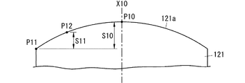
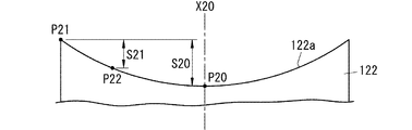
また、表示システム10は、次の第2条件を満たしている。第2条件では、虚像310の視点位置P200での虚像310の表示可能範囲300の長さ方向における画角をθ[deg]とする。また、第1光学部材121の最大サグ量をS10[mm](図2参照)、第2光学部材122の最大サグ量をS20[mm](図3参照)、S10とS20の二乗和平方根をSとする。このとき、Sは、4.0×θ−9.2以上、かつ、6.0×θ−13.8以下であり、θは8.0以上である。第2条件では、画角θを大きくする場合に、第1光学部材121及び第2光学部材122それぞれの最大サグ量を個別ではなく第1光学部材121及び第2光学部材122全体として設定する。したがって、第1光学部材121及び第2光学部材122全体の大型化を抑制できる。その結果、表示システム10全体としてはサイズを小さくできる。そのため、虚像のサイズを大きくしながらも表示システム10の小型化が図れる。
Further, the
1.2 構成
図4は、移動体としての自動車100を示す。自動車100は、移動体本体としての車体100aと、車体100aに搭載される表示システム10とを備えている。表示システム10は、自動車100において、ヘッドアップディスプレイ(HUD:Head-Up Display)として用いられる。
1.2 Configuration FIG. 4 shows a
表示システム10は、自動車100の車体(移動体本体)100aのウインドシールド101に下方から画像を投影するように、自動車100の車室内に設置されている。図4の例では、ウインドシールド101の下方のダッシュボード102内に、表示システム10が配置されている。表示システム10からウインドシールド101に画像が投影されると、反射部材としてのウインドシールド101で反射された画像がユーザ200(運転者)に視認される。
The
表示システム10によれば、ユーザ200は、自動車100の前方(車外)に設定された対象空間400に投影された虚像310を、ウインドシールド101越しに視認する。ここでいう「虚像」は、表示システム10から出射される光がウインドシールド101等の反射物にて発散するとき、その発散光線によって、実際に物体があるように結ばれる像を意味する。そのため、自動車100を運転しているユーザ200は、図5に示すように、自動車100の前方に広がる実空間に重ねて、表示システム10にて投影される虚像310を見ることができる。したがって、表示システム10によれば、例えば、車速情報、ナビゲーション情報、歩行者情報、前方車両情報、車線逸脱情報、及び車両コンディション情報等の、種々の運転支援情報を、虚像310として表示し、ユーザ200に視認させることができる。図5では、虚像310は、ナビゲーション情報であり、一例として、車線変更を示す矢印を表示している。これにより、ユーザ200は、ウインドシールド101の前方に視線を向けた状態から僅かな視線移動だけで、運転支援情報を視覚的に取得することができる。
According to the
表示システム10では、対象空間400に形成される虚像310は、表示システム10の光軸500に交差する仮想面501上に形成される。本実施形態では、光軸500は、自動車100の前方の対象空間400において、自動車100の前方の路面600に沿っている。そして、虚像310が形成される仮想面501は、路面600に対して略垂直である。例えば、路面600が水平面である場合には、虚像310は鉛直面に沿って表示されることになる。
In the
表示システム10は、図6に示すように、表示部110と、投影部120と、を備える。
The
表示部110は、対象空間400に虚像310として投影される画像を表示するために用いられる。表示部110は、図1に示すように、画像を表示する表示面110aを有する。本実施形態では、表示面110aは、表示部110の一面における長方形の領域である。表示システム10の小型化の観点からは、表示面110aは表示部110の一面のほぼ全体であることが好ましい。本実施形態では、表示部110は、液晶ディスプレイである。
The
投影部120は、対象空間400に画像(表示部110の表示面110aに表示される画像)に対応する虚像310を投影するために用いられる。投影部120は、図1に示すように、第1光学部材121と、第2光学部材122と、を備える。言い換えれば、投影部120は、第1光学部材121と第2光学部材122とからなる光学系である。
The
第1光学部材121は、表示部110からの光を第2光学部材122に向けて反射する。第1光学部材121は、図1に示すように、画像を構成する光線を反射する第1反射面121aを有する。第1反射面121aは、表示面110aよりもサイズが大きい。第1光学部材121は、表示部110に対して、第1反射面121aに表示部110の表示面110aの画像が欠けることなく写るように配置される。本実施形態において、第1反射面121aは凸面である。これにより、表示部110の表示面110aに表示された画像からの射出光は、発散角が拡大されて、第2光学部材122に入射する。つまり、画像を構成する光線は、第1反射面121aで発散されて、第2反射面122aに入射する。なお、第1反射面121aは、球面又は非球面(自由曲面)であってよい。特に、第1反射面121aは、画像の歪みを補正するように設計された非球面であってよい。また、本実施形態では、第1反射面121aは、第1光学部材121の一面の一部又は全部の領域である。つまり、第1反射面121aは、第1光学部材121の一面において実際に画像を構成する光線を反射している領域(有効領域)である。第1光学部材121の大きさは、ユーザ200の視点の位置が想定される範囲(例えばアイボックス)内で移動しても虚像310を欠けずに表示できるように設定されることが好ましい。
The first
第2光学部材122は、第1光学部材121からの光を、ウインドシールド101に向けて反射する。第2光学部材122は、表示部110の表示面110aに形成される(表示される)画像を、ウインドシールド101に投影することで、対象空間400に虚像310を投影する。第2光学部材122は、図1に示すように、第1反射面121aで反射された光線を反射して対象空間400に虚像310を投影する第2反射面122aを有する。第2反射面122aは、第1反射面121aよりもサイズが大きい。第2光学部材122は、第1光学部材121に対して、表示部110の表示面110aの画像が欠けることなく写るように配置される。本実施形態において、第2反射面122aは凹面である。なお、第2反射面122aは、球面又は非球面(自由曲面)であってよい。特に、第2反射面122aは、画像の歪みを補正するように設計された非球面であってよい。また、本実施形態では、第2反射面122aは、第2光学部材122の一面の一部又は全部の領域である。つまり、第2反射面122aは、第2光学部材122の一面において実際に画像を構成する光線を反射している領域(有効領域)である。第2光学部材122の大きさは、ユーザ200の視点の位置が想定される範囲(例えばアイボックス)内で移動しても虚像310を欠けずに表示できるように設定されることが好ましい。
The second
表示システム10は、上述したように、第1条件及び第2条件を満たしている。第1条件は、下記の関係式(1),(2)を満たすことであり、第2条件は、下記の関係式(1),(3)を満たすことである。つまり、関係式(1),(2),(3)を満たせば、第1条件及び第2条件の両方を満たしていることになる。
The

関係式(1)に関して、θは、虚像310の視点位置P200(図1参照)での虚像310の表示可能範囲300の長さ方向における画角(視野角)であり、単位は[deg]である。表示可能範囲300は、表示面110aの全体に画像を表示した場合の虚像310の大きさで定義される。本実施形態において、表示面110aと、第1反射面121a、及び第2反射面122aはそれぞれ長さ方向が一致しており、表示面110aに表示される画像の長さ方向は虚像310の表示可能範囲300の長さ方向と一致する。画角θは、虚像310の表示可能範囲300の長さL[m](図1参照)を決定するパラメータである。視点位置P200と表示可能範囲300との間の距離である表示距離をD[m]とすれば、表示可能範囲300の長さLは、2Dtanθで与えられる。よって、画角θが大きくなればなるほど、視点位置P200から見える虚像310が大きくなる。なお、視点位置P200は、虚像310が視認できる範囲(いわゆるアイボックス)の中心の位置である。また、表示システム10では、表示距離Dが7m以上、好ましくは10m以上となるようにしている。
In relation to the relational expression (1), θ is an angle of view (viewing angle) in the longitudinal direction of the
関係式(2)に関して、Wは、表示面110aの長さであり、単位は[mm]である。表示面110aの長さは、表示面110aそのものの長さというよりは、表示面110aの有効長さである。ここで、表示面110aの有効長さは、表示面110aにおいて画像の表示に利用されている領域の長さである。例えば、表示面110aの一部の領域にのみ画像を表示している場合、この一部の領域の長さが、表示面110aの有効長さとなる。
Regarding the relational expression (2), W is the length of the
関係式(2)は、画角θ毎の表示システム10のサイズの最小値Vminと表示面110aの長さWとの関係により求めている。ここで、表示システム10のサイズは、図7に示すように、表示面110aと第1反射面121aとの間の空間V10の体積と第1反射面121aと第2反射面122aとの間の空間V20の体積とを用いて評価した。より詳細には、表示システム10のサイズの評価値として、空間V10の体積と空間V20の体積の合計値から空間V10と空間V20との重複部分V30(図7参照)の体積を引いた値を用いた。表示システム10のサイズの最小値Vminは、画角θ及び表示面110aの長さに対して、表示システム10の各種パラメータを変化させて求めた評価値の最小値である。
The relational expression (2) is obtained from the relationship between the minimum value V min of the size of the
図8は、画角θ毎に、表示面110aの長さWに対して、表示システム10のサイズの最小値Vminを求めた結果を示す。つまり、図8は、表示システム10のサイズの最小値Vminと表示面110aの長さWとの関係を示すグラフである。図8において、曲線G11は、画角θが8.0[deg]、表示距離Dが20[m]である場合を示す。曲線G12は、画角θが8.0[deg]、表示距離Dが40[m]である場合を示す。曲線G21は、画角θが10.0[deg]、表示距離Dが10[m]である場合を示す。曲線G22は、画角θが10.0[deg]、表示距離Dが20[m]である場合を示す。曲線G23は、画角θが10.0[deg]、表示距離Dが40[m]である場合を示す。
FIG. 8 shows the result of finding the minimum value V min of the size of the
関係式(2)によれば、Wの下限値は、12.0×θ−26.6で与えられる。これは、図8に示すような、画角θ毎の表示システム10のサイズの最小値Vminと表示面110aの長さWとの関係に加えて、電子補正処理により歪曲収差を解消できる範囲で決定されている。補正後の残存歪曲収差はアイポイント毎に異なるが、両眼のアイポイント間で残存歪曲収差の違いが大きくなる場合には、視点位置P200から虚像310を見た際に左右それぞれの眼で見る像の傾き差が大きすぎることにより、二重に見えてしまう可能性がある。また、虚像310を見るユーザ200の疲労が蓄積され易くなる。電子補正処理は、例えば、歪曲収差がなくなるように表示面110aに表示される画像を予め変更する処理である。したがって、Wが関係式(2)を満たさない場合、つまり、12.0×θ−26.6で与えられる規定値を下回る場合、歪曲収差を良好に解消することができなくなり、虚像310を見やすく表示できなくなる可能性がある。
According to the relational expression (2), the lower limit value of W is given by 12.0 × θ-26.6. This is a range in which distortion can be eliminated by electronic correction processing in addition to the relationship between the minimum value V min of the size of the
一方で、Wが大きくなればなるほど、歪曲収差の低減効果が大きくなることが期待できる。しかしながら、Wが大きくなればなるほど、表示システム10のサイズも大きくなり得る。そこで、図8に示すような、画角θ毎の表示システム10のサイズの最小値Vminと表示面110aの長さWとの関係を考慮し、表示システム10は、更に、下記の関係式(4)を満たしている。
On the other hand, it can be expected that the larger the W, the larger the distortion reduction effect. However, the larger W can be, the larger the size of the
![]()
![]()
つまり、Wは、12.0×θ−26.6で与えられる規定値(下限値)の1.1倍以下である。言い換えれば、Wの上限値は、下限値の1.1倍である。Wが関係式(2),(4)を満たしていれば、歪曲収差の低減効果を得ながらも、表示システム10のサイズを小さくでき得る。
That is, W is equal to or less than 1.1 times the specified value (lower limit value) given by 12.0 × θ−26.6. In other words, the upper limit value of W is 1.1 times the lower limit value. If W satisfies the relational expressions (2) and (4), the size of the
上述したように、表示システム10のサイズの最小値Vminを求めるために、表示システム10の各種パラメータを利用している。表示システム10の各種パラメータは、第1反射面121aの最大サグ量と第2反射面122aの最大サグ量とを含んでいる。
As described above, in order to obtain the minimum value V min of the size of the
第1反射面121aの最大サグ量としては、第1反射面121aの長さ方向における最大サグ量を用いている。第1反射面121aの長さ方向における最大サグ量は、図2において、S10で示されている。まず、第1反射面121aの長さ方向におけるサグ量S11は、第1反射面121aの光軸X10方向における基準位置P11と任意の位置P12との距離で与えられる。基準位置P11は、第1反射面121aの光軸X10から最も離れた位置である。そして、サグ量S11は、任意の位置P12が第1反射面121aの光軸X10上の位置P10である場合に最大となる。なお、図2では、サグ量の説明のために第1光学部材121を概略的に示している。
As the maximum sag amount of the
第2反射面122aの最大サグ量としては、第2反射面122aの長さ方向における最大サグ量を用いている。第2反射面122aの長さ方向における最大サグ量は、図3において、S20で示されている。まず、第2反射面122aの長さ方向におけるサグ量S21は、第2反射面122aの光軸X20方向における基準位置P21と任意の位置P22との距離で与えられる。基準位置P21は、第2反射面122aの光軸X20から最も離れた位置である。そして、サグ量S21は、任意の位置P22が第2反射面122aの光軸X20上の位置P20である場合に最大となる。なお、図3では、サグ量の説明のために第2光学部材122を概略的に示している。
As the maximum sag amount of the second reflecting
そして、表示システム10のサイズが最小値Vminをとる場合の第1反射面121aの最大サグ量S10と第2反射面122aの最大サグ量S20と、画角θとの関係から、関係式(3)が求まる。この関係式(3)において、Sは、第1反射面121aの最大サグ量S10と第2反射面122aの最大サグ量S20との二乗和平方根である。つまり、S=(S102+S202)1/2である。換言すれば、関係式(3)は、画角θ毎の表示システム10のサイズの最小値VminとSとの関係により求めている。
Then, based on the relationship between the maximum sag amount S10 of the first
関係式(3)によれば、Sの上限値は、6.0×θ−13.8で与えられる。Sが上限値を超える場合、虚像310の歪曲が大きくなり、虚像310が見にくくなり得る。関係式(3)によれば、Sの下限値は、4.0×θ−9.2で与えられる。Sが下限値未満である場合、Sの変化に対して表示システム10のサイズが増加する傾向がある。
According to the relational expression (3), the upper limit value of S is given by 6.0 × θ−13.8. If S exceeds the upper limit value, distortion of the
このように表示システム10は第1条件(関係式(1),(2))を満たしている。これによって、第1光学部材121及び第2光学部材122の大型化を抑制できる。また、表示システム10は第2条件(関係式(1),(3))を満たしている。これによって、第1光学部材121及び第2光学部材122全体の大型化を抑制できる。そのため、虚像のサイズを大きくしながらも表示システム10の小型化が図れる。
Thus, the
本実施形態において、表示システム10は、拡張現実(Augmented Reality:AR)技術を利用して、ユーザ200の視界の前方の風景に虚像310を重ねて表示する。このような場合において、視点位置P200での虚像310の水平方向の画角(虚像310の表示可能範囲300の長さ方向における画角θに相当)は大きい方が好ましい。特に、表示システム10をヘッドアップディスプレイとして利用する場合には、虚像310により、ユーザ200に右左折や車線変更の案内を行うことが想定されている。例えば、あたかも路面上に進行方向を示す矢印が描かれているような表示を虚像310により行う。このような矢印は、図5に示すように、進行中の車線610と変更先の車線620とに跨って表示される。そのため、車線変更の目標地点がまだ遠い場合に問題なく表示できるが、水平方向の画角が小さければ、目標地点にある程度近付いた時点で、車線610,620を跨ぐ矢印が表示できなくなってしまう。したがって、目標地点の近くでも車線610,620を跨ぐ矢印を表示できるようにするためには、画角θはある程度大きいほうがよく、8度以上であることが好ましく、より好ましくは9度以上である。一方、画角θを大きくすると第1光学部材121のサグ量S11(最大サグ量S10)及び第2光学部材122のサグ量S21(最大サグ量S20)を大きくする必要が生じてくる。画角θが13度までは問題ないが、画角θが14度を超えると、第1光学部材121及び第2光学部材122の設計が難しくなる。そのため、画角θは14度以下であることが望ましい。
In the present embodiment, the
2.変形例
本開示の実施形態は、上記実施形態に限定されない。上記実施形態は、本開示の目的を達成できれば、設計等に応じて種々の変更が可能である。以下に、上記実施形態の変形例を列挙する。
2. Modifications Embodiments of the present disclosure are not limited to the above embodiments. The above embodiment can be variously modified according to the design and the like as long as the object of the present disclosure can be achieved. Below, the modification of the said embodiment is enumerated.
例えば、表示システム10は、関係式(1)〜(4)の全てを満たさなくてもよい。表示システム10は、関係式(1),(2)の組み合わせ(第1条件)と、関係式(1),(3)の組み合わせ(第2条件)とのいずれか一方を満たしていればよい。
For example, the
例えば、表示部110は、液晶ディスプレイに限定されない。例えば、表示部110は、液晶ディスプレイ以外の画像表示装置、例えば、有機ELディスプレイであってもよい。また、表示部110は、画像表示装置そのものでなくてもよい。例えば、表示部110は、プロジェクタと、プロジェクタの画像を写すスクリーンとを備えるシステムであってもよいし、レーザ走査装置と、レーザ走査装置のレーザの走査による画像を写すためのスクリーンとを備えるシステムであってもよい。また、表示部110は、スクリーンそのものであってもよいし、画像表示装置からの画像を写す平面鏡であってもよい。つまり、表示部110は、中間画像を表示してもよい。表示部110において、表示面110aは必ずしも長方形でなくても良く、互いに直交する2方向のうちの一方の寸法が他方より長くなっていればよい。
For example, the
例えば、投影部120に関し、第1光学部材121及び第2光学部材122の形状は、変更可能である。例えば、第1光学部材121において重要なのは、第1反射面121aの形状であり、その他の部位の形状は比較的自由に設定してよい。同様に、第2光学部材122において重要なのは、第2反射面122aの形状であり、その他の部位の形状は比較的自由に設定してよい。また、第1反射面121a及び第2反射面122aの形状は、表示面110aに応じて適宜設定され得る。
For example, regarding the
例えば、表示システム10は、自動車100の進行方向の前方に設定された対象空間400に虚像310を投影する構成に限らず、例えば、自動車100の進行方向の側方、後方、又は上方等に虚像310を投影してもよい。また、投影部120は、中間像を形成するためのリレー光学系を含んでいてもよいし、リレー光学系を含んでいなくてもよい。
For example, the
例えば、表示システム10は、自動車100に用いられるヘッドアップディスプレイに限らず、例えば、二輪車、電車、航空機、建設機械、及び船舶等、自動車100以外の移動体にも適用可能である。さらに、表示システム10は、移動体に限らず、例えば、アミューズメント施設で用いられてもよい。
For example, the
3.態様
上記実施形態及び変形例から明らかなように、第1の態様の表示システム(10)は、表示部(110)と、第1光学部材(121)と、第2光学部材(122)と、を備える。前記表示部(110)は、画像を表示する表示面(110a)を有する。前記第1光学部材(121)は、前記画像を構成する光線を反射する第1反射面(121a)を有する。前記第2光学部材(122)は、前記第1反射面(121a)で反射された光線を反射して対象空間(400)に虚像(310)を投影する第2反射面(122a)を有する。前記虚像(310)の視点位置(P200)での前記虚像(310)の表示可能範囲(300)の長さ方向における画角をθ[deg]とする。前記表示面(110a)の長さをW[mm]とする。Wは、12.0×θ−26.6で与えられる規定値以上であり、θは8.0以上である。第1の態様によれば、虚像(310)のサイズを大きくしながらも小型化が図れる。
3. Aspect As apparent from the above embodiment and the modification, the display system (10) of the first aspect includes the display unit (110), the first optical member (121), and the second optical member (122). Equipped with The display unit (110) has a display surface (110a) for displaying an image. The first optical member (121) has a first reflection surface (121a) that reflects the light beam that constitutes the image. The second optical member (122) has a second reflection surface (122a) for reflecting the light beam reflected by the first reflection surface (121a) and projecting a virtual image (310) onto the target space (400). An angle of view in the longitudinal direction of the displayable range (300) of the virtual image (310) at the viewpoint position (P200) of the virtual image (310) is taken as θ [deg]. The length of the display surface (110a) is W [mm]. W is not less than the specified value given by 12.0 × θ-26.6, and θ is not less than 8.0. According to the first aspect, downsizing can be achieved while increasing the size of the virtual image (310).
第2の態様の表示システム(10)は、第1の態様との組み合わせにより実現され得る。第2の態様では、Wは、前記規定値の1.1倍以下である。第2の態様によれば、虚像(310)のサイズを大きくしながらも小型化が図れる。 The display system (10) of the second aspect can be realized in combination with the first aspect. In the second aspect, W is equal to or less than 1.1 times the specified value. According to the second aspect, downsizing can be achieved while increasing the size of the virtual image (310).
第3の態様の表示システム(10)は、表示部(110)と、第1光学部材(121)と、第2光学部材(122)と、を備える。前記表示部(110)は、画像を表示する表示面(110a)を有する。前記第1光学部材(121)は、前記画像を構成する光線を反射する第1反射面(121a)を有する。前記第2光学部材(122)は、前記第1反射面(121a)で反射された光線を反射して対象空間(400)に虚像(310)を投影する第2反射面(122a)を有する。前記虚像(310)の視点位置(P200)での前記虚像(310)の表示可能範囲(300)の長さ方向における画角をθ[deg]とする。また、前記第1光学部材(121)の最大サグ量をS10[mm]、前記第2光学部材(122)の最大サグ量をS20[mm]、S10とS20の二乗和平方根をSとする。Sは、4.0×θ−9.2以上、かつ、6.0×θ−13.8以下であり、θは8.0以上である。第3の態様によれば、虚像(310)のサイズを大きくしながらも小型化が図れる。 The display system (10) of the third aspect includes a display unit (110), a first optical member (121), and a second optical member (122). The display unit (110) has a display surface (110a) for displaying an image. The first optical member (121) has a first reflection surface (121a) that reflects the light beam that constitutes the image. The second optical member (122) has a second reflection surface (122a) for reflecting the light beam reflected by the first reflection surface (121a) and projecting a virtual image (310) onto the target space (400). An angle of view in the longitudinal direction of the displayable range (300) of the virtual image (310) at the viewpoint position (P200) of the virtual image (310) is taken as θ [deg]. Further, the maximum sag amount of the first optical member (121) is S10 [mm], the maximum sag amount of the second optical member (122) is S20 [mm], and the root sum square of S10 and S20 is S. S is 4.0 × θ−9.2 or more and 6.0 × θ−13.8 or less, and θ is 8.0 or more. According to the third aspect, downsizing can be achieved while increasing the size of the virtual image (310).
第4の態様の表示システム(10)は、第1〜第3の態様のいずれか一つとの組み合わせにより実現され得る。第4の態様では、前記視点位置(P200)と前記虚像(310)の表示可能範囲(300)との間の距離である表示距離(D)は、7[m]以上である。第4の態様によれば、虚像(310)のサイズを大きくしながらも小型化が図れる。 The display system (10) of the fourth aspect can be realized by combination with any one of the first to third aspects. In the fourth aspect, a display distance (D) which is a distance between the viewpoint position (P200) and the displayable range (300) of the virtual image (310) is 7 [m] or more. According to the fourth aspect, downsizing can be achieved while increasing the size of the virtual image (310).
第5の態様の表示システム(10)は、第1〜第4の態様のいずれか一つとの組み合わせにより実現され得る。第5の態様では、前記第1反射面(121a)は、凸面である。第5の態様によれば、虚像(310)のサイズを大きくしながらも小型化が図れる。 The display system (10) of the fifth aspect can be realized by combination with any one of the first to fourth aspects. In the fifth aspect, the first reflection surface (121a) is a convex surface. According to the fifth aspect, downsizing can be achieved while increasing the size of the virtual image (310).
第6の態様の表示システム(10)は、第1〜第5の態様のいずれか一つとの組み合わせにより実現され得る。第6の態様では、前記第2反射面(122a)は、凹面である。第6の態様によれば、虚像(310)のサイズを大きくしながらも小型化が図れる。 The display system (10) of the sixth aspect can be realized by combination with any one of the first to fifth aspects. In the sixth aspect, the second reflective surface (122a) is a concave surface. According to the sixth aspect, downsizing can be achieved while increasing the size of the virtual image (310).
第7の態様の移動体(100)は、移動体本体(100a)と、前記移動体本体(100a)に搭載される第1〜第6の態様のいずれか一つの表示システム(10)と、を備える。第7の態様によれば、虚像(310)のサイズを大きくしながらも小型化が図れる。 The mobile unit (100) of the seventh aspect includes a mobile main body (100a) and the display system (10) according to any one of the first to sixth aspects mounted on the mobile main body (100a); Equipped with According to the seventh aspect, downsizing can be achieved while increasing the size of the virtual image (310).
10 表示システム
110 表示部
110a 表示面
121 第1光学部材
121a 第1反射面
122 第2光学部材
122a 第2反射面
300 表示可能範囲
310 虚像
400 対象空間
P200 視点位置
D 表示距離
100 自動車(移動体)
100a 車体(移動体本体)
DESCRIPTION OF
100a Car body (mobile body)
Claims (7)
前記画像を構成する光線を反射する第1反射面を有する第1光学部材と、
前記第1反射面で反射された光線を反射して対象空間に虚像を投影する第2反射面を有する第2光学部材と、
を備え、
前記虚像の視点位置での前記虚像の表示可能範囲の長さ方向における画角をθ[deg]、前記表示面の長さをW[mm]とすると、
Wは、12.0×θ−26.6で与えられる規定値以上であり、θは8.0以上である、
表示システム。 A display unit having a display surface for displaying an image;
A first optical member having a first reflection surface that reflects light rays that constitute the image;
A second optical member having a second reflection surface for reflecting a light beam reflected by the first reflection surface and projecting a virtual image on a target space;
Equipped with
Assuming that the angle of view in the length direction of the displayable range of the virtual image at the viewpoint position of the virtual image is θ [deg] and the length of the display surface is W [mm],
W is a specified value or more given by 12.0 × θ-26.6, θ is 8.0 or more,
Display system.
請求項1の表示システム。 W is 1.1 times or less of the specified value,
The display system of claim 1.
前記画像を構成する光線を反射する第1反射面を有する第1光学部材と、
前記第1反射面で反射された光線を反射して対象空間に虚像を投影する第2反射面を有する第2光学部材と、
を備え、
前記虚像の視点位置での前記虚像の表示可能範囲の長さ方向における画角をθ[deg]、前記第1反射面の最大サグ量をS10[mm]、前記第2反射面の最大サグ量をS20[mm]、S10とS20の二乗和平方根をSとすると、
Sは、4.0×θ−9.2以上、かつ、6.0×X−13.8以下であり、
θは8.0以上である、
表示システム。 A display unit for displaying an image;
A first optical member having a first reflection surface that reflects light rays that constitute the image;
A second optical member having a second reflection surface for reflecting a light beam reflected by the first reflection surface and projecting a virtual image on a target space;
Equipped with
The field angle in the length direction of the displayable range of the virtual image at the viewpoint position of the virtual image is θ [deg], the maximum sag amount of the first reflecting surface is S10 [mm], and the maximum sag amount of the second reflecting surface Let S 20 [mm], S 10 be the sum of square roots of S 20 and S 20,
S is 4.0 × θ−9.2 or more and 6.0 × X−13.8 or less,
θ is 8.0 or more,
Display system.
請求項1〜3のいずれか一つの表示システム。 A display distance which is a distance between the viewpoint position and the displayable range of the virtual image is 7 [m] or more.
A display system according to any one of claims 1 to 3.
請求項1〜4のいずれか一つの表示システム。 The first reflective surface is a convex surface,
The display system in any one of Claims 1-4.
請求項1〜5のいずれか一つの表示システム。 The second reflective surface is concave,
The display system in any one of Claims 1-5.
前記移動体本体に搭載される請求項1〜4のいずれか一つの表示システムと、
を備える、
移動体。 Mobile body and
The display system according to any one of claims 1 to 4 mounted on the movable body.
Equipped with
Moving body.
Priority Applications (2)
| Application Number | Priority Date | Filing Date | Title |
|---|---|---|---|
| JP2017210562A JP2019082601A (en) | 2017-10-31 | 2017-10-31 | Display system and mobile object |
| US16/174,681 US10809526B2 (en) | 2017-10-31 | 2018-10-30 | Display system and movable object |
Applications Claiming Priority (1)
| Application Number | Priority Date | Filing Date | Title |
|---|---|---|---|
| JP2017210562A JP2019082601A (en) | 2017-10-31 | 2017-10-31 | Display system and mobile object |
Related Child Applications (1)
| Application Number | Title | Priority Date | Filing Date |
|---|---|---|---|
| JP2021002257A Division JP2021073502A (en) | 2021-01-08 | 2021-01-08 | Display system and movable body |
Publications (1)
| Publication Number | Publication Date |
|---|---|
| JP2019082601A true JP2019082601A (en) | 2019-05-30 |
Family
ID=66243742
Family Applications (1)
| Application Number | Title | Priority Date | Filing Date |
|---|---|---|---|
| JP2017210562A Pending JP2019082601A (en) | 2017-10-31 | 2017-10-31 | Display system and mobile object |
Country Status (2)
| Country | Link |
|---|---|
| US (1) | US10809526B2 (en) |
| JP (1) | JP2019082601A (en) |
Families Citing this family (5)
| Publication number | Priority date | Publication date | Assignee | Title |
|---|---|---|---|---|
| CN111752046B (en) * | 2015-10-15 | 2023-06-02 | 麦克赛尔株式会社 | Head-up display device |
| CN112622767A (en) | 2019-10-08 | 2021-04-09 | 松下知识产权经营株式会社 | Display system and electronic rearview mirror system provided with same |
| US11366311B2 (en) | 2020-04-01 | 2022-06-21 | Panasonic Intellectual Property Management Co., Ltd. | Display device |
| KR20210131129A (en) * | 2020-04-23 | 2021-11-02 | 현대자동차주식회사 | User interface generating apparatus for vehicle guide and ui generating method using the same |
| CN113095184B (en) * | 2021-03-31 | 2023-01-31 | 上海商汤临港智能科技有限公司 | Positioning method, driving control method, device, computer equipment and storage medium |
Citations (6)
| Publication number | Priority date | Publication date | Assignee | Title |
|---|---|---|---|---|
| US20160048020A1 (en) * | 2014-08-12 | 2016-02-18 | Automotive Research & Test Center | Head-up display device |
| WO2016162928A1 (en) * | 2015-04-06 | 2016-10-13 | 日立マクセル株式会社 | Projection optical system and headup display device using same |
| JP2016206583A (en) * | 2015-04-28 | 2016-12-08 | 日本精機株式会社 | Head-up display device |
| JP2016212338A (en) * | 2015-05-13 | 2016-12-15 | 日本精機株式会社 | Head-up display |
| JP2017081428A (en) * | 2015-10-28 | 2017-05-18 | 日本精機株式会社 | Vehicle display device |
| JP2017134141A (en) * | 2016-01-26 | 2017-08-03 | 富士フイルム株式会社 | Head-up display device |
Family Cites Families (11)
| Publication number | Priority date | Publication date | Assignee | Title |
|---|---|---|---|---|
| US9170411B2 (en) | 2013-10-11 | 2015-10-27 | Panasonic Intellectual Property Management Co., Ltd. | Scanning optical microscope |
| JP2015194707A (en) * | 2014-03-27 | 2015-11-05 | パナソニックIpマネジメント株式会社 | display device |
| CN107003525B (en) * | 2014-12-16 | 2021-11-16 | 株式会社电装 | Head-up display cover member and display device |
| EP3264173A4 (en) * | 2015-02-26 | 2018-10-31 | Dai Nippon Printing Co., Ltd. | Transmissive screen and head-up display device using same |
| US10732409B2 (en) * | 2016-02-25 | 2020-08-04 | Konica Minolta, Inc. | Screen and head-up display device |
| WO2017163288A1 (en) | 2016-03-24 | 2017-09-28 | パナソニックIpマネジメント株式会社 | Headup display device and vehicle |
| WO2017163292A1 (en) | 2016-03-24 | 2017-09-28 | パナソニックIpマネジメント株式会社 | Headup display device and vehicle |
| JP6848219B2 (en) * | 2016-06-10 | 2021-03-24 | 株式会社リコー | Image display device |
| JP6762807B2 (en) * | 2016-08-30 | 2020-09-30 | マクセル株式会社 | Information display device |
| CN114690431B (en) * | 2016-10-04 | 2024-06-14 | 麦克赛尔株式会社 | Head-up display device |
| US20190116344A1 (en) * | 2017-10-17 | 2019-04-18 | Visteon Global Technologies, Inc. | Multiple image plane head-up display |
-
2017
- 2017-10-31 JP JP2017210562A patent/JP2019082601A/en active Pending
-
2018
- 2018-10-30 US US16/174,681 patent/US10809526B2/en active Active
Patent Citations (6)
| Publication number | Priority date | Publication date | Assignee | Title |
|---|---|---|---|---|
| US20160048020A1 (en) * | 2014-08-12 | 2016-02-18 | Automotive Research & Test Center | Head-up display device |
| WO2016162928A1 (en) * | 2015-04-06 | 2016-10-13 | 日立マクセル株式会社 | Projection optical system and headup display device using same |
| JP2016206583A (en) * | 2015-04-28 | 2016-12-08 | 日本精機株式会社 | Head-up display device |
| JP2016212338A (en) * | 2015-05-13 | 2016-12-15 | 日本精機株式会社 | Head-up display |
| JP2017081428A (en) * | 2015-10-28 | 2017-05-18 | 日本精機株式会社 | Vehicle display device |
| JP2017134141A (en) * | 2016-01-26 | 2017-08-03 | 富士フイルム株式会社 | Head-up display device |
Also Published As
| Publication number | Publication date |
|---|---|
| US10809526B2 (en) | 2020-10-20 |
| US20190129170A1 (en) | 2019-05-02 |
Similar Documents
| Publication | Publication Date | Title |
|---|---|---|
| JP2019082601A (en) | Display system and mobile object | |
| US8792177B2 (en) | Head-up display | |
| JP6201690B2 (en) | Vehicle information projection system | |
| JP6650584B2 (en) | Head-up display and moving object equipped with head-up display | |
| WO2019189308A1 (en) | Image display system, image display method, program, and moving body provided with image display system | |
| WO2018066695A1 (en) | In-vehicle display control device | |
| WO2014174575A1 (en) | Vehicular head-up display device | |
| JP2019166891A (en) | Information display device | |
| WO2017141829A1 (en) | Information presentation device | |
| JP6963732B2 (en) | Head-up display device | |
| CN111727399B (en) | Display system, mobile object, and design method | |
| JP2016101805A (en) | Display device, control method, program and storage medium | |
| JP7162273B2 (en) | Head-up displays and moving objects with head-up displays | |
| CN104685405A (en) | Head-up display for a vehicle | |
| JP6283826B2 (en) | Head-up display and mobile body equipped with head-up display | |
| US10345585B2 (en) | Head-up display device | |
| JP6864580B2 (en) | Head-up display device, navigation device | |
| JP2021073502A (en) | Display system and movable body | |
| JP6664555B2 (en) | Head-up display device | |
| JPWO2018186149A1 (en) | HEAD-UP DISPLAY SYSTEM AND MOVING BODY HAVING HEAD-UP DISPLAY SYSTEM | |
| WO2021039579A1 (en) | Head-up display device | |
| JP7375753B2 (en) | heads up display device | |
| JPWO2018110336A1 (en) | Head-up display device | |
| JP6628873B2 (en) | Projection optical system, head-up display device, and automobile | |
| WO2019176448A1 (en) | Information display device |
Legal Events
| Date | Code | Title | Description |
|---|---|---|---|
| A621 | Written request for application examination |
Free format text: JAPANESE INTERMEDIATE CODE: A621 Effective date: 20191118 |
|
| A977 | Report on retrieval |
Free format text: JAPANESE INTERMEDIATE CODE: A971007 Effective date: 20201030 |
|
| A131 | Notification of reasons for refusal |
Free format text: JAPANESE INTERMEDIATE CODE: A131 Effective date: 20201110 |
|
| A02 | Decision of refusal |
Free format text: JAPANESE INTERMEDIATE CODE: A02 Effective date: 20210511 |