JP2019082197A - Fluid sealed type cylindrical vibration isolator - Google Patents
Fluid sealed type cylindrical vibration isolator Download PDFInfo
- Publication number
- JP2019082197A JP2019082197A JP2017209149A JP2017209149A JP2019082197A JP 2019082197 A JP2019082197 A JP 2019082197A JP 2017209149 A JP2017209149 A JP 2017209149A JP 2017209149 A JP2017209149 A JP 2017209149A JP 2019082197 A JP2019082197 A JP 2019082197A
- Authority
- JP
- Japan
- Prior art keywords
- fluid
- rubber
- axial direction
- recessed groove
- partition
- Prior art date
- Legal status (The legal status is an assumption and is not a legal conclusion. Google has not performed a legal analysis and makes no representation as to the accuracy of the status listed.)
- Pending
Links
Images


Classifications
-
- F—MECHANICAL ENGINEERING; LIGHTING; HEATING; WEAPONS; BLASTING
- F16—ENGINEERING ELEMENTS AND UNITS; GENERAL MEASURES FOR PRODUCING AND MAINTAINING EFFECTIVE FUNCTIONING OF MACHINES OR INSTALLATIONS; THERMAL INSULATION IN GENERAL
- F16F—SPRINGS; SHOCK-ABSORBERS; MEANS FOR DAMPING VIBRATION
- F16F13/00—Units comprising springs of the non-fluid type as well as vibration-dampers, shock-absorbers, or fluid springs
- F16F13/04—Units comprising springs of the non-fluid type as well as vibration-dampers, shock-absorbers, or fluid springs comprising both a plastics spring and a damper, e.g. a friction damper
- F16F13/06—Units comprising springs of the non-fluid type as well as vibration-dampers, shock-absorbers, or fluid springs comprising both a plastics spring and a damper, e.g. a friction damper the damper being a fluid damper, e.g. the plastics spring not forming a part of the wall of the fluid chamber of the damper
- F16F13/08—Units comprising springs of the non-fluid type as well as vibration-dampers, shock-absorbers, or fluid springs comprising both a plastics spring and a damper, e.g. a friction damper the damper being a fluid damper, e.g. the plastics spring not forming a part of the wall of the fluid chamber of the damper the plastics spring forming at least a part of the wall of the fluid chamber of the damper
- F16F13/10—Units comprising springs of the non-fluid type as well as vibration-dampers, shock-absorbers, or fluid springs comprising both a plastics spring and a damper, e.g. a friction damper the damper being a fluid damper, e.g. the plastics spring not forming a part of the wall of the fluid chamber of the damper the plastics spring forming at least a part of the wall of the fluid chamber of the damper the wall being at least in part formed by a flexible membrane or the like
- F16F13/105—Units comprising springs of the non-fluid type as well as vibration-dampers, shock-absorbers, or fluid springs comprising both a plastics spring and a damper, e.g. a friction damper the damper being a fluid damper, e.g. the plastics spring not forming a part of the wall of the fluid chamber of the damper the plastics spring forming at least a part of the wall of the fluid chamber of the damper the wall being at least in part formed by a flexible membrane or the like characterised by features of partitions between two working chambers
-
- F—MECHANICAL ENGINEERING; LIGHTING; HEATING; WEAPONS; BLASTING
- F16—ENGINEERING ELEMENTS AND UNITS; GENERAL MEASURES FOR PRODUCING AND MAINTAINING EFFECTIVE FUNCTIONING OF MACHINES OR INSTALLATIONS; THERMAL INSULATION IN GENERAL
- F16F—SPRINGS; SHOCK-ABSORBERS; MEANS FOR DAMPING VIBRATION
- F16F15/00—Suppression of vibrations in systems; Means or arrangements for avoiding or reducing out-of-balance forces, e.g. due to motion
- F16F15/02—Suppression of vibrations of non-rotating, e.g. reciprocating systems; Suppression of vibrations of rotating systems by use of members not moving with the rotating systems
- F16F15/022—Suppression of vibrations of non-rotating, e.g. reciprocating systems; Suppression of vibrations of rotating systems by use of members not moving with the rotating systems using dampers and springs in combination
-
- F—MECHANICAL ENGINEERING; LIGHTING; HEATING; WEAPONS; BLASTING
- F16—ENGINEERING ELEMENTS AND UNITS; GENERAL MEASURES FOR PRODUCING AND MAINTAINING EFFECTIVE FUNCTIONING OF MACHINES OR INSTALLATIONS; THERMAL INSULATION IN GENERAL
- F16F—SPRINGS; SHOCK-ABSORBERS; MEANS FOR DAMPING VIBRATION
- F16F13/00—Units comprising springs of the non-fluid type as well as vibration-dampers, shock-absorbers, or fluid springs
- F16F13/04—Units comprising springs of the non-fluid type as well as vibration-dampers, shock-absorbers, or fluid springs comprising both a plastics spring and a damper, e.g. a friction damper
- F16F13/06—Units comprising springs of the non-fluid type as well as vibration-dampers, shock-absorbers, or fluid springs comprising both a plastics spring and a damper, e.g. a friction damper the damper being a fluid damper, e.g. the plastics spring not forming a part of the wall of the fluid chamber of the damper
-
- F—MECHANICAL ENGINEERING; LIGHTING; HEATING; WEAPONS; BLASTING
- F16—ENGINEERING ELEMENTS AND UNITS; GENERAL MEASURES FOR PRODUCING AND MAINTAINING EFFECTIVE FUNCTIONING OF MACHINES OR INSTALLATIONS; THERMAL INSULATION IN GENERAL
- F16F—SPRINGS; SHOCK-ABSORBERS; MEANS FOR DAMPING VIBRATION
- F16F15/00—Suppression of vibrations in systems; Means or arrangements for avoiding or reducing out-of-balance forces, e.g. due to motion
- F16F15/02—Suppression of vibrations of non-rotating, e.g. reciprocating systems; Suppression of vibrations of rotating systems by use of members not moving with the rotating systems
- F16F15/023—Suppression of vibrations of non-rotating, e.g. reciprocating systems; Suppression of vibrations of rotating systems by use of members not moving with the rotating systems using fluid means
- F16F15/027—Suppression of vibrations of non-rotating, e.g. reciprocating systems; Suppression of vibrations of rotating systems by use of members not moving with the rotating systems using fluid means comprising control arrangements
-
- B—PERFORMING OPERATIONS; TRANSPORTING
- B62—LAND VEHICLES FOR TRAVELLING OTHERWISE THAN ON RAILS
- B62D—MOTOR VEHICLES; TRAILERS
- B62D33/00—Superstructures for load-carrying vehicles
- B62D33/06—Drivers' cabs
- B62D33/0604—Cabs insulated against vibrations or noise, e.g. with elastic suspension
Abstract
Description
本発明は、内部に封入された流体の流動作用に基づく防振効果を得ることができる流体封入式筒形防振装置に係り、特に軸方向の入力振動に対する防振効果を得ることができる流体封入式筒形防振装置に関するものである。 The present invention relates to a fluid-sealed cylindrical vibration damping device capable of obtaining vibration damping effects based on the flow action of fluid enclosed in the fluid, and in particular, a fluid capable of obtaining vibration damping effects against input vibration in the axial direction. The present invention relates to a sealed cylindrical vibration damping device.
従来から、振動伝達系を構成する部材間に装着されて振動を低減する防振連結装置や防振支持装置などとして、例えば特公平2−29899号公報(特許文献1)等に示されている流体封入式の筒形防振装置が用いられている。流体封入式筒形防振装置は、一般に、本体ゴム弾性体で連結されたインナ軸部材とアウタ筒部材との間に、オリフィス通路を通じて連通された二つの流体室を備えており、振動入力時にオリフィス通路を通じて二つの流体室間を流動せしめられる流体の流動作用に基づいた防振効果が発揮されるようになっている。 Conventionally, as an anti-vibration connecting device or an anti-vibration supporting device which is mounted between members constituting a vibration transmission system to reduce vibration, it is shown, for example, in Japanese Patent Publication No. 2-29899 (Patent Document 1). A fluid-filled cylindrical anti-vibration device is used. A fluid-filled cylindrical vibration damping device generally comprises two fluid chambers communicated through an orifice passage between an inner shaft member and an outer cylinder member connected by a main rubber elastic body, and at the time of vibration input A vibration damping effect is exhibited based on the flow action of the fluid that is caused to flow between the two fluid chambers through the orifice passage.
ところで、流体封入式筒形防振装置では、軸方向の入力振動に対して効果的な防振効果を得るために、特許文献1にも示されているように、二つの流体室を仕切る隔壁ゴムをインナ軸部材に対して軸方向で移動可能とした構造が提案されている。 By the way, in the fluid-sealed cylindrical vibration isolation device, in order to obtain an effective vibration isolation effect with respect to input vibration in the axial direction, as also disclosed in Patent Document 1, a partition that partitions two fluid chambers A structure has been proposed in which the rubber can be moved in the axial direction with respect to the inner shaft member.
ところが、特許文献1に記載のように、隔壁ゴムの内周面に固着した樹脂スリーブを、インナ軸部材に対して摺動可能に外挿せしめた構造では、樹脂スリーブを準備して隔壁ゴムの内周面に固着する必要があるために構造が複雑で製造も難しかった。しかも、樹脂スリーブとインナ軸部材との間の隙間を通じて両側の流体室間で流体圧の漏れや流体の短絡が発生しやすく、目的とする防振性能を安定して得ることが難しいという問題もあった。 However, as described in Patent Document 1, in the structure in which the resin sleeve fixed to the inner peripheral surface of the partition rubber is slidably inserted onto the inner shaft member, the resin sleeve is prepared to be used as the partition rubber. The structure is complicated and it is difficult to manufacture because it needs to be fixed to the inner circumferential surface. In addition, fluid pressure leaks and fluid shorts easily occur between the fluid chambers on both sides through the gap between the resin sleeve and the inner shaft member, and it is also difficult to stably obtain the desired anti-vibration performance. there were.
なお、国際公開第2017/038357号(特許文献2)には、内側取付け部材側から外周へ向けて突出する弾性部の外周面が、外側取付け部材側に設けられた剛体部に対して非接着で径方向に押し付けられた構造の仕切り部を備える流体封入式筒形防振装置が開示されている。 Incidentally, according to International Publication WO 2017/038357 (Patent Document 2), the outer peripheral surface of the elastic portion projecting from the inner mounting member side toward the outer periphery is not bonded to the rigid portion provided on the outer mounting member side. Discloses a fluid-filled cylindrical vibration-damping device provided with a partition portion of a structure pressed in the radial direction.
しかし、特許文献2の構造では、弾性部が剛体部に対して径方向に圧縮変形させられて当接していることから、弾性部の剛体部に対する相対変位が生じ難く、無理に相対変位させようとすると、弾性部が剛体部に対して摺動する際にスティックスリップによる異音が発生するなどの不具合があった。 However, in the structure of Patent Document 2, since the elastic portion is compressed and deformed in the radial direction with respect to the rigid portion and abuts against it, relative displacement of the elastic portion with respect to the rigid portion does not easily occur. Then, when the elastic portion slides against the rigid portion, there is a problem such as generation of abnormal noise due to stick-slip.
さらに、特許文献2の図1に示された構造では、弾性部と剛体部で仕切られた二つの液室が、弾性部の外周面が剛体部の内周面の間を通じて短絡せしめられ易く、流体の流動作用に基づく防振効果が低下するおそれもある。特に、軸直角方向の荷重入力時に弾性部と剛体部が離れ易く、二つの液室が弾性部と剛体部の間を通じて短絡せしめられることで、目的とする防振効果が発揮されない場合があった。 Further, in the structure shown in FIG. 1 of Patent Document 2, the two liquid chambers partitioned by the elastic portion and the rigid portion are likely to be short-circuited through the outer peripheral surface of the rigid portion. There is also a possibility that the vibration damping effect based on the fluid flow action may be reduced. In particular, the elastic portion and the rigid portion tend to be separated at the time of load input in the direction perpendicular to the axis, and the two liquid chambers may be short-circuited between the elastic portion and the rigid portion. .
本発明は、上述の事情を背景に為されたものであって、その解決課題とするところは、軸方向の振動入力時に、流体室間の流体密性が確保されて、目的とする防振性能が有効に発揮されると共に、スティックスリップによる異音の回避なども図られる、新規な構造の流体封入式筒形防振装置を提供することにある。 The present invention has been made against the background described above, and the problem to be solved is that fluid tightness between fluid chambers is secured at the time of vibration input in the axial direction, thereby achieving desired vibration control. It is an object of the present invention to provide a fluid-filled cylindrical vibration-damping device having a novel structure, which exhibits performance effectively and prevents abnormal noise due to stick-slip.
以下、このような課題を解決するために為された本発明の態様を記載する。なお、以下に記載の各態様において採用される構成要素は、可能な限り任意の組み合わせで採用可能である。 The following describes aspects of the present invention made to solve such problems. In addition, the component employ | adopted in each aspect described below can be employ | adopted as much as possible in arbitrary combination.
すなわち、本発明の第一の態様は、インナ軸部材とアウタ筒部材が本体ゴム弾性体で連結されて、該インナ軸部材と該アウタ筒部材との間に非圧縮性流体の封入領域が形成されていると共に、該封入領域が隔壁ゴムによって仕切られて流体室が軸方向両側に形成されており、それら流体室がオリフィス通路で連通された流体封入式筒形防振装置において、前記インナ軸部材側と前記アウタ筒部材側には、前記封入領域へ突出する前記隔壁ゴムと該封入領域へ向けて開口して周方向へ延びる凹溝の各一方が設けられており、該隔壁ゴムの先端部分が該凹溝に対して軸直角方向に圧縮されない状態で差し入れられていると共に、該凹溝に差し入れられた該隔壁ゴムの先端部分が該凹溝の内面に軸方向で押し付けられることによって該隔壁ゴムと該凹溝の内面との間を流体密に遮断するシール部が構成されることを、特徴とする。 That is, according to the first aspect of the present invention, the inner shaft member and the outer cylinder member are connected by the main rubber elastic body, and the enclosed region of the non-compressible fluid is formed between the inner shaft member and the outer cylinder member. In the fluid-sealed cylindrical vibration-damping device, in which the enclosed region is partitioned by the partition rubber and the fluid chambers are formed on both sides in the axial direction, and the fluid chambers are communicated by the orifice passage, the inner shaft The member side and the outer cylindrical member side are respectively provided with the partition rubber projecting to the sealing region and a concave groove extending toward the sealing region and extending in the circumferential direction, and the tip of the partition rubber The part is inserted without being compressed in a direction perpendicular to the axial direction with respect to the recessed groove, and the tip end portion of the partition rubber inserted into the recessed groove is axially pressed against the inner surface of the recessed groove. Bulkhead rubber and That sealing portions for blocking between the inner surface of the groove in a fluid-tight is configured, characterized.
このような第一の態様に従う構造とされた流体封入式筒形防振装置によれば、インナ軸部材とアウタ筒部材が軸方向に相対変位する際に、凹溝に差し入れられた隔壁ゴムの先端部分が凹溝の溝内面に対して軸方向に当接することで、軸方向両側の流体室が隔壁ゴムによって流体密に隔てられる。これにより、軸方向の振動入力時に、流体室間において隔壁ゴムと凹溝の溝内面との間を通じた短絡が生じるのを防いで、オリフィス通路による防振効果を効率的に得ることができる。 According to the fluid-filled cylindrical vibration-damping device having the structure according to the first aspect, when the inner shaft member and the outer cylindrical member are relatively displaced in the axial direction, the partition rubber inserted in the recessed groove The tip end portion axially abuts against the inner surface of the groove, so that the fluid chambers on both sides in the axial direction are fluidly separated by the partition rubber. This prevents the occurrence of a short circuit through the partition rubber and the groove inner surface between the fluid chambers at the time of axial vibration input, so that the vibration damping effect by the orifice passage can be efficiently obtained.
さらに、隔壁ゴムの先端部分が凹溝に差し入れられた構造によってシール部が構成されることから、例えば振動荷重が軸方向だけでなく軸直角方向にも入力される場合であっても、隔壁ゴムの先端部分が凹溝に差し入れられた状態に保持されるようにすれば、流体室間の短絡がシール部によって防止されて、目的とする防振性能を安定して得ることができる。 Furthermore, since the seal portion is configured by the structure in which the tip end portion of the partition rubber is inserted into the recessed groove, for example, even when the vibration load is input not only in the axial direction but also in the direction perpendicular to the axis, If the tip end portion of the fluid chamber is held in a state of being inserted into the recessed groove, a short circuit between the fluid chambers is prevented by the seal portion, and it is possible to stably obtain the desired anti-vibration performance.
また、凹溝に差し入れられた隔壁ゴムの先端部分が軸直角方向に圧縮されていないことから、軸方向の振動荷重の入力に際して、隔壁ゴムと凹溝内面との間に作用する摩擦抵抗などが低減されて、スティックスリップに起因する異音の発生などが防止される。 In addition, since the front end portion of the partition rubber inserted in the recessed groove is not compressed in the direction perpendicular to the axial direction, the frictional resistance or the like acting between the partition rubber and the inner surface of the recessed groove when inputting the vibration load in the axial direction The noise is reduced to prevent abnormal noise and the like caused by the stick-slip.
本発明の第二の態様は、第一の態様に記載された流体封入式筒形防振装置において、前記隔壁ゴムが前記インナ軸部材側から外周へ向けて突出していると共に、前記凹溝が前記アウタ筒部材側に設けられて内周へ向けて開口しているものである。 According to a second aspect of the present invention, in the fluid-filled cylindrical vibration-damping device described in the first aspect, the partition rubber protrudes from the inner shaft member side toward the outer periphery, and the recessed groove It is provided in the said outer cylinder member side, and is opened toward the inner periphery.
第二の態様によれば、インナ軸部材側から外周へ向けて突出する隔壁ゴムが、アウタ筒部材側に設けられた凹溝に軸直角方向に圧縮されない態様で差し入れられていることで、軸方向入力時において、隔壁ゴムと凹溝の内面との当接によって流体室間の短絡が防止されると共に、隔壁ゴムと凹溝の内面との摩擦による異音の発生なども回避される。また、インナ軸部材側に隔壁ゴムを設けることにより、例えば隔壁ゴムを本体ゴム弾性体と一体形成する場合に、本体ゴム弾性体と隔壁ゴムをインナ軸部材を備える一体加硫成形品として形成することで、製造が容易になり得る。 According to the second aspect, the partition rubber that protrudes from the inner shaft member side toward the outer periphery is inserted in a mode in which it is not compressed in a direction perpendicular to the axial direction to the recessed groove provided on the outer cylinder member side. At the time of direction input, the contact between the partition rubber and the inner surface of the recessed groove prevents a short circuit between fluid chambers, and also prevents generation of abnormal noise due to the friction between the partition rubber and the inner surface of the recessed groove. Further, by providing the partition rubber on the inner shaft member side, for example, when the partition rubber is integrally formed with the main rubber elastic body, the main rubber elastic body and the partition rubber are formed as an integral vulcanized molded article comprising the inner shaft member. Can be easy to manufacture.
本発明の第三の態様は、第二の態様に記載された流体封入式筒形防振装置において、前記オリフィス通路を形成するオリフィス部材が前記アウタ筒部材の内周に配設されていると共に、前記凹溝が該オリフィス部材の内周面に開口して形成されているものである。 According to a third aspect of the present invention, in the fluid-filled cylindrical vibration damping device described in the second aspect, an orifice member forming the orifice passage is disposed on the inner periphery of the outer cylindrical member. The recessed groove is formed to open at the inner peripheral surface of the orifice member.
第三の態様によれば、オリフィス部材がアウタ筒部材の内周に配設されていることで、アウタ筒部材の内周面に沿って周方向に延びる長いオリフィス通路を形成し易くなる。また、アウタ筒部材側に設けられるオリフィス部材に凹溝を形成することで、凹溝をアウタ筒部材側に簡単に設けることができる。 According to the third aspect, by arranging the orifice member on the inner periphery of the outer cylindrical member, it becomes easy to form a long orifice passage extending in the circumferential direction along the inner peripheral surface of the outer cylindrical member. In addition, by forming a recessed groove in the orifice member provided on the outer cylindrical member side, the recessed groove can be easily provided on the outer cylindrical member side.
本発明の第四の態様は、第一〜第三の何れか1つの態様に記載された流体封入式筒形防振装置において、前記本体ゴム弾性体が前記封入領域の軸方向両側の壁部を構成する外壁ゴムを有していると共に、前記隔壁ゴムが軸方向両側の各該外壁ゴムと一体成形されているものである。 According to a fourth aspect of the present invention, in the fluid-filled cylindrical vibration-damping device described in any one of the first to third aspects, the main rubber elastic body is a wall portion on both axial sides of the enclosed area. And the partition wall rubber is integrally molded with each of the outer wall rubbers on both sides in the axial direction.
第四の態様によれば、隔壁ゴムが外壁ゴムと一体的に本体ゴム弾性体に設けられることから、ゴムの加硫成形品の数を少なくすることができて、構造の簡略化や製造工程数の削減などが図られる。 According to the fourth aspect, since the partition wall rubber is provided on the main rubber elastic body integrally with the outer wall rubber, the number of vulcanized molded articles of rubber can be reduced, and the structure can be simplified or the manufacturing process can be simplified. The number can be reduced.
本発明の第五の態様は、第一〜第四の何れか1つの態様に記載された流体封入式筒形防振装置において、前記凹溝に差し入れられた前記隔壁ゴムの先端部分が該凹溝の軸方向両側内面に対して軸方向に離れて配されており、前記インナ軸部材と前記アウタ筒部材が軸方向で相対的に変位することにより該隔壁ゴムの先端部分が該凹溝の軸方向内面に押し付けられて前記シール部が構成されるようにしたものである。 According to a fifth aspect of the present invention, in the fluid-filled cylindrical anti-vibration device described in any one of the first to fourth aspects, a tip end portion of the partition rubber inserted in the concave groove is the concave portion. The inner axial member and the outer cylindrical member are axially displaced relative to each other in the axial direction with respect to the inner surface in the axial direction of the groove, and the tip portion of the partition rubber is made of the concave groove by relative displacement in the axial direction. The seal portion is configured to be pressed against the inner surface in the axial direction.
第五の態様によれば、隔壁ゴムの先端部分が凹溝の軸方向両側の内面から離れていると共に、隔壁ゴムの先端部分が軸直角方向に圧縮されていないことから、振動の入力初期に隔壁ゴムのばねが流体封入式筒形防振装置のばね特性に影響し難く、流体封入式筒形防振装置において比較的に柔らかいばね特性を実現し易くなる。 According to the fifth aspect, since the tip end portion of the partition rubber is separated from the inner surfaces on both axial directions of the recessed groove and the tip end portion of the partition rubber is not compressed in the direction perpendicular to the axis, The spring of the partition rubber hardly affects the spring characteristics of the fluid-sealed cylindrical vibration damping device, and it becomes easy to realize relatively soft spring characteristics in the fluid-sealed cylindrical vibration damping device.
本発明の第六の態様は、第一〜第五の何れか1つの態様に記載された流体封入式筒形防振装置において、前記凹溝に差し入れられた前記隔壁ゴムの先端部分が軸方向で相互に離れて配された一対の分岐部を備えており、該一対の分岐部が該凹溝に差し入れられることで該一対の分岐部が該凹溝の軸方向各一方の内面に押し付けられて前記シール部が構成されているものである。 According to a sixth aspect of the present invention, in the fluid-filled cylindrical anti-vibration device described in any one of the first to fifth aspects, the tip end portion of the partition rubber inserted in the recessed groove is in the axial direction And the pair of bifurcated portions are inserted into the concave groove so that the pair of bifurcated portions are pressed against the inner surface of one axial direction of the concave groove. The seal portion is configured.
第六の態様によれば、隔壁ゴムの先端部分が予め凹溝の軸方向内面に押し付けられていることから、振動の入力初期から流体室間において隔壁ゴムと凹溝の間を通じた短絡が防止されており、それら流体室の相対的な圧力変動がより有利に惹起される。しかも、凹溝の溝内面に軸方向で押し付けられる一対の分岐部が、軸方向で相互に離れて設けられていることから、それら一対の分岐部が凹溝の溝内面への押付力の反力によって圧縮され難く、一対の分岐部の圧縮による高動ばね化が防止されて、隔壁ゴムの凹溝に対する軸方向の変位が有効に許容される。 According to the sixth aspect, since the tip end portion of the partition rubber is previously pressed against the axial inner surface of the recess, a short circuit between the partition rubber and the recess is prevented between the fluid chambers from the initial input of vibration. Relative pressure fluctuations of the fluid chambers are more advantageously caused. Moreover, since the pair of branch portions axially pressed to the groove inner surface of the recessed groove are provided apart from each other in the axial direction, the pair of branched portions are opposite to each other in the pressing force against the groove inner surface It is difficult to be compressed by the force, and the high dynamic springing by the compression of the pair of branch portions is prevented, and the axial displacement of the partition rubber with respect to the concave groove is effectively permitted.
本発明の第七の態様は、第六の態様に記載された流体封入式筒形防振装置において、前記一対の分岐部が先端側に向けて軸方向外側へ傾斜して延びていると共に、前記凹溝の軸方向両側内面が該凹溝の開口側に向けて軸方向外側へ傾斜して広がっており、該一対の分岐部の外周端部が該凹溝の軸方向各一方の内面に押し付けられて前記シール部が構成されているものである。 According to a seventh aspect of the present invention, in the fluid-sealed cylindrical anti-vibration device described in the sixth aspect, the pair of bifurcated portions extend axially outward toward the distal end side, and The axially opposite inner surfaces of the recessed groove are inclined and spread axially outward toward the opening side of the recessed groove, and the outer peripheral ends of the pair of bifurcated portions are formed on the inner surfaces of one axial direction of the recessed groove. The seal portion is configured to be pressed.
第七の態様によれば、軸方向の振動入力時に、隔壁ゴムが曲げ変形だけでなく圧縮変形も生じることから、シール部におけるシール性能の向上や引張応力の低減による隔壁ゴムの耐久性の向上が実現され得る。 According to the seventh aspect, not only bending deformation but also compression deformation occurs in the partition rubber at the time of axial vibration input, so the sealing performance at the seal portion is improved and the durability of the partition rubber is improved by reduction of tensile stress. Can be realized.
本発明の第八の態様は、第一〜第七の何れか1つの態様に記載された流体封入式筒形防振装置において、前記凹溝の溝深さ寸法が、該凹溝の溝幅寸法よりも大きくされているものである。 According to an eighth aspect of the present invention, in the fluid-filled cylindrical anti-vibration device described in any one of the first to seventh aspects, the groove depth dimension of the concave groove is the groove width of the concave groove. It is made larger than the dimensions.
第八の態様によれば、凹溝の溝深さ寸法が溝幅寸法よりも大きくされていることで、隔壁ゴムが先端から長い範囲に亘って凹溝に差し入れられて、例えば軸直角方向の振動が入力される場合などにも隔壁ゴムが凹溝から抜け難い。それ故、二つの流体室の短絡がより高い信頼性をもって防止されて、目的とする防振性能を安定して得ることができる。 According to the eighth aspect, since the groove depth dimension of the recessed groove is larger than the groove width dimension, the partition rubber is inserted into the recessed groove over a long range from the tip, for example, in the direction perpendicular to the axial direction Even when vibration is input, the partition rubber does not easily come out of the recessed groove. Therefore, the short circuit of the two fluid chambers can be prevented with higher reliability, and the target vibration isolation performance can be stably obtained.
本発明の第九の態様は、第一〜第八の何れか1つの態様に記載された流体封入式筒形防振装置において、前記隔壁ゴムの基端部分が前記凹溝に差し入れられた該隔壁ゴムの先端部分よりも軸方向で厚肉とされているものである。 According to a ninth aspect of the present invention, in the fluid-sealed cylindrical anti-vibration device described in any one of the first to eighth aspects, the proximal end portion of the partition rubber is inserted into the recessed groove. It is thicker in the axial direction than the end portion of the partition rubber.
第九の態様によれば、隔壁ゴムの先端部分が凹溝の内面に軸方向で当接する際に、隔壁ゴムの変形量が厚肉とされた基端部分の変形剛性に基づいて制限されることから、隔壁ゴムの凹溝からの抜けを防ぐことができる。更に、凹溝内面への当接によって引張応力が作用し易い隔壁ゴムの基端部分が厚肉とされることで、隔壁ゴムの耐久性が有利に確保される。 According to the ninth aspect, when the distal end portion of the partition rubber abuts the inner surface of the recessed groove in the axial direction, the amount of deformation of the partition rubber is limited based on the deformation rigidity of the thickened proximal end portion. Thus, it is possible to prevent the partition rubber from coming off the recessed groove. Furthermore, the durability of the partition rubber is advantageously ensured by making the base end portion of the partition rubber to which tensile stress easily acts due to the contact with the inner surface of the recessed groove to be thick.
本発明によれば、非圧縮性流体の封入領域を軸方向両側の流体室に仕切る隔壁ゴムが、凹溝に差し入れられていることにより、インナ軸部材とアウタ筒部材が軸方向に相対変位する際に、凹溝に差し入れられた隔壁ゴムが凹溝の溝内面に対して軸方向に当接することで、流体室間の短絡が防止されて、オリフィス通路による防振効果を効率的に得ることができる。また、凹溝に差し入れられた隔壁ゴムが軸直角方向に圧縮されていないことから、軸方向の振動入力に際して、スティックスリップに起因する異音の発生などが防止される。 According to the present invention, the inner shaft member and the outer cylindrical member are displaced relative to each other in the axial direction by the partition rubber which divides the enclosed region of the incompressible fluid into the fluid chambers on both sides in the axial direction. At that time, the partition rubber inserted in the concave groove abuts in the axial direction against the groove inner surface of the concave groove, so that a short circuit between the fluid chambers is prevented, and the vibration damping effect by the orifice passage is efficiently obtained. Can. In addition, since the partition rubber inserted in the recessed groove is not compressed in the direction perpendicular to the axis, generation of abnormal noise due to stick-slip, etc. is prevented when vibration input in the axial direction is performed.
以下、本発明の実施形態について、図面を参照しつつ説明する。 Hereinafter, embodiments of the present invention will be described with reference to the drawings.
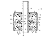
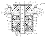
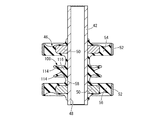
図1には、本発明の第一の実施形態として、本発明に従う構造とされた流体封入式筒形防振装置を備えた自動車用のキャブマウント10が示されている。本実施形態のキャブマウント10は、上側マウント14と下側マウント16が、車両ボデー18を挟んだ上下に組み合わされて装着された構造を有しており、本発明に係る流体封入式筒形防振装置が下側マウント16を含んで構成されている。なお、以下の説明において上下方向および軸方向とは、車両への装着状態で略上下方向とされる図1中の上下方向をいう。
FIG. 1 shows, as a first embodiment of the present invention, a
上側マウント14は、連結ゴム弾性体20の上下面に対して上板金具22と下板金具24が重ね合わされて固着された構造とされている。
The
連結ゴム弾性体20は、中心軸上を貫通する内孔26を有していると共に、上方に向かって次第に小径となるテーパ状の外周面を有している。また、上下の板金具22,24は、中心穴28,30が設けられた円環板形状とされており、各中心穴28,30が連結ゴム弾性体20の内孔26に連通されている。
The connecting rubber
なお、上板金具22の中心穴28の内径は、下板金具24の中心穴30と連結ゴム弾性体20の内孔26の何れよりも小さい。また、下板金具24には、周方向の複数箇所で外周に広がる固定部32が設けられており、各固定部32にはボルト挿通孔34が形成されている。
The inner diameter of the
そして、上側マウント14は、車両ボデー18におけるマウント装着部の上面に重ね合わされた状態で装着されるようになっている。車両ボデー18のマウント装着部には、複数のボルト挿通孔36が形成されており、各ボルト挿通孔36に挿通される固定ボルト38が、下板金具24の各ボルト挿通孔34に挿通されて、図示しないナットが各固定ボルト38に螺着されている。これにより、下板金具24が車両ボデー18に対して複数の固定ボルト38で固定されて、上側マウント14が下板金具24において車両ボデー18に取り付けられるようになっている。
The
また、車両ボデー18のマウント装着部には、上下に貫通する略円形の装着穴40が形成されており、上側マウント14における上下板金具22,24の各中心穴28,30および連結ゴム弾性体20の内孔26が、装着穴40を通じて車両ボデー18の下側に開口している。
In the mount mounting portion of the
一方、流体封入式筒形防振装置としての下側マウント16は、略同一中心軸上で径方向に所定距離を隔てて配されたインナ軸部材42とアウタ筒部材44が、本体ゴム弾性体46で弾性連結された構造を有している。
On the other hand, the
インナ軸部材42は、上下方向にストレートに延びる小径の円筒形状とされており、中央には上下方向に延びる内孔48を備えている。特に本実施形態では、インナ軸部材42が、上側マウント14の上板金具22の中心穴28と略同じ内径寸法を有していると共に、上側マウント14の連結ゴム弾性体20の内孔26と下板金具24の中心穴30との何れの内径よりも小さい外径寸法を有している。更に、インナ軸部材42には、上下の内側嵌着部材50,50が取り付けられている。この内側嵌着部材50は、環状乃至は円環板状とされており、インナ軸部材42に対して軸方向で相互に離れた二箇所に外嵌状態で固定されている。これにより、インナ軸部材42には、上下二箇所において外周へ向けて突出する外方突部が、内側嵌着部材50,50によって設けられている。
The
また、インナ軸部材42の外周には、上下の外側嵌着部材52,52が同軸的に外挿された状態で配設されている。上下の外側嵌着部材52,52は、軸方向寸法の小さい薄肉大径の略円筒形状を有しており、インナ軸部材42に対して上下の内側嵌着部材50,50と径方向で対向する軸方向位置に外挿状態で配されている。
Further, upper and lower outer
そして、上下の内側嵌着部材50,50を備えるインナ軸部材42と上下の外側嵌着部材52,52との径方向対向面間には、本体ゴム弾性体46を構成する外壁ゴムとしての上側ゴム弾性体54と下側ゴム弾性体56とが配されている。上下のゴム弾性体54,56は、何れも略円環板形状とされており、内周面にインナ軸部材42と上下の内側嵌着部材50,50とが加硫接着されている一方、外周面に上下の外側嵌着部材52,52が加硫接着されている。更に、上下のゴム弾性体54,56は、それらの内周端部が小径筒状の連結ゴム58によって連結されており、相互に一体形成されている。この連結ゴム58は、内側嵌着部材50,50の上下間において、インナ軸部材42の外周面に加硫接着されている。
And, between the diametrically opposed surfaces of the
また、上下の外側嵌着部材52,52には、アウタ筒部材44が外嵌状態で装着されている。アウタ筒部材44は、薄肉大径の略円筒形状を有しており、内周面にはシールゴム層60が被着形成されている。そして、アウタ筒部材44は、上下の外側嵌着部材52,52に外挿された状態で八方絞りなどの縮径加工を施されることにより、上下の外側嵌着部材52,52に対して外嵌状態で装着されている。なお、アウタ筒部材44と外側嵌着部材52,52との嵌着面間は、シールゴム層60によって液密にシールされている。
Further, outer
このようにアウタ筒部材44が装着されることで、インナ軸部材42とアウタ筒部材44との径方向対向面間には、上下のゴム弾性体54,56の軸方向間において、外部空間から遮断された封入領域62が画成されている。この封入領域62は、壁部の一部が上側ゴム弾性体54で構成されていると共に、壁部の他の一部が下側ゴム弾性体56で構成されており、非圧縮性流体が封入されている。なお、封入される非圧縮性流体としては、水やエチレングリコール、アルキレングリコール、ポリアルキレングリコール、シリコーン油、或いはそれらの混合液などの低粘性の液体が好適に採用される。
By mounting the outer
さらに、封入領域62には、隔壁64が配設されている。隔壁64は、全体として円環板形状を有しており、上下のゴム弾性体54,56の軸方向間において軸直角方向に広がって、インナ軸部材42とアウタ筒部材44との径方向間に跨がって配されている。この隔壁64によって封入領域62が上下方向の略中央部分で仕切られており、隔壁64の上側には、上側ゴム弾性体54で壁部の一部が構成された上側流体室66が形成されていると共に、隔壁64の下側には、下側ゴム弾性体56で壁部の一部が構成された下側流体室68が形成されている。
Furthermore, in the
より詳細には、隔壁64は、外周部分がオリフィス部材70によって構成されていると共に、内周部分が隔壁ゴム72によって構成されている。
More specifically, the
オリフィス部材70は、金属や合成樹脂などで形成された硬質の部材とされており、本実施形態では一対の半割体を径方向に組み合わせて構成されて、全体として略円環形状を有している。更に、オリフィス部材70の軸方向両面が、全体として内周側に向けて次第に軸方向内側へ傾斜するテーパ形状を有していることにより、オリフィス部材70における内周部分の軸方向寸法が小さくされている一方、オリフィス部材70の外周端部は、軸方向両側へ突出して軸方向寸法が大きく確保されている。
The
また、オリフィス部材70の外周部分には、外周面に開口して周方向に延びる周溝74が設けられている。本実施形態の周溝74は、周方向へ一周以上の長さで螺旋状に延びている。
Further, on the outer peripheral portion of the
さらに、オリフィス部材70の内周部分には、凹溝76が形成されている。凹溝76は、周方向へ全周に亘って略一定の溝断面形状で延びて、オリフィス部材70の内周面に開口している。本実施形態では、凹溝76の開口部分の溝内面が湾曲面とされており、凹溝76の開口部分が内周へ向けて次第に上下に拡開している。なお、凹溝76の具体的な形状は、特に限定されるものではないが、好適には、径方向の溝深さ寸法dが軸方向の溝幅寸法wよりも大きくされている。より望ましくは、凹溝76は、径方向の溝深さ寸法dが軸方向の溝幅寸法wの2倍以上とされる。
Furthermore, a recessed
このオリフィス部材70は、アウタ筒部材44の内周へ差し入れられており、外周面においてシールゴム層60で覆われたアウタ筒部材44の内周面に嵌着されている。これにより、オリフィス部材70がアウタ筒部材44側に固設されて、凹溝76がアウタ筒部材44側において内周へ開口するように設けられており、凹溝76が封入領域62へ向けて開口している。なお、オリフィス部材70は、外周部分が軸方向両側へ突出しており、上下の外側嵌着部材52,52間で軸方向に挟まれて位置決めされている。また、本実施形態では、オリフィス部材70の内周端が、上下の内側嵌着部材50,50の外周端よりも内周側に位置しており、それら上下の内側嵌着部材50,50の軸方向間に配されている。
The
さらに、オリフィス部材70の周溝74がアウタ筒部材44で覆蓋されることにより、アウタ筒部材44の内周面に沿って周方向に延びるオリフィス通路78が形成されている。このオリフィス通路78の長さ方向の両端が上側流体室66と下側流体室68の各一方に開口していることにより、上下の流体室66,68がオリフィス通路78によって互いに連通されている。
Further, by covering the
本実施形態では、オリフィス部材70がアウタ筒部材44の内周面に取り付けられており、オリフィス通路78がアウタ筒部材44に沿って周方向に延びるように設けられていることから、オリフィス通路78の通路長を長く得易くなっている。これにより、通路長と通路断面積の比に基づいて設定されるオリフィス通路78のチューニング周波数が、より大きな自由度で設定可能とされている。本実施形態では、アウタ筒部材44の内周面とオリフィス部材70の外周面の間にシールゴム層60が配されていることにより、周溝74の開口が流体密に覆われており、オリフィス通路78における流動流体の漏れが防止されている。
In the present embodiment, the
一方、隔壁ゴム72は、全体として略円環板形状を呈するゴム弾性体であって、本体ゴム弾性体46を構成する連結ゴム58と一体形成されて、インナ軸部材42側から外周の封入領域62へ向けて突出している。本実施形態の隔壁ゴム72は、連結ゴム58と一体形成されていることから明らかなように、上下のゴム弾性体54,56と一体形成されており、本体ゴム弾性体46の一部を構成している。
On the other hand, the
また、隔壁ゴム72は、先端部分である外周部分80が略一定の軸方向厚さ寸法で広がっていると共に、基端部分である内周部分82が内周側へ向けて次第に軸方向厚さ寸法が大きくなるテーパ形状とされており、内周部分82が外周部分80よりも厚肉とされている。なお、軸方向厚さ寸法を略一定とされた隔壁ゴム72の外周部分80は、径方向長さ寸法lが軸方向厚さ寸法tよりも大きくされており、好適には、径方向長さ寸法lが軸方向厚さ寸法tの2倍以上とされる。更に、隔壁ゴム72は、外周部分80の径方向長さ寸法が、内周部分82の径方向長さ寸法よりも大きくされている。また、隔壁ゴム72の外径寸法は、オリフィス部材70における凹溝76が形成された部分の内径寸法以下とされている。
Further, in the
そして、隔壁ゴム72は、外周部分80がオリフィス部材70の凹溝76に差し入れられており、それらオリフィス部材70と隔壁ゴム72によって上下の流体室66,68を隔てる隔壁64が構成されている。
The outer
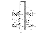
隔壁ゴム72の外周部分80は、オリフィス部材70の凹溝76の軸方向両側内面に対して、それぞれ隙間をもって差し入れられている。即ち、図4(a)に示すように、凹溝76の軸方向の溝幅寸法wが、隔壁ゴム72の外周部分80の軸方向の厚さ寸法tよりも大きくされており、隔壁ゴム72の外周部分80と凹溝76の溝内面との軸方向間に隙間が設けられている。
The outer
さらに、隔壁ゴム72の外径寸法が凹溝76の径方向の内法寸法以下とされていることによって、隔壁ゴム72は、オリフィス部材70の凹溝76に対して、径方向に圧縮されない状態で差し入れられている。要するに、隔壁ゴム72の外周面は、凹溝76の溝底内面に対して、内周へ離れているか、或いは0タッチで接触している。これにより、隔壁ゴム72とオリフィス部材70の軸方向の相対変位に際して、隔壁ゴム72の外周面と凹溝76の溝底内面との間の摩擦抵抗が略0とされている。なお、隔壁ゴム72の外周面と凹溝76の溝底内面が離れている場合には、隔壁ゴム72と凹溝76の溝内面との隙間が上下の流体室66,68に亘って連続している。
Furthermore, by making the outer diameter of the
かくの如き構造の隔壁64で仕切られて上下の流体室66,68が形成された下側マウント16は、車両ボデー18におけるマウント装着部の下面に重ね合わされた状態で装着されるようになっている。
The
下側マウント16のインナ軸部材42は、アウタ筒部材44から軸方向上方に延び出しており、車両ボデー18のマウント装着部に形成された装着穴40を通じて上方に突出している。そして、車両ボデー18のマウント装着部に対して上方から装着された上側マウント14に対して、インナ軸部材42が下方から挿し入れられており、インナ軸部材42の上端が、上側マウント14の上板金具22の内周縁部に対して重ね合わされている。
The
上側マウント14の上板金具22と下側マウント16のインナ軸部材42とは、上板金具22の中心穴28とインナ軸部材42の内孔48を貫通して挿通される図示しない固定ボルトによって、自動車のキャブハウジングに対して装着されることとなる。かかる装着状態下、上側マウント14の上板金具22と下側マウント16のインナ軸部材42とは、固定ボルトの締付力によって締結固定されて一体化される。
The upper plate fitting 22 of the
なお、インナ軸部材42の外周には、上側マウント14における連結ゴム弾性体20の内孔26や下板金具24の中心穴30の内周面、車両ボデー18の装着穴40の内周面との間に、何れも所定の隙間が設定されている。かかる隙間により、振動荷重の入力に際して、インナ軸部材42における連結ゴム弾性体20や下板金具24、車両ボデー18などへの干渉や当接が軽減又は回避されるようになっている。
The inner periphery of the
一方、下側マウント16のアウタ筒部材44は、アウタブラケット84を介して、車両ボデー18に固定されて装着されている。
On the other hand, the outer
アウタブラケット84は、大径の円筒形状とされており、下側マウント16のアウタ筒部材44が圧入固定されるようになっている。また、アウタブラケット84の軸方向上端側の開口周縁部には、外周に広がるフランジ部86が一体形成されており、フランジ部86において複数のボルト挿通孔88が設けられている。
The
そして、各ボルト挿通孔88が、車両ボデー18のボルト挿通孔36および上側マウント14における下板金具24のボルト挿通孔34に対して位置合わせされて、各ボルト挿通孔88およびボルト挿通孔36,34に挿通される固定ボルト38によって相互に締結固定されるようになっている。なお、アウタブラケット84の周壁部には、各ボルト挿通孔88に対応する周上で窓部90が形成されており、固定ボルト38の頭部の干渉が回避されている。
The bolt insertion holes 88 are aligned with the bolt insertion holes 36 of the
而して、上述の如き構造とされた本実施形態のキャブマウント10では、軸方向の静的な支持荷重に対しては、主として上側マウント14の連結ゴム弾性体20における圧縮変形によって所定の支持ばね特性が発揮される。また、軸直角方向の支持荷重が入力される場合には、剪断変形する上側マウント14の連結ゴム弾性体20と、圧縮変形する下側マウント16の上下のゴム弾性体54,56によって所定の支持ばね特性が発揮される。
Thus, in the
また、インナ軸部材42とアウタ筒部材44との間への軸方向の振動荷重の入力に際しては、下側マウント16において上下の流体室66,68間でオリフィス通路78を通じた流体流動が生ぜしめられて、流体の流動作用に基づく所定の防振効果が発揮されることとなる。
In addition, when an axial vibration load is input between the
その際、上下の流体室66,68の外側壁部を構成する上下のゴム弾性体54,56は、何れも、内外周をインナ軸部材42とアウタ筒部材44に固定されており、略同じ方向に剪断変形せしめられる。これに対して、隔壁64は、外周部分が硬質のオリフィス部材70で構成されていると共に、内周部分を構成する隔壁ゴム72がオリフィス部材70の凹溝76に差し入れられており、隔壁ゴム72の径方向の自由長が上下のゴム弾性体54,56に比して短くされている。
At that time, the upper and lower rubber
その結果、上下のゴム弾性体54,56の弾性変形による上下の流体室66,68の容積変化量が、隔壁ゴム72の弾性変形による上下の流体室66,68の容積変化量よりも大きくなって、上下の流体室66,68において圧力変動が惹起される。そして、かかる圧力変動に基づいて、上下の流体室66,68間には、オリフィス通路78を通じての流体流動が生ぜしめられ、流体の共振作用などの流動作用による防振効果が発揮されることとなる。
As a result, the volume change of the upper and lower
特に本実施形態における上下の流体室66,68は、何れも、変形容易な可撓性壁部を備えておらず、軸方向の振動荷重の入力に際して互いに正負で反対の圧力変動を生じる受圧室とされている。それ故、振動入力時にオリフィス通路78を流動せしめられる流体の水頭圧ひいては流体流動量を積極的に大きく確保することが可能となる。
In particular, the upper and lower
加えて、本実施形態では、オリフィス部材70の軸方向両面が、内周へ向けて軸方向内側へ傾斜するテーパ形状とされており、オリフィス部材70の軸方向寸法が内周側において小さくされている。それ故、上下の流体室66,68の容積が大きく確保されていると共に、上下のゴム弾性体54,56の弾性変形量がオリフィス部材70の干渉によって制限され難くなっており、オリフィス通路78を通じた流体流動量がより効率的に確保されるようになっている。
In addition, in the present embodiment, both axial surfaces of the
また、インナ軸部材42とアウタ筒部材44が軸方向の振動荷重の入力によって軸方向に相対変位せしめられると、図4(b)に示すように、インナ軸部材42側に設けられた隔壁ゴム72とアウタ筒部材44側に設けられたオリフィス部材70が軸方向に相対変位して、隔壁ゴム72の外周部分80がオリフィス部材70の凹溝76の溝内面に対して軸方向で押し付けられる。これにより、隔壁ゴム72と凹溝76の溝内面との軸方向間の隙間が部分的に流体密に遮断されて、当該隙間を通じた上下の流体室66,68の短絡を防止するシール部92が構成される。その結果、上下の流体室66,68の相対的な内圧変動が効率的に生ぜしめられて、オリフィス通路78を通じて流動する流体の量が確保されることから、オリフィス通路78による防振効果が有効に発揮される。
In addition, when the
特に本実施形態では、インナ軸部材42とアウタ筒部材44の軸方向での相対変位に際して、凹溝76に差し入れられた隔壁ゴム72の外周部分80が、凹溝76の溝内面に対して軸方向の両面において当接する。それ故、隔壁ゴム72と凹溝76の溝内面との隙間を通じた上下の流体室66,68の短絡がより効果的に防止されて、防振性能の向上が図られる。尤も、隔壁ゴム72が図4(b)に示すように弾性変形して、傾斜した隔壁ゴム72が凹溝76の溝内面に軸方向の両側で当接することは、必須ではなく、例えば、隔壁ゴム72が入力振動の位相に応じて凹溝76内で軸方向に移動することで、隔壁ゴム72の上下面が凹溝76の溝内面に当接するようにしても良い。
Particularly in the present embodiment, the outer
なお、本実施形態では、隔壁ゴム72が凹溝76の軸方向両側の内面から離れて隙間が形成されていると共に、隔壁ゴム72がオリフィス部材70に対して径方向で押し付けられていないことから、振動の入力初期に隔壁ゴム72のばねが下側マウント16のばね特性に影響し難く、下側マウント16において柔らかいばね特性を実現することができる。
In the present embodiment, the
また、隔壁64において隔壁ゴム72が、オリフィス部材70に対して、固着されることなく相対変位を許容されていることから、軸方向の振動荷重の入力時に、自由長の小さい隔壁ゴム72が剪断乃至は曲げ変形せしめられても、隔壁ゴム72が損傷し難く、優れた耐久性が実現される。蓋し、隔壁ゴム72の内周部分82が剪断乃至は曲げ変形せしめられる際に、隔壁ゴム72の外周部分80が、オリフィス部材70に対する内周側への相対変位を許容されることにより、隔壁ゴム72の表面に作用する引張応力が低減されるからである。
Further, since the
さらに、隔壁ゴム72は、オリフィス部材70よりも内周側に配された内周部分82が、凹溝76に差し入れられる外周部分80よりも軸方向で厚肉とされていることから、軸方向の振動荷重の入力に際して弾性変形せしめられる内周部分82の耐久性が有利に確保されている。特に本実施形態では、内周部分82が基端側である内周へ向けて軸方向厚さ寸法が次第に大きくなっていると共に、内周部分82の軸方向両面が湾曲面とされて、自由表面が大きく設定されていることから、内周部分82の耐久性の更なる向上が図られる。加えて、隔壁ゴム72の内周部分82が厚肉とされて、内周部分82の変形剛性が比較的に大きく設定されていることにより、隔壁ゴム72の外周部分80が凹溝76の溝内面に押し付けられる際に、外周部分80と凹溝76の溝内面との当接状態が安定して維持され易くなって、短絡の防止による防振性能の向上も図られる。
Furthermore, in the
また、本実施形態では、凹溝76の径方向の溝深さ寸法dが、凹溝76の軸方向の溝幅寸法wよりも大きくされていることから、振動入力時にも隔壁ゴム72の外周部分80が凹溝76から抜け難く、目的とする性能が安定して発揮される。しかも、本実施形態では、隔壁ゴム72の外周面が凹溝76の溝底内面に対して接触乃至は近接して配されており、隔壁ゴム72の外周部分80が凹溝76に対して径方向に十分な長さで差し入れられていることから、隔壁ゴム72の凹溝76からの抜けが防止される。
Further, in the present embodiment, since the groove depth dimension d in the radial direction of the recessed
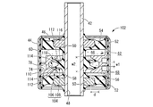
次に、図5には、本発明の第二の実施形態としてのキャブマウント100が示されている。キャブマウント100は、上側マウント14と流体封入式筒形防振装置としての下側マウント102を備えている。以下の説明において、第一の実施形態と実質的に同一の部材および部位については、図中に同一の符号を付すことにより、説明を省略する。
Next, FIG. 5 shows a
より詳細には、下側マウント102は、図6に示すように、上側流体室66と下側流体室68を仕切る隔壁104を備えている。更に、隔壁104は、外周部分がオリフィス部材106によって構成されていると共に、内周部分が隔壁ゴム108によって構成されている。
More specifically, the
オリフィス部材106は、第一の実施形態と同様に、一対の半割体を径方向に組み合わせて構成されて、全体として略円環形状を有している。更に、本実施形態では、オリフィス部材106の軸方向両面が略軸直角方向に広がっており、オリフィス部材106の内周部分が略一定の厚さ寸法とされていると共に、オリフィス部材106の外周端部が軸方向両側へ突出して軸方向寸法を大きくされている。
As in the first embodiment, the
また、オリフィス部材106の内周部分には、凹溝110が形成されている。凹溝110は、全周に亘って略一定の溝断面形状で延びており、オリフィス部材106の内周面において封入領域62へ向けて開口している。本実施形態の凹溝110は、その開口側(本実施形態では内周開口)へ向けて次第に軸方向の溝幅寸法が大きくなっており、軸方向両側の溝内面が溝開口側(本実施形態では内周)へ向けて軸方向外側へ傾斜するテーパ面112,112とされている。
Further, a recessed
凹溝110は、径方向の深さ寸法dが、外周端の軸方向幅寸法w1よりも大きくされていると共に、内周端の軸方向幅寸法w2よりも小さくされている。
The recessed
一方、隔壁ゴム108は、全体として略円環板形状を呈するゴム弾性体であって、インナ軸部材42側から封入領域62へ向けて外周へ突出している。隔壁ゴム108は、連結ゴム58を介して上下のゴム弾性体54,56と一体形成されており、本体ゴム弾性体46の一部を構成している。
On the other hand, the
また、隔壁ゴム108は、先端部分である外周部分が上下に分岐した形状とされており、軸方向で相互に離れて配された一対の分岐部114,114が外周部分に設けられている。分岐部114は、図7に示すように、その先端側(本実施形態では外周)へ行くに従って次第に軸方向外側へ傾斜するように延びるテーパ板形状とされており、本実施形態では略一定の厚さで延びている。更に、分岐部114の突出先端面は、図7に示す縦断面において略円弧状に湾曲する湾曲面とされており、分岐部114の突出先端部分が先端側に向けて薄肉となっている。なお、本実施形態では、上下の分岐部114,114が軸直角方向に広がる平面に関して略対称形状とされているが、上下の分岐部114,114は互いに非対称な形状であっても良く、例えば、互いに異なる傾斜角度で傾斜していても良い。
Further, the
また、隔壁ゴム108における分岐部114よりも基端側の内周部分116は、分岐部114よりも軸方向で厚肉とされていると共に、軸方向両面が軸方向外側に開口する凹状の湾曲面とされて、分岐部114の軸方向外面に対して滑らかに連続している。
In addition, the inner
そして、隔壁ゴム108は、外周部分である一対の分岐部114,114が、オリフィス部材106の凹溝110に差し入れられており、それらオリフィス部材106と隔壁ゴム108によって上下の流体室66,68を隔てる隔壁104が構成されている。
Further, in the
隔壁ゴム108の一対の分岐部114,114は、図6および図8(a)に示すように、オリフィス部材106の凹溝110に差し入れられて、突出先端部が凹溝110の上下のテーパ面112,112の各一方に押し付けられている。これにより、本実施形態では、振動荷重が入力されていない静置状態において、オリフィス部材106と隔壁ゴム108の間を流体密に遮断するシール部118,118が構成されている。なお、一対の分岐部114,114は、オリフィス部材106のテーパ面112,112に対して、軸方向で押し付けられて弾性変形せしめられている一方、径方向で滑り変位を許容されて圧縮が回避されている。また、本実施形態において、一対の分岐部114,114は、テーパ面112,112に対して軸方向に押し付けられることにより、突出先端部が軸方向内側へ曲がるように弾性変形している。
As shown in FIGS. 6 and 8 (a), the pair of branched
かくの如き構造の隔壁104で仕切られて上下の流体室66,68が形成された下側マウント102は、第一の実施形態と同様に、車両ボデー18におけるマウント装着部の下面に重ね合わされた状態で装着される。
The
そして、車両への装着状態において、軸方向の振動荷重が入力されて、インナ軸部材42とアウタ筒部材44が軸方向に相対変位すると、上下のゴム弾性体54,56と隔壁ゴム108が弾性変形せしめられる。隔壁ゴム108は、オリフィス部材106よりも内周側に位置する部分の径方向寸法が、上下のゴム弾性体54,56の径方向の自由長よりも小さくされていることから、上下のゴム弾性体54,56と隔壁ゴム108の弾性変形量の差によって、上下の流体室66,68間に相対的な圧力変動が惹起される。これにより、オリフィス通路78を通じた流体流動が生ぜしめられて、流体の流動作用に基づく防振効果が発揮される。
Then, when the
また、隔壁ゴム108は、図8(b)に示すように、軸方向の振動入力時にも、一対の分岐部114,114がオリフィス部材106のテーパ面112,112に押し付けられた状態に保持される。それ故、上下の流体室66,68がオリフィス部材106と隔壁ゴム108の間を通じて短絡することがなく、上下の流体室66,68の相対的な圧力変動が効率的に惹起される。
Further, as shown in FIG. 8B, the
特に本実施形態では、軸方向の振動が入力されていない状態においても、隔壁ゴム108の一対の分岐部114,114がオリフィス部材106のテーパ面112,112に軸方向で押し付けられていることから、振動の入力初期から上下の流体室66,68間の短絡が防止されて、上下の流体室66,68の相対的な圧力変動がより効率的に惹起される。
In particular, in the present embodiment, the pair of branched
なお、軸方向の振動荷重が入力された状態では、一方の分岐部114が一方のテーパ面112により強く押し付けられると共に、他方の分岐部114は他方のテーパ面112から離れるようになっていても良い。即ち、一方の分岐部114が一方のテーパ面112に対してより強く押し付けられることによって、シール部118が上下何れか1つだけになっても、十分なシール性能を得ることが可能な場合もある。
In the state where an axial vibration load is input, one
以上、本発明の実施形態について詳述してきたが、本発明はその具体的な記載によって限定されない。例えば、前記実施形態では、インナ軸部材42とアウタ筒部材44が何れも円筒形状とされていたが、インナ軸部材42とアウタ筒部材44は、何れも多角筒形状や長円筒形状、異形筒形状などであっても良い。更に、インナ軸部材42は、必ずしも筒状に限定されず、中実のロッド状なども採用され得る。
Although the embodiments of the present invention have been described above in detail, the present invention is not limited by the specific description. For example, in the above embodiment, the
また、上下のゴム弾性体54,56は、必ずしも一体形成されたものに限定されず、互いに別体とされて、それぞれインナ軸部材42およびアウタ筒部材44に取り付けられるようにしても良い。更に、隔壁ゴム72は、上下のゴム弾性体54,56の何れか一方又は両方に対して別体であっても良い。
The upper and lower rubber
さらに、上下のゴム弾性体54,56および隔壁ゴム72は、何れもインナ軸部材42に対して加硫接着されている必要はない。例えば、上下のゴム弾性体54,56および隔壁ゴム72の内周面に筒状の金具が固着されており、当該金具がインナ軸部材42に対して外嵌状態で固定されることにより、上下のゴム弾性体54,56および隔壁ゴム72の内周部分が金具を介してインナ軸部材42に取り付けられるようにもできる。
Furthermore, the upper and lower rubber
前記実施形態では、隔壁ゴム72がインナ軸部材42側から外周へ向けて突出していると共に、凹溝76がアウタ筒部材44側に設けられたオリフィス部材70の内周面に開口している構造について説明したが、例えば、隔壁ゴム72がアウタ筒部材44側に設けられると共に、凹溝76がインナ軸部材42側に設けられる構造も採用可能である。具体的には、例えば、上下のゴム弾性体の軸方向間に、オリフィス部材と隔壁ゴムが配設されて、オリフィス部材がインナ軸部材の外周面に固定されると共に、隔壁ゴムが上下のゴム弾性体とは別体とされて、アウタ筒部材の内周面に固定されるようにしても良い。なお、この場合には、例えば、特開2017−187171号公報に示されているように、上側ゴム弾性体が下側ゴム弾性体に対して別体とされると共に、上側ゴム弾性体がインナ軸部材およびアウタ筒部材に対して接着されることなく後付け可能とされて、上側ゴム弾性体をインナ軸部材およびアウタ筒部材に取り付ける前に、オリフィス部材と隔壁ゴムをインナ軸部材とアウタ筒部材に取り付けることにより、オリフィス部材と隔壁ゴムを上下のゴム弾性体の軸方向間に配することができる。
In the embodiment, the
また、凹溝は、必ずしもオリフィス通路を形成するオリフィス部材に設けられる態様に限定されず、例えば、アウタ筒部材に直接形成されていても良いし、アウタ筒部材にオリフィス部材とは別に凹溝を形成するための部材を取り付けることもできる。同様に、凹溝がインナ軸部材側に設けられる場合にも、インナ軸部材に取り付けられたオリフィス部材に形成される他、インナ軸部材に直接形成したり、オリフィス部材とは別の凹溝を形成するための部材をインナ軸部材に取り付けるなどしても良い。これらによれば、例えば、インナ軸部材側に凹溝を形成しながら、オリフィス部材をアウタ筒部材側に設けて、オリフィス通路の通路長を長く得ることも可能である。 Moreover, the recessed groove is not necessarily limited to the aspect provided in the orifice member which forms an orifice channel | path, for example, may be directly formed in the outer cylinder member, and the outer cylinder member has a recessed groove separately from the orifice member. A member for forming can also be attached. Similarly, when the recessed groove is provided on the inner shaft member side, in addition to being formed in the orifice member attached to the inner shaft member, the recessed groove may be formed directly on the inner shaft member or a recessed groove different from the orifice member. A member for forming may be attached to the inner shaft member. According to these, it is also possible to provide the orifice member on the outer cylindrical member side and to increase the passage length of the orifice passage, for example, while forming the recessed groove on the inner shaft member side.
また、第一の実施形態では、隔壁ゴム72の外周部分80が略一定の厚さ寸法とされていたが、例えば、厚さ方向の両面がテーパ面とされたり、厚さ方向の両面に凹凸が形成されるなどして、厚さ寸法が径方向で変化していても良く、具体的には外周に向けて軸方向で薄肉となる先細断面形状の隔壁ゴムなどが採用され得る。更に、隔壁ゴム72は、必ずしも軸直角方向に広がる形状に限定されず、軸直角方向に対して傾斜して広がっていても良く、更に傾斜角度が径方向で徐々に或いは段階的に変化していても良い。
Further, in the first embodiment, the outer
また、第二の実施形態では、オリフィス部材106の凹溝110の軸方向内面が内周に向けて軸方向外側に傾斜するテーパ面とされていると共に、隔壁ゴム108の外周部分である一対の分岐部114,114が外周に向けて軸方向外側へ傾斜するテーパ形状とされている構造を例示したが、一対の分岐部と凹溝の軸方向内面は、相対的に傾斜して軸方向で当接する構造とされていれば良い。具体的には、例えば、一対の分岐部が第二の実施形態と同様のテーパ形状とされると共に、凹溝の軸方向内面が略軸直角方向に広がっていても良いし、凹溝の軸方向内面が第二の実施形態と同様のテーパ面とされると共に、一対の分岐部が略軸直角方向に延びていても良い。
Further, in the second embodiment, the inner surface in the axial direction of the
また、凹溝の具体的な形状も前記実施形態に示されたものに限定されず、凹溝の溝断面形状は適宜に変更可能である。具体的には、例えば、略半円形断面のように連続的に広がる湾曲面によって溝内面を構成された凹溝を採用することもできる。 Moreover, the specific shape of a ditch | groove is not limited to what was shown by the said embodiment, The groove cross-sectional shape of a ditch | groove can be changed suitably. Specifically, for example, a concave groove in which the inner surface of the groove is formed by a curved surface continuously spreading like a substantially semicircular cross section can also be adopted.
また、流体室は、隔壁64の軸方向両側に設けられていれば、例えば周方向に複数に分割されていても良い。要するに、本発明において、流体室は、隔壁ゴムに対して軸方向の両側に配されていれば良く、例えば、周方向や軸直角方向に更なる流体室を設けて、軸直角方向の振動に対する防振性能の向上を図ることもできる。
Further, as long as the fluid chambers are provided on both sides in the axial direction of the
前記実施形態では、本発明をキャブマウントの下側マウントに適用した例を示したが、本発明は軸方向の振動入力を受ける流体封入式筒形防振装置全般に好適に適用可能であり、例えばエンジンマウントなどにも適用され得る。 In the embodiment described above, the present invention is applied to the lower mount of the cab mount, but the present invention is suitably applicable to all types of fluid-filled cylindrical vibration damping devices which receive an axial vibration input, For example, it can be applied to an engine mount and the like.
10,100:キャブマウント、16,102:下側マウント(流体封入式筒形防振装置)、42:インナ軸部材、44:アウタ筒部材、46:本体ゴム弾性体、54:上側ゴム弾性体(外壁ゴム)、56:下側ゴム弾性体(外壁ゴム)、62:封入領域、66:上側流体室(流体室)、68:下側流体室(流体室)、70,106:オリフィス部材、72,108:隔壁ゴム、76,110:凹溝、78:オリフィス通路、80:外周部分(隔壁ゴムの先端部分)、82:内周部分(隔壁ゴムの基端部分)、92,118:シール部、114:分岐部
10, 100: cab mount, 16, 102: lower mount (fluid-filled cylindrical vibration damping device), 42: inner shaft member, 44: outer cylindrical member, 46: main rubber elastic body, 54: upper rubber elastic body (Outer wall rubber) 56: lower rubber elastic body (outer wall rubber) 62: enclosed area 66: upper fluid chamber (fluid chamber) 68: lower fluid chamber (fluid chamber) 70, 106:
Claims (9)
前記インナ軸部材側と前記アウタ筒部材側には、前記封入領域へ突出する前記隔壁ゴムと該封入領域へ向けて開口して周方向へ延びる凹溝の各一方が設けられており、該隔壁ゴムの先端部分が該凹溝に対して軸直角方向に圧縮されない状態で差し入れられていると共に、該凹溝に差し入れられた該隔壁ゴムの先端部分が該凹溝の内面に軸方向で押し付けられることによって該隔壁ゴムと該凹溝の内面との間を流体密に遮断するシール部が構成されることを特徴とする流体封入式筒形防振装置。 The inner shaft member and the outer cylindrical member are connected by the main rubber elastic body, and a sealed region of the non-compressible fluid is formed between the inner shaft member and the outer cylindrical member, and the sealed region is a partition rubber. In a fluid-sealed cylindrical anti-vibration device separated by the fluid pressure chamber, the fluid chambers are formed on both sides in the axial direction, and the fluid chambers are communicated by an orifice passage,
The inner shaft member side and the outer cylindrical member side are respectively provided with the partition rubber projecting to the enclosed area and a recessed groove extending toward the enclosed area and extending in the circumferential direction. The end portion of the rubber is inserted without being compressed in a direction perpendicular to the groove in the axial direction, and the end portion of the partition rubber inserted in the groove is axially pressed against the inner surface of the groove A fluid-sealed cylindrical vibration-damping device characterized in that a seal portion is formed in a fluid-tight manner between the partition rubber and the inner surface of the recessed groove.
Priority Applications (2)
| Application Number | Priority Date | Filing Date | Title |
|---|---|---|---|
| JP2017209149A JP2019082197A (en) | 2017-10-30 | 2017-10-30 | Fluid sealed type cylindrical vibration isolator |
| US16/128,725 US11022196B2 (en) | 2017-10-30 | 2018-09-12 | Fluid-filled tubular vibration-damping device |
Applications Claiming Priority (1)
| Application Number | Priority Date | Filing Date | Title |
|---|---|---|---|
| JP2017209149A JP2019082197A (en) | 2017-10-30 | 2017-10-30 | Fluid sealed type cylindrical vibration isolator |
Publications (1)
| Publication Number | Publication Date |
|---|---|
| JP2019082197A true JP2019082197A (en) | 2019-05-30 |
Family
ID=66242782
Family Applications (1)
| Application Number | Title | Priority Date | Filing Date |
|---|---|---|---|
| JP2017209149A Pending JP2019082197A (en) | 2017-10-30 | 2017-10-30 | Fluid sealed type cylindrical vibration isolator |
Country Status (2)
| Country | Link |
|---|---|
| US (1) | US11022196B2 (en) |
| JP (1) | JP2019082197A (en) |
Families Citing this family (2)
| Publication number | Priority date | Publication date | Assignee | Title |
|---|---|---|---|---|
| ES2840223T3 (en) * | 2017-09-20 | 2021-07-06 | Zhuzhou Times New Mat Tech Co | Vibration damping support device |
| DE102020204311B3 (en) * | 2020-04-02 | 2021-07-15 | Siemens Aktiengesellschaft | Camera for observing the switch position of a switch contact |
Family Cites Families (16)
| Publication number | Priority date | Publication date | Assignee | Title |
|---|---|---|---|---|
| US2432050A (en) * | 1943-11-09 | 1947-12-02 | Gen Tire & Rubber Co | Energy dissipating antivibration device |
| JPS61130639A (en) | 1984-11-28 | 1986-06-18 | Tokai Rubber Ind Ltd | Mount with liquid |
| JPS61144444A (en) | 1984-12-19 | 1986-07-02 | Tokai Rubber Ind Ltd | Bush containing fluid |
| JPH0624595Y2 (en) | 1986-12-03 | 1994-06-29 | トヨタ自動車株式会社 | Fluid filled anti-vibration support |
| JPS6435138A (en) | 1987-07-29 | 1989-02-06 | Toyota Motor Corp | Vibration preventive device |
| JPS6435139A (en) | 1987-11-18 | 1989-02-06 | Toyota Motor Corp | Vibration preventive device |
| JPH01135940A (en) | 1987-11-18 | 1989-05-29 | Toyota Motor Corp | Vibro-isolating device |
| GB9007300D0 (en) * | 1990-03-31 | 1990-05-30 | Btr Plc | Improvements in and relating to an elastomeric mounting |
| FR2670552B1 (en) * | 1990-12-13 | 1993-02-12 | Caoutchouc Manuf Plastique | HYDROELASTIC SUSPENSION FASTENER AND GEOMETRIC LINK CONNECTED TO THIS FASTENER. |
| EP0528253B1 (en) * | 1991-08-20 | 1995-07-26 | Lemfoerder Metallwaren Ag. | Hydraulically damped support bearing for vehicle chassis |
| DE19526750C2 (en) * | 1995-07-21 | 1998-07-02 | Metzeler Gimetall Ag | Axial damping hydraulic bushing |
| JPH11230240A (en) * | 1998-02-16 | 1999-08-27 | Honda Motor Co Ltd | Liquid-sealed damper mount |
| GB9928995D0 (en) * | 1999-12-08 | 2000-02-02 | Btr Industries Ltd | Resilient bush |
| ES2224802B1 (en) * | 2002-07-31 | 2005-12-01 | Caucho Metal Productos, S.L. | HYDRAULICALLY CUSHED ELASTIC SUPPORT. |
| JP6619588B2 (en) * | 2015-09-02 | 2019-12-11 | 株式会社ブリヂストン | Vibration isolator |
| US10072725B2 (en) | 2016-03-30 | 2018-09-11 | Sumitomo Riko Company Limited | Fluid-filled tubular vibration-damping device |
-
2017
- 2017-10-30 JP JP2017209149A patent/JP2019082197A/en active Pending
-
2018
- 2018-09-12 US US16/128,725 patent/US11022196B2/en active Active
Also Published As
| Publication number | Publication date |
|---|---|
| US20190128365A1 (en) | 2019-05-02 |
| US11022196B2 (en) | 2021-06-01 |
Similar Documents
| Publication | Publication Date | Title |
|---|---|---|
| US5503376A (en) | Hydraulically damping rubber sleeve spring | |
| JP5557837B2 (en) | Vibration isolator | |
| JP2016109216A (en) | Fluid-sealed vibration isolation device | |
| US11073191B2 (en) | Fluid-filled tubular vibration-damping device | |
| JP4945162B2 (en) | Vibration isolator | |
| US20190168595A1 (en) | Fluid-filled vibration damping device | |
| JP6148951B2 (en) | Fluid filled cylindrical vibration isolator | |
| US10072725B2 (en) | Fluid-filled tubular vibration-damping device | |
| JP2019082197A (en) | Fluid sealed type cylindrical vibration isolator | |
| JP6877227B2 (en) | Anti-vibration device | |
| US10634206B2 (en) | Fluid-filled tubular vibration-damping device | |
| JP6431437B2 (en) | Vibration isolator | |
| WO2019008837A1 (en) | Fluid-filled vibration-damping device | |
| JP6297371B2 (en) | Method for manufacturing fluid-filled vibration isolator | |
| JP2017187171A (en) | Fluid sealed type cylindrical vibration-proofing device | |
| JP6691456B2 (en) | Fluid-filled cylindrical anti-vibration device | |
| JP2019158138A (en) | Anti-vibration device | |
| JP5406760B2 (en) | Method for manufacturing liquid filled vibration isolator and liquid filled vibration isolator | |
| JPH10141425A (en) | Vibrationproof device | |
| JP2011231797A (en) | Liquid sealed anti-vibration device | |
| CN110259875B (en) | Vibration-proof device | |
| JP4277314B2 (en) | Fluid-filled cylindrical vibration isolator and manufacturing method thereof | |
| JP2020012533A (en) | Vibration isolator | |
| JP2024037497A (en) | Vibration isolator | |
| JP2016075347A (en) | Fluid sealed type cylindrical vibration-proof device |