JP2019078564A - Flow sensor - Google Patents
Flow sensor Download PDFInfo
- Publication number
- JP2019078564A JP2019078564A JP2017203798A JP2017203798A JP2019078564A JP 2019078564 A JP2019078564 A JP 2019078564A JP 2017203798 A JP2017203798 A JP 2017203798A JP 2017203798 A JP2017203798 A JP 2017203798A JP 2019078564 A JP2019078564 A JP 2019078564A
- Authority
- JP
- Japan
- Prior art keywords
- heat generating
- generating portion
- flow sensor
- flow rate
- thermocouples
- Prior art date
- Legal status (The legal status is an assumption and is not a legal conclusion. Google has not performed a legal analysis and makes no representation as to the accuracy of the status listed.)
- Pending
Links
Images
Classifications
-
- G—PHYSICS
- G01—MEASURING; TESTING
- G01F—MEASURING VOLUME, VOLUME FLOW, MASS FLOW OR LIQUID LEVEL; METERING BY VOLUME
- G01F1/00—Measuring the volume flow or mass flow of fluid or fluent solid material wherein the fluid passes through a meter in a continuous flow
- G01F1/68—Measuring the volume flow or mass flow of fluid or fluent solid material wherein the fluid passes through a meter in a continuous flow by using thermal effects
- G01F1/684—Structural arrangements; Mounting of elements, e.g. in relation to fluid flow
Landscapes
- Physics & Mathematics (AREA)
- Fluid Mechanics (AREA)
- General Physics & Mathematics (AREA)
- Measuring Volume Flow (AREA)
Abstract
【課題】流量に対するセンサの出力の変化の割合の線型性を向上させる。【解決手段】フローセンサは、直線的に設けられる発熱部と、前記発熱部と離間して設けられた複数の熱電対とを備え、前記複数の熱電対の温接点は、前記発熱部からの距離及び前記発熱部からの受熱量が所定の範囲内に分散するように配置される。【選択図】図2The linearity of the rate of change in sensor output with respect to flow rate is improved. A flow sensor includes a heat generating portion provided linearly and a plurality of thermocouples provided apart from the heat generating portion, and hot junctions of the plurality of thermocouples from the heat generating portion. The distance and the amount of heat received from the heat generating portion are arranged so as to be dispersed within a predetermined range. [Selection] Figure 2
Description
本発明は、フローセンサに関する。 The present invention relates to a flow sensor.
ヒータの周囲にサーモパイルを配置し、温度分布に基づいて流体の流量や流速を測定するセンサが提案されている。 A sensor has been proposed which arranges a thermopile around a heater and measures the flow rate or flow rate of fluid based on a temperature distribution.
例えば、流体の流量や流速などを測定するサーモパイル型温度センサを用いた感熱式フローセンサであって、複数の熱電対の配置間隔を、ヒータ部から発生する熱が逃げにくい周辺部は低密度に、熱が逃げやすい中央部は高密度に配置したものや、ヒータ部の温度分布の等温曲線に沿うように熱電対の温接点を配置したものが提案されている(例えば、特許文献1)。 For example, it is a thermal type flow sensor using a thermopile type temperature sensor that measures the flow rate or flow speed of fluid, and the arrangement interval of the plurality of thermocouples is low in density at the peripheral part where heat generated from the heater is difficult to escape A central portion where heat is easily dissipated is disposed at high density, and one in which a hot junction of a thermocouple is disposed along the isothermal curve of the temperature distribution of the heater portion has been proposed (for example, Patent Document 1).
例えばヒータ部の温度分布の等温曲線に沿うように熱電対の温接点を配置した場合、ヒータ部と熱電対との距離に応じて感度を向上させることができる流量域は決まる。すなわち、当該流量域を外れると、流量の変化に対する出力の変化の割合が大きく変動し、出力から流量を求める際に必要な補正量が増大する。 For example, when the hot junction of the thermocouple is disposed along the isothermal curve of the temperature distribution of the heater unit, the flow rate range in which the sensitivity can be improved is determined according to the distance between the heater unit and the thermocouple. That is, when the flow rate region is deviated, the ratio of the change of the output to the change of the flow rate largely fluctuates, and the correction amount necessary for obtaining the flow rate from the output increases.
本発明は、上記のような問題に鑑みてなされたものであり、流量に対するセンサの出力の変化の割合の線型性を向上させることを目的とする。 The present invention has been made in view of the problems as described above, and it is an object of the present invention to improve the linearity of the ratio of the change of the output of the sensor to the flow rate.
フローセンサは、直線的に設けられる発熱部と、前記発熱部と離間して設けられた複数の熱電対とを備え、前記温度測定部は、前記発熱部からの距離及び前記発熱部からの受熱量が所定の範囲内に分散するように配置される。 The flow sensor includes a heat generating portion provided linearly and a plurality of thermocouples provided to be separated from the heat generating portion, and the temperature measuring portion is a distance from the heat generating portion and a temperature receiving from the heat generating portion. The heat is distributed so as to be dispersed within a predetermined range.
発熱部は、フローセンサの周囲を流れる流体を加熱する。発熱部は、例えば、ポリシリコンで形成されるヒータを含み、電流が流れることで発熱する。複数の熱電対は、例えばサーモパイルを形成し、熱電対の温接点と冷接点との温度差に応じた電圧を出力する。上述のように、温接点を、発熱部からの距離及び発熱部からの受熱量が分散するように配置することにより、発熱部からの距離又は発熱部からの受熱量が一定の場合よりも広い流量域において、流量に対するセンサの出力の変化の割合を平均的にすることができる。すなわち、流量に対するセンサの出力の変化の線型性を向上させることができる。 The heat generating portion heats the fluid flowing around the flow sensor. The heat generating portion includes, for example, a heater formed of polysilicon, and generates heat when a current flows. The plurality of thermocouples form, for example, a thermopile and output a voltage according to the temperature difference between the hot junction and the cold junction of the thermocouple. As described above, by arranging the hot junction so that the distance from the heat generating portion and the amount of heat received from the heat generating portion are dispersed, the distance from the heat generating portion or the amount of heat received from the heat generating portion is wider than In the flow area, the rate of change of the output of the sensor to the flow can be averaged. That is, the linearity of the change of the output of the sensor with respect to the flow rate can be improved.
また、前記複数の熱電対の温接点は、前記発熱部からの距離が遠いものと近いものとが、前記発熱部の長手方向に沿って繰り返し配置されるようにしてもよい。このようにすれば、複数の温接点において、発熱部からの距離及び発熱部からの受熱量を分散させることができる。 Further, the hot junctions of the plurality of thermocouples may be repeatedly arranged along the longitudinal direction of the heat generating portion, in which the distance from the heat generating portion is far and near. In this way, the distance from the heat generating portion and the amount of heat received from the heat generating portion can be dispersed at the plurality of hot junctions.
また、前記複数の熱電対の温接点は、前記発熱部の周囲の領域であって、前記発熱部の
長手方向の中央を含む一部に対向する領域に、前記発熱部の長手方向に略平行な方向及び前記長手方向に略垂直な方向にそれぞれ複数配置されるようにしてもよい。このようにすれば、受熱量の比較的低く出力に寄与する程度の低い温接点を減らし、温度測定部の感度を向上させることができる。
Further, the hot junctions of the plurality of thermocouples are substantially parallel to the longitudinal direction of the heat generating portion in a region that is a region around the heat generating portion and faces a part including the center in the longitudinal direction of the heat generating portion. It is also possible to arrange a plurality in the direction substantially perpendicular to the longitudinal direction and the longitudinal direction. In this way, it is possible to reduce the relatively low heat reception amount and the low temperature contact point that contributes to the output, and to improve the sensitivity of the temperature measurement unit.
なお、課題を解決するための手段に記載の内容は、本発明の課題や技術的思想を逸脱しない範囲で可能な限り組み合わせることができる。また、課題を解決するための手段に示した流量測定装置の内容は、方法又はプロセッサ等の演算装置に実行させるプログラム、若しくはプログラムを格納する媒体として提供することができる。 The contents described in the means for solving the problems can be combined as much as possible without departing from the problems and technical ideas of the present invention. Further, the contents of the flow rate measuring device shown in the means for solving the problems can be provided as a program to be executed by an arithmetic device such as a method or processor or a medium for storing the program.
流量の変化に対するセンサの出力の変化の線型性を向上させることができる。 The linearity of the change of the output of the sensor to the change of the flow rate can be improved.
<適用例>
図1は、フローセンサ(センサ素子)の一例を示す斜視図である。図2は、フローセンサの上面の一例を示す平面図である。図3は、フローセンサを図2に示すA−Aで切断した断面図である。
<Example of application>
FIG. 1 is a perspective view showing an example of a flow sensor (sensor element). FIG. 2 is a plan view showing an example of the top surface of the flow sensor. FIG. 3 is a cross-sectional view of the flow sensor taken along line A-A shown in FIG.
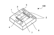
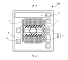
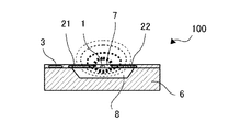
本実施形態に係るフローセンサ100は、発熱部1と、発熱部1を間にしてその両側に設けられる2つの温度測定部2と、基板・周囲気体温度測定部3と、ホール4と、パッド5とを、基板6上に備えている。また、基板6の内部にはキャビティ8が設けられており、発熱部1、温度測定部2の一部、及びホール4は、キャビティ8の上に位置する薄膜(メンブレン)7上に存在する。なお、図2においては薄膜7の範囲を破線の矩形で示している。また、図2に示すように、温度測定部2は、発熱部1と離間して設けられる第1の温度測定部21と、発熱部1を基準にして第1の温度測定部21とは反対側に設けられる第2の温度測定部22とを含む。そして、フローセンサ100は、その周囲を流れる流体の流量又は流速により変化する温度分布に応じた出力を行う。
The
発熱部1は、例えばポリシリコンで形成されるマイクロヒータを含む。すなわち、発熱部1に含まれる抵抗体は、電流が流れることにより発熱する。なお、図2及び図3においては、破線の楕円で温度分布を模式的に示している。
The
第1の温度測定部21及び第2の温度測定部22の各々は、例えば複数の熱電対を有するサーモパイルである。図2においては、模式的に、各熱電対を矩形で表し、熱電対の温接点を黒い正方形で示す。なお、各熱電対の長手方向における温接点の反対側には、冷接点が位置するものとする。各温接点は薄膜7上に配置されており、冷接点は基板6上に配置されている。
Each of the first
基板6は、例えばシリコンで形成された基体であり、フローセンサ100の周囲やキャビティ8内に存在する気体よりも一般的に熱伝導率が高くなっているといえる。また、薄膜7及びキャビティ8は、例えばエッチングにより形成される。
The
ホール4は、薄膜7に設けられ、キャビティ8の内外を連通する。また、ホール4は、発熱部1の周囲(図示せず)及び薄膜7の縁に沿って設けられ、比較的熱伝導率の高い基板6へ発熱部1の熱が伝わることを抑制する。すなわち、ホール4は薄膜7上の断熱部といえる。
The
基板・周囲気体温度測定部3は、例えば抵抗体であり、フローセンサ100が設置される環境の温度に応じて抵抗値が変化する。また、基板・周囲気体温度測定部3は、基板6上であって、温度測定部2の冷接点よりも発熱部1から離れた位置に配置され、基板6や、フローセンサ100の周囲の気体の温度を測定する。
The substrate / ambient gas
パッド5は、フローセンサ100への給電や、フローセンサ100からの出力を行うための電極であり、フローセンサ100の構成要素と導線を介して接続されている。
The
また、本実施形態に係る熱電対の温接点は、発熱部1からの距離が所定の範囲に分散するように配置されている。すなわち、温接点は、発熱部1からの距離が一定にならないように分散している。なお、発熱部1から温接点までの距離は、例えば、発熱部1から温接点への最短距離をいうものとする。また、温接点は、フローセンサ100の周囲に流体の流れがない場合(例えば、無風時)における発熱部1からの受熱量が一定にならない位置に分散しているともいえる。フローセンサ100の周囲に流体の流れがない場合における温度を、発熱部1からの受熱量とする。図2及び図3において、破線の楕円で模式的な等温線を示す。なお、楕円の太さが太いほど、高温の領域を表している。図2における等温線は、発熱部1の中心を中心として、発熱部1の長手方向に長軸が沿った楕円で表されている。
Further, the hot junctions of the thermocouple according to the present embodiment are disposed such that the distance from the
温接点を、発熱部からの距離及び発熱部からの受熱量が分散するように配置することにより、発熱部からの距離又は発熱部からの受熱量が一定の場合よりも広い流量域において、流量に対するセンサの出力の変化の割合を平均的にすることができる。すなわち、流量に対するセンサの出力の変化の線型性を向上させることができる。 By arranging the hot junction so that the distance from the heat generating portion and the heat receiving amount from the heat generating portion are dispersed, the flow rate in the flow rate range wider than the distance from the heat generating portion or the heat receiving amount from the heat generating portion is constant. The rate of change of the output of the sensor with respect to That is, the linearity of the change of the output of the sensor with respect to the flow rate can be improved.
<実施形態>
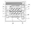
図4は、フローセンサの1つの具体例を示す平面図である。フローセンサ100は、ある方向に沿って第1の温度測定部21、発熱部1、第2の温度測定部22を有している。第1の温度測定部21及び第2の温度測定部22は、発熱部1に対して対称に設けられている。例えば、フローセンサ100の設置場所において流体が流れる方向の上流側に第1の温度測定部21が位置し、下流側に第2の温度測定部22が位置するようにフローセンサ100を設置することで、流量又は流速に応じた温度分布を、精度良く測定することができる。
Embodiment
FIG. 4 is a plan view showing one specific example of the flow sensor. The
また、フローセンサ100は、薄膜7上に発熱部1を有する。発熱部1は、図4において一点鎖線の矩形で示されており、発熱部1は、太い破線で示されるヒータ11を含む。図4に例示するヒータ11は、薄膜7上においてジグザグに折れ曲がった形状であるが、ヒータ11はクランク状に連続する曲線形状であってもよいし、直線上であってもよい。また、発熱部1は、ヒータ11の周囲にホール4を含む。ホール4は、凸部と凹部とを繰り返し含むヒータ11の凹部に、千鳥配置で複数設けられている。換言すれば、発熱部1は薄膜7の略中央を通過し薄膜7を二分するように略直線的に配置されている。そして、発熱部1の周囲には、発熱部1の長手方向に沿って、第1の温度測定部21の温接点21
1、第2の温度測定部22の温接点221が設けられている。また、第1の温度測定部21及び第2の温度測定部22は、それぞれ複数の熱電対を含む。熱電対の各々の長手方向は、発熱部1の長手方向と直交する。そして、第1の温度測定部21及び第2の温度測定部22はそれぞれ、発熱部1から遠方の端に、冷接点212及び冷接点222を有する。また、冷接点は212及び冷接点222は、薄膜7上でなく基板6上に位置している。
Further, the
A
熱電対は、2種類の導体又は半導体の端部を接合して形成される。図4においては、温接点211と冷接点212とを接続する破線及び一点鎖線が、2種類の導体又は半導体を示している。例えば、N型ポリシリコンと、アルミニウムとを接合して熱電対を形成することができるが、用いられる導体又は半導体はこれらには限定されない。また、熱電対を複数接合して、温度測定部2の一例であるサーモパイルが形成される。
The thermocouple is formed by joining the ends of two types of conductors or semiconductors. In FIG. 4, a broken line and an alternate long and short dash line connecting the
サーモパイルは、温接点と冷接点との温度差により電位差を生じる。本実施形態では、例えば流体の上流側に位置する第1の温度測定部21、及び流体の下流側に位置する第2の温度測定部22が、それぞれの熱電対の温度差に応じた電圧を出力する。
The thermopile generates a potential difference due to the temperature difference between the hot junction and the cold junction. In the present embodiment, for example, the first
そして、フローセンサ100は、例えば流体の下流側に位置する第2の温度測定部22の出力電圧と、流体の上流側に位置する第1の温度測定部21の出力電圧との差分に応じた値を、流体の流量又は流速に応じた値として出力する。
Then, for example, the
また、図4に示すように、複数の熱電対の温接点は、発熱部1からの距離が遠いものと近いものとが、前記発熱部1の長手方向に沿って繰り返し配置されている。
In addition, as shown in FIG. 4, the hot junctions of the plurality of thermocouples are repeatedly arranged along the longitudinal direction of the
<比較例>
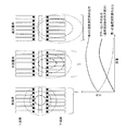
図5は、発熱部から温接点までの距離が一定であるフローセンサの出力と、測定対象流体の流量との関係を説明するための図である。流量がゼロである無風時の温度分布は、上流側と下流側とで偏りはない。したがって、上流側の第1の温度測定部の出力と、下流側の第2の温度測定部の出力との差分に応じて決まるフローセンサの出力は、ほぼゼロになっている。
Comparative Example
FIG. 5 is a diagram for explaining the relationship between the output of the flow sensor in which the distance from the heat generating portion to the hot junction is constant, and the flow rate of the fluid to be measured. There is no bias between the upstream side and the downstream side of the temperature distribution at the time of no wind when the flow rate is zero. Therefore, the output of the flow sensor determined in accordance with the difference between the output of the upstream first temperature measurement unit and the output of the downstream second temperature measurement unit is substantially zero.
流体に流れが生じた中流量時の温度分布は、高温の領域が下流側に偏る。したがって、流量の増加に伴い、上流側の第1の温度測定部の出力は無風時よりも下がると共に、下流側の第2の温度測定部の出力は無風時よりも上がり、フローセンサの出力は上昇する。このときの流量に対するフローセンサの出力の変化は線型にはならない。 The temperature distribution at the middle flow rate where the flow occurs in the fluid is such that the high temperature region is biased downstream. Therefore, with the increase of the flow rate, the output of the first temperature measurement unit on the upstream side is lower than that during no wind, and the output of the second temperature measurement unit on the downstream side is higher than that during no wind, and the output of the flow sensor is To rise. The change of the output of the flow sensor with respect to the flow rate at this time does not become linear.
さらに流量が増加し、発熱部によって加熱される領域が下流側のサーモパイルの冷接点まで到達した場合は、温接点と冷接点との温度差が小さくなる。したがって、高流量域における下流側の第2の温度測定部の出力は、ある流量をピークに減少することがある。一方、上流側の第1の温度測定部はあまり加熱されず、高流量域における第1の温度測定部の出力は小さな値に漸近する。総合すると、フローセンサの出力は、グラフに示すように、流量の増加に反し減少することがある。 When the flow rate further increases and the region heated by the heat generating portion reaches the cold junction of the downstream thermopile, the temperature difference between the hot junction and the cold junction decreases. Therefore, the output of the downstream second temperature measurement unit in the high flow rate region may decrease a flow rate to a peak. On the other hand, the first temperature measurement unit on the upstream side is not heated so much, and the output of the first temperature measurement unit in the high flow rate area gradually approaches a small value. Taken together, the output of the flow sensor may decrease against the increase in flow rate, as shown in the graph.
以上のように、複数の温接点が、発熱部からの距離が一定になる位置に配されていると、流量の増加に対するフローセンサの出力の変化の傾きが一定にならない。したがって、出力の大きさに応じて別途補正をしなければ流量を求めることができず、補正量の大きな流量域においては補正後の流量に含まれる誤差も大きくなるおそれがある。すなわち、精度よく使用できる流量域に制限があった。 As described above, when the plurality of hot junctions are disposed at positions where the distance from the heat generating portion is constant, the inclination of the change of the output of the flow sensor with respect to the increase of the flow rate is not constant. Therefore, the flow rate can not be determined unless the correction is separately performed in accordance with the magnitude of the output, and in the flow rate range where the correction amount is large, the error included in the corrected flow rate may be increased. That is, there is a limit to the flow rate area that can be used with high accuracy.
<効果>
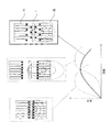
図6は、上述した実施形態に係るフローセンサ100の出力と、測定対象流体の流量と
を関係を模式的に説明するための図である。図6の例では、流量の変化にともなうフローセンサ100の出力の変化を実線のグラフで示している。フローセンサ100は、図6の右上に模式的な配置を示すように、発熱部1からの距離が異なる位置に熱電対の温接点が分散している。仮に、発熱部1からの距離が近い位置にすべての温接点を配置した場合は、出力特性はピークが低流量域にある破線のグラフになる。また、発熱部1からの距離が遠い位置にすべての温接点を配置した場合は、出力特性はピークが高流量域にある破線のグラフになる。これに対し、発熱部1からの距離が近いものと遠いものとを所定の範囲内に分散させた場合は、出力のピークに至るまでの区間にわたって、流量の増加に対する出力の変化の傾きが平均的になり、グラフが直線的になっている。すなわち、出力の変化の線型性が向上し、流量域によって必要な補正量が低減する。したがって、より広い流量域において出力の精度を向上させることができる。なお、図6の例では、発熱部1からの距離が近い温接点と遠い温接点の2種類の熱電対が交互に発熱部1の長手方向に沿って並んでいるが、発熱部1から熱電対の温接点までの距離は3段階以上であってもよい。
<Effect>
FIG. 6 is a diagram for schematically explaining the relationship between the output of the
なお、実施形態に係るフローセンサ100の温接点は、測定対象の流体について想定される流量によって生じる温度分布の幅に応じて決定される所定の範囲内に分散させることで、所望の流量域全体にわたって出力の精度を向上させることができる。
Note that the hot junction of the
<変形例>
実施形態に係る熱電対の温接点は、発熱部1からの距離が近いものから遠いものが規則的に繰り返し配置されていたが、このような例には限られない。例えば、温接点の位置は所定の範囲内でランダムに分散させてもよい。また、発熱部1から冷接点までの距離を変更してもよい。
<Modification>
The hot junction of the thermocouple according to the embodiment is regularly and repeatedly disposed so as to be far from a near distance from the
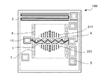
図7は、変形例に係るフローセンサの一例を示す平面図である。上述した実施形態では、熱電対の各々は、その長手方向が発熱部1の長手方向と直交するように配置されていたが、このような例には限定されない。図7の例では、発熱部1の周囲であって薄膜7の中央に近い位置に温接点を集約して配置している。換言すれば、複数の温接点は、発熱部1の周囲の領域であって、発熱部1の長手方向の中央を含む一部に対向する領域に、発熱部の長手方向に略平行な方向及び長手方向に略垂直な方向にそれぞれ複数配置されている。より具体的には、複数の熱電対の温接点は、発熱部1の周囲の領域であって、発熱部1の略中央(換言すれば、薄膜7の略中央)を中心とし長辺が発熱部1の長手方向に沿った楕円で定められる領域にほぼ収まるように配置されている。また、複数の温接点は、発熱部1の長手方向に略平行な方向及び発熱部1の長手方向に略垂直な方向にそれぞれ複数配置され、格子状または網目状に並んでいるといえる。
FIG. 7 is a plan view showing an example of a flow sensor according to a modification. In the embodiment described above, each of the thermocouples is disposed such that its longitudinal direction is orthogonal to the longitudinal direction of the
なお、熱電対の冷接点は薄膜7の外の基板6上に設けられ、適宜導体で連結されるものとする(図示せず)。すなわち、変形例に係る熱電対が配置される向きは、発熱部1の長手方向と直交する方向には限定されず、例えば、温接点と冷接点とを接続する導体同士が交差しないような任意のパターンを採用することができる。
The cold junction of the thermocouple is provided on the
発熱部1は、矩形状の薄膜7の対向する2辺の中点同士を結ぶ直線にほぼ沿って設けられている。また、発熱部1の周囲、及び上記の対向する2辺に沿った位置には、薄膜7上の又は基板6への熱の伝達を抑制するために設けられた断熱部であるホール4が存在する。しかしながら、発熱部1が発する熱は、薄膜7の端近づくほど基板6へ逃げやすい。したがって、発熱部1の長手方向に沿って熱電対を配置する場合、サーモパイルの端に近い熱電対(換言すれば、薄膜7の端に近い熱電対、または発熱部1の端に近い熱電対)の受熱量は相対的に小さく、サーモパイルの出力へ寄与する量も小さい。
The
図7の例では、無風時の温度分布に基づいて、温度が最も高くなる発熱部1の中心を中
心とする所定の範囲内に温接点を分散させている。なお、所定の範囲は、無風時の温度分布における所定の等温線に基づいて定めるようにしてもよい。
In the example of FIG. 7, the hot junctions are dispersed within a predetermined range centered on the center of the
このようにすれば、出力が小さい熱電対を減らし、サーモパイル全体としての感度を向上させることができる。 In this way, it is possible to reduce the number of thermocouples with small output and to improve the sensitivity of the thermopile as a whole.
なお、例えば、フローセンサ100は、直線的に設けられる発熱部1と、前記発熱部と離間して設けられた複数の熱電対(21、22)と、を備え、前記複数の熱電対の温接点(211、221)は、前記発熱部1からの距離及び前記発熱部1からの受熱量が所定の範囲内に分散するように配置されるものであってもよい。
For example, the
また、前記複数の熱電対の温接点(211、221)は、前記発熱部1からの距離が遠いものと近いものとが、前記発熱部1の長手方向に沿って繰り返し配置されるようにしてもよい。
Further, the hot junctions (211, 221) of the plurality of thermocouples are arranged repeatedly along the longitudinal direction of the
また、前記複数の熱電対の温接点(211、221)は、前記発熱部1の周囲の領域であって、前記発熱部1の長手方向の中央を含む一部に対向する領域に、前記発熱部1の長手方向に略平行な方向及び前記長手方向に略垂直な方向にそれぞれ複数配置されるようにしてもよい。
In addition, the hot junction (211, 221) of the plurality of thermocouples is an area around the
以上、実施形態及び変形例に係る流量測定装置について説明したが、上述した流量測定装置は一例であり、本発明に係る流量測定装置は、上記の構成には限定されない。説明した実施形態及び変形例の構成は、本発明の課題や技術的思想を逸脱しない範囲で可能な限り組み合わせることができる。 As mentioned above, although the flow measurement device concerning an embodiment and a modification was explained, the flow measurement device mentioned above is an example, and the flow measurement device concerning the present invention is not limited to the above-mentioned composition. The configurations of the embodiments and modifications described can be combined as much as possible without departing from the problems and technical ideas of the present invention.
100 :フローセンサ
1 :発熱部
2 :温度測定部
21 :第1の温度測定部
211 :温接点
212 :冷接点
22 :第2の温度測定部
221 :温接点
222 :冷接点
3 :基板・周囲気体温度測定部
4 :ホール
5 :パッド
6 :基板
7 :薄膜
8 :キャビティ
100: Flow sensor 1: Heat generation part 2: Temperature measurement part 21: First temperature measurement part 211: Hot junction 212: Cold junction 22: Second temperature measurement part 221: Hot junction 222: Cold junction 3: Substrate, surroundings Gas temperature measurement unit 4: Hole 5: Pad 6: Substrate 7: Thin film 8: Cavity
Claims (3)
前記発熱部と離間して設けられた複数の熱電対と、
を備え、
前記複数の熱電対の温接点は、前記発熱部からの距離及び前記発熱部からの受熱量が所定の範囲内に分散するように配置される
フローセンサ。 A heat generating portion provided linearly,
A plurality of thermocouples provided apart from the heat generating portion;
Equipped with
The hot junction of the plurality of thermocouples is disposed such that the distance from the heat generating portion and the amount of heat received from the heat generating portion are dispersed within a predetermined range.
請求項1に記載のフローセンサ。 2. The flow sensor according to claim 1, wherein the hot junctions of the plurality of thermocouples are repeatedly arranged along the longitudinal direction of the heat generating portion, in which the distance from the heat generating portion is far and near.
請求項1に記載のフローセンサ。 A hot junction of the plurality of thermocouples is a region around the heat generating portion, and a direction substantially parallel to the longitudinal direction of the heat generating portion in a region facing a part including the center in the longitudinal direction of the heat generating portion The flow sensor according to claim 1, wherein a plurality of the flow sensors are disposed in a direction substantially perpendicular to the longitudinal direction.
Priority Applications (2)
| Application Number | Priority Date | Filing Date | Title |
|---|---|---|---|
| JP2017203798A JP2019078564A (en) | 2017-10-20 | 2017-10-20 | Flow sensor |
| PCT/JP2018/037954 WO2019078087A1 (en) | 2017-10-20 | 2018-10-11 | Flow sensor |
Applications Claiming Priority (1)
| Application Number | Priority Date | Filing Date | Title |
|---|---|---|---|
| JP2017203798A JP2019078564A (en) | 2017-10-20 | 2017-10-20 | Flow sensor |
Publications (1)
| Publication Number | Publication Date |
|---|---|
| JP2019078564A true JP2019078564A (en) | 2019-05-23 |
Family
ID=66173955
Family Applications (1)
| Application Number | Title | Priority Date | Filing Date |
|---|---|---|---|
| JP2017203798A Pending JP2019078564A (en) | 2017-10-20 | 2017-10-20 | Flow sensor |
Country Status (2)
| Country | Link |
|---|---|
| JP (1) | JP2019078564A (en) |
| WO (1) | WO2019078087A1 (en) |
Families Citing this family (3)
| Publication number | Priority date | Publication date | Assignee | Title |
|---|---|---|---|---|
| US11262224B2 (en) | 2020-06-19 | 2022-03-01 | Honeywell International Inc. | Flow sensing device |
| US12044561B2 (en) | 2020-11-06 | 2024-07-23 | Honeywell International Inc. | Flow sensing device |
| CN118583914B (en) * | 2024-08-01 | 2025-03-28 | 苏州芯镁信电子科技有限公司 | A thermal conductivity gas sensor, preparation method and gas thermal conductivity detection method |
Family Cites Families (5)
| Publication number | Priority date | Publication date | Assignee | Title |
|---|---|---|---|---|
| JP2000074713A (en) * | 1998-08-27 | 2000-03-14 | Yazaki Corp | Thermopile structure |
| JP3470881B2 (en) * | 1999-04-19 | 2003-11-25 | 矢崎総業株式会社 | Micro flow sensor |
| US8943888B2 (en) * | 2013-01-09 | 2015-02-03 | M-Tech Instrument Corporation (Holding) Limited | Micromachined flow sensor integrated with flow inception detection and make of the same |
| JP5981397B2 (en) * | 2013-07-11 | 2016-08-31 | 日立オートモティブシステムズ株式会社 | Thermal flow meter |
| JP2018141664A (en) * | 2017-02-27 | 2018-09-13 | アズビル株式会社 | Flow sensor |
-
2017
- 2017-10-20 JP JP2017203798A patent/JP2019078564A/en active Pending
-
2018
- 2018-10-11 WO PCT/JP2018/037954 patent/WO2019078087A1/en not_active Ceased
Also Published As
| Publication number | Publication date |
|---|---|
| WO2019078087A1 (en) | 2019-04-25 |
Similar Documents
| Publication | Publication Date | Title |
|---|---|---|
| CN102004125B (en) | Thermal humidity sensor | |
| WO2019078087A1 (en) | Flow sensor | |
| US10488268B2 (en) | Temperature difference measuring apparatus | |
| CN104482971A (en) | Thermal flow sensor on basis of MEMS (micro-electromechanical systems) technology | |
| JP6348207B2 (en) | Thermoelectric generator for exhaust system and contact member of thermoelectric generator | |
| CN115280113B (en) | Thermopile Sensors | |
| JPH05157758A (en) | Method for correcting temperature characteristics of flow velocity sensor | |
| JP5224089B2 (en) | Thermal sensor | |
| US11302854B2 (en) | Sensor device | |
| JP2016170027A (en) | Internal temperature measurement device and temperature difference measuring module | |
| JP5056086B2 (en) | Thermal sensor | |
| US11307073B2 (en) | Device for measuring speed or flow of gas | |
| JP3589083B2 (en) | Thermal flow sensor | |
| JP2000298135A (en) | heater | |
| US6250150B1 (en) | Sensor employing heating element with low density at the center and high density at the end thereof | |
| JP2021144002A (en) | Flow measurement device | |
| JP2012177702A (en) | Thermal humidity sensor | |
| JP2020187009A (en) | Thermal flow sensor of temperature difference type | |
| JP6128877B2 (en) | Temperature detector | |
| JP2002286519A (en) | Thermal flow sensor | |
| KR101152839B1 (en) | Layered type micro heat flux sensor | |
| JP6475081B2 (en) | Thermal flow meter and method for improving tilt error | |
| JPH0493768A (en) | Flow velocity sensor | |
| JP2018141664A (en) | Flow sensor | |
| JPH04158263A (en) | Flow speed sensor |