JP2019074606A - Fixing apparatus - Google Patents
Fixing apparatus Download PDFInfo
- Publication number
- JP2019074606A JP2019074606A JP2017199625A JP2017199625A JP2019074606A JP 2019074606 A JP2019074606 A JP 2019074606A JP 2017199625 A JP2017199625 A JP 2017199625A JP 2017199625 A JP2017199625 A JP 2017199625A JP 2019074606 A JP2019074606 A JP 2019074606A
- Authority
- JP
- Japan
- Prior art keywords
- heater
- film
- aluminum plate
- contact
- longitudinal
- Prior art date
- Legal status (The legal status is an assumption and is not a legal conclusion. Google has not performed a legal analysis and makes no representation as to the accuracy of the status listed.)
- Granted
Links
Images


Classifications
-
- G—PHYSICS
- G03—PHOTOGRAPHY; CINEMATOGRAPHY; ANALOGOUS TECHNIQUES USING WAVES OTHER THAN OPTICAL WAVES; ELECTROGRAPHY; HOLOGRAPHY
- G03G—ELECTROGRAPHY; ELECTROPHOTOGRAPHY; MAGNETOGRAPHY
- G03G15/00—Apparatus for electrographic processes using a charge pattern
- G03G15/20—Apparatus for electrographic processes using a charge pattern for fixing, e.g. by using heat
- G03G15/2003—Apparatus for electrographic processes using a charge pattern for fixing, e.g. by using heat using heat
- G03G15/2014—Apparatus for electrographic processes using a charge pattern for fixing, e.g. by using heat using heat using contact heat
- G03G15/2053—Structural details of heat elements, e.g. structure of roller or belt, eddy current, induction heating
-
- G—PHYSICS
- G03—PHOTOGRAPHY; CINEMATOGRAPHY; ANALOGOUS TECHNIQUES USING WAVES OTHER THAN OPTICAL WAVES; ELECTROGRAPHY; HOLOGRAPHY
- G03G—ELECTROGRAPHY; ELECTROPHOTOGRAPHY; MAGNETOGRAPHY
- G03G15/00—Apparatus for electrographic processes using a charge pattern
- G03G15/20—Apparatus for electrographic processes using a charge pattern for fixing, e.g. by using heat
- G03G15/2003—Apparatus for electrographic processes using a charge pattern for fixing, e.g. by using heat using heat
- G03G15/2014—Apparatus for electrographic processes using a charge pattern for fixing, e.g. by using heat using heat using contact heat
- G03G15/2017—Structural details of the fixing unit in general, e.g. cooling means, heat shielding means
- G03G15/2028—Structural details of the fixing unit in general, e.g. cooling means, heat shielding means with means for handling the copy material in the fixing nip, e.g. introduction guides, stripping means
-
- G—PHYSICS
- G03—PHOTOGRAPHY; CINEMATOGRAPHY; ANALOGOUS TECHNIQUES USING WAVES OTHER THAN OPTICAL WAVES; ELECTROGRAPHY; HOLOGRAPHY
- G03G—ELECTROGRAPHY; ELECTROPHOTOGRAPHY; MAGNETOGRAPHY
- G03G15/00—Apparatus for electrographic processes using a charge pattern
- G03G15/20—Apparatus for electrographic processes using a charge pattern for fixing, e.g. by using heat
- G03G15/2003—Apparatus for electrographic processes using a charge pattern for fixing, e.g. by using heat using heat
- G03G15/2014—Apparatus for electrographic processes using a charge pattern for fixing, e.g. by using heat using heat using contact heat
- G03G15/2064—Apparatus for electrographic processes using a charge pattern for fixing, e.g. by using heat using heat using contact heat combined with pressure
-
- G—PHYSICS
- G03—PHOTOGRAPHY; CINEMATOGRAPHY; ANALOGOUS TECHNIQUES USING WAVES OTHER THAN OPTICAL WAVES; ELECTROGRAPHY; HOLOGRAPHY
- G03G—ELECTROGRAPHY; ELECTROPHOTOGRAPHY; MAGNETOGRAPHY
- G03G2215/00—Apparatus for electrophotographic processes
- G03G2215/20—Details of the fixing device or porcess
- G03G2215/2003—Structural features of the fixing device
- G03G2215/2016—Heating belt
Abstract
Description
本発明は、記録材に画像を形成する機能を備えた、複写機、プリンタ、ファクシミリなどの画像形成装置に用いられる定着装置に関するものである。 The present invention relates to a fixing device used in an image forming apparatus such as a copying machine, a printer, and a facsimile, which has a function of forming an image on a recording material.
電子写真方式の画像形成装置で用いられる定着装置として、フィルム加熱方式のものが知られている。この定着装置は、筒状の定着フィルムと、定着フィルムの内面に接触する板状のヒータと、定着フィルムの外面に接触してニップ部を形成する加圧ローラと、を有する。トナー画像を担持する記録材はこのニップ部で搬送されつつ加熱され、トナー画像は記録材に定着される。フィルム加熱方式の定着装置は、定着フィルムの熱容量が小さいのでウォームアップ時間が短く、消費電力を極力低く抑えることができるというメリットがある。 As a fixing device used in an electrophotographic image forming apparatus, a film heating type is known. This fixing device has a cylindrical fixing film, a plate-like heater in contact with the inner surface of the fixing film, and a pressure roller in contact with the outer surface of the fixing film to form a nip portion. The recording material carrying the toner image is heated while being conveyed by the nip portion, and the toner image is fixed to the recording material. The fixing device of the film heating type has an advantage that the warm-up time is short because the heat capacity of the fixing film is small, and the power consumption can be suppressed as low as possible.
ところで、ヒータの定着フィルムと接触する面と反対側の面に接触するように、ヒータの基板よりも熱伝導率が高い熱伝導部材を設けて、その熱伝導部材を定着フィルムに接触するように延ばした構成が開示されている(特許文献1)。ヒータから定着フィルムへの熱伝導経路に加えて、ヒータから熱伝導部材を介して定着フィルムに至る熱伝導経路が形成されるので、効率良く定着フィルムを加熱することができる。また、熱伝導部材をヒータ及び定着フィルムの長手方向に亘ってヒータ及び定着フィルムに接触させることによって、小サイズ記録材を連続的に定着処理した際に生じる非通紙部昇温を抑制することができる。 By the way, a heat conducting member having a thermal conductivity higher than that of the substrate of the heater is provided to be in contact with the surface of the heater opposite to the surface in contact with the fixing film, and the heat conducting member is brought into contact with the fixing film. An extended configuration is disclosed (Patent Document 1). In addition to the heat conduction path from the heater to the fixing film, a heat conduction path from the heater to the fixing film via the heat conduction member is formed, so that the fixing film can be efficiently heated. Further, by causing the heat conducting member to be in contact with the heater and the fixing film over the longitudinal direction of the heater and the fixing film, it is possible to suppress the non-sheet-passing portion temperature rise that occurs when the small size recording material is fixed continuously. Can.
しかしながら、ヒータ及び定着フィルムの長手方向に亘って熱伝導部材をヒータ及び定着フィルムに接触させると、それらの端部における放熱によって温度低下により端部定着性が悪化する場合がある。特に、幅が広い記録材を定着処理した際に画像端部のトナーが溶融不足となり、画像端部のオフセット(以下、「端部オフセット」と記載する)が発生する場合がある。 However, when the heat conducting member is brought into contact with the heater and the fixing film along the longitudinal direction of the heater and the fixing film, the heat may be reduced at the end due to the heat radiation at the ends of the heat conductive member. In particular, when a wide recording material is fixed, the toner at the edge of the image may be insufficiently melted, which may cause an offset at the edge of the image (hereinafter referred to as “edge offset”).
本発明は、非通紙部昇温抑制と端部定着性向上を両立できる定着装置を提供することを目的としたものである。 SUMMARY OF THE INVENTION An object of the present invention is to provide a fixing device capable of achieving both suppression of non-sheet-passing portion temperature rise and improvement of end portion fixability.
本発明の側面は、回転可能な筒状のフィルムと、第1の面と、前記第1の面と反対側の第2の面を有する板状のヒータであって、前記第1の面で前記フィルムの内面に接触する長細い板状のヒータと、前記ヒータの長手方向に長く、前記ヒータの前記第2の面に接触しているヒータ接触部を有する熱伝導部材と、を有し、前記フィルムを介した前記ヒータの熱でトナー画像を加熱し前記トナー画像を記録材に定着する定着装置において、前記熱伝導部材は、前記フィルムの回転方向に関し前記ヒータの上流端よりも上流側の領域及び前記ヒータの下流端よりも下流側の領域の少なくとも一方において、前記フィルムに近づく方向に延びて前記フィルムの内面に接触するフィルム接触部を有し、前記熱伝導部材の長手方向において、前記ヒータ接触部の長手端部は、それと同じ側の前記フィルム接触部の長手端部よりも外側まで延びていることを特徴とする。 An aspect of the present invention is a plate-like heater having a rotatable cylindrical film, a first surface, and a second surface opposite to the first surface, wherein the first surface And a heat conducting member having a heater contact portion which is long in the longitudinal direction of the heater and in contact with the second surface of the heater. In the fixing device for heating the toner image by the heat of the heater through the film and fixing the toner image to the recording material, the heat conducting member is upstream of the upstream end of the heater in the rotation direction of the film. A film contact portion extending in a direction approaching the film to be in contact with the inner surface of the film in at least one of the region and the region downstream of the downstream end of the heater; heater Longitudinal end portion of the contact portion is therewith characterized in that it extends to the outside than the longitudinal end portions of the film contact portion of the same side.
本発明によれば、非通紙部昇温抑制と端部定着性向上を両立できる定着装置を提供することができる。 According to the present invention, it is possible to provide a fixing device capable of achieving both suppression of temperature rise in non-sheet-passing portion and improvement in end portion fixability.
[実施例1]
まず、本実施例における画像形成装置の本体構成を説明し、次いで、本実施例に係わる定着装置について詳しく説明する。
Example 1
First, the main configuration of the image forming apparatus according to the present embodiment will be described, and then, the fixing device according to the present embodiment will be described in detail.
(1)画像形成装置
図1を参照して、実施例1に係る画像形成装置の構成について説明する。図1は、本発明の実施例1に係る一般的なカラー画像形成装置(本実施例では、電子写真方式の中間転写方式のフルカラープリンタ)の概略構成図である。
(1) Image Forming Apparatus The configuration of the image forming apparatus according to the first embodiment will be described with reference to FIG. FIG. 1 is a schematic configuration diagram of a general color image forming apparatus (in the present embodiment, an electrophotographic intermediate transfer full-color printer) according to a first embodiment of the present invention.
このカラー画像形成装置は、イエロー色、マゼンダ色、シアン色、ブラック色の画像を各々形成する4つの画像形成部1Y、1M、1C、1Bkを備えている。これらの4つの画像形成部は一定の間隔をおいて一列に配置されている。
The color image forming apparatus includes four
各画像形成部1Y,1M,1C,1Bkには、それぞれ像担持体としての感光体ドラム2a,2b,2c,2dが設置されている。各感光体ドラム2a,2b,2c,2dの周囲には、帯電ローラ3a,3b,3c,3d、現像装置4a,4b,4c,4d、転写シート5a,5b,5c,5d、ドラムクリーニング装置6a,6b,6c,6dがそれぞれ設置されている。更に、各感光体ドラム2a,2b,2c,2dの周囲には、帯電ローラ3a,3b,3c,3dと、現像装置4a,4b,4c,4d間の上方に露光装置7a,7b,7c,7dがそれぞれ設置されている。各現像装置4a,4b,4c,4dには、それぞれ負帯電特性のイエロートナー,マゼンタトナー,シアントナー,ブラックトナーが収納されている。
感光体ドラム2a,2b,2c,2dは、本実施例では負帯電の有機感光体でアルミニウムのドラム基体上に感光層を有しており、不図示の駆動装置によって矢印方向(反時計方向)に所定のプロセススピードで回転駆動される。
The
帯電ローラ3a,3b,3c,3dは、それぞれ感光体ドラム2a,2b,2c,2dに所定の圧接力で接触しており、不図示の帯電バイアス電源によって、所望の帯電バイアスを印加される。そして、各感光体ドラム2a,2b,2c,2d表面を所定の電位に均一に帯電する。尚、本実施例では、各感光体ドラム2a,2b,2c,2dは各帯電ローラ3a,3b,3c,3dにより負極性に帯電される。
The
露光装置(レーザスキャナ装置)7a,7b,7c,7dは、ホストコンピュータ(不図示)からそれぞれ入力される画像情報の時系列電気デジタル画素信号に対応して変調されたレーザ光をレーザ出力部(不図示)から出力する。そのレーザ光は、各反射ミラー(不図示)を介して各感光体ドラム2a,2b,2c,2d表面を画像露光する。その結果、各帯電ローラ3a,3b,3c,3dで帯電された各感光体ドラム2a,2b,2c,2d表面に画像情報に応じた静電潜像が形成される。
The exposure devices (laser scanner devices) 7a, 7b, 7c, and 7d have laser output units (laser beams modulated corresponding to time-series electric digital pixel signals of image information respectively input from a host computer (not shown)). Output from (not shown). The laser light exposes the surfaces of the
現像装置4a,4b,4c,4dは、現像方式として、接触現像方式を用いており、現像剤担持体としての現像ローラを有している。現像ローラ上の薄層担持されたトナーは不図示の現像駆動手段により回転した現像ローラにより感光体ドラム2a,2b,2c,2dとの対向部(現像部)に搬送される。そして、感光体ドラム上に形成された静電潜像は不図示の現像電圧印加手段により現像ローラに印加された現像バイアスによりトナー像として現像(反転現像)される。
The developing
現像装置4a,4b,4c,4dにおける各現像ローラと各感光体ドラムは、フルカラー画像形成モードでは当接であり、後述するモノカラー画像形成モードでは画像を形成する現像部以外の現像ローラと感光体ドラムは離間するような構成となっている。これは、現像ローラとトナーの劣化、消耗を防止するためである。
The developing rollers and the photosensitive drums in the developing
シート状転写手段としての転写シート5a,5b,5c,5dは、導電性を持たせた樹脂により形成されたシートにより構成されている。また、転写シート加圧部材としての転写パッド15a,15b,15c,15dは、ゴムなどにより形成された弾性体により構成されている。
The
中間転写ベルト20は半導電性を持たせた樹脂により無端ベルト状に形成されている。中間転写ベルト20は、駆動ローラ21、テンションローラ22、2次転写対向ローラ23により張架され、テンションローラ22に対する不図示の加圧手段によりテンションがかけられており、駆動ローラ21により回転駆動される。
The
感光ドラム2aには、無端ベルト状の中間転写体である中間転写ベルト20が当接している。転写シート5aは、中間転写ベルト20と当接し、さらに、転写パッド15aに当接し、押圧されている。結果、転写パッド15aは転写シート5aと、中間転写ベルト20を介して各感光ドラム2aに押圧している。転写シート5aには、1次転写電源としての1次転写用電源(不図示)が接続されている。感光ドラム2a上に現像されたトナー像は、1次転写電圧が印加された転写シート5aにより、回転している中間転写ベルト20上に1次転写される。
An
以上説明した構成が画像形成部1Yの転写部構成であり、他の画像形成部1M,1C,1Bkについても同様の構成である。画像形成部1Yと同様にして中間転写ベルト20上に重畳転写されたイエロー、マゼンタのトナー像上に、画像形成部1C,1Bkの感光ドラム2c,2dで形成されたイエロー,ブラックのトナー像を各1次転写部にて順次重ね合わせる。その結果、フルカラーのトナー像が中間転写ベルト20上に形成される。
The configuration described above is the transfer unit configuration of the
2次転写ローラ24は、中間転写ベルト20の外側方向から2次転写対向ローラ23部に押圧しており、中間転写ベルト20に接離自在な構成となっている。記録材Pは2次転写ローラ24と中間転写ベルト20の当接部に搬送される。2次転写ローラ24には、2次転写電源としての2次転写用電源(不図示)が接続されている。中間転写ベルト20上に1次転写されたトナー像は、2次転写電圧が印加された2次転写ローラにより、搬送されている記録材P上に2次転写される。
The
中間転写ベルト20と2次転写ローラ24の当接部の、中間転写ベルト20回転方向下流側には、中間転写ベルト20表面に残った転写残トナーを除去して回収するためのベルトクリーニング装置として、クリーニングの帯電ローラ25が接触している。このクリーニング用の帯電ローラ25には、不図示のクリーニング用電源が接続され、クリーニング電圧が印加されたクリーニング用帯電ローラ25により、転写残トナーは除去される。
As a belt cleaning device for removing and collecting transfer residual toner remaining on the surface of the
また、使用する環境の変化、画像形成枚数等の諸条件によらず、安定した色レジや、画像濃度を得るために、駆動ローラ21の近傍に、色レジ補正・濃度補正用センサユニット50が設けられている。色レジ補正・濃度補正用センサユニット50は、LEDなどの発光素子、フォトダイオードやCdSなどの受光素子から構成されている。
In addition, the
2次転写ローラ24の記録材Pの搬送方向下流側には、定着ローラ43と定着フィルム30および加圧ローラ33を有する定着装置12が設置されている。ここでは、記録材Pを定着ローラ43と加圧ローラ33間に搬送することにより、同時にトナー像tを加熱、加圧して記録材P表面に永久固着画像として定着する。
On the downstream side of the
また、色レジ補正および濃度補正時には、トナー像を中間転写ベルト20上に形成し、回転移動する中間転写ベルト20上のトナー像及びトナー像の無い部分に発光素子からの光を照射する。そして、それらからの反射光を受光素子で受けることによりトナー像パッチの形成された位置および濃度を測定する。色レジ補正時にはトナー像の有無の間隔を測定することで色レジを補正する。また、濃度補正時にはトナー像の濃度を測定することで、濃度を補正する。
Further, at the time of color registration correction and density correction, a toner image is formed on the
本実施例のカラー画像形成装置は複数の用紙サイズに対応しており、Letter紙(約216mm×279mm)、A4紙(210mm×297mm)、A5紙(148mm×210mm)を含む複数の用紙サイズをプリントできる。基本的に紙を縦送りする(長辺が搬送方向と平行になるように搬送する)プリンタであり、対応している定型の記録材サイズ(カタログ上の対応用紙サイズ)のうち最も大きな(幅が大きな)サイズはLetter紙の約216mm幅である。このように、画像形成装置が対応する最大サイズよりも小さな紙幅の用紙(A4紙、A5紙)を、本提案では小サイズ紙と定義する。 The color image forming apparatus of this embodiment is compatible with a plurality of paper sizes, and includes a plurality of paper sizes including Letter paper (about 216 mm × 279 mm), A4 paper (210 mm × 297 mm), and A5 paper (148 mm × 210 mm). It can print. Basically, it is a printer that longitudinally feeds paper (conveys with the long side parallel to the conveyance direction), and is the largest (width) among the compatible fixed recording material sizes (corresponding paper sizes in the catalog) The size is about 216 mm width of Letter paper. As described above, in the present proposal, a sheet (A4 sheet, A5 sheet) having a sheet width smaller than the maximum size supported by the image forming apparatus is defined as a small size sheet.
(2)定着装置
定着装置12について説明する。定着装置12は、フィルム加熱方式の装置である。フィルム加熱方式の定着装置12は、耐熱性フィルムとして無端ベルト状のものを用い、そのフィルムは加圧体の回転駆動力で回転駆動するようにした装置である。
(2) Fixing Device The fixing
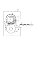
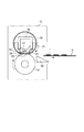
以後フィルム加熱方式の定着装置について詳細を説明する。図2は、実施例1に係るカラー画像形成装置の定着装置を示す断面図である。また、図3は同定着装置に用いられるフィルムユニットの分解斜視図、図4は同定着装置の一部切欠き正面図である。 Hereinafter, the film heating type fixing device will be described in detail. FIG. 2 is a cross-sectional view of the fixing device of the color image forming apparatus according to the first embodiment. FIG. 3 is an exploded perspective view of a film unit used for the identification attachment device, and FIG. 4 is a partially cutaway front view of the identification attachment device.
ヒータホルダ31は、ヒータ32を支持する支持部材として機能すると共に、円筒状である定着フィルム30の回転走行を案内するものである。ヒータホルダ31はポリイミド、ポリアミドイミド、PEEK、PPS、液晶ポリマー等の高耐熱性樹脂や、これらの樹脂とセラミックス、金属、ガラス等との複合材料等を好適に用いることができる。中でも耐熱温度が高く、モールド成型ができ、寸法安定性に優れる液晶ポリマーを特に好適に用いることができる。液晶ポリマーには以下のような利点がある。まず耐熱温度が高いためにヒータの設定温度の自由度が大きくできる。またモールド成型できるために、生産性が良く大量生産が可能である。さらには寸法安定性に優れるため加圧部材への押圧力を均等にすることができ紙搬送性能が安定するというメリットがある。
The
ヒータ32は、長細い板形状を有している。ヒータ32は耐熱性が高いセラミック基板(本実施例においては、熱伝導率が30W/(m・K)のアルミナを用いている)にAg/Pd(銀パラジウム)を用いた抵抗発熱体82と電極が印刷されている。更に、抵抗発熱体82を保護するようにガラスコート84が設けられている。抵抗発熱体82は2本の発熱体を用い、2つの電極を片側に配置している。ガラスコート84層が定着フィルム30と触れる側に設置される。
The
定着フィルム30は無端ベルト状(円筒状)の基層外側に弾性層を設け、さらにその外側に離型層を設けた部材であって、回転可能に構成されている。
The fixing
離型層は、は定着フィルム30の表面にトナーが一旦付着し、再度、記録材Pに移動することで発生するオフセット現象を防止する層であり、厚み5〜70μm程度の離型性の良好なPFA、PTFE、FEP等のフッ素樹脂を好適に用いることができる。本実施例では厚み15μmのPFAチューブを用いてことで、簡便に、均一なフッ素樹脂層を形成することができる。
The release layer is a layer that prevents an offset phenomenon that occurs when toner once adheres to the surface of the fixing
弾性層は、特にカラー画像形成装置における定着装置において用いられることが多い。この弾性層によって、記録材P表面の凹凸によらずトナー像tを包み込んだ形でトナー像tを加熱することを可能とし、その結果均一なカラー光沢画像を得ることを可能にしている。本実施例において弾性層には比較的熱伝導率の高いシリコーンゴム層を用いている。これにより、より高いオンデマンド性と、より良好な定着性能を得ることができる。 Elastic layers are often used, particularly in fixing devices in color image forming devices. This elastic layer makes it possible to heat the toner image t in the form of wrapping the toner image t regardless of the unevenness of the surface of the recording material P, and as a result, it is possible to obtain a uniform color gloss image. In the present embodiment, a silicone rubber layer having a relatively high thermal conductivity is used as the elastic layer. As a result, higher on-demand performance and better fixing performance can be obtained.
基層は定着フィルム30の最も内面側のヒータと接する層である。基層は耐熱性に優れ、可撓性があるポリイミド、ポリアミドイミド、PEEK等が用いられ、単体での厚み10〜100μm程度で形成されている。ヒータ32と加圧ローラが対向するニップ部Nにおいて、ヒータの熱を記録材P上のトナー像tにより効率的に伝えるために、定着フィルム30はヒータに十分ならって密着できるような可撓性を有することが重要である。
The base layer is a layer in contact with the heater on the innermost side of the fixing
可撓性を向上させるためにはより層を薄くすることが有効である。一方で、定着フィルム30は基層により機械的強度を保っていることから、極端に基層の厚みが薄い場合、強度が低下してフィルムが変形し、シワが入りやすくなることや、端部が座屈しやすくなるなど必要な強度を得られなくなってしまう。これを防止するために基層がポリイミドの場合、厚みは10μm以上であることが必要である。本実施例ではマイクロメータで計測した厚みが50μm、内径が18mmの円筒状のポリイミド樹脂を用いている。
In order to improve the flexibility, it is effective to make the layer thinner. On the other hand, since the fixing
図2の断面図を参照して、定着装置の構成について説明する。補強部材34は鉄等の金属からなり、ヒータホルダ31を加圧ローラ側に押圧する圧力でも大きく変形しないように強度を維持する部材である。ヒータ32はヒータホルダ31と補強部材34を介して加圧ローラ33側に後述の押圧手段によって押圧されている。押圧されて加圧ローラ33と定着フィルム30が密着している領域が(圧接領域としての)定着ニップ部Nである。そして、加圧ローラ33の加圧位置と、ヒータ32の記録材搬送方向中央部の位置は略同一としている。
The configuration of the fixing device will be described with reference to the cross-sectional view of FIG. The reinforcing
次に、図3の斜視図を参照して説明する。ヒータホルダ31は、横断面で略樋型形状を有しており、桶型の内側に補強部材34が嵌合する。ヒータホルダ31の加圧ローラ33と対向する側にはヒータ受け溝が設けられており、ヒータ32が前記ヒータ受け溝に嵌って所望の位置に嵌合される。この際に、ヒータ32と前記ヒータ受け溝間にはアルミ板81を挟んで配置している。アルミ板81の詳細については後述する。またヒータホルダ31には不図示のサーミスタも取り付けられ、ヒータ32およびアルミ板81がヒータ受け溝に嵌合されたときにアルミ板81と当接する位置に配置される。定着フィルム30は上述の部品が組みつけられたヒータホルダ31の外側に周長に余裕を持って外嵌している。定着フィルム30の円筒形状の軸方向(図中で定着フィルムが挿入される矢印方向)を以後長手方向と称する。補強部材34の張り出し部は定着フィルム30の両端から突き出ており、両端それぞれにフランジ部材36を嵌着させ、全体でフィルムユニットとして組み立てられる。定着フィルム30の片側端からヒータ32の給電端子も突出しており、給電コネクタ35が嵌合されている。給電コネクタ35がヒータ32の電極部と当接圧を持って接触し、給電経路を作っている。
Next, it demonstrates with reference to the perspective view of FIG. The
加圧回転体としての加圧ローラ33は金属からなる芯金と、弾性特性を有するシリコーンゴムからなる弾性層と、離型性を有する離型層とからなる。加圧ローラ33の芯金の片側の端部には駆動ギア44が取り付けられており、不図示の駆動手段により回転駆動力を受け、加圧ローラ33を回転させている。
The
次に図4の正面図を参照して説明する。フランジ部材36は回転走行する定着フィルム30の長手方向への移動を規制し、定着装置が稼働中の定着フィルムの位置を規制するものである。フランジ部材36のつば(定着フィルム端部を規制する部分)は左側と右側の間の距離が定着フィルム30の長手方向の長さより長くなるように設置されている。
Next, it demonstrates with reference to the front view of FIG. The
これは通常使用時にフィルム端部にダメージを与えないためである。また定着フィルム30よりも加圧ローラ33の長手方向の長さが約10mm程度短くなっている。これは定着フィルム30の端部からはみ出したグリスが加圧ローラに接触してグリップ力を失いスリップが発生することを防止するためである。
This is to prevent damage to the film edge during normal use. Further, the length of the
フィルムユニットは加圧ローラ33に対向して設けられ、図内の左右方向への移動は規制され、上下方向の移動は移動自在となるよう定着装置の天板側筐体39に支持されている。定着装置の天板側筐体39には加圧バネ38が圧縮した状態で取り付けられている。加圧バネの押圧力は補強部材34の張り出し部が受けており、加圧ローラ33側に34が押圧され、フィルムユニット全体が加圧ローラ側に押圧するようになっている。加圧ローラ33の芯金を軸支するように軸受け37が設けられている。フィルムユニットからの押圧力を、加圧ローラを介して軸受け37が受け止めている。比較的高温になる加圧ローラの芯金を回転自在に支持するために、軸受けの材質は耐熱性があって、かつ摺動性に優れる材質が用いられる。軸受け37は定着装置の底側筐体40に取り付けられている。
The film unit is provided opposite to the
次に図2の断面図を参照して定着装置の動作について説明する。ヒータ32の定着フィルム30と接触する反対側の面にはアルミ板81が接触するように配置されている。更に、温度検知素子であるサーミスタ41がアルミ板81に接触するように設けられている。サーミスタ41の検知温度を元に不図示の制御手段にてヒータ32に供給する電力を制御し、ヒータ32を所望の温度(目標温度)になるようにしている。
Next, the operation of the fixing device will be described with reference to the sectional view of FIG. An
加圧ローラは不図示の駆動手段により回転駆動を受け、定着ニップ部Nでの加圧ローラ33と定着フィルム30外面との摩擦力により、定着フィルム30を従動回転させる。定着フィルム30とヒータ32、ヒータホルダ31とは押圧されながら摺動するため、その摩擦抵抗を軽減するためにヒータの表面に不図示のグリス(潤滑剤)が塗られている。グリスは液体潤滑剤であるフッ素オイルをベースとしてフッ素オイルと、固体潤滑剤であるフッ素樹脂を混合、分散させた耐熱性グリスである。フィルムとヒータとの間にグリスを介在させて長期間の使用でも良好な摺動性を維持するようになっている。
The pressure roller is rotationally driven by a drive unit (not shown), and the fixing
記録材Pは先述のようにトナー像tを転写することによって画像形成され、定着フィルム30と加圧ローラ33間に搬送される。記録材Pの先端が確実に定着ニップNに導入されるように案内部材42が設けられている。記録材P上のトナー像tは定着ニップ部Nで十分な圧力と温度を受けて溶融し、記録材P上に永久固着画像として定着される。
As described above, the recording material P is formed by transferring the toner image t, and is conveyed between the fixing
(3)アルミ板
次に、本実施例の特徴であるアルミ板81について詳細に説明する。図2の断面図に示すように、ヒータ32の定着フィルム30と接触する面(第1の面)と反対側の面(第2の面)には高熱伝導部材としてのアルミ板81が接触している。ヒータホルダ31の加圧ローラ33と対向する側には溝が設けられており、アルミ板81およびヒータ32が前記ヒータ受け溝に嵌って所望の位置で支持されている。
(3) Aluminum plate Next, the
アルミ板81の長手方向に垂直である断面は、アルミ板81の短手方向(記録材搬送方向)の端部がZ形状に折り曲げられており、ヒータ32と及び定着フィルム30の双方に接触するように設けられている。このような構成とすることで、ヒータ32の第1の面から定着フィルム30に至る熱伝導経路以外にヒータ32からアルミ板81を介して定着フィルム30に至る熱伝導経路を形成している。その結果、ヒータからフィルムへの高い熱伝導効率が必要とされる高速化への対応が有利となる。
The cross section perpendicular to the longitudinal direction of the
アルミ板81の材料としては、アルミ以外にも金・銀・銅等の熱伝導性の高い金属が好ましい。アルミ板81として熱伝導性の良いマグネシウムやニッケル、更には上記金属を主材料とする例えば3000番台、5000番台、6000番台のアルミニウム合金や、銅合金などを用いることも可能である。熱伝導部材は、ヒータの基板の熱伝導率(ヒータ32の基材であるアルミナの熱伝導率が30W/(m・K))より高い熱伝導率を有することが望ましい。
As the material of the
本実施例においては、アルミ板81には純アルミニウム(A1050)を用いており、熱伝導率が230W/(m・K)である。ヒータ32の熱伝導率と比較して、熱伝導性が非常に高いことから非通紙部昇温の抑制効果が大きい。
In the present embodiment, pure aluminum (A1050) is used for the
次に、図5を用いて、本実施例のアルミ板81の長手の位置関係について説明する。図5(a)は、本実施例に係るヒータ32、アルミ板81、ヒータホルダ31等を記録材搬送方向から見た図である。図5(b)は、ヒータ32とアルミ板81をヒータホルダ31側から見た概略図である。図5(c)は定着装置の定着ニップ部の近傍を拡大した概略断面図である。
Next, the positional relationship of the longitudinal direction of the
図5(a)に示すように、本実施例においては、高熱伝導部材としてのアルミ板81をヒータホルダ31に取り付けた後にさらにヒータ32を取り付ける。この結果、ヒータ32の長手中央部はアルミ板81を挟んでヒータホルダ31に支持され、また、ヒータ32の長手端部はヒータホルダ31に直接接触して支持される。ヒータ32とアルミ板81の接触面においては、両者間の接触熱抵抗が小さいほど熱効率が良くなるため望ましい。そのため、本実施例においては、前述の耐熱性グリスを共用して用い、ヒータ32とアルミ板81の間にグリスを介在させている。
As shown in FIG. 5A, in the present embodiment, after the
図5(b)に示すように、本実施例のヒータ32の基板は長手長さが270mm、短手長さが6.0mm、厚みが1.0mmの板状の形状であり、抵抗発熱体82の長手長さは219mmであり、同一抵抗の2本パターンを形成している。図5(c)に示すように、アルミ板81は長手方向に垂直な断面が帽子型になるように短手端部がZ形状に折り曲げられている。アルミ板81の帽子のトップクラウンに当たる部分が、ヒータ32と接触する領域(部分)となる。ここでは、この領域(部分)を領域(ヒータ接触部)aとし、その長手方向の最大長さをAとする。本実施例においては、Aは218mmである。また、帽子型のひさしに当たる部分の一部(ひさしと滑りの境界部分)が、定着フィルムと接触する領域(部分)となる。この領域(部分)を領域(フィルム接触部)bとし、その長手方向の最大長さをBとする。本実施例においては、Bは214mmである。アルミ板81の長手方向において、アルミ板81の領域aの長手端部は、領域bの長手端部よりも外側にある。本実施例において、アルミ板81の領域(フィルム接触部)bは、定着フィルム30の回転方向におけるヒータ32の上流端よりも上流側の領域に設けられている第1のフィルム接触部を含む。更に、アルミ板81の領域(フィルム接触部)bは、定着フィルム30の回転方向におけるヒータ32の下流端よりも下流側の領域に設けられている第2のフィルム接触部を含む。尚、第1のフィルム接触部と第2のフィルム接触部のいずれか一方が設けられている構成でも良い。
As shown in FIG. 5B, the substrate of the
(4)効果
一般的に高熱伝導部材は長手長さが長い程、非通紙部昇温を抑制する効果があるものの、ヒータ32や定着フィルム30の長手端部の放熱によって端部定着性が悪化しやすくなる。従って、非通紙部昇温と端部定着性の間にトレードオフの関係がある。本実施例の構成にすることで、非通紙部昇温抑制と端部定着性向上の両立が可能になる。このメカニズムについて、以下に「アルミ板の熱伝導について」「端部定着性について」「非通紙部昇温について」の順に説明する。
(4) Effects Generally, the longer the longitudinal length of the high thermal conductivity member, the more effective the suppression of temperature rise in the non-sheet-passing area, but the heat is fixed by the heat radiation of the
<アルミ板の熱伝導について>
アルミ板81の領域aは、高温であるヒータ32と接触しているので、ヒータ32は熱の供給源となり、アルミ板81がその熱を受け取る。そして、アルミ板81の領域bは、ヒータ32と比較して低温である定着フィルム30と接触している領域であるため、アルミ板81が熱の供給源となり、定着フィルム30が熱を受け取る。このようにして、ヒータ32から定着フィルム30への直接的な熱の供給に加えて、アルミ板81を介した定着フィルム30へ熱供給が可能になる。ヒータ32の第2の面はアルミ板81がない場合には、ヒータ32に熱が蓄積しやすい箇所であるため、アルミ板81を接触させることでヒータ32の熱拡散性が向上する。
<About heat conduction of aluminum plate>
Since the area a of the
<端部定着性について>
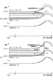
端部定着性に対する長さA、Bの影響度について、以下説明する。図6(a)に本実施例における定着装置を用いた場合の通常使用時の温度分布のイメージ図を示す。
<On the edge fixing property>
The influence of the lengths A and B on the end fixability will be described below. FIG. 6A shows an image of the temperature distribution during normal use when the fixing device in this embodiment is used.
最初に、図6(a)を用いて端部定着性に対するアルミ板81の領域aの長さAの影響について説明する。前述したように、アルミ板81の領域aでヒータ32から熱を受け取り、領域bで定着フィルム30に熱を与える。よって、アルミ板81の領域aがヒータ32の高温領域(発熱領域)と接触している限りは、熱の受け取りが期待できる。ヒータ32と接触しているアルミ板81の長手端部の領域aを介して領域bから定着フィルム30へ供給できる熱量が、アルミ板81の領域bの長手端部から定着フィルム30へ供給しなければならない熱量に対して十分余裕があるので、端部定着性は良い。
First, the influence of the length A of the area a of the
次に、図6(b)に比較例における定着装置を用いた場合の通常使用時の温度分布のイメージ図を示す。ここでは比較例として、アルミ板81の領域aの長さAよりも領域bの長さBが長い構成としている。図6(b)を用いて端部定着性に対するアルミ板81の領域bの長さBの影響について説明する。アルミ板81の領域bから定着フィルム30に熱を供給する際に、領域bの長さBが長い場合、領域bの長手端部は、定着フィルム30の長手中央よりも低温である領域と接触する。また、ヒータ32の高温領域(発熱領域)と接触するアルミ板81の領域aが本実施例よりも減少する。その結果、ヒータ32からアルミ板81の領域aを介して領域bに供給される熱量が十分でないため、アルミ板81の領域bの長手端部から定着フィルム30へ供給する熱量が不足し、端部定着性が悪化しやすい。端部定着性が悪化すると、最大サイズ紙など幅が広い記録材を定着処理した際に画像端部のトナーが溶融不足となる画像不良(端部オフセット)が発生する場合がある。
Next, FIG. 6B shows an image diagram of a temperature distribution during normal use when the fixing device in the comparative example is used. Here, as a comparative example, the length B of the area b is longer than the length A of the area a of the
以上述べたことから、端部定着性については、アルミ板81の領域bの長さBよりも領域aの長さAを長くする方が端部定着性は悪化し難い。
From the foregoing, with regard to the end fixing property, if the length A of the area a is longer than the length B of the area b of the
<非通紙部昇温について>
図7(a)に本実施例における定着装置を用いた場合の小サイズ通紙時の温度分布のイメージ図、図7(b)に比較例における定着装置を用いた場合の小サイズ通紙時の温度分布のイメージ図を示す。非通紙部昇温が発生した場合、熱源はヒータ32であることから、ヒータに直接アルミ板81が接触していることが好ましい。図7(a)に示すように、本実施例はヒータ32と接触しているアルミ板81の領域aの長さAが長い構成であり、これが長い程ヒータ32の均熱効果が得られる領域が広くなるので非通紙部昇温の抑制効果が高い。一方、比較例は、図7(b)に示すように、定着フィルム30に接触しているアルミ板81の領域bの長さBが長い構成であるので、ヒータ32に蓄積した熱を、定着フィルム30を介して均熱化しなければならないため、本実施例よりも均熱化の効率が悪い。その結果、アルミ板81の領域bの長さBが長い程、非通紙部昇温の抑制効果はあるものの、領域aの長さAと比較するとその効果が小さいことがわかる。
<About the non-sheet-passing part temperature rise>
FIG. 7 (a) is an image diagram of temperature distribution at the time of small size sheet passing when the fixing device in this embodiment is used, and FIG. 7 (b) is at the small size sheet passing when the fixing device in the comparative example is used. The image figure of temperature distribution is shown. Since the heat source is the
以上述べたことから、非通紙部昇温については、アルミ板81の領域bの長さBよりも領域aの長さAを長くする方が非通紙部昇温を抑制する効果が大きいことがわかる。アルミ板81の長手幅について、ヒータとの接触領域の最大長手幅をA、定着フィルムとの接触領域の最大長手幅をBとしたとき、B<Aとすることで非通紙部昇温抑制と端部定着性向上をより高いレベルで両立するという効果が得られる。 From the above, regarding the non-sheet-passing portion temperature rise, it is more effective to suppress the non-sheet-passing portion temperature increase by making the length A of the region a longer than the length B of the region b of the aluminum plate 81 I understand that. Assuming that the maximum longitudinal width of the contact area with the heater is A and the maximum longitudinal width of the contact area with the fixing film is B, the temperature rise of the non-sheet passing portion is suppressed by B <A. The effect of achieving both the improvement of the end portion fixing ability at a higher level can be obtained.
(5)画像出力実験結果
次に、本実施例を用いた場合の、画像出力実験の結果について説明する。
(5) Image output experiment result Next, the result of the image output experiment at the time of using a present Example is demonstrated.
非通紙部昇温と端部オフセットについて、以下のような評価を行った。まず、非通紙部昇温の評価について説明する。記録材には、坪量80g/m2、紙サイズがA4(小サイズ紙)のCanon Red Label(キヤノンE.U.、商品名)を用いた。定着装置が室温まで冷えている状態から、連続1000枚をプリントした際の加圧ローラ33の非通紙部におけるローラ表面温度の最大値を測定した。
The following evaluations were made on the non-sheet passing portion temperature rise and the end offset. First, the evaluation of the non-sheet-passing portion temperature rise will be described. As a recording material, Canon Red Label (Canon EU, trade name) having a basis weight of 80 g /
加圧ローラ33の耐熱性(弾性層として用いているシリコーンゴムの耐熱性)を考慮し、目標は230℃としてある。なので、230度を超える場合を×、230度以下を○とした。 In consideration of the heat resistance of the pressure roller 33 (heat resistance of silicone rubber used as an elastic layer), the target is set to 230 ° C. Therefore, when it exceeds 230 degrees, it was set as x and below 230 degrees as ○.
次に、端部オフセットの評価について説明する。記録材には、坪量75g/m2、紙サイズがLetter(最大サイズ紙)のXerox Vitアルミity Multipurpose Printer PaperXerox Business 4200 Paper(Xerox、商品名)を用いた。定着装置が室温まで冷えている状態から、全面RED(Y:100%+M:100%)の画像を連続100枚をプリントし、得られた画像を確認し、端部オフセットのレベルをランク付けした。全く発生しない場合を○、僅かに発生する場合を△、発生する場合を×とした。
Next, evaluation of the end offset will be described. As a recording material, Xerox Vit aluminum Multipurpose Printer Paper Xerox Business 4200 Paper (trade name: Xerox) with a basis weight of 75 g /
△レベルについては、僅かの発生であるものの、目標はオフセットが発生しない○であることとしている。 As for the Δ level, although the occurrence is slight, the target is assumed to be ○ where no offset occurs.
印字モードとしては普通紙モードを用い、実験に用いた画像形成装置において、このときのプロセススピードは300mm/sec、スループットは1分間に60枚である。尚、実験を行った雰囲気環境は温度23℃、湿度50%にて行った。 A plain paper mode is used as the printing mode, and in the image forming apparatus used in the experiment, the process speed at this time is 300 mm / sec, and the throughput is 60 sheets per minute. The atmosphere environment in which the experiment was conducted was a temperature of 23 ° C. and a humidity of 50%.
評価結果を表1に示す。実施例1の行を参照して説明する。本実施例では前述したように、アルミ板81の領域aの長さAは218mm、領域bの長さBは214mmとしている。本実施例においては、端部オフセットは発生せず(○)、非通紙部昇温は226℃であった。
The evaluation results are shown in Table 1. This will be described with reference to the line of the first embodiment. In the present embodiment, as described above, the length A of the area a of the

次に、比較例を用いた場合の、画像出力実験の結果について説明する。比較例として、画像形成装置の構成と定着装置の基本構成は実施例1と同一であり、その中で、アルミ板81の長さ(ヒータとの接触領域の最大長手幅A、および定着フィルムとの接触領域の最大長手幅B)のみ異なる条件のものを用いた。比較例1は、アルミ板の長さAが214mm、長さBが218mmである。比較例2は、アルミ板の長さAが216mm、長さBが216mmである。比較例3は、アルミ板の長さAが214mm、長さBが214mmである。比較例4は、アルミ板の長さAが218mm、長さBが218mmである。 Next, the result of the image output experiment in the case of using the comparative example will be described. As a comparative example, the configuration of the image forming apparatus and the basic configuration of the fixing device are the same as in Example 1, and among them, the length of the aluminum plate 81 (maximum longitudinal width A of the contact area with the heater and fixing film The conditions which differ only in the maximum longitudinal width B) of the contact area of. In Comparative Example 1, the length A of the aluminum plate is 214 mm and the length B is 218 mm. In Comparative Example 2, the length A of the aluminum plate is 216 mm, and the length B is 216 mm. In Comparative Example 3, the length A of the aluminum plate is 214 mm and the length B is 214 mm. In Comparative Example 4, the length A of the aluminum plate is 218 mm and the length B is 218 mm.
評価方法としては、本実施例を用いた場合の評価方法と同一の評価方法を用いて評価を行った。評価結果は表1に示すとおりである。比較例1においては、端部オフセットが発生し(×)、非通紙部昇温は236℃であった。比較例2においては、端部オフセットはわずかに発生し(△)、非通紙部昇温は231℃であった。比較例3においては、端部オフセットは発生せず(○)、非通紙部昇温は242℃であった。比較例4においては、端部オフセットは発生し(×)、非通紙部昇温は221℃であった。比較例1から4に比較して、本実施例は、より高いレベルで非通紙部昇温抑制と端部定着性向上を両立できることがわかる。 As an evaluation method, it evaluated using the evaluation method same as the evaluation method at the time of using a present Example. The evaluation results are as shown in Table 1. In Comparative Example 1, an end offset occurred (x), and the non-sheet-passing portion temperature rise was 236 ° C. In Comparative Example 2, the edge offset slightly occurred (Δ), and the non-sheet-passing portion temperature rise was 231 ° C. In Comparative Example 3, no end offset occurred (O), and the non-sheet-passing portion temperature rise was 242 ° C. In Comparative Example 4, the end offset occurred (x), and the non-sheet-passing portion temperature rise was 221 ° C. As compared with Comparative Examples 1 to 4, it can be seen that the present embodiment can achieve both suppression of temperature rise in the non-sheet-passing portion and improvement in the fixing ability at the end portion at a higher level.
以上説明したように、アルミ板の長手方向において、アルミ板の領域aの長手端部を、領域bの長手端部よりも外側まで延びているように構成することで非通紙部昇温抑制と端部定着性向上をより高いレベルで両立することができる。 As described above, in the longitudinal direction of the aluminum plate, the longitudinal end of the region a of the aluminum plate is extended to the outside of the longitudinal end of the region b, thereby suppressing the temperature rise of the non-sheet passing portion It is possible to simultaneously improve the end portion fixability at a higher level.
[実施例2]
本実施例では、実施例1で用いたアルミ板とは別の高熱伝導部材としての、グラファイトシートを用いた構成において、本発明を適用した例について説明する。画像形成装置の構成は実施例1と同様であり、図1に示すとおりである。よって重複する説明は省略する。
Example 2
In this embodiment, an example in which the present invention is applied to a configuration using a graphite sheet as a high thermal conductivity member different from the aluminum plate used in the first embodiment will be described. The configuration of the image forming apparatus is the same as that of the first embodiment, as shown in FIG. Therefore, duplicate explanations are omitted.
図8は、実施例2に係るカラー画像形成装置の定着装置を示す断面図である。実施例1と重複する説明は省略する。実施例1と異なる点は、アルミ板81ではなく、グラファイトシート83を用いていることが特徴である。グラファイトシート83は、2次元に結晶化した炭素がシート状に積層された構成となっており、シート面内の熱伝導率を非常に高くした材料である。図8に示すように、ヒータ32裏面には高熱伝導部材としてのグラファイトシート83を設けている。ヒータホルダ31の加圧ローラ33と対向する側には実施例1と同様に溝が設けられており、ヒータ32がその溝に嵌って所望の位置で支持されている。この際に、ヒータ32と前記ヒータ受け溝間にはグラファイトシート83を挟んで配置している。グラファイトシート83は断面が帽子型になるように曲げられており、ヒータ32と接触しつつ、回転する定着フィルム30とも接触するように配置されている。グラファイトシート83の断面の両端側(帽子のひさしの先)は、ヒータホルダ31に挟めて保持されるようになっている。
FIG. 8 is a cross-sectional view of the fixing device of the color image forming apparatus according to the second embodiment. The description overlapping with that of the first embodiment is omitted. The difference from the first embodiment is that the
図9を用いて、本実施例の高熱伝導部材としてのグラファイトシート83の位置関係について説明する。図9(a)は、本実施例に係るヒータ32、グラファイトシート83、ヒータホルダ31等を記録材搬送方向から見た図である。図9(b)は、本実施例に係るヒータ32とグラファイトシート83をヒータホルダ31側から見た概略図である。
The positional relationship of the
図9(a)に示すように、本実施例においては、高熱伝導部材としてのグラファイトシート83をヒータホルダ31に取り付けた後にさらにヒータ32を取り付ける。この結果、ヒータ32の長手中央部はグラファイトシート83を挟んでヒータホルダ31に支持され、また、ヒータ32の長手端部はヒータホルダ31に接触して支持される。
As shown in FIG. 9A, in the present embodiment, after the
グラファイトシート83は厚みが0.2mmのシート形状をしており、図9(b)に示すように、長手方向幅は、長さAが218mm、長さBが214mmと実施例1と同様の長さ関係としている。
The
グラファイトシート83は高熱伝導部材として金属を用いた場合に比べ柔軟なため、組み付けとともにヒータ32と密着しやすく、両者間の接触熱抵抗は低くなりやすい。よって、両者の接触面にグリスを介さなくともよく、本実施例ではこの位置にグリスは塗布していない構成とした。
The
また、グラファイトシート83は高熱伝導部材として金属を用いた場合に比べ熱容量が小さいという特徴がある。そのため、定着装置の加熱時の温度立ち上がりが早くできるというメリットがある。さらに、グラファイトシート83は、シート面内にグラファイトを配向させることでシート面内の熱伝導率を向上させているため、より高熱伝導性を得やすい。本実施例において用いたシートでは、熱伝導率が600W/(m・K)である。同材料は配向度のことなるグレードがあり、グレード違いで熱伝導率が異なる。1500W/(m・K)のシートなど、さらに熱伝導率の高いものを用いてもよい。さらに「非通紙部昇温」と「端部オフセット」を高いレベルで両立できる。また、アルミ板を用いた場合に比べると、厚みの制約があり(流通している厚みのグレードがアルミに比べ少ない)、組み付けや保持方法に工夫が必要となる。
In addition, the
本実施例を用いた場合の効果は、実施例1と同様であるため、ここでは省略する。 The effects of using the present embodiment are the same as those of the first embodiment, so the description is omitted here.
以上説明したように、本実施例の構成を採用することで非通紙部昇温抑制と端部定着性向上をより高いレベルで両立することができる。 As described above, by adopting the configuration of this embodiment, it is possible to achieve both the suppression of temperature rise in the non-sheet-passing portion and the improvement in the fixing ability at the end portion at a higher level.
[実施例3]
実施例1及び2において、高熱伝導部材の領域aの長手長さAと領域bの長手長さBを用いて本発明を説明した。この構成は画像形成装置の長手両端部のいずれにおいても本発明の効果を得ることができる構成である。本実施例では、少なくとも片側(長手一端側)において効果を得る構成について説明する。
[Example 3]
In Examples 1 and 2, the present invention has been described using the longitudinal length A of the region a and the longitudinal length B of the region b of the high thermal conductivity member. This configuration is a configuration that can obtain the effects of the present invention at any of both longitudinal end portions of the image forming apparatus. In this embodiment, a configuration for obtaining an effect on at least one side (longitudinal one end side) will be described.
本実施例が効果的に用いられる一例として、搬送(通紙)位置の基準が片側基準となっている構成を用いて説明する。画像形成装置の構成は実施例1と同様であり、図1に示すとおりである。また、定着装置の長手方向断面については、実施例1と同様であり、図2に示すとおりである。よって重複する説明は省略する。 As an example in which the present embodiment is effectively used, a description will be given using a configuration in which the reference of the transport (sheet passing) position is the one-side reference. The configuration of the image forming apparatus is the same as that of the first embodiment, as shown in FIG. The longitudinal section of the fixing device is the same as that of the first embodiment, as shown in FIG. Therefore, duplicate explanations are omitted.
図10を用いて、実施例1と異なる本実施例のアルミ板81の長手の位置関係について説明する。図10(a)は、本実施例に係るヒータ32、アルミ板81、ヒータホルダ31等を記録材搬送方向から見た図である。図10(b)は、本実施例に係るヒータ32とアルミ板81をヒータホルダ31側から見た概略断面図である。図10に示すように、本実施例においては、搬送基準が図中右側になっており、LTRとA4の右端は同位置となっている。この場合、図中右側のではA4通紙をしても非通紙部昇温は厳しくない。そのため、右側については非通紙部昇温抑制と端部定着性向上の両立がしやすい。よって、本実施例においては、図中左側のみで効果が得られる構成であれば良い。
The positional relationship in the longitudinal direction of the
片側のみで効果を得るためには紙(記録材)基準からの長手長さを考えればよい。ここではLTR通紙位置の中心から、アルミ板81の図中左側端部(効果を得たい側の端部)との距離を用いて説明する。本実施例の効果を得るためのアルミ板端部81の左側端部の構成について、実施例1と同等の構成としてある。即ち、長さAに対応した、「LTRの通紙領域中心」と「アルミ板81のヒータ32との接触領域の左側端部」までの最大となる長手長さとして109mm(実施例1の長さAの半分)としている。また、長さBに対応した、「LTRの通紙領域中心」と「アルミ板81の定着フィルム30との接触領域の左側端部」までの最大となる長手長さとして107mm(実施例1の長さBの半分)としている。
In order to obtain the effect with only one side, it is sufficient to consider the longitudinal length from the paper (recording material) standard. Here, description will be made using the distance from the center of the LTR sheet passing position to the left end (the end on the side where the effect is desired) of the
一方、図中右側は、端部オフセットがOKとなる比較例3の構成でも良い。従って、LTRの通紙領域中心とアルミ板81の領域aの右側端部までの最大長手長さを107mm、LTRの通紙領域中心とアルミ板81の領域bの右側端部までの最大長手長さを107mmとしている。
On the other hand, the right side in the figure may have the configuration of Comparative Example 3 in which the end offset is OK. Accordingly, the maximum longitudinal length to the right end of the area a of the
以上説明したように、本実施例の構成を作用することで、非通紙部昇温抑制と端部定着性向上をより高いレベルで両立することができる。 As described above, by operating the configuration of the present embodiment, it is possible to achieve both the suppression of the temperature rise in the non-sheet-passing portion and the improvement in the end portion fixability at a higher level.
[実施例4]
本実施例では、実施例1で用いたアルミ板の長さAが異なる構成において、本発明を適用した例について説明する。画像形成装置の構成は実施例1と同様であり、図1に示すとおりである。また、定着装置の構成は実施例1と同様であり、図2に示すとおりである。よって重複する説明は省略する。図11を用いて、実施例1と異なる本実施例のアルミ板81の長手の位置関係について説明する。図11(a)は、本実施例に係るヒータ32、アルミ板81、ヒータホルダ31を記録材搬送方向から見た図である。図11(b)は、本実施例に係るヒータ32とアルミ板81をヒータホルダ31側から見た概略断面図である。本実施例では、アルミ板の長さAが219.5mm、長さBが214mmとしてあり、ヒータ32の抵抗発熱体82の長手長さ(219mm)よりもアルミ板81の長さAが長いことを特徴としている。
Example 4
In this embodiment, an example in which the present invention is applied in a configuration in which the length A of the aluminum plate used in the first embodiment is different will be described. The configuration of the image forming apparatus is the same as that of the first embodiment, as shown in FIG. The configuration of the fixing device is the same as that of the first embodiment, as shown in FIG. Therefore, duplicate explanations are omitted. The longitudinal positional relationship of the
以下に、本実施例を用いた場合の、画像出力実験の結果について説明し、本実施例における効果について述べる。画像形成装置の構成と定着装置の基本構成は実施例1と同一であり、その中で、アルミ板長さのみ異なる条件のものを用いた。評価方法としては、実施例1を用いた場合の評価方法と同一の評価方法を用いて評価を行った。評価結果は表2に示すとおりである。 Hereinafter, the result of the image output experiment in the case of using the present embodiment will be described, and the effect in the present embodiment will be described. The configuration of the image forming apparatus and the basic configuration of the fixing device were the same as those of Example 1, and among them, those having conditions different only in the aluminum plate length were used. As an evaluation method, it evaluated using the evaluation method same as the evaluation method at the time of using Example 1. FIG. The evaluation results are as shown in Table 2.
実施例1の結果は、実施例1で述べたとおりである。実施例4においては、端部オフセットが発生は発生せず(○)、非通紙部昇温は221℃であり、実施例1よりも非通紙部昇抑制効果を大きくすることができた。また、アルミ板81の領域bの幅は、本実施例の画像形成装置で使用可能な最大幅の記録材であるLTR(幅約216mm)の最大画像形成領域(画像保証領域)である206mm(左右余白5mm)よりも長いことが好ましい。つまり、アルミ板81の領域bの長手端部は、アルミ板の長手方向において、最大画像形成領域の端部よりも外側にあることが好ましい。
The results of Example 1 are as described in Example 1. In Example 4, the occurrence of the end offset did not occur (O), and the temperature rise at the non-sheet-passing portion was 221 ° C. . Further, the width of the area b of the
(変形例)
以下、本実施例1〜4の変形例について説明する。実施例1〜4において、ヒータ32の抵抗発熱体82が長手方向に延びる2本パターンであり、長手方向に亘って短手方向の幅(抵抗値)が等しい構成であったが、これに限定されない。長手方向において抵抗発熱体82の抵抗を調整して中央と端部の発熱量を異なるようにしたヒータや、長手方向の長さが異なる複数の抵抗発熱体の通電比率を独立または連動してヒータの発熱分布を制御可能なヒータでも良い。抵抗発熱体が1本パターンのヒータであっても良い。
(Modification)
Hereinafter, modifications of the first to fourth embodiments will be described. In the first to fourth embodiments, the
また、本発明は、実施例1〜4において、ヒータ32からなる定着装置を用いて説明した。しかし、ポリイミドシートヒータやシリコンラバーヒータやシーズヒータなど、加熱体と定着フィルムが接触可能で、かつ高熱伝導部材の熱伝導率が加熱体の基材よりも高い構成であれば、同様の効果が得られ、本発明を適用できる。
The present invention has been described using the fixing device including the
また、本発明は、実施例1〜4において、ヒータ32と高熱伝導部材の領域aについて、記録材搬送方向において長手長さがAで一定の構成を用いて説明した。しかし、長さAが一定でない構成においても同様の効果は得られる。図12(a)〜(d)に一例を示す。図12はヒータ及び熱伝導部材をヒータホルダ側から見た図である。図12(a)〜(d)に示すように、最大となる長手長さAがBよりも長ければ良く、同様の効果は得られる。
Further, in the first to fourth embodiments, the present invention has been described using the configuration in which the longitudinal length is A in the recording material conveyance direction with respect to the
また、本発明は、実施例1〜4において、ヒータホルダ31を、定着フィルム30の円筒形状を妨げない形状とした構成を用いて説明した。しかし、図13に示すように、加圧ローラ33のR形状に倣う様にヒータホルダ31に突起を設けたような構成にも本発明を適用できる。
Further, the present invention has been described using the configuration in which the
また、本発明は、上述した実施例4において、高熱伝導部材の長手長さAとBを用いて説明した。この構成は画像形成装置の長手両端部のうちいずれか一方の側のみにおいても適用できる。実施例3のように、片側のみで効果を得るためには紙(記録材)幅方向中央からの幅方向の長さを考えればよい。例えば、LTR通紙中心を基準として、領域aの最大幅はA/2、領域bの最大幅はB/2とする。そして、それらと対応したLTR通紙中心を基準としてヒータ32の抵抗発熱体82の片側端部までの最大となる長手長さ、および最大通紙幅の最大画像形成領域(画像保証領域)の片側端部までの最大となる長手長さ、を考慮すればよい。
The present invention has been described using the longitudinal lengths A and B of the high heat transfer member in the fourth embodiment described above. This configuration can be applied to only one of the longitudinal ends of the image forming apparatus. As in the third embodiment, in order to obtain the effect with only one side, it is sufficient to consider the length in the width direction from the center of the paper (recording material) in the width direction. For example, it is assumed that the maximum width of the area a is A / 2 and the maximum width of the area b is B / 2 with reference to the LTR sheet passing center. The maximum longitudinal length of the
[実施例5]
本実施例は、実施例1に対してアルミ板81の形状が異なるが、その他の構成は同じであるので、説明を省略する。本実施例のアルミ板81について詳細を説明する。
[Example 5]
The present embodiment differs from the first embodiment in the shape of the
図14を用いて、本実施例の高熱伝導部材としてのアルミ板81の長手の位置関係について説明する。図14(a)は、本実施例に係るヒータ32、アルミ板81、ヒータホルダ31等を記録材搬送方向から見た図である。図14(b)は、本実施例に係るヒータ32とアルミ板81をヒータホルダ31側から見た概略断面図である。また、図14(c)は定着ニップ部の近傍の概略断面図である。
The positional relationship in the longitudinal direction of the
図14(a)に示すように、本実施例においては、高熱伝導部材としてのアルミ板81をヒータホルダ31に取り付けた後にさらにヒータ32を取り付ける。この結果、ヒータ32の長手中央部はアルミ板81を挟んでヒータホルダ31に支持され、また、ヒータ32の長手端部はヒータホルダ31に接触して支持される。
As shown in FIG. 14A, in the present embodiment, after the
ヒータ32とアルミ板81の接触面においては、両者間の接触熱抵抗が小さいほど熱効率が良くなるため望ましい。そのため、本実施例においては、前述の耐熱性グリスを共用して用い、ヒータ32とアルミ板81の間にグリスを介在させている。
The smaller the contact thermal resistance between the
図14(b)に示すように、本実施例のヒータ32の基板は長手方向長さが270mm、短手方向長さが6.0mm、厚みが1.0mmの板状の形状であり、抵抗発熱体82の長手長さは219mmであり、同一抵抗の2本パターンを形成している。
As shown in FIG. 14B, the substrate of the
図14(c)に示すように、アルミ板81は断面が帽子型になるようにZ形状に折り曲げられている。アルミ板81の帽子のトップクラウンに当たる部分が、ヒータ32と接触する領域(部分)となる。ここでは、この領域(部分)を領域(ヒータ接触部)aとし、帽子型のひさしに当たる部分の一部(ひさしと滑りの境界部分)が、定着フィルムと接触する領域(部分)となる。この領域(部分)を領域(フィルム接触部)bとする。本実施例においては、帽子型のひさしに当たる部分の記録材搬送方向の上流側の領域bの長手長さB1が218mm、下流側の領域bの長さB2を214mmとして、定着フィルム30の長手長さ(232mm)より短い長さとしている。アルミ板81の上流側の領域bの長さB1は、最大幅の記録材であるLTRサイズ紙(216mm幅)がある程度バラツキをもって搬送されても記録材端部まで定着フィルム30へ熱伝導するようにするために218mmとしている。また、図14(c)に示すようにアルミ板81の上流側の領域bは、ニップ部の加圧方向において、ヒータ32の定着フィルム30と接触する面(第1の面)よりも加圧ローラ33側に突出させている。これは、ステイプルが打たれた記録材を通紙された場合にステイプルがヒータ32の上流の角部に引っ掛かり、定着フィルムが破損するのを防止する為である。ステイプルによる定着フィルム30の破損を防止する意味でもアルミ板81の上流側の領域bの長さB1は最大幅を有する記録材の幅よりも広いことが好ましい。一方、アルミ板81の下流側の領域bは、ステイプルによる定着フィルム30の破損の懸念がないので、ヒータ32の第1の面と略同一高さとし、長手長さB2も最大幅の記録材の幅より狭くしている。アルミ板81の下流側の領域bの長手長さB2を狭くすることにより、定着フィルム30の端部への熱供給は若干減少するが、抵抗発熱体の長さ等で調整することも可能である。
As shown in FIG. 14C, the
このアルミ板81を介してヒータ32からの第1の面と反対側の第2の面の熱を定着フィルム30へ供給することができるので、定着フィルム30の加熱効率を大幅に向上させることができる。
Since heat of the second surface opposite to the first surface from the
しかしながら、アルミ板81の定着フィルム30との接触領域の長手端部では金属のエッジと定着フィルム30の内面とが摺動することによって徐々に削れる場合がある。特に、アルミ板81の上流側の領域bと下流側の領域bの長手端部のエッジの位置が同じ場合に両方の削れが加算されるために、定着フィルム30の内面の削れがより顕著となる。そこで、本実施例ではアルミ板81の上流側の領域bと、それと同じ側の下流側の領域bの長手端部のエッジの位置を異ならせている。尚、アルミ板81は長手端部のエッジによる定着フィルム30の内面削れを低減するために、アルミ板81の形状を打ち抜く際のダレ側を定着フィルム30との接触する側にしている。更に、研磨等の加工等を行っても良い。
However, at the longitudinal end of the contact area of the
次に、本実施例を用いた場合の、実験結果について説明する。本実施例の構成でアルミ板81の長手方向端部のエッジ部での定着フィルム内面削れの影響を検証するために通紙耐久を行った。通紙耐久に用いた記録材には、坪量75g/m2、紙サイズがLetter(最大サイズ紙)の記録材を用いた。また、通紙モードとしては、定着フィルムの回転数が多く、最も定着フィルム内面削れに厳しい1枚間欠プリントの通紙モードで行い、5万枚毎に表面粗さ計((株)東京精密製:サーフコム1500SD2)により定着フィルム内面の削れ量を測定した。実験に用いた画像形成装置において、このときのプロセススピードは200mm/sec、スループットはLTR縦送りで1分間に40枚、装置寿命は10万枚である。尚、実験を行った雰囲気環境は温度23℃、湿度50%にて行った。
Next, experimental results when this embodiment is used will be described. In order to verify the influence of internal surface scraping of the fixing film at the edge portion of the longitudinal direction end portion of the
評価結果を表3に示す。本実施例の構成では前述の通り、アルミ板81の上流側の領域bの長さB1は218mm、下流側の領域bの長さB2は214mmとし、上流側と下流側でアルミ板81の端部のエッジが定着フィルム内面の異なる位置で摺擦する構成としている。一方、比較例5の構成は、アルミ板81の上流側及び下流側の長さは共に218mmとし、アルミ板81の長手方向において、上下流のアルミ板81の長手端部のエッジ部が定着フィルム30の内面のほぼ同一の位置で摺動する構成である。
The evaluation results are shown in Table 3. In the configuration of this embodiment, as described above, the length B1 of the region b on the upstream side of the
評価結果は表3に示すとおりである。本実施例の構成では、装置の寿命である10万枚の通紙を行っても定着フィルム内面の削れ量は比較的少ない。 The evaluation results are as shown in Table 3. In the configuration of the present embodiment, the amount of scraping of the inner surface of the fixing film is relatively small even when 100,000 sheets are passed, which is the lifetime of the apparatus.
一方、比較例5の構成においては定着装置の寿命の10万枚の通紙により定着フィルム内面の削れ量が本実施例の2倍になった。尚、本実施例で示したアルミ板81の領域bの長さは一例であり、ヒータ32の抵抗発熱体82の長さや発熱分布、加圧ローラ33の構成により様々な構成をとり得る。定着ニップ部(定着フィルム30の回転方向)の上下流側でアルミ板81の長手端部のエッジ部の位置を異ならせることによって同様の効果が得られることは言うまでもない。
On the other hand, in the configuration of Comparative Example 5, the amount of scraping of the inner surface of the fixing film was twice that of this example due to the passage of 100,000 sheets of the lifetime of the fixing device. The length of the region b of the
以上説明したように、アルミ板の長手端部のエッジの位置を定着ニップ部の上下流で異なるようにすることで、定着フィルム内面の削れ等のダメージを低減することができ、長寿命、且つ、高速印字可能な定着装置を提供することができる。 As described above, by making the position of the edge of the longitudinal end of the aluminum plate different on the upper and lower sides of the fixing nip portion, damage such as scraping of the inner surface of the fixing film can be reduced, and the long life and And a fixing device capable of high-speed printing can be provided.
[実施例6]
本実施例では、実施例5で用いた高熱伝導部材としてのアルミ板81の長手端部のエッジを記録材の搬送方向に対して図15のように所定の角度をもって斜めに形成する構成について説明する。尚、画像形成装置の構成は実施例1と同様であり、重複する説明は省略する。
[Example 6]
In this embodiment, a configuration is described in which the edge of the longitudinal end of the
図15を用いて、本実施例の高熱伝導部材としてのアルミ板81のエッジ形状について説明する。図15(a)は本実施例に係るヒータ、アルミ板、ヒータホルダ等を搬送方向から見た図である。図15(b)は本実施例に係るヒータ及びアルミ板をヒータホルダ側から見た図である。また、図15(c)は本実施例に係るアルミ板の長手端部を拡大した図である。
The edge shape of the
本実施例の特徴は、図15(c)に示すように、アルミ板81の領域bの長手端部のエッジを記録材の搬送方向に関し上流側が角度α、下流側が角度βとなるように斜めに形成している構成である。この特徴的な構成によって、定着フィルム30の内面とアルミ板81のエッジで摺擦する部分を分散し、削れを低減することができる。この角度α、βは5°〜85°程度、より好ましくは20°〜70°とするのが良い。本実施例では角度α、βが共に60°の構成例について説明するが、角度αとβで異なる角度に設定することも可能である。
The characteristic of this embodiment is that, as shown in FIG. 15C, the edge of the longitudinal end of the area b of the
本実施例のようにアルミ板81の長手方向端部のエッジ部を斜め形状に形成することによってエッジ部付近の定着フィルム30の温度変化を緩やかにすることができ、端部昇温を低減できるという効果も得られる。非通紙部昇温の低減効果について図16を用いて説明する。図16(a)はアルミ板81の長手端部のエッジを拡大した図である。図16(a)の実線が本実施例の形状であり、破線(エッジがストレート形状)が比較例6である。図16(b)及び(c)はそれぞれ、LTRサイズの記録材、A4サイズの記録材を定着処理した場合における定着フィルム30の長手方向の温度分布のイメージ図である。本実施例においては、定着フィルム30と接触するアルミ板81の領域bの面積を長手方向の外側に向かうにつれて徐々に減少させている。従って、図16(b)及び(c)の実線のように、定着フィルム30の長手端部に向かって定着フィルム30の温度が緩やかに変化する。一方、比較例6においては、図16(b)及び(c)の破線のように、アルミ板81の領域bの面積が急に変化するので、定着フィルム30の温度変化も急に変化する。定着フィルム30の温度を長手端部まで定着可能な温度に保つ為には、比較例6の構成の方が長手端部まで高温になるように構成する必要がある。これにより、LTRサイズ記録材よりも幅の狭いA4紙サイズ記録材を連続的に定着処理した場合、本実施例の方が比較例6よりも非通紙部昇温が悪化しにくいことがわかる。
By forming the edge portion of the longitudinal direction end portion of the
次に、本実施例を用いた場合の、実験結果について説明する。本実施例の構成では前述の通り、アルミ板81のエッジ部を斜め形状(60°)とする構成と、比較例6としてアルミ板81の上流側及び下流側の長さは共に218mmとし、端部のエッジが定着フィルム30のほぼ同一部で摺動する構成との比較を行った。
Next, experimental results when this embodiment is used will be described. In the configuration of the present embodiment, as described above, the edge of the
評価結果は表4に示すとおりである。本実施例の構成では、定着装置の寿命である10万枚の通紙(定着処理)を行っても定着フィルム30内面の削れ量は少ない。一方、比較例6においては装置寿命の10万枚の通紙により定着フィルム30内面の削れ量が実施例6よりも多い。
The evaluation results are as shown in Table 4. In the configuration of the present embodiment, the scraping amount on the inner surface of the fixing
尚、本実施例では定着ニップの上下流側の双方の領域でアルミ板81と定着フィルム30が接触する構成について説明したが、定着ニップの上流側のみ、又は、下流側のみアルミ板81と定着フィルム30を接触させる構成においても同様の効果が得られる。
In the present embodiment, the configuration in which the
また、本実施例の構成では、アルミ板81の接触領域bの長手端部のエッジを斜め形状となっている為に、アルミ板の折り曲げ工程において製造上の技術難易度が高く、部品コストや部品精度に影響を与える。その為、装置に要求される寿命やコスト等の特性に応じて比較例6の構成(エッジ部ストレート)か本実施例の構成(エッジ部斜め形状)かを選択することが望ましい。
Further, in the configuration of the present embodiment, since the edge of the longitudinal end of the contact area b of the
以上説明したように、本実施例の構成にすることによって、定着フィルム内面の削れ等のダメージを低減することができ、長寿命、且つ、高速印字可能な定着装置を提供することができる。 As described above, by adopting the configuration of the present embodiment, damage such as abrasion of the inner surface of the fixing film can be reduced, and a long-life, high-speed printing fixing device can be provided.
[実施例7]
本実施例の画像形成装置は、プロセススピードは250mm/sec、スループットはLTR縦送りで1分間に50枚、装置寿命は30万枚である以外は実施例1と同様であり、重複する説明は省略する。
[Example 7]
The image forming apparatus of this embodiment is the same as that of Embodiment 1 except that the process speed is 250 mm / sec, the throughput is 50 sheets per minute for LTR longitudinal feed, and the apparatus life is 300,000 sheets. I omit it.
図17を用いて、本実施例の高熱伝導部材としてのアルミ板81のエッジ形状について説明する。図17(a)は本実施例に係るヒータ、アルミ板、ヒータホルダ等を記録材搬送方向から見た図である。図17(b)は、本実施例に係るヒータ及びアルミ板をヒータホルダ側から見た図である。また、図17(c)はアルミ板の長手端部を拡大した図である。
The edge shape of the
本実施例においては、図17(c)のようにアルミ板81の定着フィルム30と接触する領域bの長手端部のエッジを記録材搬送方向に対して上流側が角度α、下流側が角度βとなるように斜めに形成している。これによって、定着フィルム30の内面とアルミ板81のエッジでの摺擦する部分を分散し、削れを低減することができる。更に、アルミ板81のエッジの位置を定着二っプ部の上下流で異ならせることにより、定着フィルム30内面の摺擦部を分散させることができる。この角度α、βは5°〜85°程度、より好ましくは20°〜70°とするのが良い。本実施例では角度α、βが共に40°の構について説明するが、角度αとβで異なる角度に設定することも可能である。また、本実施例ではアルミ板81の上流側の端部エッジも定着フィルム30の進行方向に対して順方向で摺動するため定着フィルム30の内面削れには最も良い構成である。
In this embodiment, as shown in FIG. 17C, the edge of the longitudinal end of the area b of the
次に、本実施例を用いた場合の、実験結果について説明する。本実施例の構成では前述の通り、アルミ板81の領域bのエッジを斜め形状(40°)にする共に、定着ニップ部の上下流で位置を異ならせる構成と、比較例7としては実施例6の構成を用いた。評価方法は前記実施例1と同様の方法で比較を行った。また、実験に用いた画像形成装置は、プロセススピードは250mm/sec、スループットはLTR縦送りで1分間に50枚、装置寿命は30万枚である。
Next, experimental results when this embodiment is used will be described. In the configuration of the present embodiment, as described above, the edge of the region b of the
評価結果は表5に示すとおりである。本実施例の構成では、装置の寿命である30万枚の通紙を行っても定着フィルム30内面の削れ量は比較例7よりも少ない。但し、比較例7の構成は装置寿命については本実施例の構成に劣るものの、非通紙部昇温の抑制効果については本実施例よりも優れており、装置の特性に応じて選択することが望ましい。
The evaluation results are as shown in Table 5. In the configuration of the present embodiment, the scraped amount of the inner surface of the fixing
また、本実施例の変形例として、図18のような構成においても定着フィルム30内面の削れ低減効果があることが確認されている。但し、アルミ板81の上流側の長手端部のエッジが定着フィルム30の進行方向に対してカウンター方向で摺動するため定着フィルム30の内面削れ低減効果は本実施例よりも低い。しかし、製造上の難易度は図18の構成の方が低い(アルミ板の折り曲げの根元より先端部の幅が広い)為、装置のコスト/精度等の要求特性に応じてどちらの構成かを選択するのが望ましい。
Further, as a modification of the present embodiment, it is confirmed that the scraping reduction effect of the inner surface of the fixing
以上説明したように、本実施例の構成を採用することで、定着フィルム30内面の削れ等のダメージを低減することができ、長寿命、且つ、高速印字可能な定着装置を提供することができる。
As described above, by adopting the configuration of this embodiment, damage such as abrasion of the inner surface of the fixing
12 定着装置
30 定着フィルム
32 ヒータ
33 加圧ローラ
81 アルミ板
83 グラファイトシート
a ヒータ接触部
b アルミ板接触部
P 記録材
t トナー像
12
Claims (5)
第1の面と、前記第1の面と反対側の第2の面を有する板状のヒータであって、前記第1の面で前記フィルムの内面に接触する長細い板状のヒータと、
前記ヒータの長手方向に長く、前記ヒータの前記第2の面に接触しているヒータ接触部を有する熱伝導部材と、
を有し、前記フィルムを介した前記ヒータの熱でトナー画像を加熱し前記トナー画像を記録材に定着する定着装置において、
前記熱伝導部材は、前記フィルムの回転方向に関し前記ヒータの上流端よりも上流側の領域及び前記ヒータの下流端よりも下流側の領域の少なくとも一方において、前記フィルムに近づく方向に延びて前記フィルムの内面に接触するフィルム接触部を有し、
前記熱伝導部材の長手方向において、前記ヒータ接触部の長手端部は、それと同じ側の前記フィルム接触部の長手端部よりも外側まで延びていることを特徴とする定着装置。 A rotatable tubular film,
A plate-like heater having a first surface and a second surface opposite to the first surface, the long thin plate heater contacting the inner surface of the film on the first surface;
A heat conducting member having a heater contact portion which is long in the longitudinal direction of the heater and is in contact with the second surface of the heater;
A fixing device that heats a toner image by the heat of the heater through the film and fixes the toner image on a recording material;
The heat conducting member extends in a direction approaching the film in at least one of a region upstream of the upstream end of the heater and a region downstream of the downstream end of the heater in the rotational direction of the film. A film contact portion contacting the inner surface of the
A fixing device, wherein a longitudinal end of the heater contact portion extends outward beyond a longitudinal end of the film contact portion on the same side in the longitudinal direction of the heat conducting member.
Priority Applications (5)
| Application Number | Priority Date | Filing Date | Title |
|---|---|---|---|
| JP2017199625A JP7046556B2 (en) | 2017-10-13 | 2017-10-13 | Fixing device |
| EP18199450.0A EP3470930B1 (en) | 2017-10-13 | 2018-10-09 | Fixing device |
| US16/156,942 US10725405B2 (en) | 2017-10-13 | 2018-10-10 | Fixing device |
| KR1020180120846A KR102294036B1 (en) | 2017-10-13 | 2018-10-11 | Fixing device |
| CN201811189177.5A CN109669338B (en) | 2017-10-13 | 2018-10-12 | Fixing apparatus |
Applications Claiming Priority (1)
| Application Number | Priority Date | Filing Date | Title |
|---|---|---|---|
| JP2017199625A JP7046556B2 (en) | 2017-10-13 | 2017-10-13 | Fixing device |
Publications (3)
| Publication Number | Publication Date |
|---|---|
| JP2019074606A true JP2019074606A (en) | 2019-05-16 |
| JP2019074606A5 JP2019074606A5 (en) | 2020-11-26 |
| JP7046556B2 JP7046556B2 (en) | 2022-04-04 |
Family
ID=63832253
Family Applications (1)
| Application Number | Title | Priority Date | Filing Date |
|---|---|---|---|
| JP2017199625A Active JP7046556B2 (en) | 2017-10-13 | 2017-10-13 | Fixing device |
Country Status (5)
| Country | Link |
|---|---|
| US (1) | US10725405B2 (en) |
| EP (1) | EP3470930B1 (en) |
| JP (1) | JP7046556B2 (en) |
| KR (1) | KR102294036B1 (en) |
| CN (1) | CN109669338B (en) |
Cited By (2)
| Publication number | Priority date | Publication date | Assignee | Title |
|---|---|---|---|---|
| JP2021039193A (en) * | 2019-09-02 | 2021-03-11 | 東芝テック株式会社 | Heating device and image processing device |
| US20220229387A1 (en) * | 2021-01-15 | 2022-07-21 | Brother Kogyo Kabushiki Kaisha | Heating unit |
Families Citing this family (6)
| Publication number | Priority date | Publication date | Assignee | Title |
|---|---|---|---|---|
| JP7408321B2 (en) * | 2019-09-06 | 2024-01-05 | キヤノン株式会社 | Fixing device and image forming device |
| JP7391614B2 (en) * | 2019-11-01 | 2023-12-05 | 東芝テック株式会社 | Fixing device and image forming device |
| US11143996B2 (en) * | 2019-12-13 | 2021-10-12 | Ricoh Company, Ltd. | Heating device, fixing device and image forming apparatus |
| JP2021149050A (en) * | 2020-03-23 | 2021-09-27 | 東芝テック株式会社 | Heating device and image processing apparatus |
| US11599048B2 (en) * | 2020-12-04 | 2023-03-07 | Brother Kogyo Kabushiki Kaisha | Fixing device for fixing toner to sheet |
| US11340545B1 (en) * | 2021-02-09 | 2022-05-24 | Toshiba Tec Kabushiki Kaisha | Image forming apparatus including heat transmission member in contact with heater substrate |
Citations (5)
| Publication number | Priority date | Publication date | Assignee | Title |
|---|---|---|---|---|
| JP2003257592A (en) * | 2002-02-27 | 2003-09-12 | Canon Inc | Heating device |
| US20090092424A1 (en) * | 2007-10-05 | 2009-04-09 | Samsung Electronics Co., Ltd. | Fixing unit and image forming apparatus including the same |
| JP2014052662A (en) * | 2013-12-17 | 2014-03-20 | Canon Inc | Fixing device |
| JP2015176085A (en) * | 2014-03-17 | 2015-10-05 | キヤノン株式会社 | fixing device |
| JP2015176030A (en) * | 2014-03-17 | 2015-10-05 | キヤノン株式会社 | fixing device |
Family Cites Families (17)
| Publication number | Priority date | Publication date | Assignee | Title |
|---|---|---|---|---|
| JP3445034B2 (en) * | 1995-07-28 | 2003-09-08 | キヤノン株式会社 | Heating equipment |
| JP2000206810A (en) * | 1999-01-13 | 2000-07-28 | Canon Inc | Thermal fixation device and image forming device |
| JP2003332026A (en) * | 2002-05-14 | 2003-11-21 | Canon Inc | Heating element and heat-fixing device |
| KR101145216B1 (en) * | 2007-05-21 | 2012-05-25 | 삼성전자주식회사 | Fusing unit and image forming apparatus employing the same |
| JP2011033768A (en) * | 2009-07-31 | 2011-02-17 | Canon Inc | Heating rotating body and image heating device using the heating rotating body |
| JP5610894B2 (en) * | 2010-07-24 | 2014-10-22 | キヤノン株式会社 | Image heating apparatus and pressure roller used in the image heating apparatus |
| JP5863739B2 (en) * | 2012-11-21 | 2016-02-17 | キヤノン株式会社 | Image heating device |
| JP6103910B2 (en) * | 2012-12-10 | 2017-03-29 | キヤノン株式会社 | Image heating device |
| KR20140085118A (en) * | 2012-12-27 | 2014-07-07 | 삼성전자주식회사 | Fixing device and image forming apparatus using the same |
| GB2533195B (en) * | 2012-12-28 | 2017-06-28 | Canon Kk | Fixing device |
| JP6405779B2 (en) * | 2013-10-18 | 2018-10-17 | 株式会社リコー | Fixing apparatus and image forming apparatus |
| JP6478545B2 (en) * | 2013-11-18 | 2019-03-06 | キヤノン株式会社 | Image heating apparatus and image forming apparatus equipped with the image heating apparatus |
| JP6242181B2 (en) * | 2013-11-20 | 2017-12-06 | キヤノン株式会社 | Fixing device |
| JP6604731B2 (en) * | 2014-05-20 | 2019-11-13 | キヤノン株式会社 | Image heating device |
| JP6253508B2 (en) * | 2014-05-21 | 2017-12-27 | キヤノン株式会社 | Image heating apparatus and image forming apparatus equipped with the image heating apparatus |
| JP6395570B2 (en) | 2014-11-14 | 2018-09-26 | キヤノン株式会社 | Fixing device |
| JP6579754B2 (en) * | 2015-01-27 | 2019-09-25 | キヤノン株式会社 | Fixing device |
-
2017
- 2017-10-13 JP JP2017199625A patent/JP7046556B2/en active Active
-
2018
- 2018-10-09 EP EP18199450.0A patent/EP3470930B1/en active Active
- 2018-10-10 US US16/156,942 patent/US10725405B2/en active Active
- 2018-10-11 KR KR1020180120846A patent/KR102294036B1/en active IP Right Grant
- 2018-10-12 CN CN201811189177.5A patent/CN109669338B/en active Active
Patent Citations (5)
| Publication number | Priority date | Publication date | Assignee | Title |
|---|---|---|---|---|
| JP2003257592A (en) * | 2002-02-27 | 2003-09-12 | Canon Inc | Heating device |
| US20090092424A1 (en) * | 2007-10-05 | 2009-04-09 | Samsung Electronics Co., Ltd. | Fixing unit and image forming apparatus including the same |
| JP2014052662A (en) * | 2013-12-17 | 2014-03-20 | Canon Inc | Fixing device |
| JP2015176085A (en) * | 2014-03-17 | 2015-10-05 | キヤノン株式会社 | fixing device |
| JP2015176030A (en) * | 2014-03-17 | 2015-10-05 | キヤノン株式会社 | fixing device |
Cited By (3)
| Publication number | Priority date | Publication date | Assignee | Title |
|---|---|---|---|---|
| JP2021039193A (en) * | 2019-09-02 | 2021-03-11 | 東芝テック株式会社 | Heating device and image processing device |
| US20220229387A1 (en) * | 2021-01-15 | 2022-07-21 | Brother Kogyo Kabushiki Kaisha | Heating unit |
| US11822271B2 (en) * | 2021-01-15 | 2023-11-21 | Brother Kogyo Kabushiki Kaisha | Heating unit for an image forming apparatus |
Also Published As
| Publication number | Publication date |
|---|---|
| CN109669338A (en) | 2019-04-23 |
| EP3470930A1 (en) | 2019-04-17 |
| CN109669338B (en) | 2021-08-06 |
| US20190113868A1 (en) | 2019-04-18 |
| US10725405B2 (en) | 2020-07-28 |
| KR20190041930A (en) | 2019-04-23 |
| EP3470930B1 (en) | 2021-08-25 |
| KR102294036B1 (en) | 2021-08-27 |
| JP7046556B2 (en) | 2022-04-04 |
Similar Documents
| Publication | Publication Date | Title |
|---|---|---|
| JP2019074606A (en) | Fixing apparatus | |
| JP7240627B2 (en) | Heating body, fixing device and image forming device | |
| US9618888B2 (en) | Fixing device and image forming apparatus | |
| US9229389B2 (en) | Fixing device and image forming apparatus | |
| US7526242B2 (en) | Transferring apparatus and image forming apparatus | |
| JP4887402B2 (en) | Fixing device and image forming apparatus including the fixing device | |
| JP2014139660A (en) | Fixing device, and heater for use in fixing device | |
| US9280109B2 (en) | Fixation device and image formation apparatus | |
| JP2008129501A (en) | Heating element and heating device | |
| JP6249836B2 (en) | Fixing device | |
| JP6737129B2 (en) | Fixing device and image forming apparatus | |
| US11163248B2 (en) | Fixing device and image forming apparatus | |
| JP5473293B2 (en) | Image forming apparatus | |
| JP7309124B2 (en) | Heating device, fixing device and image forming device | |
| JP2012133034A (en) | Image forming apparatus | |
| JP5867434B2 (en) | Fixing apparatus and image forming apparatus | |
| JP7276700B2 (en) | Fixing device and image forming device | |
| JP7187766B2 (en) | Fixing device and image forming device | |
| JP2007047381A (en) | Image forming apparatus | |
| JP6175929B2 (en) | Fixing apparatus and image forming apparatus | |
| JP2022131654A (en) | Fixing device and image forming apparatus | |
| JP2023169620A (en) | Fixing device and image forming apparatus | |
| JP2023170922A (en) | Fixing device and image forming apparatus | |
| JP2021156982A (en) | Heater, fixing device, and image forming apparatus | |
| JP2024014609A (en) | Sliding member for fixing device, fixing device, and image forming device |
Legal Events
| Date | Code | Title | Description |
|---|---|---|---|
| A521 | Request for written amendment filed |
Free format text: JAPANESE INTERMEDIATE CODE: A523 Effective date: 20201012 |
|
| A621 | Written request for application examination |
Free format text: JAPANESE INTERMEDIATE CODE: A621 Effective date: 20201012 |
|
| A977 | Report on retrieval |
Free format text: JAPANESE INTERMEDIATE CODE: A971007 Effective date: 20210830 |
|
| A131 | Notification of reasons for refusal |
Free format text: JAPANESE INTERMEDIATE CODE: A131 Effective date: 20210921 |
|
| A521 | Request for written amendment filed |
Free format text: JAPANESE INTERMEDIATE CODE: A523 Effective date: 20211116 |
|
| TRDD | Decision of grant or rejection written | ||
| A01 | Written decision to grant a patent or to grant a registration (utility model) |
Free format text: JAPANESE INTERMEDIATE CODE: A01 Effective date: 20220222 |
|
| A61 | First payment of annual fees (during grant procedure) |
Free format text: JAPANESE INTERMEDIATE CODE: A61 Effective date: 20220323 |
|
| R151 | Written notification of patent or utility model registration |
Ref document number: 7046556 Country of ref document: JP Free format text: JAPANESE INTERMEDIATE CODE: R151 |