JP2012133034A - Image forming apparatus - Google Patents
Image forming apparatus Download PDFInfo
- Publication number
- JP2012133034A JP2012133034A JP2010283681A JP2010283681A JP2012133034A JP 2012133034 A JP2012133034 A JP 2012133034A JP 2010283681 A JP2010283681 A JP 2010283681A JP 2010283681 A JP2010283681 A JP 2010283681A JP 2012133034 A JP2012133034 A JP 2012133034A
- Authority
- JP
- Japan
- Prior art keywords
- sheet
- image
- toner
- forming apparatus
- image forming
- Prior art date
- Legal status (The legal status is an assumption and is not a legal conclusion. Google has not performed a legal analysis and makes no representation as to the accuracy of the status listed.)
- Withdrawn
Links
Images


Abstract
Description
本発明は、電子写真方式の複写機、プリンタ等であって、定着装置を有する画像形成装置に関する。 The present invention relates to an image forming apparatus having a fixing device, such as an electrophotographic copying machine or a printer.
電子写真方式の複写機、プリンタ等の画像形成装置においては、近年、シート上に転写されたトナー像を定着させるための定着手段として、フィルム加熱方式の定着装置が広く用いられている。このフィルム加熱定着方式は、エンドレス状の定着フィルムをガイドに沿って回転可能にするとともに、回転可能な加圧ローラを圧接させてニップを形成し、このニップ部をシートが通過するときに、加熱、加圧してトナー像をシートに定着するものである。このフィルム加熱定着方式は、定着フィルムの内側と発熱抵抗体を直接摺動させることで、フィルム部材の表面温度の昇温時間を短縮させることが可能であり、スタンバイ時の消費電力を極力低く抑えることが可能になる。 In image forming apparatuses such as electrophotographic copying machines and printers, in recent years, film heating type fixing devices are widely used as fixing means for fixing a toner image transferred onto a sheet. In this film heating and fixing method, an endless fixing film can be rotated along a guide and a nip is formed by pressing a rotatable pressure roller, and a sheet is heated when the sheet passes through the nip portion. The toner image is fixed on the sheet by applying pressure. In this film heat fixing method, the temperature rise time of the surface temperature of the film member can be shortened by sliding the inside of the fixing film and the heating resistor directly, and the power consumption during standby is kept as low as possible. It becomes possible.
近年ではプリンタ、複写機等の普及が、全世界的に広まっている。これに伴って使用されるシートの種類も多岐になり、それらの特性も地域によって異なる場合が多く見られる。その中でも、地域によっては、重質系の炭酸カルシウムを填料として多く含むシートを用いる地域がある。また、昨今ではシートの質感を上げるために、白色度が高く、不透明性に優れ、かつコストが安い等の理由で炭酸カルシウムの充填量を増やす傾向にある。 In recent years, the spread of printers, copiers and the like has become widespread worldwide. Along with this, the types of sheets used are also diversified, and their characteristics often vary depending on the region. Among them, depending on the region, there is a region that uses a sheet containing a large amount of heavy calcium carbonate as a filler. Also, in recent years, in order to improve the texture of the sheet, the filling amount of calcium carbonate tends to increase due to reasons such as high whiteness, excellent opacity, and low cost.
しかし、炭酸カルシウムを主成分とする紙粉は、カオリンやタルクといった他の填料を主成分とする紙粉と比較して、フッ素樹脂との摩擦では強く正帯電するといった摩擦帯電特性を有する。このため、表面がPFAやPTFEのようなフッ素系樹脂によって被覆される定着フィルムの表面に紙粉が静電吸着されやすくなる。 However, paper powder containing calcium carbonate as a main component has a frictional charging characteristic such that it is strongly positively charged by friction with a fluororesin as compared with paper powder containing other fillers such as kaolin and talc. For this reason, the paper dust is easily electrostatically adsorbed on the surface of the fixing film whose surface is covered with a fluorine-based resin such as PFA or PTFE.
そして、上記炭酸カルシウムを主成分とする紙粉が定着フィルムに多く付着し、かつ、加圧ローラによって圧接されると、定着フィルム表面上に傷が発生する可能性がある。 If a large amount of the paper powder containing calcium carbonate as a main component adheres to the fixing film and is pressed by the pressure roller, scratches may occur on the surface of the fixing film.
この問題を解決するため、従来は定着フィルムの表面に対してウェブやローラやブラシなどの清掃部材を当接して直接付着物を剥ぎ取る方法が取られている(特許文献1、特許文献2)。
In order to solve this problem, conventionally, a method has been used in which a cleaning member such as a web, a roller, or a brush is brought into contact with the surface of the fixing film to directly remove the adhered matter (
また、片面にベタ黒の画像を記録したシートを用い、該シートの記録面を加圧ローラ側に向けて定着ニップ部を通過させることで、溶融トナーに紙粉等を吸着させて加圧ローラの汚れをクリーニングする方法も提案されている(特許文献3)。 Further, by using a sheet on which a solid black image is recorded on one side and passing the fixing nip portion with the recording surface of the sheet directed toward the pressure roller, the pressure roller is made to adsorb paper powder or the like to the molten toner. A method of cleaning the dirt is also proposed (Patent Document 3).
しかしながら、清掃部材を用いる方式では、清掃部材を定着フィルムに直接当接して付着物を剥ぎ取るので、定着フィルムに傷が発生するおそれがあり、この傷により定着フィルムの表面性が悪くなって離型性が悪化する可能性がある。そのため、定着フィルムの表面にトナーが付着し、この付着したトナーにより熱伝導性が悪化して定着性が低下することになる。さらに、清掃部材を用いる方式では、定着フィルムや加圧ローラのクリーニング機構を追加するために、装置構成が複雑になると共に、装置の小型化の妨げとなる。 However, in the method using the cleaning member, the cleaning member is brought into direct contact with the fixing film to peel off the adhered matter, so that the fixing film may be scratched. The type may be deteriorated. For this reason, toner adheres to the surface of the fixing film, and the adhered toner deteriorates the thermal conductivity and lowers the fixing property. Further, in the system using the cleaning member, since the cleaning mechanism for the fixing film and the pressure roller is added, the apparatus configuration is complicated and the apparatus is prevented from being downsized.
一方、ベタ黒画像を記録したシートを用いる方式では、クリーニング用のシートが別途必要になり、かつ、使用後はこのシートを処分しなければならなかった。 On the other hand, in the method using a sheet on which a solid black image is recorded, a cleaning sheet is separately required, and this sheet has to be disposed after use.
本発明は上記問題に鑑みてなされたもので、その目的は、装置本体を大型化することなく、他の部材を用いることなく紙粉等に起因した定着部材の表面に傷の発生を防止し得る画像形成装置を提供するものである。 The present invention has been made in view of the above problems, and its purpose is to prevent the surface of the fixing member from being scratched due to paper dust or the like without increasing the size of the apparatus body and using other members. An image forming apparatus is obtained.
上記目的を達成するための本発明に係る代表的な構成は、画像形成が行われるシートを搬送するシート搬送手段と、像担持体に形成した静電像をトナー現像し、形成したトナー像を搬送されるシートに転写して画像形成する画像形成部と、前記トナー像が転写されたシートを加熱する加熱部材と前記シートを前記加熱部材に押圧する押圧部材とにより前記トナー像をシートに定着する定着装置と、を有する画像形成装置であって、前記シートの搬送方向先端余白部又は後端余白部にクリーニング画像パターンを形成し、該シートを前記定着装置で加熱することを特徴とする。 In order to achieve the above object, a typical configuration according to the present invention includes: a sheet conveying unit that conveys a sheet on which an image is formed; and an electrostatic image formed on the image carrier is developed with toner. The toner image is fixed to the sheet by an image forming unit that forms an image by transferring the image onto a conveyed sheet, a heating member that heats the sheet on which the toner image is transferred, and a pressing member that presses the sheet against the heating member. And a fixing device that forms a cleaning image pattern on a leading edge portion or a trailing edge margin portion in the conveyance direction of the sheet, and heats the sheet with the fixing device.
また、本発明の他の構成は、画像形成が行われるシートを搬送するシート搬送手段と、像担持体に形成した静電像をトナー現像し、形成したトナー像を搬送されるシートに転写して画像形成する画像形成部と、前記トナー像が転写されたシートを加熱する加熱部材と前記シートを前記加熱部材に押圧する押圧部材とにより前記トナー像をシートに定着する定着装置と、一方側の面に記録したシートを反転して他方側の面に記録を行うことを可能にシートを搬送するシート反転搬送手段と、を有する画像形成装置であって、前記シートに対する画像形成が一方側の面にのみ記録される場合は、クリーニング画像パターンをシートの他方側の面に形成することを特徴とする。 In another configuration of the present invention, a sheet conveying unit that conveys a sheet on which image formation is performed, and an electrostatic image formed on the image carrier are developed with toner, and the formed toner image is transferred to the conveyed sheet. An image forming unit for forming an image, a heating member for heating the sheet on which the toner image is transferred, a fixing device for fixing the toner image to the sheet by a pressing member for pressing the sheet against the heating member, and one side An image forming apparatus comprising: a sheet reversing and conveying unit that conveys the sheet so that the sheet recorded on the surface of the sheet can be reversed and recorded on the other side of the sheet. In the case of recording only on the surface, the cleaning image pattern is formed on the other surface of the sheet.
本発明にあっては、シートの先端余白部又は後端余白部にクリーニング画像パターンを形成し、これを定着装置で加熱することにより、前記クリーニング画像パターンを形成したトナーが溶融し、この溶融トナーにより定着部材に付着した紙粉等を回収できる。 In the present invention, a cleaning image pattern is formed on the leading edge portion or the trailing edge margin portion of the sheet, and this is heated by a fixing device, whereby the toner on which the cleaning image pattern is formed is melted, and this molten toner Thus, paper dust and the like attached to the fixing member can be collected.
また、片面記録の場合に、画像形成されていない面にクリーニング画像パターンを形成することにより、クリーニング画像パターンを目立たせることなく、紙粉等を回収することができる。 Further, in the case of single-sided recording, paper dust or the like can be collected without making the cleaning image pattern conspicuous by forming the cleaning image pattern on the surface where no image is formed.
このため、本願発明にあっては、装置本体を大型化、複雑化にすることなく、定着部材に付着した紙粉等を回収し、定着部材への傷の発生を防止することができる。 For this reason, in the present invention, paper dust and the like adhering to the fixing member can be collected and the occurrence of scratches on the fixing member can be prevented without increasing the size and complexity of the apparatus main body.
次に本発明を実施するための一形態に係る画像形成装置について、図面を参照して説明する。 Next, an image forming apparatus according to an embodiment for carrying out the present invention will be described with reference to the drawings.
〔第1実施形態〕
<画像形成装置の全体構成>
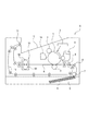
図1は本実施形態に係る画像形成装置の構成を示す概略構成図である。まず、図1を参照して画像形成装置の全体構成について、画像形成動作とともに説明する。
[First Embodiment]
<Overall configuration of image forming apparatus>
FIG. 1 is a schematic configuration diagram showing a configuration of an image forming apparatus according to the present embodiment. First, the overall configuration of the image forming apparatus will be described together with the image forming operation with reference to FIG.
本実施形態の画像形成装置Aは、像担持体に形成した静電像をトナー現像し、形成したトナー像を搬送されるシートに転写して画像形成する画像形成部を有する、電子写真プロセス方式を利用した複写機である。 An image forming apparatus A according to the present embodiment has an image forming unit that develops an electrostatic image formed on an image carrier with toner and transfers the formed toner image to a conveyed sheet to form an image. Is a copier using
画像形成部は、像担持体であるドラム形状の電子写真感光体(以下、「感光体ドラム」という)1を有し、この感光体ドラム1は、帯電手段である帯電ローラ2によって帯電される。次いで、感光体ドラム1に光学手段3から画像情報に応じたレーザ光を照射することによって画像情報に応じた静電像が形成され、この静電像が現像装置4によってトナーを用いて現像され、トナー像として可視像化される。
The image forming unit includes a drum-shaped electrophotographic photosensitive member (hereinafter referred to as “photosensitive drum”) 1 that is an image carrier, and the
一方、前記トナー像の形成と同期して、シートがシート搬送手段によって前記画像形成部へと搬送される。すなわち、装置本体下部にセットされた給送カセット5内のシート6をピックアップローラ7、搬送ローラ8により画像形成部のトナー像転写位置へと搬送する。転写位置には、転写手段としての転写ローラ9が配置されており、転写バイアスを印加することによって、感光体ドラム1上のトナー像をシート6に転写する。
On the other hand, in synchronization with the formation of the toner image, the sheet is conveyed to the image forming unit by a sheet conveying unit. That is, the
トナー像の転写を受けたシート6は、定着装置10へと搬送され、定着装置10を通過するときに熱及び圧力が印可されてトナー像がシートに溶融定着する。トナー像が定着されたシート6は、片面記録の場合は、排出ローラ11によって排出トレイ12へと搬送して排出される。一方、両面記録の場合は、シート反転搬送手段13によりシートを搬送することで、一方側の面に記録したシートを反転して再度画像転写位置に搬送し、他方側の面に記録を行った後、排出ローラ11により排出トレイ12へと排出する。
The
なお、トナー像をシート6に転写した後の感光体ドラム1は、クリーニング手段14によって感光体ドラム1上に残留したトナーを除去した後、次の画像形成プロセスに供される。
The
<定着装置>
次に本実施形態の定着装置10の構成について説明する。図2は本実施形態における定着装置10の概略構成を示すものである。本実施の形態における定着装置10は、フィルム加熱方式の定着装置である。
<Fixing device>
Next, the configuration of the
本実施形態の定着装置10は、トナー像が転写されたシートを加熱する加熱部材としての定着アンセンブリ90と、シートを定着アンセンブリ90に押圧する押圧部材としての加圧ローラ80とを備えている。加圧ローラ80は定着アンセンブリ90に圧接して加熱ニップ部Nを形成し、さらに加圧ローラ80が図2の矢印方向に回転することで、定着アンセンブリ90が図2の矢印方向に従動回転するように構成されている。
The
定着アンセンブリ90は、加熱ヒータ91、断熱ホルダ92、加熱用回転体である定着フィルム93を備える。加熱ヒータ91は、断熱ホルダ92に保持され、定着フィルム93の内周面と摺動する位置に設けられている。
The fixing
加熱ヒータ91としては、低熱容量のプレート状のものが用いられる。本実施形態では、アルミナや窒化アルミ等の絶縁性セラミック基板の表面に、基板の長手方向に沿って、Ag/Pd(銀パラジウム)、RuO2、Ta2N等の通電発熱抵抗層がスクリーン印刷されたものが用いられる。なお、定着フィルム93の内周面との摺動面に、熱効率を損なわない範囲で通電発熱抵抗層を保護するガラス層などの保護層を設ける構成であってもよい。
As the
断熱ホルダ92は、加熱ヒータ91を保持するものであって、液晶ポリマー、フェノール樹脂、PPS、PEEK等の耐熱性樹脂によって形成される。また、加熱ヒータ91を保持すると共に、定着フィルム93の回転をガイドする役目も備える。
The
また、本実施の形態における定着フィルム93は、基層と表層より形成される複層構造を有する。基層としては、ポリイミド、ポリアミドイミド、PEEK等の耐熱性樹脂、あるいは、耐熱性、高熱伝導性を有するSUS、Al、Ni、Cu、Zn等の純金属、合金等が用いられる。
In addition, the fixing
表層としては、PTFE(ポリテトラフルオロエチレン)、PFA(テトラフルオロエチレンパーフルオロアルキルビニルエーテル共重合体)、FEP(テトラフルオロエチレンヘキサフルオロプロピレン共重合体)等の樹脂が用いられる。また、ETFE(エチレンテトラフルオロエチレン共重合体)、CTFE(ポリクロロトリフルオロエチレン)、PVDF(ポリビニリデンフルオライド)等の樹脂を用いてもよい。定着フィルム93の表層をこのように構成することで、定着フィルム93の離型性が向上する。
As the surface layer, resins such as PTFE (polytetrafluoroethylene), PFA (tetrafluoroethylene perfluoroalkyl vinyl ether copolymer), and FEP (tetrafluoroethylene hexafluoropropylene copolymer) are used. Further, a resin such as ETFE (ethylene tetrafluoroethylene copolymer), CTFE (polychlorotrifluoroethylene), PVDF (polyvinylidene fluoride), or the like may be used. By configuring the surface layer of the fixing
加圧ローラ80は、SUS、SUM、Al等の金属製芯金81と、芯金81の外側に形成される弾性層82によって構成される。
The
本実施の形態では、弾性層82として、シリコーンゴムやフッ素ゴム等の耐熱ゴムで形成した弾性ソリッドゴム層、あるいはより断熱効果を持たせるためにシリコーンゴムを発泡して形成した弾性スポンジゴム層が用いられる。また、シリコーンゴム層内に中空のフィラー(マイクロバルーン等)を分散させ、硬化物内に気体部分を持たせて断熱効果を高めた弾性気泡ゴム層を用いる構成であってもよい。
In the present embodiment, as the
さらに、弾性層82の表面にパーフルオロアルコキシ樹脂(PFA)、ポリテトラフルオロエチレン樹脂(PTFE)等の離型性層を形成する構成であってもよい。
Furthermore, a configuration in which a release layer such as perfluoroalkoxy resin (PFA) or polytetrafluoroethylene resin (PTFE) is formed on the surface of the
加圧ローラ80は、不図示のバネによって定着フィルム93に対して加圧され、加熱ニップ部Nを得る。また、芯金81の端部に設けられた不図示の駆動ギアにより、図2の矢印の方向に回転する駆動力を得る。駆動力は制御手段を統制する不図示のCPUからの指令に従い、不図示のモータより伝達される。この加圧ローラ80の回転駆動に伴って、定着フィルム93は加圧ローラ80との摩擦力により従動回転する。
The
また、本実施の形態では、定着フィルム93と加熱ヒータ91との間に、フッ素系やシリコーン系の耐熱性グリース等の潤滑材を介在させることにより、摩擦抵抗を低く抑え、定着フィルム93がより滑らか回転することが可能な構成とした。
In the present embodiment, a lubricant such as a fluorine-based or silicone-based heat-resistant grease is interposed between the fixing
また、加熱ヒータ91の温度制御は、セラミック基板の背面に設けた不図示のサーミスタ等温度検知素子の信号に応じて、不図示のCPUが通電発熱抵抗層に印加する電圧のデューティー比や波数等を決定し適切に制御すること行う構成とした。この構成によれば、加熱ニップ部の温度を所望の定着設定温度に保つことが可能になる。
Further, the temperature control of the
上記のように構成される定着装置10に対して、未定着トナー画像を保持したシート6が所定のタイミングで適宜供給され、加熱ニップ部Nに搬送されて加熱定着が行われる。
A
<定着装置のクリーニング構成>
次に本実施形態の定着装置のクリーニング構成について説明する。
<Cleaning configuration of fixing device>
Next, the cleaning configuration of the fixing device of the present embodiment will be described.
前述したように、多量の紙粉が定着フィルム93に付着すると、その部分に傷が発生する可能性がある。例えば、本件発明者が印字率0%(ベタ白画像)のシートを連続して定着装置10に通紙したとき、定着フィルム93に発生する傷の状態を調べた結果を図3に示す。
As described above, when a large amount of paper dust adheres to the fixing
図3のグラフAは、A4サイズのベタ白の普通紙を長手方向が搬送方向となるようにして通紙したときの結果である。横軸は通紙枚数(×1000枚)であり、縦軸は定着フィルム93に発生した傷を数値化している。ここで、定着フィルム傷の発生を表した数値は、定着フィルム表面のRMS値(平均自乗根)で表しており、単位はμmである。今回の試験では一例として、表層にPTFE、もしくはPFA等の樹脂を用いた定着フィルム93を使用した場合、RMS値が1μmを超えた場合、定着フィルム93に傷が発生しており、異常画像の起こる閾値として設定している。
Graph A in FIG. 3 shows the results when A4 size plain white plain paper is passed with the longitudinal direction being the transport direction. The horizontal axis represents the number of sheets passed (x1000), and the vertical axis represents the number of scratches generated on the fixing
図3の結果からわかるように、全くトナーが転写されていないベタ白画像では約4万枚を通紙した付近よりRMS値が閾値である1μmを超えており、フィルム傷が発生していることがわかる。 As can be seen from the results in FIG. 3, the solid white image without any toner transferred has an RMS value exceeding the threshold value of 1 μm from the vicinity of about 40,000 sheets, and film scratches have occurred. I understand.
これに対して、図3のグラフBに示すように、シート搬送方向のシート寸法に対して印字率0.5%のトナーを転写したシートを通紙した場合は、15万枚通紙してもRMS値が閾値1μm以下であり、フィルム傷が発生していなかった。これは、転写されたトナーが定着装置で加熱されて溶融し、溶融トナーが定着フィルム93に付着している紙粉を吸着して除去するからであり、トナー塗布が僅かであってもクリーニング効果が得られるからである。なお、印字率0.5%のシートの搬送方向に対する印字ドット数は印刷時の解像度設定が600dpi×600dpiであるとすると、30ドットから40ドットに相当する。
On the other hand, as shown in graph B of FIG. 3, when a sheet having a printing rate of 0.5% transferred with respect to the sheet size in the sheet conveying direction is passed, 150,000 sheets are passed. Also, the RMS value was a threshold value of 1 μm or less, and no film scratch was generated. This is because the transferred toner is heated and melted by the fixing device, and the molten toner adsorbs and removes the paper dust adhering to the fixing
そこで、本実施形態にあっては、シートの搬送方向先端又は後端の少なくとも一方の余白部(非画像形成領域)にクリーニング画像パターン(以下「画像パターン」という)となるトナーを転写する。そして、このトナーが定着装置にニップ部において加熱されることで、このトナーを介して定着フィルム上の紙粉起因の異物を回収し、定着フィルム93に与えるダメージを防ぎ、傷の発生を抑制する。
Therefore, in the present embodiment, toner serving as a cleaning image pattern (hereinafter referred to as “image pattern”) is transferred to at least one blank portion (non-image forming region) at the leading or trailing end of the sheet in the conveyance direction. Then, the toner is heated at the nip portion of the fixing device to collect foreign matters due to paper dust on the fixing film through the toner, prevent damage to the fixing
したがって、前記画像パターンとは、パターンを形成するトナーが定着装置10で加熱されて溶融したとき、この溶融トナーによってシートに定着フィルム93に付着した紙粉等の異物を吸着除去するために形成される転写トナーのパターンである。本実施形態の画像パターンは、シートの先端余白部又は後端余白部にシート幅方向に形成される細いライン状のトナーパターンである。
Therefore, the image pattern is formed to adsorb and remove foreign matters such as paper dust attached to the fixing
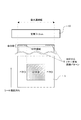
また、前記画像パターンはトナーが視覚的に目立たないようにする必要がある。そのため、本実施形態では、例えば図4に示すように、シート先端余白部に画像パターン15を形成するときに、単位面積あたりの印字率を落とし、かつ、シート幅方向(シート搬送方向と交差する方向)で複数に分割したパターンを、シート幅方向でずれた位置に印字するように構成している。なお、画像形成装置内の不図示の記憶部(メモリ)には前記画像パターンとして、印字率、形状、転写位置等のパターンが予め記憶されている。
Further, the image pattern needs to prevent the toner from being visually noticeable. Therefore, in this embodiment, for example, as shown in FIG. 4, when the
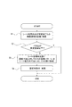
図5は上記クリーニング方法を実行するための手順を示すフローチャートである。このフローチャートに基づいて本実施形態のクリーニング手順を説明する。 FIG. 5 is a flowchart showing a procedure for executing the cleaning method. The cleaning procedure of this embodiment will be described based on this flowchart.
まず、記録開始を起点として、シート幅方向の印字領域におけるシート搬送方向の画像領域を記憶・積算しておく(S1)。 First, from the start of recording, the image area in the sheet conveyance direction in the print area in the sheet width direction is stored and integrated (S1).
次にシート幅方向の所定領域毎にシート搬送方向のベタ白画像の領域が予め設定した設定値(閾値)領域以上か否かを判別する(S2)。なお、画像形成によりシートに転写されるトナー量を計測するトナー計測手段として本実施形態では画像ドット数をカウントすることにより行う。具体的には、前記領域におけるシート搬送方向の画像ドット数をカウントして積算するとともに、定着装置を通過するシートの搬送方向長さをカウントして積算する。そして、前記搬送方向長さに対する画像ドット数が所定の設定値以下になったとき、すなわち、ベタ白部が設定値領域を超えた場合に、シートの余白部にトナーを塗布するための画像パターンを形成する(S3)。 Next, for each predetermined area in the sheet width direction, it is determined whether or not the area of the solid white image in the sheet conveyance direction is equal to or larger than a preset setting value (threshold value) area (S2). In this embodiment, the number of image dots is counted as toner measuring means for measuring the amount of toner transferred to the sheet by image formation. Specifically, the number of image dots in the sheet conveyance direction in the region is counted and integrated, and the length in the conveyance direction of the sheet passing through the fixing device is counted and integrated. Then, when the number of image dots with respect to the length in the transport direction is equal to or smaller than a predetermined set value, that is, when the solid white portion exceeds the set value region, an image pattern for applying toner to the margin portion of the sheet Is formed (S3).
本実施形態では4万枚のベタ白画像の普通紙を通紙すると定着フィルム93に傷が発生するとして、ベタ白画像が400枚に相当する量搬送されたときに、シートの先端余白部に画像パターンを形成する。この画像パターンは、図4に示すように、シート幅方向の寸法で4分割し、かつ、シート幅方向において順次ずれた位置にシート搬送方向寸法に対して0.5%の印字率のライン状の画像パターン15を形成する。そして、上記画像パターン15を形成したシートを合計400枚定着装置で搬送しつつ加熱する(S4)。
In the present embodiment, it is assumed that if 40,000 sheets of plain white images are passed through, the fixing
上記のように、本実施形態にあっては、所定のシート枚数に対して画像形成によりシートに転写されるトナー量が設定した値より少ないときに、シートの搬送方向先端余白部に画像パターンを形成する。これにより、ベタ白画像のシートを通紙したことによる定着フィルム93に付着した紙粉が除去され、定着フィルム93に紙粉起因の傷発生が防止される。
As described above, in the present embodiment, when the amount of toner transferred to the sheet by image formation is smaller than the set value with respect to a predetermined number of sheets, the image pattern is formed on the leading edge portion in the sheet conveyance direction. Form. As a result, paper dust adhering to the fixing
なお、シート先端に形成する画像パターン15は、必ずしも図4に示すように分割されてなくてもよいが、分割して複数枚のシートの幅方向でずれるように形成するほうが、シート1枚あたりの画像パターン15が目立たなくなるので好ましい。また、分割数は4個よりも多くてもよい。
Note that the
また、画像パターンを分割し、複数枚のシートに対してシート幅方向に順次ずれるように形成する場合には、シート幅方向において一部がオーバーラップし、かつ、分割した画像パターンの長さの合計は、搬送される最大幅のシートの幅以上となるように形成するとよい。すなわち、画像パターンは、シート搬送方向と交差するシート幅方向に複数に分割されたパターンの組み合わせで構成され、画像形成される1枚のシートに前記分割したパターンの中のひとつが記録され、複数のシートによって前記パターンが形成されるものである。そして、分割したパターンのシート幅方向の長さの合計は、搬送される最大幅のシートの幅方向の長さ以上となるように形成する。これにより、オーバーラップすることにより、シート幅方向で画像パターンが形成されていない部分を確実になくすことができ、また最大幅のシートに対応して紙粉の除去をより確実に行うことができる。 Further, when the image pattern is divided and formed so as to be sequentially shifted in the sheet width direction with respect to a plurality of sheets, a part of the image pattern overlaps in the sheet width direction and the length of the divided image pattern is The total may be formed to be equal to or greater than the width of the maximum width sheet to be conveyed. That is, the image pattern is composed of a combination of patterns divided into a plurality of sheets in the sheet width direction intersecting the sheet conveyance direction, and one of the divided patterns is recorded on one sheet to be image-formed, The pattern is formed by the sheet. The total length of the divided patterns in the sheet width direction is formed to be equal to or greater than the length in the width direction of the maximum width sheet to be conveyed. Thereby, by overlapping, a portion where an image pattern is not formed in the sheet width direction can be surely eliminated, and paper dust can be more reliably removed corresponding to the maximum width sheet. .
〔第2実施形態〕
次に第2実施形態に係る画像形成装置について図6及び図7を参照して説明する。なお、本実施形態の装置の基本構成は前述した実施形態と同一であるため重複する説明は省略し、ここでは本実施形態の特徴となる構成のみ説明する。
[Second Embodiment]
Next, an image forming apparatus according to a second embodiment will be described with reference to FIGS. Note that the basic configuration of the apparatus of the present embodiment is the same as that of the above-described embodiment, and thus redundant description is omitted. Only the configuration that is a feature of the present embodiment will be described here.
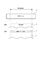
前述した実施形態ではベタ白画像が設定値領域以上となったときに、シートの先端又は後端の少なくとも一方であって、シート幅方向全域にわたるように画像パターンを形成する例を示した。ここでは、ベタ白画像が設定値領域以上となったとき、シート幅方向において前記ベタ白画像となった領域にのみ画像パターンを形成するものである。 In the above-described embodiment, an example in which an image pattern is formed so as to cover at least one of the leading edge and the trailing edge of the sheet and the entire sheet width direction when the solid white image is equal to or larger than the set value region. Here, when the solid white image is equal to or larger than the set value region, an image pattern is formed only in the region that is the solid white image in the sheet width direction.
図6のフローチャートに基づいて具体的に説明する。なお、本実施形態では第1実施形態で示したフローチャート(図5)と、ステップ23が異なる。 A specific description will be given based on the flowchart of FIG. In this embodiment, step 23 is different from the flowchart (FIG. 5) shown in the first embodiment.
まず、記録開始を起点として、シート幅方向の印字領域におけるシート搬送方向の画像領域を記憶・積算しておく(S21)。 First, from the start of recording, the image area in the sheet conveyance direction in the print area in the sheet width direction is stored and integrated (S21).
次にシート幅方向の所定領域毎にシート搬送方向のベタ白画像が予め設定した設定値(閾値)領域以上か否かを判別する(S22)。具体的には、前記領域におけるシート搬送方向の画像ドット数をカウントするとともに、定着装置を通過するシートの搬送方向長さをカウントする。そして、搬送方向長さのカウント値に対する画像ドット数のカウント値が所定の設定値以下になったとき、すなわち、ベタ白部がある予め設定した設定値領域を超えた場合に、前記所定領域におけるシート先端に画像パターン15を形成する(S23)。
Next, it is determined whether or not the solid white image in the sheet conveying direction is greater than or equal to a preset set value (threshold) region for each predetermined region in the sheet width direction (S22). Specifically, the number of image dots in the sheet conveyance direction in the region is counted, and the length in the conveyance direction of the sheet passing through the fixing device is counted. Then, when the count value of the number of image dots with respect to the count value of the conveyance direction length is equal to or smaller than a predetermined set value, that is, when the solid white portion exceeds a preset set value region, An
本実施形態では4万枚のベタ白画像の普通紙を通紙すると定着フィルム93に傷が発生するとして、ベタ白画像が400枚に相当する量搬送されたときに、図7に示すように、前記ベタ白部が位置するシート幅方向の所定領域(シート幅方向の同一位置)におけるシート先端余白部に画像パターンを形成する。この画像パターンは、シート搬送方向寸法に対して0.5%の印字率のライン状の画像パターン15であり、これを形成したシートを合計100枚定着装置で搬送しつつ加熱する(S24)。これにより、ベタ白画像を通紙したことによる定着フィルム93に付着した紙粉が除去され、定着フィルム93に紙粉起因の傷発生が防止される。
In this embodiment, assuming that 40,000 sheets of plain white images are passed through, the fixing
〔第3実施形態〕
次に第3実施形態に係る画像形成装置について図8を参照して説明する。なお、本実施形態でも装置の基本構成は前述した実施形態と同一であるため重複する説明は省略し、ここでは本実施形態の特徴となる構成のみ説明する。
[Third Embodiment]
Next, an image forming apparatus according to a third embodiment will be described with reference to FIG. In this embodiment, the basic configuration of the apparatus is the same as that of the above-described embodiment, and therefore, a duplicate description is omitted. Here, only a configuration that is a feature of this embodiment will be described.
前述した実施形態ではシートの先端又は後端に画像パターンを形成したが、本実施形態にあってはシートに対する画像形成が一方側の面(表面)にのみ記録される場合は、画像パターンをシートの他方側の面(裏面)に形成するものである。 In the above-described embodiment, the image pattern is formed on the leading edge or the trailing edge of the sheet. However, in the present embodiment, when image formation on the sheet is recorded only on one surface (front surface), the image pattern is formed on the sheet. It is formed on the other side surface (back surface).
片面記録の場合、表面に画像形成がされたシートをシート反転搬送手段13によって反転搬送し、図8に示すように、前述した実施形態と同様の画像パターン15を裏面側のシート先端又は後端に形成する。
In the case of single-sided recording, the sheet on which the image is formed on the front surface is reversed and conveyed by the sheet reversing and conveying
なお、本実施形態のように裏面に画像パターン15を形成する場合、シート先端又は後端でなくてもよく、画像パターンを形成する位置の自由度が増す。また、裏面に画像パターンを形成する場合には、画像パターンとして文字等を印字するようにしてもよい。例えば、画像パターンとして画像出力したパソコンのIPアドレス等を印字するようにしてもよい。これにより、プリントアウトしたパソコンを特定することが可能となる。
Note that when the
1 …感光体ドラム
2 …帯電ローラ
3 …光学手段
4 …現像装置
5 …給送カセット
6 …シート
7 …ピックアップローラ
8 …搬送ローラ
9 …転写ローラ
10 …定着装置
11 …排出ローラ
12 …排出トレイ
13 …シート反転搬送手段
14 …クリーニング手段
15 …クリーニング画像パターン
80 …加圧ローラ
81 …芯金
82 …弾性層
90 …定着アセンブリ
91 …加熱ヒータ
92 …断熱ホルダ
93 …定着フィルム
DESCRIPTION OF
Claims (7)
像担持体に形成した静電像をトナー現像し、形成したトナー像を搬送されるシートに転写して画像形成する画像形成部と、
前記トナー像が転写されたシートを加熱する加熱部材と前記シートを前記加熱部材に押圧する押圧部材とにより前記トナー像をシートに定着する定着装置と、
を有する画像形成装置であって、
前記シートの搬送方向先端余白部又は後端余白部に前記加熱部材に付着した異物を除去するためのクリーニング画像パターンを形成し、該シートを前記定着装置で加熱することを特徴とする画像形成装置。 Sheet conveying means for conveying a sheet on which image formation is performed;
An image forming section that develops an electrostatic image formed on the image carrier with toner and transfers the formed toner image to a conveyed sheet to form an image; and
A fixing device that fixes the toner image on the sheet by a heating member that heats the sheet to which the toner image is transferred and a pressing member that presses the sheet against the heating member;
An image forming apparatus having
An image forming apparatus comprising: forming a cleaning image pattern for removing foreign matter adhering to the heating member on a leading edge margin or a trailing edge margin of the sheet in the conveyance direction; and heating the sheet by the fixing device. .
像担持体に形成した静電像をトナー現像し、形成したトナー像を搬送されるシートに転写して画像形成する画像形成部と、
前記トナー像が転写されたシートを加熱する加熱部材と前記シートを前記加熱部材に押圧する押圧部材とにより前記トナー像をシートに定着する定着装置と、
一方側の面に記録したシートを反転して他方側の面に記録を行うことを可能にシートを搬送するシート反転搬送手段と、
を有する画像形成装置であって、
前記シートに対する画像形成が一方側の面にのみ記録される場合は、クリーニング画像パターンをシートの他方側の面に形成することを特徴とする画像形成装置。 Sheet conveying means for conveying a sheet on which image formation is performed;
An image forming section that develops an electrostatic image formed on the image carrier with toner and transfers the formed toner image to a conveyed sheet to form an image; and
A fixing device that fixes the toner image on the sheet by a heating member that heats the sheet to which the toner image is transferred and a pressing member that presses the sheet against the heating member;
A sheet reversing and conveying means for conveying the sheet so that the sheet recorded on the one side surface can be reversed and recorded on the other side surface;
An image forming apparatus having
An image forming apparatus, wherein when the image formation on the sheet is recorded only on one side surface, the cleaning image pattern is formed on the other side surface of the sheet.
シート搬送方向の画像ドット数をカウントして積算し、前記定着装置を通過するシートの搬送方向長さをカウントして積算し、
前記シートの搬送方向長さのカウント値に対する前記ドット数のカウント値が予め設定した設定値以下になったときに、前記設定値以下になったドット数に該当する位置のシート搬送方向であって余白部に前記クリーニング画像パターンを形成することを特徴とする請求項1乃至請求項5のいずれか1項に記載の画像形成装置。 When forming an image on the sheet,
Count and accumulate the number of image dots in the sheet conveyance direction, count and accumulate the conveyance direction length of the sheet passing through the fixing device,
When the count value of the number of dots with respect to the count value of the length in the conveyance direction of the sheet is equal to or less than a preset value, the sheet conveyance direction at a position corresponding to the number of dots that is equal to or less than the set value The image forming apparatus according to claim 1, wherein the cleaning image pattern is formed in a blank portion.
Priority Applications (1)
| Application Number | Priority Date | Filing Date | Title |
|---|---|---|---|
| JP2010283681A JP2012133034A (en) | 2010-12-20 | 2010-12-20 | Image forming apparatus |
Applications Claiming Priority (1)
| Application Number | Priority Date | Filing Date | Title |
|---|---|---|---|
| JP2010283681A JP2012133034A (en) | 2010-12-20 | 2010-12-20 | Image forming apparatus |
Publications (1)
| Publication Number | Publication Date |
|---|---|
| JP2012133034A true JP2012133034A (en) | 2012-07-12 |
Family
ID=46648727
Family Applications (1)
| Application Number | Title | Priority Date | Filing Date |
|---|---|---|---|
| JP2010283681A Withdrawn JP2012133034A (en) | 2010-12-20 | 2010-12-20 | Image forming apparatus |
Country Status (1)
| Country | Link |
|---|---|
| JP (1) | JP2012133034A (en) |
Cited By (2)
| Publication number | Priority date | Publication date | Assignee | Title |
|---|---|---|---|---|
| CN104704662A (en) * | 2012-10-12 | 2015-06-10 | 独立行政法人产业技术综合研究所 | Binder for use in positive electrode for lithium ion secondary battery, positive electrode for lithium ion secondary battery containing said binder, lithium ion secondary battery using said positive electrode, and electrical machinery and apparatus |
| CN109752939A (en) * | 2017-11-08 | 2019-05-14 | 柯尼卡美能达株式会社 | The control method of image forming apparatus and image forming apparatus |
-
2010
- 2010-12-20 JP JP2010283681A patent/JP2012133034A/en not_active Withdrawn
Cited By (5)
| Publication number | Priority date | Publication date | Assignee | Title |
|---|---|---|---|---|
| CN104704662A (en) * | 2012-10-12 | 2015-06-10 | 独立行政法人产业技术综合研究所 | Binder for use in positive electrode for lithium ion secondary battery, positive electrode for lithium ion secondary battery containing said binder, lithium ion secondary battery using said positive electrode, and electrical machinery and apparatus |
| CN109752939A (en) * | 2017-11-08 | 2019-05-14 | 柯尼卡美能达株式会社 | The control method of image forming apparatus and image forming apparatus |
| JP2019086682A (en) * | 2017-11-08 | 2019-06-06 | コニカミノルタ株式会社 | Image forming apparatus and method for controlling image forming apparatus |
| US10437182B2 (en) | 2017-11-08 | 2019-10-08 | Konica Minolta, Inc. | Image forming apparatus and control method of image forming apparatus |
| JP7024335B2 (en) | 2017-11-08 | 2022-02-24 | コニカミノルタ株式会社 | Image forming apparatus and control method of image forming apparatus |
Similar Documents
| Publication | Publication Date | Title |
|---|---|---|
| US7650105B2 (en) | Image heating apparatus | |
| US8532529B2 (en) | Fixing device and image forming apparatus using the same | |
| JP4095406B2 (en) | Heat fixing device | |
| JP2003186327A (en) | Image-heating apparatus | |
| JP2009251435A (en) | Rotary body for heating, and image heating device having the rotary body for heating | |
| JP5403894B2 (en) | Image forming apparatus | |
| JP4742131B2 (en) | FIXING DEVICE, IMAGE FORMING DEVICE, FIXING DEVICE CONTROL METHOD, CONTROL PROGRAM, AND RECORDING MEDIUM THEREOF | |
| JP6249836B2 (en) | Fixing device | |
| JP2008275756A (en) | Heat fixing device | |
| JP2009223291A (en) | Fixer and image forming device equipped with it | |
| JP2012133034A (en) | Image forming apparatus | |
| JP2017009894A (en) | Fixation device | |
| JP2009093017A (en) | Image heating device and image forming apparatus | |
| US8355659B2 (en) | Fixing device and image forming apparatus having same | |
| US11163248B2 (en) | Fixing device and image forming apparatus | |
| JP2008180858A (en) | Fixing device and image forming apparatus | |
| JP7102255B2 (en) | Image forming device | |
| JP2009042303A (en) | Pressure roller and image heating device | |
| JP2010054821A (en) | Image heating apparatus | |
| JP5404157B2 (en) | Image forming apparatus | |
| JP5188114B2 (en) | Image heating device | |
| JP2008268728A (en) | Thermal fixing device | |
| JP2018124505A (en) | Fixing device and image forming apparatus | |
| JP2006235006A (en) | Fixing device and image forming apparatus | |
| JP2007292958A (en) | Fixing device and image forming apparatus using same |
Legal Events
| Date | Code | Title | Description |
|---|---|---|---|
| A300 | Withdrawal of application because of no request for examination |
Free format text: JAPANESE INTERMEDIATE CODE: A300 Effective date: 20140304 |