JP2019063700A - Exhaust gas purification catalyst - Google Patents
Exhaust gas purification catalyst Download PDFInfo
- Publication number
- JP2019063700A JP2019063700A JP2017189040A JP2017189040A JP2019063700A JP 2019063700 A JP2019063700 A JP 2019063700A JP 2017189040 A JP2017189040 A JP 2017189040A JP 2017189040 A JP2017189040 A JP 2017189040A JP 2019063700 A JP2019063700 A JP 2019063700A
- Authority
- JP
- Japan
- Prior art keywords
- catalyst
- catalyst layer
- exhaust gas
- cell
- partition wall
- Prior art date
- Legal status (The legal status is an assumption and is not a legal conclusion. Google has not performed a legal analysis and makes no representation as to the accuracy of the status listed.)
- Granted
Links
- 239000003054 catalyst Substances 0.000 title claims abstract description 369
- 238000000746 purification Methods 0.000 title claims abstract description 93
- 238000005192 partition Methods 0.000 claims abstract description 162
- 230000009467 reduction Effects 0.000 claims abstract description 42
- 230000003647 oxidation Effects 0.000 claims abstract description 38
- 238000007254 oxidation reaction Methods 0.000 claims abstract description 38
- 238000002485 combustion reaction Methods 0.000 claims description 25
- 239000000463 material Substances 0.000 claims description 20
- 239000003502 gasoline Substances 0.000 claims description 7
- 230000007423 decrease Effects 0.000 claims description 4
- 239000000758 substrate Substances 0.000 abstract description 14
- 239000007789 gas Substances 0.000 description 128
- 230000000052 comparative effect Effects 0.000 description 27
- 239000002002 slurry Substances 0.000 description 27
- 229910052751 metal Inorganic materials 0.000 description 21
- 239000002184 metal Substances 0.000 description 21
- KDLHZDBZIXYQEI-UHFFFAOYSA-N palladium Substances [Pd] KDLHZDBZIXYQEI-UHFFFAOYSA-N 0.000 description 18
- 239000010948 rhodium Substances 0.000 description 16
- 229930195733 hydrocarbon Natural products 0.000 description 15
- 150000002430 hydrocarbons Chemical class 0.000 description 15
- 239000013618 particulate matter Substances 0.000 description 11
- 238000011144 upstream manufacturing Methods 0.000 description 11
- 238000006243 chemical reaction Methods 0.000 description 9
- 239000011248 coating agent Substances 0.000 description 9
- 238000000576 coating method Methods 0.000 description 9
- BASFCYQUMIYNBI-UHFFFAOYSA-N platinum Chemical compound [Pt] BASFCYQUMIYNBI-UHFFFAOYSA-N 0.000 description 9
- 238000012360 testing method Methods 0.000 description 8
- 230000006872 improvement Effects 0.000 description 7
- 238000000034 method Methods 0.000 description 7
- UGFAIRIUMAVXCW-UHFFFAOYSA-N Carbon monoxide Chemical compound [O+]#[C-] UGFAIRIUMAVXCW-UHFFFAOYSA-N 0.000 description 6
- PNEYBMLMFCGWSK-UHFFFAOYSA-N aluminium oxide Inorganic materials [O-2].[O-2].[O-2].[Al+3].[Al+3] PNEYBMLMFCGWSK-UHFFFAOYSA-N 0.000 description 6
- 229910002091 carbon monoxide Inorganic materials 0.000 description 6
- 229910052878 cordierite Inorganic materials 0.000 description 6
- JSKIRARMQDRGJZ-UHFFFAOYSA-N dimagnesium dioxido-bis[(1-oxido-3-oxo-2,4,6,8,9-pentaoxa-1,3-disila-5,7-dialuminabicyclo[3.3.1]nonan-7-yl)oxy]silane Chemical compound [Mg++].[Mg++].[O-][Si]([O-])(O[Al]1O[Al]2O[Si](=O)O[Si]([O-])(O1)O2)O[Al]1O[Al]2O[Si](=O)O[Si]([O-])(O1)O2 JSKIRARMQDRGJZ-UHFFFAOYSA-N 0.000 description 6
- MWUXSHHQAYIFBG-UHFFFAOYSA-N nitrogen oxide Inorganic materials O=[N] MWUXSHHQAYIFBG-UHFFFAOYSA-N 0.000 description 6
- 229910052763 palladium Inorganic materials 0.000 description 6
- 239000011148 porous material Substances 0.000 description 6
- 239000000843 powder Substances 0.000 description 6
- 238000001354 calcination Methods 0.000 description 5
- 239000002131 composite material Substances 0.000 description 5
- 238000001035 drying Methods 0.000 description 5
- 238000011156 evaluation Methods 0.000 description 5
- 229910052697 platinum Inorganic materials 0.000 description 5
- 239000000243 solution Substances 0.000 description 5
- 229910018072 Al 2 O 3 Inorganic materials 0.000 description 4
- QVGXLLKOCUKJST-UHFFFAOYSA-N atomic oxygen Chemical compound [O] QVGXLLKOCUKJST-UHFFFAOYSA-N 0.000 description 4
- 229910000422 cerium(IV) oxide Inorganic materials 0.000 description 4
- 239000001301 oxygen Substances 0.000 description 4
- 229910052760 oxygen Inorganic materials 0.000 description 4
- PXHVJJICTQNCMI-UHFFFAOYSA-N Nickel Chemical compound [Ni] PXHVJJICTQNCMI-UHFFFAOYSA-N 0.000 description 3
- VYPSYNLAJGMNEJ-UHFFFAOYSA-N Silicium dioxide Chemical compound O=[Si]=O VYPSYNLAJGMNEJ-UHFFFAOYSA-N 0.000 description 3
- CETPSERCERDGAM-UHFFFAOYSA-N ceric oxide Chemical compound O=[Ce]=O CETPSERCERDGAM-UHFFFAOYSA-N 0.000 description 3
- 230000000694 effects Effects 0.000 description 3
- 239000000203 mixture Substances 0.000 description 3
- 229910052703 rhodium Inorganic materials 0.000 description 3
- 239000003381 stabilizer Substances 0.000 description 3
- 238000003860 storage Methods 0.000 description 3
- XLYOFNOQVPJJNP-UHFFFAOYSA-N water Substances O XLYOFNOQVPJJNP-UHFFFAOYSA-N 0.000 description 3
- GWEVSGVZZGPLCZ-UHFFFAOYSA-N Titan oxide Chemical compound O=[Ti]=O GWEVSGVZZGPLCZ-UHFFFAOYSA-N 0.000 description 2
- MCMNRKCIXSYSNV-UHFFFAOYSA-N Zirconium dioxide Chemical compound O=[Zr]=O MCMNRKCIXSYSNV-UHFFFAOYSA-N 0.000 description 2
- 229910045601 alloy Inorganic materials 0.000 description 2
- 239000000956 alloy Substances 0.000 description 2
- 238000005275 alloying Methods 0.000 description 2
- 229910052788 barium Inorganic materials 0.000 description 2
- DSAJWYNOEDNPEQ-UHFFFAOYSA-N barium atom Chemical compound [Ba] DSAJWYNOEDNPEQ-UHFFFAOYSA-N 0.000 description 2
- TZCXTZWJZNENPQ-UHFFFAOYSA-L barium sulfate Chemical compound [Ba+2].[O-]S([O-])(=O)=O TZCXTZWJZNENPQ-UHFFFAOYSA-L 0.000 description 2
- 230000033228 biological regulation Effects 0.000 description 2
- 230000015572 biosynthetic process Effects 0.000 description 2
- 239000011575 calcium Substances 0.000 description 2
- 230000003197 catalytic effect Effects 0.000 description 2
- 239000010949 copper Substances 0.000 description 2
- 239000000446 fuel Substances 0.000 description 2
- 239000010931 gold Substances 0.000 description 2
- 238000005342 ion exchange Methods 0.000 description 2
- 238000002156 mixing Methods 0.000 description 2
- GPNDARIEYHPYAY-UHFFFAOYSA-N palladium(ii) nitrate Chemical compound [Pd+2].[O-][N+]([O-])=O.[O-][N+]([O-])=O GPNDARIEYHPYAY-UHFFFAOYSA-N 0.000 description 2
- MHOVAHRLVXNVSD-UHFFFAOYSA-N rhodium atom Chemical compound [Rh] MHOVAHRLVXNVSD-UHFFFAOYSA-N 0.000 description 2
- VXNYVYJABGOSBX-UHFFFAOYSA-N rhodium(3+);trinitrate Chemical compound [Rh+3].[O-][N+]([O-])=O.[O-][N+]([O-])=O.[O-][N+]([O-])=O VXNYVYJABGOSBX-UHFFFAOYSA-N 0.000 description 2
- 238000007789 sealing Methods 0.000 description 2
- 229910000505 Al2TiO5 Inorganic materials 0.000 description 1
- OYPRJOBELJOOCE-UHFFFAOYSA-N Calcium Chemical compound [Ca] OYPRJOBELJOOCE-UHFFFAOYSA-N 0.000 description 1
- RYGMFSIKBFXOCR-UHFFFAOYSA-N Copper Chemical compound [Cu] RYGMFSIKBFXOCR-UHFFFAOYSA-N 0.000 description 1
- XEEYBQQBJWHFJM-UHFFFAOYSA-N Iron Chemical compound [Fe] XEEYBQQBJWHFJM-UHFFFAOYSA-N 0.000 description 1
- 229910001260 Pt alloy Inorganic materials 0.000 description 1
- KJTLSVCANCCWHF-UHFFFAOYSA-N Ruthenium Chemical compound [Ru] KJTLSVCANCCWHF-UHFFFAOYSA-N 0.000 description 1
- BQCADISMDOOEFD-UHFFFAOYSA-N Silver Chemical compound [Ag] BQCADISMDOOEFD-UHFFFAOYSA-N 0.000 description 1
- 229910010413 TiO 2 Inorganic materials 0.000 description 1
- 230000009471 action Effects 0.000 description 1
- 239000000654 additive Substances 0.000 description 1
- 239000003463 adsorbent Substances 0.000 description 1
- -1 alumina (Al 2 O 3 ) Chemical class 0.000 description 1
- 239000011230 binding agent Substances 0.000 description 1
- 229910052791 calcium Inorganic materials 0.000 description 1
- 239000000919 ceramic Substances 0.000 description 1
- 239000007809 chemical reaction catalyst Substances 0.000 description 1
- 229910017052 cobalt Inorganic materials 0.000 description 1
- 239000010941 cobalt Substances 0.000 description 1
- GUTLYIVDDKVIGB-UHFFFAOYSA-N cobalt atom Chemical compound [Co] GUTLYIVDDKVIGB-UHFFFAOYSA-N 0.000 description 1
- 229910052802 copper Inorganic materials 0.000 description 1
- 238000005520 cutting process Methods 0.000 description 1
- 239000008367 deionised water Substances 0.000 description 1
- 229910021641 deionized water Inorganic materials 0.000 description 1
- 238000013461 design Methods 0.000 description 1
- 238000010586 diagram Methods 0.000 description 1
- 238000009826 distribution Methods 0.000 description 1
- 238000005516 engineering process Methods 0.000 description 1
- 230000002708 enhancing effect Effects 0.000 description 1
- 239000002737 fuel gas Substances 0.000 description 1
- PCHJSUWPFVWCPO-UHFFFAOYSA-N gold Chemical compound [Au] PCHJSUWPFVWCPO-UHFFFAOYSA-N 0.000 description 1
- 229910052737 gold Inorganic materials 0.000 description 1
- 238000010438 heat treatment Methods 0.000 description 1
- 239000003779 heat-resistant material Substances 0.000 description 1
- 238000002347 injection Methods 0.000 description 1
- 239000007924 injection Substances 0.000 description 1
- 238000009434 installation Methods 0.000 description 1
- 150000002500 ions Chemical class 0.000 description 1
- 229910052741 iridium Inorganic materials 0.000 description 1
- GKOZUEZYRPOHIO-UHFFFAOYSA-N iridium atom Chemical compound [Ir] GKOZUEZYRPOHIO-UHFFFAOYSA-N 0.000 description 1
- 229910052746 lanthanum Inorganic materials 0.000 description 1
- FZLIPJUXYLNCLC-UHFFFAOYSA-N lanthanum atom Chemical compound [La] FZLIPJUXYLNCLC-UHFFFAOYSA-N 0.000 description 1
- 229910044991 metal oxide Inorganic materials 0.000 description 1
- 150000004706 metal oxides Chemical class 0.000 description 1
- 238000012986 modification Methods 0.000 description 1
- 230000004048 modification Effects 0.000 description 1
- 229910052759 nickel Inorganic materials 0.000 description 1
- 229910000510 noble metal Inorganic materials 0.000 description 1
- 229910052762 osmium Inorganic materials 0.000 description 1
- SYQBFIAQOQZEGI-UHFFFAOYSA-N osmium atom Chemical compound [Os] SYQBFIAQOQZEGI-UHFFFAOYSA-N 0.000 description 1
- 239000002245 particle Substances 0.000 description 1
- 231100000572 poisoning Toxicity 0.000 description 1
- 230000000607 poisoning effect Effects 0.000 description 1
- AABBHSMFGKYLKE-SNAWJCMRSA-N propan-2-yl (e)-but-2-enoate Chemical compound C\C=C\C(=O)OC(C)C AABBHSMFGKYLKE-SNAWJCMRSA-N 0.000 description 1
- 229910052761 rare earth metal Inorganic materials 0.000 description 1
- 229910052707 ruthenium Inorganic materials 0.000 description 1
- HBMJWWWQQXIZIP-UHFFFAOYSA-N silicon carbide Chemical compound [Si+]#[C-] HBMJWWWQQXIZIP-UHFFFAOYSA-N 0.000 description 1
- 239000000377 silicon dioxide Substances 0.000 description 1
- 229910052709 silver Inorganic materials 0.000 description 1
- 239000004332 silver Substances 0.000 description 1
- 238000005245 sintering Methods 0.000 description 1
- 239000007787 solid Substances 0.000 description 1
- 239000006104 solid solution Substances 0.000 description 1
- 238000001179 sorption measurement Methods 0.000 description 1
- 239000010935 stainless steel Substances 0.000 description 1
- 229910001220 stainless steel Inorganic materials 0.000 description 1
- 239000011232 storage material Substances 0.000 description 1
- 229910052723 transition metal Inorganic materials 0.000 description 1
- 239000002912 waste gas Substances 0.000 description 1
- 229910052727 yttrium Inorganic materials 0.000 description 1
- VWQVUPCCIRVNHF-UHFFFAOYSA-N yttrium atom Chemical compound [Y] VWQVUPCCIRVNHF-UHFFFAOYSA-N 0.000 description 1
Images


Classifications
-
- F—MECHANICAL ENGINEERING; LIGHTING; HEATING; WEAPONS; BLASTING
- F01—MACHINES OR ENGINES IN GENERAL; ENGINE PLANTS IN GENERAL; STEAM ENGINES
- F01N—GAS-FLOW SILENCERS OR EXHAUST APPARATUS FOR MACHINES OR ENGINES IN GENERAL; GAS-FLOW SILENCERS OR EXHAUST APPARATUS FOR INTERNAL COMBUSTION ENGINES
- F01N3/00—Exhaust or silencing apparatus having means for purifying, rendering innocuous, or otherwise treating exhaust
- F01N3/08—Exhaust or silencing apparatus having means for purifying, rendering innocuous, or otherwise treating exhaust for rendering innocuous
- F01N3/10—Exhaust or silencing apparatus having means for purifying, rendering innocuous, or otherwise treating exhaust for rendering innocuous by thermal or catalytic conversion of noxious components of exhaust
- F01N3/24—Exhaust or silencing apparatus having means for purifying, rendering innocuous, or otherwise treating exhaust for rendering innocuous by thermal or catalytic conversion of noxious components of exhaust characterised by constructional aspects of converting apparatus
- F01N3/28—Construction of catalytic reactors
- F01N3/2803—Construction of catalytic reactors characterised by structure, by material or by manufacturing of catalyst support
-
- B01J35/19—
-
- B—PERFORMING OPERATIONS; TRANSPORTING
- B01—PHYSICAL OR CHEMICAL PROCESSES OR APPARATUS IN GENERAL
- B01D—SEPARATION
- B01D53/00—Separation of gases or vapours; Recovering vapours of volatile solvents from gases; Chemical or biological purification of waste gases, e.g. engine exhaust gases, smoke, fumes, flue gases, aerosols
- B01D53/34—Chemical or biological purification of waste gases
- B01D53/92—Chemical or biological purification of waste gases of engine exhaust gases
- B01D53/94—Chemical or biological purification of waste gases of engine exhaust gases by catalytic processes
- B01D53/9459—Removing one or more of nitrogen oxides, carbon monoxide, or hydrocarbons by multiple successive catalytic functions; systems with more than one different function, e.g. zone coated catalysts
- B01D53/9463—Removing one or more of nitrogen oxides, carbon monoxide, or hydrocarbons by multiple successive catalytic functions; systems with more than one different function, e.g. zone coated catalysts with catalysts positioned on one brick
- B01D53/9468—Removing one or more of nitrogen oxides, carbon monoxide, or hydrocarbons by multiple successive catalytic functions; systems with more than one different function, e.g. zone coated catalysts with catalysts positioned on one brick in different layers
-
- B—PERFORMING OPERATIONS; TRANSPORTING
- B01—PHYSICAL OR CHEMICAL PROCESSES OR APPARATUS IN GENERAL
- B01J—CHEMICAL OR PHYSICAL PROCESSES, e.g. CATALYSIS OR COLLOID CHEMISTRY; THEIR RELEVANT APPARATUS
- B01J23/00—Catalysts comprising metals or metal oxides or hydroxides, not provided for in group B01J21/00
- B01J23/38—Catalysts comprising metals or metal oxides or hydroxides, not provided for in group B01J21/00 of noble metals
- B01J23/54—Catalysts comprising metals or metal oxides or hydroxides, not provided for in group B01J21/00 of noble metals combined with metals, oxides or hydroxides provided for in groups B01J23/02 - B01J23/36
- B01J23/56—Platinum group metals
- B01J23/63—Platinum group metals with rare earths or actinides
-
- F—MECHANICAL ENGINEERING; LIGHTING; HEATING; WEAPONS; BLASTING
- F01—MACHINES OR ENGINES IN GENERAL; ENGINE PLANTS IN GENERAL; STEAM ENGINES
- F01N—GAS-FLOW SILENCERS OR EXHAUST APPARATUS FOR MACHINES OR ENGINES IN GENERAL; GAS-FLOW SILENCERS OR EXHAUST APPARATUS FOR INTERNAL COMBUSTION ENGINES
- F01N13/00—Exhaust or silencing apparatus characterised by constructional features ; Exhaust or silencing apparatus, or parts thereof, having pertinent characteristics not provided for in, or of interest apart from, groups F01N1/00 - F01N5/00, F01N9/00, F01N11/00
- F01N13/009—Exhaust or silencing apparatus characterised by constructional features ; Exhaust or silencing apparatus, or parts thereof, having pertinent characteristics not provided for in, or of interest apart from, groups F01N1/00 - F01N5/00, F01N9/00, F01N11/00 having two or more separate purifying devices arranged in series
- F01N13/0097—Exhaust or silencing apparatus characterised by constructional features ; Exhaust or silencing apparatus, or parts thereof, having pertinent characteristics not provided for in, or of interest apart from, groups F01N1/00 - F01N5/00, F01N9/00, F01N11/00 having two or more separate purifying devices arranged in series the purifying devices are arranged in a single housing
-
- F—MECHANICAL ENGINEERING; LIGHTING; HEATING; WEAPONS; BLASTING
- F01—MACHINES OR ENGINES IN GENERAL; ENGINE PLANTS IN GENERAL; STEAM ENGINES
- F01N—GAS-FLOW SILENCERS OR EXHAUST APPARATUS FOR MACHINES OR ENGINES IN GENERAL; GAS-FLOW SILENCERS OR EXHAUST APPARATUS FOR INTERNAL COMBUSTION ENGINES
- F01N3/00—Exhaust or silencing apparatus having means for purifying, rendering innocuous, or otherwise treating exhaust
- F01N3/02—Exhaust or silencing apparatus having means for purifying, rendering innocuous, or otherwise treating exhaust for cooling, or for removing solid constituents of, exhaust
- F01N3/021—Exhaust or silencing apparatus having means for purifying, rendering innocuous, or otherwise treating exhaust for cooling, or for removing solid constituents of, exhaust by means of filters
- F01N3/022—Exhaust or silencing apparatus having means for purifying, rendering innocuous, or otherwise treating exhaust for cooling, or for removing solid constituents of, exhaust by means of filters characterised by specially adapted filtering structure, e.g. honeycomb, mesh or fibrous
- F01N3/0222—Exhaust or silencing apparatus having means for purifying, rendering innocuous, or otherwise treating exhaust for cooling, or for removing solid constituents of, exhaust by means of filters characterised by specially adapted filtering structure, e.g. honeycomb, mesh or fibrous the structure being monolithic, e.g. honeycombs
-
- F—MECHANICAL ENGINEERING; LIGHTING; HEATING; WEAPONS; BLASTING
- F01—MACHINES OR ENGINES IN GENERAL; ENGINE PLANTS IN GENERAL; STEAM ENGINES
- F01N—GAS-FLOW SILENCERS OR EXHAUST APPARATUS FOR MACHINES OR ENGINES IN GENERAL; GAS-FLOW SILENCERS OR EXHAUST APPARATUS FOR INTERNAL COMBUSTION ENGINES
- F01N3/00—Exhaust or silencing apparatus having means for purifying, rendering innocuous, or otherwise treating exhaust
- F01N3/02—Exhaust or silencing apparatus having means for purifying, rendering innocuous, or otherwise treating exhaust for cooling, or for removing solid constituents of, exhaust
- F01N3/021—Exhaust or silencing apparatus having means for purifying, rendering innocuous, or otherwise treating exhaust for cooling, or for removing solid constituents of, exhaust by means of filters
- F01N3/033—Exhaust or silencing apparatus having means for purifying, rendering innocuous, or otherwise treating exhaust for cooling, or for removing solid constituents of, exhaust by means of filters in combination with other devices
- F01N3/035—Exhaust or silencing apparatus having means for purifying, rendering innocuous, or otherwise treating exhaust for cooling, or for removing solid constituents of, exhaust by means of filters in combination with other devices with catalytic reactors, e.g. catalysed diesel particulate filters
-
- F—MECHANICAL ENGINEERING; LIGHTING; HEATING; WEAPONS; BLASTING
- F01—MACHINES OR ENGINES IN GENERAL; ENGINE PLANTS IN GENERAL; STEAM ENGINES
- F01N—GAS-FLOW SILENCERS OR EXHAUST APPARATUS FOR MACHINES OR ENGINES IN GENERAL; GAS-FLOW SILENCERS OR EXHAUST APPARATUS FOR INTERNAL COMBUSTION ENGINES
- F01N3/00—Exhaust or silencing apparatus having means for purifying, rendering innocuous, or otherwise treating exhaust
- F01N3/08—Exhaust or silencing apparatus having means for purifying, rendering innocuous, or otherwise treating exhaust for rendering innocuous
- F01N3/10—Exhaust or silencing apparatus having means for purifying, rendering innocuous, or otherwise treating exhaust for rendering innocuous by thermal or catalytic conversion of noxious components of exhaust
- F01N3/101—Three-way catalysts
-
- F—MECHANICAL ENGINEERING; LIGHTING; HEATING; WEAPONS; BLASTING
- F01—MACHINES OR ENGINES IN GENERAL; ENGINE PLANTS IN GENERAL; STEAM ENGINES
- F01N—GAS-FLOW SILENCERS OR EXHAUST APPARATUS FOR MACHINES OR ENGINES IN GENERAL; GAS-FLOW SILENCERS OR EXHAUST APPARATUS FOR INTERNAL COMBUSTION ENGINES
- F01N3/00—Exhaust or silencing apparatus having means for purifying, rendering innocuous, or otherwise treating exhaust
- F01N3/08—Exhaust or silencing apparatus having means for purifying, rendering innocuous, or otherwise treating exhaust for rendering innocuous
- F01N3/10—Exhaust or silencing apparatus having means for purifying, rendering innocuous, or otherwise treating exhaust for rendering innocuous by thermal or catalytic conversion of noxious components of exhaust
- F01N3/103—Oxidation catalysts for HC and CO only
-
- F—MECHANICAL ENGINEERING; LIGHTING; HEATING; WEAPONS; BLASTING
- F01—MACHINES OR ENGINES IN GENERAL; ENGINE PLANTS IN GENERAL; STEAM ENGINES
- F01N—GAS-FLOW SILENCERS OR EXHAUST APPARATUS FOR MACHINES OR ENGINES IN GENERAL; GAS-FLOW SILENCERS OR EXHAUST APPARATUS FOR INTERNAL COMBUSTION ENGINES
- F01N3/00—Exhaust or silencing apparatus having means for purifying, rendering innocuous, or otherwise treating exhaust
- F01N3/08—Exhaust or silencing apparatus having means for purifying, rendering innocuous, or otherwise treating exhaust for rendering innocuous
- F01N3/10—Exhaust or silencing apparatus having means for purifying, rendering innocuous, or otherwise treating exhaust for rendering innocuous by thermal or catalytic conversion of noxious components of exhaust
- F01N3/105—General auxiliary catalysts, e.g. upstream or downstream of the main catalyst
- F01N3/108—Auxiliary reduction catalysts
-
- F—MECHANICAL ENGINEERING; LIGHTING; HEATING; WEAPONS; BLASTING
- F01—MACHINES OR ENGINES IN GENERAL; ENGINE PLANTS IN GENERAL; STEAM ENGINES
- F01N—GAS-FLOW SILENCERS OR EXHAUST APPARATUS FOR MACHINES OR ENGINES IN GENERAL; GAS-FLOW SILENCERS OR EXHAUST APPARATUS FOR INTERNAL COMBUSTION ENGINES
- F01N3/00—Exhaust or silencing apparatus having means for purifying, rendering innocuous, or otherwise treating exhaust
- F01N3/08—Exhaust or silencing apparatus having means for purifying, rendering innocuous, or otherwise treating exhaust for rendering innocuous
- F01N3/10—Exhaust or silencing apparatus having means for purifying, rendering innocuous, or otherwise treating exhaust for rendering innocuous by thermal or catalytic conversion of noxious components of exhaust
- F01N3/24—Exhaust or silencing apparatus having means for purifying, rendering innocuous, or otherwise treating exhaust for rendering innocuous by thermal or catalytic conversion of noxious components of exhaust characterised by constructional aspects of converting apparatus
- F01N3/28—Construction of catalytic reactors
- F01N3/2803—Construction of catalytic reactors characterised by structure, by material or by manufacturing of catalyst support
- F01N3/2825—Ceramics
- F01N3/2828—Ceramic multi-channel monoliths, e.g. honeycombs
-
- B—PERFORMING OPERATIONS; TRANSPORTING
- B01—PHYSICAL OR CHEMICAL PROCESSES OR APPARATUS IN GENERAL
- B01D—SEPARATION
- B01D2255/00—Catalysts
- B01D2255/90—Physical characteristics of catalysts
- B01D2255/915—Catalyst supported on particulate filters
- B01D2255/9155—Wall flow filters
-
- B—PERFORMING OPERATIONS; TRANSPORTING
- B01—PHYSICAL OR CHEMICAL PROCESSES OR APPARATUS IN GENERAL
- B01D—SEPARATION
- B01D2258/00—Sources of waste gases
- B01D2258/01—Engine exhaust gases
- B01D2258/014—Stoichiometric gasoline engines
-
- F—MECHANICAL ENGINEERING; LIGHTING; HEATING; WEAPONS; BLASTING
- F01—MACHINES OR ENGINES IN GENERAL; ENGINE PLANTS IN GENERAL; STEAM ENGINES
- F01N—GAS-FLOW SILENCERS OR EXHAUST APPARATUS FOR MACHINES OR ENGINES IN GENERAL; GAS-FLOW SILENCERS OR EXHAUST APPARATUS FOR INTERNAL COMBUSTION ENGINES
- F01N2370/00—Selection of materials for exhaust purification
- F01N2370/02—Selection of materials for exhaust purification used in catalytic reactors
-
- F—MECHANICAL ENGINEERING; LIGHTING; HEATING; WEAPONS; BLASTING
- F01—MACHINES OR ENGINES IN GENERAL; ENGINE PLANTS IN GENERAL; STEAM ENGINES
- F01N—GAS-FLOW SILENCERS OR EXHAUST APPARATUS FOR MACHINES OR ENGINES IN GENERAL; GAS-FLOW SILENCERS OR EXHAUST APPARATUS FOR INTERNAL COMBUSTION ENGINES
- F01N2510/00—Surface coverings
- F01N2510/06—Surface coverings for exhaust purification, e.g. catalytic reaction
- F01N2510/068—Surface coverings for exhaust purification, e.g. catalytic reaction characterised by the distribution of the catalytic coatings
- F01N2510/0682—Surface coverings for exhaust purification, e.g. catalytic reaction characterised by the distribution of the catalytic coatings having a discontinuous, uneven or partially overlapping coating of catalytic material, e.g. higher amount of material upstream than downstream or vice versa
-
- F—MECHANICAL ENGINEERING; LIGHTING; HEATING; WEAPONS; BLASTING
- F01—MACHINES OR ENGINES IN GENERAL; ENGINE PLANTS IN GENERAL; STEAM ENGINES
- F01N—GAS-FLOW SILENCERS OR EXHAUST APPARATUS FOR MACHINES OR ENGINES IN GENERAL; GAS-FLOW SILENCERS OR EXHAUST APPARATUS FOR INTERNAL COMBUSTION ENGINES
- F01N2510/00—Surface coverings
- F01N2510/06—Surface coverings for exhaust purification, e.g. catalytic reaction
- F01N2510/068—Surface coverings for exhaust purification, e.g. catalytic reaction characterised by the distribution of the catalytic coatings
- F01N2510/0684—Surface coverings for exhaust purification, e.g. catalytic reaction characterised by the distribution of the catalytic coatings having more than one coating layer, e.g. multi-layered coatings
Abstract
Description
本発明は、排ガス浄化用触媒に関する。詳しくは、ウォールフロー型の排ガス浄化用触媒に関する。 The present invention relates to an exhaust gas purification catalyst. In particular, it relates to a wall flow type exhaust gas purification catalyst.
自動車エンジンなどの内燃機関から排出される排ガスには、炭化水素(HC)、一酸化炭素(CO)、窒素酸化物(NOx)などの有害成分や、粒子状物質(PM:Particulate Matter)が含まれる。これらの有害成分やPMを排ガス中から効率よく捕集・除去するために、従来から排ガス浄化用触媒が利用されている。 Exhaust gases emitted from internal combustion engines such as automobile engines include harmful components such as hydrocarbons (HC), carbon monoxide (CO), and nitrogen oxides (NO x ), and particulate matter (PM: Particulate Matter) included. In order to efficiently capture and remove these harmful components and PM from the exhaust gas, a catalyst for exhaust gas purification has been conventionally used.
これに関連する先行技術文献として、特許文献1,2が挙げられる。特許文献1には、排ガス流入側の端部が開口した入側セルと、排ガス流出側の端部が開口した出側セルとが、多孔質な隔壁によって仕切られているウォールフロー構造の基材と、パラジウム(Pd)を含んだ触媒層(Pd含有層)と、ロジウム(Rh)を含んだ触媒層(Rh含有層)と、を備えたウォールフロー型の排ガス浄化用触媒が開示されている。特許文献1の排ガス浄化用触媒において、Pd含有層は、隔壁の内部全体に設けられ、Rh含有層は、上記Pd含有層の入側セルと接する側の面を完全に覆うように隔壁の表面全体に設けられている。特許文献1の排ガス浄化用触媒では、排ガスが隔壁の内部に設けられたPd含有層を通過する時、および/または、隔壁の表面に設けられたRh含有層と接触する時に、有害成分が浄化される。
しかしながら、特許文献1の排ガス浄化用触媒では、隔壁の表面全体を覆うようにRh含有層が配置されている。そのため、圧力損失(圧損)が増大して、内燃機関の出力が低下する問題がある。また近年、排ガス規制や燃費規制は、より一層強化される傾向にある。したがって、排ガス浄化用触媒にあっては、圧損の低減を図るとともに排ガス浄化性能をより一層向上することが望まれている。
However, in the exhaust gas purification catalyst of
本発明は上記事情に鑑みてなされたものであり、その目的は、ウォールフロー型の排ガス浄化用触媒であって、圧損の低減と有害成分の浄化性能の向上とが両立された排ガス浄化用触媒を提供することにある。 The present invention has been made in view of the above circumstances, and an object thereof is a wall flow type catalyst for exhaust gas purification, wherein the catalyst for exhaust gas purification achieves both reduction of pressure loss and improvement of purification performance of harmful components. To provide.
本発明により、内燃機関の排気経路に配置され、該内燃機関から排出される排ガスを浄化する排ガス浄化用触媒が提供される。この排ガス浄化用触媒は、排ガス流入側の端部が開口した入側セルと、排ガス流出側の端部が開口した出側セルとが、多孔質な隔壁によって仕切られているウォールフロー構造の基材と、上記隔壁の内部に、上記排ガス流入側の端部から上記隔壁の延伸方向に沿って、上記入側セルと上記出側セルとに接するように配置されている第1触媒層と、上記隔壁の内部に、上記排ガス流出側の端部から上記隔壁の延伸方向に沿って、上記入側セルと上記出側セルとに接するように配置されている第2触媒層と、を備える。上記第1触媒層および上記第2触媒層のうちのいずれか一方は、酸化触媒を含み且つ還元触媒を含まず、他方は、上記還元触媒を含み且つ上記酸化触媒を含まない。また、上記隔壁の上記入側セルと接する側の表面と上記出側セルと接する側の表面とで、上記第1触媒層と上記第2触媒層との長さの比が異なっている。 According to the present invention, an exhaust gas purification catalyst is provided which is disposed in the exhaust path of an internal combustion engine and purifies the exhaust gas discharged from the internal combustion engine. The exhaust gas purifying catalyst has a wall flow structure in which an inlet cell having an end portion at the exhaust gas inlet side and an outlet cell having an end portion at the exhaust gas outlet side are partitioned by porous partition walls. A first catalyst layer disposed inside the partition wall so as to be in contact with the inlet cell and the outlet cell along the extending direction of the partition wall from the end on the exhaust gas inflow side; The inner wall of the partition wall is provided with a second catalyst layer disposed so as to be in contact with the inlet cell and the outlet cell along the extending direction of the partition wall from the end portion on the exhaust gas outlet side. One of the first catalyst layer and the second catalyst layer contains an oxidation catalyst and does not contain a reduction catalyst, and the other contains the reduction catalyst and does not contain the oxidation catalyst. Furthermore, the ratio of the length of the first catalyst layer to the length of the second catalyst layer is different between the surface on the side in contact with the upper writing cell of the partition wall and the surface on the side in contact with the outlet cell.
上記排ガス浄化用触媒では、2つの触媒層が、いずれも隔壁の内部において入側セルと出側セルとに接するように配置されている。また、2つの触媒層が、隔壁の延伸方向の両端から配置され、かつ、隔壁の入側セルと接する側の表面と出側セルと接する側の表面とで長さの比が異なるように構成されている。このことにより、隔壁に触媒層を効果的に分散配置して、隔壁の細孔内の排ガス流路を広く確保することができる。加えて、酸化触媒と還元触媒とを別々の触媒層に配置することにより、酸化触媒および/または還元触媒に対する排ガスの接触頻度を高めることができる。したがって、上記排ガス浄化用触媒では、例えば特許文献1のように隔壁の表面に触媒層を有する場合や、入側セルおよび出側セルの少なくとも一方と接しない触媒層を有する場合に比べて、相対的に圧損の低減と有害成分の浄化性能の向上とを高いレベルで両立することができる。
In the exhaust gas purifying catalyst, the two catalyst layers are disposed so as to be in contact with the inlet cell and the outlet cell inside the partition walls. In addition, two catalyst layers are disposed from both ends in the extending direction of the partition wall, and the length ratio is different between the surface of the partition in contact with the inlet cell and the surface of the partition in contact with the outlet cell. It is done. As a result, the catalyst layer can be effectively dispersed and disposed on the partition walls, and the exhaust gas flow path in the pores of the partition walls can be widely secured. In addition, by arranging the oxidation catalyst and the reduction catalyst in separate catalyst layers, the frequency of contacting the exhaust gas with the oxidation catalyst and / or the reduction catalyst can be increased. Therefore, in the exhaust gas purification catalyst, relative to the case where the catalyst layer is provided on the surface of the partition wall as in
本発明の好ましい一態様では、上記第1触媒層が上記還元触媒を含み且つ上記酸化触媒を含まず、上記第2触媒層が上記酸化触媒を含み且つ上記還元触媒を含まない。このことにより、排ガス中のNOxをとりわけ良好に浄化することができる。 In a preferred aspect of the present invention, the first catalyst layer contains the reduction catalyst and does not contain the oxidation catalyst, and the second catalyst layer contains the oxidation catalyst and does not contain the reduction catalyst. This makes it possible to purify NO x in the exhaust gas particularly well.
本発明の好ましい一態様では、上記第1触媒層が上記酸化触媒を含み且つ上記還元触媒を含まず、上記第2触媒層が上記還元触媒を含み且つ上記酸化触媒を含まない。このことにより、排ガス中のHCやCOをとりわけ良好に浄化することができる。 In a preferred aspect of the present invention, the first catalyst layer contains the oxidation catalyst and does not contain the reduction catalyst, and the second catalyst layer contains the reduction catalyst and does not contain the oxidation catalyst. This makes it possible to purify HC and CO in the exhaust gas particularly well.
本発明の好ましい一態様では、上記第1触媒層は、上記隔壁の上記入側セルと接する側の表面において、上記隔壁の延伸方向の全長を100%としたときに、上記隔壁の全長の40%以上75%以下の長さで配置されている。このことにより、排ガス浄化用触媒の上流側で活発に浄化反応を生じさせることができる。その結果、上流側における浄化反応時の反応熱を下流側に伝達することができ、触媒全体を効率よく暖機することができる。 In a preferred aspect of the present invention, the first catalyst layer has a total length of 40% of the total length of the partition wall on the surface on the side in contact with the upper writing side cell of the partition wall when the total length in the stretching direction of the partition wall is 100%. It is arranged by the length of% or more and 75% or less. As a result, the purification reaction can be actively generated on the upstream side of the exhaust gas purification catalyst. As a result, the heat of reaction during the purification reaction on the upstream side can be transferred to the downstream side, and the entire catalyst can be efficiently warmed up.
本発明の好ましい一態様では、上記第2触媒層は、上記隔壁の上記出側セルと接する側の表面において、上記隔壁の延伸方向の全長を100%としたときに、上記隔壁の全長の35%以上70%以下の長さで配置されている。このような長さの範囲内であると、圧損をより良く低減することができる。したがって、圧損の低減と排ガス浄化性能とをより高いレベルで両立することができる。 In a preferred aspect of the present invention, the second catalyst layer has a total length of 35% of the total length of the partition walls, where the total length in the stretching direction of the partition walls is 100%, on the surface of the partition wall on the side in contact with the outlet cell. It is arranged in the length of% or more and 70% or less. Within such a range of length, the pressure loss can be better reduced. Therefore, the reduction of pressure loss and the exhaust gas purification performance can be compatible at a higher level.
本発明の好ましい一態様では、上記隔壁の上記入側セルと接する側の表面全体と、上記隔壁の上記出側セルと接する側の表面全体とが、それぞれ、上記第1触媒層および上記第2触媒層のうちのいずれか一方で覆われている。このことにより、隔壁の延伸方向に対して、排ガスがより均質に流入するようになる。したがって、圧損の低減と触媒性能の向上とをより高いレベルで両立することができる。 In a preferred aspect of the present invention, the entire surface of the partition in contact with the upper writing cell and the entire surface of the partition in contact with the outlet cell are respectively the first catalyst layer and the second catalyst layer. It is covered with one of the catalyst layers. Due to this, the exhaust gas flows in more uniformly in the extending direction of the partition walls. Therefore, the reduction of the pressure loss and the improvement of the catalyst performance can be compatible at a higher level.
本発明の好ましい一態様では、上記隔壁の上記入側セルと接する側の表面から上記出側セルと接する側の表面に向かって、上記第1触媒層は、上記隔壁の延伸方向における長さが漸減するように配置されており、上記第2触媒層は、上記隔壁の上記入側セルと接する側の表面から上記出側セルと接する側の表面に向かって、上記隔壁の延伸方向における長さが漸増するように配置されている。このことにより、上述した触媒層の配置を好適に実現することができる。 In a preferred aspect of the present invention, the first catalyst layer has a length in the extending direction of the partition wall from the surface on the side in contact with the upper writing cell of the partition wall to the surface on the side in contact with the outlet cell The second catalyst layer is disposed so as to gradually decrease, and the second catalyst layer has a length in the extending direction of the partition wall from the surface on the side contacting the upper writing cell of the partition wall to the surface on the side contacting the outlet cell Are arranged to increase gradually. By this, the arrangement of the catalyst layer described above can be suitably realized.
本発明の好ましい一態様では、上記内燃機関が、ガソリンエンジンである。内燃機関がガソリンエンジンである場合、上述した効果がより好適に発揮される。 In a preferred aspect of the present invention, the internal combustion engine is a gasoline engine. When the internal combustion engine is a gasoline engine, the above-described effects are more suitably exhibited.
以下、図面を参照しつつ本発明の好適な実施形態を説明する。なお、本明細書において特に言及している事項以外の事柄であって本発明の実施に必要な事柄は、当該分野における従来技術に基づく当業者の設計事項として把握され得る。本発明は、本明細書に開示されている内容と当該分野における技術常識とに基づいて実施することができる。また、以下の図面において、同じ作用を奏する部材・部位には同じ符号を付し、重複する説明は省略又は簡略化することがある。各図における寸法関係(長さ、幅、厚みなど)は、実際の寸法関係を必ずしも反映するものではない。
なお、本明細書において数値範囲をA〜B(ここでA,Bは任意の数値)と記載している場合は、A以上B以下を意味するものである。
Hereinafter, preferred embodiments of the present invention will be described with reference to the drawings. The matters other than the matters specifically mentioned in the present specification and necessary for the implementation of the present invention can be understood as the design matters of those skilled in the art based on the prior art in the relevant field. The present invention can be implemented based on the contents disclosed in the present specification and common technical knowledge in the field. Moreover, in the following drawings, the same code | symbol is attached | subjected to the member and site | part which show the same effect | action, and the overlapping description may be abbreviate | omitted or simplified. The dimensional relationships (length, width, thickness, etc.) in the drawings do not necessarily reflect the actual dimensional relationships.
In addition, when the numerical range is described as AB (here, A and B are arbitrary numerical values) in this specification, A or more and B or less are meant.
図1は、排ガス浄化装置1とその周辺の構造を示す模式図である。排ガス浄化装置1は、内燃機関(エンジン)2の排気系に設けられている。
内燃機関2には、酸素と燃料ガスとを含む混合気が供給される。内燃機関2は、この混合気を燃焼させ、燃焼エネルギーを力学的エネルギーへと変換する。このとき、燃焼された混合気は排ガスとなって排気系に排出される。本実施形態の内燃機関2は、自動車のガソリンエンジンを主体として構成されている。ただし、内燃機関2は、例えば、ガソリンエンジン以外のエンジン(ディーゼルエンジンなど)であってもよい。
FIG. 1 is a schematic view showing the structure of an exhaust
The
排ガス浄化装置1は、排ガスに含まれる有害成分、例えば、炭化水素(HC)、一酸化炭素(CO)、窒素酸化物(NOx)を浄化するとともに、内燃機関2から排出される排ガスに含まれる粒子状物質(PM)を捕集する。排ガス浄化装置1は、内燃機関2と排気系とを連通する排気経路(エキゾーストマニホールド3および排気管4)と、エンジンコントロールユニット(ECU)5と、上流側触媒9と、ガソリンパティキュレートフィルタ(GPF)10と、を備えている。なお、図中の矢印は、排ガスの流通方向を示している。
The exhaust
本実施形態の排気経路はエキゾーストマニホールド3と排気管4とで構成されている。すなわち、内燃機関2の排気系と連通する排気ポート(図示せず)には、エキゾーストマニホールド3の一端が接続されている。エキゾーストマニホールド3の他端は、排気管4に接続されている。
The exhaust path of the present embodiment is composed of an
排気管4の途中には、上流側触媒9とGPF10とが配置されている。なお、GPF10は、排ガス浄化用触媒の一例である。上流側触媒9の構成については従来と同様でよく、特に限定されない。上流側触媒9は、例えば、従来公知の酸化触媒(DOC:Diesel Oxidation Catalyst)、3元触媒、NOx吸着還元触媒(LNT:Lean NOx Trap)などであってもよい。上流側触媒9は、例えば、担体と、該担体に担持された貴金属、例えば、ロジウム(Rh)、パラジウム(Pd)、白金(Pt)などを備えていてもよい。上流側触媒9は、例えば、GPF10の再生時に、GPF10に流入する排ガスの温度を上昇させる機能を有していてもよい。なお、上流側触媒9は必ずしも必要ではなく省略することもできる。また、GPF10の下流側には下流側触媒を配置することもできる。
An upstream catalyst 9 and a
ECU5は、排ガス浄化装置1と内燃機関2とに電気的に接続されている。ECU5は、排ガス浄化装置1と内燃機関2とを制御する。ECU5の構成については従来と同様でよく、特に限定されない。ECU5は、例えば、デジタルコンピュータである。ECU5には、入力ポート(図示せず)が設けられている。ECU5は、排ガス浄化装置1および内燃機関2の各部位に設置されているセンサ(例えば圧力センサ8)と電気的に接続されている。これにより、各々のセンサで検知した情報が、上記入力ポートを介して電気信号としてECU5に伝達される。また、ECU5には、出力ポート(図示せず)が設けられている。ECU5は、上記出力ポートを介して制御信号を送信する。ECU5は、例えば内燃機関2から排出される排ガスの量などに応じて、排ガス浄化装置1の起動と停止とを制御する。
The
図2は、GPF10の斜視図である。図3は、GPF10を筒軸方向に切断した断面の一部を拡大した部分断面図である。なお、図2,3では、排ガスの流動方向を矢印方向で描いている。すなわち、図2,3の左側が排気管4の上流側(フロント側)であり、右側が排気管4の下流側(リア側)である。また、符号Xは、GPF10の筒軸方向、言い換えれば隔壁16の延伸方向を表している。また、符号Yは、符号Xに直交する方向であって、隔壁16の入側セル12と接する面から出側セル14と接する面に向かう方向、言い換えれば、隔壁16の厚み方向を表している。ただし、これは説明の便宜上の方向に過ぎず、GPF10の設置形態を何ら限定するものではない。
FIG. 2 is a perspective view of the
GPF10は、排ガスに含まれる有害成分を浄化したり、排ガスに含まれる粒子状物質(PM)を捕集したりする機能を有する。GPF10は、ウォールフロー構造の基材11と、第1触媒層20と、第2触媒層30とを備えている。
The
基材11は、GPF10の骨組みを構成するものである。基材11は、ハニカム構造体である。基材11としては、従来この種の用途に用いられている種々の素材および形態のものを適宜採用することができる。例えば、コージェライト、チタン酸アルミニウム、炭化ケイ素(SiC)などのセラミックや、ステンレス鋼などの合金に代表されるような、高耐熱性の素材からなるものを採用することができる。本実施形態の基材11は、全体外形が円筒形である。ただし、基材11の全体外形は特に限定されず、例えば、楕円筒形、多角筒形などとすることもできる。
The
基材11は、排ガス流入側の端部13が開口した入側セル12と、排ガス流出側の端部15が開口した出側セル14と、入側セル12と出側セル14とを仕切る隔壁16と、を有している。入側セル12および出側セル14の形状は特に限定されない。例えば、正方形、平行四辺形、長方形、台形などの矩形状、三角形状、その他の多角形状(例えば、六角形、八角形)、円形など、種々の幾何学形状とすることができる。入側セル12の排ガス流出側の端部には封止部12aが配置されて目封じされている。出側セル14の排ガス流入側の端部には、封止部14aが配置されて目封じされている。
The
隔壁16は、入側セル12と出側セル14とを仕切っている。隔壁16は、排ガスが通過可能な多孔質構造を有する。隔壁16の気孔率は特に限定されないが、圧損を低減する観点などから、概ね20〜70体積%、例えば50〜65体積%であるとよい。隔壁16の平均細孔径は特に限定されないが、圧損を低減する観点などから、概ね5〜30μm、例えば10〜20μmであるとよい。隔壁16は、GPF10の筒軸方向、すなわちX方向に延びている。隔壁16のX方向の全長Lwは特に限定されないが、概ね10〜500mm、例えば50〜300mm程度であるとよい。隔壁16のY方向の長さ、すなわち隔壁16の厚みTwは特に限定されないが、圧損を低減する観点などから、概ね1〜30ミル(1ミルは約25.4μm)程度であるとよい。
The
第1触媒層20と第2触媒層30とは、いずれも隔壁16の内部に配置されている。第1触媒層20と第2触媒層30とを隔壁16の内部に配置することで、例えば触媒層を隔壁16の表面に設ける場合と比べて、相対的に圧損を低く抑えることができる。
なお、本明細書において、「触媒層が隔壁の内部に配置されている」とは、触媒層が主として隔壁16の内部に存在することをいう。より具体的には、例えば、第1触媒層20あるいは第2触媒層30の断面を電子顕微鏡で観察したときに、排ガス流入側の端部13あるいは排ガス流出側の端部15からX方向に沿って0.1Lwの長さの範囲における金属触媒の全量を100質量%としたときに、隔壁16の内部に存在する金属触媒の割合が、典型的には80質量%以上、例えば90質量%以上、好ましくは95質量%以上であることをいう。したがって、例えば隔壁16の外部(典型的には表面)に触媒層を配置しようとした結果、該触媒層の一部が非意図的に隔壁16の内部へ侵食するような場合とは明確に区別されるものである。
The
In the present specification, “the catalyst layer is disposed inside the partition wall” means that the catalyst layer is mainly present inside the
第1触媒層20と第2触媒層30とは、それぞれ金属触媒を含んでいる。金属触媒は、例えば、排ガス中の有害成分を浄化(無害化)したり、隔壁16の細孔に捕集されたPMを燃焼・除去したりするための反応触媒である。金属触媒としては、従来この種の分野で酸化触媒または還元触媒として使用し得ることが知られている金属種を適宜採用することができる。金属触媒の一好適例として、白金族であるRh、Pd、Pt、ルテニウム(Ru)、オスミウム(Os)、イリジウム(Ir)およびこれらの合金が挙げられる。金属触媒は、上記白金族に加えて、あるいは上記白金族にかえて、例えば、鉄(Fe)、コバルト(Co)、ニッケル(Ni)、銅(Cu)、銀(Ag)、金(Au)などを含んでいてもよい。
The
本実施形態では、第1触媒層20と第2触媒層30とが、相互に異なる金属種を含んでいる。詳しくは、第1触媒層20および第2触媒層30のうちの一方が酸化触媒を含み、且つ還元触媒を含まない。他方が、還元触媒を含み、且つ酸化触媒を含まない。酸化触媒と還元触媒とを別々の触媒層に分けて配置することで、金属触媒の粒成長(シンタリング)や合金化を抑制して、排ガスとの接触面積を広く確保することができる。これにより、所望の触媒活性を長期にわたって安定的に発現させることができる。したがって、GPF10の耐久性を向上することができる。酸化触媒の一好適例として、Pd、Pt、Pd−Pt合金が挙げられる。還元触媒は、酸化触媒よりも還元性能の高い金属触媒であればよい。還元触媒の一好適例として、Rhが挙げられる。
In the present embodiment, the
好適な一態様では、第1触媒層20が、還元触媒、例えばRhを含む。また、第2触媒層30が、酸化触媒、例えばPdおよびPtのうちの少なくとも一方を含む。この実施形態では、第1触媒層20が酸化触媒を含まず、第2触媒層30が還元触媒を含まない。かかる態様によれば、排ガス中のNOxをとりわけ良好に浄化することができる。
In a preferred embodiment, the
他の好適な一態様では、第1触媒層20が、酸化触媒、例えばPdおよびPtのうちの少なくとも一方を含む。また、第2触媒層30が、還元触媒、例えばRhを含む。この実施形態では、第1触媒層20が還元触媒を含まず、第2触媒層30が酸化触媒を含まない。かかる態様によれば、排ガス中のHCやCOをとりわけ良好に浄化することができる。
In another preferred embodiment, the
酸化触媒および還元触媒は、典型的には担体に担持されている。担体としては、従来この種の用途に使用し得ることが知られているものを適宜採用することができる。例えば、アルミナ(Al2O3)、セリア(CeO2)、ジルコニア(ZrO2)、シリカ(SiO2)、チタニア(TiO2)などの金属酸化物や、これらの固溶体、例えばジルコニア−セリア複合酸化物(ZC複合酸化物:ZrO2−CeO2)を好適に採用することができる。なかでも、アルミナやZC複合酸化物が好ましい。 The oxidation catalyst and the reduction catalyst are typically supported on a carrier. As the carrier, those conventionally known to be usable for this type of application can be suitably employed. For example, metal oxides such as alumina (Al 2 O 3 ), ceria (CeO 2 ), zirconia (ZrO 2 ), silica (SiO 2 ), titania (TiO 2 ), and their solid solutions such as zirconia-ceria composite oxide (ZC complex oxide: ZrO 2 -CeO 2 ) can be suitably employed. Among them, alumina and ZC composite oxide are preferable.
第1触媒層20と第2触媒層30とは、それぞれ、金属触媒や該金属触媒を担持している担体の他に、適宜に任意成分を含んでもよい。かかる任意成分としては、例えば、金属触媒が担持されていない助触媒、酸素吸蔵能を有する酸素吸蔵材(OSC材:oxygen storage capacity)、NOx吸蔵能を有するNOx吸着剤、安定化剤などが挙げられる。助触媒としては、例えば、アルミナやシリカが挙げられる。OSC材としては、例えば、セリアやセリアを含む複合酸化物、例えば、ZC複合酸化物などが挙げられる。
The
安定化剤としては、例えば、ランタン(La)、イットリウム(Y)などの希土類元素、カルシウム(Ca)、バリウム(Ba)などのアルカリ土類元素、その他遷移金属元素などが挙げられる。これらの元素は、典型的には酸化物の形態で触媒層内に存在する。第1触媒層20および第2触媒層30のうち、酸化触媒を含む触媒層には、安定化剤、例えばバリウム元素を含むことが好ましい。これにより、酸化触媒の被毒が好適に抑えられ、触媒活性を向上することができる。また、酸化触媒の分散性が高められて、酸化触媒の粒成長をより高いレベルで抑制することができる。
Examples of the stabilizer include rare earth elements such as lanthanum (La) and yttrium (Y), alkaline earth elements such as calcium (Ca) and barium (Ba), and other transition metal elements. These elements are present in the catalyst layer, typically in the form of oxides. Of the
第1触媒層20と第2触媒層30との、それぞれのコート量は特に限定されない。隔壁16の排ガスの流通性を高くして、圧損をより良く低減する観点からは、基材の体積(セルの容積を含めた全体の嵩容積)1L当たりについて、概ね100g/L以下、好ましくは80g/L以下、例えば70g/L以下とするとよい。一方、排ガス浄化性能をより良く向上する観点からは、基材の体積1L当たりについて、概ね5g/L以上、好ましくは10g/L以上、例えば20g/L以上とするとよい。上記範囲を満たすことにより、圧損の低減と排ガス浄化性能の向上とをさらに高いレベルで両立することができる。また、第1触媒層20と第2触媒層30とのコート量の比は特に限定されないが、圧損をより良く低減する観点からは、例えば、第1触媒層:第2触媒層=30〜70:70〜30とするとよい。
The coating amount of each of the
第1触媒層20は、排ガス流入側の端部13から、隔壁16の延伸方向(X方向)に沿って配置されている。図3の第1触媒層20は、略逆台形の断面形状を有する。言い換えれば、第1触媒層20は、隔壁16の入側セル12と接する側の表面から出側セル14と接する側の表面に向かって、X方向の長さが漸減するように配置されている。
第2触媒層30は、排ガス流出側の端部15から、隔壁16の延伸方向(X方向)に沿って配置されている。図3の第2触媒層30は、略台形の断面形状を有する。言い換えれば、第2触媒層30は、隔壁16の入側セル12と接する側の表面から出側セル14と接する側の表面に向かって、X方向の長さが漸増するように配置されている。
The
The
第1触媒層20と第2触媒層30とは、それぞれ、入側セル12と出側セル14とに接するように配置されている。第1触媒層20の最大厚み(Y方向の最大長さ)は、隔壁16の厚みTwと同じである。また、第2触媒層30の最大厚み(Y方向の最大長さ)は、隔壁16の厚みTwと同じである。このことにより、触媒層をY方向に分散配置して、圧損を好適に低減することができる。また、排ガスと金属触媒との接触性を高めて、排ガス浄化性能を向上することができる。なお、本明細書において「隔壁16の厚みTwと同じ」とは、厳密に解釈されるべきものではなく、製造精度などに起因した誤差(概ね0.95Tw〜1.05Tw、好ましくは0.98Tw〜1.02Tw、例えば0.99Tw〜1.01Tw程度の変動)を許容し得るものである。
The
GPF10では、隔壁16の、入側セル12と接する側の表面と出側セル14と接する側の表面とで、第1触媒層20と第2触媒層30との面積比が異なっている。すなわち、隔壁16の入側セル12と接する側の表面において、第1触媒層20の面積をA1−inとし、第2触媒層30の面積をA2−inとする。また、隔壁16の出側セル14と接する側の表面において、第1触媒層20の面積をA1−outとし、第2触媒層30の面積をA2−outとする。このとき、面積比(A1−in/A2−in)と、面積比(A1−out/A2−out)との値が、相互に異なっている。本実施形態では、(A1−in/A2−in)>(A1−out/A2−out)である。
In the
GPF10では、隔壁16の、入側セル12と接する側の表面と出側セル14と接する側の表面とは、第1触媒層20の延伸方向の長さと第2触媒層30の延伸方向の長さとの比が異なっている。すなわち、隔壁16の入側セル12と接する側の表面において、第1触媒層20の延伸方向の長さをL1−inとし、第2触媒層30の延伸方向の長さをL2−inとする。また、隔壁16の出側セル14と接する側の表面において、第1触媒層20の延伸方向の長さをL1−outとし、第2触媒層30の延伸方向の長さをL2−outとする。このとき、長さ比(L1−in/L2−in)と、長さ比(L1−out/L2−out)との値が、相互に異なっている。このことにより、触媒層をX方向に分散配置して、圧損を好適に低減することができる。また、排ガスと金属触媒との接触性を好適に高めて、排ガス浄化性能を向上することができる。本実施形態では、(L1−in/L2−in)>(L1−out/L2−out)である。
In the
好適な一態様では、隔壁16の延伸方向の全長Lwを100%としたときに、第1触媒層20の入側セル12と接する側の表面における延伸方向の長さL1−inと、出側セル14と接する側の表面における延伸方向の長さL1−outとが、次式:5%≦|L1−in−L1−out|;例えば、次式:10%≦|L1−in−L1−out|≦20%;を満たしている。他の好適な一態様では、隔壁16の延伸方向の全長Lwを100%としたときに、第2触媒層30の入側セル12と接する側の表面における延伸方向の長さL2−inと、出側セル14と接する側の表面における延伸方向の長さL2−outとが、次式:5%≦|L2−in−L2−out|;例えば、次式:10%≦|L2−in−L2−out|≦20%;を満たしている。このことにより、ここに開示される技術の効果をより高いレベルで発揮することができる。
In one preferred embodiment, when the total length L w of the extending direction of the
隔壁16の入側セル12と接する側の表面において、第1触媒層20の延伸方向の長さL1−inは特に限定されないが、好適な一態様では、隔壁16の延伸方向の全長Lwを100%としたときに、L1−inが、概ね35%以上、典型的には40%以上、例えば50%以上であって、Lwよりも短く、概ね80%以下、典型的には75%以下、例えば70%以下である。また、第2触媒層30の延伸方向の長さL2−inは特に限定されないが、好適な一態様では、隔壁16の延伸方向の全長Lwを100%としたときに、L2−inが、概ね20%以上、典型的には25%以上、例えば30%以上であって、Lwよりも短く、概ね65%以下、典型的には60%以下、例えば50%以下である。
The length L 1 -in of the extending direction of the
好適な一態様では、隔壁16の入側セル12と接する側の表面において、L1−inが隔壁16の全長Lwの40〜75%、例えば50%以上の長さとなるように第1触媒層20が配置されている。このことにより、GPF10の上流側、すなわち排ガス流入側の端部13に近い領域で浄化反応を活発に生じさせることができる。その結果、浄化反応時の反応熱をGPF10の下流側、すなわち排ガス流出側の端部15に近い領域に伝達することができ、触媒全体を効率よく暖機することができる。例えば、運転中や信号待ちなどの一時停止中にエンジンが起動・停止を繰り返すようなエコカーでは、エンジンの起動・停止に伴って排ガスの温度が不安定になりがちであるが、このような態様によれば、より安定的に排ガス浄化性能を発揮することができる。
In a preferred embodiment, the first catalyst is such that L 1 -in is 40 to 75%, for example, 50% or more of the total length L w of the
他の好適な一態様では、隔壁16の入側セル12と接する側の表面において、隔壁16の全長Lwと、第1触媒層20の長さL1−inと、第2触媒層30の長さL2−inとが、次式:0.8Lw≦(L1−in+L2−in)≦1.2Lw;例えば、次式:0.9Lw≦(L1−in+L2−in)≦1.1Lw;を満たしている。なかでも、隔壁16の入側セル12と接する側の表面全体が、第1触媒層20および第2触媒層30のうちの少なくとも一方で覆われていることが好ましい。特には、本実施形態のように、隔壁16の入側セル12と接する側の表面全体が、第1触媒層20および第2触媒層30のうちのいずれか一方で覆われていることが好ましい。隔壁16の入側セル12と接する側の表面において、隔壁16の全長Lwと、第1触媒層20の長さL1−inと、第2触媒層30の長さL2−inとは、次式:Lw≦(L1−in+L2−in)≦1.2Lwを満たすことがより好ましく、次式:Lw=(L1−in+L2−in)を満たすことが特に好ましい。これにより、X方向において、排ガスの流量をより良く均一化することができる。したがって、圧損の低減と排ガス浄化性能の向上とをより高いレベルで両立することができる。
In another preferred aspect, the surface of the side in contact with the
なお、本実施形態では、隔壁16の入側セル12と接する側の表面において、第1触媒層20の延伸方向の長さL1−inが、第2触媒層30の延伸方向の長さL2−inよりも長い。すなわち、L1−inとL2−inとが、L1−in>L2−inである。ただし、L1−inとL2−inとは、L1−in=L2−inであってもよく、L1−in<L2−inであってもよい。
In the present embodiment, the length L 1 -in of the
隔壁16の出側セル14と接する側の表面において、第1触媒層20の延伸方向の長さL1−outは特に限定されないが、好適な一態様では、隔壁16の延伸方向の全長Lwを100%としたときに、L1−outが、概ね25%以上、典型的には30%以上、例えば40%以上であって、Lwよりも短く、概ね70%以下、典型的には65%以下、例えば60%以下である。また、第2触媒層30の延伸方向の長さL2−outは特に限定されないが、好適な一態様では、隔壁16の延伸方向の全長Lwを100%としたときに、L2−outが、概ね30%以上、典型的には35%以上、例えば40%以上であって、Lwよりも短く、概ね75%以下、典型的には70%以下、例えば60%以下である。
The length L 1 -out of the extending direction of the
好適な一態様では、隔壁16の出側セル14と接する側の表面において、L2−outが隔壁16の全長Lwの35〜70%、例えば40%以上の長さで第2触媒層30が配置されている。このことにより、GPF10の入側セル12に排ガスが流入する時の圧損を、より良く低減することができる。したがって、圧損の低減と排ガス浄化性能とをより高いレベルで両立することができる。
In a preferred embodiment, L 2-out is 35 to 70%, for example 40% or more of the total length L w of the
他の好適な一態様では、隔壁16の出側セル14と接する側の表面において、隔壁16の全長Lwと、第1触媒層20の長さL1−outと、第2触媒層30の長さL2−outとが、次式:0.8Lw≦(L1−out+L2−out)≦1.2Lw;例えば、次式:0.9Lw≦(L1−out+L2−out)≦1.1Lw;を満たしている。なかでも、隔壁16の出側セル14と接する側の表面全体が、第1触媒層20および第2触媒層30のうちの少なくとも一方で覆われていることが好ましい。特には、本実施形態のように、隔壁16の出側セル14と接する側の表面全体が、第1触媒層20および第2触媒層30のうちのいずれか一方で覆われていることが好ましい。隔壁16の出側セル14と接する側の表面において、隔壁16の全長Lwと、第1触媒層20の長さL1−outと、第2触媒層30の長さL2−outとは、次式:Lw≦(L1−out+L2−out)≦1.2Lwを満たすことがより好ましく、次式:Lw=(L1−out+L2−out)を満たすことが特に好ましい。このことにより、X方向において、排ガスの流量をより良く均一化することができる。したがって、圧損の低減と排ガス浄化性能の向上とをより高いレベルで両立することができる。
In another preferred aspect, the surface of the side in contact with the exit-
なお、本実施形態では、隔壁16の出側セル14と接する側の表面において、第1触媒層20の延伸方向の長さL1−outが、第2触媒層30の延伸方向の長さL2−outよりも長い。すなわち、L1−outとL2−outとが、L1−out>L2−outである。ただし、L1−outとL2−outとは、L1−out=L2−outであってもよく、L1−out<L2−outであってもよい。
In the present embodiment, the length L 1 -out of the
また、本実施形態では、隔壁16の全体、すなわち延伸方向と厚み方向との全体にわたって、第1触媒層20および第2触媒層30のうちのいずれか一方が配置されている。このような構成によれば、圧損をより良く低減することができると共に、排ガス中から有害成分を高い確率で取り除くことができる。また、排ガスが触媒層の配置されていない部分をすり抜けて浄化不足のまま排出されることをより良く抑制することができる。
Further, in the present embodiment, any one of the
本実施形態において、GPF10は、第1触媒層20と第2触媒層30とが重なり合った第3の触媒層40をさらに備えている。第3の触媒層40は、隔壁16の全体にわたって触媒層を形成しようとしたときに、第1触媒層20と第2触媒層30との界面付近において、第1触媒層20と第2触媒層30とが重なり合った領域である。第3の触媒層40は、酸化触媒と還元触媒とをいずれも含むため、第1触媒層20や第2触媒層30とは異なる触媒層として把握される。圧損の低減と排ガス浄化性能の向上とを高いレベルで両立する観点から、第3の触媒層40は、隔壁16の全体の体積を100%としたときに、概ね10%以上、例えば20%以上、一例では30%以上であって、概ね80%以下、例えば70%以下、一例では60%以下であってもよい。
In the present embodiment, the
なお、上述したような構成のGPF10は、例えば以下のような方法で製造し得る。先ず図2に示すような基材11を用意する。次に、2種類の触媒層形成用スラリー、すなわち、第1スラリーと第2スラリーとを調製する。触媒層形成用スラリーは、相互に異なる金属触媒成分(典型的には金属触媒をイオンとして含む溶液)を必須の成分として含み、それぞれ、その他の任意成分、例えば担体、助触媒、OSC材、バインダ、各種添加剤などを含み得る。なお、スラリーの性状(粘度や固形分率など)は、使用する基材11のサイズや隔壁16の気孔率、触媒層20の所望の性状などによって適宜調整するとよい。
The
例えば、第1スラリーと第2スラリーとは、上述した断面形状の第1触媒層20および第2触媒層30を好適に形成する観点から、それぞれ、温度25℃、せん断速度400s−1のときの粘度η400が、50mPa・s以下(例えば1〜50mPa・s)、好ましくは30mPa・s以下、より好ましくは20mPa・s以下、特には15mPa・s以下(例えば1〜15mPa・s)の低粘性となるように調整するとよい。また、第1スラリーと第2スラリーとの粘度は、概ね同等(典型的には、両者の差が10mPa・s以下、例えば、両者の差が5mPa・s以下)とするとよい。なお、上記スラリー粘度は、25℃の温度環境下において、市販のせん断粘度計を用いて測定される粘度である。
For example, from the viewpoint of suitably forming the
次に、上記調製した第1スラリーを基材11の排ガス流入側の端部13から入側セル12に流入させ、X方向に沿って隔壁16の所定の長さL1−inに供給する。そして、出側セル14の側から吸引して入側セル12と出側セル14との間に圧力差を生じさせる。スラリーの吸引速度は、上述した断面形状の第1触媒層20を好適に形成する観点から、概ね10〜100m/s、好ましくは10〜80m/s、例えば50m/s以下とするとよい。このことによって、隔壁16の細孔内に第1スラリーを行き渡らせる。次に、第1スラリーを付与した基材11を所定の温度および時間で乾燥、焼成する。乾燥や焼成の方法は従来の触媒層形成時と同様でよい。これにより、略逆台形の断面形状を有する第1触媒層20を、隔壁16の内部に形成する。
Next, the prepared first slurry is caused to flow into the
次に、上記調製した第2スラリーを基材11の排ガス流出側の端部15から出側セル14に流入させ、X方向に沿って隔壁16の所定の長さL2−outに供給する。第2スラリーを供給する長さL2−outは、隔壁16のX方向の全長Lwから第1触媒層20の形成されている部分の長さL1−outを差し引いて決定するとよい。そして、入側セル12の側から吸引して出側セル14と入側セル12との間に圧力差を生じさせる。スラリーの吸引速度は、上述した断面形状の第2触媒層30を好適に形成する観点から、概ね10〜100m/s、好ましくは10〜80m/s、例えば50m/s以下とするとよい。このことによって、隔壁16の細孔内に第2スラリーを行き渡らせる。次に、第2スラリーを付与した基材11を所定の温度および時間で乾燥、焼成する。乾燥や焼成の方法は従来の触媒層形成時と同様でよい。これにより、略台形の断面形状を有する第2触媒層30を、隔壁16の内部に形成する。
Next, the prepared second slurry is caused to flow into the
以上のような構成のGPF10では、内燃機関2から排出された排ガスが、排ガス流入側の端部13から入側セル12に流入する。入側セル12に流入した排ガスは、多孔質構造の隔壁16を通過して、出側セル14に到達する。このとき、隔壁16の内部には、第1触媒層20と第2触媒層30とが配置されている。そのため、排ガスが隔壁16内の第1触媒層20および/または第2触媒層30を通過する間に、排ガス中から有害成分やPMが除去される。隔壁16を通過して出側セル14に到達した排ガスは、有害成分やPMが除去された状態で、排ガス流出側の端部15からGPF10の外部へと排出される。
In the
以下、本発明に関する試験例を説明するが、本発明を以下の試験例に示すものに限定することを意図したものではない。 Hereinafter, although the test example regarding this invention is demonstrated, it is not intending limiting this invention to what is shown to the following test example.
≪試験例I−1≫
まず、比較例1〜3として、酸化触媒と還元触媒とを同一の触媒層に含んだ排ガス浄化用触媒を作製した。
具体的には、先ず、図2に示すようなウォールフロー型のコージェライト基材(全長122mm、外径113mm、容積1.3L、セル数300セル/in2、平均細孔径20μm、気孔率65%)を用意した。
次に、アルミナ粉末(γ−Al2O3)28gと、ZC複合酸化物(Zr/Ce比率=7/2)粉末57gと、硫酸バリウム(BaSO4)2.5gと、硝酸ロジウム溶液(Rh換算で0.2g)と、硝酸パラジウム溶液(Pd換算で0.8g)とをイオン交換水中で混合して、スラリーAを調製した。
Test Example I-1
First, as Comparative Examples 1 to 3, a catalyst for purifying an exhaust gas including an oxidation catalyst and a reduction catalyst in the same catalyst layer was produced.
Specifically, first, a wall flow type cordierite base as shown in FIG. 2 (total length 122 mm, outer diameter 113 mm, volume 1.3 L, cell number 300 cells / in 2 ,
Next, 28 g of alumina powder (γ-Al 2 O 3 ), 57 g of ZC complex oxide (Zr / Ce ratio = 7/2) powder, 2.5 g of barium sulfate (BaSO 4 ), rhodium nitrate solution (Rh) A slurry A was prepared by mixing 0.2 g in conversion and a palladium nitrate solution (0.8 g in conversion of Pd) in ion exchange water.
次に、比較例1,2では、上記調製したスラリーAをコージェライト基材の排ガス流入側の端部から入側セルに流入させ、減圧吸引法によって、隔壁の延伸方向に沿って基材の全長Lwと同じ長さで隔壁内部にコートし、乾燥および焼成することにより、触媒層を形成した。なお、基材の単位体積あたりの触媒層のコート量は88.5g/Lとした。また、触媒層の最大厚みは、比較例1で隔壁の厚みTwの50%、比較例2で隔壁と同じ厚みTwとした。すなわち、比較例1では、触媒層が入側セルに接し、出側セルには接していない。比較例2では、触媒層が入側セルおよび出側セルに接している。このようにして、単一の触媒層を有する比較例1,2の排ガス浄化用触媒を作製した。 Next, in Comparative Examples 1 and 2, the prepared slurry A is allowed to flow into the inlet cell from the end portion on the exhaust gas inflow side of the cordierite base material, and the base material is drawn along the stretching direction of the partition wall by the vacuum suction method. The catalyst layer was formed by coating the inside of the partition wall with the same length as the total length L w, and drying and calcining. The coating amount of the catalyst layer per unit volume of the substrate was 88.5 g / L. The maximum thickness of the catalyst layer was 50% of the thickness T w of the partition wall in Comparative Example 1, and the same thickness T w as the partition wall in Comparative Example 2. That is, in Comparative Example 1, the catalyst layer is in contact with the ingress cell and not in contact with the egress cell. In Comparative Example 2, the catalyst layer is in contact with the ingress cell and the egress cell. Thus, the exhaust gas purifying catalyst of Comparative Examples 1 and 2 having a single catalyst layer was produced.
また、比較例3では、上記調製したスラリーAを、コージェライト基材の排ガス流入側の端部から入側セルに流入させ、減圧吸引法によって、隔壁の延伸方向に沿って基材の全長Lwの55%にあたる部分の隔壁内部にコートし、乾燥および焼成することにより、入側触媒層を形成した。同様に、上記調製したスラリーAを排ガス流出側の端部から出側セルに流入させ、減圧吸引法によって、隔壁の延伸方向に沿って基材の全長Lwの55%にあたる部分の隔壁内部にコートし、乾燥および焼成することにより、出側触媒層を形成した。なお、基材の単位体積あたりの入側触媒層および出側触媒層のコート量は、それぞれ比較例1,2の半分(44.25g/L)とした。また、入側触媒層および出側触媒層の最大厚みは、それぞれ隔壁と同じ厚みTwとした。このようにして、入側触媒層および出側触媒層を有する比較例3の排ガス浄化用触媒を作製した。 In Comparative Example 3, the prepared slurry A is allowed to flow into the inlet cell from the end portion of the cordierite substrate on the exhaust gas inflow side, and the entire length L of the substrate along the stretching direction of the partition wall by the vacuum suction method. The inlet catalyst layer was formed by coating the inside of the partition wall corresponding to 55% of w , drying and calcining. Similarly, the prepared slurry A is allowed to flow into the outlet side cell from the end on the exhaust gas outflow side, and the inside of the partition corresponding to 55% of the total length L w of the base material along the stretching direction of the partition By coating, drying and calcining, an outlet catalyst layer was formed. The coating amount of the inlet catalyst layer and the outlet catalyst layer per unit volume of the substrate was set to half (44.25 g / L) of Comparative Examples 1 and 2, respectively. In addition, the maximum thickness of the inlet side catalyst layer and the outlet side catalyst layer was set to be the same thickness T w as the partition walls. Thus, an exhaust gas purification catalyst of Comparative Example 3 having an inlet catalyst layer and an outlet catalyst layer was produced.
次に、例1として、図3に示すような構成の排ガス浄化用触媒を作製した。
具体的には、先ず、アルミナ粉末(γ−Al2O3)18gと、ZC複合酸化物(Zr/Ce比率=7/2)粉末42gと、硝酸ロジウム溶液(Rh換算で0.2g)とをイオン交換水中で混合して、Rhスラリーを調製した。
次に、アルミナ粉末(γ−Al2O3)10gと、ZC複合酸化物(Zr/Ce比率=7/2)粉末15gと、硫酸バリウム(BaSO4)2.5gと、硝酸パラジウム溶液(Pd換算で0.8g)とをイオン交換水中で混合して、Pdスラリーを調製した。
Next, as Example 1, an exhaust gas purification catalyst having a configuration as shown in FIG. 3 was produced.
Specifically, first, 18 g of alumina powder (γ-Al 2 O 3 ), 42 g of ZC composite oxide (Zr / Ce ratio = 7/2) powder, and rhodium nitrate solution (0.2 g in Rh conversion) Were mixed in deionized water to prepare a Rh slurry.
Next, 10 g of alumina powder (γ-Al 2 O 3 ), 15 g of ZC complex oxide (Zr / Ce ratio = 7/2) powder, 2.5 g of barium sulfate (BaSO 4 ), and palladium nitrate solution (Pd) A Pd slurry was prepared by mixing 0.8 g (as converted) in ion exchange water.
次に、上記調製したRhスラリーを、コージェライト基材の排ガス流入側の端部から入側セルに流入させ、減圧吸引法によって、隔壁の延伸方向に沿って隔壁内部にコートし、乾燥および焼成することにより、入側セルおよび出側セルに接するように隔壁内部に第1触媒層を形成した。なお、基材の単位体積あたりの第1触媒層のコート量は60.2g/Lとした。また、第1触媒層は、隔壁の入側セルと接する側の表面において、基材の全長Lwの70%(0.7Lw)にあたる部分に形成した。また、第1触媒層の最大厚みは、隔壁と同じ厚みTwとした。 Next, the prepared Rh slurry is allowed to flow into the inlet cell from the end portion of the cordierite substrate on the exhaust gas inflow side, and coated inside the partition along the extending direction of the partition by vacuum suction method, dried and fired As a result, the first catalyst layer was formed inside the partition wall to be in contact with the ingress cell and the egress cell. In addition, the coating amount of the 1st catalyst layer per unit volume of a base material was 60.2 g / L. In addition, the first catalyst layer was formed at a portion corresponding to 70% (0.7 L w ) of the total length L w of the base on the surface of the partition in contact with the entry side cell. The maximum thickness of the first catalyst layer was the same as the thickness T w of the partition walls.
次に、上記調製したPdスラリーを、コージェライト基材の排ガス流出側の端部から出側セルに流入させ、減圧吸引法によって、隔壁の延伸方向に沿って隔壁内部にコートし、乾燥および焼成することにより、入側セルおよび出側セルに接するように隔壁内部に第2触媒層を形成した。なお、基材の単位体積あたりの第2触媒層のコート量は28.3g/Lとした。また、第2触媒層は、隔壁の出側セルと接する側の表面において、基材の全長Lwの40%(0.4Lw)にあたる部分に形成した。また、第2触媒層の最大厚みは、隔壁と同じ厚みTwとした。
このようにして、第1触媒層および第2触媒層を有する例1の排ガス浄化用触媒を作製した。
Next, the prepared Pd slurry is allowed to flow into the outlet cell from the end of the cordierite base material on the exhaust gas outlet side, and coated inside the partition along the extending direction of the partition by vacuum suction method, dried and fired As a result, the second catalyst layer was formed inside the partition wall so as to be in contact with the ingress cell and the egress cell. In addition, the coating amount of the 2nd catalyst layer per unit volume of a base material was 28.3 g / L. In addition, the second catalyst layer was formed at a portion corresponding to 40% (0.4 L w ) of the total length L w of the base on the surface of the partition in contact with the outlet cell. The maximum thickness of the second catalyst layer was the same as the thickness T w of the partition walls.
Thus, the exhaust gas purifying catalyst of Example 1 having the first catalyst layer and the second catalyst layer was produced.

(圧損の評価)
上記作製した排ガス浄化用触媒の圧損増加率を測定した。
具体的には、先ず、触媒層をコートする前のハニカム基材(リファレンス)を準備し、6m3/minの風量で空気を流通させたときの圧力を測定した。次に、上記作製した排ガス浄化用触媒(触媒層付きのハニカム基材)を用いて、リファレンスと同様に6m3/minの風量で空気を流通させたときの圧力を測定した。そして、次式:〔(排ガス浄化用触媒の圧力−リファレンスの圧力)/リファレンスの圧力〕×100;から圧損増加率(%)を算出した。なお、圧損増加率は、数値が小さいほど圧損の上昇が抑えられ好適であることを表している。結果を表1の該当欄に示す。表1では、比較例1の圧損増加率を基準(100%)とした相対値で表している。
(Evaluation of pressure loss)
The pressure loss increase rate of the catalyst for exhaust gas purification prepared above was measured.
Specifically, first, a honeycomb substrate (reference) before coating the catalyst layer was prepared, and the pressure was measured when air was circulated at an air volume of 6 m 3 / min. Next, using the catalyst for exhaust gas purification (the honeycomb substrate with a catalyst layer) manufactured as described above, the pressure when air was circulated at an air flow rate of 6 m 3 / min was measured in the same manner as the reference. Then, the pressure loss increase rate (%) was calculated from the following equation: [(pressure of exhaust gas purification catalyst−pressure of reference) / pressure of reference] × 100; The pressure loss increase rate indicates that the smaller the numerical value, the more preferable the pressure loss increase. The results are shown in the corresponding column of Table 1. In Table 1, it represents with the relative value which made the pressure loss increase rate of the comparative example 1 the reference | standard (100%).
図4は、比較例1〜3、例1の圧損増加率を比較したグラフである。
表1および図4に示すように、例1および比較例2〜3では、圧損増加率が比較例1のおよそ半分にまで低減されていた。なかでも、例1は圧損増加率の値が最も小さかった。この理由として、出側セルに接しない触媒層を形成した比較例1では、該触媒層を形成した部分で排ガスの流路が狭められ、排ガスの流入が不利になったことが考えられる。これに対して、入側セルと出側セルとに接するように隔壁と同じ厚みで触媒層を形成した例1では、該触媒層を形成した後においても、隔壁内の排ガスの流路が相対的に広く確保されたことが考えられる。
FIG. 4 is a graph comparing the pressure loss increase rates of Comparative Examples 1 to 3 and Example 1.
As shown in Table 1 and FIG. 4, the pressure loss increase rate was reduced to approximately half that of Comparative Example 1 in Example 1 and Comparative Examples 2 to 3. Among them, Example 1 had the smallest value of the pressure drop increase rate. As a reason for this, in Comparative Example 1 in which the catalyst layer not in contact with the outlet cell is formed, it is conceivable that the flow path of the exhaust gas is narrowed at the portion where the catalyst layer is formed, and the inflow of exhaust gas becomes disadvantageous. On the other hand, in Example 1 in which the catalyst layer is formed to have the same thickness as the partition wall so as to be in contact with the inlet cell and the outlet cell, the flow path of the exhaust gas in the partition wall is relative even after forming the catalyst layer. It can be considered that it was widely secured.
(排ガス浄化性能の評価)
上記作製した排ガス浄化用触媒について、車両評価で浄化性能を評価した。
具体的には、先ず、各排ガス浄化用触媒をガソリン直噴車両の排気経路に設置し、熱交換器を用いて触媒入ガス温度を100℃から520℃まで昇温速度10℃/minで昇温させた。このときの入ガス濃度と出ガス濃度との比から、NOx成分の浄化率を連続的に測定し、NOx成分の浄化率が50%に達したときの触媒入ガス温度(T50−NOx)を、評価した。そして、各例につき、比較例1のT50−NOxを基準(100%)とした相対値を逆数にして、NOx浄化率を求めた。結果を表1の該当欄に示す。なお、NOx浄化率は、NOx浄化性能に優れるものほど値が大きくなるように表されている。
(Evaluation of exhaust gas purification performance)
The purification performance of the exhaust gas purification catalyst prepared above was evaluated by vehicle evaluation.
Specifically, first, each exhaust gas purification catalyst is installed in the exhaust path of a gasoline direct injection vehicle, and the temperature of the gas entering the catalyst is raised from 100 ° C. to 520 ° C. at a heating rate of 10 ° C./min using a heat exchanger. I let it warm. From the ratio of the inflow gas concentration to the outgas concentration at this time, the purification rate of the NO x component is continuously measured, and the catalyst gas temperature when the purification rate of the NO x component reaches 50% (T 50 − NO x ) was evaluated. Then, for each example, the relative value with T 50 -NO x of Comparative Example 1 as a reference (100%) was taken as an inverse to obtain the NO x purification rate. The results are shown in the corresponding column of Table 1. The NO x purification rate is expressed so that the value is larger as the NO x purification performance is better.
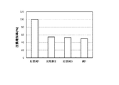
図5は、比較例1〜3、例1のNOx浄化率を比較したグラフである。
表1および図5に示すように、例1では、比較例1〜3に比べて、顕著にNOx浄化率が向上していた。この理由として、比較例1では、触媒層への排ガスの接触頻度が相対的に低かったことが考えられる。また、比較例2,3では、隔壁内部全体に酸化触媒と還元触媒とを配置したことで、金属触媒の粒成長や合金化が生じ、金属触媒への排ガスの接触頻度が低下したことが考えられる。これに対して、例1では、酸化触媒と還元触媒とを隔壁の延伸方向にそれぞれ分けて配置することにより、金属触媒への排ガスの接触頻度が向上したことが考えられる。
FIG. 5 is a graph comparing the NO x purification rates of Comparative Examples 1 to 3 and Example 1.
As shown in Table 1 and FIG. 5, in Example 1, the NO x purification rate was significantly improved as compared with Comparative Examples 1 to 3. As the reason for this, in Comparative Example 1, it is considered that the frequency of contact of the exhaust gas with the catalyst layer was relatively low. Further, in Comparative Examples 2 and 3, it is considered that particle growth and alloying of the metal catalyst occur and the contact frequency of the exhaust gas to the metal catalyst is reduced by arranging the oxidation catalyst and the reduction catalyst in the entire partition wall. Be On the other hand, in Example 1, it is conceivable that the frequency of contact of the exhaust gas with the metal catalyst is improved by dividing and arranging the oxidation catalyst and the reduction catalyst in the extending direction of the partition walls.
≪試験例I−2≫
第1触媒層および第2触媒層について、隔壁の延伸方向の長さ(L1−in、L1−out、L2−in、L2−out)を表2のように変化させたこと以外は例1と同様に、例2〜4の排ガス浄化用触媒を作製した。そして、上記した試験例I−1と同様に、排ガス浄化性能の評価を行った。結果を表2の該当欄に示す。表2では、比較例1のNOx浄化率を基準(100%)とした相対値で表している。
Test Example I-2
With respect to the first catalyst layer and the second catalyst layer, the length in the stretching direction of the partition wall (L 1 -in , L 1 -out , L 2-in , L 2-out ) was changed as shown in Table 2. In the same manner as Example 1, the exhaust gas purifying catalyst of Examples 2 to 4 was produced. And evaluation of exhaust gas purification performance was performed like the above-mentioned test example I-1. The results are shown in the corresponding column of Table 2. In Table 2, it indicated as a relative value based on (100%) of the NO x purification rate of Comparative Example 1.
図6は、第1触媒層の延伸方向の長さとNOx浄化率との関係を示すグラフである。
表2および図6に示すように、例1〜4は概ね同等のNOx浄化率であり、いずれも比較例1に比べて凡そ10%もNOx浄化率が向上していた。したがって、NOx浄化性能の観点からは、隔壁の入側セルと接する側の表面において、隔壁の延伸方向の全長Lwを100%としたときに、第1触媒層の延伸方向の長さL1−inが、50〜75%であるとよいといえる。
FIG. 6 is a graph showing the relationship between the length in the extending direction of the first catalyst layer and the NO x purification rate.
As shown in Table 2 and FIG. 6, Examples 1-4 are generally equivalent of the NO x purification rate, both also the NO x purification rate approximately 10% compared to Comparative Example 1 was improved. Therefore, from the viewpoint of the NO x purification performance, when the total length L w of the partition in the stretching direction is 100%, the length L of the first catalyst layer in the stretching direction on the surface of the partition in contact with the entry side cell. It can be said that 1-in is preferably 50 to 75%.
≪試験例II≫
例1の第1触媒層と第2触媒層とを逆さにして、例5の排ガス浄化用触媒を作製した。そして、上記した試験例I−1と同様に、圧損と排ガス浄化性能の評価を行った。なお、ここではNOx成分の浄化率にかえて、上記した試験例I−1に準じて、HC成分の浄化率(HC浄化率)を評価した。結果を表3の該当欄に示す。表3では、比較例1のHC浄化率を基準(100%)とした相対値で表している。HC浄化率は、HC浄化性能に優れるものほど値が大きくなるように表されている。
«Test Example II»
The exhaust gas purification catalyst of Example 5 was produced by inverting the first catalyst layer and the second catalyst layer of Example 1. And evaluation of pressure loss and exhaust gas purification performance was performed like the above-mentioned test example I-1. Here, instead of the purification rate of the NO x component, the purification rate (HC purification rate) of the HC component was evaluated according to the above-mentioned Test Example I-1. The results are shown in the corresponding column of Table 3. In Table 3, it represents with the relative value which made HC purification rate of comparative example 1 a standard (100%). The HC purification rate is expressed such that the higher the HC purification performance, the larger the value.
図7は、比較例1〜2、例1、例5のHC浄化率を比較したグラフである。
表3および図7に示すように、例5では、例1よりもさらにHC浄化率が向上していた。したがって、HC浄化性能の観点からは、第1触媒層に酸化触媒を配置することが好ましいといえる。
FIG. 7 is a graph comparing HC purification rates of Comparative Examples 1 to 2, Example 1, and Example 5.
As shown in Table 3 and FIG. 7, in Example 5, the HC purification rate was further improved than in Example 1. Therefore, from the viewpoint of HC purification performance, it may be preferable to dispose an oxidation catalyst in the first catalyst layer.
以上、本発明の具体例を詳細に説明したが、これらは例示にすぎず、請求の範囲を限定するものではない。請求の範囲に記載の技術には、以上に例示した具体例を様々に変形、変更したものが含まれる。 Although the specific examples of the present invention have been described above in detail, these are merely examples and do not limit the scope of the claims. The art set forth in the claims includes various variations and modifications of the specific examples illustrated above.
例えば、上述した実施形態では、GPF10が、第1触媒層20と第2触媒層30とに加えて、さらに第3の触媒層40を備えていたが、これには限定されない。GPF10は、2つの触媒層、すなわち、第1触媒層20および第2触媒層30のみを備えていてもよい。
For example, in the embodiment described above, the
例えば、上述した実施形態では、排ガス浄化用触媒がGPF10であったが、これには限定されない。例えば内燃機関2がディーゼルエンジンである場合、排ガス浄化用触媒は、ディーゼルパティキュレートフィルタ(DPF:Diesel Particulate Filter)であり得る。
For example, in the embodiment described above, the exhaust gas purification catalyst is
1 排ガス浄化装置
2 内燃機関
10 GPF(排ガス浄化用触媒)
11 基材
12 入側セル
14 出側セル
16 隔壁
20 第1触媒層
30 第2触媒層
1 exhaust
11
Claims (8)
排ガス流入側の端部が開口した入側セルと、排ガス流出側の端部が開口した出側セルとが、多孔質な隔壁によって仕切られているウォールフロー構造の基材と、
前記隔壁の内部に、前記排ガス流入側の端部から前記隔壁の延伸方向に沿って、前記入側セルと前記出側セルとに接するように配置されている第1触媒層と、
前記隔壁の内部に、前記排ガス流出側の端部から前記隔壁の延伸方向に沿って、前記入側セルと前記出側セルとに接するように配置されている第2触媒層と、
を備え、
前記第1触媒層および前記第2触媒層のうちのいずれか一方は、酸化触媒を含み且つ還元触媒を含まず、他方は、前記還元触媒を含み且つ前記酸化触媒を含まず、
前記隔壁の、前記入側セルと接する側の表面と、前記出側セルと接する側の表面とで、前記第1触媒層と前記第2触媒層との長さの比が異なっている、
排ガス浄化用触媒。 An exhaust gas purification catalyst disposed in an exhaust path of an internal combustion engine and purifying exhaust gas discharged from the internal combustion engine,
A base material of a wall flow structure in which an inlet side cell having an end portion at the exhaust gas inlet side opened and an outlet side cell having an end portion at the exhaust gas outlet side opened by porous partition walls;
A first catalyst layer disposed inside the partition wall so as to contact the inlet cell and the outlet cell along an extending direction of the partition wall from an end on the exhaust gas inflow side;
A second catalyst layer disposed inside the partition wall so as to be in contact with the inlet cell and the outlet cell along an extending direction of the partition wall from an end on the exhaust gas outlet side;
Equipped with
One of the first catalyst layer and the second catalyst layer contains an oxidation catalyst and does not contain a reduction catalyst, and the other contains the reduction catalyst and does not contain the oxidation catalyst.
The ratio of the length of the first catalyst layer to the length of the second catalyst layer is different between the surface of the partition in contact with the inlet cell and the surface of the partition in contact with the outlet cell.
Exhaust gas purification catalyst.
請求項1に記載の排ガス浄化用触媒。 The first catalyst layer includes the reduction catalyst and does not include the oxidation catalyst, and the second catalyst layer includes the oxidation catalyst and does not include the reduction catalyst.
An exhaust gas purification catalyst according to claim 1.
請求項1に記載の排ガス浄化用触媒。 The first catalyst layer contains the oxidation catalyst and does not contain the reduction catalyst, and the second catalyst layer contains the reduction catalyst and does not contain the oxidation catalyst.
An exhaust gas purification catalyst according to claim 1.
請求項1〜3の何れか一つに記載の排ガス浄化用触媒。 The first catalyst layer has a length of 40% or more and 75% or less of the total length of the partition wall when the total length in the stretching direction of the partition wall is 100% on the surface of the partition in contact with the entry side cell. Is located at,
The exhaust gas purification catalyst according to any one of claims 1 to 3.
請求項1〜4の何れか一つに記載の排ガス浄化用触媒。 The second catalyst layer has a length of 35% or more and 70% or less of the total length of the partition wall, where the total length in the stretching direction of the partition wall is 100%, on the surface of the partition in contact with the outlet cell. Is located at,
The exhaust gas purification catalyst according to any one of claims 1 to 4.
請求項1〜5の何れか一つに記載の排ガス浄化用触媒。 The entire surface of the partition in contact with the inlet cell and the entire surface of the partition in contact with the outlet cell are respectively any one of the first catalyst layer and the second catalyst layer. Covered with
The exhaust gas purifying catalyst according to any one of claims 1 to 5.
前記第2触媒層は、前記隔壁の前記入側セルと接する側の表面から前記出側セルと接する側の表面に向かって、前記隔壁の延伸方向における長さが漸増するように配置されている、
請求項1〜6の何れか一つに記載の排ガス浄化用触媒。 The first catalyst layer is disposed such that the length in the extending direction of the partition wall gradually decreases from the surface of the partition in contact with the inlet cell to the surface of the partition in contact with the outlet cell. ,
The second catalyst layer is disposed such that the length in the extending direction of the partition wall gradually increases from the surface of the partition in contact with the inlet cell to the surface of the partition in contact with the outlet cell. ,
The exhaust gas purification catalyst according to any one of claims 1 to 6.
Priority Applications (5)
| Application Number | Priority Date | Filing Date | Title |
|---|---|---|---|
| JP2017189040A JP6487982B1 (en) | 2017-09-28 | 2017-09-28 | Exhaust gas purification catalyst |
| PCT/JP2018/033544 WO2019065206A1 (en) | 2017-09-28 | 2018-09-11 | Exhaust-gas purifying catalyst |
| CN201880062609.8A CN111148571B (en) | 2017-09-28 | 2018-09-11 | Catalyst for exhaust gas purification |
| EP18860962.2A EP3689457B1 (en) | 2017-09-28 | 2018-09-11 | Exhaust-gas purifying catalyst |
| US16/647,004 US11187129B2 (en) | 2017-09-28 | 2018-09-11 | Exhaust gas purification catalyst |
Applications Claiming Priority (1)
| Application Number | Priority Date | Filing Date | Title |
|---|---|---|---|
| JP2017189040A JP6487982B1 (en) | 2017-09-28 | 2017-09-28 | Exhaust gas purification catalyst |
Publications (2)
| Publication Number | Publication Date |
|---|---|
| JP6487982B1 JP6487982B1 (en) | 2019-03-20 |
| JP2019063700A true JP2019063700A (en) | 2019-04-25 |
Family
ID=65802350
Family Applications (1)
| Application Number | Title | Priority Date | Filing Date |
|---|---|---|---|
| JP2017189040A Active JP6487982B1 (en) | 2017-09-28 | 2017-09-28 | Exhaust gas purification catalyst |
Country Status (5)
| Country | Link |
|---|---|
| US (1) | US11187129B2 (en) |
| EP (1) | EP3689457B1 (en) |
| JP (1) | JP6487982B1 (en) |
| CN (1) | CN111148571B (en) |
| WO (1) | WO2019065206A1 (en) |
Cited By (1)
| Publication number | Priority date | Publication date | Assignee | Title |
|---|---|---|---|---|
| WO2020262623A1 (en) * | 2019-06-26 | 2020-12-30 | 株式会社キャタラー | Particulate filter |
Families Citing this family (8)
| Publication number | Priority date | Publication date | Assignee | Title |
|---|---|---|---|---|
| EP3501647A1 (en) | 2017-12-19 | 2019-06-26 | Umicore Ag & Co. Kg | Catalytically active particle filter |
| EP3505245B1 (en) | 2017-12-19 | 2019-10-23 | Umicore Ag & Co. Kg | Catalytically active particle filter |
| EP3501648B1 (en) | 2017-12-19 | 2023-10-04 | Umicore Ag & Co. Kg | Catalytically active particle filter |
| CN113646064A (en) * | 2019-03-29 | 2021-11-12 | 优美科股份公司及两合公司 | Catalytically active particulate filter |
| JP7386626B2 (en) * | 2019-06-18 | 2023-11-27 | 株式会社キャタラー | particulate filter |
| CN111997718B (en) * | 2020-08-18 | 2022-05-17 | 无锡威孚环保催化剂有限公司 | Post-processing method applied to diesel-natural gas dual-fuel vehicle |
| US20230287831A1 (en) | 2020-12-28 | 2023-09-14 | Mitsubishi Heavy Industries Engine & Turbocharger, Ltd. | Turbine housing, turbocharger, and gasoline engine |
| WO2023067744A1 (en) * | 2021-10-20 | 2023-04-27 | 三井金属鉱業株式会社 | Exhaust gas purification catalyst |
Citations (6)
| Publication number | Priority date | Publication date | Assignee | Title |
|---|---|---|---|---|
| JP2007185571A (en) * | 2006-01-11 | 2007-07-26 | Toyota Central Res & Dev Lab Inc | Catalyst for cleaning exhaust gas and its manufacturing method |
| JP2012172597A (en) * | 2011-02-22 | 2012-09-10 | Honda Motor Co Ltd | Exhaust purification filter |
| WO2015087816A1 (en) * | 2013-12-11 | 2015-06-18 | 株式会社キャタラー | Exhaust gas purification material |
| WO2016060050A1 (en) * | 2014-10-16 | 2016-04-21 | 株式会社キャタラー | Exhaust gas purification catalyst |
| WO2016133085A1 (en) * | 2015-02-17 | 2016-08-25 | 株式会社キャタラー | Exhaust gas purification catalyst |
| JP2017144377A (en) * | 2016-02-16 | 2017-08-24 | 日本碍子株式会社 | Honeycomb structure |
Family Cites Families (16)
| Publication number | Priority date | Publication date | Assignee | Title |
|---|---|---|---|---|
| WO2008011146A1 (en) * | 2006-07-21 | 2008-01-24 | Dow Global Technologies Inc. | Improved zone catalyzed soot filter |
| US20080078171A1 (en) * | 2006-09-29 | 2008-04-03 | Dacosta Herbert F M | Chemically functionalized filter system |
| DE102007046158B4 (en) | 2007-09-27 | 2014-02-13 | Umicore Ag & Co. Kg | Use of a catalytically active particulate filter for the removal of particles from the exhaust gas of combustion engines operated with predominantly stoichiometric air / fuel mixture |
| JP2009287402A (en) | 2008-05-27 | 2009-12-10 | Nissan Motor Co Ltd | Exhaust emission control filter and exhaust emission control device |
| KR101765354B1 (en) * | 2009-11-20 | 2017-08-07 | 바스프 에스이 | Zoned catalyzed soot filter |
| GB2492175B (en) * | 2011-06-21 | 2018-06-27 | Johnson Matthey Plc | Exhaust system for internal combustion engine comprising catalysed filter substrate |
| US8789356B2 (en) * | 2011-07-28 | 2014-07-29 | Johnson Matthey Public Limited Company | Zoned catalytic filters for treatment of exhaust gas |
| US9347357B2 (en) * | 2012-09-27 | 2016-05-24 | Ngk Insulators, Ltd. | Honeycomb catalyst body |
| GB201221025D0 (en) * | 2012-11-22 | 2013-01-09 | Johnson Matthey Plc | Zoned catalysed substrate monolith |
| WO2016060049A1 (en) * | 2014-10-16 | 2016-04-21 | 株式会社キャタラー | Exhaust gas purification catalyst |
| CN107073465A (en) * | 2014-10-16 | 2017-08-18 | 株式会社科特拉 | Exhaust gas purification catalyst |
| JP6565184B2 (en) | 2014-12-26 | 2019-08-28 | 日産自動車株式会社 | Honeycomb type monolith catalyst and method for producing the same |
| WO2016133086A1 (en) | 2015-02-17 | 2016-08-25 | 株式会社キャタラー | Catalyst for exhaust gas purification |
| GB2575371B (en) | 2015-06-18 | 2020-05-06 | Johnson Matthey Plc | Zoned exhaust system |
| CN108698037B (en) | 2016-03-24 | 2019-10-18 | 株式会社科特拉 | Emission-control equipment |
| JP6434931B2 (en) | 2016-04-06 | 2018-12-05 | 矢崎総業株式会社 | Cable routing structure |
-
2017
- 2017-09-28 JP JP2017189040A patent/JP6487982B1/en active Active
-
2018
- 2018-09-11 EP EP18860962.2A patent/EP3689457B1/en active Active
- 2018-09-11 US US16/647,004 patent/US11187129B2/en active Active
- 2018-09-11 CN CN201880062609.8A patent/CN111148571B/en active Active
- 2018-09-11 WO PCT/JP2018/033544 patent/WO2019065206A1/en unknown
Patent Citations (6)
| Publication number | Priority date | Publication date | Assignee | Title |
|---|---|---|---|---|
| JP2007185571A (en) * | 2006-01-11 | 2007-07-26 | Toyota Central Res & Dev Lab Inc | Catalyst for cleaning exhaust gas and its manufacturing method |
| JP2012172597A (en) * | 2011-02-22 | 2012-09-10 | Honda Motor Co Ltd | Exhaust purification filter |
| WO2015087816A1 (en) * | 2013-12-11 | 2015-06-18 | 株式会社キャタラー | Exhaust gas purification material |
| WO2016060050A1 (en) * | 2014-10-16 | 2016-04-21 | 株式会社キャタラー | Exhaust gas purification catalyst |
| WO2016133085A1 (en) * | 2015-02-17 | 2016-08-25 | 株式会社キャタラー | Exhaust gas purification catalyst |
| JP2017144377A (en) * | 2016-02-16 | 2017-08-24 | 日本碍子株式会社 | Honeycomb structure |
Cited By (2)
| Publication number | Priority date | Publication date | Assignee | Title |
|---|---|---|---|---|
| WO2020262623A1 (en) * | 2019-06-26 | 2020-12-30 | 株式会社キャタラー | Particulate filter |
| US11808188B2 (en) | 2019-06-26 | 2023-11-07 | Cataler Corporation | Particulate filter |
Also Published As
| Publication number | Publication date |
|---|---|
| CN111148571B (en) | 2023-02-17 |
| EP3689457A4 (en) | 2020-10-14 |
| EP3689457B1 (en) | 2022-07-06 |
| JP6487982B1 (en) | 2019-03-20 |
| US11187129B2 (en) | 2021-11-30 |
| EP3689457A1 (en) | 2020-08-05 |
| CN111148571A (en) | 2020-05-12 |
| WO2019065206A1 (en) | 2019-04-04 |
| US20200263587A1 (en) | 2020-08-20 |
Similar Documents
| Publication | Publication Date | Title |
|---|---|---|
| JP6738185B2 (en) | Exhaust gas purification device | |
| JP6487982B1 (en) | Exhaust gas purification catalyst | |
| CN107249738B (en) | Catalyst for exhaust gas purification | |
| JP6564637B2 (en) | Exhaust gas purification device | |
| JP6655060B2 (en) | Exhaust gas purification catalyst | |
| WO2016133085A1 (en) | Exhaust gas purification catalyst | |
| WO2018173557A1 (en) | Exhaust gas purification catalyst | |
| WO2020039650A1 (en) | Exhaust gas purification catalyst | |
| JP6386697B1 (en) | Exhaust gas purification catalyst | |
| JP6955573B2 (en) | Exhaust gas purification catalyst | |
| WO2016056573A1 (en) | Exhaust gas purification device | |
| JP6445228B1 (en) | Exhaust gas purification catalyst | |
| JP2021004579A (en) | Particulate filter | |
| JP7130622B2 (en) | Exhaust gas purification catalyst | |
| US11918986B2 (en) | Exhaust gas purification device |
Legal Events
| Date | Code | Title | Description |
|---|---|---|---|
| A621 | Written request for application examination |
Free format text: JAPANESE INTERMEDIATE CODE: A621 Effective date: 20181228 |
|
| A871 | Explanation of circumstances concerning accelerated examination |
Free format text: JAPANESE INTERMEDIATE CODE: A871 Effective date: 20181228 |
|
| A975 | Report on accelerated examination |
Free format text: JAPANESE INTERMEDIATE CODE: A971005 Effective date: 20190117 |
|
| TRDD | Decision of grant or rejection written | ||
| A01 | Written decision to grant a patent or to grant a registration (utility model) |
Free format text: JAPANESE INTERMEDIATE CODE: A01 Effective date: 20190207 |
|
| A61 | First payment of annual fees (during grant procedure) |
Free format text: JAPANESE INTERMEDIATE CODE: A61 Effective date: 20190222 |
|
| R150 | Certificate of patent or registration of utility model |
Ref document number: 6487982 Country of ref document: JP Free format text: JAPANESE INTERMEDIATE CODE: R150 |
|
| R250 | Receipt of annual fees |
Free format text: JAPANESE INTERMEDIATE CODE: R250 |
|
| R250 | Receipt of annual fees |
Free format text: JAPANESE INTERMEDIATE CODE: R250 |
|
| R250 | Receipt of annual fees |
Free format text: JAPANESE INTERMEDIATE CODE: R250 |