JP2019061663A - Electronic control device - Google Patents
Electronic control device Download PDFInfo
- Publication number
- JP2019061663A JP2019061663A JP2018165972A JP2018165972A JP2019061663A JP 2019061663 A JP2019061663 A JP 2019061663A JP 2018165972 A JP2018165972 A JP 2018165972A JP 2018165972 A JP2018165972 A JP 2018165972A JP 2019061663 A JP2019061663 A JP 2019061663A
- Authority
- JP
- Japan
- Prior art keywords
- authentication code
- authentication
- electronic control
- ecu
- unit
- Prior art date
- Legal status (The legal status is an assumption and is not a legal conclusion. Google has not performed a legal analysis and makes no representation as to the accuracy of the status listed.)
- Granted
Links
Images

Landscapes
- Small-Scale Networks (AREA)
- Storage Device Security (AREA)
Abstract
【課題】なりすましを極力防止できるようにした電子制御装置を提供する。【解決手段】ECU1は、認証コードを生成し、ECU2との間で予め共有された認証コードを保存済認証コードとして不揮発性メモリに記憶している。ECU1は、S11〜S13において保存済認証コードと改めて生成された次回認証コードとをECU2に送信する。ECU1は、S15、S16において、送信された保存済認証コード及び次回認証コードが認証受付側のECU2にて正常に認証されたことを条件として次回認証コードを不揮発性メモリに保存する。【選択図】図4PROBLEM TO BE SOLVED: To provide an electronic control device capable of preventing spoofing as much as possible. An ECU 1 generates an authentication code and stores an authentication code shared in advance with the ECU 2 in a non-volatile memory as a stored authentication code. The ECU 1 transmits the saved authentication code and the newly generated next authentication code in S11 to S13 to the ECU 2. The ECU 1 stores the next authentication code in the non-volatile memory on condition that the transmitted saved authentication code and the next authentication code are normally authenticated by the ECU 2 on the authentication receiving side in S15 and S16. [Selection diagram] FIG. 4
Description
本発明は、電子制御装置に関する。 The present invention relates to an electronic control device.
車載ネットワークシステムは、複数のECU(Electronic Control Unit)をネットワーク接続して連携動作して車両用機器を制御するシステムである。この種の車載ネットワークシステムでは、各ECUは、工場出荷時の初回の起動時に、各ECUに一意の識別情報を有するメッセージを送信すると共に、他のECUからメッセージを受信し、当該メッセージから抽出した識別情報が登録されたリストを作成する。工場出荷後に起動した各ECUは、他のECUから受信したメッセージから抽出した識別情報がリストに登録されていない場合、異常検知処理を行うようにする技術が提供されている(例えば、特許文献1参照)。 The in-vehicle network system is a system in which a plurality of ECUs (Electronic Control Units) are connected in a network to cooperate with each other to control vehicle devices. In this type of in-vehicle network system, each ECU transmits a message having unique identification information to each ECU at the time of initial startup at the time of factory shipment, and receives a message from another ECU and extracts it from the message Create a list with identification information registered. There is provided a technology for performing an abnormality detection process when identification information extracted from a message received from another ECU is not registered in the list for each ECU activated after factory shipment (for example, Patent Document 1) reference).
前述した特許文献1記載の技術を適用したときには、例えば識別情報が漏えいしてしまうと、識別情報が漏洩したECUを、任意のECUに変更可能になってしまうという問題を生じる。任意のECUに変更可能になると、所謂なりすましできるようになってしまう。
本発明の目的は、識別情報が漏洩したとしても、なりすましを極力防止できるようにした電子制御装置を提供することにある。
When the technology described in Patent Document 1 described above is applied, for example, if the identification information leaks, there arises a problem that the ECU from which the identification information leaks can be changed to an arbitrary ECU. If it becomes possible to change to an arbitrary ECU, so-called spoofing will become possible.
An object of the present invention is to provide an electronic control device which can prevent impersonation as much as possible even if identification information leaks.
請求項1記載の発明は、認証処理を実施する認証システムを構成する認証要求側の第1電子制御装置を対象としている。この請求項1記載の発明によれば、認証コード生成部と、第1記憶部と、送信部と、第1保存部と、を備える。認証コード生成部は認証コードを生成し、第1記憶部は第2電子制御装置との間で予め共有された認証コードを保存済認証コードとして記憶する。送信部は、記憶部に記憶された保存済認証コードと、認証コード生成部により生成された次回認証コードとを第2電子制御装置に送信する。第1保存部は、送信された保存済認証コード及び次回認証コードが第2電子制御装置において正常に認証されたことを条件として次回認証コードを保存する。認証要求側において、次回認証コードを次の認証に用いることができるようになるため、これらの処理が繰り返されることで認証コードを次々に変更できるようになる。したがって、たとえ古い識別コードが漏洩したとしても当該古い識別コードを用いて認証処理できなくなり、意図しない電子制御装置に変更されたことを検出できるようになり、なりすましを極力防止できるようになる。 The invention according to claim 1 is directed to a first electronic control unit on an authentication request side which constitutes an authentication system for performing an authentication process. According to the first aspect of the invention, the authentication code generation unit, the first storage unit, the transmission unit, and the first storage unit are provided. The authentication code generation unit generates an authentication code, and the first storage unit stores an authentication code shared in advance with the second electronic control device as a stored authentication code. The transmission unit transmits the stored authentication code stored in the storage unit and the next authentication code generated by the authentication code generation unit to the second electronic control unit. The first storage unit stores the next authentication code on condition that the transmitted stored authentication code and the next authentication code have been successfully authenticated by the second electronic control unit. Since the authentication request side can use the authentication code for the next authentication on the authentication request side, the authentication code can be changed one after another by repeating these processes. Therefore, even if the old identification code leaks, authentication processing can not be performed using the old identification code, and it is possible to detect that the electronic control device has been changed unintentionally, and it is possible to prevent impersonation as much as possible.
請求項4記載の発明は、認証処理を実施する認証システムを構成する認証受付側の第2電子制御装置を対象としている。この請求項4記載の発明によれば、受信部と、第2記憶部と、第2保存部と、を備える。受信部は、第1電子制御装置から送信される前回認証コード及び次回認証コードを受信する。第2記憶部は、第1電子制御装置から前回受信された認証コードを保存済認証コードとして記憶する。第2保存部は、第2記憶部に記憶された保存済認証コードに、受信部により受信した前回認証コードが含まれるときに正常な認証と判断し次回認証コードを保存する。認証受付側において、次回認証コードを次の認証に用いることができるようになるため、これらの処理が繰り返されることで認証コードを次々に変更できるようになる。したがって、たとえ古い識別コードが漏洩したとしても当該古い識別コードを用いて認証処理できなくなり、意図しない電子制御装置に変更されたことを検出できるようになり、なりすましを極力防止できるようになる。
The invention according to
以下、本発明の電子制御装置の実施形態について図面を参照しながら説明する。
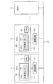
図1は車載ネットワークシステムの中の認証システムの構成例を示している。車両内には、複数のECU(Electronic Control Unit:電子制御装置)1、2…3が、車載ネットワーク(例えばCANバス)4に接続されており、互いに各種情報を送受信可能に構成されており、これらのECU1、2…3により認証システムが構成されている。CANは登録商標である。
Hereinafter, an embodiment of the electronic control device of the present invention will be described with reference to the drawings.
FIG. 1 shows a configuration example of an authentication system in the in-vehicle network system. In the vehicle, a plurality of ECUs (Electronic Control Units: Electronic Control Units) 1, 2 ... 3 are connected to the in-vehicle network (for example, CAN bus) 4 and are configured to be able to transmit and receive various information to each other, An authentication system is configured by these ECUs 1, 2. CAN is a registered trademark.
ECU1は、CPU11、メモリ12、及び通信回路13などバス14に接続して構成された第1電子制御装置に相当するものであり、車両内の各種センサ、アクチュエータ(何れも図示せず)などを制御するように構成される。メモリ12は、不揮発性メモリ15及び揮発性メモリ(図示せず)によるもので、CPU11は、メモリ12に記憶された制御プログラムに基づいて動作する。メモリ12は非遷移的実効的記録媒体として用いられる。通信回路13は、車載ネットワークに対応したトランシーバ(例えばCANトランシーバ)により構成され、ECU1は通信回路13を通じてネットワーク4を介して他のECU(例えば2)との間でデータを送受信する。本実施形態では、CPU11が認証コード生成部、認証要求側エラー処理実行部、として用いられると共に、通信回路13が送信部、第2受信部として用いられ、不揮発性メモリ15が第1記憶部、第1保存部、第3記憶部、第3保存部に相当するメモリとして用いられる。
The ECU 1 corresponds to a first electronic control unit configured to be connected to the
ECU2もECU1と同様の構成とされている。説明の便宜上、符号を変更して図示しているが、ECU2は、CPU21、メモリ22、及び通信回路23などバス24に接続して構成された第2電子制御装置に相当するものであり、車両内の各種センサ、アクチュエータ(何れも図示せず)などを制御するように構成される。メモリ22もまた、不揮発性メモリ25及び揮発性メモリ(図示せず)によるもので、CPU21は、メモリ22に記憶された制御プログラムに基づいて動作する。メモリ22もまた非遷移的実効的記録媒体として用いられる。通信回路23は、車載ネットワークに対応したトランシーバ(例えばCANトランシーバ)により構成され、ECU2は、通信回路23を通じてネットワーク4を介して他のECU(例えばECU1)との間でデータを送受信する。本実施形態では、CPU21が認証部、認証受付側エラー処理実行部として用いられ、通信回路23が第1受信部、認証結果送信部として用いられ、不揮発性メモリ25が第2記憶部、第2保存部に相当するメモリとして用いられる。以下では、前述のCPU11、21が各メモリ12、22に記憶されたプログラムに応じて実行する動作を、各ECU1、2の動作と表記して説明を行う。
The ECU 2 is also configured the same as the ECU 1. Although the reference numerals are changed and illustrated for convenience of explanation, the ECU 2 corresponds to a second electronic control unit configured by being connected to the
上記構成の作用、動作を説明する。本実施形態では、ネットワーク接続によるECUのなりすましを防止するため、複数のECU1、2の間で認証処理を実施するところに特徴を備える。以下では、その詳細説明を行う。 The operation and operation of the above configuration will be described. In the present embodiment, in order to prevent spoofing of the ECUs by the network connection, a feature is provided in that the authentication processing is performed between the plurality of ECUs 1 and 2. The details will be described below.
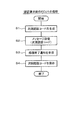
図2及び図3は、それぞれ、ECU1、ECU2の各初期化処理をフローチャートにより示している。ECU1が認証要求側のECUであり、ECU2が認証受付側のECUであることを前提として説明する。ECU1はまず、S1において次回の認証に利用する次回認証コードをランダムに生成し、S2にてこの次回認証コードをメッセージとしてネットワーク4に送信する。
FIG. 2 and FIG. 3 respectively show respective initialization processing of the ECU 1 and the ECU 2 by flowcharts. Description will be made on the assumption that the ECU 1 is an authentication request side ECU and the ECU 2 is an authentication reception side ECU. First, the ECU 1 randomly generates the next authentication code to be used for the next authentication in S1, and transmits the next authentication code as a message to the
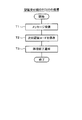
ECU2は、図2のS2で送信されたメッセージを図3のT1において受信し、T2において次回認証コードとして不揮発性メモリ25に保存する。その後、ECU2は、T3において処理終了通知をメッセージとしてネットワーク4に送信する。これによりECU2の初期化処理を終了する。
The ECU 2 receives the message transmitted in S2 of FIG. 2 at T1 of FIG. 3 and stores the message in the
ECU1は、図3のT3で送信された処理終了通知に係るメッセージを図2のS3において受信する。するとECU1は、このメッセージによりECU2が次回認証コードを不揮発性メモリ25に保存したことを確認できる。ECU1は、ECU2が次回認証コードを不揮発性メモリ15に正常に保存したことを確認した後、S4において生成した次回認証コードを不揮発性メモリ25に記憶、保存する。これによりECU1の初期化処理を終了する。これにより、認証要求側のECU1が生成した認証コードをECU1及び2の間で共有できる。この各不揮発性メモリ15、25に保存された認証コードを保存済認証コードと称する。
The ECU 1 receives the message related to the process end notification transmitted at T3 in FIG. 3 in S3 in FIG. Then, the ECU 1 can confirm from the message that the ECU 2 stores the authentication code in the
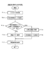
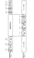
図4及び図5はECU1、ECU2の各認証時処理をフローチャートにより示しており、図6はECU1、ECU2の間で行われる認証時処理の流れの一例をシーケンス図で示しており、図7はECU1、ECU2の間で行われる認証時処理の流れの一例をタイミングチャートで示している。 4 and 5 show the respective authentication processes of the ECU 1 and the ECU 2 by flowcharts, and FIG. 6 shows an example of the flow of the authentication process performed between the ECU 1 and the ECU 2 in a sequence diagram, and FIG. An example of the flow of processing at the time of authentication performed between the ECU 1 and the ECU 2 is shown by a timing chart.
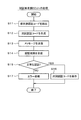
ECU1はまず、図4のS11においてECU2に予め通知すると共に保存した保存済認証コードを不揮発性メモリ15から読出す。図6のS11も参照。そしてECU1は、S12において、次回の認証に利用する次回認証コードをランダムに生成する。その後、ECU1は、S13において、不揮発性メモリ15から読み出した保存済認証コードを前回認証コードとし、この前回認証コードとランダムに生成した次回認証コードとを合わせたメッセージを生成してネットワーク4に送信する。
First, the ECU 1 reads from the
他方、ECU2は、図7に示すように、ECU1がS13にてメッセージを送信する前にはメッセージを待機している。ECU1が図4のS13で送信したメッセージをECU2は図5のT11にて受信する。図6のT11も参照。するとECU2は、図5のT12において、ECU1から前回受信して不揮発性メモリ25に保存した保存済認証コードを読出し、図5のT13において、当該読出した保存済認証コードと受信した前回認証コードとを比較する。
On the other hand, as shown in FIG. 7, the ECU 2 stands by for a message before the ECU 1 transmits the message at S13. The ECU 2 receives the message transmitted by the ECU 1 at S13 of FIG. 4 at T11 of FIG. See also T11 in FIG. Then, the ECU 2 reads the stored authentication code received last time from the ECU 1 and stored in the
ECU2は、これらの保存済認証コードと前回認証コードとが一致していればT13でYESと判断し、図5のT14において正常な認証と判断し、図5のT15において受信した次回認証コードを不揮発性メモリ25に保存する。他方ECU2は、図5のT13において、これらの保存済認証コードと受信した前回認証コードとが一致しないと判断したときには、ECU1が変更されたと判定し、図5のT16において認証エラー処理を実行する。ECU2は、このT16の認証エラー処理において、例えばECU2が、ECU1以外のECU3などに対し、ECU1が不正な電子制御装置であることを通知したり、ECU1から受信した情報をリセット、すなわち初期化したり、今後ECU1から様々な要求を受けたとしても無視する旨のフラグを立てたりする。これによりECU2側では、図6のT13〜T16において認証コードの適否に応じた処理を実行できる。
If the stored authentication code matches the previous authentication code, the ECU 2 determines YES in T13, determines that the authentication is normal in T14 of FIG. 5, and determines the next authentication code received in T15 of FIG. It is stored in the
これによりECU1が、様々ななりすまし行為を過去に行っていた、又は将来に渡り行うとしても、このなりすまし行為による被害を過去に遡って検出できると共に将来に渡る被害を未然に防ぐことができる。そしてECU2は、図5のT17において、これらのT14又はT15における認証結果をECU1に送信する。図6及び図7のT17も参照。これにより、ECU2は処理終了となる。 As a result, even if the ECU 1 has performed various spoofing acts in the past or in the future, it is possible to trace back the damage caused by the spoofing act and prevent the future damage. Then, at T17 of FIG. 5, the ECU 2 transmits the authentication result at these T14 or T15 to the ECU 1. See also T17 in FIG. 6 and FIG. Thus, the ECU 2 ends the process.
ECU1は、図7に示すように、S13においてメッセージを送信してから認証結果を受信するまで認証結果の受信を待機している。ECU1は、図4のS14においてECU2から認証結果を受信すると、S15において正常認証されたか否かを判定し、認証結果が正常な認証とされていればS15でYESと判定することで、S12にて生成した次回認証コードをS16において不揮発性メモリ15に保存し、正常な認証とされていなければS15でNOと判定することでS17においてエラー処理を実行する。
このエラー処理は、なりすまししていないECU1により実行される処理である。このためECU1は、ネットワーク4におけるトラフィックエラーによる可能性があると判断し、S11に処理を戻して再度認証処理を繰り返すようにしても良いし、所定(例えば複数)回以上繰り返し実行してもS17のエラー処理に移行してしまう場合には、ネットワーク4に問題があると断定して終了しても良い。これによりECU1は処理終了となる。ECU1、2が共に正常な認証であると判断すれば、ECU1、2が不揮発性メモリ15、25に共有される認証コードは次回認証コードに更新されることになる。
As shown in FIG. 7, the ECU 1 waits for the reception of the authentication result until the authentication result is received after the message is transmitted in S13. When the ECU 1 receives the authentication result from the ECU 2 in S14 of FIG. 4, the ECU 1 determines whether or not the normal authentication is performed in S15, and if the authentication result is determined as a normal authentication, the process proceeds to S12 by determining YES in S15. The next authentication code generated is stored in the
This error process is a process executed by the non-spoofing ECU 1. Therefore, the ECU 1 may determine that there is a possibility of a traffic error in the
したがって、次回、ECU1、2が認証処理を実施するときには、この不揮発性メモリ15、25に保存された次回認証コードを共有した認証コードとすると共に、さらに新たな次々回認証コードを生成して認証処理を繰り返し実行できるようになる。したがって、ECU1、2は共有する認証コードを例えば認証処理する度に毎回更新できるようになり、たとえ古い識別コードが漏洩したとしても当該古い識別コードを用いて認証できなくなる。この結果、ECUが意図しないECUに変更されたことを検出できるようになり、なりすましを極力防止できるようになる。
Therefore, when the ECUs 1 and 2 execute the authentication process next time, the next authentication code stored in the
<実施例>
説明を理解し易くするため8ビットの認証コードの例を挙げて説明する。例えば、ECU1及び2は、初期化処理においてそれぞれ保存済認証コードとして「&HAA」を不揮発性メモリ15、25に保存して当該コードを共有しているときに、ECU1が、次回認証コードとして「&HBB」を生成したと仮定する。
<Example>
In order to make the description easy to understand, an example of an 8-bit authentication code will be described. For example, when the ECUs 1 and 2 save “& HAA” in the
ECU1は、保存済認証コード「&HAA」を前回認証コードとして送信すると共に、次回認証コード「&HBB」を送信すると、ECU2はこれらの前回認証コード「&HAA」及び次回認証コード「&HBB」を受信する。 When the ECU 1 transmits the stored authentication code "& HAA" as the authentication code last time and transmits the authentication code "& HBB" next time, the ECU 2 receives the previous authentication code "& HAA" and the next authentication code "& HBB".
するとECU2は、前回認証コード「&HAA」と、不揮発性メモリ25に保存された保存済認証コード「&HAA」とを比較、照合し、これらが一致したときに、次回認証コード「&HBB」を不揮発性メモリ25に保存する。ECU2が、認証結果として正常な認証であることをECU1に送信すると、ECU1は、次回認証コード「&HBB」を不揮発性メモリ15に保存する。これにより、次回認証コード「&HBB」はECU1及び2の間で共有されることになる。
Then, the ECU 2 compares the previous authentication code "& HAA" with the stored authentication code "& HAA" stored in the
ECU1及び2は、次回の認証処理においてこの共有された次回認証コード「&HBB」を保存済認証コードとして用いる。この後、ECU1が、さらなる次回認証コード「&HCC」を生成したと仮定する。ECU1は、保存済認証コード「&HBB」を前回認証コードとして送信すると共に、次回認証コード「&HCC」を送信すると、ECU2は、これらの前回認証コード「&HBB」及び次回認証コード「&HCC」を受信する。 The ECUs 1 and 2 use the shared next authentication code "& HBB" as the stored authentication code in the next authentication process. After this, it is assumed that the ECU 1 generates a further next authentication code “& HCC”. When the ECU 1 transmits the stored authentication code "& HBB" as the previous authentication code and transmits the next authentication code "& HCC", the ECU 2 receives the previous authentication code "& HBB" and the next authentication code "& HCC". .
するとECU2は、前回認証コード「&HBB」と、不揮発性メモリ25に保存された保存済認証コード「&HBB」とを比較、照合し、これらが一致したときに、次回認証コード「&HCC」を不揮発性メモリ25に保存する。ECU2が、認証結果として正常な認証であることをECU1に送信すると、ECU1は、次回認証コード「&HCC」を不揮発性メモリ15に保存する。これにより、次回認証コード「&HCC」はECU1及び2の間で共有される。このような処理を繰り返すことで、認証処理を実施する度に認証コードを更新できる。
Then, the ECU 2 compares the previous authentication code "& HBB" with the stored authentication code "& HBB" stored in the
この例では、説明の簡単化のため、8ビット=1バイトを認証コードとして用いた例を示しているが、その情報量は限られるものではない。 In this example, an example in which 8 bits = 1 byte is used as an authentication code is shown to simplify the description, but the amount of information is not limited.
<本実施形態に係る概念的なまとめ>
要するに、本実施形態によれば以下の構成を備えることで以下の効果を得られる。本実施形態によれば、ECU1は認証コードを生成し、ECU2との間で予め共有された認証コードを保存済認証コードとして不揮発性メモリ15に記憶しており、ECU1は、通信回路13により、保存済認証コードと改めて生成された次回認証コードとをECU2に送信する。ECU1は、送信された保存済認証コード及び次回認証コードがECU2において正常に認証されたことを条件として次回認証コードを不揮発性メモリ15に保存するようにしている。
<Conceptual summary concerning this embodiment>
In short, according to the present embodiment, the following effects can be obtained by providing the following configuration. According to the present embodiment, the ECU 1 generates an authentication code and stores the authentication code shared in advance with the ECU 2 in the
このときECU1側では、ECU2において正常に認証されたことを条件として次回認証コードを不揮発性メモリ15に保存するようにしている。このため、ECU1は、次回の認証に用いる次回認証コードを不揮発性メモリ25に保存することで次の認証処理に用いることができる。次回認証コードを次の認証に用いることができるようになるため、これらの処理が繰り返されることで認証コードを次々に変更できるようになる。したがって、たとえ古い識別コードが漏洩したとしても当該古い識別コードを用いて認証処理できなくなる。この結果、ECUが意図しないECUに変更されたことを検出できるようになり、なりすましを極力防止できるようになる。
At this time, the ECU 1 stores the next authentication code in the
ECU1は、認証処理を実施する度に、次回認証コードをランダムに生成しているため、認証処理を実施する度に認証コードを変更することができ、仮に認証コードが漏えいしてしまった場合であっても、ECU1の変更は検知することが可能となり、なりすましを防止できる。 Since the ECU 1 randomly generates the next authentication code each time the authentication process is performed, the authentication code can be changed each time the authentication process is performed, and the authentication code is temporarily leaked. Even if there is, the change of the ECU 1 can be detected, and spoofing can be prevented.
逆に、ECU2は、通信回路23を通じてECU1から送信される前回認証コード及び次回認証コードを受信し、前回受信された認証コードを保存済認証コードとして不揮発性メモリ25に記憶している。このとき、ECU2は、不揮発性メモリ25に記憶された保存済認証コードと、通信回路23を通じて受信した前回認証コードとが一致するときに正常な認証と判断し、次回認証コードを不揮発性メモリ25に保存するようにしているため、ECU2は、ECU1を認証することができ、当該ECU1がなりすましではないことを確認できる。しかも、次回の認証に用いる次回認証コードを不揮発性メモリ25に保存することで次の認証処理に用いることができるようになる。これにより、なりすましを極力防止できる。
Conversely, the ECU 2 receives the previous authentication code and the next authentication code transmitted from the ECU 1 through the
ECU2は、保存済認証コードと、通信回路23を通じて受信した前回認証コードとの認証結果をECU1に送信するようにしているため、ECU1にその認証結果を伝えることができる。このため、ECU1は、ECU2に正常な認証がされたときにはこの確認をすることができ、ECU1とECU2との間で正常な認証確認を行うことができる。
Since the ECU 2 transmits the authentication result of the stored authentication code and the previous authentication code received through the
(他の実施形態)
前述実施形態に限定されるものではなく、例えば、以下に示す変形又は拡張が可能である。
ECU2は、メモリ22に保存された保存済認証コードと受信した前回認証コードとが一致したことを条件として正常な認証と判断して次回認証コードを不揮発性メモリ25に保存し、一致していないときには認証エラー処理を実行する形態を示したが、これに限定されるものではない。ECU2は、例えば、保存済認証コードが送信された前回認証コードに含まれていれば正常な認証と判断して次回認証コードを保存するようにしても良い。
例えば、保存済認証コードが「&HAA」であったときに、ECU1が前回認証コードとして「&HAAB」をECU2に送信し、ECU2により「&HAA」が「&HAAB」に含まれていることを条件として正常な認証と判断するようにしても良い。
(Other embodiments)
The present invention is not limited to the above embodiment, and for example, the following modifications or expansions are possible.
The ECU 2 determines that the authentication is normal authentication on the condition that the stored authentication code stored in the
For example, when the stored authentication code is "&HAA", the ECU 1 transmits "&HAAB" as the previous authentication code to the ECU 2 last time, and the ECU 2 normally operates on condition that "&HAA" is included in "&HAAB". It may be determined that the authentication is correct.
前述実施形態では、ECU1が認証要求しECU2が認証受付する形態を示したが、これに限定されるものではなく、ECU1が認証要求すると共に認証受付する機能を備えており、ECU2が認証受付すると共に認証要求する機能を備えていても良い。
すなわち、ECU1が、図2及び図4の処理を実行可能になっていると共に図3及び図5の処理を実行可能になっており、ECU2が図3及び図5の処理を実行可能になっていると共に図2及び図4の処理を実行可能になっていても良い。
これらの処理内容は、前述実施形態と同様であるため図面の記載を省略しているが、例えば、ECU2が、認証コードをランダムに次回認証コードとして生成する機能を備えており、この次回認証コードと共に、不揮発性メモリ25に保存された保存済認証コードを前回認証コードとしてECU1に送信する。そしてECU1が、通信回路23を通じて他のECU2から前回認証コード及び次回認証コードを受信し、第3記憶部となる不揮発性メモリ15に保存された保存済認証コードと、ECU2から受信した前回認証コードとに応じて認証する。この認証は、CPU11が認証部としての機能を用いて実行される処理である。ECU1は、保存済認証コードが前回認証コードに一致しているか、又は、含まれているかを判定することで、ECU2の認証を行うことができる。
In the embodiment described above, the form is shown where the ECU 1 requests authentication and the ECU 2 accepts authentication, but the present invention is not limited to this. The ECU 1 has a function of requesting authentication and accepting authentication, and the ECU 2 accepts authentication And a function to request authentication.
That is, the ECU 1 can execute the processes of FIGS. 2 and 4 and can execute the processes of FIGS. 3 and 5, and the ECU 2 can execute the processes of FIGS. 3 and 5. In addition, the processes of FIGS. 2 and 4 may be executable.
The contents of these processes are the same as those in the above-described embodiment, so the description of the drawings is omitted. For example, the ECU 2 has a function of randomly generating an authentication code as the next authentication code. At the same time, the stored authentication code stored in the
ここで、ECU1は、保存済認証コードが前回認証コードに一致していたり、含まれていたりしたときには正常な認証と判断し、ECU2がなりすまししていない旨を確認することができ、さらにECU2から受信した次回認証コードを不揮発性メモリ15に保存する。これは第3保存部としての保存機能である。このように、前述実施形態で説明したECU1及び2の各機能をECU1及び2がそれぞれ備えて相互に認証できるようにしても良い。
Here, when the stored authentication code matches or is included in the authentication code last time, the ECU 1 determines that the authentication is normal and can confirm that the ECU 2 is not spoofing, and further from the ECU 2 The received next authentication code is stored in the
前述実施形態では、認証処理を実施する度に、ランダムに認証コードを変更している形態を示したが、認証処理を実行する度に認証コードを変更しなくても良く、同じ認証コードを用いて相手方のECUの通常認証を行った上で、何回かに一度だけ認証コードを変更する形態にも適用できる。また、ランダムに認証コードを変更しなくても、規則的に認証コードを変更する形態にも適用できる。
不揮発性メモリ15、25に保存済認証コードを保存する形態を示したが、例えばバッテリ電源などが常時通電されていれば当該不揮発性メモリ15、25以外の例えばバックアップRAMなどのメモリ12に保存済認証コードを保存する形態に適用しても良い。
In the above embodiment, the authentication code is randomly changed each time the authentication process is performed. However, the authentication code may not be changed each time the authentication process is performed, and the same authentication code is used. The present invention can also be applied to a mode in which the authentication code is changed only once several times after performing the normal authentication of the other ECU. Moreover, even if it does not change an authentication code at random, it is applicable also to the form which changes an authentication code regularly.
Although the stored authentication code is stored in the
特許請求の範囲に記載した括弧内の符号は、本発明の一つの態様として前述する実施形態に記載の具体的手段との対応関係を示すものであって、本発明の技術的範囲を限定するものではない。前述実施形態の一部を、課題を解決できる限りにおいて省略した態様も実施形態と見做すことが可能である。また、特許請求の範囲に記載した文言によって特定される発明の本質を逸脱しない限度において、考え得るあらゆる態様も実施形態と見做すことが可能である。 The reference numerals in parentheses described in the claims indicate the correspondence with the specific means described in the embodiment described above as one aspect of the present invention, and limit the technical scope of the present invention It is not a thing. The aspect which abbreviate | omitted a part of above-mentioned embodiment as long as a subject can be solved can also be considered as embodiment. In addition, any conceivable aspect can be considered as an embodiment without departing from the essence of the invention specified by the language described in the claims.
また本発明は、前述した実施形態に準拠して記述したが、本発明は当該実施形態や構造に限定されるものではないと理解される。本発明は、様々な変形例や均等範囲内の変形をも包含する。加えて、様々な組み合わせや形態、さらには、それらに一要素、それ以上、あるいはそれ以下、を含む他の組み合わせや形態をも、本開示の範畴や思想範囲に入るものである。 Furthermore, although the present invention has been described based on the above-described embodiment, it is understood that the present invention is not limited to the embodiment or the structure. The invention also encompasses variations and modifications within the equivalent range. In addition, various combinations and forms as well as other combinations and forms including one element or more or less or less are also within the scope and the scope of the present disclosure.
図面中、1はECU(第1電子制御装置)、2はECU(第2電子制御装置)、11は認証要求側のECUのCPU(認証コード生成部、認証要求側エラー処理実行部)、12はメモリ(第1記憶部、第1保存部、第3記憶部、第3保存部)、13は通信回路(送信部、第2受信部)、15は不揮発性メモリ(第1記憶部、第1保存部、第3記憶部、第3保存部)、21は認証受付側のECUのCPU(認証部、認証受付側エラー処理実行部)、22はメモリ(第2記憶部、第2保存部)、23は通信回路(第1受信部、認証結果送信部)、25は不揮発性メモリ(第2記憶部、第2保存部)、を示す。
In the drawing, 1 is an ECU (first electronic control unit), 2 is an ECU (second electronic control unit), 11 is a CPU (authentication code generation unit, authentication request side error processing execution unit) of the authentication request side ECU, 12 Is a memory (first storage unit, first storage unit, third storage unit, third storage unit), 13 is a communication circuit (transmission unit, second receiving unit), 15 is a non-volatile memory (first storage unit, 1 storage unit, third storage unit, third storage unit), 21 is a CPU (authentication unit, authentication reception side error processing execution unit) of the ECU on the authentication acceptance side, 22 is a memory (second storage unit, second storage unit) , 23 denotes a communication circuit (first receiving unit, authentication result transmitting unit), and 25 denotes a non-volatile memory (second storage unit, second storage unit).
Claims (8)
認証コードを生成する認証コード生成部(11、S1)と、
第2電子制御装置との間で予め共有された認証コードを保存済認証コードとして記憶する第1記憶部(12,15、S4、S16)と、
前記第1記憶部に記憶された保存済認証コードと、前記認証コード生成部により生成された次回認証コードとを、前記第2電子制御装置に送信する送信部(13、S13)と、
前記送信された保存済認証コード及び次回認証コードが前記第2電子制御装置において正常に認証されたことを条件として前記次回認証コードを保存する第1保存部(12,15、S16)と、
を備える電子制御装置。 A first electronic control unit (1) on an authentication request side that constitutes an authentication system that carries out an authentication process among a plurality of electronic control units, comprising:
An authentication code generation unit (11, S1) that generates an authentication code;
A first storage unit (12, 15, S4, S16) that stores an authentication code shared in advance with the second electronic control device as a stored authentication code;
A transmitting unit (13, S13) for transmitting the stored authentication code stored in the first storage unit and the next authentication code generated by the authentication code generation unit to the second electronic control device;
A first storage unit (12, 15, S16) for storing the next authentication code on condition that the transmitted stored authentication code and the next authentication code have been successfully authenticated by the second electronic control device;
An electronic control unit comprising:
第1電子制御装置(1)から送信される前回認証コード及び次回認証コードを受信する第1受信部(23、T1)と、
前記第1電子制御装置から前回受信された認証コードを保存済認証コードとして記憶する第2記憶部(22,25、T2、T15)と、
前記第2記憶部に記憶された保存済認証コードが、前記第1受信部により受信した前回認証コードに含まれるときに正常な認証と判断し前記第1受信部により受信した前記次回認証コードを保存する第2保存部(22,25、T15)と、
を備える電子制御装置。 It is a second electronic control unit (2) on the authentication receiving side that constitutes an authentication system that carries out an authentication process among a plurality of electronic control units,
A first receiving unit (23, T1) for receiving the previous authentication code and the next authentication code transmitted from the first electronic control device (1);
A second storage unit (22, 25, T2, T15) for storing an authentication code previously received from the first electronic control unit as a stored authentication code;
When the stored authentication code stored in the second storage unit is included in the previous authentication code received by the first receiving unit, it is determined that the authentication is normal and the next authentication code received by the first receiving unit is A second storage unit (22, 25, T15) for storing;
An electronic control unit comprising:
第2電子制御装置(2)から前回認証コード及び次回認証コードを受信する第2受信部(13、T11)と、
前記第2電子制御装置から前回受信された認証コードを保存済認証コードとして記憶する第3記憶部(12,15、T2)と、
前記第3記憶部に記憶された保存済認証コードと、前記第2受信部により受信した前回認証コードとに応じて認証する認証部(11、T13)と、
を備える電子制御装置。 It is a 1st electronic control unit (1) of the certification | authentication request side as described in any one of Claim 1 to 3, Comprising:
A second receiver (13, T11) for receiving the previous authentication code and the next authentication code from the second electronic control device (2);
A third storage unit (12, 15, T2) for storing an authentication code previously received from the second electronic control unit as a stored authentication code;
An authentication unit (11, T13) that performs authentication according to the stored authentication code stored in the third storage unit and the previous authentication code received by the second reception unit;
An electronic control unit comprising:
When the stored authentication code stored in the third storage unit is included in the previous authentication code received by the second receiving unit, it is determined that the authentication is normal and the next authentication code received by the second receiving unit is The electronic control device according to claim 7, further comprising a third storage unit (12, 15, T15) for storing.
Priority Applications (1)
| Application Number | Priority Date | Filing Date | Title |
|---|---|---|---|
| DE102018216325.1A DE102018216325A1 (en) | 2017-09-27 | 2018-09-25 | Electronic control device |
Applications Claiming Priority (2)
| Application Number | Priority Date | Filing Date | Title |
|---|---|---|---|
| JP2017186403 | 2017-09-27 | ||
| JP2017186403 | 2017-09-27 |
Publications (2)
| Publication Number | Publication Date |
|---|---|
| JP2019061663A true JP2019061663A (en) | 2019-04-18 |
| JP7210943B2 JP7210943B2 (en) | 2023-01-24 |
Family
ID=66176849
Family Applications (1)
| Application Number | Title | Priority Date | Filing Date |
|---|---|---|---|
| JP2018165972A Active JP7210943B2 (en) | 2017-09-27 | 2018-09-05 | electronic controller |
Country Status (1)
| Country | Link |
|---|---|
| JP (1) | JP7210943B2 (en) |
Cited By (1)
| Publication number | Priority date | Publication date | Assignee | Title |
|---|---|---|---|---|
| CN112653559A (en) * | 2021-01-04 | 2021-04-13 | 潍柴动力股份有限公司 | Electric control unit starting method and device and storage medium |
Citations (3)
| Publication number | Priority date | Publication date | Assignee | Title |
|---|---|---|---|---|
| JP2000339270A (en) * | 1999-05-26 | 2000-12-08 | Nec Software Kyushu Ltd | User mutual authentication system, method therefor and recording medium |
| JP2013235481A (en) * | 2012-05-10 | 2013-11-21 | Mitsubishi Electric Corp | Failure detection device |
| JP2017168907A (en) * | 2016-03-14 | 2017-09-21 | 本田技研工業株式会社 | Communication system |
-
2018
- 2018-09-05 JP JP2018165972A patent/JP7210943B2/en active Active
Patent Citations (3)
| Publication number | Priority date | Publication date | Assignee | Title |
|---|---|---|---|---|
| JP2000339270A (en) * | 1999-05-26 | 2000-12-08 | Nec Software Kyushu Ltd | User mutual authentication system, method therefor and recording medium |
| JP2013235481A (en) * | 2012-05-10 | 2013-11-21 | Mitsubishi Electric Corp | Failure detection device |
| JP2017168907A (en) * | 2016-03-14 | 2017-09-21 | 本田技研工業株式会社 | Communication system |
Cited By (2)
| Publication number | Priority date | Publication date | Assignee | Title |
|---|---|---|---|---|
| CN112653559A (en) * | 2021-01-04 | 2021-04-13 | 潍柴动力股份有限公司 | Electric control unit starting method and device and storage medium |
| CN112653559B (en) * | 2021-01-04 | 2023-01-06 | 潍柴动力股份有限公司 | A method, device and storage medium for starting an electronic control unit |
Also Published As
| Publication number | Publication date |
|---|---|
| JP7210943B2 (en) | 2023-01-24 |
Similar Documents
| Publication | Publication Date | Title |
|---|---|---|
| JP6665728B2 (en) | In-vehicle update device, in-vehicle update system and communication device update method | |
| CN107683589B (en) | In-vehicle relay device and in-vehicle communication system | |
| US20180310173A1 (en) | Information processing apparatus, information processing system, and information processing method | |
| WO2017026359A1 (en) | Communication device | |
| JP2015103163A (en) | Program update system and program update method | |
| JP6192673B2 (en) | Key management system, key management method, and computer program | |
| US20150074404A1 (en) | Method for the protected transmission of data | |
| US9894081B2 (en) | Method and device for avoiding manipulation of a data transmission | |
| US10384625B2 (en) | Communication device and non-transitory recording medium | |
| JP7006335B2 (en) | In-vehicle communication system, in-vehicle communication method, and program | |
| US10585401B2 (en) | Method for determining a master time signal, vehicle, and system | |
| JP2018121220A (en) | In-vehicle network system | |
| JP2014204315A (en) | Relay device | |
| JP2018073245A (en) | Inspection apparatus, inspection system, information processing apparatus, inspection method and computer program | |
| US10250434B2 (en) | Electronic control apparatus | |
| JP6769270B2 (en) | In-vehicle electronic control device, in-vehicle electronic control system, relay device | |
| WO2018142504A1 (en) | Encryption key delivery system, key delivery ecu, key reception ecu, key delivery program, key reception program, and method for delivering encryption key | |
| US20200380137A1 (en) | Method and confirmation device for confirming the integrity of a system | |
| CN115879111A (en) | Method, device and system for safe starting | |
| JP2019061663A (en) | Electronic control device | |
| JP2019205009A (en) | On-vehicle communication system, determination device, communication device, determination method, and computer program | |
| US12058517B2 (en) | Vehicle system, server, and vehicle communication security method | |
| US20120110654A1 (en) | Secure connection systems and methods for vehicles | |
| JP7067508B2 (en) | Network system | |
| WO2019221058A1 (en) | Vehicle-mounted relay device, communication system, bus determination method, and computer program |
Legal Events
| Date | Code | Title | Description |
|---|---|---|---|
| A621 | Written request for application examination |
Free format text: JAPANESE INTERMEDIATE CODE: A621 Effective date: 20210323 |
|
| A977 | Report on retrieval |
Free format text: JAPANESE INTERMEDIATE CODE: A971007 Effective date: 20220131 |
|
| A131 | Notification of reasons for refusal |
Free format text: JAPANESE INTERMEDIATE CODE: A131 Effective date: 20220201 |
|
| A521 | Request for written amendment filed |
Free format text: JAPANESE INTERMEDIATE CODE: A523 Effective date: 20220323 |
|
| A131 | Notification of reasons for refusal |
Free format text: JAPANESE INTERMEDIATE CODE: A131 Effective date: 20220726 |
|
| A521 | Request for written amendment filed |
Free format text: JAPANESE INTERMEDIATE CODE: A523 Effective date: 20220822 |
|
| TRDD | Decision of grant or rejection written | ||
| A01 | Written decision to grant a patent or to grant a registration (utility model) |
Free format text: JAPANESE INTERMEDIATE CODE: A01 Effective date: 20221213 |
|
| A61 | First payment of annual fees (during grant procedure) |
Free format text: JAPANESE INTERMEDIATE CODE: A61 Effective date: 20221226 |
|
| R151 | Written notification of patent or utility model registration |
Ref document number: 7210943 Country of ref document: JP Free format text: JAPANESE INTERMEDIATE CODE: R151 |
|
| R250 | Receipt of annual fees |
Free format text: JAPANESE INTERMEDIATE CODE: R250 |