JP2019058894A - Filtration instrument and filtration method of solution containing solid component - Google Patents
Filtration instrument and filtration method of solution containing solid component Download PDFInfo
- Publication number
- JP2019058894A JP2019058894A JP2017187851A JP2017187851A JP2019058894A JP 2019058894 A JP2019058894 A JP 2019058894A JP 2017187851 A JP2017187851 A JP 2017187851A JP 2017187851 A JP2017187851 A JP 2017187851A JP 2019058894 A JP2019058894 A JP 2019058894A
- Authority
- JP
- Japan
- Prior art keywords
- filtration
- filter
- solution
- liquid
- present
- Prior art date
- Legal status (The legal status is an assumption and is not a legal conclusion. Google has not performed a legal analysis and makes no representation as to the accuracy of the status listed.)
- Pending
Links
Images


Abstract
Description
本発明は、ろ過器具及び固体成分を含む溶液のろ過方法に関する。さらに詳しくは、沈殿あるいは分散性の固体微粒子等の固体成分を含む溶液から固体と液体(ろ液)を分別するために用いられるろ過器具及び固体成分を含む溶液のろ過方法に関する。 The present invention relates to a filtering device and a method of filtering a solution containing solid components. More particularly, the present invention relates to a filtration device used for separating solid and liquid (filtrate) from a solution containing solid components such as precipitated or dispersible solid fine particles, and a method of filtering a solution containing solid components.
ろ過は、固体と液体を分離するための最も基本的な実験操作である。学校教育における理科の実験や、大学、企業の研究室等で実施される実験として、再結晶及び溶解度測定の実験がある。化合物等の溶解度を測定する場合、ある温度で溶解平衡に達した飽和溶液を調製した後、溶け残った固体と溶液を分離し、溶液中の溶質の定量を行う。また、再結晶の実験では、分離した溶液を冷却することで結晶を析出させ、化合物等の精製を行う。 Filtration is the most basic experimental operation to separate solids and liquids. There are experiments of recrystallization and solubility measurement as experiments of science in school education and experiments carried out in universities, corporate laboratories, etc. In the case of measuring the solubility of a compound etc., after preparing a saturated solution which has reached dissolution equilibrium at a certain temperature, the solid remaining from the solution and the solution are separated, and the solute in the solution is quantified. In the recrystallization experiment, the separated solution is cooled to precipitate crystals, and purification of compounds and the like is performed.
固体と液体の分離には、溶液に固体微粒子を含むため、ろ紙等のシート状のろ過材と、いわゆる三角漏斗を用いた手法が一般的に用いられる。三角漏斗とろ紙を用いたろ過(濾過)装置として、種々の形状のものが提案されている(例えば、特許文献1を参照。)。 In order to separate the solid and the liquid, since the solution contains solid fine particles, a method using a sheet-like filter medium such as filter paper and a so-called triangular funnel is generally used. As a filtration (filtering) device using a triangular funnel and a filter paper, those of various shapes have been proposed (see, for example, Patent Document 1).
しかし、三角漏斗と四つ折りろ紙を用いた従来の方法は、ろ過を実施する面(ろ過面)の面積が小さいため、ろ過速度が遅く、ろ過に時間がかかった。また、三角漏斗とひだ折りろ紙を用いた方法は、ろ紙の全面がろ過面となるため、ろ過の時間を短縮する効果があるが、ひだ折りろ紙の作製に手間がかかった。さらに、四つ折りろ紙、ひだ折りろ紙とも、ろ紙上に固体微粒子が堆積し、ろ紙が詰まりやすいという問題があった。加えて、ろ過する溶液等を漏斗上方から注ぎ込む必要があり、漏斗の開口部から溶液等をこぼしやすく、特に腐食性の溶液等のろ過では安全性の問題も大きかった。そして、これらの方法は、漏斗の容量等に制限があるため、連続操作ができない等の問題があり、好ましくなかった。 However, in the conventional method using a triangular funnel and a four-folded filter paper, the filtration speed is slow and the filtration takes time because the area of the surface (filtration surface) on which the filtration is performed is small. The method using a triangular funnel and folded paper has the effect of shortening the filtration time since the entire surface of the filter paper is a filtration surface, but it took time to produce folded paper. Further, in both the quarter-folded paper and the folded paper, solid fine particles are deposited on the filter paper, and the filter paper is easily clogged. In addition, it is necessary to pour the solution to be filtered from above the funnel, it is easy to spill the solution etc. from the opening of the funnel, and the problem of safety is particularly serious in the filtration of corrosive solution etc. And since these methods have restrictions in the capacity | capacitance of a funnel etc., there existed a problem of being unable to carry out continuous operation, and it was not preferable.
なお、ブフナー漏斗とろ紙、ろ過瓶を用いるろ過方法(吸引ろ過)も考えられるが、アスピレータを接続する必要があり、装置が大がかりとなるほか、固体微粒子がろ紙上に堆積してろ紙が詰まるという問題は残っている。加えて、ろ過瓶の容量に制限があり、ろ液を取り出すためには装置を分解する必要があることから、連続操作も困難であった。 In addition, although the filtration method (suction filtration) using a Buchner funnel and filter paper and a filter bottle is also considered, it is necessary to connect an aspirator, and besides the equipment becomes large, solid fine particles accumulate on the filter paper and the filter paper is clogged. The problem remains. In addition, the volume of the filtration bottle is limited, and continuous operation is also difficult because the device needs to be disassembled to take out the filtrate.
本発明は、前記の課題に鑑みてなされたものであり、単純な構造でありながら、ろ過を実施する面(ろ過面)が大面積であり、ろ過速度等のろ過能力が優れるとともに、ろ過のための操作がしやすく、安全性や使用性にも優れたろ過器具及び固体成分を含む溶液のろ過方法を提供することにある。 The present invention has been made in view of the above problems, and while having a simple structure, the surface (filtering surface) on which filtration is performed has a large area, and is excellent in filtration ability such as filtration rate, etc. It is an object of the present invention to provide a filtration device which is easy to operate and which is excellent in safety and usability and a method of filtering a solution containing solid components.
前記の課題を解決するために、本発明に係るろ過器具は、固体成分を含む溶液からろ液となる液体を分別するために用いられるろ過器具であって、一端に開口部を有した有底の筒体からなり、使用時にシート状のろ過材が巻き付けられて装着される側面に、液体が通過可能な複数の孔が形成されていることを特徴とする。
。
In order to solve the above-mentioned problems, the filtration device according to the present invention is a filtration device used to separate a liquid to be a filtrate from a solution containing a solid component, wherein the filtration device has a bottom with an opening at one end. A plurality of holes through which the liquid can pass are formed on the side surface of the cylindrical body, on which the sheet-like filter material is wound and mounted at the time of use.
.
本発明に係るろ過器具は、前記した本発明において、前記筒体の形状が略円筒形状であることを特徴とする。 The filtration instrument according to the present invention is characterized in that, in the above-mentioned present invention, the shape of the cylindrical body is a substantially cylindrical shape.
本発明に係るろ過器具は、前記した本発明において、前記側面に形成される前記孔が略円形状であり、当該孔の外径がφ3〜5mmであることを特徴とする。 The filtration instrument according to the present invention is characterized in that, in the above-mentioned present invention, the hole formed in the side surface is substantially circular, and the outer diameter of the hole is φ3 to 5 mm.
本発明に係る固体成分を含む溶液のろ過方法は、固体成分を含む溶液の中に、前記側面にシート状のろ過材が巻かれて装着された前記した本発明に係るろ過器具を、前記底面が下になるように入れた後、前記孔を通過して前記ろ過器具の内部に集まったろ液である液体を、前記ろ過器具の前記開口部から採取することを特徴とする。 In the method of filtering a solution containing a solid component according to the present invention, the filter device according to the present invention described above in which a sheet-like filter material is wound and mounted on the side surface in a solution containing a solid component Of the liquid, which is filtrate collected through the hole and collected inside the filtration device, is collected from the opening of the filtration device.
本発明に係る固体成分を含む溶液のろ過方法は、前記した本発明において、前記シート状のろ過材がろ紙であることを特徴とする。 The method for filtering a solution containing a solid component according to the present invention is characterized in that, in the above-mentioned present invention, the sheet-like filter material is filter paper.
本発明に係るろ過器具は、ろ過を実施する面(ろ過面)が側面となるため、ろ過面が大面積となり、ろ過速度等のろ過能力に優れるとともに、側面でのろ過により、ろ紙等のろ過材にある程度の量の固体微粒子等が堆積すると、重力により側面に巻かれたろ紙等のシート状のろ過材の表面から剥がれて落下するので、ろ過材に固体微粒子等が詰まりにくく、ろ過速度等のろ過能力を優れた状態で維持することができる。加えて、開口部からろ液を採取できるため連続操作が可能であり、ろ過する溶液を上部から注ぎ込む必要がないので、腐食性の溶液等をろ過する場合でも安全性が高い。さらに、本発明のろ過器具は、単純な構造であるため、ろ過のための操作がしやすく、ろ過材の装着や交換、及びろ過器具の洗浄も容易であり、使用性も良好である。 The filtration apparatus according to the present invention has a large area because the surface (filtering surface) on which filtration is performed is a side, and the filtration surface has a large area, and is excellent in filtration ability such as filtration speed. When a certain amount of solid fine particles and the like are deposited on the material, they fall off from the surface of the sheet-like filter material such as filter paper wound on the side by gravity and fall off. Can maintain excellent filtration capacity. In addition, since the filtrate can be collected from the opening, continuous operation is possible, and since it is not necessary to pour the solution to be filtered from the top, the safety is high even when filtering corrosive solutions and the like. Furthermore, since the filtration device of the present invention has a simple structure, operation for filtration is easy, attachment and replacement of filter media, and cleaning of the filtration device are easy, and usability is also good.
また、本発明に係る固体成分を含む溶液のろ過方法は、前記した本発明に係るろ過器具を用いているので、前記した本発明の効果を享受し、固体微粒子を含む懸濁液等、固体成分を含む溶液のろ過を迅速かつ簡単な方法で実施することができる。 Moreover, since the method of filtering a solution containing a solid component according to the present invention uses the above-described filtration device according to the present invention, the effect of the present invention described above can be obtained, and a solid such as a suspension containing solid fine particles The filtration of the solution containing the components can be carried out in a quick and simple manner.
(I)ろ過器具1の構成:
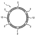
以下、本発明に係るろ過器具1の一態様について説明する。図1は、本発明に係るろ過器具1の一態様を示した斜視図であり、図2は、図1のA−A断面図、図3は図1のB−B断面図である。図1ないし図3中、1はろ過器具、11は開口部、12は側面、13は底面、2は孔、をそれぞれ示す。なお、図1及び後記する図4において、符号2は全ての孔2には付していない。同様に、図3において、符号12は全ての側面12には付していない。また、本発明にあって、ろ過器具1の「軸方向」及び「周方向」は、図1に示した矢印方向を指す。
(I) Configuration of filtration device 1:
Hereinafter, an aspect of the
本発明のろ過器具1は、例えば、ビーカー等の容器に入れられた、沈殿あるいは分散性の固体微粒子等の固体成分を含む溶液から、ろ液となる液体を分別するために用いられるろ過器具1であり、一端に開口部11を有した有底の筒体からなり、側面12に液体が通過可能な複数の孔2が形成されていることを基本構成として含む。また、側面12には、後記するが、シート状のろ過材(図4及び図5のシート状のろ過材3を参照。以下、単に「ろ過材3」とする場合もある。)が使用時に巻き付けられて装着される。
The
有底の筒体であるろ過器具1は、開口部11、側面12と底面13を有し、本実施形態では、図1にあるように、内部が中空の略円筒形状である態様を示している。ろ過器具1は、筒体の形状として、かかる円筒形状に加え、例えば、三角筒形状、四角筒形状、五角筒形状、六角筒形状の略多角筒形状等、任意の筒形状を用いることが、側面12に巻き付けられるろ紙等のろ過材3との隙間をできるだけなくすため、略円筒形状とすることが好ましい。
The
筒体からなるろ過器具1のサイズとしては、例えば、長さを85〜100mm、略円柱形状の中空の筒体とした場合はその内径をφ20〜25mmとすることができるが、特にこの範囲には限定されない。
For example, when the hollow cylindrical body having a length of 85 to 100 mm and a substantially cylindrical shape is used as the size of the
また、側面12の厚さは、例えば、1〜3mmとすることができるが、特にこの範囲には限定されない。底面13の厚さも、特に制限はなく、例えば、1〜3mmとすることができるが、特にこの範囲には限定されない。
Moreover, although the thickness of the
なお、底面13にろ紙等のシート状のろ過材3を装着することが難しいため、底面13には孔2を形成しないことが好ましい。
In addition, since it is difficult to mount the sheet-
筒体の側面12は、使用時にろ過材3が巻き付けられて装着される。側面12はろ過面となるため、液体が通過可能な複数の孔2が形成されている。孔2の形状は、図1等では正面視で略円形状の態様を示しているが、液体が通過可能であれば特に制限はなく、例えば、四角形状、五角形状、六角形状等の略多角形状等や、軸方向に長いスリット形状等、任意の形状を採用することができる。一方、孔2の加工の容易性、角が生じると強度が弱くなり、ろ過速度等のろ過能力も悪くなるため効率的なろ過が実施されない場合がある等の理由で、孔2の形状は略円形状とすることが好ましい。
At the time of use, the
側面12に形成される複数の孔2は、ろ過材3を介して、液体(ろ液)のみが中空の筒体であるろ過器具1の内部に流れ込むことにより、液体(ろ液)を分離するものである。本発明のろ過器具1にあっては、後記する図4及び図5に示すように、有底の筒体を底面13が下になるように入れてろ過を行うため、筒体の側面12をろ過面とした、水圧(液圧)を利用したろ過となる。ろ過面を側面12とすることにより、ろ過面が大面積となり、ろ過速度等のろ過能力に優れるとともに、側面12でのろ過により、ろ紙等のろ過材3に固体微粒子がある程度堆積すると、重力によりろ過材3の表面から剥がれて落下するので、ろ過材3に固体微粒子等が詰まりにくく(長い間堆積せず)、ろ過速度等のろ過能力を優れた状態で維持することができる。
The plurality of
孔2のサイズは、使用時に側面12に装着されるろ紙等のろ過材3の強度や性能等によって決定すればよい。例えば、孔2の形状を図1等に示すような略円形状とする場合には、外径(側面12に現れる径のこと。)をφ3〜5mm程度の範囲内とすればよいが、特にこの範囲には限定されない。
The size of the
孔2の形成は、側面12の周方向に規則的にあるいはランダムに、まんべんなく形成されることが好ましい。本実施形態である図1ないし図3には、側面12の周方向の全周にわたるように、同じサイズの略円形状の孔2が所定の間隔で形成された態様(図3に示すように、B−B方向に切断した断面に対して6個。)を示している。一方、これはあくまでも例示であって、側面12における孔2が形成される部分や孔2の数等は、後記する軸方向も含めて任意の部分ないし数等を形成することができる。
It is preferable that the formation of the
孔2は、軸方向にも規則的あるいはランダムに、まんべんなく形成されることが好ましい一方、孔2は、ろ過材3が巻き付けられて装着される部分について形成されていればよいので、開口部11に近い部分及び底面13に近い部分のある程度の範囲には、孔2を形成しないようにしてもよい。例えば、底面13に近い部分(例えば、底面13から軸方向に5〜10mmの長さの部分等。)は、ろ過材3が装着する面積を広くしてろ過材3を側面12に対して装着しやすくするため、孔2を形成しないようにしてもよい。
The
孔2は、同様に、開口部11に近い部分(例えば、開口部11の開口面から見て軸方向に20〜30mmの長さの部分等。)は、側面12におけるろ過材3が装着される部分は、ろ過材3が装着する面積を広くして装着しやすくするために、また、ろ過材3が装着されないそれ以外の部分は、孔2から溶液がろ過器具1の内部に流入しないようにする等の理由で、孔2を形成しないようにしてもよい。
Similarly, in a portion near the opening 11 (for example, a portion having a length of 20 to 30 mm in the axial direction when viewed from the opening surface of the opening 11), the
有底の筒体であるろ過器具1は、ある程度の機械的強度と耐薬品性を考慮し、例えば、ポリプロピレン(PP)、ポリエチレン(PE)等のオレフィン系樹脂、金属材料、セラミックス材料等で形成することが可能であり、ポリプロピレン(PP)、ポリエチレン(PE)等のオレフィン系合成樹脂で形成することが好ましいが、特にこれらに限定されない。ろ過器具1は、オレフィン系合成樹脂等で形成する場合は、射出成形等で一体的に製造することができ、従来公知の方法を用いて簡便に製造することができる。
The
本発明に係るろ過器具1は、以上に載せたような単純な構造であるため、ろ過のための操作がしやすく、洗浄も容易であり、使用性も良好である。また、ろ過する溶液等をろ過器具1の上方から注ぎ込む必要もなく、安全性にも優れる。
The
(II)ろ過器具1の使用方法(固体成分を含む溶液7のろ過方法):
図4は、使用時のろ過器具1の一例を示した図である。また、図5は、使用時の液体5と固体微粒子6の流れを示した模式図である。図4及び図5は、ろ過の対象となる懸濁液等の溶液7を、容器となるビーカー4に入れ、その中に、ろ過材3であるろ紙を側面12に巻き付けて装着したろ過器具1を、底面13が下になるようにして入れた状態を示している。
(II) Method of using filtration device 1 (method of filtering solution 7 containing solid component):
FIG. 4 is a view showing an example of the
ろ過の対象となる固体成分を含む溶液7としては、液体5、及び固体微粒子に代表される固体成分6を含むものであれば特に制限はない。沈殿や浮遊物を含む液体,懸濁液、溶け残った固体成分6を含む飽和溶液等を使用することができる。
The solution 7 containing a solid component to be filtered is not particularly limited as long as it contains the liquid 5 and the
図4及び図5に示すように、ろ過器具1の側面には、使用時にシート状のろ過材3が巻き付けられて装着される。単純な構造であるろ過器具1は、このように、ろ過材3の装着が、筒体であるろ過器具1の側面12にろ過材3が巻き付けるだけで済むので、ろ過材3の装着や交換が容易である。シート状のろ過材3として代表的なものはろ紙であるが、ろ過の対象となる懸濁液等の固体成分を含む溶液7の液体5や、固体微粒子6等の種類に応じて、ろ紙のほか、不織布等を使用するようにしてもよい。
As shown in FIGS. 4 and 5, a sheet-
図5を用いてろ過器具1の使用方法(固体成分6を含む溶液7のろ過方法)の一例を、ろ過材3としてろ紙3、固体成分6を含む溶液7として固体微粒子6を含む懸濁液7を用いた場合を挙げて説明する。まず、図5に示したように、懸濁液7が入ったビーカー4の中に、ろ過材であるろ紙3が巻かれて装着されたろ過器具1を底面13が下になるようにして、孔2が懸濁液7の中に浸されるように入れる。
An example of a method of using the filtration device 1 (a method of filtering the solution 7 containing the solid component 6) using FIG. 5 is a
ろ過器具1を溶液の中に入れることにより、固体微粒子6はろ紙3に遮られて中空の筒体であるろ過器具1の内部には入り込まない一方、ろ過器具1の内部には、図5における実線矢印が示すように、ろ紙3を介して液体5(ろ液5となる。)のみが流れこむ。また、ろ紙3によりろ別された固体微粒子6は、ろ過器具1の内部には流れ込まず、ある程度の量になると、図5の点線矢印が示すように、ろ紙3の表面に長い間堆積せず、ろ紙3から剥がれて落下して、ビーカー4の底に溜まることになる(残渣となる。)。
By putting the
そして、筒体であるろ過器具1の内部にろ液である液体5が集まったら、開口部11から図示しないピペット等を挿入し、液体(ろ液)5を採取するようにする。このように液体(ろ液)5の採取は開口部11から行うことができるため、ろ過を行っている途中であっても液体(ろ液)5を採取可能であり、連続操作が可能である。
Then, when the liquid 5 which is a filtrate is collected inside the
(III)本発明の効果:
以上説明した本発明に係るろ過器具1は、ろ過面が側面12となるため、ろ過面が大面積となり、ろ過速度等のろ過能力に優れるとともに、側面12でのろ過により、ろ紙等のろ過材3にある程度の量の固体微粒子6等が堆積すると、重力により側面12に巻かれたろ紙等のシート状のろ過材3の表面から剥がれて落下するので、ろ過材3に固体微粒子6等が詰まりにくく、ろ過速度等のろ過能力を優れた状態で維持することができる。加えて、開口部11からろ液を採取できるため連続操作が可能であり、ろ過する溶液7を上部から注ぎ込む必要がないので、腐食性の溶液等をろ過する場合でも安全性が高い。さらに、本発明のろ過器具1は、単純な構造であるため、ろ過のための操作がしやすく、ろ過材3の装着や交換、及びろ過器具1の洗浄も容易であり、使用性も良好である。
(III) Effects of the Invention:
The filtration device according to the present invention described above has a filtration surface that is the
そして、本発明に係る固体成分6を含む溶液7のろ過方法は、前記した本発明に係るろ過器具1を用いているので、前記した本発明の効果を享受し、固体微粒子6を含む懸濁液7等、固体成分6を含む溶液7のろ過を迅速かつ簡単な方法で実施することができる。
And since the filtration method of solution 7 containing
なお、以上説明した態様は、本発明の一態様を示したものであって、本発明は、前記した実施形態に限定されるものではなく、本発明の構成を備え、目的及び効果を達成できる範囲内での変形や改良が、本発明の内容に含まれるものであることはいうまでもない。また、本発明を実施する際における具体的な構造及び形状等は、本発明の目的及び効果を達成できる範囲内において、他の構造や形状等としても問題はない。本発明は前記した各実施形態に限定されるものではなく、本発明の目的を達成できる範囲での変形や改良は、本発明に含まれるものである。 In addition, the aspect demonstrated above shows one aspect of this invention, Comprising: This invention is not limited to above-described embodiment, It comprises the structure of this invention and can achieve the objective and the effect. It goes without saying that modifications and improvements within the scope are included in the contents of the present invention. In addition, the specific structure, shape, and the like in practicing the present invention have no problem as other structures, shapes, and the like as long as the objects and effects of the present invention can be achieved. The present invention is not limited to the above-described embodiments, and modifications and improvements as long as the object of the present invention can be achieved are included in the present invention.
例えば、前記した実施形態では、図1等に示すように、ろ過器具1の側面12に形成される複数の孔2として、同じサイズの略円形状の孔2が形成された態様を示したが、孔2の形状は同じサイズとする必要はなく、また、略円形状とすることも必須ではない。
その他、本発明の実施の際の具体的な構造及び形状等は、本発明の目的を達成できる範囲で他の構造等としてもよい。
For example, in the embodiment described above, as shown in FIG. 1 and the like, a mode is shown in which substantially
In addition, the specific structure, shape, and the like at the time of implementation of the present invention may be other structures and the like as long as the object of the present invention can be achieved.
本発明は、例えば、沈殿あるいは分散性の固体微粒子等を含む懸濁液からろ液である液体を分別したり、浮遊物を含む河川水のサンプリングや堆積物を含む廃液の処理等に有用であり、産業上の利用可能性は高いものである。 The present invention is useful, for example, for separating a liquid as a filtrate from a suspension containing precipitated or dispersible solid fine particles etc., sampling of river water containing suspended matter, and treating waste liquid containing sediments, etc. Yes, industrial applicability is high.
1 …… ろ過器具
11 …… 開口部
12 …… 側面
13 …… 底面
2 …… 孔
3 …… ろ紙(シート状のろ過材)
4 …… ビーカー
5 …… 液体(ろ液)
6 …… 固体微粒子(固体成分)
7 …… 懸濁液(溶液)
DESCRIPTION OF
4 ...... Beaker 5 ...... Liquid (filtrate)
6 ...... Solid particle (solid component)
7 ...... Suspension (solution)
前記の課題を解決するために、本発明に係るろ過器具は、固体成分を含む溶液からろ液となる液体を分別するために用いられるろ過器具であって、一端に開口部を有した有底の筒体からなり、使用時にシート状のろ過材が交換容易に巻き付けられて装着される、ろ過面である側面に、液体が通過可能な複数の孔が形成されていることを特徴とする。
本発明のろ過器具は、前記した本発明において、前記固体成分を含む溶液からのろ液となる液体の分別が、前記側面をろ過面とし、前記底面が下になるように静水である前記溶液に入れた場合に、前記筒体外部の液面が前記筒体内部の液面より高いことにより生じる水圧を利用したろ過であることを特徴とする。
In order to solve the above-mentioned problems, the filtration device according to the present invention is a filtration device used to separate a liquid to be a filtrate from a solution containing a solid component, wherein the filtration device has a bottom with an opening at one end. A plurality of holes through which the liquid can pass are formed on the side surface which is a filtration surface, to which a sheet-like filter material is wound and attached easily when used.
In the filtration device according to the present invention, in the above-mentioned present invention, the liquid separating from the solution containing the solid component is a solution in which the side surface is a filter surface and the bottom surface is a still water. When it puts in, it is the filtration using the hydraulic pressure which arises because the liquid level outside the said cylinder is higher than the liquid level inside the said cylinder.
Claims (5)
一端に開口部を有した有底の筒体からなり、
使用時にシート状のろ過材が巻き付けられて装着される側面に、液体が通過可能な複数の孔が形成されていることを特徴とするろ過器具。 What is claimed is: 1. A filtering device used to separate a liquid as a filtrate from a solution containing solid components, comprising:
It consists of a bottomed cylinder with an opening at one end,
A filter device characterized in that a plurality of holes through which liquid can pass are formed on the side surface to which a sheet-like filter material is wound and attached at the time of use.
Priority Applications (1)
| Application Number | Priority Date | Filing Date | Title |
|---|---|---|---|
| JP2017187851A JP2019058894A (en) | 2017-09-28 | 2017-09-28 | Filtration instrument and filtration method of solution containing solid component |
Applications Claiming Priority (1)
| Application Number | Priority Date | Filing Date | Title |
|---|---|---|---|
| JP2017187851A JP2019058894A (en) | 2017-09-28 | 2017-09-28 | Filtration instrument and filtration method of solution containing solid component |
Publications (1)
| Publication Number | Publication Date |
|---|---|
| JP2019058894A true JP2019058894A (en) | 2019-04-18 |
Family
ID=66176003
Family Applications (1)
| Application Number | Title | Priority Date | Filing Date |
|---|---|---|---|
| JP2017187851A Pending JP2019058894A (en) | 2017-09-28 | 2017-09-28 | Filtration instrument and filtration method of solution containing solid component |
Country Status (1)
| Country | Link |
|---|---|
| JP (1) | JP2019058894A (en) |
Cited By (2)
| Publication number | Priority date | Publication date | Assignee | Title |
|---|---|---|---|---|
| WO2020039677A1 (en) * | 2018-08-23 | 2020-02-27 | 株式会社村田製作所 | Filtration device and filtration method |
| CN111257094A (en) * | 2020-02-28 | 2020-06-09 | 武汉科技大学 | Filter paper composite filtering method for precipitation quantitative separation |
Citations (11)
| Publication number | Priority date | Publication date | Assignee | Title |
|---|---|---|---|---|
| JPS4861192A (en) * | 1971-12-01 | 1973-08-27 | ||
| JPS532523A (en) * | 1976-06-29 | 1978-01-11 | Nippon Electric Co | Electric discharge lamp |
| JPS58186812U (en) * | 1982-06-05 | 1983-12-12 | 石橋 良登 | Oil filter filter unit |
| JPS5927806U (en) * | 1982-08-12 | 1984-02-21 | 日本貿易産業株式会社 | cylindrical filter |
| JPS639290U (en) * | 1986-07-04 | 1988-01-21 | ||
| JPS63136788U (en) * | 1987-02-26 | 1988-09-08 | ||
| JPS63152609U (en) * | 1987-03-25 | 1988-10-06 | ||
| JPH1033911A (en) * | 1996-07-24 | 1998-02-10 | Seiko Enterp:Kk | Filter unit |
| JPH11147011A (en) * | 1997-11-14 | 1999-06-02 | Hiroshi Miyata | Filter |
| JP2000146948A (en) * | 1998-11-09 | 2000-05-26 | Meidensha Corp | Filter for water-quality measurement and turbidity removal apparatus |
| JP2005241534A (en) * | 2004-02-27 | 2005-09-08 | Miura Co Ltd | Filter for sampling organic contaminant, manufacturing method thereof, sampling instrument of contaminant, and method for sampling organic contaminant |
-
2017
- 2017-09-28 JP JP2017187851A patent/JP2019058894A/en active Pending
Patent Citations (11)
| Publication number | Priority date | Publication date | Assignee | Title |
|---|---|---|---|---|
| JPS4861192A (en) * | 1971-12-01 | 1973-08-27 | ||
| JPS532523A (en) * | 1976-06-29 | 1978-01-11 | Nippon Electric Co | Electric discharge lamp |
| JPS58186812U (en) * | 1982-06-05 | 1983-12-12 | 石橋 良登 | Oil filter filter unit |
| JPS5927806U (en) * | 1982-08-12 | 1984-02-21 | 日本貿易産業株式会社 | cylindrical filter |
| JPS639290U (en) * | 1986-07-04 | 1988-01-21 | ||
| JPS63136788U (en) * | 1987-02-26 | 1988-09-08 | ||
| JPS63152609U (en) * | 1987-03-25 | 1988-10-06 | ||
| JPH1033911A (en) * | 1996-07-24 | 1998-02-10 | Seiko Enterp:Kk | Filter unit |
| JPH11147011A (en) * | 1997-11-14 | 1999-06-02 | Hiroshi Miyata | Filter |
| JP2000146948A (en) * | 1998-11-09 | 2000-05-26 | Meidensha Corp | Filter for water-quality measurement and turbidity removal apparatus |
| JP2005241534A (en) * | 2004-02-27 | 2005-09-08 | Miura Co Ltd | Filter for sampling organic contaminant, manufacturing method thereof, sampling instrument of contaminant, and method for sampling organic contaminant |
Cited By (4)
| Publication number | Priority date | Publication date | Assignee | Title |
|---|---|---|---|---|
| WO2020039677A1 (en) * | 2018-08-23 | 2020-02-27 | 株式会社村田製作所 | Filtration device and filtration method |
| JPWO2020039677A1 (en) * | 2018-08-23 | 2021-04-30 | 株式会社村田製作所 | Filtration device and filtration method |
| JP7192867B2 (en) | 2018-08-23 | 2022-12-20 | 株式会社村田製作所 | Filtration device and filtration method |
| CN111257094A (en) * | 2020-02-28 | 2020-06-09 | 武汉科技大学 | Filter paper composite filtering method for precipitation quantitative separation |
Similar Documents
| Publication | Publication Date | Title |
|---|---|---|
| WO2019017848A1 (en) | Method and device for removing particles, preferably microfibers, from waste water | |
| WO2008114518A1 (en) | Filter apparatus | |
| JP2019058894A (en) | Filtration instrument and filtration method of solution containing solid component | |
| RU2713595C1 (en) | Filter apparatus and filter device for biological samples | |
| JP2012115747A (en) | Hollow fiber membrane module, and hollow fiber membrane module filter | |
| US2997178A (en) | Water filter | |
| JP5982668B2 (en) | filter | |
| JP5527663B2 (en) | Multistage filter | |
| JP4210831B2 (en) | Liquid processing equipment | |
| JP3201750U (en) | Wastewater treatment equipment | |
| JP6022811B2 (en) | Oil / water separator | |
| JP2003082755A (en) | Grease trap | |
| WO2016017196A1 (en) | Filter for filtration and treatment method | |
| JPH04171030A (en) | Filtration apparatus | |
| JP2008068187A (en) | Simple filter | |
| JP3198267U (en) | Grease trap cleaning device | |
| JP4076848B2 (en) | Water purifier | |
| JP3769561B2 (en) | Upward filtration device | |
| JP3132974U (en) | Garbage container | |
| FR2836471A1 (en) | Surface tank for treating surface water for domestic and industrial use has cleansing compartment with screen and hydrocarbon extraction compartment with coalescing box | |
| JPH06319921A (en) | Solid-liquid separator | |
| JP6771287B2 (en) | Hemofiltration device | |
| RU110658U1 (en) | DEVICE FOR CLEANING A LIQUID FROM DISPERSED POLLUTIONS | |
| JPH072016Y2 (en) | strainer | |
| KR101516727B1 (en) | No-backwashing filter-ii |
Legal Events
| Date | Code | Title | Description |
|---|---|---|---|
| A02 | Decision of refusal |
Free format text: JAPANESE INTERMEDIATE CODE: A02 Effective date: 20190702 |