JP2019057530A - Manufacturing apparatus and exhaust gas processing device - Google Patents
Manufacturing apparatus and exhaust gas processing device Download PDFInfo
- Publication number
- JP2019057530A JP2019057530A JP2017179330A JP2017179330A JP2019057530A JP 2019057530 A JP2019057530 A JP 2019057530A JP 2017179330 A JP2017179330 A JP 2017179330A JP 2017179330 A JP2017179330 A JP 2017179330A JP 2019057530 A JP2019057530 A JP 2019057530A
- Authority
- JP
- Japan
- Prior art keywords
- exhaust gas
- pipe
- exhaust
- drainage
- opening area
- Prior art date
- Legal status (The legal status is an assumption and is not a legal conclusion. Google has not performed a legal analysis and makes no representation as to the accuracy of the status listed.)
- Pending
Links
Images


Classifications
-
- B—PERFORMING OPERATIONS; TRANSPORTING
- B01—PHYSICAL OR CHEMICAL PROCESSES OR APPARATUS IN GENERAL
- B01D—SEPARATION
- B01D53/00—Separation of gases or vapours; Recovering vapours of volatile solvents from gases; Chemical or biological purification of waste gases, e.g. engine exhaust gases, smoke, fumes, flue gases, aerosols
- B01D53/002—Separation of gases or vapours; Recovering vapours of volatile solvents from gases; Chemical or biological purification of waste gases, e.g. engine exhaust gases, smoke, fumes, flue gases, aerosols by condensation
-
- B—PERFORMING OPERATIONS; TRANSPORTING
- B01—PHYSICAL OR CHEMICAL PROCESSES OR APPARATUS IN GENERAL
- B01D—SEPARATION
- B01D45/00—Separating dispersed particles from gases or vapours by gravity, inertia, or centrifugal forces
- B01D45/04—Separating dispersed particles from gases or vapours by gravity, inertia, or centrifugal forces by utilising inertia
- B01D45/08—Separating dispersed particles from gases or vapours by gravity, inertia, or centrifugal forces by utilising inertia by impingement against baffle separators
-
- B—PERFORMING OPERATIONS; TRANSPORTING
- B01—PHYSICAL OR CHEMICAL PROCESSES OR APPARATUS IN GENERAL
- B01D—SEPARATION
- B01D47/00—Separating dispersed particles from gases, air or vapours by liquid as separating agent
- B01D47/02—Separating dispersed particles from gases, air or vapours by liquid as separating agent by passing the gas or air or vapour over or through a liquid bath
- B01D47/024—Separating dispersed particles from gases, air or vapours by liquid as separating agent by passing the gas or air or vapour over or through a liquid bath by impinging the gas to be cleaned essentially in a perpendicular direction onto the liquid surface
-
- B—PERFORMING OPERATIONS; TRANSPORTING
- B01—PHYSICAL OR CHEMICAL PROCESSES OR APPARATUS IN GENERAL
- B01D—SEPARATION
- B01D47/00—Separating dispersed particles from gases, air or vapours by liquid as separating agent
- B01D47/05—Separating dispersed particles from gases, air or vapours by liquid as separating agent by condensation of the separating agent
-
- B—PERFORMING OPERATIONS; TRANSPORTING
- B01—PHYSICAL OR CHEMICAL PROCESSES OR APPARATUS IN GENERAL
- B01D—SEPARATION
- B01D47/00—Separating dispersed particles from gases, air or vapours by liquid as separating agent
- B01D47/06—Spray cleaning
-
- B—PERFORMING OPERATIONS; TRANSPORTING
- B01—PHYSICAL OR CHEMICAL PROCESSES OR APPARATUS IN GENERAL
- B01D—SEPARATION
- B01D53/00—Separation of gases or vapours; Recovering vapours of volatile solvents from gases; Chemical or biological purification of waste gases, e.g. engine exhaust gases, smoke, fumes, flue gases, aerosols
- B01D53/14—Separation of gases or vapours; Recovering vapours of volatile solvents from gases; Chemical or biological purification of waste gases, e.g. engine exhaust gases, smoke, fumes, flue gases, aerosols by absorption
- B01D53/1456—Removing acid components
-
- B—PERFORMING OPERATIONS; TRANSPORTING
- B01—PHYSICAL OR CHEMICAL PROCESSES OR APPARATUS IN GENERAL
- B01D—SEPARATION
- B01D53/00—Separation of gases or vapours; Recovering vapours of volatile solvents from gases; Chemical or biological purification of waste gases, e.g. engine exhaust gases, smoke, fumes, flue gases, aerosols
- B01D53/14—Separation of gases or vapours; Recovering vapours of volatile solvents from gases; Chemical or biological purification of waste gases, e.g. engine exhaust gases, smoke, fumes, flue gases, aerosols by absorption
- B01D53/18—Absorbing units; Liquid distributors therefor
-
- B—PERFORMING OPERATIONS; TRANSPORTING
- B01—PHYSICAL OR CHEMICAL PROCESSES OR APPARATUS IN GENERAL
- B01D—SEPARATION
- B01D53/00—Separation of gases or vapours; Recovering vapours of volatile solvents from gases; Chemical or biological purification of waste gases, e.g. engine exhaust gases, smoke, fumes, flue gases, aerosols
- B01D53/34—Chemical or biological purification of waste gases
- B01D53/74—General processes for purification of waste gases; Apparatus or devices specially adapted therefor
- B01D53/77—Liquid phase processes
- B01D53/78—Liquid phase processes with gas-liquid contact
-
- C—CHEMISTRY; METALLURGY
- C23—COATING METALLIC MATERIAL; COATING MATERIAL WITH METALLIC MATERIAL; CHEMICAL SURFACE TREATMENT; DIFFUSION TREATMENT OF METALLIC MATERIAL; COATING BY VACUUM EVAPORATION, BY SPUTTERING, BY ION IMPLANTATION OR BY CHEMICAL VAPOUR DEPOSITION, IN GENERAL; INHIBITING CORROSION OF METALLIC MATERIAL OR INCRUSTATION IN GENERAL
- C23C—COATING METALLIC MATERIAL; COATING MATERIAL WITH METALLIC MATERIAL; SURFACE TREATMENT OF METALLIC MATERIAL BY DIFFUSION INTO THE SURFACE, BY CHEMICAL CONVERSION OR SUBSTITUTION; COATING BY VACUUM EVAPORATION, BY SPUTTERING, BY ION IMPLANTATION OR BY CHEMICAL VAPOUR DEPOSITION, IN GENERAL
- C23C16/00—Chemical coating by decomposition of gaseous compounds, without leaving reaction products of surface material in the coating, i.e. chemical vapour deposition [CVD] processes
- C23C16/22—Chemical coating by decomposition of gaseous compounds, without leaving reaction products of surface material in the coating, i.e. chemical vapour deposition [CVD] processes characterised by the deposition of inorganic material, other than metallic material
- C23C16/24—Deposition of silicon only
-
- C—CHEMISTRY; METALLURGY
- C23—COATING METALLIC MATERIAL; COATING MATERIAL WITH METALLIC MATERIAL; CHEMICAL SURFACE TREATMENT; DIFFUSION TREATMENT OF METALLIC MATERIAL; COATING BY VACUUM EVAPORATION, BY SPUTTERING, BY ION IMPLANTATION OR BY CHEMICAL VAPOUR DEPOSITION, IN GENERAL; INHIBITING CORROSION OF METALLIC MATERIAL OR INCRUSTATION IN GENERAL
- C23C—COATING METALLIC MATERIAL; COATING MATERIAL WITH METALLIC MATERIAL; SURFACE TREATMENT OF METALLIC MATERIAL BY DIFFUSION INTO THE SURFACE, BY CHEMICAL CONVERSION OR SUBSTITUTION; COATING BY VACUUM EVAPORATION, BY SPUTTERING, BY ION IMPLANTATION OR BY CHEMICAL VAPOUR DEPOSITION, IN GENERAL
- C23C16/00—Chemical coating by decomposition of gaseous compounds, without leaving reaction products of surface material in the coating, i.e. chemical vapour deposition [CVD] processes
- C23C16/44—Chemical coating by decomposition of gaseous compounds, without leaving reaction products of surface material in the coating, i.e. chemical vapour deposition [CVD] processes characterised by the method of coating
- C23C16/4412—Details relating to the exhausts, e.g. pumps, filters, scrubbers, particle traps
-
- C—CHEMISTRY; METALLURGY
- C30—CRYSTAL GROWTH
- C30B—SINGLE-CRYSTAL GROWTH; UNIDIRECTIONAL SOLIDIFICATION OF EUTECTIC MATERIAL OR UNIDIRECTIONAL DEMIXING OF EUTECTOID MATERIAL; REFINING BY ZONE-MELTING OF MATERIAL; PRODUCTION OF A HOMOGENEOUS POLYCRYSTALLINE MATERIAL WITH DEFINED STRUCTURE; SINGLE CRYSTALS OR HOMOGENEOUS POLYCRYSTALLINE MATERIAL WITH DEFINED STRUCTURE; AFTER-TREATMENT OF SINGLE CRYSTALS OR A HOMOGENEOUS POLYCRYSTALLINE MATERIAL WITH DEFINED STRUCTURE; APPARATUS THEREFOR
- C30B25/00—Single-crystal growth by chemical reaction of reactive gases, e.g. chemical vapour-deposition growth
- C30B25/02—Epitaxial-layer growth
- C30B25/14—Feed and outlet means for the gases; Modifying the flow of the reactive gases
-
- C—CHEMISTRY; METALLURGY
- C30—CRYSTAL GROWTH
- C30B—SINGLE-CRYSTAL GROWTH; UNIDIRECTIONAL SOLIDIFICATION OF EUTECTIC MATERIAL OR UNIDIRECTIONAL DEMIXING OF EUTECTOID MATERIAL; REFINING BY ZONE-MELTING OF MATERIAL; PRODUCTION OF A HOMOGENEOUS POLYCRYSTALLINE MATERIAL WITH DEFINED STRUCTURE; SINGLE CRYSTALS OR HOMOGENEOUS POLYCRYSTALLINE MATERIAL WITH DEFINED STRUCTURE; AFTER-TREATMENT OF SINGLE CRYSTALS OR A HOMOGENEOUS POLYCRYSTALLINE MATERIAL WITH DEFINED STRUCTURE; APPARATUS THEREFOR
- C30B29/00—Single crystals or homogeneous polycrystalline material with defined structure characterised by the material or by their shape
- C30B29/02—Elements
- C30B29/06—Silicon
-
- B—PERFORMING OPERATIONS; TRANSPORTING
- B01—PHYSICAL OR CHEMICAL PROCESSES OR APPARATUS IN GENERAL
- B01D—SEPARATION
- B01D2257/00—Components to be removed
- B01D2257/20—Halogens or halogen compounds
- B01D2257/204—Inorganic halogen compounds
- B01D2257/2045—Hydrochloric acid
-
- B—PERFORMING OPERATIONS; TRANSPORTING
- B01—PHYSICAL OR CHEMICAL PROCESSES OR APPARATUS IN GENERAL
- B01D—SEPARATION
- B01D2257/00—Components to be removed
- B01D2257/20—Halogens or halogen compounds
- B01D2257/204—Inorganic halogen compounds
- B01D2257/2047—Hydrofluoric acid
-
- B—PERFORMING OPERATIONS; TRANSPORTING
- B01—PHYSICAL OR CHEMICAL PROCESSES OR APPARATUS IN GENERAL
- B01D—SEPARATION
- B01D2257/00—Components to be removed
- B01D2257/55—Compounds of silicon, phosphorus, germanium or arsenic
-
- B—PERFORMING OPERATIONS; TRANSPORTING
- B01—PHYSICAL OR CHEMICAL PROCESSES OR APPARATUS IN GENERAL
- B01D—SEPARATION
- B01D2257/00—Components to be removed
- B01D2257/55—Compounds of silicon, phosphorus, germanium or arsenic
- B01D2257/553—Compounds comprising hydrogen, e.g. silanes
-
- B—PERFORMING OPERATIONS; TRANSPORTING
- B01—PHYSICAL OR CHEMICAL PROCESSES OR APPARATUS IN GENERAL
- B01D—SEPARATION
- B01D2258/00—Sources of waste gases
- B01D2258/02—Other waste gases
- B01D2258/0216—Other waste gases from CVD treatment or semi-conductor manufacturing
Abstract
Description
本発明の実施形態は、製造装置及び排出ガス処理装置に関する。 Embodiments described herein relate generally to a manufacturing apparatus and an exhaust gas processing apparatus.
半導体装置や液晶装置を製造する製造装置では、例えば、反応性ガスを用いて基板上に膜の形成やパターンの形成を行う。一般に、膜の形成やパターンの形成は、基板の温度を上げてプロセス室に原料ガスやエッチングガスなどの反応性ガスを流し、反応性ガスの流量や圧力を調整して行っている。プロセス室で消費されなかった反応性ガスや反応により生じた反応副生成物のガスを含む排出ガスは、プロセス室から排気管、排気ポンプ、除害装置などを通って製造装置外に排出される。 In a manufacturing apparatus for manufacturing a semiconductor device or a liquid crystal device, for example, a reactive gas is used to form a film or a pattern on a substrate. In general, a film or a pattern is formed by raising the temperature of a substrate and flowing a reactive gas such as a source gas or an etching gas into a process chamber and adjusting the flow rate and pressure of the reactive gas. Exhaust gas including reactive gas not consumed in the process chamber and reaction by-product gas generated by the reaction is exhausted from the process chamber through the exhaust pipe, exhaust pump, abatement device, etc. .
排出ガスは、プロセス室から排気管を通過する際に冷却されることで凝縮して液滴になったり、昇華して固体粒子になったりする。この液滴や固体粒子が、排気管の閉塞や、排気ポンプの故障の原因になるという問題がある。また、排出ガスを除害装置により無害化処理する場合に、生成物として固体粒子が生じ、排気管が閉塞するという問題がある。 When the exhaust gas passes through the exhaust pipe from the process chamber, the exhaust gas is condensed to form droplets or sublimate to solid particles. There is a problem that the droplets or solid particles cause the exhaust pipe to be blocked or the exhaust pump to fail. Further, when the exhaust gas is detoxified by the detoxifying device, there is a problem that solid particles are generated as a product and the exhaust pipe is blocked.
排気管が閉塞したり、排気ポンプが故障したりすると、製造装置のメンテナンス作業が必要となり、製造装置の稼働率が低下する。また、排出ガスに由来する液滴や固体粒子には、有害ガスを発生する物質や、発火性がある物質もあり、メンテナンス作業に危険が伴う場合もある。 If the exhaust pipe is blocked or the exhaust pump breaks down, maintenance work for the manufacturing apparatus is required, and the operating rate of the manufacturing apparatus is reduced. In addition, the droplets and solid particles derived from the exhaust gas include substances that generate harmful gases and substances that are ignitable, which may be dangerous for maintenance work.
本発明が解決しようとする課題は、排気管の閉塞や、排気ポンプの故障の抑制を可能とする製造装置を提供することにある。 The problem to be solved by the present invention is to provide a manufacturing apparatus capable of suppressing exhaust pipe blockage and exhaust pump failure.
一つの実施形態の製造装置は、排出ガスが排出されるプロセス室と、前記排出ガスの一部を含む排液を排出する排液部と、前記プロセス室と前記排液部との間に設けられ、前記排出ガスの移動方向に対して垂直方向の断面において第1の開口面積を有する第1の配管と、前記第1の配管と前記排液部との間に設けられ、前記排出ガスの移動方向に対して垂直方向の断面において前記第1の開口面積より小さい第2の開口面積を有する第2の配管と、前記第1の配管に接続され、前記第1の配管に標準沸点が25℃以上の凝縮剤を供給する第3の配管と、を備える半導体装置又は液晶装置の製造装置である。 The manufacturing apparatus of one embodiment is provided between the process chamber and the drainage unit, a process chamber in which exhaust gas is exhausted, a drainage unit that drains a drainage that includes a part of the exhaust gas, and the process chamber. A first pipe having a first opening area in a cross section perpendicular to the direction of movement of the exhaust gas, and provided between the first pipe and the drainage part. A second pipe having a second opening area smaller than the first opening area in a cross section perpendicular to the moving direction is connected to the first pipe, and the first pipe has a standard boiling point of 25. And a third pipe for supplying a condensing agent at a temperature equal to or higher than C.
以下、図面を参照しつつ本発明の実施形態を説明する。なお、以下の説明では、同一又は類似の部材等には同一の符号を付し、一度説明した部材等については適宜その説明を省略する場合がある。 Hereinafter, embodiments of the present invention will be described with reference to the drawings. In the following description, the same or similar members are denoted by the same reference numerals, and description of members once described may be omitted as appropriate.
(第1の実施形態)
第1の実施形態の製造装置は、排出ガスが排出されるプロセス室と、排出ガスが液化した排液を排出する排液部と、プロセス室と排液部との間に設けられ、排出ガスの移動方向に対して垂直方向の断面において第1の開口面積を有する第1の配管と、第1の配管と排液部との間に設けられ、排出ガスの移動方向に対して垂直方向の断面において第1の開口面積より小さい第2の開口面積を有する第2の配管と、第1の配管に接続され、第1の配管に標準沸点が25℃以上の凝縮剤を供給する第3の配管と、を備える半導体装置又は液晶装置の製造装置である。
(First embodiment)
The manufacturing apparatus according to the first embodiment is provided between a process chamber in which exhaust gas is discharged, a drainage unit that discharges drainage liquid that has been liquefied, and a process chamber and drainage unit. The first pipe having a first opening area in a cross section perpendicular to the moving direction of the first pipe, and provided between the first pipe and the drainage portion, and perpendicular to the moving direction of the exhaust gas A second pipe having a second opening area smaller than the first opening area in cross section, and a third pipe connected to the first pipe and supplying a condensing agent having a standard boiling point of 25 ° C. or higher to the first pipe. And a liquid crystal device manufacturing apparatus.
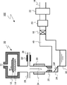
図1は、第1の実施形態の製造装置の一例の模式図である。第1の実施形態の一例の製造装置は、半導体装置の製造用の成膜装置100である。第1の実施形態の成膜装置100は、枚葉式のエピタキシャル膜の成膜装置100である。 FIG. 1 is a schematic diagram of an example of the manufacturing apparatus according to the first embodiment. An example of the manufacturing apparatus of the first embodiment is a film forming apparatus 100 for manufacturing a semiconductor device. A film forming apparatus 100 according to the first embodiment is a single-wafer epitaxial film forming apparatus 100.
成膜装置100は、反応室10(プロセス室)、ガス供給口11、ステージ12、ヒータ14、排出部16、圧力調整バルブ18、排気ポンプ20、除害装置22、凝縮管24(第1の配管)、加速管25(第2の配管)、凝縮剤供給管26(第3の配管)、クリーニングガス供給管28、温度調整部30、加熱部32、捕捉部34(部材)、排液タンク36(排液部)、排気管40を備える。
The film forming apparatus 100 includes a reaction chamber 10 (process chamber), a gas supply port 11, a
反応室10内には、ステージ12及びヒータ14が設けられる。ステージ12上にウェハWが載置される。ヒータ14はウェハWを加熱する。
A
反応室10の上部にガス供給口11が設けられる。ガス供給口11から、原料ガスが反応室10内に供給される。
A gas supply port 11 is provided in the upper part of the
反応室10の内部は、成膜時には、所望の圧力に減圧される。反応室10からは、反応室10で消費されなかった原料ガスや反応により生じた反応副生成物を含む排出ガスが排出される。
The inside of the
凝縮管24は、反応室10と排液タンク36との間に設けられる。凝縮管24は、反応室10に接続される。凝縮管24は、排出ガスの移動方向(図1中の白矢印)に対して垂直方向の断面において第1の開口面積を有する。成膜装置100では、排出ガスの凝縮管24内の移動方向は重力方向と一致している。
The
反応室10から排出された排出ガスは、凝縮管24を通過する。凝縮管24は、凝縮剤供給管26から供給される凝縮剤を、排出ガスと接触させて凝縮し、液化する機能を有する。
The exhaust gas discharged from the
加速管25は、凝縮管24と排液タンク36との間に設けられる。凝縮管24は、加速管25に接続される。加速管25は、排出ガスの移動方向(図1中の白矢印)に対して垂直方向の断面において第2の開口面積を有する。
The
第2の開口面積は第1の開口面積よりも小さい。例えば、第2の開口面積は第1の開口面積の2.5%以上20%以下である。 The second opening area is smaller than the first opening area. For example, the second opening area is 2.5% or more and 20% or less of the first opening area.
加速管25は、開口面積が凝縮管24よりも小さいため、反応室10から排出された排出ガスは、加速管25で加速される。言い換えれば、排出ガスの流速は、凝縮管24内よりも加速管25内の方が速い。
Since the opening area of the
捕捉部34は、加速管25と排液タンク36との間に設けられる。捕捉部34は、排出ガスの移動方向(図1中の白矢印)に対して傾斜した傾斜面34fを有する。傾斜面34fは、排液タンク36に向かって排液タンク36に近づく方向に傾斜している。傾斜面34fの排出ガスの移動方向に対する傾斜角は、例えば、20度以上50度以下である。捕捉部34は、傾斜面34fに排出ガスを衝突させることにより、排出ガス中に含まれる液滴を捕捉し、捕捉した液滴を排液タンク36に流し込む機能を有する。
The capturing
捕捉部34は、排出ガスの移動方向に対して垂直な面を有することも可能である。その場合は、排出ガスの移動方向を重力方向に対して傾斜させればよい。即ち、凝縮管24、加速管25、および捕捉部34をそれぞれ重力方向に対して傾斜させて配置することにより、捕捉部34が捕捉した液滴を排液タンク36に回収することができる。成膜装置100における各部の配置スペースなどに応じて選択することができる。
The capturing
排液タンク36は、捕捉部34と排気管40との間に設けられる。排液タンク36は、排液部の一例である。排液タンク36は、捕捉部34で捕捉された液滴を貯留する機能を有する。
The
排液タンク36には、排出ガスの一部を含む排液が貯留される。具体的には、排出された排出ガスに由来する固体粒子や液滴が含まれる。排液タンク36に貯留された排液を除去することにより、成膜装置100から排出ガスの一部を含む排液が排出されることになる。
In the
なお、排液タンク36に代えて、例えば、排液管(排液ドレイン)を排液部として設けることも可能である。例えば、排液管により、捕捉部34で捕捉された固体粒子や液滴を成膜装置100の外部にある排液タンクまで移送することで、成膜装置100から排出ガスの一部を含む排液が排出される。
Instead of the
排気ポンプ20は、排気管40と排出部16との間に設けられる。排気ポンプ20は、反応室10の内部を減圧する。排気ポンプ20は、例えば、真空ポンプである。
The
圧力調整バルブ18は、排気管40と排気ポンプ20との間に設けられる。圧力調整バルブ18により、反応室10の内部を所望の圧力に調整することが可能である。
The
除害装置22は、排気ポンプ20と排出部16との間に設けられる。除害装置22は、例えば、燃焼式の除害装置である。
The
除害装置22は、反応室10から排出された排出ガスを無害化する。無害化された排出ガスは、排出部16から成膜装置100の外部に排出される。
The
凝縮剤供給管26は、凝縮管24に接続される。凝縮剤供給管26は、凝縮管24に標準沸点が25℃以上の凝縮剤を供給する。標準沸点とは、1気圧すなわち101325Paのときの沸点である。
The condensing
凝縮剤は、凝縮管24内で反応室10から排出された排出ガスに含まれる微小な固体粒子や微小な液滴を核に凝縮して液化し、液滴を形成する機能を有する。
The condensing agent has a function of condensing and liquefying minute solid particles and minute droplets contained in the exhaust gas discharged from the
凝縮剤は、例えば、有機材料である、パーフルオロポリエーテル(PEPE)、ベンゼン(C6H6)である。凝縮剤として、例えば無機材料である、ヘキサクロロジシラン(Si2Cl6)を用いることも可能である。 The condensing agent is, for example, perfluoropolyether (PEPE) or benzene (C 6 H 6 ), which are organic materials. For example, hexachlorodisilane (Si 2 Cl 6 ), which is an inorganic material, can be used as the condensing agent.
パーフルオロポリエーテル(PEPE)の標準沸点は55℃〜270℃、ベンゼン(C6H6)の標準沸点は80℃、ヘキサクロロジシラン(Si2Cl6)の標準沸点は144℃である。 Perfluoropolyether (PEPE) has a normal boiling point of 55 ° C. to 270 ° C., benzene (C 6 H 6 ) has a normal boiling point of 80 ° C., and hexachlorodisilane (Si 2 Cl 6 ) has a normal boiling point of 144 ° C.
加熱部32は、例えば、凝縮剤供給管26の周囲に設けられる。加熱部32は、例えば、抵抗加熱を用いたヒータである。
For example, the
加熱部32は、凝縮剤を加熱する機能を有する。例えば、液体の凝縮剤が、加熱部32により、気化され、気体として凝縮管24に供給される。
The
温度調整部30、例えば、凝縮管24の周囲に設けられる。温度調整部30は、凝縮管24の中の温度調整を行う機能を有する。
It is provided around the temperature adjustment unit 30, for example, the
温度調整部30は、冷却機能及び加熱機能の少なくともいずれか一方を備える。温度調整部30は、例えば、抵抗加熱を用いたヒータである。また、温度調整部30は、例えば、水冷管である。 The temperature adjustment unit 30 includes at least one of a cooling function and a heating function. The temperature adjustment unit 30 is, for example, a heater using resistance heating. Moreover, the temperature adjustment part 30 is a water cooling tube, for example.
温度調整部30による温度調整により、凝縮管24の中の凝縮剤が過飽和状態に保たれる。凝縮管24内は、1気圧未満の減圧状態にあるため、凝縮管24内は、凝縮剤の標準沸点よりも低い温度に保たれる。
By the temperature adjustment by the temperature adjustment unit 30, the condensing agent in the condensing
クリーニングガス供給管28は、凝縮管24に接続される。クリーニングガス供給管28は、凝縮管24にクリーニングガスを供給する。クリーニングガスにより、反応室10での成膜が行われていない時に、凝縮管24、加速管25、排気管40などのクリーニングが行われる。
The cleaning
クリーニングガスは、例えば、三フッ化塩素(ClF3)ガスである。クリーニングガスは、例えば、標準沸点が25℃未満である。 The cleaning gas is, for example, chlorine trifluoride (ClF 3 ) gas. For example, the cleaning gas has a normal boiling point of less than 25 ° C.
次に、第1の実施形態の成膜装置100を用いた成膜方法について説明する。ウェハW上にシリコンのエピタキシャル膜を形成する場合を例に説明する。 Next, a film forming method using the film forming apparatus 100 of the first embodiment will be described. A case where a silicon epitaxial film is formed on the wafer W will be described as an example.
まず、反応室10にウェハWを搬入し、ステージ12の上に載置する。次に、ガス供給口11から水素(H2)を流しながら、排気ポンプ20を用いて反応室10の内部を減圧状態にする。反応室10内の圧力は、圧力調整バルブ18を用いて所望の圧力に調整する。また、ヒータ14を用いてウェハWを、例えば、1000℃に加熱する。
First, the wafer W is loaded into the
次に、ガス供給口11から原料ガスを反応室10内に供給し、ウェハWの表面にシリコンのエピタキシャル膜を形成する。原料ガスは、例えば、ジクロロシラン(SiH2Cl2)、水素(H2)、及び、塩化水素(HCl)である。
Next, a source gas is supplied from the gas supply port 11 into the
シリコンのエピタキシャル膜を形成する際、反応副生成物として、トリクロロシラン(SiHCl3)、テトラクロロシラン(SiCl4)、テトラクロロジシラン(Si2H2Cl4)、ヘキサクロロジシラン(Si2Cl6)、オクタクロロトリシラン(Si3Cl8)などのクロロシラン類やクロロシランポリマー類(SixHyClz:xは2以上)のガスが生成される。クロロシランポリマー類は、シリコン原子が2個以上結合した主鎖を有し、シリコン原子上の置換基が塩素又は水素となっている分子化合物、又は、それらの分子化合物が複数種類混合した物質を意味する。 When forming an epitaxial film of silicon, as reaction byproducts, trichlorosilane (SiHCl 3 ), tetrachlorosilane (SiCl 4 ), tetrachlorodisilane (Si 2 H 2 Cl 4 ), hexachlorodisilane (Si 2 Cl 6 ), Gases of chlorosilanes such as octachlorotrisilane (Si 3 Cl 8 ) and chlorosilane polymers (SixHyClz: x is 2 or more) are generated. Chlorosilane polymers mean a molecular compound that has a main chain in which two or more silicon atoms are bonded, and the substituent on the silicon atom is chlorine or hydrogen, or a substance in which multiple types of these molecular compounds are mixed. To do.
反応副生成物のガス、及び、成膜に用いられなかった原料ガスが反応室10から排出されるガスに含まれることになる。
The reaction byproduct gas and the raw material gas not used for film formation are included in the gas discharged from the
反応副生成物のガスや原料ガスの分子量が高いほど、同一圧力での沸点が高くなる。例えば、原料ガスのジクロロシランの標準沸点は約8℃であるのに対し、トリクロロシランの標準沸点は約31℃、テトラクロロシランの標準沸点は約57℃である。更に分子量が大きいクロロシランポリマー類の標準沸点は、更に高くなる。 The higher the molecular weight of the reaction byproduct gas or the raw material gas, the higher the boiling point at the same pressure. For example, the normal boiling point of the raw material gas dichlorosilane is about 8 ° C., whereas the normal boiling point of trichlorosilane is about 31 ° C., and the normal boiling point of tetrachlorosilane is about 57 ° C. Furthermore, the normal boiling point of chlorosilane polymers having a higher molecular weight is further increased.
排出ガスが反応室10の外に排出されると、排出ガスが冷却され、最初に沸点の高いクロロシランポリマー類のガスが凝縮して液化し液滴を形成する。さらに排出ガスの冷却が進むと、沸点の低いクロロシランポリマー類のガスやクロロシラン類のガスが凝縮して液化し液滴を形成する。また、一部のクロロシランポリマー類のガスは昇華、あるいは、液化を経て凝固し、固体粒子となる場合がある。
When the exhaust gas is discharged out of the
反応室10での成膜中に、凝縮剤供給管26から凝縮剤を凝縮管24に供給する。凝縮剤は、ヘキサクロロジシラン(Si2Cl6)である。ヘキサクロロジシラン(Si2Cl6)は、加熱部32によって加熱され、気化した状態で凝縮管24に供給される。
During film formation in the
凝縮管24に供給されたヘキサクロロジシランは、温度調整部30によって過飽和状態となるように温度が調整される。
The temperature of the hexachlorodisilane supplied to the
過飽和状態に保たれているヘキサクロロジシランに排出ガスが接すると、排出ガス中に含まれている液滴や固体粒子を核にヘキサクロロジシランが液化し、ヘキサクロロジシランの大きな液滴が形成される。 When the exhaust gas contacts the supersaturated hexachlorodisilane, the hexachlorodisilane is liquefied with the droplets and solid particles contained in the exhaust gas as nuclei and large hexachlorodisilane droplets are formed.
ヘキサクロロジシランの液滴を含む排出ガスは、加速管25で加速される。排出ガス中のヘキサクロロジシランの液滴も加速管25で加速される。
Exhaust gas containing hexachlorodisilane droplets is accelerated by the
加速されたヘキサクロロジシランの液滴は、捕捉部34の傾斜面34fに衝突し傾斜面34fに付着する。傾斜面34fに付着したヘキサクロロジシランの液滴は、傾斜面34fに沿って流れて、排液タンク36に流れ込み貯留される。
The accelerated hexachlorodisilane droplet collides with the
ヘキサクロロジシランの液滴が除去された排出ガスは、除害装置22で無害化され、排出部16から成膜装置100の外部に排出される。
The exhaust gas from which the hexachlorodisilane droplets have been removed is rendered harmless by the
所望のシリコンのエピタキシャル膜の形成が終了した後、原料ガスの反応室10内への供給を停止し、ウェハWの温度を低下させる。その後、ウェハWを反応室10の外へ搬出する。
After the formation of the desired silicon epitaxial film is completed, the supply of the source gas into the
次に、第1の実施形態の作用及び効果について説明する。 Next, the operation and effect of the first embodiment will be described.
一般的な成膜装置において、反応副生成物のガス、及び、成膜に用いられなかった原料ガスを含む排出ガスは、反応室から排気管、排気ポンプ、除害装置などを通って製造装置外に排出される。 In a general film forming apparatus, a reaction by-product gas and an exhaust gas containing a raw material gas that has not been used for film formation pass from the reaction chamber through an exhaust pipe, an exhaust pump, an abatement device, etc. Discharged outside.
排出ガスは、反応室から排気管を通過する際に冷却されることで凝縮して液滴になったり、昇華して固体粒子になったりする。この液滴や固体粒子が、排気管の閉塞や、排気ポンプの故障の原因になるという問題がある。 When the exhaust gas passes through the exhaust pipe from the reaction chamber, it is cooled to condense into droplets or sublimate into solid particles. There is a problem that the droplets or solid particles cause the exhaust pipe to be blocked or the exhaust pump to fail.
排気管が閉塞したり、排気ポンプが故障したりすると、製造装置のメンテナンス作業が必要となり、製造装置の稼働率が低下する。また、排出ガスに由来する液滴や固体粒子には、有害ガスを発生する物質や、発火性がある物質もあり、メンテナンス作業に危険が伴う場合もある。このため、排出ガスに由来する液滴や固体粒子に起因する、排気管の閉塞や、排気ポンプの故障を抑制することが望まれる。 If the exhaust pipe is blocked or the exhaust pump breaks down, maintenance work for the manufacturing apparatus is required, and the operating rate of the manufacturing apparatus is reduced. In addition, the droplets and solid particles derived from the exhaust gas include substances that generate harmful gases and substances that are ignitable, which may be dangerous for maintenance work. For this reason, it is desirable to suppress exhaust pipe blockage and exhaust pump failure caused by droplets and solid particles derived from exhaust gas.
第1の実施形態の成膜装置100は、反応室10から排気管40に至る経路の間に、凝縮剤供給管26、及び、凝縮管24を備える。凝縮管24内で凝縮剤が過飽和状態に保たれる。過飽和状態に保たれた凝縮剤と排出ガスが接触することにより、排出ガスに生じている液滴や固体粒子を核にして、凝縮剤が液化し、凝縮剤の大きな液滴が形成される。
The film forming apparatus 100 according to the first embodiment includes a condensing
凝縮剤の大きな液滴の中に、排出ガスに由来する液滴や固体粒子が取り込まれることにより、排出ガスに由来する液滴や固体粒子は捕捉部34で捕捉され、排液タンク36に貯留される。排出ガスに由来する液滴や固体粒子が取り除かれた排出ガスが、排気管40、圧力調整バルブ18、排気ポンプ20、及び、除害装置22に流れることになる。よって、排気管の閉塞や、排気ポンプの故障を抑制することが可能となる。
When the droplets and solid particles derived from the exhaust gas are taken into the large droplets of the condensing agent, the droplets and solid particles derived from the exhaust gas are captured by the capturing
特に、第1の実施形態では、凝縮剤の大きな液滴の中に、排出ガスに由来する液滴や固体粒子を取り込む。このため、排出ガスに由来する液滴や固体粒子が微小であっても、回収することが容易となる。 In particular, in the first embodiment, droplets and solid particles derived from the exhaust gas are taken into large droplets of the condensing agent. For this reason, even if the droplets and solid particles derived from the exhaust gas are very small, it is easy to collect them.
特に、第1の実施形態では、流動性のない固体粒子を、凝縮剤の大きな液滴の中に取り込むことで、流動性が得られる。このため、捕捉部34から排液タンク36に流し込んで集めることが可能となる。
In particular, in the first embodiment, fluidity is obtained by incorporating solid particles having no fluidity into large droplets of a condensing agent. For this reason, it becomes possible to pour into the
凝縮剤は、排液タンク36に貯留し回収する観点から、大気圧下では液体又は固体の物質であることが必要である。したがって、凝縮剤の標準沸点は25℃以上である。
The condensing agent needs to be a liquid or solid substance under atmospheric pressure from the viewpoint of storing and collecting in the
また、凝縮剤は凝縮管24内の減圧された圧力下で温度調整部30の温度調整により過飽和状態となる物質であることが必要である。言い換えれば、凝縮剤は凝縮管24内の減圧された圧力下で温度調整部30の温度調整により気体から液体へ相転移する物質であることが必要である。凝縮剤を過飽和状態にする観点から、凝縮剤の標準沸点は100℃より高い物質であることが好ましい。
In addition, the condensing agent needs to be a substance that becomes supersaturated by adjusting the temperature of the temperature adjusting unit 30 under a reduced pressure in the condensing
また、凝縮剤は排出ガス中の排出ガスに由来する液滴や固体粒子との反応性が低いことが必要である。 Further, the condensing agent needs to have low reactivity with droplets and solid particles derived from the exhaust gas in the exhaust gas.
凝縮剤の種類及び凝縮管24内の圧力により、凝縮管24内の凝縮剤を温度調整部30により加熱するか冷却するかが判断される。
Whether the condensing agent in the condensing
凝縮管24への凝縮剤の供給は、流量の調整の観点からは加熱して気体として供給することが好ましい。しかし、凝縮剤を液体で凝縮管24へ供給することも可能である。凝縮剤を液体で供給する場合は、減圧状態にある凝縮管24内で気化させることができる。その場合、気化熱により凝縮管24内の温度が低下するので、温度調整部30により気化熱分を補えばよい。
It is preferable to supply the condensing agent to the condensing
さらに、第1の実施形態では、加速管25を設けることにより、凝縮管24で形成された凝縮剤の液滴を加速する。凝縮剤の液滴を加速して捕捉部34に衝突させることにより、確実に凝縮剤の液滴を捕捉することが可能となる。したがって、排出ガスに由来する液滴や固体粒子の捕捉効率が向上する。
Furthermore, in the first embodiment, by providing the
加速管25の第2の開口面積は、凝縮管24の第1の開口面積の2.5%以上20%以下である。上記範囲を下回ると、反応室10内の圧力制御が困難となる。また、上記範囲を下回ると液滴の加速が不十分となり、液滴の捕捉効率が低下する。
The second opening area of the accelerating
以上、第1の実施形態によれば、排出ガスに由来する液滴や固体粒子の捕捉効率が向上し、排気管の閉塞や、排気ポンプの故障の抑制を可能とする製造装置を提供することが可能となる。 As described above, according to the first embodiment, it is possible to provide a manufacturing apparatus that improves the trapping efficiency of liquid droplets and solid particles derived from exhaust gas, and that can suppress exhaust pipe blockage and exhaust pump failure. Is possible.
(第2の実施形態)
第2の実施形態の製造装置は、バッチ式の成膜装置である点で第1の実施形態の製造装置と異なっている。以下、第1の実施形態と重複する内容については記述を一部省略する場合がある。
(Second Embodiment)
The manufacturing apparatus of the second embodiment is different from the manufacturing apparatus of the first embodiment in that it is a batch type film forming apparatus. Hereinafter, a part of the description overlapping the first embodiment may be omitted.
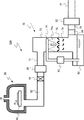
図2は、第2の実施形態の製造装置の一例の模式図である。第2の実施形態の一例の製造装置は、半導体装置の製造用の成膜装置200である。第2の実施形態の成膜装置200は、バッチ式の成膜装置200である。
FIG. 2 is a schematic diagram of an example of the manufacturing apparatus according to the second embodiment. An example of the manufacturing apparatus according to the second embodiment is a
成膜装置200は、反応室10(プロセス室)、ガス供給口11、ボート44、ヒータ46、排出部16、圧力調整バルブ42、排気ポンプ20、除害装置22、凝縮管24(第1の配管)、加速管25(第2の配管)、凝縮剤供給管26(第3の配管)、温度調整部30、加熱部32、捕捉部34(部材)、排液タンク36(排液部)、排気管40を備える。
The
反応室10は、例えば、透明な石英ガラス製である。反応室10内にはボート44が設けられる。反応室10の上部にガス供給口11が設けられる。ガス供給口11から、原料ガスが反応室10内に供給される。
The
ボート44は、複数枚のウェハWを保持すること可能である。ボート44は、例えば、石英ガラス製である。
The
ヒータ46は、反応室10の周囲に設けられる。ヒータ46は、ボート44に載置された複数のウェハWを加熱する。
The
圧力調整バルブ42は、反応室10と凝縮管24との間に設けられる。圧力調整バルブ42により、反応室10の内部を所望の圧力に減圧することが可能である。
The pressure adjustment valve 42 is provided between the
次に、第2の実施形態の成膜装置200を用いた成膜方法について説明する。ウェハW上にシリコン窒化膜を形成する場合を例に説明する。
Next, a film forming method using the
まず、反応室10にウェハWを搬入し、ボート44によって保持する。次に、排気ポンプ20を用いて反応室10を減圧状態にする。反応室10内の圧力は、圧力調整バルブ42を用いて所望の圧力に調製する。また、ヒータ46を用いてウェハWを、所定の温度に加熱する。
First, the wafer W is loaded into the
次に、ガス供給口11から原料ガスを反応室10内に供給し、ウェハWの表面にシリコン窒化膜を形成する。原料ガスは、例えば、ジクロロシラン(SiH2Cl2)、及び、三フッ化窒素(NF3)ある。
Next, a source gas is supplied into the
シリコン窒化膜を形成する際、反応副生成物として、NF4Clが生成され反応室10から排出される排出ガス中に含まれる。NF4Clは沸点が高いため、冷却されると昇華して固体粒子となりやすい。
When forming the silicon nitride film, NF 4 Cl is generated as a reaction byproduct and is contained in the exhaust gas discharged from the
反応室10でのシリコン窒化膜の成膜中に、凝縮剤供給管26から凝縮剤を凝縮管24に供給する。凝縮剤は、パーフルオロポリエーテル(PEPE)である。パーフルオロポリエーテルは、加熱部32によって加熱され、気化した状態で凝縮管24に供給される。
During the formation of the silicon nitride film in the
凝縮管24に供給したパーフルオロポリエーテルが過飽和状態となるように、温度調整部30によって凝縮管24内の温度が調整される。
The temperature in the condensing
過飽和状態に保たれているパーフルオロポリエーテルに排出ガスが接すると、排出ガス中に含まれているNF4Clの固体粒子を核にパーフルオロポリエーテルが液化し、パーフルオロポリエーテルの大きな液滴が形成される。 When the exhaust gas comes into contact with the perfluoropolyether maintained in a supersaturated state, the perfluoropolyether liquefies with the solid particles of NF 4 Cl contained in the exhaust gas as the core, and a large liquid of perfluoropolyether is obtained. Drops are formed.
パーフルオロポリエーテルの液滴を含む排出ガスは、加速管25で加速される。排出ガス中のパーフルオロポリエーテルの液滴も加速管25で加速される。
The exhaust gas containing droplets of perfluoropolyether is accelerated by the
加速されたパーフルオロポリエーテルの液滴は、捕捉部34の傾斜面34fに衝突し傾斜面34fに付着する。傾斜面34fに付着したパーフルオロポリエーテルの液滴は、傾斜面34fに沿って流れて、排液タンク36に流れ込み貯留される。
The accelerated perfluoropolyether droplet collides with the
NF4Clの固体粒子を含むパーフルオロポリエーテルの液滴が除去された排出ガスは、除害装置22で無害化され、排出部16から成膜装置200の外部に排出される。
The exhaust gas from which the perfluoropolyether droplets containing solid particles of NF 4 Cl have been removed is rendered harmless by the
所望のシリコン窒化膜の形成が終了した後、原料ガスの反応室10内への供給を停止し、ウェハWの温度を低下させる。その後、ウェハWを反応室10の外へ搬出する。
After the formation of the desired silicon nitride film is completed, the supply of the source gas into the
排出ガスに含まれるNF4Clの固体粒子は、排気管の閉塞や、排気ポンプの故障の原因になるという問題がある。 The solid particles of NF 4 Cl contained in the exhaust gas have a problem that the exhaust pipe is blocked and the exhaust pump is broken.
第2の実施形態の成膜装置200によれば、NF4Clの固体粒子を核として、パーフルオロポリエーテルの液滴を形成する。NF4Clの固体粒子を含むパーフルオロポリエーテルの液滴は流動性を有するため、捕捉部34から排液タンク36に流し込んで集めることが可能となる。
According to the
以上、第2の実施形態によれば、第1の実施形態同様、排気管の閉塞や、排気ポンプの故障の抑制を可能とする製造装置を提供することが可能となる。 As described above, according to the second embodiment, as in the first embodiment, it is possible to provide a manufacturing apparatus capable of suppressing exhaust pipe blockage and exhaust pump failure.
(第3の実施形態)
第3の実施形態の製造装置は、排出ガスが排出されるプロセス室と、排出ガスの一部を含む排液を排出する排液部と、プロセス室と排液部との間に設けられ、排出ガスの移動方向に対して垂直方向の断面において第1の開口面積を有する第1の配管と、第1の配管と排液部との間に設けられ、排出ガスの移動方向に対して垂直方向の断面において第1の開口面積より小さい第2の開口面積を有する第2の配管と、プロセス室と第1の配管との間に設けられ、プロセス室の中の圧力を制御する第1の圧力調整部と、第1の配管と排出部との間に設けられ、第1の配管の中の圧力を制御する第2の圧力調整部と、を備える半導体装置又は液晶装置の製造用の製造装置である。
(Third embodiment)
The manufacturing apparatus of the third embodiment is provided between a process chamber in which exhaust gas is discharged, a drainage unit that discharges a drainage liquid including a part of the exhaust gas, and a process chamber and a drainage unit, A first pipe having a first opening area in a cross section perpendicular to the movement direction of the exhaust gas, and provided between the first pipe and the drainage unit, is perpendicular to the movement direction of the exhaust gas. A second pipe having a second opening area smaller than the first opening area in a cross section in the direction, and a first pipe that is provided between the process chamber and the first pipe and controls the pressure in the process chamber. Manufacturing for manufacturing a semiconductor device or a liquid crystal device comprising: a pressure adjusting unit; and a second pressure adjusting unit that is provided between the first pipe and the discharge unit and controls the pressure in the first pipe. Device.
図3は、第3の実施形態の製造装置の一例の模式図である。第3の実施形態の一例の製造装置は、半導体装置の製造用の成膜装置300である。第3の実施形態の成膜装置300は、枚葉式のエピタキシャル膜の成膜装置300である。
FIG. 3 is a schematic diagram of an example of the manufacturing apparatus according to the third embodiment. An example of a manufacturing apparatus according to the third embodiment is a
成膜装置300は、反応室10(プロセス室)、ガス供給口11、ステージ12、ヒータ14、排出部16、第1の圧力調整バルブ19(第1の圧力調整部)、第1の排気ポンプ21(第1の圧力調整部)、除害装置22、第1の排気管50(第1の配管)、加速管25(第2の配管)、クリーニングガス供給管28、冷却部52、捕捉部34(部材)、排液タンク36(排液部)、第2の排気管54、第2の圧力調整バルブ56(第2の圧力調整部)、第2の排気ポンプ58(第2の圧力調整部)を備える。
The
反応室10内には、ステージ12及びヒータ14が設けられる。ステージ12上にウェハWが載置される。ヒータ14はウェハWを加熱する。
A
反応室10の上部にガス供給口11が設けられる。ガス供給口11から、原料ガスが反応室10内に供給される。
A gas supply port 11 is provided in the upper part of the
反応室10の内部は、成膜時には、所望の圧力に減圧される。反応室10からは、反応室10で消費されなかった原料ガスや反応により生じた反応副生成物を含む排出ガスが排出される。
The inside of the
第1の排気ポンプ21は、反応室10と第1の排気管50との間に設けられる。第1の排気ポンプ21は、反応室10の内部を減圧する。第1の排気ポンプ21は、例えば、真空ポンプである。
The
第1の圧力調整バルブ19は、反応室10と第1の排気ポンプ21との間に設けられる。第1の圧力調整バルブ19により、反応室10の内部を所望の圧力に調整することが可能である。
The first
第1の排気ポンプ21と第1の圧力調整バルブ19とが第1の圧力調整部を構成する。
The
第1の排気管50は、第1の排気ポンプ21と排液タンク36との間に設けられる。第1の排気管50は、反応室10に接続される。第1の排気管50は、排出ガスの移動方向(図3中の白矢印)に対して垂直方向の断面において第1の開口面積を有する。
The
反応室10から排出された排出ガスは、第1の排気管50を通過する。
Exhaust gas discharged from the
加速管25は、第1の排気管50と排液タンク36との間に設けられる。第1の排気管50は、加速管25に接続される。加速管25は、排出ガスの移動方向(図3中の白矢印)に対して垂直方向の断面において第2の開口面積を有する。
The
第2の開口面積は第1の開口面積よりも小さい。例えば、第2の開口面積は第1の開口面積の2.5%以上20%以下である。 The second opening area is smaller than the first opening area. For example, the second opening area is 2.5% or more and 20% or less of the first opening area.
加速管25は、開口面積が第1の排気管50よりも小さいため、反応室10から排出された排出ガスは、加速管25で加速される。言い換えれば、排出ガスの流速は、第1の排気管50内よりも加速管25内の方が速い。
Since the opening area of the
捕捉部34は、加速管25と排液タンク36との間に設けられる。捕捉部34は、排出ガスの移動方向(図3中の白矢印)に対して傾斜した傾斜面34fを有する。傾斜面34fは、排液タンク36に向かって排液タンク36に近づく方向に傾斜している。傾斜面34fの排出ガスの移動方向に対する傾斜角は、例えば、30度以上60度以下である。捕捉部34は、排出ガス中に含まれる液滴を捕捉し、捕捉した液滴を排液タンク36に流し込む機能を有する。
The capturing
排液タンク36は、捕捉部34と第2の排気管54との間に設けられる。排液タンク36は、排液部の一例である。排液タンク36は、捕捉部34で捕捉された液滴を貯留する機能を有する。
The
排液タンク36には、排出ガスの一部を含む排液が貯留される。具体的には、排出された排出ガスに由来する固体粒子や微小な液滴が含まれる。排液タンク36に貯留された排液を除去することにより、成膜装置300から排出ガスの一部を含む排液が排出されることになる。
In the
なお、排液タンク36に代えて、例えば、排液管(排液ドレイン)を排液部として設けることも可能である。例えば、排液管により、捕捉部34で捕捉された液滴を成膜装置300の外部にある排液タンクまで移送することで、成膜装置300から排出ガスの一部を含む排液が排出される。
Instead of the
第2の排気ポンプ58は、第2の排気管54と排出部16との間に設けられる。第2の排気ポンプ58は、第1の排気管50の内部を減圧する。第2の排気ポンプ58は、例えば、真空ポンプである。
The
第2の圧力調整バルブ56は、第2の排気管54と第2の排気ポンプ58との間に設けられる。第2の圧力調整バルブ56は、第1の排気管50の内部を所望の圧力に調整することが可能である。第2の圧力調整バルブ56は、第1の排気管50内の圧力が、反応室10内の圧力よりも高くなるように調整する。
The second
第2の排気ポンプ58と第2の圧力調整バルブ56が第2の圧力調整部を構成する。
The
除害装置22は、第2の排気ポンプ58と排出部16との間に設けられる。除害装置22は、例えば、燃焼式の除害装置である。
The
除害装置22は、反応室10から排出された排出ガスを無害化する。無害化された排出ガスは、排出部16から成膜装置300の外部に排出される。
The
冷却部52は、第1の排気管50の周囲に設けられる。冷却部52は、例えば、水冷管である。冷却部52は、第1の排気管50の中の排出ガスを冷却する機能を有する。
The cooling unit 52 is provided around the
クリーニングガス供給管28は、第1の排気管50に接続される。クリーニングガス供給管28は、第1の排気管50にクリーニングガスを供給する。クリーニングガスにより、反応室10での成膜が行われていない時に、第1の排気管50、加速管25、第2の排気管54などのクリーニングが行われる。クリーニングガスは、例えば、三フッ化塩素(ClF3)ガスである。
The cleaning
次に、第3の実施形態の成膜装置300を用いた成膜方法について説明する。ウェハW上にシリコンのエピタキシャル膜を形成する場合を例に説明する。
Next, a film forming method using the
まず、反応室10にウェハWを搬入し、ステージ12の上に載置する。次に、ガス供給口11から水素(H2)を流しながら、第1の排気ポンプ21を用いて反応室10の内部を減圧状態にする。反応室10内の圧力は、第1の圧力調整バルブ19を用いて所望の圧力に調整する。反応室10内の圧力は、例えば、10kPaである。
First, the wafer W is loaded into the
また、第2の排気ポンプ58を用いて、第1の排気管50の内部を減圧状態にする。第1の排気管50内の圧力は、第2の圧力調整バルブ56を用いて所望の圧力に調整する。第1の排気管50内の圧力は、反応室10内の圧力よりも高くする。第1の排気管50内の圧力は、例えば、40kPaである。
In addition, the
次に、ヒータ14を用いてウェハWを、例えば、1000℃に加熱する。
Next, the wafer W is heated to, for example, 1000 ° C. using the
次に、ガス供給口11から原料ガスを反応室10内に供給し、ウェハWの表面にシリコンのエピタキシャル膜を形成する。原料ガスは、例えば、ジクロロシラン(SiH2Cl2)、水素(H2)、及び、塩化水素(HCl)である。
Next, a source gas is supplied from the gas supply port 11 into the
エピタキシャル膜を形成する際、反応副生成物として、トリクロロシラン(SiHCl3)、テトラクロロシラン(SiCl4)、テトラクロロジシラン(Si2H2Cl4)、ヘキサクロロジシラン(Si2Cl6)、オクタクロロトリシラン(Si3Cl8)などのクロロシラン類やクロロシランポリマー類(SixHyClz:xは2以上)のガスが生成される。クロロシランポリマー類は、シリコン原子が2個以上結合した主鎖を有し、シリコン原子上の置換基が塩素又は水素となっている分子化合物、又は、それらの分子化合物が複数種類混合した物質を意味する。 When forming an epitaxial film, as reaction byproducts, trichlorosilane (SiHCl 3 ), tetrachlorosilane (SiCl 4 ), tetrachlorodisilane (Si 2 H 2 Cl 4 ), hexachlorodisilane (Si 2 Cl 6 ), octachloro Gases of chlorosilanes such as trisilane (Si 3 Cl 8 ) and chlorosilane polymers (SixHyClz: x is 2 or more) are generated. Chlorosilane polymers mean a molecular compound that has a main chain in which two or more silicon atoms are bonded, and the substituent on the silicon atom is chlorine or hydrogen, or a substance in which multiple types of these molecular compounds are mixed. To do.
反応副生成物のガス、及び、成膜に用いられなかった原料ガスが反応室10から排出されるガスに含まれることになる。
The reaction byproduct gas and the raw material gas not used for film formation are included in the gas discharged from the
反応副生成物のガスや原料ガスの分子量が高いほど、同一圧力での沸点が高くなる。例えば、原料ガスのジクロロシランの標準沸点は約8℃であるのに対し、トリクロロシランの標準沸点は約31℃、テトラクロロシランの標準沸点は約57℃である。さらに分子量が大きいクロロシランポリマー類の標準沸点は、さらに高くなる。標準沸点とは、1気圧すなわち101325Paのときの沸点である。 The higher the molecular weight of the reaction byproduct gas or the raw material gas, the higher the boiling point at the same pressure. For example, the normal boiling point of the raw material gas dichlorosilane is about 8 ° C., whereas the normal boiling point of trichlorosilane is about 31 ° C., and the normal boiling point of tetrachlorosilane is about 57 ° C. Furthermore, the normal boiling point of chlorosilane polymers having a higher molecular weight is further increased. The normal boiling point is the boiling point at 1 atmosphere, that is, 101325 Pa.
反応室10から排出ガスが第1の排気管50に排出されると、排出ガスの圧力が上昇する。また、排出ガスが冷却部52により冷却される。このため、最初に沸点の高いクロロシランポリマー類のガスが凝縮して液化し液滴を形成する。更に排出ガスの冷却が進むと、沸点の低いクロロシランポリマー類のガスやクロロシラン類のガスが凝縮して液化し液滴を形成する。
When exhaust gas is exhausted from the
排出ガス由来の液滴を含む排出ガスは、加速管25で加速される。排出ガス中の排出ガス由来の液滴も加速管25で加速される。
Exhaust gas containing droplets derived from the exhaust gas is accelerated by the
加速された液滴は、捕捉部34の傾斜面34fに衝突し傾斜面34fに付着する。傾斜面34fに付着した液滴は、傾斜面34fに沿って流れて、排液タンク36に流れ込み貯留される。
The accelerated droplet collides with the
排出ガス由来の液滴が除去された排出ガスは、除害装置22で無害化され、排出部16から成膜装置300の外部に排出される。
The exhaust gas from which the droplets derived from the exhaust gas have been removed is rendered harmless by the
所望のシリコンのエピタキシャル膜の形成が終了した後、原料ガスの反応室10内への供給を停止し、ウェハWの温度を低下させる。その後、ウェハWを反応室10の外へ搬出する。
After the formation of the desired silicon epitaxial film is completed, the supply of the source gas into the
次に、第3の実施形態の作用及び効果について説明する。 Next, the operation and effect of the third embodiment will be described.
一般的な成膜装置において、反応副生成物のガス、及び、成膜に用いられなかった原料ガスを含む排出ガスは、反応室から排気管、排気ポンプ、除害装置などを通って製造装置外に排出される。 In a general film forming apparatus, a reaction by-product gas and an exhaust gas containing a raw material gas that has not been used for film formation pass from the reaction chamber through an exhaust pipe, an exhaust pump, an abatement device, etc. Discharged outside.
排出ガスは、反応室から排気管を通過する際に冷却されることで凝縮して液滴になったり、昇華して固体粒子になったりする。この液滴や固体粒子が、排気管の閉塞や、排気ポンプの故障の原因になるという問題がある。 When the exhaust gas passes through the exhaust pipe from the reaction chamber, it is cooled to condense into droplets or sublimate into solid particles. There is a problem that the droplets or solid particles cause the exhaust pipe to be blocked or the exhaust pump to fail.
排気管が閉塞したり、排気ポンプが故障したりすると、製造装置のメンテナンス作業が必要となり、製造装置の稼働率が低下する。また、排出ガスに由来する液滴や固体粒子には、有害ガスを発生する物質や、発火性がある物質もあり、メンテナンス作業に危険が伴う場合もある。このため、排出ガスに由来する液滴や固体粒子によって、排気管の閉塞や、排気ポンプの故障を抑制することが望まれる。 If the exhaust pipe is blocked or the exhaust pump breaks down, maintenance work for the manufacturing apparatus is required, and the operating rate of the manufacturing apparatus is reduced. In addition, the droplets and solid particles derived from the exhaust gas include substances that generate harmful gases and substances that are ignitable, which may be dangerous for maintenance work. For this reason, it is desired to suppress the clogging of the exhaust pipe and the failure of the exhaust pump by the droplets and solid particles derived from the exhaust gas.
第3の実施形態の成膜装置300は、第1の排気ポンプ21と第1の圧力調整バルブ19で構成された第1の圧力調整部と、第2の排気ポンプ58と第2の圧力調整バルブ56で構成される第2の圧力調整部を備える。
The
第1の圧力調整部と第2の圧力調整部を備えることで、第1の排気管50内の圧力を反応室10内の圧力よりも高くすることが可能である。したがって、第1の排気管50内の圧力が反応室10内の圧力と同等の場合と比較して、沸点の低い原料ガスや反応副生成物のガスを液化させることが可能となる。また、第1の排気管50内の圧力が反応室10内の圧力と同等の場合と比較して、原料ガスや反応副生成物のガスが液化することで生成される液滴のサイズを大きくすることができる。
By providing the first pressure adjusting unit and the second pressure adjusting unit, the pressure in the
液滴は、捕捉部34の傾斜面34fに衝突することで捕捉される。捕捉された液滴は排液タンク36に貯留することで、成膜装置300外に排出される。液滴のサイズを大きくすることで、捕捉部34における捕捉効率が向上する。
The droplet is captured by colliding with the
さらに、第3の実施形態では、加速管25を設けることにより、第1の排気管50で形成された液滴を加速する。液滴を加速して捕捉部34に衝突させることにより、液滴を捕捉することが可能となる。したがって、排出ガスに由来する液滴の捕捉効率が向上する。
Further, in the third embodiment, by providing the
加速管25の第2の開口面積は、第1の排気管50の第1の開口面積の2.5%以上20%以下である。上記範囲を下回ると、反応室10内の圧力制御が困難となる。また、上記範囲を下回ると液滴の加速が不十分となり、液滴の捕捉効率が低下する。
The second opening area of the
また、第3の実施形態では、冷却部52により排出ガスを冷却することで、更に沸点の低い原料ガスや反応副生成物のガスを液化させることが可能となる。また、原料ガスや反応副生成物のガスが液化することで生成される液滴のサイズを更に大きくすることができる。したがって、更に液滴の捕捉効率が向上する。 Further, in the third embodiment, by cooling the exhaust gas by the cooling unit 52, it becomes possible to liquefy the raw material gas having a lower boiling point and the reaction by-product gas. Further, the size of the droplets generated by liquefying the raw material gas and the reaction by-product gas can be further increased. Accordingly, the droplet capture efficiency is further improved.
以上、第3の実施形態によれば、排出ガスに由来する液滴の捕捉効率が向上し、排気管の閉塞や、排気ポンプの故障の抑制を可能とする製造装置を提供することが可能となる。 As described above, according to the third embodiment, it is possible to improve the efficiency of capturing droplets derived from exhaust gas, and to provide a manufacturing apparatus that enables the exhaust pipe to be blocked and the exhaust pump to be prevented from malfunctioning. Become.
(第4の実施形態)
第4の実施形態の排出ガス処理装置は、排出ガスの移動方向に対して垂直方向の断面において第1の開口面積を有するスプレー塔と、スプレー塔の中に設けられ液体を噴出するスプレーノズルと、排出ガスの一部を含む排液を貯留する排液部と、スプレーノズルと排液部との間に設けられ、第1の開口面積より小さい第2の開口面積を有する絞りと、を備える。
(Fourth embodiment)
The exhaust gas treatment apparatus of the fourth embodiment includes a spray tower having a first opening area in a cross section perpendicular to the moving direction of the exhaust gas, and a spray nozzle provided in the spray tower for ejecting liquid. A drainage part for storing drainage containing a part of the exhaust gas, and a throttle provided between the spray nozzle and the drainage part and having a second opening area smaller than the first opening area. .
図4は、第4の実施形態の排出ガス処理装置の一例の模式図である。第4の実施形態の排出ガス処理装置70を、半導体装置の製造用の成膜装置400に適用した例を示している。成膜装置400は、枚葉式のエピタキシャル膜の成膜装置400である。
FIG. 4 is a schematic diagram of an example of the exhaust gas treatment apparatus of the fourth embodiment. The example which applied the exhaust
成膜装置400は、反応室10(プロセス室)、ガス供給口11、ステージ12、ヒータ14、排出部16、圧力調整バルブ18、排気ポンプ20、除害装置22、排出ガス処理装置70、排気管62を備える。排出ガス処理装置70は、排出ガス導入部71、スプレー塔72、排出ガス導出部73、スプレーノズル74、絞り76、捕捉板78(部材)、循環液タンク80(排液部)、循環ポンプ82、排気ファン84を備えている。
The
反応室10内には、ステージ12及びヒータ14が設けられる。ステージ12上にウェハWが載置される。ヒータ14はウェハWを加熱する。
A
反応室10の上部にガス供給口11が設けられる。ガス供給口11から、原料ガスが反応室10内に供給される。
A gas supply port 11 is provided in the upper part of the
反応室10の内部は、成膜時には、所望の圧力に減圧される。反応室10からは、反応室10で消費されなかった原料ガスや反応により生じた反応副生成物を含む排出ガスが排気管62に排出される。
The inside of the
排気ポンプ20は、排気管62と排出部16との間に設けられる。排気ポンプ20は、反応室10の内部を減圧する。排気ポンプ20は、例えば、真空ポンプである。
The
圧力調整バルブ18は、排気管40と排気ポンプ20との間に設けられる。圧力調整バルブ18により、反応室10の内部を所望の圧力に調整することが可能である。
The
除害装置22は、排気ポンプ20と排出部16との間に設けられる。除害装置22は、例えば、燃焼式の除害装置である。除害装置22は、反応室10から排出された排出ガスを無害化する処理を行う。
The
排出ガス処理装置70は、除害装置22と排出部16との間に設けられる。排出ガス処理装置70は、湿式スクラバ―である。排出ガス処理装置70は、排出ガスに含まれる固体粒子や酸性ガスなどを除去する機能を有する。
The exhaust
排出ガス処理装置70は、排出ガス導入部71、スプレー塔72、排出ガス導出部73、スプレーノズル74、絞り76、捕捉板78、循環液タンク80、循環ポンプ82、排気ファン84を備えている。
The exhaust
排出ガス導入部71から排出ガスがスプレー塔72に導入され、排出ガス処理装置70により処理された排出ガスは、排出ガス導出部73から導出される。
The exhaust gas is introduced into the
スプレー塔72は、例えば、円筒形状である。スプレー塔72は、排出ガスの移動方向(図4中の白矢印)に対して垂直方向の断面において第1の開口面積を有する。
The
スプレーノズル74は、液体74aをスプレー塔72内に霧状に噴出する。液体は、例えば、水である。例えば、液体74a中に排出ガス中の酸性ガスが溶解する。また、例えば、固体粒子を核として液体74aの蒸気(水蒸気)が凝縮し、液体74aの中に固体粒子が取り込まれる。
The
図5は、第4の実施形態の絞り76と捕捉板78の一例の模式図である。
FIG. 5 is a schematic diagram of an example of the
絞り76は、複数の開口部76aと、それぞれの開口部76aを囲む側壁76bを有する。絞り76は、排出ガスの移動方向(図4中及び図5中の白矢印)に対して垂直方向の断面において第2の開口面積を有する。絞り76が複数の開口部76aを有する場合、第2の開口面積は、複数の開口部76aの開口面積の総和である。
The
第2の開口面積は第1の開口面積よりも小さい。例えば、第2の開口面積は第1の開口面積の2.5%以上20%以下である。 The second opening area is smaller than the first opening area. For example, the second opening area is 2.5% or more and 20% or less of the first opening area.
側壁76bは、排出ガスの移動方向(図4中及び図5中の白矢印)に対して傾斜した傾斜面を有する。側壁76bは、開口部76aに向かって順テーパの傾斜を有する。側壁76bが順テーパの傾斜を有することで、側壁76bに付着した液体74aは、開口部76aに向かって流れ落ちる。
The
絞り76は、スプレー塔72内で、排出ガスの流れを加速する機能を有する。
The
絞り76に設けられる開口部76aの数は、図5では9個であるが、9個に限られることはない。開口部76aの数は、例えば、1個であっても構わない。
The number of
捕捉板78は、絞り76と循環液タンク80との間に設けられる。捕捉板78は、排出ガスの移動方向(図4中及び図5中の白矢印)に対し対向した傾斜面78aを有する。傾斜面78aと、排出ガスの移動方向がなす角度は、例えば10度以上80度以下である。
The
捕捉板78は、排出ガス中に含まれる固体粒子を捕捉する機能を有する。絞り76により加速された排出ガス中の固体粒子が、捕捉板78に衝突することで捕捉される。捕捉板78に補足された固体粒子は、固体粒子を包み込んだ液体74aと共に、あるいは、傾斜面78aに付着した液体74aと共に傾斜面78aに沿って流れ落ち、循環液タンク80に貯留される。
The
循環液タンク80に貯留された液体74aは、循環ポンプ82を用いて循環される。循環された液体74aは、スプレーノズル74からスプレー塔72内に噴出される。
The liquid 74 a stored in the circulating
排気ファン84は、排出ガス処理装置70で処理された排出ガスを排出ガス導出部73から排出する機能を有する。また、排気ファン84により、スプレー塔72の内部が減圧される。
The
次に、第4の実施形態の排出ガス処理装置70の作用及び効果について説明する。
Next, the operation and effect of the exhaust
一般的な成膜装置において、反応副生成物のガス、及び、成膜に用いられなかった原料ガスを含む排出ガスは、反応室から排気管、排気ポンプ、除害装置などを通って製造装置外に排出される。 In a general film forming apparatus, a reaction by-product gas and an exhaust gas containing a raw material gas that has not been used for film formation pass from the reaction chamber through an exhaust pipe, an exhaust pump, an abatement device, etc. Discharged outside.
排出ガスは、反応室から排気管を通過する際に冷却されることで凝縮して液滴になったり、昇華して固体粒子になったりする。この液滴や固体粒子が、排気管の閉塞や、排気ポンプの故障の原因になるという問題がある。 When the exhaust gas passes through the exhaust pipe from the reaction chamber, it is cooled to condense into droplets or sublimate into solid particles. There is a problem that the droplets or solid particles cause the exhaust pipe to be blocked or the exhaust pump to fail.
排気管が閉塞したり、排気ポンプが故障したりすると、製造装置のメンテナンス作業が必要となり、製造装置の稼働率が低下する。また、排出ガスに由来する液滴や固体粒子には、有害ガスを発生する物質や、発火性がある物質もあり、メンテナンス作業に危険が伴う場合もある。このため、排出ガスに由来する液滴や固体粒子によって、排気管の閉塞や、排気ポンプの故障を抑制することが望まれる。 If the exhaust pipe is blocked or the exhaust pump breaks down, maintenance work for the manufacturing apparatus is required, and the operating rate of the manufacturing apparatus is reduced. In addition, the droplets and solid particles derived from the exhaust gas include substances that generate harmful gases and substances that are ignitable, which may be dangerous for maintenance work. For this reason, it is desired to suppress the clogging of the exhaust pipe and the failure of the exhaust pump by the droplets and solid particles derived from the exhaust gas.
また、排出ガスを無害化するために、成膜装置に除害装置が設けられる場合がある。しかし、除害装置の無害化処理の過程で、生成物として固体粒子が生じ、排気管が閉塞するという問題がある。 In addition, a detoxification apparatus may be provided in the film forming apparatus in order to make the exhaust gas harmless. However, there is a problem that solid particles are generated as a product during the detoxification process of the detoxifying device, and the exhaust pipe is blocked.
第4の実施形態の排出ガス処理装置70では、スプレー塔72内に絞り76と捕捉板78を設ける。排出ガス中の固体粒子を絞り76を用いて加速し、捕捉板78に衝突させて捕捉することで、排出ガス中の固体粒子の捕捉効率が向上する。
In the exhaust
例えば、排ガス処理装置が絞り76と捕捉板78を備えない場合、サイズの小さい固体粒子は、排出ガスの流れに乗って排出ガス処理装置の外に排出されてしまう可能性がある。第4の実施形態の排出ガス処理装置70では、サイズの小さい固体粒子も捕捉可能となる。したがって、排出ガスに由来する固体粒子によって、排気管の閉塞や、排気ポンプの故障を抑制することが望まれる。
For example, when the exhaust gas treatment device does not include the
例えば、成膜装置400で、シリコンのエピタキシャル膜を成膜する場合、原料ガスとして、シリコン系のガス、例えば、ジクロロシラン(SiH2Cl2)を用いる。排出ガス中に含まれるシリコン系のガスは、燃焼方式の除害装置22で燃焼させ、シリコン酸化物を生成することで無害化する。シリコン酸化物は沸点が高く、除害装置22の下流側の排気管などに固体の生成物として付着して問題となる。
For example, when a silicon epitaxial film is formed by the
第4の実施形態の排出ガス処理装置70では、例えば、除害装置22で発生したシリコン酸化物の固体粒子を効率良く除去することが可能になる。
In the exhaust
捕捉板78の傾斜面78aの排出ガスの移動方向(図4中及び図5中の白矢印)に対する傾斜角度は、固体粒子を効率良く捕捉し、捕捉した固体粒子を効率良く循環液タンク80に流し込む観点から、10度以上80度以下であることが好ましく、30度以上60度以下であることがより好ましい。
The inclination angle of the
また、例えば、捕捉板78の傾斜面78aの排出ガスの移動方向(図4中及び図5中の白矢印)に対する傾斜角度を90度、すなわち、排出ガスの移動方向に対して垂直にして固体粒子を捕捉することも可能である。この場合、例えば、新たに捕捉板78の表面に堆積した固体粒子を除去するスクレーパを設けることも可能である。
Further, for example, the
絞り76の第2の開口面積は、スプレー塔72の第1の開口面積の2.5%以上20%以下であることが好ましい。上記範囲を下回ると絞り76の開口部76aに排出ガスの流れが滞るおそれがある。また、上記範囲を上回ると固体粒子の加速が不十分となり、固体粒子の捕捉効率が上がらないおそれがある。
The second opening area of the
第4の実施形態の排出ガス処理装置70では、排気ファン84により、排出ガス処理装置70のスプレー塔72の内部を減圧することで、排出ガス及び排出ガス中の固体粒子の速度を大きくすることが可能である。固体粒子の速度を大きくすることで、排出ガス中の固体粒子の捕捉効率が更に向上する。
In the exhaust
以上、第4の実施形態によれば、固体粒子を効率良く除去し、排気管の閉塞や、排気ポンプの故障の抑制を可能とする排出ガス処理装置を提供することが可能となる。 As described above, according to the fourth embodiment, it is possible to provide an exhaust gas processing apparatus that can efficiently remove solid particles and suppress the exhaust pipe from being blocked or the exhaust pump from being broken.
(第5の実施形態)
第5の実施形態は、排出ガス処理装置を、ドライエッチング装置に適用する点で第4の実施形態と異なっている。以下、第4の実施形態と重複する内容については、一部記述を省略する場合がある。
(Fifth embodiment)
The fifth embodiment is different from the fourth embodiment in that the exhaust gas processing apparatus is applied to a dry etching apparatus. Hereinafter, the description overlapping the fourth embodiment may be partially omitted.
図6は、第5の実施形態の排出ガス処理装置の一例の模式図である。第5の実施形態の排出ガス処理装置70を、半導体装置の製造用のエッチング装置500に適用した例を示している。エッチング装置500は、誘導結合型反応性イオンエッチング装置(Inductive Coupled Reactive Ion Etching装置)である。
FIG. 6 is a schematic diagram of an example of the exhaust gas treatment apparatus of the fifth embodiment. The example which applied the exhaust
エッチング装置500は、誘電体チャンバ90(プロセス室)、ガス供給口91、ステージ92、排出部16、圧力調整バルブ18、排気ポンプ20、除害装置22、排出ガス処理装置70、排気管62を備える。排出ガス処理装置70は、排出ガス導入部71、スプレー塔72、排出ガス導出部73、スプレーノズル74、絞り76、捕捉板78(部材)、循環液タンク80(排液部)、循環ポンプ82、排気ファン84を備えている。
The
誘電体チャンバ90内には、ステージ92が設けられる。ステージ92上にウェハWが載置される。誘電体チャンバ90の上部のガス供給口91からエッチングガスを導入し、エッチングガスをイオン化させる。エッチングガスのイオン化は、図示しない誘電コイルに高周波電力を供給する誘導結合方式により行われる。イオン化した反応性ガスをウェハW上に引き込み、ウェハW表面の膜をエッチングする。
A
誘電体チャンバ90の内部は、エッチング時には、所望の圧力に減圧される。誘電体チャンバ90からは、誘電体チャンバ90で消費されなかったエッチングガスや反応により生じた反応副生成物を含む排出ガスが排気管62に排出される。
The inside of the
排気ポンプ20は、排気管62と排出部16との間に設けられる。排気ポンプ20は、反応室10の内部を減圧する。排気ポンプ20は、例えば、真空ポンプである。
The
圧力調整バルブ18は、排気管62と排気ポンプ20との間に設けられる。圧力調整バルブ18により、誘電体チャンバ90の内部を所望の圧力に調整することが可能である。
The
排出ガス処理装置70は、排気ポンプ20と排出部16との間に設けられる。排出ガス処理装置70は、湿式スクラバ―である。排出ガス処理装置70は、排出ガスに含まれる固体粒子や酸性ガスを除去する機能を有する。
The exhaust
除害装置22は、排出ガス処理装置70と排出部16との間に設けられる。除害装置22は、例えば、燃焼式の除害装置である。除害装置22は、誘電体チャンバ90から排出された排出ガスを無害化する処理を行う。
The
排気ファン84は、排出ガス処理装置70で処理された排出ガスを排出ガス導入部71から排出する機能を有する。また、排気ファン84により、スプレー塔72の内部が減圧される。
The
例えば、シリコンウェハに深いトレンチを形成する場合、ボッシプロセス法が適用される場合がある。ボッシプロセス法は、SF6のようなフッ化硫黄系のガスによるドライエッチング工程と、CHF3、C4F8のようなフッ化炭素系ガスによる側壁保護膜の形成工程(パッシベーション工程)を交互に繰り返す方法である。ボッシプロセス法により、異方性の高いエッチングが実現できる。 For example, when a deep trench is formed in a silicon wafer, a boss process may be applied. In the Boss process method, a dry etching process using a sulfur fluoride-based gas such as SF 6 and a sidewall protective film forming process (passivation process) using a fluorocarbon-based gas such as CHF 3 and C 4 F 8 are alternately performed. It is a method to repeat. Etching with high anisotropy can be realized by the boss process.
しかし、ボッシュプロセス法では、側壁保護膜を形成するため、沸点の高い反応副生成物が生成され、排気管内に固体粒子が生じる。この固体粒子により排気管が閉塞するという問題がある。 However, in the Bosch process method, since a sidewall protective film is formed, a reaction by-product having a high boiling point is generated, and solid particles are generated in the exhaust pipe. There is a problem that the exhaust pipe is blocked by the solid particles.
第5の実施形態の排出ガス処理装置70では、スプレー塔72内に絞り76と捕捉板78を設ける。排出ガス中の固体粒子を絞り76を用いて加速し、捕捉板78に衝突させて捕捉することで、排出ガス中の固体粒子の捕捉効率が向上する。したがって、例えば、ボッシュプロセス法により生じる固体粒子の捕捉効率も向上する。
In the exhaust
以上、第5の実施形態によれば、固体粒子を効率良く除去し、排気管の閉塞や、排気ポンプの故障の抑制を可能とする排出ガス処理装置を提供することが可能となる。 As described above, according to the fifth embodiment, it is possible to provide an exhaust gas processing apparatus that can efficiently remove solid particles and suppress the closure of the exhaust pipe and the failure of the exhaust pump.
第1ないし第5の実施形態においては、半導体装置を製造する製造装置を例に説明したが、本発明は、液晶装置を製造する製造装置にも適用することが可能である。 In the first to fifth embodiments, the manufacturing apparatus for manufacturing a semiconductor device has been described as an example. However, the present invention can also be applied to a manufacturing apparatus for manufacturing a liquid crystal device.
本発明のいくつかの実施形態を説明したが、これらの実施形態は、例として提示したものであり、発明の範囲を限定することは意図していない。これら新規な実施形態は、その他の様々な形態で実施されることが可能であり、発明の要旨を逸脱しない範囲で、種々の省略、置き換え、変更を行うことができる。例えば、一実施形態の構成要素を他の実施形態の構成要素と置き換え又は変更してもよい。これら実施形態やその変形は、発明の範囲や要旨に含まれるとともに、特許請求の範囲に記載された発明とその均等の範囲に含まれる。 Although several embodiments of the present invention have been described, these embodiments are presented by way of example and are not intended to limit the scope of the invention. These novel embodiments can be implemented in various other forms, and various omissions, replacements, and changes can be made without departing from the scope of the invention. For example, a component in one embodiment may be replaced or changed with a component in another embodiment. These embodiments and modifications thereof are included in the scope and gist of the invention, and are included in the invention described in the claims and the equivalents thereof.
10 反応室(プロセス室)
19 第1の圧力調整バルブ(第1の圧力調整部)
21 第1の排気ポンプ(第1の圧力調整部)
24 凝縮管(第1の配管)
25 加速管(第2の配管)
26 凝縮剤供給管(第3の配管)
30 温度調整部
32 加熱部
34 捕捉部(部材)
36 排液タンク(排液部)
50 第1の排気管(第1の配管)
52 冷却部
56 第2の圧力調整バルブ(第2の圧力調整部)
58 第2の排気ポンプ(第2の圧力調整部)
70 排出ガス処理装置
72 スプレー塔
74 スプレーノズル
76 絞り
78 捕捉板(部材)
80 循環液タンク(排液部)
84 排気ファン
100 成膜装置(製造装置)
200 成膜装置(製造装置)
300 成膜装置(製造装置)
10 Reaction chamber (process chamber)
19 1st pressure regulation valve (1st pressure regulation part)
21 First exhaust pump (first pressure adjusting unit)
24 Condensation pipe (first pipe)
25 Acceleration pipe (second pipe)
26 Condensant supply pipe (third pipe)
30
36 Drainage tank (drainage section)
50 First exhaust pipe (first pipe)
52
58 Second exhaust pump (second pressure regulator)
70 Exhaust
80 Circulating fluid tank (drainage part)
84 Exhaust fan 100 Film deposition system (manufacturing system)
200 Film deposition equipment (manufacturing equipment)
300 Film forming equipment (manufacturing equipment)
(第3の実施形態)
第3の実施形態の製造装置は、排出ガスが排出されるプロセス室と、排出ガスの一部を含む排液を排出する排液部と、排出ガスの残部を外部に排出する排出部と、プロセス室と排液部との間に設けられ、排出ガスの移動方向に対して垂直方向の断面において第1の開口面積を有する第1の配管と、第1の配管と排液部との間に設けられ、排出ガスの移動方向に対して垂直方向の断面において第1の開口面積より小さい第2の開口面積を有する第2の配管と、プロセス室と第1の配管との間に設けられ、プロセス室の中の圧力を制御する第1の圧力調整部と、排液部と排出部との間に設けられ、第1の配管の中の圧力を制御する第2の圧力調整部と、を備える半導体装置又は液晶装置の製造用の製造装置である。
(Third embodiment)
The manufacturing apparatus of the third embodiment includes a process chamber in which exhaust gas is discharged, a drainage unit that discharges a drainage liquid that includes a part of the exhaust gas, a discharge unit that discharges the remainder of the exhaust gas to the outside, A first pipe that is provided between the process chamber and the drainage section and has a first opening area in a cross section perpendicular to the movement direction of the exhaust gas, and between the first pipe and the drainage section. Provided between the process chamber and the first pipe, the second pipe having a second opening area smaller than the first opening area in a cross section perpendicular to the moving direction of the exhaust gas. a first pressure regulator for controlling the pressure in the process chamber, provided between the discharge portion drainage portion, and a second pressure regulator for controlling the pressure in the first pipe, A manufacturing apparatus for manufacturing a semiconductor device or a liquid crystal device.
Claims (10)
前記排出ガスの一部を含む排液を排出する排液部と、
前記プロセス室と前記排液部との間に設けられ、前記排出ガスの移動方向に対して垂直方向の断面において第1の開口面積を有する第1の配管と、
前記第1の配管と前記排液部との間に設けられ、前記排出ガスの移動方向に対して垂直方向の断面において前記第1の開口面積より小さい第2の開口面積を有する第2の配管と、
前記第1の配管に接続され、前記第1の配管に標準沸点が25℃以上の凝縮剤を供給する第3の配管と、
を備える半導体装置又は液晶装置の製造装置。 A process chamber where the exhaust gas is discharged;
A drainage part for draining a drainage containing a part of the exhaust gas;
A first pipe provided between the process chamber and the drainage section and having a first opening area in a cross section perpendicular to the movement direction of the exhaust gas;
A second pipe provided between the first pipe and the drainage section and having a second opening area smaller than the first opening area in a cross section perpendicular to the movement direction of the exhaust gas. When,
A third pipe connected to the first pipe and supplying a condensing agent having a standard boiling point of 25 ° C. or higher to the first pipe;
An apparatus for manufacturing a semiconductor device or a liquid crystal device.
前記排出ガスの一部を含む排液を排出する排液部と、
前記プロセス室と前記排液部との間に設けられ、前記排出ガスの移動方向に対して垂直方向の断面において第1の開口面積を有する第1の配管と、
前記第1の配管と前記排液部との間に設けられ、前記排出ガスの移動方向に対して垂直方向の断面において前記第1の開口面積より小さい第2の開口面積を有する第2の配管と、
前記プロセス室と前記第1の配管との間に設けられ、前記プロセス室の中の圧力を制御する第1の圧力調整部と、
前記第1の配管と前記排液部との間に設けられ、前記第1の配管の中の圧力を制御する第2の圧力調整部と、
を備える半導体装置又は液晶装置の製造装置。 A process chamber where the exhaust gas is discharged;
A drainage part for draining a drainage containing a part of the exhaust gas;
A first pipe provided between the process chamber and the drainage section and having a first opening area in a cross section perpendicular to the movement direction of the exhaust gas;
A second pipe provided between the first pipe and the drainage section and having a second opening area smaller than the first opening area in a cross section perpendicular to the movement direction of the exhaust gas. When,
A first pressure adjusting unit that is provided between the process chamber and the first pipe and controls the pressure in the process chamber;
A second pressure adjusting unit that is provided between the first pipe and the drainage part and controls the pressure in the first pipe;
An apparatus for manufacturing a semiconductor device or a liquid crystal device.
を備える排出ガス処理装置。 A spray tower having a first opening area in a cross section perpendicular to the movement direction of the exhaust gas, a spray nozzle provided in the spray tower for ejecting liquid, and a waste liquid containing a part of the exhaust gas A drainage portion for storing the fluid, and a throttle provided between the spray nozzle and the drainage portion and having a second opening area smaller than the first opening area;
An exhaust gas treatment apparatus comprising:
The exhaust gas processing apparatus according to claim 9, wherein the second opening area is 20% or less of the first opening area.
Priority Applications (2)
| Application Number | Priority Date | Filing Date | Title |
|---|---|---|---|
| JP2017179330A JP2019057530A (en) | 2017-09-19 | 2017-09-19 | Manufacturing apparatus and exhaust gas processing device |
| US15/901,944 US20190083918A1 (en) | 2017-09-19 | 2018-02-22 | Manufacturing apparatus and exhaust gas treatment apparatus |
Applications Claiming Priority (1)
| Application Number | Priority Date | Filing Date | Title |
|---|---|---|---|
| JP2017179330A JP2019057530A (en) | 2017-09-19 | 2017-09-19 | Manufacturing apparatus and exhaust gas processing device |
Publications (2)
| Publication Number | Publication Date |
|---|---|
| JP2019057530A true JP2019057530A (en) | 2019-04-11 |
| JP2019057530A5 JP2019057530A5 (en) | 2019-11-07 |
Family
ID=65719102
Family Applications (1)
| Application Number | Title | Priority Date | Filing Date |
|---|---|---|---|
| JP2017179330A Pending JP2019057530A (en) | 2017-09-19 | 2017-09-19 | Manufacturing apparatus and exhaust gas processing device |
Country Status (2)
| Country | Link |
|---|---|
| US (1) | US20190083918A1 (en) |
| JP (1) | JP2019057530A (en) |
Cited By (1)
| Publication number | Priority date | Publication date | Assignee | Title |
|---|---|---|---|---|
| JP7293178B2 (en) | 2020-09-17 | 2023-06-19 | 株式会社東芝 | Deposition equipment |
Families Citing this family (4)
| Publication number | Priority date | Publication date | Assignee | Title |
|---|---|---|---|---|
| FR3114329B1 (en) * | 2020-09-24 | 2023-06-23 | Safran Ceram | Process for treating a residual gaseous phase resulting from a CVI technique |
| CN114588762A (en) * | 2020-12-03 | 2022-06-07 | 中国科学院微电子研究所 | Exhaust device and method for semiconductor processing equipment |
| US11845029B2 (en) * | 2021-03-09 | 2023-12-19 | Jeffrey R. Mitchell | Scent presentation system and method of use |
| WO2023031819A1 (en) * | 2021-09-02 | 2023-03-09 | Edwards Vacuum Llc | In line water scrubber system for semiconductor processing |
Citations (5)
| Publication number | Priority date | Publication date | Assignee | Title |
|---|---|---|---|---|
| JP2005087958A (en) * | 2003-09-19 | 2005-04-07 | Kanken Techno Co Ltd | Exhaust gas introducing structure and exhaust gas treating apparatus using the structure |
| JP2005259932A (en) * | 2004-03-11 | 2005-09-22 | Hitachi Kokusai Electric Inc | Semiconductor manufacturing apparatus |
| JP2010537811A (en) * | 2007-08-31 | 2010-12-09 | アプライド マテリアルズ インコーポレイテッド | Method and apparatus for performing detoxification treatment on emissions from electronic device manufacturing equipment |
| JP2011142257A (en) * | 2010-01-08 | 2011-07-21 | Sumco Corp | Device for manufacturing epitaxial wafer |
| JP2016225411A (en) * | 2015-05-28 | 2016-12-28 | 株式会社東芝 | Deposition system |
-
2017
- 2017-09-19 JP JP2017179330A patent/JP2019057530A/en active Pending
-
2018
- 2018-02-22 US US15/901,944 patent/US20190083918A1/en not_active Abandoned
Patent Citations (5)
| Publication number | Priority date | Publication date | Assignee | Title |
|---|---|---|---|---|
| JP2005087958A (en) * | 2003-09-19 | 2005-04-07 | Kanken Techno Co Ltd | Exhaust gas introducing structure and exhaust gas treating apparatus using the structure |
| JP2005259932A (en) * | 2004-03-11 | 2005-09-22 | Hitachi Kokusai Electric Inc | Semiconductor manufacturing apparatus |
| JP2010537811A (en) * | 2007-08-31 | 2010-12-09 | アプライド マテリアルズ インコーポレイテッド | Method and apparatus for performing detoxification treatment on emissions from electronic device manufacturing equipment |
| JP2011142257A (en) * | 2010-01-08 | 2011-07-21 | Sumco Corp | Device for manufacturing epitaxial wafer |
| JP2016225411A (en) * | 2015-05-28 | 2016-12-28 | 株式会社東芝 | Deposition system |
Cited By (1)
| Publication number | Priority date | Publication date | Assignee | Title |
|---|---|---|---|---|
| JP7293178B2 (en) | 2020-09-17 | 2023-06-19 | 株式会社東芝 | Deposition equipment |
Also Published As
| Publication number | Publication date |
|---|---|
| US20190083918A1 (en) | 2019-03-21 |
Similar Documents
| Publication | Publication Date | Title |
|---|---|---|
| JP2019057530A (en) | Manufacturing apparatus and exhaust gas processing device | |
| KR101875421B1 (en) | Plasma abatement of compounds containing heavy atoms | |
| KR100786611B1 (en) | Free radical initiator in remote plasma chamber clean | |
| JP3855081B2 (en) | CVD apparatus equipped with fluorine gas cleaning mechanism and method of cleaning CVD apparatus with fluorine gas | |
| US9957611B2 (en) | Removal device for semiconductor manufacturing apparatus and semiconductor manufacturing apparatus | |
| KR20020011454A (en) | Method and system for in situ cleaning of semiconductor manufacturing equipment using combination chemistries | |
| JP2012517581A (en) | Exhaust gas treatment method | |
| CN101214487B (en) | Method for cleaning cavity of semiconductor etching equipment | |
| TW200402092A (en) | CVD apparatus and method for cleaning the same | |
| US10889891B2 (en) | Apparatus for gaseous byproduct abatement and foreline cleaning | |
| KR100687942B1 (en) | Trapping device, processing system, and method for removing impurities | |
| JP5877702B2 (en) | Film forming apparatus and film forming method | |
| JP6371738B2 (en) | Deposition equipment | |
| CN101410167B (en) | Method of treating a gas stream | |
| KR102490739B1 (en) | Method of refining etching composition | |
| CN104303273A (en) | Etching method and plasma processing device | |
| JP4772223B2 (en) | Exhaust gas abatement apparatus and method | |
| WO2012002159A1 (en) | Substrate treatment device, and method for cleaning of substrate treatment device | |
| KR100658953B1 (en) | Apparatus for processing waste gas using water | |
| JP5004453B2 (en) | Exhaust gas treatment method and treatment apparatus | |
| KR100943321B1 (en) | Devices for etching glass and Methods for removing sludge of glass panel | |
| KR102498830B1 (en) | Method of refining etching composition | |
| US20200041211A1 (en) | Apparatus with multistaged cooling | |
| KR100316999B1 (en) | Method for eliminating waste-gas dust. | |
| JP2002033315A (en) | Method and device for cleaning film-forming apparatus |
Legal Events
| Date | Code | Title | Description |
|---|---|---|---|
| A521 | Request for written amendment filed |
Free format text: JAPANESE INTERMEDIATE CODE: A523 Effective date: 20180216 |
|
| A521 | Request for written amendment filed |
Free format text: JAPANESE INTERMEDIATE CODE: A523 Effective date: 20190919 |
|
| A621 | Written request for application examination |
Free format text: JAPANESE INTERMEDIATE CODE: A621 Effective date: 20190919 |
|
| A977 | Report on retrieval |
Free format text: JAPANESE INTERMEDIATE CODE: A971007 Effective date: 20200731 |
|
| A131 | Notification of reasons for refusal |
Free format text: JAPANESE INTERMEDIATE CODE: A131 Effective date: 20200908 |
|
| A02 | Decision of refusal |
Free format text: JAPANESE INTERMEDIATE CODE: A02 Effective date: 20210309 |