JP2019043542A - Bicycle wheel hub and related hub assembly - Google Patents
Bicycle wheel hub and related hub assembly Download PDFInfo
- Publication number
- JP2019043542A JP2019043542A JP2018148080A JP2018148080A JP2019043542A JP 2019043542 A JP2019043542 A JP 2019043542A JP 2018148080 A JP2018148080 A JP 2018148080A JP 2018148080 A JP2018148080 A JP 2018148080A JP 2019043542 A JP2019043542 A JP 2019043542A
- Authority
- JP
- Japan
- Prior art keywords
- hub
- annular
- spacer
- coupling member
- axially
- Prior art date
- Legal status (The legal status is an assumption and is not a legal conclusion. Google has not performed a legal analysis and makes no representation as to the accuracy of the status listed.)
- Pending
Links
Images


Classifications
-
- B—PERFORMING OPERATIONS; TRANSPORTING
- B60—VEHICLES IN GENERAL
- B60B—VEHICLE WHEELS; CASTORS; AXLES FOR WHEELS OR CASTORS; INCREASING WHEEL ADHESION
- B60B27/00—Hubs
- B60B27/0047—Hubs characterised by functional integration of other elements
- B60B27/0052—Hubs characterised by functional integration of other elements the element being a brake disc
-
- B—PERFORMING OPERATIONS; TRANSPORTING
- B60—VEHICLES IN GENERAL
- B60B—VEHICLE WHEELS; CASTORS; AXLES FOR WHEELS OR CASTORS; INCREASING WHEEL ADHESION
- B60B1/00—Spoked wheels; Spokes thereof
- B60B1/003—Spoked wheels; Spokes thereof specially adapted for bicycles
-
- B—PERFORMING OPERATIONS; TRANSPORTING
- B60—VEHICLES IN GENERAL
- B60B—VEHICLE WHEELS; CASTORS; AXLES FOR WHEELS OR CASTORS; INCREASING WHEEL ADHESION
- B60B1/00—Spoked wheels; Spokes thereof
- B60B1/02—Wheels with wire or other tension spokes
- B60B1/04—Attaching spokes to rim or hub
- B60B1/042—Attaching spokes to hub
-
- B—PERFORMING OPERATIONS; TRANSPORTING
- B60—VEHICLES IN GENERAL
- B60B—VEHICLE WHEELS; CASTORS; AXLES FOR WHEELS OR CASTORS; INCREASING WHEEL ADHESION
- B60B27/00—Hubs
- B60B27/02—Hubs adapted to be rotatably arranged on axle
- B60B27/023—Hubs adapted to be rotatably arranged on axle specially adapted for bicycles
-
- B—PERFORMING OPERATIONS; TRANSPORTING
- B60—VEHICLES IN GENERAL
- B60B—VEHICLE WHEELS; CASTORS; AXLES FOR WHEELS OR CASTORS; INCREASING WHEEL ADHESION
- B60B2900/00—Purpose of invention
- B60B2900/20—Avoidance of
- B60B2900/211—Soiling
-
- B—PERFORMING OPERATIONS; TRANSPORTING
- B60—VEHICLES IN GENERAL
- B60Y—INDEXING SCHEME RELATING TO ASPECTS CROSS-CUTTING VEHICLE TECHNOLOGY
- B60Y2200/00—Type of vehicle
- B60Y2200/10—Road Vehicles
- B60Y2200/13—Bicycles; Tricycles
- B60Y2200/134—Racing bikes
-
- B—PERFORMING OPERATIONS; TRANSPORTING
- B62—LAND VEHICLES FOR TRAVELLING OTHERWISE THAN ON RAILS
- B62L—BRAKES SPECIALLY ADAPTED FOR CYCLES
- B62L1/00—Brakes; Arrangements thereof
-
- F—MECHANICAL ENGINEERING; LIGHTING; HEATING; WEAPONS; BLASTING
- F16—ENGINEERING ELEMENTS AND UNITS; GENERAL MEASURES FOR PRODUCING AND MAINTAINING EFFECTIVE FUNCTIONING OF MACHINES OR INSTALLATIONS; THERMAL INSULATION IN GENERAL
- F16D—COUPLINGS FOR TRANSMITTING ROTATION; CLUTCHES; BRAKES
- F16D65/00—Parts or details
- F16D65/02—Braking members; Mounting thereof
- F16D65/12—Discs; Drums for disc brakes
- F16D65/123—Discs; Drums for disc brakes comprising an annular disc secured to a hub member; Discs characterised by means for mounting
Abstract
Description
本発明は、自転車ホイールハブに関する。
本発明は、また、そうしたハブを備える自転車のホイールハブアセンブリに関する。
具体的には、当該ホイールハブはブレーキディスクを受けるように構成されている。
好ましくは、前記自転車は競走用自転車である。
The present invention relates to a bicycle wheel hub.
The invention also relates to a bicycle wheel hub assembly comprising such a hub.
Specifically, the wheel hub is configured to receive the brake disc.
Preferably, the bicycle is a racing bicycle.
知られているとおり、現在では、自転車においてディスクブレーキを用いることは一般的である。
実際、ディスクブレーキは、高い制動力と、極めて高いブレーキ感度が得られる、より良好なモジュール性とを保証し、かつ泥や水によって引き起こされる問題を受けづらいことから、様々なデザインの従来的なブレーキよりも好まれることが多い。
As is known, it is now common to use disc brakes in bicycles.
In fact, disc brakes offer a wide range of designs, as they guarantee high braking power, better modularity with very high brake sensitivity, and are less susceptible to problems caused by mud and water. Often favored over brakes.
通常、ディスクブレーキは、自転車のフレームに固定されたブレーキキャリパと、車輪のハブに取り付けられたブレーキディスクとを備える。ブレーキキャリパの内側には、2つまたは4つの対向するブレーキパッドが設けられている。ブレーキディスクは対向するパッド間に形成された空間内で回転し、ブレーキディスクはこれらのパッドの間で回転する。ブレーキレバーを作動させることにより、パッドはブレーキディスクに近づけられて、ブレーキディスクに摩擦を生じさせ、結果的に車輪を制動する。 Usually, the disc brake comprises a brake caliper fixed to the frame of the bicycle and a brake disc attached to the hub of the wheel. Inside the brake calipers, two or four opposing brake pads are provided. The brake disc rotates in the space formed between the opposing pads, and the brake disc rotates between these pads. By activating the brake lever, the pad is brought close to the brake disc causing friction on the brake disc and consequently braking the wheel.
通常、ブレーキディスクは、車輪のハブに取り付けるための取付孔が設けられた径方向内側部分に連結された径方向外側のブレーキトラックを備える。
ブレーキディスクは、ボルトによって、または、最新かつ最も性能の良い解決手段においてはハブの外側表面とブレーキディスクの取付孔の内側表面との間を形状カップリングさせることによって、車輪のハブと一体で回転するように形成されている。
Typically, the brake disc comprises a radially outer brake track connected to a radially inner portion provided with mounting holes for attachment to a wheel hub.
The brake disc rotates integrally with the wheel hub by means of bolts or, in the most modern and best performing solution, by means of a form coupling between the outer surface of the hub and the inner surface of the mounting hole of the brake disc. It is formed to be.
ブレーキディスク、および特にブレーキトラックが、ハブの回転軸心に対して完全に垂直になっていることが重要である。
実際、完全に垂直でない場合には、車輪の回転時にブレーキディスクが振動して、ブレーキトラックとブレーキキャリパのパッドとの間の相対位置を変動させてしまう。したがって、ブレーキディスクは、車輪の回転速度に応じた頻度でブレーキキャリパのパッドに対して意図せずにスライドしてしまうことがあり、明白な欠点を有する。
It is important that the brake disc, and in particular the brake track, be completely perpendicular to the rotational axis of the hub.
In fact, if it is not completely vertical, the brake disc vibrates as the wheels rotate, causing the relative position between the brake track and the pads of the brake caliper to fluctuate. Thus, the brake disc can slide unintentionally against the pad of the brake caliper at a frequency that is dependent on the rotational speed of the wheel, which has obvious disadvantages.
さらに、ブレーキトラックが、ブレーキキャリパのパッド間の完全にセンタにくるように配置して、ブレーキトラックとブレーキキャリパのパッドとの間における連続的かつ意図しないスライドを防止することが重要である。また、ブレーキディスクを、ブレーキキャリパのパッド間において正確にセンタリングすることは、確実に、ブレーキディスクの両側に配置されたパッドを同時にブレーキディスクに対して作用させて、発生する摩耗を均一なものにするためにも不可欠である。 Furthermore, it is important that the brake track be positioned so that it is fully centered between the pads of the brake caliper to prevent continuous and unintended sliding between the brake track and the pad of the brake caliper. Also, accurate centering of the brake disc between the pads of the brake caliper ensures that the pads arranged on both sides of the brake disc simultaneously act on the brake disc to even out the generated wear. It is also essential to
これにつき、通常、自転車のホイールハブは、ブレーキディスクが当接状態で取り付けられる環状の肩部を備える。
このような環状の肩部は、ブレーキディスクがハブに取り付けられたとき、ブレーキキャリパのパッド間の正確にセンタにブレーキディスクを配置することができるような軸方向位置においてハブに形成されている。
For this, the wheel hub of a bicycle usually comprises an annular shoulder on which the brake disc is mounted in abutment.
Such annular shoulders are formed on the hub in an axial position such that when the brake disc is attached to the hub, the brake disc can be located exactly at the center between the pads of the brake caliper.
しかしながら、ハブおよびブレーキディスクの両製造工程における公差(constructive tolerance)は、極めて狭く、また十分に準拠されているものの、ブレーキキャリパのパッドの間において正確にセンタにブレーキディスクが配置されること、および、環状の肩部がハブの回転軸心に対して完全に垂直であることを常に保証することができないサイズである。 However, although the constructive tolerances in both the hub and brake disc manufacturing processes are extremely narrow and well-compliant, the brake disc is accurately positioned at the center between the pads of the brake caliper, and The size can not always guarantee that the annular shoulder is completely perpendicular to the hub's rotational axis.
工作機械を用いてハブの環状の肩部を加工して、環状の肩部が完全に平面状かつハブの回転軸心に対して完全に垂直であることを確保することが知られている。
しかしながら、このような機械加工はいつも可能というわけではなく、特に、ハブが、極めて高い機械的性能を有するものの、工作機械で加工された表面を表面コーティングして酸化を防止する必要がある金属合金から、例えば、Ergal(7000系アルミニウム合金)またはAvional(2000系アルミニウム合金)などから形成されている場合には常に可能というわけではない。
実際、工作機械を用いて環状の肩部を加工することにより、表面コーティングが除去され、ベア材(bare material)が酸化プロセスに晒されることになる。
さらに、環状の肩部の機械加工後であっても、一旦車輪が自転車に取り付けられると、ブレーキディスクが、ブレーキキャリパのパッド間の正確にセンタに配置されることを常に保証することはできない。
It is known to machine the annular shoulder of the hub using a machine tool to ensure that the annular shoulder is completely planar and completely perpendicular to the rotational axis of the hub.
However, such machining is not always possible, and in particular, although the hub has very high mechanical performance, metal alloys that require surface coating on machined surfaces to prevent oxidation. It is not always possible, for example, if it is made of, for example, Ergal (a 7000 series aluminum alloy) or Aionical (a 2000 series aluminum alloy).
In fact, machining the annular shoulder with a machine tool removes the surface coating and exposes the bare material to the oxidation process.
Furthermore, even after machining of the annular shoulders, it is not always possible to guarantee that the brake disc is exactly centered between the pads of the brake caliper, once the wheel is mounted on the bicycle.
特許文献1には、ハブに対するブレーキディスクの軸方向位置の調節機構を備える自転車のホイールハブが記載されている。この調節機構は、環状の肩部とブレーキディスクとの間に作用してブレーキディスクをハブの自由端に向かって押圧する弾性部材(ばね等)を備えている。ブレーキディスクは、弾性部材の反対側においてハブとブレーキディスクに作用してブレーキディスクを押圧する作用に対抗する係止部材(ブッシュ等)によって所定の軸方向位置に係止されている。係止部材を作用させる軸方向位置を選択することにより、ブレーキディスクの軸方向位置を選択することが可能である。 Patent Document 1 describes a wheel hub of a bicycle provided with an adjustment mechanism of an axial position of a brake disc with respect to the hub. The adjustment mechanism comprises an elastic member (such as a spring) acting between the annular shoulder and the brake disc to push the brake disc towards the free end of the hub. The brake disc is locked at a predetermined axial position by a locking member (such as a bush) opposing the action of the hub and the brake disc on the opposite side of the elastic member to press the brake disc. By selecting the axial position at which the locking member acts, it is possible to select the axial position of the brake disc.
上記の解決手段は、ブレーキキャリパのパッド間のセンタにブレーキディスクを配置することができるように考案されたものであるが、弾性部材は、その表面を、ブレーキディスクが当接するための安定かつ完全な平面に形成することができないので、ブレーキディスクとハブの回転軸心との間の完全な垂直性を保証することができない可能性がある。 Although the above solution was devised to be able to place the brake disc at the center between the pads of the brake caliper, the elastic member is stable and complete for the brake disc to abut on its surface It may not be possible to guarantee perfect verticality between the brake disc and the rotational axis of the hub, as it can not be formed into a flat surface.
したがって、本発明は、その第1の構成において、自転車のホイールハブであって、ブレーキディスクに連結される連結部と、前記連結部に対して軸方向内側にある少なくとも1つのスポーク保持フランジとを備え、前記連結部が、第1の回転カップリング部材を備え、前記第1の回転カップリング部材が、前記スポーク保持フランジに対して軸方向外側にある第1の環状セクタと、前記第1の環状セクタに対して軸方向外側にある第2の環状セクタとを備え、前記連結部が、前記第1の回転カップリング部材の前記第1および第2の環状セクタの間に軸方向に設けられた円周溝をさらに備える、自転車のホイールハブに関する。 Accordingly, the invention in its first configuration is a wheel hub of a bicycle, comprising: a connecting part connected to a brake disc; and at least one spoke retaining flange axially inside said connecting part A first annular sector, wherein the coupling portion comprises a first rotational coupling member, and the first rotational coupling member is axially outward with respect to the spoke holding flange; And a second annular sector that is axially outward relative to the annular sector, the coupling being provided axially between the first and second annular sectors of the first rotational coupling member. The bicycle wheel hub further comprises a circumferential groove.
本明細書および添付の請求の範囲において、「軸方向」、「長手方向」などの用語は、ハブの回転軸心と実質的に一致するまたは実質的に平行な方向を指しており、「径方向」などの用語は、ハブの回転軸心に対して実質的に垂直かつこの回転軸心を通る平面上にある方向を指している。
「軸方向内側」および「軸方向外側」という表現は、それぞれ、ハブの軸方向端に対してより遠い軸方向位置およびより近い軸方向位置を意味している。
「径方向内側」および「径方向外側」という表現は、それぞれ、ハブの軸心/回転軸心に対してより近い径方向位置およびより遠い径方向位置を意味している。
As used herein and in the appended claims, the terms "axial", "longitudinal" and the like refer to a direction substantially coincident with or substantially parallel to the rotational axis of the hub; The term "direction" or the like refers to a direction that is substantially perpendicular to and passing through the rotational axis of the hub.
The expressions "axially inner" and "axially outer" mean, respectively, an axial position farther away from and closer to an axial end of the hub.
The expressions "radially inner" and "radially outer" mean, respectively, a closer radial position and a farther radial position with respect to the hub axis / rotational axis.
前記第1の回転カップリング部材は、前記ハブ上でブレーキディスクを受けて、回転可能に保持するように構成されている。
出願人は、前記第1の回転カップリング部材の2つの環状セクタを設けることにより、軸方向最内側の環状セクタ(すなわち、前記第1の環状セクタ)を用いて、前記ブレーキディスクを前記ハブ上において軸方向位置決めするためのストライキングかつリフェレンス要素(striking and reference element)として作用することができるスペーサを受けることが可能であると考えた。
The first rotational coupling member is configured to receive and rotatably hold the brake disc on the hub.
The applicant uses the axially innermost annular sector (i.e. the first annular sector) to provide the brake disc on the hub by providing two annular sectors of the first rotary coupling member. It has been considered possible to receive a spacer which can act as a striking and reference element for axial positioning in.
出願人は、さらに、前記第1の回転カップリング部材の前記2つの環状セクタを円周溝で分離することによって、前記スペーサが前記ハブに既に取り付けられている場合、前記スペーサの軸方向外側表面を、例えばチップ除去などによって、工作機械を用いて加工することが可能であると考えた。
実際、前記円周溝は、前記第1の環状セクタ(したがって、前記第1の環状セクタに取り付けられた前記スペーサ)を前記ハブの外側表面から径方向に離間させる凹部を形成することにより、工具を前記スペーサの前記軸方向外側表面全体に横切らせることができる。
これにより、前記スペーサの前記軸方向外側表面を加工して、完全に平面状かつ前記ハブの前記回転軸心に対して完全に垂直なものとすることが可能である。
したがって、前記ブレーキディスクを、前記第1の回転カップリング部材の前記第2の環状セクタに取り付けて、前記スペーサの前記軸方向外側表面にストライキングさせて(突き当てて)、かつ前記ハブの回転方向に対して完全に垂直に配置することが可能である。
Applicants further claim that if the spacer is already attached to the hub by separating the two annular sectors of the first rotational coupling member with a circumferential groove, the axial outer surface of the spacer It was thought that it was possible to process using a machine tool, for example by chip removal etc.
In fact, the circumferential groove is a tool by forming a recess that radially spaces the first annular sector (and thus the spacer attached to the first annular sector) from the outer surface of the hub. Can be traversed across the entire axial outer surface of the spacer.
This allows the axially outer surface of the spacer to be machined to be completely planar and completely perpendicular to the axis of rotation of the hub.
Therefore, the brake disc is attached to the second annular sector of the first rotary coupling member, striked against the axially outer surface of the spacer, and the rotational direction of the hub It is possible to arrange completely perpendicular to.
さらに、前記第1の回転カップリング部材の前記第1の環状セクタを所定かつ算出された軸方向延長部(axial extension)を有して、その結果として前記円周溝を前記軸方向位置に設けることにより、前記ブレーキキャリパの前記パッド間のセンタに正確に前記ブレーキディスクを位置づけるスペーサを選択することが可能である。
前記スペーサを、表面コーティング層がない場合であっても酸化されない任意の材料から形成することが可能であることにより、前記スペーサの機械加工性が確保される。
Furthermore, the first annular sector of the first rotary coupling member has a predetermined and calculated axial extension, as a result of which the circumferential groove is provided at the axial position. Thereby, it is possible to select a spacer which positions the brake disc exactly at the center between the pads of the brake caliper.
The machinability of the spacer is ensured by being able to be made of any material that is not oxidized even without the surface coating layer.
実際、出願人は、前記スペーサはその構造的機能が単に前記ブレーキディスクに対する当接部として作用することであることから、(機械加工中を除いて)大きな機械的応力を受けないということに気付いた。
これにより、前記ハブは、機械的強度および軽量性の観点から最大の性能が得られる材料から形成することが可能であり、酸化を防止する層で被覆することが可能である。
以下において、本発明に係る自転車のホイールハブの好適な特徴を説明する。これらの特徴は、単独または組合せて設けることが可能である。
In fact, the applicant notices that the spacer is not subjected to great mechanical stresses (except during machining) since its structural function is merely to act as an abutment for the brake disc The
This allows the hub to be formed of a material that provides maximum performance in terms of mechanical strength and light weight, and can be coated with a layer that prevents oxidation.
In the following, preferred features of the bicycle wheel hub according to the invention will be described. These features can be provided alone or in combination.
好ましくは、前記第1および第2の環状セクタは、円周方向に離間し、且つ前記軸方向に直線状に延びる複数の径方向凸条をそれぞれ備える。
有利なことに、こうした径方向凸条は適合リブ(matching ribbing)が設けられて、従来的なブレーキディスクを取り付けることができる従来的なリブを形成している。
Preferably, the first and second annular sectors are respectively provided with a plurality of radially extending ridges which are circumferentially spaced and linearly extend in the axial direction.
Advantageously, such radial ridges are provided with matching ribs to form conventional ribs to which conventional brake disks can be attached.
好ましくは、前記第1および第2の環状セクタの前記径方向凸条は互いに軸方向に整合(axially aligned)しており、1つの凸条の径方向の延長部分(extension in the radial direction )は、前記第1および第2の環状セクタの他の前記径方向凸条の径方向の延長部分と等しい。 Preferably, the radial ridges of the first and second annular sectors are axially aligned with one another, and the extension in the radial direction of one ridge is , Equal to the radial extensions of the other radial ridges of the first and second annular sectors.
より好ましくは、前記第1の環状セクタの前記径方向凸条は、径方向および円周方向に、前記第2の環状セクタの対応する凸条と等しい延長部分を有している。
有利なことに、前記第1および第2の環状セクタの2組のリブは実質的に同一であり、これにより、前記スペーサの前記リブが前記第2の環状セクタを通過して前記第1の環状セクタと係合するように、適合するリブによって前記スペーサを調節することが可能である。換言すれば、前記スペーサは、まず前記第2の環状セクタに、そして前記第1の環状セクタにスライドさせることで、前記ハブに取り付けられる。
More preferably, the radial ridges of the first annular sector have radial and circumferential extensions equal to the corresponding ridges of the second annular sector.
Advantageously, the two sets of ribs of the first and second annular sectors are substantially identical, such that the ribs of the spacer pass through the second annular sector and the first It is possible to adjust the spacer by means of matching ribs to engage the annular sector. In other words, the spacer is attached to the hub by first sliding on the second annular sector and then on the first annular sector.
好ましくは、前記第2の環状セクタの軸方向延長部は、前記第1の環状セクタの軸方向延長部よりも大きく、かつ、前記円周溝の軸方向延長部は、前記第1の環状セクタの軸方向延長部よりも小さい。
有利なことに、これによって、従来的な軸方向寸法の中央部を有するブレーキディスクを受けるための軸方向空間が得られる。さらに、前記スペーサが挿入されて前記第2の環状セクタから前記第1の環状セクタへと通過するとき、前記スペーサは完全に前記溝の上を通過するので、引っ掛かることがない。
Preferably, an axial extension of the second annular sector is larger than an axial extension of the first annular sector, and an axial extension of the circumferential groove is the first annular sector Smaller than the axial extension of
Advantageously, this provides an axial space for receiving a brake disc having a central portion of conventional axial dimension. Furthermore, when the spacer is inserted and passes from the second annular sector to the first annular sector, the spacer completely passes over the groove so that it does not get stuck.
好ましくは、前記スポーク保持フランジは径方向に延びる複数の突起部を備え、各突起部は、スポークの端部を受けるように構成された座部をそれぞれ備え、前記座部は、前記第1の回転カップリング部材の前記第1の環状セクタに面する挿入開口を備える。
有利なことに、この形式のスポーク保持フランジは、軸方向に占める空間を低減させることが可能であり、特に、大抵、軸方向に片持ち支持され、かつ前記ブレーキディスクに連結される前記連結部の反対側に面する挿入開口が設けられたスポーク収容座部を有する従来的なスポーク保持フランジに対して低減することが可能である。これにより、前記ハブの全体的な軸方向寸法を同一に保ったまま前記スペーサを使用することができるように、前記ハブの前記連結部が利用できる軸方向空間が増大される。なお、上記の従来的なスポーク保持フランジに対して、軸方向に片持ち支持されるスポーク収容座部がないことにより、望まない破壊につながり得る前記スポーク収容座部の屈曲が生じないことにも着目すべきである。
Preferably, said spoke retaining flange comprises a plurality of radially extending protrusions, each comprising a seat adapted to receive an end of a spoke, said seat comprising said first An insertion opening facing the first annular sector of the rotary coupling member is provided.
Advantageously, this type of spoke-retaining flange makes it possible to reduce the space taken up in the axial direction, in particular in most cases the connection being axially cantilevered and connected to the brake disc It is possible to reduce with respect to a conventional spoke retaining flange having a spoke receiving seat provided with an insertion opening facing the opposite side of the. This increases the axial space available to the connection of the hub so that the spacer can be used while keeping the overall axial dimension of the hub the same. It should be noted that, in contrast to the above-mentioned conventional spoke retaining flanges, the absence of an axially cantilevered spoke receiving seat also prevents bending of said spoke receiving seat which can lead to undesired breakage. It should be noted.
好ましくは、環状のガスケットのための円周方向座部が、前記スポーク保持フランジと、前記第1の回転カップリング部材の前記第1の環状セクタとの間に軸方向に設けられている。
好ましくは、前記環状のガスケットは、前記ハブの外側表面と、前記スペーサの内側表面との間に径方向に設けることが可能である。
前記環状のガスケットにより、[ハブとスペーサとの間における前記環状のガスケットの機械的インターフェレンス(mechanical interference)によって]、前記スペーサを前記ハブの上で軸方向に保持することが可能であり、(以下に詳述するように)工作機械の上で前記ハブおよび前記スペーサを容易に位置決めすることが可能である。
Preferably, a circumferential seat for an annular gasket is provided axially between the spoke retaining flange and the first annular sector of the first rotary coupling member.
Preferably, the annular gasket can be provided radially between the outer surface of the hub and the inner surface of the spacer.
By means of the annular gasket it is possible to hold the spacer axially on the hub (by mechanical interference of the annular gasket between the hub and the spacer), It is possible to easily position the hub and the spacer on the machine tool (as described in more detail below).
本発明、第2の構成において、自転車のホイールハブアセンブリであって、
− ブレーキディスクに連結される連結部と、前記連結部に対して軸方向内側にある少なくとも1つのスポーク保持フランジとを有するハブであって、前記連結部は第1の回転カップリング部材を有し、前記第1の回転カップリング部材は、前記スポーク保持フランジに対して軸方向外側にある第1の環状セクタと、前記第1の環状セクタに対して軸方向外側にある第2の環状セクタとを有し、前記連結部が、前記第1の回転カップリング部材の前記第1および第2の環状セクタの間に軸方向に設けられた円周溝をさらに有する、ハブと、
− ブレーキディスクに向いているストライキング面と、前記ストライキング面に対して軸方向反対側にあるアバットメント面と、前記第1の回転カップリング部材と適合する第2の回転カップリング部材が設けられた中央開口とを有するスペーサと、を備え、
前記スペーサは、前記第1の回転カップリング部材の前記第1の環状セクタに係合された前記第2の回転カップリング部材と、前記スポーク保持フランジに面する前記アバットメント面と、前記円周溝に軸方向に配置された前記ストライキング面とで、前記連結部に取り付けられる自転車のホイールハブアセンブリ、に関する。
好ましくは、前記ハブは、上述した前記ホイールハブの1つ以上の特徴を備えている。
前記スペーサは、前記ハブ上において前記ブレーキディスクを軸方向に位置決めするためのストライキングかつリフェレンス要素として作用する。
In a second aspect of the present invention, a bicycle wheel hub assembly comprising:
A hub having a connection coupled to the brake disc and at least one spoke retaining flange axially inward with respect to the connection, the connection comprising a first rotational coupling member The first rotary coupling member includes a first annular sector axially outward with respect to the spoke retaining flange; and a second annular sector axially outward with respect to the first annular sector The hub further comprising: a circumferential groove axially disposed between the first and second annular sectors of the first rotational coupling member;
A striking surface facing the brake disc, an abutment surface axially opposite the striking surface, and a second rotary coupling member adapted to the first rotary coupling member And a spacer having a central opening,
The spacer may include the second rotational coupling member engaged with the first annular sector of the first rotational coupling member, the abutment surface facing the spoke retaining flange, and the circumference. A bicycle wheel hub assembly mounted on said connection with said striking surface arranged axially in a groove.
Preferably, the hub comprises one or more features of the wheel hub described above.
The spacer acts as a striking and referencing element for axially positioning the brake disc on the hub.
前記第1の回転カップリング部材の2つの環状セクタを前記円周溝で分離することによって、前記スペーサが前記ハブに既に取り付けられている場合、前記スペーサの軸方向外側表面を、例えばチップ除去などによって、機械加工することが可能である。
前記ストライキング面が前記円周溝に軸方向に配置されていることにより、前記円周溝は、前記第1の環状セクタ(したがって、前記第1の環状セクタに取り付けた前記スペーサ)を前記ハブの前記外側表面から径方向に離間させる凹部を形成しており、工具を、前記スペーサの前記軸方向外側表面全体に横切らせる(intercept)ことが可能である。
前記円周溝に対する前記スペーサの前記ストライキング面の位置に言及する「(円周溝)に」という記載は、前記円周溝の前記径方向凸条(the radial projection of the circumferential groove)に軸方向に収容されるストライキング面の位置を示している。
換言すれば、前記スペーサの前記ストライキング面は、前記円周溝の軸方向延長部を定める2つの肩部の間に軸方向に配置されている。
If the spacer is already attached to the hub by separating the two annular sectors of the first rotary coupling member with the circumferential groove, the axially outer surface of the spacer may be removed, for example, by chip removal etc. It is possible to machine.
By virtue of the striking surface being arranged axially in the circumferential groove, the circumferential groove is formed by the first annular sector (and thus the spacer attached to the first annular sector) of the hub A recess is formed radially spaced from the outer surface to allow a tool to be intercepted across the entire axial outer surface of the spacer.
The phrase “in (circumferential grooves)” referring to the location of the striking surface of the spacer with respect to the circumferential grooves is axially directed to the radial projection of the circumferential grooves of the circumferential grooves. Indicates the position of the striking surface housed in the
In other words, the striking surface of the spacer is arranged axially between two shoulders which define an axial extension of the circumferential groove.
好ましくは、前記ストライキング面は、チップ除去機械処理により水平化/研削される。
有利なことに、前記スペーサの前記軸方向外側表面は、完全に平面状かつ前記ハブの前記回転軸に対して完全に垂直である。
したがって、前記ブレーキディスクは、前記スペーサの前記軸方向外側表面に突き当てられ、かつ前記ハブの回転方向に対して完全に垂直に配置された前記第1の回転カップリング部材の前記第2の環状セクタに取り付けられている。
Preferably, the striking surface is leveled / ground by chip removal machining.
Advantageously, the axially outer surface of the spacer is completely planar and completely perpendicular to the rotational axis of the hub.
Thus, the brake disc abuts against the axially outer surface of the spacer and the second annular of the first rotational coupling member is disposed completely perpendicular to the rotational direction of the hub. Attached to the sector.
好ましくは、前記スペーサの前記アバットメント面は、前記スポーク保持フランジに接触している。
有利なことに、前記スペーサの径方向寸法を選択することによって、前記スポーク保持フランジに挿入された前記スポークの端部に対する肩部を形成することが可能である。このことは、ラジアル型のスポーク保持フランジが使用される場合に、特に好都合である。これらのフランジにおいて、前記スポークの端部は、前記スポーク保持フランジの前記座部に軸方向に挿入されており、前記スポークは、自転車の車輪のリムとハブとの間に一定のトラクションを有するように取り付けられているので、前記座部に留まる。不規則な地形(例えば、穴など)の場合、または、事故の場合には、前記スポークが緩んで張力を受けなくなり、前記スポーク保持フランジの前記座部から前記スポークの端部が軸方向に外れてしまうことが発生し得る。前記スペーサによって形成される前記肩部により、これが発生することが防止される。
Preferably, the abutment surface of the spacer is in contact with the spoke retaining flange.
Advantageously, by selecting the radial dimension of the spacer it is possible to form a shoulder for the end of the spoke inserted in the spoke retaining flange. This is particularly advantageous when radial type spoke retaining flanges are used. In these flanges, the ends of the spokes are axially inserted in the seat of the spoke retaining flange, the spokes having a certain traction between the rim of the bicycle wheel and the hub Because it is attached to, stay in the seat. In the case of irregular terrain (e.g. holes etc.) or in case of an accident, the spokes loosen and become untensioned and the ends of the spokes come off axially from the seat of the spoke retaining flange It can happen that The shoulder formed by the spacer prevents this from happening.
好ましくは、前記スペーサは、径方向に延びる複数の突起部を備え、前記スペーサの各突起部は、前記スポーク保持フランジの前記座部の各挿入開口に少なくとも部分的に挿入された小ブロックを有する。
有利なことに、前記小ブロックは、前記スポークの端部の前記座部に土や泥、塵が入り込んでしまうことを防止することを目的としている。前記スペーサの前記突起部の数は、前記スポーク保持フランジの突起部の数と等しい。
Preferably, the spacer comprises a plurality of radially extending projections, each projection of the spacer having a small block at least partially inserted into each insertion opening of the seat of the spoke retaining flange .
Advantageously, the small block is intended to prevent dirt, dirt and dust from getting into the seat at the end of the spoke. The number of protrusions of the spacer is equal to the number of protrusions of the spoke retaining flange.
好ましくは、本発明に係る前記ハブアセンブリは、前記ハブの外側表面と、前記スペーサの内側表面との間に径方向に配置された環状のガスケットを備える。
有利なことに、前記環状のガスケットは、前記スペーサを用いて生じるインターフェレンスにより、前記スペーサの位置付けを維持することが可能であり、前記スペーサ自体の前記ストライキング面を加工する前に、前記ハブの前記連結部から抜け落ちてしまうことを防止する。
Preferably, the hub assembly according to the invention comprises an annular gasket radially disposed between the outer surface of the hub and the inner surface of the spacer.
Advantageously, the annular gasket is capable of maintaining the positioning of the spacer by means of the interference created by means of the spacer, and before processing the striking surface of the spacer itself, the hub It prevents that it falls off from the said connection part.
好ましくは、本発明に係る前記ハブアセンブリは、前記ストライキング面において、前記スペーサの軸方向外側に配置された少なくとも1つの調整ワッシャを備える。
好ましくは、前記調整ワッシャの全ては前記軸方向に同一の厚さ、すなわち、同一の寸法を有する。
好ましくは、前記調整ワッシャの厚さは、約0.02mmから約0.2mmの間であり、好ましくは0.05mmである。
有利なことに、調整ワッシャの数を選択することによって、前記ブレーキキャリパのパッド間のセンタに正確に前記ブレーキディスクを配置することが可能である。
Preferably, the hub assembly according to the present invention comprises at least one adjustment washer located axially outward of the spacer at the striking surface.
Preferably, all of the adjustment washers have the same thickness in the axial direction, ie the same dimensions.
Preferably, the thickness of the adjustment washer is between about 0.02 mm and about 0.2 mm, preferably 0.05 mm.
Advantageously, by choosing the number of adjustment washers, it is possible to position the brake disc exactly at the center between the pads of the brake caliper.
好ましくは、前記スペーサは、前記ストライキング面を備える径方向内側の環状部分と、前記径方向内側の環状部分と対応する径方向外側の環状部分とから形成されている。
有利なことに、前記径方向内側の環状部分に対する表面コーティング層がない場合であっても、酸化されない任意の機械加工可能な材料を用いて、前記スペーサを2種類の異なる材料から形成することが可能である。
Preferably, the spacer is formed of a radially inner annular portion provided with the striking surface, and a radially outer annular portion corresponding to the radially inner annular portion.
Advantageously, forming the spacer from two different materials using any machinable material that is not oxidized, even in the absence of a surface coating for the radially inner annular portion It is possible.
好ましくは、前記径方向外側の環状部分が、径方向に延びる前記複数の突起部を備える。
有利なことに、前記スペーサの前記径方向外側の環状部分をプラスチック材料から形成することが可能である。
Preferably, the radially outer annular portion comprises the plurality of radially extending projections.
Advantageously, it is possible to form the radially outer annular portion of the spacer from a plastic material.
本発明のさらなる特徴および利点は、添付の図面を参照しながら行う、好適な実施形態についての説明からさらに明らかとなる。 Additional features and advantages of the present invention will become more apparent from the description of the preferred embodiments, which proceeds with reference to the accompanying drawings.
図面を参照すると、符号10は、本発明に係る自転車のホイールハブアセンブリの全体を示している。図1および図2には、あくまでも例示であり、限定を意図したものではないが、自転車の後輪11が図示されている。
Referring to the drawings,
ハブアセンブリ10は、ブレーキディスク20を受けるために適したハブ12を備える。
ハブ12は、自転車のフレームにおいて後輪11の2つの対向する支持アームの間に取り付けられており、支持アームの各自由端部には、ハブ12の両側の自由端部のハウジング座部が設けられている。
The
The
ディスクブレーキのキャリパ(図示せず)は、自転車のフレームに固定されている。特に、このキャリパは、従来的な方法で車輪11の一方の支持アームに固定されている。
キャリパの内側には、少なくとも2つの対向するブレーキパッドが配置されている。
ブレーキディスク20は、対向するブレーキパッド間に形成される空間内で回転する。ブレーキレバー(図示せず)を作動させることにより、ブレーキパッドはブレーキディスク20に近づけられて、ブレーキディスク20に摩擦を生じさせ、結果的に車輪11を制動する。
Disc brake calipers (not shown) are fixed to the bicycle frame. In particular, the caliper is fixed to one of the support arms of the
At least two opposing brake pads are arranged inside the caliper.
The
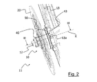
ハブ12は、自転車の車輪およびブレーキディスク20(図2)の回転軸心と一致する長手方向軸心Xに沿って延在する。
ハブ12は、ブレーキディスク20に連結され、ブレーキディスク20を回転中に受けて係止する連結部30と、車輪11の2組の複数のスポーク13がそれぞれ固定される一対のスポーク保持フランジ40および45とを備える。
図示された限定的でない後輪11の場合において、ハブ12は、カセット(図示せず)に連結される連結部35を備える。
The
The
In the case of the non-limiting
ブレーキディスク20に連結される連結部30は、スポーク保持フランジ40に対して軸方向外側に設けられており、カセットに連結される連結部35は、スポーク保持フランジ45に対して軸方向外側に設けられている。したがって、ブレーキディスク20に連結される連結部30は、カセットに連結される連結部35に対して軸方向の反対側にある。
スポーク13は、スポーク保持フランジ40および45と車輪11のリム14との間に張力下に置かれている。スポーク13はスチール製またはアルミニウム合金製であることが好ましい。
The connecting
The
図2および図4に示されているように、スポーク保持フランジ40は、径方向に延びる複数の突起部(appendage)42を備え、各突起部は、スポーク13の端部を受けるように構成された座部42aをそれぞれ有する。
突起部42は、ハブ12に結合されたスポーク保持フランジ40の中央クラウン43に結合されている。好ましくは、中央クラウン43はハブ12と一体形成されており、突起部42は中央クラウン43と一体形成されている。
As shown in FIGS. 2 and 4, the
The
座部42aは、図5により良く示されているように、連結部30に面する挿入開口42bを備える。各スポーク13は、ヘッド(図示せず)が設けられたスポーク13の端部13a(図2)が座部42a内で径方向に保持されるように、挿入開口42bを介して各座部42aに挿入されている。
スポーク13に張力をかけることにより、スポーク13が座部42a内で軸方向に並進して座部から外れてしまうことがないようにする。
The
Tensioning the
ハブ12の連結部30は、ハブ12の径方向外側表面を成すハブ本体12aに形成されている。ハブ本体12aは、径方向内側位置においてハブピン12bが軸方向に貫通しており、ハブ本体12aは、このハブピン12bに対して車輪11の回転軸心回りに回転可能である。ハブピン12bは、車輪11の回転軸心を形成している。
The connecting
連結部30は、ブレーキディスク20を受けて回転可能に保持する第1の回転カップリング部材32を備える。
第1の回転カップリング部材32は、ブレーキディスク20がブレーキ・トルクを車輪11に伝達することができるように、ブレーキディスク20とハブ12の間で偶力(pairs of forces)を交換することができるように構成されている。
The connecting
The first
第1の回転カップリング部材32は、ハブ12とブレーキディスク20との間において軸方向に結合されていない。
第1の回転カップリング部材32は、スポーク保持フランジ40に対して軸方向外側にある第1の環状セクタ33と、第1の環状セクタ33に対して軸方向外側にある第2の環状セクタ34とを備える。
第1の環状セクタ33は、軸方向において、第2の環状セクタ34よりもスポーク保持フランジ40の近くにある。
The first
The first
The first
第1および第2の環状セクタ33,34は、形状適合プロファイル(shape coupling profile)に従って形付けられている。形状適合プロファイルという用語は、第1および第2の環状セクタ33,34のプロファイルが、ハブ12とブレーキディスク20との間においてねじり(torsion)を伝達できるような幾何学的特徴を有していることを意味している。形状適合プロファイルは、例えば、多角形プロファイル、または、(例えば、コードに沿って平らにした)変形円形プロファイルなどとすることが可能である。
The first and second
これにつき、第1の環状セクタ33および第2の環状セクタ34は、凹条付きの径方向外側表面(fluted radially outer surface)、すなわち、長手方向に延在する径方向外側表面であって、軸方向において直線状であり且つ径方向に突出している隣り合う径方向凸条(radial projection)33c,34cの間に形成された長手方向凹条(longitudinal flute) 33b,34bが設けられた径方向外側表面を備える。
第1および第2の環状セクタ33,34の径方向凸条33c,34cの全ては、径方向に同一の延長部(equal extension in the radial direction)を有する。
第1および第2の環状セクタ33,34の径方向凸条33c,34cおよび長手方向凹条33b,34bは、互いに軸方向に整合している。
In this respect, the first
All of the
The
円周方向において、径方向凸条33c,34cは、(添付の図面に示された実施例のように)同一の延長部を有していてもよく、または、少なくとも1つの径方向凸条33c,34cが他の径方向凸条33c,34cよりも大きな円周方向延長部を有し、径方向リフェレンス凸条(radial reference projection)を形成していてもよい。
(長手方向凹条33b,34bを形成している)径方向凸条33c,34c間の円周方向距離は一定であってもよく、または、好ましくは、少なくとも2つの径方向凸条34cが、他の径方向凸条を分離する円周方向距離よりも長い円周方向距離で離間し、(図5に示されているように)長手方向リフェレンス凹条33a,34aを形成していてもよい。
In the circumferential direction, the
The circumferential distance between the
第1および第2の環状セクタ33,34は、その軸方向延長部が異なるという点を除いて、互いに同一である。
図6に明瞭に示されているように、第2の環状セクタ34の軸方向延長部は、第1の環状セクタ33の軸方向延長部よりも長い。
連結部30は、第1および第2の環状セクタ33,34を互いに分離する円周溝38をさらに備える。
第1および第2の環状セクタ33,34の間に軸方向に設けられた円周溝38は、その径方向深さが、第1および第2の環状セクタ33,34の凹条33b,34bの径方向深さよりも深い。
特に(図6)、溝38は、第1および第2の環状の肩部38a,38bと底壁38cとの間に形成されている。
The first and second
As clearly shown in FIG. 6, the axial extension of the second
The
The
In particular (FIG. 6), the
第1の環状の肩部38aは第1の環状セクタ33に隣接しており、第2の肩部38bは第2の環状の肩部34に隣接している。
各環状の肩部38a,38bは、第1および第2の環状セクタ33,34の凹条33b,34bを越えない程度に径方向外側に延びている。
好ましくは、各環状の肩部38a,38bは、ハブ本体12aの外側表面に到達するまで径方向外側に延びている。
各環状の肩部38a,38bは、底壁38cと接合するまで径方向内側に延びている。
したがって、底壁38cは、第1および第2の環状セクタ33,34の凹条33b,34bよりもさらに径方向内側に設けられている。
換言すれば、円周溝38は、第1の環状セクタ33を第2の環状セクタ34から分離する凹部を形成している。
溝38の軸方向延長部、すなわち、第1および第2の肩部38a,38bの間の距離は、第1の環状セクタ33の径方向延長部よりも小さいことが好ましい。
A first
Each
Preferably, each
Each
Therefore, the
In other words, the
The axial extension of the
ハブアセンブリ10は、ハブ12においてブレーキディスク20を軸方向に位置決めするストライキングかつリフェレンス要素(striking and reference element)として作用するように構成されるスペーサ50をさらに備える。
スペーサ50は実質的に環状の形状を有し、ブレーキディスク20のためのストライキング面(striking surface)50aと、ストライキング面50aに対して軸方向反対側にあるアバットメント面(abutment surface)50bと、を備える。
スペーサ50は、第1の回転カップリング部材32と適合する第2の回転カップリング部材52が設けられた中央開口51をさらに備える。
The
The
第2の回転カップリング部材52は、第1の環状セクタ33の第1の回転カップリング部材32の凹条付き表面と適合する凹条付きの径方向内側表面53を備える。
凹条付きの径方向内側表面53は、長手方向に延在しており、軸方向において直線状であり且つ径方向内側に突出している隣り合う径方向凸条53bの間に形成された長手方向凹条53aが設けられている。
長手方向凹条53aは第1の環状セクタ33の径方向凸条33cと適合し、径方向凸条53bは第1の環状セクタ33の長手方向凹条33bと適合する。
径方向凸条53bの全ては、径方向に同一の延長部を有する。
The second
The concave radial
The
All of the
(長手方向凹条53aを形成している)径方向凸条53bの間の円周方向距離は、(添付の図面に示された実施例のように)一定であってもよく、または、少なくとも2つの径方向凸条53bが、他の径方向凸条53bを分離する円周方向距離よりも長い円周方向距離で離間し、長手方向リフェレンス凹条を形成していてもよい。
円周方向において、径方向凸条53bは、同一の円周方向延長部を有していてもよく、または、好ましくは、少なくとも1つの径方向凸条53bが、(図7に示されているように)他の径方向凸条53bよりも大きい円周方向延長部を有し、径方向リフェレンス凸条53cを形成していてもよい。
径方向リフェレンス凸条53cは、第1の環状セクタ33のリフェレンス凹条33aに挿入されるように構成されている。
The circumferential distance between the
In the circumferential direction, the
The
スペーサ50は、連結部30の第1の回転カップリング部材32において係合された第2の回転カップリング部材52によって連結部30に取り付けられている。
特に、スペーサ50は第1の環状セクタ33に取り付けられており、1の環状セクタ33に対して回転可能に拘束されている。スペーサ50のアバットメント面50bは、スポーク保持フランジ40に面しており、スポーク保持フランジ40と接触して当接している。
In particular, the
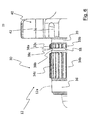
図4に示されているように、スペーサ50は、径方向に延びる複数の突起部56を備える。突起部56の数は、スポーク保持フランジ40の突起部42の数と等しく、スポーク13を軸方向に保持する座部42aの挿入開口42bを閉じるような形状を有する。
スペーサ50の突起部56は、スポーク保持フランジ40の突起部42と実質的に当接し、スポーク13を保持する座部42aの挿入開口42bを少なくとも部分的に軸方向に覆っている。
スペーサ50の突起部56は、スポーク保持フランジ40の座部42aに挿入されたスポーク13の端部13aに対する肩部を形成しており、スポーク13が座部42aから軸方向に意図せず外れてしまうことを防止する。
なお、第1の環状セクタ33の長手方向リフェレンス凹条33aは、スペーサ50の径方向リフェレンス凸条53cと共に、スペーサの突起部56がスポーク保持フランジ40の突起部42に配置されるようにスペーサ50を第1の環状セクタ33に適合(orient)させる。
As shown in FIG. 4, the
The
The
The longitudinal
スペーサ50の各突起部56は、スポーク保持フランジ40に面する側から軸方向に延びる小ブロック59(図8)を備える。
小ブロック59は、スポーク保持フランジ40の座部42aの挿入開口42bに少なくとも部分的に挿入されて、スポーク13の座部42aに土や泥、塵が入り込んでしまうことを防止する。
Each
The
代替的に、突起部56の代わりに、スペーサ50は、スポーク13を保持する座部42aの挿入開口42bを閉じるまで径方向に延びる単一の環状の突起部を備えていてもよい。
スペーサ50の突起部56は、(図4の実施例に示されているように)アバットメント面50aおよびストライキング面50bと一体形成されていてもよく、または、(図7および図8の実施例に示されているように)アバットメント面50aおよびストライキング面50bを有するスペーサ50の部分から別体である環状のクラウン57に設けられていてもよい。
後者の場合、スペーサは、アバットメント面50aおよびストライキング面50bを有する実質的に環状の内側部分58と、第2の回転カップリング部材52とを備える。
Alternatively, instead of the
The
In the latter case, the spacer comprises a substantially annular
環状のクラウン57は、内側部分58に対して径方向外側に配置されており、この内側部分と機械的なインターフェレンスによってカップリングされていてもよい。
環状のクラウン57は、例えば、プラスチックまたは複合材料から形成することが可能である。
An
The
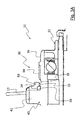
図3Aに模式的に示されているように、スペーサ50のストライキング面50aは、円周溝38において軸方向に配置されている。
特に、ストライキング面50aは、円周溝38の第1および第2の肩部38a,38bの間に軸方向に配置されている。
ストライキング面50aは、円周溝38の底壁38cから径方向に離間しているので、スペーサ50がハブ12の第1の環状セクタ33に既に取り付けられている場合、例えばチップ除去などによって、機械加工することが可能である。
これにより、スペーサ50のストライキング面50aは、完全に平面状かつ長手方向軸心Xに対して完全に垂直に形成される。
As schematically shown in FIG. 3A, the
In particular, the
The
Thereby, the
スペーサ50は、表面コーティング層がない場合であっても酸化されない任意の材料から形成される。例えば、スペーサ50は、6000系アルミニウム合金製またはステンレススチール製である。
したがって、ハブ12は、機械的強度および軽量性の観点から最大の性能が得られる材料から形成することが可能であり、酸化を防止する層で被覆することが可能である。例えば、ハブ12は、高い機械的性能を有するアルミニウム合金から、例えば、Ergal(7000系アルミニウム合金)またはAvional(2000系アルミニウム合金)などから形成することが可能である。
The
Thus, the
アセンブリ10は、ハブ12とスペーサ50との間に配置された環状のガスケット60〔好ましくは、トロイダル(toroidal)〕を備える(図3)。
これにつき、環状のガスケット60に対する円周方向座部39が、ハブ12において連結部30の軸方向内側の、第1の環状セクタ33とスポーク保持フランジ40との間に形成されている(図5)。
図3Aに示されているように、スペーサ50は、第2の回転カップリング部材52に対して軸方向内側位置において、環状のガスケット60に対する収容座部54を備える。
環状のガスケット60は、スペーサ50とハブ12との間に機械的なインターフェレンスを生じさせ、スペーサ50がハブアセンブリ10の組み立て中に定位置に留まることができるようにする。
The
In this respect, a
As shown in FIG. 3A, the
The
ブレーキディスク20は、第2の環状セクタ34の長手方向凹条34bおよび径方向凸条34cと適合する径方向内側表面22を備える。
ブレーキディスク20は、ハブの連結部30に、特には、連結部の第2の環状セクタ34に取り付けられている。
ブレーキディスク20は、整合面として作用してブレーキディスク20を長手方向軸心Xに対して完全に垂直に配置するスペーサ50のストライキング面50aと接触している第2の環状セクタ34に取り付けられている。
なお、第2の環状セクタ34の軸方向延長部は、従来的な厚さのブレーキディスクを用いることを可能にしている。
The
The
The
It should be noted that the axial extension of the second
図3および図4に示されているように、アセンブリ10は1つ以上の調整ワッシャ70(thickening washers)を備える。
調整ワッシャ70は、スペーサ50とブレーキディスク20との間に軸方向に配置されている。
特に、調整ワッシャ70は、スペーサ50に対して軸方向外側において、ストライキング面50aと接触状態で設けられている。
好ましくは、調整ワッシャ70の全てが同一の厚さ、すなわち、同一の軸方向寸法を有する。調整ワッシャ70の厚さおよび形状は、両面が完全に扁平且つ平行になるように調節されている。
調整ワッシャ70の厚さは、約0.02mmから約0.2mmの間であり、好ましくは0.05mmである。
スペーサとブレーキディスク20との間に配置される調整ワッシャ70の数を選択することによって、ブレーキキャリパのパッド間のセンタにブレーキディスク20を正確に配置することが可能である。
As shown in FIGS. 3 and 4, the
In particular, the
Preferably, all of the
The thickness of the
By choosing the number of
第2の環状セクタ34に対する軸方向外側位置において、ハブ12の自由端部に、ねじ部36が形成されている。
アセンブリ10は、ハブ12のねじ部36に螺合可能なロックナット80を備え、このロックナット80は、ブレーキディスク20の軸方向外側表面20aと当接し、連結部30において軸方向外側表面20aを軸方向に保持する。ロックナット80は、ブレーキディスク20をハブ12に締め付け、ブレーキディスク20と、スペーサ50と、設けられている場合には一つ以上の調整ワッシャ70とを束ねる。
A threaded
The
本発明に係るハブアセンブリ10の取付け工程は、環状のガスケット60を用いてハブ12の連結部30にスペーサ50を取り付けることを含む。この動作の間、スペーサ50は、第2の環状セクタ34に沿って軸方向にスライドされ、スペーサが当接する第1の環状セクタ33に到達して、スポーク保持フランジ40とアバットメントを成す。
The process of attaching
上述のとおり、スペーサ50のストライキング面50aは円周溝38に配置されている。
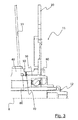
この時点において、ハブ12およびスペーサ50を備えるハブアセンブリ10は、工作機械の上に配置されており、ハブ12に取り付けられたスペーサ50のストライキング面50aの水平化/研削工程が行われる。
これにより加工されたアセンブリ10は、工作機械から取り除かれ、調整ワッシャ70を設ける場合には、ハブ12の連結部30に取り付けられる。
特に、調整ワッシャ70は、スペーサ50のストライキング面50aと接触するように軸方向に配置されている。
そして、ブレーキディスク20は、ブレーキディスク20がスペーサ50のストライキング面50aまたは(設けられている場合には)調整ワッシャ70に接触するように、ハブ12の連結部30に、特に、第2の環状セクタ34に取り付けられる。
そして、ロックナット80が、ハブ12に既に取り付けられている部品を軸方向に係止するようにハブ12に取り付けられる。
As described above, the
At this point, the
The
In particular, the
The
A
当然ながら、当業者であれば、その時々の要件や偶発的な要件を満足するために本発明の自転車のホイールハブおよび関連のハブアセンブリに様々な変更や変形を施すことができ、いずれにせよ、これらの変更や変形の全ては添付の特許請求の範囲により定まる保護範囲内に含まれる。
Of course, one of ordinary skill in the art can make various modifications and variations to the bicycle wheel hub and associated hub assembly of the present invention in order to satisfy the occasional requirements and incidental requirements. All such changes and modifications are included in the scope of protection defined by the appended claims.
Claims (15)
請求項1から7のいずれか一項に記載のハブ(12)と、
前記ブレーキディスク(20)に向いているストライキング面(50a)と、前記ストライキング面(50a)に対して軸方向反対側にあるアバットメント面(50b)と、前記第1の回転カップリング部材(32)と適合する第2の回転カップリング部材(52)が設けられた中央開口(51)と、を有するスペーサ(50)と、 を備え、
前記スペーサ(50)は、前記第1の回転カップリング部材(32)の前記第1の環状セクタ(33)に係合された前記第2の回転カップリング部材(52)と、スポーク保持フランジ(40)に面する前記アバットメント面(50b)と、前記円周溝(38)に軸方向に配置された前記ストライキング面(50a)とで、前記連結部(30)に取り付けられる、ハブアセンブリ(10)。 A hub assembly (10) of a bicycle wheel (11),
A hub (12) according to any one of the preceding claims.
A striking surface (50a) facing the brake disc (20), an abutment surface (50b) axially opposite to the striking surface (50a), and the first rotary coupling member (32) A central opening (51) provided with a second rotational coupling member (52), and a spacer (50)
The spacer (50) comprises the second rotational coupling member (52) engaged with the first annular sector (33) of the first rotational coupling member (32); A hub assembly (40) attached to the connection (30) with the abutment surface (50b) facing the 40) and the striking surface (50a) axially disposed in the circumferential groove (38) 10).
Hub assembly (10) according to any one of claims 11 to 14, wherein the radially outer annular portion (57) comprises a plurality of said radially extending projections (56). ).
Applications Claiming Priority (2)
| Application Number | Priority Date | Filing Date | Title |
|---|---|---|---|
| IT102017000091932 | 2017-08-08 | ||
| IT102017000091932A IT201700091932A1 (en) | 2017-08-08 | 2017-08-08 | Wheel hub for bicycle and related hub assembly |
Publications (2)
| Publication Number | Publication Date |
|---|---|
| JP2019043542A true JP2019043542A (en) | 2019-03-22 |
| JP2019043542A5 JP2019043542A5 (en) | 2021-07-26 |
Family
ID=60570159
Family Applications (1)
| Application Number | Title | Priority Date | Filing Date |
|---|---|---|---|
| JP2018148080A Pending JP2019043542A (en) | 2017-08-08 | 2018-08-07 | Bicycle wheel hub and related hub assembly |
Country Status (6)
| Country | Link |
|---|---|
| US (1) | US10994572B2 (en) |
| EP (1) | EP3441235B1 (en) |
| JP (1) | JP2019043542A (en) |
| CN (1) | CN109383187A (en) |
| IT (1) | IT201700091932A1 (en) |
| TW (1) | TWI763897B (en) |
Citations (2)
| Publication number | Priority date | Publication date | Assignee | Title |
|---|---|---|---|---|
| JP2003136903A (en) * | 2001-08-30 | 2003-05-14 | Shimano Inc | Disk brake hub for bicycle |
| DE202011101081U1 (en) * | 2010-11-11 | 2011-10-28 | Shimano Inc. | bicycle hub |
Family Cites Families (16)
| Publication number | Priority date | Publication date | Assignee | Title |
|---|---|---|---|---|
| US6540306B2 (en) * | 2001-06-29 | 2003-04-01 | Shimano Inc. | Bicycle disc brake hub |
| US7059686B2 (en) * | 2003-01-22 | 2006-06-13 | Shimano Inc. | Bicycle hub |
| JP2005188704A (en) * | 2003-12-26 | 2005-07-14 | Shimano Inc | Disk brake rotor assembly |
| JP2005308059A (en) * | 2004-04-20 | 2005-11-04 | Shimano Inc | Disk brake rotor assembly for bicycle |
| TWM274312U (en) * | 2005-03-03 | 2005-09-01 | Joy Ind Co Ltd | Conversion device structure for disc brake hub |
| US7306292B2 (en) * | 2005-05-27 | 2007-12-11 | Shimano Inc. | Bicycle hub |
| US7331639B2 (en) * | 2005-11-04 | 2008-02-19 | Shimano Inc. | Bicycle rim |
| JP4610532B2 (en) * | 2006-02-17 | 2011-01-12 | 株式会社シマノ | Bicycle disc brake hub |
| ITMI20062221A1 (en) | 2006-11-20 | 2008-05-21 | Campagnolo Srl | HUB FOR BICYCLE WHEEL AND BICYCLE WHEEL INCLUDING SUCH HUB |
| ITMI20062385A1 (en) * | 2006-12-13 | 2008-06-14 | Campagnolo Srl | HUB GROUP FOR BICYCLE WHEEL WITH DISC BRAKE |
| US9267560B2 (en) | 2013-07-31 | 2016-02-23 | Shimano Inc. | Bicycle disc brake rotor assembly and bicycle disc brake rotor |
| US9199509B2 (en) * | 2014-01-21 | 2015-12-01 | Shimano Inc. | Bicycle hub |
| CN103953670B (en) * | 2014-05-04 | 2016-09-07 | 宏展五金塑胶制品(苏州)有限公司 | Bicycle disk brake |
| GB201414356D0 (en) * | 2014-08-13 | 2014-09-24 | Ison Disbribution Ltd | Rear wheel for bicycles and method of adapting a rear wheel |
| ITUB20156263A1 (en) * | 2015-12-03 | 2017-06-03 | Campagnolo Srl | Hub for a bicycle wheel |
| DE102016107752A1 (en) * | 2016-04-26 | 2017-10-26 | Dt Swiss Ag | Hub and impeller |
-
2017
- 2017-08-08 IT IT102017000091932A patent/IT201700091932A1/en unknown
-
2018
- 2018-07-31 EP EP18186717.7A patent/EP3441235B1/en active Active
- 2018-08-07 TW TW107127395A patent/TWI763897B/en active
- 2018-08-07 JP JP2018148080A patent/JP2019043542A/en active Pending
- 2018-08-07 US US16/056,872 patent/US10994572B2/en active Active
- 2018-08-08 CN CN201810895420.9A patent/CN109383187A/en active Pending
Patent Citations (2)
| Publication number | Priority date | Publication date | Assignee | Title |
|---|---|---|---|---|
| JP2003136903A (en) * | 2001-08-30 | 2003-05-14 | Shimano Inc | Disk brake hub for bicycle |
| DE202011101081U1 (en) * | 2010-11-11 | 2011-10-28 | Shimano Inc. | bicycle hub |
Also Published As
| Publication number | Publication date |
|---|---|
| CN109383187A (en) | 2019-02-26 |
| EP3441235A1 (en) | 2019-02-13 |
| US10994572B2 (en) | 2021-05-04 |
| TWI763897B (en) | 2022-05-11 |
| IT201700091932A1 (en) | 2019-02-08 |
| EP3441235B1 (en) | 2022-06-15 |
| US20190047323A1 (en) | 2019-02-14 |
| TW201919923A (en) | 2019-06-01 |
Similar Documents
| Publication | Publication Date | Title |
|---|---|---|
| EP1964767B1 (en) | Quick release mechanism for securing a bicycle wheel | |
| US7216743B2 (en) | Bicycle disc brake rotor assembly | |
| TWI748054B (en) | Brake disc for a bicycle | |
| EP2025965A1 (en) | Brake Disc Assembly | |
| US7958978B2 (en) | Multi-disc brake hub assembly with disc slide pins | |
| CN107499440B (en) | Mounting structure of brake disc and speed sensor ring | |
| JP2007297031A (en) | Disk brake hub for bicycle | |
| JP2018028384A (en) | Brake disc for bicycle | |
| TW201631264A (en) | Vehicle disc brake | |
| JP2018189238A (en) | Brake disc assembly for bicycle | |
| US10451128B2 (en) | Bell for brake disc with integrated auxiliary brake | |
| TWI707787B (en) | Hub for a bicycle wheel | |
| JP2019043542A (en) | Bicycle wheel hub and related hub assembly | |
| TWI243108B (en) | Bicycle hub | |
| JP2018127037A (en) | Structure for assembling tire wheel, brake rotor, and hub | |
| TW201807331A (en) | Brake disc for a bicycle | |
| US6422362B1 (en) | Brake device | |
| JPS6073132A (en) | Disk brake for car | |
| JP2017106516A (en) | Disc brake | |
| TWI825768B (en) | Brake disk assembly | |
| JP5494783B2 (en) | Manufacturing method of wheel bearing device | |
| TW202348910A (en) | Brake disk assembly | |
| TW202348911A (en) | Brake disk assembly | |
| WO2023084934A1 (en) | Floating-type brake disc, and wheel for straddle-type vehicle | |
| JP2022015090A (en) | Floating-type brake disc and wheel for saddle-riding type vehicle |
Legal Events
| Date | Code | Title | Description |
|---|---|---|---|
| A521 | Request for written amendment filed |
Free format text: JAPANESE INTERMEDIATE CODE: A523 Effective date: 20210525 |
|
| A621 | Written request for application examination |
Free format text: JAPANESE INTERMEDIATE CODE: A621 Effective date: 20210525 |
|
| A977 | Report on retrieval |
Free format text: JAPANESE INTERMEDIATE CODE: A971007 Effective date: 20220510 |
|
| A131 | Notification of reasons for refusal |
Free format text: JAPANESE INTERMEDIATE CODE: A131 Effective date: 20220517 |
|
| A02 | Decision of refusal |
Free format text: JAPANESE INTERMEDIATE CODE: A02 Effective date: 20221206 |