JP2019042075A - In-vivo imaging apparatus and in-vivo monitor camera system - Google Patents

In-vivo imaging apparatus and in-vivo monitor camera system Download PDF

Info

Publication number
JP2019042075A
JP2019042075A JP2017167930A JP2017167930A JP2019042075A JP 2019042075 A JP2019042075 A JP 2019042075A JP 2017167930 A JP2017167930 A JP 2017167930A JP 2017167930 A JP2017167930 A JP 2017167930A JP 2019042075 A JP2019042075 A JP 2019042075A
Authority
JP
Japan
Prior art keywords
camera
side electrode
support member
imaging unit
unit
Prior art date
Legal status (The legal status is an assumption and is not a legal conclusion. Google has not performed a legal analysis and makes no representation as to the accuracy of the status listed.)
Pending
Application number
JP2017167930A
Other languages
Japanese (ja)
Inventor
岩 銭
Yan Qian
岩 銭
圭 浦川
Kei Urakawa
圭 浦川
下村 奈良和
Narakazu Shimomura
奈良和 下村
Current Assignee (The listed assignees may be inaccurate. Google has not performed a legal analysis and makes no representation or warranty as to the accuracy of the list.)
Sharp Corp
Original Assignee
Sharp Corp
Priority date (The priority date is an assumption and is not a legal conclusion. Google has not performed a legal analysis and makes no representation as to the accuracy of the date listed.)
Filing date
Publication date
Application filed by Sharp Corp filed Critical Sharp Corp
Priority to JP2017167930A priority Critical patent/JP2019042075A/en
Priority to US16/116,778 priority patent/US20190060027A1/en
Priority to CN201811005510.2A priority patent/CN109419486A/en
Publication of JP2019042075A publication Critical patent/JP2019042075A/en
Pending legal-status Critical Current

Links

Images

Classifications

    • AHUMAN NECESSITIES
    • A61MEDICAL OR VETERINARY SCIENCE; HYGIENE
    • A61BDIAGNOSIS; SURGERY; IDENTIFICATION
    • A61B1/00Instruments for performing medical examinations of the interior of cavities or tubes of the body by visual or photographical inspection, e.g. endoscopes; Illuminating arrangements therefor
    • A61B1/04Instruments for performing medical examinations of the interior of cavities or tubes of the body by visual or photographical inspection, e.g. endoscopes; Illuminating arrangements therefor combined with photographic or television appliances
    • AHUMAN NECESSITIES
    • A61MEDICAL OR VETERINARY SCIENCE; HYGIENE
    • A61BDIAGNOSIS; SURGERY; IDENTIFICATION
    • A61B1/00Instruments for performing medical examinations of the interior of cavities or tubes of the body by visual or photographical inspection, e.g. endoscopes; Illuminating arrangements therefor
    • A61B1/00002Operational features of endoscopes
    • A61B1/00043Operational features of endoscopes provided with output arrangements
    • A61B1/00045Display arrangement
    • AHUMAN NECESSITIES
    • A61MEDICAL OR VETERINARY SCIENCE; HYGIENE
    • A61BDIAGNOSIS; SURGERY; IDENTIFICATION
    • A61B1/00Instruments for performing medical examinations of the interior of cavities or tubes of the body by visual or photographical inspection, e.g. endoscopes; Illuminating arrangements therefor
    • A61B1/00064Constructional details of the endoscope body
    • A61B1/00105Constructional details of the endoscope body characterised by modular construction
    • AHUMAN NECESSITIES
    • A61MEDICAL OR VETERINARY SCIENCE; HYGIENE
    • A61BDIAGNOSIS; SURGERY; IDENTIFICATION
    • A61B1/00Instruments for performing medical examinations of the interior of cavities or tubes of the body by visual or photographical inspection, e.g. endoscopes; Illuminating arrangements therefor
    • A61B1/00112Connection or coupling means
    • A61B1/00114Electrical cables in or with an endoscope
    • AHUMAN NECESSITIES
    • A61MEDICAL OR VETERINARY SCIENCE; HYGIENE
    • A61BDIAGNOSIS; SURGERY; IDENTIFICATION
    • A61B1/00Instruments for performing medical examinations of the interior of cavities or tubes of the body by visual or photographical inspection, e.g. endoscopes; Illuminating arrangements therefor
    • A61B1/00112Connection or coupling means
    • A61B1/00121Connectors, fasteners and adapters, e.g. on the endoscope handle
    • A61B1/00128Connectors, fasteners and adapters, e.g. on the endoscope handle mechanical, e.g. for tubes or pipes
    • AHUMAN NECESSITIES
    • A61MEDICAL OR VETERINARY SCIENCE; HYGIENE
    • A61BDIAGNOSIS; SURGERY; IDENTIFICATION
    • A61B1/00Instruments for performing medical examinations of the interior of cavities or tubes of the body by visual or photographical inspection, e.g. endoscopes; Illuminating arrangements therefor
    • A61B1/00147Holding or positioning arrangements
    • AHUMAN NECESSITIES
    • A61MEDICAL OR VETERINARY SCIENCE; HYGIENE
    • A61BDIAGNOSIS; SURGERY; IDENTIFICATION
    • A61B1/00Instruments for performing medical examinations of the interior of cavities or tubes of the body by visual or photographical inspection, e.g. endoscopes; Illuminating arrangements therefor
    • A61B1/00163Optical arrangements
    • A61B1/00174Optical arrangements characterised by the viewing angles
    • A61B1/00183Optical arrangements characterised by the viewing angles for variable viewing angles
    • AHUMAN NECESSITIES
    • A61MEDICAL OR VETERINARY SCIENCE; HYGIENE
    • A61BDIAGNOSIS; SURGERY; IDENTIFICATION
    • A61B1/00Instruments for performing medical examinations of the interior of cavities or tubes of the body by visual or photographical inspection, e.g. endoscopes; Illuminating arrangements therefor
    • A61B1/04Instruments for performing medical examinations of the interior of cavities or tubes of the body by visual or photographical inspection, e.g. endoscopes; Illuminating arrangements therefor combined with photographic or television appliances
    • A61B1/041Capsule endoscopes for imaging
    • AHUMAN NECESSITIES
    • A61MEDICAL OR VETERINARY SCIENCE; HYGIENE
    • A61BDIAGNOSIS; SURGERY; IDENTIFICATION
    • A61B1/00Instruments for performing medical examinations of the interior of cavities or tubes of the body by visual or photographical inspection, e.g. endoscopes; Illuminating arrangements therefor
    • A61B1/04Instruments for performing medical examinations of the interior of cavities or tubes of the body by visual or photographical inspection, e.g. endoscopes; Illuminating arrangements therefor combined with photographic or television appliances
    • A61B1/05Instruments for performing medical examinations of the interior of cavities or tubes of the body by visual or photographical inspection, e.g. endoscopes; Illuminating arrangements therefor combined with photographic or television appliances characterised by the image sensor, e.g. camera, being in the distal end portion
    • A61B1/053Instruments for performing medical examinations of the interior of cavities or tubes of the body by visual or photographical inspection, e.g. endoscopes; Illuminating arrangements therefor combined with photographic or television appliances characterised by the image sensor, e.g. camera, being in the distal end portion being detachable
    • AHUMAN NECESSITIES
    • A61MEDICAL OR VETERINARY SCIENCE; HYGIENE
    • A61BDIAGNOSIS; SURGERY; IDENTIFICATION
    • A61B1/00Instruments for performing medical examinations of the interior of cavities or tubes of the body by visual or photographical inspection, e.g. endoscopes; Illuminating arrangements therefor
    • A61B1/313Instruments for performing medical examinations of the interior of cavities or tubes of the body by visual or photographical inspection, e.g. endoscopes; Illuminating arrangements therefor for introducing through surgical openings, e.g. laparoscopes
    • A61B1/3132Instruments for performing medical examinations of the interior of cavities or tubes of the body by visual or photographical inspection, e.g. endoscopes; Illuminating arrangements therefor for introducing through surgical openings, e.g. laparoscopes for laparoscopy
    • AHUMAN NECESSITIES
    • A61MEDICAL OR VETERINARY SCIENCE; HYGIENE
    • A61BDIAGNOSIS; SURGERY; IDENTIFICATION
    • A61B90/00Instruments, implements or accessories specially adapted for surgery or diagnosis and not covered by any of the groups A61B1/00 - A61B50/00, e.g. for luxation treatment or for protecting wound edges
    • A61B90/36Image-producing devices or illumination devices not otherwise provided for
    • A61B90/361Image-producing devices, e.g. surgical cameras
    • AHUMAN NECESSITIES
    • A61MEDICAL OR VETERINARY SCIENCE; HYGIENE
    • A61BDIAGNOSIS; SURGERY; IDENTIFICATION
    • A61B90/00Instruments, implements or accessories specially adapted for surgery or diagnosis and not covered by any of the groups A61B1/00 - A61B50/00, e.g. for luxation treatment or for protecting wound edges
    • A61B90/36Image-producing devices or illumination devices not otherwise provided for
    • A61B90/37Surgical systems with images on a monitor during operation
    • AHUMAN NECESSITIES
    • A61MEDICAL OR VETERINARY SCIENCE; HYGIENE
    • A61BDIAGNOSIS; SURGERY; IDENTIFICATION
    • A61B17/00Surgical instruments, devices or methods, e.g. tourniquets
    • A61B17/00234Surgical instruments, devices or methods, e.g. tourniquets for minimally invasive surgery
    • A61B2017/00238Type of minimally invasive operation
    • A61B2017/00283Type of minimally invasive operation with a device releasably connected to an inner wall of the abdomen during surgery, e.g. an illumination source

Landscapes

  • Health & Medical Sciences (AREA)
  • Life Sciences & Earth Sciences (AREA)
  • Surgery (AREA)
  • Engineering & Computer Science (AREA)
  • Nuclear Medicine, Radiotherapy & Molecular Imaging (AREA)
  • General Health & Medical Sciences (AREA)
  • Animal Behavior & Ethology (AREA)
  • Veterinary Medicine (AREA)
  • Public Health (AREA)
  • Pathology (AREA)
  • Biomedical Technology (AREA)
  • Heart & Thoracic Surgery (AREA)
  • Medical Informatics (AREA)
  • Molecular Biology (AREA)
  • Radiology & Medical Imaging (AREA)
  • Biophysics (AREA)
  • Physics & Mathematics (AREA)
  • Optics & Photonics (AREA)
  • Oral & Maxillofacial Surgery (AREA)
  • Mechanical Engineering (AREA)
  • Gynecology & Obstetrics (AREA)
  • Endoscopes (AREA)

Abstract

To provide an in-vivo imaging apparatus capable of simplifying camera installation work in a body and capable of finely adjusting the camera even after the installation.SOLUTION: An in-vivo imaging device (1) comprises: a camera (11); a support bar (13) to be inserted to a tubular instrument (31); and a grip part (14) for gripping the camera (11) provided at an end of the support bar (13). When the support bar (13) is pulled up toward the outside of the body, the grip part (14) comes into contact with the body inside end (31a) of the tubular instrument (31) and thereby becomes deformed so as to grip the camera (11).SELECTED DRAWING: Figure 5

Description

本発明は、体内撮像装置、および体内監視カメラシステムに関する。   The present invention relates to an in-vivo imaging device and an in-vivo monitoring camera system.

術者は、撮像手段を備えた内視鏡を用いることによって、腹腔内を撮像し、患部を観察しながら、手術を行う。また、公知技術として、処置対象の患部だけでなく、腹腔内全体を観察できるように腹壁にカメラを固定することにより俯瞰的な視野を確保する技術も知られている。   The operator performs an operation while imaging the inside of the abdominal cavity and observing the affected area by using an endoscope provided with an imaging unit. Further, as a known technique, there is also known a technique for securing a bird's-eye view by fixing a camera to the abdominal wall so that not only the affected area to be treated but also the entire abdominal cavity can be observed.

特許文献1および2には、信頼性と使い勝手の向上のために、撮像部を体内で支持管の一端と接合し、支持管の他端を体外に露出させる、または、該他端を、一部が体内に導入された管状器具に接続する体内監視カメラシステムが記載されている。   In Patent Literatures 1 and 2, in order to improve reliability and usability, the imaging unit is joined to one end of a support tube in the body, and the other end of the support tube is exposed outside the body, or the other end is An in-body monitoring camera system is described that connects a tubular device whose part is introduced into the body.

また、特許文献3には、腹腔内に留置される医療機器である腹腔内設置カメラと、カメラを体内へ導入および体内から回収する導入回収専用具と、を有する医療システムが開示されている。前記導入回収専用具は、腹腔内に向けて腹壁を穿孔して体内へ導入されたトロッカーを介してカメラを体内へ導入および体内から回収する挿入回収手段である。   Further, Patent Document 3 discloses a medical system having an intra-abdominal installation camera, which is a medical device to be indwelled in the abdominal cavity, and an introduction and collection dedicated tool for introducing the camera into the body and recovering it from the body. The introduction and recovery device is an insertion and recovery means for perforating the abdominal wall toward the inside of the abdominal cavity and for introducing the camera into the body and recovering it from the body through the trocar introduced into the body.

特許第5886481号明細書(2016年 3月16日発行)Patent No. 5886481 Specification (issued March 16, 2016) 国際公開第2016/203864号パンフレット(2016年12月22日公開)International Publication No. 2016/203864 Pamphlet (released on December 22, 2016) 特許第5669666号明細書(2015年 2月12日発行)Patent No. 5669666 specification (issued on February 12, 2015)

特許文献1〜3に記載の技術では、カメラを腹壁に固定し、腹腔内全体を俯瞰的に撮像する場合、カメラを腹壁に固定するまでの設置作業の簡略化、及び設置後のカメラの微調整という点で、改良の余地が残されていた。   In the techniques described in Patent Documents 1 to 3, when the camera is fixed to the abdominal wall and the whole inside of the abdominal cavity is imaged in an overhead view, the installation work is simplified until the camera is fixed to the abdominal wall and the camera after installation There was room for improvement in terms of adjustment.

通常、術者は、腹腔内において鉗子でカメラを把持しながら、カメラのワイヤーを摘み、体外に引き上げる工程を要する。この工程の中で、カメラと支持管を接合する作業がある。特許文献1〜3の技術では、カメラと支持管の接合部を合致させる際に、スムーズに行うことが考慮されておらず、術者に負担を強いることがあった。また、カメラを腹壁に上記設置作業を終えた後も、カメラにズレが生じる場合が考えられる。   Usually, the operator needs a process of picking the wire of the camera and pulling it out of the body while holding the camera with forceps in the abdominal cavity. In this process, there is an operation of joining the camera and the support tube. In the techniques of Patent Documents 1 to 3, when the junctions of the camera and the support tube are made to coincide with each other, it is not considered to be performed smoothly, and a burden may be imposed on the operator. In addition, it is conceivable that the camera may shift even after the installation work is completed on the abdominal wall.

本発明の一態様は、体内でのカメラの設置作業を簡略化することができ、かつ設置後もカメラの微調整が可能な体内撮像装置、及び体内監視カメラシステムを実現することを目的とする。   An aspect of the present invention aims to realize an in-vivo imaging device and an in-vivo monitoring camera system that can simplify installation work of a camera in the body and can finely adjust the camera even after installation. .

上記の課題を解決するために、本発明の一態様に係る体内撮像装置は、体腔内を撮像する撮像部と、体内に導入される管状器具に挿入される支持部材と、前記支持部材における体内側の端部に設けられた前記撮像部を把持するための把持部と、を備え、前記把持部は、前記支持部材を体外側へ引き上げたときに、前記管状器具の体内側端部と当接することにより、前記撮像部を把持するように変形することを特徴としている。   In order to solve the above problems, an in-vivo imaging device according to one aspect of the present invention includes an imaging unit for imaging a body cavity, a support member inserted into a tubular device introduced into the body, and a body in the support member. A gripping portion for gripping the imaging portion provided at an inner end portion, the gripping portion being in contact with a body inner end portion of the tubular instrument when the support member is pulled out of the body By being in contact with each other, the imaging unit is deformed so as to be gripped.

また、上記の課題を解決するために、本発明の他の態様に係る体内撮像装置は、体腔内を撮像する撮像部と、体内に導入される管状器具に挿入される支持部材と、前記支持部材における体内側の端部に設けられた前記撮像部を把持するための把持部と、を備え、前記把持部は、前記撮像部に吸着する吸盤部を有することを特徴としている。   In order to solve the above problems, an in-vivo imaging device according to another aspect of the present invention includes an imaging unit for imaging a body cavity, a support member inserted into a tubular device introduced into the body, and the support And a gripping portion provided at an end portion inside the body of the member for gripping the imaging portion, the gripping portion being characterized by having a suction cup portion suctioned to the imaging portion.

また、上記の課題を解決するために、本発明のさらに他の態様に係る体内撮像装置は、体腔内を撮像する撮像部と、体内に導入される管状器具に挿入される支持部材と、前記支持部材における体内側の端部に設けられた前記撮像部を把持するための把持部と、を備え、前記支持部材は、筒状のアウター部材と、前記アウター部材内を挿通可能に配されたインナー部材と、前記インナー部材の上下動に連動して前記把持部が前記撮像部を把持する把持機構を備え、前記把持機構は、前記アウター部材に対して回転可能に支持された爪本体部材と、前記爪本体部材と前記インナー部材とを連結し、前記爪本体部材に対して回転可能に支持されたリンク部材と、を備え、前記リンク部材は、前記インナー部材に対して回転可能に支持されていることを特徴としている。   In order to solve the above problems, an in-vivo imaging device according to still another aspect of the present invention includes an imaging unit for imaging a body cavity, a support member inserted in a tubular device introduced into the body, and And a holding portion provided at an end portion inside the body in the support member for holding the imaging unit, the support member being a cylindrical outer member, and the inner member being disposed so as to be insertable therein. An inner member, and a gripping mechanism in which the gripping unit grips the imaging unit in conjunction with the vertical movement of the inner member, the gripping mechanism including a claw main body member rotatably supported with respect to the outer member; A link member connecting the claw main body member and the inner member and rotatably supported relative to the claw main body member, the link member rotatably supported relative to the inner member Being It is characterized.

本発明のこれら態様によれば、体内でのカメラの設置作業を簡略化することができ、かつ設置後もカメラの微調整が可能な体内撮像装置を実現できる。   According to these aspects of the present invention, the installation operation of the camera in the body can be simplified, and the in-vivo imaging device capable of finely adjusting the camera even after the installation can be realized.

本発明の実施形態1に係る体内監視カメラシステムの構成を示す模式図である。It is a schematic diagram which shows the structure of the monitoring camera system in a body which concerns on Embodiment 1 of this invention. 本発明の実施形態1に係る体内撮像装置の構成を示す斜視図である。It is a perspective view showing the composition of the in-vivo imaging device concerning Embodiment 1 of the present invention. 本発明の実施形態1に係る体内撮像装置の支持棒を示し、(a)は、トロッカーおよび支持棒それぞれの構成を示す模式図であり、(b)は、(a)における側方から見た支持棒の構成を示す側面図であり、(c)は、体内撮像装置の使用時における支持棒及びトロッカーの位置関係を示す模式図である。The support rod of the in-vivo imaging device which concerns on Embodiment 1 of this invention is shown, (a) is a schematic diagram which shows each structure of a trocker and a support rod, (b) was seen from the side in (a). It is a side view which shows the structure of a support rod, (c) is a schematic diagram which shows the positional relationship of a support rod and trocar at the time of use of an in-vivo imaging device. (a)〜(e)は、本発明の実施形態1におけるカメラの体内設置方法を示す模式図である。(A)-(e) is a schematic diagram which shows the body installation method of the camera in Embodiment 1 of this invention. 図4の(e)のステップ後の、カメラの体内設置方法を示す模式図であり、(a)は、図4の(e)のステップを示し、(b)〜(d)は、図4の(e)のステップ後のステップを示し、(e)は、(d)のI−I断面図である。FIG. 5A is a schematic view showing a method for installing the camera in the body after the step of (e) of FIG. 4, (a) shows the step of (e) of FIG. 4, (b) to (d) are The step after the step of (e) is shown, and (e) is an II sectional view of (d). 本発明の実施形態1に係る体内監視カメラシステムの使用状況を示す模式図である。It is a schematic diagram which shows the use condition of the in-body monitoring camera system which concerns on Embodiment 1 of this invention. 本発明の実施形態1に係る体内撮像装置のカメラの変形例を示し、(a)は側面図であり、(b)は上面図である。The modification of the camera of the in-vivo imaging device concerning Embodiment 1 of this invention is shown, (a) is a side view, (b) is a top view. 図7に示すカメラが把持部により把持された状態を示し、(a)は、側面図であり、(b)は上面図である。The camera shown in FIG. 7 shows the state gripped by the grip part, (a) is a side view, (b) is a top view. 把持部が1つの爪部を有する場合の構成を示し、(a)は、開いた状態の爪部の状態を示す側面図であり、(b)は、カメラを把持したときの爪部の状態を示す側面図であり、(c)は、(b)の断面図である。The structure in case a holding part has one nail | claw part is shown, (a) is a side view which shows the state of the nail | claw part in the open state, (b) is a state of a nail | claw when holding a camera And (c) is a cross-sectional view of (b). 把持部が3つの爪部を有する場合の構成を示し、(a)は、開いた状態の爪部の状態を示す側面図であり、(b)は、(a)に示す把持部の下側から見た下面図であり、(c)は、カメラを把持したときの爪部の状態を示す側面図である。The structure in case a holding part has three nail parts is shown, (a) is a side view which shows the state of the nail part in the open state, (b) is the lower side of a holding part shown to (a). It is the bottom view seen from, and (c) is a side view showing the state of a nail part when a camera is grasped. 把持部が4つの爪部を有する場合の構成を示し、(a)は、開いた状態の爪部の状態を示す側面図であり、(b)は、(a)に示す把持部の下側から見た下面図であり、(d)は、把持部が4つの爪部を有する場合のカメラの構成を示す上面図であり、(d)は、カメラを把持したときの爪部の状態を示す側面図である。The structure in case a holding part has four claw parts is shown, (a) is a side view which shows the state of the claw part in the open state, (b) is the lower side of the holding part shown to (a) (D) is a top view which shows the structure of a camera in case a holding part has four nail | claw parts, (d) is a bottom view seen from the state, and the state of the nail | claw part when holding a camera is FIG. (a)〜(e)は、環状部を有する把持部の構成、及び環状部を有する把持部を用いたカメラの把持方法を示す模式図である。(A)-(e) is a schematic diagram which shows the structure of the holding part which has an annular part, and the holding method of the camera using the holding part which has an annular part. (a)〜(c)は、吸盤部を有する把持部の構成、及び吸盤部を有する把持部に適したカメラの構成を示す模式図である。(A)-(c) is a schematic diagram which shows the structure of the holding part which has a suction part, and the structure of the camera suitable for the holding part which has a suction part. (a)〜(c)は、摘み部を有する把持部の構成、及び摘み部を有する把持部を用いたカメラの把持方法を示す模式図である。(A)-(c) is a schematic diagram which shows the structure of the holding part which has a knob part, and the holding method of a camera using the holding part which has a knob part. (a)〜(e)は、把持部に磁石が設けられた支持棒および支持棒の操作方法を示す模式図である。(A)-(e) is a schematic diagram which shows the operating method of the support rod and support rod in which the magnet was provided in the holding part. (a)〜(c)は、把持部により角度調整されたカメラの構成を示す模式図である。(A)-(c) is a schematic diagram which shows the structure of the camera by which angle adjustment was carried out by the holding part. (a)及び(b)は、把持部の体内側端部に対する当接状態を維持する機構の一例を示す模式図である。(A) And (b) is a schematic diagram which shows an example of a mechanism which maintains the contact state with respect to the body inner side edge part of a holding part. 本発明の実施形態2に係る体内撮像装置の支持棒を示し、(a)は、管状器具31および支持棒それぞれの構成を示す模式図であり、(b)は、(a)における側方から見た支持棒の構成を示す側面図であり、(c)は、体内撮像装置の使用時における支持棒及び管状器具31の位置関係を示す模式図である。The support rod of the in-vivo imaging device which concerns on Embodiment 2 of this invention is shown, (a) is a schematic diagram which shows the structure of each of the tubular instrument 31 and a support rod, (b) is from the side in (a). It is a side view which shows the structure of the seen support rod, and (c) is a schematic diagram which shows the positional relationship of the support rod and the tubular instrument 31 at the time of use of an in-vivo imaging device. (a)は、本発明の実施形態2に係る体内撮像装置のカメラの構成を示す側面図及び上面図であり、(b)は、図18の(a)〜(c)に示す支持棒13Aを用いたカメラの保持方法を示す模式図であり、(c)は、把持部によりカメラを把持したときの構成を示す断面図である。(A) is a side view and a top view showing the configuration of the camera of the in-vivo imaging device according to Embodiment 2 of the present invention, and (b) is a support rod 13A shown in (a) to (c) of FIG. It is a schematic diagram which shows the holding method of the camera using these, (c) is sectional drawing which shows a structure when a camera is hold | gripped by a holding part. (a)は、把持部が1つの爪部を有する場合における支持棒側電極の配置の一例を示す模式図であり、(b)は、把持部が4つの爪部を有する場合における支持棒側電極の配置の一例を示す模式図であり、(c)は、(b)に示される支持棒側電極の配置に対応した、カメラ側電極の配置を示す模式図であり、(d)は、把持部が4つの爪部を有する場合に対応した、カメラ側電極の配置を示す模式図である。(A) is a schematic diagram which shows an example of arrangement | positioning of the support rod side electrode in case a holding part has one nail | claw part, (b) is a support bar side in the case where a holding part has four nails It is a schematic diagram which shows an example of arrangement | positioning of an electrode, (c) is a schematic diagram which shows arrangement | positioning of the camera side electrode corresponding to arrangement | positioning of the support rod side electrode shown by (b), (d) It is a schematic diagram which shows arrangement | positioning of the camera side electrode corresponding to, when the holding part has four nail | claw parts. (a)〜(c)は、把持部がカメラに吸着する吸盤部を有している場合の支持棒側電極、及びそれに対応するカメラ側電極の配置を示す模式図である。(A)-(c) is a schematic diagram which shows arrangement | positioning of the support rod side electrode in, and the camera side electrode corresponding to it in the case where the holding part has a sucker part which adsorb | sucks to a camera. (a)〜(c)は、支持棒側電極とカメラ側電極との接続部分の防水機構を示す模式図である。(A)-(c) is a schematic diagram which shows the waterproof mechanism of the connection part of a support rod side electrode and a camera side electrode. (a)〜(d)は、変形例である支持棒及び把持部の構成、並びにその操作方法を示す模式図である。(A)-(d) is a schematic diagram which shows the structure of the support rod which is a modification, and a holding part, and its operation method. (a)〜(c)は、本発明の実施形態3に係る体内撮像装置に備えられた支持棒および把持部の構成、及びその操作方法を示す模式図である。(A)-(c) is a schematic diagram which shows the structure of the support rod and holding part with which the in-vivo imaging device concerning Embodiment 3 of this invention was equipped, and its operation method. 図25の(a)〜(c)に示す把持部に磁石が設けられた支持棒および支持棒の操作方法を示す模式図である。It is a schematic diagram which shows the operating method of the support rod and support rod in which the magnet was provided in the holding part shown to (a)-(c) of FIG.

〔実施形態1〕
以下、本発明の一実施形態について、図1〜図17に基づいて説明すれば、以下のとおりである。なお、各図面に記載した構成の形状、並びに、長さ、大きさおよび幅などの寸法は、実際の形状や寸法を反映させたものではなく、図面の明瞭化および簡略化のために適宜変更している。
Embodiment 1
An embodiment of the present invention will be described below with reference to FIGS. 1 to 17. The shape of the configuration described in each drawing, and the dimensions such as length, size, and width do not reflect the actual shape or size, and are appropriately changed to clarify and simplify the drawing. doing.

(体内監視カメラシステムの構成)
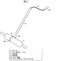
図1は、本実施形態に係る体内監視カメラシステム10の構成を示す模式図である。図2は、本実施形態に係る体内撮像装置1の構成を示す斜視図である。図1に示されるように、体内監視カメラシステム10は、体内撮像装置1と、制御システムと、機器側ケーブル16と、を備えている。図1及び図2に示されるように、体内撮像装置1は、カメラ11(撮像部)と、カメラ側ケーブル12と、カメラ11を把持する把持部14を有する支持棒13(支持部材)と、を備えている。機器側ケーブル16は、カメラ側ケーブル12および制御システムを接続する。また、制御システムは、カメラ制御機器17およびディスプレイ18(表示装置)を含み、機器側ケーブル16の一端はカメラ制御機器17に接続されている。
(Configuration of internal monitoring camera system)
FIG. 1 is a schematic view showing a configuration of an in-vivo monitoring camera system 10 according to the present embodiment. FIG. 2 is a perspective view showing the configuration of the in-vivo imaging device 1 according to the present embodiment. As shown in FIG. 1, the in-vivo monitoring camera system 10 includes an in-vivo imaging device 1, a control system, and a device-side cable 16. As shown in FIGS. 1 and 2, the in-vivo imaging device 1 includes a camera 11 (imaging unit), a camera-side cable 12, and a support rod 13 (support member) having a gripping unit 14 that grips the camera 11. Is equipped. The device side cable 16 connects the camera side cable 12 and the control system. The control system also includes a camera control device 17 and a display 18 (display device), and one end of the device-side cable 16 is connected to the camera control device 17.

なお、カメラ側ケーブル12は、カメラ11との接続端の反対側に、凸型のカメラ側ケーブルコネクタ15aを有する。また、機器側ケーブル16は、カメラ制御機器17との接続端の反対側に、凹型の機器側ケーブルコネクタ15bを有する。術者は、カメラ側ケーブルコネクタ15aと機器側ケーブルコネクタ15bとを嵌合することにより、カメラ側ケーブル12と機器側ケーブル16とを接続する。なお、凹型のカメラ側ケーブルコネクタと、凸型の機器側ケーブルコネクタとを嵌合させる構成であってもよい。また、図1では、カメラ側ケーブルコネクタ15aのピンを1本で図示しているが、通常は、ケーブルに使用する電線の本数に応じたピン数となる。   The camera-side cable 12 has a convex camera-side cable connector 15 a on the opposite side to the connection end with the camera 11. The device-side cable 16 also has a recessed device-side cable connector 15 b on the opposite side of the connection end with the camera control device 17. The operator connects the camera-side cable 12 and the device-side cable 16 by fitting the camera-side cable connector 15 a and the device-side cable connector 15 b. The concave camera-side cable connector may be fitted with the convex device-side cable connector. Further, although one pin of the camera-side cable connector 15a is shown in FIG. 1, the number of pins generally corresponds to the number of electric wires used for the cable.

カメラ側ケーブル12と機器側ケーブル16とが接続されることにより、カメラ11とカメラ制御機器17とが電気的に接続される。これにより、カメラ11にて撮像された映像がカメラ制御機器17へ送信される。カメラ制御機器17は、カメラ11から送信された映像をディスプレイ18に表示させる、あるいは制御信号をカメラ11へ送信する。なお、カメラ制御機器17とディスプレイ18とは、一体であってもよいし、別体であってもよい。   By connecting the camera-side cable 12 and the device-side cable 16, the camera 11 and the camera control device 17 are electrically connected. As a result, the video captured by the camera 11 is transmitted to the camera control device 17. The camera control device 17 causes the display 18 to display an image transmitted from the camera 11 or transmits a control signal to the camera 11. The camera control device 17 and the display 18 may be integrated or separated.

なお、カメラ側ケーブルコネクタ15aは、管状器具31を通って体内から体外へ引き出される。そのため、カメラ側ケーブルコネクタ15aの外径は、少なくとも、管状器具31の内径より小さくなる。換言すれば、カメラ側ケーブルコネクタ15aの外径を小さくすれば、管状器具31の内径を小さくすることができ、さらに支持棒13の径を小さくすることができる。これにより、体内監視カメラシステム10は、低侵襲性が向上するといった効果を奏する。   The camera-side cable connector 15a is pulled out of the body through the tubular instrument 31. Therefore, the outer diameter of the camera-side cable connector 15 a is smaller than at least the inner diameter of the tubular instrument 31. In other words, if the outer diameter of the camera-side cable connector 15a is reduced, the inner diameter of the tubular device 31 can be reduced, and the diameter of the support rod 13 can be further reduced. As a result, the intracorporeal monitoring camera system 10 has the effect of improving the low invasiveness.

また、カメラ側ケーブル12およびカメラ側ケーブルコネクタ15aは、カメラ11の回収時に一旦体内に戻すこととなる。そのため、機器側ケーブルコネクタ15b、および、機器側ケーブル16のうち、カメラ側ケーブル12と接触する所定長さの部分は清潔を維持する必要がある。   Further, the camera side cable 12 and the camera side cable connector 15 a will be temporarily put back into the body when the camera 11 is recovered. Therefore, it is necessary to maintain cleanliness of the device-side cable connector 15 b and the portion of the device-side cable 16 having a predetermined length in contact with the camera-side cable 12.

また、図1に示されるように、体内監視カメラシステム10は、カメラ11とカメラ制御機器17との間の信号の伝送に、有線方式を採用している。これにより、伝送速度が高速化でき、信号を安定して送受信することができる。また、無線方式に比べて低電力で通信でき、電源を外部から供給することによりカメラ11の小型化を図ることができる。従って、小型化により、カメラ11を体内に導入するときの傷を小さくすることができる。これにより、低侵襲性が向上するといった効果を奏する。   Further, as shown in FIG. 1, the intracorporeal monitoring camera system 10 employs a wired system for transmitting signals between the camera 11 and the camera control device 17. As a result, the transmission speed can be increased, and signals can be stably transmitted and received. Further, compared with the wireless system, communication can be performed with lower power, and the camera 11 can be miniaturized by externally supplying power. Therefore, the miniaturization can reduce the damage when introducing the camera 11 into the body. This produces the effect of improving the low invasiveness.

体内監視カメラシステム10では、カメラ11が保持された状態では、支持棒13の把持部14の体外側の面は、腹壁41に穿刺された管状器具31の体内側の端部と接触している。また、体内に導入されたカメラ11は、支持棒13の把持部14によって把持される。支持棒13の詳細については後述する。なお、本実施形態では、図示のように、体壁は腹壁41であるものとして説明するが、体壁は腹壁41に限定されない。   In the in-body monitoring camera system 10, when the camera 11 is held, the outer surface of the grip portion 14 of the support rod 13 is in contact with the inner end of the tubular device 31 punctured in the abdominal wall 41. . The camera 11 introduced into the body is held by the holding portion 14 of the support rod 13. Details of the support rod 13 will be described later. In the present embodiment, as illustrated, the body wall is described as the abdominal wall 41, but the body wall is not limited to the abdominal wall 41.

(体内撮像装置の支持棒及び把持部の構成)
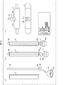
図3は、体内撮像装置1の支持棒13及び把持部14を示し、図3の(a)は、管状器具31、並びに支持棒13及び把持部14それぞれの構成を示す模式図であり、図3の(b)は、図3の(a)における側方から見た支持棒13及び把持部14の構成を示す側面図であり、図3の(c)は、体内撮像装置1の使用時における支持棒13及び管状器具31の位置関係を示す模式図である。
(Configuration of Support Bar and Grasping Part of Internal Imaging Device)
FIG. 3 shows the support rod 13 and the grip 14 of the in-vivo imaging device 1, and FIG. 3 (a) is a schematic view showing the configuration of the tubular device 31, and the support rod 13 and the grip 14. 3 (b) is a side view showing the configuration of the support rod 13 and the grip 14 as viewed from the side in FIG. 3 (a), and FIG. It is a schematic diagram which shows the positional relationship of the support rod 13 and the tubular instrument 31 in these.

図3の(a)〜(c)に示されるように、支持棒13は、管状器具31内に挿入可能な棒状体である。そして、支持棒13の体内側の端部には、把持部14が設けられている。把持部14は、カメラ11を把持する形状であり、2つの爪部14a及び14bを有する。爪部14a及び14bを含む把持部14全体の寸法は、管状器具31の外径よりも大きくなっている。   As shown in (a) to (c) of FIG. 3, the support rod 13 is a rod that can be inserted into the tubular device 31. A grip 14 is provided at an end of the support rod 13 inside the body. The gripping portion 14 is shaped to grip the camera 11, and has two claws 14a and 14b. The overall dimensions of the grip 14, including the claws 14 a and 14 b, are larger than the outer diameter of the tubular device 31.

また、体内撮像装置1では、少なくとも支持棒13と把持部14との連結部Xは、力を加えると変形可能な材料により構成されている。このため、図3の(c)に示されるように、体内撮像装置1を使用するに際し、支持棒13を管状器具31に挿入したとき、把持部14は、爪部14a及び14b同士の間隔が小さくなるように閉じた状態で、体内側へ移動する(管状器具挿入時)。そして、カメラ11を把持するため、管状器具31外部へ移動したとき、把持部14は、爪部14a及び14b同士の間隔が大きくなるように、開いた状態となる(カメラを掴む時)。   Further, in the in-vivo imaging device 1, at least the connecting portion X between the support rod 13 and the gripping portion 14 is made of a material that can be deformed when a force is applied. Therefore, as shown in FIG. 3C, when using the in-vivo imaging device 1, when the support rod 13 is inserted into the tubular instrument 31, the grip portion 14 has an interval between the claw portions 14a and 14b. Move to the inside of the body (when inserting a tubular device) in a closed state so as to be smaller. Then, when moving to the outside of the tubular instrument 31 in order to grasp the camera 11, the grasping portion 14 is in an open state (when grasping the camera) such that the distance between the claws 14a and 14b is large.

また、把持部14によりカメラ11を把持しカメラ11の位置を保持するとき、支持棒13を体外側へ引き上げることにより、把持部14の爪部14a及び14bは、管状器具31の体内側端部31aに当接する。そして、さらに、支持棒13を引き上げると、管状器具31の体内側端部31aとの当接により、把持部14の爪部14a及び14bに体内側の力がかかる。その結果、把持部14は、支持棒13の体外側への引き上げにより、爪部14a及び14bの間隔が小さくなるように変形し、カメラ11を把持する。これにより、把持部14による把持により、カメラ11の位置が保持される(カメラ固定時)。   Further, when the camera 11 is held by the holding unit 14 and the position of the camera 11 is held, the claws 14 a and 14 b of the holding unit 14 are the in-body end of the tubular instrument 31 by pulling the support rod 13 outside the body. Abuts on 31a. Then, when the support rod 13 is further pulled up, due to the contact with the in-body end 31 a of the tubular instrument 31, an inward force is applied to the claws 14 a and 14 b of the grip 14. As a result, when the support rod 13 is pulled up to the outside of the body, the grip portion 14 is deformed so as to reduce the distance between the claw portions 14 a and 14 b, thereby gripping the camera 11. Thus, the position of the camera 11 is held by the holding by the holding unit 14 (at the time of fixing the camera).

なお、支持棒13及び把持部14は、支持棒13と把持部14との連結部Xが変形可能な材料で構成されていればよく、同じ材料であっても、異なる材料であってもよい。例えば、少なくとも把持部14は、変形のしやすさから、ゴム等の弾性体で構成されている。   In addition, the support rod 13 and the holding part 14 should just be comprised with the material in which the connection part X of the support rod 13 and the holding part 14 can be deformed, and may be the same material or different materials. . For example, at least the grip portion 14 is made of an elastic body such as rubber because of ease of deformation.

(カメラ11の体内設置方法)
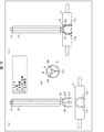
体内撮像装置1のカメラ11の体内設置方法について、説明する。図4は、本実施形態に係るカメラ11の体内設置方法を示す模式図である。
(How to install the camera 11 in the body)
A method of installing the camera 11 of the in-vivo imaging device 1 will be described. FIG. 4 is a schematic view showing a method of installing the camera 11 in the body according to the present embodiment.

図4の(a)に示すように、まず、術者は、鉗子や内視鏡を体腔内へ挿入するための孔(ポート)を腹壁41へ開け、ポートにトロッカー32a〜32cを挿入する。さらに、カメラ11を体腔内へ設置するために、腹壁41における、患者を含む腹腔内全体を見渡すことのできる位置にポートを開け、管状器具31を挿入する。具体的には、針形状のオブチュレータを管状器具31内に通した状態で、オブチュレータをポート位置に穿刺することで、管状器具31が腹壁41に挿入される。また、管状器具31は、低侵襲性を実現するために、直径が短いものが好ましい。具体的には、管状器具31は、直径が3mm以下であることが好ましい。なお、トロッカー32a〜32cのうちの少なくとも1つが挿入された後、術者は、トロッカー32a〜32cを通してガスを体内に送り、前もって体腔内を膨張させ、器具を挿入する空間を確保しておく。   As shown in (a) of FIG. 4, the operator first opens holes (ports) for inserting forceps and an endoscope into a body cavity in the abdominal wall 41, and inserts the trockers 32a to 32c into the ports. Further, in order to place the camera 11 in the body cavity, the port is opened in the abdominal wall 41 so as to overlook the entire abdominal cavity including the patient, and the tubular instrument 31 is inserted. Specifically, with the needle-shaped obturator being inserted into the tubular instrument 31, the tubular instrument 31 is inserted into the abdominal wall 41 by puncturing the obturator at the port position. Also, the tubular device 31 preferably has a short diameter in order to achieve low invasiveness. Specifically, the tubular device 31 preferably has a diameter of 3 mm or less. In addition, after at least one of the trockers 32a to 32c is inserted, the operator sends gas into the body through the trockers 32a to 32c, inflates the body cavity in advance, and secures a space for inserting an instrument.

次に、図4の(b)に示すように、術者は、トロッカー32cを通して内視鏡34を体腔内へ挿入する。そして、術者は、内視鏡34を用いて体内を観察しながら、鉗子33aで握持したカメラ11、カメラ側ケーブル12、およびカメラ側ケーブルコネクタ15aを、トロッカー32bを通して体腔内へ挿入する。   Next, as shown in (b) of FIG. 4, the operator inserts the endoscope 34 into the body cavity through the trocar 32 c. Then, while observing the inside of the body using the endoscope 34, the operator inserts the camera 11, the camera side cable 12 and the camera side cable connector 15a held by the forceps 33a into the body cavity through the trocker 32b.

次に、図4の(c)に示すように、術者は、鉗子33aを操作してカメラ11を管状器具31の近傍に移動させるとともに、管状器具31を通して鉗子33bを体腔内へ挿入する。   Next, as shown in FIG. 4C, the operator operates the forceps 33a to move the camera 11 to the vicinity of the tubular instrument 31, and inserts the forceps 33b into the body cavity through the tubular instrument 31.

次に、図4の(d)に示すように、術者は、鉗子33bにてカメラ側ケーブル12を挟んだ状態で、鉗子33bを管状器具31から引き抜くことで、カメラ側ケーブル12を体外へ導出する。このとき、カメラ11(の握持部)は鉗子33aによって握持された状態となっている。なお、カメラ11側から体腔内に挿入されている例を図示しているが、カメラ側ケーブルコネクタ15aから先に体腔内に挿入し、それを鉗子で掴んでからカメラ11を体内に挿入する手順でも構わない。   Next, as shown in (d) of FIG. 4, the operator pulls the forceps 33 b out of the tubular instrument 31 with the forceps 33 b sandwiching the camera side cable 12 so that the camera side cable 12 is taken out of the body To derive. At this time, (the grip of the camera 11) is held by the forceps 33a. Although an example in which the camera 11 is inserted into the body cavity from the camera 11 side is illustrated, the procedure of inserting the camera 11 into the body after inserting it into the body cavity from the camera side cable connector 15a first and grasping it with forceps I don't care.

次に、図4の(e)に示すように、術者は、体外に導出したカメラ側ケーブル12を、鉗子や手などで引き上げる。そして、トロッカー32aを通して鉗子33cを体腔内へ挿入し、体内のカメラ11の両端を鉗子33a及び33cにより握持して、カメラ11を予備的に保持する。本実施形態では、カメラ側ケーブル12を引き上げた後、支持棒13を用いて、カメラ11の位置を保持する。図5は、本実施形態における支持棒13を用いたカメラ11の保持方法を示す模式図であり、図4の(e)のステップ後の、カメラの体内設置方法を示す。図5の(a)は、図4の(e)のステップを示し、図5の(b)〜(d)は、図4の(e)のステップ後のステップを示し、図5の(e)は、図5の(d)のI−I断面図である。なお、図面を簡便化するため、図5の(b)〜(d)では、カメラ側ケーブル12を省略している。   
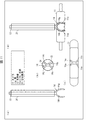
Next, as shown in (e) of FIG. 4, the operator pulls up the camera-side cable 12 drawn out of the body with a forceps or a hand. Then, the forceps 33c are inserted into the body cavity through the trocker 32a, and both ends of the camera 11 in the body are grasped by the forceps 33a and 33c, and the camera 11 is preliminarily held. In the present embodiment, after the camera side cable 12 is pulled up, the support rod 13 is used to hold the position of the camera 11. FIG. 5 is a schematic view showing the method of holding the camera 11 using the support rod 13 in the present embodiment, and shows the method of installing the camera in the body after the step of (e) of FIG. 4. (A) of FIG. 5 shows the step of (e) of FIG. 4, (b) to (d) of FIG. 5 show the step after the step of (e) of FIG. ) Is a cross-sectional view taken along the line I-I of (d) of FIG. In addition, in (b)-(d) of FIG. 5, the camera side cable 12 is abbreviate | omitted in order to simplify drawing.

カメラ側ケーブル12を鉗子や手などで引き上げた(図5の(a)に対応)後、図5の(b)に示されるように、術者は、鉗子や手等により、管状器具31を通して支持棒13を体腔内へ挿入する。ここで、上述のように、少なくとも支持棒13と把持部14との連結部Xが変形可能な材料で構成されているので、把持部14は、爪部14a及び14bの間隔が小さくなるように、閉じた状態で管状器具31に挿入される。   After pulling up the camera side cable 12 with a forceps or a hand (corresponding to (a) in FIG. 5), as shown in (b) of FIG. 5, the operator passes the tubular instrument 31 with a forceps or hand. The support rod 13 is inserted into the body cavity. Here, as described above, since at least the connection portion X between the support rod 13 and the grip portion 14 is made of a deformable material, the grip portion 14 is configured such that the distance between the claw portions 14a and 14b is reduced. , Is inserted into the tubular device 31 in the closed state.

そして、把持部14をさらに体内側へ移動させ、カメラ11近傍に配置する。このとき、図5の(c)に示されるように、把持部14は、爪部14a及び14bの大きくなった、開いた状態となり、カメラ11を把持可能となる。術者は、把持部14の爪部14a及び14bがカメラ11に接触するように、支持棒13を押し下げる。   Then, the grip portion 14 is further moved to the inside of the body, and disposed in the vicinity of the camera 11. At this time, as shown in (c) of FIG. 5, the gripping portion 14 is in the opened state where the claw portions 14 a and 14 b are large and can hold the camera 11. The operator depresses the support bar 13 so that the claws 14 a and 14 b of the grip 14 contact the camera 11.

次に、図5の(d)に示されるように、術者は、把持部14が開いた状態で、支持棒13を体外側へ引き上げる。このとき、把持部14は、管状器具31の体内側端部31aに当接する。そして、さらに、支持棒13を引き上げると、把持部14は、爪部14a及び14bの間隔が小さくなるように変形する。そして、最終的に、カメラ11は、把持部14の爪部14a及び14bにより把持され、管状器具31の体内側端部31a近傍の位置に保持される。   Next, as shown in (d) of FIG. 5, the operator pulls the support rod 13 outside the body with the grip portion 14 open. At this time, the grip 14 abuts on the in-body end 31 a of the tubular device 31. Then, when the support rod 13 is further pulled up, the grip portion 14 is deformed so that the distance between the claw portions 14 a and 14 b is reduced. Finally, the camera 11 is gripped by the claws 14 a and 14 b of the grip 14 and held at a position near the in-body end 31 a of the tubular instrument 31.

なお、本実施形態に係る体内撮像装置において、管状器具31は、体内に挿入可能な管状の構造であれば、特に限定されない。管状器具31としては、例えばトロッカーが挙げられる。また、多くのトロッカーは、管状器具31として用いることができる。しかし、トロッカーの体内側端部によっては、把持部14を変形させカメラ11を把持するために、管状器具31の体内側端部31aとの当接を用いることが不適切となる場合がある。このような場合、管状器具31の代わりに、体内側端部の形状が水平である外管を使用することも可能である。また、管状器具31と前記外管とを併せて使用して、把持部14を変形させカメラ11を把持することも可能である。   In the in-vivo imaging device according to the present embodiment, the tubular device 31 is not particularly limited as long as it is a tubular structure that can be inserted into the body. The tubular device 31 includes, for example, a trocker. Also, many trocars can be used as the tubular device 31. However, depending on the in-body end of the trocker, it may be inappropriate to use the abutment with the in-body end 31 a of the tubular instrument 31 in order to deform the grip 14 and grip the camera 11. In such a case, instead of the tubular device 31, it is also possible to use an outer tube in which the shape of the body inner end is horizontal. It is also possible to hold the camera 11 by deforming the holding portion 14 using the tubular instrument 31 and the outer tube in combination.

ここで、図5の(e)に示されるように、管状器具31内のカメラ側ケーブル12の占有空間を考慮して、支持棒13は、断面形状を半円状に設計変更しても良い。すなわち、支持棒13は、半円柱の棒形状となっている。   Here, as shown in (e) of FIG. 5, in consideration of the space occupied by the camera-side cable 12 in the tubular instrument 31, the support rod 13 may be redesigned in a semicircular shape in cross section. . That is, the support rod 13 has a semi-cylindrical rod shape.

カメラ11を体内に設置した後は、図6に示すように、カメラ側ケーブルコネクタ15aを機器側ケーブルコネクタ15bに嵌め込んでカメラ側ケーブル12と機器側ケーブル16とを接続する。これにより、処置部の局所映像は、内視鏡制御機器117によってディスプレイ118に表示され、カメラ11で撮影された臓器42を含む腹腔内の全体映像はカメラ制御機器17によってディスプレイ18に表示される。   After the camera 11 is placed in the body, as shown in FIG. 6, the camera cable connector 15a is fitted into the device cable connector 15b to connect the camera cable 12 and the device cable 16. Thereby, the local image of the treatment section is displayed on the display 118 by the endoscope control device 117, and the entire image in the abdominal cavity including the organ 42 photographed by the camera 11 is displayed on the display 18 by the camera control device 17. .

使用後については以下のとおりである。まず、術者は、体内のカメラ11の握持部を鉗子33aにて把持した状態で、支持棒13を押し下げ、支持棒13とカメラ11とを分離する。次いで、術者は、支持棒13を管状器具31から引き離し、その後、トロッカー32bから、カメラ11、およびカメラ側ケーブル12を体外に導出するとともに、管状器具31から支持棒13を体外に導出する。   The use is as follows. First, the operator depresses the support bar 13 while separating the support bar 13 and the camera 11 while holding the grip of the camera 11 in the body with the forceps 33a. Next, the operator pulls the support bar 13 away from the tubular instrument 31 and thereafter guides the camera 11 and the camera side cable 12 out of the trocar 32 b and the support bar 13 out of the tubular instrument 31.

(カメラの変形例)
図7は、カメラ11の変形例を示し、図7の(a)は側面図であり、図7の(b)は上面図である。図8は、図7に示すカメラ11が把持部14により把持された状態を示し、図8の(a)は、側面図であり、図8の(b)は上面図である。
(Modified example of camera)
FIG. 7 shows a modification of the camera 11. FIG. 7 (a) is a side view, and FIG. 7 (b) is a top view. FIG. 8 shows a state in which the camera 11 shown in FIG. 7 is held by the holding unit 14, (a) in FIG. 8 is a side view, and (b) in FIG. 8 is a top view.

図7の(a)及び(b)に示されるように、体内撮像装置1は、カメラ11に溝11aが形成された構成であってもよい。また、図8の(a)及び(b)に示されるように、溝11aは、カメラ11が把持部14により把持されたときに爪部14aおよび14bに対応する位置に設けられている。このため、カメラ11が把持部14に把持されたとき、爪部14a及び14bはそれぞれ、カメラ11の溝11a内に配置される。このため、カメラ11が把持部14から外れることを防止することができる。   As shown in (a) and (b) of FIG. 7, the in-vivo imaging device 1 may have a configuration in which a groove 11 a is formed in the camera 11. Further, as shown in (a) and (b) of FIG. 8, the groove 11 a is provided at a position corresponding to the claws 14 a and 14 b when the camera 11 is gripped by the grip 14. Therefore, when the camera 11 is held by the holding unit 14, the claws 14 a and 14 b are disposed in the groove 11 a of the camera 11 respectively. Therefore, it is possible to prevent the camera 11 from coming off the grip portion 14.

(把持部の変形例)
図3の例では、把持部14は、2つの爪部14a及び14bを有する構成であった。しかし、本実施形態における把持部14の爪部の数は、2つに限定されず、カメラ11を把持することが可能であれば限定されない。
(Modified example of grip part)
In the example of FIG. 3, the gripping portion 14 is configured to have two claw portions 14 a and 14 b. However, the number of claws of the grip 14 in the present embodiment is not limited to two, and is not limited as long as the camera 11 can be gripped.

図9は、把持部14が1つの爪部14cを有する場合の構成を示し、図9の(a)は、開いた状態の爪部14cの状態を示す側面図であり、図9の(b)は、カメラ11を把持したときの爪部14cの状態を示す側面図であり、図9の(c)は、図9の(b)の断面図である。図9の(a)〜(c)に示されるように、把持部14が1つの爪部14cを有する場合、爪部14cは、カメラ11の体外側の端部に掛かるように屈曲した形状である。爪部14cの寸法は、管状器具31の外径よりも大きくなっている。このため、爪部14cが体腔内で開いた状態で支持棒13を引き上げると、図9の(b)に示されるように、爪部14cは、管状器具31の体内側端部31aに当接する。そして、さらに支持棒13を引き上げると、爪部14cは、カメラ11を包み込むように変形し、最終的にカメラ11を把持する。   FIG. 9 shows a configuration in the case where the gripping portion 14 has one claw portion 14c, and FIG. 9A is a side view showing a state of the claw portion 14c in an open state, and FIG. 9 is a side view showing the state of the claw portion 14c when the camera 11 is gripped, and (c) of FIG. 9 is a cross-sectional view of (b) of FIG. As shown in (a) to (c) of FIG. 9, in the case where the grip portion 14 has one claw portion 14 c, the claw portion 14 c is bent in such a manner as to hang on the end of the camera 11 outside the body. is there. The dimension of the claw portion 14 c is larger than the outer diameter of the tubular device 31. Therefore, when the support rod 13 is pulled up with the claw portion 14c opened in the body cavity, the claw portion 14c abuts on the in-body end 31a of the tubular instrument 31, as shown in FIG. 9B. . Then, when the support rod 13 is further pulled up, the claws 14 c deform so as to wrap the camera 11, and finally hold the camera 11.

図10は、把持部14が3つの爪部14d〜14fを有する場合の構成を示し、図10の(a)は、開いた状態の爪部14d〜14fの状態を示す側面図であり、図10の(b)は、図10の(a)に示す把持部14の下側から見た下面図であり、図10の(c)は、カメラ11を把持したときの爪部14d〜14fの状態を示す側面図である。図10の(a)〜(c)に示されるように、把持部14は、3つの爪部14d〜14fを有していてもよい。この場合、爪部14d〜14fに対応するようにカメラ11に3つの溝11aが形成されていれば、カメラ11が把持部14から外れることを防止することができる。   FIG. 10 shows the configuration in the case where the grip 14 has three claws 14 d to 14 f, and FIG. 10 (a) is a side view showing a state of the claws 14 d to 14 f in an open state. 10 (b) is a bottom view seen from the lower side of the grip 14 shown in FIG. 10 (a), and FIG. 10 (c) is a view of the claws 14d to 14f when the camera 11 is gripped. It is a side view which shows a state. As shown in (a) to (c) of FIG. 10, the gripping portion 14 may have three claws 14d to 14f. In this case, if the three grooves 11a are formed in the camera 11 so as to correspond to the claws 14d to 14f, it is possible to prevent the camera 11 from being detached from the grip 14.

図11は、把持部14が4つの爪部14g〜14jを有する場合の構成を示し、図11の(a)は、開いた状態の爪部14g〜14jの状態を示す側面図であり、図11の(b)は、図11の(a)に示す把持部14の下側から見た下面図であり、図11の(c)は、把持部14が4つの爪部14g〜14jを有する場合のカメラ11の構成を示す上面図であり、図11の(d)は、カメラ11を把持したときの爪部14g〜14jの状態を示す側面図である。図11の(a)、(b)、及び(d)に示されるように、把持部14は、4つの爪部14g〜14jを有していてもよい。この場合、図11の(c)に示されるように、カメラ11には、爪部14g〜14jに対応するように4つの溝11aが形成されている。これにより、カメラ11が把持部14から外れることを防止することができる。   FIG. 11 shows the configuration in the case where the grip 14 has four claws 14g-14j, and FIG. 11 (a) is a side view showing the state of the claws 14g-14j in an open state, 11 (b) is a bottom view seen from the lower side of the grip 14 shown in FIG. 11 (a), and FIG. 11 (c) shows that the grip 14 has four claws 14g to 14j. FIG. 11D is a top view showing the configuration of the camera 11 in the case, and FIG. 11D is a side view showing the state of the claws 14g to 14j when the camera 11 is gripped. As shown in (a), (b), and (d) of FIG. 11, the gripping portion 14 may have four claws 14 g to 14 j. In this case, as shown in FIG. 11C, the camera 11 is formed with four grooves 11a corresponding to the claws 14g to 14j. Thereby, the camera 11 can be prevented from being detached from the grip portion 14.

また、把持部14は、爪部を有するものに限定されない。例えば、図12の(a)及び(b)に示されるように、把持部14は、環状部14kを有していてもよい。この場合、環状部14kの内径は、カメラ11の寸法よりも若干大きくなっている。すなわち、開いた状態では、カメラ11が環状部14k内に入ることができる構成となっている。実際のカメラ11の設置方法では、術者は、まず、図12の(c)に示されるように、支持棒13を管状器具31に挿入し把持部14を体内側へ移動させる。そして、図12の(d)に示されるように、把持部14をさらに体内側へ移動させ、環状部14kを開いた状態にする。このとき、術者は、カメラ11を、開いた状態の環状部14k内に入るように操作する。そして、図12の(e)に示されるように、支持棒13を引き上げたときに、環状部14kは、管状器具31の体内側端部31aに当接することにより、内径が小さくなるように変形し、閉じた状態となる。そして、このように支持棒13を引き上げて環状部14kを閉じることにより、環状部14k内でカメラ11を把持する。   Moreover, the holding part 14 is not limited to what has a nail | claw part. For example, as shown in (a) and (b) of FIG. 12, the gripping portion 14 may have an annular portion 14 k. In this case, the inner diameter of the annular portion 14 k is slightly larger than the size of the camera 11. That is, in the open state, the camera 11 can enter the annular portion 14k. In the actual method of installing the camera 11, the operator first inserts the support rod 13 into the tubular instrument 31 to move the grip 14 inside the body, as shown in FIG. 12 (c). Then, as shown in (d) of FIG. 12, the grip portion 14 is further moved to the inside of the body, and the annular portion 14k is in an open state. At this time, the operator operates the camera 11 so as to enter the annular portion 14k in the open state. Then, as shown in (e) of FIG. 12, when the support rod 13 is pulled up, the annular portion 14 k is deformed so as to decrease the inner diameter by coming into contact with the in-body end 31 a of the tubular device 31. Will be closed. Then, by pulling up the support rod 13 in this manner and closing the annular portion 14k, the camera 11 is gripped in the annular portion 14k.

また、図13の(a)〜(c)に示されるように、把持部14は、カメラ11に吸着する吸盤部14lを有していてもよい。この場合、吸盤部14lは、図13の(b)に示されるように、カメラ11の形状に適合した形状であってもよい。また、図13の(c)に示されるように、カメラ11に、吸盤部14lに適合した凹部11bが設けられていてもよい。なお、把持部14が吸盤部14lを有する場合、吸盤部14lそのものにカメラ11を保持する機能がある。このため、把持部14は、支持棒13を体外側へ引き上げたときに、管状器具31の体内側端部31aと当接することにより変形することはない。   In addition, as shown in (a) to (c) of FIG. 13, the gripping portion 14 may have a suction cup portion 14 l that is attracted to the camera 11. In this case, the suction cup portion 14 l may have a shape adapted to the shape of the camera 11 as shown in (b) of FIG. 13. Further, as shown in (c) of FIG. 13, the camera 11 may be provided with a concave portion 11 b adapted to the suction cup portion 14 l. In addition, when the holding part 14 has the suction cup part 14l, the suction cup part 14l itself has a function of holding the camera 11. For this reason, the grip portion 14 is not deformed by coming into contact with the in-body end 31 a of the tubular device 31 when the support rod 13 is pulled out of the body.

また、図14の(a)〜(c)に示されるように、カメラ11には、摘み部11cが設けられていてもよい。図14の(b)に示されるように、摘み部11cの上面は、カメラ11の上面と面一になっている。そして、摘み部11cの下側に空洞部11dが設けられている。図14の(b)における上面図に示されるように、空洞部11dの底面は、カメラ11の短手方向において、内部へ向かって傾斜した傾斜面となっている。   Further, as shown in (a) to (c) of FIG. 14, the camera 11 may be provided with a knob 11 c. As shown in (b) of FIG. 14, the upper surface of the knob 11 c is flush with the upper surface of the camera 11. And the hollow part 11d is provided under the knob part 11c. As shown in the top view in (b) of FIG. 14, the bottom surface of the hollow portion 11 d is an inclined surface that is inclined toward the inside in the short direction of the camera 11.

また、図14の(a)及び(c)に示されるように、把持部14は、摘み部11cを摘まむように構成されている。より具体的には、把持部14は、鉗子の先端形状に類似した鉗子部14mを有している。カメラ11の短手方向において、この鉗子部14mは、開いた状態で、カメラ11の寸法よりも小さく、摘み部11c及び管状器具31よりも大きい。このため、鉗子部14mが体腔内で開いた状態で支持棒13を引き上げると、図14の(c)の右図に示されるように、鉗子部14mは、管状器具31の体内側端部31aに当接する。そして、さらに支持棒13を引き上げると、鉗子部14mは、カメラ11の空洞部11dに入ることにより、摘み部11cを摘まむように変形し、最終的にカメラ11を把持する。図14の(a)〜(c)に示された構成では、把持部14は、カメラ11の寸法よりも小さい摘み部14mを摘まむ程度の寸法となる。このため、把持部14の小型化・細径化を実現できる。   Further, as shown in (a) and (c) of FIG. 14, the gripping portion 14 is configured to pick the knob portion 11 c. More specifically, the grip portion 14 has a forceps portion 14m similar to the tip shape of the forceps. In the transverse direction of the camera 11, the forceps portion 14m is smaller than the size of the camera 11 and larger than the knob 11c and the tubular instrument 31 in the open state. Therefore, when the support rod 13 is pulled up with the forceps portion 14m open in the body cavity, as shown in the right view of FIG. 14C, the forceps portion 14m is the inward end 31a of the tubular instrument 31. Abut on. Then, when the support rod 13 is further pulled up, the forceps portion 14m enters the hollow portion 11d of the camera 11 to be deformed so as to pick the knob portion 11c, and finally grips the camera 11. In the configuration shown in (a) to (c) of FIG. 14, the grip portion 14 has a size that is smaller than the size of the camera 11 and that the user grips the knob 14m. For this reason, size reduction and diameter reduction of the holding part 14 are realizable.

また、図15の(a)に示されるように、把持部14は、支持棒13との連結部Xに磁石15cまたは磁性体が設けられていてもよい。この場合、カメラ側ケーブルコネクタ15aの先端部に磁石あるいは磁性体が取り付けられており、磁石15cは、カメラ側ケーブルコネクタ15aに磁気吸着する。このように磁石15cが設けられていることにより、把持部14が設けられた支持棒13を、カメラ側ケーブル12を引き上げるための引き出し具として用いることができる。このような引き出し具は、例えば図4の(d)のステップで用いられる。   In addition, as illustrated in (a) of FIG. 15, the holding unit 14 may be provided with a magnet 15 c or a magnetic body at a connecting portion X with the support rod 13. In this case, a magnet or a magnetic body is attached to the tip of the camera cable connector 15a, and the magnet 15c is magnetically attracted to the camera cable connector 15a. By providing the magnet 15 c as described above, the support rod 13 provided with the grip portion 14 can be used as a drawer for pulling up the camera-side cable 12. Such a drawer is used, for example, in the step of (d) of FIG.

図15の(b)〜(e)は、図15の(a)に示す支持棒13を用いてカメラ側ケーブル12を引き上げる方法を示す模式図である。図15の(b)に示されるように、まず、支持棒13を管状器具31に挿入し、把持部14を開いた状態で、体腔内のカメラ側ケーブルコネクタ15a近傍に配置する。そして、図15の(c)に示されるように、把持部14に設けられた磁石15cをカメラ側ケーブルコネクタ15aに磁気吸着させる。そして、図15の(d)に示されるように、磁石15cにてカメラ側ケーブルコネクタ15aに磁気吸着させた状態で、支持棒13を管状器具31から引き抜くことで、カメラ側ケーブル12を体外へ導出する。このとき、支持棒13を引き上げることにより、把持部14は、管状器具31と当接することにより閉じた状態となる。このため、カメラ側ケーブル12またはカメラ側ケーブルコネクタ15aは、管状器具31内で把持部14により把持された状態で引き上げられる。   (B)-(e) of FIG. 15 is a schematic diagram which shows the method of pulling up the camera side cable 12 using the support rod 13 shown to (a) of FIG. As shown in (b) of FIG. 15, first, the support rod 13 is inserted into the tubular device 31 and disposed in the vicinity of the camera-side cable connector 15 a in a body cavity in a state where the grip portion 14 is opened. Then, as shown in (c) of FIG. 15, the magnet 15c provided in the grip portion 14 is magnetically attracted to the camera side cable connector 15a. Then, as shown in (d) of FIG. 15, the support rod 13 is pulled out from the tubular device 31 in a state where the magnet 15c magnetically attracts to the camera side cable connector 15a, the camera side cable 12 is taken out of the body To derive. At this time, by pulling up the support rod 13, the grip portion 14 comes into a closed state by coming into contact with the tubular instrument 31. For this reason, the camera side cable 12 or the camera side cable connector 15 a is pulled up in a state of being gripped by the grip portion 14 in the tubular instrument 31.

また、本実施形態によれば、図16の(a)〜(c)に示されるように、カメラ11の保持角度を調節することが可能である。例えば、図4の(e)のステップにて、鉗子33a及び33cを用いてカメラ11を所望の角度に傾けて予備的に保持する。そして、支持棒13を用いて予備的に保持されたカメラ11を保持する(図5の(b)〜(d)のステップ)ことにより、カメラ11の保持角度を調節することが可能である。   Further, according to the present embodiment, as shown in (a) to (c) of FIG. 16, it is possible to adjust the holding angle of the camera 11. For example, in the step of (e) of FIG. 4, the camera 11 is inclined at a desired angle and preliminarily held using the forceps 33a and 33c. Then, the holding angle of the camera 11 can be adjusted by holding the camera 11 held in advance using the support rod 13 (steps of (b) to (d) in FIG. 5).

ここで、カメラ11を把持した把持部14は、管状器具31の体内側端部31aに当接した状態が維持される。これにより、より安定してカメラ11の位置を保持することができる。図17の(a)及び(b)は、把持部14の体内側端部31aに対する当接状態を維持する機構の一例を示す模式図である。   Here, the gripping portion 14 gripping the camera 11 is maintained in a state of being in contact with the in-body end 31 a of the tubular instrument 31. Thereby, the position of the camera 11 can be held more stably. (A) and (b) of FIG. 17 is a schematic view showing an example of a mechanism for maintaining the contact state of the grip portion 14 with the in-body end 31a.

図17の(a)に示される構成では、体内撮像装置は、管状器具31に挿入されている支持棒13を体外側へ付勢するスプリング19aを備えている。支持棒13は、スプリング19a内に挿入されるように配置されている。また、支持棒13の体外側の端部には、スプリング19aの端部に当接しスプリング19aを係止する当接部13aが設けられている。スプリング19aにおける当接部13aと反対側の端部(体内側の端部)は、管状器具31における体外側端部31bに当接している。これにより、スプリング19aは、支持棒13の体外側端部である当接部13aを押圧する。このため、把持部14の爪部14a及び14bは、管状器具31の体内側端部31aに当接した状態が維持される。   In the configuration shown in FIG. 17A, the in-vivo imaging device includes a spring 19a that biases the support rod 13 inserted in the tubular device 31 to the outside of the body. The support rod 13 is arranged to be inserted into the spring 19a. In addition, an abutting portion 13a that abuts on an end portion of the spring 19a and locks the spring 19a is provided at an end of the support rod 13 outside the body. The end of the spring 19 a opposite to the contact portion 13 a (the end on the inside of the body) is in contact with the outside end 31 b of the tubular device 31. Thereby, the spring 19a presses the contact portion 13a which is the outboard end of the support rod 13. Therefore, the claws 14 a and 14 b of the grip 14 are maintained in contact with the in-body end 31 a of the tubular instrument 31.

また、図17の(b)に示された構成では、管状器具31にストッパ19bが設けられている。このストッパ19bは、管状器具31に挿入されている支持棒13が体外側または、体内側へ移動するのを係止する構造になっている。このため、ストッパ19bが支持棒13を係止することにより、把持部14の爪部14a及び14bは、管状器具31の体内側端部31aに当接した状態が維持される。   Moreover, in the structure shown by (b) of FIG. 17, the stopper 19b is provided in the tubular instrument 31. As shown in FIG. The stopper 19 b is structured to stop the support rod 13 inserted in the tubular device 31 from moving to the outside of the body or to the inside of the body. Therefore, when the stopper 19 b locks the support rod 13, the claws 14 a and 14 b of the grip 14 are maintained in contact with the in-body end 31 a of the tubular device 31.

〔実施形態2〕
本発明の他の実施形態について、図18〜図23に基づいて説明すれば、以下のとおりである。なお、説明の便宜上、上記実施形態にて説明した部材と同じ機能を有する部材については、同じ符号を付記し、その説明を省略する。
Second Embodiment
It will be as follows if other embodiment of this invention is described based on FIGS. 18-23. In addition, about the member which has the same function as the member demonstrated in the said embodiment for convenience of explanation, the same code | symbol is appended and the description is abbreviate | omitted.

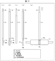
図18は、本実施形態に係る体内撮像装置の支持棒13A及び把持部14を示し、図18の(a)は、管状器具31、並びに支持棒13A及び把持部14それぞれの構成を示す模式図であり、図18の(b)は、図18の(a)における側方から見た支持棒13A及び把持部14の構成を示す側面図であり、図18の(c)は、体内撮像装置の使用時における支持棒13A及び管状器具31の位置関係を示す模式図である。   FIG. 18 shows the support rod 13A and the grip 14 of the in-vivo imaging device according to this embodiment, and FIG. 18 (a) is a schematic view showing the configuration of the tubular device 31, and the support rod 13A and the grip 14. 18 (b) is a side view showing the configuration of the support rod 13A and the grip 14 as viewed from the side in FIG. 18 (a), and FIG. 18 (c) is an internal imaging device 10A is a schematic view showing the positional relationship between the support rod 13A and the tubular device 31 when in use.

図18の(a)及び(b)に示されるように、本実施形態に係る体内撮像装置は、支持棒13Aが内部にカメラ側ケーブル12を備える点が、実施形態1と異なる。また、支持棒13Aと把持部14との連結部Xには、カメラ側ケーブル12に接続した支持棒側電極20a(支持部材側電極)が設けられている。   As shown in (a) and (b) of FIG. 18, the in-vivo imaging device according to the present embodiment differs from that of the first embodiment in that the support rod 13A includes the camera-side cable 12 therein. Further, at the connecting portion X between the support rod 13A and the grip portion 14, a support rod side electrode 20a (support member side electrode) connected to the camera side cable 12 is provided.

図18の(c)に示されるように、支持棒13Aを管状器具31に挿入したとき、把持部14は、爪部14a及び14b同士の間隔が小さくなるように閉じた状態で、体内側へ移動する(管状器具31挿入時)。このとき、支持棒側電極20aは、爪部14a及び14bにより、体腔から遮られている。   As shown in (c) of FIG. 18, when the support rod 13A is inserted into the tubular device 31, the grip portion 14 is closed to the inside of the body in a state in which the distance between the claws 14a and 14b is reduced. Move (at the time of insertion of the tubular device 31). At this time, the support rod side electrode 20a is shielded from the body cavity by the claws 14a and 14b.

そして、カメラ11を把持するため、管状器具31外部へ移動したとき、把持部14は、爪部14a及び14b同士の間隔が大きくなるように、開いた状態となる(カメラを掴む時)。このとき、支持棒側電極20aは、爪部14a及び14bが開いた状態となることにより、体腔内に露出する。   Then, when moving to the outside of the tubular instrument 31 in order to grasp the camera 11, the grasping portion 14 is in an open state (when grasping the camera) such that the distance between the claws 14a and 14b is large. At this time, the support rod side electrode 20a is exposed in the body cavity when the claws 14a and 14b are opened.

そして、支持棒13Aを体外側へ引き上げることにより、把持部14の爪部14a及び14bを管状器具31の体内側端部31aに当接させ、カメラ11を把持部14に把持させる(カメラ固定時)。このとき、支持棒側電極20aは、カメラ11と接触し、カメラ11と電気的に接続する。   Then, by pulling up the support rod 13A to the outside of the body, the claws 14a and 14b of the gripping unit 14 are brought into contact with the body inner end 31a of the tubular instrument 31, and the camera 11 is gripped by the gripping unit 14 ). At this time, the support rod side electrode 20 a is in contact with the camera 11 and electrically connected to the camera 11.

図19の(a)は、本実施形態に係る体内撮像装置のカメラ11の構成を示す側面図及び上面図であり、図19の(b)は、支持棒13Aを用いたカメラ11の保持方法を示す模式図であり、図19の(c)は、把持部14によりカメラ11を把持したときの構成を示す断面図である。図19の(a)に示されるように、カメラ11の上面には、把持部14に設けられた支持棒側電極20aと対応するように、カメラ側電極20b(撮像部側電極)が設けられている。   FIG. 19A is a side view and a top view showing the configuration of the camera 11 of the in-vivo imaging device according to the present embodiment, and FIG. 19B is a method of holding the camera 11 using the support rod 13A. FIG. 19C is a cross-sectional view showing a configuration when the camera 11 is gripped by the grip portion 14. As shown in (a) of FIG. 19, a camera side electrode 20 b (imaging unit side electrode) is provided on the upper surface of the camera 11 so as to correspond to the support rod side electrode 20 a provided in the grip unit 14. ing.

図19の(b)に示されるように、管状器具31を通して把持部14を体内側へ移動させ、把持部14の爪部14a及び14bが開いた状態となったとき、術者は、カメラ側電極20bが支持棒側電極20aと対向するように、カメラ11を移動させる。そして、支持棒13Aを体外側へ引き上げて、把持部14によりカメラ11を把持する。このとき、図19の(c)に示されるように、支持棒側電極20aとカメラ側電極20bとは接続する。その結果、本実施形態では、把持部14によりカメラ11を把持したとき、カメラ11とカメラ側ケーブル12とが電気接続する。   As shown in (b) of FIG. 19, when the grasping portion 14 is moved to the inside of the body through the tubular instrument 31 and the claws 14 a and 14 b of the grasping portion 14 are in an open state, the operator The camera 11 is moved so that the electrode 20 b faces the support rod side electrode 20 a. Then, the support rod 13A is pulled up to the outside of the body, and the camera 11 is held by the holding unit 14. At this time, as shown in (c) of FIG. 19, the support rod side electrode 20a and the camera side electrode 20b are connected. As a result, in the present embodiment, when the camera 11 is held by the holding unit 14, the camera 11 and the camera-side cable 12 are electrically connected.

図19に示した例では、支持棒側電極20aは、支持棒13Aと把持部14との連結部Xに設けられていた。しかし、支持棒側電極20aの位置、及び数は、図19の例に限定されない。支持棒側電極20aは、例えば、図20の(a)及び(b)に示されるように、少なくとも2つ設けられていてよい。   In the example shown in FIG. 19, the support rod side electrode 20 a is provided at the connecting portion X between the support rod 13 A and the grip portion 14. However, the position and the number of the support rod electrodes 20a are not limited to the example of FIG. For example, as shown in (a) and (b) of FIG. 20, at least two support rod electrodes 20a may be provided.

図20の(a)は、把持部14が1つの爪部14cを有する場合の例を示す。この場合、2つの支持棒側電極20aはそれぞれ、電源電極及びグランド電極であり、爪部14cにおける上下方向(体内側から体外側へ向かう方向)の端部に互いに離間するように配置されている。また、図20の(b)は、把持部14が2つの爪部14a及び14bを有する場合の例を示す。この場合、2つの支持棒側電極20aはそれぞれ、電源電極及びグランド電極であり、爪部14a及び14bに互いに離間するように配置されている。このように、2つの支持棒側電極20aとしての電源電極及びグランド電極が互いに離間するように配置されることにより、ショートが防止される。   (A) of FIG. 20 shows an example in the case where the grip portion 14 has one claw portion 14c. In this case, the two support rod side electrodes 20a are respectively a power supply electrode and a ground electrode, and are arranged to be separated from each other at the end of the claw portion 14c in the vertical direction (direction from inside to outside of the body) . Also, FIG. 20B shows an example in the case where the grip portion 14 has two claw portions 14a and 14b. In this case, the two support rod side electrodes 20a are respectively a power supply electrode and a ground electrode, and are disposed to be separated from each other in the claws 14a and 14b. As such, by arranging the power supply electrode and the ground electrode as the two support rod side electrodes 20a to be separated from each other, a short circuit is prevented.

また、図20の(c)及び(d)に示されるように、カメラ11に設けられるカメラ側電極20bは、カメラ11が把持部14により把持されたとき、支持棒側電極20aと接触する位置に配置されればよい。図20の(c)に示された例は、図20の(b)に示される支持棒側電極20aの配置に対応した、カメラ側電極20bの配置である。また、図20の(d)に示された例は、把持部が4つの爪部を有する場合に対応した、カメラ側電極20bの配置である。図20の(d)に示された構成の場合、支持棒側電極20aは、4つ設けられおり、4つの爪部に互いに離間するように配置されている。   Further, as shown in (c) and (d) of FIG. 20, when the camera 11 is gripped by the grip portion 14, the camera side electrode 20b provided in the camera 11 contacts the support rod side electrode 20a. It should be placed in The example shown in (c) of FIG. 20 is the arrangement of the camera-side electrodes 20 b corresponding to the arrangement of the support rod side electrodes 20 a shown in (b) of FIG. 20. The example shown in (d) of FIG. 20 is the arrangement of the camera-side electrode 20b corresponding to the case where the grip has four claws. In the case of the configuration shown in (d) of FIG. 20, four support rod electrodes 20a are provided, and are arranged to be spaced apart from one another in four claws.

また、図21の(a)〜(c)に示されるように、把持部14がカメラ11に吸着する吸盤部14lを有している場合、支持棒側電極20aは、吸盤部14l内に配置される。そして、図21の(b)に示されるように、吸盤部14lがカメラ11の形状に適合した形状である場合、カメラ側電極20bは、カメラ11が把持部14により把持されたとき、支持棒側電極20aに接触する位置に設けられる。また、図21の(c)に示されるように、カメラ11に吸盤部14lに適合した凹部11bが設けられている場合、カメラ側電極20bは、凹部11b内に設けられる。   In addition, as shown in (a) to (c) of FIG. 21, in the case where the grip portion 14 has a suction cup portion 14l to be adsorbed to the camera 11, the support rod side electrode 20a is disposed in the suction cup portion 14l. Be done. Then, as shown in (b) of FIG. 21, when the suction cup portion 14l has a shape conforming to the shape of the camera 11, the camera side electrode 20b is a support rod when the camera 11 is gripped by the grip portion 14. It is provided in the position which contacts the side electrode 20a. Further, as shown in (c) of FIG. 21, when the camera 11 is provided with the concave portion 11b adapted to the suction cup portion 14l, the camera side electrode 20b is provided in the concave portion 11b.

図22の(a)〜(c)は、支持棒側電極20aとカメラ側電極20bとの接続部分の防水機構を示す模式図である。図22の(a)に示された例では、カメラ11のカメラ側電極20bの表面に防水フィルム22(防水保護部材)が設けられている。支持棒側電極20aとカメラ側電極20bとが接続したとき、支持棒側電極20a側の端子21a(第1端子)がカメラ側電極20bの端子21b(第2端子)に挿入される。そして、これにより、防水フィルム22が破れる。その結果、支持棒側電極20aとカメラ側電極20bとの間の部分は、端子21aと端子21bとの接続部分を除き、防水フィルム22が介在する。それゆえ、支持棒側電極20aとカメラ側電極20bとの接続部分を防水することができる。なお、防水フィルム22は、端子21aと端子21bとの接続により破れるものであれば、特に限定されず、端子21a及び端子21bの構成に応じて適宜設定することができる。   (A)-(c) of FIG. 22 is a schematic diagram which shows the waterproof mechanism of the connection part of the support rod side electrode 20a and the camera side electrode 20b. In the example shown in (a) of FIG. 22, the waterproof film 22 (waterproof protective member) is provided on the surface of the camera side electrode 20 b of the camera 11. When the support rod side electrode 20a and the camera side electrode 20b are connected, the terminal 21a (first terminal) on the support rod side electrode 20a side is inserted into the terminal 21b (second terminal) of the camera side electrode 20b. And thereby, the waterproof film 22 is torn. As a result, the waterproof film 22 interposes the part between the support rod side electrode 20a and the camera side electrode 20b except the connection part of the terminal 21a and the terminal 21b. Therefore, the connection portion between the support rod side electrode 20a and the camera side electrode 20b can be waterproofed. The waterproof film 22 is not particularly limited as long as it is torn by the connection between the terminal 21a and the terminal 21b, and can be appropriately set according to the configuration of the terminal 21a and the terminal 21b.

また、図22の(b)に示された例では、カメラ11のカメラ側電極20bの表面に穴付き防水ゴム23(穴付き防水弾性部材)が設けられている。穴付き防水ゴム23の穴は、支持棒側電極20a側の端子21aに対応するように形成されている。支持棒側電極20aとカメラ側電極20bとが接続したとき、支持棒側電極20a側の端子21aは、穴付き防水ゴム23の穴を通って、カメラ側電極20bの端子21bに挿入される。このため、支持棒側電極20aとカメラ側電極20bとの間の部分は、端子21aと端子21bとの接続部分を除き、穴付き防水ゴム23が介在する。それゆえ、支持棒側電極20aとカメラ側電極20bとの接続部分を防水することができる。   Moreover, in the example shown by (b) of FIG. 22, the waterproof rubber 23 (a waterproof elastic member with a hole) with a hole is provided in the surface of the camera side electrode 20b of the camera 11. The holes of the waterproof rubber 23 with holes are formed to correspond to the terminals 21 a on the support rod side electrode 20 a side. When the support rod side electrode 20a and the camera side electrode 20b are connected, the terminal 21a on the support rod side electrode 20a side is inserted into the terminal 21b of the camera side electrode 20b through the hole of the waterproof rubber 23 with a hole. For this reason, except for the connection part of the terminal 21a and the terminal 21b, the waterproof rubber 23 with a hole intervenes between the support rod side electrode 20a and the camera side electrode 20b. Therefore, the connection portion between the support rod side electrode 20a and the camera side electrode 20b can be waterproofed.

また、図22の(c)に示された例では、カメラ側電極20bにスライド機構24が設けられている。このスライド機構24は、支持棒側電極20a側の端子21aがカメラ側電極20bの端子21bに挿入されたとき、端子21bに対する端子21aの相対的位置を保持する。スライド機構24は、端子21bを挟む位置に設けられた2つのスライダー24a(スライド部材)と、端子21bを挟む方向に2つのスライダー24aを付勢する2つのばね24b(付勢部材)とを備えている。   Further, in the example shown in (c) of FIG. 22, the slide mechanism 24 is provided on the camera side electrode 20 b. The slide mechanism 24 holds the relative position of the terminal 21a to the terminal 21b when the terminal 21a on the support rod side electrode 20a side is inserted into the terminal 21b of the camera side electrode 20b. The slide mechanism 24 includes two sliders 24a (slide members) provided at positions sandwiching the terminals 21b, and two springs 24b (biasing members) biasing the two sliders 24a in a direction sandwiching the terminals 21b. ing.

2つのスライダー24aは、2つのばね24bの付勢により、側方から端子21bと交差するように配置されている。また、2つのスライダー24aにおける互いに対向する2つの端面は、当該2つの端面間の間隔が端子21aの挿入方向へ向かうに従って小さくなるように傾斜した傾斜面となっている。支持棒側電極20a側の端子21aがカメラ側電極20bの端子21bに挿入されると、端子21aがスライダー24aの上記傾斜面に当接する。そして、この当接により、2つのスライダー24aは、互いの間隔が遠くなるように(ばね24bの付勢方向と反対側の方向に)移動する。これにより、端子21aがさら移動し、支持棒側電極20aとカメラ側電極20bとが密着し電気接続が確立する。このとき、ばね24bの付勢により、2つのスライダー24aは、端子21aを挟む方向に押圧する。この押圧により、端子21bに対する端子21aの相対的位置を保持される。その結果、支持棒側電極20aとカメラ側電極20bとの密着状態が維持され、支持棒側電極20aとカメラ側電極20bとの接続部分を防水することができる。   The two sliders 24a are arranged to intersect the terminal 21b from the side by the biasing of the two springs 24b. Further, the two end surfaces facing each other in the two sliders 24a are inclined surfaces which are inclined such that the distance between the two end surfaces becomes smaller toward the insertion direction of the terminal 21a. When the terminal 21a on the support rod side electrode 20a side is inserted into the terminal 21b of the camera side electrode 20b, the terminal 21a abuts on the inclined surface of the slider 24a. Then, due to the contact, the two sliders 24a move so as to be distant from each other (in the direction opposite to the biasing direction of the spring 24b). As a result, the terminal 21a further moves, and the support rod side electrode 20a and the camera side electrode 20b come in close contact with each other to establish an electrical connection. At this time, the two sliders 24a press the terminals 21a in a direction sandwiching the terminals 21a by the biasing of the spring 24b. By this pressing, the relative position of the terminal 21a to the terminal 21b is held. As a result, the close contact between the support rod side electrode 20a and the camera side electrode 20b is maintained, and the connection portion between the support rod side electrode 20a and the camera side electrode 20b can be waterproofed.

(変形例)
本実施形態に係る体内撮像装置の支持棒13Aの変形例について説明する。図23の(a)〜(d)は、変形例である支持棒13A及び把持部14の構成、並びにその操作方法を示す模式図である。
(Modification)
A modification of the support rod 13A of the in-vivo imaging device according to the present embodiment will be described. (A)-(d) of FIG. 23 is a schematic diagram which shows the structure of 13 A of support rods which are a modification, and the holding part 14, and its operation method.

また、図23の(a)〜(d)に示されるように、支持棒13Aは、筒状のアウター部材13bと、アウター部材13b内を挿通可能に配されたインナー部材13cとを備えている。インナー部材13cは、把持部14まで延びており、把持部14側の先端に支持棒側電極20aを備えている。支持棒側電極20aは、支持棒13Aと把持部14との連結部Xに配置されており、把持部14から突出して設けられている。また、アウター部材13bに対しインナー部材13cを引き上げることにより、支持棒側電極20aは、把持部14から突出することなく、アウター部材13b内に収容される。また、アウター部材13bに対しインナー部材13cを押し下げることにより、支持棒側電極20aは把持部14から突出する。   Further, as shown in (a) to (d) of FIG. 23, the support rod 13A is provided with a cylindrical outer member 13b and an inner member 13c disposed so as to be insertable in the outer member 13b. . The inner member 13c extends to the grip portion 14, and is provided with the support rod side electrode 20a at the tip end on the grip portion 14 side. The support rod side electrode 20 a is disposed at the connecting portion X between the support rod 13 A and the grip portion 14 and is provided so as to protrude from the grip portion 14. Further, by pulling up the inner member 13 c with respect to the outer member 13 b, the support rod side electrode 20 a is accommodated in the outer member 13 b without protruding from the grip portion 14. In addition, the support rod side electrode 20 a protrudes from the grip portion 14 by pressing the inner member 13 c downward with respect to the outer member 13 b.

支持棒13Aを図23の(a)に示す構成とすることにより、支持棒側電極20aは、アウター部材13bに対するインナー部材13cの上下動に連動して、把持部14から突出する、あるいは、アウター部材13b内に収容される。このため、把持部14によるカメラ11の把持のタイミングに依存せず、支持棒側電極20aとカメラ側電極20bとを電気接続するタイミングを自由に制御することが可能である。   By forming the support rod 13A as shown in FIG. 23 (a), the support rod side electrode 20a protrudes from the grip portion 14 in conjunction with the vertical movement of the inner member 13c with respect to the outer member 13b, or the outer It is accommodated in the member 13b. Therefore, it is possible to freely control the timing at which the support rod side electrode 20a and the camera side electrode 20b are electrically connected, regardless of the timing at which the camera 11 is gripped by the grip portion 14.

まず、図23の(b)に示されるように、カメラ11を把持部14により把持し位置を保持する前には、支持棒13Aのインナー部材13cを引き上げることにより、支持棒側電極20aをアウター部材13b内に収容する(カメラ保持前)。そして、図23の(c)に示されるように、カメラ11を把持部14により把持し位置を保持したとき、支持棒13Aのインナー部材13cを引き上げた状態を維持し、支持棒側電極20aをアウター部材13b内に収容したままとする(カメラ保持時)。そして、図23の(d)に示されるように、カメラ11を把持部14により把持し位置を保持した後、アウター部材13bに対しインナー部材13cを押し下げることにより、支持棒側電極20aを把持部14から突出させ、支持棒側電極20aとカメラ側電極20bとを電気接続する。   First, as shown in (b) of FIG. 23, before holding the camera 11 by the holding portion 14 and holding the position, the support rod side electrode 20 a is outered by pulling up the inner member 13 c of the support rod 13A. It is accommodated in the member 13b (before holding the camera). Then, as shown in (c) of FIG. 23, when the camera 11 is held by the holding portion 14 and the position is held, the state where the inner member 13c of the support rod 13A is pulled up is maintained, and the support rod side electrode 20a is held. It is assumed that it is housed in the outer member 13 b (at the time of holding the camera). Then, as shown in (d) of FIG. 23, after holding the camera 11 by the holding portion 14 and holding the position, the support rod side electrode 20a is held by pressing the inner member 13c against the outer member 13b. The support rod side electrode 20a and the camera side electrode 20b are electrically connected.

なお、変形例の支持棒13Aを用いた操作方法では、カメラ11を把持部14により把持し位置を保持したとき(図23の(c)のステップ)に、アウター部材13bに対しインナー部材13cを押し下げ、支持棒側電極20aとカメラ側電極20bとを電気接続することも可能である。このように、変形例の支持棒13Aを用いた操作方法では、把持部14によるカメラ11の把持のタイミングに依存せず、支持棒側電極20aとカメラ側電極20bとを電気接続するタイミングを自由に制御することができる。   In the operation method using the support rod 13A of the modification, the inner member 13c is held against the outer member 13b when the camera 11 is held by the holding portion 14 and the position is held (step of (c) in FIG. 23). It is also possible to press down and electrically connect the support rod side electrode 20a and the camera side electrode 20b. As described above, in the operation method using the support rod 13A of the modification, the timing at which the support rod side electrode 20a and the camera side electrode 20b are electrically connected is free regardless of the timing at which the camera 11 is gripped by the grip portion 14. Can be controlled.

〔実施形態3〕
本発明のさらに他の実施形態について、図24及び図25に基づいて説明すれば、以下のとおりである。なお、説明の便宜上、上記実施形態にて説明した部材と同じ機能を有する部材については、同じ符号を付記し、その説明を省略する。
Third Embodiment
Still another embodiment of the present invention is described below with reference to FIGS. 24 and 25. In addition, about the member which has the same function as the member demonstrated in the said embodiment for convenience of explanation, the same code | symbol is appended and the description is abbreviate | omitted.

図24の(a)〜(c)は、本実施形態に係る体内撮像装置に備えられた支持棒13Bおよび把持部14の構成、及びその操作方法を示す模式図である。図24の(a)〜(c)それぞれにおいて、部分Bの拡大断面図を示している。また、図面の簡略化から、図24の(a)〜(c)それぞれの部分Bの拡大断面図では、爪部14bの構成を省略している。爪部14bの構成は、部分Bの拡大断面図に示された爪部14aの構成と左右対称である。   (A)-(c) of Drawing 24 is a mimetic diagram showing the composition of support stick 13B and grasping part 14 with which the internal imaging device concerning this embodiment was equipped, and its operation method. In each of (a) to (c) of FIG. 24, an enlarged cross-sectional view of the portion B is shown. Moreover, the structure of the nail | claw part 14b is abbreviate | omitted in the expanded sectional view of each part B of (a)-(c) of FIG. 24 from the simplification of drawing. The configuration of the claw portion 14 b is symmetrical to the configuration of the claw portion 14 a shown in the enlarged cross-sectional view of the part B.

図24の(a)〜(c)に示されるように、本実施形態に係る体内撮像装置は、支持棒13Bが筒状のアウター部材13eと、アウター部材13e内を挿通可能に配されたインナー部材13fとを備え、インナー部材13fの上下動に連動して把持部14がカメラ11を把持する把持機構140を備えた点が前記実施形態1及び2と異なる。   As shown in (a) to (c) of FIG. 24, in the in-vivo imaging device according to the present embodiment, the support rod 13B is an inner member in which the cylindrical outer member 13e and the outer member 13e can be inserted. The third embodiment differs from the first and second embodiments in that it includes a member 13 f and a holding mechanism 140 for holding the camera 11 by the holding unit 14 in conjunction with the vertical movement of the inner member 13 f.

把持機構140は、爪本体部材141aと、爪本体部材141aとインナー部材13fとを連結するリンク部材142aと、回転軸141b、141c、142bと、備えている。爪本体部材141aの略中央部分には、回転軸141bが設けられている。回転軸141bは、アウター部材13eに固定されている。このため、爪本体部材141aは、回転軸141bにより、アウター部材13eに対して回転可能に支持されている。また、爪本体部材141aのリンク部材142a側の端部には、リンク部材142aと連結するための回転軸141cが設けられている。リンク部材142aは、回転軸141cにより、爪本体部材141aに対して回転可能に支持されている。また、リンク部材142aのインナー部材13f側の端部には、インナー部材13fと連結するための回転軸142bが設けられている。回転軸142bは、インナー部材13fに固定されている。このため、リンク部材142aは、回転軸142bにより、インナー部材13fに対して回転可能に支持されている。   The gripping mechanism 140 includes a claw body member 141a, a link member 142a connecting the claw body member 141a and the inner member 13f, and rotation shafts 141b, 141c, and 142b. A rotating shaft 141 b is provided at a substantially central portion of the nail main body member 141 a. The rotating shaft 141b is fixed to the outer member 13e. For this reason, the claw main body member 141a is rotatably supported relative to the outer member 13e by the rotation shaft 141b. Further, a rotary shaft 141c for connecting with the link member 142a is provided at an end of the claw main body member 141a on the side of the link member 142a. The link member 142a is rotatably supported relative to the claw main body member 141a by the rotation shaft 141c. Further, a rotary shaft 142b for connecting with the inner member 13f is provided at an end of the link member 142a on the inner member 13f side. The rotating shaft 142b is fixed to the inner member 13f. For this reason, the link member 142a is rotatably supported relative to the inner member 13f by the rotation shaft 142b.

図24の(a)に示されるように、アウター部材13eに対しインナー部材13fを押し下げたとき、回転軸141bと回転軸142bとの距離が小さくなる。これに伴い、回転軸141cにより、爪本体部材141aとリンク部材142aとの角度が小さくなるように作動する。その結果、爪本体部材141aは、回転軸141bを軸として、アウター部材13eの軸から離れる方向に回転する。また、図示していないが、爪部14bの爪本体部材も同様の機構により、アウター部材13eの軸から離れる方向に回転する。その結果、把持部14は、インナー部材13fの押し下げ操作により、開いた状態となり、爪部14a及び14bの距離が大きくなる。   As shown in (a) of FIG. 24, when the inner member 13f is pushed down with respect to the outer member 13e, the distance between the rotation shaft 141b and the rotation shaft 142b decreases. Along with this, the rotary shaft 141c operates so that the angle between the claw main body member 141a and the link member 142a becomes smaller. As a result, the claw main body member 141a rotates in a direction away from the axis of the outer member 13e about the rotation axis 141b. Although not shown, the claw main body member of the claw portion 14b is also rotated away from the axis of the outer member 13e by the same mechanism. As a result, the gripping portion 14 is opened by the depressing operation of the inner member 13 f, and the distance between the claws 14 a and 14 b is increased.

また、図24の(b)に示されるように、アウター部材13eに対しインナー部材13fを引き上げたとき、回転軸141bと回転軸142bとの距離が大きくなる。これに伴い、回転軸141cにより、爪本体部材141aとリンク部材142aとの角度が大きくなるように作動する。その結果、爪本体部材141aは、回転軸141bを軸として、アウター部材13eの軸に近づく方向に回転する。また、図示していないが、爪部14bの爪本体部材も同様の機構により、アウター部材13eの軸に近づく方向に回転する。その結果、把持部14は、インナー部材13fの引き上げ操作により、閉じた状態となり、爪部14a及び14bの距離が小さくなる。これにより、把持部14は、カメラ11を把持可能となる。   Further, as shown in (b) of FIG. 24, when the inner member 13f is pulled up with respect to the outer member 13e, the distance between the rotation shaft 141b and the rotation shaft 142b becomes large. Along with this, the rotary shaft 141c operates to increase the angle between the claw main body member 141a and the link member 142a. As a result, the claw main body member 141a rotates in a direction approaching the axis of the outer member 13e, with the rotary shaft 141b as an axis. Although not shown, the claw main body member of the claw portion 14b is also rotated in the direction approaching the axis of the outer member 13e by the same mechanism. As a result, the gripping portion 14 is closed by the pulling operation of the inner member 13 f, and the distance between the claws 14 a and 14 b is reduced. Thus, the gripping unit 14 can grip the camera 11.

また、図24の(c)に示されるように、カメラ11を把持することなく、アウター部材13eに対しインナー部材13fを引き上げたとき、回転軸141b、回転軸141c、及び回転軸142bが同一直線に並ぶ。このため、その結果、爪本体部材141aは、回転軸141bを軸として、アウター部材13eの軸に近づく方向にさらに回転する。それゆえ、把持部14は、爪部14aと爪部14bとが交差した状態となる。   Further, as shown in FIG. 24C, when the inner member 13f is pulled up with respect to the outer member 13e without gripping the camera 11, the rotation shaft 141b, the rotation shaft 141c, and the rotation shaft 142b are in the same straight line Line up. For this reason, as a result, the claw main body member 141a further rotates in the direction approaching the axis of the outer member 13e, with the rotation axis 141b as the axis. Therefore, the gripping portion 14 is in a state where the claws 14a and the claws 14b intersect.

このように本実施形態に係る体内撮像装置は、インナー部材13fの上下動に連動して把持部14がカメラ11を把持する把持機構140を備えている。それゆえ、把持部14によりカメラ11を把持するタイミングの設定自由度が高くなる。   As described above, the in-vivo imaging device according to the present embodiment includes the gripping mechanism 140 in which the gripping unit 14 grips the camera 11 in conjunction with the vertical movement of the inner member 13 f. Therefore, the setting freedom of the timing of holding the camera 11 by the holding unit 14 is increased.

また、図25に示されるように、把持部14は、支持棒13Bとの連結部Xに磁石15cまたは磁性体が設けられていてもよい。この場合、カメラ側ケーブルコネクタ15aの先端部に磁石あるいは磁性体が取り付けられており、磁石15cは、カメラ側ケーブルコネクタ15aに磁気吸着する。このように磁石15cが設けられていることにより、把持部14が設けられた支持棒13Bを、カメラ側ケーブル12を引き上げるための引き出し具として用いることができる。   Further, as shown in FIG. 25, in the grip portion 14, a magnet 15 c or a magnetic body may be provided at the connecting portion X with the support rod 13 </ b> B. In this case, a magnet or a magnetic body is attached to the tip of the camera cable connector 15a, and the magnet 15c is magnetically attracted to the camera cable connector 15a. By providing the magnet 15 c in this manner, the support rod 13 B provided with the grip portion 14 can be used as a drawer for pulling up the camera-side cable 12.

図25の左図に示されるように、把持部14を開いた状態で、支持棒13Bを体腔内のカメラ側ケーブルコネクタ15a近傍に配置する。そして、図25の右図に示されるように、インナー部材13fの引き上げ操作を行う。この操作に連動して、把持部14は閉じた状態となり、カメラ側ケーブル12またはカメラ側ケーブルコネクタ15aは、把持部14により把持されると共に、磁石15cに磁気吸着する。その状態で、支持棒13Bを体外へ引き抜くことで、カメラ側ケーブル12を体外へ導出する。   As shown in the left view of FIG. 25, the support rod 13B is disposed in the vicinity of the camera-side cable connector 15a in the body cavity in a state where the grip portion 14 is opened. Then, as shown in the right view of FIG. 25, the inner member 13 f is pulled up. In conjunction with this operation, the gripping portion 14 is closed, and the camera side cable 12 or the camera side cable connector 15 a is gripped by the gripping portion 14 and magnetically attracted to the magnet 15 c. In that state, the camera side cable 12 is drawn out of the body by pulling out the support rod 13B from the body.

このように図25に示された構成では、インナー部材13fの操作に連動して、カメラ側ケーブル12またはカメラ側ケーブルコネクタ15aを把持することができる。それゆえ、把持部14によりカメラ側ケーブル12を把持し体外へ導出するタイミングの設定自由度が高くなる。   Thus, in the configuration shown in FIG. 25, it is possible to grip the camera side cable 12 or the camera side cable connector 15a in conjunction with the operation of the inner member 13f. Therefore, the setting freedom of the timing at which the camera side cable 12 is gripped by the grip portion 14 and taken out from the body is increased.

〔まとめ〕
本発明の態様1に係る体内撮像装置は、体腔内を撮像する撮像部(カメラ11)と、体内に導入される管状器具31に挿入される支持部材(支持棒13)と、前記支持部材における体内側の端部に設けられた前記撮像部を把持するための把持部14と、を備え、前記把持部14は、前記支持部材を体外側へ引き上げたときに、前記管状器具31の体内側の端部(体内側端部31a)と当接することにより、前記撮像部を把持するように変形する構成である。
[Summary]
An in-vivo imaging device according to aspect 1 of the present invention includes an imaging unit (camera 11) for imaging a body cavity, a support member (support bar 13) inserted into a tubular device 31 introduced into the body, and the support member. And a grip portion 14 for gripping the imaging portion provided at an end portion inside the body, the grip portion 14 being an inside of the tubular device 31 when the support member is pulled up outside the body. The image pickup unit is deformed so as to be gripped by abutting on the end portion (body inner end portion 31a).

上記の構成によれば、前記把持部は、前記支持部材を体外側へ引き上げたときに、前記管状器具の体内側の端部と当接することにより、前記撮像部を把持するように変形する。それゆえ、術者は、体内での撮像部を設置作業に際し、環状器具を通して支持棒を押し下げることで把持部を前記撮像部近傍に配置した後、支持棒を引き上げることにより把持部を前記管状器具の前記体内側端部に当接させて、前記撮像部の位置を保持することができる。このように、支持棒を引き上げることにより把持部を前記管状器具の前記体内側端部に当接させる操作のみで撮像部の位置を保持できるので、撮像部の設置作業を簡略化することができる。また、設置後も撮像部の微調整が可能である。   According to the above configuration, the grip portion is deformed to grip the imaging portion by coming into contact with the end portion inside the body of the tubular instrument when the support member is pulled up outside the body. Therefore, the operator arranges the grasping portion in the vicinity of the imaging unit by pushing down the support bar through the annular instrument when installing the imaging unit in the body, and then pulls up the support bar to thereby form the tubular device The position of the imaging unit can be held by abutting on the in-body end of the body. As described above, since the position of the imaging unit can be held only by the operation of bringing the gripping unit into contact with the body inner end of the tubular instrument by pulling up the support rod, the installation operation of the imaging unit can be simplified. . In addition, fine adjustment of the imaging unit is possible even after installation.

したがって、上記の構成によれば、体内でのカメラの設置作業を簡略化することができ、かつ設置後もカメラの微調整が可能な体内撮像装置を実現できる。   Therefore, according to the above configuration, the installation operation of the camera in the body can be simplified, and the in-vivo imaging device capable of finely adjusting the camera even after the installation can be realized.

また、本発明の態様2に係る体内撮像装置は、上記態様1において、前記把持部14は、前記管状器具31の体内側端部31aと当接する、少なくとも1つの爪部14aを有する構成であってもよい。   In the in-vivo imaging device according to aspect 2 of the present invention, in the above aspect 1, the grip portion 14 has at least one claw portion 14 a that abuts on the in-body end 31 a of the tubular device 31. May be

また、本発明の態様3に係る体内撮像装置は、上記態様1において、前記把持部14は、前記撮像部(カメラ11)を包囲し、かつ、前記管状器具31の体内側端部31aと当接する、環状部14kを有する構成であってもよい。   In the in-vivo imaging device according to aspect 3 of the present invention, in the above-mentioned aspect 1, the grip portion 14 surrounds the imaging portion (camera 11) and is in contact with the in-body end 31a of the tubular device 31. It may be configured to have an annular portion 14k in contact.

また、本発明の態様4に係る体内撮像装置は、上記態様1において、前記撮像部(カメラ11)には、当該撮像部よりも寸法が小さい摘み部11cが設けられ、前記把持部14は、前記摘み部11cを摘まむように構成されている。   Further, in the in-vivo imaging device according to aspect 4 of the present invention, in the above aspect 1, the imaging section (camera 11) is provided with a knob 11c smaller in size than the imaging section, and the grip 14 is It is comprised so that the said knob part 11c may be pinched.

上記の構成によれば、前記把持部14は、撮像部よりも寸法が小さい前記摘み部11cを摘まむように構成されているので、把持部14を小型化できる。   According to the above configuration, since the grip portion 14 is configured to pick the knob portion 11c smaller in size than the imaging portion, the grip portion 14 can be miniaturized.

また、本発明の態様5に係る体内撮像装置は、上記態様1〜4において、前記撮像部(カメラ11)に接続されるケーブル(カメラ側ケーブル12)を備え、前記ケーブルは、前記支持部材(支持棒13)内部に設けられており、前記把持部14には、前記撮像部と前記ケーブルとを電気接続するための支持部材側電極(支持棒側電極20a)が設けられている構成であることが好ましい。   In the in-vivo imaging device according to aspect 5 of the present invention, in the above-mentioned aspects 1 to 4, the cable (camera side cable 12) connected to the imaging unit (camera 11) is provided, and the cable is the support member ( The support rod 13) is provided inside, and the holding portion 14 is configured to be provided with a support member side electrode (support bar side electrode 20a) for electrically connecting the imaging unit and the cable. Is preferred.

上記の構成によれば、前記把持部14には、前記撮像部と前記ケーブルとを電気接続するための支持部材側電極が設けられている。それゆれ、体内に配置された撮像部の位置を保持するに際し、把持部により撮像部を把持するとともに、前記ケーブルと前記撮像部との電気接続も可能となる。このため、体内でのカメラの設置作業を簡略化することができる。   According to the above configuration, the holding unit 14 is provided with a support member side electrode for electrically connecting the imaging unit and the cable. When holding the position of the imaging unit disposed in the body, the holding unit grips the imaging unit, and electrical connection between the cable and the imaging unit becomes possible. Therefore, the installation work of the camera in the body can be simplified.

また、本発明の態様6に係る体内撮像装置は、上記態様5において、支持部材側電極(支持棒側電極20a)は、前記支持部材(支持棒13)と前記把持部14との連結部Xに設けられている構成であってもよい。   In the in-vivo imaging device according to aspect 6 of the present invention, the supporting member side electrode (supporting rod side electrode 20a) according to aspect 5 is a connecting portion X between the supporting member (supporting bar 13) and the grip portion 14. The configuration may be provided in

また、本発明の態様7に係る体内撮像装置は、上記態様5において、前記支持部材側電極(支持棒側電極20a)は、少なくとも2つ前記把持部14に設けられており、互いに離間するように配置されている構成であってもよい。   Further, in the in-vivo imaging device according to aspect 7 of the present invention, in the above aspect 5, at least two of the support member side electrodes (support rod side electrodes 20 a) are provided in the grip portion 14 and are separated from each other. It may be arranged in the

これにより、電極間のショートを防止することができる。   Thereby, a short circuit between the electrodes can be prevented.

また、本発明の態様8に係る体内撮像装置は、上記態様5〜7において、前記撮像部(カメラ11)には、前記支持部材側電極(支持棒側電極20a)と接続する撮像部側電極(カメラ側電極20b)が設けられており、前記撮像部側電極は、前記撮像部が前記把持部14により把持されたとき、前記支持部材側電極と接触する位置に配置されている構成であることが好ましい。   In the in-vivo imaging device according to aspect 8 of the present invention, in the above-mentioned aspects 5 to 7, the imaging unit (camera 11) includes the imaging unit side electrode connected to the support member side electrode (supporting rod side electrode 20a) (Camera-side electrode 20b) is provided, and the imaging unit-side electrode is disposed at a position where it contacts the support member-side electrode when the imaging unit is gripped by the grip unit 14. Is preferred.

これにより、より簡単な構成で、前記ケーブルと前記撮像部とを電気接続できる。   Thereby, the cable and the imaging unit can be electrically connected with a simpler configuration.

また、本発明の態様9に係る体内撮像装置は、上記態様8において、前記支持部材側電極(支持棒側電極20a)と前記撮像部側電極(カメラ側電極20b)との間に防水保護部材(防水フィルム22)が設けられており、前記支持部材側電極及び前記撮像部側電極の一方の端子21aは、防水保護部材を貫通する構成であってもよい。   In the in-vivo imaging device according to aspect 9 of the present invention, in the above-mentioned aspect 8, a waterproof protection member is provided between the supporting member side electrode (supporting rod side electrode 20a) and the imaging unit side electrode (camera side electrode 20b). (Waterproof film 22) may be provided, and one terminal 21a of the support member side electrode and the imaging unit side electrode may be configured to penetrate a waterproof protection member.

これにより、前記支持部材側電極と前記撮像部側電極との接続部分を防水することができる。   Thereby, the connection part of the said supporting member side electrode and the said imaging part side electrode can be waterproofed.

また、本発明の態様10に係る体内撮像装置は、上記態様8において、前記支持部材側電極(支持棒側電極20a)と前記撮像部側電極(カメラ側電極20b)との間に穴付き防水弾性部材(穴付き防水ゴム23)が設けられており、前記支持部材側電極及び前記撮像部側電極の一方の端子21aは、前記防水弾性部材の穴を通過する構成であってもよい。   In the in-vivo imaging device according to aspect 10 of the present invention, in the above-mentioned aspect 8, a waterproofing hole is provided between the support member side electrode (supporting rod side electrode 20a) and the imaging unit side electrode (camera side electrode 20b) An elastic member (a waterproof rubber 23 with a hole) may be provided, and one of the terminals 21a of the support member side electrode and the imaging unit side electrode may pass through the hole of the waterproof elastic member.

また、本発明の態様11に係る体内撮像装置は、上記態様8において、前記支持部材側電極(支持棒側電極20a)側の第1端子(端子21a)が前記撮像部側電極(カメラ側電極20b)の第2端子(端子21b)に挿入されたとき、前記第2端子に対する第1端子の相対的位置を保持するスライド機構24を備え、前記スライド機構24は、前記第2端子に挿入された前記第1端子を挟む位置に設けられた少なくとも2つのスライド部材(スライダー24a)と、前記第1端子を挟む方向に前記スライド部材を付勢する付勢部材(ばね24b)とを備えている構成であってもよい。   In the in-vivo imaging device according to aspect 11 of the present invention, in the aspect 8, the first terminal (terminal 21a) on the support member side electrode (supporting rod side electrode 20a) side is the imaging unit side electrode (camera side electrode 20b), the slide mechanism 24 holds the relative position of the first terminal to the second terminal, and the slide mechanism 24 is inserted into the second terminal. And at least two slide members (slider 24a) provided at positions sandwiching the first terminal, and a biasing member (spring 24b) biasing the slide member in a direction sandwiching the first terminal. It may be a configuration.

上記の構成によれば、スライド機構24は、前記支持部材側電極側の第1端子が前記撮像部側電極の第2端子に挿入されたとき、前記第2端子に対する第1端子の相対的位置を保持するので、前記支持部材側電極と前記撮像部側電極との密着状態が維持される。そのため、前記支持部材側電極と前記撮像部側電極との接続部分を防水することができる。   According to the above configuration, when the first terminal on the support member side electrode is inserted into the second terminal of the imaging unit side electrode, the slide mechanism 24 indicates the relative position of the first terminal to the second terminal. Thus, the close contact between the support member side electrode and the imaging unit side electrode is maintained. Therefore, the connection portion between the support member side electrode and the imaging unit side electrode can be waterproofed.

また、本発明の態様12に係る体内撮像装置は、上記態様5〜11において、前記支持部材は、筒状のアウター部材13bと、前記アウター部材13b内を挿通可能に配されたインナー部材13cとを備え、前記インナー部材13cは、前記把持部14まで延びており、把持部14側の先端に前記支持部材側電極(支持棒側電極20a)を備え、前記支持部材側電極は、前記アウター部材13bに対する前記インナー部材13cの上下動に連動して、前記把持部14から突出する、あるいは、前記アウター部材13b内に収容される構成であることが好ましい。   In the in-vivo imaging device according to aspect 12 of the present invention, in the above aspects 5 to 11, the support member includes a cylindrical outer member 13 b, and an inner member 13 c disposed so as to be insertable in the outer member 13 b. The inner member 13c extends to the grip portion 14, and includes the support member side electrode (support rod side electrode 20a) at the tip end on the grip portion 14 side, and the support member side electrode is the outer member It is preferable to be a structure which protrudes from the said holding part 14 in response to the up-down movement of the said inner member 13c with respect to 13b, or is accommodated in the said outer member 13b.

上記の構成によれば、前記支持棒側電極は、前記アウター部材13bに対する前記インナー部材13cの上下動に連動して、前記把持部14から突出する、あるいは、前記アウター部材13b内に収容される。このため、把持部14による撮像部の把持のタイミングに依存せず、前記支持部材側電極と前記撮像部側電極と電気接続するタイミングを自由に制御することができる。   According to the above configuration, the support rod side electrode protrudes from the grip portion 14 in cooperation with the vertical movement of the inner member 13c with respect to the outer member 13b, or is accommodated in the outer member 13b. . Therefore, it is possible to freely control the timing at which the support member side electrode and the imaging unit side electrode are electrically connected, without depending on the timing at which the imaging unit is held by the holding unit 14.

また、本発明の態様13に係る体内撮像装置は、上記態様1〜12において、前記撮像部(カメラ11)には、前記把持部14の形状に適合した溝部(溝11a)が形成されている構成であることが好ましい。   Further, in the in-vivo imaging device according to aspect 13 of the present invention, in the above-mentioned aspects 1 to 12, in the imaging section (camera 11), a groove (groove 11a) adapted to the shape of the grip 14 is formed. It is preferable that it is a structure.

これにより、把持部14によって、前記撮像部をより安定して把持することができる。   Thereby, the imaging unit can be gripped more stably by the gripping unit 14.

また、本発明の態様14に係る体内撮像装置は、体腔内を撮像する撮像部(カメラ11)と、体内に導入される管状器具31に挿入される支持部材(支持棒13)と、前記支持部材における体内側の端部に設けられた前記撮像部を把持するための把持部14と、を備え、前記把持部14は、前記撮像部に吸着する吸盤部14lを有する構成である。   In the in-vivo imaging device according to aspect 14 of the present invention, an imaging unit (camera 11) for imaging a body cavity, a support member (support bar 13) inserted into a tubular device 31 introduced into the body, and the support And a grip portion 14 for gripping the imaging unit provided at an end portion inside the body of the member, the grip portion 14 having a suction cup portion 14l adsorbed to the imaging unit.

上記の構成によれば、前記把持部は、前記撮像部に吸着する吸盤部14lを有する。それゆえ、術者は、体内での撮像部を設置作業に際し、管状器具を通して支持棒を押し下げることで把持部を前記撮像部近傍に配置した後、撮像部を吸盤部14lに吸着させて、前記撮像部の位置を保持することができる。このように、撮像部を吸盤部14lに吸着させる操作のみで撮像部の位置を保持できるので、撮像部の設置作業を簡略化することができる。また、設置後も撮像部の微調整が可能である。   According to said structure, the said holding part has the suction cup part 141 to adsorb | suck to the said imaging part. Therefore, the operator places the grip in the vicinity of the imaging unit by depressing the support rod through the tubular instrument when installing the imaging unit in the body, and then causes the suction unit 14l to adsorb the imaging unit. The position of the imaging unit can be held. As described above, since the position of the imaging unit can be held only by the operation of adsorbing the imaging unit to the suction unit 141, the installation operation of the imaging unit can be simplified. In addition, fine adjustment of the imaging unit is possible even after installation.

したがって、上記の構成によれば、体内でのカメラの設置作業を簡略化することができ、かつ設置後もカメラの微調整が可能な体内撮像装置を実現できる。   Therefore, according to the above configuration, the installation operation of the camera in the body can be simplified, and the in-vivo imaging device capable of finely adjusting the camera even after the installation can be realized.

本発明の態様15に係る体内撮像装置は、上記態様14において、前記撮像部(カメラ11)には、前記吸盤部14lの形状に適合した凹部11bが形成されている構成であることが好ましい。   In the in-vivo imaging device according to aspect 15 of the present invention, in the above-mentioned aspect 14, it is preferable that the imaging section (camera 11) has a configuration in which a recess 11b adapted to the shape of the suction cup portion 14l is formed.

これにより、吸盤部14lによって、前記撮像部をより安定して把持することができる。   Thereby, the imaging unit can be held more stably by the suction cup portion 14l.

本発明の態様16に係る体内撮像装置は、体腔内を撮像する撮像部(カメラ11)と、体内に導入される管状器具31に挿入される支持部材(支持棒13)と、前記支持部材における体内側の端部(体内側端部31a)に設けられた前記撮像部を把持するための把持部14と、を備え、前記支持部材は、筒状のアウター部材13eと、前記アウター部材13e内を挿通可能に配されたインナー部材13fと、前記インナー部材13fの上下動に連動して前記把持部14が前記撮像部を把持する把持機構140を備え、前記把持機構140は、前記アウター部材13eに対して回転可能に支持された爪本体部材141aと、前記爪本体部材141aと前記インナー部材13fとを連結し、前記爪本体部材141aに対して回転可能に支持されたリンク部材142aと、を備え、前記リンク部材142aは、前記インナー部材13fに対して回転可能に支持されている構成である。   An in-vivo imaging device according to aspect 16 of the present invention includes an imaging unit (camera 11) for imaging a body cavity, a support member (support bar 13) inserted into a tubular device 31 introduced into the body, and the support member. And a grip portion 14 for gripping the imaging unit provided at an end inside the body (body inside end 31a), the support member includes a cylindrical outer member 13e, and the inside of the outer member 13e And an grasping mechanism 140 in which the grasping unit 14 grasps the imaging unit in conjunction with the vertical movement of the inner member 13f. The grasping mechanism 140 includes the outer member 13e. The claw main body member 141a rotatably supported with respect to each other, and the claw main body member 141a and the inner member 13f are connected to each other, and rotatably supported with respect to the claw main body member 141a It includes a link member 142a, and the link member 142a has a configuration which is rotatably supported relative to the inner member 13f.

上記の構成によれば、体内でのカメラの設置作業を簡略化することができ、かつ設置後もカメラの微調整が可能な体内撮像装置を実現できる。   According to the above configuration, the installation operation of the camera in the body can be simplified, and the in-vivo imaging device capable of finely adjusting the camera even after the installation can be realized.

また、上記の構成によれば、インナー部材13fの上下動に連動して把持部14がカメラ11を把持する把持機構140を備えている。それゆえ、把持部14によりカメラ11を把持するタイミングの設定自由度が高くなる。   Further, according to the above configuration, the gripping portion 140 is provided with the gripping mechanism 140 for gripping the camera 11 in conjunction with the vertical movement of the inner member 13 f. Therefore, the setting freedom of the timing of holding the camera 11 by the holding unit 14 is increased.

また、本発明の態様17に係る体内撮像装置は、上記態様1〜16において、前記撮像部(カメラ11)に接続されるケーブル(カメラ側ケーブル)を備え、前記把持部14は、支持部材(支持棒13)との連結部Xに、前記ケーブルにおける外部機器接続用のコネクタ(カメラ側ケーブルコネクタ15a)と磁気吸着する磁石15cまたは磁性体が設けられている構成であることが好ましい。   In the in-vivo imaging device according to aspect 17 of the present invention, the cable (camera side cable) connected to the imaging unit (camera 11) according to the above-mentioned aspects 1 to 16 is provided. It is preferable that the connector X for connection to the support rod 13) be provided with a connector (camera-side cable connector 15a) for connecting an external device in the cable and a magnet 15c or a magnetic body that is magnetically attracted.

上記の構成によれば、前記把持部14は、支持部材との連結部Xに、前記ケーブルにおける外部機器接続用のコネクタと磁気吸着する磁石15cまたは磁性体が設けられている。このため、把持部14が設けられた支持部材を、上記ケーブルを引き上げるための引き出し具として用いることができる。   According to the above configuration, the grip portion 14 is provided at the connecting portion X with the support member with the connector for connecting the external device in the cable and the magnet 15 c or the magnetic body that is magnetically attracted. Therefore, the support member provided with the grip portion 14 can be used as a drawer for pulling up the cable.

また、本発明の態様18に係る体内撮像装置は、上記態様1〜17において、前記撮像部(カメラ11)は、長手方向に延びた形状となっており、前記支持部材(支持棒13)と前記把持部14との連結部Xは、弾性材料により構成され、前記把持部14は、前記撮像部の外周形状に対応するように湾曲した湾曲形状であり、前記連結部Xよりも剛性であり、前記撮像部の短手方向の幅よりも大きく開く構成であることが好ましい。   In the in-vivo imaging device according to aspect 18 of the present invention, in the above-mentioned aspects 1 to 17, the imaging unit (camera 11) has a shape extending in the longitudinal direction, and the supporting member (supporting rod 13) The connecting portion X with the gripping portion 14 is made of an elastic material, and the gripping portion 14 has a curved shape that is curved to correspond to the outer peripheral shape of the imaging portion, and is more rigid than the connecting portion X Preferably, the imaging unit is configured to be wider than the width in the short direction of the imaging unit.

また、本発明の態様19に係る体内監視カメラシステムは、上記態様1〜18の何れかに記載の体内撮像装置と、前記撮像部(カメラ11)に接続されるケーブル(カメラ側ケーブル)と、体外にあり、上記ケーブルに電気的に接続され、少なくとも表示装置(ディスプレイ18)を含む制御システムと、を備えてもよい。   In the in-vivo monitoring camera system according to aspect 19 of the present invention, the in-vivo imaging device according to any one of the above-mentioned aspects 1 to 18, a cable (camera side cable) connected to the imaging unit (camera 11); A control system external to the body, electrically connected to the cable, and including at least a display (display 18).

上記の構成によれば、制御システムが表示装置を含むため、体内を撮像した画像を表示することができる。   According to the above configuration, since the control system includes the display device, an image obtained by imaging the inside of the body can be displayed.

本発明は上述した各実施形態に限定されるものではなく、請求項に示した範囲で種々の変更が可能であり、異なる実施形態にそれぞれ開示された技術的手段を適宜組み合わせて得られる実施形態についても本発明の技術的範囲に含まれる。さらに、各実施形態にそれぞれ開示された技術的手段を組み合わせることにより、新しい技術的特徴を形成することができる。   The present invention is not limited to the above-described embodiments, and various modifications can be made within the scope of the claims, and embodiments obtained by appropriately combining the technical means disclosed in the different embodiments. Is also included in the technical scope of the present invention. Furthermore, new technical features can be formed by combining the technical means disclosed in each embodiment.

1 体内撮像装置
14 把持部
10 体内監視カメラシステム
11 カメラ(撮像部)
11a 溝(溝部)
11b 凹部
11c 摘み部
12 カメラ側ケーブル(ケーブル)
13、13A、13B 支持棒(支持部材)
13a 当接部
13b、13e アウター部材
13c、13f インナー部材
14a、14b、14c、14d、14f、14g 爪部
14k 環状部
14l 吸盤部
15c 磁石
18、118 ディスプレイ
20a 支持棒側電極(支持部材側電極)
20b カメラ側電極(撮像部側電極)
21a 端子(第1端子)
21b 端子(第2端子)
22 防水フィルム(防水保護部材)
23 穴付き防水ゴム(穴付き防水弾性部材)
24 スライド機構
24a スライダー(スライド部材)
31 管状器具
31a 体内側端部
140 把持機構
141a 爪本体部材
142a リンク部材
Reference Signs List 1 in-vivo imaging device 14 gripping unit 10 in-vivo monitoring camera system 11 camera (imaging unit)
11a Grooves (grooves)
11b recessed portion 11c knob 12 camera side cable (cable)
13, 13A, 13B Support rods (support members)
13a contact portion 13b, 13e outer member 13c, 13f inner member 14a, 14b, 14c, 14d, 14g claw portion 14k annular portion 14l sucker portion 15c magnet 18, 118 display 20a support rod side electrode (support member side electrode)
20b Camera side electrode (imaging part side electrode)
21a terminal (first terminal)
21b terminal (second terminal)
22 Waterproof film (waterproof protective member)
23 Waterproof rubber with holes (waterproof elastic member with holes)
24 Slide mechanism 24a Slider (slide member)
Reference Signs List 31 tubular instrument 31a body inner end 140 gripping mechanism 141a claw main body member 142a link member

Claims (19)

体腔内を撮像する撮像部と、
体内に導入される管状器具に挿入される支持部材と、
前記支持部材における体内側の端部に設けられた前記撮像部を把持するための把持部と、を備え、
前記把持部は、前記支持部材を体外側へ引き上げたときに、前記管状器具の体内側端部と当接することにより、前記撮像部を把持するように変形することを特徴とする体内撮像装置。
An imaging unit for imaging a body cavity;
A support member inserted into the tubular device introduced into the body;
And a gripping unit for gripping the imaging unit provided at an end of the support member on the inner side of the body,
The in-vivo imaging device according to claim 1, wherein the gripping portion is deformed so as to grip the imaging unit by coming into contact with the in-body end of the tubular device when the support member is pulled out of the body.
前記把持部は、前記管状器具の体内側端部と当接する、少なくとも1つの爪部を有することを特徴とする請求項1に記載の体内撮像装置。   The in-vivo imaging device according to claim 1, wherein the grip portion has at least one claw that abuts on the in-body end of the tubular device. 前記把持部は、前記撮像部を包囲し、かつ、前記管状器具の体内側端部と当接する、環状部を有することを特徴とする請求項1に記載の体内撮像装置。   The in-vivo imaging device according to claim 1, wherein the grip portion includes an annular portion surrounding the imaging unit and abutting on an in-body end of the tubular device. 前記撮像部には、当該撮像部よりも寸法が小さい摘み部が設けられ、
前記把持部は、前記摘み部を摘まむように構成されていることを特徴とする請求項1に記載の体内撮像装置。
The imaging unit is provided with a knob having a size smaller than that of the imaging unit.
The in-vivo imaging device according to claim 1, wherein the grip unit is configured to pick the knob.
前記撮像部に接続されるケーブルを備え、前記ケーブルは、前記支持部材内部に設けられており、
前記把持部には、前記撮像部と前記ケーブルとを電気接続するための支持部材側電極が設けられていることを特徴とする請求項1〜4の何れか1項に記載の体内撮像装置。
A cable connected to the imaging unit, the cable being provided inside the support member;
The in-vivo imaging device according to any one of claims 1 to 4, wherein the holding portion is provided with a support member side electrode for electrically connecting the imaging portion and the cable.
前記支持部材側電極は、前記支持部材と前記把持部との連結部に設けられていることを特徴とする請求項5に記載の体内撮像装置。   The in-vivo imaging device according to claim 5, wherein the support member side electrode is provided at a connecting portion between the support member and the grip portion. 前記支持部材側電極は、少なくとも2つ前記把持部に設けられており、互いに離間するように配置されていることを特徴とする請求項5に記載の体内撮像装置。   The in-vivo imaging device according to claim 5, wherein the support member side electrodes are provided in at least two of the grip portions and arranged to be separated from each other. 前記撮像部には、前記支持部材側電極と接続する撮像部側電極が設けられており、
前記撮像部側電極は、前記撮像部が前記把持部により把持されたとき、前記支持部材側電極と接触する位置に配置されていることを特徴とする請求項5〜7の何れか1項に記載の体内撮像装置。
The imaging unit is provided with an imaging unit side electrode connected to the support member side electrode,
The image pickup unit side electrode is disposed at a position to be in contact with the support member side electrode when the image pickup unit is held by the holding unit. The in-vivo imaging device described.
前記支持部材側電極と前記撮像部側電極との間に防水保護部材が設けられており、前記支持部材側電極及び前記撮像部側電極の一方の端子は、防水保護部材を貫通することを特徴とする請求項8に記載の体内撮像装置。   A waterproof protection member is provided between the support member side electrode and the imaging unit side electrode, and one terminal of the support member side electrode and the imaging unit side electrode penetrates the waterproof protection member. The in-vivo imaging device according to claim 8. 前記支持部材側電極と前記撮像部側電極との間に穴付き防水弾性部材が設けられており、前記支持部材側電極及び前記撮像部側電極の一方の端子は、前記防水弾性部材の穴を通過することを特徴とする請求項8に記載の体内撮像装置。   A waterproof elastic member with a hole is provided between the support member side electrode and the imaging unit side electrode, and one terminal of the support member side electrode and the imaging unit side electrode is a hole of the waterproof elastic member The in-vivo imaging device according to claim 8, characterized in that it passes through. 前記支持部材側電極側の第1端子が前記撮像部側電極の第2端子に挿入されたとき、前記第2端子に対する第1端子の相対的位置を保持するスライド機構を備え、
前記スライド機構は、前記第2端子に挿入された前記第1端子を挟む位置に設けられた少なくとも2つのスライド部材と、前記第1端子を挟む方向に前記スライド部材を付勢する付勢部材とを備えていることを特徴とする請求項8に記載の体内撮像装置。
The slide mechanism includes a slide mechanism that holds the relative position of the first terminal to the second terminal when the first terminal on the supporting member side electrode is inserted into the second terminal of the imaging unit side electrode,
The slide mechanism includes at least two slide members provided at positions sandwiching the first terminal inserted into the second terminal, and an urging member urging the slide member in a direction sandwiching the first terminal. The in-vivo imaging device according to claim 8, comprising:
前記支持部材は、筒状のアウター部材と、前記アウター部材内を挿通可能に配されたインナー部材とを備え、
前記インナー部材は、前記把持部まで延びており、把持部側の先端に前記支持部材側電極を備え、
前記支持部材側電極は、前記アウター部材に対する前記インナー部材の上下動に連動して、前記把持部から突出する、あるいは、前記アウター部材内に収容されることを特徴とする請求項5〜11の何れか1項に記載の体内撮像装置。
The support member includes a cylindrical outer member and an inner member disposed so as to be insertable in the outer member.
The inner member extends to the grip portion, and the support member side electrode is provided at a tip end of the grip portion side,
12. The support member side electrode is protruded from the grip portion in cooperation with the vertical movement of the inner member with respect to the outer member, or is accommodated in the outer member. The in-vivo imaging device according to any one of the above.
前記撮像部には、前記把持部の形状に適合した溝部が形成されていることを特徴とする請求項1〜12の何れか1項に記載の体内撮像装置。   The in-vivo imaging device according to any one of claims 1 to 12, wherein a groove portion adapted to the shape of the grip portion is formed in the imaging portion. 体腔内を撮像する撮像部と、
体内に導入される管状器具に挿入される支持部材と、
前記支持部材における体内側の端部に設けられた前記撮像部を把持するための把持部と、を備え、
前記把持部は、前記撮像部に吸着する吸盤部を有することを特徴とする体内撮像装置。
An imaging unit for imaging a body cavity;
A support member inserted into the tubular device introduced into the body;
And a gripping unit for gripping the imaging unit provided at an end of the support member on the inner side of the body,
The in-vivo imaging device characterized in that the grip unit has a sucker unit that adsorbs to the imaging unit.
前記撮像部には、前記吸盤部の形状に適合した凹部が形成されていることを特徴とする請求項14に記載の体内撮像装置。   The in-vivo imaging device according to claim 14, wherein the imaging unit is formed with a concave portion adapted to the shape of the suction unit. 体腔内を撮像する撮像部と、
体内に導入される管状器具に挿入される支持部材と、
前記支持部材における体内側の端部に設けられた前記撮像部を把持するための把持部と、を備え、
前記支持部材は、筒状のアウター部材と、前記アウター部材内を挿通可能に配されたインナー部材と、前記インナー部材の上下動に連動して前記把持部が前記撮像部を把持する把持機構を備え、
前記把持機構は、
前記アウター部材に対して回転可能に支持された爪本体部材と、
前記爪本体部材と前記インナー部材とを連結し、前記爪本体部材に対して回転可能に支持されたリンク部材と、を備え、
前記リンク部材は、前記インナー部材に対して回転可能に支持されていることを特徴とする体内撮像装置。
An imaging unit for imaging a body cavity;
A support member inserted into the tubular device introduced into the body;
And a gripping unit for gripping the imaging unit provided at an end of the support member on the inner side of the body,
The support member includes a cylindrical outer member, an inner member disposed so as to be insertable in the outer member, and a gripping mechanism in which the gripping portion grips the imaging unit in conjunction with the vertical movement of the inner member. Equipped
The gripping mechanism
A claw body member rotatably supported on the outer member;
A link member connecting the claw body member and the inner member and rotatably supported with respect to the claw body member;
The in-vivo imaging device, wherein the link member is rotatably supported with respect to the inner member.
前記撮像部に接続されるケーブルを備え、
前記把持部は、支持部材との連結部に、前記ケーブルにおける外部機器接続用のコネクタと磁気吸着する磁石または磁性体が設けられていることを特徴とする請求項1〜16の何れか1項に記載の体内撮像装置。
A cable connected to the imaging unit;
The connector according to any one of claims 1 to 16, wherein the holding portion is provided at a connecting portion with the support member with a magnet or a magnetic body that magnetically adsorbs to a connector for connecting an external device in the cable. The in-vivo imaging device according to claim 1.
前記撮像部は、長手方向に延びた形状となっており、
前記支持部材と前記把持部との連結部は、弾性材料により構成され、
前記把持部は、前記撮像部の外周形状に対応するように湾曲した湾曲形状であり、前記連結部よりも剛性であり、前記撮像部の短手方向の幅よりも大きく開くことを特徴とする請求項1〜17の何れか1項に記載の体内撮像装置。
The imaging unit has a shape extending in the longitudinal direction,
A connecting portion between the support member and the grip portion is made of an elastic material,
The grip portion has a curved shape that is curved to correspond to the outer peripheral shape of the imaging portion, is more rigid than the connection portion, and is wider than the width of the imaging portion in the lateral direction. The in-vivo imaging device according to any one of claims 1 to 17.
請求項1〜18の何れか1項に記載の体内撮像装置と、
前記撮像部に接続されるケーブルと、
体外にあり、前記ケーブルに電気的に接続され、少なくとも表示装置を含む制御システムと、を備える体内監視カメラシステム。
The in-vivo imaging device according to any one of claims 1 to 18;
A cable connected to the imaging unit;
A control system external to the body, electrically connected to the cable, and including at least a display device.
JP2017167930A 2017-08-31 2017-08-31 In-vivo imaging apparatus and in-vivo monitor camera system Pending JP2019042075A (en)

Priority Applications (3)

Application Number Priority Date Filing Date Title
JP2017167930A JP2019042075A (en) 2017-08-31 2017-08-31 In-vivo imaging apparatus and in-vivo monitor camera system
US16/116,778 US20190060027A1 (en) 2017-08-31 2018-08-29 In-vivo imaging device and in-vivo monitoring camera system
CN201811005510.2A CN109419486A (en) 2017-08-31 2018-08-30 Internal camera and in vivo monitoring camera chain

Applications Claiming Priority (1)

Application Number Priority Date Filing Date Title
JP2017167930A JP2019042075A (en) 2017-08-31 2017-08-31 In-vivo imaging apparatus and in-vivo monitor camera system

Publications (1)

Publication Number Publication Date
JP2019042075A true JP2019042075A (en) 2019-03-22

Family

ID=65436396

Family Applications (1)

Application Number Title Priority Date Filing Date
JP2017167930A Pending JP2019042075A (en) 2017-08-31 2017-08-31 In-vivo imaging apparatus and in-vivo monitor camera system

Country Status (3)

Country Link
US (1) US20190060027A1 (en)
JP (1) JP2019042075A (en)
CN (1) CN109419486A (en)

Families Citing this family (2)

* Cited by examiner, † Cited by third party
Publication number Priority date Publication date Assignee Title
EP4066770A1 (en) * 2021-04-02 2022-10-05 Robeaute Delivery and gathering system comprising a microrobot
KR20230119150A (en) * 2020-12-16 2023-08-16 로보테 Delivery and collection system including microrobot

Family Cites Families (16)

* Cited by examiner, † Cited by third party
Publication number Priority date Publication date Assignee Title
US6632171B2 (en) * 1997-12-22 2003-10-14 Given Imaging Ltd. Method for in vivo delivery of autonomous capsule
JP2001257028A (en) * 2000-03-10 2001-09-21 Yazaki Corp Coupling structure of connector
US7001329B2 (en) * 2002-07-23 2006-02-21 Pentax Corporation Capsule endoscope guidance system, capsule endoscope holder, and capsule endoscope
ES2260557T3 (en) * 2003-10-17 2006-11-01 Henke-Sass, Wolf Gmbh ENDOSCOPE
EP1690490B1 (en) * 2003-11-11 2012-04-18 Olympus Corporation Capsule type medical device system
US8289381B2 (en) * 2005-01-05 2012-10-16 Avantis Medical Systems, Inc. Endoscope with an imaging catheter assembly and method of configuring an endoscope
CN100413459C (en) * 2005-07-15 2008-08-27 Srj公司 Method for collecting/transporting a medical capsule and endoscopic apparatus for the method
US20070161855A1 (en) * 2006-01-06 2007-07-12 Olympus Medical Systems Corp. Medical procedure through natural body orifice
JP2008029527A (en) * 2006-07-27 2008-02-14 Olympus Medical Systems Corp Endoscope system
US20080161639A1 (en) * 2006-12-28 2008-07-03 Olympus Medical Systems Corporation Capsule medical apparatus and body-cavity observation method
JP2008307226A (en) * 2007-06-14 2008-12-25 Olympus Medical Systems Corp Endoscope system
KR101565441B1 (en) * 2008-04-30 2015-11-03 각코우호우진 지치 이카다이가쿠 Surgical system for natural orifice transluminal endoscopic surgery(notes)
DE102010039731A1 (en) * 2010-08-25 2012-03-01 Olympus Winter & Ibe Gmbh Electrical connector and endoscopy system
EP3395228A1 (en) * 2013-08-08 2018-10-31 Sharp Kabushiki Kaisha In-body imaging apparatus
JP6334680B2 (en) * 2014-03-31 2018-06-06 シャープ株式会社 Camera unit
WO2016104075A1 (en) * 2014-12-25 2016-06-30 株式会社カネカ Medical clip device, method for manufacturing and operating medical clip device

Also Published As

Publication number Publication date
US20190060027A1 (en) 2019-02-28
CN109419486A (en) 2019-03-05

Similar Documents

Publication Publication Date Title
RU2692231C2 (en) Surgical system with sterile isolation
US20080309758A1 (en) Endoscope system, camera set on body cavity inner wall and method of setting the camera set on body cavity inner wall on inner surface of body cavity wall
US7708685B2 (en) Operating instrument system for endoscope
US7326209B2 (en) Bipolar high frequency treatment tool for endoscope
US8353820B2 (en) Medical apparatus
US8212861B2 (en) Medical apparatus
EP2394564A1 (en) Medical tube
KR101656944B1 (en) Endoscopic Injection Apparatus
JP2019042075A (en) In-vivo imaging apparatus and in-vivo monitor camera system
JP4648365B2 (en) Endoscopic treatment system
CN105899115A (en) In-body monitoring camera system and auxiliary implement
JP4800692B2 (en) Capsule type medical device indwelling device
CN110755157B (en) Actuating device, transmission mechanism, instrument structure and robot
EP2443990A1 (en) Medical device
US20190305474A1 (en) Connector unit
WO2018163538A1 (en) Auxiliary tool set and in-vivo imaging device
US20210121055A1 (en) Endoscope system, curved needle delivery system, and curved needle delivery method
JP5259433B2 (en) Medical equipment
US9700377B2 (en) Surgical robot for changing position of surgical equipment
WO2018093228A1 (en) Suturing device for laparoscopic surgery
US20080178715A1 (en) Needle holder with magnet
US11350818B2 (en) In-vivo camera device and in-vivo monitoring camera system
US20230210522A1 (en) Endoscopic suture Device and Operation Method Thereof
CN216603056U (en) Main hand control unit and auxiliary robot for digestive tract operation
CN211633563U (en) Surgical robot system