JP2019041978A - Game machine - Google Patents
Game machine Download PDFInfo
- Publication number
- JP2019041978A JP2019041978A JP2017166960A JP2017166960A JP2019041978A JP 2019041978 A JP2019041978 A JP 2019041978A JP 2017166960 A JP2017166960 A JP 2017166960A JP 2017166960 A JP2017166960 A JP 2017166960A JP 2019041978 A JP2019041978 A JP 2019041978A
- Authority
- JP
- Japan
- Prior art keywords
- special symbol
- symbol
- display
- game
- special
- Prior art date
- Legal status (The legal status is an assumption and is not a legal conclusion. Google has not performed a legal analysis and makes no representation as to the accuracy of the status listed.)
- Pending
Links
Images


Classifications
-
- Y—GENERAL TAGGING OF NEW TECHNOLOGICAL DEVELOPMENTS; GENERAL TAGGING OF CROSS-SECTIONAL TECHNOLOGIES SPANNING OVER SEVERAL SECTIONS OF THE IPC; TECHNICAL SUBJECTS COVERED BY FORMER USPC CROSS-REFERENCE ART COLLECTIONS [XRACs] AND DIGESTS
- Y02—TECHNOLOGIES OR APPLICATIONS FOR MITIGATION OR ADAPTATION AGAINST CLIMATE CHANGE
- Y02E—REDUCTION OF GREENHOUSE GAS [GHG] EMISSIONS, RELATED TO ENERGY GENERATION, TRANSMISSION OR DISTRIBUTION
- Y02E60/00—Enabling technologies; Technologies with a potential or indirect contribution to GHG emissions mitigation
- Y02E60/10—Energy storage using batteries
Landscapes
- Pinball Game Machines (AREA)
Abstract
Description
本発明は、パチンコ機などの遊技機に関するものである。 The present invention relates to a gaming machine such as a pachinko machine.
従来より、パチンコ機等の遊技機には、始動入賞口への遊技球の入賞に基づいて行われる抽選の結果が当たりだった場合に、当たり状態へと移行するものがある。かかる遊技機の中には、当たり状態の終了を契機として、通常遊技状態と、通常遊技状態よりも有利な有利遊技状態とのいずれかに設定されるものがある。この従来型の遊技機では、通常遊技状態と有利遊技状態とで遊技者が主に入賞させる始動入賞口の種別を異ならせることにより、遊技状態の変化によって遊技の興趣を異ならせて多様な遊技を遊技者に提供することによる興趣向上が図られていた。 2. Description of the Related Art Conventionally, some gaming machines such as pachinko machines shift to a winning state when the result of the lottery performed based on the winning of the gaming ball to the start winning opening is a win. Some of such gaming machines are set to either the normal gaming state or the advantageous gaming state more advantageous than the normal gaming state, triggered by the termination of the winning state. In this conventional gaming machine, by making the types of start-up winning openings that the player mainly makes a prize different in the normal gaming state and the advantageous gaming state, the amusement of the game is made different by changing the gaming state, and various games are performed. By providing the player with the player, the interest has been improved.
しかしながら、始動入賞口へ遊技球が入賞した場合に実行される抽選遊技は、予め定められた変動パターンで変動表示されるのみであり、遊技が単調となり、遊技者が早期に遊技に飽きてしまうという問題点があった。 However, the lottery game to be executed when the game ball has won the start winning opening is only displayed in a fluctuating manner according to a predetermined fluctuation pattern, the game becomes monotonous, and the player gets bored with the game early There was a problem of that.
本発明は、上記例示した問題点等を解決するためになされたものであり、遊技の興趣を向上できる遊技機を提供することを目的とする。 The present invention has been made to solve the above-described problems and the like, and it is an object of the present invention to provide a gaming machine capable of improving the interest of a game.
この目的を達成するために請求項1記載の遊技機は、第1判定を実行可能な第1判定手段と、その第1判定手段による第1判定結果を示すための第1識別情報を表示手段に動的表示させることが可能な第1動的表示手段と、その第1動的表示手段により表示される前記第1識別情報の第1動的表示期間を決定可能な第1動的表示期間決定手段と、前記表示手段に特定の前記第1判定結果を示すための表示態様で前記第1識別情報が表示された場合に、遊技者に有利となる第1特典を付与可能な第1特典付与手段と、第2判定を実行可能な第2判定手段と、その第2判定手段により第2判定結果を示すための第2識別情報を表示手段に動的表示させることが可能な第2動的表示手段と、その第2動的表示手段により表示される前記第2識別情報の第2動的表示期間を決定可能な第2動的表示期間決定手段と、前記表示手段に特定の前記第2判定結果を示すための表示態様で前記第2識別情報が表示された場合に、遊技者に有利となる第2特典を付与可能な第2特典付与手段と、第1遊技状態と、前記第1遊技状態よりも遊技者に有利となる第2遊技状態とを設定可能な遊技状態設定手段と、を有し、前記遊技状態設定手段は、前記特定の第1判定結果に対応する前記第1識別情報が動的表示される期間において、前記第1遊技状態から前記第2遊技状態に切り替えて設定することが可能なものであり、前記遊技機は、前記第1特典が付与される場合に、前記第2遊技状態から遊技者に不利となる遊技状態を設定するものであり、前記第1動的表示手段により前記第1識別情報が動的表示されている期間に、第1条件の成立に基づいて、前記動的表示されている前記第1識別情報に対応する前記第1判定結果を強制的に前記特定の第1判定結果以外とする第1制御を実行可能な第1制御手段を有するものである。
In order to achieve this object, the gaming machine according to
請求項2記載の遊技機は、請求項1記載の遊技機において、前記第1条件は、前記特定の第1判定結果に対応する前記第1識別情報が動的表示されている場合に、前記第2特典が付与されることを条件に成立することが可能に構成されているものである。
The gaming machine according to
請求項3記載の遊技機は、請求項1または2記載の遊技機において、前記第2判定手段は、前記特定の第2判定結果とは異なる特殊第2判定結果を判定可能なものであり、前記特殊第2判定結果と判定されたことに基づいて、前記第1特典よりも遊技者に有利となる特殊特典が遊技者に付与されるものである。
The gaming machine according to
請求項1記載の遊技機によれば、第1判定を実行可能な第1判定手段と、その第1判定手段による第1判定結果を示すための第1識別情報を表示手段に動的表示させることが可能な第1動的表示手段と、その第1動的表示手段により表示される前記第1識別情報の第1動的表示期間を決定可能な第1動的表示期間決定手段と、前記表示手段に特定の前記第1判定結果を示すための表示態様で前記第1識別情報が表示された場合に、遊技者に有利となる第1特典を付与可能な第1特典付与手段と、第2判定を実行可能な第2判定手段と、その第2判定手段により第2判定結果を示すための第2識別情報を表示手段に動的表示させることが可能な第2動的表示手段と、その第2動的表示手段により表示される前記第2識別情報の第2動的表示期間を決定可能な第2動的表示期間決定手段と、前記表示手段に特定の前記第2判定結果を示すための表示態様で前記第2識別情報が表示された場合に、遊技者に有利となる第2特典を付与可能な第2特典付与手段と、第1遊技状態と、前記第1遊技状態よりも遊技者に有利となる第2遊技状態とを設定可能な遊技状態設定手段と、を有し、前記遊技状態設定手段は、前記特定の第1判定結果に対応する前記第1識別情報が動的表示される期間において、前記第1遊技状態から前記第2遊技状態に切り替えて設定することが可能なものであり、前記遊技機は、前記第1特典が付与される場合に、前記第2遊技状態から遊技者に不利となる遊技状態を設定するものであり、前記第1動的表示手段により前記第1識別情報が動的表示されている期間に、第1条件の成立に基づいて、前記動的表示されている前記第1識別情報に対応する前記第1判定結果を強制的に前記特定の第1判定結果以外とする第1制御を実行可能な第1制御手段を有するものである。 According to the gaming machine of the first aspect, the first determination means capable of performing the first determination and the first identification information for indicating the first determination result by the first determination means are dynamically displayed on the display means A first dynamic display means capable of determining the first dynamic display period of the first identification information displayed by the first dynamic display means; A first benefit giving means capable of giving a first benefit which is advantageous to a player when the first identification information is displayed in a display mode for showing the specific first determination result on a display means; (2) second determination means capable of executing determinations, and second dynamic display means capable of causing the display means to dynamically display second identification information for indicating a second determination result by the second determination means; Second dynamic display period of the second identification information displayed by the second dynamic display means When the second identification information is displayed in a determinable second dynamic display period determining means and a display mode for indicating the specific second determination result on the display means, the second game is advantageous to the player It has a second benefit granting means capable of granting two benefits, and a gaming state setting means capable of setting a first gaming state and a second gaming state that is more advantageous to the player than the first gaming state. The gaming state setting means may switch and set the first gaming state to the second gaming state in a period in which the first identification information corresponding to the specific first determination result is dynamically displayed. The gaming machine is capable of setting a gaming state that is disadvantageous to the player from the second gaming state when the first benefit is awarded, and the first dynamic display means During the period in which the first identification information is displayed dynamically Based on establishment of a first condition, it is possible to execute first control that forcibly sets the first determination result corresponding to the dynamically displayed first identification information to be other than the specific first determination result It has a first control means.
よって、遊技者が早期に遊技に飽きてしまう不具合を抑制できるという効果がある。 Therefore, there is an effect that it is possible to suppress a problem that the player gets bored with the game early.
請求項2記載の遊技機によれば、請求項1記載の遊技機の奏する効果に加え、次の効果を奏する。即ち、前記第1条件は、前記特定の第1判定結果に対応する前記第1識別情報が動的表示されている場合に、前記第2特典が付与されることを条件に成立することが可能に構成されているものである。
According to the gaming machine of
よって、第2特典が付与されることで、第1特典が付与されて遊技者に不利な遊技状態が設定されることを回避できる構成であるので、第2特典の付与を期待して遊技を行なうことができ、遊技の興趣を向上できるという効果がある。 Therefore, the configuration is such that it is possible to avoid that the first benefit is given and the gaming state that is disadvantageous to the player is set by giving the second benefit, so the game is expected in expectation of giving the second benefit. There is an effect that it can be performed and the interest of the game can be improved.
請求項3記載の遊技機によれば、請求項1または2記載の遊技機の奏する効果に加え、次の効果を奏する。即ち、前記第2判定手段は、前記特定の第2判定結果とは異なる特殊第2判定結果を判定可能なものであり、前記特殊第2判定結果と判定されたことに基づいて、前記第1特典よりも遊技者に有利となる特殊特典が遊技者に付与されるものである。 According to the gaming machine of the third aspect, in addition to the effects of the gaming machine of the first aspect or the second aspect, the following effect can be obtained. That is, the second determination means can determine the special second determination result different from the specific second determination result, and the first determination means determines the first special determination result based on the determination as the special second determination result. A special benefit that is more advantageous to the player than a benefit is provided to the player.
よって、第2判定により第1特典よりも有利な特殊特典が遊技者に付与されるので、第1特典の付与が規制される構成であっても、遊技者の遊技意欲を低下せる不具合を抑制できるという効果がある。 Therefore, since the special benefit that is more advantageous than the first benefit is given to the player by the second determination, even with the configuration in which the grant of the first benefit is restricted, it is possible to suppress the problem of reducing the player's willingness to play It has the effect of being able to
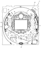
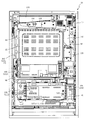
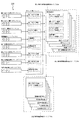
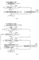
以下、本発明の実施形態について、添付図面を参照して説明する。まず、図1から図87を参照し、第1実施形態として、本発明をパチンコ遊技機(以下、単に「パチンコ機」という)10に適用した場合の一実施形態について説明する。図1は、第1実施形態におけるパチンコ機10の正面図であり、図2はパチンコ機10の遊技盤13の正面図であり、図3はパチンコ機10の後面図である。
Hereinafter, embodiments of the present invention will be described with reference to the attached drawings. First, an embodiment in which the present invention is applied to a pachinko gaming machine (hereinafter simply referred to as a "pachinko machine") 10 will be described as a first embodiment with reference to FIGS. FIG. 1 is a front view of the
図1に示すように、パチンコ機10は、略矩形状に組み合わせた木枠により外殻が形成される外枠11と、その外枠11と略同一の外形形状に形成され外枠11に対して開閉可能に支持された内枠12とを備えている。外枠11には、内枠12を支持するために正面視(図1参照)左側の上下2カ所に金属製のヒンジ18が取り付けられ、そのヒンジ18が設けられた側を開閉の軸として内枠12が正面手前側へ開閉可能に支持されている。
As shown in FIG. 1, the
内枠12には、多数の釘や球が入球可能な入球口63,64b1,64b2,640等を有する遊技盤13(図2参照)が裏面側から着脱可能に装着される。この遊技盤13の正面を球(遊技球)が流下することにより弾球遊技が行われる。なお、内枠12には、球を遊技盤13の正面領域(遊技領域)に発射する球発射ユニット112a(図4参照)やその球発射ユニット112aから発射された球を遊技盤13の正面領域まで誘導する発射レール(図示せず)等が取り付けられている。尚、遊技盤13に設けられた多数の入球口の内容については、図2を参照して後述する。
In the
内枠12の正面側には、その正面上側を覆う正面枠14と、その下側を覆う下皿ユニット15とが設けられている。正面枠14及び下皿ユニット15を支持するために正面視(図1参照)左側の上下2カ所に金属製のヒンジ19が取り付けられ、そのヒンジ19が設けられた側を開閉の軸として正面枠14及び下皿ユニット15が正面手前側へ開閉可能に支持されている。なお、内枠12の施錠と正面枠14の施錠とは、シリンダ錠20の鍵穴21に専用の鍵を差し込んで所定の操作を行うことでそれぞれ解除される。
On the front side of the
正面枠14は、装飾用の樹脂部品や電気部品等を組み付けたものであり、その略中央部には略楕円形状に開口形成された窓部14cが設けられている。正面枠14の裏面側には2枚の板ガラスを有するガラスユニット16が配設され、そのガラスユニット16を介して遊技盤13の正面がパチンコ機10の正面側に視認可能となっている。
The
正面枠14には、球を貯留する上皿17が正面側へ張り出して上面を開放した略箱状に形成されており、この上皿17に賞球や貸出球などが排出される。上皿17の底面は正面視(図1参照)右側に下降傾斜して形成され、その傾斜により上皿17に投入された球が球発射ユニット112a(図9参照)へと案内される。また、上皿17の上面には、枠ボタン22が設けられている。この枠ボタン22は、例えば、第3図柄表示装置81(図2参照)で表示される演出のステージを変更したり、スーパーリーチの演出内容を変更したりする場合などに、遊技者により操作される。
In the
正面枠14には、その周囲(例えばコーナー部分)に各種ランプ等の発光手段が設けられている。これら発光手段は、大当たり時や所定のリーチ時等における遊技状態の変化に応じて、点灯又は点滅することにより発光態様が変更制御され、遊技中の演出効果を高める役割を果たす。窓部14cの周縁には、LED等の発光手段を内蔵した電飾部29〜33が設けられている。パチンコ機10においては、これら電飾部29〜33が大当たりランプ等の演出ランプとして機能し、大当たり時やリーチ演出時等には内蔵するLEDの点灯や点滅によって各電飾部29〜33が点灯または点滅して、大当たり中である旨、或いは大当たり一歩手前のリーチ中である旨が報知される。また、正面枠14の正面視(図1参照)左上部には、LED等の発光手段が内蔵され賞球の払い出し中とエラー発生時とを表示可能な表示ランプ34が設けられている。
The
また、右側の電飾部32下側には、正面枠14の裏面側を視認できるように裏面側より透明樹脂を取り付けて小窓35が形成され、遊技盤13正面の貼着スペースK1(図2参照)に貼付される証紙等がパチンコ機10の正面から視認可能とされている。また、パチンコ機10においては、より煌びやかさを醸し出すために、電飾部29〜33の周りの領域にクロムメッキを施したABS樹脂製のメッキ部材36が取り付けられている。
A
窓部14cの下方には、貸球操作部40が配設されている。貸球操作部40には、度数表示部41と、球貸しボタン42と、返却ボタン43とが設けられている。パチンコ機10の側方に配置されるカードユニット(球貸しユニット)(図示せず)に紙幣やカード等を投入した状態で貸球操作部40が操作されると、その操作に応じて球の貸出が行われる。具体的には、度数表示部41はカード等の残額情報が表示される領域であり、内蔵されたLEDが点灯して残額情報として残額が数字で表示される。球貸しボタン42は、カード等(記録媒体)に記録された情報に基づいて貸出球を得るために操作されるものであり、カード等に残額が存在する限りにおいて貸出球が上皿17に供給される。返却ボタン43は、カードユニットに挿入されたカード等の返却を求める際に操作される。なお、カードユニットを介さずに球貸し装置等から上皿17に球が直接貸し出されるパチンコ機、いわゆる現金機では貸球操作部40が不要となるが、この場合には、貸球操作部40の設置部分に飾りシール等を付加して部品構成は共通のものとしても良い。カードユニットを用いたパチンコ機と現金機との共通化を図ることができる。
Under the
上皿17の下側に位置する下皿ユニット15には、その中央部に上皿17に貯留しきれなかった球を貯留するための下皿50が上面を開放した略箱状に形成されている。下皿50の右側には、球を遊技盤13の正面へ打ち込むために遊技者によって操作される操作ハンドル51が配設される。
In the
操作ハンドル51の内部には、球発射ユニット112aの駆動を許可するためのタッチセンサ51aと、押下操作している期間中には球の発射を停止する発射停止スイッチ51bと、操作ハンドル51の回動操作量(回動位置)を電気抵抗の変化により検出する可変抵抗器(図示せず)などが内蔵されている。操作ハンドル51が遊技者によって右回りに回動操作されると、タッチセンサ51aがオンされると共に可変抵抗器の抵抗値が回動操作量に対応して変化し、その可変抵抗器の抵抗値に対応した強さ(発射強度)で球が発射され、これにより遊技者の操作に対応した飛び量で遊技盤13の正面へ球が打ち込まれる。また、操作ハンドル51が遊技者により操作されていない状態においては、タッチセンサ51aおよび発射停止スイッチ51bがオフとなっている。
Inside the
下皿50の正面下方部には、下皿50に貯留された球を下方へ排出する際に操作するための球抜きレバー52が設けられている。この球抜きレバー52は、常時、右方向に付勢されており、その付勢に抗して左方向へスライドさせることにより、下皿50の底面に形成された底面口が開口して、その底面口から球が自然落下して排出される。この球抜きレバー52の操作は、通常、下皿50の下方に下皿50から排出された球を受け取る箱(一般に「千両箱」と称される)を置いた状態で行われる。下皿50の右方には、上述したように操作ハンドル51が配設され、下皿50の左方には灰皿53が取り付けられている。
At the front lower portion of the
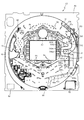
図2に示すように、遊技盤13は、正面視略正方形状に切削加工したベース板60に、球案内用の多数の釘(図示せず)や風車の他、レール61,62、一般入球口63、上第1入球口64b1、下第1入球口64b2、第2入球口640、左可変入賞装置65、右可変入賞装置650、普通図柄始動口(スルーゲート)67、可変表示装置ユニット80等を組み付けて構成され、その周縁部が内枠12(図1参照)の裏面側に取り付けられる。ベース板60は光透過性の樹脂材料からなり、その正面側からベース板60の後面側に配設された各種構造体を遊技者に視認させることが可能に形成される。一般入球口63、第1入球口64、第2入球口640、左可変入賞装置65、右可変入賞装置650、可変表示装置ユニット80は、ルータ加工によってベース板60に形成された貫通穴に配設され、遊技盤13の正面側からタッピングネジ等により固定されている。
As shown in FIG. 2, the
遊技盤13の正面中央部分は、正面枠14の窓部14c(図1参照)を通じて内枠12の正面側から視認することができる。以下に、主に図2を参照して、遊技盤13の構成について説明する。
The front center portion of the
遊技盤13の正面には、帯状の金属板を略円弧状に屈曲加工して形成した外レール62が植立され、その外レール62の内側位置には外レール62と同様に帯状の金属板で形成した円弧状の内レール61が植立される。この内レール61と外レール62とにより遊技盤13の正面外周が囲まれ、遊技盤13とガラスユニット16(図1参照)とにより前後が囲まれることにより、遊技盤13の正面には、球の挙動により遊技が行われる遊技領域が形成される。遊技領域は、遊技盤13の正面であって2本のレール61,62とレール間を繋ぐ樹脂製の外縁部材73とにより区画して形成される領域(入賞口等が配設され、発射された球が流下する領域)である。
On the front of the
2本のレール61,62は、球発射ユニット112a(図4参照)から発射された球を遊技盤13上部へ案内するために設けられたものである。内レール61の先端部分(図2の左上部)には戻り球防止部材68が取り付けられ、一旦、遊技盤13の上部へ案内された球が再度球案内通路内に戻ってしまうといった事態が防止される。外レール62の先端部(図2の右上部)には、球の最大飛翔部分に対応する位置に返しゴム69が取り付けられ、所定以上の勢いで発射された球は、返しゴム69に当たって、勢いが減衰されつつ中央部側へ跳ね返される。
The two
返しゴム69の左上側には第1図柄表示装置37が設けられている。この第1図柄表示装置37は、透明の樹脂(例えば、ABS)にて形成されている遊技盤13の裏面(遊技領域を形成する面とは反対側の面)に覆われるように配設されており、発射された球が第1図柄表示装置37に衝突しないように構成している。
A first
この第1図柄表示装置37には、発光手段である複数のLED及び7セグメント表示器を備える第1図柄表示装置37A,37Bが配設されている。第1図柄表示装置37A,37Bは、主制御装置110(図4参照)で行われる各制御に応じた表示がなされるものであり、主にパチンコ機10の遊技状態の表示が行われる。本実施形態では、第1図柄表示装置37A,37Bは、球が、上第1入球口64b1、或いは、下第1入球口64b2へ入球(入賞)したか、第2入球口640へ入球(入賞)したかに応じて使い分けられるように構成されている。具体的には、球が、上第1入球口64b1、或いは、下第1入球口64b2へ入球(入賞)した場合には、第1図柄表示装置37Aが作動し、一方で、球が、第2入球口640へ入球(入賞)した場合には、第1図柄表示装置37Bが作動するように構成されている。つまり、第1図柄表示装置37Aは、上第1入球口64b1、或いは、下第1入球口64b2に球が入球した場合に実行される抽選(特図1抽選)の抽選結果を示すための表示手段であり、第1図柄表示装置37Bは、第2入球口640に球が入球した場合に実行される抽選(特図2抽選)の抽選結果を示すための表示手段となる。
The first
また、第1図柄表示装置37A,37Bは、LEDにより、パチンコ機10の遊技状態(確変状態、潜確状態、通常状態等)の何れであるかを点灯状態により示したり、第1図柄が変動中(抽選結果を示すための図柄の組み合わせを停止表示させるための動的表示中)であるか否かを点灯状態により示したり、停止図柄が遊技者に有利な大当たりに対応した図柄か不利な大当たりに対応した図柄か外れ図柄であるかを点灯状態により示したり、保留球数を点灯状態により示すと共に、7セグメント表示装置により、大当たり中のラウンド数やエラー表示を行う。複数のLEDは、それぞれのLEDの発光色(例えば、赤、緑、青)が異なるよう構成され、その発光色の組み合わせにより、少ないLEDでパチンコ機10の各種遊技状態を示唆することができる。なお、本実施形態では、発光手段(7セグメント表示装置)の発光色の組み合わせにより各種遊技状態を報知するように構成しているが、遊技者が各種遊技状態を識別可能な構成であれば良く、例えば、発光手段が点灯している期間と消灯している期間との長さ(点滅態様)を可変させることにより各種遊技状態を報知するように構成しても良い。
In addition, the first
尚、本パチンコ機10では、上第1入球口64b1、下第1入球口64b2及び第2入球口640へ入球(入賞)があったことを契機として抽選(特別図柄の抽選)が行われる。そして、その特別図柄の抽選において、大当たりか否かの当否判定(大当たり抽選)を行う。ここで、大当たりに当選したと判定されたことに基づいて、遊技者に有利な特典遊技状態となる大当たり遊技が実行される。
In addition, in this
大当たり遊技が実行されると、左可変入賞装置65の特定入賞口65a、或いは、右可変入賞装置650のV入賞口650aに球を容易に入賞させることが可能な開放状態となり、各入賞口に球を入賞させることで多くの賞球を短期間で獲得可能な遊技が実行される。この大当たり遊技中は、特別図柄の抽選結果が停止表示(確定表示)された後に実行されるものであり、所定時間(例えば1秒)のオープニング期間(可変入賞装置65の特定入賞口65a、或いは、右可変入賞装置650のV入賞口650aに球を入球させ難い閉鎖状態が設定される期間)と、開放状態が設定されるラウンド遊技期間と、1のラウンド遊技期間が終了した後に、次のラウンド遊技が開始されるまでの所定期間(例えば、0.5秒)、閉鎖状態が設定されるインターバル期間と、最後のラウンド遊技期間が終了した後に、所定期間(例えば、2秒)の閉鎖状態が設定されるエンディング期間と、からなる大当たり遊技期間が設定される。
When the jackpot game is executed, the specific winning
このように、大当たり当選を示す特別図柄の抽選結果が停止表示(確定表示)された後に、オープニング期間を設定することにより、大当たり遊技中における各入賞口が開放状態となるタイミングに合わせて球を任意の方向に向けて発射させる準備を行うことができるため、大当たり遊技を円滑に行わせることができる。また、このオープニング期間を、今回の大当たり遊技の遊技内容を遊技者に報知する期間として用いることができるため、分かり易い遊技を提供することができる。 In this manner, after the lottery result of the special symbol indicating the big hit is displayed in a stopped state (confirmed display), the opening period is set to match the timing when each winning opening in the big hit game is in the open state. Since preparation can be made to fire in any direction, the jackpot game can be played smoothly. Further, since the opening period can be used as a period for notifying the player of the game content of the present jackpot game, it is possible to provide an easy-to-understand game.
また、大当たり遊技の最終期間としてエンディング期間を設定することにより、最後のラウンド遊技が終了した直後から、新たな特別図柄の抽選が実行されることを抑制することができるため、大当たり遊技の終了後に実行される遊技に向けて、球を任意の方向に向けて発射させる準備を行うことができるため、遊技の切り替えを円滑に行わせることができる。 In addition, by setting the ending period as the final period of the jackpot game, it is possible to suppress that a new special symbol lottery is executed immediately after the last round game is over, so after the jackpot game is over Since it is possible to prepare to shoot the ball in any direction for the game to be executed, it is possible to smoothly switch the game.
さらに、大当たり抽選において大当たりと判定した場合はその大当たり種別の判定も行う。詳細な説明は後述するが、判定される大当たり種別としては、大当たり遊技のラウンド数が16ラウンドで大当たり終了後に特別図柄の高確率状態、普通図柄の低確率が付与される16R潜確大当たり、大当たり遊技のラウンド数が2ラウンドで大当たり終了後に特別図柄の高確率状態、普通図柄の低確率が付与される2R潜確大当たり、大当たり遊技のラウンド数が2ラウンドで大当たり終了後に特別図柄の高確率状態、普通図柄の高確率状態が付与される2R確変大当たりが用意されている。 Furthermore, when it is determined that the jackpot is a jackpot in the jackpot lottery, it is also determined the jackpot type. Although the detailed description will be described later, as the jackpot type to be determined, the high probability state of the special symbol after the big hit end with 16 rounds of the jackpot game, the 16R latent probability jackpot that the low probability of the normal symbol is given, jackpot The number of game rounds is 2 rounds High probability state of special symbol after big hit end, 2R latent probability big hit with low probability of normal symbol, high round state of big hit game is high probability state of special symbol after big hit end in 2 rounds , 2R probability variation jackpot that is given a high probability state of the normal symbol is prepared.
また、大当たり抽選の抽選結果として上述した大当たりでは無く、外れと判定された場合の一部において、上述した大当たりよりも少ない特典(例えば、1ラウンドのみ右可変入賞装置650を開放させ、その開放中に入賞した球数に対応した賞球を付与する特典)が遊技者に付与される小当たりに当選するように構成されている。第1図柄表示装置37A,37Bには、変動終了後の停止図柄として抽選の結果が大当たりであるか否か(小当たりであるか否か)が示されるだけでなく、大当たりである場合はその大当たり種別に応じた図柄が示される。
In addition, the jackpot which is not the jackpot mentioned above as a lottery result of the jackpot lottery, and a part of the case where it is determined to be out, a bonus less than the jackpot mentioned above (e.g. It is configured such that a bonus for awarding a winning ball corresponding to the number of balls that has been won is won for a small hit awarded to the player. Not only is it shown whether or not the result of the lottery is a big hit (a small hit or not) as the stop symbol after the end of the fluctuation, if the first
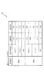
本実施形態では、遊技状態として、「通常状態」、「潜確状態」、「確変状態」の何れかが設定されるように構成している(図14参照)。通常状態は、特別図柄の大当たり確率が低確率(1/229)に設定され、普通図柄の当たり確率が低確率(11/233)に設定される遊技状態(以下、特別図柄:低確率状態、普通図柄:低確率状態と称す)であり、潜確状態は、特別図柄の大当たり確率が高確率(1/120)に設定され、普通図柄の当たり確率が低確率(11/233)に設定される遊技状態(以下、特別図柄:高確率状態、普通図柄:低確率状態と称す)であり、確変状態は、特別図柄の大当たり確率が高確率(1/120)に設定され、普通図柄の当たり確率が高確率(232/233)に設定される遊技状態(以下、特別図柄:高確率状態、普通図柄:高確率状態と称す)である。 In the present embodiment, one of “normal state”, “latency state”, and “probable state” is set as the gaming state (see FIG. 14). In the normal state, the jackpot probability of the special symbol is set to the low probability (1/229), and the hit probability of the ordinary symbol is set to the low probability (11/233). The game state (hereinafter, special symbol: low probability state, Normal symbol: Low probability state), and in the latent state, the jackpot probability of the special symbol is set to high probability (1/120), and the hit probability of the normal symbol is set to low probability (11/233). Playing state (hereinafter, special symbol: high probability state, normal symbol: low probability state), and the probability change state is set to the high probability (1/120) of the special symbol and the hit of the normal symbol It is a gaming state in which the probability is set to the high probability (232/233) (hereinafter referred to as a special symbol: high probability state, normal symbol: high probability state).
なお、詳細な説明は後述するが、本実施形態では、特別図柄の大当たりに当選し、同一の大当たり種別が設定された場合であっても、その大当たりに当選した際に設定されている遊技状態に応じて、大当たり遊技終了後に設定される遊技状態を異ならせるように構成している。これにより、遊技者に対して特別図柄の抽選結果に加え、設定されている遊技状態を意識させながら遊技を行わせることができる。 In addition, although a detailed description will be described later, in this embodiment, even when the jackpot of the special symbol is won and the same jackpot type is set, the gaming state set when the jackpot is won In accordance with, the game state set after the end of the jackpot game is configured to be different. In this way, it is possible to cause the player to play a game while being aware of the set gaming state in addition to the lottery result of the special symbol.
ここで、本実施形態のパチンコ機10が有する大当たり種別について詳細に説明をすると、「16R潜確大当たり」は、最大ラウンド数が16ラウンドの大当たり遊技(右可変入賞装置(第2アタッカ)650を16ラウンド分開放させる大当たり遊技)の後に潜確状態(特別図柄の高確率状態、普通図柄の低確率状態)が設定される大当たり種別である。
Here, the jackpot type possessed by the
「2R潜確大当たり」とは、最大ラウンド数が2ラウンドの大当たり遊技(左可変入賞装置(第1アタッカ)65を2ラウンド分開放させる大当たり遊技)の後に潜確状態(特別図柄の高確率状態、普通図柄の低確率状態)が設定される大当たり種別である。 The “2R latent probability jackpot” is the jackpot state (special symbol high probability state) after the jackpot game with the maximum number of rounds of 2 rounds (a jackpot game in which the left variable winning device (first attacher) 65 is opened for 2 rounds) , It is a jackpot type in which the low probability state of the symbol is set.
「2R確変大当たり」とは、最大ラウンド数が2ラウンドの大当たり遊技(左可変入賞装置(第1アタッカ)65を2ラウンド分開放させ、大当たり遊技後に確変状態(特別図柄の高確率状態、普通図柄の高確率状態)が設定される大当たり種別である。
The "2R probability variation big hit" is the jackpot game of the
このように構成されたパチンコ機10において、「16R潜確大当たり」に対応した大当たり遊技が実行されると、右可変入賞装置(第2アタッカ)650が所定期間(30秒経過、或いは、10球入賞するまでの期間)開放される遊技(ラウンド遊技)が、所定回数(16回)実行される。よって、この大当たり遊技中に右打ち遊技(右可変入賞装置650を狙って球を発射される遊技)を行うことにより、右可変入賞装置650に容易に球を入賞させることができる。この右可変入賞装置650は、1個の球の入賞に対して15球の賞球が払い出されるように構成されており、後述する左可変入賞装置65よりも多くの賞球を遊技者に付与することができるように構成している。
In the
一方、「2R確変大当たり」、或いは「2R潜確大当たり」に対応した大当たり遊技では、左可変入賞装置(第1アタッカ)65の開放動作として、上述した「16R潜確大当たり」に応じた大当たり遊技よりも制限された開放動作が実行される。具体的には、1回の大当たり遊技中に左可変入賞装置(第1アタッカ)65が短期間(0.5秒間)開放される遊技(ラウンド遊技)が、2回実行される大当たり遊技が実行される。この左可変入賞装置650は、1個の球の入賞に対して15球の賞球が払い出されるように構成されており、上述した右可変入賞装置650よりも少ない賞球が遊技者に付与されることになる。つまり、本実施形態では、「16R潜確大当たり」に対応する大当たり遊技のほうが、「2R確変大当たり」、或いは「2R潜確大当たり」に対応する大当たり遊技よりも、大当たり遊技中におけるアタッカの開放期間が長く、多くの賞球を得られ易くなるように構成している。このように構成することで、大当たり当選をした場合に設定される大当たり種別に応じて遊技者に異なる量の特典(賞球)を異ならせることができるため、遊技者に対して、大当たりに当選するか否かだけでは無く、設定される大当たり種別に対しても興味を持たせることができる。なお、本実施形態では、遊技者に有利となる大当たり遊技(「16R潜確大当たり」に対応する大当たり遊技)のほうが、他の大当たり遊技よりも、多くの回数のラウンド遊技が実行され、さらに、入賞した球1個に対する賞球数も多くなるように構成しているが、大当たり遊技中に付与される賞球数の量が異なるように構成されていれば良く、例えば、大当たり遊技中に実行されるラウンド数を同一とし、球1個に対する賞球数のみ異ならせるように構成しても良いし、球1個に対する賞球数を同一にし、大当たり遊技中に実行されるラウンド遊技の回数のみ異ならせるように構成しても良い。また、大当たり遊技中に開放動作される可変入賞口の種別に応じて、大当たり遊技終了後に設定される遊技状態が異なるように構成しても良い。
On the other hand, in the jackpot game corresponding to "2R probability variation jackpot" or "2R latent probability jackpot", the jackpot game according to the "16R latent probability jackpot" described above as the opening operation of the left variable prize device (first attacker) 65 A more restricted opening operation is performed. Specifically, a jackpot game in which a game (round game) in which the left variable winning device (first attacher) 65 is opened for a short time (0.5 seconds) during one jackpot game is executed twice is executed Be done. The left variable winning
図2に戻り説明を続ける。遊技盤13の表面に形成される遊技領域の左下方側には、球が入球することにより10個の球が賞球として払い出される一般入球口63が配設されている。また、遊技領域の中央部分には、可変表示装置ユニット80が配設されている。可変表示装置ユニット80には、上第1入球口64b1、下第1入球口64b2及び第2入球口640への入球(始動入賞)をトリガとして、第1図柄表示装置37A,37Bにおける変動表示と同期させながら、第3図柄の変動表示を行う液晶ディスプレイ(以下単に「表示装置」と略す)で構成された第3図柄表示装置81と、普通図柄始動口(スルーゲート)67への球の通過をトリガとして第2図柄を変動表示するLEDで構成される第2図柄表示装置(図示せず)とが設けられている。また、可変表示装置ユニット80には、第3図柄表示装置81の外周を囲むようにして、センターフレーム86が配設されている。
Returning to FIG. 2, the explanation will be continued. On the lower left side of the game area formed on the surface of the
第3図柄表示装置81は15インチサイズの大型の液晶ディスプレイで構成されるものであり、表示制御装置114(図4参照)によって表示内容が制御されることにより、例えば、上、中及び下の3つの図柄列が表示される。各図柄列は複数の図柄(第3図柄)によって構成され、これらの第3図柄が図柄列毎に横スクロールして第3図柄表示装置81の表示画面上にて第3図柄が可変表示されるようになっている。本実施形態の第3図柄表示装置81は、主制御装置110(図4参照)の制御に伴った遊技状態の表示が第1図柄表示装置37A,37Bで行われるのに対して、その第1図柄表示装置37A,37Bの表示に応じた装飾的な表示を行うものである。なお、表示装置に代えて、例えばリール等を用いて第3図柄表示装置81を構成するようにしても良い。
The third
第2図柄表示装置は、球が普通図柄始動口(スルーゲート)67を通過する毎に表示図柄(第2図柄(図示せず))としての「○」の図柄と「×」の図柄とを所定時間交互に点灯させる変動表示を行うものである。パチンコ機10では、球が普通図柄始動口(スルーゲート)67を通過したことが検出されると、当たり抽選が行われる。その当たり抽選の結果、当たりであれば、第2図柄表示装置において、第2図柄の変動表示後に「○」の図柄が停止表示される。また、当たり抽選の結果、外れであれば、第2図柄表示装置において、第3図柄の変動表示後に「×」の図柄が停止表示される。
The second symbol display device, each time the ball passes the normal symbol starting opening (through gate) 67, the symbol of "o" and the symbol of "x" as a display symbol (the second symbol (not shown)) The variable display is performed to alternately turn on for a predetermined time. In the
パチンコ機10は、第2図柄表示装置における変動表示が所定図柄(本実施形態においては「○」の図柄)で停止した場合に、下第1入球口64b2に付随された電動役物64aが所定時間だけ作動状態(開放状態)となるよう構成されている。
In the
なお、不正な遊技(例えば、通常状態中に右打ち遊技)が行われていることを判別し、異常報知するための処理として、右打ち遊技によって第2特別図柄の保留記憶数が所定個数(2以上の数)となったと判別した場合に異常報知を実行するように構成すると良い。これにより、遊技者の操作ミスによって発射された少量(1発)の球が右側領域に侵入してしまい、異常報知が実行されてしまうことを抑制することができる。 In addition, it is determined that the illegal game (for example, right-handed game is being performed during the normal state) is being performed, and processing for notifying abnormality is that the number of pending storages of the second special symbol is a predetermined number (right If it is determined that the number is 2 or more), it may be configured to execute the abnormality notification. As a result, it is possible to suppress that a small amount (one shot) of balls fired due to an operation error of the player intrudes into the right side area and the abnormality notification is executed.
なお、普通図柄の高確率状態中(普図高確中)において、当たり確率を高める、1回に当たりに対する電動役物64aの開放時間や開放回数を増やすなど、その他の方法を用いて普図高確中に下第1入球口64b2へ球が入球しやすい状態としている場合は、第2図柄の変動表示にかかる時間を遊技状態にかかわらず一定としてもよい。一方、第2図柄の変動表示にかかる時間を、普図高確中において通常状態よりも短く設定する場合は、当たり確率を遊技状態にかかわらず一定にしてもよいし、また、1回の当たりに対する電動役物64aの開放時間や開放回数を遊技状態にかかわらず一定にしてもよい。
In addition, during the high probability state of the normal symbol (general figure high certainty), using other methods such as increasing the open time and the number of times of opening of the
普通図柄始動口(スルーゲート)67は、可変表示装置ユニット80の左側の領域(左側領域)に組み付けられ、遊技盤13に発射された球のうち、左側領域を流下する球の一部(約50%)が通過可能に構成されている。普通図柄始動口(スルーゲート)67を球が通過すると、第2図柄の当たり抽選が行われる。当たり抽選の後、第2図柄表示装置にて変動表示を行い、当たり抽選の結果が当たりであれば、変動表示の停止図柄として「○」の図柄を表示し、当たり抽選の結果が外れであれば、変動表示の停止図柄として「×」の図柄を表示する。
The normal symbol starting port (through gate) 67 is assembled to the left area (left area) of the
球の普通図柄始動口(スルーゲート)67の通過回数は、合計で最大4回まで保留され、その保留球数が第2図柄保留ランプ(図示せず)において表示される。第2図柄保留ランプは、最大保留数分の4つ設けられ、第3図柄表示装置81の下方に左右対称に配設されている。
The number of times the ball passes through the normal symbol starting opening (through gate) 67 is held up to a total of four times, and the number of holding balls is indicated by the second symbol holding lamp (not shown). Four second symbol holding lamps are provided for the maximum number of holdings, and are arranged symmetrically below the third
なお、第2図柄の変動表示は、本実施形態のように、第2図柄表示装置において複数のランプの点灯と非点灯を切り換えることにより行うものの他、第1図柄表示装置37A,37B及び第3図柄表示装置81の一部を使用して行うようにしても良い。同様に、第2図柄保留ランプの点灯を第3図柄表示装置81の一部で行うようにしても良い。また、普通図柄始動口(スルーゲート)67の球の通過に対する最大保留球数は4回に限定されるものでなく、3回以下、又は、5回以上の回数(例えば、8回)に設定しても良い。また、普通図柄始動口(スルーゲート)67の組み付け数は1つに限定されるものではなく、複数(例えば、2つ)であっても良い。また、普通図柄始動口(スルーゲート)67の組み付け位置は可変表示装置ユニット80の左方に限定されるものではなく、例えば、可変表示装置ユニット80の右方でも良い。また、第1図柄表示装置37A,37Bにより保留球数が示されるので、第2図柄保留ランプにより点灯表示を行わないものとしてもよい。
In addition, as the variable display of the second symbol is performed by switching on and off of a plurality of lamps in the second symbol display device as in the present embodiment, the first
可変表示装置ユニット80の下方には、球が入球し得る上第1入球口64b1が配設されている。この上第1入球口64b1へ球が入球すると遊技盤13の裏面側に設けられる第1入球口スイッチ(図示せず)がオンとなり、その第1入球口スイッチのオンに起因して主制御装置110(図4参照)で大当たりの抽選がなされ、その抽選結果に応じた表示が第1図柄表示装置37Aで示される。
Below the variable
上第1入球口64b1の下方には、球が入球し得る下第1入球口64b2が配設されている。この下第1入球口64b2へ球が入球すると遊技盤13の裏面側に設けられる第1入球口スイッチ(図示せず)がオンとなり、その第1入球口スイッチのオンに起因して主制御装置110(図9参照)で大当たりの抽選がなされ、その抽選結果に応じた表示が第1図柄表示装置37Aで示される。即ち、本第1実施形態では、上第1入球口64b1に球が入球した場合も、下第1入球口64b2に球が入球した場合も、同一の大当たり抽選(特図1抽選)が実行されるように構成されている。
Below the upper first ball entry port 64b1, a lower first ball entry port 64b2 to which a ball can enter is disposed. When the ball enters the lower first entrance 64b2, the first entrance switch (not shown) provided on the back side of the
下第1入球口64b2の右方であって、遊技盤13の右側領域には、球が入球し得る第2入球口640が配設されている。この第2入球口640へ球が入球すると遊技盤13の裏面側に設けられる第2入球口スイッチ(図示せず)がオンとなり、その第2入球口スイッチのオンに起因して主制御装置110(図4参照)で大当たりの抽選がなされ、その抽選結果に応じた表示が第1図柄表示装置37Bで示される。また、遊技盤の左側領域には、一般入球口63が配設されている。この一般入球口63は、左側領域を流下する球のうち、左可変入賞装置65へ到達することが困難な流路を流下する球が入球し易くなるように配置されている。これにより、例えば、左可変入賞装置65が開放動作する大当たり遊技中において、左打ち遊技によって発射した球が左可変入賞装置65に入賞し得ない流路を流下した場合にも、遊技者に特典(賞球)を付与することが可能となる。
On the right side of the lower first entrance 64b2, in the right area of the
上第1入球口64b1、或いは、下第1入球口64b2に球が入球すると4個の球が賞球として払い出され、第2入球口640に球が入球すると1個の賞球として払い出されるように構成している。また、一般入球口63に球が入球すると6個の球が賞球として払い出されるように構成している。このように構成することで、通常状態中に右打ち遊技を行ったとしても、賞球が1個に設定されている第2入球口640に球が入賞するだけであるため、球が増加することが無い。よって、通常状態中に右打ち遊技が行われることを抑制することができる。
When a ball enters the upper first entrance 64b1 or the lower first entrance 64b2, four balls are paid out as winning balls, and when a ball enters the
また、第2入球口640に球が入球した場合には、第2特別図柄(特図2)の抽選が実行されることになるが、本実施形態では、通常状態において実行される第2特別図柄(特図2)の抽選に対して設定される変動パターン(変動時間)として、長時間(例えば、10分)の変動パターン(変動時間)が設定されるように構成している。よって、たとえ、通常状態において第2特別図柄(特図2)の抽選が実行されたとしても、効率良く特図2の抽選が実行されることを抑制することができる。
In addition, when the ball enters the
上述した通り、本実施形態では、通常状態が設定されている状態で右打ち遊技(遊技盤13の右側領域に球を流下させて第2特別図柄(特図2)抽選を実行するために、第2入球口640へ球を入球させるための遊技)を実行したとしても、1回の抽選結果が確定するまでの時間が長く、且つ、左打ち遊技によって獲得可能な賞球数よりも少ない数の賞球しか獲得することができないように構成している。つまり、遊技状態として通常状態が設定されている場合は、左打ち遊技(遊技盤13の左側領域に球を流下させて第1特別図柄(特図1)抽選を実行するために、上第1入球口64b1へ球を入球させるための遊技)を行うことが遊技者に有利な遊技となる。
As described above, in the present embodiment, in the state where the normal state is set, in order to execute the second special symbol (special figure 2) lottery by letting the ball flow down to the right area of the
なお、本実施形態においては、上第1入球口64b1、或いは、下第1入球口64b2へ球が入賞した場合に払い出される賞球数と第2入球口640へ球が入賞した場合に払い出される賞球数とを異ならせるように構成したが、上第1入球口64b1、或いは、下第1入球口64b2へ球が入賞した場合に払い出される賞球数と第2入球口640へ球が入賞した場合に払い出される賞球数とを同一の数、例えば、上第1入球口64b1、或いは、下第1入球口64b2へ球が入賞した場合に払い出される賞球数も1個として構成してもよい。
In the present embodiment, the number of winning balls to be paid out when the ball is won in the first upper ball entry port 64b1 or the lower first ball entrance 64b2 and the ball is won in the
図2に示した通り、下第1入球口64b2には電動役物64aが付随されている。この電動役物64aは1つの羽根形状に構成されており、球が下第1入球口64b2に入球することを規制する閉鎖状態(図2の電動役物64a(実線)参照)と、球が下第1入球口64b2に入球することを許容する開放状態(図2の電動役物64a(破線)参照)とに可変可能に制御されるものである。
As shown in FIG. 2, the lower first ball entrance 64
電動役物64aは、通常、閉鎖状態に位置しており、球が下第1入球口64b2に入球し得ないように構成されている。そして、普通図柄(第2図柄)の抽選によって当たりに当選したことに基づいて、所定期間の間、開放状態へと可変動作され球が下第1入球口64b2に入球し易くなるように構成されているものである。
The
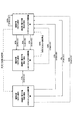
図3に示すように、パチンコ機10の後面側には、制御基板ユニット90,91と、裏パックユニット94とが主に備えられている。制御基板ユニット90は、主基板(主制御装置110)と音声ランプ制御基板(音声ランプ制御装置113)と表示制御基板(表示制御装置114)とが搭載されてユニット化されている。制御基板ユニット91は、払出制御基板(払出制御装置111)と発射制御基板(発射制御装置112)と電源基板(電源装置115)とカードユニット接続基板116とが搭載されてユニット化されている。
As shown in FIG. 3,
裏パックユニット94は、保護カバー部を形成する裏パック92と払出ユニット93とがユニット化されている。また、各制御基板には、各制御を司る1チップマイコンとしてのMPU、各種機器との連絡をとるポート、各種抽選の際に用いられる乱数発生器、時間計数や同期を図る場合などに使用されるクロックパルス発生回路等が、必要に応じて搭載されている。
In the
なお、主制御装置110、音声ランプ制御装置113及び表示制御装置114、払出制御装置111及び発射制御装置112、電源装置115、カードユニット接続基板116は、それぞれ基板ボックス100〜104に収納されている。基板ボックス100〜104は、ボックスベースと該ボックスベースの開口部を覆うボックスカバーとを備えており、そのボックスベースとボックスカバーとが互いに連結されて、各制御装置や各基板が収納される。
The
また、基板ボックス100(主制御装置110)及び基板ボックス102(払出制御装置111及び発射制御装置112)は、ボックスベースとボックスカバーとを封印ユニット(図示せず)によって開封不能に連結(かしめ構造による連結)している。また、ボックスベースとボックスカバーとの連結部には、ボックスベースとボックスカバーとに亘って封印シール(図示せず)が貼着されている。この封印シールは、脆性な素材で構成されており、基板ボックス100,102を開封するために封印シールを剥がそうとしたり、基板ボックス100,102を無理に開封しようとすると、ボックスベース側とボックスカバー側とに切断される。よって、封印ユニット又は封印シールを確認することで、基板ボックス100,102が開封されたかどうかを知ることができる。
In addition, the substrate box 100 (main controller 110) and the substrate box 102 (dispensing
払出ユニット93は、裏パックユニット94の最上部に位置して上方に開口したタンク130と、タンク130の下方に連結され下流側に向けて緩やかに傾斜するタンクレール131と、タンクレール131の下流側に縦向きに連結されるケースレール132と、ケースレール132の最下流部に設けられ、払出モータ216(図4参照)の所定の電気的構成により球の払出を行う払出装置133とを備えている。タンク130には、遊技ホールの島設備から供給される球が逐次補給され、払出装置133により必要個数の球の払い出しが適宜行われる。タンクレール131には、当該タンクレール131に振動を付加するためのバイブレータ134が取り付けられている。
Dispensing
また、払出制御装置111には状態復帰スイッチ120が設けられ、発射制御装置112には可変抵抗器の操作つまみ121が設けられ、電源装置115にはRAM消去スイッチ122が設けられている。状態復帰スイッチ120は、例えば、払出モータ216(図4参照)部の球詰まり等、払出エラーの発生時に球詰まりを解消(正常状態への復帰)するために操作される。操作つまみ121は、発射ソレノイドの発射力を調整するために操作される。RAM消去スイッチ122は、パチンコ機10を初期状態に戻したい場合に電源投入時に操作される。
In addition, the
次に、図4を参照して、本パチンコ機10の電気的構成について説明する。図4は、パチンコ機10の電気的構成を示すブロック図である。
Next, the electrical configuration of the
主制御装置110には、演算装置である1チップマイコンとしてのMPU201が搭載されている。MPU201には、該MPU201により実行される各種の制御プログラムや固定値データを記憶したROM202と、そのROM202内に記憶される制御プログラムの実行に際して各種のデータ等を一時的に記憶するためのメモリであるRAM203と、そのほか、割込回路やタイマ回路、データ送受信回路などの各種回路が内蔵されている。主制御装置110では、MPU201によって、大当たり抽選や第1図柄表示装置37A,37B及び第3図柄表示装置81における表示の設定、第2図柄表示装置における表示結果の抽選といったパチンコ機10の主要な処理を実行する。
The
なお、払出制御装置111や音声ランプ制御装置113などのサブ制御装置に対して動作を指示するために、主制御装置110から該サブ制御装置へ各種のコマンドがデータ送受信回路によって送信されるが、かかるコマンドは、主制御装置110からサブ制御装置へ一方向にのみ送信される。
Although various commands are transmitted from the
RAM203は、各種エリア、カウンタ、フラグのほか、MPU201の内部レジスタの内容やMPU201により実行される制御プログラムの戻り先番地などが記憶されるスタックエリアと、各種のフラグおよびカウンタ、I/O等の値が記憶される作業エリア(作業領域)とを有している。なお、RAM203は、パチンコ機10の電源の遮断後においても電源装置115からバックアップ電圧が供給されてデータを保持(バックアップ)できる構成となっており、RAM203に記憶されるデータは、すべてバックアップされる。
The
停電などの発生により電源が遮断されると、その電源遮断時(停電発生時を含む。以下同様)のスタックポインタや、各レジスタの値がRAM203に記憶される。一方、電源投入時(停電解消による電源投入を含む。以下同様)には、RAM203に記憶される情報に基づいて、パチンコ機10の状態が電源遮断前の状態に復帰される。RAM203への書き込みはメイン処理(図示せず)によって電源遮断時に実行され、RAM203に書き込まれた各値の復帰は電源投入時の立ち上げ処理(図示せず)において実行される。なお、MPU201のNMI端子(ノンマスカブル割込端子)には、停電等の発生による電源遮断時に、停電監視回路252からの停電信号SG1が入力されるように構成されており、その停電信号SG1がMPU201へ入力されると、停電時処理としてのNMI割込処理(図示せず)が即座に実行される。
When the power is shut off due to the occurrence of a power failure or the like, the stack pointer at the time of the power shutoff (including the time of the power failure, the same applies hereinafter) and the value of each register are stored in the
主制御装置110のMPU201には、アドレスバス及びデータバスで構成されるバスライン204を介して入出力ポート205が接続されている。入出力ポート205には、払出制御装置111、音声ランプ制御装置113、第1図柄表示装置37A,37B、第2図柄表示装置、第2図柄保留ランプ、特定入賞口65aの開閉板の下辺を軸として正面側に開閉駆動するための大開放口ソレノイドや電動役物を駆動するためのソレノイドなどからなるソレノイド209が接続され、MPU201は、入出力ポート205を介してこれらに対し各種コマンドや制御信号を送信する。
An input /
また、入出力ポート205には、図示しないスイッチ群およびスライド位置検出センサSや回転位置検出センサRを含むセンサ群などからなる各種スイッチ208、電源装置115に設けられた後述のRAM消去スイッチ回路253が接続され、MPU201は各種スイッチ208から出力される信号や、RAM消去スイッチ回路253より出力されるRAM消去信号SG2に基づいて各種処理を実行する。
The input /
払出制御装置111は、払出モータ216を駆動させて賞球や貸出球の払出制御を行うものである。演算装置であるMPU211は、そのMPU211により実行される制御プログラムや固定値データ等を記憶したROM212と、ワークメモリ等として使用されるRAM213とを有している。
The
払出制御装置111のRAM213は、主制御装置110のRAM203と同様に、MPU211の内部レジスタの内容やMPU211により実行される制御プログラムの戻り先番地などが記憶されるスタックエリアと、各種のフラグおよびカウンタ、I/O等の値が記憶される作業エリア(作業領域)とを有している。RAM213は、パチンコ機10の電源の遮断後においても電源装置115からバックアップ電圧が供給されてデータを保持(バックアップ)できる構成となっており、RAM213に記憶されるデータは、すべてバックアップされる。なお、主制御装置110のMPU201と同様、MPU211のNMI端子にも、停電等の発生による電源遮断時に停電監視回路252から停電信号SG1が入力されるように構成されており、その停電信号SG1がMPU211へ入力されると、停電時処理としてのNMI割込処理(図示せず)が即座に実行される。
The
払出制御装置111のMPU211には、アドレスバス及びデータバスで構成されるバスライン214を介して入出力ポート215が接続されている。入出力ポート215には、主制御装置110や払出モータ216、発射制御装置112などがそれぞれ接続されている。また、図示はしないが、払出制御装置111には、払い出された賞球を検出するための賞球検出スイッチが接続されている。なお、該賞球検出スイッチは、払出制御装置111に接続されるが、主制御装置110には接続されていない。
An input /
発射制御装置112は、主制御装置110により球の発射の指示がなされた場合に、操作ハンドル51の回動操作量に応じた球の打ち出し強さとなるよう球発射ユニット112aを制御するものである。球発射ユニット112aは、図示しない発射ソレノイドおよび電磁石を備えており、その発射ソレノイドおよび電磁石は、所定条件が整っている場合に駆動が許可される。具体的には、遊技者が操作ハンドル51に触れていることをタッチセンサ51aにより検出し、球の発射を停止させるための発射停止スイッチ51bがオフ(操作されていないこと)を条件に、操作ハンドル51の回動操作量(回動位置)に対応して発射ソレノイドが励磁され、操作ハンドル51の操作量に応じた強さで球が発射される。
The
音声ランプ制御装置113は、音声出力装置(図示しないスピーカなど)226における音声の出力、ランプ表示装置(電飾部29〜33、表示ランプ34など)227における点灯および消灯の出力、変動演出(変動表示)や予告演出といった表示制御装置114で行われる第3図柄表示装置81の表示態様の設定などを制御するものである。演算装置であるMPU221は、そのMPU221により実行される制御プログラムや固定値データ等を記憶したROM222と、ワークメモリ等として使用されるRAM223とを有している。
The sound
音声ランプ制御装置113のMPU221には、アドレスバス及びデータバスで構成されるバスライン224を介して入出力ポート225が接続されている。入出力ポート225には、主制御装置110、表示制御装置114、音声出力装置226、ランプ表示装置227、その他装置228、枠ボタン22などがそれぞれ接続されている。その他装置228には、パチンコ機10に設けられる演出用の駆動役物を動作させるための各種駆動モータが含まれる。
An input /
音声ランプ制御装置113は、主制御装置110から受信した各種のコマンド(変動パターンコマンド、停止種別コマンド等)に基づいて、第3図柄表示装置81の表示態様を決定し、決定した表示態様をコマンド(表示用変動パターンコマンド、表示用停止種別コマンド等)によって表示制御装置114へ通知する。また、音声ランプ制御装置113は、枠ボタン22からの入力を監視し、遊技者によって枠ボタン22が操作された場合は、第3図柄表示装置81で表示されるステージを変更したり、スーパーリーチ時の演出内容を変更したりするように、表示制御装置114へ指示する。ステージが変更される場合は、変更後のステージに応じた後面画像を第3図柄表示装置81に表示させるべく、変更後のステージに関する情報を含めた後面画像変更コマンドを表示制御装置114へ送信する。ここで、後面画像とは、第3図柄表示装置81に表示させる主要な画像である第3図柄の後面側に表示される画像のことである。表示制御装置114は、この音声ランプ制御装置113から送信されるコマンドに従って、第3図柄表示装置81に各種の画像を表示する。
The voice
なお、遊技者によって枠ボタン22が操作された場合に、図示しない演出用の役物を駆動させるためにその他装置228へ役物駆動コマンドを送信したり、枠ボタン22への操作内容に対応した音声を音声出力装置226に出力させるための音声出力コマンドを設定したり、枠ボタン22への操作内容に対応した発光態様でランプ表示装置227を発光させるためのランプ出力コマンドを設定したりするように構成しても良い。
In addition, when the
また、音声ランプ制御装置113は、表示制御装置114から第3図柄表示装置81の表示内容を表すコマンド(表示コマンド)を受信する。音声ランプ制御装置113では、表示制御装置114から受信した表示コマンドに基づき、第3図柄表示装置81の表示内容に合わせて、その表示内容に対応する音声を音声出力装置226から出力し、また、その表示内容に対応させてランプ表示装置227の点灯および消灯を制御する。
In addition, the audio
表示制御装置114は、音声ランプ制御装置113及び第3図柄表示装置81が接続され、音声ランプ制御装置113より受信したコマンドに基づいて、第3図柄表示装置81における第3図柄の変動演出などの表示を制御するものである。また、表示制御装置114は、第3図柄表示装置81の表示内容を通知する表示コマンドを適宜音声ランプ制御装置113へ送信する。音声ランプ制御装置113は、この表示コマンドによって示される表示内容にあわせて音声出力装置226から音声を出力することで、第3図柄表示装置81の表示と音声出力装置226からの音声出力とをあわせることができる。
The
電源装置115は、パチンコ機10の各部に電源を供給するための電源部251と、停電等による電源遮断を監視する停電監視回路252と、RAM消去スイッチ122(図4参照)が設けられたRAM消去スイッチ回路253とを有している。電源部251は、図示しない電源経路を通じて、各制御装置110〜114等に対して各々に必要な動作電圧を供給する装置である。その概要としては、電源部251は、外部より供給される交流24ボルトの電圧を取り込み、各種スイッチ208などの各種スイッチや、ソレノイド209などのソレノイド、モータ等を駆動するための12ボルトの電圧、ロジック用の5ボルトの電圧、RAMバックアップ用のバックアップ電圧などを生成し、これら12ボルトの電圧、5ボルトの電圧及びバックアップ電圧を各制御装置110〜114等に対して必要な電圧を供給する。
The
停電監視回路252は、停電等の発生による電源遮断時に、主制御装置110のMPU201及び払出制御装置111のMPU211の各NMI端子へ停電信号SG1を出力するための回路である。停電監視回路252は、電源部251から出力される最大電圧である直流安定24ボルトの電圧を監視し、この電圧が22ボルト未満になった場合に停電(電源断、電源遮断)の発生と判断して、停電信号SG1を主制御装置110及び払出制御装置111へ出力する。停電信号SG1の出力によって、主制御装置110及び払出制御装置111は、停電の発生を認識し、NMI割込処理を実行する。なお、電源部251は、直流安定24ボルトの電圧が22ボルト未満になった後においても、NMI割込処理の実行に充分な時間の間、制御系の駆動電圧である5ボルトの電圧の出力を正常値に維持するように構成されている。よって、主制御装置110及び払出制御装置111は、NMI割込処理(図示せず)を正常に実行し完了することができる。
The power failure monitoring circuit 252 is a circuit for outputting the power failure signal SG1 to each NMI terminal of the
RAM消去スイッチ回路253は、RAM消去スイッチ122(図4参照)が押下された場合に、主制御装置110へ、バックアップデータをクリアさせるためのRAM消去信号SG2を出力するための回路である。主制御装置110は、パチンコ機10の電源投入時に、RAM消去信号SG2を入力した場合に、バックアップデータをクリアすると共に、払出制御装置111においてバックアップデータをクリアさせるための払出初期化コマンドを払出制御装置111に対して送信する。
The RAM erase switch circuit 253 is a circuit for outputting a RAM erase signal SG2 for clearing the backup data to the
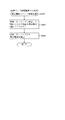
次に、本実施形態における第3図柄表示装置81の表示内容について図5〜図7(a)を参照して説明する。図5(a)および(b)は本実施形態における第3図柄表示装置81の表示内容を模式的に示した模式図である。第3図柄表示装置81は、15インチサイズの液晶ディスプレイで構成されるものであり、後述する表示制御装置114によって表示内容が制御されることにより、例えば上、中及び下の3つの図柄列(L1〜L3)が表示される(図5(a)参照)。第3図柄表示装置81の表示画面に表示される第3図柄(第1特別図柄(特図1)または第2特別図柄(特図2)の変動表示に対応して変動する装飾図柄)は、「0」から「9」の数字を模した識別情報が付された10種類の主図柄によりそれぞれ構成されている。
Next, the display contents of the third
本実施形態のパチンコ機10では、主図柄が数字を模した識別情報毎に異なる種類のキャラクタ(動物等)を用いて形成されている。このように、各識別情報に対応させたキャラクタを用いることで、遊技者に対して特別図柄の抽選結果を視覚的に報知することができるため分かり易い遊技を行わせることができる。また、本実施形態のパチンコ機10においては、後述する主制御装置110による抽選結果が大当たりであった場合に、同一の主図柄が揃う(例えば「777」)変動表示が行われ、その変動表示が終わった後に大当たりが発生するよう構成されている。つまり、第3図柄は、主制御装置110による特別図柄の抽選結果を示すための図柄として第3図柄表示装置81に表示されるものである。
In the
主表示領域Dmは、上・中・下のそれぞれ3つの図柄列L1,L2,L3が表示される。各図柄列L1〜L3には、上述した第3図柄が規定の順序で表示される。即ち、各図柄列L1〜L3には、数字の昇順または降順に主図柄が配列され、図柄列L1〜L3毎に周期性をもって左右方向へスクロールして変動表示が行われる。 In the main display area Dm, three symbol rows L1, L2 and L3 are displayed at the top, middle and bottom respectively. In each of the symbol rows L1 to L3, the above-described third symbol is displayed in a prescribed order. That is, the main symbols are arranged in ascending order or descending order of the numbers in each of the symbol rows L1 to L3, and the variable display is performed by scrolling in the horizontal direction with periodicity for each of the symbol rows L1 to L3.
具体的には、上図柄列L1と中図柄列L2は右から左に向かって数字が昇順となるように図柄列が形成され、右から左へとスクロールして変動表示されるように構成されており、下図柄列L3は左から右に向かって数字が昇順となるように図柄列が形成され、右から左へとスクロールして変動表示されるように構成されている。さらに、各図柄列は、主図柄の間に特別図柄の抽選結果を示さない副図柄(ブランク図柄)が形成されている。 Specifically, the upper symbol row L1 and the middle symbol row L2 are configured such that the symbol rows are formed so that the numbers are in ascending order from right to left, and are scrolled from right to left to be variably displayed The symbol row is formed so that the numbers are in ascending order from left to right, and the symbol row L3 in the lower figure is configured to be scrolled and displayed from right to left. Further, in each symbol row, a sub symbol (blank symbol) not showing the lottery result of the special symbol is formed between the main symbols.
そして、図5(a)に示した通り、主表示領域Dmは、上下方向に形成される3つの有効ラインV1〜V3、及び、斜め方向に形成される2つの有効ラインV4,V5を有しており、各図柄列L1〜L3が停止表示された状態で、第3図柄が有効ライン上に大当たり図柄の組合せ(本第1実施形態では、同一の主図柄の組合せ)で揃って停止されれば、大当たりとして大当たり動画が表示される。 As shown in FIG. 5A, the main display area Dm has three effective lines V1 to V3 formed in the vertical direction, and two effective lines V4 and V5 formed in the oblique direction. In a state where each symbol row L1 to L3 is stopped and displayed, the third symbol is stopped together in a combination of big hit symbols on the effective line (in the first embodiment, a combination of the same main symbols). For example, a jackpot animation is displayed as a jackpot.
図5(a)に示した通り、本第1実施形態では、各有効ライン(V1〜V5)が、各図柄列L1〜L3の図柄表示位置を含むように形成されているため、第3図柄表示装置81の主表示領域Dmに表示される各図柄列L1〜L3の全てが停止表示されるまで、対応する特別図柄の抽選結果を分かり難くすることができる。よって、最後の図柄列(本実施形態では、中図柄列L2)が停止表示されるまでの間、主表示領域Dmにて実行される第3図柄の変動表示に興味を持たせることができる。
As shown in FIG. 5A, in the first embodiment, the respective effective lines (V1 to V5) are formed to include the symbol display positions of the respective symbol rows L1 to L3, so the third symbol is formed. Until all the symbol rows L1 to L3 displayed in the main display area Dm of the
なお、第3図柄表示装置81における第3図柄の変動表示の態様は、上記のものに限定されることはなく任意であり、図柄列の数、図柄列における図柄の変動表示の方向、各図柄列の図柄数などは適宜変更可能である。また、第3図柄表示装置81にて変動表示される図柄は上記に限られることはなく、例えば図形やキャラクタ等の画像と数字とを組み合わせた図柄を第3図柄として構成してもよい。さらに、第3図柄が変動表示される領域を可変させる構成にしてもよく、例えば、第3図柄表示装置81の表示画面上で特定の演出が実行される場合は、第3図柄の変動表示領域を小さくしたり、変動表示領域を遊技者が視認し難い位置(例えば、表示画面の隅部)へと移動させたりすることで、第3図柄が変動しているか否かを遊技者が分かり難くするようにしてもよい。また、特別図柄が変動している期間中に、第3図柄の変動を一旦停止(仮停止)させ、再度変動させるように構成してもよい。
In addition, the aspect of the variation display of the 3rd symbol in the 3rd
さらに、本実施形態では、第1特別図柄の変動に対応した第3図柄の表示態様と、第2特別図柄の変動に対応した第3図柄の表示態様とが同一(遊技者が識別困難な程度の相違も含む)となるように構成しているが、変動している特別図柄の種別に対応するように第3図柄の表示態様や表示領域を異ならせても良い。 Furthermore, in the present embodiment, the display mode of the third symbol corresponding to the change of the first special symbol and the display mode of the third symbol corresponding to the change of the second special symbol are the same (the degree to which the player is difficult to identify Although it is configured to include the difference in (3), the display mode and display area of the third symbol may be made different so as to correspond to the type of the special symbol that is fluctuating.
次に、第3図柄表示装置81に実際に表示される内容について図5(b)を参照して説明をする。図5(b)に示した通り、主表示領域Dmにおける正面視右上には、小表示領域Dm1,Dm2が形成されている。この小表示領域Dm1,Dm2は、特別図柄の抽選状況(抽選中(変動中)であるか否か、及び、抽選結果)を示すための識別情報(第4図柄)が表示される領域であって、第1特別図柄(特図1)の抽選状況を示すための第4図柄(特図1第4図柄)が小表示領域Dm1に表示され、第2特別図柄(特図2)の抽選状況を示すための第4図柄(特図2第4図柄)が小表示領域Dm2に表示されるように構成している。
Next, contents actually displayed on the third
このように小表示領域Dm1,Dm2を設けることにより、特図1と特図2とが同時に変動可能なパチンコ機10において、特別図柄の抽選状況を遊技者に報知することができる。なお、詳細は後述するが、本実施形態のパチンコ機10では、第4図柄を、数字を用いた表示態様で示しており、小表示領域Dm1,Dm2にて第4図柄を変動表示させることで(図6(a)参照)、特別図柄が変動している状況を示し、小表示領域Dm1,Dm2にて第4図柄を停止表示させることで(図6(a)参照)、特別図柄の抽選結果を示すように構成しているが、これに限ること無く、例えば、第4図柄として図形を模した表示態様や、複数の色を示す表示態様を用いて、図形を変形させる表示態様や、色を可変させる表示態様によって特別図柄が変動していることを示し、特定の図柄や色を示す表示態様を停止表示させることで、特別図柄の抽選結果を示すように構成しても良い。
By providing the small display areas Dm1 and Dm2 in this manner, it is possible to inform the player of the lottery situation of the special symbol in the
さらに、本実施形態では、第4図柄を用いて、特別図柄の抽選状況(抽選中(変動中)であるか否か、及び、抽選結果)を示すように構成しているが、これに限ること無く、特別図柄が抽選中(変動中)であるか否かのみを報知するように構成しても良い。また、図5(b)に示した通り、本実施形態では、特別図柄の抽選状況を示すための第4図柄が表示される第4図柄表示領域(小表示領域Dm1,Dm2)を、主表示領域Dmの右上側に形成する例を示しているが、この第4図柄表示領域が形成される位置や、大きさを、主表示領域Dmの中央部分で実行される変動演出の演出態様に応じて異ならせても良い。 Furthermore, in the present embodiment, the fourth symbol is used to indicate the lottery status of the special symbol (whether or not the lottery is being performed (during variation), and the lottery result), but the present invention is limited thereto. It may be configured so as to notify only whether or not the special symbol is in a lottery (during a change) without a warning. Further, as shown in FIG. 5 (b), in the present embodiment, the fourth symbol display area (small display areas Dm1, Dm2) in which the fourth symbol for showing the lottery status of the special symbol is displayed is mainly displayed. Although the example which forms in the upper right side of field Dm is shown, the position where this 4th design display field is formed, size according to the production feature of the fluctuation production which is executed in the central part of main indicatory territory Dm It may be different.
このように構成することで、第4図柄表示領域によって、変動演出が実行される領域が制限されてしまい、演出効果が低下してしまうことを抑制することができる。なお、この場合、第4図柄表示領域を第3図柄表示装置81の主表示領域Dmから削除し、可変表示装置ユニット80に設けられた発光手段(LED等)を用いて第4図柄の変動表示を実行するように構成すると良い。
By comprising in this way, the area | region where a fluctuation production is performed is restrict | limited by 4th symbol display area, and it can suppress that a rendering effect falls. In this case, the fourth symbol display area is deleted from the main display area Dm of the third
主表示領域Dmにおける正面視左上には、小表示領域Dm3が形成されている。この小表示領域Dm3は、遊技者に対して球を発射させる方向(遊技方向)を案内するための案内表示態様が表示される(図6(a)参照)。 A small display area Dm3 is formed on the upper left of the main display area Dm in a front view. In this small display area Dm3, a guidance display mode for guiding a direction (game direction) in which the ball is fired to the player is displayed (see FIG. 6A).
本実施形態では、小表示領域Dm3を案内表示領域として用いている。このように構成することで、遊技者は案内表示領域に表示されている案内表示態様を視認するだけで、遊技盤のどの領域に向けて球を発射すれば良いのかを容易に把握することができるため、遊技者に分かり易い遊技機を提供することができる。 In the present embodiment, the small display area Dm3 is used as a guidance display area. By configuring in this manner, the player can easily grasp which area of the game board the ball should be launched toward by simply viewing the guidance display mode displayed in the guidance display area. Since it is possible, it is possible to provide the gaming machine which is easy for the player to understand.
この案内表示領域(小表示領域Dm3)には、遊技者に対して右打ち遊技を行わせることを案内するための「右打ち」の表示態様と、遊技者に対して左打ち遊技を行わせることを案内するための「左打ち」の表示態様と、が表示されるように構成されており、「右打ち」の表示態様は、右打ち遊技が遊技者にとって有利となる遊技状態、即ち、潜確状態中及び、特定の大当たり遊技中(右可変入賞装置650を開放動作させる大当たり遊技中)に表示され、「左打ち」の表示態様は、右打ち遊技が終了してから所定期間(例えば、10秒間)表示されるように構成している。また、左打ち遊技が遊技者にとって有利となる遊技状態、即ち、通常状態、確変状態中に、右打ち遊技が実行されていることを検知した場合にも、所定期間(例えば、10秒間)「左打ち」の表示態様が表示されるように構成している。 In this guidance display area (small display area Dm3), the display mode of "right-handed" for guiding the player to perform the right-handed game and the left-handed game for the player The "left-handed" display mode for guiding the user is configured to be displayed, and the "right-handed" display mode is a game state in which the right-handed game is advantageous to the player, that is, Displayed during latent condition and during a specific jackpot game (during jackpot operation to open the right variable winning device 650), the display mode of "left strike" is a predetermined period (for example, after the right strike game is ended) 10 seconds) is configured to be displayed. Also, when it is detected that the right-handed game is being executed during a game state in which the left-handed game is advantageous to the player, that is, the normal state or the probability change state, a predetermined period (for example, 10 seconds) It is configured such that the display mode of "left-handed" is displayed.
図5(b)に戻り説明を続ける。第4図柄表示領域(小表示領域Dm1,Dm2)の左方には、小表示領域Dm1a,Dm2aが形成されている。この小表示領域Dm1a,Dm2aは、各特別図柄の保留球数を示すための保留数表示態様が表示される領域であって、小表示領域Dm1aには、第1特別図柄の保留球数(保留記憶数)を示すための特図1保留情報が表示され、小表示領域Dm2aには、第2特別図柄の保留球数(保留記憶数)を示すための特図2保留情報が表示される。 Returning to FIG. 5 (b), the explanation will be continued. Small display areas Dm1a and Dm2a are formed on the left side of the fourth symbol display area (small display areas Dm1 and Dm2). The small display areas Dm1a and Dm2a are areas in which the number display mode for displaying the number of holding balls of each special symbol is displayed, and in the small display area Dm1a, the number of holding balls for the first special symbol Special figure 1 reservation information for showing the number of memories) is displayed, and special figure 2 reservation information for showing the number of holding balls (number of reserved memories) of the second special symbol is displayed in the small display area Dm 2 a.
詳細は、図6(a)を参照して後述するが、小表示領域Dm1a,Dm2aは、対応する特別図柄の保留球数を示すための値以外に、保留記憶されている入賞情報を事前に判別した結果(先読み結果)を遊技者に示唆報知可能な表示態様を表示するように構成している。このように構成することで、遊技者に対して今後実行される遊技(保留記憶されている特別図柄の抽選結果)に対して期待を持たせながら遊技を行わせることができる。 The details will be described later with reference to FIG. 6A, but the small display areas Dm1a and Dm2a have the prize information stored in advance pending in addition to the value for indicating the number of pending balls of the corresponding special symbol. The determination result (pre-reading result) is configured to display a display mode capable of suggesting and notifying the player. By configuring in this manner, it is possible to cause the player to play the game while giving expectation to the game to be executed in the future (lottery result of the special symbol stored and stored).
さらに、主表示領域Dmの下方には、副表示領域Dsが形成される。この副表示領域Dsは、図6(a)に示す通り、実行中の遊技内容に対するコメントが表示されるように構成されている。このように構成することで、遊技者に対して分かり易い遊技を提供することができる。なお、副表示領域Dsを別の目的に用いても良く、例えば、小表示領域Dm4,Dm5に示した各特別図柄の保留球数を示すための情報を、副表示領域Dsに表示するように構成しても良い。 Further, a sub display area Ds is formed below the main display area Dm. As shown in FIG. 6A, the sub display area Ds is configured to display a comment on the game content being executed. By configuring in this manner, it is possible to provide the player with an easy-to-understand game. Note that the sub display area Ds may be used for another purpose, for example, information for indicating the number of holding balls of each special symbol shown in the small display areas Dm4 and Dm5 is displayed in the sub display area Ds. You may configure.
この場合、例えば、副表示領域Dsに、各特別図柄の保留球数を個々に示すための保留表示態様(例えば、円形からなる保留図柄表示態様)を表示するように構成すると良い。そして、保留表示態様の表示数によって、現在の特別図柄の保留球数を遊技者が把握できるように構成すると良い。さらに、保留記憶されている各特別図柄に対応する入賞情報を事前に判別し、その判別結果に基づいて、対応する保留表示態様を可変させるように構成すると良い。 In this case, for example, it may be configured to display in the sub display area Ds a holding display mode (for example, a holding symbol display mode having a circular shape) for individually indicating the number of holding balls of each special symbol. Then, it is preferable that the player can grasp the number of balls currently held for the special symbol by the displayed number of the held display mode. Furthermore, it is preferable to determine in advance the winning a prize information corresponding to each special symbol stored on hold, and to change the corresponding hold display mode based on the result of the judgment.
このように構成することで、複数存在し得る保留図柄のうち、表示態様が可変された保留図柄に対応する特別図柄の抽選にて、大当たりに当選するのではと期待を持たせながら遊技を行わせることができる。さらに、本実施形態とは異なり、個々の保留記憶数に対応する保留図柄表示するように構成しているため、複数ある保留図柄のうち、遊技者に有利となり得る遊技結果を示すための表示態様に可変された保留図柄表示を容易に表示する結果表示を設定することができる。 By configuring in this manner, a game is performed while giving expectation that a big hit will be won in the drawing of the special symbol corresponding to the holding symbol in which the display mode is changed among the holding symbols that can be present in plurality. You can Furthermore, unlike the present embodiment, since the holding symbols corresponding to the number of holding memories are displayed, a display mode for showing a game result that can be advantageous to the player among a plurality of holding symbols. It is possible to set the result display to easily display the display of the suspension symbol changed to.
さらに、本実施形態では、その他に、遊技者に対して遊技結果(各図柄の抽選結果)を示唆するための遊技結果示唆態様や、主表示領域Dmにて実行されている演出表示の内容を説明するための演出説明態様や、枠ボタン22を操作するタイミングや操作した結果を示すための枠ボタン関連表示態様や、大当たり遊技に関する情報が表示される当たり関連情報表示態様が副表示領域Dsに表示されるように構成されており、副表示領域Dsに表示する内容によって、主表示領域Dmと副表示領域Dsとの表示領域の割合が異なるように設定されている。
Furthermore, in the present embodiment, in addition to the above, the game result suggestion mode for suggesting the game result (lottery result of each symbol) to the player, and the contents of the effect display executed in the main display area Dm. In the sub display area Ds, the effect explanation mode for explaining, the frame button related display mode for showing the timing of operating the
また、停止表示された第3図柄の組み合わせが外れに対応する組み合わせであって、保留球が存在する場合は、1秒間の停止表示後に、保留球に基づく抽選に対応する変動表示が開始される。なお、複数の保留球が存在する場合は、時間的に最も古い入球に対応する保留球に基づいて抽選が実行される。 In addition, when the combination of the 3rd symbol which is stopped and displayed is the combination which corresponds to the disassembly and there is a holding ball, the fluctuation display corresponding to the lottery based on the holding ball is started after 1 second of stop display . In addition, when several holding balls exist, a lottery is performed based on the holding ball corresponding to the oldest entering ball in time.
一方、保留球が存在しない状態で、特別図柄の外れに対応する組み合わせの第3図柄が1秒間停止表示された場合は、その後も第3図柄が停止表示された状態が継続する。この状態は、所定時間(例えば、30秒)が経過するか、または、上第1入球口64b1、下第1入球口64b2、或いは第2入球口640に対して新たに球が入球するまで継続する。そして、第3図柄が停止表示されてから所定時間(例えば、30秒)が経過した場合は、遊技が実行されていないことを示すデモ演出が表示される。遊技者が球を所定時間(例えば、30秒)連続して発射させているにも関わらず、上第1入球口64b1、下第1入球口64b2、第2入球口640のいずれにも入球が無いという状況は稀であり、第3図柄が停止表示された状態が所定時間(例えば、30秒)継続する場合の多くは、遊技者が遊技を辞めたことで、パチンコ機10による遊技が全く行われていないことに起因する。
On the other hand, when the third symbol of the combination corresponding to the removal of the special symbol is stopped and displayed for one second in the state where the holding ball is not present, the state where the third symbol is stopped and displayed continues thereafter. In this state, a predetermined time (for example, 30 seconds) elapses, or a new ball is inserted into the upper first inlet 64b1, the lower first inlet 64b2, or the
よって、本実施形態のパチンコ機10では、第3図柄が停止表示されてから所定時間(例えば、30秒)が経過した時点で、遊技者が遊技を行っていないと判断し、デモ演出を開始する。これにより、遊技を開始するためにパチンコ機10を選択しようとしている遊技者が、デモ演出の表示の有無に基づいて遊技が行われているか否かを容易に判断することができる。一方、所定時間(例えば、30秒)が経過する前に上第1入球口64b1、下第1入球口64b2、第2入球口640のいずれかに対して新たに球が入球した場合は、その新たな入球に対応する第3図柄の変動表示が実行される。
Therefore, in the
次に、図6〜図7を参照して本実施形態のパチンコ機10における第3図柄表示装置81にて表示される演出内容について説明をする。この第3図柄表示装置81は、第1図柄表示装置37の表示に応じた装飾的な表示を行うものである。例えば、上1入球口64b1、下第1入球口64b2、または第2入球口640へ球が入球(始動入賞)すると、それをトリガとして、第1図柄表示装置37において第1特別図柄(特図1)または第2特別図柄(特図2)の変動表示が実行される。更に、第3図柄表示装置81では、その特図1または特図2の変動表示に同期して、その特別図柄の変動表示に対応する第3図柄の変動演出が行われる。
Next, with reference to FIGS. 6-7, the contents of the effects displayed on the third
本実施形態のパチンコ機10は、特図1と特図2とが同時に変動表示可能に構成されており、設定されている遊技状態に応じて、各特別図柄の抽選(変動)のし易さが異なるように構成されている。そして、第3図柄表示装置81にて実行される変動演出の対象となる第3図柄が、第1特別図柄、第2特別図柄のうち、設定されている遊技状態おいて抽選(変動)が実行され易い特別図柄に対応する第3図柄となるように構成されている。このように構成することで、どの遊技状態が設定されていたとしても、常に第3図柄を用いた変動演出が実行され易くすることができ、演出効果を高めることができる。なお、本実施形態に用いた構成に限ること無く、例えば、特図1或いは特図2の抽選結果に基づいて第3図柄として対応させる特別図柄の種別を可変させても良いし、第3図柄の1回の変動演出を、特図1の抽選結果と特図2の抽選結果との両方に基づいて設定するように構成しても良い。具体的には、30秒の変動時間が設定された特図1変動が実行され、その5秒後に、50秒の変動時間が設定される特図2変動を実行する場合には、30秒の特図1変動が実行される際に、55秒間の変動演出を設定し、その変動演出内で30秒の特図1変動の変動結果(抽選結果)と、50秒の特図2変動の変動結果(抽選結果)と、を遊技者に報知するように構成すれば良い。これにより、1回の変動演出によって複数の特別図柄抽選の抽選結果を報知することが可能となるため、特図1変動も特図2変動も共に外れである場合に設定される抽選結果が外れであることを示す変動演出の設定数を、抽選回数(変動回数)よりも少なくすることが可能となる。よって、外れを示す変動演出が頻繁に実行されることにより遊技者の遊技意欲が低下してしまうことを抑制することができる。
The
まず、本実施形態のパチンコ機10における第3図柄表示装置81にて表示される演出内容のうち、本実施形態の大当たり遊技終了後に潜確状態(特別図柄の高確率状態、普通図柄の低確率状態)が設定される場合の遊技の流れについて、図7(b),(c)を参照して説明する。図7(b)は、大当たり遊技の終了時点で第1特別図柄(特図1)の保留球数が「0」である場合に実行される演出内容の流れを示したタイミングチャートであり、図7(c)は、大当たり遊技終了時点で第1特別図柄(特図1)の保留球数が「3」である場合に実行される演出内容の流れを示したタイミングチャートである。本実施形態では、大当たり種別に応じて大当たり遊技終了後に異なる遊技状態が設定されるように構成しており、大当たり遊技終了後に潜確状態が設定される場合には、特図2遊技(右打ち遊技)が遊技者に有利となるよう設定されている。具体的には、潜確状態中は、第2特別図柄(特図2)抽選が他の遊技状態よりも実行され易く(特図2抽選の変動時間として短い変動時間が設定され易く)なり、この特図2抽選は第1特別図柄(特図1)抽選よりも遊技者に有利な抽選結果(大当たり(大当たりD)、小当たり)に当選し易くなるよう設定されている。
First, among the effect contents displayed on the third
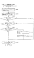
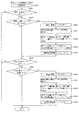
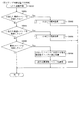
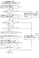
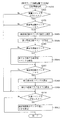
しかしながら、本実施形態は、同時変動タイプの(特図1変動と、特図2変動とが同時に(並行して)実行される機能を有する)遊技機であることから、大当たり遊技終了後に潜確状態が設定された後、右打ち遊技を行い第2入球口640に球を入球させ、特図2抽選(変動)を実行させている最中も、大当たり遊技終了時点で特図1保留が記憶されている場合、或いは、大当たり遊技終了後に発射した球が上1入球口64b1、或いは、下第1入球口64b2へ入球した場合は、特図1抽選が実行されることになる。そして、特図2抽選よりも先に特図1抽選によって大当たりに当選した場合(大当たりを示す表示態様で特図1が停止表示した場合)は、潜確状態中であるにも関わらず遊技者に不利となる大当たり遊技が実行されてしまい、遊技者に不信感を与えてしまうという問題があった。その問題を解決するために、本実施形態では、特図2抽選で小当たりに当選すると(小当たりを示す表示態様で特図2が停止表示した場合に)、実行中の特図1の大当たり変動を、その抽選結果(変動結果)を外れにして強制停止させることが可能となるように構成している。また、特図2の抽選確率として、大当たりに当選する確率(特図高確状態で約1/110)よりも、小当たりに当選する確率(特図高確状態で約1/2)のほうが高確率となるように構成している。このように構成することで、潜確状態が設定されている状態で特図1の大当たり変動が実行されたとしても、その変動期間中に特図2遊技を複数回実行することにより、特図1の大当たり変動を強制的に外れ停止させることが可能となる。よって、潜確状態中に特図1抽選に基づく大当たり遊技(特図2抽選に基づく大当たり遊技よりも遊技者に不利となる大当たり遊技)が実行されてしまうことを抑制することができ、遊技者に不信感を与えることの無い遊技機を提供することができる。加えて、本実施形態では、大当たり遊技終了直後に潜確状態を設定可能に構成していることから、例えば、左打ち遊技によって特図1抽選を実行する特図1遊技によって大当たりに当選し、大当たり遊技終了後に潜確状態が設定される場合では、潜確状態が設定された時点で特図1の保留記憶を有し、特図2の保留記憶を有さない状況が発生し易くなる。この状態において、遊技者が遊技を中断(トイレ休憩)してしまうと、潜確状態中に保留記憶数に対応した回数分、特図1の抽選が実行されてしまい、潜確状態中に特図1の大当たりに当選してしまうという問題があった。そこで、本実施形態では大当たり遊技終了後に潜確状態が設定される場合において、特図1に保留球がある場合には、速やかに右打ち遊技を実行し、第2入球口640へ球を入球させ小当たりに当選させるよう促す演出を第3図柄表示装置81に表示させるよう構成している。このように構成することで、特図2抽選で小当たりに当選させ、潜確状態において遊技者に不利となる大当たり遊技が提供されてしまうことを抑制することができる。
However, since this embodiment is a simultaneous variation type (special figure 1 variation and special figure 2 variation have a function to be executed simultaneously (in parallel)) game machine, the jackpot is determined after the end of the jackpot game After the state is set, the player performs right-handed game and enters the ball into the
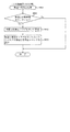
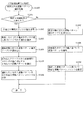
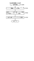
まずは、図7(b)を参照して、大当たり遊技終了後に潜確状態へ移行する場合において、その大当たり遊技終了時(エンディング(ED)時)に特図1保留球がない場合(0個の場合)に実行される演出の表示内容の流れについて説明する。本実施形態では、大当たり遊技中に実行される最後のラウンド遊技の終了後に設定されるエンディング(ED)期間突入時(図7(b)A参照)に特図1保留の有無を判別するように構成しており、その判別によって特図1保留が無い(0である)と判別した場合は、大当たり遊技終了時点までに保留記憶されている特図1保留に基づいて潜確状態中に特図1変動が実行されることが無い(され難い)ため、大当たり遊技のエンディング(ED)期間中において、大当たり遊技終了後に潜確状態(スーパーモード)が設定される旨を示す表示態様(スーパーモード用ED)が表示される。そして、ED期間終了時(図7(b)B参照)、即ち、大当たり遊技が終了し、特図変動(潜確状態の特図変動)が実行される時点で特図1保留球がない場合には、潜確状態を示す表示態様としてスーパーモード(潜確状態に対応するモード)の表示態様を表示する。 First, referring to FIG. 7 (b), when transitioning to the latent state after the end of the jackpot game, there is no special figure 1 holding ball at the end of the jackpot game (ending (ED)) (0 pieces) The flow of the display content of the presentation performed in the case In this embodiment, when the ending (ED) period rushing in (see FIG. 7 (b) A) set after the end of the last round game to be executed during the jackpot game (see FIG. 7 (b) A), it is determined whether or not to suspend If it is determined that the special figure 1 is not held (is 0) according to the judgment, the special figure is in the latent state based on the special figure 1 held which is held and held by the end of the jackpot game. (1) A display mode (for super mode) indicating that the latent state (super mode) is set after the end of the jackpot game during the ending (ED) period of the jackpot game because the fluctuation is never executed (it is difficult to be done) ED) is displayed. And when the ED period end (see FIG. 7 (b) B), that is, when the jackpot game is over and special figure fluctuation (special figure fluctuation of the latent state) is executed, there is no special figure 1 holding ball The display mode of the super mode (the mode corresponding to the latent state) is displayed as a display mode indicating the latent state.
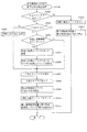
一方、図7(c)に示した通り、大当たり遊技のエンディングED期間突入時に特図1保留球がある(3個ある)場合(図7(c)A参照)と判別した場合には、ED期間中に遊技者に速やかに右打ち遊技を実行するよう促すための表示態様(ダッシュ用ED)が表示される。そして、ED期間終了時、即ち、大当たり遊技が終了し、特図変動(潜確状態の特図変動)が実行される時点で特図1保留球が存在する場合には、遊技者に速やかに右打ち遊技を実行させるための表示態様としてダッシュモードの表示態様を表示する。以上、説明をした通り、本実施形態では、潜確状態が設定される場合において、その潜確状態中に特図1変動(抽選)が実行される条件が予め成立している場合に(潜確状態が設定される大当たり遊技中に特図1保留が存在する場合に)、特図1変動(抽選)の結果に基づく遊技が実行されてしまうことを防止するために、特図2変動(抽選)を積極的に実行させるための表示態様(右打ち遊技を促す表示態様)を、大当たり遊技のED期間から表示するように構成している。これにより、潜確状態中の遊技が開始された直後から特図2変動(抽選)を実行させることができ、その特図2変動(抽選)の小当たり当選によって実行中の特図1変動(抽選)を強制的に外れ停止(破棄)させることができる。よって、潜確状態中に特図1変動(抽選)の結果に基づく遊技が実行されることを抑制することができ、遊技者が不快な思いをし難い遊技を提供することができる。 On the other hand, as shown in FIG. 7 (c), when it is determined that there is a special figure 1 holding ball (there are three balls) at the time of entering the ending ED period of the big hit game (see FIG. 7 (c) A), the ED A display mode (ED for dash) for prompting the player to execute the right-handed game quickly during the period is displayed. Then, when there is a special figure 1 holding ball at the end of the ED period, that is, when the big hit game is over and the special figure fluctuation (special figure fluctuation of the latent state) is executed, the player promptly The display mode of the dash mode is displayed as the display mode for executing the right-handed game. As described above, in the present embodiment, when the latent state is set, the special figure 1 fluctuation (lottery) is executed during the latent state in the present embodiment (the latent state is established in advance (latent). In order to prevent a game based on the result of the special figure 1 fluctuation (lottery drawing) from being executed, the special figure 2 fluctuation ( A display mode (a display mode for prompting a right-handed game) for actively executing the lottery is configured to be displayed from the ED period of the big hit game. Thereby, it is possible to execute the special figure 2 fluctuation (lottery drawing) immediately after the game in the latent state is started, and the special figure 1 fluctuation (running) by the small hitting of the special figure 2 fluctuation (lottery drawing) The lottery can be forcibly removed (stopped). Therefore, it is possible to suppress that the game based on the result of the special figure 1 fluctuation (lottery drawing) is executed during the latent state, and it is possible to provide the game in which the player is less likely to feel uncomfortable.
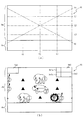
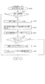
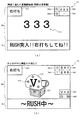
次に、大当たり遊技のエンディング(ED)期間中に表示される表示内容について、図6を参照して具体的に説明をする。図6(a)は、大当たり遊技のエンディング(ED)期間の開始時に特図1の保留球が存在している場合におけるED中の表示画面の一例を示した図である。図6(a)に示した通り、第3図柄表示装置81の主表示領域Dmには、ウサギのキャラクタ811とカメのキャラクタ814を表示されている。本実施形態では、遊技者に有利な遊技状態が設定される場合に、特定のキャラクタ(キャラクタ811,814)が表示画面に表示するように構成している。このように構成することにより、遊技者は表示画面にキャラクタ811やキャラクタ814が表示されているか否かを把握することにより、現在設定されている遊技状態の概要(有利度合い)を把握することができるため、分かり易い遊技を提供することができる。
Next, the display contents displayed during the ending (ED) period of the jackpot game will be specifically described with reference to FIG. FIG. 6A is a view showing an example of a display screen in the ED when the holding ball of the
図6(a)は、通常状態が設定されている状態で、特図1抽選(変動)で大当たりに当選し、大当たり遊技として、図2に示した左可変入賞装置65(第1アタッカ)が開放動作されるラウンド遊技が2回(2ラウンド)実行され、その大当たり遊技の終了後に潜確状態が設定される「2R潜確大当たり」が実行された場合のエンディング画面の一例を示したものである。この「2R潜確大当たり」では、大当たり遊技中に第1アタッカへ球を入賞させるための左打ち遊技を実行させるため、ラウンド遊技中(大当たり遊技が開始されてから、2ラウンド目のラウンド遊技が終了するまでの期間)は、表示領域Dm3に「左打ち」のコメントが表示される。そして、図6(a)に示した通り、大当たり遊技のエンディング期間の開始時に特図1の保留球が存在している場合には、表示領域Dm3に「右打ち」の案内表示態様が表示されると共に、副表示領域Dsに、右打ち遊技を促すために「急いで右打ちして亀より先にゴールしろ!!」とのコメントが表示される。これにより遊技者に急いで(エンディング期間中から)右打ち遊技を行う必要性があることを分かりやすく報知することが出来る。つまり、図6(a)に示した例によれば、大当たり当選する前の遊技、及び大当たり遊技、共に左打ち遊技が行われているため、第2特別図柄(特図2)の保留球が0のまま、潜確状態が設定されることになり、潜確状態中に特図1抽選(変動)のみが実行されてしまう虞がある。これに対して、本実施形態では、潜確状態が設定されるよりも前の時点(大当たり遊技のエンディング期間)で、遊技者に対して特図2の保留球を獲得させるための遊技(左打ち遊技)を促すための表示態様を表示するように構成しているため、潜確状態が設定されてから特図2変動(抽選)が実行されるまでの期間を短縮することができる。よって、潜確状態中に特図1抽選の結果に基づく遊技(例えば、特図1大当たり遊技)が実行され難くすることができる。
In FIG. 6 (a), in the state in which the normal state is set, the special figure 1 lottery (fluctuation) wins a jackpot, and the left variable winning device 65 (first attacker) shown in FIG. It shows an example of the ending screen when “2R latent certain jackpot” is executed, in which a round game to be opened is performed twice (two rounds) and a latent state is set after the end of the jackpot game. is there. In this “2R latent probability big hit”, in order to execute the left hitting game for winning the ball to the first attacher during the big hit game, during the round game (from the start of the big hit game, the second round game round During the period until the end, the comment “left-handed” is displayed in the display area Dm3. Then, as shown in FIG. 6A, when the holding ball of the
さらに、図6(a)に示した通り、現在の特図1保留球の数を示唆するための保留示唆表示態様が小表示領域Dm4a〜小表示領域Dm4eに表示されている。ここで、小表示領域Dm4a〜小表示領域Dm4eは、特図1保留球の数を示唆するための保留示唆表示態様が表示される表示領域であって、具体的には、保留球数が1の場合はDm4a〜Dm4bが、保留球数が2の場合はDm4a〜Dm4cが、保留球数が3の場合はDm4a〜Dm4dが、保留球数が4の場合はDm4a〜Dm4eが点灯表示されるように保留示唆表示態様が形成される。そして小表示領域Dm4aには「GOAL」の文字が表示されており、特図1保留球数が「0」となった場合に、キャラクタ811がゴールに到達する演出が実行される。このように、特図1保留球数を0にすることを目的とした遊技性を有するダッシュモードにおいて、特図1保留球数が減算されていく過程を、遊技者が視覚的に判別可能となるように構成することにより、遊技者に分かり易い演出を提供することができる。なお、図6(a)は、小表示領域Dm1aに「3」、即ち、現在の特図1保留球数が3個であるため、表示領域Dm4a〜表示領域Dm4dが点灯表示されている。また、第1特別図柄の抽選結果を示すための第4図柄が表示される表示領域Dm1には、実行中の大当たり遊技に対応する大当たり図柄「555」が、第2特別図柄の抽選結果を示すための第4図柄が表示される表示領域Dm2には、前回の第2特別図柄の抽選結果が外れであることを示すための図柄「246」が表示されており、小表示領域Dm5には、今回の大当たり遊技(2R潜確大当たり)にて獲得した賞球数を示すための賞球表示態様として「100」の文字が、小表示領域Dm6には、大当たり遊技の進捗状況を報知するための「ラウンドEND」の文字が表示される。
Furthermore, as shown to Fig.6 (a), the reservation indication display mode for suggesting the number of present special figure 1 reservation balls is displayed on the small display area Dm4a-the small display area Dm4e. Here, the small display area Dm4a to the small display area Dm4e are display areas in which a reservation indication display mode for suggesting the number of
次に、潜確状態が設定された時点で特図1保留球が存在している場合に表示される表示内容について、図6(b)を参照して説明をする。本実施形態では潜確状態が設定される時点で特図1保留球が存在していると判別した場合は、図6(b)に示した通り、潜確状態中であっても、ダッシュモードが継続して設定されるように構成している。潜確状態中は、右打ち遊技によって第2入球口640に球を入球させ、第2特別図柄の抽選(変動)を実行することが遊技者に有利となるよう構成されている。そして、第2特別図柄で大当たり、或いは、小当たりに当選すると第1特別図柄の変動(抽選)を仮停止、或いは、外れで強制停止させることが可能である。更に、潜確遊技中の第2特別図柄の抽選において1/2は小当たりに当選するよう構成されており、変動時間も潜確状態中においては第1特別図柄の方が第2特別図柄より長い変動時間が設定されているため、第2特別図柄の変動中に第1特別図柄で遊技者に不利となる大当たりに当選する可能性はごく稀である。
Next, the display contents displayed when the special figure 1 holding ball is present when the latent state is set will be described with reference to FIG. 6 (b). In this embodiment, when it is determined that the special figure 1 holding ball is present when the latent state is set, as shown in FIG. 6B, the dash mode is in the latent state as well. Is configured to be set continuously. During the latent state, it is configured that it is advantageous for the player to execute a lottery (variation) of the second special symbol by causing the ball to enter the
しかしながら、潜確状態移行後に第1特別図柄のみ保留球数がある場合に遊技者が右打ち遊技を実行しないと、第1特別図柄の変動時間が経過し遊技者に不利となる大当たりに当選してしまう可能性があった。そこで、本実施形態では大当たり終了後に第1特別図柄の保留球がある場合には、潜確状態中に表示されるスーパーモードではなく、遊技者に右打ち遊技を速やかに実行させるためのダッシュモードを表示し、第1特別図柄の保留球を消化させるための演出を実行する。 However, if the player does not execute the right-handed game when there is only the first special symbol holding ball number after the transition to the latent state, the variation time of the first special symbol elapses and the player wins a jackpot which is disadvantageous to the player. There was a possibility of Therefore, in the present embodiment, when there is a holding ball of the first special symbol after the big hit end, it is not the super mode displayed during the latent state but the dash mode for making the player execute the right-handed game promptly. Is displayed, and the effect for digesting the holding ball of the first special symbol is executed.
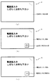
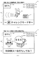
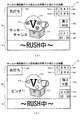
図7(b)では、主表示領域Dmの中央にはウサギを模したキャラ811と亀を模したキャラ814がGOAL812を目指して競争している様子が表示画面中央に表示され、副表示領域Dsには、「急いで右打ちしろ!!」のコメントが表示される。さらに小表示領域Dm3にも「右打ち」の案内表示態様が表示される。このように副表示領域Dsと小表示領域Dm3とどちらにも右打ちを案内する表示態様を表示することで、遊技者により強調して右打ち遊技について報知することが出来る。また、遊技者への不利度合いに応じて、遊技者に対して適正な遊技方法を案内するための案内表示態様の内容を可変させることにより、遊技者が不利な遊技を継続して実行してしまうことを抑制することができる。
In FIG. 7B, a state in which a
そして、小表示領域Dm1と小表示領域Dm2とには第1特別図柄と第2特別図柄とが変動中であることを表示しており、小表示領域Dm2aには第2特別図柄の保留球数を2つ獲得した状態が表示している。また、小表示領域Dm1aには第1特別図柄の保留球数が1つであることを表示している。よって、上述したように小表示領域Dm4a〜Dm4bには第1特別図柄の保留球数が1であることを示す点灯表示がされる。 The small display area Dm1 and the small display area Dm2 indicate that the first special symbol and the second special symbol are changing, and the small display area Dm2a holds the number of holding balls of the second special symbol. It shows the state of having won two. Further, in the small display area Dm1a, it is displayed that the number of holding balls of the first special symbol is one. Therefore, as described above, the small display areas Dm4a to Dm4b are lit and displayed to indicate that the number of holding balls in the first special symbol is one.
図7(c)に戻り説明を続ける。ダッシュモードは第1特別図柄の保留球数が0になった場合に終了し、潜確状態に対応するスーパーモード用の演出に切り替わる。 Returning to FIG. 7 (c), the explanation will be continued. The dash mode ends when the number of holding balls in the first special symbol becomes 0, and switches to the effect for the super mode corresponding to the latent state.
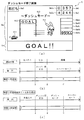
ここで図7(a)を参照して、ダッシュモード終了を示す表示画面について説明する。本実施形態では、上述したように第2特別図柄で大当たり、或いは、小当たりに当選すると第1特別図柄の変動を仮停止、或いは、外れ図柄で強制停止するよう構成されており、ダッシュモードは潜確状態中に第2特別図柄で小当たりに当選することによって、第1特別図柄の保留球数が0になった場合に終了し、潜確状態であることを遊技者に示すスーパーモードの表示態様となる。 Here, with reference to FIG. 7A, a display screen indicating the end of the dash mode will be described. In the present embodiment, as described above, when the jackpot is won by the second special symbol, or when the win is made, the variation of the first special symbol is configured to be temporarily stopped or forcibly stopped by the outlier, and the dash mode is It is ended when the number of holding balls in the first special symbol becomes 0 by winning a small hit with the second special symbol in the latent state, and the player is shown in the super mode to indicate that the latent state is in the latent state. It becomes a display mode.
主表示領域Dmの中央には、ダッシュモード中競争をしていたウサギを模したキャラ811が亀を模したキャラ814より先にGOAL812を通過している様子が表示される。そして、副表示領域Dsには「GOAL!!」のコメントが表示され、遊技者に対し、ダッシュモードが終了したことを分かりやすく報知している。
At the center of the main display area Dm, it is displayed that a
そして、小表示領域Dm2に、第2特別図柄の抽選結果が小当たりであることを示す表示態様「246」で第4図柄が停止表示されると同時に、小表示領域Dm1に、第1特別図柄の抽選結果が外れを示す表示態様「357」で第4図柄が強制的に停止表示される。また上表示領域Dm4aが点灯表示され第1特別図柄の保留球数がなくなったことを遊技者に分かりやすく報知し、ダッシュモードを終了する。 And at the same time as the fourth symbol is stopped and displayed in the small display area Dm2 in the display mode "246" indicating that the lottery result of the second special symbol is a small hit, the first special symbol is displayed in the small display area Dm1. The fourth symbol is forcibly stopped and displayed in the display mode "357" in which the result of the lottery indicates the disconnection. Further, the upper display area Dm4a is lighted and displayed, and the player is informed in an easy-to-understand manner that the number of holding balls in the first special symbol has disappeared, and the dash mode is ended.
なお、本実施形態では、第2特別図柄で小当たりに当選し、実行中の特図1変動を強制的に外れで停止させる(特図1変動を破棄する)場合、第1特別図柄の抽選結果を表示する表示領域Dm1に、実際の抽選結果では無く強制外れ図柄「357」を停止させるように構成しているが、これに限ること無く、破棄された特図1変動(抽選)の変動結果(抽選結果)を遊技者に示唆(報知)可能な表示態様で外れ図柄を停止表示させるように構成すると良く、例えば、表示領域Dm1に表示される外れ図柄「357」の色を可変させることにより、破棄された特図1抽選の結果を遊技者に示唆可能に構成すると良い。具体的には、「357」の表示態様が赤色で表示された場合には、破棄された特図1抽選の抽選結果が「大当たり」であったことを示し、虹色で表示された場合には、「大当たり」のうち、「遊技者に不利となる大当たり(例えば、大当たり遊技中に獲得可能な賞球数が最も少なく、且つ、大当たり遊技終了後に潜確状態が設定されることが無い大当たり)」であったことを示すように構成すれば良い。このように構成することで、特図1変動が破棄されて外れとなった旨と、破棄された特図1抽選の抽選結果と、を遊技者に把握させることが可能となる。よって、特図1抽選を破棄したことにより付与された特典を遊技者に容易に把握させることができる。さらに、表示領域Dm1内の表示態様では無く、主表示領域Dmの第3図柄の停止表示態様や小当たり遊技中に獲得した賞球数を示すための表示態様を可変することにより破棄された特図1抽選の結果を示唆(報知)しても良いし、音声出力手段や発光手段を用いて示唆(報知)しても良い。このように構成することで、遊技者は不利な大当たりに当選してしまうことを防ぐことが出来たという安心感を得ることができる。また、先読み結果が大当たりである場合にはその変動表示の色などを可変して表示してもよい。このように構成することで、遊技者に分かりやすい遊技を提供することができ、さらに演出効果を高めることが出来る。 In addition, in this embodiment, when winning a small hit with the second special symbol and forcibly stopping the special figure 1 fluctuation under execution by disengaging it (discarding the special figure 1 fluctuation), the lottery of the first special symbol In the display area Dm1 displaying the result, not the actual lottery result but the forced removal symbol "357" is stopped, but the present invention is not limited to this, and the fluctuation of the discarded special figure 1 fluctuation (lottery) It is good to constitute so as to stop and display off symbols in a display mode that can suggest (inform) the result (lottery result) to the player, for example, to change the color of off symbol “357” displayed in the display area Dm1 It is preferable that the player be able to suggest to the player the result of the special figure 1 lottery which has been discarded. Specifically, when the display mode of "357" is displayed in red, it indicates that the lottery result of the discarded special figure 1 lottery is "big hit" and is displayed in rainbow color. Among the "big hit", "the big hit which is disadvantageous to the player (for example, the number of winning balls obtainable during the big hit game is the smallest, and the jackpot state is not set after the big hit game is over) It may be configured to indicate that it is ")". By configuring in this manner, it is possible to make the player grasp that the special figure 1 fluctuation has been discarded and has come off, and the lottery result of the special figure 1 lottery that has been discarded. Therefore, it is possible to make the player easily grasp the benefit given by discarding the special figure 1 lottery. Furthermore, it is not the display mode in the display area Dm1 but the special display discarded by changing the display mode for indicating the stop display mode of the third symbol of the main display area Dm or the number of winning balls acquired during the small hitting game. The results of the lottery may be suggested (notified) or may be suggested (notified) using an audio output means or a light emitting means. By configuring in this manner, it is possible to obtain a sense of security that the player can be prevented from winning an adverse jackpot. Further, when the pre-reading result is a big hit, the color of the variable display may be changed and displayed. By configuring in this manner, it is possible to provide an easy-to-understand game to the player, and it is possible to further enhance the rendering effect.
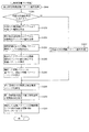
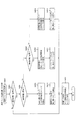
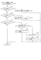
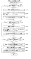
<第1実施形態におけるパチンコ機10の遊技状態の遷移について>
次に、図8を参照して、本第1実施形態におけるパチンコ機10の遊技状態の遷移について説明をする。図8は本第1実施形態におけるパチンコ機10にて設定される遊技状態の流れを示した遷移図である。
<About transition of the gaming state of the
Next, with reference to FIG. 8, the transition of the gaming state of the
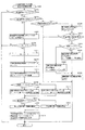
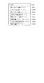
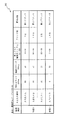
図8に示した通り、本第1実施形態では、遊技状態として、通常状態(特別図柄の低確率状態、普通図柄の低確率状態)、確変状態(特別図柄の高確率状態、普通図柄の高確率状態)、潜確状態(特別図柄の高確率状態、普通図柄の低確率状態)と、3つの遊技状態が設定可能に構成されており、当選した大当たりの種別、及び、大当たり当選時の遊技状態に応じて予め定められた遊技状態が設定されるように構成している(図13、図14参照)。ここで設定される複数の遊技状態は、遊技者への有利度合いが異なるように構成されており、潜確状態が遊技者にとって最も有利な遊技状態となるように構成されている。 As shown in FIG. 8, in the first embodiment, as the gaming state, the normal state (the low probability state of the special symbol, the low probability state of the normal symbol), the positive variation state (the high probability state of the special symbol, the high normal symbol) Probability status), latency status (special symbol high probability status, normal symbol low probability status) and three game status can be set, the type of jackpot winning, and the game when jackpot winning A predetermined gaming state is set according to the state (see FIGS. 13 and 14). The plurality of gaming states set here are configured such that the degree of advantage to the player is different, and the latent state is configured to be the most advantageous gaming state for the player.
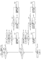
まず、遊技状態として通常状態が設定されている場合について説明をする。本実施形態のパチンコ機10では、初期状態(主制御装置110の立ち上げ処理(図51参照)にてRAM消去スイッチ122(図9参照)が操作されたと判別した際の処理が実行された状態)の遊技状態として通常状態が設定される。
First, the case where the normal state is set as the gaming state will be described. In the
この通常状態中において、第1特別図柄(特図1)の抽選にて大当たりに当選した場合に、大当たり種別として大当たりA(大当たり当選の71%)が設定されると、その大当たり遊技終了後に確変状態(チャレンジモード)が設定され、大当たりB(大当たり当選の25%)、或いは大当たりC(大当たり当選の4%)が設定されると、その大当たり遊技終了後に潜確状態(スーパーモード)が設定されているよう構成している。一方、通常状態中に、第2特別図柄(特図2)の抽選にて大当たりに当選した場合には、大当たり種別として大当たりDが設定され(大当たり当選の100%)、その大当たり遊技終了後に潜確状態(スーパーモード)が設定されるように構成している。 In this normal state, if the jackpot A (71% of the jackpot win) is set as the jackpot type when the jackpot is won in the first special symbol (special figure 1) lottery, the probability variation after the jackpot game is over When the state (challenge mode) is set and the jackpot B (25% of the jackpot win) or the jackpot C (4% of the jackpot win) is set, the latent state (super mode) is set after the jackpot game is over Are configured to On the other hand, if the jackpot is won in the second special symbol (special figure 2) lottery during the normal state, the jackpot D is set as the jackpot type (100% of the jackpot win) and the latent after the jackpot game is over The confirmation state (super mode) is set.
つまり、通常状態において特図1抽選で大当たりに当選した場合には、71%の確率でチャレンジモード(確変状態)に突入し、29%の確率でスーパーモード(潜確状態)に突入する。また、特図2抽選で大当たりに当選した場合には、100%の確率でスーパーモード(潜確状態)が設定されるように構成している。なお、本実施形態では、通常状態中に特図2変動(抽選)が実行される場合に、長時間(例えば、10分)の変動時間が設定されるように構成している。よって、実際には、通常状態中の特図2抽選を実行させるための遊技(右打ち遊技)が行われることが無い。なお、本実施形態では、通常状態中の特図2変動の変動時間として、特図2抽選の抽選結果に関わらず長時間変動が設定されるように構成しているが、これに限ること無く、例えば、通常状態が設定されてからの所定回数のみ特図2変動の変動時間として短い変動時間が設定され易くなるように構成しても良いし、大当たりに当選している場合の変動(大当たり変動)のみ、短い変動時間(例えば、5秒)が設定されるように構成しても良い。ここで、本実施形態では累計の大当たり回数(通常状態で大当たり(初当たり)に当選してからの大当たり回数)が3回(初当たり含む)に到達した場合には(リミット回数に到達した場合には)、その大当たり遊技の終了後に通常状態が設定されるように構成しているため、例えば、右打ち遊技が実行される潜確状態が設定されている状態でリミット回数に到達すると、特図2保留を獲得した状態で通常状態が設定される場合がある。このような場合においても、通常状態が設定されてからの所定回数のみ特図2変動の変動時間として短い変動時間が設定され易くなるように構成することにより、潜確状態中に獲得した特図2保留を円滑に消化(抽選の実行)することができる。さらに、通常状態が設定されている状態で特図2抽選の大当たりに当選した場合は、特図1抽選の大当たりに当選した場合よりも高い確率(本実施形態では100%)で潜確状態が設定されるため、遊技者に有利な抽選を円滑に実行することができる。 That is, when winning a big hit in the special figure 1 lottery in the normal state, it enters into the challenge mode (probability variation state) with a probability of 71%, and enters the super mode (latency state) with a probability of 29%. In addition, when winning a big hit in the special figure 2 lottery, it is configured such that the super mode (latency state) is set with a probability of 100%. In the present embodiment, when the special figure 2 fluctuation (lottery drawing) is executed in the normal state, the fluctuation time of a long time (for example, 10 minutes) is set. Therefore, actually, a game (right-handed game) for executing the special figure 2 lottery in the normal state is not performed. In the present embodiment, as the fluctuation time of the special figure 2 fluctuation in the normal state, the long time fluctuation is set regardless of the lottery result of the special figure 2 lottery, but the present invention is not limited thereto. For example, it may be configured such that a short fluctuation time is easily set as the fluctuation time of the special figure 2 fluctuation only a predetermined number of times after the normal state is set, or the fluctuation when the jackpot is won (big hit Only the fluctuation) may be configured to set a short fluctuation time (for example, 5 seconds). Here, in the present embodiment, when the number of cumulative big hits (the number of big hits since winning a big hit (first hit) in a normal state) reaches 3 times (including the first hit) (when the limit number of times is reached ), So that the normal state is set after the end of the jackpot game, for example, when the limit number of times is reached in the state where the latent state where the right-handed game is executed is set, The normal state may be set in the state of FIG. Even in such a case, the special figure acquired during the latent state by configuring so that a short variation time is easily set as the variation time of the special figure 2 only a predetermined number of times after the normal state is set. (2) It is possible to smoothly manage the suspension (execution of the lottery). Furthermore, when the jackpot of the special figure 2 lottery is won in the state where the normal state is set, the latent state is 100% higher than the probability of winning the jackpot of the special figure 1 lottery (100% in this embodiment) Since the setting is made, it is possible to smoothly execute the lottery which is advantageous to the player.
このように、本実施形態では、大当たり遊技中における遊技内容によって、その大当たり遊技後に設定される遊技状態が異なるように構成しているため、大当たり遊技中に実行される遊技の興趣を向上させることができる。 As described above, in the present embodiment, the gaming state set after the big hit is different depending on the game content in the big hit game, so the interest of the game to be executed during the big hit is improved. Can.
次に、遊技状態として確変状態(特別図柄の高確率状態、普通図柄の高確率状態)が設定されている場合における遊技状態の移行の流れについて説明をする。本実施形態では、確変状態が設定されている間は、左打ち遊技を実行し、特図1の抽選が実行されるよう構成している。そして、確変状態中に、特図1の抽選で大当たりに当選した場合には、大当たり種別として大当たりA(大当たり当選の60%)が設定されると、その大当たり遊技終了後に、確変状態(チャレンジモード)がループするよう設定される。また、大当たりB(大当たり当選の25%)と大当たりC(大当たり当選の15%)とが設定されると、潜確状態(スーパーモード)が設定される。
Next, the flow of transition of the gaming state will be described in the case where a probability change state (special symbol high probability state, normal symbol high probability state) is set as the gaming state. In the present embodiment, while the probability change state is set, the left-handed game is executed, and the lottery of the
また、保留記憶されている特図2保留に基づいて実行された特図2の抽選で大当たりに当選した場合には、大当たり種別として大当たりD(大当たり当選の100%)が設定される。その大当たり遊技終了後に再度確変状態が設定されるように構成している。 In addition, when the jackpot is won in the lottery of the special figure 2 executed based on the special figure 2 reserve stored on hold, the jackpot D (100% of the jackpot win) is set as the jackpot type. After the jackpot game is finished, a positive change state is set again.
つまり、確変状態において特図1抽選で大当たりに当選した場合には、60%の確率で確変状態(チャレンジモード)がループするよう設定され、40%の確率で潜確状態(スーパーモード)が設定される。そして、特図2抽選で大当たりに当選した場合には、100%の確率で確変状態が設定されるように構成している。つまり、本実施形態では、通常状態が設定されている場合よりも、確変状態が設定されているほうが、大当たり当選に基づいて潜確状態へと移行し易くなるように構成している。これにより、潜確状態へと移行する期待度を段階的に上昇させることができるため、遊技者が遊技に早期に飽きてしまうことを抑制することができる。また、本実施形態では、大当たり回数が所定回数(3回)に到達した場合に、その大当たり遊技の終了後に強制的に通常状態が設定されるように構成しているため、通常状態中に大当たりに当選した場合よりも、通常状態で大当たりに当選し、その大当たりで潜確状態に移行しなかった場合に移行される確変状態中に大当たりに当選した場合のほうが、潜確状態への移行割合を高く設定したとしても、遊技者に対して過剰に特典が付与されることが無い。 In other words, if you win the jackpot in the special figure 1 lottery in the definite variation state, the probability variation state (challenge mode) is set to loop with a probability of 60%, and the latent state (super mode) is set with a probability of 40% Be done. And, when winning a big hit in the special figure 2 lottery, it is configured such that the probability variation state is set with a probability of 100%. That is, in the present embodiment, it is configured that transition to the latent state becomes easier based on the jackpot win if the positive change state is set than when the normal state is set. As a result, since the degree of expectation to shift to the latent state can be raised stepwise, it is possible to suppress that the player gets bored with the game early. Further, in the present embodiment, when the number of big hits reaches a predetermined number of times (three times), since the normal state is forcibly set after the end of the big hit game, the large hit in the normal state The percentage of transition to the latent status in the case where the jackpot is won during the probability change state where the jackpot is won in the normal state and the transition to the latent state is not made in the jackpot than in the case of winning the Even if is set to a high value, the player will not receive an extra benefit.
最後に、遊技状態として潜確状態(特別図柄の高確率状態、普通図柄の低確率状態)が設定されている状態における遊技状態の移行の流れについて説明をする。本実施形態では、潜確状態が設定されている間は、右打ち遊技によって特図2の抽選を主に実行させる遊技が行われる。そして、特図2の抽選で大当たりに当選した場合に、大当たりの種別として大当たりD(大当たり当選の100%)が設定されると、その大当たり遊技の終了後に、再度潜確状態が設定される。
Finally, the flow of transition of the gaming state in the state where the latent state (special symbol high probability state, normal symbol low probability state) is set as the gaming state will be described. In the present embodiment, while the latent state is set, a game is performed in which the lottery of the
一方、遊技状態として潜確状態が設定されている状態において、特図1の抽選で大当たりに当選した場合には、大当たり種別として大当たりA(大当たり当選の60%)が設定されると、その大当たり遊技終了後に確変状態が設定され、大当たりB(大当たり当選の25%)と大当たりC(大当たり当選の15%)とが設定されると、その大当たり遊技終了後に再度、潜確状態(スーパーモード)が設定される。 On the other hand, in the state where the latent state is set as the gaming state, if the jackpot A (60% of the jackpot win) is set as the jackpot type, if the jackpot is won in the lottery of special figure 1, the jackpot If the jackpot B (25% of the jackpot win) and the jackpot C (15% of the jackpot win) are set after the game is over and the jackpot B (25% of the jackpot win) is set, the latent state (super mode) It is set.
つまり、潜確状態において特図1抽選で大当たりに当選した場合には、40%の確率で全力モード(潜確状態)をループし、60%の確率で確変状態が設定され、特図2抽選で大当たりに当選した場合には、100%の確率で潜確状態(スーパーモード)をループする。さらに、本実施形態では、潜確状態中に実行される特図変動の変動時間として、特図1よりも、特図2のほうが短い変動時間が設定され易くなるように構成している。よって、潜確状態中は、特図2抽選を狙う右打ち遊技が遊技者に有利な遊技方法となる。加えて、本実施形態では、特図2抽選において、大当たりに当選しなかった場合の一部で小当たりに当選するように構成している。この小当たりに当選すると、大当たりよりも遊技者に付与可能な特典の量が少ない小当たり遊技が実行される。また、本実施形態では、特図2抽選において小当たりに当選する確率(約1/2)が大当たりに当選する確率よりも高く設定されている。よって、潜確状態が設定されると、右打ち遊技を行い、大当たりに当選するまでの間、小当たり遊技を複数回実行することができる。このように構成することで、潜確状態中に特図2抽選で大当たりに当選しない期間(連続して大当たり以外の抽選結果となる期間)が長くなったとしも、その分、多くの小当たり遊技を実行することができるため、遊技者が遊技に早期に飽きてしまうことを抑制することができる。 That is, when winning a big hit in the special figure 1 lottery in the latent state, the full power mode (latency state) is looped with a probability of 40%, a definite variation state is set with a probability of 60%, and the special figure 2 lottery If the jackpot is won, the latent state (super mode) is looped with 100% probability. Furthermore, in the present embodiment, as the fluctuation time of the special figure fluctuation that is executed during the latent state, the special figure 2 is configured to be easier to set a shorter fluctuation time than the special figure 1. Therefore, while in the latent state, the right-hand game aiming for the special figure 2 lottery is a game method advantageous to the player. In addition, in the present embodiment, in the special figure 2 lottery, it is configured to win the small hit in a part of the case where the big hit is not won. When the player wins this small hit, a small hit game is executed in which the amount of the privilege that can be given to the player is smaller than that of the big hit. Moreover, in this embodiment, the probability (about 1/2) of winning in a small hit in the special figure 2 lottery is set higher than the probability of winning in a large hit. Therefore, when the latent state is set, the right hitting game can be performed, and the small hitting game can be executed a plurality of times until the jackpot is won. By configuring in this manner, it is assumed that the period during which the jackpot is not won in the special figure 2 lottery during the latent state (the period in which the lottery results other than the jackpot continuously occur) becomes long, but many small hits Since the game can be executed, it is possible to suppress that the player gets bored early in the game.
よって、本実施形態は、潜確状態が設定されている状態では、特図2の抽選を実行したほうが遊技者に有利な遊技状態である潜確状態を確実にループできるように構成されていることから、特図1よりも特図2のほうが遊技者に有利な抽選を実行する特別図柄となる。
Therefore, in the present embodiment, in the state where the latent state is set, it is possible to surely loop the latent state which is a gaming state that is more advantageous to the player if the drawing of the
加えて、本実施形態のパチンコ機10では、大当たり回数が3回に到達すると、その3回目の大当たり遊技終了後、必ず通常状態が設定されるよう構成している。よって最初の大当たりで潜確状態へ移行する大当たり種別に当選すると、次の大当たり2回は、必ず遊技者に最も有利となる大当たりDに当選する特図2遊技を実行することができる。
In addition, in the
以上、説明をした通り、本実施形態のパチンコ機10では、潜確状態以外の遊技状態が設定されている状態、即ち、特図1の抽選を実行させることが適正な遊技方法として規定されている遊技状態中に特図2遊技が実行され、大当たりに当選してしまった場合、遊技者に最も有利となる潜確状態が設定されてしまい、遊技者に過度な特典が付与されてしまう恐れがある。
As described above, in the
よって、本実施形態では、通常状態が設定されている状態で特図2抽選が実行された場合に、長時間(10分)の変動時間が設定されるように構成している。これにより通常状態中において頻繁に特図2抽選が実行されないようにすることができるため、通常状態における遊技者に過度な特典(有利な遊技状態を設定する特典)が付与されてしまうことをより抑制することができる。 Therefore, in the present embodiment, when the special figure 2 lottery is executed in the state where the normal state is set, the fluctuation time of a long time (10 minutes) is set. As a result, it is possible to prevent the special figure 2 lottery from being executed frequently in the normal state, and it is possible to prevent the player in the normal state from being given an excessive privilege (a privilege to set an advantageous gaming state). It can be suppressed.
加えて、普通図柄の低確率状態である通常状態中において、適正な遊技(左打ち遊技)とは異なる遊技(右打ち遊技)を実行し、特図2抽選が実行されたとしても、遊技者に過度な特典(有利な遊技状態を設定する特典)が付与されてしまうことを抑制することができる。 In addition, during the normal state where the normal symbol is in a low probability state, the player executes a game (right-handed game) different from the appropriate game (left-handed game) and the special figure 2 lottery is executed, the player It is possible to suppress that an excessive benefit (a benefit to set an advantageous gaming state) is given.
なお、本実施形態では、確変状態が設定された場合に、通常状態が設定されている状態よりも、特別図柄の大当たり確率を高確率に設定し、且つ、第2入球口640に球が入球し難くなるように構成することで特図2抽選が実行され難く構成しているが、これに限ること無く、確変状態が設定された場合に、通常状態が設定されている状態よりも、特別図柄の大当たり確率を高確率に設定し、且つ、新たな特図2抽選が実行され易くなるように(特図1抽選よりも特図2抽選が実行され易くなるように)普通図柄の変動時間や特別図柄の変動時間を設定するように構成しても良く、具体的には、確変状態が設定されている状態は、通常状態が設定されている状態よりも、第2特別図柄の変動時間として設定される時間が短くなるように(例えば、3分)構成しても良い。
In the present embodiment, when the probability change state is set, the jackpot probability of the special symbol is set to a higher probability than the state in which the normal state is set, and the ball is in the
このように構成することで、確変状態が設定された場合に、遊技者に最も有利な遊技状態である潜確状態への移行を目指して第1特別図柄(特図1)の抽選を行う遊技(左打ち遊技)と、潜確状態へ移行することは無いが、多くの特別図柄抽選を実行することにより、様々な変動演出(大当たり演出)を見ることを目指して第2特別図柄(特図2)の抽選を行う遊技(右打ち遊技)と、を遊技者が選択することができる。 By configuring in this manner, when a definite change state is set, a game is performed in which a lottery of the first special symbol (special figure 1) is performed aiming at the transition to the latent state which is the game state most advantageous to the player. There is no transition to the latent condition (left-handed game), but by executing many special symbol lottery, the second special symbol (special figure (special design) is aimed at looking at various variation effects (big hit effects) The player can select a game (right-handed game) in which the lottery of 2) is made.
<第1実施形態におけるパチンコ機10の電気的構成について>
次に、図4を参照して、本パチンコ機10の電気的構成について説明する。図4は、パチンコ機10の電気的構成を示すブロック図である。
Regarding Electrical Configuration of
Next, the electrical configuration of the
主制御装置110には、演算装置である1チップマイコンとしてのMPU201が搭載されている。MPU201には、該MPU201により実行される各種の制御プログラムや固定値データを記憶したROM202と、そのROM202内に記憶される制御プログラムの実行に際して各種のデータ等を一時的に記憶するためのメモリであるRAM203と、そのほか、割込回路やタイマ回路、データ送受信回路などの各種回路が内蔵されている。なお、払出制御装置111や音声ランプ制御装置113などのサブ制御装置に対して動作を指示するために、主制御装置110から該サブ制御装置へ各種のコマンドがデータ送受信回路によって送信されるが、かかるコマンドは、主制御装置110からサブ制御装置へ一方向にのみ送信される。
The
主制御装置110では、特別図柄の抽選、普通図柄の抽選、第1図柄表示装置37における表示の設定、第2図柄表示装置83における表示の設定、および、第3図柄表示装置81における表示の設定といったパチンコ機10の主要な処理を実行する。そして、RAM203には、これらの処理を制御するための各種カウンタが設けられている。ここで、図9を参照して、主制御装置110のRAM203内に設けられるカウンタ等について説明する。図9は、主制御装置110のRAM203内に設けられるカウンタ等を模式的に示した模式図である。これらのカウンタ等は、特別図柄の抽選、普通図柄の抽選、第1図柄表示装置37における表示の設定、第2図柄表示装置83における表示の設定、および、第3図柄表示装置81における表示の設定などを行うために、主制御装置110のMPU201で使用される。
In
特別図柄の抽選や、第1図柄表示装置37および第3図柄表示装置81の表示の設定には、特別図柄の抽選に使用する第1当たり乱数カウンタC1と、特別図柄の大当たり種別を選択するために使用する第1当たり種別カウンタC2と、特別図柄における外れの停止種別を選択するために使用する停止種別選択カウンタ(図示せず)と、特別図柄の小当たり種別を選択するために使用する小当たり種別カウンタC5と、第1当たり乱数カウンタC1の初期値設定に使用する第1初期値乱数カウンタCINI1と、変動パターン選択に使用する変動種別カウンタCS1と、が用いられる。
In order to select the jackpot type of the special symbol and the first random number counter C1 used for the lottery of the special symbol, in the drawing of the special symbol and the setting of the display of the first
また、普通図柄の抽選には、第2当たり乱数カウンタC4が用いられ、第2当たり乱数カウンタC4の初期値設定には第2初期値乱数カウンタCINI2と、普通図柄の変動パターン選択に使用する変動種別カウンタCS1と、が用いられる。これら各カウンタは、更新の都度、前回値に1が加算され、最大値に達した後0に戻るループカウンタとなっている。 In addition, the second random number counter C4 is used for the lottery of the normal symbol, the second initial value random number counter CINI2 for setting the initial value of the second random number counter C4, and the variation used for the variation pattern selection of the normal symbol The type counter CS1 is used. Each of these counters is a loop counter in which 1 is added to the previous value each time it is updated, and it returns to 0 after reaching the maximum value.
各カウンタは、例えば、タイマ割込処理(図28参照)の実行間隔である2ミリ秒間隔で更新され、また、一部のカウンタは、メイン処理(図52参照)の中で不定期に更新されて、その更新値がRAM203の所定領域に設定されたカウンタ用バッファに適宜格納される。RAM203には、4つの保留エリア(保留第1〜第4エリア)とからなる上第1入球口64b1、下第1入球口64b2への入球に対応する第1特別図柄保留球格納エリア203aと、4つの保留エリア(保留第1〜第4エリア)とからなる第2入球口640への入球に対応する第2特別図柄保留球格納エリア203bと、が設けられており、第1特別図柄保留球格納エリア203aには、上第1入球口64b1、下第1入球口64b2への入球タイミングに合わせて、第1当たり乱数カウンタC1、第1当たり種別カウンタC2、停止種別選択カウンタC3、及び変動種別カウンタCS1の各値がそれぞれ格納される。
Each counter is updated, for example, at intervals of 2 milliseconds, which is an execution interval of timer interrupt processing (see FIG. 28), and some counters are periodically updated in the main processing (see FIG. 52) The updated value is appropriately stored in the counter buffer set in the predetermined area of the
そして、第1特別図柄の始動条件(変動条件)が成立した場合に、第1特別図柄保留球格納エリア203aの保留第1エリアに格納されている各種値を第1特別図柄実行エリアへシフトし、格納されている各種値に基づいた特別図柄変動が開始される。
Then, when the starting condition (variation condition) of the first special symbol is satisfied, various values stored in the first holding area of the first special symbol holding
同様に、第2特別図柄保留球格納エリア203bには、第2入球口640への入球タイミングに合わせて、第1当たり乱数カウンタC1、第1当たり種別カウンタC2、停止種別選択カウンタC3、小当たり種別カウンタC5、及び変動種別カウンタCS1の各値がそれぞれ格納される。
Similarly, in the second special symbol holding
そして、第2特別図柄の始動条件(変動条件)が成立した場合に、第2特別図柄保留球格納エリア203bの保留第1エリアに格納されている各種値を第2特別図柄実行エリアへシフトし、格納されている各種値に基づいた特別図柄変動が開始される。
Then, when the starting condition (variation condition) of the second special symbol is satisfied, various values stored in the first holding area of the second special symbol holding
以上、説明をした通り、本実施形態のパチンコ機10は、第1特別図柄の抽選と、第2特別図柄の抽選とを同時に(並行して)実行可能に構成されているため、各特別図柄保留球格納エリア(第1特別図柄保留球格納エリア203a、第2特別図柄保留球格納エリア203b)がそれぞれ実行エリアを有するように構成している。これにより、各特別図柄の始動条件が成立した場合に、速やかに次の特別図柄変動を実行させることができる。
As described above, as described above, the
なお、本実施形態では、第2特別図柄のみ抽選結果として小当たりを有するように構成しているため、第1特別図柄保留球格納エリア203aに対して小当たり種別カウンタC5の値を格納しないように構成しているが、例えば、第1特別図柄の抽選結果として小当たりを有するように構成し、小当たり種別カウンタC5の値を第1特別図柄保留球格納エリア203aに対して格納するように構成しても良い。
In this embodiment, only the second special symbol is configured to have a small hit as a lottery result, so that the value of the small hit type counter C5 is not stored in the first special symbol holding
また、本実施形態のように、抽選結果として小当たりを有さない特別図柄種別(第1特別図柄)に対応した保留球格納エリア(第1特別図柄保留球格納エリア203a)においても、小当たり種別カウンタC5の値を格納するように構成しても良い。このように、特別図柄の抽選の仕様(小当たりの有無)に関わらず、特別図柄の抽選契機となる始動口(上第1入球口64b1、下第1入球口64b2、第2入球口640)への球の入球によって取得した各カウンタ値を全て格納するように構成し、特別図柄の始動条件(変動条件)が成立した場合に、取得した各カウンタ値のうち、必要となる値のみを用いて特別図柄の抽選を実行するように構成することで、特別図柄の抽選の仕様(小当たりの有無)が異なる複数の遊技機に対して、同一の構成を用いることができるため、部品、技術の共通化を図ることができ、コストの削減を図ることができる。
Also, as in the present embodiment, in the holding ball storage area (first special symbol holding
さらに、本実施形態のRAM203には、上述した特別図柄と同様に4つの保留エリア(保留第1〜第4エリア)からなるスルーゲート67への入球(球の通過)に対応する普通図柄保留球格納エリア203cが設けられており、普通図柄保留球格納エリア203cには、スルーゲート67への入球タイミングに合わせて、第2当たり乱数カウンタC4、及び普図変動種別カウンタCS2の各値がそれぞれ格納される。
Furthermore, in the
そして、普通図柄の始動条件(変動条件)が成立した場合に、普通図柄保留球格納エリア203cの保留第1エリアに格納されている各種値を普通図柄実行エリアへシフトし、格納されている各種値に基づいた普通図柄変動が開始される。
Then, when the starting condition (variation condition) of the ordinary symbol is satisfied, various values stored in the first reserved area of the ordinary symbol holding
なお、本実施形態では第2入球口640への入球に基づいて取得した各カウンタ値を保留して格納する構成、および、スルーゲート67を球が通過したことに基づいて取得した各カウンタ値を保留して格納する構成を有しているが、これに限ること無く、各図柄(特別図柄、普通図柄)に対して取得した各カウンタ値を格納する機能(保留記憶機能)を設けないように構成しても良い。
In this embodiment, each counter value acquired based on entering the ball into the
このように構成することで、設定される遊技状態に応じて一の特別図柄種別の抽選として遊技者に有利となる抽選と、不利となる抽選とが切り替わる遊技機において、有利抽選を実行させるために一の特別図柄の保留記憶を多く獲得した状態で、異なる遊技状態が設定され、一の特別図柄にて不利抽選が実行されてしまう事態を抑制することができる。 By configuring in this manner, in order to execute the advantageous lottery in the gaming machine, the lottery that is advantageous to the player as the lottery of one special symbol type is switched to the lottery that is disadvantageous according to the set gaming state. It is possible to suppress a situation in which a different gaming state is set and a disadvantageous lottery is executed with one special symbol in a state where a large number of reserved memories of one special symbol have been acquired.
次に、図9を参照して、各カウンタについて詳しく説明する。第1当たり乱数カウンタC1は、所定の範囲(例えば、0〜479)内で順に1ずつ加算され、最大値(例えば、0〜479の値を取り得るカウンタの場合は479)に達した後0に戻る構成となっている。特に、第1当たり乱数カウンタC1が1周した場合、その時点の第1初期値乱数カウンタCINI1の値が当該第1当たり乱数カウンタC1の初期値として読み込まれる。 Next, each counter will be described in detail with reference to FIG. The first random number counter C1 is sequentially incremented by 1 within a predetermined range (for example, 0 to 479), and is 0 after reaching the maximum value (for example, 479 in the case of a counter capable of taking values of 0 to 479). It is configured to return to. In particular, when the first random number counter C1 makes one revolution, the value of the first initial value random number counter CINI1 at that time is read as the initial value of the first random number counter C1.
また、第1初期値乱数カウンタCINI1は、第1当たり乱数カウンタC1と同一範囲で更新されるループカウンタとして構成される。即ち、例えば、第1当たり乱数カウンタC1が0〜479の値を取り得るループカウンタである場合には、第1初期値乱数カウンタCINI1もまた、0〜479の範囲のループカウンタである。この第1初期値乱数カウンタCINI1は、タイマ割込処理(図28参照)の実行毎に1回更新されると共に、メイン処理(図52参照)の残余時間内で繰り返し更新される。 The first initial value random number counter CINI1 is configured as a loop counter that is updated in the same range as the first random number counter C1. That is, for example, when the first random number counter C1 is a loop counter that can take values of 0 to 479, the first initial value random number counter CINI1 is also a loop counter in the range of 0 to 479. The first initial value random number counter CINI1 is updated once each time the timer interrupt process (see FIG. 28) is executed, and repeatedly updated within the remaining time of the main process (see FIG. 52).
第1当たり乱数カウンタC1の値は、例えば定期的に(本実施形態ではタイマ割込処理毎に1回)更新され、球が第1入球口64または第2入球口640に入球したタイミングでRAM203の第1特別図柄保留球格納エリア203aや、第2特別図柄保留球格納エリア203bに格納される。そして、特別図柄の大当たりとなる乱数の値は、主制御装置110のROM202に格納される第1当たり乱数テーブル202aによって設定されており、第1当たり乱数カウンタC1の値が、第1当たり乱数テーブル202aによって設定された大当たりとなる乱数の値と一致する場合に、特別図柄の大当たりと判定する。
The value of the first hit random number counter C1 is, for example, periodically (in the present embodiment, updated once in each timer interrupt processing), the ball enters the first entrance 64 or the
ここで、図11(a)を参照して、第1当たり乱数テーブル202aについて説明する。図11(a)は、第1当たり乱数テーブル202aに規定されている内容を模式的に示した模式図である。この第1当たり乱数テーブル202aは、第1特別図柄または第2特別図柄の抽選において、大当たりと判定される乱数値(判定値)が規定されたテーブルである。 Here, the first random number table 202a will be described with reference to FIG. 11 (a). FIG. 11A is a schematic view schematically showing the contents defined in the first random number table 202a. The first random number table 202a is a table in which random number values (determination values) determined to be a big hit in the lottery of the first special symbol or the second special symbol are defined.
具体的には、第1当たり乱数テーブル202aには、大当たりと判定される判定値が特別図柄の種別(第1特別図柄、第2特別図柄)に対して共通に規定されており、特別図柄の状態(低確率状態、高確率状態)に対応させて所定範囲の判定値が規定されている。図11(a)に示した通り、特別図柄の低確率状態(通常状態)が設定されている場合は、第1当たり乱数カウンタC1の値のうち「7〜8」が大当たり判定値として規定されており、それ以外の値が大当たり以外(即ち、小当たり、或いは外れ)の判定値として規定されている。 Specifically, in the first random number table 202a, the determination value determined to be a big hit is commonly defined for the special symbol types (first special symbol, second special symbol), and the special symbol Judgment values in a predetermined range are defined corresponding to the states (low probability state, high probability state). As shown in FIG. 11A, when the low probability state (normal state) of the special symbol is set, "7 to 8" among the values of the first random number counter C1 is defined as the big hit determination value The other values are defined as determination values other than the jackpot (i.e., a small hit or a drop).
また、特別図柄の高確率状態(確変状態、潜確状態)が設定されている場合は、第1当たり乱数カウンタC1の値のうち「0〜3」が大当たり判定値として規定されており、それ以外の値が大当たり以外(即ち、小当たり、或いは外れ)の判定値として規定されている。つまり、本実施形態では、特別図柄の低確率状態が設定されている場合は、2/458の確率(1/227)で大当たりに当選するように規定されており、特別図柄の高確率状態が設定されている場合は、4/458の確率(1/109)で大当たりに当選するように規定されている。よって、特別図柄の低確率状態よりも高確率状態のほうが大当たりに当選し易い遊技状態となる。 In addition, when the high probability state (certain variation state, latent state) of the special symbol is set, “0 to 3” among the values of the random number counter C1 per first is defined as the jackpot determination value, A value other than the jackpot is defined as a judgment value other than the jackpot (i.e., a small hit or a drop). That is, in this embodiment, when the low probability state of the special symbol is set, it is defined that the jackpot is won with the probability (1/227) of 2/458, and the high probability state of the special symbol is If set, it is defined that the jackpot will be won with a probability of 1/458 (1/109). Therefore, the game state in which the high probability state is more likely to win the jackpot is easier than the low probability state of the special symbol.
なお、本実施形態では、大当たりに当選する確率を第1特別図柄の抽選と、第2特別図柄の抽選とで、同一の確率となるように構成しているが、これに限ること無く、特別図柄の種別に応じて大当たり確率が異なる様に構成しても良く、例えば、第1特別図柄よりも第2特別図柄のほうが大当たり確率を低くするように構成しても良い。また、本実施形態では、特別図柄の大当たり確率を、高確率状態と低確率状態の2種類用意しているが、1種類にしても良いし、3種類以上にしても良い。この場合、例えば、特別図柄の状態と、普通図柄の状態と、を組み合わせることによって設定される最大で4種類の遊技状態毎に特別図柄の大当たり確率を異ならせるように構成しても良いし、単純に、特別図柄の状態を高確率状態、通常確率状態、低確率状態のように3種類以上設定可能にし、各状態に対して異なる大当たり確率を設定するように構成しても良い。 In the present embodiment, the probability of winning the jackpot is configured to be the same probability in the drawing of the first special symbol and the drawing of the second special symbol, but the invention is not limited thereto. The jackpot probability may be configured to be different depending on the type of symbol, and for example, the second special symbol may be configured to lower the jackpot probability than the first special symbol. Moreover, in this embodiment, although the jackpot probability of the special symbol is prepared in two types, a high probability state and a low probability state, it may be one type or three or more types. In this case, for example, the jackpot probability of the special symbol may be configured to be different for each of up to four types of gaming states set by combining the state of the special symbol and the state of the normal symbol, Simply, three or more types of special symbol states can be set, such as a high probability state, a normal probability state, and a low probability state, and different jackpot probabilities may be set for each state.
さらに、第1当たり乱数カウンタC1の値は、特別図柄の抽選結果が小当たりに当選しているかを判別する際にも参照される。特別図柄の小当たりとなる乱数の値は、主制御装置110のROM202に格納される小当たり乱数テーブル202bによって設定されており、取得した第1当たり乱数カウンタC1の値が、小当たり乱数テーブル202bに規定された小当たりとなる乱数の値と一致する場合に、特別図柄の小当たりと判定する。
Furthermore, the value of the first random number counter C1 is also referred to when it is determined whether or not the lottery result of the special symbol is small. The value of the random number to be the small winning of the special symbol is set by the small hitting random number table 202b stored in the
ここで、図11(b)を参照して、小当たり乱数テーブル202bについて説明する。図11(b)は、小当たり乱数テーブル202bに規定されている内容を模式的に示した模式図である。この小当たり乱数テーブル202bは、第1特別図柄または第2特別図柄の抽選において、小当たりと判定される乱数値(判定値)が規定されたテーブルである。 Here, the small hitting random number table 202b will be described with reference to FIG. 11 (b). FIG. 11B is a schematic view schematically showing the contents defined in the small hit random number table 202b. The small hit random number table 202b is a table in which random number values (determination values) determined to be small hits are defined in the lottery of the first special symbol or the second special symbol.
具体的には、小当たり乱数テーブル202bには、小当たりと判定される判定値が特別図柄の種別(第1特別図柄、第2特別図柄)毎に規定されており、特別図柄の状態(低確率状態、高確率状態)に関わらず所定範囲の判定値が規定されている。図11(b)に示した通り、図柄種別が第1特別図柄の場合には、小当たりに対応する第1当たり乱数カウンタC1の値が規定されておらず、第1特別図柄の抽選で小当たりに当選することが無いように規定されている。 Specifically, in the small hitting random number table 202b, the judgment value to be judged as small hitting is specified for each type of the special symbol (first special symbol, second special symbol), and the state of the special symbol (low) Judgment values in a predetermined range are defined regardless of the probability state and the high probability state. As shown in FIG. 11 (b), when the symbol type is the first special symbol, the value of the first hit random number counter C1 corresponding to the small hit is not defined, and the small of the first special symbol is small It is stipulated that there will be no wins per win.
一方、図柄種別が第2特別図柄の場合には、小当たりに対応する第1当たり乱数カウンタC1の値が「112〜342」の範囲に規定されている。つまり、本実施形態では、第1特別図柄の抽選で小当たりに当選する確率が0(当選しない)で、第2特別図柄の抽選で小当たりに当選する確率が224/458(約1/2.1)となるように規定されている。 On the other hand, when the symbol type is the second special symbol, the value of the first hit random number counter C1 corresponding to the small hit is defined in the range of "112 to 342". That is, in this embodiment, the probability of winning in a small winning in the first special symbol lottery is 0 (does not win) and the probability of winning in a small in the second special symbol lottery is 224/458 (approximately 1/2 .1) is specified.
さらに、本実施形態では図11(a),(b)に示した通り、大当たりに当選する第1当たり乱数カウンタC1値と、小当たりに当選する第1当たり乱数カウンタC1値とが異なるように構成されており、特別図柄の抽選を実行する1回の処理(当たりの有無を判別する処理)において、大当たりの当否判定と小当たりの当否判定とを連続して(同時に)実行するように構成している。 Furthermore, in the present embodiment, as shown in FIGS. 11A and 11B, the first random number counter C1 value for winning the big win and the first random number counter C1 value for winning the small win are different. It is constituted, and it is constituted so that the judgment of big hit and the judgment of small hit will be performed continuously (simultaneously) in one process (process to judge the presence or absence of a hit) which executes the lottery of a special symbol. doing.
このように構成することで、取得した1つのカウンタ値(第1当たり乱数カウンタC1値)に対して、予め規定されている確率で大当たり、或いは小当たりの抽選を実行することができる。 By configuring in this way, it is possible to execute a jackpot or small winning lottery with a predetermined probability with respect to one acquired counter value (the first random number counter C1 value).
なお、本実施形態では、第1特別図柄の抽選と第2特別図柄の抽選とで、小当たりに当選する確率を異ならせて規定している。このように構成することにより、第1特別図柄の抽選と、第2特別図柄の抽選とで、遊技者に付与する特典を異ならせることができる。また、遊技者に対して、より有利となる特別図柄の抽選をより多く実行しようと意欲的に遊技を行わせることができる。上述した通り、本実施形態では、特定の遊技状態(潜確状態)が設定されない限り、遊技者に有利となる第2特別図柄の抽選が頻繁に実行されないように構成しているため、遊技者に対して、特定の遊技状態が設定されるように意欲的に遊技を行わせることができる。 In the present embodiment, the probability of winning in a small hit is defined differently between the first special symbol lottery and the second special symbol lottery. By configuring in this manner, it is possible to differentiate the benefits to be provided to the player between the lottery of the first special symbol and the lottery of the second special symbol. Further, it is possible to cause the player to play the game eagerly in order to execute more lottery of special symbols that are more advantageous. As described above, in the present embodiment, the player is configured so that the lottery of the second special symbol advantageous to the player is not executed frequently unless the specific gaming state (latency state) is set. On the other hand, it is possible to play the game with enthusiasm so that a specific gaming state is set.
また、本実施形態では、大当たり抽選を実行する際に参照されるテーブル(第1当たり乱数テーブル202a)と、小当たり抽選を実行する際に参照されるテーブル(小当たり乱数テーブル202b)と、を別々に構成しているが、これに限ること無く、1つのテーブルを用いて、大当たり抽選と、小当たり抽選とを実行するように構成しても良い。この場合、例えば、第1当たり乱数テーブル202aに、小当たり当選するカウンタ値の範囲を特別図柄の種別毎に規定するように構成すれば良い。このように構成することで、主制御装置110のROM202が有するデータテーブルの数を削減することができる。
Further, in the present embodiment, a table (first hit random number table 202a) referred to when executing the big hit lottery and a table (small hit random number table 202b) referred to when the small hit lottery is performed Although it comprises separately, it may constitute so that a big hit lottery and a small hit lottery may be performed using one table, without restricting to this. In this case, for example, the first hit random number table 202a may be configured so as to define the range of the counter value for which the small hit is won for each type of the special symbol. By configuring in this manner, the number of data tables that the
以上、説明をしたとおり、本実施形態では、取得した第1当たり乱数カウンタC1の値と、特別図柄の種別と、特別図柄の状態と、に応じて予め規定されている判定値に応じて大当たり当選、或いは小当たり当選の判定を実行するように構成しているが、これに限ること無く、例えば、所定条件が成立するまでの特定期間内における大当たり当選回数や小当たり当選回数に応じて、大当たり当選、或いは小当たり当選として規定されている第1当たり乱数カウンタC1値を可変させるように構成しても良いし、所定の異常条件が成立している状態において実行される大当たり抽選、小当たり抽選において参照される異常時用のデータテーブルとして、大当たりに対応する判定値や小当たりに対応する判定値が規定されていないデータテーブルを設けても良い。 As described above, in the present embodiment, the jackpot according to the determination value defined in advance according to the acquired value of the first random number counter C1, the type of the special symbol, and the state of the special symbol in the present embodiment Although it is configured to execute the determination of winning or small hitting, the invention is not limited thereto. For example, according to the number of big winnings and the number of small winnings within a specific period until a predetermined condition is established, A configuration may be made to vary the first random number counter C1 value defined as a jackpot win or a small jack win, or a jackpot lottery executed under a condition where a predetermined abnormal condition is established, a small jack As a data table for abnormal time to be referred to in the lottery, a data table in which a judgment value corresponding to a big hit or a judgment value corresponding to a small hit is not defined It may be provided.
また、本実施形態のパチンコ機10は、第1特別図柄の抽選(変動)と第2特別図柄の抽選(変動)とを同時に(並行して)実行可能に構成し、且つ、両方の特別図柄が同時に(並行して)大当たりに当選しないように(大当たり遊技が実行されないように)制限を設けている。このような制限を有するパチンコ機10において、例えば、一方の特別図柄の抽選で大当たりに当選し、その大当たり当選に対応する大当たり遊技が実行されるまでの期間中は、他方の特別図柄の抽選で大当たりに当選することが無いように、大当たりに対応する判定値を規定せず、小当たりに対応する判定値のみを規定させた専用のデータテーブルを参照して特別図柄の抽選を実行するように構成しても良い。
In addition, the
第1当たり種別カウンタC2は、特別図柄の大当たりとなった場合に、第1図柄表示装置37の表示態様を決定するものであり、所定の範囲(例えば、0〜99)内で順に1ずつ加算され、最大値(例えば、0〜99の値を取り得るカウンタの場合は99)に達した後0に戻る構成となっている。第1当たり種別カウンタC2の値は、例えば、定期的に(本実施形態ではタイマ割込処理毎に1回)更新され、球が第1入球口64または第2入球口640に入球したタイミングでRAM203の第1特別図柄保留球格納エリア203aまたは第2特別図柄保留球格納エリア203bに格納される。
The first hit type counter C2 determines the display mode of the first
本実施形態のパチンコ機10における第1当たり種別カウンタC2の値は、0〜99の範囲のループカウンタとして構成されている。本実施形態では取得した第1当たり種別カウンタC2の値を用いて、大当たり種別選択テーブル202dを参照して大当たりに当選した場合の大当たり種別を判別するように構成している。
The value of the first collision type counter C2 in the
ここで、図12〜図14を参照して、大当たり種別選択テーブル202dの詳細について説明する。この大当たり種別選択テーブル202dは、上述した通り、取得した第1当たり種別カウンタC2の値を用いて、大当たりに当選した場合の大当たり種別を判別する乱数値が規定されている。 Here, the details of the jackpot type selection table 202 d will be described with reference to FIGS. 12 to 14. As described above, in the jackpot type selection table 202d, random number values for determining the jackpot type when a jackpot is won are defined using the acquired value of the first punch type counter C2.
図12に示した通り、大当たり種別選択テーブル202dは、通常状態において大当たり種別を決定する通常用テーブル202d1と、確変状態、或いは、潜確状態において大当たり種別を決定する確変・潜確用テーブル202d2とが少なくとも含まれる。 As shown in FIG. 12, the jackpot type selection table 202d includes a normal table 202d1 for determining the jackpot type in the normal state, and a probability variation / latency table 202d2 for determining the jackpot type in the probability change state or the latent state. Is at least included.
まず、図13を参照して、通常用テーブル202d1に規定されている内容を模式的に示した模式図である。通常用テーブル202d1は、遊技状態が通常状態において参照されるテーブルである。図13に示した通り、この通常用テーブル202d1は、大当たりに当選した特別図柄の種別(特図1、特図2)と、取得した第1当たり種別カウンタC2の値とに、対応づけて複数の大当たり種別が規定されている。 First, with reference to FIG. 13, it is a schematic diagram schematically showing the contents defined in the normal table 202d1. The normal table 202d1 is a table to which the gaming state is referred to in the normal state. As shown in FIG. 13, the table 202d1 for ordinary use is associated with the types of special symbols (special figures 1 and 2) which have won a jackpot and the values of the acquired first hitting type counter C2 in a plurality. The jackpot type of is specified.
具体的には、特別図柄の図柄種別が第1特別図柄(特図1)であって、第1当たり種別カウンタC2の値が「0〜70」の範囲には、「大当たりA」が規定されており、「71〜95」の範囲には、「大当たりB」が規定されており、「96〜99」の範囲には、「大当たりC」が規定されている。また、特別図柄の図柄種別が第2特別図柄(特図2)であって、第1当たり種別カウンタC2の値が「0〜99」の範囲に、「大当たりD」が規定されている。 Specifically, "big hit A" is defined in the range where the symbol type of the special symbol is the first special symbol (special figure 1) and the value of the first type counter C2 is "0 to 70". In the range of "71 to 95", "big hit B" is defined, and in the range of "96 to 99", "big hit C" is defined. Also, the symbol type of the special symbol is the second special symbol (special figure 2), and the "big hit D" is defined in the range where the value of the first hit type counter C2 is "0 to 99".
ここで、各大当たり種別に対応した大当たり遊技中の開放動作について説明をする。本実施形態では、大当たり種別に応じて実行される開放動作内容(ラウンド遊技内容)、即ち、大当たり遊技中に実行される複数の可動部材(右可変入賞装置650の開閉扉650f1や、左可変入賞装置65の開閉扉65f1や、切替部材650h)に対する動作内容(タイミング、回数)を時系列に規定した開放動作シナリオとして主制御装置110のROM202に予め記憶している。
Here, the opening operation in the jackpot game corresponding to each jackpot type will be described. In the present embodiment, the opening operation content (round game content) to be executed according to the jackpot type, that is, a plurality of movable members (opening and closing door 650f1 of the right
そして、大当たりに当選した場合に設定された大当たり種別に対応する開放動作シナリオが読み出され、主制御装置110のRAM203内の実行中シナリオ格納エリア(図示せず)に格納される。開放動作シナリオが実行中シナリオ格納エリア(図示せず)に格納されると、主制御装置110のメイン処理(図52参照)が実行される毎(4ミリ秒毎)に、シナリオ内容が更新され、大当たり遊技中の制御を実行する大当たり制御処理(図55のS2404参照)において、現在のシナリオ内容を判別し、その判別結果に基づいた処理を実行するように構成している。
Then, the open operation scenario corresponding to the jackpot type set when the jackpot is won is read out and stored in the executing scenario storage area (not shown) in the
このように、複数の可動部材(右可変入賞装置650の開閉扉650f1や、左可変入賞装置65の開閉扉65f1や、切替部材650h)を可動させる大当たり遊技中における各可動部材の動作内容を時系列に規定した開放動作シナリオを用いることで、複数の可動部材に対する動作制御を一元管理することができる。よって、例えば、各可動部材に対して別個に動作制御を実行する場合に比べて、各可動部材の動作タイミングを適正に設定することができるとともに、一つの可動部材に不具合が生じた場合における他の可動部材に対する動作処理を円滑に実行することができる。
In this manner, the operation content of each movable member during the big hit game of moving the plurality of movable members (the opening and closing door 650f1 of the right
「大当たりA」は、大当たり遊技としてラウンド数(ラウンド遊技が実行される回数)が2ラウンドで、2ラウンドの間、第1アタッカ(左可変入賞装置)65が開放動作されるラウンド遊技1の大当たり遊技が実行される大当たり種別である。このラウンド遊技1とは、1回のラウンド遊技として、球が10球入賞する、或いは、開放期間が30秒を経過するまでの間、第1アタッカ(左可変入賞装置)65を継続して開放させるラウンド遊技のことである。
The “big hit A” is a big hit of the
また、大当たり種別として「大当たりA」が設定された場合は、大当たり遊技終了後に普通図柄の高確率状態が設定(時短フラグ203mがオンに設定)され、特別図柄の高確率状態が設定される(確変フラグ203gがオンに設定)。つまり、「大当たりA」に基づく大当たり遊技が実行された後は、確変状態が設定される。
Also, if "big hit A" is set as the big hit type, the high probability state of the normal symbol is set (
「大当たりB」は、大当たり遊技としてラウンド数(ラウンド遊技が実行される回数)が16ラウンドで、16ラウンドの間、第2アタッカ(右可変入賞装置)650を開放動作する大当たり遊技が実行される。 The “big hit B” is a big hit game where the number of rounds (the number of times the round game is executed) is 16 rounds and the big hit game of opening the second attacker (right variable winning device) 650 for 16 rounds is executed .
また、「大当たりB」に基づく大当たり遊技が実行された場合は、大当たり遊技終了後に普通図柄の低確率状態が設定(時短フラグ203mがオフに設定)され、特別図柄の高確率状態が設定される(確変フラグ203gがオンに設定)。つまり、「大当たりB」に基づく大当たり遊技が実行された後は、潜確状態が設定される。潜確状態中は、詳しくは後述するが、特図2遊技を実行し、大当たりに当選した場合に選択される大当たり種別が遊技者に最も有利となる「大当たりD」が100%の確率で選択されるため、大当たり遊技終了後、潜確状態が設定される「大当たりB」は「大当たりA」と比べて遊技者に有利となる大当たり遊技となる。
In addition, when the big hit game based on "big hit B" is executed, the low probability state of the normal symbol is set (
「大当たりC」は、大当たり遊技としてラウンド数(ラウンド遊技が実行される回数)がラウンドで、2ラウンドの間、第1アタッカ(左可変入賞装置)65が開放動作されるラウンド遊技1の大当たり遊技が実行される大当たり種別である。 The "big hit C" is the number of rounds as the big hit game (the number of times the round game is executed) is round, and the first attacher (left variable winning apparatus) 65 is opened for 2 rounds Is the type of jackpot to be performed.
また、「大当たりC」に基づく大当たり遊技が実行された場合は、大当たり遊技終了後に普通図柄の低確率状態が設定(時短フラグ203mがオフに設定)され、特別図柄の高確率状態が設定される(確変フラグ203gがオンに設定)。つまり、「大当たりC」に基づく大当たり遊技が実行された後は、潜確状態が設定される。よって、「大当たりA」と比べて遊技者に有利となる大当たり遊技となり、ラウンド数が少ないため、「大当たりB」と比べた場合、遊技者に不利となる大当たり遊技となる。
In addition, when the big hit game based on "big hit C" is executed, the low probability state of the normal symbol is set (
つまり、第1特別図柄の抽選によって大当たりに当選し、遊技状態として通常状態が設定されている場合には、71%の確率で遊技者に不利な大当たり遊技(「大当たりA」)に当選し、29%の確率で遊技者に不利な大当たり遊技(「大当たりB」もしくは「大当たりC」)に当選するように構成している。 That is, when the player wins a big hit by drawing the first special symbol and the normal state is set as the gaming state, the player wins a jackpot game ("big hit A") which is disadvantageous to the player with a probability of 71%. It is configured to win a jackpot game ("jackpot B" or "jackpot C") which is disadvantageous to the player with a probability of 29%.
なお、本実施形態では、第1特別図柄の抽選によって遊技者に有利な大当たりに当選した場合は、第1アタッカ(左可変入賞装置)65を2ラウンド分開放動作させる大当たり遊技が実行され、遊技者に有利な大当たりに当選した場合は、第2アタッカ(右可変入賞装置)650を16ラウンド分開放動作させる大当たり遊技が実行されるように構成しているため、今回当選した大当たりの種別が有利なものであるか否かを、遊技者が大当たり遊技中に判別可能としているが、これに限ること無く、遊技者に有利な大当たりに当選した場合と、遊技者に不利な大当たりに当選した場合とで、同一の入賞装置(例えば、第1アタッカ(左可変入賞装置)65)を開放動作させる大当たり遊技を実行するように構成しても良い。 In the present embodiment, when the player wins a jackpot advantageous to the player by the lottery of the first special symbol, the jackpot game is executed to open the first attacker (left variable winning device) 65 for two rounds, and the game If the jackpot wins in favor of the winner, the second attacker (right variable winning device) 650 is configured to perform a jackpot game to open operation for 16 rounds, so the type of jackpot winning this time is advantageous It is possible for the player to determine whether or not the player is in the jackpot game, but the present invention is not limited thereto. In the case of winning the jackpot advantageous to the player and the case of winning the jackpot disadvantageous to the player And the jackpot game may be configured to open the same winning device (for example, the first attacker (left variable winning device) 65).
このように構成することで、今回当選した大当たりの種別が有利なものであるか否かを大当たり遊技の遊技内容によって遊技者に容易に判別されてしまうことを抑制することができるため、大当たり遊技終了後に設定される遊技状態が何であるかを、遊技状態が設定される直前まで予測させることができ、遊技の興趣を向上させることができる。 By configuring in this way, it is possible to prevent the player from easily determining whether or not the type of jackpot winning this time is advantageous depending on the game content of the jackpot game, so the jackpot game It is possible to predict what the gaming state set after the end is until immediately before the gaming state is set, and it is possible to improve the interest of the game.
この場合、大当たり遊技中に設定される開放動作シナリオとして、遊技者に有利となる大当たりに対応する開放動作シナリオと、遊技者に不利となる大当たりに対応する開放動作シナリオとで、各入賞装置(第1アタッカ65、第2アタッカ650)が開放状態や閉鎖状態となるように開閉扉(開閉扉65f1、開閉扉650f1)を動作制御する内容を同一にし、遊技者に有利となる大当たりに対応する開放動作シナリオには、切替部材650hに対する動作制御内容として、球が特定領域を通過し易くなる動作制御内容を規定し、遊技者に不利となる大当たりに対応する開放動作シナリオには、切替部材650hに対する動作制御内容として、球が特定領域を通過し難くなる動作制御内容を規定するように構成すれば良い。
In this case, each winning device (the opening operation scenario corresponding to the jackpot advantageous to the player and the opening operation scenario corresponding to the jackpot disadvantageous to the player) as the opening operation scenario set during the jackpot game The content to control the operation of the open / close door (open / close door 65f1, open / close door 650f1) is identical so that the
また、遊技者に有利となる大当たりに対応する開放動作シナリオと、遊技者に不利となる大当たりに対応する開放動作シナリオとで、切替部材650hの動作制御内容を同一にし、各入賞装置(第1アタッカ65、第2アタッカ650)が開放状態や閉鎖状態となるように開閉扉(開閉扉65f1、開閉扉650f1)を動作制御するタイミングを異ならせるように構成しても良く、例えば、大当たり遊技が実行されてから、1回目のラウンド遊技が実行されるまでの待機期間(オープニング期間)の長さを可変させることで、ラウンド遊技の実行タイミングと、切替部材650hの動作タイミングと、を異ならせることにより、球が特定領域を通過し易くなる大当たり遊技と、球が特定領域を通過し難くなる大当たり遊技とを実行可能に構成しても良い。
Further, the operation control contents of the switching member 650h are made the same between the opening operation scenario corresponding to the jackpot advantageous to the player and the opening operation scenario corresponding to the jackpot disadvantageous to the player, and each winning device (first The timing to control the operation of the open / close door (the open / close door 65f1, the open / close door 650f1) may be configured to be different such that the
「大当たりD」は、上述した「大当たりB」と同一の大当たり遊技が実行されるため、大当たり遊技内容の詳細な説明は省略するが、「大当たりD」は第2特別図柄の抽選によってのみ選択される点で大当たりBと相違し、そして、「大当たりD」の大当たり遊技終了後は潜確状態が設定されるため遊技者にとって最も有利な大当たり遊技となる。 Since "big hit D" is executed the same big hit game as "big hit B" mentioned above, detailed description of the big hit game contents is omitted, but "big hit D" is selected only by the lottery of the second special symbol The jackpot B differs from the jackpot B in that the jackpot B is the most advantageous jackpot game for the player because the state of latency is set after the jackpot game of "jackpot D" is over.
以上説明をした通り、本実施形態では、大当たりに当選した特別図柄の種別と、大当たり当選時の遊技状態とに応じて、大当たり遊技終了後に設定される遊技状態を設定するように構成しているため、遊技者に対して、大当たりに当選することに期待させて遊技を行わせるだけでは無く、大当たりに当選した特別図柄の種別や、当選時の遊技状態に対しても興味を持たせることができる。 As described above, this embodiment is configured to set the gaming state to be set after the end of the jackpot game according to the type of the special symbol winning the jackpot and the gaming state at the time of the jackpot win Therefore, it is possible not only to make the player play the game by expecting to win the jackpot, but also to be interested in the type of the special symbol winning the jackpot and the gaming state at the time of winning it can.
本実施形態では、大当たりの種類は4種類としたが、それに限らず、3種類以下でもよいし、5種類以上設けるように構成してもよい。また、第1特別図柄と第2特別図柄とで、同じ第1当たり種別カウンタC2の値であっても、異なる大当たり種別が選択されるように構成してもよい。このように構成することで、例えば、第2特別図柄で大当たりした場合に、よりラウンド数が多く実行される大当たり種別を設定しておくことで、第2特別図柄での当たりをより遊技者に期待させることができる。よって、高確率遊技状態での当たりをより遊技者に有利にすることができ、高確率状態中における遊技の趣向性を向上させることができる。従って、高確率状態へ移行させたいと遊技者に強く思わせることができ、より長く遊技を行わせることができる。 In the present embodiment, four types of jackpots are used. However, the present invention is not limited thereto, and three or less types may be used, or five or more types may be provided. Moreover, you may be comprised so that a different big hit classification may be selected even if it is the value of the same 1st contact classification counter C2 with a 1st special symbol and a 2nd special symbol. By configuring in this manner, for example, when the jackpot with the second special symbol is performed, by setting the jackpot type in which the number of rounds is executed is larger, the player with the hit with the second special symbol is made more to the player. It can be expected. Therefore, the hit in the high probability gaming state can be made more advantageous to the player, and the convenience of the game in the high probability state can be improved. Therefore, the player can strongly feel that he / she wants to shift to the high probability state, and the game can be played for a longer time.
また、第1特別図柄と第2特別図柄とで選択される大当たり種別の種類と、各大当たり種別の選択率(振分率)を同一にし、各大当たり種別に対応させる第1当たり種別カウンタC2の範囲のみを異ならせるように構成しても良い。これにより特定のカウンタ値を狙って第1当たり種別カウンタC2の値を取得する不正行為が第1特別図柄と第2特別図柄との両方で実行されることを抑制することができる。 In addition, the type of jackpot type selected with the first special symbol and the second special symbol and the selection rate (allocation ratio) of each jackpot type are made the same, and the first hit type counter C2 corresponding to each jackpot type You may comprise so that only a range may be varied. Thereby, it is possible to suppress that the fraudulent act of aiming at a specific counter value and acquiring the value of the first hit type counter C2 is executed in both the first special symbol and the second special symbol.
次に、図14(a)を参照して、確変・潜確用テーブル202d2に規定されている内容について説明する。図14(a)は、確変・潜確用テーブル202d2に規定されている内容を模式的に示した模式図である。確変・潜確用テーブル202d2は、遊技状態が確変状態、或いは、潜確状態において参照されるテーブルである。図14(a)に示した通り、この確変・潜確用テーブル202d2は、大当たりに当選した特別図柄の種別(特図1、特図2)と、取得した第1当たり種別カウンタC2の値とに、対応づけて複数の大当たり種別が規定されている。 Next, with reference to FIG. 14A, the contents defined in the probability variation / latency determination table 202d2 will be described. FIG. 14A is a schematic view schematically showing the contents defined in the probability variation / latency determination table 202d2. The probability variation / latency determination table 202d2 is a table referred to in the probability variation state or the latency state of the game state. As shown in FIG. 14 (a), the table 202d2 for probability variation / latency confirmation includes the type of the special symbol (special figure 1, special figure 2) that has won the jackpot, and the value of the acquired first hitting type counter C2 , And in correspondence, a plurality of jackpot types are defined.
確変・潜確用テーブル202d2は、通常用テーブル202d1に対して、遊技状態が確変状態、或いは、潜確状態において参照される点で相違し、また、特別図柄の図柄種別が第1特別図柄(特図1)であって、第1当たり種別カウンタC2の値が「0〜59」の範囲には、「大当たりA」が規定されており、「60〜84」の範囲には、「大当たりB」が規定されており、「85〜99」の範囲には、「大当たりC」が規定されている点で相違する。 The table 202d2 for probability change / latency confirmation differs from the table 202d1 for normal use in that the gaming state is referred to in the probability change state or the latent state, and the symbol type of the special symbol is the first special symbol ( In the special figure 1), the "big hit A" is defined in the range of "0 to 59" in the value of the first hit type counter C2, and the "big hit B" is in the range of "60 to 84". Is defined, and in the range of "85 to 99", "big hit C" is defined in that it is different.
小当たり種別カウンタC5は、特別図柄の小当たりとなった場合に、小当たり種別を決定して、第1図柄表示装置37の表示態様を決定するものであり、所定の範囲(例えば、0〜99)内で順に1ずつ加算され、最大値(例えば、0〜99の値を取り得るカウンタの場合は99)に達した後0に戻る構成となっている。小当たり種別カウンタC5の値は、例えば、定期的に(本実施形態ではタイマ割込処理毎に1回)更新され、球が上第1入球口64b1、或いは、下第1入球口64b2に入球したタイミングでRAM203の第1特別図柄保留球格納エリア203aに格納され、球が第2入球口640に入球したタイミングでRAM203の第2特別図柄保留球格納エリア202bに格納される。
The small hit type counter C5 determines the small hit type and determines the display mode of the first
本実施形態のパチンコ機10における小当たり種別カウンタC5の値は、0〜99の範囲のループカウンタとして構成されている。そして、第2特別図柄に対する抽選の結果が小当たりである場合に、実行される小当たりの種別を決定するために、取得した小当たり種別カウンタC5の値と、主制御装置110のROM202に設定されている小当たり種別選択テーブル202gを用いて小当たりの種別(小当たり遊技内容)が決定される。
The value of the small hitting type counter C5 in the
ここで、図14(b)を参照して、小当たり種別選択テーブル202gについて説明する。この、小当たり種別選択テーブル202gでは、取得した小当たり種別カウンタC5の値に基づき、2種類の小当たり種別が規定されている。具体的には、取得した小当たり種別カウンタの値が「0〜49」の範囲には、「小当たりA」が、「50〜99」の範囲には「小当たりB」が規定されている。 Here, the small hit type selection table 202g will be described with reference to FIG. 14 (b). In the small hit type selection table 202g, two types of small hit types are defined based on the value of the small hit type counter C5 acquired. Specifically, "small hit A" is specified in the range of "0 to 49", and "small hit B" is specified in the range of "50 to 99". .
本実施形態では、上述した様に、第2特別図柄の抽選でのみ小当たりに当選するよう構成している。そして、第2特別図柄の抽選において小当たりに当選した場合に、その小当たり種別に応じて、同時に変動している第1特別図柄の変動を仮停止、或いは、外れ図柄で強制停止させるよう構成している。具体的には、第2特別図柄の抽選で、小当たりに当選した場合に、その小当たり種別が「小当たりA」であれば同時に変動している第1特別図柄を仮停止し、「小当たりB」であれば外れで強制停止する。 In this embodiment, as described above, the player wins the small hit only in the second special symbol lottery. And when it wins a small hit in the lottery of the second special symbol, according to the small hit type, it is configured to temporarily stop the fluctuation of the first special symbol that is changing at the same time, or forcibly stop at the out-of-pattern doing. Specifically, in the second special symbol lottery, if you win a small hit, if the small hit type is "small hit A" will temporarily stop the first special symbol that is simultaneously changing, "small If it is a hit B ", it is forced off at the end.
このように構成することで、潜確状態中に特図2遊技を実行している際に、同時に変動している第1特別図柄が大当たりを示す変動であったとしても、本実施形態では第2特別図柄の抽選で、1/2の確率で小当たりに当選するよう構成されているため、仮停止、もしくは外れ図柄で強制停止し、遊技者が不利な大当たりに当選してしまうことを防ぐことができる。 By configuring in this manner, even when the first special symbol that is fluctuating at the same time is a fluctuation that indicates a jackpot when the special figure 2 game is executed during the latent state, in the present embodiment, the second special symbol (2) Since it is configured to win a small hit with a probability of 1/2 in the drawing of a special symbol, it is temporarily stopped or forced to stop with an out symbol, preventing the player from winning an adverse jackpot. be able to.
また、本実施形態では当選する小当たり種別は2種類としたが、2種類以下でもよいし、3種類以上であってもよい。このように構成することで、例えば、第1特別図柄の変動が停止しない小当たり種別などを設け、より遊技者にどきどき感を与えることが可能であり、また多様な遊技性を提供することができる。 Further, in the present embodiment, although two types of small hit types to be won are used, the number may be two or less, or three or more. By configuring in this manner, for example, it is possible to provide a small hit type or the like in which the variation of the first special symbol does not stop, and to provide the player with a more fancy feeling, and to provide various game characteristics. it can.
なお、第1特別図柄の抽選、第2特別図柄の抽選の両方で小当たりに当選するように構成し、且つ、小当たりに当選した特別図柄の種別に応じて異なる小当たり種別(小当たり遊技内容)を設定するように構成する場合は、特別図柄の種別毎に異なる小当たり種別(小当たり遊技内容)を規定するように小当たり種別選択テーブルを設定すれば良い。 In addition, it is constituted so that it will be elected in small hit in both the lottery of the first special symbol, the lottery of the second special symbol, and different small hitting type (small hitting game according to the type of the special symbol won in small hitting When configuring to set the content), the small hit type selection table may be set so as to define a small hit type (small hit game content) that is different for each special symbol type.
変動種別カウンタCS1は、例えば0〜198の範囲内で順に1ずつ加算され、最大値(つまり198)に達した後0に戻る構成となっている。変動種別カウンタCS1によって、いわゆる短時間外れ、長時間外れ、ノーマルリーチ、スーパーリーチ等の大まかな表示態様が決定される。表示態様の決定は、具体的には、図柄変動の変動時間の決定である。変動種別カウンタCS1により決定された変動時間に基づいて、音声ランプ制御装置113や表示制御装置114により第3図柄表示装置81で表示される第3図柄のリーチ種別や細かな図柄変動態様が決定される。変動種別カウンタCS1の値は、後述するメイン処理(図52参照)が1回実行される毎に1回更新され、当該メイン処理内の残余時間内でも繰り返し更新される。尚、変動種別カウンタCS1の値(乱数値)から、図柄変動の変動時間を一つ決定する乱数値を格納した変動パターン選択テーブル202e(図15参照)は、主制御装置110のROM202内に設けられている。
The fluctuation type counter CS1 is configured to be sequentially incremented by one within the range of 0 to 198, for example, and returned to 0 after reaching the maximum value (that is, 198). The fluctuation type counter CS1 determines rough display modes such as so-called short time deviation, long time deviation, normal reach, and super reach. Specifically, the determination of the display mode is the determination of the variation time of the symbol variation. Based on the fluctuation time determined by the fluctuation type counter CS1, the reach type and the detailed symbol fluctuation mode of the third symbol displayed on the third
ここで、図15を参照して変動パターン選択テーブル202eの内容について説明をする。図15は変動パターン選択テーブル202eに規定されている内容を模式的に示した模式図である。図15に示した通り、変動パターン選択テーブル202eには、遊技状態として通常状態を設定している状態で用いられる通常用テーブル202e1と、確変状態を設定している状態で用いられる確変用テーブル202e2と、潜確状態を設定している状態で用いられる潜確用テーブル202e3と、が規定されている。詳細については後述するが、本実施形態では遊技状態に応じて変動パターンを選択するために用いるデータテーブルを異ならせているため、遊技状態に応じて選択される変動パターン(変動時間)を異ならせることができる。
Here, the contents of the fluctuation pattern selection table 202e will be described with reference to FIG. FIG. 15 is a schematic view schematically showing the contents defined in the fluctuation pattern selection table 202e. As shown in FIG. 15, the fluctuation pattern selection table 202e includes a normal table 202e1 used in a state in which a normal state is set as the gaming state, and a probability change table 202e2 used in a state in which a positive change state is set. And a latency confirmation table 202
次に、変動パターン選択テーブル202eに規定されている各テーブルの詳細な内容について、図16及び図17を参照して説明をする。図16は通常用テーブル202e1に規定されている内容を模式図に示した模式図である。この通常用テーブル202e1は、遊技状態として通常状態が設定されている場合に参照されるデータテーブルであって、第1特別図柄の抽選に対して設定される変動時間に対して、第2特別図柄の抽選に対して設定される変動時間が長くなるように規定されている。 Next, the detailed contents of each table defined in the fluctuation pattern selection table 202e will be described with reference to FIGS. FIG. 16 is a schematic view showing the contents defined in the ordinary table 202e1 in a schematic view. The normal table 202e1 is a data table to be referred to when the normal state is set as the gaming state, and the second special symbol is used for the fluctuation time set for the first special symbol lottery. It is specified that the fluctuation time set for the lottery is long.
具体的には、図16に示した通り、図柄種別が第1特別図柄(特図1)、抽選結果が「大当たり(当たり)」であって、変動種別カウンタCS1の値が「0〜50」の範囲に変動時間が20秒の当たりノーマルリーチ各種が対応付けて規定され、「51〜100」の範囲に変動時間が30秒の当たりスーパーリーチAが対応付けて規定され、「101〜150」の範囲に変動時間が30秒の当たりスーパーリーチBが対応付けて規定され、「151〜198」の範囲に変動時間が30秒の当たりスーパーリーチCが対応付けて規定されている。 Specifically, as shown in FIG. 16, the symbol type is the first special symbol (special figure 1), the lottery result is "big hit", and the value of the fluctuation type counter CS1 is "0 to 50". The range of fluctuation time is 20 seconds, and the normal reach various types are associated with each other, and the range of “51 to 100” is defined with the reach time of 30 seconds, Super reach A is associated with “101 to 150”. The range has a variation time of 30 seconds in association with super reach B, and the range of “151 to 198” has a variation time of 30 seconds in association with super reach C.
また、抽選結果が「外れ」で、変動種別カウンタCS1の値が「0〜50」の範囲に変動時間が8秒の短外れが対応付けて規定され、「51〜70」の範囲に変動時間が12秒の長外れが対応付けて規定され、「71〜150」の範囲に変動時間が20秒の外れノーマルリーチ対応付けて規定され、「151〜170」の範囲に変動時間が30秒の外れスーパーリーチAが対応付けて規定され、「171〜198」の範囲に変動時間が30秒の外れスーパーリーチBが対応付けて規定されている。 In addition, a short result of 8 seconds is defined in association with the range of "0 to 50" with the value of the variation type counter CS1 in which the lottery result is "out of place" and the variation time is defined in the range of "51 to 70". 12 seconds is defined in association with a long deviation of 12 seconds, a variation time of 20 seconds is defined in the range of "71 to 150", and a variation time of 30 seconds is defined in the range of "151 to 170" The super reach A is defined in association with each other, and the range of “171 to 198” is defined in association with the deviated super reach B with a variation time of 30 seconds.
一方、図柄種別が第2特別図柄(特図2)である場合には、その特別図柄の抽選結果や、取得した変動種別カウンタCS1の値に関わること無く、10分(600秒)の変動パターン(ロング当たり変動、ロング小当たり変動、ロング外れ変動)が設定される。 On the other hand, when the symbol type is the second special symbol (special figure 2), the fluctuation pattern of 10 minutes (600 seconds) regardless of the lottery result of the special symbol or the value of the acquired fluctuation type counter CS1. (Long fluctuation, long small fluctuation, long deviation fluctuation) is set.
ここで、本実施形態では、上述した通り、遊技状態として通常状態が設定されている状態において右打ち遊技を実行した場合に第2入球口640に球が入球可能となるように構成されているが、上述した通り、通常状態中の第2特別図柄の変動時間として長時間(10分)が設定されることから、通常状態中は上第1入球口64b1に球を入球させる遊技、即ち、第1特別図柄の抽選を実行する遊技が行われるように構成されている。
Here, in the present embodiment, as described above, when the right-handed game is executed in the state where the normal state is set as the gaming state, the ball is configured to be able to enter the second
なお、本実施形態では当選した大当たり種別に関わらず、同一の変動パターンテーブルを用いる構成としているが、これに限ること無く、大当たり種別が遊技者に有利となる大当たり(例えば、大当たりA)を示す大当たり種別である場合と、それ以外の大当たり(大当たりB)を示す大当たり種別である場合とで、異なる変動パターンテーブルを用いる構成としても良い。この場合、例えば、有利大当たり(大当たりA)を示す大当たり種別に当選した場合に用いられる変動パターンテーブルよりも、それ以外の大当たりを示す大当たり種別に当選した場合に用いられる変動パターンテーブルのほうが短い変動時間の変動パターンが選択され易くなるように構成すると良い。これにより、実行される変動パターンに設定される変動時間が長ければ長いほど遊技者に有利となる遊技結果に期待することができるため、遊技者に対して特別図柄の変動時間に興味を持たせることができる。 In the present embodiment, the same variation pattern table is used regardless of the jackpot type won, but the present invention is not limited thereto, and the jackpot type indicates a jackpot (for example, jackpot A) which is advantageous to the player. Different fluctuation pattern tables may be used in the case of the jackpot type and the case of the jackpot type indicating the other jackpots (jackpot B). In this case, for example, the fluctuation pattern table used when the jackpot type showing the other jackpot is elected is shorter than the fluctuation pattern table used when the jackpot type showing the advantageous jackpot (jackpot A) is won It is good to constitute so that a change pattern of time may become easy to be chosen. As a result, since the longer the fluctuation time set to the fluctuation pattern to be executed can be expected for the game result to be advantageous to the player, the player is made to be interested in the fluctuation time of the special symbol. be able to.
また、確変大当たりを示す大当たり種別に当選した場合に用いられる変動パターンテーブルよりも、通常大当たりを示す大当たり種別に当選した場合に用いられる変動パターンテーブルのほうが長い変動時間の変動パターンが選択され易くなるように構成しても良い、これにより、短い変動時間で大当たりに当選した場合に、遊技者に意外性のある遊技結果を提供することができ、短い変動時間が選択された場合であっても、最後まで期待を持たせることができる。 In addition, a fluctuation pattern with a longer fluctuation time is more likely to be selected in the fluctuation pattern table used when the jackpot type indicating the large jackpot is won normally than the fluctuation pattern table used when the jackpot type indicating the probability variation jackpot is won It may be configured as described above, whereby a player can be provided with surprising game results when winning a big hit in a short fluctuation time, even if a short fluctuation time is selected. , Can be expected to the end.
次に、図18(a)を参照して変動パターン選択テーブル202eに設けられた確変用テーブル202e2の内容について説明をする。図18(a)は確変用テーブル202e2に規定された内容を模式的に示した模式図である。図18(a)に示した通り、確変用テーブル202e2には、図柄種別、抽選結果、および変動種別カウンタCS1の値の範囲と、変動パターンとが対応付けて規定されている。 Next, the contents of the probability variation table 202e2 provided in the variation pattern selection table 202e will be described with reference to FIG. 18 (a). FIG. 18A is a schematic view schematically showing the contents defined in the probability variation table 202e2. As shown in FIG. 18A, in the probability variation table 202e2, the range of values of the symbol type, the lottery result, and the variation type counter CS1 is defined in association with the variation pattern.
具体的には、図18(a)に示した通り、図柄種別が第1特別図柄(特図1)、抽選結果が「当たり(大当たり)」である場合は、変動種別カウンタCS1の値が「0〜99」の範囲に変動時間が10秒の当たりノーマル変動が規定され、「100〜198」の範囲に変動時間が20秒の当たりスーパー変動が規定されている。また、「外れ」である場合は、変動種別カウンタCS1の値が「0〜198」の範囲、即ち、全範囲に変動時間が8秒の外れ変動が規定されている。 Specifically, as shown in FIG. 18A, when the symbol type is the first special symbol (special figure 1) and the lottery result is "hit (big hit)", the value of the fluctuation type counter CS1 is " A fluctuation time of 10 seconds is defined in the range of 0 to 99 ", and a super fluctuation of 20 seconds is defined in the range of" 100 to 198 ". Further, in the case of "out", the value of the fluctuation type counter CS1 is defined in the range of "0-198", that is, out of fluctuation fluctuation time of 8 seconds in the whole range.
一方、図柄種別が第2特別図柄(特図2)である場合は、特別図柄の抽選結果や、取得した変動種別カウンタCS1の値に関わらず、変動時間が600秒(10分)の変動パターン(当たり変動、小当たり変動、外れ変動)が規定されている。 On the other hand, when the symbol type is the second special symbol (special figure 2), the variation pattern has a variation time of 600 seconds (10 minutes) regardless of the lottery result of the special symbol or the value of the acquired variation type counter CS1. (Performing variation, small variation, outlier variation) is specified.
上述した通り、確変状態中は、通常状態中よりも第2特別図柄の変動時間として短い変動時間が設定されるように構成されている。さらに、確変状態中は第2特別図柄の保留記憶を新たに獲得できない(困難)ように構成されている。よって、一旦確変状態に移行すると、短期間で第2特別図柄の保留記憶を消化することができる。 As described above, during the definite change state, a shorter change time is set as the change time of the second special symbol than in the normal state. Furthermore, it is comprised so that it can not newly acquire (pending) a reservation memory of a 2nd special symbol newly during a definite change state. Therefore, once it shifts to the positive variation state, it is possible to digest the retention memory of the second special symbol in a short period of time.
また、第1特別図柄の変動パターンとして設定可能な変動時間(8秒、10秒、20秒)が、通常状態中の第1特別図柄の変動パターンとして設定可能な変動時間と全て重複するように構成し、第1特別図柄の変動時間を把握することにより、現在の遊技状態が通常状態であるか確変状態であるかを容易に判別できないようにしてもよい。なお、これに限らず、何れの遊技状態が設定されているのかを遊技者が判別可能な変動時間が設定されるように構成しても良い。 In addition, the fluctuation time (8 seconds, 10 seconds, 20 seconds) that can be set as the fluctuation pattern of the first special symbol all overlap with the fluctuation time that can be set as the fluctuation pattern of the first special symbol in the normal state. It may be configured not to be able to easily determine whether the current gaming state is the normal state or the definite variation state by configuring and grasping the fluctuation time of the first special symbol. In addition, you may comprise so that the fluctuation time which a player can discriminate | determine not only this but which game state is set may be set.
次に、図17(b)を参照して変動パターン選択テーブル202eに設けられた潜確用テーブル202e3の内容について説明をする。図17(b)は潜確用テーブル202e3に規定された内容を模式的に示した模式図である。図17(b)に示した通り、潜確用テーブル202e3には、図柄種別、抽選結果、および変動種別カウンタCS1の値の範囲と、変動パターンとが対応付けて規定されている。 Next, the contents of the latency confirmation table 202e3 provided in the variation pattern selection table 202e will be described with reference to FIG. 17 (b). FIG. 17B is a schematic view schematically showing the contents defined in the latent confirmation table 202e3. As shown in FIG. 17B, in the latent determination table 202e3, the range of the symbol type, the lottery result, and the value of the variation type counter CS1 and the variation pattern are defined in association with each other.
具体的には、図17(b)に示した通り、図柄種別が第1特別図柄(特図1)である場合は、特別図柄の抽選結果や、取得した変動種別カウンタCS1の値に関わらず、変動時間が10分の変動パターン(当たりロング変動、外れロング変動)が規定され、図柄種別が第2特別図柄(特図2)である場合は、特別図柄の抽選結果や、取得した変動種別カウンタCS1の値に関わらず、変動時間が1秒の変動パターン(当たりショート変動、小当たりショート変動、外れショート変動)が規定されている。 Specifically, as shown in FIG. 17B, when the symbol type is the first special symbol (special figure 1), regardless of the lottery result of the special symbol or the value of the acquired variation type counter CS1 , A fluctuation pattern of 10 minutes (long fluctuation, outlying long fluctuation) is specified, and if the symbol type is the second special symbol (special figure 2), the lottery result of the special symbol or the acquired fluctuation type Regardless of the value of the counter CS1, a fluctuation pattern of 1 second (per-short fluctuation, short-per-short fluctuation, out-of-short fluctuation) is defined.
これにより、潜確状態中は、他の遊技状態とは異なり、第1特別図柄の抽選に対応する変動時間よりも第2特別図柄の抽選に対応する変動時間のほう短い変動時間が設定されるため、第1特別図柄の抽選よりも、第2特別図柄の抽選のほうが実行され易い遊技状態(即ち、特図2遊技)とすることができる。 Thus, during the latent state, unlike the other gaming states, the fluctuation time corresponding to the lottery of the second special symbol is set shorter than the fluctuation time corresponding to the lottery of the first special symbol. Therefore, it is possible to set the gaming state in which the second special symbol lottery is more easily executed than the first special symbol lottery (i.e., the special figure 2 game).
さらに、本実施形態では、上述したように第2特別図柄の変動で、大当たり、小当たりに当選した場合に、第1特別図柄の変動を仮停止、或いは、強制停止するよう構成している。このように潜確状態中に、第1特別図柄を10分の変動パターンのみとし、第2特別図柄の変動は1秒の変動パターンのみで構成することで、ほぼ確実に第1特別図柄の変動を強制停止することができ、遊技者にとって不利な大当たりに当選してしまうことを防ぐことができる。 Furthermore, in the present embodiment, as described above, when the player wins a big hit or a small hit due to the change of the second special symbol, the change of the first special symbol is temporarily stopped or forcibly stopped. As described above, during the latent state, the first special symbol has a variation pattern of only 10 minutes, and the variation of the second special symbol has a variation pattern of only one second, thereby almost certainly causing the variation of the first special symbol Can be stopped, and it is possible to prevent the player from winning an adverse jackpot.
なお、本実施形態では、上述したように第1特別図柄を10分の変動パターンのみとなるよう構成したが、より短い変動パターン(例えば、30秒など)が実行されるよう構成してもよい。このように構成することで、特図2遊技で、遊技者にとって不利となる大当たりに当選してしまうことを防げるかどうかなど、多様な遊技性を遊技者に提供することが出来る。 In the present embodiment, as described above, the first special symbol is configured to have only a variation pattern of 10 minutes, but a shorter variation pattern (for example, 30 seconds) may be configured to be executed. . By configuring in this manner, it is possible to provide the player with various game characteristics such as whether or not it is possible to prevent winning in a jackpot which is disadvantageous to the player in the special figure 2 game.
図9に戻り説明を続ける。第2当たり乱数カウンタC4は、例えば0〜232の範囲内で順に1ずつ加算され、最大値(つまり232)に達した後0に戻るループカウンタとして構成されている。また、第2当たり乱数カウンタC4が1周した場合、その時点の第2初期値乱数カウンタCINI2の値が当該第2当たり乱数カウンタC4の初期値として読み込まれる。第2当たり乱数カウンタC4の値は、本実施形態ではタイマ割込処理(図28参照)毎に、例えば定期的に更新され、球が普通始動口(スルーゲート)67を通過したことが検知された時に取得され、RAM203の普通図柄保留球格納エリア203cに格納される。
Returning to FIG. 9, the description will be continued. The second random number counter C4 is configured, for example, as a loop counter that is sequentially incremented by one within the range of 0 to 232, and returns to 0 after reaching the maximum value (that is, 232). When the second random number counter C4 makes one revolution, the value of the second initial value random number counter CINI2 at that time is read as the initial value of the second random number counter C4. In the present embodiment, the value of the second random number counter C4 is periodically updated, for example, every timer interrupt process (see FIG. 28), and it is detected that the ball has passed the normal start opening (through gate) 67. It is acquired at the same time, and is stored in the normal symbol holding
そして、普通図柄の当たりとなる乱数の値は、主制御装置のROM202に格納される第2当たり乱数テーブル202cによって設定されており、第2当たり乱数カウンタC4の値が、第2当たり乱数テーブル202cによって設定された当たりとなる乱数の値と一致する場合に、普通図柄(第2図柄)の当たりと判定する。また、この第2当たり乱数テーブル202cは、普通図柄の低確率時用と、その低確率時より普通図柄の当たりとなる確率の高い高確率時用との2種類に分けられ、それぞれに含まれる大当たりとなる乱数の個数が異なって設定されている。このように、当たりとなる乱数の個数を異ならせることにより、普通図柄の低確率時と普通図柄の高確率時とで、当たりとなる確率が変更される。
And the value of the random number which becomes a hit of the ordinary symbol is set by the second hit random number table 202c stored in the
この第2当たり乱数テーブル202cに規定されている内容について、図11(c)を参照して説明をする。図11(c)は、第2当たり乱数テーブル202cに規定されている内容を模式的に示した模式図である。図11(c)に示した通り、普通図柄の低確率状態である場合は、取得した第2当たり乱数カウンタC4が「0〜10」の範囲に普図当たりが規定され、普通図柄の高確率状態である場合は、取得した第2当たり乱数カウンタC4が「0〜231」の範囲に普図当たりが規定されている。 The contents defined in the second random number table 202c will be described with reference to FIG. FIG. 11C is a schematic view schematically showing the contents defined in the second random number table 202c. As shown in FIG. 11 (c), in the case of the low probability state of the normal symbol, the obtained per second random number counter C4 is defined within the range of “0 to 10”, and the common figure is defined, and the high probability of the normal symbol In the case of the state, the obtained per second random number counter C4 is defined within the range of “0 to 231” for the common figure.
第2初期値乱数カウンタCINI2は、第2当たり乱数カウンタC4と同一範囲で更新されるループカウンタとして構成され(値=0〜232)、タイマ割込処理(図28参照)毎に1回更新されると共に、メイン処理(図52参照)の残余時間内で繰り返し更新される。 The second initial value random number counter CINI2 is configured as a loop counter updated in the same range as the second random number counter C4 (value = 0 to 232), and updated once for each timer interrupt process (see FIG. 28). And is repeatedly updated within the remaining time of the main process (see FIG. 52).
このように、RAM203には種々のカウンタ等が設けられており、主制御装置110では、このカウンタ等の値に応じて大当たり抽選や第1図柄表示装置37および第3図柄表示装置81における表示の設定、第2図柄表示装置83における表示結果の抽選といったパチンコ機10の主要な処理を実行することができる。
As described above, the
普図変動種別カウンタCS2は、例えば0〜198の範囲内で順に1ずつ加算され、最大値(つまり198)に達した後0に戻る構成となっている。この普図変動種別カウンタCS2の値は、後述するメイン処理(図52参照)が1回実行される毎に1回更新され、当該メイン処理内の残余時間内でも繰り返し更新される。そして、普図変動種別カウンタCS2の値によって、普通図柄の変動時間が決定される。具体的には、取得した普図変動種別カウンタCS2の値を用いて、主制御装置110のROM202内に設けられている普図変動パターンテーブル202fを参照して普通図柄の変動時間が決定されるように構成している。
The common pattern fluctuation type counter CS2 is configured to be sequentially incremented by one within a range of 0 to 198, for example, and returned to 0 after reaching the maximum value (that is, 198). The value of the common pattern variation type counter CS2 is updated once each time a main process (see FIG. 52) to be described later is executed once, and is repeatedly updated even within the remaining time in the main process. Then, the fluctuation time of the normal symbol is determined by the value of the common drawing fluctuation type counter CS2. Specifically, the variation time of the normal symbol is determined with reference to the common drawing fluctuation pattern table 202f provided in the
次に、図18を参照して、普図変動パターンテーブル202fに規定している内容について説明をする。図18は、普図変動パターンテーブル202fに規定されている内容を模式的に示した模式図である。図18に示した通り、普通図柄の低確率状態が設定されている場合は、取得した普図変動種別カウンタCS2の値が「0〜198」の範囲である場合に30秒の変動時間が設定される。そして、普通図柄の高確率状態が設定され、取得した普図変動種別カウンタCS2の値が「0〜198」の範囲である場合には、0.5秒の変動時間が設定されるように規定している。 Next, with reference to FIG. 18, contents defined in the common drawing fluctuation pattern table 202f will be described. FIG. 18 is a schematic view schematically showing the contents defined in the common drawing fluctuation pattern table 202f. As shown in FIG. 18, when the low probability state of the normal symbol is set, the fluctuation time of 30 seconds is set when the value of the acquired common drawing fluctuation type counter CS2 is in the range of "0-198". Be done. Then, when the high probability state of the normal symbol is set and the value of the common drawing fluctuation type counter CS2 obtained is in the range of "0-198", the fluctuation time of 0.5 seconds is set to be set. doing.
以上、説明をした通り、本実施形態では、普通図柄の変動時間を、普通図柄の遊技状態と、普図変動種別カウンタCS2の値とに基づいて可変させるように構成しており、設定される変動時間によって、下第1入球口64b2への球の入球のし易さを異ならせるように構成している。これにより、各遊技状態において、遊技者に有利となる抽選結果を得やすい第2特別図柄の抽選行為を制限することができるため、遊技者に過剰な特典が付与されてしまうことを抑制することができる。 As described above, in the present embodiment, the variation time of the normal symbol is configured to be varied based on the gaming state of the normal symbol and the value of the common pattern variation type counter CS2 in this embodiment, and is set. The ease of entering the ball into the lower first ball entrance 64b2 is configured to be different depending on the fluctuation time. Thereby, in each gaming state, since it is possible to limit the lottery action of the second special symbol which is easy to obtain the lottery result which is advantageous to the player, it is possible to suppress the player from being given an excessive benefit. Can.
図4に戻り、説明を続ける。RAM203は、図4に図示した各種カウンタのほか、MPU201の内部レジスタの内容やMPU201により実行される制御プログラムの戻り先番地などが記憶されるスタックエリアと、各種のフラグおよびカウンタ、I/O等の値が記憶される作業エリア(作業領域)とを有している。
Returning to FIG. 4, the description will be continued. The
なお、RAM203は、パチンコ機10の電源の遮断後においても電源装置115からバックアップ電圧が供給されてデータを保持(バックアップ)できる構成となっており、RAM203に記憶されるデータは、すべてバックアップされる。
The
停電などの発生により電源が遮断されると、その電源遮断時(停電発生時を含む。以下同様)のスタックポインタや、各レジスタの値がRAM203に記憶される。一方、電源投入時(停電解消による電源投入を含む。以下同様)には、RAM203に記憶される情報に基づいて、パチンコ機10の状態が電源遮断前の状態に復帰される。RAM203への書き込みはメイン処理(図52参照)によって電源遮断時に実行され、RAM203に書き込まれた各値の復帰は電源投入時の立ち上げ処理(図51参照)において実行される。なお、MPU201のNMI端子(ノンマスカブル割込端子)には、停電等の発生による電源遮断時に、停電監視回路252からの停電信号SG1が入力されるように構成されており、その停電信号SG1がMPU201へ入力されると、停電時処理としてのNMI割込処理(図50参照)が即座に実行される。
When the power is shut off due to the occurrence of a power failure or the like, the stack pointer at the time of the power shutoff (including the time of the power failure, the same applies hereinafter) and the value of each register are stored in the
また、RAM203は、図19に示すように、第1特別図柄保留球格納エリア203a、第2特別図柄保留球格納エリア203b、普通図柄保留球格納エリア203c、第1特別図柄保留球数カウンタ203d、第2特別図柄保留球数カウンタ203e、普通図柄保留球数カウンタ203f、確変フラグ203g、確変回数カウンタ203h、特図1仮停止フラグ203i、特図2仮停止フラグ203j、遊技状態格納エリア203k、時短フラグ203m、大当たりフラグ203n、特図2変動停止フラグ203o、小当たりフラグ203p、特図1変動時間カウンタ203r、特図2変動時間カウンタ203s、その他メモリエリア203zを有している。
Also, as shown in FIG. 19, the
第1特別図柄保留球格納エリア203aは、上限個数(本実施形態では、4個)まで、上第1入球口64b1、或いは、下第1入球口64b2に球が入球(始動入賞)したことに基づいて取得された各種カウンタ値を記憶するための記憶エリアである。また、第2特別図柄保留球格納エリア203bは、上限個数(本実施形態では、4個)まで、遊技球が第2入球口640に球が入球(始動入賞)したことに基づいて取得された各種カウンタ値を記憶するための記憶エリアである。
In the first special symbol holding
第1特別図柄保留球実行エリア(図示せず)は、第1特別図柄を変動表示開始するための各種カウンタ値が格納される記憶エリアであり、第1特別図柄が変動表示停止した場合に、第1特別図柄保留球格納エリア203aに各種カウンタ値が記憶されている場合に、その各種カウンタ値がシフトして記憶される記憶エリアである。第2特別図柄保留球実行エリア(図示せず)は、第2特別図柄を変動表示開始するための各種カウンタ値が格納される記憶エリアであり、詳細については第1特別図柄保留球実行エリア(図示せず)と同様である。
The first special symbol holding ball execution area (not shown) is a storage area in which various counter values for starting variable display of the first special symbol are stored, and when the first special symbol stops variable display, When various counter values are stored in the first special symbol holding
第1特別図柄保留球格納エリア203a、第2特別図柄保留球格納エリア203b、第1特別図柄保留球実行エリア(図示せず)、第2特別図柄保留球実行エリア(図示せず)は、始動入賞の検出に伴ってカウンタ用バッファ(図9参照)より取得した第1当たり乱数カウンタC1、第1当たり種別カウンタC2、変動種別カウンタCS1、小当たり種別カウンタC5の各値がそれぞれ記憶される。MPU201は、タイマ割込処理(図28参照)の中で、球が上第1入球口64b1、或いは、下第1入球口64b2へ球が入球(始動入賞)したことを検出すると、カウンタ用バッファから各カウンタC1〜C2,C5,CS1の値を取得し、第1特別図柄保留球格納エリア203aにそれぞれ格納する。一方、球が第2入球口640へ入球(始動入賞)したことを検出すると、第1特別図柄保留球格納エリア203aと同様に、カウンタ用バッファから各カウンタC1〜C2,C5,CS1の値を取得し、各対応するエリア(図示せず)にそれぞれ同様に記憶される。
The first special symbol holding
MPU201は、特別図柄変動(抽選)の実行開始タイミングであることを検出すると、大当たり抽選や、第1図柄表示装置37または第3図柄表示装置81の表示の設定等の処理を実行するために、上述した第1特別図柄保留球格納エリア203a、第2特別図柄保留球格納エリア203bに記憶されている各始動入賞に対応するデータ(カウンタC1〜C2,C5,CS1の各値)のうち、一の始動入賞に対応するデータを、この特別図柄保留球実行エリアへシフトする。なお、本実施形態におけるシフトとは、一の領域に記憶されているデータを別の領域へ移動させることを示す。
When the
普通図柄保留球格納エリア203cはスルーゲート67への球の通過(始動入賞)検出に伴ってカウンタ用バッファ(図9参照)より取得した第2当たり乱数カウンタC4、普図変動種別カウンタCS2の各値が記憶される記憶エリアである。主制御装置110のMPU201は、タイマ割込処理(図28参照)の中で、球がスルーゲート67を通過(始動入賞)したことを検出すると、カウンタ用バッファから第2当たり乱数カウンタC4の値、普図変動種別カウンタCS2の値を取得し、普通図柄保留球格納エリア203cに格納する。普通図柄保留球格納エリア203cは、一の始動入賞に対応するデータ(カウンタC4,CS2の値)が、最大4回分まで記憶(保留)できるように、4つの保留エリアを有している。普通図柄保留球格納エリア203cには、スルーゲート67へ通過(始動入賞)した順に保留球のデータが、データが空いている保留エリアの内、消化される順序の早い保留エリアから順に記憶される。
The normal symbol holding
また、普通図柄保留球実行エリア(図示せず)は、始動入賞に基づいて、普通図柄の変動表示演出の実行開始タイミングであることを検出すると、各カウンタ値が格納され、普通図柄の当たり抽選や、第1図柄表示装置37または第3図柄表示装置81の表示(変動パターン)の設定等の処理において参照すべきデータ(カウンタC4,CS2の値)を記憶するためのメモリである。
In addition, when it is detected that it is the execution start timing of the fluctuation indication production of normal design on the basis of the starting winning a prize, each counter value is stored in the normal design holding ball execution area (not shown) It is a memory for storing data (values of the counters C4 and CS2) to be referred to in processing such as setting of display (variation pattern) of the first
なお、MPU201は、普通図柄の変動表示演出の実行開始タイミングであることを検出すると、当たり抽選や、第2図柄表示装置83の表示の設定等の処理を実行するために、上述した普通図柄保留球格納エリア203cに記憶されている各始動入賞に対応するデータ(第2当たり乱数カウンタC4の値、普図変動種別カウンタCS2の値)のうち、一の始動入賞に対応するデータを、この普通図柄保留球実行エリア(図示せず)へシフトする。なお、本実施形態におけるシフトとは、一の領域に記憶されているデータを別の領域へ移動させることを示す。
In addition, when the
第1特別図柄保留球数カウンタ203d、第2特別図柄保留球数カウンタ203eは、2ミリ秒毎に定期的に実行されるタイマ割込処理(図28参照)の中で検出される上第1入球口64b1、下第1入球口64b2、または第2入球口640への入賞に基づいて、第1図柄表示装置37で行われる変動表示演出(第3図柄表示装置81で行われる変動表示演出)の保留球数(待機回数)をそれぞれ最大4回まで計数するカウンタである。第1特別図柄保留球数カウンタ203d、第2特別図柄保留球数カウンタ203eは、電源投入後のRAM203の初期設定処理(図51のS2301参照)によって、初期値としてゼロが設定される。そして、始動入賞が検出されて変動表示の保留球数が増加する毎に、それぞれ最大値4まで1加算される。一方、第1特別図柄保留球数カウンタ203a、第2特別図柄保留球数カウンタ203bは、変動表示演出が実行される毎に1減算される。
The first special symbol holding ball number counter 203d and the second special symbol holding
また、第1特別図柄保留球数カウンタ203dの値(即ち、保留球数)は、第1入球口64に球が入球(始動入賞)したことに基づいて、第1特別図柄保留球格納エリア203aにカウンタ値が格納された場合に、主制御装置110から出力される第1特別図柄保留球数コマンドによって音声ランプ制御装置113に通知される。第1特別図柄保留球数コマンドは、始動入賞が検出されて第1特別図柄保留球数カウンタ203dが1加算される毎に、主制御装置110から音声ランプ制御装置113に対して送信されるコマンドである。
In addition, the value of the first special symbol holding ball number counter 203d (that is, the number of holding balls) is based on the fact that the ball enters the first entrance 64 (start winning combination), the first special symbol holding ball storage When the counter value is stored in the
また、第2特別図柄保留球数カウンタ203eの値(即ち、保留球数)は、第2入球口640に球が入球(始動入賞)したことに基づいて、第2特別図柄保留球格納エリア203bにカウンタ値が格納された場合に、主制御装置110から出力される第2特別図柄保留球数コマンドによって音声ランプ制御装置113に通知される。第2特別図柄保留球数コマンドは、始動入賞が検出されて第2特別図柄保留球数カウンタ203eが1加算される毎に、主制御装置110から音声ランプ制御装置113に対して送信されるコマンドである。
In addition, the value of the second special symbol holding
MPU201は、第1特別図柄保留球実行エリア(図示せず)または第2特別図柄保留球実行エリア(図示せず)にカウンタ用バッファから取得される上記カウンタC1〜C2,C5,CS1の各値がそれぞれ記憶された場合には、第1特別図柄保留球実行エリア(図示せず)または第2特別図柄保留球実行エリア(図示せず)に格納されたデータを、第1特別図柄変動開始処理(図30のS210参照)または第2特別図柄変動開始処理(図36のS212)において参照し、その参照データに基づいて大当たり抽選を行うと共に、その抽選結果に対応する変動パターン及び停止種別を決定する。第1図柄表示装置37では、主制御装置110の制御により、この決定された変動パターンおよび停止種別に基づいて、変動表示が行われる。
The
また、ここで決定された変動パターン及び停止種別は、第1または特図2変動パターンコマンドおよび停止種別コマンドによって、音声ランプ制御装置113や表示制御装置114へ通知される。そして、表示制御装置114の制御によって、第3図柄表示装置81では、変動パターンコマンドおよび停止種別コマンドにより通知された変動パターンおよび停止種別に基づいて、変動表示演出が行われる。
Further, the variation pattern and the stop type determined here are notified to the audio
普通図柄保留球数カウンタ203fは、2ミリ秒毎に定期的に実行されるタイマ割込処理(図28参照)の中で検出されるスルーゲート67を球が通過(以下「始動入賞」と称す)したことに基づいて、第2図柄表示装置83で行われる変動表示の保留球数(待機回数)を最大4回まで計数するカウンタである。この普通図柄保留球数カウンタ203fは、スルーゲート67を球が通過したことに基づいて記憶される保留球数の合計を記憶するカウンタである。電源投入後のRAM203の初期設定処理(図51のS2301参照)によって、初期値としてゼロが設定される。そして、始動入賞が検出されて変動表示の保留球数が増加する毎に、最大値4まで1加算される(図49のS2106参照)。一方、普通図柄保留球数カウンタ203fは、普通図柄の変動表示が実行される毎に1減算される(図48、S2005参照)。
In the normal symbol holding
確変フラグ203gは、現在の遊技状態が特別図柄の高確率状態(確変状態、または潜確状態)であるか否かを示すフラグである。確変フラグ203gがオンに設定されていると、遊技状態が特別図柄の高確率状態(確変状態、または潜確状態)あることを示し、オフであると特別図柄の低確率状態(通常状態)であることを示している。本実施形態では、大当たり遊技終了時に確変フラグ203gがオンに設定される(図55のS2706、S2708参照)。一方、大当たり遊技が開始される場合にオフに設定される(図34のS813、図42のS1510参照)。なお、初期化された状態では、オフに設定され、通常の電源断が発生した場合には、電源断直前の状態がバックアップされるように構成されている。
The
確変回数カウンタ203hは、大当たり遊技後に大当たりの回数をカウントするためのカウンタである。本実施形態では、大当たり回数が3回に到達すると、どの大当たり種別に当選しても、その3回目の大当たり遊技終了後に通常状態が設定されるよう構成されている。この確変回数カウンタ203hは、大当たり遊技終了後に、その値が上限値の2になるまで加算され(図55のS2704)、上限値の2となった場合に、0にリセットされる(図55のS2703)。なお、この確変回数カウンタ203hは、電源断時にはバックアップされる。また、初期化された状態では、0に設定される。
The
なお、本実施形態ではこの確変回数カウンタの値を大当たり終了時に加算するよう構成したが、大当たり遊技の開始時に加算してもよい。また、上限値を2と設定したが、それに限らず、2以下としてもよいし、3以上としてもよい。このように構成することで多様な遊技性を提供することが出来る。 In the present embodiment, the value of the probability variation counter is added at the end of the big hit, but may be added at the start of the big hit game. In addition, although the upper limit value is set to 2, the present invention is not limited thereto, and may be 2 or less, or 3 or more. By configuring in this manner, various game characteristics can be provided.
特図1仮停止フラグ203iは、特図1の変動時間の更新(減算)を停止する期間を示すフラグであって、オンに設定されている場合に変動時間の更新(減算)を停止し、オンに設定された状態からオフに設定された場合に、停止されていた変動時間の更新(減算)が再開されるものである。
Special figure 1
この特図1仮停止フラグ203iは、抽選結果が小当たりAである場合に、第2特別図柄(特図2)の変動を停止する際にオンに設定され(図43のS1604)、特別図柄変動処理(図29参照)において参照される(図29のS202)。S202の処理においてオンに設定されている場合には、第1特別図柄(特図1)に対応する第1図柄表示装置37の表示を変動中と同様に更新する処理が実行される(図29のS203)。つまり、特図1仮停止フラグ203iがオンに設定されている間は、変動時間の更新(減算)は停止しているが、第1図柄表示装置は変動表示が継続して実行される状態となる。これにより、特図1仮停止フラグ203iがオンに設定されたことにより、特図1の変動が強制停止されていないことを報知することができる。そして、第1特別図柄変動実行中処理(図33参照)においてオンに設定されていると判別された場合に(図33のS701:Yes)、オフに設定される(図33のS703)。
This special figure 1
上述した通り、本実施形態では、一方の特別図柄の抽選結果が大当たりである場合には、大当たり種別に応じて、大当たりを示す組み合わせで一方の特別図柄が停止したことに基づいて(大当たり遊技が実行されることに基づいて)、他方の特別図柄の変動表示を強制的に外れで停止させる処理と、他方の特別図柄の変動表示を一旦停止するよう構成している。また、一方の特別図柄の抽選結果が小当たりである場合には、小当たりを示す組み合わせで一方の特別図柄が停止したことに基づいて、他方の特別図柄の変動表示を一旦停止(小当たり遊技が終了するまで停止)、或いは、外れで停止するように構成している。 As described above, in the present embodiment, when the lottery result of one of the special symbols is a big hit, according to the big hit type, based on the fact that one special symbol is stopped in the combination showing the big hit (the big hit game is A process of forcibly disengaging and stopping the variation display of the other special symbol) and temporarily stopping the variation display of the other special symbol). In addition, when the lottery result of one of the special symbols is a small hit, based on the fact that one of the special symbols is stopped in the combination showing the small hit, temporarily stop the variable display of the other special symbol (small hit game Stop until the end of) or stop at the end.
即ち、一方の特別図柄の抽選結果に応じて、他方の特別図柄の変動表示を様々な態様に加工することができるように構成している。このように構成することで、一方の特別図柄の抽選結果が遊技者に最も有利な遊技結果(例えば、大当たり)となり、その遊技結果を示すための変動表示が実行されている最中に、他方の特別図柄(抽選結果は小当たり)が停止表示されてしまい、小当たりによって大当たりが消去されてしまうことを抑制することができる。 That is, according to the lottery result of one special symbol, it is constituted so that change indication of the other special symbol can be processed into various modes. By configuring in this way, the lottery result of one of the special symbols becomes the game result (for example, a big hit) that is most advantageous to the player, and while the variable display for showing the game result is being executed, The special symbol (lottery result is a small hit) of is stopped and displayed, and it can be suppressed that a big hit is erased by a small hit.
特図2仮停止フラグ203jは、特図2の変動時間の更新(減算)を停止する期間を示すフラグであって、オンに設定されている場合に変動時間の更新(減算)を停止し、オンに設定された状態からオフに設定された場合に、停止されていた変動時間の更新(減算)が再開されるものである。
Special figure 2
この特図2仮停止フラグ203jは、抽選結果が大当たりBである場合に、第1特別図柄(特図1)の変動を停止する際にオンに設定され(図35のS832)、特別図柄変動処理(図29参照)において参照される(図29のS204)。S204の処理においてオンに設定されている場合には、第1特別図柄(特図1)に対応する第1図柄表示装置37の表示を変動中と同様に更新する処理が実行される(図29のS205)。つまり、特図2仮停止フラグ203jがオンに設定されている間は、変動時間の更新(減算)は停止しているが、第1図柄表示装置は変動表示が継続して実行される状態となる。これにより、特図2仮停止フラグ203jがオンに設定されたことにより、特図2の変動が強制停止されていないことを報知することができる。そして、第2特別図柄変動実行中処理(図41参照)においてオンに設定されていると判別された場合に(図41のS1401:Yes)、オフに設定される(図41のS1403)。
This special figure 2
遊技状態格納エリア203kは、現在設定されている遊技状態を一時的に格納するための記憶領域であって、大当たり遊技終了後に設定される遊技状態(確変フラグ203g、及び時短フラグ203mの設定状況)に対応した遊技状態が記憶される。具体的には、確変フラグ203gがオフ、時短フラグ203mがオフに設定されている場合に通常状態が記憶され、確変フラグ203gがオン、時短フラグ203mがオンに設定されている場合に確変状態が記憶され、確変フラグ203gがオン、時短フラグ203mがオフに設定されている場合に潜確状態が記憶される。
The gaming
さらに、大当たり遊技や、小当たり遊技が実行されている状態では、各当たり遊技が実行されている状態であることを示す当たり遊技状態(大当たり状態、小当たり状態)と、実行されている大当たり遊技に対応する大当たり種別を示す種別情報も記憶されるように構成されている。 Furthermore, in the state where the big hit game and the small hit game are being executed, the hit gaming state (big hit state, small hit state) indicating that each hit game is being executed and the big hit game being executed are shown. The type information indicating the jackpot type corresponding to is also stored.
そして、遊技状態格納エリア203kに格納(記憶)された情報に基づいて、状態コマンドが設定され、その状態コマンドが音声ランプ制御装置113へと出力される。音声ランプ制御装置113では出力された状態コマンドを受信し、従状態設定エリア223kに一時的に記憶する。
Then, based on the information stored (stored) in the gaming
この遊技状態格納エリア203kに記憶された情報は、パチンコ機10の電源が断された場合であっても、その情報を保持可能に構成されており、パチンコ機10の電源を入れた際に実行される立ち上げ処理(図51参照)において、遊技状態格納エリア203kに記憶されている情報に対応する状態コマンドを設定するように構成している。
The information stored in the gaming
これにより、停電等によりパチンコ機10の電源が断された場合であっても、現在の遊技状態を音声ランプ制御装置113側が判別可能にすることができる。
As a result, even when the
時短フラグ203mは、普通図柄の高確率状態が設定されている状態を示すためのフラグであって、普通図柄の高確率状態が設定されている場合にオンに設定される。この時短フラグ203mは、大当たり遊技終了後に、その当選した大当たり種別に対応してオンに設定される(図55のS2706)。そして、大当たり遊技に当選した場合にオフに設定される。これにより、大当たり遊技中は普通図柄の高確率状態が設定されないため、大当たり遊技中において遊技者に過度な特典を付与してしまうことを抑制することができる。
The
なお、本実施形態では、普通図柄の高確率状態が設定されると、少なくとも、次回の大当たりに当選するまでは、普通図柄の高確率状態が継続するように構成しているが、このような構成に限ること無く、例えば、主制御装置110の実行する各種処理の処理内容によって成立し得る終了条件が成立した場合に、普通図柄の高確率状態が終了するように構成してもよい。具体的には、普通図柄の高確率状態が設定されている状態で実行される各図柄抽選の抽選結果が所定の抽選結果(例えば、小当たり当選)となった場合、或いは、所定の抽選結果(例えば、小当たり)となった回数が所定回数(例えば、2回)に到達した場合に、普通図柄の高確率状態を終了するように構成しても良いし、各図柄抽選の抽選回数が所定回数(例えば、30回)に到達した場合に、普通図柄の高確率状態を終了するように構成しても良い。
In this embodiment, when the high probability state of the normal symbol is set, the high probability state of the normal symbol continues at least until the next jackpot is won, but such a configuration For example, the high probability state of the normal symbol may be ended when an end condition that can be satisfied by the processing contents of various types of processing executed by the
この場合、当選した大当たり種別や当選時の遊技状態に応じて、上述した終了条件を異ならせるように構成すると良い。これにより、普通図柄の高確率状態が設定された場合に、その普通図柄の高確率状態がいつまで続くのかを遊技者に予測させ難くすることができる。 In this case, it is preferable to configure the above-described end condition to be different depending on the winning jackpot type and the gaming state at the time of winning. Thus, when the high probability state of the normal symbol is set, it is possible to make it difficult for the player to predict how long the high probability state of the normal symbol will last.
大当たりフラグ203nは、上第1入球口64b1、下第1入球口64b2または第2入球口640に球が入球したことに基づいて、取得した第1当たり乱数カウンタC1の値が、変動開始時に大当たりであると判定された場合に、オンに設定されるフラグである。また、大当たり遊技が終了するとオフに設定される。なお、第1特別図柄と第2特別図柄とのどちらの図柄に対応した大当たりであるかを識別可能なフラグで構成されている。具体的には、2ビットで構成されて、「10」で第1特別図柄に対して大当たりフラグ203nがオン、「01」で、第2特別図柄に対して大当たりフラグ203nがオンとして設定され、「00」で大当たりフラグ203nがオフとして設定される。
In the
ここで、大当たりフラグ203nは、第1特別図柄の大当たり当選と、第2特別図柄の大当たり当選と、を区分けして判別可能に構成されているため、特図変動開始時に、第1特別図柄と第2特別図柄とで先にどちらか一方がオンに設定されている場合に、他方の抽選結果が大当たりになっても、それぞれの特別図柄の大当たりに対応する大当たりフラグ203nがオンに設定される。
Here, since the
詳細な説明は省略するが、本実施形態では、第1特別図柄の抽選と、第2特別図柄の抽選とを同時に(並行して)実行可能に構成しており、両方の特別図柄が大当たりに当選した場合には、先に特別図柄変動が停止(特別図柄の確定表示)された側の特別図柄の抽選結果に基づく大当たり遊技を実行し、先に特別図柄変動が停止(特別図柄の確定表示)した時点で大当たり種別によっては、他方の特別図柄変動を抽選結果が外れであることを示す表示態様で強制的に停止表示するように構成している。 Although detailed explanation is omitted, in this embodiment, the lottery of the first special symbol and the lottery of the second special symbol can be executed simultaneously (in parallel), and both of the special symbols are used as a jackpot. When the player wins, the big hit game is executed based on the lottery result of the special symbol on which the special symbol variation has been stopped (the final display of the special symbol), and the special symbol variation is stopped first (the final display of the special symbol) Depending on the jackpot type at the time of), it is configured to forcibly stop and display the other special symbol variation in a display mode indicating that the lottery result is out.
このように構成することで、複数の特別図柄種別の抽選を同時に(並行して)実行可能なパチンコ機10において各特別図柄の抽選で大当たりに当選してしまい、遊技者に対して同時に過剰な特典(大当たり遊技)が付与されてしまう事態の発生を抑制することができる。
By configuring in this manner, in the
さらに、一方の特別図柄抽選で遊技者に不利となる大当たりに当選したとしても、その当選結果が停止表示(確定表示)されるまでに、他方の特別図柄抽選で遊技者に有利となる大当たりに当選させることが可能となる。この場合、特別図柄の抽選結果が停止表示されるまでの変動時間を用いて、遊技者に不利当たりに当選したことを示唆する変動演出を実行すると良い。これにより、遊技者に対して不利当たりに当選したのではと思わせることができるため、その変動時間中に他方の特別図柄抽選を意欲的に実行させることができる。 Furthermore, even if the player wins a jackpot which is disadvantageous to the player in one special symbol lottery, the jackpot becomes advantageous to the player in the other special symbol lottery until the winning result is stopped (confirmed display). It will be possible to win. In this case, it is preferable to execute a fluctuation effect that suggests that the player has won the disadvantaged winning using fluctuation time until the lottery result of the special symbol is stopped and displayed. This makes it possible for the player to think that the player has won the disadvantaged jackpot, and therefore, the other special symbol lottery can be actively executed during the fluctuation time.
加えて、遊技者に不利となる大当たりに当選した場合よりも、遊技者に有利となる大当たりに当選したほうが、短い変動時間が設定され易くなるように構成しても良い。これにより、不利当たりに当選した一方の特別図柄の変動中に他方の特別図柄抽選で有利当たりに当選させ、その当選結果を不利当たりの当選結果よりも先に停止表示(確定表示)させることができる。 In addition, a shorter variation time may be set more easily if a player wins a jackpot that is advantageous to the player than if a player wins a jackpot that is disadvantageous to the player. In this way, during the fluctuation of one special symbol won in the disadvantaged, it is possible to win the advantage hit in the other special symbol lottery, and to display the result of the stop earlier than the result of the disadvantaged hit (fixed display) it can.
なお、本実施形態では、第1特別図柄の抽選結果(当たり当選)と第2特別図柄の抽選結果(当たり当選)とを別々に記憶可能な大当たりフラグ203nを用いているが、これに限ること無く、第1特別図柄と第2特別図柄とで共通の大当たりフラグを設け、第1特別図柄の抽選と第2特別図柄の抽選とのうち、一方で大当たりに当選した場合に大当たりフラグ203nをオンに設定し、大当たりフラグ203nがオンに設定された状態で実行される他方の特別図柄抽選では大当たりに当選しないように構成しても良い。
In the present embodiment, the
特図2変動停止フラグ203oは、第2特別図柄が変動表示中に、第1特別図柄の大当たりA、或いは、大当たりCが実行されることを示すフラグであって、第2特別図柄の変動表示中に、第1特別図柄の大当たりが実行される場合にオンに設定されるものである。この特図2変動停止フラグ203oは、主制御装置110のMPU201が実行する第1特別図柄変動停止処理(図34のS209参照)のS805においてオンに設定される。また、第2特別図柄変動開始処理(図36のS212参照)のS902の処理において、オフに設定される。
The special figure 2 fluctuation stop flag 203o is a flag indicating that the jackpot A or jackpot C of the first special symbol is to be executed while the second special symbol is being displayed in a variable manner, and the fluctuation display of the second special symbol During, when the jackpot of the first special symbol is executed is set to ON. This
これにより、第1特別図柄の抽選で大当たりに当選し、その大当たり図柄が停止表示された時点で、強制的に外れ図柄で停止表示させた第2特別図柄が再度抽選を実行することを防止することができる。 Thereby, when the jackpot is won by the lottery of the first special symbol and the jackpot symbol is stopped and displayed, the second special symbol that is forcibly displayed in the stopped symbol display is prevented from executing the lottery again be able to.
なお、本実施形態のパチンコ機10の主制御装置110では、1回の特別図柄変動処理(図33のS104参照)内で、第1特別図柄に関する処理を実行した後に、第2特別図柄に関する処理を実行するように構成することで、各特別図柄に対する変動処理を遅滞なく実行するように構成している。
In addition, in the
そして、特別図柄変動処理(図33のS104参照)において、何れかの特別図柄が大当たりを示す表示態様で停止表示されると、主制御装置110のメイン処理(図52参照)にて大当たり制御処理(図53のS2404)が実行されるように構成している。加えて、特別図柄変動処理(図29のS104参照)は、現在が大当たり状態または小当たり状態である場合(図29のS201:Yes)には、特別図柄変動処理(図29のS204〜S213)をスキップするように構成している。 Then, in the special symbol variation process (see S104 of FIG. 33), when any special symbol is stopped and displayed in the display mode indicating the big hit, the main hit control process of the main control unit 110 (see FIG. 52) (S2404 in FIG. 53) is configured to be executed. In addition, the special symbol variation process (see S104 in FIG. 29) is a special symbol variation process (S204 to S213 in FIG. 29) when the current state is a big hit state or a small hit state (S201 in FIG. 29: Yes). Is configured to skip.
つまり、本実施形態では、特別図柄の抽選結果に基づいて大当たり遊技、或いは、小当たり遊技が実行されている間は、新たな特別図柄変動(抽選)が実行されないように構成しているが、特別図柄変動処理(図29のS104参照)において先に実行される第1特別図柄に対する変動処理によって、抽選結果が大当たりであることを示すための表示態様で第1特別図柄が停止表示された場合に、その特別図柄変動処理(図29のS104参照)内で第2特別図柄に対する新たな変動処理が行われるように構成している。 That is, in the present embodiment, while the big hit game or the small hit game is being executed based on the lottery result of the special symbol, a new special symbol fluctuation (lottery draw) is not executed. When the first special symbol is stopped and displayed in the display mode for showing that the lottery result is a big hit by the variation processing for the first special symbol executed earlier in the special symbol variation processing (see S104 in FIG. 29) In the special symbol variation process (see S104 in FIG. 29), a new variation process for the second special symbol is performed.
このように構成された本実施形態において、特図2変動停止フラグ203oを用いることで、抽選結果が大当たりであることを示すための表示態様で第1特別図柄が停止表示された場合に、その特別図柄変動処理(図29のS104参照)内で第2特別図柄に対する新たな変動処理が実行されてしまうことを抑制することができる。 In this embodiment configured in this way, when the first special symbol is stopped and displayed in the display mode for showing that the lottery result is a big hit by using the special figure 2 fluctuation stop flag 203o, It is possible to suppress that a new variation process for the second special symbol is executed in the special symbol variation process (see S104 in FIG. 29).
小当たりフラグ203pは、第2特別図柄の当否判定結果が小当たりであることを示すフラグであって、小当たりに当選した場合にオンに設定されるものである。この小当たりフラグ203pは、第2特別図柄の当否判定結果が小当たりとなる場合にオンに設定され(図38のS1102参照)、当選結果が小当たりである特別図柄変動が停止表示された場合にオフに設定される(図43のS1608参照)。
The small hit
特図1変動時間カウンタ203rは、第1特別図柄の変動時間を計測するためのカウンタであって、第1特別図柄変動パターン選択処理(図32のS307参照)にて選択された変動パターンに対応する変動時間を示す値がセットされる(図32のS511参照)。そして、第1特別図柄変動実行中処理(図33のS207参照)が実行される毎に値が更新(減算)され、特別図柄変動処理(図29のS104参照)にて値が0であるかが判別される(図29のS208参照)。ここで、特図1変動時間カウンタ203rの値が0であると判別されると(図29のS208:Yes)、変動中の第1特別図柄を停止させるための第1特別図柄変動停止処理(図34のS209参照)が実行される。
The special figure 1
さらに、この特図1変動時間カウンタ203rの値は、第2特別図柄が大当たりを示す表示態様で停止表示された場合に、その値が0にクリアされる(図44のS1653参照)。これにより、第2特別図柄の大当たり停止表示時に第1特別図柄を、外れを示す表示態様で強制的に停止表示した場合に、特図1変動時間カウンタ203rの値が残ってしまい、強制的に停止表示した後に、特図2変動時間カウンタ203sに残された値に基づいて再度第1特別図柄の変動が再開されてしまうことを抑制することができる。
Furthermore, the value of the special figure 1
特図2変動時間カウンタ203sは、第2特別図柄の変動時間を計測するためのカウンタであって、第2特別図柄変動パターン選択処理(図39のS906参照)にて選択された変動パターンに対応する変動時間を示す値がセットされる(図39のS1210参照)。そして、第2特別図柄変動実行中処理(図41のS213参照)が実行される毎に値が更新(減算)され、特別図柄変動処理(図29のS104参照)にて値が0であるかが判別される(図29のS212参照)。ここで、特図2変動時間カウンタ203sの値が0であると判別されると(図29のS212:Yes)、変動中の第2特別図柄を停止させるための第2特別図柄変動停止処理(図42のS213参照)が実行される。
The special figure 2
さらに、この特図2変動時間カウンタ203sの値は、第1特別図柄が大当たりを示す表示態様で停止表示された場合に、その値が0にクリアされる(図34のS808参照)。これにより、第1特別図柄の大当たり停止表示時に第2特別図柄を、外れを示す表示態様で強制的に停止表示した場合に、特図2変動時間カウンタ203sの値が残ってしまい、強制的に停止表示した後に、特図2変動時間カウンタ203sに残された値に基づいて再度第2特別図柄の変動が再開されてしまうことを抑制することができる。
Furthermore, the value of the special figure 2
その他メモリエリア203zは、遊技に必要なその他のデータや、カウンタ、フラグ等が設定(記憶)される。
In the
図4に戻って説明を続ける。主制御装置110のMPU201には、アドレスバス及びデータバスで構成されるバスライン204を介して入出力ポート205が接続されている。入出力ポート205には、払出制御装置111、音声ランプ制御装置113、第1図柄表示装置37、第2図柄表示装置83、第2図柄保留ランプ84、特定入賞口65aの開閉板65bの下辺を軸として前方側に開閉駆動するための大開放口ソレノイドや、右可変入賞装置650の開閉扉650f1を開閉駆動するためのV開放口ソレノイドや、右可変入賞装置650内に設けられた切替部材650hを駆動させるための流路ソレノイド650kや電動役物を駆動するためのソレノイド(その他ソレノイド209z)などからなるソレノイド209が接続され、MPU201は、入出力ポート205を介してこれらに対し各種コマンドや制御信号を送信する。
Returning to FIG. 4, the description will be continued. An input /
また、入出力ポート205には、図示しないスイッチ群やセンサ群などからなる各種スイッチ208や、電源装置115に設けられた後述のRAM消去スイッチ回路253が接続され、MPU201は各種スイッチ208から出力される信号や、RAM消去スイッチ回路253より出力されるRAM消去信号SG2に基づいて各種処理を実行する。
The input /
払出制御装置111は、払出モータ216を駆動させて賞球や貸出球の払出制御を行うものである。演算装置であるMPU211は、そのMPU211により実行される制御プログラムや固定値データ等を記憶したROM212と、ワークメモリ等として使用されるRAM213とを有している。
The
払出制御装置111のRAM213は、主制御装置110のRAM203と同様に、MPU211の内部レジスタの内容やMPU211により実行される制御プログラムの戻り先番地などが記憶されるスタックエリアと、各種のフラグおよびカウンタ、I/O等の値が記憶される作業エリア(作業領域)とを有している。RAM213は、パチンコ機10の電源の遮断後においても電源装置115からバックアップ電圧が供給されてデータを保持(バックアップ)できる構成となっており、RAM213に記憶されるデータは、すべてバックアップされる。なお、主制御装置110のMPU201と同様、MPU211のNMI端子にも、停電等の発生による電源遮断時に停電監視回路252から停電信号SG1が入力されるように構成されており、その停電信号SG1がMPU211へ入力されると、停電時処理としてのNMI割込処理(図50参照)が即座に実行される。
The
払出制御装置111のMPU211には、アドレスバス及びデータバスで構成されるバスライン214を介して入出力ポート215が接続されている。入出力ポート215には、主制御装置110や払出モータ216、発射制御装置112などがそれぞれ接続されている。また、図示はしないが、払出制御装置111には、払い出された賞球を検出するための賞球検出スイッチが接続されている。なお、該賞球検出スイッチは、払出制御装置111に接続されるが、主制御装置110には接続されていない。
An input /
発射制御装置112は、主制御装置110により球の発射の指示がなされた場合に、操作ハンドル51の回転操作量に応じた球の打ち出し強さとなるよう球発射ユニット112aを制御するものである。球発射ユニット112aは、図示しない発射ソレノイドおよび電磁石を備えており、その発射ソレノイドおよび電磁石は、所定条件が整っている場合に駆動が許可される。具体的には、遊技者が操作ハンドル51に触れていることをタッチセンサ51aにより検出し、球の発射を停止させるための打ち止めスイッチ51bがオフ(操作されていないこと)を条件に、操作ハンドル51の回動量に対応して発射ソレノイドが励磁され、操作ハンドル51の操作量に応じた強さで球が発射される。
The
音声ランプ制御装置113は、音声出力装置(図示しないスピーカなど)226における音声の出力、ランプ表示装置(電飾部29〜33、表示ランプ34など)227における点灯および消灯の出力、変動演出(変動表示)や予告演出といった表示制御装置114で行われる第3図柄表示装置81の表示態様の設定などを制御するものである。演算装置であるMPU221は、そのMPU221により実行される制御プログラムや固定値データ等を記憶したROM222と、ワークメモリ等として使用されるRAM223とを有している。
The sound
音声ランプ制御装置113のMPU221には、アドレスバス及びデータバスで構成されるバスライン224を介して入出力ポート225が接続されている。入出力ポート225には、主制御装置110、表示制御装置114、音声出力装置226、ランプ表示装置227、枠ボタン22などがそれぞれ接続されている。
An input /
音声ランプ制御装置113は、枠ボタン22からの入力を監視し、遊技者によって枠ボタン22が操作された場合は、第3図柄表示装置81で表示されるステージを変更したり、スーパーリーチ時の演出内容を変更したりするように、音声出力装置226、ランプ表示装置227を制御し、また、表示制御装置114へ指示する。ステージが変更される場合は、変更後のステージに応じた背面画像を第3図柄表示装置81に表示させるべく、変更後のステージに関する情報を含めた背面画像変更コマンドを表示制御装置114へ送信する。ここで、背面画像とは、第3図柄表示装置81に表示させる主要な画像である第3図柄の背面側に表示される画像のことである。
The voice
音声ランプ制御装置113は、主制御装置110からのコマンドや、音声ランプ制御装置113に接続された各種装置等の状況に応じてエラーを判定し、そのエラーの種別を含めてエラーコマンドを表示制御装置114へ送信する。表示制御装置114では、受信したエラーコマンドによって示されるエラー種別(例えば、振動エラー)に応じたエラーメッセージ画像を第3図柄表示装置81に遅滞無く表示させる制御が行われる。
The voice
音声ランプ制御装置113のROM222には、図20(a)に示すように、変動パターン選択テーブル222aと再開変動パターン選択テーブル222bとが少なくとも記憶されている。
As shown in FIG. 20A, at least a fluctuation pattern selection table 222a and a restart fluctuation pattern selection table 222b are stored in the
変動パターン選択テーブル222aは、図示しない変動パターン選択用のカウンタ値に各変動パターンの種別(ど外れ、リーチ外れ、リーチ各種等)の変動パターンがそれぞれ設定されている。音声ランプ制御装置113は、主制御装置110より受信した変動パターンコマンドが示す変動パターン種別、当否判定結果、取得した選択用のカウンタ値に基づいて、詳細な変動パターンを選択する。これにより、変動時間や変動パターンの種別等の大まかな情報は厳守しつつ、音声ランプ制御装置113が多種多様の変動態様を選択することができる。よって、同じ変動表示態様等が頻繁に表示されることが防止でき、遊技者が早期に飽きてしまう不具合を抑制できる。
In the fluctuation pattern selection table 222a, fluctuation patterns of types of fluctuation patterns (such as out-of-range, out-of-reach, various types of reach, etc.) are respectively set to counter values for selecting fluctuation patterns (not shown). The voice
再開変動パターン選択テーブル222bは、仮停止された特別図柄の再開を示すコマンドを受信した場合に、その残時間から残時間情報記憶エリアから「残時間A」「残時間B」「残時間C」と記憶された残時間に基づき、詳細な再開変動パターンを選択する。これにより、仮停止されていた変動パターンとして再開変動パターンを選択し直すことで、より違和感のない遊技を提供することが出来る。 When the restart variation pattern selection table 222b receives a command indicating the restart of the temporarily stopped special symbol, from the remaining time to the remaining time information storage area from "remaining time A" "remaining time B" "remaining time C" The detailed restart variation pattern is selected based on the stored remaining time. As a result, by reselecting the restart fluctuation pattern as the fluctuation pattern that has been temporarily stopped, it is possible to provide a game with less discomfort.
次に、図20(b)を参照して、音声ランプ制御装置113のMPU221のRAM223について説明する。図20(b)に示すように、音声ランプ制御装置113のRAM223には、コマンド記憶領域223a、入賞情報格納エリア223b、第1特別図柄保留球数カウンタ223c、第2特別図柄保留球数カウンタ223d、特図1変動開始フラグ223e、特図2変動開始フラグ223f、特図1停止種別選択フラグ223g、特図2停止種別選択フラグ223i、右打ちフラグ223j、従状態設定エリア223k、特図1仮停止フラグ223m、特図2仮停止フラグ223n、残時間情報記憶エリア223p、その他メモリエリア223zが少なくとも設けられている。
Next, with reference to FIG. 20 (b), the
コマンド記憶領域223aは、主制御装置110から音声ランプ制御装置113へ出力された各種コマンドがそのコマンドに対する処理が実行されるまで一時的に記憶され領域である。詳細には、リングバッファで構成され、FIFO(First In First Out)方式によってデータの読み書きが行われる。音声ランプ処理装置113のコマンド判定処理(図59参照)が実行されると、コマンド記憶領域223aに記憶された未処理のコマンドのうち、最初に格納されたコマンドが読み出され、コマンド判定処理によって、そのコマンドが解析されて、そのコマンドに応じた処理が行われる。
The
入賞情報格納エリア223bは、1つの実行エリアと、4つのエリア(第1エリア〜第4エリア)とを第1特別図柄と第2特別図柄に対してそれぞれ有しており、これらの各エリアには、入賞情報がそれぞれ格納される。この入賞情報格納エリア223bに格納される情報により、保留球の抽選結果等が変動開始前に音声ランプ制御装置113により判別できる。
The winning
第1特別図柄保留球数カウンタ223cは、主制御装置110の第1特別図柄保留球数カウンタ203dと同様に、第1図柄表示装置37(および第3図柄表示装置81)で行われる変動演出(変動表示)であって、主制御装置110において保留されている変動演出の保留球数(待機回数)を最大4回まで計数するカウンタである。即ち、第1特別図柄に対応する保留球の数が、主制御装置110より出力される保留球数コマンドに基づいて設定される。
The first special symbol holding ball number counter 223c is, similarly to the first special symbol holding ball number counter 203d of the
上述したように、音声ランプ制御装置113は、主制御装置110に直接アクセスして、主制御装置110のRAM203に格納されている第1特別図柄保留球数カウンタ203dの値を取得することができない。よって、音声ランプ制御装置113では、主制御装置110から送信される保留球数コマンドに基づいて保留球数をカウントし、第1特別図柄保留球数カウンタ223cにて、その保留球数を管理するようになっている。
As described above, the voice
具体的には、主制御装置110では、上第1入球口64b1、或いは、下第1入球口64b2への入球によって変動表示の保留球数が加算された場合、又は、主制御装置110において特別図柄における変動表示が実行されて保留球数が減算された場合に、加算後または減算後の第1特別図柄保留球数カウンタ203dの値を示す保留球数コマンドを、音声ランプ制御装置113へ送信する。
Specifically, in
音声ランプ制御装置113は、主制御装置110より送信される保留球数コマンドを受信すると、その保留球数コマンドから、主制御装置110の第1特別図柄保留球数カウンタ203dの値を取得して、第1特別図柄保留球数カウンタ223cに格納する。このように、音声ランプ制御装置113では、主制御装置110より送信される保留球数コマンドに従って、第1特別図柄保留球数カウンタ223cの値を更新するので、主制御装置110の第1特別図柄保留球数カウンタ203dと同期させながら、その値を更新することができる。
When the voice
第1特別図柄保留球数カウンタ223cの値は、第3図柄表示装置81における保留球数図柄の表示に用いられる。即ち、音声ランプ制御装置113は、保留球数コマンドの受信に応じて、そのコマンドにより示される保留球数を第1特別図柄保留球数カウンタ223cに格納すると共に、格納後の第1特別図柄保留球数カウンタ223cの値を表示制御装置114に通知するべく、表示用保留球数コマンドを表示制御装置114に対して送信する。
The value of the first special symbol holding ball number counter 223c is used for displaying the number-of-holding-balls symbol in the third
表示制御装置114では、この表示用保留球数コマンドを受信すると、そのコマンドにより示される保留球数の値、即ち、音声ランプ制御装置113の第1特別図柄保留球数カウンタ223cの値分の保留球数を第3図柄表示装置81の小領域Dm1a(図6(a)参照)に表示するように、画像の描画を制御する。上述したように、第1特別図柄保留球数カウンタ223cは、主制御装置110の第1特別図柄保留球数カウンタ203aと同期しながら、その値が変更される。従って、第3図柄表示装置81に表示される保留球数図柄の数も、主制御装置110の第1特別図柄保留球数カウンタ203aの値に同期させながら、変化させることができる。よって、第3図柄表示装置81には、変動表示が保留されている保留球の数を正確に表示させることができる。
When the
また、本実施形態では、遊技状態が潜確状態となった場合に、この表示用保留球数コマンドを受信すると、小表示領域Dm4a〜小表示領域Dm4eに第1特別図柄保留球数の値に応じて点灯表示するように制御する。このように構成することで、潜確状態中の第1特別図柄の保留球数の値をより遊技者に分かりやすく伝えることができる。 Further, in the present embodiment, when the gaming state is in the latent state, when the display holding ball number command is received, the small display area Dm4a to the small display area Dm4e is set to the value of the first special symbol holding ball number. Control to light up accordingly. By configuring in this manner, it is possible to convey the value of the number of holding balls of the first special symbol in the latent state to the player more easily.
第2特別図柄保留球数カウンタ223dは、第1特別図柄保留球数カウンタ223cに対して、第2特別図柄に対応する保留球の数が主制御装置110から出力される保留球数コマンドに基づいて記憶される点で異なるのみであるので、その詳細な説明については省略する。
The second special symbol holding
特図1変動開始フラグ223eは、電源投入時に初期値としてオフに設定され、主制御装置110から出力された第1特別図柄の変動パターンを通知する特図1変動パターンコマンドを受信した場合にオンに設定される。一方、第3図柄表示装置81における変動表示の設定がなされるときにオフされる。
Special figure 1
特図2変動開始フラグ223fは、電源投入時に初期値としてオフに設定され、主制御装置110から出力された第2特別図柄の変動パターンを通知する特図2変動パターンコマンドを受信した場合にオンに設定される。一方、第3図柄表示装置81における変動表示の設定がなされるときにオフされる。
Special figure 2
特図1停止種別選択フラグ223gは、主制御装置110から出力される第1特別図柄の変動停止種別を通知する第1停止種別コマンドを受信した場合にオンに設定される。一方、第3図柄表示装置81における変動表示の設定がなされるときにオフされる。
Special figure 1 stop
特図2停止種別選択フラグ223iは、主制御装置110から出力される第2特別図柄の変動停止種別を通知する第2停止種別コマンドを受信した場合にオンに設定される。一方、第3図柄表示装置81における変動表示の設定がなされるときにオフされる。
Special figure 2 stop
右打ちフラグ223jは、大当たりのエンディングコマンドを受信した場合に、第1特別図柄保留球数カウンタ223cの値が1以上である場合にオンに設定される。一方、潜確状態中に、保留球数コマンドを受信し、その値が0であると判別した場合にオフに設定される。
The right-
従状態設定エリア223kは、主制御装置110から出力される状態コマンドに対応したデータが設定される。従状態設定エリア223kに設定されるデータにより、現在の遊技状態を音声ランプ制御装置113でも判別することができる。なお、状態設定コマンドは、電源投入時にも主制御装置110より出力されて、バックアップされた遊技状態が音声ランプ制御装置113により判別可能に構成されている。
The slave
特図1仮停止フラグ223mは、第1特別図柄の変動が仮停止しているかを示すフラグであって、特図1仮停止コマンドを受信した場合にオンに設定され、特図1再開コマンドを受信した場合にオフに設定される。
The special figure 1
特図2仮停止フラグ223nは、第2特別図柄の変動が仮停止しているかを示すフラグであって、特図2仮停止コマンドを受信した場合にオンに設定され、特図2再開コマンドを受信した場合にオフに設定される。
The special figure 2
残時間情報記憶エリア223pは、仮停止する特別図柄の変動の残時間を示す情報を格納するための記憶領域である。この残時間情報記憶エリア223pには、仮停止された特別図柄変動表示の残変動時間を示すための残期間情報(期間A〜期間C)が設定され、仮停止された特別図柄の変動表示を再開させる場合の再開演出を設定する際に格納されている残期間情報が参照される。
The remaining time
ダッシュ終了フラグ223qは、潜確状態が設定された際に残っていた第1特別図柄の保留球数が0になりダッシュモードが終了することを示すためのフラグであり、第1特別図柄の保留球数コマンドが0を示すコマンドである場合に、オンに設定される。一方、その変動の確定コマンドを受信した場合に、オフに設定される。 The dash end flag 223 q is a flag for indicating that the number of holding balls of the first special symbol remaining when the latent state is set becomes 0 and the dash mode is ended, and the first special symbol is held. When the ball number command is a command indicating 0, it is set to on. On the other hand, when the determination command of the fluctuation is received, it is set to off.
その他メモリエリア223zは上述したデータ以外のデータを格納する領域として設けられており、音声ランプ制御装置113のMPU221が使用するその他カウンタ値などを一時的に記憶しておくための領域である。
The
表示制御装置114は、音声ランプ制御装置113及び第3図柄表示装置81が接続され、音声ランプ制御装置113より受信したコマンドに基づいて、第3図柄表示装置81における第3図柄の変動表示(変動演出)や予告演出を制御するものである。この表示制御装置114の詳細については、詳細について後述する。
The
電源装置115は、パチンコ機10の各部に電源を供給するための電源部251と、停電等による電源遮断を監視する停電監視回路252と、RAM消去スイッチ122(図4参照)が設けられたRAM消去スイッチ回路253とを有している。電源部251は、図示しない電源経路を通じて、各制御装置110〜114等に対して各々に必要な動作電圧を供給する装置である。その概要としては、電源部251は、外部より供給される交流24ボルトの電圧を取り込み、各種スイッチ208などの各種スイッチや、ソレノイド209などのソレノイド、モータ等を駆動するための12ボルトの電圧、ロジック用の5ボルトの電圧、RAMバックアップ用のバックアップ電圧などを生成し、これら12ボルトの電圧、5ボルトの電圧及びバックアップ電圧を各制御装置110〜114等に対して必要な電圧を供給する。
The
停電監視回路252は、停電等の発生による電源遮断時に、主制御装置110のMPU201及び払出制御装置111のMPU211の各NMI端子へ停電信号SG1を出力するための回路である。停電監視回路252は、電源部251から出力される最大電圧である直流安定24ボルトの電圧を監視し、この電圧が22ボルト未満になった場合に停電(電源断、電源遮断)の発生と判断して、停電信号SG1を主制御装置110及び払出制御装置111へ出力する。停電信号SG1の出力によって、主制御装置110及び払出制御装置111は、停電の発生を認識し、NMI割込処理を実行する。なお、電源部251は、直流安定24ボルトの電圧が22ボルト未満になった後においても、NMI割込処理の実行に充分な時間の間、制御系の駆動電圧である5ボルトの電圧の出力を正常値に維持するように構成されている。よって、主制御装置110及び払出制御装置111は、NMI割込処理(図50参照)を正常に実行し完了することができる。
The power failure monitoring circuit 252 is a circuit for outputting the power failure signal SG1 to each NMI terminal of the
RAM消去スイッチ回路253は、RAM消去スイッチ122(図4参照)が押下された場合に、主制御装置110へ、バックアップデータをクリアさせるためのRAM消去信号SG2を出力するための回路である。主制御装置110は、パチンコ機10の電源投入時に、RAM消去信号SG2を入力した場合に、バックアップデータをクリアすると共に、払出制御装置111においてバックアップデータをクリアさせるための払出初期化コマンドを払出制御装置111に対して送信する。
The RAM erase switch circuit 253 is a circuit for outputting a RAM erase signal SG2 for clearing the backup data to the
<第1実施形態における表示制御装置の電気的構成について>
次に、図21〜図27を参照して、本第1実施形態における表示制御装置114の電気的構成について説明する。図21は、表示制御装置114の電気的構成を示すブロック図である。表示制御装置114は、MPU231と、ワークRAM233と、キャラクタROM234と、常駐用ビデオRAM235と、通常用ビデオRAM236と、画像コントローラ237と、入力ポート238と、出力ポート239と、バスライン240,241とを有している。
Regarding Electrical Configuration of Display Control Device in First Embodiment
Next, an electrical configuration of the
入力ポート238の入力側には音声ランプ制御装置113の出力側が接続され、入力ポート238の出力側には、MPU231、ワークRAM233、キャラクタROM234、画像コントローラ237がバスライン240を介して接続されている。画像コントローラ237には、常駐用ビデオRAM235及び通常用ビデオRAM236が接続されると共に、バスライン241を介して出力ポート239が接続されている。また、出力ポート239の出力側には、第3図柄表示装置81が接続されている。
The output side of the audio
なお、パチンコ機10は、特別図柄の大当たりとなる抽選確率や、1回の特別図柄の大当たりで払い出される賞球数が異なる別機種であっても、第3図柄表示装置81で表示される図柄構成が全く同じ仕様の機種があるので、表示制御装置114は共通部品化されコスト低減が図られている。
In addition, the
以下では、先にMPU231、キャラクタROM234、画像コントローラ237、常駐用ビデオRAM235、通常用ビデオRAM236について説明し、次いで、ワークRAM233について説明する。
In the following, the
まず、MPU231は、主制御装置110の変動パターンコマンドに基づく音声ランプ制御装置113から出力された表示用変動パターンコマンドに基づいて、第3図柄表示装置81の表示内容を制御するものである。MPU231は、命令ポインタ231aを内蔵しており、命令ポインタ231aで示されるアドレスに格納された命令コードを読み出してフェッチし、その命令コードに従って各種処理を実行する。MPU231には、電源投入(停電からの復電を含む。以下、同じ。)直後に、電源装置115からシステムリセットがかけられるようになっており、そのシステムリセットが解除されると、命令ポインタ231aは、MPU231のハードウェアによって自動的に「0000H」に設定される。そして、命令コードがフェッチされる度に、命令ポインタ231aは、その値が1ずつ加算される。また、MPU231が命令ポインタの設定命令を実行した場合は、その設定命令により指示されたポインタの値が命令ポインタ231aにセットされる。
First, the
なお、詳細については後述するが、本実施形態において、MPU231によって実行される制御プログラムや、その制御プログラムで使用される各種の固定値データは、従来の遊技機のように専用のプログラムROMを設けて記憶させるのではなく、第3図柄表示装置81に表示させる画像のデータを記憶させるために設けられたキャラクタROM234に記憶させている。
Although details will be described later, in the present embodiment, the control program executed by the
詳細については後述するが、キャラクタROM234は、小面積で大容量化を図ることが可能なNAND型フラッシュメモリ234aによって構成されている。これにより、画像データだけでなく制御プログラム等を十分に記憶させておくことができる。そして、キャラクタROM234に制御プログラム等を記憶させておけば、制御プログラム等を記憶する専用のプログラムROMを設ける必要がない。よって、表示制御装置114における部品点数を削減することができ、製造コストを削減できるほか、部品数増加による故障発生率の増加を抑制することができる。
Although the details will be described later, the
一方で、一般的にNAND型フラッシュメモリは、特にランダムアクセスを行う場合において読み出し速度が遅くなるという問題点がある。例えば、複数のページに連続して並んだデータの読み出しを行う場合において、2ページ目以降のデータは高速読み出しが可能であるが、最初の1ページ目のデータの読み出しには、アドレスが指定されてからデータが出力されるまでに大きな時間を要する。また、連続していないデータを読み出す場合は、そのデータを読み出す度に大きな時間を要する。このように、NAND型フラッシュメモリは、その読み出しに係る速度が遅いため、MPU231が直接キャラクタROM234から制御プログラムを読み出して各種処理を実行するように構成すると、制御プログラムを構成する命令の読み出しに時間がかかる場合が発生し、MPU231として高性能のプロセッサを用いても、表示制御装置114の処理性能を悪化させてしまうおそれがある。
On the other hand, NAND flash memories generally have a problem that the reading speed is slow particularly when random access is performed. For example, in the case of reading data arranged in a row in a plurality of pages, data of the second and subsequent pages can be read at high speed, but an address is specified for reading the first page of data. It takes a long time to output data after In addition, when reading out non-consecutive data, a large amount of time is required each time the data is read. As described above, since the speed for reading the NAND flash memory is low, if the
そこで、本実施形態では、MPU231のシステムリセットが解除されると、まず、キャラクタROM234のNAND型フラッシュメモリ234aに記憶されている制御プログラムを、各種データの一時記憶用に設けたワークRAM233に転送して格納する。そして、MPU231はワークRAM233に格納された制御プログラムに従って、各種処理を実行する。ワークRAM233は、後述するようにDRAM(Dynamic RAM)によって構成され、高速でデータの読み書きが行われるので、MPU231は遅滞なく制御プログラムを構成する命令の読み出しを行うことができる。よって、表示制御装置114において高い処理性能を保つことができ、第3図柄表示装置81を用いて、多様化、複雑化させた演出を容易に実行することができる。
Therefore, in the present embodiment, when the system reset of the
キャラクタROM234は、MPU231において実行される制御プログラムや、第3図柄表示装置81に表示される画像のデータを記憶したメモリであり、MPU231とバスライン240を介して接続されている。MPU231は、バスライン240を介してシステムリセット解除後にキャラクタROM234に直接アクセスし、そのキャラクタROM234の後述する第2プログラム記憶エリア234a1に記憶された制御プログラムを、ワークRAM233のプログラム格納エリア233aへ転送する。また、バスライン240には画像コントローラ237も接続されており、画像コントローラ237はキャラクタROM234の後述するキャラクタ記憶エリア234a2に格納された画像データを、画像コントローラ237に接続されている常駐用ビデオRAM235や通常用ビデオRAM236へ転送する。
The
このキャラクタROM234は、NAND型フラッシュメモリ234a、ROMコントローラ234b、バッファRAM234c、NOR型ROM234dをモジュール化して構成されている。
The
NAND型フラッシュメモリ234aは、キャラクタROM234におけるメインの記憶部として設けられる不揮発性のメモリであり、MPU231によって実行される制御プログラムの大部分や第3図柄表示装置81を駆動させるための固定値データを記憶する第2プログラム記憶エリア234a1と、第3図柄表示装置81に表示させる画像(キャラクタ等)のデータを格納するキャラクタ記憶エリア234a2とを少なくとも有する。
The
ここで、NAND型フラッシュメモリは、小さな面積で大きな記憶容量が得られる特徴を有しており、キャラクタROM234を容易に大容量化することができる。これにより、本パチンコ機において、例えば2ギガバイトの容量を持つNAND型フラッシュメモリ234aを用いることにより、第3図柄表示装置81に表示させる画像として、多くの画像をキャラクタ記憶エリア234a2に記憶させることができる。よって、遊技者の興趣をより高めるために、第3図柄表示装置81に表示される画像を多様化、複雑化することができる。
Here, the NAND flash memory is characterized in that a large storage capacity can be obtained with a small area, and the capacity of the
また、NAND型フラッシュメモリ234aは、多くの画像データをキャラクタ記憶エリア234a2に記憶させた状態で、更に、制御プログラムや固定値データも第2プログラム記憶エリア234a1に記憶させることができる。このように、制御プログラムや固定値データを、従来の遊技機のように専用のプログラムROMを設けて記憶させることなく、第3図柄表示装置81に表示させる画像のデータを記憶させるために設けられたキャラクタROM234に記憶させることができるので、表示制御装置114における部品点数を削減することができ、製造コストを削減できるほか、部品数増加による故障発生率の増加を抑制することができる。
The
ROMコントローラ234bは、キャラクタROM234の動作を制御するためのコントローラであり、例えば、バスライン240を介してMPU231や画像コントローラ237から伝達されたアドレスに基づいて、NAND型フラッシュメモリ234a等から該当するデータを読み出し、バスライン240を介してMPU231又は画像コントローラ237へ出力する。
The
ここで、NAND型フラッシュメモリ234aは、その性質上、データの書き込み時にエラービット(誤ったデータが書き込まれたビット)が比較的多く発生したり、データを書き込むことができない不良データブロックが発生したりする。そこで、ROMコントローラ234bは、NAND型フラッシュメモリ234aから読み出したデータに対して公知の誤り訂正を施し、また、不良データブロックを避けてNAND型フラッシュメモリ234aへのデータの読み書きが行われるように公知のデータアドレスの変換を実行する。
Here, due to the nature of the
このROMコントローラ234bにより、エラービットを含むNAND型フラッシュメモリ234aから読み出されたデータに対して誤り訂正が行われるので、キャラクタROM234としてNAND型フラッシュメモリ234aを用いたとしても、誤ったデータに基づいてMPU231が処理を行ったり、画像コントローラ237が各種画像を生成したりすることを抑制することができる。
Since error correction is performed on the data read from the
また、ROMコントローラ234bによってNAND型フラッシュメモリ234aの不良データブロックが解析され、その不良データブロックへのアクセスが回避されるので、MPU231や画像コントローラ237は、個々のNAND型フラッシュメモリ234aで異なる不良データブロックのアドレス位置を考慮することなく、キャラクタROM234へのアクセスを容易に行うことができる。よって、キャラクタROM234にNAND型フラッシュメモリ234aを用いても、キャラクタROM234へのアクセス制御が複雑化することを抑制することができる。
Further, since the defective data block of the
バッファRAM234cは、NAND型フラッシュメモリ234aから読み出したデータを一時的に記憶するバッファとして用いられるメモリである。MPU231や画像コントローラ237からバスライン240を介してキャラクタROM234に割り振られたアドレスが指定されると、ROMコントローラ234bは、その指定されたアドレスに対応するデータを含む1ページ分(例えば、2キロバイト)のデータがバッファRAM234cにセットされているか否かを判断する。そして、セットされていなければ、その指定されたアドレスに対応するデータを含む1ページ分(例えば、2キロバイト)のデータをNAND型フラッシュメモリ234a(またはNOR型ROM234d)より読み出してバッファRAM234cに一旦セットする。そして、ROMコントローラ234bは、公知の誤り訂正処理を施した上で、指定されたアドレスに対応するデータを、バスライン240を介してMPU231や画像コントローラ237に出力する。
The
このバッファRAM234cは、2バンクで構成されており、1バンク当たりNAND型フラッシュメモリ234aの1ページ分のデータがセットできるようになっている。これにより、ROMコントローラ234bは、例えば、一方のバンクにデータをセットした状態のまま他方のバンクを使用して、NAND型フラッシュメモリ234aのデータを外部に出力したり、MPU231や画像コントローラ237より指定されたアドレスに対応するデータを含む1ページ分のデータをNAND型フラッシュメモリ234aから一方のバンクに転送してセットする処理と、MPU231や画像コントローラ237によって指定されたアドレスに対応するデータを他方のバンクから読み出してMPU231や画像コントローラ237に対して出力する処理とを、並列して処理したりすることができる。よって、キャラクタROM234の読み出しにおける応答性を向上させることができる。
The
NOR型ROM234dは、キャラクタROM234におけるサブの記憶部として設けられる不揮発性のメモリであり、NAND型フラッシュメモリ234aを補完することを目的にそのNAND型フラッシュメモリ234aよりも極めて小容量(例えば、2キロバイト)に構成されている。このNOR型ROM234dには、キャラクタROM234に記憶される制御プログラムのうち、NAND型フラッシュメモリ234aの第2プログラム記憶エリア234a1に記憶されていないプログラム、具体的には、MPU231においてシステムリセット解除後に最初に実行されるブートプログラムの一部を格納する第1プログラム記憶エリア234d1が少なくとも設けられている。
The NOR
ブートプログラムは、第3図柄表示装置81に対する各種制御が実行可能となるように表示制御装置114を起動するための制御プログラムであり、システムリセット解除後にMPU231が先ずこのブートプログラムを実行する。これにより、表示制御装置114において各種制御が実行可能に状態とすることができる。第1プログラム記憶エリア234d1は、このブートプログラムのうち、バッファRAM234cの1バンク分(即ち、NAND型フラッシュメモリ234aの1ページ分)の容量の範囲で、システムリセット解除後にMPU231によって最初に処理すべき命令から所定数の命令(例えば、1ページの容量が2キロバイトであれば、1024ワード(1ワード=2バイト)分の命令)を格納する。なお、第1プログラム記憶エリア234d1に格納されるブートプログラムの命令数は、バッファRAM234cの1バンク分の容量以下に収まっていればよく、表示制御装置114の仕様に合わせて適宜設定されるものであってもよい。
The boot program is a control program for activating the
MPU231は、システムリセットが解除されると、ハードウェアによって命令ポインタ231aの値を「0000H」に設定すると共に、バスライン240に対して命令ポインタ231aにて示されるアドレス「0000H」を指定するように構成されている。一方、キャラクタROM234のROMコントローラ234bは、バスライン240にアドレス「0000H」が指定されたことを検知すると、NOR型ROM234dの第1プログラム記憶エリア234d1に記憶されたブートプログラムをバッファRAM234cの一方のバンクにセットして、対応するデータ(命令コード)をMPU231へ出力する。
When the system reset is released, the
MPU231は、キャラクタROM234から受け取った命令コードをフェッチすると、そのフェッチした命令コードに従って各種処理を実行するとともに、命令ポインタ231aを1だけ加算し、命令ポインタ231aにて示されるアドレスをバスライン240に対して指定する。そして、キャラクタROM234のROMコントローラ234bは、バスライン240によって指定されたアドレスがNOR型ROM234dに記憶されたプログラムを指し示すアドレスである間、先にNOR型ROM234dからバッファRAM234cにセットされたプログラムの中から、対応するアドレスの命令コードをバッファRAM234cより読み出して、MPU231に対して出力する。
When the
ここで、本実施形態において、制御プログラムを全てNAND型フラッシュメモリ234aに格納するのではなく、ブートプログラムのうち、システムリセット解除後にMPU231によって最初に処理すべき命令から所定数の命令をNOR型ROM234dに格納するのは、次の理由による。即ち、NAND型フラッシュメモリ234aは、上述したように、最初の1ページ目のデータの読み出しにおいて、アドレスを指定してからデータが出力されるまでに大きな時間を要する、というNAND型フラッシュメモリ特有の問題がある。
Here, in the present embodiment, instead of storing all the control programs in the
このようなNAND型フラッシュメモリ234aに対して制御プログラムを全て格納すると、システムリセット解除後にMPU231が最初に実行すべき命令コードをフェッチするためにMPU231からバスライン240を介してアドレス「0000H」が指定された場合、キャラクタROM234はアドレス「0000H」に対応するデータ(命令コード)を含む1ページ分のデータをNAND型フラッシュメモリ234aから読み出してバッファRAM234cにセットしなければならい。そして、NAND型フラッシュメモリ234aの性質上、その読み出しからバッファRAM234cへのセットに多大な時間を要することになるので、MPU231は、アドレス「0000H」を指定してからアドレス「0000H」に対応する命令コードを受け取るまでに多くの待ち時間を消費する。よって、MPU231の起動にかかる時間が長くなるので、結果として、表示制御装置114における第3図柄表示装置81の制御が即座に開始されないおそれがあるという問題点が生じる。
When all control programs are stored in such a
これに対し、NOR型ROMは高速にデータを読み出すことが可能なメモリであるので、ブートプログラムのうち、システムリセット解除後にMPU231によって最初に処理すべき命令から所定数の命令をNOR型ROM234dに格納することによって、システムリセット解除後にMPU231からバスライン240を介してアドレス「0000H」が指定されると、キャラクタROM234は即座にNOR型ROM234dの第1プログラム記憶エリア234d1に記憶されたブートプログラムをバッファRAM234cにセットして、対応するデータ(命令コード)をMPU231へ出力することができる。よって、MPU231は、アドレス「0000H」を指定してから短い時間でアドレス「0000H」に対応する命令コードを受け取ることができ、MPU231の起動を短時間で行うことができる。従って、読み出し速度の遅いNAND型フラッシュメモリ234aで構成されたキャラクタROM234に制御プログラムを格納しても、表示制御装置114における第3図柄表示装置81の制御を即座に開始することができる。
On the other hand, since the NOR ROM is a memory that can read data at high speed, a predetermined number of instructions are stored in the NOR
さて、ブートプログラムは、NAND型フラッシュメモリ234aの第2プログラム記憶エリア234a1に記憶されている制御プログラム、即ち、NOR型ROM234dの第1プログラム記憶エリア234d1に記憶されているブートプログラムを除く制御プログラムや、その制御プログラムで用いられる固定値データ(例えば、後述する表示データテーブル、転送データテーブルなど)を、所定量(例えば、NAND型フラッシュメモリ234aの1ページ分の容量)ずつワークRAM233のプログラム格納エリア233aやデータテーブル格納エリア233bへ転送するようにプログラミングされている。そして、MPU231は、まず、システムリセット解除後に第1プログラム記憶エリア234d1から読み出したブートプログラムに従って、第2プログラム記憶エリア234a1に記憶されている制御プログラムを、第1プログラム記憶エリア234d1のブートプログラムがセットされているバッファRAM234cのバンクとは異なるバンクを使用しながら、所定量だけプログラム格納エリア233aに転送し、格納する。
The boot program is a control program stored in the second program storage area 234a1 of the
ここで、第1プログラム記憶エリア234d1に記憶されているブートプログラムは、上述したように、バッファRAM234cの1バンク分に相当する容量で構成されているので、内部バスのアドレスが「0000H」に指定されたことを受けて第1プログラム記憶エリア234d1のブートプログラムがバッファRAM234cにセットされる場合、そのブートプログラムはバッファRAM234cの一方のバンクにのみセットされる。よって、第1プログラム記憶エリア234d1のブートプログラムに従って、第2プログラム記憶エリア234a1に記憶されている制御プログラムをプログラム格納エリア233aに転送する場合は、バッファRAM234cの一方のバンクにセットされた第1プログラム記憶エリア234d1のブートプログラムを残したまま、他方のバンクを使用してその転送処理を実行することができる。従って、その転送処理後に、第1プログラム記憶エリア234d1のブートプログラムを再度バッファRAM234cにセットし直すといった処理が不要であるので、ブート処理に係る時間を短くすることができる。
Here, as described above, the boot program stored in the first program storage area 234d1 is configured to have a capacity equivalent to one bank of the
第1プログラム記憶エリア234d1に記憶されているブートプログラムは、第2プログラム記憶エリア234a1に記憶されている制御プログラムを所定量だけプログラム格納エリア233aに転送すると、命令ポインタ231aをプログラム格納エリア233a内の第1の所定番地に設定するようにプログラミングされている。これにより、システムリセット解除後、MPU231によって第2プログラム記憶エリア234a1に記憶されている制御プログラムが所定量だけプログラム格納エリア233aに転送されると、命令ポインタ231aがプログラム格納エリア233aの第1の所定番地に設定される。
When the boot program stored in the first program storage area 234d1 transfers the control program stored in the second program storage area 234a1 to the
よって、第2プログラム記憶エリア234a1に記憶されている制御プログラムのうち所定量のプログラムがプログラム格納エリア233aに格納されると、MPU231は、そのプログラム格納エリア233aに格納された制御プログラムを読み出して、各種処理を実行することができる。即ち、MPU231は、第2プログラム記憶エリア234a1を有するNAND型フラッシュメモリ234aから制御プログラムを読み出して命令フェッチするのではなく、プログラム格納エリア233aを有するワークRAM233に転送された制御プログラムを読み出して命令フェッチし、各種処理を実行することになる。後述するように、ワークRAM233はDRAMによって構成されるため、高速に読み出し動作が行われる。よって、制御プログラムの殆どを読み出し速度の遅いNAND型フラッシュメモリ234aに記憶させた場合であっても、MPU231は高速に命令をフェッチし、その命令に対する処理を実行することができる。
Therefore, when a predetermined amount of program among the control programs stored in the second program storage area 234a1 is stored in the
ここで、第2プログラム記憶エリア234a1に記憶されている制御プログラムには、第1プログラム記憶エリア234d1に記憶されていない残りのブートプログラムが含まれている。一方、第1プログラム記憶エリア234d1に記憶されているブートプログラムは、ワークRAM233のプログラム格納エリア233aに所定量だけ第2プログラム記憶エリア234a1から転送される制御プログラムの中に、その残りのブートプログラムが含まれるようにプログラミングされていると共に、プログラム格納エリア233aに格納されたその残りのブートプログラムの先頭アドレスを第1の所定番地として命令ポインタ231aを設定するようにプログラミングされている。
Here, the control programs stored in the second program storage area 234a1 include the remaining boot programs not stored in the first program storage area 234d1. On the other hand, among the control programs transferred from the second program storage area 234a1 by a predetermined amount to the
これにより、MPU231は、第1プログラム記憶エリア234d1に記憶されているブートプログラムによって、第2プログラム記憶エリア234a1に記憶されている制御プログラムを所定量だけプログラム格納エリア233aに転送した後、その転送した制御プログラムに含まれる残りのブートプログラムを実行する。
Thus, the
この残りのブートプログラムでは、プログラム格納エリア233aに転送されていない残りの制御プログラムやその制御プログラムで用いられる固定値データ(例えば、後述する表示データテーブル、転送データテーブルなど)を全て第2プログラム記憶エリア234a1から所定量ずつプログラム格納エリア233a又はデータテーブル格納エリア233bに転送する処理を実行する。また、ブートプログラムの最後で、命令ポインタ231aをプログラム格納エリア233a内の第2の所定番地に設定する。具体的には、この第2の所定番地として、プログラム格納エリア233aに格納された、ブートプログラムによるブート処理(図73のS6001参照)の終了後に実行される初期設定処理(図73のS6002参照)に対応するプログラムの先頭アドレスを設定する。
In this remaining boot program, all remaining control programs not transferred to the
MPU231は、この残りのブートプログラムを実行することによって、第2プログラム記憶エリア234a1に記憶されている制御プログラムや固定値データが全てプログラム格納エリア233a又はデータテーブル格納エリア233bに転送される。そして、ブートプログラムがMPU231により最後まで実行されると、命令ポインタ231aが第2の所定番地に設定され、以後、MPU231は、NAND型フラッシュメモリ234aを参照することなく、プログラム格納エリア233aに転送された制御プログラムを用いて各種処理を実行する。
By executing this remaining boot program, the
よって、制御プログラムの殆どを読み出し速度の遅いNAND型フラッシュメモリ234aによって構成されるキャラクタROM234に記憶させた場合であっても、システムリセット解除後にその制御プログラムをワークRAM233のプログラム格納エリア233aに転送することで、MPU231は、読み出し速度が高速なDRAMによって構成されるワークRAMから制御プログラムを読み出して各種制御を行うことができる。従って、表示制御装置114において高い処理性能を保つことができ、第3図柄表示装置81を用いて、多様化、複雑化させた演出を容易に実行することができる。
Therefore, even when most of the control program is stored in the
また、上述したように、NOR型ROM234dにブートプログラムを全て格納せずに、システムリセット解除後にMPU231によって最初に処理すべき命令から所定数の命令を格納しておき、残りのブートプログラムについては、NAND型フラッシュメモリ234aの第2プログラム記憶エリア234a1に記憶させても、第2プログラム記憶エリア234a1に記憶されている制御プログラムを確実にプログラム格納エリア233aに転送することができる。よって、キャラクタROM234は、極めて小容量のNOR型ROM234dを追加するだけで、MPU231の起動を短時間で行うことができるようになるので、その短時間化に伴うキャラクタROM234のコスト増加を抑制することができる。
Further, as described above, without storing all boot programs in the NOR
画像コントローラ237は、画像を描画し、その描画した画像を所定のタイミングで第3図柄表示装置81に表示させるデジタル信号プロセッサ(DSP)である。画像コントローラ237は、MPU231から送信される後述の描画リスト(図27参照)に基づき1フレーム分の画像を描画して、後述する第1フレームバッファ236bおよび第2フレームバッファ236cのいずれか一方のフレームバッファに描画した画像を展開すると共に、他方のフレームバッファにおいて先に展開された1フレーム分の画像情報を第3図柄表示装置81へ出力することによって、第3図柄表示装置81に画像を表示させる。画像コントローラ237は、この1フレーム分の画像の描画処理と1フレーム分の画像の表示処理とを、第3図柄表示装置81における1フレーム分の画像表示時間(本実施形態では、20ミリ秒)の中で並列処理する。
The
画像コントローラ237は、1フレーム分の画像の描画処理が完了する20ミリ秒毎に、MPU231に対して垂直同期割込信号(以下、「V割込信号」と称す)を送信する。MPU231は、このV割込信号を検出する度に、V割込処理(図75(b)参照)を実行し、画像コントローラ237に対して、次の1フレーム分の画像の描画を指示する。この指示により、画像コントローラ237は、次の1フレーム分の画像の描画処理を実行すると共に、先に描画によって展開された画像を第3図柄表示装置81に表示させる処理を実行する。
The
このように、MPU231は、画像コントローラ237からのV割込信号に伴ってV割込処理を実行し、画像コントローラ237に対して描画指示を行うので、画像コントローラ237は、画像の描画処理および表示処理間隔(20ミリ秒)毎に、画像の描画指示をMPU231より受け取ることができる。よって、画像コントローラ237では、画像の描画処理や表示処理が終了していない段階で、次の画像の描画指示を受け取ることがないので、画像の描画途中で新たな画像の描画を開始したり、表示中の画像情報が格納されているフレームバッファに、新たな描画指示に伴って画像が展開されたりすることを防止することができる。
As described above, the
画像コントローラ237は、また、MPU231からの転送指示や、描画リストに含まれる転送データ情報に基づいて、画像データをキャラクタROM234から常駐用ビデオRAM235や通常用ビデオRAM236に転送する処理も実行する。
The
なお、画像の描画は、常駐用ビデオRAM235および通常用ビデオRAM236に格納された画像データを用いて行われる。即ち、描画の際に必要となる画像データは、その描画が行われる前に、MPU231からの指示に基づき、キャラクタROM234から常駐用ビデオRAM235または通常用ビデオRAM236へ転送される。
The drawing of the image is performed using the image data stored in the
ここで、一般的にNAND型フラッシュメモリは、ROMの大容量化を容易にする一方、読み出し速度がその他のROM(マスクROMやEEPROMなど)と比して遅い。これに対し、表示制御装置114では、MPU231が、キャラクタROM234に格納されている画像データのうち一部の画像データを電源投入後に常駐用ビデオRAM235に転送するように、画像コントローラ237に対して指示するよう構成されている。そして、後述するように、常駐用ビデオRAM235に格納された画像データは、上書きされることなく常駐されるように制御される。
Here, in general, the NAND flash memory makes it easy to increase the capacity of the ROM, but the reading speed is slower compared to other ROMs (mask ROM, EEPROM, etc.). On the other hand, in the
これにより、電源が投入されてから常駐用ビデオRAM235に常駐すべき画像データの転送が終了した後は、常駐用ビデオRAM235に常駐された画像データを使用しながら、画像コントローラ237にて画像の描画処理を行うことができる。よって、描画処理に使用する画像データが常駐用ビデオRAM235に常駐されていれば、画像描画時に読み出し速度の遅いNAND型フラッシュメモリ234aで構成されたキャラクタROM234から対応する画像データを読み出す必要がないため、その読み出しにかかる時間を省略でき、画像の描画を即座に行って第3図柄表示装置81に描画した画像を表示することができる。
Thus, after the transfer of the image data to be resident in the
特に、常駐用ビデオRAM235には、頻繁に表示される画像の画像データや、主制御装置110または表示制御装置114によって表示が決定された後、即座に表示すべき画像の画像データを常駐させるので、キャラクタROM234をNAND型フラッシュメモリ234aで構成しても、第3図柄表示装置81に何らかの画像を表示させるまでの応答性を高く保つことができる。
In particular, the
また、表示制御装置114は、常駐用ビデオRAM235に非常駐の画像データを用いて画像の描画を行う場合は、その描画が行われる前に、キャラクタROM234から通常用ビデオRAM236に対して描画に必要な画像データを転送するように、MPU231が画像コントローラ237に対して指示するよう構成されている。後述するように、通常用ビデオRAM236に転送された画像データは、画像の描画に用いられた後、上書きによって削除される可能性はあるものの、画像描画時には、読み出し速度の遅いNAND型フラッシュメモリ234aで構成されたキャラクタROM234から対応する画像データを読み出す必要がなく、その読み出しにかかる時間を省略できるので、画像の描画を即座に行って第3図柄表示装置81に描画した画像を表示することができる。
When the
また、通常用ビデオRAM236にも画像データを格納することによって、全ての画像データを常駐用ビデオRAM235に常駐させておく必要がないため、大容量の常駐用ビデオRAM235を用意する必要がない。よって、常駐用ビデオRAM235を設けたことによるコスト増大を抑えることができる。
Further, by storing the image data also in the
画像コントローラ237は、NAND型フラッシュメモリ234aの1ブロック分の容量である132キロバイトのSRAMによって構成されたバッファRAM237aを有している。
The
MPU231が、転送指示や描画リストの転送データ情報によって画像コントローラ237に対して行う画像データの転送指示には、転送すべき画像データが格納されているキャラクタROM234の先頭アドレス(格納元先頭アドレス)と最終アドレス(格納元最終アドレス)、転送先の情報(常駐用ビデオRAM235及び通常用ビデオRAM236のいずれに転送するかを示す情報)、及び転送先(常駐用ビデオRAM235又は通常用ビデオRAM236)の先頭アドレスが含まれる。なお、格納元最終アドレスに代えて、転送すべき画像データのデータサイズを含めてもよい。
The transfer instruction of the image data that the
画像コントローラ237は、この転送指示の各種情報に従って、キャラクタROM234の所定アドレスから1ブロック分のデータを読み出して一旦バッファRAM237aに格納し、常駐用ビデオRAM235または通常用ビデオRAM236の未使用時に、バッファRAM237aに格納された画像データを常駐RAM235または通常用ビデオRAM236に転送する。そして、転送指示により示された格納元先頭アドレスから格納元最終アドレスに格納された画像データが全て転送されるまで、その処理を繰り返し実行する。
The
これにより、キャラクタROM234から時間をかけて読み出された画像データを一旦そのバッファRAM237aに格納し、その後、その画像データをバッファRAM237aから常駐用ビデオRAM235又は通常用ビデオRAM236へ短時間で転送することができる。よって、キャラクタROM234から画像データが常駐用ビデオRAM235又は通常用ビデオRAM236へ転送される間に、常駐用ビデオRAM235又は通常用ビデオRAM236が、その画像データの転送で長時間占有されるのを防止することができる。従って、画像データの転送により常駐用ビデオRAM235や通常用ビデオRAM236が占有されることで、画像の描画処理にそれらのビデオRAM235,236が使用できず、結果として必要な時間までに画像の描画や、第3図柄表示装置81への表示が間に合わないことを防止することができる。
Thereby, the image data read out from the
また、バッファRAM234cから常駐用ビデオRAM235又は通常用ビデオRAM236への画像データへの転送は、画像コントローラ237によって行われるので、常駐用ビデオRAM235及び通常用ビデオRAM236が画像の描画処理や第3図柄表示装置81への表示処理に未使用である期間を容易に判定することができ、処理の単純化を図ることができる。
In addition, since transfer from the
常駐用ビデオRAM235は、キャラクタROM234より転送された画像データが、電源投入中、上書きされることがなく保持され続けるように用いられ、電源投入時主画像エリア235a、背面画像エリア235c、キャラクタ図柄エリア235e、エラーメッセージ画像エリア235fが設けられているほか、電源投入時変動画像エリア235b、第3図柄エリア235dが少なくとも設けられている。
The
電源投入時主画像エリア235aは、電源が投入されてから常駐用ビデオRAM235に常駐すべき全ての画像データが格納されるまでの間に第3図柄表示装置81に表示する電源投入時主画像に対応するデータを格納する領域である。また、電源投入時変動画像エリア235bは、第3図柄表示装置81に電源投入時主画像が表示されている間に遊技者によって遊技が開始され、上第1入球口64b1、または下第1入球口64b2への入球が検出された場合に、主制御装置110において行われた抽選結果を変動演出によって表示する電源投入時変動画像に対応する画像データを格納する領域である。
The power-on
MPU231は、電源部251から電源供給が開始されたときに、キャラクタROM234から電源投入時主画像および電源投入時変動画像に対応する画像データを電源投入時主画像エリア235aへ転送するように、画像コントローラ237へ転送指示を送信する(図73のS6003,S6004参照)。
When the power supply from the power supply unit 251 is started, the
ここで、図22を参照して、電源投入時変動画像について説明する。図22は、表示制御装置114が電源投入直後において、常駐用ビデオRAM235に対して格納すべき画像データをキャラクタROM234から転送している間に、第3図柄表示装置81にて表示される電源投入時画像を説明する説明図である。
Here, the power-on fluctuation image will be described with reference to FIG. FIG. 22 shows the power-on display on the third
表示制御装置114は、電源投入直後に、キャラクタROM234から電源投入時主画像および電源投入時変動画像に対応する画像データを、電源投入時主画像エリア235aおよび電源投入時変動画像エリア235bへ転送すると、続いて、常駐用ビデオRAM235に格納すべき残りの画像データを、キャラクタROM234から常駐用ビデオRAM235に対して転送する。この残りの画像データの転送が行われている間、表示制御装置114は、先に電源投入時主画像エリア235aに格納された画像データを用いて、図22(a)に示す電源投入時主画像を第3図柄表示装置81に表示させる。
When the
このとき、変動開始の指示コマンドである主制御装置110からの変動パターンコマンドに基づき音声ランプ制御装置113から送信される表示用変動パターンコマンドを受信すると、表示制御装置114は、図22(b)に示すように、電源投入時主画像の表示画面上に、画面に向かって右下の位置に「○」図柄の電源投入時変動画像と、図22(c)に示すように、「○」図柄と同位置に「×」図柄の電源投入時変動画像とを、変動期間中、交互に繰り返して表示する。そして、主制御装置110からの変動パターンコマンドや停止種別コマンドに基づき音声ランプ制御装置113から送信される表示用変動パターンコマンドおよび表示用停止種別コマンドから、主制御装置110にて行われた抽選の結果を判断し、「特別図柄の大当たり」である場合は図22(b)に示す画像を変動演出の停止後に一定期間表示させ、「特別図柄の外れ」である場合は図22(c)に示す画像を変動演出の停止後に一定期間表示させる。
At this time, when receiving the display variation pattern command transmitted from the audio
MPU231は、常駐用ビデオRAM235に常駐すべき全ての画像データが常駐用ビデオRAM235に対して転送されるまで、画像コントローラ237に対し、電源投入時主画像エリア235aに格納された画像データを用いて電源投入時主画像の描画を行うよう指示する。これにより、残りの常駐すべき画像データが常駐用ビデオRAM235に転送されている間、遊技者やホール関係者は、第3図柄表示装置81に表示された電源投入時主画像を確認することができる。よって、表示制御装置114は、電源投入時主画像を第3図柄表示装置81に表示させている間に、時間をかけて残りの常駐すべき画像データをキャラクタROM234から常駐用ビデオRAM235に転送することができる。また、遊技者等は、電源投入時主画像が第3図柄表示装置81に表示されている間、何らかの処理が行われていることを認識できるので、残りの常駐用ビデオRAM235に常駐すべき画像データが、キャラクタROM234から常駐用ビデオRAM235に転送されるまでの間、動作が停止していないか、といった不安を持つことなく、常駐用ビデオRAM235への画像データの転送が完了するまで待機することができる。
The
また、製造時の工場等における動作チェックにおいても、電源投入時主画像がすぐに第3図柄表示装置81に表示されることによって、第3図柄表示装置81が電源投入によって問題なく動作が開始されていることをすぐに確認することができ、更に、キャラクタROM234に読み出し速度の遅いNAND型フラッシュメモリ234aを用いることにより動作チェックの効率が悪化することを抑制できる。
In addition, also in the operation check in the factory etc. at the time of manufacture, the main image is displayed on the third
また、電源投入時主画像が第3図柄表示装置81に表示されている間に遊技者が遊技を開始し、上第1入球口64b1、または下第1入球口64b2に入球が検出された場合は、電源投入時変動画像エリア235bに常駐された電源投入時変動画像に対応する画像データを用いて電源投入時変動画像が描画され、図22(b)及び(c)に示す画像が交互に第3図柄表示装置81に表示されるように、MPU231から画像コントローラ237に対して指示される。これにより、電源投入時変動画像を用いて簡単な変動演出を行うことができる。よって、遊技者は、電源投入時主画像が第3図柄表示装置81に表示されている間であっても、その簡単な変動演出によって確実に抽選が行われたことを確認することができる。
In addition, the player starts playing while the main image is displayed on the third
また、電源投入時主画像が第3図柄表示装置81に表示される段階で、すでに電源投入時変動演出画像に対応する画像データが電源投入時変動画像エリア235bに常駐されているので、電源投入時主画像が第3図柄表示装置81に表示されている間に上第1入球口64b1、または下第1入球口64b2に入球が検出された場合は、対応する変動演出を第3図柄表示装置81に即座に表示させることができる。
Further, at the stage when the main image at power on is displayed on the third
図21に戻って、説明を続ける。背面画像エリア235cは、第3図柄表示装置81に表示される背面画像に対応する画像データを格納する領域である。ここで、図23を参照して、背面画像と、その背面画像のうち、背面画像エリア235cに格納される背面画像の範囲について説明する。図23は、4種類の背面画像と、各背面画像に対して常駐用ビデオRAM235の背面画像エリア235cに格納される背面画像の範囲を説明する説明図であり、図23(a)は、「街中ステージ」に対応する背面Aに対して、図23(b)は、「森ステージ」、「川ステージ」、および「空ステージ」に対応する背面B〜Dに対してそれぞれ示したものである。また、図24は、「島ステージ」に対応する背面Eに対して示したものである。
Returning to FIG. 21, the description will be continued. The
各背面A〜Dに対応する背面画像は、図23に示すように、いずれも第3図柄表示装置81において表示される表示領域よりも水平方向に長い画像が、キャラクタROM234に用意されている。画像コントローラ237は、その画像を水平方向に左から右へスクロールさせながら背面画像が第3図柄表示装置81に表示されるように、画像の描画をおこなう。
As the back surface images corresponding to the back surfaces A to D, as shown in FIG. 23, an image longer in the horizontal direction than the display area displayed on the third
各背面A〜Dに用意された画像(以下、「スクロール用画像」と称す。)は、いずれも位置aおよび位置cのところで背面画像が連続するように画像が構成されている。そして、位置cから位置dの間の画像および位置aから位置a’の間の画像は、表示領域の水平方向の幅分の画像によって構成されており、位置cから位置dの間にある画像が表示領域として第3図柄表示装置81に表示された後に、位置aから位置a’の間にある画像を表示領域として第3図柄表示装置81に表示させると、第3図柄表示装置81にスムーズなつながりで背面画像がスクロール表示されるようになっている。
The images prepared on the respective back faces A to D (hereinafter, referred to as "scroll images") are configured such that the back face images are continuous at positions a and c. The image between the position c and the position d and the image between the position a and the position a ′ are composed of images corresponding to the horizontal width of the display area, and the image between the position c and the position d Is displayed on the third
背面種別選択テーブル(図示せず)に基づいて背面種別の変更が決定され、ステージが「街中ステージ」、「森ステージ」、「川ステージ」、または「空ステージ」に変更されると、MPU231は、対応する背面画像のまず位置aから位置a’の間を表示領域の初期位置として設定し、その初期位置の画像が第3図柄表示装置81に表示されるように、画像コントローラ237を制御する。そして、時間の経過とともに、表示領域をスクロール用画像に対して左から右に移動させ、順次その表示領域が第3図柄表示装置81に表示されるように画像コントローラ237を制御し、更に、表示領域が位置cから位置dの間の画像に到達した場合、再び表示領域を位置aから位置a’の画像として第3図柄表示装置81に表示されるように画像コントローラ237を制御する。よって、第3図柄表示装置81には、位置a〜位置cの間の画像を、左方向に向かって流れるように、スムーズなつながりで繰り返しスクロールされて表示させることができる。
When the change of the back surface type is determined based on the back surface type selection table (not shown) and the stage is changed to "town stage", "forest stage", "river stage", or "empty stage", the
一方、背面Eにおける背面画像は、図24に示すように、時間の経過とともに、図24の(a)→(b)→(c)→(a)→・・・の順で、第3図柄表示装置81に表示される。具体的には、背面Eは、島にそびえる山の画像と、山のふもとに広がる砂浜の画像と、島を囲む海の画像とが、その表示される位置が固定された状態で第3図柄表示装置81に表示される。一方、山の上に広がる空の画像は、その色調が時間経過とともに変化する。
On the other hand, as shown in FIG. 24, the back image on the back E is the third symbol in the order of (a) → (b) → (c) → (a) →... Of FIG. 24 as time passes. It is displayed on the
ステージが「島ステージ」に変更されると、背面Eの初期背面画像として、図24(a)に示す背面画像が表示される。この図24(a)に示す背面画像では、朝やけを示すオレンジ色の空が表示される。そして、時間の経過とともに空の色調がオレンジ色から徐々に鮮やかな青色に変化して、所定時間経過後、図24(b)に示す背面画像が表示される。図24(b)に示す背面画像では、昼を示す鮮やかな青色の空が表示される。次に、時間の経過とともに空の色調が鮮やかな青色から徐々に黒色に変化して、所定時間経過後、図24(c)に示す背面画像が表示される。図24(c)に示す背面画像では、夜を示す黒色の空が表示される。その後、時間の経過とともに空の色調が黒色から徐々に白みはじめ更にオレンジ色に変化する。そして、所定時間経過後、図24(a)に示す背面画像に戻って、再び図24(a)〜(c)の背面画像が第3図柄表示装置81に表示される。
When the stage is changed to the “island stage”, a rear surface image shown in FIG. 24A is displayed as an initial rear surface image of the rear surface E. In the rear image shown in FIG. 24A, an orange sky indicating morning glow is displayed. Then, as the time passes, the color tone of the sky gradually changes from orange to bright blue, and after a predetermined time, the rear image shown in FIG. 24B is displayed. In the back surface image shown in FIG. 24B, a bright blue sky indicating day is displayed. Next, the color tone of the sky gradually changes from bright blue to black as time passes, and after a predetermined time passes, the rear image shown in FIG. 24C is displayed. In the rear image shown in FIG. 24C, a black sky indicating night is displayed. After that, as time passes, the color tone of the sky gradually changes from black to white and gradually to orange. And after predetermined time progress, it returns to the back surface image shown to Fig.24 (a), and the back surface image of Fig.24 (a)-(c) is displayed on the 3rd
次いで、各背面画像において、背面画像エリア235cに格納される背面画像の範囲について説明する。初期ステージである街中ステージに対応する背面Aは、図23(a)に示すように、その背面Aの全範囲、即ち、位置aから位置dに対応する画像データが全て常駐用ビデオRAM235の背面画像エリア235cに格納される。通常、初期ステージである「街中ステージ」を表示させたまま、ステージを変更せずに遊技が行われる場合が多いので、多頻度で表示される「街中ステージ」に対応する背面Aの画像データを全て背面画像エリア235cに常駐させておくことで、キャラクタROM234へのデータアクセス回数を減らすことができる。よって、表示制御装置114にかかる処理負荷を軽減することができる。
Next, in each rear surface image, the range of the rear surface image stored in the rear
一方、「森ステージ」に対応する背面B、「川ステージ」に対応する背面C、および「空ステージ」に対応する背面Dは、図23(b)に示すように、その背面の一部領域、即ち、位置aから位置bの間の画像に対応する画像データだけが常駐用ビデオRAM235の背面画像エリア235cに格納される。また、島ステージに対応する背面Eは、図24(a)を含み、図24(b)を除く図24(a)〜(b)の間の背面画像に対応する画像データが、電源投入後の立ち上げ処理の中で常駐用ビデオRAM235の背面画像エリア235cに格納され、常駐される。
On the other hand, as shown in FIG. 23 (b), the back surface B corresponding to the "Mori stage", the back surface C corresponding to the "kawa stage", and the back surface D corresponding to the "empty stage" That is, only the image data corresponding to the image between the position a and the position b is stored in the
ここで、即座に背面画像を変更するためには、全ての背面画像について全範囲の画像データを常駐用ビデオRAM235に常駐させておくことが理想的であるが、そのようにすると常駐用ビデオRAM235として非常に大きな容量のRAMを用いなければならず、コストの増大につながるおそれがある。
Here, in order to change the back image immediately, it is ideal to keep the entire range of image data resident in the
これに対し、本パチンコ機10では、ステージが変更された場合に最初に表示される背面画像の初期位置を、位置aから位置a’の範囲(または図24(a)〜(b)の範囲)に固定し、その初期位置を含む位置aから位置bの間の画像(または図24(a)〜(b)の間の画像)に対応する画像データを常駐用ビデオRAM235の背面画像エリア235cに格納しておく構成としているので、キャラクタROM234を読み出し速度の遅いNAND型フラッシュメモリ234aで構成しても、変動開始時の抽選によりステージの変更が決定された場合に、常駐用ビデオRAM235の背面画像エリア235cに常駐されている画像データを用いることによって、即座にその背面B〜Dの初期位置を第3図柄表示装置81に表示させることができ、また、時間経過とともにスクロール表示または色調を変化させながら表示させることができる。また、背面B〜Dについては、一部範囲の画像に対応する画像データだけを格納するので、常駐用ビデオRAM235の記憶容量の増大を抑制でき、コストの増大を抑えることができる。
On the other hand, in the
また、背面B〜Dは、初期位置の画像が表示された後、常駐用ビデオRAM235の背面画像エリア235cに常駐された画像データを用いて位置aから位置bの範囲を左から右に向けてスクロールさせている間に、位置b’から位置dの画像に対応する画像データをキャラクタROM234から通常用RAM236へ転送完了できるように、その位置aから位置bの範囲が設定されている。これにより、位置aから位置bの範囲をスクロールさせる間に位置b’から位置dの画像データを通常用ビデオRAM236へ転送できるので、常駐用ビデオRAM235の背面画像エリア235cに格納された画像データを用いて位置aから位置bの範囲をスクロールさせた後、遅滞なく通常用ビデオRAM236に格納された背面画像に対応する画像データを用いて、位置b’から位置dの範囲をスクロールさせて第3図柄表示装置81に表示させることができる。
In addition, after the image of the initial position is displayed, the back surfaces B to D face the range from position a to position b from left to right using the image data resident in the
同様に、背面Eは、初期位置の画像が表示された後、常駐用ビデオRAM235の背面画像エリア235cに常駐された画像データを用いて図24(a)〜(b)の画像を表示させている間に、図24(b)〜(c)および図24(c)〜(a)に対応する画像の画像データがキャラクタROM234から通常用RAM236へ転送が完了できるように、図24(a)〜(b)の範囲が設定されている。これにより、図24(a)〜(b)の画像を表示させている間に図24(b)〜(c)および図24(c)〜(a)の画像に対応する画像データを通常用ビデオRAM236へ転送できるので、常駐用ビデオRAM235の背面画像エリア235cに常駐された画像データを用いて図24(a)〜(b)の画像を表示させた後、遅滞なく通常用ビデオRAM236に格納された背面画像に対応する画像データを用いて、図24(b)〜(c)および図24(c)〜(a)の画像を時間経過とともに、順次、第3図柄表示装置81に表示させることができる。
Similarly, after the image of the initial position is displayed, the back surface E displays the images of FIGS. 24A and 24B using the image data resident in the
なお、背面B〜Eにおいて、通常用ビデオRAM236に格納される画像データは、通常用ビデオRAM236の画像格納エリア236a(図21参照)に設けられた背面画像専用のサブエリアに格納される。これにより、背面画像専用のサブエリアに格納された背面画像データが、他の画像データによって上書きされることがないので、背面画像を確実に表示させることができる。
In the back faces B to E, the image data stored in the
また、背面B〜Dにおいて、常駐用ビデオRAM235の背面画像エリア235cに格納される画像データと、通常用ビデオRAM236に格納される画像データとでは、位置b’から位置bの間の画像に対応する画像データが重複して格納される。そして、MPU231による画像コントローラ237の制御により、常駐用ビデオRAM235の背面画像エリア235cに格納された画像データを用いて位置bまでの画像を第3図柄表示装置81に表示させ、次いで、通常用ビデオRAM236に格納された画像データを用いて位置b’からの画像を第3図柄表示装置81に表示させることで、第3図柄表示装置81にスムーズなつながりで背面画像がスクロール表示されるようになっている。
Further, on the back faces B to D, the image data stored in the
更に、MPU231は、通常用ビデオRAM236の画像データを用いて、位置cから位置dの間の画像を表示領域として第3図柄表示装置81に表示されるように画像コントローラ237を制御すると、次いで、MPU231は、常駐用ビデオRAM235の背面画像エリア235cの画像データを用いて、位置aから位置a’の間の画像を表示領域として第3図柄表示装置81に表示されるように画像コントローラ237を制御する。これにより、第3図柄表示装置81には、位置a〜位置cの間の画像が、左方向に向かって流れるように、スムーズなつながりで繰り返しスクロールされて表示させることができる。
Furthermore, when the
図21に戻って、説明を続ける。第3図柄エリア235dは、第3図柄表示装置81に表示される変動演出において使用される第3図柄を常駐するためのエリアである。即ち、第3図柄エリア235dには、第3図柄である「0」から「9」の数字を付した上述の10種類の主図柄に対応する画像データが常駐される。これにより、第3図柄表示装置81にて変動演出を行う場合、逐一キャラクタROM234から画像データを読み出す必要がないので、キャラクタROM234にNAND型フラッシュメモリ234aを用いても、第3図柄表示装置81において素早く変動演出を開始することができる。よって、第1入球口64、または第2入球口640への入球が発生してから、第1図柄表示装置37では変動演出が開始されているにも関わらず、第3図柄表示装置81において変動演出が即座に開始されないような状態が発生するのを抑制することができる。
Returning to FIG. 21, the description will be continued. The
また、第3図柄エリア235dには、「0」から「9」の数字が付されていない主図柄として、木箱といった後方図柄からなる主図柄や、後方図柄とかんな,風呂敷,ヘルメット等のキャラクタを模した付属図柄とからなる主図柄に対応する画像データも常駐される。これらの画像データは、一の変動演出が停止してから所定時間経過しても、始動入賞に伴う次の変動演出が開始されない場合に、第3図柄表示装置81に表示されるデモ演出に用いられる。これにより、デモ演出が第3図柄表示装置81に表示されると、そのデモ演出において、第3図柄として数字の付されていない主図柄が表示される。よって、遊技者は、数字の付されていない主図柄を第3図柄表示装置81の表示画像から視認することによって、当該パチンコ機10がデモ状態にあることを容易に認識することができる。
In the
キャラクタ図柄エリア235eは、第3図柄表示装置81に表示される各種演出で使用されるキャラクタ図柄に対応する画像データを格納する領域である。本パチンコ機10では、「少年」や「老人」、「少女」をはじめとする様々なキャラクタが各種演出にあわせて表示されるようになっており、これらに対応するデータがキャラクタ図柄エリア235eに常駐されることにより、表示制御装置114は、音声ランプ制御装置113より受信したコマンドの内容に基づいてキャラクタ図柄を変更する場合、キャラクタROM234から対応の画像データを新たに読み出すのではなく、常駐用ビデオRAM235のキャラクタ図柄エリア235eに予め常駐されている画像データを読み出すことによって、画像コントローラ237にて所定の画像を描画できるようになっている。これにより、キャラクタROM234から対応の画像データを読み出す必要がないので、キャラクタROM234に読み出し速度の遅いNAND型フラッシュメモリ234aを用いても、キャラクタ図柄を即座に変更することができる。
The
エラーメッセージ画像エリア235fは、パチンコ機10内にエラーが発生した場合に表示されるエラーメッセージに対応する画像データを格納する領域である。本パチンコ機10では、例えば、遊技盤13の裏面に取り付けられた振動センサ(図示せず)の出力から、音声ランプ制御装置113によって振動を検出すると、音声ランプ制御装置113は振動エラーの発生をエラーコマンドによって表示制御装置114に通知する。また、音声ランプ制御装置113により、その他のエラーの発生が検出された場合にも、音声ランプ制御装置113は、エラーコマンドによって、そのエラーの発生をそのエラー種別と共に表示制御装置114へ通知する。表示制御装置114では、エラーコマンドを受信すると、その受信したエラーに対応するエラーメッセージを第3図柄表示装置81に表示させるように構成されている。
The error message image area 235 f is an area for storing image data corresponding to an error message displayed when an error occurs in the
ここで、エラーメッセージは、遊技者の不正防止やエラーに対する遊技者の保護の観点から、エラーの発生とほぼ同時に表示されることが求められる。本パチンコ機10では、エラーメッセージ画像エリア235fに、各種エラーメッセージに対応する画像データが予め常駐されているので、表示制御装置114は、受信したエラーコマンドに基づいて、常駐用ビデオRAM235のエラーメッセージ画像エリア235fに予め常駐されている画像データを読み出すことによって、画像コントローラ237にて各エラーメッセージ画像を即座に描画できるようになっている。これにより、キャラクタROM234から逐次エラーメッセージに対応する画像データを読み出す必要がないので、キャラクタROM234に読み出し速度の遅いNAND型フラッシュメモリ234aを用いても、エラーコマンドを受信してから対応するエラーメッセージを即座に表示させることができる。
Here, the error message is required to be displayed almost simultaneously with the occurrence of the error from the viewpoint of the player's fraud prevention and the player's protection against the error. In the
通常用ビデオRAM236は、データが随時上書きされ更新されるように用いられるもので、画像格納エリア236a、第1フレームバッファ236b、第2フレームバッファ236cが少なくとも設けられている。
The
画像格納エリア236aは、第3図柄表示装置81に表示させる画像の描画に必要な画像データのうち、常駐用ビデオRAM235に常駐されていない画像データを格納するためのエリアである。画像格納エリア236aは、複数のサブエリアに分割されており、サブエリア毎に、そのサブエリアに格納される画像データの種別が予め定められている。
The
MPU231は、常駐用ビデオRAM235に常駐されていない画像データのうち、その後の画像の描画で必要となる画像データを、キャラクタROM234から通常用ビデオRAM236の画像格納エリア236aに設けられたサブエリアのうち、その画像データの種別を格納すべき所定のサブエリアに転送するように、画像コントローラ237に対して指示をする。これにより画像コントローラ237は、MPU231により指示された画像データをキャラクタROM234から読み出し、バッファRAM237aを介して、画像格納エリア236aの指定された所定のサブエリアにその読み出した画像データを転送する。
Among the image data not required to be resident in the
なお、画像データの転送指示は、MPU231が画像コントローラ237に対して画像の描画を指示する後述の描画リストの中に、転送データ情報を含めることによって行われる。これにより、MPU231は、画像の描画指示と、画像データの転送指示とを、描画リストを画像コントローラ237に送信するだけで行うことができるので、処理負荷を低減することができる。
The transfer instruction of the image data is performed by including transfer data information in a drawing list described later in which the
第1フレームバッファ236bおよび第2フレームバッファ236cは、第3図柄表示装置81に表示すべき画像を展開するためのバッファである。画像コントローラ237は、MPU231からの指示に従って描画した1フレーム分の画像を、第1フレームバッファ236bおよび第2フレームバッファ236cのいずれか一方のフレームバッファに書き込むことによって、そのフレームバッファに1フレーム分の画像を展開すると共に、その一方のフレームバッファに画像を展開している間、他方のフレームバッファから先に展開された1フレーム分の画像情報を読み出し、駆動信号と共に第3図柄表示装置81に対してその画像情報を送信することによって、第3図柄表示装置81に、その1フレーム分の画像を表示させる処理を実行する。
The
このように、フレームバッファとして、第1フレームバッファ236bおよび第2フレームバッファ236cの2つを設けることによって、画像コントローラ237は、一方のフレームバッファに描画した1フレーム分の画像を展開しながら、同時に、他方のフレームバッファから先に展開された1フレーム分の画像を読み出して、第3図柄表示装置81にその読み出した1フレーム分の画像を表示させることができる。
As described above, by providing two of the
そして、1フレーム分の画像を展開するフレームバッファと、第3図柄表示装置81に画像を表示させるために1フレーム分の画像情報が読み出されるフレームバッファとは、1フレーム分の画像の描画処理が完了する20ミリ秒毎に、MPU231によって、それぞれ第1フレームバッファ236bおよび第2フレームバッファ236cのいずれかが交互に入れ替えて指定される。
Then, with the frame buffer for expanding the image for one frame and the frame buffer for reading the image information for one frame to display the image on the third
即ち、あるタイミングで、1フレーム分の画像を展開するフレームバッファとして第1フレームバッファ236bが指定され、1フレーム分の画像情報が読み出されるフレームバッファとして第2フレームバッファ236cが指定されて、画像の描画処理および表示処理が実行されると、1フレーム分の画像の描画処理が完了する20ミリ秒後に、1フレーム分の画像を展開するフレームバッファとして第2フレームバッファ236cが指定され、1フレーム分の画像情報が読み出されるフレームバッファとして第1フレームバッファ236bが指定される。これにより、先に第1フレームバッファ236bに展開された画像の画像情報が読み出されて第3図柄表示装置81に表示させることができると同時に、第2フレームバッファ236cに新たな画像が展開される。
That is, at a certain timing, the
そして、更に次の20ミリ秒後には、1フレーム分の画像を展開するフレームバッファとして第1フレームバッファ236bが指定され、1フレーム分の画像情報が読み出されるフレームバッファとして第2フレームバッファ236cが指定される。これにより、先に第2フレームバッファ236cに展開された画像の画像情報が読み出されて第3図柄表示装置81に表示させることができると同時に、第1フレームバッファ236bに新たな画像が展開される。以後、1フレーム分の画像を展開するフレームバッファと、1フレーム分の画像情報が読み出されるフレームバッファとを、20ミリ秒毎に、それぞれ第1フレームバッファ236bおよび第2フレームバッファ236cのいずれかを交互に入れ替えて指定することによって、1フレーム分の画像の描画処理を行いながら、1フレーム分の画像の表示処理を20ミリ秒単位で連続的に行わせることができる。
Then, after the next 20 milliseconds, the
ワークRAM233は、キャラクタROM234に記憶された制御プログラムや固定値データを格納したり、MPU231による各種制御プログラムの実行時に使用されるワークデータやフラグを一時的に記憶するためのメモリであり、DRAMによって構成される。このワークRAM233は、プログラム格納エリア233a、データテーブル格納エリア233b、簡易画像表示フラグ233c、表示データテーブルバッファ233d、転送データテーブルバッファ233e、ポインタ233f、描画リストエリア233g、計時カウンタ233h、格納画像データ判別フラグ233i、描画対象バッファフラグ233j、背面画像変更フラグ233w、背面画像判別フラグ233x、デモ表示フラグ233y、確定表示フラグ233zを少なくとも有している。
The
プログラム格納エリア233aは、MPU231によって実行される制御プログラムを格納するためのエリアである。MPU231は、システムリセットが解除されると、キャラクタROM234から制御プログラムを読み出してワークRAM233へ転送し、このプログラム格納エリア233aに格納する。そして、全ての制御プログラムをプログラム格納エリア233aに格納すると、以後、MPU231はプログラム格納エリア233aに格納された制御プログラムを用いて各種制御を実行する。上述したように、ワークRAM233はDRAMによって構成されるため、高速に読み出し動作が行われる。よって、制御プログラムを読み出し速度の遅いNAND型フラッシュメモリ234aによって構成されるキャラクタROM234に記憶させた場合であっても、表示制御装置114において高い処理性能を保つことができ、第3図柄表示装置81を用いて、多様化、複雑化させた演出を容易に実行することができる。
The
データテーブル格納エリア233bは、主制御装置110からのコマンドに基づき表示させる一の演出に対し、時間経過に伴い第3図柄表示装置81に表示すべき表示内容を記載した表示データテーブルと、表示データテーブルにより表示される一の演出において使用される画像データのうち常駐用ビデオRAM235に常駐されていない画像データの転送データ情報ならびに転送タイミングを規定した転送データテーブルとが格納される領域である。
The data
これらのデータテーブルは、通常、キャラクタROM234のNAND型フラッシュメモリ234aに設けられた第2プログラム記憶エリア234a1に固定値データの一種として記憶されており、システムリセット解除後にMPU231によって実行されるブートプログラムに従って、これらのデータテーブルがキャラクタROM234からワークRAM233へ転送され、このデータテーブル格納エリア233bに格納される。そして、全てのデータテーブルがデータテーブル格納エリア233bに格納されると、以後、MPU231は、データテーブル格納エリア233bに格納されたデータテーブルを用いて第3図柄表示装置81の表示を制御する。上述したように、ワークRAM233はDRAMによって構成されるため、高速に読み出し動作が行われる。よって、各種データテーブルを読み出し速度の遅いNAND型フラッシュメモリ234aによって構成されるキャラクタROM234に記憶させた場合であっても、表示制御装置114において高い処理性能を保つことができ、第3図柄表示装置81を用いて、多様化、複雑化させた演出を容易に実行することができる。
These data tables are normally stored as a type of fixed value data in the second program storage area 234a1 provided in the
ここで、各種データテーブルの詳細について説明する。まず、表示データテーブルは、主制御装置110からのコマンドに基づいて第3図柄表示装置81に表示される各演出の演出態様毎に1つずつ用意されるもので、例えば、変動演出、オープニング演出、ラウンド演出、エンディング演出、デモ演出に対応する表示データテーブルが用意されている。
Here, the details of the various data tables will be described. First, one display data table is prepared for each effect mode of each effect displayed on the third
変動演出は、音声ランプ制御装置113からの表示用変動パターンコマンドを受信した場合に、第3図柄表示装置81おいて開始される演出である。なお、表示用変動パターンコマンドが受信される場合には、変動演出の停止種別を示す表示用停止種別コマンドも受信される。例えば、変動演出が開始された場合に、その変動演出の停止種別が外れであれば、外れを示す停止図柄が最終的に停止表示される一方、その変動演出の停止種別が大当たりA、大当たりBのいずれかであれば、それぞれの大当たり示す停止図柄が最終的に停止表示される。遊技者は、この変動演出における停止図柄を視認することで大当たり種別を認識でき、大当たり種別に応じて付与される遊技価値を容易に判断することができる。
The fluctuation effect is an effect started in the third
オープニング演出は、これからパチンコ機10が特別遊技状態へ移行して、通常時には閉鎖されている大開放口が繰り返し開放されることを遊技者に報知するための演出であり、ラウンド演出は、これから開始されるラウンド数を遊技者に報知するための演出である。エンディング演出は、特別遊技状態の終了を遊技者に報知するための演出である。
The opening effect is an effect for notifying the player that the
なお、デモ演出は、上述したように、一の変動演出が停止してから所定時間経過しても、始動入賞に伴う次の変動演出が開始されない場合に、第3図柄表示装置81に表示される演出であり、「0」から「9」の数字が付されていない主図柄からなる第3図柄が停止表示されると共に、背面画像のみが変化する。第3図柄表示装置81にデモ演出が表示されていれば、遊技者やホール関係者が、当該パチンコ機10において遊技が行われていないことを認識することができる。
In addition, as described above, the demonstration effect is displayed on the third
データテーブル格納エリア233bには、オープニング演出、ラウンド演出、エンディング演出およびデモ演出に対応する表示データテーブルをそれぞれ1つずつ格納する。また、変動演出用の表示データテーブルである変動表示データテーブルは、設定される変動演出パターンが32パターンあれば、1変動演出パターンに1テーブル、合計で32テーブルが用意される。
The data
ここで、図25を参照して、表示データテーブルの詳細について説明する。図25は、表示データテーブルのうち、変動表示データテーブルの一例を模式的に示した模式図である。表示データテーブルは、第3図柄表示装置81において1フレーム分の画像が表示される時間(本実施形態では、20ミリ秒)を1単位として表したアドレスに対応させて、その時間に表示すべき1フレーム分の画像の内容(描画内容)を詳細に規定したものである。
Here, the details of the display data table will be described with reference to FIG. FIG. 25 is a schematic view schematically showing an example of the variable display data table in the display data table. The display data table should be displayed at the time corresponding to the address in which the time (20 milliseconds in this embodiment) in which the image for one frame is displayed in the third
描画内容には、1フレーム分の画像を構成する表示物であるスプライト毎に、そのスプライトの種別を規定すると共に、そのスプライトの種別に応じて、表示位置座標、拡大率、回転角度、半透明値、αブレンディング情報、色情報、フィルタ指定情報といった、スプライトを第3図柄表示装置81に描画させるための描画情報が規定されている。
In the drawing content, for each sprite that is a display object constituting an image of one frame, the type of the sprite is specified, and according to the type of the sprite, display position coordinates, enlargement ratio, rotation angle, semitransparent Drawing information such as a value, α blending information, color information, and filter specification information for causing the third
スプライトの種別は、表示すべきスプライトを特定するための情報である。表示位置座標は、そのスプライトを表示すべき第3図柄表示装置81上の座標を特定するための情報である。拡大率は、そのスプライトに対して予め設定された標準的な表示サイズに対する拡大率を指定するための情報で、その拡大率に従って表示されるスプライトの大きさが特定される。なお、拡大率が100%より大きい場合は、そのスプライトが標準的な大きさよりも拡大されて表示され、拡大率が100%未満の場合は、そのスプライトが標準的な大きさもよりも縮小されて表示される。
The type of sprite is information for specifying the sprite to be displayed. The display position coordinates are information for specifying the coordinates on the third
回転角度は、スプライトを回転させて表示させる場合の回転角度を特定するための情報である。半透明値は、スプライト全体の透明度を特定するためのものであり、半透明値が高いほど、スプライトの背面側に表示される画像が透けて見えるように画像が表示される。αブレンディング情報は、他のスプライトとの重ね合わせ処理を行う場合に用いられる既知のαブレンディング係数を特定するための情報である。色情報は、表示すべきスプライトの色調を指定するための情報である。そして、フィルタ指定情報は、指定されたスプライトを描画する場合に、そのスプライトに対して施すべき画像フィルタを指定するための情報である。 The rotation angle is information for specifying the rotation angle when rotating and displaying the sprite. The semitransparent value is for specifying the transparency of the entire sprite, and the higher the semitransparent value, the image is displayed so that the image displayed on the back side of the sprite can be seen through. The alpha blending information is information for specifying a known alpha blending coefficient used when performing superposition processing with another sprite. Color information is information for specifying the color tone of a sprite to be displayed. The filter specification information is information for specifying an image filter to be applied to the sprite when drawing the specified sprite.
変動表示データテーブルでは、各アドレスに対応して規定される1フレーム分の描画内容として、1つの背面画像、9個の第3図柄(図柄1,図柄2,・・・)、その画像において光の差し込みなどを表現するエフェクト、少年画像や文字などの各種演出に用いられるキャラクタといった各スプライトに対する描画情報が、アドレス毎に規定されている。なお、エフェクトやキャラクタに関する情報は、そのフレームに表示すべき内容に合わせて、1つ又は複数規定される。
In the variable display data table, as drawing contents for one frame defined corresponding to each address, one back image, nine third symbols (
ここで、背面画像は、表示位置は第3図柄表示装置81の画面全体に固定され、拡大率、回転角度、半透明値、αブレンディング情報、色情報およびフィルタ指定情報は、時間経過に対して一定とされるので、変動表示データテーブルでは、背面画像の種別を特定するための情報である背面種別のみが規定されている。この背面種別は、遊技者によって選択されているステージ(「街中ステージ」、「森ステージ」、「川ステージ」、「空ステージ」、「島ステージ」のいずれか)に対応する背面A〜Eのいずれかを表示させるか、背面A〜Eとは異なる背面画像を表示させるかを特定する情報が記載されている。また、背面種別は、背面A〜Eとは異なる背面画像を表示させることを特定する場合、どの背面画像を表示させるかを特定する情報も合わせて記載されている。
Here, the display position of the back image is fixed to the entire screen of the third
MPU231は、この背面種別によって、背面A〜Eのいずれかを表示させることが特定される場合は、背面A〜Eのうち抽選により決定されたステージに対応する背面画像を描画対象として特定し、また、そのフレームに対して表示すべき背面画像の範囲を時間経過に合わせて特定する。一方、背面A〜Eとは異なる背面画像を表示させることが特定される場合は、背面種別から表示させるべき背面画像を特定する。
When it is specified that one of the back surfaces A to E is displayed according to the back surface type, the
なお、本実施形態では、表示データテーブルにおいて、背面画像の描画内容として背面種別のみを規定する場合について説明するが、これに代えて、背面種別と、その背面種別に対応する背面画像のどの範囲を表示すべきかを示す位置情報とを規定するようにしてもよい。この位置情報は、例えば、初期位置に対応する範囲の背面画像が表示されてからの経過時間を示す情報であってもよい。この場合、MPU231は、そのフレームに対して表示すべき背面画像の範囲を、位置情報により示される初期位置に対応する範囲の背面画像が表示されてからの経過時間に基づいて特定する。
In the present embodiment, only the back surface type is defined as the drawing content of the back surface image in the display data table, but instead, the back surface type and the range of the back surface image corresponding to the back surface type And position information indicating whether or not to be displayed. The position information may be, for example, information indicating an elapsed time after the back image of the range corresponding to the initial position is displayed. In this case, the
また、位置情報は、この表示データテーブルに基づく画像の描画(もしくは、第3図柄表示装置81の表示)が開始されてからの経過時間を示す情報であってもよい。この場合、MPU231は、そのフレームに対して表示すべき背面画像の範囲を、表示用データベースに基づき画像の描画(もしくは、第3図柄表示装置81の表示)が開始された段階で表示されていた背面画像の位置と、位置情報により示される該画像の描画(もしくは、第3図柄表示装置81の表示)が開始されてからの経過時間とに基づいて特定する。
Further, the position information may be information indicating an elapsed time since the drawing of the image based on the display data table (or the display of the third symbol display device 81) is started. In this case, the
更に、位置情報は、背面種別に応じて、初期位置に対応する範囲の背面画像が表示されてからの経過時間を示す情報および表示データテーブルに基づく画像の描画(もしくは、第3図柄表示装置81の表示)が開始されてからの経過時間を示す情報のいずれかを示すものであってもよいし、背面種別および位置情報とともに、その位置情報の種別情報(例えば、初期位置に対応する範囲の背面画像が表示されてからの経過時間を示す情報であるか、表示用データベースに基づく画像の描画(もしくは、第3図柄表示装置81の表示)が開始されてからの経過時間を示す情報であるかを示す情報)を、背面画像の描画内容として規定してもよい。その他、位置情報は、経過時間を示す情報ではなく、表示すべき背面画像の範囲が格納されたアドレスを示す情報であってもよい。
Further, the position information is information indicating an elapsed time since the back image of the range corresponding to the initial position is displayed according to the back surface type, and drawing of the image based on the display data table (or the third
第3図柄(図柄1,図柄2,・・・)は、表示すべき第3図柄を特定するための図柄種別情報として、図柄種別オフセット情報が記載されている。このオフセット情報は、各第3図柄に付された数字の差分を表す情報である。第3図柄の種別を直接特定するのではなく、オフセット情報を特定するのは、変動演出における第3図柄の表示は、1つ前に行われた変動演出の停止図柄および今回行われる変動演出の停止図柄に応じて変わるためであり、変動が開始されてから所定時間経過するまでの図柄オフセット情報では、1つ前に行われた変動演出の停止図柄からのオフセット情報を記載する。これにより、1つ前の変動演出における停止図柄から変動演出が開始される。
In the third symbol (
一方、変動が開始されてから所定時間経過後は、音声ランプ制御装置113を介して主制御装置110より受信した停止種別コマンド(表示用停止種別コマンド)に応じて設定される停止図柄からのオフセット情報を記載する。これにより、変動演出を、主制御装置110より指定された停止種別に応じた停止図柄で停止させることができる。
On the other hand, after a predetermined time has passed since the start of the fluctuation, the offset from the stop symbol set according to the stop type command (display stop type command) received from the
なお、各第3図柄には固有の数字が付されているので、1つ前の変動演出における変動図柄や、主制御装置110より指定された停止種別に応じた停止図柄を、その第3図柄に付された数字で管理し、また、オフセット情報を、各第3図柄に付された数字の差分で表すことにより、そのオフセット情報から容易に表示すべき第3図柄を特定することができる。
In addition, since a unique number is attached to each third symbol, the third symbol is the variation symbol in the variation production of one before or the stop symbol according to the stop type designated by the
また、図柄オフセット情報において、1つ前に行われた変動演出の停止図柄のオフセット情報から今回行われている変動演出の停止図柄のオフセット情報に切り替えられる所定時間は、第3図柄が高速に変動表示されている時間となるように設定されている。第3図柄が高速に変動表示されている間は、その第3図柄が遊技者に視認不能な状態であるので、その間に、図柄オフセット情報を1つ前に行われた変動演出の停止図柄のオフセット情報から今回行われている変動演出の停止図柄のオフセット情報に切り替えることによって、第3図柄の数字の連続性が途切れても、その数字の連続性の途切れを遊技者に認識させないようにすることができる。 In addition, in the symbol offset information, the third symbol fluctuates at high speed for the predetermined time that is switched from the offset information of the stop symbol of the fluctuation effect performed one before to the offset information of the stop symbol of the fluctuation effect currently performed this time It is set to be the displayed time. While the third symbol is fluctuatingly displayed at high speed, the third symbol is in a state in which it is not visible to the player. By switching from the offset information to the offset information of the stop symbol of the fluctuation effect being performed this time, even if the continuity of the numbers of the third symbol is interrupted, the player is not made to recognize the interruption of the continuity of the numbers. be able to.
表示データテーブルの先頭アドレスである「0000H」には、データテーブルの開始を示す「Start」情報が記載され、表示データテーブルの最終アドレス(図25の例では、「02F0H」)には、データテーブルの終了を示す「End」情報が記載されている。そして、「Start」情報が記載されたアドレス「0000H」と「End」情報が記載されたアドレスとの間の各アドレスに対して、その表示データテーブルで規定すべき演出態様に対応させた描画内容が記載されている。 The “Start” information indicating the start of the data table is described in “0000H” which is the top address of the display data table, and the data table is described in the final address of the display data table (“02F0H” in the example of FIG. 25). "End" information indicating the end of the Then, for each address between the address "0000H" in which the "Start" information is described and the address in which the "End" information is described, the drawing content corresponding to the presentation mode to be defined in the display data table Is described.
MPU231は、主制御装置110からのコマンド等に基づき音声ランプ制御装置113から送信されるコマンド(例えば、表示用変動パターンコマンド)等に応じて、使用する表示データテーブルを選定し、その選定した表示データテーブルをデータテーブル格納エリア233bから読み出して、表示データテーブルバッファ233dに格納すると共に、ポインタ233fを初期化する。そして、1フレーム分の描画処理が完了する度にポインタ233fを1加算し、表示データテーブルバッファ233dに格納された表示データテーブルにおいて、ポインタ233fが示すアドレスに規定された描画内容に基づき、次に描画すべき画像内容を特定して後述する描画リスト(図27参照)を作成する。この描画リストを画像コントローラ237に送信することで、その画像の描画指示を行う。これにより、ポインタ233fの更新に従って、表示データテーブルで規定された順に描画内容が特定されるので、その表示データテーブルで規定された通りの画像が第3図柄表示装置81に表示される。
The
このように、本パチンコ機10では、表示制御装置114において、主制御装置110からのコマンド等に基づき音声ランプ制御装置113から送信されるコマンド(例えば、表示用変動パターンコマンド)等に応じて、MPU231により実行すべきプログラムを変更するのではなく、表示データテーブルを表示データテーブルバッファ233dに適宜置き換えるという単純な操作だけで、第3図柄表示装置81に表示すべき演出画像を変更することができる。
As described above, in the
ここで、従来のパチンコ機のように、第3図柄表示装置81に表示させる演出画像を変更する度にMPU231で実行されるプログラムを起動するように構成した場合、演出画像の多種多様化に伴って複雑かつ膨大化するプログラムの起動や実行の処理に多大な負荷がかかるため、表示制御装置114における処理能力が制限となって、制御可能な演出画像の多様化に限界が生じてしまうおそれがあった。これに対し、本パチンコ機10では、表示データテーブルを表示データテーブルバッファ233dに適宜置き換えるという単純な操作だけで、第3図柄表示装置81に表示すべき演出画像を変更することができるので、表示制御装置114の処理能力に関係なく、多種多様な演出画像を第3図柄表示装置81に表示させることができる。
Here, when the program executed by the
また、このように各演出態様に対応して表示データテーブルを用意し、表示すべき演出態様に応じた表示データテーブルバッファを設定して、その設定されたデータテーブルに従い、1フレームずつ描画リストを作成することができるのは、パチンコ機10では、始動入賞に基づいて行われる抽選の結果に基づいて、予め第3図柄表示装置81に表示させる演出が決定されるためである。これに対し、パチンコ機といった遊技機を除くゲーム機などでは、ユーザの操作に基づいてその場その場で表示内容が変わるため、表示内容を予測することができず、よって、上述したような各演出態様に対応する表示データテーブルを持たせることはできない。このように、各演出態様に対応して表示データテーブルを用意し、表示すべき演出態様に応じた表示データテーブルバッファを設定して、その設定されたデータテーブルに従い、1フレームずつ描画リストを作成する構成は、パチンコ機10が、始動入賞に基づいて行われる抽選の結果に基づき予め第3図柄表示装置81に表示させる演出態様を決定する構成であることに基づいて初めて実現できるものである。
Also, in this way, a display data table is prepared corresponding to each presentation mode, a display data table buffer corresponding to the presentation mode to be displayed is set, and a drawing list is displayed one frame at a time according to the set data table. The
次いで、図26を参照して、転送データテーブルの詳細について説明する。図26は、転送データテーブルの一例を模式的に示した模式図である。転送データテーブルは、演出毎に用意された表示データテーブルに対応して用意されるもので、上述したように、表示データテーブルで規定されている演出において使用されるスプライトの画像データのうち、常駐用ビデオRAM235に常駐されていない画像データをキャラクタROM234から通常用ビデオRAM236の画像格納エリア236aに転送するための転送データ情報ならびにその転送タイミングが規定されている。
Next, details of the transfer data table will be described with reference to FIG. FIG. 26 is a schematic view schematically showing an example of the transfer data table. The transfer data table is prepared corresponding to the display data table prepared for each effect, and as described above, the resident data among the image data of the sprites used in the effects specified in the display data table Transfer data information for transferring image data not resident in the
なお、表示データテーブルに規定された演出において使用されるスプライトの画像データが、全て常駐用ビデオRAM235に格納されていれば、その表示データテーブルに対応する転送データテーブルは用意されていない。これにより、データテーブル格納エリア233bの容量増大を抑制することができる。
If all the image data of the sprites used in the effects specified in the display data table are stored in the
転送データテーブルは、表示データテーブルにおいて規定されるアドレスに対応させて、そのアドレスで示される時間に転送を開始すべきスプライトの画像データ(以下、「転送対象画像データ」と称す)の転送データ情報が記載されている(図26のアドレス「0001H」及び「0097H」が該当)。ここで、表示データテーブルに従って所定のスプライトの描画が開始されるまでに、その所定のスプライトに対応する画像データが画像格納エリア236aに格納されるように、その転送対象画像データの転送開始タイミングが設定されており、転送データテーブルでは、その転送開始タイミングに対応するアドレスに対応させて、転送対象画像データの転送データ情報が規定される。
The transfer data table corresponds to an address defined in the display data table, and transfer data information of sprite image data (hereinafter referred to as “transfer target image data”) for which transfer should be started at the time indicated by the address. Are described (the addresses “0001H” and “0097H” in FIG. 26 correspond). Here, the transfer start timing of the transfer target image data is set so that the image data corresponding to the predetermined sprite is stored in the
一方、表示データテーブルにおいて規定されるアドレスで示される時間に、転送を開始すべき転送対象画像データが存在しない場合は、そのアドレスに対応して転送を開始すべき転送対象画像データが存在しないことを意味するNullデータが規定される(図26のアドレス「0002H」が該当)。 On the other hand, when there is no transfer target image data to start transfer at the time indicated by the address defined in the display data table, there is no transfer target image data to start transfer corresponding to the address. Null data is defined to mean (corresponding to the address “0002H” in FIG. 26).
転送データ情報としては、その転送対象画像データが格納されているキャラクタROM234の先頭アドレス(格納元先頭アドレス)と最終アドレス(格納元最終アドレス)、及び、転送先(通常用ビデオRAM236)の先頭アドレスが含まれる。
As transfer data information, the start address (storage source start address) and final address (storage source final address) of the
なお、転送データテーブルの先頭アドレスである「0000H」には、表示データテーブルと同様に、データテーブルの開始を示す「Start」情報が記載され、転送データテーブルの最終アドレス(図26の例では、「02F0H」)には、データテーブルの終了を示す「End」情報が記載されている。そして、「Start」情報が記載されたアドレス「0000H」と「End」情報が記載されたアドレスとの間の各アドレスに対して、その転送データテーブルで規定すべき転送対象画像データの転送データ情報が記載されている。 As in the case of the display data table, “Start” information indicating the start of the data table is described in “0000H” which is the start address of the transfer data table, and the final address of the transfer data table (in the example of FIG. In “02F0H”), “End” information indicating the end of the data table is described. Then, for each address between the address "0000H" in which the "Start" information is described and the address in which the "End" information is described, transfer data information of transfer target image data to be defined in the transfer data table Is described.
MPU231は、主制御装置110からのコマンド等に基づき音声ランプ制御装置113から送信されるコマンド(例えば、表示用変動パターンコマンド)等に応じて、使用する表示データテーブルを選定すると、その表示データテーブルに対応する転送データテーブルが存在する場合は、その転送データテーブルをデータテーブル格納エリア233bから読み出して、後述するワークRAM233の転送データテーブルバッファ233eに格納する。そして、ポインタ233fの更新毎に、表示データテーブルバッファ233dに格納された表示データテーブルから、ポインタ233fが示すアドレスに規定された描画内容を特定して、後述する描画リスト(図27参照)を作成すると共に、転送データテーブルバッファ233eに格納された転送データテーブルから、その時点において転送を開始すべき所定のスプライトの画像データの転送データ情報を取得して、その転送データ情報を作成した描画リストに追加する。
When
例えば、図26の例では、ポインタ233fが「0001H」や「0097H」となった場合に、MPU231は、転送データテーブルの当該アドレスに規定された転送データ情報を、表示データテーブルに基づいて作成した描画リストに追加して、その追加後の描画リストを画像コントローラ237へ送信する。一方、ポインタ233fが「0002H」である場合、転送データテーブルのアドレス「0002H」には、Nullデータが規定されているので、転送を開始すべき転送対象画像データが存在しないと判断し、生成した描画リストに転送データ情報を追加せずに、描画リストを画像コントローラ237へ送信する。
For example, in the example of FIG. 26, when the pointer 233f becomes "0001H" or "0097H", the
そして、画像コントローラ237は、MPU231より受信した描画リストに転送データ情報が記載されていた場合、その転送データ情報に従って、転送対象画像データを、キャラクタROM234から画像格納エリア236aの所定のサブエリアに転送する処理を実行する。
When transfer data information is described in the drawing list received from
ここで、上述したように、表示データテーブルに従って所定のスプライトの描画が開始されるまでに、その所定のスプライトに対応する画像データが画像格納エリア236aに格納されるように、転送データテーブルでは、転送対象画像データの転送データ情報が所定のアドレスに対して規定されているので、この転送データテーブルに規定された転送データ情報に従って、画像データをキャラクタROM234から画像格納エリア236aに転送することにより、表示データテーブルに従って所定のスプライトを描画する場合に、そのスプライトの描画に必要な常駐用ビデオRAM235に常駐されていない画像データを、必ず画像格納エリア236aに格納させておくことができる。そして、その画像格納エリア236aに格納された画像データを用いて、表示データテーブルに基づき、所定のスプライトの描画を行うことができる。
Here, as described above, in the transfer data table, the image data corresponding to the predetermined sprite is stored in the
これにより、読み出し速度の遅いNAND型フラッシュメモリ234aによってキャラクタROM234を構成しても、遅滞なく表示に必要な画像を予めキャラクタROM234から読み出し、通常用ビデオRAM236へ転送しておくことができるので、表示データテーブルで指定された各スプライトの画像を描画しながら、対応する演出を第3図柄表示装置81に表示させることができる。また、転送データテーブルの記載によって、常駐用ビデオRAM235に非常駐の画像データだけを容易に且つ確実にキャラクタROM234から通常用ビデオRAM236へ転送することができる。
Thereby, even if the
また、本パチンコ機10では、表示制御装置114において、主制御装置110からのコマンド等に基づき音声ランプ制御装置113から送信されるコマンド(例えば、表示用変動パターンコマンド)等に応じて、表示データテーブルを表示データテーブルバッファ233dに設定するのに合わせて、その表示データテーブルに対応する転送データテーブルが転送データテーブルバッファ233eに設定されるので、その表示データテーブルで用いられるスプライトの画像データを、所望のタイミングで確実にキャラクタROM234から通常用ビデオRAM236へ転送することができる。
Further, in the
また、転送データテーブルでは、スプライトに対応する画像データ毎にキャラクタROM234から通常用ビデオRAM236へ画像データが転送されるように、その転送データ情報を規定する。これにより、その画像データの転送をスプライト毎に管理し、また、制御することができるので、その転送に係る処理を容易に行うことができる。そして、スプライト単位でキャラクタROM234から通常用ビデオRAM236への画像データの転送を制御することにより、その処理を容易にしつつ、詳細に画像データの転送を制御できる。よって、転送にかかる負荷の増大を効率よく抑制することができる。
Further, in the transfer data table, transfer data information is defined so that the image data is transferred from the
また、転送データテーブルは、表示データテーブルと同様のデータ構造を有し、表示データテーブルにおいて規定されるアドレスに対応させて、そのアドレスで示される時間に転送を開始すべき転送対象画像データの転送データ情報が規定されているので、表示データテーブルバッファ233dに設定された表示データテーブルに基づいて所定のスプライトの画像データが用いられる前に、確実にその画像データが通常用ビデオRAM236へ格納されるように、転送開始のタイミングを指示することができるので、読み出し速度の遅いNAND型フラッシュメモリ234aによってキャラクタROM234を構成しても、多種多様な演出画像を容易に第3図柄表示装置81に表示させることができる。
The transfer data table has the same data structure as the display data table, and transfers transfer target image data to be started at the time indicated by the address in correspondence with the address defined in the display data table. Since data information is defined, before the image data of a predetermined sprite is used based on the display data table set in the display
簡易画像表示フラグ233cは、第3図柄表示装置81に、図22(a)〜(c)に示す電源投入時画像(電源投入時主画像および電源投入時変動画像)を表示するか否かを示すフラグである。この簡易画像表示フラグ233cは、電源投入時主画像および電源投入時変動画像に対応する画像データが常駐用ビデオRAMの電源投入時主画像エリア235a又は電源投入時変動画像エリア235bに転送された後に、MPU231により実行されるメイン処理(図73参照)の中でオンに設定される(図73のS6005参照)。そして、画像転送処理の常駐画像転送処理によって、全ての常駐対象画像データが常駐用ビデオRAM235に格納された段階で、第3図柄表示装置81に電源投入時画像以外の画像を表示させるために、オフに設定される(図85(b)のS7605参照)。
The simplified
この簡易画像表示フラグ233cは、画像コントローラ237から送信されるV割込信号を検出する毎にMPU231によって実行されるV割込処理の中で参照され(図75(b)のS6301参照)、簡易画像表示フラグ233cがオンである場合は、電源投入時画像が第3図柄表示装置81に表示されるように、簡易コマンド判定処理(図75(b)のS6308参照)および簡易表示設定処理(図75(b)のS6309参照)が実行される。一方、簡易画像表示フラグ233cがオフである場合は、主制御装置110からのコマンド等に基づき音声ランプ制御装置113から送信されるコマンドに応じて、種々の画像が表示されるように、コマンド判定処理(図76〜図81参照)および表示設定処理(図82〜図84参照)が実行される。
The simplified
また、簡易画像表示フラグ233cは、V割込処理の中でMPU231により実行される転送設定処理の中で参照され(図85(a)のS7501参照)、簡易画像表示フラグ233cがオンである場合は、常駐用ビデオRAM235に格納されていない常駐対象画像データが存在するため、常駐対象画像データをキャラクタROM234から常駐用ビデオRAM235へ転送する常駐画像転送設定処理(図85(b)参照)を実行し、簡易画像表示フラグ233cがオフである場合は、描画処理に必要な画像データをキャラクタROM234から通常用ビデオRAM236へ転送する通常画像転送設定処理(図86参照)を実行する。
Also, the simplified
表示データテーブルバッファ233dは、主制御装置110からのコマンド等に基づき音声ランプ制御装置113から送信されるコマンド等に応じて第3図柄表示装置81に表示させる演出態様に対応する表示データテーブルを格納するためのバッファである。MPU231は、その音声ランプ制御装置113から送信されるコマンド等に基づいて、第3図柄表示装置81に表示させる演出態様を判断し、その演出態様に対応する表示データテーブルをデータテーブル格納エリア233bから選定して、その選定された表示データテーブルを表示データテーブルバッファ233dに格納する。そして、MPU231は、ポインタ233fを1ずつ加算しながら、表示データテーブルバッファ233dに格納された表示データテーブルにおいてそのポインタ233fで示されるアドレスに規定された描画内容に基づき、1フレーム毎に画像コントローラ237に対する画像描画の指示内容を記載した後述の描画リスト(図27参照)を生成する。これにより、第3図柄表示装置81には、表示データテーブルバッファ233dに格納された表示データテーブルに対応する演出が表示される。
The display
MPU231は、ポインタ233fを1ずつ加算しながら、表示データテーブルバッファ233dに格納された表示データテーブルにおいてそのポインタ233fで示されるアドレスに規定された描画内容に基づき、1フレーム毎に画像コントローラ237に対する画像描画の指示内容を記載した後述の描画リスト(図27参照)を生成する。これにより、第3図柄表示装置81には、表示データテーブルに対応する演出が表示される。
The
転送データテーブルバッファ233eは、主制御装置110からのコマンド等に基づき音声ランプ制御装置113から送信されるコマンド等に応じて、表示データテーブルバッファ233dに格納された表示データテーブルに対応する転送データテーブルを格納するためのバッファである。MPU231は、表示データテーブルバッファ233dに表示データテーブルを格納するのに合わせて、その表示データテーブルに対応する転送データテーブルをデータテーブル格納エリア233bから選定して、その選定された転送データテーブルを転送データテーブルバッファ233eに格納する。なお、表示データテーブルバッファ233dに格納される表示データテーブルにおいて用いられるスプライトの画像データが全て常駐用ビデオRAM235に格納されている場合は、その表示データテーブルに対応する転送データテーブルが用意されていないので、MPU231は、転送データテーブルバッファ233eに転送対象画像データが存在しないことを意味するNullデータを書き込むことで、その内容をクリアする。
The transfer
そして、MPU231は、ポインタ233fを1ずつ加算しながら、転送データテーブルバッファ233eに格納された転送データテーブルにおいてそのポインタ233fで示されるアドレスに規定された転送対象画像データの転送データ情報が規定されていれば(即ち、Nullデータが記載されていなければ)、1フレーム毎に生成される画像コントローラ237に対する画像描画の指示内容を記載した後述の描画リスト(図27参照)に、その転送データ情報を追加する。
Then, the
これにより、画像コントローラ237は、MPU231より受信した描画リストに転送データ情報が記載されていた場合、その転送データ情報に従って、転送対象画像データを、キャラクタROM234から画像格納エリア236aの所定のサブエリアに転送する処理を実行する。ここで、上述したように、表示データテーブルに従って所定のスプライトの描画が開始されるまでに、その所定のスプライトに対応する画像データが画像格納エリア236aに格納されるように、転送データテーブルでは、転送対象画像データの転送データ情報が所定のアドレスに対して規定されている。よって、この転送データテーブルに規定された転送データ情報に従って、画像データをキャラクタROM234から画像格納エリア236aに転送することにより、表示データテーブルに従って所定のスプライトを描画する場合に、そのスプライトの描画に必要な常駐用ビデオRAM235に常駐されていない画像データを、必ず画像格納エリア236aに格納させておくことができる。
Thereby, when transfer data information is described in the drawing list received from
これにより、読み出し速度の遅いNAND型フラッシュメモリ234aによってキャラクタROM234を構成しても、遅滞なく表示に必要な画像を予めキャラクタROM234から読み出し、通常用ビデオRAM236へ転送しておくことができるので、表示データテーブルで指定された各スプライトの画像を描画しながら、対応する演出を第3図柄表示装置81に表示させることができる。また、転送データテーブルの記載によって、常駐用ビデオRAM235に非常駐の画像データだけを容易に且つ確実にキャラクタROM234から通常用ビデオRAM236へ転送することができる。
Thereby, even if the
ポインタ233fは、表示データテーブルバッファ233dおよび転送データテーブルバッファ233eの各バッファにそれぞれ格納された表示データテーブルおよび転送データテーブルから、対応する描画内容もしくは転送対象画像データの転送データ情報を取得すべきアドレスを指定するためのものである。MPU231は、表示データテーブルバッファ233dに表示データテーブルが格納されるのに合わせて、ポインタ233fを一旦0に初期化する。そして、画像コントローラ237から1フレーム分の画像の描画処理が完了する20ミリ秒ごとに送信されるV割込信号に基づいてMPU231により実行されるV割込処理の表示設定処理(図75(b)のS6303参照)の中で、ポインタ更新処理(図84のS7205参照)が実行され、ポインタ233fの値が1ずつ加算される。
The pointer 233 f is an address at which transfer data information of the corresponding drawing content or transfer target image data should be acquired from the display data table and transfer data table respectively stored in the display
MPU231は、このようなポインタ233fの更新が行われる毎に、表示データテーブルバッファ233dに格納された表示データテーブルから、ポインタ233fが示すアドレスに規定された描画内容を特定して、後述する描画リスト(図27参照)を作成すると共に、転送データテーブルバッファ233eに格納された転送データテーブルから、その時点において転送を開始すべき所定のスプライトの画像データの転送データ情報を取得して、その転送データ情報を作成した描画リストに追加する。
The
これにより、表示データテーブルバッファ233dに格納された表示データテーブルに対応する演出が第3図柄表示装置81に表示される。よって、表示データテーブルバッファ233dに格納する表示データテーブルを変更するだけで、容易に第3図柄表示装置81に表示させる演出を変更することができる。従って、表示制御装置114の処理能力に関わらず、多種多様な演出を表示させることができる。
As a result, the effect corresponding to the display data table stored in the display
また、転送データテーブルバッファ233eに格納された転送データテーブルが格納されている場合は、その転送データテーブルに基づいて、対応する表示データテーブルによって所定のスプライトの描画が開始されるまでに、そのスプライトの描画で用いられる常駐用ビデオRAM235に常駐されていない画像データを、必ず画像格納エリア236aに格納させておくことができる。これにより、読み出し速度の遅いNAND型フラッシュメモリ234aによってキャラクタROM234を構成しても、遅滞なく表示に必要な画像を予めキャラクタROM234から読み出し、通常用ビデオRAM236へ転送しておくことができるので、表示データテーブルで指定された各スプライトの画像を描画しながら、対応する演出を第3図柄表示装置81に表示させることができる。また、転送データテーブルの記載によって、常駐用ビデオRAM235に非常駐の画像データだけを容易に且つ確実にキャラクタROM234から通常用ビデオRAM236へ転送することができる。
Also, when the transfer data table stored in the transfer
描画リストエリア233gは、表示データテーブルバッファ233dに格納された表示データテーブル、及び、転送データテーブルバッファ233eに格納された転送データテーブルに基づいて生成される、1フレーム分の画像の描画を画像コントローラ237に指示する描画リストを格納するためのエリアである。
The
ここで、図27を参照して、描画リストの詳細について説明する。図27は、描画リストの内容を模式的に示した模式図である。描画リストは、画像コントローラ237に対して、1フレーム分の画像の描画を指示する指示表であり、図27に示すように、1フレームの画像で使用する背面画像、第3図柄(図柄1,図柄2,・・・)、エフェクト(エフェクト1,エフェクト2,・・・)、キャラクタ(キャラクタ1,キャラクタ2,・・・,保留球数図柄1,保留球数図柄2,・・・,エラー図柄)といったスプライト毎に、そのスプライトの詳細な描画情報(詳細情報)を記述したものである。また、描画リストには、画像コントローラ237に対して所定の画像データをキャラクタROM234から通常用ビデオRAM236へ転送させるための転送データ情報もあわせて記述される。
Here, the details of the drawing list will be described with reference to FIG. FIG. 27 is a schematic view schematically showing the contents of the drawing list. The drawing list is an instruction table for instructing the
各スプライトの詳細な描画情報(詳細情報)には、対応するスプライト(表示物)の画像データが格納されているRAM種別(常駐用ビデオRAM235か、通常用ビデオRAM236か)を示す情報と、そのアドレスとが記述されており、画像コントローラ237は、そのRAM種別およびアドレスによって指定されるメモリ領域から、当該スプライトの画像データを取得する。また、その詳細な描画情報(詳細情報)には、表示位置座標、拡大率、回転角度、半透明値、αブレンディング情報、色情報およびフィルタ指定情報が含まれており、画像コントローラ237は、各種ビデオRAMより読み出した当該スプライトの画像データにより生成される標準的な画像に対し、拡大率に応じて拡大縮小処理を施し、回転角度に応じて回転処理を施し、半透明値に応じて半透明化処理を施し、αブレンディング情報に応じて他のスプライトとの合成処理を施し、色情報に応じて色調補正処理を施し、フィルタ指定情報に応じてその情報により指定された方法でフィルタリング処理を施した上で、表示位置座標に示される表示位置に各種処理を施して得られた画像を描画する。そして、描画した画像は、画像コントローラ237によって、描画対象バッファフラグ233jで指定される第1フレームバッファ236b又は第2フレームバッファ236cのいずれかに展開される。
The detailed drawing information (detailed information) of each sprite includes information indicating the RAM type (
MPU231は、表示データテーブルバッファ233dに格納された表示データテーブルにおいて、ポインタ233fによって示されるアドレスに規定された描画内容と、その他の描画すべき画像の内容(例えば、保留球数図柄を表示する保留画像や、エラーの発生を通知する警告画像など)とに基づき、1フレーム分の画像の描画に用いられる全スプライトに対する詳細な描画情報(詳細情報)を生成すると共に、その詳細情報をスプライト毎に並び替えることによって描画リストを作成する。
In the display data table stored in the display
ここで、各スプライトの詳細情報のうち、スプライト(表示物)のデータの格納RAM種別とアドレスとは、表示データテーブルに規定されるスプライト種別や、その他の画像の内容から特定されるスプライト種別に応じて生成される。即ち、スプライト毎に、そのスプライトの画像データが格納される常駐用ビデオRAM235のエリア、又は、通常用ビデオRAM236の画像格納エリア236aのサブエリアが固定されているので、MPU231は、スプライト種別に応じて、そのスプライトの画像データが格納されている格納RAM種別とアドレスとを即座に特定し、それらの情報を描画リストの詳細情報に容易に含めることができる。
Here, among the detailed information of each sprite, the storage RAM type and address of data of a sprite (display object) are the sprite type specified in the display data table or the sprite type specified from the contents of other images. It is generated accordingly. That is, since the area of the
また、MPU231は、各スプライトの詳細情報のうち、その他の情報(表示位置座標、拡大率、回転角度、半透明値、αブレンディング情報、色情報およびフィルタ指定情報)について、表示データテーブルに規定されるそれらの情報をそのままコピーする。
Further, the
また、MPU231は、描画リストを生成するにあたり、1フレーム分の画像の中で、最も背面側に配置すべきスプライトから前面側に配置すべきスプライト順に並び替えて、それぞれのスプライトに対する詳細な描画情報(詳細情報)を記述する。即ち、描画リストでは、最初に背面画像に対応する詳細情報が記述され、次いで、第3図柄(図柄1,図柄2,・・・)、エフェクト(エフェクト1,エフェクト2,・・・)、キャラクタ(キャラクタ1,キャラクタ2,・・・,保留球数図柄1,保留球数図柄2,・・・,エラー図柄)の順に、それぞれのスプライトに対応する詳細情報が記述される。
Further, when generating the drawing list, the
画像コントローラ237では、描画リストに記述された順番に従って、各スプライトの描画処理を実行し、フレームバッファにその描画されたスプライトを上書きによって展開していく。従って、描画リストによって生成した1フレーム分の画像において、最初に描画したスプライトが最も背面側に配置させ、最後に描画したスプライトが最も前面側に配置させることができるのである。
The
また、MPU231は、転送データテーブルバッファ233eに格納された転送データテーブルにおいて、ポインタ233fによって示されるアドレスに転送データ情報が記載されている場合、その転送データ情報(転送対象画像データが格納されたキャラクタROM234における格納元先頭アドレスおよび格納元最終アドレスと、その転送対象画像データを格納すべき画像格納エリア236aに設けられたサブエリアの格納先先頭アドレス)を、描画リストの最後に追加する。画像コントローラ237は、描画リストにこの転送データ情報が含まれていれば、その転送データ情報に基づいて、キャラクタROM234の所定の領域(格納元先頭アドレスおよび格納元最終アドレスによって示される領域)から画像データを読み出して、通常用ビデオRAM236の画像格納エリア236aに設けられた所定のサブエリア(格納先アドレス)に、転送対象となる画像データを転送する。
When the transfer data information is described in the address indicated by the pointer 233f in the transfer data table stored in the transfer
計時カウンタ233hは、表示データテーブルバッファ233dに格納された表示データテーブルにより第3図柄表示装置81にて表示される演出の演出時間をカウントするカウンタである。MPU231は、表示データテーブルバッファ233dに一の表示データテーブルを格納するのに合わせて、その表示データテーブルに基づいて表示される演出の演出時間を示す時間データを設定する。この時間データは、演出時間を第3図柄表示装置81における1フレーム分の画像表示時間(本実施形態では、20ミリ秒)で割った値である。
The
そして、1フレーム分の画像の描画処理および表示処理が完了する20ミリ秒毎に画像コントローラ237から送信されるV割込信号に基づいて、MPU231により実行されるV割込処理(図75(b)参照)の表示設定処理が実行される度に、計時カウンタ233hが1ずつ減算される(図82のS7207参照)。その結果、計時カウンタ233hの値が0以下となった場合、MPU231は、表示データテーブルバッファ233dに格納された表示データテーブルにより表示される演出が終了したことを判断し、演出終了に合わせて行うべき種々の処理を実行する。
Then, based on the V interrupt signal transmitted from the
格納画像データ判別フラグ233iは、対応する画像データが常駐用ビデオRAM235に常駐されない全てのスプライトに対して、それぞれ、そのスプライトに対応する画像データが通常用ビデオRAM236の画像格納エリア236aに格納されているか否かを表す格納状態を示すフラグである。
The stored image data discrimination flag 233i stores image data corresponding to the sprite in the
この格納画像データ判別フラグ233iは、電源投入時にメイン処理の中でMPU231により実行される初期設定処理(図73のS6002参照)によって生成される。ここで生成される格納画像データ判別フラグ233iは、全てのスプライトに対する格納状態が、画像格納エリア236aに格納されていないことを示す「オフ」に設定される。
The stored image data determination flag 233i is generated by an initial setting process (see S6002 in FIG. 73) executed by the
そして、格納画像データ判別フラグ233iの更新は、MPU231により実行される通常画像転送設定処理(図86参照)の中で、一のスプライトに対応する転送対象画像データの転送指示を設定した場合に行われる。この更新では、転送指示が設定された一のスプライトに対応する格納状態を、対応する画像データが画像格納エリア236aに格納されていることを示す「オン」に設定する。また、その一のスプライトと同じ画像格納エリア236aのサブエリアに格納されることになっているその他のスプライトの画像データは、一のスプライトの画像データが格納されることによって必ず未格納状態となるので、その他のスプライトに対応する格納状態を「オフ」に設定する。
The stored image data determination flag 233i is updated when the transfer instruction of transfer target image data corresponding to one sprite is set in the normal image transfer setting process (see FIG. 86) executed by the
また、MPU231は、常駐用ビデオRAM235に画像データが常駐されていないスプライトの画像データをキャラクタROM234から通常用ビデオRAM236へ転送する際に、格納画像データ判別フラグ233iを参照し、転送対象のスプライトの画像データが、既に通常用ビデオRAM236の画像格納エリア236aに格納されているか否かを判断する(図86のS7713参照)。そして、転送対象のスプライトに対応する格納状態が「オフ」であり、対応する画像データが画像格納エリア236aに格納されていなければ、その画像データの転送指示を設定し(図86のS7714参照)、画像コントローラ237に対して、その画像データをキャラクタROM234から画像格納エリア236aの所定サブエリアに転送させる。一方、転送対象のスプライトに対応する格納状態が「オン」であれば、既に対応する画像データが画像格納エリア236aに格納されているので、その画像データの転送処理を中止する。これにより、無駄にキャラクタROM234から通常用ビデオRAM236に対して転送されるのを抑制することができ、表示制御装置114の各部における処理負担の軽減や、バスライン240におけるトラフィックの軽減を図ることができる。
Further, when transferring image data of a sprite whose image data is not resident in the
描画対象バッファフラグ233jは、2つのフレームバッファ(第1フレームバッファ236bおよび第2フレームバッファ236c)の中から、画像コントローラ237によって描画された画像を展開するフレームバッファ(以下、「描画対象バッファ」と称す)を指定するためのフラグで、描画対象バッファフラグ233jが0である場合は描画対象バッファとして第1フレームバッファ236bを指定し、1である場合は第2フレームバッファ236cを指定する。そして、この指定された描画対象バッファの情報は、描画リストと共に画像コントローラ237に送信される(図87のS7802参照)。
The drawing target buffer flag 233 j is a frame buffer (hereinafter referred to as “drawing target buffer”) for expanding an image drawn by the
これにより、画像コントローラ237は、描画リストに基づいて描画した画像を、指定された描画対象バッファ上に展開する描画処理を実行する。また、画像コントローラ237は、描画処理と同時並列的に、描画対象バッファとは異なるフレームバッファから先に展開済みの描画画像情報を読み出し、駆動信号と共に第3図柄表示装置81に対して、その画像情報を転送することで、第3図柄表示装置81に画像を表示させる表示処理を実行する。
Thus, the
描画対象バッファフラグ233jは、描画対象バッファ情報が描画リストと共に画像コントローラ237に対して送信されるのに合わせて、更新される。この更新は、描画対象バッファフラグ233jの値を反転させることにより、即ち、その値が「0」であった場合は「1」に、「1」であった場合は「0」に設定することによって行われる。これにより、描画対象バッファは、描画リストが送信される度に、第1フレームバッファ236bと第2フレームバッファ236cとの間で交互に設定される。また、描画リストの送信は、1フレーム分の画像の描画処理および表示処理が完了する20ミリ秒毎に画像コントローラ237から送信されるV割込信号に基づいて、MPU231により実行されるV割込処理の描画処理(図75(b)のS6306参照)が実行される度に行われる。
The drawing target buffer flag 233 j is updated as the drawing target buffer information is sent to the
即ち、あるタイミングで、1フレーム分の画像を展開するフレームバッファとして第1フレームバッファ236bが指定され、1フレーム分の画像情報が読み出されるフレームバッファとして第2フレームバッファ236cが指定されて、画像の描画処理および表示処理が実行されると、1フレーム分の画像の描画処理が完了する20ミリ秒後に、1フレーム分の画像を展開するフレームバッファとして第2フレームバッファ236cが指定され、1フレーム分の画像情報が読み出されるフレームバッファとして第1フレームバッファ236bが指定される。これにより、先に第1フレームバッファ236bに展開された画像の画像情報が読み出されて第3図柄表示装置81に表示させることができると同時に、第2フレームバッファ236cに新たな画像が展開される。
That is, at a certain timing, the
そして、更に次の20ミリ秒後には、1フレーム分の画像を展開するフレームバッファとして第1フレームバッファ236bが指定され、1フレーム分の画像情報が読み出されるフレームバッファとして第2フレームバッファ236cが指定される。これにより、先に第2フレームバッファ236cに展開された画像の画像情報が読み出されて第3図柄表示装置81に表示させることができると同時に、第1フレームバッファ236bに新たな画像が展開される。以後、1フレーム分の画像を展開するフレームバッファと、1フレーム分の画像情報が読み出されるフレームバッファとを、20ミリ秒毎に、それぞれ第1フレームバッファ236bおよび第2フレームバッファ236cのいずれかを交互に入れ替えて指定することによって、1フレーム分の画像の描画処理を行いながら、1フレーム分の画像の表示処理を20ミリ秒単位で連続的に行わせることができる。
Then, after the next 20 milliseconds, the
背面画像変更フラグ233wは、第3図柄表示装置81に表示される背面画像の種別を変更するか否かを判別するためのフラグである。この背面画像変更フラグ233wがオンであれば、背面画像の種別を変更することを意味し、オフであれば変更を行わないことを意味する。背面画像変更フラグ233wは、音声ランプ制御装置113から送信される背面画像変更コマンドを受信した場合にオンに設定される(図81(a)のS7001参照)。また、この背面画像変更フラグ233wは、通常画像転送設定処理において参照され(図86のS7709参照)、背面画像の変更処理が実行される際にオフに設定される(図86のS7710参照)。これにより、音声ランプ制御装置113から受信した背面画像変更コマンドや演出モード変更コマンドに対応した背面画像を表示することができる。
The rear surface image change flag 233 w is a flag for determining whether or not to change the type of the rear surface image displayed on the third
背面画像判別フラグ233xは、設定されている背面画像種別を示すフラグである。このフラグは、例えば1バイトで構成されており、各ビットに対して各背面種別が対応付けられている。この背面画像判別フラグ233xのうち、いずれかのビットがオンであれば、そのオンのビットに対応する背面種別が現在の背面種別として設定されていることを意味する。例えば、背面画像判別フラグ233xの0ビット目がオンであれば、背面Aが設定されていることを意味する。この背面画像判別フラグ233xは、音声ランプ制御装置113から送信される背面画像変更コマンドを受信した場合に、そのコマンドにより通知された背面画像に対応するビットがオンに設定される(図81(a)のS7002参照)。この際、他のビットは全てオフに設定される。この背面画像判別フラグ233xにより、容易に現在設定されている背面種別を特定することができる。
The rear
デモ表示フラグ233yは、デモ演出中であるか否かを示すフラグである。このデモ表示フラグ233yがオンであればデモ演出中であることを意味し、オフであればデモ演出中でないことを意味する。このデモ表示フラグ233yは、表示設定処理(図82参照)において、デモ用表示データテーブルを表示データテーブルバッファ233dに設定した場合にオンに設定され(図82のS7221参照)、デモ用表示データテーブル以外の他の表示データテーブルが表示データテーブルバッファ233dに対して設定された場合にオフに設定される(図77(a)のS6505、図78(a)のS6705、図78(b)のS6805、図79のS6905参照)。このデモ表示フラグ233yにより、現在がデモ演出中であるか否かを容易に判別することができる。
The demonstration display flag 233 y is a flag indicating whether or not a demonstration effect is in progress. If the demonstration display flag 233y is on, it means that demonstration is in progress, and if it is off, it means that demonstration is not in progress. The demonstration display flag 233y is set to ON when the demonstration display data table is set in the display
確定表示フラグ233zは、確定表示演出の実行中であるか否かを示すフラグである。ここで、確定表示演出とは、変動パターン後に停止図柄を所定期間(例えば、1秒)停止表示(確定表示)する演出を示す。この確定表示フラグ233zがオンであれば、確定表示演出中であることを意味し、オフであれば、確定表示演出中でないことを意味する。確定表示フラグ233zは、表示設定処理(図82参照)の中で、確定表示データテーブルを表示データテーブルバッファ233dに設定した場合にオンに設定され(図82のS7214)、確定表示データテーブル以外の他の表示データテーブルが表示データテーブルバッファ233dに対して設定された場合にオフに設定される(図77(a)のS6505、図78(a)のS6705、図78(b)のS6805、図79のS6905参照)。この確定表示フラグ233zにより、現在が確定表示演出中であるか否かを容易に判別することができる。
The finalized display flag 233z is a flag indicating whether or not the finalized display effect is being executed. Here, the finalized display effect refers to an effect of stopping and displaying (finalized display) the stop symbol for a predetermined period (for example, one second) after the fluctuation pattern. If the finalized display flag 233z is on, it means that a static display effect is being performed, and if it is off, it means that the static display effect is not on. The finalized display flag 233z is set to ON when the finalized display data table is set in the display
<第1実施形態における主制御装置により実行される制御処理について>
次に、図28から図56のフローチャートを参照して、主制御装置110内のMPU201により実行される各制御処理を説明する。かかるMPU201の処理としては大別して、電源投入に伴い起動される立ち上げ処理と、その立ち上げ処理後に実行されるメイン処理と、定期的に(本実施形態では2m秒間隔で)起動されるタイマ割込処理と、NMI端子への停電信号SG1の入力により起動されるNMI割込処理とがあり、説明の便宜上、はじめにタイマ割込処理とNMI割込処理とを説明し、その後、立ち上げ処理とメイン処理とを説明する。
<Control Process Executed by Main Controller in First Embodiment>
Next, each control process executed by the
図28は、主制御装置110内のMPU201により実行されるタイマ割込処理を示すフローチャートである。タイマ割込処理は、例えば2ミリ秒毎に実行される定期処理である。タイマ割込処理では、まず各種入賞スイッチの読み込み処理を実行する(S101)。即ち、主制御装置110に接続されている各種スイッチの状態を読み込むと共に、当該スイッチの状態を判定して検出情報(入賞検知情報)を保存する。
FIG. 28 is a flowchart showing timer interrupt processing executed by the
次に、第1初期値乱数カウンタCINI1と第2初期値乱数カウンタCINI2の更新を実行する(S102)。具体的には、第1初期値乱数カウンタCINI1を1加算すると共に、そのカウンタ値が最大値(本実施形態では479)に達した際、0にクリアする。そして、第1初期値乱数カウンタCINI1の更新値を、RAM203の該当するバッファ領域に格納する。同様に、第2初期値乱数カウンタCINI2を1加算すると共に、そのカウンタ値が最大値(本実施形態では232)に達した際、0にクリアし、その第2初期値乱数カウンタCINI2の更新値をRAM203の該当するバッファ領域に格納する。
Next, the first initial value random number counter CINI1 and the second initial value random number counter CINI2 are updated (S102). Specifically, the first initial value random number counter CINI1 is incremented by 1 and cleared to 0 when the counter value reaches the maximum value (479 in this embodiment). Then, the updated value of the first initial value random number counter CINI1 is stored in the corresponding buffer area of the
更に、第1当たり乱数カウンタC1、第1当たり種別カウンタC2、停止種別選択カウンタC3、第2当たり乱数カウンタC4、小当たり種別カウンタC5の更新を実行する(S103)。具体的には、第1当たり乱数カウンタC1、第1当たり種別カウンタC2、停止種別選択カウンタC3、第2当たり乱数カウンタC4及び小当たり種別カウンタC5をそれぞれ1加算すると共に、それらのカウンタ値が最大値(本実施形態ではそれぞれ、479,99,239,232,99)に達した際、それぞれ0にクリアする。そして、各カウンタC1〜C4の更新値を、RAM203の該当するバッファ領域に格納する。
Furthermore, the first random number counter C1, the first collision type counter C2, the stop type selection counter C3, the second random number counter C4, and the small hit type counter C5 are updated (S103). Specifically, the first random number counter C1, the first collision type counter C2, the stop type selection counter C3, the second random number counter C4 and the small hit type counter C5 are respectively incremented by 1, and their counter values are maximum. When the values (in this embodiment, 479, 99, 239, 232, 99, respectively) are reached, they are cleared to 0 respectively. The updated values of the counters C1 to C4 are stored in the corresponding buffer area of the
次に、第1図柄表示装置37A,37Bにおいて表示を行うための処理であると共に、第3図柄表示装置81による第3図柄の変動パターンなどを設定する特別図柄変動処理を実行する(S104)。その後、第1入球口64への球の入球(始動入賞)や第2入球口640への球の入球(始動入賞)に伴う始動入賞処理を実行する(S105)。尚、特別図柄変動処理、始動入賞処理の詳細は、図29〜図45を参照して後述する。
Next, special symbol variation processing for setting a variation pattern or the like of the third symbol by the third
始動入賞処理を実行した後は、第2図柄表示装置において表示を行うための処理である普通図柄変動処理を実行し(S106)、普通図柄始動口(スルーゲート)67における球の通過に伴うスルーゲート通過処理を実行する(S107)。尚、普通図柄変動処理、及び、スルーゲート通過処理の詳細は、図48および図49を参照して後述する。スルーゲート通過処理を実行した後は、次いで、発射制御処理を実行し(S108)、更に、定期的に実行すべきその他の処理を実行して(S109)、タイマ割込処理を終了する。なお、発射制御処理は、遊技者が操作ハンドル51に触れていることをタッチセンサ51aにより検出し、且つ、発射を停止させるための発射停止スイッチ51bが操作されていないことを条件に、球の発射のオン/オフを決定する処理である。主制御装置110は、球の発射がオンである場合に、発射制御装置112に対して球の発射指示をする。
After the start winning process is executed, the normal symbol variation process which is a process for performing display in the second symbol display device is executed (S106), and the through associated with the passage of the ball in the normal symbol starting port (through gate) 67 Gate passage processing is executed (S107). The details of the normal symbol variation processing and the through gate passing processing will be described later with reference to FIGS. 48 and 49. After the through gate passing process is executed, the emission control process is then executed (S108), and other processes to be periodically executed are executed (S109), and the timer interrupt process is ended. In the shot control process, the
次に、図29を参照して、主制御装置110内のMPU201により実行されるタイマ割込処理の一処理である特別図柄変動処理(S104)を説明する。図29は、この特別図柄変動処理(S104)を示すフローチャートである。特別図柄変動処理(図29、S104)は、第1特別図柄と第2特別図柄とを、取得した各カウンタ値に基づいて、各種判定(当否判定)や決定を行い、所定の制御によりその決定された変動表示態様で、第1図柄表示装置37に変動表示を可能に制御したり、第3図柄表示装置81にて第3図柄、第4図柄の変動表示演出を実行させるための各種コマンドを設定したり、判定結果(当否判定結果)を示す表示態様で停止表示させるための制御が実行される。以下、特別図柄変動処理(図29、S104)について説明する。
Next, with reference to FIG. 29, the special symbol variation process (S104) which is one process of the timer interrupt process executed by the
特別図柄変動処理(図29、S104)では、まず、大当たり遊技中(大当たり中)、或いは小当たり遊技中(小当たり中)であるかを判別する(S201)。ここでは、遊技状態格納エリア203kに記憶されている情報に基づいて現在が大当たり遊技中(大当たり中)、或いは小当たり遊技中(小当たり中)であるかが判別される。
In the special symbol variation process (FIG. 29, S104), first, it is determined whether a jackpot game is in progress (big hit) or a small hit game is in progress (small hit) (S201). Here, based on the information stored in the gaming
S201の処理において、大当たり中又は小当たり中であると判別した場合には(S201:Yes)、次に、特図1仮停止フラグ203iがオンに設定されているかを判別し(S202)、オンに設定されていると判別した場合は(S202:Yes)、仮停止されている特図に対応する第1図柄表示装置37の表示を更新し(S203)、本処理を終了する。一方、S202の処理において、特図1仮停止フラグ203iがオンに設定されていないと判別した場合は(S202:No)、特図2仮停止フラグ203jがオンに設定されているかどうか判別する(S204)。特図2仮停止フラグ203jがオンに設定されていると判別した場合には(S204:Yes)、仮停止されている特図に対応する第1図柄表示装置の表示を更新し(S205)、本処理を終了する。一方、S204の処理において、特図2仮停止フラグ203jがオンではない(即ち、オフである)と判別した場合には、(S204:No)、そのまま本処理を終了する。
In the process of S201, when it is determined that the jackpot is medium or small hit (S201: Yes), next, it is determined whether the special figure 1
ここで、特図1仮停止フラグ203iは、第2特別図柄が小当たりAの当選を示す表示態様で停止表示(確定表示)される場合にオンに設定されるものである。本実施形態では、小当たりA遊技が実行されている間は、特別図柄の抽選結果を示すための変動表示(特図変動表示)に設定されている変動時間が更新(減算)されないように構成しており、その期間は、第1図柄表示装置37にて第1特別図柄の変動表示が仮停止されていることを示すための仮停止表示態様が表示されるように構成している。
Here, the special figure 1
また、特図2仮停止フラグ203jは、第1特別図柄が大当たりBの当選を示す表示態様で停止表示される場合に、オンに設定されるものである。本実施形態では、大当たりBが設定されている間には、第1特別図柄の変動時間が更新されないように構成しており、その期間は、第1図柄表示装置37で第2特別図柄の表示態様が更新されないように構成している。
The special figure 2
このように構成することで、遊技者に対して、小当たり遊技や大当たり遊技の開始に伴って実行中であった特別図柄の変動表示が仮停止していることを報知することができるため、実行中の特別図柄変動が消滅してしまったと遊技者に不信感を与えてしまうことを抑制することができる。なお、特別図柄の変動表示が仮停止中であることを示すための表示態様としては、例えば、通常の変動表示中であることを示すための表示態様(例えば、0.2秒間隔で点灯、消灯を繰り返す点滅表示態様)と同一の表示態様でも良いし、変動表示中であることを示すための表示態様よりも点滅間隔が遅い表示態様(例えば、0.5秒間隔で点灯、消灯を繰り替える点滅表示態様)を用いても良い。さらに、第1図柄表示装置37の表示態様として複数色の表示態様を表示可能に構成している場合は、仮停止中である場合にのみ表示され得る専用色を用いた点滅表示態様を用いても良い。
By configuring in this way, it is possible to inform the player that the variation display of the special symbol that was being executed with the start of the small hit game or the big hit game is temporarily stopped, It is possible to suppress giving a sense of distrust to the player when the special symbol variation being executed disappears. In addition, as a display mode for showing that the change display of a special symbol is in temporary stop, for example, a display mode for showing that it is in the normal change display (for example, lighting at intervals of 0.2 seconds, The same display mode as blinking display mode that repeats turning off may be used, or a display mode (for example, lighting and turning off at intervals of 0.5 seconds later than the display mode for indicating that variable display is in progress may be repeated (Flashing display mode) may be used. Furthermore, when the display mode of a plurality of colors is configured to be able to be displayed as the display mode of the first
一方、S201の処理において、現在が大当たり中、或いは小当たり中では無いと判別した場合には(S201:No)、特図1変動時間カウンタ203rの値が0よりも大きいか、即ち、第1特別図柄が変動表示中であるかを判別する(S206)。第1特別図柄の変動表示中である(特図1変動時間カウンタ203rの値が0よりも大きい)と判別した場合には(S206:Yes)、第1特別図柄変動実行中処理を実行する(S207)。
On the other hand, if it is determined in the process of S201 that the current is not a big hit or a small hit (S201: No), the value of the special figure 1
この第1特別図柄変動実行中処理(S207)では、第1特別図柄が変動している期間中に第1図柄表示装置37に表示されている特別図柄の変動表示態様を可変(更新)するための処理が実行される。そして、S207の処理を終えると、次に、第1特別図柄変動実行中処理(S207)にて更新された特図1変動時間カウンタ203rの値が0であるかを判別し(S208)、S208の処理にて特図1変動時間カウンタ203rが0であると判別した場合は(S208:Yes)、第1特別図柄変動停止処理を実行し(S209)、後述するS211の処理へ移行する。
In this first special symbol variation in-progress process (S207), in order to change (update) the variation display mode of the special symbol displayed on the first
第1特別図柄変動停止処理(S209)では、変動表示中の第1特別図柄に規定されている変動時間が経過した場合に、第1特別図柄の抽選結果を示す図柄で変動表示を停止する処理が実行される。また、第1特別図柄変動停止処理(S209)では、第1特別図柄の抽選結果が大当たりである場合に、実行中の第2特別図柄を、強制的に外れを示す表示態様で停止表示させる処理が実行される。さらに、実行中の第2特別図柄が大当たりに当選している場合にはその大当たりに関する情報を消去するための処理が実行される。この第1特別図柄変動停止処理(S209)の詳細については、図34を参照して後述する。また、S208の処理にて特図1変動時間カウンタ203rが0では無いと判別した場合は(S208:No)、S209の処理をスキップしてS211の処理へ移行する。
In the first special symbol fluctuation stop process (S209), when the fluctuation time defined in the first special symbol in the fluctuation display has elapsed, processing to stop the fluctuation display with the symbol indicating the lottery result of the first special symbol Is executed. In addition, in the first special symbol fluctuation stop processing (S209), when the lottery result of the first special symbol is a big hit, a process to forcibly stop and display the second special symbol in execution in the display mode indicating the detachment Is executed. Furthermore, when the 2nd special symbol under execution wins a big hit, processing for erasing the information about the big hit is performed. The details of the first special symbol variation stop process (S209) will be described later with reference to FIG. If it is determined in the process of S208 that the special figure 1
一方、S206の処理において特図1変動時間カウンタ203rが0よりも大きくない(0である)と判別した場合は(S206:No)、即ち、現在が特図1変動中では無いと判別した場合は、次に、第1特別図柄変動開始処理を実行する(S210)。この第1特別図柄変動開始処理(S210)では、第1特別図柄の新たな抽選(変動)を実行するための処理が行われるものであり、新たな抽選(変動)を実行可能な状態であるかの判別と、新たな抽選(変動)を実行可能な状態である場合には、新たな抽選(変動)を行う処理が実行される。この第1特別図柄変動開始処理(S210)については、図30から図32を参照して詳しく後述する。
On the other hand, when it is determined that the special figure 1
第1特別図柄変動開始処理(S210)を実行した後、S208の処理で特図1の変動中であると判別(S208:No)した後、或いは、第1特別図柄変動停止処理(S207)を実行した後には、次に、第2特別図柄に関する変動処理(S211〜S215)を実行する。 After executing the first special symbol variation start process (S210), after determining that the special figure 1 is in the process of variation in the process of S208 (S208: No) or the first special symbol variation stop process (S207) After execution, next, fluctuation processing (S211-S215) regarding the 2nd special symbol is executed.
まず、特図2変動時間カウンタ203sの値が0よりも大きいかを判別する(S211)。即ち、現在が第2特別図柄(特図2)の変動表示中であるかを判別する。S211の処理において特図2変動時間カウンタ203sの値が0よりも大きくない(0である)と判別した場合は(S211:No)、現在が特図2変動中では無い場合であるため、次に、第2特別図柄の新たな抽選(変動)を実行するための第2特別図柄変動開始処理を実行し(S212)、本処理を終了する。
First, it is determined whether the value of the special figure 2
第2特別図柄変動開始処理(S212)では、第2特別図柄保留球数格納エリア203bに保留データ(各種カウンタ値)が記憶されていれば、その保留データに基づいた大当たり判定や変動パターンの選択処理が実行される。また、第2特別図柄変動開始処理(S212)では、抽選結果が大当たり(または小当たり)となる場合には、大当たりフラグ203n(または小当たりフラグ203p)をオンに設定する。
In the second special symbol change start process (S212), if the hold data (various counter values) is stored in the second special symbol hold ball
一方で、S211の処理において、特図2変動時間カウンタ203sの値が0よりも大きい、即ち、現在が特図2変動中であると判別した場合は(S211:Yes)、次に、第2特別図柄変動実行中処理を実行する(S213)。この第2特別図柄変動実行中処理(S213)の内容については、図41を参照して後述するが、上述した第1特別図柄変動実行中処理(S205)と同様の内容の処理を、処理対象を第1特別図柄から第2特別図柄へと変更して実行するものである。
On the other hand, in the process of S211, when it is determined that the value of the special figure 2
そして、第2特別図柄変動実行中処理(S213)を終えると、現在の特図2変動時間カウンタ203sの値が0であるかを判別し(S214)、0であると判別した場合は(S214:Yes)、第2特別図柄変動停止処理を実行し(S215)、その後本処理を終了する。一方、S214の処理において特図2変動時間カウンタ203sの値が0では無いと判別した場合は(S214:No)、S215の処理をスキップして本処理を終了する。
Then, when the second special symbol variation in progress processing (S213) is finished, it is determined whether the value of the special figure 2
第2特別図柄変動停止処理(S215)については、図42を参照して後述するが、第1特別図柄変動停止処理(S209)と同様に、変動表示中の第2特別図柄に規定されている変動時間が経過した場合に、第2特別図柄の抽選結果を示す図柄で変動表示を停止する処理が実行される。また、第2特別図柄変動停止処理(S213)では、第2特別図柄の抽選結果が大当たりである場合に、実行中の第1特別図柄変動を、強制的に外れを示す表示態様で停止表示させる処理が実行される。さらに、実行中の第2特別図柄が大当たりに当選している場合にはその大当たりに関する情報を消去するための処理が実行される。加えて、本実施形態では第2特別図柄の抽選で小当たりに当選し得るように構成していることから、第2特別図柄の抽選結果が大当たりでは無い場合に、小当たり或いは、外れに対応した処理が実行される。 The second special symbol fluctuation stop process (S215) will be described later with reference to FIG. 42, but, like the first special symbol fluctuation stop process (S209), is specified in the second special symbol during the fluctuation display When the fluctuation time has elapsed, a process of stopping the fluctuation display with a symbol indicating the lottery result of the second special symbol is executed. In addition, in the second special symbol fluctuation stop process (S213), when the lottery result of the second special symbol is a big hit, the first special symbol fluctuation in execution is forcibly stopped and displayed in the display mode indicating the detachment. Processing is performed. Furthermore, when the 2nd special symbol under execution wins a big hit, processing for erasing the information about the big hit is performed. In addition, since this embodiment is configured to be able to win a small hit in the second special symbol lottery, if the second special symbol lottery result is not a big hit, it corresponds to the small hit or out Processing is executed.
以上、図29を参照して説明をした通り、本実施形態では第1特別図柄の抽選(変動)と、第2特別図柄の抽選(変動)と、を同時に(並行して)実行可能な構成において、1回の特別図柄変動処理内で第1特別図柄に関する変動処理(S206〜S210)と、第2特別図柄に関する変動処理(S211〜S215)と、を実行するように構成している。よって、各特別図柄に対して新たな抽選(変動)の実行が可能となった場合に遅滞なく変動処理を実行することができ、円滑な遊技を提供することができる。 As described above with reference to FIG. 29, in the present embodiment, the configuration in which the lottery (variation) of the first special symbol and the lottery (variation) of the second special symbol can be executed simultaneously (in parallel) In one special symbol variation processing, the variation processing (S206 to S210) related to the first special symbol and the variation processing (S211 to S215) related to the second special symbol are executed. Therefore, when it becomes possible to execute a new lottery (variation) for each special symbol, the variation process can be executed without delay, and a smooth game can be provided.
また、本実施形態では、1回の特別図柄変動処理において、第1特別図柄に関する変動処理を第2特別図柄に関する変動処理よりも先に(優先して)実行するように構成している。このように、各特別図柄の処理順位を明確に設定することにより、たとえ、第1特別図柄の変動停止タイミングと第2特別図柄の変動停止タイミングとが同一となったとしても、優先して第1特別図柄の変動停止処理が実行されることになる。 Moreover, in this embodiment, it is comprised so that the fluctuation | variation process regarding a 1st special symbol may be performed prior to the fluctuation | variation process regarding a 2nd special symbol (prioritizing) in one special symbol fluctuation process. Thus, even if the variation stop timing of the first special symbol and the variation stop timing of the second special symbol become the same by clearly setting the processing order of each special symbol, the first priority is given first. 1 Special symbol variation stop processing will be executed.
なお、本実施形態では、第1特別図柄に関する変動処理を、第2特別図柄に関する変動処理よりも優先して実行するように構成しているが、これに限ること無く、第2特別図柄に関する変動処理を、第1特別図柄に関する変動処理よりも優先して実行するように構成してもよい。 In the present embodiment, the variation processing for the first special symbol is configured to be executed prior to the variation processing for the second special symbol, but the present invention is not limited to this, and variation for the second special symbol The processing may be configured to be executed prior to the variation processing regarding the first special symbol.
また、設定されている遊技状態において遊技者に有利となる抽選が実行される特別図柄種別に対する変動処理を優先して実行するように構成しても良く、設定される遊技状態に応じて遊技者に有利となる抽選が実行される特別図柄種別が切り替わるパチンコ機10であれば、変動処理を実行する特別図柄種別の順番を切り替える手段を設けると良い。このように構成することで、遊技者に有利となる抽選の抽選結果が、遊技者に不利となる抽選結果によって消滅(破棄)されてしまうことを抑制することができる。
In addition, the variation process for the special symbol type in which the lottery which is advantageous to the player is executed in the set gaming state may be prioritized to be executed, the player according to the set gaming state In the case of the
次に、図30を参照して、特別図柄変動処理(図29のS104)の一処理である第1特別図柄変動開始処理(S210)について説明する。図30は、この第1特別図柄変動開始処理(S210)を示すフローチャートである。 Next, with reference to FIG. 30, a first special symbol variation start process (S210) which is one process of the special symbol variation process (S104 of FIG. 29) will be described. FIG. 30 is a flowchart showing the first special symbol variation start process (S210).
第1特別図柄変動開始処理(図30のS210)では、まず、第1特別図柄保留球数カウンタ203dの値(N1)を取得し(S301)、取得した第1特別図柄保留球数カウンタ203dの値(N1)が0より大きいかを判別する(S302)。第1特別図柄保留球数カウンタ203dの値(N1)が0より大きいと判別した場合には(S302:Yes)、第1特別図柄保留球数カウンタ203dの値(N1)を1減算する(S303)。 In the first special symbol variation start process (S210 in FIG. 30), first, the value (N1) of the first special symbol holding ball number counter 203d is acquired (S301), and the acquired first special symbol holding ball number counter 203d It is determined whether the value (N1) is greater than 0 (S302). When it is determined that the value (N1) of the first special symbol holding ball number counter 203d is larger than 0 (S302: Yes), the value (N1) of the first special symbol holding ball number counter 203d is decremented by 1 (S303) ).
そして、減算後の保留球数を示した保留球数コマンドを設定し(S304)、第1特別図柄保留球数格納エリア203aの保留エリア1〜保留エリア4に格納されているデータを、実行エリア側に順にシフトさせる処理を行う(S305)。より具体的には、保留エリア1→実行エリア、保留エリア2→保留エリア1、保留エリア3→保留エリア2、保留エリア4→保留エリア3といった具合に各エリア内のデータをシフトする。
And the number of balls holding command which showed the number of balls holding after subtraction is set (S304), the data stored in the holding area 1-holding
次に、第1特別図柄大当たり判定処理を実行する(S306)。第1特別図柄大当たり判定処理(図31のS306)については、詳しく後述するが、第1特別図柄保留球実行エリア(図示せず)にシフトされた第1当たり乱数カウンタC1の値を用いて、設定されている遊技状態に基づいて、大当たりか否かの大当たり判定を実行する。 Next, the first special symbol jackpot determination process is executed (S306). The first special symbol jackpot determination process (S306 in FIG. 31) will be described in detail later, but using the value of the first random number counter C1 shifted to the first special symbol holding ball execution area (not shown), Based on the set gaming state, the jackpot determination of whether or not a jackpot is executed.
次に、第1特別図柄変動パターン選択処理が実行される(S307)。第1特別図柄変動パターン選択処理(S307)は、詳しく後述するが、第1特別図柄保留球実行エリア(図示せず)に格納された変動種別カウンタCS2の値に基づいた当否判定の結果に基づいて、変動パターンを各カウンタ値に基づいて選択するための処理である。 Next, a first special symbol variation pattern selection process is executed (S307). The first special symbol variation pattern selection process (S307), which will be described in detail later, is based on the result of the pass / fail determination based on the value of the variation type counter CS2 stored in the first special symbol holding ball execution area (not shown) Is a process for selecting a variation pattern based on each counter value.
次に、図31を参照して、第1特別図柄変動開始処理(図30のS210)の一処理である第1特別図柄大当たり判定処理(S306)について説明する。図31は、この第1特別図柄大当たり判定処理(S306)を示すフローチャートである。 Next, with reference to FIG. 31, the first special symbol jackpot determination process (S306) which is one process of the first special symbol variation start process (S210 in FIG. 30) will be described. FIG. 31 is a flowchart showing the first special symbol jackpot determination process (S306).
第1特別図柄大当たり判定処理(図31のS306)では、まず、第1特別図柄保留球実行エリア(図示せず)に記憶されている各カウンタ値を取得する(S401)。そして、現在の遊技状態が特別図柄の高確率状態(確変状態、潜確状態)であるか否かを判別するために、確変フラグ203gがオンに設定されているかを判別する(S402)。確変フラグ203gがオンである(即ち、特別図柄の高確率状態である)と判別した場合には(S402:Yes)、第1当たり乱数テーブル202a(図11(a)参照)に基づいて、S401の処理で取得した第1当たり乱数カウンタC1の値が高確率状態の大当たり判定値と一致するか否かを判定し、その抽選結果(判定結果)を取得する(S403)。
In the first special symbol jackpot determination process (S306 in FIG. 31), first, each counter value stored in the first special symbol holding ball execution area (not shown) is acquired (S401). Then, in order to determine whether or not the current gaming state is a high probability state (a probability change state, a latent state) of the special symbol, it is determined whether the
一方、確変フラグ203gがオフである(即ち、特別図柄の低確率状態である)と判別した場合には(S402:No)、第1当たり乱数テーブル202a(図171a)参照)に基づいて、第1当たり乱数カウンタC1の値が低確率状態の大当たり判定値と一致するか否を判定し、その抽選結果(判定結果)を取得する(S404)。
On the other hand, when it is determined that the
S403またはS404の処理を終えると、次に、今回の抽選結果が大当たりであるかを判別し(S405)、大当たりであると判別した場合は(S405:Yes)、第1特別図柄の大当たり当選を示すように大当たりフラグ203nをオンに設定する(S406)。本実施形態では大当たりフラグ203nが、大当たり当選の有無を示す情報に加え、大当たり当選した特別図柄の種別を示す情報も記憶(設定)することが可能に構成されており、具体的には、特別図柄種別毎に大当たりの有無を示す情報を設定可能に構成している。よって、S406の処理では、大当たりフラグ203nのうち、第1特別図柄に対応する領域に対して大当たりを示す情報が設定される。
When the processing of S403 or S404 is finished, it is next determined whether or not the current lottery result is a big hit (S405), and if it is determined that it is a big hit (S405: Yes), a big hit of the first special symbol is won. As shown, the
そして、第1特別図柄の抽選結果を大当たりに設定し(S407)、取得した当たり種別カウンタC2の値に基づいて、第1図柄表示装置37に表示する第1特別図柄の大当たり図柄をセットし(S408)、本処理を終了する。一方、S405の処理において今回の抽選結果が大当たりでは無いと判別した場合は(S405:No)、第1図柄表示装置37に第1特別図柄の外れ図柄をセットし(S409)、本処理を終了する。
Then, the lottery result of the first special symbol is set as a jackpot (S407), and the jackpot symbol of the first special symbol displayed on the first
次に、図32を参照して、第1特別図柄変動開始処理(図30のS210)の一処理である第1特別図柄変動パターン選択処理(S307)について説明する。図32はこの第1特別図柄変動パターン選択処理(S307)を示すフローチャートである。 Next, with reference to FIG. 32, the first special symbol variation pattern selection processing (S307), which is one of the first special symbol variation start processing (S210 in FIG. 30), will be described. FIG. 32 is a flowchart showing the first special symbol variation pattern selection process (S307).
第1特別図柄変動パターン選択処理(図32のS307)では、まず、第1特別図柄大当たり判定処理(図31のS306)において、第1特別図柄の抽選結果が大当たりであるか否か、即ち、第1特別図柄の大当たりが設定されているか否かを判別する(S501)。ここで、大当たりであるか否かの判定は、第1特別図柄に対して大当たりフラグ203nがオンであるか否かで判別される。この大当たりフラグ203nは、上述した第1特別図柄大当たり判定処理(図31参照)におけるS406の処理でオンに設定されるものである。
In the first special symbol variation pattern selection process (S307 in FIG. 32), first, in the first special symbol jackpot determination process (S306 in FIG. 31), whether or not the lottery result of the first special symbol is a big hit, ie, It is determined whether or not the jackpot of the first special symbol is set (S501). Here, it is determined whether or not the
第1特別図柄の抽選結果が大当たりであると判別した場合(S501:Yes)、確変フラグ203gがオンであるかどうか判別する(S502)。即ち、現在のパチンコ機10の遊技状態が確変状態(特別図柄の高確率、普通図柄の高確率状態)であるかどうか判別する。確変フラグ203gは、大当たり終了処理(図55参照)のS2705の処理において、当選した大当たり種別が大当たりAであると判別した場合に(S2705:Yes)、大当たり終了後に確変状態を設定するためにオンに設定されるものである。そして、S502の処理において、時短フラグ203mがオフであると判別した場合には(S502:Yes)、現在の遊技状態は、通常状態であるため、通常用大当たり種別選択テーブル202d1より、取得している第1当たり種別カウンタCS2に基づき、今回の大当たり種別を決定する(S503)。一方、S502の処理において、時短フラグ203mがオンであると判別した場合には(S502:Yes)、確変用大当たり種別選択テーブル202d2より、取得している第1当たり種別カウンタC2の値に基づき、今回の大当たり種別を決定する(S504)。一方、S501の処理において、今回の抽選結果が大当たりではない(即ち、大当たりフラグ203nがオフである)と判別した場合には、大当たり種別を決定する必要がないためS502〜S504の処理をスキップし、S505の処理に移行する。
When it is determined that the lottery result of the first special symbol is a big hit (S501: Yes), it is determined whether the
本実施形態では、上述したように大当たり当選時の遊技状態に基づいて、当選する大当たり種別が異なるよう設定されているため、遊技者は常に、どの大当たり種別に当選するかどうかわくわくしながら遊技を行うことができる。尚、本実施形態では、遊技状態に基づき大当たり種別を決定するよう構成したが、これに限ることなく、大当たり当選時の保留球数に基づき大当たり種別を決定してもよい。 In the present embodiment, as described above, since the jackpot type to be won is set to be different based on the gaming state at the time of the jackpot, the player is always excited to see which jackpot type he / she wins It can be carried out. In the present embodiment, the jackpot type is determined based on the gaming state. However, the present invention is not limited thereto, and the jackpot type may be determined based on the number of holding balls at the time of jackpot winning.
S501,S503,S504のいずれかの処理が終了した後、次に、第1特別図柄実行エリアに格納されている変動種別カウンタCS2の値を取得し(S505)、遊技状態格納エリア203kに記憶されている情報に対応する現在の遊技状態(通常状態、潜伏状態、確変状態)に対応した変動パターン選択テーブル202eを読み出す(S506)。
After the processing of any of S501, S503, S504 is finished, next, the value of the fluctuation type counter CS2 stored in the first special symbol execution area is acquired (S505), and stored in the gaming
そして、S505の処理で取得した変動種別カウンタCS2の値と、S506の処理で読み出した変動パターン選択テーブル202eとに基づいて変動パターンを選択し(S507)、S507の処理で選択した変動パターンに基づいて、特図1変動パターンコマンドを設定する(S508)。 Then, the variation pattern is selected based on the value of the variation type counter CS2 acquired in the process of S505 and the variation pattern selection table 202e read in the process of S506 (S507), and based on the variation pattern selected in the process of S507. Then, the special figure 1 fluctuation pattern command is set (S508).
次に、第1特別図柄の停止図柄を示す特図1停止種別コマンドを設定し(S509)、第1図柄表示装置37で第1特別図柄の変動開始を設定し(S510)、選択した変動パターンの変動時間を示す値を特図1変動時間カウンタ203rの値にセットし(S511)、本処理を終了する。
Next, the special figure 1 stop type command indicating the stop symbol of the first special symbol is set (S 509), and the variation start of the first special symbol is set by the first symbol display device 37 (S 510). The value indicating the fluctuation time of the is set to the value of the special figure 1
次に、図33を参照して、特別図柄変動処理(図28のS104)の一処理である第1特別図柄変動実行中処理(S207)について説明をする。図33は第1特別図柄変動実行中処理(S207)を示すフローチャートである。この第1特別図柄変動実行中処理(S205)では、実行中の特別図柄変動の変動時間を更新するための処理と、第2特別図柄の抽選にて小当たりに当選したことにより中断された特別図柄変動を再開するための処理が実行される。 Next, with reference to FIG. 33, the first special symbol variation in-execution processing (S207) which is one of the special symbol variation processing (S104 in FIG. 28) will be described. FIG. 33 is a flowchart showing the first special symbol variation in progress processing (S207). In this first special symbol variation in-progress process (S205), a process for updating the variation time of the special symbol variation being executed, and a special symbol interrupted by having won a small hit in the second special symbol lottery A process for resuming symbol variation is executed.
第1特別図柄変動実行中処理(S205)では、まず、特図1仮停止フラグ203iがオンに設定されているかを判別する。この特図1仮停止フラグ203iは第2特別図柄の抽選で小当たりに当選した場合にオンに設定されるものである。本実施形態では、一方の特別図柄にて小当たりに当選し、その小当たり種別が小当たりAであり他方の特別図柄が変動表示中である場合には、その他方の特別図柄変動を所定期間(小当たり当選から小当たり遊技が終了するまでの期間)中断し、所定期間経過後(小当たり遊技終了後)に再度他方の特別図柄変動を再開させるように構成している。このように構成することで、一方の小当たり遊技中に他方の特別図柄変動が終了してしまい、遊技者に分かり難い遊技が実行されてしまうことを抑制することができる。さらに、本実施形態では、当選した小当たり種別により他方の特別図柄の変動が中断されるか破棄されるかが決定されるよう構成しているため、遊技者はどちらの小当たり種別に当選したかどうかどきどきしながら遊技を楽しむことができる。
In the first special symbol variation under-execution process (S205), first, it is determined whether the special view
S701の処理において、特図1仮停止フラグ203iがオンに設定されていると判別した場合は(S701:Yes)、特図1変動再開コマンドを設定し(S702)、特図1仮停止フラグをオフに設定し(S703)、特図1変動時間カウンタ203rの値を1減算し(S704)、第1図柄表示装置37の第1特別図柄の表示を更新し(S705)、本処理を終了する。
If it is determined in the process of S701 that the special figure 1
本実施形態では、2ミリ秒毎に実行されるタイマ割込処理(図28参照)にて実行される特別図柄変動処理(図29のS104参照)内で、第1特別図柄変動実行中処理(図31のS205参照)を実行するように構成しており、その第1特別図柄変動実行中処理(図32のS207参照)内で特図1変動時間カウンタ203rの値を更新(1減算)するように構成している。よって、例えば、第1特別図柄の変動時間として30秒の変動時間が設定された場合には、特図1変動時間カウンタ203rの値として「15000」が設定され、2ミリ秒毎に値が1減算されるように構成している。
In the present embodiment, during the special symbol variation process (see S104 in FIG. 29) executed in the timer interrupt process (see FIG. 28) executed every 2 milliseconds, the first special symbol variation in-progress process (in FIG. 31 is configured to execute S205 of FIG. 31, and the value of the special figure 1
一方、S701の処理において特図1仮停止フラグ203iがオンに設定されていないと判別した場合(S701:No)、即ち、第2特別図柄の抽選で小当たりに当選していないと判別した場合は、S702,S703の処理をスキップしてS704の処理へ移行する。
On the other hand, when it is determined that the special figure 1
次に、図34を参照して、特別図柄変動処理(図29のS104)の一処理である第1特別図柄変動停止処理(S209)について説明する。図34はこの第1特別図柄変動停止処理(S209)を示すフローチャートである。この第1特別図柄変動停止処理(S207)は、現在が特図1変動時間カウンタ203rの値が「0」であると判別した場合、即ち、第1特別図柄(特図1)の変動時間が経過した場合に実行される処理である。
Next, with reference to FIG. 34, the first special symbol variation stop processing (S209) which is one of the special symbol variation processing (S104 in FIG. 29) will be described. FIG. 34 is a flowchart showing the first special symbol variation stop process (S209). If it is determined that the current
第1特別図柄変動停止処理(図34のS209)を実行すると、まず第1特別図柄(特図1)に対して大当たりフラグ203nがオンに設定されているかを判別する(S801)。第1特別図柄に対して大当たりフラグ203nがオンに設定されていると判別した場合には(S801:Yes)、次に、今回当選した大当たり種別が大当たりA、或いは、大当たりCであるかどうか判別する(S802)。大当たり種別がA、或いは、Cではないと判別した場合には(S802:No)、特図2仮停止処理(S803)を実行し、S812の処理に移行する。
When the first special symbol variation stop process (S209 in FIG. 34) is executed, it is first determined whether the
ここで、図35を参照して、第1特別図柄変動停止処理(図34のS209)の一処理である特図2仮停止処理(S803)について説明する。この特図2仮停止処理(S803)では、第1特別図柄の変動を停止する処理を実行する際に、その変動結果が大当たりBである際に、第2特別図柄の変動を中断するための処理を実行する。
Here, with reference to FIG. 35, the special figure 2 temporary stop processing (S 803) which is one of the first special symbol fluctuation stop processing (
特図2仮停止処理(S803)では、まず、特図2変動時間カウンタ203sの値が0より大きい値かどうか、即ち、第2特別図柄が変動中であるかどうか判別する(S831)。特図2変動時間カウンタ203sの値が0より大きい値ではない(即ち、0である)と判別した場合には(S831:No)、第2特別図柄の変動を中断(仮停止)させる必要がないため、そのまま本処理を終了する。
In the special figure 2 temporary stop process (S803), first, it is judged whether the value of the special figure 2
一方、S831の処理において、特図2変動時間カウンタ203sの値が0より大きい値であると判別した場合には(S831:Yes)、特図2仮停止フラグ203jをオンに設定し(S832)、特図2仮停止フラグ203jがオンになったことを示す特図2仮停止コマンドを設定し(S833)、本処理を終了する。
On the other hand, if it is determined in the process of S831 that the value of the special figure 2
本実施形態では、第1特別図柄の変動で大当たりBに当選した場合に、第2特別図柄の変動を仮停止(中断)し、大当たり遊技終了後に再度第2特別図柄が再開されるよう構成している。このように構成することで、今回の大当たり種別は、第2特別図柄の変動が中断されるのか外れで強制的に変動停止されるのか、遊技者に興味をそそる遊技を提供することができる。尚、本実施形態では、大当たりBに当選した場合に第2特別図柄の変動が仮停止するよう構成したが、これに限らず、特定の結果となった場合に仮停止するよう構成してもよい。このように構成することで、いつ他方の特別図柄が仮停止されるかわからないというどきどき感を、遊技者に提供することができる。 In this embodiment, when the jackpot B is won by the fluctuation of the first special symbol, the fluctuation of the second special symbol is temporarily stopped (suspended), and the second special symbol is resumed again after the jackpot game is over. ing. By configuring in this manner, it is possible to provide the player with a game that is intriguing to the player, whether the present jackpot type is forcibly stopped due to the interruption of the second special symbol or the deviation. In the present embodiment, the variation of the second special symbol is temporarily stopped when the jackpot B is won, but the present invention is not limited to this, and may be configured to be temporarily stopped when a specific result is obtained. Good. By configuring in this manner, it is possible to provide the player with a sensation of not knowing when the other special symbol is temporarily stopped.
図34に戻り説明を続ける。S802の処理において、今回当選した大当たり種別が大当たりA、或いは、大当たりCであると判別した場合には(S802:Yes)、第2特別図柄の変動を強制停止させるための処理を実行する。具体的には、特図2変動時間カウンタ203sの値が、0より大きい値であるかどうか判別する(S804)。特図2変動時間カウンタ203sの値が0より大きい値であると判別した場合には(S804:Yes)、特図2変動停止フラグ203oをオンに設定し(S805)、特図2変動停止フラグ203oがオンになったことを示す特図2変動停止コマンドを設定する(S806)。
Returning to FIG. 34, the description will be continued. If it is determined in the process of S802 that the jackpot type selected this time is the jackpot A or the jackpot C (S802: Yes), a process for forcibly stopping the fluctuation of the second special symbol is executed. Specifically, it is determined whether the value of the special figure 2
次に、第1図柄表示装置37の第2特別図柄を外れ図柄で停止表示し(S807)、特図2変動時間カウンタ203sの値を0に設置する(S808)。これにより、第1特別図柄が大当たりを示す表示態様で停止表示された場合に、実行中の第2特別図柄(特図2)の変動表示を、外れを示す表示態様(外れ図柄)で停止表示(確定表示)することができる。
Next, the second special symbol of the first
S808の処理を終えると、次に、第2特別図柄に対する大当たりフラグ203nがオンに設定されているかを判別し(S809)、大当たりフラグ203nがオンに設定されていると判別した場合は(S809:Yes)、上述したS807の処理にて強制的に外れで停止表示された第2特別図柄に対して第2特別図柄の抽選結果を適応させるために、第2特別図柄に対する大当たりフラグ203nをオフに設定し(S810)、特図2大当たりに対する記憶情報を削除し(S811)、S812の処理へ移行する。一方で、S809の処理において、第2特別図柄の抽選で大当たりに当選していないと判別した場合は、S810,811の処理をスキップして、S812の処理へ移行する。
When the process of S808 is finished, it is then determined whether the
S812の処理では、まず、今回の特別図柄変動で当選した大当たりシナリオを設定し(S812)、次いで、第1特別図柄に対応する大当たりフラグ202u、確変フラグ203g、時短フラグ203mをオフに設定し(S813)、遊技状態格納エリア203kに現在の遊技状態が大当たり中(大当たり遊技中)であることを示す情報を記憶する(S814)。遊技状態格納エリア203kは、抽選遊技に関する遊技状態(通常状態、確変状態、潜確状態)と、当たり遊技に関する遊技状態(大当たり中、小当たり中)とを分けて記憶することができるように構成しており、S811の処理を実行することにより、大当たり当選したタイミングにおける抽選遊技に関する遊技状態(通常状態、確変状態、潜確状態)と、大当たり中であることを示す遊技状態とが記憶される。
In the process of S812, first, the jackpot scenario won by the special symbol variation this time is set (S812), and then the jackpot flag 202u corresponding to the first special symbol, the
このように構成することで、大当たり遊技終了時点で、大当たりに当選したタイミングで設定されていた遊技状態を判別することができる。 By configuring in this manner, it is possible to determine the gaming state set at the timing of winning the jackpot at the end of the jackpot game.
S814の処理を終えると、次に、第1特別図柄を確定停止することを音声ランプ制御装置113に対して指示するための特図1確定コマンドを設定し(S815)、第1特別図柄表示装置37で変動表示している第1特別図柄の変動表示を停止する処理を実行し(S816)、本処理を終了する。
When the processing of S814 is finished, next, a special figure 1 determination command for instructing the voice
一方、S801の処理において、第1特別図柄に対して大当たりフラグ203nがオンに設定されていないと判別した場合には(S801:No)、S802〜S814の処理をスキップして、上述したS815の処理へ移行する。
On the other hand, when it is determined that the
このように、第1特別図柄変動停止処理(S209)では、第1特別図柄の抽選(第1抽選遊技)結果を示す図柄で変動表示を停止する処理(S812〜S816)が実行される。また、今回の抽選結果が大当たりである場合には(S801:Yes)、変動中の第2特別図柄が、抽選結果が外れとなるように強制的に停止表示される(S807)。このように、一方の特別図柄を、大当たりを示す図柄で停止表示(確定表示)させる処理において、変動中の他方の特別図柄を強制的に停止させる処理を実行するように構成することで、同時に実行される複数の特別図柄変動に対して適正な処理を実行することができる。 As described above, in the first special symbol fluctuation stop process (S209), processing (S812 to S816) is executed to stop the fluctuation display with the symbol indicating the result of the first special symbol lottery (first lottery game). In addition, if the current lottery result is a big hit (S801: Yes), the second special symbol in change is forcibly stopped and displayed so that the lottery result is out (S807). As described above, in the process of stopping and displaying one special symbol with the symbol indicating the jackpot (determination display), the other special symbol in the process of moving is forcibly stopped at the same time. It is possible to execute appropriate processing for a plurality of special symbol variations to be executed.
つまり、本実施形態のパチンコ機10のように、第1特別図柄に関する変動処理と、第2特別図柄に関する変動処理とを順に実行する構成において、第1特別図柄の抽選結果に基づいて実行される第2特別図柄の変動処理(強制停止処理)を、第1特別図柄に関する変動処理内で実行することにより、第2特別図柄に関する変動処理が実行されていないタイミングで第2特別図柄を強制停止することができるため、第2特別図柄に関する処理が重複してしまうことを防ぐことができスムーズに処理を実行することができる。
That is, like the
なお、本実施形態では一方の特別図柄が大当たりを示す図柄で停止表示したタイミングで他方の特別図柄を、外れを示す図柄で強制的に停止させる処理を実行するように構成しているが、これに限ること無く、例えば、一方の特別図柄が大当たりに当選したと判別した場合、即ち、第1特別図柄大当たり判定処理(図31のS306)において今回の抽選結果が大当たりであると判別した場合(図31のS405:Yes)に、他方の特別図柄の変動を強制的に外れ図柄で停止させるように構成しても良い。この場合、強制的に外れ停止された他方の特別図柄に対して、一方の特別図柄の大当たり変動が終了するまでの期間、大当たりに当選することのない特殊変動を実行させるように構成すると良い。このように構成することで、一方の特別図柄で大当たりに当選した際に強制的に他方の特別図柄変動を停止させたことを遊技者が気づき難くすることができる。よって、他方の特別図柄変動が強制的に停止表示されたことを判別し、大当たり当選の有無を遊技者が把握してしまうことを抑制することができる。 In this embodiment, one special symbol is configured to perform a process to forcibly stop the other special symbol with a symbol indicating disengaging at the timing when the special symbol indicating a large hit is stopped and displayed. For example, when it is determined that one special symbol has won a big hit, that is, when it is determined that the present lottery result is a big hit in the first special symbol big hit determination process (S306 in FIG. 31) (for example, In S405 of FIG. 31 (Yes), the variation of the other special symbol may be forcibly pulled out and stopped at the symbol. In this case, it is preferable that the special variation that does not win the jackpot be executed for the other special symbol that has been forcibly removed and stopped until the jackpot variation of the one special symbol ends. By configuring in this manner, it is possible to make it difficult for the player to notice that the variation of the other special symbol has been forcibly stopped when the jackpot is won by one of the special symbols. Therefore, it is possible to determine that the other special symbol variation has been forcibly stopped and displayed, and it is possible to suppress the player from grasping the presence or absence of the big hit.
加えて、一方の特別図柄の抽選結果に基づいて、実行中の他方の特別図柄変動を制御する場合に、実行中の他方の特別図柄の抽選結果に応じて変動制御内容を異ならせるように構成しても良く、例えば、第1特別図柄が大当たり図柄で停止表示したタイミングで、第2特別図柄の抽選が外れであることを示すための変動(外れ変動)中である場合には、その抽選結果を破棄し、且つ、その外れ変動を強制停止させる強制停止処理を実行し、第2特別図柄の抽選結果が当たり(大当たり、小当たり)であることを示すための変動(当たり変動)中である場合には、第1特別図柄の大当たり遊技が終了した後に、第2特別図柄の変動が再開できるように中断処理を実行するように構成しても良い。 In addition, when controlling the other special symbol variation being executed based on the lottery result of one special symbol, the variation control content is configured to be different according to the lottery result of the other special symbol being executed. For example, at the timing when the first special symbol is stopped and displayed with the big hit symbol, if it is during fluctuation (outlier fluctuation) to show that the lottery of the second special symbol is out, the lottery Discard the result and execute the forced stop process to forcibly stop the deviation fluctuation, and within the fluctuation (circumstances fluctuation) to show that the lottery result of the second special symbol is hit (big hit, small hit) In some cases, after the jackpot game of the first special symbol is finished, the interruption process may be executed so that the fluctuation of the second special symbol can be resumed.
この場合、第1特別図柄の大当たり遊技が終了した後に、新たな第2特別図柄変動が実行されるのか、中断中の第2特別図柄変動が再開されるのかについて遊技者に興味を持たせながら遊技を行わせることができる。さらに、このような構成を用いた場合は、第1特別図柄の大当たり遊技中における第2特別図柄の状況(中断中か否か)を遊技者に示唆するための示唆演出を実行するように構成すると良い。 In this case, after the jackpot game of the first special symbol is finished, while making the player interested in whether a new second special symbol variation is executed or the second special symbol variation being interrupted is resumed I can play a game. Furthermore, when such a configuration is used, it is configured to execute a suggestive effect for suggesting to the player the situation of the second special symbol (whether interrupted or not) during the jackpot game of the first special symbol. Good.
次に、図36を参照して、特別図柄変動処理(図29のS104)の一処理である第2特別図柄変動開始処理(S212)について説明する。図36はこの第2特別図柄変動開始処理(S212)を示すフローチャートである。 Next, with reference to FIG. 36, the second special symbol variation start process (S212) which is one process of the special symbol variation process (S104 of FIG. 29) will be described. FIG. 36 is a flowchart showing the second special symbol variation start process (S212).
第2特別図柄変動開始処理(S212)が実行されると、まず、特図2変動停止フラグ203oがオンに設定されているかを判別する(S901)。即ち、本処理が実行される直前に(同一の特別図柄変動処理(図29のS104参照)内で)実行された第1特別図柄の抽選(第1特別図柄大当たり判定処理(図31のS306参照))にて大当たりに当選したか否かを判別する。
When the second special symbol variation start process (S212) is executed, first, it is determined whether the
S901の処理において、特図2変動停止フラグ203oがオンに設定されていると判別した場合は(S901:Yes)、第2特別図柄の変動を開始するための各種処理をスキップし、特図2変動停止フラグ203oをオフに設定し(S902)、本処理を終了する。つまり、本実施形態では、特図2変動停止フラグ203oを用いることで、第1特別図柄大当たり判定処理(図31のS306参照)において、第1特別図柄を大当たり図柄で停止表示すると共に、第2特別図柄を外れ図柄で強制的に停止表示させた後に、新たな第2特別図柄変動が実行されることを禁止している。これにより、第1特別図柄に関する変動処理内で第2特別図柄を強制的に停止表示させたとしても不具合が生じること無く制御処理を実行することができる。 If it is determined in the process of S901 that the special figure 2 fluctuation stop flag 203o is set to ON (S901: Yes), various processes for starting the fluctuation of the second special symbol are skipped, and the special figure 2 is selected. The fluctuation stop flag 203o is set to OFF (S902), and this processing ends. That is, in this embodiment, by using the special figure 2 fluctuation stop flag 203o, in the first special symbol jackpot determination process (see S306 in FIG. 31), the first special symbol is stopped and displayed with the jackpot symbol and the second A new second special symbol variation is prohibited from being executed after the special symbol is removed and forced to be stopped and displayed with the symbol. Thereby, even if the second special symbol is forcibly stopped and displayed in the variation processing relating to the first special symbol, the control processing can be executed without causing a problem.
本実施形態では、S901の処理において特図2変動停止フラグ203oがオンに設定されていると判別すると(S901:Yes)、特図2変動停止フラグ203oをオフに設定するように構成しているため、特図2変動停止フラグ203oを設定することで、第2特別図柄変動開始処理(図36のS212)を1回だけスキップすることができるように構成している。
In this embodiment, when it is determined that the special figure 2 fluctuation stop flag 203o is set to ON in the processing of S901 (S901: Yes), the special figure 2 fluctuation stop flag 203o is set to be OFF. Therefore, the second special symbol variation start process (S212 in FIG. 36) can be skipped only once by setting the
これは、第2特別図柄変動開始処理(S212)が実行される直前に(同一の特別図柄変動処理(図29のS104参照)内で)実行された第1特別図柄の抽選(第1特別図柄大当たり判定処理(図31のS306参照))にて大当たりに当選した場合のみ、直後に実行される第2特別図柄変動開始処理(図36のS212)をスキップすれば、その後、第1特別図柄大当たり判定処理(図31のS306参照)にて設定された大当たり情報(大当たりシナリオ)に基づいて大当たり遊技が開始され、特別図柄変動処理(図29のS104参照)のS201の処理によって、大当たり遊技が終了するまで、第2特別図柄変動開始処理(図36のS212)が実行されないように構成されているためである。 This is a lottery (first special symbol) of the first special symbol executed immediately before the second special symbol variation start process (S212) is executed (within the same special symbol variation process (see S104 in FIG. 29)) If the second special symbol variation start process (S212 in FIG. 36) to be executed immediately after is skipped only when the jackpot is won in the large hit determination process (see S306 in FIG. 31)), then the first special symbol big hit The jackpot game is started based on the jackpot information (jackpot scenario) set in the determination process (see S306 in FIG. 31), and the jackpot game is ended by the process of S201 in the special symbol variation process (see S104 in FIG. 29). This is because the second special symbol variation start process (S212 in FIG. 36) is not performed until it is performed.
このように構成することで、一方の特別図柄の抽選結果に基づいて、他方の特別図柄の変動処理をスキップする処理を簡素化することができるため、主制御装置110にて実行される制御処理の処理負荷を軽減させることができる。
By configuring in this way, it is possible to simplify the process of skipping the variation process of the other special symbol based on the lottery result of the one special symbol, so the control process executed by
なお、本実施形態では、一方の特別図柄の抽選結果が所定の抽選結果(大当たり当選)である場合に、他方の特別図柄を強制的に停止表示(外れ図柄で停止表示)させ、一方の特別図柄の抽選結果に基づく大当たり遊技が実行されるまで、他方の特別図柄の新たな変動(抽選)が実行されないようにするために特図2変動停止フラグ203oを設定し他方の特別図柄の変動処理を1回スキップさせる構成を用いているが、これ以外の構成を用いても良い。 In the present embodiment, when the lottery result of one of the special symbols is a predetermined lottery result (big hit), the other special symbol is forcibly stopped and displayed (stopped with a missing symbol), and one of the special symbols is displayed. Special figure 2 fluctuation stop flag 203o is set so that new fluctuation (lottery) of the other special symbol is not executed until the big hit game based on the lottery result of the symbol is executed, fluctuation processing of the other special symbol Although the structure which skips 1 time is used, you may use structures other than this.
つまり、一方の特別図柄の抽選結果が所定の抽選結果(大当たり当選)である場合に、その大当たり当選に基づく大当たり遊技が終了するまで、他方の特別図柄抽選(変動)で大当たりに当選しないように構成すれば良く、例えば、後述する主制御装置110のメイン処理(図52参照)にて大当たり遊技を実行するための大当たり制御処理(図53のS2512参照)が実行される場合に、特図2変動停止フラグ203oをオフに設定するように構成しても良い。
That is, when the lottery result of one of the special symbols is a predetermined lottery result (big hit), the big hit in the other special symbol lottery (variation) is not won until the big hit game based on the big hit is finished. For example, if the jackpot control process (see S2512 in FIG. 53) for executing the jackpot game is executed in the main process (see FIG. 52) of the
このように構成することで、特図2変動停止フラグ203oをオンにするタイミングを第1特別図柄が大当たり図柄で停止表示されるタイミングよりも前に設定したとしても、大当たり遊技が実行されるまで新たな第2特別図柄の変動(抽選)が実行されることを禁止することができる。
By configuring in this way, even if the timing to turn on the
また、本実施形態では、特図2変動停止フラグ203oがオンに設定されている状態で第2特別図柄変動開始処理(図36のS212参照)が実行された場合に、第2特別図柄の変動処理をスキップする、即ち、新たな変動を開始しない(第2特別図柄を停止させたままにする)ように構成しているが、これに限ること無く、特図2変動停止フラグ203oがオンに設定されている場合専用の第2特別図柄の変動表示を実行するように構成しても良い。
Moreover, in this embodiment, when the second special symbol variation start process (see S212 in FIG. 36) is executed in a state where the
この場合、大当たりに当選しない特殊抽選を用いて第2特別図柄の抽選を行い、その特殊抽選の結果に基づいて決定した変動パターンに対応する期間、第2特別図柄の変動表示を実行するように構成しても良いし、第2特別図柄の抽選を実行すること無く、第1特別図柄の大当たり当選に基づく大当たり遊技が実行されるまでの期間、大当たり遊技中の特定タイミングに到達するまでの期間、或いは、大当たり遊技が終了するまでの期間、第2特別図柄を変動表示するように構成しても良い。これにより、遊技者に対して、特別図柄変動を強制停止させたことを分かり難くすることができる。 In this case, the second special symbol is drawn using a special lottery that does not win the jackpot, and the variable display of the second special symbol is executed for a period corresponding to the fluctuation pattern determined based on the result of the special lottery. It may be configured, without executing the lottery of the second special symbol, the period until the jackpot game based on the jackpot winning of the first special symbol is executed, the period until the specific timing in the jackpot game is reached Alternatively, the second special symbol may be variably displayed during the period until the end of the jackpot game. This makes it difficult for the player to understand that the special symbol variation has been forcibly stopped.
なお、上述した各特別図柄に関する変動処理の内容は、その内容を示すコマンドを設定することにより、適宜、音声ランプ制御装置113側へと出力されるように構成されており、第3図柄表示装置81の主表示領域Dmに表示される第3図柄、第4図柄の変動表示を上述した第1図柄表示装置37に表示される各特別図柄の表示態様と同期させることができるように構成しているが、第1図柄表示装置37に表示される第2特別図柄を強制停止させている間、第2特別図柄が強制的に停止表示されたことを示すコマンドを音声ランプ制御装置113側で受信した場合に、第3図柄表示装置81にて変動表示される第2特別図柄に対応する第3図柄、或いは、第4図柄を用いて、強制停止中の変動演出を実行するように構成しても良い。
In addition, the contents of the fluctuation processing about each special symbol mentioned above are configured to be outputted appropriately to the voice
このように、遊技者が視認し易い第3図柄表示装置81に特別図柄の変動表示と同期させて変動表示される各図柄(第3図柄、第4図柄)を用いて、実際の第2特別図柄が強制停止中に変動演出を実行するように構成した場合であっても、遊技者に対して、特別図柄変動を強制停止させたことを分かり難くすることができる。
In this way, using the respective symbols (the third symbol and the fourth symbol) that are variably displayed in synchronization with the variation display of the special symbol on the third
S901の処理において、特図2変動停止フラグ203oがオンに設定されていない、即ち、第1特別図柄が大当たり図柄で停止表示されていないと判別した場合は(S901:No)は、S903〜S909の処理を実行し、本処理を終了する。このS903〜S909の処理は、上記した第1特別図柄変動開始処理(図30のS210)のS301〜S307までの各処理に対して、第1特別図柄保留球数カウンタ203d、第1特別図柄保留球数カウンタの値(N1)、第1特別図柄保留球格納エリア203a、第1特別図柄大当たり判定処理(S306)、第1特別図柄変動パターン選択処理(S307)を、第2特別図柄保留球数カウンタ203e、第2特別図柄保留球数カウンタの値(N2)、第2特別図柄保留球格納エリア203b、第2特別図柄大当たり判定処理(S908)、第2特別図柄変動パターン選択処理(S909)に変更した点を除いては同一であるので、その説明は省略する。
In the process of S901, when it is determined that the special figure 2 fluctuation stop flag 203o is not set to ON, that is, the first special symbol is not stopped and displayed with a big hit symbol (S901: No), S903 to S909. The process of is executed, and this process ends. The processing of S903 to S909 is the first special symbol holding ball number counter 203d and the first special symbol holding with respect to each processing up to S301 to S307 of the above-described first special symbol variation start processing (S210 in FIG. 30). Ball number counter value (N1), the first special symbol holding
次に、図37を参照して、第2特別図柄変動開始処理(図36のS212)の一処理である第2特別図柄大当たり判定処理(S908)について説明する。図37は、第2特別図柄大当たり判定処理(S908)を示すフローチャートである。この第2特別図柄大当たり判定処理(S908)は、上述した第1特別図柄大当たり判定処理(図31のS306)に対して、対象となる特別図柄の種別を第1特別図柄から第2特別図柄へと変更し、その他、一部処理を追加したものである。 Next, with reference to FIG. 37, the second special symbol jackpot determination process (S908) which is one process of the second special symbol variation start process (S212 in FIG. 36) will be described. FIG. 37 is a flowchart showing the second special symbol jackpot determination process (S908). This second special symbol jackpot determination process (S 908) is the first special symbol from the first special symbol to the second special symbol as opposed to the first special symbol jackpot determination process (S306 in FIG. 31) described above. And other, some processing has been added.
第2特別図柄大当たり判定処理(図37のS908)では、上記した第1特別図柄大当たり判定処理(図31のS306)に対して、次の点で相違する。即ち、S401の処理に対応するS1001の処理で、第1特別図柄保留球実行エリア(図示せず)を、第2特別図柄保留球実行エリア(図示せず)に変更した点と、S406〜S408の処理に対応するS1006〜S1008の処理で、対象を特図1(第1特別図柄)から特図2(第2特別図柄)に変更した点と、特別図柄の抽選結果が外れである場合に実行される処理を変更した点で相違する。その他の点は同一であるので、その説明は省略する。 The second special symbol jackpot determination process (S908 in FIG. 37) is different from the above-described first special symbol jackpot determination process (S306 in FIG. 31) in the following points. That is, in the processing of S1001 corresponding to the processing of S401, the point that the first special symbol holding ball execution area (not shown) is changed to the second special symbol holding ball execution area (not shown), and S406 to S408 In the processing of S1006 to S1008 corresponding to the processing of the point when the object is changed from the special figure 1 (first special symbol) to the special figure 2 (second special symbol) and when the lottery result of the special symbol is out The difference is that the process to be executed has been changed. Since the other points are the same, the description is omitted.
第2特別図柄大当たり判定処理(図37のS908)において、今回の抽選が大当たりでは無いと判別した場合は(S1005:No)、特図2外れ変動処理を実行し(S1009)、本処理を終了する。 In the second special symbol jackpot determination process (S908 in FIG. 37), when it is determined that the current lottery is not a jackpot (S1005: No), the special figure 2 deviation fluctuation process is executed (S1009), and this process is ended. Do.
この特図2外れ変動処理(S1009)は、第2特別図柄の抽選結果が大当たり以外、即ち、小当たり、或いは外れである場合に実行される処理である。詳細な説明は図37を参照して後述するが、抽選結果が外れである場合は、上述した第1特別図柄大当たり判定処理(図35のS306)のS409の処理と同様の処理が実行され、抽選結果が小当たりである場合は、小当たり当選に対応する処理が実行される。
This
ここで、図37を参照して、特図2外れ変動処理(S1009)の内容について説明をする。図37は、特図2外れ変動処理(S1009)を示したフローチャートである。 Here, with reference to FIG. 37, the contents of the special figure 2 deviation variation process (S1009) will be described. FIG. 37 is a flowchart showing the special figure 2 deviation fluctuation process (S1009).
特図2外れ変動処理(S1009)では、まず、今回の抽選結果(第2特別図柄大当たり判定処理(図36のS905参照)のS1003或いはS1004の処理で取得した抽選結果)が小当たりであるかを判別する(S1101)。 In the special figure 2 out-of-range fluctuation process (S1009), first, whether the lottery result this time (the lottery result acquired by the process of S1003 or S1004 of the second special symbol jackpot determination process (see S905 in FIG. 36)) is a small hit Is determined (S1101).
S1101の処理で小当たりに当選していると判別した場合は(S1101:Yes)、小当たりフラグ203xをオンに設定し(S1102)、第2特別図柄の抽選結果を小当たりに設定し(S1103)、次いで、第1図柄表示装置37に表示する第2特別図柄の小当たり図柄をセットし(S1104)、本処理を終了する。
If it is determined that the small hit is won in the process of S1101 (S1101: Yes), the small hit flag 203x is set to ON (S1102), and the lottery result of the second special symbol is set to the small hit (S1103) Then, the small hitting symbol of the second special symbol to be displayed on the first
一方、S1101の処理において、今回の抽選結果が小当たりでは無い、即ち、外れであると判別した場合は(S1101:No)、第1図柄表示装置37に表示する第2特別図柄の外れ図柄をセットし(S1105)、本処理を終了する。
On the other hand, in the process of S1101, when it is determined that the current lottery result is not a small hit, that is, it is out of place (S1101: No), the second special symbol out of the pattern displayed on the first
以上、説明をした通り、第2特別図柄変動開始処理(図36のS212参照)の一処理として実行される特図2外れ変動処理(図38のS1009)、即ち、特別図柄の変動(抽選)を開始するタイミングにて実行される処理で小当たりに当選したと判別した場合に小当たりフラグ203xをオンに設定することで、第2特別図柄の変動停止タイミングでその小当たりフラグ203xの設定状況に基づいて小当たり当選に対応する処理を容易に実行することができる。 As described above, the special figure 2 deviation fluctuation process (S1009 in FIG. 38) executed as one process of the second special symbol fluctuation start process (see S212 in FIG. 36), that is, the special symbol fluctuation (lottery) The small hitting flag 203x is set to ON when it is determined that the small hitting is won in the process executed at the timing to start the setting situation of the small hitting flag 203x at the fluctuation stop timing of the second special symbol. The processing corresponding to the small hit can be easily executed based on the above.
次に、図39を参照して、第2特別図柄変動開始処理(図36のS212)の一処理である第2特別図柄変動パターン選択処理(S906)について説明する。図39はこの第2特別図柄変動パターン選択処理(S906)を示すフローチャートである。 Next, with reference to FIG. 39, the second special symbol variation pattern selection processing (S906) which is one of the second special symbol variation start processing (S212 in FIG. 36) will be described. FIG. 39 is a flowchart showing the second special symbol variation pattern selection process (S906).
第2特別図柄変動パターン選択処理(図39のS906)では、上記した第1特別図柄変動パターン選択処理(図32のS307)に対して、次の点で相違する。S501の処理に対応するS901の処理で、特図1抽選結果(第1特別図柄の抽選結果)が特図2抽選結果(第2特別図柄の抽選結果)に変更される点と、S506〜S507までの各処理に対応するS906〜S907の各処理で、特図1変動パターンコマンド(第1特別図柄の変動パターンコマンド)が特図2変動パターンコマンドに変更される点でそれぞれ相違する。その他の点は同一であるので、詳細な説明は省略する。 The second special symbol variation pattern selection process (S906 in FIG. 39) is different from the above-described first special symbol variation pattern selection process (S307 in FIG. 32) in the following points. In the process of S901 corresponding to the process of S501, the special figure 1 lottery result (the first special symbol lottery result) is changed to the special figure 2 lottery result (the second special symbol lottery result), and S506 to S507 It differs in the point that a special figure 1 fluctuation pattern command (a fluctuation pattern command of the first special symbol) is changed to a special figure 2 fluctuation pattern command in each processing of S906 to S907 corresponding to each processing up to. The other points are the same, so detailed description will be omitted.
次に、図40を参照して、第2特別図柄変動開始処理(図36のS212)の一処理である第2特別図柄変動パターン選択処理(S906)にて実行される特図2外れ変動パターン選択処理(図40のS1207)の内容について説明をする。 Next, referring to FIG. 40, the second special symbol variation pattern selection processing (S906), which is one of the second special symbol variation start processing (S212 in FIG. 36), is a special pattern deviation variation pattern to be executed. The contents of the selection process (S1207 in FIG. 40) will be described.
第2特別図柄変動開始処理(図36のS212)が実行されると、まず、今回の抽選結果が小当たりであるかを判別する(S1301)。このS1301の処理では、第2特別図柄大当たり判定処理(図37のS908参照)のS1003、或いはS1004の処理にて取得した抽選結果に基づいて判別を実行する。 When the second special symbol variation start process (S212 in FIG. 36) is executed, first, it is determined whether the current lottery result is a small hit (S1301). In the process of S1301, the determination is performed based on the lottery result acquired in the process of S1003 or S1004 of the second special symbol jackpot determination process (see S908 in FIG. 37).
S1301の処理において、今回の抽選結果が小当たりであると判別した場合は(S1301:Yes)、次に、小当たり種別カウンタC5の値を取得し(S1302)、取得した小当たり種別カウンタC5の値に基づいて小当たり種別を選択する(S1303)。なお、本実施形態のパチンコ機10では、小当たり種別が1種類しかないため、取得した小当たり種別カウンタC5の値に基づいて異なる小当たり種別が設定されることがないが、例えば、複数の小当たり種別を設定可能に構成されたパチンコ機10であれば、取得した小当たり種別カウンタC5の値の範囲に対して異なる小当たり種別が規定される小当たり種別選択テーブルを設け、S1302及びS1303の処理によって異なる小当たり種別を選択するように構成すれば良い。
If it is determined in the process of S1301 that the current lottery result is a small hit (S1301: Yes), then the value of the small hit type counter C5 is acquired (S1302), and the acquired small hit type counter C5 The small hit type is selected based on the value (S1303). In the
S1303の処理を終えると、次いで、現在の遊技状態に応じた変動パターン選択テーブルを読み出し(S1304)、読み出した変動パターン選択テーブルと、取得した変動種別カウンタCS1の値と、に基づいて小当たり用の変動パターン(小当たり変動パターン)を選択する(S1305)。そして、S1305の処理で選択した小当たり変動パターンを示す特図2変動パターンコマンドを設定し(S1306)、本処理を終了する。 After the process of S1303, the fluctuation pattern selection table corresponding to the current gaming state is read (S1304), and the small fluctuation pattern selection table is read based on the read fluctuation pattern selection table and the acquired value of the fluctuation type counter CS1. The variation pattern (small hitting variation pattern) of the image is selected (S1305). Then, the special figure 2 fluctuation pattern command indicating the small hitting fluctuation pattern selected in the process of S1305 is set (S1306), and the process is ended.
一方、S1301の処理で、今回の抽選結果が小当たりでは無い(外れである)と判別した場合は(S1301:No)、抽選結果が外れである場合の処理(S1307〜S1309)を実行する。S1307の処理では、まず、遊技状態に応じた変動パターン選択テーブルを読み出し(S1307)、取得した変動種別カウンタCS2の値に基づいて変動パターンを選択し(S1308)、選択した変動パターンに基づいて特図2変動パターンコマンドを設定し(S1309)、本処理を終了する。 On the other hand, when it is determined in the process of S1301 that the current lottery result is not a small hit (is out) (S1301: No), a process (S1307 to S1309) is executed when the lottery result is out. In the process of S1307, first, the variation pattern selection table corresponding to the gaming state is read (S1307), and a variation pattern is selected based on the acquired value of the variation type counter CS2 (S1308). The fluctuation pattern command is set (S1309), and this processing ends.
次に、図41を参照して、特別図柄変動処理(図28のS104)の一処理である第2特別図柄変動実行中処理(S213)の内容について説明をする。図41は、第2特別図柄変動実行中処理(S213)を示したフローチャートである。第2特別図柄の変動の更新を実行するための処理を実行し、また第2特別図柄の変動が仮停止されている場合には、変動を再開するための処理を実行する。 Next, with reference to FIG. 41, the contents of the second special symbol variation in-execution processing (S213) which is one of the special symbol variation processing (S104 in FIG. 28) will be described. FIG. 41 is a flowchart showing the second special symbol variation in-execution process (S213). The process for updating the variation of the second special symbol is executed, and when the variation of the second special symbol is temporarily stopped, the process for resuming the variation is executed.
第2特別図柄変動実行中処理(S213)では、まず特図2仮停止フラグ203jがオンであるかどうか判別する(S1401)。特図2仮停止フラグ203jがオンである、即ち、第2特別図柄が仮停止していると判別した場合には(S1401:Yes)、第2特別図柄の変動を再開するための特図2再開コマンドを設定し(S1402)、特図2仮停止フラグ203jをオフに設定し(S1403)、S1404の処理に移行する。一方、特図2仮停止フラグ203jがオンではないと判別した場合には(S1401:No)、第2特別図柄が仮停止していないため、S1404の処理に移行する。
In the second special symbol variation in-execution process (S213), it is first determined whether the
S1401、或いは、S1403の処理を実行した後、次に、特図2変動時間カウンタ203sの値を減算して更新し(S1404)、第1図柄表示装置37の第2特別図柄の表示を更新し(S1405)、本処理を終了する。
After executing the processing of S1401 or S1403, next, the value of the special figure 2
次に、図42を参照して、特別図柄変動処理(図28のS104)の一処理である第2特別図柄変動停止処理(S215)について説明する。図42はこの第2特別図柄変動停止処理(S215)を示すフローチャートである。第2特別図柄変動停止処理(S215)では、上記した第1特別図柄変動停止処理(図33のS209参照)に対して、処理の対象を第1特別図柄から第2特別図柄に変更した点と、抽選結果が大当たり以外である場合に実行される処理の内容を変更した点と、他方の特別図柄の変動を停止させるためのフラグを設定する処理を省略した点と、今回の抽選結果が大当たりでは無いと判別した場合に(S1501:No)、特図2外れ停止処理(S1514)を実行する点とでそれぞれ相違する。その他の点は同一であるので、詳細な説明は省略する。 Next, with reference to FIG. 42, the second special symbol variation stop processing (S215) which is one of the special symbol variation processing (S104 in FIG. 28) will be described. FIG. 42 is a flow chart showing the second special symbol variation stop process (S215). In the second special symbol fluctuation stop process (S215), the target of the process is changed from the first special symbol to the second special symbol with respect to the above-mentioned first special symbol fluctuation stop process (see S209 in FIG. 33) , The point of having changed the contents of the process executed when the lottery result is other than the big hit, the point of omitting the process of setting the flag for stopping the variation of the other special symbol, and the current lottery result is a big hit When it is determined that the above is not the case (S1501: No), it is different in that the special figure 2 off stop process (S1514) is executed. The other points are the same, so detailed description will be omitted.
次に、図43を参照して、第2特別図柄変動停止処理(図42参照)において実行される特図2外れ停止処理(S1508)の内容について説明をする。図43は特図2外れ停止処理(S1508)の内容を示したフローチャートである。この特図2外れ停止処理(S1508)は、第2大当たり判定処理(図37のS908参照)にて取得した抽選結果が大当たり以外(小当たり、または外れ)である場合に対応した特別図柄変動の停止処理を実行するものであり、また、当選した小当たり種別に応じて、第1特別図柄の変動を打ち消し(強制停止)、或いは、仮停止する処理を実行する。
Next, with reference to FIG. 43, contents of the special figure 2 off stop process (S1508) executed in the second special symbol variation stop process (see FIG. 42) will be described. FIG. 43 is a flow chart showing the contents of the
特図2外れ停止処理(S1614)が実行されると、まず小当たりフラグ203xがオンに設定されているかを判別し(S1601)、小当たりフラグ203xがオンに設定されていると判別した場合は(S1601:Yes)、今回当選した小当たり種別が小当たりAであるかどうか判別する(S1602)。今回当選した小当たり種別が小当たりAであると判別した場合には(S1602:Yes)、第1特別図柄の変動を仮停止するための処理を実行する。具体的には、まず、特図1変動時間カウンタ203rの値が0以上であるか、即ち、第1特別図柄の変動中であるかどうか判別する(S1603)。特図1変動時間カウンタ203rの値が0より大きいと判別した場合には(S1603:Yes)、特図1仮停止フラグ203iをオンに設定し(S1604)、特図1仮停止フラグ203iのオンを示す特図1仮停止コマンドを設定し(S1605)、S1606の処理に移行する。一方、特図1変動時間カウンタ203rの値が0であると判別した場合には(S1603:No)、第1特別図柄は変動中ではないため、S1604〜S1605の処理をスキップし、S1607の処理に移行する。
When the special figure 2 stop processing (S1614) is executed, it is first determined whether the small hit flag 203x is set to ON (S1601), and it is determined that the small hit flag 203x is set to ON. (S1601: Yes), it is determined whether or not the small hit type selected this time is the small hit A (S1602). If it is determined that the small hit type selected this time is the small hit A (S1602: Yes), processing for temporarily stopping the fluctuation of the first special symbol is executed. Specifically, first, it is determined whether the value of the special figure 1
本実施形態では、第2特別図柄のみ小当たりに当選するよう構成されており、その当選した小当たり種別に応じて、第2特別図柄の変動停止時に第1特別図柄の変動を仮停止(中断)させる、或いは、外れで強制停止させる処理を実行する。上述したように当選した小当たり種別が小当たりAである場合には、特図1仮停止フラグ203iをオンに設定し、特図1仮停止コマンドを、主制御装置110のメイン処理(図52参照)で実行される外部出力処理(S2401)によって音声ランプ制御装置113へと出力される。そして、音声ランプ制御装置113側で特図1仮停止コマンドを受信した場合には、第1特別図柄(特図1)が仮停止したこと(していること)を示すための仮停止態様を第3図柄表示装置81に表示させるための表示用コマンドを設定し、表示制御装置114へと出力する。表示制御装置114は受信した表示用コマンドに基づいて第3図柄表示装置81に特図1の仮停止態様表示を表示するための処理を実行する。このように構成することで、遊技者に対して、第1特別図柄が仮停止していることを容易に把握させることができる。
In the present embodiment, only the second special symbol is configured to win the small hit, and the variation of the first special symbol is temporarily stopped (suspension of the variation of the second special symbol according to the won small hit type) ) Or execute a process of forcibly stopping at the time of removal. If the small hit type selected as described above is the small hit A, the special view
一方、S1602の処理において、当選した小当たり種別がAではないと判別した場合(即ち、小当たりBである)と判別した場合には、特図1打ち消し処理(S1606)を実行し、S1607の処理に移行する。 On the other hand, when it is determined that the small hit type won in the process of S1602 is not A (ie, it is the small hit B), the special figure 1 cancellation process (S1606) is executed, and S1607 Transfer to processing.
ここで、図43を参照して、特図2外れ停止処理(図43のS1514)の一処理である特図1打ち消し処理(S1606)について説明する。この特図1打ち消し処理(S1606)では、第2特別図柄の変動を停止する処理を実行する際に、その変動結果が小当たりBである際に、第1特別図柄の変動を強制停止するための処理を実行する。 Here, the special figure 1 cancellation process (S1606) which is one process of the special figure 2 stop processing (S1514 in FIG. 43) will be described with reference to FIG. In this special figure 1 cancellation process (S1606), when the process of stopping the variation of the second special symbol is executed, the variation result of the first special symbol is forcibly stopped when the variation result is small hitting B. Execute the process of
特図1打ち消し処理(S1606)では、まず、特図1変動時間カウンタ203rの値が0より大きいかどうか判別する(S1651)。特図1変動時間カウンタ203rの値が0より大きい値ではないと判別した場合には(S1651:No)、第1特別図柄を強制停止する必要がないため、そのまま本処理を終了する。一方、S1651の処理において、特図1変動時間カウンタ203rの値が0より大きいと判別した場合には(S1651:Yes)、特図1変動停止コマンドを設定する(S1652)。この特図1変動停止コマンドは、後述する主制御装置110のメイン処理(図52参照)で実行される外部出力処理(S2401)によって音声ランプ制御装置113へと出力される。そして、音声ランプ制御装置113側で特図1変動停止コマンドを受信した場合には、第1特別図柄(特図1)が外れで強制停止したこと(していること)を示すため外れ停止態様を第3図柄表示装置81に表示させるための表示用コマンドを設定し、表示制御装置114へと出力する。
In the special figure 1 cancellation process (S1606), first, it is determined whether the value of the special figure 1
次に、第1図柄表示装置37の第1特別図柄を外れ図柄で停止表示する(S1654)。そして、特図1変動時間カウンタ203rの値を0にセットし(S1655)、S1656の処理に移行する。S1656の処理では、特図1に対応する大当たりフラグ203nがオンであるかどうか判別する(S1656)。大当たりフラグ203nがオフであると判別した場合には(S1656:Yes)、大当たりフラグ203nをオフに設定し(S1657)、特図1大当たりに対する記憶情報を削除し(S1658)、本処理を終了する。一方、大当たりフラグ203nがオンではないと判別した場合には(S1656:No)、そのまま本処理を終了する。
Next, the first special symbol of the first
本実施形態では、特図2遊技で小当たりBに当選すると、実行されている特図1変動が外れで強制停止するよう構成している。このように構成することで潜確遊技中に、遊技者にとって不利な大当たりに当選してしまい、遊技の興趣を損ねてしまうことを防ぐことができ、安心な遊技を提供することができる。 In the present embodiment, when the small hit B is won in the special figure 2 game, the special figure 1 variation being executed is configured to be forcibly stopped at a break. By configuring in this manner, it is possible to prevent a player from winning a jackpot which is disadvantageous to the player during the latent game, and to prevent losing the interest of the game, and a safe game can be provided.
以上、説明をした通り、本実施形態のパチンコ機10では、第1特別図柄と第2特別図柄との変動表示の制御はそれぞれ独立して並行して実行可能に構成されているので、第1特別図柄と第2特別図柄とを同時に変動表示させることができる。よって、所定時間内に、より多くの特別図柄の抽選遊技を実行させることができ、遊技者に大当たりが所定時間内に付与される確率が高くできる。従って、遊技者は、効率よく遊技を行うことができる。
As described above, in the
また、第1特別図柄と第2特別図柄が同時に変動表示して抽選遊技が実行される構成であっても、第1または第2特別図柄の一方で大当たり遊技が発生した場合には、他方の特別図柄の変動表示が停止されるので、遊技者は、大当たり遊技に集中して遊技を行うことができる。 In addition, even if the first special symbol and the second special symbol are simultaneously changed and displayed and the lottery game is executed, if a big hit game occurs in one of the first or second special symbols, the other is selected. Since the variation display of the special symbol is stopped, the player can concentrate on the jackpot game and play the game.
なお、本実施形態では、第1特別図柄と第2特別図柄とのどちらか一方で大当たりを示す図柄(大当たり図柄)か小当たり図柄が停止表示された場合に、他方の特別図柄を強制的に外れ図柄で停止表示させるように構成したが、それに限らず、当選した大当たり種別や小当たり種別に応じて、他方の特別図柄を仮停止または変動時間の計測を中断した状態で変動表示するように構成している。このように構成することで、仮停止した特別図柄は、仮停止中であることが遊技者に分かる表示態様または報知態様で停止されているので、遊技者は変動表示途中であった抽選遊技が消滅していないことを把握することができ、安心して大当たり遊技を行うことができる。 In addition, in this embodiment, when the symbol (big hit symbol) showing a big hit or the small hit symbol is stopped and displayed by either one of the first special symbol and the second special symbol, the other special symbol is forcibly forced. Although it was configured to stop and display with the out-of-hand symbol, it is not limited to that, and according to the jackpot type and the small hitting type won, the other special symbol is variably displayed in a state of interrupting temporary stop or measurement of fluctuation time. Configured. By configuring in this way, the temporarily stopped special symbol is stopped in the display mode or the notification mode that shows the player that the temporary stop is in progress, so the player can play the lottery game during the variable display. It can be grasped that it has not disappeared, and a jackpot game can be played with ease.
次に、図45を参照して、主制御装置110内のMPU201により実行されるタイマ割込処理(図32)の一処理である始動入賞処理(S105)を説明する。図45は、この始動入賞処理(S105)を示すフローチャートである。始動入賞処理(図45のS105)は、上第1入球口64b1、下第1入球口64b2、第2入球口640のいずれかに球が入球(始動入賞)したか判別して、始動入賞した場合には、保留上限個数(上第1入球口64b1、下第1入球口64b2で合わせて最大4個、第2入球口640に最大4個)まで、取得した各カウンタ値を第1特別図柄保留球格納エリア203aまたは第2特別図柄保留球格納エリア203bにそれぞれ格納する処理である。
Next, with reference to FIG. 45, the start winning process (S105) which is one process of the timer interrupt process (FIG. 32) executed by the
また、保留球に基づいて取得された各カウンタ値が、第1特別図柄保留球格納エリア203aまたは第2特別図柄保留球格納エリア203bにそれぞれ記憶されると、第1特別図柄保留球格納エリア203aまたは第2特別図柄保留球格納エリア203bのそれぞれに記憶されている各カウンタ値に基づいて、事前に当否判定結果や選択される変動パターン等を予測する処理(所謂、先読み処理)が実行される。以下、始動入賞処理(図45のS105)について説明する。
In addition, when each counter value acquired based on the holding ball is stored in the first special symbol holding
始動入賞処理(図45のS105)では、まず、球が第1始動口である上第1入球口64b1或いは下第1入球口64b2に入球(始動入賞)したか否かを判別する(S1701)。ここでは、上第1入球口64b1或いは下第1入球口64b2内に設けられた球検知スイッチ(図示せず)への球の入球を検出する。球が上第1入球口64b1或いは下第1入球口64b2に入球した(始動入賞があった)と判別する(S1701:Yes)、第1特別図柄保留球数カウンタ203dの値(N1)を取得し(S1702)、その取得した値(N1)が4未満であるかを判別する(S1703)。 In the start winning process (S105 in FIG. 45), first, it is determined whether or not the ball has entered the first upper entrance 64b1 or the lower first entrance 64b2 as the first start opening (start winning). (S1701). Here, the entry of the ball into the ball detection switch (not shown) provided in the upper first ball entry port 64b1 or the lower first ball entry port 64b2 is detected. It is determined that the ball has entered the upper first ball entrance 64b1 or the lower first ball entrance 64b2 (there has been a start winning) (S1701: Yes), the value of the first special symbol holding ball number counter 203d (N1 Is acquired (S1702), and it is determined whether the acquired value (N1) is less than 4 (S1703).
つまり、現時点で上第1入球口64b1或いは下第1入球口64b2に対する保留個数が上限値である4個よりも少ない状態であるか(即ち、保留個数が上限値まで記憶されていないか)が判別される。取得した値(N1)が4未満であると判別した場合には(S1703:Yes)、第1特別図柄保留球数カウンタ203dの値(N1)を1加算し(1704)、音声ランプ制御装置113に対して第1始動口の保留個数(第1特別図柄の抽選権利保留数)を通知するための保留球数コマンドを設定する(S1705)。 That is, at this moment, whether the number of pending items for the upper first ball entry port 64b1 or the lower first incoming ball slot 64b2 is less than four, which is the upper limit value (that is, is the pending item count not stored to the upper limit value? Is determined. If it is determined that the acquired value (N1) is less than 4 (S1703: Yes), the value (N1) of the first special symbol holding ball number counter 203d is incremented by 1 (1704), and the voice lamp control device 113 A hold ball number command for notifying the hold number of the first starting opening (number of drawing rights held for the first special symbol) is set (S1705).
そして、各種カウンタ値(第1当たり乱数カウンタC1、第1当たり種別カウンタC2、変動種別カウンタCS1)の各値をカウンタ用バッファから読み出し(取得して)、RAM203の第1特別図柄保留球実行エリア203aの対応する保留球数の記憶エリアに各々保留(格納)する(S1706)。
Then, each value of various counter values (first random number counter C1, first collision type counter C2, fluctuation type counter CS1) is read (obtained) from the counter buffer, and the first special symbol holding ball execution area of the
次に、第1先読み処理を実行する(S1707)。この第1先読み処理(S1707)については、図48を参照して後述するが、新たに第1特別図柄保留球格納エリア203aに記憶された各カウンタ値から当否判定結果や、決定される変動パターン、停止種別等を判別する処理が実行される。なお、本実施形態では、新たに記憶された各カウンタ値に基づいて当否判定結果や、決定される変動パターン、停止種別等を判別する処理を実行するように構成しているが、これに限ること無く、例えば、新たな始動入賞があった場合に、第1特別図柄保留球格納エリア203aに記憶(格納)されている全ての保留記憶に対して当否判定結果や、決定される変動パターン、停止種別等を判別する処理を実行するように構成しても良い。
Next, the first prefetch process is executed (S1707). The first pre-reading process (S1707) will be described later with reference to FIG. 48, but the variation determination result and the variation pattern determined from the respective counter values newly stored in the first special symbol holding
また、本実施形態では、第1特別図柄保留球格納エリア203aに新たな情報(入賞情報)を格納する場合、即ち、第1特別図柄の抽選権利を新たに獲得した場合に、第1特別図柄の抽選権利(入賞情報)の内容を事前に判別する構成としているが、これに限ること無く、第1特別図柄の抽選権利を新たに獲得した場合に、第2特別図柄の抽選権利(入賞情報)の内容を事前に判別するように構成しても良い。
Further, in the present embodiment, when new information (winning information) is stored in the first special symbol holding
そして、S1707の処理を実行すると、次にS1708の処理を実行する。また、S1701の処理で球が上第1入球口64b1或いは下第1入球口64b2に入球していないと判別した場合(S1701:No)、或いは、S1703の処理で、現時点で上第1入球口64b1或いは下第1入球口64b2に対する保留個数が上限値であると判別した場合(S1703:No)は、第1特別図柄保留球数カウンタ203dの値(N1)を加算する処理をスキップして、S1708の処理へ移行する。 And if the process of S1707 is performed, the process of S1708 will be performed next. Also, if it is determined in the process of S1701 that the ball has not entered the upper first ball entrance 64b1 or the lower first ball entrance 64b2 (S1701: No), or the process at S1703, the current time is If it is determined that the number of held items for the 1 entrance ball slot 64b1 or the lower 1st entrance ball slot 64b2 is the upper limit value (S1703: No), the process of adding the value (N1) of the first special symbol holding ball number counter 203d And skip to the processing of S1708.
上述した通り、本実施形態では、第1特別図柄保留球数カウンタ203dの値(N1)を加算した場合に、加算された入賞に関する情報(入賞情報)に基づいた第1先読み処理(S1707)を実行するように構成しているが、これに限ること無く、例えば、S1703の処理で第1特別図柄保留球数カウンタ203dの値(N1)が上限数(4)であると判別した場合(S1703:No)、即ち、第1特別図柄の保留球数が上限に到達している状態で第1入球口64に球を入球させた場合に第1先読み処理(S1707)を実行することができるように構成しても良い。これにより、第1特別図柄の保留球数が上限に到達している状態においても、先読み処理を実行させるために遊技者に継続して遊技を行わせることができる。また、第1特別図柄の保留球数が上限に到達している状態で上第1入球口64b1或いは下第1入球口64b2に球を入球させた場合に付加価値を付与することができるため、第1特別図柄の保留球数が上限に到達している状態で上第1入球口64b1或いは下第1入球口64b2に球が入球した際に遊技意欲が低下してしまうことを抑制することができる。 As described above, in the present embodiment, when the value (N1) of the first special symbol holding ball number counter 203d is added, the first pre-reading process (S1707) based on the information (winning information) related to the added winning is Although it is configured to execute, without being limited thereto, for example, when it is determined that the value (N1) of the first special symbol holding ball number counter 203d is the upper limit number (4) in the process of S1703 (S1703 : No), that is, performing the first pre-reading process (S1707) when entering the ball into the first entrance 64 in a state where the number of holding balls of the first special symbol has reached the upper limit It may be configured to be able to. As a result, even in the state where the number of holding balls in the first special symbol has reached the upper limit, the player can continue to play a game in order to execute the prefetching process. In addition, when adding the ball to the upper first ball entrance 64b1 or the lower first ball entrance 64b2 while the number of balls reserved for the first special symbol has reached the upper limit, adding value may be given. Because it is possible, when the ball enters the upper first ball entrance 64b1 or the lower first ball entrance 64b2 while the number of holding balls of the first special symbol has reached the upper limit, the game intention is reduced Can be suppressed.
次に、S1708〜S1714までの各処理については、S1701〜S1707までの各処理で実行された第1始動口(上第1入球口64b1或いは下第1入球口64b2)への球の入賞に対して行われた処理と同様の処理が、第2入球口640に対して実行される処理であることが相違するのみであるので、詳細な説明は省略する。なお、本実施形態では、第2特別図柄の抽選で小当たりに当選し得るように構成していることから、S1713の処理では、小当たり種別カウンタC5の値も取得される。
Next, about each processing to S1708-S1714, the winning of a ball to the 1st starting opening (upper 1st ball entrance 64b1 or 1st lower ball entrance 64b2) performed by each processing to S1701-S1707 The same processing as the processing performed for the second embodiment is different from the processing performed for the
次に、図46を参照して、始動入賞処理(図45のS105)の一処理である第1先読み処理(S1707)について説明する。図46は、この第1先読み処理(S1707)を示すフローチャートである。 Next, with reference to FIG. 46, the first prefetch process (S1707) which is one process of the start winning process (S105 of FIG. 45) will be described. FIG. 46 is a flowchart showing the first pre-reading process (S1707).
第1先読み処理(図46のS1707)では、まず、新たに第1特別図柄保留格納エリア203aに記憶された格納エリアから各種カウンタ値である、第1当たり乱数カウンタC1、第1当たり種別カウンタC2、変動種別カウンタCS1の各値を読み出す(S1821)。そして、読み出したデータを先読み保留記憶エリアの空いている記憶エリアのうち、入賞順序がもっとも小さいエリアに記憶する(S1822)。
In the first pre-reading process (S1707 in FIG. 46), first, the first hit random number counter C1 and the first hit type counter C2, which are various counter values from the storage area newly stored in the first special symbol
そして、S1823の処理における判別結果が大当たりである(低確率状態のみ大当たり、高確率状態のみ大当たり、低確率状態、高確率状態の何れも大当たり)と判別した場合は(S1823:Yes)、大当たりに当選する条件(抽選時に設定される遊技状態)と、当選した場合の大当たり種別とを示す第1入賞コマンドを設定し(S1824)、本処理を終了する。 When it is determined that the determination result in the process of S1823 is a big hit (only a low probability state big hit, only a high probability state big hit, both a low probability state and a high probability state) (S1823: Yes), A first winning command indicating the winning condition (the gaming state set at the time of lottery) and the jackpot type when winning is set is set (S1824), and the present process is ended.
一方、S1823の処理における判別結果が大当たりでは無い(特別図柄が高確率状態でも、低確率状態でも外れである)と判別した場合は(S1823:No)、外れを示す第1入賞コマンドを設定し(S1825)、本処理を終了する。 On the other hand, when it is determined that the determination result in the process of S1823 is not a big hit (a special symbol is out even in a high probability state or a low probability state) (S1823: No), the first winning command indicating the out is set. (S1825), this processing ends.
ここで、S1824、或いはS1825の処理で設定された第1入賞コマンドは、上述した当否判定結果を示すための情報(当否判定結果に基づいて異なる意味を持たせる情報)に加え、共通情報として、S1821の処理によって読み出された各種カウンタ値の値を示すための情報も含んで設定される。そして、本処理で設定された入賞コマンドが主制御装置110のメイン処理(図52参照)にて実行される外部出力処理(S2401)によって音声ランプ制御装置113に対して出力される。
Here, the first winning command set in the process of S1824 or S1825 is added to the information (information giving different meaning based on the result of the result of the determination of the judgment) as the common information in addition to the information for indicating the result of the determination of the result of the judgment. It is set including information for indicating the values of various counter values read out by the process of S1821. Then, the winning command set in the present processing is output to the voice
音声ランプ制御装置113側では、入賞コマンドを受信した場合に、入賞コマンドに含まれる各種情報に基づいて、保留球の表示態様を可変させて(例えば、保留球の色を通常とは異なる色で可変して)表示させたり、変動開始前に予告図柄等を表示して遊技者に当否判定結果を示唆したりする演出(先読み演出)を実行できる。
On the voice
なお、本実施形態では、先読み処理を実行する場合に、特別図柄の高確率状態の場合の当否判定結果と、特別図柄の低確率状態の場合の当否判定結果とを判別し、各判別の結果に基づいた入賞コマンドを設定するように構成しているが、これに限ること無く、例えば、特別図柄が高確率状態であっても、低確率状態であっても大当たりと判定される判定値(第1当たり乱数カウンタC1の値)を規定し、その判定値を読み出した場合のみ特別図柄の大当たりを示す入賞コマンドを設定するように構成しても良い。 In the present embodiment, when the prefetching process is performed, the judgment result of the success or failure in the high probability state of the special symbol and the judgment on the probability of the low probability state of the special symbol are discriminated, and the result of each discrimination However, the present invention is not limited thereto. For example, even if the special symbol is in the high probability state or in the low probability state, it is determined that the jackpot is determined to be a big hit The first winning random number counter C1 may be defined, and a winning command indicating the jackpot of the special symbol may be set only when the determination value is read.
このように構成することで、音声ランプ制御装置113側に対して、特定の大当たりであることを事前判別した場合のみ大当たりを示す入賞コマンドを出力することになるため、先読み演出が実行されない特別図柄変動に対して、大当たり当選の期待感を持たせることができる。
By configuring in this way, a special prize symbol for which a pre-reading effect is not executed, since a winning command indicating a big hit will be output only when it is determined in advance that a specific big hit is made to the voice
さらに、第1特別図柄保留格納エリア203aに格納(記憶)されている保留記憶(入賞情報)に基づく特別図柄の抽選が行われる際の遊技状態を正確に判別して、その遊技状態に基づいて当否判定を実行するように構成してもよい。この場合には、変動パターンの選択を保留球数によって可変するのではなく、変動開始時の保留球数に関わらず一定の変動パターンを選択するように構成することで判別が可能となる。先読みを実行する場合に、その保留球が変動開始されるまでの変動順序を保留記憶されている情報に基づいて判別することで変動開始時の遊技状態を判別できる。
Furthermore, the game state when the lottery of the special symbol based on the hold storage (winning information) stored (stored) in the first special symbol
また、本実施形態では、第1特別図柄保留格納エリア203aに新たな保留記憶(入賞情報)が格納(記憶)された場合に、その入賞情報に基づく先読み処理を実行し、その先読み処理の中で当否判定を事前に予測する構成を用いているが、これに限ること無く、主制御装置110の先読み処理において、第1特別図柄保留格納エリア203aに新たに格納(記憶)された入賞情報(保留記憶)の内容(各カウンタ値)を示す情報を入賞コマンドとして設定し、音声ランプ制御装置113側で受信した入賞コマンドに含まれる情報に基づいて当否判定結果を予測するように構成しても良い。
Further, in the present embodiment, when a new hold storage (winning information) is stored (stored) in the first special symbol
このように構成することで、主制御装置110の処理負荷を軽減することができる。また、音声ランプ制御装置113側で、先読み演出を実行するか否かを判別する処理を実行し、先読み演出を実行すると判別した場合に、主制御装置110から受信した入賞コマンドに含まれる情報を解析(当否判定結果の予測)するように構成すると良い。これにより、先読み演出を実行しない場合には、具体的な先読み処理(当否判定結果の予測)が実行されないため、パチンコ機10にて無駄な制御が実行されることを抑制することができる。また、無題に実行された先読み処理の結果を遊技者に不正に取得されてしまう不具合を抑制することができる。
With this configuration, the processing load on the
次に、図47を参照して、始動入賞処理(図46のS105)の一処理である第2先読み処理(S1714)について説明する。図47は、この第2先読み処理(S1714)を示すフローチャートである。第2先読み処理(図47のS1714)は、上記した第1先読み処理(図46のS1707)が第1始動口(上第1入球口64b1或いは下第1入球口64b2)に球が入球(始動入賞)したことに基づく保留データ(入賞情報)を事前に判別(先読み)して、各種判定を行う処理であるのに対して、判定を行う対象を第1始動口に始動入賞したことに基づく入賞情報から第2始動口(第2入球口640)に始動入賞したことに基づく入賞情報へと変更した点でなるのみであり、その他は同一の処理が実行されるため、詳細な説明は省略する。 Next, with reference to FIG. 47, the second prefetch process (S1714) which is one process of the start winning process (S105 of FIG. 46) will be described. FIG. 47 is a flowchart showing this second pre-reading process (S1714). In the second pre-reading process (S1714 in FIG. 47), a ball enters the first starting opening (upper first ball entry port 64b1 or lower first ball inlet 64b2) in the first pre-reading process (S1707 in FIG. 46) described above. In contrast to the processing of performing various determinations by determining (prefetching) in advance pending data (winning information) based on the ball (start winning combination), the target to be determined is the starting winning combination at the first starting opening The only difference is that it is changed from the prize information on the basis to the prize information on the basis of the start prize in the second starting opening (the second entrance ball opening 640), and the other processes are the same. Description is omitted.
次に、図48を参照して、主制御装置110内のMPU201により実行されるタイマ割込処理の一処理である普通図柄変動処理(S106)について説明する。図48は、この普通図柄変動処理(S106)を示すフローチャートである。普通図柄変動処理(S106)は、第2図柄(普通図柄)の変動表示や、電動役物64aの開放時間などを制御するための処理である。
Next, with reference to FIG. 48, normal symbol variation processing (S106) which is one of timer interrupt processing executed by the
この普通図柄変動処理(図48のS106)では、まず、今現在が、普通図柄(第2図柄)の当たり中であるかを判別する(S2001)。普通図柄(第2図柄)の当たり中としては、第2図柄表示装置83において当たりを示す表示がなされてから(当たり図柄が停止表示してから)電動役物64aの開閉制御がなされている最中まで(当たり遊技が終了するまで)が含まれる。普通図柄(第2図柄)の当たり中であると判別した場合には(S2001:Yes)、そのまま本処理を終了する。
In this normal symbol variation process (S106 in FIG. 48), first, it is determined whether or not the current symbol is in the middle of the normal symbol (second symbol) (S2001). As the middle of the normal symbol (the second symbol), after the display showing the hit on the second
一方、普通図柄(第2図柄)の当たり中でないと判別した場合には(S2001:No)、第2図柄表示装置83の普通図柄が変動表示中であるかを判別する(S2002)。普通図柄の変動表示中では無い、即ち、現在が新たな普通図柄変動(抽選)を実行可能な状態であると判別した場合は(S2002:No)、次に、普通図柄保留球数カウンタ203fの値(M)を取得し(S2003)、その値が0よりも大きいかを判別する(S2004)。
On the other hand, when it is determined that the normal symbol (the second symbol) is not in contact (S2001: No), it is determined whether the normal symbol of the second
S2004の処理で普通図柄保留球数カウンタ203fの値(M)が0であると判別された場合には(S2004:No)、そのまま本処理を終了する。一方、普通図柄保留球数カウンタ203fの値が0よりも大きいと判別した場合は(S2004:Yes)、普通図柄保留球数カウンタ203fの値(M)を1減算する(S2005)。つまり、S2004の処理において新たな普通図柄変動を実行するための条件(普通図柄変動に用いるための入賞情報が保留記憶されていること)が成立していると判別された場合は、保留記憶されている入賞情報を用いて普通図柄変動を実行するため、普通図柄保留球数カウンタ203fの値を1減算する。
If it is determined in the process of S2004 that the value (M) of the normal symbol holding
次に、普通図柄保留球格納エリア203cに格納されたデータをシフトする(S2006)。S2006の処理では、普通図柄保留球格納エリア203cの普通図柄保留1〜普通図柄保留4に格納されているデータを、実行エリア側に順にシフトさせる処理を行う。より具体的には、普通図柄保留1→実行エリア、普通図柄保留2→普通図柄保留1、普通図柄保留3→普通図柄保留2、普通図柄保留4→普通図柄保留4といった具合に各エリア内のデータをシフトする。データをシフトした後は、普通図柄保留球実行エリア(図示せず)に格納されている第2当たり乱数カウンタC4の値を取得する(S2007)。
Next, the data stored in the normal symbol holding
次に、時短フラグ203mがオンであるか否か、即ち、現在が普通図柄の高確率状態であるか否かを判別し(S2008)、時短フラグ203mがオンに設定されていると判別した場合は(S2008:Yes)、高確率時用の第2当たり乱数テーブル202c(図11(c)参照)の当たり判定値に基づいて当否判定結果(抽選結果)を取得しS2011の処理へ移行する。一方、時短フラグ203mがオフであると判別した場合は(S2008:No)、低確率時用の第2当たり乱数テーブル202c(図11(c)参照)の当たり判定値に基づいて、当否判定結果が取得され(S2010)、S2011の処理へ移行する。
Next, it is determined whether or not the
S2011の処理では、今回の普通図柄変動(抽選)が当たりであるかを判別し(S2011)、当たりであると判別した場合は(S2011:Yes)、当たり時の表示態様である「○」の表示態様を設定し(S2012)、普図変動種別カウンタの値を用いて普図変動パターンに基づいて普通図柄の変動時間を決定する(S2014)。一方、S2011の処理で、今回の普通図柄変動(抽選)が当たりでは無い(外れである)と判別した場合は(S2011:No)、外れ時の表示態様である「×」の表示態様を設定し(S2013)、上述したS2014の処理へ移行する。 In the processing of S2011, it is determined whether or not the current symbol variation (lottery) is a hit (S2011), and if it is determined that a hit (S2011: Yes), the display mode of "o" is the hit time. The display mode is set (S2012), and the fluctuation time of the normal symbol is determined based on the common drawing fluctuation pattern using the value of the common drawing fluctuation type counter (S2014). On the other hand, if it is determined in the process of S2011 that the current symbol variation (lottery) is not a hit (is out of place) (S2011: No), a display mode of "x" which is a display mode at the time of out is set (S2013), the process proceeds to the above-described processing of S2014.
ここで、普通図柄の変動時間を決定するための処理(S2014の処理)について、普図変動パターンテーブル202f(図18参照)に規定されている内容を用いて説明をする。本実施形態では、普通図柄変動の変動時間を、設定されている普通図柄の確率状態(高確率状態、低確率状態)と、普通図柄保留球数カウンタ203fの値(普図保留数)と、に基づいて可変設定するように構成している。そして、設定された普通図柄の変動時間によって、下第1入球口64b2への球の入球のし易さが異なるように構成している。
Here, the process for determining the variation time of the normal symbol (the process of S2014) will be described using the contents defined in the common drawing variation pattern table 202f (see FIG. 18). In this embodiment, the fluctuation state of the normal symbol variation is set to the probability state (high probability state, low probability state) of the normal symbol set and the value of the normal symbol holding
上述した通り、普図変動パターンテーブル202f(図18参照)には、普通図柄の高確率状態が設定されている場合に0.5秒の変動時間が規定されている。そして、普通図柄の高確率状態が設定されている場合には、0.1秒間の閉鎖期間(オープニング期間)を経て0.8秒間の開放期間が設定される開放パターンに基づいた当たり遊技(普図当たり遊技)が実行される。よって、普通図柄の高確率状態が設定されている場合は、スルーゲート67を通過した球が下第1入球口64b2に到達するまでに、普図当たり遊技が終了してしまうため、その球が下第1入球口64b2に入球し得ないように構成している。
As described above, when the high probability state of the normal symbol is set, the fluctuation time of 0.5 seconds is defined in the common drawing fluctuation pattern table 202f (see FIG. 18). Then, when the high probability state of the normal symbol is set, a hit game based on an open pattern in which an open period of 0.8 seconds is set after a closed period (opening period) of 0.1 seconds A game per figure is executed. Therefore, when the high probability state of the normal symbol is set, because the game which has passed the through
一方、普通図柄の低確率状態が設定されている場合は、普通図柄の保留球数(普通図柄保留球数カウンタ203fの値)に応じて異なる変動時間が設定されるように構成しており、普通図柄の保留球数が0個の場合には、普通図柄の変動時間が30秒の変動時間が規定されており、普通図柄の保留球数が1〜3個の場合には、普通図柄の変動時間として1.4秒の変動時間が規定されている。
On the other hand, when the low probability state of the normal symbol is set, different fluctuation time is set according to the number of holding balls of the normal symbol (value of the normal symbol holding
そして、普通図柄の低確率状態が設定されている場合には、0.1秒間の閉鎖期間(オープニング期間)を経て0.7秒間の開放期間が設定される開放パターンに基づいた当たり遊技(普図当たり遊技)が実行される。よって、普通図柄の低確率状態が設定されており普通図柄の保留球数が0個の場合は、スルーゲート67を通過した球が下第1入球口64b2に到達した時点(スルーゲート67を通過してから1.6秒後)で普通図柄の変動(30秒変動)が実行されている最中であるため、その球が下第1入球口64b2に入球し得ないように構成されており、普通図柄の低確率状態が設定されており普通図柄の保留球数が1〜3個の場合は、スルーゲート67を通過した球が下第1入球口64b2に到達した時点(スルーゲート67を通過してから1.6秒後)では普図当たり遊技が実行されているため、その球が第2入球口640に入球し得るように構成されている。
Then, when the low probability state of the normal symbol is set, a hit game based on an opening pattern in which an opening period of 0.7 seconds is set after a closing period (opening period) of 0.1 seconds A game per figure is executed. Therefore, when the low probability state of the normal symbol is set and the number of holding balls of the normal symbol is zero, the point at which the ball passing through the through
このように、設定される普通図柄の変動時間の長さに応じて、下第1入球口64b2への球の入球具合を可変させるように構成することで、下第1入球口64b2への球の入球のし易さを遊技状態に応じて容易に可変することができるため、様々な遊技性を創り出すことができる。 As described above, according to the length of fluctuation time of the normal symbol set, it is possible to change the degree of ball entry into the lower first ball entry port 64b2, thereby the lower first ball entry port 64b2 Since the ease of entering the ball to the ball can be easily changed according to the gaming state, various game characteristics can be created.
また、上述した通り、普通図柄の変動時間を適正範囲よりも短くした場合であっても、長くした場合であっても、球が下第1入球口64b2に入球し難くなるように構成することができるため、例えば、普通図柄の変動時間を短縮する必要がある遊技状態(例えば、確変状態)においても、球が下第1入球口64b2に入球し難くすることができる。
In addition, as described above, even if the variation time of the normal symbol is shorter than the appropriate range or longer, it is difficult for the ball to enter the lower first
なお、本実施形態では、普通図柄の遊技状態、及び、普通図柄の保留球数に応じて、普通図柄の変動パターンを設定するように構成しているが、これに限ること無く、例えば、取得した普図変動種別カウンタCS2の値に基づいて異なる変動時間が設定されるように構成しても良い。 In the present embodiment, the variation pattern of the normal symbol is set according to the gaming state of the normal symbol and the holding ball number of the normal symbol, but the present invention is not limited to this, for example, acquisition Different fluctuation times may be set based on the value of the common drawing fluctuation type counter CS2.
一方、S2002の処理において、普通図柄(第2図柄)が変動表示中ではないと判別した場合には(S2002:No)、第2図柄表示装置83において実行している普通図柄の変動時間が経過したかを判別し(S2015)、変動時間が経過していないと判別した場合は(S2015:No)、そのまま本処理を終了する。
On the other hand, in the process of S2002, when it is determined that the normal symbol (the second symbol) is not in the variable display (S2002: No), the variation time of the normal symbol executed in the second
一方、S2015の処理において変動時間が経過していると判別した場合は(S2015:Yes)、次に、第2図柄表示装置83の停止表示を設定する(S2016)。S2016の処理では、今回の普通図柄の抽選が当たりである場合には、第2図柄表示装置83には「○」図柄が停止表示(点灯表示)されるように設定する。一方、普通図柄の抽選が外れである場合には、第2図柄表示装置83には「×」図柄が停止表示(点灯表示)される。つまり、上述したS2012、或いはS2013の処理で設定された表示態様を停止表示させるための設定が行われる。
On the other hand, when it is determined that the fluctuation time has elapsed in the process of S2015 (S2015: Yes), next, the stop display of the second
S2016の処理により、停止表示を設定すると、第2図柄表示装置83における変動表示が終了し、S2012の処理、或いはS2013の処理で設定された表示態様で、停止図柄(第2図柄)が第2図柄表示装置83に停止表示(点灯表示)される。
When the stop display is set by the process of S2016, the variable display in the second
次に、今回の普通図柄の抽選結果は当たりであるかを判別する(S2017)。今回の普通図柄の抽選結果は当たりであると判別した場合には(S2017:Yes)、電動役物64aの開閉制御態様(開放パターン)を設定するための処理が実行される。一方、今回の普通図柄の抽選結果が当たりでは無い(外れである)と判別した場合は(S2017:No)、そのまま本処理を終了する。
Next, it is determined whether the lottery result of the current normal symbol is a hit (S2017). If it is determined that the lottery result of the normal symbol this time is a hit (S2017: Yes), a process for setting the open / close control mode (open pattern) of the
次に、本実施形態における電動役物64aの開閉制御態様(開放パターン)について説明をする。本実施形態のパチンコ機10では、普通図柄の当否判定を行うタイミング(S2008〜S2011の処理を行うタイミング)にて設定されている普通図柄の確率状態(高確率状態、低確率状態)に基づいて普通図柄の当否判定を実行し、電動役物64aの開放制御態様(開放パターン)を設定するタイミング(S2015の処理で変動時間が経過したと判別したタイミング)にて設定されている普通図柄の確率状態(高確率状態、低確率状態)に基づいて電動役物64aの開放制御態様(開放パターン)を設定するように構成している。
Next, the opening / closing control mode (opening pattern) of the
即ち、本実施形態では、普通図柄に関する変動処理(抽選処理)と、特別図柄に関する変動処理(抽選処理)とが独立して実行されるように構成されており、さらに、特別図柄に関する変動処理(抽選処理)の結果に基づいて普通図柄の確率状態(高確率状態、低確率状態)が可変するように構成している。よって、普通図柄に関する変動処理(抽選処理)が実行されている期間中に並行して実行される特別図柄に関する変動処理(抽選処理)の結果によっては、普通図柄の当否判定を行うタイミングでは普通図柄の高確率状態が設定され、電動役物64aの開放制御態様(開放パターン)を設定するタイミングでは普通図柄の低確率状態が設定される場合が発生する。
That is, in the present embodiment, the variation processing (lottery processing) for the normal symbol and the variation processing (lottery processing) for the special symbol are configured to be executed independently, and further, the variation processing (for the special symbol ( The probability state (high probability state, low probability state) of the normal symbol is configured to be variable based on the result of the lottery process). Therefore, depending on the result of the variation process (lottery process) for the special symbol executed in parallel during the period when the variation process (lottery process) for the regular symbol is being executed, the normal symbol is determined at the timing of judging the success or failure of the regular symbol. The high probability state of is set, and the case where the low probability state of an ordinary symbol is set occurs at the timing of setting the opening control mode (opening pattern) of the
このような状況において、例えば、普通図柄の当否判定を行うタイミングにて設定されている普通図柄の確率状態(高確率状態、低確率状態)に基づいて、電動役物64aの開放制御態様(開放パターン)を設定してしまうと、普通図柄の低確率状態が設定されている状態で、電動役物64aがロング開放(普通図柄の高確率状態中が設定されている場合に実行される開放パターン)してしまうという問題があった。 In such a situation, for example, based on the probability state (high probability state, low probability state) of the normal symbol set at the timing of performing the normality judgment of the normal symbol, the open control mode (open When the pattern) is set, the low-probability state of the normal symbol is set, and the open pattern executed when the high-power state of the normal symbol is set is open (when the high probability state of the normal symbol is set) There was a problem that would be
そこで、本実施形態では、電動役物64aの開放制御態様(開放パターン)を設定するタイミングにおける普通図柄の確率状態(高確率状態、低確率状態)を判別し、その判別結果に基づいて電動役物64aの開放制御態様(開放パターン)を設定するように構成している。これにより、設定されている遊技状態に応じた開放パターンで電動役物64aを開放させることができる。
Therefore, in this embodiment, the probability state (high probability state, low probability state) of the normal symbol at the timing of setting the open control mode (open pattern) of the
S2017の処理において、今回の普通図柄の抽選結果が当たりであると判別した場合は(S2017:Yes)、次に、現在の普通図柄の確率状態(高確率状態、低確率状態)を判別するために、時短フラグ203mがオンであるかを判別し(S2018)、時短フラグ203mがオンでは無い(オフである)、即ち、現在が普通図柄の低確率状態であると判別した場合は(S2018:No)、普通図柄の低確率状態用の開放パターンとして、0.7秒間の開放を1回実行する開放パターン「0.7秒間×1回」を設定する(S2019)。
In the process of S2017, when it is determined that the lottery result of the current normal symbol is a hit (S2017: Yes), next, in order to determine the probability state (high probability state, low probability state) of the current normal symbol. If it is determined that the
一方、S2018の処理において、時短フラグ203mがオンに設定されていると判別した場合は(S2018:Yes)、普通図柄の高確率状態用の開放パターンとして、0.8秒間の開放を1回実行する開放パターン「0.8秒間×1回」を設定する(S2020)。つまり、本実施形態では、普通図柄の高確率状態用の開放パターン(0.8秒×1回)のほうが、普通図柄の低確率状態用の開放パターン(0.7秒×1回)よりも、長い期間電動役物64aを開放させるように構成している。よって、電動役物64aの開放パターンとしては、普通図柄の高確率状態が設定されているほうが、普通図柄の低確率状態が設定されている場合よりも、遊技者に有利となる当たり遊技(下第1入球口64b2が開放状態となる期間が長くなる)ように構成している。
On the other hand, in the process of S2018, when it is determined that the
次いで、S2019、或いはS2020の処理において設定された開放パターンに基づいて電動役物64aの開閉制御開始を設定し(S2021)、本処理を終了する。
Next, based on the release pattern set in the process of S2019 or S2020, the start of the open / close control of the
なお、本実施形態では、普通図柄の当否判定を行うタイミングにおける普通図柄の確率状態に基づいて普通図柄の当否判定を実行し、普通図柄の当たり遊技にて可動させる電動役物64aの開放制御態様(開放パターン)を設定するタイミングにおける普通図柄の確率状態に基づいて電動役物64aの開放パターンを設定するように構成しているが、これに限ること無く、例えば、普通図柄の当否判定を行うタイミングで普通図柄の高確率状態が設定されており、且つ普通図柄の当たり遊技にて可動させる電動役物64aの開放制御態様(開放パターン)を設定するタイミングでも普通図柄の高確率状態が設定されている場合にのみ、電動役物64aがロング開放するように構成しても良いし、普通図柄の当否判定を行うタイミングで設定されている遊技状態に基づいて、電動役物64aの開放パターンを設定するように構成しても良い。
In addition, in this embodiment, based on the probability state of the normal symbol at the timing of performing the normality decision of the normal symbol, the success or failure determination of the normal symbol is executed, and the open control mode of the
このように、本実施形態では、普図変動パターンテーブル202f(図18参照)より普図変動種別カウンタCS2の値に基づいて普図の変動パターン(変動時間)が決定される。図18に示すように、普図変動パターンテーブル202fでは、各遊技状態や普通図柄の保留球数に対応して、普通図柄の変動パターンが設定されている。確変状態(確変:電サポ有り)以外では、変動パターンは1種類であり、選択した普図変動種別カウンタの値に関わらず常に同じ変動時間が決定される。 Thus, in this embodiment, the fluctuation pattern (variation time) of the common drawing is determined based on the value of the common drawing fluctuation type counter CS2 from the common drawing fluctuation pattern table 202f (see FIG. 18). As shown in FIG. 18, in the common pattern fluctuation pattern table 202f, the fluctuation pattern of the normal symbol is set corresponding to each gaming state and the number of holding balls of the normal symbol. Except for the positive change state (positive change: presence of power supply), the change pattern is one type, and the same change time is always determined regardless of the value of the selected common drawing change type counter.
次に、図49を参照して、本第1実施形態にて実行されるスルーゲート通過処理実行(S107)する。本処理は、タイマ割込処理(図28参照)の中で実行され、普通図柄始動口(スルーゲート)67における球の通過の有無を判断し、球の通過があった場合に、第2当たり乱数カウンタC4が示す値を取得し実行エリアに格納するための処理である。 Next, referring to FIG. 49, the through gate passing process executed in the first embodiment is executed (S107). This process is executed in the timer interrupt process (see FIG. 28), and it is determined whether or not the passage of the ball in the normal symbol starting port (through gate) 67 has passed, and the second hit occurs when the ball is passed. It is a process for acquiring the value indicated by the random number counter C4 and storing it in the execution area.
スルーゲート通過処理(図49のS107)では、まず、球が普通図柄始動口(スルーゲート)67を通過したか否かを判定する(S2101)。ここでは、普通図柄始動口(スルーゲート)67における球の通過を3回のタイマ割込処理にわたって検出する。そして、球が普通図柄始動口(スルーゲート)67を通過したと判定されると(S2101:Yes)、次に、現在設定されている遊技状態が通常状態であるかを判別し(S2102)、通常状態であると判別した場合は(S2002:Yes)、通常状態が設定している状態で右打ち遊技が行われた場合であるため、発射異常を示すための報知コマンドを設定し(S2103)、S2106の処理へ移行する。 In the through gate passing process (S107 in FIG. 49), first, it is determined whether or not the ball has passed through the normal symbol starting port (through gate) 67 (S2101). Here, passage of the ball in the normal symbol starting opening (through gate) 67 is detected over three timer interrupt processes. Then, when it is determined that the ball has passed the normal symbol starting opening (through gate) 67 (S2101: Yes), next, it is determined whether the currently set gaming state is the normal state (S2102), If it is determined that the game is in the normal state (S2002: Yes), a right-handed game is performed while the normal state is set, so a notification command for indicating a firing abnormality is set (S2103) , S2106.
S2103の処理によって設定された報知コマンドが音声ランプ制御装置113へと出力(通知)されると、音声ランプ制御装置113側で異常報知処理が実行され、第3図柄表示装置81にて発射異常を示す第1異常報知態様(図示せず)が表示される。
When the notification command set by the processing of S2103 is output (notified) to the audio
一方、S2102の処理で現在の遊技状態が通常状態(特別図柄の低確率状態、普通図柄の低確率状態)では無いと判別した場合は(S2102:No)、次に、現在の遊技状態が潜確状態(特別図柄の高確率状態、普通図柄の低確率状態)であるかを判別し(S2104)、潜確状態であると判別した場合は(S2104:Yes)、発射異常を示す第2報知コマンドを設定し(S2105)、S2106の処理へ移行する。S2104の処理で確変状態では無い(潜確状態である)と判別した場合は(S2104:No)、そのままS2106の処理へ移行する。 On the other hand, if it is determined in the process of S2102 that the current gaming state is not the normal state (the low probability state of the special symbol, the low probability state of the normal symbol) (S2102: No), then the current gaming state is the latent It is determined whether it is in a definite state (high probability state of special symbol, low probability state of normal symbol) (S2104), and when it is determined that it is latent state (S2104: Yes), the second notification indicating a firing abnormality A command is set (S2105), and the process proceeds to S2106. If it is determined in the process of S2104 that it is not a definite change state (in the latent state) (S2104: No), the process proceeds to the process of S2106.
ここで、S2105の処理によって設定された第2報知コマンドが音声ランプ制御装置113へと出力(通知)されると、音声ランプ制御装置113側で異常報知処理が実行され、第3図柄表示装置81にて発射異常を示す第2異常報知態様(図示せず)が表示される。
Here, when the second notification command set by the processing of S2105 is output (notified) to the sound
このように、球がスルーゲート67を通過したことを検知した場合に、右打ち遊技が実行されていると判別するように構成することで、右打ち遊技を行っているか否かを判別するための専用の検知手段(例えば、発射された球が可変表示装置ユニット80を超えた遊技領域に到達したことを検知するためのセンサ)を設ける必要が無くなるため、製造コストを削減することができる。また、右打ち遊技が行われている時点において設定されている遊技状態に応じて、発射異常を示すための報知コマンドを異ならせて設定することにより、異なる異常報知態様を容易に表示させることができる。
As described above, when it is detected that the ball has passed the through
なお、本実施形態では、スルーゲート67を球が通過したことを検知した場合に、右打ち遊技が実行されていることを判別するように構成しているが、右打ち遊技が実行されていることを検知する構成で有ればこれ以外の構成を用いても良く、例えば、操作ハンドル51が右打ち領域に球を発射する程度の強度(操作量)で操作されたことを検知する検知手段を設けても良い。
In the present embodiment, when it is detected that the ball has passed through the through
図51に戻り説明を続ける。S2103〜S2105の処理を終えると、次に、S2106の処理が実行される。S2106では、普通図柄保留球数カウンタ203fの値(M)を取得し、次いで、その取得した普通図柄保留球数カウンタ203fの値(M)が4よりも大きくないか(普通図柄の保留球数が上限値に到達していないか)を判別する(S2107)。
Referring back to FIG. 51, the description will be continued. When the processes of S2103 to S2105 are finished, the process of S2106 is next executed. In S2106, the value (M) of the normal symbol holding
S2107の処理で、普通図柄保留球数カウンタ203fの値(M)が4よりも大きい(上限値の4である)と判別した場合は(S2107:No)、そのまま本処理を終了する。一方、普通図柄保留球数カウンタ203fの値(M)が4よりも大きくない(3以下である)と判別した場合は(S2107:Yes)、普通図柄保留球数カウンタ203fの値(M)に1を加算し(S2108)、普図保留球数コマンド(普通図柄保留球数カウンタ203fの値(M)を示すためのコマンド)を設定し(S2109)、第2当たり乱数カウンタC4の値を普通図柄保留球格納エリア203cに格納し(S2110)、本処理を終了する。
When it is determined in the process of S2107 that the value (M) of the normal symbol holding
次に、図50を参照して、NMI割込処理について説明をする。図50は、主制御装置110内のMPU201により実行されるNMI割込処理を示すフローチャートである。NMI割込処理は、停電の発生等によるパチンコ機10の電源遮断時に、主制御装置110のMPU201により実行される処理である。このNMI割込処理により、電源断の発生情報がRAM203に記憶される。即ち、停電の発生等によりパチンコ機10の電源が遮断されると、停電信号SG1が停電監視回路252から主制御装置110内のMPU201のNMI端子に出力される。すると、MPU201は、実行中の制御を中断してNMI割込処理を開始し、電源断の発生情報の設定として、電源断の発生情報をRAM203に記憶し(S2201)、NMI割込処理を終了する。
Next, NMI interrupt processing will be described with reference to FIG. FIG. 50 is a flowchart showing an NMI interrupt process executed by the
なお、上記のNMI割込処理は、払出発射制御装置111でも同様に実行され、かかるNMI割込処理により、電源断の発生情報がRAM213に記憶される。即ち、停電の発生等によりパチンコ機10の電源が遮断されると、停電信号SG1が停電監視回路252から払出制御装置111内のMPU211のNMI端子に出力され、MPU211は実行中の制御を中断して、NMI割込処理を開始するのである。
The above-described NMI interrupt processing is also executed by the payout and
次に、図51を参照して、主制御装置110に電源が投入された場合に主制御装置110内のMPU201により実行される立ち上げ処理について説明する。図51は、この立ち上げ処理を示すフローチャートである。
Next, with reference to FIG. 51, the start-up process executed by the
この立ち上げ処理は電源投入時のリセットにより起動される。立ち上げ処理(図51)では、まず、電源投入に伴う初期設定処理を実行する(S2301)。例えば、スタックポインタに予め決められた所定値を設定する。次いで、サブ側の制御装置(音声ランプ制御装置113、払出制御装置111等の周辺制御装置)が動作可能な状態になるのを待つために、ウエイト処理(本実施形態では1秒)を実行する(S2302)。そして、RAM203のアクセスを許可する(S2303)。
This start-up process is started by the reset upon power-on. In the start-up process (FIG. 51), first, an initial setting process associated with power on is executed (S2301). For example, a predetermined value determined in advance is set in the stack pointer. Subsequently, in order to wait for the control device on the sub side (peripheral control devices such as the audio
その後は、電源装置115に設けたRAM消去スイッチ122(図4参照)がオンされているか否かを判別し(S2304)、オンされていれば(S2304:Yes)、処理をS2312へ移行する。一方、RAM消去スイッチ122がオンされていなければ(S2304:No)、更にRAM203に電源断の発生情報が記憶されているか否かを判別し(S2305)、記憶されていなければ(S2305:No)、前回の電源遮断時の処理が正常に終了しなかった可能性があるので、この場合も、処理をS2312へ移行する。
Thereafter, it is determined whether or not the RAM erase switch 122 (see FIG. 4) provided in the
RAM203に電源断の発生情報が記憶されていれば(S2305:Yes)、RAM判定値を算出し(S2306)、算出したRAM判定値が正常でなければ(S2307:No)、即ち、算出したRAM判定値が電源遮断時に保存したRAM判定値と一致しなければ、バックアップされたデータは破壊されているので、かかる場合にも処理をS2312へ移行する。なお、RAM判定値は、例えばRAM203の作業領域アドレスにおけるチェックサム値である。このRAM判定値に代えて、RAM203の所定のエリアに書き込まれたキーワードが正しく保存されているか否かによりバックアップの有効性を判断するようにしても良い。
If the occurrence information of the power failure is stored in the RAM 203 (S2305: Yes), the RAM determination value is calculated (S2306), and if the calculated RAM determination value is not normal (S2307: No), that is, the calculated RAM If the determination value does not match the RAM determination value stored at the time of power-off, the backed up data is destroyed, so the process also proceeds to S2312. The RAM determination value is, for example, a checksum value at a work area address of the
S2312の処理では、サブ側の制御装置(周辺制御装置)となる払出制御装置111を初期化するために払出初期化コマンドを送信する(S2312)。払出制御装置111は、この払出初期化コマンドを受信すると、RAM213のスタックエリア以外のエリア(作業領域)をクリアし、初期値を設定して、遊技球の払い出し制御を開始可能な状態となる。主制御装置110は、払出初期化コマンドの送信後は、RAM203の初期化処理(S2313、S2314)を実行する。
In the process of S2312, a payout initialization command is transmitted to initialize the
上述したように、本パチンコ機10では、例えばホールの営業開始時など、電源投入時にRAMデータを初期化する場合にはRAM消去スイッチ122を押しながら電源が投入される。従って、立ち上げ処理の実行時にRAM消去スイッチ122が押されていれば、RAM203の初期化処理(S2313、S2314)を実行する。
As described above, in the
また、電源断の発生情報が設定されていない場合や、RAM判定値(チェックサム値等)によりバックアップの異常が確認された場合も同様に、RAM203の初期化処理(S2313、S2314)を実行する。RAMの初期化処理(S2313、S2314)では、RAM203の使用領域を0クリアし(S2313)、その後、RAM203の初期値を設定する(S2314)。RAM203の初期化処理の実行後は、S2310の処理へ移行する。
In addition, the initialization process (S2313, S2314) of the
一方、RAM消去スイッチ122がオンされておらず(S2304:No)、電源断の発生情報が記憶されており(S2305:Yes)、更にRAM判定値(チェックサム値等)が正常であれば(S2307:Yes)、RAM203にバックアップされたデータを保持したまま、電源断の発生情報をクリアする(S2308)。次に、サブ側の制御装置(周辺制御装置)を駆動電源遮断時の遊技状態に復帰させるための復電時の払出復帰コマンドを送信し(S2309)、S2310の処理へ移行する。払出制御装置111は、この払出復帰コマンドを受信すると、RAM213に記憶されたデータを保持したまま、遊技球の払い出し制御を開始可能な状態となる。
On the other hand, if the RAM erase
次に、音声ランプ制御装置113に対して、各種演出を実行することを許可する演出許可コマンドを出力する(S2310)。その後、割込みを許可する(S2311)。そして、後述するメイン処理に移行する。 Next, an effect permission command for permitting execution of various effects is output to the sound lamp control device 113 (S2310). Thereafter, the interrupt is permitted (S2311). And, it shifts to the main processing which it mentions later.
次に、図52を参照して、上記した立ち上げ処理後に主制御装置110内のMPU201により実行されるメイン処理について説明する。図52は、このメイン処理を示すフローチャートである。このメイン処理では、大別して、カウンタの更新処理と、電源断時処理とが実行される。
Next, with reference to FIG. 52, the main process executed by the
メイン処理(図52参照)においては、まず、タイマ割込処理(図29参照)の中でRAM223に設けられたコマンド送信用のリングバッファに記憶されたコマンド等の出力データをサブ側の各制御装置(周辺制御装置)に送信する外部出力処理を実行する(S2401)。具体的には、タイマ割込処理(図29参照)におけるスイッチ読み込み処理で検出した入賞検知情報の有無を判別し、入賞検知情報があれば払出制御装置111に対して獲得球数に対応する賞球コマンドを送信する。また、特別図柄変動処理(図29参照)や始動入賞処理(図45参照)で設定された保留球数コマンドを音声ランプ制御装置113に送信する。更に、この外部出力処理(図52のS2401)により、主制御装置110の各種処理にて設定された各種コマンドを音声ランプ制御装置113に送信し、第3図柄表示装置81にて表示される各種演出(変動演出、装飾演出等)を設定するための情報とする。また、大当たり制御処理(図53参照)で設定されたオープニングコマンド、ラウンド数コマンド、エンディングコマンドを音声ランプ制御装置113へ送信する。加えて、球の発射を行う場合には、発射制御装置112へ球発射信号を送信する。
In the main processing (see FIG. 52), first, during timer interrupt processing (see FIG. 29), control of output data such as a command stored in a ring buffer for command transmission provided in the
次に、変動種別カウンタCS1の値を更新する(S2402)。具体的には、変動種別カウンタCS1を1加算すると共に、そのカウンタ値が最大値(本実施形態では198)に達した際、0にクリアする。そして、変動種別カウンタCS1の更新値を、RAM203の該当するバッファ領域に格納する。
Next, the value of the fluctuation type counter CS1 is updated (S2402). Specifically, the fluctuation type counter CS1 is incremented by 1 and cleared to 0 when the counter value reaches the maximum value (198 in the present embodiment). Then, the update value of the fluctuation type counter CS1 is stored in the corresponding buffer area of the
変動種別カウンタCS1の更新が終わると、払出制御装置111より受信した賞球計数信号や払出異常信号を読み込み(S2403)、次いで、特別図柄の大当たり状態である場合に、音声ランプ制御装置113にて大当たり演出を実行させるためのコマンドの設定や、左可変入賞装置65、右可変入賞装置650を開放又は閉鎖するための大当たり制御処理を実行する(S2404)。
When the variation type counter CS1 is updated, the prize ball counting signal and the payout abnormality signal received from the
大当たり制御処理(S2404)の詳細な内容については、図53〜図55を参照して後述するが、この大当たり制御処理(S2404)では、大当たり状態のラウンド毎に左可変入賞装置65、右可変入賞装置650(以下、入賞口等と称す)を開放し、入賞口等(左可変入賞装置65、右可変入賞装置650)の最大開放時間が経過したか、又は入賞口等(左可変入賞装置65、右可変入賞装置650)に球が規定数入賞したかを判定する。そして、これら何れかの条件が成立すると入賞口等(左可変入賞装置65、右可変入賞装置650)を閉鎖する。この入賞口等(左可変入賞装置65、右可変入賞装置650)の開放と閉鎖とを所定ラウンド数繰り返し実行する。尚、本実施形態では、大当たり制御処理(S2404)をメイン処理において実行しているが、タイマ割込処理において実行しても良い。
Detailed contents of the jackpot control process (S2404) will be described later with reference to FIGS. 53 to 55, but in this jackpot control process (S2404), the left variable winning
次いで、特別図柄の抽選で小当たりに当選した場合に実行される小当たり遊技に関する小当たり制御処理を実行する(S2405)。この小当たり制御処理(S2405)では、小当たり遊技中に開放動作される右可変入賞装置650に対して、V入賞口650aを開放する期間と、閉鎖する期間とを、予め定められたシナリオ(小当たりシナリオ)に基づいて設定するための処理が実行される。なお、小当たり制御処理(S2405)の詳細な内容については、図56を参照して後述する。
Next, the small hitting control processing concerning the small hitting game which is executed when winning in the small hitting with the drawing of the special symbol is executed (S2405). In this small hitting control process (S2405), for the right
次に、下第1入球口64b2に付随する電動役物64aの開閉制御を行う電動役物開閉処理を実行する(S2406)。電動役物開閉処理では、普通図柄変動処理(図48参照)のS2021の処理によって電動役物の開閉制御開始が設定された場合に、電動役物の開閉制御を開始する。尚、この電動役物の開閉制御は、普通図柄変動処理におけるS2019の処理、S2020の処理、によって設定された期間が終了するまで継続される。
Next, a motor-operated article opening and closing process is performed to control the opening and closing of the motor-operated
次に、第1図柄表示装置37A,37Bの表示を更新する第1図柄表示更新処理を実行する(S2407)。第1図柄表示更新処理では、第1特別図柄変動開始処理(図30のS210)または第2特別図柄変動開始処理(図36のS212)によって変動パターンが設定された場合に、その変動パターンに応じた変動表示を、第1図柄表示装置37A,37Bにおいて開始する。本実施形態では、第1図柄表示装置37A,37BのLEDの内、変動が開始されてから変動時間が経過するまでは、例えば、現在点灯しているLEDが赤であれば、その赤のLEDを消灯すると共に緑のLEDを点灯させ、緑のLEDが点灯していれば、その緑のLEDを消灯すると共に青のLEDを点灯させ、青のLEDが点灯していれば、その青のLEDを消灯すると共に赤のLEDを点灯させる。
Next, a first symbol display update process for updating the display of the first
なお、メイン処理は4ミリ秒毎に実行されるが、そのメイン処理の実行毎にLEDの点灯色を変更すると、LEDの点灯色の変化を遊技者が確認することができない。そこで、遊技者がLEDの点灯色の変化を確認することができるように、メイン処理が実行される毎にカウンタ(図示せず)を1カウントし、そのカウンタが100に達した場合に、LEDの点灯色の変更を行う。即ち、0.4s毎にLEDの点灯色の変更を行う。尚、カウンタの値は、LEDの点灯色が変更されたら、0にリセットされる。 The main processing is executed every 4 milliseconds, but if the lighting color of the LED is changed each time the main processing is executed, the player can not confirm the change of the lighting color of the LED. Therefore, each time the main processing is performed, a counter (not shown) is counted by one so that the player can check the change in the lighting color of the LED, and the LED reaches 100 when the counter reaches 100. Change the lighting color of. That is, the lighting color of the LED is changed every 0.4 s. The value of the counter is reset to 0 when the lighting color of the LED is changed.
また、第1図柄表示更新処理では、第1特別図柄変動開始処理(図30参照)または第2特別図柄変動開始処理(図36参照)によって設定された変動パターンに対応する変動時間が終了した場合に、第1図柄表示装置37A,37Bにおいて実行されている変動表示を終了し、第1特別図柄変動停止処理(図34のS207参照)によって、第1特別図柄変動パターン選択処理(図36のS307参照)のS507で設定された表示態様で、停止図柄(第1図柄)を第1図柄表示装置37A,37Bに停止表示(点灯表示)する。第2特別図柄においても同様の処理によって、停止図柄(第1図柄)を第1図柄表示装置37A,37Bに停止表示(点灯表示)する。
In addition, in the first symbol display update process, when the variation time corresponding to the variation pattern set by the first special symbol variation start process (see FIG. 30) or the second special symbol variation start process (see FIG. 36) ends. Then, the variation display being executed in the first
さらに、本実施形態では、一方の特別図柄が大当たりを示す表示態様(大当たり図柄)で停止表示された場合に、他方の特別図柄を、外れを示す表示態様(外れ図柄)で停止表示させるように構成しており、そのための停止表示も実行される。 Furthermore, in the present embodiment, when one special symbol is stopped and displayed in the display mode (big hit symbol) indicating the big hit, the other special symbol is stopped and displayed in the display mode (disappeared symbol) indicating the removal. It is configured, and the stop display for that is also executed.
次に、第2図柄表示装置の表示を更新する第2図柄表示更新処理を実行する(S2408)。第2図柄表示更新処理では、普通図柄変動処理(図48参照)のS2014の処理によって第2図柄の変動時間が設定された場合に、第2図柄表示装置において変動表示を開始する。これにより、第2図柄表示装置では、第2図柄としての「○」の図柄と「×」の図柄とを交互に点灯させる変動表示が行われる。また、第2図柄表示更新処理(S2408)では、普通図柄変動処理(図48参照)のS2016の処理によって第2図柄表示装置の停止表示が設定された場合に、第2図柄表示装置において実行されている変動表示を終了し、普通図柄変動処理(図48参照)のS2012の処理またはS2013の処理によって設定された表示態様で、停止図柄(第2図柄)を第2図柄表示装置に停止表示(点灯表示)する。 Next, a second symbol display update process for updating the display of the second symbol display device is executed (S2408). In the second symbol display update processing, when the variation time of the second symbol is set by the processing of S2014 of the normal symbol variation processing (see FIG. 48), the variation display is started in the second symbol display device. As a result, in the second symbol display device, the variable display is performed in which the symbol of "o" as the second symbol and the symbol of "x" are alternately lit. Also, in the second symbol display update process (S2408), when the stop display of the second symbol display device is set by the processing of S2016 of the normal symbol variation processing (see FIG. 48), it is executed in the second symbol display device Ends the fluctuation display and displays the stop symbol (the second symbol) on the second symbol display device in the display mode set by the processing of S2012 or the processing of S2013 of the normal symbol fluctuation processing (see FIG. 48) ( Turn on).
その後は、RAM203に電源断の発生情報が記憶されているか否かを判別し(S2409)、RAM203に電源断の発生情報が記憶されていなければ(S2409:No)、停電監視回路252から停電信号SG1は出力されておらず、電源は遮断されていない。よって、かかる場合には、次のメイン処理の実行タイミングに至ったか否か、即ち今回のメイン処理の開始から所定時間(本実施形態では4m秒)が経過したか否かを判別し(S2410)、既に所定時間が経過していれば(S2410:Yes)、処理をS2401へ移行し、上述したS2401以降の各処理を繰り返し実行する。 After that, it is judged whether or not the occurrence information of the power failure is stored in the RAM 203 (S2409), and if the occurrence information of the power failure is not stored in the RAM 203 (S2409: No), the power failure signal from the power failure monitoring circuit 252 SG1 is not output and the power is not shut off. Therefore, in such a case, it is determined whether or not the execution timing of the next main processing has arrived, that is, whether or not a predetermined time (4 ms in this embodiment) has elapsed since the start of the main processing this time (S2410) If the predetermined time has already passed (S2410: Yes), the process proceeds to S2401, and the above-described S2401 and subsequent processes are repeatedly executed.
一方、今回のメイン処理の開始から未だ所定時間が経過していなければ(S2410:No)、所定時間に至るまで間、即ち、次のメイン処理の実行タイミングに至るまでの残余時間内において、第1初期値乱数カウンタCINI1、第2初期値乱数カウンタCINI2及び変動種別カウンタCS1の更新を繰り返し実行する(S2411,S2412)。 On the other hand, if the predetermined time has not yet elapsed from the start of the main processing of this time (S2410: No), the first main processing is performed until the predetermined time is reached, that is, within the remaining time until the next main processing execution timing is reached. (1) Updating of the initial value random number counter CINI1, the second initial value random number counter CINI2 and the variation type counter CS1 is repeatedly executed (S2411, S2412).
まず、第1初期値乱数カウンタCINI1と第2初期値乱数カウンタCINI2との更新を実行する(S2411)。具体的には、第1初期値乱数カウンタCINI1と第2初期値乱数カウンタCINI2を1加算すると共に、そのカウンタ値が最大値(本実施形態では479、232)に達した際、0にクリアする。そして、第1初期値乱数カウンタCINI1と第2初期値乱数カウンタCINI2の更新値を、RAM203の該当するバッファ領域にそれぞれ格納する。次に、変動種別カウンタCS1の更新を、S2411の処理と同一の方法によって実行する(S2412)。なお、このS2412の処理では、変動種別カウンタCS1の値と同様に普図変動種別カウンタCS2の値も更新される。
First, update of the first initial value random number counter CINI1 and the second initial value random number counter CINI2 is executed (S2411). Specifically, the first initial value random number counter CINI1 and the second initial value random number counter CINI2 are incremented by 1 and cleared to 0 when the counter value reaches the maximum value (479, 232 in this embodiment). . Then, the updated values of the first initial value random number counter CINI1 and the second initial value random number counter CINI2 are stored in the corresponding buffer areas of the
ここで、S2401〜S2408の各処理の実行時間は遊技の状態に応じて変化するため、次のメイン処理の実行タイミングに至るまでの残余時間は一定でなく変動する。故に、かかる残余時間を使用して第1初期値乱数カウンタCINI1と第2初期値乱数カウンタCINI2の更新を繰り返し実行することにより、第1初期値乱数カウンタCINI1と第2初期値乱数カウンタCINI2(即ち、第1当たり乱数カウンタC1の初期値、第2当たり乱数カウンタC4の初期値)をランダムに更新することができ、同様に変動種別カウンタCS1、普図変動種別カウンタCS2の値についてもランダムに更新することができる。よって、特別図柄や普通図柄の抽選に関する判定値を更新するための処理内容を把握され難くすることができ、当たりに対応する判定値が取得されるタイミングを狙った不正遊技が実行されることを抑制することができる。 Here, since the execution time of each process of S2401 to S2408 changes according to the state of the game, the remaining time until the execution timing of the next main process is not constant but fluctuates. Therefore, by repeatedly executing the update of the first initial value random number counter CINI1 and the second initial value random number counter CINI2 using such remaining time, the first initial value random number counter CINI1 and the second initial value random number counter CINI2 (ie, The initial value of the first random number counter C1 and the initial value of the second random number counter C4 can be updated at random, and the values of the variation type counter CS1 and the general-purpose variation type counter CS2 are also updated at random. can do. Therefore, it is difficult to grasp the processing content for updating the determination value regarding the lottery of the special symbol or the normal symbol, and it is executed that the illegal game aimed at the timing when the determination value corresponding to the win is acquired It can be suppressed.
また、S2409の処理において、RAM203に電源断の発生情報が記憶されていれば(S2409:Yes)、停電の発生または電源のオフにより電源が遮断され、停電監視回路252から停電信号SG1が出力された結果、図50のNMI割込処理が実行されたということなので、S2413以降の電源遮断時の処理が実行される。まず、各割込処理の発生を禁止し(S2413)、電源が遮断されたことを示す電源断コマンドを他の制御装置(払出制御装置111や音声ランプ制御装置113等の周辺制御装置)に対して送信する(S2414)。そして、RAM判定値を算出して、その値を保存し(S2415)、RAM203のアクセスを禁止して(S2416)、電源が完全に遮断して処理が実行できなくなるまで無限ループを継続する。ここで、RAM判定値は、例えば、RAM203のバックアップされるスタックエリア及び作業エリアにおけるチェックサム値である。
Further, in the process of S2409, if the power-off occurrence information is stored in the RAM 203 (S2409: Yes), the power is shut off due to the occurrence of a power failure or the power is turned off, and the power failure monitoring circuit 252 outputs the power failure signal SG1. As a result, it means that the NMI interrupt processing of FIG. 50 has been executed, so the processing at the time of the power-off after S 2413 is executed. First, the occurrence of each interrupt processing is inhibited (S2413), and a power-off command indicating that the power is shut off is sent to another control device (peripheral control devices such as the
なお、S2409の処理は、S2401〜S2408で行われる遊技の状態変化に対応した一連の処理の終了時、又は、残余時間内に行われるS2411とS2412の処理の1サイクルの終了時となるタイミングで実行されている。よって、主制御装置110のメイン処理において、各設定が終わったタイミングで電源断の発生情報を確認しているので、電源遮断の状態から復帰する場合には、立ち上げ処理の終了後、処理をS2401の処理から開始することができる。即ち、立ち上げ処理において初期化された場合と同様に、処理をS2401の処理から開始することができる。よって、電源遮断時の処理において、MPU201が使用している各レジスタの内容をスタックエリアへ退避したり、スタックポインタの値を保存しなくても、初期設定の処理(S2301)において、スタックポインタが所定値(初期値)に設定されることで、S2401の処理から開始することができる。従って、主制御装置110の制御負担を軽減することができると共に、主制御装置110が誤動作したり暴走したりすることなく正確な制御を行うことができる。
Note that the processing of S2409 is at the end of a series of processing corresponding to the state change of the game performed in S2401 to S2408, or at the timing of the end of one cycle of the processing of S2411 and S2412 performed within the remaining time. It is running. Therefore, in the main process of
次に、図53のフローチャートを参照して、主制御装置110内のMPU201により実行される大当たり制御処理(S2404)を説明する。図53は、この大当たり制御処理(S2404)を示すフローチャートである。この大当たり制御処理(S2404)は、タイマ割込処理(図28参照)の中で実行され、パチンコ機10が特別図柄の大当たり状態である場合に、大当たりに応じた各種演出を実行するための情報(コマンド)の設定や、入賞口等(特定入賞口(大開放口)65a、V入賞口650a)を開放又は閉鎖するための処理である。
Next, the jackpot control process (S2404) executed by the
大当たり制御処理(S2404)では、まず、特別図柄の大当たりが開始されるタイミングであるかを判別する(S2501)。具体的には、第1特別図柄変動停止処理(図38のS207参照)のS809または第2特別図柄変動停止処理(図45参照)のS1509の処理が実行され、特別図柄の大当たりの開始が設定されていれば、特別図柄の大当たりが開始されると判別する。S2501の処理において、特別図柄の大当たりが開始タイミングであると判別した場合には(S2501:Yes)、オープニングコマンドを設定して(S2502)、本処理を終了する。 In the jackpot control process (S2404), first, it is determined whether it is the timing at which the jackpot of the special symbol is started (S2501). Specifically, S809 of the first special symbol fluctuation stop process (see S207 in FIG. 38) or S1509 of the second special symbol fluctuation stop process (see FIG. 45) is executed, and the start of the jackpot of the special symbol is set. If it is, it is determined that the jackpot of the special symbol is started. If it is determined in the process of S2501 that the jackpot of the special symbol is the start timing (S2501: Yes), an opening command is set (S2502), and the present process is ended.
なお、オープニングコマンドは遊技状態や大当たり種別に応じて遅延(可変)して送信するように構成してもよい。具体的には、定期的(4ms毎)に更新されるオープニングカウンタを設ける。そして、特別図柄の大当たりまたは小当たりが開始される場合に、オープニングカウンタを0に初期化して、その後、オープニングカウンタが所定値(例えば、大当たりAの場合は2500、大当たりBの場合は5000)となった場合に、オープニングコマンドを送信するようにすればよい。このようにすることで、例えば、左打ち遊技において大当たりとなった場合には、大当たりの開始までの時間を長くし、右打ち遊技において大当たりとなった場合には、大当たりの開始までの時間を短くできる。本実施形態では、左打ち遊技中に大当たりとなった場合には、大当たり遊技として右打ち遊技に切り替える必要がある。上記構成によれば、左打ち遊技において大当たりとなった場合に、右打ち遊技(大当たり遊技)に切り替える時間を十分に確保することができる。これにより、遊技者の操作負担を軽減できる。 Note that the opening command may be transmitted in a delayed (variable) manner according to the gaming state or the jackpot type. Specifically, an opening counter that is updated periodically (every 4 ms) is provided. Then, when the big hit or small hit of the special symbol is started, the opening counter is initialized to 0, and then, the opening counter has a predetermined value (for example, 2500 for big hit A, 5000 for big hit B) If it does, an opening command may be sent. By doing in this way, for example, when it becomes a big hit in the left hitting game, time to the start of the big hit is lengthened, when it becomes a big hit in the right hitting game, time to the beginning of the big hit It can be shortened. In the present embodiment, when a big hit occurs during the left hitting game, it is necessary to switch to the right hitting game as the big hit game. According to the above configuration, it is possible to sufficiently secure the time for switching to the right hitting game (big hit game) when it becomes a big hit in the left hitting game. Thereby, the operation burden on the player can be reduced.
一方、S2501の処理において、特別図柄の大当たり開始タイミングでは無いと判別した場合は(S2501:No)、次に、現在が特別図柄の大当たり中であるかを判別する(S2503)。このS2503の処理では、遊技状態格納エリア203kに記憶されている当たり遊技に関する遊技情報を読み出して判別が行われる。
On the other hand, if it is determined in the process of S2501 that it is not the jackpot start timing of the special symbol (S2501: No), it is next determined whether the jackpot of the special symbol is currently being played (S2503). In the process of S2503, the discrimination is performed by reading out the gaming information on the winning game stored in the gaming
特別図柄の大当たり中としては、第1図柄表示装置37及び第3図柄表示装置81において特別図柄の大当たり(特別図柄の大当たり遊技中も含む)を示す表示がなされている最中と、特別図柄の大当たり遊技終了後の所定時間の最中とが含まれる。S2503の処理において、特別図柄の大当たり中では無いと判別した場合は(S2503:No)、そのまま本処理を終了する。一方、特別図柄の大当たり中であると判別した場合は(S2503:Yes)、次に、新たなラウンドの開始タイミングであるか判別する(S2504)。
As a big hit of the special symbol, during the display showing the big hit of the special symbol (including during the big hit game of the special symbol) in the first
S2504の処理において新たなラウンドの開始タイミングであると判別した場合には(S2504:Yes)、大当たり動作設定処理を実行する(S2505)。この大当たり動作設定処理(S2505)については、図54を参照して詳細を説明するが、大当たり種別に対応した開放動作シナリオに対応する処理(左可変入賞装置65、右可変入賞装置650、及び切替部材650hの動作処理)が実行される。
When it is determined in the process of S2504 that it is the start timing of a new round (S2504: Yes), the jackpot operation setting process is executed (S2505). The jackpot operation setting process (S2505) will be described in detail with reference to FIG. 54. However, the process corresponding to the opening operation scenario corresponding to the jackpot type (left variable winning
ここで、図54を参照して、大当たり制御処理(図53のS2404)内の一処理である大当たり動作設定処理(S2505)について説明する。図54は、大当たり動作設定処理(S2505)の内容を示したフローチャートである。 Here, with reference to FIG. 54, the jackpot operation setting process (S2505) which is one process in the jackpot control process (S2404 in FIG. 53) will be described. FIG. 54 is a flowchart showing the contents of the jackpot operation setting process (S2505).
大当たり動作設定処理(S1625)が実行されると、まず、今回の大当たりに対応して設定されている開放動作シナリオのうち、今回開始する大当たりのラウンド数に対応した開放動作が設定されている開放動作シナリオを読み込む(S2641)。そして、流路ソレノイド(確変ソレノイド)650k(図4参照)の開放動作をS2641で読み込んだデータに基づいて設定する(S2642)。次いで、左可変入賞装置65の開閉扉65f1、或いは、V入賞口650aの開閉扉650f1の開放動作をS2641の処理で読み込んだデータにより設定する(S2643)。その後、本処理を終了する。
When the jackpot operation setting process (S1625) is executed, an opening operation corresponding to the number of rounds of jackpots to be started this time among the opening operation scenarios set corresponding to the jackpots of this time is opened first The operation scenario is read (S2641). Then, the opening operation of the flow passage solenoid (probable change solenoid) 650k (see FIG. 4) is set based on the data read in S2641 (S2642). Next, the opening operation of the open / close door 65f1 of the left variable winning
なお、本実施形態のパチンコ機10は、大当たり遊技として第1アタッカ(右可変入賞装置650)に対して開放動作を実行する大当たり遊技(ラウンド遊技)と、第2アタッカ(可変入賞装置65)に対して開放動作を実行する大当たり遊技(ラウンド遊技)と、を実行可能に構成されており、上述したS2642の処理は、第1アタッカ(右可変入賞装置650)を開放動作させるラウンド遊技のうち、1ラウンド目のラウンド遊技に対応する開放動作シナリオにのみ規定されているものである。よって、それ以外のラウンド遊技を実行する場合には、対応する開放動作シナリオに流路ソレノイド(確変ソレノイド)650kを開放させるシナリオ(切替部材650hを可動させて特別排出流路650e2を連通させるシナリオ)が規定されていないため、S2642の処理がスキップされる。
The
このように、各ラウンドの開始毎に、可変入賞装置65の各動作が設定されるので、予期せぬ電源断が大当たり遊技中に発生しても、大当たり遊技が途中で終了してしまうような不具合を抑制できる。また、詳細な説明は省略するが、本実施形態では新たなラウンドの開始タイミングであると判別した場合に(図55のS2504:Yes)、新たなラウンド遊技が実行されることを示すためのラウンドコマンドが設定されるように構成している。ここで設定されたラウンドコマンドは音声ランプ制御装置113に出力され、音声ランプ制御装置113側で実行中の大当たり遊技に対する進行状況を判別することができるように構成している。よって、主制御装置110から受信したラウンドコマンドに基づいて、第3図柄表示装置81の主表示領域Dmに、現在が何ラウンド目のラウンド遊技中であるかを表示することができる。
As described above, since each operation of the variable winning
なお、本実施形態では、主制御装置110が設定するラウンドコマンドとして、実行されるラウンド遊技のラウンド数を示すための情報が含まれるラウンドコマンドを設定するように構成しているが、これに限ること無く、ラウンド遊技が新たに開始されたことを示す情報のみを含むラウンドコマンドを設定するように構成しても良い。この場合、音声ランプ制御装置113側で1回の大当たり遊技中に受信したラウンドコマンドの数を計測する手段を設け、音声ランプ制御装置113側で今回実行されるラウンド遊技が何ラウンド目であるのかを算出し、その算出結果に基づいて第3図柄表示装置81に表示するラウンド数表示の表示態様を設定するように構成しても良い。このように構成することで、主制御装置110側で設定するラウンドコマンドに含まれる情報量を削減することができるため、主制御装置110の負担を軽減することができる。
In the present embodiment, as the round command set by the
図55に戻って説明を続ける。S2504の処理において、新たなラウンドの開始タイミングではないと判別した場合には(S2504:No)、開閉扉650f1の動作タイミングであるか判別する(S2506)。動作タイミングであると判別した場合には(S2506:Yes)、開放ソレノイド650f2をオンに設定する(S2507)。その後、この処理を終了する。 Referring back to FIG. 55, the description will be continued. If it is determined in the process of S2504 that it is not the start timing of a new round (S2504: No), it is determined whether it is the operation timing of the open / close door 650f1 (S2506). When it is determined that it is the operation timing (S2506: Yes), the open solenoid 650f2 is set to ON (S2507). Thereafter, this process ends.
一方、S2506の処理において、開放動作のタイミングでないと判別した場合には(S2506:No)、エンディング演出の開始タイミングであるか判別する(S2509)。エンディング演出の開始タイミングは、大当たり遊技における最終ラウンド(大当たりAの場合であれば2ラウンド目)が終了して開閉扉650f1が閉状態にされ、球はけ時間である待機時間(本実施形態では、3秒)が経過した場合に、エンディング演出の開始タイミングであると判別する。エンディング演出の開始タイミングであると判別した場合には(S2509:Yes)、エンディングの開始を示すエンディングコマンドを設定して(S2510)、本処理を終了する。 On the other hand, if it is determined in the process of S2506 that it is not the timing of the opening operation (S2506: No), it is determined whether it is the start timing of the ending effect (S2509). The start timing of the ending effect is the end of the final round in the jackpot game (the second round in the case of jackpot A) and the open / close door 650f1 is closed, and the waiting time (in this embodiment) which is the balling time When 3 seconds have elapsed, it is determined that it is the start timing of the ending effect. If it is determined that it is the start timing of the ending effect (S2509: Yes), an ending command indicating the start of ending is set (S2510), and this processing is ended.
一方、S2509の処理において、エンディング演出の開始タイミングでないと判別した場合は(S2509:No)、次に、大当たりの終了タイミングであるか否かを判別する(S2511)。なお、大当たりの終了タイミングとは、具体的には、設定したエンディング演出の終了タイミングである。S2511の処理において、大当たりの終了タイミング(エンディング演出の終了タイミング)であると判別した場合は(S2511:Yes)、大当たりの終了を設定するための大当たり終了処理を実行して(S2512)、本処理を終了する。一方、大当たり終了のタイミングではないと判別した場合には(S2511)、そのまま本処理を終了する。 On the other hand, if it is determined in the process of S2509 that it is not the start timing of ending effect (S2509: No), it is next determined whether it is the end timing of the big hit (S2511). The end timing of the jackpot is, specifically, the end timing of the ending effect set. When it is determined in the process of S2511 that the end timing of the big hit (the end timing of ending effect) (S2511: Yes), the big hit end process for setting the end of the big hit is executed (S2512), this processing Finish. On the other hand, when it is determined that it is not the timing of the big hit end (S2511), the present process is finished as it is.
次に、図54を参照して大当たり終了処理(S2512)の詳細について説明する。図54は、大当たり終了処理(S2512)の内容を示したフローチャートである。この大当たり終了処理(S2512)では、確変回数カウンタの値を更新し、当選した大当たり種別に応じて特別図柄の高確率状態を設定したり、当選した大当たり種別に基づいて、普通図柄の高確率状態を設定したりする処理が実行される。 Next, the details of the jackpot end process (S2512) will be described with reference to FIG. FIG. 54 is a flowchart showing the contents of the jackpot end process (S2512). In this jackpot end process (S2512), the value of the probability variation counter is updated, and the high probability state of the special symbol is set according to the jackpot type won, or the high probability state of the ordinary symbol based on the jackpot type won. The process of setting or is executed.
大当たり終了処理(S2512)が実行されると、まず、確変回数カウンタ203hの値が3であるかどうか判別する(S2701)。確変回数カウンタ203hの値が3以上であると判別した場合には(S2701:Yes)、確変回数が上限の3であるため、確変フラグ203gと時短フラグ203mをオフに設定し(S2702)、確変回数カウンタ203hの値をリセットする(S2703)。そして遊技状態の変更を示すコマンドを設定し(S2709)、本処理を終了する。
When the jackpot end process (S2512) is executed, first, it is determined whether or not the value of the probability
本実施形態では、大当たり遊技終了後に3回まで確変状態、或いは、潜確状態が設定され、その回数が3回になると遊技状態が通常状態となるよう構成されている。このように構成することで、遊技者は3回まで確変、或いは、潜確遊技を安心して楽しむことが出来るという効果がある。尚、本実施形態では、確変回数を3回までとするよう構成したが、これに限ることなく5回にしたり、ランダムに更新されるよう構成してもよい。このように構成することで、多種多様な遊技性を提供することが出来る。 In the present embodiment, after the jackpot game is over, a definite change state or a latent state is set up to three times, and when the number of times reaches three times, the gaming state becomes the normal state. By configuring in this way, there is an effect that the player can enjoy the three-time positive change or the latent game with confidence. In the present embodiment, the number of definite variations is set to three, but the number is not limited to five and may be updated at random. By configuring in this way, various game characteristics can be provided.
一方、S2701の処理において、確変回数カウンタ203hの値が3ではない(即ち、2以下である)と判別した場合には、確変が終了するタイミングではないため、確変回数カウンタ203hの値を1加算する(S2704)。そして、今回当選した大当たり種別がAであるか判別する(S2705)。今回の大当たり種別がAであると判別した場合には(S2705:Yes)、遊技状態として確変状態を設定するため、時短フラグ203mと確変フラグ203gをオンに設定し(S2706)、上述したS2709の処理を実行し、本処理を終了する。一方、大当たり種別がAではないと判別した場合(S2705:No)、遊技状態として潜確状態を設定するため、時短フラグ203mをオフに設定し(S2707)、確変フラグ203gをオンに設定する(S2708)。そして、上述したS2709の処理を実行し、本処理を終了する。
On the other hand, when it is determined in the process of S2701 that the value of the
次に、図56のフローチャートを参照して、主制御装置110内のMPU201により実行される小当たり制御処理(S2405)を説明する。図56は、この小当たり制御処理(S2405)を示すフローチャートである。この小当たり制御処理(S2405)は、メイン処理(図32参照)の中で実行され、パチンコ機10が特別図柄の小当たり状態である場合に、小当たりに応じた各種演出を実行するための情報(コマンド)の設定や、右可変入賞装置650を開放又は閉鎖するための処理である。
Next, the small hitting control process (S2405) executed by the
小当たり制御処理(S2405)では、まず、小当たり開始のタイミングであるかどうか判別する(S2801)。小当たり開始のタイミングである場合には(S2801:Yes)、小当たりオープニングコマンドを設定し(S2802)、本処理を終了する。一方、小当たり開始のタイミングではないと判別した場合には(S2801:No)、小当たり中であるかどうか判別する(S2803)。小当たり中ではないと判別した場合には(S2803:Yes)、小当たりに対する制御を実行する必要がないためそのまま本処理を終了する。 In the small hitting control process (S2405), first, it is judged whether it is a small hitting start timing (S2801). If it is the small hitting start timing (S2801: Yes), the small hitting opening command is set (S2802), and the process ends. On the other hand, when it is determined that it is not the timing of the small hitting start (S2801: No), it is determined whether the small hitting is in progress (S2803). If it is determined that the small hit is not in progress (S2803: Yes), the control for the small hit does not need to be executed, and the process ends.
一方、小当たり中であると判別した場合には(S2803:Yes)、右可変入賞装置650の開放動作のタイミングであるかどうか判別する(S2804)。開放動作のタイミングであると判別した場合には(S2804:Yes)、開放ソレノイドのオンを設定し(S2805)、本処理を終了する。一方、開放動作のタイミングではないと判別した場合には(S2804:No)、小当たり終了のタイミングであるかどうか判別する(S2806)。小当たり終了のタイミングであると判別した場合には(S2806:Yes)、小当たりフラグ203xをオフに設定し(S2807)、本処理を終了する。一方、小当たり終了のタイミングではないと判別した場合には(S2806:No)、本処理を終了する。 On the other hand, if it is determined that the small hit is in progress (S2803: Yes), it is determined whether it is the timing of the opening operation of the right variable winning device 650 (S2804). When it is determined that it is the timing of the opening operation (S2804: Yes), the on state of the opening solenoid is set (S2805), and this processing is ended. On the other hand, when it is determined that it is not the timing of the opening operation (S2804: No), it is determined whether it is the timing of the small hitting end (S2806). If it is determined that it is the small hitting end timing (S2806: Yes), the small hitting flag 203x is set to OFF (S2807), and the process is ended. On the other hand, when it is determined that it is not the timing of the small hitting end (S2806: No), this processing is ended.
<第1実施形態における音声ランプ制御装置により実行される制御処理について>
次に、図57から図71を参照して、音声ランプ制御装置113内のMPU221により実行される各制御処理を説明する。かかるMPU221の処理としては大別して、電源投入に伴い起動される立ち上げ処理と、その立ち上げ処理後に実行されるメイン処理とがある。
<About the control process executed by the voice lamp control device in the first embodiment>
Next, with reference to FIGS. 57 to 71, each control process executed by the
まず、図57を参照して、音声ランプ制御装置113内のMPU221により実行される立ち上げ処理を説明する。図57は、この立ち上げ処理を示したフローチャートである。この立ち上げ処理は電源投入時に起動される。
First, with reference to FIG. 57, the start-up process executed by the
立ち上げ処理が実行されると、まず、電源投入に伴う初期設定処理を実行する(S4001)。具体的には、スタックポインタに予め決められた所定値を設定する。その後、電源断処理中フラグがオンしているか否かによって、今回の立ち上げ処理が瞬間的な電圧降下(瞬間的な停電、所謂「瞬停」)によって、S4116の電源断処理(図58参照)の実行途中に開始されたものであるか否かが判断される(S4002)。図58を参照して後述する通り、音声ランプ制御装置113は、主制御装置110から電源断の発生情報を受信すると(図58のS4113参照)、S4116の電源断処理を実行する。かかる電源断処理の実行前に、電源断処理中フラグがオンされ、該電源断処理の終了後に、電源断処理中フラグはオフされる。よって、S4116の電源断処理が実行途中であるか否かは、電源断処理中フラグの状態によって判断できる。
When the start-up process is executed, first, an initial setting process is performed upon power-on (S4001). Specifically, a predetermined value determined in advance is set in the stack pointer. Thereafter, depending on whether the power-off process flag is on or not, the power-on process of S4116 (see FIG. 58) is performed by a momentary voltage drop (a momentary power failure, so-called “temporary power failure”). It is judged whether or not it is started during the execution of (S4002). As described later with reference to FIG. 58, the audio
電源断処理中フラグがオフであれば(S4002:No)、今回の立ち上げ処理は、電源が完全に遮断された後に開始されたか、瞬間的な停電が生じた後であってS4116の電源断処理の実行を完了した後に開始されたか、或いは、ノイズなどによって音声ランプ制御装置113のMPU221にのみリセットがかかって(主制御装置110からの電源断コマンドを受信することなく)開始されたものである。よって、これらの場合には、RAM223のデータが破壊されているか否かを確認する(S4003)。
If the power-off process flag is off (S4002: No), the current start-up process is started after the power is completely shut off, or after a momentary power failure occurs and the power-off of S4116 occurs. It was started after completing execution of the process, or was started after reset (only without receiving a power-off command from the main control unit 110) by resetting only the
RAM223のデータ破壊の確認は、次のように行われる。即ち、RAM223の特定の領域には、S4006の処理によって「55AAh」のキーワードとしてのデータが書き込まれている。よって、その特定領域に記憶されるデータをチェックし、該データが「55AAh」であればRAM223のデータ破壊は無く、逆に「55AAh」でなければRAM223のデータ破壊を確認することができる。RAM223のデータ破壊が確認されれば(S4003:Yes)、S4004へ移行して、RAM223の初期化を開始する。一方、RAM223のデータ破壊が確認されなければ(S4003:No)、S4008へ移行する。
Confirmation of data corruption in the
なお、今回の立ち上げ処理が、電源が完全に遮断された後に開始された場合には、RAM223の特定領域に「55AAh」のキーワードは記憶されていないので(電源断によってRAM223の記憶は喪失するから)、RAM223のデータ破壊と判断され(S4003:Yes)、S4004へ移行する。一方、今回の立ち上げ処理が、瞬間的な停電が生じた後であってS4116の電源断処理の実行を完了した後に開始されたか、或いは、ノイズなどによって音声ランプ制御装置113のMPU221にのみリセットがかかって開始された場合には、RAM223の特定領域には「55AAh」のキーワードが記憶されているので、RAM223のデータは正常と判断されて(S4003:No)、S4008へ移行する。
In addition, since the keyword of "55AAh" is not memorize | stored in the specific area | region of RAM223 when the start-up process this time is started after the power supply was cut off completely (The memory of RAM223 is lost by power-off. ) Is judged to be data destruction of the RAM 223 (S4003: Yes), and the process proceeds to S4004. On the other hand, the current start-up process is started after completing the execution of the power-off process of S4116 after a momentary power failure occurs, or reset only to the
電源断処理中フラグがオンであれば(S4002:Yes)、今回の立ち上げ処理は、瞬間的な停電が生じた後であって、S4117の電源断処理の実行途中に、音声ランプ制御装置113のMPU221にリセットがかかって開始されたものである。かかる場合は電源断処理の実行途中なので、RAM223の記憶状態は必ずしも正しくない。よって、かかる場合には制御を継続することはできないので、処理をS4004へ移行して、RAM223の初期化を開始する。
If the power-off process flag is on (S4002: Yes), the current start-up process is after an instantaneous power failure, and the voice
S4004の処理では、RAM223の全範囲の記憶領域をチェックする(S4004)。チェック方法としては、まず、1バイト毎に「0FFh」を書き込み、それを1バイト毎に読み出して「0FFh」であるか否かを確認し、「0FFh」であれば正常と判別する。かかる1バイト毎の書き込み及び確認を、「0FFh」に次いで、「55h」、「0AAh」、「00h」の順に行う。このRAM223の読み書きチェックにより、RAM223のすべての記憶領域が0クリアされる。
In the process of S4004, the storage area of the entire range of the
RAM223のすべての記憶領域について、読み書きチェックが正常と判別されれば(S4005:Yes)、RAM223の特定領域に「55AAh」のキーワードを書き込んで、RAM破壊チェックデータを設定する(S4006)。この特定領域に書き込まれた「55AAh」のキーワードを確認することにより、RAM223にデータ破壊があるか否かがチェックされる。一方、RAM223のいずれかの記憶領域で読み書きチェックの異常が検出されれば(S4005:No)、RAM223の異常を報知して(S4007)、電源が遮断されるまで無限ループする。RAM223の異常は、表示ランプ34により報知される。なお、音声出力装置226により音声を出力してRAM223の異常報知を行うようにしても良いし、表示制御装置114にエラーコマンドを送信して、第3図柄表示装置81にエラーメッセージを表示させるようにしてもよい。
If it is determined that the read / write check is normal for all the storage areas of the RAM 223 (S4005: Yes), the keyword "55AAh" is written in the specific area of the
S4008の処理では、電源断フラグがオンされているか否かを判別する(S4008)。電源断フラグはS4117の電源断処理の実行時にオンされる(図58のS4116参照)。つまり、電源断フラグは、S4116の電源断処理が実行される前にオンされるので、電源断フラグがオンされた状態でS4008の処理に至るのは、今回の立ち上げ処理が、瞬間的な停電が生じた後であってS4116の電源断処理の実行を完了した状態で開始された場合である。従って、かかる場合には(S4008:Yes)、音声ランプ制御装置113の各処理を初期化するためにRAMの作業エリアをクリアし(S4009)、RAM223の初期値を設定した後(S4010)、次いで、割込み許可を設定して(S4011)、メイン処理へ移行する。なお、RAM223の作業エリアとしては、主制御装置110から受信したコマンド等を記憶する領域以外の領域をいう。
In the process of S4008, it is determined whether the power-off flag is on (S4008). The power-off flag is turned on when the power-off process of S4117 is performed (see S4116 in FIG. 58). That is, since the power-off flag is turned on before the power-off processing of S4116 is performed, the process of S4008 when the power-off flag is turned on is that the current start-up process is instantaneous. This is the case where the process is started after the power failure has occurred and the execution of the power-off process in S4116 has been completed. Therefore, in such a case (S4008: Yes), the work area of the RAM is cleared to initialize each process of the audio lamp control device 113 (S4009), and the initial value of the
一方、電源断フラグがオフされた状態でS4008の処理に至るのは、今回の立ち上げ処理が、例えば電源が完全に遮断された後に開始されたためにS4004からS4006の処理を経由してS4008の処理へ至ったか、或いは、ノイズなどによって音声ランプ制御装置113のMPU221にのみリセットがかかって(主制御装置110からの電源断コマンドを受信することなく)開始された場合である。よって、かかる場合には(S4008:No)、RAM223の作業領域のクリア処理であるS4009をスキップして、処理をS4010へ移行し、RAM223の初期値を設定する(S4010)。
On the other hand, the reason for reaching the processing of S4008 in the state where the power-off flag is turned off is, for example, that the start processing of this time is started after the power is completely shut off, and the processing of S4004 to S4006 is performed. It is a case where the processing is reached or the
なお、S4009のクリア処理をスキップするのは、S4004からS4006の処理を経由してS4008の処理へ至った場合には、S4004の処理によって、既にRAM223のすべての記憶領域はクリアされているし、ノイズなどによって音声ランプ制御装置113のMPU221にのみリセットがかかって、立ち上げ処理が開始された場合には、RAM223の作業領域のデータをクリアせず保存しておくことにより、音声ランプ制御装置113の制御を継続できるからである。
When the process of S4009 skips the process of S4009 when the process of S4008 is performed via the processes of S4004 to S4006, all the storage areas of the
次に、図58を参照して、音声ランプ制御装置113の立ち上げ処理後に音声ランプ制御装置113内のMPU221により実行されるメイン処理について説明する。図58は、このメイン処理を示したフローチャートである。メイン処理が実行されると、まず、メイン処理が開始されてから、又は、前回S4101の処理が実行されてから1ミリ秒以上が経過したか否かが判別され(S4101)、1ミリ秒以上経過していなければ(S4101:No)、S4102〜S4110の処理を行わずにS4111の処理へ移行する。S4101の処理で、1ミリ秒経過したか否かを判別するのは、S4102〜S4110が表示(演出)に関する処理であり、短い周期(1ミリ秒以内)で編集する必要がないのに対して、S4111のコマンド判定処理やS4112の変動表示設定処理を短い周期で実行する方が好ましいからである。S4111の処理が短い周期で実行されることにより、主制御装置110から送信されるコマンドの受信洩れを防止でき、S4111の処理が短い周期で実行されることにより、コマンド判定処理によって受信されたコマンドに基づき、変動表示演出に関する設定を遅滞なく行うことができる。
Next, with reference to FIG. 58, the main process executed by the
S4101の処理で1ミリ秒以上経過していれば(S4101:Yes)、まず、S4103〜S4113の処理によって設定された、表示制御装置114に対する各種コマンドを、表示制御装置114に対して送信するコマンド出力処理を実行する(S4102)。次いで、表示ランプ34の点灯態様の設定や後述するS4108の処理で編集されるランプの点灯態様となるよう各ランプの出力を設定し(S4103)、その後電源投入報知処理を実行する(S4104)。電源投入報知処理は、電源が投入された場合に所定の時間(例えば30秒)電源が投入されたことを知らせる報知を行うものであり、その報知は音声出力装置226やランプ表示装置227により行われる。また、第3図柄表示装置81の画面において電源が供給されたことを報知するようコマンドを表示制御装置114に送信するものとしても良い。なお、電源投入時でなければ、電源投入報知処理による報知は行わずにS4105の処理へ移行する。
If one millisecond or more has elapsed in the process of S4101 (S4101: Yes), a command to transmit various commands to the
S4105の処理では客待ち演出が実行され、その後、保留個数表示更新処理が実行される(S4106)。客待ち演出では、パチンコ機10が遊技者により遊技されない時間が所定時間経過した場合に、第3図柄表示装置81の表示をタイトル画面に切り替える設定などが行われ、その設定がコマンドとして表示制御装置114に送信される。
In the process of S4105, the customer waiting effect is executed, and then the number-of-helds display update process is executed (S4106). In the customer waiting effect, when the
その後、枠ボタン入力監視・演出処理が実行される(S4107)。この枠ボタン入力監視・演出処理では、演出効果を高めるために遊技者に操作される枠ボタン22が押されたか否かの入力を監視し、枠ボタン22の入力が確認された場合に対応した演出を行うよう設定する処理である。この処理では、枠ボタン22の遊技者による操作が検出されると、表示制御装置114に対して枠ボタン22が操作されたことを通知する枠ボタン操作コマンドを設定する。
Thereafter, the frame button input monitoring and effect process is executed (S4107). In this frame button input monitoring and effect processing, the input whether or not the
枠ボタン入力監視・演出処理が終わると、次いで、ランプ編集処理を実行し(S4108)、その後音編集・出力処理を実行する(S4109)。ランプ編集処理では、第3図柄表示装置81で行われる表示に対応するよう電飾部29〜33の点灯パターンなどが設定される。音編集・出力処理では、第3図柄表示装置81で行われる表示に対応するよう音声出力装置226の出力パターンなどが設定され、その設定に応じて音声出力装置226から音が出力される。
When the frame button input monitoring / rendering process is finished, next, the lamp editing process is executed (S4108), and then the sound editing / output process is executed (S4109). In the lamp editing process, lighting patterns and the like of the
S4109の処理後、液晶演出実行管理処理が実行される(S4110)。この後、S4111の処理へ移行する。液晶演出実行管理処理では、主制御装置110から送信される変動パターンコマンドに基づいて第3図柄表示装置81で行われる変動表示に要する時間と同期した時間が設定される。この液晶演出実行監視処理で設定された時間に基づいてS4108のランプ編集処理が実行される。なお、S4109の音編集・出力処理も第3図柄表示装置81で行われる変動表示に要する時間と同期した時間で実行される。
After the process of S4109, a liquid crystal effect execution management process is executed (S4110). Thereafter, the process proceeds to the process of S4111. In the liquid crystal effect execution management process, based on the fluctuation pattern command transmitted from the
S4110の処理後、主制御装置110より受信したコマンドに応じた処理を行うコマンド判定処理(S4111)が実行され、S4112の処理へ移行する。このコマンド判定処理(S4111)の詳細については、図59を参照して後述する。
After the process of S4110, a command determination process (S4111) for performing a process according to the command received from the
S4112の処理では、第3図柄表示装置81において変動表示演出を表示させるために、主制御装置110より受信した変動パターンコマンドに基づいて表示用変動パターンコマンドを生成し、そのコマンドを表示制御装置114に送信するために設定する処理である変動表示設定処理を実行する。この変動表示設定処理の詳細については、図71を参照して後述する。
In the process of S4112, in order to display the variation display effect in the third
S4112の処理が終わると、ワークRAM233に電源断の発生情報が記憶されているか否かを判別する(S4113)。電源断の発生情報は、主制御装置110から電源断コマンドを受信した場合に記憶される。S4113の処理で電源断の発生情報が記憶されていれば(S4113:Yes)、電源断フラグ及び電源断処理中フラグを共にオンして(S4115)、電源断処理を実行する(S4116)。電源断処理の実行後は、電源断処理中フラグをオフし(S4117)、その後、処理を、無限ループする。電源断処理では、割込処理の発生を禁止すると共に、各出力ポートをオフして、音声出力装置226およびランプ表示装置227からの出力をオフする。また、電源断の発生情報の記憶も消去する。
When the process of S4112 is finished, it is determined whether or not the occurrence information of the power-off is stored in the work RAM 233 (S4113). The power-off occurrence information is stored when a power-off command is received from the
一方、S4113の処理で電源断の発生情報が記憶されていなければ(S4113:No)、RAM223に記憶されるキーワードに基づき、RAM223が破壊されているか否かが判別され(S4114)、RAM223が破壊されていなければ(S4114:No)、S4101の処理へ戻り、繰り返しメイン処理が実行される。一方、RAM223が破壊されていれば(S4114:Yes)、以降の処理の実行を停止させるために、処理を無限ループする。ここで、RAM破壊と判別されて無限ループするとメイン処理が実行されないので、その後、第3図柄表示装置81による表示が変化しない。よって、遊技者は、異常が発生したことを知ることができるので、ホールの店員などを呼びパチンコ機10の修復などを頼むことができる。また、RAM223が破壊されていると確認された場合に、音声出力装置226やランプ表示装置227によりRAM破壊の報知を行うものとしても良い。
On the other hand, if the power failure occurrence information is not stored in the process of S4113 (S4113: No), it is judged based on the keyword stored in the
次に、図59を参照して、音声ランプ制御装置113内のMPU221により実行されるコマンド判定処理(S4111)について説明する。図59は、このコマンド判定処理(S4111)を示したフローチャートである。このコマンド判定処理(S4111)は、音声ランプ制御装置113内のMPU221により実行されるメイン処理(図62参照)の中で実行され、上述したように、主制御装置110から受信したコマンドを判定する。以下、コマンド判定処理(S4111)の詳細を説明する。
Next, with reference to FIG. 59, a command determination process (S4111) executed by the
コマンド判定処理(S4111)では、まず、RAM223に設けられたコマンド記憶領域223aから、未処理のコマンドのうち主制御装置110より受信した最初のコマンドを読み出して解析し、主制御装置110より特図1変動パターンコマンドを受信したか否かを判別する(S4201)。ここで、特図1変動パターンコマンドは、第1特別図柄の変動パターン(変動時間)を通知するためのコマンドである。S4201の処理において、特図1変動パターンコマンドを受信したと判別された場合には(S4201:Yes)、特図1変動開始処理を実行し(S4202)、本処理を終了する。この特図1変動開始処理(S4202)の詳細については、図60を参照して後述する。
In the command determination process (S4111), first, the first command received from the
一方、S4201の処理において、特図1変動パターンコマンドを受信していないと判別した場合には(S4201:No)、主制御装置110より特図2変動パターンコマンドを受信したか否かを判別する(S4203)。なお、特図2変動パターンコマンドは、第2特別図柄の変動パターン(変動時間)を通知するためのコマンドである。
On the other hand, when it is determined in the process of S4201 that the special figure 1 fluctuation pattern command is not received (S4201: No), it is determined whether the special figure 2 fluctuation pattern command is received from the
S4203の処理において、特図2変動パターンコマンドを受信したと判別した場合には(S4203:Yes)、RAM223に設けられた特図2変動開始処理を実行し(S4204)、本処理を終了する。この特図2変動開始処理(S4204)の詳細については、図61を参照して後述する。ここで抽出された変動パターン種別は、RAM223のその他メモリエリア223zに、第2特別図柄の変動パターン種別であることが識別可能な形式で記憶され、後述の変動表示設定処理(図71参照)において、表示制御装置114に対して第2特別図柄の変動表示演出の開始と、その第2特別図柄の変動表示演出の表示態様とを通知する場合(第2特別図柄の表示用変動パターンコマンドを設定する場合)に用いられる。
When it is determined in the process of S4203 that the special figure 2 fluctuation pattern command is received (S4203: Yes), the special figure 2 fluctuation start process provided in the
S4203の処理において、特図2変動パターンコマンドを受信していないと判別した場合には(S4203:No)、次に、特図1停止種別コマンド、または特図2停止種別コマンドを受信したか否かを判別する(S4205)。特図1停止種別コマンド、または特図2停止種別コマンドのいずれかを受信したと判別した場合は(S4205:Yes)、停止種別コマンド受信処理を実行し(S4206)、本処理を終了する。この停止種別コマンド受信処理(S4206)の詳細については図62を参照して後述する。
When it is determined in the process of S4203 that the special figure 2 fluctuation pattern command has not been received (S4203: No), whether the special figure 1 stop type command or the special figure 2 stop type command is received next It is determined whether or not (S4205). If it is determined that the special figure 1 stop type command or the
一方、S4205の処理において、特図1停止種別コマンドも、特図2停止種別コマンドも受信していないと判別した場合は(S4205:No)、主制御装置110より保留球数コマンドを受信したか判別する(S4207)。ここで、保留球数コマンドを受信したと判別した場合には(S4207:Yes)、保留球数処理(S4208)を実行し、本処理を終了する。保留球数処理(S4208)の詳細については、図63を参照して後述する。
On the other hand, if it is determined in the process of S4205 that neither the special figure 1 stop type command nor the special figure 2 stop type command has been received (S4205: No), has the ball number command for holding balls been received from the
また、S4207の処理において、保留球数コマンドを受信していないと判別した場合は(S4207:No)、主制御装置110より入賞情報コマンドを受信したか判別する(S4209)。S4209の処理において、入賞情報コマンドを受信したと判別した場合は(S4209:Yes)、今回受信した入賞情報コマンドの情報を対応する入賞情報格納エリア223bに設定し(S4210)、本処理を終了する。
If it is determined in the process of S4207 that the ball holding ball number command has not been received (S4207: No), it is determined whether a winning information command has been received from the main control device 110 (S4209). If it is determined in the process of S4209 that a winning information command has been received (S4209: Yes), information on the winning information command received this time is set in the corresponding winning
S4209の処理において、入賞情報コマンドを受信していないと判別した場合は(S4209:No)、次に、主制御装置110より状態コマンドを受信したか否かを判別する(S4211)。状態コマンドを受信したと判別した場合には(S4211:Yes)、状態コマンド受信処理を実行し(S4212)、本処理を終了する。この状態コマンド受信処理(S4212)の詳細については、図64を参照して後述するが、主制御装置110から出力される状態コマンドに基づいてパチンコ機10の遊技状態(通常状態、確変状態、潜確状態)と、当たり遊技状態(大当たり中、小当たり中)を従状態設定エリア223kに設定する処理が実行される。
If it is determined in the process of S4209 that no winning information command has been received (S4209: No), it is next determined whether a status command has been received from the main control device 110 (S4211). If it is determined that a status command has been received (S4211: Yes), status command reception processing is executed (S4212), and this processing ends. The details of the state command reception process (S4212) will be described later with reference to FIG. 64, but the gaming state (normal state, definite change state, latency) of the
次に、S4211の処理において、状態コマンドを受信していないと判別した場合は(S4211:No)、変動停止関連コマンドを受信したかを判別する(S4213)。S4213の処理において変動停止関連コマンドを受信したと判別した場合は(S4213)、変動停止処理を実行し(S4214)、本処理を終了する。この変動停止処理(S4214)の詳細な説明は図65を参照して後述するが、主制御装置110から出力される各種停止コマンドに基づいて、第3図柄表示装置81に表示される第3図柄や第4図柄を用いた変動演出の表示態様を設定するための処理が実行される。
Next, when it is determined in the process of S4211 that the status command has not been received (S4211: No), it is determined whether the fluctuation stop related command has been received (S4213). If it is determined in the process of S4213 that the fluctuation stop related command has been received (S4213), the fluctuation stop process is executed (S4214), and this process is ended. The detailed description of the fluctuation stop process (S4214) will be described later with reference to FIG. 65, but the third symbol displayed on the third
本実施形態では、特別図柄の変動表示が実行される期間として、特別図柄変動を実行する際に変動パターン(変動時間)を予め設定するように構成しているが、予め設定された変動パターンに基づいて特別図柄変動を実行している最中でも、他の特別図柄変動の結果に応じて強制的に特別図柄変動を停止させる処理を実行する場合がある。そのため、音声ランプ制御装置113側で変動停止処理(S4214)を実行し、特別図柄変動が停止されたタイミングに対応させて第3図柄、第4図柄の変動表示(変動演出)を停止することができるように構成している。これにより、特別図柄の変動状況と第3図柄表示装置81に表示される変動演出の状況とを同期させることができ、遊技者に分かり易い表示態様を提供することができる。
In this embodiment, as a period during which the variation display of the special symbol is executed, the variation pattern (variation time) is set in advance when the special symbol variation is performed, but in the variation pattern set in advance. Even while special symbol variations are being executed based on processing, there may be cases where processing is performed to forcibly stop special symbol variations according to the results of other special symbol variations. Therefore, the variation stop process (S4214) is executed on the audio
一方、S4213の処理において、変動停止関連コマンドを受信していないと判別した場合は(S4213:No)、仮停止関連コマンドを受信したかを判別し(S4215)、仮停止関連コマンドを受信したと判別した場合は(S4215:Yes)、仮停止関連処理を実行し(S4216)、本処理を終了する。仮停止関連処理(S4216)の詳細については、図66を参照して後述するが、特別図柄の抽選の結果、大当たり又は小当たりに当選した場合に実行される仮停止関連に対応した演出表示を第3図柄表示装置81に実行させるための処理を行うものである。
On the other hand, if it is determined in the process of S4213 that the variable stop related command has not been received (S4213: No), it is determined whether the temporary stop related command has been received (S4215) and the temporary stop related command has been received. If it is determined (S4215: Yes), the temporary stop related process is executed (S4216), and this process ends. The details of the temporary stop related process (S4216) will be described later with reference to FIG. 66, but the effect display corresponding to the temporary stop relation to be executed when the jackpot or small hit is won as a result of the drawing of the special symbol. A process for causing the third
S4215の処理において、仮停止関連コマンドを受信していないと判別した場合には(S4215:No)、当たり関連コマンドを受信したかを判別し(S4217)、当たり関連コマンドを受信したと判別した場合は(S4217:Yes)、当たり関連処理を実行し(S4218)、本処理を終了する。当たり関連処理(S4218)の詳細については、図68を参照して後述するが、特別図柄の抽選の結果、大当たり又は小当たりに当選した場合に実行される大当たり遊技又は小当たり遊技に対応した演出表示を第3図柄表示装置81に実行させるための処理を行うものである。
In the process of S4215, when it is determined that the temporary stop related command has not been received (S4215: No), it is determined whether the hit related command has been received (S4217), and it is determined that the hit related command has been received. (S4217: Yes), the hit related process is executed (S4218), and this process is ended. The details of the win-related processing (S4218) will be described later with reference to FIG. 68, but the effect corresponding to the jackpot game or the small hit game executed when winning a big hit or a small hit as a result of the drawing of the special symbol. A process for causing the third
S4217の処理において、当たり関連コマンドを受信していないと判別した場合には(S4217:No)、その他のコマンドに応じた処理を実行して(S4219)、本処理を終了する。S4220の処理では、その他のコマンドが、音声ランプ制御装置113で用いるコマンドであればそのコマンドに対応した処理を行い、処理結果をRAM223に記憶し、表示制御装置114で用いるコマンドであればそのコマンドを表示制御装置114に送信するように、コマンドの設定を行うものである。
In the process of S4217, when it is determined that the hit related command is not received (S4217: No), the process according to the other commands is executed (S4219), and the present process is ended. In the processing of S4220, if the other command is a command used by the audio
以上、本実施形態の音声ランプ制御装置113にて実行されるコマンド判定処理(図59のS4111)について説明をしたが、コマンド判定処理(S4111)において、各種コマンドに対する受信の有無を判別する順序について、本実施形態に示した順序以外の順序を用いても良く、例えば、状態コマンドを受信したか否かを判別する処理を、特図1変動パターンコマンド、特図2変動パターンコマンドの何れかを受信したか否かを判別する処理よりも先に実行するよう判別順序を規定しても良い。
The command determination process (S4111 in FIG. 59) executed by the audio
このように構成することで、変動パターンコマンドと状態コマンドとが同時に主制御装置110から出力される場合、即ち、主制御装置110の第1特別図柄変動開始処理(図30のS210参照)の中で、第1特別図柄変動パターン選択処理(図32のS307参照)を実行し、特図1変動パターンコマンドを設定し、その後に遊技状態が可変したことを示す状態コマンドを設定した場合であっても、音声ランプ制御装置113側で現在設定されている遊技状態を特図1変動パターンコマンドよりも先に判定することができる。
By configuring in this manner, when the variation pattern command and the state command are simultaneously output from
よって、例えば、確変状態が設定されている状態で特図1の大当たりに当選し、その大当たり変動中に潜確状態が設定される場合において、音声ランプ制御装置113側では、潜確状態が設定されたと判別した状態で大当たり変動となる変動パターンコマンドに対応する変動演出を、容易に設定することができる。
Therefore, for example, in the case where the jackpot of Special Figure 1 is won in the state where the probability change state is set, and the latency state is set during the jackpot variation, the latency state is set on the audio
なお、本実施形態の構成とは異なり、状態コマンドの判別処理よりも前段に変動パターンコマンドに応じた処理を実行するように構成した場合、上述した大当たり変動に対応する変動パターンコマンドからは、確変状態中の第1特別図柄抽選によって大当たりに当選したことを示す情報のみを先に受信し、その受信内容に応じた変動表示が設定されることになる。よって、第1特別図柄の大当たり変動が開始されると同時に潜確状態が設定されたことを示す変動表示を実行することが困難となる。このように潜確状態が設定されたことを示す変動表示が遅れてしまうことにより、遊技者に対して右打ち遊技を行わせる旨を報知するタイミングが遅れてしまうことから、遊技者に不快感を与えてしますという問題が発生する。 Note that, unlike the configuration of the present embodiment, when the processing according to the variation pattern command is performed at the previous stage of the determination processing of the state command, the variation pattern command corresponding to the above-mentioned big hit variation Only the information indicating that the jackpot has been won by the first special symbol lottery in the state is first received, and the variable display according to the received content is set. Therefore, it becomes difficult to execute the variable display indicating that the latent state has been set at the same time that the jackpot fluctuation of the first special symbol is started. By delaying the variable display indicating that the latent state has been set as described above, the timing for notifying the player that the right-handed game is to be played is delayed, which makes the player uncomfortable. The problem arises of giving.
これに対して、本実施形態では、上述した通り、主制御装置110側では、大当たりの当否判定、変動パターン設定の後に遊技状態を可変させる処理を実行するのに対して、音声ランプ制御装置113側では、先に現在の遊技状態を判別する処理を実行し、その後に変動パターンに対応する変動表示を設定するように構成している。よって、潜確状態が設定されているにも関わらず、それより以前の遊技状態に対応した変動表示が設定、実行されてしまうことを確実に防止することができる。
On the other hand, in the present embodiment, as described above, the
また、音声ランプ制御装置113側にて主制御装置110から出力された各種コマンドの受信順序を規定するように構成することで、主制御装置110側にて各種コマンドの出力順序を規定する必要性を低減することが可能となる。よって、主制御装置110の制御負荷を軽減させることができる。
Further, by configuring the audio
次に、図60を参照して、音声ランプ制御装置113内のMPU221により実行される特図1変動開始処理(S4202)について説明をする。図60は、特図1変動開始処理(S4202)を示したフローチャートである。この特図1変動開始処理(S4202)は、音声ランプ制御装置113内のMPU221により実行されるコマンド判定処理(図59参照)の中で実行されるものであって、設定されている遊技状態に応じて第3図柄表示装置81に表示される第1特別図柄に対応する表示態様(主変動用変動パターン、従変動用変動パターン)を設定する処理が実行される。
Next, with reference to FIG. 60, the
そして、表示制御装置114は、ここで設定された表示態様(表示用コマンド)と、後述する変動表示設定処理(図73参照)にて設定された表示用変動パターンコマンドとに基づいて第3図柄表示装置81の表示領域に表示される表示態様を設定する。以下、特図1変動開始処理(S4202)の詳細を説明する。
Then, the
特図1変動開始処理が設定されると、まず。特図1変動開始フラグ223eをオンに設定し(S4301)、受信した特図1変動パターンコマンドから変動パターンを抽出し(S4302)、変動パターン選択テーブル222aを用いて詳細な表示態様を選択するS4303)。
First, when the special figure 1 change start process is set. The
次に、従状態設定エリア223kに設定(記憶)されている情報(現在の遊技状態を示す情報)を読み出して、現在の遊技状態が潜確状態であるかを判別する(S4304)。S4304の処理で、現在が潜確状態では無い(通常状態、確変状態)であると判別した場合は(S4304:No)、第1特別図柄の変動表示が主となる遊技状態であるため、特図1主変動パターンを示す表示用コマンドを設定し(S4305)、本処理を終了する。
Next, the information (information indicating the current gaming state) set (stored) in the slave
一方、S4304の処理で、現在の遊技状態が潜確状態であると判別した場合は(S4304:Yes)、第2特別図柄の変動表示が主となる遊技状態であるため(第1特別図柄の変動表示が従となる遊技状態であるため)、特図1従変動パターンを示す表示用コマンドを設定し(S4306)、本処理を終了する。 On the other hand, if it is determined in the process of S4304 that the current gaming state is the latent state (S4304: Yes), it is the gaming state in which the variable display of the second special symbol is the main (the first special symbol Since the variable display is a subordinate gaming state), a display command indicating a special figure 1 secondary fluctuation pattern is set (S4306), and this processing is ended.
次に、図61を参照して、音声ランプ制御装置113内のMPU221により実行される特図2変動開始処理(S4204)について説明をする。図61は、特図2変動開始処理(S4204)を示したフローチャートである。この特図2変動開始処理(S4204)は、音声ランプ制御装置113内のMPU221により実行されるコマンド判定処理(図59参照)の中で実行されるものであって、設定されている遊技状態に応じて第3図柄表示装置81に表示される第2特別図柄に対応する表示態様(主変動用変動パターン、従変動用変動パターン)を設定する処理が実行される。
Next, with reference to FIG. 61, the
そして、表示制御装置114は、ここで設定された表示態様(表示用コマンド)と、後述する変動表示設定処理(図71参照)にて設定された表示用変動パターンコマンドとに基づいて第3図柄表示装置81の表示領域に表示される表示態様を設定する。以下、特図2変動開始処理(S4204)の詳細を説明する。
Then, the
特図2変動開始処理(S4204)が設定されると、まず。特図2変動開始フラグ223fをオンに設定し(S4351)、受信した特図2変動パターンコマンドから変動パターンを抽出し(S4352)、変動パターン選択テーブル222aを用いて詳細な表示態様を選択する(S4353)。
First, when the special figure 2 fluctuation start process (S4204) is set. The special figure 2
次に、従状態設定エリア223kに設定(記憶)されている情報(現在の遊技状態を示す情報)を読み出して、現在の遊技状態が潜確状態であるかを判別する(S4354)。S4354の処理で、現在が潜確状態では無い(通常状態、確変状態である)と判別した場合は(S4354:No)、第2特別図柄の変動表示が従となる遊技状態であるため、特図2従変動パターンを示す表示用コマンドを設定し(S4355)、本処理を終了する。
Next, the information (information indicating the current gaming state) set (stored) in the slave
一方、S4354の処理で、遊技状態が潜確状態であると判別した場合は(S4354:Yes)、第2特別図柄の変動表示が主となる遊技状態であるため(第1特別図柄の変動表示が従となる遊技状態であるため)、特図2主変動パターンを示す表示用コマンドを設定し(S4356)、本処理を終了する。 On the other hand, if it is determined in the process of S4354 that the gaming state is in the latent state (S4354: Yes), the second special symbol is in the gaming state where the variation display is main (the first special symbol variation display Is a subordinate game state), a display command indicating a special figure 2 main variation pattern is set (S4356), and this processing is ended.
このように、第1特別図柄の変動(抽選)と、第2特別図柄の変動(抽選)とが同時に(並行)して実行される本第1実施形態のパチンコ機10において、両方の特別図柄の変動表示に対応する変動演出表示(第3図柄、第4図柄の変動表示)を、第3図柄表示装置81に同時に表示させながら、設定される遊技状態に応じて、各特別図柄(第1特別図柄、第2特別図柄)の表示態様(表示領域の大きさや、第3図柄としての表示の有無)を可変設定するように構成することにより、現状において変動状況(抽選結果や変動回数)を注視すべき特別図柄種別を遊技者に容易に分からせることができる。
Thus, in the
よって、複数の特別図柄種別が同時に(並行して)変動(抽選)を実行する遊技仕様を用いたとしても、遊技者に分かり難い遊技が提供されることを抑制することができる。 Therefore, even when a game specification in which a plurality of special symbol types execute fluctuation (lottery) simultaneously (in parallel) is used, it is possible to suppress the provision of a game that is difficult for the player to understand.
次に、図62を参照して音声ランプ制御装置113内のMPU221により実行される停止種別コマンド受信処理(S4206)について説明する。図62は、この停止種別コマンド受信処理(S4206)を示したフローチャートである。この停止種別コマンド受信処理(S4206)は、音声ランプ制御装置113内のMPU221により実行されるコマンド判定処理(図59参照)の中で実行される。以下、停止種別コマンド受信処理(S4206)の詳細を説明する。
Next, stop type command reception processing (S4206) executed by the
停止種別コマンド受信処理(S4206)では、まず、受信したコマンドに対応して、特図1停止種別コマンドを受信した場合には、特図1停止種別選択フラグ223gをオンに設定し、特図2停止種別コマンドを受信した場合には、特図2停止種別選択フラグ223gをオンに設定する(S4401)。次に、受信した特図1停止種別コマンドまたは特図2停止種別コマンドから停止種別(大当たりA〜大当たりD、小当たり,外れ、リーチ外れ等)を抽出し(S4402)、本処理を終了する。
In the stop type command reception process (S4206), first, when the
S4402の処理において抽出した停止種別は、音声ランプ制御装置113のMPU221のRAM223のその他メモリエリア223zに記憶される。なお、特図1停止種別コマンドから抽出された停止種別は、第1特別図柄の停止種別であることを識別可能に、特図2停止種別コマンドから抽出された停止種別は、第2特別図柄の停止種別であることを識別可能にそれぞれ記憶される。これにより、第1特別図柄(特図1)と第2特別図柄(特図2)とが同時に変動を開始したとしても停止種別をそれぞれ管理することが可能となり、適切な変動表示を実行することができる。
The stop type extracted in the process of S4402 is stored in the
次に、図63を参照してコマンド判定処理(図59のS4151)にて実行される保留球数処理(S4208)の内容について説明をする。図63は、保留球数処理(S4208)を示したフローチャートである。この保留球数処理(S4208)では、遊技状態が潜確状態である場合に競争モードの表示態様を設定するための処理が実行される。 Next, with reference to FIG. 63, contents of the number-of-held-balls process (S4208) executed in the command determination process (S4151 of FIG. 59) will be described. FIG. 63 is a flowchart showing the number-of-held-balls processing (S4208). In the holding ball number process (S4208), when the gaming state is the latent state, a process for setting the display mode of the competition mode is executed.
保留球数処理(S4208)が実行されると、まず、受信したコマンド(保留球数コマンド)に対応する図柄種別(第1特別図柄、第2特別図柄、普通図柄)を抽出し(S4501)、抽出した図柄種別に対応した保留球数カウンタ(第1特別図柄保留球数カウンタ223c、第2特別図柄保留球数カウンタ223d)の値を更新し(S4502)、S4503の処理へ移行する。
When the holding ball number process (S4208) is executed, first, the symbol type (first special symbol, second special symbol, ordinary symbol) corresponding to the received command (holding ball number command) is extracted (S4501), The value of the holding ball number counter (the first special symbol holding ball number counter 223c and the second special symbol holding
S4503の処理では、遊技状態が潜確中であるかどうか判別する(S4503)。潜確中ではない(通常状態、或いは、確変状態である)と判別した場合には(S4503:No)、その他保留球に関連する処理を実行し(S4509)、本処理を終了する。一方、遊技状態が潜確中である場合には(S4503:Yes)、右打ちフラグ223jがオンであるかどうか判別する(S4504)。この右打ちフラグ223jは、当たり関連処理(S4218)内の大当たり関連処理(S5002)でオンに設定され、大当たり遊技終了後に潜確状態が設定される大当たりのエンディング中に第1特別図柄の保留球があると判別した場合に、遊技者に右打ち遊技を促すダッシュモードを設定するためのフラグである。S4504の処理において、右打ちフラグ223jがオンではないと判別した場合には(S4504:No)、そのまま本処理を終了する。
In the process of S4503, it is determined whether or not the gaming state is latent (S4503). If it is determined that the state is not latent (in the normal state or in the positive change state) (S4503: No), the processing associated with the other holding balls is executed (S4509), and this processing is ended. On the other hand, if the gaming state is in the state of latency (S4503: YES), it is determined whether the right-
一方、S4504の処理において、右打ちフラグ223jがオンであると判別した場合(S4504:Yes)、第1特別図柄の保留球数が0であるか判別する(S4505)。第1特別図柄の保留球数が0であると判別した場合には(S4505:Yes)、ダッシュモード終了のタイミングであるため、ダッシュ終了フラグ223qをオンに設定し(S4506)、右打ちフラグ223jをオフに設定し(S4507)その他保留球に関連する処理を実行し(S4508)、本処理を終了する。一方、第1特別図柄保留球数が0ではない(即ち、1以上である)と判別した場合には(S4505:No)、その他の処理を実行し(S4508)、本処理を終了する。
On the other hand, when it is determined in the process of S4504 that the right-
本実施形態では、潜確状態となった場合に、第1特別図柄に保留球があることを遊技者にダッシュモードを用いて報知していたが、その第1特別図柄の状態に応じて、特図2遊技を実行することをより強調して表示してもよい。具体的には、第1特別図柄が非変動中、外れ変動中、大当たり変動中など遊技状態や抽選結果に応じて右打ち表示の表示態様を可変するなどしてもよい。これにより遊技者に分かりすく特図2遊技を促すことができる。 In this embodiment, when in the latent state, the player is notified that there is a holding ball in the first special symbol using the dash mode, but according to the state of the first special symbol, The special figure 2 game may be displayed more emphatically. Specifically, the display mode of the right-handed display may be changed in accordance with the gaming state such as the first special symbol being non-fluctuating, out-of-fluctuating, or jackpot fluctuating, and the like. As a result, it is possible to urge the player to play the special figure 2 game.
次に、図64を参照して、音声ランプ制御装置113内のMPU221により実行される状態コマンド処理(S4212)について説明する。図64は、この状態コマンド処理(S4212)を示したフローチャートである。この状態コマンド処理(S4212)は、音声ランプ制御装置113内のMPU221により実行されるコマンド判定処理(図59参照)の中で実行されるものであって、設定されている遊技状態に応じて第3図柄表示装置81に表示される表示モードを異ならせて設定するための処理を実行するものである。以下、状態コマンド処理(S4212)の詳細を説明する。
Next, referring to FIG. 64, state command processing (S4212) executed by the
状態コマンド処理(S4212)が実行されると、まず、現在設定されている遊技状態が変更されるか否かを判別する(S4601)。ここでは、従状態設定エリア223kに設定されている遊技状態と、今回受信した状態コマンドが示す遊技状態とが、相違するか否かが判別される。S4601の処理において、遊技状態に変更があると判別した場合は(S4601:Yes)、変更後の遊技状態が通常状態であるかを判別する(S4602)。
When state command processing (S4212) is executed, it is first determined whether the currently set gaming state is to be changed (S4601). Here, it is determined whether or not the gaming state set in the slave
S4602の処理において、変更後の遊技状態が通常状態であると判別した場合(今回受信した状態コマンドが通常状態を示すコマンドである場合)は(S4602:Yes)、通常状態に対応した主表示領域設定コマンドを設定し(S4603)、通常モードを示す表示用コマンドを設定し(S4604)、今回受信した状態コマンドが示す情報を従状態設定エリア223kに記憶(設定)し(S4610)、本処理を終了する。
If it is determined in the process of S4602 that the gaming state after change is the normal state (if the state command received this time is a command indicating the normal state) (S4602: Yes), the main display area corresponding to the normal state The setting command is set (S4603), the display command indicating the normal mode is set (S4604), and the information indicated by the state command received this time is stored (set) in the slave
ここで、S4603の処理、及びS4604の処理で設定されたコマンドが表示制御装置114に通知されることにより通常状態中における変動演出表示が実行されることになる。このように、本実施形態では、音声ランプ制御装置113にて、主制御装置110から出力された状態コマンドに基づいて第3図柄表示装置81の表示領域にて表示される各種表示態様の種別(モード、背景)を設定し、その種別を示すコマンドを表示制御装置114へと出力するように構成している。
Here, when the command set in the processing of S4603 and the processing of S4604 is notified to the
このように構成することで、例えば、音声ランプ制御装置113側で設定されている遊技状態に対してそれぞれ変動演出表示の表示態様を設定する必要を無くすことが可能となる。つまり、現在設定されている遊技状態に対応する各種表示態様の種別を示すコマンド(種別コマンド)と、特別図柄の変動表示に対応する変動パターンコマンド(共通コマンド)とを表示制御装置114に出力するだけで、表示制御装置114側で受信した種別コマンドと、共通コマンドとに基づいて、現在の遊技状態と受信した変動パターンとに対応した表示態様で第3図柄表示装置81に表示させる表示データを設定することができる。よって、音声ランプ制御装置113の処理負荷を軽減させることができる。
With this configuration, for example, it is possible to eliminate the need to set the display mode of the variation effect display for the gaming state set on the audio
なお、上述したように、音声ランプ制御装置113から受信した複数のコマンドを表示制御装置114側で組み合わせることにより第3図柄表示装置81に表示させる表示データを設定するように構成した場合には、表示制御装置114側から音声ランプ制御装置113側へと設定後の表示データの内容を示す情報(確認情報)を出力するように構成し、音声ランプ制御装置113側で受信した確認情報が適正であるかを判別する判別手段を設け、その判別結果が適正では無いと判別した場合に、適正な情報を示す簡易的な表示用変動パターンコマンドを設定し、既に設定されている表示データの内容を簡易的な表示データに書き換えるように構成すると良い。
In the case where display data to be displayed on the third
このように構成することで、音声ランプ制御装置113が主制御装置110から受信した各種コマンドに対して適正な表示データが設定されなかった場合に、適正な情報を示す簡易的な表示データを設定することができ、その簡易的な表示データに基づく変動演出表示を表示することができる。よって、実際の遊技結果(特別図柄の抽選結果)とは異なる内容の変動演出表示が実行されてしまい、遊技者の遊技意欲が低下してしまうことを抑制することができる。また、上述した簡易的な表示データにとしては、例えば、どの遊技状態にも対応しない特殊モード(例えば、黒背景のモード)を表示する表示データや、第4図柄の変動表示を実行する表示データといった、通常の変動演出表示にて用いる表示データよりもデータ量の少ない表示データを用いれば良い。
By configuring in this way, simple display data indicating appropriate information is set when appropriate display data is not set for various commands received from the
なお、本実施形態では、上述した構成を用いているがこれに限ること無く、音声ランプ制御装置113側で、現在の遊技状態と、受信した変動パターンとに基づいた表示用変動パターンコマンドを設定するように構成しても良い。
In the present embodiment, the above-described configuration is used, but the present invention is not limited to this. The voice
図64に戻り説明を続ける。S4602の処理において、変更後の遊技状態が通常状態では無いと判別した場合(今回受信した状態コマンドが通常状態を示すコマンドでは無い場合)は(S4602:No)、次いで、変更後の遊技状態が潜確状態であるかを判別すし(S4605)、遊技状態が潜確状態である(今回受信した状態コマンドが潜確状態を示すコマンドである)と判別した場合は(S4605:Yes)、潜確状態に対応した主表示領域設定コマンド、即ち、第2特別図柄の抽選結果に対応した第3図柄とするコマンドを設定し(S4606)、スーパーモードを示す表示用コマンドを設定し(S4607)、上述したS4610の処理へ移行する。 Referring back to FIG. 64, the description will be continued. If it is determined in the process of S4602 that the gaming state after change is not the normal state (if the state command received this time is not a command indicating the normal state) (S4602: No), then the gaming state after change is If it is determined that the gaming state is the latent state (the state command received this time is the command indicating the latent state) (S4605: Yes), the latent state is determined. Set the main display area setting command corresponding to the state, that is, the command to be the third symbol corresponding to the lottery result of the second special symbol (S4606), set the display command indicating the super mode (S4607), It transfers to the process of S4610.
一方、S4605の処理において、変更後の遊技状態が潜確状態では無い(今回受信した状態コマンド潜確状態を示すコマンドでは無い)と判別した場合、即ち、確変状態を示す状態コマンドを受信した場合は(S4605:No)、確変状態に対応した主表示領域設定コマンドを設定し(S4608)、チャレンジモードを示す表示用コマンドを設定し(S4609)、上述したS4610の処理へ移行する。 On the other hand, in the process of S4605, when it is determined that the gaming state after the change is not the latent state (not the command indicating the state command latent state received this time), that is, the state command indicating the definite variation state is received (S4605: No), the main display area setting command corresponding to the definite variation state is set (S4608), the display command indicating the challenge mode is set (S4609), and the process proceeds to the above-described S4610.
次に、図65を参照して、音声ランプ制御装置113内のMPU221により実行されるコマンド判定処理(図59参照)内の一処理である変動停止処理(S4214)について説明する。図65は、変動停止処理(S4214)の内容を示したフローチャートである。この変動停止処理(S4214)は、主制御装置110から変動停止関連コマンド(他の特別図柄抽選の抽選結果に基づいて停止表示される場合に設定されるコマンド)を受信した場合の表示態様を設定するための処理が実行される。
Next, with reference to FIG. 65, the variation stop process (S4214) which is one process in the command determination process (see FIG. 59) executed by the
変動停止処理(S4214)が実行されると、まず、特図1変動停止コマンドを受信したかを判別する(S4701)。この特図1変動停止コマンドは、主制御装置110の第2特別図柄変動停止処理(図42のS215参照)において、第2特別図柄(特図2)が大当たりで停止表示される場合に設定されるコマンドである(図42のS1503参照)。
When the fluctuation stop process (S4214) is executed, first, it is judged whether the
S4701の処理において、特図1変動停止コマンドを受信したと判別した場合は(S4701:Yes)、次に、現在の遊技状態が潜確状態であるか(スーパーモード実行中であるか)を判別し(S4702)、潜確状態であると判別した場合は(S4702:Yes)、従変動停止用の表示コマンドを設定し(S4703)、S4705の処理へ移行する。S4703の処理で従変動停止用の表示コマンドが設定されると、小表示領域Dm1(図6(a)参照)に表示される第4図柄が外れを示す表示態様で停止表示される。
If it is determined in the process of S4701 that the
一方、S4702の処理で潜確状態では無いと判別した場合は(S4702:No)、割り込みV演出に対応した変動停止用の表示コマンドを設定し(S4704)、S4705の処理へ移行する。また、S4701の処理において、特図1変動停止コマンドを受信していないと判別した場合は(S4701:No)、S4705の処理へ移行する。
On the other hand, if it is determined in the process of S4702 that it is not in the latent state (S4702: No), a display command for fluctuation stop corresponding to the interrupt V effect is set (S4704), and the process shifts to the process of S4705. If it is determined in the process of S4701 that the
次いで、S4705の処理では、今回受信した変動停止関連コマンドが特図2変動停止コマンドであるかを判別する(S4705)。この特図2変動停止コマンドは、主制御装置110の第1特別図柄変動停止処理(図34のS209参照)において、第1特別図柄(特図1)が大当たりで停止表示される場合に設定されるコマンドである(図34のS806参照)。
Next, in the process of S4705, it is determined whether the fluctuation stop related command received this time is the
S4705の処理において、特図2変動停止コマンドを受信したと判別した場合は(S4705:Yes)、次に、現在の遊技状態が潜確状態であるか(スーパーモード実行中であるか)を判別し(S4706)、潜確状態であると判別した場合は(S4706:Yes)、主変動停止用の表示コマンドを設定し(S4707)、S4709の処理へ移行する。 If it is determined in the process of S4705 that the special figure 2 fluctuation stop command has been received (S4705: Yes), it is next determined whether the current gaming state is the latent state (super mode is being executed) If it is determined that the state is the latent state (S4706: Yes), a display command for stopping the main change is set (S4707), and the process proceeds to S4709.
一方、S4706の処理で潜確状態では無いと判別した場合は(S4706:No)、従変動停止用の表示コマンドを設定し(S4708)、S4709の処理へ移行する。S4708の処理で表示コマンドが設定されると、小表示領域Dm2(図7(a)参照)に表示される第4図柄が外れを示す表示態様で停止表示される。また、S4705の処理で特図2変動停止コマンドを受信していないと判別した場合は(S4705:No)、S4709の処理へ移行する。
On the other hand, if it is determined in the process of S4706 that it is not in the latent state (S4706: No), a display command for stopping the follow change is set (S4708), and the process proceeds to S4709. When the display command is set in the process of S4708, the fourth symbol displayed in the small display area Dm2 (see FIG. 7A) is stopped and displayed in a display mode indicating detachment. If it is determined in the process of S4705 that the
次に、図66を参照して、音声ランプ制御装置113内のMPU221により実行されるコマンド判定処理(図59参照)内の一処理である確定関連処理(S4216)について説明する。図66は、確定関連処理(S4216)の内容を示したフローチャートである。この確定関連処理(S4216)では、第1特別図柄の確定コマンドを受信した場合に、ダッシュモードを終了するタイミングか判別し、ダッシュモードを終了する処理を実行する。
Next, with reference to FIG. 66, the determination related process (S4216) which is one process in the command determination process (see FIG. 59) executed by the
確定関連処理(S4216)では、まず、ダッシュ終了フラグ223qがオンであるかどうか判別する(S4751)。音声ランプ制御装置113では、主制御装置110より特図1確定コマンドを受信するとダッシュモードの終了タイミングであるかどうか判別する。ダッシュ終了フラグ223qがオンであると判別した場合には(S4751:Yes)、ダッシュモード終了を示すコマンドを設定し(S4752)、ダッシュ終了フラグ223qをオフに設定し(S4753)、本処理を終了する。一方、S4751の処理において、ダッシュ終了フラグ223qがオンではないと判別した場合には(S4751:No)、そのまま本処理を終了する。
In the determination related process (S4216), first, it is determined whether the dash end flag 223q is on (S4751). When the voice
次に、図67を参照して、仮停止関連処理(S4218)の内容について説明をする。図67は、仮停止関連処理(S4218)の内容を示すフローチャートである。この仮停止関連処理(S4218)では、仮停止コマンド受信した場合における特図変動時間の残時間を判別する処理と、1変動再開コマンドを受信した場合に、第3図柄表示装置81で実行する演出(追加演出)を設定する処理とが実行される。
Next, with reference to FIG. 67, the contents of the temporary stop related process (S4218) will be described. FIG. 67 is a flowchart showing the contents of the temporary stop related process (S4218). In this temporary stop related process (S4218), a process for determining the remaining time of the special view fluctuation time when the temporary stop command is received, and the effect executed by the third
仮停止関連処理(S4218)が実行されると、まず、特図1仮停止コマンドを受信したかを判別し(S4801)、受信したと判別した場合には(S4801:Yes)、特図1仮停止フラグ223mをオンに設定する(S4802)。そして、現在設定されている変動パターンの残変動時間を算出する(S4803)。そして、S4803の処理で算出した残変動時間が5秒より少ないかを判別し(S4804)、5秒よりも少ないと判別した場合は(S4804:Yes)、残時間情報記憶エリア223pに残変動時間が短いことを示す残期間Aを設定し(S4805)、S4809の処理へ移行する。
When temporary stop related processing (S4218) is executed, it is first determined whether a special view temporary stop command has been received (S4801), and if it is determined that it has been received (S4801: Yes) The
一方、S4804の処理において、残変動時間が5秒よりも少なくない(5秒以上)と判別した場合には(S4804:No)、次に、残変動期間が5秒以上であり60秒よりも少ないかを判別し(S4806)、5秒以上であり60秒よりも少ないと判別した場合は(S4806:Yes)、残時間情報記憶エリア223pに通常の残変動時間であることを示す期間Bを設定し(S4807)、S4809の処理へ移行する。
On the other hand, in the process of S4804, when it is determined that the remaining fluctuation time is not less than 5 seconds (5 seconds or more) (S4804: No), the remaining fluctuation period is 5 seconds or more and more than 60 seconds. If it is determined that there is less (S4806) and it is determined that it is 5 seconds or more and less than 60 seconds (S4806: Yes), the remaining time
一方、S4806の処理において、残変動時間が60秒よりも多いと判別した場合は(S4806:No)、残時間情報記憶エリア223pに残変動時間が長いことを示す期間Cを設定し(S4808)、S4809の処理へ移行する。このように、特図変動が再開した場合に実行される変動時間(残変動期間)を、特図変動を中断した(特図変動時間の減算を中断した)タイミングで算出し、その期間に対応する情報を設定しておくことにより、特図変動を再開するタイミングで遅滞なく、且つ、残変動時間に適した演出(追加演出)を実行することができる。
On the other hand, if it is determined in the process of S4806 that the remaining fluctuation time is longer than 60 seconds (S4806: No), a period C indicating that the remaining fluctuation time is long is set in the remaining time
なお、本実施形態では、特図変動が再開した場合に実行される変動時間(残変動期間)に対応して残時間情報記憶エリア223pに設定する期間情報(期間A〜期間C)を異ならせるように構成しているが、これに限ること無く、例えば、残時間が短い程、期間Aが選ばれ易く、残時間が長い程、期間Cが選ばれ易くなるように各期間情報の選択割合を残時間に応じて異ならせるように構成しても良いし、残期間を所定期間(例えば、30秒)間隔で区切り、各区切りに対して期間A〜期間Cを順序立てて振り分けるように構成しても良い。
In the present embodiment, the period information (period A to period C) to be set in the remaining time
このように構成することで、残時間情報記憶エリア223pに設定されている期間情報に基づいて実行される追加演出と残変動時間との関係性を遊技者に分かり難くすることができ、残変動時間を予測する楽しみを提供することができる。
With this configuration, it is possible to make it difficult for the player to understand the relationship between the additional effect performed based on the period information set in the remaining time
一方、S4801の処理において特図1仮停止コマンドを受信していないと判別した場合には(S4801:No)、特図2仮停止コマンドを受信したかどうか判別する(S4809)。特図2仮停止コマンドを受信したと判別した場合には(S4809:Yes)、上述したS4802〜S4808の処理の対象を第1特別図柄から第2特別図柄に変更した処理を実行し(S4810〜S4816)、S4817の処理に移行する。S4813,S4815,S4816のいずれかの処理を実行した後、或いは、S4809の処理において特図2仮停止コマンドを受信していないと判別した場合には(S4809:No)、再開処理(S4817)を実行し、本処理を終了する。 On the other hand, if it is determined that the special figure 1 temporary stop command has not been received in the process of S4801 (S4801: No), it is determined whether the special figure 2 temporary stop command has been received (S4809). When it is determined that the special figure 2 temporary stop command has been received (S4809: Yes), the processing of S4802 to S4808 described above is changed from the first special symbol to the second special symbol and executed (S4810) It transfers to the process of S4816) and S4817. After executing any of the processes of S4813, S4815, and S4816, or if it is determined that the special figure 2 temporary stop command has not been received in the process of S4809 (S4809: No), the restart process (S4817) is performed. Execute and complete this process.
次に、図68を参照して、音声ランプ制御装置113内のMPU221により実行される再開処理(S4817)の内容について説明をする。図68は、再開処理(S4817)の内容を示すフローチャートである。この再開処理(S4817)は、特図1再開コマンドを受信した場合に、実行される演出を設定する処理を実行するものである。
Next, the contents of the restart processing (S4817) executed by the
再開処理(S4817)が実行されるとまず、特図1仮停止フラグがオンであるかを判別し(S4901)、特図1仮停止フラグがオフであると判別した場合は(S4901:No)、本処理を終了する。一方、S4901の処理において、特図1仮停止フラグがオンであると判別した場合は(S4901:Yes)、次に、特図1再開コマンドを受信したかを判別し(S4902)、特図1再開コマンドを受信したと判別した場合は(S4902:Yes)、次に、特図1仮停止フラグをオフに設定し(S4903)、残時間情報記憶エリア223pに格納されている残時間情報を読み出し(S4904)、読み出した残時間情報に基づいて再開変動パターン選択テーブル222bより変動パターンを決定し(S4905)、決定した変動パターンに対応する表示用再開変動パターンコマンドを設定する(S4906)。次いで、残時間情報記憶エリア223pに設定されている情報をリセットし(S4907)、その後、S4908の処理へ移行する。一方、S4902の処理において、特図1再開コマンドを受信していないと判別した場合においても(S4902:No)、S4908の処理へ移行する。
When restart processing (S4817) is executed, it is first determined whether the special view temporary stop flag is on (S4901), and when the special view temporary stop flag is determined to be off (S4901: No) , End this process. On the other hand, when it is determined that the special figure 1 temporary stop flag is on in the process of S4901 (S4901: Yes), next, it is determined whether the special figure 1 restart command has been received (S4902). If it is determined that the restart command has been received (S4902: Yes), the special view temporary stop flag is set to off (S4903), and the remaining time information stored in the remaining time
S4908の処理では、まず、特図2仮停止フラグがオンであるかを判別し(S4908)、特図2仮停止フラグがオフであると判別した場合は(S4908:No)、本処理を終了する。一方、S4908の処理において、特図2仮停止フラグがオンであると判別した場合は(S4901:Yes)、次に、特図2再開コマンドを受信したかを判別し(S4909)、特図2再開コマンドを受信したと判別した場合は(S4909:Yes)、次に、特図2仮停止フラグをオフに設定し(S4910)、残時間情報記憶エリア223pに格納されている残時間情報を読み出し(S4911)、読み出した残時間情報に基づいて再開変動パターン選択テーブル222bより変動パターンを決定し(S4912)、決定した変動パターンに対応する表示用再開変動パターンコマンドを設定する(S4913)。次いで、残時間情報記憶エリア223pに設定されている情報をリセットし(S4914)、その後、本処理を終了する。
In the process of S4908, first, it is determined whether the special figure 2 temporary stop flag is on (S4908), and when it is determined that the special figure 2 temporary stop flag is off (S4908: No), this process is ended. Do. On the other hand, if it is determined in the process of S4908 that the special figure 2 temporary stop flag is on (S4901: Yes), then it is determined whether the special figure 2 restart command has been received (S4909). If it is determined that the restart command has been received (S4909: Yes), next, the
以上、説明をしたように本実施形態では特図変動が中断された場合において、通常演出(特図変動が開始された場合に実行される演出表示)が終了してから、特図変動が再開されるまでの期間で第3図柄を揺動表示する揺れ演出を実行し、特図変動が再開された場合に、再開後の特図変動期間(残変動期間)に対応した追加演出を実行するように構成しているが、それ以外の構成を用いても良い。 As described above, in the present embodiment, when the special figure fluctuation is interrupted, the special figure fluctuation resumes after the normal effect (the effect display executed when the special figure fluctuation is started) is finished in the present embodiment. In the period until it is performed, the swing effect for displaying the third symbol is performed, and when the special figure change is resumed, the additional effect corresponding to the special figure change period (remaining change period) after the restart is performed. Although configured as described above, any other configuration may be used.
例えば、通常演出が実行される通常演出期間を判別する演出期間判別手段を設け、その演出期間判別手段により通常演出期間が終了したと判別された場合に、追加演出を実行するように構成してもよい。このように構成することで、通常演出と追加演出とを連続して実行することができるため、より遊技者に好適な演出表示を提供することができる。また、この場合、追加演出が実行される追加演出期間の終了タイミングと、再開後の特図変動期間とに誤差が生じる場合があるが、その誤差期間中は追加演出を継続して実行してもよいし、第3図柄を揺動表示させる揺れ演出を実行してもよい。さらに、誤差期間の長さを判別する誤差期間判別手段を設け、誤差期間判別手段により誤差期間が所定期間(例えば5秒)以上であると判別された場合に、再度、追加演出が実行されるように構成してもよい。 For example, there is provided an effect period determination means for determining a normal effect period in which a normal effect is executed, and when the effect period determination means determines that the normal effect period is over, the additional effect is executed. It is also good. By configuring in this manner, the normal effect and the additional effect can be continuously performed, so it is possible to provide a more suitable effect display to the player. Moreover, in this case, an error may occur between the end timing of the additional effect period in which the additional effect is executed and the special figure fluctuation period after resumption, but the additional effect is continuously executed during the error period. Or, a swing effect may be performed to swing and display the third symbol. Furthermore, an error period determination means for determining the length of the error period is provided, and when the error period determination means determines that the error period is equal to or longer than a predetermined period (for example, 5 seconds), the additional effect is executed again. It may be configured as follows.
次に、図69を参照して、音声ランプ制御装置113内のMPU221により実行されるコマンド判定処理(図59参照)内の一処理である当たり関連処理(S4220)について説明する。図69は、当たり関連処理(S4220)の内容を示したフローチャートである。この当たり関連処理(S4220)では、特別図柄の抽選の結果、大当たり又は小当たりに当選した場合に実行される大当たり遊技又は小当たり遊技に対応した演出表示を第3図柄表示装置81に実行させるための処理を行うものであり、大当たり又は小当たりに当選した場合に主制御装置110から送信される様々なコマンドに対応した処理が実行される。
Next, with reference to FIG. 69, the hit related process (S4220) which is one process in the command determination process (see FIG. 59) executed by the
加えて、当たり遊技(大当たり遊技、小当たり遊技)中に獲得した賞球の数を示すための賞球数コマンドを受信した場合に、その賞球数コマンドが示す賞球数を累積し、累積結果に基づいた表示用賞球数コマンドを設定する処理が実行される。 In addition, when a prize ball number command for indicating the number of prize balls acquired during a hit game (big hit game, small hit game) is received, the number of prize balls indicated by the prize ball number command is accumulated and accumulated. A process of setting a display award ball number command based on the result is executed.
当たり関連処理(S4220)では、まず、コマンド判定処理(図59参照)により受信したコマンドが、大当たり関連コマンドであるかを判別する(S5001)。受信したコマンドが大当たり関連コマンドであると判別した場合には(S5001:Yes)、大当たり関連処理を実行し(S5002)、その後、本処理を終了する。 In the hit related process (S4220), first, it is determined whether the command received in the command determination process (see FIG. 59) is a jackpot related command (S5001). When it is determined that the received command is a jackpot related command (S5001: Yes), the jackpot related processing is executed (S5002), and then the present processing ends.
ここで、図70を参照して、音声ランプ制御装置113内のMPU221により実行される当たり関連処理(図69のS4220)内の一処理である大当たり関連処理(S5002)について説明する。図70は、大当たり関連処理(S5002)の内容を示したフローチャートである。大当たり関連処理では、大当たりに当選した場合に実行される大当たり遊技に対応した演出表示を第3図柄表示装置81に実行させるための処理を行うものであり、大当たりに当選した場合に、主制御装置110から送信される様々なコマンドに対応した処理が実行される。
Here, with reference to FIG. 70, the jackpot related processing (S5002) which is one of the processing in the hit related processing (S4220 in FIG. 69) executed by the
大当たり関連処理(S5002)では、まず、当たり関連処理(図69のS5001)により受信した当たり関連のコマンドが、大当たり開始コマンドであるかを判別する(S5101)。受信したコマンドが大当たり開始コマンドであると判別した場合には(S5101:Yes)、表示用大当たり開始コマンドを設定し(S5102)、その後、本処理を終了する。ここで設定される表示用大当たり開始コマンドは、RAM223に設けられたコマンド送信用のリングバッファに記憶され、MPU221により実行されるメイン処理(図58参照)のコマンド出力処理(S4102)の中で、表示制御装置114に向けて送信される。表示制御装置114は、表示用大当たり開始コマンドを受信すると、大当たりの開始を示唆する演出を第3図柄表示装置81に表示する。
In the jackpot related process (S5002), first, it is determined whether or not the hit related command received by the win related process (S5001 in FIG. 69) is a jackpot start command (S5101). If it is determined that the received command is a jackpot start command (S5101: Yes), a jackpot start command for display is set (S5102), and then the process ends. The display jackpot start command set here is stored in the command transmission ring buffer provided in the
一方、S5101の処理において、大当たり開始コマンドを受信していないと判別した場合には(S5101:No)、次に、ラウンド数コマンドを受信したか判別する(S5103)。ラウンド数コマンドを受信したと判別した場合には(S5103:Yes)、ラウンド数に基づいて表示用ラウンド数コマンドを設定し(S5104)、その後、本処理を終了する。なお、本実施形態では主制御装置110からラウンド数コマンドとしてラウンド数を示す情報を送信しているため、受信したラウンド数コマンドに基づいて表示用ラウンド数コマンドを設定しているが、例えば、主制御装置110から送信するコマンドデータの容量を軽減するために、主制御装置110から新たなラウンドが開始されたことを示すための情報をラウンド更新コマンドとして送信する構成する場合は、音声ランプ制御装置113のRAM223にラウンド更新コマンドを受信した場合に、受信したラウンド更新コマンドの数を蓄積するラウンド数蓄積カウンタを設け、そのラウンド数蓄積カウンタの値に基づいて音声ランプ制御装置113側で現在のラウンド数を算出し、表示用ラウンド数コマンドを設定するように構成しても良い。
On the other hand, if it is determined in the process of S5101 that the big hit start command has not been received (S5101: No), it is next determined whether a round number command has been received (S5103). If it is determined that the round number command has been received (S5103: Yes), the display round number command is set based on the number of rounds (S5104), and then the process ends. In the present embodiment, since the information indicating the number of rounds is transmitted from the
一方、S5103の処理において、ラウンド数コマンドを受信していないと判別した場合には(S5103:No)、次いで、エンディングコマンドを受信したか否か判別する(S5105)。エンディングコマンドを受信していないと判別した場合には(S5105:No)、そのまま本処理を終了する。一方、S5105の処理において、エンディングコマンドを受信したと判別した場合には(S5105:Yes)、S5106の処理へ移行する。 On the other hand, if it is determined in the process of S5103 that the round number command has not been received (S5103: No), it is then determined whether an ending command has been received (S5105). If it is determined that the ending command has not been received (S5105: No), this processing ends. On the other hand, if it is determined in the process of S5105 that the ending command has been received (S5105: Yes), the process proceeds to S5106.
S5106の処理では、第1特別図柄保留球数カウンタ223cの値が1以上であるか否かを判別し(S5106)、第1特別図柄保留球数カウンタ223cの値が1より小さい(つまり0である)と判別した場合は(S5106:No)、RUSHを含むエンディングコマンドを設定し(S5107)、その後、本処理を終了する。一方、S5106の処理において、第1特別図柄保留球数カウンタ223cの値が1以上であると判別した場合は(S5106:Yes)、右打ちフラグ223jをオンに設定し(S5108)、ダッシュを含むエンディングコマンドを設定し(S5109)、その後、本処理を終了する。
In the process of S5106, it is determined whether the value of the first special symbol holding ball number counter 223c is 1 or more (S5106), and the value of the first special symbol holding ball number counter 223c is smaller than 1 (that is, 0) If it is determined that there is (YES at S5106), an ending command including RUSH is set (S5107), and the process ends. On the other hand, if it is determined in the process of S5106 that the value of the first special symbol holding ball number counter 223c is 1 or more (S5106: Yes), the
図69に戻り、説明を続ける。S5001の処理において、受信したコマンドが大当たり関連コマンドではないと判別した場合には(S5001:No)、受信したコマンドが、小当たり関連コマンドであるか否かを判別する(S5003)。受信したコマンドが小当たり関連コマンドであると判別した場合には(S5003:Yes)、小当たり関連処理(S5004)を実行し、その後、本処理を終了する。 Referring back to FIG. 69, the description will be continued. If it is determined in the process of S5001 that the received command is not a jackpot related command (S5001: No), it is determined whether the received command is a small hit related command (S5003). If it is determined that the received command is a small hit related command (S5003: Yes), a small hit related process (S5004) is executed, and then this process is ended.
ここで、図71を参照して、音声ランプ制御装置113内のMPU221により実行される当たり関連処理(図69のS4220)内の一処理である小当たり関連処理(S5004)について説明する。図71)は、小当たり関連処理(S5004)の内容を示したフローチャートである。小当たり関連処理では、小当たりに当選した場合に実行される小当たり遊技に対応した演出表示を第3図柄表示装置81に実行させるための処理を行うものであり、小当たりに当選した場合に、主制御装置110から送信される様々なコマンドに対応した処理が実行される。
Here, with reference to FIG. 71, the small hit related process (S5004) which is one process in the hit related process (S4220 in FIG. 69) executed by the
小当たり関連処理(S5004)では、まず、当たり関連処理(図69のS4220)により受信した当たり関連のコマンドが、小当たり開始コマンドであるか否かを判別する(S5201)。S5201の処理において、小当たり開始コマンドを受信したと判別した場合には(S5201:Yes)、表示用小当たり開始コマンドを設定し(S5202)、その後、本処理を終了する。 In the small hit related process (S5004), first, it is determined whether the hit related command received by the hit related process (S4220 in FIG. 69) is a small hit start command (S5201). If it is determined in the process of S5201 that the small hitting start command has been received (S5201: Yes), a small hitting start command for display is set (S5202), and then the process ends.
一方、S5201の処理において、受信したコマンドが小当たり開始コマンドではないと判別した場合には(S5201:No)、次に、エンディングコマンドを受信したか判別する(S5203)。受信したコマンドがエンディングコマンドではないと判別した場合には(S5203:No)、そのまま本処理を終了する。一方、受信したコマンドがエンディングコマンドであると判別した場合には(S5203:Yes)、表示用エンディングコマンドを設定し(S5204)、本処理を終了する。 On the other hand, if it is determined in the process of S5201 that the received command is not a small hit start command (S5201: No), it is next determined whether an ending command has been received (S5203). If it is determined that the received command is not an ending command (S5203: No), the process ends. On the other hand, if it is determined that the received command is the ending command (S5203: Yes), the display ending command is set (S5204), and this processing is ended.
図69に戻り、説明を続ける。S5003の処理において、受信したコマンドが小当たり関連コマンドではないと判別した場合には(S5003:No)、次いで、賞球コマンドを受信したか否かを判別する(S5005)。受信したコマンドが賞球コマンドではないと判別した場合には(S5005:No)、そのまま本処理を終了する。一方、受信したコマンドが、賞球コマンドであると判別した場合には(S5005:Yes)、受信したコマンドに対応する値を賞球数カウンタ(図示せず)の値に加算し(S5006)、加算した後の賞球数カウンタの値に対応した表示用賞球数コマンドを設定し(S5007)、その後、本処理を終了する。 Referring back to FIG. 69, the description will be continued. If it is determined in the process of S5003 that the received command is not a small hit related command (S5003: No), it is then determined whether a winning ball command has been received (S5005). If it is determined that the received command is not a winning ball command (S5005: No), this processing ends. On the other hand, when it is determined that the received command is a winning ball command (S5005: Yes), a value corresponding to the received command is added to the value of the winning ball number counter (not shown) (S5006), A display award ball number command corresponding to the value of the award ball number counter after the addition is set (S5007), and then the process ends.
なお、詳細な説明は省略するが、本実施形態のパチンコ機10では、状態コマンド受信処理(図64のS4212参照)において、通常状態、或いは確変状態が設定されるまでの期間(有利継続期間)中に受信した賞球数コマンドに対応する賞球数を賞球数カウンタにて累積するように構成している。そして、当たり遊技(大当たり遊技、小当たり遊技)中や潜確状態中に、賞球数カウンタの累積値に応じた賞球数が表示されるように構成している。
Although detailed description is omitted, in the
このように構成することで、潜確状態が設定されてから、再度通常状態(確変状態)が設定されるまでの期間(有利継続期間)中に獲得した球数の累計を遊技者に分かり易く報知することができる。 By configuring in this manner, it is easy for the player to understand the total number of balls acquired during the period (the advantageous continuation period) from the setting of the latent state to the setting of the normal state (positive change state) again. It can be informed.
本実施形態では、有利継続期間中に獲得した賞球数の累計値を有利継続期間中に表示するように構成しているが、有利継続期間中に獲得した賞球数を遊技者に報知可能な構成であれば良く、例えば、有利継続期間中のうち、大当たり遊技で獲得した賞球数と、小当たり遊技で獲得した賞球数とを区分けして表示するように構成しても良い。この場合、賞球コマンドを受信した時点の当たり遊技状態(大当たり中、小当たり中)を従状態設定エリア223kに設定されている情報に基づいて判別し、判別結果毎に賞球数を累積する手段を設けると良い。これにより、有利継続期間中に獲得した賞球数を容易に区分けすることができる。
In the present embodiment, the cumulative value of the number of winning balls acquired during the advantageous duration is configured to be displayed during the advantageous duration, but the player can be notified of the number of winning balls acquired during the advantageous duration. The configuration may be such that, for example, the number of winning balls obtained in the jackpot game and the number of winning balls obtained in the small hitting game may be divided and displayed during the advantageous continuation period. In this case, the winning gaming state (large hit, small hitting) at the time of receiving the winning ball command is determined based on the information set in the
さらに、有利継続期間内における1回の遊技期間(大当たり遊技期間と、次の大当たり遊技が実行されるまでの潜確状態期間とを合わせた期間)において獲得した賞球数を累積して表示するように構成しても良い。この場合、1回の遊技期間内に獲得した賞球数の累積数を履歴情報として記憶する記憶手段を設け、その記憶手段に記憶されている情報を履歴表示するように構成すると良い。 Furthermore, the number of winning balls acquired in one game period (a period in which the jackpot game period is combined with the latent state period until the next jackpot game is executed) within the advantageous duration period is accumulated and displayed. It may be configured as follows. In this case, it is preferable to provide storage means for storing, as history information, the cumulative number of winning balls acquired in one game period as history information, and to display the information stored in the storage means as history.
また、上述した通り、有利継続期間内に獲得した賞球数を累積表示する構成を用いる場合は、特別図柄の抽選結果が遊技者に有利となる抽選結果(大当たり、小当たり)となった回数を表示したり、特別図柄の抽選結果が遊技者に有利となる抽選結果(大当たり、小当たり)となった抽選確率を表示したりするように構成しても良い。 In addition, as described above, when using a configuration in which the number of winning balls acquired within the advantageous continuation period is cumulatively displayed, the number of times that the lottery result of the special symbol becomes the lottery result (big hit, small hit) which becomes advantageous to the player. , Or may be configured to display the lottery probability that the lottery result of the special symbol is advantageous to the player (big hit, small hit).
このように構成することで、有利継続期間中に実行された特別図柄の抽選結果と、有利継続期間中に獲得した賞球数と、を遊技者に分析させることが可能となり、意欲的に遊技を行わせることができる。 By configuring in this manner, it is possible to allow the player to analyze the lottery result of the special symbol executed during the advantageous duration, and the number of prize balls acquired during the advantageous duration, and the game is actively played Can be done.
さらに、本実施形態では、潜確状態が設定されている状態で特別図柄の大当たりに当選しない限り、潜確状態が継続するように構成されており、且つ潜確状態中は小当たり遊技が行われ易く(特図2抽選が実行され易く)なるように構成されている。よって、遊技者は、有利継続期間中において、再度有利継続期間が設定される大当たりに当選することに加え、大当たりに当選しない状態が長期間継続することに対しても期待感を持って遊技を行うことになる。 Furthermore, in the present embodiment, the latent state is configured to continue unless the jackpot of the special symbol is won in the state where the latent state is set, and the small hit game is performed during the latent state. It is configured to be easy to be hit (special figure 2 lottery is easy to be executed). Therefore, in addition to winning the jackpot in which the advantageous duration is set again during the advantageous duration, the player is expected to play the game with an expectation that the state in which the jackpot is not won continues for a long period of time. It will be done.
このような場合は、パチンコ機10に予め設定されている大当たり当選確率と、小当たり当選確率に対して、実際の遊技内容(特図2抽選結果)がどうであるかを遊技者が把握可能な表示態様を表示するように構成すると良い。このような構成を用いることで、例えば、実際の大当たり当選確率が予め設定されている大当たり当選確率よりも低いため、潜確状態中に実行される小当たり遊技回数が増加し、多くの賞球を獲得できた場合と、実際の小当たり当選確率が予め設定されている小当たり当選確率よりも高いため、潜確状態中に実行される小当たり遊技回数が増加し、多くの賞球を獲得できた場合と、を遊技者が識別可能に分析することができる。よって、遊技者に対して、有利継続期間中に獲得した賞球数について分析させることで、遊技内容に興味を持たせ、継続して遊技を行わせ易くすることができる。
In such a case, the player can grasp how the actual game content (special figure 2 lottery result) is for the jackpot probability and the small jackpot probability preset in the
さらに、有利継続期間中における遊技内容(特別図柄の抽選結果)が所定条件を満たした場合に、その旨を示すための条件達成報知を実行する報知手段を設けても良く、例えば、大当たり当選するまでに実行された特別図柄抽選回数(所謂、ハマリ回数)が、所定回数(100回)を超えたことを示すための条件達成報知を実行しても良いし、小当たり当選間に実行された特別図柄抽選回数(特図2の抽選回数)が所定回数(10回)を超えたことを示すための条件達成報知を実行しても良い。また、1回の遊技パターン内で獲得した賞球数が所定数(5000)を超えたことを示すための条件達成報知を実行しても良い。 Furthermore, when the game content (lottery result of the special symbol) during the advantageous continuation period satisfies a predetermined condition, a notification means may be provided to execute condition achievement notification for indicating that, for example, a jackpot is won The condition achievement notification may be executed to show that the special symbol lottery number (so-called, number of incidents) executed until then exceeds the predetermined number (100 times), or it is executed during the small hitting win A condition achievement notification may be executed to show that the special symbol lottery number (lottery number of the special figure 2) exceeds a predetermined number (10 times). In addition, a condition achievement notification may be executed to indicate that the number of winning balls acquired in one game pattern has exceeded a predetermined number (5000).
次に、図72を参照して、音声ランプ制御装置113内のMPU221により実行される変動表示設定処理(S4112)について説明する。図72は、この変動表示設定処理(S4112)を示したフローチャートである。この変動表示設定処理(図72のS4112)は、音声ランプ制御装置113内のMPU221により実行されるメイン処理(図58参照)の一処理である。上述したように、変動表示設定処理(図72のS4112)は、第3図柄表示装置81において変動表示演出を表示させるために、主制御装置110より受信した第1または特図2変動パターンコマンドに基づいて、第1特別図柄または第2特別図柄の表示用変動パターンコマンドを設定し、そのコマンドを表示制御装置114に送信する処理を実行する。また、抽出した停止種別(大当たりA〜大当たりD)に基づいて、その停止種別を表示制御装置114に通知するための表示用特図1または特図2停止種別コマンドを設定する処理を実行する。
Next, with reference to FIG. 72, the variable display setting process (S4112) executed by the
変動表示設定処理(S4112)では、まず、RAM223に設けられた特図1変動開始フラグ223eがオンに設定されているか判別する(S5301)。そして、特図1変動開始フラグ223eがオフであると判別した場合には(S5301:No)、主制御装置110より特図1変動パターンコマンドを受信していない状態であるので、S5305の処理へ移行する。一方、特図1変動開始フラグ223eはオンであると判別した場合には(S5301:Yes)、特図1変動開始フラグ223eをオフに設定する(S5302)。
In the fluctuation display setting process (S4112), first, it is judged whether the special figure 1
そして、コマンド判定処理(図59のS4111参照)にて実行される特図1変動開始処理(図60のS4202参照)のS4302の処理において、主制御装置110から受信した変動パターンコマンドから抽出した変動演出に関する変動パターンに基づいて、第1特別図柄(特図1)の表示用変動パターンコマンドを設定し(S5303)、第1特別図柄保留球数カウンタ223cの値を1減算し(S5304)、第2特別図柄(特図2)に関する変動表示を設定するためのS5305の処理へ移行する。
Then, in the process of S4302 of the
S5303の処理で設定された表示用変動パターンコマンドは、音声ランプ制御装置113のメイン処理(図58参照)で実行されるコマンド出力処理(図58のS4102)にて表示制御装置114へと出力される。表示制御装置114は受信した表示用変動パターンコマンドと、遊技状態を示すための各種表示用コマンドとに基づいて第3図柄表示装置81の表示領域(表示画面)に表示する表示データを作成する。
The display variation pattern command set in the process of S5303 is output to the
次に、図72のS5305〜S5308の処理について説明をする。このS5305〜S5308の処理は、上述した図72のS5301〜S5304の処理に対して、対象となる特別図柄の種別を第1特別図柄から第2特別図柄へと変更した点で相違し、それ以外は同一である。よって、詳細な説明は省略する。 Next, the processing of S5305 to S5308 in FIG. 72 will be described. The processing of S5305 to S5308 is different from the processing of S5301 to S5304 in FIG. 72 described above in that the type of the special symbol to be targeted is changed from the first special symbol to the second special symbol, Are identical. Therefore, the detailed description is omitted.
S5305の処理が実行されると、まず、特図2変動開始フラグ223fがオンであるかを判別し(S5305)、オンに設定されていないと判別した場合は(S5305:No)、S5309の処理へ移行する。一方、S5305の処理でオンに設定されていると判別した場合は(S5305:Yes)、特図2変動開始フラグ223fをオフに設定し(S5306)、抽出した変動パターンコマンドに基づいて、第2特別図柄の表示用変動パターンコマンドを設定し(S5307)、第2特別図柄保留球数カウンタ223dの値を1減算し(S5308)、5309の処理へ移行する。
When the process of S5305 is executed, first, it is determined whether the special figure 2
S5309の処理では、特図1停止種別選択フラグ223g、または特図2停止種別選択フラグ223iがオンに設定されているかを判別し(S5309)、オンに設定されていないと判別した場合は(S5309:No)、そのまま本処理を終了する。一方、オンに設定されていると判別した場合は(S5309:Yes)、特図1停止種別選択フラグ223g、または特図2停止種別選択フラグ223iをオフに設定し(S5310)、抽出した停止種別をそのまま設定し(S5311)、表示用特図1または特図2停止種別コマンドを設定し(S5312)、本処理を終了する。
In the process of S5309, it is determined whether the special figure 1 stop
以上、説明をした通り、本実施形態は、第1特別図柄の抽選と、第2特別図柄の抽選とを同時に(並行して)実行可能に構成し、且つ、第1特別図柄の抽選よりも第2特別図柄の抽選のほうが、遊技者に有利となる抽選結果(例えば、小当たり当選や遊技者に有利な遊技状態への移行)に当選し易くなるように構成している。 As described above, in the present embodiment, the lottery of the first special symbol and the lottery of the second special symbol can be executed simultaneously (in parallel), and more than the lottery of the first special symbol The lottery of the second special symbol is configured to be easier to win the lottery result (for example, a small hit or transition to a gaming state advantageous to the player) which is advantageous to the player.
そして、設定される遊技状態に応じて抽選が実行され易い特別図柄の種別を可変可能に構成し、特定の第1遊技状態(例えば、潜確状態)が設定された場合に、第2特別図柄の抽選が実行され易くなるように構成し、その第1遊技状態中に、第2特別図柄の抽選で大当たりに当選した場合は、再度第1遊技状態が設定されるように構成している。 Then, the type of the special symbol for which the lottery is easy to be executed is variably configured according to the set gaming state, and the second special symbol is configured when the specific first gaming state (for example, the latent state) is set. In the first gaming state, when the jackpot is won by the second special symbol lottery, the first gaming state is set again.
さらに、普通図柄の低確率状態である潜確状態中に第2特別図柄の抽選が行われ易くするために、同様に普通図柄の低確率状態である通常状態が設定されている場合であっても、第2特別図柄の抽選が実行可能となることから、通常状態中において第2特別図柄の抽選が頻繁に実行されることを抑制するために、長時間(10分)の変動時間が設定されるように構成している。 Furthermore, in order to facilitate the drawing of the second special symbol during the low probability state of the normal symbol, it is also the case where the normal state, which is the low probability state of the normal symbol, is set. Also, since the lottery of the second special symbol becomes executable, the fluctuation time of a long time (10 minutes) is set to suppress that the lottery of the second special symbol is frequently executed in the normal state. Are configured to be
しかしながら、このように構成された遊技機では、通常状態中において、効率は悪いが第2特別図柄の抽選を実行することができ、その第2特別図柄の抽選で大当たりに当選した場合には、遊技者に有利となる抽選結果を付与してしまうという問題があった。 However, in the gaming machine configured in this manner, although the efficiency is low, the lottery of the second special symbol can be executed during the normal state, and when the jackpot is won in the lottery of the second special symbol, There is a problem that a lottery result that gives the player an advantage is given.
これに対して、本実施形態では、通常状態が設定されている状態で第1特別図柄の抽選で大当たりに当選した場合に、第2特別図柄の抽選を外れで強制停止、または仮停止するように構成しているため、通常状態が設定されている状態では第2特別図柄が大当たりに当選しにくいよう設定されている。 On the other hand, in the present embodiment, when the jackpot is won by the first special symbol lottery in the state where the normal state is set, the forced stop or the temporary stop is caused outside the second special symbol lottery In the state where the normal state is set, it is set so that it is difficult for the second special symbol to be won by the jackpot.
なお、上述した本第1実施形態では、大当たりに当選したことに基づいて実行される大当たり遊技中に、入賞装置内に設けられた特定領域を球が通過することで、その大当たり遊技終了後に特別図柄の高確率状態が設定されるように構成しても良い。 In the first embodiment described above, during the jackpot game executed based on winning a jackpot, the ball passes through a specific area provided in the winning device, and after the jackpot game is finished The high probability state of the symbol may be set.
また、本実施形態では、遊技状態として3つの遊技状態(通常状態、潜確状態、確変状態)を設定可能に構成しているが、設定可能な遊技状態を4つ(通常状態、潜確状態、確変状態、時短状態(特別図柄の低確率状態、普通図柄の高確率状態)にしても良いし、2つ以下にしても良い。 Further, in the present embodiment, three gaming states (normal state, latent state, positive change state) can be set as gaming states, but four game states which can be set (normal state, latent state) It may be a definite change state, a short time state (a low probability state of a special symbol, a high probability state of a normal symbol), or two or less.
さらに、本第1実施形態では、第1特別図柄の抽選と、第2特別図柄の抽選と、を同時に実行可能に構成し、小当たりに当選し易い第2特別図柄の抽選が特定の遊技状態(潜確状態)で実行し易くなるように構成しているが、これ以外の構成を用いても良く、例えば、左側領域に第1入球口64を設け、右側領域に電動役物640aを付設した第1入球口と、電動役物640aが付設されない第2入球口640を設け、確変状態が設定される場合に右打ち遊技を行うことが遊技者に最も有利な遊技となるように構成しても良い。
Furthermore, in the first embodiment, the first special symbol lottery and the second special symbol lottery are configured to be simultaneously executable, and the second special symbol lottery that is easy to win in a small hit is a specific gaming state Although it is configured to be easy to execute in the (latent state), other configurations may be used, for example, the first ball entry port 64 is provided in the left side area, and the
このように構成した場合に、通常状態中は、上述した第1実施形態と同様に特図1変動が特図2変動よりも短い変動時間が設定され易くなるように設定し、潜確状態中は、上述した第1実施形態と同様に特図1変動よりも特図2変動のほうが短い変動時間が設定され易くなるように設定し、確変状態、時短状態は、電動役物640aを開放され易くなるように設定すると良い。
When configured in this manner, during the normal state, as in the first embodiment described above, the special figure 1 fluctuation is set so that the fluctuation time shorter than the special figure 2 fluctuation can be easily set, and during the latent state As in the first embodiment described above, the special figure 2 variation is set so that the variation time shorter than the special figure 1 variation is easier to be set, and in the positive change state and the short time state, the
これにより、通常状態中は、左打ち遊技によって、第1特別図柄の抽選で大当たりを目指す遊技を行い、時短状態中は、右打ち遊技によって、通常状態中よりも効率良く第1特別図柄の抽選を行って大当たりを目指す遊技を行い、確変状態中は、右打ち遊技によって、通常状態よりも高確率で、且つ、効率良く第1特別図柄の抽選を行って大当たりを目指す遊技を行い、潜確状態中は、右打ち遊技によって、第2特別図柄の抽選で大当たり又は小当たりを目指す遊技を行わせることができる。 In this way, during the normal state, play a game aiming for a big hit by lottery of the first special symbol by left-handling game, and during time saving state, by the right-handed game, lottery of the first special symbol more efficiently than during normal state Play a game aiming for a big hit, and during a definite change state, with a right-handed game, with a higher probability than in a normal state, efficiently perform a lottery for the first special symbol to play a game aiming for a big hit, During the state, it is possible to play a game aiming for a jackpot or a small hit by the lottery of the second special symbol by the right-handed game.
<第1実施形態における表示制御装置の制御処理について>
次に、図73から図87を参照して、表示制御装置114のMPU231により実行される各制御について説明する。かかるMPU231の処理としては大別して、電源投入後から繰り返し実行されるメイン処理と、音声ランプ制御装置113よりコマンドを受信した場合に実行されるコマンド割込処理と、画像コントローラ237より1フレーム分の画像の描画処理が完了する20ミリ秒毎に送信されるV割込信号をMPU231が検出した場合に実行されるV割込処理とがある。MPU231は、通常、メイン処理を実行し、コマンドの受信やV割込信号の検出に合わせて、コマンド割込処理やV割込処理を実行する。なお、コマンドの受信とV割込信号の検出とが同時に行われた場合は、コマンド受信処理を優先的に実行する。これにより、音声ランプ制御装置113より受信したコマンドの内容を素早く反映して、V割込処理を実行させることができる。
<Control Processing of Display Control Device in First Embodiment>
Next, each control executed by the
まず、図73を参照して、表示制御装置114内のMPU231により実行されるメイン処理について説明する。図73は、このメイン処理を示したフローチャートである。メイン処理は、電源投入時の初期化処理を実行するものである。
First, main processing executed by the
このメイン処理の起動は、具体的には、以下の流れに従って行われる。電源装置115から表示制御装置114に対して電源が投入され、システムリセットが解除されると、MPU231は、そのハードウェア構成によって、MPU231内に設けられた命令ポインタ231aを「0000H」に設定すると共に、命令ポインタ231aにて示されるアドレス「0000H」をバスライン240に対して指定する。キャラクタROM234のROMコントローラ234bは、バスライン240に指定されたアドレスが「0000H」であることを検知すると、NOR型ROM234dの第1プログラム記憶エリア234d1に記憶されたブートプログラムをバッファRAM234cにセットして、対応するデータ(命令コード)をMPU231へ出力する。そして、MPU231は、キャラクタROM234から受け取った命令コードをフェッチし、そのフェッチした命令に応じた処理の実行を開始することで、メイン処理を起動する。
Specifically, the start of the main process is performed according to the following flow. When power is supplied from the
ここで、仮にシステムリセット解除後にMPU231によって最初に処理されるブートプログラムを全てNAND型フラッシュメモリ234aに記憶させた場合、キャラクタROM234は、バスライン240に指定されたアドレスが「0000H」であることを検知すると、アドレス「0000H」に対応するデータ(命令コード)を含む1ページ分のデータをNAND型フラッシュメモリ234aから読み出してバッファRAM234cにセットしなければならない。そして、NAND型フラッシュメモリ234aの性質上、その読み出しからバッファRAM234cへのセットに多大な時間を要するので、MPU231は、アドレス「0000H」を指定してからアドレス「0000H」に対応する命令コードを受け取るまでに多くの待ち時間を消費することとなる。よって、MPU231の起動にかかる時間が長くなるので、結果として、表示制御装置114における第3図柄表示装置81の制御が即座に開始されないおそれがあるという問題点が生じる。
Here, if all boot programs to be processed first by the
これに対し、本実施形態のように、ブートプログラムのうち、システムリセット解除後にMPU231によって最初に処理すべき命令から所定数の命令がNOR型ROM234dに格納されることにより、NOR型ROMは高速にデータを読み出すことが可能なメモリであるため、システムリセット解除後にMPU231からバスライン240を介してアドレス「0000H」が指定されると、キャラクタROM234は即座にNOR型ROM234dの第1プログラム記憶エリア234d1に記憶されたブートプログラムをバッファRAM234cにセットして、対応するデータ(命令コード)をMPU231へ出力することができる。よって、MPU231は、アドレス「0000H」を指定してから短い時間でアドレス「0000H」に対応する命令コードを受け取ることができるので、MPU231においてメイン処理の起動を短時間で行うことができる。従って、読み出し速度の遅いNAND型フラッシュメモリ234aで構成されたキャラクタROM234に制御プログラムを格納しても、表示制御装置114における第3図柄表示装置81の制御を即座に開始することができる。
On the other hand, the NOR type ROM can be operated at high speed by storing a predetermined number of instructions from the instruction to be processed first by the
以上のようにしてメイン処理が実行されると、まず、ブートプログラムによって実行されるブート処理を実行し(S6001)、第3図柄表示装置81に対する各種制御が実行可能となるように表示制御装置114を起動する。
When the main processing is executed as described above, first, the boot processing executed by the boot program is executed (S6001), and the
ここで、図74を参照して、ブート処理(S6001)について説明する。図74は、表示制御装置114のMPU231において、メイン処理の中で実行されるブート処理(S6001)を示すフローチャートである。
Here, the boot process (S6001) will be described with reference to FIG. FIG. 74 is a flowchart showing the boot process (S6001) executed in the main process in the
上述したように、本実施形態では、MPU231によって実行される制御プログラムや固定値データは、従来の遊技機のように専用のプログラムROMを設けて記憶させるのではなく、第3図柄表示装置81に表示させる画像のデータを記憶させるために設けられたキャラクタROM234に記憶させている。そしてキャラクタROM234は、小面積で大容量化を図ることが可能なNAND型フラッシュメモリ234aによって構成されているため、画像データだけでなく制御プログラム等を十分に記憶させておくことができる一方、制御プログラム等を記憶する専用のプログラムROMを設ける必要がない。よって、表示制御装置114における部品点数を削減することができ、製造コストを削減できるほか、部品数増加による故障発生率の増加を抑制することができる。
As described above, in the present embodiment, the control program and fixed value data executed by the
一方、NAND型フラッシュメモリは、特にランダムアクセスを行う場合において読み出し速度が遅いため、MPU231がNAND型フラッシュメモリ234aに格納された制御プログラムや固定値データを直接読み出して処理していては、MPU231として高性能のプロセッサを用いても、表示制御装置114の処理性能を悪化させてしまうおそれがある。そこで、本ブート処理では、NAND型フラッシュメモリ234aの第2プログラム記憶エリア234a1に記憶されている制御プログラム及び固定値データを、DRAMによって構成されるワークRAM233に設けられたプログラム格納エリア233aやデータテーブル格納エリア233bへ転送し格納する処理を実行する。
On the other hand, since the reading speed of the NAND flash memory is slow especially when random access is performed, the
具体的には、まず、上述のMPU231及びキャラクタROM234のハードウェアによる動作に基づき、システムリセット解除後にNOR型ROM234dの第1プログラム記憶エリア234d1より読み出されバッファRAM234cにセットされたブートプログラムに従って、第2プログラム記憶エリア234a1に記憶されている制御プログラムのうち、所定量だけプログラム格納エリア233aへ転送する(S6101)。ここで転送される所定量の制御プログラムには、第1プログラム記憶エリア234d1に記憶されていない残りのブートプログラムが含まれる。
Specifically, first, based on the hardware operation of the above-mentioned
そして、命令ポインタ231aをプログラム格納エリア233aの第1の所定番地、即ち、プログラム格納エリア233aに格納されたその残りのブートプログラムの先頭アドレスを設定する(S6102)。これにより、MPU231は、S6101の処理によってプログラム格納エリア233aに転送され格納された制御プログラムに含まれる残りのブートプログラムの実行を開始する。
Then, the
また、S6102の処理により命令ポインタ231aをプログラム格納エリア233aの所定番地に設定することで、MPU231は、そのワークRAM233のプログラム格納エリア233aに格納された制御プログラムを読み出しながら、各種処理を実行することになる。即ち、MPU231は、第2プログラム記憶エリア234a1を有するNAND型フラッシュメモリ234aから制御プログラムを読み出して命令フェッチするのではなく、プログラム格納エリア233aを有するワークRAM233に転送された制御プログラムを読み出して命令フェッチし、各種処理を実行する。上述したように、ワークRAM233はDRAMによって構成されるため、高速に読み出し動作が行われる。よって、制御プログラムを読み出し速度の遅いNAND型フラッシュメモリ234aによって構成されるキャラクタROM234に記憶させた場合であっても、MPU231は高速に命令をフェッチし、その命令に対する処理を実行することができる。
Also, by setting the
S6102の処理により命令ポインタ231aが設定されると、続いて、その設定された命令ポインタ231aによって実行が開始される残りのブートプログラムに従って、NAND型フラッシュメモリ234aの第2プログラム記憶エリア234a1に記憶されている制御プログラムのうちプログラム格納エリア233aに未転送である残りの制御プログラムと固定値データとを、所定量ずつプログラム格納エリア233a又はデータテーブル格納エリア233bへ転送する(S6103)。具体的には、制御プログラムおよび一部の固定データを、ワークRAM233のプログラム格納エリア233aに格納し、また、固定値データのうち上述の各種データテーブル(表示データテーブル、転送データテーブル)をデータテーブル格納エリア233bに転送する。
When the
そして、ブート処理に必要なその他の処理を実行(S6104)した後、命令ポインタ231aをプログラム格納エリア233aの第2の所定番地、即ち、このブート処理(図73のS6001参照)の終了後に実行すべき初期化処理(図73のS6002参照)に対応するプログラムの先頭アドレスを設定することで(S6105)、ブートプログラムの実行を終え、本ブート処理を終了する。
Then, after performing other processing necessary for the boot processing (S6104), the
このように、ブート処理(S6001)が実行されることによって、NAND型フラッシュメモリ234aの第2プログラム記憶エリア234a1に記憶されている制御プログラム及び固定値データは、全てDRAMによって構成されたワークRAM233のプログラム格納エリア233a及びデータテーブル格納エリア233bに転送され、格納される。そして、ブート処理の終了時に、命令ポインタ231aが上述の第2の所定番地に設定され、以後、MPU231は、NAND型フラッシュメモリ234aを参照することなく、プログラム格納エリア233aに転送された制御プログラムを用いて各種処理を実行する。
As described above, when the boot process (S6001) is executed, the control program and fixed value data stored in the second program storage area 234a1 of the
よって、制御プログラムを読み出し速度の遅いNAND型フラッシュメモリ234aによって構成されるキャラクタROM234に記憶させた場合であっても、システムリセット解除後にその制御プログラムや固定値データをワークRAM233のプログラム格納エリア233a及びデータテーブル格納エリア233bに転送することで、MPU231は、読み出し速度が高速なDRAMによって構成されるワークRAMから制御プログラムや固定値データを読み出して各種制御を行うことができるので、表示制御装置114において高い処理性能を保つことができ、補助演出部を用いて多様化、複雑化させた演出を容易に実行することができる。
Therefore, even when the control program is stored in the
一方、NOR型ROM234dにブートプログラムを全て格納せずに、システムリセット解除後にMPU231によって最初に処理すべき命令から所定数の命令を格納しておき、残りのブートプログラムについては、NAND型フラッシュメモリ234aの第2プログラム記憶エリア234a1に記憶させても、第2プログラム記憶エリア234a1に記憶されている制御プログラムを確実にプログラム格納エリア233aに転送することができる。よって、キャラクタROM234は、極めて小容量のNOR型ROM234dを追加するだけで、MPU231の起動を短時間で行うことができるようになるので、その短時間化に伴うキャラクタROM234のコスト増加を抑制することができる。
On the other hand, without storing all boot programs in the NOR
なお、図74に示すブート処理では、S6101の処理によってプログラム格納エリア233aに転送される所定量の制御プログラムに、第1プログラム記憶エリア234d1に記憶されていない残りのブートプログラムが全て含まれるように構成されているが、必ずしもこれに限られるものではなく、S6101の処理によってプログラム格納エリア233aに転送される所定量の制御プログラムは、S6102の処理に続いて処理すべきブート処理を実行するブートプログラムの一部としてもよい。ここで転送されるブートプログラムは、残りのブートプログラムを全て含む制御プログラムを所定量だけプログラム格納エリア233aに転送し、更に、これによりプログラム格納エリア233aに格納されたブートプログラムの先頭アドレスを命令ポインタ231aに設定する処理を実行するものであってもよい。そして、プログラム格納エリア233aに格納された残り全てのブートプログラムによって、S6103〜S6105の処理を実行するようにしてもよい。
In the boot process shown in FIG. 74, a predetermined amount of control program transferred to the
また、S6101の処理によって転送されるブートプログラムは、残りのブートプログラムの一部を更に所定量だけプログラム格納エリア233aに転送し、続いて、これによりプログラム格納エリア233aに格納されたブートプログラムの先頭アドレスを命令ポインタ231aに設定する処理を実行するものであってもよい。また、この処理によってプログラム格納エリア233aに格納された一部のブートプログラムは、更に残りのブートプログラムの一部を所定量だけプログラム格納エリア233aに転送し、続いて、これによりプログラム格納エリア233aに格納されたブートプログラムの先頭アドレスを命令ポインタ231aに設定する処理を実行するものであってもよい。そして、残りのブートプログラムの一部を所定量だけプログラム格納エリア233aに転送し、続いて、これによりプログラム格納エリア233aに格納されたブートプログラムの先頭アドレスを命令ポインタ231aに設定する処理を、S6101及びS6102の処理を含めて複数回繰り返した後、S6103〜S6105の処理を実行するようにしてもよい。
In addition, the boot program transferred by the process of S610 further transfers a part of the remaining boot program to the
これにより、ブートプログラムのプログラムサイズが大きく、第1プログラム記憶エリア234d1に記憶されていない残りのブートプログラムが一度にプログラム格納エリア233aへ転送できなくても、MPU231はプログラム格納エリア233aに既に格納されたブートプログラムを使用して、所定量ずつプログラム格納エリア233aに転送することができる。
Thus, even if the program size of the boot program is large and the remaining boot programs not stored in the first program storage area 234d1 can not be transferred to the
また、本実施形態では、第1プログラム記憶エリア234d1に、ブートプログラムのうち、システムリセット解除時にまずMPU231によって実行されるブートプログラムの一部を記憶させる場合について説明したが、全てのブートプログラムを第1プログラム記憶エリア234d1に記憶させてもよい。この場合、MPU231は、ブート処理を開始すると、S6101及びS6102の処理を行わずに、S6103〜S6105の処理を実行してもよい。これにより、ブートプログラムをプログラム格納エリア233aへ転送する処理が不要となるので、キャラクタROM234かプログラム格納エリア233aへのプログラムの転送処理回数が減るため、ブート処理の処理時間を減らすことができる。よって、ブート処理後に可能となるMPU231における補助演出部の制御の開始をより早く行うことができる。
Further, in the present embodiment, a case has been described where in the first program storage area 234d1 a part of the boot program to be executed by the
ここで、図73の説明に戻る。ブート処理を終了すると、次いで、ワークRAM233のプログラム格納エリア233aに転送され格納された制御プログラムに従って、初期設定処理を実行する(S6002)。具体的には、スタックポインタの値をMPU231内に設定すると共に、MPU231内のレジスタ群や、I/O装置等に対する各種の設定などを行う。また、ワークRAM233、常駐用ビデオRAM235、通常用ビデオRAM236の記憶をクリアする処理などが行われる。更に、ワークRAM233に各種フラグを設け、それぞれのフラグに初期値を設定する。なお、各フラグの初期値として、特に明示した場合を除き、「オフ」又は「0」が設定される。
Here, the description returns to FIG. When the boot process is finished, next, the initialization process is executed according to the control program transferred and stored in the
更に、初期設定処理では、画像コントローラ237の初期設定を行った後、第3図柄表示装置81に特定の色の画像が画面全体に表示されるように、画像コントローラ237に対して、画像の描画および表示処理の実行を指示する。これにより、電源投入直後において、第3図柄表示装置81には、まず、特定の色の画像が画面全体に表示される。ここで、電源投入直後に第3図柄表示装置81の画面全体に表示される画像の色が、パチンコ機の機種に応じて異なる色となるように設定されている。これにより、製造時の工場等における動作チェックにおいて、電源投入直後に、その機種に応じた色の画像が第3図柄表示装置81に表示されるか否かを検査することで、パチンコ機10が正常に起動開始できるか否かを簡易かつ即座に判断することができる。
Furthermore, in the initial setting process, after the initial setting of the
次いで、電源投入時主画像に対応する画像データを常駐用ビデオRAM235の電源投入時主画像エリア235aへ転送するように、画像コントローラ237に対して転送指示を送信する(S6003)。この転送指示には、電源投入時主画像に対応する画像データが格納されているキャラクタROM234の先頭アドレスおよび最終アドレスと、転送先の情報(ここでは、常駐用ビデオRAM235)と、転送先である電源投入時主画像エリア235aの先頭アドレスとが含まれており、画像コントローラ237は、この転送指示に従って、電源投入時主画像に対応する画像データがキャラクタROM234から常駐用ビデオRAM235の電源投入時主画像エリア235aに転送される。
Next, a transfer instruction is transmitted to the
そして、転送指示により示された画像データの転送が全て完了すると、画像コントローラ237は、MPU231に対して転送終了を示す転送終了信号を送信する。MPU231はこの転送終了信号を受信することにより、転送指示で指定した画像データの転送が終了したことを把握することができる。なお、画像コントローラ237は、転送指示により示された画像データの転送を全て完了した場合、画像コントローラ237の内部に設けられたレジスタまたは内蔵メモリの一部領域に、転送終了を示す転送終了情報を書き込むようにしてもよい。そして、MPU231は随時このレジスタまたは内蔵メモリの一部領域の情報を読み出し、画像コントローラ237による転送終了情報の書き込みを検出することによって、転送指示で指定した画像データの転送が終了したことを把握するようにしてもよい。
Then, when all the transfer of the image data indicated by the transfer instruction is completed, the
電源投入時主画像エリア235aに転送された画像データは、電源が遮断されるまで上書きされないように保持される。S6003の処理により画像コントローラ237に対して送信された転送指示に基づき、電源投入時主画像に対応する画像データの電源投入時主画像エリア235aへの転送が終了すると、次いで、電源投入時変動画像に対応する画像データを常駐用ビデオRAM235の電源投入時変動画像エリア235bへ転送するように、画像コントローラに対して転送指示を送信する(S6004)。この転送指示には、電源投入時変動画像に対応する画像データが格納されているキャラクタROM234の先頭アドレスと、その画像データのデータサイズと、転送先の情報(ここでは、常駐用ビデオRAM235)と、転送先である電源投入時変動画像エリア235bの先頭アドレスとが含まれており、画像コントローラは、この転送指示に従って、電源投入時変動画像に対応する画像データがキャラクタROM234から常駐用ビデオRAM235の電源投入時変動画像エリア235bに転送される。そして、電源投入時変動画像エリア235bに転送された画像データは、電源が遮断されるまで上書きされないように保持される。
At power-on, the image data transferred to the
S6004の処理により画像コントローラ237に対して送信された転送指示に基づき、電源投入時変動画像に対応する画像データの電源投入時変動画像エリア235bへの転送が終了すると、次いで、簡易画像表示フラグ233cをオンする(S6005)。これにより、簡易画像表示フラグ233cがオンの間は、後述する転送設定処理(図85(a)参照)において、常駐用ビデオRAM235に常駐すべき全ての画像データをキャラクタROM234から常駐用ビデオRAM235へ転送するように画像コントローラ237へ転送を指示する常駐画像転送設定処理が実行される(図85(a)のS7502参照)。
When the transfer of the image data corresponding to the power-on fluctuation image to the power-on
また、簡易画像表示フラグ233cは、この常駐画像転送設定処理による画像コントローラ237への転送指示に基づき、常駐用ビデオRAM235に常駐すべき全ての画像データのキャラクタROM234から常駐用ビデオRAM235への転送が終了するまでの間、オンに維持される。これにより、その間は、V割込処理(図75(b)参照)において、電源投入時画像(電源投入時主画像や電源投入時変動画像)(図示せず)が描画されるように、簡易コマンド判定処理(図75(b)のS6308参照)および簡易表示設定処理(図75(b)のS6309参照)が実行される。
The simplified
上述したように、本パチンコ機10では、キャラクタROM234にNAND型フラッシュメモリ234aを用いているため、その読み出し速度が遅いことに起因して、常駐用ビデオRAM235に格納すべき全ての画像データが、キャラクタROM234から常駐用ビデオRAM235に転送されるまでに多くの時間を要する。そこで、本メイン処理のように、電源が投入された後、まず先に電源投入時主画像および電源投入時変動画像をキャラクタROM234から常駐用ビデオRAM235へ転送し、電源投入時主画像を第3図柄表示装置81に表示することで、残りの常駐すべき画像データが常駐用ビデオRAM235に転送されている間、遊技者やホール関係者は、第3図柄表示装置81に表示された電源投入時主画像を確認することができる。よって、表示制御装置114は、電源投入時主画像を第3図柄表示装置81に表示させている間に、時間をかけて残りの常駐すべき画像データをキャラクタROM234から常駐用ビデオRAM235に転送することができる。一方、遊技者等は、電源投入時主画像が第3図柄表示装置81に表示されている間、何らかの初期化処理が行われていることを認識できるので、残りの常駐用ビデオRAM235に常駐すべき画像データがキャラクタROM234から常駐用ビデオRAM235に転送されるまでの間、動作が停止していないか、といった不安を持つことなく、初期化が完了するまで待機することができる。
As described above, in the
また、製造時の工場等における動作チェックにおいても、電源投入時主画像がすぐに第3図柄表示装置81に表示されることによって、第3図柄表示装置81が電源投入によって問題なく動作が開始されていることをすぐに確認することができ、キャラクタROM234に読み出し速度の遅いNAND型フラッシュメモリ234aを用いることにより動作チェックの効率が悪化することを抑制できる。
In addition, also in the operation check in the factory etc. at the time of manufacture, the main image is displayed on the third
また、パチンコ機10の表示制御装置114では、電源投入後に電源投入時主画像とあわせて電源投入時変動画像もキャラクタROM234から常駐用ビデオRAM235へ転送するので、電源投入時主画像が第3図柄表示装置81に表示されている間に遊技者が遊技を開始したことにより、第1入球口64、または第2入球口640へ入球(始動入賞)があり、変動演出の開始指示が主制御装置110より音声ランプ制御装置113を介してあった場合、即ち、表示用変動パターンコマンドを受信した場合は、電源投入時変動画像をその変動演出期間中に即座に表示させ、簡単な変動演出を行うことができる。よって、遊技者は、電源投入時主画像が第3図柄表示装置81に表示されている間であっても、その簡単な変動演出によって確実に抽選が行われたことを確認することができる。
The
また、上述したように、残りの常駐すべき画像データがキャラクタROM234から常駐用ビデオRAM235に転送されている間は、第3図柄表示装置81に電源投入時主画像が表示され続けるが、キャラクタROM234は読み出し速度の遅いNAND型フラッシュメモリ234aによって構成されており、その転送に時間がかかるので、電源投入後、電源投入時主画像が表示され続ける時間も長くなる。しかしながら、本パチンコ機10では、電源投入後に常駐用ビデオRAM235に転送された電源投入時変動画像を用いて簡易的な変動演出を行うことができるので、電源が投入された直後、例えば、停電復帰直後などにおいて、電源投入時主画像が表示されている間であっても、遊技者に安心して遊技を行わせることができる。
Also, as described above, while the remaining image data to be resident is transferred from the
S6005の処理の後、割込許可を設定し(S6006)、以後、メイン処理は電源が切断されるまで、無限ループ処理を実行する。これにより、S6006の処理によって割込許可が設定されて以降、コマンドの受信およびV割込信号の検出に従って、コマンド割込処理およびV割込処理を実行する。 After the processing of S6005, interrupt permission is set (S6006), and thereafter, the main processing executes infinite loop processing until the power is turned off. Thus, after the interrupt permission is set by the process of S6006, command interrupt processing and V interrupt processing are executed according to the reception of the command and the detection of the V interrupt signal.
次いで、図75(a)を参照して、表示制御装置114のMPU231で実行されるコマンド割込処理について説明する。図75(a)は、そのコマンド割込処理を示すフローチャートである。上述したように、音声ランプ制御装置113からコマンドを受信すると、MPU231によってコマンド割込処理が実行される。
Next, with reference to FIG. 75 (a), the command interrupt process executed by the
このコマンド割込処理では、受信したコマンドデータを抽出し、ワークRAM233に設けられたコマンドバッファ領域に、その抽出したコマンドデータを順次格納して(S6201)、終了する。このコマンド割込処理によってコマンドバッファ領域に格納された各種コマンドは、後述するV割込処理のコマンド判定処理または簡易コマンド判定処理によって読み出され、そのコマンドに応じた処理が行われる。 In this command interruption process, the received command data is extracted, and the extracted command data is sequentially stored in the command buffer area provided in the work RAM 233 (S6201), and the process is ended. The various commands stored in the command buffer area by the command interrupt process are read out by the command determination process or the simple command determination process of V interrupt process described later, and the process according to the command is performed.
次いで、図75(b)を参照して、表示制御装置114のMPU231で実行されるV割込処理について説明する。図75(b)は、そのV割込処理を示すフローチャートである。このV割込処理では、コマンド割込処理によってコマンドバッファ領域に格納されたコマンドに対応する各種処理を実行すると共に、第3図柄表示装置81に表示させる画像を特定した上で、その画像の描画リストを作成し、その描画リストを画像コントローラ237に送信することで、画像コントローラ237に対し、その画像の描画処理および表示処理の実行を指示するものである。
Next, with reference to FIG. 75 (b), the V interrupt process executed by the
上述したように、このV割込処理は、画像コントローラ237からのV割込信号が検出されることによって実行が開始される。このV割込信号は、画像コントローラ237において、1フレーム分の画像の描画処理が完了する20ミリ秒毎に生成され、MPU231に対して送信される信号である。よって、このV割込信号に同期させてV割込処理を実行することにより、画像コントローラ237に対して描画指示が、1フレーム分の画像の描画処理が完了する20ミリ秒毎に行われることになる。よって、画像コントローラ237では、画像の描画処理や表示処理が終了していない段階で、次の画像の描画指示を受け取ることがないので、画像の描画途中で新たな画像の描画を開始したり、表示中の画像情報が格納されているフレームバッファに、新たな描画指示に伴って画像が展開されたりすることを防止することができる。
As described above, this V interrupt processing is started when the V interrupt signal from the
ここでは、まず、V割込処理のフローの概略について説明し、次いで、各処理の詳細について他の図面を参照して説明する。このV割込処理では、図75(b)に示すように、まず、簡易画像表示フラグ233cがオンであるか否かを判別し(S6301)、簡易画像表示フラグ233cがオンではない、即ち、オフであれば(S6301:No)、常駐用ビデオRAM235に常駐すべき全ての画像データの転送が完了していることを意味するので、電源投入時画像ではなく、通常の演出画像を第3図柄表示装置81に表示させるべく、コマンド判定処理(S6302)を実行し、次いで、表示設定処理(S6303)を実行する。
Here, first, an outline of the flow of the V interrupt processing will be described, and then details of each processing will be described with reference to other drawings. In this V interruption process, as shown in FIG. 75 (b), first, it is determined whether or not the simple
コマンド判定処理(S6302)では、コマンド割込処理によってコマンドバッファ領域に格納された音声ランプ制御装置113からのコマンドの内容を解析し、そのコマンドに応じた処理を実行すると共に、表示用デモコマンドや表示用変動パターンコマンドが格納されていた場合は、デモ用表示データテーブル又は変動パターン種別に応じた変動表示データテーブルを表示データテーブルバッファ233dに設定すると共に、設定された表示データテーブルに対応する転送データテーブルを転送データテーブルバッファ233eに設定する。
In the command determination process (S6302), the contents of the command from the voice
このコマンド判定処理では、その時点でコマンドバッファ領域に格納されている全てのコマンドを解析して、処理を実行する。これは、コマンド判定処理が、V割込処理の実行される20ミリ秒間隔で行われるため、その20ミリ秒の間に複数のコマンドがコマンドバッファ領域に格納されている可能性が高いためである。特に、主制御装置110において、変動演出の開始が決定された場合、表示用変動パターンコマンドや表示用停止種別コマンドなどが同時にコマンドバッファ領域に格納されている可能性が高い。従って、これらのコマンドを一度に解析して実行することによって、主制御装置110や音声ランプ制御装置113によって選定された変動演出の態様や停止種別を素早く把握し、その態様に応じた演出画像を第3図柄表示装置81に表示させるように、画像の描画を制御することができる。なお、このコマンド判定処理の詳細については、図76〜図81を参照して後述する。
In this command determination process, all the commands stored in the command buffer area at that time are analyzed to execute the process. This is because command determination processing is performed at an interval of 20 milliseconds at which V interrupt processing is executed, and it is highly likely that a plurality of commands are stored in the command buffer area within that 20 milliseconds. is there. In particular, when the start of the fluctuation effect is determined in the
表示設定処理(S6303)では、コマンド判定処理(S6302)などによって表示データテーブルバッファ233dに設定された表示データテーブルの内容に基づき、第3図柄表示装置81において次に表示すべき1フレーム分の画像の内容を具体的に特定する。また、処理の状況などに応じて、第3図柄表示装置81に表示すべき演出態様を決定し、その決定した演出態様に対応する表示データテーブルを表示データテーブルバッファ233dに設定する。なお、この表示設定処理の詳細については、図82〜図84を参照して後述する。
In the display setting process (S6303), the image for one frame to be displayed next in the third
表示設定処理が実行された後、次いで、タスク処理を実行する(S6304)。このタスク処理では、表示設定処理(S6303)もしくは簡易表示設定処理(S6309)によって特定された、第3図柄表示装置81に表示すべき次の1フレーム分の画像の内容に基づき、その画像を構成するスプライト(表示物)の種別を特定すると共に、各スプライト毎に、表示座標位置や拡大率、回転角度といった描画に必要な各種パラメータを決定する。
After the display setting process is executed, task processing is then executed (S6304). In this task processing, the image is configured based on the contents of the image of the next one frame to be displayed on the third
次に、転送設定処理を実行する(S6305)。この転送設定処理では、簡易画像表示フラグ233cがオンである間は、画像コントローラ237に対して、常駐用ビデオRAM235に常駐すべき画像データをキャラクタROM234から常駐用ビデオRAM235の所定エリアへ転送させる転送指示を設定する。また、簡易画像表示フラグ233cがオフである間は、転送データテーブルバッファ233eに設定される転送データテーブルの転送データ情報に基づき、画像コントローラ237に対して、所定の画像データをキャラクタROM234から通常用ビデオRAM236の画像格納エリア236aの所定サブエリアへ転送させる転送指示を設定すると共に、音声ランプ制御装置113から連続予告コマンドや背面画像変更コマンドを受信した場合にも、画像コントローラ237に対して、連続予告演出で使用する連続予告画像の画像データや変更後の背面画像の画像データをキャラクタROM234から通常用ビデオRAM236の画像格納エリア236aの所定サブエリアへ転送させる転送指示を設定する。なお、転送設定処理の詳細については、図85および図86を参照して後述する。
Next, transfer setting processing is executed (S6305). In this transfer setting process, while the simplified
次いで、描画処理を実行する(S6306)。この描画処理では、タスク処理(S6304)で決定された、1フレームを構成する各種スプライトの種別やそれぞれのスプライトの描画に必要なパラメータと、転送設定処理(S6305)により設定された転送指示とから、図27に示す描画リストを生成し、描画対象バッファ情報と共に、その描画リストを画像コントローラ237に対して送信する。これにより、画像コントローラ237では、描画リストに従って、画像の描画処理を実行する(S6306)。なお、描画処理の詳細については、図87を参照して後述する。
Next, drawing processing is executed (S6306). In this drawing process, types of various sprites constituting one frame, parameters necessary for drawing the respective sprites determined in the task process (S6304), and a transfer instruction set in the transfer setting process (S6305) The drawing list shown in FIG. 27 is generated, and the drawing list is transmitted to the
次いで、表示制御装置114に設けられた各種カウンタの更新処理を実行する(S6307)。そして、V割込処理を終了する。S6307の処理によって更新されるカウンタとしては、例えば、停止図柄を決定するための停止図柄カウンタ(図示せず)がある。この停止図柄カウンタの値は、ワークRAM233に格納され、V割込処理が実行される度に、更新処理が行われる。そして、コマンド判定処理において、表示用停止種別コマンドの受信が検出されると、表示用停止種別コマンドにより示される停止種別(大当たりA、大当たりB、前後外れリーチ、前後外れ以外リーチ、完全外れ)に対応する停止種別テーブルと停止種別カウンタとが比較され、第3図柄表示装置81に表示される変動演出後の停止図柄が最終的に設定される。
Next, update processing of various counters provided in the
一方、S6301の処理において、簡易画像表示フラグ233cがオンであると判別されると(S6301:Yes)、常駐用ビデオRAM235に常駐すべき全ての画像データの転送が完了していないことを意味するので、電源投入時画像を第3図柄表示装置81に表示させるべく、簡易コマンド判定処理(S6308)を実行し、次いで、簡易表示設定処理(S6309)を実行して、S6304の処理へ移行する。
On the other hand, if it is determined in the process of S6301 that the simple
次いで、図76〜図81を参照して、表示制御装置114のMPU231で実行されるV割込処理の一処理である上述のコマンド判定処理(S6302)の詳細について説明する。まず、図76は、このコマンド判定処理を示すフローチャートである。
Next, with reference to FIGS. 76 to 81, details of the above-mentioned command determination process (S6302) which is one process of the V interrupt process executed by the
このコマンド判定処理では、図76に示すように、まず、コマンドバッファ領域に未処理の新規コマンドがあるか否かを判別し(S6401)、未処理の新規コマンドがなければ(S6401:No)、コマンド判定処理を終了してV割込処理に戻る。一方、未処理の新規コマンドがあれば(S6401:Yes)、オン状態で新規コマンドを処理したことを表示設定処理(S6303)に通知する新規コマンドフラグをオンに設定し(S6402)、次いで、コマンドバッファ領域に格納されている未処理のコマンドすべてについて、そのコマンドの種別を解析する(S6403)。 In this command determination process, as shown in FIG. 76, it is first determined whether there is an unprocessed new command in the command buffer area (S6401), and if there is no unprocessed new command (S6401: No), The command determination process is ended and the process returns to the V interrupt process. On the other hand, if there is an unprocessed new command (S6401: Yes), the new command flag for notifying the display setting processing (S6303) that the new command has been processed in the on state is set to ON (S6402). For all unprocessed commands stored in the buffer area, the type of the command is analyzed (S6403).
そして、未処理のコマンドの中に、表示用変動パターンコマンドがあるか否かを判別する(S6404)。そして、表示用変動パターンコマンドがあれば(S6404:Yes)、変動パターンコマンド処理を実行して(S6405)、S6401の処理へ戻る。 Then, it is determined whether or not there is a display variation pattern command among the unprocessed commands (S6404). If there is a display variation pattern command (S6404: YES), variation pattern command processing is executed (S6405), and the process returns to S6401.
ここで、図77(a)を参照して、変動パターンコマンド処理(S6405)の詳細について説明する。図77(a)は、変動パターンコマンド処理(S6405)を示すフローチャートである。この変動パターンコマンド処理(S6405)は、音声ランプ制御装置113より受信した表示用変動パターンコマンドに対応する処理を実行するものである。
Here, with reference to FIG. 77 (a), the details of the fluctuation pattern command processing (S6405) will be described. FIG. 77 (a) is a flowchart showing variation pattern command processing (S6405). The variation pattern command processing (S6405) is to execute processing corresponding to the display variation pattern command received from the audio
変動パターンコマンド処理では、まず、表示用変動パターンコマンドによって示される変動演出パターンに対応した変動表示データテーブルを決定し、その決定した変動表示データテーブルをデータテーブル格納エリア233bから読み出して、表示データテーブルバッファ233dに設定する(S6501)。
In the fluctuation pattern command processing, first, the fluctuation display data table corresponding to the fluctuation effect pattern indicated by the display fluctuation pattern command is determined, and the determined fluctuation display data table is read out from the data
ここで、主制御装置110において変動の開始の判断は、必ず数秒以上離れて行われるので、20ミリ秒以内に2以上の表示用変動パターンコマンドを受信することはなく、したがって、コマンド判定処理を実行する場合に、コマンドバッファ領域に2以上の表示用変動パターンコマンドが格納されている場合はあり得ないが、ノイズ等の影響によってコマンドの一部が変化し、別のコマンドが誤って表示用変動パターンコマンドとして解釈されるおそれもあり得る。S6501の処理では、このような場合に備え、2以上の表示用変動パターンコマンドがコマンドバッファ領域に格納されていると判断される場合は、変動時間が最も短い変動パターンに対応する変動表示データテーブルを表示データテーブルバッファ233dに設定する。
Here, since the determination of the start of the change is always made several seconds or more apart in
仮に、変動時間の長い変動パターンに対応する変動表示データテーブルを表示データテーブルバッファ233dに設定してしまうと、実際には、設定した表示データテーブルよりも短い変動時間を有する変動演出が主制御装置110によって指示されていた場合に、設定された変動表示データテーブルに従った変動演出を第3図柄表示装置81に表示させている最中に主制御装置110から次の表示用変動パターンコマンドを受信することとなり、別の変動表示が急に開始されてしまうので、遊技者に対して違和感を持たせるおそれがあった。
Assuming that the fluctuation display data table corresponding to the fluctuation pattern having a long fluctuation time is set in the display
これに対し、本実施形態のように、変動時間が最も短い変動パターンに対応する変動表示データテーブルを表示データテーブルバッファ233dに設定することで、実際には、設定した表示データテーブルよりも長い変動時間を有する変動演出が主制御装置110によって指示されていた場合であっても、後述するように、表示データテーブルバッファ233dに従った変動演出が終了したのち、主制御装置110から次の表示用パターンコマンドを受信するまでの間、デモ演出が表示されるように、表示設定処理によって、第3図柄表示装置81の表示が制御されるので、遊技者は違和感なく第3図柄表示装置81における第3図柄の変動を見続けることができる。
On the other hand, by setting the fluctuation display data table corresponding to the fluctuation pattern with the shortest fluctuation time to the display
次いで、S6501で設定された表示データテーブルに対応する転送データテーブルを決定してデータテーブル格納エリア233bから読み出し、それを転送データテーブルバッファ233eに設定する(S6502)。そして、S6501の処理によって表示データテーブルバッファ233dに設定された変動表示データテーブルに対応する変動パターンの変動時間を基に、その変動時間を表す時間データを計時カウンタ233hに設定し(S6503)、ポインタ233fを0に初期化する(S6504)。そして、デモ表示フラグおよび確定表示フラグをいずれもオフに設定して(S6505)、変動パターンコマンドを終了し、コマンド判定処理に戻る。
Next, the transfer data table corresponding to the display data table set in S6501 is determined and read out from the data
この変動パターンコマンド処理が実行されることにより、表示設定処理では、S6505の処理によって初期化されたポインタ233fを更新しながら、S6501の処理によって表示データテーブルバッファ233dに設定された変動表示データテーブルから、ポインタ233fに示されるアドレスに規定された描画内容を抽出し、第3図柄表示装置81において次に表示すべき1フレーム分の画像の内容を特定すると同時に、S6502の処理によって転送データテーブルバッファ233eに設定された転送データテーブルから、ポインタ233fに示されるアドレスに規定された転送データ情報を抽出し、設定された変動表示データテーブルにおいて必要なスプライトの画像データが、予めキャラクタROM234から通常用ビデオRAM236の画像格納エリア236aに転送されるように、画像コントローラ237を制御する。
By executing the variation pattern command process, in the display setting process, while updating the pointer 233f initialized in the process of S6505, from the variation display data table set in the display
また、表示設定処理では、S6503の処理によって時間データが設定された計時カウンタ233hを用いて、変動表示データテーブルで規定された変動演出の時間を計時し、変動表示データテーブルにおける変動演出が終了すると判断された場合、主制御装置110からの表示用停止種別コマンドに応じた停止図柄を第3図柄表示装置81に表示するように、その停止表示の設定を制御する。
Further, in the display setting process, the time of the fluctuation effect defined in the fluctuation display data table is measured using the
ここで、図76の説明に戻る。S6404の処理において、表示用変動パターンコマンドがないと判別されると(S6404:No)、次いで、未処理のコマンドの中に、表示用停止種別コマンドがあるか否かを判別し(S6406)、表示用停止種別コマンドがあれば(S6406:Yes)、停止種別コマンド処理を実行して(S6407)、S6401の処理へ戻る。 Here, the description returns to FIG. If it is determined in the process of S6404 that there is no display variation pattern command (S6404: No), then it is determined whether or not there is a display stop type command among the unprocessed commands (S6406), If there is a display type-of-stop command (S6406: Yes), the type-of-stop command processing is executed (S6407), and the process returns to S6401.
ここで、図77(b)を参照して、停止種別コマンド処理(S6407)の詳細について説明する。図77(b)は、停止種別コマンド処理を示すフローチャートである。この停止種別コマンド処理は、音声ランプ制御装置113より受信した表示用変動種別コマンドに対応する処理を実行するものである。
Here, the details of the stop type command process (S6407) will be described with reference to FIG. FIG. 77 (b) is a flowchart showing the stop type command process. The stop type command processing is to execute processing corresponding to the display variation type command received from the audio
停止種別コマンド処理(S6407)では、まず、表示用停止種別コマンドによって示される停止種別情報(大当たりA〜G、小当たりA〜C、リーチ外れ、完全外れ、のいずれか)に対応する停止種別テーブルを決定し(S6601)、その停止種別テーブルと、V割込処理(図75(b)参照)が実行されるたびに更新される停止種別カウンタの値とを比較して、第3図柄表示装置81に表示される変動演出後の停止図柄を最終的に設定する(S6602)。 In the stop type command process (S6407), first, a stop type table corresponding to the stop type information (one of big hit A to G, small hit A to C, reach out, complete out) indicated by the display stop type command Is determined (S6601), and the stop type table is compared with the value of the stop type counter updated each time V interrupt processing (see FIG. 75 (b)) is executed, and the third symbol display device Finally, the stop symbol after the fluctuation effect displayed on 81 is set (S6602).
そして、各停止図柄毎に設けられた停止図柄判別フラグのうち、S6602の処理によって設定された停止図柄に対応する停止図柄判別フラグをオンすると共に、その他の停止図柄に対応する停止図柄判別フラグをオンに設定し(S6603)、コマンド判定処理に戻る。 Then, among the stop symbol determination flags provided for each stop symbol, the stop symbol determination flag corresponding to the stop symbol set by the process of S6602 is turned on, and the stop symbol determination flag corresponding to the other stop symbols is It is set to ON (S6603), and returns to the command determination processing.
ここで、上述したように、変動表示データテーブルでは、そのデータテーブルに基づく変動が開始されてから所定時間経過後において、第3図柄表示装置81に表示すべき第3図柄を特定する種別情報として、S6602の処理によって設定された停止図柄からのオフセット情報(図柄オフセット情報)が記載されている。上述のタスク処理(S6304)では、変動が開始されてから所定時間が経過した後、S6603によって設定された停止図柄判別フラグからS6602の処理によって設定された停止図柄を特定すると共に、その特定した停止図柄に対して表示設定処理により取得された図柄オフセット情報を加算することによって、実際に表示すべき第3図柄を特定する。そして、この特定された第3図柄に対応する画像データが格納されたアドレスを特定する。第3図柄に対応する画像データは、上述したように、常駐用ビデオRAM235の第3図柄エリア235dに格納されている。
Here, as described above, in the fluctuation display data table, as the type information for specifying the third symbol to be displayed on the third
なお、主制御装置110において変動の開始の判断は、必ず数秒以上離れて行われるので、20ミリ秒以内に2以上の表示用停止種別コマンドを受信することはなく、したがって、コマンド判定処理を実行する場合に、コマンドバッファ領域に2以上の表示用停止種別コマンドが格納されている場合はあり得ないが、ノイズ等の影響によってコマンドの一部が変化し、別のコマンドが誤って表示用停止種別コマンドとして解釈されるおそれもあり得る。S6601の処理では、このような場合に備え、2以上の表示用停止種別コマンドがコマンドバッファ領域に格納されていると判断される場合は、停止種別が完全外れであると仮定して、停止種別テーブルを決定する。これにより、完全外れに対応する停止図柄がS6602の処理によって設定される。
Since determination of the start of the change is always made several seconds or more apart in
仮に、「特別図柄の大当たり」に対応する停止図柄が設定されてしまうと、実際には、「特別図柄の外れ」であった場合であっても、第3図柄表示装置81には「特別図柄の大当たり」に対応する停止図柄が表示されることとなり、遊技者にパチンコ機10が「特別図柄の大当たり」となったと勘違いさせてしまい、パチンコ機10の信頼性を低下させるおそれがあった。これに対し、本実施形態のように、完全外れに対応する停止図柄が設定されることで、実際には、「特別図柄の大当たり」であれば、第3図柄表示装置81に完全外れの停止図柄が表示されても、パチンコ機10が「特別図柄の大当たり」になるので、遊技者を喜ばせることができる。
Temporarily, if the stop symbol corresponding to "the big hit of the special symbol" is set, in fact, even if it is "the removal of the special symbol", the "special symbol" in the third
図76に戻り、説明を続ける。S6406の処理において、表示用停止種別コマンドがないと判別されると(S6406:No)、次いで、未処理のコマンドの中に、表示用オープニングコマンドがあるか否かを判別し(S6408)、表示用オープニングコマンドがあれば(S6408:Yes)、オープニングコマンド処理を実行して(S6409)、S6401の処理へ戻る。 Referring back to FIG. 76, the description will be continued. If it is determined in the process of S6406 that there is no display stop type command (S6406: No), then it is determined whether or not there is a display opening command among the unprocessed commands (S6408), and display is performed. If there is an opening command for use (S6408: Yes), an opening command process is executed (S6409), and the process returns to S6401.
ここで、図78(a)を参照して、オープニングコマンド処理(S6409)の詳細について説明する。図78(a)は、オープニングコマンド処理を示すフローチャートである。このオープニングコマンド処理は、音声ランプ制御装置113より受信したオープニングコマンドに対応する処理を実行するものである。
Here, the details of the opening command process (S6409) will be described with reference to FIG. 78 (a). FIG. 78 (a) is a flowchart showing opening command processing. This opening command processing is to execute processing corresponding to the opening command received from the audio
オープニングコマンド処理では、まず、オープニング表示データテーブルを表示データテーブルバッファ233dに設定する(S6701)。その後、オープニング表示データテーブルに対応する転送データテーブルを転送データテーブルバッファ233eに設定し(S6702)、設定したオープニング表示データテーブルを基に、時間データを計時カウンタ233hに設定する(S6703)。その後、ポインタ233fを0に初期化する(S6704)。そして、デモ表示フラグ233y、および確定表示フラグ233zをいずれもオフに設定して(S6705)、オープニングコマンドを終了し、コマンド判定処理に戻る。
In the opening command process, first, the opening display data table is set in the display
図76に戻り、説明を続ける。S6408の処理において、表示用オープニングコマンドがないと判別されると(S6408:No)、次いで、未処理のコマンドの中に、表示用ラウンド数コマンドがあるか否かを判別し(S6410)、表示用ラウンド数コマンドがあれば(S6410:Yes)、ラウンド数コマンド処理を実行して(S6411)、S6401の処理へ戻る。 Referring back to FIG. 76, the description will be continued. If it is determined in the process of S6408 that there is no display opening command (S6408: No), it is then determined whether or not there is a display round number command among the unprocessed commands (S6410). If there is a command for the number of rounds (S6410: Yes), the command processing for the number of rounds is executed (S6411), and the process returns to the process of S6401.
ここで、図78(b)を参照して、ラウンド数コマンド処理(S6411)の詳細について説明する。図78(b)は、ラウンド数コマンド処理を示すフローチャートである。このラウンド数コマンド処理は、音声ランプ制御装置113より受信した表示用ラウンド数コマンドに対応する処理を実行するものである。
Here, the details of the round number command process (S6411) will be described with reference to FIG. 78 (b). FIG. 78 (b) is a flowchart showing round number command processing. The round number command processing is to execute processing corresponding to the display round number command received from the audio
ラウンド数コマンド処理では、まず、表示用ラウンド数コマンドによって示されるラウンド数に対応したラウンド数表示データテーブルを決定し、その決定したラウンド数表示データテーブルをデータテーブル格納エリア233bから読み出して、表示データテーブルバッファ233dに設定する(S6801)。次いで、転送データテーブルバッファ233eにNullデータを書き込むことで、その内容をクリアする(S6802)。
In the round number command processing, first, the round number display data table corresponding to the round number indicated by the display round number command is determined, and the determined round number display data table is read out from the data
そして、S6801の処理によって表示データテーブルバッファ233dに設定されたラウンド数表示データテーブルを基に、その演出時間を表す時間データを計時カウンタ233hに設定し(S6803)、ポインタ233fを0に初期化する(S6804)。そして、デモ表示フラグ233y、および確定表示フラグ233zをいずれもオフに設定して(S6805)、ラウンド数コマンド処理を終了し、コマンド判定処理に戻る。
Then, based on the number-of-rounds display data table set in the display
図76に戻って説明を続ける。S6410の処理において、表示用ラウンド数コマンドがないと判別されると(S6410:No)、次いで、未処理のコマンドの中に、表示用エンディングコマンドがあるか否かを判別し(S6412)、表示用エンディングコマンドがあれば(S6412:Yes)、エンディングコマンド処理を実行して(S6413)、S6401の処理へ戻る。 Referring back to FIG. 76, the description will be continued. If it is determined in the process of S6410 that there is no display round number command (S6410: No), it is then determined whether or not there is a display ending command among the unprocessed commands (S6412), and display is performed. If there is an ending command for use (S6412: Yes), an ending command process is executed (S6413), and the process returns to the process of S6401.
ここで、図79を参照して、エンディングコマンド処理(S6413)の詳細について説明する。図79は、エンディングコマンド処理を示すフローチャートである。このエンディングコマンド処理は、音声ランプ制御装置113より受信した表示用エンディングコマンドに対応する処理を実行するものである。
Here, the details of the ending command process (S6413) will be described with reference to FIG. FIG. 79 is a flowchart showing ending command processing. The ending command process is to execute a process corresponding to the display ending command received from the audio
エンディングコマンド処理では、まず、表示用エンディングコマンドによって示されるエンディング演出の表示態様に対応したエンディング表示データテーブルを決定し、その決定したエンディング表示データテーブルをデータテーブル格納エリア233bから読み出して、表示データテーブルバッファ233dに設定する(S6901)。次いで、転送データテーブルバッファ233eにNullデータを書き込むことで、その内容をクリアする(S6902)。
In the ending command process, first, the ending display data table corresponding to the display mode of the ending effect indicated by the display ending command is determined, and the determined ending display data table is read out from the data
次いで、S6901の処理によって表示データテーブルバッファ233dに設定されたエンディング表示データテーブルを基に、その演出時間を表す時間データを計時カウンタ233hに設定し(S6903)、ポインタ233fを0に初期化する(S6904)。そして、デモ表示フラグ233y、および確定表示フラグ233zをいずれもオフに設定して(S6905)、エンディングコマンド処理を終了し、コマンド判定処理に戻る。
Next, based on the ending display data table set in the display
図76に戻り、説明を続ける。S6412の処理において、表示用エンディングコマンドがないと判別されると(S6412:No)、次いで、未処理のコマンドの中に、表示用変動停止コマンドがあるか否かを判別し(S6414)、表示用変動停止コマンドがあれば(S6414:Yes)、変動停止コマンド処理を実行して(S6415)、S6401の処理へ戻る。 Referring back to FIG. 76, the description will be continued. If it is determined in the process of S6412 that there is no display ending command (S6412: No), then it is determined whether or not there is a display fluctuation stop command among the unprocessed commands (S6414), and display is performed. If there is a fluctuation stop command for use (S6414: Yes), the fluctuation stop command process is executed (S6415), and the process returns to the process of S6401.
ここで、図80(a)を参照して、変動停止コマンド処理(S6415)の詳細について説明する。図80(a)は、変動停止コマンド処理を示すフローチャートである。この変動停止コマンド処理は、音声ランプ制御装置113より受信した表示用変動停止コマンドに対応する処理を実行するものである。
Here, the details of the variable stop command processing (S6415) will be described with reference to FIG. 80 (a). FIG. 80 (a) is a flowchart showing the variable stop command process. This fluctuation stop command processing is to execute processing corresponding to the display fluctuation stop command received from the audio
この表示用変動停止コマンドとは、音声ランプ制御装置113の変動表示設定処理(図73のS4112参照)において設定された表示用変動パターンコマンドの終了タイミング、即ち、主制御装置110における各特別図柄の変動パターンを設定する処理にて設定された変動パターン(変動時間)の終了タイミング(主制御装置110が停止コマンドを設定するタイミング)にて、音声ランプ制御装置113から出力される表示用停止コマンド(正常停止コマンド)と、音声ランプ制御装置113のへ変動停止処理(図70のS4217参照)にて設定された各種表示コマンドを示すものである。
This display fluctuation stop command is the end timing of the display fluctuation pattern command set in the fluctuation display setting process (see S4112 in FIG. 73) of the voice
上述した通り、本実施形態のパチンコ機10は、第1特別図柄の抽選(変動)と、第2特別図柄の抽選(変動)とを独立(並行)して実行可能に構成されており、さらに、一方の特別図柄が特定の抽選結果(例えば、大当たり)を示す図柄で停止(確定)表示された場合に、変動中の他方の特別図柄を、予め定められた変動パターン(変動時間)の終了の有無に関わらず、強制的に外れを示す図柄で停止表示するように構成している。
As described above, the
そして、音声ランプ制御装置113では主制御装置110から強制的に特別図柄の変動を停止させる際に設定されるコマンドを受信した場合に、変動停止処理(図70のS4217参照)を実行することで、特別図柄変動に対応する第3図柄、或いは第4図柄の表示態様を可変表示(強制的に停止表示される特別図柄の表示態様に対応させるように可変表示)させるための表示用コマンド(強制停止コマンド)を設定するように構成している。
Then, when the voice
なお、本実施形態では、上述した正常停止コマンドを既に受信している場合であっても、第3図柄表示装置81に第3図柄、或いは第4図柄が停止表示されていない状態であれば、後で受信した強制停止コマンドに基づく停止表示が実行されるように構成している。即ち、強制停止コマンドが、正常停止コマンドよりも優先して処理されるように構成している。これにより、主制御装置110の制御内容に対応した表示態様で第3図柄、第4図柄を確実に表示することができる。
In the present embodiment, even if the normal stop command described above has already been received, if the third symbol or the fourth symbol is not stopped and displayed on the third
加えて、表示用変動停止コマンドには、音声ランプ制御装置113の変動停止処理(図65のS4214参照)において設定される仮停止を示す表示コマンドも含まれており、この仮停止を示す表示コマンド(表示用仮停止コマンド)を受信した場合には、変動停止表示データとして、停止表示される図柄が若干揺動する表示データが設定されるデータテーブルが決定されるように構成している。 In addition, the display fluctuating stop command also includes a display command indicating a temporary stop set in the variable stop processing of the voice lamp control device 113 (see S4214 in FIG. 65), and the display command indicating this temporary stop When (display temporary stop command) is received, a data table in which display data in which a symbol to be stopped is slightly rocked is set as the variable stop display data is determined.
変動停止コマンド処理では、まず、表示用変動停止コマンドによって示される変動停止データテーブルを決定し、その決定した変動停止データテーブルをデータテーブル格納エリア233bから読み出して、表示データテーブルバッファ233dに設定する(S6931)。次いで、転送データテーブルバッファ233eにNullデータを書き込むことで、その内容をクリアする(S6932)。
In the fluctuation stop command processing, first, the fluctuation stop data table indicated by the display fluctuation stop command is determined, and the determined fluctuation stop data table is read from the data
次いで、S6931の処理によって表示データテーブルバッファ233dに設定された変動停止データテーブルを基に、その演出時間を表す時間データを計時カウンタ233hに設定し(S6933)、ポインタ233fを0に初期化する(S6934)。そして、デモ表示フラグ233y、および確定表示フラグ233zをいずれもオフに設定して(S6935)、変動停止コマンド処理を終了し、コマンド判定処理に戻る。
Next, based on the fluctuation stop data table set in the display
図76に戻り、説明を続ける。S6412の処理において、変動停止コマンドがないと判別されると(S6414:No)、次いで、未処理のコマンドの中に、表示用報知コマンドがあるか否かを判別し(S6416)、表示用報知コマンドがあれば(S6416:Yes)、表示用報知コマンド処理を実行して(S6417)、S6401の処理へ戻る。 Referring back to FIG. 76, the description will be continued. If it is determined in the process of S6412 that there is no fluctuation stop command (S6414: No), then it is determined whether or not there is a display notification command among the unprocessed commands (S6416), and the display notification If there is a command (S6416: Yes), display information command processing is executed (S6417), and the process returns to S6401.
ここで、図80(b)を参照して、報知コマンド処理(S6415)の詳細について説明する。図80(b)は、報知コマンド処理を示すフローチャートである。この報知コマンド処理は、音声ランプ制御装置113より受信した(表示用)報知コマンドに対応する処理を実行するものである。
Here, the details of the notification command process (S6415) will be described with reference to FIG. FIG. 80 (b) is a flowchart showing notification command processing. The notification command process is to execute a process corresponding to the (display) notification command received from the audio
この報知コマンドは、主制御装置110にて設定された各種異常状態を示すためのコマンドを音声ランプ制御装置113が受信した場合に設定される各種報知コマンドのうち、表示制御装置114に出力された表示用報知コマンドを表示制御装置114が受信した場合に実行される処理である。
The notification command is output to the
報知コマンド処理では、まず、報知コマンドによって示される報知態様に対応した表示(報知)データテーブルを決定し、その決定した表示(報知)データテーブルをデータテーブル格納エリア233bから読み出して、表示データテーブルバッファ233dに設定する(S6951)。次いで、転送データテーブルバッファ233eにNullデータを書き込むことで、その内容をクリアする(S6952)。
In the notification command process, first, a display (notification) data table corresponding to the notification mode indicated by the notification command is determined, and the determined display (notification) data table is read out from the data
次いで、S6951の処理によって表示データテーブルバッファ233dに設定された表示(報知)データテーブルを基に、その演出時間を表す時間データを計時カウンタ233hに設定し(S6953)、ポインタ233fを0に初期化する(S6954)。そして、デモ表示フラグ233y、および確定表示フラグ233zをいずれもオフに設定して(S6955)、報知コマンド処理を終了し、コマンド判定処理に戻る。
Next, based on the display (notification) data table set in the display
なお、本実施形態では、音声ランプ制御装置113の設定した各種報知コマンドのうち、報知対象が第3図柄表示装置81(表示装置)であることを示す表示用コマンドのみを表示制御装置114が判別するように構成しているが、これに限ること無く、表示用コマンド以外の発光用コマンドや、音声出力用コマンドや、役物駆動用コマンドといった関連コマンドも一旦受信し、表示制御装置114の処理にて設定されたデータ内容(表示態様)を示すための情報を追加した状態で、関連コマンドを対応する制御装置に出力するように構成しても良い。
In the present embodiment, the
図76に戻り、説明を続ける。S6416の処理において、表示用報知コマンドがないと判別されると(S6416:No)、次いで、未処理のコマンドの中に、背面画像変更コマンドがあるか否かを判別し(S6418)、背面画像変更コマンドがあれば(S6418:Yes)、背面画像変更コマンド処理を実行して(S6419)、S6401の処理へ戻る。 Referring back to FIG. 76, the description will be continued. If it is determined in the process of S6416 that there is no display notification command (S6416: No), then it is determined whether or not there is a back image change command among the unprocessed commands (S6418), and the back image is displayed. If there is a change command (S6418: Yes), the rear image change command processing is executed (S6419), and the process returns to the process of S6401.
ここで、図81(a)を参照して、背面画像変更コマンド処理(S6419)の詳細について説明する。図81(a)は、背面画像変更コマンド処理を示すフローチャートである。この背面画像変更コマンド処理は、音声ランプ制御装置113より受信した背面画像変更コマンドに対応する処理を実行するものである。
Here, the details of the rear image change command processing (S6419) will be described with reference to FIG. 81 (a). FIG. 81 (a) is a flowchart showing the back image change command processing. The rear image change command processing is to execute processing corresponding to the rear image change command received from the audio
背面画像変更コマンド処理では、まず、オン状態で背面画像変更コマンドを受信したことに伴う背面画像の変更を通常画像転送設定処理(S7503)に通知する背面画像変更フラグ233wをオンに設定する(S7001)。そして、背面画像種別(背面A,B)毎に設けられた背面画像判別フラグ233xの各ビットのうち、背面画像変更コマンドによって示された背面画像種別に対応するビットをオンに設定すると共に、その他の背面画像種別に対応するビットをオフに設定して(S7002)、この背面画像変更コマンド処理を終了し、コマンド判定処理に戻る。
In the rear surface image change command processing, first, the rear surface image change flag 233w for notifying the normal image transfer setting processing (S7503) of the change of the rear surface image accompanying the reception of the rear surface image change command in the on state is set on (S7001). ). Then, among the bits of the rear surface
通常画像転送設定処理では、S7001の処理により設定される背面画像変更フラグ233wがオンされていることを検出すると、S7002の処理によって設定される背面画像判別フラグ233xから、変更後の背面画像種別を特定する。
In the normal image transfer setting process, when it is detected that the back image change flag 233w set in the process of S7001 is turned on, the back image type after change is selected from the back
また、タスク処理では、表示データテーブルに規定された背面画像の背面種別によって、背面A,Bのいずれかを表示させることが規定されていた場合、S7002によって設定された背面画像判別フラグ233xから、その時点において表示すべき背面画像種別を特定し、更に、表示すべき背面画像の範囲を時間経過に合わせて特定して、その背面画像の範囲に対応する画像データが格納されているRAM種別(常駐用ビデオRAM235か、通常用ビデオRAM236か)と、そのRAMのアドレスを特定する。
In addition, in the task processing, when it is specified that either the back surface A or B is displayed by the back surface type of the back surface image defined in the display data table, from the back surface
なお、遊技者が枠ボタン22を20ミリ秒以下で連続して操作することはないので、20ミリ秒以内に2以上の背面画像変更コマンドを受信することはなく、したがって、コマンド判定処理を実行する場合に、コマンドバッファ領域に2以上の背面画像変更コマンドが格納されている場合はないはずであるが、ノイズ等の影響によってコマンドの一部が変化し、別のコマンドが誤って背面画像変更コマンドとして解釈されるおそれもあり得る。S7002の処理では、2以上の背面画像コマンドがコマンドバッファ領域に格納されていると判断される場合、先に受信した背面画像コマンドによって示される背面画像種別に対応する背面画像判別フラグ233xをオンしてもよいし、後に受信した背面画像コマンドによって示される背面画像種別に対応する背面画像判別フラグ233xをオンしてもよい。また、任意の1の背面画像変更コマンドを抽出し、そのコマンドによって示される背面画像種別に対応する背面画像判別フラグ233xをオンしてもよい。この背面画像の変更は、パチンコ機10における遊技価値の直接影響を与えるものではないので、パチンコ機10の特性や操作性に応じて、適宜設定するのが好ましい。
Since the player does not continuously operate the
ここで、図76の説明に戻る。S6418の処理において、背面画像変更コマンドがないと判別されると(S6418:No)、次いで、未処理のコマンドの中に、エラーコマンドがあるか否かを判別し(S6420)、エラーコマンドがあれば(S6420:Yes)、エラーコマンド処理を実行して(S6421)、S6401の処理へ戻る。 Here, the description returns to FIG. If it is determined in the process of S6418 that there is no rear surface image change command (S6418: No), then it is determined whether there is an error command among the unprocessed commands (S6420), and there is an error command For example (S6420: Yes), error command processing is executed (S6421), and the process returns to S6401.
ここで、図81(b)を参照して、エラーコマンド処理(S6421)の詳細について説明する。図81(b)は、エラーコマンド処理を示すフローチャートである。このエラーコマンド処理は、音声ランプ制御装置113より受信したエラーコマンドに対応する処理を実行するものである。
Here, the details of the error command processing (S6421) will be described with reference to FIG. 81 (b). FIG. 81 (b) is a flowchart showing error command processing. This error command processing is to execute processing corresponding to the error command received from the voice
エラーコマンド処理では、まず、オン状態でエラーが発生していることを示すエラー発生フラグをオンに設定する(S7101)。そして、エラー種別毎に設けられたエラー判別フラグのうち、エラーコマンドによって示されるエラー種別に対応するエラー判別フラグをオンすると共に、その他のエラー判別フラグをオフに設定して(S7102)、エラーコマンド処理を終了し、コマンド判定処理に戻る。 In the error command processing, first, an error occurrence flag indicating that an error has occurred in the on state is set to on (S7101). Then, among error determination flags provided for each error type, the error determination flag corresponding to the error type indicated by the error command is turned on, and the other error determination flags are set to off (S7102). The process ends and returns to the command determination process.
表示設定処理では、S7101の処理によって設定されたエラー発生フラグに基づいて、エラーの発生を検出すると、S7102の処理によって設定されたエラー判別フラグから発生したエラー種別を判断し、そのエラー種別に対応する警告画像を第3図柄表示装置81に表示させるように処理を実行する。
In the display setting process, when the occurrence of an error is detected based on the error occurrence flag set by the process of S7101, the type of the generated error is determined from the error determination flag set by the process of S7102, and the error type is handled. The process is executed to display a warning image to be displayed on the third
なお、2以上のエラーコマンドがコマンドバッファ領域に格納されていると判断される場合、S7102に処理では、それぞれのエラーコマンドによって示される全てのエラー種別に対応するエラー判別フラグをオンに設定する。これにより、全てのエラー種別に対応する警告画像が第3図柄表示装置81に表示されるので、遊技者やホール関係者が、エラーの発生状況を正しく把握することができる。
If it is determined that two or more error commands are stored in the command buffer area, in S7102, the error determination flags corresponding to all the error types indicated by the respective error commands are set to on. As a result, since the warning images corresponding to all the error types are displayed on the third
ここで、図76の説明に戻る。S6416の処理において、エラーコマンドがないと判別されると(S6420:No)、次いで、その他の未処理のコマンドに対応する処理を実行し(S6422)、S6401の処理へ戻る。 Here, the description returns to FIG. If it is determined in the process of S6416 that there is no error command (S6420: No), then the process corresponding to the other unprocessed command is executed (S6422), and the process returns to the process of S6401.
各コマンドの処理が実行された後に再び実行されるS6401の処理では、再度、コマンドバッファ領域に未処理の新規コマンドがあるか否かを判別し、未処理の新規コマンドがあれば(S6401:Yes)、再びS6402〜S6422の処理を実行する。そして、コマンドバッファ領域に未処理の新規コマンドがなくなるまで、S6401〜S6422の処理が繰り返し実行され、S6401の処理で、コマンドバッファ領域に未処理の新規コマンドがないと判別されると、このコマンド判定処理を終了する。 In the process of S6401 executed again after the process of each command is executed, it is judged again whether or not there is an unprocessed new command in the command buffer area, and if there is an unprocessed new command (S6401: Yes ), The processing of S6402 to S6422 is executed again. Then, the processes of S6401 to S6422 are repeatedly executed until there is no unprocessed new command in the command buffer area, and if it is determined in the process of S6401 that there is no unprocessed new command in the command buffer area, this command determination is made. End the process.
なお、V割込処理(図75(b)参照)において簡易画像表示フラグ233cがオンの場合に実行される簡易コマンド判定処理(S6308)も、コマンド判定処理と同様の処理が行われる。ただし、簡易コマンド判定処理では、コマンドバッファ領域に格納されている未処理のコマンドから、電源投入時画像を表示するのに必要なコマンド、即ち、表示用変動パターンコマンドおよび表示用停止種別コマンドだけを抽出して、それぞれのコマンドに対応する処理である、変動パターンコマンド処理(図77(a)参照)および停止種別コマンド処理(図77(b)参照)を実行すると共に、その他のコマンドについては、そのコマンドに対応する処理を実行せずに破棄する処理を行う。
In the simplified command determination process (S6308) executed when the simplified
ここで、この場合に実行される、変動パターンコマンド処理(図77(a)参照)では、S6501の処理で、電源投入時変動画像の表示に対応した表示データテーブルバッファが表示データテーブルバッファ233dに設定され、また、その場合に必要となる電源投入時主画像および電源投入時変動画像の画像データは常駐用ビデオRAM235の電源投入時主画像エリア235aおよび電源投入時変動画像エリア235bに格納されているので、S6502の処理では、転送データテーブルバッファ233eにはNullデータを書き込み、その内容をクリアする処理が行われる。
Here, in the variation pattern command processing (see FIG. 77A) executed in this case, in the processing of S6501, the display data table buffer corresponding to the display of the variation image upon power-on is displayed in the display
次いで、図82〜図84を参照して、表示制御装置114のMPU231で実行されるV割込処理の一処理である上述の表示設定処理(S6303)の詳細について説明する。図82は、この表示設定処理を示すフローチャートである。
Next, with reference to FIGS. 82 to 84, details of the above-mentioned display setting process (S6303) which is one process of the V interrupt process executed by the
この表示設定処理では、図82に示すように、まず、新規コマンドフラグがオンであるか否かを判別し(S7201)、新規コマンドフラグがオンではない、即ち、オフであれば(S7201:No)、先に実行されるコマンド判定処理において新規コマンドが処理されていないと判断して、S7202〜S7204の処理をスキップし、S7205の処理へ移行する。一方、新規コマンドフラグがオンであれば(S7201:Yes)、先に実行されるコマンド判定処理において新規コマンドが処理されたと判断し、新規コマンドフラグをオフに設定した後(S7202)、S7203〜S7204の処理によって、新規コマンドに対応する処理を実行する。 In this display setting process, as shown in FIG. 82, it is first determined whether or not the new command flag is on (S7201), and if the new command flag is not on, that is, if it is off (S7201: No ), It is determined that the new command has not been processed in the command determination process to be executed first, and the processes of S7202 to S7204 are skipped, and the process proceeds to S7205. On the other hand, if the new command flag is on (S7201: Yes), it is determined that the new command has been processed in the command determination process to be executed earlier, and after setting the new command flag to off (S7202), S7203 to S7204. The processing corresponding to the new command is executed by the processing of
S7203の処理では、エラー発生フラグがオンであるか否かを判別する(S7203)。そして、エラー発生フラグがオンであれば(S7203:Yes)、警告画像設定処理を実行する(S7204)。 In the process of S7203, it is determined whether the error occurrence flag is on (S7203). Then, if the error occurrence flag is on (S7203: Yes), warning image setting processing is executed (S7204).
ここで、図83を参照して、警告画像設定処理の詳細について説明する。図83は、警告画像設定処理を示すフローチャートである。この処理は、発生したエラーに対応する警告画像を第3図柄表示装置81に表示させる画像データを展開するための処理で、まず、エラー判別フラグを参照し、オンが設定された全てのエラー判別フラグに対応したエラーの警告画像を第3図柄表示装置81に表示させる警告画像データを展開する(S7301)。
Here, with reference to FIG. 83, the details of the warning image setting process will be described. FIG. 83 is a flowchart showing a warning image setting process. This process is a process for expanding the image data that causes the third
タスク処理(S6304)では、この展開された警告画像データを元に、その警告画像を構成するスプライト(表示物)の種別を特定すると共に、各スプライト毎に、表示座標位置や拡大率、回転角度といった描画に必要な各種パラメータを決定する。 In task processing (S6304), based on the expanded warning image data, the type of sprite (display object) constituting the warning image is specified, and for each sprite, the display coordinate position, enlargement ratio, rotation angle Decide various parameters necessary for drawing.
そして、警告画像設定処理では、S7301の処理の後、エラー発生フラグをオフに設定して(S7302)、表示設定処理に戻る。 Then, in the warning image setting process, after the process of S7301, the error occurrence flag is set to OFF (S7302), and the process returns to the display setting process.
ここで、図82の説明に戻る。警告画像設定処理(S7204)の後、又は、S7203の処理において、エラー発生フラグがオンではない、即ち、オフであると判別されると(S7203:No)、次いで、S7205の処理へ移行する。 Here, the description returns to FIG. After the warning image setting process (S7204), or when it is determined that the error occurrence flag is not on, ie, off in the process of S7203, the process proceeds to S7205.
S7205では、ポインタ更新処理を実行する(S7205)。ここで、図84を参照して、ポインタ更新処理の詳細について説明する。図84は、ポインタ更新処理を示すフローチャートである。このポインタ更新処理は、表示データテーブルバッファ233dおよび転送データテーブルバッファ233eの各バッファにそれぞれ格納された表示データテーブルおよび転送データテーブルから、対応する描画内容もしくは転送対象画像データの転送データ情報を取得すべきアドレスを指定するポインタ233fの更新を行う処理である。
At S7205, pointer update processing is executed (S7205). Here, the details of the pointer update process will be described with reference to FIG. FIG. 84 is a flowchart showing pointer update processing. In this pointer update process, transfer data information of the corresponding drawing content or transfer target image data is acquired from the display data table and transfer data table respectively stored in the display
このポインタ更新処理では、まず、ポインタ233fに1を加算する(S7401)。即ち、ポインタ233fは、原則、V割込処理が実行される度に1だけ加算されるように更新処理が行われる。また、上述したように、各種データテーブルは、アドレス「0000H」には、Start情報が記載されており、それぞれのデータの実体はアドレス「0001H」以降に規定されているところ、表示データテーブルが表示データテーブルバッファ233dに格納されるのに合わせてポインタ233fの値が0に初期化された場合は、このポインタ更新処理によってその値が1に更新されるので、アドレス「0001H」から順に、それぞれのデータテーブルから実体的なデータを読み出すことができる。
In this pointer update process, first, 1 is added to the pointer 233 f (S7401). That is, in principle, the pointer 233 f is updated so that only one is added each time the V interrupt processing is executed. Further, as described above, in the various data tables, the Start information is described at the address "0000H", and the substance of each data is defined at the address "0001H" and thereafter, the display data table is displayed. When the value of the pointer 233f is initialized to 0 in accordance with being stored in the
S7401の処理によって、ポインタ233fの値を更新した後、次いで、表示データテーブルバッファ233dに設定された表示データテーブルにおいて、その更新後のポインタ233fで示されるアドレスのデータがEnd情報であるか否かを判別する(S7402)。その結果、End情報であれば(S7402:Yes)、表示データテーブルバッファ233dに設定された表示データテーブルにおいて、その実体データが記載されたアドレスを過ぎてポインタ233fが更新されたことを意味する。
After the value of the pointer 233f is updated by the process of S7401, then in the display data table set in the display
そこで、表示データテーブルバッファ233dに格納されている表示データテーブルがデモ用表示データテーブルであるか否かを判別して(S7403)、デモ用表示データテーブルであれば(S7403:Yes)、表示データテーブルバッファ233dに設定されているデモ用表示データテーブルの演出時間に対応する時間データを計時カウンタ233hに設定し(S7404)、ポインタ233fを1に設定して初期化し(S7405)、本処理を終了し、表示設定処理に戻る。これにより、表示設定処理では、デモ用表示データテーブルの先頭から順に描画内容を展開することができるので、第3図柄表示装置81には、デモ演出を繰り返し表示させることができる。
Therefore, it is determined whether or not the display data table stored in the display
一方、S7403の処理において、表示データテーブルバッファ233dに格納されている表示データテーブルがデモ用表示データテーブルでないと判別された場合は(S7403:No)、ポインタ233fの値を1だけ減算して(S7406)、本処理を終了し、表示設定処理に戻る。これにより、表示設定処理では、表示データテーブルバッファ233dにデモ用表示データテーブル以外の表示データテーブル、例えば、変動表示データテーブルが設定されている場合は、End情報が記載された1つ前のアドレスの描画内容が常に展開されるので、第3図柄表示装置81には、その表示データテーブルで規定される最後の画像を停止させた状態で表示させることができる。一方、S7402の処理において、更新後のポインタ233fで示されるアドレスのデータがEnd情報でなければ(S7402:No)、本処理を終了し、表示設定処理に戻る。
On the other hand, if it is determined in the process of S7403 that the display data table stored in the display
ここで、図82に戻り説明を続ける。ポインタ更新処理の後、表示データテーブルバッファ233dに設定されている表示データテーブルから、ポインタ更新処理によって更新されたポインタ233fで示されるアドレスの描画内容を取得する(S7206)。タスク処理(S6304)では、先に展開された警告画像などと共に、S7206の処理で展開された描画内容を元に、画像を構成するスプライト(表示物)の種別を特定すると共に、各スプライト毎に、表示座標位置や拡大率、回転角度といった描画に必要な各種パラメータを決定する。
Here, returning to FIG. 82, the description will be continued. After the pointer update process, the drawing content of the address indicated by the pointer 233f updated by the pointer update process is acquired from the display data table set in the display
次いで、計時カウンタ233hの値を1だけ減算し(S7207)、減算後の計時カウンタ233hの値が0以下であるか否かを判別する(S7208)。そして、計時カウンタ233hの値が1以上である場合は(S7208:No)、そのまま表示設定処理を終了してV割込処理に戻る。一方、計時カウンタ233hの値が0以下である場合は(S7208:Yes)、表示データテーブルバッファ233dに設定されている表示データテーブルに対応する演出の演出時間が経過したことを意味する。このとき、表示データテーブルバッファ233dに変動表示データテーブルが設定されている場合は、その変動表示を終了すると共に停止表示を行うタイミングであるので、確定表示フラグがオンであるか否かを確認する(S7209)。
Next, the value of the
その結果、確定表示フラグがオフであれば(S7209:No)、まだ確定表示の演出を行っておらず、確定表示の演出を行うタイミングなので、まず、確定表示データテーブルを表示データテーブルバッファ233dに設定し(S7210)、次いで、転送データテーブルバッファ233eにNullデータを書き込むことで、その内容をクリアする(S7211)。そして、確定表示データテーブルの演出時間に対応する時間データを計時カウンタ233hに設定し(S7212)、更に、ポインタ233fの値を0に初期化する(S7213)。そして、オン状態で確定表示演出中であることを示す確定表示フラグをオンに設定した後(S7214)、停止図柄判別フラグの内容をそのままワークRAM233に設けられた前回停止図柄判別フラグにコピーして(S7215)、V割込処理に戻る。
As a result, if the finalized display flag is off (S7209: No), the finalized display is not yet performed and the finalized display is performed, so first, the finalized display data table is displayed in the display
これにより、表示データテーブルバッファ233dに変動表示データテーブルが設定されている場合などにおいて、その演出の終了に合わせて、変動演出における停止図柄の確定表示演出が第3図柄表示装置81に表示されるように、その描画内容を設定することができる。また、表示データテーブルバッファ233dに設定される表示データテーブルを確定表示データテーブルに変更するだけで、容易に、第3図柄表示装置81に表示させる演出を確定表示演出に変更することができる。そして、従来のように、別のプログラムを起動させることによって表示内容を変更する場合と比較して、プログラムが複雑かつ肥大化することなく、よって、MPU231に多大な負荷がかかることがないので、表示制御装置114の処理能力に関係なく、多種多様な演出画像を第3図柄表示装置81に表示させることができる。
Thereby, when the variation display data table is set in the display
なお、S7215の処理によって設定された前回停止図柄判別フラグは、次に行われる変動演出において第3図柄表示装置81に表示すべき第3図柄を特定するために用いられる。即ち、上述したように、変動演出における第3図柄の表示は、1つ前に行われた変動演出の停止図柄に応じて変わるためであり、変動表示データテーブルでは、そのデータテーブルに基づく変動が開始されてから所定時間経過するまでは、1つ前に行われた変動演出の停止図柄からの図柄オフセット情報が記載されている。タスク処理(S6304)では、変動が開始されてから所定時間が経過するまで、S7215によって設定された前回停止図柄判別フラグから、1つ前に行われた変動演出の停止図柄を特定すると共に、その特定した停止図柄に対して表示設定処理により取得された図柄オフセット情報を加算することによって、実際に表示すべき第3図柄を特定する。これにより、1つ前の変動演出における停止図柄から変動演出が開始される。
In addition, the previous stop symbol determination flag set by the process of S7215 is used to specify the third symbol to be displayed on the third
一方、S7209の処理において、確定表示フラグがオンであれば(S7209:Yes)、デモ表示フラグがオンであるか否かを判別する(S7216)。そして、デモ表示フラグがオフであれば(S7216:No)、確定表示演出の終了に伴って計時カウンタ233hの値が0以下になったことを意味するので、確定表示演出の終了から一定時間経過後に、第3図柄表示装置81にデモ演出を表示させるための処理を行う。
On the other hand, if the finalized display flag is on in the process of S7209 (S7209: Yes), it is determined whether or not the demonstration display flag is on (S7216). Then, if the demonstration display flag is off (S7216: No), this means that the value of the
まず、デモ表示データテーブルを取得して表示データテーブルバッファ233dへ設定し(S7217)、転送データテーブルバッファ233eにNullデータを書き込むことで、その内容をクリアする(S7218)。そして、デモ表示データテーブルの演出時間に対応する時間データを計時カウンタ233hに設定する(S7219)。そして、ポインタ233fを0に初期化し(S7220)、オン状態でデモ演出中であることを示すデモ表示フラグをオンに設定して(S7221)、本処理を終了し、V割込処理に戻る。
First, the demo display data table is acquired and set in the display
これにより、確定表示演出が終了した後に、次の変動演出開始を示す表示用変動パターンコマンドを受信しなかった場合には、自動的に、第3図柄表示装置81にデモ演出が表示されるように、その描画内容を設定することができる。
As a result, if the display variation pattern command indicating the start of the next variation effect is not received after the finalized display effect is finished, the demonstration effect is automatically displayed on the third
S7216の処理において、デモ表示フラグがオンであれば(S7216:Yes)、確定表示演出が終了した後にデモ演出が行われ、そのデモ演出が終了したことを意味するので、そのまま表示設定処理を終了し、V割込処理に戻る。そして、この場合、次回のV割込処理の中で実行されるポインタ更新処理によって、上述したように、再びデモ演出が開始されるように、各種設定が行われるので、音声ランプ制御装置113より新たな表示用変動パターンコマンドを受信するまでは、デモ演出を繰り返し第3図柄表示装置81に表示させることができる。
In the process of S7216, if the demonstration display flag is on (S7216: Yes), the demonstration effect is performed after the completion of the definite display effect, which means that the demonstration effect is ended, so the display setting process is ended as it is And return to the V interrupt processing. Then, in this case, as described above, various settings are performed so that the demonstration effect is started again by the pointer updating process performed in the next V interruption process. The demonstration effect can be repeated and displayed on the third
なお、V割込処理(図75(b)参照)において簡易画像表示フラグ233cがオンの場合に実行される簡易表示設定処理(S6309)でも、表示設定処理と同様の処理が行われる。ただし、簡易表示設定処理では、電源投入時変動画像による変動演出の演出時間が終了した後、所定時間、表示用停止種別コマンドに基づいて設定された停止図柄に応じた電源投入時変動画像の一方の画像を停止表示させることを規定した表示データテーブルを、表示データテーブルバッファ233dに設定する処理が行われる。
In the simple display setting process (S6309) executed when the simple
次いで、図85及び図86を参照して、表示制御装置114のMPU231で実行されるV割込処理の一処理である上述の転送設定処理(S6305)の詳細について説明する。まず、図85(a)は、この転送設定処理を示すフローチャートである。
Next, with reference to FIGS. 85 and 86, details of the above-described transfer setting process (S6305) which is one process of the V interrupt process executed by the
この転送設定処理では、まず、簡易画像表示フラグ233cがオンか否かを判別する(S7501)。そして、簡易画像表示フラグ233cがオンであれば、(S7501:Yes)、常駐用ビデオRAM235に常駐すべき全ての画像データがキャラクタROM234から常駐用ビデオRAM235に転送されていないので、常駐画像転送設定処理を実行して(S7502)、転送設定処理を終了し、V割込処理へ戻る。これにより、画像コントローラ237に対して、常駐用ビデオRAM235に常駐すべき画像データをキャラクタROM234から常駐用ビデオRAM235へ転送させるための転送指示が設定される。なお、常駐画像転送設定処理の詳細については、図85(b)を参照して後述する。
In this transfer setting process, first, it is determined whether the simple
一方、S7501の処理の結果、簡易画像表示フラグ233cがオンではない、即ち、オフであれば、(S7501:No)、常駐用ビデオRAM235に常駐すべき全ての画像データがキャラクタROM234から常駐用ビデオRAM235に転送されている。この場合は、通常画像転送設定処理を実行し(S7503)、転送設定処理を終了して、V割込処理へ戻る。これにより、以後のキャラクタROM234からの画像データの転送は、通常用ビデオRAM236に対して行われるように転送指示が設定される。なお、通常画像転送設定処理の詳細については、図86を参照して後述する。
On the other hand, if the result of the process of S7501 is that the simple
次いで、図85(b)を参照して、表示制御装置114のMPU231で実行される転送設定処理(S6305)の一処理である常駐画像転送設定処理(S7502)について説明する。図85(b)は、この常駐画像転送設定処理(S7502)を示すフローチャートである。
Next, with reference to FIG. 85 (b), a resident image transfer setting process (S7502) which is one process of the transfer setting process (S6305) executed by the
この常駐画像転送設定処理では、まず、画像コントローラ237に対して、未転送の画像データの転送指示をしているか否かを判別し(S7601)、転送指示を送信していれば(S7601:Yes)、更に、その転送指示に基づき画像コントローラ237により行われる画像データの転送処理が終了したか否かを判別する(S7602)。このS7602の処理では、画像コントローラ237に対して画像データの転送指示を行った後、画像コントローラ237から、転送処理の終了を示す転送終了信号を受信した場合に、転送処理が終了したと判断する。そして、S7602の処理により、転送処理が終了していないと判別される場合(S7602:No)、画像コントローラ237において画像の転送処理が継続して行われているので、この常駐画像転送設定処理を終了する。一方、転送処理が終了したと判別される場合(S7602:Yes)、S7603の処理へ移行する。また、S7601の処理の結果、画像コントローラ237に対して、未転送の画像データの転送指示を送信していない場合も(S7601:No)、S7603の処理へ移行する。
In this resident image transfer setting process, first, it is determined whether or not transfer instruction of untransferred image data is given to the image controller 237 (S7601), and if the transfer instruction is transmitted (S7601: Yes) Furthermore, it is determined whether the transfer process of the image data performed by the
S7603の処理では、常駐用ビデオRAM235に常駐すべき全ての常駐対象画像データを転送したか否かを判別し(S7603)、未転送の常駐対象画像データがあれば(S7603:No)、その未転送の常駐対象画像データをキャラクタROM234から常駐用ビデオRAM235へ転送するように、画像コントローラ237に対する転送指示を設定し(S7604)、本処理を終了する。
In the process of S7603, it is determined whether or not all resident target image data to be resident in the
これにより、描画処理において画像コントローラ237に対して送信される描画リストに、未転送の常駐対象画像データに関する転送データ情報が含められることになり、画像コントローラ237は、その描画リストに記載された転送データ情報を基に、常駐対象画像データをキャラクタROM234から常駐用ビデオRAM235へ転送することができる。なお、転送データ情報には、常駐対象画像データが格納されているキャラクタROM234の先頭アドレスと最終アドレス、転送先の情報(この場合は、常駐用ビデオRAM235)、及び転送先(ここで転送される常駐対象画像データを格納すべき常駐用ビデオRAM235に設けられたエリア)の先頭アドレスが含められる。画像コントローラ237は、この転送データ情報に基づいて画像転送処理を実行し、転送処理で指定された画像データをキャラクタROM234から読み出して一旦バッファRAM237aに格納した後、常駐用ビデオRAM235の未使用期間中に、常駐用ビデオRAM235の指定されたアドレスに転送する。そして、転送が完了すると、MPU231に対して、転送終了信号を送信する。
As a result, transfer data information regarding the untransferred resident target image data is included in the drawing list transmitted to the
S7603の処理の結果、全ての常駐対象画像データが転送されていれば(S7603:Yes)、簡易画像表示フラグ233cをオフに設定して(S7605)、本処理を終了する。これにより、V割込処理(図75(b)参照)において、簡易コマンド判定処理(図75(b)のS6308参照)および簡易表示設定処理(図75(b)のS6309参照)ではなく、コマンド判定処理(図76〜図81参照)および表示設定処理(図82〜図84参照)が実行されるので、通常時の画像の描画が設定されることになり、第3図柄表示装置81には通常時の画像が表示される。また、以後のキャラクタROM234からの画像データの転送は、通常画像転送設定処理(図86参照)により、通常用ビデオRAM236に対して行われる(図85(a)のS7501:No参照)。
As a result of the process of S7603, if all resident target image data has been transferred (S7603: Yes), the simplified
MPU231は、この常駐画像転送設定処理を実行することにより、既にメイン処理の中で転送されている電源投入時主画像および電源投入時変動画像を除く、常駐用ビデオRAM235に常駐すべき全ての常駐対象画像データをキャラクタROM234から常駐用ビデオRAM235に対して転送することができる。そして、MPU231は、常駐用ビデオRAM235に転送された画像データを、電源投入中、上書きすることなく保持され続けるよう制御する。これにより、常駐画像転送設定処理によって常駐用ビデオRAM235に転送された画像データは、電源投入中、常駐用ビデオRAM235に常駐されることになる。
By executing the resident image transfer setting process, the
よって、常駐用ビデオRAM235に常駐すべき全ての画像データが常駐用ビデオRAM235に転送された後、表示制御装置114は、この常駐用ビデオRAM235に常駐された画像データを使用しながら、画像コントローラ237にて画像の描画処理を行うことができる。これにより、描画処理に使用する画像データが常駐用ビデオRAM235に常駐されていれば、画像描画時に読み出し速度の遅いNAND型フラッシュメモリ234aで構成されたキャラクタROM234から対応する画像データを読み出す必要がないため、その読み出しにかかる時間を省略でき、画像の描画を即座に行って第3図柄表示装置81に描画した画像を表示することができる。
Therefore, after all the image data to be resident in the
特に、常駐用ビデオRAM235には、背面画像や、第3図柄、キャラクタ図柄、エラーメッセージといった、頻繁に表示される画像の画像データや、主制御装置110、音声ランプ制御装置113や表示制御装置114などによって表示が決定された後、即座に表示すべき画像の画像データを常駐させるので、キャラクタROM234をNAND型フラッシュメモリ234aで構成しても、遊技者によって任意のタイミングで行われる種々の操作から、第3図柄表示装置81に何らかの画像を表示させるまでの応答性を高く保つことができる。
In particular, image data for frequently displayed images such as a back image, a third symbol, a character symbol, and an error message in the
次いで、図86を参照して、表示制御装置114のMPU231で実行される転送設定処理(S6305)の一処理である通常画像転送設定処理(S7503)について説明する。図86は、この通常画像転送設定処理(S7503)を示すフローチャートである。
Next, with reference to FIG. 86, a normal image transfer setting process (S7503) which is one process of the transfer setting process (S6305) executed by the
この通常画像転送設定処理では、まず、転送データテーブルバッファ233eに設定されている転送データテーブルから、先に実行された表示設定処理(S6303)のポインタ更新処理(S7205)によって更新されたポインタ233fで示されるアドレスに記載された情報を取得する(S7701)。そして、取得した情報が転送データ情報であるか否かを判別し(S7702)、転送データ情報であれば(S7702:Yes)、その転送データ情報から、転送対象画像データが格納されているキャラクタROM234の先頭アドレス(格納元先頭アドレス)と最終アドレス(格納元最終アドレス)、及び、転送先(通常用ビデオRAM236)の先頭アドレスを抽出して、ワークRAM233に設けられた転送データバッファに格納し(S7703)、更に、ワークRAM233に設けられ、オン状態で転送開始すべき画像データが存在することを示す転送開始フラグをオンに設定して(S7704)、S7705の処理へ移行する。
In this normal image transfer setting process, first, from the transfer data table set in the transfer
また、S7702の処理において、取得した情報が転送データ情報ではなく、Nullデータであれば(S7702:No)、S7703及びS7704の処理をスキップして、S7705の処理へ移行する。S7705の処理では、画像コントローラ237に対して、前回行われた画像データの転送が終了した後に、新たに画像データの転送指示を設定したか否かを判別し(S7705)、転送指示を設定していれば(S7705:Yes)、更に、その転送指示に基づき画像コントローラ237により行われる画像データの転送が終了したか否かを判別する(S7706)。
If the acquired information is not transfer data information but null data in the process of S7702 (S7702: No), the processes of S7703 and S7704 are skipped, and the process proceeds to S7705. In the process of S7705, it is determined whether or not the image data transfer instruction is newly set to the
このS7706の処理では、画像コントローラ237に対して画像データの転送指示を設定した後、画像コントローラ237から、転送処理の終了を示す転送終了信号を受信した場合に、転送処理が終了したと判断する。そして、S7706の処理により、転送処理が終了していないと判別される場合(S7706:No)、画像コントローラ237において画像の転送処理が継続して行われているので、この通常画像転送設定処理を終了する。一方、転送処理が終了したと判別される場合(S7706:Yes)、S7707の処理へ移行する。また、S7705の処理の結果、前回の転送処理の終了後に、画像コントローラ237に対して画像データの転送指示を設定していない場合も(S7705:No)、S7707の処理へ移行する。
In the process of S7706, after setting the transfer instruction of the image data to the
S7707の処理では、転送開始フラグがオンか否かを判別し(S7707)、転送開始フラグがオンであれば(S7707:Yes)、転送開始すべき画像データが存在しているので、転送開始フラグをオフにし(S7708)、S7703の処理によって転送データバッファに格納した各種情報によって示されるスプライトの画像データを転送対象画像データに設定した上で、S7713の処理へ移行する。一方、転送開始フラグがオンではなく、オフであれば(S7707:No)、次いで、背面画像変更フラグ233wはオンか否かを判別する(S7709)。そして、背面画像変更フラグ233wがオンではなく、オフであれば(S7709:No)、転送開始すべき画像データが存在していないので、そのまま通常画像転送設定処理を終了する。 In the process of S7707, it is determined whether or not the transfer start flag is on (S7707), and if the transfer start flag is on (S7707: Yes), there is image data to be transferred, so the transfer start flag Is turned off (S7708), and the image data of the sprite indicated by the various information stored in the transfer data buffer by the process of S7703 is set as the image data to be transferred, and then the process proceeds to the process of S7713. On the other hand, if the transfer start flag is not on but off (S7707: No), it is then determined whether the rear image change flag 233w is on (S7709). If the back image change flag 233w is not on but off (S7709: No), since there is no image data to be transferred, the normal image transfer setting process is ended as it is.
一方、背面画像変更フラグ233wがオンであれば(S7709:Yes)、背面画像の変更を意味するので、背面画像変更フラグ233wをオフに設定した後(S7710)、背面画像種別毎に設けられた背面画像判別フラグ233xのうち、オン状態にある背面画像判別フラグ233xに対応する背面画像の画像データを特定し、その画像データを転送対象画像データに設定する(S7711)。更に、オン状態にある背面画像判別フラグ233xに対応する背面画像の画像データが格納されているキャラクタROM234の先頭アドレス(格納元先頭アドレス)と最終アドレス(格納元最終アドレス)、及び、転送先(通常用ビデオRAM236)の先頭アドレスを取得し(S7712)、S7713の処理へ移行する。
On the other hand, if the back image change flag 233w is on (S7709: Yes), it means that the back image is changed, and therefore, the back image change flag 233w is set to off (S7710) and then provided for each back image type. The image data of the back image corresponding to the back
S7713の処理では、転送対象画像データが通常用ビデオRAM236に既に格納されているか否かを判別する(S7713)。このS7713の処理における判別では、格納画像データ判別フラグ233iを参照することによって行われる。即ち、転送対象画像データとされたスプライトに対応する格納状態を格納画像データ判別フラグ233iより読み出して、その格納状態が「オン」であれば、転送対象となったスプライトの画像データが通常用ビデオRAM236に格納されていると判断し、格納状態が「オフ」であれば、転送対象となったスプライトの画像データが通常用ビデオRAM236に格納されていないと判断する。
In the process of S7713, it is determined whether the transfer target image data is already stored in the normal video RAM 236 (S7713). The determination in the process of S7713 is performed by referring to the stored image data determination flag 233i. That is, the storage state corresponding to the sprite as the transfer target image data is read from the storage image data determination flag 233i, and if the storage state is "on", the image data of the sprite as the transfer target is the normal video If it is determined that the stored state is "off", it is determined that the image data of the sprite to be transferred is not stored in the
そして、S7713の処理の結果、転送対象画像データが通常用ビデオRAM236に格納されていれば(S7713:Yes)、キャラクタROM234から通常用ビデオRAM236に対して、その画像データを転送する必要がないので、そのまま通常画像転送設定処理を終了する。これにより、無駄に画像データがキャラクタROM234から通常用ビデオRAM236に対して転送されるのを抑制することができ、表示制御装置114の各部における処理負担の軽減や、バスライン240におけるトラフィックの軽減を図ることができる。
If the transfer target image data is stored in the
一方、S7713の処理の結果、転送対象画像データが通常用ビデオRAM236に格納されていなければ(S7713:No)、その転送対象画像データの転送指示を設定する(S7714)。これにより、描画処理において画像コントローラ237に対して送信される描画リストに、転送対象画像データの転送データ情報が含められることになり、画像コントローラ237は、その描画リストに記載された転送データ情報を基に、転送対象画像の画像データをキャラクタROM234から通常用ビデオRAM236へ転送することができる。なお、転送データ情報には、転送対象画像の画像データが格納されているキャラクタROM234の先頭アドレスと最終アドレス、転送先の情報(この場合は、通常用ビデオRAM236)、及び転送先(ここで転送される転送対象画像の画像データを格納すべき通常用ビデオRAM236の画像格納エリア236aに設けられたサブエリア)の先頭アドレスが含められる。画像コントローラ237は、この転送データ情報に基づいて画像転送処理を実行し、転送処理で指定された画像データをキャラクタROM234から読み出して、指定されたビデオRAM(ここでは、通常用ビデオRAM236)の指定されたアドレスに転送する。そして、転送が完了すると、MPU231に対して、転送終了信号を送信する。
On the other hand, if the transfer target image data is not stored in the
S7714の処理の後、格納画像データ判別フラグ233iを更新し(S7715)、この通常用転送設定処理を終了する。格納画像データ判別フラグ233iの更新は、上述したように、転送対象画像データとなったスプライトに対応する格納状態を「オン」に設定し、また、その一のスプライトと同じ画像格納エリア236aのサブエリアに格納されることになっているその他のスプライトに対応する格納状態を「オフ」に設定することによって行われる。
After the process of S7714, the stored image data determination flag 233i is updated (S7715), and the normal transfer setting process is ended. As described above, updating of the stored image data determination flag 233i sets the storage state corresponding to the sprite that has become the transfer target image data to "on", and the sub of the same
このように、この通常用画像転送処理を実行することによって、先に実行されたコマンド判定処理の中で、表示用停止種別コマンドに対応する処理が実行され、その結果、表示用停止種別コマンドによって示される停止種別情報が大当たりの停止種別であると判別された場合は、ファンファーレ演出において使用する画像データを遅滞なくキャラクタROM234から通常用ビデオRAM236に転送させることができる。また、先に実行されたコマンド判定処理の中で背面画像変更コマンドの受信に基づいて背面画像の変更が行われた場合は、その背面画像で用いられる画像データのうち、常駐用ビデオRAM235の背面画像エリア235cに格納されていない画像データを、遅滞なく、キャラクタROM234から通常用ビデオRAM236に転送させることができる。
As described above, by executing the normal image transfer process, the process corresponding to the display stop type command is executed in the command determination process previously executed, and as a result, the display stop type command is executed. If it is determined that the indicated stop type information is a stop type for a big hit, it is possible to transfer the image data used in the fanfare effect from the
また、本実施形態では、主制御装置110からのコマンド等に基づき音声ランプ制御装置113から送信されるコマンド(例えば、表示用変動パターンコマンド)等に応じて、表示データテーブルが表示データテーブルバッファ233dに設定されるのに合わせて、その表示データテーブルに対応する転送データテーブルが転送データテーブルバッファ233eに設定される。そして、MPU231は、通常画像転送設定処理を実行することにより、転送データテーブルバッファ233eに設定された転送データテーブルのポインタ233fで示されるエリアに記載されている転送データ情報に従って、画像コントローラ237に対し転送対象画像データの転送指示を設定するので、表示データテーブルバッファ233dに設定された表示データテーブルで用いられるスプライトの画像データを、所望のタイミングで確実にキャラクタROM234から通常用ビデオRAM236へ転送することができる。
Further, in the present embodiment, the display data table is displayed in the display
ここで、表示データテーブルに従って所定のスプライトの描画が開始されるまでに、その所定のスプライトに対応する画像データが画像格納エリア236aに格納されるように、転送データテーブルでは、転送対象画像データの転送データ情報が所定のアドレスに対して規定されているので、この転送データテーブルに規定された転送データ情報に従って、画像データをキャラクタROM234から画像格納エリア236aに転送することにより、表示データテーブルに従って所定のスプライトを描画する場合に、そのスプライトの描画に必要な常駐用ビデオRAM235に常駐されていない画像データを、必ず画像格納エリア236aに格納させておくことができる。
Here, in the transfer data table, image data corresponding to the predetermined sprite is stored in the
これにより、読み出し速度の遅いNAND型フラッシュメモリ234aによってキャラクタROM234を構成しても、遅滞なく表示に必要な画像を予めキャラクタROM234から読み出し、通常用ビデオRAM236へ転送しておくことができるので、表示データテーブルで指定された各スプライトの画像を描画しながら、対応する演出を第3図柄表示装置81に表示させることができる。また、転送データテーブルの記載によって、常駐用ビデオRAM235に非常駐の画像データだけを容易に且つ確実にキャラクタROM234から通常用ビデオRAM236へ転送することができる。
Thereby, even if the
また、転送データテーブルでは、スプライトに対応する画像データ毎にキャラクタROM234から通常用ビデオRAM236へ画像データが転送されるように、その転送データ情報を規定する。これにより、その画像データの転送をスプライト毎に管理し、また、制御することができるので、その転送に係る処理を容易に行うことができる。そして、スプライト単位でキャラクタROM234から通常用ビデオRAM236への画像データの転送を制御することにより、その処理を容易にしつつ、詳細に画像データの転送を制御できる。よって、転送にかかる負荷の増大を効率よく抑制することができる。
Further, in the transfer data table, transfer data information is defined so that the image data is transferred from the
次いで、図87を参照して、表示制御装置114のMPU231で実行されるV割込処理の一処理である上述の描画処理(S6306)の詳細について説明する。図87は、この描画処理を示すフローチャートである。
Next, with reference to FIG. 87, details of the above-mentioned drawing process (S6306) which is one process of the V interrupt process executed by the
描画処理では、タスク処理(S6304)で決定された1フレームを構成する各種スプライトの種別ならびにそれぞれのスプライトの描画に必要なパラメータ(表示位置座標、拡大率、回転角度、半透明値、αブレンディング情報、色情報、フィルタ指定情報)、及び、転送設定処理(S6305)により設定された転送指示から、描画リスト(図27)を生成する(S7801)。即ち、S7801の処理では、タスク処理(S6304)で決定された1フレームを構成する各種スプライトの種別から、各スプライト毎に、そのスプライトの画像データが格納されている格納RAM種別とアドレスとを特定し、その特定された格納RAM種別とアドレスとに対して、タスク処理で決定されたそのスプライトに必要なパラメータを対応付ける。そして、各スプライトを、1フレーム分の画像の中で最も背面側に配置すべきスプライトから前面側に配置すべきスプライト順に並び替えた上で、その並び替え後のスプライト順に、それぞれのスプライトに対する詳細な描画情報(詳細情報)として、スプライトの画像データが格納されている格納RAM種別ならびにアドレスおよびそのスプライトの描画に必要なパラメータを記述することで、描画リストを生成する。また、転送設定処理(S6305)により転送指示が設定された場合は、その描画リストの末尾に、転送データ情報として、転送対象画像データが格納されているキャラクタROM234の先頭アドレス(格納元先頭アドレス)と最終アドレス(格納元最終アドレス)、及び、転送先(通常用ビデオRAM236)の先頭アドレスを追記する。
In the drawing process, types of various sprites constituting one frame determined in the task process (S6304) and parameters necessary for drawing each sprite (display position coordinates, enlargement ratio, rotation angle, semitransparent value, α blending information) The drawing list (FIG. 27) is generated from the color information, the filter specification information), and the transfer instruction set by the transfer setting process (S6305) (S7801). That is, in the processing of S7801, based on the types of various sprites constituting one frame determined in the task processing (S6304), for each sprite, the storage RAM type storing the image data of the sprite and the address are specified Then, with respect to the specified storage RAM type and address, the necessary parameters for the sprite determined by the task processing are associated. Then, the sprites are rearranged in the order of the sprites to be placed on the front side from the sprites to be placed on the back side in the image for one frame, and then details for each sprite in the sprite order after the rearrangement. The drawing list is generated by describing the storage RAM type in which the image data of the sprite is stored, the address, and the parameters necessary for drawing the sprite as proper drawing information (detailed information). When a transfer instruction is set by the transfer setting process (S6305), the start address (storage source start address) of the
なお、上述したように、スプライト毎に、そのスプライトの画像データが格納される常駐用ビデオRAM235のエリア、又は、通常用ビデオRAM236の画像格納エリア236aのサブエリアが固定されているので、MPU231は、スプライト種別に応じて、そのスプライトの画像データが格納されている格納RAM種別とアドレスとを即座に特定し、それらの情報を描画リストの詳細情報に容易に含めることができる。
As described above, since the area of the
描画リストを生成すると、その生成した描画リストと、描画対象バッファフラグ233jによって特定される描画対象バッファ情報とを画像コントローラへ送信する(S7802)。ここでは、描画対象バッファフラグ233jが0である場合は、描画対象バッファ情報として第1フレームバッファ236bに描画された画像を展開するよう指示する情報を含め、描画対象バッファフラグ233jが1である場合は、描画対象バッファ情報として第2フレームバッファ236cに描画された画像を展開するよう指示する情報を含める。
When the drawing list is generated, the generated drawing list and the drawing target buffer information specified by the drawing target buffer flag 233 j are transmitted to the image controller (S 7802). Here, in the case where the drawing target buffer flag 233 j is 0, the drawing target buffer flag 233 j is 1 including the information for expanding the image drawn in the
画像コントローラ237は、MPU231より受信した描画リストに基づいて、その描画リストの先頭に記述されたスプライトから順に画像を描画し、それを描画対象バッファ情報によって指示されたフレームバッファに上書きによって展開する。これにより、描画リストによって生成された1フレーム分の画像において、最初に描画したスプライトが最も背面側に配置させ、最後に描画したスプライトが最も前面側に配置させることができる。
The
また、描画リストに転送データ情報が含まれている場合は、その転送データ情報から、転送対象画像データが格納されているキャラクタROM234の先頭アドレス(格納元先頭アドレス)と最終アドレス(格納元最終アドレス)、及び、転送先(通常用ビデオRAM236)の先頭アドレスを抽出し、その格納元先頭アドレスから格納元最終アドレスまでに格納された画像データを順にキャラクタROM234から読み出してバッファRAM237aに一時的に格納した後、通常用ビデオRAM236が未使用状態にあるときを見計らって、バッファRAM237aに格納した画像データを通常用ビデオRAM236の転送先先頭アドレスによって示されるエリアに順次転送する。そして、この通常用ビデオRAM236に格納された画像データは、その後にMPU231より送信される描画リストに基づいて使用され、描画リストに従った画像の描画が行われる。
If transfer data information is included in the drawing list, the start address (storage source start address) and the final address (storage source final address) of the
なお、画像コントローラ237は、描画対象バッファ情報によって指示されたフレームバッファとは異なるフレームバッファから、先に展開された画像の画像情報を読み出して、駆動信号と共にその画像情報を第3図柄表示装置81に送信する。これにより、第3図柄表示装置81に対して、フレームバッファに展開した画像を表示させることができる。また、一方のフレームバッファに描画した画像を展開しながら、一方のフレームバッファから展開した画像を第3図柄表示装置81に表示させることができ、描画処理と表示処理とを同時並列的に処理することができる。
The
描画処理は、S7802の処理の後、描画対象バッファフラグ233jを更新する(S7803)。そして、描画処理を終了して、V割込処理に戻る。描画対象バッファフラグ233jの更新は、その値を反転させることにより、即ち、値が「0」であった場合は「1」に、「1」であった場合は「0」に設定することによって行われる。これにより、描画対象バッファは、描画リストが送信される度に、第1フレームバッファ236bと第2フレームバッファ236cとの間で交互に設定される。
In the drawing process, after the process of S7802, the drawing object buffer flag 233j is updated (S7803). Then, the drawing process ends, and the process returns to the V interrupt process. The update of the drawing target buffer flag 233 j is performed by inverting the value, that is, setting “1” when the value is “0”, and setting “0” when the value is “1”. To be done. Thereby, the drawing target buffer is alternately set between the
ここで、描画リストの送信は、1フレーム分の画像の描画処理および表示処理が完了する20ミリ秒毎に画像コントローラ237から送信されるV割込信号に基づいて、MPU231により実行されるV割込処理(図75(b)参照)の描画処理が実行される度に、行われることになる。これにより、あるタイミングで、1フレーム分の画像を展開するフレームバッファとして第1フレームバッファ236bが指定され、1フレーム分の画像情報が読み出されるフレームバッファとして第2フレームバッファ236cが指定されて、画像の描画処理および表示処理が実行されると、1フレーム分の画像の描画処理が完了する20ミリ秒後に、1フレーム分の画像を展開するフレームバッファとして第2フレームバッファ236cが指定され、1フレーム分の画像情報が読み出されるフレームバッファとして第1フレームバッファ236bが指定される。よって、先に第1フレームバッファ236bに展開された画像の画像情報が読み出されて第3図柄表示装置81に表示させることができると同時に、第2フレームバッファ236cに新たな画像が展開される。
Here, transmission of the drawing list is executed by the
そして、更に次の20ミリ秒後には、1フレーム分の画像を展開するフレームバッファとして第1フレームバッファ236bが指定され、1フレーム分の画像情報が読み出されるフレームバッファとして第2フレームバッファ236cが指定される。よって、先に第2フレームバッファ236cに展開された画像の画像情報が読み出されて第3図柄表示装置81に表示させることができると同時に、第1フレームバッファ236bに新たな画像が展開される。以後、1フレーム分の画像を展開するフレームバッファと、1フレーム分の画像情報が読み出されるフレームバッファとを、20ミリ秒毎に、それぞれ第1フレームバッファ236bおよび第2フレームバッファ236cのいずれかを交互に指定することによって、1フレーム分の画像の描画処理を行いながら、1フレーム分の画像の表示処理を20ミリ秒単位で連続的に行わせることができる。なお、本第1実施形態では、第1特別図柄と第2特別図柄との変動表示を同時並行して実行可能に構成していたが、これに限られるものではない。例えば、第1特別図柄であるか、第2特別図柄であるかに関係なく、1の変動表示が実行されている状態では、他の変動表示を実行不可能に構成してもよい。そして、保留球が存在する場合には、始動入賞が時間的に古い保留球から順番に変動表示を実行する構成としてもよい。このように構成することで、制御を単純にすることができるので、処理負荷を軽減することができる。
Then, after the next 20 milliseconds, the
以上説明をしたように、本第1実施形態では、通常状態(特別図柄の低確率状態、且つ、普通図柄の通常状態)、確変状態(特別図柄の高確率状態、且つ、普通図柄の高確率状態)、時短状態(特別図柄の低確率状態、且つ、普通図柄の高確率状態)および潜確状態(特別図柄の高確率状態、且つ、普通図柄の通常状態)の4つの遊技状態を設けている。そして、潜確状態が遊技者にとって最も有利な遊技状態となるように構成している。 As described above, in the first embodiment, the normal state (the low probability state of the special symbol and the normal state of the normal symbol) and the positive change state (the high probability state of the special symbol and the high probability of the normal symbol) Four game states are provided: state), short time state (special symbol low probability state and normal symbol high probability state) and latent state (special symbol high probability state and normal symbol normal state) There is. Then, the latent state is configured to be the most advantageous game state for the player.
<第1実施形態の変形例について>
上述した第1実施形態では、潜確状態が設定された場合に第2特別図柄の抽選が実行され易くなるように構成し、その第2特別図柄の抽選にて小当たりに当選した場合に、変動中の第1特別図柄を外れで示す表示態様で強制停止、或いは、変動時間の減算を一時的に(小当たり遊技が終了するまで)中断するように構成することで、第2特別図柄の抽選が実行され易いように構成したが、それに限らず、次のような構成であってもよい。
Regarding Modification of First Embodiment
In the first embodiment described above, the second special symbol is configured to be easily executed when the latent state is set, and when the small win is won in the second special symbol lottery, The second special symbol of the second special symbol by making a forced stop in the display mode shown by showing the first special symbol in change out, or temporarily interrupting the subtraction of the fluctuation time (until the small hitting game is over). Although it was constituted so that a lottery might be performed easily, not only it but the following composition may be sufficient.
特別図柄の大当たり確率は遊技状態に関わらず、常に一定として、第1特別図柄の変動契機となる第1入球口を左打ちの遊技球が入球可能となる位置に配置して、右打ちした遊技球が入球可能となる領域に第1特別図柄に対応する右第1入球口と、第2特別図柄に対応する右第2入球口とを配置して、右第2入球口には、右打ちされた遊技球が通過可能なスルーゲートを遊技球が通過した場合に右第2入球口に遊技球を開放状態となることで閉鎖状態よりも入球し易くする電動役物を配置して構成する。 The jackpot probability of the special symbol is always constant regardless of the gaming state, and the first ball entry which becomes the fluctuation trigger of the first special symbol is disposed at the position where the left-handed game ball can enter the ball, the right-handed The first right ball entry corresponding to the first special symbol and the second right ball entry corresponding to the second special symbol are arranged in the area where the game ball can enter the ball, and the second right ball enters the right In the mouth, when the game ball passes through the through gate through which the right-handed game ball can pass, the game ball is opened to the right second ball entrance by making it easier to enter the ball than the closed state. Arrange and configure features.
通常遊技状態(低確率、非電サポ(普通図柄の確率が低確率))である場合には、左打ちで遊技を行なう第1入球口に遊技球を入球させて第1特別図柄の抽選をさせて遊技を行なう。第1特別図柄の抽選結果が大当たりとなり、大当たり遊技後に普通図柄の確率が高確率となり、電動役物が開放状態となりやすい時短遊技状態(電サポありの遊技状態)となると、右打ちして遊技を行なうことで、右第1入球口、右第2入球口に遊技球を入球させて遊技を行なうことが可能となり、第1特別図柄と第2特別図柄との抽選遊技が同時に実行されることが可能となる。第2特別図柄では、第1特別図柄よりも小当たりに当選する確率が高く設定されており、V入賞領域を可変入賞装置内に形成されたV入賞装置が開放状態となる小当たり遊技が実行され易く構成されている。また、小当たりB(小当たりAと小当たりBが設定されている)が実行されると変動中の第1特別図柄は強制終了(外れの判定結果に強制的に設定)されるように構成されている。 In the normal gaming state (low probability, non-power support (normal symbol probability is low probability)), the game ball is made to enter the first ball entry port to play the game with a left strike, and the first special symbol Make a lottery and play a game. The first special symbol lottery result is a big hit, the probability of a normal symbol becomes high probability after a big hit game, and when it becomes a short game state (playing state with power support) when the electric role is likely to be open, it is right It becomes possible to play the game by entering the game ball in the first right ball entrance and the second right ball entrance by performing the, and the lottery game of the first special symbol and the second special symbol is executed simultaneously It will be possible to In the second special symbol, the probability of winning in a small hit is set higher than the first special symbol, and a small winning game in which the V prize device formed in the variable prize device in the V prize area is opened is executed It is easily configured. In addition, when small hitting B (small hitting A and small hitting B are set), the 1st special symbol in fluctuation is forced to end (forced to the judgment result of falling off) when constitution is executed It is done.
ここで、変形例では、第1特別図柄の大当たりで実行される大当たり遊技よりも、小当たり遊技によりV入賞領域を遊技球が通過することで実行される大当たり遊技の方が遊技者に有利となる大当たりで設定されている。ここで、V入賞領域を遊技球が通過することで実行される大当たりは、大当たり遊技後に時短遊技状態が設定される大当たりの選択割合が第1特別図柄の大当たりよりも高く設定されている。なお、ラウンド数が第1特別図柄の大当たりよりも多くなるように設定することでV入賞領域を通過して実行される大当たりが有利となるように構成してもよい。 Here, in the modification, the jackpot game executed by the game ball passing through the V winning area by the small hitting game is more advantageous to the player than the jackpot game executed by the jackpot of the first special symbol. Becomes a jackpot is set. Here, the jackpot that is executed by the game ball passing the V prize area is set such that the selection ratio of the jackpot for which the short time gaming state is set after the jackpot game is higher than the jackpot of the first special symbol. The number of rounds may be set to be larger than the jackpot of the first special symbol so that the jackpot executed by passing through the V prize area may be advantageous.
このように、いわゆる1種2種混合の遊技機であっても、遊技者に不利となる大当たりの変動が実行されている一方の特別図柄を、他方の特別図柄の小当たりや大当たりに基づいて強制的に外れで停止させることで、遊技者に有利な大当たりが付与され易くすることができる。 As described above, even in the so-called 1-type / 2-type game machine, the special symbol on which the jackpot fluctuation which is disadvantageous to the player is executed is based on the small hit or jackpot of the other special symbol. By forcing the game to come off and stop, it is possible to make it easier for the player to be awarded a favorable jackpot.
<第2実施形態>
次に、図88〜図100を参照して本パチンコ機10の第2実施形態について説明する。本第2実施形態では、第1実施形態に対して、特別図柄の抽選結果に応じて設定される遊技状態の種類と、主制御装置110の構成と、音声ランプ制御装置113の構成と、が相違している。
Second Embodiment
Next, a second embodiment of the
上述した第1実施形態では、図12〜図14に示した通り、当選した大当たり種別によって、その大当たり遊技の終了後に設定される遊技状態が異なるように構成していた。具体的には、第1特別図柄(特図1)の抽選でのみ当選する大当たりAは、大当たり遊技終了後に確変状態が設定され、大当たりB、大当たりCは、大当たり遊技終了後に潜確状態が設定される。そして、第2特別図柄(特図2)の抽選で当選する大当たりDは、大当たり遊技終了後に潜確状態が設定されるよう構成している。 In the first embodiment described above, as shown in FIG. 12 to FIG. 14, the gaming state set after the end of the jackpot game is different depending on the winning jackpot type. Specifically, the jackpot A winning only in the lottery of the first special symbol (special figure 1) is set a definite change state after the end of the jackpot game, jackpot B, jackpot C is set the latent state after the jackpot game end Be done. And, the jackpot D which is won by the lottery of the second special symbol (special figure 2) is configured such that the latent state is set after the jackpot game is over.
また、上述したように、第1実施形態は、第1特別図柄の抽選(変動)と、第2特別図柄の抽選(変動)を同時に(並行して)実行する遊技機(所謂、同時変動機)であり、第2特別図柄の抽選で小当たりに当選した場合には、その小当たり種別に応じて、第1特別図柄の抽選を破棄(外れで強制停止)、或いは、中断(仮停止)するように構成している。 In addition, as described above, in the first embodiment, a gaming machine (so-called simultaneous fluctuation machine) simultaneously (in parallel) executing the lottery (variation) of the first special symbol and the lottery (variation) of the second special symbol And, if the player wins a small hit in the second special symbol lottery, discard the first special symbol lottery according to the small hit type (forced stop by removal) or, interrupted (temporary stop) Are configured to
これに対して、本第2実施形態では、その当選した大当たり種別に関わらず、第1特別図柄で大当たりに当選した場合には、大当たり遊技終了後に確変状態が設定されるよう構成している。さらに、確変状態中に第1特別図柄の大当たりに当選すると、その変動開始時に遊技状態として潜確状態が設定され、小当たり遊技(小当たりRUSH)が設定されるよう構成している。 On the other hand, in the second embodiment, regardless of the jackpot type of winning, when the jackpot is won by the first special symbol, the positive change state is set after the jackpot game is over. Furthermore, when the jackpot of the first special symbol is won during the definite change state, the latent state is set as the game state at the start of the change, and the small hit game (small hit RUSH) is set.
ここで、図88を参照して、本第2実施形態における遊技の流れについて説明をする。図88は、確変状態が設定されている状態において、第1特別図柄(特図1)の抽選で大当たりに当選した場合における遊技の流れの一例を示したタイミングチャートである。図88に示した通り、本第2実施形態では、確変状態が設定されている状態において大当たりに当選した場合に、その大当たり変動が開始するタイミング(図88(c)参照)から、そしてどちらかの特別図柄の大当たり遊技が実行されるまでの期間(図柄確定期間)にて潜確状態が設定される。 Here, with reference to FIG. 88, the flow of the game in the second embodiment will be described. FIG. 88 is a timing chart showing an example of the flow of games in the case where the jackpot is won by the lottery of the first special symbol (special figure 1) in the state where the probability change state is set. As shown in FIG. 88, in the second embodiment, when the jackpot is won in the state where the probability variation state is set, either the timing when the jackpot fluctuation starts (see FIG. 88C), and either In the period until the big hit game of the special symbol of is executed (the symbol determination period), the latent state is set.
そして、潜確状態が設定されている状態では、上述した第1実施形態と同様に、第2特別図柄(特図2)の抽選を行わせるための遊技が実行される。また、特図1の図柄変動中に特図2の小当たりに当選すると、小当たり遊技が実行されている期間、特図1の図柄変動時間の計測(減算)を中断(仮停止)、或いは、破棄(外れで強制停止)するように構成している。加えて、本第2実施形態では、第1特別図柄の大当たり種別に応じて、異なる変動時間が設定されやすく構成する。よって、選択された変動パターンによっては、第2特別図柄の小当たりによって、大当たり変動を中断、或いは、破棄できない恐れがある。これにより、遊技者は、潜確状態が設定される期間として長い期間が設定されることを所望するため、変動期間が長い変動パターンが選択されることを所望することになる。 Then, in the state in which the latent state is set, the game for performing the lottery of the second special symbol (special figure 2) is executed as in the first embodiment described above. In addition, if you win the small hit of the special figure 2 during the symbol change of the special figure 1, during the small hitting game is executed, interrupt the measurement (subtraction) of the symbol variation time of the special figure 1 (temporary stop), or , It is configured to discard (forced stop at the disconnection). In addition, in the second embodiment, different fluctuation times are easily set according to the jackpot type of the first special symbol. Therefore, depending on the selected fluctuation pattern, the small hit of the second special symbol may not be able to interrupt or discard the jackpot fluctuation. As a result, the player desires that a long period be set as the period in which the latent state is set, and thus desires that a fluctuation pattern with a long fluctuation period be selected.
図88を参照して示すように、大当たり遊技終了後に確変状態が設定される場合には、大当たりのエンディング時に、遊技状態が確変状態(チャレンジモード)となることを遊技者に報知する画面を第3図柄表示装置81に表示する(図88(a)参照)。 As shown with reference to FIG. 88, when the probability change state is set after the end of the jackpot game, the screen notifying the player that the game state will be the probability change state (challenge mode) at the end of the jackpot is displayed. 3 Display on the symbol display device 81 (see FIG. 88 (a)).
ここで、図89(a)を参照して、大当たり遊技の終了画面(エンディング画面)の表示内容について説明をする。図89(a)は、大当たり遊技の終了画面(エンディング画面)の表示内容を模式的に示した模式図である。図89(a)に示した通り、大当たり遊技のエンディング画面では、大当たり遊技終了後に確変状態が設定されることを示す「チャレンジモード突入!!」のコメントが副表示領域Dsに表示される。そして、主表示領域Dmには、確変状態や潜確状態が設定される期間中に表示されるキャラクタ811が表示される。このキャラクタ811は、通常状態が設定されている期間中には登場しない(表示されない)ように構成されており、第3図柄表示装置81の表示画面にキャラクタ811が表示されている期間を遊技者に有利な遊技状態(通常状態よりも有利な遊技状態)とするようにしている。
Here, with reference to FIG. 89 (a), the display content of the end screen (ending screen) of the jackpot game will be described. FIG. 89 (a) is a schematic view schematically showing the display content of the end screen (ending screen) of the big hit game. As shown in FIG. 89 (a), on the ending screen of the jackpot game, a comment of "challenge mode entry !!" indicating that the positive change state is set after the jackpot game is displayed is displayed in the sub display area Ds. Then, in the main display area Dm, a
また、主表示領域Dmに潜確状態が設定されることを狙うための「RUSHを目指せ!!」のコメントが表示される。さらに、主表示領域Dmの案内表示領域Dm3には、遊技者に左打つ遊技を行わせるための案内表示態様として「左打ち」の文字が表示される。これにより、遊技者に対して確変状態が設定された場合に左側領域を狙う左側遊技を行うことを容易に把握させることができる。 In addition, a comment of “Aim for RUSH !!” for aiming to set the latent state in the main display area Dm is displayed. Furthermore, in the guidance display area Dm3 of the main display area Dm, the characters "left strike" are displayed as a guidance display mode for causing the player to play the left strike game. This makes it possible to easily grasp that the player plays the left side game aiming at the left side area when the probability change state is set.
また、小表示領域Dm1には、現在実行中(エンディング画面表示中)の大当たり遊技に対応する表示態様として「555」が表示されている。なお、特図2表示領域Dm2には、第2特別図柄が変動表示していないことを示す非変動表示態様として「−」が表示されている。そして、小表示領域Dm1aと小表示領域Dm2aとには、第1特別図柄と第2特別図柄の保留球がないことを示す「0」がそれぞれ表示されている。 In the small display area Dm1, “555” is displayed as a display mode corresponding to the jackpot game currently being executed (during the displaying of the ending screen). In addition, "-" is displayed on the special figure 2 display area Dm2 as a non-variation display mode which shows that the 2nd special symbol is not fluctuatingly displayed. And in the small display area Dm1a and the small display area Dm2a, "0" indicating that there is no holding ball of the first special symbol and the second special symbol is displayed respectively.
図88に戻り説明を続ける。遊技状態として確変状態が設定されている状態(図88(b)参照)では、左打ち遊技によって第1特別図柄の抽選を実行し易い遊技状態となる。つまり、確変状態は、普通図柄の高確率状態が設定されていることから電動役物64aが開放し易い状態となり、下第1入球口64b2に球が入球し易い状態となる。
Referring back to FIG. 88, the description will be continued. In the state where the probability change state is set as the game state (see FIG. 88 (b)), it becomes a game state in which it is easy to execute the lottery of the first special symbol by the left hitting game. That is, since the high probability state of the symbol is normally set in the positive change state, the
この確変状態中における第3図柄表示装置81の表示画面の内容について、図89(b)を参照して説明をする。図89(b)は確変状態中における表示画面の表示内容を模式的に示した模式図である。図89(b)に示した通り、現在の遊技状態が確変状態であることを示す「チャンスゾーン中」のコメントが副表示領域Dsに横方向(右から左方向)にスクロールするように表示される。
The contents of the display screen of the third
そして、主表示領域Dmではキャラクタ811が横方向(左から右方向)に移動する(走る)演出が表示される。そして、案内表示領域Dm3には「左打ち」が表示され、小表示領域Dm1には第1特別図柄が変動中であることを示す変動中表示が表示される。なお、この時点においても、図88(b)に示した状態から新たに第2特別図柄を変動させていないため(右打ち遊技により第2入球口640に球を入球させていないため)、特図2表示領域Dm2には非変動表示態様「−」が継続して表示される。
Then, in the main display area Dm, an effect of moving (running) the
詳細な説明は省略するが、本第2実施形態のパチンコ機10では、確変状態においてキャラクタ811の動作表示パターンが複数記憶されており、確変状態中における第1特別図柄の抽選結果(当否判定結果)に応じてキャラクタ811の動作表示パターンを異ならせて設定するように構成している。これにより、確変状態中において第1特別図柄の抽選結果が大当たりに当選するか否かを遊技者に予測させる楽しみを提供することができる。
Although detailed explanation is omitted, in the
図88に戻り説明を続ける。図89(b)に示した表示画面が表示された後、第1特別図柄の抽選結果が大当たりに当選したことを示すための変動表示が実行されると、図90(a)に示した表示画面が表示される。図90(a)は、確変状態中において大当たりに当選した変動表示が開始された場合に表示される表示内容を示した模式図である。上述した通り、本第2実施形態のパチンコ機10では、確変状態中に第1特別図柄が大当たりに当選したことを示す変動表示が開始されるタイミング(図88(c)参照)で遊技状態が確変状態から潜確状態へと移行するように構成している。
Referring back to FIG. 88, the description will be continued. After the display screen shown in FIG. 89 (b) is displayed, the display shown in FIG. 90 (a) is performed when the variable display for showing that the lottery result of the first special symbol has won the big hit is executed. The screen is displayed. FIG. 90 (a) is a schematic diagram showing the display content displayed when the variable display in which the jackpot is won is started in the probability change state. As described above, in the
よって、第1特別図柄の変動が開始するタイミングで遊技状態が遊技者にとって有利な状態(潜確状態)へと移行するため、表示画面の小表示領域Dm1にて第1特別図柄の変動表示が実行されていることを示す変動表示態様が表示されている状態で、遊技者に遊技状態が移行したことを示すための演出図柄816の表示態様(「333」の表示態様)が停止表示される。これにより、遊技者には演出図柄816が停止表示されたことにより、遊技状態が確変状態から潜確状態へと移行したと思わせることができる。また、本第2実施形態では、演出図柄表示態様として、第3図柄の表示態様と同様の表示態様を用いているため、停止表示された演出図柄表示態様が、特別図柄の抽選結果を示すための表示態様と思わせることができる。そして、副表示領域Dsには遊技状態として潜確状態が設定されたことを示すための「RUSH突入!!右打ちしてね!!」のコメントが表示される。
Therefore, since the gaming state shifts to the advantageous state (latency state) for the player at the timing when the variation of the first special symbol starts, the variation display of the first special symbol is displayed in the small display area Dm1 of the display screen. While the variable display mode indicating that the game is being executed is displayed, the display mode (the display mode of "333") of the
上述した通り、本第2実施形態では、大当たりに当選した第1特別図柄の変動開始時に特図1表示領域Dm1の演出態様を可変することなく、主表示領域Dmに表示された演出図柄を停止表示させるように構成しているため、遊技者に対して、あたかも演出図柄の抽選結果に応じて遊技状態が移行したと思わせることができる。 As described above, in the second embodiment, the production symbol displayed in the main display area Dm is stopped without changing the presentation mode of the special figure 1 display area Dm1 at the start of variation of the first special symbol winning the jackpot. Since the display is made, it is possible to make the player think that the gaming state has shifted according to the lottery result of the effect symbols.
そして、右打ち遊技が継続して実行されている潜確状態中(第1特別図柄の大当たり変動中)に、第2特別図柄の抽選で小当たりに当選すると、図90(b)に示した通り、小当たりに当選したことを示すための演出態様が表示される。ここで、図90(b)を参照して潜確状態が設定されている場合における表示内容について説明をする。図90(b)は、潜確状態中における表示画面の表示内容を模式的に示した模式図である。 And, when winning a small hit in the lottery of the second special symbol during the latent state where the right-handed game is continuously executed (during the big hit of the first special symbol), it was shown in FIG. 90 (b) As shown in the figure, an effect mode is displayed to indicate that the player has won the small hit. Here, the display content in the case where the latent state is set will be described with reference to FIG. FIG. 90 (b) is a schematic view schematically showing display contents of the display screen in the latent state.
図90(b)によれば、潜確状態が設定されている状態中(RUSH中)において、第2特別図柄の抽選で小当たりに当選すると、小表示領域Dm1には変動中であった第1特別図柄の変動が破棄(外れで強制停止)されたことを示唆するための表示態様を示した「541」が表示され、特図2表示領域Dm2には、小当たりに当選したことを示した表示態様「246」が表示される。さらに、小表示領域Dm7では、小当たりの累積当選回数を示す表示態様として、小当たりに3回当選したことを示す「V×3」が表示され、小表示領域Dm8には、この潜確状態が設定されてからの経過時間「01:50(1分50秒)」が表示される。
According to FIG. 90 (b), in the state where the latent state is set (during RUSH), if the small win is won in the second special symbol lottery, the small display area Dm1 is changing. 1 "541" showing the display mode to indicate that the variation of the special symbol has been discarded (forced stop at the out) is displayed, and the special figure 2 display area Dm2 indicates that the small hit is won. The display mode “246” is displayed. Furthermore, in the small display area Dm7, “V × 3” indicating that the small win is won three times is displayed as a display mode indicating the cumulative winning number of small hits, and in the small display area Dm8, this latency state The elapsed time "01: 50 (1
そして、RUSH中の演出態様として表示される宝箱817を開放し、中から遊技結果を示すための演出図柄818として小当たりを示すための「V」が表示される。これにより、遊技者に対して潜確状態中(RUSH中)に第2特別図柄にて小当たりに当選し、小当たり遊技が実行されることを遊技者に報知することができる。
Then, the
また、演出図柄818の周りには、星印819が表示されている。この、星印819は、今回の小当たり当選によって、遊技者にとって不利となる大当たり遊技が実行されてしまう大当たり変動を外れで強制停止させたことを示す表示態様である。このように構成することで、遊技者は安堵感を得ることができ、より右打ち遊技に集中することができる。
In addition, a
なお、本第2実施形態では、第1特別図柄の変動結果を示すために星印819を表示するよう構成したが、これに限ることなく第1特別図柄の変動結果を示すために、演出図柄818を可変するよう表示してもよい。また、変動結果だけではなく、破棄した第1特別図柄の残変動期間などを表示するよう構成してもよい。このように構成することで多様な演出を遊技者に提供することが出来る。
In the second embodiment, the
さらに、潜確状態中に第1特別図柄の状態を遊技者に分かりやすく報知するため、第1特別図柄が非変動中、外れ変動中、大当たり変動中などの状態によって演出内容を可変して表示してもよい。例えば、小表示領域Dm3の「右打ち」の案内表示の色を可変させたり点滅表示したりしてもよい。このように構成することで遊技者により分かりやすい遊技を提供することができる。 Furthermore, in order to inform the player of the state of the first special symbol in an easy-to-understand manner during the latent state, the contents of the effect can be changed depending on the state such as the first special symbol being non-fluctuating You may For example, the color of the guidance display of "right-handed" in the small display area Dm3 may be changed or blinked. By configuring in this manner, it is possible to provide a game that is more understandable to the player.
なお、本第2実施形態では、小当たりに当選した場合に回動動作される右第2可変入賞装置650を右側領域に設けており、潜確状態中と同一の遊技方法(右打ち)で遊技を行えるように構成している。このように構成することで、潜確状態中に小当たり遊技が頻繁に実行されたとしても、遊技者は右打ち遊技を継続するだけで良いため、遊技者に分かり易い遊技を提供することができる。
In the second embodiment, the right second variable winning
上述した通り、本第2実施形態のパチンコ機10では、確変状態中に第1特別図柄の大当たり変動が開始された場合に、その大当たり変動開始時から潜確状態が設定されるようにし、潜確状態が設定されている状態では第2特別図柄(特図2)の抽選を効率良く行えるように構成している。
As described above, in the
よって、潜確状態が設定されたと同時に(潜確状態が設定されたことに基づいて)遊技者に対して潜確状態が設定される期間を報知するように構成していた(図90(a))参照。しかしながら、本第2実施形態のパチンコ機10は、第1特別図柄と第2特別図柄とを同時に変動させることが可能であることから、確変状態が設定されている状態において、第1特別図柄も第2特別図柄も両方とも変動している場合がある。
Therefore, it is configured to notify the player of a period in which the latent state is set (based on the setting of the latent state) (see FIG. 90 (a)). ))reference. However, since the
このような場合では、潜確状態が設定されたタイミングで潜確状態(RUSH)が設定されたことを示す表示態様を表示(図90(a)参照)したとしても、現在変動中の第2特別図柄が変動停止するまでは潜確状態中における第2特別図柄の抽選を実行することができず、RUSH状態中にも関わらずいつまでたっても小当たり遊技が実行されないという問題が発生してしまう虞があった。 In such a case, even if the display mode indicating that the latent state (RUSH) has been set is displayed at the timing when the latent state is set (see FIG. 90 (a)), The lottery of the second special symbol in the latent condition can not be executed until the special symbol stops fluctuating, and a problem occurs that the small hit game is not executed regardless of how long it is in the RUSH condition. There was a fear.
そこで、本第2実施形態では、潜確状態への移行条件が成立した場合(確変状態中に第1特別図柄の抽選で大当たりに当選した場合)において、第2特別図柄の変動状況(変動の有無、変動残期間)を判別し、その判別結果に基づいて、RUSH状態が設定されたことを報知するタイミングを異ならせるように構成している。 Therefore, in the second embodiment, when the transition condition to the latent state is established (when the jackpot is won in the lottery of the first special symbol during the probability change state), the fluctuation state of the second special symbol (variation) The presence or absence, the remaining period of fluctuation) is determined, and based on the determination result, the timing for notifying that the RUSH state has been set is configured to be different.
ここで、図88、及び図91を参照して、潜確状態への移行条件が成立した場合(確変状態中に第1特別図柄の抽選で大当たりに当選した場合)において、第2特別図柄(特図2)が変動している場合における演出内容について説明をする。図88に示した通り、確変状態が設定されている状態において第1特別図柄の大当たり変動が開始された時点において第2特別図柄が変動中の場合は(図88の(c)参照)、確変状態を示すための「チャレンジモード」よりも、RUSH状態が設定される期待度を高めた「超チャレンジモード」が表示される。 Here, with reference to FIG. 88 and FIG. 91, the second special symbol (when the jackpot is won in the lottery of the first special symbol during the definite change state) is satisfied when the transition condition to the latent state is satisfied. The contents of the effect when the special figure 2) is fluctuating will be described. As shown in FIG. 88, when the jackpot variation of the first special symbol is started in the state where the probability variation state is set, if the second special symbol is in the process of variation (see (c) in FIG. 88), the probability variation The "super challenge mode" is displayed in which the expectation for setting the RUSH state is higher than the "challenge mode" for indicating the state.
「超チャレンジモード」が設定されると、副表示領域Dsには「超チャレンジモード」であることを示すためのコメントが表示される。そして主表示領域Dmには、キャラクタ811が図89(b)よりも高速移動している態様で表示され、高速移動しているキャラクタ811が宝箱816を発見し易いように構成している。
When the "super challenge mode" is set, a comment indicating that the "super challenge mode" is displayed is displayed in the sub display area Ds. The
そして、小表示領域Dm1には、第1特別図柄が変動中であることを示すための「変動表示態様」が表示され、小表示領域Dm2には、潜確状態が設定されるよりも前の時点から変動中の「変動表示態様」が表示されている。 And in the small display area Dm1, a "variation display mode" for indicating that the first special symbol is in change is displayed, and in the small display area Dm2, before the latent state is set, The "variation display mode" during fluctuation from the time point is displayed.
図88に戻り説明を続ける。図91(a)に示した「超チャレンジモード」の表示画面は、確変状態から潜確状態へと遊技状態を移行させるタイミングを跨いで実行される特図2変動が終了するタイミングまで表示され、その特図2変動が終了すると(図88(d)参照)、「RUSH」に突入したことを遊技者に報知する「RUSH」突入画面が表示される(図91(b)参照)。 Referring back to FIG. 88, the description will be continued. The display screen of the "super challenge mode" shown in FIG. 91 (a) is displayed until the timing at which the special figure 2 variation executed across the timing of shifting the gaming state from the probability change state to the latent state ends. When the special figure 2 fluctuation ends (see FIG. 88D), a “RUSH” rush screen is displayed to inform the player that the player has entered “RUSH” (see FIG. 91B).
ここで、図91(b)を参照して、「超チャレンジモード」を経由して「RUSH」に突入した画面の内容について説明をする。図91(b)は、「超チャレンジモード」を経由して「RUSH」に突入した画面を模式的に示した模式図である。図91(b)に示した通り、主表示領域Dmでは宝箱817の中から演出図柄813が表示され「RUSH」に突入したことを遊技者に報知する表示態様が表示される。そして、案内表示領域Dm3にラッシュ遊技中の遊技方法を案内する「右打ち」が表示される。この時点では特図1表示領域Dm1には第1特別図柄が変動中(大当たり変動中)であることを示唆するための変動表示態様が表示され、特図2表示領域Dm2には、外れを示した表示態様「435」が停止表示される。
Here, with reference to FIG. 91 (b), the contents of the screen that has entered “RUSH” via the “super challenge mode” will be described. FIG. 91 (b) is a schematic view schematically showing a screen that has entered “RUSH” via “super challenge mode”. As shown in FIG. 91 (b), in the main display area Dm, the
図88に戻り説明を続ける。ラッシュ遊技中(RUSH中)、即ち、潜確状態中は、右打ち遊技を行わせることにより変動時間が短い変動パターンが設定される第2特別図柄の抽選を頻繁に行わせる遊技が実行される。 Referring back to FIG. 88, the description will be continued. During rush game (during RUSH), that is, during the latent state, a game in which a variation pattern with a short variation time is set by playing a right-handed game is frequently played a second special symbol lottery .
よって、ラッシュ遊技中は、1/2の確率で小当たりに当選し、小当たり遊技によって第1特別図柄の変動を中断や破棄することが可能となるよう構成している。しかしながら、第1特別図柄の大当たり変動が開始されると、その大当たり種別に応じて変動パターンが異なるよう構成されているため、短い変動パターンが選ばれた場合、小当たりによって、その大当たり変動を破棄することができない。これにより、遊技者は、ラッシュ遊技で不利な大当たりに当選することを阻止し、最も有利な大当たりに当選することができるかどうかどきどきしながら、ラッシュ遊技を実行することが出来る。 Therefore, during the rush game, the player wins the small hit with a probability of 1/2, and it is possible to interrupt or discard the change of the first special symbol by the small hit game. However, when the jackpot fluctuation of the first special symbol is started, the fluctuation pattern is configured to be different depending on the jackpot type, so when the short fluctuation pattern is selected, the jackpot fluctuation is discarded by the small hitting Can not do it. In this way, the player can prevent the player from winning an adverse jackpot in the rush game, and can execute the rush game while wondering whether he can win the most advantageous jackpot.
<第2実施形態における電気的構成について>
次に、図92〜図93を参照して、第2実施形態における電気的構成について説明をする。本第2実施形態では、上述した第1実施形態に対して、主制御装置110のMPU201のROM202内容が変更されている点で相違する。その他の点については、第1実施形態と同一であり、同一の要素については同一の符号を付し、その詳細な説明は省略する。
Regarding Electrical Configuration in Second Embodiment
Next, the electrical configuration in the second embodiment will be described with reference to FIGS. 92 to 93. FIG. The second embodiment differs from the first embodiment described above in that the contents of the
図92は、本第2実施形態における確変・潜確用テーブル202ad2の内容を模式的に示した模式図である。図92に示した通り、確変・潜確用テーブル202ad2は、上述した第1実施形態の確変・潜確用テーブル202d(図14(a)参照)に規定されている大当たり種別と同一の大当たり動作内容が規定されており、各大当たり種別に対して、時短フラグ203m、確変フラグ203gの設定内容が規定されている。
FIG. 92 is a schematic view schematically showing the contents of the probability variation / latency table 202ad2 in the second embodiment. As shown in FIG. 92, the probability variation / latency table 202ad2 performs the same jackpot operation as the jackpot type defined in the probability variation / latency table 202d (see FIG. 14A) of the first embodiment described above. The contents are defined, and for each jackpot type, the set contents of the
そして、上述した第1実施形態の確変・潜確用テーブル202ad2の大当たりB、大当たりCの、大当たり遊技終了後設定される遊技状態が異なる点で相違する。具体的には、大当たりB、大当たりCは、時短フラグ203mがオフに設定され、大当たり遊技終了後に潜確状態が設定されるよう構成していた。本第2実施形態では、時短フラグ203mがオンに設定されるよう構成している。つまり、本第2実施形態では、確変状態、或いは、潜確状態が設定される場合に第1特別図柄の大当たりに当選すると、その大当たり遊技終了後、その大当たり種別に関わることなく大当たり遊技終了後に確変状態が設定される。
And, the jackpot B of the table 202ad2 for probability change / latency confirmation of the first embodiment and the jackpot C of the first embodiment are different in that the gaming state set after the jackpot game is different is different. Specifically, the jackpot B and the jackpot C are configured such that the
次に、図93を参照して、確変用2テーブル202ae2の内容について説明をする。図93は、本第2実施形態における確変用2テーブル202ae2の内容を模式的に示した模式図である。図93に示した通り、時短・確変用テーブル202ae2は、上述した第1実施形態の時短・確変用テーブル202e2(図17(a)参照)に対して、特図1に対応する変動パターンの長さを異ならせている点で相違している。それ以外は、時短・確変用テーブル202f2(図19(a)参照)と同一である。同一の要素については、その詳細な説明を省略する。
Next, with reference to FIG. 93, the contents of the
具体的には、図93に示した通り、図柄種別が第1特別図柄(特図1)の抽選結果が「大当たりA」であって、変動種別カウンタCS1の値が「0〜159」の範囲に変動時間が0.1秒のショート変動が対応付けて規定され、「160〜196」の範囲に変動時間が2秒のミドル変動が対応付けて規定され、「197〜198」の範囲に変動時間が600秒のロング変動が対応付けて規定されている。 Specifically, as shown in FIG. 93, the lottery result of the first special symbol (special figure 1) is “big hit A”, and the value of the variation type counter CS1 is in the range of “0 to 159” as shown in FIG. A short variation with a variation time of 0.1 second is associated with it, and a middle variation with a variation time of 2 seconds is associated with the range of “160 to 196”, and the range of “197 to 198” varies A long fluctuation of 600 seconds is defined in association with the time.
本第2実施形態では、上述したように、確変状態中に第1特別図柄の大当たりに当選すると、遊技状態として潜確状態が設定され右打ち遊技を実行する。そして、確変状態中に「大当たりA」に当選すると、変動パターンとしてショート変動(0.1秒)が選ばれやすくなっており、急いで特図2遊技を実行したとしても、ほぼ確実に第1特別図柄の大当たりに当選してしまう。よって、大当たりAが遊技者にとって最も不利となる大当たりである。 In the second embodiment, as described above, when the jackpot of the first special symbol is won during the probability change state, the latent state is set as the gaming state, and the right-handed game is executed. And if you win the "big hit A" in the definite change state, the short change (0.1 seconds) is more likely to be selected as the change pattern, and even if you execute the special figure 2 game in a hurry, the first one is almost certainly I will be elected to the jackpot of the special symbol. Therefore, the jackpot A is the jackpot which is most disadvantageous to the player.
次に、図柄種別が第1特別図柄(特図1)の抽選結果が「大当たりB」であって、変動種別カウンタCS1の値が「0〜4」の範囲に変動時間が0.1秒のショート変動が対応付けて規定され、「5〜41」の範囲に変動時間が2秒のミドル変動が対応付けて規定され、「42〜198」の範囲に変動時間が600秒のロング変動が対応付けて規定されている。 Next, the lottery result of the first special symbol (special figure 1) is "big hit B", and the value of the fluctuation type counter CS1 is within the range of "0 to 4", and the fluctuation time is 0.1 second Short fluctuation is specified in association with it, middle fluctuation of 2 seconds is correlated with the range of “5 to 41”, long fluctuation of 600 seconds is in the range of “42 to 198” Is specified.
大当たりBでは、変動パターンとしてミドル変動が選ばれやすいよう構成している。そして、上述したように、潜確状態中の第2特別図柄の変動パターンは抽選結果に関わらず1秒が設定されているため(図17(b)参照)、大当たりAよりも小当たり当選で破棄しやすい大当たりとなっている。 In the jackpot B, the middle fluctuation is easily selected as the fluctuation pattern. And, as described above, since the variation pattern of the second special symbol in the latent state is set to 1 second regardless of the lottery result (refer to FIG. 17 (b)) It has become a jackpot that is easy to discard.
次に、図柄種別が第1特別図柄(特図1)の抽選結果が「大当たりC」であって、変動種別カウンタCS1の値が「0〜1」の範囲に変動時間が0.1秒のショート変動が対応付けて規定され、「2〜5」の範囲に変動時間が2秒のミドル変動が対応付けて規定され、「6〜198」の範囲に変動時間が600秒のロング変動が対応付けて規定されている。 Next, the lottery result of the first special symbol (special figure 1) is “big hit C”, and the value of the variation type counter CS1 is within the range of “0 to 1”, and the variation time is 0.1 seconds Short variation is defined in association, middle variation of 2 seconds is associated with the range of "2 to 5", long variation of 600 seconds corresponds to the range of "6 to 198" Is specified.
上述したように、大当たりCに当選すると、その変動パターンとして600秒のロング変動が実行されやすいよう構成している。600秒のロング変動中に、第2特別図柄の1秒の変動で、1/2の確率で小当たりに当選するので、確実にこの大当たりを破棄することが可能であり、最も破棄しやすい大当たり種別となっている。 As described above, when the jackpot C is won, a long variation of 600 seconds is easily executed as the variation pattern. During the long fluctuation of 600 seconds, it wins a small hit with a probability of 1/2 with a one second fluctuation of the second special symbol, so it is possible to reliably discard this jackpot, and the most easy to discard jackpot It is a type.
次に、図94を参照して、本第2実施形態の遊技の流れについて説明する。図94は、本第2実施形態のゲームの流れを示したゲームフローである。本第2実施形態では、上述した第1実施形態と、遊技状態が確変状態である場合に第1特別図柄の抽選で大当たりの変動が開始されると100%潜確状態に移行する点と、確変・潜確状態にて第1特別図柄の抽選で大当たりに当選した場合、その大当たりの終了後に100%確変状態が設定される点と、で相違する。その他のゲームの流れについては、第1実施形態と同一であるため、その詳細な説明は省略する。 Next, with reference to FIG. 94, the flow of the game of the second embodiment will be described. FIG. 94 is a game flow showing the flow of the game according to the second embodiment. In the second embodiment, the first embodiment described above, and when the jackpot variation is started in the drawing of the first special symbol when the gaming state is a definite change state, the point shifts to the 100% latent state, When a jackpot is won in the first special symbol lottery in the definite variation / latent condition, it is different from the point that the 100% definite variation state is set after the termination of the big hit. About the flow of other games, since it is the same as that of a 1st embodiment, the detailed explanation is omitted.
<第2実施形態における主制御装置により実行される制御処理について>
次に、図95〜図99を参照して、本第2実施形態における主制御装置110により実行される制御処理について、上述した第1実施形態における主制御装置110にて実行される制御処理との相違点を中心に説明を行う。本第2実施形態では、上述した第1実施形態に対して、第1特別図柄の変動開始時に遊技状態として確変状態から潜確状態を設定可能にした点で大きく相違する。
Regarding Control Process Executed by Main Controller in Second Embodiment
Next, with reference to FIGS. 95 to 99, the control process executed by
ここで、図95を参照して、第1特別図柄変動開始処理2(S231)の内容について説明をする。図95は、第1特別図柄変動開始処理2(S231)の内容を示したフローチャートである。この第1特別図柄変動開始処理2(S231)は、上述した第1実施形態の第1特別図柄変動開始処理(図30のS210参照)に対して、第1特別図柄大当たり判定処理2(S331)を実行する点、第1特別図柄変動パターン選択処理(S307)を実行した後、遊技状態更新処理(S332)を実行する点で相違し、それ以外は同一であるため、同一の符号を付してその説明を省略する。 Here, the contents of the first special symbol variation start process 2 (S231) will be described with reference to FIG. FIG. 95 is a flowchart showing the contents of the first special symbol variation start process 2 (S231). This first special symbol variation start process 2 (S231) is the first special symbol big hit determination process 2 (S331) with respect to the first special symbol variation start process (see S210 of FIG. 30) of the first embodiment described above. The difference is that the game state update process (S332) is performed after the first special symbol variation pattern selection process (S307) is performed, and the other points are the same. The explanation is omitted.
次に、図96を参照して、第1特別図柄変動開始処理2(S231)内の一処理である第1特別図柄大当たり判定処理2(S331)の内容について説明をする。図96は、第1特別図柄大当たり判定処理2(S331)の内容を示したフローチャートである。この第1特別図柄大当たり判定処理2(S331)は、上述した第1実施形態の第1特別図柄大当たり判定処理(図31のS306参照)に対して、今回の第1特別図柄の抽選結果が大当たりである場合に、遊技状態を潜確状態に設定する処理を実行する点で相違し、それ以外は同一であるため、同一の符号を付してその説明を省略する。 Next, with reference to FIG. 96, the contents of the first special symbol jackpot determination process 2 (S331), which is one process in the first special symbol variation start process 2 (S231), will be described. FIG. 96 is a flowchart showing the contents of the first special symbol jackpot determination process 2 (S331). The first special symbol jackpot determination process 2 (S331) is the first special symbol jackpot determination process (see S306 in FIG. 31) of the first embodiment described above, but the lottery result of the first special symbol this time is a big hit In this case, the processing is different from that of performing the processing of setting the gaming state to the latent state, and the other parts are the same.
第1特別図柄大当たり判定処理2(S331)では、S403、或いは、S404の処理で今回の抽選結果を取得した後、第2特別図柄に対する大当たりフラグ203nがオンであるかどうか判別する(S451)。大当たりフラグ203nがオンであると判別した場合には(S451:Yes)、第1図柄表示装置37の第1特別図柄に外れ図柄をセットし(S409)、本処理を終了する。一方、S451の処理において特図2大当たりフラグ203nがオンではないと判別した場合には(S451:No)、今回の第1特別図柄の抽選結果が大当たりであるかどうか判別する(S405)。大当たりであると判別した場合には(S405:Yes)、上述したS406〜S408の処理を実行し、次に、時短フラグ203mをオフに設定し(S452)、本処理を終了する。
In the first special symbol jackpot determination process 2 (S331), after the present lottery result is acquired in the process of S403 or S404, it is determined whether or not the
次に、図97を参照して、第1特別図柄変動開始処理2(S231)内の一処理である遊技状態更新処理(S332)の内容について説明する。図97は、遊技状態更新処理(S332)の内容を示したフローチャートである。この遊技状態更新処理(S332)は、第1特別図柄の変動開始時に遊技状態を更新し、音声ランプ制御装置に送るコマンドを設定する処理を実行する。 Next, with reference to FIG. 97, contents of the gaming state update process (S332) which is one process in the first special symbol variation start process 2 (S231) will be described. FIG. 97 is a flow chart showing the contents of the gaming state update process (S332). In this game state update process (S332), the game state is updated at the start of variation of the first special symbol, and a process of setting a command to be sent to the voice lamp control device is executed.
遊技状態更新処理(S332)では、まず、時短フラグ203mがオンであるかどうか判別する(S651)。時短フラグ203mがオンであると判別した場合には(S651:Yes)、そのまま本処理を終了する。一方、時短フラグ203mがオンではないと判別した場合には(S651:No)、確変フラグ203gがオンであるか判別する(S652)。確変フラグ203gがオンではあると判別した場合には(S652:Yes)、潜確状態を示す状態コマンドを設定し(S653)、本処理を終了する。一方、確変フラグ203gがオンではないと判別した場合には(S652:No)、通常状態を示す状態コマンドを設定し(S654)、本処理を終了する。
In the gaming state update process (S332), first, it is determined whether or not the
次に、図98を参照して、第1特別図柄変動停止処理2(S232)の内容について説明する。図98は、第1特別図柄変動停止処理2(S232)の内容を示したフローチャートである。第1特別図柄変動停止処理2(S232)は、第1特別図柄変動停止処理(図34のS209)に対して、特図2仮停止処理(S803)を実行しない点、また特図2の大当たりを破棄する処理(S809〜S811)を実行しない点で相違する。それ以外は同一であるため、同一の符号を付してその説明を省略する。
Next, the contents of the first special symbol variation stop process 2 (S232) will be described with reference to FIG. FIG. 98 is a flowchart showing the contents of the first special symbol variation stop process 2 (S232). The first special symbol fluctuation stop process 2 (S232) does not execute the special figure 2 temporary stop process (S803) with respect to the first special symbol fluctuation stop process (S209 in FIG. 34), and the big hit of the special figure 2 Is different in that the process (
次に、図99を参照して、大当たり終了処理2(S2551)の内容について説明する。図99は、大当たり終了処理2(S2551)の内容を示したフローチャートである。大当たり終了処理2(S2551)は、上述した第一実施形態の大当たり終了処理(S2512)に対して、遊技状態が潜確状態である場合に、大当たりA、大当たりB、大当たりCのいずれかに当選すると確変状態を設定する処理が実行される点で相違する。それ以外は同一であるため、同一の符号を付してその説明を省略する。 Next, the contents of the jackpot end process 2 (S2551) will be described with reference to FIG. FIG. 99 is a flowchart showing the contents of the jackpot end process 2 (S2551). The jackpot end process 2 (S2551) wins either the jackpot A, the jackpot B, or the jackpot C when the gaming state is the latent state with respect to the jackpot end process (S2512) of the first embodiment described above. Then, it differs in the point which the process which sets a probability change state is performed. The other components are the same, so the same reference numerals are given and the description thereof is omitted.
大当たり終了処理2(S2551)では、上述したS2701〜S2704の処理を実行した後、当選時の遊技状態は潜確状態かどうか判別する(S2751)。遊技状態は潜確状態であると判別した場合には(S2751:Yes)、今回の大当たり種別はDであるかどうか判別する(S2752)。今回の大当たり種別が大当たりDである場合には(S2752:Yes)、遊技状態に潜確状態を設定するために時短フラグ203mをオフに設定し(S2753)、確変フラグ203gをオンに設定し(S2754)、遊技状態の変更を示すコマンドを設定し(S2709)、本処理を終了する。一方、今回の大当たり種別がDではないと判別した場合には(S2752:No)、遊技状態に確変状態を設定するため、時短フラグ203m、確変フラグ203gをオンに設定し(S2706)、上述したS2709の処理を実行し、本処理を終了する。
In the jackpot end processing 2 (S2551), after executing the above-described processing of S2701 to S2704, it is determined whether or not the gaming state at the time of winning is the latent state (S2751). If it is determined that the gaming state is the latent state (S2751: Yes), it is determined whether the current jackpot type is D (S2752). If the jackpot type of this time is the jackpot D (S 2752: Yes), the
<第2実施形態における音声ランプ制御装置の制御処理について>
次に、図100を参照して、本第2実施形態における音声ランプ制御装置113により実行される制御処理について、上述した第1実施形態における音声ランプ制御装置113にて実行される制御処理との相違点を中心に説明を行う。本第2実施形態の音声ランプ制御装置113により実行される制御処理は、上述した第1実施形態の音声ランプ制御装置113にて実行される制御処理に対して、変動停止処理(図65のS4214参照)に替えて変動停止処理2(図100のS4251参照)を実行する点で相違している。それ以外の要素は同一であり、同一の要素については同一の符号を付して、その詳細な説明を省略する。
<Control Process of Voice Lamp Controller in Second Embodiment>
Next, with reference to FIG. 100, the control process executed by the audio
次に、図100を参照して、本第2実施形態における音声ランプ制御装置113により実行される変動停止処理2(S4251)について説明する。変動停止処理2(S4251)では、第1実施形態の変動停止処理(S4214)に対して、潜確状態中に特図1変動停止コマンドを受信した場合に、今回の抽選結果に対応した表示用コマンドを設定する処理(S4751)を追加する点で相違する。このように構成することで、遊技者に強制停止した第1特別図柄の抽選結果を分かりやすく伝えることができる。それ以外は同一であるため、同一の符号を付してその説明を省略する。
Next, with reference to FIG. 100, the fluctuation stop process 2 (S4251) executed by the audio
以上説明をした第2実施形態では、遊技状態が確変状態であり、確変状態中に第1特別図柄の変動で大当たりに当選した場合には、その変動開始時(大当たり変動開始時)に、時短フラグ203mをオフに設定することで潜確状態が設定され、その第1特別図柄の変動が終了するまで小当たり遊技を実行する小当たりRUSHが設定されるよう構成している。
In the second embodiment described above, when the gaming state is a definite change state, and the big win is won by the change of the first special symbol during the positive change state, the time start of the change (at the start of the big hit change) By setting the
また、第1特別図柄の大当たりに当選し、潜確状態が設定されると、特図2遊技(右打ち遊技)を実行する。そして、第2特別図柄の小当たりに当選することで、その第1特別図柄の大当たり変動を仮停止、もしくは、外れで強制停止することが可能であり、第2特別図柄の大当たりに当選するまで、或いは、第1特別図柄の大当たり変動を破棄できずに、その変動が停止してしまうまで潜確状態が設定されるよう構成している。 Further, when the jackpot of the first special symbol is won and the latent state is set, the special figure 2 game (right-handed game) is executed. And by winning a small hit of the second special symbol, it is possible to temporarily stop or discontinue the jackpot fluctuation of the first special symbol, or until the jackpot of the second special symbol is won. Alternatively, the jackpot variation of the first special symbol can not be discarded, and the latent state is set until the variation is stopped.
このような構成に加え、確変終了条件や潜確終了条件(例えば、特図1の変動回数、特図2の変動回数、小当たり実行回数等)を設定し、その条件が成立した場合に、潜確状態を終了し、通常状態へと移行するよう構成してもよい。また、その終了条件(例えば、潜確終了条件までの残りの変動回数)を遊技者に対して報知し、遊技者がその遊技状況を判断し、特図2遊技から特図1遊技(左打ち遊技)へと切り替えるよう構成してもよい。このように構成することで多様な遊技性を提供することができ、遊技の興趣を向上することができる。 In addition to such a configuration, when the definite variation end condition and the latent confirmation end condition (for example, the number of changes in the special figure 1, the number of changes in the special figure 2, the number of small hits, etc.) are set, It may be configured to end the latent state and shift to the normal state. In addition, the end condition (for example, the remaining number of changes until the latent confirmation end condition) is informed to the player, the player judges the game situation, and special figure 1 game to special figure 1 game (left strike) It may be configured to switch to the game). By configuring in this manner, various game characteristics can be provided, and the interest of the game can be improved.
<第3実施形態>
次に、図101〜図112を参照して本パチンコ機10の第3実施形態について説明する。本第3実施形態では、第1実施形態に対して、遊技盤13の構成と、特別図柄の抽選結果に応じて設定される遊技状態の種類と、主制御装置110の構成と、音声ランプ制御装置113の構成と、が相違している。
Third Embodiment
Next, a third embodiment of the
上述した第1実施形態では、第2特別図柄の抽選でのみ小当たりに当選するように構成し、特定の小当たり(小当たりA)に当選した場合(小当たりを示す表示態様で特別図柄が停止表示した場合)に、変動中の第1特別図柄を、外れを示す表示態様で強制停止させ、他の小当たり(小当たりB)に当選した場合に、変動中の第1特別図柄の変動時間の減算を中断するように構成していた。 In the first embodiment described above, the small special winning character is configured to be won only in the second special symbol lottery, and the special small symbol is displayed in the display mode indicating the small small winning when it is elected as a specific small hitting (small hitting A). In the case of stop display), the first special symbol in fluctuation is forcibly stopped in the display mode indicating disengaging, and when the other small hit (small hit B) is won, the fluctuation of the first special symbol in fluctuation It was configured to interrupt the subtraction of time.
そして、遊技状態として潜確状態が設定されている場合に、第2特別図柄の抽選が実行され易くなるように構成し、潜確状態中に小当たり当選を頻発させることにより、遊技者に対して賞球を付与することができるように構成していた。さらに、第1実施形態では、第2特別図柄の抽選で大当たりに当選し、大当たり遊技が実行された後に潜確状態に移行し易いように構成し、その潜確状態が設定される回数(大当たり当選回数)に上限を設け、その上限に到達した場合には、当選した大当たりの種別に係わらず通常状態が設定されるように構成していた。 Then, when the latent state is set as the gaming state, the lottery of the second special symbol is configured to be executed more easily, and the player is made to hit the small hit frequently during the latent state, whereby It was configured to be able to give a prize ball. Furthermore, in the first embodiment, the jackpot is won by the second special symbol lottery, and it is configured to be easily shifted to the latent state after the jackpot game is executed, and the number of times the latent state is set An upper limit is set for the number of wins, and when the upper limit is reached, the normal state is set regardless of the type of jackpot that has won.
これに対して本第3実施形態では、第1特別図柄の抽選、第2特別図柄の抽選の何れにおいても小当たりに当選するようにし、一方の特別図柄で小当たりに当選した場合に(特別図柄の抽選結果が小当たりであることを示す表示態様で特別図柄が停止表示された場合に)、実行中の他方の特別図柄の変動を、強制的に外れを示す表示態様で停止表示するように構成している。 On the other hand, in the third embodiment, a small winning is won in any of the first special symbol drawing and the second special symbol drawing, and when one small special symbol is won (a special When the special symbol is stopped and displayed in the display mode indicating that the lottery result of the symbol is a small hit), the variation of the other special symbol in execution is forcibly stopped and displayed in the display mode indicating the removal It is composed of
このように構成することで、何れの特別図柄の抽選によっても他方の特別図柄変動を強制的に外れにすることが可能となる。また、第2特別図柄の大当たり変動を第1特別図柄の小当たり当選によって強制停止させることができるため、特別図柄の大当たりに当選したとしてもその大当たり遊技が実行されないようにすることができる。 By configuring in this manner, it becomes possible to forcibly remove the other special symbol variation even by drawing any special symbol. Further, since the jackpot fluctuation of the second special symbol can be forcibly stopped by the small jackpot of the first special symbol, the jackpot game can be prevented from being executed even if the jackpot of the special symbol is won.
さらに、本第3実施形態では、特定の遊技状態(例えば、潜確状態)が設定されている場合に、第1特別図柄の抽選と第2特別図柄の抽選が共に実行され易くなるように構成し、特定の遊技状態が設定されている場合に、一方の大当たり変動を他方の小当たり当選によって強制停止させる制御が互いに実行されるように構成している。これにより、大当たり当選によって、特定の遊技状態が終了することを防ぎ、長期間に渡って潜確状態を継続することができる。 Furthermore, in the third embodiment, when a specific gaming state (for example, a latent state) is set, the lottery of the first special symbol and the lottery of the second special symbol can be easily executed together. When a specific gaming state is set, the control for forcibly stopping one big hit variation by the other small hit is configured to be executed mutually. As a result, it is possible to prevent the specific gaming state from ending by the jackpot winning, and to continue the latent state over a long period of time.
加えて、本第3実施形態では、各特別図柄の変動パターンを設定する際に参照される変動パターンテーブルを複数有しており、各変動パターンテーブルに規定されている変動パターンを異ならせている。具体的には、大当たりに当選した際に設定される変動パターン(変動時間)と、小当たりに当選した際に設定される変動パターン(変動時間)の長さを異ならせている。 In addition, in the third embodiment, a plurality of fluctuation pattern tables are referred to when setting fluctuation patterns of each special symbol, and fluctuation patterns defined in each fluctuation pattern table are made different. . Specifically, the variation pattern (variation time) set when winning a jackpot is different from the length of the variation pattern (variation time) set when winning a small prize.
このように構成することで、特別図柄の抽選で大当たりに当選する確率や、小当たりに当選する確率が同一の遊技状態であっても、実際に大当たり遊技が実行される確率を可変させることができる。例えば、特別図柄の大当たり変動として設定される変動パターンとして長い変動時間(例えば、10分)が設定され易い変動パターンテーブルが参照される場合は、その一方の特別図柄変動として10分間の大当たり変動が実行される場合に、その特別図柄変動中に他方の特別図柄抽選を数多く実行することが可能となる。そして、他方の特別図柄抽選にて小当たりに当選することで一方の特別図柄の大当たり変動が強制停止されるため特別図柄の大当たり遊技が行われ難くなる。また、同様に、特別図柄の大当たり変動として設定される変動パターンとして短い変動時間(例えば、0.5秒)が設定され易い変動パターンテーブルが参照される場合は、その特別図柄変動中に実行される他方の特別図柄抽選回数が少なくなるため、特別図柄の大当たり遊技が行われ易くなる。 By configuring in this manner, it is possible to vary the probability that the jackpot game is actually executed even if the probability that the jackpot is won in the special symbol lottery or the probability that the small jackpot is won is the same. it can. For example, when a fluctuation pattern table in which a long fluctuation time (for example, 10 minutes) is easily set is referred to as a fluctuation pattern set as a jackpot fluctuation of a special symbol, a jackpot fluctuation of 10 minutes occurs as one of the special symbol fluctuations. When executed, it is possible to execute many other special symbol lottery while the special symbol changes. And since the big hit fluctuation of one of the special symbols is forcibly stopped by winning the small hit in the other special symbol lottery, it becomes difficult to play the big hit game of the special symbol. Also, similarly, when a variation pattern table is easily referred to which a short variation time (for example, 0.5 seconds) is easily set as a variation pattern set as a jackpot variation of a special symbol, it is executed during the special symbol variation. Since the other special symbol lottery number decreases, the jackpot game of the special symbol becomes easy to be played.
また、本第3実施形態では、特別図柄の小当たり変動として設定される変動パターンも、上述した大当たり変動として設定される変動パターンと同様に複数の変動パターン(変動時間)から選択可能となるように構成されており、小当たり変動の変動時間として短い変動時間が設定されることで大当たり遊技が行われ易くすることができる。 Also, in the third embodiment, the variation pattern set as the small hit variation of the special symbol can be selected from a plurality of variation patterns (variation time) in the same manner as the variation pattern set as the big hit variation described above The jackpot game can be facilitated to be performed by setting a short fluctuation time as the fluctuation time of the small hitting fluctuation.
さらに、本第3実施形態では、上述した第1実施形態と同様に、遊技状態として潜確状態が設定されると第2特別図柄の抽選が実行され易くなる遊技者に有利な遊技状態となり、一度潜確状態が設定されると特別図柄の大当たり遊技が実行されない限り潜確状態が終了しないように構成している。よって、各特別図柄の抽選で小当たりに当選し、大当たり遊技が実行されることを抑制することにより潜確状態中の遊技を長期間行うことが可能となる。 Furthermore, in the third embodiment, as in the above-described first embodiment, when the latent state is set as the gaming state, the gaming state advantageous to the player, in which the lottery of the second special symbol is easy to be executed, becomes. Once the latent state is set, the latent state does not end unless the jackpot game of the special symbol is executed. Therefore, it becomes possible to play a game in a latent state for a long period of time by suppressing a small hit being won in each special symbol lottery and a big hit game being executed.
このように、一方の特別図柄の大当たり変動を、他方の特別図柄の小当たり当選によって強制的に停止させる(外れにする)ことで遊技者に有利な潜確状態を継続させる遊技性を用いることにより、大当たり変動中においても意欲的に遊技(大当たり変動中では無い特別図柄の抽選を行う遊技)を行わせることができるため、遊技の稼働を向上させることができる。 In this way, using the game characteristic of continuing the latent state advantageous to the player by forcibly stopping (disengaging) the jackpot fluctuation of one special symbol by the small hit of the other special symbol. Since it is possible to play the game (playing a lottery for a special symbol which is not during the jackpot fluctuation), even in the jackpot fluctuation, the operation of the game can be improved.
さらに、本第3実施形態では、第3図柄表示装置81の表示画面に小当たりに当選したことを示すための表示態様が表示される場合に、その小当たりによって強制的に外れ停止させた特別図柄変動の実際の抽選結果や、その特別図柄変動の残変動時間を遊技者に示唆可能な示唆表示を実行可能に構成している。
Furthermore, in the third embodiment, when the display mode for indicating that the small winning is won is displayed on the display screen of the third
具体的には、音声ランプ制御装置113が、主制御装置110から送信された特別図柄の変動パターンコマンドを受信した場合に、表示制御装置114へと送信する表示用の変動パターンコマンドを設定するとともに、主制御装置110から受信した変動パターンコマンドに含まれる変動情報(特別図柄の抽選結果、変動時間等)を、一時的に記憶する変動情報記憶手段を設け、その後、変動中の特別図柄を強制的に外れ停止させるためのコマンド(変動停止コマンド)のうち、小当たり当選に基づいて変動中の特別図柄を強制的に外れ停止させるためのコマンド(小当たり時変動停止コマンド)を受信した場合に、表示制御装置114へ、変動中の特別図柄を、強制的に外れを示す表示態様で停止表示させるための表示用コマンドとともに、変動情報記憶手段に記憶されている変動情報に基づいて停止変動情報を示唆するための表示用コマンドを設定する。
Specifically, when the voice
そして、停止変動情報を示唆するための表示用コマンドを表示制御装置114が受信すると、例えば、今回強制停止した特別図柄の実際の抽選結果に基づく演出表示態様が表示される。具体的には、抽選結果が大当たりであれば、怪獣のキャラクタを表示し、小当たりであれば、宝箱の図柄を表示するように構成する。また、大当たり種別により怪獣のキャラクタの色を可変させるように表示させる。このように構成することで、潜伏確変の遊技状態の終了が小当たりさせることにより何回回避させることができたかを遊技者に認識させることができる。
Then, when the
なお、本実施形態では、小当たり当選を示す表示態様(「V図柄」)を表示するタイミングにおいても、今回強制停止した特別図柄の実際の抽選情報(抽選結果、残変動時間)を示唆するための示唆表示を行うように構成しているが、示唆表示を行うタイミングはこれに限ること無く、例えば、小当たり遊技が開始されるタイミングや、小当たり遊技中、或いは、小当たり遊技が終了したタイミングで行うように構成しても良い。加えて、示唆表示と、小当たり当選を示すための表示と、を融合した融合表示を実行しても良いし、小当たり遊技結果を示すための遊技情報(例えば、賞球数や潜確状態中に実行された小当たり遊技回数)と、示唆表示とを融合させても良い。 In the present embodiment, also at the timing of displaying the display mode ("V symbol") indicating a small hit, in order to suggest the actual lottery information (lottery result, remaining fluctuation time) of the special symbol that was forcibly stopped this time However, the timing at which the small hit game is started, the timing at which the small hit game is started, the small hit game, or the small hit game is ended. It may be configured to be performed at timing. In addition, it may be possible to execute a combined display combining the suggestion display and the display for showing the small hit winnings, or gaming information for showing the small hitting game result (for example, the number of winning balls and the latent state) The number of small hitting games executed during) and the indication may be fused.
また、上述した示唆表示は、今回強制停止した特別図柄が大当たりに当選していた場合のほうが、大当たりに当選していない場合よりも実行され易く設定されていれば良い。これにより、今回強制停止した特別図柄が大当たりに当選していなかった場合であっても、遊技者に対して良いタイミングで小当たりに当選したと思わせることができる。 In addition, the above-described suggestion display may be set to be easier to be executed when the special symbol forcibly stopped this time is won by the jackpot than when the jackpot is not won by the jackpot. This makes it possible for the player to think that he has won a small hit at a good timing even if the special symbol forced to stop this time has not been won for a big hit.
本第3実施形態では、上述した第1実施形態と同様に、小当たりに当選した場合に、変動中の特別図柄を強制停止させる場合と、仮停止させる場合とがある。この場合、今回の小当たりが実行中の特別図柄変動を強制停止させたのか、仮停止させたのかを遊技者が判別し難くなるように第3図柄表示装置81にて表示される第3図柄の表示態様を設定すると良い。
In the third embodiment, as in the first embodiment described above, when the player wins a small hit, there are cases in which a special symbol in motion is forcibly stopped and a case in which it is temporarily stopped. In this case, the third symbol displayed on the third
次に、図101を参照して、本第3実施形態における遊技盤13の構成について説明する。本第3実施形態では、第1実施形態に対して、第3図柄表示装置81の下方には、第1入球口64b1のみを配置して、第3図柄表示装置81の右側には、右第1入球口64b2、第2入球口640を配置し、その下流側には、大当たり遊技の際に開放状態となる第1可変入賞装置65とその第1可変入賞装置65の右側に小当たり遊技の際に開放状態となる第2可変入賞装置650が配置されている。
Next, with reference to FIG. 101, the configuration of the
また、第3図柄表示装置81の右側には、右第1入球口64b2と第2入球口640とに遊技球を振り分けて案内することが可能な振り分け流路が形成されている。振り分け流路の上部には、右打ち(第3図柄表示装置81の右側を遊技球が流下するように発射することが可能な発射強度で遊技球を遊技者が発射操作する遊技方法)で発射された遊技球を交互に第1流路701と第2流路702とに交互に振り分けることが可能な回転振分部材700が配置されている。
Further, on the right side of the third
回転振分部材700には、遊技球を受け入れ可能な第1受け入れ部と第2受け入れ部とがそれぞれ形成されており、回転振分部材700が回動することで第1受け入れ部と第2受け入れ部とが交互に、左斜め上方を向くように構成されている。回転振分部材700は、左右方向に約90度ずつ回動するように構成されており、第1受け入れ部が左斜め上方を向いた状態(図101に示した状態)で右打ちされた遊技球が第1受け入れ部に入ると、遊技球の自重により左方向に回転振分部材700が90度回動して、第1流路701へと遊技球を振り分ける(誘導する)。回転振分部材700によって、遊技球が第1流路7901へと遊技球が振り分けられると、回転振分部材700は、第2受け入れ部を左斜め上方に向けた状態で停止している。次に、右打ちされた遊技球は、第2受け入れ部へと入球して、その入球した遊技球の自重により回転振分部材700が右方向へと回動して、第2流路702へと第2受け入れ部内の遊技球を振り分ける(誘導する)。
A first receiving portion and a second receiving portion capable of receiving the game ball are formed in the
このように、右打ち遊技によって発射された球は、回転振分部材700によって、第1流路701と第2流路702とに交互に振り分けられる。第1流路701へと振り分けられた球は、屈曲路701aを通過し、スルーゲート67、第2入球口640を通過して右側領域下方へと流出する。また、第2流路702へと振り分けられた球は、その下流側に設けられた第3流路703aを流下し、流入口704aに流入して第1流路701の裏面側(図101の視点で奥側)に設けられた第5流路704bを流下し、流出口704cより遊技盤13上の右側領域下方へと流出する。
In this manner, the balls emitted by the right-handed game are alternately distributed to the first channel 701 and the
そして回転振分部材700によって2つの流路(第1流路701、第2流路702)に振り分けられた球は右側領域下方で合流し、第2可変入賞装置650、第1可変入賞装置65上を流下しアウト口66へと流入する。
The balls distributed to the two flow paths (the first flow path 701 and the second flow path 702) by the
回転振分部材700は、右打ち遊技によって発射された球を交互に第1流路701と第2流路702に振り分けるため、1分間に100個の球を発射した場合には、第1流路701に1.2秒間隔で50個、第2流路702に1.2秒間隔で50個流下するように振り分けられる。第1流路701は、球1個分の通路幅(約15mm)で形成される球通路で構成されており、その途中に設けられる屈曲路701aにより、球の流下速度を低下させており、第1流路701に流入した球が第1流路701から流出するまでの球通過時間が約2秒となるように構成されている。
Since the
本第3実施形態では、第1流路701にスルーゲート67を配設し、第2流路702に第2入球口640を配設する構成にしている。これにより、スルーゲート67を通過した球が第2入球口640に入球することを物理的に防止することができる。
In the third embodiment, the through
遊技盤13では、第1流路701の最上流部の球転動面に沿って、常時可動部材1500が設けられており、その常時可動部材1500が開放位置に可動している場合に(開放状態の場合に)、球が右第1入球口64bに入球可能に構成されている。
In the
ここで、常時可動部材1500の動作について詳細に説明をする。この常時可動弁1500は、パチンコ機10に電源が投入されたことに基づいて、予め定められたタイミングで開放位置(開放状態)と閉鎖位置(閉鎖状態)とに可変されるように構成されている。具体的には、主制御装置110のメイン処理において4ミリ秒毎に実行される可動部材駆動処理(図示せず)において、ROM203に格納されている可動シナリオに基づいて動作制御されている。この可動シナリオは、常時可動部材1500を0.1秒間開放させ、その後1.2秒間閉鎖させる動作を繰り返し実行するものである。
Here, the operation of the
つまり、本第3実施形態の遊技盤13(図101参照)では、右打ち遊技にて発射された球が、1.2秒間隔で第1流路701に流入し、常時可動部材1500が配設されている転動面を転動しながら下流方向へと流下していく。この球が第1流路701に流入し、常時可動部材1500上を転動(または、常時可動部材上に落下)するタイミングと、常時可動弁1500が開放状態となるタイミングとが合致した場合に球が開放状態の常時可動部材1500を通過して、右第1入球口64bに入球することになる。
That is, in the gaming board 13 (see FIG. 101) of the third embodiment, the balls fired in the right-handed game flow into the first flow path 701 at intervals of 1.2 seconds, and the
常時可動部材1500上を転動(または、常時可動部材上に落下)するタイミングは、1.2秒間隔であり、常時可動弁1500が開放状態となるタイミングとは、1.3秒中の0.1秒であるため、両者が合致するタイミングは約15.6秒に一回となる。即ち、右打ち遊技を連続して実行した場合には、1分間に約4発の球が右第1入球口64bに入球することになる。
The timing at which the
つまり、大当たり遊技中や時短遊技中といった、右打ち遊技が継続的に実行される遊技状態においては、定期的に右第1入球口64bに球が入球することになるため、大当たり遊技が終了して時短状態に移行した場合に、特図1の保留が無い状態が発生することを防止することができる。また、常時可動弁1500が1回に開放する期間として、遊技者が狙い打ちすることが困難な期間(0.1秒)が設定されているため、遊技状態が通常状態において、左第1入球口64aを狙う左打ち遊技よりも右打ち遊技のほうが遊技者に不利とすることができる。
That is, in the gaming state where the right-handed game is continuously executed, such as during a big hit game or during a short time game, the ball enters the right first ball inlet 64b regularly, so the big hit game is It is possible to prevent the occurrence of a state where there is no hold of the special figure 1 when it has ended and shifted to the short time state. In addition, since a period (0.1 seconds) in which it is difficult for the player to hit the target is set as the period in which the
具体的に説明をすると、遊技状態が通常状態の場合において、左打ち遊技を行うと、発射された250発の球のうち、左第1入球口64aに約15発が入球するように設計されており、球が入球した場合は5発の賞球が払い出される。また、一般入球口63に約5発が入球するように設計されており、球が入球した場合5個の賞球が払い出される。よって、左打ち遊技では、250発の球を発射した場合に、払い出される賞球を再度発射させることも考慮すると、約20個の球を左第1入球口64aに入球させることが可能となる。
Specifically, if the gaming state is the normal state, when the left hitting game is performed, about 15 shots enter the first left
一方、遊技状態が通常状態の場合において、右打ち遊技を行った場合は、発射された250個の球のうち、右第1入球口64bに約9発が入球するように設計されており、球入球した場合は2発の賞球が払い出される。また、右側領域には一般入球口63が設けられていない。よって右打ち遊技では、250発の球を発射した場合に、払い出される賞球を再度発射されることを考慮したとしても、約10個の球を右第1入球口64bに入球させることしかできない。従って、遊技状態が通常状態の場合において、遊技者が右打ち遊技を行うことを抑制することができる。
On the other hand, when the gaming state is the normal state, when the right-handed game is played, about nine shots are designed to enter the first right ball entrance 64b out of 250 balls fired. If you hit the ball, two balls will be paid out. Moreover, the
なお、本実施形態では、右打ち遊技によって発射された球が通過する遊技領域(右側領域)に一般入球口63を設けていないが、遊技状態が通常状態において、左打ち遊技よりも右打ち遊技のほうが遊技者に有利とならない程度の設計思想の基、一般入球口63を配設してもよい。これにより、時短状態中や大当たり状態中の右打ち遊技において、賞球として払い出される球数を増加させることができる。
In the present embodiment, the
次に、遊技盤13の右側領域に配設された構成のうち、スルーゲート67と第2入球口640について、上述した第1実施形態の遊技盤13の構成との相違点を中心に説明する。
Next, among the components arranged in the right area of the
屈曲路701aを有する第1流路701の下流部にスルーゲート67を配設し、第2流路702の下流部(第5流路704bの下端部)に第2入球口640を配設している。このように構成することで、1.2秒間隔で第2流路702に流入する球の流下速度を低下させることなく第2入球口640に向けて流下させることができる。よって、第2流路702を流下する球の流下間隔を一定にすることができるため、第2流路702内で球が連なってしまい複数の球が同時に第2入球口640に入球されてしまうことを抑制することができる。また、電動役物640aが開放動作されたことに気付かず、第3図柄表示装置81にて電動役物640aが開放していることが報知された場合に、いち早く球を第2入球口640へ入球させることができる。
The through
また、普通図柄の抽選の実行契機となるスルーゲート67と、普通図柄の当たり当選によって動作制御される電動役物640aと、を振分部材700によって振り分けられる異なる流路(第1流路701、第2流路702)に配設したため、振分部材700を何れか一方の流路にのみ球を流下させるように破壊された場合(振り分け機能を無効にした場合)に、第2入球口640に球を入球させ難くすることができる。つまり、振分部材700によって振り分けられる一方の流路にスルーゲート67と、電動役物640aを配設した場合、振分部材700を破壊し、一方の流路にのみ球を流下させる状態を作り出すことで第2入球口640に球を入球させやすい状態を作り出すことが可能となってしまうが、本変形例の構成を用いることで、不正に第2入球口640に球を入球させやすい状態を作り出すことを抑制することができる。
In addition, different flow paths (first flow path 701,) through which the distributing
球が第2流路702を流下する場合の説明をする。第2流路702は、上述した第1流路701と比べて球が流下する期間が短くなるように構成されている。具体的には、第2流路702に流入した球が流出口から流出されるまでに要する時間が約1.5秒となるように構成されている。このように構成することで、1分間に100個の球を右側領域に向けて発射した場合に、第1流路701に流入した球と、その球の次に発射され、第2流路702に流入した球とがほぼ同時(約0.1秒差)に遊技盤13の右下領域(第1可変入賞装置65、第2可変入賞装置650が配設される領域)を流下することとなる。よって、各可変入賞装置が開放される遊技状態(大当たり状態または小当たり状態)において、一度に複数の球を入賞させ易くすることができる。
The case where the ball flows down the
また、第2流路702の一部(第5流路704b)を、第1流路701の裏側に設け、正面視で複数の流路が重複するように構成している。このように、遊技盤13の奥行き方向を利用して複数の球流路を形成することで、球流路を形成するスペース(遊技盤13を球流路が占有する領域)を小さくすることができる。
In addition, a part of the second flow channel 702 (
さらに、第2流路702の球出口が、第1流路701の流出口(第2入球口640の下流側)よりも下方に位置し、且つ、遊技盤13の右下領域において第1流路701から流出した球よりも下流側に球が流出するように構成されている。これにより、流出口704cから勢いよく流出した球(第1流路701を流下した球よりも高速で流出した球)が、第1流路701から流出した球に直接衝突してしまい不規則な球流れが発生してしまう事態を抑制することができる。
Furthermore, the ball outlet of the
なお、本実施形態では、回転振分部材700によって右打ち遊技によって発射された球を交互に2つの流路に振り分ける構成を用いているが、それ以外の構成を用いてもよく、例えば、2つの流路に対して交互(1:1)ではなく、異なる割合で球を振り分けるように構成してもよいし、3つ以上の流路に対して球を振り分ける構成にしてもよい。また、本実施形態では、通過した球の自重によって次に通過する球の振り分け先が変化する振分部材700を用いているが、例えば、予め定められた規則に沿って電気的に駆動する振分部材を用いてもよい。
In the present embodiment, although the configuration in which the balls emitted by the right-handed game are alternately distributed to the two flow paths by the
<第3実施形態における電気的構成について>
次に、図102〜図110を参照して、本第3実施形態における電気的構成について説明する。なお、第1実施形態に対して相違する点のみを図示して説明し、第1実施形態と同一の構成については、その図示と説明を省略する。
Regarding Electrical Configuration in Third Embodiment
Next, an electrical configuration in the third embodiment will be described with reference to FIGS. 102 to 110. FIG. Note that only differences from the first embodiment will be illustrated and described, and the illustration and description of the same configuration as the first embodiment will be omitted.
図102は、本第3実施形態における主制御装置110のROM202の内容を示した模式図である。本第3実施形態におけるROM202は、第1実施形態におけるROM202(図10参照)に対して、移行先選択テーブル202baが追加されている点、小当たり乱数テーブル202bが小当たり乱数3テーブル202bbに、第2当たり乱数テーブル202cが第2当たり乱数3テーブル202bcに、普図変動パターンテーブル202fが普図変動パターン3テーブル202bfに、小当たり種別選択テーブル202gが小当たり種別選択3テーブル202bgに変更されている点で第1実施形態と相違する。その他の構成については、第1実施形態と同一であるのでその説明を省略する。
FIG. 102 is a schematic view showing the contents of the
次に、図103(a)を参照して、小当たり乱数3テーブル202bbについて説明する。本第3実施形態では、上述したように、第1特別図柄の抽選においても小当たりに当選するよう構成されている。具体的には、取得した第1当たり乱数カウンタの値が「112〜116」の範囲にあれば、小当たりとなるよう構成されている。
Next, the small hitting
次に、図103(b)を参照して、第2当たり乱数3テーブル202bcについて説明する。本第3実施形態では、第1実施形態に対して、普通図柄の低確率時(通常状態、潜確状態)でも、ほぼ普通図柄の当たりに当選するよう構成している。具体的には、第2当たり乱数カウンタC4の値が「0〜230」であれば、普通図柄の当たりとなるよう構成している。
Next, the second
次に、図104(a)を参照して、小当たり種別選択3テーブル202bgについて説明する。本第3実施形態では、上述したように、第1特別図柄(特図1)の抽選においても小当たりに当選するよう構成されている。そして、小当たり種別カウンタの値が「0〜49」の範囲にあれば小当たり種別として「小当たりA」が設定され、「50〜99」の範囲にあれば、「小当たりB」が設定される。なお、第2特別図柄(特図2)の抽選で小当たりに当選した場合に選択される小当たり種別の内容については、上述した第1実施形態と同一であるため、その詳細な説明を省略する。
Next, the small
そして、小当たりに当選した場合には、第2特別図柄で小当たりに当選した場合と同様に、小当たり種別に応じて、他方の特別図柄の変動を仮停止、或いは、外れで強制停止するよう構成している。具体的には、「小当たりA」に当選した場合には、変動中である第2特別図柄を仮停止し、「小当たりB」である場合には、第2特別図柄の変動を外れで強制停止するよう構成している。なお、本第3実施形態では、特図1の抽選で小当たりに当選した場合も、特図2の抽選で小当たりに当選した場合も、同一の小当たり種別(小当たりA、小当たりB)を同一の割合(それぞれ50%)で選択するように構成しているが、各小当たり種別の選択割合は適宜設定すれば良く、例えば、小当たり当選の確率が低い特図1抽選で小当たりに当選した場合は、小当たり当選の確率が高い特図2抽選で小当たりに当選した場合よりも、高い割合で小当たりBが選択されるように構成しても良い。このように構成することで、特図1の小当たり当選に基づいて、特図2の大当たり変動を破棄する頻度を高めることができる。さらに、特図1抽選で小当たりに当選した場合は、小当たりBのみが設定されるように構成しても良いし、小当たり当選時、あるいは、小当たり図柄の停止表示時に設定されている遊技状態に応じて選択される小当たり種別の割合を可変させるように構成しても良い。
And when it wins in the small hit, as in the case of winning in the small hit with the second special symbol, depending on the small hit type, the change of the other special symbol is temporarily stopped or forcedly stopped by disengaging It is configured as follows. Specifically, when the player wins "small hit A", it temporarily stops the second special symbol that is changing, and when it is "small hit B", it deviates from the change of the second special symbol. It is configured to stop forcibly. In the third embodiment, the same small hitting type (small hitting A, small hitting B, even when the small winning in the drawing of the special figure 1 and the small winning in the drawing of the special drawing 2) Is configured to select at the same rate (each 50%), but the selection rate of each small hit type may be set appropriately, for example, the probability of winning small If the winning is won, the small hitting B may be selected at a higher rate than the case where the small hitting is selected in the
次に、図104(b)を参照して、普図変動パターン3テーブル202bfについて説明する。本第3実施形態では、上述した第1実施形態に対して、普通図柄の低確率時にも、変動時間が短くなるよう構成されている点で相違する。具体的には、普通図柄の低確率時において、変動時間が500ミリ秒(0.5秒)となるよう構成している。このように構成することで、より変動しやすくなり、普通図柄の抽選機会が増加する。また、上述した様に、本第3実施形態では、普通図柄の低確率時にも普通図柄の当たりに当選し易いよう構成されている。これにより、潜確状態である場合にも、右第1入球口64b2に球が入球し易くなる。
Next, the common
次に、図105〜図108を参照して、移行先選択テーブル202baについて説明する。移行先選択テーブル202baは、第1特別図柄または第2特別図柄において小当たりに当選した場合に、小当たり遊技後に決定される変動パターンを選択するための変動パターン選択テーブルの種別と、その移行回数(移行した変動パターン選択テーブルから変動パターンを選択する判定遊技(特別図柄の抽選)の実行回数)の回数を決定するための抽選テーブルである。 Next, the migration destination selection table 202ba will be described with reference to FIGS. 105 to 108. The transition destination selection table 202ba is a type of fluctuation pattern selection table for selecting a fluctuation pattern to be determined after a small hitting game when the first special symbol or the second special symbol is won, and the number of times of transition thereof It is a lottery table for determining the number of times (the number of times of execution of the determination game (lottery of special symbols) of selecting a variation pattern from the transition pattern selection table which has been shifted).
図105は、移行先選択テーブル202baの内容を模式的に示した図である。移行先テーブル202baには、移行1テーブル202ba1(図107参照)と移行2テーブル202ba2(図108参照)とが設定されており、移行先選択テーブル202baにより決定された移行1テーブル202ba1または移行2テーブル202ba2が設定されるように構成されている。
FIG. 105 schematically shows the contents of the transfer destination selection table 202ba. A
図106は、移行先選択テーブル202baの内容を詳細に示した図である。遊技状態が潜確状態(高確率遊技状態における非電サポ遊技状態)である場合と、潜確遊技状態以外の遊技状態(その他)である場合とで、それぞれ分けられており、現在の遊技状態が潜確遊技状態以外の遊技状態である場合には、移行先テーブルは設定されず、現状に設定されている変動パターン選択テーブル202e(図15参照)より変動パターンが設定されるように構成されている。 FIG. 106 is a diagram showing the contents of the transfer destination selection table 202ba in detail. The current gaming state is divided into the case where the gaming state is the latent state (non-power support gaming state in the high probability gaming state) and the gaming state other than the latent state (others). If the game state is a game state other than the latent game state, the transition destination table is not set, and the change pattern is set from the change pattern selection table 202e (see FIG. 15) set to the current state. ing.
一方、潜確遊技状態である場合には、取得した移行カウンタ203baの値に基づいてそれぞれ移行先テーブルと、その移行先テーブルより変動パターンを選択する特別図柄の変動回数(移行後規定数)とがそれぞれ設定されている。具体的には、取得した移行カウンタ203baの値が「0〜90」である場合には、移行1テーブル202ba1が設定(選択)されて、移行後規定数として10回が設定(選択)される。また、取得した移行カウンタ203baの値が「91〜98」である場合には、移行1テーブルba1が設定されて、移行後規定数として3回が設定される。また、取得した移行カウンタ203baの値が「99」である場合には、移行2テーブル202ba2が設定されて、移行後規定数として100回が設定される。
On the other hand, in the case of the latent game state, the transition destination table and the number of times of variation of the special symbol for selecting the variation pattern from the transition destination table based on the value of the acquired transition counter 203ba (prescribed number after transition) Is set respectively. Specifically, when the value of the acquired migration counter 203ba is "0 to 90", the
このように、潜確遊技状態である場合のみ、小当たりに当選すると小当たり遊技後に使用される変動パターン選択テーブル202eとして、移行1テーブル202ba1または移行2テーブル202ba2が設定されるように構成されている。このように構成することで、左打ち遊技(第3図柄表示装置81の左側流路を遊技球が流下する発射強度で遊技者が遊技球を発射させて遊技を行なう遊技方法)ではなく右打ち遊技で遊技を行なう遊技状態である潜確遊技状態でのみ、小当たり遊技となると規定回数の間、特定の変動パターン選択テーブルを使用して変動パターンを決定させるように構成させることができる。
As described above, only when the game is in the latent game state, the
ここで、通常遊技状態(低確率電サポなしの遊技状態)と、確変遊技状態(高確率電サポありの遊技状態)では、第2特別図柄の変動時間として10分間が選択されるように構成されており、また右第1入球口64b2への入賞率も左打ちした場合よりも低くなるように構成されているので、遊技者にとって左打ちして左第1入球口64b1へと遊技球を入球させて遊技を行なう方が遊技者にとって有利な遊技方法となるように構成されている。なお、本実施形態では、図示は省略したが、第2当たり乱数テーブル202cの判定値の設定が変更されており、低確率時用の普通図柄当たり乱数テーブルの判定値として、「0〜230」が設定されており、高確率時用の普通図柄当たり乱数テーブルとして「0〜231」が設定されており、低確率時と高確率時との差が縮められている。また、普図変動パターンテーブル202fの設定値も変更されており、普図低確、普図高確ともに500msに設定されている。このように構成することで、電サポありの遊技状態(普図の高確率遊技状態)である場合にも、非電サポ遊技状態(普図の低確率遊技状態)である場合にも、電動役物は開放し易い状態に設定されており、第2入球口640へと遊技球が左第1入球口64b1よりも入球し易く構成されている。
Here, in the normal gaming state (playing state without low probability power support) and the probability change gaming state (playing state with high probability power support), 10 minutes is selected as the variation time of the second special symbol. Because the winning rate to the first right ball entrance 64b2 is configured to be lower than when hit to the left, it is possible for the player to hit left and play the game to the first left ball entrance 64b1. It is configured such that playing a game by entering a ball becomes an advantageous game method for the player. In this embodiment, although illustration is omitted, the setting of the judgment value of the second random number table 202c is changed, and "0 to 230" is used as the judgment value of the random symbol per random symbol table for low probability. Is set, and "0 to 231" is set as the random number per random symbol table for high probability time, and the difference between the low probability time and the high probability time is reduced. Further, the set values of the common drawing fluctuation pattern table 202f are also changed, and the common drawing low certainty and the common drawing high certainty are set to 500 ms. By configuring in this way, even in the gaming state with power support (high probability gaming state in the common view), even in the non-power support gaming state (low probability gaming state in the common drawing), electric The special effects are set to be easily released, and the gaming ball is more easily entered into the
しかしながら、通常遊技状態と確変遊技状態とでは、第2特別図柄の変動時間が著しく長くなるように構成されているので、右打ちした遊技球を遊技者にとって不利となるように構成することができ、左打ち遊技によって遊技を行なうようにさせることができる。また、潜確遊技状態では、第2特別図柄の変動時間は短く設定されるので、右打ちして遊技を行なう方が遊技者にとって有利となるように構成されている(図17(b)参照)。一方、第1特別図柄の変動時間は、図17(b)に示すように10分間に設定されており、第1特別図柄の抽選が抑制されるように構成されている。 However, in the normal gaming state and the probability variation gaming state, since the variation time of the second special symbol is configured to be significantly long, the game ball hit to the right can be configured to be disadvantageous to the player. , Can play a game by left-handed game. Further, in the latent game state, since the fluctuation time of the second special symbol is set short, it is configured that it is advantageous for the player to play the game by hitting the right (refer to FIG. 17B). ). On the other hand, the fluctuation time of the first special symbol is set to 10 minutes as shown in FIG. 17 (b), and the lottery of the first special symbol is configured to be suppressed.
本第3実施形態では、潜確遊技状態となると、右打ち遊技が可能(変動時間が短く設定されて可能)となり第2特別図柄での抽選がされることにより小当たりに当選し易くなる。小当たり遊技は、2Rの第2可変入賞装置650の開放遊技が行なわれるので、第2可変入賞装置650へと遊技球を入賞させることが可能となり、遊技者に入賞に対する賞球が払い出されることにより遊技者の持ち玉を増加させることができる。よって、潜確遊技状態の期間が長く設定されるほど、小当たりの当選機会(当選回数)を増やすことができるように構成されている。
In the third embodiment, when in the latent game state, right-handed game is possible (variation time can be set short), and a lottery with the second special symbol is made, and it becomes easy to win a small hit. In the small hit game, since the open game of the 2R second variable winning
ここで、第1特別図柄における大当たりAに当選すると大当たり後の遊技状態が確変遊技状態(高確率、電サポありの遊技状態)に設定されるように構成されているので、左打ち遊技状態に設定されて、潜確遊技状態よりも遊技者に不利となる遊技状態(小当たり遊技が実行され難い遊技状態)が設定されるように構成されている。 Here, when winning the jackpot A in the first special symbol, the gaming state after the jackpot is configured to be set to the probability variation gaming state (the gaming state with high probability, power support), so in the left-handed gaming state It is configured to be set, and a gaming state (a gaming state in which a small hit game is hard to be executed) which is more disadvantageous to the player than the latent probability gaming state is set.
しかしながら、本第3実施形態では、小当たりBである場合には、変動中の第1特別図柄の変動について抽選結果を強制的に外れとして小当たりを示す特別図柄の停止に基づいて強制的に停止させるように構成されている。よって、大当たりAとなる抽選結果に基づく(対応した)第1特別図柄の変動表示が実行されている場合には、その変動時間(変動期間)が経過するよりも前に第2特別図柄において小当たりBとなる抽選結果の変動が停止されることで、変動中の第1特別図柄における大当たりAとなる変動について強制的に抽選結果を外れにして停止表示させることができ、潜確遊技状態から確変遊技状態へと移行されることを阻止することができ、潜確遊技状態の期間を長くすることができる。 However, in the third embodiment, in the case of the small hitting B, the fluctuation of the first special symbol during the fluctuation is forcibly removed based on the stop of the special symbol showing the small hitting as the lottery result is forcibly removed. It is configured to stop. Therefore, when the fluctuation display of the first special symbol based on (corresponding to) the lottery result to be the jackpot A is executed, the second special symbol is small before the fluctuation time (variation period) elapses. By stopping the fluctuation of the lottery result of hitting B, the fluctuation of becoming the jackpot A in the first special symbol during fluctuation can be forced out of the lottery result and can be stopped and displayed, from the latent gaming state The transition to the probability variation gaming state can be prevented, and the period of the latent gaming state can be extended.
よって、潜確遊技状態において、第2特別図柄における小当たり(小当たりBのみでもよい)となる変動時間が第1特別図柄の大当たり(大当たりAのみでもよい)となる変動時間よりも短い変動時間が選択され易くすることで、遊技者に有利な遊技の状態とすることができる。 Therefore, in the latent state, the variation time for the second special symbol to be small hit (may only be the small hit B) is shorter than the variation time for the first special symbol to be big hit (it may be only the big hit A). By making it easy to be selected, it is possible to make the gaming state advantageous to the player.
従って、詳細は、後述するが、移行2テーブル202ba2(図108参照)が決定されると、第1特別図柄において当否判定結果が大当たりとなる変動時間は、選択率99%の確率で60sの変動時間が決定され、第2特別図柄において当否判定結果が小当たりとなる変動時間は、選択率95%の確率で1sの変動時間が決定される。また、第2特別図柄では、当否判定結果が外れである場合には、100%の選択確率で0.5sの変動時間が決定される。よって、第1特別図柄で大当たりとなる変動が開始されてから、120回の外れ変動が可能となり、第2特別図柄における小当たりとなる確率は231/459(図103(a)参照)で設定されていることから、高確率で小当たりBに当選(小当たりBが選択される確率は、小当たり当選における1/2)して、第2特別図柄を停止させて、大当たりAに当選した第1特別図柄の変動を強制的に外れとして停止させることができる。また、移行2テーブル202ba2は、図106に示すように規定回数が100回設定されるので、第1特別図柄と第2特別図柄との変動回数の合計が100回となるまで移行2テーブル202ba2が固定されて設定される(潜確遊技状態が設定されていることが条件(潜確遊技状態から他の遊技状態に移行した場合には、移行先の遊技状態に対応した変動パターン選択テーブル(第1実施形態と同様)が設定される))。なお、移行1テーブル202ba1または移行2テーブル202ba2が設定されている期間(規定回数内)に小当たりに当選しても、移行先テーブルが変更されることはなく、規定回数が経過するまで同一の移行先テーブルが維持して設定される。
Therefore, although the details will be described later, when the
このように、移行2テーブル202ba2が設定されることで潜確遊技状態の設定期間が長くなり、その間、小当たりに当選させることができ、小当たり当選回数を増大させて遊技者に付与される賞球の数を多くすることができる。
In this manner, the setting period of the latent game state is extended by setting the
なお、本実施形態では、第1特別図柄、第2特別図柄との両方で小当たりすることが可能な構成としたがそれに限ることなく、第1実施形態のように第2特別図柄のみで小当たりさせるように構成してもよい。また、小当たりBのみを第1特別図柄の変動を外れの抽選結果で強制的に停止させるように構成したが、それに限ることなく、すべての小当たりで第1特別図柄(第1特別図柄で小当たりとなった場合には、第2特別図柄)を強制的に外れで停止するように構成してもよい。 In addition, in this embodiment, although it was set as the structure which can hit small in both a 1st special symbol and a 2nd special symbol, it is small with only a 2nd special symbol like 1st Embodiment, without restricting to it It may be configured to hit. In addition, small hit B only was configured to be forced to stop the variation of the first special symbol by the lottery result out of the first special symbol, but it is not limited thereto, the first special symbol (with the first special symbol in all small hits In the case of a small hit, the second special symbol may be configured to be forcibly removed and stopped.
次に、図107を参照して、移行1テーブル202ba1について説明する。図107は、移行1テーブル202ba1の内容を模式的に示した模式図である。移行1テーブル202ba1は、移行先選択テーブル202ba(図106参照)により小当たりに当選した場合に(小当たり遊技の終了タイミング)、移行先テーブルとして移行1テーブル202ba1が決定されることで移行情報記憶エリア203bcに設定されるテーブルである。
Next, the
移行1テーブル202ba1では、第1特別図柄(特図1)の抽選結果が大当たりである場合には、95%の選択確率で0.5sの変動時間が決定されて、5%の選択確率で60sの変動時間が決定されるように構成されている。また、抽選結果が小当たりである場合には、100%の選択確率で1sの変動時間が決定されるように構成されている。また、抽選結果が外れである場合には、100%の選択確率で1sの変動時間が決定されるように構成されている。
In the
一方、第2特別図柄(特図2)の抽選結果が大当たりである場合には、95%の選択確率で0.5sの変動時間が決定され、5%の選択確率で600sの変動時間が決定されるように構成されている。また、抽選結果が小当たりである場合には、90%の選択確率で1sの変動時間が決定されるように構成され、10%の選択確率で0.5sの変動時間が決定されるように構成されている。抽選結果が外れである場合には、100%の選択確率で1sの変動時間が決定されるように構成されている。 On the other hand, when the lottery result of the second special symbol (special figure 2) is a big hit, the fluctuation time of 0.5s is determined with the selection probability of 95%, and the fluctuation time of 600s is determined with the selection probability of 5%. It is configured to be. In addition, when the lottery result is a small winning, it is configured that the fluctuation time of 1s is determined with a selection probability of 90%, and the fluctuation time of 0.5s is determined with a selection probability of 10%. It is configured. When the lottery result is out, the variation time of 1 s is determined with the selection probability of 100%.
このように、移行1テーブル202ba1では、第1特別図柄が大当たりとなる場合には、高い選択確率で0.5sの短い変動時間が決定され、第2特別図柄が小当たりとなる場合には、1sまたは0.5sの変動時間が選択されるので、第1特別図柄が変動開始した後に第1特別図柄が変動開始して強制的に停止することは困難となるように構成されている。よって、移行1テーブル202ba1では、第1特別図柄で大当たりAが当選した場合には、その変動を強制的に停止させることは困難に構成されているので、遊技者に不利となる移行先テーブル(変動パターン選択テーブル)として構成されている。よって、移行先選択テーブル202baによって、移行1テーブル202ba1の移行後規定回数が多い回数(本実施形態では10回)は遊技者に不利な設定がされることとなる。また、移行1テーブル202ba1は、選択される確率が99/100に移行先選択テーブル202baでは設定されており、潜確遊技状態において、潜確遊技状態が長く設定されて、射幸性が高くなり過ぎる不具合を抑制できるように構成されている。
Thus, in the
次に、図108を参照して、移行2テーブル202ba2について説明する。図108は、この移行2テーブル202ba2の内容を模式的に示した模式図である。移行2テーブル202ba2は、移行先選択テーブル202baによって、移行2テーブル202ba2が決定された場合に、移行情報記憶エリア203bcに設定される。
Next, the
移行2テーブル202ba2では、第1特別図柄の当否判定結果が大当たりである場合には、1%の選択確率で0.5sの変動時間が決定さ、99%の選択確率で60sの変動時間が決定されるように構成されている。また、当否判定結果が小当たりである場合には、100%の選択確率で1sの変動時間が決定されるように構成されている。また、当否判定結果が外れである場合には、100%の選択確率で1sの変動時間が決定されるように構成されている。
In
一方、第2特別図柄の当否判定結果が大当たりである場合には、1%の選択確率で0.5sの変動時間が決定されるように構成され、99%の選択確率で600sの変動時間が決定されるように構成されている。また、当否判定結果が小当たりである場合には、95%の選択確率で1sの変動時間が決定され、5%の選択確率で30sの変動時間が決定されるように構成されている。また、当否判定結果が外れである場合には、100%の選択確率で0.5sの変動時間が決定されるように構成されている。 On the other hand, when the success or failure judgment result of the second special symbol is a big hit, the fluctuation time of 0.5 s is determined with a selection probability of 1%, and the fluctuation time of 600 s with a selection probability of 99% It is configured to be determined. In addition, when the success / failure determination result is a small winning, the variation time of 1 s is determined with a selection probability of 95%, and the variation time of 30 s is determined with a selection probability of 5%. Further, in the case where the result of the determination of the success or failure is out, the variation time of 0.5 s is determined with the selection probability of 100%.
このように、移行2テーブル202ba2では、第1特別図柄の抽選結果が大当たりである場合に選択される変動時間は、高確率で長い変動時間(60s)が決定され、第2特別図柄の抽選結果が小当たりである場合に選択される変動時間は、高確率で短い変動時間(1s)が選択されるように構成されている。よって、第1特別図柄において大当たりとなる変動が開始された後に、第2特別図柄において小当たりBの変動が開始された場合にも、第1特別図柄の変動が停止するよりも先に、第2特別図柄の変動が停止し易くなり、変動中の第1特別図柄を外れの判定結果に強制的にして強制停止させることができる。よって、大当たりAの実行を阻止し易く構成でき、潜伏確変が維持されて設定される期間を長くして、小当たり遊技の実行回数を増大させ、遊技者に対する賞球を多くすることができる。
In this manner, in the
また、移行2テーブル202ba2では、第2特別図柄の抽選結果が外れである場合には、変動時間が0.5sと短く設定されているので、第1特別図柄の大当たりとなる変動時間(60s)が実行された後にも、変動が停止するまで120回の変動をさせることができ、小当たりの抽選確率は、231/459であるので、高い確率で複数回、第1特別図柄が変動停止するまでの間に小当たりに当選させることができる。小当たりに当選したもののうち、小当たりBの選択割合は1/2であるので、第1特別図柄の変動停止するまでに小当たりBとなる変動が停止され易くでき、大当たりAの実行を阻止し易く構成されている。
In addition, in the
次に、図109を参照して、特殊テーブルについて説明する。特殊テーブルは、移行1テーブル202ba1または移行2テーブルba2が設定され、規定回数が経過した場合に、第1特別図柄、第2特別図柄における潜確遊技状態中における変動パターンを選択するための変動パターン選択テーブルの1種である。
Next, referring to FIG. 109, the special table will be described. In the special table, the
図109は、特殊テーブルの内容を模式的に示した模式図である。この特殊テーブルは、移行1テーブル202ba1または移行2テーブル202ba2が設定されて規定回数が経過すると、その規定回数の変動が終了した後に、次の変動パターンが選択されるタイミングで移行情報記憶エリア203bcに設定される。
FIG. 109 is a schematic view schematically showing the contents of the special table. In this special table, when the
特殊テーブルは、第1特別図柄の抽選結果が大当たりである場合には、20%の選択確率で0.5sの変動時間が決定され、80%の選択確率で60sの変動時間が決定されるように構成されている。また、当否判定結果が小当たりである場合には、100%の選択確率で1sの変動時間が決定されるように構成されている。また、当否判定結果が外れである場合には、100%の選択確率で1sの変動時間が決定されるように構成されている。 In the special table, if the lottery result of the first special symbol is a big hit, the variation time of 0.5s is determined with a 20% selection probability, and the variation time of 60s is determined with an 80% selection probability Is configured. In addition, when the success / failure determination result is a small winning, the variation time of 1 s is determined with a selection probability of 100%. Further, in the case where the result of the determination of the success or failure is out, the variation time of 1 s is determined with a selection probability of 100%.
一方、第2特別図柄の当否判定結果が大当たりである場合には、20%の選択確率で0.5sの変動時間が決定され、80%の選択確率で600sの変動時間が決定されるように構成されている。また、第2特別図柄の当否判定結果が小当たりである場合には、50%の選択確率で1sの変動時間が決定され、50%の選択確率で30sの変動時間が決定されるように構成されている。また、第2特別図柄の当否判定結果が外れである場合には、100%の選択確率で0.5sの変動時間が決定されるように構成されている。 On the other hand, if the success or failure of the second special symbol is a big hit, the variation time of 0.5s is determined with a 20% selection probability, and the variation time of 600s is determined with an 80% selection probability. It is configured. Moreover, when the success / failure determination result of the second special symbol is a small hit, the variation time of 1s is determined with a 50% selection probability, and the variation time of 30s is determined with a 50% selection probability. It is done. Moreover, when the success / failure determination result of a 2nd special symbol is remove | excluded, it is comprised so that the fluctuation | variation time of 0.5s may be determined with 100% of selection probability.
このように、特殊テーブルでは、移行1テーブル202ba1よりも第1特別図柄の抽選結果が大当たりである場合に60s(秒)の変動時間が決定される選択確率が高く設定されている一方、第2特別図柄における小当たりの変動時間として1sの変動時間が決定される選択割合は低く設定されている。また、第2特別図柄における外れ時の変動時間は、0.5sで設定されており、移行1テーブル202ba1よりも短く設定されている。即ち、特殊テーブルでは、移行1テーブル202ba2よりも第1特別図柄における大当たりAとなる60sの変動を第2特別図柄の小当たりBとなる変動が停止されることにより外れで強制停止させ易く構成されており、遊技者に有利なテーブルで構成されており、特殊テーブルが設定されることで遊技者に有利な遊技の状態を設定することに相当する。
Thus, in the special table, the selection probability is set such that the fluctuation time of 60 s (seconds) is determined higher when the lottery result of the first special symbol is a big win than the
一方、特殊テーブルでは、小当たりの変動時間が1/2の選択確率で30sの長い変動時間が決定されることにより、第1特別図柄における大当たりAとなる変動(変動時間60s)が開始されてから最大でも1回の小当たり変動が実行可能に構成されている。これにより、特殊テーブルが移行2テーブル202ba2よりも有利なテーブルとならないように構成されている。
On the other hand, in the special table, a long fluctuation time of 30s is determined with a selection probability of 1/2 with a small hitting fluctuation time, so that a fluctuation (
このように、移行1テーブル202ba1が設定されて、規定回数が経過すると、次に小当たりして移行先テーブルが抽選により決定されるまで、有利な遊技の状態となる特殊テーブルが設定されるように構成されている。これにより、規定回数が経過してから次に移行先テーブルに移行するまでの間に大当たりAが実行されて潜確遊技状態が終了してしまうことを抑制するように構成されている。さらに、遊技者に最も有利な遊技の状態となる移行2テーブル202ba2が設定されて、その規定回数が経過した後にも、移行1テーブル202ba1よりも遊技者に有利となる特殊テーブルが設定されるので、遊技者の遊技意欲を高めた状態を維持することができ、次に設定される移行先テーブルの種別について興味を持たせることができる。
In this way, the
通常、遊技機では、大当たり遊技における獲得できる賞球に対して遊技者の興味が最も高くなるが、本実施形態によれば、通常遊技状態または確変遊技状態では、大当たり遊技に興味を持たせて遊技をさせて、潜確遊技状態では、第1特別図柄における大当たり遊技が実行されないことを期待させて遊技を行なわせることができ、異なる期待を遊技状態によって持たせることができ、遊技をより多様にすることができる。 Usually, in the gaming machine, the interest of the player is the highest for winning balls that can be obtained in the jackpot game, but according to the present embodiment, in the normal gaming state or the odd change gaming state, the jackpot game is made interesting In the latent game state, the game can be played with the expectation that the jackpot game in the first special symbol will not be executed, and different expectations can be held depending on the game state, making the game more diverse. Can be
次に、図110を参照して、本第3実施形態における主制御装置110のRAM203について説明する。図110は、本第3実施形態におけるRAM203の内容を示した模式図である。第3実施形態におけるRAM203は、第1実施形態におけるRAM203(図19参照)に対して、移行カウンタ203ba、移行後変動回数カウンタ203bb、移行情報記憶エリア203bcが追加されている点で相違する。その他の構成については、第1実施形態と同一であるので、その説明を省略する。
Next, the
移行カウンタ203baは、移行先選択テーブル202baより移行先テーブルと移行後規定回数(規定回数)を決定するためのカウンタである。移行カウンタ203baは、「0〜99」の範囲で繰り返し更新されるカウンタ値であり、主制御装置110のMPU201が実行するメイン処理(図52参照)内のS2411の処理で更新されるカウンタ値である。電源投入時には、電源断時にバックアップされていた値より更新がされ、RAMクリアが実行され、バックアップエリアが初期化された場合には、初期値である「0」より更新が開始される。この移行カウンタ203baは、主制御装置110のMPU201が実行する特図2外れ変動処理3(図112:S1071参照)におけるS1172の処理において小当たりに当選したことに基づいて取得されるように構成されている。なお、特図1外れ変動処理3については、特図2外れ変動処理3(図112:S1071参照)の処理における第2特別図柄の処理が第1特別図柄に、第1特別図柄の処理が第2特別図柄にそれぞれ置き換わるのみであるので、その図示と説明を省略した。
The
移行後変動回数カウンタ203bbは、移行先テーブルが設定された後の実行された特別図柄の変動回数(第1特別図柄と第2特別図柄との変動回数の合計)をカウントするためのカウンタである。移行後変動回数カウンタ203bbは、主制御装置110のMPU201が実行する特図2外れ変動処理3(図112:S1071参照)におけるS1175の処理において、移行先テーブルが設定された場合に、初期値である「0」が設定される。また、特図2外れ変動処理3(図112:S1071参照)におけるS1176、S1199の処理において、1ずつ加算された後に、S1177の処理の値は、移行先選択テーブル202baにより決定された規定回数であるか判定されて、規定回数である場合には、特殊テーブルを移行情報記憶エリア203bcに設定する処理が行なわれる。
The post-transition variation number counter 203bb is a counter for counting the number of variations of the special symbol executed (the total number of variations of the first special symbol and the second special symbol) executed after the transition destination table is set. . The post-transition variation number counter 203bb is an initial value when the transition destination table is set in the process of S1175 in the special figure 2 deviation variation process 3 (see FIG. 112: S1071) executed by the
なお、特図1外れ変動処理3(図示省略)においても、特図2外れ変動処理3と同様に、移行後変動回数カウンタ203bbに対する処理が実行される。
In the special figure 1 out-of-variation process 3 (not shown), as with the special figure 2 out-of-
移行情報記憶エリア203bcは、移行先選択テーブル202baより決定された移行先テーブルと設定された移行先テーブルの規定回数が経過した場合に設定される特殊テーブルとが設定される記憶エリアである。このエリアに移行先テーブルの情報が記憶されている場合には、特別図柄の変動パターン選択テーブルとして、記憶されている種別の移行先テーブルより変動パターンが決定されるように制御される。
The migration
<第3実施形態における主制御装置110の制御処理について>
次に、図111から図112を参照して、主制御装置110のMPU201により実行される制御処理について説明する。本実施形態では、第1実施形態における主制御装置110が実行する制御処理に対して、第1特別図柄大当たり判定処理(図31:S306参照)が第1特別図柄大当たり判定処理3(図示省略)に、第2特別図柄大当たり判定処理(図37:S908)が第2特別図柄大当たり判定処理3(図111:S972)に、特図2外れ変動処理(図38:S1009)が特図2外れ変動処理3(図112:S1071)に変更されている点で相違する。なお、第1特別図柄大当たり判定処理3は、第2特別図柄大当たり判定処理3(図111:S972)における第1特別図柄に対する処理が第2特別図柄に、第2特別図柄に対する処理が第1特別図柄に変更される点で相違するのみであるので、その詳細な図示と説明を省略する。
Regarding Control Processing of
Next, control processing executed by the
図111を参照して、本第3実施形態における主制御装置110のMPU201が実行する第2特別図柄大当たり判定処理3(図111:S972)について説明する。第2特別図柄大当たり判定処理3(図111:S972)では、まず、第2特別図柄保留球格納エリア203bのデータが取得される(S1001)。確変フラグ203gがオンであるか判別される(S1002)。確変フラグ203gがオンであるか、即ち、確変遊技状態または、潜伏確変遊技状態であるか判定する。確変フラグ203がオンであると判別した場合には、高確率時用の第1当たり乱数テーブル202aに基づいて抽選結果を取得する(S1003)。その後、S1005の処理を実行する。
With reference to FIG. 111, the second special symbol jackpot determination process 3 (FIG. 111: S972) executed by the
一方、S1002の処理において、確変フラグ203gがオフであると判別した場合には(S1002:No)、低確率時用の第1当たり乱数テーブル202aに基づいて抽選結果を取得する(S1004)。S1005の処理では、S1003,S1004の処理において取得した抽選結果が大当たりであるか判別する(S1005)。大当たりであると判別された場合には(S1005:Yes)、特図2に対応する大当たりフラグ203nをオンに設定する(S1006)。第2特別図柄に対する抽選結果を大当たりに設定する(S1007)。
On the other hand, when it is determined in the process of S1002 that the
取得した第1当たり種別カウンタC2の値に基づいて、第1図柄表示装置37に表示する第2特別図柄の大当たり図柄を設定する(S1008)。移行後変動回数カウンタ203bbの値を「0」にリセットする(S1071)。その後、この処理を終了する。
Based on the acquired value of the first hit classification counter C2, the jackpot symbol of the second special symbol to be displayed on the first
一方、S1005の処理において、抽選結果が外れであると判別した場合には(S1005:No)、特図2外れ変動処理を実行する(S1009)。特図2外れ変動処理(S1009)を実行した後には、この処理を終了する。なお、特図2外れ変動処理(S1009)については、図112を参照して、詳細について説明するが、第2特別図柄の抽選結果が外れである場合における特別図柄の変動開始に必要な処理が実行される。 On the other hand, in the process of S1005, when it is determined that the lottery result is out (S1005: No), the special figure 2 out-of-variation fluctuation process is executed (S1009). After the special figure 2 out-of-variation process (S1009) is executed, this process ends. In addition, about the special figure 2 deviation change processing (S1009), although details are explained with reference to FIG. 112, the process necessary for the start of change of the special symbol when the lottery result of the second special symbol is out is To be executed.
ここで、図112を参照して、本第3実施形態における第2特別図柄大当たり判定処理3(図111:S972)内の一処理である特図2外れ変動処理3(図112:S1071)の処理について説明する。特図2外れ変動処理3(図112:S1071)では、まず、抽選結果が小当たりであるか判別する(S1101)。抽選結果が小当たりであると判別した場合には(S1101:Yes)、小当たりフラグ203pをオンに設定する(S1102)。第2特別図柄の抽選結果を小当たりに設定する(S1103)。第1図柄表示装置37に表示する第2特別図柄について小当たり図柄に対応する図柄を設定する(S1104)。移行先テーブル(移行1テーブルまたは移行2テーブル)または特殊テーブルのいずれかが設定されているか判別する(S1171)。移行先テーブルまたは特殊テーブルが設定されていると判別した場合には(S1171:Yes)、移行後変動回数カウンタ203bbの値に1加算し(S1199)、その後、この処理を終了する。
Here, with reference to FIG. 112, the special figure 2 deviation fluctuation process 3 (FIG. 112: S1071) which is one process in the second special symbol jackpot determination process 3 (FIG. 111: S972) in the third embodiment. The process will be described. In the special figure 2 deviation fluctuation processing 3 (FIG. 112: S1071), first, it is determined whether or not the lottery result is a small hit (S1101). If it is determined that the lottery result is a small hit (S1101: Yes), the
一方、S1171の処理において、移行先テーブル(移行1テーブルまたは移行2テーブル)または特殊テーブルのいずれかが設定されていないと判別した場合には(S1171:No)、移行カウンタ203baの値を取得する(S1172)。次に、取得した移行カウンタ203baの値に基づいて移行先テーブルを設定する(S1173)。そして、設定した移行先テーブルを示すコマンドを設定し(S1174)、移行後変動回数カウンタ203bbの値を0にセットし(S1175)、本処理を終了する。
On the other hand, when it is determined in the process of S1171 that either the migration destination table (
また、S1101の処理において、今回の抽選結果が小当たりではないと判別した場合には(S1101:No)、移行後変動回数カウンタ203bbの値を1加算する(S1176)。そして、S1176の処理において、加算した移行後変動回数カウンタ203bbの値は規定数であるかどうか判別する(S1177)。移行後変動回数カウンタ203bbの値が規定数である場合には(S1177:Yes)、特殊テーブルを設定し(S1178)、移行コマンドを設定し(S1179)、第1図柄表示装置37に表示する第2特別図柄の外れ図柄をセットし(S1105)、本処理を終了する。
When it is determined in the process of S1101 that the current lottery result is not a small hit (S1101: No), the value of the post-transition variation counter 203bb is incremented by 1 (S1176). Then, in the process of S1176, it is determined whether or not the value of the post-transition variation number counter 203bb is a specified number (S1177). If the value of the post-transition fluctuation number counter 203bb is a prescribed number (S1177: Yes), a special table is set (S1178), a transition command is set (S1179), and the first
S1177の処理において、移行後変動回数カウンタ203bbの値が規定数ではないと判別した場合には(S1177:No)、上述したS1178〜S1179の処理をスキップし、第1図柄表示装置37に表示する第2特別図柄の外れ図柄をセットし(S1105)、本処理を終了する。
If it is determined in the process of S1177 that the value of the post-transition fluctuation number counter 203bb is not a prescribed number (S1177: No), the process of S1178 to S1179 described above is skipped and displayed on the first
<第3実施形態の変形例>
次に、上述した第3実施形態の変形例について説明をする。潜伏確変、確変遊技状態における高確率遊技状態を特別図柄(第1特別図柄と第2特別図柄との合計)の変動回数が所定回数(例えば、100回)となった場合に低確率状態に移行するように構成してもよい。このように構成することで、大当たりAの実行を強制的に外れで強制停止させる移行先テーブルが決定され続けた場合にも、遊技状態を可変させることができ、射幸性が著しく高くなってしまう不具合を抑制できる。
<Modification of Third Embodiment>
Next, a modification of the third embodiment described above will be described. Transition to a low probability state when the number of times the special symbol (the sum of the first special symbol and the second special symbol) changes the predetermined probability (for example, 100 times) the high probability gaming state in the latent probability change and the positive change gaming state It may be configured to By configuring in this manner, even when the transition destination table for forcibly stopping the execution of the jackpot A by force and stopping is continuously determined, the gaming state can be varied, and the euphoria becomes extremely high. Problems can be suppressed.
また、上記第3実施形態のさらに変形例2として、潜伏確変遊技状態において、特別図柄の変動回数によって、選択される移行先テーブルを可変するように設定しておき、例えば、200回以上(第1特別図柄、第2特別図柄の変動回数の合計値)変動した場合には、第1特別図柄の大当たり変動を長くして(例えば、300s)、第2特別図柄の小当たり変動を短く(例えば、0.5s)設定する。第2特別図柄の外れ変動の変動時間も0.5sと短くすることで、遊技者にとってさらに有利となる移行先テーブルを設定するように構成してもよい。このように構成することで、潜伏確変において大当たりAを強制的に第2特別図柄の小当たりによって外れで停止させようとする意欲を高めることができ、遊技の興趣を高めることができる。
Further, as a
<第4実施形態>
次に、図113〜図129を参照して、第4実施形態について説明をする。本第4実施形態は、上述した第2実施形態に対して、特別図柄の高確率状態、及び、普通図柄の高確率状態をそれぞれ低確率状態へと移行させるための条件(特図高確終了条件、普図高確終了条件)として、特別図柄の変動回数を追加した点と、上述した終了条件に基づいて、新たな演出を追加した点で相違している。
Fourth Embodiment
Next, a fourth embodiment will be described with reference to FIG. 113 to FIG. The fourth embodiment is a condition for shifting the high probability state of the special symbol and the high probability state of the normal symbol to the low probability state with respect to the above-described second embodiment (special image high probability end) The condition is that the number of times of variation of the special symbol is added as a condition, a common drawing high certainty end condition, and that a new effect is added based on the above-described end condition.
上述した第2実施形態では、確変状態中に特図1抽選で大当たりに当選すると、その大当たり当選を示すための変動(大当たり変動)開始時に潜確状態が設定され、その潜確状態が、大当たり遊技が開始されるまで(大当たりを示す表示態様で特別図柄が停止表示(確定表示)されるまで)の期間、継続するように構成した。さらに、特図1の大当たり変動中に、特図2の小当たりに当選し、小当たり遊技が実行される場合に(小当たりを示す表示態様で特図2が停止表示(確定表示)された場合に)、実行中の特図1の大当たり変動の抽選結果(大当たり)を破棄して、特図1外れで強制的に停止させるように構成した。 In the second embodiment described above, when a jackpot is won in the special figure 1 lottery during the definite variation state, the latent state is set at the start of the fluctuation (jackpot fluctuation) for showing the jackpot winning, and the latent state is the jackpot The game is configured to continue until the game is started (until the special symbol is stopped and displayed in the display mode indicating the big hit). Furthermore, during the big hit of the special figure 1, when the small hit of the special figure 2 is won, when the small hitting game is executed (the special figure 2 is the stop indication (decision indication) with the indication mode which shows the small hitting) In this case, the lottery result (big hit) of the jackpot fluctuation of the special figure 1 being executed is discarded, and it is configured to be forcibly stopped at the special figure 1 off.
このように構成することで、潜確状態を設定した大当たり変動による大当たり遊技が実行されないため、予め定められた潜確状態期間(特図1の大当たり変動期間)を可変させることができることから、場合によっては、長い期間の潜確状態を遊技者に提供することができ遊技の興趣を向上させることができるものであった。 By configuring in this way, since the jackpot game due to the jackpot fluctuation in which the latent state is set is not executed, it is possible to vary the predetermined latency state period (jackpot fluctuation period of the special figure 1). In some cases, it is possible to provide the player with a long-term latency status and to improve the interest of the game.
これに対して、本第4実施形態では、上述した第2実施形態と同様に、確変状態中に特図1抽選で大当たりに当選した場合に、その大当たり変動の開始時に潜確状態が設定されるように構成し、潜確状態が終了する条件として、特別図柄の変動回数が所定回数に到達した場合に成立する特図変動終了条件を新たに追加している。このように構成することで、特図1の大当たり当選を破棄することで潜確状態が継続して設定される期間を可変させることができると共に、大当たり当選を破棄したまま潜確状態の終了条件が成立してしまう危機感を遊技者に提供することができる。 On the other hand, in the fourth embodiment, as in the second embodiment described above, when the jackpot is won in the special figure 1 lottery during the probability change state, the latent state is set at the start of the jackpot fluctuation. As a condition for ending the latent state, a special figure fluctuation end condition which is satisfied when the number of times of fluctuation of the special symbol reaches a predetermined number is newly added. By configuring in this way, it is possible to vary the period in which the latent state is continuously set by discarding the jackpot win of the special figure 1, and the termination condition of the latent state while discarding the jackpot win Can provide the player with a sense of crisis that
さらに、本第4実施形態では、特図変動終了条件として、大当たり終了後に設定される特別図柄の高確率状態を低確率状態へと移行させるための条件が設定されている。つまり、特図変動終了条件として、例えば50回の特図変動が設定された場合には、確変状態における特図変動10回目で特図1大当たりに当選すると、最大で残りの40回の特図変動を潜確状態中の遊技として実行可能となる。一方、確変状態における特図変動40回目で特図1大当たりに当選した場合は、最大でも10回の特図変動しか潜確状態中の遊技として実行することができないように構成している。これにより、大当たり終了後に確変状態が設定された場合において、いち早く、潜確状態へと移行させた方が遊技者に有利となるため、遊技者に対して確変状態中の遊技に注視させることができる。 Furthermore, in the fourth embodiment, a condition for shifting the high probability state of the special symbol set after the big hit end to the low probability state is set as the special figure fluctuation end condition. That is, for example, when the special figure fluctuation is set 50 times as the special figure fluctuation end condition, if the special figure 1 jackpot is won in the special figure fluctuation 10th in the definite change state, the remaining 40 special figures are maximum. It becomes possible to execute the game while the fluctuation is in the latent state. On the other hand, in the case of winning the special figure 1 jackpot at the 40th special figure change in the definite change state, it is configured such that only 10 special figure changes can be executed as a game in the latent state at the maximum. In this way, when the positive change state is set after the big hit ends, it is advantageous for the player to shift to the latent state sooner, so that the player can pay attention to the game during the positive change state. it can.
また、本第4実施形態では、潜確状態中に特図2抽選で小当たりに当選したことを示すための報知演出の演出態様を、潜確状態期間の残期間に基づいて可変設定するように構成している。つまり、本実施形態では、大当たりに当選することなく潜確状態が終了する(特図変動終了条件が成立する)ように構成しているため、例えば、潜確状態の残期間が少ない状態で、特図2小当たり当選に基づいて特図1大当たりが破棄されてしまうと、大当たりが破棄されたまま潜確状態が終了してしまう可能性が高くなることから、特図1大当たりの破棄が、遊技者にとって不利な遊技となってしまう場合がある。 Further, in the fourth embodiment, the effect mode of the notification effect for indicating that the small hit has been won by the special figure 2 lottery during the latent state is variably set based on the remaining period of the latent state period. It is composed of That is, in the present embodiment, since the latent state is ended without winning in the big win (the special map change end condition is satisfied), for example, in the state where the remaining period of the latent state is small, If the special figure 1 jackpot is destroyed based on the special figure 2 small hit, it is highly likely that the latency will end while the big hit is destroyed, so the special figure 1 jackpot is discarded, It may be a disadvantage for the player.
よって、本実施形態では、潜確状態中に特図2抽選で小当たりに当選したことを示すための報知演出の演出態様として、潜確状態の残期間が所定期間以上(例えば、残変動回数が30回以上)である場合は、今回の特図1大当たりの破棄が遊技者にとって有利な遊技となり得ることを示唆する有利演出態様を設定し、潜確状態の残期間が所定期間未満である場合は、今回の特図1大当たりの破棄が遊技者にとって不利な遊技となり得ることを示唆する不利演出態様を設定するように構成している。これにより、遊技者に対して今後の遊技展開を示唆することができるため、分かり易い遊技を行わせることができる。 Therefore, in the present embodiment, the remaining period of the latent state is a predetermined period or more (for example, the number of remaining fluctuations) as an effect aspect of the notification effect for indicating that the small hit in the special figure 2 lottery is won during the latent state. Is 30 times or more), an advantageous rendering mode is suggested to indicate that discarding the special figure 1 jackpot this time can be an advantageous game for the player, and the remaining period of the latent state is less than the predetermined period In this case, it is configured to set an adverse rendering mode that suggests that discarding the special figure 1 jackpot at this time may be a disadvantaged game for the player. In this way, it is possible to suggest a future game development to the player, so it is possible to play an easy-to-understand game.
さらに、本第4実施形態では、上述した第2実施形態と同様に、特図2小当たりの種別に応じて、実行中の特図1変動を破棄する小当たり種別と、破棄しない(中断する)小当たり種別と、を有しており、当選した小当たりの種別が何れであったとしても、上述した報知演出を実行するように構成している。これにより、遊技者に対して、特図1変動をいつ破棄したのか分かり難くすることができる。 Furthermore, in the fourth embodiment, similarly to the above-described second embodiment, the small hit type for discarding the special figure 1 fluctuation being executed is not discarded according to the special figure 2 small hit type, and is not discarded. A small hit type is provided, and the above-described notification effect is executed regardless of the type of the small hit that has been won. As a result, it is possible to make it difficult for the player to know when the special figure 1 fluctuation has been discarded.
次に、図113、及び、図114を参照して、本第4実施形態における遊技の流れについて説明をする。図113は、大当たり終了後に確変状態が設定されてから潜確状態が設定される遊技の流れのうち、遊技者に有利な流れを示すタイミングチャートであって、図114は、大当たり終了後に確変状態が設定されてから潜確状態が設定される遊技の流れのうち、遊技者に有利な流れを示すタイミングチャートである。なお、大当たり遊技終了後に確変状態が設定される流れや、確変状態から潜確状態へと移行する際の流れ、及び、そのタイミングにおいて実行される演出表示の表示態様については、上述した第2実施形態と同一であるため、その詳細な説明を省略する。 Next, with reference to FIG. 113 and FIG. 114, the flow of the game in the fourth embodiment will be described. FIG. 113 is a timing chart showing a flow which is advantageous for the player in the flow of the game in which the latent change state is set after the positive change state is set after the big hit, and FIG. 114 is the positive change state after the big hit It is a timing chart showing a flow which is advantageous to the player in the flow of the game in which the latent state is set after the setting of. In addition, about the flow in which the probability change state is set after the end of the jackpot game, the flow when shifting from the probability change state to the latent state, and the display mode of the effect display performed at that timing, the second embodiment described above As it is identical to the embodiment, the detailed description thereof is omitted.
まず、図113を参照して、大当たり終了後に確変状態が設定されてから潜確状態が設定される遊技の流れのうち、遊技者に有利な流れについて説明をする。図113に示した通り、大当たり遊技終了後に確変状態(50回)が設定された状態で、特図1、及び特図2の変動が開始されると、特図変動が停止表示されるタイミングで残確変回数が減算して表示される。 First, with reference to FIG. 113, a flow that is advantageous for the player in the flow of the game in which the latent change state is set after the probability change state is set after the big hit ends. As shown in FIG. 113, when fluctuation of special figure 1 and special figure 2 is started in the state where the definite change state (50 times) is set after the end of the big hit game, the special figure fluctuation is stopped and displayed at the timing The remaining definite number of variations is displayed by subtraction.
そして、上述した第2実施形態と同様に、確変状態が設定されてから3回目の特図1抽選にて大当たりに当選すると、その大当たり当選に対応する特図1変動(特図1大当たり変動)が開始されるタイミングで、遊技状態が確変状態から潜確状態へと移行する。この時点において、特図2変動が実行されている場合は、その特図2変動が終了するまでの期間(図113(b)参照)は、超チャレンジモードが表示される(図91(a)参照)。そして、潜確状態中の特図2変動が実行可能となると、小当たり遊技が頻繁に実行されるRUSHモードが表示される(図91(b)参照)。 Then, similarly to the second embodiment described above, if the jackpot is won in the third special figure 1 lottery after the probability change state is set, the special figure 1 fluctuation (special figure 1 jackpot fluctuation) corresponding to the jackpot is won The game state shifts from the probability change state to the latent state at the timing when the is started. At this time, when the special figure 2 fluctuation is executed, the super challenge mode is displayed in the period until the special figure 2 fluctuation ends (see FIG. 113 (b)) (FIG. 91 (a) reference). Then, when the special figure 2 variation in the latent state becomes executable, the RUSH mode in which the small hitting game is frequently executed is displayed (see FIG. 91 (b)).
特図1大当たり変動が実行されたことにより、遊技状態が潜確状態へと移行した状態では、右打ち遊技によって、特図2抽選を繰り返し実行する遊技が行われ、その中で、特図2小当たり(小当たりB)に当選すると、小当たりBに当選した時点における残確変回数に基づいた小当たり報知演出が実行される。図113に示した例によれば、残確変回数が「44」の時点で小当たりBに当選しているため、残りの潜確期間中に特図2抽選で大当たり当選を容易に狙えることから遊技者に有利なタイミングで小当たりBに当選したことを示す「チャンス表示」(図113(d))が表示される(図115(a)参照)。そして、小当たり遊技が終了した後には、特図1変動と、特図2変動とが新たに開始されると共に、潜確状態中であることを示すRUSHモードが表示される(図113(e))。その後、残確変回数が「30」の時点で、特図2抽選で大当たりに当選し、大当たり遊技が実行される。 In the state where the gaming state has shifted to the latent state by executing the special figure 1 jackpot variation, a game in which the special figure 2 lottery is repeatedly executed is performed by the right-handed game, and among them, the special figure 2 When the small hit (small hit B) is won, a small hit notification effect based on the remaining number of certainty changes at the time when the small hit B is won is executed. According to the example shown in FIG. 113, since the player wins the small hit B when the remaining certainty change number is “44”, it is possible to easily aim for the jackpot in the special figure 2 lottery during the remaining latent period. A "chance display" (FIG. 113 (d)) is displayed (see FIG. 115 (a)) indicating that the player has won the small hit B at a timing advantageous to the player. Then, after the small hitting game is finished, the special figure 1 fluctuation and the special figure 2 fluctuation are newly started, and the RUSH mode indicating that it is in the latent state is displayed (FIG. 113 (e )). After that, when the remaining certainty change number is "30", the jackpot is won by the special figure 2 lottery, and the jackpot game is executed.
上述した通り、図113に示した遊技の流れによれば、確変状態が設定された直後に(確変状態設定後3回目の特図1抽選で)特図1大当たりに当選し、潜確状態が設定され、その潜確状態中の早い段階で(潜確状態が設定されてから2回目の特図2抽選で)特図2小当たり(小当たりB)に当選しているため、特図1大当たり変動の残期間に関わること無く、長い期間の潜確状態遊技を実行することができる。さらに、潜確状態中に、破棄した特図1大当たりよりも遊技者に有利となる特図2大当たりに当選しているため、遊技者に最も有利な遊技の流れとなる。
As described above, according to the flow of the game shown in FIG. 113, immediately after the definite change state is set (in the third
一方、図114に示した遊技の流れによれば、確変状態が設定されてから、特図1大当たりに当選するまでに多くの特図変動が実行されており、潜確状態が設定された時点で残確変回数が「7」となる。そして、その潜確状態中に特図2小当たり(小当たりB)に当選したため、特図1大当たり変動が破棄される。つまり、特図1大当たり変動が破棄されるタイミングが、残確変回数が「5」であることから、残りの潜確期間中に特図2抽選で大当たりを狙うのが困難な状態であるため、遊技者に不利なタイミングで小当たりBに当選したことを示す「ピンチ表示」(図114の(c))が表示される(図115(b)参照)。 On the other hand, according to the flow of the game shown in FIG. 114, many special figure fluctuations are executed until a special figure 1 jackpot is won after the definite change state is set, and the latent certain state is set And the number of remaining definite changes is "7". Since the special figure 2 small hit (small hit B) is won during the latent state, the special figure 1 jackpot variation is discarded. That is, since the timing at which the special figure 1 jackpot variation is discarded has a remaining probability variation number of "5", it is difficult to aim for a big hit in the special figure 2 lottery during the remaining latent period, “Pinch display” ((c) in FIG. 114) indicating that the player has won the small hit B at a timing disadvantageous to the player is displayed (see (b) in FIG. 115).
さらに、図114に示した遊技の流れによれば、特図1大当たり変動が破棄された後に実行される7回の潜確状態遊技において、特図2抽選で大当たりに当選しなかったため、大当たりに当選すること無く、潜確状態が終了し通常状態へと移行する流れとなる。このように、本実施形態では、潜確状態中に実行されている特図1大当たり変動を破棄するタイミングによっては、図113で示したように、特図1大当たりを破棄したほうが遊技者に有利となり易い場合と、図114で示したように、特図1大当たりを破棄したほうが遊技者に不利となり易い場合と、設定することが可能となる。よって、遊技者に対して常に緊張感を持たせて遊技を行わせることができる。 Furthermore, according to the flow of the game shown in FIG. 114, in the seven latent game states executed after the special figure 1 jackpot variation is discarded, the jackpot is not won because the special figure 2 lottery has won the jackpot. Without winning, the latent state ends and the flow shifts to the normal state. Thus, in the present embodiment, depending on the timing of discarding the special figure 1 jackpot variation being executed during the latent state, it is advantageous for the player to discard the special figure 1 jackpot as shown in FIG. 113. It becomes possible to set the case where it becomes easy, and as shown in FIG. 114, the case where it is easy for the player to be disadvantageous if the special figure 1 jackpot is discarded. Therefore, it is possible to make the player play a game by giving a sense of tension at all times.
また、本実施形態では、確変状態が設定された状態において、所定の移行条件(特図1大当たり)が成立した場合に、遊技者に有利となる潜確状態へと移行するように構成しており、その移行条件が成立するまでの期間の長さに応じて、潜確状態が設定される最大の期間が可変するように構成している。つまり、図114に示した通り、潜確状態が設定された直後に特図1大当たりを破棄したとしても、残りの残潜確期間が短い場合がある。よって、確変状態が設定されてから、潜確状態への移行条件をいち早く成立させ、さらに、潜確状態が設定されてから、特図1大当たりをいち早く破棄させるという複合的な遊技を行わせることができるため、遊技の興趣を向上させることができる。 Further, in the present embodiment, when a predetermined transition condition (special figure 1 big hit) is satisfied in a state in which the probability change state is set, it is configured to shift to the latent state which is advantageous to the player. The maximum period in which the latent state is set is variable according to the length of the period until the transition condition is satisfied. That is, as shown in FIG. 114, even if the special figure 1 jackpot is discarded immediately after the latent state is set, the remaining latency period may be short. Therefore, after the definite change state is set, the transition condition to the latent state is quickly established, and further, after the latent state is set, a special game is performed in which the special figure 1 jackpot is quickly discarded. Can improve the interest of the game.
なお、本実施形態では、潜確状態における残潜確期間の長さ(潜確状態中に実行可能な特図変動回数の残回数)に基づいて、小当たり当選時の演出態様を可変させるように構成しているが、これに限ること無く、例えば、実行中の特図1大当たり変動の残変動時間と、潜確状態中に実行可能な特図変動回数の残回数とを判別し、特図1大当たり変動を破棄したほうが、潜確状態中に実行し得る特図変動回数が多くなると判別した場合に、遊技者に有利なタイミングで小当たりBに当選したことを示す「チャンス表示」を表示し、特図1大当たり変動を破棄したほうが潜確状態中に実行し得る特図変動回数が少なくなると判別した場合に、遊技者に不利なタイミングで小当たりBに当選したことを示す「ピンチ表示」を表示するように構成しても良い。 In the present embodiment, based on the length of the remaining latent probability period in the latent state (remaining number of times of special figure fluctuation that can be executed during the latent state), the effect mode at the time of winning a small hit is varied. However, the present invention is not limited to this. For example, the remaining variation time of the special figure 1 jackpot variation under execution and the remaining number of special figure variation counts that can be performed during the latent state are determined. If it is determined that the number of times that the special figure variation that can be executed during the latent condition increases when the big hit variation is discarded as shown in FIG. 1, the “chance display” indicating that the small hit B is won at a timing advantageous to the player is displayed. If it is determined that it is displayed and the special figure fluctuation number that can be executed during the latent state decreases if the special figure 1 big hit fluctuation is discarded, it indicates that the player wins the small hit B at a disadvantage timing to the player. Configured to display Good.
<第4実施形態における演出内容について>
次に、図115を参照して、本第4実施形態のパチンコ機10にて実行される演出のうち、特徴的な演出の表示態様の一例について説明をする。図115(a)は、残潜確期間が所定回数(30回)以上であって、特図1大当たり変動中に、特図2変動で小当たりBに当選した場合に表示される表示内容の一例を示した模式図であって、図115(b)は、残潜確期間が所定回数(30回)未満であって、特図1大当たり変動中に、特図2変動で小当たりBに当選した場合に表示される表示内容の一例を示した模式図である。なお、第3図柄表示装置81の表示画面に表示される各種表示態様(表示領域)のうち、上述した第2実施形態と同一の要素については、同一の符号を付してその詳細な説明を省略する。
<About the contents of effects in the fourth embodiment>
Next, with reference to FIG. 115, an example of a display mode of a distinctive effect among effects performed by the
図115(a)に示した通り、本実施形態では、大当たり終了後に特別図柄の高確率状態が設定された場合、特図変動回数が所定回数(例えば、50回)に到達すると特別図柄の高確率状態が低確率状態へと移行するように構成しており、潜確状態が設定された状態で、特別図柄の低確率状態へと移行するまでの残特図変動回数(残潜確期間)を示すための表示態様(図では、「44回」)を示すための表示領域として小表示領域Dm21が形成されている。つまり、図115(a)では、特図変動が44回実行されると潜確状態が終了する状態を示している。 As shown in FIG. 115 (a), in the present embodiment, when the high probability state of the special symbol is set after the big hit, when the number of times of special figure fluctuation reaches a predetermined number of times (for example, 50 times), the high of the special symbol The probability state is configured to shift to the low probability state, and in the state where the latent state is set, the number of times of residual figure fluctuation until it shifts to the low probability state of the special symbol (remaining latency period) A small display area Dm21 is formed as a display area for showing a display mode ("44 times" in the figure) for showing the image. That is, FIG. 115 (a) shows a state in which the latent state ends when the special figure fluctuation is performed 44 times.
さらに、図115(a)は、特図1大当たり変動中の潜確状態であって、特図2抽選によって小当たりBに当選したタイミング、即ち、特図1大当たり変動が破棄される場合に表示される表示画面を示したものであることから、小表示領域Dm1には、特図1変動が強制的に外れを示す表示態様(「541」)で停止表示されており、小表示領域Dm2には、特図2変動が小当たりを示す表示態様(「246」)で停止表示されている。そして、主表示領域Dmでは、小当たりBに当選したことを遊技者に報知するための小当たり報知演出として、宝箱817が開き、中から演出図柄818が「V」を示す表示態様で表示される。加えて、本実施形態では、特図1大当たり変動中に小当たりB当選したタイミングが遊技者にとって有利なタイミングであることを示唆するためのラッキー表示態様851が宝箱817の中から表示されるように構成している。
Further, FIG. 115 (a) is a latent state during the special figure 1 jackpot fluctuation and is displayed when the small jackpot B is won by the special figure 2 lottery, that is, the special figure 1 jackpot fluctuation is discarded. Therefore, the
つまり、本実施形態では、特図1大当たりよりも特図2大当たりのほうが遊技者にとって有利な特典(大当たり中の賞球が多い、大当たり遊技終了後に遊技者に有利な遊技状態が設定され易い)が付与され易くなるように構成しており、且つ、潜確状態中は、他の遊技状態に対して特図2抽選が実行され易くなるように構成している。 That is, in the present embodiment, the special figure 2 jackpot is more advantageous for the player than the special figure 1 jackpot (there are many winning balls in the jackpot, a gaming state advantageous to the player after the jackpot game is easy to be set) Is configured to be easily awarded, and in the latent state, the special figure 2 lottery is configured to be easily executed with respect to other gaming states.
よって、確変状態中に特図1大当たりに当選し、潜確状態が設定された場合には、特図2抽選で小当たりに当選させ、実行中の特図1大当たり変動を破棄した後に、特図2抽選で大当たりに当選することが最も有利な遊技となる。しかしながら、本実施形態では、大当たり遊技終了後に、特別図柄の高確率状態が設定されたとしても、所定回数(50回)の特図変動が実行された場合に、特別図柄の低確率状態へと移行するように構成していることから、潜確状態が設定されている状態で、特図1大当たり変動を破棄するタイミングが遅い場合には、特図1大当たりを破棄し、特図2大当たりに当選すること無く、特別図柄の高確率状態が終了してしまう虞があった。 Therefore, when the special figure 1 jackpot is won during the definite change state and the latent state is set, the small figure is won by the special figure 2 lottery, and the special figure 1 jackpot variation being executed is destroyed. It is the most advantageous game to win the jackpot in Figure 2 lottery. However, in the present embodiment, even if the high probability state of the special symbol is set after the big hit game is ended, when the special figure fluctuation is performed a predetermined number of times (50 times), the state is changed to the low probability state of the special symbol. Since it is configured to shift, when the timing to discard the special figure 1 jackpot variation is late in the state where the latent state is set, the special figure 1 jackpot is discarded, and the special figure 2 jackpot is selected. There is a possibility that the high probability state of the special symbol may end without winning.
そこで、本実施形態では、潜確状態中に特図1大当たり変動を破棄したタイミングにおける残潜確期間を判別し、その判別結果に基づいて、今回の大当たり破棄が、遊技者に有利となる遊技結果であるか否かを示唆(報知)することができるように構成している。具体的には、特図1大当たり変動を破棄する小当たり(小当たりB)に当選したタイミングにおける残潜確期間が、所定回数(特図変動30回)以上の場合は、残りの潜確状態中に容易に特図2抽選で大当たりに当選させることが可能であるため、遊技者にとって良いタイミングで小当たりBに当選したことを示すラッキー表示態様851が表示される(図115(a)参照)。
Therefore, in the present embodiment, the remaining latency period at the timing of discarding the special figure 1 jackpot fluctuation during the latency state is determined, and based on the determination result, the game in which the present jackpot destruction becomes advantageous to the player It is comprised so that it can be shown (notified) whether it is a result. Specifically, when the remaining latency period at the timing of winning the small hit (small hit B) for discarding the special figure 1 big hit variation is equal to or more than a predetermined number of times (
一方、特図1大当たり変動を破棄する小当たり(小当たりB)に当選したタイミングにおける残潜確期間が、所定回数(特図変動30回)未満の場合は、残りの潜確状態中に特図2抽選で大当たりに当選することが困難であることから、遊技者にとって悪いタイミングで小当たりBに当選したことを示すピンチ表示態様851が表示される(図115(b)参照)。
On the other hand, if the remaining latency period at the timing of winning the small hit (small hit B) for discarding the special figure 1 big hit variation is less than the predetermined number of times (30 special variation), the remaining latent condition is Since it is difficult to win the jackpot in FIG. 2 lottery, a
上述した通り、本実施形態では、特図2小当たりに当選した時点における残潜確期間に応じて、第3図柄表示装置81の表示画面に表示させる表示態様を可変させるように構成しているため、潜確状態中に頻繁に実行される小当たり遊技に、更なる意味合いを持たせることができるため、遊技者が早期に飽きることの無い遊技機を提供することができる。
As described above, in the present embodiment, the display mode to be displayed on the display screen of the third
<第4実施形態の遊技状態移行の遷移について>
次に、図116を参照して、本第4実施形態の遊技状態移行の遷移について説明をする。図116は、本第4実施形態の遊技状態移行の遷移を模式的に示した模式図である。本実施形態のパチンコ機10は、上述した第2実施形態に対して、特別図柄の高確率状態が低確率状態へと移行する条件として、特別図柄の高確率状態が設定されている間に実行される特図変動回数に関わる条件を追加した点で相違し、それ以外は同一である。同一の要素については、その詳細な説明を省略する。
<About transition of the game state transition of the fourth embodiment>
Next, with reference to FIG. 116, transition of the gaming state transition of the fourth embodiment will be described. FIG. 116 is a schematic view schematically showing transition of the gaming state transition of the fourth embodiment. The
図116に示した通り、本第4実施形態では、大当たり終了後に特別図柄の高確率状態(確変状態、潜確状態)が設定された場合、所定回数(50回)の特図変動が実行されると特別図柄の低確率状態へと移行するように構成している。このように構成することで、遊技者に有利な遊技状態(特別図柄の高確率状態)が設定される期間に上限を設定することができるため、遊技者に対して過剰な特典が付与されてしまうことを抑制することができる。 As shown in FIG. 116, in the fourth embodiment, when the high probability state (probability change state, latent state) of the special symbol is set after the big hit, the special figure change is performed a predetermined number of times (50 times) Then, it is configured to shift to the low probability state of the special symbol. By configuring in this manner, an upper limit can be set during a period in which a gaming state (high probability state of special symbol) advantageous to the player is set, so an extra benefit is given to the player. It is possible to suppress the
また、本実施形態では、上述した第2実施形態と同様に、潜確状態が遊技者に最も有利な遊技状態となるように構成されており、通常状態が設定されている状態での特図1大当たりとして、大当たり遊技終了後に確変状態(特別図柄の高確率状態、普通図柄の高確率状態)が設定される大当たり(大当たりA)と、大当たり遊技終了後に潜確状態(特別図柄の高確率状態、普通図柄の低確率状態)が設定される大当たり(大当たりB、大当たりC)とを有しているため、大当たり遊技終了後に確変状態を介して潜確状態へと移行する場合よりも、大当たり遊技終了後に潜確状態が設定されるほうが、長い期間、潜確状態で遊技を行うことが可能となる。よって、大当たり遊技終了後にどの遊技状態が設定されるのかに対して遊技者に興味を持たせることができる。 Also, in the present embodiment, as in the second embodiment described above, the latent state is configured to be the gaming state most advantageous to the player, and the special view in the state in which the normal state is set. As a jackpot, jackpot (jackpot A) in which a definite change state (special symbol high probability state, normal symbol high probability state) is set after the jackpot game end and a jackpot state after jackpot game end (high probability state of special symbol Because it has a big hit (big hit B, big hit C) in which a low probability state of a normal symbol is set, it is a big hit game than in the case of transitioning to a latent state via a probability change state after the end of a big hit game. It is possible to play the game in the latent state for a long period if the latent state is set after the end. Therefore, the player can be interested in which game state is set after the end of the jackpot game.
なお、本実施形態では、確変状態と潜確状態との遊技移行に問わず、大当たり遊技終了後に設定される特別図柄の高確率状態中に実行される特図変動回数に基づいて、特別図柄の高確率状態から低確率状態へと移行させるように構成しているが、これに限ること無く、遊技状態が確変状態から潜確状態へと移行したことを条件に、特別図柄の高確率状態が終了する(低確率状態へと移行する)条件を再度設定するように構成しても良い。 In the present embodiment, regardless of the game transition between the probability change state and the latent state, the special symbol is selected based on the number of times of special figure fluctuation executed during the high probability state of the special symbol set after the big hit game is over. Although it is configured to shift from the high probability state to the low probability state, without being limited thereto, the high probability state of the special symbol is on condition that the gaming state is shifted from the probability change state to the latent state The condition for ending (transition to the low probability state) may be set again.
<第4実施形態における電気的構成について>
次に、図117〜図122を参照して、本第4実施形態における電気的構成について説明をする。本第4実施形態は、上述した第2実施形態に対して、主制御装置110のMPU201のROM202、及びRAM203の構成を一部変更した点と、音声ランプ制御装置113のMPU221のROM222、及びRAM223の構成を一部変更した点と、で相違している。なお、上述した第2実施形態と同一の要素に対しては、同一の符号を付して、その詳細な説明を省略する。
Regarding Electrical Configuration in Fourth Embodiment
Next, an electrical configuration according to the fourth embodiment will be described with reference to FIGS. 117 to 122. FIG. The fourth embodiment differs from the above-described second embodiment in that the configuration of the
まず、図117を参照して、本第4実施形態の主制御装置110のROM202の構成について説明をする。図117は、ROM202に規定されている内容を模式的に示した模式図である。図117に示した通り、本第4実施形態のROM202は、上述した第2実施形態のROM202に対して、大当たり種別選択2テーブル(図示せず)を、大当たり種別選択4テーブル202cdに変更した点と、変動パターン選択2テーブル(図示せず)を、変動パターン選択4テーブル202ceに変更した点で相違している。それ以外の要素については、上述した第2実施形態と同一であるため、同一の符号を付して、その詳細な説明を省略する。
First, the configuration of the
大当たり種別選択4テーブル202cdは、本第4実施形態において特別図柄の大当たりに当選した場合に設定される大当たり種別の内容を規定したものであって、上述した第2実施形態の大当たり種別選択2テーブルに対して、大当たり遊技終了後の遊技状態を設定するための規定内容を変更している。
The
ここで、図118、及び、図119を参照して、大当たり種別選択4テーブル202cdが有する各種テーブルの内容について具体的に説明をする。本第4実施形態では、遊技状態に応じて異なるテーブルを参照して大当たり種別を選択するように構成しており、具体的には、通常状態で大当たりに当選した場合に参照される通常用4テーブル202cd1と、確変状態、潜確状態で大当たりに当選した場合に参照される確変・潜確用4テーブル202cd2と、を有している。
Here, with reference to FIG. 118 and FIG. 119, the contents of the various tables included in the
図118は、通常用4テーブル202cd1に規定されている内容を模式的に示した模式図である。図118に示した通り、通常用4テーブル202cd1に規定されている内容は、上述した第2実施形態でも用いられる通常用テーブル202d1(図13参照)に対して、時短フラグ203mに替えて時短カウンタ203cm、確変フラグ203gに替えて確変カウンタ203cgに関する内容を規定する点で相違し、それ以外は同一である。
FIG. 118 is a schematic view schematically showing the contents defined in the 4 tables for
具体的には、大当たり種別が「大当たりA」の場合は、時短カウンタ203cmの値に「50」をセットし、確変カウンタ203cgの値に「50」をセットするように規定し、それ以外の大当たり(「大当たりB」〜「大当たりD」)の場合は、時短カウンタ203cmの値に「0」をセットし、確変カウンタ203cgの値に「50」をセットするように規定している。つまり、「大当たりA」が選択された場合は、大当たり遊技終了後に確変状態(特別図柄の高確率状態、普通図柄の高確率状態)が、特別図柄変動(特図変動)が50回実行されるまで継続するように設定され、「大当たりB」〜「大当たりD」が選択された場合は、大当たり遊技終了後に潜確状態(特別図柄の高確率状態、普通図柄の低確率状態)が、特図変動が50回実行されるまで継続するように設定される。
Specifically, when the jackpot type is "big hit A", "50" is set to the value of the time reduction counter 203 cm, and "50" is set to the value of the probability change counter 203cg, and other big hit In the case of (“big hit B” to “big hit D”), “0” is set to the value of the time reduction counter 203 cm, and “50” is set to the value of the
なお、詳細な説明は後述するが、本第4実施形態では、特図変動が開始されるタイミングで時短カウンタ203cmの値を更新(減算)し、特図変動の停止タイミングで確変カウンタ203cgの値を更新(減算)するように構成している。つまり、確変状態が設定されてから50回目の特図変動が実行されると、その特図変動期間中は、時短カウンタ203cmの値が「0」、確変カウンタ203cgの値が「1」の状態、即ち、潜確状態が設定されることになる。
Although the detailed description will be described later, in the fourth embodiment, the value of the time reduction counter 203 cm is updated (subtracted) at the timing when the special figure fluctuation starts, and the value of the
このように構成することにより、50回目の特図変動に設定される変動時間の長さに応じて潜確状態が設定される期間を可変させることができるため、遊技者に対して、特図変動の抽選結果(当否判定結果)だけでは無く、変動パターンの選択結果(変動時間の選択結果)に対しても興味を持たせることができる。さらに、この場合、50回目の特図変動の抽選結果が外れである場合の変動パターン(外れ変動パターン)を選択する際に、僅かな確率(例えば、0.1%)で、長時間(10分)の外れ変動(超ロング外れ変動)が選択されるように構成し、この超ロング変動が選択された場合に設定される潜確状態の期間で、特図抽選で大当たりに当選するよりも遊技者に多くの特典が付与されるように構成しても良い。 By configuring in this manner, it is possible to vary the period in which the latent state is set according to the length of the fluctuation time set to the 50th special drawing fluctuation, so that the player can make special Not only the lottery result of the fluctuation (the result of the judgment of success or failure) but also the result of selection of the fluctuation pattern (the result of selection of the fluctuation time) can be made interesting. Furthermore, in this case, when selecting the fluctuation pattern (outlier fluctuation pattern) in the case where the lottery result of the 50th special drawing fluctuation is out, it is possible to obtain a long time (10%) with a slight probability (for example, 0.1%). Minute) (outly long fluctuation) is selected, and in the period of the latent state set when this very long fluctuation is selected, rather than winning the jackpot in the special figure lottery The player may be configured to be given many benefits.
なお、確変状態が設定される最終変動(本実施形態では50回目の特図変動)中に潜確状態が設定されないよう、各種カウンタの値や、更新条件を設定しても良く、例えば、51回目の特図変動が開始される直前(51回目の特図変動の開始条件が成立してから、当該特図変動に対応する変動パターンが選択されるまでの期間)に時短カウンタ203cmの値が「0」となるように構成しても良い。これにより、50回目の特図変動が実行されている期間中も普通図柄の高確率状態を継続させることができる。 Note that values of various counters and update conditions may be set so that the latent state is not set during the final change (in the present embodiment, the 50th special figure change) in which the positive change state is set, for example, 51 The value of the short time counter 203 cm immediately before the start of the second special figure change (period from when the 51st special figure change start condition is established to when the change pattern corresponding to the special figure change is selected) It may be configured to be "0". Thereby, the high probability state of the normal symbol can be continued even during the period when the 50th special figure fluctuation is being executed.
また、本実施形態では、確変カウンタ203cgの値を更新(減算)するタイミングを、特図変動の停止タイミングとしているが、これに限ること無く、例えば、50回目の特図変動の停止タイミングに加え、51回目の特図変動が開始される直前(51回目の特図変動の開始条件が成立してから、当該特図変動に対応する大当たり判定、或いは変動パターンが選択されるまでの期間)に確変カウンタ203cgの値を更新(減算)するように構成しても良い。このように構成することで、50回目の特図変動が実行されている間に、51回目移行の特図変動が実行されたとしても、その51回目移行の特図変動に対して特別図柄の高確率状態に基づく大当たり判定が実行されることが無く、遊技者に過剰な特典が付与されてしまうことを抑制することができる。 Further, in the present embodiment, the timing of updating (subtracting) the value of the probability variation counter 203cg is the stop timing of the special figure fluctuation, but it is not limited to this. For example, in addition to the stop timing of the 50th special figure fluctuation Immediately before the 51st special figure fluctuation starts (the period from when the 51st special figure fluctuation start condition is established to the jackpot determination corresponding to the special figure fluctuation, or until the fluctuation pattern is selected) The value of the probability variation counter 203cg may be updated (subtracted). By configuring in this way, even if the 51st special pattern change is performed while the 50th special figure change is being executed, the special symbol of the special pattern change is performed for the 51st special pattern change Since the jackpot determination based on the high probability state is not executed, it is possible to suppress that the player is given an excessive benefit.
次に、図119を参照して、確変・潜確用4テーブル202cd2に規定されている内容について説明をする。図119は、確変・潜確用4テーブル202cd2に規定されている内容を模式的に示した模式図である。図119に示した通り、具体的には、大当たり種別が「大当たりA」〜「大当たりC」の場合は、時短カウンタ203cmの値に「50」をセットし、確変カウンタ203cgの値に「50」をセットするように規定し、「大当たりD」の場合は、時短カウンタ203cmの値に「0」をセットし、確変カウンタ203cgの値に「50」をセットするように規定している。つまり、「大当たりA」〜「大当たりC」、即ち、特図1大当たりが選択された場合は、大当たり遊技終了後に確変状態(特別図柄の高確率状態、普通図柄の高確率状態)が、特別図柄変動(特図変動)が50回実行されるまで継続するように設定され、「大当たりD」、即ち、特図2大当たりが選択された場合は、大当たり遊技終了後に潜確状態(特別図柄の高確率状態、普通図柄の低確率状態)が、特図変動が50回実行されるまで継続するように設定される。
Next, with reference to FIG. 119, the contents defined in the 4 tables 202cd for probability change / latency confirmation will be described. FIG. 119 is a schematic view schematically showing the contents defined in the table for the probability variation /
このように構成することで、特別図柄の高確率状態中(確変状態中、潜確状態中)は、特図1大当たりよりも特図2大当たりのほうが、潜確状態が設定され易くなる。よって、特図1大当たりを破棄して、特図2大当たりを狙う遊技を、遊技者に対して意欲的に行わせることができる。また、特図2小当たりによって破棄される大当たりが、遊技者にとって最も有利な大当たりとならないため、遊技者に不快感を与えることを抑制することができる。 By configuring in this manner, during the high probability state of the special symbol (during the probability change state, during the latent state), the special figure 2 jackpot is easier to set the latent state than the special figure 1 jackpot. Therefore, the player can be motivated to play the game aiming for the special figure 2 jackpot by discarding the special figure 1 jackpot. In addition, since the jackpot discarded by the special figure 2 jackpot does not become the jackpot most advantageous to the player, it is possible to suppress giving the player an unpleasant feeling.
次に、図120を参照して、本第4実施形態の主制御装置110のRAM203の構成について説明をする。図120は、本実施形態のRAM203に規定されている内容を模式的に示した模式図である。図120に示した通り、本実施形態では、上述した第2実施形態のRAM203(図19参照)に対して、確変フラグ203gに替えて確変カウンタ203cgを、時短フラグ203mに替えて時短カウンタ203cmを設けた点で相違し、それ以外は同一である。同一の要素については同一の符号を付して、その詳細な説明を省略する。
Next, the configuration of the
確変カウンタ203cgは、特別図柄の高確率状態が設定される期間を計測するためのカウンタであって、確変カウンタ203cgの値として0よりも大きい(1以上)の値が設定されている期間が特別図柄の高確率状態となるように構成している。この確変カウンタ203cgの値は、特別図柄変動(特図変動)が停止するタイミングで更新(1減算)されるように構成している。また、特図抽選の結果が大当たりであることを示す表示態様で停止表示(確定表示)された場合に、確変カウンタ203cgの値が「0」にセットされる。 The probability variation counter 203cg is a counter for measuring a period during which the high probability state of the special symbol is set, and a period for which the value of the probability variation counter 203cg is larger than 0 (one or more) is special It is configured to be a high probability state of the symbol. The value of this probability variation counter 203cg is configured to be updated (one subtracted) at the timing when the special symbol variation (special figure variation) stops. In addition, when the stop display (final display) is performed in the display mode indicating that the special drawing lottery result is a big hit, the value of the probability variation counter 203cg is set to "0".
詳細は後述するが、本実施形態では、大当たり遊技の終了タイミングにおいて、当選した大当たり種別に基づいて確変カウンタ203cgの値(例えば、50回)をセットする。そして、確変カウンタ203cgの値が0よりも大きい場合に、特別図柄の高確率状態に応じた大当たり判定や変動パターンの選択を実行し、特図変動が停止された場合に、その値が1減算される。つまり、確変カウンタ203cgの値は、特図変動回数に対応して更新(減算)されるように構成しており、確変カウンタ203cgの値に「50」が設定された場合には、特別図柄の高確率状態が設定されてから50回目の特図変動が停止するまでの期間が特別図柄の高確率状態として設定される。 Although the details will be described later, in the present embodiment, the value (for example, 50 times) of the probability variation counter 203cg is set based on the winning jackpot type at the end timing of the jackpot game. Then, when the value of the probability change counter 203cg is larger than 0, the jackpot determination or the selection of the variation pattern according to the high probability state of the special symbol is executed, and when the special figure variation is stopped, the value is decremented by one. Be done. That is, the value of the probability variation counter 203cg is configured to be updated (subtracted) according to the number of times of special figure fluctuation, and when “50” is set to the value of the probability variation counter 203cg, the special symbol A period from when the high probability state is set to when the 50th special figure fluctuation stops is set as the high probability state of the special symbol.
時短カウンタ203cmは、普通図柄の高確率状態が設定される期間を計測するためのカウンタであって、時短カウンタ203cmの値として0よりも大きい(1以上)の値が設定されている期間が普通図柄の低確率状態となるように構成している。この時短カウンタ203cmの値は、特図変動を開始するタイミングで更新(1減算)されるように構成している。また、特図抽選の結果が大当たりである場合に、その大当たり変動が実行されるタイミングで時短カウンタ203cmの値が「0」に設定される。
The short time counter 203 cm is a counter for measuring a period in which a high probability state of a symbol is set, and a period in which a value larger than 0 (one or more) is set as the value of the time
詳細は後述するが、本実施形態では、大当たり遊技の終了タイミングにおいて、当選した大当たり種別に基づいて時短カウンタ203cmの値(例えば、50回)をセットする。そして、時短カウンタ203cmの値が0よりも大きい場合に、普通図柄の高確率状態に応じた当たり判定(第2図柄の当たり判定)や普通図柄(第2図柄)の変動パターン(変動時間)や、特別図柄の変動パターンの選択を実行し、特図変動が実行された場合に、その値が1減算される。つまり時短カウンタ203cmの値は、特図変動回数に対応して更新(減算)されるように構成しており、時短カウンタ203cmの値に「50」が設定された場合には、普通図柄の高確率状態が設定されてから50回目の特図変動を開始するまでの期間が普通図柄の高確率状態として設定される。 Although the details will be described later, in the present embodiment, at the end timing of the jackpot game, a value (for example, 50 times) of the time saving counter 203 cm is set based on the jackpot type won. And when the value of the time reduction counter 203 cm is larger than 0, the hit determination (the hit determination of the second symbol) according to the high probability state of the normal symbol or the variation pattern (variation time) of the normal symbol (the second symbol) The selection of the variation pattern of the special symbol is executed, and when the special figure variation is performed, its value is decremented by one. That is, the value of the time saving counter 203 cm is configured to be updated (subtracted) according to the number of times of special figure fluctuation, and when “50” is set to the value of the time saving counter 203 cm, the height of the normal symbol is high. A period from when the probability state is set to when the 50th special figure fluctuation starts is set as the high probability state of the normal symbol.
なお、本実施形態では、大当たり遊技の終了タイミングで設定される確変カウンタ203cgの値と、時短カウンタ203cmの値と、を同一の数値(50)としているが、これに限ること無く、異なる数値を設定可能に構成しても良い。このように構成することにより、特図変動の実行回数に基づいて、様々な遊技状態を設定することが可能となり、遊技者に多彩な遊技を提供することができる。具体的には、大当たり種別の一部に、確変カウンタ203cgの値(例えば、「100))よりも少ない数値を時短カウンタ203cmの値と(例えば、「1」)してセットする大当たり種別を設けることで、大当たり遊技の終了後に確変状態が設定される大当たり種別の中で、確変状態から潜確状態への移行のし易さを異ならせるように構成すると良い。このように構成することにより、大当たり遊技の終了後に確変状態が設定された場合であっても、いち早く潜確状態が設定されることを期待しながら遊技を行わせることができ、遊技の興趣を向上させることができる。 In the present embodiment, the value of the probability variation counter 203cg set at the end timing of the big hit game and the value of the time reduction counter 203 cm are the same numerical value (50), but the present invention is not limited to this. It may be configured to be settable. By configuring in this manner, it becomes possible to set various gaming states based on the number of times of execution of the special figure variation, and it is possible to provide the player with various games. Specifically, a jackpot type is set in which a numerical value smaller than the value (for example, "100") of the probability variation counter 203cg is set as the value of the time reduction counter 203cm (for example, "1") in part of the jackpot type. Thus, among jackpot types for which the probability change state is set after the end of the jackpot game, it is preferable to configure the easiness of transition from the probability change state to the latent state to be different. By configuring in this way, even if the probability change state is set after the end of the big hit game, it is possible to play the game while expecting the latency state to be set quickly, which makes the fun of the game It can be improved.
次に、図121を参照して、本第4実施形態の音声ランプ制御装置113の電気的構成の内容について説明をする。図121(a)は、本実施形態における音声ランプ制御装置113のROM222に規定されている内容を模式的に示した模式図であって、図121(b)は、本実施形態における音声ランプ制御装置113のRAM223に規定されている内容を模式的に示した模式図である。
Next, the contents of the electrical configuration of the audio
まず、図121を参照して、本実施形態における音声ランプ制御装置113のROM222について説明をする。本実施形態のROM222は、上述した第2実施形態のROM222に対して、小当たり表示選択テーブル222caを追加した点で相違し、それ以外は同一である。同一の要素については、同一の符号を付してその詳細な説明を省略する。
First, the
小当たり表示選択テーブル222caは、潜確状態中に小当たり当選したことを示すための演出態様(小当たり遊技中の演出態様)を選択するためのデータテーブルであって、小当たり当選時の確変カウンタ203cgの値、及び、時短カウンタ203cmの値に基づいて異なる演出態様が選択されるように構成している。 The small hit display selection table 222ca is a data table for selecting an effect mode (effect mode during a small hit game) for indicating that the small hit is won during the latent state, and the probability change at the time of the small hit A different effect mode is selected based on the value of the counter 203cg and the value of the time reduction counter 203cm.
ここで、図122を参照して、本実施形態における小当たり表示選択テーブル222caに規定されている内容について説明をする。図122は、小当たり表示選択テーブル222caに規定されている内容を模式的に示した模式図である。図122に示した通り、この小当たり表示選択テーブル222caは、当選した小当たりの種別と、確変残回数カウンタ223aの値と、取得した演出カウンタ223ccの値とに対応させて異なる表示態様が規定されている。
Here, with reference to FIG. 122, contents defined in the small hitting display selection table 222ca in the present embodiment will be described. FIG. 122 is a schematic diagram schematically showing the contents defined in the small hit display selection table 222ca. As shown in FIG. 122, in this small hitting display selection table 222ca, different display modes are defined in correspondence to the kind of winning small hit, the value of the probability variation remaining
具体的には、小当たり種別が「小当たりA」で、確変残回数カウンタ223caの値が「50〜1」の場合は、演出カウンタ223ccの値が「0〜69」の範囲に「チャンス」の表示態様、「70〜99」の範囲に「ピンチ」の表示態様が規定されている。一方で、小当たり種別が「小当たりB」で、確変残回数カウンタ223caの値が「50〜31」の場合は、演出カウンタ223ccの値が「0〜69」の範囲に「チャンス」の表示態様、「70〜99」の範囲に「チャンス」の表示態様が規定されており、確変残回数カウンタ223caの値が「30〜1」の場合は、演出カウンタ223ccの値が「0〜99」の範囲に「ピンチ」の表示態様が規定されている。
Specifically, when the small hitting type is “small hitting A” and the value of the probability variation remaining
ここで、本実施形態では、特図2抽選で小当たり当選した場合に選択される小当たり種別によって、実行中の特図1変動に対する処理を異ならせており、具体的には、小当たり種別として「小当たりA」が選択された場合は、小当たり遊技が終了するまでの間、実行中の特図1変動の変動時間を減算すること無く一時的に中断し、小当たり遊技の終了後に中断していた変動時間の減算を再開する制御(中断制御)が実行され、「小当たりB」が選択された場合は、小当たり遊技が実行されるタイミング(小当たりを示す表示態様で特別図柄が停止表示(確定表示)されるタイミング)で、実行中の特図1変動を、外れを示す表示態様で強制停止させる制御(破棄制御)が実行されるように構成している。 Here, in the present embodiment, the processing for the special figure 1 change being executed is made different depending on the small hitting type selected when the small hitting is selected in the special figure 2 lottery, and specifically, the small hitting type If "small hit A" is selected, the game is temporarily suspended without subtracting the variation time of the special figure 1 change during the small hit game until the small hit game is over, and after the small hit game is over The control (interruption control) which restarts the subtraction of the fluctuation time which had been interrupted is executed, and when “small hitting B” is selected, the timing when the small hitting game is executed (the special symbol in the display mode which shows the small hitting) The control (discard control) for forcibly stopping the special figure 1 fluctuation being executed in the display mode indicating the disconnection is executed at the timing when the stop display (decision display) is performed.
このように、実行中の特図1大当たり変動を破棄可能な小当たりと、破棄不可能な小当たりと、を有することにより、実行中の特図1大当たり変動が破棄されたか否かを、小当たり遊技の実行の有無だけで遊技者に容易に判別されてしまうことを抑制することができる。さらに、上述した通り、本実施形態では、選択された小当たり種別に基づいて小当たり報知演出の表示態様を異ならせるように構成している。これにより、小当たり報知演出の表示態様を確認することで特図1大当たり変動が破棄されたか否かを予測させる楽しみを提供することができる。 In this way, by having the small hit that can discard the special figure 1 jackpot variation being executed and the small hit that can not be discarded, it is small whether the special figure 1 jackpot variation being executed has been discarded or not It can be suppressed that the player is easily determined only by the presence or absence of the execution of the hit game. Furthermore, as described above, in the present embodiment, the display mode of the small hitting notification effect is configured to be different based on the selected small hitting type. Thus, it is possible to provide enjoyment to predict whether or not the special figure 1 jackpot variation has been discarded by confirming the display mode of the small hit notification effect.
本実施形態では、特図変動回数が所定回数に到達した場合に、特別図柄の高確率状態が低確率状態へと移行するように構成しており、さらに、小当たりBに当選し、実行中の特図1変動を破棄した場合は、その小当たり遊技の終了後に新たな特図1変動が実行されるように構成している。よって、潜確状態中に特図1変動を破棄する小当たり(小当たりB)に基づく小当たり遊技が頻繁に実行されてしまうと、抽選結果が破棄された特図変動によって特図変動回数が頻繁に更新されてしまい、遊技者に対して十分に潜確状態を楽しませることが出来なくなる。 In this embodiment, the special symbol high probability state is configured to shift to the low probability state when the special figure fluctuation number reaches a predetermined number of times, and a small hit B is won, and it is in execution. When the special figure 1 change of is discarded, a new special figure 1 change is configured to be executed after the small hitting game is over. Therefore, if the small hitting game based on the small hitting (small hitting B) which discards the special figure 1 fluctuation during the latent state is executed frequently, the special figure fluctuation frequency is due to the special figure fluctuation where the lottery result was discarded It is updated frequently, and it is not possible for the player to enjoy the latent state sufficiently.
つまり、本実施形態では、潜確状態が設定されている期間のうち、特図1大当たり変動が実行されている第1潜確期間では、特図2抽選で小当たりBに当選することが遊技者に有利な遊技結果となり、特図1大当たり変動が破棄された後の第2潜確期間では、特図2抽選で小当たりAに当選することが遊技者に有利な遊技結果となる。このように、同一の遊技状態(潜確状態)が設定されている期間内に、遊技者に有利となる小当たり種別が切り替わるように構成することで、小当たりに当選するタイミングと、当選した小当たり種別の内容と、の両方に対して遊技者に興味を持たせることができ、遊技の興趣を向上させることができる。
That is, in this embodiment, in the first latent period during which the special figure 1 jackpot variation is executed during the period in which the latent state is set, it is a game that the small figure B is won in the special figure 2 lottery In the second latency period after the
なお、詳細な説明は後述するが、本実施形態では、潜確状態中に当選した小当たりBによって、特図1大当たりが破棄されている状態か否かを判別可能に構成しており、特図1大当たりが既に破棄されている状態では、小当たりBに当選した場合であっても、小当たりAに当選した場合と同一の処理で小当たり表示の表示態様を選択するように構成している。このように構成することで、特図1大当たり変動が破棄された後に当選した小当たりが「小当たりA」なのか「小当たりB」なのかを分かり難くすることができる。 Although the detailed description will be described later, in the present embodiment, it is possible to determine whether the special figure 1 jackpot has been discarded or not by the small hitting B won during the latent state, 1 In the state where the jackpot has already been discarded, even if the player wins the small jackpot B, it is configured to select the display mode of the small jackpot display in the same process as when winning the small jackpot A. There is. By configuring in this way, it is possible to make it difficult to understand whether the small hit won after the special figure 1 jackpot variation is discarded is "small hit A" or "small hit B".
本実施形態では、抽選結果が破棄された特図変動であっても、1回の特図変動として特図変動回数を減算するように構成しているが、これに限ること無く、例えば、抽選結果が破棄された特図変動を特図変動回数に加えないように構成しても良い。具体的には、特図変動の開始タイミングで特図変動回数を更新(減算)し、抽選結果が破棄された場合に、特図変動回数を更新(加算)するように構成すれば良い。これにより、特別図柄の高確率状態が低確率状態へと移行する特図変動回数と同一数の特図抽選結果を遊技者に提供することができる。 In this embodiment, even if the drawing result is a special drawing fluctuation discarded, the special drawing fluctuation count is subtracted as one special drawing fluctuation, but the present invention is not limited to this, for example, the drawing It is also possible not to add the feature map variation whose result is discarded to the number of feature map variations. Specifically, the special figure fluctuation number is updated (subtracted) at the start timing of the special figure fluctuation, and when the lottery result is discarded, the special figure fluctuation number may be updated (added). As a result, it is possible to provide the player with the same number of special drawing lottery results as the number of times of special drawing fluctuation in which the high probability state of the special symbol shifts to the low probability state.
<第4実施形態における主制御装置の制御処理について>
次に、図123〜図126を参照して、本第4実施形態における主制御装置110の制御処理内容について説明をする。本第4実施形態では、上述した第2実施形態に対して、確変カウンタ203cgの値、時短カウンタ203cmの値、の設定、更新処理、及び、各値を用いて実行される処理を設けた点で相違し、且つ、確変フラグ203g、時短フラグ203mの設定、更新処理、及び、確変フラグ203g、時短フラグ203mの設定状況に基づいて実行される処理を削除した点で相違している。具体的には、第1特別図柄大当たり判定処理(図96のS331参照)に替えて第1特別図柄大当たり判定処理4(S351)を、遊技状態更新処理(図97のS332参照)に替えて遊技状態更新処理4(図124のS371参照)を、第1特別図柄変動停止処理2(図98のS232参照)に替えて第1特別図柄変動停止処理4(図125のS251参照)を、大当たり終了処理2(図99のS2551参照)に替えて大当たり終了処理4(図126のS2571参照)を実行する点で相違している。なお、本第4実施形態では、上述した第1特別図柄(特図1)に対して実行される処理の対象を第1特別図柄(特図1)から第2特別図柄(特図2)へと変更した特図2用の処理も実行される点で、第2実施形態と相違しているが、上述した特図1用の処理の対象を特図2に変更し、各処理においいて用いられる要素についても特図1用の要素を特図2用の要素に変更した点でのみ相違し、それ以外は同一であるため、その詳細な説明を省略する。加えて、それ以外の要素は同一であり、同一の内容についても、その詳細な説明を省略する。
Regarding Control Processing of Main Control Device in Fourth Embodiment
Next, control processing contents of the
まず、図123を参照して、第1特別図柄大当たり判定処理4(S351)の内容について説明をする。図123は、第1特別図柄大当たり判定処理4(S351)の内容を示したフローチャートである。この第1特別図柄大当たり判定処理4(S351)は、上述した第1特別図柄大当たり判定処理2(図96のS331参照)に対して、確変フラグ203gの設定状況の代わりに確変カウンタ203cgの値を判別する処理(図123のS471参照)と、時短フラグ203mの設定状況の変わりに時短カウンタ203cmの値を判別する処理(図123のS472参照)と、を実行する点で相違し、それ以外は同一である。同一の処理内容については同一の符号を付して詳細な説明を省略する。
First, with reference to FIG. 123, the contents of the first special symbol jackpot determination process 4 (S351) will be described. FIG. 123 is a flow chart showing the contents of the first special symbol jackpot determination process 4 (S351). The first special symbol jackpot determination process 4 (S351) is the first special symbol jackpot determination process 2 (see S331 in FIG. 96) described above, but the value of the probability variation counter 203cg instead of the setting status of the
次に、図124を参照して遊技状態更新処理4(S271)の内容について説明をする。図124は、遊技状態更新処理4(S271)の内容を示したフローチャートである。この遊技状態更新処理4(S271)は、特別図柄の変動開始タイミングで実行されるものであり、時短カウンタ203cmの値を更新(減算)する処理と、時短カウンタ203cmの値と、確変カウンタ203cgの値と、を判別して現在の遊技状態を示すための状態コマンドを設定する処理と、が実行される。
Next, the contents of the game state update process 4 (S271) will be described with reference to FIG. FIG. 124 is a flowchart showing the contents of the gaming state update process 4 (S271). This game state update process 4 (S271) is executed at the start timing of fluctuation of the special symbol, and the process of updating (subtracting) the value of the time reduction counter 203 cm, the value of the time reduction counter 203 cm, and the value of the
遊技状態更新処理4(S271)が実行されると、まず、時短カウンタ203cmの値が0よりも大きいか、即ち、現在が普通図柄の高確率状態中であるかを判別し(S671)、0よりも大きい(1以上である)と判別した場合は(S671:Yes)、時短カウンタ203cmの値を1減算し(S672)、減算後の時短カウンタ203cmの値を示す残時短回数コマンドを設定する(S673)。一方、S671の処理において、時短カウンタ203cmの値が0よりも大きくない(0である)と判別した場合は(S671:No)、後述するS675へ移行する。
When the gaming state update process 4 (S271) is executed, first, it is determined whether the value of the time reduction counter 203 cm is larger than 0, that is, whether the current state is a high probability state of a normal symbol (S671), 0 If it is determined that it is larger than 1 (it is 1 or more) (S671: Yes), the value of the hour counting counter 203 cm is decremented by 1 (S672), and the remaining hour count command indicating the value of the hour counting counter 203 cm after subtraction is set (S673). On the other hand, when it is determined in the process of S671 that the value of the hour-
S673の処理で設定される残時短回数コマンドは、他のコマンドと同様の処理で音声ランプ制御装置113へと出力される。音声ランプ制御装置113は、残時短回数コマンドを受信することにより、時短状態(普通図柄の高確率状態)が終了するまでの特図変動回数を判別すると共に、残時短回数に基づく演出態様(例えば、残時短回数表示)を設定する。
The remaining-time short-time number command set in the process of S673 is output to the audio
S673の処理を終えると、次に、減算後の時短カウンタ203cmの値が0であるかを判別し(S674)、時短カウンタ203cmの値が0では無いと判別した場合は(S674:No)、そのまま本処理を終了する。一方、S674の処理で時短カウンタ203cmの値が0であると判別した場合は(S674:Yes)、確変カウンタ203cgの値が0よりも大きいかを判別し(S675)、0よりも大きいと判別した場合は(S675:Yes)、潜確状態を示す状態コマンドを設定し(S653)、本処理を終了する。
When the process of S673 is finished, it is next determined whether the value of the time reduction counter 203 cm after subtraction is 0 (S674), and when it is determined that the value of the time reduction counter 203 cm is not 0 (S674: No), This processing ends as it is. On the other hand, if it is determined in the process of S674 that the value of the short time counter 203 cm is 0 (S674: Yes), it is determined whether the value of the
一方、確変カウンタ203cgの値が0よりも大きくないと判別した場合は(S675:No)、通常状態を示す状態コマンドを設定し(S654)、本処理を終了する。また、S671の処理において、時短カウンタ203cmの値が0よりも大きくない(0である)と判別した場合、即ち、現在が普通図柄の低確率状態であると判別した場合は(S671:No)、次に、上述したS675の処理へ移行し、S653、或いはS654の処理を実行し、本処理を終了する。 On the other hand, when it is determined that the value of the probability variation counter 203cg is not larger than 0 (S675: No), a state command indicating a normal state is set (S654), and this processing is ended. Moreover, in the process of S671, when it is determined that the value of the time reduction counter 203 cm is not larger than 0 (is 0), that is, when it is determined that the present is a low probability state of a normal symbol (S671: No) Next, the process proceeds to the process of S675 described above, the process of S653 or S654 is performed, and the process ends.
このように構成することで、時短カウンタ203cmの値と、確変カウンタ203cgの値とに基づいて可変される遊技状態を適宜判別することが可能となり、その判別結果を音声ランプ制御装置113へと確実に出力することができる。さらに、本実施形態では、特別図柄の変動開始タイミングで時短カウンタ203cmの値が更新(減算)され、特別図柄の停止表示タイミングで確変カウンタ203cgの値が更新(減算)されるように構成していることから、現状の遊技状態を示すためのコマンドを、特図変動開始タイミングと、特図変動停止タイミングと、の両方で設定可能に構成している。これにより、より詳細に現在の遊技状態を判別することができる。
By configuring in this manner, it is possible to appropriately determine the gaming state to be changed based on the value of the time reduction counter 203 cm and the value of the
なお、本実施形態では、時短カウンタ203cmの値に設定される数値と、確変カウンタ203cgの値に設定される数値と、を同一にしているため、時短カウンタ203cmの値と、確変カウンタ203cgの値とに大きな相違が生じることが無いが、時短カウンタ203cmに設定される値と、確変カウンタ203cgに設定される値と、を異ならせることにより、各種カウンタの値が0になった場合における遊技状態の遷移を多様にするように構成しても良い。このような場合であっても、本実施形態の遊技状態更新処理4(図124参照)を用いることにより、確実に遊技状態を示すコマンドを設定することができる。
In the present embodiment, since the numerical value set to the value of the time reduction counter 203 cm and the numerical value set to the value of the
次に、図125を参照して、第1特別図柄変動停止処理4(図125のS251参照)の内容について説明をする。図125は、第1特別図柄変動停止処理4(S251参照)の内容を示したフローチャートである。この第1特別図柄変動停止処理4(図125のS251参照)は、上述した第2実施形態の第1特別図柄変動停止処理2(図98のS232参照)に対して、特別図柄の停止表示タイミングで確変カウンタ203cgの値を更新する処理を追加した点で相違している。それ以外の処理内容については、同一であり、その詳細な説明を省略する。 Next, the contents of the first special symbol variation stop process 4 (see S251 in FIG. 125) will be described with reference to FIG. FIG. 125 is a flowchart showing the contents of the first special symbol variation stop process 4 (see S251). This first special symbol fluctuation stop process 4 (see S251 in FIG. 125) is the stop display timing of the special symbol in contrast to the first special symbol fluctuation stop process 2 (see S232 in FIG. 98) of the second embodiment described above. Is different in that processing for updating the value of the probability variation counter 203cg is added. About the processing content other than that, it is the same and abbreviate | omits the detailed description.
第1特別図柄変動停止処理4(図125のS251参照)が実行されるとまず、特図1大当たりフラグ(大当たりフラグ203nのうち特図1の大当たりに当選したことを示すフラグ)がオンに設定されているかを判別し(S801)、特図1大当たりフラグがオンに設定されていないと判別した場合は(S801:No)、次に、確変カウンタ203cgの値が0よりも大きいかを判別する(S851)。
When the first special symbol fluctuation stop process 4 (see S251 in FIG. 125) is executed, the special figure 1 jackpot flag (flag indicating that the jackpot of the special figure 1 is won among the
S851の処理において確変カウンタ203cgの値が0よりも大きいと判別した場合、即ち、現在が特別図柄の高確率状態中であると判別した場合は(S851:Yes)、確変カウンタ203cgの値を1減算し(S852)、現在の時短カウンタ203cmの値と、確変カウンタ203cgの値と、に応じた遊技状態を示す状態コマンドを設定し(S853)、S852の処理によって確変カウンタ203cgの値を減算したことを示す減算コマンドを設定し(S854)、本処理を終了する。一方、S851の処理において、確変カウンタ203cgの値が0よりも大きくない(0である)と判別した場合は(S851:No)、現在が通常状態であるため、そのまま本処理を終了する。 When it is determined in the process of S851 that the value of the probability variation counter 203cg is larger than 0, that is, when it is determined that the present is in the high probability state of the special symbol (S851: Yes), the value of the probability variation counter 203cg is 1 A state command indicating the gaming state corresponding to the current value of the short time counter 203 cm and the value of the probability variation counter 203cg is set (S853), and the value of the probability variation counter 203cg is subtracted by the processing of S852. A subtraction command indicating that is set (S854), and this processing ends. On the other hand, if it is determined in the process of S851 that the value of the probability variation counter 203cg is not larger than 0 (is 0) (S851: No), the present process is in the normal state, and the process ends.
上述した通り、本実施形態では、遊技状態を移行させる要因となる各種パラメータ(確変カウンタ203cg、時短カウンタ203cm)の更新処理を、特図変動の開始タイミングと、停止タイミングとで行っている。具体的には、時短カウンタ203cmの値を更新する処理を特図変動の開始タイミングで実行し、確変カウンタ203cgの値を更新する処理を特図変動の停止タイミングで実行するように構成している。このように構成することで、例えば、確変状態(時短カウンタ203cmの値が「50」、確変カウンタ203cgの値が「50」に設定される遊技状態)が設定されている場合において、特図変動の開始タイミングで時短カウンタ203cmの値が更新(減算)され、その値が「0」になると、その特図変動が終了するまでの期間、遊技状態が確変状態から潜確状態へと移行させ、さらに特図変動が終了するタイミングで潜確状態を通常状態へと移行させることが可能となる。よって、遊技者に対して特定の期間(特図変動期間)のみ潜確状態を提供することができる。
As described above, in the present embodiment, the update process of various parameters (probability variation counter 203cg, time reduction counter 203 cm) which causes the game state to be shifted is performed at the start timing of the special figure fluctuation and the stop timing. Specifically, the processing for updating the value of the time reduction counter 203 cm is executed at the start timing of the special chart change, and the processing for updating the value of the
また、本実施形態では、特図変動の開始タイミング(遊技状態更新処理4(図124のS371参照)が実行されるタイミング)と、特図変動が終了するタイミング(第1特別図柄変動停止処理4(図125のS251参照)が実行されるタイミング)との両方で、現在の遊技状態を示すための状態コマンドを設定するように構成している。このように構成することで、1回の特図変動の開始される時点から終了するまでの期間中に遊技状態が複数回移行し得る本実施形態のパチンコ機10であっても、音声ランプ制御装置113側で現在の遊技状態を確実に判別することができる。
Moreover, in the present embodiment, the start timing of special figure fluctuation (the timing when the gaming state update process 4 (see S371 in FIG. 124) is executed) and the timing when the special figure fluctuation ends (first special symbol
本実施形態では、大当たり遊技終了時に、設定されている大当たり種別に基づいて確変カウンタ203cgの値を設定(初期設定)し、その設定値(例えば、50)を示すためのコマンド(回数コマンド)を音声ランプ制御装置113へと出力するように構成し、さらに、確変カウンタ203cgの値を減算したことを示すための減算コマンドを音声ランプ制御装置113へと出力するように構成している。これにより、音声ランプ制御装置113側では、回数コマンドを受信した場合に、その回数コマンドに含まれる情報に基づいて、確変残回数カウンタ223caの値(例えば、50)を設定し、減算コマンドを受信する毎に、確変残回数カウンタ223caの値を1減算するように構成している。これにより、主制御装置110は、初期設定値を示すためのコマンド(回数コマンド)と、減算されたことを示すためのコマンド(減算コマンド)と、を設定するだけで良く、減算後の確変カウンタ203cgの値を示すコマンドを設定する必要が無いため、主制御装置110の制御負荷を軽減させることができる。なお、これに限ること無く、主制御装置110が確変カウンタ203cgの値を直接示すための残回数コマンドを設定するように構成しても良い。
In the present embodiment, at the end of the jackpot game, the value of the probability variation counter 203cg is set (initially set) based on the jackpot type set, and a command (count command) for indicating the set value (for example, 50) It is configured to output to the audio
図125に戻り説明を続ける。S801の処理において、特図1大当たりフラグがオンである(大当たりに当選している)と判別した場合は(S801:Yes)、上述した第2実施形態と同様に、S804〜S816の処理を実行し、本処理を終了する。なお、本実施形態では、上述した第2実施形態に対してS813の処理において、リセットする要素を確変フラグ203gの代わりに確変カウンタ203cgの値とし、時短フラグ203mの代わりに時短カウンタ203cmの値としている点のみ相違しているが、その詳細な説明を省略する。
Referring back to FIG. 125, the description will be continued. If it is determined in the process of S801 that the
次に、図126を参照して、大当たり終了処理4(図126のS2571)の内容について説明をする。図126は、大当たり終了処理4(図126のS2571)の内容を示したフローチャートである。この大当たり終了処理4(図126のS2571)は、上述した第2実施形態の大当たり終了処理2(図99のS2551参照)に対して、大当たり遊技終了後に設定される遊技状態を規定するための処理が相違している。具体的には、上述した第2実施形態では、確変フラグ203g、時短フラグ203mを、当選した大当たり種別に応じて設定(オン、オフ設定)する処理が実行されるのに対して、本実施形態では、確変カウンタ203cgの値、時短カウンタ203cmの値を設定する処理が実行されるように構成した点で相違している。それ以外の要素は同一であり、同一の要素については同一の符号を付してその詳細な説明を省略する。
Next, the contents of the jackpot end process 4 (S2571 of FIG. 126) will be described with reference to FIG. FIG. 126 is a flowchart showing the contents of the jackpot end process 4 (S2571 in FIG. 126). This jackpot end process 4 (S2571 in FIG. 126) is a process for defining the gaming state set after the jackpot game is finished, with respect to the jackpot end process 2 (see S2551 in FIG. 99) of the second embodiment described above. Is different. Specifically, in the second embodiment described above, the process of setting (on / off setting) the
この大当たり終了処理4(図126のS2571)が実行されると、上述した第2実施形態の大当たり終了処理2(図99のS2551参照)と同様の処理が実行され、S2701の処理において、確変回数カウンタ203hの値が2であると判別した場合は(S2701:Yes)、確変カウンタ203cgの値、時短カウンタ203cmの値に0をセットし(S2771)、確変回数カウンタ203hの値を0にセットし(S2703)、S2709の処理へ移行し、本処理を終了する。
When this jackpot end process 4 (S2571 in FIG. 126) is executed, the same process as the jackpot end process 2 (see S2551 in FIG. 99) of the second embodiment described above is executed, and in the process of S2701 If it is determined that the value of the
一方、S2701,S2704の順で処理が実行された場合は、次いで、当選時の遊技状態が確変状態、或いは潜確状態であるかを判別し(S2772)、その後、確変状態、或いは潜確状態であると判別した場合は(S2752:Yes)、今回の大当たり種別が大当たりDであるかを判別し(S2752)、大当たりDであると判別した場合は(S2752:Yes)、確変カウンタ203cgの値に「50」を、時短カウンタ203cmの値に「0」を設定し(S2775)、S2709の処理へ移行する。 On the other hand, if the processing is executed in the order of S2701 and S2704, then it is determined whether the gaming state at the time of winning is a definite change state or a latent state (S2772), and then a positive change state or a latent state If it is determined that (S2752: Yes), it is determined whether the present jackpot type is the jackpot D (S2752), if it is determined that it is the jackpot D (S2752: Yes), the value of the probability variation counter 203cg Is set to “50”, and the value of the hour reduction counter 203 cm is set to “0” (S2775), and the process shifts to the process of S2709.
また、S2752の処理において、今回の大当たり種別が大当たりDでは無い(大当たりA〜Cである)と判別した場合は(S2752:No)、次に、時短カウンタ203cmの値、確変カウンタ203cgの値の両方に「50」をセットし(S2773)、S2709へ移行する。一方、S2772の処理で当選時の遊技状態が確変状態、或いは、潜確状態では無い(通常状態である)と判別した場合は(S2772:No)、今回の大当たり種別が大当たりAであるかを判別し(S2706)、大当たりAであると判別した場合は(S2706:Yes)、上述したS2773の処理を実行した後に、S2709の処理へ移行する。 If it is determined in the process of S2752 that the present jackpot type is not the jackpot D (is the jackpot A to C) (S2752: No), then the value of the time reduction counter 203 cm and the value of the probability change counter 203cg Set “50” to both (S2773), and shift to S2709. On the other hand, if it is determined in the process of S2772 that the gaming state at the time of winning is a definite change state or not a latent state (a normal state) (S2772: No), whether the current jackpot type is a jackpot A If it discriminate | determines (S2706) and it discriminate | determines that it is jackpot A (S2706: Yes), after performing the process of S2773 mentioned above, it will transfer to the process of S2709.
S2705の処理において、大当たりAでは無いと判別した場合は(S2705:No)、確変カウンタ203cgの値に「50」を、時短カウンタ203cmの値に「0」を設定し(S2774)、S2709の処理へ移行する。S2709の処理では、上述した第2実施形態の大当たり終了処理2(図99のS2551参照)と同一の処理が実行され、その後、上述した大当たり終了処理4(S2571)にて設定された確変カウンタ203cgの値、時短カウンタ203cmの値を示すための回数コマンドを設定し(S2776)、本処理を終了する。 In the process of S2705, when it is determined that the jackpot is not A (S2705: No), "50" is set as the value of the probability variation counter 203cg, "0" is set as the value of the time shortening counter 203 cm (S2774), and the process of S2709. Transition to In the process of S2709, the same process as the jackpot end process 2 (see S2551 of FIG. 99) of the second embodiment described above is executed, and thereafter, the probability variation counter 203cg set in the jackpot end process 4 (S2571) described above And a count command to indicate the value of the time reduction counter 203 cm (S2776), and the process ends.
<本第4実施形態における音声ランプ制御装置113の制御内容について>
次に、図127〜図129を参照して、本第4実施形態における音声ランプ制御装置113の制御内容について説明をする。本第4実施形態のパチンコ機10は、上述した第2実施形態のパチンコ機10に対して、特別図柄の高確率状態が設定され得る最大の期間(主制御装置110側の確変カウンタ203cgの値が0になるまでに要する特図変動回数)を遊技者に報知(示唆)するための表示態様(確変残回数表示)を第3図柄表示装置81の表示画面に表示させるための処理と、潜確状態が設定されている状態で小当たりに当選した場合に実行される小当たり報知演出にて、今回の小当たり当選(小当たり遊技の実行)によって、特図1変動が破棄されたか否かを示唆するための表示態様を設定する処理と、を実行する点で相違している。それ以外の要素については同一であり、その詳細な説明を省略する。
<About the control contents of the sound
Next, with reference to FIGS. 127 to 129, control contents of the audio
まず、図127を参照して、本第4実施形態のコマンド判定処理4(S4151)の内容について説明をする。図127は、コマンド判定処理4(S4151)の内容を示したフローチャートである。このコマンド判定処理4(S4151)は、上述したコマンド判定処理(図59のS4111参照)に対して、主制御装置110から残回数コマンドを受信した場合の処理を追加した点で相違し、それ以外の要素は同一である。同一の要素については同一の符号を付してその詳細な説明を省略する。
First, contents of the command determination process 4 (S4151) of the fourth embodiment will be described with reference to FIG. FIG. 127 is a flowchart showing the contents of command determination processing 4 (S4151). This command determination process 4 (S4151) is different from the above-described command determination process (see S4111 in FIG. 59) in that processing when the remaining number of times command is received from the
コマンド判定処理4(S4151)が実行されると、上述したコマンド判定処理(図59のS4111参照)と同一のS4201〜S4214の処理を実行し、S4213の処理において、変動停止関連コマンドを受信していないと判別した場合は(S4213:No)、次に、回数関連コマンド(確変カウンタ203cgの値を示すための回数コマンド、確変カウンタ203cgの値が減算されたことを示すための減算コマンド)を受信したかを判別し(S4251)、受信したと判別した場合は、回数関連処理を実行し(S4252)、本処理を終了する。 When command determination processing 4 (S4151) is executed, the processing of S4201 to S4214 that is the same as the command determination processing (see S4111 in FIG. 59) described above is executed, and the fluctuation stop related command is received in the processing of S4213. If it is determined that there is not (S4213: No), then a count related command (a count command for indicating the value of the probability variation counter 203cg, a subtraction command for indicating that the value of the probability variation counter 203cg has been subtracted) is received It is determined whether or not it has been received (S4251), and if it is determined that it has been received, the number related processing is executed (S4252), and this processing is ended.
ここで、S4252の処理において実行される回数関連処理では、確変カウンタ203cgの値に基づいて、特別図柄の高確率状態の有無、及び、特別図柄の高確率状態が設定される期間(残期間)を判別し、その判別結果に基づく表示態様(残確変回数)を表示させるための表示用コマンドを設定する処理が実行される。一方、S4252の処理で、回数関連コマンドを受信していないと判別した場合は(S4251:No)、上述したコマンド判定処理(図59のS4151参照)と同一のS4215〜S4221の処理を実行し、本処理を実行する。 Here, in the processing related to the number of times executed in the processing of S4252, the presence or absence of the high probability state of the special symbol and the period in which the high probability state of the special symbol is set based on the value of the probability variation counter 203cg (remaining period) A process of setting a display command for displaying a display mode (remaining probability variation number) based on the determination result is executed. On the other hand, if it is determined in the process of S4252 that the count related command has not been received (S4251: No), the process of S4215 to S4221 identical to the command determination process described above (see S4151 in FIG. 59) is executed. Execute this process.
ここで、図128を参照して、回数関連処理(S4252)の内容について説明をする。図128は、回数関連処理(S4252)の内容を示したフローチャートである。この回数関連処理(S4252)が実行されると、まず、今回受信した回数関連コマンドが減算コマンドであるかを判別し(S5401)、減算コマンドでは無いと判別した場合は(S5401:No)、減算コマンドを受信した場合に実行される各種処理をスキップして、後述するS5410の処理へ移行する。 Here, with reference to FIG. 128, the contents of the number related process (S4252) will be described. FIG. 128 is a flowchart showing the contents of the number related process (S4252). When the number related processing (S4252) is executed, it is first determined whether the number related command received this time is a subtraction command (S5401), and if it is not determined as a subtraction command (S5401: No), subtraction is performed. The process skips various processes executed when a command is received, and shifts to the process of S5410 described later.
今回受信した関連コマンドが減算コマンドであると判別した場合は(S5401:Yes)、次に、確変残回数カウンタ223caの値が0よりも大きいかを判別し(S5402)、大きいと判別した場合は(S5402:Yes)、確変残回数カウンタ223caの値を1減算し(S5403)、減算後の確変残回数カウンタ223caの値を示す表示用残回数コマンドを設定し(S5404)、次いで、減算後の確変残回数カウンタ223caの値が1であるかを判別する(S5405)。 If it is determined that the related command received this time is a subtraction command (S5401: Yes), then it is determined whether the value of the probability variable remaining number counter 223ca is larger than 0 (S5402). (S5402: Yes), the value of the probability variation remaining number counter 223ca is decremented by 1 (S5403), and a display remaining number command indicating the value of the probability variation remaining number counter 223ca after subtraction is set (S5404), and then, after subtraction It is determined whether the value of the probability variation remaining number counter 223ca is 1 (S5405).
S5405の処理において、確変残回数カウンタ223caの値が1であると判別した場合は(S5405:Yes)、間もなく、特別図柄の高確率状態が終了する状態であることから、特別図柄の高確率状態が終了してしまうことを示唆する表示用コマンドを設定する(S5406)。ここで、本実施形態では、実際に特別図柄の高確率状態が終了するタイミングを示唆するためのエンディング示唆報知を、確変残回数カウンタ223caの値が1である場合(後、1回転の特図変動が実行された場合に特別図柄の高確率状態が低確率状態へと移行する場合)に、実行するように構成しているが、これに限ること無く、確変残回数カウンタ223caの値が2以上の特定値(例えば、5)となった場合に、上述したエンディング示唆報知を実行するように構成しても良い。
In the process of S5405, when it is determined that the value of the probability variation remaining number counter 223ca is 1 (S5405: Yes), the high probability state of the special symbol is soon to end, so the high probability state of the special symbol A display command is suggested to indicate that the command has ended (S5406). Here, in the present embodiment, when the value of the probability variation remaining
S5406の処理を終えると、次に、確変回数カウンタ223caの値が0であるかを判別し(S5407)、確変残回数カウンタ223caの値が0であると判別した場合は(S5407;Yes)、次に、特別図柄の高確率状態が終了する旨を示唆するための終了用表示コマンドを設定し(S5408)、当たり破棄フラグ112cbをオフに設定し(図S5409)、S5410の処理へ移行する。一方。S5407の処理において、確変残回数カウンタ223caの値が1よりも大きいと判別した場合、即ち、特別図柄の高確率状態が継続する状態であると判別した場合は(S5407:No)、そのままS5410の処理へ移行する。 When the process of S5406 is completed, it is next determined whether the value of the probability variation counter 223ca is 0 (S5407), and if it is determined that the value of the probability variation remaining count counter 223ca is 0 (S5407; Yes), Next, an end display command for suggesting that the high probability state of the special symbol is ended is set (S5408), the hit discard flag 112cb is set to be off (Fig. S5409), and the process shifts to the processing of S5410. on the other hand. In the process of S5407, when it is determined that the value of the probability variation residual number counter 223ca is larger than 1, that is, when it is determined that the high probability state of the special symbol continues (S5407: No), the S5410 Transfer to processing.
S5410の処理が実行されると、まず、今回受信した回数関連コマンドが回数コマンドであるかを判別し(S5410)、回数コマンドであると判別した場合は(S5410:Yes)、その回数コマンドに含まれる確変カウンタ203cgの値を示す情報に基づいて、確変残回数カウンタ223caの値に「50」を設定し(S5411)、本処理を終了する。一方、S5410の処理で、回数コマンドでは無いと判別した場合は(S5410:No)、そのまま本処理を終了する。 When the process of S5410 is executed, it is first determined whether the number-of-times-related command received this time is the number-of-times command (S5410), and if it is determined that it is the number-of-times command (S5410: Yes), included in the number of times command Based on the information indicating the value of the probability variation counter 203cg, “50” is set to the value of the probability variation remaining number counter 223ca (S5411), and the process ends. On the other hand, if it is determined in the process of S5410 that the command is not the number command (S5410: No), the present process ends.
ここで、上述した回数関連処理(図128のS4252参照)にて実行されるS5406の処理内容について、詳細に説明をする。本実施形態では、特別図柄の高確率状態が設定される遊技状態として、確変状態と、潜確状態と、を有しており、各遊技状態で異なる演出態様が実行されるように構成している。具体的には、確変状態が設定されている状態では、チャレンジモード演出(図89参照)が実行され、潜確状態が設定されている状態では、RUSHモード演出(図90参照)が実行される。そして、S5406の処理が実行される場合には、現在の遊技状態が確変状態であるか潜確状態であるかを判別し、その判別結果に対応した表示用コマンドを設定するように構成している。なお、本実施形態の構成に限ること無く、例えば、遊技状態に関わらず特別図柄の高確率状態が終了することを示唆する表示用コマンドを設定し、その表示用コマンドを表示制御装置114側が受信した場合に、第3図柄表示装置81の表示画面に表示されている演出モードに対応した終了示唆演出を実行するように構成しても良い。
Here, the processing content of S5406 executed in the above-described number related processing (see S4252 in FIG. 128) will be described in detail. In this embodiment, as a gaming state in which a high probability state of a special symbol is set, there is a probability change state and a latent state, and different effect modes are executed in each gaming state. There is. Specifically, in the state in which the probability change state is set, the challenge mode effect (see FIG. 89) is performed, and in the state in which the latent state is set, the RUSH mode effect (see FIG. 90) is performed. . Then, when the process of S5406 is executed, it is determined whether the present gaming state is a probability change state or a latent state, and a display command corresponding to the determination result is set. There is. It is to be noted that the present invention is not limited to the configuration of the present embodiment. For example, a display command which suggests that the high probability state of the special symbol is ended is set regardless of the gaming state, and the
次に、図129を参照して、小当たり関連処理4(S5054)の内容について説明をする。図129は、小当たり関連処理4(S5054)の内容を示したフローチャートである。この小当たり関連処理4(S5054)は、潜確状態で実行される小当たり遊技中の演出態様を設定するための処理を追加した点で、上述した小当たり関連処理(図71のS5004参照)と相違している。それ以外の要素は同一であり、同一の要素については同一の符号を付してその詳細な説明を省略する。 Next, the contents of the small hitting associated process 4 (S5054) will be described with reference to FIG. FIG. 129 is a flowchart showing the contents of the small hitting related process 4 (S5054). This small hit related process 4 (S5054) is a small hit related process described above (see S5004 in FIG. 71) in that the process for setting the effect mode in the small hit game performed in the latent state is added. And is different. The other elements are the same, and the same reference numerals are given to the same elements and the detailed description thereof is omitted.
小当たり関連処理4(S5054)が実行されると、まず、現在の遊技状態が潜確状態であるかを判別する(S5251)。この処理では、従状態設定エリア223kに記憶されている現在の遊技状態を読み出し、その読み出した情報に基づいて判別が実行される。S5251の処理において、現在の遊技状態が潜確状態では無いと判別した場合は(S5251:No)、現在の遊技状態に対応する小当たり用表示コマンドを設定し、本処理を終了する。なお、本実施形態では、潜確状態が設定されていない状態で小当たり遊技が実行されることが適切な遊技では無いことから、例えば、エラー報知(「左打ちをして下さい」のコメント)を含む小当たり遊技中の表示を実行するように構成している。
When the small hit related process 4 (S5054) is executed, it is first determined whether the current gaming state is the latent state (S5251). In this process, the current gaming state stored in the slave
一方、S5251の処理において、現在の遊技状態が潜確状態であると判別した場合は(S5251:Yes)、次に、今回当選した小当たりの小当たり種別が小当たりBであるかを判別し(S5252)、小当たりBであると判別した場合は(S5252:Yes)、当たり破棄フラグ223cbをオンに設定し(S5253)、S5254の処理へ移行する。一方、S5252の処理において、今回の小当たり種別が小当たりBでは無い(小当たりAである)と判別した場合は(S5252:No)、S5253の処理をスキップして、S5254の処理へ移行する。 On the other hand, if it is determined in the process of S5251 that the current gaming state is the latent state (S5251: Yes), next, it is determined whether the small hitting type of the small hitting that was won this time is the small hitting B (S5252) If it is determined that the small hit B (S5252: Yes), the hit discard flag 223cb is set to ON (S5253), and the process proceeds to S5254. On the other hand, if it is determined in the process of S5252 that the small hitting type of this time is not the small hitting B (it is the small hitting A) (S5252: No), the process of S5253 is skipped and the process proceeds to the process of S5254. .
S5254の処理では、当たり破棄フラグ223cbがオンに設定されているかを判別し(S5254)、オンに設定されている場合は(S5254:Yes)、今回当選した小当たりの小当たり種別に関わらず、小当たり表示選択テーブル222caの小当たりA用テーブルを参照して表示態様を決定し(S5256)、決定した表示態様を示す表示用コマンドを設定し、本処理を終了する。 In the process of S5254, it is determined whether or not the hit discard flag 223cb is set to ON (S5254), and if it is set to ON (S5254: Yes), regardless of the small hit type of the small win that was won this time, The display mode is determined with reference to the small hit A table of the small hit display selection table 222ca (S5256), a display command indicating the determined display mode is set, and the process ends.
S5254の処理で、当たり破棄フラグ223cbがオンに設定されていないと判別した場合は(S5254)、確変カウンタ203cgの値と、取得した演出カウンタ(図示せず)の値と、に基づいて、小当たり表示選択テーブル222caより小当たり遊技中の表示態様を決定し(S5255)、決定した表示態様を示す表示用コマンドを設定し、本処理を終了する。 If it is determined in the process of S5254 that the hit discard flag 223cb is not set to ON (S5254), the value is small based on the value of the probability change counter 203cg and the value of the acquired effect counter (not shown). The display mode in the small hit game is determined from the hit display selection table 222ca (S5255), a display command indicating the determined display mode is set, and the present process is ended.
つまり、本実施形態にて実行される小当たり関連処理4(図129のS5054)では、潜確状態が設定されてから初めての小当たりB当選時のみ、小当たり表示選択テーブル222caの小当たりB用テーブルを参照して表示態様を設定するように構成している。即ち、特図1大当たり変動を破棄し得る小当たり当選時のみ専用のテーブル(小当たりB用テーブル)を用いて表示態様を決定し、それ以外の小当たり当選(小当たりA当選、及び、既に特図1大当たり変動を破棄した後の小当たりB当選)時には共通のテーブル(小当たりA用テーブル)を用いて表示態様を決定するように構成している。 That is, in the small hitting related process 4 (S5054 in FIG. 129) executed in the present embodiment, the small hitting B of the small hitting display selection table 222ca is made only when the small win B is won for the first time after the latent state is set. It is configured to set the display mode with reference to the user table. That is, the display mode is determined using a dedicated table (table for small hit B) only when small hit is selected, which can discard the special figure 1 big hit variation, and other small hit wins (small hit A elected, and already At the time of the small hit B after discarding the special figure 1 jackpot variation) is configured to determine the display mode using a common table (table for small hit A).
このように構成することで、特図1大当たり変動を破棄した後に当選した小当たりの小当たり種別を遊技者に分かり難くすることができる。よって、特別図柄の高確率状態が継続する回数(特図変動回数)が規定されているパチンコ機10において、小当たり当選に基づいて、特図変動が破棄されてしまい、無駄に特図変動回数が減算されてしまうことを分かり難くすることができる。
By configuring in this manner, it is possible to make it difficult for the player to understand the small hitting type of the small hitting that is won after discarding the special figure 1 jackpot variation. Therefore, in the
<上述した各実施形態において実行される演出の一例を示す第1演出例>
以上、第1実施形態から第3実施形態では、第1特別図柄の抽選(変動)と、第2特別図柄の抽選(変動)と、を同時(並行して)実行可能なパチンコ機10において、一方の特別図柄の大当たり変動中(大当たりに当選したことを示すための特別図柄(識別情報)が変動表示(動的表示)されている期間)に、他方の特別図柄が小当たり当選を示す停止態様で停止表示(確定表示)されると、停止表示された小当たりに基づく小当たり遊技を実行すると共に、実行中の大当たり変動を強制的に外れ停止(大当たりを破棄)させる技術思想について説明をした。
<First Effect Example Showing an Example of Effects Performed in Each Embodiment Above>
As described above, in the first to third embodiments, in the
さらに、上述した第1実施形態は、第1特別図柄の大当たり当選よりも、第2特別図柄の大当たり当選のほうが、遊技者に有利となる大当たり遊技が実行され易くなるように構成し、第2特別図柄の抽選によってのみ小当たりに当選し得るように構成している。加えて、遊技状態として、第2特別図柄の抽選が実行され易い有利遊技状態(例えば、潜確状態)と、その有利遊技状態(潜確状態)よりも第2特別図柄の抽選が実行され難い不利遊技状態(例えば、通常状態)と、を設定可能に構成している。 Furthermore, in the first embodiment described above, the jackpot winning of the second special symbol is configured to be more easily performed by the jackpot game advantageous to the player than the jackpot winning of the first special symbol, It is configured to be able to win a small hit only by the drawing of the special symbol. In addition, as the gaming state, it is difficult to execute the lottery of the second special symbol than the advantageous gaming state (for example, the latent state) where the lottery of the second special symbol is easy to be executed and the advantageous gaming state (latency state) The disadvantaged game state (for example, the normal state) is configured to be settable.
このように構成された第1実施形態では、有利遊技状態が設定されている状態において、第1特別図柄の大当たり当選に基づく大当たり遊技が実行されてしまうことを抑制することができる。つまり、小当たり当選によって大当たりを破棄することにより、遊技者に有利な状態(大当たりを破棄しない場合よりも有利な状態)を提供することができる。 In the first embodiment configured as described above, it is possible to suppress that the jackpot game based on the jackpot win of the first special symbol is executed in the state where the advantageous gaming state is set. That is, by discarding the jackpot by the small jackpot, it is possible to provide the player with a state advantageous to the player (a state more advantageous than not discarding the jackpot).
また、上述した第2実施形態では、確変状態が設定されている状態で第1特別図柄の大当たりに当選した場合に、その大当たり当選を示すための特別図柄の変動表示が実行されるタイミングから、その変動表示が終了するまでの期間が潜確状態を設定するように構成し、潜確状態が第2特別図柄の抽選が実行され易い遊技状態となるように構成している。 Further, in the above-described second embodiment, when the jackpot of the first special symbol is won in the state where the definite variation state is set, from the timing when the variation display of the special symbol for showing the jackpot winning is executed, The period until the end of the variable display is configured to set the latent state, and the latent state is configured to be a gaming state in which the lottery of the second special symbol is easy to be executed.
そして、上述した第1実施形態と同様に、第2特別図柄の抽選で小当たりに当選し得るように構成し、小当たりに当選し、その当選結果が停止表示(確定表示)された場合に、実行中の第1特別図柄の変動表示を、抽選結果が外れであることを示す表示態様で強制的に終了させる(大当たりを破棄する)ように構成している。 Then, as in the first embodiment described above, it is configured to be able to win a small hit in the lottery of the second special symbol, and wins a small hit, when the winning result is stop display (confirmation display) The variable display of the first special symbol in execution is configured to be forcibly ended (discard the big hit) in a display mode indicating that the lottery result is out.
このように構成された第2実施形態では、第2特別図柄の抽選で小当たりに当選したことに基づいて、第1特別図柄の大当たりを破棄することにより、潜確状態の終了条件も合わせて破棄することができるため、潜確状態が設定される期間として、当初設定されていた期間(第1特別図柄の大当たり変動期間)よりも長くすることができる。つまり、小当たり当選によって大当たりを破棄することにより、遊技者に有利な状態(潜確状態)が設定される期間を長くすることができる。 In the second embodiment configured in this manner, the termination condition of the latent state is also included by discarding the jackpot of the first special symbol based on having won the small hit in the lottery of the second special symbol. Since it can be discarded, it can be made longer than the period (the jackpot fluctuation period of the first special symbol) initially set as the period in which the latent state is set. That is, by discarding the big hit by the small hit, it is possible to lengthen the period in which the player's advantageous state (latency state) is set.
また、上述した第3実施形態では、上述した第1実施形態、第2実施形態とは異なり、第1特別図柄の抽選、第2特別図柄の抽選の何れでも小当たりに当選し得るように構成し、一方の特別図柄の抽選で小当たりに当選した場合に、他方の大当たりを破棄できるように構成している。 Further, in the third embodiment described above, unlike the first embodiment and the second embodiment described above, it is configured such that a small winning can be won in any of the drawing of the first special symbol and the drawing of the second special symbol. When the player wins a small hit in one of the special symbol lottery, the other jackpot can be discarded.
このように構成された第3実施形態では、遊技者に有利な遊技状態(潜確状態)が設定されている場合に、大当たり遊技が実行されることにより潜確状態が終了してしまう事態が発生することを抑制することができる。つまり、小当たり当選によって大当たりを破棄することにより、遊技者に有利な状態(潜確状態)が設定される期間を長くすることができる。 In the third embodiment configured as described above, when the gaming state (latency state) advantageous to the player is set, there is a situation where the latency state is ended by the jackpot game being executed. It can suppress that it occurs. That is, by discarding the big hit by the small hit, it is possible to lengthen the period in which the player's advantageous state (latency state) is set.
上述した通り、上記各実施形態では、遊技者に有利な特典を付与可能な第1特典遊技(大当たり遊技)と、その第1特典遊技(大当たり遊技)よりも少ない特典を遊技者に付与可能な第2特典遊技(小当たり遊技)と、を実行可能に構成し、第2特典遊技が実行される状況に応じて、遊技者に対して特殊特典(有利な遊技状態の設定、或いは、有利な遊技状態が設定される期間の延長)を付与することができるように構成している。 As described above, in each of the above-described embodiments, it is possible to provide the player with a first benefit game (big hit game) capable of giving a benefit advantageous to the player and a benefit less than the first benefit game (big hit game). The second benefit game (small hit game) is configured to be executable, and a special benefit (setting of an advantageous game state, or an advantage for the player according to the situation in which the second benefit game is executed. It is configured to be able to give an extension of the period in which the gaming state is set).
また、第2特典遊技が実行される条件が成立した場合に、第1特典遊技が実行される条件を破棄するように構成しているが、第2特典遊技が実行される条件が成立するタイミングや、破棄された条件に基づいて実行される第1特典遊技の遊技内容によっては、第2特典遊技が実行される条件の成立に基づいて、第1特典遊技が実行される条件を破棄した場合のほうが、破棄しない場合よりも遊技者に有利となるように構成している。 Further, when the condition for executing the second benefit game is established, the condition for executing the first benefit game is configured to be discarded, but the timing at which the condition for executing the second benefit game is satisfied. Or depending on the game content of the first benefit game to be executed based on the discarded conditions, if the condition to execute the first benefit game is discarded based on the establishment of the condition to execute the second benefit game Is more advantageous to the player than not being discarded.
このように構成されたパチンコ機10では、第2特典遊技が実行される条件が成立した場合に、具体的には、小当たり当選を示すための表示態様で特別図柄が停止表示(確定表示)された場合に、第2特典遊技(小当たり遊技)が実行される特典以外の特典(例えば、複数の大当たり種別のうち遊技者に不利となる大当たり種別が設定された大当たりを破棄する特典や、遊技者に有利な遊技状態が終了してしまう大当たりを破棄する特典等)が付与されるか否かについて遊技者に興味を持たせることができ、遊技の興趣を向上させることができる。
In the
そして、上述した各実施形態では、小当たりに当選したことを遊技者に示すための演出を実行する際に、小当たり当選の有無だけでは無く、小当たり当選によって付与される小当たり遊技以外の特典の有無についても遊技者に示唆報知するように構成している。ここで、本演出例では、上述した各実施形態の技術思想を有するパチンコ機10において実行される小当たり当選時の演出内容について説明をする。
And in each embodiment mentioned above, when performing the effect for showing a player that it was elected in small hitting, not only the presence or absence of small hitting election but the small hitting game which is granted by the small hitting election The player is also notified and informed of the presence or absence of the benefit. Here, in the present effect example, the contents of effects at the time of winning a small hit performed in the
本演出例では、小当たり当選を示すための演出(小当たり示唆演出)として、小当たり当選の有無を示す当否態様と、小当たり当選により破棄された特別図柄の抽選内容を示唆する破棄態様と、を含む演出態様を表示可能に構成している。 In this example of the effect, as an effect (small hit suggestion effect) for showing a small hitting win, a passing / failing mode indicating the presence or absence of a small hitting win, and a discarding mode suggesting a lottery content of a special symbol discarded by the small win. , And can be displayed.
具体的には、当否態様として、小当たり当選を報知するための「V」の文字で形成される第1当否態様と、小当たり非当選を報知するための「残念」の文字で形成される第2当否態様と、小当たり当選の有無を分かり難く報知(示唆)するための「?」の文字で形成される第3当否態様と、を少なくとも表示可能にし、破棄態様として、大当たりに当選している特別図柄の抽選(変動)を破棄したことを報知するための「ラッキー」の文字で形成される第1破棄態様と、大当たりに当選していない特別図柄の抽選(変動)を破棄したことを報知するための「??」の表示態様で形成される第2破棄態様と、破棄された特別図柄の抽選結果を示唆すること無く、単に特別図柄の変動(抽選)を破棄したことを報知するための「破棄」の文字で形成される第3破棄態様と、を少なくとも表示可能に構成している。 Specifically, as a pass / fail mode, it is formed by a first pass / fail mode formed of the letter "V" for notifying small wins and a letter "sorry" for notifying small wins. At least the display of the second pass / fail mode and the third pass / fail mode formed by the characters “?” The first destruction mode formed by the letters "Lucky" for notifying that the special symbol lottery (variation) has been destroyed and the lottery (variation) of the special symbol not winning the jackpot has been destroyed The second destruction mode formed in the display mode of "??" for informing the user and a notification that the variation (lottery) of the special symbol is simply destroyed without suggesting the lottery result of the special symbol discarded Form with the word "discard" to The third and the discard mode, the at least capable of displaying being.
このように演出態様を設定することにより、小当たり当選の有無と、小当たり当選に基づいて実行される特別図柄変動の破棄内容と、を遊技者に示唆することができるため、遊技者に対して今後の遊技内容を予測させる楽しみを提供することができる。 By setting the effect mode in this manner, it is possible to suggest to the player the presence or absence of a small hit and the content of discarding the special symbol variation to be executed based on the small hit. It is possible to provide enjoyment to predict future game content.
なお、本演出例では、上述した当否態様と、破棄態様と、をそれぞれ異なる態様で表示するように構成しているが、これに限ること無く、例えば、小当たりの当否判定結果と、破棄される特別図柄の抽選結果と、の両方に基づいて1つの演出態様(融合態様)の表示態様を設定するように構成しても良い。これにより、表示された融合態様から複数の遊技結果を予測させることができるため、遊技者に対して今後の遊技内容を予測させる楽しみを提供することができる。 In the present production example, although the above-mentioned success or failure mode and the discarding mode are displayed in different modes, the present invention is not limited to this, and for example, the success or failure judgment result of the small hit is discarded The display mode of one effect mode (fusion mode) may be set on the basis of both of the lottery results of the special symbols. As a result, since it is possible to predict a plurality of game results from the displayed fusion mode, it is possible to provide the player with the pleasure of predicting the future game content.
また、本演出例では、当否態様と破棄態様とを同時に表示するように構成しているが、これに限ること無く、例えば、当否態様を表示した後に、破棄態様を表示するように構成しても良いし、破棄態様を表示した後に、当否態様を表示するように構成しても良い。このように、上述した2つの態様(当否態様、破棄態様)の表示タイミングを異ならせることにより、先に表示された態様を確認した後に、次に表示される態様を予測させ易くすることができる。また、先に表示された態様を把握した後に表示される次の態様の内容として所定の態様が表示されることを所望しながら遊技を行うことができる。 Further, in the present effect example, although the pass / fail mode and the discard mode are displayed at the same time, the present invention is not limited thereto. For example, after the pass / fail mode is displayed, the discard mode is displayed Alternatively, after displaying the discard mode, the pass / fail mode may be displayed. As described above, by making the display timings of the two modes (pass / fail mode, discard mode) different from each other, it is possible to easily predict the mode to be displayed next after confirming the mode displayed earlier. . In addition, it is possible to play a game while wishing that a predetermined mode is displayed as the content of the next mode to be displayed after grasping the previously displayed mode.
詳細な説明は省略するが、本演出例では、一方の特別図柄抽選(特図抽選)において小当たりに当選(小当たり図柄で停止表示)した時点で、他方の特別図柄の変動が実行されていない場合は、今回の小当たり当選によって破棄される特別図柄変動が存在していない状態となるため、上述した破棄態様が表示されないように構成している。これにより、小当たり当選時(小当たり図柄停止時)に表示される表示態様に基づいて、小当たり当選時の遊技状況を遊技者に判別させ易くすることができる。 Although a detailed description is omitted, in the present production example, when one small symbol is won (special symbol lottery), the variation of the other special symbol is executed when the small winning is won (the small hitting symbol is stopped). If not, since there is no special symbol variation discarded due to the current small hit, there is no display of the discarding mode described above. As a result, it is possible to make it easy for the player to distinguish the game situation at the time of the small hitting on the basis of the display mode displayed at the time of the small hitting (when the small hitting symbol is stopped).
さらに、本演出例では、小当たり当選に基づいて破棄された特別図柄の抽選結果が、大当たりである場合に、その大当たりに対応付けて設定された大当たり種別を判別し、その判別結果に基づいて表示態様(第1破棄態様の表示態様)を可変させることができるように構成している。加えて、小当たり当選時(小当たりを示す表示態様で特別図柄が停止表示される時)に設定されている遊技状態を判別し、その判別結果に基づいても、表示態様(第1破棄態様の表示態様)を可変させることができるように構成している。具体的には、遊技状態として潜確状態が設定されている場合にのみ、上述した当否態様や破棄態様を設定するように構成している。このように構成することで、一方の特別図柄抽選で小当たりに当選したことに基づいて、実行中の他方の特別図柄変動を破棄することが遊技に大きく影響を与える場合にのみ、当否態様や破棄態様を用いた演出を実行することができるため、遊技者に分かり易い遊技を提供することができる。 Furthermore, in the present production example, when the lottery result of the special symbol discarded based on the small hit is a big hit, the big hit type set in association with the big hit is determined, and based on the determined result The display mode (display mode of the first discard mode) can be varied. In addition, it determines the gaming state which is set at the time of winning a small hit (when the special symbol is stopped and displayed in the display mode showing a small hit), and the display mode (the first discarding mode also based on the determination result Is configured to be variable. Specifically, only when the latent state is set as the gaming state, it is configured to set the above-mentioned pass / fail mode and the discard mode. By configuring in this manner, the to-is-necessary aspect or only when discarding the other special symbol variation being executed on the basis of having won a small hit in one special symbol lottery greatly affects the game. Since the effect using the discard mode can be executed, it is possible to provide the player with an easy-to-understand game.
<上述した各実施形態において実行される演出の一例を示す第2演出例>
上述した第1演出例では、小当たり当選に基づいて破棄される特別図柄の抽選結果を遊技者に示唆するための演出について説明をした。このような演出を実行することにより、小当たりに当選をしたことに基づいて付与される様々な特典を遊技者に示唆することができるため、遊技の興趣を向上することができるものであった。一方、上述した各実施形態のように、一方の特別図柄で大当たり変動が実行されている最中に、他方の特別図柄の抽選で小当たりに当選(小当たり遊技を実行する条件が成立)することで、遊技者に有利となる特典を付与可能とする遊技性は、従来には無い新たな遊技性であることから、一方の特別図柄にて大当たり変動が実行されている最中に、他方の特別図柄で小当たりを狙う遊技を行わず、特典を獲得できない虞があった。
<Second Effect Example Showing One Example of Effect Performed in Each Embodiment Above>
In the first effect example described above, the effect for suggesting to the player the lottery result of the special symbol discarded based on the small hit is described. By performing such an effect, it is possible to suggest to the player various benefits to be awarded based on having won a small hit, so it was possible to improve the interest of the game. . On the other hand, as in the above-described embodiments, while the jackpot variation is being executed with one special symbol, a small winning is won in the other special symbol lottery (a condition for executing a small hit game is established) Since the game property which can give the privilege which is advantageous to the player is a new game property which has not been achieved in the prior art, while the big hit fluctuation is being executed with one special symbol, the other There was a possibility that it would not be possible to acquire a bonus without playing a game aiming for a small hit with the special symbol of.
そこで、本第2演出例では、一方の特別図柄の変動状況(抽選結果)に基づいて他方の特別図柄で小当たり当選を狙わせるための演出について詳細に説明をする。 Therefore, in the second effect example, effects for aiming a small hit in the other special symbol are explained in detail based on the fluctuation condition (lottery result) of one special symbol.
具体的には、潜確状態中に実行されている第1特別図柄(特図1)変動の抽選結果が大当たりであるか否かを判別し、大当たりである(実行中の特図変動が、特図1大当たり変動である)と判別した場合は、第2特別図柄(特図2)抽選が実行中であるか、或いは、特図2保留が存在しているかを判別する。ここで、特図2抽選が実行中である、或いは、特図2保留が存在していると判別した場合には、特図2抽選によって小当たりに当選することにより、特図1大当たり変動を破棄することが可能となるため、遊技者に対して、通常の右打ち報知を実行する。 Specifically, it is determined whether or not the lottery result of the first special symbol (special figure 1) variation being executed during the latent state is a big hit, and it is a big hit (special figure variation being executed, If it is determined that the special figure 1 is a jackpot fluctuation), it is determined whether the second special symbol (special figure 2) lottery is being executed or the special figure 2 hold exists. Here, when it is determined that the special figure 2 lottery is being executed, or the special figure 2 reserve is present, the special figure 1 jackpot fluctuation is selected by winning the small figure by the special figure 2 lottery. Since it is possible to discard, a normal right-handed notification is performed to the player.
一方、潜確状態中に特図1大当たり変動が実行されている状態で、特図2抽選が実行中では無く、且つ、特図2保留が存在していないと判別した場合は、このままの状態では、小当たり当選に基づいて特図1大当たり変動を破棄することができない状態であるため、通常の右打ち報知よりも遊技者に対して右打ち遊技を強調して報知する強右打ち報知を実行する。このように構成することで、潜確状態中に特図1大当たり当選に基づく大当たり遊技が実行されてしまい、遊技者に不利な状況が提供されてしまうことを抑制することができる。 On the other hand, when it is determined that the special figure 2 lottery is not being executed and the special figure 2 suspension is not present while the special figure 1 jackpot variation is being executed during the latent state, the state as it is Then, since it is in a state where it is not possible to discard the special figure 1 big hit fluctuation based on the small hit win, the strong right hit notification that emphasizes and gives a right hit game to the player than a normal right hit notification. Run. By configuring in this manner, it is possible to suppress that the jackpot game based on the special figure 1 jackpot win is executed during the latent state, and the player is provided with a disadvantageous situation.
なお、本第2演出例では、上述した演出態様に限らず、例えば、実行中の特図1変動が大当たり当選していない場合、即ち、外れ変動である場合には、特図2抽選が実行中では無く、且つ、特図2保留が存在していない状態であったとしても、強右打ち報知を実行しないように構成している。さらに、この場合、特図1の外れ変動が実行されている期間中(ロング変動中)は、特図1大当たり変動が実行されることが無く、さらに、特図2抽選が実行されることが無い状態であることから、遊技者に対して、遊技を一旦休憩して離席可能な状態であることを報知する演出表示を実行するようにしても良い。
In addition, in this 2nd production example, when the special figure 1 fluctuation under execution is not big hit, for example, when it is out of fluctuation, it is not limited to the above-mentioned production mode, for example, special figure 2 lottery is executed Even if it is not in the middle and there is no
以上、第1実施形態から第3実施形態では、第1特別図柄の抽選(変動)と、第2特別図柄の抽選(変動)と、を同時に実行可能なパチンコ機10について説明をしたが、上述した各構成を、それ以外のパチンコ機10、即ち、第1特別図柄の抽選(変動)と、第2特別図柄の抽選(変動)とが同時に実行されることなく、各抽選の契機となる入賞情報を取得した順番(第1入球口64への入球と第2入球口640への入球の順番)で抽選を実行するタイプのパチンコ機10や、一方の特別図柄の抽選を優先的に実行するタイプのパチンコ機10に用いるように構成しても良い。
As described above, in the first to third embodiments, the
また、上述した各実施形態では、第1特別図柄の変動と、第2特別図柄の変動とが同時に実行され、どちらかの図柄で特定の大当たりに当選した場合に、その変動停止時に他方の図柄の変動を破棄(外れで強制停止)、或いは、中断を実行するよう構成したが、これに限ることなく、その大当たり変動が開始される時に実行されるよう構成してもよい。さらに、他方の特別図柄の変動で小当たりに当選した場合にも、その小当たり種別に応じて、他方の特別図柄の変動を破棄、或いは、中断するよう構成したが、その小当たりの変動開始時に設定してもよい。 Moreover, in each embodiment mentioned above, when the fluctuation of the first special symbol and the fluctuation of the second special symbol are simultaneously executed, and a particular jackpot is won with one of the symbols, the other symbol is stopped when the fluctuation is stopped. In the above, although the variation of C is eliminated (forced stop at disconnection) or interruption is performed, the present invention is not limited thereto, and may be configured to be executed when the jackpot variation is started. Furthermore, even if the player wins a small hit due to the change of the other special symbol, the change of the other special symbol is discarded or interrupted depending on the small hit type, but the change of the small hit starts It may be set from time to time.
なお、上述した各実施形態では、実行される各種演出の例として、第3図柄表示装置81の表示画面に表示される表示演出を用いて説明をしたが、同様の目的効果を奏する演出態様であれば良く、第3図柄表示装置81以外の表示装置に表示する表示演出や、音声により遊技者に報知する音声演出や、パチンコ機10に付設される各種発光手段(LED)を用いて遊技者に報知する発光演出を用いても良い。
In each embodiment mentioned above, although it explained using the display production displayed on the display screen of the
また、上述した各実施形態において実行される各種演出として、遊技者に対して確実に内容を把握させる報知演出と、遊技者がその内容をそれとなく知らせる示唆演出とを用いているが、報知演出に替えて示唆演出を実行しても良いし、示唆演出に替えて報知演出を実行するように構成しても良い。 Also, as various effects performed in each embodiment described above, a notification effect for making the player know the contents surely and a suggestion effect for notifying the content without hesitation are used for the notification effect. Alternatively, the suggested effect may be executed, or the notified effect may be executed instead of the suggested effect.
さらに、上述した各実施形態では、特別図柄の抽選で大当たりに当選する確率(大当たり確率)を高低の2種類(特別図柄の高確率状態、特別図柄の低確率状態)設けたパチンコ機10を用いているが、これに限ることなく、例えば、複数種類の設定値の中から一の設定値を設定可能な設定手段(例えば、設定スイッチ)を設け、その設定手段により設定された設定値毎に異なる大当たり確率が設定される制御を主制御装置110が実行するように構成しても良い。
Furthermore, in each embodiment mentioned above, it uses the
この場合、例えば、1〜6の6段階の設定値を用意しておき、設定値「1」が設定された場合に、大当たり確率が最も高くなるように構成し、設定値「6」が設定された場合に、大当たり確率が最も低くなるように順に各設定値に対して大当たり確率を設定するように構成すると良い。 In this case, for example, six setting values of 1 to 6 are prepared, and when the setting value “1” is set, the jackpot probability is configured to be the highest, and the setting value “6” is set. In this case, the jackpot probability may be set for each set value in order to minimize the jackpot probability.
加えて、各設定値に対して設定される大当たり確率として、特別図柄の低確率状態に対応する大当たり確率のみ、設定値に応じて異ならせるように構成しても良いし、特別図柄の高確率状態に対応する大当たり確率のみ、設定値に応じて異ならせるように構成しても良い。 In addition, as the jackpot probability set for each setting value, only the jackpot probability corresponding to the low probability state of the special symbol may be configured to differ according to the setting value, or the high probability of the special symbol Only the jackpot probability corresponding to the state may be configured to be different according to the set value.
また、上述した設定値に応じて、大当たり確率だけでは無く、例えば、各大当たり種別の選択割合を異ならせたり、小当たりに当選する確率を異ならせたり、特別図柄の変動パターンの選択割合や、変動時間を異ならせたりしても良い。この場合、例えば、特定の設定値が設定された場合にのみ選択され易い変動パターンや大当たり種別を設け、その変動パターンに基づく特別図柄変動や、その大当たり種別に基づく大当たり遊技が実行されたか否かを遊技者が注目することで、現在設定されている設定値を判別するように構成しても良い。 In addition, depending on the setting value mentioned above, not only the jackpot probability, for example, the selection ratio of each jackpot type is made different, the probability of winning in a small hit is made different, the selection ratio of the variation pattern of the special symbol, The variation time may be made different. In this case, for example, a variation pattern or jackpot type that is easy to select only when a specific set value is set is provided, and whether a special symbol variation based on that fluctuation pattern or a jackpot game based on that jackpot type is executed The player may be configured to determine the currently set setting value by paying attention to the player.
さらに、設定された設定値を示すための設定コマンドを設定し、音声ランプ制御装置113側で受信した設定コマンドに基づいて現在設定されている設定値を示唆する設定示唆演出を実行するように構成しても良いし、主制御装置110から出力される大当たり種別を示すコマンド(抽選結果を示すためのコマンド)や、特別図柄の変動パターンを示すためのコマンド(変動時間を示すためのコマンド)を受信した場合に、その受信したコマンドの内容から現在設定されている設定値を判別し、その判別結果に基づいた設定示唆演出を実行するように構成しても良い。このように構成することで、主制御装置110から出力されるコマンド数を削減することができる。
Furthermore, a setting command for indicating the set value set is set, and a setting indication effect is suggested to suggest the set value currently set based on the set command received by the audio
また、上述した各実施形態のように、第1特別図柄の抽選(変動)と、第2特別図柄の抽選(変動)と、を同時に実行可能なパチンコ機10において、上述した設定値を設定可能な構成を用いる場合は、設定された設定値に応じて、各特別図柄の変動(抽選)のし易さが可変するように各設定値に対して各種パラメータを規定しても良いし、特定の設定値では一方の特別図柄の抽選が遊技者に有利となる特定遊技状態が、特定の設定値とは異なる所定の設定値の場合は一方の特別図柄とは異なる他方の特別図柄の抽選が遊技者に有利となるように各設定値に対して各種パラメータを規定しても良い。この場合、特別図柄の抽選が遊技者に有利になるとは、特別図柄の抽選が実行され易くなる状態や、特別図柄の抽選結果が特定の抽選結果である場合に付与される特典(大当たり遊技内容、小当たり遊技内容、大当たり遊技終了後に設定される遊技状態)が遊技者に有利となることを含む概念である。
In addition, as in each embodiment described above, in the
なお、各遊技状態における大当たり後の遊技状態移行先および移行振分率については、これに限ること無く適宜設定すればよい。例えば、通常遊技状態から移行する時短状態を、時短状態2のみとしてもよい。これにより、通常遊技状態で大当たりに当選したにも関わらず確変状態に移行できなかった遊技者の遊技意欲が低下してしまうことを抑制することができるという効果がある。
It should be noted that the game state transition destination after the big hit in each game state and the transition distribution ratio may be appropriately set without being limited thereto. For example, the time saving state transitioning from the normal gaming state may be only the
また、遊技状態に関わらず特図の種別に応じて遊技状態の移行先および振分率を統一しているが、これに限ること無く遊技状態に応じて遊技状態の移行先および移行振分率を変更してもよい。これにより、より複雑な遊技性を提供することが可能となり、遊技に早期に飽きてしまうことを抑制することができるという効果がある。 Moreover, regardless of the gaming state, the transition destination and distribution ratio of the gaming state are unified according to the type of the special drawing, but there is no limitation to this and the transition destination and transition distribution ratio of the gaming state according to the gaming state May be changed. As a result, it is possible to provide more complicated gameplay, and it is possible to suppress the player from being bored early in the game.
上記各実施形態では、主制御装置110において特別図柄1保留球数カウンタ203dの値(N)が更新される度(即ち、増加した場合や、減少した場合にそれぞれ)に、保留球数コマンドを主制御装置110から音声ランプ制御装置113へ送信する場合について説明したが、必ずしもこれに限られるものではない。例えば、主制御装置110において特別図柄1保留球数カウンタ203dの値(N)が増加する場合だけ、保留数コマンドを主制御装置110から音声ランプ制御装置113へ送信する。また、音声ランプ制御装置113では、主制御装置110より送信された変動パターンコマンドを受信すると、特別図柄2保留球数カウンタ223bの値を1減らすように構成する。これにより、主制御装置110が音声ランプ制御装置113へ保留数コマンドを送信する回数と、音声ランプ制御装置113が保留数コマンドを受信する回数とをそれぞれ減らすことができるので、主制御装置110および音声ランプ制御装置113の制御的負担を軽減することができる。
In the above embodiments, each time the value (N) of the
上記各実施形態においては、第1入球口64への入賞およびスルーゲート67の通過は、それぞれ最大4回まで保留されるように構成したが、最大保留球数は4回に限定されるものでなく、3回以下、又は、5回以上の回数(例えば、8回)に設定してもよい。また、第1入球口64への入賞に基づく変動表示の保留球数を、第3図柄表示装置81の一部において、数字で、或いは、4つに区画された領域を保留球数分だけ異なる態様(例えば、色や点灯パターン)にして表示するようにしてもよく、第1図柄表示装置37とは別体でランプ等の発光部材を設け、該発光部材によって保留球数を通知するように構成してもよい。
In each of the above embodiments, the winnings to the first entrance 64 and the passing of the through
また、上記各実施形態に示すように、動的表示の一種である変動表示は、第3図柄表示装置81の表示画面上で識別情報としての図柄を縦方向にスクロールさせるものに限定されず、縦方向あるいはL字形等の所定経路に沿って図柄を移動表示して行うものであってもよい。また、識別情報の動的表示としては、図柄の変動表示に限られるものではなく、例えば、1又は複数のキャラクタを図柄と共に、若しくは、図柄とは別に多種多様に動作表示または変化表示させて行われる演出表示なども含まれるのである。この場合、1又は複数のキャラクタが、第3図柄として用いられる。
Further, as shown in the above embodiments, the variable display, which is a kind of dynamic display, is not limited to the one in which the symbols as identification information are scrolled in the vertical direction on the display screen of the third
上述した各実施形態では、遊技者に各図柄の抽選結果を示すための第3図柄表示を1つの表示手段(第3図柄表示装置81)にて実行しているが、それ以外の構成を用いてもよく、例えば、第3図柄のうち、遊技者に強調して表示される主図柄を表示する表示手段と、従図柄を表示する表示手段とで異なる表示手段を設けてもよい。また、表示手段の構成として、液晶ディスプレイ以外の構成を用いても良い。 In each embodiment mentioned above, although the 3rd symbol display for showing a player the lottery result of each symbol is performed by one display means (3rd symbol display device 81), it uses composition of other than that. For example, among the third symbols, different display means may be provided for the display means for displaying the main symbol to be displayed emphatically to the player and the display means for displaying the subordinate symbol. Moreover, you may use structures other than a liquid crystal display as a structure of a display means.
上述した各実施形態では、遊技者が操作可能な操作手段として、遊技者が押下動作することにより、操作手段が操作されたことが判別される枠ボタン22,23を用いているが、それ以外の構成を用いてもよく、遊技者が左右または前後に傾倒させることで操作されたことを判別可能なレバー状に構成された操作手段や、遊技者が接触または近接したで操作されたことを判別可能なタッチセンサ式の操作手段や、所定の電波を発信することで操作されたことを判別可能な無線式の操作手段等を用いても良い。また、可動弁750や貯留装置(第1貯留装置770、第2貯留装置771)や第2枠ボタン(解除用ボタン)22b(1022b、1122b)や第3枠ボタン(解除用ボタン)22cの各動作制御の一部または全部を主制御装置110ではなく、音声ランプ制御装置113側で実行するように構成してもよい。
In each of the above-described embodiments, the
上述した各実施形態では、第3図柄表示装置81の表示画面を用いて実行される演出における表示態様を設定するための処理を音声ランプ制御装置113が行い、遊技(抽選)そのものは、音声ランプ制御装置113とは異なる主制御装置110が実行するように構成しているが、これに限ること無く、遊技(抽選)を実行するための処理と、遊技(抽選)の結果を演出として表示するための処理とを、同一の制御装置で実行するように構成しても良い。このように構成することで、一つの制御装置にて複数の異なる処理を実行することが可能となる。
In each embodiment mentioned above, sound
本発明を上記各実施形態とは異なるタイプのパチンコ機等に実施してもよい。例えば、一度大当たりすると、それを含めて複数回(例えば2回、3回)大当たり状態が発生するまで、大当たり期待値が高められるようなパチンコ機(通称、2回権利物、3回権利物と称される)として実施してもよい。また、大当たり図柄が表示された後に、所定の領域に球を入賞させることを必要条件として遊技者に所定の遊技価値を付与する特別遊技を発生させるパチンコ機として実施してもよい。また、Vゾーン等の特別領域を有する入賞装置を有し、その特別領域に球を入賞させることを必要条件として特別遊技状態となるパチンコ機に実施してもよい。更に、パチンコ機以外にも、アレパチ、雀球、スロットマシン、いわゆるパチンコ機とスロットマシンとが融合した遊技機などの各種遊技機として実施するようにしても良い。 The present invention may be implemented on a type of pachinko machine or the like different from the above-described embodiments. For example, a pachinko machine (common name, two-time, three-time, and so on) in which the jackpot expected value can be increased until the jackpot state occurs a plurality of times (for example, two times, three times) including the jackpot once May be implemented as In addition, after the jackpot symbol is displayed, it may be implemented as a pachinko machine that generates a special game in which a predetermined game value is given to the player, as a prerequisite to winning a ball in a predetermined area. In addition, it is possible to have the winning device which possesses special territory such as V zone and to execute to the pachinko machine which becomes special game state as a necessary condition to make the special territory win the ball. Furthermore, in addition to pachinko machines, various types of gaming machines may be implemented, such as arelapachis, ball balls, slot machines, gaming machines in which so-called pachinko machines and slot machines are fused.
さらに、上記各実施形態では、複数の特別図柄種別として第1特別図柄と第2特別図柄との2種類の特別図柄を用いているが、特別図柄の種別はこれに限ること無く、3つ以上の特別図柄種別を用いても良いし、1つの特別図柄種別のみ用いるように構成しても良い。また、上述した各実施形態では、複数の特別図柄が予め定められた規則に従って抽選(変動)が行われる遊技性と、個々に独立して抽選(変動)が行われる遊技性と、を説明したが、各実施形態にて説明をした遊技性のそれぞれを入れ替えたり、組み合わせたりしても良い。 Furthermore, in the above embodiments, two types of special symbols, the first special symbol and the second special symbol, are used as a plurality of special symbol types, but the type of the special symbol is not limited to this, and three or more The special symbol type of may be used, or only one special symbol type may be used. Moreover, in each embodiment mentioned above, the game property in which a lottery (fluctuation) is performed according to the rule in which several special symbols were predetermined, and the game property in which a lottery (fluctuation) is independently performed were demonstrated. However, each of the game characteristics described in the embodiments may be replaced or combined.
なお、スロットマシンは、例えばコインを投入して図柄有効ラインを決定させた状態で操作レバーを操作することにより図柄が変動され、ストップボタンを操作することにより図柄が停止されて確定される周知のものである。従って、スロットマシンの基本概念としては、「複数の識別情報からなる識別情報列を変動表示した後に識別情報を確定表示する表示装置を備え、始動用操作手段(例えば操作レバー)の操作に起因して識別情報の変動表示が開始され、停止用操作手段(例えばストップボタン)の操作に起因して、或いは、所定時間経過することにより、識別情報の変動表示が停止して確定表示され、その停止時の識別情報の組合せが特定のものであることを必要条件として、遊技者に所定の遊技価値を付与する特別遊技を発生させるスロットマシン」となり、この場合、遊技媒体はコイン、メダル等が代表例として挙げられる。 In the slot machine, for example, a symbol is changed by operating the operation lever in a state where the coin is inserted and the symbol effective line is determined, and the symbol is stopped and determined by operating the stop button. It is a thing. Therefore, as a basic concept of the slot machine, “a display device is provided which displays the identification information after displaying the identification information sequence consisting of a plurality of identification information in a variable manner, and is derived from the operation of the starting operation means (for example, operation lever) The variable display of identification information is started, and the variable display of identification information is stopped and fixedly displayed due to the operation of the operation means for stop (for example, stop button) or when a predetermined time elapses. It is a slot machine that generates a special game that gives a predetermined game value to the player, as a prerequisite that the combination of identification information at the time is a specific one. In this case, the game medium is represented by coins, medals, etc. An example is given.
また、パチンコ機とスロットマシンとが融合した遊技機の具体例としては、複数の図柄からなる図柄列を変動表示した後に図柄を確定表示する表示装置を備えており、球打出用のハンドルを備えていないものが挙げられる。この場合、所定の操作(ボタン操作)に基づく所定量の球の投入の後、例えば操作レバーの操作に起因して図柄の変動が開始され、例えばストップボタンの操作に起因して、或いは、所定時間経過することにより、図柄の変動が停止され、その停止時の確定図柄がいわゆる大当たり図柄であることを必要条件として遊技者に所定の遊技価値を付与する特別遊技が発生させられ、遊技者には、下部の受皿に多量の球が払い出されるものである。かかる遊技機をスロットマシンに代えて使用すれば、遊技ホールでは球のみを遊技価値として取り扱うことができるため、パチンコ機とスロットマシンとが混在している現在の遊技ホールにおいてみられる、遊技価値たるメダルと球との別個の取扱による設備上の負担や遊技機設置個所の制約といった問題を解消し得る。 In addition, as a specific example of a gaming machine in which a pachinko machine and a slot machine are fused, a display device is provided which variably displays a symbol row consisting of a plurality of symbols and then displays the symbols, and is provided with a handle for ball launch. Not included. In this case, after the injection of a predetermined amount of balls based on a predetermined operation (button operation), for example, the variation of the symbol is started due to the operation of the operation lever, for example, due to the operation of the stop button or By the passage of time, the fluctuation of the symbol is stopped, and a special game for giving a predetermined game value to the player is generated as a necessary condition that the determined symbol at the time of the stop is a so-called jackpot symbol. Is a lot of balls being dispensed to the lower tray. If such a gaming machine is used in place of a slot machine, only balls can be handled as gaming value in the gaming hall, so the gaming value is found in the current gaming hall where pachinko machines and slot machines are mixed. It is possible to solve the problems such as the burden on equipment due to the separate handling of medals and balls and the restriction on the installation location of gaming machines.
本発明を上記各実施形態とは異なるタイプのパチンコ機等に実施してもよい。例えば、一度大当たりすると、それを含めて複数回(例えば2回、3回)大当たり状態が発生するまで、大当たり期待値が高められるようなパチンコ機(通称、2回権利物、3回権利物と称される)として実施してもよい。また、大当たり図柄が表示された後に、所定の領域に球を入賞させることを必要条件として遊技者に所定の遊技価値を付与する特別遊技を発生させるパチンコ機として実施してもよい。また、Vゾーン等の特別領域を有する入賞装置を有し、その特別領域に球を入賞させることを必要条件として特別遊技状態となるパチンコ機に実施してもよい。また、大当たり抽選に係る確率の組み合わせ(通称、設定と称される)が複数段階設けられ、遊技店側で設定を変更することが可能に構成されているパチンコ機として実施してもよい。更に、パチンコ機以外にも、アレパチ、雀球、スロットマシン、いわゆるパチンコ機とスロットマシンとが融合した遊技機などの各種遊技機として実施するようにしてもよい。 The present invention may be implemented on a type of pachinko machine or the like different from the above-described embodiments. For example, a pachinko machine (common name, two-time, three-time, and so on) in which the jackpot expected value can be increased until the jackpot state occurs a plurality of times (for example, two times, three times) including the jackpot once May be implemented as In addition, after the jackpot symbol is displayed, it may be implemented as a pachinko machine that generates a special game in which a predetermined game value is given to the player, as a prerequisite to winning a ball in a predetermined area. In addition, it is possible to have the winning device which possesses special territory such as V zone and to execute to the pachinko machine which becomes special game state as a necessary condition to make the special territory win the ball. Further, the pachinko machine may be implemented as a pachinko machine that is provided with a plurality of combinations of probabilities related to the jackpot lottery (generally referred to as setting), and the setting can be changed on the game shop side. Furthermore, in addition to pachinko machines, various game machines may be implemented, such as arelapachis, ball balls, slot machines, and so-called game machines in which so-called pachinko machines and slot machines are fused.
なお、複数段階の設定が設けられているパチンコ機としては、大当たり確率の組み合わせ(低確率状態における大当たり確率と、確変状態における大当たり確率との組み合わせ)を複数段階(例えば、6段階)のいずれかに設定することが可能なものが代表例として挙げられるが、これに限られるものではない。大当たり確率の組み合わせに代えて、又は加えて、例えば、大当たりとなった場合に決定される各大当たり図柄(各大当たり種別)の割合を、設定に応じて可変させることが可能なパチンコ機として実施してもよい。即ち、設定に応じて遊技者に有利な種別の大当たりが決定される割合を可変させたり、遊技者に不利な種別の大当たりが決定される割合を可変させたりしてもよい。より具体的には、例えば、ラウンド数が多い(例えば、16ラウンドの)大当たりが決定される割合を、設定に応じて可変させたり、ラウンド数が少ない(例えば、2ラウンドの)大当たりが決定される割合を、設定に応じて可変させたりすることにより、設定毎の有利度合いを可変させる構成としてもよい。また、例えば、大当たり終了後に多い時短回数(例えば、100回)が付与される大当たりが決定される割合を、設定に応じて可変させたり、少ない時短回数(例えば、0回)が付与される大当たりが決定される割合を、設定に応じて可変させたりしてもよい。更に、大当たり終了後に有利な遊技状態(例えば、確変状態)へと移行する(若しくは移行し易い)大当たりが決定される割合を、設定に応じて可変させたり、不利な遊技状態(例えば、通常状態)へと移行する(若しくは移行し易い)大当たりが決定される割合を、設定に応じて可変させたりしてもよい。また、特定の設定でのみ決定される割合が大幅に高くなる(他の設定ではほぼ決定されることがない)大当たり種別を設ける構成としてもよい。具体的には、例えば、設定を1から6の6段階で設定可能に構成しておき、最も有利な設定を設定6とする。そして、設定6では、大当たりとなった場合に2%の割合でラウンド数が6ラウンドの大当たりが決定される一方で、他の設定では0.01%の割合でしか6ラウンドの大当たりが決定されない構成としてもよい。このように構成することで、大当たりが6ラウンドで終了した時点で、最も有利な設定6である可能性が極めて高くなるので、遊技者に対して大当たりのラウンド数に注目して遊技を行わせることができる。また、これに代えて、又は加えて、例えば、設定6では、大当たり終了後に66回の時短回数が付与される大当たり種別となる割合が他の設定よりも高くなるように構成してもよい。このように構成することで、時短状態が終了する回数に注目して遊技を行わせることができる。また、これらに代えて、又は加えて、例えば、大当たり遊技の実行中に他の大当たり種別とは異なる作動パターンで大入賞口(若しくは大入賞口の内部の役物等)が作動する大当たり種別を設ける構成とし、当該大当たり種別が特定の設定で決定され易くなる(決定される割合が高くなる)ように構成してもよい。また、大当たりの確率の組み合わせを設定に応じて可変させる場合において、低確率状態では、遊技者に有利な設定であるほど大当たり確率を高くする一方で、確変状態では、遊技者に不利な設定であるほど大当たり確率を高くする構成としてもよい。本構成は、特に、確変状態において、特別図柄の抽選回数が多くなる程持ち球を増加させ易い(発射された遊技球の数よりも、払い出される賞球数の方が多くなり易い)タイプの遊技機において有効である。より具体的には、例えば、確変状態が次に大当たりに当選するまで継続する構成であり、且つ、確変状態では高確率で小当たりとなるタイプの遊技機に適用することで、高設定の優位性をより高めることができる。即ち、確変状態において大当たりとなる確率が低いと、次に大当たりとなるまでの抽選回数が多くなり易いので、小当たりとなって賞球を獲得する機会も多くなる。よって、確変状態になると、次に大当たりとなるまでの間により多くの賞球を獲得し易くなるので、遊技者にとって有利となる。
In addition, as a pachinko machine provided with a plurality of stages of setting, any combination of jackpot probability (combination of jackpot probability in low probability state and jackpot probability in positive change state) in any of plural stages (for example, 6 stages) Although what can be set to is mentioned as a representative example, it is not restricted to this. As a pachinko machine that can change the proportion of each jackpot symbol (each jackpot type) determined in the case of jackpot, for example, instead of or in combination with the jackpot probability, according to the setting May be That is, the rate at which the jackpot of the type advantageous to the player is determined may be varied according to the setting, or the rate at which the jackpot of the type disadvantageous to the player may be varied. More specifically, for example, the rate at which a large number of rounds (for example, 16 rounds) is determined is varied depending on the setting, or the small number of rounds (for example, two rounds) is determined It is also possible to vary the degree of advantage for each setting by varying the ratio according to the setting. In addition, for example, the ratio in which the jackpot to which a large number of short time (for example, 100 times) is given after the big jack end is determined is varied according to the setting, or the small jack (for example, 0 times) is given The rate at which is determined may be varied according to the setting. Furthermore, after the jackpot ends, the rate at which the jackpot is determined to shift (or is easy to shift) to an advantageous gaming state (for example, a probability change state) can be varied according to the setting, or the disadvantageous gaming state (eg, normal state) Depending on the setting, the rate at which the jackpot is determined (or is easy to shift) may be changed. In addition, a jackpot type may be provided in which the proportion determined only in a specific setting is significantly high (which is hardly determined in other settings). Specifically, for example, the setting is configured to be settable in six stages from 1 to 6, and the most advantageous setting is set as setting 6. And in setting 6, while the number of rounds is determined the number of rounds of six rounds at a rate of 2% when becoming a big hit, in other settings only six rounds of jackpots are determined at a rate of 0.01% It is good also as composition. By configuring in this way, when the jackpot ends in six rounds, the possibility of being the most
上記した各実施形態についてその全部またはその一部を組み合わせて構成してもよい。 All or some of the above-described embodiments may be combined.
以下に、本発明の遊技機に加えて上述した実施形態に含まれる各種発明の概念を示す。 Hereinafter, the concepts of various inventions included in the above-described embodiment in addition to the gaming machine of the present invention will be described.
<特徴A群>(小当たりで大当たりを破棄)
第1判定を実行可能な第1判定手段と、その第1判定手段による第1判定結果を示すための第1識別情報を表示手段に動的表示させることが可能な第1動的表示手段と、その第1動的表示手段により表示される前記第1識別情報の第1動的表示期間を決定可能な第1動的表示期間決定手段と、前記表示手段に特定の前記第1判定結果を示すための表示態様で前記第1識別情報が表示された場合に、遊技者に有利となる第1特典を付与可能な第1特典付与手段と、第2判定を実行可能な第2判定手段と、その第2判定手段により第2判定結果を示すための第2識別情報を表示手段に動的表示させることが可能な第2動的表示手段と、その第2動的表示手段により表示される前記第2識別情報の第2動的表示期間を決定可能な第2動的表示期間決定手段と、前記表示手段に特定の前記第2判定結果を示すための表示態様で前記第2識別情報が表示された場合に、遊技者に有利となる第2特典を付与可能な第2特典付与手段と、を有した遊技機において、前記第1動的表示手段により前記第1識別情報が動的表示されている期間に、成立した条件に基づいて、前記動的表示されている前記第1識別情報に対応する前記第1判定結果を強制的に前記特定の第1判定結果以外とする第1制御と、前記動的表示されている前記第1識別情報の動的表示を中断させる第2制御とを切り替えて実行可能な切替手段を有するものであることを特徴とする遊技機A1。
<Feature A group> (Discard the big hit with a small hit)
First determination means capable of executing the first determination; and first dynamic display means capable of causing the display means to dynamically display first identification information for indicating the first determination result by the first determination means; A first dynamic display period determining means capable of determining a first dynamic display period of the first identification information displayed by the first dynamic display means, and the first determination result specific to the display means A first benefit granting means capable of granting a first benefit which is advantageous to a player when the first identification information is displayed in a display mode for showing; and a second judging means capable of executing a second determination The second dynamic display means capable of causing the display means to dynamically display the second identification information for indicating the second judgment result by the second judgment means, and the second dynamic display means Second dynamic display period determination that can determine the second dynamic display period of the second identification information Means and a display mode for displaying the second determination result specific to the display means, when the second identification information is displayed, a second benefit can be awarded which is advantageous to the player A game machine comprising: means for displaying the first dynamic information displayed on the basis of a condition established during a period in which the first identification information is dynamically displayed by the first dynamic display means. The first control for forcibly setting the first determination result corresponding to the identification information to be other than the specific first determination result, and the second control for interrupting the dynamic display of the dynamically displayed first identification information A game machine A1 characterized by having switching means which can be switched to execute control.
パチンコ機等の遊技機には、始動入賞口への遊技球の入賞に基づいて行われる抽選の結果が当たりだった場合に、当たり状態へと移行するものがある。かかる遊技機の中には、当たり状態の終了を契機として、通常遊技状態と、通常遊技状態よりも有利な有利遊技状態とのいずれかに設定されるものがある。この従来型の遊技機では、通常遊技状態と有利遊技状態とで遊技者が主に入賞させる始動入賞口の種別を異ならせることにより、遊技状態の変化によって遊技の興趣を異ならせて多様な遊技を遊技者に提供することによる興趣向上が図られていた(例えば、特許文献1:特開2006−000392号公報)。始動入賞口へ遊技球が入賞した場合に実行される抽選遊技は、予め定められた変動パターンで変動表示されるのみであり、遊技が単調となり、遊技者が早期に遊技に飽きてしまうという問題点があった。 Some gaming machines such as pachinko machines shift to the winning state when the result of the lottery performed based on the winning of the gaming ball to the starting winning opening is a win. Some of such gaming machines are set to either the normal gaming state or the advantageous gaming state more advantageous than the normal gaming state, triggered by the termination of the winning state. In this conventional gaming machine, by making the types of start-up winning openings that the player mainly makes a prize different in the normal gaming state and the advantageous gaming state, the amusement of the game is made different by changing the gaming state, and various games are performed. The interest is improved by providing the player with the character (for example, Patent Document 1: Japanese Patent Application Laid-Open No. 2006-000392). The lottery game to be executed when the game ball is won to the start winning opening is only displayed by fluctuation with a predetermined fluctuation pattern, the game becomes monotonous, and the player gets bored with the game early There was a point.
遊技機A1によれば、動的表示されている第1識別情報が成立した条件に応じて強制的に特定の第1判定結果以外にさせる第1制御と、動的表示を中断させる第2制御とが切り替えて切替手段により実行されるので、成立している条件により第1識別情報が動的表示する内容を動的表示開始時とは異ならせることができ、遊技者に多様な演出を提供して、遊技者が早期に遊技に飽きてしまう不具合を抑制できるという効果がある。 According to the gaming machine A1, according to the condition that the first identification information being dynamically displayed is established, the first control to forcibly cause other than the specific first determination result and the second control to interrupt the dynamic display The first identification information can be dynamically displayed differently from the time of the dynamic display start according to the established conditions, thereby providing the player with various effects. Therefore, there is an effect that it is possible to suppress the problem that the player gets bored with the game early.
遊技機A1において、前記切替手段は、前記第1動的表示手段により第1識別情報が動的表示されている期間に、前記第2特典における第1種別特典が付与されることを前記条件における第1条件として、前記第1制御を実行可能なものであり、前記第1動的表示手段により第1識別情報が動的表示されている期間に、前記第2特典における第2種別特典が付与されることを前記条件における第2条件として、前記第2制御を実行可能なものであることを特徴とする遊技機A2。 In the gaming machine A1, the switching unit is configured to receive the first type privilege in the second benefit during the period in which the first identification information is dynamically displayed by the first dynamic display unit. As a first condition, the first control can be executed, and a second type privilege in the second benefit is awarded during a period in which the first identification information is dynamically displayed by the first dynamic display means. A game machine A2 characterized in that the second control can be executed with the second condition in the condition being set.
遊技機A2によれば、遊技機A1の奏する効果に加え、付与される特典により動的表示されている第1識別情報の動的表示における制御を切り替えることができるので、遊技者に付与された特典を認識させやすくすることができるという効果がある。 According to the gaming machine A2, in addition to the effects of the gaming machine A1, the control in the dynamic display of the first identification information dynamically displayed by the provided benefit can be switched, so it is given to the player There is an effect that it can be made easy to recognize a privilege.
遊技機A1またはA2において、前記切替手段は、前記第1条件の成立条件の少なくとも一つとして、前記特定の第1判定結果と判定されたことに基づく前記第1識別情報の動的表示が実行されていることを条件としていることを特徴とする遊技機A3。 In the gaming machine A1 or A2, the switching means executes the dynamic display of the first identification information based on being determined as the specific first determination result as at least one of the establishment conditions of the first condition. A game machine A3 characterized in that the condition is satisfied.
遊技機A3によれば、遊技機A1またはA2の奏する効果に加え、特定の第1判定結果と判定されたことに基づく第1識別情報が動的表示されていることが第1条件の成立条件の少なくとも一つに設定されているので、第1特典が付与されることを抑制して、付与される特典を制限することができるという効果がある。 According to the gaming machine A3, in addition to the effects produced by the gaming machine A1 or A2, the condition that the first condition is satisfied that the first identification information based on being determined as the specific first determination result is dynamically displayed. Since it is set to at least one of these, it is effective in the ability to suppress that a 1st privilege is provided, and to limit the provided privilege.
遊技機A1からA3のいずれかにおいて、前記第1特典は、前記第2特典よりも遊技者に有利となる特典で構成されているものであることを特徴とする遊技機A4。 In any one of game machines A1 to A3, a game machine A4 characterized in that the first benefit is a benefit that is more advantageous to the player than the second benefit.
遊技機A4によれば、遊技機A1からA4のいずれかの奏する効果に加え、第1特典は第2特典よりも有利に設定されているので、第1特典が付与されることが強制停止されることで抑制されることにより、射幸性が短期間に高くなる不具合を抑制して、第2特典が付与され易くすることができるという効果がある。 According to the gaming machine A4, in addition to the effects produced by any of the gaming machines A1 to A4, since the first benefit is set to be more advantageous than the second benefit, it is forcibly stopped that the first benefit is provided. Thus, the second privilege can be easily provided by suppressing the inconvenience that the euphorism is increased in a short period by being suppressed.
遊技機A1からA4のいずれかにおいて、第1遊技状態と、その第1遊技状態よりも遊技者に有利となる第2遊技状態とを設定可能な遊技状態設定手段を有し、前記遊技状態設定手段は、前記第2遊技状態が設定されている状態で、前記第1特典が付与されることに基づいて、前記第1遊技状態を設定することが可能なものであることを特徴とする遊技機A5。 In any one of the gaming machines A1 to A4, the gaming state setting means is capable of setting a first gaming state and a second gaming state that is more advantageous to the player than the first gaming state, and the gaming state setting A game is characterized in that the first gaming state can be set based on the provision of the first benefit while the second gaming state is set. Machine A5.
遊技機A5によれば、遊技機A1からA4の奏する効果に加え、第1制御が実行されることで第1特典の付与が規制されるので、第1特典が付与されない代わりに第1遊技状態へと第2遊技状態から移行してしまい遊技者の興趣が著しく低下してしまう不具合を抑制できるという効果がある。 According to the gaming machine A5, since the provision of the first benefit is restricted by the execution of the first control in addition to the effects exhibited by the gaming machines A1 to A4, the first gaming state is not given but the first benefit is not provided. There is an effect that it is possible to suppress such a problem that the second gaming state is shifted to the second gaming state and the interest of the player is significantly reduced.
遊技機A1からA5のいずれかにおいて、所定条件が成立した場合に、前記第1条件が成立し易くさせるための示唆演出を実行可能な示唆演出実行手段を有することを特徴とする遊技機A6。 A gaming machine A6 comprising: suggestion effect performing means capable of executing suggestion effects for facilitating the establishment of the first condition when any of the gaming machines A1 to A5 meets a predetermined condition.
遊技機A6によれば、遊技機A1からA5のいずれかの奏する効果に加え、第1条件が成立し易くさせる示唆演出が実行されることにより、示唆演出の実行で第1条件の成立を遊技者に期待させることができ、遊技の興趣を向上できるという効果がある。 According to the gaming machine A6, in addition to the effects produced by any of the gaming machines A1 to A5, the suggestion effect is made to facilitate the establishment of the first condition, whereby the execution of the suggestion effect achieves the fulfillment of the first condition It is possible to make people expect the game and to improve the interest of the game.
<特徴B群>(小当たりによる大当たり変動の破棄難度可変)
第1判定を実行可能な第1判定手段と、その第1判定手段による第1判定結果を示すための第1識別情報を表示手段に動的表示させることが可能な第1動的表示手段と、その第1動的表示手段により表示される前記第1識別情報の第1動的表示期間を決定可能な第1動的表示期間決定手段と、前記表示手段に特定の前記第1判定結果を示すための表示態様で前記第1識別情報が表示された場合に、遊技者に有利となる第1特典を付与可能な第1特典付与手段と、第2判定を実行可能な第2判定手段と、その第2判定手段により第2判定結果を示すための第2識別情報を表示手段に動的表示させることが可能な第2動的表示手段と、その第2動的表示手段により表示される前記第2識別情報の第2動的表示期間を決定可能な第2動的表示期間決定手段と、前記表示手段に特定の前記第2判定結果を示すための表示態様で前記第2識別情報が表示された場合に、遊技者に有利となる第2特典を付与可能な第2特典付与手段と、を有した遊技機において、前記第1動的表示手段により前記第1識別情報が動的表示されている期間に、第1条件の成立に基づいて、前記動的表示されている前記第1識別情報に対応する前記第1判定結果を強制的に前記特定の第1判定結果以外とする第1制御を実行可能な第1制御手段と、前記第1条件の成立頻度を可変させることが可能な頻度可変手段と、を有するものであることを特徴とする遊技機B1。
<Features B group> (variation difficulty of jackpot fluctuation due to jackpot)
First determination means capable of executing the first determination; and first dynamic display means capable of causing the display means to dynamically display first identification information for indicating the first determination result by the first determination means; A first dynamic display period determining means capable of determining a first dynamic display period of the first identification information displayed by the first dynamic display means, and the first determination result specific to the display means A first benefit granting means capable of granting a first benefit which is advantageous to a player when the first identification information is displayed in a display mode for showing; and a second judging means capable of executing a second determination The second dynamic display means capable of causing the display means to dynamically display the second identification information for indicating the second judgment result by the second judgment means, and the second dynamic display means Second dynamic display period determination that can determine the second dynamic display period of the second identification information Means and a display mode for displaying the second determination result specific to the display means, when the second identification information is displayed, a second benefit can be awarded which is advantageous to the player A game machine including: means for displaying the dynamically displayed first identification information based on establishment of a first condition during a period in which the first identification information is dynamically displayed by the first dynamic display means. First control means capable of executing first control for forcibly setting the first determination result corresponding to first identification information to be other than the specific first determination result, and varying the establishment frequency of the first condition A game machine B1 having a frequency changer capable of
パチンコ機等の遊技機には、始動入賞口への遊技球の入賞に基づいて行われる抽選の結果が当たりだった場合に、当たり状態へと移行するものがある。かかる遊技機の中には、当たり状態の終了を契機として、通常遊技状態と、通常遊技状態よりも有利な有利遊技状態とのいずれかに設定されるものがある。この従来型の遊技機では、通常遊技状態と有利遊技状態とで遊技者が主に入賞させる始動入賞口の種別を異ならせることにより、遊技状態の変化によって遊技の興趣を異ならせて多様な遊技を遊技者に提供することによる興趣向上が図られていた(例えば、特許文献1:特開2006−000392号公報)。始動入賞口へ遊技球が入賞した場合に実行される抽選遊技は、予め定められた変動パターンで変動表示されるのみであり、遊技が単調となり、遊技者が早期に遊技に飽きてしまうという問題点があった。 Some gaming machines such as pachinko machines shift to the winning state when the result of the lottery performed based on the winning of the gaming ball to the starting winning opening is a win. Some of such gaming machines are set to either the normal gaming state or the advantageous gaming state more advantageous than the normal gaming state, triggered by the termination of the winning state. In this conventional gaming machine, by making the types of start-up winning openings that the player mainly makes a prize different in the normal gaming state and the advantageous gaming state, the amusement of the game is made different by changing the gaming state, and various games are performed. The interest is improved by providing the player with the character (for example, Patent Document 1: Japanese Patent Application Laid-Open No. 2006-000392). The lottery game to be executed when the game ball is won to the start winning opening is only displayed by fluctuation with a predetermined fluctuation pattern, the game becomes monotonous, and the player gets bored with the game early There was a point.
遊技機B1によれば、頻度可変手段により第1制御が実行される頻度を可変させることができるので、第1特典が付与される頻度を可変させることができ、遊技が単調となってしまい遊技者が早期に飽きてしまう不具合を抑制できるという効果がある。 According to the gaming machine B1, since the frequency at which the first control is executed can be varied by the frequency varying means, the frequency at which the first benefit is awarded can be varied, and the game becomes monotonous. There is an effect that it is possible to suppress a problem that a person gets bored early.
遊技機B1において、前記第1条件は、前記特定の第1判定結果に対応する前記第1識別情報が動的表示されている場合に、前記第2特典が付与されることに基づいて成立可能に構成されており、頻度可変手段は、前記第2動的表示期間決定手段により決定される前記第2動的表示期間を可変させることで前記成立頻度を可変させるものであることを特徴とする遊技機B2。 In the gaming machine B1, the first condition can be satisfied based on the provision of the second benefit when the first identification information corresponding to the specific first determination result is dynamically displayed. The frequency variable unit is configured to vary the establishment frequency by varying the second dynamic display period determined by the second dynamic display period determining unit. Game machine B2.
遊技機B2によれば、遊技機B1の奏する効果に加え、決定される特定の第2判定結果に対応する第2動的表示期間を可変させることで成立頻度を可変させることができるので、容易な制御で頻度を可変させることができるという効果がある。 According to the gaming machine B2, in addition to the effects of the gaming machine B1, the establishment frequency can be varied by varying the second dynamic display period corresponding to the specific second determination result to be determined, which is easy. Has the effect of being able to vary the frequency by such control.
遊技機B1またはB2において、前記第2動的表示期間決定手段により決定される前記第2動的表示期間として、短い動的表示期間が選択され易く設定された短動的表示期間群と、長い動的表示期間が選択され易く設定された長動的表示期間群と、が少なくとも設定されており、前記頻度可変手段は、前記短動的表示期間群と長動的表示期間群とのどちらか一方を設定することで前記成立頻度を可変させるものであることを特徴とする遊技機B3。 In the game machine B1 or B2, as the second dynamic display period determined by the second dynamic display period determining means, a short dynamic display period group is set such that a short dynamic display period is easily selected, and a long At least a long dynamic display period group in which a dynamic display period is set to be easily set is set, and the frequency variable means is either the short dynamic display period group or the long dynamic display period group A game machine B3 characterized in that the establishment frequency is varied by setting one.
遊技機B3によれば、遊技機B1またはB2の奏する効果に加え、動的表示期間群を切り替えることで成立頻度を可変させることができるので、多様な動的表示期間群を設定することで、多様に成立頻度を切り替えることができるという効果がある。 According to the gaming machine B3, in addition to the effects of the gaming machine B1 or B2, the establishment frequency can be varied by switching the dynamic display period group, so by setting various dynamic display period groups, There is an effect that the frequency of establishment can be switched in various ways.
<特徴C群>(小当たり当選で有利期間を可変)
第1判定を実行可能な第1判定手段と、その第1判定手段による第1判定結果を示すための第1識別情報を表示手段に動的表示させることが可能な第1動的表示手段と、その第1動的表示手段により表示される前記第1識別情報の第1動的表示期間を決定可能な第1動的表示期間決定手段と、前記表示手段に特定の前記第1判定結果を示すための表示態様で前記第1識別情報が表示された場合に、遊技者に有利となる第1特典を付与可能な第1特典付与手段と、第2判定を実行可能な第2判定手段と、その第2判定手段により第2判定結果を示すための第2識別情報を表示手段に動的表示させることが可能な第2動的表示手段と、その第2動的表示手段により表示される前記第2識別情報の第2動的表示期間を決定可能な第2動的表示期間決定手段と、前記表示手段に特定の前記第2判定結果を示すための表示態様で前記第2識別情報が表示された場合に、遊技者に有利となる第2特典を付与可能な第2特典付与手段と、第1遊技状態と、前記第1遊技状態よりも遊技者に有利となる第2遊技状態とを設定可能な遊技状態設定手段と、を有した遊技機において、前記遊技状態設定手段は、前記特定の第1判定結果に対応する前記第1識別情報が動的表示される期間において、前記第1遊技状態から前記第2遊技状態に切り替えて設定することが可能なものであり、前記遊技機は、前記第1特典が付与される場合に、前記第2遊技状態から遊技者に不利となる遊技状態を設定するものであり、前記第1動的表示手段により前記第1識別情報が動的表示されている期間に、第1条件の成立に基づいて、前記動的表示されている前記第1識別情報に対応する前記第1判定結果を強制的に前記特定の第1判定結果以外とする第1制御を実行可能な第1制御手段を有するものであることを特徴とする遊技機C1。
<Feature C group> (Available period can be changed by winning a small hit)
First determination means capable of executing the first determination; and first dynamic display means capable of causing the display means to dynamically display first identification information for indicating the first determination result by the first determination means; A first dynamic display period determining means capable of determining a first dynamic display period of the first identification information displayed by the first dynamic display means, and the first determination result specific to the display means A first benefit granting means capable of granting a first benefit which is advantageous to a player when the first identification information is displayed in a display mode for showing; and a second judging means capable of executing a second determination The second dynamic display means capable of causing the display means to dynamically display the second identification information for indicating the second judgment result by the second judgment means, and the second dynamic display means Second dynamic display period determination that can determine the second dynamic display period of the second identification information Means and a display mode for displaying the second determination result specific to the display means, when the second identification information is displayed, a second benefit can be awarded which is advantageous to the player A game state setting unit configured to set a game state setting unit capable of setting a first game state and a second game state that is more advantageous to the player than the first game state; During the period when the first identification information corresponding to the specific first determination result is dynamically displayed, it is possible to switch and set the first gaming state to the second gaming state, The gaming machine sets a gaming state which is disadvantageous to the player from the second gaming state when the first benefit is awarded, and the first identification information is set by the first dynamic display means. During the dynamically displayed period, the first condition is met A first control means capable of executing first control for forcibly setting the first determination result corresponding to the dynamically displayed first identification information to be other than the specific first determination result based on A game machine C1 characterized by having.
パチンコ機等の遊技機には、始動入賞口への遊技球の入賞に基づいて行われる抽選の結果が当たりだった場合に、当たり状態へと移行するものがある。かかる遊技機の中には、当たり状態の終了を契機として、通常遊技状態と、通常遊技状態よりも有利な有利遊技状態とのいずれかに設定されるものがある。この従来型の遊技機では、通常遊技状態と有利遊技状態とで遊技者が主に入賞させる始動入賞口の種別を異ならせることにより、遊技状態の変化によって遊技の興趣を異ならせて多様な遊技を遊技者に提供することによる興趣向上が図られていた(例えば、特許文献1:特開2006−000392号公報)。始動入賞口へ遊技球が入賞した場合に実行される抽選遊技は、予め定められた変動パターンで変動表示されるのみであり、遊技が単調となり、遊技者が早期に遊技に飽きてしまうという問題点があった。 Some gaming machines such as pachinko machines shift to the winning state when the result of the lottery performed based on the winning of the gaming ball to the starting winning opening is a win. Some of such gaming machines are set to either the normal gaming state or the advantageous gaming state more advantageous than the normal gaming state, triggered by the termination of the winning state. In this conventional gaming machine, by making the types of start-up winning openings that the player mainly makes a prize different in the normal gaming state and the advantageous gaming state, the amusement of the game is made different by changing the gaming state, and various games are performed. The interest is improved by providing the player with the character (for example, Patent Document 1: Japanese Patent Application Laid-Open No. 2006-000392). The lottery game to be executed when the game ball is won to the start winning opening is only displayed by fluctuation with a predetermined fluctuation pattern, the game becomes monotonous, and the player gets bored with the game early There was a point.
遊技機C1によれば、第1制御が実行されることで遊技者に不利となる遊技状態への切替を回避することができるので、第1条件が成立することを期待して遊技を行なうことができ、遊技者が早期に遊技に飽きてしまうという不具合を抑制できるという効果がある。 According to the gaming machine C1, it is possible to avoid switching to a gaming state which is disadvantageous to the player by executing the first control, so playing a game in anticipation that the first condition is established. Thus, there is an effect that it is possible to suppress the problem that the player gets bored with the game early.
遊技機C1において、前記第1条件は、前記特定の第1判定結果に対応する前記第1識別情報が動的表示されている場合に、前記第2特典が付与されることを条件に成立することが可能に構成されているものであることを特徴とする遊技機C2。 In the gaming machine C1, the first condition is satisfied on the condition that the second benefit is provided when the first identification information corresponding to the specific first determination result is dynamically displayed. A game machine C2 characterized in that it is configured to be possible.
遊技機C2によれば、遊技機C1の奏する効果に加え、第2特典が付与されることで、第1特典が付与されて遊技者に不利な遊技状態が設定されることを回避できる構成であるので、第2特典の付与を期待して遊技を行なうことができ、遊技の興趣を向上できるという効果がある。 According to the gaming machine C2, in addition to the effects exhibited by the gaming machine C1, by the provision of the second benefit, it is possible to avoid that the first benefit is granted and the gaming state disadvantageous to the player is set. Since there is, it is possible to play the game in expectation of the second benefit, and it is possible to improve the interest of the game.
遊技機C1またはC2において、前記第2判定手段は、前記特定の第2判定結果とは異なる特殊第2判定結果を判定可能なものであり、前記特殊第2判定結果と判定されたことに基づいて、前記第1特典よりも遊技者に有利となる特殊特典が遊技者に付与されるものであることを特徴とする遊技機C3。 In the gaming machine C1 or C2, the second determination means is capable of determining a special second determination result different from the specific second determination result, based on the determination as the special second determination result. Game machine C3 characterized in that a special benefit which is more advantageous to the player than the first benefit is given to the player.
遊技機C3によれば、遊技機C1またはC2の奏する効果に加え、第2判定により第1特典よりも有利な特殊特典が遊技者に付与されるので、第1特典の付与が規制される構成であっても、遊技者の遊技意欲を低下せる不具合を抑制できるという効果がある。 According to the gaming machine C3, in addition to the effects played by the gaming machine C1 or C2, a special benefit that is more advantageous than the first benefit is given to the player by the second determination, so that the provision of the first benefit is restricted. Even in this case, there is an effect that it is possible to suppress a problem that reduces the player's willingness to play the game.
遊技機C1からC3のいずれかにおいて、前記第1条件は、前記特殊特典が付与される場合にも成立可能なものであることを特徴とする遊技機C4。 A gaming machine C4 characterized in that, in any one of the gaming machines C1 to C3, the first condition can be satisfied even when the special benefit is given.
遊技機C4によれば、遊技機C1からC3のいずれかの奏する効果に加え、特殊特典が付与される場合にも第1特典が付与されることが規制されるので、遊技者に不利となる遊技状態の設定を規制しつつ、遊技者に特殊特典を付与して、遊技の興趣を向上できるという効果がある。 According to the gaming machine C4, in addition to the effects produced by any of the gaming machines C1 to C3, the provision of the first benefit is restricted even when the special benefit is awarded, which is disadvantageous to the player. While restricting the setting of the gaming state, the player can be given special benefits to improve the interest of the game.
遊技機C1からC3のいずれかにおいて、前記特殊特典が付与される場合には、前記動的表示されている前記第1識別情報は、解除条件が成立するまで動的表示が中断されるものであることを特徴とする遊技機C5。 In the case where the special benefit is given in any one of the gaming machines C1 to C3, the first identification information being dynamically displayed is such that the dynamic display is interrupted until a release condition is satisfied. A gaming machine C5 characterized by
遊技機C5によれば、遊技機C1からC3のいずれかの奏する効果に加え、特殊特典が付与される場合には、第1識別情報の動的表示が中断されるので、特殊特典が付与された後にも第1判定の結果について興味を持たせることができるという効果がある。 According to the gaming machine C5, the dynamic display of the first identification information is interrupted when the special benefit is given in addition to the effect of any of the gaming machines C1 to C3, so the special benefit is given. There is an effect that it is possible to give an interest about the result of the first judgment even after
<特徴D群>(大当たり変動中に有利大当たりを目指す(ST機におけるリプレイはずし))
第1判定を実行可能な第1判定手段と、その第1判定手段による第1判定結果を示すための第1識別情報を表示手段に動的表示させることが可能な第1動的表示手段と、その第1動的表示手段により表示される前記第1識別情報の第1動的表示期間を決定可能な第1動的表示期間決定手段と、前記表示手段に特定の前記第1判定結果を示すための表示態様で前記第1識別情報が表示された場合に、遊技者に有利となる第1特典を付与可能な第1特典付与手段と、第2判定を実行可能な第2判定手段と、その第2判定手段により第2判定結果を示すための第2識別情報を表示手段に動的表示させることが可能な第2動的表示手段と、その第2動的表示手段により表示される前記第2識別情報の第2動的表示期間を決定可能な第2動的表示期間決定手段と、前記表示手段に特定の前記第2判定結果を示すための表示態様で前記第2識別情報が表示された場合に、遊技者に有利となる第2特典を付与可能な第2特典付与手段と、第1遊技状態と、前記第1遊技状態よりも遊技者に有利となる第2遊技状態とを設定可能な遊技状態設定手段と、を有した遊技機において、前記遊技状態設定手段は、前記第2遊技状態が設定されている場合には、前記第1特典が付与されることに基づいて、前記第1遊技状態を設定し、前記第1判定手段または前記第2判定手段による判定回数が終了回数となることに基づいて、前記第2遊技状態から前記第1遊技状態に切り替えて設定するものであることを特徴とする遊技機D1。
<Feature D group> (Aim for an advantageous jackpot during jackpot fluctuation (Replay removal on ST aircraft))
First determination means capable of executing the first determination; and first dynamic display means capable of causing the display means to dynamically display first identification information for indicating the first determination result by the first determination means; A first dynamic display period determining means capable of determining a first dynamic display period of the first identification information displayed by the first dynamic display means, and the first determination result specific to the display means A first benefit granting means capable of granting a first benefit which is advantageous to a player when the first identification information is displayed in a display mode for showing; and a second judging means capable of executing a second determination The second dynamic display means capable of causing the display means to dynamically display the second identification information for indicating the second judgment result by the second judgment means, and the second dynamic display means Second dynamic display period determination that can determine the second dynamic display period of the second identification information Means and a display mode for displaying the second determination result specific to the display means, when the second identification information is displayed, a second benefit can be awarded which is advantageous to the player A game state setting unit configured to set a game state setting unit capable of setting a first game state and a second game state that is more advantageous to the player than the first game state; When the second gaming state is set, the first gaming state is set based on the provision of the first benefit, and the determination by the first determination means or the second determination means A gaming machine D1 characterized by switching and setting from the second gaming state to the first gaming state based on the number of times the ending number of times being reached.
パチンコ機等の遊技機には、始動入賞口への遊技球の入賞に基づいて行われる抽選の結果が当たりだった場合に、当たり状態へと移行するものがある。かかる遊技機の中には、当たり状態の終了を契機として、通常遊技状態と、通常遊技状態よりも有利な有利遊技状態とのいずれかに設定されるものがある。この従来型の遊技機では、通常遊技状態と有利遊技状態とで遊技者が主に入賞させる始動入賞口の種別を異ならせることにより、遊技状態の変化によって遊技の興趣を異ならせて多様な遊技を遊技者に提供することによる興趣向上が図られていた(例えば、特許文献1:特開2006−000392号公報)。始動入賞口へ遊技球が入賞した場合に実行される抽選遊技は、予め定められた変動パターンで変動表示されるのみであり、遊技が単調となり、遊技者が早期に遊技に飽きてしまうという問題点があった。 Some gaming machines such as pachinko machines shift to the winning state when the result of the lottery performed based on the winning of the gaming ball to the starting winning opening is a win. Some of such gaming machines are set to either the normal gaming state or the advantageous gaming state more advantageous than the normal gaming state, triggered by the termination of the winning state. In this conventional gaming machine, by making the types of start-up winning openings that the player mainly makes a prize different in the normal gaming state and the advantageous gaming state, the amusement of the game is made different by changing the gaming state, and various games are performed. The interest is improved by providing the player with the character (for example, Patent Document 1: Japanese Patent Application Laid-Open No. 2006-000392). The lottery game to be executed when the game ball is won to the start winning opening is only displayed by fluctuation with a predetermined fluctuation pattern, the game becomes monotonous, and the player gets bored with the game early There was a point.
遊技機D1によれば、判定回数が終了回数となることで第1遊技状態に切り替えられる場合と、第1特典が付与されて第1遊技状態が設定される場合とがあるので、遊技者に多様な遊技をさせることが可能となり、早期に遊技に飽きてしまう不具合を抑制できるという効果がある。 According to the gaming machine D1, the player may be switched to the first gaming state when the number of determinations is the end number, or the first gaming state may be set by the provision of the first benefit. There is an effect that it is possible to play various games, and it is possible to suppress a defect that the user gets bored with the game early.
遊技機D1において、前記遊技状態設定手段は、所定条件が成立している場合に、前記特定の第1判定結果に基づく前記第1識別情報の動的表示の実行に基づいて、前記第2遊技状態を設定し、前記第1識別情報の動的表示が終了した後に、前記第1遊技状態を設定することが可能なものであることを特徴とする遊技機D2。 In the gaming machine D1, when the predetermined condition is satisfied, the gaming state setting unit performs the second gaming based on execution of the dynamic display of the first identification information based on the specific first determination result. A gaming machine D2 characterized in that it is possible to set the first gaming state after setting the state and ending the dynamic display of the first identification information.
遊技機D2によれば、遊技機D1の奏する効果に加え、特定の第1判定結果に基づく第1識別情報の動的表示期間によって、第2遊技状態の期間が決まるので、第1識別情報の動的表示期間に対して遊技者に興味を持たせることができ、遊技の興趣を向上できるという効果がある。 According to the gaming machine D2, since the period of the second gaming state is determined by the dynamic display period of the first identification information based on the specific first determination result in addition to the effects of the gaming machine D1, the period of the second gaming state is determined. The player can be made interested in the dynamic display period, and the interest of the game can be improved.
遊技機D1またはD2において、前記第1動的表示手段により前記第1識別情報が動的表示されている期間に、第1条件の成立に基づいて、前記動的表示されている前記第1識別情報に対応する前記第1判定結果を強制的に前記特定の第1判定結果以外とする第1制御を実行可能な第1制御手段を有することを特徴とする遊技機D3。 In the gaming machine D1 or D2, during the period in which the first identification information is dynamically displayed by the first dynamic display means, the first identification being displayed dynamically based on the establishment of a first condition. A game machine D3 comprising: first control means capable of executing first control for forcibly setting the first determination result corresponding to information to be other than the specific first determination result.
遊技機D3によれば、遊技機D1またはD2の奏する効果に加え、第1条件が成立することで強制的に特定の第1判定結果以外とすることができるので、第2遊技状態から第1遊技状態へと移行するのを阻止することが可能となり、第1条件の成立に対して期待を高めて興趣を向上できるという効果がある。 According to the gaming machine D3, in addition to the effects produced by the gaming machine D1 or D2, the first condition is satisfied, and it can be forced to be other than the specific first determination result. It is possible to prevent transition to the gaming state, and there is an effect that it is possible to raise expectations for the establishment of the first condition and to improve interest.
遊技機D1からD3のいずれかにおいて、前記第1条件は、前記特定の第1判定結果に対応する前記第1識別情報が動的表示されている場合に、前記第2特典が付与されることを条件に成立する可能に構成されているものであることを特徴とする遊技機D4。 In any one of the gaming machines D1 to D3, when the first identification information corresponding to the specific first determination result is dynamically displayed, the second condition is provided. A game machine D4 characterized in that it is configured to be established under the condition of.
遊技機D4によれば、遊技機D1からD3のいずれかの奏する効果に加え、第2特典が付与されることが第1条件の成立可能要件であるので、第2特典に対する価値を高めることができるという効果がある。 According to the gaming machine D4, in addition to the effects achieved by any of the gaming machines D1 to D3, the provision of the second benefit is a possible requirement of the first condition, so that the value for the second benefit can be increased. It has the effect of being able to
<特徴E群>(有利期間の残期間演出C群演出)
第1判定を実行可能な第1判定手段と、その第1判定手段による第1判定結果を示すための第1識別情報を表示手段に動的表示させることが可能な第1動的表示手段と、その第1動的表示手段により表示される前記第1識別情報の第1動的表示期間を決定可能な第1動的表示期間決定手段と、前記表示手段に特定の前記第1判定結果を示すための表示態様で前記第1識別情報が表示された場合に、遊技者に有利となる第1特典を付与可能な第1特典付与手段と、第2判定を実行可能な第2判定手段と、その第2判定手段により第2判定結果を示すための第2識別情報を表示手段に動的表示させることが可能な第2動的表示手段と、その第2動的表示手段により表示される前記第2識別情報の第2動的表示期間を決定可能な第2動的表示期間決定手段と、前記表示手段に特定の前記第2判定結果を示すための表示態様で前記第2識別情報が表示された場合に、遊技者に有利となる第2特典を付与可能な第2特典付与手段と、を有した遊技機において、前記第1動的表示手段により前記第1識別情報が動的表示されている期間に、第1条件の成立に基づいて、前記動的表示されている前記第1識別情報に対応する前記第1判定結果を強制的に前記特定の第1判定結果以外とする第1制御を実行可能な第1制御手段と、前記特定の第1判定結果となる前記第1識別情報が動的表示されている場合に、前記第1動的表示期間の残期間を示唆する示唆演出を実行可能な示唆演出実行手段と、を有するものであることを特徴とする遊技機E1。
<Feature E group> (remaining term effect C group effect of the advantageous period)
First determination means capable of executing the first determination; and first dynamic display means capable of causing the display means to dynamically display first identification information for indicating the first determination result by the first determination means; A first dynamic display period determining means capable of determining a first dynamic display period of the first identification information displayed by the first dynamic display means, and the first determination result specific to the display means A first benefit granting means capable of granting a first benefit which is advantageous to a player when the first identification information is displayed in a display mode for showing; and a second judging means capable of executing a second determination The second dynamic display means capable of causing the display means to dynamically display the second identification information for indicating the second judgment result by the second judgment means, and the second dynamic display means Second dynamic display period determination that can determine the second dynamic display period of the second identification information Means and a display mode for displaying the second determination result specific to the display means, when the second identification information is displayed, a second benefit can be awarded which is advantageous to the player A game machine including: means for displaying the dynamically displayed first identification information based on establishment of a first condition during a period in which the first identification information is dynamically displayed by the first dynamic display means. First control means capable of executing first control for forcibly setting the first determination result corresponding to first identification information to be other than the specific first determination result, and the first control means serving as the specific first determination result (1) A gaming machine characterized by including suggestion effect performing means capable of performing suggestion effect suggesting a remaining period of the first dynamic display period when identification information is dynamically displayed. E1.
パチンコ機等の遊技機には、始動入賞口への遊技球の入賞に基づいて行われる抽選の結果が当たりだった場合に、当たり状態へと移行するものがある。かかる遊技機の中には、当たり状態の終了を契機として、通常遊技状態と、通常遊技状態よりも有利な有利遊技状態とのいずれかに設定されるものがある。この従来型の遊技機では、通常遊技状態と有利遊技状態とで遊技者が主に入賞させる始動入賞口の種別を異ならせることにより、遊技状態の変化によって遊技の興趣を異ならせて多様な遊技を遊技者に提供することによる興趣向上が図られていた(例えば、特許文献1:特開2006−000392号公報)。始動入賞口へ遊技球が入賞した場合に実行される抽選遊技は、予め定められた変動パターンで変動表示されるのみであり、遊技が単調となり、遊技者が早期に遊技に飽きてしまうという問題点があった。 Some gaming machines such as pachinko machines shift to the winning state when the result of the lottery performed based on the winning of the gaming ball to the starting winning opening is a win. Some of such gaming machines are set to either the normal gaming state or the advantageous gaming state more advantageous than the normal gaming state, triggered by the termination of the winning state. In this conventional gaming machine, by making the types of start-up winning openings that the player mainly makes a prize different in the normal gaming state and the advantageous gaming state, the amusement of the game is made different by changing the gaming state, and various games are performed. The interest is improved by providing the player with the character (for example, Patent Document 1: Japanese Patent Application Laid-Open No. 2006-000392). The lottery game to be executed when the game ball is won to the start winning opening is only displayed by fluctuation with a predetermined fluctuation pattern, the game becomes monotonous, and the player gets bored with the game early There was a point.
遊技機E1によれば、特定の第1判定結果が動的表示されている場合に、残りの動的表示期間を示唆する示唆態様が表示されることで、第1条件が成立することで第1特典の付与が規制される期間を遊技者が認識することができ、第1特典の付与されるタイミングについても興味を持たせることができ、遊技者が早期に遊技に飽きてしまう不具合を抑制できるという効果がある。 According to the gaming machine E1, when the specific first determination result is dynamically displayed, the indication condition that suggests the remaining dynamic display period is displayed, so that the first condition is satisfied. (1) The player can recognize the period in which the awarding of benefits is restricted, and can give an interest in the timing at which the first benefit is granted, and suppresses the problem that the player gets bored with the game early It has the effect of being able to
遊技機E1において、第1遊技状態と、その第1遊技状態よりも遊技者に有利となる第2遊技状態とを設定可能な遊技状態設定手段を有し、前記遊技状態設定手段は、前記第1遊技状態が設定されている場合に、前記特定の第1判定結果に対応する前記第1識別情報が動的表示されることに基づいて、前記第2遊技状態を設定するものであることを特徴とする遊技機E2。 The gaming machine E1 has a gaming state setting means capable of setting a first gaming state and a second gaming state which is more advantageous to the player than the first gaming state, the gaming state setting means comprising: (1) When the first gaming state is set, the second gaming state is set based on the dynamic display of the first identification information corresponding to the specific first determination result. A game machine E2 to be characterized.
遊技機E2によれば、遊技機E1の奏する効果に加え、第1遊技状態が設定されている場合には、特定の第1判定結果に対応する第1識別情報が動的表示されることの価値を高めることができるという効果がある。 According to the gaming machine E2, in addition to the effects produced by the gaming machine E1, when the first gaming state is set, the first identification information corresponding to the specific first determination result is dynamically displayed. It has the effect of being able to increase value.
遊技機E1またはE2において、前記第1条件は、前記特定の第1判定結果に対応する前記第1識別情報が動的表示されている場合に、前記第2特典が付与されることを条件に成立する可能に構成されているものであることを特徴とする遊技機E3。 In the gaming machine E1 or E2, the first condition is provided that the second benefit is provided when the first identification information corresponding to the specific first determination result is dynamically displayed. A game machine E3 characterized in that it is configured to be established.
遊技機E3によれば、遊技機E1またはE2の奏する効果に加え、第2特典が付与されることを条件に第1条件が成立可能となるので、第2特典が付与されることの価値を高めることができるという効果がある。 According to the gaming machine E3, in addition to the effects produced by the gaming machine E1 or E2, the first condition can be established on the condition that the second benefit is given, so that it is possible to set the value of the second benefit given. There is an effect that it can be enhanced.
<特徴F群>(小当たり当選が有利となる期間を報知)
第1判定を実行可能な第1判定手段と、その第1判定手段による第1判定結果を示すための第1識別情報を表示手段に動的表示させることが可能な第1動的表示手段と、その第1動的表示手段により表示される前記第1識別情報の第1動的表示期間を決定可能な第1動的表示期間決定手段と、前記表示手段に特定の前記第1判定結果を示すための表示態様で前記第1識別情報が表示された場合に、遊技者に有利となる第1特典を付与可能な第1特典付与手段と、第2判定を実行可能な第2判定手段と、その第2判定手段により第2判定結果を示すための第2識別情報を表示手段に動的表示させることが可能な第2動的表示手段と、その第2動的表示手段により表示される前記第2識別情報の第2動的表示期間を決定可能な第2動的表示期間決定手段と、前記表示手段に特定の前記第2判定結果を示すための表示態様で前記第2識別情報が表示された場合に、遊技者に有利となる第2特典を付与可能な第2特典付与手段と、を有した遊技機において、前記第2特典の付与タイミングに基づいて、前記第2特典で付与される特典を可変させる特典可変手段を有するものであることを特徴とする遊技機F1。
<Feature F group> (informing the period when the small hitting win is advantageous)
First determination means capable of executing the first determination; and first dynamic display means capable of causing the display means to dynamically display first identification information for indicating the first determination result by the first determination means; A first dynamic display period determining means capable of determining a first dynamic display period of the first identification information displayed by the first dynamic display means, and the first determination result specific to the display means A first benefit granting means capable of granting a first benefit which is advantageous to a player when the first identification information is displayed in a display mode for showing; and a second judging means capable of executing a second determination The second dynamic display means capable of causing the display means to dynamically display the second identification information for indicating the second judgment result by the second judgment means, and the second dynamic display means Second dynamic display period determination that can determine the second dynamic display period of the second identification information Means and a display mode for displaying the second determination result specific to the display means, when the second identification information is displayed, a second benefit can be awarded which is advantageous to the player A game machine F1 comprising: benefit variable means for varying the benefit awarded by the second benefit based on the timing of applying the second benefit.
パチンコ機等の遊技機には、始動入賞口への遊技球の入賞に基づいて行われる抽選の結果が当たりだった場合に、当たり状態へと移行するものがある。かかる遊技機の中には、当たり状態の終了を契機として、通常遊技状態と、通常遊技状態よりも有利な有利遊技状態とのいずれかに設定されるものがある。この従来型の遊技機では、通常遊技状態と有利遊技状態とで遊技者が主に入賞させる始動入賞口の種別を異ならせることにより、遊技状態の変化によって遊技の興趣を異ならせて多様な遊技を遊技者に提供することによる興趣向上が図られていた(例えば、特許文献1:特開2006−000392号公報)。始動入賞口へ遊技球が入賞した場合に実行される抽選遊技は、予め定められた変動パターンで変動表示されるのみであり、遊技が単調となり、遊技者が早期に遊技に飽きてしまうという問題点があった。 Some gaming machines such as pachinko machines shift to the winning state when the result of the lottery performed based on the winning of the gaming ball to the starting winning opening is a win. Some of such gaming machines are set to either the normal gaming state or the advantageous gaming state more advantageous than the normal gaming state, triggered by the termination of the winning state. In this conventional gaming machine, by making the types of start-up winning openings that the player mainly makes a prize different in the normal gaming state and the advantageous gaming state, the amusement of the game is made different by changing the gaming state, and various games are performed. The interest is improved by providing the player with the character (for example, Patent Document 1: Japanese Patent Application Laid-Open No. 2006-000392). The lottery game to be executed when the game ball is won to the start winning opening is only displayed by fluctuation with a predetermined fluctuation pattern, the game becomes monotonous, and the player gets bored with the game early There was a point.
遊技機F1によれば、第2特典の付与タイミングによって、第2特典で付与される特典が可変されるので、第2特典が付与されるタイミングについても遊技者に関心を持たせることができ、遊技者が遊技に早期に飽きてしまう不具合を抑制できるという効果がある。 According to the gaming machine F1, since the benefit provided by the second benefit is variable according to the application timing of the second benefit, it is possible to make the player interested in the timing at which the second benefit is provided, There is an effect that it is possible to suppress a problem that the player gets bored early in the game.
遊技機F1において、前記第1動的表示手段により前記第1識別情報が動的表示されている期間に、前記第2特典の付与が実行されることに基づいて、前記動的表示されている前記第1識別情報に対応する前記第1判定結果を強制的に前記特定の第1判定結果以外とする第1制御を実行可能な第1制御手段を有するものであることを特徴とする遊技機F2。 In the gaming machine F1, the dynamic display is performed based on execution of the provision of the second benefit during a period in which the first identification information is dynamically displayed by the first dynamic display means. A gaming machine characterized by comprising a first control means capable of executing a first control for forcibly setting the first determination result corresponding to the first identification information to be other than the specific first determination result. F2.
遊技機F2によれば、遊技機F1の奏する効果に加え、第1制御が実行されることにより第1特典の付与を回避することができ、第2特典の価値を高めることができるという効果がある。 According to the gaming machine F2, in addition to the effects exhibited by the gaming machine F1, the provision of the first benefit can be avoided by executing the first control, and the value that the second benefit can be enhanced is there.
遊技機F1またはF2において、前記第1特典付与手段は、複数の異なる特典種別より1の特典種別を前記第1特典として付与するものであり、前記第1制御が実行された場合に、付与されることが可能であった前記第1特典における前記特典種別に基づく示唆情報を報知可能なものであることを特徴とする遊技機F3。 In the gaming machine F1 or F2, the first benefit granting means grants one benefit type as the first benefit from a plurality of different benefit types, and is awarded when the first control is executed. A gaming machine F3 characterized in that it is possible to notify suggestion information based on the benefit type in the first benefit that has been able to be played.
遊技機F3によれば、遊技機F1またはF2の奏する効果に加え、付与されなかった第1特典の種別について示唆情報によって遊技者が認識することが可能となり、遊技の興趣を向上できるという効果がある。 According to the gaming machine F3, in addition to the effects produced by the gaming machine F1 or F2, the player can recognize the type of the first benefit not granted by the suggestion information, and the interest of the game can be improved. is there.
<特徴G群>(破棄内容を報知)
第1判定を実行可能な第1判定手段と、その第1判定手段による第1判定結果を示すための第1識別情報を表示手段に動的表示させることが可能な第1動的表示手段と、その第1動的表示手段により表示される前記第1識別情報の第1動的表示期間を決定可能な第1動的表示期間決定手段と、第2判定を実行可能な第2判定手段と、その第2判定手段により第2判定結果を示すための第2識別情報を表示手段に動的表示させることが可能な第2動的表示手段と、その第2動的表示手段により表示される前記第2識別情報の第2動的表示期間を決定可能な第2動的表示期間決定手段と、を有した遊技機において、前記特定の第1判定結果を示すための前記第1識別情報が表示された場合に、遊技者に付与する特典種別を複数の異なる特典種別より1の特典種別に対応した第1特典を付与可能な第1特典付与手段と、前記第1動的表示手段により前記第1識別情報が動的表示されている期間に、第1条件の成立に基づいて、前記動的表示されている前記第1識別情報に対応する前記第1判定結果を強制的に前記特定の第1判定結果以外とする第1制御を実行可能な第1制御手段と、前記第1制御が実行された場合に、前記第1特典付与手段により前記特定の第1判定結果であれば付与されていた前記第1特典の種別に対応した情報を示唆可能な示唆情報を報知する報知手段と、を有することを特徴とする遊技機G1。
<Feature G group> (notify the contents of discard)
First determination means capable of executing the first determination; and first dynamic display means capable of causing the display means to dynamically display first identification information for indicating the first determination result by the first determination means; A first dynamic display period determination means capable of determining a first dynamic display period of the first identification information displayed by the first dynamic display means; a second determination means capable of executing a second determination; The second dynamic display means capable of causing the display means to dynamically display the second identification information for indicating the second judgment result by the second judgment means, and the second dynamic display means A second dynamic display period determining means capable of determining a second dynamic display period of the second identification information, wherein the first identification information for indicating the specific first determination result is If it is displayed, the bonus type to be given to the player is a plurality of different bonus types. In the period in which the first identification information is dynamically displayed by the first benefit granting means capable of granting the first benefit corresponding to the benefit type of 1, and the first dynamic display means, the first condition is met. First control means capable of executing first control for forcibly setting the first determination result corresponding to the dynamically displayed first identification information other than the specific first determination result, based on the first control information; When the first control is executed, notification information that can suggest information corresponding to the type of the first benefit given by the first benefit giving means if it is the specific first determination result is notified A gaming machine G1 characterized by:
パチンコ機等の遊技機には、始動入賞口への遊技球の入賞に基づいて行われる抽選の結果が当たりだった場合に、当たり状態へと移行するものがある。かかる遊技機の中には、当たり状態の終了を契機として、通常遊技状態と、通常遊技状態よりも有利な有利遊技状態とのいずれかに設定されるものがある。この従来型の遊技機では、通常遊技状態と有利遊技状態とで遊技者が主に入賞させる始動入賞口の種別を異ならせることにより、遊技状態の変化によって遊技の興趣を異ならせて多様な遊技を遊技者に提供することによる興趣向上が図られていた(例えば、特許文献1:特開2006−000392号公報)。始動入賞口へ遊技球が入賞した場合に実行される抽選遊技は、予め定められた変動パターンで変動表示されるのみであり、遊技が単調となり、遊技者が早期に遊技に飽きてしまうという問題点があった。 Some gaming machines such as pachinko machines shift to the winning state when the result of the lottery performed based on the winning of the gaming ball to the starting winning opening is a win. Some of such gaming machines are set to either the normal gaming state or the advantageous gaming state more advantageous than the normal gaming state, triggered by the termination of the winning state. In this conventional gaming machine, by making the types of start-up winning openings that the player mainly makes a prize different in the normal gaming state and the advantageous gaming state, the amusement of the game is made different by changing the gaming state, and various games are performed. The interest is improved by providing the player with the character (for example, Patent Document 1: Japanese Patent Application Laid-Open No. 2006-000392). The lottery game to be executed when the game ball is won to the start winning opening is only displayed by fluctuation with a predetermined fluctuation pattern, the game becomes monotonous, and the player gets bored with the game early There was a point.
遊技機G1によれば、第1制御が実行されたことにより付与されなかった第1特典の種別について示唆情報により遊技者が認識することができ、遊技の興趣を向上して、遊技者が早期に遊技に飽きてしまう不具合を抑制できるという効果がある。 According to the gaming machine G1, the player can recognize the type of the first benefit not granted by the execution of the first control by the suggestion information, and the interest of the game is improved, and the player is early The effect is that it is possible to suppress the problem of getting bored with the game.
遊技機G1において、前記第1条件は、前記特定の第1判定結果に対応する前記第1識別情報が動的表示されている場合に、前記第2特典が付与されることを条件に成立する可能に構成されているものであることを特徴とする遊技機G2。 In the gaming machine G1, the first condition is satisfied on the condition that the second benefit is provided when the first identification information corresponding to the specific first determination result is dynamically displayed. A game machine G2 characterized in that it is configured as possible.
遊技機G2によれば、遊技機G1の奏する効果に加え、第2特典が付与されることにより第1条件が成立可能であるので、第2特典の価値を高めることができるという効果がある。 According to the gaming machine G2, in addition to the effects of the gaming machine G1, since the first condition can be satisfied by the provision of the second benefit, the value of the second benefit can be enhanced.
遊技機G1またはG2において、前記第2特典が付与されたことに基づいて演出を実行可能な演出実行手段を有し、前記演出実行手段は、前記示唆情報に基づいて演出を可変させるものであることを特徴とする遊技機G3。 The game machine G1 or G2 has effect executing means capable of executing effects based on the provision of the second benefit, and the effect executing means varies the effect based on the suggestion information A game machine G3 characterized by
遊技機G3によれば、遊技機G1またはG2の奏する効果に加え、第2特典が付与されたことに基づいて実行される演出が示唆情報により可変されるので、付与される第1特典と付与される第2特典とを比較することが可能となり、興趣を高めることができるという効果がある。 According to the gaming machine G3, in addition to the effects exhibited by the gaming machine G1 or G2, the effect to be executed based on the provision of the second benefit is changed by the suggestion information, so the first benefit and the award are provided. It is possible to compare with the second benefit to be done, and it is possible to enhance the interest.
前記各遊技機は、パチンコ遊技機であることを特徴とする遊技機Z1。中でも、パチンコ遊技機の基本構成としては操作ハンドルを備え、その操作ハンドルの操作に応じて球を所定の遊技領域へ発射し、球が遊技領域内の所定の位置に配設された入賞口に入賞(又は入賞口を通過)することを必要条件として、表示手段において動的表示されている識別情報が所定時間後に確定停止されるものが挙げられる。また、特別遊技状態の発生時には、遊技領域内の所定の位置に配設された可変入賞装置(特定入賞口)が所定の態様で開放されて球を入賞可能とし、その入賞個数に応じた有価価値(景品球のみならず、磁気カードへ書き込まれるデータ等も含む)が付与されるものが挙げられる。 Each of the gaming machines is a pachinko gaming machine, and a gaming machine Z1. Above all, the basic configuration of a pachinko gaming machine includes an operation handle, and in response to the operation of the operation handle, the ball is fired to a predetermined game area, and the ball is placed on a winning opening arranged at a predetermined position in the game area. As a necessary condition for winning (or passing through the winning opening), identification information dynamically displayed on the display means may be determined and stopped after a predetermined time. In addition, when the special game state occurs, the variable winning device (specific winning opening) disposed at a predetermined position in the gaming area is opened in a predetermined manner to enable the ball to be won, and the value according to the number of winnings There is a case where a value (including not only prize balls but also data etc. written to a magnetic card) is given.
前記各遊技機は、スロットマシンであることを特徴とする遊技機Z2。中でも、スロットマシンの基本構成としては、「複数の識別情報からなる識別情報列を動的表示した後に識別情報を確定表示する可変表示手段を備え、始動用操作手段(例えば操作レバー)の操作に起因して識別情報の動的表示が開始され、停止用操作手段(ストップボタン)の操作に起因して、或いは、所定時間経過することにより、識別情報の動的表示が停止され、その停止時の確定識別情報が特定識別情報であることを必要条件として、遊技者に有利な特別遊技状態を発生させる特別遊技状態発生手段とを備えた遊技機」となる。この場合、遊技媒体はコイン、メダル等が代表例として挙げられる。 Each of the gaming machines is a slot machine. Among them, as a basic configuration of the slot machine, “a variable display means for dynamically displaying an identification information sequence consisting of a plurality of identification information and subsequently displaying the identification information is provided. The dynamic display of identification information is started as a result, and the dynamic display of identification information is stopped due to the operation of the stop operation means (stop button) or when a predetermined time elapses It is a gaming machine provided with a special gaming state generation means for generating a special gaming state advantageous to the player, as a necessary condition that the final identification information of is a specific identification information. In this case, the game medium may be a coin, a medal or the like as a representative example.
前記各遊技機は、パチンコ遊技機とスロットマシンとを融合させたものであることを特徴とする遊技機Z3。中でも、融合させた遊技機の基本構成としては、「複数の識別情報からなる識別情報列を動的表示した後に識別情報を確定表示する可変表示手段を備え、始動用操作手段(例えば操作レバー)の操作に起因して識別情報の変動が開始され、停止用操作手段(例えばストップボタン)の操作に起因して、或いは、所定時間経過することにより、識別情報の動的表示が停止され、その停止時の確定識別情報が特定識別情報であることを必要条件として、遊技者に有利な特別遊技状態を発生させる特別遊技状態発生手段とを備え、遊技媒体として球を使用すると共に、前記識別情報の動的表示の開始に際しては所定数の球を必要とし、特別遊技状態の発生に際しては多くの球が払い出されるように構成されている遊技機」となる。 Each of the gaming machines is a combination of a pachinko gaming machine and a slot machine. Among them, as a basic configuration of the integrated gaming machine, "a variable display means for dynamically displaying an identification information sequence consisting of a plurality of identification information and subsequently displaying identification information, and for starting operation means (for example, operation lever) Fluctuation of the identification information is started due to the operation of, and the dynamic display of the identification information is stopped due to the operation of the operation means for stop (for example, the stop button) or when a predetermined time elapses. A special game state generation means for generating a special game state advantageous to the player, provided that the finalized identification information upon stopping is the specific identification information, and using a ball as a game medium and the identification information In order to start the dynamic display of the game, a predetermined number of balls are required, and when a special gaming state occurs, a large number of balls are paid out.
10 パチンコ機(遊技機) 10 Pachinko machines (game machines)
Claims (3)
その第1判定手段による第1判定結果を示すための第1識別情報を表示手段に動的表示させることが可能な第1動的表示手段と、
その第1動的表示手段により表示される前記第1識別情報の第1動的表示期間を決定可能な第1動的表示期間決定手段と、
前記表示手段に特定の前記第1判定結果を示すための表示態様で前記第1識別情報が表示された場合に、遊技者に有利となる第1特典を付与可能な第1特典付与手段と、
第2判定を実行可能な第2判定手段と、
その第2判定手段により第2判定結果を示すための第2識別情報を表示手段に動的表示させることが可能な第2動的表示手段と、
その第2動的表示手段により表示される前記第2識別情報の第2動的表示期間を決定可能な第2動的表示期間決定手段と、
前記表示手段に特定の前記第2判定結果を示すための表示態様で前記第2識別情報が表示された場合に、遊技者に有利となる第2特典を付与可能な第2特典付与手段と、
第1遊技状態と、前記第1遊技状態よりも遊技者に有利となる第2遊技状態とを設定可能な遊技状態設定手段と、を有した遊技機において、
前記遊技状態設定手段は、前記特定の第1判定結果に対応する前記第1識別情報が動的表示される期間において、前記第1遊技状態から前記第2遊技状態に切り替えて設定することが可能なものであり、
前記遊技機は、
前記第1特典が付与される場合に、前記第2遊技状態から遊技者に不利となる遊技状態を設定するものであり、
前記第1動的表示手段により前記第1識別情報が動的表示されている期間に、第1条件の成立に基づいて、前記動的表示されている前記第1識別情報に対応する前記第1判定結果を強制的に前記特定の第1判定結果以外とする第1制御を実行可能な第1制御手段を有するものであることを特徴とする遊技機。 First determination means capable of performing the first determination;
First dynamic display means capable of causing the display means to dynamically display first identification information for indicating a first determination result by the first determination means;
First dynamic display period determination means capable of determining the first dynamic display period of the first identification information displayed by the first dynamic display means;
First benefit giving means capable of giving a first benefit which is advantageous to a player when the first identification information is displayed in a display mode for showing the specific first determination result on the display means;
A second determination unit capable of executing a second determination;
Second dynamic display means capable of causing the display means to dynamically display second identification information for indicating a second determination result by the second determination means;
Second dynamic display period determination means capable of determining the second dynamic display period of the second identification information displayed by the second dynamic display means;
A second benefit giving unit capable of giving a second benefit which is advantageous to the player when the second identification information is displayed in a display mode for indicating the specific second determination result on the display unit;
In a gaming machine having gaming state setting means capable of setting a first gaming state and a second gaming state that is more advantageous to the player than the first gaming state.
The gaming state setting means can switch and set the first gaming state to the second gaming state in a period in which the first identification information corresponding to the specific first determination result is dynamically displayed. It is
The gaming machine is
It is to set a gaming state which is disadvantageous to the player from the second gaming state when the first benefit is awarded.
During a period in which the first identification information is dynamically displayed by the first dynamic display means, the first corresponding to the first identification information being dynamically displayed based on the establishment of a first condition. A game machine characterized by comprising a first control means capable of executing a first control for forcibly setting a determination result to be other than the specific first determination result.
前記特殊第2判定結果と判定されたことに基づいて、前記第1特典よりも遊技者に有利となる特殊特典が遊技者に付与されるものであることを特徴とする請求項1または2記載の遊技機。 The second determination means is capable of determining a special second determination result different from the specific second determination result,
The special benefit which is more advantageous to the player than the first benefit is provided to the player based on the determination as the special second determination result. Of gaming machines.
Priority Applications (2)
| Application Number | Priority Date | Filing Date | Title |
|---|---|---|---|
| JP2017166960A JP2019041978A (en) | 2017-08-31 | 2017-08-31 | Game machine |
| JP2022074103A JP2022093527A (en) | 2017-08-31 | 2022-04-28 | Game machine |
Applications Claiming Priority (1)
| Application Number | Priority Date | Filing Date | Title |
|---|---|---|---|
| JP2017166960A JP2019041978A (en) | 2017-08-31 | 2017-08-31 | Game machine |
Related Child Applications (1)
| Application Number | Title | Priority Date | Filing Date |
|---|---|---|---|
| JP2022074103A Division JP2022093527A (en) | 2017-08-31 | 2022-04-28 | Game machine |
Publications (1)
| Publication Number | Publication Date |
|---|---|
| JP2019041978A true JP2019041978A (en) | 2019-03-22 |
Family
ID=65815868
Family Applications (2)
| Application Number | Title | Priority Date | Filing Date |
|---|---|---|---|
| JP2017166960A Pending JP2019041978A (en) | 2017-08-31 | 2017-08-31 | Game machine |
| JP2022074103A Pending JP2022093527A (en) | 2017-08-31 | 2022-04-28 | Game machine |
Family Applications After (1)
| Application Number | Title | Priority Date | Filing Date |
|---|---|---|---|
| JP2022074103A Pending JP2022093527A (en) | 2017-08-31 | 2022-04-28 | Game machine |
Country Status (1)
| Country | Link |
|---|---|
| JP (2) | JP2019041978A (en) |
Families Citing this family (3)
| Publication number | Priority date | Publication date | Assignee | Title |
|---|---|---|---|---|
| JP2019041976A (en) * | 2017-08-31 | 2019-03-22 | 株式会社三洋物産 | Game machine |
| JP2019041980A (en) * | 2017-08-31 | 2019-03-22 | 株式会社三洋物産 | Game machine |
| JP2019041977A (en) * | 2017-08-31 | 2019-03-22 | 株式会社三洋物産 | Game machine |
Citations (3)
| Publication number | Priority date | Publication date | Assignee | Title |
|---|---|---|---|---|
| JP2009172195A (en) * | 2008-01-25 | 2009-08-06 | Olympia:Kk | Game machine, program, and storage medium |
| JP2016131643A (en) * | 2015-01-16 | 2016-07-25 | 京楽産業.株式会社 | Game machine |
| JP2016163607A (en) * | 2015-03-06 | 2016-09-08 | 株式会社ソフイア | Game machine |
Family Cites Families (4)
| Publication number | Priority date | Publication date | Assignee | Title |
|---|---|---|---|---|
| JP2019041976A (en) * | 2017-08-31 | 2019-03-22 | 株式会社三洋物産 | Game machine |
| JP2019041980A (en) * | 2017-08-31 | 2019-03-22 | 株式会社三洋物産 | Game machine |
| JP2019041977A (en) * | 2017-08-31 | 2019-03-22 | 株式会社三洋物産 | Game machine |
| JP2020146551A (en) * | 2020-06-17 | 2020-09-17 | 株式会社三洋物産 | Game machine |
-
2017
- 2017-08-31 JP JP2017166960A patent/JP2019041978A/en active Pending
-
2022
- 2022-04-28 JP JP2022074103A patent/JP2022093527A/en active Pending
Patent Citations (3)
| Publication number | Priority date | Publication date | Assignee | Title |
|---|---|---|---|---|
| JP2009172195A (en) * | 2008-01-25 | 2009-08-06 | Olympia:Kk | Game machine, program, and storage medium |
| JP2016131643A (en) * | 2015-01-16 | 2016-07-25 | 京楽産業.株式会社 | Game machine |
| JP2016163607A (en) * | 2015-03-06 | 2016-09-08 | 株式会社ソフイア | Game machine |
Also Published As
| Publication number | Publication date |
|---|---|
| JP2022093527A (en) | 2022-06-23 |
Similar Documents
| Publication | Publication Date | Title |
|---|---|---|
| JP2022093529A (en) | Game machine | |
| JP2022093529A5 (en) | ||
| JP7428205B2 (en) | gaming machine | |
| JP7424418B2 (en) | gaming machine | |
| JP2022093525A (en) | Game machine | |
| JP2022093528A (en) | Game machine | |
| JP2022093526A (en) | Game machine | |
| JP2022093527A (en) | Game machine | |
| JP2022093527A5 (en) | ||
| JP2022093526A5 (en) | ||
| JP2022093528A5 (en) | ||
| JP2022093525A5 (en) | ||
| JP2022128506A (en) | game machine | |
| JP2022111216A (en) | game machine | |
| JP2022128505A5 (en) | ||
| JP2022128506A5 (en) | ||
| JP2022111216A5 (en) | ||
| JP2022090095A5 (en) | ||
| JP2022079703A (en) | Game machine | |
| JP2022079704A (en) | Game machine | |
| JP7428204B2 (en) | gaming machine | |
| JP6720936B2 (en) | Amusement machine | |
| JP6809406B2 (en) | Game machine | |
| JP7388460B2 (en) | gaming machine | |
| JP6784241B2 (en) | Game machine |
Legal Events
| Date | Code | Title | Description |
|---|---|---|---|
| A621 | Written request for application examination |
Free format text: JAPANESE INTERMEDIATE CODE: A621 Effective date: 20200828 |
|
| A131 | Notification of reasons for refusal |
Free format text: JAPANESE INTERMEDIATE CODE: A131 Effective date: 20210713 |
|
| A02 | Decision of refusal |
Free format text: JAPANESE INTERMEDIATE CODE: A02 Effective date: 20220201 |