JP2019040107A - Image formation apparatus - Google Patents
Image formation apparatus Download PDFInfo
- Publication number
- JP2019040107A JP2019040107A JP2017162866A JP2017162866A JP2019040107A JP 2019040107 A JP2019040107 A JP 2019040107A JP 2017162866 A JP2017162866 A JP 2017162866A JP 2017162866 A JP2017162866 A JP 2017162866A JP 2019040107 A JP2019040107 A JP 2019040107A
- Authority
- JP
- Japan
- Prior art keywords
- developer
- image
- speed
- image forming
- screw
- Prior art date
- Legal status (The legal status is an assumption and is not a legal conclusion. Google has not performed a legal analysis and makes no representation as to the accuracy of the status listed.)
- Pending
Links
Images


Abstract
Description
本発明は、プリンタ、複写機、ファクシミリあるいは複合機など、電子写真技術を用いた画像形成装置に関する。 The present invention relates to an image forming apparatus using electrophotographic technology, such as a printer, a copying machine, a facsimile machine, or a multifunction machine.
プリンタ、複写機、ファクシミリあるいは複合機などの画像形成装置は、感光ドラム上に形成した静電像を現像剤により現像して、可視像化する現像装置を備えている。現像装置では、トナーとキャリアを含む二成分現像剤(以下、単に現像剤と呼ぶ)が用いられている。現像装置ではトナーをキャリアにより摩擦帯電させるために、回転する搬送スクリューによって現像剤が現像容器内を撹拌搬送されている。トナーは画像形成時に消費される一方で、キャリアはほとんど消費されずに繰り返し使用される。それ故、繰り返し使用されたキャリアはトナーに対する帯電性能が低下してしまい、そうしたキャリアを多く含む現像剤がそのまま用い続けられると、トナーの帯電不足により画像不良が生じやすくなる。 2. Description of the Related Art Image forming apparatuses such as printers, copiers, facsimile machines, and multifunction machines include a developing device that develops an electrostatic image formed on a photosensitive drum with a developer to make a visible image. In the developing device, a two-component developer including toner and carrier (hereinafter simply referred to as developer) is used. In the developing device, in order to frictionally charge the toner by the carrier, the developer is stirred and conveyed in the developing container by a rotating conveying screw. The toner is consumed at the time of image formation, while the carrier is used repeatedly with little consumption. Therefore, the repetitively used carrier deteriorates the charging performance with respect to the toner. If the developer containing a large amount of such a carrier is used as it is, an image defect is likely to occur due to insufficient charging of the toner.
従来、キャリアの帯電性能を維持するためにトナーと共にキャリアを補給し、それに伴い生ずる余剰分の現像剤を排出口から排出させる、所謂ACR(Auto Carrier Refresh)方式を採用した現像装置が提案されている(特許文献1)。この現像装置の場合、余剰分の現像剤が搬送スクリューによる搬送時に排出口から溢れ出るようにオーバーフローさせて排出可能なように、現像容器の側壁の所定高さ位置に排出口が形成されている。また、搬送スクリューの跳ね上げによる排出口からの過剰な現像剤の排出を抑制するために、搬送スクリューのうち排出口に対向した対向部において、羽根を小径化したり羽根を切り欠いたりすることが提案されている(特許文献2)。 2. Description of the Related Art Conventionally, a developing device that employs a so-called ACR (Auto Carrier Refresh) system has been proposed in which a carrier is supplied together with toner in order to maintain the charging performance of the carrier, and a surplus developer generated thereby is discharged from a discharge port. (Patent Document 1). In the case of this developing device, a discharge port is formed at a predetermined height position on the side wall of the developing container so that excess developer can overflow and be discharged so as to overflow from the discharge port when transported by the transport screw. . In addition, in order to suppress excessive developer discharge from the discharge port due to the jumping up of the conveying screw, the blade may be reduced in diameter or notched at the opposite portion of the conveying screw facing the discharge port. It has been proposed (Patent Document 2).
ところで、最近では一台で多様な記録材への印刷を行うべく、感光ドラムや現像スリーブのプロセススピードを可変としている。そして、現像スリーブのプロセススピードが変更されることに伴って、搬送スクリューの回転数も変更される。上述した特許文献2に記載の現像装置では、遅いプロセススピードで画像形成される場合、搬送スクリューは低速回転される。しかし、搬送スクリューが低速回転された場合、搬送スクリューの対向部に現像剤が溜まり難くなり、現像剤の剤面高さが排出口をオーバーフローするまでに至らないことが多かった。つまり、現像剤が現像容器から排出され難くなる。現像剤が現像容器から排出され難くなれば、現像容器内の現像剤量が増えすぎて、現像剤が排出口以外から現像容器外に漏れ出したり(剤漏れと呼ぶ)、搬送スクリューが現像剤により回転し難くなったりし得る(スクリューロックと呼ぶ)。 By the way, recently, the process speed of the photosensitive drum and the developing sleeve is made variable so that printing can be performed on various recording materials with one unit. As the process speed of the developing sleeve is changed, the rotation speed of the conveying screw is also changed. In the developing apparatus described in Patent Document 2 described above, when an image is formed at a slow process speed, the conveying screw is rotated at a low speed. However, when the conveying screw is rotated at a low speed, it is difficult for the developer to accumulate in the opposite portion of the conveying screw, and the developer surface height often does not reach the overflow outlet. That is, it becomes difficult for the developer to be discharged from the developing container. If it becomes difficult for the developer to be discharged from the developing container, the amount of the developer in the developing container increases too much, and the developer leaks out of the developing container from other than the discharge port (referred to as agent leakage), or the conveying screw is used as the developer. May be difficult to rotate (referred to as screw lock).
本発明は上記問題に鑑みてなされたもので、搬送スクリューを低速回転させ画像形成を行う場合に、現像容器内の現像剤量が増えることに起因する現像容器からの剤漏れや搬送スクリューのスクリューロックなどを抑制できる画像形成装置の提供を目的とする。 The present invention has been made in view of the above problems. When image formation is performed by rotating the conveying screw at a low speed, the agent leakage from the developing container due to an increase in the amount of developer in the developing container or the screw of the conveying screw. An object of the present invention is to provide an image forming apparatus capable of suppressing locking and the like.
本発明に係る画像形成装置は、像担持体と、トナーとキャリアを含む現像剤を担持し、前記像担持体に形成された静電像を前記現像剤により現像する現像剤担持体と、前記現像剤担持体に現像剤を供給する第一室と、前記第一室とで現像剤の循環経路を形成する第二室と、前記循環経路の現像剤をオーバーフローさせて排出可能に前記第一室又は前記第二室の所定高さ位置に形成された排出口とを有する現像容器と、前記排出口が形成された前記第一室又は前記第二室に配置され、回転軸と、前記回転軸に形成された螺旋状の羽根と、回転軸線方向に関し前記排出口の範囲内の少なくとも一部に前記羽根よりも現像剤の跳ね上げが抑制される跳ね上げ抑制部とを有した、現像剤を搬送する搬送スクリューと、前記搬送スクリューを第一速度と前記第一速度よりも速い第二速度とで駆動可能な駆動手段と、前記現像容器に現像剤を補給する補給手段と、前記搬送スクリューを前記第一速度で回転させて画像形成し、非画像形成時に、前記搬送スクリューを前記第一速度から前記第二速度に切り替えて駆動する駆動モードを実行可能な制御手段と、を備え、前記制御手段は、前回の前記駆動モードから、前記搬送スクリューを前記第一速度で回転させて画像形成した記録材の枚数を累計すると共にそれら記録材の平均画像比率を求め、前記累計した記録材の枚数が所定枚数以上で、且つ、前記平均画像比率が所定比率以上となった場合に前記駆動モードを実行する、ことを特徴とする。 An image forming apparatus according to the present invention carries an image carrier, a developer containing toner and a carrier, and a developer carrier for developing an electrostatic image formed on the image carrier with the developer, A first chamber for supplying a developer to the developer carrying member; a second chamber for forming a developer circulation path in the first chamber; and the first chamber for allowing the developer in the circulation path to overflow and be discharged. A developer container having a discharge port formed at a predetermined height position of the chamber or the second chamber, the rotation chamber disposed in the first chamber or the second chamber in which the discharge port is formed, and the rotation A developer having a spiral blade formed on the shaft, and a spring-up suppressing unit that suppresses the developer from jumping more than the blade in at least a part of the range of the discharge port in the rotation axis direction. A conveying screw for conveying the conveying screw; A driving means that can be driven at a second speed higher than the first speed, a replenishing means for replenishing the developer to the developer container, and rotating the conveying screw at the first speed to form an image, thereby forming a non-image. Control means capable of executing a drive mode for switching the drive screw from the first speed to the second speed at the time of formation, and the control means removes the carry screw from the previous drive mode. The number of recording materials imaged by rotating at the first speed is accumulated and an average image ratio of the recording materials is obtained. The accumulated number of recording materials is equal to or greater than a predetermined number, and the average image ratio is predetermined. The drive mode is executed when the ratio exceeds the ratio.
本発明に係る画像形成装置は、像担持体と、トナーとキャリアを含む現像剤を担持し、前記像担持体に形成された静電像を前記現像剤により現像する現像剤担持体と、前記現像剤担持体に現像剤を供給する第一室と、前記第一室とで現像剤の循環経路を形成する第二室と、前記循環経路の現像剤の一部をオーバーフローさせて排出可能に前記第一室又は前記第二室の所定高さ位置に形成される排出口とを有する現像容器と、前記排出口が形成された前記第一室又は前記第二室に配置され、回転軸と、前記回転軸に形成された螺旋状の羽根と、回転軸線方向に関し前記排出口の範囲内の少なくとも一部に前記羽根よりも現像剤の跳ね上げが抑制される跳ね上げ抑制部とを有した、現像剤を搬送する搬送スクリューと、前記搬送スクリューを第一速度と前記第一速度よりも速い第二速度とで駆動可能な駆動手段と、前記現像容器に現像剤を補給する補給手段と、前記搬送スクリューを前記第一速度で回転させて画像形成し、非画像形成時に、前記搬送スクリューを前記第一速度から前記第二速度に切り替えて駆動する駆動モードを実行可能な制御手段と、を備え、前記制御手段は、前回の前記駆動モードから、前記搬送スクリューを前記第一速度で回転させて画像形成した際に前記補給手段により補給された現像剤の補給量を現像剤の補給量に関する情報に基づき累計し、前記累計した補給量が所定値以上となった場合に前記駆動モードを実行する、ことを特徴とする。 An image forming apparatus according to the present invention carries an image carrier, a developer containing toner and a carrier, and a developer carrier for developing an electrostatic image formed on the image carrier with the developer, A first chamber for supplying developer to the developer carrying member, a second chamber for forming a developer circulation path in the first chamber, and a part of the developer in the circulation path can be overflowed and discharged. A developing container having a discharge port formed at a predetermined height position of the first chamber or the second chamber; and a rotating shaft disposed in the first chamber or the second chamber in which the discharge port is formed; And a spiral blade formed on the rotation shaft, and at least a portion within the range of the discharge port with respect to the direction of the rotation axis, a jump suppression unit that suppresses the developer splashing more than the blade. A conveying screw for conveying the developer and the conveying screw A drive unit that can be driven at a second speed that is faster than the first speed, a replenishing unit that replenishes the developer to the developer container, and an image is formed by rotating the conveying screw at the first speed, Control means capable of executing a driving mode in which the conveying screw is switched from the first speed to the second speed during non-image formation, and the control means performs the conveying from the previous driving mode. When the image is formed by rotating the screw at the first speed, the amount of developer replenished by the replenishing means is accumulated based on the information related to the developer replenishment amount, and the accumulated replenishment amount is equal to or greater than a predetermined value. The drive mode is executed when it becomes.
本発明によれば、搬送スクリューを画像形成時よりも速い第二速度で回転させることにより排出口からの現像剤の排出が促進されて、現像容器内の現像剤量が増えることに起因する現像容器からの剤漏れや搬送スクリューのスクリューロックなどを抑制できる。 According to the present invention, the developer caused by increasing the amount of developer in the developing container is promoted by rotating the conveying screw at a second speed faster than that at the time of image formation, thereby promoting the discharge of the developer from the discharge port. Agent leakage from the container and screw locking of the conveying screw can be suppressed.
[第一実施形態]
第一実施形態について説明する。まず、本実施形態の画像形成装置の概要について、図1を用いて説明する。図1に示す画像形成装置100は、中間転写ベルト5に沿ってイエロー、マゼンタ、シアン、ブラックの画像形成部PY、PM、PC、PKを配列したタンデム型中間転写方式のフルカラープリンタである。
[First embodiment]
A first embodiment will be described. First, an outline of the image forming apparatus of the present embodiment will be described with reference to FIG. An
<画像形成装置>
画像形成部PYでは、像担持体としての感光ドラム1Yにイエロートナー像が形成されて中間転写ベルト5に転写される。画像形成部PMでは、感光ドラム1Mにマゼンタトナー像が形成されて中間転写ベルト5上のイエロートナー像に重ねて転写される。画像形成部PC、PKでは、感光ドラム1C、1Kにそれぞれシアントナー像、ブラックトナー像が形成されて中間転写ベルト5に順次重ねて転写される。中間転写ベルト5に転写された四色のトナー像は、二次転写部T2へ搬送されて記録材S(用紙、OHPシートなどのシート材など)へ一括二次転写される。記録材Sは、記録材カセット12から給紙ローラ13により1枚ずつ取り出され、搬送路11を二次転写部T2へと搬送される。
<Image forming apparatus>
In the image forming unit PY, a yellow toner image is formed on the photosensitive drum 1Y as an image carrier and is transferred to the intermediate transfer belt 5. In the image forming unit PM, a magenta toner image is formed on the
画像形成部PY、PM、PC、PKは、現像装置4Y、4M、4C、4Kで用いるトナーの色がイエロー、マゼンタ、シアン、ブラックと異なる以外は、ほぼ同一に構成される。以下では、画像形成部PY、PM、PC、PKの区別を表す符号末尾のY、M、C、Kを省略して、画像形成部PY〜PKの構成及び動作を説明する。
The image forming units PY, PM, PC, and PK are configured substantially the same except that the color of toner used in the developing
画像形成部Pは、感光ドラム1を囲んで、一次帯電器2、露光装置3、現像装置4、一次転写ローラ6、ドラムクリーニング装置9が配置されている。感光ドラム1はアルミニウム製シリンダの外周面に感光層が形成されたもので、不図示のモータにより所定のプロセススピードで矢印R1方向に回転する。感光ドラム1は一例であるが、記録材Sの坪量が250(g/m2)までの場合に比較して320(mm/sec)の速い速度で、坪量が250(g/m2)以上300(g/m2)以下の場合に比較して140(mm/sec)の遅い速度で回転駆動される。この場合、速い速度におけるA4プリント生産性は70ppmであり、遅い速度におけるA4プリント生産性は35ppmである。
The image forming unit P surrounds the
一次帯電器2は、例えばコロナ放電に伴う荷電粒子を照射して感光ドラム1の表面を、一様な負極性の暗部電位に帯電させる。露光装置3は例えばレーザースキャナであって、各色の分解色画像を展開した走査線画像データをON−OFF変調したレーザービームを回転ミラーで走査して、帯電した感光ドラム1の表面に画像の静電像を書き込む。
The primary charger 2 irradiates, for example, charged particles accompanying corona discharge to charge the surface of the
現像装置4は、トナーを感光ドラム1に供給し静電像をトナー像に現像する。現像装置4は画像形成時に、制御部20により設定された現像条件に従って画像形成動作を行う。現像装置4(詳しくは現像容器)には、例えば初期状態でトナーとキャリアとを重量比で約1:9の割合で混合した約10%のトナー濃度(現像剤の全重量に占めるトナーの重量の割合(TD比))の二成分現像剤が収容されている。本実施形態では、現像剤として負帯電特性の非磁性トナーと正帯電特性の磁性キャリアとを含む二成分現像剤が用いられる。現像装置4の詳細な説明については後述する(図2参照)。
The developing
一次転写ローラ6は、中間転写ベルト5を挟んで感光ドラム1に対向配置され、感光ドラム1と中間転写ベルト5との間にトナー像の一次転写ニップ部T1を形成する。一次転写ニップ部T1では、不図示の高圧電源により一次転写ローラ6に一次転写電圧が印加されることで、トナー像が感光ドラム1から中間転写ベルト5へ一次転写される。ドラムクリーニング装置9は、感光ドラム1にクリーニングブレードを摺擦させて、一次転写後に感光ドラム1上に僅かに残る一次転写残トナーを除去する。
The primary transfer roller 6 is disposed opposite to the
中間転写ベルト5は、駆動ローラ53、二次転写内ローラ52及びテンションローラ51等のローラに掛け渡して支持され、駆動ローラ53に駆動されて矢印R2方向に回転する。二次転写部T2は、二次転写内ローラ52に張架された中間転写ベルト5に二次転写外ローラ10を当接して形成される記録材Sへのトナー像転写ニップ部である。二次転写部T2では、二次転写外ローラ10に二次転写電圧が印加されることで、トナー像が中間転写ベルト5から二次転写部T2に搬送される記録材Sへ二次転写される。二次転写後に中間転写ベルト5に付着したまま残る二次転写残トナーは、ベルトクリーニング装置18により除去される。ベルトクリーニング装置18は、中間転写ベルト5にクリーニングブレードを摺擦させて二次転写残トナーを除去する。
The intermediate transfer belt 5 is supported by being laid over rollers such as a driving
二次転写部T2で四色のトナー像を二次転写された記録材Sは、定着装置16へ搬送される。定着装置16は、トナー像が転写された記録材Sを加熱/加圧して、トナー像を記録材Sに定着する。定着装置16によりトナー像が定着された記録材Sは、機体外の排出トレー17へ排出される。
The recording material S on which the four-color toner images are secondarily transferred in the secondary transfer portion T2 is conveyed to the fixing
補給手段としての補給装置7は、画像形成に伴い現像装置4のトナーが消費されることに応じて、消費されたトナー量に相当する分のトナー(詳しくは後述する補給剤)を、現像剤の補給量に関する情報に基づいて現像装置4に補給する。また、画像形成装置100の装置本体内には、センサ300として装置本体内の湿度を検出可能な湿度センサが配置されている。なお、センサ300(湿度センサ)は各現像装置4Y〜4Kのそれぞれの現像容器内に配置されていてもよい。
The
<二成分現像剤>
ここで、現像装置4で現像に供される二成分現像剤について説明する。二成分現像剤は、非磁性トナーと磁性キャリアとを含む。トナーは、スチレン系樹脂やポリエステル樹脂等の結着樹脂、カーボンブラックや染料、顔料等の着色剤、さらには必要に応じてその他の添加剤を含む着色樹脂粒子と、コロイダルシリカ微粉末のような外添剤が外添されている着色粒子とを有する。トナーの重量平均粒径は4μm以上10μm以下が好ましく、8μm以下がより好ましい。他方、キャリアは、例えば表面酸化あるいは未酸化の鉄、ニッケル、コバルト、マンガン、クロム、希土類などの金属、及びそれらの合金、あるいは酸化物フェライトなどが好適に使用可能である。キャリアの重量平均粒径は20〜60μmが好ましく、30〜50μmがより好ましい。また、キャリアの電気的な抵抗率は107Ωcm以上、より好ましくは108Ωcm以上であるとよい。
<Two-component developer>
Here, the two-component developer used for development in the developing
<現像装置>
現像装置4について、図2及び図3を用いて説明する。図2に示す現像装置4は、第一室としての現像室45と、第二室としての撹拌室46とを上下方向に配置した縦撹拌型の現像装置である。現像装置4は、ハウジングを形成する現像容器41と、現像剤担持体としての現像スリーブ42と、規制ブレード43とを有している。
<Developing device>
The developing
図2に示すように、現像スリーブ42は、感光ドラム1に対向した位置に設けられた現像容器41の開口部から一部露出して、また回転可能に現像容器41に配設されている。 現像スリーブ42は、感光ドラム1に対し所定の隙間(SDギャップ)を空けて近接配置されている。現像スリーブ42と感光ドラム1との最近接距離つまりSDギャップの距離は、回転軸線方向に沿って例えば260μmに保たれる。このSDギャップを介して感光ドラム1と現像スリーブ42とが相対する領域がSDギャップ部(現像領域)である。現像スリーブ42は、SDギャップ部において感光ドラム1の進行方向(矢印R1方向)と反対方向に移動するように、スリーブモータ60によって回転駆動される(矢印R3方向)。即ち、本実施形態ではカウンタ現像方式が採用されている。
As shown in FIG. 2, the developing
現像スリーブ42はアルミニウムやステンレスなどのような非磁性材料で円筒状に形成され、その内部にはマグネットローラ42mが固定配置されている。マグネットローラ42m内に配置された複数の磁石(N1、N2、N3、S1、S2)の磁力によって、現像スリーブ42の表面には現像剤の磁気穂(磁気ブラシとも呼ばれる)が形成される。現像スリーブ42の表面に形成された磁気穂は、非磁性材料で構成された板状の規制ブレード43により層厚が規制される。規制ブレード43は、現像スリーブ42の回転軸線方向に沿って延在するようにアルミニウムなどで形成された板状の非磁性部材43aと、鉄などで形成された磁性部材43bで構成されている。規制ブレード43は、現像スリーブ42の表面との間隙が調整されている。本実施形態では、規制ブレード29により規制された現像スリーブ42の表面上の単位面積当りのコート量(現像剤層の層厚)が約30mg/cm2になるように調整される。具体的に、規制ブレード43と現像スリーブ42の表面との間隙は200〜1000μm、好ましくは300〜700μmである。本実施形態では400μmとした。
The developing
現像スリーブ42は、規制ブレード43によって層厚を規制された現像剤を担持したまま矢印R3方向に回転し、SDギャップ部において感光ドラム1を磁気穂により摺擦して感光ドラム1に現像剤を供給する。現像スリーブ42には、不図示の高圧電源から直流電圧と交流電圧とを重畳した現像バイアス電圧が印加される。これにより、感光ドラム1に形成された静電像にトナーが供給されて、静電像がトナー像に現像される。
The developing
現像容器41は、重力方向の略中央部において図面垂直方向に延在する隔壁44によって、重力方向上側の現像室45と重力方向下側の撹拌室46とに上下方向に区画されている。後述するように(図3参照)、現像室45と撹拌室46とは隔壁44の両端部で連通して現像剤の循環経路を形成している。
The developing
現像室45及び撹拌室46の各室内には、現像スクリュー47と撹拌スクリュー48が回転自在にそれぞれ配設されている。これら現像スクリュー47及び撹拌スクリュー48は、回転軸の周りに螺旋状に形成された羽根を有するスクリュー構造である(図3参照)。それ故、現像スクリュー47と撹拌スクリュー48とが回転することによって、現像剤は撹拌されながら現像容器41内を循環搬送される。現像剤が現像容器41内を撹拌されながら搬送されることに伴い、トナーが負極性に、キャリアが正極性に帯電される。
In each of the developing
図3に示すように、第一搬送スクリューとしての現像スクリュー47は、現像室45において現像スリーブ42(図2参照)の回転軸線方向に沿ってほぼ平行に配置され、所定の第一方向(矢印R4方向)に現像剤を搬送する。他方、第二搬送スクリューとしての撹拌スクリュー48は、撹拌室46において現像スクリュー47とほぼ平行に配置され、現像スクリュー47と反対の第二方向(矢印R5方向)に現像剤を搬送する。これら現像スクリュー47及び撹拌スクリュー48は、それぞれ回転軸47a、48aの周囲に螺旋状の羽根47b、48bを形成することで構成されている。回転軸47a、48aの両端部は、それぞれ現像容器41に回転自在に支持されている。
As shown in FIG. 3, the developing
隔壁44は、現像スクリュー47の回転軸線方向(長手方向)両端部に、それぞれ現像室45と撹拌室46とを連通させる第一連通口21と第二連通口22とを有する。第一連通口21は第一方向下流側で現像室45から撹拌室46へ現像剤の受け渡しを可能とし、第二連通口22は第一方向上流側で撹拌室46から現像室45へ現像剤の受け渡しを可能とする現像剤の受け渡し部である。
The
図2に戻り、現像スリーブ42はスリーブモータ60により回転される。他方、現像スクリュー47及び撹拌スクリュー48は、駆動手段としてのスクリューモータ61により回転される。また、現像スクリュー47と撹拌スクリュー48とは、例えばギア比が1:1.07の不図示のギア列に連結されている。現像スリーブ42のプロセススピードは、例えば記録材Sの坪量に従ってスリーブモータ60の回転数が切り替えられることで切り替え可能である。そして、現像スリーブ42のプロセススピードが変更された場合には、スクリューモータ61の回転数が切り替えられることで、現像スクリュー47と撹拌スクリュー48の回転数が変わる。本実施形態では、プロセススピードが早くなると、現像スクリュー47と撹拌スクリュー48の回転数が上げられる。即ち、現像スクリュー47と撹拌スクリュー48は、第一速度と、第一速度よりも速い第二速度でスクリューモータ61により駆動可能となっている。例えば、現像スクリュー47はスクリューモータ61により第一速度として650(rpm)で回転され、第二速度として890(rpm)で回転される。なお、現像スリーブ42はスリーブモータ60により260(rpm)と520(rpm)とで回転される。
Returning to FIG. 2, the developing
<現像剤の補給と排出>
ところで、二成分現像剤を用いて現像を行う現像装置4では、画像形成に伴いトナーが減るだけでなく、例えばキャリアのトナーに対する帯電性能が低下するなどの現像剤の現像特性が変化し得る。キャリアの帯電性能が低下した場合、濃度変動や飛散かぶり等の画像不良が生じ得る。そこで、キャリアの帯電性能を回復すべく、現像装置4に接続された補給装置7から例えばトナーとキャリアが重量比で9:1に混合された補給剤を補給して、トナー補給と共にキャリアをリフレッシュする制御が行われる(所謂ACR方式)。
<Replenishment and discharge of developer>
By the way, in the developing
図3に示すように、現像容器41には現像室45の第一方向下流側に補給口30が形成されており、補給口30には補給装置7(図2参照)が接続されている。本実施形態の場合、補給口30は現像室45の第一連通口21よりも第一方向上流側に形成される。補給装置7は、補給剤を収容した補給容器としてのホッパー31と、ホッパー31に収容されている補給剤をホッパー外に搬送する補給スクリュー32とを有する。補給スクリュー32が回転することで、補給口30を介して現像室45に補給剤が補給される。補給スクリュー32は、駆動モータ33によって回転される。補給装置7による補給剤の補給方法として、本実施形態ではブロック補給方式を採用している。ブロック補給方式とは、任意の補給量を随時補給するのではなく、予め設定した1ブロック補給量(例えば310mg)ごとに補給スクリュー32を1周回転することで補給する制御である。
As shown in FIG. 3, a replenishing
上記のように、補給剤は補給装置7により補給されるが、補給剤の補給に伴い現像容器内に現像剤が多くなり過ぎると、現像剤の撹拌が不十分となって濃度変動や飛散かぶり等の画像不良が生じやすくなる。そこで、補給剤の補給に伴い余剰になった現像剤が現像容器41から排出されるように、現像容器41には排出口40が形成されている。排出口40は、余剰の現像剤をオーバーフローさせて排出可能とするために、現像スクリュー47と撹拌スクリュー48の回転に伴い現像容器内の現像剤の剤面が安定した状態(定常状態)に至ったときの剤面高さにあわせた所定高さ位置に形成されている。本実施形態の場合、排出口40は現像室45において補給口30よりも第一方向上流側の現像容器41の側壁に形成されている。これは、補給された補給剤がすぐに排出されないようにするためである。
As described above, the replenishment agent is replenished by the
<現像スクリューの対向部>
余剰の現像剤をオーバーフローさせて排出させる構成の場合、現像スクリュー47によって跳ね上げられた現像剤が排出口40から排出されてしまうと、現像剤が余剰でないにも関わらず排出されてしまい、現像容器内の現像剤が少なくなり過ぎる虞がある。そこで、本実施形態では、回転軸線方向に関し排出口40の範囲内の少なくとも一部の領域、ここでは現像スクリュー47のうち排出口40に対向する領域(便宜上、対向部と呼ぶ)に関し、羽根47bを切り欠くなどしている。こうした現像スクリュー47について、図4乃至図5(c)を用いて説明する。
<Opposing part of developing screw>
In the case of a configuration in which excess developer is discharged by being overflowed, if the developer bounced up by the developing
図4に示すように、本実施形態の場合、現像スクリュー47のうち排出口40に対向する対向部47cでは、羽根47bが一時的に途切れており、回転軸47aのみが存在している。羽根47bを切り欠くことによって、現像スクリュー47の跳ね上げによる排出口40からの現像剤の排出は抑制される。つまり、対向部47cは羽根47bを切り欠いて形成された切り欠き部であって、羽根47bよりも現像剤の跳ね上げが抑制される跳ね上げ抑制部である。また、羽根47bを切り欠いた場合、対向部47cにおける現像剤の搬送力は、対向部47cに第一方向の上流側と下流側で隣接する、羽根47bが切り欠かれていない領域47dにおける現像剤の搬送力よりも小さくなる。対向部47cと領域47dにおける現像剤の搬送力とが上記のように異なると、対向部47cでは現像剤が滞留しやすくなるので、現像剤の剤面高さが高くなりやすい。なお、本実施形態の場合、例えば対向部47cの第一方向長さは14mmに、排出口40の第一方向長さは10mmに設定される。また、第一方向に関し、対向部47cの中心と排出口40の中心とが一致するように、対向部47cと排出口40とが形成されている。
As shown in FIG. 4, in the case of the present embodiment, the
なお、対向部47cは羽根47bを切り欠いて形成することに限らず、羽根47bを対向部47cにおいて領域47dよりも小径化して形成してもよい。また、図5(a)乃至図5(c)に示すように、羽根47bを切り欠いた場合、対向部47cに領域47dの羽根47bよりも小径のリブを形成してもよい。図5(a)に示すリブ47eは、回転軸47aから径方向に突出して回転軸線方向に延びる突状のリブである。図5(b)に示すリブ47fは、回転軸47aの周方向全周に亘って形成された断面が略楕円形状のリブである。図5(c)に示すリブ47gは、回転軸47aから径方向に突出して回転軸線方向に対し交差する方向に延びる突状のリブである。上記したリブ47eやリブ47gは、回転軸47aに周方向及び回転軸線方向で互いに重なり合わないように、複数が形成されていてよい。こうしたリブ47e、47f、47gを形成することにより、対向部47cにおいて現像剤の剤面高さがならされやすくなる。
The facing
<制御部>
図1に示すように、画像形成装置100は制御部200を有し、制御部200によって上記したような画像形成装置100を構成する各部が制御される。制御部200について、図6を用いて説明する。なお、制御部200には感光ドラム1、一次帯電器2、露光装置3、一次転写ローラ6、ドラムクリーニング装置9、中間転写ベルト5等、またそれらを駆動するモータや電源等も接続されるが、ここでは発明の本旨でないので図示及び説明を省略する。
<Control unit>
As shown in FIG. 1, the
制御手段としての制御部200は、画像形成動作などの画像形成装置100の各種制御を行うものであり、図示を省略したCPU201(Central Processing Unit)を有する。制御部200には、記憶手段としてのROM(Read Only Memory)やRAM(Random Access Memory)あるいはハードディスク装置などのメモリ202が接続されている。メモリ202には、例えば画像形成ジョブなどの各種プログラムやデータ等が記憶されている。制御部200はメモリ202に記憶されている各種プログラムを実行して、画像形成装置100を動作させ得る。なお、メモリ202は、各種プログラムの実行に伴う演算処理結果などを一時的に記憶することもできる。
The
画像形成ジョブとは、記録材Sに画像形成するプリント信号に基づいて、画像形成開始してから画像形成動作が完了するまでの一連の動作のことである。即ち、画像形成を行うにあたり必要となる予備動作(所謂、前回転)を開始してから、画像形成工程を経て、画像形成を終了するにあたり必要となる予備動作(所謂、後回転)が完了するまでの一連の動作のことである。具体的には、プリント信号を受けた(画像形成ジョブの入力)後の前回転時(画像形成前の準備動作)から、後回転(画像形成後の動作)までのことを指し、画像形成期間、紙間を含む。なお、本明細書において、紙間とは、連続して画像形成が行われる場合に、連続搬送される記録材1枚に対して形成されるトナー像と次の記録材1枚に対して形成されるトナー像との間に対応する時間である。また、非画像形成時とは、例えば紙間、後回転時などである。 The image forming job is a series of operations from the start of image formation to the completion of the image forming operation based on a print signal for forming an image on the recording material S. In other words, after the preliminary operation (so-called pre-rotation) necessary for image formation is started, the pre-operation (so-called post-rotation) necessary for ending the image formation is completed through the image forming process. It is a series of operations up to. Specifically, it refers to the period from pre-rotation (preparation operation before image formation) after receiving a print signal (input of an image formation job) to post-rotation (operation after image formation). , Including paper space. In this specification, the term “between sheets” refers to a toner image formed on one sheet of recording material that is continuously conveyed and an image on the next sheet of recording material when images are continuously formed. This is the time corresponding to the toner image to be printed. Further, the non-image forming time is, for example, between papers or after rotation.
制御部200には、上述したスリーブモータ60、スクリューモータ61、駆動モータ33が接続され、これらが制御部200によって制御される。制御部200は、例えば記録材Sの坪量に従ってスリーブモータ60の回転数を切り替えて、現像スリーブ42のプロセススピードを変え得る。また、制御部200は、現像スリーブ42のプロセススピードに応じてスクリューモータ61の回転数を切り替えて、現像スクリュー47と撹拌スクリュー48の回転数を上記した第一速度と第二速度とに変え得る。さらに、制御部200は駆動モータ33を制御して、補給スクリュー32の回転数を変え得る。制御部200は、例えば現像剤のトナー濃度を光学的あるいは磁気的に検出する方法、感光ドラム上の基準潜像を現像したトナー像の濃度を検出する方法などの適宜の方法により求めた補給剤の補給量に応じて、補給スクリュー32の回転数と回転時間とを決める。また、制御部200にはセンサ300(湿度センサ)が接続されており、制御部200はセンサ300により検出された湿度を取得できる。
The
<現像剤の排出特性>
次に、補給剤の補給時における現像剤の排出特性について説明する。図7に、現像剤の排出特性の典型例を示す。現像剤の排出特性とは、現像容器内の現像剤量を変数としたときの単位時間当たりの現像剤の排出量のことであり、図7では実線で表している。この単位時間当たりの現像剤の排出量と、単位時間当たりに補給される補給剤の補給量と現像に供されたトナー量との差により、現像容器内の現像剤量は変化し得る。図7に示すように、現像容器内の現像剤量は、補給剤の単位時間当たりの最小補給量と排出特性(実線)との交点aで示される現像剤量と、補給剤の単位時間当たりの最大補給量(ベタ連続時)と排出特性との交点bで示される現像剤量の間を概ねとる。上記交点aと交点bとは、それぞれ最小補給時と最大補給時に現像容器内の現像剤量が安定(バランス)する点である。そして、現像容器内の現像剤量が著しく少なくなると現像スリーブ42のコーティング不良を生じさせ、反対に著しく多くなると現像容器41からの剤漏れを生じさせる可能性がある。
<Developer discharge characteristics>
Next, the developer discharge characteristics when the replenisher is replenished will be described. FIG. 7 shows a typical example of developer discharge characteristics. The developer discharge characteristic is the developer discharge amount per unit time when the developer amount in the developer container is a variable, and is represented by a solid line in FIG. The developer amount in the developing container can vary depending on the difference between the developer discharge amount per unit time and the replenishment amount of the replenisher replenished per unit time and the toner amount used for development. As shown in FIG. 7, the amount of developer in the developer container is determined by the amount of developer indicated by the intersection point a between the minimum replenishment amount per unit time of the replenisher and the discharge characteristic (solid line), and per unit time of the replenisher. Is approximately between the developer amount indicated by the intersection b between the maximum replenishment amount (when solid is continuous) and the discharge characteristics. The intersection point a and the intersection point b are points at which the amount of developer in the developer container is stabilized (balanced) at the time of minimum supply and maximum supply, respectively. If the amount of developer in the developing container is significantly reduced, coating failure of the developing
一般的に、現像剤の排出特性は次のようにして測定可能である。現像スリーブ42、現像スクリュー47及び撹拌スクリュー48を所定の速度(回転数)で回転させた状態で、現像スリーブ上に現像剤が均一にコーティングされるまで現像容器41に現像剤を投入する。即ち、まず現像容器内の現像剤が定常状態になるまで、現像スリーブ42、現像スクリュー47及び撹拌スクリュー48を回転させる(例えば1〜2分間)。次に、現像スリーブ上に現像剤が均一にコーティングされてから、所定量の補給剤を少しずつ補給口30から投入したときの現像剤の排出量を測定する。例えば30秒間に亘って少しずつ合計10gの補給剤を投入し、その間の現像剤の排出量を測定する。これにより、単位時間当たりの現像剤の排出量が算出できる。
Generally, developer discharge characteristics can be measured as follows. With the developing
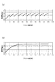
図8に、現像スクリュー47を高速回転させて画像形成ジョブを行った場合の現像剤の排出特性を示す。ここでは、ベタ画像の画像形成時の感光ドラム上のトナー量を0.5(mg/cm2)とした。その場合、図8に示すように、高速回転時における単位時間当たりの現像剤排出量は0.04(g/sec)となる。そして、排出特性との交点b(ベタ連続時現像剤安定点b)は約330グラムとなる。つまり、ベタ画像を連続プリントした場合(ベタ連続時)、現像容器内の現像剤量は330グラムに至り維持される。
FIG. 8 shows developer discharge characteristics when an image forming job is performed by rotating the developing
上述のように、本実施形態は、羽根47bを切り欠いた対向部47cにより、跳ね上げによる排出口40からの現像剤の排出を抑制すると共に、現像剤を滞留させオーバーフローによる排出口40からの現像剤の排出を実現しようとするものである(図4参照)。しかしながら、現像スクリュー47の対向部47cにおける現像剤の滞留の度合いは、現像剤の搬送速度ひいては現像スクリュー47の回転数によって著しく異なることが発明者により実験で確認されている。
As described above, in the present embodiment, the opposed
ここで、現像剤の搬送速度が速い場合として現像スクリュー47を高速回転させた場合の現像剤の剤面高さを図9(a)に、現像剤の搬送速度が遅い場合として現像スクリュー47を低速回転させた場合の現像剤の剤面高さを図9(b)に示す。なお、図中の実線の矢印F1、F3は回転する現像スクリュー47によって図示の位置における第一方向への搬送速度を表し、図中の点線の矢印F2は現像剤の剤面を上昇させる方向(第一方向に直交する方向)に働く力を表している。
Here, FIG. 9A shows the developer surface height when the
図9(a)に示すように、現像剤の搬送速度が速い場合には、現像剤の搬送速度が遅い場合に比べて、対向部47cにおける搬送力と、第一方向(図中R4方向)上流側の領域47dの搬送力との差が大きくなる。それ故、領域47dに比べて対向部47cでの現像剤の搬送速度が大きく減速する。これにより、現像剤が滞留して現像剤の剤面高さが上昇するので、排出口40からの現像剤の排出が促される。また、図9(b)に示すように、現像剤の搬送速度が遅い場合には、現像剤の搬送速度が速い場合に比べて、対向部47cにおける搬送力と、第一方向上流側の領域47dの搬送力との差分が小さくなる。それ故、対向部47cと領域47dとで現像剤の搬送速度はほとんど変わらない。つまり、領域47dに比べ対向部47cでの現像剤の搬送速度が大きく減速していない。よって、現像剤の剤面高さが上昇し難く、排出口40からの現像剤の排出が抑制される。
As shown in FIG. 9A, when the developer conveyance speed is high, the conveyance force at the facing
即ち、現像剤の搬送速度は現像スクリュー47(詳しくは羽根47b)の回転数に比例し、羽根47bがより速く回転するにつれて現像剤の搬送速度は速くなる。しかしながら、対向部47cでは羽根47bを切り欠いているが故に、対向部47cにおける現像剤の搬送速度は現像スクリュー47の回転数に比例しない。従って、現像スクリュー47の回転数が速ければ速いほど、対向部47cに現像剤が滞留しやすくなる。他方、現像スクリュー47の回転数が遅ければ遅いほど、対向部47cに現像剤が滞留し難くなる。現像スクリュー47が所定の回転数以下で回転された場合、対向部47cに現像剤がほとんど滞留し得ない。
That is, the developer conveyance speed is proportional to the rotation speed of the developing screw 47 (specifically, the
図10に、現像スクリュー47を低速回転させて画像形成ジョブを行った場合の現像剤の排出特性を示す。現像スクリュー47を低速回転させた場合には、上述したように対向部47cに現像剤が滞留し難くなる結果、現像スクリュー47を高速回転させた場合に比べて現像剤の排出量が減少する(図9(b)参照)。ここでは、図10に示すように、低速回転時における単位時間当たりの現像剤排出量は0.02(g/sec)となる。そして、排出特性との交点b(ベタ連続時現像剤安定点b)は約405グラムとなる。つまり、低速回転でベタ画像を連続プリントした場合には、現像容器内の現像剤量が405グラムに至り維持される。このように、現像スクリュー47を第二速度よりも遅い第一速度で低速回転させた場合には、現像剤の排出量が減少して現像容器内の現像剤量が増えやすい。
FIG. 10 shows developer discharge characteristics when an image forming job is performed by rotating the developing
ただし、現像容器内の現像剤量が増えすぎると、既に述べたように、現像容器41からの剤漏れ、現像スクリュー47や撹拌スクリュー48のスクリューロックなどが生じやすくなる。そこで、現像容器内の現像剤量を増えすぎないようにするために、画像形成動作時に現像スクリュー47の回転数を速くすることが考えられる。しかしながら、そうした場合には、低速回転での単位時間当たりの最小補給量と排出特性との交点aが高速回転での単位時間当たりの最小補給量と排出特性との交点aと大きくずれてしまい得る(図7参照)。そうなると、現像容器内の現像剤量が著しく少なくなり、現像スリーブ42のコーティング不良を生じさせる虞があるので、単純に現像スクリュー47の回転数を速くすることはできない。
However, if the amount of the developer in the developing container is excessively increased, the agent leakage from the developing
本実施形態では上記点に鑑み、現像スクリュー47を低速回転させて画像形成ジョブを行った場合に、非画像形成時に、一時的に現像スクリュー47を高速回転で所定時間に亘って回転させるようにした。具体的には、連続搬送される記録材と記録材との間(紙間)あるいは画像形成ジョブの後回転時に、現像スクリュー47を高速回転で所定時間に亘って回転させる。こうすると、排出口40からの現像剤の排出が促進されて現像容器内の現像剤量が減少するので、現像容器内の現像剤量が増えすぎることに起因する剤漏れやスクリューロックなどを抑制できる。以下、本実施形態について説明する。
In the present embodiment, in view of the above points, when an image forming job is performed by rotating the developing
<回転制御処理>
本実施形態の回転制御処理について、図6を参照しながら図11を用いて説明する。図11に、本実施形態の回転制御処理のフローチャートを示す。本実施形態の回転制御処理(駆動モード)は制御部200により実行可能な処理であり、画像形成ジョブの開始にあわせて開始され、画像形成ジョブの終了にあわせて終了される。ただし、本実施形態の回転制御処理は実質的に、現像スクリュー47を低速回転させて画像形成ジョブを行った場合に、1枚の記録材Sのプリントが開始される度に繰り返される。
<Rotation control processing>
The rotation control process of this embodiment will be described with reference to FIG. 11 with reference to FIG. FIG. 11 shows a flowchart of the rotation control process of the present embodiment. The rotation control process (driving mode) of the present embodiment is a process that can be executed by the
図11に示すように、制御部200は、所定条件として平均画像比率が所定比率(例えば15%)以上の記録材Sの枚数をカウントする(S1)。具体的には、現像スクリュー47を低速回転させて画像形成した記録材Sの枚数をカウント(累計)すると共に、記録材Sの1枚当たりの画像比率の平均値(これを平均画像比率と呼ぶ)を算出していく。平均画像比率は、例えば1枚ごとに計算し更新してもよいし、所定枚数(例えば10枚)ごとに計算し更新してもよい。なお、記録材Sの累計枚数と平均画像比率は、現像スクリュー47を第一速度で回転させて画像形成する最初の画像形成開始からカウントされる。
As shown in FIG. 11, the
本実施形態は、平均画像比率と記録材Sの累計枚数とにより「現像容器41内に入ってきた現像剤の剤量」を得ようとするものである。即ち、現像容器内の現像剤の増加量は、「現像容器41内に入ってきた現像剤の剤量」−「現像容器から排出された現像剤の剤量」で求められる。ただし、現像スクリュー47を低速回転させて画像形成した場合、「現像容器から排出された現像剤の剤量」は実質的に「0」であるので、本実施形態では「現像容器41内に入ってきた現像剤の剤量」だけで現像容器内の現像剤の増加量を予測している。現像容器内の現像剤の増加量を予測できれば、現像剤が現像容器41から漏れ出したり、あるいはスクリューロックを生じさせたりするほど、現像容器内の現像剤が増えたか否かを把握できる。
In the present embodiment, an “amount of developer entering the developing
図11の説明に戻り、制御部200は、平均画像比率が所定比率以上であり且つ上記カウントした記録材Sの累計枚数が第一閾値より小さいか否かを判定する(S2)。第一閾値は、例えば500枚である。累計枚数が第一閾値より小さい場合(S2のYES)、制御部200は回転制御処理を終了する。この場合、画像形成ジョブは終了していないので、次の記録材Sへのプリント開始にあわせて、制御部200は回転制御処理を繰り返す。また、この場合、画像形成ジョブがこのまま終了したとしても、累計枚数と平均画像比率はリセットされずに、メモリ201に記憶される。つまり、前回の回転制御処理時の累計枚数と平均画像比率は、次回の回転制御処理に引き継がれる。
Returning to the description of FIG. 11, the
他方、累計枚数が第一閾値以上である場合(S2のNO)、制御部200は実行中の画像形成ジョブの終了であるか否か、詳しくは画像形成ジョブを終了させる信号を受信したか否かを判定する(S3)。画像形成ジョブの終了である場合(S3のYES)、制御部200は、スクリューモータ61を制御して現像スクリュー47の回転数を第一速度から第二速度に変え、画像形成ジョブの後回転時に現像スクリュー47を第一時間に亘り高速回転させる(S4)。第一時間は、例えば60秒である。そして、制御部200は累計枚数と平均画像比率をリセットする(S5)。なお、この場合には、次の画像形成ジョブが開始されるまで、制御部200は回転制御処理を繰り返さない。
On the other hand, when the cumulative number is equal to or greater than the first threshold value (NO in S2), the
画像形成ジョブの終了でない場合(S3のNO)、制御部200は平均画像比率が所定比率以上であり且つ上記カウントした記録材Sの累計枚数が第二閾値より小さいか否かを判定する(S6)。第二閾値は、例えば1000枚である。累計枚数が第二閾値(所定枚数)より小さい場合(S6のYES)、制御部200は回転制御処理を終了する。この場合、画像形成ジョブは終了していないので、次の記録材Sへのプリント開始にあわせて、制御部200は回転制御処理を繰り返す。
If it is not the end of the image forming job (NO in S3), the
他方、累計枚数が第二閾値以上(所定枚数以上)である場合(S6のNO)、制御部200はスクリューモータ61を制御して現像スクリュー47の回転数を第一速度から第二速度に変えて、紙間で現像スクリュー47を第二時間に亘り高速回転させる(S7)。第二時間は例えば120秒であり、制御部200は第二時間を確保すべく紙間を拡げるように変更する。また、制御部200は現像スクリュー47を第二時間に亘り高速回転した後、現像スクリュー47の回転数を第二速度から第一速度に戻すと共に、紙間を変更前に戻す。即ち、制御部200は駆動モード時、紙間を駆動モードを実行しない場合よりも拡げる。そして、制御部200は累計枚数と平均画像比率をリセットする(S8)。この場合、画像形成ジョブは終了していないので、次の記録材Sへのプリント開始にあわせて、制御部200は回転制御処理を繰り返す。
On the other hand, when the cumulative number is equal to or greater than the second threshold (a predetermined number or greater) (NO in S6), the
なお、連続して画像形成ジョブが入力された場合や画像形成ジョブの途中に次の画像形成ジョブが入力された場合、制御部200はこれらをまとめて1つの画像形成ジョブと判断する。それ故、1つの画像形成ジョブ中に、現像スクリュー47を低速回転させて画像形成を行う場合と、現像スクリュー47を高速回転させて画像形成を行う場合とが混在し得る。そうした場合に、現像スクリュー47が低速回転から高速回転に切り替えられて所定時間(例えば60秒)以上に亘り回転されれば、上記の累計枚数と平均画像比率をリセットしてよい。これは、現像スクリュー47が高速回転されて画像形成ジョブが行われることで、現像容器41からの現像剤の排出が促進されるからである。従って、現像スクリュー47が高速回転されても、それが所定時間以上でない場合には、上記の累計枚数と平均画像比率をリセットしなくてよい。
Note that when the image forming job is continuously input or when the next image forming job is input in the middle of the image forming job, the
本実施形態の場合、制御部200は、平均画像比率が第一比率である場合に第一駆動時間に亘り現像スクリュー47を駆動し、平均画像比率が第一比率より高い第二比率である場合に第一駆動時間よりも長い第二駆動時間に亘り現像スクリュー47を駆動する。具体的には、表1に示すように、平均画像比率に応じて現像スクリュー47を高速回転させる駆動時間を変更可能である。

なお、上記の累計枚数は、センサ300により検出された湿度や予測される湿度(予測値)が所定湿度(例えば40%)以上である場合に限りカウントするようにしてもよい。また、上記した第一閾値と第二閾値、第一時間と第二時間とは、現像スクリュー47の低速回転時の回転数によって異なってよい。例えば、現像スクリュー47の回転数が140(mm/sec)の場合には、上述したように第一閾値を500枚、第二閾値を1000枚、第一時間を60秒、第二時間を120秒とする。これに対し、現像スクリュー47の回転数が160(mm/sec)の場合には、第一閾値を800枚、第二閾値を1600枚、第一時間を50秒、第二時間を100秒としてよい。即ち、現像スクリュー47がより低速で回転され画像形成ジョブを行っている場合には、より少ない枚数のときにより長い時間に亘って現像スクリュー47を高速回転させるのが好ましい。
The cumulative number of sheets may be counted only when the humidity detected by the
<実験結果>
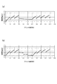
発明者らは、上述した回転制御処理を行う本実施形態と、上述した回転制御処理を行わない比較例とについて、現像スクリュー47を低速回転させベタ画像を連続して1万枚の記録材Sにプリントする実験を行った。図12(a)に本実施形態の実験結果を、図12(b)に比較例の実験結果を示す。図12(a)及び図12(b)は、プリント枚数に応じた現像容器内の現像剤量の推移を表している。
<Experimental result>
The inventors of the present embodiment that performs the above-described rotation control process and the comparative example that does not perform the above-described rotation control process rotate the developing
図12(b)に示す比較例の場合、プリント枚数が4000枚までは現像剤量が増加する。そして、プリント枚数が4000枚以上になると、現像剤量が約400グラムでほとんど増減しなくなる。現像容器内の現像剤量が約400グラムである場合、上記したように、現像容器内の現像剤量が増えすぎることに起因して剤漏れやスクリューロックなどが生じやすくなる。これに対し、本実施形態の場合には、上記した回転制御処理に従って1000枚のプリント毎に、現像スクリュー47が所定時間に亘って高速回転される(図11のS6、S7参照)。それ故、図12(a)に示すように、プリント枚数が1000の倍数に達する毎に、現像容器内の現像剤量が回転数の変更前後で約150〜200グラムほど減少される。こうして、本実施形態の場合には現像容器内の現像剤が例えば380グラム程度で抑制される。
In the case of the comparative example shown in FIG. 12B, the developer amount increases up to 4000 prints. When the number of printed sheets is 4000 or more, the amount of developer hardly increases or decreases at about 400 grams. When the amount of developer in the developing container is about 400 grams, as described above, the amount of developer in the developing container is excessively increased, so that agent leakage or screw lock is likely to occur. On the other hand, in the present embodiment, the developing
以上のように、本実施形態では、所定条件でプリント枚数が閾値に達していたら、画像形成ジョブの終了時や紙間で、低速回転させていた現像スクリュー47を所定時間に亘って高速回転させるようにした(図11のS4、S7参照)。現像スクリュー47を画像形成時よりも高速で回転させることで、現像スクリュー47の対向部47cにおいて現像剤の剤面を上昇させることができ、もってオーバーフローによる排出口40からの現像剤の排出が促進される(図9(a)及び図9(b)参照)。即ち、現像容器内の現像剤は排出口40から半強制的に排出される。これにより、現像容器内の現像剤量が減少するので、現像容器内の現像剤量が増えすぎることに起因する現像容器41からの剤漏れや、現像スクリュー47や撹拌スクリュー48のスクリューロックなどを抑制することができる。
As described above, in this embodiment, when the number of prints reaches the threshold value under a predetermined condition, the developing
[第二実施形態]
上述した第一実施形態の回転制御処理では(図11参照)、平均画像比率と記録材Sの累計枚数とにより「現像容器41内に入ってきた現像剤の剤量」を得る場合を示したがこれに限らない。例えば、補給装置7(図2参照)により補給された補給剤の補給量に応じて、画像形成ジョブの終了時や紙間で、低速回転させていた現像スクリュー47を所定時間に亘って高速回転させるようにしてもよい。こうした第二実施形態の回転制御処理は図11に示した回転制御処理を一部読み替えることで説明できるので、以下では第二実施形態について図11を用いて説明する。なお、第一実施形態と異なる処理以外は上述した第一実施形態と同様であるので説明を簡略化している。
[Second Embodiment]
In the rotation control process of the first embodiment described above (see FIG. 11), the case where “the amount of developer that has entered the developing
第二実施形態の回転制御処理の場合、制御部200は現像剤の補給量に関する情報として、補給スクリュー32(図2参照)を回転した回数に相当する補給ブロック数をカウント(累計)する(S1)。本実施形態の場合、補給装置7から補給される補給剤は一ブロック当たり310mgであり、補給ブロック数をカウントすることで現像容器41に補給された補給剤の補給量がわかる(補給量=310mg×補給ブロック数)。制御部200は、カウントした補給ブロック数が第一閾値より小さいか否かを判定する(S2)。第一閾値は、例えば50ブロックである。補給ブロック数が第一閾値より小さい場合(S2のYES)、制御部200は回転制御処理を終了する。この場合、画像形成ジョブがこのまま終了したとしても、累計した補給ブロック数はリセットされずにメモリ201に記憶され、次回の回転制御処理に引き継がれる。なお、補給ブロック数は、現像スクリュー47を第一速度で回転させて画像形成する最初の画像形成開始からカウントされる。
In the case of the rotation control process of the second embodiment, the
他方、補給ブロック数が第一閾値以上である場合(S2のNO)、制御部200は実行中の画像形成ジョブの終了時であるか否かを判定する(S3)。画像形成ジョブの終了時である場合(S3のYES)、制御部200は画像形成ジョブの後回転時に現像スクリュー47を第一時間に亘り高速回転させる(S4)。第一時間は、例えば60秒である。そして、制御部200は補給ブロック数をリセットする(S5)。
On the other hand, when the number of replenishment blocks is equal to or greater than the first threshold (NO in S2), the
画像形成ジョブの終了時でない場合(S3のNO)、制御部200はカウントした補給ブロック数が第二閾値より小さいか否かを判定する(S6)。第二閾値は、例えば70ブロックである。累計枚数が第二閾値より小さい場合(S6のYES)、制御部200は回転制御処理を終了する。他方、カウントした補給ブロック数が第二閾値以上(所定値以上)である場合(S6のNO)、制御部200は紙間で現像スクリュー47を第二時間に亘り高速回転させる(S7)。第二時間は例えば120秒であり、制御部200は第二時間を確保すべく紙間を拡げるように変更する。また、制御部200は現像スクリュー47を第二時間に亘り高速回転した後、現像スクリュー47の回転数を第二速度から第一速度に戻すと共に、紙間を変更前に戻す。そして、制御部200は補給ブロック数をリセットする(S8)。
If it is not at the end of the image forming job (NO in S3), the
<実験結果>
発明者らは、上述した第一実施形態と第二実施形態のそれぞれで、現像スクリュー47を低速回転させ、ベタ画像を3000枚、画像比率5%の画像を3000枚、さらにベタ画像を4000枚を順に、記録材Sに連続してプリントする画像形成ジョブを行った。図13(a)に第二実施形態の実験結果を、図13(b)に比較例として第一実施形態の実験結果を示す。図13(a)及び図13(b)は、プリント枚数に応じた現像容器内の現像剤量の推移を表す。なお、この場合、画像比率5%の画像をプリント中に補給剤は補給されない(図中の3000〜6000枚)。
<Experimental result>
In each of the first embodiment and the second embodiment described above, the inventors rotate the developing
図13(a)と図13(b)とを比較して理解できるように、プリント枚数が3000枚までの場合またプリント枚数が6000枚より多い場合には、第一実施形態でも第二実施形態でも現像剤量がほぼ同じように推移している。他方、プリント枚数が3000〜6000枚の場合(画像比率5%の画像のプリント中)には、現像剤量の推移が第一実施形態と第二実施形態とで異なる。図13(b)に示すように、第一実施形態の場合、現像剤量が4000枚、5000枚、6000枚のときに現像剤量が極端に減少している。これは、上述したように、第一実施形態の場合には補給剤の補給に関わらず、1000枚のプリント枚数毎に現像スクリュー47を高速回転させ、排出口40から強制的に現像剤を排出させるからである。
As can be understood by comparing FIG. 13A and FIG. 13B, when the number of prints is up to 3000 or when the number of prints is more than 6000, both the first embodiment and the second embodiment are used. However, the amount of developer has remained almost the same. On the other hand, when the number of prints is 3000 to 6000 (during the printing of an image with an image ratio of 5%), the transition of the developer amount differs between the first embodiment and the second embodiment. As shown in FIG. 13B, in the case of the first embodiment, the developer amount is extremely reduced when the developer amount is 4000 sheets, 5000 sheets, and 6000 sheets. As described above, in the first embodiment, the
これに対し、図13(a)に示す第二実施形態の場合には、プリント枚数が3000〜6000枚のときに現像剤量が少しずつ減少している。これは、第一実施形態の場合と異なり、4000枚、5000枚、6000枚のときに、現像スクリュー47を高速回転させる上述した回転制御処理が行われていないことを示している。即ち、第二実施形態の場合には、紙間を変更して回転制御処理が行われない分、第一実施形態の場合に比べダウンタイムを少なくできている。そして、第二実施形態の場合には3分(60秒×3回)だけダウンタイムが少なくなるにも関わらず、最大現像剤量は第一実施形態の場合と変わらない380グラムに抑制できている。以上のように、第二実施形態の場合には不要なダウンタイムを生じさせずに、現像容器内の現像剤量が増えすぎることに起因する現像容器41からの剤漏れ、あるいは現像スクリュー47や撹拌スクリュー48のスクリューロックなどを抑制し得る。
On the other hand, in the case of the second embodiment shown in FIG. 13A, the developer amount is gradually reduced when the number of printed sheets is 3000 to 6000. This indicates that, unlike the case of the first embodiment, the above-described rotation control process for rotating the developing
なお、上述した第二実施形態では、現像剤の補給量に関する情報として補給ブロック数を用いたが、これに限らない。例えば、補給剤の補給量をビデオカウント値から予想されるトナー消費量に応じて求めるような場合には、現像剤の補給量に関する情報としてビデオカウント値を用いてもよい。また、現像剤の補給量に関する情報が取得できれば、補給装置7による補給剤の補給方法は上述したブロック補給方式以外であってもよい。例えば、トナーを収容したトナーボトルを回転させて補給剤の補給を行う構成の場合には、トナーボトルの1回転当たりの補給量が推定できることから、現像剤の補給量に関する情報としてトナーボトルを回転した回数を用いてもよい。
In the second embodiment described above, the number of replenishment blocks is used as the information regarding the developer replenishment amount, but the present invention is not limited to this. For example, when the supply amount of the replenishment agent is obtained according to the toner consumption amount expected from the video count value, the video count value may be used as information relating to the developer replenishment amount. Further, as long as the information related to the developer replenishment amount can be acquired, the replenisher replenishment method by the
[他の実施形態]
なお、上述した各実施形態では、排出口40が現像室45に形成されている場合を例に説明したが、これに限らない。上述した各実施形態は、排出口40が撹拌室46に形成された現像装置にも適用できる。
[Other Embodiments]
In each of the above-described embodiments, the case where the
なお、上述した各実施形態では、現像容器41が現像室45と撹拌室46とに上下方向に区画されている縦撹拌型の現像装置を例に説明したが、これに限らない。上述した各実施形態は、例えば現像容器41が現像室45と撹拌室46とに水平方向に区画されている横撹拌型の現像装置にも適用できる。
In each of the above-described embodiments, the developing
1(1Y〜1Bk)…像担持体(感光ドラム)、7…補給手段(補給装置)、31…補給容器(ホッパー)、32…補給スクリュー、40…排出口、41…現像容器、42…現像剤担持体(現像スリーブ)、45…第一室(現像室)、46…第二室(撹拌室)、47…搬送スクリュー(現像スクリュー)、47a…回転軸、47b…羽根、47c…跳ね上げ抑制部(切り欠き部、対向部)、61…駆動手段(スクリューモータ)、100…画像形成装置、200…制御手段(制御部)
DESCRIPTION OF SYMBOLS 1 (1Y-1Bk) ... Image carrier (photosensitive drum), 7 ... Supply means (supply device), 31 ... Supply container (hopper), 32 ... Supply screw, 40 ... Discharge port, 41 ... Developer container, 42 ... Development Agent carrier (developing sleeve), 45 ... first chamber (developing chamber), 46 ... second chamber (stirring chamber), 47 ... conveying screw (developing screw), 47a ... rotating shaft, 47b ... blade, 47c ... flying up Suppressing part (notch part, opposing part), 61... Driving means (screw motor), 100... Image forming apparatus, 200.
Claims (10)
トナーとキャリアを含む現像剤を担持し、前記像担持体に形成された静電像を前記現像剤により現像する現像剤担持体と、
前記現像剤担持体に現像剤を供給する第一室と、前記第一室とで現像剤の循環経路を形成する第二室と、前記循環経路の現像剤をオーバーフローさせて排出可能に前記第一室又は前記第二室の所定高さ位置に形成された排出口とを有する現像容器と、
前記排出口が形成された前記第一室又は前記第二室に配置され、回転軸と、前記回転軸に形成された螺旋状の羽根と、回転軸線方向に関し前記排出口の範囲内の少なくとも一部に前記羽根よりも現像剤の跳ね上げが抑制される跳ね上げ抑制部とを有した、現像剤を搬送する搬送スクリューと、
前記搬送スクリューを第一速度と前記第一速度よりも速い第二速度とで駆動可能な駆動手段と、
前記現像容器に現像剤を補給する補給手段と、
前記搬送スクリューを前記第一速度で回転させて画像形成し、非画像形成時に、前記搬送スクリューを前記第一速度から前記第二速度に切り替えて駆動する駆動モードを実行可能な制御手段と、を備え、
前記制御手段は、前回の前記駆動モードから、前記搬送スクリューを前記第一速度で回転させて画像形成した記録材の枚数を累計すると共にそれら記録材の平均画像比率を求め、前記累計した記録材の枚数が所定枚数以上で、且つ、前記平均画像比率が所定比率以上となった場合に前記駆動モードを実行する、
ことを特徴とする画像形成装置。 An image carrier;
A developer carrying body that carries a developer containing toner and a carrier, and that develops the electrostatic image formed on the image carrying body with the developer;
A first chamber for supplying developer to the developer carrying member; a second chamber for forming a developer circulation path in the first chamber; and the developer in the circulation path to allow the developer to overflow and be discharged. A developing container having a discharge port formed at a predetermined height in one chamber or the second chamber;
Arranged in the first chamber or the second chamber in which the discharge port is formed, at least one of a rotation shaft, a spiral blade formed on the rotation shaft, and within the range of the discharge port in the rotation axis direction A conveying screw that conveys the developer, and a jumping suppression unit that suppresses the developer jumping from the blades in the part;
Drive means capable of driving the conveying screw at a first speed and a second speed faster than the first speed;
Supply means for supplying developer to the developer container;
Control means capable of executing a drive mode in which the conveying screw is rotated at the first speed to form an image, and the conveying screw is driven by switching from the first speed to the second speed during non-image formation; Prepared,
The control means accumulates the number of recording materials imaged by rotating the conveying screw at the first speed from the previous driving mode and calculates an average image ratio of the recording materials, and the accumulated recording materials. The drive mode is executed when the number of sheets is equal to or greater than a predetermined number and the average image ratio is equal to or greater than a predetermined ratio.
An image forming apparatus.
ことを特徴とする請求項1に記載の画像形成装置。 The control means accumulates the number of image-formed recording materials from the start of the first image formation to form an image by rotating the conveying screw at the first speed, and obtains an average image ratio of the recording materials. The drive mode is executed when the number of recorded materials is equal to or greater than a predetermined number and the average image ratio is equal to or greater than a predetermined ratio;
The image forming apparatus according to claim 1.
ことを特徴とする請求項1又は2に記載の画像形成装置。 In the driving mode, the control unit drives the conveying screw for a first driving time when the average image ratio is a first ratio, and the average image ratio is a second ratio higher than the first ratio. Driving the conveying screw for a second drive time longer than the first drive time in some cases,
The image forming apparatus according to claim 1, wherein the image forming apparatus is an image forming apparatus.
ことを特徴とする請求項1乃至3のいずれか1項に記載の画像形成装置。 The control means resets the accumulated number of recording materials and the average image ratio when the conveying screw is switched from the first speed to the second speed and rotated for a predetermined time or more to form an image. ,
The image forming apparatus according to claim 1, wherein the image forming apparatus is an image forming apparatus.
トナーとキャリアを含む現像剤を担持し、前記像担持体に形成された静電像を前記現像剤により現像する現像剤担持体と、
前記現像剤担持体に現像剤を供給する第一室と、前記第一室とで現像剤の循環経路を形成する第二室と、前記循環経路の現像剤の一部をオーバーフローさせて排出可能に前記第一室又は前記第二室の所定高さ位置に形成される排出口とを有する現像容器と、
前記排出口が形成された前記第一室又は前記第二室に配置され、回転軸と、前記回転軸に形成された螺旋状の羽根と、回転軸線方向に関し前記排出口の範囲内の少なくとも一部に前記羽根よりも現像剤の跳ね上げが抑制される跳ね上げ抑制部とを有した、現像剤を搬送する搬送スクリューと、
前記搬送スクリューを第一速度と前記第一速度よりも速い第二速度とで駆動可能な駆動手段と、
前記現像容器に現像剤を補給する補給手段と、
前記搬送スクリューを前記第一速度で回転させて画像形成し、非画像形成時に、前記搬送スクリューを前記第一速度から前記第二速度に切り替えて駆動する駆動モードを実行可能な制御手段と、を備え、
前記制御手段は、前回の前記駆動モードから、前記搬送スクリューを前記第一速度で回転させて画像形成した際に前記補給手段により補給された現像剤の補給量を現像剤の補給量に関する情報に基づき累計し、前記累計した補給量が所定値以上となった場合に前記駆動モードを実行する、
ことを特徴とする画像形成装置。 An image carrier;
A developer carrying body that carries a developer containing toner and a carrier, and that develops the electrostatic image formed on the image carrying body with the developer;
A first chamber for supplying developer to the developer carrier, a second chamber for forming a developer circulation path in the first chamber, and a part of the developer in the circulation path can be overflowed and discharged. A developing container having a discharge port formed at a predetermined height position of the first chamber or the second chamber;
Arranged in the first chamber or the second chamber in which the discharge port is formed, at least one of a rotation shaft, a spiral blade formed on the rotation shaft, and within the range of the discharge port in the rotation axis direction A conveying screw that conveys the developer, and a jumping suppression unit that suppresses the developer jumping from the blades in the part;
Drive means capable of driving the conveying screw at a first speed and a second speed faster than the first speed;
Supply means for supplying developer to the developer container;
Control means capable of executing a drive mode in which the conveying screw is rotated at the first speed to form an image, and the conveying screw is driven by switching from the first speed to the second speed during non-image formation; Prepared,
The control means uses the developer replenishment amount replenished by the replenishment means when the image is formed by rotating the conveying screw at the first speed from the previous drive mode as information relating to the developer replenishment amount. Based on the accumulated amount, and when the accumulated replenishment amount exceeds a predetermined value, the drive mode is executed.
An image forming apparatus.
ことを特徴とする請求項5に記載の画像形成装置。 The control means accumulates the replenishment amount from the start of the first image formation in which image formation is performed by rotating the conveying screw at the first speed, and the driving is performed when the accumulated replenishment amount becomes a predetermined value or more. Run mode,
The image forming apparatus according to claim 5.
前記現像剤の補給量に関する情報は、前記補給スクリューを回転した回数である、
ことを特徴とする請求項5又は6に記載の画像形成装置。 The replenishing means includes a replenishing container containing a developer, and a replenishing screw for replenishing the developing container with a predetermined amount of developer from the replenishing container every rotation.
The information regarding the replenishment amount of the developer is the number of times the replenishment screw is rotated.
The image forming apparatus according to claim 5, wherein the image forming apparatus is an image forming apparatus.
ことを特徴とする請求項5乃至7のいずれか1項に記載の画像形成装置。 The control means resets the accumulated replenishment amount when the conveying screw is switched from the first speed to the second speed and rotated for a predetermined time or longer to form an image.
The image forming apparatus according to claim 5, wherein the image forming apparatus is an image forming apparatus.
前記制御手段は、前記駆動モード時、前記記録材と記録材との間に対応する時間を前記駆動モードを実行しない場合よりも拡げる、
ことを特徴とする請求項1乃至8のいずれか1項に記載の画像形成装置。 The non-image formation time is a time corresponding to the recording material continuously conveyed for image formation and the recording material,
The control means expands a corresponding time between the recording material and the recording material in the driving mode as compared with a case where the driving mode is not executed.
The image forming apparatus according to claim 1, wherein the image forming apparatus is an image forming apparatus.
ことを特徴とする請求項1乃至9のいずれか1項に記載の画像形成装置。 The flip-up restraining part is a notch part obtained by notching the spiral blade.
The image forming apparatus according to claim 1, wherein the image forming apparatus is an image forming apparatus.
Priority Applications (1)
| Application Number | Priority Date | Filing Date | Title |
|---|---|---|---|
| JP2017162866A JP2019040107A (en) | 2017-08-25 | 2017-08-25 | Image formation apparatus |
Applications Claiming Priority (1)
| Application Number | Priority Date | Filing Date | Title |
|---|---|---|---|
| JP2017162866A JP2019040107A (en) | 2017-08-25 | 2017-08-25 | Image formation apparatus |
Publications (2)
| Publication Number | Publication Date |
|---|---|
| JP2019040107A true JP2019040107A (en) | 2019-03-14 |
| JP2019040107A5 JP2019040107A5 (en) | 2020-10-01 |
Family
ID=65726481
Family Applications (1)
| Application Number | Title | Priority Date | Filing Date |
|---|---|---|---|
| JP2017162866A Pending JP2019040107A (en) | 2017-08-25 | 2017-08-25 | Image formation apparatus |
Country Status (1)
| Country | Link |
|---|---|
| JP (1) | JP2019040107A (en) |
Citations (4)
| Publication number | Priority date | Publication date | Assignee | Title |
|---|---|---|---|---|
| JP2008249769A (en) * | 2007-03-29 | 2008-10-16 | Canon Inc | Image forming apparatus |
| JP2013054106A (en) * | 2011-09-01 | 2013-03-21 | Canon Inc | Image forming apparatus |
| JP2015152894A (en) * | 2014-02-19 | 2015-08-24 | キヤノン株式会社 | image forming apparatus |
| JP2015222394A (en) * | 2014-05-23 | 2015-12-10 | キヤノン株式会社 | Image forming apparatus |
-
2017
- 2017-08-25 JP JP2017162866A patent/JP2019040107A/en active Pending
Patent Citations (4)
| Publication number | Priority date | Publication date | Assignee | Title |
|---|---|---|---|---|
| JP2008249769A (en) * | 2007-03-29 | 2008-10-16 | Canon Inc | Image forming apparatus |
| JP2013054106A (en) * | 2011-09-01 | 2013-03-21 | Canon Inc | Image forming apparatus |
| JP2015152894A (en) * | 2014-02-19 | 2015-08-24 | キヤノン株式会社 | image forming apparatus |
| JP2015222394A (en) * | 2014-05-23 | 2015-12-10 | キヤノン株式会社 | Image forming apparatus |
Similar Documents
| Publication | Publication Date | Title |
|---|---|---|
| JP6604992B2 (en) | Developing device and image forming apparatus | |
| KR101509850B1 (en) | Image forming apparatus | |
| CN106462100B (en) | Developing device | |
| US10168643B2 (en) | Developing apparatus having developer distribution control | |
| JP7412958B2 (en) | Image forming device | |
| JP6794131B2 (en) | Developer | |
| US20150168871A1 (en) | Developing device | |
| JP6373064B2 (en) | Image forming apparatus | |
| JP2008076428A (en) | Developing device, process cartridge and image forming apparatus | |
| JP2019040107A (en) | Image formation apparatus | |
| JP2017194645A (en) | Developing device | |
| JP2013054111A (en) | Image forming apparatus | |
| US10372068B2 (en) | Development device | |
| JP6532578B2 (en) | Image forming device | |
| JP6563059B2 (en) | Image forming apparatus | |
| JP7183661B2 (en) | image forming device | |
| JP2020008648A (en) | Image formation device | |
| JP7147036B2 (en) | developing device | |
| JP4560354B2 (en) | Image forming apparatus | |
| US20240045356A1 (en) | Image forming apparatus | |
| JP7392291B2 (en) | Image forming device | |
| JP6308868B2 (en) | Development device | |
| JP7412959B2 (en) | Image forming device | |
| JP7367449B2 (en) | Developing device and image forming device equipped with the same | |
| JP2023127147A (en) | Image forming apparatus |
Legal Events
| Date | Code | Title | Description |
|---|---|---|---|
| RD02 | Notification of acceptance of power of attorney |
Free format text: JAPANESE INTERMEDIATE CODE: A7422 Effective date: 20200206 |
|
| RD04 | Notification of resignation of power of attorney |
Free format text: JAPANESE INTERMEDIATE CODE: A7424 Effective date: 20200207 |
|
| A521 | Request for written amendment filed |
Free format text: JAPANESE INTERMEDIATE CODE: A523 Effective date: 20200814 |
|
| A621 | Written request for application examination |
Free format text: JAPANESE INTERMEDIATE CODE: A621 Effective date: 20200814 |
|
| A977 | Report on retrieval |
Free format text: JAPANESE INTERMEDIATE CODE: A971007 Effective date: 20210623 |
|
| A131 | Notification of reasons for refusal |
Free format text: JAPANESE INTERMEDIATE CODE: A131 Effective date: 20210706 |
|
| A521 | Request for written amendment filed |
Free format text: JAPANESE INTERMEDIATE CODE: A523 Effective date: 20210902 |
|
| A02 | Decision of refusal |
Free format text: JAPANESE INTERMEDIATE CODE: A02 Effective date: 20220208 |