JP2019026030A - Vehicle side part body structure - Google Patents
Vehicle side part body structure Download PDFInfo
- Publication number
- JP2019026030A JP2019026030A JP2017146386A JP2017146386A JP2019026030A JP 2019026030 A JP2019026030 A JP 2019026030A JP 2017146386 A JP2017146386 A JP 2017146386A JP 2017146386 A JP2017146386 A JP 2017146386A JP 2019026030 A JP2019026030 A JP 2019026030A
- Authority
- JP
- Japan
- Prior art keywords
- reinforcement
- bead
- vertical direction
- surface portion
- strength
- Prior art date
- Legal status (The legal status is an assumption and is not a legal conclusion. Google has not performed a legal analysis and makes no representation as to the accuracy of the status listed.)
- Granted
Links
Images


Classifications
-
- B—PERFORMING OPERATIONS; TRANSPORTING
- B62—LAND VEHICLES FOR TRAVELLING OTHERWISE THAN ON RAILS
- B62D—MOTOR VEHICLES; TRAILERS
- B62D25/00—Superstructure or monocoque structure sub-units; Parts or details thereof not otherwise provided for
- B62D25/04—Door pillars ; windshield pillars
Abstract
Description
本発明は、車両の側部車体構造に関するものである。 The present invention relates to a side body structure of a vehicle.
車両としての自動車においては、車体側部において前後方向に延びる強度部材として左右一対のサイドシルを有する。そして、サイドシルの前端部には、上下方向に延びるヒンジピラーの下端部が接合される。 An automobile as a vehicle has a pair of left and right side sills as strength members extending in the front-rear direction on the side of the vehicle body. And the lower end part of the hinge pillar extended in an up-down direction is joined to the front-end part of a side sill.
ヒンジピラーには、サイドドアの取付け用となる上下一対のヒンジ取付部が形成されると共に、各ヒンジ取付部を補強するガセットが設けられる。 The hinge pillar is provided with a pair of upper and lower hinge attachment portions for attaching the side door, and is provided with a gusset for reinforcing each hinge attachment portion.
ヒンジピラーは、強度(剛性)が要求されるものであり、特に、側突に対する耐変形性や前突の際に前輪から受ける後方への荷重に対する耐変形性が要求される。 The hinge pillar is required to have strength (rigidity). In particular, the hinge pillar is required to have deformation resistance against a side collision and resistance to a rearward load received from the front wheel during the front collision.
特許文献1には、ヒンジピラーを構成するパネルに、上下方向に延びるビード部を形成して、耐変形性を向上させるものが開示されている。 Japanese Patent Application Laid-Open No. H10-228667 discloses a panel that constitutes a hinge pillar by forming a bead portion extending in the vertical direction to improve deformation resistance.
ところで、最近では、側突や前突の際のヒンジピラーの耐変形性をより向上させることが望まれるようになっている。このため、ヒンジピラー内に配設される補強用のレインフォースメントを肉厚にして、レインフォースメントの強度を向上させることが考えられる。しかしながら、レインフォースメントを肉厚にすることは、重量増加やコストアップを招くいことになり、好ましくない。 Recently, it has been desired to further improve the deformation resistance of the hinge pillar at the time of a side collision or a front collision. For this reason, it is conceivable to increase the strength of the reinforcement by making the reinforcement reinforcement disposed in the hinge pillar thick. However, increasing the thickness of the reinforcement is not preferable because it increases the weight and costs.
本発明は以上のような事情を勘案してなされたもので、その目的は、ヒンジピラー内に配設されたレインフォースメントを、同じ肉厚であればその強度をより高められるようにして、側突や前突の際におけるヒンジピラーの耐変形性をより向上できるようにした車両の側部車体構造を提供することにある。 The present invention has been made in consideration of the above circumstances, and the purpose of the present invention is to improve the strength of the reinforcement disposed in the hinge pillar so that the strength can be further increased if the wall thickness is the same. It is an object of the present invention to provide a side body structure of a vehicle that can further improve the deformation resistance of the hinge pillar at the time of a collision or front collision.
前記目的を達成するため、本発明にあっては次のような解決手法を採択してある。すなわち、請求項1に記載のように、
上下方向に延びるヒンジピラーが、アウタパネルとインナパネルとによって閉断面構造とされると共に、該アウタパネルとインナパネルとの間に配設された上下方向に延びるレインフォースメントによって補強されており、
前記レインフォースメントは、側面部と、該側面部の前端から車幅方向内方側に延びる前面部と、を有しており、
前記レインフォースメントに、サイドドア用の上下一対のヒンジ取付部を補強する上下のガセットが設けられ、
前記側面部に、上下の前記ガセットの間において、ビード部が形成され、
前記レインフォースメントには、前記側面部と前記前面部との境界部位において、上下方向に延びると共に該側面部および該前面部にそれぞれ開口されたくびれ部が形成されている、
ようにしてある。
In order to achieve the above object, the following solution is adopted in the present invention. That is, as described in claim 1,
The hinge pillar extending in the vertical direction has a closed cross-sectional structure by the outer panel and the inner panel, and is reinforced by a reinforcement extending in the vertical direction between the outer panel and the inner panel.
The reinforcement has a side part and a front part extending inward in the vehicle width direction from the front end of the side part,
The reinforcement is provided with upper and lower gussets for reinforcing a pair of upper and lower hinge mounting portions for side doors,
A bead portion is formed between the upper and lower gussets on the side surface portion,
In the reinforcement, at the boundary portion between the side surface portion and the front surface portion, a constriction that extends in the vertical direction and is opened to the side surface portion and the front surface portion is formed.
It is like that.
上記解決手法によれば、ビード部およびくびれ部の形成によって、レインフォースメントの肉厚を大きくすることなくその強度を大きく向上させることができる。特に、くびれ部は、もともと強度の高い側面部と前面部との境界部位となる角部に形成するので、この部分の強度を飛躍的に高めることができる。また、くびれ部は、側突および前突の両方向の衝突に対応して耐変形性を高めるものとなり、ヒンジピラーの強度を高める上で極めて好ましいものとなる。なお、ビード部およびくびれ部のいずれも、プレス成形によってレインフォースメントを形成する場合に合わせて形成することができ、製造上の観点からも好ましいものとなる。 According to the above solution, the strength of the reinforcement can be greatly improved without increasing the thickness of the reinforcement by forming the bead portion and the constricted portion. In particular, since the constricted portion is originally formed at a corner portion which is a boundary portion between the side portion and the front portion having high strength, the strength of this portion can be dramatically increased. Further, the constricted portion increases the deformation resistance in response to the collision in both the side collision and the front collision, and is extremely preferable for increasing the strength of the hinge pillar. Note that both the bead portion and the constricted portion can be formed in accordance with the formation of the reinforcement by press molding, which is preferable from the viewpoint of manufacturing.
上記解決手法を前提とした好ましい態様は、請求項2以下に記載のとおりである。すなわち、
前記ビード部は、前記側面部の前後方向略中央部の位置において、上下方向に直線状に延びるように形成されている、ようにしてある(請求項2対応)。この場合、ビード部によって、側面部の上下方向および前後方向の広い範囲に渡って強度を向上させる上で好ましいものとなる。
A preferred mode based on the above solution is as described in
The bead portion is formed so as to extend linearly in the vertical direction at the position of the substantially central portion in the front-rear direction of the side surface portion (corresponding to claim 2). In this case, the bead portion is preferable in improving the strength over a wide range of the side portion in the vertical direction and the front-rear direction.
前記ビード部の下端が、下側にある前記ガセットにまで延びている、ようにしてある(請求項3対応)。この場合、ヒンジピラー下端部の強度向上の上で好ましいものとなる。 The lower end of the bead portion extends to the lower gusset (corresponding to claim 3). In this case, it is preferable for improving the strength of the lower end portion of the hinge pillar.
前記くびれ部の下端が前記ビード部の下端よりも高い位置でかつ該ビード部の上端よりも低い位置とされると共に、該くびれ部の上端が該ビード部の上端よりも高い位置されている、ようにしてある(請求項4対応)。この場合、ビード部とくびれ部とが上下方向においてオーバラップする部分の強度を十分に高めつつ、下側部分においてはビード部による強度向上を図りつつ、上側部分についてくびれ部による強度向上を図ることができる。 The lower end of the constricted portion is positioned higher than the lower end of the bead portion and lower than the upper end of the bead portion, and the upper end of the constricted portion is positioned higher than the upper end of the bead portion. (Corresponding to claim 4). In this case, the strength of the portion where the bead portion and the constricted portion overlap in the vertical direction is sufficiently increased, the strength of the lower portion is improved by the bead portion, and the strength of the upper portion is improved by the constricted portion. Can do.
本発明によれば、同じ肉厚であればレインフォースメントの強度をより高めて、側突や前突の際におけるヒンジピラーの耐変形性をより向上させることができる。 According to the present invention, if the wall thickness is the same, the strength of the reinforcement can be further increased, and the deformation resistance of the hinge pillar at the time of a side collision or a front collision can be further improved.
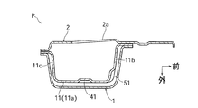
図1において、上下方向に延びるヒンジピラーPは、アウタパネル1とインナパネル2とによって閉断面構造とされ、閉断面内にはレインフォースメント11が配設されている。アウタパネル1とインナパネル2とレインフォースメント11とは、そのフランジ部同士で互いに接合されている。このようなヒンジピラーPは、その下端部が前後方向に延びるサイドシルの前端部に接合され、その上端部はフロントピラーへと連なっているものである。
In FIG. 1, a hinge pillar P extending in the vertical direction has a closed cross-sectional structure by an outer panel 1 and an
レインフォースメント11は、側面部11aと、側面部11aの前端から車幅方向内方側に延びる前面部11bと、側面部11aの後端から車幅方向内方側に延びる後面部11cとを有する形状とされて、断面略コ字状(ハット状)として形成されている。
The
レインフォースメント11は、車幅方向内方側に向けて開口された形状とされているが、この開口部を塞ぐように、インナパネル2がレインフォースメント11に接合されている(図1参照)。インナパネル2には、適宜の位置に開口部2aが形成されている。
The
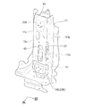
図2において、ヒンジピラーPは、その側面部において、上下一対のヒンジ取付部が形成される。このヒンジ取付部に相当する部位が、アウタパネル1においては符号21A、21Bで示され、レインフォースメント11においては符号22A、2Bで示される。
In FIG. 2, the hinge pillar P has a pair of upper and lower hinge attachment portions formed on the side surface portion thereof. The parts corresponding to the hinge mounting portions are indicated by
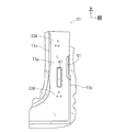
図3に示すように、レインフォースメント11における上側のヒンジ取付部22A(したがってアウタパネル1における上側のヒンジ取付部21A)が、その内面側に接合されるガセット13により補強される。また、レインフォースメント11における下側のヒンジ取付部22B(したがってアウタパネル1における下側のヒンジ取付部21B)が、その外面側に接合されるガセット14により補強される。
As shown in FIG. 3, the upper
レインフォースメント11のうち、その側面部11aには、ビード部41が形成されている。このビード部41は、上下のガセット13と14との間(ヒンジ取付部22Aと22Bとの間)において、上下方向に直線状に長く延びている。また、ビード部41は、側面部11aのうち、前後方向略中央部に形成されている。
In the
ビード部41の下端は、下側のガセット14の直近あるいはこれに達するように形成され、このガセット14と上下方向において若干オーバラップするように形成することもできる。一方、ビード部41の上端は、上側のガセット13には達しないで、これよりも低い位置に設定されているが、ガセット13の直近あるいはこれに達するように形成したり、ガセット13と上下方向にオーバラップするように形成することもできる。なお、ビード部41は、車幅方向内方側に向けて凸となるように形成されているが、車幅方向外方側に向けて凸となるように形成することもできる。
The lower end of the
レインフォースメント11には、さらに、上下方向に延びるくびれ部(凹部)51が形成されている。くびれ部51は、側面部11aと前面部11bとの境界となる角部に形成されている。より具体的には、くびれ部51は、車外側から見たときに直線状に延びる凹部となるように形成されて、側面部11aおよび前面部11bの両方に開口されている。
The
くびれ部51は、その上下方向略中間部から下側部分が、ビード部41に対して上下方向においてオーバラップされているが、上側部分は、ビード部41の上端よりもさらに上方に延びている。すなわち、くびれ部51の下端が、ビード部41の上下方向略中間部付近に位置され、くびれ部51の上端が、ビード部41の上端よりも高い位置とされている。
The lower part of the
上述のようなレインフォースメント11はプレス成形によって形成され、このプレス成形の際に、ビード部41とくびれ部51とが合わせて形成されるようにしてある。
The
ヒンジピラー10の下端部は、節部材12によって補強されている。この節部材12は、レインフォースメント11とインナパネル2との間に配設されて、レインフォースメント1およびインナパネル2に対して接合されている。節部材12は、その上端部において、略水平方向(前後方向および車幅方向)に延びる節部12aを有して、この節部12aが、ヒンジピラーP内の空間を上下方向で仕切るようにされている。
A lower end portion of the hinge pillar 10 is reinforced by a
以上のような構成において、レインフォースメント11は、ビード部41とくびれ部51とによって、大幅な重量増加や大型化を避けつつその強度が大幅に向上される。これにより、レインフォースメント11によって補強されたヒンジピラーPは、側突や前突に対する耐変形性が大きく向上される。特に、側面部11aと前面部11bとの境界となる角部は、強度(剛性)が元々高い部分となるが、ここに上下方向に延びるくびれ部51を形成することにより、その強度が飛躍的に向上される。勿論、側面部11aは、特に上下方向に長く延びるビード部41によって、その耐変形性が確保される。
In the configuration as described above, the strength of the
ビード部41の下端を、下側のガセット14の少なくとも直近にまで達するように形成しておくことにより、とりわけガセット14に対して上下方向においてオーバラップするように形成することにより、下側のガセット14付近の強度がより十分に向上される。
By forming the lower end of the
以上実施形態について説明したが、本発明は、実施形態に限定されるものではなく、特許請求の範囲の記載された範囲において適宜の変更が可能であり、例えば次のような場合をも含むものである。
(1)ビード部41の上端を、上側のガセット13の直近、あるいはガセット13にまで達するようにしてもよく、さらには上下方向においてガセット13とオーバラップさせることもできる。
(2)ビード部41を、前後方向に並列に2あるいは3以上形成することもできる。
(3)くびれ部51の下端位置を、下側のガセット14の直近あるいはこれに達するように、さらには上下方向においてオーバラップするように設定してもよい。また、くびれ部51の上端位置を、上側のガセット13の直近あるいはこれに達するように設定してもよい。
(4)くびれ部51を、側面部11aと後面部11cとの境界となる角部に形成してもよい。ビード部41に相当するビード部を、前面部11bと後面部11cとのいずれか一方あるいは両方に形成してもよい。
(5)本発明の目的は、明記されたものに限らず、実質的に好ましいあるいは利点として表現されたものを提供することをも暗黙的に含むものである。
Although the embodiment has been described above, the present invention is not limited to the embodiment, and can be appropriately changed within the scope described in the scope of claims. For example, the invention includes the following cases. .
(1) The upper end of the
(2) Two or three or
(3) The lower end position of the
(4) The constricted
(5) The object of the present invention is not limited to what is explicitly stated, but also implicitly includes providing what is substantially preferred or expressed as an advantage.
本発明は、ヒンジピラーの強度を高めて、衝突安全向上の上で好ましいものとなる。 The present invention is preferable for improving the collision safety by increasing the strength of the hinge pillar.
P:ヒンジピラー
1:アウタパネル
2:インナパネル
11:レインフォースメント
11a:側面部
11b:前面部
11c:後面部
12:節部材
12a:節部
13:ガセット(上側のヒンジ取付部補強用)
14:ガセット(下側のヒンジ取付部補強用)
21A:ヒンジ取付部(アウタパネルの上部)
21B:ヒンジ取付部(アウタパネルの下部)
22A:ヒンジ取付部(レインフォースメントの上部)
22B:ヒンジ取付部(レインフォースメントの下部)
41:ビード部
51:くびれ部
P: Hinge pillar 1: Outer panel 2: Inner panel 11:
14: Gusset (for reinforcement of lower hinge mounting part)
21A: Hinge mounting part (upper part of outer panel)
21B: Hinge mounting part (lower part of outer panel)
22A: Hinge mounting part (upper part of reinforcement)
22B: Hinge mounting part (lower part of reinforcement)
41: Bead part 51: Constriction part
本発明は、車両の側部車体構造に関するものである。 The present invention relates to a side body structure of a vehicle.
車両としての自動車においては、車体側部において前後方向に延びる強度部材として左右一対のサイドシルを有する。そして、サイドシルの前端部には、上下方向に延びるヒンジピラーの下端部が接合される。 An automobile as a vehicle has a pair of left and right side sills as strength members extending in the front-rear direction on the side of the vehicle body. And the lower end part of the hinge pillar extended in an up-down direction is joined to the front-end part of a side sill.
ヒンジピラーには、サイドドアの取付け用となる上下一対のヒンジ取付部が形成されると共に、各ヒンジ取付部を補強するガセットが設けられる。 The hinge pillar is provided with a pair of upper and lower hinge attachment portions for attaching the side door, and is provided with a gusset for reinforcing each hinge attachment portion.
ヒンジピラーは、強度(剛性)が要求されるものであり、特に、側突に対する耐変形性や前突の際に前輪から受ける後方への荷重に対する耐変形性が要求される。 The hinge pillar is required to have strength (rigidity). In particular, the hinge pillar is required to have deformation resistance against a side collision and resistance to a rearward load received from the front wheel during the front collision.
特許文献1には、ヒンジピラーを構成するパネルに、上下方向に延びるビード部を形成して、耐変形性を向上させるものが開示されている。 Japanese Patent Application Laid-Open No. H10-228667 discloses a panel that constitutes a hinge pillar by forming a bead portion extending in the vertical direction to improve deformation resistance.
ところで、最近では、側突や前突の際のヒンジピラーの耐変形性をより向上させることが望まれるようになっている。このため、ヒンジピラー内に配設される補強用のレインフォースメントを肉厚にして、レインフォースメントの強度を向上させることが考えられる。しかしながら、レインフォースメントを肉厚にすることは、重量増加やコストアップを招くいことになり、好ましくない。 Recently, it has been desired to further improve the deformation resistance of the hinge pillar at the time of a side collision or a front collision. For this reason, it is conceivable to increase the strength of the reinforcement by making the reinforcement reinforcement disposed in the hinge pillar thick. However, increasing the thickness of the reinforcement is not preferable because it increases the weight and costs.
本発明は以上のような事情を勘案してなされたもので、その目的は、ヒンジピラー内に配設されたレインフォースメントを、同じ肉厚であればその強度をより高められるようにして、側突や前突の際におけるヒンジピラーの耐変形性をより向上できるようにした車両の側部車体構造を提供することにある。 The present invention has been made in consideration of the above circumstances, and the purpose of the present invention is to improve the strength of the reinforcement disposed in the hinge pillar so that the strength can be further increased if the wall thickness is the same. It is an object of the present invention to provide a side body structure of a vehicle that can further improve the deformation resistance of the hinge pillar at the time of a collision or front collision.
前記目的を達成するため、本発明にあっては次のような第1の解決手法を採択してある。すなわち、請求項1に記載のように、
上下方向に延びるヒンジピラーが、アウタパネルとインナパネルとによって閉断面構造とされると共に、該アウタパネルとインナパネルとの間に配設された上下方向に延びるレインフォースメントによって補強されており、
前記レインフォースメントは、側面部と、該側面部の前端から車幅方向内方側に延びる前面部と、を有しており、
前記レインフォースメントに、サイドドア用の上下一対のヒンジ取付部を補強する上下のガセットが設けられ、
前記側面部に、上下の前記ガセットの間において、ビード部が形成され、
前記レインフォースメントには、前記側面部と前記前面部との境界部位において、上下方向に延びると共に該側面部および該前面部にそれぞれ開口されたくびれ部が形成されており、
前記ビード部は、前記側面部の前後方向略中央部の位置において、上下方向に直線状に延びるように形成され、
前記ビード部の下端が、下側にある前記ガセットにまで延びている、
ようにしてある。
In order to achieve the above object, the following first solution is adopted in the present invention. That is, as described in claim 1,
The hinge pillar extending in the vertical direction has a closed cross-sectional structure by the outer panel and the inner panel, and is reinforced by a reinforcement extending in the vertical direction between the outer panel and the inner panel.
The reinforcement has a side part and a front part extending inward in the vehicle width direction from the front end of the side part,
The reinforcement is provided with upper and lower gussets for reinforcing a pair of upper and lower hinge mounting portions for side doors,
A bead portion is formed between the upper and lower gussets on the side surface portion,
In the reinforcement, at the boundary portion between the side surface portion and the front surface portion, a constricted portion that extends in the vertical direction and is opened to each of the side surface portion and the front surface portion is formed .
The bead portion is formed so as to extend linearly in the vertical direction at the position of the substantially central portion in the front-rear direction of the side surface portion,
The lower end of the bead portion extends to the lower gusset,
It is like that.
上記第1の解決手法によれば、ビード部およびくびれ部の形成によって、レインフォースメントの肉厚を大きくすることなくその強度を大きく向上させることができる。特に、くびれ部は、もともと強度の高い側面部と前面部との境界部位となる角部に形成するので、この部分の強度を飛躍的に高めることができる。また、くびれ部は、側突および前突の両方向の衝突に対応して耐変形性を高めるものとなり、ヒンジピラーの強度を高める上で極めて好ましいものとなる。なお、ビード部およびくびれ部のいずれも、プレス成形によってレインフォースメントを形成する場合に合わせて形成することができ、製造上の観点からも好ましいものとなる。以上に加えて、ビード部によって、側面部の上下方向および前後方向の広い範囲に渡って強度を向上させる上で好ましいものとなる。また、ヒンジピラー下端部の強度向上の上で好ましいものとなる。 According to the first solution, the strength can be greatly improved by forming the bead portion and the constricted portion without increasing the thickness of the reinforcement. In particular, since the constricted portion is originally formed at a corner portion which is a boundary portion between the side portion and the front portion having high strength, the strength of this portion can be dramatically increased. Further, the constricted portion increases the deformation resistance in response to the collision in both the side collision and the front collision, and is extremely preferable for increasing the strength of the hinge pillar. Note that both the bead portion and the constricted portion can be formed in accordance with the formation of the reinforcement by press molding, which is preferable from the viewpoint of manufacturing. In addition to the above, the bead portion is preferable in improving the strength over a wide range of the side portion in the vertical direction and the front-rear direction. Moreover, it becomes a preferable thing on the strength improvement of a hinge pillar lower end part.
前記目的を達成するため、本発明にあっては次のような第2の解決手法を採択してある。すなわち、請求項2に記載のように、 In order to achieve the above object, the following second solution is adopted in the present invention. That is, as described in
上下方向に延びるヒンジピラーが、アウタパネルとインナパネルとによって閉断面構造とされると共に、該アウタパネルとインナパネルとの間に配設された上下方向に延びるレインフォースメントによって補強されており、The hinge pillar extending in the vertical direction has a closed cross-sectional structure by the outer panel and the inner panel, and is reinforced by a reinforcement extending in the vertical direction between the outer panel and the inner panel.
前記レインフォースメントは、側面部と、該側面部の前端から車幅方向内方側に延びる前面部と、を有しており、 The reinforcement has a side part and a front part extending inward in the vehicle width direction from the front end of the side part,
前記レインフォースメントに、サイドドア用の上下一対のヒンジ取付部を補強する上下のガセットが設けられ、 The reinforcement is provided with upper and lower gussets for reinforcing a pair of upper and lower hinge mounting portions for side doors,
前記側面部に、上下の前記ガセットの間において、ビード部が形成され、 A bead portion is formed between the upper and lower gussets on the side surface portion,
前記レインフォースメントには、前記側面部と前記前面部との境界部位において、上下方向に延びると共に該側面部および該前面部にそれぞれ開口されたくびれ部が形成されており、 In the reinforcement, at the boundary portion between the side surface portion and the front surface portion, a constricted portion that extends in the vertical direction and is opened to each of the side surface portion and the front surface portion is formed.
前記ビード部の下端が、下側にある前記ガセットにまで延びている、 The lower end of the bead portion extends to the lower gusset,
ようにしてある。It is like that.
上記第2の解決手法によれば、ビード部およびくびれ部の形成によって、レインフォースメントの肉厚を大きくすることなくその強度を大きく向上させることができる。特に、くびれ部は、もともと強度の高い側面部と前面部との境界部位となる角部に形成するので、この部分の強度を飛躍的に高めることができる。また、くびれ部は、側突および前突の両方向の衝突に対応して耐変形性を高めるものとなり、ヒンジピラーの強度を高める上で極めて好ましいものとなる。なお、ビード部およびくびれ部のいずれも、プレス成形によってレインフォースメントを形成する場合に合わせて形成することができ、製造上の観点からも好ましいものとなる。以上に加えて、ヒンジピラー下端部の強度向上の上で好ましいものとなる。 According to the second solution, the strength of the reinforcement can be greatly improved without increasing the thickness of the reinforcement by forming the bead portion and the constricted portion. In particular, since the constricted portion is originally formed at a corner portion which is a boundary portion between the side portion and the front portion having high strength, the strength of this portion can be dramatically increased. Further, the constricted portion increases the deformation resistance in response to the collision in both the side collision and the front collision, and is extremely preferable for increasing the strength of the hinge pillar. Note that both the bead portion and the constricted portion can be formed in accordance with the formation of the reinforcement by press molding, which is preferable from the viewpoint of manufacturing. In addition to the above, it is preferable for improving the strength of the lower end portion of the hinge pillar.
上記各解決手法を前提とした好ましい態様は,次のとおりである。すなわち、
前記くびれ部の下端が前記ビード部の下端よりも高い位置でかつ該ビード部の上端よりも低い位置とされると共に、該くびれ部の上端が該ビード部の上端よりも高い位置されている、ようにしてある(請求項3対応)。この場合、ビード部とくびれ部とが上下方向においてオーバラップする部分の強度を十分に高めつつ、下側部分においてはビード部による強度向上を図りつつ、上側部分についてくびれ部による強度向上を図ることができる。
A preferred mode based on the above-described solutions is as follows. That is,
The lower end of the constricted portion is positioned higher than the lower end of the bead portion and lower than the upper end of the bead portion, and the upper end of the constricted portion is positioned higher than the upper end of the bead portion. (Corresponding to claim 3 ). In this case, the strength of the portion where the bead portion and the constricted portion overlap in the vertical direction is sufficiently increased, the strength of the lower portion is improved by the bead portion, and the strength of the upper portion is improved by the constricted portion. Can do.
本発明によれば、同じ肉厚であればレインフォースメントの強度をより高めて、側突や前突の際におけるヒンジピラーの耐変形性をより向上させることができる。 According to the present invention, if the wall thickness is the same, the strength of the reinforcement can be further increased, and the deformation resistance of the hinge pillar at the time of a side collision or a front collision can be further improved.
図1において、上下方向に延びるヒンジピラーPは、アウタパネル1とインナパネル2とによって閉断面構造とされ、閉断面内にはレインフォースメント11が配設されている。アウタパネル1とインナパネル2とレインフォースメント11とは、そのフランジ部同士で互いに接合されている。このようなヒンジピラーPは、その下端部が前後方向に延びるサイドシルの前端部に接合され、その上端部はフロントピラーへと連なっているものである。
In FIG. 1, a hinge pillar P extending in the vertical direction has a closed cross-sectional structure by an outer panel 1 and an
レインフォースメント11は、側面部11aと、側面部11aの前端から車幅方向内方側に延びる前面部11bと、側面部11aの後端から車幅方向内方側に延びる後面部11cとを有する形状とされて、断面略コ字状(ハット状)として形成されている。
The
レインフォースメント11は、車幅方向内方側に向けて開口された形状とされているが、この開口部を塞ぐように、インナパネル2がレインフォースメント11に接合されている(図1参照)。インナパネル2には、適宜の位置に開口部2aが形成されている。
The
図2において、ヒンジピラーPは、その側面部において、上下一対のヒンジ取付部が形成される。このヒンジ取付部に相当する部位が、アウタパネル1においては符号21A、21Bで示され、レインフォースメント11においては符号22A、2Bで示される。
In FIG. 2, the hinge pillar P has a pair of upper and lower hinge attachment portions formed on the side surface portion thereof. The parts corresponding to the hinge mounting portions are indicated by
図3に示すように、レインフォースメント11における上側のヒンジ取付部22A(したがってアウタパネル1における上側のヒンジ取付部21A)が、その内面側に接合されるガセット13により補強される。また、レインフォースメント11における下側のヒンジ取付部22B(したがってアウタパネル1における下側のヒンジ取付部21B)が、その外面側に接合されるガセット14により補強される。
As shown in FIG. 3, the upper
レインフォースメント11のうち、その側面部11aには、ビード部41が形成されている。このビード部41は、上下のガセット13と14との間(ヒンジ取付部22Aと22Bとの間)において、上下方向に直線状に長く延びている。また、ビード部41は、側面部11aのうち、前後方向略中央部に形成されている。
In the
ビード部41の下端は、下側のガセット14の直近あるいはこれに達するように形成され、このガセット14と上下方向において若干オーバラップするように形成することもできる。一方、ビード部41の上端は、上側のガセット13には達しないで、これよりも低い位置に設定されているが、ガセット13の直近あるいはこれに達するように形成したり、ガセット13と上下方向にオーバラップするように形成することもできる。なお、ビード部41は、車幅方向内方側に向けて凸となるように形成されているが、車幅方向外方側に向けて凸となるように形成することもできる。
The lower end of the
レインフォースメント11には、さらに、上下方向に延びるくびれ部(凹部)51が形成されている。くびれ部51は、側面部11aと前面部11bとの境界となる角部に形成されている。より具体的には、くびれ部51は、車外側から見たときに直線状に延びる凹部となるように形成されて、側面部11aおよび前面部11bの両方に開口されている。
The
くびれ部51は、その上下方向略中間部から下側部分が、ビード部41に対して上下方向においてオーバラップされているが、上側部分は、ビード部41の上端よりもさらに上方に延びている。すなわち、くびれ部51の下端が、ビード部41の上下方向略中間部付近に位置され、くびれ部51の上端が、ビード部41の上端よりも高い位置とされている。
The lower part of the
上述のようなレインフォースメント11はプレス成形によって形成され、このプレス成形の際に、ビード部41とくびれ部51とが合わせて形成されるようにしてある。
The
ヒンジピラー10の下端部は、節部材12によって補強されている。この節部材12は、レインフォースメント11とインナパネル2との間に配設されて、レインフォースメント1およびインナパネル2に対して接合されている。節部材12は、その上端部において、略水平方向(前後方向および車幅方向)に延びる節部12aを有して、この節部12aが、ヒンジピラーP内の空間を上下方向で仕切るようにされている。
A lower end portion of the hinge pillar 10 is reinforced by a
以上のような構成において、レインフォースメント11は、ビード部41とくびれ部51とによって、大幅な重量増加や大型化を避けつつその強度が大幅に向上される。これにより、レインフォースメント11によって補強されたヒンジピラーPは、側突や前突に対する耐変形性が大きく向上される。特に、側面部11aと前面部11bとの境界となる角部は、強度(剛性)が元々高い部分となるが、ここに上下方向に延びるくびれ部51を形成することにより、その強度が飛躍的に向上される。勿論、側面部11aは、特に上下方向に長く延びるビード部41によって、その耐変形性が確保される。
In the configuration as described above, the strength of the
ビード部41の下端を、下側のガセット14の少なくとも直近にまで達するように形成しておくことにより、とりわけガセット14に対して上下方向においてオーバラップするように形成することにより、下側のガセット14付近の強度がより十分に向上される。
By forming the lower end of the
以上実施形態について説明したが、本発明は、実施形態に限定されるものではなく、特許請求の範囲の記載された範囲において適宜の変更が可能であり、例えば次のような場合をも含むものである。
(1)ビード部41の上端を、上側のガセット13の直近、あるいはガセット13にまで達するようにしてもよく、さらには上下方向においてガセット13とオーバラップさせることもできる。
(2)ビード部41を、前後方向に並列に2あるいは3以上形成することもできる。
(3)くびれ部51の下端位置を、下側のガセット14の直近あるいはこれに達するように、さらには上下方向においてオーバラップするように設定してもよい。また、くびれ部51の上端位置を、上側のガセット13の直近あるいはこれに達するように設定してもよい。
(4)くびれ部51を、側面部11aと後面部11cとの境界となる角部に形成してもよい。ビード部41に相当するビード部を、前面部11bと後面部11cとのいずれか一方あるいは両方に形成してもよい。
(5)本発明の目的は、明記されたものに限らず、実質的に好ましいあるいは利点として表現されたものを提供することをも暗黙的に含むものである。
Although the embodiment has been described above, the present invention is not limited to the embodiment, and can be appropriately changed within the scope described in the scope of claims. For example, the invention includes the following cases. .
(1) The upper end of the
(2) Two or three or
(3) The lower end position of the
(4) The constricted
(5) The object of the present invention is not limited to what is explicitly stated, but also implicitly includes providing what is substantially preferred or expressed as an advantage.
本発明は、ヒンジピラーの強度を高めて、衝突安全向上の上で好ましいものとなる。 The present invention is preferable for improving the collision safety by increasing the strength of the hinge pillar.
P:ヒンジピラー
1:アウタパネル
2:インナパネル
11:レインフォースメント
11a:側面部
11b:前面部
11c:後面部
12:節部材
12a:節部
13:ガセット(上側のヒンジ取付部補強用)
14:ガセット(下側のヒンジ取付部補強用)
21A:ヒンジ取付部(アウタパネルの上部)
21B:ヒンジ取付部(アウタパネルの下部)
22A:ヒンジ取付部(レインフォースメントの上部)
22B:ヒンジ取付部(レインフォースメントの下部)
41:ビード部
51:くびれ部
P: Hinge pillar 1: Outer panel 2: Inner panel 11:
14: Gusset (for reinforcement of lower hinge mounting part)
21A: Hinge mounting part (upper part of outer panel)
21B: Hinge mounting part (lower part of outer panel)
22A: Hinge mounting part (upper part of reinforcement)
22B: Hinge mounting part (lower part of reinforcement)
41: Bead part 51: Constriction part
Claims (4)
前記レインフォースメントは、側面部と、該側面部の前端から車幅方向内方側に延びる前面部と、を有しており、
前記レインフォースメントに、サイドドア用の上下一対のヒンジ取付部を補強する上下のガセットが設けられ、
前記側面部に、上下の前記ガセットの間において、ビード部が形成され、
前記レインフォースメントには、前記側面部と前記前面部との境界部位において、上下方向に延びると共に該側面部および該前面部にそれぞれ開口されたくびれ部が形成されている、
ことを特徴とする車両の側部車体構造。 The hinge pillar extending in the vertical direction has a closed cross-sectional structure by the outer panel and the inner panel, and is reinforced by a reinforcement extending in the vertical direction between the outer panel and the inner panel.
The reinforcement has a side part and a front part extending inward in the vehicle width direction from the front end of the side part,
The reinforcement is provided with upper and lower gussets for reinforcing a pair of upper and lower hinge mounting portions for side doors,
A bead portion is formed between the upper and lower gussets on the side surface portion,
In the reinforcement, at the boundary portion between the side surface portion and the front surface portion, a constriction that extends in the vertical direction and is opened to the side surface portion and the front surface portion is formed.
A side body structure of a vehicle characterized by the above.
前記ビード部は、前記側面部の前後方向略中央部の位置において、上下方向に直線状に延びるように形成されている、ことを特徴とする車両の側部車体構造。 In claim 1,
The side body structure of a vehicle according to claim 1, wherein the bead portion is formed so as to extend linearly in the vertical direction at a position of a substantially central portion in the front-rear direction of the side surface portion.
前記ビード部の下端が、下側にある前記ガセットにまで延びている、ことを特徴とする車両の側部車体構造。 In claim 2,
A side body structure of a vehicle, wherein a lower end of the bead portion extends to the lower gusset.
前記くびれ部の下端が前記ビード部の下端よりも高い位置でかつ該ビード部の上端よりも低い位置とされると共に、該くびれ部の上端が該ビード部の上端よりも高い位置されている、ことを特徴とする車両の側部車体構造。 In any one of Claims 1 thru | or 3,
The lower end of the constricted portion is positioned higher than the lower end of the bead portion and lower than the upper end of the bead portion, and the upper end of the constricted portion is positioned higher than the upper end of the bead portion. A side body structure of a vehicle characterized by the above.
Priority Applications (4)
| Application Number | Priority Date | Filing Date | Title |
|---|---|---|---|
| JP2017146386A JP6555303B2 (en) | 2017-07-28 | 2017-07-28 | Vehicle side body structure |
| US16/045,392 US10683037B2 (en) | 2017-07-28 | 2018-07-25 | Side body structure of vehicle |
| CN201810833985.4A CN109305225B (en) | 2017-07-28 | 2018-07-26 | Side body structure of vehicle |
| DE102018118084.5A DE102018118084B4 (en) | 2017-07-28 | 2018-07-26 | LATERAL VEHICLE BODY STRUCTURE |
Applications Claiming Priority (1)
| Application Number | Priority Date | Filing Date | Title |
|---|---|---|---|
| JP2017146386A JP6555303B2 (en) | 2017-07-28 | 2017-07-28 | Vehicle side body structure |
Publications (2)
| Publication Number | Publication Date |
|---|---|
| JP2019026030A true JP2019026030A (en) | 2019-02-21 |
| JP6555303B2 JP6555303B2 (en) | 2019-08-07 |
Family
ID=65003948
Family Applications (1)
| Application Number | Title | Priority Date | Filing Date |
|---|---|---|---|
| JP2017146386A Active JP6555303B2 (en) | 2017-07-28 | 2017-07-28 | Vehicle side body structure |
Country Status (4)
| Country | Link |
|---|---|
| US (1) | US10683037B2 (en) |
| JP (1) | JP6555303B2 (en) |
| CN (1) | CN109305225B (en) |
| DE (1) | DE102018118084B4 (en) |
Families Citing this family (4)
| Publication number | Priority date | Publication date | Assignee | Title |
|---|---|---|---|---|
| KR102429057B1 (en) * | 2017-10-11 | 2022-08-04 | 현대자동차주식회사 | Collision Load Multi Decentralization type Side Body Frame and Vehicle thereby |
| JP6917413B2 (en) * | 2019-07-01 | 2021-08-11 | 本田技研工業株式会社 | Front pillar structure |
| DE102020100202A1 (en) * | 2020-01-08 | 2021-07-08 | Bayerische Motoren Werke Aktiengesellschaft | FRONT CARRIAGE STRUCTURE FOR VEHICLE |
| CN115092261A (en) * | 2022-07-15 | 2022-09-23 | 岚图汽车科技有限公司 | B-pillar structure for improving safety performance |
Citations (2)
| Publication number | Priority date | Publication date | Assignee | Title |
|---|---|---|---|---|
| JP2010018254A (en) * | 2008-07-14 | 2010-01-28 | Toyota Motor Corp | Pillar structure for vehicle and its manufacturing method |
| JP2016068603A (en) * | 2014-09-26 | 2016-05-09 | マツダ株式会社 | Side body structure of vehicle |
Family Cites Families (39)
| Publication number | Priority date | Publication date | Assignee | Title |
|---|---|---|---|---|
| CA2445930C (en) * | 2001-11-27 | 2009-09-29 | Kikuchi Co., Ltd. | Press molding and its high frequency quenching method and its high frequency quenching system |
| SE530228C2 (en) * | 2006-08-25 | 2008-04-01 | Gestamp Hardtech Ab | Ways to heat mold and harden a plate detail, as well as a B-pillar for a vehicle |
| US7543883B2 (en) * | 2006-10-11 | 2009-06-09 | Ford Global Technologies, Llc | Roof rail with integrally formed pinched flanges |
| US7959217B2 (en) * | 2008-08-14 | 2011-06-14 | Honda Motor Co., Ltd. | Modified upper rear door hinge patch |
| CN102202960B (en) * | 2009-01-08 | 2014-03-05 | 丰田自动车株式会社 | Framework structure of vehicle |
| SE533528C2 (en) * | 2009-12-13 | 2010-10-19 | Gestamp Hardtech Ab | B-pillar for vehicles |
| JP5400899B2 (en) * | 2009-12-22 | 2014-01-29 | 本田技研工業株式会社 | Body side structure |
| JP5120409B2 (en) * | 2010-04-13 | 2013-01-16 | トヨタ自動車株式会社 | Center pillar for vehicle |
| KR101163872B1 (en) * | 2010-04-29 | 2012-07-09 | 기아자동차주식회사 | Center pillar assembly of 3-door vehicle |
| KR101210086B1 (en) * | 2010-11-12 | 2012-12-07 | 현대자동차주식회사 | Combination structure of outer upper center pillar reinforcement and seat belt bracket |
| JP5691460B2 (en) * | 2010-12-07 | 2015-04-01 | トヨタ自動車株式会社 | Vehicle pillar structure |
| CN103813954B (en) * | 2011-11-25 | 2016-03-09 | 本田技研工业株式会社 | Vehicular side body structure |
| DE102011120519A1 (en) * | 2011-12-08 | 2013-06-13 | GM Global Technology Operations LLC (n. d. Gesetzen des Staates Delaware) | Reinforcement for a vehicle pillar, in particular the B-pillar of a vehicle |
| JP5935494B2 (en) * | 2012-05-08 | 2016-06-15 | マツダ株式会社 | Vehicle frame structure |
| DE102012023653A1 (en) * | 2012-11-28 | 2014-05-28 | GM Global Technology Operations LLC (n. d. Gesetzen des Staates Delaware) | Motor vehicle body with lightweight component |
| US9688310B2 (en) * | 2013-03-26 | 2017-06-27 | Toyota Jidosha Kabushiki Kaisha | Automobile front pillar lower structure |
| CN105102309B (en) * | 2013-03-26 | 2017-04-12 | 丰田自动车株式会社 | Automobile body lateral-portion structure |
| JP5962627B2 (en) * | 2013-09-27 | 2016-08-03 | トヨタ自動車株式会社 | Body reinforcement structure |
| US10023237B2 (en) * | 2013-11-15 | 2018-07-17 | Autotech Engineering A.I.E. | Beam for producing a metal framework |
| KR101592645B1 (en) * | 2013-12-19 | 2016-02-05 | 기아자동차주식회사 | Center pillar outer and manufacturing method of the same |
| JP5983593B2 (en) * | 2013-12-24 | 2016-08-31 | トヨタ自動車株式会社 | Vehicle side structure |
| JP2015123811A (en) * | 2013-12-25 | 2015-07-06 | トヨタ自動車株式会社 | Vehicle skeleton structure |
| FR3016597B1 (en) * | 2014-01-20 | 2017-09-22 | Autotech Eng A I E | VEHICLE BODY STRUCTURE DEVICE |
| CA2943630A1 (en) * | 2014-03-25 | 2015-10-01 | Honda Motor Co., Ltd. | Vehicle body side structure |
| JP6172079B2 (en) * | 2014-07-24 | 2017-08-02 | マツダ株式会社 | Car side body structure |
| JP6344126B2 (en) * | 2014-08-05 | 2018-06-20 | スズキ株式会社 | Center pillar structure |
| DE102014216225A1 (en) * | 2014-08-14 | 2016-02-18 | Muhr Und Bender Kg | Structural component and method for producing a structural component |
| DE102015106812B4 (en) * | 2015-04-30 | 2018-11-08 | Benteler Automobiltechnik Gmbh | Motor vehicle pillar with reinforcement plate and method for its production |
| JP6306543B2 (en) * | 2015-08-05 | 2018-04-04 | トヨタ自動車株式会社 | Vehicle side structure |
| DE102015115439B3 (en) * | 2015-09-14 | 2017-01-05 | Muhr Und Bender Kg | B-pillar for a vehicle body and method for manufacturing a B-pillar |
| US9580111B1 (en) * | 2015-09-28 | 2017-02-28 | Ford Global Technologies, Llc | Vehicle body component |
| JP6256519B2 (en) * | 2016-04-28 | 2018-01-10 | マツダ株式会社 | Vehicle side body structure |
| JP6256518B2 (en) * | 2016-04-28 | 2018-01-10 | マツダ株式会社 | Vehicle side body structure |
| DE102016114062B3 (en) * | 2016-07-29 | 2017-06-22 | Benteler Automobiltechnik Gmbh | Pillar for a motor vehicle and method for producing a pillar |
| DE102016116787B3 (en) * | 2016-09-07 | 2017-10-05 | Muhr Und Bender Kg | B-pillar for a motor vehicle body and motor vehicle body with such a B-pillar |
| JP6536526B2 (en) * | 2016-10-07 | 2019-07-03 | トヨタ自動車株式会社 | Roof structure for vehicle |
| KR101866080B1 (en) * | 2016-10-31 | 2018-06-11 | 현대자동차주식회사 | Shock absorption structure of reinforce for center pillar |
| CN106627774B (en) * | 2016-11-25 | 2023-08-08 | 上汽通用五菱汽车股份有限公司 | Offset bump high security's A post structure |
| KR102383237B1 (en) * | 2017-06-29 | 2022-04-05 | 현대자동차 주식회사 | Reinforcement structure of side-sill for vehicle |
-
2017
- 2017-07-28 JP JP2017146386A patent/JP6555303B2/en active Active
-
2018
- 2018-07-25 US US16/045,392 patent/US10683037B2/en active Active
- 2018-07-26 DE DE102018118084.5A patent/DE102018118084B4/en active Active
- 2018-07-26 CN CN201810833985.4A patent/CN109305225B/en active Active
Patent Citations (2)
| Publication number | Priority date | Publication date | Assignee | Title |
|---|---|---|---|---|
| JP2010018254A (en) * | 2008-07-14 | 2010-01-28 | Toyota Motor Corp | Pillar structure for vehicle and its manufacturing method |
| JP2016068603A (en) * | 2014-09-26 | 2016-05-09 | マツダ株式会社 | Side body structure of vehicle |
Also Published As
| Publication number | Publication date |
|---|---|
| US10683037B2 (en) | 2020-06-16 |
| US20190031243A1 (en) | 2019-01-31 |
| DE102018118084B4 (en) | 2021-10-28 |
| DE102018118084A1 (en) | 2019-01-31 |
| JP6555303B2 (en) | 2019-08-07 |
| CN109305225A (en) | 2019-02-05 |
| CN109305225B (en) | 2021-04-27 |
Similar Documents
| Publication | Publication Date | Title |
|---|---|---|
| JP6555303B2 (en) | Vehicle side body structure | |
| JP5971007B2 (en) | Body rear structure | |
| JP2019177831A (en) | Front part vehicle body structure of vehicle | |
| JP5639936B2 (en) | Body side structure | |
| JP2003237623A (en) | Front-pillar panel assembly structure of automobile | |
| JP2002211436A (en) | Body side part structure of automobile | |
| JP7014038B2 (en) | Vehicle body structure | |
| US20200180703A1 (en) | Vehicle Body Structure | |
| JP5040722B2 (en) | Lower body structure of automobile | |
| JPH02258481A (en) | Rear body structure for automobile | |
| JP2019073097A (en) | Vehicle side part structure | |
| KR102645056B1 (en) | Center pillar assembly for vehicle | |
| JP2018158706A (en) | Vehicle back door inner panel | |
| JP6237669B2 (en) | Upper body structure of the vehicle | |
| JP2020147255A (en) | Vehicle rear part structure | |
| JP5411245B2 (en) | Body side structure | |
| JP2000255451A (en) | Front car body structure for automobile | |
| JP5516001B2 (en) | Vehicle side structure | |
| JP4639976B2 (en) | Rear structure of the car body | |
| JP2002029455A (en) | Connecting structure for front end of side sill | |
| JP7009690B2 (en) | Backdoor inner panel for vehicles | |
| US10160496B2 (en) | Structure of side sill for vehicle | |
| JP2016120783A (en) | Vehicle side structure | |
| JP2019189161A (en) | Body structure of vehicle | |
| JP6520525B2 (en) | Vehicle front structure |
Legal Events
| Date | Code | Title | Description |
|---|---|---|---|
| A131 | Notification of reasons for refusal |
Free format text: JAPANESE INTERMEDIATE CODE: A131 Effective date: 20190108 |
|
| A601 | Written request for extension of time |
Free format text: JAPANESE INTERMEDIATE CODE: A601 Effective date: 20190123 |
|
| A521 | Request for written amendment filed |
Free format text: JAPANESE INTERMEDIATE CODE: A523 Effective date: 20190425 |
|
| TRDD | Decision of grant or rejection written | ||
| A01 | Written decision to grant a patent or to grant a registration (utility model) |
Free format text: JAPANESE INTERMEDIATE CODE: A01 Effective date: 20190611 |
|
| A61 | First payment of annual fees (during grant procedure) |
Free format text: JAPANESE INTERMEDIATE CODE: A61 Effective date: 20190624 |
|
| R150 | Certificate of patent or registration of utility model |
Ref document number: 6555303 Country of ref document: JP Free format text: JAPANESE INTERMEDIATE CODE: R150 |