JP2019021968A - Image encoding device and control method therefor - Google Patents
Image encoding device and control method therefor Download PDFInfo
- Publication number
- JP2019021968A JP2019021968A JP2017135657A JP2017135657A JP2019021968A JP 2019021968 A JP2019021968 A JP 2019021968A JP 2017135657 A JP2017135657 A JP 2017135657A JP 2017135657 A JP2017135657 A JP 2017135657A JP 2019021968 A JP2019021968 A JP 2019021968A
- Authority
- JP
- Japan
- Prior art keywords
- image
- encoding
- memory
- tile
- unit
- Prior art date
- Legal status (The legal status is an assumption and is not a legal conclusion. Google has not performed a legal analysis and makes no representation as to the accuracy of the status listed.)
- Pending
Links
Images


Classifications
-
- H—ELECTRICITY
- H04—ELECTRIC COMMUNICATION TECHNIQUE
- H04N—PICTORIAL COMMUNICATION, e.g. TELEVISION
- H04N5/00—Details of television systems
- H04N5/76—Television signal recording
- H04N5/91—Television signal processing therefor
- H04N5/917—Television signal processing therefor for bandwidth reduction
-
- G—PHYSICS
- G03—PHOTOGRAPHY; CINEMATOGRAPHY; ANALOGOUS TECHNIQUES USING WAVES OTHER THAN OPTICAL WAVES; ELECTROGRAPHY; HOLOGRAPHY
- G03B—APPARATUS OR ARRANGEMENTS FOR TAKING PHOTOGRAPHS OR FOR PROJECTING OR VIEWING THEM; APPARATUS OR ARRANGEMENTS EMPLOYING ANALOGOUS TECHNIQUES USING WAVES OTHER THAN OPTICAL WAVES; ACCESSORIES THEREFOR
- G03B37/00—Panoramic or wide-screen photography; Photographing extended surfaces, e.g. for surveying; Photographing internal surfaces, e.g. of pipe
- G03B37/02—Panoramic or wide-screen photography; Photographing extended surfaces, e.g. for surveying; Photographing internal surfaces, e.g. of pipe with scanning movement of lens or cameras
-
- G—PHYSICS
- G06—COMPUTING; CALCULATING OR COUNTING
- G06T—IMAGE DATA PROCESSING OR GENERATION, IN GENERAL
- G06T3/00—Geometric image transformation in the plane of the image
- G06T3/40—Scaling the whole image or part thereof
- G06T3/4038—Scaling the whole image or part thereof for image mosaicing, i.e. plane images composed of plane sub-images
-
- H—ELECTRICITY
- H04—ELECTRIC COMMUNICATION TECHNIQUE
- H04N—PICTORIAL COMMUNICATION, e.g. TELEVISION
- H04N19/00—Methods or arrangements for coding, decoding, compressing or decompressing digital video signals
- H04N19/10—Methods or arrangements for coding, decoding, compressing or decompressing digital video signals using adaptive coding
- H04N19/102—Methods or arrangements for coding, decoding, compressing or decompressing digital video signals using adaptive coding characterised by the element, parameter or selection affected or controlled by the adaptive coding
- H04N19/119—Adaptive subdivision aspects, e.g. subdivision of a picture into rectangular or non-rectangular coding blocks
-
- H—ELECTRICITY
- H04—ELECTRIC COMMUNICATION TECHNIQUE
- H04N—PICTORIAL COMMUNICATION, e.g. TELEVISION
- H04N19/00—Methods or arrangements for coding, decoding, compressing or decompressing digital video signals
- H04N19/50—Methods or arrangements for coding, decoding, compressing or decompressing digital video signals using predictive coding
- H04N19/59—Methods or arrangements for coding, decoding, compressing or decompressing digital video signals using predictive coding involving spatial sub-sampling or interpolation, e.g. alteration of picture size or resolution
-
- H—ELECTRICITY
- H04—ELECTRIC COMMUNICATION TECHNIQUE
- H04N—PICTORIAL COMMUNICATION, e.g. TELEVISION
- H04N19/00—Methods or arrangements for coding, decoding, compressing or decompressing digital video signals
- H04N19/70—Methods or arrangements for coding, decoding, compressing or decompressing digital video signals characterised by syntax aspects related to video coding, e.g. related to compression standards
-
- H—ELECTRICITY
- H04—ELECTRIC COMMUNICATION TECHNIQUE
- H04N—PICTORIAL COMMUNICATION, e.g. TELEVISION
- H04N23/00—Cameras or camera modules comprising electronic image sensors; Control thereof
- H04N23/60—Control of cameras or camera modules
-
- H—ELECTRICITY
- H04—ELECTRIC COMMUNICATION TECHNIQUE
- H04N—PICTORIAL COMMUNICATION, e.g. TELEVISION
- H04N23/00—Cameras or camera modules comprising electronic image sensors; Control thereof
- H04N23/60—Control of cameras or camera modules
- H04N23/698—Control of cameras or camera modules for achieving an enlarged field of view, e.g. panoramic image capture
-
- H—ELECTRICITY
- H04—ELECTRIC COMMUNICATION TECHNIQUE
- H04N—PICTORIAL COMMUNICATION, e.g. TELEVISION
- H04N25/00—Circuitry of solid-state image sensors [SSIS]; Control thereof
- H04N25/40—Extracting pixel data from image sensors by controlling scanning circuits, e.g. by modifying the number of pixels sampled or to be sampled
- H04N25/41—Extracting pixel data from a plurality of image sensors simultaneously picking up an image, e.g. for increasing the field of view by combining the outputs of a plurality of sensors
-
- H—ELECTRICITY
- H04—ELECTRIC COMMUNICATION TECHNIQUE
- H04N—PICTORIAL COMMUNICATION, e.g. TELEVISION
- H04N5/00—Details of television systems
- H04N5/76—Television signal recording
- H04N5/765—Interface circuits between an apparatus for recording and another apparatus
- H04N5/77—Interface circuits between an apparatus for recording and another apparatus between a recording apparatus and a television camera
- H04N5/772—Interface circuits between an apparatus for recording and another apparatus between a recording apparatus and a television camera the recording apparatus and the television camera being placed in the same enclosure
-
- H—ELECTRICITY
- H04—ELECTRIC COMMUNICATION TECHNIQUE
- H04N—PICTORIAL COMMUNICATION, e.g. TELEVISION
- H04N9/00—Details of colour television systems
- H04N9/79—Processing of colour television signals in connection with recording
- H04N9/80—Transformation of the television signal for recording, e.g. modulation, frequency changing; Inverse transformation for playback
-
- H—ELECTRICITY
- H04—ELECTRIC COMMUNICATION TECHNIQUE
- H04N—PICTORIAL COMMUNICATION, e.g. TELEVISION
- H04N13/00—Stereoscopic video systems; Multi-view video systems; Details thereof
- H04N2013/0074—Stereoscopic image analysis
- H04N2013/0088—Synthesising a monoscopic image signal from stereoscopic images, e.g. synthesising a panoramic or high resolution monoscopic image
Abstract
Description
本発明は、複数枚の撮像画像を合成して得る広角画像の符号化技術に関するものである。 The present invention relates to a wide-angle image encoding technique obtained by combining a plurality of captured images.
近年、JCT−VC(Joint Collaborative Team on Video Coding)において、H.264の後継となる次世代動画像符号化方式であるHEVC(High Efficiency Video Coding)の標準化が進められている。HEVCでは、Main Still Picture profileなどの静止画用のプロファイルが存在し、動画だけでなく静止画の符号化も行うことができる。 In recent years, JCT-VC (Joint Collaborative Team on Video Coding) The standardization of High Efficiency Video Coding (HEVC), which is a next-generation moving image encoding method that is a successor to H.264, is underway. In HEVC, there is a profile for still images such as Main Still Picture profile, and not only moving images but also still images can be encoded.
また、デジタルカメラやカメラ機能付き携帯電話などを用いて、撮影範囲を動かしながら連続撮影し、得られた複数の画像を位置合わせして合成することで広角な画像を生成する手法が提案されている(特許文献1)。以下、このような手法を広角合成と呼び、合成された画像を広角合成画像と呼ぶ。 In addition, a method has been proposed in which a digital camera or a mobile phone with a camera function is used to continuously shoot while moving the shooting range, and a wide-angle image is generated by aligning and combining the obtained images. (Patent Document 1). Hereinafter, such a method is referred to as wide-angle composition, and the synthesized image is referred to as a wide-angle composition image.
しかしながら特許文献1の方法では、連続撮影で得られた複数の画像を位置合わせすることで広角合成画像の生成を待って符号化を行うため、より多くのメモリを必要とする。また、画像の全領域の合成処理が完了してから符号化を行うため、撮影から符号化完了までの処理時間が長くなる。結果、ユーザがディスプレイ上で広角合成画像を確認するためまで、多くの時間待たなければならない。
However, in the method of
本発明は撮像方向を変更しながら撮像を複数回行うことで得た広角合成画像の符号化処理を、これまでよりも少ないメモリで実現すると共に、撮影終了から符号化完了までに要する時間をこれまでよりも短くする技術を提供する。 The present invention realizes encoding processing of a wide-angle composite image obtained by performing imaging a plurality of times while changing the imaging direction with less memory than before, and the time required from completion of imaging to completion of encoding. Provide technology to make it shorter than before.
この課題を解決するため、例えば本発明の画像符号化装置は以下の構成を備える。すなわち、
撮像手段の撮像方向を変えながら得た複数の画像から求めた広角合成画像を符号化する画像符号化装置であって、
撮像画像を一時的に記憶するためのメモリと、
前記撮像手段による撮像画像を入力するたびに、入力した撮像画像の予め定められた領域の部分画像を抜き出し、当該部分画像を、前記メモリに格納されている従前に入力した撮像画像で得た合成画像に、位置合わせして合成することで、前記合成画像を更新する合成手段と、
該合成手段による更新後の合成画像が、予め設定された符号化単位のタイルのサイズになった場合、前記合成画像における前記タイルの画像を符号化する符号化手段と、
前記メモリにおける、符号化を終えた前記タイルを上書き可能に解放する解放手段と、
予め設定された条件を満たすまで、前記合成手段、前記符号化手段、前記解放手段を繰り返すように制御し、広角合成画像の符号化データを生成する制御手段とを有する。
In order to solve this problem, for example, an image encoding device of the present invention has the following configuration. That is,
An image encoding device that encodes a wide-angle composite image obtained from a plurality of images obtained while changing the imaging direction of an imaging means,
A memory for temporarily storing captured images;
Each time a captured image is input by the imaging means, a partial image of a predetermined area of the input captured image is extracted, and the partial image is obtained by a previously input captured image stored in the memory. A composition unit that updates the composite image by aligning and compositing the image, and
An encoding means for encoding an image of the tile in the composite image when the composite image after the update by the composite means has a tile size of a preset encoding unit;
Release means for releasing the tile that has been encoded in the memory in an overwriteable manner;
Control means for controlling the synthesis means, the encoding means, and the release means to repeat until a preset condition is satisfied, and generating encoded data of a wide-angle synthesized image.
本発明によれば、撮像方向を変更しながら撮像を複数回行うことで得た広角合成画像の符号化処理を、これまでよりも少ないメモリで実現すると共に、撮影終了から符号化完了までに要する時間をこれまでよりも短くすることが可能になる。 According to the present invention, encoding of a wide-angle composite image obtained by performing imaging a plurality of times while changing the imaging direction is realized with less memory than before, and is required from the end of shooting to the completion of encoding. It becomes possible to make time shorter than before.
以下、添付図面に従って本発明に係る実施形態を詳細に説明する。 Hereinafter, embodiments according to the present invention will be described in detail with reference to the accompanying drawings.
[第1の実施形態]
<装置構成>
図1は、実施形態の画像符号化装置が適用する撮像装置100の斜視図である。なお、レンズは図示の背面側に設けられるものである
表示部116は画像や各種情報を表示する表示部である。操作部104はユーザーからの各種操作を受け付ける各種スイッチ、ボタン、シャッターボタン、モード切り替えボタン、タッチパネル、コントローラホイール等の操作部材より成る操作部である。電源のオンとオフを切り替える電源スイッチもこれに含まれる。
[First Embodiment]
<Device configuration>
FIG. 1 is a perspective view of an
<全体ブロック図>
図2は、撮像装置100のブロック構成を示す図である。撮像装置100は、図2に示すように、CPU101、メモリ102、不揮発性メモリ103、操作部104、撮像レンズ111、撮像部112、画像処理部113、符号化処理部114、表示制御部115、表示部116、通信制御部117、通信部118、記録媒体制御部119、記録媒体120、検出部140、及び内部バス130を有する。
<Overall block diagram>
FIG. 2 is a diagram illustrating a block configuration of the
CPU101は、不揮発性メモリ103に記憶されているコンピュータプログラムを実行することによって、撮像装置100の各部の動作を制御する。メモリ102は、書き換え可能な揮発性メモリ(RAM)であり、一時的に撮像装置100の各部の動作を制御するコンピュータプログラム、各部の動作に関するパラメータ等の情報、通信制御部117によって受信した情報等を記憶する。メモリ102は、撮像部112、画像処理部113、符号化処理部114等で処理した画像や情報を一時的に記憶するワークメモリとしても機能する。
The
不揮発性メモリ103は、電気的に消去・記録可能なメモリであり、例えばEEPROMやSDメモリカード等の記憶媒体が用いられる。不揮発性メモリ103は、撮像装置100の各部の動作を制御するコンピュータプログラム及び各部の動作に関するパラメータ等の情報を記憶する。ここでいう、コンピュータプログラムとは、本実施形態にて後述する各種フローチャートを実行するためのプログラムが含まれる。
The nonvolatile memory 103 is an electrically erasable / recordable memory, and for example, a storage medium such as an EEPROM or an SD memory card is used. The nonvolatile memory 103 stores information such as a computer program for controlling the operation of each unit of the
操作部104は、撮像装置100を操作するためのユーザインターフェースを提供する。操作部104は、撮像装置100の電源ボタン及びメニューボタン、シャッターボタン、モード切り替えボタン等を有し、各ボタンはスイッチ、タッチパネル等により構成される。CPU101は、操作部104を介して入力されたユーザの指示に従って撮像装置100を制御する。なお、操作部104は、不図示のリモートコントローラから受信したリモコン信号や、不図示の携帯端末から通信制御部117を介して通知された要求に応じて撮像装置100を制御してもよい。
The
撮像レンズ111は、ズームレンズ、フォーカスレンズを含むレンズ群、レンズ制御部、絞りなどにより構成される。撮像レンズ111は図示しないレンズ制御部を有し、CPU101から送信される制御信号により、焦点の調整や絞り値(F値)を制御する。
撮像部112は、被写体の光学像を電気信号に変換する撮像素子を備える。撮像素子は、例えばCCD(電荷結合素子)やCMOS(相補型金属酸化膜半導体)素子等で構成されるエリアイメージセンサである。撮像部112は撮像した画像を画像処理部113またはメモリ102に出力する。
The
The
画像処理部113は、撮像部112から出力されるデータ、又は、メモリ102から読み出されたデータに対し所定の画素補間、縮小といったリサイズ処理、アスペクト比を合わせるための画像の付与、色変換処理等を行う。また、画像処理部113では、撮像した画像データを用いて所定の演算処理が行われ、得られた演算結果に基づいてCPU101が露光制御、測距制御を行う。これにより、AE(自動露出)処理、AWB(オートホワイトバランス)処理、AF(オートフォーカス)処理が行われる。
The
また、画像処理部113では、画像データの位置合わせを行い、位置合わせした複数枚の画像を合成して、広角な合成画像を生成する広角合成を行う。本実施形態における広角合成の詳細は後述する。
In addition, the
符号化処理部114は、入力された画像データを画面内予測及び画面間予測符号化することでデータサイズを圧縮する。符号化処理部114は、例えばHEVC方式で圧縮処理を行う。符号化処理部114の詳細な説明は図3を用いて後述する。
The
表示制御部115は、表示部116を制御するための制御部である。表示制御部115は表示部116で表示可能な画像になるようにリサイズ処理や色変換処理等を行い、画像信号を表示部116に出力する。
The
表示部116は、液晶ディスプレイや有機EL等で構成されており、表示制御部115からの画像データに基づく画像を表示する。なお、表示部116の前面にはタッチパネルが設けられ、ユーザからの操作を受け付ける操作部も兼ねる。
The
通信制御部117は、CPU101に制御され、IEEE802.11等で予め定められた無線通信規格に適用した変調信号を生成して、通信部118へ出力する。また、通信制御部117は、通信部118より無線通信規格に適用した変調信号を受信して復号することでアナログ信号をデジタル信号変換してCPU101に通知する。また、通信制御部117は通信を設定するためのレジスタを持っており、CPU101から制御されることで通信時の送受信感度を調整し、所定の変調方式で送受信をおこなうことができる。通信部118は、通信制御部117から送られてくる変調信号を外部へ出力、もしくは外部からの変調信号を受信するアンテナ及び、アナログ回路等により構成される。
The
記録媒体制御部119は、記録媒体120を制御するための制御部であり、CPU101から要求を受けて、記録媒体120を制御するための制御信号を出力する。記録媒体120は、撮像され符号化された画像データを記録するための着脱式、または内蔵式の不揮発性メモリや磁気ディスク等から構成される。なお、CPU101が記録媒体120に記録する場合には、記録媒体のファイルシステムに適応した形式でファイルデータとして保存する。ここでいうファイルデータとは、MP4ファイル(ISO/IEC 14496-14:2003)やMXF(Material eXchange Format)ファイル等のコンテナを示す。
The recording
検出部140は、ジャイロセンサや加速度センサ等を含む。CPU101は、検出部140の検出結果から撮像装置100の撮影の視線方向(角度)と移動量を算出する。例えば、検出部140の検出結果が角速度もしくは加速度の場合、CPU101は、それぞれ積分することで角度と位置を算出する。角度と位置を検出することにより、パンニング操作(撮像方向を変更する操作)と撮像状態(シャッター全押し状態)が継続しているか検出することもできる。
The
内部バス130は、CPU101とメモリ102に各処理部がアクセスするための内部バスである。
The
<符号化処理部114の詳細>
次に実施形態における符号化処理部114の構成及び処理の流れを図3に示すブロック図を参照して説明する。なお、本実施形態ではタイルとスライスのサイズは同じサイズとするが、画像を垂直方向にのみ分割する場合は、タイルは分割せず、スライスのみ分割して処理してもよい。また、本実施形態は静止画を対象としているため、画面内符号化のみ説明し、画面間符号化の説明は省略する。
<Details of
Next, the configuration and processing flow of the
画像分割制御部301は、CPU101からのパラメータに従って、撮像画像を分割する。なお、指示内容によっては分割しない場合もある。ここで、スライスまたは及びタイルへの分割が、ここで言う画像分割に相当する。分割画像のサイズは、垂直、水平方向の画素数で定義されるものとする。
The image
画像分割制御部301は、決定した座標位置で、符号化対象の画像をタイル状に分割し、各分割領域(以下、この領域を単にタイルと呼ぶ)に番号(以下、タイル番号という)を付す。そして、画像分割制御部301は、タイル番号と符号化対象の画像におけるタイルの位置とを対応づける。なお、各タイルのサイズはCTB(Cording Tree Block)の数を示す各種情報で決定される。
The image
そして、画像分割制御部301は、符号化処理中に、タイル毎の予測符号化条件を予測符号化方法決定部302へ出力する。この予測符号化条件には、或るタイル内の着目画素ブロックを符号化する際、その着目画素ブロック(符号化対象ブロック)の予測画素ブロックを取得する範囲を規定する情報が含まれる(詳細後述)。なお、ここで言う画素ブロックは例えば8×8画素として説明するが、これに限らない。
Then, the image
予測符号化方法決定部302は、画像分割制御部301から入力される画像分割情報及び予測符号化条件に基づき符号化対象画面内の各画素ブロックに対する予測方法を決定する。予測符号化方法決定部302は、入力される画像信号と符号化済みの復号画像を格納するメモリ102から読み出した符号化済み画素値から簡易的な画面内予測を行うことにより符号化効率を示す評価値を算出する。そして、予測符号化方法決定部302は、その符号化効率が最適となる予測方式を決定し、決定した予測方式を特定する符号化用パラメータを予測符号化処理部303へ出力する。
The prediction encoding
予測符号化処理部303は、符号化対象のフレーム中の着目タイル内の着目画素ブロックを符号化する際、予測符号化方法決定部302により決定された予測符号化用パラメータに応じて、メモリ102から読出した符号化済み画像から予測画素ブロックを生成する。そして、予測符号化処理部303は、着目画素ブロックと予測画素ブロックの差分である予測残差ブロックを、直交変換・量子化部305へ出力する。また、予測符号化処理部303は、予測画素ブロックを局所復号化部306に出力する。
The predictive
直交変換・量子化部305は、与えられた予測残差ブロックに対して直交変換処理(DCTがその代表である)を行う。また、直交変換・量子化部305は、後述する符号量制御部307から設定された量子化パラメータに応じた量子化ステップを用いて、直交変換して得られた係数を量子化する。その量子化後の係数(量子化データ)はエントロピー符号化部308、局所復号化部306へ供給される。
The orthogonal transform /
局所復号化部306は、入力した量子化データに対し逆量子化処理、逆直交変換処理を行うことで、予測残差データを生成する。そして、局所復号化部306は、予測符号化処理部303から入力される予測画素ブロックに、生成された予測残差データを加算して復号処理を行い画素ブロックを生成する。そして、局所復号化部306は、生成された画素ブロックを、注目画素ブロックに後続する画素ブロックの符号化のためにメモリ102へ格納する。メモリ102へ格納された復号後の画像データは、以降の画面内予測処理に利用される。更にデブロッキングフィルタ処理が施された復号した画素ブロックをメモリ102へ保持する。
The
エントロピー符号化部308では、入力された量子化データに対してスライス単位にCABAC(コンテキスト適応型2値算術符号化)によるエントロピー符号化処理を行う。エントロピー符号化部308は、このため入力される量子化データ(多値データ)を2値データに変換する2値化部、その2値化部により生成された2値化データを格納する2値化データ・メモリを有する。また、エントロピー符号化部308は、2値化データの発生確率をコンテキストに応じて計算し、保持するコンテキスト計算部、及びコンテキスト計算部により供給される発生確率に応じて算術符号化を行う算術符号化部を有する。エントロピー符号化部308は、こうして符号化したデータをメモリ102または多重化処理部309へ供給すると共に、発生符号量を符号量制御部307へ出力する。
The
符号量制御部307は、符号化ピクチャバッファをオーバーフロー、又はアンダーフローさせないように符号化データの符号量を制御する処理部である。符号量制御部307は、エントロピー符号化部308から供給されるエントロピー符号化後の発生符号量を元に、後続して入力するフレームに対する量子化パラメータを生成し、直交変換・量子化部305へ供給する。
The code
多重化処理部309は、ファイルヘッダに画像サイズ、タイルの分割数、各タイルの画像サイズ、タイル番号、表示領域範囲などのシンタックスなどを格納する。多重化処理部309は、シンタックス値に仮の値を指定してメモリ102や記録媒体120に格納し、格納した仮の値を書き替えることも可能である。
The
なお、水平方向の画像サイズのシンタックスは、pic_width_in_luma_samplesであり、垂直方向の画像サイズのシンタックスは、pic_height_in_luma_samplesである。 The horizontal image size syntax is pic_width_in_luma_samples, and the vertical image size syntax is pic_height_in_luma_samples.
水平方向のタイル分割数のシンタックスは、水平方向のタイル分割数のシンタックスはnum_tile_columns_minus1であり、垂直方向のタイル分割数のシンタックスはnum_tile_rows_minus1である。 The syntax of the number of tile divisions in the horizontal direction is num_tile_columns_minus1 and the syntax of the number of tile divisions in the vertical direction is num_tile_rows_minus1.
各タイルの水平方向の画像サイズのシンタックスは、column_width_minus1[i]であり、各タイルの垂直方向の画像サイズのシンタックスは、column_height_minus1[i]である。 The syntax of the horizontal image size of each tile is column_width_minus1 [i], and the syntax of the vertical image size of each tile is column_height_minus1 [i].
表示領域の左端のオフセットのシンタックスは、conf_win_left_offsetである。表示領域の右端のオフセットのシンタックスは、conf_win_right_offsetである。表示領域の上端のオフセットのシンタックスは、conf_win_top_offsetである。表示領域の下端のオフセットのシンタックスは、conf_win_bottom_offsetである。 The syntax of the offset at the left end of the display area is conf_win_left_offset. The syntax of the offset at the right end of the display area is conf_win_right_offset. The syntax of the offset at the upper end of the display area is conf_win_top_offset. The syntax of the offset at the lower end of the display area is conf_win_bottom_offset.
なお、タイル番号が、タイルを単位とするラスタースキャン順に符番されることが、符号化、復号化を行う装置双方の共通事項である場合にはタイル番号は不要としてもよい。 Note that the tile number may be unnecessary if it is common to both the encoding and decoding apparatuses that the tile numbers are numbered in the raster scan order in units of tiles.
<撮像装置100の全体の処理フロー>
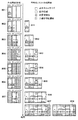
図4に撮像装置100における処理全体の一例を示す。図4は本実施形態の処理の広角合成モードの処理の流れを示すフローチャートである。操作部104に設けられたモード切り替えスイッチで、広角合成モードが選択された場合に図4の処理を実行する。
<Overall Processing Flow of
FIG. 4 shows an example of the entire processing in the
なお、本実施形態におけるフローチャートの制御プログラムは、撮像装置100の電源がONの状態において、不揮発性メモリ103に格納されているプログラムをメモリ102に展開してCPU101が実行する。本実施形態における撮像装置100の制御プログラムは、定期的に処理を繰り返し実行してもよい。
Note that the control program of the flowchart in the present embodiment is executed by the
本実施形態では、ユーザは撮像装置100を水平方向にパンニング操作を行い、そのパンニング操作中に連続撮影を行い、広角画像を生成して符号化する処理を示す。従って以下の説明では、撮影するたびに撮像装置100の視線方向が水平方向に移動することになる点に注意されたい。また、本実施形態では、最初に符号化するタイルから最後に符号化するタイルの1つ前のタイルまでは、同じタイルサイズで符号化する。このタイルサイズを基準タイルサイズと呼ぶ。また、この基準タイルの垂直方向の長さである画素数は、撮像部112が撮像する画像の垂直方向の画素数より予め設定された値以上大きい。この値は、ユーザが水平方向にパンニング操作を行う場合に、垂直方向のブレを吸収するためのものであり、適宜設定できるものとする。
In this embodiment, the user performs a panning operation on the
S100において、CPU101は、操作部104の設定ボタンが押されたか否かの判定を行う。CPU101は、設定ボタンが押されたと判定された場合、本フローチャートにおける処理をS100からS101へ進め、設定ボタンが押されなかったと判定された場合、本フローチャートにおける処理をS100からS102へ進める。設定が変更されなかった場合で、初めて動作させる場合は初期設定値を使用する。
In S100, the
S101において、CPU101は、ユーザによる操作部104の操作に応じて、撮影のパンニング角度やパンニングの方向、作成しようとする広角合成画像の解像度(サイズ)などの設定を変更する。CPU101は、設定に応じて基準タイルサイズ、合成画像用の記憶領域(以下、合成画像領域と呼ぶ)のサイズ、最大画像サイズを決定し、本フローチャートにおける処理をS101からS102へ進める。
In step S <b> 101, the
S102において、CPU101は、操作部104のシャッタースイッチが半押しされたか判定する。S102において、シャッタースイッチが半押しされたと判定された場合、CPU101は、本フローチャートにおける処理をS102からS103へ進める。S102において、シャッタースイッチが半押しされなかったと判定された場合、CPU101は、本フローチャートにおける処理をS102からS100に戻す。
In S <b> 102, the
S103において、CPU101は、AE処理とAF処理を行い、本フローチャートにおける処理をS103からS104に進める。
In S103, the
S104において、CPU101は、操作部104のシャッタースイッチが全押しされたか判定する。S102において、シャッタースイッチが全押しされたと判定された場合、CPU101は、本フローチャートにおける処理をS104からS106へ進める。S102において、シャッタースイッチが全押しされなかったと判定された場合、CPU101は、本フローチャートにおける処理をS104からS105へ進める。
In step S <b> 104, the
S105において、CPU101は、操作部104のシャッタースイッチが半押しされたままかどうかを判定する。S105において、シャッタースイッチが半押しされたままと判定された場合、CPU101は、本フローチャートにおける処理をS105からS103に戻す。S105において、シャッタースイッチが半押しされていない(シャッタースイッチが解放された)と判定された場合、CPU101は、本フローチャートにおける処理をS105からS100に戻す。
In step S <b> 105, the
S106において、CPU101は、撮像部112により連続撮影の最初の撮影を行う。
In step S <b> 106, the
S107において、CPU101は、S106で撮影された画像をメモリ102の合成画像領域に記憶する。そして、CPU101は、処理をS107からS108へ進める。
In step S <b> 107, the
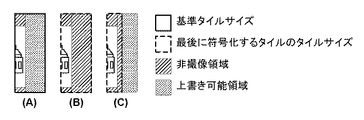
ここで、実施形態におけるS107の処理の例を図5を用いて説明する。本実施形態では、図5(A)に示すように、1枚の画像に対する合成画像領域としてタイル1からタイル3までの3領域を確保しているものとする。図5(A)に示した3領域は、それぞれ基準タイルサイズと同じサイズとする。パンニングの方向と垂直となる方向の基準タイルのサイズは、撮像された画像サイズよりも大きいサイズとする。撮像した画像を縮小した画像を合成に使用する場合、縮小した画像サイズよりも大きいサイズとする。
Here, an example of the processing of S107 in the embodiment will be described with reference to FIG. In the present embodiment, as shown in FIG. 5A, it is assumed that three areas from
図5(B)に示すように撮像した画像の中央部をクロップして、図5(C)に示すようにメモリ102に確保した合成画像領域のタイル1に記憶する。この際、パンニングの方向と垂直な方向に関して、合成画像領域の方がサイズが大きい。このため、最初に撮影した画像については、クロップした画像の上端と下端に非撮像領域が位置するように、そのクロップした画像が中央の位置となるようにメモリ102の合成画像領域に記憶する。そして、CPU101は、非撮像領域は全画素「黒」の画素値を合成画像領域に書き込む(以後、黒埋めと呼ぶ)。なお、非撮像領域に書き込む画素値は、全画素白の画素値や全画素グレーの画素値、その他の決められた画像パターンなどでもよい。また、クロップされる画像の範囲は、検出部140の検出結果から算出されたパンニングの量に応じて決定するようにしてもよい。
The central portion of the captured image is cropped as shown in FIG. 5B and stored in
S108において、CPU101は、多重化処理部309により、記録媒体120に画像サイズ、タイル分割数、タイルサイズ、表示領域のシンタックスに仮の値を設定した情報を含んだファイルヘッダを記録する。そしてCPU101は、処理をS108からS109へ進める。
In S <b> 108, the
S109において、CPU101は、撮像部112により撮影を行わせる。そして、CPU101は、処理をS109からS110へ進める。
In step S <b> 109, the
S110において、CPU101は、画像処理部113によりメモリ102の合成画像領域に既に記憶されている合成画像を位置合わせの基準として、S109で取得した画像の中央部をクロップした画像との位置合わせを行う。位置合わせは、画像を任意のサイズの小ブロックに分割して、小ブロック毎に輝度のSAD(Sum of Absolute Difference)が最小となる対応点を算出する。この処理は、動きベクトルの算出方法などと同等の処理で構わない。そして、CPU101はメモリ102に位置合わせ情報を記憶し、処理をS110からS111へ進める。
In S <b> 110, the
S111において、CPU101は、画像処理部113によりS110で位置合わせされた画像を、従前の合成画像に合成して、メモリ102の合成画像領域に記憶する。つまり、合成画像の更新である。なお、画像が重複する領域は加重加算を行い合成する。この後、CPU101は、処理をS111からS112へ進める。
In S <b> 111, the
S112において、CPU101は、メモリ102の合成画像領域に記憶された更新後の合成画像(記憶領域)が所定の条件を満たしたか判定する。本実施形態では、メモリ102の合成画像領域に記憶された合成画像サイズが、符号化されるタイルのタイルサイズ以上となることを条件とする。S112において、メモリ102の合成画像領域に記憶された画像サイズが符号化されるタイルのタイルサイズ以上と判定された場合、CPU101は、処理をS112からS113へ進める。また、S112において、メモリ102の合成画像領域に記憶された画像サイズが次に符号化されるタイルのタイルサイズ未満と判定された場合、CPU101は、処理をS112からS115へ進める。
In step S <b> 112, the
S113において、CPU101は、符号化対象のタイルを符号化処理部114で符号化し、符号化したHEVCストリームを記録媒体120に記録する。CPU101は、符号化したタイルのサイズ情報をメモリ102に記憶する。そして、CPU101は、処理をS113からS114へ進める。
In S113, the
S114において、CPU101は、S113で符号化したタイルのメモリ領域を上書き可能にする(メモリ領域を解放する)。そして、CPU101は、処理をS114からS115へ進める。
In S114, the
S115において、CPU101は、操作部104のシャッタースイッチが全押しされているか否か、または検出部140によりパンニングが継続しているか検出することにより撮影が継続しているか判定する。撮影が継続していると判断された場合、CPU101は、本フローチャートにおける処理をS115からS116へ進める。撮影が継続していないと判断された場合、CPU101は、処理をS115からS117へ進める。
In step S <b> 115, the
S116において、CPU101は、S116の処理までに合成された合成画像のサイズが目的とする最大画像サイズ以上のサイズかどうか判定する。
In S <b> 116, the
具体的には、目標とする広角合成画像の水平方向のサイズ(画素数)をW、合成画像領域の1つのタイルの水平方向のサイズをTw、S114の解放処理後に合成画像領域に残っている合成画像の水平方向のサイズをLwとする。そして、S113の符号化処理の実行回数をnとしたとき、CPU101は次式を満たすか否かを判定すれば良い。
W≦Tw×n+Lw
Specifically, the horizontal size (number of pixels) of the target wide-angle composite image is W, the horizontal size of one tile of the composite image region is Tw, and remains in the composite image region after the release process of S114. Let Lw be the horizontal size of the composite image. Then, when the number of execution times of the encoding process in S113 is n, the
W ≦ Tw × n + Lw
さて、この合成画像のサイズが最大画像サイズ以上のサイズになったと判定された場合、CPU101は、処理をS116からS117へ進める。合成画像のサイズが最大画像サイズ未満のサイズと判定された場合、CPU101は、処理をS116からS109に戻す。
If it is determined that the size of the composite image is equal to or larger than the maximum image size, the
なお、S116にて、CPU101は、シャッタースイッチが解放状態にあると判断し場合にも、S117に処理を進めるようにして良い。
Note that the
S117において、CPU101は、メモリ102の残っている未符号化の合成画像に終端画像の付加が必要であれば、終端画像を付加する。HEVCの符号化のタイルサイズは、CTU(Coding Tree Unit)単位のサイズなので、CTUの倍数のサイズとなるように、黒画像を埋め込む。以後、この処理を終端処理と呼ぶ。CPU101は、この後、処理をS117からS118に進める。
In S <b> 117, the
図6を用いて終端処理の例を説明する。メモリ102の合成画像領域には、図6(A)のような画像が記憶されているものとする。図6(B)は、符号化するタイルのサイズが基準タイルと同じタイルサイズとなるように非撮像領域に黒埋めした例を示している。そして、図6(C)は、符号化するタイルのサイズが小さくなるように、非撮像領域に黒埋め画像した例である。黒太線が基準タイルサイズを示している。黒点線が終端画像を付加し、最後に符号化するタイルのタイルサイズを示している。斜め線のハッチングは非撮像領域を示している。網点のハッチングは上書き可能領域を示している。
An example of termination processing will be described with reference to FIG. Assume that an image as shown in FIG. 6A is stored in the composite image area of the
S118において、CPU101は、終端処理後の未符号化の合成画像を符号化処理部114で符号化させ、符号化したHEVCストリームを記録媒体120に記録する。CPU101は、符号化したタイルのサイズ情報をメモリ102に記憶する。CPU101は、本フローチャートにおける処理をS118からS119へ進める。
In S118, the
S119において、CPU101は、メモリ102に記憶されている符号化されたタイルサイズの総和から画像サイズを算出する。また、CPU101は、メモリ102に記憶されている位置合わせ情報から表示領域を算出する。CPU101は、多重化処理部309により、記録媒体120に仮の値を設定したファイルヘッダの画像サイズ、タイル分割数、タイルサイズ、表示領域のシンタックスを上書きする。CPU101は、本フローチャートにおける処理を終了する。
In S <b> 119, the
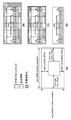
図7を参照して表示領域の算出の例を説明する。図7(A)は画像サイズと表示領域のシンタックスの関係を示した図である。図7(B)と図7(C)は水平方向に6分割されたタイルにより符号化された画像を示している。図7(B)と図7(C)は、終端処理が異なっており、図7(B)は、図6(B)の終端処理を行った画像であり、図7(C)は、図6(C)の終端処理を行った画像である。 An example of display area calculation will be described with reference to FIG. FIG. 7A shows the relationship between the image size and the syntax of the display area. FIG. 7B and FIG. 7C show images encoded by tiles divided into six in the horizontal direction. 7B and 7C are different in termination processing. FIG. 7B is an image obtained by performing the termination processing in FIG. 6B. FIG. 7C is a diagram of FIG. 6C is an image that has been subjected to termination processing.
表示領域は、撮像領域のみが含まれる矩形とする。パンニングと垂直な方向の撮像領域は、位置合わせした画像の位置ずれ量から算出することができる。パンニングと同じ方向の撮像領域は、タイルのサイズの和から算出することができる。 The display area is a rectangle that includes only the imaging area. The imaging area in the direction perpendicular to panning can be calculated from the amount of positional deviation of the aligned images. An imaging region in the same direction as panning can be calculated from the sum of tile sizes.
図7の黒太線は符号化されたタイルサイズを示し、黒点線は表示領域を示し、斜め線のハッチングは非撮像領域を示している。図7(D)は表示領域のみを示した図である。図7(B)と図7(C)の表示領域は同じ領域となる。なお、表示領域は、図7(C)の有意な合成画像に内接する最大矩形領域としても良い。 The black thick line in FIG. 7 indicates the encoded tile size, the black dotted line indicates the display area, and the hatched hatching indicates the non-imaging area. FIG. 7D shows only the display area. The display areas in FIGS. 7B and 7C are the same area. The display area may be a maximum rectangular area inscribed in the significant composite image in FIG.
次に、実施形態におけるメモリ102に確保された合成画像領域への画像の格納と、符号化処理の推移を図8を参照して説明する。同図は、上から下に向かって時間が流れるものとする。
Next, the storage of an image in the composite image area secured in the
符号801乃至807は合成画像領域への画像の格納状態を示し、符号811〜818は符号化された合成画像を示している。合成画像817と818は終端処理の違いを示している。図8における黒太線は基準タイルサイズを示している。合成画像817、818における黒点線は表示領域を示している。図8の斜め線のハッチングは非撮像領域を示している。図8の合成画像領域における網点ハッチングは上書き可能領域を示している。
最初の撮影(S106)で得た画像からクロップされた部分画像は、合成画像領域のタイル1に格納される(状態801)。そして、次に撮影された画像からクロップされた部分画像が、タイル1に格納されている画像と位置合わせされ合成される(状態802)。図示の状態802では、合成後の画像がタイル1、2を跨いでいることを示している。つまり、タイル1は符号化しても良いことになる。それ故、タイル1の画像は符号化処理される(合成画像811)。またタイル1の画像の符号化を終えると、タイル1は上書き可能とすべく解放される(S114)。
The partial image cropped from the image obtained in the first shooting (S106) is stored in
次に撮影された画像からクロップされた部分画像は、タイル2に対して合成されることになる。タイル2に対して合成した際に余分な画像はタイル3に格納される。そして、タイル2が符号化単位の画像を含んだ(状態803)、タイル2の画像が符号化される(合成画像812)。
Next, the partial image cropped from the photographed image is combined with the
以下、タイル3→タイル1→タイル2…と、ユーザがシャッタースイッチを離す、もしくは当初予定のサイズの合成画像が生成されるまで繰り返される。
Thereafter, the process is repeated until
以上の結果、これまでは広角合成画像を生成するための複数の画像を格納するためのメモリが必要であったのに対し、実施形態では広角合成画像を生成する撮影する回数には依存せず、上記の如くメモリ102には合成画像領域が確保できれば広角合成画像を生成できる。また、ユーザがパンニング操作を行って撮影中に、合成画像領域に符号化単位のタイルの合成画像が構築されるたびに符号化を実施していくことになる。従って、広角合成画像の符号化が完了するのは、広角合成の最後の撮影が完了するタイミングに依存し、これまでよりも大幅に符号化に係る遅延時間を短縮できる。
As a result of the above, a memory for storing a plurality of images for generating a wide-angle composite image has been necessary so far. In the embodiment, the embodiment does not depend on the number of times of shooting for generating a wide-angle composite image. As described above, if a composite image area can be secured in the
なお、実施形態では、符号化開始の所定の条件を合成画像領域に記憶された画像サイズが符号化されるタイルのタイルサイズ以上となることとしたが、他の条件としてもよい。例えば、合成画像領域に記憶された画像サイズがタイルサイズよりも大きく、予め決められたサイズ以上となることを条件にしても良い。 In the embodiment, the predetermined condition for starting the encoding is such that the image size stored in the composite image area is equal to or larger than the tile size of the tile to be encoded, but other conditions may be used. For example, the condition may be that the image size stored in the composite image area is larger than the tile size and equal to or larger than a predetermined size.
また、符号化される第1のタイルと、それに隣接する第2のタイルの、2フレーム以上に画像が記憶されたことを符号化開始の所定の条件としてもよい。図5(A)を例とすると次に符号化される領域がタイル1の場合、タイル2に2フレーム以上のフレーム数の画像が記憶されたことを符号化開始の所定の条件としてもよい。
The predetermined condition for starting encoding may be that an image is stored in two frames or more of the first tile to be encoded and the second tile adjacent to the first tile. Taking FIG. 5A as an example, if the area to be encoded next is
また、次に符号化される第1のタイルと隣接し、第1のタイルの次に符号化される第2のタイルと隣接し、第2のタイルの次に符号化される第3のタイルに画像が記憶されたことを符号化開始の所定の条件としてもよい。図5(A)を例とすると、次に符号化される領域がタイル1の場合、タイル3に画像が記憶されたことを符号化開始の所定の条件としてもよい。
A third tile that is adjacent to the first tile to be encoded next, adjacent to the second tile to be encoded next to the first tile, and encoded next to the second tile. The predetermined condition for starting encoding may be that the image is stored in Taking FIG. 5A as an example, if the area to be encoded next is
また、本実施形態では、撮像装置100を水平方向にパンニングにして連続撮影を行い、広角画像を生成して符号化する処理を示したが、撮像装置100を垂直方向にパンニングして連続撮影を行い、広角画像を生成して符号化してもよい。このためには、広角合成モードを設定するとき、パンニング方向を水平、垂直のいずれかを選択すればよい。そして、水平の場合には、上記実施形態で示した処理を行い、垂直の場合には、上記実施形態の説明を90度回転したものとして処理すればよい。
Further, in the present embodiment, a process of performing continuous shooting by panning the
[第2の実施形態]
第2の実施形態として、合成画像領域に記憶された画像が所定の条件を満たしたら画像の符号化を行い、符号化したストリームをメモリに記憶した後に、合成画像領域を上書き可能とする処理を示す。また、本第2の実施形態では、全画像領域の符号化が完了した後に記録媒体にファイルヘッダを記録し、メモリに記憶されている符号化したストリームを記録媒体に記録する処理を示す。装置構成は上記第1の実施形態と同じとし、その説明は省略する。
[Second Embodiment]
As a second embodiment, a process of encoding an image when an image stored in the composite image area satisfies a predetermined condition, and storing the encoded stream in the memory and then overwriting the composite image area is performed. Show. In the second embodiment, a process is described in which a file header is recorded on a recording medium after encoding of all image areas is completed, and an encoded stream stored in a memory is recorded on the recording medium. The apparatus configuration is the same as that of the first embodiment, and the description thereof is omitted.
図9は本第2の実施形態の処理の広角合成モードの処理の流れを示すフローチャートである。 FIG. 9 is a flowchart showing the flow of processing in the wide-angle composition mode of the processing of the second embodiment.
なお、同図のS200からS207、S208からS211、S213からS216の処理は、それぞれ図4のS100からS107、S109からS112、S114からS117と同様の処理であるため説明を省略する。 Note that the processing from S200 to S207, S208 to S211, and S213 to S216 in the figure is the same as S100 to S107, S109 to S112, and S114 to S117 in FIG.
S212において、CPU101は、符号化対象のタイルを符号化処理部114で符号化させる。CPU101は、符号化で得られたHEVCストリームをメモリ102に一時的に格納する。また、CPU101は、符号化したタイルのサイズ情報をメモリ102に記憶する。そして、CPU101は処理をS212からS213へ進める。
In S212, the
S217において、CPU101は、終端処理を行った合成画像を符号化処理部114で符号化させる。そして、CPU101は、符号化した得たHEVCストリームをメモリ102に記憶する。また、CPU101は、符号化したタイルのサイズ情報をメモリ102に記憶する。そして、CPU101は、処理をS217からS218へ進める。なお、このとき、メモリ102には、広角合成画像の全符号化データが格納されていることになることに注意されたい。
In S <b> 217, the
S218において、CPU101は、メモリ102に記憶されている符号化されたタイルサイズの総和から画像サイズを算出する。また、CPU101は、メモリ102に記憶されている位置合わせ情報から表示領域を算出する。CPU101は、多重化処理部309により、画像サイズ、タイル分割数、タイルサイズ、表示領域のシンタックスなどを含むファイルヘッダを記録媒体120に記録する。そしてCPU101は、処理をS218からS219へ進める。
In step S <b> 218, the
S219において、CPU101は、メモリ102に記憶されている符号化されたHEVCストリームを順次読み出し、記録媒体120に記録し、広角合成画像ファイルを完成させる。そして、CPU101は、本フローチャートにおける処理を終了する。
In step S219, the
[第3の実施形態]
第3の実施形態として、合成画像の縮小画像をサムネイル用の画像として生成し、縮小合成画像も符号化し、ファイルの一部として格納する例を説明する。また、本第3の実施形態では縮小合成画像は分割して符号化しないものとする。装置構成は上記第1の実施形態と同じとし、その説明は省略する。
[Third Embodiment]
As a third embodiment, an example in which a reduced image of a composite image is generated as a thumbnail image, the reduced composite image is also encoded, and stored as part of a file will be described. In the third embodiment, the reduced composite image is not divided and encoded. The apparatus configuration is the same as that of the first embodiment, and the description thereof is omitted.
図10は本第3の実施形態における広角合成モードの処理の流れを示すフローチャートである。図示におけるS300からS312、S314からS316、S320とS321の処理は、それぞれ図9のS200からS212、S213からS215、S216とS217と同様の処理であるため、その説明を省略する。 FIG. 10 is a flowchart showing a flow of processing in the wide-angle composition mode in the third embodiment. The processes from S300 to S312, S314 to S316, S320 and S321 in the figure are the same as S200 to S212, S213 to S215, and S216 and S217 in FIG.
S313において、CPU101は、画像処理部113によりS312で符号化された合成画像の縮小画像を生成し、メモリ102に記憶する。なお、メモリ102には、S300またはS301の設定に応じた縮小合成画像用の記憶容量が割り当てられているものとする。そして、CPU101は、処理をS313からS314へ進める。
In step S <b> 313, the
S317において、CPU101は、画像処理部113により縮小合成画像を生成し、メモリ102に記憶する。そして、CPU101は、処理をS317からS318へ進める。
In step S <b> 317, the
S318において、CPU101は、画像処理部113により縮小合成画像に終端処理を行う。そして、CPU101は、処理をS318からS319に進める。
In step S <b> 318, the
S319において、CPU101は、符号化処理部114によりメモリ102に記憶されている縮小合成画像を符号化させ、その結果(符号化データ)をメモリ102に記憶させる。そして、CPU101は、処理をS319からS320へ進める。
In S <b> 319, the
S322において、CPU101は、メモリ102に記憶されている符号化されたタイルサイズの総和から画像サイズを算出する。また、CPU101は、メモリ102に記憶されている位置合わせ情報から表示領域を算出する。CPU101は、多重化処理部309により、画像サイズ、タイル分割数、タイルサイズ、表示領域、サムネイル画像の情報などのシンタックスを含むファイルヘッダを記録媒体120に記録する。そして、CPU101は、処理をS322からS323へ進める。
In S <b> 322, the
S323において、CPU101は、メモリ102に記憶されている符号化された縮小合成画像のストリームを含めた符号化されたストリームを順次読み出し、記録媒体120に記録する。そして、CPU101は、本フローチャートにおける処理を終了する。
In step S <b> 323, the
(その他の実施例)
上記各実施形態における撮像装置100はデジタルカメラ等の装置を基礎にして説明したが、撮像機能を有する装置であれば例えばスマートホンであっても構わず、デジタルカメラに限定されるものではない。
(Other examples)
The
また、本実施形態で説明した様々な処理及び機能は、コンピュータプログラムにより実現することも可能である。この場合、本発明に係るコンピュータプログラムは、コンピュータ(CPU等を含む)で実行可能であり、本実施例で説明した様々な機能を実現することになる。 The various processes and functions described in this embodiment can also be realized by a computer program. In this case, the computer program according to the present invention can be executed by a computer (including a CPU and the like), and implements various functions described in this embodiment.
本発明に係るコンピュータプログラムは、コンピュータ上で稼動しているOS(Operating System)などを利用して、本実施例で説明した様々な処理及び機能を実現してもよいことは言うまでもない。 It goes without saying that the computer program according to the present invention may realize various processes and functions described in this embodiment by using an OS (Operating System) running on the computer.
本発明は、上述の実施形態の1以上の機能を実現するプログラムを、ネットワーク又は記憶媒体を介してシステム又は装置に供給し、そのシステム又は装置のコンピュータにおける1つ以上のプロセッサーがプログラムを読出し実行する処理でも実現可能である。また、1以上の機能を実現する回路(例えば、ASIC)によっても実現可能である。 The present invention supplies a program that realizes one or more functions of the above-described embodiments to a system or apparatus via a network or a storage medium, and one or more processors in a computer of the system or apparatus read and execute the program This process can be realized. It can also be realized by a circuit (for example, ASIC) that realizes one or more functions.
100…撮像装置、101…CPU、102…メモリ、103…不揮発性メモリ、104…操作部、111…撮像レンズ、112…撮像部、113…画像処理部、114…符号化処理部、115…表示制御部、116…表示部、117…通信制御部、118…通信部、119…記録媒体制御部、120…記録媒体、130…内部バス、140…検出部、301…画像分割制御部、302…予測符号化方法決定部、303…予測符号化処理部、305…直交変換量子化部、306…局所復号化部、307…符号量制御部、308…エントロピー符号化部、309…多重化処理部
DESCRIPTION OF
Claims (9)
撮像画像を一時的に記憶するためのメモリと、
前記撮像手段による撮像画像を入力するたびに、入力した撮像画像の予め定められた領域の部分画像を抜き出し、当該部分画像を、前記メモリに格納されている従前に入力した撮像画像で得た合成画像に、位置合わせして合成することで、前記合成画像を更新する合成手段と、
該合成手段による更新後の合成画像が、予め設定された符号化単位のタイルのサイズになった場合、前記合成画像における前記タイルの画像を符号化する符号化手段と、
前記メモリにおける、符号化を終えた前記タイルを上書き可能に解放する解放手段と、
予め設定された条件を満たすまで、前記合成手段、前記符号化手段、前記解放手段を繰り返すように制御し、広角合成画像の符号化データを生成する制御手段と
を有することを特徴とする画像符号化装置。 An image encoding device that encodes a wide-angle composite image obtained from a plurality of images obtained while changing the imaging direction of an imaging means,
A memory for temporarily storing captured images;
Each time a captured image is input by the imaging means, a partial image of a predetermined area of the input captured image is extracted, and the partial image is obtained by a previously input captured image stored in the memory. A composition unit that updates the composite image by aligning and compositing the image, and
An encoding means for encoding an image of the tile in the composite image when the composite image after the update by the composite means has a tile size of a preset encoding unit;
Release means for releasing the tile that has been encoded in the memory in an overwriteable manner;
Control means for controlling the synthesis means, the encoding means, and the release means to repeat until a preset condition is satisfied, and generating encoded data of a wide-angle synthesized image. Device.
前記合成手段で得た合成画像の縮小合成画像を生成して前記メモリに格納し、
予め設定された条件を満たした場合、前記メモリに格納された縮小合成画像を前記広角合成画像のサムネイルとして、前記不揮発性メモリのファイルの一部として格納する
ことを特徴とする請求項4に記載の画像符号化装置。 The control means includes
Generating a reduced composite image of the composite image obtained by the combining means and storing it in the memory;
5. The reduced composite image stored in the memory is stored as a thumbnail of the wide-angle composite image as a part of a file in the nonvolatile memory when a preset condition is satisfied. Image coding apparatus.
前記ファイルのヘッダに画像サイズ、タイルの分割数、各タイルの画像サイズ、タイル番号および表示領域範囲のうち少なくとも1つを含むシンタックスを格納することを特徴とする請求項4に記載の画像符号化装置。 The control means includes
5. The image code according to claim 4, wherein a syntax including at least one of an image size, a tile division number, an image size of each tile, a tile number, and a display area range is stored in a header of the file. Device.
前記撮像手段による撮像画像を入力するたびに、入力した撮像画像の予め定められた領域の部分画像を抜き出し、当該部分画像を、前記メモリに格納されている従前に入力した撮像画像で得た合成画像に、位置合わせして合成することで、前記合成画像を更新する合成工程と、
該合成工程による更新後の合成画像が、予め設定された符号化単位のタイルのサイズになった場合、前記合成画像における前記タイルの画像を符号化する符号化工程と、
前記メモリにおける、符号化を終えた前記タイルを上書き可能に解放する解放工程と、
予め設定された条件を満たすまで、前記合成工程、前記符号化工程、前記解放工程を繰り返すように制御し、広角合成画像の符号化データを生成する制御工程と
を有することを特徴とする画像符号化装置の制御方法。 An image code that encodes a wide-angle composite image obtained from a plurality of images obtained by changing the imaging direction of the imaging unit using the memory while temporarily storing an imaging unit and a captured image A control method for a control device comprising:
Each time a captured image is input by the imaging means, a partial image of a predetermined area of the input captured image is extracted, and the partial image is obtained by a previously input captured image stored in the memory. A composition step of updating the composite image by aligning and compositing the image, and
An encoding step of encoding the tile image in the composite image when the composite image after the update by the combining step has a tile size of a preset encoding unit;
A release step of releasing the tiles that have been encoded in the memory in an overwriteable manner;
An image code comprising: a control step of controlling to repeat the synthesis step, the encoding step, and the release step until a preset condition is satisfied, and generating encoded data of a wide-angle synthesized image Control method.
Priority Applications (2)
| Application Number | Priority Date | Filing Date | Title |
|---|---|---|---|
| JP2017135657A JP2019021968A (en) | 2017-07-11 | 2017-07-11 | Image encoding device and control method therefor |
| US16/022,849 US10674110B2 (en) | 2017-07-11 | 2018-06-29 | Image encoding apparatus, and control method thereof |
Applications Claiming Priority (1)
| Application Number | Priority Date | Filing Date | Title |
|---|---|---|---|
| JP2017135657A JP2019021968A (en) | 2017-07-11 | 2017-07-11 | Image encoding device and control method therefor |
Publications (1)
| Publication Number | Publication Date |
|---|---|
| JP2019021968A true JP2019021968A (en) | 2019-02-07 |
Family
ID=65000264
Family Applications (1)
| Application Number | Title | Priority Date | Filing Date |
|---|---|---|---|
| JP2017135657A Pending JP2019021968A (en) | 2017-07-11 | 2017-07-11 | Image encoding device and control method therefor |
Country Status (2)
| Country | Link |
|---|---|
| US (1) | US10674110B2 (en) |
| JP (1) | JP2019021968A (en) |
Families Citing this family (5)
| Publication number | Priority date | Publication date | Assignee | Title |
|---|---|---|---|---|
| JP7418152B2 (en) * | 2018-12-17 | 2024-01-19 | キヤノン株式会社 | Image encoding device, image encoding method, image decoding device, image decoding method |
| KR102259186B1 (en) * | 2019-01-16 | 2021-06-01 | 텔레호낙티에볼라게트 엘엠 에릭슨(피유비엘) | Video coding with uniform tile fragmentation with remainder |
| US11425374B2 (en) * | 2019-03-12 | 2022-08-23 | FG Innovation Company Limited | Device and method for coding video data |
| CN113763238B (en) * | 2020-06-01 | 2023-09-26 | 杭州海康威视数字技术股份有限公司 | Picture synthesis method and device and electronic equipment |
| US20230217022A1 (en) * | 2022-01-05 | 2023-07-06 | Agora Lab, Inc. | Real-Time Wide-Angle Video Communication System |
Family Cites Families (9)
| Publication number | Priority date | Publication date | Assignee | Title |
|---|---|---|---|---|
| US7292261B1 (en) * | 1999-08-20 | 2007-11-06 | Patrick Teo | Virtual reality camera |
| US6677981B1 (en) * | 1999-12-31 | 2004-01-13 | Stmicroelectronics, Inc. | Motion play-back of still pictures comprising a panoramic view for simulating perspective |
| US6885392B1 (en) * | 1999-12-31 | 2005-04-26 | Stmicroelectronics, Inc. | Perspective correction for preview area of panoramic digital camera |
| JP5223318B2 (en) * | 2007-12-07 | 2013-06-26 | ソニー株式会社 | Image processing apparatus, image processing method, and program |
| JP5256725B2 (en) * | 2007-12-25 | 2013-08-07 | 株式会社ニコン | Imaging device |
| JP5115731B2 (en) | 2008-07-24 | 2013-01-09 | ソニー株式会社 | Imaging apparatus, image processing method, and program |
| JP5592776B2 (en) * | 2010-12-21 | 2014-09-17 | オリンパスイメージング株式会社 | Image processing apparatus, image processing method, and image processing program |
| JP2013020527A (en) * | 2011-07-13 | 2013-01-31 | Sony Corp | Image processing device, method, and program |
| KR102460906B1 (en) * | 2016-02-17 | 2022-11-01 | 삼성전자주식회사 | Image processing Method and electronic device supporting the same |
-
2017
- 2017-07-11 JP JP2017135657A patent/JP2019021968A/en active Pending
-
2018
- 2018-06-29 US US16/022,849 patent/US10674110B2/en active Active
Also Published As
| Publication number | Publication date |
|---|---|
| US10674110B2 (en) | 2020-06-02 |
| US20190020851A1 (en) | 2019-01-17 |
Similar Documents
| Publication | Publication Date | Title |
|---|---|---|
| JP2019021968A (en) | Image encoding device and control method therefor | |
| US8103111B2 (en) | Coding method, electronic camera, recording medium storing coded program, and decoding method | |
| US8103112B2 (en) | Decoding method, decoding apparatus, storage medium in which decoding program is stored, and electronic camera | |
| KR101229600B1 (en) | Image capturing apparatus and camera shake correction method, and computer-readable medium | |
| KR100994063B1 (en) | Image processing device, image processing method and a computer readable storage medium having stored therein a program | |
| CN107636692B (en) | Image capturing apparatus and method of operating the same | |
| KR102304784B1 (en) | Double camera-based imaging method and apparatus | |
| US9197813B2 (en) | Method and apparatus for obtaining a digital image | |
| JP6083162B2 (en) | Image processing apparatus, imaging apparatus, and image processing program | |
| JP2020017807A (en) | Image processing apparatus, image processing method, and imaging apparatus | |
| JP5869839B2 (en) | Image processing apparatus and control method thereof | |
| JP2020057898A (en) | Image coding device | |
| JP6921703B2 (en) | Encoding device, its control method, and control program, and imaging device | |
| JP2021118403A (en) | Image processing device, control method thereof, program, and image processing system | |
| JP5247346B2 (en) | Imaging apparatus, control method and program thereof, image processing apparatus, and image processing method | |
| JP7076983B2 (en) | Coding device, image processing device and image processing method | |
| JP6838951B2 (en) | Coding device and coding method | |
| JP7148236B2 (en) | Encoding device and its control method and program | |
| JP2014119725A (en) | Device and method for controlling exposure and focus and program | |
| JP7409604B2 (en) | Image processing device, imaging device, image processing method, program and recording medium | |
| JP2018088600A (en) | Image processing device, image processing method, and program | |
| JP6828069B2 (en) | Imaging equipment, imaging methods and programs | |
| JP2006033160A (en) | Imaging system | |
| JP2021182728A (en) | Image encoding device and image decoding device, method, and program | |
| JP2005039777A (en) | Photographing apparatus and photographing system |