JP2019021432A - Laser driving light source device - Google Patents
Laser driving light source device Download PDFInfo
- Publication number
- JP2019021432A JP2019021432A JP2017136778A JP2017136778A JP2019021432A JP 2019021432 A JP2019021432 A JP 2019021432A JP 2017136778 A JP2017136778 A JP 2017136778A JP 2017136778 A JP2017136778 A JP 2017136778A JP 2019021432 A JP2019021432 A JP 2019021432A
- Authority
- JP
- Japan
- Prior art keywords
- laser
- plasma
- light
- time
- light source
- Prior art date
- Legal status (The legal status is an assumption and is not a legal conclusion. Google has not performed a legal analysis and makes no representation as to the accuracy of the status listed.)
- Pending
Links
- 230000010355 oscillation Effects 0.000 claims abstract description 15
- 238000005086 pumping Methods 0.000 claims description 10
- 230000005457 Black-body radiation Effects 0.000 abstract description 4
- 230000003595 spectral effect Effects 0.000 abstract description 3
- 229910052751 metal Inorganic materials 0.000 description 10
- 239000002184 metal Substances 0.000 description 10
- 238000001228 spectrum Methods 0.000 description 10
- 239000007789 gas Substances 0.000 description 9
- 230000003287 optical effect Effects 0.000 description 5
- 238000005219 brazing Methods 0.000 description 4
- 238000000034 method Methods 0.000 description 4
- 238000000295 emission spectrum Methods 0.000 description 3
- QSHDDOUJBYECFT-UHFFFAOYSA-N mercury Chemical compound [Hg] QSHDDOUJBYECFT-UHFFFAOYSA-N 0.000 description 3
- 229910052753 mercury Inorganic materials 0.000 description 3
- 239000004065 semiconductor Substances 0.000 description 3
- VYPSYNLAJGMNEJ-UHFFFAOYSA-N silicon dioxide Inorganic materials O=[Si]=O VYPSYNLAJGMNEJ-UHFFFAOYSA-N 0.000 description 3
- 238000003466 welding Methods 0.000 description 3
- XKRFYHLGVUSROY-UHFFFAOYSA-N Argon Chemical compound [Ar] XKRFYHLGVUSROY-UHFFFAOYSA-N 0.000 description 2
- 230000000052 comparative effect Effects 0.000 description 2
- 238000009826 distribution Methods 0.000 description 2
- 230000000694 effects Effects 0.000 description 2
- 230000001678 irradiating effect Effects 0.000 description 2
- 239000013307 optical fiber Substances 0.000 description 2
- 230000002093 peripheral effect Effects 0.000 description 2
- 230000005855 radiation Effects 0.000 description 2
- BQCADISMDOOEFD-UHFFFAOYSA-N Silver Chemical compound [Ag] BQCADISMDOOEFD-UHFFFAOYSA-N 0.000 description 1
- 229910052782 aluminium Inorganic materials 0.000 description 1
- XAGFODPZIPBFFR-UHFFFAOYSA-N aluminium Chemical compound [Al] XAGFODPZIPBFFR-UHFFFAOYSA-N 0.000 description 1
- 229910052786 argon Inorganic materials 0.000 description 1
- 230000015556 catabolic process Effects 0.000 description 1
- 229910010293 ceramic material Inorganic materials 0.000 description 1
- 238000006243 chemical reaction Methods 0.000 description 1
- 238000010586 diagram Methods 0.000 description 1
- 230000005284 excitation Effects 0.000 description 1
- 239000000835 fiber Substances 0.000 description 1
- 239000011521 glass Substances 0.000 description 1
- 230000010354 integration Effects 0.000 description 1
- 229910052743 krypton Inorganic materials 0.000 description 1
- DNNSSWSSYDEUBZ-UHFFFAOYSA-N krypton atom Chemical compound [Kr] DNNSSWSSYDEUBZ-UHFFFAOYSA-N 0.000 description 1
- 239000004973 liquid crystal related substance Substances 0.000 description 1
- 238000012423 maintenance Methods 0.000 description 1
- 238000004519 manufacturing process Methods 0.000 description 1
- 239000000463 material Substances 0.000 description 1
- 238000000059 patterning Methods 0.000 description 1
- 230000000149 penetrating effect Effects 0.000 description 1
- 229920002120 photoresistant polymer Polymers 0.000 description 1
- 239000010453 quartz Substances 0.000 description 1
- 230000007261 regionalization Effects 0.000 description 1
- 229910052594 sapphire Inorganic materials 0.000 description 1
- 239000010980 sapphire Substances 0.000 description 1
- 239000002094 self assembled monolayer Substances 0.000 description 1
- 239000013545 self-assembled monolayer Substances 0.000 description 1
- 229910052709 silver Inorganic materials 0.000 description 1
- 239000004332 silver Substances 0.000 description 1
- 239000000758 substrate Substances 0.000 description 1
- 229910052724 xenon Inorganic materials 0.000 description 1
- FHNFHKCVQCLJFQ-UHFFFAOYSA-N xenon atom Chemical compound [Xe] FHNFHKCVQCLJFQ-UHFFFAOYSA-N 0.000 description 1
Images


Classifications
-
- H—ELECTRICITY
- H05—ELECTRIC TECHNIQUES NOT OTHERWISE PROVIDED FOR
- H05G—X-RAY TECHNIQUE
- H05G2/00—Apparatus or processes specially adapted for producing X-rays, not involving X-ray tubes, e.g. involving generation of a plasma
- H05G2/001—Production of X-ray radiation generated from plasma
- H05G2/008—Production of X-ray radiation generated from plasma involving an energy-carrying beam in the process of plasma generation
-
- G—PHYSICS
- G21—NUCLEAR PHYSICS; NUCLEAR ENGINEERING
- G21K—TECHNIQUES FOR HANDLING PARTICLES OR IONISING RADIATION NOT OTHERWISE PROVIDED FOR; IRRADIATION DEVICES; GAMMA RAY OR X-RAY MICROSCOPES
- G21K1/00—Arrangements for handling particles or ionising radiation, e.g. focusing or moderating
- G21K1/06—Arrangements for handling particles or ionising radiation, e.g. focusing or moderating using diffraction, refraction or reflection, e.g. monochromators
-
- H—ELECTRICITY
- H01—ELECTRIC ELEMENTS
- H01J—ELECTRIC DISCHARGE TUBES OR DISCHARGE LAMPS
- H01J61/00—Gas-discharge or vapour-discharge lamps
- H01J61/02—Details
- H01J61/025—Associated optical elements
-
- H—ELECTRICITY
- H01—ELECTRIC ELEMENTS
- H01J—ELECTRIC DISCHARGE TUBES OR DISCHARGE LAMPS
- H01J61/00—Gas-discharge or vapour-discharge lamps
- H01J61/02—Details
- H01J61/54—Igniting arrangements, e.g. promoting ionisation for starting
- H01J61/545—Igniting arrangements, e.g. promoting ionisation for starting using an auxiliary electrode inside the vessel
-
- H—ELECTRICITY
- H01—ELECTRIC ELEMENTS
- H01J—ELECTRIC DISCHARGE TUBES OR DISCHARGE LAMPS
- H01J65/00—Lamps without any electrode inside the vessel; Lamps with at least one main electrode outside the vessel
- H01J65/04—Lamps in which a gas filling is excited to luminesce by an external electromagnetic field or by external corpuscular radiation, e.g. for indicating plasma display panels
-
- H—ELECTRICITY
- H01—ELECTRIC ELEMENTS
- H01S—DEVICES USING THE PROCESS OF LIGHT AMPLIFICATION BY STIMULATED EMISSION OF RADIATION [LASER] TO AMPLIFY OR GENERATE LIGHT; DEVICES USING STIMULATED EMISSION OF ELECTROMAGNETIC RADIATION IN WAVE RANGES OTHER THAN OPTICAL
- H01S3/00—Lasers, i.e. devices using stimulated emission of electromagnetic radiation in the infrared, visible or ultraviolet wave range
- H01S3/005—Optical devices external to the laser cavity, specially adapted for lasers, e.g. for homogenisation of the beam or for manipulating laser pulses, e.g. pulse shaping
- H01S3/0071—Beam steering, e.g. whereby a mirror outside the cavity is present to change the beam direction
-
- H—ELECTRICITY
- H01—ELECTRIC ELEMENTS
- H01S—DEVICES USING THE PROCESS OF LIGHT AMPLIFICATION BY STIMULATED EMISSION OF RADIATION [LASER] TO AMPLIFY OR GENERATE LIGHT; DEVICES USING STIMULATED EMISSION OF ELECTROMAGNETIC RADIATION IN WAVE RANGES OTHER THAN OPTICAL
- H01S3/00—Lasers, i.e. devices using stimulated emission of electromagnetic radiation in the infrared, visible or ultraviolet wave range
- H01S3/09—Processes or apparatus for excitation, e.g. pumping
- H01S3/091—Processes or apparatus for excitation, e.g. pumping using optical pumping
- H01S3/0912—Electronics or drivers for the pump source, i.e. details of drivers or circuitry specific for laser pumping
-
- H—ELECTRICITY
- H01—ELECTRIC ELEMENTS
- H01S—DEVICES USING THE PROCESS OF LIGHT AMPLIFICATION BY STIMULATED EMISSION OF RADIATION [LASER] TO AMPLIFY OR GENERATE LIGHT; DEVICES USING STIMULATED EMISSION OF ELECTROMAGNETIC RADIATION IN WAVE RANGES OTHER THAN OPTICAL
- H01S3/00—Lasers, i.e. devices using stimulated emission of electromagnetic radiation in the infrared, visible or ultraviolet wave range
- H01S3/09—Processes or apparatus for excitation, e.g. pumping
- H01S3/091—Processes or apparatus for excitation, e.g. pumping using optical pumping
- H01S3/094—Processes or apparatus for excitation, e.g. pumping using optical pumping by coherent light
- H01S3/094076—Pulsed or modulated pumping
-
- H—ELECTRICITY
- H01—ELECTRIC ELEMENTS
- H01S—DEVICES USING THE PROCESS OF LIGHT AMPLIFICATION BY STIMULATED EMISSION OF RADIATION [LASER] TO AMPLIFY OR GENERATE LIGHT; DEVICES USING STIMULATED EMISSION OF ELECTROMAGNETIC RADIATION IN WAVE RANGES OTHER THAN OPTICAL
- H01S3/00—Lasers, i.e. devices using stimulated emission of electromagnetic radiation in the infrared, visible or ultraviolet wave range
- H01S3/09—Processes or apparatus for excitation, e.g. pumping
- H01S3/091—Processes or apparatus for excitation, e.g. pumping using optical pumping
- H01S3/094—Processes or apparatus for excitation, e.g. pumping using optical pumping by coherent light
- H01S3/0941—Processes or apparatus for excitation, e.g. pumping using optical pumping by coherent light of a laser diode
Landscapes
- Physics & Mathematics (AREA)
- Engineering & Computer Science (AREA)
- Electromagnetism (AREA)
- Plasma & Fusion (AREA)
- Optics & Photonics (AREA)
- Microelectronics & Electronic Packaging (AREA)
- Spectroscopy & Molecular Physics (AREA)
- General Engineering & Computer Science (AREA)
- High Energy & Nuclear Physics (AREA)
- Exposure And Positioning Against Photoresist Photosensitive Materials (AREA)
- Plasma Technology (AREA)
Abstract
Description
この発明は、レーザ駆動光源装置に関するものであり、特に、プラズマ容器内にレーザ光を間欠的に照射するレーザ駆動光源装置に係わるものである。 The present invention relates to a laser-driven light source device, and more particularly to a laser-driven light source device that irradiates laser light intermittently into a plasma container.
近年、半導体、液晶基板およびカラーフィルタ等の被処理物の製造工程においては、入力電力の大きな紫外線光源を使用されている。
このような高出力の紫外線、特に、短波長側の紫外線を出力する光源として、点光源管球において電極間で点灯した後にそのプラズマにレーザ光を照射することによって、連続的な高輝度光を発生させるレーザ駆動光源が提案されている。例えば、特表2009−532829号公報(特許文献1)に開示されている。
2. Description of the Related Art In recent years, ultraviolet light sources with large input power have been used in the manufacturing process of objects to be processed such as semiconductors, liquid crystal substrates and color filters.
As a light source that outputs such high-power ultraviolet rays, particularly ultraviolet rays on the short wavelength side, after lighting between electrodes in a point light source tube, continuous high-intensity light is emitted by irradiating the plasma with laser light. Laser driving light sources to be generated have been proposed. For example, it is disclosed in JP-T-2009-532829 (Patent Document 1).
この特許文献1には、図5に示すように、希ガス、水銀等のイオン性媒体(放電媒体)が封入されたチャンバ(管球)21と、該チャンバ21内のイオン性媒体をイオン化するための点火源である一対の電極32、33と、連続またはパルス状のレーザエネルギーを照射するレーザ発振部24とを備えるレーザ駆動光源20が開示されている。
該レーザ発振部24は、光ファイバ26を介してレーザ光25を出力するダイオードレーザである。該光ファイバ26は、レーザ光25を実質的に互いに平行にするためのコリメータ27にレーザ光25を供給する。次いで、コリメータ27はビームエキスパンダ28にレーザ光25を向ける。ビームエキスパンダ28は、レーザ光のサイズを拡大してレーザ光を生成する。また、ビームエキスパンダ28は、光学レンズ29にレーザ光を向ける。光学レンズ29は、チャンバ21のうちのプラズマ30が存在する領域に向けられる小径レーザ光を生成するためにレーザ光25を集光する。
In
The
このレーザ駆動光源20は、陽極32および陰極33からなる点火源によってチャンバ21内で放電を発生させてイオン性媒体をイオン化し、次いで、イオン化された媒体にレーザエネルギーを供給して高輝度光31を発生するプラズマ30を維持または生成するものである。
しかして、このレーザ駆動光源20では、プラズマの温度が放射および他のプロセスによってバランスされるまで上昇し、10000K〜20000Kという極めて高温になり、高温プラズマから放射される短波長の紫外線エネルギーが増加するものである。
また、上記特許文献1には、点火源として、上記一対の電極を利用する以外に、パルスレーザ光を利用することも記載されている(請求項43)。
The laser-driven
Thus, in this laser-driven
Further,
このような点火源としてパルスレーザ光を利用する場合、ピークのエネルギーがメガワット(MW)のオ−ダーであり、パルス幅がフェムト秒(fs)〜ナノ秒(ns)程度であり、また、繰り返しの周期がミリ秒(ms)程度のパルスレーザ光が使用される。
ところが、パルスレーザ光は、ピークのエネルギーは大きいが、パルス幅が極めて短く、繰り返し周期も短くできないため、時間平均したエネルギーは低くなる。そのため、パルスレーザ光の照射で、チャンバ内にプラズマ(火種)を生成することができても、パルスレーザ光のみを繰り返すだけでは、生成されたプラズマを定常的に維持することができない。
そこで、この種の光源の始動(点火)の際には、図6(A)で示すように、CWレーザ光(Continuous Wave Laser)を照射するとともにパルスレーザ光(Pulse Laser)を重畳して照射し、図6(B)に示すように、パルスレーザ光の照射で発生したプラズマ(火種)を、CWレーザ光から供給されるエネルギーで維持する方法がとられる。
When using pulsed laser light as such an ignition source, the peak energy is on the order of megawatts (MW), the pulse width is on the order of femtoseconds (fs) to nanoseconds (ns), and repeated. Pulsed laser light having a period of about milliseconds (ms) is used.
However, although the pulse laser beam has a large peak energy, the pulse width is extremely short and the repetition period cannot be shortened, so the time averaged energy is low. For this reason, even if plasma (fire type) can be generated in the chamber by irradiation with pulsed laser light, the generated plasma cannot be constantly maintained only by repeating only pulsed laser light.
Therefore, when starting (igniting) this type of light source, as shown in FIG. 6A, the CW laser beam (Continuous Wave Laser) is irradiated and the pulsed laser beam (Pulse Laser) is superimposed and irradiated. Then, as shown in FIG. 6B, a method is adopted in which plasma (fire type) generated by irradiation with pulsed laser light is maintained with energy supplied from CW laser light.
ところで、半導体集積回路の微細化、高集積化につれて、露光用紫外線光源の短波長化が進められている。特に波長200nm以下の真空紫外光(VUV光)は、半導体露光はもちろん、これ以外の様々な分野でも用いられている。例えば、フォトレジストによるパターン形成工程を用いずに、VUV光とマスクを用いて、直接光で化学反応を引き起こして自己組織化単分子膜をパターニングする技術にも応用される。
プラズマから放射される光は、黒体からの輻射と考えることができ、放射スペクトルはプランクの式に従う。この式では、プラズマ温度が上昇すると、短波長側の成分が大きいスペクトルに変化する。
By the way, with the miniaturization and high integration of semiconductor integrated circuits, the wavelength of the ultraviolet light source for exposure is being shortened. In particular, vacuum ultraviolet light (VUV light) having a wavelength of 200 nm or less is used not only for semiconductor exposure but also in various other fields. For example, the present invention can be applied to a technique for patterning a self-assembled monolayer by using a VUV light and a mask to cause a chemical reaction with direct light without using a photoresist pattern formation process.
The light emitted from the plasma can be considered as radiation from a black body, and the emission spectrum follows Planck's equation. In this equation, when the plasma temperature rises, the short wavelength component changes to a large spectrum.
このようなレーザ駆動光源において、プラズマ容器から放射されるプラズマ光に含まれる短波長の紫外線の成分を増やそうとすれば、プラズマ容器内に形成されるプラズマに投入するレーザのパワー(時間あたりエネルギー;ワット)を増やすことが考えられる。
図7は、このことを概念的に示す図である。レーザパワーがP1の時のプラズマ温度をT1とし、レーザパワーがP2の時のプラズマ温度をT2とすると、レーザパワーがP1<P2の時、プラズマ温度はT1<T2である。
このとき、黒体輻射の分光スペクトルにおいて、ある紫外線の波長λ以下の面積Aを、レーザパワーがP1とP2の場合で比較すれば、A1<A2となっている。
これは、プラズマに投入するレーザパワーPを上げれば、単に光出力が大きくなるだけでなく、プラズマ温度Tが高くなることにより、黒体輻射のスペクトルが短波長側にシフトすることに由来し、その結果、短波長側の紫外線成分(光出力全体に対する紫外線出力の割合)を増やすことができて効率的である。
In such a laser-driven light source, if an attempt is made to increase the short-wavelength ultraviolet component contained in the plasma light emitted from the plasma container, the power of the laser (energy per hour; It is possible to increase watts).
FIG. 7 is a diagram conceptually showing this. Assuming that the plasma temperature when the laser power is P1 is T1, and the plasma temperature when the laser power is P2 is T2, the plasma temperature is T1 <T2 when the laser power is P1 <P2.
At this time, in the spectrum of black body radiation, if the area A of a certain ultraviolet ray having a wavelength λ or less is compared between the cases where the laser power is P1 and P2, A1 <A2.
This is because if the laser power P applied to the plasma is increased, not only the light output is increased, but also the plasma temperature T is increased, so that the spectrum of the black body radiation is shifted to the short wavelength side, As a result, the ultraviolet component on the short wavelength side (the ratio of the ultraviolet output to the entire optical output) can be increased, which is efficient.
しかしながら、短波長側の紫外線成分の増加を目的としてレーザパワーを増大させるためには、大出力のCWレーザ源を用意しなければならず、装置が大掛かりとなり多大なコストがかかる。
また、大出力のレーザパワーをチャンバ(バルブ)内に入力することになり、チャンバに過剰な熱負荷をかけバルブ破損の原因にもなる。
であるからといって、始動時に用いられるパルスレーザをプラズマ維持のために使用しようとすれば、前述したように、パルスレーザは1つのパルスにより、大きなエネルギーを投入できるが、パルス幅がnsec、繰り返しの周期がmsec程度のオーダーであって、パルスレーザだけでは、プラズマを維持することができないという問題もある。
However, in order to increase the laser power for the purpose of increasing the ultraviolet component on the short wavelength side, it is necessary to prepare a high-power CW laser source, which requires a large apparatus and a great cost.
In addition, a high output laser power is input into the chamber (valve), and an excessive heat load is applied to the chamber, which may cause the valve to break.
Even if it is going to use the pulse laser used at the time of starting for plasma maintenance because it is as mentioned above, a pulse laser can inject big energy with one pulse as mentioned above, but a pulse width is nsec, There is also a problem that the repetition cycle is on the order of msec, and the plasma cannot be maintained only by the pulse laser.
この発明は、上記従来技術の問題点に鑑みて、レーザ発振部と、放電媒体が封入されたプラズマ容器とを備え、前記レーザ発振部からのレーザ光を前記プラズマ容器内に集光してプラズマを生成するレーザ駆動光源装置において、大出力のCWレーザ発振部を用意せずとも、黒体放射のスペクトルの形状を大出力のCWレーザを入射した場合と相似形状に保って、真空紫外領域とそれ以外の領域の比率を変えずに真空紫外線を効率よく得られるレーザ駆動光源装置を提供することを目的とする。 In view of the above-described problems of the prior art, the present invention includes a laser oscillation unit and a plasma container in which a discharge medium is sealed, and condenses laser light from the laser oscillation unit into the plasma container to generate plasma. In the laser-driven light source device that generates a high-power CW laser oscillating unit, the shape of the spectrum of the blackbody radiation is kept similar to the case where a high-power CW laser is incident, An object of the present invention is to provide a laser-driven light source device capable of efficiently obtaining vacuum ultraviolet rays without changing the ratio of other regions.
上記課題を解決するために、この発明に係わるレーザ駆動光源装置は、前記レーザ光が、数μsec〜数msecのオン時間、及び、プラズマが消滅しない時間のオフ時間となるようにオンオフ制御されてその出力が変調されていることを特徴とする。
また、前記レーザ発振部は、ポンピング器と、レーザ共振器と、これに給電する給電装置と、該給電装置を制御する制御部とからなり、前記制御部は前記給電装置を、数μsec〜数msecのオン時間、及び、プラズマが消滅しない時間のオフ時間となるようにオンオフ制御することを特徴とする。
また、前記プラズマ容器が、凹面反射面を有する本体と、該本体の後方開口に設けられた入射窓と、該本体の前方開口に設けられた出射窓とからなり、前記本体と前記入射窓と前記出射窓によって密閉空間が形成されていて、該密閉空間内に前記放電媒体が封入されてなり、前記レーザ源からのレーザ光は、前記入射窓から前記プラズマ容器内に導入されていることを特徴とする。
In order to solve the above-described problems, the laser-driven light source device according to the present invention is on / off-controlled so that the laser light has an on-time of several μsec to several msec and an off-time of a time when plasma is not extinguished. The output is modulated.
The laser oscillation unit includes a pumping device, a laser resonator, a power feeding device that feeds power to the pump, and a control unit that controls the power feeding device. The control unit moves the power feeding device from several μsec to several The on / off control is performed so that the on-time of msec and the off-time of the time when the plasma is not extinguished.
The plasma container includes a main body having a concave reflecting surface, an incident window provided in a rear opening of the main body, and an emission window provided in a front opening of the main body. The main body and the incident window A sealed space is formed by the exit window, the discharge medium is enclosed in the sealed space, and laser light from the laser source is introduced into the plasma container from the entrance window. Features.
本発明によれば、高いエネルギーのレーザパワーを連続的に投入する場合に比べて、プラズマに投入される平均エネルギーを低く維持しつつも、瞬間的に高エネルギーのレーザパワーを投入することで、その結果得られる分光強度のプロファイルを、連続した高いエネルギーのレーザパワーを投入した場合と同等のものとすることができ、短波長の紫外線領域の発光強度を増加させることができる。
これにより、大掛かりなレーザ発振部を必要とすることなしに効率的な紫外線領域をもった発光が得られる。
According to the present invention, compared to the case where high energy laser power is continuously input, while maintaining the average energy input to the plasma low, by instantaneously applying high energy laser power, The spectral intensity profile obtained as a result can be made equivalent to the case where a continuous high energy laser power is applied, and the emission intensity in the ultraviolet region of a short wavelength can be increased.
Thereby, light emission with an efficient ultraviolet region can be obtained without requiring a large-scale laser oscillation unit.
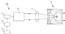
図1に本発明のレーザ駆動光源装置が示されていて、プラズマ容器1内には希ガス、水銀等のイオン性の放電媒体が封入されている。
このプラズマ容器1には、レーザ発振部12からのレーザ光が集光レンズ11によって集光されて入射される。
レーザ発振部12は、レーザ共振器13と、ポンピング器14と、これに給電する給電装置15、および、これを制御する制御部16とが接続されている。
FIG. 1 shows a laser-driven light source device of the present invention, in which an ionic discharge medium such as a rare gas or mercury is enclosed in a
The laser beam from the
The
レーザ共振器13は、部分反射鏡と全反射鏡からなる一対の反射鏡を有し、その内部の光路上にレーザ媒質が配置される。
レーザ共振器13には、このレーザ媒質を励起するポンピング器14が配置される。このポンピング器14としては、レーザ媒質を励起させる光を供給するものが用いられ、例えば複数のレーザダイオード(LD)や、ランプなどが用いられる。
そして、ポンピング器14には、制御部16によって制御される給電装置15が接続される。
制御部16は、ファンクションジェネレータからの信号、例えば一定周期のサイン信号や矩形波信号などに応じ、給電装置15からポンピング器14への給電を調整する。ポンピング器14は、給電装置15からの給電に応じたエネルギーでレーザ共振器13を励起する。
The
The
The
The
図2にプラズマ容器1の一詳細例が示されていて、プラズマ容器1は、セラミックス材料などからなる柱状の本体2と、その前後面に設けられた光出射窓3と、光入射窓4とからなる。
そして、この胴体部2の前面側には凹面反射面5が形成されるとともに、その中心にはこれを光軸方向に貫通するレーザ光通過孔6が穿設されている。このレーザ光通過孔6の後端側、即ち、入射側は面取りされてテーパー部6aが形成されている。このテーパー部6aは、集光されたレーザ光が光入射窓4を経て導入されてレーザ光通過孔6に導かれるときに、このレーザ光通過孔6の入射側で蹴られて遮断されるがないようにしたものである。
前記凹面反射面5は、放物線形状や楕円形状によって構成され、この実施例では放物線形の反射面として記載されている。この凹面反射面5には、アルミニウムなどが蒸着された金属蒸着膜や、あるいは、誘電体多層膜が被覆形成されている。
FIG. 2 shows a detailed example of the
A concave reflecting
The concave reflecting
前記凹面反射面5の前方に設けられる光出射窓3は紫外光透過性であり、後方の光入射窓4はレーザ光透過性であって、ともに水晶、サファイア、石英ガラスなどの硝材からなる。
そして、外周面がメタライズされた光出射窓3は、弾性的なリング部材7と銀ロウなどによりロウ付けにより接合され、一方、本体2のメタライズされた前端部には金属筒体8がロウ付けにより接合されている。そして、前記リング部材7と金属筒体8とが、TIG溶接やレーザ溶接などにより溶接接合されている。これにより、本体2の前方開口に光出射窓3が取り付けられる。
The
The
また、同様に外周面がメタライズされた光入射窓4は、金属ブロック9にロウ付けにより接合され、本体2のメタライズされた後端部には金属筒体10がロウ付けにより接合されていて、前記金属ブロック9と金属筒体10とが溶接接合されている。これにより、本体2の後方開口に光入射窓4が取り付けられる。
このようにして組み立てられた本体2と、光出射窓3および光入射窓4とによってプラズマ容器1が構成され、その内部には密閉空間Sが形成され、該密閉空間S内には放電媒体としてキセノンガス、クリプトンガス、アルゴンガス等の希ガスや水銀ガスなどの発光ガスが発光波長に合わせて封入されている。
Similarly, the
The
そして、レーザ発振部12からのレーザ光は、集光レンズ11によって集光されつつ、プラズマ容器1の光入射窓4から入射して、凹面反射面5の焦点位置Fに集光する。これにより当該焦点位置Fを中心としてプラズマが生成され、放電媒体が励起されて生じる励起光は、凹面反射面5により反射されて、光出射窓3から外部に出射されていく。
The laser light from the
しかして、始動(点火)の際には、従来技術と同様に、図3に示すように、レーザ発振部12からCWレーザ光を照射するとともにパルスレーザ光を重畳して照射し、パルスレーザ光の照射でプラズマ(火種)を発生させる。このプラズマ(火種)は、同時に照射されているCWレーザ光のエネルギーによって維持される。
本発明においては、このプラズマを維持するCWレーザ光の出力を制御するものであって、制御部16によって給電装置15が、所定のオン時間とオフ時間となるようにオンオフ制御されて、前記レーザ発振部12からのCWレーザ光の出力が変調されている。
このオン時間は、数μsec〜数msecであって、オフ時間はプラズマが消滅しない時間となるように制御される。
なお、このオン時間は、パルスレーザ光のパルス幅が〜ns程度であることを勘案すれば、少なくとも1000倍以上の幅を有するものである。
ところで、本発明では、間欠的にレーザ光を照射するものであるので、用語のみを勘案したとき厳密には「連続(CW)レーザ光」とはいえないかもしれないが、従来技術におけるCW(連続)レーザ光を供給する場合に、オン時間とオフ時間を設けて間欠的に供給するものであって、本明細書では、これをパルスレーザ光との対比において、(CW)レーザ光の出力を変調すると表現しているものである。
When starting (igniting), as in the prior art, as shown in FIG. 3, the
In the present invention, the output of the CW laser beam for maintaining the plasma is controlled, and the
This on-time is several μsec to several msec, and the off-time is controlled to be a time during which the plasma does not disappear.
The on-time has a width of at least 1000 times considering that the pulse width of the pulse laser beam is about ns.
By the way, in the present invention, since laser light is irradiated intermittently, it may not be strictly called “continuous (CW) laser light” when only terms are taken into consideration, but CW ( When supplying continuous (continuous) laser light, an on-time and an off-time are provided intermittently. In this specification, this is compared with pulsed laser light, and (CW) laser light output Is expressed as modulating.
このように、本発明においては、プラズマを維持するCWレーザ光の出力は変調されているものであるが、その効果について図4に基づいて説明する。
プラズマには間欠的にレーザ光が照射されているため、レーザ光が照射されていない時間(オフ時間)も入れてレーザパワーを平均すると、連続的に照射される場合と比べてその強度は低くなる。
つまり、照射されるレーザパワーをPとして、レーザ光が照射されている時間(オン時間)をTonとし、レーザ光が照射されていない時間(オフ時間)をToffとすると、平均エネルギーはPa=P×Ton/(Ton+Toff)となる。
このとき、オン時のレーザパワーPは同じなので、プラズマ温度は同じとなり、プラズマからの発光スペクトルの形状は同じとなる。
As described above, in the present invention, the output of the CW laser beam for maintaining the plasma is modulated. The effect will be described with reference to FIG.
Since the laser beam is intermittently irradiated to the plasma, the intensity of the laser power is lower than the case of continuous irradiation when the laser power is averaged including the time (off time) when the laser beam is not irradiated. Become.
That is, assuming that the laser power to be irradiated is P, the laser beam irradiation time (on time) is Ton, and the laser beam irradiation time (off time) is Toff, the average energy is Pa = P. × Ton / (Ton + Toff).
At this time, since the laser power P at the on time is the same, the plasma temperature is the same, and the shape of the emission spectrum from the plasma is the same.
CWレーザ光のレーザパワーをPとしたときのスペクトルにおける波長λ以下の領域の面積をS1、λ以上の領域の面積をS2とし、CWレーザ光を変調したときの波長λ以下の領域の面積をS3、λ以上の領域の面積をS4とすると、
S1:S2=S3:S4である。
即ち、例えば、λ=200nmとしたとき、真空紫外領域(200nm以下)と、それ以外の領域(200nm以上)の面積比率は同様である。
このように、間欠的な入力とすることで、平均レーザパワーを小さくしても、大入力を連続的に入力するときに得られるスペクトルと同様なプロファイルを持ったスペクトルが得られる。
When the laser power of the CW laser beam is P, the area of the region with a wavelength λ or less in the spectrum is S1, the area of the region with a wavelength λ or more is S2, and the area of the region with a wavelength λ or less when the CW laser beam is modulated is If the area of a region equal to or greater than S3 and λ is S4,
S1: S2 = S3: S4.
That is, for example, when λ = 200 nm, the area ratio of the vacuum ultraviolet region (200 nm or less) and the other region (200 nm or more) is the same.
As described above, by making the input intermittent, even if the average laser power is reduced, a spectrum having the same profile as the spectrum obtained when a large input is continuously input can be obtained.
以上のように、平均レーザパワーを小さくすることで、レーザ発振部全体の装置大型化を抑制しつつ、所定の短波長の紫外線領域(例えば、真空紫外領域)の発光強度を効率的に増加させることができる。
換言すると、連続供給の場合(従来技術)と、間欠供給の場合(本発明)で、平均レーザパワーを同等としたときには、本発明の方が、紫外線領域が増加した発光スペクトルが得られることになる。
なお、始動(点火)の際のプラズマ(火種)生成用の点火源としては、上記パルスレーザ光以外に、プラズマ容器内に一対の電極を設け、この電極間に高電圧を印加して絶縁破壊させプラズマを発生させるものであってもよい。
As described above, by reducing the average laser power, it is possible to efficiently increase the light emission intensity in the ultraviolet region (for example, the vacuum ultraviolet region) of a predetermined short wavelength while suppressing an increase in the size of the entire laser oscillation unit. be able to.
In other words, when the average laser power is made equal in the case of continuous supply (prior art) and in the case of intermittent supply (invention), the present invention provides an emission spectrum with an increased ultraviolet region. Become.
In addition to the pulse laser beam, a pair of electrodes is provided in the plasma vessel as the ignition source for generating plasma (fire type) at the start (ignition), and a high voltage is applied between these electrodes to cause dielectric breakdown. And generating plasma.
以下、一実施例を挙げると以下の通りである。
プラズマ容器:合成石英ガラス製の管球(点火用電極付き)
封入ガス:Xe 10atm
使用レーザ:ファイバーレーザ(M2≒1.1、ビーム径φ14mm)
波長:1070nm
集光レンズ:f=40
レーザ出力:変調CWレーザ、平均出力211W
(オン時間80μs、オフ時間80μs、ピーク値419W)
The following is an example.
Plasma container: Tube made of synthetic quartz glass (with ignition electrode)
Filled gas: Xe 10atm
Laser used: Fiber laser (M2 ≒ 1.1, beam diameter φ14mm)
Wavelength: 1070nm
Condenser lens: f = 40
Laser power: Modulated CW laser, average power 211W
(ON time 80μs, OFF time 80μs, peak value 419W)
上記の本発明のレーザ駆動光源装置と、レーザとして出力212WのCWレーザ(無変調)を用いた比較例との比較を行った。
VUV(波長160〜180nm)の出力は、スペクトル積算値で、比較例では9,770(任意単位:Arbitrary Unit:a.u.)であったのに対して、本発明では11,864であり、平均レーザ出力が同じであるにも拘わらず、VUV出力は約1.2倍に増加した。
A comparison was made between the laser-driven light source device of the present invention and a comparative example using a CW laser (non-modulated) with an output of 212 W as the laser.
The output of VUV (wavelength 160 to 180 nm) is a spectrum integrated value, which is 9,770 (arbitrary unit: au) in the comparative example, whereas it is 11,864 in the present invention, and the average laser output is the same. Despite being, the VUV output increased about 1.2 times.
以上のように、本発明のレーザ駆動光源装置では、プラズマ容器内のプラズマを維持するレーザ光として、数μsec〜数msecのオン時間、及び、プラズマが消滅しない時間のオフ時間となるように出力が変調されたレーザ光を照射することで、平均レーザ出力が小さいにも拘わらず、大出力で得られるスペクトルと同様なスペクトルを得られて、レーザ発振部の装置の大型化を抑制しつつ、所定の短波長以下の紫外線領域の発光強度を効率的に増加することができる。 As described above, in the laser-driven light source device of the present invention, the laser light that maintains the plasma in the plasma container is output so as to have an on-time of several μsec to several msec and an off-time that does not extinguish the plasma. By irradiating the modulated laser light, it is possible to obtain a spectrum similar to the spectrum obtained with a large output even though the average laser output is small, while suppressing the enlargement of the apparatus of the laser oscillation unit, The light emission intensity in the ultraviolet region below a predetermined short wavelength can be increased efficiently.
1 :プラズマ容器
2 :本体
3 :光入射窓
4 :光出射窓
5 :凹面反射面
6 :レーザ光通過孔
7 :リング部材
8 :金属筒体
9 :金属ブロック
10:金属筒体
11:集光レンズ
12:レーザ発振部
13:レーザ共振器
14:ポンピング器
15:給電装置
16:制御部
S :密閉空間
F :(凹面反射面の)焦点
DESCRIPTION OF SYMBOLS 1: Plasma container 2: Main body 3: Light incident window 4: Light emission window 5: Concave reflective surface 6: Laser beam passage hole 7: Ring member 8: Metal cylinder 9: Metal block 10: Metal cylinder 11: Condensing Lens 12: Laser oscillator 13: Laser resonator 14: Pumping device 15: Feeding device 16: Control unit S: Sealed space F: Focus of concave reflecting surface
Claims (3)
前記レーザ光は、数μsec〜数msecのオン時間、及び、プラズマが消滅しない時間のオフ時間となるようにオンオフ制御されてその出力が変調されていることを特徴とするレーザ駆動光源装置。 A laser-driven light source device that includes a laser oscillation unit and a plasma container in which a discharge medium is sealed, and that condenses laser light from the laser oscillation unit into the plasma container to generate plasma,
A laser-driven light source device characterized in that the laser light is on-off controlled and modulated so as to have an on-time of several μsec to several msec and an off-time that does not extinguish plasma.
前記制御部は前記給電装置を、数μsec〜数msecのオン時間、及び、プラズマが消滅しない時間のオフ時間となるようにオンオフ制御することを特徴とする請求項1に記載のレーザ駆動光源装置。 The laser oscillation unit includes a pumping device, a laser resonator, a power feeding device that feeds power to the pump, and a control unit that controls the power feeding device.
2. The laser-driven light source device according to claim 1, wherein the control unit performs on / off control of the power supply device so as to have an on time of several μsec to several msec and an off time of a time when plasma is not extinguished. .
前記本体と前記光入射窓と前記光出射窓によって密閉空間が形成されていて、該密閉空間内に前記放電媒体が封入されてなり、
前記レーザ発振部からのレーザ光は、前記光入射窓から前記プラズマ容器内に導入されていることを特徴とする請求項1または2に記載のレーザ駆動光源装置。
The plasma container comprises a main body having a concave reflecting surface, a light incident window provided in a rear opening of the main body, and a light emission window provided in a front opening of the main body,
A sealed space is formed by the main body, the light incident window, and the light exit window, and the discharge medium is enclosed in the sealed space,
3. The laser-driven light source device according to claim 1, wherein the laser light from the laser oscillation unit is introduced into the plasma container from the light incident window.
Priority Applications (2)
| Application Number | Priority Date | Filing Date | Title |
|---|---|---|---|
| JP2017136778A JP2019021432A (en) | 2017-07-13 | 2017-07-13 | Laser driving light source device |
| US16/031,174 US20190021158A1 (en) | 2017-07-13 | 2018-07-10 | Laser-driven light source device |
Applications Claiming Priority (1)
| Application Number | Priority Date | Filing Date | Title |
|---|---|---|---|
| JP2017136778A JP2019021432A (en) | 2017-07-13 | 2017-07-13 | Laser driving light source device |
Publications (1)
| Publication Number | Publication Date |
|---|---|
| JP2019021432A true JP2019021432A (en) | 2019-02-07 |
Family
ID=65000304
Family Applications (1)
| Application Number | Title | Priority Date | Filing Date |
|---|---|---|---|
| JP2017136778A Pending JP2019021432A (en) | 2017-07-13 | 2017-07-13 | Laser driving light source device |
Country Status (2)
| Country | Link |
|---|---|
| US (1) | US20190021158A1 (en) |
| JP (1) | JP2019021432A (en) |
Families Citing this family (4)
| Publication number | Priority date | Publication date | Assignee | Title |
|---|---|---|---|---|
| US11367989B1 (en) | 2020-12-21 | 2022-06-21 | Hamamatsu Photonics K.K. | Light emitting unit and light source device |
| US11862922B2 (en) | 2020-12-21 | 2024-01-02 | Energetiq Technology, Inc. | Light emitting sealed body and light source device |
| US11972931B2 (en) | 2020-12-21 | 2024-04-30 | Hamamatsu Photonics K.K. | Light emitting sealed body, light emitting unit, and light source device |
| US11587781B2 (en) | 2021-05-24 | 2023-02-21 | Hamamatsu Photonics K.K. | Laser-driven light source with electrodeless ignition |
Citations (2)
| Publication number | Priority date | Publication date | Assignee | Title |
|---|---|---|---|---|
| US20150332908A1 (en) * | 2014-05-15 | 2015-11-19 | Excelitas Technologies Corp. | Laser Driven Sealed Beam Lamp |
| RU2571433C1 (en) * | 2014-08-18 | 2015-12-20 | Игорь Георгиевич Рудой | Method of generating broadband high-brightness optical radiation |
-
2017
- 2017-07-13 JP JP2017136778A patent/JP2019021432A/en active Pending
-
2018
- 2018-07-10 US US16/031,174 patent/US20190021158A1/en not_active Abandoned
Patent Citations (2)
| Publication number | Priority date | Publication date | Assignee | Title |
|---|---|---|---|---|
| US20150332908A1 (en) * | 2014-05-15 | 2015-11-19 | Excelitas Technologies Corp. | Laser Driven Sealed Beam Lamp |
| RU2571433C1 (en) * | 2014-08-18 | 2015-12-20 | Игорь Георгиевич Рудой | Method of generating broadband high-brightness optical radiation |
Also Published As
| Publication number | Publication date |
|---|---|
| US20190021158A1 (en) | 2019-01-17 |
Similar Documents
| Publication | Publication Date | Title |
|---|---|---|
| US7435982B2 (en) | Laser-driven light source | |
| JP5322217B2 (en) | Light source device | |
| EP3295470B1 (en) | Electrodeless single cw laser driven xenon lamp | |
| JP5322231B2 (en) | Light source device | |
| US8369374B2 (en) | Light source device | |
| US8358069B2 (en) | Lighting method of light source apparatus | |
| JP2019021432A (en) | Laser driving light source device | |
| US10057973B2 (en) | Electrodeless single low power CW laser driven plasma lamp | |
| JP5182958B2 (en) | Light source device | |
| WO2018136683A1 (en) | Electrodeless single low power cw laser driven plasma lamp | |
| JP2018060640A (en) | Laser-driven light source | |
| JP2017220319A (en) | Laser drive light source device | |
| JP6233616B2 (en) | Laser drive lamp | |
| WO2017212710A1 (en) | Laser-driving light source device | |
| JP2017220439A (en) | Laser-driving light source device | |
| JP2017216125A (en) | Laser driven lamp | |
| JP2017212061A (en) | Laser drive lamp | |
| WO2018042888A1 (en) | Laser-driven lamp | |
| WO2017212683A1 (en) | Laser-driving light source device | |
| US20170373460A1 (en) | Laser-driven light source device | |
| JP2018006394A (en) | Laser-driven light source device |
Legal Events
| Date | Code | Title | Description |
|---|---|---|---|
| A621 | Written request for application examination |
Free format text: JAPANESE INTERMEDIATE CODE: A621 Effective date: 20200618 |
|
| A977 | Report on retrieval |
Free format text: JAPANESE INTERMEDIATE CODE: A971007 Effective date: 20210520 |
|
| A131 | Notification of reasons for refusal |
Free format text: JAPANESE INTERMEDIATE CODE: A131 Effective date: 20210526 |
|
| A02 | Decision of refusal |
Free format text: JAPANESE INTERMEDIATE CODE: A02 Effective date: 20211116 |