JP2019018511A - Method for controlling liquid discharge head and liquid discharge device - Google Patents
Method for controlling liquid discharge head and liquid discharge device Download PDFInfo
- Publication number
- JP2019018511A JP2019018511A JP2017141121A JP2017141121A JP2019018511A JP 2019018511 A JP2019018511 A JP 2019018511A JP 2017141121 A JP2017141121 A JP 2017141121A JP 2017141121 A JP2017141121 A JP 2017141121A JP 2019018511 A JP2019018511 A JP 2019018511A
- Authority
- JP
- Japan
- Prior art keywords
- heating resistor
- covering portion
- liquid
- liquid discharge
- potential
- Prior art date
- Legal status (The legal status is an assumption and is not a legal conclusion. Google has not performed a legal analysis and makes no representation as to the accuracy of the status listed.)
- Pending
Links
- 239000007788 liquid Substances 0.000 title claims abstract description 134
- 238000000034 method Methods 0.000 title claims abstract description 12
- 238000010438 heat treatment Methods 0.000 claims abstract description 153
- 230000004044 response Effects 0.000 claims description 4
- 238000007599 discharging Methods 0.000 claims description 3
- 239000011248 coating agent Substances 0.000 abstract description 25
- 238000000576 coating method Methods 0.000 abstract description 25
- 238000010828 elution Methods 0.000 abstract description 11
- 230000006866 deterioration Effects 0.000 abstract 1
- 239000010410 layer Substances 0.000 description 46
- 239000000758 substrate Substances 0.000 description 17
- 230000004075 alteration Effects 0.000 description 8
- 230000008859 change Effects 0.000 description 8
- 239000011241 protective layer Substances 0.000 description 8
- 230000000052 comparative effect Effects 0.000 description 7
- 230000020169 heat generation Effects 0.000 description 6
- 238000005338 heat storage Methods 0.000 description 6
- 230000005611 electricity Effects 0.000 description 4
- 238000003487 electrochemical reaction Methods 0.000 description 4
- 230000007423 decrease Effects 0.000 description 3
- 238000010586 diagram Methods 0.000 description 3
- 239000000126 substance Substances 0.000 description 3
- 229910004200 TaSiN Inorganic materials 0.000 description 2
- 230000009471 action Effects 0.000 description 2
- 238000009835 boiling Methods 0.000 description 2
- 238000004090 dissolution Methods 0.000 description 2
- 238000005187 foaming Methods 0.000 description 2
- 230000001771 impaired effect Effects 0.000 description 2
- 229910052741 iridium Inorganic materials 0.000 description 2
- 239000000463 material Substances 0.000 description 2
- 239000007769 metal material Substances 0.000 description 2
- 230000000704 physical effect Effects 0.000 description 2
- 229910052707 ruthenium Inorganic materials 0.000 description 2
- 229910018125 Al-Si Inorganic materials 0.000 description 1
- 229910018182 Al—Cu Inorganic materials 0.000 description 1
- 229910018520 Al—Si Inorganic materials 0.000 description 1
- KJTLSVCANCCWHF-UHFFFAOYSA-N Ruthenium Chemical compound [Ru] KJTLSVCANCCWHF-UHFFFAOYSA-N 0.000 description 1
- 229910004298 SiO 2 Inorganic materials 0.000 description 1
- 239000000956 alloy Substances 0.000 description 1
- 229910045601 alloy Inorganic materials 0.000 description 1
- 229910052782 aluminium Inorganic materials 0.000 description 1
- 239000006260 foam Substances 0.000 description 1
- GKOZUEZYRPOHIO-UHFFFAOYSA-N iridium atom Chemical compound [Ir] GKOZUEZYRPOHIO-UHFFFAOYSA-N 0.000 description 1
- 239000008258 liquid foam Substances 0.000 description 1
- 229910052751 metal Inorganic materials 0.000 description 1
- 239000002184 metal Substances 0.000 description 1
- BASFCYQUMIYNBI-UHFFFAOYSA-N platinum Chemical group [Pt] BASFCYQUMIYNBI-UHFFFAOYSA-N 0.000 description 1
- 238000011084 recovery Methods 0.000 description 1
- 239000011347 resin Substances 0.000 description 1
- 229920005989 resin Polymers 0.000 description 1
- 229910052710 silicon Inorganic materials 0.000 description 1
- 239000010703 silicon Substances 0.000 description 1
- 239000002356 single layer Substances 0.000 description 1
- 229910052715 tantalum Inorganic materials 0.000 description 1
- GUVRBAGPIYLISA-UHFFFAOYSA-N tantalum atom Chemical compound [Ta] GUVRBAGPIYLISA-UHFFFAOYSA-N 0.000 description 1
- WFKWXMTUELFFGS-UHFFFAOYSA-N tungsten Chemical compound [W] WFKWXMTUELFFGS-UHFFFAOYSA-N 0.000 description 1
- 229910052721 tungsten Inorganic materials 0.000 description 1
- 239000010937 tungsten Substances 0.000 description 1
Images


Classifications
-
- B—PERFORMING OPERATIONS; TRANSPORTING
- B41—PRINTING; LINING MACHINES; TYPEWRITERS; STAMPS
- B41J—TYPEWRITERS; SELECTIVE PRINTING MECHANISMS, i.e. MECHANISMS PRINTING OTHERWISE THAN FROM A FORME; CORRECTION OF TYPOGRAPHICAL ERRORS
- B41J2/00—Typewriters or selective printing mechanisms characterised by the printing or marking process for which they are designed
- B41J2/005—Typewriters or selective printing mechanisms characterised by the printing or marking process for which they are designed characterised by bringing liquid or particles selectively into contact with a printing material
- B41J2/01—Ink jet
- B41J2/015—Ink jet characterised by the jet generation process
- B41J2/04—Ink jet characterised by the jet generation process generating single droplets or particles on demand
- B41J2/045—Ink jet characterised by the jet generation process generating single droplets or particles on demand by pressure, e.g. electromechanical transducers
- B41J2/04501—Control methods or devices therefor, e.g. driver circuits, control circuits
- B41J2/04541—Specific driving circuit
-
- B—PERFORMING OPERATIONS; TRANSPORTING
- B41—PRINTING; LINING MACHINES; TYPEWRITERS; STAMPS
- B41J—TYPEWRITERS; SELECTIVE PRINTING MECHANISMS, i.e. MECHANISMS PRINTING OTHERWISE THAN FROM A FORME; CORRECTION OF TYPOGRAPHICAL ERRORS
- B41J2/00—Typewriters or selective printing mechanisms characterised by the printing or marking process for which they are designed
- B41J2/005—Typewriters or selective printing mechanisms characterised by the printing or marking process for which they are designed characterised by bringing liquid or particles selectively into contact with a printing material
- B41J2/01—Ink jet
- B41J2/015—Ink jet characterised by the jet generation process
- B41J2/04—Ink jet characterised by the jet generation process generating single droplets or particles on demand
- B41J2/045—Ink jet characterised by the jet generation process generating single droplets or particles on demand by pressure, e.g. electromechanical transducers
- B41J2/04501—Control methods or devices therefor, e.g. driver circuits, control circuits
- B41J2/0458—Control methods or devices therefor, e.g. driver circuits, control circuits controlling heads based on heating elements forming bubbles
-
- B—PERFORMING OPERATIONS; TRANSPORTING
- B41—PRINTING; LINING MACHINES; TYPEWRITERS; STAMPS
- B41J—TYPEWRITERS; SELECTIVE PRINTING MECHANISMS, i.e. MECHANISMS PRINTING OTHERWISE THAN FROM A FORME; CORRECTION OF TYPOGRAPHICAL ERRORS
- B41J2/00—Typewriters or selective printing mechanisms characterised by the printing or marking process for which they are designed
- B41J2/005—Typewriters or selective printing mechanisms characterised by the printing or marking process for which they are designed characterised by bringing liquid or particles selectively into contact with a printing material
- B41J2/01—Ink jet
- B41J2/135—Nozzles
- B41J2/14—Structure thereof only for on-demand ink jet heads
- B41J2/14016—Structure of bubble jet print heads
- B41J2/14072—Electrical connections, e.g. details on electrodes, connecting the chip to the outside...
-
- B—PERFORMING OPERATIONS; TRANSPORTING
- B41—PRINTING; LINING MACHINES; TYPEWRITERS; STAMPS
- B41J—TYPEWRITERS; SELECTIVE PRINTING MECHANISMS, i.e. MECHANISMS PRINTING OTHERWISE THAN FROM A FORME; CORRECTION OF TYPOGRAPHICAL ERRORS
- B41J2/00—Typewriters or selective printing mechanisms characterised by the printing or marking process for which they are designed
- B41J2/005—Typewriters or selective printing mechanisms characterised by the printing or marking process for which they are designed characterised by bringing liquid or particles selectively into contact with a printing material
- B41J2/01—Ink jet
- B41J2/135—Nozzles
- B41J2/14—Structure thereof only for on-demand ink jet heads
- B41J2/14016—Structure of bubble jet print heads
- B41J2/14088—Structure of heating means
- B41J2/14112—Resistive element
- B41J2/14129—Layer structure
-
- B—PERFORMING OPERATIONS; TRANSPORTING
- B41—PRINTING; LINING MACHINES; TYPEWRITERS; STAMPS
- B41J—TYPEWRITERS; SELECTIVE PRINTING MECHANISMS, i.e. MECHANISMS PRINTING OTHERWISE THAN FROM A FORME; CORRECTION OF TYPOGRAPHICAL ERRORS
- B41J2/00—Typewriters or selective printing mechanisms characterised by the printing or marking process for which they are designed
- B41J2/005—Typewriters or selective printing mechanisms characterised by the printing or marking process for which they are designed characterised by bringing liquid or particles selectively into contact with a printing material
- B41J2/01—Ink jet
- B41J2/135—Nozzles
- B41J2/16—Production of nozzles
- B41J2/1621—Manufacturing processes
- B41J2/164—Manufacturing processes thin film formation
Abstract
Description
本発明は、液体を吐出する液体吐出ヘッドの制御方法、および液体を吐出する液体吐出装置に関する。 The present invention relates to a method for controlling a liquid discharge head that discharges liquid and a liquid discharge apparatus that discharges liquid.
現在、発熱抵抗体を通電させて液室の内部の液体を加熱して液体に膜沸騰を生じさせ、このときの発泡エネルギーによって吐出口から液滴を吐出させる形式の液体吐出装置が多く採用されている。 Currently, many liquid ejection devices of the type that energize the heating resistor to heat the liquid inside the liquid chamber to cause film boiling in the liquid and eject liquid droplets from the ejection port by the foaming energy at this time are widely used. ing.
このような液体吐出装置では、発熱抵抗体上の領域で液体が発泡、収縮、消泡する際に生じるキャビテーションによる衝撃といった物理的作用が発熱抵抗体上の領域に及ぼされることがある。また、液体の吐出が行われる際には、発熱抵抗体は高温となっているので、液体の成分が熱分解して発熱抵抗体の表面に付着して固着・堆積するといった化学的作用が発熱抵抗体上の領域に及ぼされることがある。これらの発熱抵抗体への物理的作用あるいは化学的作用から発熱抵抗体を保護するために、発熱抵抗体上には、発熱抵抗体を覆う金属材料等で形成された被覆部が配置される場合がある。 In such a liquid ejecting apparatus, a physical action such as impact caused by cavitation that occurs when the liquid foams, contracts, or disappears in the region on the heating resistor may be exerted on the region on the heating resistor. In addition, when the liquid is discharged, the heating resistor is at a high temperature. Therefore, the chemical action of the liquid components pyrolyzing and adhering to the surface of the heating resistor is fixed and deposited. It may be applied to the area on the resistor. In order to protect the heating resistor from physical action or chemical action on the heating resistor, a covering portion made of a metal material or the like covering the heating resistor is disposed on the heating resistor. There is.
通常、被覆部は液体と接する位置に配置される。したがって、被覆部に電気が流れてしまうと、被覆部と液体との間で電気化学反応が生じてしまい、場合によっては被覆部としての機能が損なわれてしまう場合がある。そのため、発熱抵抗体に供給される電気の一部が被覆部へ流れないように、発熱抵抗体と被覆部との間に絶縁層が配置されている。 Usually, a coating | coated part is arrange | positioned in the position which touches a liquid. Therefore, when electricity flows through the covering portion, an electrochemical reaction occurs between the covering portion and the liquid, and the function as the covering portion may be impaired in some cases. Therefore, an insulating layer is arranged between the heating resistor and the covering portion so that a part of the electricity supplied to the heating resistor does not flow to the covering portion.
ところが、何らかの原因によって絶縁層の機能が損なわれてしまい、発熱抵抗体あるいは配線から、被覆部へ直接的に電気が流れてしまう導通が生じる可能性がある。発熱抵抗体に供給される電気の一部が被覆部に流れた場合には、被覆部と液体との間で電気化学反応が生じてしまい、被覆部が変質してしまうことがある。さらに、複数の発熱抵抗体をそれぞれ覆う被覆部が互いに電気的に接続されている場合は、導通が生じた被覆部とは別の被覆部にも電流が流れてしまい、変質の影響が広がる恐れがある。 However, for some reason, the function of the insulating layer is impaired, and there is a possibility that conduction occurs in which electricity flows directly from the heating resistor or the wiring to the covering portion. When a part of the electricity supplied to the heating resistor flows to the covering portion, an electrochemical reaction may occur between the covering portion and the liquid, and the covering portion may be altered. Furthermore, when the covering portions that respectively cover the plurality of heating resistors are electrically connected to each other, a current may flow through a covering portion that is different from the covering portion where conduction has occurred, and the influence of alteration may spread. There is.
そこで、特許文献1には、複数の被覆部と電気的に接続された共通配線に対し、ヒューズ部を介してそれぞれの被覆部が接続された構成が記載されている。このような構成において上記の導通が生じて1つの被覆部に電流が流れた場合に、この電流によってヒューズ部が切断されることで、他の被覆部との電気的な接続が切断される。これにより、被覆部の変質の影響が広がることを抑えることができる。また、特許文献1には、発熱抵抗体を覆う被覆部や共通配線よりもヒューズ部の膜厚を薄くしてヒューズ部を切断されやすくすることが記載されている。
Therefore,
しかしながら、発熱抵抗体と被覆部との導通が生じた場合であっても、発熱抵抗体と被覆部との接触領域が微小であると接触抵抗が大きくヒューズ部に流れる電流は小さくなるため、ヒューズ部が確実に切断されない可能性がある。 However, even when conduction between the heat generating resistor and the covering portion occurs, if the contact area between the heat generating resistor and the covering portion is very small, the contact resistance is large and the current flowing through the fuse portion is small. The part may not be cut reliably.
そのため、ヒューズ部を設けた構成であってもヒューズ部が切断されずに導通が生じた被覆部から他の被覆部に電流が流れてしまい、ヘッド全体として被覆部の変質の影響が広がる恐れがある。 For this reason, even if the fuse portion is provided, current may flow from the covered portion where the fuse portion is not cut off to the other covered portion, and the influence of alteration of the covered portion as a whole may spread. is there.
そこで、本発明では、液体吐出ヘッドに設けられる発熱抵抗体と被覆部とが導通した場合における被覆部の変質や溶出の影響を抑えることを目的とする。 Therefore, an object of the present invention is to suppress the influence of alteration and elution of the covering portion when the heating resistor provided in the liquid ejection head and the covering portion are conducted.
本発明の液体吐出ヘッドの制御方法は、駆動電圧が印加されることで液体を吐出するための熱エネルギーを発生する第1の発熱抵抗体および第2の発熱抵抗体と、前記第1の発熱抵抗体を被覆する第1被覆部と、前記第1の被覆部と電気的に接続され、前記第2の発熱抵抗体を被覆する第2被覆部と、前記第1の発熱抵抗体と前記第1の被覆部との間、および前記第2の発熱抵抗体と前記第2の被覆部との間に設けられた絶縁層と、を有する液体吐出ヘッドの制御方法において、前記第1の発熱抵抗体および前記第2の発熱抵抗体のうちの少なくともいずれかに対する駆動電圧の印加に応じて、前記第1の発熱抵抗体および前記第2の発熱抵抗体に駆動電圧が印加されていない状態で、前記第1の被覆部および前記第2の被覆部の表面電位をグランド電位以下とすることを特徴とする。 The method for controlling a liquid discharge head according to the present invention includes a first heat generation resistor and a second heat generation resistor that generate thermal energy for discharging a liquid when a drive voltage is applied, and the first heat generation. A first covering portion covering the resistor, a second covering portion electrically connected to the first covering portion and covering the second heating resistor, the first heating resistor and the first In the method for controlling a liquid ejection head, the first heating resistor, comprising: an insulating layer provided between the first covering portion and between the second heating resistor and the second covering portion. In response to the application of the drive voltage to at least one of the body and the second heating resistor, the drive voltage is not applied to the first heating resistor and the second heating resistor. The surface potential of the first covering portion and the second covering portion is Characterized by the following land potential.
本発明によると、液体吐出ヘッドに設けられる発熱抵抗体と被覆部とが導通した場合における被覆部の変質や溶出の影響を抑えることができる。 According to the present invention, it is possible to suppress the influence of alteration and elution of the covering portion when the heating resistor provided in the liquid discharge head is electrically connected to the covering portion.
(液体吐出装置)
図1(a)は、本発明の実施形態に係る液体吐出装置1000を示す斜視図である。液体吐出装置1000は、内部に液体吐出ヘッドユニット410が収納されるキャリッジ211を備えている。本実施形態の液体吐出装置1000において、キャリッジ211は、ガイドシャフト206に沿って矢印Aの主走査方向に移動自在にガイドされている。ガイドシャフト206は、記録媒体の幅方向に沿って延びるように配置されている。したがって、キャリッジ211に搭載された液体吐出ヘッドは、記録媒体の搬送される搬送方向と交差する方向に走査しながら記録を行う。このように、液体吐出装置1000は、液体吐出ヘッド1の主走査方向の移動と、記録媒体の副走査方向の搬送と、を伴って画像を記録するいわゆるシリアルスキャンタイプの液体吐出装置である。
(Liquid discharge device)
FIG. 1A is a perspective view showing a
キャリッジ211は、記録媒体の搬送方向に直交する方向に走査されるように、ガイドシャフト206によって貫通されて支持されている。キャリッジ211にはベルト204が取り付けられており、ベルト204にはキャリッジモータ212が取り付けられている。これにより、キャリッジモータ212による駆動力がベルト204を介してキャリッジ211に伝えられるので、キャリッジ211がガイドシャフト206によって案内されながら主走査方向に移動可能に構成されている。
The
また、キャリッジ211には、制御部からの電気信号を液体吐出ヘッドユニット410の液体吐出ヘッドに転送するためのフレキシブルケーブル213が、液体吐出ヘッドユニットに接続されるように取り付けられている。また、液体吐出装置1000は、液体吐出ヘッドの回復処理を行うために用いられるキャップ241及びワイパブレード243が配置されている。また、液体吐出装置1000は、記録媒体を積層状態で蓄える給紙部215と、キャリッジ211の位置を光学的に読み取るエンコーダセンサ216を有している。
In addition, a
(液体吐出ヘッドユニット)
図1(b)は、液体吐出ヘッドユニット410を示す斜視図である。液体吐出ヘッドユニット410は、液体吐出ヘッドをタンクと一体化してなるカートリッジ形態のユニットである。液体吐出ヘッドユニット410は、キャリッジの内部に、装着及び取り外し可能に構成されている。液体吐出ヘッドユニット410には、液体吐出ヘッド1が取り付けられている。液体吐出ヘッドユニット410には、電力を供給するための端子を有するTAB(Tape Automated Bonding)用のテープ部材402が貼り付けられている。このテープ部材402を通って、液体吐出装置からそれぞれの発熱抵抗体108へ選択的に電力が供給される。発熱抵抗体108へ電力が供給される際には、接点403からテープ部材402を通って、液体吐出ヘッド1へ電力が供給される。また、液体吐出ヘッドユニット410は、液体を一旦貯留し、そこから液体吐出ヘッド1に供給するためのタンク404を備えている。
(Liquid discharge head unit)
FIG. 1B is a perspective view showing the liquid
(液体吐出ヘッド)
図2(a)は液体吐出ヘッド1を示しており、その一部を破断して示す斜視図である。また、図2(b)は、図2(a)におけるIIb−IIb線に沿った模式的な断面図である。
(Liquid discharge head)
FIG. 2A shows the
液体吐出ヘッド1は、液体吐出ヘッド用基板100と流路形成部材120とが貼り付けられることで構成されている。液体吐出ヘッド用基板100と流路形成部材120との間には、内部に液体を貯留させることが可能な複数の液室132が画成されている。液体吐出ヘッド用基板100には、液体吐出ヘッド用基板100を表面から裏面へ貫通するように液体供給口130が形成されており、液体供給口130から各液室132へと液体が供給される。それぞれの液室132の内部には熱作用部117が形成されている。流路形成部材120における熱作用部117に対応する位置には吐出口121が形成されている。複数の熱作用部117は列をなして配設されており、熱作用部117に対応して設けられた吐出口121も列をなして配設されている。
The
液体吐出ヘッド用基板100の基体101の熱作用部117が設けられる面の側には後述する発熱抵抗体108が備えられており、この発熱抵抗体108への通電により熱エネルギーが発生する。この熱エネルギーにより熱作用部117上の液体が加熱されて膜沸騰により発泡し、そのときの発泡エネルギーによって吐出口121から液滴が吐出される。
A
液体吐出ヘッド1は、シリコンによって形成された基体101上に複数の層が積層された液体吐出ヘッド用基板100を有する。基体101上には、熱酸化膜、SiO膜、SiN膜等によって形成される蓄熱層102が配置される。また、蓄熱層102上には、TaSiN等によって形成される発熱抵抗体層104が配置され、発熱抵抗体層104上には、Al、Al−Si、Al−Cu等の金属材料から形成される配線としての電極配線層105が配置されている。電極配線層105上には絶縁保護層106(絶縁層)が配置されている。絶縁保護層106は、発熱抵抗体層104及び電極配線層105を覆うようにこれらの上側に設けられている。絶縁保護層106は、SiO膜、SiN膜、SiCN膜等によって形成されている。
The
絶縁保護層106の上側には発熱抵抗体108を覆うように被覆部107が配置されている。被覆部107は、発熱抵抗体108の発熱に伴う化学的、物理的衝撃から発熱抵抗体108を保護している。また、被覆部107は複数の発熱抵抗体108のそれぞれを覆うように設けられている。本実施形態では、被覆部107は、イリジウム(Ir)、ルテニウム(Ru)等の白金族やタンタル(Ta)によって20〜100nmの厚さで形成されている。なお、被覆部107は、Ir、Ru、Taのいずれかに限らず、これらを含む合金によって形成してもよく、また、これらを積層して形成してもよい。なお、これらの材料によって形成された被覆部107は導電性を有している。
A covering
絶縁保護層106と被覆部107との間には複数の被覆部107を電気的に接続する配線層109が設けられている。例えば、この配線層109はTaによって形成することができる。なお、配線層109が設けられていない構成でもよく、すなわち、被覆部107同士が直接接続されている構成であってもよい。
Between the insulating
発熱抵抗体108は電極配線層105が部分的に除去されることによって形成されている。すなわち、電極配線層105の一部が除去されてその部分から発熱抵抗体層104が露出しており、この電極配線層105から露出する発熱抵抗体層104の部分が発熱抵抗体108として機能する。電極配線層105は、不図示の駆動素子回路ないし外部電源端子に接続されており、外部からの電力の供給を受けることができるように構成されている。
The
なお、発熱抵抗体108は、上述したような、発熱抵抗体層104の上に電極配線層105を配置する構成に限定されない。例えば、電極配線層105を基体101または熱酸化膜102上に形成し、電極配線層105の一部を部分的に除去してギャップを形成して、その電極配線層105の上に発熱抵抗体層104を配置する構成であってもよい。また、電極配線層105を蓄熱層102の中に埋め込み、蓄熱層102上に単層として形成された発熱抵抗体層104に対して電極配線層105から例えばタングステンなどの金属プラグを介して電力を供給するような構成であってもよい。
The
図3に、液体吐出ヘッド1の発熱抵抗体108の駆動用の回路図を示す。発熱抵抗体108は、電源301、スイッチングトランジスタ114及び選択回路115に接続されており、選択回路115によって選択された発熱抵抗体108に駆動電圧が印加されて発熱する。電源301は、例えば20〜35Vの駆動電圧である。電源301と発熱抵抗体108の間にスイッチングトランジスタ114が設けられている。本実施形態の液体吐出ヘッド用基板100は、このようなソースフォロア回路を有している。したがって、常に発熱抵抗体108に電源電圧が印加されるのではなく、吐出信号に応じて発熱抵抗体108の駆動時のみパルス状で発熱抵抗体108に電源301から電圧が印加される。
FIG. 3 is a circuit diagram for driving the
このような構成により、選択回路115からの吐出信号に応じて、所定のタイミングで発熱抵抗体108に対して電源301から電力が供給され、所定のタイミングで吐出口121から液体が吐出される。
With such a configuration, according to the ejection signal from the
(電位制御回路)
図4は本実施形態の液体吐出ヘッド1の模式的上面図である。なお、図4では流路形成部材120は省略している。
(Potential control circuit)
FIG. 4 is a schematic top view of the
液体供給口130に対して両側にそれぞれ発熱抵抗体108の列が配置され、それぞれの発熱抵抗体108を覆う被覆部107が配置されている。また、配線層109は帯状に延在しており、それぞれの被覆部107は配線層109を介して液体吐出ヘッド用基板100の外部に設けられた電位制御回路200に電気的に接続されている。
A row of
電位制御回路200は被覆部107の表面電位を制御する回路(制御手段)であり、被覆部107の電位をグランド電位とすることができる。電位制御回路200はスイッチ201を含んでおり、このスイッチ201のON/OFFを切り替えることで、被覆部107の表面電位の制御の切り替えが可能である。なお、電位制御回路200は、液体吐出ヘッド1の外部の液体吐出ヘッドユニットや液体吐出装置本体に設けられてもよく、液体吐出ヘッド1や液体吐出ヘッド用基板100に設けられてもよい。
The
液体の吐出を行っていると、何らかの理由で発熱抵抗体108と被覆部107との間が導通してしまい、被覆部107の表面電位が上昇する場合がある。
When the liquid is discharged, the
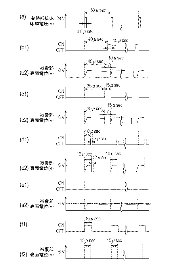
図5(e2)は、電位制御回路200が設けられていない構成において、発熱抵抗体108と被覆部107とが導通した場合の被覆部107の表面電位の時間変化を示す図である。発熱抵抗体108と被覆部107とが導通した後も導通が生じた箇所が特定されていないため、発熱抵抗体108には、例えば0.5〜2μsec程度のパルス幅の24Vの電圧が繰り返し印加される。そのため、被覆部107の表面電位は、発熱抵抗体108にパルス状の電圧が印加された直後に、5〜10V程度まで上昇する。その後、発熱抵抗体108に電圧が印加されなくなると、被覆部107の表面電位は徐々に低下していくが、特に、発熱抵抗体108の駆動周波数が高い場合は被覆部107の電位は下がりきらずに電位が印加された状態のまま維持される。
FIG. 5 (e2) is a diagram illustrating a change over time of the surface potential of the covering
このため、被覆部107が例えばIrを含んで構成されている場合、発熱抵抗体108との導通が生じた被覆部107は液体との電気化学反応が生じて液体中に溶出する。さらに、複数の被覆部107が電気的に接続されていると、被覆部107(第1の被覆部)との導通が生じた発熱抵抗体108(第1の発熱抵抗体)とは別の発熱抵抗体108(第2の発熱抵抗体)を覆う被覆部107(第2の被覆部)も溶出する恐れがある。すなわち、被覆部107の変質の影響が液体吐出ヘッド全体へと広がる可能性がある。
For this reason, when the covering
なお、被覆部107がTaを含んで構成されている場合においても、被覆部107の表面電位が高い状態で維持されると、発熱抵抗体108との導通が生じた被覆部107は酸化が生じてしまう。さらに、被覆部107との導通が生じた発熱抵抗体108とは別の発熱抵抗体108を覆う被覆部107も酸化する恐れがある。
Even when the covering
そこで、本実施形態では、複数の発熱抵抗体108のうち少なくともいずれかに駆動電圧が印加された後、複数の発熱抵抗体108のうちのいずれにも駆動電圧が印加されていない状態で、電位制御回路200のスイッチ201をONとする。これにより、一時的に被覆部107の電位をグランド電位とする。この際、発熱抵抗体108の駆動電圧の印加に応じて電位制御回路200のスイッチ201をONとして、周期的に被覆部107の電位をグランド電位とする。なお、ここで、複数の発熱抵抗体108とは、発熱抵抗体108に対応する被覆部107同士が電気的に接続されている発熱抵抗体108を称する。すなわち、電位制御回路200のスイッチ201をONにする際に、対応する被覆部107が電気的に接続されていない発熱抵抗体108については、駆動電圧が印加された状態であってもよい。
Therefore, in the present embodiment, after a driving voltage is applied to at least one of the plurality of
発熱抵抗体108と被覆部107との導通が生じている場合、発熱抵抗体108の駆動電圧によって被覆部107の電位は上昇するが、電位制御回路200によって被覆部107の電位は一時的にグランド電位に下がる。したがって、被覆部107に電位が印加された状態で維持されることを抑えることができる。これにより、被覆部107と液体との電気化学反応の進行を抑えることができ、被覆部107の変質の影響を低減することができる。
When conduction between the
なお、発熱抵抗体108に駆動電圧が印加された状態で被覆部107の電位をグランド電位とすると、発熱抵抗体108と被覆部107と導通が生じている場合、その導通箇所を介して被覆部107、電位制御回路200へとリーク電流が流れてしまう。これにより、意図しない発熱が生じて、液体吐出ヘッド用基板の信頼性を損なう恐れがある。そのため、液体を吐出するために電源301から複数の発熱抵抗体108のうちの少なくともいずれかに対して駆動電圧が印加されている状態では、スイッチ201をOFFとして被覆部107を電気的にフローティングとすることが好ましい。
In addition, when the potential of the covering
なお、電位制御回路200は、被覆部107の電位をグランド電位よりも低くするような構成であってもよい。被覆部107の電位をグランド電位以下とすることで被覆部107の変質の影響を抑えることができる。
Note that the
なお、被覆部107がIrを含んで構成されている場合、2.5V以上の電位が被覆部107に印加された状態が35μsecよりも長く続くと、被覆部107に含まれるIrの液体への溶解が開始される。したがって、被覆部107の表面電位が2.5V以上の状態が35μsecよりも長く続かないように被覆部107の電位をグランド電位とすることがより好ましい。すなわち、発熱抵抗体108への駆動電圧の印加開始から35μsec以内に電位制御回路200のスイッチ201をONとして被覆部107をグランド電位とすることが好ましい。
In addition, when the coating |
また、本実施形態では、発熱抵抗体108と被覆部107との導通箇所の発生の有無にかかわらず、電位制御回路200のスイッチ201を上記のように周期的にONとしている。これにより、発熱抵抗体108と被覆部107との導通の発生の有無についての検知を行わずに済む。
Further, in the present embodiment, the
なお、上述したように発熱抵抗体108に駆動電圧が印加されていない時に電位制御回路200を動作させるため、選択回路115(図3)の信号と同期させて電位制御回路200のスイッチ201のON/OFFを切り替えてもよい。
As described above, since the
また、上述した実施形態では、発熱抵抗体108の駆動電圧の印加に応じて被覆部107の電位をグランド電位とするものであるが、1つの発熱抵抗体108を1回駆動した後に毎回電位制御回路200のスイッチ201をONにしなくてもよい。すなわち、1つの発熱抵抗体108に複数回駆動電圧を印加した後に1回電位制御回路200のスイッチ201をONとすることでも被覆部107の変質の影響を低減することは可能である。
In the above-described embodiment, the potential of the covering
(実施例1)
上記実施形態を適用した本実施例として以下に説明する液体吐出ヘッド1を用いた。液体吐出ヘッド1を構成する液体吐出ヘッド用基板100は、基体101と、この上に設けられたSiO2からなる蓄熱層102と、を有する。さらに、液体吐出ヘッド用基板100は、蓄熱層102の上に厚さ約50nmのTaSiNで形成された発熱抵抗体層104と、この上に厚さ約300nmのAl配線で形成された電極配線層105と、を有する。また、液体吐出ヘッド用基板100は、発熱抵抗体層104の一部が電極配線層105の間から露出されることで形成された発熱抵抗体108を有する。さらに、液体吐出ヘッド用基板100は、発熱抵抗体層104と電極配線層105とを覆うように厚さ約350nmのSiNで形成された絶縁保護層106と、この上側に発熱抵抗体108を覆う厚さ100nmのIrからなる被覆部107が形成されている。被覆部107は吐出口形成部材との密着性が低いため、発熱抵抗体108によって熱が作用する領域のみを覆うように配置されている。絶縁保護層106と被覆部107との間には、厚さ100nmのTaからなる配線層109が設けられている。この配線層109は複数の被覆部107を電気的に接続するとともに、被覆部107と電位制御回路200とを接続している。この液体吐出ヘッド用基板100と、これとともに流路を形成する樹脂材料からなる流路形成部材120とが接合され、液体吐出ヘッド1が構成されている。
Example 1
A
本実施例では、上記のような液体吐出ヘッドを用いて、発熱抵抗体と被覆部との導通が発生した場合における液体吐出ヘッドの信頼性に関して検証した。 In this example, the liquid discharge head as described above was used to verify the reliability of the liquid discharge head when conduction between the heating resistor and the covering portion occurred.
まず、液体吐出ヘッドの1ビットの発熱抵抗体に長パルスを印加して断線させることで、発熱抵抗体と被覆部とを導通させた。この断線した発熱抵抗体1ビットに対して、図5(a)のように、電圧24V、パルス幅0.8μsecの駆動パルスを周波数20kHzで印加させ続けた。すなわち、発熱抵抗体に対して50μsec毎に駆動パルスを印加した。 First, a long pulse was applied to the 1-bit heat generating resistor of the liquid discharge head to disconnect the heat generating resistor and the covering portion. As shown in FIG. 5A, a drive pulse having a voltage of 24 V and a pulse width of 0.8 μsec was continuously applied to the disconnected one bit of the heating resistor at a frequency of 20 kHz. That is, a driving pulse was applied to the heating resistor every 50 μsec.
また、図5(b1)のように、発熱抵抗体の駆動周波数に合わせて、電位制御回路のスイッチをONとし、被覆部の表面電位が周期的にグランド電位となるようにした。具体的には、発熱抵抗体への駆動電圧の印加を開始してから40μs後に電位制御回路のスイッチがONとなるように、電位制御回路の駆動周波数を20kHz、パルス幅を10μsecとした。 Further, as shown in FIG. 5 (b1), in accordance with the driving frequency of the heating resistor, the switch of the potential control circuit is turned on so that the surface potential of the covering portion periodically becomes the ground potential. Specifically, the drive frequency of the potential control circuit was set to 20 kHz and the pulse width was set to 10 μsec so that the switch of the potential control circuit was turned on 40 μs after the start of application of the drive voltage to the heating resistor.
断線した発熱抵抗体を被覆部とは別の被覆部について、液体への溶出の有無を確認したところ、被覆部の表面から少し泡が発生していたが、後述する比較例1よりも被覆部の溶出速度が遅いことが確認された。図5(b2)に本実施例の被覆部の表面電位の時間変化を示す。 When the presence or absence of elution into the liquid was confirmed with respect to the coating portion different from the coating portion of the disconnected heating resistor, a little foam was generated from the surface of the coating portion. It was confirmed that the elution rate of was slow. FIG. 5 (b2) shows the change over time of the surface potential of the covering portion of this example.
(実施例2)
上述の実施例で説明した液体吐出ヘッドを用いた。本実施例では、断線した発熱抵抗体1ビットに対して、図5(a)のように、電圧24V、パルス幅0.8μsecの駆動パルスを周波数20kHzで印加させ続けた。すなわち、発熱抵抗体に対して50μsec毎に駆動パルスを印加した。
(Example 2)
The liquid discharge head described in the above embodiment was used. In this example, a drive pulse having a voltage of 24 V and a pulse width of 0.8 μsec was continuously applied to the disconnected bit of the heating resistor at a frequency of 20 kHz as shown in FIG. That is, a driving pulse was applied to the heating resistor every 50 μsec.
また、図5(c1)のように、発熱抵抗体の駆動周波数に合わせて、電位制御回路のスイッチをONとし、被覆部の表面電位が周期的にグランド電位となるようにした。具体的には、発熱抵抗体への駆動電圧の印加を開始してから35μs後に電位制御回路のスイッチがONとなるように、電位制御回路の駆動周波数を20kHz、パルス幅を15μsecとした。 Further, as shown in FIG. 5 (c1), the switch of the potential control circuit is turned on in accordance with the driving frequency of the heating resistor so that the surface potential of the covering portion periodically becomes the ground potential. Specifically, the drive frequency of the potential control circuit was set to 20 kHz and the pulse width was set to 15 μsec so that the switch of the potential control circuit was turned on 35 μs after the start of application of the drive voltage to the heating resistor.
断線した発熱抵抗体を被覆部とは別の被覆部について、液体への溶出の有無を確認したところ、被覆部の表面から泡が発生しておらず、被覆部が溶出していないことが確認された。図5(c2)に本実施例の被覆部の表面電位の時間変化を示す。 When the disconnected heating resistor was checked for elution into the liquid on the coating part different from the coating part, no bubbles were generated from the surface of the coating part, and it was confirmed that the coating part did not elute It was done. FIG. 5 (c2) shows the change over time of the surface potential of the covering portion of this example.
(実施例3)
上述の実施例で説明した液体吐出ヘッドを用いた。本実施例では、断線した発熱抵抗体1ビットに対して、図5(a)のように、電圧24V、パルス幅0.8μsecの駆動パルスを周波数20kHzで印加させ続けた。すなわち、発熱抵抗体に対して50μsec毎に駆動パルスを印加した。
(Example 3)
The liquid discharge head described in the above embodiment was used. In this example, a drive pulse having a voltage of 24 V and a pulse width of 0.8 μsec was continuously applied to the disconnected bit of the heating resistor at a frequency of 20 kHz as shown in FIG. That is, a driving pulse was applied to the heating resistor every 50 μsec.
また、図5(d1)のように、発熱抵抗体の駆動周波数に合わせて、電位制御回路のスイッチをONとし、被覆部の表面電位が周期的にグランド電位となるようにした。具体的には、発熱抵抗体への駆動電圧の印加を開始してから10μs後に電位制御回路のスイッチがONとなるように、電位制御回路の駆動周波数を20kHz、パルス幅を2μsecとした。 Further, as shown in FIG. 5 (d1), the switch of the potential control circuit is turned on in accordance with the driving frequency of the heating resistor so that the surface potential of the covering portion periodically becomes the ground potential. Specifically, the drive frequency of the potential control circuit was set to 20 kHz and the pulse width was set to 2 μsec so that the switch of the potential control circuit was turned on 10 μs after the start of application of the drive voltage to the heating resistor.
断線した発熱抵抗体を被覆部とは別の被覆部について、液体への溶出の有無を確認したところ、被覆部の表面から泡が発生しておらず、被覆部が溶出していないことが確認された。図5(d2)に本実施例の被覆部の表面電位の時間変化を示す。 When the disconnected heating resistor was checked for elution into the liquid on the coating part different from the coating part, no bubbles were generated from the surface of the coating part, and it was confirmed that the coating part did not elute It was done. FIG. 5 (d2) shows the change over time of the surface potential of the covering portion of this example.
(比較例1)
上述の実施例で説明した液体吐出ヘッドを用いた。本比較例では、断線した発熱抵抗体1ビットに対して、図5(a)のように、電圧24V、パルス幅0.8μsecの駆動パルスを周波数20kHzで印加させ続けた。すなわち、発熱抵抗体に対して50μsec毎に駆動パルスを印加した。
(Comparative Example 1)
The liquid discharge head described in the above embodiment was used. In this comparative example, as shown in FIG. 5A, a drive pulse having a voltage of 24 V and a pulse width of 0.8 μsec was continuously applied to a
また、図5(e1)のように、電位制御回路のスイッチをOFFとし、被覆部が電気的にフローティングとなるようにした。 Further, as shown in FIG. 5 (e1), the switch of the potential control circuit is turned off so that the covering portion is electrically floating.
断線した発熱抵抗体を被覆部とは別の被覆部について、液体への溶出の有無を確認したところ、被覆部の表面から泡が発生しており、被覆部の溶出が確認された。図5(e2)に本比較例の被覆部の表面電位の時間変化を示す。被覆部の表面電位は、6V程度の電位が継続的に印加された状態であった。 The presence or absence of elution into the liquid of the coated heating part other than the coated part of the disconnected heating resistor was confirmed. Bubbles were generated from the surface of the coated part, and elution of the coated part was confirmed. FIG. 5 (e2) shows the change over time of the surface potential of the covering portion of this comparative example. The surface potential of the covering portion was a state in which a potential of about 6 V was continuously applied.
(比較例2)
上述の実施例で説明した液体吐出ヘッドを用いた。本比較例では、断線した発熱抵抗体1ビットに対して、図5(a)のように、電圧24V、パルス幅0.8μsecの駆動パルスを周波数20kHzで印加させ続けた。すなわち、発熱抵抗体に対して50μsec毎に駆動パルスを印加した。
(Comparative Example 2)
The liquid discharge head described in the above embodiment was used. In this comparative example, as shown in FIG. 5A, a drive pulse having a voltage of 24 V and a pulse width of 0.8 μsec was continuously applied to a
また、図5(f1)のように、発熱抵抗体の駆動周波数に合わせて、電位制御回路のスイッチをONとし、被覆部の表面電位が周期的にグランド電位となるようにした。具体的には、発熱抵抗体への駆動電圧の印加の開始とともに電位制御回路のスイッチがONとなるように、電位制御回路の駆動周波数を20kHzとし、パルス幅を15μsecとした。図5(f2)に本比較例の被覆部の表面電位の時間変化を示す。被覆部の表面電位は、グランド電位で維持された状態であった。 Further, as shown in FIG. 5 (f1), the switch of the potential control circuit is turned on in accordance with the driving frequency of the heating resistor so that the surface potential of the covering portion periodically becomes the ground potential. Specifically, the drive frequency of the potential control circuit was set to 20 kHz and the pulse width was set to 15 μsec so that the switch of the potential control circuit was turned on with the start of application of the drive voltage to the heating resistor. FIG. 5 (f2) shows the change over time of the surface potential of the covering portion of this comparative example. The surface potential of the covering portion was maintained at the ground potential.
断線した発熱抵抗体を被覆部とは別の被覆部について、液体への溶出の有無を確認したところ、被覆部の表面から泡が発生しておらず、被覆部が溶出していないことが確認された。しかし、発熱抵抗体から電位制御回路へリーク電流が流れてしまった。 When the disconnected heating resistor was checked for elution into the liquid on the coating part different from the coating part, no bubbles were generated from the surface of the coating part, and it was confirmed that the coating part did not elute It was done. However, a leakage current has flowed from the heating resistor to the potential control circuit.
表1に上記の実施例と比較例をまとめて示す。 Table 1 summarizes the above examples and comparative examples.
電位制御回路を駆動させて周期的に被覆部の表面電位をグランド電位とすることで、被覆部(Ir)の溶出速度が低減することが確認できた。また、被覆部の表面電位が2.5V以上である状態が35μsecより長く続くと、被覆部に含まれるIrの液体への溶解が開始されることがわかった。したがって、被覆部の表面電位が2.5V以上の状態が35μsecよりも長く続かないように被覆部の電位をグランド電位とすることがより好ましいことがわかった。すなわち、発熱抵抗体への駆動電圧の印加開始から35μsec以内に電位制御回路200のスイッチをONとして被覆部107をグランド電位とすることが好ましいことがわかった。
It was confirmed that the elution rate of the covering portion (Ir) was reduced by driving the potential control circuit and periodically setting the surface potential of the covering portion to the ground potential. Further, it was found that when the surface potential of the covering portion was 2.5 V or more and continued for longer than 35 μsec, dissolution of Ir contained in the covering portion into the liquid was started. Therefore, it has been found that it is more preferable to set the potential of the covering portion to the ground potential so that the state where the surface potential of the covering portion is 2.5 V or more does not last longer than 35 μsec. That is, it was found that it is preferable to turn on the switch of the
1 液体吐出ヘッド
106 絶縁保護層(絶縁層)
107 被覆部
108 発熱抵抗体
1
107
Claims (10)
前記第1の発熱抵抗体を被覆する第1被覆部と、
前記第1の被覆部と電気的に接続され、前記第2の発熱抵抗体を被覆する第2被覆部と、
前記第1の発熱抵抗体と前記第1の被覆部との間、および前記第2の発熱抵抗体と前記第2の被覆部との間に設けられた絶縁層と、
を有する液体吐出ヘッドの制御方法において、
前記第1の発熱抵抗体および前記第2の発熱抵抗体のうちの少なくともいずれかに対する駆動電圧の印加に応じて、前記第1の発熱抵抗体および前記第2の発熱抵抗体に駆動電圧が印加されていない状態で、前記第1の被覆部および前記第2の被覆部の表面電位をグランド電位以下とすることを特徴とする液体吐出ヘッドの制御方法。 A first heating resistor and a second heating resistor that generate thermal energy for discharging liquid by applying a driving voltage;
A first covering portion covering the first heating resistor;
A second covering portion electrically connected to the first covering portion and covering the second heating resistor;
An insulating layer provided between the first heating resistor and the first covering portion, and between the second heating resistor and the second covering portion;
In a method for controlling a liquid ejection head having
A driving voltage is applied to the first heating resistor and the second heating resistor in response to application of a driving voltage to at least one of the first heating resistor and the second heating resistor. A method for controlling a liquid ejection head, wherein the surface potential of the first covering portion and the second covering portion is set to a ground potential or less in a state where the first covering portion and the second covering portion are not provided.
前記第1の発熱抵抗体および前記第2の発熱抵抗体のうちの少なくともいずれかに駆動電圧の印加が開始されてから35μsec以内に前記第1の被覆部および前記第2の被覆部の表面電位をグランド電位以下とする、請求項1乃至請求項3のいずれか一項に記載の液体吐出ヘッドの制御方法。 The first covering portion and the second covering portion include Ir,
Surface potentials of the first covering portion and the second covering portion within 35 μsec after application of a driving voltage to at least one of the first heating resistor and the second heating resistor is started. 4. The method of controlling a liquid ejection head according to claim 1, wherein is set to a ground potential or less. 5.
前記第1の被覆部および前記第2の被覆部の表面電位を制御するための制御手段と、
を有する液体吐出装置において、
前記制御手段は、前記第1の発熱抵抗体および前記第2の発熱抵抗体のうちの少なくともいずれかに対する駆動電圧の印加に応じて、前記第1の発熱抵抗体および前記第2の発熱抵抗体に駆動電圧が印加されていない状態で、前記第1の被覆部および前記第2の被覆部の表面電位をグランド電位以下とするためのスイッチを含むことを特徴とする液体吐出装置。 A first heating resistor and a second heating resistor that generate thermal energy for ejecting liquid when a driving voltage is applied; a first covering portion that covers the first heating resistor; A second covering portion that is electrically connected to the first covering portion and covers the second heating resistor; between the first heating resistor and the first covering portion; and A liquid ejection head having an insulating layer provided between the second heating resistor and the second covering portion;
Control means for controlling the surface potential of the first covering portion and the second covering portion;
In a liquid ejection device having
The control means includes the first heating resistor and the second heating resistor in response to application of a drive voltage to at least one of the first heating resistor and the second heating resistor. And a switch for setting the surface potential of the first covering portion and the second covering portion to a ground potential or less when no driving voltage is applied to the liquid discharging apparatus.
前記制御手段は、前記第1の発熱抵抗体および前記第2の発熱抵抗体のうちの少なくともいずれかに駆動電圧の印加が開始されてから35μsec以内に前記第1の被覆部および前記第2の被覆部の表面電位をグランド電位以下とする、請求項6乃至請求項8のいずれか一項に記載の液体吐出装置。 The first covering portion and the second covering portion include Ir,
The control means includes the first covering portion and the second heating portion within 35 μsec after application of a driving voltage to at least one of the first heating resistor and the second heating resistor is started. The liquid ejection apparatus according to claim 6, wherein the surface potential of the covering portion is set to a ground potential or less.
10. The liquid ejection apparatus according to claim 6, wherein a driving voltage is applied to the first heating resistor and the second heating resistor in a pulsed manner in accordance with an ejection signal. 11. .
Priority Applications (2)
| Application Number | Priority Date | Filing Date | Title |
|---|---|---|---|
| JP2017141121A JP2019018511A (en) | 2017-07-20 | 2017-07-20 | Method for controlling liquid discharge head and liquid discharge device |
| US16/020,244 US10421272B2 (en) | 2017-07-20 | 2018-06-27 | Control method of liquid ejection head and liquid ejection apparatus |
Applications Claiming Priority (1)
| Application Number | Priority Date | Filing Date | Title |
|---|---|---|---|
| JP2017141121A JP2019018511A (en) | 2017-07-20 | 2017-07-20 | Method for controlling liquid discharge head and liquid discharge device |
Publications (1)
| Publication Number | Publication Date |
|---|---|
| JP2019018511A true JP2019018511A (en) | 2019-02-07 |
Family
ID=65014462
Family Applications (1)
| Application Number | Title | Priority Date | Filing Date |
|---|---|---|---|
| JP2017141121A Pending JP2019018511A (en) | 2017-07-20 | 2017-07-20 | Method for controlling liquid discharge head and liquid discharge device |
Country Status (2)
| Country | Link |
|---|---|
| US (1) | US10421272B2 (en) |
| JP (1) | JP2019018511A (en) |
Family Cites Families (2)
| Publication number | Priority date | Publication date | Assignee | Title |
|---|---|---|---|---|
| JP6143454B2 (en) | 2012-12-27 | 2017-06-07 | キヤノン株式会社 | Inkjet head substrate, inkjet head, and inkjet recording apparatus |
| JP6433153B2 (en) * | 2014-05-22 | 2018-12-05 | キヤノン株式会社 | Liquid ejection head, cleaning method for the head, and recording apparatus including the head |
-
2017
- 2017-07-20 JP JP2017141121A patent/JP2019018511A/en active Pending
-
2018
- 2018-06-27 US US16/020,244 patent/US10421272B2/en not_active Expired - Fee Related
Also Published As
| Publication number | Publication date |
|---|---|
| US20190023005A1 (en) | 2019-01-24 |
| US10421272B2 (en) | 2019-09-24 |
Similar Documents
| Publication | Publication Date | Title |
|---|---|---|
| KR100849746B1 (en) | Circuit board for ink jet head, ink jet head having the same, method for cleaning the head and ink jet printing apparatus using the head | |
| JP6270358B2 (en) | Liquid discharge head | |
| JP6150519B2 (en) | INKJET RECORDING HEAD SUBSTRATE, INKJET RECORDING HEAD, INKJET RECORDING HEAD MANUFACTURING METHOD, INKJET RECORDING DEVICE, AND INKJET RECORDING HEAD SUBSTRATE | |
| JP5213367B2 (en) | Inkjet recording head | |
| JP6143454B2 (en) | Inkjet head substrate, inkjet head, and inkjet recording apparatus | |
| JP6143455B2 (en) | Inkjet head substrate, inkjet head, and inkjet recording apparatus | |
| JP4995355B2 (en) | Inkjet head and inkjet recording apparatus | |
| JP6497902B2 (en) | Recording head substrate, recording head, and recording apparatus | |
| EP3392044B1 (en) | Method of disconnecting fuse portion of liquid-discharging head and liquid discharge apparatus | |
| JP2019018511A (en) | Method for controlling liquid discharge head and liquid discharge device | |
| JP2016168841A (en) | Element substrate and liquid discharge method | |
| JP2018202718A (en) | Liquid ejection head, cleaning method for liquid ejection head and liquid ejection device | |
| JP7071067B2 (en) | A method for manufacturing a substrate for a liquid discharge head, a liquid discharge head, and a substrate for a liquid discharge head. | |
| US10994532B2 (en) | Liquid discharge apparatus and control method thereof | |
| JP7346119B2 (en) | Liquid ejection head cleaning method and liquid ejection device | |
| US10538085B2 (en) | Liquid discharge head substrate, liquid discharge head, and method for disconnecting fuse portion in liquid discharge head substrate | |
| US10981381B2 (en) | Liquid discharge head substrate, liquid discharge head, and liquid discharge apparatus | |
| JP5590906B2 (en) | Manufacturing method of substrate for liquid discharge head | |
| JP2019209617A (en) | Substrate for liquid discharge heads and liquid discharge device | |
| JP2023079429A (en) | Liquid discharge device | |
| JP2021112882A (en) | Element substrate, liquid ejection head, and recording apparatus | |
| JP4258141B2 (en) | Thermal ink jet print head | |
| JP2007223330A (en) | Thermal inkjet print head |