JP2019016052A - Operation input device - Google Patents
Operation input device Download PDFInfo
- Publication number
- JP2019016052A JP2019016052A JP2017131202A JP2017131202A JP2019016052A JP 2019016052 A JP2019016052 A JP 2019016052A JP 2017131202 A JP2017131202 A JP 2017131202A JP 2017131202 A JP2017131202 A JP 2017131202A JP 2019016052 A JP2019016052 A JP 2019016052A
- Authority
- JP
- Japan
- Prior art keywords
- button
- unit
- operated
- capacitance
- operation input
- Prior art date
- Legal status (The legal status is an assumption and is not a legal conclusion. Google has not performed a legal analysis and makes no representation as to the accuracy of the status listed.)
- Pending
Links
Images


Landscapes
- Input From Keyboards Or The Like (AREA)
Abstract
Description
本発明は、被操作部が操作される操作入力装置に関する。 The present invention relates to an operation input device in which an operated part is operated.
タッチ面を有する操作入力装置であるタッチパッドと押圧されるボタン等のプッシュスイッチの双方の利点を同時に実現した操作入力装置が提案されている。 An operation input device that simultaneously realizes the advantages of both a touch pad that is an operation input device having a touch surface and a push switch such as a pressed button has been proposed.
この種の操作入力装置として、例えば特許文献1が提案されている。特許文献1に記載された操作入力装置は、タッチ面の一部の領域に存在する操作体可動部を、タッチ面と面一となるタッチ面位置と、その位置から上昇したボタン位置との間で移動する操作体を備えることが記載されている。そして、操作体を支持する3個以上の起歪体の歪検出結果に基づいて、ボタン位置の操作体可動部への押圧操作をプッシュボタン操作入力として受け付け、タッチ面位置への押圧操作をタッチ操作入力として受け付ける。
As this type of operation input device, for example,
また、特許文献2には、意匠パネルの裏面に複数の電極が敷設され、当該電極から発生している静電容量を基に意匠パネルに対するタッチ位置を検出するタッチ位置検出装置が記載されている。このタッチ位置検出装置は、意匠パネルの厚さの違いに起因する静電容量のばらつきを無くすための補正係数を基に、電極の静電容量を補正してタッチ位置を算出する。
特許文献1に記載されている操作入力装置の場合、操作体を支持する3個以上の起歪体のそれぞれの歪量に基づいて操作体に作用する力の重心を算出し、これに基づいて操作位置を判定する。したがって、3個以上の起歪体の歪量検出に高い精度が要求される。さらに、各起歪体間の特性のバラつきや外部振動による検出値のバラつき、或いは温度変化や経年変化等によって検出精度が悪化する。
In the case of the operation input device described in
そこで、起歪体に代えて特許文献2に記載されている静電センサ3を利用して、操作位置を判定する方法が考えられる。しかしながら、特許文献2に記載の発明は、特許文献1に記載されているようにタッチ面の一部がボタンとなって、そのボタンが上昇/下降するようなものについては何ら考慮されていない。特許文献1に記載されているようなボタンは上昇時と下降時において静電センサが検出する静電容量値が異なるため、特許文献2に記載されているような補正係数では正しく補正できない場合がある。そのため、適切な操作位置を検出できない場合がある。
Therefore, a method of determining the operation position using the
本発明が解決しようとする課題としては、上述したような適切な操作位置を検出することが一例として挙げられる。 An example of a problem to be solved by the present invention is to detect an appropriate operation position as described above.
上記課題を解決するために、請求項1に記載の発明は、被操作部の形体を変化させる形体変更部と、前記被操作部を含む周辺の物体との間の静電容量を検出する静電センサと、操作子が前記被操作部に接近又は接触していない状態で前記静電センサにより検出される静電容量を、前記被操作部の形体ごとに初期値として記憶する記憶部と、前記操作子が前記被操作部に接近又は接触した際に、前記初期値を基準として算出した静電容量変化に基づいて前記被操作部になされた操作を特定する特定部と、を備えることを特徴としている。
In order to solve the above-mentioned problem, the invention according to
請求項7に記載の発明は、被操作部になされた操作を特定する操作入力装置が実行する入力検出方法であって、操作子が前記被操作部に接近または接触していない状態で、前記被操作部を含む周辺の物体との間の静電容量を検出する静電センサにより検出される静電容量を、前記被操作部の形体を変化させる形体変更部により変化された前記形体ごとに初期値として記憶する記憶工程と、前記操作子が前記被操作部に接近又は接触した際に、前記初期値を基準として算出した静電容量変化に基づいて前記被操作部になされた操作を特定する特定工程と、を含むことを特徴としている。
The invention according to
請求項8に記載の発明は、請求項7に記載の入力検出方法を、コンピュータにより実行させることを特徴としている。
The invention according to
以下、本発明の一実施形態にかかる操作入力装置を説明する。本発明の一実施形態にかかる操作入力装置は、被操作部の形体を変化させる形体変更部と、被操作部を含む周辺の物体との間の静電容量を検出する静電センサと、を備えている。さらに、操作子が被操作部に接近又は接触していない状態で静電センサにより検出される静電容量を、被操作部の形体ごとに初期値として記憶する記憶部と、操作子が被操作部に接近又は接触した際に、初期値を基準として算出した静電容量変化に基づいて被操作部になされた操作を特定する特定部と、を備えている。このようにすることにより、静電容量が変化する形体に応じてその初期値を取得して記憶することができる。そのため、この初期値を利用して操作を特定することで、被操作部が変形等により静電容量が変化する場合であっても、その影響を受けずに適切に操作を特定することができる。 Hereinafter, an operation input device according to an embodiment of the present invention will be described. An operation input device according to an embodiment of the present invention includes: a shape changing unit that changes the shape of the operated unit; and an electrostatic sensor that detects a capacitance between surrounding objects including the operated unit. I have. Furthermore, a storage unit that stores the capacitance detected by the electrostatic sensor in a state where the operating unit is not approaching or in contact with the operated unit as an initial value for each form of the operated unit, and the operating unit is operated A specifying unit that specifies an operation performed on the operated unit based on a change in capacitance calculated based on an initial value when approaching or contacting the unit. By doing in this way, the initial value can be acquired and memorize | stored according to the form from which an electrostatic capacitance changes. Therefore, by specifying the operation using the initial value, it is possible to appropriately specify the operation without being affected even when the capacitance of the operated part changes due to deformation or the like. .
また、静電センサは、当該静電センサ上の複数の領域のそれぞれについて静電容量を検出可能であって、記憶部は、複数の領域のそれぞれに対応する初期値を記憶してもよい。このようにすることにより、被操作部における形体の変化する領域と変化しない領域とに分けて初期値を取得して記憶することができる。 Further, the electrostatic sensor can detect the electrostatic capacitance for each of the plurality of regions on the electrostatic sensor, and the storage unit may store an initial value corresponding to each of the plurality of regions. In this way, the initial value can be acquired and stored separately for the region where the shape of the operated part changes and the region where it does not change.
また、記憶部は、操作子が被操作部に接近又は接触していない状態で形体変更部が被操作部の形体を変化させた際に、静電センサが検出した静電容量を初期値として記憶してもよい。このようにすることにより、形体が変化した時点の静電容量を記憶することができる。 In addition, the storage unit uses, as an initial value, the capacitance detected by the electrostatic sensor when the shape changing unit changes the shape of the operated unit while the operator is not approaching or in contact with the operated unit. You may remember. By doing in this way, the electrostatic capacitance at the time of the shape change can be stored.
また、形体変更部及び記憶部を制御する制御部を備え、制御部は、被操作部が形体を順次変化させるように形体変更部を制御し、操作子が被操作部に接近又は接触していない状態で被操作部の形体が変化する度に、静電センサが検出した静電容量を記憶部に記憶させてもよい。このようにすることにより、順次形体を変化させて、その形体に対応した静電容量を記憶させることができる。 In addition, a control unit that controls the feature changing unit and the storage unit is provided, and the control unit controls the feature changing unit so that the operated unit sequentially changes the shape, and the operator approaches or contacts the operated unit. The capacitance detected by the electrostatic sensor may be stored in the storage unit each time the shape of the operated portion changes without being stored. By doing in this way, a form can be changed sequentially and the electrostatic capacity corresponding to the form can be memorized.
また、特定部は、操作子の被操作部への接近又は接触に起因する静電容量変化に基づいて操作子の接近位置又は接触位置を算出し、当該接近位置又は接触位置に基づいて被操作部になされた操作を特定してもよい。このようにすることにより、形体に応じた初期値によって形体の変化による静電容量の変化の影響を無くして静電容量により操作を特定することができる。 In addition, the specifying unit calculates the approach position or contact position of the operation element based on the capacitance change caused by the approach or contact of the operation element to the operated part, and operates the operation element based on the approach position or contact position. The operation performed on the part may be specified. By doing so, it is possible to specify the operation based on the capacitance without the influence of the change in the capacitance due to the change in the shape by the initial value corresponding to the shape.
また、形体変更部は、被操作部の一以上の領域を変形させるための駆動部を含んでいてもよい。このようにすることにより、被操作部を、操作の態様に応じて適宜変形させることができる。 In addition, the shape changing unit may include a driving unit for deforming one or more regions of the operated unit. By doing in this way, a to-be-operated part can be suitably changed according to the mode of operation.
また、本発明の一実施形態にかかる入力検出方法は、操作子が被操作部に接近または接触していない状態で、被操作部を含む周辺の物体との間の静電容量を検出する静電センサにより検出される静電容量を、被操作部の形体を変化させる形体変更部により変化された形体ごとに初期値として記憶する記憶工程を含んでいる。また、操作子が被操作部に接近又は接触した際に、初期値を基準として算出した静電容量変化に基づいて被操作部になされた操作を特定する特定工程を含んでいる。このようにすることにより、静電容量が変化する形体に応じてその初期値を取得して記憶することができる。そのため、この初期値を利用して操作を特定することで、被操作部が変形等により静電容量が変化する場合であっても、その影響を受けずに適切に操作を特定することができる。 In addition, the input detection method according to an embodiment of the present invention is a static detection method for detecting a capacitance between a manipulation object and a surrounding object including a manipulation part in a state where the manipulation element is not approaching or in contact with the manipulation part. A storage step is included in which the capacitance detected by the electric sensor is stored as an initial value for each feature changed by the feature changing unit that changes the feature of the operated portion. In addition, when the operation element approaches or comes into contact with the operated part, a specific process for specifying an operation performed on the operated part based on a change in capacitance calculated based on the initial value is included. By doing in this way, the initial value can be acquired and memorize | stored according to the form from which an electrostatic capacitance changes. Therefore, by specifying the operation using the initial value, it is possible to appropriately specify the operation without being affected even when the capacitance of the operated part changes due to deformation or the like. .
また、上述した操作入力方法をコンピュータにより実行させる入力検出プログラムとしてもよい。このようにすることにより、コンピュータを用いて、被操作部の形体に応じてその初期値を取得して記憶することができる。そのため、この初期値を利用して操作を特定することで、被操作部が変形等により静電容量が変化する場合であっても、その影響を受けずに適切に操作を特定することができる。 Moreover, it is good also as an input detection program which performs the operation input method mentioned above by computer. By doing in this way, the initial value can be acquired and memorize | stored according to the form of the to-be-operated part using a computer. Therefore, by specifying the operation using the initial value, it is possible to appropriately specify the operation without being affected even when the capacitance of the operated part changes due to deformation or the like. .
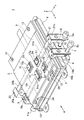
本発明の第1の実施例にかかる操作入力装置を図1〜図4を参照して説明する。操作入力装置1は、図1及び図2に示したように、窓付パネル2と、静電センサ3と、ホルダ4と、荷重センサ5と、モータホルダ6、7と、モータ8、10と、モータの出力軸9、11、12と、窓付パネル固定ねじ13と、ボタン14、15、16、17と、ボタン押上げレバー18、19、20、21と、モータホルダ固定ねじ22と、表面シート23と、ボス24と、を備えている。
An operation input device according to a first embodiment of the present invention will be described with reference to FIGS. As shown in FIGS. 1 and 2, the
図1、図2において、ボタン押上げレバー18、19、20、21が移動する方向をx方向、ボタン14、15、16、17が移動(突没)する方向をz方向、x方向とz方向と直交する方向をy方向と呼ぶ。
1 and 2, the direction in which the button push-up
窓付パネル2は、樹脂等で形成された略板状のパネルであり、開口として複数の窓部2aが形成されている。複数の窓部2aからは、後述するボタン14、15、16、17の表面部14a、15a、16a、17aが露出する。窓付パネル2は、複数の窓付パネル固定ねじ13で静電センサ3と固定されている。また、窓付パネル2は、後述するボタン押上げレバー18、19、20、21がx方向に移動する溝が形成されている。
The
静電センサ3は、窓付パネル2の下層(表面シート23と相対しない側)に重ねて配置されている。静電センサ3は、電極がメッシュ状に張り巡らされた平板センサ部と、所定電圧を電極に印加して、電極に流れる微少電流を検出することで、平板センサ部上の各位置に対する周辺物体の寄生静電容量に相当する値を算出する検出回路部を備える。つまり、静電センサ3は、当該静電センサ3上の複数の座標位置(領域)のそれぞれについて静電容量を検出可能に構成されている。そして、静電センサ3は、使用者の指先等の操作子と導電膜の間での静電容量の変化を捉えて操作子の接触位置を検出する周知のデバイスである。
The
ホルダ4は、板金等で形成され、窓付パネル2と、静電センサ3と、荷重センサ5と、が載置固定される。また、ホルダ4は、モータホルダ6、7を介してモータ8、10を固定する。
The
荷重センサ5は、静電センサ3とホルダ4との間に複数配置される(図2を参照)。複数の荷重センサ5は、荷重がかかる方向(押圧される方向)と直交する方向(図1のx方向、y方向、図2のx方向)に離間して配置される。本実施例では、静電センサ3の四隅に配置されている。なお、荷重センサ5は例えばボタン15等が押圧されることによる荷重を検出できれば、任意の位置に任意の個数を配置してよい。荷重センサ5は、例えばひずみセンサや圧電センサ等、静電センサ3にかかる荷重を検出することができれば特に限定されない。
A plurality of
モータホルダ6は、複数のモータホルダ固定ねじ22によりホルダ4に固定されている。モータホルダ6は、モータ8を固定する。モータホルダ7は、複数のモータホルダ固定ねじ22によりホルダ4に固定されている。モータホルダ7は、モータ10を固定する。
The
モータ8は、モータホルダ6に固定されている。モータ8は、その出力軸9を回転させることによって、後述するボタン押上げレバー19をx方向に移動させる。出力軸9には、ねじ溝が形成され、そのねじ溝がボタン押上げレバー19に設けられているナットと螺合している。したがって、モータ8の出力軸9が回転すると、ナットがねじ溝を移動することによりボタン押上げレバー19が移動する。なお、出力軸9の先端部にはボタン押上げレバー19の移動を規制するストッパ9aが形成されている。
The
モータ10は、モータホルダ7に固定されている。モータ10は、その出力軸11を回転させることによって、後述するボタン押上げレバー18をx方向に移動させる。出力軸11には、ねじ溝が形成され、そのねじ溝がボタン押上げレバー18に設けられているナットと螺合している。出力軸11の先端部にはボタン押上げレバー18の移動を規制するストッパ11aが形成されている。
The
なお、操作入力装置1は、上述したモータ8、10以外にも、ボタン押上げレバー19、20をx方向に移動させるためにモータを備えている。そして、これらのモータもモータ8、10と同様に出力軸を回転させることによってボタン押上げレバー19、20をx軸方向に移動させる。例えば、図1では、ボタン押上げレバー19を移動させるモータの出力軸12が図示されている。
In addition to the
ボタン14は、静電センサ3上に載置されている(図2を参照)。ボタン14は、窓付パネル2の窓部2aから表面部14aが露出する。ボタン14は、ボタン押上げレバー18により、窓部2aから突没するように(z方向に)移動する。
The
ボタン15は、静電センサ3上に載置されている(図2を参照)。ボタン15は、窓付パネル2の窓部2aから表面部15aが露出する。ボタン15は、ボタン押上げレバー19により、窓部2aから突没するように(z方向に)移動する。
The
ボタン16、17も同様に静電センサ3上に載置され、窓付パネル2の窓部2aから表面部16a、17aが露出する。ボタン16は、ボタン押上げレバー20により、窓部2aから突没するように移動する。ボタン17は、ボタン押上げレバー21により、窓部2aから突没するように移動する。
Similarly, the
ボタン押上げレバー18は、本体部18aと、レバー部18bと、を有している。本体部18aは、一方の端部は、図2に示したように、出力軸11が貫通する。そのため、出力軸11が貫通する孔が設けられている。この孔は、上述したようにナットとして機能して、出力軸11に形成されたねじ溝と螺合している。レバー部18bは、本体部18aの他方の端部からボタン14の配置位置に向かって延在している。レバー部18bは、本体部18aの移動に伴って図2の右方向に移動すると、窓付パネル2に形成された溝を通って、ボタン14と静電センサ3との間に進入してボタン14を窓部2aから突出する方向(z方向)に移動させる。レバー部18bは、その先端部がテーパー状に形成されており、ボタン14と静電センサ3との間に進入し易くなっている。また、レバー部18bは、本体部18aの移動に伴って図2の左方向に移動すると、窓付パネル2に形成された溝を通って、ボタン14と静電センサ3との間から抜け出してボタン14を窓部2aへ没する方向に移動させる。
The button push-up
ボタン押上げレバー19は、本体部19aと、レバー部19bと、を有している。本体部19aは、一方の端部には、図2に示したように、出力軸9が貫通する。そのため、出力軸9が貫通する孔が設けられている。この孔は、上述したようにナットとして機能して、出力軸9に形成されたねじ溝と螺合している。レバー部19bは、本体部19aの他方の端部からボタン15の配置位置に向かって延在している。レバー部19bは、本体部19aの移動に伴って図2の左方向に移動すると、窓付パネル2に形成された溝を通って、ボタン15と静電センサ3との間に進入してボタン15を窓部2aから突出する方向(z方向)に移動させる。レバー部19bは、その先端部がテーパー状に形成されており、ボタン15と静電センサ3との間に進入し易くなっている。また、レバー部19bは、本体部19aの移動に伴って図2の右方向に移動すると、窓付パネル2に形成された溝を通って、ボタン15と静電センサ3との間から抜け出してボタン15を窓部2aへ没する方向に移動させる。
The button push-up
ボタン押上げレバー20は、本体部20aと、レバー部20bと、を有している。本体部20aは、一方の端部にモータの出力軸が貫通する孔が設けられている。この孔は、上述したようにナットとして機能して、出力軸に形成されたねじ溝と螺合している。レバー部20bは、本体部20aの他方の端部からボタン16の配置位置に向かって延在している。レバー部20bは、本体部20aの移動に伴って移動することで、ボタン16を窓部2aから突出する方向に移動させたり、窓部2aへ没する方向に移動させたりする。レバー部20bは、その先端部がテーパー状に形成されており、ボタン16と静電センサ3との間に進入し易くなっている。
The button push-up
ボタン押上げレバー21は、本体部21aと、レバー部21bと、を有している。本体部21aは、一方の端部にモータの出力軸が貫通する孔が設けられている。この孔は、上述したようにナットとして機能して、出力軸に形成されたねじ溝と螺合している。レバー部21bは、本体部21aの他方の端部からボタン17の配置位置に向かって延在している。レバー部21bは、本体部21aの移動に伴って移動することで、ボタン17を窓部2aから突出する方向(z方向)に移動させたり、窓部2aへ没する方向に移動させたりする。レバー部21bは、その先端部がテーパー状に形成されており、ボタン17と静電センサ3との間に進入し易くなっている。
The button push-up
ボタン押上げレバー18、19、20、21は、表面シート23(操作面)と静電センサ3の間に配置され、操作面内の夫々独立した複数の領域を夫々個別に押し上げ可能な押上げ部として機能する。なお、ボタン押上げレバー18、19、20、21は、各レバー部の移動のために各レバー部と静電センサ3との間に微小な隙間を有している。
The button push-up
即ち、モータ8、10、ボタン押上げレバー18、19、20、21は、ボタン14、15、16、17を突没(被操作部の一部の形体を変化)させるための形体変更部(駆動部)として機能する。
That is, the
表面シート23は、窓付パネル2の表面(静電センサ3と相対する面と反対側の面)に設けられている。表面シート23は、弾力性を有し、ボタンが押し上げられると伸びて隆起し、各ボタンが押し上げられていない際には平面状を維持する。表面シート23は、窓付パネル2を被覆してボタン14、15、16、17の抜け防止や、窓付パネル固定ねじ13及びボス24等の目隠し板としての機能も果たす。したがって、表面シート23の表面が操作面(被操作部)となる。なお、表面シート23は無くてもよい。その場合は、窓付パネル2の表面及び各ボタンの表面部が操作面(被操作部)となる。
The
即ち、表面シート23(被操作部)と静電センサ3とは離間して配置されている。また、各ボタンが押し上げられたときは、各ボタンは静電センサ3と離間して配置されることとなる。
In other words, the top sheet 23 (operated part) and the
ボス24は、窓付パネル2を静電センサ3に固定する際の位置決め用に設けられている。本実施例では、ボス24は2つ設けられている。つまり、窓付パネル2と静電センサ3には、ボス24が貫通する孔(ボス穴)が形成されており、ボス24が、それらの孔を貫通することで窓付パネル2と静電センサ3との位置決めがなされる。
The
上述した構成の操作入力装置1は、例えば、ボタン14が操作可能な場合は、ボタン押上げレバー18によりボタン14を窓付パネル2から突出させる。すると、使用者等は、操作可能なボタンを手探りで識別することができる。そして、ボタン14が使用者等に押圧された場合は、ボタン14に対応付けられた操作内容を示す動作をすることができる。
For example, when the
次に、本実施例の操作入力装置1の機能的構成を図3を参照して説明する。
Next, the functional configuration of the
図3に示したように、操作入力装置1は、図1に示した構成に加えて、操作入力制御部102を備えている。
As illustrated in FIG. 3, the
操作入力制御部102は、操作対象となるボタンの位置を例えばナビゲーション装置等の操作される装置から取得し、モータ8等を制御することで、対応するボタンを突出させる。また、操作入力制御部102は、静電センサ3が検出した指の接触位置(座標)と、荷重センサ5が検出した荷重値と、に基づいて実際の操作(押圧)されたボタンを特定する。また、操作入力制御部102は、静電センサ3が検出した座標について、ボタン14〜17が操作(押圧)と判定する座標の範囲(操作有効領域)が各ボタン毎に設定されている。即ち、ボタン押上げレバー18〜21(押上げ部)により押し上げられた領域を、操作有効領域として設定している。
The operation
次に、上述した構成の操作入力装置1の動作(初期値キャリブレーション)について図4を参照して説明する。なお、以下の説明においては操作子としてユーザ等の指で説明するが、指には限定されず導電性のタッチペン等であってもよい。
Next, the operation (initial value calibration) of the
静電センサ3上には、位置が変化する構造物(ボタン押上げレバー18等、ボタン15等、表面シート23)が存在するため、ボタン15等の押し上げのパターン(形体)によって、静電センサ3が検出する寄生静電容量(に相当する値)が変化してしまう。そこで、以下に説明する初期値キャリブレーションを行う。
On the
図4に初期値キャリブレーション動作のフローチャートを示す。このフローチャートは操作入力制御部102で実行される。なお、この初期値キャリブレーション動作は、ユーザ等が指で操作入力装置1の操作面に触れない状態で実行する。
FIG. 4 shows a flowchart of the initial value calibration operation. This flowchart is executed by the operation
まず、出荷時やユーザ等による指定により初期値キャリブレーションの指示が入力されると(ステップS101)、操作入力制御部102は、ボタン14〜17の押上げパターンの1つのパターンについて実行する(ステップS102)。つまり、ボタン14〜17がそれぞれ単独で押し上げられるパターンや複数のボタンが押し上げられるパターン等の複数のパターンのうちの一のパターンについて、その状態になるようにモータ8、10等を駆動する。
First, when an instruction for initial value calibration is input at the time of shipment or designation by a user or the like (step S101), the operation
次に、ステップS102で実行されたパターンについての寄生静電容量を静電センサ3から取得し、対応するパターンと関連付けて初期値として操作入力制御部102内に記憶する(ステップS103)。そして、全パターンについて寄生静電容量の記憶が終了した場合は初期値キャリブレーションを終了し(ステップS104:Y)、そうでない場合は次のパターンについて寄生静電容量の検出と記憶を行うために順次形体を変化させる(ステップS104:N)。なお、この記憶の際は静電容量が検出される座標位置(領域)ごとに記憶する。
Next, the parasitic capacitance for the pattern executed in step S102 is acquired from the
即ち、操作入力制御部102は、指(操作子)がボタン15等(被操作部)に接近又は接触していない状態で静電センサ3により検出される静電容量をパターン(形体)ごとに初期値として記憶する記憶部として機能する。
That is, the operation
このようにして、操作入力制御部102は、全ての押し上げパターンに対応する位置座標ごとの寄生静電容量を、予め初期値として記憶してすることができる。そして、操作入力装置1の使用時(通常使用時)には、ボタン15等を押し上げた(突出させた)際に、対応する押し上げパターンの初期値を読み出して、これを基準として指が触れた際の静電容量変化を算出し、その算出された静電容量変化に基づいて指が触れた位置を特定してボタン15等の操作を検出する。
In this way, the operation
通常使用時の具体例としては、ボタン15が押し上げられた場合には、そのボタン15が押されたと判定する座標の範囲が予め定められており、指が操作入力制御部102の操作面に接触したことを静電容量変化によって検出すると、その静電容量の変化が最も大きい座標位置を押された位置と算出する。そして、その算出された位置がボタン15が押されたと判定する座標の範囲にある場合は、ボタン15が押されたと特定する。
As a specific example during normal use, when the
なお、ボタン15等の操作の検出は、荷重センサ5で検出された荷重値が所定以上であった場合に、静電容量変化に基づき算出された位置に対応するボタンが確実に押し込まれていると判定して、操作を確定することができる。
The operation of the
即ち、操作入力制御部102は、指(操作子)がボタン15等(被操作部)に接近又は接触した際に、初期値を基準として算出した静電容量変化に基づいてボタン15等(被操作部)になされた操作を特定する特定部として機能する。
That is, when the finger (operator) approaches or touches the
図4のフローチャートから明らかなように、本実施例においては、ステップS103が記憶工程となる。なお、図4のフローチャートは、初期値の取得のみであるので、上述した通常使用時やその具体例の動作が特定工程となる。 As is apparent from the flowchart of FIG. 4, in this embodiment, step S103 is a storage process. In the flowchart of FIG. 4, only the initial value is acquired, and thus the normal operation and the operation of the specific example are the specific steps.
本実施例によれば、操作入力装置1は、ボタン15等を突没させるボタン押上げレバー18等、モータ8等と、ボタン15等を含む周辺の物体との間の静電容量を検出する静電センサ3と、を備えている。さらに、指がボタン15等に接近又は接触していない状態で静電センサ3により検出される静電容量を、ボタンが突没した形体ごとに初期値として記憶する操作入力制御部102を備え、この操作入力制御部102は、指がボタン15等に接近又は接触した際に、初期値を基準として算出した静電容量変化に基づいてボタン15等になされた操作を特定する。このようにすることにより、静電容量が変化する形体に応じてその初期値を取得して記憶することができる。そのため、この初期値を利用して指がボタン15等に接近又は接触したことで生じる静電容量変化のみを検出可能となり、この静電容量変化に基づいて操作を特定することで、被操作部が変形等により静電容量が変化する場合であっても、その影響を受けずに適切に操作を特定することができる。
According to the present embodiment, the
また、静電センサ3は、当該静電センサ上の複数の領域のそれぞれについて静電容量を検出可能であって、操作入力制御部102は、静電センサ3が検出可能な座標位置(領域)のそれぞれに対応する初期値を記憶している。このようにすることにより、ボタン14が突没することにより形体の変化する領域と変化しない領域とに分けて初期値を取得して記憶することができる。
In addition, the
また、操作入力制御部102は、ボタン15等の突没状態を順次変化させるようにボタン押上げレバー18等、モータ8等を制御し、指がボタン15等に接近又は接触していない状態でボタン15等が突没する度に、静電センサ3が検出した静電容量を記憶している。また、操作入力制御部102は、指がボタン15等に接近又は接触していない状態でボタン押上げレバー18等、モータ8等がボタン15等を突没させた際に、静電センサ3が検出した静電容量を初期値として記憶している。このようにすることにより、形体が変化した時点の静電容量を記憶することができる。
Further, the operation
また、操作入力制御部102は、指に起因する静電容量変化に基づいて指の接近位置又は接触位置を算出し、当該接近位置又は接触位置に基づいてボタン15等になされた操作を特定している。このようにすることにより、形体に応じた初期値によって形体の変化による静電容量の変化の影響を無くして静電容量により操作を特定することができる。
Further, the operation
また、ボタン14〜17の一以上を突出させるための駆動部であるモータ8、10、ボタン押上げレバー18〜21を備えている。このようにすることにより、ボタン14〜17を、操作の態様に応じて適宜突出させることができる。
Moreover, the
次に、本発明の第2の実施例にかかる操作入力装置を図5〜図11を参照して説明する。なお、前述した第1の実施例と同一部分には、同一符号を付して説明を省略する。 Next, an operation input device according to a second embodiment of the present invention will be described with reference to FIGS. The same parts as those in the first embodiment described above are denoted by the same reference numerals and description thereof is omitted.
本実施例では、有効操作領域調整動作について説明する。図1等に示した操作入力装置1は、静電センサ3上に構造物が存在するために、指と静電センサ3との距離が離れざるを得ないため、静電センサ3の静電容量の検出感度を高く設定せざるを得ない。このため、静電センサ3は、指の操作面に接していない部分に対する寄生容量を検出してしまう場合がある。このような現象は、特に操作面に対して指が平行に近い状態で接近するほど、指の操作面に接していない部分の影響が大きくなる。
In this embodiment, the effective operation area adjustment operation will be described. Since the
このように、指が操作面に対して傾いている方向(操作子が被操作部に沿って延在する方向)に亘って静電容量変化が検出されるため、指のタッチ位置座標が、指の傾き方向にズレて検出される傾向がある。そこで、操作入力する指の操作面に対する角度に起因する操作位置のズレを踏まえて、操作領域(操作ボタン15等)の有効判定領域を調整する。 As described above, since the capacitance change is detected in the direction in which the finger is inclined with respect to the operation surface (the direction in which the operation element extends along the operated portion), the touch position coordinate of the finger is There is a tendency to be detected in the direction of finger tilt. Therefore, the validity determination area of the operation area (such as the operation button 15) is adjusted based on the deviation of the operation position caused by the angle of the finger to be operated with respect to the operation surface.
図5に有効操作領域調整動作のフローチャートを示す。このフローチャートは操作入力制御部102で実行される。
FIG. 5 shows a flowchart of the effective operation area adjustment operation. This flowchart is executed by the operation
まず、操作入力装置1が起動(システム起動)されると(ステップS201)、ナビゲーション装置等に連動して操作可能とするボタン15等をモータ8、10等を駆動させて突出させるとともに、そのボタン15等が操作されていると認識する領域(有効操作領域)の初期値を設定する(ステップS202)。図6に有効操作領域の例を示す。図6において、ボタン15〜17それぞれの周囲に破線で示した領域A〜Cが各ボタンが突出した際の有効操作領域となる。
First, when the
次に、実際にユーザ等が指で操作をした際の静電容量変化を静電センサ3から取得する(ステップS203)。静電センサ3における静電容量変化の例を図7を参照して説明する。図7は、静電センサ3を図1のz方向から見た模式図であり、各領域内の数字が当該位置における静電容量の変化量を示している。符号Fは指を示している。
Next, the capacitance change when the user or the like actually operates with a finger is acquired from the electrostatic sensor 3 (step S203). An example of capacitance change in the
図7において、指Fは図8に示すように、操作面である表面シート23に対して図中右側に傾けるようにして触れている。また、操作入力装置1は、静電センサ3との間に表面シート23等の構造物があるため、静電センサ3の検出感度を高めている。そのため、静電センサ3は、指Fが触れた位置だけでなく、指Fが触れていない部分についても表面シート23に近い部分については静電容量が変化する。
In FIG. 7, as shown in FIG. 8, the finger F touches the
即ち、操作入力制御部102は、ボタン15等(被操作部)と離間して配置された静電センサ3の出力に基づいて、当該ボタン15等(被操作部)へ近接又は接触する指(操作子)に起因する静電容量変化を検出する第1検出部として機能する。
That is, the operation
次に、荷重センサ5が検出した荷重値が所定以上か否かで操作入力の有無を判断し、操作入力無しと判断された場合はステップS203に戻る(ステップS204:N)。一方、操作入力有りと判断された場合は(ステップS204:Y)、指Fの方向を算出する(ステップS205)。指Fの方向の算出について図9を参照して説明する。
Next, the presence / absence of an operation input is determined based on whether the load value detected by the
即ち、操作入力制御部102は、静電容量変化に基づいて、指(操作子)が表面シート23(被操作部)に沿って延在する方向を検出する第2検出部として機能する。また、操作入力制御部102は、荷重センサ5によって所定以上の荷重で押された場合に、指(操作子)によるボタン15等(被操作部)への操作入力がなされたとして、指(操作子)がボタン15等(被操作部)に沿って延在する方向を検出している。
That is, the operation
図9の網掛け部分は、静電容量の変化が生じている領域の形状を幾何学的に解析した結果である。そして、最大の静電容量変化が生じている領域を基準に図8の(1)〜(8)の8方向のどの方向に静電容量の変化が生じている領域が伸びているかを解析する。図8の場合は(4)の方向に伸びていることが分かる。なお、図8では8方向としているが、8方向よりも少なくしてもよいし多くしてもよい。 The shaded portion in FIG. 9 is the result of geometrical analysis of the shape of the region where the capacitance change occurs. Then, based on the region where the maximum capacitance change occurs, the direction in which the capacitance change occurs in one of the eight directions (1) to (8) in FIG. 8 is analyzed. . In the case of FIG. 8, it can be seen that it extends in the direction of (4). In FIG. 8, eight directions are used, but the number may be fewer or more than eight directions.
次に、ステップS205で算出された指の方向に基づいてステップS202で初期設定した有効操作領域を調整する(ステップS206)。調整の例を図10及び図11に示す。図10は、静電容量の変化が生じている領域が伸びている方向へ有効操作領域を拡張した様子を示している。なお、拡張ではなく、その方向へ有効操作領域を移動させるようにしてもよい。即ち、操作入力制御部102は、ボタン15等(被操作部)に沿って延在する方向に応じてボタン15等(被操作部)の有効操作領域を調整する調整部として機能する。図9に示す静電容量変化が検出された場合は、静電容量の変化が生じている領域が伸びている方向が(4)であるから、図10(4)が示す方向に有効操作領域が拡張される。
Next, the effective operation area initially set in step S202 is adjusted based on the finger direction calculated in step S205 (step S206). An example of adjustment is shown in FIGS. FIG. 10 shows a state where the effective operation area is expanded in the direction in which the area where the capacitance change occurs is extended. The effective operation area may be moved in that direction instead of being expanded. That is, the operation
図10に示した領域拡張を図6に示した有効操作領域A〜Cに適用した例を図11に示す。図11の領域A1〜C1が拡張された領域である。なお、この処理は、例えば突出させているボタンに対応する有効操作領域のみに行ってもよい。 An example in which the area expansion shown in FIG. 10 is applied to the effective operation areas A to C shown in FIG. 6 is shown in FIG. Regions A1 to C1 in FIG. 11 are expanded regions. Note that this processing may be performed only in the effective operation area corresponding to the protruding button, for example.
一方、ステップS205、S206と平行して、例えば最大の静電容量変化を検出した座標をタッチ位置座標として算出する(ステップS207)。なお、タッチ位置座標は、隣接する所定の複数座標からなる領域の容量変化値の合計を算出し、その合計が最大となった領域の中心としてもよい。 On the other hand, in parallel with steps S205 and S206, for example, the coordinates at which the maximum capacitance change is detected are calculated as the touch position coordinates (step S207). Note that the touch position coordinates may be the center of the area where the sum of the capacitance change values of the area composed of a predetermined plurality of adjacent coordinates is calculated and the sum is maximized.
そして、ステップS207で算出したタッチ位置座標がステップS206で調整した有効操作領域の範囲にあるか判定し(ステップS208)、ステップS208の結果有効操作領域に含まれると判定した場合は、その有効範囲に対応するボタン15等の操作に応じたコマンドをナビゲーション装置等の操作される装置へ出力する(ステップS209)。そして、コマンド出力後は次の操作入力に備えてステップS203へ戻る。
Then, it is determined whether the touch position coordinates calculated in step S207 are within the range of the effective operation area adjusted in step S206 (step S208). If it is determined in step S208 that the touch position coordinates are included in the effective operation area, the effective range is determined. A command corresponding to the operation of the
即ち、操作入力制御部102は、ステップS208、S209を実行することにより、静電容量変化に基づいて特定した指(操作子)の近接又は接触の位置が、調整後の有効操作領域に対応するか判定する判定部として機能する。
That is, the operation
また、図5のフローチャートから明らかなように、本実施例においては、ステップS203が第1検出工程、ステップS205が第2検出工程、ステップS206が調整工程、ステップS208、S209が判定工程として機能する。 Further, as is apparent from the flowchart of FIG. 5, in this embodiment, step S203 functions as a first detection process, step S205 functions as a second detection process, step S206 functions as an adjustment process, and steps S208 and S209 function as a determination process. .
本実施例によれば、操作入力装置1は、ボタン15等と離間して配置された静電センサ3の出力に基づいて、当該ボタン15へ近接又は接触する操作子に起因する静電容量変化を検出する操作入力制御部102を備えている。また、操作入力制御部102は、静電容量変化に基づいて、指がボタン15等に沿って延在する方向を検出し、その方向に応じてボタン15等の有効操作領域を調整する。そして、操作入力制御部102は、静電容量変化に基づいて特定した指の近接又は接触の位置が、調整後の有効操作領域に対応するか判定する。このようにすることにより、指等でボタン15等の操作面に対して傾けて押した場合に、その指の傾いた方向を検出することができる。そのため、指の傾き方向へのズレを考慮した検出をすることが可能となる。したがって、操作面であるボタン15等と静電センサ3の距離が離れた場合でも、精度良く操作された操作領域を判定できるため、操作面のデザイン及び操作入力装置の配置の自由度を高めることができる。
According to the present embodiment, the
また、操作入力制御部102は、指がボタン15等に沿って延在する方向に有効操作領域を拡張している。このようにすることにより、指の傾き方向へのズレを考慮した検出をすることが可能となる。したがって、精度良く操作された操作領域を判定できる。
Further, the operation
また、操作入力制御部102は、指によるボタン15等への操作入力がなされた際に、指がボタン15等に沿って延在する方向を検出している。このようにすることにより、入力操作がされたことが確定した時点の指の方向を検出するので、操作領域の判定制度を向上させることができる。
Further, the operation
なお、突出量の大きいボタンと、突出量の小さいボタンとを設け、突出量の大きいボタンの有効領域の拡張量を、突出しないボタンの拡張量よりも大きく設定してもよい。即ち、複数のボタン15等(操作対象)を備え、操作入力制御部102(調整部)は、ボタン15等(操作対象)の突出量(静電センサに対する離間量)が大きいほど、当該ボタン15等(操作対象)に対応する有効操作領域の調整量を大きくする。これは、例えばレバー部19bの厚みを徐々に変化させることで、レバー部19bの移動量に応じてボタン15の突出量、即ち離間量を変化させることができる。
A button with a large protrusion amount and a button with a small protrusion amount may be provided, and the expansion amount of the effective area of the button with a large protrusion amount may be set larger than the expansion amount of a button that does not protrude. That is, a plurality of
このように動作させると、ボタン15等の突出量が大きくなるほど指が接触している部分とそうでない部分とで検出される静電容量に差異が少なくなる。言い換えれば、指の操作面に接していない部分に対する寄生容量の影響により、指のタッチ位置座標が指の傾き方向にズレて検出される傾向が強くなる。そこで、有効操作領域を広げるように調整することで、このような場合でも精度良く操作領域を判定することができる。また、このように突出量をボタン毎に異ならせることで、ボタン毎に複数の突出量を設定することができ、その突出量でボタン等の識別が可能となる。
When operated in this manner, the difference in the capacitance detected between the portion in contact with the finger and the portion not in contact with the finger decreases as the protruding amount of the
次に、本発明の第3の実施例にかかる操作入力装置を図12を参照して説明する。なお、前述した第1の実施例と同一部分には、同一符号を付して説明を省略する。 Next, an operation input device according to a third embodiment of the present invention will be described with reference to FIG. The same parts as those in the first embodiment described above are denoted by the same reference numerals and description thereof is omitted.
本実施例では、押圧前座標取得動作について説明する。静電センサ3上の構造物のうち例えばボタン15等は、それらが変位可能に構成されているため、それぞれのパーツの間に、わずかな隙間を設けて配置されている。このため、操作面に指が軽く触れている時に対して、操作面を指で押圧した時には、パーツ間の隙間が詰まったり、構造物自体の変形などによって、静電センサ3に対する寄生容量が変化してしまう場合がある。つまり、操作面の同じ位置に指が触れている場合であっても、指が軽く接触している時と、操作面を指で強く押圧した時とで、静電センサ3は、異なる座標位置を検出してしまうという現象が発生し得る。
In this embodiment, a pre-pressing coordinate acquisition operation will be described. Of the structures on the
そこで、荷重センサ5が、接触閾値(操作面への指の軽い接触を検出する閾値)より大きい押圧荷重を検出した際に、検出された指のタッチ位置座標を記憶しておき、荷重センサ5が続けて確定閾値(操作入力有りを検出する閾値)を超えた場合に、先に記憶していたタッチ位置座標での操作入力があったと判定する。即ち、接触閾値が第2閾値、確定閾値が第1閾値となる。
Therefore, when the
図12に押圧前座標取得動作(入力操作方法)のフローチャートを示す。このフローチャートは操作入力制御部102で実行される。
FIG. 12 shows a flowchart of the pre-pressing coordinate acquisition operation (input operation method). This flowchart is executed by the operation
まず、操作入力装置1が起動(システム起動)されると(ステップS301)、ナビゲーション装置等に連動して操作可能とするボタン15等をモータ8、10等を駆動させて突出させるとともに、そのボタン15等が操作されていると認識する領域(有効操作領域)の初期値を設定する(ステップS302)。ステップS302は、基本的に上述したステップS202と同様である。
First, when the
次に、操作面に指が接近又は接触しているときの静電容量の変化からタッチ位置座標を静電センサ3から取得し(ステップS303)、荷重センサ5から荷重値を取得する(ステップS304)。タッチ位置座標は、例えば上述したステップS207と同様の最大の静電容量変化を検出した座標を操作位置座標として算出すればよい。即ち、操作入力制御部102が静電センサの出力に基づいて、ボタン15等(被操作部)へ接触する指(操作子)の接触位置を検出する接触位置検出部として機能する。
Next, the touch position coordinate is acquired from the
次に、ステップS304で取得した荷重値が接触閾値よりも大きいか否かを判断し、小さい場合はステップS303に戻り(ステップS305:N)、大きい場合は(ステップS305:Y)直近のタッチ位置座標をタッチ位置座標Oとして保存する(ステップS306)。このタッチ位置座標Oが第1接触位置となる。即ち、操作入力制御部102(特定部)は、荷重センサ5が検出する押圧荷重が確定閾値(第1閾値)より小さい接触閾値(第2閾値)を超えた際のタッチ位置座標O(第1接触位置)を取得している。
Next, it is determined whether or not the load value acquired in step S304 is larger than the contact threshold value. If it is smaller, the process returns to step S303 (step S305: N), and if larger (step S305: Y), the latest touch position. The coordinates are stored as touch position coordinates O (step S306). This touch position coordinate O becomes the first contact position. That is, the operation input control unit 102 (specifying unit) detects the touch position coordinate O (first value) when the pressing load detected by the
なお、ステップS306は、荷重センサ5の検出値により判断しているが、例えば、静電センサ3の検出結果に基づく静電容量変化の大きさが一定以上となったか否かで判断してもよい。
Note that step S306 is determined based on the detection value of the
次に、再度荷重センサ5から荷重値を取得し(ステップS307)、荷重値が確定閾値よりも大きいか否かを判断する。判断の結果、荷重値が確定閾値よりも小さい場合は(ステップS308:N)、その荷重値が接触閾値よりも大きいか否か再度判断し、接触閾値よりも大きい場合は(ステップS309:Y)、再度荷重値を取得すべくステップS307に戻る。 Next, a load value is acquired again from the load sensor 5 (step S307), and it is determined whether or not the load value is larger than a fixed threshold value. As a result of the determination, when the load value is smaller than the fixed threshold value (step S308: N), it is determined again whether or not the load value is larger than the contact threshold value, and when it is larger than the contact threshold value (step S309: Y). Then, the process returns to step S307 to acquire the load value again.
ステップS309の判断の結果、荷重値が接触閾値よりも小さいと判断された場合は(ステップS309:N)、荷重値が接触閾値よりも大きくなった後に小さくなったこととなる。つまり、指による操作が中断されたと見做してステップS303に戻る。即ち、ステップS308、S309は、操作入力制御部102が、荷重センサ5が検出する押圧荷重が接触閾値(第2閾値)を超えた後に、当該接触閾値(第2閾値)以下となることなく確定閾値(第1閾値)を超えたことを検出している。
As a result of the determination in step S309, when it is determined that the load value is smaller than the contact threshold value (step S309: N), the load value becomes smaller after being larger than the contact threshold value. That is, assuming that the operation with the finger is interrupted, the process returns to step S303. That is, steps S308 and S309 are determined without the operation
ステップS308の判断の結果、荷重値が確定閾値よりも大きいと判断された場合は(ステップS308:Y)、現時点のタッチ位置座標Gを取得する(ステップS310)。即ち、操作入力制御部102は、確定閾値(第1閾値)を超えた際に検出したタッチ位置座標G(第2接触位置)を取得している。
As a result of the determination in step S308, if it is determined that the load value is larger than the fixed threshold (step S308: Y), the current touch position coordinate G is acquired (step S310). That is, the operation
次に、ステップS306で記憶したタッチ位置座標OとステップS301で取得したタッチ位置座標Gとを比較する。この比較においては、例えば座標の差分が所定範囲内に収まっているか否かを判定する。この差分が所定範囲内に収まっていない場合は、指が操作面に接触してから押し込むまでに指の位置がスライドしたと判定し、本実施例では、このような場合は操作を受け付けない(ステップS311:N)。なお、ステップS310およびステップS311は、任意に採用できる工程であり省略してもよい。その場合、ステップS308の判断が肯定であれば、ステップS312に進めばよい。 Next, the touch position coordinate O stored in step S306 is compared with the touch position coordinate G acquired in step S301. In this comparison, for example, it is determined whether or not the coordinate difference is within a predetermined range. If this difference is not within the predetermined range, it is determined that the finger position has been slid from when the finger touches the operation surface until it is pressed, and in this embodiment, no operation is accepted in such a case ( Step S311: N). Note that step S310 and step S311 can be arbitrarily adopted and may be omitted. In that case, if the determination in step S308 is affirmative, the process may proceed to step S312.
ステップS306で比較した座標の差が所定範囲内である場合は(ステップS311:Y)、タッチ位置座標Oから選択領域を確定し、どのボタン15等が操作されたかを決定(特定)し(ステップS312)、決定したボタン15等の操作に応じたコマンドをナビゲーション装置等の操作される装置へ出力する(ステップS313)。そして、コマンド出力後は次の操作入力に備えてステップS303へ戻る。ステップS311における所定範囲は、ボタン15等の構造物を押し込んだ際の静電容量の変化の程度に基づいて適宜設定すればよい。
If the difference between the coordinates compared in step S306 is within a predetermined range (step S311: Y), the selected area is determined from the touch position coordinates O, and which
即ち、操作入力制御部102は、押圧荷重が確定閾値(第1閾値)を超えた際に、ボタン15等(被操作部)になされた操作を特定する特定部として機能している。さらに、操作入力制御部102は、荷重センサ5が検出する押圧荷重が確定閾値(第1閾値)を超えた際に、押圧荷重が確定閾値(第1閾値)を超える前に検出されたタッチ位置座標O(第1接触位置)に基づいて、ボタン15等(被操作部)になされた操作を特定している。
That is, the operation
図11のフローチャートから明らかなように、本実施例においては、ステップS303が接触位置検出工程、ステップS304、S307が荷重検出工程、ステップS312が特定工程として機能する。 As is apparent from the flowchart of FIG. 11, in this embodiment, step S303 functions as a contact position detection process, steps S304 and S307 function as a load detection process, and step S312 functions as a specific process.
本実施例によれば、操作入力装置1は、操作入力制御部102が、操作面である表面シート23と離間して配置された静電センサ3の出力に基づいて、ボタン15等へ接触する指のタッチ位置座標を検出する。また、操作入力制御部102は、指によるボタン15等への押圧荷重を検出する荷重センサ5と、押圧荷重が確定閾値を超えた際に、ボタン15等になされた操作を特定する。そして、操作入力制御部102は、押圧荷重が確定閾値を超える前に検出されたタッチ位置座標に基づいて、ボタン15等になされた操作を特定する。このようにすることにより、操作入力装置1が操作を特定する押圧荷重を検出する前のボタン15等への接触に基づいて操作を特定することができる。つまり、確定閾値よりも小さい力で触れたタッチ位置座標に基づいて操作を特定するので、ボタン15等への力加減によらず適切な操作位置を検出することができる。したがって、被操作部等の操作面の部材や強度等の選択に幅を持たせることができ、デザインの自由度を高めることができる。
According to the present embodiment, in the
操作入力制御部102は、荷重センサ5が検出する押圧荷重が確定閾値より小さい接触閾値を超えた際のタッチ位置座標Oを取得し、荷重センサ5が検出する押圧荷重が確定閾値を超えた際に、このタッチ位置座標Oに基づいて、ボタン15等になされた操作を特定している。このようにすることにより、操作入力制御部102が操作を特定する押圧荷重を検出する前である接触閾値を超えた際のタッチ位置座標Oに基づいて操作を特定することができる。つまり、タッチ位置は、指が軽く接触している時のタッチ位置を基準とし、操作の特定は、操作面を指で強く押圧した時として、それぞれの役割を分けているために加減によらず適切な操作位置を検出することができる。また、軽く触れているときのタッチ位置に基準としているので、構造物の変形等の影響を受けないようにすることができる。
The operation
また、操作入力制御部102は、荷重センサ5が検出する押圧荷重が接触閾値を超えた後に、当該接触閾値以下となることなく確定閾値を超えた際に、タッチ位置座標Oに基づいて、ボタン15等になされた操作を特定している。このようにすることにより、荷重が増加し続けて確定閾値を超えた場合にのみ動作を特定することができる。つまり、一度の押圧操作を検出して、操作を特定することができるようになる。
In addition, the operation
また、操作入力制御部102は、確定閾値を超えた際に検出したタッチ位置座標Gを取得し、タッチ位置座標Gとタッチ位置座標Oとを比較し、それらの座標の差分が所定範囲内である場合に、タッチ位置座標Oに基づいてボタン15等になされた操作を特定している。このようにすることにより、指が操作面に接触させながら、指の位置をスライドしてボタンを選び直したような場合に発生し得る誤操作を抑制することができる。
Further, the operation
また、ボタン14〜17の一以上を突出させるための駆動部であるモータ8、10、ボタン押上げレバー18〜21を備えている。このようにすることにより、ボタン15等について、押圧した場合に力加減によらず適切な操作位置を検出することができる。
Moreover, the
なお、第1の実施例〜第3の実施例の処理は組み合わせてもよい。 The processes of the first to third embodiments may be combined.
また、上述した実施例2、3では、突出させたボタン15等のみを操作対象として説明したが、突出させないボタン15等も操作対象に含めても良い。例えば、場面に応じて使用頻度の高いボタンのみを突出させてユーザの利便性を図りつつ、突出させないボタンについても操作可能としてもよい。この場合に、操作入力制御部102は、例えば突出させたボタン14のみについて、第2の実施例で説明した有効操作領域調整を適用してもよい。具体的には、例えば突出したボタン14のみについては、ボタン14と静電センサ3との距離が大きいので、有効領域を拡張するなどとすればよい。
In the second and third embodiments described above, only the protruded
また、操作入力装置は、ボタンの押し上げ機構を備えなくともよい。例えばデザイン上の制約で、操作面(指が触れる面)に対して静電センサ3を離間して配置した場合に、第2の実施例で説明した有効操作領域調整を適用すれば、指でどの方向から操作された場合であっても、適切に操作面の所定位置が操作されたことを判定することができる。これは、図1等の構成であれば、ボタン14〜17以外の領域について有効操作領域調整を適用できることを意味する。このようにすることにより、例えば操作入力装置1が車両のセンターコンソールに配置された場合は、運転席/助手席からの操作に適切に対応し、ハンドルに配置された場合は、運転者のハンドルの握り位置の違いに適切に対応できる。
The operation input device may not include a button push-up mechanism. For example, when the
また、操作入力装置は、ボタンの押し上げ機構を備えなくともデザイン上の制約等で操作面に変形し易い部材を使用した場合は、第3の実施例で説明した押圧前座標取得を適用することで、押圧により操作面が変形しても、適切に操作面のいずれの位置が操作されたかを判定することができる。これは、図1等の構成であれば、窓付パネル2が変形し易い場合に、ボタン14〜17以外の領域について押圧前座標取得を適用できることを意味する。
Further, when the operation input device uses a member that does not have a button push-up mechanism and is easily deformed due to a design restriction or the like, apply the pre-press coordinate acquisition described in the third embodiment. Thus, even if the operation surface is deformed by pressing, it is possible to determine which position of the operation surface has been appropriately operated. This means that the coordinate acquisition before pressing can be applied to regions other than the
また、操作入力装置は、操作面への指が接触しなくても、ある程度接近したことをもって、操作入力がなされたと判定してもよい。この場合、荷重センサ5を備えず、静電センサ3が検出した静電容量変化の最大値が、所定値以上となった場合に、指が操作面にある程度接近した(=操作入力有り)と判定させればよい。この場合も第1の実施例や第2の実施例で説明した処理を組み合わせて、または単独で、適用すれば、適切にいずれの位置が操作されたかを判定することができる。
Further, the operation input device may determine that an operation input has been made with a certain degree of proximity even if a finger does not touch the operation surface. In this case, the
また、本発明は上記実施例に限定されるものではない。即ち、当業者は、従来公知の知見に従い、本発明の骨子を逸脱しない範囲で種々変形して実施することができる。かかる変形によってもなお本発明の操作入力装置の構成を具備する限り、勿論、本発明の範疇に含まれるものである。 Further, the present invention is not limited to the above embodiment. That is, those skilled in the art can implement various modifications in accordance with conventionally known knowledge without departing from the scope of the present invention. Of course, such modifications are included in the scope of the present invention as long as the configuration of the operation input device of the present invention is provided.
1 操作入力装置
3 静電センサ
5 荷重センサ
8 モータ(駆動部)
10 モータ(駆動部)
14 ボタン(被操作部)
15 ボタン(被操作部)
16 ボタン(被操作部)
17 ボタン(被操作部)
18 ボタン押上げレバー(駆動部)
19 ボタン押上げレバー(駆動部)
20 ボタン押上げレバー(駆動部)
21 ボタン押上げレバー(駆動部)
23 表面シート(被操作部)
102 操作入力制御部(接触位置検出部、特定部)
1
10 Motor (drive unit)
14 button (operated part)
15 button (operated part)
16 buttons (operated part)
17 button (operated part)
18 Button push-up lever (drive unit)
19 Button push-up lever (drive unit)
20 Button push-up lever (drive unit)
21 Button push-up lever (drive unit)
23 Surface sheet (operated part)
102 Operation input control unit (contact position detection unit, identification unit)
Claims (8)
前記被操作部を含む周辺の物体との間の静電容量を検出する静電センサと、
操作子が前記被操作部に接近又は接触していない状態で前記静電センサにより検出される静電容量を、前記被操作部の形体ごとに初期値として記憶する記憶部と、
前記操作子が前記被操作部に接近又は接触した際に、前記初期値を基準として算出した静電容量変化に基づいて前記被操作部になされた操作を特定する特定部と、
を備えることを特徴とする操作入力装置。 A shape changer that changes the shape of the operated part;
An electrostatic sensor that detects a capacitance between a peripheral object including the operated portion; and
A storage unit that stores an electrostatic capacitance detected by the electrostatic sensor in a state where an operator is not approaching or in contact with the operated unit as an initial value for each form of the operated unit;
A specifying unit for specifying an operation performed on the operated unit based on a change in capacitance calculated based on the initial value when the operating unit approaches or contacts the operated unit;
An operation input device comprising:
前記記憶部は、前記複数の領域のそれぞれに対応する前記初期値を記憶する、
ことを特徴とする請求項1に記載の操作入力装置。 The electrostatic sensor can detect the capacitance for each of a plurality of regions on the electrostatic sensor,
The storage unit stores the initial value corresponding to each of the plurality of regions.
The operation input device according to claim 1.
前記制御部は、前記被操作部が前記形体を順次変化させるように前記形体変更部を制御し、前記操作子が前記被操作部に接近又は接触していない状態で前記被操作部の前記形体が変化する度に、前記静電センサが検出した静電容量を前記記憶部に記憶させることを特徴とする請求項3に記載の操作入力装置。 A control unit for controlling the shape changing unit and the storage unit;
The control unit controls the shape changing unit so that the operated unit sequentially changes the shape, and the form of the operated unit is in a state where the operation element is not approaching or contacting the operated unit. 4. The operation input device according to claim 3, wherein the capacitance detected by the electrostatic sensor is stored in the storage unit each time the value changes. 5.
操作子が前記被操作部に接近または接触していない状態で、前記被操作部を含む周辺の物体との間の静電容量を検出する静電センサにより検出される静電容量を、前記被操作部の形体を変化させる形体変更部により変化された前記形体ごとに初期値として記憶する記憶工程と、
前記操作子が前記被操作部に接近又は接触した際に、前記初期値を基準として算出した静電容量変化に基づいて前記被操作部になされた操作を特定する特定工程と、
を含むことを特徴とする入力検出方法。 An input detection method executed by an operation input device that identifies an operation performed on an operated part,
A capacitance detected by an electrostatic sensor that detects a capacitance between the operating element and a surrounding object including the operated part in a state where the operating element is not approaching or in contact with the operated part. A storing step of storing as an initial value for each of the features changed by the feature changing unit that changes the feature of the operation unit;
A specifying step of specifying an operation performed on the operated portion based on a change in capacitance calculated based on the initial value when the operating element approaches or contacts the operated portion;
An input detection method comprising:
Priority Applications (1)
| Application Number | Priority Date | Filing Date | Title |
|---|---|---|---|
| JP2017131202A JP2019016052A (en) | 2017-07-04 | 2017-07-04 | Operation input device |
Applications Claiming Priority (1)
| Application Number | Priority Date | Filing Date | Title |
|---|---|---|---|
| JP2017131202A JP2019016052A (en) | 2017-07-04 | 2017-07-04 | Operation input device |
Publications (1)
| Publication Number | Publication Date |
|---|---|
| JP2019016052A true JP2019016052A (en) | 2019-01-31 |
Family
ID=65358475
Family Applications (1)
| Application Number | Title | Priority Date | Filing Date |
|---|---|---|---|
| JP2017131202A Pending JP2019016052A (en) | 2017-07-04 | 2017-07-04 | Operation input device |
Country Status (1)
| Country | Link |
|---|---|
| JP (1) | JP2019016052A (en) |
-
2017
- 2017-07-04 JP JP2017131202A patent/JP2019016052A/en active Pending
Similar Documents
| Publication | Publication Date | Title |
|---|---|---|
| JPWO2019116490A1 (en) | Operation support device, touch panel device, and touch panel input system | |
| EP2801892B1 (en) | Touch type input device and method for detecting touching of touch panel | |
| US10108293B2 (en) | Touch-type input device | |
| US20150379914A1 (en) | Touch-type input device | |
| EP2960756A1 (en) | Touch-type input device | |
| JP7203854B2 (en) | Input device, control method and program | |
| JP5939225B2 (en) | Capacitive switch | |
| JP2016218542A (en) | Operation device and operation system | |
| US11711078B2 (en) | On/off detection device and vehicle interior component | |
| JP2019016052A (en) | Operation input device | |
| US9377911B2 (en) | Input device | |
| JP2019016051A (en) | Operation input device | |
| WO2019220749A1 (en) | Input device | |
| JP6565856B2 (en) | Touch input device | |
| JPWO2019009138A1 (en) | Operation input device | |
| JP2017215866A (en) | Input device | |
| JP2018092315A (en) | Operation input device | |
| JP2018092317A (en) | Operation input device | |
| US20160054843A1 (en) | Touch pad system and program for touch pad control | |
| JP2013136296A (en) | Operating device for vehicle | |
| CN113246729A (en) | Operating device | |
| WO2020110545A1 (en) | Input device | |
| JP2018190278A (en) | Operation input device | |
| WO2019215915A1 (en) | Input control device, display input device, and input control method | |
| JP2018092316A (en) | Operation input device |
Legal Events
| Date | Code | Title | Description |
|---|---|---|---|
| RD04 | Notification of resignation of power of attorney |
Free format text: JAPANESE INTERMEDIATE CODE: A7424 Effective date: 20180305 |